

Page 1

Page 2

Page 3

Contents
About this Concise User Guide ......................................................... 1
System Startup ................................................................................... 4
System Map: Front View with LCD Panel Open (Models A & B) ...5
LED Indicators ................................................................................... 6
Keyboard ............................................................................................ 6
Control Center ................................................................................... 8
System Map: Front, Left, Right, Rear & Bottom Views (Model A) 11
System Map: Front, Left, Right, Rear & Bottom Views (Model B) 12
3G Module ....................................................................................... 13
Driver Installation ............................................................................14
Troubleshooting ............................................................................... 15
Specifications ................................................................................... 16
Carte du système: Vue de face avec l’écran LCD ouvert
(Modèles A & B) ............................................................................41
Indicateurs LED ...............................................................................42
Clavier .............................................................................................. 42
Control Center (Centre de contrôle) ................................................44
Carte du système: Vues de face, gauche, droite, arrière & dessous
(Modèle A) .......................................................................................47
Carte du système: Vues de face, gauche, droite, arrière & dessous
(Modèle B) .......................................................................................48
Module 3G .......................................................................................49
Installation du pilote ........................................................................50
Dépannage ....................................................................................... 51
Spécifications ...................................................................................52
Inhalt
Über das Ausführliche Benutzerhandbuch ...................................... 19
Schnellstart ...................................................................................... 22
Systemübersicht: Ansicht von vorne mit geöffnetem LCD-Bildschirm
(Modelle A & B) ..............................................................................23
LED-Anzeigen ................................................................................. 24
Tastatur ............................................................................................ 24
Control Center (Steuerzentrum) ....................................................... 26
Systemübersicht: Ansicht von vorne, links, rechts, hinten und unten
(Modell A) .......................................................................................29
Systemübersicht: Ansicht von vorne, links, rechts, hinten und unten
(Modell B) ....................................................................................... 30
3G-Modul ........................................................................................ 31
Installation der Treiber ..................................................................... 32
Fehlerbehebung ................................................................................ 33
Technische Daten ............................................................................. 34
Sommaire
A propos de ce Guide Utilisateur Concis ......................................... 37
Guide de démarrage rapide ..............................................................40
Contenidos
Acerca de esta Guía del Usuario Concisa ........................................55
Guía rápida para empezar ................................................................58
Mapa del sistema: Vista frontal con panel LCD abierto
(Modelos A & B) ............................................................................. 59
Indicadores LED .............................................................................. 60
Teclado ............................................................................................. 60
Control Center (Centro de control) ..................................................62
Mapa del sistema: Vistas frontal, izquierda, derecha, posterior e
inferior (Modelo A) .........................................................................65
Mapa del sistema: Vistas frontal, izquierda, derecha, posterior e
inferior (Modelo B) ..........................................................................66
Módulo 3G .......................................................................................67
Instalación de controladores ............................................................68
Solución de problemas .....................................................................69
Especificaciones ............................................................................... 70
Sommario
Informazioni su questa guida rapida ................................................73
Guida di avvio rapido ...................................................................... 76
Descrizione del sistema: Vista anteriore con pannello LCD aperto
Page 4

(Modelli A & B) .............................................................................. 77
Indicatori LED ................................................................................. 78
Tastiera ............................................................................................ 78
Control Center (Centro di controllo) ............................................... 80
Descrizione del sistema: Vista anteriore, sinistra, destra, posteriore e
inferiore (Modello A) ....................................................................... 83
Descrizione del sistema: Vista anteriore, sinistra, destra, posteriore e
inferiore (Modello B) .......................................................................84
Modulo 3G .......................................................................................85
Installazione driver ..........................................................................86
Risoluzione dei problemi .................................................................87
Specifiche tecniche .......................................................................... 88
Page 5

About this Concise User Guide
FCC Statement
This device complies with Part
15 of the FCC Rules. Operation
is subject to the following two
conditions:
1.This device may not cause
harmful interference.
2. This device must accept any
interference received, including interference that may
cause undesired operation.
This quick guide is a brief introduction to getting your system started. This is a supplement, and not a substitu te for the
expanded English language User’s Manual in Adobe Acrobat format on the Device Drivers & Utilities + User’s Manual
disc supplied with your computer. This disc also contains the drivers and utilities necessary for the prop er operation of
the computer (Note: The company reserves the right to revise this publication or to change its contents without notice).
Some or all of the computer’s features may already have been setup. If they aren’t, or you are planning to re-configure
(or re-install) portions of the system, refer to the expanded User’s Manual. The Device Drivers & Utilities + User’s
Manual disc does not contain an operating system.
Regulatory and Safety Information
Please pay careful attention to the full regulatory notices and safety information contained in the expanded User’s Manual on the Device Drivers & Utilities + User’s Manual disc.
© December 2012
Trademarks
Intel and Intel Core are trademarks/registered trademarks of Intel Corporation.
English
1
Page 6

Instructions for Care and Operation
The computer is quite rugged, but it can be damaged. To prevent this, follow these suggestions:
• Don’t drop it, or expose it to shock. If the computer falls, the
case and the components could be damaged.
• Keep it dry, and don’t overheat it. Keep the computer and
power supply away from any kind of heating element. This is an
electrical appliance. If water or any other liquid gets into it, the
computer could be badly damaged.
English
• A void interference. Keep the computer away from high capacity
transformers, electric motors, and other strong magnetic fields.
These can hinder proper performance and damage your data.
• Follow the proper working procedures for the computer. Shut
the computer down properly and don’t forget to save your work.
Remember to periodically save your data as data may be lost.
Servicing
Do not attempt to service the computer yourself. Doing so may
violate your warranty and expose you and the computer to
electric shock. Refer all servicing to authorized service personnel. Unplug the computer from the power supply. Then refer
servicing to qualified service personnel under any of the fo llowing conditions:
• When the power cord or AC/DC adapter is damaged or frayed.
• If the computer has been exposed to any liquids.
• If the computer does not work normally when you follow the
operating instructions.
• If the computer has been dropped or damaged (do not touch the
poisonous liquid if the LCD panel breaks).
• If there is an unusual odor, heat or smoke coming from your computer.
Safety Information
• Only use an AC/DC adapter approved for use with this computer.
• Use only the power cord and batteries indicated in this manual.
Do not dispose of batteries in a fire. They may explode. Check
with local codes for possible special disposal instructions.
• Do not continue to use a battery that has been dropped, or that
appears damaged (e.g. bent or twisted) in any way. Even if the
computer continues to work with a damaged battery in place, it
may cause circuit damage, which may possibly result in fire.
• Make sure that your computer is completely powered off before
putting it into a travel bag (or any such container).
• Before cleaning the computer, make sure it is disconnected from
any external power supplies, peripherals and cables (including
telephone lines). It is advisable to also remove your battery in
order to prevent accidentally turning the machine on.
• Use a soft clean cloth to clean the computer, but do not apply
cleaner directly to the computer. Do not use volatile (petroleum
distillates) or abrasive cleaners on any part of the computer.
• Do not try to repair a battery pack. Refer any battery pack repair
or replacement to your service representative or qualified service
personnel.
• Note that in computer’s featuring a raised LCD electro-plated
logo, the logo is covered by a protective adhesive. Due to general
wear and tear, this adhesive may deteriorate over time and the
exposed logo may develop sharp edges. Be careful when handling
the computer in this case, and avoid touching the raised LCD
electro-plated logo. Avoid placing any other items in the carrying
bag which may rub against the top of the computer during transport. If any such wear and tear develops contact your service center.
2
Page 7

Polymer Battery Precautions
Battery Disposal & Caution
The product that you have purchased contains a rechargeable battery. The battery is recyclable. At the end of its useful life, under various state and local laws, it may be illegal
to dispose of this battery into the municipal waste stream.
Check with your local solid waste officials for details in your
area for recycling options or proper disposal.
Danger of explosion if battery is incorrectly replaced. Replace only with the same or equivalent type recommended
by the manufacturer. Discard used battery according to the
manufacturer’s instructions.
Note the following information which is specific to polymer
batteries only, and where applicable, this overrides the general
battery precaution information.
• Polymer batteries may experience a slight expansion or swelling,
however this is part of the battery’s safety mechanism and is not a
cause for concern.
• Use proper handling procedures when using polymer batteries.
Do not use polymer batteries in high ambient temperature environments, and do not store unused batteries for extended periods.
English
3
Page 8
System Startup
130 ゚
Shut Down
Windows 7
Note that you should always shut your computer down by
choosing Shut Down from the Start menu.
Windows 8
Note that you should always shut your computer down by
clicking Settings in the Charms Bar (use the Windows
Logo Key + C key combination to access the Charms
Bar) and choosing Shut down from the Power menu.
This will help prevent hard disk or system problems.
1. Remove all packing materials.
2. Place the computer on a stable surface.
3. Insert the battery and make sure it is locked in position.
4. Securely attach any peripherals you want to use with the
computer (e.g. keyboard and mouse) to their ports.
5. Attach the AC/DC adapter to the DC-In jack on the left of the
computer, then plug the AC power cord into an outlet, and
English
connect the AC power cord to the AC/DC adapter.
6. Use one hand to raise the
(do not exceed 130 degrees); use the other hand (as illustrated
in Figure 1) to support the base of the computer (Note: Never
lift the computer by the lid/LCD).
7. Press the power button to turn the computer “on”.
lid/LCD to a comfortable viewing angle
System Software
Your computer may already come with system software
pre-installed. Where this is not the case, or where you are
re-configuring your computer for a different system, you
will find this manual refers to Microsoft Windows 7 and
8.
Model Differences
This notebook series includes different models that vary
slightly in design style, color and general appearance.
Note that though your computer may look slightly different from that pictured throughout this documentation, all
ports, jacks, indicators, specifications and general functions are the same for all the design styles.
4
Figure 1 - Opening the Lid/LCD/Computer with AC/DC
Adapter Plugged-In
Page 9

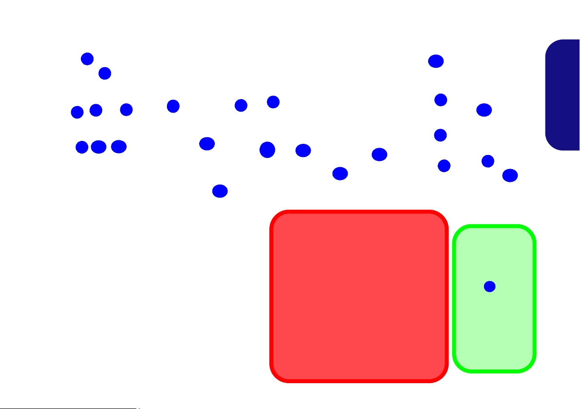
System Map: Front View with LCD Panel Open (Models A & B)
Note that the Touchpad and
Buttons valid operational area
is that indicated within the red
dotted lines above.
7
Figure 2
Front View with LCD
Panel Open (Models A
& B)
1. PC Camera
2. Built-In Microphone
3. *PC Camera LED
*When the PC camera
is in use, the LED will
be illuminated in red.
4. LCD
5. Power Button
6. Keyboard
7. Touchpad & Buttons
2
4
1
6
3
5
Wireless Device
Operation Aboard Aircraft
The use of any portable electronic transmission devices aboard aircraft is usually prohibited.
Make sure the wireless modules are OFF or in Airplane mode (for Windows 8 only) if you
are using the computer aboard aircraft.
Model A
14” (35.56cm)
Model B
15.6” (39.62cm)
6
2
5
1
4
6
7
3
7
English
5
Page 10

LED Indicators
Function Keys
Model B
Model A
Numeric
Keypad
Fn Key
Function Keys
NumLk &
ScrLk
Numeric
Keypad
Fn Key
NumLk &
ScrLk
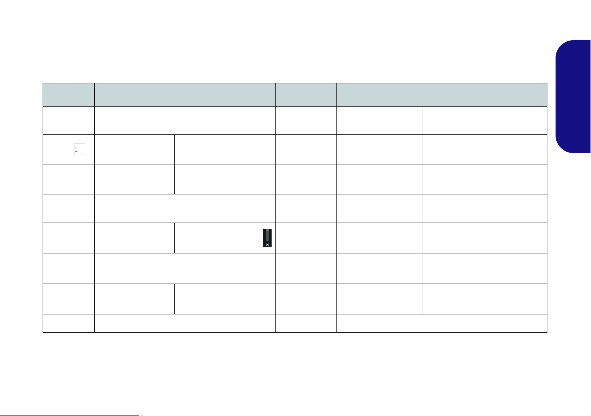
The LED indicators on the computer display helpful information about the current status of the computer.
Icon Color Description
English
Orange The AC/DC Adapter is Plugged In
Green The Computer is On
6
Blinking
Green
Orange The Battery is Charging
Green The Battery is Fully Charged
Blinking
Orange
Green
Orange
Green Hard Disk Activity
Table 1 - LED Indicators
The Computer is in Sleep Mode
The Battery Has Reached Critically
The Wireless LAN Module is Pow-
Win 7 - The Bluetooth Module is
Win 8 - The Bluetooth Module is
Installed (this is not a power on/off
Low Power Status
ered On
Powered On
indicator in Win 8)
Keyboard
The keyboard (Model A) has a numeric keypad for easy
numeric data input. Pressing Fn + NumLk turns on/off
the numeric keypad. It also features function keys to allow you to change operational features instantly.
The keyboard (Model B) includes a numeric keypad (on
the right side of the keyboard) for easy numeric data input. Pressing Fn + NumLk turns on/off the numeric keypad. It also features function keys to allow you to change
operational features instantly.
Figure 3 - Keyboard
Page 11
Function Keys
The function keys (F1 - F12 etc.) will act as hot keys when pressed while the Fn key is held down. In addition to the
basic function key combinations, visual indicators (Windows 7 or Windows 8 Desktop only) are available when the hot
key driver is installed.
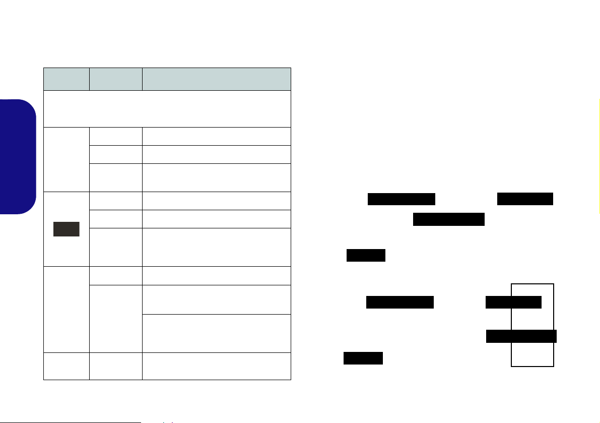
Keys Function/Visual Indicators Keys Function/Visual Indicators
English
Fn + ~ Play/Pause (in Audio/Video Programs) Fn + F8/F9
Fn +
Fn + F1 Touchpad Toggle Fn + F11
Fn + F2
Fn + F3 Mute Toggle Fn + NumLk Number Lock Toggle
Fn + F4 Sleep Toggle Fn + ScrLk Scroll Lock Toggle
Fn + F5/F6
Fn + F7 Display Toggle Fn + Esc Control Center Toggle (see page 8)
3G Module Power
Toggle
Turn LCD Backlight Off
(Press a key to or use Touchpad to turn on)
Volume Decrease/
Increase
Fn + F10
Fn + F12
Caps Lock Caps Lock Toggle
Brightness Decrease/
Increase
PC Camera Power
Toggle
WLAN Module Power
Toggle
Bluetooth Module
Power Toggle
Table 2 - Function Keys & Visual Indicators
7
Page 12

Control Center
Windows 7
Windows 8
Press the Fn + Esc key combination, or double-click the icon in the notification area of the taskbar to toggle the
Control Center on/off. The Control Center gives quick access to frequently used controls, and enables you to quickly
turn modules on/off. The Control Center is only accessible from the Windows Desktop (use the Windows Logo Key
+ D key combination) in Windows 8 and not from the Start Screen in the Metro UI.
English
Figure 4 - Control Center
Click on any button to turn any of the modules (e.g. TouchPad, Camera) on/off. Click on Power Conservation to switch
between Performance, Balanced or Energy Star modes. Click on the buttons (or just click and hold the mouse button)
to adjust the slider for Brightness/Volume. Click on Display Switch/Time Zone/ Desktop Background to bring up
the appropriate Windows control panel. Click on the Sleep button to put the computer into Hibernate or Sleep modes.
8
Page 13

Power Status
The Power Status icon will show whether you are currently powered by the battery, or by the AC/DC adapter plugged
in to a working power outlet. The power status bar will show the current battery charge state.
Brightness
The Brightness icon will show the current screen brightness level. You can use the slider to adjust the screen brightness
or the Fn + F8/F9 key combinations, or use the Fn + F2 key combination to turn off the LED backlight (press any key
to turn it on again). Note that screen brightness is also effected by the Power Mode selected.
Volume
The Volume icon will show the current volume level. You can use the slider to adjust the Volume or the Fn + F5/F6
key combinations, or use the Fn + F3 key combination to mute the volume.
Power Conservation
This system supports Energy Star power management features that place computers (CPU, hard drive, etc.) into a lowpower sleep mode after a designated period of inactivity. Click either the Performance, Balanced or Energy Star but-
ton.
Sleep
Click the Sleep button to bring up the Hibernate or Sleep buttons, and click either button to have the computer
enter the appropriate power-saving mode.
English
9
Page 14
Display Switch
Click the Display Switch button to access the menu (or use the / + P key combination) and select th e appropriate
attached display mode.
Time Zone
Clicking the Time Zone button will access the Date and Time Windows control panel.
Desktop Background
English
Clicking the Desktop Background button will allow you to change the desktop background picture.
Touchpad/PC Camera/Wireless LAN Module /Bluetooth/3G Module (Win 7 Only)
Click any of these buttons to toggle the Touchpad or module’s power status. A crossed out icon will appear over the top
left of the icon when it is off
Power Mode selected.
. Note that the power status of a module, and Touchpad power, is also effected by the
Touchpad/PC Camera (Win 8 Only)
Click any of these buttons to toggle the Touchpad or module’s power status. A crossed out icon will appear over the top
left of the icon when it is off
Power Mode selected.
. Note that the power status of a module, and Touchpad power, is also effected by the
Caps Lock/Scroll Lock/ Number Lock
Click the button to toggle the appropriate lock mode.
10
Page 15
System Map: Front, Left, Right, Rear & Bottom Views (Model A)
2
1
7
8
4
6
3
Left
Right
5
Front
Rear
10
14
12
15
13
9
16
15
6
Bottom
17
18
6
18
11
Figure 5 - Front, Left, Right, Rear & Bottom Views
(Model A)
1. LED Indicators
2. Multi-in-1 Card
Reader
3. DC-In Jack
4. RJ-45 LAN Jack
5. External Monitor Port
6. Vent
7. HDMI-Out Port
8. 2 USB 3.0 Ports
9. Microphone-In Jack
10. Headphone-Out Jack
11. USB 2.0 Port
12. Optical Device Drive
Bay
13. Emergency Eject Hole
14. Security Lock Slot
15. Battery
16. Component Bay Cover
17. Hard Disk Bay Cover
18. Speakers
6
Overheating
To prevent your computer from overheating
make sure nothing blocks any vent while the
computer is in use.
Disc Emergency Eject
If you need to manually eject a disc (e.g. due
to an unexpected power interruption) you
may push the end of a straightened paper
clip into the emergency eject hole. Do not
use a sharpened pencil or similar object that
may break and become lodged in the hole.
USB 3.0 Port
The USB 3.0
ports
are col-
ored blue. USB
3.0 will transfer
data much faster
than USB 2.0,
and is backwards-compatible with USB 2.0.
8
6
English
11
Page 16
System Map: Front, Left, Right, Rear & Bottom Views (Model B)
2
1
7
8
4
6
3
Left
Right
5
Front
Rear
10
14
12
15
13
9
Bottom
11
Figure 6 - Front, Left, Right, Rear & Bottom Views
(Model B)
1. LED Indicators
2. Multi-in-1 Card
Reader
3. DC-In Jack
4. RJ-45 LAN Jack
5. External Monitor Port
6. Vent
7. HDMI-Out Port
8. 2 USB 3.0 Ports
9. Microphone-In Jack
10. Headphone-Out Jack
11. 2 USB 2.0 Ports
12. Optical Device Drive
Bay
13. Emergency Eject Hole
14. Security Lock Slot
15. Battery
16. Component Bay Cover
17. Hard Disk Bay Cover
18. Speakers
Overheating
To prevent your computer from overheating
make sure nothing blocks any vent while the
computer is in use.
Disc Emergency Eject
If you need to manually eject a disc (e.g. due
to an unexpected power interruption) you
may push the end of a straightened paper
clip into the emergency eject hole. Do not
use a sharpened pencil or similar object that
may break and become lodged in the hole.
USB 3.0 Port
The USB 3.0
ports
are col-
ored blue. USB
3.0 will transfer
data much faster
than USB 2.0,
and is backwards-compatible with USB 2.0.
8
16
15
6
17
18
6
18
6
6
6
English
12
Page 17

3G Module
1
Model A
USIM Card Orientation
Note that the USIM card’s
readable side (with the goldcolored contacts) should
face upwards as illustrated.
1
1
If you have included an optional 3G module in your purchase option, follow the instructions below to install the USIM
card (which will be provided by your service provider), and then run the appropriate application supplied with your
module.
USIM Card Insertion
1. Turn off the computer, and turn it over and remove the battery (slide the latches in the direction indicated below and slide the battery out).
2. Insert the USIM card as illustrated below until it clicks into position, and replace the battery.
English
Figure 7 - Remove the battery and Insert the USIM Card
13
Page 18

Driver Installation
General Guidelines
As a general guide follow
the default on-screen instructions for each driver
(e.g. Next > Next > Fin-
ish) unless you are an
advanced user. In many
cases a restart is required to install the driver.
Make sure any modules
(e.g. PC Camera, WLAN
or 3G) are ON before installing the appropriate
driver.
Windows Update
After installing all the drivers make sure you enable Windows Update in
order to get all the la test
security updates etc. (all
updates will include the
latest hotfixes from Microsoft).
Driver Installation & Power
When installing drivers make sure your
computer is powered by the AC/DC
adapter connected to a working power
source. Some drivers draw a significant
amount of power during the installation
procedure, and if the remaining battery
capacity is not adequate this may cause
the system to shut down and cause system problems (note that there is no safety
issue involved here, and the battery will
be rechargeable within 1 minute).
Figure 8 - Install Drivers
English
14
Driver Installation
The Device Drivers & Utilities + User’s Manual disc contains the drivers and utilities nec-
essary for the proper operation of the computer. This setup will probably have already
been done for you. If this is not the case, insert the disc and click Install Drivers (button),
or Option Drivers (button) to access the Optional driver menu. Install the drivers in the
order indicated in Figure 8. Click to select the drivers you wish to install (you should note
down the drivers as you install them). Note: If you need to reinstall any driver, you should
uninstall the driver first.
Manual Driver Installation
Click the Browse CD/DVD button in the Drivers Installer application and browse to the
executable file in the appropriate driver folder.
Found New Hardware
If a
and follow the installation procedure as directed.
wizard appears
during the installation procedure, click Cancel,
Page 19

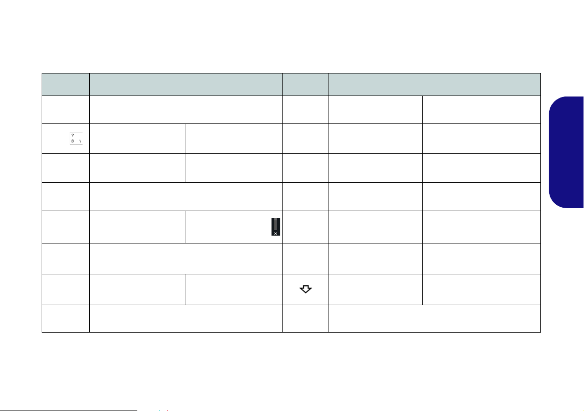
Troubleshooting
Problem Possible Cause - Solution
The Bluetooth module is off
after resuming from Sleep.
A file cannot be copied to/
from a connected Bluetooth
device.
The captured video files from
the PC Camera are taking up
too much disk space.
English
The Bluetooth module’s default state will be off after resuming from the Sleep power-saving state.
Use the key combination (Fn + F12) to power on the Bluetooth module after the computer resumes
from Sleep.
Transferring data between the computer and a Bluetooth enabled device is supported in one
direction only (simultaneous data transfer is not supported). If you are copying a file from your
computer to a Bluetooth enabled device, you will not be able to copy a file from the Bluetooth
enabled device to your computer until the file transfer process from the computer has been
completed.
Note that capturing high resolution video files requires a substantial amount of disk space for each
file.
Note that the Windows system requires a minimum of 15GB of free space on the C: drive system
partition. It is recommended that yo u save th e capture video file to a locati on other than the C:drive,
limit the file size of the captured video or reduce video resolution.
15
Page 20

Specifications
Latest Specification Information
The specifications listed in this here
are correct at the time of going to
press. Certain items (particularly
processor types/speeds) may be
changed, delayed or updated due
to the manufacturer's release
schedule. Check with your service
center for details.
English
Processor Options
Intel® Core™ i7 Processor
i7-3612QM (2.10GHz)
6MB L3 Cache, 22nm, DDR3-1600MHz,
TDP 35W
i7-3540M (3.00GHz), i7-3520M (2.90GHz)
4MB L3 Cache, 22nm, DDR3-1600MHz,
TDP 35W
Intel® Core™ i5 Processor
i5-3380M (2.90GHz), i5-3360M (2.80GHz),
i5-3340M (2.70GHz), i5-3320M (2.60GHz),
i5-3230M (2.60GHz), i5-3210M (2.50GHz)
3MB L3 Cache, 22nm, DDR3-1600MHz,
TDP 35W
16
Intel® Core™ i3 Processor
i3-3130M (2.60GHz), i3-3120M
(2.50GHz), i3-3110M (2.40GHz)
3MB L3 Cache, 22nm, DDR3-1600MHz,
TDP 35W
Intel® Pentium® Processor®
2030M (2.50GHz), 2020M (2.40GHz)
2MB L3 Cache, 22nm, DDR3-1600MHz,
TDP 35W
Core Logic
Intel® HM76 Chipset
BIOS
64Mb SPI Flash ROM
AMI BIOS
Memory
Two 204 Pin SO-DIMM Sockets Supporting DDR3 1333/1600MHz Memory
Memory Expandable up to 16GB
(The real memory operating frequency
depends on the FSB of the processor.)
LCD
Model A:
14" (35.56cm) HD
Model B:
15.6" (39.62cm) HD/FHD
Video Adapter
Intel HD Graphics 4000
Dynamic Frequency (Intel Dynamic Video
Memory Technology for up to 1.7GB)
Microsoft DirectX®11 Compatible
Security
Security (Kensington® Type) Lock Slot
BIOS Password
Audio
High Definition Audio Compliant Interface
2 * Built-In Speakers
Built-In Microphone
Storage
(Factory Option) One Changeable
12.7mm(h) Optical Device Type Drive
(Super Multi Drive Module or Blu-Ray
Combo Drive Module)
One Changeable 2.5" 9.5mm (h) SATA
HDD
(Factory Option) Dummy ODD
(Factory Option) One mSATA Solid State
Drive (SSD)
Pointing Device
Built-in Touchpad
Page 21

Keyboard
Card Reader
Power
Model A:
“WinKey” keyboard (with embedded
numeric keypad)
Model B:
Full-size “WinKey” keyboard (with numeric
keypad)
Interface
One HDMI-Out Port
One Headphone-Out Jack
One Microphone-In Jack
One RJ-45 LAN Jack
One External Monitor Port
Two USB 3.0 Ports
One DC-in Jack
Model A:
One USB 2.0 Port
Model B:
Two USB 2.0 Ports
Mini Card Slots
Slot 1 for WLAN Module or Combo
WLAN and Bluetooth Module
(Factory Option) Slot 2 for 3G Module
OR mSATA SSD
Embedded Multi-In-1 Card Reader
MMC (MultiMedia Card) / RS MMC
SD (Secure Digital) / Mini SD / SDHC/
SDXC
MS (Memory Stick) / MS Pro / MS Duo
Communication
Built-In Gigabit Ethernet LAN
2M HD PC Camera Module
(Factory Option) 3G Mini-Card Module
WLAN/ Bluetooth Half Mini-Card
Modules:
(Factory Option) Intel® Centrino® Wireless-N 2230 Wireless LAN (802.11b/g/n)
+ Bluetooth 4.0
(Factory Option) Intel® Centrino® Wireless-N 135 Wireless LAN (802.11b/g/n) +
Bluetooth 4.0
(Factory Option) Third-Party Wireless
LAN (802.11b/g/n)
(Factory Option) Third-Party Wireless
LAN (802.11b/g/n) + Bluetooth 4.0
6 Cell Smart Lithium-Ion Battery Pack,
48.84WH
(Factory Option) 6 Cell Smart Lithium-
Ion Battery Pack, 62.16WH
Full Range AC/DC Adapter
AC Input: 100 - 240V, 50 - 60Hz
DC Output: 19V, 3.42A (65W)
Environmental Spec
Temperature
Operating: 5°C - 35°C
Non-Operating: -20°C - 60°C
Relative Humidity
Operating: 20% - 80%
Non-Operating: 10% - 90%
Dimensions & Weight
Model A:
340mm (w) * 241mm (d) * 11 - 25.4mm (h)
(Height Excluding Battery Area)
(with 48.84WH Battery and ODD)
2.15 kg
Model B:
374mm (w) * 252mm (d) * 14 - 25.4mm (h)
(Height Excluding Battery Area)
2.2 kg (with 48.84WH Battery and ODD)
English
17
Page 22

English
18
Page 23

Über das Ausführliche Benutzerhandbuch
Diese Kurzanleitung soll einen Überblick über die Schritte geben, die dazu notwendig s ind, das System zu starten. Dieses ist
nur eine Ergänzung und kein Ersatz für das erweiterte englischsprachige Benutzerhandbuch, das auf der mitgelieferten Disc
Device Drivers & Utilities + User's Manual im Adobe-Acrobat-Format vorliegt. Diese Disc enthält auch die Treiber und
Utility-Programme, die für einen einwandfreien Betrieb des Computers notwendig sind (Hinweis: Das Unternehmen behält
sich das Recht vor, diese Publikation ohne Vorankündigung zu überarbeiten und den Inhalt zu verändern).
Einige oder alle Funktionen des Computers sind bereits eingerichtet worden. Falls das nicht der Fall ist oder wenn Sie einzelne Teile des Systems neu konfigurieren (oder neu installieren) möchten, finden Sie eine Anleitung im erweiterten Benut-
zerhandbuch. Die Disc Device Drivers & Utilities + User's Manual enthält nicht das Betriebssystem.
Einhaltung gesetzlicher Vorschriften und Sicherheitshinweise
Beachten Sie sorgfältig die Hinweise zu gesetzlichen Vorschriften und zu Sicherheitshinweisen im erweiterten Benutzerhandbuch auf der Disc Device Drivers & Utilities + User's Manual.
© Dezember 2012
Warenzeichen
Intel und Intel Core sind warenzeichen/e inget ragenes ware nzeichen der Intel Corporation.
Deutsch
19
Page 24

Hinweise zu Pflege und Betrieb
Das Notebook ist zwar sehr stabil, kann aber dennoch beschädigt werden. Damit es nicht dazu kommt, sollten Sie die
folgenden Hinweise beachten:
• Das Gerät darf nicht herunterfallen und in anderer Form Stößen
ausgesetzt werden. Wenn der Computer fällt, können das Gehäuse und
andere Komponenten beschädigt werden.
• Das Gerät darf nicht nass werden und sich nicht überhitzen. Compu-
ter und Netzteil dürfen nicht in der Nähe von Wärmequellen stehen oder
gelagert werden. Dies ist ein elektrisches Gerät. Wenn Wasser oder
andere Flüssigkeiten eindringen, kann der Computer stark beschädigt
werden.
• Vermeiden Sie Interferenzen mit anderen Geräten. Halten Sie den
Computer fern von magnetischen Feldern, die von Stromquellen, Monitoren, Magneten etc. erzeugt werden. Die können die Leistung beein-
Deutsch
trächtigen und Ihre Daten beschädigen.
• Achten Sie auf die richtige Bedienung des Computers. Schalten Sie
ihn erst aus, wenn alle Programme geschlossen wurden (speichern Sie
Ihre Daten!). Speichern Sie regelmäßig Ihre Daten, da diese verloren
gehen können, wenn der Akku verbraucht ist.
Reparatur
Nehmen Sie vor dem Reinigen des Wenn Sie versuchen, den
Computer selbst zu reparieren, können Ihre Garantieansprüche
verloren gehen. Außerdem besteht Stromschlaggefahr für Ihre
Gesundheit und das Gerät durch frei liegende Teile. Lassen Sie
Reparaturarbeiten nur von qualifizierten Reparaturfachleuten
durchführen, insbesondere wenn folgende Umstände vorliegen:
• Wenn das Netzkabel oder der AC/DC-Adapter beschädigt oder ze rsch l i s-
sen sind.
• Wenn der Computer Regen ausgesetzt war oder mit Flüssigkeiten in
Berührung gekommen ist.
• Wenn der Computer unter Beachtung der Bedienungsanweisungen nicht
korrekt arbeitet.
20
• Wenn der Computer heruntergefallen ist oder beschädigt wurde (berühren Sie nicht die giftige Flüssigkeit des LCD-Bildschirms).
• Wenn ein ungewöhnlicher Geruch, Hitze oder Rauch aus dem Computer
entweicht.
Sicherheitsinformationen
• Verwenden Sie nur einen AC/DC-Adapter, der für die Verwendung mit
diesem Computer zugelassen ist.
• Verwenden Sie nur das Netzkabel und die Akkus, die in diesem Benutzerhandbuch spezifiziert sind
Sie können explodieren. Richten Sie sich nach den regional gültigen Entsorgungsvorschriften.
• Verwenden Sie den Akku nicht mehr, wenn er herunter gefallen ist oder in
anderer Weise beschädigt (z.B. verzogen) ist. Auch wenn der Computer
mit dem beschädigten Akku zu funktionieren schein, können dadurch
Stromkreise beschädigt werden, die schließlich einen Brand verursachen
können.
• Achten Sie darauf, dass Ihr Computer ausgeschaltet ist, wenn Sie es fur
den Transport z.B. wahrend einer Reise in eine Tasche einpakken.
• Nehmen Sie vor dem Reinigen des Computers den Akku heraus, und
trennen Sie es von allen externen Stromquellen, Peripheriegeräten und
Kabeln (einschließlich Telefonkabel) ab.
• Reinigen Sie den Computer mit einem weichen, sauberen Tuch. Tragen
Sie das Reinigungsmittel nicht direkt auf den Computer auf. Verwenden
Sie keine flüchtigen Reinigungsmittel (Petroleumdestillate) oder Scheuermittel zum Reinigen des Computers.
• Versuchen Sie nicht, Akkus zu reparieren. Lassen Sie die Akkupacks
durch den Servicevertreter oder qualifiziertes Fachpersonal reparieren
oder austauschen.
• Beachten Sie, dass das Logo bei den Computern, die über ein galvanisch
beschichtetes LCD-Logo verfügen, von einer Schutzfolie bedeckt ist.
Durch die natürliche Abnutzung kann diese Schutzfolie beschädigt werden oder abgehen und die scharfen Kanten des frei liegenden Logos
freigeben. Seien Sie in solch einem Fall vorsichtig bei der Handhabung
des Computers, und vermeiden Sie es, das herausstehende beschichtete
LCD-Logo zu berühren. Legen Sie keine Gegenstände in die Tragetasche, da diese während des Transports gegen den Computer drücken
können. Wenden Sie sich in einem solchen Fall von Abnutzung an Ihr
Service Center.
. Entsorgen Sie die Akkus nicht in Feuer.
Page 25

Polymer Akku Sicherheitshinweise
Entsorgen der Akkus/ Batterien & Achtung
Das von Ihnen gekaufte Produkt enthält einen aufladbaren
Akku. Dier Akku ist wiederverwertbar. Nach verschiedenen nationalen und regionalen Getzgebungen kann es verboten in,
einen nicht mehr gebrauchsfähigen Akku in den normalen
Hausmüll zu werfen. Informieren Sie sich bei Ihrem regionalen
Entsorgungsunternehmen über Recycling-Möglichkeiten oder
korrekte Entsorgung.
Wenn ein falscher Akku eingesetzt wird, besteht Explosionsgefahr. Tauschen Sie den Akku nur durch den gleichen oder
einen baugleichen Typ aus, der vom Hersteller empfohlen
wird. Entsorgen Sie den verbrauchten Akku entsprechend der
Anweisungen des Herstellers.
Beachten Sie die folgenden Hinweise, die sich speziell auf Polymer Akkus beziehen. Diese Hinweise haben zudem Vorrang
gegenüber den Allgemeinen Akku Sicherheitshinweisen.
• Polymer Akkus können sich etwas ausdehnen oder anschwellen. Dies ist
Teil des Sicherheitsmechanismus des Akkus und kein Anlass zur Sorge.
• Seien Sie vernünftig im Umgang mit Polymer Akkus. Verwenden Sie
keine Polymer Akkus in Umgebungen mit hohen Temperaturen und
lagern Sie keine ungenutzten Akkus über längere Zeiträume.
Deutsch
21
Page 26

Schnellstart
130 ゚
Herunterfahren
Windows 7
Bitte beachten Sie, daß der Computer immer mit dem Befehl
Herunterfahren im Menü
Start heruntergefahren werden muß.
Windows 8
Schalten Sie den Computer immer durch Klicken auf Einstellungen in der Charms-Leiste aus (die Charms-Leiste wird
aufgerufen, indem Sie die Windows Logo-Taste
und
gleichzeitig auf C drucken). Wahlen Sie dann aus dem
Ein/
Aus
-Menü die Option Herunterfahren.
Dadurch werden Festplatten- bzw. Systemprobleme vermieden.
1. Entfernen Sie das gesamte Verpackungsmaterial.
2. Legen Sie den Computer auf eine stabile Unterlage.
3. Setzen Sie den Akku ein, und stellen Sie sicher, dass sie fest sitzt.
4. Schließen Sie alle Peripheriegeräte, die Sie mit dem Computer
verwenden wollen (z. B. Tastatur und Maus), an die
entsprechenden Schnittstellen an.
5. Schließen Sie den AC/DC-Adapter an die DC-Eingangsbuchse an
der linken Seite des Computers an. Verbinden Sie dann das
Netzkabel mit einer Netzsteckdose und dem AC/DC-Adapter.
6. Klappen Sie den Deckel/LCD vorsichtig mit einer Hand auf, und
öffnen Sie ihn auf einen angenehmen Sichtwinkel (jedoch nicht
weiter als 130°). Mit der anderen Hand halten Sie das Unterteil
des Computers fest (siehe Abb. 1) (Hinweis: Heben Sie den
Computer niemals am Deckel/LCD hoch).
Deutsch
7. Drücken Sie auf den Netzschalter, um den Computer
einzuschalten.
Systemsoftware
Möglicherweise wurde das Notebook bereits mit vorinstallierter Software ausgeliefert. Ist das nicht der Fall, oder
wenn Sie das Notebook für ein anderes System neu konfigurieren möchten, finden Sie dazu eine Anleitung in diesem
Handbuch zu Microsoft Windows 7 und 8.
Modellunterschiede
Diese Notebookserie umfasste verschiedene Modelle, die
sich leicht in Design, Farbe und allgemeinen äußeren
Merkmalen voneinander unterscheiden. Ihr Modell kann
zwar äußerlich von dem in dieser Dokument abgebildeten
Modell etwas abweichen, jedoch sind alle Ports, Anschlüsse,
Anzeigen, Spezifikationen und allgemeinen Funktionen bei
allen Modellen gleich.
22
Abb. 1 - Öffnen des Deckels/LCD/Computers mit ange-
schlossenem AC/DC-Adapter
Page 27

Systemübersicht: Ansicht von vorne mit geöffnetem LCD-Bild-
Abb. 2
Ansicht von vorne mit ge-
öffnetem LCD-Bildschirm
(Modelle A & B)
1. PC-Kamera
2. Mikrofon
3. *LED der PC-Kamera
*Wenn die PC-Kamera
verwendet wird, leuchtet
die LED rot.
4. LCD-Bildschirm
5. Netzschalter
6. Tastatur
7. Touchpad mit Tasten
Beachten Sie, dass der
Funktionsbereich des
Touchpads und der Tasten
innerhalb der rot gepunkteten Linien liegt.
7
Die Benutzung drahtlos angeschlossener Geräte in Flugzeugen
In der Regel ist die Benutzung jeglicher tragbarer elektronischer Funkgeräte in Flugzeugen verboten.
Achten Sie darauf, daß die Wireless-Module AUSGESCHALTET sind oder im Flugzeugmodus
(nur für Windows 8), wenn Sie den Computer im Flugzeug benutzen.
2
5
1
4
6
Modell A
14” (35,56cm)
Modell B
15,6” (39,62cm)
7
2
5
1
4
6
7
3
3
schirm (Modelle A & B)
Deutsch
23
Page 28
LED-Anzeigen
Fn Taste
Nummemtastatur
Num & Rollen
Modell A
Nummemtastatur
Funktionstasten
Fn Taste
Num & Rollen
Modell B
Funktionstasten
Die LED-Anzeigen auf dem Computer zeigen wichtige
Informationen über den aktuellen Status des Computers.
Symbol Farbe Beschreibung
Orange Der AC/DC-Adapter ist angeschlossen
Grün Der Computer ist angeschaltet
Deutsch
Lampe
blinkt grün
Orange Der Akku wird geladen
Grün Der Akku ist voll geladen
Das System ist im konfigurierten
Energiesparmodus
Tastatur
Die Tastatur (Modell A) hat eine eingebettete Nummerntastatur für einfache Zahleneingabe. Durch Drükken auf Fn +
Num wird die Nummerntastatur ein- und ausgeschaltet. Zusätzlich gibt es Funktionstasten, über die Sie direkt zwischen den Funktionen umschalten können.
Die Tastatur (Modell B) umfasst eine Nummerntastatur (an
der rechten Seite der Tastatur) für die Eingabe von Zahlen.
Durch Drücken auf Fn + Num wird die Nummerntastatur
ein- und ausgeschaltet. Zusätzlich gibt es Funktionstasten,
über die Sie direkt zwischen den Funktionen umschalten
können.
24
Lampe
blinkt
orange
Grün Das WLAN-Modul ist eingeschaltet
Orange
Grün Es wird auf die Festplatte zugegriffen
Tabelle 1 - LED-Anzeigen
Der Akku hat einen kritisch niedrigen
Win 7 - Das Bluetooth-Modul ist
Win 8 - Das Bluetooth-Modul ist
installiert (es ist keine Betriebsan-
Stromstatus erreicht
eingeschaltet
zeige bei Win 8)
Abb. 3 - Tastatur
Page 29
Funktionstasten
Wenn die Funktionstasten (F1 - F12) gleichzeitig mit der Fn-Taste gedrückt werden, funktionieren sie wie Hotkeys. N eben
den Tastenkombinationen für die Grundfunktionen gibt es visuelle Anzeigen (Windows 7 oder nur Windows 8-Desktop),
wenn der Hotkey Treiber installiert ist.
Tasten Funktion/ Visuelle Anzeigen Tasten Funktion/ Visuelle Anzeigen
Fn + ~ Wiedergabe/Pause (in Audio /Videoprogrammen) Fn + F8/F9
Fn +
Fn + F1
Fn + F2
Fn + F3
Fn + F4 Wechsel Schlaf/Wiederaufnahme Fn + Rollen
Fn + F5/F6
Fn + F7 Wechseln der Anzeigegerate
3G-Modul
aktivieren/deaktivieren
Touchpad aktivieren/
deaktivieren
LCD-Hintergrundlicht ausschalten (zum Einschalten
beliebige Taste drücken oder Touchpad berühren)
Stummschaltung/Stumm-
schaltung aufheben
Audio-Lautstärke
verringern/erhöhen
Fn + F10
Fn + F11
Fn + F12
Fn + Num
Fn + Esc
Tabelle 2 - Funktionstasten & visuelle Anzeigen
LCD-Helligkeit verringern/
erhöhen
Deutsch
PC-Kamera aktivieren/
deaktivieren
Wireless-LAN-Modul
aktivieren/deaktivieren
Bluetooth-Modul
aktivieren/deaktivieren
Ein-/Ausschalten der
Nummerntastatur
Ein-/Ausschalten des
Scroll-Modus
Ein-/Ausschalten der
Feststelltaste
Ein-/Ausschalten des Control Center (Steuerzentrum) (siehe
Seite 26)
25
Page 30

Control Center (Steuerzentrum)
Windows 7
Windows 8
Drücken Sie auf die Tastenkombination Fn + Esc, oder doppelklicken Sie auf das Symbol im Infobereich auf der Taskleis-
um das Control Center (Steuerzentrum) ein-/auszuschalten. Das Control Center (Steuerzentrum) bietet den schnellen Zu-
te
griff auf häufig verwendete Funktionen, und Sie haben hier die Möglichkeit, Module direkt ein-/auszu schalten. Das Control
Center (Steuerzentrum) ist nur über den Windows-Desktop (verwenden Sie die Tastenkombination Windows-Logo-
Taste
Deutsch
Klicken Sie auf eine beliebige Taste, um ein Modul (z. B. Touchpad, Kamera) ein-/auszuschalten. Klicken Sie auf Power
Conservation (Strom sparen), um einen der Modi Performance (Leistung), Balanced (Ausgeglichen) oder Energy Star
auszuwählen. Klicken Sie auf die Tasten (oder drücken Sie nur auf die Maustaste, und halten Sie diese gedrückt), um die
Helligkeit/Lautstärke (Brightness/Volume) einzustellen. Klicken Sie auf Display Switch (Anzeige wechseln)/Time Zone
(Zeitzone)/Desktop Background (Desktop-Hintergrund), um das entsprechende Windows-Systemsteuerungsfenster aufzurufen. Klicken Sie auf den Sleep (Schalter) für den Ruhezustand, um den Computer in den Ruhezustand oder in einen Ener-
giesparmodus zu versetzen.
+ D) in Windows 8 und nicht über den Startbildschirm der Metro-UI erreichbar.
Abb. 4 - Control Center
26
Page 31

Power Status (Energiestatus)
Das Energiestatus-Symbol zeigt an, ob die Stromversorgung aktuell über den Akku oder über das an das Stromnetz angeschlossene Netzteil erfolgt. Die Energiestatus-Anzeige zeigt den aktuellen Akkuladestatus an.
Brightness (Helligkeits)
Das Helligkeits-Symbol zeigt die aktuell eingestellte Bildschirmhelligkeit an.Sie können die Bildschirmhelligkeit entweder
mit dem Schieberegler oder mit der Tastenkombination Fn + F8/F9 ändern. Mit der Tastenkombination Fn + F2 wird das
LED-Hintergrundlicht ausgeschaltet (drücken Sie auf eine beliebige Taste, um es wieder einzuschalten). Beachten Sie, dass
die Bildschirmhelligkeit auch vom eingestellten Energiemodus abhängt.
Volume (Lautstärke)
Das Lautstärke-Symbol zeigt die aktuelle Lautstärke an.Sie können die Lautstärke entweder mit dem Schieberegler oder mit
der Tastenkombination Fn + F5/F6 einstellen. Mit der Tastenkombination Fn + F3 wird der Ton ausgeschaltet.
Power Conservation (Strom sparen)
Dieses System unterstützt die Energy Star-Stromsparfunktionen, die Computer (CPU, Festplatte usw.) nach einer längeren
Zeit der Inaktivität in einen Ruhemodus versetzen, bei dem weniger Strom verbraucht wird. Klicken Sie entweder auf die
Taste Performance, Balanced oder Energy Star.
Sleep (Schalter)
Klicken Sie auf den Schalter für den Ruhezustand, um die Schaltflächen Ruhezustand oder Schlaf aufzurufen.
Klicken Sie dann auf eine der beiden Tasten, um den Computer in den jeweiligen Modus zu versetzen.
Deutsch
27
Page 32

Display Switch (Anzeige wechseln)
Klicken Sie auf die Taste zum Wechseln des Anzeigegeräts, um das Menü aufzurufen (Sie können dazu auch die
Tastenkombination / + P verwenden), und wählen Sie einen Anzeigemodus aus.
Time Zone (Zeitzone)
Wenn Sie auf die Schaltfläche Zeitzone klicken, wird das Windows-Systemsteuerungsfenster Datum und Uhrzeit aufgerufen.
Desktop Background (Desktop-Hintergrund)
Wenn Sie auf die Schaltfläche Desktop-Hintergrund klicken, können Sie das Bild für den Desktophintergrund einstellen.
Touchpad/PC-Kamera/Wireless-LAN-Modul/Bluetooth-Modul/3G-Modul (Nur Win 7)
Klicken Sie auf eine dieser Tasten, um das Touchpad/Modul ein- oder auszuschalten. Ist es ausgeschaltet, erscheint links oben
Deutsch
am Symbol
gewählten Energiemodus abhängen.
ein Kreuz. Beachten Sie, dass sowohl der Energiemodus eines Moduls und des Touchpads auch vom aus-
Touchpad/PC-Kamera-Modul (Nur Win 8)
Klicken Sie auf eine dieser Tasten, um das Touchpad/Modul ein- oder auszuschalten. Ist es ausgeschaltet, erscheint links oben
am Symbol
gewählten Energiemodus abhängen.
ein Kreuz. Beachten Sie, dass sowohl der Energiemodus eines Moduls und des Touchpads auch vom aus-
Caps Lock/Scroll Lock/ Number Lock
Klicken Sie auf die Taste, um den gewünschten Feststellmodus auszuwählen.
28
Page 33

Systemübersicht: Ansicht von vorne, links, rechts, hinten und unten
2
1
7
8
4
6
3
5
15
16
15
6
17
18
6
18
6
6
Unterseite
Überhitzung
Zum Schutz vor Überhitzung Ihres Computers
dürfen die Luftungsoffnung(en) nicht während
das Notebook in Betrieb ist verdeckt werden.
Disc-Notauswurf
Wenn eine Disc manuell entnommen werden
muß (z.B. wegen eines Stromausfalls) können
Sie mit dem Ende einer geradegebogenen Büroklammer in das Notauswurfloch drükken.
Verwenden Sie hierzu aber keinen spitzen
Bleistift oder ähnliche Objekte, die im Loch
abbrechen und darin stekkenbleiben könnten.
USB 3.0-
Anschluss
Die USB 3.0-Anschlüsse
sind blau. Die
Datenübertragung ist bei
USB 3.0 viel
schneller als bei
USB 2.0, und
USB 3.0 ist
rückwärts
kompatibel mit
USB 2.0.
8
Vorderseite
Linke Seite
Hinterseite
Abb. 5 - Ansicht von vorne, links, rechts, hinten und
unten (Modell A)
1. LED-Anzeigen
2. Multi-in-1 Kartenleser
3. DC-Eingangsbuchse
4. RJ-45 LAN-Buchse
5. Schnitt stelle für externen Monitor
6. Luftungsoffnung
7. HDMI-Ausgangsanschluss
8. 2 USB 3.0-Anschlüsse
9. Mikrofon-Eingangsbuchse
10. Kopfhörer-Ausgangsbuchse
11. USB 2.0-Anschluss
12. Schacht für optisches
Laufwerk
13. Notauswurfloch
14. Sicherheitsschloß-Buchse
15. Akku
16. Komponentenfachabdekkung
17. Abdeckung des Festplattenschachts
18. Lautsprecher
10
14
12
13
9
11
Rechte Seite
(Modell A)
Deutsch
29
Page 34

Systemübersicht: Ansicht von vorne, links, rechts, hinten und unten
2
1
7
8
4
6
3
5
10
14
12
15
13
9
16
15
6
17
18
6
18
11
6
6
6
Unterseite
Überhitzung
Zum Schutz vor Überhitzung Ihres Computers
dürfen die Luftungsoffnung(en) nicht während
das Notebook in Betrieb ist verdeckt werden.
Disc-Notauswurf
Wenn eine Disc manuell entnommen werden
muß (z.B. wegen eines Stromausfalls) können
Sie mit dem Ende einer geradegebogenen Büroklammer in das Notauswurfloch drükken.
Verwenden Sie hierzu aber keinen spitzen
Bleistift oder ähnliche Objekte, die im Loch
abbrechen und darin stekkenbleiben könnten.
USB 3.0-
Anschluss
Die USB 3.0-Anschlüsse
sind blau. Die
Datenübertragung ist bei
USB 3.0 viel
schneller als bei
USB 2.0, und
USB 3.0 ist
rückwärts
kompatibel mit
USB 2.0.
8
Vorderseite
Linke Seite
Rechte Seite
Hinterseite
Abb. 6 - Ansicht von vorne, links, rechts, hinten und
unten (Modell B)
1. LED-Anzeigen
2. Multi-in-1 Kartenleser
3. DC-Eingangsbuchse
4. RJ-45 LAN-Buchse
5. Schnitt stelle für externen Monitor
6. Luftungsoffnung
7. HDMI-Ausgangsanschluss
8. 2 USB 3.0-Anschlüsse
9. Mikrofon-Eingangsbuchse
10. Kopfhörer-Ausgangsbuchse
11. 2 USB 2.0-Anschlüsse
12. Schacht für optisches
Laufwerk
13. Notauswurfloch
14. Sicherheitsschloß-Buchse
15. Akku
16. Komponentenfachabdekkung
17. Abdeckung des Festplattenschachts
18. Lautsprecher
(Modell B)
Deutsch
30
Page 35

3G-Modul
1
Model A
Ausrichtung der USIM-Karte
Die lesbare Seite der USIM-Karte
(die Seite, auf der sich die
Goldkontakte befinden) muss wie
abgebildet nach oben zeigen.
1
1
Wenn Ihr Modell das optionale 3G-Modul enthält, folgen Sie den nachfolgenden Anweisungen, um die USIM-Karte zu installieren (Sie erhalten sie von Ihrem Dienstanbieter). Installieren Sie dann die Anwendung.
Einsetzen der USIM-Karte
1. Schalten Sie den Computer aus, drehen Sie es herum, und nehmen Sie den Akku heraus (schieben Sie die Riegel in die unten
angezeigte Richtung, und ziehen Sie den Akku heraus).
2.
Schieben Sie die USIM-Karte wie unten abgebildet hinein, und lassen Sie sie einrasten. Setzen Sie den Akku wieder ein.
Deutsch
Abb. 7 - Herausnehmen des Akkus und einsetzen der USIM-Karte
31
Page 36

Allgemeine Hinweise zur
Treiberinstallation
Wenn Sie keine fortgeschrittenen Kenntnisse
haben, folgen Sie für jeden
Treiber den Anweisungen
auf dem Bildschirm (z. B.
Weiter > Weiter > Fertig
stellen). In vielen Fällen ist
es erforderlich, den Computer nach der Treiberinstallation neu zu starten.
Alle Module (z. B. PCKamera, WLAN oder 3G)
müssen vor der Treiberinstallation eingeschaltet
werden.
Windows Update
Nachdem Sie alle Treiber
installiert haben, sollten Sie
die Funktion Windows Up-
date aktualisieren, um
immer die neuesten Sicherheits-Updates usw. zu
erhalten (die Updates enthalten die neuesten
Fehlerbehebungen von
Microsoft).
Treiberinstallation und Stromversorgung
Während die Treiber installiert werden, muss
der Computer über den AC/DC-Adapter mit
Strom versorgt werden. Einige Treiber benötigen für den Installationsvorgang sehr viel
Strom. Wenn der Akku nicht mehr über genügend Strom verfügt, kann sich das System
während der Installation ausschalten, was zu
Systemfehlern führen kann (das ist kein Sicherheitsproblem, und der Akku ist innerhalb
von einer Minute wieder aufladbar).
Abb. 8 - Installation der Treiber
Deutsch
32
Installation der Treiber
Die Disc Device Drivers & Utilities + User's Manual enthält die Treiber und Hilfsprogramme, die für das einwandfreie Funktionieren des Computers notwendig sind. Möglicherweise wurden diese bereits vorinstalliert. Ist das nicht der Fall, legen Sie die Disc ein, und
klicken Sie auf Install Drivers (Schaltfläche) oder Option Drivers (Schaltfläche), um das
Treibermenü Optional aufzurufen.
Reihenfolge. Markieren Sie die Treiber, die installiert werden sollen (notieren Sie zum späteren Nachlesen die Treiber, die Sie installiert haben). Hinweis: Muss ein Treiber neu in-
stalliert werden, sollten Sie den alten Treiber zunächst deinstallieren.
Manuelle Treiber-Installation
Klicken Sie in der Anwendung Drivers Installer auf die Schaltfläche Browse CD/DVD und
navigieren Sie zu der ausführbaren Datei in dem Ordner für Ihren Treiber.
Wenn während des Installationsvorgangs das Fenster Neue Hardware gefunden erscheint,
klikken Sie auf Abbrechen, um das Fenster zu schließen. Befolgen Sie dann die Installationsanweisungen.
Installieren Sie die Treiber in der in Abb. 8 angegebenen
Page 37

Fehlerbehebung
Problem Mögliche Ursache - Lösung
Das Bluetooth-Modul ist aus,
wenn das Gerät aus dem
Energiesparmodus
zurückkehrt.
Eine Datei kann nicht auf ein/
von einem angeschlossenen
Bluetooth-Gerät übertragen
werden.
Die mit der PC-Kamera
aufgenommenen Dateien
benötigen zu viel
Speicherplatz.
Das Bluetooth-Modul ist standardmäßig ausgeschaltet, wenn es aus dem Energiesparmodus
zurückkehrt. Drücken Sie die Tastenkombination (Fn + F12), um das Bluetooth-Modul nach der
Rückkehr aus dem Energiesparmodus wieder einzuschalten.
Die Datenübertragung zwischen dem Computer und einem Bluetooth-Gerät nur in einer
Richtung möglich ist (eine gleichzeitige Datenübertragung in beide Richtungen wird nicht
unterstützt). Sie können eine Datei vom Computer auf ein aktiviertes Bluetooth-Gerät nur dann
kopieren, wenn nicht gleichzeitig Dateien vom Gerät zum Computer übertragen werden. Dieser
Vorgang muss zuerst abgeschlossen werden.
Videodateien, die mit hoher Auflösung aufgenommen werden, erfordern sehr viel Speicherplatz.
Beachten Sie, dass das Betriebssystem Windows mindestens 15GB freien Speic her im Laufwerk
C: der Systempartition benötigt. Es wird empfohlen, die aufgenommenen Videodateien in einem
anderen Laufwerk als C: zu speichern, die Dateigröße der Aufnahmedateien zu beschränken
oder die Auflösung der Videos zu verringern.
Deutsch
33
Page 38

Technische Daten
Aktualität der technischen Daten
Die in diesem Teil aufgeführten
technischen Daten sind zum Zeitpunkt
der Druckstellung richtig. Bestimmte
Elemente (insbesondere Prozessortypen/-geschwindigkeiten) können im
Rahmen des Entwicklungsplans des
Herstellers zwischenzeitlich geändert
oder aktualisiert werden. Detailinformationen erhalten Sie bei Ihrem Servicezentrum.
Deutsch
Prozessor-Optionen
Intel® Core™ i7 Prozessor
i7-3612QM (2,10GHz)
6MB L3 Cache, 22nm, DDR3-1600MHz,
TDP 35W
i7-3540M (3.00GHz), i7-3520M (2.90GHz)
4MB L3 Cache, 22nm, DDR3-1600MHz,
TDP 35W
Intel® Core™ i5 Prozessor
i5-3380M (2.90GHz), i5-3360M (2.80GHz),
i5-3340M (2.70GHz), i5-3320M (2.60GHz),
i5-3230M (2.60GHz), i5-3210M (2.50GHz)
3MB L3 Cache, 22nm, DDR3-1600MHz,
TDP 35W
34
Intel® Core™ i3 Prozessor
i3-3130M (2.60GHz), i3-3120M (2.50GHz),
i3-3110M (2.40GHz)
3MB L3 Cache, 22nm, DDR3-1600MHz,
TDP 35W
Intel® Pentium® Prozessor
2030M (2.50GHz), 2020M (2.40GHz)
2MB L3 Cache, 22nm, DDR3-1600MHz,
TDP 35W
Core Logic
Intel® HM76 Chipsatz
BIOS
AMI BIOS (64Mb SPI Flash-ROM)
Speicher
Zwei 204-Pin SODIMM-Sockel,
Unterstützung von DDR3 1333/1600MHz
Speicher
Speicher auf bis zu 16GB erweiterbar
(Die tatsächliche Speicherarbeitsfrequenz
hängt vom FSB des Prozessors ab.)
LCD
Modell A:
14" (35,56cm) HD
Modell B:
15,6" (39,62cm) HD/FHD
Videoadapter
Intel HD Graphics 4000
Dynamische Frequenz (Intel Dynamic Video
Memory Technology für bis zu 1,7GB)
Kompatibel mit MS DirectX® 11
Sicherheit
Öffnung für Sicherheitsschloß (Typ
Kensington)
BIOS-Paßwort
Audio
High-Definition-Audio-kompatible
Schnittstelle
2 eingebaute Lautsprecher
Eingebautes Mikrofon
Speicher
(Werkseitige Option) Ein austauschbares
optisches Laufwerk (12,7mm Höhe) (Super
Multi-Laufwekrsmodul oder kombiniertes
Blu-Ray-Laufwerksmodul)
Eine Austauschbare SATA-2,5"-Festplatte
(9,5mm Höhe)
(Werkseitige Option) Dummy-Laufwerk
(Werkseitige Option) Ein mSATA-SSD-
Laufwerk
Zeigegerät
Eingebautes Touchpad
Page 39

Tastatur
Modell A:
“Win Key”-Tastatur (mit integrierter
Nummerntastatur)
Modell B:
"Win Key"-T astatur (mit Nummerntastatur) in
Normalgröße
Schnittstellen
Ein HDMI-Ausgangsanschluss
Eine Lautsprecher/Kopfhörer
Ausgangsbuchse
Eine Mikrofon-Eingangsbuchse
Eine RJ-45 LAN-Buchse
Eine Schnittstelle für externen Monitor
Zwei USB 3.0-Anschlüsse
Eine DC-Eingangsbuchse
Modell A:
Ein USB 2.0-Anschluss
Modell B:
Zwei USB 2.0-Anschlüsse
Mini-Card-Steckplätze
Steckplatz 1 für Wireless-LAN-Modul o
Kombinierte Bluetooth und WLAN-Modul
(Werkseitige Option) Steckplatz 2 für 3GModul oder mSATA-SSD-Laufwerk
Kartenleser
Festes Multi-in-1 Kartenleser-Modul
MMC (MultiMedia Card) / RS MMC
SD (Secure Digital) / Mini SD / SDHC/
SDXC
MS (Memory Stick) / MS Pro / MS Duo
Kommunikation
1 Gbit Ethernet-LAN eingebaut
2M HD PC-Kamera-Modul
(Werkseitige Option) 3G Mini-Card-Modul
WLAN/ Bluetooth Half Mini-Card Module:
(Werkseitige Option) Intel® Centrino®
Wireless-N 2230 Bluetooth 4.0 und WLAN
(802.11b/g/n)
(Werkseitige Option) Intel® Centrino®
Wireless-N 135 Bluetooth 4.0 und WLAN
(802.11b/g/n)
(Werkseitige Option) Wireless LAN
(802.11b/g/n) (andere Hersteller)
(Werkseitige Option) Wireless LAN
(802.11b/g/n) und Bluetooth 4.0 (andere
Hersteller)
Stromversorgung
6 Zellen-smart Lithium-Ionen-Akkupack,
48,84WH
(Werkseitige Option) 6 Zellen-smart
Lithium-Ionen-Akkupack, 62,16WH
AC/DC-Adapter für den gesamten
Spannungsbereich
AC-Eingang: 100-240 V, 50-60Hz
DC-Ausgang: 19V, 3,42A (65W)
Umgebungsbedingungen
Temperatur
In Betrieb: 5ºC – 35ºC
Bei Aufbewahrung: -20ºC – 60ºC
Relative Luftfeuchtigkeit
In Betrieb: 20 – 80 %
Bei Aufbewahrung: 10 – 90 %
Abmessungen und Gewicht
Modell A:
340 (B) x 241 (T) x 11 - 25,4 (H) mm (Höhe
ohne Akkubereich)
2,15 kg (mit 48,84WH-Akku und optischem
Laufwerk)
Modell B:
374 (B) x 252 (T) x 14 - 25,4(H) mm (Höhe
ohne Akkubereich)
2,2 kg (mit 48,84WH-Akku und optischem
Laufwerk)
Deutsch
35
Page 40

Deutsch
36
Page 41

A propos de ce Guide Utilisateur Concis
Ce guide rapide est une brève introduction à la mise en route de votre système. Il s’agit d’un supplément, et non pas d’une
alternative au Manuel de l’Utilisateur en Anglais complet au format Adobe Acrobat s ur le disque Device Drivers & Utilities
+ User's Manual fourni avec votre ordinateur . Ce disque contient aussi les pilo tes et utilitaires nécessaires au fonctionnement
correct de votre ordinateur (Remarque: La compagni e se réserve le droit de revoir cette publication ou de modifier son contenu sans préavis).
Certains ou tous les éléments de l’ordinateur peuvent avoir été déjà installés. Si ce n’est pas le cas , ou si vous avez l’intention
de reconfigurer (ou réinstaller) des portions du système, reportez-vous au Manuel de l’Utilisateur complet. Le disq ue Device
Drivers & Utilities + User’s Manual ne contient pas de système d’exploitation.
Informations de réglementation et de sécurité
Prêtez attention aux avis réglementaires et informations de sécurité contenus dans le Manuel de l'Utilisateur se trouvant sur
le disque Device Drivers & Utilities + User’s Manual.
© Décembre 2012
Marques déposées
Intel et Intel Core sont des marques déposées ou enregistrées d’Intel Corporation.
Français
37
Page 42

Instructions d’entretien et d’utilisation
L’ordinateur est robuste, mais il peut toutefois être endommagé. Afin d’éviter ceci, veuillez suivre ces recommandations :
• Ne le laissez pastomber. Ne l’exposez à aucun choc ou vibration.
Si l’ordinateur tombe, le boîtier et d’autres éléments pourraient être
endommagés.
• Gardez-le sec. Ne le laisser pas surchauffer. Tenez l’ordinateur et
son alimentation externe à distance de toute source de chaleur. Il
s’agit d’un appareil électrique. Si de l’eau ou tout autre liquide venait
à pénétrer à l’intérieur de votre ordinateur , il pourrait être sérieusement endommagé.
• Evitez les interférences. Tenez l’ordinateur à distance de transfor-
mateurs à haute capacité, moteurs électriques, et autres appareils
générateurs de champs magnétiques importants. Ceux-ci peuvent
gêner ses performances normales et endommager vos données.
• Suivez les procédures appropriées d’utilisation de votre ordina-
teur. Arrêtez l’ordinateur correctement, et fermez tous vos programmes (n’oubliez pas d’enregistrer votre travail). N’oubliez pas
d’enregistrer vos données régulièrement puisqu’elles peuvent être
perdues si la batterie est vide.
Français
Révision
Si vous essayez de réparer l'ordinateur par vous-même, votre
garantie sera annulée et vous risquez de vous exposer et d'exposer l'ordinateur à des chocs électriques. Confiez toute réparation à un technicien qualifié, particulièrement dans les cas
suivants:
• Si le cordon d’alimentation ou l’adaptateur AC/DC est endommagé,
abimé ou effiloché.
• Si votre ordinateur a été exposé à la pluie ou tout autre liquide.
• Si votre ordinateur ne fonctionne pas normalement bien que vous
ayez suivi les instructions de mise en marche à la lettre.
• Si votre ordinateur est tombé par terre ou a été endommagé (si l'écran
LCD est cassé, ne touchez pas le liquide car il contient du poison).
38
• Si une odeur inhabituel, de la chale ur ou de la fumé e app ara issai t sortant de votre ordinateur.
Informations de sécurité
• Utilisez uniquement un adaptateur AC/DC agréé avec votre ordinateur.
• Utilisez uniquement le cordon d’alimentation et les batteries indiqués
dans ce manuel. Ne jetez pas les batteries dans le feu. Elles peuvent
exploser. Consultez la réglementation locale pour des instructions de
recyclage possibles.
• Ne continuez pas d'utiliser une batterie qui est tombée, ou qui paraît
endommagée (ex: tordue ou vrillée) d'une manière quelconque.
Même si l'ordinateur continue de fonctionner avec la batterie en
place, cela peut détériorer le circuit, pouvant déclencher un incendie.
• Assurez-vous que votre ordinateur est complètement éteint avant de
le mettre dans un sac de voyage (ou tout autre bagage similaire).
• Avant de nettoyer l'ordinateur, retirez la batterie et assurez-vous que
l'ordinateur est débranché de toute alimentation électr iq ue externe,
périphériques et câbles (y compris les lignes téléphoniques).
• Utilisez un chiffon propre et doux pour nettoyer l'ordinateur, mais
n'appliquez pas d'agent de nettoyage directement sur l'ordinateur.
N’utilisez pas de produit de nettoyage volatil (des distillés pétrôle) ou
abrasifs sur aucun des éléments de l’ordinateur.
• N’essayez jamais de réparer la batterie. Au cas où votre batterie
aurait besoin d’être réparée ou changée, veuillez vous adresser à
votre représentant de service ou à des professionnels qualifiés.
• Notez que dans les ordinateurs ayant un logo fixé par dépôt électrolytique, le logo est recouvert par une protection adhésive. À cause de
l’usure générale, cette protection adhésive se détériore avec le temps
et le logo exposé peut former des angles coupants. Faites bien attention lorsque vous manipulez l'ordinateur , et évitez de toucher le logo
fixé par dépôt électrolytique. Dans la sacoche de voyage, ne mettez
pas d’autres objets qui risquent de se frotter contre l’ordinateur pendant le transport. En cas d’une telle usure, contactez votre centre de
services.
Page 43

Précautions concernant les batteries polymères
Elimination de la batterie & avertissement
Le produit que vous venez d’acheter contient une batterie rechargeable. Cette batterie est recyclable. Quand elle n’est plus
utilisable, en fonction des lois locales des différents états et
pays, il peut être illégal de s’en débarrasser en la jetant avec les
ordures ménagères normales. Vérifiez auprès du responsable
local de l’élimination des déchets solides de votre quartier pour
vous informer des possibilités de recyclage ou de la manière
appropriée de la détruire.
Il existe un danger d’explosion si la batterie est remise de façon
incorrecte. Remplacez-la uniquement par des batteries de
même type ou de type équivalent, recommandées par le fabricant. Eliminez les batteries usagées selon les instructions du
fabricant.
Notez les informations suivantes spécifiques aux batteries polymères, et le cas échéant, celles-ci remplacent les informations générales de précaution sur les batteries.
• Les batteries polymères peuvent présenter une légère dilatation ou
gonflement, mais cela est inhérent au mécanisme de sécurité de la
batterie et ne représente pas une anomalie.
• Manipulez les batteries polymères de façon appropriée lors de leur
utilisation. Ne pas utiliser de batteries polymères dans des environnements présentant une température ambiante élevée, et ne pas stocker
les batteries non utilisées pendant de longues périodes.
Français
39
Page 44

Guide de démarrage rapide
130 ゚
Arrêt
Windows 7
Veuillez noter que vous devriez toujours éteindre votre ordinateur en utilisant la commande Arrêter du menu Démarrer.
Windows 8
Veuillez noter que vous devriez toujours éteindre votre ordinateur en cliquant sur Périphériques dans la barre des charmes
(utilisez la combinaison de touches Touche Logo de Win-
dows + touche C pour accéder à la barre des charmes)
et en utilisant la commande Arrêter du menu Marche/Arrêt.
Cette précaution évite des problèmes de disque dur ou de système.
1. Enlevez tous les memballages.
2. Posez l’ordinateur sur une surface stable.
Installez la batterie et assurez-vous qu’elle correctement
3.
positionnée.
4. Connectez fermement les périphériques que vous souhaitez
utiliser avec votre ordinateur (par ex. clavier et souris) à leurs ports
respectifs.
5. Branchez l'adaptateur AC/DC à la prise d'entrée DC sur la gauche
de l’ordinateur, branchez ensuite le cordon secteur à une prise
murale, puis à l’adaptateur AC/DC.
6. D'une main, soulevez soigneusement le couvercle/LCD pour
obtenir un angle de vision confortable (ne pas dépasser 130
degrés), de l'autre main (comme illustré dans la Figure 1)
maintenez la base de l'ordinateur (Remarque : Ne soulevez
jamais l'ordinateur par le couvercle/LCD).
7. Pressez le bouton de mise en marche pour allumer.
Logiciel système
Votre ordinateur peut être livré avec un logiciel système pré-
Français
installé. Si ce n’est pas le cas, ou si vous re-configurez votre
ordinateur pour un système différent, vous constaterez que ce
manuel fait référence à Microsoft Windows 7 et 8.
Différences de modèles
Cette série d’ordinateurs portables incluent différents modèles avec des légères variations de style, de couleur et d’apparence. Notez que même si votre ordinateur a une
apparence différente des illustrations proposées dans cette
documentation, tous les ports, prises, indicateurs, spécifications et toutes les fonctions générales sont les mêmes pour
tous les styles de design.
40
Figure 1 - Ouvrir le couvercle/LCD/ordinateur avec un adap-
tateur AC/DC branché
Page 45

Carte du système: Vue de face avec l’écran LCD ouvert (Modèles A
Die Benutzung drahtlos angeschlossener Geräte in Flugzeugen
In der Regel ist die Benutzung jeglicher tragbarer elektronischer Funkgeräte in Flugzeugen
verboten.
Assurez-vous que les modules sans fil sont éteints ou en Mode Avion (seulement pour Win-
dows 8) si vous utilisez l'ordinateur à bord d'un avion.
Figure 2
Vue de face avec l’écran
LCD ouvert (Modèles A & B)
1. Caméra PC
2. Microphone
3. *Indicateur LED de ca méra
PC
*Quand la caméra PC est
en cours d'utilisation le
Indicateur LED sera
illuminé en rouge.
4. Écran LCD
5. Bouton d'alimentation
6. Clavier
7. Pavé tactile (Touchpad) et
boutons
Remarquez que la zone d’utilisation valide du Touchpad et des
boutons est celle indiquée à l’intérieur des lignes en pointillé
rouges ci-dessus.
7
2
5
1
4
6
Modèle A
14” (35,56cm)
Modèle B
15,6” (39,62cm)
7
2
5
1
4
6
7
3
3
& B)
Français
41
Page 46

Indicateurs LED
Modèle A
Pavé
Touche Fn
Touches Fonction
numérique
Verr Num &
ArrêtDétl
Modèle B
Touche Fn
Touches Fonction
Verr Num &
Pavé
numérique
ArrêtDét
Les indicateurs LED sur votre ordinateur affichent des infor mations utiles sur l’état actuel de votre ordinateur.
Icône Couleur Description
Orange L'adaptateur AC/DC est branché
Vert L’ordinateur est allumé
Français
Vert
clignotant
Orange La batterie est en charge
Vert La batterie est complètement chargée
Orange
clignotant
Vert Le module LAN sans fil est allumé
Orange
Le système est dans le mode de Veille
configuré
La batterie a atteint le niveau bas cri-
tique
Win 7 - Le module Bluetooth est
Win 8 - Le module Bluetooth est
installé (ce n'est pas un indicateur
d'alimentation dans Win 8)
allumé
Clavier
Le clavier (Modèle A) est doté d'un pavé numérique intégré
pour une saisie des données numériq ues plu s facile . Le fait
d'appuyer sur Fn + Verr Num active ou désactive le pavé
numérique. Il est également doté de touches fonc tion pour
vous permettre de changer instantanément de mode opérationnel.
Le clavier (Modèle B) comporte un pavé numérique (sur le
côté droit du clavier) permettant une entrée facile de données numériques. Le fait d'appuyer sur Fn + Verr Num ac-
tive ou désactive le pavé numérique. Il est également doté
de touches fonction pour vous permettre de changer instantanément de mode opérationnel.
42
Vert Le disque dur est en cours d'utilisation
Tableau 1 - Indicateurs LED
Figure 3 - Clavier
Page 47

Touches fonction
Les touches de fonctions (F1 - F12 etc.) agiront comme touches de raccourci (h ot-key) quand pressée en maintenant la touche
Fn appuyée. En plus des combinaisons des touches de fonction de base, les indicateurs visuels (Windows 7 ou Bureau Win-
dows 8 seulement) sont disponibles quand le pilote de touches de raccourci est installé.
Touches Fonction/ indicateurs visuels Touches Fonction/ indicateurs visuels
Fn + ~ Lecture/Pause (dans les programmes audio/vidéo) Fn + F8/F9
Fn +
Fn + F1
Fn + F2
Fn + F3 Allume/Éteind le son
Fn + F4 Permutation veille
Fn + F5/F6
Fn + F7 Alternance d'affichage Fn + Échap
Activer/Désactiver le
module 3G
Activer/Désactiver le
Touchpad
Eteindre le rétroéclairage LCD (Appuyez sur une
touche ou utilisez le Touchpad pour allumer)
Diminution/Augmentation
du volume sonore
Fn + F10
Fn + F11
Fn + F12
Fn + Verr
Num
Fn + Arrêt-
Dét
Tableau 2 - Touches de fonctions & indicate urs visuels
Diminution/Augmentation de
la luminosité de l’écran LCD
Activer/Désactiver le module
Caméra PC
Activer/Désactiver le module
LAN sans fil
Activer/Désactiver le module
Bluetooth
Activer/Désactiver le pavé
numérique
Activer/Désactiver l'arrêt
défilement
Basculer entre majuscule et
minuscule
Basculer entre les centres de contrôle (Control Center) (voir
la page 44)
Français
43
Page 48

Control Center (Centre de contrôle)
Windows 7
Windows 8
Appuyez sur la combinaison de touches Fn + Échap ou double-cliquez sur l'icône dans la zone de notification de la
barre des tâches pour activer/désactiver le Control Center (Centre de contrôle). Le Control Center (Centre de contrôle)
donne un accès rapide aux commandes fréquemment utilisées, et vous permet de rapidement d'activer/désactiver des modules.
Le Control Center (Centre de contrôle) est uniquement accessible depuis le bur eau de Windows (utilisez la combinaison
de touches Touche Logo de Windows + touche D) dans Windows 8 et non à partir de l'écran d'accueil de l'interface uti-
lisateur Metro.
Français
Figure 4 - Control Center
Cliquez sur un bouton pour activer/désactiver l'un des modules (par ex emple, Touchpad, Appareil photo). Cliquez sur Power
Conservation (Économie d'énergie) pour basculer entre les modes Performance (Performances), Balanced (Equilibré) ou
Energy Star. Cliquez sur les boutons (ou cliquez et maintenez simplement le bouton de la souris) pour ajuster le curseur de
Luminosité (Brightness)/Volume. Cliquez sur Display Switch (Permutation d’affichage)/Time Zone (Fuseau horaire)/Desktop Background (Fond d'écran du bureau) pour faire apparaître le panneau de configuration de W indows approprié. Cliquez
sur le bouton Veille pour mettre l'ordinateur en mode Veille prolongée ou Veille.
44
Page 49

Power Status (État d'alimentation)
L'icône État d'alimentation indique si vous êtes actuellement alimenté par la batterie, o u par l'adaptateur AC/DC branché à
une prise de courant. La barre d’état d’alimentation indiquera l'état de charge actuel de la batterie.
Brightness (Luminosité)
L'icône Luminosité indiquera le niveau de luminosité actuel de l'écran. Vous pouvez utiliser le curseur pour ajuster la luminosité de l'écran ou les combinaisons de touches Fn + F8/F9, ou utiliser la combinai son de touch es Fn + F2 pour éteindre le
rétroéclairage LED (appuyez sur une touche pour le rallumer). Notez que la luminosité de l'écran est également affectée par
le Mode d'alimentation choisi.
Volume
L'icône Volume indiquera le niveau du volume actuel. Vous pouvez utiliser le curseur pour régler le volume ou les combinaisons de touches Fn + F5/F6, ou utiliser les combinaisons de touches Fn + F3 pour couper le volume.
Power Conservation (Économie d'énergie)
Ce système prend en charge les fonctionnalités de gestion d’alimentation Energy Star qui placent les ordinateurs (CPU,
disque dur, etc.) dans des modes veille à fai ble conso mmation d ' én er gi e après une période d'inactivité don née. Cliquez sur l e
bouton Performance (Performances), Balanced (Equilibré) ou Energy Star.
Sleep (Veille)
Cliquez sur le bouton Veille pour faire apparaître les boutons Veille Prolongée ou Veille , et cliquez sur l’un des
boutons pour que l'ordinateur entre dans le mode d’économie d'énergie approprié.
Français
45
Page 50

Display Switch (Permutation d’affichage)
Cliquez sur le bouton Permutation d’affichage pour accéder au menu (ou utilisez la combinaison de touches / + P) et
sélectionnez le mode d'affichage approprié.
Time Zone (Fuseau horaire)
Cliquer sur le bouton Fuseau horaire permet d’accéder au panneau de configuration de Date et heure de Windows .
Desktop Background (Fond d'écran du bureau)
Cliquer sur le bouton Fond d'écran du bureau vous permettra de changer l'image du fond d'écran du bureau.
Touchpad/caméra PC/module LAN sans fil/module Bluetooth/module 3G (Win 7 seulement)
Cliquez sur l’un de ces boutons pour activer l’état d’alimentation du Touchpad ou du module. Une icône barrée apparaît audessus du coin supérieur gauche de l'icône
l'alimentation du Touchpad, est également affecté par le mode d'alimentation choisi.
quand elle est désactivée. Notez que l'état de l'alimentation d'un module, et
Touchpad/caméra PC (Win 8 seulement)
Français
Cliquez sur l’un de ces boutons pour activer l’état d’alimentation du Touchpad ou du module. Une icône barrée apparaît audessus du coin supérieur gauche de l'icône
l'alimentation du Touchpad, est également affecté par le mode d'alimentation choisi.
quand elle est désactivée. Notez que l'état de l'alimentation d'un module, et
Verr.Maj./Arrêt Défil./ Verr.Num
Cliquez sur le bouton pour activer le mode de verrouillage approprié.
46
Page 51

Carte du système: Vues de face, gauche, droite, arrière & dessous
2
1
7
8
4
6
3
5
15
16
15
6
17
18
6
18
6
6
Surchauffe
Afin de ne pas causer une surchauffe de votre
ordinateur, verifiez que rien ne bouche la (les)
ventilation(s) quand le systeme est allumé.
Ejection d’urgence du disque
Si vous devez éjecter manuellement un
disque (par ex. suite à une coupure de courant) vous pouvez enfoncer l’extrémité d’un
trombone redressé dans le trou d’ejection
d’urgence. N’utilisez pas la pointe d’un
crayon, ou tout autre objet similaire qui pourrait se casser et rester coincé dans le trou.
Port USB 3.0
Les ports USB
3.0 sont
colorés en
bleu. USB 3.0
transfèrera
des données
bien plus rapidement que
l’USB 2.0, et il
est compatible en amont
avec USB 2.0.
8
Figure 5 - Vues de face, gauche, droite, arrière & des-
sous (Modèle A)
1. Indicateurs LED
2. Lecteur de carte mult i-en-1
3. Prise d’entrée DC
4. Prise réseau RJ-45
5. Port moniteur externe
6. Ventilation
7. Prise de sortie HDMI
8. 2 Ports USB 3.0
9. Prise d'entrée de
microphone
10. Prise de sortie hautparleurs/casque
11. Port USB 2.0
12. Baie de périphérique
optique
13. Trou d’ejection d’urgence
14. Fente de verrouillage de
sécurité
15. Batterie
16. Couvercle de baie de
composant
17. Couvercle de baie de
disque dur
18. Haut-parleurs
Face
Gauche
Arrière
Dessous
10
14
12
13
9
11
Droit
(Modèle A)
Français
47
Page 52

Carte du système: Vues de face, gauche, droite, arrière & dessous
2
1
7
8
4
6
3
5
10
14
12
15
13
9
11
Surchauffe
Afin de ne pas causer une surchauffe de votre
ordinateur, verifiez que rien ne bouche la (les)
ventilation(s) quand le systeme est allumé.
Ejection d’urgence du disque
Si vous devez éjecter manuellement un
disque (par ex. suite à une coupure de courant) vous pouvez enfoncer l’extrémité d’un
trombone redressé dans le trou d’ejection
d’urgence. N’utilisez pas la pointe d’un
crayon, ou tout autre objet similaire qui pourrait se casser et rester coincé dans le trou.
Port USB 3.0
Les ports USB
3.0 sont
colorés en
bleu. USB 3.0
transfèrera
des données
bien plus rapidement que
l’USB 2.0, et il
est compatible en amont
avec USB 2.0.
8
Figure 6 - Vues de face, gauche, droite, arrière & des-
sous (Modèle B)
1. Indicateurs LED
2. Lecteur de carte mult i-en-1
3. Prise d’entrée DC
4. Prise réseau RJ-45
5. Port moniteur externe
6. Ventilation
7. Prise de sortie HDMI
8. 2 Ports USB 3.0
9. Prise d'entrée de
microphone
10. Prise de sortie hautparleurs/casque
11. 2 Ports USB 2.0
12. Baie de périphérique
optique
13. Trou d’ejection d’urgence
14. Fente de verrouillage de
sécurité
15. Batterie
16. Couvercle de baie de
composant
17. Couvercle de baie de
disque dur
18. Haut-parleurs
Face
Gauche
Droit
Arrière
Dessous
16
15
6
17
18
6
18
6
6
6
(Modèle B)
Français
48
Page 53

Module 3G
1
Model A
Orientation de la carte USIM
Notez que le côté lisible de la
carte USIM (avec les contacts
dorés) doit être orienté vers le
haut comme illustré.
1
1
Si votre option d'achat comporte un module 3G optionnel, suivez les instructions ci-dessous pour installer la carte USIM
(qui vous sera fournie par votre fournisseur de service), et installez ensuite l'application.
Insérer la carte USIM
1. Eteignez l'ordinateur, retournez-le et retirez la batterie (faites glisser le loquet dans la direction indiquée en dessous et sortez la batterie).
2. Insérez la carte USIM comme illustré ci-dessous jusqu'à ce qu'elle se clique en position, et remettez la batterie.
Français
Figure 7 - Retirer la batterie et insérer la carte USIM
49
Page 54

Directives générales pour
l'installation du pilote
D'une manière générale,
suivez les instructions par
défaut à l'écran pour chaque
pilote (par exemple Suivant
> Suivant > Terminer) à
moins que vous ne soyez un
utilisateur avancé. Dans la
plupart des cas, un redémarrage est nécessaire
pour installer le pilote.
Assurez-vous que les modules (par exemple caméra
PC, WLAN ou 3G) sont allu-
més avant d'installer le pilote correspondant.
Windows Update
Après avoir installé tous les
pilotes vérifiez que vous
avez activé Windows
Update afin d'obtenir toutes
les dernières mises à jour
de sécurité etc. (toutes les
mises à jour incluront les
derniers correctifs de Microsoft).
Installation des pilotes et alimentation
Lors de l'installation des pilotes assurez-vous
que votre ordinateur est alimenté par l'adaptateur CA/CC connecté à une source d'alimentation. Certains pilotes consomment une quantité
importante d'énergie pendant la procédure
d'installation, et si la capacité restante de la
batterie n'est pas suffisante cela peut provoquer l'arrêt du système et entraîner des problèmes de système (à noter qu'il n'y a pas ici de
problème de sécurité en cause, et la batterie
sera rechargeable en 1 minute).
Figure 8 - Installation du pilot
Français
50
Installation du pilote
Le disque Device Drivers & Utilities + User’s Manual contient les pilotes et les utilitaires né-
cessaires pour un bon fonctionnement de votre ordinateur. Cette installation aura probablement déjà été faite pour vous. Si ce n'est pas le cas, insérez le disque et cliquez sur Install
Drivers (bouton), ou Option Drivers (bouton) pour accéder au menu des pilotes Optionnels.
Installez les pilotes en respectant l'ordre indiqué dans la Figure 8. Cliquez pour sélection ner
les pilotes que vous désirez installer (vous devez noter les pilotes lorsque vous les installez).
Remarque: Si vous devez réinstaller un pilote, vous devez d’abord le désinstaller.
Installation manuelle du pilote
Cliquez le bouton Browse CD/DVD dans l'application Drivers Installer et n aviguer jusqu'au
fichier exécutable dans le dossier de pilote approprié.
Si l’assistant Nouveau matériel détecté apparaît pendant la procédure d'installation, cliquez
sur Annuler pour fermer l’assistant, et suivez la procédure d'installation comme indiqué.
Page 55

Dépannage
Problème Cause possible - résolution
Le module Bluetooth est
désactivé après la reprise depuis
Veille.
Un fichier ne peut être copié sur/
depuis un périphérique Bluetooth
connecté.
Les fichiers vidéo capturés depuis
la caméra PC prennent trop de
place sur le disque.
L'état par défaut du module Bluetooth sera désactivé après la reprise à partir de l'état
Économie d'énergie de veille. Utilisez la combinaison de touches (Fn + F12) pour activer le
module Bluetooth quand l'ordinateur reprend à partir de l'état de Veille.
Le transfert de données entre l'ordinateur et un périphérique Bluetoot h est pris en charge dans
une direction seulement (le transfert simultané de données n'est pas pris en charge). Si
vous copiez un fichier depuis votre ordinateur sur un périphérique Bluetooth, vous ne pourrez
pas copier un fichier à partir d'un périphérique Bluetooth sur votre ordinateur tant que le
transfert de fichier depuis l'ordinateur ne sera pas terminé.
Notez que la capture de fichiers vidéo à haute résolution nécessi te un esp ace sub st antiel sur le
disque pour chaque fichier.
Notez que le système Windows nécessite un m inim um de 15Go d'espace libre sur la partition
système du lecteur C:. Il vous est recommandé d'enregistrer le fichier vidéo capturé dans un
autre emplacement que le lecteur C:, limitez la t aille d u fichie r de la v idéo capturé e ou réduisez
la résolution vidéo.
Français
51
Page 56

Spécifications
Dernières informations de
spécification
Les spécifications énumérées dans
cette section sont correctes à l'heure de
la mise sous presse. Certains éléments
(particulièrement les types de processeur/vitesse unique) peuvent être modifiés ou mis à niveau en fonction du
calendrier des parutions du fabricant.
Voyez auprès de votre service clientèle
pour les détails.
Options de processeurs
Processeur Intel® Core i7
Français
i7-3612QM (2,10GHz)
Cache L3 6Mo, 22nm, DDR3-1600MHz,
TDP 35W
i7-3540M (3,00GHz), i7-3520M (2,90GHz)
Cache L3 4Mo, 22nm, DDR3-1600MHz,
TDP 35W
Processeur Intel® Core i5
i5-3380M (2,90GHz), i5-3360M (2,80GHz),
i5-3340M (2,70GHz), i5-3320M (2,60GHz),
i5-3230M (2,60GHz), i5-3210M (2,50GHz
Cache L3 3Mo, 22nm, DDR3-1600MHz,
TDP 35W
52
Processeur Intel® Core i3
i3-3130M (2,60GHz), i3-3120M (2,50GHz),
i3-3110M (2,40GHz)
Cache L3 3Mo, 22nm, DDR3-1600MHz,
TDP 35W
Processeur Intel® Pentium®
2030M (2,50GHz), 2020M (2,40GHz)
Cache L3 3Mo, 22nm, DDR3-1600MHz,
TDP 35W
Core logic
Chipset Intel® HM76
BIOS
AMI BIOS (SPI Flash ROM de 64Mb)
Mémoire
Deux emplacements SODIMM 204
broches, supportant la mémoire DDR3
1333/1600MHz
Mémoire extensible jusqu’à 16Go
(La fréquence réelle d’opération de la
mémoire dépend du FSB du processeur.)
LCD
Modèle A:
14" (35,56cm) HD
Modèle B:
15,6" (39,62cm) HD/FHD
Adaptateur Vidéo
Intel® HD Graphics 4000
Fréquence dynamique (Technologie de
mémoire vidéo dynamique d'Intel jusqu’à
1,7Go)
Compatible avec MS DirectX® 11
Sécurité
Fente de verrouillage de sécurité (type
Kensington)
Mot de Passe du BIOS
Son
Interface conforme HDA (Son Haute
Définition)
2 haut-parleurs intégrés
Microphone intégré
Stockage de données
(Option d’usine) Un module de lecteur
optique
échangeable (module de lecteur
Super Multi ou module de lecteur combo
Blu-Ray)
Un disque dur SATA remplaçable de 2,5"
9,5mm (H)
(Option d’usine) Dummy ODD
(Option d’usine) Un lecteur SSD mSATA
Dispositif de pointage
Touchpad intégré
Page 57

Clavier
Modèle A:
Clavier “Win Key” (avec pavé numérique
intégré)
Modèle B:
Clavier "Win Key" pleine taille (avec pavé
numérique)
Interface
Une prise de sortie HDMI
Une prise de sortie haut-parleurs/casque
Une prise d'entrée de microphone
Une prise réseau RJ-45
Un port moniteur externe
Deux ports USB 3.0
Une prise d’entrée en DC
Modèle A:
Un port USB 2.0
Modèle B:
Deux ports USB 2.0
Logements Mini-carte
Logement 1 pour module LAN sans fil o
module combo Bluetooth et LAN sans fil
(Option d’usine) Logement 2 pour module
3G ou lecteur SSD mSATA
Lecteur de carte
Lecteur de carte multi-en-1
MMC (MultiMedia Card) / RS MMC
SD (Secure Digital)/ Mini SD/ SDHC/ SDXC
MS (Memory Stick) / MS Pro / MS Duo
Communication
1Gbit réseau Ethernet intégré
Caméra PC 2M HD
(Option d’usine) Module Mini-carte 3G
Modules Half Mini-carte LAN sans fil/
Bluetooth:
(Option d’usine) Bluetooth 4.0 et LAN
sans fil (802.11b/g/n) Intel® Centrino®
Wireless-N 2230
(Option d’usine) Bluetooth 4.0 et LAN
sans fil (802.11b/g/n) Intel® Centrino®
Wireless-N 135
(Option d’usine) LAN sans fil (802.11b/g/
n) (tiers)
(Option d’usine) Bluetooth 4.0 et LAN
sans fil (802.11b/g/n) (tiers)
Mise en marche
Batterie Smart Lithium-Ion à 6 éléments,
48,84WH
(Option d’usine) Batterie Smart LithiumIon à 6 éléments, 62,16WH
Adaptateur AC/DC pleine bande
Entrée AC: 100-240V, 50-60Hz
Sortie DC: 19V, 3,42A (65W)
Spécifications environnementales
Température
En fonction : 5°C- 35°C
Eteint : -20
Humidité relative
En fonction : 20% - 80%
Eteint : 10% - 90%
°C - 60°C
Dimensions physiques & Poids
Modèle A:
340 (l) x 241 (p) x 11 - 25,4 (h) mm
(Hauteur hors zone de batterie)
2,15kg (avec batterie 48,84WH & lecteur
optique)
Modèle B:
374 (l) x 252 (p) x 14 - 25,4 (h) mm
(Hauteur hors zone de batterie)
2,2kg (avec batterie 48,84WH & lecteur
optique)
Français
53
Page 58

Français
54
Page 59

Acerca de esta Guía del Usuario Concisa
Esta guía rápida es una breve introducción para poner su sistema en funcionamiento. Es un suplemento y no un sustituto del
Manual del usuario completo en inglés en formato Adobe Acrobat del disco Device Drivers & Utilities + User's Manual
suministrado con el ordenador. En este disco también se encuentran los controladores y utilitarios necesarios para utilizar el
ordenador correctamente (Nota:
previo aviso).
Algunas o todas las características del ordenador pueden haberse configurado de antemano. Si no lo están, o si desea
reconfigurar (o reinstalar) partes del sistema, consulte el Manual del usuario completo. El disco Device Drivers & Utilities
+ User’s Manual no contiene un sistema operativo.
Información de regulación y seguridad
Por favor, preste especial atención a todos los avisos de regulación e información de seguridad contenidos en el Manual del
usuario completo del disco Device Drivers & Utilities + User’s Manual.
Diciembre del 2012
©
Marcas registradas
Intel e Intel Core son marcas/marcas registradas de Intel Corporation.
La compañía se reserva el derecho a revisar esta publicación o cambiar su contenido sin
Español
55
Page 60

Instrucciones para el cuidado y funcionamiento
El ordenador portátil es muy robusto, pero puede dañarse. Para
evitar esto, siga estas sugerencias:
• No lo deje caer ni lo exponga a golpes fuertes. Si el ordena dor se
cae, la carcasa y los componentes podrían dañarse.
• Manténgalo seco y no lo sobrecaliente. Mantenga el ordenador y
fuente de alimentación alejados de cualquier tipo de fuente de
calor. Esto es un aparato eléc trico. Si se derrama agua u otro líquido
en su interior, el ordenador podría dañarse seriamente.
• Evite las interferencias. Mantenga el ordenador alejado de trans-
formadores de alta capacidad, motores eléctricos y otros campos
magnéticos fuertes. Éstos pueden dificultar el correcto funcionamiento y dañar los datos.
• Siga las instrucciones apropiadas de manejo del ordenador.
Apague el ordenador correctamente y no olvide guardar su trabajo.
Recuerde guardar periódicamente sus datos, pues los datos pueden
perderse si la batería se descarga.
Servicio
Si intenta reparar el ordenador usted mismo, podría anular la
garantía y exponerse usted y el ordenador a descarga eléctrica.
Deje que sea personal de reparación cualificado el que realice
las reparaciones, especialmente bajo cualquiera de estas condi-
Español
ciones:
• Cuando el cable de alimentación o adaptador AC/DC esté dañado o
pelado.
• Si el ordenador ha estado expuesto a la lluvia u otros líquidos.
• Si el ordenador no funciona con normalidad tras seguir las instrucciones de uso.
• Si el ordenador se ha caído o dañado (no toque el líquido venenoso
si el panel LCD se rompe).
56
• Si hay un olor fuera de lo normal, calor o humo que sale del ordenador.
Información de seguridad
• Utilice solamente un adaptador de alimentación aprobado para su
uso con este ordenador.
• Utilice solamente el cable de corriente y las baterías indicados en
este manual. No tire las baterías al fuego. Podrían explotar. Consulte los códigos locales para posibles instrucciones para desechos
especiales.
• Nunca utilice una batería que se haya caído o que parezca dañada
(p. ej. doblada o retorcida). Incluso si el ordenador sigue funcionando con una batería dañada, puede provocar daños en el circuito
que podrían causar fuego.
• Compruebe que su ordenador esté completamente apagado antes de
introducirlo en una bolsa de viaje (o en cualquier funda).
• Antes de limpiar el ordenador, quite la batería y asegúrese de que el
ordenador esté desconectado de cualquier fuente de alimentación
externa, periféricos y cables (incluyendo la línea telefónica).
• Utilice un trapo limpio y suave para limpiar el ordenador, pero no
aplique limpiador directamente en el ordenador. No utilice limpiadores volátiles (derivados del petróleo) o limpiadores abrasivos en
ningún lugar del ordenador.
• No intente reparar baterías. Solicite la reparación o la sustitución a
su representante de servicio o a personal de servicio cualificado.
• Tenga en cuenta que en ordenadores con logotipos de LCD etiquetados eléctricamente en relieve, el logotipo está recubierto por un
adhesivo protector. Debido al desgaste y rotura normales, este
adhesivo puede deteriorarse con el tiempo y en el logotipo expuesto
pueden formarse bordes afilados. Tenga cuidado al manipular el
ordenador en este caso y evite tocar el logotipo del LCD etiquetado
eléctricamente. Evite colocar cualquier elemento en la bolsa de
transporte que pueda rozar la parte superior del ordenador durante
el transporte Si ocurre un desgaste o rotura, contacte con el centro
de servicios.
Page 61

Precauciones para baterías de polímero
Eliminación de la batería & Cuidado
El producto que usted ha comprado contiene una batería
recargable. La batería es reciclable Terminada su vida útil,
según las leyes locales y estatales, puede ser ilegal
desecharla junto con los residuos ordinarios. Verifique con las
autoridades locales responsables de los desechos sólidos
cuáles son las opciones de eliminación y reciclado existentes
en su zona.
Peligro de explosión si la batería está mal colocada.
Sustitúyala con un tipo de batería igual o equivalente al
recomendado por el fabricante. Elimine la batería usada de
conformidad con las instrucciones del fabricante.
Tenga en cuenta la información siguiente específica para baterías de polímero; además, donde corresponda, invalida la información sobre precauciones para baterías normales.
• Las baterías pueden aumentar o hincharse ligeramente, sin embar go,
esto es parte del mecanismo de seguridad de la batería y o supone un
problema.
• Utilice los procedimientos de manejo apropiados cuando utilice
baterías de polímero. No utilice baterías de polímero en entornos
con temperatura ambiental alta y no guarde las baterías sin usar
durante mucho tiempo.
Español
57
Page 62

Guía rápida para empezar
130 ゚
Apagar
Windows 7
Por favor, tenga en cuenta que debería siempre apagar el ordenador eligiendo la opción Apagar desde el menú Inicio.
Windows 8
Por favor, tenga en cuenta que debería siempre apagar el ordenador haciendo clic en Configuración en la Barra Charms
(utilice la combinación T ecla de W indows
+ tecla C para
acceder a la Barra Charms) y eligiendo la opción Apagar desde el menú Iniciar/Apagar.
Esto le ayudará a evitar problemas con el disco duro o el sistema.
1. Quite todos los materiales del embalaje.
2. Coloque el ordenador en una superficie estable.
3. Inserte la batería y asegúrese de que quede bloqueada en su
posición.
4. Conecte en los puertos correspondientes los periféricos que
desee utilizar con el ordenador (p. ej. teclado y ratón).
5. Conecte el adaptador AC/DC al conector de entrada DC que está
del lado izquierdo del ordenador, y luego conecte el cable de
alimentación AC en un eschufe y al adaptador.
6. Utilice una mano para levantar con cuidado la tapa/LCD a un
ángulo de visión cómodo (no exceder 130 grados), mientras utiliza
la otra mano (como se muestra en la Figura 1) para sostener la
base del ordenador (Nota: Nunca levante el ordenador por la
tapa/LCD).
7. Presione el botón de encendido para “encender”.
Software de sistema
Puede ser que su ordenador tenga instalado un software de
sistema. Si no es el caso, o si desea reconfigurarlo con otro
sistema, este manual se refiere a Microsoft Windows 7 & 8.
Diferencias de modelos
Español
Esta serie de portátiles incluye diferentes modelos que varían
ligeramente en el estilo del diseño, color y apariencia
general. Tenga en cuenta que aunque su ordenador puede
parecer distinto del de las imágenes en este documento, todos
los puertos, conectores, indicadores, especificaciones y
funciones generales son las mismas para todos los estilos de
diseños.
58
Figura 1 - Abrir la tapa/LCD/ordenador con el adaptador
AC/DC enchufado
Page 63

Mapa del sistema: Vista frontal con panel LCD abierto (Mo de los A &
Figura 2
Vista frontal con panel
LCD abierto (Modelos A &
B)
1. Cámara PC
2. Micrófono incorporado
3. *LED de cámara PC
*Cuando la cámara PC
esté en uso, el LED se
iluminará en rojo.
4. Panel LCD
5. Botón de encendido
6. Teclado
7. Touchpad (almohadilla
táctil) y botones
Uso de dispositivos inalámbricos a bordo
El uso de dispositivos electrónicos portátiles a bordo de un avión suele estar prohibido.
Compruebe que los módulos inalámbricos estén DESCONECTADOS o en Modo
avión (sólo para Windows 8) si va a utilizar el ordenador en el avión.
Tenga en cuenta que el área
válida de operación del
Touchpad y los botones es
la indicada dentro de las líneas de puntos de arriba.
7
2
5
1
4
6
Modelo A
14” (35,56cm)
Modelo B
15,6” (39,62cm)
7
2
5
1
4
6
7
3
3
B)
Español
59
Page 64

Indicadores LED
Teclas de función
Tecla Fn
Teclado
numérico
Bloq Num &
BloqDespl
Modelo B
Teclado
Tecla Fn
Teclas de función
numérico
Bloq Num &
Bloq Despl
Modelo A
Los indicadores LED en su ordenador muestran una valiosa
información sobre el estado actual del ordenador.
Icono Color Descripción
Naranja El adaptador AC/DC está conectado
Verde El ordenador está encendido
Español
60
Verde par-
padeante
Naranja La batería se está cargando
Verde
Naranja par-
padeante
Verde
Naranja
Verde El disco duro está en uso
Tabla 1 - Indicadores LED
El ordenador está en modo Suspen-
sión
La batería está completamente car-
gada
La batería ha alcanzado el estado crí-
El módulo LAN wireless está acti-
Win 7 - El módulo Bluetooth está
Win 8 - El módulo Bluetooth está
instalado (esto no es un indicador
de encendido/apagado en Win 8)
tico de poca energía
vado
activado
Teclado
El teclado (Modelo A) tiene un teclado numérico para una
entrada fácil de datos numéricos. Al presionar Fn + Bloq
Num el teclado numérico se habilita o inhabilita. También
incluye las teclas de función para permitirle cambiar las
características operacionales al instante.
El teclado (Modelo B) incluye un teclado numérico (en la
parte derecha del teclado) para una entrada fácil de datos
numéricos. Al presionar Fn + Bloq Num el teclado
numérico se habilita o inhabilita. Tambié n incluye las teclas
de función para permitirle cambiar las características
operacionales al instante.
Figura 3 - Teclado
Page 65

Teclas de función
Las teclas de función (F1 - F12 etc.) actuarán como teclas directas (Hot-Key) cuando se pulsan junto con la tecla Fn. Además
de las c ombinaciones de teclas de función básicas los indicadores visuales (Windows 7 o sólo escritorio de Windows 8) están
disponibles cuando el controlador de teclas directas está instalado.
Teclas Función/indicadores visuales Teclas Función/indicadores visuales
Fn + ~
Fn +
Fn + F1
Fn + F2
Fn + F3 Conmutación mudo Fn + Bloq Num
Fn + F4 Conmutación dormir
Fn + F5/F6
Fn + F7 Conmutación pantalla
Reproducir/Pausar (en los programas Audio/
Vídeo)
Activar/desactivar el
módulo 3G
Activar/desactivar el
Touchpad
Apagar luz de fondo del LCD (presione una tecla
o utilice el Touchpad para encenderlo)
Reducción/Aumento
volumen de sonido
Fn + F8/F9
Fn + F10
Fn + F11
Fn + F12
Fn + Bloq Despl
(BloqDespl)
Fn + Esc
Tabla 2 - Teclas de función & indicadores visuales
Reducción/Aumento
brillo LCD
Activar/desactivar el
módulo Cámara PC
Activar/desactivar el
módulo LAN Wireless
Activar/desactivar el
módulo Bluetooth
Activar/disactivar el
teclado numérico
Cambiar el bloqueo de
desplazamiento
Cambio Bloq. Mayús-
culas
Cambiar Control Center (centro de control)
(vea la página 62)
Español
61
Page 66

Control Center (Centro de control)
Windows 7
Windows 8
Presione la combinación de teclas Fn + Esc o haga doble clic en el icono en el área de notificación de la barra de tareas
para activar o desactivar el Control Center (Centro de control). El Control Center (Centro de control) ofrece un acceso
rápido a los controles usados con más frecuencia y le permite activar, y desactivar módulos rápidamente. El Control Center
(Centro de control) sólo es accesible desde el Escritorio de Windows (utilice la combinación Tecla de Windows +
tecla D) en Windows 8 y no desde la pantalla de Inicio en la interfaz de usuario Metro.
Español
Haga clic en cualquier botón para activar o desactivar cualquiera de los módulos (p.ej. Touchpad, Cámara). Haga clic en
Power Conservation (Ahorro de energía) para cambiar entre los modos Performance (Rendimiento), Balanced
(Equilibrado) o Energy Star. Haga clic en los botones (o simplemente haga clic y mantenga presionado el botón del ratón)
para ajustar el control deslizante del Brightness/Volume (Brillo/Volumen). Haga clic en Display Switch (Cambiar pantalla)/
Time Zone (Zona horaria)/Desktop Background (Fondo de pantalla) para abrir el panel de control de Windows adecuado.
Haga clic en el botón Suspensión para cambiar el equipo a los modos Hibernar o Suspender.
62
Figura 4 - Control Center
Page 67

Power Status (Estado de energía)
El icono Estado de energía mostrará si la alimentación actual viene dada por la batería o por el adaptador AC/DC enchufado
en una toma de corriente. La barra de estado de energía muestra el estado actual de la carga de la batería.
Brightness (Brillo)
El icono Brillo mostrará el nivel actual del brillo de la pantalla. Puede usar el control deslizante para ajustar el brillo de la
pantalla o las combinaciones de teclas Fn + F8/F9 o usar la combinación de teclas Fn + F2 para apagar la retroiluminación
LED (presione una tecla para volver encenderla). Tenga en cuenta que Modo de energía también puede afectar el brillo de
la pantalla.
Volume (Volumen)
El icono Volumen mostrará el nivel actual del volumen. También puede usar el control deslizante para ajustar el Volumen o
las combinaciones de teclas Fn + F5/F6 o la combinación de teclas Fn + F3 para silenciar el volumen.
Power Conservation (Ahorro de energía)
Este sistema soporta las características de administración de energía Energy Star qu e hace que los equipos (CPU, disco duro,
etc.) entren en modos de ahorro de energía y suspensión tras el período de tiempo de inactividad designado. Haga clic en el
botón Performance (Rendimiento), Balanced (Equilibrado) o Energy Star.
Sleep (Suspender)
Haga clic en el botón Suspender para abrir los botones Hibernar o Suspender y haga clic en uno de esos botones
para que el equipo entre en el modo de ahorro de energía elegido.
Español
63
Page 68

Display Switch (Cambiar pantalla) ,
Haga clic en el botón Cambiar pantalla para acceder al menú (o utilice la combinación de teclas / + P) y seleccione
el modo de pantalla apropiado.
Time Zone (Zona horaria)
Si hace clic en el botón Zona horaria accederá al panel de control Fecha y hora de Windows.
Desktop Background (Fondo de pantalla)
Si hace clic en el botón Fondo de pantalla podrá cambiar la imagen del fondo del escritorio.
Touchpad/cámara PC/módulo LAN Wireless /módulo Bluetooth/módulo 3G (Sólo Win 7)
Haga clic en cualquiera de estos botones para cambiar el estado de energía del Touchpad o módulo. Aparecerá una cruz en
la esquina superior izquierda del icono
la energía del Touchpad, también quedan afectados por el Modo de energía seleccionado.
cuando esté apagado. Tenga en cuenta que el estado de energía de un módulo, y
Touchpad/cámara PC (Sólo Win 8)
Haga clic en cualquiera de estos botones para cambiar el estado de energía del Touchpad o módulo. Aparecerá una cruz en
la esquina superior izquierda del icono
la energía del Touchpad, también quedan afectados por el Modo de energía seleccionado.
cuando esté apagado. Tenga en cuenta que el estado de energía de un módulo, y
Bloqueo mayúsculas/Bloqueo desplazamiento/ Bloqueo numérico
Español
Haga clic en el botón para cambiar al modo de bloqueo apropiado.
64
Page 69

Mapa del sistema: Vistas frontal, izquierda, derecha, posterior e
Figura 5 - Vistas frontal, izquierda, derecha, posterior e
inferior (Modelo A)
1. Indicadores LED
2. Lector de tarjetas multi-en-1
3. Conector de entrada DC
4. Conector LAN RJ-45
5. Puerto para monitor externo
6. Rejilla
7. Puerto de salida de HDMI
8. 2 Puertos USB 3.0
9. Conector de entrada para
micrófono
10. Conector de salida de
auriculares
11. Puerto USB 2.0
12. Bahía de dispositivo óptico
13. Orificio de expulsión de
emergencia
14. Ranura del cierre de
seguridad
15. Batería
16. Tapa de la bahía
componente
17. Tapa de la bahía para el
disco duro
18. Altavoces incorporados
Recalentamiento
Para evitar que su ordenador se recaliente
compruebe que nada bloquea la(s) rejilla(s)
con el equipo encendido.
Expulsión de emergencia del disco
Si necesita expulsar un disco manualmente (p.
ej. por un corte de corriente inesperado) puede
introducir la punta de un clip en el orificio de
expulsión de emergencia. No utilice la punta
de un lápiz u otros objetos que puedan
romperse y quedar atrapados en el orificio.
Puerto USB
3.0
El color de los
puertos USB
3.0 es
azul. USB 3.0
transfiere los
datos mucho
más rápido
que USB 2.0 y
es compatible
con su antecesor USB 2.0.
8
2
1
7
8
4
6
3
5
15
16
15
6
17
18
6
18
6
6
Cara inferior
Parte frontal
Lateral izquierdo
Parte posterior
10
14
12
13
9
11
Lateral derecho
inferior (Modelo A)
Español
65
Page 70

Mapa del sistema: Vistas frontal, izquierda, derecha, posterior e
Figura 6 - Vistas frontal, izquierda, derecha, posterior e
inferior (Modelo B)
1. Indicadores LED
2. Lector de tarjetas multi-en-1
3. Conector de entrada DC
4. Conector LAN RJ-45
5. Puerto para monitor externo
6. Rejilla
7. Puerto de salida de HDMI
8. 2 Puertos USB 3.0
9. Conector de entrada para
micrófono
10. Conector de salida de
auriculares
11. 2 Puertos USB 2.0
12. Bahía de dispositivo óptico
13. Orificio de expulsión de
emergencia
14. Ranura del cierre de
seguridad
15. Batería
16. Tapa de la bahía
componente
17. Tapa de la bahía para el
disco duro
18. Altavoces incorporados
Recalentamiento
Para evitar que su ordenador se recaliente
compruebe que nada bloquea la(s) rejilla(s)
con el equipo encendido.
Expulsión de emergencia del disco
Si necesita expulsar un disco manualmente (p.
ej. por un corte de corriente inesperado) puede
introducir la punta de un clip en el orificio de
expulsión de emergencia. No utilice la punta
de un lápiz u otros objetos que puedan
romperse y quedar atrapados en el orificio.
Puerto USB
3.0
El color de los
puertos USB
3.0 es
azul. USB 3.0
transfiere los
datos mucho
más rápido
que USB 2.0 y
es compatible
con su antecesor USB 2.0.
8
2
1
7
8
4
6
3
5
10
14
12
15
13
9
16
15
6
17
18
6
18
11
6
6
6
Cara inferior
Parte frontal
Lateral izquierdo
Lateral derecho
Parte posterior
inferior (Modelo B)
Español
66
Page 71

Módulo 3G
1
Model A
Orientación de la tarjeta USIM
Tenga en cuenta que el lateral legible de la tarjeta USIM (con los
contactos dorados) debería mirar
hacia arriba, como se ilustra.
1
1
Si ha incluido un módulo opcional 3G en su opción de compra, siga las instrucciones siguientes para instalar la tarjeta USIM
(suministrada por su proveedor de servicios) y luego instale la aplicación.
Insertar la tarjeta USIM
1. Apague el ordenador y gírelo para quitar la batería (deslice los pestillos en la dirección indicada abajo y saque la batería).
2. Inserte la tarjeta USIM como se ilustra a continuación hasta que haga clic en su posición y vuelva a colocar la batería.
Español
Figura 7 - Quitar la batería e insertar la tarjeta USIM
67
Page 72

Directrices generales
para la instalación del
controlador
Como guía general, siga
las instrucciones predeterminadas en pantalla para
cada controlador (p.ej. Si-
guiente > Siguiente > Finalizar) a menos que sea
usuario avanzado. En muchos casos necesitará reiniciar para instalar el
controlador.
Asegúrese de que los módulos (p.ej. cámara PC,
WLAN o 3G) estén EN-
CENDIDOS antes de instalar el controlador
apropiado.
Windows Update
Tras instalar todos los controladores asegúrese de
haber habilitado Windows
Update para obtener las
últimas actualizaciones de
seguridad, etc. (todas las
actualizaciones incluirán
los últimos parches de Microsoft).
Instalación del controlador y
alimentación
Cuando instale controladores asegúrese de
que el ordenador esté alimentado por el
adaptador AC/DC conectado a una fuente
de corriente activa. Algunos controladores
consumen una cantidad significativa de
corriente durante el proceso de instalación, y
si la batería se consume puede provocar que
el sistema se apague, causando problemas
en el sistema (tenga en cuenta que esto no
supone un problema de seguridad y la
batería podrá recargarse en 1 minuto).
Figura 8 - Instalación de controladores
Español
68
Instalación de controladores
El disco Device Drivers & Utilities + User’s Manual contiene los co ntroladores y utilitarios
necesarios para utilizar el ordenador correctamente. Inserte el disco y haga clic en Install
Drivers (botón), u Option Drivers (botón) para acceder al menú de controladores opcional.
Instale los controladores en el orden indicado en la Figura 8. Haga clic para seleccionar los
controladores que desea instalar (debería anotar los controladores conforme los instala).
Nota: Si necesita reinstalar un controlador, debería desinstalar el controlador antes.
Instalación manual del controlador
Haga clic en el botón Browse CD/DVD en la aplicación Drivers Installer y busque el archivo
ejecutable en la carpeta de controladores apropiada.
Si durante el procedimiento de instalación aparece una ventana Nuevo hardware
encontrado, haga clic en Cancelar para cerrar la ventana y siga con el procedimiento de
instalación.
Page 73

Solución de problemas
Problema Posible causa - Solución
El módulo Bluetooth está
apagado tras reanudar desde
la Suspensión.
Un archivo no puede copiarse
a o desde un dispositivo
conectado con Bluetooth.
Los archivos de vídeo
capturados de la cámara PC
ocupan demasiado espacio en
el disco.
El estado predeterminado del módulo Bluetooth será apagado tras reanudar desde el estado de
ahorro de energía Suspensión. Utilice la combinación de teclas (Fn + F12) para encender el
módulo Bluetooth tras reanudar el ordenador desde Suspensión.
La transferencia de datos entre el ordenador y un dispositivo con Bluetooth se realiza sólo en
una dirección (no soporta la transferencia de datos simultánea). Si copia un archivo de su
ordenador a un dispositivo con Bluetooth, no podrá copiar un archivo del dispositivo Bluetooth a
su ordenador hasta que se haya completado el proceso de tran sferencia del ordenador.
Tenga en cuenta que capturar archivos de vídeo de alta resolución requiere una cantidad
sustancial de espacio en el disco p ara cada archivo.
Tenga en cuenta que el sistema Windows requiere un mínimo de 15GB de espacio libre en la
partición del sistema unidad C:. Se recomienda que gua rde el archivo de víde o capturado en una
ubicación distinta a la unidad C:, limite el tamaño de archivo del vídeo capturado o reduzca la
resolución del vídeo.
Español
69
Page 74

Especificaciones
Información actualizada de
especificaciones
Las especificaciones listadas en esta
sección son correctas en el momento de
publicación. Ciertas opciones (particularmente tipos/velocidades de procesadores) pueden cambiar o actualizarse
según la fecha de lanzamiento del fabricante. Diríjase a su centro de servicios
para más detalles.
Opciones de procesadores
Procesador Intel® Core™ i7
i7-3612QM (2,10GHz)
Caché de nivel 3 de 6MB, 22nm, DDR31600MHz, TDP 35W
i7-3540M (3,00GHz), i7-3520M (2,90GHz)
Caché de nivel 3 de 4MB, 22nm, DDR31600MHz, TDP 35W
Español
Procesador Intel® Core™ i5
i5-3380M (2,90GHz), i5-3360M (2,80GHz),
i5-3340M (2,70GHz), i5-3320M (2,60GHz),
i5-3230M (2,60GHz), i5-3210M (2,50GHz)
Caché de nivel 3 de 3MB, 22nm, DDR31600MHz, TDP 35W
70
Procesador Intel® Core™ i3
i3-3130M (2,60GHz), i3-3120M (2,50GHz),
i3-3110M (2,40GHz)
Caché de nivel 3 de 3MB, 22nm, DDR31600MHz, TDP 35W
Procesador Intel® Pentium®
2030M (2,50GHz), 2020M (2,40GHz)
Caché de nivel 3 de 3MB, 22nm, DDR31600MHz, TDP 35W
Núcleo logic
Chipset Intel® HM76
BIOS
AMI BIOS (SPI Flash ROM de 64Mb)
Memoria
Dos zócalos de 204 pins SODIMM, para
memoria DDR3 1333/1600MHz
Memoria expansible hasta 16GB
(La frecuencia de operación de memoria
real depende del FSB del procesador.)
LCD
Modelo A:
14" (35,56cm) HD
Modelo B:
15.6" (39,62cm) HD/FHD
Adaptador de vídeo
Intel® HD Graphics 4000
Frecuencia dinámica (Tecnología de
memoria de vídeo dinámica Intel hasta
1,7GB)
Compatible con DirectX® 11
Seguridad
Ranura para cierre de seguridad (tipo
Kensington®)
Contraseña de BIOS
Audio
Interfaz compatible HDA (Sonido Intel de
alta definición)
2 altavoces incorporados
Micrófono incorporado
Dispositivos de almacenamiento
(Opción de fábrica) Una unidad de
dispositivo óptico de 12,7mm(h)
intercambiable (módulo unidad Super Multi/
módulo unidad combo Blu-Ray)
Un HDD SATA intercambiable de 2,5"
9,5mm (h)
(Opción de fábrica) ODD falso
(Opción de fábrica) Una unidad Solid State
(SSD) mSATA
Dispositivo puntero
Touchpad incorporado
Page 75

Teclado
Modelo A:
Teclado “Win Key” (con teclado numérico
incorporado)
Modelo B:
T eclado "Win Key" de tamaño completo (con
teclado numérico)
Interfaz
Un puerto de salida HDMI
Un conector de salida de altavoces/
auriculares
Un conector de entrada para micrófono
Un conector LAN RJ-45
Un puerto para monitor externo
Dos puertos USB 3.0
Un conector de entrada DC
Modelo A:
Un puerto USB 2.0
Modelo B:
Dos puertos USB 2.0
Ranuras Mini-Card
Ranura 1 para módulo LAN inalámbrica o
módulo combo Bluetooth y LAN
Inalámbrica
(Opción de fábrica) Ranura 2 para módulo
3G o mSATA SSD
Lector de tarjetas
Módulo lector de tarjetas multi-en-1
MMC (MultiMedia Card) / RS MMC
SD (Secure Digital)/ Mini SD/ SDHC/
SDXC
MS (Memory Stick) / MS Pro / MS Duo
Comunicaciones
LAN Ethernet de 1Gbit incorporada
Módulo cámara PC 2M HD
(Opción de fábrica) Módulo Mini-Card 3G
Módulos Half Mini-Card WLAN/
Bluetooth:
(Opción de fábrica) Bluetooth 4.0 y LAN
inalámbrica (802.11b/g/n) Intel® Centrino®
Wireless-N 2230
(Opción de fábrica) Bluetooth 4.0 y LAN
inalámbrica (802.11b/g/n) Intel® Centrino®
Wireless-N 135
(Opción de fábrica) LAN inalámbrica
(802.11b/g/n) (tercera parte)
(Opción de fábrica) Bluetooth 4.0 y LAN
Inalámbrica (802.11b/g/n) (tercera parte)
Alimentación
Batería de Litio-Ion inteligente de 6
elementos, 48,84WH
(Opción de fábrica) Batería de Litio-Ion
inteligente de 6 elementos, 62,16WH
Adaptador de AC/DC autodetector de
corriente
Entrada AC: 100-240V, 50-60Hz
Salida DC: 19V, 3,42A (65W)
Especificaciones del ambiente
Temperatura
En funcionamiento: 5°C - 35°C
Apagado: -20°C - 60°C
Humedad relativa
En funcionamiento: 20% - 80%
Apagado: 10% - 90%
Dimensiones y Peso
Modelo A:
340 (a) x 241 (l) x 11 - 25,4(h) mm (Altura
excluyendo el área de la batería)
2,15kgs (con batería de 48,84WH & unidad
óptica)
Modelo B:
374 (a) x 252 (l) x 14 - 25,4(h) mm (Altura
excluyendo el área de la batería)
2,2kgs (con batería de 48,84WH & unidad
óptica)
Español
71
Page 76

Español
72
Page 77

Informazioni su questa guida rapida
Questa guida rapida rappresenta un’introduzione rapida all’avvio del sistema. Si tratta di un supplemento e non di una
sostituzione del Manuale per l'utente completo in lingua inglese nel formato Adobe Acrobat, memorizzato sul disco Device
Drivers & Utilities + User's Manual fornito a corredo del computer. Inoltre, questo disco contiene i driver e le utilità necessari
per il corretto uso del computer (Nota: La società si riserva il diritto di revisionare la presente pubblicazione o di mod ificarne
il contenuto senza preavviso).
È possibile che alcune o tutte le funzionalità del computer siano già state configurate. In caso contrari o, o se si sta pianificando
di riconfigurare (o reinstallare) componenti del sistema, fare riferimento al Manuale per l'utente completo. Il disco Device
Drivers & Utilities + User’s Manual non contiene il sistema operativo.
Informazioni legali e di sicurezza
Prestare particolare attenzione alle informative legali e di sicurezza contenute nel Manuale per l'utente che si trova sul disco
Device Drivers & Utilities + User’s Manual.
© Dicembre 2012
Marchi registrati
Intel ed Intel Core sono marchi/marchi registrati della Intel Corporation.
Italiano
73
Page 78

Istruzioni per la custodia e il funzionamento
Il computer notebook è abbastanza rigido, ma è possibile che
possa essere danneggiato. Per evitare qualsiasi danno, attenersi
ai seguenti suggerimenti:
• Non lasciarlo cadere ed evitare urti. Se il computer cade, è possi-
bile che il telaio e i componenti possano esserne danneggiati.
• Tenerlo all'asciutto e non provocarne il surriscaldamento. Tenere
il computer e l'alimentazione lontani da ogni tipo di impianto di
riscaldamento. Si tratta di un apparato elettrico. Se acqua o altri
liquidi dovessero penetrarvi, esso potrebbe risultarne seriamente
danneggiato.
• Evitare le interferenze. Tenere il computer lontano da trasformatori
ad alta capacità, motori elettrici e altri intensi campi magnetici. Ciò
ne può impedire il corretto funzionamento e danneggiare i dati.
• Attenersi alle corrette procedure di lavoro con il computer. Spe-
gnere il computer correttamente e non dimenticare di salvare il proprio lavoro. Ricordare di salvare frequentemente i propri dati poiché
essi potrebbero essere persi nel caso in cui la batteria si esaurisse.
Assistenza
Ogni tentativo di riparare da soli il computer può an nullare la
garanzia ed esporre l'utente a scosse elettriche. Per l'assistenza
rivolgersi solo a personale tecnico qualificato, in particolar
modo nelle situazioni seguenti:
• Quando il cavo di alimentazione o l'adattatore AC/DC è danneggiato
o logorato.
• Se il computer è stato esposto alla pioggia o ad altri liquidi.
Italiano
• Se il computer non funziona normalmente dopo aver seguito cor rettamente le istruzioni operative.
• Se il computer è caduto o si è danneggiato (non toccare il liquido
velenoso in caso di rottura dello schermo LCD).
• Se c'è un odore non usuale, calore o fumo che fuoriesce dal computer.
Informazioni di sicurezza
• Utilizzare esclusivamente un adattatore approvato per l'utilizzo di
questo computer.
• Utilizzare solo il cavo di alimentazione e le batterie indicate in questo manuale. Non gettare le batterie nel fuoco, poiché potrebbero
esplodere. Fare riferimento alle normative locali per istruzioni speciali in tema di smaltimento rifiuti.
• Non continuare a usare in alcun modo una batteria che sia caduta in
terra o che sembri danneggiata (es. piegata o torta). Anche se il computer continua a funziona re con una bat teria danneg giata, quest a può
provocare danni ai circuiti risultanti in pericolo di incendio.
• Assicurarsi che il computer sia completamente spento prima di inserirlo in una borsa da via ggio (o in un contenitore simile).
• Prima di pulire il computer ricordare sempre di rimuovere la batteria
e di scollegare il computer da qualsiasi fonte di alimentazione
esterna, da periferiche e altri cavi (incluse linee telefoniche).
• Per pulire il computer utilizzare solo un panno morbido e pulito, evitando di applicare detergenti direttamente sul computer. Non utilizzare detergenti volatili (distillati di petrolio) o abrasivi su qualsiasi
parte del computer.
• Non provare a riparare il pacco batteria. Fare riferimento sempre
all'assistenza tecnica o a personale qualificato per la riparazione o la
sostituzione del pacco batteria.
• Si noti che nei computer che hanno un logo elettroimpresso LCD in
rilievo, questo è coperto da un adesivo protettivo. Nell'uso quotidiano e con il passare del tempo, questo adesivo potrebbe deteriorarsi e il logo sottostante potrebbe avere del bordi acuminati. In
questo caso, fare attenzione quando si maneggia il computer ed evitare di toccare il logo elettroimpresso LCD in rilievo. Evitare di inserire altri oggetti nella borsa di trasporto poiché potrebbero sfregare
contro la copertura del computer durante il trasporto. Se si sviluppano parti consumate e logorate, contattare il centro di assistenza.
74
Page 79

Precauzioni relative alla batteria ai polimeri
Smaltimento della batteria & Attenzione
Il prodotto acquistato contiene una batteria ricaricabile. La
batteria è riciclabile. Al termine della durata di uso, in base
alle diverse leggi locali e statali, può essere illegale smaltire
questa batteria insieme ai rifiuti comuni. Controllare i requisiti
previsti nella propria zona consultando i funzionari locali
addetti allo smaltimento dei rifiuti solidi per le opzioni di riciclo
o lo smaltimento corretto.
Pericolo di esplosione in caso sostituzione errata della
batteria. Sostituire solamente con lo stesso tipo o con uno
analogo raccomandato dal produttore. Eliminare la batteria
usata seguendo le istruzioni del produttore.
Le informazioni seguenti sono molto importanti e si riferiscono
unicamente alle batterie ai polimeri e, ove applicabile, hanno
priorità rispetto alle precauzioni generali relative alle batterie.
• Le batterie ai polimeri posso no espandersi o gonfiarsi leggermente,
tuttavia questo fa parte del meccanismo di sicurezza della batteria e
non deve essere causa di preoccupazione.
• Maneggiare le batterie ai polimeri in modo corretto nel loro utilizzo.
Non utilizzare batterie ai polimeri in ambienti con temperature elevate e non conservare le batterie inutilizzate per periodi di tempo prolungati.
Italiano
75
Page 80

Guida di avvio rapido
130 ゚
Spegnimento
Windows 7
È importante tenere presente che è sempre necessario spegnere il computer scegliendo il comando Arresta il sistema
disponibile dal menu Start.
Windows 8
È importante tenere presente che è sempre necessario spegnere il computer
facendo clic su Impostazioni nella barra
Charms (utilizzare la combinazione di tasti Tasto logo Win-
dows + C per accedere alla barra Charms)
e scegliendo
il comando Arresta il sistema disponibile dal menu Arresta.
In questo modo si evitano problemi al sistema o al disco rigido.
1. Eliminare tutti i materiali di imballo.
2. Appoggiare il computer su una superficie stabile.
3. Inserire la batteria e verificare che sia bloccata in posizione.
4. Collegare bene le periferiche che si desidera usare con il
computer (per esempio tastiera e mouse) alle porte
corrispondenti.
5. Collegare l'adattatore AC/DC al jack di ingresso DC situato alla
sinistra del computer, quindi inserire il cavo di alimentazione AC in
una presa e collegare il cavo di alimentazione AC all'adattatore
AC/DC.
6. Con una mano sollevare con cautela il coperchio/LCD fino a un
angolo di visione comodo (non superare i 130 gradi), mentre con
l'altra mano (come illustrato nella Figura 1) si mantiene la base
del computer (Nota: Non sollevare mai il computer tenendolo dal
coperchio/LCD).
7. Premere il pulsante di alimentazione per accendere.
Software del sistema
È possibile che il software sia già pre-installato sul computer.
In caso contrario, oppure in casi di riconfigurazione del
computer per un sistema diverso, questo manuale si riferisce
a Microsoft Windows 7 e 8.
Differenze dei modelli
Questa serie di notebook comprende diversi modelli che
variano leggermente per stile di design, colorazioni e aspetto
generale. Si noti che il proprio computer potrebbe essere
Italiano
leggermente diverso da quello rappresentato nelle figure di
questa documentazione. Tutte le porte, i jack, gli indicatori,
le caratteristiche tecniche e le funzioni generali sono uguali
per tutti gli stili di design.
76
Figura 1 - Apertura del coperchio/LCD/Computer con ali-
mentatore AC/DC collegato
Page 81

Descrizione del sistema: Vista anteriore con pannello LCD aperto
Figura 2
Vista anteriore con pannello LCD aperto (Modelli A &
B)
1. Camera PC
2. Microfono incorporato
3. *LED della camera PC
*Quando si utilizza la
camera PC, l'indicatore
LED si illumina in rosso.
4. Schermo LCD
5. Pulsante di alimentazione
6. Tastiera
7. Touchpad e pulsanti
Funzionamento del dispositivo senza fili a bordo di un aereo
Solitamente l’uso di qualsiasi dispositivo di trasmissione elettronica è proibito a bordo di un aereo.
Accertarsi che i moduli wireless siano spenti o in Modalità aereo (solo per Windows 8) quando si
utilizza il computer in aereo.
Si noti che l'area operativa valida del touchpad e dei pulsanti
è quella indicata all'interno delle linee tratteggiate sopra.
7
2
5
1
3
6
Modello A
14” (39,62cm)
Modello B
15,6” (39,62cm)
7
2
5
1
4
6
7
3
3
(Modelli A & B)
Italiano
77
Page 82

Indicatori LED
Modello B
Tastierino
numerico
Tasti funzione
Tasto Fn
Bloc Num &
Bloc Scorr
Tastierino
Tasti funzione
Bloc Num &
Tasto Fn
Bloc Scorr
numerico
Modello A
Gli indicatori LED sul computer segnalano importanti
informazioni relative allo stato corrente del computer.
Icona Colore Descrizione
Arancione L'alimentatore è collegato
Verde Il computer è acceso
Verde lampeg-
giante
Arancione La batteria è in carica
Verde Batteria completamente carica
Il computer è in modalità Sospen-
sione
Tastiera
Nella tastiera (Modello A) è stato integrato un tastierino
numerico per un facile inserimento dei numeri. Premere Fn
+ Bloc Num per commutare l’attivazione e la disattivazione
della tastiera numerica. Dispone anche di tasti funzione che
consentono di cambiare istantaneamente le funzionalità
operative.
La tastiera (Modello B) è dotata di un tastierino numerico
(sul lato destro della tastiera) per facilitare l'immissione di
dati numerici. Premere Fn + Bloc Num per commutare
l’attivazione e la disattivazione della tastiera numerica.
Dispone anche di tasti funzione che consentono di cambiare
istantaneamente le funzionalità operative.
Italiano
78
Arancione lam-
peggiante
Verde Il modulo LAN Wireless è attivo
Arancione
Verde Il disco rigido è in uso
Tabella 1 - Indicatori LED
La batteria ha raggiunto lo stato cri-
Win 7 - Il modulo Bluetooth è attivo
sante di accensione/spegnimento in
tico di carica bassa
Win 8 - Il modulo Bluetooth è
installato (questo non è un pul-
Win 8)
Figura 3 - Tastiera
Page 83

Tasti funzione
I tasti funzione (da F1 a F12) agiscono come Hot-Key quando premuti tenendo premuto il tasto Fn. In aggiunta alle
combinazioni di tasti funzione base, quando è installato il driver hot key sono disponibili gli indicatori visivi (Windows 7 o
solo Windows 8 Desktop).
Tasti Tasti funzione e indicatori visivi Tasti Funzione/indicatori visivi
Fn + ~ Play/pausa (nei programmi Audio/Video) Fn + F8/F9
Fn +
Fn + F1
Fn + F2
Fn + F3 Commutazione mute Fn + Bloc Num
Fn + F4 Commutazione Sospendi Fn + Bloc Scorr
Fn + F5/F6
Fn + F7 Commutazione display Fn + Esc
Attiva/disattiva il
modulo 3G/HSPA
Attiva/disattiva
Touchpad
Spegne la retroilluminazione dello schermo LCD
(premere un tasto o utilizzare il Touchpad per ripri-
stinare lo schermo)
Riduzione/Aumento
volume audio
Fn + F10
Fn + F11
Fn + F12
Tabella 2 - Tasti funzione e indicatori visivi
Riduzione/Aumento
luminosità LCD
Attiva/disattiva camera
PC
Attiva/disattiva il modulo
LAN wireless
Attiva/disattiva il modulo
Bluetooth
Attiva/disattiva il tastie-
rino numerico
Attiva/disattiva il
blocco dello scorrimento
Attiva/ disattiva maiu-
scolo
Attiva disattiva Control Center (Centro di controllo)
(vedere la pagina 80)
Italiano
79
Page 84

Control Center (Centro di controllo)
Windows 7
Windows 8
Premere la combinazione di tasti Fn + Esc oppure fare doppio clic sull'icona nell'area di notifica della barra delle
applicazioni
di accedere rapidamente ai controlli utilizzati più frequentemente, e di attivare/disattivare velocemente i vari moduli del
computer. Il Control Center (Centro di controllo) è accessibile solo dal desktop di Windows (util izzare la combinazione
di tasti Tasto logo Windows + D) in Windows 8 e non dalla Schermata Start di Metro.
Fare clic su uno dei pulsanti per attivare/disattivare i moduli (ad esempio il Touchpad o la fotocamera). Fare clic su Power
Conservation (Risparmio energetico) per selezionare le modalità Performance (Prestazioni), Balanced (Bilanciate) o
Energy Star. Fare clic sui pulsanti (oppure semplicemente fare clic e tenere premuto il tasto del mouse) per regolare il cursore
Italiano
di Luminosità (Brightness)/Volume. Fare clic su Display Switch (Switch visualizzazione)/Time Zone (Fuso orario)/
Desktop Background (Sfondo del desktop) per aprire il pannello di controllo di Windows desiderato. Fare clic sul pulsante
Sospensione per passare il computer nelle modalità Ibernazione o Sospensione.
per attivare/disattivare il Control Center (Centro di controllo). Il Control Center (Centro di controllo) consente
Figura 4 - Control Center
80
Page 85

Power Status (Stato di alimentazione)
L'icona Stato di alimentazione viene visualizzata se attualmente il computer è alimentatore con la batteria, oppure mediante
l'alimentatore collegato in una presa funzionante. La barra dello stato di alimentazione mostra la carica corrente della batter ia.
Brightness (Luminosità)
L'icona Luminosità mostra il livello di luminosità corrente dello schermo. È possibile utilizzare la barra di scorrimento per
regolare la luminosità dello schermo o le combinazioni di tasti Fn + F8/F9, oppure utilizzare la combinazione di tasti Fn +
F2 per disattivare la retroilluminazione LED (premere un tasto qualsiasi per riattivarla). Si noti che anche la luminosità dello
schermo viene influenzata dalla Modalità di risparmio energetico selezionata.
Volume (Volume)
L'icona Volume mostra il livello di volume corrente. È possibile utilizzare la barra di scorrimento per regolare il Volume o
le combinazioni di tasti Fn + F5/F6, oppure utilizzare la combinazione di tasti Fn + F3 per disattivare totalmente l'audio.
Power Conservation (Conservazione dell'energia)
Il sistema supporta le funzionalità della gestione energetica Energy Star che pone i computer (CPU, di sco rigido ecc.) in una
modalità di sospensione a basso consumo dopo un certo periodo di inattività impostato. Fare clic sul pulsante Prestazioni,
Bilanciato o Energy Star.
Italiano
Sospensione
Fare clic sul pulsante Sospensione per mostrare i pulsanti Ibernazione e Sospensione , quindi scegliere uno dei
pulsanti per porre il computer nella modalità di risparmio energetico desiderata.
81
Page 86

Display Switch (Switch visualizzazione)
Fare clic sul pulsante Switch visualizzazione per accedere al menu (o utilizzare la combinazione di tasti / + P) e
selezionare la modalità di visualizzazione appropriata.
Time Zone (Fuso orario)
Il pulsante Fuso orario consente di accedere al pannello di controllo di Windows Data e ora.
Desktop Background (Sfondo del desktop)
Il pulsante Sfondo del desktop consente di cambiare l'immagine sullo sfondo del desktop.
Touchpad/camera PC/modulo LAN wireless/modulo Bluetooth/modulo 3G (Solo Win 7)
Fare clic su uno di questi pulsanti per cambia re lo stato di risparmio energetico del Touchpad o dei moduli. Quando dis attivata,
sull'angolo superiore sinistro dell'icona
modulo e la potenza del Touchpad viene influenzato anche dalla Modalità di risparmio energetico selezionata.
compare un segn o di spunta. Si noti che lo stato di risparmio energetico di un
Touchpad/camera PC (Solo Win 8)
Fare clic su uno di questi pulsanti per cambia re lo stato di risparmio energetico del Touchpad o dei moduli. Quando dis attivata,
sull'angolo superiore sinistro dell'icona
modulo e la potenza del Touchpad viene influenzato anche dalla Modalità di risparmio energetico selezionata.
compare un segn o di spunta. Si noti che lo stato di risparmio energetico di un
Bloc Maiusc/Bloc Scorr/Bloc Num
Utilizzare questi pulsanti per attivare/disattivare la funzione di blocco corrispondente.
Italiano
82
Page 87

Descrizione del sistema: Vista anteriore, sinistra, destra, posteriore
2
1
7
8
4
6
3
5
15
16
15
6
17
18
6
18
6
6
Surriscaldamento
Per prevenire il surriscaldamento del computer,
accertarsi che non vi sia nulla che ostruisca la
(le) ventola (ventole) durante l’uso del computer.
Espulsione di emergenza del disco
Se si desidera estrarre manualmente un disco (per
esempio a causa di un'inaspettata interruzione
dell'alimentazione) è possibile spingere l'estremità
di una graffetta per carta raddrizzata nel foro di
espulsione di emergenza. Non usare una matita
appuntita o un oggetto analogo che potrebbe
rompersi oppure rimanere incastrato nel foro.
Porta USB
3.0
Le porte USB
3.0 sono
di colore blu.
USB 3.0 trasferisce i dati
molto più velocemente di
USB 2.0 ed è
compatibile
con i dispositivi USB 2.0.
8
Figura 5 - Vista anteriore, sinistra, destra, posteriore
e inferiore (Modello A)
1. Indicatori LED
2. Lettore di schede multiin-1
3. Jack di ingresso DC
4. Jack RJ-4 5 per L AN
5. Porta per monitor
esterno
6. Ventola
7. Porta uscita HDMI
8. 2 Porte USB 3.0
9. Jack ingresso del
microfono
10. Jack uscita delle cuffie
11. Porta USB 2.0
12. Bay unità ottica
13. Foro di espulsione di
emergenza
14. Slot blocco di sicurezza
15. Batteria
16. Coperchio bay
Component
17. Coperchio bay disco
rigido
18. Altoparlanti incorporati
Lato anteriore
Lato sinistro
Lato posteriore
Parte inferiore
10
14
12
13
9
11
Lato destro
e inferiore (Modello A)
Italiano
83
Page 88

Descrizione del sistema: Vista anteriore, sinistra, destra, posteriore
2
1
7
8
4
6
3
5
10
14
12
15
13
9
16
15
6
17
18
6
18
11
6
6
6
Surriscaldamento
Per prevenire il surriscaldamento del computer,
accertarsi che non vi sia nulla che ostruisca la
(le) ventola (ventole) durante l’uso del computer.
Espulsione di emergenza del disco
Se si desidera estrarre manualmente un disco (per
esempio a causa di un'inaspettata interruzione
dell'alimentazione) è possibile spingere l'estremità
di una graffetta per carta raddrizzata nel foro di
espulsione di emergenza. Non usare una matita
appuntita o un oggetto analogo che potrebbe
rompersi oppure rimanere incastrato nel foro.
Porta USB
3.0
Le porte USB
3.0 sono
di colore blu.
USB 3.0 trasferisce i dati
molto più velocemente di
USB 2.0 ed è
compatibile
con i dispositivi USB 2.0.
8
Figura 6 - Vista anteriore, sinistra, destra, posteriore
e inferiore (Modello B)
1. Indicatori LED
2. Lettore di schede multiin-1
3. Jack di ingresso DC
4. Jack RJ-4 5 per L AN
5. Porta per monitor
esterno
6. Ventola
7. Porta uscita HDMI
8. 2 Porte USB 3.0
9. Jack ingresso del
microfono
10. Jack uscita delle cuffie
11. 2 Porte USB 2.0
12. Bay unità ottica
13. Foro di espulsione di
emergenza
14. Slot blocco di sicurezza
15. Batteria
16. Coperchio bay
Component
17. Coperchio bay disco
rigido
18. Altoparlanti incorporati
Lato anteriore
Lato sinistro
Lato destro
Lato posteriore
Parte inferiore
e inferiore (Modello B)
Italiano
84
Page 89

Modulo 3G
1
Model A
Orientamento della scheda USIM
Si noti che il lato leggibile della
scheda USIM, quello con i contatti
di colore oro, deve essere rivolto
verso l'alto, come illustrato in figura.
1
1
Se nell'opzione di acquisto è stato incluso un modulo 3G opzionale, seguire le istruzioni sotto per installare la carta USIM
(presumibilmente fornita dal proprio operatore), quindi installare l'applicazione.
Inserimento della carta USIM
1. Spegnere il computer, girarlo e rimuovere la batteria (rilasciare i fermi nella direzione indicata sotto e sganciare la batteria facendola
scorrere).
Inserire la carta USIM come illustrato sotto finché non scatta in posizione e installare nuovamente la batteria.
2.
Italiano
Figura 7 - Rimozione della batteria e inserimento della carta USIM
85
Page 90

Linee guida generali per
l'installazione dei driver
Come guida generale, attenersi alle istruzioni predefinite visualizzate sullo schermo per
ogni driver (ad esempio Avanti
> Avanti > Fine) finché le proprie conoscenze non consentiranno di operare come utente
più avanzato. Per installare il
driver spesso sarà necessario
riavviare il computer.
Verificare che tutti i moduli (ad
esempio camera PC, WLAN o
3G) siano ACCESI prima di installare il driver appropriato.
Windows Update
Dopo l'installazione di tutti i driver assicurarsi di aver attivato
Windows update per ottenere
tutti i recenti aggiornamenti di
sicurezza ecc. (tutti gli aggiornamenti includeranno i più recenti hotfixes di Microsoft).
Installazione dei driver e alimentazione
Quando si installano i driver, assicurarsi
che il computer sia alimentato con
l'alimentatore collegato a una fonte di
corrente funzionante. Alcuni driver
assorbono una quantità considerevole di
energia durante la procedura
d'installazione, e se la capacità rimanente
della batteria non è sufficiente, il computer
potrebbe spegnersi e causare problemi al
sistema (si noti che non si tratta di un
problema legato alla sicurezza e che la
batteria sarà ricaricabile in un minuto).
Figura 8 - Installazione driver
Italiano
86
Installazione driver
Il disco Device Drivers & Utilities + User’s Manual contiene i driver e le utilità necessari
per il corretto funzionamento del computer. Inserire il disco e fare clic su Install Drivers
(pulsante), oppure il pulsante Option Drivers per accedere al menu del driver opzionale.
Installare i driver attenendosi all'ordine indicato nella Figura 8. Fare clic per selezionare
i driver da installare (è consigliabile annotarsi i driver quando li si installa). Nota: Se
occorre reinstallare un qualsiasi driver, è opportuno disinstallare prima quello precedente.
Installazione manuale dei driver
Fare clic sul pulsante Browse CD/DVD nell'applicazione Drivers Installer e selezionare
il file eseguibile nella cartella del driver corrispondente.
Se compare l’installazione guidata Trovato nuovo hardware durante la procedura di
installazione, fare clic su Annulla e seguire la procedura di installazione come descritto.
Page 91

Risoluzione dei problemi
Problema Possibile causa - Soluzione
Il modulo Bluetooth viene spento
dopo aver ripreso dalla modalità
Sospensione.
Non è possibile copiare un file da/
verso un dispositivo Bluetooth
connesso.
I file video catturati dalla camera
PC prendono troppo spazio sul
disco.
Il modulo Bluetooth è spento dopo aver ripreso dalla Sospensione. Lo stato predefinito del
modulo Bluetooth sarà spento dopo aver ripreso dallo stato di risparmio energetico
Sospensione. Utilizzare la combinazione di tasti (Fn + F12) per accendere il modulo Bluetooth
dopo che il computer ha ripreso da Sospensione.
Il trasferimento di dati tra il computer e un dispositivo Bluetooth è supportato solo in una
direzione (il trasferimento dati simultaneo non è supportato). Se si st a copiando un file dal
computer a un dispositivo Bluetooth, non sarà pos sibil e copiare un fi le dal disposi tivo Blu etooth
al computer finché il processo di trasferimento che parte dal computer non è terminato.
Nota catturare file di video ad altra risoluzione molto spazio disco disponibile per ogni file.
Nota Windows richiede un mi nimo di 15GB di sp azi o d isco li bero sul la partizione del disco C:.
Si consiglia di salvare la cattura del file video in un'ubicazione diversa dal disco C:, limitare la
dimensione del file del video catturato o ridurne la risoluzione.
Italiano
87
Page 92

Specifiche tecniche
Ultimi aggiornamenti delle
specifiche tecniche
Le specifiche tecniche elencate in questa sezione sono corrette al momento
di andare in stampa. Alcuni elementi (in
particolare tipi di processore e velocità)
possono essere modificati o aggiornati
causa la programmazione del produttore. Per dettagli rivolgersi al proprio centro di assistenza.
Opzioni di processore
Processore Intel® Core™i7
i7-3612QM (2,10GHz)
Cache L3 da 6MB, 22nm, DDR3-1600MHz,
TDP 35W
i7-3540M (3,00GHz), i7-3520M (2,90GHz)
Cache L3 da 4MB, 22nm, DDR3-1600MHz,
TDP 35W
Processore Intel® Core™i5
i5-3380M (2,90GHz), i5-3360M (2,80GHz),
i5-3340M (2,70GHz), i5-3320M (2,60GHz),
i5-3230M (2,60GHz), i5-3210M (2,50GHz)
Cache L3 da 3MB, 22nm, DDR3-1600MHz,
Italiano
TDP 35W
88
Processore Intel® Core™ i3
i3-3130M (2,60GHz), i3-3120M (2,50GHz),
i3-3110M (2,40GHz)
Cache L3 da 3MB, 22nm, DDR3-1600MHz,
TDP 35W
Processore
2030M (2,50GHz), 2020M (2,40GHz)
Cache L3 da 2MB, 22nm, DDR3-1600MHz,
TDP 35W
Intel® Pentium®
Logica del core
Chipset Intel® HM76
BIOS
AMI BIOS (SPI Flash ROM da 64Mb)
Memoria
Due prese SODIMM 204 pin, dotate di
supporto per la memoria DDR3 1333/
1600MHz
Memoria espandibile fino a 16GB
(La frequenza operativa reale della
memoria dipende dal bus FSB del
processore.)
LCD
Modello A:
14" (35,56cm) HD
Modello B:
15,6" (39,62cm) HD/FHD
Adattatore Video
Intel® HD Graphics 4000
Frequenza dinamica (Intel Dynamic Video
Memory Technology fino a 1,7GB)
Compatibile con MS DirectX® 11
Sicurezza
Slot blocco di sicurezza (tipo Kensington®)
Password del BIOS
Audio
Interfaccia conforme High Definition Audio
2 altoparlanti incorporati
Microfono incorporato
Periferiche di memorizzazione
(Opzione di fabbrica) Una unità di tipo
ottico sostituibile da 12,7mm (altezza)
(modulo unità Super Multi/ modulo unità
combo Blu-Ray)
Un disco rigido SATA sostituibile da 2,5" di
9,5 mm (altezza)
(Opzione di fabbrica) ODD fittizio
(Opzione di fabbrica) Un Solid State Drive
(SSD) mSATA
Periferica di puntamento
Touchpad incorporato
Page 93

Tastiera
Modello A:
Tastiera "Win Key" (con tastierino numerico
integrato)
Modello B:
Tastiera "Win Key" completa (con tastierino
numerico)
Interfaccia
Una porta uscita HDMI
Un jack uscita delle cuffie
Un jack ingresso del microfono
Un jack RJ-45 per LAN
Una porta per monitor esterno
Due porte USB 3.0
Un jack di ingresso DC
Modello A:
Una porta USB 2.0
Modello B:
Due porte USB 2.0
Slot Mini-Card
Slot 1 per il modulo Wireless LAN o
modulo combo Bluetooth e Wireless LAN
(Opzione di fabbrica) Slot 2 per il modulo
3G o modulo per SSD mSATA
Lettore di schede
Modulo lettore di schede multi-in-1
MMC (MultiMedia Card) / RS MMC
SD (Secure Digital)/ Mini SD/ SDHC/ SDXC
MS (Memory Stick) / MS Pro / MS Duo
Comunicazione
LAN 1Gbit Ethernet
Modulo di camera PC 2M HD
(Opzione di fabbrica) Modulo 3G Mini-
Card
Moduli Half Mini-Card WLAN/ Bluetooth:
(Opzione di fabbrica) Intel® Centrino®
Wireless-N 2230 Bluetooth 4.0 e Wireless
LAN (802.11b/g/n)
(Opzione di fabbrica) Intel® Centrino®
Wireless-N 135 Bluetooth 4.0 e Wireless
LAN (802.11b/g/n)
(Opzione di fabbrica) Wireless LAN
(802.11b/g/n) (terze parti)
(Opzione di fabbrica) Bluetooth 4.0 e
Wireless LAN (802.11b/g/n) (terze parti)
Requisiti ambientali
Temperatura
In esercizio: 5
Non in esercizio: -20°C - 60°C
Umidità relativa
In esercizio: 20% - 80%
Non in esercizio: 10% - 90%
°C - 35°C
Alimentazione
Pacco batteria Smart agli ioni di Litio a 6
celle, 48,84WH
(Opzione di fabbrica) Pacco batteria
Smart agli ioni di Litio a 6 celle, 62,16WH
Adattatore AC/DC a pieno campo
Ingresso AC: 100-240V, 50-60Hz
Uscita DC: 19V, 3,42A (65W)
Dimensioni fisiche & Peso
Modello A:
340 (B) x 241 (T) x 11 - 25,4 (H) mm
(Altezza escluso l'area batteria)
2,15kg (con batteria 48,84WH & unità
ottica)
Modello B:
374 (B) x 252 (T) x 14 - 25,4 (H) mm
(Altezza escluso l'area batteria)
2,2kg (con batteria 48,84WH & unità ottica)
Italiano
89
Page 94

Italiano
90
 Loading...