


Introduction (English)
This Concise User’s Guide introduces the main features
of your computer. The English version of this guide begins on page 1. The expanded User’s Manual is on the
Device Drivers & Utilities + User’s Manual disc.
Einführung (Deutsch)
Dieses Ausführliche Benutzerhandbuch führt Sie in die
Hauptfunktionen des Computers ein. Die deutsche Version des Handbuchs beginnt auf Seite 29. Das erweiterte
Benutzerhandbuch finden Sie auf der Disc für die Gerätetreiber und Hilfsprogramme (Disc Device Drivers &
Utilities + User's Manual).
Présentation (Français)
Ce Guide Utilisateur Concis présente les fonctionnalités
principales de votre ordinateur. La version française de
ce guide commence à la page 57. Le Manuel de l'Utilisa-
teur étendu se trouve sur le disque de Pilotes & Utilitaires + Manuel de l'Utilisateur (disque Device Drivers
& Utilities + User's Manual).
Introducción (Español)
Esta Guía del Usuario Concisa le presenta las características principales de su ordenador. La versión española de
esta guía comienza en la página 85. El Manual del usua-
rio completo se encuentra en el disco de Controladores
del dispositivo y Utilidades + Manual del usuario (disco
Device Drivers & Utilities + User's Manual).
Introduzione (Italiano)
La presente Guida Rapida per l'Utente introduce le caratteristiche principali del computer. La versione italiana di
questa guida inizia da pagina 113. Il Manuale utente
completo si trova nel disco contenente driver e utilità +
Manuale utente (disco Device Drivers & Utilities +
User's Manual).
I

Contents
About this Concise User Guide .........................................................1
System Startup ..................................................................................3
RAID Setup for Windows 7 ..............................................................5
System Map: Front View with LCD Panel Open (Models A & B) ..7
LED Indicators ..................................................................................8
Hot Key Buttons & Keyboard ...........................................................9
Control Center .................................................................................11
System Map: Front, Left, Right & Rear Views (Model A) ............14
System Map: Front, Left, Right & Rear Views (Model B) ............15
System Map: Bottom View .............................................................16
Windows Control Panel & Desktop ................................................17
Video Features ................................................................................18
Audio Features ................................................................................20
Fingerprint Reader ..........................................................................21
3G Module ......................................................................................22
Driver Installation ...........................................................................23
Troubleshooting ..............................................................................24
Specifications ................. .................................... ............................. 25
Inhalt
Über das Ausführliche Benutzerhandbuch ......................................29
Schnellstart .................... ............................................ ......................31
RAID Setup für Windows 7 ............................................................33
Systemübersicht: Ansicht von vorne mit geöffnetem LCD-Bildschirm
(Modelle A & B) .............................................................................35
LED-Anzeigen ................................................................................36
Hot-Key-Tasten & Tastatur .............................................................37
Control Center (Steuerzentrum) ................. .....................................39
Systemübersicht: Ansicht von vorne, links, rechts und hinten
(Modell A) . ......................................................................................42
Systemübersicht: Ansicht von vorne, links, rechts und hinten
(Modell B) ............................ ...........................................................43
Systemübersicht: Ansicht von unten ...............................................44
Windows Systemsteuerung und Arbeitsplatz ..................................45
Grafikfunktionen ...................... ....................................................... 46
Audiofunktionen ..............................................................................48
Fingerabdruckleser ................... ............................................... ........49
3G-Modul .......................... ............................................... ...............50
Installation der Treiber ....................................................................51
Fehlerbehebung ...............................................................................52
Technische Daten ............................................................................53
II

Sommaire
A propos de ce Guide Utilisateur Concis ........................................57
Guide de démarrage rapide .............................................................59
Configuration RAID pour Windows 7 ............................................61
Carte du système: Vue de face avec l’écran LCD ouvert
(Modèles A & B) ............................................................................63
lndicateurs LED ..............................................................................64
Boutons Hot-Key & Clavier ...........................................................65
Control Center (Centre de contrôle) ...............................................67
Carte du système: Vues de face, gauche, droite, arrière & dessous
(Modèle A) ......................................................................................70
Carte du système: Vues de face, gauche, droite, arrière & dessous
(Modèle B) ......................................................................................71
Carte du système: Vue d’en dessous ...............................................72
Windows Control Panel & Desktop ................................................73
Caractéristiques vidéo .....................................................................74
Caractéristiques audio .....................................................................76
Lecteur d'empreintes digitales .........................................................77
Module 3G ......................................................................................78
Installation du pilote .......................................................................79
Dépannage .................... ....... ...... ....... .... ....... ....... ...... ..... ...... ....... .....80
Spécifications ................. .................................... ............................. 81
Contenidos
Acerca de esta Guía del Usuario Concisa .......................................85
Guía rápida para empezar ................................................................87
Configuración RAID para Windows 7 ............................................89
Mapa del sistema: Vista frontal con panel LCD abierto
(Modelos A & B) .............................................................................91
Indicadores LED .............................................................................92
Botones Hot-Key & Teclado ...........................................................93
Control Center (Centro de control) .................................................95
Mapa del sistema: Vistas frontal, izquierda, derecha y posterior
(Modelo A) ......................................................................................98
Mapa del sistema: Vistas frontal, izquierda, derecha y posterior
(Modelo B) ......................................................................................99
Mapa del sistema: Vista inferior ...................................................100
Panel de Control y escritorio de Windows ....................................101
Características de audio .................................................................102
Parámetros de vídeo ......................................................................103
Lector de huellas digitales .............................................................105
Módulo 3G ....................................................................................106
Instalación de controladores ..........................................................107
Solución de problemas ............................... ...................................108
Especificaciones .............. ............................................... ...............109
III

Sommario
Informazioni su questa guida rapida .............................................113
Guida di avvio rapido ....................................................................115
Configurazione RAID per Windows 7 .........................................117
Descrizione del sistema: Vista anteriore con pannell o LCD aper to
(Modelli A & B) ...................... ......................................................119
Indicatori LED ..............................................................................120
Pulsanti Hot-Key & Tastiera .........................................................121
Control Center (Centro di controllo) ............... ..............................123
Descrizione del sistema: Vista anteriore, sinistra, destra e posteriore
(Modello A) ..................................................................................126
Descrizione del sistema: Vista anteriore, sinistra, destra e posteriore
(Modello B) ...................................................................................127
Descrizione del sistema: Vista inferiore .......................................128
Pannello di controllo e Desktop di Windows ...............................129
Funzioni video ...... ........................................................................130
Funzionalità audio .........................................................................132
Lettore d’impronte digitali ............................................................133
Modulo 3G ....................................................................................134
Installazione driver ........................................................................135
Risoluzione dei problemi ........ ......................................................136
Specifiche tecniche .......................................................................137
IV

About this Concise User Guide
FCC Statement
This device complies with Part
15 of the FCC Rules. Operation
is subject to the following two
conditions:
1.This device may not cause
harmful interference.
2. This device must accept any
interference received, including interference that may
cause undesired operation.
This quick guide is a brief introduction to getting your system started. This is a supplement, and not a substitu te for the
expanded English language User’s Manual in Adobe Acrobat format on the Device Drivers & Utilities + User’s Manual
disc supplied with your computer. This disc also contains the drivers and utilities necessary for the prop er operation of
the computer (Note: The company reserves the right to revise this publication or to change its contents without notice).
Some or all of the computer’s features may already have been setup. If they aren’t, or you are planning to re-configure
(or re-install) portions of the system, refer to the expanded User’s Manual. The Device Drivers & Utilities + User’s
Manual disc does not contain an operating system.
Regulatory and Safety Information
Please pay careful attention to the full regulatory notices and safety information contained in the expanded User’s Manual on the Device Drivers & Utilities + User’s Manual disc.
© October 2012
Trademarks
Intel and Intel Core are trademarks/registered trademarks of Intel Corporation.
English
1

Instructions for Care and Operation
Battery Disposal & Caution
The product that you have purchased contains a recharg eable
battery. The battery is recyclable. At the end of its useful life, under various state and local laws, it may be illegal to dispose of
this battery into the municipal waste stream. Check with your local solid waste officials for details in your area for recycling options or proper disposal.
Danger of explosion if battery is incorrectly replaced. Replace
only with the same or equivalent type recommended by the
manufacturer. Discard used battery according to the manufacturer’s instructions.
The computer is quite rugged, but it can be damaged. To prevent this,
follow these suggestions:
• Don’t drop it, or expose it to shock. If the computer falls, the case and the
components could be damaged.
• Keep it dry, and don’t overheat it. Keep the computer and power supply
away from any kind of heating element. This is an electrical appliance. If
water or any other liquid gets into it, the computer could be badly damaged.
• Avoid interference . Keep the computer away from high capacity trans-
English
formers, electric motors, and other strong magnetic fields. These can hinder proper performance and damage your data.
• Follow the proper working procedures for the computer. Shut the com-
puter down properly and don’t forg et to save yo ur work. Remember to
periodically save your data as data may be lost.
Servicing
Do not attempt to service the computer yourself. Doing so may violate
your warranty and expose you and the computer to electric shock. Refer all servicing to authorized service personnel. Unplug the computer
from the power supply. Then refer servicing to qualified service personnel under any of the following conditions:
• When the power cord or AC/DC adapter is damaged or frayed.
• If the computer has been exposed to any liquids.
• If the computer does not work normally when you follow the operating
instructions.
• If the computer has been dropped or damaged (do not touch the poisonous
liquid if the LCD panel breaks).
• If there is an unusual odor, heat or smoke coming from your computer.
Safety Information
• Only use an AC/DC adapter approved for use with this computer.
• Use only the power cord and batteries indicated in this manual. Do not dis-
• Do not continue to use a battery that has been dropped, or that appears
2
pose of batteries in a fire. They may explode. Check with local codes for
possible special disposal instructions.
damaged (e.g. bent or twisted) in any way. Even if the computer continues
to work with a damaged battery in place, it may cause circuit damage,
which may possibly result in fire.
• Make sure that your computer is completely powered off before putting it
into a travel bag (or any such container).
• Before cleaning the computer, make sure it is disconnected from any external power supplies, peripherals and cables (including telephone lines). It is
advisable to also remove your battery in order to prevent accidentally turning the machine on.
• Use a soft clean cloth to clean the computer, but do not apply cleaner
directly to the computer. Do not use volatile (petroleum distillates) or abrasive cleaners on any part of the computer.
• Do not try to repair a battery pack. Refer any battery pack repair or replacement to your service representative or qualified service personnel.
Polymer Battery Precautions
Note the following information which is specific to polymer batteries
only, and where applicable, this overrides the general battery precaution information.
• Polymer batteries may experience a slight expansion or swelling, however
this is part of the battery’s safety mechanism and is not a cause for concern.
• Use proper handling procedures when using polymer batteries. Do not use
polymer batteries in high ambient temperature environments, and do not
store unused batteries for extended periods.

System Startup
135 ゚
Shut Down
Windows 7
Note that you should always shut your computer down by
choosing Shut Down from the Start menu.
Windows 8
Note that you should always shut your computer down by
clicking Settings in the Charms Bar (use the Windows
Logo Key + C key combination to access the Charms
Bar) and choosing Shut down from the Power menu.
This will help prevent hard disk or system problems.
1. Remove all packing materials.
2. Place the computer on a stable surface.
3. Insert the battery and make sure it is locked in position.
4. Securely attach any peripherals you want to use with the
computer (e.g. keyboard and mouse) to their ports.
5. Attach the AC/DC adapter to the DC-In jack at the rear of the
computer, then plug the AC power cord into an outlet, and
connect the AC power cord to the AC/DC adapter.
6. Use one hand to raise the
(do not exceed 135 degrees); use the other hand (as illustrated
in Figure 1) to support the base of the computer (Note: Never
lift the computer by the lid/LCD).
7. Press the power button to turn the computer “on”.
System Software
Your computer may already come with system software
pre-installed. Where this is not the case, or where you are
re-configuring your computer for a different system, you
will find this manual refers to Microsoft Windows 7 and
8.
lid/LCD to a comfortable viewing angle
English
Figure 1 - Opening the Lid/LCD/Computer with AC/DC
Adapter Plugged-In
3
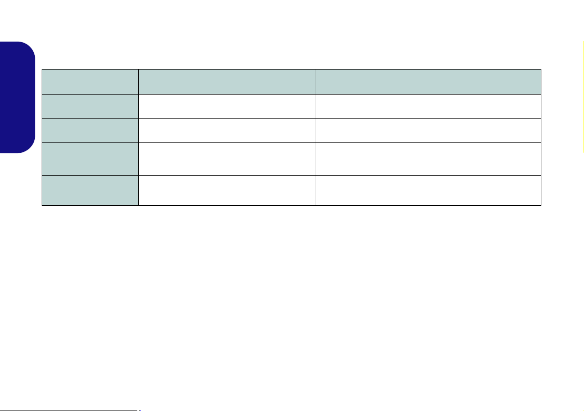
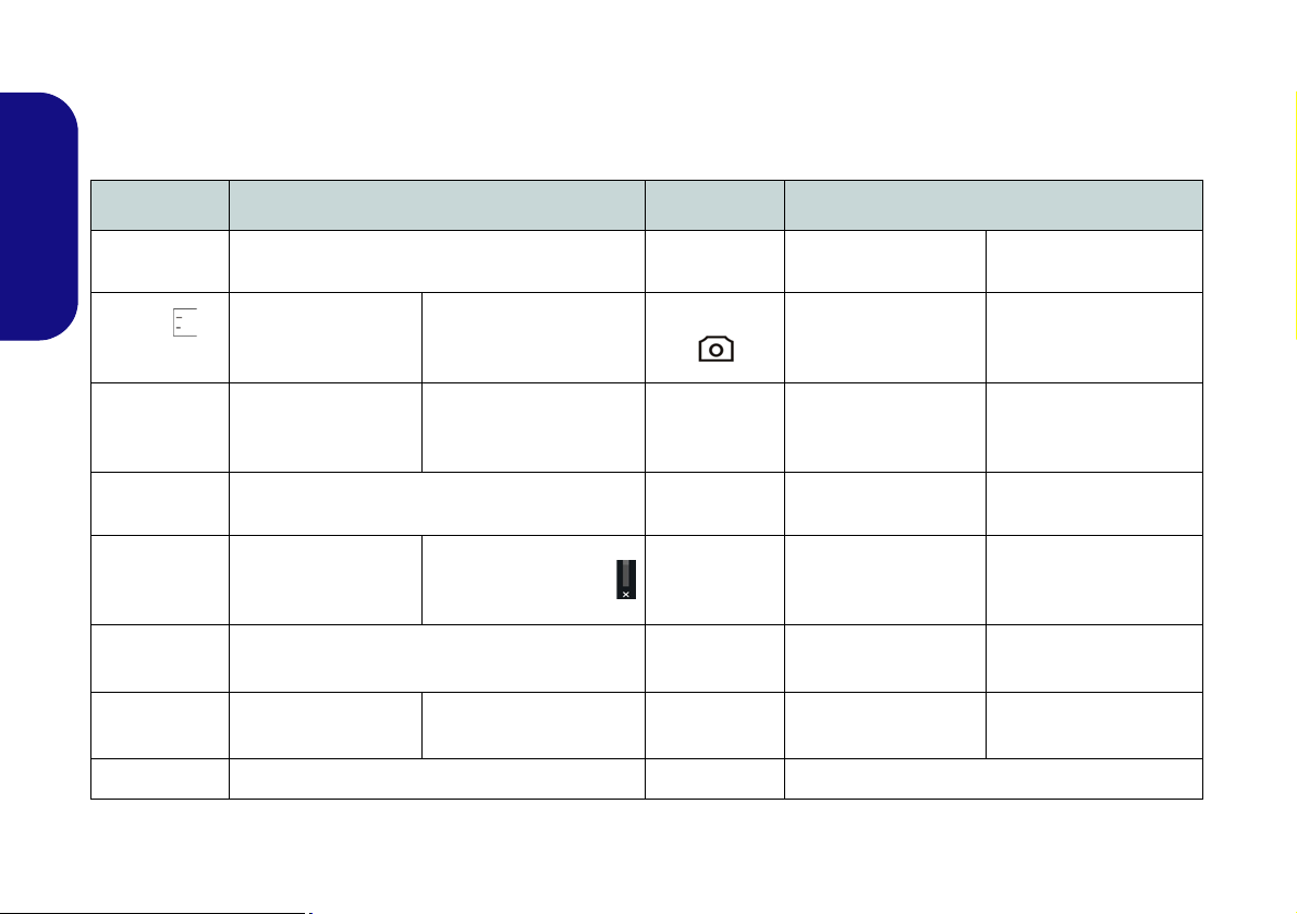
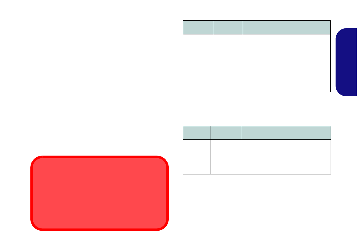
Model Differences
This notebook series includes two different model types that mainly differ as indicated in the table below. Note that
your model may appear slightly different from those pictured in this manual.
Feature Model A Model B
Display Type
15.6” (39.62cm) HD+/ FHD 17.3” (43.94cm) HD+/ FHD
English
3G module Option Not Supported
Fingerprint Reader
Module
Dimensions & Weight
374mm (w) * 250mm (d) * 16.3 - 42.7mm (h)
2.7kg with ODD and Battery
Option Not Supported
413mm (w) * 277.5mm (d) * 17.5 - 44mm (h)
3.2kg with ODD and Battery
Table 1 - Model Differences
HDD RAID Support
Your hard disk(s) can be set up in AHCI mode or RAID mode (for increased performance or protection). Note that setting up your hard disk(s) in RAID mode needs to be done prior to installing the Windows OS.
RAID Setup for Windows 7
See RAID Setup for Windows 7 on page 5.
RAID Setup for Windows 8
Refer to the expanded User’s Manual on the Device Drivers & Utilities + User’s Manual disc.
4

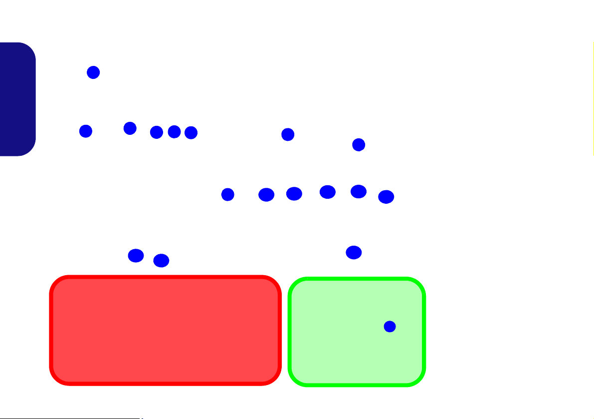
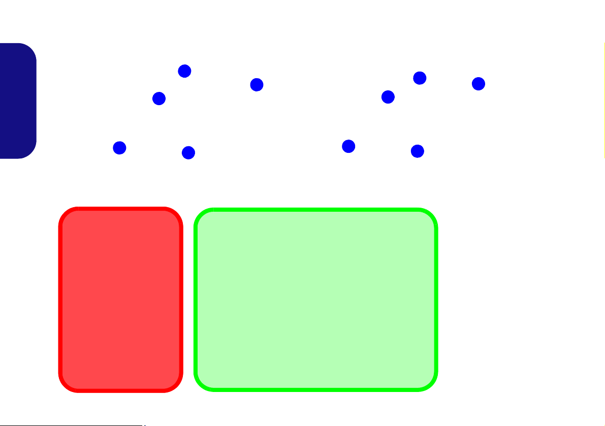
RAID Setup for Windows 7
You may use your hard disks in combination with Striping
(RAID 0), Mirroring (RAID 1), or Recovery for either
fault tolerance or performance.
RAID Level Description
Identical drives reading and writing data in p aral-
RAID 0
(at lease two
hard disks
needed)
RAID 1
(at lease two
hard disks
needed)
Recovery
(at lease two
hard disks
needed)
lel to increase performance. RAID 0 implements a striped disk array and the data is broken
into blocks and each block is written to a separate disk drive.
RAID 0 (a striped array) is not fault-tolerant. The
failure of one drive will result in the loss of all
data in the array.
Identical drives in a mirrored configuration used
to protect data. Should a drive that is part of a
mirrored array fail, the mirrored drive (which
contains identical data) will handle all the data.
When a new replacement drive is installed, data
to the new drive is rebuilt from the mirrored drive
to restore fault tolerance.
RAID 1 (mirrored array) provides full data protection, as data can simply be copied from a
healthy disk to a replacement for any failed disk.
Two identical drives copying data between a
master and a recovery disk. This provides more
control over how data is copied between the
master and recovery drives, fast volume
updates and the ability to view the data in Win-
dows Explorer.
Prepare the following before setting up your serial ATA
hard disks in RAID mode:
•The Microsoft Windows 7 OS disc.
•The Device Drivers & Utilities + User’s Manual disc.
English
Note: All hard disks in a RAID should be identical (the
same size and brand) in order to prevent unexpected system behavior.
RAID Setup Procedure
Part I: BIOS
1. Start-up your computer and press F2 to enter the BIOS.
2. Go to the Advanced menu, select SATA Mode and press
Enter.
3. Select RAID Mode.
4. Press Esc and go to the Boot menu.
5. Set the CD/DVD-ROM Drive (make sure the Microsoft
Windows OS disc is inserted) as the first device in the boot
order from the Boot menu.
6. Select Save Changes and Reset from the Exit menu (or press
F4) and press Enter to exit the BIOS and reboot the computer.
Table 2 - RAID Description
5

Part II: Intel Matrix
Figure 2
RAID
Created
1. Press Ctrl + i to enter RAID configuration menu.
2. Select 1.Create RAID Volume and press Enter.
3. Type the RAID volume name and then press Tab or Enter to
advance to the next field.
4. Specify (use the up and down arrow keys) the RAID level
(RAID 0 or RAID 1 or Recovery - see Table 2) and then press
Tab or Enter to advance to the next field.
5. Press Enter and the system will select the physical disks to use.
English
6. Press Enter and select (if applicable) the Strip Size (best set to
default).
7. Press Enter and select the Capacity size (best set to default).
8. Press Enter to select Create Volume.
9. Press Enter to create the volume, and confirm the selection by
pressing Y.
10. This will now return to the main menu.
12. Make sure the Windows 7 OS DVD is in the DVD drive and as
the computer starts up it will automatically boot from the
Windows 7 OS DVD (you will be prompted to press a key to
boot from the DVD).
13. Press Enter to continue installing the operating system as
normal (see your Windows documentation if you need help on
installing the Windows OS).
11. Select 6.Exit and press Enter, then press Y to exit the RAID
configuration menu.
6
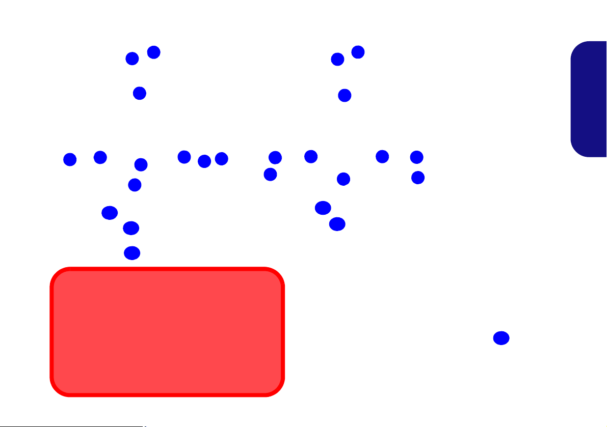
System Map: Front View with LCD Panel Open (Models A & B)
2
1
4
3
Note that the Touchpad and
Buttons valid operational
area is that indicated within
the red dotted lines above.
Figure 3
Front View with LCD
Panel Open
1. PC Camera (Optional)
2. *PC Camera LED
*When the PC camera
is in use, the LED will
be illuminated in red.
3. LCD
4. GPU Button
5. LED Indicators
6. Power Button
7. Hot Key Buttons
8. Speakers
9. Keyboard
10. Microphone
1 1. Touchpad & Buttons
12. Fingerprint Reader
(Optional for Model A
Only)
Wireless Device
Operation Aboard Aircraft
The use of any portable electronic transmission devices aboard aircraft is usually prohibited.
Make sure the wireless modules are OFF or in Air-
plane mode (for Windows 8 only) if you are using the
computer aboard aircraft.
11
9
8
6
7
10
2
1
7
3
9
6
8
10
8
5
Model A
15.6” (39.62cm)
Model B
17.3” (43.94cm)
11
8
5
4
11
12
English
7
LED Indicators
Model A
Model B
The LED indicators on the computer display helpful information about the current status of the computer.
Icon Color Description
English
Icon Color Description
8
Orange
Green The Computer is On
Blinking Green The Computer is in Sleep Mode
Orange The Battery is Charging
Green The Battery is Fully Charged
Blinking Orange
Green Number Lock Activated
Green Caps Lock Activated
Green Scroll Lock Activated
Table 3 - Front Left LED Indicators
The AC/DC Adapter is Plugged
In
The Battery Has Reached Criti-
cally Low Power Status
White The Computer is On
Green UMA Mode Activated
Orange Optimus Mode Activated
Green Intel Integrated GPU (iGPU) Activated
Orange NVIDIA Discrete GPU (dGPU) Activated
White Hard Disk Activity
Green The Wireless LAN Module is Powered On
Win 7 - The Bluetooth Module is Powered
On
Orange
Win 8 - The Bluetooth Module is Installed
(this is not a power on/off indicator in Win 8)
Table 4 - Top Case LED Indicators
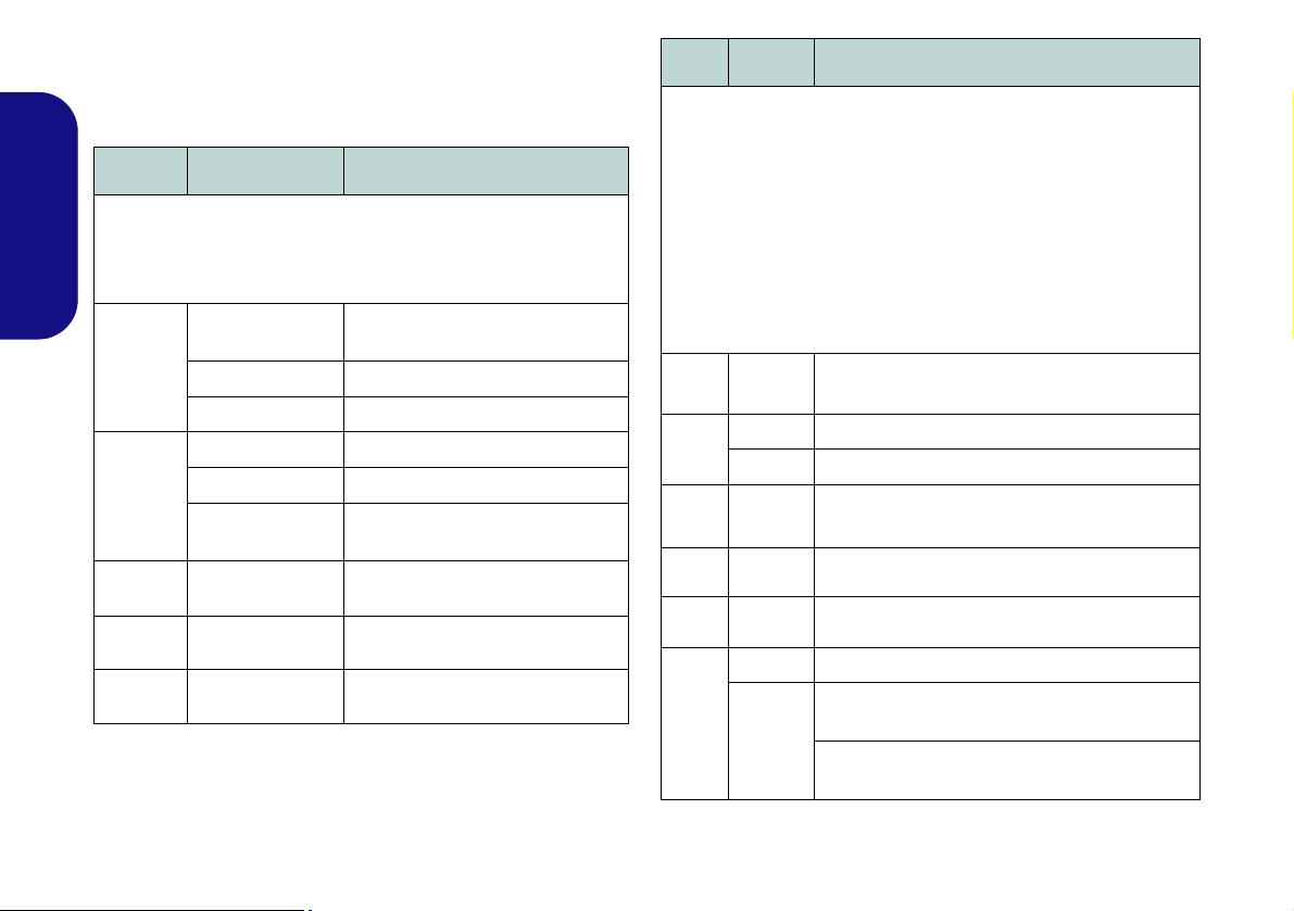
Hot Key Buttons & Keyboard
Function Keys
NumLk &
ScrLk
Numeric
Keypad
Fn Key
Special Characters
Some software applications allow the number-keys to be
used with Alt to produce special characters. These special
characters can only be produced by using the numeric keypad. Regular number keys (in the upper row of the keyboard) will not work. Make sure that the numeric keypad is
on.
3G Module
Power Toggle
Press the Hot Key buttons on the computer to toggle the
appropriate function on/off.
Icon Description
WLAN Module Power Toggle
Table 5 - Hot Key Button (Model A)
Icon Description
The keyboard has a numeric keypad for easy numeric data
input. Pressing NumLk turns on/off the numeric keypad.
It also features function keys to allow you to change operational features instantly.
English
PC Camera Power Toggle
WLAN Module Power Toggle
Table 6 - Hot Key Buttons (Model B)
Mute Toggle
Figure 4 - Keyboard
9
Function Keys
The function keys (F1 - F12 etc.) will act as hot keys when pressed while the Fn key is held down. In addition to the
basic function key combinations, visual indicators (Windows 7 or Windows 8 Desktop only) are available wh en the hot
key driver is installed.
Keys Function/Visual Indicators Keys Function/Visual Indicators
English
Fn + ~ Play/Pause (in Audio/Video Programs) Fn + F8/F9
Fn +
(Model A Only)
Fn + F1 Touchpad Toggle
Fn + F2
Fn + F3
()
Fn + F4 Sleep Toggle Fn + ScrLk Scroll Lock Toggle
Fn + F5/F6
Fn + F7 Display Toggle Fn + Esc Control Center Toggle (see page 11)
Brightness Decrease/
3G Module Power
Toggle
Turn LCD Backlight Off
(Press a key to or use TouchPad to turn on)
Mute Toggle NumLk Number Lock Toggle
Volume Decrease/
Increase
Fn + F10
()
Fn + F11
()
Fn + F12
Caps Lock Caps Lock Toggle
PC Camera Power
WLAN Module Power
Bluetooth Module
Power Toggle
Table 7 - Function Keys & Visual Indicators
Increase
Toggle
Toggle
10

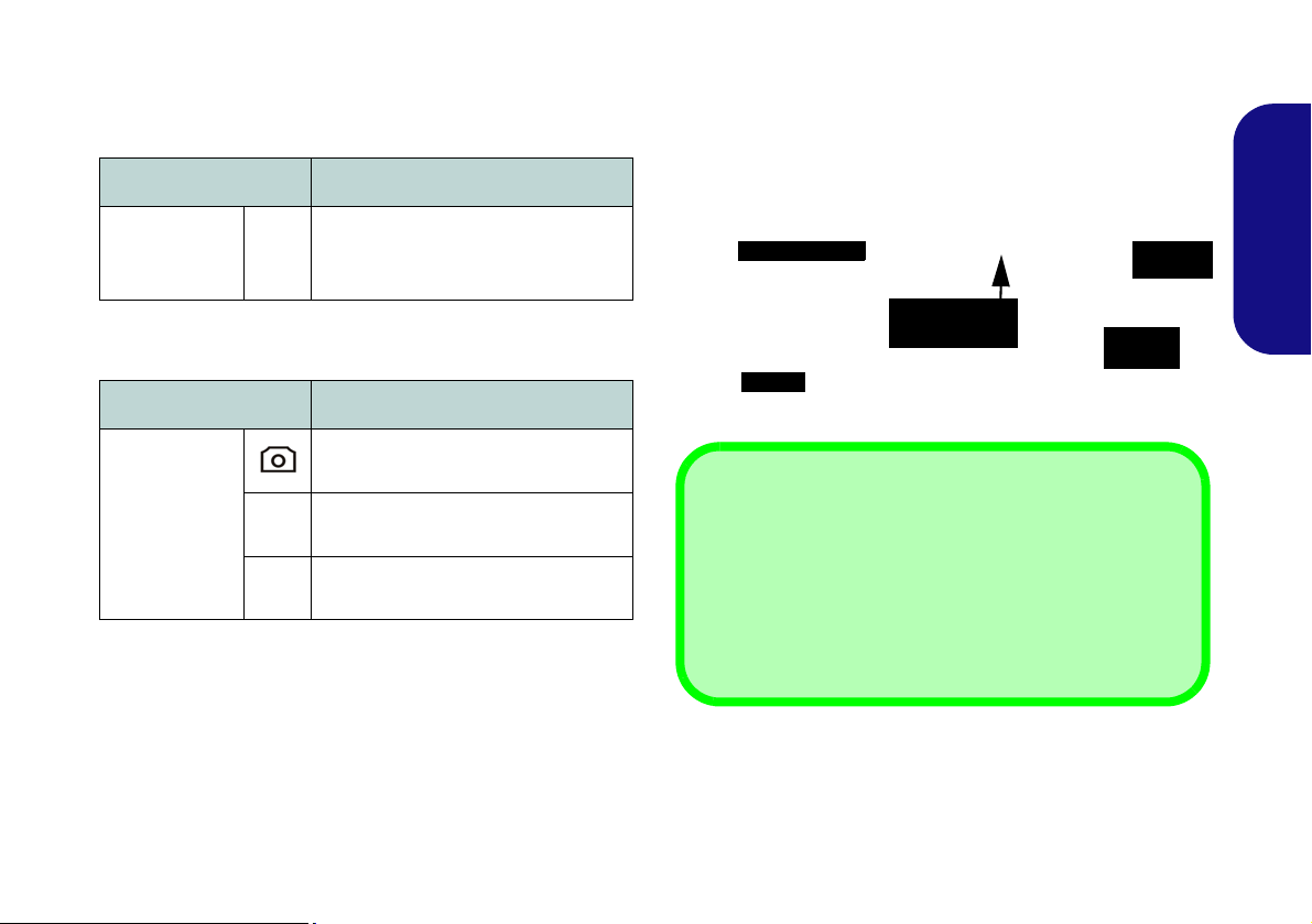
Control Center
Windows 7
Windows 8
Press the Fn + Esc key combination, or double-click the icon in the notification area of the taskbar to toggle the
Control Center on/off. The Control Center gives quick access to frequently used controls, and enables you to quickly
turn modules on/off. The Control Center is only accessible from the Windows Desktop (use the Windows Lo go Key
+ D key combination) in Windows 8 and not from the Start Screen in the Metro UI.
Figure 5 - Control Center
English
Click on any button to turn any of the modules (e.g. TouchPad, Camera) on/off. Click on Power Conservation to switch
between Performance, Balanced or Energy Star modes. Click on the buttons (or just click and hold the mouse button)
to adjust the slider for Brightness/Volume. Click on Display Switch/Time Zone/ Desktop Background to bring up
the appropriate Windows control panel. Click on the Sleep button to put the computer into Hibernate or Sleep modes.
11

Power Status
The Power Status icon will show whether you are currently powered by the battery, or by the AC/DC adapter plugged
in to a working power outlet. The power status bar will show the current battery charge state.
Brightness
The Brightness icon will show the current screen brightness level. You can use the slider to adjust the screen brightness
or the Fn + F8/F9 key combinations, or use the Fn + F2 key combination to turn off the LED backlight (press any key
to turn it on again). Note that screen brightness is also effected by the Power Mode selected.
English
Volume
The Volume icon will show the current volume level. You can use the slider to adjust the volume or the Fn + F5/F6
key combinations, or use the Fn + F3 key combination to mute the volume.
Power Conservation
This system supports Energy Star power management features that place computers (CPU, hard drive, etc.) into a lowpower sleep mode after a designated period of inactivity. Click either the Performance, Balanced or Energy Star but-
ton.
Sleep
Click the Sleep button to bring up the Hibernate or Sleep buttons, and click either button to have the computer
enter the appropriate power-saving mode.
12

Display Switch
Click the Display Switch button to access the menu (or use the + P key combination) and select the appropriate
display mode.
Time Zone
Clicking the Time Zone button will access the Date and Time Windows control panel.
Desktop Background
Clicking the Desktop Background button will allow you to change the desktop background picture.
Touchpad/PC Camera/Wireless LAN Module /Bluetooth/3G Module (Win 7 Only)
Click any of these buttons to toggle the Touchpad or module’s power status. A crossed out icon will appear over the top
left of the icon when it is off
Power Mode selected.
. Note that the power status of a module, and Touchpad power, is also effected by the
Touchpad/PC Camera (Win 8 Only)
Click any of these buttons to toggle the Touchpad or module’s power status. A crossed out icon will appear over the top
left of the icon when it is off
Power Mode selected.
. Note that the power status of a module, and Touchpad power, is also effected by the
Caps Lock/Scroll Lock/ Number Lock
Click the button to toggle the appropriate lock mode.
English
13
System Map: Front, Left, Right & Rear Views (Model A)
1
Front
10
13
12
11
14
Right
Rear
2
5
4
3
8
6
7
Left
9
15
USB
The USB 3.0 ports are
colored blue. USB 3.0 will
transfer data much faster than
USB 2.0, and is backwardscompatible with USB 2.0.
10
Figure 6
Front, Left, Right & Rear
Views (Model A)
1. LED Indicators
2. Security Lock Slot
3. USB 2.0 Port
4. S/PDIF-Out Jack
5. Microphone-In Jack
6. Headphone-Out Jack
7. Optical Device Drive Bay
8. Emergency Eject Hole
9. Multi-in-1 Card Reader
10. USB 3.0 Ports
11. Combined eSATA/USB
3.0 Port
12. HDMI-Out Port
13. RJ-45 LAN Jack
14. External Monitor Port
15. DC-In Jack
16. Vent
10
16
Disc Emergency Eject
If you need to manually eject a disc (e.g. due to an unexpected power interruption) you may push the end of a
straightened paper clip into the emergency eject hole.
Do not use a sharpened pencil or similar object that may
break and become lodged in the hole.
English
14

System Map: Front, Left, Right & Rear Views (Model B)
1
Front
10
13
12
11
14
Right
Rear
2
5
4
3
8
6
7
Left
9
15
USB
The USB 3.0 ports are
colored blue. USB 3.0 will
transfer data much faster than
USB 2.0, and is backwardscompatible with USB 2.0.
10
Figure 7
Front, Left, Right & Rear
Views (Model B)
1. LED Indicators
2. Security Lock Slot
3. USB 2.0 Port
4. S/PDIF-Out Jack
5. Microphone-In Jack
6. Headphone-Out Jack
7. Optical Device Drive Bay
8. Emergency Eject Hole
9. Multi-in-1 Card Reader
10. USB 3.0 Ports
11. Combined eSATA/USB
3.0 Port
12. HDMI-Out Port
13. RJ-45 LAN Jack
14. External Monitor Port
15. DC-In Jack
16. Vent
10
16
Disc Emergency Eject
If you need to manually eject a disc (e.g. due to an unexpected power interruption) you may push the end of a
straightened paper clip into the emergency eject hole.
Do not use a sharpened pencil or similar object that may
break and become lodged in the hole.
English
15
System Map: Bottom View
2
1
4
3
2
Battery Information
Always completely discharge, then fully charge, a new
battery before using it. Completely discharge an d charge
the battery at least once every 30 days or after about 20
partial discharges (see the expanded User’s Manual on
the Device Drivers & Utilities + User’s Manual disc).
HDMI
Note that the HDMI Port supports video and audio signals to attached external displays (Note THX Tru Studio
Pro will be disabled when you are connecting to an external display through an HDMI connection -
see page 20).
Figure 8
Bottom View
1. Component Bay Cover
2. Vent
3. Battery
4. HDD Bay
CPU
The CPU is not a user serviceable part. Accessing
the CPU in any way may
violate your warranty.
Overheating
To prevent your computer
from overheating make
sure nothing blocks any
vent while the computer is
in use.
2
1
4
3
2
Model A
Model B
English
16
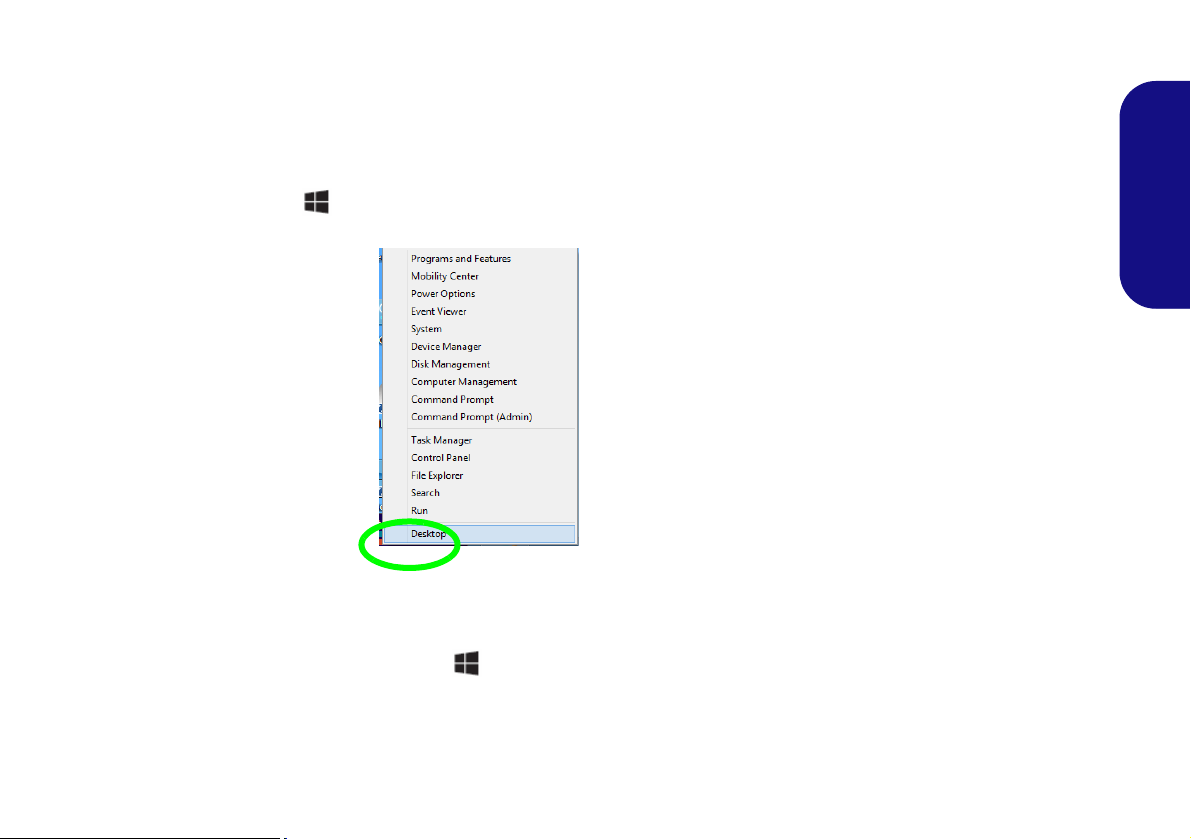
Windows Control Panel & Desktop
Move the mouse to the
and right-click to access
bottom left of the screen
the menu.
Most of the control panels, utilities and applications within Windows are accessed from the Start menu in Windows 7,
and from the Desktop in Windows 8.
Throughout this manual you will see an instruction to open the Control Panel. In Windows 7 click the Start menu and
select Control Panel. In Windows 8
the Windows Logo Key + X key combination)
right-click the lower left hot corner to bring up the context menu (or use
and select Control Panel.
Figure 9 - Windows 8 Context Menu
English
The desktop interfaces for both Windows 7 & 8 are similar (Windows 8 has no start button). To access the Desktop App
in Windows 8 use the Windows Logo Key + D key combination or Desktop App in the Metro UI Start Screen (Windows 7’s standard interface is the desktop).
17

Video Features
1
2
2
1
Figure 10 - Display Control Panel
The system features both an Intel’s Integrated GPU (for
power-saving) and an NVIDIA’s discrete GPU (for performance). You can switch display devices, and configure
display options as long as the video drivers are installed.
To access Display control panel:
1. Go to the Control Panel.
English
2. Click Display (icon) - in the Appearances and
Personalization category.
3. Click Adjust Screen Resolution/Adjust resolution.
OR
4. Alternatively you can right-click the desktop and select Screen
resolution.
5. Use the dropbox to select the screen resolution .
6. Click Advanced settings .
To access the Intel® Graphics and Media Control Panel:
1. Go to the Control Panel.
2. Click Intel(R) Graphics and Media in the icon view.
OR
3. Right-click the desktop and select Graphics Properties from
the menu.
4. Choose the application mode (Basic, Advanced or Wizard).
To access the NVIDIA Control Panel:
1. Go to the Control Panel.
2. Click NVIDIA Control Panel (icon) - in the Appearances and
Personalization category.
OR
3. Right-click the desktop and select NVIDIA Control Panel from
the menu.
Display Devices
Besides the built-in LCD you can also use an external
monitor/flat panel display/TV (TV through HDMI-Out
port only), connected to the external monitor port or to the
HDMI-Out port (High-Definition Multimedia Interface)
as your display device.
18
NVIDIA® Optimus™ Technology
Screen Resolution for Metro Style Apps
(Windows 8)
The minimum resolution in which Metro style apps will
run is 1024x768.
The minimum resolution required to support all the features of Windows 8 (including multitasking with snap) is
1366x768.
Nvidia® Optimus™ technology is a seamless technology
designed to get best performance from the graphics system while allowing longer battery life, without having to
manually change settings. Thus when an application is run
that requires extra performance or quality, then the system
will run the discrete GPU (dGPU); when the system does
not require such enhanced performance it will let the integrated (iGPU) handle it.
GPU Button
This computer also features a button that allows the
user to switch between Optimus Mode and UMA Mode
(Unified Memory Architecture). UMA Mode will use
only the integrated GPU; Optimus Mode will allow the
system to automatically determine whether the dGPU or
iGPU is used. Thus the user can completely control how
the graphics system operates. Press the GPU button ,
and the button color will indicate the current mode.
Icon Color Description
UMA Mode Activated
Green
Orange
Table 8 - GPU Button Modes
The system will use the Intel inte-
grated GPU (iGPU) only
Optimus Mode Activated
Optimus technology will determine
when to use the Intel integrated GPU
(iGPU) or NVIDIA discrete GPU
(dGPU) automatically
The GPU LED indicators will display which GPU is currently in use.
Icon Color Description
Green Intel Integrated GPU (iGPU) Activated
English
Orange
Table 9 - GPU LED Indicators
NVIDIA Discrete GPU (dGPU) Acti-
vated
19
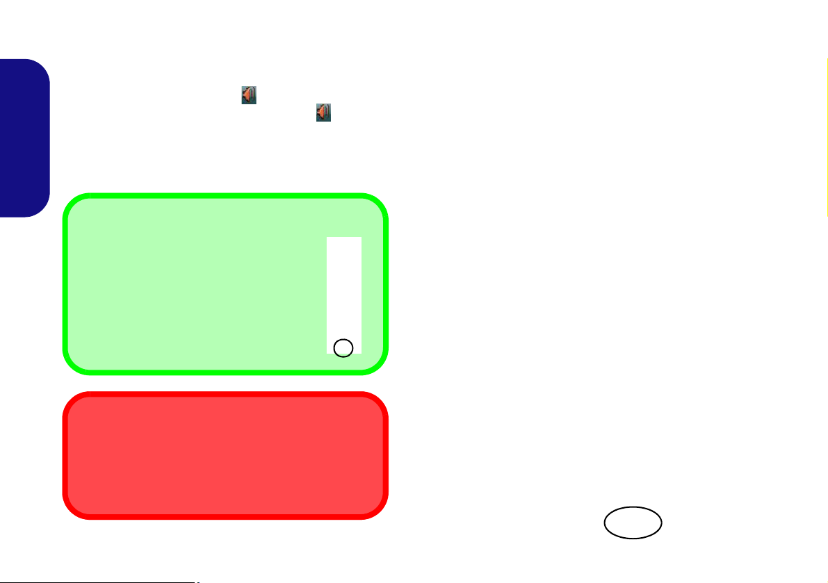
Audio Features
Sound Volume Adjustment
The sound volume level is set using the volume control within Windows (and the volume function keys on the computer). Click
the Speaker ico n in the taskbar to check the
setting.
THX TruStudio Pro Audio
Note that you will need to install the THX TruStudio audio application in order to get maximum audio performance.
Menu
Figure 11
THX TruStu-
dio Pro HDMI
Display Warn-
ing
You can configure the audio options on your computer
from the Sound control panel in Windows, or from the
Realtek HD Audio Manager
control panel (right-click the taskbar icon to bring up
an audio menu). The volume may also be adjusted by
means of the Fn + F5/F6 key combination/the volume
control.
English
20
/ icon in the taskbar/
THX TruStudio Pro Audio
Install the THX TruStudio AP to allow you to configure
the audio settings to your requirements for the best performance in games, music and movies.
THX TruStudio Pro Activation
On the first run of THX TruStudio Pro you will need to activate the application.
1. To activate the application you will need to be connected to the
internet.
2. Double-click the THX Activate icon on the desktop and
click the Activate button.
3. The program will connect to the internet to verify the activation
key.
4. Click Finish to complete the application activation.
5. Restart the computer .
THX Tru Studio Pro & HDMI
1. When you connect an HDMI display to the HDMI-Out port, the
THX TruStudio Pro controls will be disabled.
2. A warning box will pop-up and will prompt “Do you want to
select another audio device now?”.
3. Click No to continue using the HDMI audio output from your
external display (do not attempt to select another audio device
when connected to the external HDMI display).
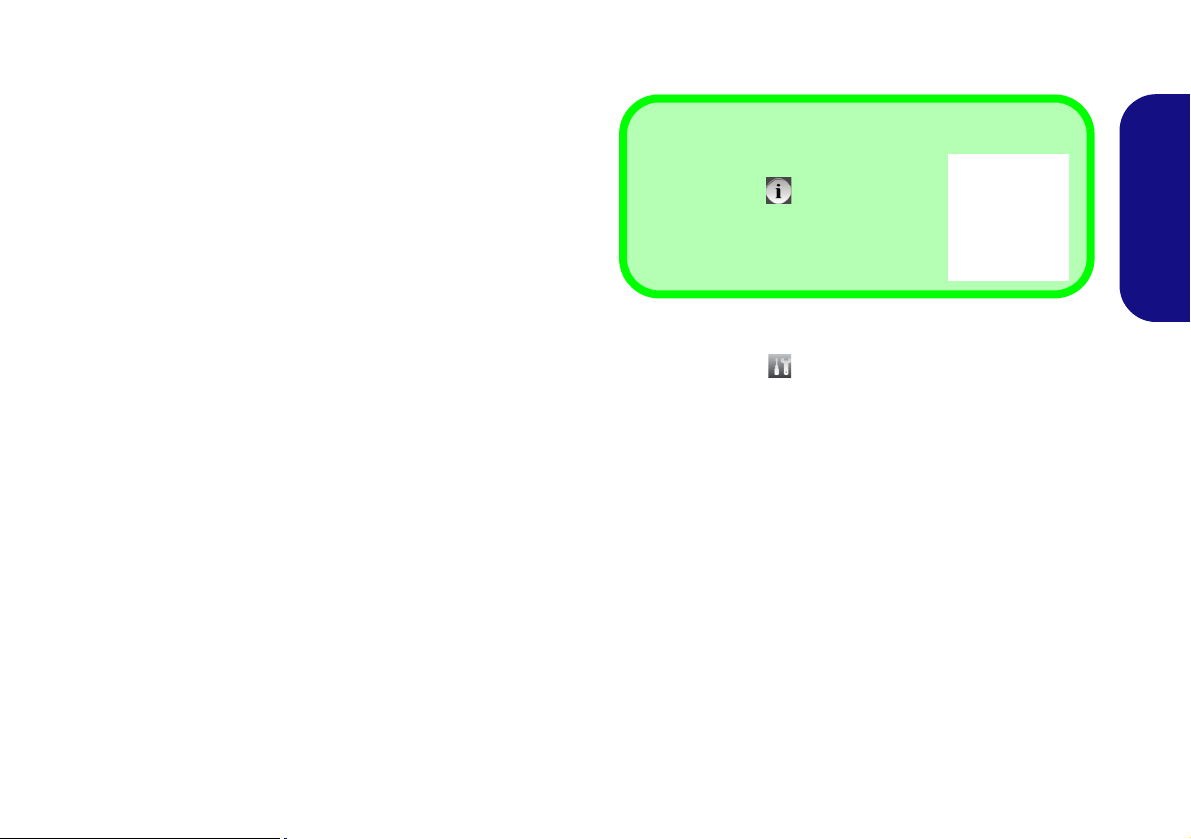
Fingerprint Reader
Help
Click the Help icon and select a
help topic from the drop-down menu.
Get more help will provide a more comprehensive list of help topics.
Figure 12
AuthenTec
TrueSuite -
Settings
(Optional for Model A Only)
Install the driver and enroll your fingerprints as instructed
below before use.
Fingerprint Reader Driver Installation
1. Click Option Drivers (button).
2. Click 4.Install Fingerprint Driver > Yes.
3. Click Next.
4. Click the button to accept the license and click Next.
5. Click Next > Install.
6. Click Finish > Yes to restart the computer.
User Enrollment
1. Click Start > Programs/All Programs > AuthenTec TrueSuite.
2. Click Yes when you have identified your finge rprint sensor.
3. Click Yes when you are ready to enroll your fingerprints.
4. Click on the fingerprint diagram to select any finger to enroll.
5. You will be required to enter your Windows password (you will
be prompted to create a password if you have not already done
so) at this point (click OK to confirm the password entry).
6. Swipe the finger until the progress bar reaches 100% to enroll
that finger.
7. Y ou will be prompted to select another fing er for enrollment (it is
8. Click the button to continue once you have enrolled a number of
9. Enter the required information and click the button to register
recommended that you enroll a number of fingers).
fingerprints.
your software, or click to register later.
10. Your fingerprints will now be enrolled (you may enroll any
additional fingerprints at any time).
English
Settings
Click the Settings button on the menu bar to access the
personalization settings for AuthenTec TrueSuite. Here
you can choose to enable/disable Website Log On, QuickLaunch, Fast User Switching and the desktop icon. You
can also select the Theme and export/import identities.
Click the Save button to save any changes made.
21

3G Module
1
Model A
USIM Card Orientation
Note that the USIM
card’s readable side
(with the gold-colored
contacts) should face
upwards as illustrated.
1
(Optional for Model A Only)
If you have included an optional 3G module in your purchase option, follow the instructions below to install the USIM
card (which will be provided by your service provider), and then run the appropriate application supplied with your
module.
USIM Card Insertion
1. Turn off the computer, and turn it over and remove the battery .
English
2. Insert the USIM card as illustrated below until it clicks into position, and replace the battery.
Figure 13 - Remove the battery and Insert the USIM Card
22

Driver Installation
General Guidelines
As a general guide follow
the default on-screen instructions for each driver
(e.g. Next > Next > Fin-
ish) unless you are an advanced user. In many
cases a restart is required
to install the driver.
Make sure any modules
(e.g. PC Camera or
WLAN ) are ON before installing the appropriate
driver.
Windows Update
After installing all the drivers make sure you enable
Windows Update in order to get all the latest security updates etc. (all
updates will include the
latest hotfixes from Microsoft).
Driver Installation & Power
When installing drivers make sure your
computer is powered by the AC/DC
adapter connected to a working power
source. Some drivers draw a significant
amount of power during the installation
procedure, and if the remaining battery
capacity is not adequate this may cause
the system to shut down and cause system problems (note that there is no safety
issue involved here, and the battery will
be rechargeable within 1 minute).
Figure 14 - Install Drivers
Driver Installation
The Device Drivers & Utilities + User’s Manual disc contains the drivers and utilities
necessary for the proper operation of the computer. This setup will probably have already
been done for you. If this is not the case, insert the disc and click Install Drivers (button),
or Option Drivers (button) to access the Optional driver menu. Install the drivers in the
order indicated in Figure 14. Click to select the drivers you wish to install (you should
note down the drivers as you install them). Note: If you need to reinstall any driver, you
should uninstall the driver first.
Manual Driver Installation
Click the Browse CD/DVD button in the Drivers Installer application and browse to the
executable file in the appropriate driver folder.
Found New Hardware
If a
cel, and follow the installation procedure as directed.
wizard appears
during the installation procedure, click Can-
English
23

Troubleshooting
Problem Possible Cause - Solution
The captured video files
from the PC Camera are
taking up too much disk
space.
English
The Bluetooth module is
off after resuming from
Sleep.
A file cannot be copied to/
from a connected
Bluetooth device.
Note that capturing high resolution vid eo files requires a substantial amount of disk space for each file.
Note that the Windows system requires a minimum of 15GB of free space on the C: drive system
partition. It is recommended that you save the capture video file to a location other than the C:drive,
limit the file size of the captured video or reduce video resolutio n.
The Bluetooth module’s default state will be off after resuming from the Sleep power-saving state. Use
the key combination (Fn + F12) to power on the Bluetooth module after the computer resumes from
Sleep.
Transferring data between the computer and a Bluetooth enabled device is supported in one direction
only (simultaneous data transfer is not supported). If you are copying a file from your computer to a
Bluetooth enabled device, you will not be able to copy a file from the Bluetooth enabled device to your
computer until the file transfer process from the computer has been completed.
24

Specifications
Latest Specification Information
The specifications listed in this section
are correct at the time of going to
press. Certain items (particularly processor types/speeds) may be
changed, delayed or updated due to
the manufacturer's release schedule.
Check with your service center for details.
Processor Options
Intel® Core™ i7 Processor
i7-3820QM (2.70GHz)
8MB L3 Cache, 22nm, DDR3-1600MHz,
TDP 45W
i7-3720QM (2.60GHz), i7-3610QM
(2.30GHz)
6MB L3 Cache, 22nm, DDR3-1600MHz,
TDP 45W
i7-3520M (2.90GHz)
4MB L3 Cache, 22nm, DDR3-1600MHz,
TDP 35W
Intel® Core™ i5 Processor
i5-3360M (2.80GHz), i5-3320M (2.60GHz),
i5-3210M (2.50GHz)
3MB L3 Cache, 22nm, DDR3-1600MHz,
TDP 35W
Intel® Core™ i3 Processor
i3-3110M (2.40GHz)
3MB L3 Cache, 22nm, DDR3-1600MHz,
TDP 35W
Intel® Core™ i7 Processor
i7-2860QM (2.50GHz), i7-2820QM
(2.30GHz)
8MB L3 Cache, 32nm, DDR3-1600MHz,
TDP 45W
i7-2760QM (2.40GHz), i7-2720QM
(2.20GHz)
6MB L3 Cache, 32nm, DDR3-1600MHz,
TDP 45W
i7-2670QM (2.20GHz), i7-2630QM
(2.00GHz)
6MB L3 Cache, 32nm, DDR3-1333MHz,
TDP 45W
i7-2640M (2.80GHz), i7-2620M (2.70GHz)
4MB L3 Cache, 32nm, DDR3-1333MHz,
TDP 35W
Intel® Core™ i5 Processor
i5-2540M (2.60GHz), i5-2520M (2.50GHz),
i5-2450M (2.50GHz), i5-2430M (2.40GHz),
i5-2410M (2.30GHz)
3MB L3 Cache, 32nm, DDR3-1333MHz,
TDP 35W
Intel® Core™ i3 Processor
i3-2370M (2.40GHz), i3-2350M (2.30GHz),
i3-2330M (2.20GHz), i3-2310M (2.10GHz)
3MB L3 Cache, 32nm, DDR3-1333MHz,
TDP 35W
Core Logic
Intel® HM77 Chipset
BIOS
One 48Mb SPI Flash ROM
AMI BIOS
LCD
Model A:
15.6" (39.62cm) HD+/ FHD
Model B:
17.3" (43.94cm) HD+/ FHD
English
25

Security
BIOS Password
Security (Kensington® Type) Lock Slot
(Factory Option) Fingerprint Reader
(Model A Only)
Video Adapter
Intel® Integrated GPU and NVIDIA®
Discrete GPU
English
Supports NVIDIA® Optimus Technology
Intel Integrated GPU (GPU is Dependent
on Processor)
Intel® HD Graphics
Dynamic Frequency (Intel Dynamic Video
Memory Technology for up to 1.7GB)
Microsoft DirectX®10 Compatible
Intel® HD Graphics 3000
Dynamic Frequency (Intel Dynamic Video
Memory Technology for up to 1.7GB)
Microsoft DirectX®10 Compatible
Intel® HD Graphics 4000
Dynamic Frequency (Intel Dynamic Video
Memory Technology for up to 1.7GB)
Microsoft DirectX®11 Compatible
NVIDIA Discrete GPU
NVIDIA® GeForce GTX 660M
2GB GDDR5 Video RAM
Microsoft DirectX®11 Compatible
Audio
High Definition Audio Compliant Interface
THX TruStudio Pro
2 * Built-In Speakers
Built-In Microphone
Memory
Three 204 Pin SO-DIMM Sockets Supporting DDR3 1333/1600MHz Memory
Memory Expandable up to 24GB
(The real memory operating frequency
depends on the FSB of the processor.)
Note: Three SO-DIMMs are only supported
by Quad-Core CPUs; Dual-Core CPUs support two SO-DIMMs maximum
Storage
(Factory Option) One Changeable
12.7mm(h) Optical Device Type Drive
(Super Multi Drive Module or Blu-Ray
Combo Drive Module)
(Factory Option) Two Changeable 2.5"
(6cm) 9.5mm (h) SATA (Serial) Hard Disk
Drives supporting RAID
level 0/1
Interface
One USB 2.0 Port
Three USB 3.0 Ports
One eSATA Port (USB 3.0 Port Combined)
One HDMI-Out Port
One Headphone-Out Jack
One Microphone-In Jack
One S/PDIF Out Jack
One RJ-45 LAN Jack
One External Monitor Port
One DC-in Jack
Keyboard
Full-size “WinKey” keyboard (with numeric
keypad)
Pointing Device
Built-in Touchpad (scrolling key functionality
integrated
Card Reader
Embedded Multi-in-1 Push-Push Card
Reader
MMC (MultiMedia Card) / RS MMC
SD (Secure Digital) / Mini SD / SDHC/
SDXC
MS (Memory Stick) / MS Pro / MS Duo
26

Communication
Built-In Gigabit Ethernet LAN
(Factory Option) 1.3M Pixels/2M Pixels
(HD) PC Camera Module
(Factory Option) 3G Mini-Card Module
(Model A Only)
WLAN/ Bluetooth Half Mini-Card
Modules:
(Factory Option) Intel® Centrino® Ultimate-N 6300 Wireless LAN (802.11a/g/n)
(Factory Option) Intel® Centrino®
Advanced-N 6235 Wireless LAN (802.11a/
g/n) + Bluetooth 4.0
(Factory Option) Intel® Centrino® Wireless-N 2230 Wireless LAN (802.11b/g/n) +
Bluetooth 4.0
(Factory Option) Third-Party Wireless LAN
(802.11b/g/n)
(Factory Option) Third-Party Wireless LAN
(802.11b/g/n) + Bluetooth 4.0
Mini Card Slots
Model A:
Slot 1 for WLAN Module or WLAN and
Bluetooth Combo Module
(Factory Option) Slot 2 for 3G Module
Model B:
Slot 1 for WLAN Module or WLAN and
Bluetooth Combo Module
Environmental Spec
Temperature
Operating: 5
Non-Operating: -20°C - 60°C
Relative Humidity
Operating: 20% - 80%
Non-Operating: 10% - 90%
°C - 35°C
Power
Full Range AC/DC Adapter
AC Input: 100 - 240V, 50 - 60Hz
DC Output: 19V, 6.3A (120W)
8 Cell Smart Lithium-Ion Battery Pack,
76.96WH
Dimensions & Weight
Model A:
374mm (w) * 250mm (d) * 16.3 - 42.7mm (h)
2.7kg with ODD & 76.96WH Battery
Model B:
413mm (w) * 277.5mm (d) * 17.5 - 44mm (h)
3.2kg with ODD & 76.96WH Battery
English
27

English
28

Über das Ausführliche Benutzerhandbuch
Diese Kurzanleitung soll einen Überblick über die Schritte geben, die dazu notwendig s ind, das System zu starten. Dieses ist
nur eine Ergänzung und kein Ersatz für das erweiterte englischsprachige Benutzerhandbuch, das auf der mitgelieferten Disc
Device Drivers & Utilities + User's Manual im Adobe-Acrobat-Format vorliegt. Diese Disc enthält auch die Treiber und
Utility-Programme, die für einen einwandfreien Betrieb des Computers notwendig sind (Hinweis: Das Unternehmen behält
sich das Recht vor, diese Publikation ohne Vorankündigung zu überarbeiten und den Inhalt zu verändern).
Einige oder alle Funktionen des Computers sind bereits eingerichtet worden. Falls das nicht der Fall ist oder wenn Sie einzelne Teile des Systems neu konfigurieren (oder neu installieren) möchten, finden Sie eine Anleitung im erweiterten Benut-
zerhandbuch. Die Disc Device Drivers & Utilities + User's Manual enthält nicht das Betriebssystem.
Einhaltung gesetzlicher Vorschriften und Sicherheitshinweise
Beachten Sie sorgfältig die Hinweise zu gesetzlichen Vorschriften und zu Sicherheitshinweisen im erweiterten Benutzerhandbuch auf der Disc Device Drivers & Utilities + User's Manual.
© Oktober 2012
Warenzeichen
Intel und Intel Core sind warenzeichen/e inget ragenes ware nzeichen der Intel Corporation.
Deutsch
29

Hinweise zu Pflege und Betrieb
Entsorgen der Akkus/ Batterien & Achtung
Das von Ihnen gekaufte Produkt enthält einen aufladbaren Akku. Dier
Akku ist wiederverwertbar. Nach verschieden en nationalen und regionalen Getzgebungen kann es verboten in, einen nicht mehr
gebrauchsfähigen Akku in den normalen Hausmüll zu werfen. Informieren Sie sich bei Ihrem regionalen Entsorgungs unternehmen über
Recycling-Möglichkeiten oder korrekte Entsorgung.
Wenn ein falscher Akku eing esetzt wird, besteht Explosionsgefahr.
Tauschen Sie den Akku nur durch den gleichen oder einen
baugleichen Typ aus, der vom Hersteller empfohle n wird . Entsorg en
Sie den verbrauchten Akku entsprechend der Anweisungen des Herstellers.
Das Notebook ist zwar sehr stabil, kann aber dennoch beschädigt werden.
Damit es nicht dazu kommt, sollten Sie die folgenden Hinweise beachten:
• Das Gerät darf nicht herunterfallen und in anderer Form Stößen ausge-
setzt werden. Wenn der Computer fäl lt, können das Gehäuse und andere Komponenten beschädigt werden.
• Das Gerät darf nicht nass werden und sich nicht überhitzen. Computer und
Netzteil dürfen nicht in der Nähe von Wärmequellen stehen oder gelagert werden. Dies ist ein elektrisches Gerät. Wenn Wasser oder andere Flüssigkeiten
eindringen, kann der Computer stark beschädigt werden.
• Vermeiden Sie Interferenzen mit anderen Geräten. Halten Sie den Computer
fern von magnetischen Feldern, die von Stromquellen, Monitoren, Magneten
etc. erzeugt werden. Die kö nnen die Leistung beeinträchtigen und Ihre Daten
beschädigen.
• Achten Sie auf die richtige Bedienung des Computers. Schalten Sie i hn erst
aus, wenn alle Programme geschlossen wurden (speichern Sie Ihre Daten!).
Speichern Sie regelmäßig Ihre Daten, da diese verloren gehen können, wenn der
Akku verbraucht ist.
Deutsch
Reparatur
Nehmen Sie vor dem Reinigen des Wenn Sie versuchen, den Computer
selbst zu reparieren, können Ihre Garantieansprüche verloren gehen. Außerdem besteht Stromschlaggefahr für Ihre Gesundheit und das Gerät
durch frei liegende Teile. Lassen Sie Reparaturarbeiten nur von qualifizierten Reparaturfachleuten durchführen, insbesondere wenn folgende
Umstände vorliegen:
• Wenn das Netzkabel oder der AC/DC-Adapter beschädigt oder zerschlissen sind.
• Wenn der Computer Regen ausgesetzt war oder mit Flüssigkeiten in Berührung
gekommen ist.
• Wenn der Computer unter Beachtung der Bedienungsanweisungen nicht korrekt
arbeitet.
• Wenn der Computer heruntergefallen ist oder beschädigt wurde (berühren Sie
nicht die giftige Flüssigkeit des LCD-Bildschirms).
• Wenn ein ungewöhnlicher Geruch, Hitze oder Rauch aus dem Computer entweicht.
Sicherheitsinformationen
• Verwenden Sie nur einen AC/DC-Adapter, der für die Verwendung mit diesem
Computer zugelassen ist.
• Verwenden Sie nur das Netzkabel und die Akkus, die in diesem Benutzerhandbuch spezifiziert sind. Entsorgen Sie die Akkus nicht in Feuer. Sie können
30
explodieren. Richten Sie sich nach den regional gültigen Entsorgungsvorschriften.
• Verwenden Sie den Akku nicht mehr, wenn er heruntergefallen ist oder in anderer Weise beschädigt (z.B. verzogen) ist. Auch wenn der Computer mit de m
beschädigten Akku zu funktionieren schein, können dadurch Stromkreise
beschädigt werden, die schli eßlich einen Brand verursachen können.
• Achten Sie darauf, dass Ihr Computer ausgeschaltet ist, wenn Sie es fur den
Transport z.B. wahrend einer Reise in eine Tasche einpakken.
• Nehmen Sie vor dem Reinigen des Computers den Akku heraus, und trennen
Sie es von allen externen Stromquellen, Peripheriegeräten und Ka beln (einschließlich Telefonkabel) ab.
• Reinigen Sie den Computer mit einem weichen, sauberen Tuch. Tragen Sie das
Reinigungsmittel nicht direkt auf den Computer auf. Verwenden Sie keine
flüchtigen Reinigungsmittel (Petroleumde stillate) oder Scheuermittel zum
Reinigen des Computers.
• Versuchen Sie nicht, Akkus zu reparieren. Lassen Sie die Akkupacks durch den
Servicevertreter oder qualifiziertes Fachpersonal reparieren oder austauschen.
Polymer Akku Sicherheitshinweise
Beachten Sie die folgenden Hinweise, die sich speziell auf Polymer
Akkus beziehen. Diese Hinweise haben zudem Vorrang gegenüber den
Allgemeinen Akku Sicherheitshinweisen.
• Polymer Akkus können sich etwas ausdehnen oder anschwellen. Dies ist Teil
des Sicherheitsmechanismus des Akkus und kein Anlass zur Sorge.
• Seien Sie vernünftig im Umgang mit Polymer Akkus. Verwenden Sie keine
Polymer Akkus in Umgebungen mit hohen Temperaturen und lagern Sie keine
ungenutzten Akkus über längere Zeiträume.

Schnellstart
135 ゚
Herunterfahren
Windows 7
Bitte beachten Sie, daß der Computer immer mit dem Befehl
Herunterfahren im Menü
Start heruntergefahren werden muß.
Windows 8
Schalten Sie den Computer immer durch Klicken auf Einstellungen in der Charms Bar aus (die Charms Bar wird aufge-
rufen, indem Sie die Windows Logo-Taste
und
gleichzeitig auf C drucken). Wahlen Sie dann aus dem
Ein/
Aus
-Menü die Option Herunterfahren.
Dadurch werden Festplatten- bzw. Systemprobleme vermieden.
1. Entfernen Sie das gesamte Verpackungsmaterial.
2. Legen Sie den Computer auf eine stabile Unterlage.
3. Setzen Sie den Akku ein, und stellen Sie sicher, dass sie fest sitzt.
4. Schließen Sie alle Peripheriegeräte, die Sie mit dem Computer
verwenden wollen (z. B. Tastatur und Maus), an die
entsprechenden Schnittstellen an.
5. Schließen Sie den AC/DC-Adapter an die DC-Eingangsbuchse an
der Rückseite de
Netzkabel mit einer Netzsteckdose und dem AC/DC-Adapter.
6. Klappen Sie den Deckel/LCD vorsichtig mit einer Hand auf, und
öffnen Sie ihn auf einen angenehmen Sichtwinkel (jedoch nicht
weiter als 135°). Mit der anderen Hand halten Sie das Unterteil des
Computers fest (siehe Abb. 1) (Hinweis: Heben Sie den Computer
niemals am Deckel/LCD hoch).
7. Drücken Sie auf den Netzschalter, um den Computer
einzuschalten.
Systemsoftware
Möglicherweise wurde das Notebook bereits mit vorinstallierter Software ausgeliefert. Ist das nicht der Fall, oder
wenn Sie das Notebook für ein anderes System neu konfigurieren möchten, finden Sie dazu eine Anleitung in diesem
Handbuch zu Microsoft Windows 7 und 8.
s Computers an. Verbinden Sie dann das
Deutsch
Abb. 1 - Öffnen des Deckels/LCD/Computers mit ange-
schlossenem AC/DC-Adapter
31

Modellunterschiede
Diese Notebookserie umfasst zwei verschiedene Modelltypen, die sich in Folge ndem unterscheiden. Es ist möglich , dass das
von Ihnen erworbene Modell von dem in diesem Benutzerhandbuch abgebildeten Modell abweicht.
Funktion Modell A Modell B
15,6” (39,62cm) HD+/ FHD 17,3” (43,94cm) HD+/ FHD
Option Nicht unterstützt
Option Nicht unterstützt
374 (B) x 250 (T) x 16,3 - 42,7 (H) mm
2,7kg mit optischem Laufwerk und Akku
Tabelle 1 - Modellunterschiede
413 (B) x 277,5 (T) x 17,5 - 44 (H) mm
3,2kg mit optischem Laufwerk und Akku
Fingerabdruckleser
Deutsch
Abmessungen und
LCD-Typ
3G-Modul
Gewicht
HDD RAID-Unterstützung
Die Festplatte(n) können im AHCI-Modus und im RAID-Modus (für eine erhöhte Leistung oder Sicherheit) eingerichtet werden. Die Einrichtung der Festplatte(n) im RAID-Modus muss vor der Installation des Windows-Betriebssystems erfolgen.
RAID Setup für Windows 7
Siehe "RAID Setup für Windows 7" auf Seite 33.
RAID Setup für Windows 8
Siehe erweitertes Benutzerhandbuch auf der Disc Device Drivers & Utilities + User's Manual.
32

RAID Setup für Windows 7
Sie können Ihre Festplatten für jede beliebige Fehlertoleranz
oder Leistung in Kombination mit Striping (RAID 0), Mirroring (RAID 1) oder Recovery verwenden.
Um die Serial ATA-Festplatten im RAID-Modus einrichten
können, benötigen Sie Folgendes:
•Die Microsoft Windows 7 Betriebssystem-Disc.
•Die Disc Device Drivers & Utilities + User's Manual.
Tabelle 2 - RAID-Beschreibung
RAID-Ebene Beschreibung
Identische Laufwerke lesen und schreiben Daten
parallel, um die Leistung zu verbessern. Bei RAID 0
RAID 0
(mindestens
zwei Fest-
platten
erforderlich)
RAID 1
(mindestens
zwei Fest-
platten
erforderlich)
Recovery
(mindestens
zwei Fest-
platten
erforderlich)
wird ein Striped-Disk-Array verwendet, die Daten werden in Blöcke aufgeteilt, und je der Block wird auf ein
anderes Laufwerk geschrieben.
Ein Striped Array (RAID 0) ist NICHT fehlertolerant,
sodass der Ausfall eines Laufwerks zum Verlust aller
Daten im Array führen kann.Ein Striped Array ist NICHT
fehlertolerant, sodass der Ausfall eines Laufwerks zum
Verlust aller Daten im Array führen kann.
Identische Laufwerke mit einer Mi rror-Konfiguration
zum Schutz von Daten. Wenn ein Laufwerk, das Teil
eines "gespiegelten" Arrays ist, nicht funktionieren,
übernimmt das andere Laufwerk (das dieselben Daten
enthält) die weiteren Funktionen. Wenn ein neues
Ersatzlaufwerk installiert wird, werden die Daten aus
dem Mirror-Laufwerk auf dieses Laufwerk gespielt, um
die Fehlertoleranz wieder herzustellen.
RAID 1 (Mirrored Array) bietet einen vollständigen
Datenschutz, da die Daten dabei von einer gesunden
Disk auf eine beschädigte Disk k opiert werden können.
Zwei identische Laufwerke kopieren Daten zwischen einer Master- und einer Recovery-Disk. Auf
diese Weise können Sie besser steuern, wie Daten
zwischen dem Master- und dem RecoveryLaufwerk kopiert werden, schnelle Laufwerksaktualisierungen durchführen, und Sie können sich die
Daten im Windows Explorer ansehen.
Hinweis: Alle Festplatten in einem RAID sollten identisch
sein (gleiche Größe und Marke), um ein unerwartetes Systemverhalten zu vermeiden.
Deutsch
Beschreibung des RAIDSetup
Teil I: BIOS
1. Starten Sie den Computer und drücken Sie auf die Taste F2, um in
das BIOS zu gelangen.
2. Gehen Sie zum Menü Advanced, wählen Sie SATA Mode und
drücken Sie auf Enter.
3. Wählen Sie "RAID Mode".
4. Drücken Sie auf Esc und gehen Sie zum Menü Boot.
5. Legen Sie im Menü Boot das CD/DVD-ROM-Laufwerk (stellen
Sie sicher, dass die Betriebssystem-Disc mit Microsoft Windows
eingelegt ist) als das in der Bootreihenfolge erste Gerät fest.
6. Wählen Sie Save Changes and Reset aus dem Menü Exit (oder
drücken Sie auf F4) und drücken Sie auf Enter um das BIOS zu
verlassen und den Computer neu zu starten.
33

Teil II: Intel Matrix
Abb. 2
Erzeugtes
RAID
1. Drücken Sie auf Ctrl + i, um in das RAID-Konfigurationsmenü zu
gelangen.
2. Wählen Sie 1.Create RAID Volume und drücken Sie auf Enter.
3. Geben Sie den Namen des RAID-Volumens ein, und drücken Sie
auf Tab oder Enter, um zum nächsten Feld zu wechseln.
4. Wählen Sie (mit den Pfeltasten) das RAID-Level (RAID 0, RAID
1, RAID 5 oder Recovery - siehe Tabelle 2 auf Seite 33), und
drücken Sie auf Tab oder Enter, um zum nächsten Feld zu
wechseln.
5. Drücken Sie auf Enter. Das System wählt nun die physikalischen
Disks, die verwendet werden sollen.
6. Drücken Sie auf Enter, und wählen Sie (wenn zutreffend) die
Strip-Größe (am besten Standard).
7. Drücken Sie auf Enter, und wählen Sie die Kapazität (am besten
Deutsch
Standard).
8. Drücken Sie auf Enter, um die Option Create Volume zu wählen.
9. Drücken Sie auf Enter, um das Volumen zu erstellen, und
bestätigen Sie die Auswahl mit Y.
10. Sie gelangen in das Hauptmenü zurück.
11. Wählen Sie 6.Exit, und drücken Sie auf Enter, danach auf Y, um
das RAID-Konfigurationsmenü zu beenden.
12. Stellen Sie sicher, dass sich die Windows 7-DVD im DVDLaufwerk befindet. Während der Computer hochfährt, startet
dieser automatisch von der Windows 7-DVD (Sie werden
aufgefordert, eine Taste zu drücken, um den Systemstart von der
DVD auszuführen).
13. Drücken Sie auf Enter, um die Installation des Betriebssystems
wie herkömmlich fortzusetzen (die Anleitung zur Installation des
Windows-Betriebssystems finden Sie in der WindowsDokumentation).
34

Systemübersicht: Ansicht von vorne mit geöffnetem LCD-Bild-
Beachten Sie, dass der Funktionsbereich des Touchpads
und der Tasten innerhalb der
rot gepunkteten Linien liegt.
Abb. 3
Ansicht von vorne mit ge-
öffnetem LCD-Bildschirm
1. PC-Kamera (optional)
2. *LED der PC-Kamera
*Wenn die PC-Kamera
verwendet wird, leuchtet
die LED rot.LCD-Bild-
schirm
3. LCD-Bildschirm
4. GPU-Taste
5. LED-Anzeigen
6. Netzschalter
7. Hot-Key-Tasten
8. Lautsprecher
9. Tastatur
10. Mikrofon
11. Touchpad mit Tasten
12. Fingerabdruckleser
(optional nur für Modell
A)
Die Benutzung drahtlos angeschlossener Geräte in
Flugzeugen
In der Regel ist die Benutzung jeglicher tragbarer elektronischer
Funkgeräte in Flugzeugen verboten.
Achten Sie darauf, daß die Wireless-Module AUSGESCHAL-
TET sind oder im Flugzeugmodus (nur für Windows 8), w enn
Sie den Computer im Flugzeug benutzen.
11
2
1
4
3
9
8
6
7
10
2
1
7
3
9
6
8
10
8
5
Modell A
15,6” (39,62cm)
Modell B
17,3” (43,94cm)
11
8
5
4
11
12
schirm (Modelle A & B)
Deutsch
35

LED-Anzeigen
Modell A
Modell B
Die LED-Anzeigen auf dem Computer zeigen wichtige
Informationen über den aktuellen Status des Computers.
Symbol Farbe Beschreibung
Symbol Farbe Beschreibung
Deutsch
36
Orange
Grün Der Computer ist angeschaltet
Lampe blinkt grün
Orange Der Akku wird geladen
Grün Der Akku ist voll geladen
Lampe blinkt
orange
Grün
Grün Caps-Lock ist aktiviert
Grün Scroll-Lock ist aktiviert
Der AC/DC-Adapter ist ange-
schlossen
Das System ist im konfigurierten
Energiesparmodus
Der Akku hat einen kritisch nied-
rigen Stromstatus erreicht
Die Funktion NumLk
(Nummerntastatur) ist aktiviert
Tabelle 3 - LED-Anzeigen vorn links
Weiß Der Computer ist angeschaltet
Grün UMA-Modus aktiviert
Orange Optimus-Modus aktiviert
Grün Integrierte GPU (iGPU) von Intel aktiviert
Orange Diskrete GPU (dGPU) von NVIDIA aktiviert
Weiß Es wird auf die Festplatte zugegriffen
Grün Das WLAN-Modul ist eingeschaltet
Win 7 - Das Bluetooth-Modul ist einge-
Orange
Win 8 - Das Bluetooth-Modul ist Installiert
(es ist keine Betriebsanzeige bei Win 8)
schaltet
Tabelle 4 - LED-Anzeigen oben

Hot-Key-Tasten & Tastatur
Numeric
Fn Taste
Nummemtastatur
Funktionstasten
Num &
Rollen
Sonderzeichen
Bei einigen Programmen können die Nummern-Tasten zur Erzeugung von Sonderzeichen zusammen mit der Taste Alt
gedrückt werden. Diese Sonderzeichen können nur mit der
Nummerntastatur erzeugt werden. Die normalen Zahlentasten
(in der oberen Tastenreihe der Tastatur) können dazu nicht
verwendet werden. Die Nummerntastatur muß aktiviert sein.
Ein-/Ausschalten des
3G-Moduls
Drücken Sie auf die Hot-Key-Tasten des Computers, um die
jeweilige Funktion ein-/auszuschalten.
Symbol Beschreibung
Die Tastatur hat eine eingebettete Nummerntastatur für
einfache Zahleneingabe. Durch Drücken auf Num wird die
Nummerntastatur ein- und ausgeschaltet. Zusätzlich gibt es
Funktionstasten, über die Sie direkt zwischen den Funktionen umschalten können.
Wireless-LAN-Modul aktivieren/deaktivieren
Tabelle 5 - Hot-Key-Taste (Modell A)
Symbol Beschreibung
PC-Kamera aktivieren/deaktivieren
Stummschaltung/Stummschaltung
Tabelle 6 - Hot-Key-Tasten (Modell B)
Wireless-LAN-Modul aktivieren/deaktivie-
aufheben
ren
Deutsch
Abb. 4 - Tastatur
37

Funktionstasten
Wenn die Funktionstasten (F1 - F12) gleichzeitig mit der Fn-Taste gedrückt werden, funktionieren sie wie Hotkeys. Neben
den Tastenkombinationen fü r die Grundfu nktionen gi bt es visuel le Anzeigen (Windows 7 oder nur Windows 8-Arbeitsplatz),
wenn der Hotkey Treiber installiert ist.
Tasten Funktion/ Visuelle Anzeigen Tasten Funktion/ Visuelle Anzeigen
Fn + ~ Wiedergabe/Pause (in Audio /Videoprogrammen) Fn + F8/F9
Fn +
Deutsch
Fn + F1
Fn + F2
Fn + F3
()
Fn + F4 Wechsel Schlaf/Wiederaufnahme Fn + Rollen
Fn + F5/F6
Fn + F7 Wechseln der Anzeigegerate Fn + Esc
Touchpad aktivieren/deakti-
3G-Modul
aktivieren/deaktivieren
vieren
LCD-Hintergrundlicht ausschalten (zum Einschalten
beliebige Taste drücken oder Touchpad berühren)
Stummschaltung/Stumm-
schaltung aufheben
Audio-Lautstärke
verringern/erhöhen
Tabelle 7 - Funktionstasten & visuelle Anzeigen
Fn + F10
()
Fn + F11
()
Fn + F12
Num
LCD-Helligkeit ver-
ringern/erhöhen
PC-Kamera aktivieren/
deaktivieren
Wireless-LAN-Modul
aktivieren/deaktivieren
Bluetooth-Modul
aktivieren/deaktivieren
Ein-/Ausschalten der
Nummerntastatur
Ein-/Ausschalten des
Scroll-Modus
Ein-/Ausschalten der
Feststelltaste
Ein-/Ausschalten des Control Center (Steuerzentrum)
(siehe Seite 39)
38

Control Center (Steuerzentrum)
Windows 7
Windows 8
Drücken Sie auf die Tastenkombination Fn + Esc, oder doppelklicken Sie auf das Symbol im Infobereich auf der Taskleis-
um das Control Center (Steuerzentrum) ein-/auszuschalten. Das Control Center (Steuerzentrum) bietet den schnellen Zu-
te
griff auf häufig verwendete Funktionen, und Sie haben hier die Möglichkeit, Module direkt ein-/auszu schalten. Das Control
Center (Steuerzentrum) ist nur über den Windows-Arbeitsplatz (verwenden Sie die Tastenkombination WindowsLogo-Taste
Klicken Sie auf eine beliebige Taste, um ein Modul (z. B. Touchpad, Kamera) ein-/auszuschalten. Klicken Sie auf Power
Conservation (Strom sparen), um einen der Modi Performance (Leistung), Balanced (Ausgeglichen) oder Energy Star
auszuwählen. Klicken Sie auf die Tasten (oder drücken Sie nur auf die Maustaste, und halten Sie diese gedrückt), um die
Helligkeit/Lautstärke (Brightness/Volume) einzustellen. Klicken Sie auf Display Switch (Anzeige wechseln)/Time Zone
(Zeitzone)/Desktop Background (Desktop-Hintergrund), um das entsprechende Windows-Systemsteuerungsfenster aufzurufen. Klicken Sie auf den Sleep (Schalter) für den Ruhezustand, um den Computer in den Ruhezustand oder in einen Ener-
giesparmodus zu versetzen.
+ D) in Windows 8 und nicht über das Start-Fenster der Metro-UI erreichbar.
Abb. 5 - Control Center
Deutsch
39

Power Status (Energiestatus)
Das Energiestatus-Symbol zeigt an, ob die Stromversorgung aktuell über den Akku oder über das an das Stromnetz angeschlossene Netzteil erfolgt. Die Energiestatus-Anzeige zeigt den aktuellen Akkuladestatus an.
Brightness (Helligkeits)
Das Helligkeits-Symbol zeigt die aktuell eingestellte Bildschirmhelligkeit an.Sie können die Bildschirmhelligkeit entweder
mit dem Schieberegler oder mit der Tastenkombination Fn + F8/F9 ändern. Mit der Tastenkombination Fn + F2 wird das
LED-Hintergrundlicht ausgeschaltet (drücken Sie auf eine beliebige Taste, um es wieder einzuschalten). Beachten Sie, dass
die Bildschirmhelligkeit auch vom eingestellten Energiemodus abhängt.
Volume (Lautstärke)
Das Lautstärke-Symbol zeigt die aktuelle Lautstärke an.Sie können die Lautstärke entweder mit dem Schieberegler oder mit
der Tastenkombination Fn + F5/F6 einstellen. Mit der Tastenkombination Fn + F3 wird der Ton ausgeschaltet.
Deutsch
Power Conservation (Strom sparen)
Dieses System unterstützt die Energy Star-Stromsparfunktionen, die Computer (CPU, Festplatte usw.) nach einer längeren
Zeit der Inaktivität in einen Ruhemodus versetzen, bei dem weniger Strom verbraucht wird. Klicken Sie entweder auf die
Taste Performance, Balanced oder Energy Star.
Sleep (Schalter)
Klicken Sie auf den Schalter für den Ruhezustand, um die Schaltflächen Ruhezustand oder Schlaf aufzurufen.
Klicken Sie dann auf eine der beiden Tasten, um den Computer in den jeweiligen Modus zu versetzen.
40

Display Switch (Anzeige wechseln)
Klicken Sie auf die Taste zum Wechseln des Anzeigegeräts, um das Menü aufzurufen (Sie können dazu auch die
Tastenkombination + P verwenden), und wählen Sie einen Anzeigemodus aus.
Time Zone (Zeitzone)
Wenn Sie auf die Schaltfläche Zeitzone klicken, wird das Windows-Systemsteuerungsfenster Datum und Uhrzeit aufgerufen.
Desktop Background (Desktop-Hintergrund)
Wenn Sie auf die Schaltfläche Desktop-Hintergrund klicken, können Sie das Bild für den Desktophintergrund einstellen.
Touchpad/PC-Kamera/Wireless-LAN-Modul/Bluetooth-Modul/3G-Modul (Nur Win 7)
Klicken Sie auf eine dieser Tasten, um das Touchpad ein- oder auszuschalten. Ist es ausgeschaltet, erscheint links oben am
Symbol
gewählten Energiemodus abhängen.
ein Kreuz. Beachten Sie, dass sowohl der Energiemodus eines Moduls und des Touchpads auch vom aus-
Touchpad/PC-Kamera-Modul (Nur Win 8)
Klicken Sie auf eine dieser Tasten, um das Touchpad ein- oder auszuschalten. Ist es ausgeschaltet, erscheint links oben am
Symbol
gewählten Energiemodus abhängen.
ein Kreuz. Beachten Sie, dass sowohl der Energiemodus eines Moduls und des Touchpads auch vom aus-
Caps Lock/Scroll Lock/ Number Lock
Klicken Sie auf die Taste, um den gewünschten Feststellmodus auszuwählen.
Deutsch
41

Systemübersicht:
USB
Die USB 3.0 Anschlüsse sind
blau. Die Datenübertragung ist
bei USB 3.0 viel schneller als bei
USB 2.0, und USB 3.0 ist
rückwärts kompatibel mit USB 2.0.
Abb. 6
Ansicht von vorne, links,
rechts und hinten (Modell
A)
1. LED-Anzeigen
2. Sicherheitsschloß-Buchse
3. USB 2.0 Anschluss
4. S/PDIF-Ausgangsbuchse
5. Mikrofon-Eingangsbuchse
6. Kopfhörer-Ausgangsbuchse
7. Schacht für optisches
Laufwerk
8. Notauswurfloch
9. Multi-in-1 Kartenleser
10. USB 3.0 Anschlüsse
11. Kombinierter eSATA/USB
3.0 Anschluss
12. HDMI-Ausgangsanschluss
13. RJ-45 LAN-Buchse
14. Schnittstelle für externen
Monitor
15. DC-Eingangsbuchse
16. Luftungsoffnung
Disc-Notauswurf
Wenn eine Disc manuell entnommen werden muß (z.B.
wegen eines Stromausfalls) können Sie mit dem Ende
einer geradegebogenen Büroklammer in das Notauswurfloch drükken. Verwenden Sie hierzu aber keinen
spitzen Bleistift oder ähnliche Objekte, die im Loch abbrechen und darin stekkenbleiben könnten.
1
10
13
12
11
14
2
5
4
3
8
6
7
9
15
10
16
Linke Seite
Hinterseite
Rechte Seite
Vorderseite
dell A)
Ansicht von vorne, links, rechts und hinten (Mo-
Deutsch
42

Systemübersicht:
1
10
13
12
11
14
2
5
4
3
8
6
7
9
15
USB
Die USB 3.0 Anschlüsse sind
blau. Die Datenübertragung ist
bei USB 3.0 viel schneller als bei
USB 2.0, und USB 3.0 ist
rückwärts kompatibel mit USB 2.0.
10
16
Linke Seite
Hinterseite
Rechte Seite
Vorderseite
Disc-Notauswurf
Wenn eine Disc manuell entnommen werden muß (z.B.
wegen eines Stromausfalls) können Sie mit dem Ende
einer geradegebogenen Büroklammer in das Notauswurfloch drükken. Verwenden Sie hierzu aber keinen
spitzen Bleistift oder ähnliche Objekte, die im Loch abbrechen und darin stekkenbleiben könnten.
Abb. 7
Ansicht von vorne, links,
rechts und hinten (Modell
B)
1. LED-Anzeigen
2. Sicherheitsschloß-Buchse
3. USB 2.0 Anschluss
4. S/PDIF-Ausgangsbuchse
5. Mikrofon-Eingangsbuchse
6. Kopfhörer-Ausgangsbuchse
7. Schacht für optisches
Laufwerk
8. Notauswurfloch
9. Multi-in-1 Kartenleser
10. USB 3.0 Anschlüsse
11. Kombinierter eSATA/USB
3.0 Anschluss
12. HDMI-Ausgangsanschluss
13. RJ-45 LAN-Buchse
14. Schnittstelle für externen
Monitor
15. DC-Eingangsbuchse
16. Luftungsoffnung
dell B)
Ansicht von vorne, links, rechts und hinten (Mo-
Deutsch
43

Systemübersicht:
Hinweis zum Akku
Ein neuer Akku sollte bei seiner ersten Verwendung zuerst einmal
vollständig entladen und dann komplett wieder geladen werden.
Entladen und laden Sie den Akku mindestens einmal im Monat
oder nach etwa 20 Teilentladungen einmal
vollständig (siehe das
erweiterte Benutzerhandbuch auf der Disc Device Drivers & Utilities
+ User's Manual).
HDMI
Der HDMI-Ausgangsanschluss unterstützt sowohl Video- als auch
Audiosignale angeschlossener externer Anzeigegeräte (THX Tru
Studio Pro wird deaktiviert, wenn Sie ein externes Anzeigegerät
über den HDMI-Ausgangsanschluss anschließen - siehe Seite 48).
Abb. 8
Ansicht von unten
1. Komponentenfachabdekkung
2. Luftungsoffnung
3. Akku
4. HDD-Schacht
CPU
Die CPU darf nicht vom Anwender repariert werden.
Jeglicher Zugriff auf die CPU
führt zum Verlust der Garantieansprüche.
Überhitzung
Zum Schutz vor Überhitzung
Ihres Computers dürfen die
Luftungsoffnung(en) nicht
während das Notebook in Betrieb ist verdeckt werden.
2
1
4
3
2
2
1
4
3
2
Modell A
Modell B
Ansicht von unten
Deutsch
44

Windows Systemsteuerung und Arbeitsplatz
Verschieben Sie die Maus
in die linke untere Ecke
des Bildschirms, und klikken Sie mit der rechten
Maustaste darauf, um das
Menü aufzurufen.
Die Systemsteuerung und die meisten Dienstprogramme und Anwendungen erreichen Sie bei Windows über das Start-Menü
(Windows 7) und über den Arbeitsplatz (Windows 8).
In diesem Handbuch finden Sie eine Anleitung zum Öffnen der Systemsteuerung. Klicken Sie auf das Start-Menü, und wählen Sie Systemsteuerung (Windows 7). Klicken Sie mit der rechten Maustaste in die linke untere Hot Corner, um das Kontextmenü aufzurufen (verwenden Sie die Tastenkombination Windows-Logo-Taste
Systemsteuerung (Windows 8).
+ X). Wählen Sie dann
Deutsch
Die Arbeitsplatz-Oberflächen sind bei Windows 7 und 8 ähnlich (bei Windows 8 gibt es keine Start-Taste). Sie können die
Arbeitsplatz-App bei Windows 8 öffnen, indem Sie die Windows-Logo-Taste
auf dem Metro UI Startfenster klicken (die Standardoberfläche von Windows 7 ist der Desktop).
Abb. 9 - Kontextmenü (Windows 8)
und die Taste D oder die Desktop-App
45

Grafikfunktionen
1
2
2
1
Abb. 10 - Einstellfenster Anzeige
Dieses System verfügt sowohl über eine integrierte GPU
von Intel (zum Energie sparen) und eine diskrete GPU von
NVIDIA (für die Leistung). Wenn die Videotreiber in-
stalliert sind, können Sie die Anzeigegeräte wechseln und die
Anzeigeoptionen konfigurieren.
So öffnen Sie in Windows das Einstellfenster Anzeige:
1. Rufen Sie die Systemsteuerung auf.
2. Klicken Sie auf Anzeige (Symbol) - im Kategorie Darstellung und
Anpassung.
3. Klicken Sie auf Bildschirmauflösung anpassen/Auflösung
anpassen.
Deutsch
Oder
4. Sie können auch mit der rechten Maustaste auf den Arbeitsplatz
klicken und dann die Option Bildschirmauflösung wählen.
5. Wählen Sie aus dem Drop-down-Menü die Bildschirmauflösung .
6. Klicken Sie auf Erweiterte Einstellungen .
So rufen Sie die Intel® Steuerung für Grafik und Medien
auf:
1. Rufen Sie die Systemsteuerung auf.
2. Klicken Sie auf Intel® Grafik und Medien (Symbol) in der
Klassischen Ansicht.
Oder
3. Klicken Sie mit der rechten Maustaste auf den Desktop und dann
aus dem Menü die Option Grafikeigenschaften wählen.
4. Wählen Sie den Anwendungsmodus (Standardmodus,
Erweiterter Modus oder Assistentenmodus) und klicken Sie auf
OK.
So öffnen Sie die NVIDIA Systemsteuerung :
1. Rufen Sie die Systemsteuerung auf.
2. Klicken Sie auf NVIDIA Systemsteuerung (Symbol) - im
Kategorie Darstellung und Anpassung.
Oder
3. Klicken Sie mit der rechten Maustaste auf den Desktop und dann
aus dem Menü die Option NVIDIA Systemsteuerung wählen.
Anzeigegeräte
Neben dem LCD-Bildschirm des Notebooks können Sie als
Anzeigegerät auch einen externen Monitor/Flachbildschirm/
TV-Bildschirm (TV nur über den HDMI-Ausgangsanschluss) verwenden, der an die Schnittstelle für externen Monitor oder an den HDMI-Ausgangsanschluss (HighDefinition Multimedia Interface) angeschlossen ist.
46

Nvidia® Optimus™-Technologie
Bildschirmauflösung für Metro Style-Apps (Windows 8)
Die Mindestauflösung für Metro Style-Apps ist 1024x768.
Damit alle Funktionen von Windows 8 unterstützt werden
(einschließlich Multitasking mit Snap), ist eine Mindestauflösung von 1366x768 erforderlich.
Die Nvidia® Optimus™-Technologie ist eine nahtlose
Technologie, mit der bei längerer Akkubetriebsdauer die
höchstmögliche Leistung des Grafiksystems erreicht wird,
ohne manuell die Einstellungen ändern zu müssen. Wenn
eine Anwendung gestartet wird, die eine besonders hohe
Leistung oder Qualität erfordert, wird die diskrete GPU
(dGPU) verwendet; wenn das System nur eine normale Leistung erfordert, wird die integrierte (iGPU) verwendet.
GPU-Taste
Dieser Computer verfügt außerdem über die Taste , mit
der Sie zwischen dem Optimus-Modus und dem UMA-Mo-
dus (Unified Memory Architecture) wechseln können. Beim
UMA-Modus wird nur die integrierte GPU verwendet; beim
Optimus-Modus bestimmt das System automatisch, ob die
dGPU oder die iGPU verwendet wird. Auf diese Weise kann
der Benutzer selbst bestimmen, wie das Grafiksystem arbeitet. Wenn Sie auf die GPU-Taste drücken, zeigt die Tastenfarbe den aktuellen Modus an.
Symbol Farbe Beschreibung
UMA-Modus aktiviert
Grün
Orange
Tabelle 8 - GPU-Tastenmodi
Das System verwendet unr die integ-
rierte GPU (iGPU) von Intel
Optimus-Modus aktiviert
Die Optimus-Technologie bestimmt
automatisch, wann die integrierte
GPU (iGPU) von Intel oder die dis-
krete GPU (dGPU) von NVIDIA ver-
wendet wird
Die GPU-LED-Anzeigen zeigen an, welche GPU gerade
verwendet wird.
Symbol Farbe Beschreibung
Grün
Orange
Tabelle 9 - GPU-LED-Anzeigen
Integrierte GPU (iGPU) von Intel akti-
viert
Diskrete GPU (dGPU) von NVIDIA
aktiviert
Deutsch
47

Audiofunktionen
Lautstärkeeinstellung
Die Lautstärke wird mit den Windows-Lautstärke-
reglern (oder den Lautstärkereglern am Computer) eingestellt. Überprüfen Sie die Einstellung,
indem Sie in der Taskleiste auf das Laut-
sprecher-Symbol Klicken.
THX TruStudio Pro Audio
Beachten Sie, dass Sie die THX TruStudio Audio-Anwendung installieren müssen, um die maximale Audioleistung zu erhalten.
Menu
Abb. 11
Warnmeldung von
THX TruStudio Pro bei
HDMI-Anzeigegeräten
Die Audioeinstellungen können Sie bei Windows durch Anklicken des Soundsymbols ode r d es Realtek HD Audio
Manager -Symbols / in der Taskleiste/Systemsteuerung aufrufen (wenn Sie mit der rechten Maustaste auf das
Taskleistensymbol klikken, wird das Audiomenü aufgerufen). Die Lautstärke können Sie durch die Tastenkombination Fn + F5/F6/den Lautstärkeregler ändern.
Deutsch
48
THX TruStudio Pro Audio
Mit der Anwendung THX TruStudio Pro können Sie die
Audioeinstellungen nach Ihren Anforderungen konfigurieren, um eine bestmögliche Audioleistung bei Spielen und der
Wiedergabe von Musik und Videos zu erreichen.
Aktivierung von THX TruStudio Pro
Wenn Sie THX TruStudio Pro das erste Mal starten, müssen
Sie diese Anwendung aktivieren.
1. Um die Anwendung zu aktivieren, müssen Sie zunächst eine Verbindung zum Internet herstellen.
2. Klicken Sie doppelt auf das Symbol THX Aktivieren auf dem
Desktop und klicken Sie auf Aktivieren (Schaltfläche).
3. Das Programm stellt eine Verbindung zum Internet her, um den
Aktivierungsschlüssel zu prüfen.
4. Klicken Sie auf Finish (Fertig stellen), um die Aktivierung der
Anwendung abzuschließen.
5. Starten Sie den Computer neu.
THX Tru Studio Pro & HDMI
1. Wenn Sie ein HDMI-Anzeigegerät an den HDMI-Ausgangsanschluss anschließen, werden die Steuertasten von THX Tru S tudio
Pro deaktiviert.
2. Die Warnmeldung “Möchten Sie jetzt ein anderes Audiogerät
auswählen?” erscheint.
3. Klicken Sie auf Nein, wenn Sie weiterhin den HDMIAudioausgang Ihres externen Anzeigegeräts verwenden möchten
(wählen Sie kein anderes Audiogerät aus, wenn ein HDMIAnzeigegerät angeschlossen ist).

Fingerabdruckleser
Hilfe
Klicken Sie auf das Hilfe-Symbol
, und
wählen Sie aus dem Dropdown-Menü ein HilfeThema aus. Bei “Weitere Hilfe” erhalten Sie
eine umfassendere Liste der Hilfe-Themen.
Abb. 12
AuthenTec TrueSui-
te - Einstellungen
(Optional nur für Modell A)
Installieren Sie die Treiber und melden Sie Ihre Fingerabdrücke vor dem Benutzen wie unten beschrieben an.
Installieren des FingerabdruckleserTreibers
1. Klicken Sie auf Option Drivers (Schaltfläche).
2. Klicken Sie auf 4.Install Fingerprint Driver > Ja.
3. Klicken Sie auf Weiter.
4. Klicken Sie auf die Schaltfläche Ich akzeptiere die
Bedingungen der Lizenzvereinbarung, und dann auf
Weiter.
5. Klicken Sie auf Weiter >
6. Klicken Sie auf Fertig stellen > Ja, um den Computer neu
zu starten.
Benutzerregistrierung
1. Klicken Sie auf Start > Programme/ Alle Programme > Authen-
Tec TrueSuite
2. Klicken Sie auf Ja, wenn Sie den Fingerabdrucksensor gefunden
haben.
3. Klicken Sie auf Ja, wenn Sie bereit sind, Ihre Fingerabdrücke
anzumelden.
4. Wählen Sie in der Abbildung den Finger aus, der angemeldet
werden soll.
5. An dieser Stelle müssen Sie Ihr Windwos-Passwort eingeben
(wenn noch keins besteht, müssen Sie es hier festlegen). Klicken
Sie auf OK, um das Passwort zu bestätigen.
6. Führen Sie den Finger zum Registrieren des Abdrucks so lange
über den Sensor, bis der Fortschrittsbalken 100% erreicht hat.
.
Installieren > Weiter.
7. Sie werden nun aufgefordert, einen weiteren Finger anzumelden
(es wird empfohlen, mehrere Finger anzumelden ).
8. Wenn Sie mehrere Fingerabdrücke angemeldet haben, klicken Sie
zum Fortfahren auf die Schaltfläche.
9. Geben Sie die erforderlichen Daten ein, und klicken Sie auf die
Schaltfläche, um die Software zu registrieren. Sie können die
Software auch zu einem späteren Zeitpunkt registrieren.
10. Ihre Fingerabdrücke werden jetzt angemeldet (Sie können
jederzeit weitere Fingerabdrücke anmelden).
Deutsch
Einstellungen
Klicken Sie in der Menüleiste auf Einstellungen , um die
Einstellungen bei AuthenTec TrueSuite zu konfigurieren.
Hier können Sie das Website-Logon (Website-Anmeldung),
QuickLaunch, Fast User Switching (Schnelle Benutzerumschaltung) und das Desktopsymbol aktivieren/deaktivieren.
Sie können auch das Thema auswählen und Identitäten exportieren/importieren. Klicken Sie auf Speichern, um alle
Änderungen zu speichern.
49

3G-Modul
1
Ausrichtung der USIM-
Karte
Die lesbare Seite der USIMKarte (die Seite, auf der sich
die Goldkontakte befinden)
muss wie abgebildet nach
oben zeigen.
Model A
1
(Optional nur für Modell A)
Wenn Ihr Modell das optionale 3G-Modul enthält, folgen Sie den nachfolgenden Anweisungen, um die USIM-Karte zu installieren (Sie erhalten sie von Ihrem Dienstanbieter). Installieren Sie dann die Anwendung.
Einsetzen der USIM-Karte
1. Schalten Sie den Computer aus, drehen Sie es herum, und nehmen Sie den Akku heraus.
2.
Schieben Sie die USIM-Karte wie unten abgebildet hinein, und lassen Sie sie einrasten. Setzen Sie den Akku wieder ein.
Deutsch
Abb. 13 - Herausnehmen des Akkus und einsetzen der USIM-Karte
50

Installation der Treiber
Allgemeine Hinweise zur
Treiberinstallation
Wenn Sie keine fortgeschrittenen Kenntnisse
haben, folgen Sie für jeden
Treiber den Anweisungen
auf dem Bildschirm (z. B.
Weiter > Weiter > Fertig
stellen). In vielen Fällen
ist es erforderlich, den
Computer nach der
Treiberinstallation neu zu
starten.
Alle Module (z. B. PCKamera oder WLAN )
müssen vor der Treiberinstallation eingeschaltet
werden.
Windows Update
Nachdem Sie alle Treiber
installiert haben, sollten
Sie die Funktion Windows
Update aktualisieren, um
immer die neuesten Sicherheits-Updates usw. zu
erhalten (die Updates enthalten die neuesten
Fehlerbehebungen von
Microsoft).
Treiberinstallation und Stromversorgung
Während die Treiber installiert werden, muss der
Computer über den AC/DC-Adapter mit Strom versorgt werden. Einige Treiber benötigen für den Installationsvorgang sehr viel Strom. Wenn der Akku
nicht mehr über genügend Strom verfügt, kann sich
das System während der Installation ausschalten,
was zu Systemfehlern führen kann (das ist kein Sicherheitsproblem, und der Akku ist innerhalb von
einer Minute wieder aufladbar).
Abb. 14 - Installation der Treiber
Die Disc Device Drivers & Utilities + User's Manual enthält die Treiber und Hilfspro-
gramme, die für das einwandfreie Funktionieren des Computers notwendig sind. Möglicherweise wurden diese bereits vorinstalliert. Ist das nicht der Fall, legen Sie die Disc ein, und
klicken Sie auf Install Drivers (Schaltfläche) oder Option Drivers (Schaltfläche), um das
Treibermenü Optional aufzurufen.
Reihenfolge. Markieren Sie die Treiber, die installiert werden soll en (notieren Si e zum späteren Nachlesen die Treiber, die Sie installiert haben). Hinweis: Muss ein Treiber neu installiert
werden, sollten Sie den alten Treiber zunächst deinstallieren.
Manuelle Treiber-Installation
Klicken Sie in der Anwendung Drivers Installer auf die Schaltfläche Browse CD/DVD und
navigieren Sie zu der ausführbaren Datei in dem Ordner für Ihren Treiber.
Wenn während des Installationsvorgangs das Fenster Neue Hardware gefunden erscheint,
klicken Sie auf Abbrechen, um das Fenster zu schließen. Befolgen Sie dann die Installationsanweisungen.
Installieren Sie die Treiber in der in Abb. 14 angegebenen
Deutsch
51

Fehlerbehebung
Problem Mögliche Ursache - Lösung
Das Bluetooth-Modul ist aus, wenn
das Gerät aus dem Energiesparmodus
zurückkehrt.
Eine Datei kann nicht auf ein/von einem
angeschlossenen Bluetooth-Gerät
übertragen werden.
Die mit der PC-Kamera
aufgenommenen Dateien benötigen zu
Deutsch
viel Speicherplatz.
Das Bluetooth-Modul ist standardmäßig ausgeschaltet, wenn es aus dem Energiesparmodus
zurückkehrt. Drücken Sie die Tastenkombination (Fn + F12), um das Bluetooth-Modul nach der
Rückkehr aus dem Energiesparmodus wieder einzuschalten.
Die Datenübertragung zwischen dem Computer und einem Bluetooth-Gerät nur in einer Richtung
möglich ist (eine gleichzeitige Datenübertragung in beide Richtungen wird nicht
unterstützt). Sie können eine Datei vom Computer auf ein aktiviertes Bluetooth-Gerät nur dann
kopieren, wenn nicht gleichzeitig Dateien vom Gerät zum Computer übertragen werden. Dieser
Vorgang muss zuerst abgeschlossen werden.
Videodateien, die mit hoher Auflösung aufgenommen werden, erfordern sehr viel Speicherplatz.
Beachten Sie, dass das Betriebssystem Windows mindestens 15GB freien S peicher im Laufwerk
C: der Systempartition benötigt. Es wird empfohlen, die aufgenommenen Videodateien in einem
anderen Laufwerk als C: zu speichern, die Dateigröße der Aufnahmedateien zu beschränken oder
die Auflösung der Videos zu verringern.
52

Technische Daten
Aktualität der technischen Daten
Die in diesem Teil aufgeführten technischen Daten sind zum Zeitpunkt der
Druckstellung richtig. Bestimmte Elemente (insbesondere Prozessortypen/geschwindigkeiten) können im Rahmen
des Entwicklungsplans des Herstellers
zwischenzeitlich geändert oder aktualisiert werden. Detailinformationen erhalten Sie bei Ihrem Servicezentrum.
Prozessor-Optionen
Intel® Core™ i7 Prozessor
i7-3820QM (2,70GHz)
8MB L3 Cache, 22nm, DDR3-1600MHz,
TDP 45W
i7-3720QM (2,60GHz), i7-3610QM
(2,30GHz)
6MB L3 Cache, 22nm, DDR3-1600MHz,
TDP 45W
i7-3520M (2,90GHz)
4MB L3 Cache, 22nm, DDR3-1600MHz,
TDP 35W
Intel® Core™ i5 Prozessor
i5-3360M (2,80GHz), i5-3320M (2,60GHz),
i5-3210M (2,50GHz)
3MB L3 Cache, 22nm, DDR3-1600MHz,
TDP 35W
Intel® Core™ i3 Prozessor
i3-3110M (2,40GHz)
3MB L3 Cache, 22nm, DDR3-1600MHz,
TDP 35W
Intel® Core™ i7 Prozessor
i7-2860QM (2,50GHz), i7-2820QM
(2,30GHz)
8MB L3 Cache, 32nm, DDR3-1600MHz,
TDP 45W
i7-2760QM (2,40GHz), i7-2720QM
(2,20GHz)
6MB L3 Cache, 32nm, DDR3-1600MHz,
TDP 45W
i7-2670QM (2,20GHz), i7-2630QM
(2,00GHz)
6MB L3 Cache, 32nm, DDR3-1333MHz,
TDP 45W
i7-2640M (2,80GHz), i7-2620M (2,70GHz)
4MB L3 Cache, 32nm, DDR3-1333MHz,
TDP 35W
Intel® Core™ i5 Prozessor
i5-2540M (2,60GHz), i5-2520M (2,50GHz),
i5-2450M (2,50GHz), i5-2430M (2,40GHz),
i5-2410M (2,30GHz)
3MB L3 Cache, 32nm, DDR3-1333MHz,
TDP 35W
Intel® Core™ i3 Prozessor
i3-2370M (2,40GHz), i3-2350M (2,30GHz),
i3-2330M (2,20GHz), i3-2310M (2,10GHz)
3MB L3 Cache, 32nm, DDR3-1333MHz,
TDP 35W
Core Logic
Intel® HM77 Chipsatz
BIOS
AMI BIOS (48Mb SPI Flash-ROM)
LCD
Modell A:
15,6" (39,62cm) HD+/ FHD
Modell B:
17,3" (43,94cm) HD+/ FHD
Deutsch
53

Videoadapter
Integrierte GPU von Intel® und Diskrete
GPU von NVIDIA®
Unterstützt die Optimus-Technologie
von NVIDIA®
Integrierte GPU von Intel® (die GPU ist
vom Prozessor abhängig)
Intel® HD Graphics
Dynamische Frequenz (Intel Dynamic
Video Memory Technology für bis zu
1,7GB)
Kompatibel mit MS DirectX® 10
Intel® HD Graphics 3000
Dynamische Frequenz (Intel Dynamic
Deutsch
Video Memory Technology für bis zu
1,7GB)
Kompatibel mit MS DirectX® 10
Intel® HD Graphics 4000
Dynamische Frequenz (Intel Dynamic
Video Memory Technology für bis zu
1,7GB)
Kompatibel mit MS DirectX® 11
Diskrete GPU von NVIDIA®
NVIDIA® GeForce GTX 660M
2GB GDDR5 Video-RAM
Kompatibel mit MS DirectX® 11
Sicherheit
BIOS-Paßwort
Öffnung für Sicherheitsschloß (Typ
Kensington)
(Werkseitige Option) Fingerabdruckleser
(nur Modell A)
Audio
High-Definition-Audio-kompatible
Schnittstelle
THX TruStudio Pro
2 eingebaute Lautsprecher
Eingebautes Mikrofon
Speicher
Drei 204-Pin SODIMM-Sockel,
Unterstützung von DDR3 1333/1600MHz
Speicher
Speicher auf bis zu 24GB erweiterbar
(Die tatsächliche Speicherarbeitsfrequenz
hängt vom FSB des Prozessors ab.)
Hinweis: Drei SO-DIMMs werden nur von
Quad-Core CPUs unterstützt; Dual-Core
CPUs unterstützen maximal zwei SODIMMs
Speicher
(Werkseitige Option) Ein austauschbares
optisches Laufwerk (12,7 mm Höhe)
(Super Multi-Laufwekrsmodul oder
kombiniertes Blu-Ray-Laufwerksmodul)
(Werkseitige Option) Zwei
austauschbare, 9,5mm hohe 2,5" (6cm)SATA-Festplatten (seriell), die RAID Level
0/1
Schnittstellen
Ein USB 2.0-Anschluss
Drei USB 3.0-Anschlüsse
Ein eSATA-Anschluss (kombinierter USB
3.0-Anschluss)
Ein HDMI-Ausgangsanschluss
Eine Lautsprecher/Kopfhörer-
Ausgangsbuchse
Eine Mikrofon-Eingangsbuchse
Eine S/PDIF-Ausgangsbuchse
Eine RJ-45 LAN-Buchse
Eine Schnittstelle für externen Monitor
Eine DC-Eingangsbuchse
Tastatur
"Win Key"-Tastatur (mit Nummerntastatur)
in Normalgröße
Zeigegerät
Eingebautes Touchpad (integrierte
Rolltastenfunktion
Kartenleser
Festes Multi-in-1 Push-Push KartenleserModul
MMC (MultiMedia Card) / RS MMC
SD (Secure Digital) / Mini SD / SDHC/
SDXC kompatibel
MS (Memory Stick) / MS Pro / MS Duo
54

Kommunikation
1 Gbit Ethernet-LAN eingebaut
(Werkseitige Option) 1,3M Pixel/2M Pixel
(HD) PC-Kamera-Modul
(Werkseitige Option) 3G Mini-Card-Modul
(Nur Modell A)
WLAN/ Bluetooth Half Mini-Card
Module:
(Werkseitige Option) Intel® Centrino®
Ultimate-N 6300 Wireless LAN (802.11a/g/
n)
(Werkseitige Option) Intel® Centrino®
Advanced-N 6235 Wireless LAN (802.11a/
g/n) und Bluetooth 4.0
(Werkseitige Option) Intel® Centrino®
Wireless-N 2230 Wireless LAN (802.11b/g/
n) und Bluetooth 4.0
(Werkseitige Option) Wireless LAN
(802.11b/g/n) (andere Hersteller)
(Werkseitige Option) Wireless LAN
(802.11b/g/n) und Bluetooth 4.0 (andere
Hersteller)
Mini-Card-Steckplatz
Modell A:
Steckplatz 1 für Wireless-LAN-Modul o
Kombinierte Bluetooth und WLAN-Modul
(Werkseitige Option) Steckplatz 2 für 3GModul
Modell B:
Steckplatz 1 für Wireless-LAN-Modul o
Kombinierte Bluetooth und WLAN-Modul
Umgebungsbedingungen
Temperatur
In Betrieb: 5ºC – 35ºC
Bei Aufbewahrung: -20ºC – 60ºC
Relative Luftfeuchtigkeit
In Betrieb: 20 – 80 %
Bei Aufbewahrung: 10 – 90 %
Stromversorgung
AC/DC-Adapter für den gesamten
Spannungsbereich
AC-Eingang: 100-240 V, 50-60Hz
DC-Ausgang: 19V, 6,3A (120W)
8 Zellen-smart Lithium-Ionen-Akkupack,
76,96WH
Abmessungen und Gewicht
Modell A:
374 (B) x 250 (T) x 16,3 - 42,7 (H) mm
2,7kg mit
76,96WH-Akku
optischem Laufwerk und
Modell B:
413 (B) x 277,5 (T) x 17,5 - 44 (H) mm
3,2kg mit
76,96WH-Akku
optischem Laufwerk und
Deutsch
55

Deutsch
56

A propos de ce Guide Utilisateur Concis
Ce guide rapide est une brève introduction à la mise en route de votre système. Il s’agit d’un supplément, et non pas d’une
alternative au Manuel de l’Utilisateur en Anglais complet au format Adobe Acrobat s ur le disque Device Drivers & Utilities
+ User's Manual fourni avec votre ordinateur . Ce disque contient aussi les pilo tes et utilitaires nécessaires au fonctionnement
correct de votre ordinateur (Remarque: La compagni e se réserve le droit de revoir cette publication ou de modifier son contenu sans préavis).
Certains ou tous les éléments de l’ordinateur peuvent avoir été déjà installés. Si ce n’est pas le cas , ou si vous avez l’intention
de reconfigurer (ou réinstaller) des portions du système, reportez-vous au Manuel de l’Utilisateur complet. Le disq ue Device
Drivers & Utilities + User’s Manual ne contient pas de système d’exploitation.
Informations de réglementation et de sécurité
Prêtez attention aux avis réglementaires et informations de sécurité contenus dans le Manuel de l'Utilisateur se trouvant sur
le disque Device Drivers & Utilities + User’s Manual.
© Octobre 2012
Marques déposées
Intel et Intel Core sont des marques déposées ou enregistrées d’Intel Corporation.
Français
57

Instructions d’entretien et d’utilisation
Elimination de la batterie & avertissement
Le produit que vous venez d’acheter contient une batterie rechargeable. Cette batterie est recyclable. Quand elle n’est plus utilisable,
en fonction des lois locales des différents états et pays, il peut être illégal de s’en débarrasser en la je tant avec les ordures ménagères
normales. Vérifiez auprès du responsa ble local de l’élimination des
déchets solides de votre quartier p our vo us in former des p ossibil ités
de recyclage ou de la manière appro priée de la détruire.
Il existe un danger d’exp losion si la b atterie est remi se de façon in correcte. Remplacez-la uniquement par des batteries de même type ou
de type équivalent, recommandées par le fabricant. Eliminez les batteries usagées selon les instructions du fabricant.
L’ordinateur est robuste, mais il peut toutefois être endommagé. Afin
d’éviter ceci, veuillez suivre ces recommandations :
• Ne le laissez pastomber. Ne l’exposez à aucun choc ou vibration. Si l’ordi-
nateur tombe, le boîtier et d’autres éléments pourraient être endommagés.
• Gardez-le sec. Ne le laisser pas surchauffer. Tenez l’ordinateur et son ali-
mentation externe à distance de toute source de chaleur. Il s’agit d’un appareil
électrique. Si de l’eau ou tout autre liquide venait à pénétrer à l’intérieur de
votre ordinateur, il pourrait être sérieusement endommagé.
• Evitez les interférences. Tenez l’ordinateur à distance de transformateurs à
haute capacité, moteurs électriques, et autres appareils générateurs de champs
magnétiques importants. Ceux-ci peuvent gêner ses performances normales et
endommager vos données.
• Suivez les procédures appropriées d’utilisation de votre ordinateur. Arrê-
tez l’ordinateur correctement, et fermez tous vos programmes (n’oubliez pas
d’enregistrer votre travail). N’oubliez pas d’enregistrer vos données régulièrement puisqu’elles peuvent être perdues si la batterie est vide.
Révision
Si vous essayez de réparer l'ordinateur par vous-même, votre garantie
sera annulée et vous risquez de vous exposer et d'exposer l'ordinateur à
des chocs électriques. Confiez toute réparation à un technicien qualifié,
particulièrement dans les cas suivants:
Français
• Si le cordon d’alimentation ou l’adaptateur AC/DC est endommagé, abimé ou
effiloché.
• Si votre ordinateur a été exposé à la pluie ou tout autre liquide.
• Si votre ordinateur ne fonctionne pas normalement bien que vous ayez suivi
les instructions de mise en marche à la lettre.
• Si votre ordinateur est tombé par terre ou a été endommagé (si l'écran LCD est
cassé, ne touchez pas le liquide car il contient du poison).
• Si une odeur inhabituel, de la chaleur ou de la fumée apparaissait sortant de
votre ordinateur.
Informations de sécurité
• Utilisez uniquement un adaptateur AC/DC agréé avec votre ordinateur.
• Utilisez uniquement le cordon d’alimentation et les batteries indiqués dans ce
manuel. Ne jetez pas les batteries dans le feu. Elles peuvent exploser. Consul-
tez la réglementation locale pour des instructions de recyclage possibles.
• Ne continuez pas d'utiliser une batterie qui est tombée, ou qui paraît endom-
magée (ex: tordue ou vrillée) d'une manière quelconque. Même si l'ordinateur
58
continue de fonctionner avec la batterie en place, cela peut détériorer le circuit,
pouvant déclencher un incendie.
• Assurez-vous que votre ordinateur est complètement éteint avant de le mettre
dans un sac de voyage (ou tout autre bagage similaire).
• Avant de nettoyer l'ordinateur, retirez la batterie et assurez-vous que l'ordinateur est débranché de toute alimentation électrique externe, périphériques et
câbles (y compris les lignes téléphoniques).
• Utilisez un chiffon propre et doux pour nettoyer l'ordinateur, mais n'appliquez
pas d'agent de nettoyage directement sur l'ordinateur. N’utili sez pas de produit
de nettoyage volatil (des distillés pétrôle) ou abrasifs sur aucun des éléments
de l’ordinateur.
• N’essayez jamais de réparer la batterie. Au cas où votre batterie aurait besoin
d’être réparée ou changée, veuillez vous adresser à votre représentant de service ou à des professionnels qualifiés.
Précautions concernant les batteries polymères
Notez les informations suivantes spécifiques aux batteries polymères,
et le cas échéant, celles-ci remplacent les informations générales de
précaution sur les batteries.
• Les batteries polymères peuvent présenter une légère dilatation ou gonflement, mais cela est inhérent au mécanisme de sécurité de la batterie et ne
représente pas une anomalie.
• Manipulez les batteries polymères de façon appropriée lors de leur utilisation.
Ne pas utiliser de batteries polymères dans des environnements présentant une
température ambiante élevée, et ne pas stocker les batteries non utilisées pendant de longues périodes.

Guide de démarrage rapide
Arrêt
Windows 7
Veuillez noter que vous devriez toujours éteindre votre ordinateur en utilisant la commande Arrêter du menu Démarrer.
Windows 8
Veuillez noter que vous devriez toujours éteindre votre ordinateur en cliquant sur Périphériques dans la barre des charmes
(utilisez la combinaison de touches Touche Logo de Windows
+ touche C pour accéder à la barre des charmes) et en uti-
lisant la commande Arrêter du menu Marche/Arrêt.
Cette précaution évite des problèmes de disque dur ou de système.
135 ゚
1. Enlevez tous les memballages.
2. Posez l’ordinateur sur une surface stable.
3. Installez la batterie et assurez-vous qu’elle correctement
positionnée.
4. Connectez fermement les périphériques que vous souhaitez
utiliser avec votre ordinateur (par ex. clavier et souris) à leurs ports
respectifs.
5. Branchez l'adaptateur AC/DC à la prise d'entrée DC à l’arrière de
l’ordinateur, branchez ensuite le cordon secteur à une prise
murale, puis à l’adaptateur AC/DC.
6. D'une main, soulevez soigneusement le couvercle/LCD pour
obtenir un angle de vision confortable (ne pas dépasser 135
degrés), de l'autre main (comme illustré dans la Figure 1)
maintenez la base de l'ordinateur (Remarque : Ne soulevez
jamais l'ordinateur par le couvercle/LCD).
7. Pressez le bouton de mise en marche pour allumer.
Logiciel système
Votre ordinateur peut être livré avec un logiciel système préinstallé. Si ce n’est pas le cas, ou si vous re-configurez votre
ordinateur pour un système différent, vous constaterez que ce
manuel fait référence à
Microsoft Windows 7 et 8.
Français
Figure 1 - Ouvrir le couvercle/LCD/ordinateur avec un
adaptateur AC/DC branché
59

Différences de modèles
Cette série d’ordinateurs portables inclut deux types de modèles dont les différences sont indiquées dans le tableau ci-dessous. Remarquez que l’apparence de votre modèle peut être légèrement différente de celles présentées dans ce manuel.
Caractéristique Modèle A Modèle B
Type de LCD
Module 3G Option Pas compatible
Lecteur d'empreintes
digitales
Dimensions physiques
& poids
2,7kg avec lecteur de disque optique et batterie
15,6” (39,62cm) HD+/ FHD 17,3” (43,94cm) HD+/ FHD
Option Pas compatible
374 (l) x 250(p) x 16,3 - 42,7 (h) mm
Tableau 1 - Différences de modèles
413 (l) x 277,5 (p) x 17,5 - 44 (h) mm
3,2kg avec lecteur de disque optique et batterie
Français
Prend en charge les disques durs RAID
Votre disque dur peut être configuré en mode AHCI ou RAID (pour améliorer les performances ou la protection) Notez que
la configuration de votre disque dur en mode RAID doit être faite avant d'installer le SE Windows.
Configuration RAID pour Windows 7
Reportez-vous à Configuration RAID pour Windows 7 à la page 61.
Configuration RAID pour Windows 8
Reportez-vous au Manuel de l’Utilisateur complet sur le disque Device Drivers & Utilities + User’s Manual.
60

Configuration RAID pour Windows 7
Vous pouvez utiliser vos disques durs en RAID 0 (Striping),
RAID 1 (Mirroring) ou Récupération pour améliorer la tolérance aux pannes et les performances.
Niveau RAID Description
Disques identiques lisant et écrivant des données en
RAID 0
(deux disques
durs minimum
sont néces-
saires)
RAID 1
(deux disques
durs minimum
sont néces-
saires)
Récupération
(deux disques
durs minimum
sont néces-
saires)
parallèle pour améliorer les performances. RAID 0
implémente une matrice de disque s agrégés et les
données sont décomposées en blocs et chaque bloc
est écrit sur un disque séparé.
Une matrice agrégée (RAID 0) NE tolère PAS de
panne étant donné que la panne d'un lecteur entraînera la perte de toutes les donné es dans la matrice.
Des disques identiques dans une configuration en
miroir utilisée pour protéger les données. Si un
disque faisant partie d'une matrice en miroir tombe en
panne, le disque en miroir (qui contie nt des données
identiques) gèrera toutes les données. Quand un nouveau disque de rechange est installé, les données sont
reconstruites sur le nouveau disque à partir du disque
en miroir pour rétablir la tolérance de faute.
RAID 1 (matrice de mise en miroir) f ournit une complète protection des données , car les données sont
simplement copiées à partir d'un disque en bon état
vers un disque de remplacement en cas de défaillance
de disque.
Deux disques identiques copiant d es données entre un
disque maître et un disque de récupération . Ce la offre
plus de contrôle sur la façon dont les données sont
copiées entre le disque maître et le disque de récupération, des mises à jour rapides de volume et la possibilité de consulter les données dans Windows
Explorer.
Tableau 2 - Description RAID
Avant de configurer votre disque dur Serial ATA en mode
RAID, vous devrez préparer ce qui suit :
• Le disque de SE Microsoft Windows 7.
•Le disque Device Drivers & Utilities + User’s Manual.
Remarque: Tous les disques durs en configuration RAID
doivent être identiques (même capacité et même marque) afin
d’éviter tout comportement inattendu du système.
Procédure de configuration RAID
1ère Partie : BIOS
1. Allumez l’ordinateur et appuyez sur F2 pour aller dans le BIOS.
2. Allez au menu Advanced, sélectionnez SATA Mode et appuyez
3. Sélectionnez "RAID Mode".
4. Appuyez sur Échap et allez au menu Boot.
5. Configurez le lecteur de CD-ROM/DVD-ROM (assurez-vous que
6. Sélectionnez Save Changes and Reset du menu Exit (ou
Français
sur Entrée.
le disque SE Microsoft Windows est inséré) comme premier
périphérique dans l'ordre de boot dans le menu Boot.
appuyez sur F4 et appuyez sur Entrée pour sortir du BIOS et
démarrer l'ordinateur.
61

2ère Partie: Intel Matrix
Figure 2
RAID créé
1. Appuyez sur Ctrl + i pour aller dans le menu de configuration
2. RAIDSélectionnez 1.Create RAID V olume et appuyez sur Entrée.
3. Tapez le nom du volume RAID puis appuyez sur Tab ou Entrée
pour passer au champ suivant.
4. Spécifiez (utilisez les touches fléchées haut et bas) le niveau
RAID (RAID 0, RAID 1 ou Récupération - voir le Tableau 2 à la
page 61) puis appuyez sur Tab ou Entrée pour passer au champ
suivant.
5. Appuyez sur Entrée et le système sélectionnera les disques
physiques à utiliser.
6. Appuyez sur Entrée et sélectionnez (si applicable) la taille de la
bande (meilleure configuration par défaut).
7. Appuyez sur Entrée et sélectionnez la taille de la capacité
(meilleure configuration par défaut).
8. Appuyez sur Entrée pour sélectionner Créer le volume.
9. Appuyez sur Entrée pour créer le volume, et confirmez la
sélection en appuyant sur Y.
10. Vous retournerez maintenant au menu principal.
Français
12. Vérifiez que le DVD du SE Windows 7 est dans le lecteur de
DVD, ainsi l'ordinateur démarrera automatiquement à partir du
DVD du SE Windows 7 (vous serez invité à appuyer sur une
touche pour démarrer à partir du DVD).
13. Appuyez sur Entrée pour continuer à installer le système
d'exploitation normalement (voir votre documentation de
Windows si vous avez besoin d'instructions pour installer le
Système d'Exploitation Windows).
11. Sélectionnez 6.Exit (Quitter) et appuyez sur Entrée, puis appuyez
sur Y pour quitter le menu de configuration RAID.
62

Carte du système: Vue de face avec l’écran LCD ouvert (Modèles A
Remarquez que la zone d’utilisation valide du Touchpad et
des boutons est celle indiquée
à l’intérieur des lignes en pointillé rouges ci-dessus.
Figure 3
Vue de face avec l’écran
LCD ouvert
1. Caméra PC (optionnelle)
2. *Indicateur LED de caméra
PC
*Quand la caméra PC est
en cours d'utilisation le
Indicateur LED sera
illuminé en rouge.
3. Écran LC D
4. Bout on G P U
5. Indicateurs LED
6. Bouton d'alimentation
7. Boutons Hot-Key
8. Haut-parleurs
9. Clavier
10. Microphone
11. Pavé tactile (Touchpad) et
boutons
12. Lecteur d'empreintes
digitales (optionnel pour
Modèle A seulement)
Utilisation des appareils sans fil à bord d'un avion
L'utilisation de tout appareil électronique de transmission
est généralement interdite à bord d'un avion.
Assurez-vous que les modules sans fil sont éteints ou en
Mode Avion (seulement pour Windows 8) si vous utilisez
l'ordinateur à bord d'un avion.
11
Modèle A
Modèle B
2
1
4
3
9
8
6
7
10
2
1
7
3
9
6
8
10
8
5
15,6” (39,62cm)
17,3” (43,94cm)
11
8
5
4
11
12
& B)
Français
63

lndicateurs LED
Modèle A
Modèle B
Les indicateurs LED sur votre ordinateur affichent des infor mations utiles sur l’état actuel de votre ordinateur.
Icône Couleur Description
Orange L'adaptateur AC/DC est branché
Vert L’ordinateur est allumé
Icône Couleur Description
Français
64
Vert
clignotant
Orange La batterie est en charge
Vert
Orange
clignotant
Vert
Vert Verrouillage majuscule activé
Vert Verrouillage défilement activé
Le système est dans le mode de
Veille configuré
La batterie est complètement
chargée
La batterie a atteint le niveau bas
critique
Verrouillage numérique (pavé
numérique) activé
Tableau 3 - Indicateurs LED avant gauche
Blanc L’ordinateur est allumé
Vert Mode UMA activé
Orange Mode Optimus activé
Vert GPU intégré Intel (iGPU) activé
Orange GPU discret NVIDIA (dGPU) activé
Blanc Le disque dur est en cours d'utilisation
Vert Le module LAN sans fil est allumé
Win 7 - Le module Bluetooth est allumé
Orange
Win 8 - Le module Bluetooth est Installé
(ce n'est pas un indicateur d'alimentation
dans Win8)
Tableau 4 - Indicateurs LED du bloc sup érieur

Boutons Hot-Key & Clavier
Caractères Spéciaux
Certaines applications permettent que les touches du pavé
numérique soient utilisées avec Alt pour produire des caractères spéciaux. Ces caractères spéciaux peuvent être produits uniquement en utilisant le pavé numérique. Les
touches normales des chiffres (sur la rangée supérieure du
clavier) ne le permettent pas. Assurez-vous que le pavé numérique est activé.
Pavé
Touche Fn
Touches Fonction
numérique
Verr Num &
ArrêtDét
Activer/
Désactiver
le module 3G
Appuyez sur les boutons Hot-Key sur l’ordinateur pour activer/désactiver la fonction appropriée.
Icône Description
Activer/Désactiver le module LAN sans
fil
Tableau 5 - Bouton Hot-Key (Modèle A)
Le clavier est doté d'un pavé numérique intégré pour une saisie des données numériques plus facile. Le fait d'appuyer sur
Verr Num active ou désactive le pavé numérique. Il est également doté de touches fonction pour vous permettre de
changer instantanément de mode opérationnel.
Icône Description
Tableau 6 - Boutons Hot-Key (Modèle B)
Activer/Désactiver le module caméra
Activer/Désactiver le module LAN sans
Allume/Éteind le son
PC
fil
Français
Figure 4 - Clavier
65

Touches fonction
Les touches de fonctions (F1 - F12 etc.) agiront comme touches de raccourci (h ot-key) quand pressée en maintenant la touche
Fn appuyée. En plus des combinaisons des touches de fonction de base, les indicateurs visuels (Windows 7 ou Bureau Win-
dows 8 seulement) sont disponibles quand le pilote de touches de raccourci (HotKey Driver) est installé.
Touches Fonction/ indicateurs visuels Touches Fonction/ indicateurs visuels
Fn + ~ Lecture/Pause (dans les programmes audio/vidéo) Fn + F8/F9
Fn +
(Modèle A
seulement)
Fn + F1
Fn + F2
Français
Fn + F3
()
Fn + F4 Permutation veille Fn + ArrêtDét
Fn + F5/F6
Fn + F7 Alternance d'affichage Fn + Échap
Activer/Désactiver le
module 3G
Activer/Désactiver le
Touchpad
Eteindre le rétroéclairage LCD (Appuyez sur une touche
ou utilisez le Touchpad pour allumer)
Allume/Éteind le son Verr Num
Diminution/Augmentation
du volume sonore
Tableau 7 - Touches de fonctions & indicate urs visuels
Fn + F10
()
Fn + F11
()
Fn + F12
Diminution/Augmentation de
la luminosité de l’écran LCD
Activer/Désactiver le
module caméra PC
Activer/Désactiver le
module LAN sans fil
Activer/Désactiver le
module Bluetooth
Activer/Désactiver le pavé
numérique
Activer/Désactiver l'arrêt
défilement
Basculer entre majuscule et
minuscule
Basculer entre les centres de contrôle (Control Center)
(voir la page 67)
66

Control Center (Centre de contrôle)
Windows 7
Windows 8
Appuyez sur la combinaison de touches Fn + Esc ou double-cliquez sur l'icône dans la zone de notification de la barre
des tâches pour activer/désactiver le Control Center (Centre de contrôle). Le Control Center (Centre de contrôle) donne
un accès rapide aux commandes fréquemment utilisées, et vous permet de rapidement d'activer/désactiver des modules. Le
Control Center (Centre de contrôle) est uniquement accessible depuis le bureau de Windows (utilisez la combinaison de
touches Touche Logo de Windows + touche D) dans Windows 8 et non à partir de l'écran Démarrer de l'interface utilisateur Metro.
Figure 5 - Control Center
Français
Cliquez sur un bouton pour activer/désactiver l'un des modules (par ex emple, Touchpad, Appareil photo). Cliquez sur Power
Conservation (Économie d'énergie) pour basculer entre les modes Performance (Performances), Balanced (Equilibré) ou
Energy Star. Cliquez sur les boutons (ou cliquez et maintenez simplement le bouton de la souris) pour ajuster le curseur de
Luminosité (Brightness)/Volume. Cliquez sur Display Switch (Permutation d’affich age)/Time Zone (Fuseau horaire)/Desktop Background (Fond d'écran du bureau) pour faire apparaître le panneau de configuration de W indows approprié. Cliquez
sur le bouton Veille pour mettre l'ordinateur en mode Veille prolongée ou Veille.
67

Power Status (État d'alimentation)
L'icône État d'alimentation indique si vous êtes actuellement alimenté par la batterie, o u par l'adaptateur AC/DC branché à
une prise de courant. La barre d’état d’alimentation indiquera l'état de charge actuel de la batterie.
Brightness (Luminosité)
L'icône Luminosité indiquera le niveau de luminosité actuel de l'écran. Vous pouvez utiliser le curseur pour ajuster la luminosité de l'écran ou les combinaisons de touches Fn + F8/F9, ou utiliser la combinai son de touch es Fn + F2 pour éteindre le
rétroéclairage LED (appuyez sur une touche pour le rallumer). Notez que la luminosité de l'écran est également affectée par
le Mode d'alimentation choisi.
Volume
L'icône Volume indiquera le niveau du volume actuel. Vous pouvez utiliser le curseur pour régler le volume ou les combinaisons de touches Fn + F5/F6, ou utiliser les combinaisons de touches Fn + F3 pour couper le volume.
Power Conservation (Économie d'énergie)
Ce système prend en charge les fonctionnalités de gestion d’alimentation Energy Star qui placent les ordinateurs (CPU,
disque dur, etc.) dans des modes veille à fai ble conso mmation d ' én er gi e après une période d'inactivité don née. Cliquez sur l e
bouton Performance (Performances), Balanced (Equilibré) ou Energy Star.
Français
Sleep (Veille)
Cliquez sur le bouton Veille pour faire apparaître les boutons Veille Prolongée ou Veille , et cliquez sur l’un des
boutons pour que l'ordinateur entre dans le mode d’économie d'énergie approprié.
68

Display Switch (Permutation d’affichage)
Cliquez sur le bouton Permutation d’affichage pour accéder au menu (ou utilisez la combinaison de touches + P) et sélectionnez le mode d'affichage approprié.
Time Zone (Fuseau horaire)
Cliquer sur le bouton Fuseau horaire permet d’accéder au panneau de configuration de Date et heure de Windows .
Desktop Background (Fond d'écran du bureau)
Cliquer sur le bouton Fond d'écran du bureau vous permettra de changer l'image du fond d'écran du bureau.
Touchpad/caméra PC/module LAN sans fil/module Bluetooth/module 3G (Win 7 seulement)
Cliquez sur l’un de ces boutons pour activer l’état d’alimentation du Touchpad ou du module. Une icône barrée apparaît audessus du coin supérieur gauche de l'icône
l'alimentation du Touchpad, est également affecté par le mode d'alimentation choisi.
quand elle est désactivée. Notez que l'état de l'alimentation d'un module, et
Touchpad/caméra PC (Win 8 seulement)
Cliquez sur l’un de ces boutons pour activer l’état d’alimentation du Touchpad ou du module. Une icône barrée apparaît audessus du coin supérieur gauche de l'icône
l'alimentation du Touchpad, est également affecté par le mode d'alimentation choisi.
quand elle est désactivée. Notez que l'état de l'alimentation d'un module, et
Verr.Maj./Arrêt Défil./ Verr.Num
Cliquez sur le bouton pour activer le mode de verrouillage approprié.
Français
69

Carte du système: Vues de face, gauche, droite, arrière & dessous
Figure 6
Vues de face, gauche,
droite, arrière & dessous
(Modèle A)
1. Indicateurs LED
2. Fente de verrouillage de
sécurité
3. Port USB 2.0
4. Prise d e sortie S/PDIF
5. Prise d 'en trée de
microphone
6. Prise d e s or tie ha u t parleurs/casque
7. Baie de pé ri ph é ri qu e
optique
8. Trou d’ejection d’urgence
9. Lect eu r de ca rt e m u lti-en-1
10. Ports USB 3.0
11. Po rt combiné eSATA et
USB 3.0
12. Prise de sortie HDMI
13. Prise réseau RJ-45
14. Port moniteur externe
15. Prise d’entrée DC
16. Ventilation
1
10
13
12
11
14
2
5
4
3
8
6
7
9
15
10
16
Face
Gauche
Droit
Arrière
USB
Les ports USB 3.0 sont colorés en
bleu. USB 3.0 transfèrera des données bien plus rapidement que
l’USB 2.0, et il est compatible en
amont avec USB 2.0.
Ejection d’urgence du disque
Si vous devez éjecter manuellement un disque (par
ex. suite à une coupure de courant) vous pouvez enfoncer l’extrémité d’un trombone redressé dans le
trou d’ejection d’urgence. N’utilisez pas la pointe
d’un crayon, ou tout autre objet similaire qui pourrait
se casser et rester coincé dans le trou.
(Modèle A)
Français
70

Carte du système: Vues de face, gauche, droite, arrière & dessous
1
10
13
12
11
14
2
5
4
3
8
6
7
9
15
USB
Les ports USB 3.0 sont colorés en
bleu. USB 3.0 transfèrera des données bien plus rapidement que
l’USB 2.0, et il est compatible en
amont avec USB 2.0.
10
16
Face
Gauche
Droit
Arrière
Figure 7
Vues de face, gauche,
droite, arrière & dessous
(Modèle B)
1. Indicateurs LED
2. Fente de verrouillage de
sécurité
3. Port USB 2.0
4. Prise de so rtie S/PDIF
5. Prise d' en trée de
microphone
6. Prise de sortie hautparleurs/casque
7. Baie de périphérique
optique
8. Trou d’ejection d’urgence
9. Lecteur de carte multi-en-1
10. Ports USB 3.0
11. Port combiné eSATA et
USB 3.0
12. Pri se de sortie HDMI
13. Prise réseau RJ-45
14. Port moniteur externe
15. Prise d’entrée DC
16. Ventilation
Ejection d’urgence du disque
Si vous devez éjecter manuellement un disque (par
ex. suite à une coupure de courant) vous pouvez enfoncer l’extrémité d’un trombone redressé dans le
trou d’ejection d’urgence. N’utilisez pas la pointe
d’un crayon, ou tout autre objet similaire qui pourrait
se casser et rester coincé dans le trou.
(Modèle B)
Français
71

Carte du système: Vue d’en dessous
Informations batterie
Décharger puis rechargez toujours complètement une
batterie neuve avant de l'utiliser. Déchargez complètement puis rechargez la batterie au moins une fois tous
les 30 jours ou après environ 20 décharges partielles
(consultez le Manuel de l’Utilisateur complet sur le
disque Device Drivers & Utilities +User’s Manual).
HDMI
Remarquez que la prise de sortie HDMI prend en
charge les signaux vidéo et audio sur les écrans externes connectés (Remarquez que THX TruStudio Pro
est désactivé lorsque vous connectez un écran externe
via une connexion HDMI - voir la page 76).
Figure 8
Vue d’en dessous
1. Couvercle de baie de
composant
2. Ventilation
3. Batterie
4. Baie du disque dur
CPU
Veuillez ne pas essayer d’ouvrir ou de forcer le processeur
UC de votre ordinateur. Le fait
d'accéder au CPU de quelque
manière que ce soit risque de
violer la garantie.
Surchauffe
Afin de ne pas causer une surchauffe de votre ordinateur, verifiez que rien ne bouche la (les)
ventilation(s) quand le systeme
est allumé.
2
1
4
3
2
2
1
4
3
2
Modèle A
Modèle B
Français
72

Windows Control Panel & Desktop
Déplacez la souris vers le
coin inférieur gauche de
l'écran et faites un clic droit
pour accéder au menu.
La plupart des panneaux de configuration, utilitaires et applications dans Windows sont accessibles à partir du menu Démar-
rer dans Windows 7, et à partir du Bureau dans Windows 8.
Tout au long de ce manuel, vous verrez une instruction pour ouvrir le Panneau de Configuration . Dans Windows 7 cliquez
sur le menu Démarrer et sélectionnez Panneau de Configuration. Dans Windows 8 cliquez-droit sur le coin chaud inférieur
gauche pour faire apparaître le menu contextuel (utilisez la combinaison de touches Touche Logo de Windows + X) et
sélectionnez Panneau de Configuration.
Figure 9 - Menu contextuel (Windows 8)
Français
Les interfaces du bureau pour Windows 7 & 8 sont similaires (Windows 8 n'a pas de bouton Démarrer). Pour accéder à l'application Bureau dans Windows 8 utilisez la combinaison de touches Touche Logo de Windows + D ou l'application
Bureau dans l'écran Démarrer de l'interface utilisateur Métro (L'interface standard de Windows 7 est le bureau).
73

Caractéristiques vidéo
1
2
2
1
Figure 10 - Panneau de contrôle Affichage
Le système comporte à la fois un GPU intégré Intel (pour
l’économie d’énergie) et un GPU discr et NVIDIA (pour les
performances). Vous pouvez changer de périphérique d’affichage, et configurer les options d’affichage dès le moment
que les pilotes vidéo sont installés.
Pour accéder au panneau de contrôle Affichage:
1. Allez au Panneau de Configuration.
2. Cliquez sur Affichage dan Apparence et personnalisation
(catégorie).
3. Cliquez sur Modifier la résolution de l’écran/Ajuster la
résolution.
OU
4. Autrement, vous pouvez cliquer-droit sur le bureau et sélectionner
la Résolution d’écran.
5. Utilisez le menu déroulant pour sélectionner la résolution d’écran
.
6. Cliquez sur Paramètres avancés .
Français
Pour accéder au Panneau de configuration NVIDIA:
1. Allez au Panneau de Configuration.
2. Cliquez sur Panneau de configuration NVIDIA dan Apparence
et personnalisation (catégorie).
OU
3. Cliquez-droit sur le bureau et sélectionnez Panneau de
configuration NVIDIA dans le menu.
Pour accéder au panneau de configuration graphiques et
média Intel:
1. Allez au Panneau de Configuration.
2. Cliquez sur Graphiques et média Intel(R) en Affichage
classique.
OU
3. Cliquez-droit sur le bureau et sélectionnez Propriétés
graphiques dans le menu.
4. Sélectionnez le mode pour l’application (Mode de Base, Mode
Avancé ou Mode Assistant).
74
Périphériques d’affichage
Hormis le LCD intégré vous pouvez aussi utiliser un moniteur/écran plat/TV (TV via la prise de sortie HDMI seulement), connecté au port moniteur externe ou à la prise de
sortie HDMI (High-Definition Multimedia Interface)
comme périphérique d'affichage.

Technologie Nvidia® Optimus™
Résolution de l'écran des applications de style Metro
(Windows 8)
La résolution minimale dans laquelle les applications de style
Metro s'exécuteront est 1024x768.
La résolution minimale requise pour prendre en charge toutes
les fonctionnalités de Windows 8 (y compris le multitâche
avec ancrage) est 1366x768.
La technologie Nvidia® Optimus™ est une technologie
transparente conçue pour tirer les meilleures performances
du système graphique tout en permettant une durée de batterie plus longue, sans avoir à changer manuellement les paramètres. Ainsi quand une application est exécutée et nécessite
un supplément de performances ou de qualité, alors le système exécutera le GPU discret (dGPU); quand le système ne
nécessite pas une telle amélioration de performances il laisse
le (iGPU) intégré le gérer.
Bouton GPU
Cet ordinateur comporte aussi un bouton permettant à
l’utilisateur de basculer entre le Mode Optimus et le Mode
UMA (Unified Memory Architecture). Le Mode UMA utilisera seulement le GPU intégré; Le Mode Optimus permettra au système de déterminer automatiquement si le dGPU
ou le iGPU est utilisé. L’utilisateur peut ainsi contrôler totalement la manière dont le système graphique fonctionne. Appuyez sur le bouton GPU , et la couleur du bouton
indiquera le mode en cours.
Icône Couleur Description
Mode UMA activé
Vert
Orange
Tableau 8 - Modes du bouton GPU
Le système utilisera le GPU Intel inté-
gré (iGPU) seulement
Mode Optimus activé
La technologie Optimus déterminera
automatiquement quand utiliser le
GPU intégré Intel (iGPU) ou le GPU
discret NVIDIA (dGPU)
Les indicateurs LED GPU indiqueront quel GPU est actuellement utilisé.
Icône Couleur Description
Vert GPU intégré Intel (iGPU) activé
Orange GPU discret NVIDIA (dGPU) activé
Tableau 9 - Indicateurs LED GPU
Français
75

Caractéristiques audio
Réglages du Volume Sonore
Le niveau du volume sonore est réglé à l'aide du
contrôle de volume dans Windows (et les
touches de fonctions de volume sur l'ordinateur). Cliquez sur l'icône Haut-parleurs dans la
barre des tâches pour vérifier le réglage.
Son THX TruStudio Pro
Notez quevous aurez besoin d'installer l'application audio
THX TruStudio afin d'obtenir une performance audio maximale.
Menu
Figure 11
Avertissement de
l’affichage HDMI de
THX TruStudio Pro
Vous pouvez configurer les options audio sur votre ordinateur à partir du panneau de configuration de Sons dan
Windows, ou à partir de l'icône du Gestionnaire audio DD
Realtek / dans la barre des tâches/panneau de confi-
guration (cliquez avec le bouton droit sur l'icône de la
barre des tâches pour faire apparaître un menu audio). Le volume peut aussi être réglé à l'aide de la combinaison de
touches Fn + F5/F6/de la commande de volume.
Français
76
Son THX TruStudio Pro
Installez l'application THX TruStudio Pro afin de pouvoir
configurer les paramètres audio adéquats permettant d’obtenir les meilleures performances de jeux, de musique et de
films.
Activation de THX TruStudio Pro
Lors de la première utilisation de THX TruStudio Pro vous
devrez activer l'application.
1. Pour activer l'application, vous devrez être connecté à Internet.
2. Double-cliquez sur l’icône THX Activer sur le bureau et
cliquez sur le bouton Activer.
3. Le programme va se connecter à Internet pour vérifier la clé
d'activation.
4. Cliquez sur Terminer pour terminer l'activation de l'application.
5. Redémarrez votre ordinateur.
THX Tru Studio Pro & HDMI
1. Lorsque vous connectez un écran HDMI à la prise de sortie HDMI,
les commandes de THX TruStudio Pro sont désactivées.
2. Une fenêtre d'avertissement apparaîtra avec le message «
Voulez-vous sélectionner un autre périphérique audio
maintenant? ».
3. Cliquez sur Non pour continuer à utiliser la sortie audio HDMI
depuis votre écran externe (n’essayez pas de sélectionner un
autre périphérique audio lorsque l'écran externe HDMI est
connecté).

Lecteur d'empreintes digitales
Aide
Cliquez sur l'icône Aide , puis sélectionnez une rubrique d'aide dans le menu déroulant. « Obtenir de l'aide » fournira une
liste plus complète de rubriques d'aide.
Figure 12
AuthenTec
TrueSuite -
Paramètres
(Optionnel pour Modèle A seulement)
Installez le pilote et enregistrez vos empreintes digitales
comme indiqué ci-dessus avant utilisation.
Installation du pilote du lecteur d'empreintes digitales
1. Cliquez sur Option Drivers (bouton).
2. Cliquez sur 4.Install Fingerprint Driver > Oui.
3. Cliquez sur Suivant.
4.
Cliquez sur le bouton J’accepte les termes de ce contrat
de licence, puis cliquez sur
5. Cliquez sur Suivant > Installer.
6. Cliquez sur Terminer > Qui
ordinateur.
Enregistrement de l'utilisateur
1. Cliquez sur Démarrer > Programmes/Tous les programmes >
AuthenTec TrueSuite
2. Cliquez sur Oui lorsque vous avez identifié votre capteur
d'empreintes digitales.
3. Cliquez sur Oui lorsque vous êtes prêt à enregistrer vos
empreintes digitales.
4. Cliquez sur le schéma d'empreintes digitales pour sélectionner un
doigt à enregistrer.
5. Il vous sera demandé d'entrer votre mot de passe Windows (vous
serez invité à créer un mot de passe si vous ne l’avez pas déjà fait) à
ce stade (cliquez sur OK pour confirmer la saisie du mot de passe).
6. Appuyez le doigt jusqu'à ce que la barre de progression atteigne
7. Vous serez invité à sélectionner un autre doigt pour l'enregistrement
100% pour inscrire ce doigt.
(il est recommandé d’enregistrer un certain nombre de doig ts).
.
Suivant.
pour redémarrer votre
8. Cliquez sur le bouton pour continuer une fois que vous avez
enregistré un certain nombre d'empreintes digitales.
9. Entrez les informations requises et cliquez sur le bouton pour
enregistrer votre logiciel, ou cliquez pour l’enregistrer plus tard.
10. Vos empreintes digitales seront désormais enregistrées (vous pouvez
enregistrer des empreintes digitales suppléme nt aires à tout momen t).
Français
Paramètres
Cliquez sur le bouton Paramètres dans la barre de menu
pour accéder aux Paramètres de personnalisation pour AuthenTec TrueSuite. Ici vous pouvez choisir d'activer/désactiver Connexion au site web, QuickLaunch, Changement
rapide d’utilisateur et l'icône du bureau. Vous pouvez également sélectionner le Thème et exporter/importer des identités. Cliquez sur le bouton Enregistrer pour enregistrer les
modifications effectuées.
77

Module 3G
1
Orientation de la carte
USIM
Notez que le côté lisible
de la carte USIM (avec
les contacts dorés) doit
être orienté vers le haut
comme illustré.
1
(Optionnel pour Modèle A seulement)
Si votre option d'achat comporte un module 3G optionnel, suivez les instructions ci-dessous pour installer la carte USIM
(qui vous sera fournie par votre fournisseur de service), et installez ensuite l'application.
Insérer la carte USIM
1. Eteignez l'ordinateur, retournez-le et retirez la batterie .
2. Insérez l a carte USIM comme illustré ci-dessous jusqu'à ce qu'elle se clique en position, et remettez la batterie.
Français
Figure 13 - Retirer la batterie et insérer la carte USIM
78

Installation du pilote
Directives générales pour
l'installation du pilote
D'une manière générale,
suivez les instructions par
défaut à l'écran pour chaque
pilote (par exemple Suivant
> Suivant > Terminer) à
moins que vous ne soyez un
utilisateur avancé. Dans la
plupart des cas, un redémarrage est nécessaire
pour installer le pilote.
Assurez-vous que les modules (par exemple caméra
PC ou WLAN ) sont allumés
avant d'installer le pilote correspondant.
Windows Update
Après avoir installé tous les
pilotes vérifiez que vous
avez activé Windows
Update afin d'obtenir toutes
les dernières mises à jour de
sécurité etc. (toutes les
mises à jour incluront les
derniers correctifs de Microsoft).
Installation des pilotes et alimentation
Lors de l'installation des pilotes assurez-vous
que votre ordinateur est alimenté par l'adaptateur CA/CC connecté à une source d'alimentation. Certains pilotes consomment une quantité
importante d'énergie pendant la procédure
d'installation, et si la capacité restante de la batterie n'est pas suffisante cela peut provoquer
l'arrêt du système et entraîner des problèmes
de système (à noter qu'il n'y a pas ici de problème de sécurité en cause, et la batterie sera
rechargeable en 1 minute).
Figure 14 - Installation du pilote
Le disque Device Drivers & Utilities + User’s Manual contient les pilotes et les utilitaires
nécessaires pour un bon fonctionnement de votre ordinateur. Cette installation aura probablement déjà été faite pour vous. Si ce n'est pas le cas, insérez le disque et cliquez sur Install
Drivers (bouton), ou Option Drivers (bouton) pour accéder au menu des pilotes Option-
nels. Installez les pilotes en respectant l'ordre indiqué dans la Figure 14. Cliquez pour sé-
lectionner les pilotes que vous désirez installer (vous devez noter les pilotes lorsque vous
les installez). Remarque: Si vous devez réinstaller un pilote, vous devez d’abord le désinstaller.
Installation manuelle du pilote
Cliquez le bouton Browse CD/DVD dans l'application Drivers Installer et naviguer jus-
qu'au fichier exécutable dans le dossier de pilote approprié.
Si l’assistant Nouveau matériel détecté apparaît pendant la procédure d'installation, cliquez
sur Annuler pour fermer l’assistant, et suivez la procédure d'installation comme indiqué.
Français
79

Dépannage
Problème Cause possible - résolution
Le module Bluetooth est désactivé
après la reprise depuis Veille.
Un fichier ne peut être copié sur/
depuis un périphérique Bluetooth
connecté.
Les fichiers vidéo capturés depuis la
caméra PC prennent trop de place
sur le disque.
Français
L'état par défaut du module Bluetooth sera désactivé après la reprise à partir de l'état Economie
d'énergie de veille. Utilisez la combinaison de touches (Fn + F12) pour activer le module Bluetooth
quand l'ordinateur reprend à partir de l'état de Veille.
Le transfert de données entre l'ordinateur et un périphérique Bluetooth est pris en charge dans une
direction seulement (le transfert simultané de données n'est pas pris en charge). Si vous
copiez un fichier depuis votre ordinateur sur un périphérique Bluetooth, vous ne pourrez pas copier
un fichier à partir d'un périphérique Bluetooth sur votre ordinateur tant que le transfert de fichier
depuis l'ordinateur ne sera pas terminé.
Notez que la capture de fichiers vidéo à haute résolution nécessite un espace substantiel sur le
disque pour chaque fichier.
Notez que le système Windows nécessite un minimum de 15Go d'espace libre sur la partition
système du lecteur C:. Il vous est recommandé d'enregistrer le fichier vidéo capturé dans un autre
emplacement que le lecteur C:, limitez la taille du fichier de la vidéo capturée ou réduisez la
résolution vidéo.
80

Spécifications
Dernières informations de
spécification
Les spécifications énumérées dans
cette section sont correctes à l'heure de
la mise sous presse. Certains éléments
(particulièrement les types de processeur/vitesse unique) peuvent être modifiés ou mis à niveau en fonction du
calendrier des parutions du fabricant.
Voyez auprès de votre service clientèle
pour les détails.
Options de processeurs
Processeur Intel® Core i7
i7-3820QM (2,70GHz)
Cache L3 8Mo, 22nm, DDR3-1600MHz,
TDP 45W
i7-3720QM (2,60GHz), i7-3610QM
(2,30GHz)
Cache L3 6Mo, 22nm, DDR3-1600MHz,
TDP 45W
i7-3520M (2,90GHz)
Cache L3 4Mo, 22nm, DDR3-1600MHz,
TDP 35W
Processeur Intel® Core i5
i5-3360M (2,80GHz), i5-3320M (2,60GHz),
i5-3210M (2,50GHz)
Cache L3 3Mo, 22nm, DDR3-1600MHz,
TDP 35W
Processeur Intel® Core i3
i3-3110M (2,40GHz)
Cache L3 3Mo, 22nm, DDR3-1600MHz,
TDP 35W
Processeur Intel® Core i7
i7-2860QM (2,50GHz), i7-2820QM
(2,30GHz)
Cache L3 8Mo, 32nm, DDR3-1600MHz,
TDP 45W
i7-2760QM (2,40GHz), i7-2720QM
(2,20GHz)
Cache L3 6Mo, 32nm, DDR3-1600MHz,
TDP 45W
i7-2670QM (2,20GHz), i7-2630QM
(2,00GHz)
Cache L3 6Mo, 32nm, DDR3-1333MHz,
TDP 45W
i7-2640M (2,80GHz), i7-2620M (2,70GHz)
Cache L3 4Mo, 32nm, DDR3-1333MHz,
TDP 35W
Processeur Intel® Core i5
i5-2540M (2,60GHz), i5-2520M (2,50GHz),
i5-2450M (2,50GHz), i5-2430M (2,40GHz),
i5-2410M (2,30GHz)
Cache L3 3Mo, 32nm, DDR3-1333MHz,
TDP 35W
Processeur Intel® Core i3
i3-2370M (2,40GHz), i3-2350M (2,30GHz),
i3-2330M (2,20GHz), i3-2310M (2,10GHz)
Cache L3 3Mo, 32nm, DDR3-1333MHz,
TDP 35W
Core logic
Chipset Intel® HM77
BIOS
AMI BIOS (SPI Flash ROM de 48Mb)
Options d’écrans LCD
Modèle A:
15,6" (39,62cm) HD+/ FHD
Modèle B:
17,3" (43,94cm) HD+/ FHD
Français
81

Adaptateur vidéo
GPU intégré Intel® et GPU discret NVIDIA
Prennent en charge la technologie
NVIDIA® Optimus
GPU intégré Intel® (le GPU dépend du
processeur)
Intel® HD Graphics
Fréquence dynamique (Technologie de
mémoire vidéo dynamique d'Intel jusqu’à
1,7Go)
Compatible avec MS DirectX® 10
Intel® HD Graphics 3000
Fréquence dynamique (Technologie de
mémoire vidéo dynamique d'Intel jusqu’à
1,7Go)
Compatible avec MS DirectX® 10
Intel® HD Graphics 4000
Fréquence dynamique (Technologie de
Français
mémoire vidéo dynamique d'Intel jusqu’à
1,7Go)
Compatible avec MS DirectX® 11
GPU discret NVIDIA®
NVIDIA® GeForce GTX 660M
RAM Vidéo interne GDDR5 2Go
Compatible avec MS DirectX® 11
Sécurité
Mot de Passe du BIOS
Fente de verrouillage de sécurité (type
Kensington)
(Option d’usine) Lecteur d'empreintes
digitales (Modèle A seulement)
Son
Interface conforme HDA (Son Haute
Définition)
THX TruStudio Pro
2 haut-parleurs intégrés
Microphone intégré
Mémoire
Trois emplacements SODIMM 204 broches,
supportant la mémoire DDR3 1333MHz/
1600MHz
Mémoire extensible jusqu’à 24Go
(La fréquence réelle d’opération de la
mémoire dépend du FSB du processeur.)
Remarque: Seuls trois modules SO-DIMM
sont pris en charge par les processeurs
Quad-Core ; les processeurs Dual-Core
prennent en charge deux modules SODIMM au maximum
Stockage de données
(Option d’usine) Un module de lecteur
optique
échangeable (module de lecteur
Super Multi ou module de lecteur combo
Blu-Ray)
(Option d’usine) Deux disques durs 2.5"
(6cm) 9.5mm (h) SA T A (Serial) changeables
prenant en charge la configuration RAID
niveau 0/1
Interface
Un port USB 2.0
Trois ports USB 3.0
Un port eSATA (port USB 3.0 combiné)
Un port de Sortie HDMI-Out
Une prise de sortie haut-parleurs/casque
Une prise d'entrée de microphone
Une prise de sortie S/PDIF
Une prise réseau RJ-45
Un port moniteur externe
Une prise d’entrée en DC
Clavier
Clavier "Win Key" pleine taille (avec pavé
numérique)
Dispositif de pointage
Touchpad intégré (avec fonction de
défilement)
82

Communication
1Gbit réseau Ethernet intégré
(Option d’usine) 1,3M pixel/2M pixel (HD)
caméra PC
(Option d’usine) Module Mini-carte
3G (Modèle A seulement)
Modules Half Mini-carte LAN sans fil/
Bluetooth:
(Option d’usine) LAN sans fil (802.11a/g/n)
Intel® Centrino® Ultimate-N 6300
(Option d’usine) Bluetooth 4.0 et LAN sans
fil (802.11a/g/n) Intel® Centrino®
Advanced-N 6235
(Option d’usine) Bluetooth 4.0 et LAN sans
fil (802.11b/g/n) Intel® Centrino® Wireless-
N 2230
(Option d’usine) LAN sans fil (802.11b/g/n)
(tiers)
(Option d’usine) Bluetooth 4.0 et LAN sans
fil (802.11b/g/n) (tiers)
Lecteur de carte
Lecteur de carte Push-Push multi-en-1
MMC (MultiMedia Card) / RS MMC
SD (Secure Digital) / Mini SD / SDHC/
SDXC
MS (Memory Stick) / MS Pro / MS Duo
Logement Mini-carte
Modèle A:
Logement 1 pour module LAN sans fil o
module combo Bluetooth et LAN sans fil
(Option d’usine) Logement 2 pour module
3G
Modèle B:
Logement 1 pour module LAN sans fil o
module combo Bluetooth et LAN sans fil
Spécifications environnementales
Température
En fonction : 5
Eteint : -20°C - 60°C
Humidité relative
En fonction : 20% - 80%
Eteint : 10% - 90%
°C- 35°C
Mise en marche
Adaptateur AC/DC pleine bande
Entrée AC: 100-240V, 50-60Hz
Sortie DC: 19V, 6,3A (120W)
Batterie Smart Lithium-Ion à 8 éléments,
76,96WH
Dimensions physiques & poids
Modèle A:
374 (l) x 250(p) x 16,3 - 42,7 (h) mm
2,7kg avec lecteur de disque optique et
batterie 76,96WH
Modèle B:
413 (l) x 277,5 (p) x 17,5 - 44 (h) mm
3,2kg avec lecteur de disque optique et
batterie 76,96WH
Français
83

Français
84

Acerca de esta Guía del Usuario Concisa
Esta guía rápida es una breve introducción para poner su sistema en funcionamiento. Es un suplemento y no un sustituto del
Manual del usuario completo en inglés en formato Adobe Acrobat del disco Device Drivers & Utilities + User's Manual
suministrado con el ordenador. En este disco también se encuentran los controladores y utilitarios necesarios para utilizar el
ordenador correctamente (Nota:
previo aviso).
Algunas o todas las características del ordenador pueden haberse configurado de antemano. Si no lo están, o si desea
reconfigurar (o reinstalar) partes del sistema, consulte el Manual del usuario completo. El disco Device Drivers & Utilities
+ User’s Manual no contiene un sistema operativo.
Información de regulación y seguridad
Por favor, preste especial atención a todos los avisos de regulación e información de seguridad contenidos en el Manual del
usuario completo del disco Device Drivers & Utilities + User’s Manual.
© Octubre del 2012
Marcas registradas
Intel, e Intel Core son marcas/marcas registradas de Intel Corporation.
La compañía se reserva el derecho a revisar esta publicación o cambiar su contenido sin
Español
85

Instrucciones para el cuidado y funcio-
Eliminación de la batería & Cuidado
El producto que usted ha comprado conti ene una bater ía recargable. La batería es reciclable Terminada su vida úti l, según la s
leyes locales y estatales, puede ser ilegal desecharla junto con
los residuos ordinarios. Verifique con las autoridades locales responsables de los desechos sólido s cuáles son las opciones de
eliminación y reciclado existentes en su zona.
Peligro de explosión si la batería está mal colocada. S ustitúyala
con un tipo de batería igual o equivalente al recomendado por el
fabricante. Elimine la batería usad a de conform idad con las instrucciones del fabricante.
namiento
El ordenador portátil es muy robusto, pero puede dañarse. Para evitar
esto, siga estas sugerencias:
• No lo deje caer ni lo exponga a golpes fuertes. Si el ordenador se cae, la
carcasa y los componentes podrían dañarse.
• Manténgalo seco y no lo sobrecaliente. Mantenga el ordenador y fuente
de alimentación alejados de cualquier tipo de fuente de calor. Esto es un
aparato eléctrico. Si se derrama agua u otro líquido en su interior, el ordenador podría dañarse seriamente.
• Evite las interferencias. Mantenga el ordenador alejado de transformado-
res de alta capacidad, motores eléctricos y otros campos magnéticos fuertes. Éstos pueden dificultar el correcto funcionamiento y dañar los datos.
• Siga las instrucciones apropiadas de manejo del ordenador . Apague el
ordenador correctamente y no olvide guardar su trabajo. Recuerde guardar
periódicamente sus datos, pues los datos pueden perderse si la batería se
descarga.
Servicio
Si intenta reparar el ordenador usted mismo, podría anular la garantía
y exponerse usted y el ordenador a descarga eléctrica. Deje que sea
personal de reparación cualificado el que realice las reparaciones, especialmente bajo cualquiera de estas condiciones:
• Cuando el cable de alimentación o adaptador AC/DC esté dañado o pelado.
• Si el ordenador ha estado expuesto a la lluvia u otros líquidos.
• Si el ordenador no funciona con normalidad tras seguir las instrucciones de
uso.
Español
• Si el ordenador se ha caído o dañado (no toque el líquido venenoso si el
panel LCD se rompe).
• Si hay un olor fuera de lo normal, calor o humo que sale del ordenador.
Información de seguridad
• Utilice solamente un adaptador de alimentación aprobado para su uso con
este ordenador.
• Utilice solamente el cable de corriente y las baterías indicados en este
manual. No tire las baterías al fuego. Podrían explotar. Consulte los códigos locales para posibles instrucciones para desechos especiales.
• Nunca utilice una batería que se haya caído o que parezca dañada (p. ej.
86
doblada o retorcida). Incluso si el ordenador sigue funcionando con una
batería dañada, puede provocar daños en el circuito que podrían causar
fuego.
• Compruebe que su ordenador esté completamente apagado antes de introducirlo en una bolsa de viaje (o en cualquier funda).
• Antes de limpiar el ordenador, quite la batería y asegúrese de que el ordenador esté desconectado de cualquier fuente de alimentación externa, periféricos y cables (incluyendo la línea telefónica).
• Utilice un trapo limpio y suave para limpiar el ordenador, pero no aplique
limpiador directamente en el ordenador. No utilice limpiadores volátiles
(derivados del petróleo) o limpiadores abrasivos en ningún lugar del ordenador.
• No intente reparar baterías. Solicite la reparación o la sustitución a su
representante de servicio o a personal de servicio cualificado.
Precauciones para baterías de polímero
Tenga en cuenta la información siguiente específica para baterías de
polímero; además, donde corresponda, invalida la información sobre
precauciones para baterías normales.
• Las baterías pueden aumentar o hincharse ligeramente, sin embargo, esto
es parte del mecanismo de seguridad de la batería y o supone un problema.
• Utilice los procedimientos de manejo apropiados cuando utilice baterías de
polímero. No utilice baterías de polímero en entornos con temperatura
ambiental alta y no guarde las baterías sin usar durante mucho tiempo.

Guía rápida para empezar
Apagar
Windows 7
Por favor, tenga en cuenta que debería siempre apagar el ordenador eligiendo la opción Apagar desde el menú Inicio.
Windows 8
Por favor, tenga en cuenta que debería siempre apagar el ordenador haciendo clic en Configuración en la Barra Charms
(utilice la combinación Tecla de Windows
+ tecla C para
acceder a la Barra Charms) y eligiendo la opción Apagar desde el menú Iniciar/Apagar.
Esto le ayudará a evitar problemas con el disco duro o el sistema.
135 ゚
1. Quite todos los materiales del embalaje.
2. Coloque el ordenador en una superficie estable.
3. Inserte la batería y asegúrese de que quede bloqueada en su
posición.
4. Conecte en los puertos correspondientes los periféricos que desee
utilizar con el ordenador (p. ej. teclado y ratón).
5. Conecte el adaptador AC/DC al conector de entrada DC que está
del lado posterior del ordenador, y luego conecte el cable de
alimentación AC en un eschufe y al adaptador.
6. Utilice una mano para levantar con cuidado la tapa/LCD a un
ángulo de visión cómodo (no exceder 135 grados), mientras utiliza
la otra mano (como se muestra en la Figura 1) para sostener la
base del ordenador (Nota: Nunca levante el ordenador por la tapa/
LCD).
7. Presione el botón de encendido para “encender”.
Software de sistema
Puede ser que su ordenador tenga instalado un software de
sistema. Si no es el caso, o si desea reconfigurarlo con otro
sistema, este manual se refiere a Microsoft Windows 7 y 8.
Español
Figura 1 - Abrir la tapa/LCD/ordenador con el adaptador AC/
DC enchufado
87

Diferencias de modelos
Esta serie de portátil incluye dos tipos de modelos distintos que se diferencian según se indica en la siguiente tabla. Tenga en
cuenta que el modelo puede parecer ligeramente distinto al de las imágenes en este manual.
Característica Modelo A Modelo B
Tipo de LCD
Módulo 3G
Lector de huellas
digitales
Dimensiones y peso
15,6” (39,62cm) HD+/ FHD 17,3” (43,94cm) HD+/ FHD
Opción No soportado
Opción No soportado
374 (a) x 250 (l) x 16,3 - 42,7 (h) mm
2,7Kg con unidad óptica y batería
Tabla 1 - Diferencias de modelos
413 (a) x 277,5 (l) x 17,5 - 44(h) mm
3,2Kg con unidad óptica y batería
Soporte para HDD RAID
Su(s) disco(s) duro(s) puede(n) configurarse en modo AHCI o en modo RAID (para rendimiento mejorado o protección).
Tenga en cuenta que necesita configurar su(s) disco(s) duro(s) en el modo RAID antes de instalar el SO Windows.
Español
Configuración RAID para Windows 7
Consulte Configuración RAID para Windows 7 en la página 89.
Configuración RAID para Windows 8
Consulte el Manual del usuario completo del disco Device Drivers & Utilities + User’s Manual.
88

Configuración RAID para Windows 7
Puede utilizar sus discos duros combinando en Tira (RAID
0), Espejo (RAID 1) o Recuperación para tolerancia de fallo
o rendimiento.
Tabla 2 - Descripción de RAID
Nivel de RAID Descripción
Unidades idénticas leyendo y escr ib ien d o da tos
en paralelo para aument ar el rendimiento. RAID
RAID 0
(se necesitan al
menos dos discos
duros)
RAID 1
(se necesitan al
menos dos discos
duros)
Recuperación
(se necesitan al
menos dos discos
duros)
0 implementa una matriz de discos dividid a, los
datos se dividen en dos bloques y cada uno se
escribe en una unidad de disco diferente.
Una Matriz Repartida (RAID 0) NO tolera fallos
pues el fallo de una unidad dará como resultado la
pérdida de todos los datos en la mat riz.
Se usan unidades idénticas en una configuración
de espejo (mirror) para proteger los datos. Si
una unidad que es parte de una matriz de espe jo
falla, la unidad refleja da (que contiene datos idénticos) continuará con todos los datos. Cuando se
instala una nueva unidad, los datos se reconstruyen en la nueva unidad desde la unidad reflejada
para restablecer la tolerancia a fallos.
RAID 1 (matriz reflejada) ofrece pr otección de
datos completa, pues los datos simplemente pueden copiarse de un disco sano a uno de repuesto
para cualquier disco con fallos.
Dos unidades idénticas copiando datos entre un
disco maestro y un disco de recuperación. Esto
ofrece más control sobre cómo los datos son
copiados entre las unidades maestra y de recuperación, las actualizacione s de volumen rápidas y
la posibilidad de ver los datos en el Explorador de
Windows.
Antes de configurar su disco duro Serial ATA en el modo
RAID necesitará preparar lo siguiente:
• El disco del SO Microsoft Windows 7.
•El disco Device Drivers & Utilities + User’s Manual.
Nota: Todos los discos duros en la RAID deben ser idénticos
(del mismo tamaño y marca) para evitar un comportamiento
inesperado del sistema.
Procedimiento de configuración de RAID
Parte I: BIOS
1. Inicie su ordenador y pulse F2 para entrar en la BIOS.
2. Vaya al menú Advanced, seleccione SATA Mode y pulse Entrar.
3. Seleccione "RAID Mode".
4. Pulse Esc y vaya al menú Boot.
5. Seleccione CD-ROM/DVD-ROM (asegúrese de que el disco del
6. Seleccione Save Changes and Reset en el menú Exit (o pulse
SO Microsoft Windows esté insertado) como primer dispositivo
en "Boot priority order" en el menú Boot.
F4) y pulse Entrar para salir de la BIOS y reiniciar el ordenador.
Español
89

Parte II: Intel Matrix
Figura 2
RAID
creada
1. Pulse Ctrl + i para entrar en el menú de configuración RAID.
2. Seleccione 1.Create RAID Volume (Crear volumen RAID) y
pulse Entrar.
3. Escriba el nombre del volumen RAID y luego presione
Tabulador o Entrar para ir al campo siguiente.
4. Especifique (utilizando las flechas arriba y abajo) el nivel RAID
(RAID 0 o RAID 1 o Recuperación - vea la Tabla 2 en la
página 89) y luego presione Tabulador o Entrar para pasar al
campo siguiente.
5. Pulse Entrar y el sistema seleccionará los discos físicos para
usar.
6. Pulse Entrar y seleccione (si es necesario) el Strip Size (Tamaño
de tira) (mejor ajustarlo a predeterminado).
7. Pulse Entrar y seleccione Capacity size (Tamaño de capacidad)
(mejor ajustarlo a predeterminado).
8. Pulse Entrar para seleccionar Create Volume (Crear volumen).
9. Pulse Entrar para crear el volumen y confirme la selección
pulsando Y.
10. Ahora volverá al menú principal.
Español
11. Seleccione 6.Exit (Salir) y pulse Entrar, luego pulse Y para salir
del menú de configuración RAID.
12. Asegúrese de que el DVD del SO Windows 7 esté en la unidad
de DVD. Cuando el ordenador se inicie, arrancará
automáticamente desde el DVD del SO Windows 7 (Se le pedirá
que presione una tecla para iniciar desde el DVD).
13. Pulse Entrar para continuar instalando el sistema operativo
normalmente (consulte su documentación de Windows si
necesita instrucciones sobre la instalación del SO Windows).
90

Mapa del sistema: Vista frontal con panel LCD abierto (Mo de los A &
Uso de dispositivos inalámbricos a bordo
El uso de dispositivos electrónicos portátiles a bordo de
un avión suele estar prohibido.
Compruebe que los módulos inalámbricos estén DESCO-
NECTADOS o en Modo avión (sólo para Windows 8) si
va a utilizar el ordenador en el avión.
Tenga en cuenta que el área
válida de operación del
Touchpad y los botones es la
indicada dentro de las líneas
de puntos de arriba.
Figura 3
Vista frontal con panel
LCD abierto
1. Cámara PC (opcional)
2. *LED de cámara PC
*Cuando la cámara PC
esté en uso, el LED se
iluminará en rojo.
3. Panel LCD
4. Botón de la GPU
5. Indicadores LED
6. Botón de encendido
7. Botones Hot-Key
8. Altavoces incorporados
9. Teclado
10. Micrófono incorporado
11. Touchpad (almohadilla
táctil) y botones
12. Lector de huellas
digitales (opcional sólo
para Modelo A)
11
2
1
4
3
9
8
6
7
10
2
1
7
3
9
6
8
10
8
5
Modelo A
15,6” (39,62cm)
Modelo B
17,3” (43,94cm)
11
8
5
4
11
12
B)
Español
91

Indicadores LED
Modelo A
Modelo B
Los indicadores LED en su ordenador muestran una valiosa
información sobre el estado actual del ordenador.
Icono Color Descripción
Naranja El adaptador AC/DC está conectado
Verde El ordenador está encendido
Español
Tabla 3 - Indicadores LED frontales izquierdos
Verde
parpadeante
Naranja La batería se está cargando
Verde La batería está completamente cargada
Naranja
parpadeante
Verde
Verde El bloqueo de mayúsculas está activado
Verde
El ordenador está en modo Suspen-
sión
La batería ha alcanzado el estado crítico
de poca energía
El teclado numérico (NumLk) está acti-
vado
El bloqueo de desplazamiento está acti-
vado
Icono Color Descripción
Blanco El ordenador está encendido
Verde Modo UMA activado
Naranja Modo Optimus activado
Verde GPU integrada de Intel (iGPU) activada
Naranja GPU discreta NVIDIA (dGPU) activada
Blanco El disco duro está en uso
Verde El módulo LAN Wireless está activado
Win 7 - El módulo Bluetooth está acti-
vado
Naranja
Win 8 - El módulo Bluetooth está Insta-
lado (esto no es un indicador de encen-
dido/apagado en Win 8)
92
Tabla 4 - Indicadores LED de la carcasa superior

Botones Hot-Key & Teclado
Teclado
Tecla Fn
Teclas de función
numérico
Bloq Num &
Bloq Despl
Caracteres especiales
Algunas aplicaciones de software le permiten usar las teclas
numéricas con Alt para producir caracteres especiales. Estos caracteres especiales sólo pueden producirse utilizando
el teclado numérico. Las teclas numéricas normales (en la
fila superior del teclado) no funcionarán. Asegúrese de que
el teclado numérico esté activado.
Activar/ desactivar
módulo 3G
Presione los botones Hot-Key en el ordenador para activar o
desactivar la función apropiada.
Icono Descripción
El teclado tiene un teclado numérico para una entrada fácil
de datos numéricos. Al presionar Bloq Num el teclado
numérico se habilita o inhabilita. También incluye las teclas
de función para permitirle cambiar las características
operacionales al instante.
Activar/desactivar el módulo LAN
Tabla 5 - Botón Hot-Key (Modelo A)
Wireless
Icono Descripción
Tabla 6 - Botones Hot-Key (Modelo B)
Activar/desactivar el módulo cámara
Activar/desactivar el módulo LAN
PC
Conmutación mudo
Wireless
Español
Figura 4 - Teclado
93

Teclas de función
Las teclas de función (F1 - F12 etc.) actuarán como teclas directas (Hot-Key) cuando se pulsan junto con la tecla Fn. Además
de las combinaciones de teclas de función básicas los indicadores visuales (Windows 7 o sólo escritorio de Windows 8) están
disponibles cuando el controlador de teclas directas está instalado.
Teclas Función/indicadores visuales Teclas Función/indicadores visuales
Fn + ~ Reproducir/Pausar (en los programas Audio/Vídeo) Fn + F8/F9
Fn +
(Sólo
Modelo A)
Fn + F1
Fn + F2
Fn + F3
()
Fn + F4 Conmutación dormir Fn + BloqDespl
Español
Fn + F5/F6
Fn + F7 Conmutación pantalla Fn + Esc
Activar/desactivar el
módulo 3G
Activar/desactivar el
Touchpad
Apagar luz de fondo del LCD (presione una tecla o uti-
lice el Touchpad para encenderlo)
Conmutación mudo Bloq Num
Reducción/Aumento
volumen de sonido
Tabla 7 - Teclas de función & indicadores visuales
Fn + F10
()
Fn + F11
()
Fn + F12
Reducción/Aumento
brillo LCD
Activar/desactivar el
módulo cámara PC
Activar/desactivar el
módulo LAN Wireless
Activar/desactivar el
módulo Bluetooth
Activar/disactivar el
teclado numérico
Cambiar el bloqueo de
desplazamiento
Cambio Bloq. Mayús-
culas
Cambiar Control Center (centro de control)
(vea la página 95)
94
 Loading...