

Page 1

Page 2

Page 3

Introduction (English)
This Concise User’s Guide introduces the main features
of your computer. The English version of this guide begins on page 1. The expanded User’s Manual is on the
Device Drivers & Utilities + User’s Manual disc.
Einführung (Deutsch)
Dieses Ausführliche Benutzerhandbuch führt Sie in die
Hauptfunktionen des Computers ein. Die deutsche Version des Handbuchs beginnt auf Seite 25. Das erweiterte
Benutzerhandbuch finden Sie auf der Disc für die Gerätetreiber und Hilfsprogramme (Disc Device Drivers &
Utilities + User's Manual).
Présentation (Français)
Ce Guide Utilisateur Concis présente les fonctionnalités
principales de votre ordinateur. La version française de
ce guide commence à la page 49. Le Manuel de l'Utilisa-
teur étendu se trouve sur le disque de Pilotes & Utilitaires + Manuel de l'Utilisateur (disque Device Drivers
& Utilities + User's Manual).
Introducción (Español)
Esta Guía del Usuario Concisa le presenta las características principales de su ordenador. La versión española de
esta guía comienza en la página 73. El Manual del usua-
rio completo se encuentra en el disco de Controladores
del dispositivo y Utilidades + Manual del usuario (disco
Device Drivers & Utilities + User's Manual).
Introduzione (Italiano)
La presente Guida Rapida per l'Utente introduce le caratteristiche principali del computer. La versione italiana di
questa guida inizia da pagina 97. Il Manuale utente completo si trova nel disco contenente driver e utilità + Ma-
nuale utente (disco Device Drivers & Utilities + User's
Manual).
I
Page 4

Contents
About this Concise User Guide .........................................................1
System Startup ..................................................................................3
RAID Setup .......................................................................................4
System Map: Front View with LCD Panel Open ............... ..............6
LED Indicators ..................................................................................7
Hot Key Buttons & Keyboard ...........................................................8
Control Center .................................................................................10
System Map: Front, Left, Right & Rear Views ..............................14
System Map: Bottom View .............................................................15
Video Features ................................................................................16
Audio Features ................................................................................18
Driver Installation ...........................................................................19
Troubleshooting ..............................................................................20
Specifications ................. .................................... ............................. 21
Inhalt
Über das Ausführliche Benutzerhandbuch .....................................25
Schnellstart ................. ................. ................ ................ ............... .....27
RAID Setup .....................................................................................28
Systemübersicht: Ansicht von vorne mit geöffnetem
LCD-Bildschirm ............................................................................30
LED-Anzeigen ................. ........................................................ .......31
Hot-Key-Tasten & Tastatur ............................................................32
Control Center (Steuerzentrum) ................. .....................................34
Systemübersicht: Ansicht von vorne, links, rechts und hinten .......38
Systemübersicht: Ansicht von unten ...............................................39
Grafikfunktionen ...................... ....................................................... 40
Audiofunktionen ..............................................................................42
Installation der Treiber ....................................................................43
Fehlerbehebung ...............................................................................44
Technische Daten ............................................................................45
Sommaire
A propos de ce Guide Utilisateur Concis ........................................49
Guide de démarrage rapide .............................................................51
Configuration RAID ........................................................................52
Carte du système: Vue de face avec l’écran LCD ouvert ...............54
lndicateurs LED ...............................................................................55
Boutons Hot-Key & Clavier ............................................................56
Control Center (Centre de contrôle) ............................................ ....58
Carte du système: Vues de face, gauche, droite & arrière ..............62
Carte du système: Vue d’en dessous ................ ...............................63
Caractéristiques vidéo .....................................................................64
Caractéristiques audio .....................................................................66
Installation du pilote ........................................................................67
Dépannage ......................... ...................................... ........................68
Spécifications ..................................................................................69
II
Page 5

Contenidos
Acerca de esta Guía del Usuario Concisa .......................................73
Guía rápida para empezar ...............................................................75
Configuración RAID .......................................................................76
Mapa del sistema: Vista frontal con panel LCD abierto ................78
Indicadores LED .............................................................................79
Botones Hot-Key & Teclado ..........................................................80
Control Center (Centro de control) ...................... ...........................82
Mapa del sistema: Vistas frontal, izquierda, derecha y posterior ...86
Mapa del sistema: Vista inferior .....................................................87
Características de audio .......... ........................................................88
Parámetros de vídeo ................................ ........................................89
Instalación de controladores ...........................................................91
Solución de problemas ............................ ........................................92
Especificaciones .................... .................. ................. .................... ... 93
Sommario
Informazioni su questa guida rapida ...............................................97
Guida di avvio rapido ......................................................................99
Configurazione RAID ................................. .. ................................100
Descrizione del sistema: Vista anteriore con pannello
LCD aperto ....................................................................................102
Indicatori LED ..............................................................................103
Pulsanti Hot-Key & Tastiera .........................................................104
Control Center (Centro di controllo) ................................ .............106
Descrizione del sistema: Vista anteriore, sinistra, destra e
posteriore .................. .................................... .................................110
Descrizione del sistema: Vista inferiore ........................................111
Funzioni video . ..............................................................................112
Funzionalità audio .........................................................................113
Installazione driver ....................... .................................................115
Risoluzione dei problemi ........... ...................................................116
Specifiche tecniche ........................................................................117
III
Page 6

IV
Page 7

About this Concise User Guide
FCC Statement
This device complies with Part
15 of the FCC Rules. Operation
is subject to the following two
conditions:
1.This device may not cause
harmful interference.
2. This device must accept any
interference received, including interference that may
cause undesired operation.
This quick guide is a brief introduction to getting your system started. This is a supplement, and not a substitu te for the
expanded English language User’s Manual in Adobe Acrobat format on the Device Drivers & Utilities + User’s Manual
disc supplied with your computer. This disc also contains the drivers and utilities necessary for the prop er operation of
the computer (Note: The company reserves the right to revise this publication or to change its contents without notice).
Some or all of the computer’s features may already have been setup. If they aren’t, or you are planning to re-configure
(or re-install) portions of the system, refer to the expanded User’s Manual. The Device Drivers & Utilities + User’s
Manual disc does not contain an operating system.
Regulatory and Safety Information
Please pay careful attention to the full regulatory notices and safety information contained in the expanded User’s Manual on the Device Drivers & Utilities + User’s Manual disc.
© June 2012
Trademarks
Intel and Intel Core are trademarks/registered trademarks of Intel Corporation.
English
1
Page 8

Instructions for Care and Operation
Battery Disposal & Caution
The product that you have purchased contains a recharg eable
battery. The battery is recyclable. At the end of its useful life, under various state and local laws, it may be illegal to dispose of
this battery into the municipal waste stream. Check with your local solid waste officials for details in your area for recycling options or proper disposal.
Danger of explosion if battery is incorrectly replaced. Replace
only with the same or equivalent type recommended by the
manufacturer. Discard used battery according to the manufacturer’s instructions.
The computer is quite rugged, but it can be damaged. To prevent
this, follow these suggestions:
• Don’t drop it, or expose it to shock. If the computer falls, the case and the
components could be damaged.
• Keep it dry, and don’t overheat it. Keep the computer and power supply
away from any kind of heating element. This is an electrical appliance. If
water or any other liquid gets into it, the computer could be badly damaged.
• Avoid interference . Keep the computer away from high capacity trans-
English
formers, electric motors, and other strong magnetic fields. These can hinder proper performance and damage your data.
• Follow the proper working procedures for the computer. Shut the com-
puter down properly and don’t forg et to save yo ur work. Remember to
periodically save your data as data may be lost.
Servicing
Do not attempt to service the computer yourself. Doing so may v iolate your warranty and expose you and the computer to electric
shock. Refer all servicing to authorized service personnel. U nplug
the computer from the power supply. Then refer servicing to qualified service personnel under any of the following conditions:
• When the power cord or AC/DC adapter is damaged or frayed.
• If the computer has been exposed to any liquids.
• If the computer does not work normally when you follow the operating
instructions.
• If the computer has been dropped or damaged (do not touch the poisonous
liquid if the LCD panel breaks).
• If there is an unusual odor, heat or smoke coming from your computer.
Safety Information
• Only use an AC/DC adapter approved for use with this computer.
• Use only the power cord and batteries indicated in this manual. Do not dispose of batteries in a fire. They may explode. Check with local codes for
possible special disposal instructions.
• Do not continue to use a battery that has been dropped, or that appears
damaged (e.g. bent or twisted) in any way. Even if the computer continues
2
to work with a damaged battery in place, it may cause circuit damage,
which may possibly result in fire.
• Make sure that your computer is completely powered off before putting it
into a travel bag (or any such container).
• Before cleaning the computer, make sure it is disconnected from any external power supplies, peripherals and cables (including telephone lines). It is
advisable to also remove your battery in order to prevent accidentally turning the machine on.
• Use a soft clean cloth to clean the computer, but do not apply cleaner
directly to the computer. Do not use volatile (petroleum distillates) or abrasive cleaners on any part of the computer.
• Do not try to repair a battery pack. Refer any battery pack repair or replacement to your service representative or qualified service personnel.
Polymer Battery Precautions
Note the following information which is specific to polymer ba tteries only, and where applicable, this overrides the general battery precaution information.
• Polymer batteries may experience a slight expansion or swelling, however
this is part of the battery’s safety mechanism and is not a cause for concern.
• Use proper handling procedures when using polymer batteries. Do not use
polymer batteries in high ambient temperature environments, and do not
store unused batteries for extended periods.
Page 9

System Startup
Figure 1
Opening the Lid/LCD/Computer with AC/DC Adapter
Plugged-In
Shut Down
Note that you should
always shut your computer down by choosing Shut Down from
the Start Menu.
This will help prevent
hard disk or system
problems.
135 ゚
1. Remove all packing materials.
2. Place the computer on a stable surface.
3. Insert the battery and make sure it is locked in position.
4. Securely attach any peripherals you want to use with the
computer (e.g. keyboard and mouse) to their ports.
5. Attach the AC/DC adapter to the DC-In jack at the rear of the
computer, then plug the AC power cord into an outlet, and
connect the AC power cord to the AC/DC adapter.
6. Use one hand to raise the
angle
(do not exceed 135 degrees); use the other hand (as
illustrated in Figure 1) to support the base of the computer
(Note: Never lift the computer by the lid/LCD).
7. Press the power button to turn the computer “on”.
System Software
Your computer may already come with system software
pre-installed. Where this is not the case, or where you are
re-configuring your computer for a different system, you
will find this manual refers to Microsoft Windows 7.
Model Differences
This notebook series includes two different models (see
Specifications on page 21 for details).
lid/LCD to a comfortable viewing
English
3
Page 10

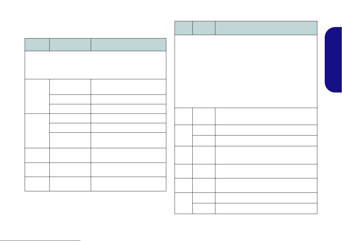
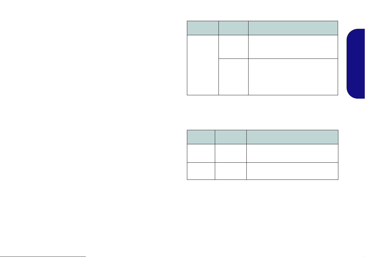
RAID Setup
You may use your hard disks in combination with Striping
(RAID 0), Mirroring (RAID 1), or Recovery for either
fault tolerance or performance.
RAID Level Description
Identical drives reading and writing data in p aral-
English
RAID 0
(at lease two
hard disks
needed)
RAID 1
(at lease two
hard disks
needed)
Recovery
(at lease two
hard disks
needed)
lel to increase performance. RAID 0 implements a striped disk array and the data is broken
into blocks and each block is written to a separate disk drive.
RAID 0 (a striped array) is not fault-tolerant. The
failure of one drive will result in the loss of all
data in the array.
Identical drives in a mirrored configuration used
to protect data. Should a drive that is part of a
mirrored array fail, the mirrored drive (which
contains identical data) will handle all the data.
When a new replacement drive is installed, data
to the new drive is rebuilt from the mirrored drive
to restore fault tolerance.
RAID 1 (mirrored array) provides full data protection, as data can simply be copied from a
healthy disk to a replacement for any failed disk.
Two identical drives copying data between a
master and a recovery disk. This provides more
control over how data is copied between the
master and recovery drives, fast volume
updates and the ability to view the data in Win-
dows Explorer.
Prepare the following before setting up your serial ATA
hard disks in RAID mode:
•The Microsoft Windows 7 OS disc.
•The Device Drivers & Utilities + User’s Manual disc.
Note: All hard disks in a RAID should be identical (the
same size and brand) in order to prevent unexpected system behavior.
RAID Setup Procedure
Part I: BIOS
1. Start-up your computer and press F2 to enter the BIOS.
2. Go to the Advanced menu, select SATA Mode and press
Enter.
3. Select RAID Mode.
4. Press Esc and go to the Boot menu.
5. Set the CD/DVD-ROM Drive (make sure the Microsoft
Windows OS disc is inserted) as the first device in the boot
order from the Boot menu.
6. Select Save Changes and Reset from the Exit menu (or
press F4) and press Enter to exit the BIOS and reboot the
computer.
4
Table 1 - RAID Description
Page 11

Part II: Intel Matrix
Figure 2
RAID
Created
RAM Module Speeds
Use either 1333MHz OR 1600MHz DDR3 modules of the
same brand. Do not mix DRAM speeds/brands in order to
prevent unexpected system behavior.
RAID Hard Disks
All hard disks in a RAID should be identical (the same
size and brand) in order to prevent unexpected system
behavior.
1. Press Ctrl + i to enter RAID configuration menu.
2. Select 1.Create RAID Volume and press Enter.
3. Type the RAID volume name and then press Tab or Enter to
advance to the next field.
4. Specify (use the up and down arrow keys) the RAID level
(RAID 0 or RAID 1 or Recovery - see Table 1) and then
press Tab or Enter to advance to the next field.
5. Press Enter and the system will select the physical disks to
use.
6. Press Enter and select (if applicable) the Strip Size (best set
to default).
7. Press Enter and select the Capacity size (best set to default).
8. Press Enter to select Create Volume.
9. Press Enter to create the volume, and confirm the selecti on by
pressing Y.
10. This will now return to the main menu.
11. Select 6.Exit and press Enter, then press Y to exit the RAID
configuration menu.
12. Make sure the Windows 7 OS DVD is in the DVD drive and
as the computer starts up it will automatically boot from the
Windows 7 OS DVD (you will be prompted to press a key to
boot from the DVD).
13. Press Enter to continue installing the ope rating system as
normal (see your Windows documentation if you need help
on installing the Windows OS).
English
5
Page 12

System Map: Front View with LCD Panel Open
2
1
9
8
6
7
4
5
3
10
Note that the Touchpad and
Buttons valid operational
area is that indicated within
the red dotted lines above.
Figure 3
Front View with LCD Panel
Open
1. PC Camera (Optional)
2. LCD
3. GPU Button
4. LED Indicators
5. Power Button
6. Hot Key Buttons
7. Speakers
8. Keyboard
9. Built-In Microphone
10. Touchpad & Buttons
Wireless Device
Operation Aboard
Aircraft
The use of any portable
electronic transmission
devices aboard aircraft
is usually prohibited.
Make sure the wireless modules are OFF
if you are using the
computer aboard aircraft.
Use the key combinations to toggle power to
the WLAN/Bluetooth
modules, and check the
LED indicator/visual indicator to see if the
modules are powered
on or not (see Table 5
on page 9).
7
10
English
6
Page 13
LED Indicators
The LED indicators on the computer display helpful information about the current status of the computer.
Icon Color Description
Icon Color Description
Orange
Green The Computer is On
Blinking Green The Computer is in Sleep Mode
Orange The Battery is Charging
Green The Battery is Fully Charged
Blinking Orange
Green Number Lock Activated
Green Caps Lock Activated
Green Scroll Lock Activated
Table 2 - Front Left LED Indicators
The AC/DC Adapter is Plugged
In
The Battery Has Reached Criti-
cally Low Power Status
English
White The Computer is On
Green UMA Mode Activated
Orange Optimus Mode Activated
Green Intel Integrated GPU (iGPU) Activated
Orange NVIDIA Discrete GPU (dGPU) Activated
White Hard Disk Activity
Green The Wireless LAN Module is Powered On
Orange The Bluetooth Module is On
Table 3 - Top Case LED Indicators
7
Page 14
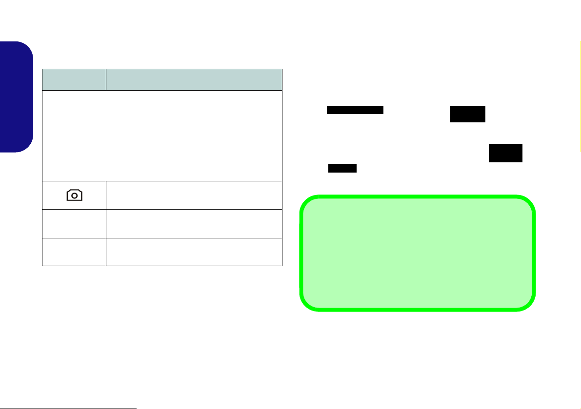
Hot Key Buttons & Keyboard
Function Keys
NumLk &
ScrLk
Numeric
Keypad
Fn Key
Special Characters
Some software applications allow the number-keys to be
used with Alt to produce special characters. These special
characters can only be produced by using the numeric keypad. Regular number keys (in the upper row of the keyboard) will not work. Make sure that the numeric keypad is
on.
Press the Hot Key buttons on the computer to toggle the
appropriate function on/off.
Icon Description
English
The keyboard has a numeric keypad for easy numeric data
input. Pressing NumLk turns on/off the numeric keypad.
It also features function keys to allow you to change operational features instantly.
Table 4 - Hot Key Buttons
PC Camera Power Toggle
Mute Toggle
WLAN Module Power Toggle
8
Figure 4 - Keyboard
Page 15
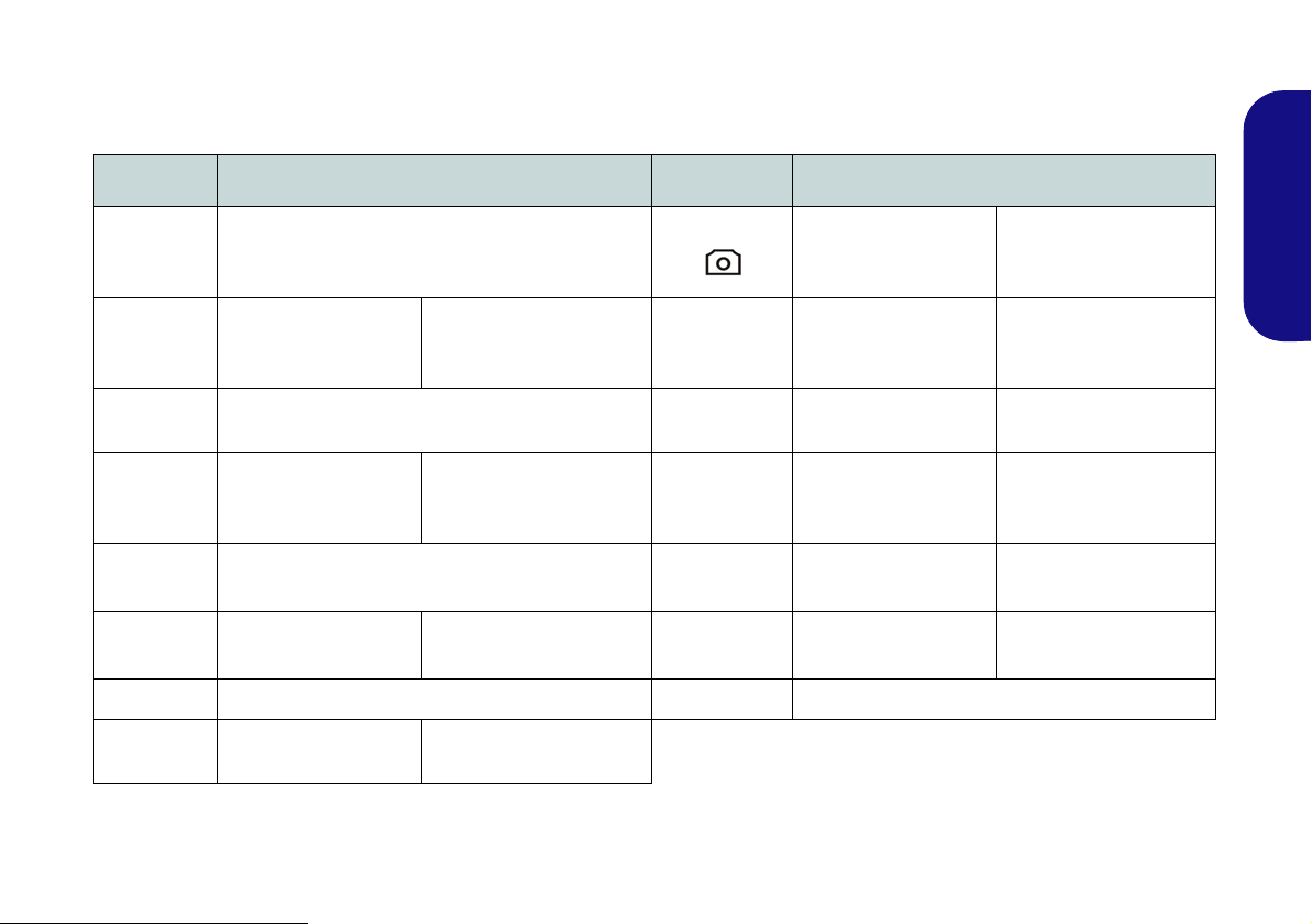
Function Keys
The function keys (F1 - F12 etc.) will act as hot keys when pressed while the Fn key is held down. In addition to the
basic function key combinations, visual indicators are available when the hot key driver is installed.
Keys Function/Visual Indicators Keys Function/Visual Indicators
English
Fn + F10
Fn + ~ Play/Pause (in Audio/Video Programs)
Fn + F1 Touchpad Toggle
Fn + F2
Fn + F3
()
Fn + F4 Sleep Toggle Fn + ScrLk Scroll Lock Toggle
Fn + F5/F6
Fn + F7 Display Toggle Fn + Esc Control Center Toggle (see page 10)
Fn + F8/F9
(Press a key to or use TouchPad to turn on)
Mute Toggle NumLk Number Lock Toggle
Volume Decrease/
Brightness Decrease/
Turn LCD Backlight Off
Increase
Increase
()
Fn + F11
()
Fn + F12
Caps Lock Caps Lock Toggle
Table 5 - Function Keys & Visual Indicators
PC Camera Power
Toggle
WLAN Module Power
Toggle
Bluetooth Module
Power Toggle
9
Page 16

Control Center
Wireless & Bluetooth
Modules are Off
Press the Fn + Esc key combination, or double-click the icon in the notification area of the taskbar to toggle the
Control Center on/off. The Control Center gives quick access to frequently used controls, and enables you to quickly
turn modules on/off.
English
Figure 5 - Control Center
Click on any button to turn any of the modules (e.g. TouchPad, Camera) on/off. Click on Power Conservation Modes
to switch between Performance, Balanced or Energy Star modes. To remove the Power Conservation Modes screen
just click in a blank area of the icon or press a key on the keyboard. Click on the buttons (or just click and hold the mouse
button) to adjust the slider for Brightness/Volume. Click on Display Switch/Time Zone/ Desktop Background to
bring up the appropriate Windows control panel. Click on the Sleep button to put the computer into Hibernate or Sleep
modes.
10
Page 17
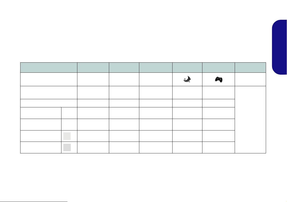
Power Modes
You can set a Power Mode by clicking the appropriate icon at the top of the Control Center. Each power mode will
affect the power status of modules (e.g. WLAN or Camera), screen brightness, Touchpad power and Silent Mode. You
can click a Control Center icon to set an overall power mode and then click individual icons in the Control Center to
power on/off any modules etc.
Table 6 illustrates the basic settings for each power mode. If you choose User Defined the settings will correspond to
your selected system settings.
Modes Power Saving Flight Entertainment Quiet Performance User Defined
Icon
Power Plan Power Saver Balanced Power Saver Power Saver
Power Conservation Mode Energy Star BIOS Default Energy Star Energy Star Performance
Brightness 14 42 100 42 100
WLAN OFF OFF ON ON ON
PC Camera OFF OFF OFF ON ON
Touchpad ON ON OFF ON ON
High Perfor-
mance
User Defined
English
Table 6 - Power Modes
11
Page 18

Power Status
The Power Status icon will show whether you are currently powered by the battery, or by the AC/DC adapter plugged
in to a working power outlet. The power status bar will show the current battery charge state.
Brightness
The Brightness icon will show the current screen brightness level. You can use the slider to adjust the screen brightness
or the Fn + F8/F9 key combinations, or use the Fn + F2 key combination to turn off the LED backlight (press any key
to turn it on again). Note that screen brightness is also effected by the Power Mode selected.
English
Volume
The Volume icon will show the current volume level. You can use the slider to adjust the Volume or the Fn + F5/F6
key combinations, or use the Fn + F3 key combination to mute the volume.
Power Conservation
This system supports Energy Star power management features that place computers (CPU, hard drive, etc.) into a lowpower sleep modes after a designated period of inactivity. Click either the Performance, Balanced or Energy Star
button. Click in a blank area of the icon or press a key on the keyboard to exit Power Conservation Mode without
making any changes.
Sleep
Click the Sleep button to bring up the Hibernate or Sleep buttons, and click either button to have the computer
enter the appropriate power-saving mode. Click in a blank area of the icon or press a key on the keyboard to exit Power
Conservation Mode without making any changes.
12
Page 19

Display Switch
Click the Display Switch button to access the menu (or use the + P key combination) and select the appropriate
attached display mode.
Time Zone
Clicking the Time Zone button will access the Date and Time Windows control panel.
Desktop Background
Clicking the Desktop Background button will allow you to change the desktop background picture.
Touchpad/PC Camera/Wireless LAN Module /Bluetooth Module
Click any of these buttons to toggle the Touchpad or module’s power status. A crossed out icon will appear over the top
left of the icon when it is off
Power Mode selected.
. Note that the power status of a module, and Touchpad power, is also effected by the
Caps Lock/Scroll Lock/ Number Lock
Click the button to toggle the appropriate lock mode.
English
13
Page 20

System Map: Front, Left, Right & Rear Views
1
Front
10
13
12
11
14
Right
Rear
2
5
4
3
8
6
7
Left
9
15
USB
The USB 3.0 ports are colored blue. USB 3.0 will transfer data much faster than USB 2.0,
and is backwards-compatible with USB 2.0.
10
Figure 6
Front, Left, Right & Rear
Views
1. LED Indicators
2. Security Lock Slot
3. USB 2.0 Port
4. Headphone-Out Jack
5. Microphone-In Jack
6. S/PDIF-Out Jack
7. Optical Device Drive Bay
8. Emergency Eject Hole
9. Multi-in-1 Card Reader
10. USB 3.0 Ports
11 . Combined eSATA/USB
3.0 Port
12. HDMI-Out Port
13. RJ-45 LAN Jack
14. External Monitor Port
15. DC-In Jack
16. Vent
10
16
English
14
Page 21

System Map: Bottom View
Figure 7
Bottom View
1. Component Bay Cover
2. Vent
3. Battery
4. HDD Bay
CPU
The CPU is not a user
serviceable part. Accessing the CPU in any way
may violate your warranty.
Overheating
To prevent your computer from overheating
make sure nothing blocks
any vent while the computer is in use.
2
1
4
3
2
Battery Information
Always completely discharge, then fully charge, a new battery before using it. Completely
discharge and charge the battery at least once every 30 days or after about 20 partial discharges (see the expanded User’s Manual on the Device Drivers & Utilities + User’s Manu al
disc).
HDMI
Note that the HDMI Port supports video and audio signals to attached external displays
(Note THX Tru Studio Pro will be disabled when you are connecting to an external display
through an HDMI connection -
see
page 18).
English
15
Page 22

Video Features
1
2
2
1
Figure 8 - Display Control Panel
The system features both an Intel’s Integrated GPU (for
power-saving) and an NVIDIA’s discrete GPU (for performance). You can switch display devices, and configure
display options as long as the video drivers are installed.
To access Display control panel:
1. Click Start, and click Control Panel (or point to Settings and
English
click Control Panel).
2. Click Display (icon) - in the Appearances and
Personalization category.
3. Click Adjust Screen Resolution/Adjust resolution.
OR
4. Alternatively you can right-click the desktop and select
Screen resolution.
5. Use the dropbox to select the screen resolution .
6. Click Advanced settings .
To access the Intel® Graphics and Media Control Panel:
1. Click Start, and click Control Panel (or point to Settings and
click Control Panel).
2. Click Intel(R) Graphics and Media in the icon view.
OR
3. Right-click the desktop and select Graphics Properties from
4. Choose the application mode (Basic, Advanced or Wizard).
the menu.
To access the NVIDIA Control Panel:
1. Click Start, and click Control Panel (or point to Settings and
click Control Panel).
2. Click NVIDIA Control Panel (icon) - in the Appearances and
Personalization category.
OR
3. Right-click the desktop and select NVIDIA Control Panel
from the menu.
Display Devices
Besides the built-in LCD you can also use an external
monitor/flat panel display/TV (TV through HDMI-Out
port only), connected to the external monitor port or to the
HDMI-Out port (High-Definition Multimedia Interface)
as your display device.
16
Page 23
NVIDIA® Optimus™ Technology
Nvidia® Optimus™ technology is a seamless technology
designed to get best performance from the graphics system while allowing longer battery life, without having to
manually change settings. Thus when an application is run
that requires extra performance or quality, then the system
will run the discrete GPU (dGPU); when the system does
not require such enhanced performance it will let the integrated (iGPU) handle it.
GPU Button
This computer also features a button that allows the
user to switch between Optimus Mode and UMA Mode
(Unified Memory Architecture). UMA Mode will use
only the integrated GPU; Optimus Mode will allow the
system to automatically determine whether the dGPU or
iGPU is used. Thus the user can completely control how
the graphics system operates. Press the GPU button ,
and the button color will indicate the current mode.
Icon Color Description
UMA Mode Activated
Green
Orange
Table 7 - GPU Button Modes
The system will use the Intel inte-
grated GPU (iGPU) only
Optimus Mode Activated
Optimus technology will determine
when to use the Intel integrated GPU
(iGPU) or NVIDIA discrete GPU
(dGPU) automatically
The GPU LED indicators will display which GPU is
currently in use.
Icon Color Description
Green
Orange
Table 8 - GPU LED Indicators
Intel Integrated GPU (iGPU) Acti-
vated
NVIDIA Discrete GPU (dGPU) Acti-
vated
English
17
Page 24
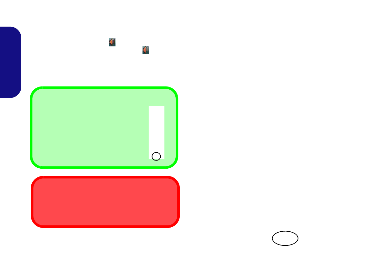
Audio Features
Sound Volume Adjustment
The sound volume level is set using the volume control within Windows (and the volume function keys on the computer). Click
the Speaker icon in the taskbar to check
the setting.
THX TruStudio Pro Audio
Note that you will need to ins tall the THX TruStudio audio
application in order to get maximum audio performance.
Menu
Figure 9
THX TruStu-
dio Pro HDMI
Display Warn-
ing
You can configure the audio options on your computer
from the Sound control panel in Windows, or from the
Realtek HD Audio Manager
control panel (right-click the taskbar icon to bring up
an audio menu). The volume may also be adjusted by
means of the Fn + F5/F6 key combination/the volume
control.
English
18
/ icon in the taskbar/
THX TruStudio Pro Audio
Install the THX TruStudio AP to allow you to configure
the audio settings to your requirements for the best performance in games, music and movies.
THX TruStudio Pro Activation
On the first run of THX TruStudio Pro you will need to activate the application.
1. To activate the application you will need to be connected to
the internet.
2. Double-click the THX Activate icon on the desktop and
click the Activate button.
3. The program will connect to the internet t o verify the acti vation
key.
4. Click Finish to complete the application activation.
5. Restart the computer.
THX Tru Studio Pro & HDMI
1. When you connect an HDMI display to the HDMI-Out port, the
THX TruStudio Pro controls will be disabled.
2. A warning box will pop-up and will prompt “Do you want to
select another audio device now?”.
3. Click No to continue using the HDMI audio output from your
external display (do not attempt to select another audio device
when connected to the external HDMI display).
Page 25

Driver Installation
General Guidelines
As a general guide follow
the default on-screen instructions for each driver
(e.g. Next > Next > Fin-
ish) unless you are an advanced user. In many
cases a restart is required
to install the driver.
Make sure any modules
(e.g. PC Camera or
WLAN ) are ON before installing the appropriate
driver.
Windows Update
After installing all the drivers make sure you enable
Windows Update in order to get all the latest security updates etc. (all
updates will include the
latest hotfixes from Microsoft).
Driver Installation & Power
When installing drivers make sure your
computer is powered by the AC/DC
adapter connected to a working power
source. Some drivers draw a significant
amount of power during the installation
procedure, and if the remaining battery
capacity is not adequate this may cause
the system to shut down and cause system problems (note that there is no safety
issue involved here, and the battery will
be rechargeable within 1 minute).
Figure 10 - Install Drivers
Driver Installation
The Device Drivers & Utilities + User’s Manual disc contains the drivers and utilities
necessary for the proper operation of the computer. This setup will probably have already
been done for you. If this is not the case, insert the disc and click Install Drivers (button),
or Option Drivers (button) to access the Optional driver menu. Install the drivers in the
order indicated in Figure 10. Click to select the drivers you wish to install (you should
note down the drivers as you install them). Note: If you need to reinstall any driver, you
should uninstall the driver first.
Manual Driver Installation
Click the Browse CD/DVD button in the Drivers Installer application and browse to the
executable file in the appropriate driver folder.
If a
Found New Hardware
cel, and follow the installation procedure as directed.
wizard appears
during the installation procedure, click Can-
19
English
Page 26
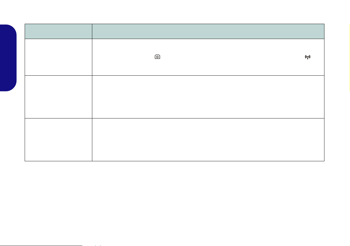
Troubleshooting
Problem Possible Cause - Solution
The PC Camera/Wireless
LAN/Bluetooth modules
cannot be detected.
English
The captured video files
from the PC Camera are
taking up too much disk
space.
The captured video files
from the PC Camera are
taking up too much disk
space.
The modules are off. Check the LED indicator und/or function key indicator to see if the PC Camera/
WLAN/Bluetooth module is on or off (see Table 3 on page 7 and Table on page 9). Use the key
combination Fn + F10/the Hot Key button (PC Camera), the key combination Fn + F11
Key button (WLAN) or the key combination Fn + F12 (Bluetooth) to toggle power to the module (see
Table on page 9).
Note that capturing high resolution vid eo files requires a substantial amount of disk space for each file.
Note that the Windows system requires a minimum of 15GB of free space on the C: drive system
partition. It is recommended that you save the capture video file to a location other than the C:drive,
limit the file size of the captured video or reduce video resolution (Options > Video Capture Pin... >
Output Size).
/the Hot
20
Page 27

Specifications
Latest Specification Information
The specifications listed in this section
are correct at the time of going to
press. Certain items (particularly processor types/speeds) may be
changed, delayed or updated due to
the manufacturer's release schedule.
Check with your service center for details.
Processor Options
Intel® Core™ i7 Processor
i7-3820QM (2.70GHz)
8MB L3 Cache, 22nm, DDR3-1600MHz,
TDP 45W
i7-3720QM (2.60GHz), i7-3610QM
(2.30GHz)
6MB L3 Cache, 22nm, DDR3-1600MHz,
TDP 45W
i7-3520M (2.90GHz)
4MB L3 Cache, 22nm, DDR3-1600MHz,
TDP 35W
Intel® Core™ i5 Processor
i5-3360M (2.80GHz), i5-3320M (2.60GHz),
i5-3210M (2.50GHz)
3MB L3 Cache, 22nm, DDR3-1600MHz,
TDP 35W
Intel® Core™ i3 Processor
i3-3110M (2.40GHz)
3MB L3 Cache, 22nm, DDR3-1600MHz,
TDP 35W
Intel® Core™ i7 Processor
i7-2860QM (2.50GHz), i7-2820QM
(2.30GHz)
8MB L3 Cache, 32nm, DDR3-1600MHz,
TDP 45W
i7-2760QM (2.40GHz), i7-2720QM
(2.20GHz)
6MB L3 Cache, 32nm, DDR3-1600MHz,
TDP 45W
i7-2670QM (2.20GHz), i7-2630QM
(2.00GHz)
6MB L3 Cache, 32nm, DDR3-1333MHz,
TDP 45W
i7-2640M (2.80GHz), i7-2620M (2.70GHz)
4MB L3 Cache, 32nm, DDR3-1333MHz,
TDP 35W
Intel® Core™ i5 Processor
i5-2540M (2.60GHz), i5-2520M (2.50GHz),
i5-2450M (2.50GHz), i5-2430M (2.40GHz),
i5-2410M (2.30GHz)
3MB L3 Cache, 32nm, DDR3-1333MHz,
TDP 35W
Intel® Core™ i3 Processor
i3-2370M (2.40GHz), i3-2350M (2.30GHz),
i3-2330M (2.20GHz), i3-2310M (2.10GHz)
3MB L3 Cache, 32nm, DDR3-1333MHz,
TDP 35W
Core Logic
Intel® HM77 Chipset
BIOS
One 48Mb SPI Flash ROM
AMI BIOS
LCD
17.3" (43.94cm) HD+/ FHD LCD
Security
BIOS Password
Security (Kensington® Type) Lock Slot
English
21
Page 28

Video Adapter
Intel® Integrated GPU and NVIDIA®
Discrete GPU
Supports NVIDIA® Optimus Technology
Intel Integrated GPU (GPU is Dependent
on Processor)
Intel® HD Graphics
English
Dynamic Frequency (Intel Dynamic Video
Memory Technology for up to 1.7GB)
Microsoft DirectX®10 Compatible
Intel® HD Graphics 3000
Dynamic Frequency (Intel Dynamic Video
Memory Technology for up to 1.7GB)
Microsoft DirectX®10 Compatible
Intel® HD Graphics 4000
Dynamic Frequency (Intel Dynamic Video
Memory Technology for up to 1.7GB)
Microsoft DirectX®11 Compatible
NVIDIA Discrete GPU
NVIDIA® GeForce GTX 660M
2GB GDDR5 Video RAM
Microsoft DirectX®11 Compatible
Audio
High Definition Audio Compliant Interface
THX TruStudio Pro
2 * Built-In Speakers
Built-In Microphone
Memory
Three 204 Pin SO-DIMM Sockets Supporting DDR3 1333/1600MHz Memory
Memory Expandable up to 24GB
(The real memory operating frequency
depends on the FSB of the processor.)
Note: Three SO-DIMMs are only supported
by Quad-Core CPUs; Dual-Core CPUs support two SO-DIMMs maximum
Storage
(Factory Option) One Changeable
12.7mm(h) Optical Device Type Drive
(Super Multi Drive Module or Blu-Ray
Combo Drive Module)
(Factory Option) Two Changeable 2.5"
(6cm) 9.5mm (h) SATA (Serial) Hard Disk
Drives supporting RAID
level 0/1
Interface
One USB 2.0 Port
Three USB 3.0 Ports
One eSATA Port (USB 3.0 Port Combined)
One HDMI-Out Port
One Headphone-Out Jack
One Microphone-In Jack
One S/PDIF Out Jack
One RJ-45 LAN Jack
One External Monitor Port
One DC-in Jack
Keyboard
Full-size “WinKey” keyboard (with numeric
keypad)
Pointing Device
Built-in Touchpad (scrolling key functionality
integrated
Communication
Built-In Gigabit Ethernet LAN
(Factory Option) 1.3M Pixels/2M Pixels
(HD) PC Camera Module
WLAN/ Bluetooth Half Mini-Card
Modules:
(Factory Option) Intel® Centrino® Ultimate-N 6300 Wireless LAN (802.11a/g/n)
(Factory Option) Intel® Centrino®
Advanced-N 6235 Wireless LAN (802.11a/
g/n) + Bluetooth 4.0
(Factory Option) Intel® Centrino® Wireless-N 2230 Wireless LAN (802.11b/g/n) +
Bluetooth 4.0
(Factory Option) Third-Party Wireless LAN
(802.11b/g/n)
(Factory Option) Third-Party Wireless LAN
(802.11b/g/n) + Bluetooth 4.0
22
Page 29

Card Reader
Embedded Multi-in-1 Push-Push Card
Reader
MMC (MultiMedia Card) / RS MMC
SD (Secure Digital) / Mini SD / SDHC/
SDXC
MS (Memory Stick) / MS Pro / MS Duo
Mini Card Slots
Slot 1 for WLAN Module or WLAN and
Bluetooth Combo Module
Environmental Spec
Temperature
Operating: 5
Non-Operating: -20°C - 60°C
Relative Humidity
Operating: 20% - 80%
Non-Operating: 10% - 90%
°C - 35°C
Power
Full Range AC/DC Adapter
AC Input: 100 - 240V, 50 - 60Hz
DC Output: 19V, 6.3A (120W)
8 Cell Smart Lithium-Ion Battery Pack,
76.96WH
Dimensions & Weight
413mm (w) * 277.5mm (d) * 17.5 - 44mm (h)
3.2kg with ODD & 76.96WH Battery
English
23
Page 30

English
24
Page 31

Über das Ausführliche Benutzerhandbuch
Diese Kurzanleitung soll einen Überblick über die Schritte geben, die dazu notwendig s ind, das System zu starten. Dieses ist
nur eine Ergänzung und kein Ersatz für das erweiterte englischsprachige Benutzerhandbuch, das auf der mitgelieferten Disc
Device Drivers & Utilities + User's Manual im Adobe-Acrobat-Format vorliegt. Diese Disc enthält auch die Treiber und
Utility-Programme, die für einen einwandfreien Betrieb des Computers notwendig sind (Hinweis: Das Unternehmen behält
sich das Recht vor, diese Publikation ohne Vorankündigung zu überarbeiten und den Inhalt zu verändern).
Einige oder alle Funktionen des Computers sind bereits eingerichtet worden. Falls das nicht der Fall ist oder wenn Sie einzelne Teile des Systems neu konfigurieren (oder neu installieren) möchten, finden Sie eine Anleitung im erweiterten Benut-
zerhandbuch. Die Disc Device Drivers & Utilities + User's Manual enthält nicht das Betriebssystem.
Einhaltung gesetzlicher Vorschriften und Sicherheitshinweise
Beachten Sie sorgfältig die Hinweise zu gesetzlichen Vorschriften und zu Sicherheitshinweisen im erweiterten Benutzerhandbuch auf der Disc Device Drivers & Utilities + User's Manual.
© Juni 2012
Warenzeichen
Intel und Intel Core sind warenzeichen/e inget ragenes ware nzeichen der Intel Corporation.
Deutsch
25
Page 32

Hinweise zu Pflege und Betrieb
Entsorgen der Akkus/ Batterien & Achtung
Das von Ihnen gekaufte Produkt enthält einen aufladbaren Akku. Dier
Akku ist wiederverwertbar. Nach verschieden en nationalen und regionalen Getzgebungen kann es verboten in, einen nicht mehr
gebrauchsfähigen Akku in den normalen Hausmüll zu werfen. Informieren Sie sich bei Ihrem regionalen Entsorgungs unternehmen über
Recycling-Möglichkeiten oder korrekte Entsorgung.
Wenn ein falscher Akku eingesetzt wird, besteht Explosionsgefahr.
Tauschen Sie den Akku nur durch den gleichen oder einen baugleichen
Typ aus, der vom Hersteller e mpfohlen wird. Entsorgen Sie den ver brauchten Akku entsprechend der Anweisungen des Herstellers.
Das Notebook ist zwar sehr stabil, kann aber dennoch beschädigt werden.
Damit es nicht dazu kommt, sollten Sie die folgenden Hinweise beachten:
• Das Gerät darf nicht herunterfallen und in anderer Form Stößen ausge-
setzt werden. Wenn der Computer fäl lt, können das Gehäuse und andere Komponenten beschädigt werden.
• Das Gerät darf nicht nass werden und sich nicht überhitzen. Computer und
Netzteil dürfen nicht in der Nähe von Wärmequellen stehen oder gelagert werden. Dies ist ein elektrisches Gerät. Wenn Wasser oder andere Flüssigkeiten
eindringen, kann der Computer stark beschädigt werden.
• Vermeiden Sie Interferenzen mit anderen Geräten. Halten Sie den Computer
fern von magnetischen Feldern, die von Stromquellen, Monitoren, Magneten
etc. erzeugt werden. Die kö nnen die Leistung beeinträchtigen und Ihre Daten
beschädigen.
• Achten Sie auf die richtige Bedienung des Computers. Schalten Sie i hn erst
aus, wenn alle Programme geschlossen wurden (speichern Sie Ihre Daten!).
Speichern Sie regelmäßig Ihre Daten, da diese verloren gehen können, wenn der
Deutsch
Akku verbraucht ist.
Reparatur
Nehmen Sie vor dem Reinigen des Wenn Sie versuchen, den Computer
selbst zu reparieren, können Ihre Garantieansprüche verloren gehen. Außerdem besteht Stromschlaggefahr für Ihre Gesundheit und das Gerät
durch frei liegende Teile. Lassen Sie Reparaturarbeiten nur von qualifizierten Reparaturfachleuten durchführen, insbesondere wenn folgende
Umstände vorliegen:
• Wenn das Netzkabel oder der AC/DC-Adapter beschädigt oder zerschlissen sind.
• Wenn der Computer Regen ausgesetzt war oder mit Flüssigkeiten in Berührung
gekommen ist.
• Wenn der Computer unter Beachtung der Bedienungsanweisungen nicht korrekt
arbeitet.
• Wenn der Computer heruntergefallen ist oder beschädigt wurde (berühren Sie
nicht die giftige Flüssigkeit des LCD-Bildschirms).
• Wenn ein ungewöhnlicher Geruch, Hitze oder Rauch aus dem Computer entweicht.
Sicherheitsinformationen
• Verwenden Sie nur einen AC/DC-Adapter, der für die Verwendung mit diesem
Computer zugelassen ist.
• Verwenden Sie nur das Netzkabel und die Akkus, die in diesem Benutzerhandbuch spezifiziert sind. Entsorgen Sie die Akkus nicht in Feuer. Sie können
26
explodieren. Richten Sie sich nach den regional gültigen Entsorgungsvorschriften.
• Verwenden Sie den Akku nicht mehr, wenn er heruntergefallen ist oder in anderer Weise beschädigt (z.B. verzogen) ist. Auch wenn der Computer mit de m
beschädigten Akku zu funktionieren schein, können dadurch Stromkreise
beschädigt werden, die schli eßlich einen Brand verursachen können.
• Achten Sie darauf, dass Ihr Computer ausgeschaltet ist, wenn Sie es fur den
Transport z.B. wahrend einer Reise in eine Tasche einpakken.
• Nehmen Sie vor dem Reinigen des Computers den Akku heraus, und trennen
Sie es von allen externen Stromquellen, Peripheriegeräten und Ka beln (einschließlich Telefonkabel) ab.
• Reinigen Sie den Computer mit einem weichen, sauberen Tuch. Tragen Sie das
Reinigungsmittel nicht direkt auf den Computer auf. Verwenden Sie keine
flüchtigen Reinigungsmittel (Petroleumde stillate) oder Scheuermittel zum
Reinigen des Computers.
• Versuchen Sie nicht, Akkus zu reparieren. Lassen Sie die Akkupacks durch den
Servicevertreter oder qualifiziertes Fachpersonal reparieren oder austauschen.
Polymer Akku Sicherheitshinweise
Beachten Sie die folgenden Hinweise, die sich speziell auf Polymer
Akkus beziehen. Diese Hinweise haben zudem Vorrang gegenüber den
Allgemeinen Akku Sicherheitshinweisen.
• Polymer Akkus können sich etwas ausdehnen oder anschwellen. Dies ist Teil
des Sicherheitsmechanismus des Akkus und kein Anlass zur Sorge.
• Seien Sie vernünftig im Umgang mit Polymer Akkus. Verwenden Sie keine
Polymer Akkus in Umgebungen mit hohen Temperaturen und lagern Sie keine
ungenutzten Akkus über längere Zeiträume.
Page 33

Schnellstart
Abb. 1
Öffnen des Deckels/LCD/Computers mit angeschlos-
senem AC/DC-Adapter
Herunterfahren
Bitte beachten Sie, daß
der Computer immer mit
dem Befehl Herunter-
fahren im Menü
Start
heruntergefahren werden muß.
Dadurch werden Festplatten- bzw. Systemprobleme vermieden.
135 ゚
1. Entfernen Sie das gesamte Verpackungsmaterial.
2. Legen Sie den Computer auf eine stabile Unterlage.
3. Setzen Sie den Akku ein, und stellen Sie sicher, dass sie fest sitzt.
4. Schließen Sie alle Peripheriegeräte, die Sie mit dem Computer
verwenden wollen (z. B. Tastatur und Maus), an die
entsprechenden Schnittstellen an.
Schließen Sie den AC/DC-Adapter an die DC-Eingangsbuchse an
5.
der Rückseite de
Netzkabel mit einer Netzsteckdose und dem AC/DC-Adapter.
6. Klappen Sie den Deckel/LCD vorsichtig mit einer Hand auf, und
öffnen Sie ihn auf einen angenehmen Sichtwinkel (jedoch nicht
weiter als 135°). Mit der anderen Hand halten Sie das Unterteil
des Computers fest (siehe Abb. 1) (Hinweis: Heben Sie den
Computer niemals am Deckel/LCD hoch).
7. Drücken Sie auf den Netzschalter, um den Computer
einzuschalten.
Systemsoftware
Möglicherweise wurde das Notebook bereits mit vorinstallierter Software ausgeliefert. Ist das nicht der Fall, oder
wenn Sie das Notebook für ein anderes System neu konfigurieren möchten, finden Sie dazu eine Anleitung in diesem
Handbuch zu Microsoft Windows 7.
Modellunterschiede
Diese Notebookserie umfasste zwei verschiedene Modelle
(Informationen finden Sie unter Technische Daten auf
Seite 45).
s Computers an. Verbinden Sie dann das
Deutsch
27
Page 34

RAID Setup
Sie können Ihre Festplatten für jede beliebige Fehlertoleranz
oder Leistung in Kombination mit Striping (RAID 0), Mirroring (RAID 1) oder Recovery verwenden.
Tabelle 1 - RAID-Beschreibung
RAID-Ebene Beschreibung
Identische Laufwerke lesen und schreiben Daten
parallel, um die Leistung zu verbessern. Bei RAID 0
RAID 0
(mindestens
zwei Fest-
Deutsch
platten
erforderlich)
RAID 1
(mindestens
zwei Fest-
platten
erforderlich)
Recovery
(mindestens
zwei Fest-
platten
erforderlich)
wird ein Striped-Disk-Array verwendet, die Daten werden in Blöcke aufgeteilt, und je der Block wird auf ein
anderes Laufwerk geschrieben.
Ein Striped Array (RAID 0) ist NICHT fehlertolerant,
sodass der Ausfall eines Laufwerks zum Verlust aller
Daten im Array führen kann.Ein Striped Array ist NICHT
fehlertolerant, sodass der Ausfall eines Laufwerks zum
Verlust aller Daten im Array führen kann.
Identische Laufwerke mit einer Mi rror-Konfiguration
zum Schutz von Daten. Wenn ein Laufwerk, das Teil
eines "gespiegelten" Arrays ist, nicht funktionieren,
übernimmt das andere Laufwerk (das dieselben Daten
enthält) die weiteren Funktionen. Wenn ein neues
Ersatzlaufwerk installiert wird, werden die Daten aus
dem Mirror-Laufwerk auf dieses Laufwerk gespielt, um
die Fehlertoleranz wieder herzustellen.
RAID 1 (Mirrored Array) bietet einen vollständigen
Datenschutz, da die Daten dabei von einer gesunden
Disk auf eine beschädigte Disk k opiert werden können.
Zwei identische Laufwerke kopieren Daten zwischen einer Master- und einer Recovery-Disk. Auf
diese Weise können Sie besser steuern, wie Daten
zwischen dem Master- und dem Recovery-Laufwerk
kopiert werden, schnelle Laufwerksaktualisierungen durchführen, und Sie können sich die
Daten im Windows Explorer ansehen.
Um die Serial ATA-Festplatten im RAID-Modus einrichten
können, benötigen Sie Folgendes:
•Die Microsoft Windows 7 Betriebssystem-Disc.
•Die Disc Device Drivers & Utilities + User's Manual.
Hinweis: Alle Festplatten in einem RAID sollten identisch
sein (gleiche Größe und Marke), um ein unerwartetes Systemverhalten zu vermeiden.
Beschreibung des RAIDSetup
Teil I: BIOS
1. Starten Sie den Computer und drücken Sie auf die Taste F2, um in
das BIOS zu gelangen.
2. Gehen Sie zum Menü Advanced, wählen Sie SATA Mode und
drücken Sie auf Enter.
3. Wählen Sie "RAID Mode".
4. Drücken Sie auf Esc und gehen Sie zum Menü Boot.
5. Legen Sie im Menü Boot das CD/DVD-ROM-Laufwerk (stellen
Sie sicher, dass die Betriebssystem-Disc mit Microsoft Windows
eingelegt ist) als das in der Bootreihenfolge erste Gerät fest.
6. Wählen Sie Save Changes and Reset aus dem Menü Exit (oder
drücken Sie auf F4) und drücken Sie auf Enter um das BIOS zu
verlassen und den Computer neu zu starten.
28
Page 35

Teil II: Intel Matrix
Abb. 2
Erzeugtes
RAID
RAM-Modulgeschwindigkeiten
Verwenden Sie entweder DDR3-Module mit 1333MHz
ODER 1600MHz derselben Marke. Mischen Sie bei den
DRAM keine unterschiedlichen Geschwindigkeiten/Marken, um ein unerwartetes Systemverhalten zu vermeiden.
RAID-Festplatten
Alle Festplatten in einem RAID sollten identisch sein
(gleiche Größe und Marke), um ein unerwartetes Systemverhalten zu vermeiden.
1. Drücken Sie auf Ctrl + i, um in das RAID-Konfigurationsmenü zu
gelangen.
2. Wählen Sie 1.Create RAID Volume und drücken Sie auf Enter.
3. Geben Sie den Namen des RAID-Volumens ein, und drücken Sie
auf Tab oder Enter, um zum nächsten Feld zu wechseln.
4. Wählen Sie (mit den Pfeltasten) das RAID-Level (RAID 0, RAID
1, RAID 5 oder Recovery - siehe Tabelle 1 auf Seite 28), und
drücken Sie auf Tab oder Enter, um zum nächsten Feld zu
wechseln.
5. Drücken Sie auf Enter. Das System wählt nun die physikalischen
Disks, die verwendet werden sollen.
6. Drücken Sie auf Enter, und wählen Sie (wenn zutreffend) die
Strip-Größe (am besten Standard).
7. Drücken Sie auf Enter, und wählen Sie die Kapazität (am besten
Standard).
8. Drücken Sie auf Enter, um die Option Create Volume zu wählen.
9. Drücken Sie auf Enter, um das Volumen zu erstellen, und
bestätigen Sie die Auswahl mit Y.
10. Sie gelangen in das Hauptmenü zurück.
11. Wählen Sie 6.Exit, und drücken Sie auf Enter, danach auf Y, um
das RAID-Konfigurationsmenü zu beenden.
12. Stellen Sie sicher, dass sich die Windows 7-DVD im DVDLaufwerk befindet. Während der Computer hochfährt, startet
dieser automatisch von der Windows 7-DVD (Sie werden
aufgefordert, eine Taste zu drücken, um den Systemstart von der
DVD auszuführen).
13. Drücken Sie auf Enter, um die Installation des Betriebssystems
wie herkömmlich fortzusetzen (die Anleitung zur Installation des
Windows-Betriebssystems finden Sie in der WindowsDokumentation).
Deutsch
29
Page 36

Systemübersicht: Ansicht von vorne mit geöffnetem LCD-Bildschirm
Beachten Sie, dass der Funktionsbereich des Touchpads und der
Tasten innerhalb der rot gepunkteten Linien liegt.
Abb. 3
Ansicht von vorne mit ge-
öffnetem LCD-Bildschirm
1. PC-Kamera (optional)
2. LCD-Bildschirm
3. GPU-Taste
4. LED-Anzeigen
5. Netzschalter
6. Hot-Key-Tasten
7. Lautsprecher
8. Tastatur
9. Mikrofon
10. Touchpad mit Tasten
Die Benutzung drahtlos
angeschlossener
Geräte in Flugzeugen
In der Regel ist die Benutzung jeglicher tragbarer
elektronischer Funkgeräte in Flugzeugen verboten. Achten Sie
darauf, daß die
Wireless-Module AUSGESCHALTET sind,
wenn Sie den Computer
im Flugzeug benutzen.
Drücken Sie die entsprechenden
Tastenkombinationen,
um jeweils das WLANoder das Bluetooth-Modul
zu aktivieren. Prüfen Sie
anhand der LED-Anzeigen/visuellen Anzeigen, ob die Module
eingeschaltet sind (siehe
Tabelle 5 auf Seite 33).
2
1
9
8
6
7
4
5
3
10
7
10
Deutsch
30
Page 37

LED-Anzeigen
Die LED-Anzeigen auf dem Computer zeigen wichtige
Informationen über den aktuellen Status des Computers.
Symbol Farbe Beschreibung
Symbol Farbe Beschreibung
Deutsch
Orange
Grün Der Computer ist angeschaltet
Lampe blinkt grün
Orange Der Akku wird geladen
Grün Der Akku ist voll geladen
Lampe blinkt
orange
Grün
Grün Caps-Lock ist aktiviert
Grün Scroll-Lock ist aktiviert
Der AC/DC-Adapter ist ange-
schlossen
Das System ist im konfigurierten
Energiesparmodus
Der Akku hat einen kritisch nied-
rigen Stromstatus erreicht
Die Funktion NumLk
(Nummerntastatur) ist aktiviert
Tabelle 2 - LED-Anzeigen vorn links
Weiß Der Computer ist angeschaltet
Grün UMA-Modus aktiviert
Orange Optimus-Modus aktiviert
Grün Integrierte GPU (iGPU) von Intel aktiviert
Orange Diskrete GPU (dGPU) von NVIDIA aktiviert
Weiß Es wird auf die Festplatte zugegriffen
Grün Das WLAN-Modul ist eingeschaltet
Orange Das Bluetooth-Modul ist eingeschaltet
Tabelle 3 - LED-Anzeigen oben
31
Page 38

Hot-Key-Tasten & Tastatur
Numeric
Fn Taste
Nummemtastatur
Funktionstasten
Num &
Rollen
Sonderzeichen
Bei einigen Programmen können die Nummern-Tasten zur Erzeugung von Sonderzeichen zusammen mit der Taste Alt
gedrückt werden. Diese Sonderzeichen können nur mit der
Nummerntastatur erzeugt werden. Die normalen Zahlentasten
(in der oberen Tastenreihe der Tastatur) können dazu nicht
verwendet werden. Die Nummerntastatur muß aktiviert sein.
Drücken Sie auf die Hot-Key-Tasten des Computers, um die
jeweilige Funktion ein-/auszuschalten.
Symbol Beschreibung
Deutsch
PC-Kamera aktivieren/deaktivieren
Die Tastatur hat eine eingebettete Nummerntastatur für
einfache Zahleneingabe. Durch Drücken auf Num wird die
Nummerntastatur ein- und ausgeschaltet. Zusätzlich gibt es
Funktionstasten, über die Sie direkt zwischen den Funktionen umschalten können.
Stummschaltung/Stummschaltung aufheben
Wireless-LAN-Modul aktivieren/deaktivieren
Tabelle 4 - Hot-Key-Tasten
32
Abb. 4 - Tastatur
Page 39

Funktionstasten
Wenn die Funktionstasten (F1 - F12) gleichzeitig mit der Fn-Taste gedrückt werden, funktionieren sie wie Hotkeys. Neben
den Tastenkombinationen für die Grundfunktionen gibt es visuelle Anzeigen, wenn der Hotkey Treiber installiert ist.
Tasten Funktion/ Visuelle Anzeigen Tasten Funktion/ Visuelle Anzeigen
Fn + ~ Wiedergabe/Pause (in Audio /Videoprogrammen)
Fn + F1
Fn + F2
Fn + F3
()
Fn + F4 Wechsel Schlaf/Wiederaufnahme Fn + Rollen
Fn + F5/F6
Fn + F7 Wechseln der Anzeigegerate Fn + Esc
Fn + F8/F9
Touchpad aktivieren/deak-
tivieren
LCD-Hintergrundlicht ausschalten (zum Einschalten
beliebige Taste drücken oder Touchpad berühren)
Stummschaltung/
Stummschaltung aufhe-
ben
Audio-Lautstärke
verringern/erhöhen
LCD-Helligkeit verringern/
erhöhen
Fn + F10
()
Fn + F11
()
Fn + F12
Num
Tabelle 5 - Funktionstasten & visuelle Anzeigen
PC-Kamera aktivie-
ren/deaktivieren
Deutsch
Wireless-LAN-Modul
aktivieren/deaktivieren
Bluetooth-Modul
aktivieren/deaktivieren
Ein-/Ausschalten der
Nummerntastatur
Ein-/Ausschalten des
Scroll-Modus
Ein-/Ausschalten der
Feststelltaste
Ein-/Ausschalten des Control Center (Steuerzen-
trum) (siehe Seite 34)
33
Page 40

Control Center (Steuerzentrum)
Die WLAN- und
Bluetooth-Module
sind aus
Drücken Sie auf die Tastenkombination Fn + Esc, oder doppelklicken Sie auf das Symbol im Infobereich auf der Taskleis-
um das Control Center (Steuerzentrum) ein-/auszuschalten. Das Control Center (Steuerzentrum) bietet den schnellen Zu-
te
griff auf häufig verwendete Funktionen, und Sie haben hier die Möglichkeit, Module direkt ein-/auszuschalten.
Deutsch
Abb. 5 - Control Center
Klicken Sie auf eine beliebige Taste, um ein Modul (z. B. Touchpad, Kamera) ein-/auszuschalten. Klicken Sie auf Power
Conservation Modes (Stromsparmodi), um einen der Modi Performance (Leistung), Balanced (Ausgeglichen) oder Energy Star auszuwählen. Um das Fenster Power Conservation Modes (Stromsparmodi) zu entfernen, klicken auf einen leeren
Bereich des Symbols, oder drücken Sie auf eine Taste der Tastatur. Klicken Sie auf die Tasten (oder drücken Sie nur auf die
Maustaste, und halten Sie diese gedrückt), um die Helligkeit/Lautstärke (Brightness/Volume) einzustellen. Klicken Sie auf
Display Switch (Anzeige wechseln)/Time Zone (Zeitzone)/Desktop Background (Desktop-Hintergrund), um das entsprechende Windows-Systemsteuerungsfenster aufzurufen. Klicken Sie auf den Sleep (Schalter) für den Ruhezustand, um
den Computer in den Ruhezustand oder in einen Energiesparmodus zu versetzen.
34
Page 41

Energiemodi
Sie können einen Energiemodus einstellen, indem Sie im Control Center auf das entsprechende Symbol klicken. Jeder
Energiemodus wirkt sich auf den Stromstatus der Module (z. B. WLAN oder Kamera), die Bildschirmhelligkeit, die Stromversorgung des TouchPads und den Lautlos-Modus aus. Klicken Sie auf das Control Center-Symbol, um einen allgemein
gültigen Energiemodus einzustellen. Klicken Sie dann auf die einzelnen Symbol e des Control Centers, um die Module ein/auszuschalten.
In Tabelle 6 finden Sie die Grundeinstellungen für jeden Energiemodus.Wenn Sie die Option User Defined (Benut-
zerdefiniert) wählen, werden die von Ihnen konfigurierten Einstellungen angezeigt.
Deutsch
Modi
Symbol
Energiesparplan Energiesparmodus Ausbalanciert Energiesparmodus
Power Conserva-
tion Mode
(Stromsparmodus)
Brightness
(Helligkeits)
WLAN AUS AUS AN AN AN
PC-Kamera AUS AUS AUS AN AN
TouchPad AN AN AUS AN AN
Power Saving
(Stromsparmodus)
Energy Star BIOS-Standard Energy Star Energy Star
14 42 100 42 100
Flight
(Flugmodus)
Entertainment
(Unterhaltungsmodus)
Quiet
(Lautlosmodus)
Energiesparmo-
dus
Performance
(Leistungsmodus)
Höchstleistung
Performance (Leis-
tung)
Tabelle 6 - Energiemodus
User Defined
(Benutzerdefiniert)
Benutzerdefiniert
35
Page 42

Power Status (Energiestatus)
Das Energiestatus-Symbol zeigt an, ob die Stromversorgung aktuell über den Akku oder über das an das Stromnetz angeschlossene Netzteil erfolgt. Die Energiestatus-Anzeige zeigt den aktuellen Akkuladestatus an.
Brightness (Helligkeits)
Das Helligkeits-Symbol zeigt die aktuell ei ngestellte Bi ldschirmhelligkeit an. Sie können die Bildschirmhelligkeit ent weder
mit dem Schieberegler oder mit der Tastenkombination Fn + F8/F9 ändern. Mit der Tastenkombination Fn + F2 wird das
LED-Hintergrundlicht ausgeschaltet (drücken Sie auf eine beliebige Taste, um es wieder einzuschalten). Beachten Sie, dass
die Bildschirmhelligkeit auch vom eingestellten Energiemodus abhängt.
Volume (Lautstärke)
Das Lautstärke-Symbol zeigt die aktuelle Lautstärke an. Sie können die Lautstärke entweder mit dem Schieberegler oder
mit der Tastenkombination Fn + F5/F6 einstellen. Mit der Tastenkombination Fn + F3 wird der Ton ausgeschaltet.
Deutsch
Power Conservation (Strom sparen)
Dieses System unterstützt die Energy Star-Stromsparfunktionen, die Computer (CPU, Festplatte usw.) nach einer längeren
Zeit der Inaktivität in einen Ruhemodus versetzen, bei dem weni ger Strom verbraucht wird.Klicken Si e entweder auf die Taste Performance, Balanced oder Energy Star. Klicken Sie auf einen leeren Bereich des Symbols, oder drücken Sie auf eine
beliebige Taste der Tastatur, um den Stromsparmodi zu verlassen, ohne Veränderungen vorzunehmen.
Sleep (Schalter)
Klicken Sie auf den Schalter für den Ruhezustand, um die Schaltflächen Ruhezustand oder Schlaf aufzurufen.
Klicken Sie dann auf eine der beiden Tasten, um den Computer in den jeweiligen Modus zu versetzen. Klicken Sie auf einen
leeren Bereich des Symbols oder drücken Sie auf eine beliebige Taste der Tastatur, um den Stromsparmodi zu verlassen,
ohne Änderungen zu übernehmen.
36
Page 43

Display Switch (Anzeige wechseln)
Klicken Sie auf die Taste zum Wechseln des Anzeigegeräts, um das Menü aufzurufen (Sie können dazu auch die
Tastenkombination + P verwenden), und wählen Sie einen Anzeigemodus aus.
Time Zone (Zeitzone)
Wenn Sie auf die Schaltfläche Zeitzone klicken, wird das Windows-Systemsteuerungsfenster Datum und Uhrzeit aufgerufen.
Desktop Background (Desktop-Hintergrund)
Wenn Sie auf die Schaltfläche Desktop-Hintergrund klicken, können Sie das Bild für den Desktophintergrund einstellen.
TouchPad/PC-Kamera/Wireless-LAN-Modul/Bluetooth-Modul
Klicken Sie auf eine dieser Tasten, um das TouchPad ein- oder auszuschalten. Ist es ausgeschaltet, erscheint links oben am
Symbol
gewählten Energiemodus abhängen.
ein Kreuz. Beachten Sie, dass sowohl der Energiemodus eines Moduls und des TouchPads auch vom aus-
Caps Lock/Scroll Lock/ Number Lock
Klicken Sie auf die Taste, um den gewünschten Feststellmodus auszuwählen.
Deutsch
37
Page 44

Systemübersicht:
1
10
13
12
11
14
2
5
4
3
8
6
7
9
15
USB
Die USB 3.0 Anschlüsse sind blau. Die Datenübertragung ist bei USB 3.0 viel schneller als bei USB
2.0, und USB 3.0 ist rückwärts kompatibel mit USB 2.0.
10
16
Linke Seite
Hinterseite
Rechte Seite
Vorderseite
Abb. 6
Ansicht von vorne, links,
rechts und hinten
1. LED-Anzeigen
2. Sicherheitsschloß-Buchse
3. USB 2.0 Anschluss
4. Kopfhörer-Ausgangsbuchse
5. Mikrofon-Eingangsbuchse
6. S/PDIF-Ausgangsbuchse
7. Schacht für optisches
Laufwerk
8. Notauswurfloch
9. Multi-in-1 Kartenleser
10. USB 3.0 Anschlüsse
11. Kombinierter eSATA/USB
3.0 Anschluss
12. HDMI-Ausgangsanschluss
13. RJ-45 LAN-Buchse
14. Schnittstelle für externen
Monitor
15. DC-Eingangsbuchse
16. Luftungsoffnung
Ansicht von vorne, links, rechts und hinten
Deutsch
38
Page 45

Systemübersicht:
Abb. 7
Ansicht von unten
1. Komponentenfachabdekkung
2. Luftungsoffnung
3. Akku
4. HDD-Schacht
CPU
Die CPU darf nicht vom
Anwender repariert werden. Jeglicher Zugriff auf
die CPU führt zum Verlust
der Garantieansprüche.
Überhitzung
Zum Schutz vor Überhitzung Ihres Computers dürfen die
Luftungsoffnung(en) nicht
während das Notebook in
Betrieb ist verdeckt werden.
2
1
4
3
2
Hinweis zum Akku
Ein neuer Akku sollte bei seiner ersten Verwendung zuerst einmal vollständig entladen und dann
komplett wieder geladen werden. Entladen und laden Sie den Akku mindestens einmal im Monat
oder nach etwa 20 Teilentladungen einmal
vollständig (siehe das erweiterte Benutzerhandbuch
auf der Disc Device Drivers & Utilities + User's Manual).
HDMI
Der HDMI-Ausgangsanschluss unterstützt sowohl Video- als auch Audiosignale angeschlossener externer Anzeigegeräte (THX Tru Studio Pro wird deaktiviert, wenn Sie ein externes Anzeigegerät über den HDMI-Ausgangsanschluss anschließen - siehe Seite 42).
Ansicht von unten
Deutsch
39
Page 46

Deutsch
1
2
2
1
Abb. 8 - Einstellfenster Anzeige
Grafikfunktionen
Dieses System verfügt sowohl über eine integrierte GPU
von Intel (zum Energie sparen) und eine diskrete GPU von
NVIDIA (für die Leistung). Wenn die Videotreiber in-
stalliert sind, können Sie die Anzeigegeräte wechseln und die
Anzeigeoptionen konfigurieren.
So öffnen Sie in Windows das Einstellfenster Anzeige:
1. Klicken Sie Start (Menü) und klicken Sie Systemsteuerung
(oder zeigen auf Einstellungen und klicken Systemsteuerung).
2. Klicken Sie auf Anzeige (Symbol) - im Kategorie Darstellung
und Anpassung.
3. Klicken Sie auf Bildschirmauflösung anpassen/Auflösung
anpassen.
Oder
4. Sie können auch mit der rechten Maustaste auf den Arbeitsplatz
klicken und dann die Option Bildschirmauflösung wählen.
5. Wählen Sie aus dem Drop-down-Menü die Bildschirmauflösung .
6. Klicken Sie auf Erweiterte Einstellungen .
So rufen Sie die Intel® Steuerung für Grafik und Medien
auf:
1. Klicken Sie Start (Menü) und klicken Sie Systemsteuerung
(oder zeigen auf Einstellungen und klicken Systemsteuerung).
2. Klicken Sie auf Intel® Grafik und Medien (Symbol) in der
Klassischen Ansicht.
Oder
3. Klicken Sie mit der rechten Maustaste auf den Desktop und dann
aus dem Menü die Option Grafikeigenschaften wählen.
4. Wählen Sie den Anwendungsmodus (Standardmodus,
Erweiterter Modus oder Assistentenmodus) und klicken Sie
auf OK.
40
So öffnen Sie die NVIDIA Systemsteuerung :
1. Klicken Sie Start (Menü) und klicken Sie Systemsteuerung
(oder zeigen auf Einstellungen und klicken Systemsteuerung).
2. Klicken Sie auf NVIDIA Systemsteuerung (Symbol) - im
Kategorie Darstellung und Anpassung.
Oder
3. Klicken Sie mit der rechten Maustaste auf den Desktop und dann
aus dem Menü die Option NVIDIA Systemsteuerung wählen.
Anzeigegeräte
Neben dem LCD-Bildschirm des Notebooks können Sie als
Anzeigegerät auch einen externen Monitor/Flachbildschirm/
TV-Bildschirm (TV nur über den HDMI-Ausgangsanschluss) verwenden, der an die Schnittstelle für externen Monitor oder an den HDMI-Ausgangsanschluss (HighDefinition Multimedia Interface) angeschlossen ist.
Page 47

Nvidia® Optimus™-Technologie
Die Nvidia® Optimus™-Technologie ist eine nahtlose
Technologie, mit der bei längerer Akkubetriebsdauer die
höchstmögliche Leistung des Grafiksystems erreicht wird,
ohne manuell die Einstellungen ändern zu müssen. Wenn
eine Anwendung gestartet wird, die eine besonders hohe
Leistung oder Qualität erfordert, wird die diskrete GPU
(dGPU) verwendet; wenn das System nur eine normale Leistung erfordert, wird die integrierte (iGPU) verwendet.
GPU-Taste
Dieser Computer verfügt außerdem über die Taste , mit
der Sie zwischen dem Optimus-Modus und dem UMA-Mo-
dus (Unified Memory Architecture) wechseln können. Beim
UMA-Modus wird nur die integrierte GPU verwendet; beim
Optimus-Modus bestimmt das System automatisch, ob die
dGPU oder die iGPU verwendet wird. Auf diese Weise kann
der Benutzer selbst bestimmen, wie das Grafiksystem arbeitet. Wenn Sie auf die GPU-Taste drücken, zeigt die Tastenfarbe den aktuellen Modus an.
Symbol Farbe Beschreibung
UMA-Modus aktiviert
Grün
Orange
Tabelle 7 - GPU-Tastenmodi
Das System verwendet unr die integ-
rierte GPU (iGPU) von Intel
Optimus-Modus aktiviert
Die Optimus-Technologie bestimmt
automatisch, wann die integrierte
GPU (iGPU) von Intel oder die dis-
krete GPU (dGPU) von NVIDIA ver-
wendet wird
Die GPU-LED-Anzeigen zeigen an, welche GPU gerade
verwendet wird.
Symbol Farbe Beschreibung
Grün
Orange
Tabelle 8 - GPU-LED-Anzeigen
Integrierte GPU (iGPU) von Intel akti-
viert
Diskrete GPU (dGPU) von NVIDIA
aktiviert
Deutsch
41
Page 48

Audiofunktionen
Lautstärkeeinstellung
Die Lautstärke wird mit den Windows-Lautstärke-
reglern (oder den Lautstärkereglern am Computer) eingestellt. Überprüfen Sie die Einstellung,
indem Sie in der Taskleiste auf das Laut-
sprecher-Symbol Klicken.
THX TruStudio Pro Audio
Beachten Sie, dass Sie die THX TruStudio Audio-Anwendung installieren müssen, um die maximale Audioleistung zu erhalten.
Menu
Abb. 9
Warnmeldung von
THX TruStudio Pro bei
HDMI-Anzeigegeräten
Die Audioeinstellungen können Sie bei Windows durch Anklicken des Soundsymbols ode r d es Realtek HD Audio
Manager -Symbols / in der Taskleiste/Systemsteuerung aufrufen (wenn Sie mit der rechten Maustaste auf das
Taskleistensymbol klikken, wird das Audiomenü aufgerufen). Die Lautstärke können Sie durch die Tastenkombination Fn + F5/F6/den Lautstärkeregler ändern.
Deutsch
THX TruStudio Pro Audio
Mit der Anwendung THX TruStudio Pro können Sie die
Audioeinstellungen nach Ihren Anforderungen konfigurieren, um eine bestmögliche Audioleistung bei Spielen und der
Wiedergabe von Musik und Videos zu erreichen.
Aktivierung von THX TruStudio Pro
Wenn Sie THX TruStudio Pro das erste Mal starten, müssen
Sie diese Anwendung aktivieren.
1. Um die Anwendung zu aktivieren, müssen Sie zunächst eine Verbindung zum Internet herstellen.
2. Klicken Sie doppelt auf das Symbol THX Aktivieren auf dem
Desktop und klicken Sie auf Aktivieren (Schaltfläche).
3. Das Programm stellt eine Verbindung zum Internet her, um den
Aktivierungsschlüssel zu prüfen.
4. Klicken Sie auf Finish (Fertig stellen), um die Aktivierung der
Anwendung abzuschließen.
5. Starten Sie den Computer neu.
THX Tru Studio Pro & HDMI
1. Wenn Sie ein HDMI-Anzeigegerät an den HDMI-Ausgangsanschluss anschließen, werden die Steuertasten von THX Tru S tudio
Pro deaktiviert.
2. Die Warnmeldung “Möchten Sie jetzt ein anderes Audiogerät
auswählen?” erscheint.
3. Klicken Sie auf Nein, wenn Sie weiterhin den HDMIAudioausgang Ihres externen Anzeigegeräts verwenden möchten
(wählen Sie kein anderes Audiogerät aus, wenn ein HDMIAnzeigegerät angeschlossen ist).
42
Page 49

Installation der Treiber
Allgemeine Hinweise zur
Treiberinstallation
Wenn Sie keine fortgeschrittenen Kenntnisse
haben, folgen Sie für jeden
Treiber den Anweisungen
auf dem Bildschirm (z. B.
Weiter > Weiter > Fertig
stellen). In vielen Fällen
ist es erforderlich, den
Computer nach der
Treiberinstallation neu zu
starten.
Alle Module (z. B. PCKamera oder WLAN )
müssen vor der Treiberinstallation eingeschaltet
werden.
Windows Update
Nachdem Sie alle Treiber
installiert haben, sollten
Sie die Funktion Windows
Update aktualisieren, um
immer die neuesten Sicherheits-Updates usw. zu
erhalten (die Updates enthalten die neuesten
Fehlerbehebungen von
Microsoft).
Treiberinstallation und Stromversorgung
Während die Treiber installiert werden, muss der
Computer über den AC/DC-Adapter mit Strom versorgt werden. Einige Treiber benötigen für den Installationsvorgang sehr viel Strom. Wenn der Akku
nicht mehr über genügend Strom verfügt, kann sich
das System während der Installation ausschalten,
was zu Systemfehlern führen kann (das ist kein Sicherheitsproblem, und der Akku ist innerhalb von
einer Minute wieder aufladbar).
Abb. 10 - Installation der Treiber
Die Disc Device Drivers & Utilities + User's Manual enthält die Treiber und Hilfspro-
gramme, die für das einwandfreie Funktionieren des Computers notwendig sind. Möglicherweise wurden diese bereits vorinstalliert. Ist das nicht der Fall, legen Sie die Disc ein, und
klicken Sie auf Install Drivers (Schaltfläche) oder Option Drivers (Schaltfläche), um das
Treibermenü Optional aufzurufen.
Reihenfolge. Markieren Sie die Treiber, die installiert werden soll en (notieren Si e zum späteren Nachlesen die Treiber, die Sie installiert haben). Hinweis: Muss ein Treiber neu installiert
werden, sollten Sie den alten Treiber zunächst deinstallieren.
Manuelle Treiber-Installation
Klicken Sie in der Anwendung Drivers Installer auf die Schaltfläche Browse CD/DVD und
navigieren Sie zu der ausführbaren Datei in dem Ordner für Ihren Treiber.
Wenn während des Installationsvorgangs das Fenster Neue Hardware gefunden erscheint,
klicken Sie auf Abbrechen, um das Fenster zu schließen. Befolgen Sie dann die Installationsanweisungen.
Installieren Sie die Treiber in der in Abb. 10 angegebenen
Deutsch
43
Page 50

Fehlerbehebung
Problem Mögliche Ursache - Lösung
Die Module PC-Kamera/WirelessLAN/Bluetooth können nicht erkannt
werden.
Die mit der PC-Kamera
aufgenommenen Dateien benötigen
zu viel Speicherplatz.
Deutsch
Das/Die Modul(e) ist/sind ausgeschaltet. Prüfen Sie der LED-Anzeige und/oder
Funktionstastenanzeige, ob das PC-Kamera/ WLAN/Bluetooth-Mo dul ein- oder ausge schaltet
ist (siehe Tabelle 3 auf Seite 31 und Tabelle 5 auf Seite 33). Mit der Tastenkombination Fn
+ F10/Hot-Key-Taste (PC-Kamera), der Tastenk ombinat ion Fn + F11/Hot-Key-Taste
(WLAN) oder der Tastenkombination Fn + F12 (Bluetooth) können Sie das Modul ein- oder
ausschalten (siehe Tabelle 5 auf Seite 33).
Videodateien, die mit hoher Auflösung aufgenommen werden, erfordern sehr viel
Speicherplatz.
Beachten Sie, dass das Betriebssystem Windows mindestens 15GB freien Speicher im
Laufwerk C: der Systempartition benötigt. Es wird empfohlen, die aufgenommenen
Videodateien in einem anderen Laufwerk als C: zu speichern, die Dateigröße der
Aufnahmedateien zu beschränken oder die Auflösung der Videos zu verringern (Optionen/
Options > Video Aufnahme konfigurieren.../Video Capture Pin... > Ausgabegröße).
44
Page 51

Technische Daten
Aktualität der technischen Daten
Die in diesem Teil aufgeführten technischen Daten sind zum Zeitpunkt der
Druckstellung richtig. Bestimmte Elemente (insbesondere Prozessortypen/geschwindigkeiten) können im Rahmen
des Entwicklungsplans des Herstellers
zwischenzeitlich geändert oder aktualisiert werden. Detailinformationen erhalten Sie bei Ihrem Servicezentrum.
Prozessor-Optionen
Intel® Core™ i7 Prozessor
i7-3820QM (2,70GHz)
8MB L3 Cache, 22nm, DDR3-1600MHz,
TDP 45W
i7-3720QM (2,60GHz), i7-3610QM
(2,30GHz)
6MB L3 Cache, 22nm, DDR3-1600MHz,
TDP 45W
i7-3520M (2,90GHz)
4MB L3 Cache, 22nm, DDR3-1600MHz,
TDP 35W
Intel® Core™ i5 Prozessor
i5-3360M (2,80GHz), i5-3320M (2,60GHz),
i5-3210M (2,50GHz)
3MB L3 Cache, 22nm, DDR3-1600MHz,
TDP 35W
Intel® Core™ i3 Prozessor
i3-3110M (2,40GHz)
3MB L3 Cache, 22nm, DDR3-1600MHz,
TDP 35W
Intel® Core™ i7 Prozessor
i7-2860QM (2,50GHz), i7-2820QM
(2,30GHz)
8MB L3 Cache, 32nm, DDR3-1600MHz,
TDP 45W
i7-2760QM (2,40GHz), i7-2720QM
(2,20GHz)
6MB L3 Cache, 32nm, DDR3-1600MHz,
TDP 45W
i7-2670QM (2,20GHz), i7-2630QM
(2,00GHz)
6MB L3 Cache, 32nm, DDR3-1333MHz,
TDP 45W
i7-2640M (2,80GHz), i7-2620M (2,70GHz)
4MB L3 Cache, 32nm, DDR3-1333MHz,
TDP 35W
Intel® Core™ i5 Prozessor
i5-2540M (2,60GHz), i5-2520M (2,50GHz),
i5-2450M (2,50GHz), i5-2430M (2,40GHz),
i5-2410M (2,30GHz)
3MB L3 Cache, 32nm, DDR3-1333MHz,
TDP 35W
Intel® Core™ i3 Prozessor
i3-2370M (2,40GHz), i3-2350M (2,30GHz),
i3-2330M (2,20GHz), i3-2310M (2,10GHz)
3MB L3 Cache, 32nm, DDR3-1333MHz,
TDP 35W
Core Logic
Intel® HM77 Chipsatz
BIOS
AMI BIOS (48Mb SPI Flash-ROM)
LCD
17,3" (43,94cm) HD+/ FHD LCD
Sicherheit
BIOS-Paßwort
Öffnung für Sicherheitsschloß (Typ
Kensington)
Deutsch
45
Page 52

Videoadapter
Integrierte GPU von Intel® und Diskrete
GPU von NVIDIA®
Unterstützt die Optimus-Technologie
von NVIDIA®
Integrierte GPU von Intel® (die GPU ist
vom Prozessor abhängig)
Intel® HD Graphics
Dynamische Frequenz (Intel Dynamic
Video Memory Technology für bis zu
1,7GB)
Kompatibel mit MS DirectX® 10
Intel® HD Graphics 3000
Deutsch
Dynamische Frequenz (Intel Dynamic
Video Memory Technology für bis zu
1,7GB)
Kompatibel mit MS DirectX® 10
Intel® HD Graphics 4000
Dynamische Frequenz (Intel Dynamic
Video Memory Technology für bis zu
1,7GB)
Kompatibel mit MS DirectX® 11
Diskrete GPU von NVIDIA®
NVIDIA® GeForce GTX 660M
2GB GDDR5 Video-RAM
Kompatibel mit MS DirectX® 11
Audio
High-Definition-Audio-kompatible
Schnittstelle
THX TruStudio Pro
2 eingebaute Lautsprecher
Eingebautes Mikrofon
Speicher
Drei 204-Pin SODIMM-Sockel,
Unterstützung von DDR3 1333/1600MHz
Speicher
Speicher auf bis zu 24GB erweiterbar
(Die tatsächliche Speicherarbeitsfrequenz
hängt vom FSB des Prozessors ab.)
Hinweis: Drei SO-DIMMs werden nur von
Quad-Core CPUs unterstützt; Dual-Core
CPUs unterstützen maximal zwei SODIMMs
Speicher
(Werkseitige Option) Ein austauschbares
optisches Laufwerk (12,7 mm Höhe)
(Super Multi-Laufwekrsmodul oder
kombiniertes Blu-Ray-Laufwerksmodul)
(Werkseitige Option) Zwei
austauschbare, 9,5mm hohe 2,5" (6cm)SATA-Festplatten (seriell), die RAID Level
0/1
Schnittstellen
Ein USB 2.0-Anschluss
Drei USB 3.0-Anschlüsse
Ein eSATA-Anschluss (kombinierter USB
3.0-Anschluss)
Ein HDMI-Ausgangsanschluss
Eine Lautsprecher/Kopfhörer-
Ausgangsbuchse
Eine Mikrofon-Eingangsbuchse
Eine S/PDIF-Ausgangsbuchse
Eine RJ-45 LAN-Buchse
Eine Schnittstelle für externen Monitor
Eine DC-Eingangsbuchse
Tastatur
"Win Key"-Tastatur (mit Nummerntastatur)
in Normalgröße
Zeigegerät
Eingebautes Touchpad (integrierte
Rolltastenfunktion)
46
Page 53

Kommunikation
1 Gbit Ethernet-LAN eingebaut
(Werkseitige Option) 1,3M Pixel/2M Pixel
(HD) PC-Kamera-Modul
WLAN/ Bluetooth Half Mini-Card
Module:
(Werkseitige Option) Intel® Centrino®
Ultimate-N 6300 Wireless LAN (802.11a/g/
n)
(Werkseitige Option) Intel® Centrino®
Advanced-N 6235 Wireless LAN (802.11a/
g/n) und Bluetooth 4.0
(Werkseitige Option) Intel® Centrino®
Wireless-N 2230 Wireless LAN (802.11b/g/
n) und Bluetooth 4.0
(Werkseitige Option) Wireless LAN
(802.11b/g/n) (andere Hersteller)
(Werkseitige Option) Wireless LAN
(802.11b/g/n) und Bluetooth 4.0 (andere
Hersteller)
Kartenleser
Festes Multi-in-1 Push-Push KartenleserModul
MMC (MultiMedia Card) / RS MMC
SD (Secure Digital) / Mini SD / SDHC/
SDXC kompatibel
MS (Memory Stick) / MS Pro / MS Duo
Mini-Card-Steckplatz
Ein Mini-Card-Steckplatz für WLAN-Modul
oder Kombinierte Bluetooth und WLANModul
Umgebungsbedingungen
Temperatur
In Betrieb: 5ºC – 35ºC
Bei Aufbewahrung: -20ºC – 60ºC
Relative Luftfeuchtigkeit
In Betrieb: 20 – 80 %
Bei Aufbewahrung: 10 – 90 %
Stromversorgung
AC/DC-Adapter für den gesamten
Spannungsbereich
AC-Eingang: 100-240 V, 50-60Hz
DC-Ausgang: 19V, 6,3A (120W)
8 Zellen-smart Lithium-Ionen-Akkupack,
76,96WH
Abmessungen und Gewicht
413 (B) x 277,5 (T) x 17,5 - 44 (H) mm
3,2kg mit optischem Laufwerk und
76,96WH-Akku
Deutsch
47
Page 54

Deutsch
48
Page 55

A propos de ce Guide Utilisateur Concis
Ce guide rapide est une brève introduction à la mise en route de votre système. Il s’agit d’un supplément, et non pas d’une
alternative au Manuel de l’Utilisateur en Anglais complet au format Adobe Acrobat s ur le disque Device Drivers & Utilities
+ User's Manual fourni avec votre ordinateur . Ce disque contient aussi les pilo tes et utilitaires nécessaires au fonctionnement
correct de votre ordinateur (Remarque: La compagni e se réserve le droit de revoir cette publication ou de modifier son contenu sans préavis).
Certains ou tous les éléments de l’ordinateur peuvent avoir été déjà installés. Si ce n’est pas le cas , ou si vous avez l’intention
de reconfigurer (ou réinstaller) des portions du système, reportez-vous au Manuel de l’Utilisateur complet. Le disq ue Device
Drivers & Utilities + User’s Manual ne contient pas de système d’exploitation.
Informations de réglementation et de sécurité
Prêtez attention aux avis réglementaires et informations de sécurité contenus dans le Manuel de l'Utilisateur se trouvant sur
le disque Device Drivers & Utilities + User’s Manual.
© Juin 2012
Marques déposées
Intel et Intel Core sont des marques déposées ou enregistrées d’Intel Corporation.
Français
49
Page 56

Instructions d’entretien et d’utilisation
Elimination de la batterie & avertissement
Le produit que vous venez d’acheter contient une batterie rechargeable. Cette batterie est recyclable. Quand elle n’est plus utilisable,
en fonction des lois locales des différents états et pays, il peut être illégal de s’en débarrasser en la je tant avec les ordures ménagères
normales. Vérifiez auprès du responsa ble local de l’élimination des
déchets solides de votre quartier p our vo us in former des p ossibil ités
de recyclage ou de la manière appro priée de la détruire.
Il existe un danger d’exp losion si la b atterie est remi se de façon in correcte. Remplacez-la uniquement par des batteries de même type ou
de type équivalent, recommandées par le fabricant. Eliminez les batteries usagées selon les instructions du fabricant.
L’ordinateur est robuste, mais il peut toutefois être endommagé. Afin
d’éviter ceci, veuillez suivre ces recommandations :
• Ne le laissez pastomber. Ne l’exposez à aucun choc ou vibration. Si l’ordi-
nateur tombe, le boîtier et d’autres éléments pourraient être endommagés.
• Gardez-le sec. Ne le laisser pas surchauffer. Tenez l’ordinateur et son ali-
mentation externe à distance de toute source de chaleur. Il s’agit d’un appareil
électrique. Si de l’eau ou tout autre liquide venait à pénétrer à l’intérieur de
votre ordinateur, il pourrait être sérieusement endommagé.
• Evitez les interférences. Tenez l’ordinateur à distance de transformateurs à
haute capacité, moteurs électriques, et autres appareils générateurs de champs
magnétiques importants. Ceux-ci peuvent gêner ses performances normales et
endommager vos données.
• Suivez les procédures appropriées d’utilisation de votre ordinateur. Arrê-
tez l’ordinateur correctement, et fermez tous vos programmes (n’oubliez pas
d’enregistrer votre travail). N’oubliez pas d’enregistrer vos données régulièrement puisqu’elles peuvent être perdues si la batterie est vide.
Révision
Si vous essayez de réparer l'ordinateur par vous-même, votre garantie
sera annulée et vous risquez de vous exposer et d'exposer l'ordinateur à
des chocs électriques. Confiez toute réparation à un technicien qualifié,
particulièrement dans les cas suivants:
Français
• Si le cordon d’alimentation ou l’adaptateur AC/DC est endommagé, abimé ou
effiloché.
• Si votre ordinateur a été exposé à la pluie ou tout autre liquide.
• Si votre ordinateur ne fonctionne pas normalement bien que vous ayez suivi
les instructions de mise en marche à la lettre.
• Si votre ordinateur est tombé par terre ou a été endommagé (si l'écran LCD est
cassé, ne touchez pas le liquide car il contient du poison).
• Si une odeur inhabituel, de la chaleur ou de la fumée apparaissait sortant de
votre ordinateur.
Informations de sécurité
• Utilisez uniquement un adaptateur AC/DC agréé avec votre ordinateur.
• Utilisez uniquement le cordon d’alimentation et les batteries indiqués dans ce
manuel. Ne jetez pas les batteries dans le feu. Elles peuvent exploser. Consultez la réglementation locale pour des instructions de recyclage possibles.
• Ne continuez pas d'utiliser une batterie qui est tombée, ou qui paraît endommagée (ex: tordue ou vrillée) d'une manière quelconque. Même si l'ordinateur
50
continue de fonctionner avec la batterie en place, cela peut détériorer le circuit,
pouvant déclencher un incendie.
• Assurez-vous que votre ordinateur est complètement éteint avant de le mettre
dans un sac de voyage (ou tout autre bagage similaire).
• Avant de nettoyer l'ordinateur, retirez la batterie et assurez-vous que l'ordinateur est débranché de toute alimentation électrique externe, périphériques et
câbles (y compris les lignes téléphoniques).
• Utilisez un chiffon propre et doux pour nettoyer l'ordinateur, mais n'appliquez
pas d'agent de nettoyage directement sur l'ordinateur. N’utili sez pas de produit
de nettoyage volatil (des distillés pétrôle) ou abrasifs sur aucun des éléments
de l’ordinateur.
• N’essayez jamais de réparer la batterie. Au cas où votre batterie aurait besoin
d’être réparée ou changée, veuillez vous adresser à votre représentant de service ou à des professionnels qualifiés.
Précautions concernant les batteries polymères
Notez les informations suivantes spécifiques aux batteries polymères,
et le cas échéant, celles-ci remplacent les informations générales de
précaution sur les batteries.
• Les batteries polymères peuvent présenter une légère dilatation ou gonflement, mais cela est inhérent au mécanisme de sécurité de la batterie et ne
représente pas une anomalie.
• Manipulez les batteries polymères de façon appropriée lors de leur utilisation.
Ne pas utiliser de batteries polymères dans des environnements présentant une
température ambiante élevée, et ne pas stocker les batteries non utilisées pendant de longues périodes.
Page 57

Guide de démarrage rapide
Figure 1
Ouvrir le couvercle/LCD/ordinateur avec un adaptateur
AC/DC branché
Herunterfahren
Bitte beachten Sie,
daß der Computer
immer mit dem Befehl
Herunterfahren im
Menü
Start herunter-
gefahren werden muß.
Dadurch werden Fest-
platten- bzw. Systemprobleme vermieden.
135 ゚
1. Enlevez tous les memballages.
2. Posez l’ordinateur sur une surface stable.
3. Installez la batterie et assurez-vous qu’elle correctement
positionnée.
4. Connectez fermement les périphériques que vous souhaitez
utiliser avec votre ordinateur (par ex. clavier et souris) à leurs
ports respectifs.
Branchez l'adaptateur AC/DC à la prise d'entrée DC à l’arrière de
5.
l’ordinateur, branchez ensuite le cordon secteur à une prise
murale, puis à l’adaptateur AC/DC.
6. D'une main, soulevez soigneusement le couvercle/LCD pour
obtenir un angle de vision confortable (ne pas dépasser 135
degrés), de l'autre main (comme illustré dans la Figure 1)
maintenez la base de l'ordinateur (Remarque : Ne soulevez
jamais l'ordinateur par le couvercle/LCD).
7. Pressez le bouton de mise en marche pour allumer.
Logiciel système
Votre ordinateur peut être livré avec un logiciel système préinstallé. Si ce n’est pas le cas, ou si vous re-configurez votre
ordinateur pour un système différent, vous constaterez que ce
manuel fait référence à Microsoft Windows 7.
Différences de modèles
Cette série de notebooks comporte deux différents modèles
(reportez-vous à Spécifications à la page 69 pour les dé-
tails).
Français
51
Page 58

Configuration RAID
Vous pouvez utiliser vos disques durs en RAID 0 (Striping),
RAID 1 (Mirroring) ou Récupération pour améliorer la tolérance aux pannes et les performances.
Niveau RAID Description
Disques identiques lisant et é crivant des données en
RAID 0
(deux disques
durs minimum
sont néces-
saires)
RAID 1
Français
(deux disques
durs minimum
sont néces-
saires)
Récupération
(deux disques
durs minimum
sont néces-
saires)
parallèle pour améliorer les performances. RAID 0
implémente une matrice de disques agrégés et les
données sont décomposées en blocs et chaque bloc
est écrit sur un disque séparé.
Une matrice agrégée (RAID 0) NE tolère PAS de
panne étant donné que la panne d'un lecteur entraînera la perte de toutes les donn ées dans la matrice.
Des disques identiques dans une configuration en
miroir utilisée pour protéger les données. Si un
disque faisant partie d'une matrice en miroir tombe en
panne, le disque en miroir (qui contient des données
identiques) gèrera toutes les données. Quand un nouveau disque de rechange est installé, les données sont
reconstruites sur le nouvea u disque à partir du disque
en miroir pour rétablir la tolérance de faute.
RAID 1 (matrice de mise en miroir) fournit une complète protection des données, car les données sont
simplement copiées à partir d'un disque en bon état
vers un disque de remplacement en cas de défaillance
de disque.
Deux disques identiques copiant des données
entre un disque maître et un disque de récupération. Cela offre plus de contrôle sur la façon dont
les données sont copiées entre le disque maître et
le disque de récupération, des mises à jour rapides
de volume et la possibilité de consulter les données
dans Windows Explorer.
Tableau 1 - Description RAID
Avant de configurer votre disque dur Serial ATA en mode
RAID, vous devrez préparer ce qui suit :
• Le disque de SE Microsoft Windows 7.
• Le disque Device Drivers & Utilities + User’s Manual.
Remarque: Tous les disques durs en configuration RAID
doivent être identiques (même capacité et même marque)
afin d’éviter tout comportement inattendu du système.
Procédure de configuration RAID
1ère Partie : BIOS
1. Allumez l’ordinateur et appuyez sur F2 pour aller dans le BIOS.
2. Allez au menu Advanced, sélectionnez SATA Mode et appuyez
sur Entrée.
3. Sélectionnez "RAID Mode".
4. Appuyez sur Échap et allez au menu Boot.
5. Configurez le lecteur de CD-ROM/DVD-ROM (assurez-vous que
le disque SE Microsoft Windows est inséré) comme premier
périphérique dans l'ordre de boot dans le menu Boot.
6. Sélectionnez Save Changes and Reset du menu Exit (ou
appuyez sur F4 et appuyez sur Entrée pour sortir du BIOS et
démarrer l'ordinateur.
52
Page 59

2ère Partie: Intel Matrix
Figure 2
RAID créé
Vitesses du module de RAM
Utilisez des modules 1333MHz OU 1600MHz DDR3 de la
même marque. Ne mélangez pas les vitesses/marques de
DRAM afin d’éviter tout comportement inattendu du système.
Disques durs RAID
Tous les disques durs en configuration RAID doivent être
identiques (même capacité et même marque) afin d’éviter
tout comportement inattendu du système.
1. Appuyez sur Ctrl + i pour aller dans le menu de configuration
2. RAIDSélectionnez 1.Create RAID Volume et appuyez sur Entrée.
3. Tapez le nom du volume RAID puis appuyez sur Tab ou Entrée
pour passer au champ suivant.
4. Spécifiez (utilisez les touches fléchées haut et bas) le niveau
RAID (RAID 0, RAID 1 ou Récupération - voir le Tableau 1 à la
page 52) puis appuyez sur Tab ou Entrée pour passer au champ
suivant.
5. Appuyez sur Entrée et le système sélectionnera les disques
physiques à utiliser.
6. Appuyez sur Entrée et sélectionnez (si applicable) la taille de la
bande (meilleure configuration par défaut).
7. Appuyez sur Entrée et sélectionnez la taille de la capacité
(meilleure configuration par défaut).
8. Appuyez sur Entrée pour sélectionner Créer le volume.
9. Appuyez sur Entrée pour créer le volume, et confirmez la sélection
en appuyant sur Y.
10. Vous retournerez maintenant au menu principal.
12. Vérifiez que le DVD du SE Windows 7 est dans le lecteur de DVD,
ainsi l'ordinateur démarrera automatiquement à partir du DVD du
SE Windows 7 (vous serez invité à appuyer sur une touche pour
démarrer à partir du DVD).
13. Appuyez sur Entrée pour continuer à installer le système
d'exploitation normalement (voir votre documentation de Windows
si vous avez besoin d'instructions pour installer le Système
d'Exploitation Windows).
Français
11. Sélectionnez 6.Exit (Quitter) et appuyez sur Entrée, puis appuyez
sur Y pour quitter le menu de configuration RAID.
53
Page 60

Carte du système: Vue de face avec l’écran LCD ouvert
Remarquez que la zone d’utilisation valide du Touchpad et
des boutons est celle indiquée à
l’intérieur des lignes en pointillé
rouges ci-dessus.
Figure 3
Vue de face avec l’écran
LCD ouvert
1. Caméra PC (optionnelle)
2. Écran LCD
3. Bouto n GP U
4. Indicateurs LED
5. Bouton d'alimentation
6. Bouton s Hot-Key
7. Haut-parleurs
8. Clavier
9. Microphone
10. Pavé tactile (Touchpad) et
boutons
Utilisation des
appareils sans fil à
bord d'un avion
L'utilisation de tout appareil électronique de
transmission est généralement interdite à bord
d'un avion. Assurez-
vous que les modules
sans fil sont éteints si
vous utilisez l'ordinateur à bord d'un a vion.
Utilisez les combinaisons de touches pour
basculer l'alimentation
sur les modules WLAN/
Bluetooth, et consultez
l’indicateur LED/visuel
pour voir si les modules
sont alimentés ou pas
(
voir le Tableau 5 à la
page 57
).
2
1
9
8
6
7
4
5
3
10
7
10
Français
54
Page 61

lndicateurs LED
Les indicateurs LED sur votre ordinateur affichent des infor mations utiles sur l’état actuel de votre ordinateur.
Icône Couleur Description
Icône Couleur Description
Orange
Vert L’ordinateur est allumé
Vert
clignotant
Orange La batterie est en charge
Vert
Orange
clignotant
Vert
Vert Verrouillage majuscule activé
Vert Verrouillage défilement activé
L'adaptateur AC/DC est bran-
chée
Le système est dans le mode de
Veille configuré
La batterie est complètement
chargée
La batterie a atteint le niveau bas
critique
Verrouillage numérique (pavé
numérique) activé
Tableau 2 - Indicateurs LED avant gauche
Français
Blanc L’ordinateur est allumé
Vert Mode UMA activé
Orange Mode Optimus activé
Vert GPU intégré Intel (iGPU) activé
Orange GPU discret NVIDIA (dGPU) activé
Blanc Le disque dur est en cours d'utilisation
Vert Le module LAN sans fil est allumé
Orange Le module Bluetooth est allumé
Tableau 3 - Indicateurs LED du bloc sup érieur
55
Page 62

Boutons Hot-Key & Clavier
Caractères Spéciaux
Certaines applications permettent que les touches du pavé
numérique soient utilisées avec Alt pour produire des caractères spéciaux. Ces caractères spéciaux peuvent être produits uniquement en utilisant le pavé numérique. Les
touches normales des chiffres (sur la rangée supérieure du
clavier) ne le permettent pas. Assurez-vous que le pavé numérique est activé.
Pavé
Touche Fn
Touches Fonction
numérique
Verr Num &
ArrêtDét
Appuyez sur les boutons Hot-Key sur l’ordinateur pour activer/désactiver la fonction appropriée.
Icône Description
Le clavier est doté d'un pavé numérique intégré pour une saisie des données numériques plus facile. Le fait d'appuyer sur
Verr Num active ou désactive le pavé numérique. Il est également doté de touches fonction pour vous permettre de
changer instantanément de mode opérationnel.
Français
Activer/Désactiver le module caméra PC
Allume/Éteind le son
Activer/Désactiver le module LAN sans fil
Tableau 4 - Boutons Hot-Key
56
Figure 4 - Clavier
Page 63

Touches fonction
Les touches de fonctions (F1 - F12 etc.) agiront comme touches de raccourci (h ot-key) quand pressée en maintenant la touche
Fn appuyée. En plus des combinaisons des touch es de fonction de base, les indicateurs visuels sont disponibles quand le pilote
de touches de raccourci (Hot-Key) est installé.
Touches Fonction/ indicateurs visuels Touches Fonction/ indicateurs visuels
Fn + ~ Lecture/Pause (dans les programmes audio/vidéo)
Fn + F1
Fn + F2
Fn + F3
()
Fn + F4 Permutation veille Fn + ArrêtDét
Fn + F5/F6
Fn + F7 Alternance d'affichage Fn + Échap
Fn + F8/F9
Activer/Désactiver le
Touchpad
Eteindre le rétroéclairage LCD (Appuyez sur une
touche ou utilisez le Touchpad pour allumer)
Allume/Éteind le son Verr Num
Diminution/Augmentation
du volume sonore
Diminution/Augmentation
de la luminosité de l’écran
LCD
Fn + F10
()
Fn + F11
()
Fn + F12
Tableau 5 - Touches de fonctions & indicateurs visuels
Activer/Désactiver le
module caméra PC
Activer/Désactiver le
module LAN sans fil
Activer/Désactiver le
module Bluetooth
Activer/Désactiver le pavé
numérique
Activer/Désactiver l'arrêt
défilement
Basculer entre majuscule
et minuscule
Basculer entre les centres de contrôle (Control Center)
(voir la page 58)
Français
57
Page 64

Control Center (Centre de contrôle)
Les modules WLAN
et Bluetooth sont
désactivés
Appuyez sur la combinaison de touches Fn + Echap ou double-cliquez sur l'icône dans la zone de notification de la
barre des tâches pour activer/désactiver le Control Center (Centre de contrôle). Le Control Center (Centre de contrôle)
donne un accès rapide aux commandes fréquemment utilisées, et vous permet de rapidement d'activer/désactiver des modules.
Français
Figure 5 - Control Center
Cliquez sur un bouton pour activer/désactiver l'un des modules (par ex emple, Touchpad, Appareil photo). Cliquez sur Power
Conservation Modes (Modes d'économie d'énergie) pour basculer entre les modes Performance (Performances), Balanced
(Equilibré) ou Energy Star. Pour supprimer l'écran Power Conservation Modes (Modes d'économie d'énergie) il suffit de
cliquer sur une zone vierge de l'icône ou appuyez sur une touche du clavier. Cliquez sur les boutons (ou cliquez et maintenez
simplement le bouton de la souris) pour ajuster le curseur de Luminosité (Brightness)/Volume. Cliquez sur Display Switch
(Permutation d’affichage)/Time Zone (Fuseau horaire)/Desktop Background (Fond d'écran du bureau) pour faire apparaître
le panneau de configuration de Windows app roprié. Cliquez sur le bouton Veille pour mettre l'ordinateur en mode Veille pro-
longée ou Veille.
58
Page 65

Modes d’alimentation
Vous pouvez définir un Mode d’alimentation en cliquant sur l'icône appropriée au dessus du Control Center (Centre de
contrôle). Chaque mode d'alimentation aura une incidence sur l’état d’alimentation des modules (par exemple WLAN, 3G ou
caméra), la luminosité de l'écran, le TouchPad et le Mode Silencieux. Vous pouvez cliquer sur l’icône du Control Center
(Centre de contrôle) pour définir un mode d'alimentation générale, puis cliquer sur les icônes individuelles dans le Control
Center (Centre de contrôle) pour activer/désactiver des modules etc.
Le Tableau 6 illustre les paramètres de base pour chaque mode d'alimentation. Si vous choisissez User Defined (Personna-
lisé), les paramètres correspondront aux paramètres sélectionnés de votre système.
Modes
Icône
Mode de gestion de l'ali-
mentation
Power Conservation
Mode (Mode Economie
d'énergie)
Brightness
(Luminosité)
LAN sans fil Désactivé Désactivé Activé Activé Activé
Caméra PC Désactivé Désactivé Désactivé Activé Activé
TouchPad
Power Saving
(Economie d’énergie)
Economie d'énergie Usage normal
Energy Star
14 42 100 42 100
Activé Activé Désactivé Activé Activé
Flight
(Avion)
BIOS par
défaut
Entertainment
(Divertissement)
Economie d'éner-
gie
Energy Star Energy Star
Quiet
(Silencieux)
Economie
d'énergie
Performance
(Performances)
Performances
élevées
Performance
(Performances)
Tableau 6 - Modes d’alimentation
User Defined
(Personnalisé)
Français
Personnalisé
59
Page 66

Power Status (Etat d'alimentation)
L'icône Etat d'alimentation indique si vous êtes actuellement alimenté par la batterie, ou par l'adaptateur CA/ CC branché à
une prise de courant. La barre d’état d’alimentation indiquera l'état de charge actuel de la batterie.
Brightness (Luminosité)
L'icône Luminosité indiquera le niveau de luminosité actuel de l'écran. Vous pouvez utiliser le curseur pour ajuster la luminosité de l'écran ou les combinaisons de touches Fn + F8/F9, ou utiliser la combinai son de touch es Fn + F2 pour éteindre le
rétroéclairage LED (appuyez sur une touche pour le rallumer). Notez que la luminosité de l'écran est également affectée par
le Mode d'alimentation choisi.
Volume
L'icône Volume indiquera le niveau du volume actuel. Vous pouvez utiliser le curseur pour régler le volume ou les combinaisons de touches Fn + F5/F6, ou utiliser les combinaisons de touches Fn + F3 pour couper le volume.
Power Conservation (Economie d'énergie)
Ce système prend en charge les fonctionnalités de gestion d’alimentation Energy Star qui placent les ordinateurs (CPU,
disque dur, etc.) dans des modes veille à fai ble conso mmation d ' én er gi e après une période d'inactivité don née. Cliquez sur l e
bouton Performance (Performanc es), Balanced (Equilibré) ou Energy Star. Cliquez dans une zone vierge de l'icône ou ap-
Français
puyez sur une touche du clavier pour quitter le mode Economie d'énergie sans apporter aucune modification.
Sleep (Veille)
Cliquez sur le bouton Vieille pour faire apparaître les boutons Veille Prolongée ou Veille , et cliquez sur l’un des
boutons pour que l'ordinateur entre dans le mode d’économie d'énergie approprié. Cliquez dans une zone vierge de l'icône ou
appuyez sur une touche du clavier pour quitter le Mode Economie d'énergie sans apporter aucune modification.
60
Page 67

Display Switch (Permutation d’affichage)
Cliquez sur le bouton Permutation d’affichage pour accéder au menu (ou utilisez la combinaison de touches + P) et sélectionnez le mode d'affichage joint approprié.
Time Zone (Fuseau horaire)
Cliquer sur le bouton Fuseau horaire permet d’accéder au panneau de configuration de Date et heure de Windows .
Desktop Background (Fond d'écran du bureau)
Cliquer sur le bouton Fond d'écran du bureau vous permettra de changer l'image du fond d'écran du bureau.
TouchPad/caméra PC/module LAN sans fil/module Bluetooth
Cliquez sur l’un de ces boutons pour activer l’état d’alimentation du TouchPad ou du module. Une icône barrée apparaît audessus du coin supérieur gauche de l'icône
l'alimentation du TouchPad, est également affecté par le mode d'alimentation choisi.
quand elle est désactivée. Notez que l'état de l'alimentation d'un module, et
Verr.Maj./Arrêt Défil./ Verr.Num
Cliquez sur le bouton pour activer le mode de verrouillage approprié.
Français
61
Page 68

Carte du système: Vues de face, gauche, droite & arrière
1
10
13
12
11
14
2
5
4
3
8
6
7
9
15
USB
Les ports USB 3.0 sont colorés en bleu. USB 3.0 transfèrera des données bien plus rapidement
que l’USB 2.0, et il est compatible en amont avec USB 2.0.
10
16
Face
Gauche
Droit
Arrière
Figure 6
Vues de face, gauche,
droite & arrière
1. Indicateurs LED
2. Fente de verrouillage de
sécurité
3. Port USB 2.0
4. Prise de sortie hautparleurs/casque
5. Prise d'entrée de
microphone
6. Prise de sortie S/PDIF
7. Baie de périphérique
optique
8. Trou d’ejection d’urgence
9. Lecteur de carte multi-en-1
10. Ports USB 3.0
11. Port combiné eSATA et
USB 3.0
12. Pri se de sortie HDMI
13. Prise réseau RJ-45
14. Port moniteur externe
15. Prise d’entrée DC
16. Ventilation
Français
62
Page 69

Carte du système: Vue d’en dessous
Figure 7
Vue d’en dessous
1. Couvercle de baie de
composant
2. Ventilation
3. Batterie
4. Baie du disque dur
CPU
Veuillez ne pas essayer
d’ouvrir ou de forcer le
processeur UC de votre
ordinateur. Le fait d'accéder au CPU de quelque
manière que ce soit risque
de violer la garantie.
Surchauffe
Afin de ne pas causer une
surchauffe de votre ordinateur, verifiez que rien
ne bouche la (les) ventilation(s) quand le systeme
est allumé.
2
1
4
3
2
Informations batterie
Décharger puis rechargez toujours complètement une batterie neuve avant de l'utiliser. Déchargez complètement puis rechargez la batterie au moins une fois tous les 30 jours ou après
environ 20 décharges partielles (consultez le Manuel de l’Utilisateur complet sur le disque De-
vice Drivers & Utilities +User’s Manual).
HDMI
Remarquez que la prise de sortie HDMI prend en charge les signaux vidéo et audio sur les
écrans externes connectés (Remarquez que THX TruStudio Pro est désactivé lorsque vous
connectez un écran externe via une connexion HDMI -
voir la page 66).
Français
63
Page 70

Caractéristiques vidéo
1
2
2
1
Figure 8 - Panneau de contrôle Affichage
Le système comporte à la fois un GPU intégré Intel (pour
l’économie d’énergie) et un GPU discr et NVIDIA (pour les
performances). Vous pouvez changer de périphérique d’affichage, et configurer les options d’affichage dès le moment
que les pilotes vidéo sont installés.
Pour accéder au panneau de contrôle Affichage:
1. Cliquez sur le menu Démarrer, et cliquez sur Panneau de
configuration (ou pointez sur Paramètres et cliquez sur Panneau de configuration).
2. Cliquez sur Affichage dan Apparence et personnalisation
(catégorie).
3. Cliquez sur Modifier la résolution de l’écran/Ajuster la
résolution.
OU
4. Autrement, vous pouvez cliquer-droit sur le bureau et
sélectionner la Résolution d’écran.
5. Utilisez le menu déroulant pour sélectionner la résolution d’écran
Français
.
6. Cliquez sur Paramètres avancés .
Pour accéder au panneau de configuration graphiques et
média Intel:
1. Cliquez sur le menu Démarrer, et cliquez sur Panneau de
configuration (ou pointez sur Paramètres et cliquez sur Panneau de configuration).
2. Cliquez sur Graphiques et média Intel(R) en Affichage
classique.
OU
3. Cliquez-droit sur le bureau et sélectionnez Propriétés
graphiques dans le menu.
4. Sélectionnez le mode pour l’application (Mode de Base, Mode
Avancé ou Mode Assistant).
Pour accéder au Panneau de configuration NVIDIA:
1. Cliquez sur le menu Démarrer, et cliquez sur Panneau de
configuration (ou pointez sur Paramètres et cliquez sur Panneau de configuration).
2. Cliquez sur Panneau de configuration NVIDIA dan Apparence
et personnalisation (catégorie).
OU
3. Cliquez-droit sur le bureau et sélectionnez Panneau de
configuration NVIDIA dans le menu.
Périphériques d’affichage
Hormis le LCD intégré vous pouvez aussi utiliser un moniteur/écran plat/TV (TV via la prise de sortie HDMI seulement), connecté au port moniteur externe ou à la prise de
sortie HDMI (High-Definition Multimedia Interface)
comme périphérique d'affichage.
64
Page 71

Technologie Nvidia® Optimus™
La technologie Nvidia® Optimus™ est une technologie
transparente conçue pour tirer les meilleures performances
du système graphique tout en permettant une durée de batterie plus longue, sans avoir à changer manuellement les paramètres. Ainsi quand une application est exécutée et nécessite
un supplément de performances ou de qualité, alors le système exécutera le GPU discret (dGPU); quand le système ne
nécessite pas une telle amélioration de performances il laisse
le (iGPU) intégré le gérer.
Bouton GPU
Cet ordinateur comporte aussi un bouton permettant à
l’utilisateur de basculer entre le Mode Optimus et le Mode
UMA (Unified Memory Architecture). Le Mode UMA utilisera seulement le GPU intégré; Le Mode Optimus permettra au système de déterminer automatiquement si le dGPU
ou le iGPU est utilisé. L’utilisateur peut ainsi contrôler totalement la manière dont le système graphique fonctionne. Appuyez sur le bouton GPU , et la couleur du bouton
indiquera le mode en cours.
Icône Couleur Description
Mode UMA activé
Vert
Orange
Tableau 7 - Modes du bouton GPU
Le système utilisera le GPU Intel inté-
gré (iGPU) seulement
Mode Optimus activé
La technologie Optimus déterminera
automatiquement quand utiliser le
GPU intégré Intel (iGPU) ou le GPU
discret NVIDIA (dGPU)
Les indicateurs LED GPU indiqueront quel GPU est actuellement utilisé.
Icône Couleur Description
Vert GPU intégré Intel (iGPU) activé
Orange GPU discret NVIDIA (dGPU) activé
Tableau 8 - Indicateurs LED GPU
Français
65
Page 72

Caractéristiques audio
Réglages du Volume Sonore
Le niveau du volume sonore est réglé à l'aide du
contrôle de volume dans Windows (et les
touches de fonctions de volume sur l'ordinateur). Cliquez sur l'icône Haut-parleurs dans la
barre des tâches pour vérifier le réglage.
Son THX TruStudio Pro
Notez quevous aurez besoin d'installer l'application audio THX TruStudio afin d'obtenir une performance audio
maximale.
Menu
Figure 9
Avertissement de
l’affichage HDMI de
THX TruStudio Pro
Vous pouvez configurer les options audio sur votre ordinateur à partir du panneau de configuration de Sons dan
Windows, ou à partir de l'icône du Gestionnaire audio DD
Realtek / dans la barre des tâches/panneau de confi-
guration (cliquez avec le bouton droit sur l'icône de la
barre des tâches pour faire apparaître un menu audio). Le volume peut aussi être réglé à l'aide de la combinaison de
touches Fn + F5/F6/de la commande de volume.
Français
Son THX TruStudio Pro
Installez l'application THX TruStudio Pro afin de pouvoir
configurer les paramètres audio adéquats permettant d’obtenir les meilleures performances de jeux, de musique et de
films.
Activation de THX TruStudio Pro
Lors de la première utilisation de THX TruStudio Pro vous
devrez activer l'application.
1. Pour activer l'application, vous devrez être connecté à Internet.
2. Double-cliquez sur l’icône THX Activer sur le bureau et
cliquez sur le bouton Activer.
3. Le programme va se connecter à Internet pour vérifier la clé
d'activation.
4. Cliquez sur Terminer pour terminer l'activation de l'application.
5. Redémarrez votre ordinateur.
THX Tru Studio Pro & HDMI
1. Lorsque vous connectez un écran HDMI à la prise de sortie
HDMI, les commandes de THX TruStudio Pro sont désactivées.
2. Une fenêtre d'avertissement apparaîtra avec le message «
Voulez-vous sélectionner un autre périphérique audio
maintenant? ».
3. Cliquez sur Non pour continuer à utiliser la sortie audio HDMI
depuis votre écran externe (n’essayez pas de sélectionner un
autre périphérique audio lorsque l'écran externe HDMI est
connecté).
66
Page 73

Installation du pilote
Directives générales pour
l'installation du pilote
D'une manière générale,
suivez les instructions par
défaut à l'écran pour chaque
pilote (par exemple Suivant
> Suivant > Terminer) à
moins que vous ne soyez un
utilisateur avancé. Dans la
plupart des cas, un redémarrage est nécessaire
pour installer le pilote.
Assurez-vous que les modules (par exemple caméra
PC ou WLAN ) sont allumés
avant d'installer le pilote correspondant.
Windows Update
Après avoir installé tous les
pilotes vérifiez que vous
avez activé Windows
Update afin d'obtenir toutes
les dernières mises à jour de
sécurité etc. (toutes les
mises à jour incluront les
derniers correctifs de Microsoft).
Installation des pilotes et alimentation
Lors de l'installation des pilotes assurez-vous
que votre ordinateur est alimenté par l'adaptateur CA/CC connecté à une source d'alimentation. Certains pilotes consomment une quantité
importante d'énergie pendant la procédure
d'installation, et si la capacité restante de la batterie n'est pas suffisante cela peut provoquer
l'arrêt du système et entraîner des problèmes
de système (à noter qu'il n'y a pas ici de problème de sécurité en cause, et la batterie sera
rechargeable en 1 minute).
Figure 10 - Installation du pilote
Le disque Device Drivers & Utilities + User’s Manual contient les pilotes et les utilitaires
nécessaires pour un bon fonctionnement de votre ordinateur. Cette installation aura probablement déjà été faite pour vous. Si ce n'est pas le cas, insérez le disque et cliquez sur Install
Drivers (bouton), ou Option Drivers (bouton) pour accéder au menu des pilotes Option-
nels. Installez les pilotes en respectant l'ordre indiqué dans la Figure 10. Cliquez pour sé-
lectionner les pilotes que vous désirez installer (vous devez noter les pilotes lorsque vous
les installez). Remarque: Si vous devez réinstaller un pilote, vous devez d’abord le désinstaller.
Installation manuelle du pilote
Cliquez le bouton Browse CD/DVD dans l'application Drivers Installer et naviguer jus-
qu'au fichier exécutable dans le dossier de pilote approprié.
Si l’assistant Nouveau matériel détecté apparaît pendant la procédure d'installation, cliquez
sur Annuler pour fermer l’assistant, et suivez la procédure d'installation comme indiqué.
Français
67
Page 74

Dépannage
Problème Cause possible - résolution
Les modules caméra PC/LAN
sans fil/Bluetooth ne peuvent
pas être détectés.
Les fichiers vidéo capturés depuis
la caméra PC prennent trop de
place sur le disque.
Français
Le(s) module(s) est (sont) désactivé(s). Vérifiez l'indicateur LED et/ou l’indicateur de la touche
de fonction pour voir si le module caméra PC/WLAN/Bluetooth est activé ou désactivé (voir le
Tableau 3 à la page 55 et le Tableau à la page 58). Utilisez la combinaison de touches Fn +
F10/le bouton Hot-Key
Key
(WLAN), ou la combinaison de touches Fn + F12 (Bluetooth) pour basculer
l'alimentation sur le module (voir le Tableau à la page 58).
Notez que la capture de fichiers vidéo à haute réso lution nécess ite un es pace substa ntiel su r le
disque pour chaque fichier.
Notez que le système Windows nécessite un minimum de 15Go d'espace libre sur la partition
système du lecteur C:. Il vous est recommandé d'enregistrer le fichier vidéo capturé dans un
autre emplacement que le lecteur C:, limitez la taille du fichier de la vidéo capturée ou
réduisez la résolution vidéo (Options > Video Capture Pin... > Taille de sortie).
(caméra PC), la combinaison de touches Fn + F11/le bouton Hot-
68
Page 75

Spécifications
Dernières informations de
spécification
Les spécifications énumérées dans
cette section sont correctes à l'heure de
la mise sous presse. Certains éléments
(particulièrement les types de processeur/vitesse unique) peuvent être modifiés ou mis à niveau en fonction du
calendrier des parutions du fabricant.
Voyez auprès de votre service clientèle
pour les détails.
Options de processeurs
Processeur Intel® Core i7
i7-3820QM (2,70GHz)
Cache L3 8Mo, 22nm, DDR3-1600MHz,
TDP 45W
i7-3720QM (2,60GHz), i7-3610QM
(2,30GHz)
Cache L3 6Mo, 22nm, DDR3-1600MHz,
TDP 45W
i7-3520M (2,90GHz)
Cache L3 4Mo, 22nm, DDR3-1600MHz,
TDP 35W
Processeur Intel® Core i5
i5-3360M (2,80GHz), i5-3320M (2,60GHz),
i5-3210M (2,50GHz)
Cache L3 3Mo, 22nm, DDR3-1600MHz,
TDP 35W
Processeur Intel® Core i3
i3-3110M (2,40GHz)
Cache L3 3Mo, 22nm, DDR3-1600MHz,
TDP 35W
Processeur Intel® Core i7
i7-2860QM (2,50GHz), i7-2820QM
(2,30GHz)
Cache L3 8Mo, 32nm, DDR3-1600MHz,
TDP 45W
i7-2760QM (2,40GHz), i7-2720QM
(2,20GHz)
Cache L3 6Mo, 32nm, DDR3-1600MHz,
TDP 45W
i7-2670QM (2,20GHz), i7-2630QM
(2,00GHz)
Cache L3 6Mo, 32nm, DDR3-1333MHz,
TDP 45W
i7-2640M (2,80GHz), i7-2620M (2,70GHz)
Cache L3 4Mo, 32nm, DDR3-1333MHz,
TDP 35W
Processeur Intel® Core i5
i5-2540M (2,60GHz), i5-2520M (2,50GHz),
i5-2450M (2,50GHz), i5-2430M (2,40GHz),
i5-2410M (2,30GHz)
Cache L3 3Mo, 32nm, DDR3-1333MHz,
TDP 35W
Processeur Intel® Core i3
i3-2370M (2,40GHz), i3-2350M (2,30GHz),
i3-2330M (2,20GHz), i3-2310M (2,10GHz)
Cache L3 3Mo, 32nm, DDR3-1333MHz,
TDP 35W
Core logic
Chipset Intel® HM77
BIOS
AMI BIOS (SPI Flash ROM de 48Mb)
Options d’écrans LCD
17,3" (43,94cm) HD+/ FHD-LCD
Sécurité
Mot de Passe du BIOS
Fente de verrouillage de sécurité (type
Kensington)
Français
69
Page 76

Adaptateur vidéo
GPU intégré Intel® et GPU discret NVIDIA
Prennent en charge la technologie
NVIDIA® Optimus
GPU intégré Intel® (le GPU dépend du
processeur)
Intel® HD Graphics
Fréquence dynamique (Technologie de
mémoire vidéo dynamique d'Intel jusqu’à
1,7Go)
Compatible avec MS DirectX® 10
Intel® HD Graphics 3000
Fréquence dynamique (Technologie de
mémoire vidéo dynamique d'Intel jusqu’à
1,7Go)
Compatible avec MS DirectX® 10
Intel® HD Graphics 4000
Français
Fréquence dynamique (Technologie de
mémoire vidéo dynamique d'Intel jusqu’à
1,7Go)
Compatible avec MS DirectX® 11
GPU discret NVIDIA®
NVIDIA® GeForce GTX 660M
RAM Vidéo interne GDDR5 2Go
Compatible avec MS DirectX® 11
Son
Interface conforme HDA (Son Haute
Définition)
THX TruStudio Pro
2 haut-parleurs intégrés
Microphone intégré
Mémoire
Trois emplacements SODIMM 204 broches,
supportant la mémoire DDR3 1333MHz/
1600MHz
Mémoire extensible jusqu’à 24Go
(La fréquence réelle d’opération de la
mémoire dépend du FSB du processeur.)
Remarque: Seuls trois modules SO-DIMM
sont pris en charge par les processeurs
Quad-Core ; les processeurs Dual-Core
prennent en charge deux modules SODIMM au maximum
Stockage de données
(Option d’usine) Un module de lecteur
optique
échangeable (module de lecteur
Super Multi ou module de lecteur combo
Blu-Ray)
(Option d’usine) Deux disques durs 2.5"
(6cm) 9.5mm (h) SA T A (Serial) changeables
prenant en charge la configuration RAID
niveau 0/1
Interface
Un port USB 2.0
Trois ports USB 3.0
Un port eSATA (port USB 3.0 combiné)
Un port de Sortie HDMI-Out
Une prise de sortie haut-parleurs/casque
Une prise d'entrée de microphone
Une prise de sortie S/PDIF
Une prise réseau RJ-45
Un port moniteur externe
Une prise d’entrée en DC
Clavier
Clavier "Win Key" pleine taille (avec pavé
numérique)
Dispositif de pointage
Touchpad intégré (avec fonction de
défilement)
70
Page 77

Communication
1Gbit réseau Ethernet intégré
(Option d’usine) 1,3M pixel/2M pixel (HD)
caméra PC
Modules Half Mini-carte LAN sans fil/
Bluetooth:
(Option d’usine) LAN sans fil (802.11a/g/n)
Intel® Centrino® Ultimate-N 6300
(Option d’usine) Bluetooth 4.0 et LAN sans
fil (802.11a/g/n) Intel® Centrino®
Advanced-N 6235
(Option d’usine) Bluetooth 4.0 et LAN sans
fil (802.11b/g/n) Intel® Centrino® Wireless-
N 2230
(Option d’usine) LAN sans fil (802.11b/g/n)
(tiers)
(Option d’usine) Bluetooth 4.0 et LAN sans
fil (802.11b/g/n) (tiers)
Lecteur de carte
Lecteur de carte Push-Push multi-en-1
MMC (MultiMedia Card) / RS MMC
SD (Secure Digital) / Mini SD / SDHC/
SDXC
MS (Memory Stick) / MS Pro / MS Duo
Logement Mini-carte
Un logement Mini-carte pour module WLAN
ou
module combo Bluetooth et LAN sans
fil
Spécifications environnementales
Température
En fonction : 5
Eteint : -20
Humidité relative
En fonction : 20% - 80%
Eteint : 10% - 90%
°C- 35°C
°C - 60°C
Mise en marche
Adaptateur AC/DC pleine bande
Entrée AC: 100-240V, 50-60Hz
Sortie DC: 19V, 6,3A (120W)
Batterie Smart Lithium-Ion à 8 éléments,
76,96WH
Dimensions physiques & poids
413 (l) x 277,5 (p) x 17,5 - 44 (h) mm
3,2kg avec lecteur de disque optique et
batterie 76,96WH
Français
71
Page 78

Français
72
Page 79

Acerca de esta Guía del Usuario Concisa
Esta guía rápida es una breve introducción para poner su sistema en funcionamiento. Es un suplemento y no un sustituto del
Manual del usuario completo en inglés en formato Adobe Acrobat del disco Device Drivers & Utilities + User's Manual
suministrado con el ordenador. En este disco también se encuentran los controladores y utilitarios necesarios para utilizar el
ordenador correctamente (Nota:
previo aviso).
Algunas o todas las características del ordenador pueden haberse configurado de antemano. Si no lo están, o si desea
reconfigurar (o reinstalar) partes del sistema, consulte el Manual del usuario completo. El disco Device Drivers & Utilities
+ User’s Manual no contiene un sistema operativo.
Información de regulación y seguridad
Por favor, preste especial atención a todos los avisos de regulación e información de seguridad contenidos en el Manual del
usuario completo del disco Device Drivers & Utilities + User’s Manual.
© Junio del 2012
Marcas registradas
Intel, e Intel Core son marcas/marcas registradas de Intel Corporation.
La compañía se reserva el derecho a revisar esta publicación o cambiar su contenido sin
Español
73
Page 80

Instrucciones para el cuidado y funcio-
Eliminación de la batería & Cuidado
El producto que usted ha comprado conti ene una bater ía recargable. La batería es reciclable Terminada su vida úti l, según la s
leyes locales y estatales, puede ser ilegal desecharla junto con
los residuos ordinarios. Verifique con las autoridades locales responsables de los desechos sólido s cuáles son las opciones de
eliminación y reciclado existentes en su zona.
Peligro de explosión si la batería está mal colocada. S ustitúyala
con un tipo de batería igual o equivalente al recomendado por el
fabricante. Elimine la batería usad a de conform idad con las instrucciones del fabricante.
namiento
El ordenador portátil es muy robusto, pero puede dañarse. Para evitar
esto, siga estas sugerencias:
• No lo deje caer ni lo exponga a golpes fuertes. Si el ordenador se cae, la
carcasa y los componentes podrían dañarse.
• Manténgalo seco y no lo sobrecaliente. Mantenga el ordenador y fuente
de alimentación alejados de cualquier tipo de fuente de calor. Esto es un
aparato eléctrico. Si se derrama agua u otro líquido en su interior, el ordenador podría dañarse seriamente.
• Evite las interferencias. Mantenga el ordenador alejado de transformado-
res de alta capacidad, motores eléctricos y otros campos magnéticos fuertes. Éstos pueden dificultar el correcto funcionamiento y dañar los datos.
• Siga las instrucciones apropiadas de manejo del ordenador . Apague el
ordenador correctamente y no olvide guardar su trabajo. Recuerde guardar
periódicamente sus datos, pues los datos pueden perderse si la batería se
descarga.
Servicio
Si intenta reparar el ordenador usted mismo, podría anular la garantía
y exponerse usted y el ordenador a descarga eléctrica. Deje que sea
personal de reparación cualificado el que realice las reparaciones, especialmente bajo cualquiera de estas condiciones:
• Cuando el cable de alimentación o adaptador AC/DC esté dañado o pelado.
• Si el ordenador ha estado expuesto a la lluvia u otros líquidos.
• Si el ordenador no funciona con normalidad tras seguir las instrucciones de
Español
uso.
• Si el ordenador se ha caído o dañado (no toque el líquido venenoso si el
panel LCD se rompe).
• Si hay un olor fuera de lo normal, calor o humo que sale del ordenador.
Información de seguridad
• Utilice solamente un adaptador de alimentación aprobado para su uso con
este ordenador.
• Utilice solamente el cable de corriente y las baterías indicados en este
manual. No tire las baterías al fuego. Podrían explotar. Consulte los códigos locales para posibles instrucciones para desechos especiales.
• Nunca utilice una batería que se haya caído o que parezca dañada (p. ej.
74
doblada o retorcida). Incluso si el ordenador sigue funcionando con una
batería dañada, puede provocar daños en el circuito que podrían causar
fuego.
• Compruebe que su ordenador esté completamente apagado antes de introducirlo en una bolsa de viaje (o en cualquier funda).
• Antes de limpiar el ordenador, quite la batería y asegúrese de que el ordenador esté desconectado de cualquier fuente de alimentación externa, periféricos y cables (incluyendo la línea telefónica).
• Utilice un trapo limpio y suave para limpiar el ordenador, pero no aplique
limpiador directamente en el ordenador. No utilice limpiadores volátiles
(derivados del petróleo) o limpiadores abrasivos en ningún lugar del ordenador.
• No intente reparar baterías. Solicite la reparación o la sustitución a su
representante de servicio o a personal de servicio cualificado.
Precauciones para baterías de polímero
Tenga en cuenta la información siguiente específica para baterías de
polímero; además, donde corresponda, invalida la información sobre
precauciones para baterías normales.
• Las baterías pueden aumentar o hincharse ligeramente, sin embargo, esto
es parte del mecanismo de seguridad de la batería y o supone un problema.
• Utilice los procedimientos de manejo apropiados cuando utilice baterías de
polímero. No utilice baterías de polímero en entornos con temperatura
ambiental alta y no guarde las baterías sin usar durante mucho tiempo.
Page 81

Guía rápida para empezar
Apagar
Por favor, tenga en
cuenta que debería
siempre apagar el ordenador eligiendo la opción Apagar desde el
menú Inicio.
Esto le ayudará a evitar
problemas con el disco
duro o el sistema.
Figura 1
Abrir la tapa/LCD/ordenador con el adaptador AC/DC
enchufado
135 ゚
1. Quite todos los materiales del embalaje.
2. Coloque el ordenador en una superficie estable.
3. Inserte la batería y asegúrese de que quede bloqueada en su
posición.
4. Conecte en los puertos correspondientes los periféricos que
desee utilizar con el ordenador (p. ej. teclado y ratón).
5.
Conecte el adaptador AC/DC al conector de entrada DC que está
del lado posterior del ordenador, y luego conecte el cable de
alimentación AC en un eschufe y al adaptador.
6. Utilice una mano para levantar con cuidado la tapa/LCD a un
ángulo de visión cómodo (no exceder 135 grados), mientras
utiliza la otra mano (como se muestra en la Figura 1) para
sostener la base del ordenador (Nota: Nunca levante el
ordenador por la tapa/LCD).
7. Presione el botón de encendido para “encender”.
Software de sistema
Puede ser que su ordenador tenga instalado un software de
sistema. Si no es el caso, o si desea reconfigurarlo con otro
sistema, este manual se refiere a Microsoft Windows 7.
Diferencias de modelos
Esta serie de portátil incluye dos diferentes modelos (
consulte Especificaciones en la página 93 para los detalles).
Español
75
Page 82

Configuración RAID
Puede utilizar sus discos duros combinando en Tira (RAID
0), Espejo (RAID 1) o Recuperación para tolerancia de fallo
o rendimiento.
Tabla 1 - Descripción de RAID
Nivel de RAID Descripción
Unidades idénticas leyendo y escribiendo datos
en paralelo para aumentar el rendimiento. RAID
RAID 0
(se necesitan al
menos dos discos
duros)
RAID 1
(se necesitan al
menos dos discos
duros)
Español
Recuperación
(se necesitan al
menos dos discos
duros)
0 implementa una matriz de discos dividi da, los
datos se dividen en dos bloques y cad a uno se
escribe en una unidad de disco diferente.
Una Matriz Repartida (RAID 0) NO tolera fallos
pues el fallo de una unidad dará como resultado la
pérdida de todos los datos en la matriz.
Se usan unidades idénticas en una c onfiguración
de espejo (mirror) para proteger los datos. Si
una unidad que es parte de una matriz de esp ejo
falla, la unidad reflejada (que contiene datos idénticos) continuará con todos los datos. Cuando se
instala una nueva unidad, los datos se re construyen en la nueva unidad desde la unidad reflejada
para restablecer la tolerancia a fallos.
RAID 1 (matriz reflejada) ofrece protección de
datos completa, pues los datos simplemente pueden copiarse de un disco sano a uno de repuesto
para cualquier disco con fallos.
Dos unidades idénticas copiando datos entre
un disco maestro y un disco de recuperación.
Esto ofrece más control sobre cómo los datos
son copiados entre las unidades maestra y de
recuperación, las actualizaciones de volumen
rápidas y la posibilidad de ver los datos en el
Explorador de Windows.
Antes de configurar su disco duro Serial ATA en el modo
RAID necesitará preparar lo siguiente:
• El disco del SO Microsoft Windows 7.
•El disco Device Drivers & Utilities + User’s Manual.
Nota: Todos los discos duros en la RAID deben ser idénticos
(del mismo tamaño y marca) para evitar un comportamiento
inesperado del sistema.
Procedimiento de configuración de RAID
Parte I: BIOS
1. Inicie su ordenador y pulse F2 para entrar en la BIOS.
2. Vaya al menú Advanced, seleccione SATA Mode y pulse Entrar.
3. Seleccione "RAID Mode".
4. Pulse Esc y vaya al menú Boot.
5. Seleccione CD-ROM/DVD-ROM (asegúrese de que el disco del
SO Microsoft Windows esté insertado) como primer dispositivo
en "Boot priority order" en el menú Boot.
6. Seleccione Save Changes and Reset en el menú Exit (o pulse
F4) y pulse Entrar para salir de la BIOS y reiniciar el ordenador.
76
Page 83

Parte II: Intel Matrix
Figura 2
RAID
creada
Velocidades del módulo RAM
Utilice módulos DDRIII (DDR3) a 1333MHz O 1600MHz de
la misma marca. No mezcle velocidades o marcas de
DRAM para evitar un comportamiento inesperado del sistema.
Discos duros RAID
Todos los discos duros en la RAID deben ser idénticos (del
mismo tamaño y marca) para evitar un comportamiento inesperado del sistema.
1. Pulse Ctrl + i para entrar en el menú de configuración RAID.
2. Seleccione 1.Create RAID Volume (Crear volumen RAID) y pulse
Entrar.
3. Escriba el nombre del volumen RAID y luego presione
Tabulador o Entrar para ir al campo siguiente.
4. Especifique (utilizando las flechas arriba y abajo) el nivel RAID
(RAID 0 o RAID 1 o Recuperación - vea la Tabla 1 en la
página 76) y luego presione Tabulador o Entrar para pasar al
campo siguiente.
5. Pulse Entrar y el sistema seleccionará los discos físicos para usar.
6. Pulse Entrar y seleccione (si es necesario) el Strip Size (Tamaño
de tira) (mejor ajustarlo a predeterminado).
7. Pulse Entrar y seleccione Capacity size (Tamaño de capacidad)
(mejor ajustarlo a predeterminado).
8. Pulse Entrar para seleccionar Create Volume (Crear volumen).
9. Pulse Entrar para crear el volumen y confirme la selección
pulsando Y.
10. Ahora volverá al menú principal.
12. Asegúrese de que el DVD del SO Windows 7 esté en la unidad de
DVD. Cuando el ordenador se inicie, arrancará automáticamente
desde el DVD del SO Windows 7 (Se le pedirá que presione una
tecla para iniciar desde el DVD).
13. Pulse Entrar para continuar instalando el sistema operativo
normalmente (consulte su documentación de Windows si necesita
instrucciones sobre la instalación del SO Windows).
Español
11. Seleccione 6.Exit (Salir) y pulse Entrar, luego pulse Y para salir
del menú de configuración RAID.
77
Page 84

Mapa del sistema: Vista frontal con panel LCD abierto
Tenga en cuenta que el área válida de operación del Touchpad y
los botones es la indicada dentro
de las líneas de puntos de arriba.
Figura 3
Vista frontal con panel
LCD abierto
1. Cámara PC (opcional)
2. Panel LCD
3. Botón de la GPU
4. Indicadores LED
5. Botón de encendido
6. Botones Hot-Key
7. Altavoces incorporados
8. Teclado
9. Micrófono incorporado
10. Touchpad (almohadilla
táctil) y botones
Uso de dispositivos
inalámbricos a bordo
El uso de dispositivos
electrónicos portátiles a
bordo de un avión suele
estar prohibido.
Compruebe que los
módulos inalámbricos
estén
DESCONECTADOS si
va a utilizar el
ordenador en el avión.
Utilice las combinaciones de teclas para cambiar la alimentación
entre los módulos
WLAN/Bluetooth y haga
compruebe el indicador
LED/ indicador visual
para ver si los módulos
están encendidos o no
(
vea la Tabla 5 en la
página 81
).
2
1
9
8
6
7
4
5
3
10
7
10
Español
78
Page 85

Indicadores LED
Los indicadores LED en su ordenador muestran una valiosa
información sobre el estado actual del ordenador.
Icono Color Descripción
Naranja El adaptador AC/DC está conectado
Verde El ordenador está encendido
Verde
parpadeante
Naranja La batería se está cargando
Verde
Naranja
parpadeante
Verde
Verde
Verde
El ordenador está en modo Suspen-
sión
La batería está completamente car-
gada
La batería ha alcanzado el estado crí-
tico de poca energía
El teclado numérico (NumLk) está
activado
El bloqueo de mayúsculas está acti-
vado
El bloqueo de desplazamiento está
activado
Icono Color Descripción
Blanco El ordenador está encendido
Verde Modo UMA activado
Naranja Modo Optimus activado
Español
Verde GPU integrada de Intel (iGPU) activada
Naranja GPU discreta NVIDIA (dGPU) activada
Blanco El disco duro está en uso
Verde El módulo LAN Wireless está activado
Naranja El módulo Bluetooth está activado
Tabla 2 - Indicadores LED frontales izquierdos
Tabla 3 - Indicadores LED de la carcasa superior
79
Page 86

Botones Hot-Key & Teclado
Teclado
Tecla Fn
Teclas de función
numérico
Bloq Num &
Bloq Despl
Caracteres especiales
Algunas aplicaciones de software le permiten usar las teclas
numéricas con Alt para producir caracteres especiales. Estos caracteres especiales sólo pueden producirse utilizando
el teclado numérico. Las teclas numéricas normales (en la
fila superior del teclado) no funcionarán. Asegúrese de que
el teclado numérico esté activado.
Presione los botones Hot-Key en el ordenador para activar o
desactivar la función apropiada.
Icono Descripción
El teclado tiene un teclado numérico para una entrada fácil
de datos numéricos. Al presionar Bloq Num el teclado
numérico se habilita o inhabilita. También incluye las teclas
de función para permitirle cambiar las características
operacionales al instante.
Activar/desactivar el módulo cámara PC
Conmutación mudo
Activar/desactivar el módulo LAN Wireless
Tabla 4 - Botones Hot-Key
Español
80
Figura 4 - Teclado
Page 87

Teclas de función
Las teclas de función (F1 - F12 etc.) actuarán como teclas directas (Hot-Key) cuando se pulsan junto con la tecla Fn. Además
de las combinaciones de teclas de función básicas los indicadores visuales están disponibles cuando el controlador de teclas
directas (Hot-Key) está instalado.
Teclas Función/indicadores visuales Teclas Función/indicadores visuales
Fn + ~ Reproducir/Pausar (en los programas Audio/Vídeo)
Fn + F1
Fn + F2
Fn + F3
()
Fn + F4 Conmutación dormir Fn + BloqDespl
Fn + F5/F6
Fn + F7 Conmutación pantalla Fn + Esc
Fn + F8/F9
Activar/desactivar el
Touchpad
Apagar luz de fondo del LCD (presione una tecla o
utilice el Touchpad para encenderlo)
Conmutación mudo Bloq Num
Reducción/Aumento
volumen de sonido
Reducción/Aumento
brillo LCD
Fn + F10
()
Fn + F11
()
Fn + F12
Tabla 5 - Teclas de función & indicadores visuales
Activar/desactivar el
módulo cámara PC
Activar/desactivar el
módulo LAN Wireless
Activar/desactivar el
módulo Bluetooth
Activar/disactivar el
teclado numérico
Cambiar el bloqueo de
desplazamiento
Cambio Bloq. Mayús-
culas
Cambiar Control Center (centro de control)
(vea la página 82)
Español
81
Page 88

Control Center (Centro de control)
Los módulos WLAN y
Bluetooth están
desactivados
Presione la combinación de teclas Fn + Esc o haciendo doble clic en el icono en el área de notificación de la barra de
para activar o desactivar el Control Center (Centro de control). El Control Center (Centro de control) ofrece un
tareas
acceso rápido a los controles usados con más frecuencia y le permite activar, y desactivar módulos rápidamente.
Figura 5 - Control Center
Español
Haga clic en cualquier botón para activar o desactivar cualquiera de los módulos (p.ej. Touchpad, Cámara). Haga clic en
Power Conservation Modes (Modos de ahorro de energía) para cambiar entre los modos Performance (Rendimiento),
Balanced (Equilibrado) o Energy Star. Para quitar la pantalla Power Conservation Modes (Modos de ahorro de energía)
simplemente haga clic en un área vacía del icono o presione una tecla del teclado. Haga clic en los botones (o simplemente
haga clic y mantenga presionado el botón del ratón) para ajustar el control deslizante del Brightness/Volume (Brillo/
Volumen). Haga clic en Display Switch (Cambiar pantalla)/Time Zone (Zona horaria)/Desktop Background (Fondo de
pantalla) para abrir el panel de control de Windows adecuado. Haga clic en el botón Suspensión para cambiar el equipo a los
modos Hibernar o Suspender.
82
Page 89

Modos de energía
Puede ajustar el Modo de energía haciendo clic en el icono apropiado en la parte superior del Control Center (Centro de
control). Cada modo de energía afecta al estado de energía de lo s módulos (es decir, WLAN o cámara), el brillo de la pantalla,
la energía del TouchPad y el Modo silencioso. Puede hacer clic en un icono del Control Center (Centro de control) para
ajustar un modo de energía global y luego hacer clic en iconos individuales en el Control Center (Centro de control) para
encender o apagar módulos, etc.
La Tabla 6 ilustra la configuración básica de cada modo de energía. Si elige User Defined (Definido por el usuario) la
configuración corresponderá al ajuste del sistema que ha seleccionado.
Modos
Icono
Plan de energía Economizador Equilibrado Economizador Economizador Alto rendimiento
Power Conservation Mode
(Modo ahorro de energía)
Brightness (Brillo) 14 42 100 42 100
WLAN Desactivado Desactivado Activado Activado Activado
Cámara PC Desactivado Desactivado Desactivado Activado Activado
TouchPad Activado Activado Desactivado Activado Activado
Power Saving
(Ahorro de
energía)
Energy Star
Flight
(Vuelo)
BIOS predeter-
minado
Tabla 6 - Modos de energía
Entertainment
(Entretenimiento)
Energy Star Energy Star
Quiet
(Silencioso)
Performance
(Rendimiento)
Performance
(Rendimiento)
User Defined
(Definido por
el usuario)
Definido por el usuario
Español
83
Page 90

Power Status (Estado de energía)
El icono Estado de energía mostrará si la alimentación actual viene dada por la batería o por el adaptador AC/DC enchufado
en una toma de corriente. La barra de estado de energía muestra el estado actual de la carga de la batería.
Brightness (Brillo)
El icono Brillo mostrará el nivel actual del brillo de la pantalla. Puede usar el control deslizante para ajustar el brillo de la
pantalla o las combinaciones de teclas Fn + F8/F9 o usar la combinación de teclas Fn + F2 para apagar la retroiluminación
LED (presione una tecla para volver encenderla). Tenga en cuenta que Modo de energía también puede afectar el brillo de
la pantalla.
Volume (Volumen)
El icono Volumen mostrará el nivel actual del volumen. También puede usar el control deslizante para ajustar el Volumen o
las combinaciones de teclas Fn + F5/F6 o la combinación de teclas Fn + F4 para silenciar el volumen.
Power Conservation (Ahorro de energía)
Este sistema soporta las características de administración de energía Energy Star qu e hace que los equipos (CPU, disco duro,
etc.) entren en modos de ahorro de energía y suspensión tras el período de tiempo de inactividad designado. Haga clic en el
botón Performance (Rendimiento), Balanced (Equilibrado) o Energy Star. Haga clic en un área del icono o presione una
tecla en el teclado para salir del Modo ahorro de energía sin realizar cambios.
Español
Sleep (Suspender)
Haga clic en el botón Suspender para abrir los botones Hibernar o Suspender y haga clic en uno de esos botones
para que el equipo entre en el modo de ahorro de energía elegido. Haga clic en un área del icono o presione una tecla en el
teclado para salir del Modo ahorro de energía sin realizar cambios.
84
Page 91

Display Switch (Cambiar pantalla)
Haga clic en el botón Cambiar pantalla para acceder al menú (o utilice la combinación de teclas + P) y seleccione el
modo de pantalla apropiado.
Time Zone (Zona horaria)
Si hace clic en el botón Zona horaria accederá al panel de control Fecha y hora de Windows.
Desktop Background (Fondo de pantalla)
Si hace clic en el botón Fondo de pantalla podrá cambiar la imagen del fondo del escritorio.
TouchPad/cámara PC/módulo LAN Wireless /módulo Bluetooth
Haga clic en cualquiera de estos botones para cambiar el estado de energía del TouchPad o módulo. Aparecerá una cruz en
la esquina superior izquierda del icono
la energía del TouchPad, también quedan afectados por el Modo de energía seleccionado.
cuando esté apagado. Tenga en cuenta que el estado de energía de un módulo, y
Bloqueo mayúsculas/Bloqueo desplazamiento/ Bloqueo numérico
Haga clic en el botón para cambiar al modo de bloqueo apropiado.
Español
85
Page 92

Mapa del sistema: Vistas frontal, izquierda, derecha y posterior
1
10
13
12
11
14
2
5
4
3
8
6
7
9
15
USB
El color de los puertos USB 3.0 es azul. USB 3.0 transfiere los datos mucho más rápido que USB
2.0 y es compatible con su antecesor USB 2.0.
10
16
Lateral derecho
Parte frontal
Lateral izquierdo
Parte posterior
Figura 6
Vistas frontal, izquierda,
derecha y posterior
1. Indicadores LED
2. Ranura del cierre de
seguridad
3. Puerto USB 2.0
4. Conector de salida de
auriculares
5. Conector de ent rada para
micrófono
6. Conector de salida S/
PDIF
7. Bahía de dispositivo
óptico
8. Orificio de expulsion de
emergencia
9. Lector de tarjetas multien-1
10. Puertos USB 3.0
11. Puerto combinado
eSATA/USB 3.0
12. Puerto de salida de HDMI
13. Conector LAN RJ-45
14. Puerto para monitor
externo
15. Conector de entrada DC
16. Rejilla
Español
86
Page 93

Mapa del sistema: Vista inferior
Figura 7
Vista inferior
1. Tapa de la bahía
componente
2. Rejilla
3. Batería
4. Bahía HDD
CPU
El usuario no debe
manipular la CPU. El acceso
a la CPU de cualquier modo
puede anular su garantía.
Recalentamiento
Para evitar que su ordenador
se recaliente compruebe que
nada bloquea la(s) rejilla(s)
con el equipo encendido.
2
1
4
3
2
Información de la batería
Siempre complete la descarga de una batería nueva y luego cárguela por completo antes de
usarla. Descárguela por completo y vuelva a cargarla al menos una vez cada 30 días o tras unas
20 descargas parciales (consulte el Manual del usuario completo en el disco Device Drivers &
Utilities + User’s Manual).
HDMI
Tenga en cuenta que el puerto de salida de HDMI soporta las señales de vídeo y audio en pantallas externas conectadas (THX Tru Studio Pro será desactivado cuando esté conectado a una
pantalla externa a través de una conexión HDMI - vea la página 88).
Español
87
Page 94

Características de audio
Ajuste del volumen del sonido
El nivel del volumen del sonido se ajusta utilizando el control dentro de Windows (y las teclas de función del volumen en el ordenador).
Haga clic en el icono Altavoces de la barra de
tareas para comprobar la configuración.
Sonido THX TruStudio Pro
Tenga en cuenta que necesitará instalar la aplicación de
audio THX TruStudio para obtener el máximo rendimiento de audio.
Menu
Figura 8
Advertencia de
pantalla HDMI en
THX TruStudio
Pro
Puede configurar las opciones de audio de su ordenador en el
panel de control de Sonido , o desde el icono de
Administrador de sonido Realtek HD / en la barra
de tareas o en el panel de control (haga clic en el icono de la
barra de tareas para abrir el menú de audio). El volumen
también puede ajustarse con la combinación de teclas Fn +
F5/F6/el control del volumen.
Español
88
Sonido THX TruStudio Pro
Instale la aplicación THX TruStudio Pro para poder ajustar
la configuración de audio según sus necesidades para obtener
el mejor rendimiento en juegos, música y películas.
THX TruStudio Pro Activación
En la primera ejecución de THX TruStudio Pro necesitará
activar la aplicación.
1. Para activar la aplicación necesitará est ar conectado a Internet.
2. Haga doble clic en el icono THX Activar en el escritorio y
haga clic en Activar (botón).
3. El programa se conectará a Internet para verificar la clave de
activación.
4. Haga clic en Finalizar para completar la activación de la
aplicación.
5. Reinicie el sistema.
THX Tru Studio Pro & HDMI
1. Cuando conecte una pantalla HDMI al puerto HDMI-Out, los
controles de THX Tru Studio Pro serán desactivados.
2. Aparecerá un cuadro de aviso preguntando “¿Desea
seleccionar otro dispositivo de audio ahora?”.
3. Haga clic en No para continuar utilizando la salida de audio
HDMI de su pantalla externa (procure no seleccionar otro
dispositivo de audio cuando esté conectado a una pantalla
HDMI).
Page 95

Parámetros de vídeo
1
2
2
1
Figura 9
Panel de control Pantalla
El sistema incluyo una GPU integrada de Intel (para el
ahorro de energía) y una GPU discreta NVIDIA (para
mayor rendimiento). Puede cambiar entre los dispositivos de
pantalla y configurar las opciones de pantalla siempre que los
controladores de vídeo estén instalados.
Para acceder al panel de control Pantalla:
1. Haga clic en Inicio (menú), y haga clic en Panel de control (o
vaya a Configuración y haga clic en Panel de control).
2. Haga clic en Pantalla (icono) - en Ap ariencia y
personalización (categoría).
3. Haga clic en Ajustar resolución de pantalla/Ajustar
resolución.
Para acceder al Panel de control de NVIDIA:
1. Haga clic en Inicio (menú), y haga clic en Panel de control (o
vaya a Configuración y haga clic en Panel de control).
2. Haga clic en
Apariencia y personalización (categoría).
O
3. Haga clic con el botón derecho en el escritorio y seleccione
Panel de control de NVIDIA en el menú.
Panel de control de NVIDIA (icono) - en
O
4. Como alternativa, puede hacer clic con el botón derecho en el
escritorio y seleccionar Resolución de pantalla.
5. Utilice el cuadro desplegable para seleccionar la resolución de
la pantalla .
6. Haga clic en Configuración avanzada .
Español
Para acceder al Panel de control de gráficos y multimedia
Intel®:
1. Haga clic en Inicio (menú), y haga clic en Panel de control (o
vaya a Configuración y haga clic en Panel de control).
2.
Haga clic en Gráficos y multimedia Intel(R) (icono) en Vista
clásica
.
O
3. Haga clic con el botón derecho en el escritorio y seleccione
Propiedades de gráficos en el menú.
4. Seleccione el modo de aplicación (Modo básico, Modo
avanzado o Modo de asistente) y
haga clic en Aceptar.
Dispositivos de pantalla
Además del LCD incorporado también puede utilizar un
monitor, una pantalla plana o un televisor externo (televisor
sólo a través del puerto de salida de HDMI), conectado al
puerto para monitor externo o al puerto de salida de HDMI
(High-Definition Multimedia Interface) como dispositivo de
pantalla.
89
Page 96

Tecnología Nvidia® Optimus™
La tecnología Nvidia® Optimus™ es una tecnología sin
interrupciones diseñada para obtener el mejor rendimiento
del sistema de gráficos permitiendo una mayor duración de
la batería, sin tener que cambiar la configuración
manualmente. Por lo tanto, cuando una aplicación en
ejecución requiere más rendimiento o calidad, entonces el
sistema activará la GPU discreta (dGPU); si el sistema no
necesita mayor rendimiento, dejará que la GPU integrada
(iGPU) se ocupe de la tarea.
Icono Color Descripción
Modo UMA activado
Verde
Naranja
El sistema utilizará solamente la
GPU integrada (iGPU)
Modo Optimus activado
La tecnología Optimus determinará
cuándo utilizar la GPU integrada
(iGPU) o la GPU discreta NVIDIA
(dGPU) automáticamente
Botón de la GPU
Este ordenador también incluye un botón que permite al
usuario cambiar entre el Modo Optimus y el Modo UMA
(Arquitectura de Memoria Unificada). El Modo UMA sólo
utilizará la GPU integrada; el Modo Optimus permite al
sistema determinar automáticamente si utilizar la dGPU o la
iGPU. Por lo tanto, el usuario puede controlar por completo
el funcionamiento del sistema gráfico. Presione el botón de
la GPU , y el color del botón indicará el modo actual.
Español
90
Tabla 7 - Modos del botón GPU
Los indicadores LED de la GPU mostrarán qué GPU se está
utilizando.
Icono Color Descripción
Verde
Naranja
Tabla 8 - Indicadores LED de la GPU
GPU integrada de Intel (iGPU) acti-
vada
GPU discreta NVIDIA (dGPU) acti-
vada
Page 97

Instalación de controladores
Directrices generales
para la instalación del
controlador
Como guía general, siga
las instrucciones predeterminadas en pantalla para
cada controlador (p.ej. Si-
guiente > Siguiente > Finalizar) a menos que sea
usuario avanzado. En muchos casos necesitará reiniciar para instalar el
controlador.
Asegúrese de que los módulos (p.ej. cámara PC o
WLAN) estén ENCENDI-
DOS antes de instalar el
controlador apropiado.
Windows Update
Tras instalar todos los controladores asegúrese de
haber habilitado Windows
Update para obtener las
últimas actualizaciones de
seguridad, etc. (todas las
actualizaciones incluirán
los últimos parches de Microsoft).
Instalación del controlador y
alimentación
Cuando instale controladores asegúrese de
que el ordenador esté alimentado por el
adaptador AC/DC conectado a una fuente
de corriente activa. Algunos controladores
consumen una cantidad significativa de
corriente durante el proceso de instalación, y
si la batería se consume puede provocar que
el sistema se apague, causando problemas
en el sistema (tenga en cuenta que esto no
supone un problema de seguridad y la
batería podrá recargarse en 1 minuto).
Figura 10 - Instalación de controladores
El disco Device Drivers & Utilities + User’s Manual contiene los controladores y utilitarios
necesarios para utilizar el ordenador correctamente. Inserte el disco y haga clic en Install
Drivers (botón), u Option Drivers (botón) para acceder al menú de controladores opcional.
Instale los controladores en el orden indicado en la Figura 10. Haga clic para seleccionar los
controladores que desea instalar (debería anotar los controladores conforme lo s instala). Nota:
Si necesita reinstalar un controlador, debería desinstalar el controlador antes.
Instalación manual del controlador
Haga clic en el botón Browse CD/DVD en la aplicación Drivers Installer y busque el archivo
ejecutable en la carpeta de controladores apropiada.
Si durante el procedimiento de instalación aparece una ventana Nuevo hardware
encontrado, haga clic en Cancelar para cerrar la ventana y siga con el procedimiento de
instalación.
Español
91
Page 98

Solución de problemas
Problema Posible causa - Solución
Los módulos cámara PC, WLAN y
Bluetooth no pueden detectarse.
Los archivos de vídeo capturados de la
cámara PC ocupan demasiado esp acio
en el disco.
Español
El (Los) módulo(s) está(n) desactivado(s). Compruebe el indicador LED y/o el indicador
de la tecla de función para ver si el módulo cámara PC/WLAN/Bluetooth está apagado o
encendido (vea la Tabla 3 en la página 79 y la Tabla 5 en la página 81). Utilice la
combinación de teclas Fn + F10/el botón Hot-Key (cámara PC), la combinación de
teclas Fn + F11/el botón Hot-Key (WLAN)
(Bluetooth) para cambiar la energía al módulo (vea la Tabla 5 en la página 81).
Tenga en cuenta que capturar archivos de vídeo de alta resolución requiere una cantidad
sustancial de espacio en el disco p ara cada archivo.
Tenga en cuenta que el sistema Windows requiere un mínimo de 15GB de espacio libre
en la partición del sistema unidad C:. Se recomienda que guarde el archivo de vídeo
capturado en una ubicación distinta a la unidad C:, limite el tamaño de archivo del vídeo
capturado o reduzca la resolución del vídeo (Options > Video Capture Pin... > Tamaño
de salida).
o la combinación de teclas Fn + F12
92
Page 99

Especificaciones
Información actualizada de
especificaciones
Las especificaciones listadas en esta
sección son correctas en el momento de
publicación. Ciertas opciones (particularmente tipos/velocidades de procesadores) pueden cambiar o actualizarse
según la fecha de lanzamiento del fabricante. Diríjase a su centro de servicios
para más detalles.
Opciones de procesadores
Procesador Intel® Core™ i7
i7-3820QM (2,70GHz)
Caché de nivel 3 de 8MB, 22nm, DDR31600MHz, TDP 45W
i7-3720QM (2,60GHz), i7-3610QM
(2,30GHz)
Caché de nivel 3 de 6MB, 22nm, DDR31600MHz, TDP 45W
i7-3520M (2,90GHz)
Caché de nivel 3 de 4MB, 22nm, DDR31600MHz, TDP 35W
Procesador Intel® Core™ i5
i5-3360M (2,80GHz), i5-3320M (2,60GHz),
i5-3210M (2,50GHz)
Caché de nivel 3 de 3MB, 22nm, DDR31600MHz, TDP 35W
Procesador Intel® Core™ i3
i3-3110M (2,40GHz)
Caché de nivel 3 de 3MB, 22nm, DDR31600MHz, TDP 35W
Procesador Intel® Core™ i7
i7-2860QM (2,50GHz), i7-2820QM
(2,30GHz)
Caché de nivel 3 de 8MB, 32nm, DDR31600MHz, TDP 45W
i7-2760QM (2,40GHz), i7-2720QM
(2,20GHz)
Caché de nivel 3 de 6MB, 32nm, DDR31600MHz, TDP 45W
i7-2670QM (2,20GHz), i7-2630QM
(2,00GHz)
Caché de nivel 3 de 6MB, 32nm, DDR31333MHz, TDP 45W
i7-2640M (2,80GHz), i7-2620M (2,70GHz)
Caché de nivel 3 de 4MB, 32nm, DDR31333MHz, TDP 35W
Procesador Intel® Core™ i5
i5-2540M (2,60GHz), i5-2520M (2,50GHz),
i5-2450M (2,50GHz), i5-2430M (2,40GHz),
i5-2410M (2,30GHz)
Caché de nivel 3 de 3MB, 32nm, DDR31333MHz, TDP 35W
Procesador Intel® Core™ i3
i3-2370M (2,40GHz), i3-2350M (2,30GHz),
i3-2330M (2,20GHz), i3-2310M (2,10GHz)
Caché de nivel 3 de 3MB, 32nm, DDR31333MHz, TDP 35W
Núcleo logic
Chipset Intel® HM77
BIOS
AMI BIOS (SPI Flash ROM de 48Mb)
Opciones del LCD
17,3" (43,94cm) HD+/ FHD-LCD
Seguridad
Contraseña de BIOS
Ranura para cierre de seguridad (tipo
Kensington®)
Español
93
Page 100

Adaptador de vídeo
GPU integrada de Intel® y GPU discreta
NVIDIA®
Soporta la Tecnología NVIDIA® Optimus
GPU integrada de Intel® (la GPU depende
del procesador)
Intel® HD Graphics
Frecuencia dinámica (Tecnología de
memoria de vídeo dinámica Intel hasta
1,7GB)
Compatible con DirectX® 10
Intel® HD Graphics 3000
Frecuencia dinámica (Tecnología de
memoria de vídeo dinámica Intel hasta
1,7GB)
Compatible con DirectX® 10
Intel® HD Graphics 4000
Frecuencia dinámica (Tecnología de
memoria de vídeo dinámica Intel hasta
1,7GB)
Compatible con DirectX® 11
GPU discreta NVIDIA®
Español
NVIDIA® GeForce GTX 660M
2GB de RAM de vídeo GDDR5
Compatible con DirectX® 11
Audio
Interfaz compatible HDA (Sonido de alta
definición)
THX TruStudio Pro
2 altavoces incorporados
Micrófono incorporado
Memoria
Tres zócalos de 204 pins SODIMM, para
memoria DDR3 1333/1600MHz
Memoria expansible hasta 24GB
(La frecuencia de operación de memoria
real depende del FSB del procesador.)
Nota: Tres SO-DIMMs sólo son soportados
por CPUs Quad-Core; CPUs Dual-Core
soportan un máximo de dos SO-DIMMs
Dispositivos de almacenamiento
(Opción de fábrica) Una unidad de
dispositivo óptico de 12,7mm(h)
intercambiable (módulo unidad Super Multi/
módulo unidad combo Blu-Ray)
(Opción de fábrica) Dos unidades de disco
duro intercambiables de 2,5" (6cm) 9,5mm
(h) SATA (Serial) con soporte para RAID
nivel 0/1
Interfaz
Un puerto USB 2.0
Tres puertos USB 3.0
Un puerto eSATA (puerto USB 3.0
combinado)
Un conector de salida HDMI (1.4a)
Un conector de salida de altavoces/
auriculares
Un conector de entrada para micrófono
Un conector de salida S/PDIF
Un puerto para monitor externo
Un conector LAN RJ-45
Un conector de entrada DC
Teclado
T eclado "Win Key" de t amaño completo (con
teclado numérico)
Dispositivo puntero
Touchpad incorporado (funcionalidad de
tecla de desplazamiento integrada)
94
 Loading...