


Contents
About this Concise User Guide ...........................................................1
System Startup .....................................................................................4
System Map: Front View with LCD Panel Open (Model A) ..............
System Map: Front View with LCD Panel Open (Models B & C) .....6
LED Indicators ....................................................................................7
Hot-Key Buttons - Some Model A Designs Only ...............................8
Keyboard .............................................................................................8
Control Center ...................................................................................
System Map: Front, Left, Right, Rear & Bottom Views
(Model A) ..........................................................................................12
System Map: Front, Left, Right, Rear & Bottom Views
(Model B) ..........................................................................................13
System Map: Front, Left, Right, Rear & Bottom Views
(Model C) ..........................................................................................14
Windows 8.1 Control Panel ...............................................................
Windows 8.1 Start Screen & Desktop ...............................................15
Apps & Tiles ......................................................................................16
Charms Bar ........................................................................................16
Video Features ...................................................................................17
Power Options ...................................................................................18
Driver Installation ..............................................................................19
3G Module .........................................................................................
Troubleshooting .................................................................................21
Specifications ....................................................................................22
5
10
15
20
Inhalt
Über das Ausführliche Benutzerhandbuch ........................................
Schnellstart . .......................................................................................28
Systemübersicht: Ansicht von vorne mit geöffnetem LCD-Bildschirm
(Modell A) .........................................................................................29
Systemübersicht: Ansicht von vorne mit geöffnetem LCD-Bildschirm
(Modelle B & C) ................................................................................
LED-Anzeigen ...................................................................................31
Hot-Key-Tasten - nur einige Designs des Modells A .......................32
25
30
Tastatur .............................................................................................. 32
Control Center (Steuerzentrum) ........................................................ 34
Systemübersicht: Ansicht von vorne, links, rechts, hinten und unten
(Modell A) ......................................................................................... 36
Systemübersicht: Ansicht von vorne, links, rechts, hinten und unten
(Modell B) ......................................................................................... 37
Systemübersicht: Ansicht von vorne, links, rechts, hinten und unten
(Modell C) ......................................................................................... 38
Windows 8.1 Systemsteuerung ......................................................... 39
Windows 8.1 Start-Bildschirm und Desktop .................................... 39
Apps und Kacheln ............................................................................. 40
Charms-Leiste ................................................................................... 40
Grafikfunktionen ............................................................................... 41
Energieoptionen ................................................................................ 42
Installation der Treiber ...................................................................... 43
3G-Modul .......................................................................................... 44
Fehlerbehebung ................................................................................. 45
Technische Daten .............................................................................. 46
Sommaire
A propos de ce Guide Utilisateur Concis .......................................... 49
Guide de démarrage rapide ............................................................... 52
Carte du système: Vue de face avec l’écran LCD ouvert
(Modèle A) ........................................................................................ 53
Carte du système: Vue de face avec l’écran LCD ouvert
(Modèles B & C) ...............................................................................
Indicateurs LED ................................................................................ 55
Boutons Hot-Key - certains designs du modèle A seulement ........... 56
Clavier ............................................................................................... 56
Control Center (Centre de contrôle) .................................................. 58
Carte du système: Vues de face, gauche, droite, arrière & dessous
(Modèle A) ........................................................................................ 60
Carte du système: Vues de face, gauche, droite, arrière & dessous
(Modèle B) ........................................................................................ 61
54

Carte du système: Vues de face, gauche, droite, arrière & dessous
(Modèle C) .........................................................................................62
Panneau de Configuration de Windows 8.1 ......................................63
Écran d'accueil & bureau de Windows 8.1 ........................................63
Applications et Vignettes ..................................................................64
Barre des charmes ..............................................................................64
Caractéristiques vidéo .......................................................................65
Options d’alimentation ......................................................................66
Installation du pilote ..........................................................................67
Module 3G .........................................................................................68
Dépannage .........................................................................................69
Spécifications ....................................................................................70
Contenidos
Acerca de esta Guía del Usuario Concisa ..........................................73
Guía rápida para empezar ..................................................................76
Mapa del sistema: Vista frontal con panel LCD abierto
(Modelo A) ........................................................................................77
Mapa del sistema: Vista frontal con panel LCD abierto
(Modelos B & C) ...............................................................................78
Indicadores LED ................................................................................79
Botones Hot-Key - sólo algunos diseños del Modelo A ...................80
Teclado ..............................................................................................80
Control Center (Centro de control) ....................................................82
Mapa del sistema: Vistas frontal, izquierda, derecha, posterior
e inferior (Modelo A) ........................................................................84
Mapa del sistema: Vistas frontal, izquierda, derecha, posterior
e inferior (Modelo B) .........................................................................85
Mapa del sistema: Vistas frontal, izquierda, derecha, posterior
e inferior (Modelo C) .........................................................................86
Instalación de controladores ..............................................................87
Panel de Control de Windows 8.1 .....................................................88
Pantalla Inicio y escritorio de Windows 8.1 ......................................88
Apps y Mosaicos ...............................................................................89
Barra Charms .....................................................................................89
Parámetros de vídeo .......................................................................... 90
Opciones de energía .......................................................................... 91
Módulo 3G ........................................................................................ 92
Solución de problemas ...................................................................... 93
Especificaciones ................................................................................ 94
Sommario
Informazioni su questa guida rapida ................................................. 99
Guida di avvio rapido ...................................................................... 102
Descrizione del sistema: Vista anteriore con pannello LCD aperto
(Modello A) ..................................................................................... 103
Descrizione del sistema: Vista anteriore con pannello LCD aperto
(Modelli B & C) .............................................................................. 104
Indicatori LED ................................................................................ 105
Pulsanti Hot-Key (solo alcuni design di modello A) ...................... 106
Tastiera ............................................................................................ 106
Control Center (Centro di controllo) ............................................... 108
Descrizione del sistema: Vista anteriore, sinistra, destra,
posteriore e inferiore (Modello A) ..................................................
Descrizione del sistema: Vista anteriore, sinistra, destra,
posteriore e inferiore (Modello B) .................................................. 111
Descrizione del sistema: Vista anteriore, sinistra, destra,
posteriore e inferiore (Modello C) .................................................. 112
Pannello di controllo di Windows 8.1 ............................................. 113
Schermata Start e Desktop di Windows 8.1 .................................... 113
App & Titoli .................................................................................... 114
Charms Bar ...................................................................................... 114
Funzioni video ................................................................................. 115
Opzioni risparmio energia ............................................................... 116
Installazione driver .......................................................................... 117
Modulo 3G ...................................................................................... 118
Risoluzione dei problemi ................................................................ 119
Specifiche tecniche .......................................................................... 120
110

III

IV

About this Concise User Guide
FCC Statement
This device complies with Part
15 of the FCC Rules. Operation
is subject to the following two
conditions:
1. This device may not cause
harmful interference.
2. This device must accept any
interference received, including interference that may
cause undesired operation.
This quick guide is a brief introduction to getting your system started. This is a supplement, and not a substitute for the
expanded English language User’s Manual in Adobe Acrobat format on the Device Drivers & Utilities + User’s Manual
disc supplied with your computer. This disc also contains the drivers and utilities necessary for the proper operation of
the computer (Note: The company reserves the right to revise this publication or to change its contents without notice).
Some or all of the computer’s features may already have been setup. If they aren’t, or you are planning to re-configure
(or re-install) portions of the system, refer to the expanded User’s Manual. The Device Drivers & Utilities + User’s
Manual disc does not contain an operating system.
Regulatory and Safety Information
Please pay careful attention to the full regulatory notices and safety information contained in the expanded User’s Manual on the Device Drivers & Utilities + User’s Manual disc.
© October 2013
Trademarks
Intel and Celeron are trademarks/registered trademarks of Intel Corporation.
English
1

Instructions for Care and Operation
The computer is quite rugged, but it can be damaged. To prevent this, follow these suggestions:
• Don’t drop it, or expose it to shock. If the computer falls, the
case and the components could be damaged.
• Keep it dry, and don’t overheat it. Keep the computer and power
supply away from any kind of heating element. This is an electrical appliance. If water or any other liquid gets into it, the computer
could be badly damaged.
English
• Avoid interference. Keep the computer away from high capacity
transformers, electric motors, and other strong magnetic fields.
These can hinder proper performance and damage your data.
• Follow the proper working procedures for the computer. Shut
the computer down properly and don’t forget to save your work.
Remember to periodically save your data as data may be lost.
Servicing
Do not attempt to service the computer yourself. Doing so may
violate your warranty and expose you and the com puter to
electric shock. Refer all servicing to authorized service personnel. Unplug the computer from the power supply. Then refer
servicing to qualified service personnel under any of th e following conditions:
• When the power cord or AC/DC adapter is damaged or frayed.
• If the computer has been exposed to any liquids.
• If the computer does not work normally when you follow the operating instructions.
• If the computer has been dropped or damaged (do not touch the
poisonous liquid if the LCD panel breaks).
• If there is an unusual odor, heat or smoke coming from your computer.
Safety Information
• Only use an AC/DC adapter approved for use with this computer.
• Use only the power cord and batteries indicated in this manual. Do
not dispose of batteries in a fire. They may explode. Check with
local codes for possible special disposal instructions.
• Do not continue to use a battery that has been dropped, or that
appears damaged (e.g. bent or twisted) in any way. Even if the
computer continues to work with a damaged battery in place, it
may cause circuit damage, which may possibly result in fire.
• Make sure that your computer is completely powered off before
putting it into a travel bag (or any such container).
• Before cleaning the computer, make sure it is disconnected from
any external power supplies, peripherals and cables (including
telephone lines). It is advisable to also remove your battery in
order to prevent accidentally turning the machine on.
• Use a soft clean cloth to clean the computer, but do not apply
cleaner directly to the computer. Do not use volatile (petroleum
distillates) or abrasive cleaners on any part of the computer.
• Do not try to repair a battery pack. Refer any battery pack repair or
replacement to your service representative or qualified service personnel.
• Note that in computer’s featuring a raised LCD electro-plated
logo, the logo is covered by a protective adhesive. Due to general
wear and tear, this adhesive may deteriorate over time and the
exposed logo may develop sharp edges. Be careful when handling
the computer in this case, and avoid touching the raised LCD electro-plated logo. Avoid placing any other items in the carrying bag
which may rub against the top of the computer during transport. If
any such wear and tear develops contact your service center.
2

Polymer Battery Precautions
Battery Disposal & Caution
The product that you have purchased contains a rechargeable battery. The battery is recyclable. At the end of its useful life, under various state and local laws, it may be illegal
to dispose of this battery into the municipal waste stream.
Check with your local solid waste officials for details in your
area for recycling options or proper disposal.
Danger of explosion if battery is incorrectly replaced. Replace only with the same or equivalent type recommended
by the manufacturer. Discard used battery accord ing to the
manufacturer’s instructions.
Note the fol lowing informat ion which is specific to polymer
batteries only, and where applicable, this overrides the general
battery precaution information.
• Polymer batteries may experience a slight expansion or swelling,
however this is part of the battery’s safety mechanism and is not a
cause for concern.
• Use proper handling procedures when using polymer batteries. Do
not use polymer batteries in high ambient temperature environments, and do not store unused batteries for extended periods.
English
3
System Startup
Shut Down
Note that you should always
shut your computer down by
choosing the Shut down
command in Windows (see
below). This will help prevent
hard disk or system problems.
Click Settings in the Charms
Bar (use the Windows Logo
Key + C key combina-
tion to access the Charms
Bar) and choose Shut down
from the Power menu.
Or
Choose Shut down or sign
out > Shut down from the
context menu (use the Windows Logo Key + X key
combination to access the
context menu).
.130 °
Figure 1
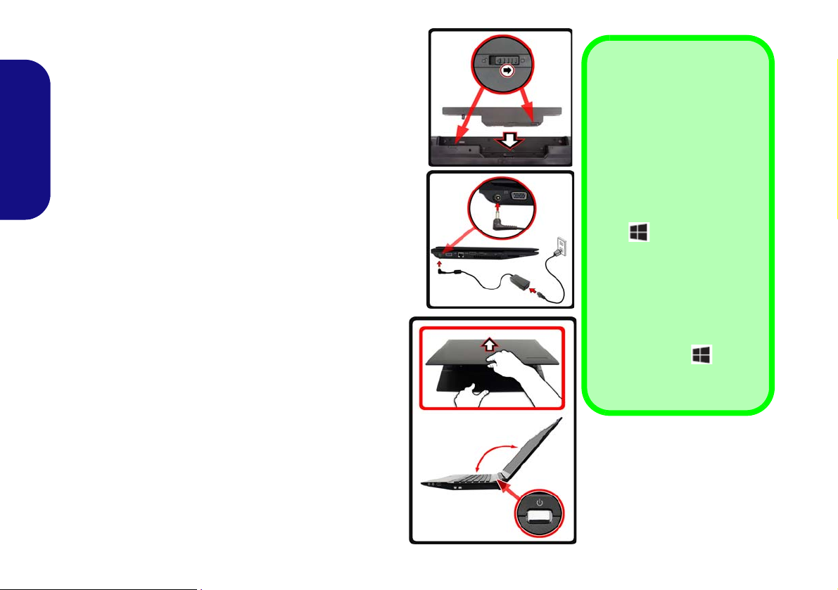
Opening the Lid/LCD/
Computer with AC/DC
Adapter Plugged-In
1. Remove all packing materials.
2. Place the computer on a stable surface.
3. Insert the battery and make sure it is locked in position.
4. Securely attach any peripherals you want to use with the
computer (e.g. keyboard and mouse) to their ports.
5. Attach the AC/DC adapter to the DC-In jack on the left of the
computer, then plug the AC power cord into an outlet, and
English
connect the AC power cord to the AC/DC adapter.
6. Use one hand to raise the
angle
(do not exceed 130 degrees); use the other hand (as
illustrated in Figure 1) to support the base of the computer
(Note: Never lift the computer by the lid/LCD).
7. Press the power button to turn the computer “on”.
System Software
Your computer may already come with system software
pre-installed. Where this is not the case, or where you
are re-configuring your computer for a different system,
you will find this manual refers to Microsoft Windows
8.1.
Model Differences
lid/LCD to a comfortable viewing
This notebook series includes different models that vary
slightly in design style, colo r and general appearance.
Note that though your computer may look slightly different from that pictured throughou t this documen tation, all ports, jacks, indicato rs, specifications and
general functions are the same for all the design styles.
4
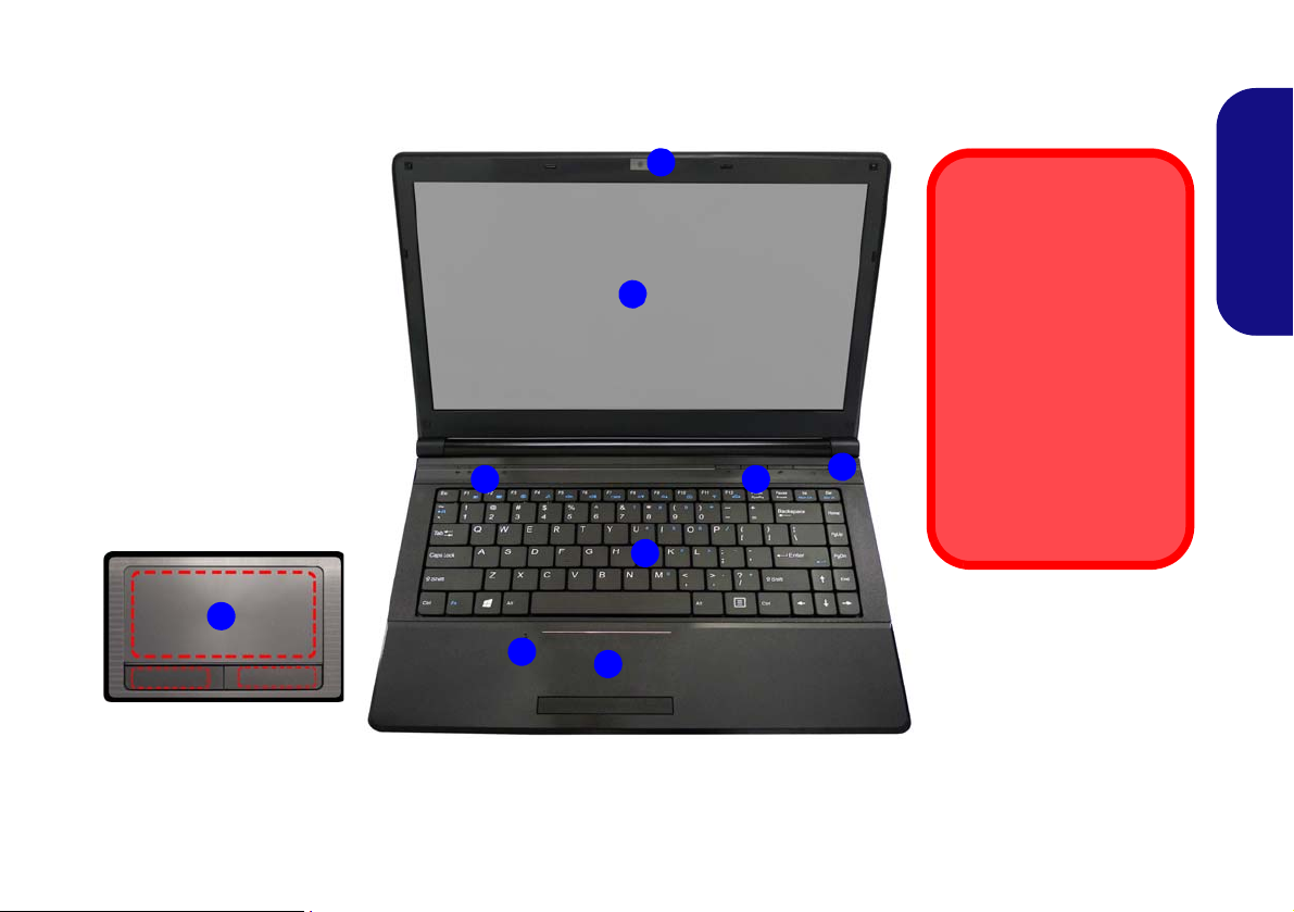
System Map: Front View with LCD Panel Open (Model A)
Figure 2
Front View with LCD Panel
Open (Model A)
1. PC Camera (Optional)
2. LCD
3. Power Button
4. Hot-Key Buttons (So
me
Model A Designs Only)
5. LED Status Indicators
6. Keyboard
7. Built-In Microphone
8. Touchpad & Buttons
8
Note that the Touchpad and
Buttons valid operational
area is that indicated within
the red dotted lines above.
4
6
3
5
7
1
8
2
14” (35.56cm)
Wireless Device
Operation Aboard
Aircraft
The use of any portable
electronic transmission
devices aboard aircraft is
usually prohibited.
Make sure the WLAN &
Bluetooth module(s) are
OFF if you are using the
computer aboard aircraft
by putting the system in to
Airplane Mode.
English
5
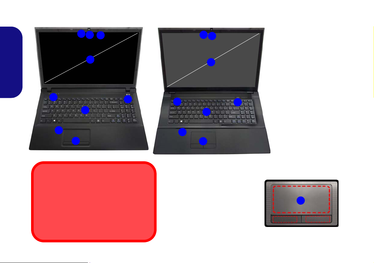
System Map: Front View with LCD Panel Open (Models B & C)
Figure 3
15.6” (39.62cm)
Model B
5
4
6
1
7
2
8
3
7
17.3” (43.94cm)
Model C
4
6
5
7
1
2
3
8
Front View with LCD Panel
Open (Models B & C)
1. PC Camera (Optional)
2. *PC Camera LED
*When the PC camera is
in u
se, the LED will be
illuminated in red.
3. LCD
4. Power Button
5. LED Status Indicators
6. Keyboard
7. *Built-In Microphone
*Note t
hat the microphone
location is dependent
upon your model design.
8. Touchpad & Buttons
Wireless Device
Operation Aboard Aircraft
The use of any portable electronic transmission
devices aboard aircraft is usually prohibited.
Make sure the WLAN & Bluetooth module(s) are
OFF if you are using the computer aboard aircraft by putting the system in to Airplane Mode.
Note that the Touchpad and
Buttons valid operational
area is that indicated within
the red dotted lines.
8
English
6

LED Indicators
Model A - Design lI
Model A - Designs l & III
Models B & C
The LED indicators on the computer display helpful information about the current status of the computer.
Icon Color Description
Icon Color Description
Green The Wireless LAN Module is Powered On
Orange The Bluetooth Module is Installed
Green Hard Disk Activity
Green
Green Caps Lock Activated
Green Scroll Lock Activated
Table 1 - LED Status Indicators
Number Lock (Numeric Keypad) Acti-
vated
Orange The AC/DC Adapter is Plugged In
Green The Computer is On
Blinking
Green
Blinking
Orange
Orange The Battery is Charging
Green The Battery is Fully Charged
Blinking
Orange
Table 2 - LED Power Indicators
The Computer is in Sleep Mode
The PC Camera is In Use
(14.0”/35.56cm Model A only)
The Battery Has Reached Critically
Low Power Status
English
7
Models B & C
Function Keys
Numeric
Keypad
Menu/Application Key
Num Lk &
Scr Lk
Function Keys
Num Lk &
Scr Lk
Numeric
Keypad
Fn Key
Windows Logo Key
Menu/Application Key
Model A
Fn Key
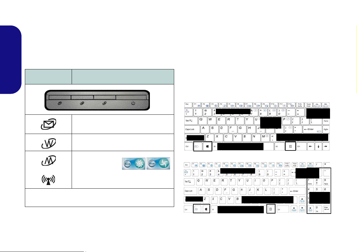
Hot-Key Buttons - Some Model
Windows Logo Key
Keyboard
English
A Designs Only
The Hot-Key buttons give instant access to the default Internet browser and e-mail program, and allow you to toggle the Silent Mode/the WLAN module on/off with one
quick button press.
Hot-Key Button Function
Activate the Default E-Mail Browser
Activate the Default Internet Program
or
*Toggle Silent Mode
*When enabled, Silent Mode will reduce fan noise and save power
consumption. Note this may reduce computer performance.
WLAN Module Power Toggle
or
The keyboard (Model A) has a numeric keypad for easy
numeric data input. Pressing Fn + Num Lk turns on/off
the numeric keypad. It also features func tion keys to allow you to change operational features instantly.
The keyboard (Models B & C) includes a numeric keypad (on the right side of the keyboard) for easy numeric
data input. Pressing Fn + Num Lk turns on/off the numeric keypad. It also features function keys to allow you
to change operational features instantly.
Table 3 - Hot-Key Buttons - Some Model A Designs Only
8
Figure 4 - Keyboard
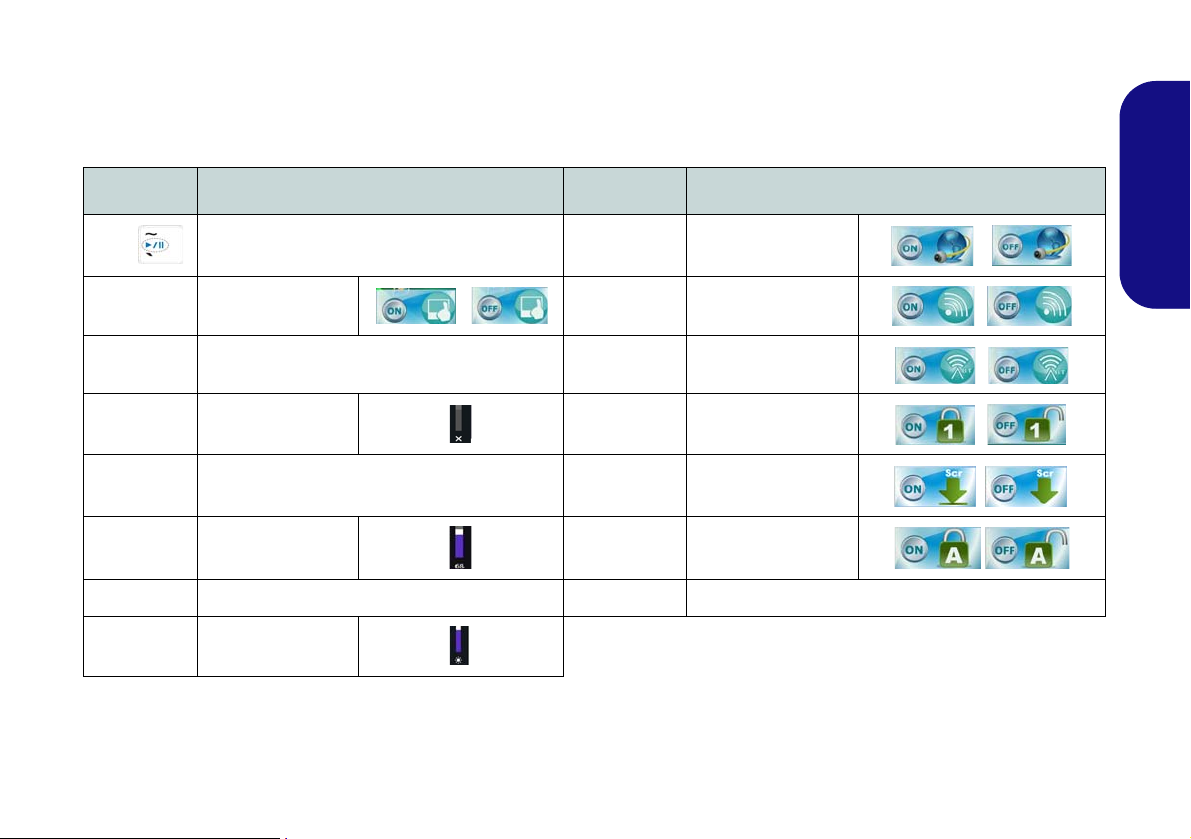
Function Keys
The function keys (F1 - F12 etc.) will act as hot keys when pressed while the Fn key is held down. In addition to the
basic function key combinations, some visual indicators are available (in the Windows Desktop application only and
not in the Start Screen) when the hot key driver is installed.
Keys Function/Visual Indicators Keys Function/Visual Indicators
English
Fn +
Fn + F1 Touchpad Toggle Fn + F11
Fn + F2
Fn + F3 Mute Toggle Fn + NumLk Number Lock Toggle
Fn + F4 Sleep Toggle Fn + ScrLk Scroll Lock Toggle
Fn + F5/F6
Fn + F7 Display Toggle Fn + Esc Control Center Toggle (see page 10)
Fn + F8/F9
Play/Pause (in Audio/Video Programs)
Turn LCD Backlight Off
(Press a key to or use Touchpad to turn on)
Volume Decrease/
Increase
Brightness Decrease/
Increase
Fn + F10
Fn + F12
Caps Lock Caps Lock Toggle
PC Camera Power
Toggle
WLAN Module Power
Toggle
Bluetooth Module
Power Toggle
Table 4 - Function Keys & Visual Indicators
9
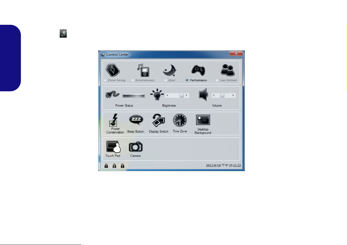
Control Center
When in the Windows Desktop application ( not in the Start Screen), press the Fn + Esc key combination, or doubleclick the icon in the notification area of the taskbar to toggle the Control Center on/off. The Control Center gives
quick access to frequently used controls, and enables you to quickly turn modules on/off.
English
Figure 5 - Control Center
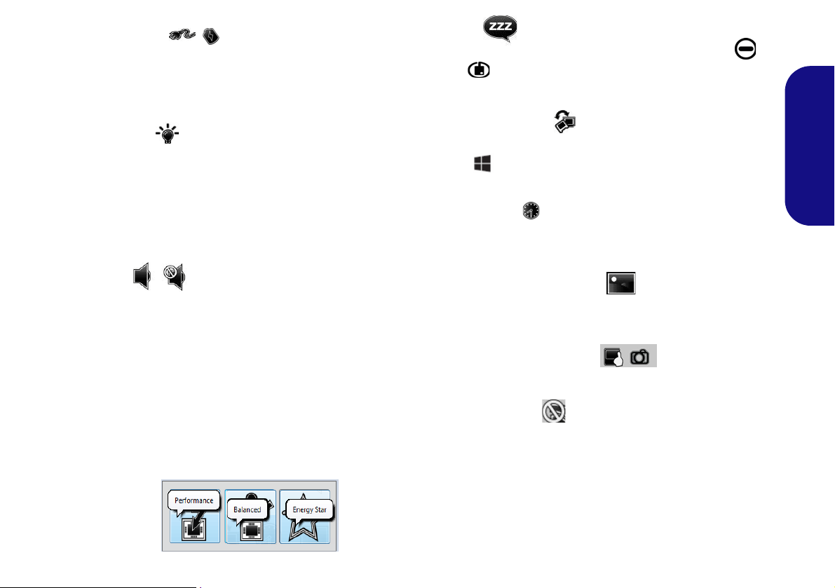
Click on any button to turn any of the modules (e.g. TouchPad, Camera) on/off. Click on Power Conservation to switch
between Performance, Balanced or Energy Star modes. Click on the buttons (or just click and hold the mouse button)
to adjust the slider for Brightness/Volume. Click on Display Switch/Time Zone/ Desktop Background to bring up
the appropriate Windows control panel. Click on the Sleep button to put the computer into Hibernate or Sleep modes.
10
Power Status
The Power Status icon will sho w whether y ou are currently powered by the battery, or by the AC/DC adapter
plugged in to a working power outlet. The power status
bar will show the current battery charge state.
Brightness
The Brightness icon will show the current screen brightness level. You can use the slider to adjust the screen
brightness or the Fn + F8/F9 key combinations, or use the
Fn + F2 key combination to turn off the LED backlight
(press any key to turn it on again). Note that screen brightness is also effected by the Power Mode selected.
Sleep
Click the Sleep button to bring up the Hibernate or
Sleep
computer enter the appropriate power-saving mode.
Display Switch
Click the Display Switch button to access the me nu (or
use the
ate display mode.
buttons, and click either button to have the
+ P key combination) and select the appropri-
Time Zone
Clicking the Time Zone button will access the Date and
Time Windows control panel.
English
Volume
The Volume icon will show the current volume level. You
can use the slider to adjust the volume or the Fn + F5/F6
key combinations, or use the Fn + F3 key combination to
mute the volume.
Power Conservation
This system supports Energy Star p ower management
features that place computers (CPU, hard drive, etc.) into
a low-power sleep mode after a designated period of inactivity. Click either the Performance, Balanced or Ener-
gy Star button.
Desktop Background
Clicking the Desktop Background button will allow you
to change the desktop background picture.
Touchpad/PC Camera
Click any of these buttons to toggle the Touchpad or module’s power status. A crossed out icon will appear over the
top left of the icon when it is off
status of a module, and Touchpad power, is also effected
by the Power Mode selected.
. Note that the power
11
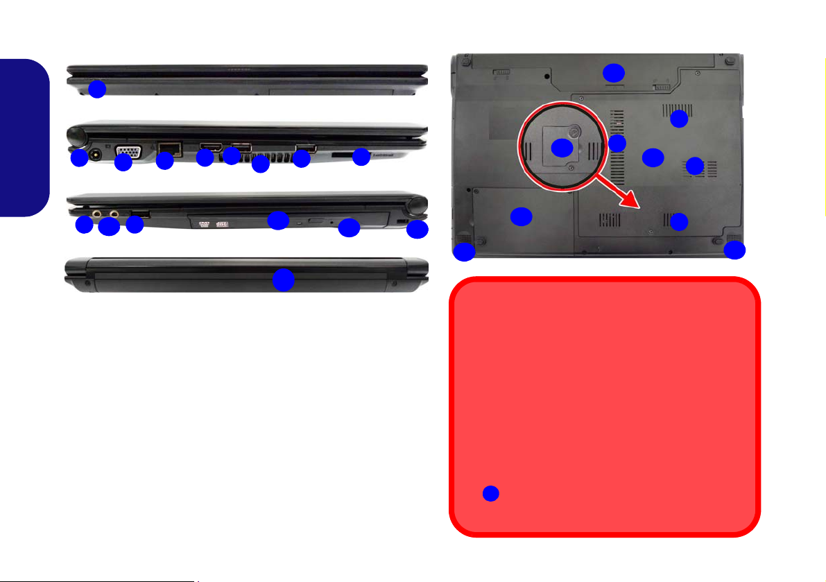
System Map: Front, Left, Right, Rear & Bottom Views (Model A)
2
1
7
8
4
6
3
Left
Right
5
Front
Rear
10
6
12
11
13
14
6
9
Figure 6 - Front, Left, Right, Rear & Bottom Views (Model A)
1. LED Power Indicators 11. Optical Device Drive Bay
2. DC-In Jack 12
. Emergency Eject Hole
3. External Monitor Port 13
. Security Lock Slot
4. RJ-45 LAN Jack 14
. Battery
5. HDMI-Out Port 15
. Component Bay Cover
6. 3 * USB 2.0 Ports 16
. Hard Disk Bay Cover
7. Vent 17
. Speakers
8. Multi-in-1 Card Reader 18
. USIM Card Cover
9. Microphone-In Jack
(
Optional)
10. Headphone-Out Jack
15
18
Bottom
7
17
7
17
16
7
7
14
Overheating
To prevent your computer from overheating make
sure nothing blocks any vent while the computer is in
use.
CPU
The CPU is not a user serviceable part. Accessing the
CPU in any way may violate your warranty.
Bottom Covers
If your model includes the 3G option then a small cover to enable you to access the module’s USIM
card will be included (see page 20).
18
English
12
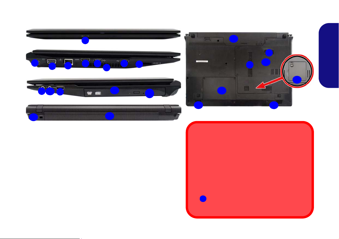
System Map: Front, Left, Right, Rear & Bottom Views (Model B)
2
1
7
8
4
6
3
Left
Right
5
Front
Rear
10
6
13
11
14
12
6
9
Figure 7 - Front, Left, Right, Rear & Bottom Views (Model B)
1. LED Power Indicators 11. Optical Device Drive Bay
2. DC-In Jack 12.
Emergency Eject Hole
3. External Monitor Port 13.
Security Lock Slot
4. RJ-45 LAN Jack 14.
Battery
5. HDMI-Out Port 15.
Component Bay Cover
6. 3 * USB 2.0 Ports 16.
Hard Disk Bay Cover
7. Vent 17.
Speakers
8. Multi-in-1 Card Reader 18.
USIM Card Cover
9. Microphone-In Jack
(
Optional)
10. Headphone-Out Jack
15
14
7
Bottom
16
17
7
17
18
Disc Emergency Eject
If you need to manually eject a disc (e.g. due to an unexpected power interruption) you may push the end of
a straightened paper clip into the emergency eject
hole. Do not use a sharpened pencil or similar object
that may break and become lodged in the hole.
Bottom Covers
If your model includes the 3G option then a small cover to enable you to access the module’s USIM
card will be included (see page 20).
18
English
13
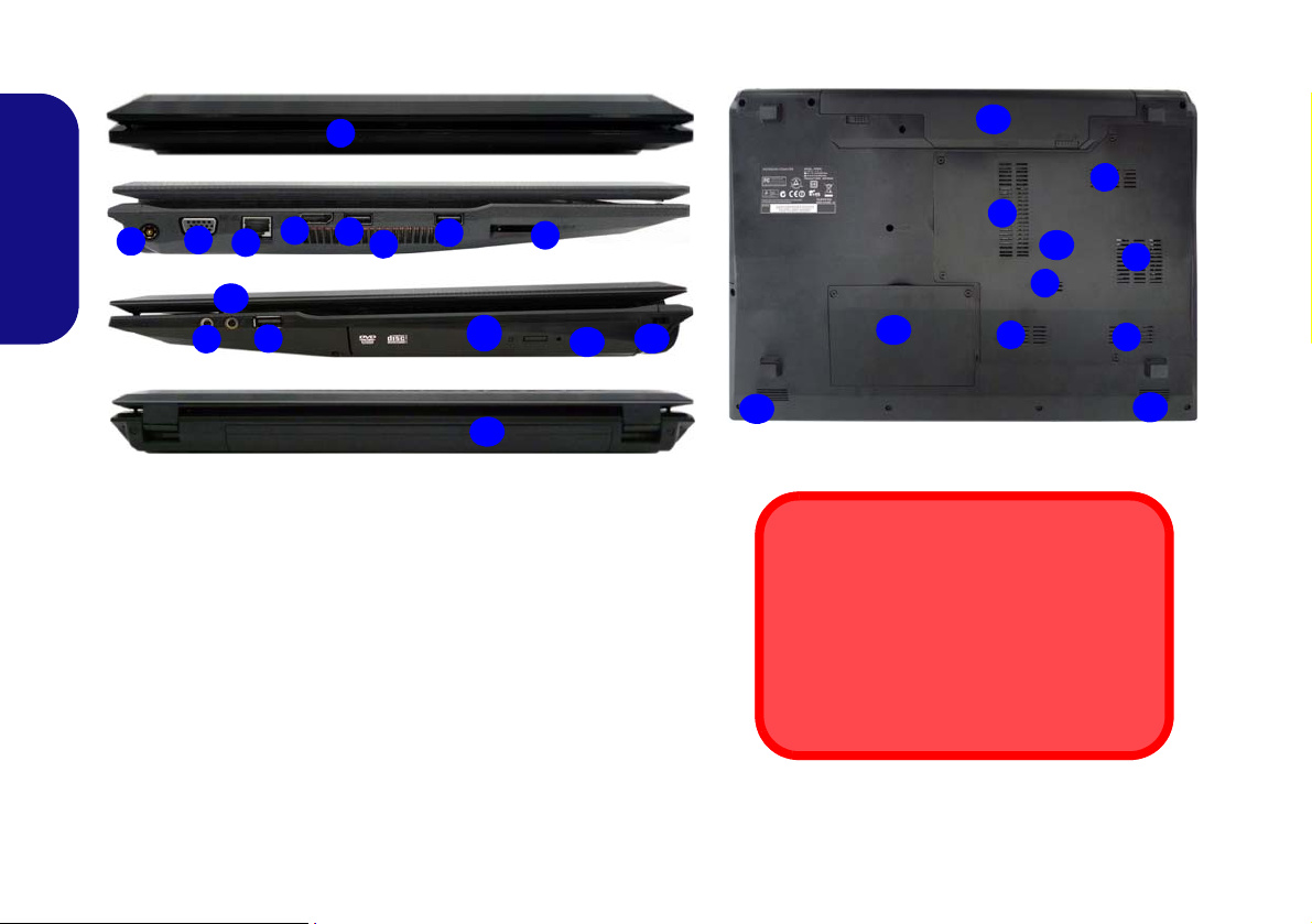
System Map: Front, Left, Right, Rear & Bottom Views (Model C)
1
7
6
4
6
3
Left
Right
5
Front
Rear
10
12
13
11
8
14
9
6
2
17
7
Bottom
7
15
7
7
14
17
7
16
7
Figure 8 - Front, Left, Right, Rear & Bottom Views (Model C)
1. LED Power Indicators 11. Optical Device Drive Bay
2. DC-In Jack 12.
Emergency Eject Hole
3. External Monitor Port 13.
Security Lock Slot
4. RJ-45 LAN Jack 14.
Battery
5. HDMI-Out Port 15.
Component Bay Cover
6. 3 * USB 2.0 Ports 16.
Hard Disk Bay Cover
7. Vent 17.
Speakers
8. Multi-in-1 Card Reader
9. Microphone-In Jack
10. Headphone-Out Jack
Disc Emergency Eject
If you need to manually eject a disc (e.g. due
to an unexpected power interruption) you
may push the end of a straightened paper
clip into the emergency eject hole. Do not
use a sharpened pencil or similar object that
may break and become lodged in the hole.
English
14
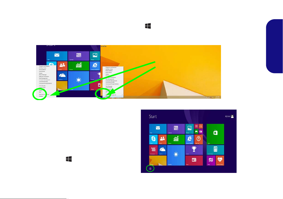
Windows 8.1 Control Panel
Move the mouse to
the bottom left of the
screen and right-click
the Start button to access the menu.
Figure 9
Context
Menu
Figure 10
Start
Screen
Throughout this manual you will see an instruction to open the Control Panel. Right-click the Start button in the
Desktop app or Start screen (or use the Windows Logo Key
menu of useful features such as Control Panel, Programs and Features, Power Options, Task Manager, Search, File Explorer, Command Prompt, Device Manager and Network Connections etc. and then select Control Panel.
+ X key combination) to bring up an advanced context
Windows 8.1 Start Screen & Desktop
The Apps, control panels, utilities and programs within
Windows are a ccessed f rom the Start screen and/or
Windows Desktop app. The Desktop (which runs as an
app within the Start screen) can be accessed by clicking
the Desktop item in the Start screen (or by using the
Windows Logo Key + D key combination). Click
the arrow at the bottom of the Start screen to access Ap-
ps.
15
English
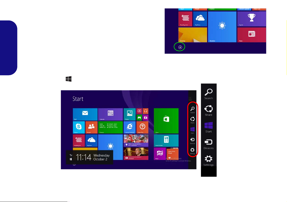
Apps & Tiles
Click the arrow at the bottom of the
screen to access Apps
The Start screen will contain a nu mber of apps, and many more
will be installed as you add more applications etc. Not all of these
apps can fit on one screen so you will often need use the slider at
the bottom of the screen in order to view all the necessary Apps.
Charms Bar
English
The right side of the screen displays the Charms Bar. The Charms Bar contains the Search, Share, Start, Devices and
Settings menus. To access up the Charms Bar move the cursor to the upper or lower right corners of the screen, and
then hover over one of the items in th e Charms Bar to activate it (the bar will be black when it is active), or u se the
Windows Logo Key
+ C key combination.
16
Figure 11 - Start Screen with Charms Bar
Video Features
1
2
2
1
Figure 12
Display
Control
Panel
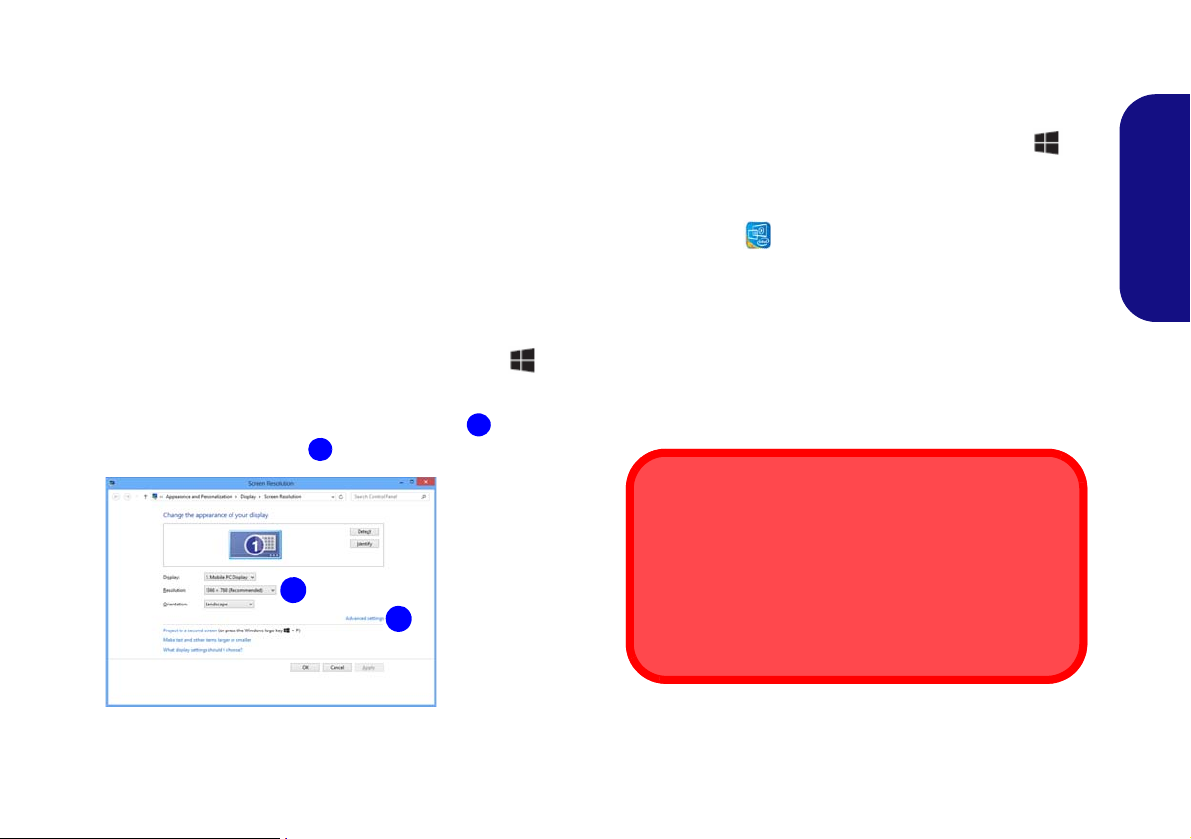
Screen Resolution for Apps (Windows 8.1)
The minimum resolution in which Apps will run is
1024x768.
The minimum resolution required to support all the features of Windows 8.1 (including multitasking with snap)
is 1366x768.
The system features an Intel integrated GPU. You can
switch display devices, and configure display options,
from the Display control panel in Windows as long as the
video driver is installed.
To access the Display control panel in Windows:
1. Go to the Control Panel.
2. Click Display (icon) - in the Appearances and
Personalization category.
3. Click Adjust Screen Resolution/Adjust resolution.
OR
4. Right-click the desktop (use the Windows Logo Key + D
key combination to access the desktop) and select Screen
resolution.
5. Use the dropbox to select the screen resolution
6. Click Advanced settings
.
.
To access the Intel® HD Graphics Control Panel:
1. Click the icon (Intel® HD Graphics Control Panel) on the
Start screen.
OR
2. Right-click the desktop (use the Windows Logo Key + D
key combination to access the desktop) and select Graphics
Properties from the menu.
OR
3. Click the icon in the notification area of the Desktop
taskbar and select
Graphics Properties from the menu.
Display Devices
Besides the built-in LCD, you can als o use an external
VGA monitor (C RT)/external Flat Panel Disp lay or TV
(connected to the external monitor port/HDMI-Out port)
as your display device.
English
17
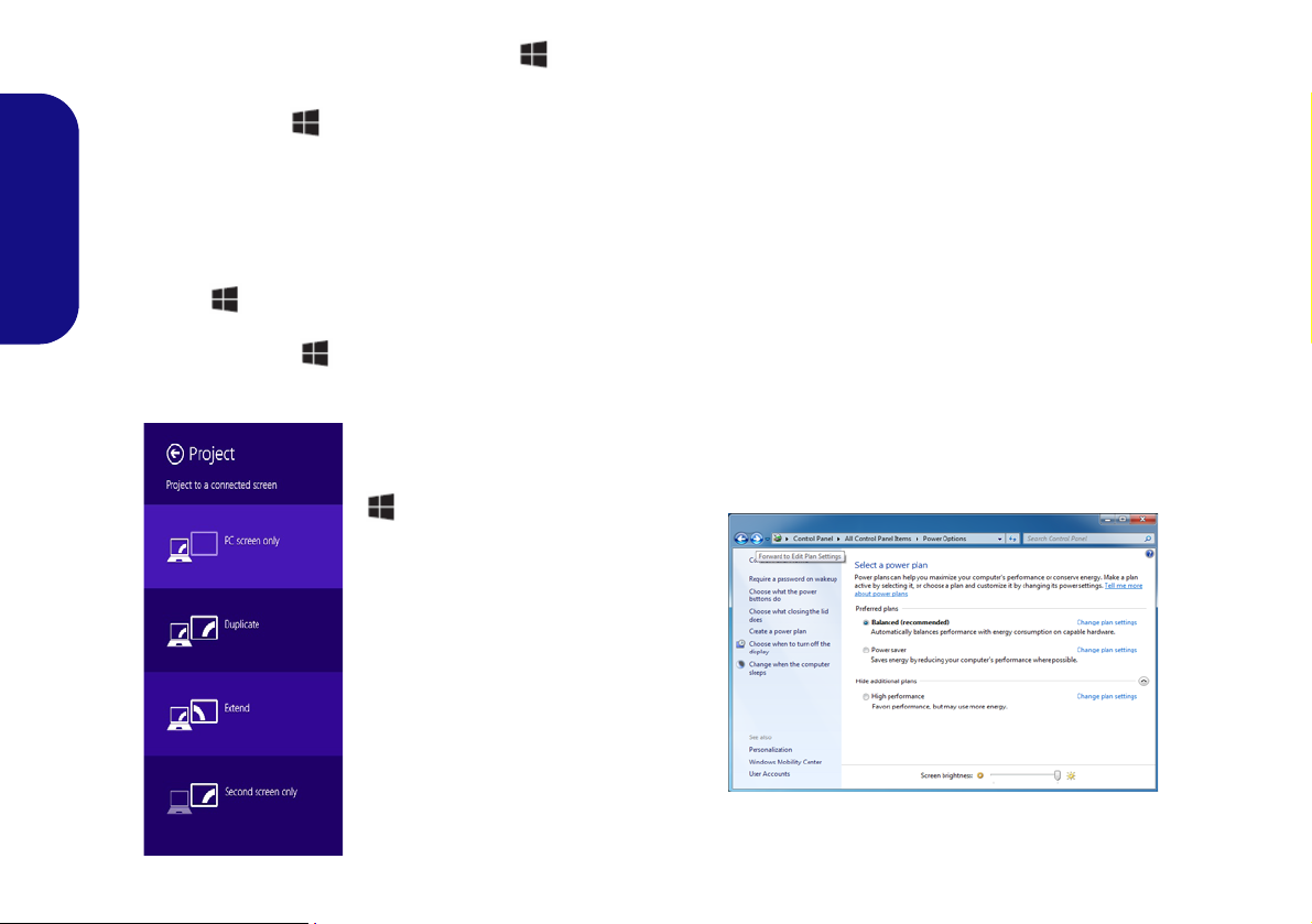
Using the Windows Logo Key + P
Figure 13
+ P (Change Display
Configuration)
Figure 14 - Power Options
Key Combination to Switch Displays
You can also use the + P key combination (or Fn + F7
) to quickly change display configuration and modes (this
is particularly useful when attaching a projector) in Win-
dows.
1. Attach your external display to the external monitor port/HDMI-
English
Out port, and turn it on.
2. Press the
3. An on-screen menu will pop up.
4. Use the cursor keys (
configuration from the menu, and press Enter to confirm the
selection.
+ P (or Fn + F7) key combination.
+ P) to select the appropriate
Power Options
The Power Options (Hardware and Sound menu) control panel icon in Windows allows you to configure power
management features f or your comp uter. You can conserve power by means of power plans and configure the
options for the power button, sleep button (Fn + F4),
computer lid (when closed), display and sleep mode (the
default power saving state) from the left menu. Note that
the Power saver plan may have an affect on computer
performance.
Click to select one of the existing plans, or click Create a
power plan in the left menu and select the options to create a new plan. Click Change Plan Settings and click
Change advanced power settings to access further configuration options.
18

Driver Installation
Driver Installation & Power
When installing drivers make sure
your computer is powered by the
AC/DC adapter connected to a
working power source. Some drivers draw a significant amount of
power during the installation procedure, and if the remaining battery
capacity is not adequate this may
cause the system to shut down and
cause system problems (note that
there is no safety issue involved
here, and the battery will be rechargeable within 1 minute).
Driver Installation General
Guidelines
As a general guide follow the
default on-screen instructions for each driver (e.g.
Next > Next > Finish) unless
you are an advanced user. In
many cases a restart is required to install the driver.
Make sure any modules (e.g.
WLAN or Bluetooth) are ON
before installing the appropriate driver.
Windows Update
After installing all the drivers
make sure you enable Win-
dows Update in order to get
all the latest security updates
etc. (all updates will include
the latest hotfixes from Mi-
crosoft).
The Device Drivers & Utilities + User’s Manual disc contains the drivers and utilities
necessary for the proper operation of the computer. This setup will probably have already been done for you. If this is not the case, insert the disc and click Install Drivers
(button), or Option Drivers (button) to access the Optional driver menu. Install the
drivers in the order indicated in Figure 15. Click to select the dr ivers you wish to
install (you should note down the drivers as you in stall them). Note: If you need to
reinstall any driver, you should uninstall the driver first
If the Found New Hardware wizard appears during the installation procedure, click
Cancel to close the window, and follow the installation procedure as directed.
Figure 15 - Install Drivers
.
English
19
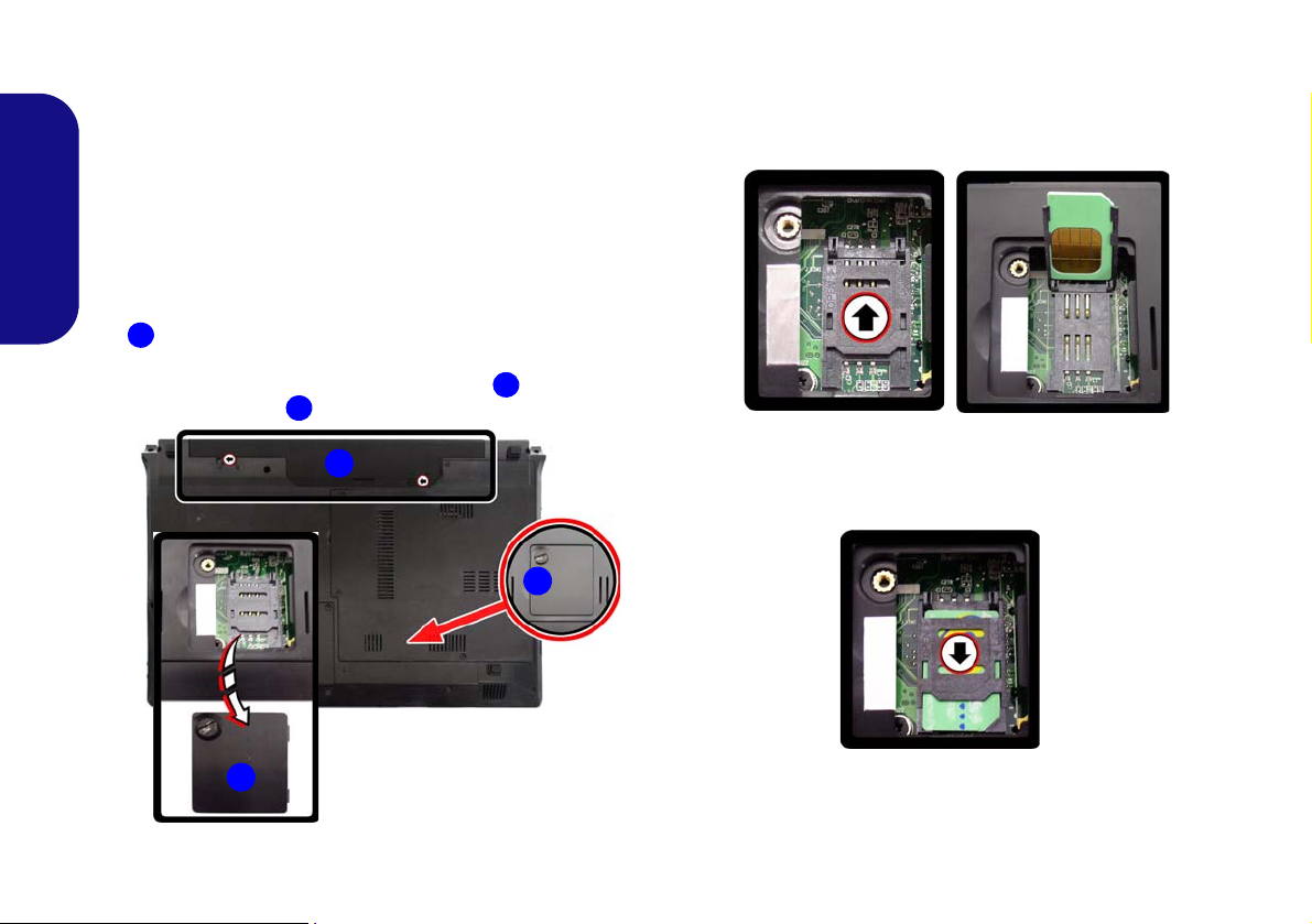
3G Module
3
2
1
3
2
(Models A & B Only)
If you have included an optional 3G module in your purchase option, follow the instructions below to install the
USIM card (which will be pr ovided by your service provider), and then run the appropriate application supplied
with your module.
English
USIM Card Insertion
1. Turn 1 off the computer, and turn it over and remove the battery
the battery out).
2. Locate the SIM card cover and loosen screw
the SIM card cover .
(slide the latches in the direction indicated below and slide
and remove
3. Insert the USIM card as you would into your mobile phone.
4. Slide the SIMLOCK towards the hinge (in the direction to the
arrow illustrated in Figure 17) in order to release the lock and
lift it up.
5. Insert the USIM card and close the SIMLOCK.
Figure 17 - Unlock the SIMLOCK
Figure 16 - Battery & SIM Card Cover Removal
20
6. Lock the SIMLOCK by pushing it in the direction of the arrow in
Figure 18 until it clicks into the lock position.
Figure 18 - Lock the SIMLOCK
7. Replace the cover, screw and battery.

Troubleshooting
Problem Possible Cause - Solution
The Bluetooth module is off
after resuming from Sleep.
A file cannot be copied to/
from a connected Bluetooth
device.
The PC Camera module
cannot be detected.
The captured video files from
the PC Camera are taking up
too much disk space.
The Bluetooth module’s default state will be off after resuming from the Sleep power-saving state.
Use the key combination (Fn + F12) to power on the Bluetooth module after the computer resumes
from Sleep.
Transferring data between the computer and a Bluetooth enabled device is supported in one
direction only (simultaneous data transfer is not supported). If you are copying a file from your
computer to a Bluetooth enabled device, you will not be able to copy a file from the Bluetooth
enabled device to your computer until the file transfer process from the computer has been
completed.
The module is off. Press the Fn + F10 key combination in order to enable the module (see Table 4
on page 9). Run the camera application to view the camera picture.
Note that capturing high resolution video files requires a substantial amount of disk space for each
file.
Note that the Windows system requires a minimum of 16GB (32bit) or 20GB (64bit) of free space
on the C: drive system partition. It is recommended that you save the capture video file to a
location other than the C:drive, limit the file size of the captured video or reduce video resolution.
English
21

Specifications
Latest Specification Information
The specifications listed in this here
are correct at the time of going to
press. Certain items (particularly
processor types/speeds) may be
changed, delayed or updated due to
the manufacturer's release schedule. Check with your service center
for details.
Processor
BIOS
English
Intel® Celeron® 847 Processor
1.10GHz, 32nm, 2MB L3 Cache, DDR3-
1333MHz, TDP: 17W
Intel® Celeron® 877 Processor
1.40GHz, 32nm, 2MB L3 Cache, DDR3-
1333MHz, TDP: 17W
Display
Model A - Designs I & III:
14” (35.65cm) HD (Thickness: 5.2mm)
Model A - Design II:
14” (35.65cm) HD (Thickness: 3.6mm)
Model B:
15.6” (39.62cm) HD
Model C:
17.3" (43.94cm) HD+ / FHD
Core Logic
Intel® NM70 Chipset
Memory
Two 204 Pin SO-DIMM Socket Supporting
DDR3 1333/1600MHz Memory (The real
memory operating frequency depends on the
FSB of the processor)
Memory Expandable up to 8GB
One 48Mb SPI Flash ROM
AMI BIOS
Video Adapter
Intel® HD Graphics
Dynamic Frequency (Intel Dynamic Video
Memory Technology for up to 1.7GB)
Microsoft DirectX®10.1 Compatible
Audio
High Definition Audio Compliant Interface
2 * Built-In Speakers
Built-In Microphone
Storage
(Factory Option) One Changeable
12.7mm(h) Super Multi Optical Device Drive
(Factory Option) Dummy ODD (Some
Model A designs and some Model B
designs Only)
One Changeable 2.5" 9.5mm (h) SATA
HDD
22

Interface
Communication
Mini Card Slots
Three USB 2.0 Ports
One Headphone-Out Jack
One Microphone-In Jack
One External Monitor Port
One HDMI-Out Port
One RJ-45 LAN Jack
One DC-in Jack
Security
Kensington Lock Slot
BIOS Password
Keyboard
Model A:
“WinKey” keyboard (with embedded
numeric keypad)
Models B & C:
Full-size “WinKey” keyboard (with numeric
keypad)
Pointing Device
Built-in Touchpad
10Mb/100Mb Ethernet LAN
(Factory Option - Models A & B) 300K
Pixel
/2M HD PC Camera Module
(Factory Option - Model C) 2M HD PC
Camera Module
(Factory Option) 3G Mini-Card Module
(Models A & B Only)
WLAN/ Bluetooth Half Mini-Card
Modules:
(Factory Option) Intel® Centrino® Wireless-N 105 Wireless LAN (802.11b/g/n)
(Factory Option) Intel® Centrino® Wireless-N 135 Wireless LAN (802.11b/g/n) +
Bluetooth 3.0
(Factory Option) Third-Party Wireless LAN
(802.11b/g/n)
(Factory Option) Third-Party Wireless LAN
(802.11b/g/n) + Bluetooth 4.0
Card Reader
Embedded Multi-In-1 Card Reader
MMC (MultiMedia Card) / RS MMC
SD (Secure Digital) / Mini SD
MS (Memory Stick) / MS Pro / MS Duo
Models A & B:
Slot 1 for WLAN Module or WLAN and
Bluetooth Combo Module
(Factory Option) Slot 2 for 3G Module
Model C:
Slot 1 for WLAN Module or WLAN and
Bluetooth Combo Module
Power
Model A:
Full Range AC/DC Adapter
AC Input: 100 - 240V, 50 - 60Hz
DC Output: 19V, 3.42A/18.5V, 3.5A (65W)
Removable 6 Cell Smart Lithium-Ion Battery Pack, 48.84WH
(Factory Option) Removable 3 Cell Smart
Lithium-Ion Battery Pack, 24.42WH
(
Factory Option) Removable 6 Cell Smart
Lithium-Ion Battery Pack, 62.16WH
Models B & C:
Full Range AC/DC Adapter
AC Input: 100 - 240V, 50 - 60Hz
DC Output: 19V, 3.42A/18.5V, 3.5A (65W)
Removable 6 Cell Smart Lithium-Ion Battery Pack, 48.84WH
(
Factory Option) Removable 6 Cell Smart
Lithium-Ion Battery Pack, 62.16WH
English
23

Environmental Spec
Dimensions & Weight
Temperature
Operating: 5
Non-Operating: -20°C - 60°C
Relative Humidity
Operating: 20% - 80%
Non-Operating: 10% - 90%
°C - 35°C
English
Model A Design I:
340mm (w) * 238mm (d) * 25.05 - 33.5mm
(h)
2.2kg with 48.84WH Battery & ODD
Model A Design II:
340mm (w) * 238mm (d) * 13.9 - 31.8mm
(h)
340mm (w) * 238mm (d) * 12 - 30.2mm (h)
2.2kg with 48.84WH Battery & ODD
Model A Design III:
341mm (w) * 238.5mm (d) * 16 - 34mm (h)
(h)
2.2kg with 48.84WH Battery & ODD
Model B Design I:
374mm (w) * 250mm (d) * 20 - 37.2mm (h)
2.6kg with 48.84WH Battery & ODD
Model B Design II:
374mm (w) * 238mm (d) * 14.3 - 34.1mm
(h)
2.3kg with 48.84WH Battery & ODD
Model C:
413mm (w) * 270mm (d) * 14 - 40.5mm (h)
2.9kg (with 48.84WH Battery and ODD)
24
 Loading...