


Contents
About this Concise User Guide ...........................................................1
System Startup .....................................................................................4
System Map: Front View with LCD Panel Open (Model A) ..............
System Map: Front View with LCD Panel Open (Models B & C) .....6
LED Indicators ....................................................................................7
Hot-Key Buttons - Some Model A Designs Only ...............................8
Keyboard .............................................................................................8
Control Center ...................................................................................
System Map: Front, Left, Right, Rear & Bottom Views
(Model A) ..........................................................................................12
System Map: Front, Left, Right, Rear & Bottom Views
(Model B) ..........................................................................................13
System Map: Front, Left, Right, Rear & Bottom Views
(Model C) ..........................................................................................14
Windows 8.1 Control Panel ...............................................................
Windows 8.1 Start Screen & Desktop ...............................................15
Apps & Tiles ......................................................................................16
Charms Bar ........................................................................................16
Video Features ...................................................................................17
Power Options ...................................................................................18
Driver Installation ..............................................................................19
3G Module .........................................................................................
Troubleshooting .................................................................................21
Specifications ....................................................................................22
5
10
15
20
Inhalt
Über das Ausführliche Benutzerhandbuch ........................................
Schnellstart . .......................................................................................28
Systemübersicht: Ansicht von vorne mit geöffnetem LCD-Bildschirm
(Modell A) .........................................................................................29
Systemübersicht: Ansicht von vorne mit geöffnetem LCD-Bildschirm
(Modelle B & C) ................................................................................
LED-Anzeigen ...................................................................................31
Hot-Key-Tasten - nur einige Designs des Modells A .......................32
25
30
Tastatur .............................................................................................. 32
Control Center (Steuerzentrum) ........................................................ 34
Systemübersicht: Ansicht von vorne, links, rechts, hinten und unten
(Modell A) ......................................................................................... 36
Systemübersicht: Ansicht von vorne, links, rechts, hinten und unten
(Modell B) ......................................................................................... 37
Systemübersicht: Ansicht von vorne, links, rechts, hinten und unten
(Modell C) ......................................................................................... 38
Windows 8.1 Systemsteuerung ......................................................... 39
Windows 8.1 Start-Bildschirm und Desktop .................................... 39
Apps und Kacheln ............................................................................. 40
Charms-Leiste ................................................................................... 40
Grafikfunktionen ............................................................................... 41
Energieoptionen ................................................................................ 42
Installation der Treiber ...................................................................... 43
3G-Modul .......................................................................................... 44
Fehlerbehebung ................................................................................. 45
Technische Daten .............................................................................. 46
Sommaire
A propos de ce Guide Utilisateur Concis .......................................... 49
Guide de démarrage rapide ............................................................... 52
Carte du système: Vue de face avec l’écran LCD ouvert
(Modèle A) ........................................................................................ 53
Carte du système: Vue de face avec l’écran LCD ouvert
(Modèles B & C) ...............................................................................
Indicateurs LED ................................................................................ 55
Boutons Hot-Key - certains designs du modèle A seulement ........... 56
Clavier ............................................................................................... 56
Control Center (Centre de contrôle) .................................................. 58
Carte du système: Vues de face, gauche, droite, arrière & dessous
(Modèle A) ........................................................................................ 60
Carte du système: Vues de face, gauche, droite, arrière & dessous
(Modèle B) ........................................................................................ 61
54

Carte du système: Vues de face, gauche, droite, arrière & dessous
(Modèle C) .........................................................................................62
Panneau de Configuration de Windows 8.1 ......................................63
Écran d'accueil & bureau de Windows 8.1 ........................................63
Applications et Vignettes ..................................................................64
Barre des charmes ..............................................................................64
Caractéristiques vidéo .......................................................................65
Options d’alimentation ......................................................................66
Installation du pilote ..........................................................................67
Module 3G .........................................................................................68
Dépannage .........................................................................................69
Spécifications ....................................................................................70
Contenidos
Acerca de esta Guía del Usuario Concisa ..........................................73
Guía rápida para empezar ..................................................................76
Mapa del sistema: Vista frontal con panel LCD abierto
(Modelo A) ........................................................................................77
Mapa del sistema: Vista frontal con panel LCD abierto
(Modelos B & C) ...............................................................................78
Indicadores LED ................................................................................79
Botones Hot-Key - sólo algunos diseños del Modelo A ...................80
Teclado ..............................................................................................80
Control Center (Centro de control) ....................................................82
Mapa del sistema: Vistas frontal, izquierda, derecha, posterior
e inferior (Modelo A) ........................................................................84
Mapa del sistema: Vistas frontal, izquierda, derecha, posterior
e inferior (Modelo B) .........................................................................85
Mapa del sistema: Vistas frontal, izquierda, derecha, posterior
e inferior (Modelo C) .........................................................................86
Instalación de controladores ..............................................................87
Panel de Control de Windows 8.1 .....................................................88
Pantalla Inicio y escritorio de Windows 8.1 ......................................88
Apps y Mosaicos ...............................................................................89
Barra Charms .....................................................................................89
Parámetros de vídeo .......................................................................... 90
Opciones de energía .......................................................................... 91
Módulo 3G ........................................................................................ 92
Solución de problemas ...................................................................... 93
Especificaciones ................................................................................ 94
Sommario
Informazioni su questa guida rapida ................................................. 99
Guida di avvio rapido ...................................................................... 102
Descrizione del sistema: Vista anteriore con pannello LCD aperto
(Modello A) ..................................................................................... 103
Descrizione del sistema: Vista anteriore con pannello LCD aperto
(Modelli B & C) .............................................................................. 104
Indicatori LED ................................................................................ 105
Pulsanti Hot-Key (solo alcuni design di modello A) ...................... 106
Tastiera ............................................................................................ 106
Control Center (Centro di controllo) ............................................... 108
Descrizione del sistema: Vista anteriore, sinistra, destra,
posteriore e inferiore (Modello A) ..................................................
Descrizione del sistema: Vista anteriore, sinistra, destra,
posteriore e inferiore (Modello B) .................................................. 111
Descrizione del sistema: Vista anteriore, sinistra, destra,
posteriore e inferiore (Modello C) .................................................. 112
Pannello di controllo di Windows 8.1 ............................................. 113
Schermata Start e Desktop di Windows 8.1 .................................... 113
App & Titoli .................................................................................... 114
Charms Bar ...................................................................................... 114
Funzioni video ................................................................................. 115
Opzioni risparmio energia ............................................................... 116
Installazione driver .......................................................................... 117
Modulo 3G ...................................................................................... 118
Risoluzione dei problemi ................................................................ 119
Specifiche tecniche .......................................................................... 120
110

III

IV

About this Concise User Guide
FCC Statement
This device complies with Part
15 of the FCC Rules. Operation
is subject to the following two
conditions:
1. This device may not cause
harmful interference.
2. This device must accept any
interference received, including interference that may
cause undesired operation.
This quick guide is a brief introduction to getting your system started. This is a supplement, and not a substitute for the
expanded English language User’s Manual in Adobe Acrobat format on the Device Drivers & Utilities + User’s Manual
disc supplied with your computer. This disc also contains the drivers and utilities necessary for the proper operation of
the computer (Note: The company reserves the right to revise this publication or to change its contents without notice).
Some or all of the computer’s features may already have been setup. If they aren’t, or you are planning to re-configure
(or re-install) portions of the system, refer to the expanded User’s Manual. The Device Drivers & Utilities + User’s
Manual disc does not contain an operating system.
Regulatory and Safety Information
Please pay careful attention to the full regulatory notices and safety information contained in the expanded User’s Manual on the Device Drivers & Utilities + User’s Manual disc.
© October 2013
Trademarks
Intel and Celeron are trademarks/registered trademarks of Intel Corporation.
English
1

Instructions for Care and Operation
The computer is quite rugged, but it can be damaged. To prevent this, follow these suggestions:
• Don’t drop it, or expose it to shock. If the computer falls, the
case and the components could be damaged.
• Keep it dry, and don’t overheat it. Keep the computer and power
supply away from any kind of heating element. This is an electrical appliance. If water or any other liquid gets into it, the computer
could be badly damaged.
English
• Avoid interference. Keep the computer away from high capacity
transformers, electric motors, and other strong magnetic fields.
These can hinder proper performance and damage your data.
• Follow the proper working procedures for the computer. Shut
the computer down properly and don’t forget to save your work.
Remember to periodically save your data as data may be lost.
Servicing
Do not attempt to service the computer yourself. Doing so may
violate your warranty and expose you and the com puter to
electric shock. Refer all servicing to authorized service personnel. Unplug the computer from the power supply. Then refer
servicing to qualified service personnel under any of th e following conditions:
• When the power cord or AC/DC adapter is damaged or frayed.
• If the computer has been exposed to any liquids.
• If the computer does not work normally when you follow the operating instructions.
• If the computer has been dropped or damaged (do not touch the
poisonous liquid if the LCD panel breaks).
• If there is an unusual odor, heat or smoke coming from your computer.
Safety Information
• Only use an AC/DC adapter approved for use with this computer.
• Use only the power cord and batteries indicated in this manual. Do
not dispose of batteries in a fire. They may explode. Check with
local codes for possible special disposal instructions.
• Do not continue to use a battery that has been dropped, or that
appears damaged (e.g. bent or twisted) in any way. Even if the
computer continues to work with a damaged battery in place, it
may cause circuit damage, which may possibly result in fire.
• Make sure that your computer is completely powered off before
putting it into a travel bag (or any such container).
• Before cleaning the computer, make sure it is disconnected from
any external power supplies, peripherals and cables (including
telephone lines). It is advisable to also remove your battery in
order to prevent accidentally turning the machine on.
• Use a soft clean cloth to clean the computer, but do not apply
cleaner directly to the computer. Do not use volatile (petroleum
distillates) or abrasive cleaners on any part of the computer.
• Do not try to repair a battery pack. Refer any battery pack repair or
replacement to your service representative or qualified service personnel.
• Note that in computer’s featuring a raised LCD electro-plated
logo, the logo is covered by a protective adhesive. Due to general
wear and tear, this adhesive may deteriorate over time and the
exposed logo may develop sharp edges. Be careful when handling
the computer in this case, and avoid touching the raised LCD electro-plated logo. Avoid placing any other items in the carrying bag
which may rub against the top of the computer during transport. If
any such wear and tear develops contact your service center.
2

Polymer Battery Precautions
Battery Disposal & Caution
The product that you have purchased contains a rechargeable battery. The battery is recyclable. At the end of its useful life, under various state and local laws, it may be illegal
to dispose of this battery into the municipal waste stream.
Check with your local solid waste officials for details in your
area for recycling options or proper disposal.
Danger of explosion if battery is incorrectly replaced. Replace only with the same or equivalent type recommended
by the manufacturer. Discard used battery accord ing to the
manufacturer’s instructions.
Note the fol lowing informat ion which is specific to polymer
batteries only, and where applicable, this overrides the general
battery precaution information.
• Polymer batteries may experience a slight expansion or swelling,
however this is part of the battery’s safety mechanism and is not a
cause for concern.
• Use proper handling procedures when using polymer batteries. Do
not use polymer batteries in high ambient temperature environments, and do not store unused batteries for extended periods.
English
3
System Startup
Shut Down
Note that you should always
shut your computer down by
choosing the Shut down
command in Windows (see
below). This will help prevent
hard disk or system problems.
Click Settings in the Charms
Bar (use the Windows Logo
Key + C key combina-
tion to access the Charms
Bar) and choose Shut down
from the Power menu.
Or
Choose Shut down or sign
out > Shut down from the
context menu (use the Windows Logo Key + X key
combination to access the
context menu).
.130 °
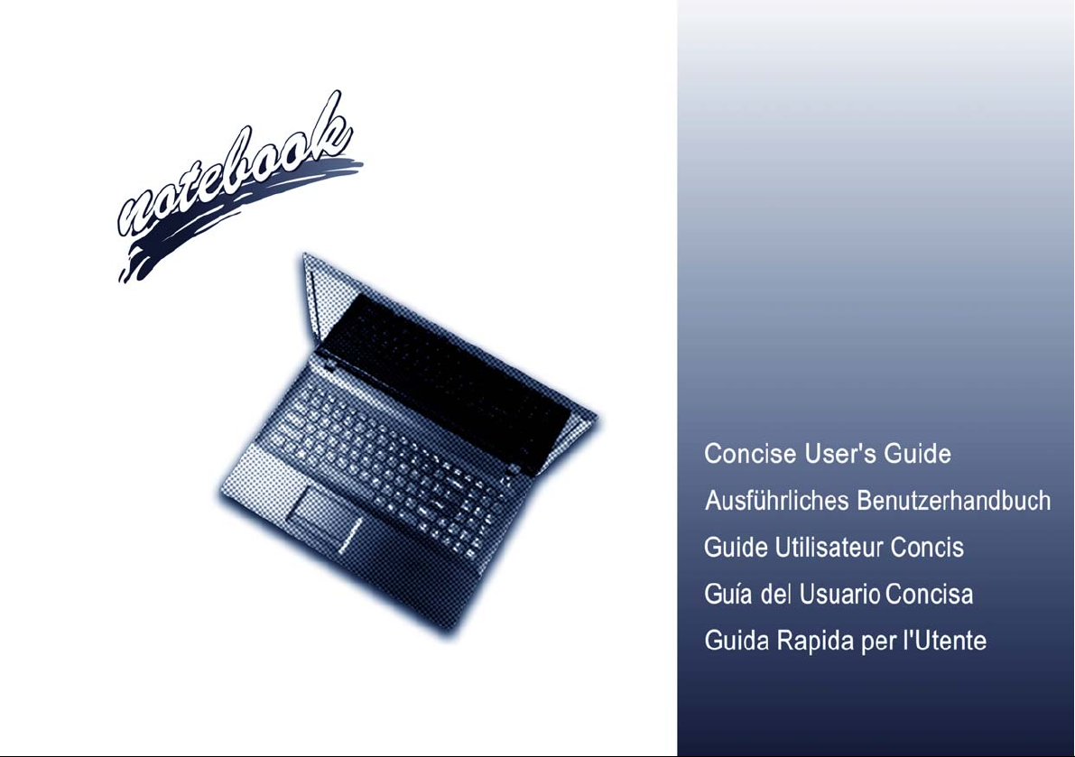
Figure 1
Opening the Lid/LCD/
Computer with AC/DC
Adapter Plugged-In
1. Remove all packing materials.
2. Place the computer on a stable surface.
3. Insert the battery and make sure it is locked in position.
4. Securely attach any peripherals you want to use with the
computer (e.g. keyboard and mouse) to their ports.
5. Attach the AC/DC adapter to the DC-In jack on the left of the
computer, then plug the AC power cord into an outlet, and
English
connect the AC power cord to the AC/DC adapter.
6. Use one hand to raise the
angle
(do not exceed 130 degrees); use the other hand (as
illustrated in Figure 1) to support the base of the computer
(Note: Never lift the computer by the lid/LCD).
7. Press the power button to turn the computer “on”.
System Software
Your computer may already come with system software
pre-installed. Where this is not the case, or where you
are re-configuring your computer for a different system,
you will find this manual refers to Microsoft Windows
8.1.
Model Differences
lid/LCD to a comfortable viewing
This notebook series includes different models that vary
slightly in design style, colo r and general appearance.
Note that though your computer may look slightly different from that pictured throughou t this documen tation, all ports, jacks, indicato rs, specifications and
general functions are the same for all the design styles.
4
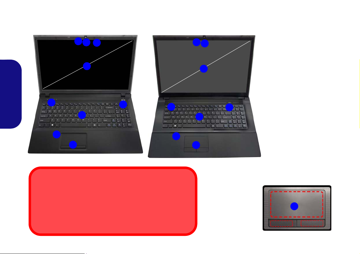
System Map: Front View with LCD Panel Open (Model A)
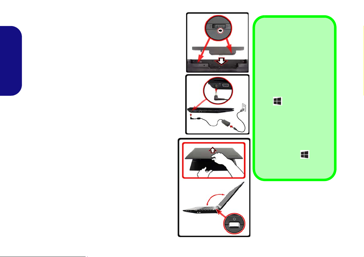
Figure 2
Front View with LCD Panel
Open (Model A)
1. PC Camera (Optional)
2. LCD
3. Power Button
4. Hot-Key Buttons (So
me
Model A Designs Only)
5. LED Status Indicators
6. Keyboard
7. Built-In Microphone
8. Touchpad & Buttons
8
Note that the Touchpad and
Buttons valid operational
area is that indicated within
the red dotted lines above.
4
6
3
5
7
1
8
2
14” (35.56cm)
Wireless Device
Operation Aboard
Aircraft
The use of any portable
electronic transmission
devices aboard aircraft is
usually prohibited.
Make sure the WLAN &
Bluetooth module(s) are
OFF if you are using the
computer aboard aircraft
by putting the system in to
Airplane Mode.
English
5
System Map: Front View with LCD Panel Open (Models B & C)
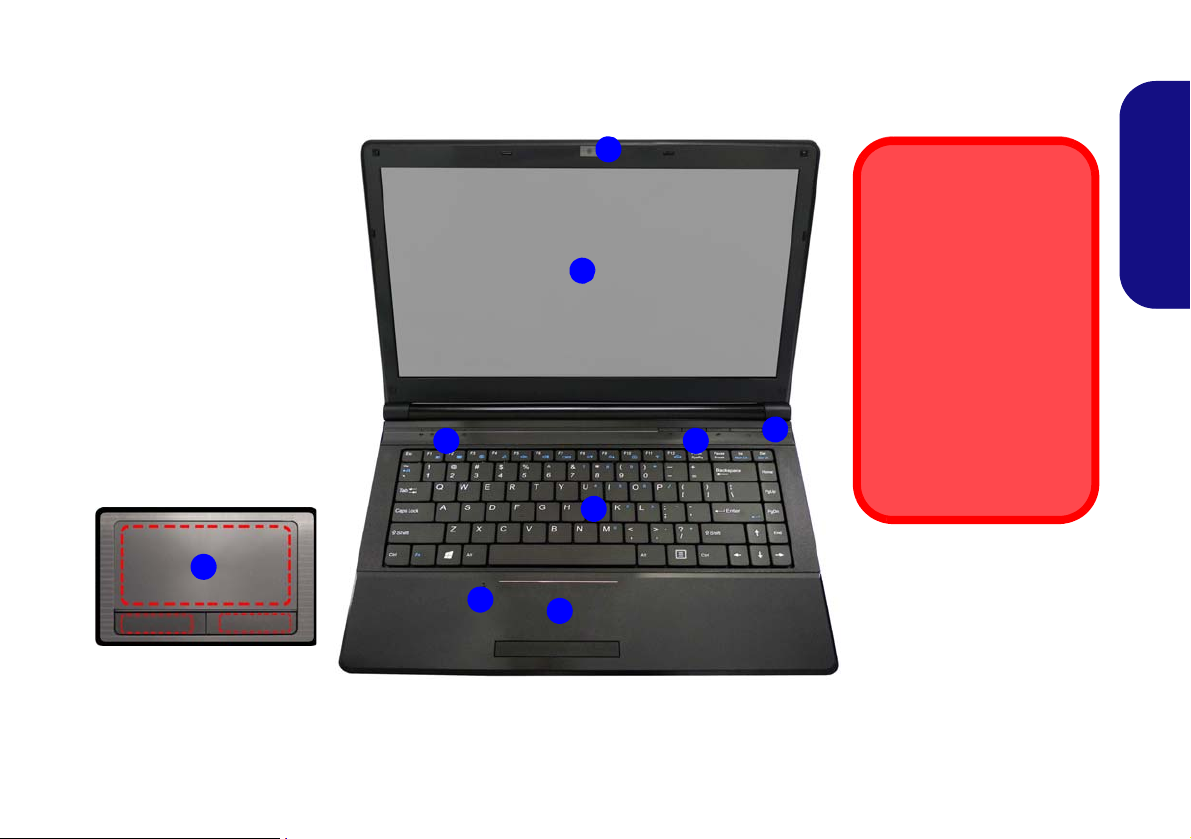
Figure 3
15.6” (39.62cm)
Model B
5
4
6
1
7
2
8
3
7
17.3” (43.94cm)
Model C
4
6
5
7
1
2
3
8
Front View with LCD Panel
Open (Models B & C)
1. PC Camera (Optional)
2. *PC Camera LED
*When the PC camera is
in u
se, the LED will be
illuminated in red.
3. LCD
4. Power Button
5. LED Status Indicators
6. Keyboard
7. *Built-In Microphone
*Note t
hat the microphone
location is dependent
upon your model design.
8. Touchpad & Buttons
Wireless Device
Operation Aboard Aircraft
The use of any portable electronic transmission
devices aboard aircraft is usually prohibited.
Make sure the WLAN & Bluetooth module(s) are
OFF if you are using the computer aboard aircraft by putting the system in to Airplane Mode.
Note that the Touchpad and
Buttons valid operational
area is that indicated within
the red dotted lines.
8
English
6

LED Indicators
Model A - Design lI
Model A - Designs l & III
Models B & C
The LED indicators on the computer display helpful information about the current status of the computer.
Icon Color Description
Icon Color Description
Green The Wireless LAN Module is Powered On
Orange The Bluetooth Module is Installed
Green Hard Disk Activity
Green
Green Caps Lock Activated
Green Scroll Lock Activated
Table 1 - LED Status Indicators
Number Lock (Numeric Keypad) Acti-
vated
Orange The AC/DC Adapter is Plugged In
Green The Computer is On
Blinking
Green
Blinking
Orange
Orange The Battery is Charging
Green The Battery is Fully Charged
Blinking
Orange
Table 2 - LED Power Indicators
The Computer is in Sleep Mode
The PC Camera is In Use
(14.0”/35.56cm Model A only)
The Battery Has Reached Critically
Low Power Status
English
7
Models B & C
Function Keys
Numeric
Keypad
Menu/Application Key
Num Lk &
Scr Lk
Function Keys
Num Lk &
Scr Lk
Numeric
Keypad
Fn Key
Windows Logo Key
Menu/Application Key
Model A
Fn Key
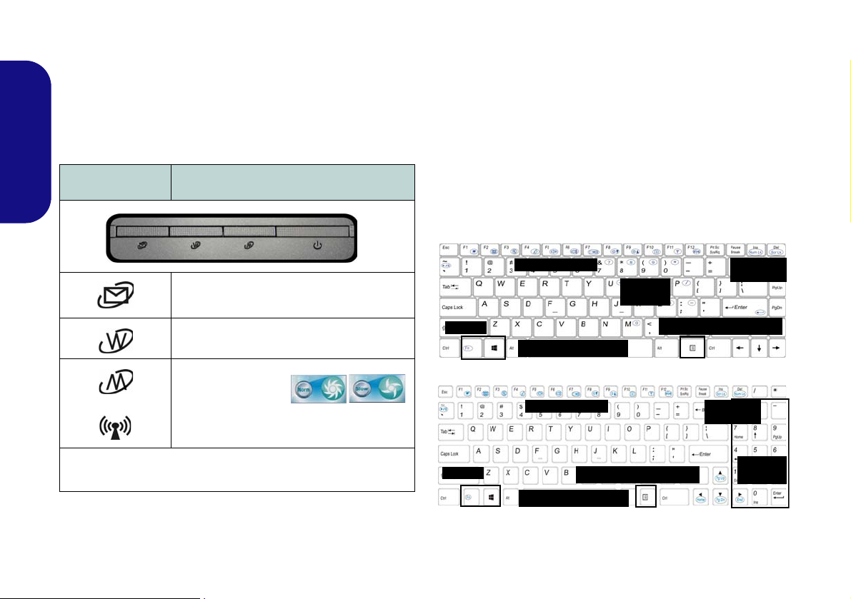
Hot-Key Buttons - Some Model
Windows Logo Key
Keyboard
English
A Designs Only
The Hot-Key buttons give instant access to the default Internet browser and e-mail program, and allow you to toggle the Silent Mode/the WLAN module on/off with one
quick button press.
Hot-Key Button Function
Activate the Default E-Mail Browser
Activate the Default Internet Program
or
*Toggle Silent Mode
*When enabled, Silent Mode will reduce fan noise and save power
consumption. Note this may reduce computer performance.
WLAN Module Power Toggle
or
The keyboard (Model A) has a numeric keypad for easy
numeric data input. Pressing Fn + Num Lk turns on/off
the numeric keypad. It also features func tion keys to allow you to change operational features instantly.
The keyboard (Models B & C) includes a numeric keypad (on the right side of the keyboard) for easy numeric
data input. Pressing Fn + Num Lk turns on/off the numeric keypad. It also features function keys to allow you
to change operational features instantly.
Table 3 - Hot-Key Buttons - Some Model A Designs Only
8
Figure 4 - Keyboard
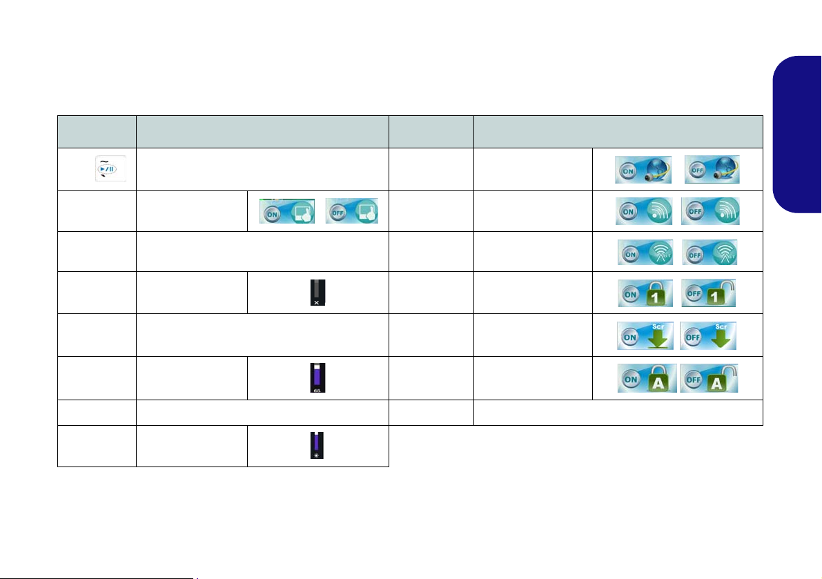
Function Keys
The function keys (F1 - F12 etc.) will act as hot keys when pressed while the Fn key is held down. In addition to the
basic function key combinations, some visual indicators are available (in the Windows Desktop application only and
not in the Start Screen) when the hot key driver is installed.
Keys Function/Visual Indicators Keys Function/Visual Indicators
English
Fn +
Fn + F1 Touchpad Toggle Fn + F11
Fn + F2
Fn + F3 Mute Toggle Fn + NumLk Number Lock Toggle
Fn + F4 Sleep Toggle Fn + ScrLk Scroll Lock Toggle
Fn + F5/F6
Fn + F7 Display Toggle Fn + Esc Control Center Toggle (see page 10)
Fn + F8/F9
Play/Pause (in Audio/Video Programs)
Turn LCD Backlight Off
(Press a key to or use Touchpad to turn on)
Volume Decrease/
Increase
Brightness Decrease/
Increase
Fn + F10
Fn + F12
Caps Lock Caps Lock Toggle
PC Camera Power
Toggle
WLAN Module Power
Toggle
Bluetooth Module
Power Toggle
Table 4 - Function Keys & Visual Indicators
9
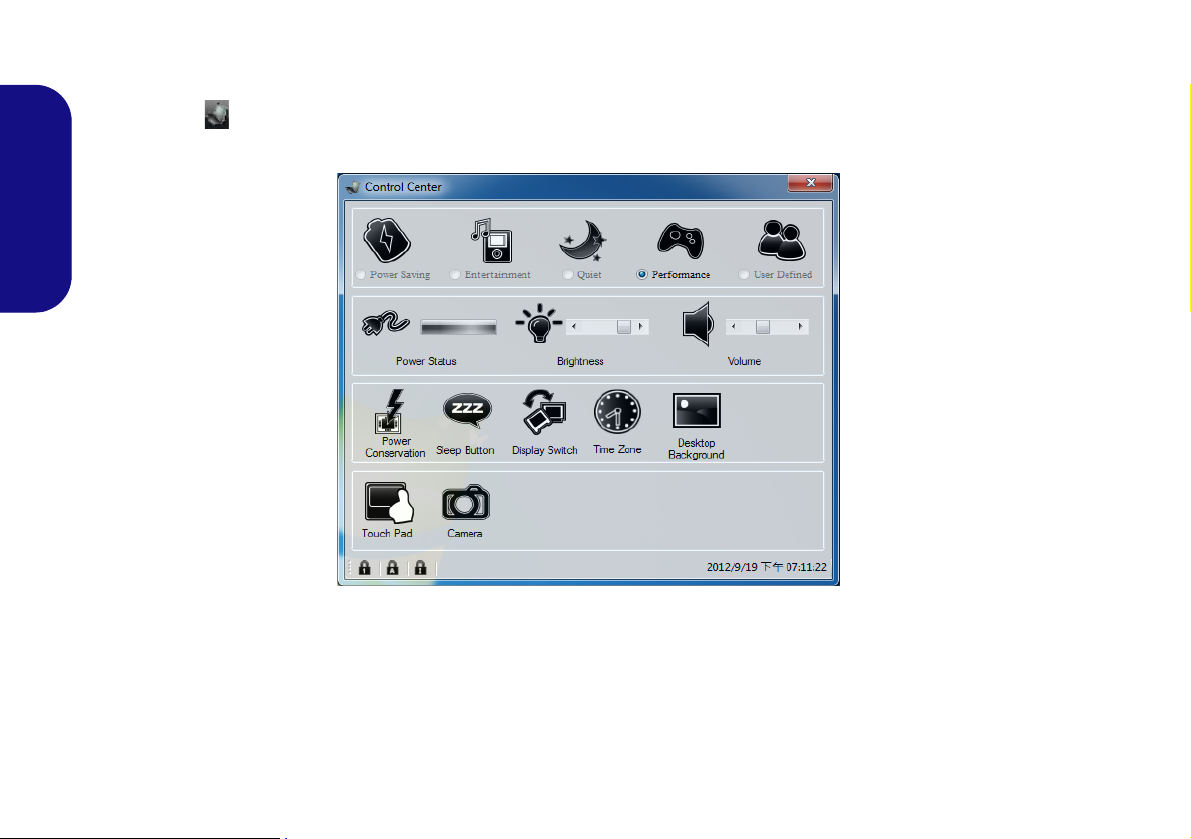
Control Center
When in the Windows Desktop application ( not in the Start Screen), press the Fn + Esc key combination, or doubleclick the icon in the notification area of the taskbar to toggle the Control Center on/off. The Control Center gives
quick access to frequently used controls, and enables you to quickly turn modules on/off.
English
Figure 5 - Control Center
Click on any button to turn any of the modules (e.g. TouchPad, Camera) on/off. Click on Power Conservation to switch
between Performance, Balanced or Energy Star modes. Click on the buttons (or just click and hold the mouse button)
to adjust the slider for Brightness/Volume. Click on Display Switch/Time Zone/ Desktop Background to bring up
the appropriate Windows control panel. Click on the Sleep button to put the computer into Hibernate or Sleep modes.
10
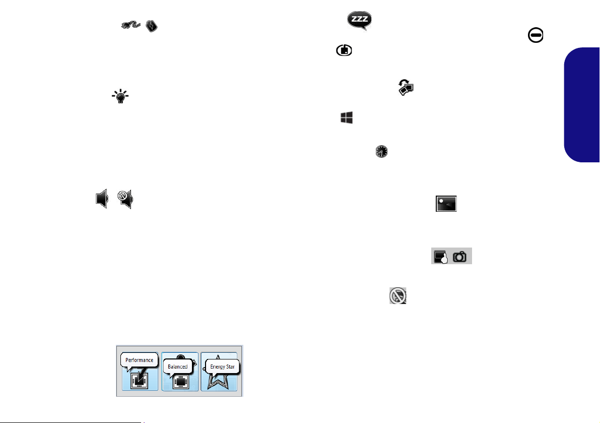
Power Status
The Power Status icon will sho w whether y ou are currently powered by the battery, or by the AC/DC adapter
plugged in to a working power outlet. The power status
bar will show the current battery charge state.
Brightness
The Brightness icon will show the current screen brightness level. You can use the slider to adjust the screen
brightness or the Fn + F8/F9 key combinations, or use the
Fn + F2 key combination to turn off the LED backlight
(press any key to turn it on again). Note that screen brightness is also effected by the Power Mode selected.
Sleep
Click the Sleep button to bring up the Hibernate or
Sleep
computer enter the appropriate power-saving mode.
Display Switch
Click the Display Switch button to access the me nu (or
use the
ate display mode.
buttons, and click either button to have the
+ P key combination) and select the appropri-
Time Zone
Clicking the Time Zone button will access the Date and
Time Windows control panel.
English
Volume
The Volume icon will show the current volume level. You
can use the slider to adjust the volume or the Fn + F5/F6
key combinations, or use the Fn + F3 key combination to
mute the volume.
Power Conservation
This system supports Energy Star p ower management
features that place computers (CPU, hard drive, etc.) into
a low-power sleep mode after a designated period of inactivity. Click either the Performance, Balanced or Ener-
gy Star button.
Desktop Background
Clicking the Desktop Background button will allow you
to change the desktop background picture.
Touchpad/PC Camera
Click any of these buttons to toggle the Touchpad or module’s power status. A crossed out icon will appear over the
top left of the icon when it is off
status of a module, and Touchpad power, is also effected
by the Power Mode selected.
. Note that the power
11
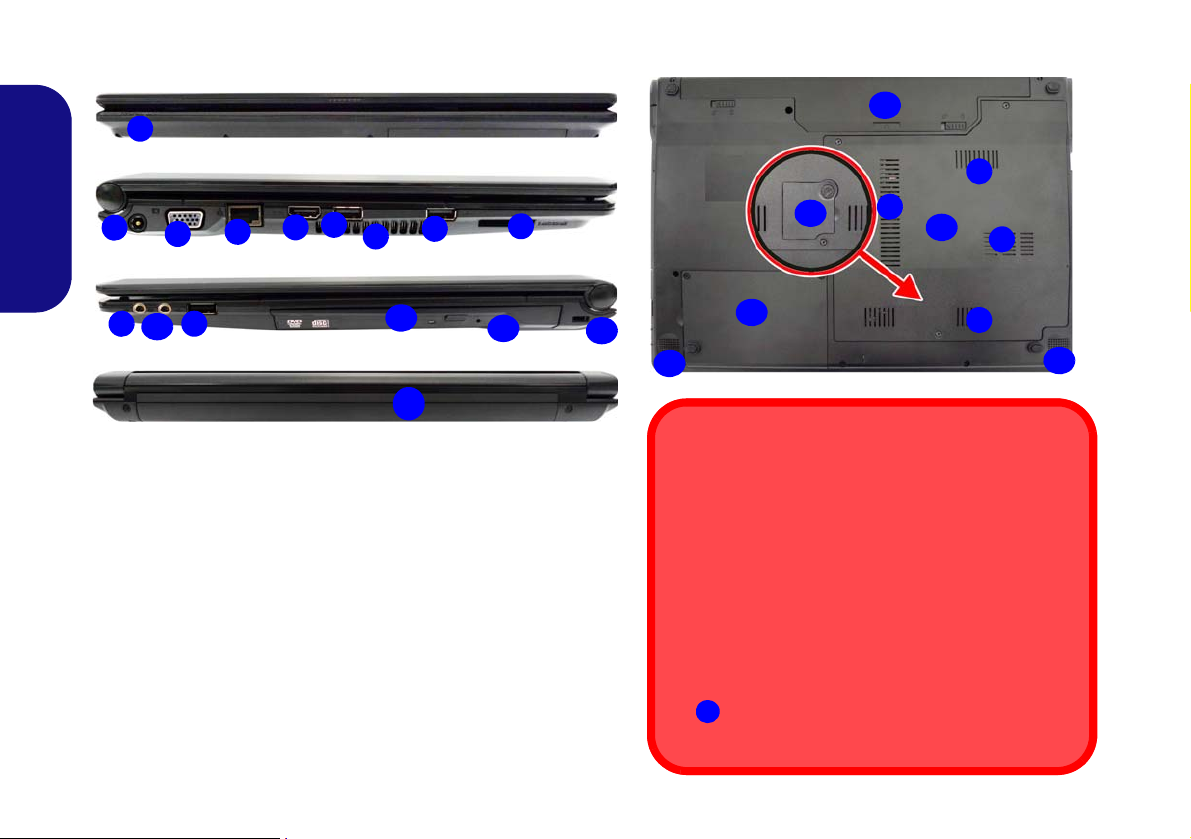
System Map: Front, Left, Right, Rear & Bottom Views (Model A)
2
1
7
8
4
6
3
Left
Right
5
Front
Rear
10
6
12
11
13
14
6
9
Figure 6 - Front, Left, Right, Rear & Bottom Views (Model A)
1. LED Power Indicators 11. Optical Device Drive Bay
2. DC-In Jack 12
. Emergency Eject Hole
3. External Monitor Port 13
. Security Lock Slot
4. RJ-45 LAN Jack 14
. Battery
5. HDMI-Out Port 15
. Component Bay Cover
6. 3 * USB 2.0 Ports 16
. Hard Disk Bay Cover
7. Vent 17
. Speakers
8. Multi-in-1 Card Reader 18
. USIM Card Cover
9. Microphone-In Jack
(
Optional)
10. Headphone-Out Jack
15
18
Bottom
7
17
7
17
16
7
7
14
Overheating
To prevent your computer from overheating make
sure nothing blocks any vent while the computer is in
use.
CPU
The CPU is not a user serviceable part. Accessing the
CPU in any way may violate your warranty.
Bottom Covers
If your model includes the 3G option then a small cover to enable you to access the module’s USIM
card will be included (see page 20).
18
English
12
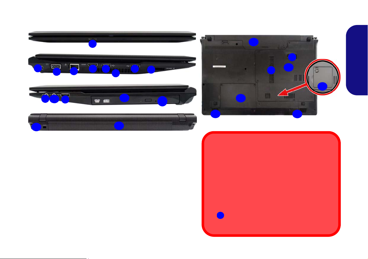
System Map: Front, Left, Right, Rear & Bottom Views (Model B)
2
1
7
8
4
6
3
Left
Right
5
Front
Rear
10
6
13
11
14
12
6
9
Figure 7 - Front, Left, Right, Rear & Bottom Views (Model B)
1. LED Power Indicators 11. Optical Device Drive Bay
2. DC-In Jack 12.
Emergency Eject Hole
3. External Monitor Port 13.
Security Lock Slot
4. RJ-45 LAN Jack 14.
Battery
5. HDMI-Out Port 15.
Component Bay Cover
6. 3 * USB 2.0 Ports 16.
Hard Disk Bay Cover
7. Vent 17.
Speakers
8. Multi-in-1 Card Reader 18.
USIM Card Cover
9. Microphone-In Jack
(
Optional)
10. Headphone-Out Jack
15
14
7
Bottom
16
17
7
17
18
Disc Emergency Eject
If you need to manually eject a disc (e.g. due to an unexpected power interruption) you may push the end of
a straightened paper clip into the emergency eject
hole. Do not use a sharpened pencil or similar object
that may break and become lodged in the hole.
Bottom Covers
If your model includes the 3G option then a small cover to enable you to access the module’s USIM
card will be included (see page 20).
18
English
13
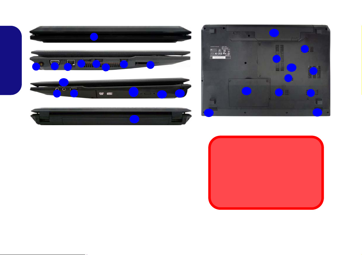
System Map: Front, Left, Right, Rear & Bottom Views (Model C)
1
7
6
4
6
3
Left
Right
5
Front
Rear
10
12
13
11
8
14
9
6
2
17
7
Bottom
7
15
7
7
14
17
7
16
7
Figure 8 - Front, Left, Right, Rear & Bottom Views (Model C)
1. LED Power Indicators 11. Optical Device Drive Bay
2. DC-In Jack 12.
Emergency Eject Hole
3. External Monitor Port 13.
Security Lock Slot
4. RJ-45 LAN Jack 14.
Battery
5. HDMI-Out Port 15.
Component Bay Cover
6. 3 * USB 2.0 Ports 16.
Hard Disk Bay Cover
7. Vent 17.
Speakers
8. Multi-in-1 Card Reader
9. Microphone-In Jack
10. Headphone-Out Jack
Disc Emergency Eject
If you need to manually eject a disc (e.g. due
to an unexpected power interruption) you
may push the end of a straightened paper
clip into the emergency eject hole. Do not
use a sharpened pencil or similar object that
may break and become lodged in the hole.
English
14
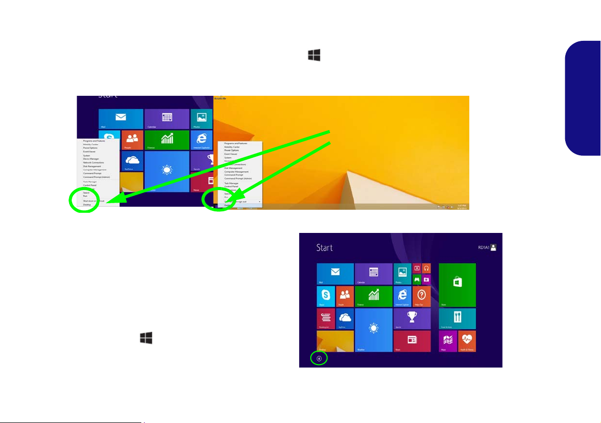
Windows 8.1 Control Panel
Move the mouse to
the bottom left of the
screen and right-click
the Start button to access the menu.
Figure 9
Context
Menu
Figure 10
Start
Screen
Throughout this manual you will see an instruction to open the Control Panel. Right-click the Start button in the
Desktop app or Start screen (or use the Windows Logo Key
menu of useful features such as Control Panel, Programs and Features, Power Options, Task Manager, Search, File Explorer, Command Prompt, Device Manager and Network Connections etc. and then select Control Panel.
+ X key combination) to bring up an advanced context
Windows 8.1 Start Screen & Desktop
The Apps, control panels, utilities and programs within
Windows are a ccessed f rom the Start screen and/or
Windows Desktop app. The Desktop (which runs as an
app within the Start screen) can be accessed by clicking
the Desktop item in the Start screen (or by using the
Windows Logo Key + D key combination). Click
the arrow at the bottom of the Start screen to access Ap-
ps.
15
English
Apps & Tiles
Click the arrow at the bottom of the
screen to access Apps
The Start screen will contain a nu mber of apps, and many more
will be installed as you add more applications etc. Not all of these
apps can fit on one screen so you will often need use the slider at
the bottom of the screen in order to view all the necessary Apps.
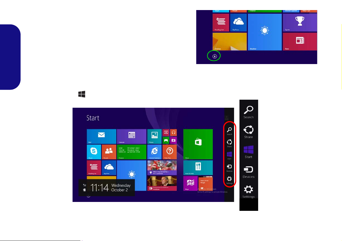
Charms Bar
English
The right side of the screen displays the Charms Bar. The Charms Bar contains the Search, Share, Start, Devices and
Settings menus. To access up the Charms Bar move the cursor to the upper or lower right corners of the screen, and
then hover over one of the items in th e Charms Bar to activate it (the bar will be black when it is active), or u se the
Windows Logo Key
+ C key combination.
16
Figure 11 - Start Screen with Charms Bar
Video Features
1
2
2
1
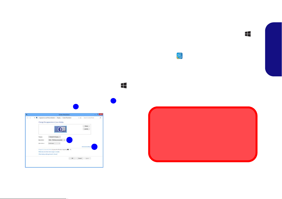
Figure 12
Display
Control
Panel
Screen Resolution for Apps (Windows 8.1)
The minimum resolution in which Apps will run is
1024x768.
The minimum resolution required to support all the features of Windows 8.1 (including multitasking with snap)
is 1366x768.
The system features an Intel integrated GPU. You can
switch display devices, and configure display options,
from the Display control panel in Windows as long as the
video driver is installed.
To access the Display control panel in Windows:
1. Go to the Control Panel.
2. Click Display (icon) - in the Appearances and
Personalization category.
3. Click Adjust Screen Resolution/Adjust resolution.
OR
4. Right-click the desktop (use the Windows Logo Key + D
key combination to access the desktop) and select Screen
resolution.
5. Use the dropbox to select the screen resolution
6. Click Advanced settings
.
.
To access the Intel® HD Graphics Control Panel:
1. Click the icon (Intel® HD Graphics Control Panel) on the
Start screen.
OR
2. Right-click the desktop (use the Windows Logo Key + D
key combination to access the desktop) and select Graphics
Properties from the menu.
OR
3. Click the icon in the notification area of the Desktop
taskbar and select
Graphics Properties from the menu.
Display Devices
Besides the built-in LCD, you can als o use an external
VGA monitor (C RT)/external Flat Panel Disp lay or TV
(connected to the external monitor port/HDMI-Out port)
as your display device.
English
17
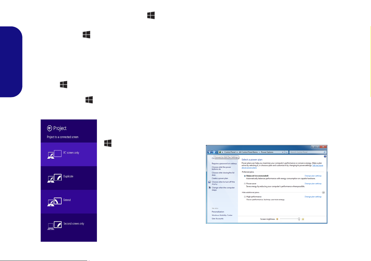
Using the Windows Logo Key + P
Figure 13
+ P (Change Display
Configuration)
Figure 14 - Power Options
Key Combination to Switch Displays
You can also use the + P key combination (or Fn + F7
) to quickly change display configuration and modes (this
is particularly useful when attaching a projector) in Win-
dows.
1. Attach your external display to the external monitor port/HDMI-
English
Out port, and turn it on.
2. Press the
3. An on-screen menu will pop up.
4. Use the cursor keys (
configuration from the menu, and press Enter to confirm the
selection.
+ P (or Fn + F7) key combination.
+ P) to select the appropriate
Power Options
The Power Options (Hardware and Sound menu) control panel icon in Windows allows you to configure power
management features f or your comp uter. You can conserve power by means of power plans and configure the
options for the power button, sleep button (Fn + F4),
computer lid (when closed), display and sleep mode (the
default power saving state) from the left menu. Note that
the Power saver plan may have an affect on computer
performance.
Click to select one of the existing plans, or click Create a
power plan in the left menu and select the options to create a new plan. Click Change Plan Settings and click
Change advanced power settings to access further configuration options.
18
Driver Installation
Driver Installation & Power
When installing drivers make sure
your computer is powered by the
AC/DC adapter connected to a
working power source. Some drivers draw a significant amount of
power during the installation procedure, and if the remaining battery
capacity is not adequate this may
cause the system to shut down and
cause system problems (note that
there is no safety issue involved
here, and the battery will be rechargeable within 1 minute).
Driver Installation General
Guidelines
As a general guide follow the
default on-screen instructions for each driver (e.g.
Next > Next > Finish) unless
you are an advanced user. In
many cases a restart is required to install the driver.
Make sure any modules (e.g.
WLAN or Bluetooth) are ON
before installing the appropriate driver.
Windows Update
After installing all the drivers
make sure you enable Win-
dows Update in order to get
all the latest security updates
etc. (all updates will include
the latest hotfixes from Mi-
crosoft).
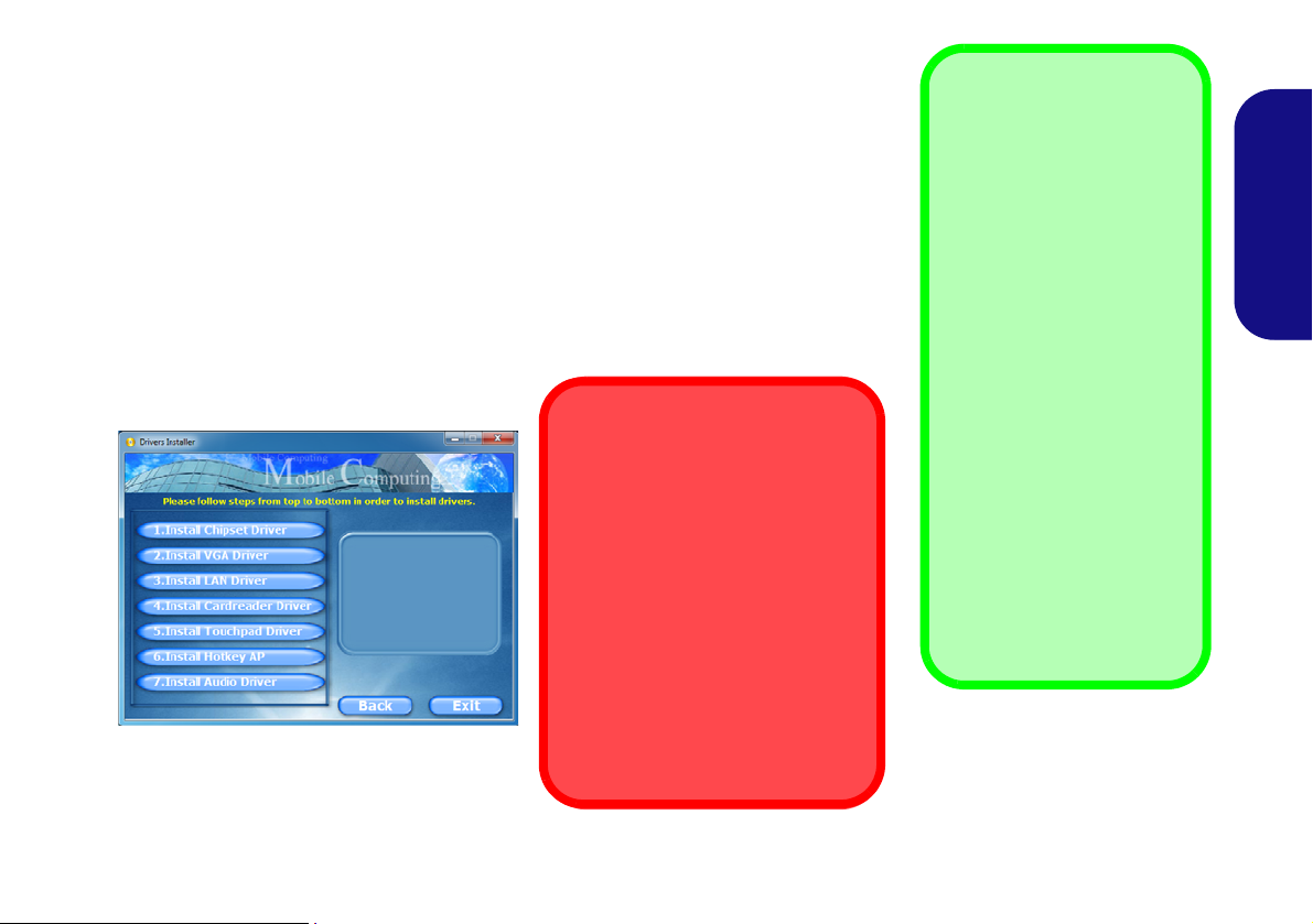
The Device Drivers & Utilities + User’s Manual disc contains the drivers and utilities
necessary for the proper operation of the computer. This setup will probably have already been done for you. If this is not the case, insert the disc and click Install Drivers
(button), or Option Drivers (button) to access the Optional driver menu. Install the
drivers in the order indicated in Figure 15. Click to select the dr ivers you wish to
install (you should note down the drivers as you in stall them). Note: If you need to
reinstall any driver, you should uninstall the driver first
If the Found New Hardware wizard appears during the installation procedure, click
Cancel to close the window, and follow the installation procedure as directed.
Figure 15 - Install Drivers
.
English
19
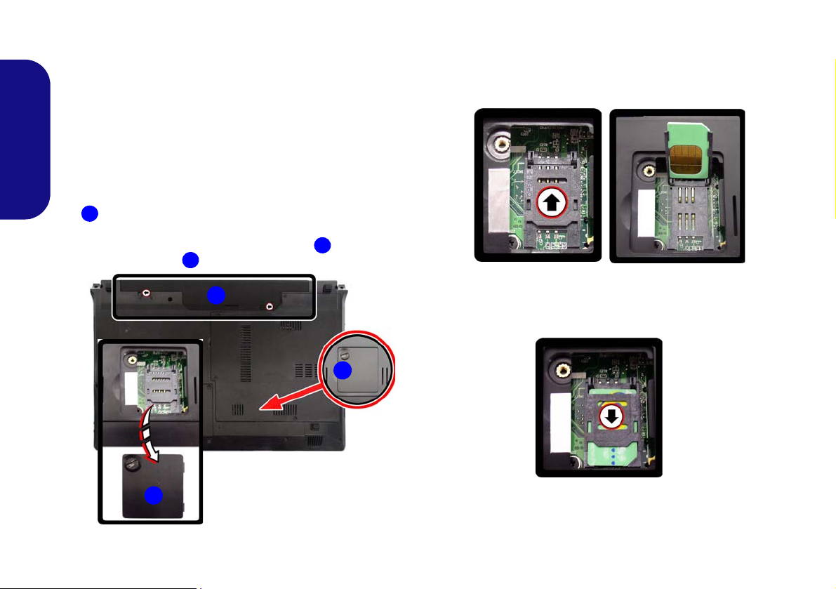
3G Module
3
2
1
3
2
(Models A & B Only)
If you have included an optional 3G module in your purchase option, follow the instructions below to install the
USIM card (which will be pr ovided by your service provider), and then run the appropriate application supplied
with your module.
English
USIM Card Insertion
1. Turn 1 off the computer, and turn it over and remove the battery
the battery out).
2. Locate the SIM card cover and loosen screw
the SIM card cover .
(slide the latches in the direction indicated below and slide
and remove
3. Insert the USIM card as you would into your mobile phone.
4. Slide the SIMLOCK towards the hinge (in the direction to the
arrow illustrated in Figure 17) in order to release the lock and
lift it up.
5. Insert the USIM card and close the SIMLOCK.
Figure 17 - Unlock the SIMLOCK
Figure 16 - Battery & SIM Card Cover Removal
20
6. Lock the SIMLOCK by pushing it in the direction of the arrow in
Figure 18 until it clicks into the lock position.
Figure 18 - Lock the SIMLOCK
7. Replace the cover, screw and battery.
Troubleshooting
Problem Possible Cause - Solution
The Bluetooth module is off
after resuming from Sleep.
A file cannot be copied to/
from a connected Bluetooth
device.
The PC Camera module
cannot be detected.
The captured video files from
the PC Camera are taking up
too much disk space.
The Bluetooth module’s default state will be off after resuming from the Sleep power-saving state.
Use the key combination (Fn + F12) to power on the Bluetooth module after the computer resumes
from Sleep.
Transferring data between the computer and a Bluetooth enabled device is supported in one
direction only (simultaneous data transfer is not supported). If you are copying a file from your
computer to a Bluetooth enabled device, you will not be able to copy a file from the Bluetooth
enabled device to your computer until the file transfer process from the computer has been
completed.
The module is off. Press the Fn + F10 key combination in order to enable the module (see Table 4
on page 9). Run the camera application to view the camera picture.
Note that capturing high resolution video files requires a substantial amount of disk space for each
file.
Note that the Windows system requires a minimum of 16GB (32bit) or 20GB (64bit) of free space
on the C: drive system partition. It is recommended that you save the capture video file to a
location other than the C:drive, limit the file size of the captured video or reduce video resolution.
English
21

Specifications
Latest Specification Information
The specifications listed in this here
are correct at the time of going to
press. Certain items (particularly
processor types/speeds) may be
changed, delayed or updated due to
the manufacturer's release schedule. Check with your service center
for details.
Processor
BIOS
English
Intel® Celeron® 847 Processor
1.10GHz, 32nm, 2MB L3 Cache, DDR3-
1333MHz, TDP: 17W
Intel® Celeron® 877 Processor
1.40GHz, 32nm, 2MB L3 Cache, DDR3-
1333MHz, TDP: 17W
Display
Model A - Designs I & III:
14” (35.65cm) HD (Thickness: 5.2mm)
Model A - Design II:
14” (35.65cm) HD (Thickness: 3.6mm)
Model B:
15.6” (39.62cm) HD
Model C:
17.3" (43.94cm) HD+ / FHD
Core Logic
Intel® NM70 Chipset
Memory
Two 204 Pin SO-DIMM Socket Supporting
DDR3 1333/1600MHz Memory (The real
memory operating frequency depends on the
FSB of the processor)
Memory Expandable up to 8GB
One 48Mb SPI Flash ROM
AMI BIOS
Video Adapter
Intel® HD Graphics
Dynamic Frequency (Intel Dynamic Video
Memory Technology for up to 1.7GB)
Microsoft DirectX®10.1 Compatible
Audio
High Definition Audio Compliant Interface
2 * Built-In Speakers
Built-In Microphone
Storage
(Factory Option) One Changeable
12.7mm(h) Super Multi Optical Device Drive
(Factory Option) Dummy ODD (Some
Model A designs and some Model B
designs Only)
One Changeable 2.5" 9.5mm (h) SATA
HDD
22

Interface
Communication
Mini Card Slots
Three USB 2.0 Ports
One Headphone-Out Jack
One Microphone-In Jack
One External Monitor Port
One HDMI-Out Port
One RJ-45 LAN Jack
One DC-in Jack
Security
Kensington Lock Slot
BIOS Password
Keyboard
Model A:
“WinKey” keyboard (with embedded
numeric keypad)
Models B & C:
Full-size “WinKey” keyboard (with numeric
keypad)
Pointing Device
Built-in Touchpad
10Mb/100Mb Ethernet LAN
(Factory Option - Models A & B) 300K
Pixel
/2M HD PC Camera Module
(Factory Option - Model C) 2M HD PC
Camera Module
(Factory Option) 3G Mini-Card Module
(Models A & B Only)
WLAN/ Bluetooth Half Mini-Card
Modules:
(Factory Option) Intel® Centrino® Wireless-N 105 Wireless LAN (802.11b/g/n)
(Factory Option) Intel® Centrino® Wireless-N 135 Wireless LAN (802.11b/g/n) +
Bluetooth 3.0
(Factory Option) Third-Party Wireless LAN
(802.11b/g/n)
(Factory Option) Third-Party Wireless LAN
(802.11b/g/n) + Bluetooth 4.0
Card Reader
Embedded Multi-In-1 Card Reader
MMC (MultiMedia Card) / RS MMC
SD (Secure Digital) / Mini SD
MS (Memory Stick) / MS Pro / MS Duo
Models A & B:
Slot 1 for WLAN Module or WLAN and
Bluetooth Combo Module
(Factory Option) Slot 2 for 3G Module
Model C:
Slot 1 for WLAN Module or WLAN and
Bluetooth Combo Module
Power
Model A:
Full Range AC/DC Adapter
AC Input: 100 - 240V, 50 - 60Hz
DC Output: 19V, 3.42A/18.5V, 3.5A (65W)
Removable 6 Cell Smart Lithium-Ion Battery Pack, 48.84WH
(Factory Option) Removable 3 Cell Smart
Lithium-Ion Battery Pack, 24.42WH
(
Factory Option) Removable 6 Cell Smart
Lithium-Ion Battery Pack, 62.16WH
Models B & C:
Full Range AC/DC Adapter
AC Input: 100 - 240V, 50 - 60Hz
DC Output: 19V, 3.42A/18.5V, 3.5A (65W)
Removable 6 Cell Smart Lithium-Ion Battery Pack, 48.84WH
(
Factory Option) Removable 6 Cell Smart
Lithium-Ion Battery Pack, 62.16WH
English
23

Environmental Spec
Dimensions & Weight
Temperature
Operating: 5
Non-Operating: -20°C - 60°C
Relative Humidity
Operating: 20% - 80%
Non-Operating: 10% - 90%
°C - 35°C
English
Model A Design I:
340mm (w) * 238mm (d) * 25.05 - 33.5mm
(h)
2.2kg with 48.84WH Battery & ODD
Model A Design II:
340mm (w) * 238mm (d) * 13.9 - 31.8mm
(h)
340mm (w) * 238mm (d) * 12 - 30.2mm (h)
2.2kg with 48.84WH Battery & ODD
Model A Design III:
341mm (w) * 238.5mm (d) * 16 - 34mm (h)
(h)
2.2kg with 48.84WH Battery & ODD
Model B Design I:
374mm (w) * 250mm (d) * 20 - 37.2mm (h)
2.6kg with 48.84WH Battery & ODD
Model B Design II:
374mm (w) * 238mm (d) * 14.3 - 34.1mm
(h)
2.3kg with 48.84WH Battery & ODD
Model C:
413mm (w) * 270mm (d) * 14 - 40.5mm (h)
2.9kg (with 48.84WH Battery and ODD)
24

Über das Ausführliche Benutzerhandbuch
Diese Kurzanleitung soll einen Überblick über die Schritte geben, die dazu notwendig sind, das System zu starten. Dieses ist
nur eine Ergänzung und kein Ersatz für das erweiterte englischsprachige Benutzerhandbuch, das auf der mitgelieferten Disc
Device Drivers & Utilities + User's Manual im Adobe-Acrobat-Format vorli egt. Diese Dis c enthält auch die Treiber und
Utility-Programme, die für einen einwandfreien Betrieb des Computers notwendig sind (Hinweis: Das Unternehmen behält
sich das Recht vor, diese Publikation ohne Vorankündigung zu überarbeiten und den Inhalt zu verändern).
Einige oder alle Funktionen des Computers sind bereits eingerichtet worden. Falls das nicht der Fall ist oder wenn Sie einzelne Teile des Systems neu konfigurieren (oder neu installieren) möchten, finden Sie eine Anleitung im erweiterten Benut-
zerhandbuch. Die Disc Device Drivers & Utilities + User's Manual enthält nicht das Betriebssystem.
Einhaltung gesetzlicher Vorschriften und Sicherheitshinweise
Beachten Sie sorgfältig die Hin weise zu gesetzli chen Vorschriften und zu Sicherheitshinweisen im erweiterten Benutzerhandbuch auf der Disc Device Drivers & Utilities + User's Manual.
© Oktober 2013
Warenzeichen
Intel und Celeron sind warenzeichen/eingetragenes warenzeichen der Intel Corporation.
Deutsch
25

Hinweise zu Pflege und Betrieb
Das Noteb ook is t z war s ehr s tabil, kan n a ber d ennoch be schädigt werden. Dami t e s nicht dazu kommt, so llten Sie die
folgenden Hinweise beachten:
• Das Gerät darf nicht herunterfallen und in anderer Form Stößen
ausgesetzt werden. Wenn der Computer fällt, können das Gehäuse und
andere Komponenten beschädigt werden.
• Das Gerät darf nicht nass werden und sich nicht überhitzen. Computer und Netzteil dürfen nicht in der Nähe von Wärmequellen stehen oder
gelagert werden. Dies ist ein elektrisches Gerät. Wenn Wasser oder
andere Flüssigkeiten eindringen, kann der Computer stark beschädigt
werden.
• Vermeiden Sie Interferenzen mit anderen Geräten. Halten Sie den
Computer fern von magnetischen Feldern, die von Stromquellen, Monitoren, Magneten etc. erzeugt werden. Die können die Leistung beein-
Deutsch
trächtigen und Ihre Daten beschädigen.
• Achten Sie auf die richtige Bedienung des Computers. Schalten Sie
ihn erst aus, wenn alle Programme geschlossen wurden (speichern Sie
Ihre Daten!). Speichern Sie regelmäßig Ihre Daten, da diese verloren
gehen können, wenn der Akku verbraucht ist.
Reparatur
Nehmen Sie vor de m Reinige n d es Wenn Sie versuchen, d en
Computer selbst zu reparieren, können Ihre Garantieansprüche
verloren gehen. Außerdem besteht Stromschlaggefahr für Ihre
Gesundheit und das Gerät durch frei liegende Teile. Lassen Sie
Reparaturarbeiten nur von qua lifizierten Repar aturfachleuten
durchführen, insbesondere wenn folgende Umstände vorliegen:
• Wenn das Netzkabel oder der AC/DC-Adapter beschädigt oder zerschlissen sind.
• Wenn der Computer Regen ausgesetzt war oder mit Flüssigkeiten in
Berührung gekommen ist.
• Wenn der Computer unter Beachtung der Bedienungsanweisungen nicht
korrekt arbeitet.
26
• Wenn der Computer heruntergefallen ist oder beschädigt wurde (berühren Sie nicht die giftige Flüssigkeit des LCD-Bildschirms).
• Wenn ein ungewöhnlicher Geruch, Hitze oder Rauch aus dem Computer
entweicht.
Sicherheitsinformationen
• Verwenden Sie nur einen AC/DC-Adapter, der für die Verwendung mit
diesem Computer zugelassen ist.
• Verwenden Sie nur das Netzkabel und die Akkus, die in diesem Benutzerhandbuch spezifiziert sind
Sie können explodieren. Richten Sie sich nach den regional gültigen Entsorgungsvorschriften.
• Verwenden Sie den Akku nicht mehr, wenn er heruntergefallen ist oder in
anderer Weise beschädigt (z.B. verzogen) ist. Auch wenn der Computer
mit dem beschädigten Akku zu funktionieren schein, können dadurch
Stromkreise beschädigt werden, die schließlich einen Brand verursachen
können.
• Achten Sie darauf, dass Ihr Computer ausgeschaltet ist, wenn Sie es fur
den Transport z.B. wahrend einer Reise in eine Tasche einpakken.
• Nehmen Sie vor dem Reinigen des Computers den Akku heraus, und
trennen Sie es von allen externen Stromquellen, Peripheriegeräten und
Kabeln (einschließlich Telefonkabel) ab.
• Reinigen Sie den Computer mit einem weichen, sauberen Tuch. Tragen
Sie das Reinigungsmittel nicht direkt auf den Computer auf. Verwenden
Sie keine flüchtigen Reinigungsmittel (Petroleumdestillate) oder Scheuermittel zum Reinigen des Computers.
• Versuchen Sie nicht, Akkus zu reparieren. Lassen Sie die Akkupacks
durch den Servicevertreter oder qualifiziertes Fachpersonal reparieren
oder austauschen.
• Beachten Sie, dass das Logo bei den Computern, die über ein galvanisch
beschichtetes LCD-Logo verfügen, von einer Schutzfolie bedeckt ist.
Durch die natürliche Abnutzung kann diese Schutzfolie beschädigt werden oder abgehen und die scharfen Kanten des frei liegenden Logos
freigeben. Seien Sie in solch einem Fall vorsichtig bei der Handhabung
des Computers, und vermeiden Sie es, das herausstehende beschichtete
LCD-Logo zu berühren. Legen Sie keine Gegenstände in die Tragetasche, da diese während des Transports gegen den Computer drücken
können. Wenden Sie sich in einem solchen Fall von Abnutzung an Ihr
Service Center.
. Entsorgen Sie die Akkus nicht in Feuer.

Polymer Akku Sicherheitshinweise
Entsorgen der Akkus/ Batterien & Achtung
Das von Ihnen gekaufte Produkt enthält einen aufladbaren
Akku. Dier Akku ist wiederverwertbar. Nach verschiedenen nationalen und regionalen Getzgebungen kann es verboten in,
einen nicht mehr gebrauchsfähigen Akku in den normalen
Hausmüll zu werfen. Informieren Sie sich bei Ihrem regionalen
Entsorgungsunternehmen über Recycling-Möglichkeiten oder
korrekte Entsorgung.
Wenn ein falscher Akku eingesetzt wird, besteht Explosionsgefahr. Tauschen Sie den Akku nur durch den gleichen oder
einen baugleichen Typ aus, der vom Hersteller empfohlen
wird. Entsorgen Sie den verbrauchten Akku entsprechend der
Anweisungen des Herstellers.
Beachten Sie die folgenden Hinweise, die sich speziell auf Polymer Akk us be ziehen. Di ese Hin weise haben zu dem Vor rang
gegenüber den Allgemeinen Akku Sicherheitshinweisen.
• Polymer Akkus können sich etwas ausdehnen oder anschwellen. Dies ist
Teil des Sicherheitsmechanismus des Akkus und kein Anlass zur Sorge.
• Seien Sie vernünftig im Umgang mit Polymer Akkus. Verwenden Sie
keine Polymer Akkus in Umgebungen mit hohen Temperaturen und
lagern Sie keine ungenutzten Akkus über längere Zeiträume.
Deutsch
27

Schnellstart
.130 °
Herunterfahren
Bitte beachten Sie, daß der
Computer immer mit dem Befehl
Herunterfahren in Windows
(siehe unten) heruntergefahren
werden muß. Dadurch werden
Festplatten- bzw. Systemprobleme vermieden.
Klicken auf Einstellungen in
der Charms-Leiste aus (die
Charms-Leiste wird aufgerufen,
indem Sie die Windows Logo-
Taste und gleichzeitig auf
C drükken). Wählen Sie dann
aus dem
Ein/Aus-Menü die Op-
tion Herunterfahren.
Oder
Wählen Sie aus dem Kontextmenü Herunterfahren oder
abmelden > Herunterfahren
(das Kontextmenü wird aufgerufen, indem Sie die Windows
Logo-Taste und gleichzeitig auf X drücken).
Abb. 1
Öffnen des Deckels/LCD/
Computers mit angeschlossenem AC/DC-
Adapter
1. Entfernen Sie das gesamte Verpackungsmaterial.
2. Legen Sie den Computer auf eine stabile Unterlage.
3. Setzen Sie den Akku ein, und stellen Sie sicher, dass sie fest sitzt.
4. Schließen Sie alle Peripheriegeräte, die Sie mit dem Computer
verwenden wollen (z. B. Tastatur und Maus), an die
entsprechenden Schnittstellen an.
5. Schließen Sie den AC/DC-Adapter an die DC-Eingangsbuchse
an der linken Seite des Computers an. Verbinden Sie dann das
Netzkabel mit einer Netzsteckdose und dem AC/DC-Adapter.
6. Klappen Sie den Deckel/LCD vorsichtig mit einer Hand auf, und
öffnen Sie ihn auf einen angenehmen Sichtwinkel (jedoch nicht
weiter als 130°). Mit der anderen Hand halten Sie das Unterteil
des Computers fest (siehe Abb. 1) (Hinweis: Heben Sie den
Deutsch
Computer niemals am Deckel/LCD hoch).
7. Drücken Sie auf den Netzschalter, um den Computer
einzuschalten.
Systemsoftware
Möglicherweise wurde das Notebook bereits mit vorinstallierter Software ausgeliefert. Ist das nicht der Fall, oder
wenn Sie das Notebook für ei n anderes Syst em neu
konfigurieren möchten, finden Sie dazu eine Anleitung in
diesem Handbuch zu Microsoft Windows 8.1.
Modellunterschiede
Diese Notebookserie umfasste verschiedene Modelle, die
sich leicht in Des ign, Farbe und al lgemeinen äu ßeren
Merkmalen voneinander unterscheiden. Ihr Modell kann
zwar äußerlich von dem in dieser Dokument abgebildeten
Modell etwas abweichen, jedoch sind alle Ports, Anschlüsse, Anzeigen, Spezifikationen und allgemeinen Funktionen
bei allen Modellen gleich.
28

Systemübersicht: Ansicht von vorne mit geöffnetem LCD-Bildschirm
Abb. 2
Ansicht von vorne mit ge-
öffnetem LCD-Bildschirm
(Modell A)
1. PC-Kamera (optional)
2. LCD-Bildschirm
3. Netzschalter
4. Hot-Key-Tasten (nu
r
einige Designs des
Modells A)
5. LED-Statusanzeigen
6. Tastatur
7. Mikrofon
8. Touchpad mit Tasten
4
6
3
5
7
1
8
2
14” (35,56cm)
In der Regel ist die Benutzung jeglicher tragbarer
elektronischer Funkgeräte in Flugzeugen verboten.
Stellen Sie sicher, dass
das WLAN- und das Bluetooth-Modul durch Aktivieren des
Flugzeugmodus ausgeschaltet sind, wenn Sie
sich an Bord eines Flugzeugs befinden.
8
Beachten Sie, dass der Funktionsbereich des Touchpads
und der Tasten innerhalb der
rot gepunkteten Linien liegt.
(Modell A)
Deutsch
29
Modell B
5
4
6
1
7
15,6” (39,62cm)
2
4
6
5
7
1
2
17,3” (43,94cm)
8
3
3
8
7
Systemübersicht: Ansicht von vorne mit geöffnetem LCD-Bild-
Abb. 3
Ansicht von vorne mit ge-
öffnetem LCD-Bildschirm
(Modelle B & C)
1. PC-Kamera (optional)
2. *LED der PC-Kamera
*Wenn die PC-Kamera
verwen
det wird, leuchtet
die LED rot.
3. LCD-Bildschirm
4. Netzschalter
5. LED-Statusanzeigen
6. Tastatur
7. *Mikrofon
*Die Posi
tion des Mikrofons hängt vom Modell
ab.
8. To uc h pad m it Tasten
Modell C
Die Benutzung drahtlos angeschlossener Geräte in Flugzeugen
In der Regel ist die Benutzung jeglicher tragbarer elektronischer
Funkgeräte in Flugzeugen verboten.
Stellen Sie sicher, dass das WLAN- und das Bluetooth-Modul durch Aktivieren des Flugzeugmodus ausgeschaltet sind, wenn Sie sich an Bord
eines Flugzeugs befinden.
Beachten Sie, dass der
Funktionsbereich des
Touchpads und der
Tasten innerhalb der rot
gepunkteten Linien liegt.
8
schirm (Modelle B & C)
Deutsch
30

LED-Anzeigen
Modell A - Design lI
Modelle B & C
Modell A - Designs l & III
Die LED -Anzeigen auf d em Comp uter zeigen wichtige
Informationen über den aktuellen Status des Computers.
Symbol Farbe Beschreibung
Symbol Farbe Beschreibung
Grün Das WLAN-Modul ist eingeschaltet
Orange
Grün Es wird auf die Festplatte zugegriffen
Grün
Grün Caps-Lock ist aktiviert
Grün Scroll-Lock ist aktiviert
Tabelle 1 - LED-Statusanzeigen
Das Bluetooth-Modul ist installiert
Die Funktion NumLk (Nummernta-
statur) ist aktiviert
Orange Der AC/DC-Adapter ist angeschlossen
Grün Der Computer ist angeschaltet
Lampe
blinkt
grün
Lampe
blinkt
orange
Orange Der Akku wird geladen
Grün Der Akku ist voll geladen
Lampe
blinkt
orange
Tabelle 2 - LED-Stromanzeigen
Das System ist im konfigurierten
Energiesparmodus
Die PC-Kamera wird verwendet
(Nur das 14,0”/35,56cm-Modell A)
Der Akku hat einen kritisch niedrigen
Stromstatus erreicht
Deutsch
31

-
-
Hot-Key-Tasten - nur einige Desi-
Modell A
Nummemtastatur
Funktionstasten
Fn Taste
Windows Logo-Taste
Menü/Anwendungstaste
Num & Rollen
Funktionstasten
Numm
Num &
emtastatur
Rollen
Menü/Anwendungstaste
Fn Taste
Windows Logo-Taste
Modelle B & C
gns des Modells A
Mit den Ho t-Key-Tasten haben Sie einen direkt en Zugriff
auf den St andard-Internetbrowser und Ih r E-Mail Standardprogramm, und Sie können mit nur einem schnellen
Tastendruck den Leise-Modus/das Wireless-LAN-Modul
ein- oder ausschalten.
Hot-Key-Taste Funktion
Deutsch
Das Standard-E-Mail-Programm aktivieren
Tastatur
Die Tastatur (Modell A) hat eine eingebettete Nummerntastatur für einfache Zahleneingabe. Durch Drükken auf Fn +
Num wird die Nummerntastatur ein- und ausgeschaltet. Zusätzlich gibt es Fun ktionstasten, über die Si e di rekt zwischen den Funktionen umschalten können.
Die Tastatur (Modelle B & C) umfasst eine Nummerntastatur (an d er rechten Seite der Tastatur) für die Eingabe
von Zahlen. D urch D rücken auf Fn + Num wi rd die
Nummerntastatur ein- und ausgeschaltet. Zusätzlich gibt es
Funktionstasten, ü ber d ie Si e d irekt zw ischen den Fu nktionen umschalten können.
Oder
*Wenn der Leise-Modus aktiviert ist, werden die Lüftergeräusche
und der Stromverbrauch reduziert. Beachten Sie, dass sich dabei
auch die Leistung des Computers verringern kann.
Tabelle 3 - Hot-Key-Tasten - nur einige Des igns des Mod el ls A
32
Einen Standard-Internet browser aktivieren
*Leise-Modus ein-/ausschalten
Wireless-LAN-Modul aktivieren/deaktivieren
Oder
Abb. 4 - Tastatur

Funktionstasten
Wenn die Funktionstasten (F1 - F12) gleichzeitig mit der Fn-Taste gedrückt werden, funktionieren sie wie Hotkeys. Neben
den Tastenkombinationen für die Grundfunktionen gibt es ei nige visuelle Anzeigen (nur bei der Windows Desktop-An-
wendung, aber nicht im Start-Bildschirm), wenn der Hotkey Treiber installiert ist.
Tasten Funktion/ Visuelle Anzeigen Tasten Funktion/ Visuelle Anzeigen
Fn +
Fn + F1
Fn + F2
Fn + F3
Fn + F4 Wechsel Schlaf/Wiederaufnahme
Fn + F5/F6
Fn + F7
Fn + F8/F9
Wiedergabe/Pause (in Audio /Videoprogrammen)
Touchpad aktivieren/
deaktivieren
LCD-Hintergrundlicht ausschalten (zum Einschalten
beliebige Taste drücken oder Touchpad berühren)
Stummschaltung/Stumm-
schaltung aufheben
Audio-Lautstärke
verringern/erhöhen
Ändern der Anzeigeeinstellungen (siehe Seite 42) Fn + Esc
LCD-Helligkeit verringern/
erhöhen
Fn + F10
Fn + F11
Fn + F12
Fn + Num
Fn + Rollen
PC-Kamera aktivieren/
deaktivieren
Wireless-LAN-Modul
aktivieren/deaktivieren
Bluetooth-Modul
aktivieren/deaktivieren
Ein-/Ausschalten der
Nummerntastatur
Ein-/Ausschalten des
Scroll-Modus
Ein-/Ausschalten der
Feststelltaste
Ein-/Ausschalten des Control Center (Steuerzentrum) (siehe
Seite 34)
Deutsch
Tabelle 4 - Funktionstasten & visuelle Anzeigen
33

Control Center (Steuerzentrum)
Drücken Sie auf die Tastenkombination Fn + Esc, oder doppelklicken Sie auf das Symbol im Infobereich auf der Taskleiste um das Control Center (Steuerzentrum) ein-/auszuschalten in der Windows Desktop-Anwend ung (nicht Start-Bild-
schirm). Das Control Center (Steuerzentrum) bietet den schnellen Zugriff auf häufig verwendete Funktionen, und Sie haben
hier die Möglichkeit, Module direkt ein-/auszuschalten.
Deutsch
Abb. 5 - Control Center
Klicken Sie auf eine beli ebige Taste, um ein Modul (z. B. Touchpad, Kamera) ein-/auszus chalten. Klicken Sie auf Power
Conservation (Strom sparen), um einen d er Modi Performance (Leistung), Balanced (Ausgeglichen) oder Energy Star
auszuwählen. Klicken Sie auf die Tasten (oder drücken Sie nur auf die Maustaste, und halten Sie diese gedrückt), um die
Helligkeit/Lautstärke (Brightness/Volume) einzustellen. Klicken Sie auf Display Switch (Anzeige wechseln)/Time Zone
(Zeitzone)/Desktop Background (Desktop-Hintergrund), um das entsprechende Windows-Systemsteuerungsfenster aufzurufen. Klicken Sie auf den Sleep (Schalter) für den Ruhezustand, um den Computer in den Ruhezustand oder in einen Ener-
giesparmodus zu versetzen.
34

Power Status (Energiestatus)
Das Energiestatus-Symbol zeigt an, ob die Stromvers orgung aktuell über den Akku oder über das an das Stromnetz
angeschlossene Netzteil erfolgt. Die Energiestatus -Anzeige
zeigt den aktuellen Akkuladestatus an.
Sleep (Schalter)
Klicken Sie auf den Schalter für den Ruhezustand, um di e
Schaltflächen Ruhezustand oder Schlaf
fen. Klicken Sie dann auf eine der b eiden Tast en, um den
Computer in den jeweiligen Modus zu versetzen.
aufzuru-
Brightness (Helligkeits)
Das Helligkeits-Symbol zeigt die aktuell eingestellte Bildschirmhelligkeit an.Sie können die Bildschirmhelligkeit entweder mit dem Sc hieberegler oder m it der
Tastenkombination Fn + F8/F9 ändern . Mit der
Tastenkombination Fn + F2 wird das LED-Hintergrundlicht
ausgeschaltet (drücken Sie auf eine beliebige Taste, um es
wieder einzuschalten). Beachten Sie, d ass die Bilds chirmhelligkeit auch vom eingestellten Energiemodus abhängt.
Volume (Lautstärke)
Das Lautstärke-Symbol zeigt die aktuelle Lautstärke an.Sie
können die Lautstärke entweder mit dem Schieberegler oder
mit der Tastenkombination Fn + F5/F6 einstellen. Mit der
Tastenkombination Fn + F3 wird der Ton ausgeschaltet.
Power Conservation (Strom sparen)
Dieses System unterstützt die Energy Star-Stromsparfunktionen, die Computer (CPU, Fest platte usw.) nach ei ner
längeren Zeit der Inaktivität in einen Ruhemodus versetzen,
bei dem weniger Strom verbraucht wird. Klicken Sie entweder auf die Ta ste Performance, Balanced oder Energy
Star.
Display Switch (Anzeige wechseln)
Klicken Sie auf die Taste zum Wechseln des Anzeigegeräts,
um das Menü aufzurufen (Sie könn en
Tastenkombination + P verwenden), und wählen Si e
einen Anzeigemodus aus.
dazu auch di e
Time Zone (Zeitzone)
Wenn Sie auf die Schal tfläche Zeitzone klicken, wird das
Windows-Systemsteuerungsfenster Datum und Uhrzeit
aufgerufen.
Desktop Background (Desktop-Hintergrund)
Wenn Sie auf die Schaltfläche Desktop-Hintergrund klikken, können Sie das Bild für den Des ktophintergrund einstellen.
Touchpad/PC-Kamera-Modul
Klicken Sie auf eine dieser Tasten, um das Touchpad/Modul
ein- oder auszuschalten. Ist es ausgeschaltet, erscheint links
oben am Symbol ein Kreuz. Beachten Sie, dass sowohl
der Energiemodus ei nes Mo duls und des Touchpads auch
vom ausgewählten Energiemodus abhängen.
Deutsch
35

Systemübersicht: Ansicht von vorne, links, rechts, hinten und unten
Vorderseite
Linke Seite
Rechte Seite
Hinterseite
2
1
7
8
4
6
3
5
10
6
12
11
13
14
6
9
Abb. 6
Ansicht von vorne, links, rechts, hinten und unten (Modell A)
1. LED-Stromanzeigen
2. DC-Eingangsbuchse
3. Schnittstelle für externen
Moni
tor
4. RJ-45 LAN-Buchse
5. HDMI-Ausgangsanschluss
6. 3 USB 2.0 Anschlüsse
7. Luftungsoffnung
8. Multi-in-1 Kartenleser
9. Mikrofon-Eingangsbuchse
10. Kopfhörer-Ausgangsbuchse
11. Schacht für optisches Laufwerk
12. Notauswurfloch
13. Sicherheitsschloß-Buchse
14. Akku
15. Komponentenfachabdekkung
16. Abdeckung des Festplattenschac
hts
17. Lautsprecher
18. USIM-Kartenfachabdekkung
(
optional)
Unterseite
Überhitzung
Zum Schutz vor Überhitzung Ihres Computers dürfen die
Luftungsoffnung(en) nicht während das Notebook in Betrieb ist verdeckt werden.
CPU
Die CPU darf nicht vom Anwender repariert werden.
Jeglicher Zugriff auf die CPU führt zum Verlust der Garantieansprüche.
Modulfachdeckel an der Unterseite
Wenn Ihr Gerät die 3G-Option enthält, ist das Fach, in
dem sich die USIM-Karte des Moduls befindet, mit einem
Modulfachdeckel verschlossen, den Sie für den Zugriff auf das Fach öffnen können (siehe Seite 44).
18
15
18
7
17
7
17
16
7
7
14
(Modell A)
Deutsch
36

Systemübersicht: Ansicht von vorne, links, rechts, hinten und unten
2
1
7
8
4
6
3
5
10
6
13
11
14
12
6
9
Vorderseite
Linke Seite
Rechte Seite
Hinterseite
Abb. 7
Ansicht von vorne, links, rechts, hinten und unten (Modell B)
1. LED-Stromanzeigen 11. Schacht für optisches Laufwerk
2. DC-Eingangsbuchse 12.
Notauswurfloch
3. Schnittstelle für externen 13.
Sicherheitsschloß-Buchse
Monitor
14. Akku
4. RJ-45 LAN-Buchse
15.
Komponentenfachabdekkung
5. HDMI-Ausgangsanschluss
16.
Abdeckung des Festplatten-
6. 3 USB 2.0 Anschlüsse schac
hts
7. Luftungsoffnung 17.
Lautsprecher
8. Multi-in-1 Kartenleser 18.
USIM-Kartenfachabdekkung
9. Mikrofon-Eingangsbuchse
(
optional)
10. Kopfhörer-Ausgangsbuchse
15
14
7
16
17
7
17
18
Unterseite
Disc-Notauswurf
Wenn eine Disc manuell entnommen werden muß (z.B.
wegen eines Stromausfalls) können Sie mit dem Ende
einer geradegebogenen Büroklammer in das Notauswurfloch drükken. Verwenden Sie hierzu aber keinen spitzen
Bleistift oder ähnliche Objekte, die im Loch abbrechen
und darin stekkenbleiben könnten.
Modulfachdeckel an der Unterseite
Wenn Ihr Gerät die 3G-Option enthält, ist das Fach, in
dem sich die USIM-Karte des Moduls befindet, mit einem
Modulfachdeckel verschlossen, den Sie für den Zugriff auf das Fach öffnen können (siehe Seite 44).
18
(Modell B)
Deutsch
37

Systemübersicht: Ansicht von vorne, links, rechts, hinten und unten
1
7
6
4
6
3
5
10
12
13
11
8
14
9
6
2
Vorderseite
Linke Seite
Rechte Seite
Hinterseite
17
7
7
15
7
7
14
17
7
16
7
Unterseite
Abb. 8
Ansicht von vorne, links, rechts, hinten und unten (Modell C)
1. LED-Stromanzeigen 11. Schacht für optisches Laufwerk
2. DC-Eingangsbuchse 12.
Notauswurfloch
3. Schnittstelle für externen 13.
Sicherheitsschloß-Buchse
Monitor
14. Akku
4. RJ-45 LAN-Buchse
15.
Komponentenfachabdekkung
5. HDMI-Ausgangsanschluss
16.
Abdeckung des Festplatten-
6. 3 USB 2.0 Anschlüsse schac
hts
7. Luftungsoffnung 17.
Lautsprecher
8. Multi-in-1 Kartenleser
9. Mikrofon-Eingangsbuchse
10. Kopfhörer-Ausgangsbuchse
Disc-Notauswurf
Wenn eine Disc manuell entnommen werden muß
(z.B. wegen eines Stromausfalls) können Sie mit dem
Ende einer geradegebogenen Büroklammer in das
Notauswurfloch drükken. Verwenden Sie hierzu aber
keinen spitzen Bleistift oder ähnliche Objekte, die im
Loch abbrechen und darin stekkenbleiben könnten.
(Modell C)
Deutsch
38

Windows 8.1 Systemsteuerung
Verschieben Sie die Maus in
die linke untere Ecke des Bildschirms, und klikken Sie mit der
rechten Maustaste auf die
Abb. 9
Start-Taste darauf, um das
Kontextmenü
Menü aufzurufen.
Abb. 10 - Start-Bildschirm
In diesem Handbuch finden Sie eine Anleitung zum Öffnen der Systemsteuerung. Klicken Sie mit der rechten Maustaste
auf die Start-Taste in der
Windows-Logo-Taste + X), um ein erweitertes Kontextmenü der nützlichen Funktionen aufzurufen: Systemsteuerung,
Programme und Funkti onen, Energieop tionen, T ask-Manager, Su che, Datei-Exp lorer, Eingabeaufforderu ng, Gerät eManager, Netzwerkverbindungen usw. Wählen Sie dann Systemsteuerung.
Desktop-App oder auf dem Start-Bildschirm (oder verwenden Sie di e Tastenkombination
Windows 8.1 Start-Bildschirm und Desktop
Die Apps, Bedienfenster, Dienstprogramme und andere Software erreichen Sie bei Windows üb er d en St art-Bildschirm u nd/oder d ie
Windows Desktop-App. Der Desktop (der im Start-Bildschirm ei ne
App startet) wird geöffnet durch Anklicken des Desktop-Eintrags im
Start-Bildschirm (oder durch
Windows-Logo-Taste + D). D ie Taskl eiste wird am u nteren
Rand des Desktop -Bildschirms angeze igt. Der Infobereich befind et
sich in der rechten unteren Ecke des Bildschirms. Klicken Sie auf den
Pfeil unten auf dem Start-Bildschirm, um auf die Apps zuzugreifen.
Drükken d er Tast enkombination
39
Deutsch

Apps und Kacheln
Klicken Sie auf den Pfeil unten auf dem
Start-Bildschirm, um auf die Apps zuzugreifen.
Der Start-Bildschirm enthält bereits eine Reihe von Apps, die mit
jeder weiteren Installation erweitert wird. Wenn auf dem Bildschirm nicht ausreichend Platz ist, um alle Apps anzuzeigen, können Sie den Schieberegler am unteren Rand des B ildschirms
verwenden, um das Fenster entsprechend zu verschieben und die
gewünschten Apps sehen zu können.
Charms-Leiste
An der rechten Sei te des Bildschirms wird die Charms-Leiste angezeigt. Die Charm s-Leiste enthä lt die Me nüs Suchen,
Teilen, Start, Geräte und Einstellungen. Um eines der Menüs aus der Charms-Leiste aufzurufen, bewegen Sie den Cursor
in die unteren rechten Ecken des Bildschirms und dann über den jeweiligen Eintrag in der Charms-Leiste, um diesen zu ak-
Deutsch
tivieren (ein aktivierter Eintrag wird schwarz dargestellt) oder drücken Sie auf die Tastenkombination Windows-Logo-Taste
+ C.
40
Abb. 11 - Start-Bildschirm mit Charms-Leiste

Grafikfunktionen
2
1
2
1
Abb. 12
Ein-
stellfens-
ter Anzeige
Bildschirmauflösung für Apps (Windows 8.1)
Die Mindestauflösung für Apps ist 1024x768.
Damit alle Funktionen von Windows 8.1 unterstützt werden
(einschließlich Multitasking mit Snap), ist eine Mindestauflösung von 1366x768 erforderlich.
Dieses System verfügt über eine integrierte GPU von Intel.
Wenn der Grafi ktreiber inst alliert ist , können Si e bei
Windows im Ei nstellfenster Anzeige d ie Anzeigegerät e
wechseln und Anzeigeoptionen konfigurieren.
So öffnen Sie in Windows das Einstellfenster Anzeige:
1. Rufen Sie die Systemsteuerung auf.
2. Klicken Sie auf Anzeige (Symbol) - im Kategorie Darstellung
und Anpassung.
3. Klicken Sie auf Bildschirmauflösung anpassen/Auflösung
anpassen.
Oder
4. Klicken Sie mit der rechten Maustaste auf den Desktop (der
Desktop wird aufgerufen, indem Sie die
und gleichzeitig auf D drucken) und dann die Option
Bildschirmauflösung wählen.
5. Wählen Sie aus dem Drop-down-Menü die Bildschirmauflösung
6. Klicken Sie auf Erweiterte Einstellungen .
Windows Logo-Taste
So rufen Sie die Steuerung für Intel® HD-Grafik auf:
1. Klicken Sie auf das Symbol (Steuerung für Intel® HD-Grafik)
auf dem Start-Bildschirm.
Oder
2. Klicken Sie mit der rechten Maustaste auf den Desktop (der
Desktop wird aufgerufen, indem Sie die
und gleichzeitig auf D drucken) und
Option Grafikeigenschaften wählen.
Windows Logo-Taste
dann aus dem Menü die
Oder
3. Klicken Sie auf das Symbol im Infobereich auf der Desktop-
Taskleiste und dann aus dem Menü die Option
Grafikeigenschaften wählen.
Anzeigegeräte
Neben d em int egrierten LCD-Monit or können Sie auch
einen externen VGA-Mon itor/Flachbildschirm oder ein
.
Fernsehgerät (an die Schnittstelle für externen Monitor oder
an den H DMI-Ausgangsanschluss angeschlo ssen) als Anzeigegerät anschließen.
Deutsch
41

Wechseln der Anzeigegeräte mit der
Abb. 13
+ P (Ändern der
Anzeigeeinstellungen)
Abb. 14 - Energieoptionen
Windows-Logo-Taste
Wenn Sie gleichzeitig auf die Tasten und P (oder Fn +
F7) drücken, konnen Sie bei Windows schnell und einfach
die Anzeigeeinst ellungen und -modi wechseln (was besonders praktisch ist, wenn Sie einen Projektor anschließen).
1. Schließen Sie das externe Anzeigegerät an die Schnittstelle für
externen Monitor oder an den HDMI-Ausgangsanschlussan an,
und schalten Sie es ein.
2. Drücken Sie die Tastenkombination
3. Auf dem Bildschirm erscheint ein Menü.
4. Wählen Sie mit den Cursor-Tasten (oder + P) eine geeignete
Deutsch
Konfiguration aus dem Menü aus, und bestätigen Sie die Auswahl
durch Drücken der Eingabetaste.
und der Taste P
+ P (oder Fn + F7).
Energieoptionen
Die Energieoptionen von Windows ermöglichen Ihnen die
Konfiguration der Optionen für das Energiemanagement des
Computers. Sie k önnen Strom sp aren, indem Sie Ener-
giesparpläne erstellen und im linken Menü können Sie di e
Optionen für den Netzschalter, die Energiespartasten (Fn
+ F4) und Zuklappeinstellung (beim Schl ießen des
Dekkels) u nd den Anzeige- und Energiesparmodus (die
Standardeinstellung En ergie sparen) konfigu rieren.
Beachten Si e, dass si ch die Energiesparpläne (Ener-
giesparmodus) auf die Computerleistung auswirken.
Wählen Sie einen bestehenden Plan aus, oder klicken Sie im
linken Menü auf Energiesparplan erstellen, und wählen Sie
die Optionen, um einen neuen Plan zu erstellen. Klicken Sie
auf Energieplaneinstellungen ändern, und klicken Sie auf
Erweiterte Energieeinstellungen ändern, um weitere Optionen für die Konfiguration aufzurufen.
42

Installation der Treiber
Treiberinstallation und Stromversorgung
Während die Treiber installiert werden, muss der
Computer über den AC/DC-Adapter mit Strom versorgt werden. Einige Treiber benötigen für den Installationsvorgang sehr viel Strom. Wenn der Akku
nicht mehr über genügend Strom verfügt, kann sich
das System während der Installation ausschalten,
was zu Systemfehlern führen kann (das ist kein Sicherheitsproblem, und der Akku ist innerhalb von
einer Minute wieder aufladbar).
Abb. 15 - Installation der Treiber
Allgemeine Hinweise zur
Treiberinstallation
Wenn Sie keine fortgeschrittenen Kenntnisse
haben, folgen Sie für jeden
Treiber den Anweisungen
auf dem Bildschirm (z. B.
Weiter > Weiter > Fertig
stellen). In vielen Fällen
ist es erforderlich, den
Computer nach der
Treiberinstallation neu zu
starten.
Alle Module (z. B. WLAN
oder Bluetooth) müssen
vor der Treiberinstallation
eingeschaltet werden.
Windows Update
Nachdem Sie alle Treiber
installiert haben, sollten
Sie die Funktion Windows
Update aktualisieren, um
immer die neuesten Sicherheits-Updates usw. zu
erhalten (die Updates enthalten die neuesten
Fehlerbehebungen von
Microsoft).
Die Di sc Device Drivers & Utilities + User's Manual enthält die Trei ber und Hi lfspro-
gramme, die für das einwandfreie Funktionieren des Computers notwendig sind. Möglicherweise wurden diese bereits vorinstalliert. Ist das nicht der Fall, legen Sie die Di sc ein, u nd
klicken Sie auf Install Drivers (Schaltfläche) oder Option Drivers (Schaltfläche), um das
Treibermenü Optional aufzurufen. Installieren Sie die Treiber in der in Abb. 15 angegebenen
Reihenfolge. Markieren Sie die Treiber, die installiert werden sollen (notieren Sie zum späteren Nachlesen die Treiber, die Sie installiert haben). Hinweis: Muss ein Treiber neu installiert
werden, sollten Sie den alten Treiber zunächst deinstallieren.
Manuelle Treiber-Installation
Klicken Sie in der Anwendung Drivers Installer auf die Schaltfläche Browse CD/DVD und
navigieren Sie zu der ausführbaren Datei in dem Ordner für Ihren Treiber.
Wenn während des Installationsvorgangs das Fenster Neue Hardware gefunden erscheint,
klicken Sie au f Abbrechen, um das Fenster zu schließen. Befolgen Sie dann die Installationsanweisungen.
Deutsch
43

3G-Modul
2
1
3
2
(Nur Modelle A & B)
Wenn Ihr Modell das optionale 3G-Modul enthält, folgen
Sie den nachfolgend en Anweisungen, um die USIM-Kart e
zu installieren (Sie erhalten si e von Ihrem Dienst anbieter).
Installieren Sie dann die Anwendung.
Einsetzen der USIM-Karte
1. Schalten Sie den Computer 1 aus, drehen Sie es herum, und
nehmen Sie den Akku heraus (schieben Sie die Riegel in
die unten angezeigte Richtung, und ziehen Sie den Akku
heraus).
2. Finden Sie die USIM-Kartenfachabdeckung und lösen Sie die
Deutsch
Schraube 3 , und nehmen Sie die USIM-Kartenfachabdeckung
ab.
3. Setzen Sie die USIM-Karte wie bei Ihrem Mobiltelefon ein.
4. Schieben Sie den SIMLOCK-Riegel in Richtung Scharnier (in die
Richtung des in Abb. 17 dargestellten Pfeils), um den Riegel zu
öffnen, und klappen Sie ihn hoch.
5. Setzen Sie die USIM-Karte wie abgebildet ein, und schließen Sie
den SIMLOCK.
Abb. 17 - Lösen des SIMLOCK-Riegels
6. Verriegeln Sie den SIMLOCK, indem Sie ihn bis zum Einrasten in
Pfeilrichtung schieben (Abb. 18).
Abb. 18 - Schließen des SIMLOCK-Riegels
Abb. 16 - Herausnehmen des Akkus und Abnehmen der
USIM-Kartenfachabdeckung
7. Setzen Sie die Abdeckung wieder auf, die Schraube und den Akku
ein.
44

Fehlerbehebung
Problem Mögliche Ursache - Lösung
Das Bluetooth-Modul ist aus,
wenn das Gerät aus dem
Energiesparmodus
zurückkehrt.
Eine Datei kann nicht auf ein/
von einem angeschlossenen
Bluetooth-Gerät übertragen
werden.
Das PC-Kamera-Modul kann
nicht erkannt werden.
Die mit der PC-Kamera
aufgenommenen Dateien
benötigen zu viel
Speicherplatz.
Das Bluetooth-Modul ist standardmäßig ausgeschaltet, wenn es aus dem Energiesparmodus
zurückkehrt. Drücken Sie die Tastenkombination (Fn + F12), um das Bluetooth-Modul nach der
Rückkehr aus dem Energiesparmodus wieder einzuschalten.
Die Datenübertragung zwischen dem Computer und einem Bluetooth-Gerät nur in einer
Richtung möglich ist (eine gleichzeitige Datenübertragung in beide Richtungen wird nicht
unterstützt). Sie können eine Datei vom Computer auf ein aktiviertes Bluetooth-Gerät nur dann
kopieren, wenn nicht gleichzeitig Dateien vom Gerät zum Computer übertragen werden. Dieser
Vorgang muss zuerst abgeschlossen werden.
Das ist ausgeschaltet. Mit der Tastenkombination Fn + F10 können Sie das PC-Kamera-Modul
einschalten (siehe Tabelle 4 auf Seite 33). Starten Sie die Kamera-Anwendung, um das
Kamerabild zu sehen.
Videodateien, die mit hoher Auflösung aufgenommen werden, erfordern sehr viel Speicherplatz.
Beachten Sie, dass das Betriebssystem Windows mindestens 16GB (32bit) oder 20GB (64bit)
freien Speicher im Laufwerk C: der Systempartition benötigt. Es wird empfohlen, die
aufgenommenen Videodateien in einem anderen Laufwerk als C: zu speichern, die Dateigröße
der Aufnahmedateien zu beschränken oder die Auflösung der Videos zu verringern.
Deutsch
45

Technische Daten
Aktualität der technischen Daten
Die in diesem Teil aufgeführten
technischen Daten sind zum Zeitpunkt
der Druckstellung richtig. Bestimmte
Elemente (insbesondere Prozessortypen/-geschwindigkeiten) können im
Rahmen des Entwicklungsplans des
Herstellers zwischenzeitlich geändert
oder aktualisiert werden. Detailinformationen erhalten Sie bei Ihrem Servicezentrum.
Deutsch
Prozessor-Optionen
Intel® Celeron® Prozessor 847
1,10GHz, 32nm, 2MB L3 Cache, DDR3-
1333MHz, TDP: 17W
Intel® Celeron® Prozessor 877
1,40GHz, 32nm, 2MB L3 Cache, DDR3-
1333MHz, TDP: 17W
LCD
Modell A - Designs I & III:
14” (35,65cm) HD (Dicke: 5,2mm)
Modell A - Design II:
14” (35,65cm) HD (Dicke: 3,6mm)
Modell B:
15,6” (39,62cm) HD
Modell C:
17,3" (43,94cm) HD+/ FHD
Core Logic
Intel® HM10 Chipsatz
Speicher
Zwei 204-Pin SODIMM-Sockel,
Unterstützung von DDR3 1333/1600MHz
Speicher (Die tats ächliche
Speicherarbeitsfrequenz hängt vom FSB
des Prozessors ab.)
Speicher auf bis zu 8GB erweiterbar
BIOS
AMI BIOS (48Mb SPI Flash-ROM)
Videoadapter
Intel® HD Graphics
Dynamische Frequenz (Intel Dynamic Video
Memory Technology für bis zu 1,7GB)
Kompatibel mit MS DirectX® 10.1
Audio
High-Definition-Audio-kompatible Schnittstelle
2 eingebaute Lautsprecher
Eingebautes Mikrofon
Speicher
(Werkseitige Option) Ein austauschbares
Super Multi-optisches Laufwerk (12,7mm
Höhe)
(Werkseitige Option) Dummy-Laufwerk
(nur einige Designs des Modells A und
einige Designs des Modells B)
Eine Austauschbare SATA-2,5"-Festplatte
(9,5mm Höhe)
Sicherheit
Öffnung für Sicherheitsschloß (Typ
Kensington)
BIOS-Paßwort
46

Schnittstellen
Drei USB 2.0-Anschlüsse
Eine Lautsprecher/Kopfhörer-
Ausgangsbuchse
Eine Mikrofon-Eingangsbuchse
Ein HDMI-Ausgangsanschluss
Eine RJ-45 LAN-Buchse
Eine Schnittstelle für externen Monitor
Eine DC-Eingangsbuchse
Tastatur
Modell A:
“Win Key”-Tastatur (mit integrierter
Nummerntastatur)
Modelle B & C:
"Win Key"-T astatur (mit Nummerntastatur) in
Normalgröße
Zeigegerät
Eingebautes Touchpad
Kommunikation
10Mb/100Mb Ethernet LAN
(Werkseitige Option - Modelle A & B)
300K Pixel/2M HD PC-Kamera-Modul
(Werkseitige Option - Modell C) 2M HD
PC-Kamera-Modul
(Werkseitige Option) 3G Mini-Card-Modul
(Nur Modelle A & B)
WLAN/ Bluetooth Half Mini-Card Module:
(Werkseitige Option) Intel® Centrino®
Wireless-N 105 Wireless LAN (802.11b/g/n)
(Werkseitige Option) Intel® Centrino®
Wireless-N 135 Wireless LAN (802.11b/g/n)
und Bluetooth 3.0
(Werkseitige Option) Wireless LAN
(802.11b/g/n) (andere Hersteller)
(Werkseitige Option) Wireless LAN
(802.11b/g/n) und Bluetooth 4.0 (andere
Hersteller)
Kartenleser
Festes Multi-in-1 Kartenleser-Modul
MMC (MultiMedia Card) / RS MMC
SD (Secure Digital) / Mini SD / SDHC
MS (Memory Stick) / MS Pro / MS Duo
Mini-Card-Steckplätze
Modelle A & B:
Steckplatz 1 für WLAN-Modul oder
Kombinierte Bluetooth und WLAN-Modul
(Werkseitige Option) Steckplatz 2 für 3GModul
Modell C:
Steckplatz 1 für Wireless-LAN-Modul o
Kombinierte Bluetooth und WLAN-Modul
Stromversorgung
Modell A:
AC/DC-Adapter für den gesamten
Spannungsbereich
AC-Eingang: 100-240 V, 50-60Hz
DC-Ausgang: 19V, 3,42A/18V, 3,5A (65W)
Smart Lithium-Ionen-Akkupack mit 6 Zellen,
48,84WH
(Werkseitige Option) Smart Lithium-IonenAkkupack mit 3 Zellen, 24,42WH
(Werkseitige Option) Smart Lithium-IonenAkkupack mit 6 Zellen, 62,16WH
Modelle B & C:
AC/DC-Adapter für den gesamten
Spannungsbereich
AC-Eingang: 100-240 V, 50-60Hz
DC-Ausgang: 19V, 3,42A/18V, 3,5A (65W)
Smart Lithium-Ionen-Akkupack mit 6 Zellen,
48,84WH
(Werkseitige Option) Smart Lithium-IonenAkkupack mit 6 Zellen, 62,16WH
Deutsch
47

Umgebungsbedingungen
Temperatur
In Betrieb: 5ºC – 35ºC
Bei Aufbewahrung: -20ºC – 60ºC
Relative Luftfeuchtigkeit
In Betrieb: 20 – 80 %
Bei Aufbewahrung: 10 – 90 %
Deutsch
Abmessungen und Gewicht
Modell A - Design I:
340 (B) x 238 (T) x 25,05 - 33,5 (H) mm
2,2kg (mit 48,84WH-Akku & optischem
Laufwerk)
Modell A - Design II:
340 (B) x 238 (T) x 12 - 13,9 - 31,8 (H) mm
340 (B) x 238 (T) x 12 - 12 - 30,2 (H) mm
2,2kg (mit 48,84WH-Akku & optischem
Laufwerk)
Modell A - Design III:
341 (B) x 238,5 (T) x 16 - 34 (H) mm
2,2kg (mit 48,84WH-Akku & optischem
Laufwerk)
Modell B - Design I:
374 (B) x 250 (T) x 20 - 37,2 (H) mm
2,6kg (mit 48,84WH-Akku & optischem
Laufwerk)
Modell B - Design II:
374 (B) x 238 (T) x 14,3 - 34,1 (H) mm
2,3kg (mit 48,84WH-Akku & optischem
Laufwerk)
Modell C:
413 (B) x 270 (T) x 14 - 40,5 (H) mm
2,9kg (mit 48,84WH-Akku & optischem
Laufwerk)
48

A propos de ce Guide Utilisateur Concis
Ce guide rapide est une brève introduction à la mise en route de votre système. Il s’agit d’un supplément, et non pas d’une
alternative au Manuel de l’Utilisateur en Anglais complet au format Adobe Acrobat sur le disque Device Drivers & Utilities
+ User's Manual fourni avec votre ordinateur. Ce disque contient aussi les pilotes et utilitaires nécessaires au fonctionnement
correct de votre ordinateur (Remarque: La compagnie se réserve le droit de revoir cette publication ou de modifier son contenu sans préavis).
Certains ou tous les éléments de l’ordinateur peuvent avoir été déjà installés. Si ce n’est pas le cas, ou si vous avez l’intention
de reconfigurer (ou réinstaller) des portions du système, reportez-vous au Manuel de l’Utilisateur complet. Le disque Device
Drivers & Utilities + User’s Manual ne contient pas de système d’exploitation.
Informations de réglementation et de sécurité
Prêtez attention aux avis réglementaires et informations de sécurité contenus dans le Manuel de l'Utilisateur se trouvant sur
le disque Device Drivers & Utilities + User’s Manual.
© Octobre 2013
Marques déposées
Intel et Celeron sont des marques déposées ou enregistrées d’Intel Corporation.
Français
49

Instructions d’entretien et d’utilisation
L’ordinateur est robuste, mais il peut toutefois être endommagé.
Afin d’éviter ceci, veuillez suivre ces recommandations :
• Ne le laissez pastomber. Ne l’exposez à aucun choc ou vibration.
Si l’ordinateur tombe, le boîtier et d’autres éléments pourraient être
endommagés.
• Gardez-le sec. Ne le laisser pas surchauffer. Tenez l’ordinateur et
son alimentation externe à distance de toute source de chaleur. Il
s’agit d’un appareil électrique. Si de l’eau ou tout autre liquide venait
à pénétrer à l’intérieur de votre ordinateur, il pourrait être sérieusement endommagé.
• Evitez les interférences. Tenez l’ordinateur à distance de transfor-
mateurs à haute capacité, moteurs électriques, et autres appareils
générateurs de champs magnétiques importants. Ceux-ci peuvent
gêner ses performances normales et endommager vos données.
• Suivez les procédures appropriées d’utilisation de votre ordina-
teur. Arrêtez l’ordinateur correctement, et fermez tous vos programmes (n’oubliez pas d’enregistrer votre travail). N’oubliez pas
d’enregistrer vos données régulièrement puisqu’elles peuvent être
Français
perdues si la batterie est vide.
Révision
Si vous essayez de rép arer l' ordinateur par vous-même, vo tre
garantie sera annulée et vous risquez de vous exposer et d'exposer l'ordinateur à des chocs électriques. Confiez toute réparation
à un technicien qualifié, particulièrement dans les cas suivants:
• Si le cordon d’alimentation ou l’adaptateur AC/DC est endommagé,
abimé ou effiloché.
• Si votre ordinateur a été exposé à la pluie ou tout autre liquide.
• Si votre ordinateur ne fonctionne pas normalement bien que vous
ayez suivi les instructions de mise en marche à la lettre.
• Si votre ordinateur est tombé par terre ou a été endommagé (si l'écran
LCD est cassé, ne touchez pas le liquide car il contient du poison).
• Si une odeur inhabituel, de la chaleur ou de la fumée apparaissait sortant de votre ordinateur.
Informations de sécurité
• Utilisez uniquement un adaptateur AC/DC agréé avec votre ordinateur.
• Utilisez uniquement le cordon d’alimentation et les batteries indiqués
dans ce manuel. Ne jetez pas les batteries dans le feu. Elles peuvent
exploser. Consultez la réglementation locale pour des instructions de
recyclage possibles.
• Ne continuez pas d'utiliser une batterie qui est tombée, ou qui paraît
endommagée (ex: tordue ou vrillée) d'une manière quelconque.
Même si l'ordinateur continue de fonctionner avec la batterie en
place, cela peut détériorer le circuit, pouvant déclencher un incendie.
• Assurez-vous que votre ordinateur est complètement éteint avant de
le mettre dans un sac de voyage (ou tout autre bagage similaire).
• Avant de nettoyer l'ordinateur, retirez la batterie et assurez-vous que
l'ordinateur est débranché de toute alimentation électrique externe,
périphériques et câbles (y compris les lignes téléphoniques).
• Utilisez un chiffon propre et doux pour nettoyer l'ordinateur, mais
n'appliquez pas d'agent de nettoyage directement sur l'ordinateur.
N’utilisez pas de produit de nettoyage volatil (des distillés pétrôle) ou
abrasifs sur aucun des éléments de l’ordinateur.
• N’essayez jamais de réparer la batterie. Au cas où votre batterie
aurait besoin d’être réparée ou changée, veuillez vous adresser à
votre représentant de service ou à des professionnels qualifiés.
• Notez que dans les ordinateurs ayant un logo fixé par dépôt électrolytique, le logo est recouvert par une protection adhésive. À cause de
l’usure générale, cette protection adhésive se détériore avec le temps
et le logo exposé peut former des angles coupants. Faites bien attention lorsque vous manipulez l'ordinateur, et évitez de toucher le logo
fixé par dépôt électrolytique. Dans la sacoche de voyage, ne mettez
pas d’autres objets qui risquent de se frotter contre l’ordinateur pendant le transport. En cas d’une telle usure, contactez votre centre de
services.
50

Précautions concernant les batteries polymères
Elimination de la batterie & avertissement
Le produit que vous venez d’acheter contient une batterie rechargeable. Cette batterie est recyclable. Quand elle n’est plus
utilisable, en fonction des lois locales des différents états et
pays, il peut être illégal de s’en débarrasser en la jetant avec les
ordures ménagères normales. Vérifiez auprès du responsable
local de l’élimination des déchets solides de votre quartier pour
vous informer des possibilités de recyclage ou de la manière appropriée de la détruire.
Il existe un danger d’explosion si la batterie est remise de façon
incorrecte. Remplacez-la uniquement par des batteries de
même type ou de type équivalent, recommandées par le fabricant. Eliminez les batteries usagées selon les instructions du fabricant.
Notez les informations suivantes spécifiques aux batteries polymères, et le ca s éc héant, celles-ci remplacent les informations
générales de précaution sur les batteries.
• Les batteries polymères peuvent présenter une légère dilatation ou
gonflement, mais cela est inhérent au mécanisme de sécurité de la
batterie et ne représente pas une anomalie.
• Manipulez les batteries polymères de façon appropriée lors de leur
utilisation. Ne pas utiliser de batteries polymères dans des environnements présentant une température ambiante élevée, et ne pas stocker
les batteries non utilisées pendant de longues périodes.
Français
51

Guide de démarrage rapide
.130 °
Arrêt
Veuillez noter que vous devriez
toujours éteindre votre ordinateur en utilisant la commande
Arrêter dans Windows (voir ci-
dessous). Cette précaution
évite des problèmes de disque
dur ou de système.
Cliquez sur Périphériques
dans la barre des charmes (utilisez la combinaison de
touches T ouche Logo de Win-
dows + touche C pour ac-
céder à la barre des charmes)
et sélectionnez Arrêter dans el
menu Marche/Arrêt.
Ou
Sélectionnez Arrêter ou se dé-
connecter > Arrêter dans el
menu contextuel (utilisez la
combinaison de touches
Touche Logo de Windows
+ touche X pour accéder
au menu contextuel).
Figure 1
Ouvrir le couvercle/LCD/or-
dinateur avec un adaptateur
AC/DC branché
1. Enlevez tous les memballages.
2. Posez l’ordinateur sur une surface stable.
Installez la batterie et assurez-vous qu’elle correctement
3.
positionnée.
4. Connectez fermement les périphériques que vous souhaitez
utiliser avec votre ordinateur (par ex. clavier et souris) à leurs
ports respectifs.
5. Branchez l'adaptateur AC/DC à la prise d'entrée DC sur la
gauche de l’ordinateur, branchez ensuite le cordon secteur à
une prise murale, puis à l’adaptateur AC/DC.
6. D'une main, soulevez soigneusement le couvercle/LCD pour
obtenir un angle de vision confortable (ne pas dépasser 130
degrés), de l'autre main (comme illustré dans la Figure 1)
maintenez la base de l'ordinateur (Remarque : Ne soulevez
jamais l'ordinateur par le couvercle/LCD).
7. Pressez le bouton de mise en marche pour allumer.
Logiciel système
Français
Votre ordinateur peut être livré avec un logiciel sys tème
pré-installé. Si ce n’est pas le cas, ou si vous re-configurez
votre ordinateur pour un système différent, vous constaterez que ce manuel fait référence à Microsoft W indows 8.1.
Différences de modèles
Cette série d’ordinateurs portables incluent différents modèles avec des légères varia tions de s tyle, de couleur et
d’apparence. Notez que même si votre ordinateur a une apparence différente des i llustrations proposées d ans cette
documentation, tous les ports, prises, indicateurs, spécifications et tout es les fon ctions générales sont les mêmes
pour tous les styles de design.
52

Carte du système: Vue de face avec l’écran LCD ouvert (Modèle A)
Figure 2
Vue de face avec l’écran
LCD ouvert (Modèle A)
1. Caméra PC (optionnelle)
2. Écran LCD
3. Bouton d'alimentation
4. Boutons Hot-Key
(
certains designs du
modèle A seulement)
5. Indicateurs d’e tat LE D
6. Clavier
7. Microphone
8. Pavé tactile (Touchpad) et
bout
ons
8
4
6
3
5
7
1
8
2
14” (35,56cm)
Die Benutzung drahtlos
angeschlossener Geräte
in Flugzeugen
In der Regel ist die Benutzung jeglicher tragbarer
elektronischer Funkgeräte
in Flugzeugen verboten.
Vérifiez que les modules
WLAN & Bluetooth sont désactivés si vous utilisez l'ordinateur à bord d'un avion
en mettant le système en
Mode Avion.
Remarquez que la zone d’utilisation
valide du Touchpad et des boutons
est celle indiquée à l’intérieur des
lignes en pointillé rouges ci-dessus.
Français
53

”
Carte du système: Vue de face avec l’écran LCD ouvert
Modèle B
5
4
6
1
7
15,6 (39,62cm)
2
8
3
7
Die Benutzung drahtlos angeschlossener Geräte in Flugzeugen
In der Regel ist die Benutzung jeglicher tragbarer elektronischer Funkgeräte in Flugzeugen verboten.
Vérifiez que les modules WLAN & Bluetooth sont désactivés si vous utilisez
l'ordinateur à bord d'un avion en mettant le système en Mode Avion.
Modèle C
4
6
5
7
1
2
17,3” (43,94cm)
3
8
Figure 3 - Vue de face avec
l’écran LCD ouvert (Mo-
dèles B & C)
1. Caméra PC (optionnelle)
2. *Indicateur LED de
ca
méra PC
*Quand la caméra PC est
e
n cours d'utilisation le
Indicateur LED sera
illuminé en rouge.
3. Écran LCD
4. Bouton d'alimentation
5. Indicateurs d’état LED
6. Clavier
7. *Microphone
*Not
ez que l'emplacement
du microphone dépend de
la conception de votre
modèle.
8. Pavé tactile (Touchpad) et
b
outons
Remarquez que la zone
d’utilisation valide du Touchpad et des boutons est
celle indiquée à l’intérieur
des lignes en pointillé
rouges.
8
(Modèles B & C)
Français
54

Indicateurs LED
Modèle A - Design lI
Modèles B & C
Modèle A - Designs l & III
Les indicateurs LED sur votre ordinateur affichent des informations utiles sur l’état actuel de votre ordinateur.
Icône Couleur Description
Icône Couleur Description
Orange L'adaptateur AC/DC est branchée
Vert Le module LAN sans fil est allumé
Orange Le module Bluetooth est installé
Vert Le disque dur est en cours d'utilisation
Vert
Vert Verrouillage majuscule activé
Vert Verrouillage défilement activé
Verrouillage nu mérique (pavé numé-
rique) activé
Tableau 1 - Indicateurs d’etat LED
Vert L’ordinateur est allumé
Vert
clignotant
Orange
clignotant
Orange La batterie est en charge
Vert La batterie est complètement chargée
Orange
clignotant
Tableau 2 - Indicateurs d’alimentation LED
Le système est dans le mode de
Veille configuré
La caméra PC est en cours d'utilisation
(Modèle A de 14,0"/35,56cm seule-
La batterie a atteint le niveau bas cri-
ment)
tique
Français
55

Boutons Hot-Key - certains
Pavé
Touches Fonction
numérique
Verr Num &
ArrêtDétl
Touche Fn
Touche Logo de Windows
Touche Menu/Application
Modèle A
Touche Fn
Modèles B & C
Touches Fonction
Verr Num &
Pavé
numérique
ArrêtDét
Touche Logo de Windows
Touche Menu/Application
designs du modèle A seulement
Les boutons Hot-Key donnent un accès instantané au navigateur Internet par défaut et au programme de messagerie, et
vous permettent d'activer/désactiver le Mod e Silencieux/le
module LAN sans fil d'une simple pression sur un bouton.
Français
*Quand il est activé, le Mode Silencieux diminuera le bruit du ventilateur et permettra de consommer moins de courant. Remarquez
que cela peut diminuer les performances de l'ordinateur.
Tableau 3 - Boutons Hot-Key - certains designs du mod èle
Bouton Hot-Key Fonction
Activer le programme d’e-mail par défaut
Activer le navigateur Internet par défaut
ou
*Passer en Mode Silencieux
Activer/Désactiver le module LAN sans fil
A seulement
ou
Clavier
Le clavier (Modèle A) est doté d'un pavé numérique intégré
pour une saisie des données numériques plus facile. Le fait
d'appuyer sur Fn + Verr Num active ou désactive le pavé
numérique. Il est égal ement doté de t ouches fonction pour
vous permettre de changer instantanément de mode opérationnel.
Le clavier (Modèles B & C) comporte un pavé numérique
(sur le côté droit du clavier) permettant une entrée facile de
données numériques. Le fait d'appuyer sur Fn + Verr Num
active ou désactive le pavé numérique. Il est également doté
de touches fonction pour vous permettre de changer instantanément de mode opérationnel.
56
Figure 4 - Clavier

Touches fonction
Les touches de fonctions (F1 - F12 etc.) agiront comme touches de raccourci (hot-key) quand pressée en maintenant la touche
Fn appuyée. En plus des combinaisons des touches de fonction de base, des indicateurs visuels sont disponibles (dans l'ap-
plication Bureau de Windows uniquement et pas dans l'écran d'accueil) quand le pilote de touches de raccourci (HotKey
Driver) est installé.
Touches Fonction/ indicateurs visuels Touches Fonction/ indicateurs visuels
Fn +
Fn + F1
Fn + F2
Fn + F3 Allume/Éteind le son
Fn + F4 Permutation veille
Fn + F5/F6
Fn + F7
Fn + F8/F9
Lecture/Pause (dans les programmes audio/vidéo)
Activer/Désactiver le
Eteindre le rétroéclairage LCD (Appuyez sur une
touche ou utilisez le Touchpad pour allumer)
Diminution/Augmentation du volume sonore
Modifiez la configuration de l'affichage (voir la
Diminution/Augmenta-
tion de la luminosité de
l’écran LCD
Touchpad
page 66)
Fn + F10
Fn + F11
Fn + F12
Fn + Verr
Num
Fn + Arrêt-
Dét
Fn + Échap
Tableau 4 - Touches de fonctions & indicateurs visuels
Activer/Désactiver le module
Caméra PC
Activer/Désactiver le module
LAN sans fil
Activer/Désactiver le module
Basculer entre majuscule et
Basculer entre les centres de contrôle (Control Center) (voir
Bluetooth
Activer/Désactiver le pavé
numérique
Activer/Désactiver l'arrêt
défilement
minuscule
la page 58)
57
Français

Control Center (Centre de contrôle)
Lorsque vous êtes dans l'application Bureau de Windows (pas dans l'écran d'accueil) appuyez sur la combi naison de
touches Fn + Échap ou double-cliquez sur l'icône dans la zone de notification de la barre des tâches pour activer/dé-
sactiver le Control Center (Centre de contrôle). Le Control Center (Centre de contrôle) donne un accès rapide aux commandes fréquemment utilisées, et vous permet de rapidement d'activer/désactiver des modules.
Français
Figure 5 - Control Center
Cliquez sur un bouton pour activer/désactiver l'un des modules (par exemple, Touchpad, Appareil photo). Cliquez sur Power
Conservation (Économie d'énergie) pour basculer entre les modes Performance (Performances), Balanced (Equilibré) ou
Energy Star. Cliquez sur les boutons (ou cliquez et maintenez simplement le bouton de la souris) pour ajuster le curseur de
Luminosité (Brightness)/Volume. Cliquez sur Display Switch (Permutation d’affichage)/Time Zone (Fuseau horaire)/Desktop Background (Fond d'écran du bureau) pour faire apparaître le panneau de configuration de Windows approprié. Cliquez
sur le bouton Veille pour mettre l'ordinateur en mode Veille prolongée ou Veille.
58

Power Status (État d'alimentation)
L'icône État d'alimentation ind ique si vous êtes actuellement alimenté par la batterie, ou p ar l 'adaptateur AC/DC
branché à une prise de courant. La barre d’état d’alimen tation indiquera l'état de charge actuel de la batterie.
Sleep (Veille)
Cliquez sur le bouton Veille pour faire apparaître les boutons
Veille Prolongée ou Veille
boutons pour que l'ordinateur entre dans le mode d’économie
d'énergie approprié.
, et cliquez sur l’un des
Brightness (Luminosité)
L'icône Luminosité indiquera le niveau de luminosité actuel
de l'écran. Vous pouvez utiliser le curseur pour ajuster la luminosité de l'écran ou les combinaisons de touches Fn + F8/
F9, ou ut iliser l a combinais on de touches Fn + F2 po ur
éteindre le rétroéclairage LED (appuyez sur une touche pour
le rallumer). Notez que la luminosité de l'écran est également
affectée par le Mode d'alimentation choisi.
Volume
L'icône Volume indiquera le niveau du volume actuel. Vous
pouvez utiliser le curseur pour régler le volume ou les combinaisons de touches Fn + F5/F6, ou utiliser les combinaisons de touches Fn + F3 pour couper le volume.
Power Conservation (Économie d'énergie)
Ce s ystème prend en charge les fonctionnalités de gestion
d’alimentation Energy S tar qui placent les ordinateurs (CPU,
disque dur, etc.) dans des modes veille à faible consommation
d'énergie après une période d'inactivité donnée. Cliquez sur le
bouton Performance (Performances), Balanced (Equilibré)
ou Energy Star.
Display Switch (Permutation d’affichage)
Cliquez sur le bouton Permutation d’affichage pour accéder au menu (ou utilisez la combinaison de touches
et sélectionnez le mode d'affichage joint approprié.
+ P)
Time Zone (Fuseau horaire)
Cliquer sur le bouton Fuseau horaire permet d’accéder au
panneau de configuration de Date et heure de Windows.
Desktop Background (Fond d'écran du bureau)
Cliquer sur le bouton Fond d'écran du bureau vous permettra de changer l'image du fond d'écran du bureau.
Touchpad/caméra PC
Cliquez sur l’un de ces boutons pour activer l’état d’alimentation du Touchpad ou du module. Une icône barrée apparaît
au-dessus du coin supérieur gauche de l'icône quand elle
est désactivée. No tez que l'état de l'alimentation d'un module, et l'alimentation du Touchpad, est également affecté par
le mode d'alimentation choisi.
Français
59
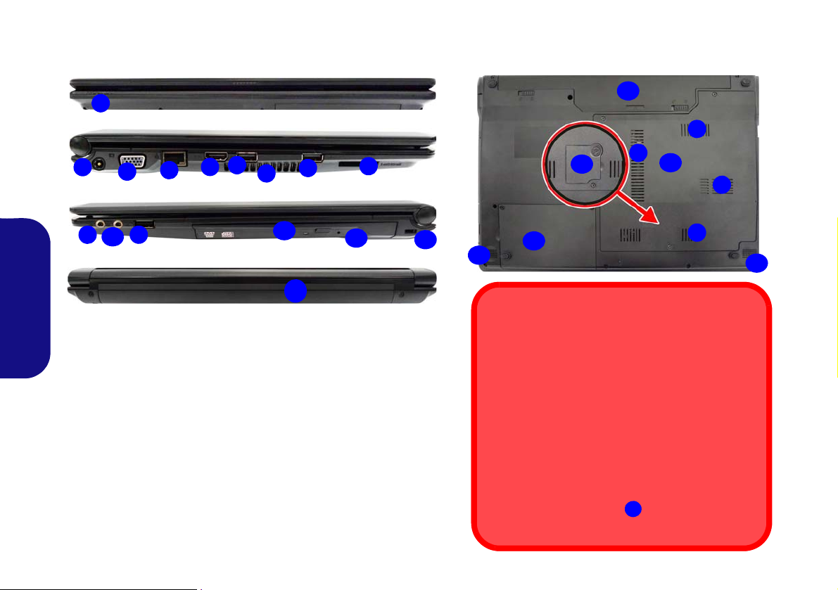
Carte du système: Vues de face, gauche, droite, arrière & dessous
Face
Gauche
Droit
Arrière
2
1
7
8
4
6
3
5
10
6
12
11
13
14
6
9
Figure 6
Vues de face, gauche, droite, arrière & dessous (Modèl e A)
Dessous
Surchauffe
Afin de ne pas causer une surchauffe de votre ordinateur, verifiez que rien ne bouche la (les) ventilation(s)
quand le systeme est allumé.
CPU
Veuillez ne pas essayer d’ouvrir ou de forcer le processeur UC de votre ordinateur. Le fait d'accéder au
CPU de quelque manière que ce soit risque de violer
la garantie.
Couvercle inférieur
Si votre modèle comporte l'option 3G, il sera alors
équipé d’un petit couvercle vous permettant d'accéder à la carte USIM du module (voir la page 68).
18
15
18
7
17
7
17
16
7
7
14
1. Indicateurs d’alimentation LED
2. Prise d’entrée DC
3. Port moniteur externe
4. Prise réseau RJ-45
5. Prise de sortie HDMI
6. 3 Ports USB 2.0
7. Ventilation
8. Lecteur de carte multi-en-1
9. Prise d'entrée de microphone
10. Prise de sortie haut-parleurs/
casqu
e
11. Baie de périphérique optique
12. Trou d’ejection d’urgence
13. Fente de verrouillage de
sécu
rité
14. Batterie
15. Couvercle de baie de
compo
sant
16. Couvercle de baie de disque dur
17. Haut-parleurs
18. Couvercle de la carte USIM
(opt
ionnel)
(Modèle A)
Français
60

Carte du système: Vues de face, gauche, droite, arrière & dessous
2
1
7
8
4
6
3
5
10
6
13
11
14
12
6
9
15
14
7
16
17
7
17
18
Face
Gauche
Droit
Arrière
Dessous
Figure 7
Vues de face, gauche, droite, arrière & dessous (Modèle B)
1. Indicateurs d’alimentation
LED
2. Prise d’entrée DC
3. Port moniteur externe
4. Prise réseau RJ-45
5. Prise de sortie HDMI
6. 3 Ports USB 2.0
7. Ventilation
8. Lecteur de carte multi-en-1
9. Prise d'entrée de microphone
10. Prise de sortie haut-parleurs/
cas
que
11. Baie de périphérique optique
12. Trou d’ejection d’urgence
13. Fente de verrouillage de sécurité
14. Batterie
15. Couvercle de baie de composant
16. Couvercle de baie de disque dur
17. Haut-parleurs
18. Couvercle de la carte USIM
(
optionnel)
Ejection d’urgence du disque
Si vous devez éjecter manuellement un disque (par
ex. suite à une coupure de courant) vous pouvez enfoncer l’extrémité d’un trombone redressé dans le
trou d’ejection d’urgence. N’utilisez pas la pointe d’un
crayon, ou tout autre objet similaire qui pourrait se
casser et rester coincé dans le trou.
Couvercle inférieur
Si votre modèle comporte l'option 3G, il sera alors
équipé d’un petit couvercle vous permettant d'accéder à la carte USIM du module (voir la page 68).
18
(Modèle B)
Français
61

Carte du système: Vues de face, gauche, droite, arrière & dessous
1
7
6
4
6
3
5
10
12
13
11
8
14
9
6
2
Face
Gauche
Droit
Arrière
17
7
7
15
7
7
14
17
7
16
7
Dessous
Figure 8
Vues de face, gauche, droite, arrière & dessous (Modèle C)
1. Indicateurs d’alimentation 10. Prise de sortie haut-parleurs/
LED casque
2. Prise d’entrée DC 1
1. Baie de périphérique optique
3. Port moniteur externe 1
2. Trou d’ejection d’urgence
4. Prise réseau RJ-45 1
3. Fente de verrouillage de sécurité
5. Prise de sortie HDMI 14
. Batterie
6. 3 Ports USB 2.0 1
5. Couvercle de baie de composant
7. Ventilation 1
6. Couvercle de baie de disque dur
8. Lecteur de carte multi-en-1 1
7. Haut-parleurs
9. Prise d'entrée de microphone
Ejection d’urgence du disque
Si vous devez éjecter manuellement un disque
(par ex. suite à une coupure de courant) vous
pouvez enfoncer l’extrémité d’un trombone redressé dans le trou d’ejection d’urgence. N’utilisez pas la pointe d’un crayon, ou tout autre objet
similaire qui pourrait se casser et rester coincé
dans le trou.
(Modèle C)
Français
62

Panneau de Configuration de Windows 8.1
Déplacez la souris vers le
coin inférieur gauche de
Figure 9
l'écran et faites un clic
Menu
droit sur le bouton Dé-
contextuel
marrer pour accéder au
menu.
Figure 10 - Écran d'accueil
Tout au long de ce manuel, vous verrez une instruction pour ouvrir le Panneau de Configuration. Faites un clic droit sur
dans l'appli Bureau ou sur l'écran d'accueil (ou utilisez la combinaison de touches Touche Logo de
le bouton Démarrer
Windows + X) pour faire apparaître un menu contextuel avancé de fonctionnalités utiles telles que Panneau de configu-
ration, Programmes et fonctionnalités, Options d'alimentation, Gestionnaire de tâches, Rechercher, Explorateur de fichiers,
Invite de commandes, Gestionnaire de périphériques et Connexions réseau, et plus encore et sélectionnez Panneau de Confi-
guration.
Écran d'accueil & bureau de Windows 8.1
Les applications, les panneaux de contrôle, les utilitaires et les programmes
dans Windows sont accessi bles depuis l 'écran d'accu eil et/ou l' application
Bureau de Windows. Le Bureau (qui fonctionne comme une application dans
l'écran d'accueil) est accessible en cliquant sur l'élément Bureau dans l'écran
d'accueil (ou en utilisant la combinaison de touches
dows + D). La barre des tâches est affichée au bas de l'écran du bureau,
et vous pouvez voir la zone de notification de la barre des tâches en bas à
droite de l'écran. Cliquez sur la flèche en bas de l'écran d'accueil pour accéder
à Applications.
Touche Logo de Win-
Français
63

Applications et Vignettes
Cliquez sur la flèche en bas de
l'écran d'accueil pour accéder à Applications.
L'écran d'accueil contiendra un certain nombre d'applications, et bien
d'autres seront installées lorsque vous ajouterez des applications, etc.
Toutes ces applications peuvent tenir sur un seul écran ainsi vous aurez
souvent besoin d' utiliser le curseur au bas de l'écran afin d'afficher
toutes les applications nécessaires.
Barre des charmes
Le côté droit de l'écran affiche la Barre des charmes. La Barre des charmes contient les menus Rechercher, Partager, Accueil, Périphériques et Paramètres. Pour accéder à la Barre des charmes déplacez le curseur vers les coins supérieurs ou
inférieurs à droite de l'écran, pui s passez la souris sur l'un des éléments de la Barre d es charmes pour l'activer (la barre est
noire quand elle est active), ou utilisez la combinaison de touches Touche Logo de Windows
Français
+ C.
Figure 11 - Ecran d'accueil avec la Barre des charmes
64
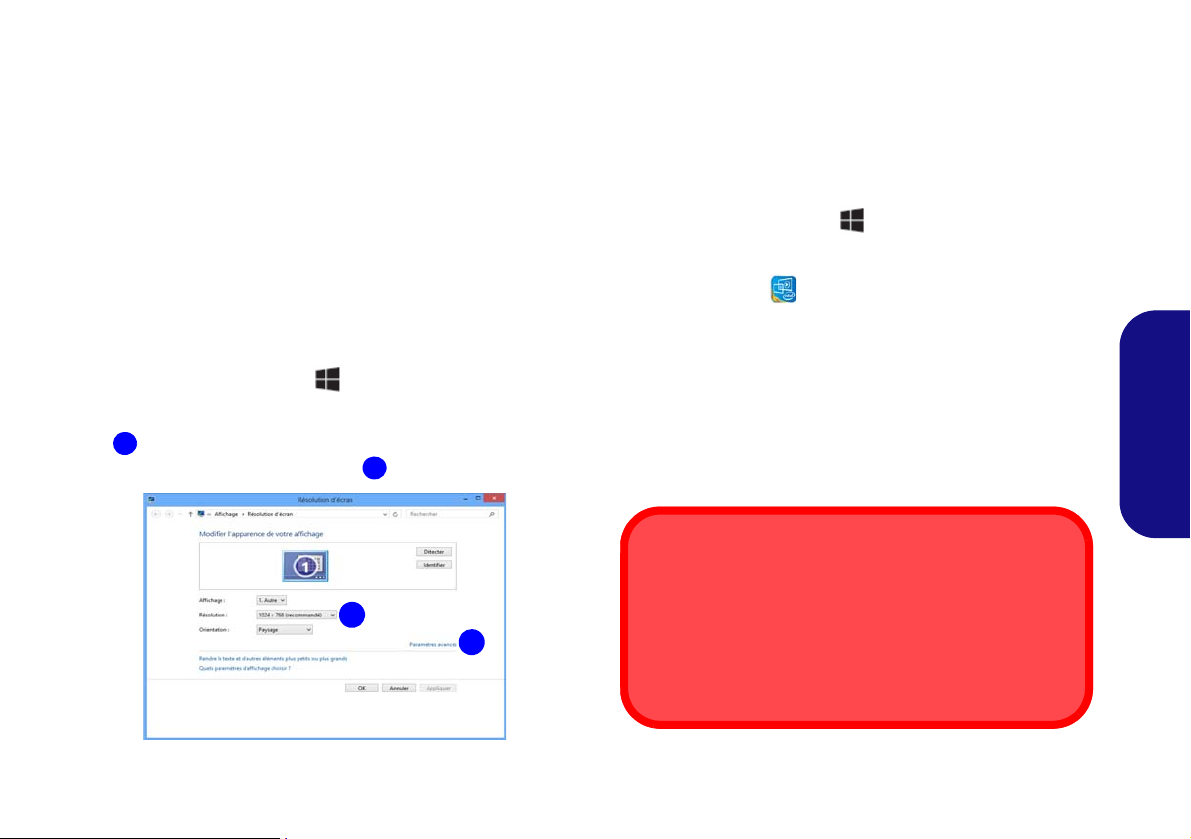
Caractéristiques vidéo
1
2
2
1
Résolution de l'écran des applications (Windows 8.1)
La résolution minimale dans laquelle les applications s'exécuteront est 1024x768.
La résolution minimale requise pour prendre en charge
toutes les fonctionnalités de Windows 8.1 (y compris le multitâche avec ancrage) est 1366x768.
Le système comporte un GPU intégré Intel. Vous pouvez
permuter les dispositifs d'affichage et configurer les options
d'affichage depuis le panneau de contrôle Affichage dans
Windows, à partir du moment où le pilote vidéo est installé.
Pour accéder au panneau de contrôle Affichage:
1. Allez au Panneau de Configuration.
2. Cliquez sur Affichage dan Apparence et personnalisation
(catégorie).
3. Cliquez sur Modifier la résolution de l’écran/Ajuster la
résolution.
OU
4. Cliquez-droit sur le bureau (utilisez la combinaison de touches
Touche Logo de Windows + touche D pour accéder au
bureau) et sélectionner la Résolution d’écran.
5. Utilisez le menu déroulant pour sélectionner la résolution d’écran
.
6. Cliquez sur Paramètres avancés
.
Pour accéder au Panneau de configuration des graphiques
HD Intel®:
1. Cliquez sur l’icône (Panneau de configuration des graphiques
HD Intel®) dans l'écran d'accueil.
OU
2. Cliquez-droit sur le bureau (utilisez la combinaison de touches
Touche Logo de Windows + touche D pour accéder au
bureau) et sélectionnez Propriétés graphiques dans le menu.
OU
3. Cliquez sur l'icône dans la zone de notification de la barre des
tâches du bureau et sélectionnez
menu.
Propriétés graphiques dans le
Périphériques d’affichage
En plus du LCD intégré, vous pouvez aussi utiliser un moniteur VGA externe/écran plat ou TV (connecté au port moniteur externe ou à la prise de sorti e HDMI) co mme
périphérique d'affichage.
Français
Figure 12 - Panneau de contrôle Affichage
65

Utilisez la combinaison de touches du
Figure 13
+ P (Modifiez la
configuration de l'af-
fichage)
Figure 14 - Options d’alimentation
logo de Windows
+ P pour changer
d'affichage
Vous pouvez utiliser la combinaison de touches + P (ou
Fn + F7) pour changer rapidement de con figuration d'affi-
chage et de mode (ce qui est particulièrement utile lors de la
connexion d'un projecteur) sous Windows.
1. Connectez votre écran externe au port moniteur externe ou à la
prise de sortie HDMI, et allumez-le.
2. Appuyez sur la combinaison de touches
3. Un menu d'écran apparaîtra.
4. Utilisez les touches du curseur (ou + P) pour sélectionner la
configuration appropriée dans le menu, et appuyez sur Entrée
pour confirmer la sélection.
+ P (ou Fn + F7).
Français
Options d’alimentation
Le panneau de configuration Options d'alimentation de
Windows vous permet de configu rer la gestion d 'alimentation de votre ordinateur. Vous pouvez économiser de l'énergie à l' aide de modes de gestion de l'alimentation et
configurer les options pour le bouton d'alimentation, bou-
ton de veille (Fn + F4), couvercle de l'ordinateur (lorsqu'il est fermé), mode Affichage et Veille (l'état d'économie
d'énergie par défaut) dans le menu d e gauche. Remarquez
que le mode de gestion d'économie d'énergie peut avoir un
impact sur les performances de l'ordinateur.
Cliquez pour sélect ionner l'un de s modes existants, ou cliquez sur Créer un mode de gestion d'alimentation dans le
menu gauche et sélectionnez les options pour créer un nouveau mode. Cliquez sur Modifier les paramètres du mode
et cliquez sur Modifier les paramètres d'alimentation
avancés pour accéder à plus d'options de configuration.
66

Installation du pilote
Figure 15 - Installation du pilote
Installation des pilotes et alimentation
Lors de l'installation des pilotes assurez-vous
que votre ordinateur est alimenté par l'adaptateur CA/CC connecté à une source d'alimentation. Certains pilotes consomment une quantité
importante d'énergie pendant la procédure
d'installation, et si la capacité restante de la batterie n'est pas suffisante cela peut provoquer
l'arrêt du système et entraîner des problèmes
de système (à noter qu'il n'y a pas ici de problème de sécurité en cause, et la batterie sera
rechargeable en 1 minute).
Directives générales pour
l'installation du pilote
D'une manière générale,
suivez les instructions par
défaut à l'écran pour chaque
pilote (par exemple Suivant
> Suivant > Terminer) à
moins que vous ne soyez un
utilisateur avancé. Dans la
plupart des cas, un redémarrage est nécessaire
pour installer le pilote.
Assurez-vous que les modules (par exemple WLAN
ou Bluetooth) sont allumés
avant d'installer le pilote correspondant.
Windows Update
Après avoir installé tous les
pilotes vérifiez que vous
avez activé Windows
Update afin d'obtenir toutes
les dernières mises à jour de
sécurité etc. (toutes les
mises à jour incluront les
derniers correctifs de Microsoft).
Le disque Device Drivers & Utilities + User’s Manual contient les pilotes et les utilitaires
nécessaires pour un bon fonctionnement de votre ordinateur. Cette installation aura probablement déjà été faite pour vous. Si ce n'est pas le cas, insérez le disque et cliquez sur Install
Drivers (bouton), ou Option Drivers (bouton) pour accéder au menu des pilotes Option-
nels. Installez les pilotes en respectant l'ordre indiqué dans la Figure 15. Cliquez pour sé-
lectionner les pilotes que vous désirez installer (vous devez noter les pilotes lorsque vous
les installez). Remarque: Si vous devez réinstaller un pilote, vous devez d’abord le désinstaller.
Installation manuelle du pilote
Cliquez le bouton Browse CD/DVD dans l'appl ication Drivers Installer et naviguer jusqu'au fichier exécutable dans le dossier de pilote approprié.
Si l’assistant Nouveau matériel détecté apparaît pendant la procédure d'installation, cliquez
sur Annuler pour fermer l’assistant, et suivez la procédure d'installation comme indiqué.
Français
67
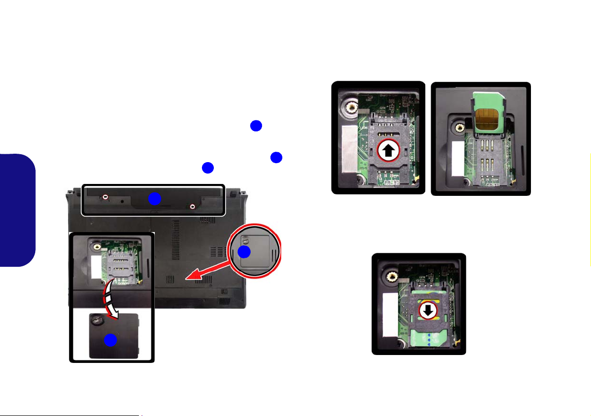
Module 3G
3
2
1
3
2
(Modèles A & B seulement)
Si votre option d'achat comporte un module 3G optionnel,
suivez l es inst ructions ci-dessous pour installer la cart e
USIM (qui vous sera fournie pa r votre fournisseur de s ervice), et installez ensuite l'application.
Insérer la carte USIM
1. Eteignez l'ordinateur, retournez-le et retirez la batterie 1 (faites
glisser le loquet dans la direction indiquée en dessous et sortez la
batterie).
2. Repérez le couvercle de la carte USIM et desserrez la vis
et retirez le couvercle de la carte USIM .
Français
3. Insérez la carte USIM comme vous le feriez dans votre téléphone
mobile.
4. Faites coulisser le SIMLOCK vers la charnière (dans la direction à
celle de la flèche illustrée dans la Figure 17) afin de libérer le
verrouillage et le soulever.
5. Insérez la carte USIM comme et fermez le SIMLOCK.
,
Figure 17 - Déverrouillez le SIMLOCK
6. Verrouillez le SIMLOCK en appuyant sur celui-ci dans la direction
de la flèche dans la Figure 18 jusqu'à ce qu'elle se mette en
position verrouillée en émettant un clic.
Figure 18 - Verrouiller le SIMLOCK
Figure 16 - Retirer la batterie et le couvercle de la carte
USIM
7. Replacez le couvercle, la vis et la batterie.
68

Dépannage
Problème Cause possible - résolution
Le module Bluetooth est
désactivé après la reprise depuis
Veille.
Un fichier ne peut être copié sur/ Le transfert de données entre l'ordinateur et un périphérique Bluetooth est pris en charge dans
depuis un périphérique Bluetooth une direction seulement (le transfert simultané de données n'est pas pris en charge). Si
connecté. vous copiez un fichier depuis votre ordinateur sur un périphérique Bluetooth, vous ne pourrez
Le module caméra PC ne peut
pas être détecté.
Les fichiers vidéo capturés depuis Notez que la cap ture de fichiers vidéo à haute rés olution nécess ite un espa ce subst antiel sur le
la caméra PC prennent trop de disque pour chaque fichier.
place sur le disque.
L'état par défaut du module Bluetooth sera désactivé après la reprise à partir de l'état
Economie d'énergie de veille. Utilisez la combinaison de touches (Fn + F12) pour activer le
module Bluetooth quand l'ordinateur reprend à partir de l'état de Veille.
pas copier un fichier à partir d'un périphérique Bluetooth sur votre ordinateur tant que le
transfert de fichier depuis l'ordinateur ne sera pas terminé.
Le module est désactivé. Utilisez la combinaison de touches Fn + F10 pour activer le module
(voir le Tableau 4 à la page 57). Exécutez l’application Caméra pour voir l'image de l'appareil
photo.
Notez que le système Windows nécessite un minimum de 16Go (32bit) ou 20Go (64bit)
d'espace libre sur la partition système du lecteur C: . Il vous est recommandé d'enregistrer le
fichier vidéo capturé dans un autre emplacement que le lecteur C:, limitez la taille du fichier de
la vidéo capturée ou réduisez la résolution vidéo.
Français
69

Spécifications
Dernières informations de
spécification
Les spécifications énumérées dans
cette section sont correctes à l'heure de
la mise sous presse. Certains éléments
(particulièrement les types de processeur/vitesse unique) peuvent être modifiés ou mis à niveau en fonction du
calendrier des parutions du fabricant.
Voyez auprès de votre service clientèle
pour les détails.
Français
Options de processeurs
Processeur Intel® Celeron® 847
1,10GHz, 32nm, cache L3 2Mo, DDR3-
1333MHz, TDP: 17W
Processeur Intel® Celeron® 877
1,40GHz, 32nm, cache L3 2Mo, DDR3-
1333MHz, TDP: 17W
LCD
Modèle A - Designs I & III:
14" (35,65cm) HD (épaisseur: 5,2mm)
Modèle A - Design II:
14" (35,65cm) HD (épaisseur: 3,6mm)
Modèle B:
15,6" (39,62cm)HD
Modèle C:
17,3" (39,62cm) HD+/FHD
Core logic
Chipset Intel® NM70
Mémoire
Deux emplacements SODIMM 204
broches, supportant la mémoire DDR3
1333/1600MHz (La fréquence réelle
d’opération de la mémoire dépend du FSB
du processeur.)
Mémoire extensible jusqu’à 8Go
BIOS
AMI BIOS (SPI Flash ROM de 48Mb)
Adaptateur vidéo
Intel® HD Graphics
Fréquence dynamique (Technologie de
mémoire vidéo dynamique d'Intel jusqu’à
1,7Go)
Compatible avec MS DirectX® 10.1
Son
Interface conforme HDA (Son Haute
Définition)
2 haut-parleurs intégrés
Microphone intégré
Stockage de données
(Option d’usine) Un module de Super Multi
lecteur optique échangeable
(Option d’usine) Dummy ODD (certains
designs du modèle A et certains designs
du modèle B seulement)
Un disque dur SATA remplaçable de 2,5"
9,5mm (H)
Sécurité
Fente de verrouillage de sécurité (type
Kensington)
Mot de Passe du BIOS
70

Interface
Trois ports USB 2.0
Une prise de sortie haut-parleurs/casque
Une prise d'entrée de microphone
Un port moniteur externe
Un port de Sortie HDMI
Une prise réseau RJ-45
Une prise d’entrée en DC
Clavier
Modèle A:
Clavier “Win Key” (avec pavé numérique
intégré)
Modèles B & C:
Clavier "Win Key" pleine taille (avec pavé
numérique)
Dispositif de pointage
Touchpad intégré
Communication
LAN 10Mb/100Mb Ethernet
(Option d’usine - Modèles A & B) 300K
pixel/2M HD caméra PC
(Option d’usine - Modèle C) 2M HD
caméra PC
(Option d’usine) Module Mini-carte
3G (Modèles A & B seulement)
Modules Half Mini-carte LAN sans fil/
Bluetooth:
(Option d’usine) LAN sans fil (802.11b/g/
n) Intel® Centrino® Wireless-N 105
(Option d’usine) Bluetooth 3.0 et LAN
sans fil (802.11b/g/n) Intel® Centrino®
Wireless-N 135
(Option d’usine) LAN sans fil (802.11b/g/
n) (tiers)
(Option d’usine) Bluetooth 4.0 et LAN
sans fil (802.11b/g/n) (tiers)
Lecteur de carte
Lecteur de carte multi-en-1
MMC (MultiMedia Card) / RS MMC
SD (Secure Digital) / Mini SD / SDHC
MS (Memory Stick) / MS Pro / MS Duo
Logements Mini-carte
Modèles A & B:
Logement 1 pour module WLAN ou module
Combo Bluetooth et LAN sans fil
(Option d’usine) Logement 2 pour module
3G
Modèle C:
Logement 1 pour module LAN sans fil o
module combo Bluetooth et LAN sans fil
Mise en marche
Modèle A:
Adaptateur AC/DC pleine bande
Entrée AC: 100-240V, 50-60Hz
Sortie DC: 19V, 3,42A/18.5V,3,5A (65W)
Batterie Smart Lithium-Ion à 6 éléments,
48,84WH
(Option d’usine) Batterie Smart LithiumIon à 3 éléments, 24,42WH
(Option d’usine) Batterie Smart LithiumIon à 3 éléments, 62,16WH
Modèles B & C:
Adaptateur AC/DC pleine bande
Entrée AC: 100-240V, 50-60Hz
Sortie DC: 19V, 3,42A/18.5V,3,5A (65W)
Batterie Smart Lithium-Ion à 6 éléments,
48,84WH
(Option d’usine) Batterie Smart LithiumIon à 3 éléments, 62,16WH
Français
71

Spécifications environnementales Dimensions physiques & poids
Température
En fonction : 5
Eteint : -20
Humidité relative
En fonction : 20% - 80%
Eteint : 10% - 90%
°C - 60°C
Français
°C- 35°C
Modèle A - Design I:
340 (l) x 238 (p) x 25,05 - 33,5(h) mm
2,2kg (avec batterie 48,84WH & lecteur
optique)
Modèle A - Design II:
340 (l) x 238 (p) x 13,9 - 31,8(h) mm
340 (l) x 238 (p) x 12 - 30,2(h) mm
2,2kg (avec batterie 48,84WH & lecteur
optique)
Modèle A - Design III:
341 (l) x 238,5 (p) x 16 - 34(h) mm
2,2kg (avec batterie 48,84WH & lecteur
optique)
Modèle B - Design I:
374 (l) x 250 (p) x 20 - 37,2(h) mm
2,6kg (avec batterie 48,84WH & lecteur
optique)
Modèle B - Design II:
374 (l) x 238 (p) x 14,3 - 34,1(h) mm
2,3kg (avec batterie 48,84WH & lecteur
optique)
Modèle C:
374 (l) x 270 (p) x 14 - 40,5(h) mm
2,9kg (avec batterie 48,84WH & lecteur
optique)
72

Acerca de esta Guía del Usuario Concisa
Esta guía rápida es una breve introducción para poner su sistema en funcionamiento. Es un suplemento y no un sustituto del
Manual del usuario completo en ing lés en formato Ado be Acrobat del disco Device Drivers & Utilities + User's Manual
suministrado con el ordenador. En este disco también se encuentran los controladores y utilitarios necesarios para utilizar el
ordenador corr ectamente (Nota: La compañía se reserv a el derecho a revisar esta pub licación o cambiar su con tenido sin
previo aviso).
Algunas o todas las característi cas del or denador pueden haberse configurado de antemano. Si no lo están, o si desea
reconfigurar (o reinstalar) partes del sistema, consulte el Manual del usuario completo. El disco Device Drivers & Utilities
+ User’s Manual no contiene un sistema operativo.
Información de regulación y seguridad
Por favor, preste especial atención a todos los avisos de regulación e información de seguridad contenidos en el Manual del
usuario completo del disco Device Drivers & Utilities + User’s Manual.
© Octubre del 2013
Marcas registradas
Intel y Celeron son marcas/marcas registradas de Intel Corporation.
Español
73

Instrucciones para el cuidado y funcionamiento
El ordenador portátil es muy robusto, pero puede dañarse. Para
evitar esto, siga estas sugerencias:
• No lo deje caer ni lo exponga a golpes fuertes. Si el ordenador se
cae, la carcasa y los componentes podrían dañarse.
• Manténgalo seco y no lo sobrecaliente. Mantenga el ordenador y
fuente de alimentación alejados de cualquier tipo de fuente de
calor. Esto es un aparato eléctrico. Si se derrama agua u otro líquido
en su interior, el ordenador podría dañarse seriamente.
• Evite las interferencias. Mantenga el ordenador alejado de trans-
formadores de alta capacidad, motores eléctricos y otros campos
magnéticos fuertes. Éstos pueden dificultar el correcto funcionamiento y dañar los datos.
• Siga las instrucciones apropiadas de manejo del ordenador.
Apague el ordenador correctamente y no olvide guardar su trabajo.
Recuerde guardar periódicamente sus datos, pues los datos pueden
perderse si la batería se descarga.
Servicio
Si intenta reparar el ordenador usted m ismo, podría anular la
garantía y exponerse usted y el ordenador a descarga eléctrica.
Deje que sea personal de reparación cualificado el que realice
las reparaciones, especialmente bajo cualquiera de estas condi-
Español
ciones:
• Cuando el cable de alimentación o adaptador AC/DC esté dañado o
pelado.
• Si el ordenador ha estado expuesto a la lluvia u otros líquidos.
• Si el ordenador no funciona con normalidad tras seguir las instrucciones de uso.
• Si el ordenador se ha caído o dañado (no toque el líquido venenoso
si el panel LCD se rompe).
74
• Si hay un olor fuera de lo normal, calor o humo que sale del ordenador.
Información de seguridad
• Utilice solamente un adaptador de alimentación aprobado para su
uso con este ordenador.
• Utilice solamente el cable de corriente y las baterías indicados en
este manual. No tire las baterías al fuego. Podrían explotar. Consulte los códigos locales para posibles instrucciones para desechos
especiales.
• Nunca utilice una batería que se haya caído o que parezca dañada
(p. ej. doblada o retorcida). Incluso si el ordenador sigue funcionando con una batería dañada, puede provocar daños en el circuito
que podrían causar fuego.
• Compruebe que su ordenador esté completamente apagado antes de
introducirlo en una bolsa de viaje (o en cualquier funda).
• Antes de limpiar el ordenador, quite la batería y asegúrese de que el
ordenador esté desconectado de cualquier fuente de alimentación
externa, periféricos y cables (incluyendo la línea telefónica).
• Utilice un trapo limpio y suave para limpiar el ordenador, pero no
aplique limpiador directamente en el ordenador. No utilice limpiadores volátiles (derivados del petróleo) o limpiadores abrasivos en
ningún lugar del ordenador.
• No intente reparar baterías. Solicite la reparación o la sustitución a
su representante de servicio o a personal de servicio cualificado.
• Tenga en cuenta que en ordenadores con logotipos de LCD etiquetados eléctricamente en relieve, el logotipo está recubierto por un
adhesivo protector. Debido al desgaste y rotura normales, este
adhesivo puede deteriorarse con el tiempo y en el logotipo expuesto
pueden formarse bordes afilados. Tenga cuidado al manipular el
ordenador en este caso y evite tocar el logotipo del LCD etiquetado
eléctricamente. Evite colocar cualquier elemento en la bolsa de
transporte que pueda rozar la parte superior del ordenador durante
el transporte Si ocurre un desgaste o rotura, contacte con el centro
de servicios.

Precauciones para baterías de polímero
Eliminación de la batería & Cuidado
El producto que usted ha comprado contiene una batería recargable. La batería es reciclable Terminada su vida útil, según las leyes locales y estatales, puede ser ilegal desecharla
junto con los residuos ordinarios. Verifique con las autoridades locales responsables de los desechos sólidos cuáles son
las opciones de eliminación y reciclado existentes en su zona.
Peligro de explosión si la batería está mal colocada. Sustitúyala con un tipo de batería igual o equivalente al recomendado por el fabricante. Elimine la batería usada de conformidad
con las instrucciones del fabricante.
Tenga en cuenta la información siguiente específica para baterías de polímero; además, donde corresponda, invalida la información sobre precauciones para baterías normales.
• Las baterías pueden aumentar o hincharse ligeramente, sin embargo,
esto es parte del mecanismo de seguridad de la batería y o supone un
problema.
• Utilice los procedimientos de manejo apropiados cuando utilice
baterías de polímero. No utilice baterías de polímero en entornos
con temperatura ambiental alta y no guarde las baterías sin usar
durante mucho tiempo.
Español
75

Guía rápida para empezar
.130 °
Apagar
Por favor, tenga en cuenta que
debería siempre apagar el ordenador eligiendo la opción
Apagar en Windows (ver aba-
jo). Esto le ayudará a evitar
problemas con el disco duro o
el sistema.
Haga clic en Configuración en
la Barra Charms (utilice la combinación Tecla de Windows
+ tecla C para acceder a la
Barra Charms) y elige la opción
Apagar desde el menú Iniciar/
Apagar.
O
Elige Apagar o cerrar
sesión
> Apagar en el menú contex-
tual (utilice la combinación Tecla de Windows + tecla X
para acceder al menú contextual).
Figura 1
Abrir la tapa/LCD/or-
denador con el adapta-
dor AC/DC enchufado
1. Quite todos los materiales del embalaje.
2. Coloque el ordenador en una superficie estable.
3. Inserte la batería y asegúrese de que quede bloqueada en su
posición.
4. Conecte en los puertos correspondientes los periféricos que
desee utilizar con el ordenador (p. ej. teclado y ratón).
5. Conecte el adaptador AC/DC al conector de entrada DC que
está del lado izquierdo del ordenador, y luego conecte el cable
de alimentación AC en un eschufe y al adaptador.
6. Utilice una mano para levantar con cuidado la tapa/LCD a un
ángulo de visión cómodo (no exceder 130 grados), mientras
utiliza la otra mano (como se muestra en la Figura ) para
sostener la base del ordenador (Nota: Nunca levante el
ordenador por la tapa/LCD).
7. Presione el botón de encendido para “encender”.
Software de sistema
Puede ser que su ordenador tenga instalado un software de
sistema. Si no es el caso, o si desea reconfigurarlo con otro
sistema, este manual se refiere a Microsoft Windows 8.1.
Diferencias de modelos
Español
Esta serie de portátiles incluye diferent es modelos que
varían li geramente en el estilo d el di seño, color y
apariencia general . Tenga en cuenta que au nque su
ordenador puede parecer distinto del de las imágenes en
este documento , todos los pu ertos, conectores,
indicadores, especificaci ones y fu nciones general es s on
las mismas para todos los estilos de diseños.
76

Mapa del sistema: Vista frontal con panel LCD abierto (Modelo A)
Figura 2
Vista frontal con panel LCD
abierto (Modelo A)
1. Cámara PC (opcional)
2. Panel LCD
3. Botón de encendido
4. Botones Hot-Key (sólo
algunos di
seños del
Modelo A)
5. Indicadores LED de estado
6. Teclado
7. Micrófono incorporado
8. Touchpad (almohadilla
tác
til) y botones
8
Tenga en cuenta que el área
válida de operación del
Touchpad y los botones es la
indicada dentro de las líneas
de puntos de arriba.
Uso de dispositivos
inalámbricos a bordo
El uso de dispositivos
electrónicos portátiles a
bordo de un avión suele
estar prohibido.
Asegúrese de que los módulos WLAN y Bluetooth
estén apagados si utiliza
el equipo en un avión
ajustando el sistema al
modo Avión.
4
6
3
5
7
1
8
2
14” (35,56cm)
Español
77

Mapa del sistema: Vista frontal con panel LCD abierto (Modelos B & C)
Modelo B
5
4
6
1
7
15,6” (39,62cm)
2
4
6
5
7
1
2
17,3” (43,94cm)
8
3
3
8
7
Uso de dispositivos inalámbricos a bordo
El uso de dispositivos electrónicos portátiles a bordo de un avión
suele estar prohibido.
Asegúrese de que los módulos WLAN y Bluetooth estén
apagados si utiliza el equipo en un avión ajustando el sistema al
modo Avión.
Figura 3
Vista frontal con panel
LCD abierto (Modelos B &
C)
1. Cámara PC (opcional)
2. *LED de cámara PC
*Cuando la cámara PC
est
é en uso, el LED se
iluminará en rojo.
3. Panel LCD
4. Botón de encendido
5. Indicadores LED de
est
ado
6. Teclado
7. *Micrófono incorporado
*Tenga en cuenta que la
ubi
cación del micrófono
depende del diseño del
Modelo C
modelo.
8. Touchpad (almohadilla
tá
ctil) y botones
Tenga en cuenta que el área válida de operación del Touchpad
y los botones es la indicada
dentro de las líneas de puntos.
8
Español
78

Indicadores LED
Modelo A - Diseño lI
Modelos B & C
Modelo A - Diseños l & III
Los indicadores LED en su ordenador muestran una valiosa
información sobre el estado actual del ordenador.
Icono Color Descripción
Icono Color Descripció n
Naranja El adaptador AC/DC está conectado
Verde El módulo LAN wirel e ss es t á ac t iv a do
Naranja El módulo Bluetooth está instalado
Verde El disco duro está en uso
Verde
Verde
Verde
Tabla 1 - Indicadores LED de estado
El teclado numérico (NumLk) está acti-
vado
El bloqueo de mayúsculas está acti-
vado
El bloqueo de desplazamiento está
activado
Verde El ordenador está encendido
Verde
parpa-
deante
Naranja
parpadeante
Naranja La batería se está cargando
Verde La batería está completamente cargada
Naranja
parpadeante
El ordenador está en modo Suspen-
sión
La cámara PC está en uso
(Sólo Modelo A de 14,0"/35,56cm)
La batería ha alcanzado el estado crítico
de poca energía
Tabla 2 - Indicadores LED de encendido
Español
79

Botones Hot-Key - sólo algunos
Teclado
Teclas de función
numérico
Bloq Num &
Bloq Despl
Modelo A
Tecla Fn
Tecla Menú/Aplicación
Tecla de Windows
Teclas de función
Modelos B & C
Tecla Fn
Tecla Menú/Aplicación
Tecla de Windows
Teclado
numérico
Bloq Num &
BloqDespl
diseños del Modelo A
Los botones Hot- Key of recen ac ceso instantá neo al
explorador de Internet y al p rograma de co rreo electróni co
predeterminado y le permiten activar o desactiva r el Modo
silencio/el módulo LAN Wireless con una pu lsación de
botón.
Botón Hot-Key Función
Activar el programa de correo electrónico predeter-
minado
Activar el buscador de Internet predeterminado
Español
*Cuando se activa, el Modo silencio reduce el ruido del ventilador
y ahorra energía. T enga en cuent a que esto puede reducir el rendimiento del ordenador.
Tabla 3 - Botones Hot-Key - sólo algunos diseños del Mo-
O
*Cambiar Modo silencio
Activar/desactivar el módulo LAN Wireless
delo A
O
Teclado
El teclado (Modelo A) tiene un teclado numérico para una
entrada fácil de datos numéricos. Al pre sionar Fn + Bloq
Num el teclado numérico se habilita o inhabilita. También
incluye las tecl as de función pa ra permit irle cambiar las
características operacionales al instante.
El teclado (Modelos B & C) incluye un teclado numérico
(en la parte derecha del teclado) para una entrada fác il de
datos numéricos. Al presionar Fn + Bloq Num el teclado
numérico se habilita o inhabilita. También incluye las teclas
de func ión para permit irle cambiar l as c aracterísticas
operacionales al instante.
80
Figura 4 - Teclado

Teclas de función
Las teclas de función (F1 - F12 etc.) actuarán como teclas directas (Hot-Key) cuando se pulsan junto con la tecla Fn. Además
de las combinaciones de teclas de función básicas algunos indicadores visuales están di sponibles (sólo en la aplicación
Escritorio de Windows y no en la pantalla Inicio) cuando el controlador de teclas directas está instalado.
Teclas Función/indicadores visuales Teclas Función/indicadores visuales
vídeo)
vea la
)
Fn + F10
Fn + F11
Fn + F12
Fn + Bloq Despl
(BloqDespl)
Fn + Esc
Tabla 4 - Teclas de función & indicadores visuales
Fn +
Fn + F1
Fn + F2
Fn + F3 Conmutación mudo Fn + Bloq Num
Fn + F4 Conmutación dormir
Fn + F5/F6
Fn + F7
Fn + F8/F9
Reproducir/pausar (en los programas audio/
Activar/desactivar el
Touchpad
Apagar luz de fondo del LCD (presione una
tecla o utilice el Touchpad para encenderlo)
Reducción/aumento
volumen de sonido
Cambiar la configuración de pantalla (
Reducción/aumento
página 91
brillo LCD
Activar/desactivar el
módulo Cámara PC
Activar/desactivar el
módulo LAN Wireless
Activar/desactivar el
módulo Bluetooth
Activar/disactivar el
teclado numérico
Cambiar el bloqueo de
desplazamiento
Cambio Bloq. Mayús-
culas
Cambiar Control Center (centro de control)
(vea la página 82)
Español
81

Control Center (Centro de control)
Presione la combinación de teclas Fn + Esc o haga doble clic en el icono en el área de notificación de la barra de tareas
para activar o desactivar el Control Center (Centro de control) en la aplicación Escritorio de Windows (no en la pantalla
Inicio). El Control Center (Centro de control) ofrece un acceso rápido a los controles usados con más frecuencia y le permite
activar, y desactivar módulos rápidamente.
Español
Haga clic en cualquier botón para acti var o desactivar cualquiera de los módu los (p.ej. Touchpad, Cámara). Haga clic en
Power Conservation (Ahorro de energí a) para cambiar entre los modos Performance ( Rendimiento), Balanced
(Equilibrado) o Energy Star. Haga clic en los botones (o simplemente haga clic y mantenga presionado el botón del ratón)
para ajustar el control deslizante del Brightness/Volume (Brillo/Volumen). Haga clic en Display Switch (Cambiar pantalla)/
Time Zone (Zona horaria)/Desktop Background (Fondo de pantalla) para abrir el panel de control de Windows adecuado.
Haga clic en el botón Suspensión para cambiar el equipo a los modos Hibernar o Suspender.
Figura 5 - Control Center
82

Power Status (Estado de energía)
El i cono Estado de energía most rará si la ali mentación
actual viene dada po r la batería o po r el adaptador AC/DC
enchufado en una toma de corriente. La barra de estado de
energía muestra el estado actual de la carga de la batería.
Sleep (Suspender)
Haga clic en el bot ón Suspender para abrir los b otones
Hibernar
botones para que el equipo entre en el modo de ah orro de
energía elegido.
o Suspender y haga clic en uno de esos
Brightness (Brillo)
El i cono Brillo most rará el nivel actual del b rillo de l a
pantalla. Puede usar el control deslizante para ajustar el brillo
de la pantalla o las combinaciones de teclas Fn + F8/F9 o
usar la com binación de te clas Fn + F2 para apagar la
retroiluminación LED (presi one una tecla para vol ver
encenderla). Tenga en cuenta que Modo de energía también
puede afectar el brillo de la pantalla.
Volume (Volumen)
El icono Volumen most rará el nivel actual del vo lumen.
También puede usar el con trol desl izante para ajust ar el
volumen o las combinaciones de teclas Fn + F5/F6 o l a
combinación de teclas Fn + F3 para silenciar el volumen.
Power Conservation (Ahorro de energía)
Este sistema so porta las características de adminis tración de
energía Energy Star que hace que los equip os (CPU , disco
duro, etc.) entren en modos de ahorro de energía y suspensión
tras el período d e tiempo de inactividad designado. Haga clic
en el bo tón Performance (Rendimiento), Balanced
(Equilibrado) o Energy Star.
Display Switch (Cambiar pantalla)
Haga clic en el botón Cambiar pantalla para ac ceder al
menú (o utilice la comb inación de teclas + P) y
seleccione el modo de pantalla apropiado.
Time Zone (Zona horaria)
Si hace clic en el botón Zona horaria accederá al panel de
control Fecha y hora de Windows.
Desktop Background (Fondo de pantalla)
Si hace clic en el botón Fondo de pantalla podrá cambiar la
imagen del fondo del escritorio.
Touchpad/cámara PC
Haga clic en cualq uiera de est os b otones para cambiar el
estado de energía d el Touchpad o módulo . Aparecerá un a
cruz en la esquina superior izquierda del icono cuando
esté apagado. Tenga en cuenta que el estado de energía de un
módulo, y l a energía d el To uchpad, también quedan
afectados por el Modo de energía seleccionado.
Español
83

Mapa del sistema: Vistas frontal, izquierda, derecha, posterior e
Parte frontal
Lateral izquierdo
Parte posterior
Lateral derecho
2
1
7
8
4
6
3
5
10
6
12
11
13
14
6
9
Cara inferior
Recalentamiento
Para evitar que su ordenador se recaliente
compruebe que nada bloquea la(s) rejilla(s) con el
equipo encendido.
CPU
El usuario no debe manipular la CPU. El acceso a la
CPU de cualquier modo puede anular su garantía.
Tapas inferiores
Si su modelo incluye la opción 3G entonces incluirá
una pequeña tapa para poder acceder a la tarjeta
USIM del módulo (vea la página 92).
18
15
18
7
17
7
17
16
7
7
14
Figura 6 - Vistas frontal, izquierda, derecha, posterior e inferior
(Modelo A)
1. Indicadores LED de encendido
2. Conector de entrada DC
3. Puerto para monitor externo
4. Conector LAN RJ-45
5. Puerto de salida de HDMI
6. 3 Puertos USB 2.0
7. Rejilla
8. Lector de tarjetas multi-en-1
9. Conector de entrada para
micróf
ono
10. Conector de salida de
auric
ulares
11. Bahía de dispositivo óptico
12. Orificio de expulsión de
eme
rgencia
13. Ranura del cierre de seguridad
14. Batería
15. Tapa de la bahía componente
16. Tapa de la bahía para el disco
du
ro
17. Altavoces incorporados
18. Tapa de la tarjeta USIM
(
opcional)
inferior (Modelo A)
Español
84

Mapa del sistema: Vistas frontal, izquierda, derecha, posterior e
2
1
7
8
4
6
3
5
10
6
13
11
14
12
6
9
15
14
7
16
17
7
17
18
Parte frontal
Lateral izquierdo
Parte posterior
Lateral derecho
Cara inferior
Figura 7 - Vistas frontal, izquierda, derecha, posterior e inferior
(Modelo B)
1. Indicadores LED de encendido
2. Conector de entrada DC
3. Puerto para monitor externo
4. Conector LAN RJ-45
5. Puerto de salida de HDMI
6. 3 Puertos USB 2.0
7. Rejilla
8. Lector de tarjetas multi-en-1
9. Conector de entrada para
m
icrófono
10. Conector de salida de
auri
culares
11. Bahía de dispositivo óptico
12. Orificio de expulsión de
emergen
cia
13. Ranura del cierre de seguridad
14. Batería
15. Tapa de la bahía componente
16. Tapa de la bahía para el disco
duro
17. Altavoces incorporados
18. Tapa de la tarjeta USIM
(
opcional)
Expulsión de emergencia del disco
Si necesita expulsar un disco manualmente (p. ej.
por un corte de corriente inesperado) puede
introducir la punta de un clip en el orificio de
expulsión de emergencia. No utilice la punta de un
lápiz u otros objetos que puedan romperse y
quedar atrapados en el orificio.
Tapas inferiores
Si su modelo incluye la opción 3G entonces
incluirá una pequeña tapa para poder acceder
a la tarjeta USIM del módulo (vea la página 92).
18
inferior (Modelo B)
Español
85

Mapa del sistema: Vistas frontal, izquierda, derecha, posterior e
1
7
6
4
6
3
5
10
12
13
11
8
14
9
6
2
Parte frontal
Lateral izquierdo
Parte posterior
Lateral derecho
17
7
7
15
7
7
14
17
7
16
7
Cara inferior
Figura 8
Vistas frontal, izquierda, derecha, posterior e inferior (Modelo C)
1. Indicadores LED de encendido
2. Conector de entrada DC
3. Puerto para monitor externo
4. Conector LAN RJ-45
5. Puerto de salida de HDMI
6. 3 Puertos USB 2.0
7. Rejilla
8. Lector de tarjetas multi-en-1
9. Conector de entrada para
m
icrófono
10. Conector de salida de auriculares
11. Bahía de dispositivo óptico
12. Orificio de expulsión de
emergen
cia
13. Ranura del cierre de seguridad
14. Batería
15. Tapa de la bahía componente
16. Tapa de la bahía para el disco
duro
17. Altavoces incorporados
Expulsión de emergencia del disco
Si necesita expulsar un disco manualmente
(p. ej. por un corte de corriente inesperado)
puede introducir la punta de un clip en el
orificio de expulsión de emergencia. No
utilice la punta de un lápiz u otros objetos
que puedan romperse y quedar atrapados
en el orificio.
inferior (Modelo C)
Español
86

Instalación de controladores
Instalación del controlador y
alimentación
Cuando instale controladores asegúrese de
que el ordenador esté alimentado por el
adaptador AC/DC conectado a una fuente
de corriente activa. Algunos controladores
consumen una cantidad significativa de
corriente durante el proceso de instalación, y
si la batería se consume puede provocar que
el sistema se apague, causando problemas
en el sistema (tenga en cuenta que esto no
supone un problema de seguridad y la
batería podrá recargarse en 1 minuto).
Figura 9 - Instalación de controladores
Directrices generales
para la instalación del
controlador
Como guía general, siga
las instrucciones predeterminadas en pantalla para
cada controlador (p.ej. Si-
guiente > Siguiente > Finalizar) a menos que sea
usuario avanzado. En muchos casos necesitará reiniciar para instalar el
controlador.
Asegúrese de que los módulos (p.ej. WLAN o Bluetooth) estén
ENCENDIDOS antes de
instalar el controlador
apropiado.
Windows Update
Tras instalar todos los controladores asegúrese de
haber habilitado Windows
Update para obtener las
últimas actualizaciones de
seguridad, etc. (todas las
actualizaciones incluirán
los últimos parches de Microsoft).
El disco Device Drivers & Utilities + User’s Manual contiene los controladores y utilitarios
necesarios para uti lizar el ordenador correct amente. Ins erte el disco y haga cli c en Install
Drivers (botón), u Option Drivers (botón) para acceder al menú de controladores opcional.
Instale los controladores en el orden indicado en la Figura 9. Haga clic para seleccionar los
controladores que desea instalar (debería anotar los controladores conforme los instala). Nota:
Si necesita reinstalar un controlador, debería desinstalar el controlador antes.
Instalación manual del controlador
Haga clic en el botón Browse CD/DVD en la aplicación Drivers Install er y busque el archivo
ejecutable en la carpeta de controladores apropiada.
Si durante el procedimiento de instalación aparece una vent ana Nuevo hardware
encontrado, haga clic en Cancelar para cerrar la ventana y sig a con el procedimi ento de
instalación.
Español
87

Panel de Control de Windows 8.1
Mueva el ratón a la esquina
inferior izquierda de la pan-
Figura 10
talla y haga clic con el botón
Menú contextual
derecho en el botón Inicio
para acceder al menú.
Figura 11 - Pantalla Inicio
A lo largo de este manual verá una instrucción para abrir el Panel de Control. Haga clic con el botón derecho en el botón
Inicio en la app del Escritorio o en la pantalla Inicio (o utilice la combinación Tecla de Windows + tecla X) para abrir
un menú contextual avanzado con características útiles como Panel de control, Prog ramas y caract erísticas, Opciones d e
energía, Administrador de tareas, Bus car, Exp lorador de arch ivos, Símbolo del sistema, Admi nistrador de dispositivos,
Conexiones de red, etc y seleccionar Panel de Control.
Pantalla Inicio y escritorio de Windows
8.1
A las apps, p aneles de control, utilidades y programas en Windows se
accede desde la pantalla Inicio y/o desde la app Escritorio de Windows.
Español
Al Escritorio (que se ejecuta como una app dentro de la pantalla Inicio)
se puede acceder haciendo clic en Escritorio en el menú Inicio (o usando
+ tecla D). La barra de tareas
la combinación Tecla de Windows
aparecerá en la parte inferior de la pantalla del escritorio y verá el área
de notificación de la barra de tareas en la parte inferior derecha de la
pantalla. Haga clic en la flecha en la parte inferior de la pantall a Inicio
para acceder a Aplicaciones.
88

Haga clic en la flecha en la parte inferior de
la pantalla Inicio para acceder a Aplicaciones.
Apps y Mosaicos
La pantall a Inicio co ntendrá varias apps y muchas más se instalarán
conforme añada más aplicaciones, etc. No todas estas app s caben en una
pantalla, por lo que a menudo deberá usar el control deslizante de la parte
inferior de la pantalla para ver todas las apps necesarias.
Barra Charms
El lado derecho de la pantalla muestra la barra Charms. La barra Charms contiene los menús Buscar, Compartir, Inicio,
Dispositivos y Configuración. Para acceder a la barra Charms, mueva el cursor hacia la esquina superior o inferior derecha
de la pantalla y luego mueva uno de los elementos hacia la barra Charms para activarla (la barra estará en negro cuando esté
activa) o utilice la combinación Tecla de Windows + tecla C.
Español
Figura 12 - Pantalla Inicio con la barra Charms
89

Parámetros de vídeo
1
2
1
Resolución de pantalla para Apps (Windows 8.1)
La resolución mínima en la que las apps se ejecutarán es de
1024x768.
La resolución mínima necesaria para soportar todas las
características de Windows 8.1 (incluyendo multitarea con
snap) es de 1366x768.
Figura 13 - Panel de control Pantalla
El sist ema incluyo un a GPU integrada de Intel. Puede
cambiar los dispo sitivos de pan talla y co nfigurar las
opciones de pantalla des de el panel de control Pantalla en
Windows siempre que tenga inst alado el cont rolador de
vídeo.
Para acceder al panel de control Pantalla:
1. Vaya al Panel de Control.
2. Haga clic en Pantalla (icono) - en Apariencia y
personalización (categoría).
3. Haga clic en Ajustar resolución de pantalla/Ajustar
resolución.
O
4. Haga clic con el botón derecho en el escritorio (utilice la
combinación Tecla de Windows + tecla D para acceder al
escritorio) y seleccione Resolución de pantalla.
5. Utilice el cuadro desplegable para seleccionar la resolución de la
pantalla .
6. Haga clic en Configuración avanzada2 .
Español
Para acceder al Panel de control de gráficos HD Intel®:
1. Haga clic en el icono (Panel de control de gráficos HD Intel®)
en la pantalla Inicio.
O
2. Haga clic con el botón derecho en el escritorio (utilice la
combinación T ecla de Windows + tecla D para acceder al
escritorio) y seleccione Propiedades de gráficos en el menú.
O
3. Haga clic en el icono en el área de notificación de la barra
de tareas del escritorio y seleccione
en el menú.
Propiedades de gráficos
Dispositivos de pantalla
Además del LCD incorporado, t ambién pu ede ut ilizar un
monitor VGA/pantalla plana o TV (conectado al puerto para
monitor externo o al puerto de salid a de HDMI) como
dispositivo de pantalla.
90

Usar la combinación de teclas del
Figura 15 - Opciones de energía
Figura 14
+ P (Cambiar la
configuración de
pa
ntalla)
logotipo Windows
+ P para cambiar
entre pantallas
Puede usar la combinación de teclas + P (o Fn + F7) para
cambiar ráp idamente la c onfiguración de pantalla y los
modos (esto resulta especialmente útil cuando s e coloca un
proyector) en Windows.
1. Conecte una pantalla externa al puerto para monitor externo o
puerto de salida de HDMI y enciéndala.
2. Pulse la combinación de teclas
3. Aparecerá un menú en pantalla.
4. Utilice las teclas del cursor (o + P) para seleccionar la
configuración apropiada en el menú y presione Entrar para
confirmar la selección.
+ P (o Fn + F7).
Opciones de energía
El panel de control de las opcion es d e energía (menú
Hardware y sonido) de Windows permit e configurar las
funciones de administración de energía del ordenador. Puede
ahorrar energía con l os planes de energía y configurar las
opciones para el botón de encendido, botón de suspensión
(Fn + F4), tapa del ordenador (al cerrarla), pantalla y
modo de suspensión (el est ado de ahorro de energía
predeterminado) en el menú de la izquierda. Tenga en cuenta
que el plan economizador puede afectar al rendimiento del
ordenador.
Haga clic para seleccionar u no de los planes existent es o
haga clic en Crear un plan de energía en el menú izquierdo
y seleccione las opciones para crear un plan nuevo. Haga clic
en Cambiar la configuración del plan y haga clic en
Cambiar la configuración avanzada de energía para
acceder a más opciones de configuración.
Español
91

Módulo 3G
3
2
1
3
2
(Sólo Modelos A & B)
Si ha inclui do un módulo opcional 3G en su opción de
compra, s iga las instrucciones siguientes p ara i nstalar l a
tarjeta USIM (suministrada por su proveedor de servicios) y
luego instale la aplicación.
Insertar la tarjeta USIM
1. Apague el ordenador y gírelo para quitar la batería 1 (deslice
los pestillos en la dirección indicada abajo y saque la batería).
2. Localice la t apa de la t arjeta USIM y afloje el tornillo
la tapa de la tarjeta USIM .
, y quite
4. Deslice SIMLOCK hacia la bisagra (en la dirección a la flecha
ilustrada en la Figura 17) para soltar el bloqueo y levantarlo.
5. Inserte la tarjeta USIM y cierre SIMLOCK.
Español
Figura 16 - Quitar la batería y la tapa de la tarjeta USIM
3. Inserte la tarjeta USIM como lo haría en un teléfono móvil.
92
Figura 17 - Desbloquear SIMLOCK
6. Bloquee SIMLOCK presionando en la dirección de la flecha de la
Figura 18 hasta que encaje en su posición de bloqueo.
7. Vuelva a colocar la tapa, el tornillo y la batería.
Figura 18 - Bloquear SIMLOCK
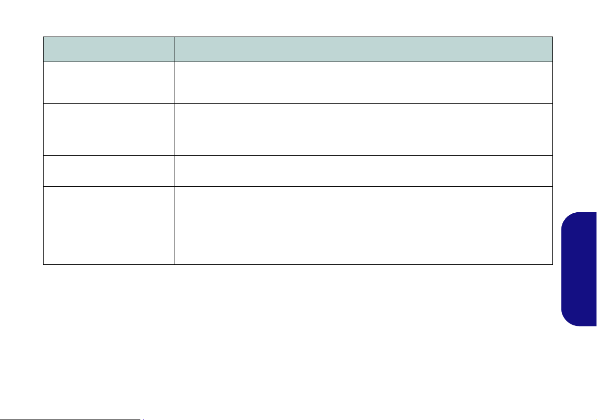
Solución de problemas
Problema Posible causa - Solución
El módulo Bluetooth está
apagado tras reanudar desde
la Suspensión.
Un archivo no puede copiarse
a o desde un dispositivo
conectado con Bluetooth.
El módulo cámara PC no
puede detectarse.
Los archivos de vídeo
capturados de la cámara PC
ocupan demasiado espacio en
el disco.
El estado predeterminado del módulo Bluetooth será apagado tras reanudar desde el estado de
ahorro de energía Suspensión. Utilice la combinación de teclas (Fn + F12) para encender el
módulo Bluetooth tras reanudar el ordenador desde Suspensión.
La transferencia de datos entre el ordenador y un dispositivo con Bluetooth se realiza sólo en
una dirección (no soporta la transferencia de datos simultánea). Si copia un archivo de su
ordenador a un dispositivo con Bluetooth, no podrá copiar un archivo del dispositivo Bluetooth a
su ordenador hasta que se haya completado el proceso de tran sferencia del ordenador.
El módulo está desactivado. Utilice la combinación de teclas Fn + F11 para ac tivar el módulo (vea
la Tabla 4 en la página 81). Ejecute la aplicación de la cámara para ver la imagen de la cámara.
Tenga en cuenta que capturar archivos de vídeo de alta resolución requiere una cantidad
sustancial de espacio en el disco p ara cada archivo.
Tenga en cuenta que el sistema Windows requiere un mínimo de 16GB (32bit) o 20GB (64bit)
de espacio libre en la partición del sist ema unidad C:. Se recomienda que guarde el archivo de
vídeo capturado en una ubicación distinta a la unidad C:, limite el tamaño de archivo del vídeo
capturado o reduzca la resolución del vídeo.
Español
93

Especificaciones
Información actualizada de
especificaciones
Las especificaciones listadas en esta
sección son correctas en el momento de
publicación. Ciertas opciones (particularmente tipos/velocidades de procesadores) pueden cambiar o actualizarse
según la fecha de lanzamiento del fabricante. Diríjase a su centro de servicios
para más detalles.
Español
Opciones de procesadores
Procesador Intel® Celeron® 847
1,10GHz, 32nm, caché de nivel 3 de 2MB,
DDR3-1333MHz, TDP: 17W
Procesador Intel® Celeron® 877
1,40GHz, 32nm, caché de nivel 3 de 2MB,
DDR3-1333MHz, TDP: 17W
LCD
Modelo A - Diseños I & III:
14" (35,65cm) HD (espesura: 5,2mm)
Modelo A - Diseño II:
14" (35,65cm) HD (espesura: 3,6mm)
Modelo B:
15,6" (39,62cm) HD
Modelo C:
17,3" (43,94cm) HD+/ FHD
Núcleo logic
Chipset Intel® NM70
Memoria
Dos zócalo de 204 pins SODIMM, para
memoria DDR3 1333/1600MHz (La
frecuencia de operación de memoria real
depende del FSB del procesador.)
Memoria expansible hasta 8GB
BIOS
AMI BIOS (SPI Flash ROM de 48Mb)
Adaptador de vídeo
Intel® HD Graphics
Frecuencia dinámica (T ecnología de memoria
de vídeo dinámica Intel hasta 1,7GB)
Compatible con DirectX® 10.1
Audio
Interfaz compatible HDA (Sonido Intel de
alta definición)
2 altavoces incorporados
Micrófono incorporado
Dispositivos de almacenamiento
(Opción de fábrica) Un dispositivo óptico
Super Multi de 12,7mm(h) intercambiable
(Opción de fábrica) ODD falso (
algunos diseños del Modelo A y
algunos diseños del Modelo B
Un HDD SATA intercambiable de 2,5" 9,5
mm (h)
Seguridad
Ranura para cierre de seguridad (tipo
Kensington®)
Contraseña de BIOS
sólo
)
94
 Loading...