

Clevo W244ELQ, W246ELQ, W24AEL Concise User's Guide


Contents
About this Concise User Guide .........................................................1
System Startup ..................................................................................4
System Map: Front View with LCD Panel Open (Model A) ...........6
System Map: Front View with LCD Panel Open (Models B & C) ..7
LED Indicators ..................................................................................8
Hot-Key Buttons ...............................................................................9
Keyboard ...........................................................................................9
System Map: Front, Left, Right, Rear & Bottom Views
(Model A) ............................................................................... .........11
System Map: Front, Left, Right, Rear & Bottom Views
(Model B) ........................................................... .............................12
System Map: Front, Left, Right, Rear & Bottom Views
(Model C) ........................................................... .............................13
3.75G/HSPA Module ......................................................................14
Driver Installation ...........................................................................15
Troubleshooting ..............................................................................16
Specifications ................. .................................... ............................. 17
Inhalt
Über das Ausführliche Benutzerhandbuch .....................................21
Schnellstart ................. ................. ................ ................ ............... .....24
Systemübersicht: Ansicht von vorne mit geöffnetem
LCD-Bildschirm (Modell A) ..........................................................26
Systemübersicht: Ansicht von vorne mit geöffnetem
LCD-Bildschirm (Modelle B & C) .................................................27
LED-Anzeigen ................. ........................................................ .......28
Hot-Key-Tasten .............. ..... ...... ....... ....... .... ....... ...... ....... ....... .... .....29
Tastatur ...........................................................................................29
Funktionstasten ...............................................................................30
Systemübersicht: Ansicht von vorne, links, rechts, hinten und
unten (Modell A) ................... ............................... ...........................31
Systemübersicht: Ansicht von vorne, links, rechts, hinten und
unten (Modell B) .............................................................................32
Systemübersicht: Ansicht von vorne, links, rechts, hinten und unten
(Modell C) .......... ............................... ..............................................33
3.75G/HSPA-Modul ................... ................ ............... ................ ......34
Installation der Treiber ....................................................................35
Fehlerbehebung ...............................................................................36
Technische Daten ............................................................................37
Sommaire
A propos de ce Guide Utilisateur Concis ........................................41
Guide de démarrage rapide .............................................................44
Carte du système: Vue de face avec l’écran LCD ouvert (Modèle A)
46
Carte du système: Vue de face avec l’écran LCD ouvert
(Modèles B & C) .............................................................................47
Indicateurs LED ..................... .........................................................48
Boutons Hot-Key ................................................... ..........................49
Clavier ...................................................... .......................................49
Touches fonction .... ............................................................ .............50
Carte du système: Vues de face, gauche, droite, arrière & dessous
(Modèle A) ............................... .......................................................51
Carte du système: Vues de face, gauche, droite, arrière & dessous
(Modèle B) ............................................................ ..........................52
Carte du système: Vues de face, gauche, droite, arrière & dessous
(Modèle C) ............................................................ ..........................53
Module 3.75G/HSPA ......................................................................54
Installation du pilote ........................................................................55
Dépannage ......................... ...................................... ........................56
Spécifications ..................................................................................57

Contenidos
Acerca de esta Guía del Usuario Concisa .......................................61
Guía rápida para empezar ...............................................................64
Mapa del sistema: Vista frontal con panel LCD abierto
(Modelo A) ............................................................................... .......66
Mapa del sistema: Vista frontal con panel LCD abierto
(Modelos B & C) ............................................................................67
Indicadores LED .............................................................................68
Botones Hot-Key ............................................ ................................69
Teclado ....................... ............... .................. ................ ............... .....69
Mapa del sistema: Vistas frontal, izquierda, derecha, posterior e
inferior (Modelo A) .........................................................................71
Mapa del sistema: Vistas frontal, izquierda, derecha, posterior e
inferior (Modelo B) .........................................................................72
Mapa del sistema: Vistas frontal, izquierda, derecha, posterior e
inferior (Modelo C) .........................................................................73
Módulo 3.75G/HSPA ......................................................................74
Instalación de controladores ...........................................................75
Solución de problemas ....................................................................76
Especificaciones .................. ............... ................ ............... ..............77
Sommario
Informazioni su questa guida rapida ...............................................81
Guida di avvio rapido ......................................................................84
Descrizione del sistema: Vista anteriore con pannell o LCD aper to
(Modello A) ....................................................................................86
Descrizione del sistema: Vista anteriore con pannell o LCD aper to
(Modelli B & C) ............................................................ ..................87
Indicatori LED ................................................................................88
Pulsanti Hot-Key ................................ .............................................89
Tastiera ................... ........................................ .................................89
Tasti funzione ..................................................................................90
Descrizione del sistema: Vista anteriore, sinistra, destra,
posteriore e inferiore (Modello A) ..................................................91
Descrizione del sistema: Vista anteriore, sinistra, destra,
posteriore e inferiore (Modello B) ..................................................92
Descrizione del sistema: Vista anteriore, sinistra, destra,
posteriore e inferiore (Modello C) ..................................................93
Modulo 3.75G/HSPA ......................................................................94
Installazione driver ...... ............................... .....................................95
Risoluzione dei problemi ........... .....................................................96
Specifiche tecniche ..........................................................................97

About this Concise User Guide
FCC Statement
This device complies with Part
15 of the FCC Rules. Operation
is subject to the following two
conditions:
1.This device may not cause
harmful interference.
2. This device must accept any
interference received, including interference that may
cause undesired operation.
This quick guide is a brief introduction to getting your system started. This is a supplement, and not a substitu te for the
expanded English language User’s Manual in Adobe Acrobat format on the Device Drivers & Utilities + User’s Manual
disc supplied with your computer. This disc also contains the drivers and utilities necessary for the prop er operation of
the computer (Note: The company reserves the right to revise this publication or to change its contents without notice).
Some or all of the computer’s features may already have been setup. If they aren’t, or you are planning to re-configure
(or re-install) portions of the system, refer to the expanded User’s Manual. The Device Drivers & Utilities + User’s
Manual disc does not contain an operating system.
Regulatory and Safety Information
Please pay careful attention to the full regulatory notices and safety information contained in the expanded User’s Manual on the Device Drivers & Utilities + User’s Manual disc.
©April 2012
Trademarks
Intel, Pentium and Celeron are trademarks/registered trademarks of Intel Corporation.
English
1

Instructions for Care and Operation
The computer is quite rugged, but it can be damaged. To prevent this, follow these suggestions:
• Don’t drop it, or expose it to shock. If the computer falls, the
case and the components could be damaged.
• Keep it dry, and don’t overheat it. Keep the computer and power
supply away from any kind of heating element. This is an electrical appliance. If water or any other liquid gets into it, the computer
English
could be badly damaged.
• Avoid interference. Keep the compute r away from high capacity
transformers, electric motors, and other strong magnetic fields.
These can hinder proper performance and damage your data.
• Follow the proper working procedures for the computer. Shut
the computer down properly and don’t forget to save your work.
Remember to periodically save your data as data may be lost.
Servicing
Do not attempt to service the computer yourself. Doing so may
violate your warranty and expose you and the computer to
electric shock. Refer all servicing to authorized service personnel. Unplug the computer from the power supply. Then refer
servicing to qualified service personnel under any of the fo llowing conditions:
• When the power cord or AC/DC adapter is damaged or frayed.
• If the computer has been exposed to any liquids.
• If the computer does not work normally when you follow the operating instructions.
• If the computer has been dropped or damaged (do not touch the
poisonous liquid if the LCD panel breaks).
• If there is an unusual odor, heat or smoke coming from your computer.
Safety Information
• Only use an AC/DC adapter approved for use with this computer.
• Use only the power cord and batteries indicated in this manual. Do
not dispose of batteries in a fire. They may explode. Check with
local codes for possible special disposal instructions.
• Do not continue to use a battery that has been dropped, or that
appears damaged (e.g. bent or twisted) in any way. Even if the
computer continues to work with a damaged battery in place, it
may cause circuit damage, which may possibly result in fire.
• Make sure that your computer is completely powered off before
putting it into a travel bag (or any such container).
• Before cleaning the computer, make sure it is disconnected from
any external power supplies, peripherals and cables (including
telephone lines). It is advisable to also remove your battery in
order to prevent accidentally turning the machine on.
• Use a soft clean cloth to clean the computer, but do not apply
cleaner directly to the computer. Do not use volatile (petroleum
distillates) or abrasive cleaners on any part of the computer.
• Do not try to repair a battery pack. Refer any battery pack repair or
replacement to your service representative or qualified service personnel.
• Note that in computer’s featuring a raised LCD electro-pl ated
logo, the logo is covered by a protective adhesive. Due to general
wear and tear, this adhesive may deter iorate over time and the
exposed logo may develop sharp edges. Be careful when handling
the computer in this case, and avoid touching the raised LCD electro-plated logo. Av oid placing any other items in the carrying bag
which may rub against the top of the computer during transport. If
any such wear and tear develops contact your service center.
2

Polymer Battery Precautions
Battery Disposal & Caution
The product that you have purchased contains a rechargeable
battery. The battery is recyclable. At the end of its useful life,
under various state and local laws, it may be illegal to dispose
of this battery into the municipal waste stream. Check with
your local solid waste officials for details in your area for recycling options or proper disposal.
Danger of explosion if battery is incorrectly replaced. Replace
only with the same or equivalent type recommended by the
manufacturer. Discard used battery according to the manufacturer’s instructions.
Note the following information which is specific to poly mer
batteries only, and where applicable, this overrides the general
battery precaution information.
• Polymer batteries may experience a slight expansion or swelling,
however this is part of the battery’s safety mechanism and is not a
cause for concern.
• Use proper handling procedures when using polymer batteries. Do
not use polymer batteries in high ambient temperature environments, and do not store unused batteries for extended periods.
English
3

System Startup
Shut Down
Note that you should always shut your computer down by
choosing Shut Down
from the Start Menu.
This will help prevent
hard disk or system
problems.
130 ゚
1. Remove all packing materials.
2. Place the computer on a stable surface.
Insert the battery and make sure it is locked in position.
3.
4. Securely attach any peripherals you want to use with the
computer (e.g. keyboard and mouse) to their ports.
5. Attach the AC/DC adapter to the DC-In jack on the left of the
computer, then plug the AC power cord into an outlet, and
English
connect the AC power cord to the AC/DC adapter.
6. Use one hand to raise the
(do not exceed 130 degrees); use the other hand (as
angle
illustrated in Figure 1) to support the base of the computer
(Note: Never lift the computer by the lid/LCD).
7. Press the power button to turn the computer “on”.
lid/LCD to a comfortable viewing
System Software
Your computer may already come with system software
pre-installed. Where this is not the case, or where you are
re-configuring your computer for a different system, you
will find this manual refers to Microsoft Windows 7.
Figure 1 - Opening the Lid/LCD/Computer with AC/DC
Adapter Plugged-In
4

Model Differences
This notebook series includes three different model types that mainly differ as indicated in the table below. Note that
your model may appear slightly different from those pictured in this manual.
Feature Model A Model B Model C
Display Type 14.0” (35.56cm) HD 15.6” (39.62cm) HD 17.3” (43.94cm) HD+
3.75G/HSPA
module
Dimensions &
Weight
340mm (w) * 238mm (d) * 26.25 -
34.7mm (h)
2.2kg
(with 48.84WH Battery and
ODD)
Or
341mm (w) * 238.5mm (d) * 16 -
34mm (h)
2.2kg
(with 48.84WH Battery and
ODD)
Or
340mm (w) * 238mm (d) * 12 -
30.2mm (h)
2.15kg (with 48.84WH Battery and
ODD)
Factory Option Not Supported
374mm (w) * 250mm (d) * 14.3 - 34.1mm
(h)
2.3kg
(with 48.84WH Battery and ODD)
Or
374mm (w) * 250mm (d) * 20 - 37.2mm (h)
2.6kg (with 48.84WH Battery and ODD)
413mm (w) * 270mm (d) * 14 -
40.5mm (h)
2.9kg (with 48.84WH Battery
and ODD)
Table 1 - Model Differences
English
5

System Map: Front View with LCD Panel Open (Model A)
4
6
3
5
7
1
Note that the Touchpad and Buttons valid operational area is
that indicated within
the red dotted lines
above.
8
6
3
5
7
1
8
Design I
Design II
14” (35.56cm)
2
2
8
Figure 2
Front View with LCD Panel
Open (Model A)
1. PC Camera (Optional)
2. LCD
3. Power Button
4. Hot-Key Buttons (Design I
Only)
5. LED Status Indicators
6. Keyboard
7. Built-In Microphone
8. Touchpad & Buttons
14” (35.56cm)
Wireless Device
Operation Aboard Aircraft
The use of any portable electronic transmission device s aboard aircra ft
is usually prohibited. Make sure the wireless modules are OFF if you
are using the computer aboard aircraft.
Use the key combinations to toggle power to the 3.75G/HSPA/WLAN/
Bluetooth modules, and check the LED indicator/visual indicator to see
if the modules are powered on or not (see Table 5 on page 10).
English
6

System Map: Front View with LCD Panel Open (Models B & C)
Note that the Touchpad and Buttons valid
operational area is that
indicated within the red
dotted lines above.
5
3
4
6
1
7
15.6” (39.62cm)
2
7
Figure 3 - Front View with LCD Panel Open (Models B & C)
1. PC Camera (Optional)
2. LCD
3. Power Button
4. LED Status Indicators
5. Keyboard
6. *Built-In Microphone
*Note that the microphone location is dependent upon you r
model design.
7. Touchpad & Bu ttons
4
6
3
5
7
1
2
17.3” (43.94cm)
Model B
Model C
6
English
7
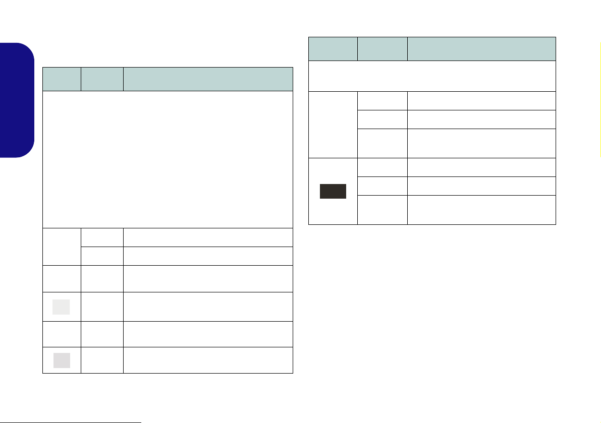
LED Indicators
Model A - Design lI
Model A - Design l
Models B & C
The LED indicators on the computer display helpful information about the current status of the computer.
Icon Color Description
Icon Color Description
Orange The AC/DC Adapter is Plugged In
English
Green The Wireless LAN Module is Powered On
Orange The Bluetooth Module is Powered On
Green Hard Disk Activity
Green
Green Caps Lock Activated
Green Scroll Lock Activated
Table 2 - LED Status Indicators
Number Lock (Numeric Keypad) Acti-
vated
Green The Computer is On
Blinking
Green
Orange The Battery is Charging
Green The Battery is Fully Charged
Blinking
Orange
Table 3 - LED Power Indicators
The Computer is in Sleep Mode
The Battery Has Reached Critically
Low Power Status
8
Hot-Key Buttons
Function Keys
NumLk &
ScrLk
Models B & C
Model A
Numeric
Keypad
Fn Key
Function Keys
NumLk &
ScrLk
Numeric
Keypad
Fn Key
(Model A - Design I Only)
The Hot-Key buttons give instant access to the default Internet browser and e-mail program, and allow you to toggle the Silent Mode/the WLAN module on/off with one
quick button press.
Hot-Key Button Function
*Activate the Default E-Mail Browser
Activate the Default Internet Program
or
*Note that In Windows 7 without Outlook/Outlook Express installed
this button has no function. If Outlook/Outlook Express are installed
then the button will activate the application.
**When enabled, Silent Mode will reduce fan noise and save power
consumption. Note this may reduce computer performance.
**Toggle Silent Mode
or
WLAN Module Power Toggle
Keyboard
The keyboard (Model A) has a numeric keypad for easy
numeric data input. Pressing Fn + NumLk turns on/off
the numeric keypad. It also features function keys to allow you to change operational features instantly.
The keyboard (Models B & C) includes a numeric keypad (on the right side of the keyboard) for easy numeric
data input. Pressing Fn + NumLk turns on/off the numeric keypad. It also features function keys to allow you
to change operational features instantly.
English
Table 4 - Hot-Key Buttons (Model A - Design I)
Figure 4 - Keyboard
9

Function Keys
The function keys (F1 - F12 etc.) will act as hot keys when pressed while the Fn key is held down. In addition to the
basic function key combinations, visual indicators are available when the hot key driver is installed.
Keys Function/Visual Indicators Keys Function/Visual Indicators
Fn + ~ Play/Pause (in Audio/Video Programs) Fn + F8/F9
English
Fn +
(Models A &
B Only)
Fn + F1 Touchpad Toggle Fn + F11
Fn + F2
Fn + F3 Mute Toggle Fn + NumLk Number Lock Toggle
Fn + F4 Sleep Toggle Fn + ScrLk Scroll Lock Toggle
Fn + F5/F6
Fn + F7 Display Toggle Fn + Esc Control Center Toggle (see page 9)
3.75G/HSPA Module
Power Toggle
Turn LCD Backlight Off
(Press a key to or use Touchpad to turn on)
Volume Decrease/
Increase
Table 5 - Function Keys & Visual Indicators
Brightness Decrease/
Increase
Fn + F10
Fn + F12
Caps Lock Caps Lock Toggle
PC Camera Power
Toggle
WLAN Module Power
Toggle
Bluetooth Module
Power Toggle
10

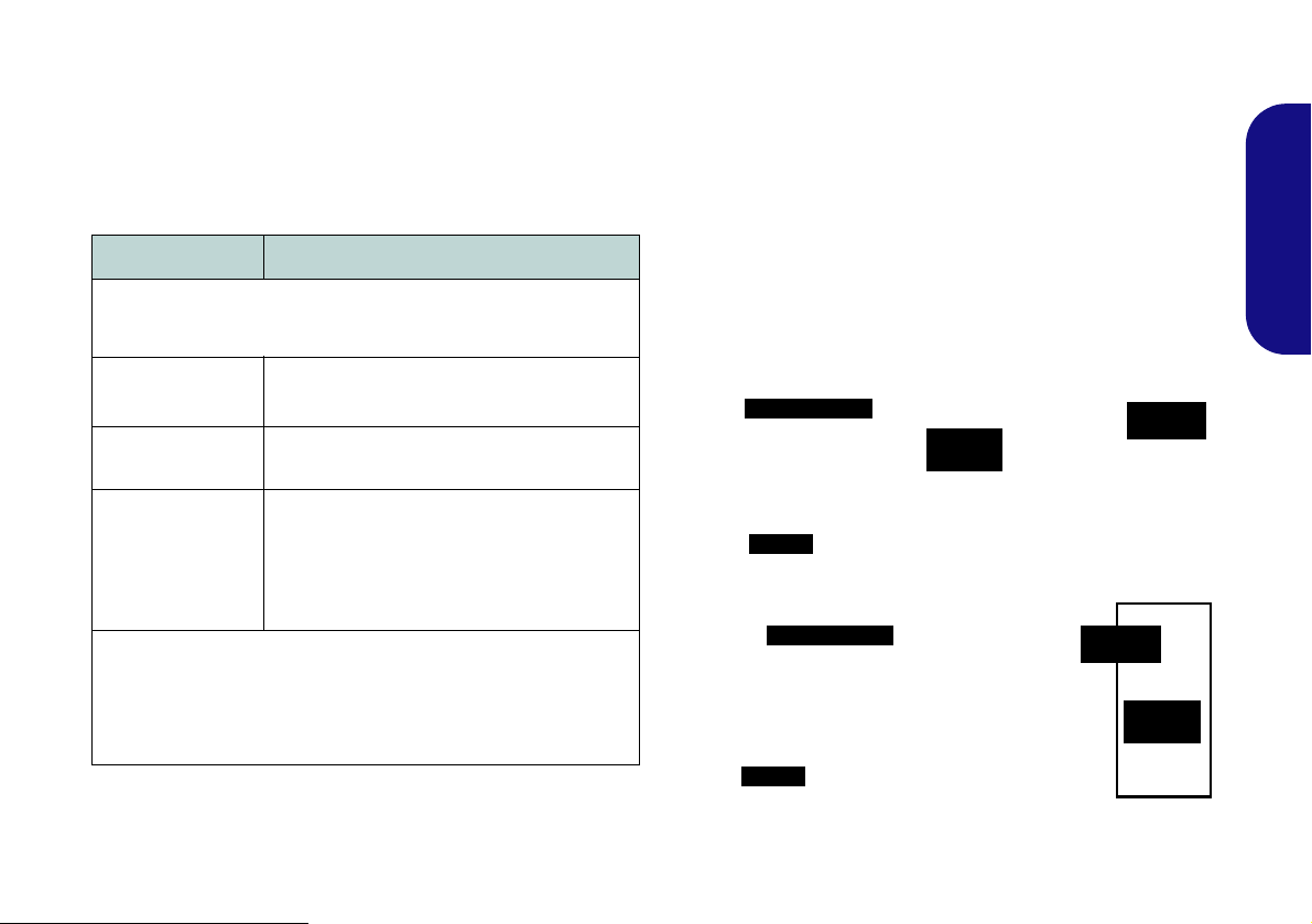
Control Center
Wireless & Bluetooth
Modules are Off
Press the Fn + Esc key combination, or double-click the icon in the notification area of the taskbar to toggle the
Control Center on/off. The Control Center gives quick access to frequently used controls,
turn modules on/off.
Figure 5 - Control Center
and enables you to quickly
English
Click on any button to turn any of the modules (e.g. Touchpad, Camera) on/off. Click on Power Conservation Modes
to switch between Performance, Balanced or Energy Star modes. To remove the Power C onservation Modes screen
just click in a blank area of the icon or press a key on the keyboard. Click on the buttons (or just click and hold the mouse
button) to adjust the slider for Brightness/Volume. Click on Display Switch/Time Zone/ Desktop Background to
bring up the appropriate Windows control panel. Click on the Sleep button to put the computer into Hibernate or Sleep
modes.
11
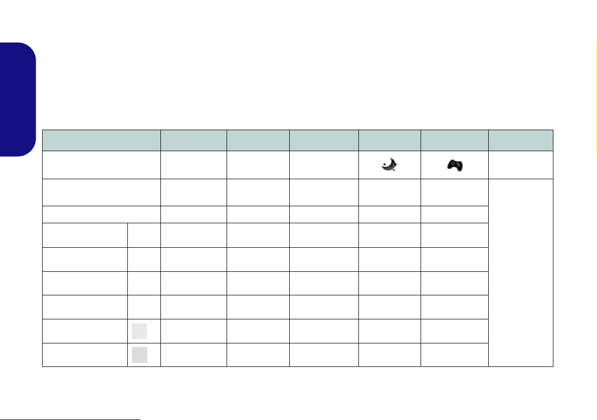
Power Modes
You can set a Power Mode by clicking the appropriate icon at the top of the Control Center. Each power mode will
affect the power status of modules (e.g. WLAN, 3G or Camera), screen brightness, Touchpad power and Silent Mode.
You can click a Control Center icon to set an overall power mode and then click individual icons in the Control Cen-
ter to power on/off any modules etc.
Table 6 illustrates the basic settings for each power mode. If you choose User Defined the settings will correspond to
your selected system settings.
English
Modes Power Saving Flight Entertainment Quiet Performance User Defined
Icon
Power Plan Power Saver Balanced Power Saver Power Saver
Power Conservation Mode Energy Star BIOS Default Energy Star Energy Star Performance
Silent ON OFF ON ON OFF
Brightness 14 42 100 42 100
WLAN OFF OFF ON ON ON
3G OFF OFF OFF OFF OFF
High Perfor-
mance
User Defined
PC Camera OFF OFF OFF ON ON
Touchpad ON ON OFF ON ON
Table 6 - Power Modes
12

Power Status
The Power Status icon will show whether you are currently powered by the battery, or by the AC/DC adapter plugged
in to a working power outlet. The power status bar will show the current battery charge state.
Brightness
The Brightness icon will show the current screen brightness level. You can use the slider to adjust the screen brightness
or the Fn + F8/F9 key combinations, or use the Fn + F2 key combination to turn off the LED backlight (press any key
to turn it on again). Note that screen brightness is also effected by the Power Mode selected.
Volume
The Volume icon will show the current volume level. You can use the slider to adjust the Volume or the Fn + F5/F6
key combinations, or use the Fn + F3 key combination to mute the volume.
Power Conservation
This system supports Energy Star power management features that place computers (CPU, hard drive, etc.) into a lowpower sleep modes after a designated period of inactivity. Click either the Performance, Balanced or Energy Star
button. Click in a blank area of the icon or press a key on the keyboard to exit Power Conservation Mode without
making any changes.
Sleep
Click the Sleep button to bring up the Hibernate or Sleep buttons, and click either button to have the computer
enter the appropriate power-saving mode. Click in a blank area of the icon or press a key on the keyboard to exit Power
Conservation Mode without making any changes.
English
13

Display Switch
Click the Display Switch button to access the menu (or use the + P key combination) and select the appropriate
attached display mode.
Time Zone
Clicking the Time Zone button will access the Date and Time Windows control panel.
Desktop Background
English
Clicking the Desktop Background button will allow you to change the desktop background picture.
Touchpad/PC Camera/Wireless LAN Module /Bluetooth/3.75G Module
Click any of these buttons to toggle the Touchpad or module’s power status. A crossed out icon will appear over the top
left of the icon when it is off
Power Mode selected.
. Note that the power status of a module, and Touchpad power, is also effected by the
Silent Mode
Click the Silent Mode button toggles silent mode on/off. You can use Silent Mode to reduce power consumption and
fan noise. Note that the Silent Mode effected by the Power Mode selected.
• Silent Mode is OFF
• Silent Mode is On
Note Silent Mode may reduce computer performance.
Caps Lock/Scroll Lock/ Number Lock
Click the button to toggle the appropriate lock mode.
14

System Map: Front, Left, Right, Rear & Bottom Views (Model A)
2
1
7
8
4
6
3
Left
Right
5
Front
Rear
10
13
16
12
19
Bottom
14
15
6
9
7
18
7
18
17
7
7
15
11
Overheating
To prevent your computer from overheating
make sure nothing blocks any vent while the
computer is in use.
Disc Emergency Eject
If you need to manually eject a disc (e.g. due
to an unexpected power interruption) you
may push the end of a straightened paper
clip into the emergency eject hole. Do not
use a sharpened pencil or similar object that
may break and become lodged in the hole.
USB 3.0 Port
The USB 3.0
ports
are col-
ored blue. USB
3.0 will transfer
data much faster
than USB 2.0,
and is backwards-compatible with USB 2.0.
6
Figure 6 - Front, Left, Right, Rear & Bottom
Views (Model A)
1. LED Power Indicators
2. DC-In Jack
3. External Monitor Port
4. RJ-45 LAN Jack
5. HDMI-Out Port
6. 2 * USB 3.0 Ports
7. Vent
8. Multi-in-1 Card
9. Microphone-In Jack
10. Headphone-Out Jack
Reader
11. USB 2. 0 Po rt
12. Optical Device Drive
Bay
13. Emergency Eject Hole
14. Security Lock Slot
15. Battery
16. Component Bay Cover
17. Hard Disk Bay Cover
18. Speakers
19. USIM Card Cover
(Optional)
English
15

System Map: Front, Left, Right, Rear & Bottom Views (Model B)
2
1
7
8
4
6
3
Left
Right
5
Front
Rear
10
14
12
15
13
6
9
16
15
7
Bottom
17
18
7
18
19
11
Overheating
To prevent your computer from overheating
make sure nothing blocks any vent while the
computer is in use.
Disc Emergency Eject
If you need to manually eject a disc (e.g. due
to an unexpected power interruption) you
may push the end of a straightened paper
clip into the emergency eject hole. Do not
use a sharpened pencil or similar object that
may break and become lodged in the hole.
USB 3.0 Port
The USB 3.0
ports
are col-
ored blue. USB
3.0 will transfer
data much faster
than USB 2.0,
and is backwards-compatible with USB 2.0.
6
English
Figure 7 - Front, Left, Right, Rear & Bottom
Views (Model B)
1. LED Power Indicators
2. DC-In Jack
3. External Monitor Port
4. RJ-45 LAN Jack
5. HDMI-Out Port
6. 2 * USB 3.0 Ports
7. Vent
8. Multi-in-1 Card
9. Microphone-In Jack
10. Headphone-Out Jack
16
Reader
11. USB 2.0 Port
12. Optical Device Drive
Bay
13. Emergency Eject Hole
14. Security Lock Slot
15. Battery
16. Component Bay Cover
17. Hard Disk Bay Cover
18. Speakers
19. USIM Card Cover
(Optional)

System Map: Front, Left, Right, Rear & Bottom Views (Model C)
18
7
Bottom
7
2
1
7
6
4
6
3
Left
Right
5
Front
Rear
10
13
11
14
12
8
15
16
7
7
9
15
18
7
17
Overheating
To prevent your computer from overheating
make sure nothing blocks any vent while the
computer is in use.
Disc Emergency Eject
If you need to manually eject a disc (e.g. due
to an unexpected power interruption) you
may push the end of a straightened paper
clip into the emergency eject hole. Do not
use a sharpened pencil or similar object that
may break and become lodged in the hole.
USB 3.0 Port
The USB 3.0
ports
are col-
ored blue. USB
3.0 will transfer
data much faster
than USB 2.0,
and is backwards-compatible with USB 2.0.
6
Figure 8 - Front, Left, Right, Rear & Bottom
Views (Model C)
1. LED Power Indicators
2. DC-In Jack
Reader
3. External Monitor Port
4. RJ-45 LAN Jack
5. HDMI-Out Port
6. 2 * USB 3.0 Ports
7. Vent
8. Multi-in-1 Card
9. Microphone-In Jack
10. Headphone-Out Jack
11. USB 2.0 Port
12. Optical Device Drive
Bay
13. Emergency Eject Hole
14. Security Lock Slot
15. Battery
16. Component Bay Cover
17. Hard Disk Bay Cover
18. Speakers
English
17

3.75G/HSPA Module
123
1
3
2
(Models A & B Only)
If you have included an optional 3.75G/HSPA module in
your purchase option, follow the instructions below to install the USIM card (which will be provided by your service provider), and then run the appropriate application
supplied with your module.
English
USIM Card Insertion
1. Turn off the computer, and turn it o ver and remove the battery
(slide the latches in the direction indicated below and slide
the battery out).
2. Locate the SIM card cover and loosen screw and remove
the SIM card cover .
3. Insert the USIM card as you would into your mobile phone.
4. Slide the SIMLOCK towards the hinge (in the direction to the
arrow illustrated in Figure 10) in order to release the lock and
lift it up.
5. Insert the USIM card and close the SIMLOCK.
Figure 10 - Unlock the SIMLOCK
6. Lock the SIMLOCK by pushing it in the direction of the arrow in
Figure 11 until it clicks into the lock position.
Figure 11 - Lock the SIMLOCK
Figure 9 - Battery & SIM Card Cover Removal
18
7. Replace the cover, screw and battery.

Driver Installation
Driver Installation General
Guidelines
As a general guide follow the
default on-screen instructions for each driver (e.g.
Next > Next > Finish) unless
you are an advanced user. In
many cases a restart is required to install the driver.
Make sure any modules (e.g.
PC Camera, WLAN or 3.75G/
HSPA) are ON before install-
ing the appropriate driver.
Windows Update
After installing all the drivers
make sure you enable Win-
dows Update in order to get
all the latest security updates
etc. (all updates will include
the latest hotfixes from Mi-
crosoft).
The Device Drivers & Utilities + User’s Manual disc contains the drivers and utilities
necessary for the proper operation of the computer. This setup will probably have already been done for you. If this is not the case, insert the disc and click Install Drivers
(button), or Option Drivers (button) to access the Optional driver menu. Install the
drivers in the order indicated in Figure 12. Click to select the drivers you wish to install (you should note down the drivers as you install them). Note: If you need to reinstall any driver, you should uninstall the driver first.
Manual Driver Installation
Click the Browse CD/DVD button in the Drivers Installer application and browse to
the executable file in the appropriate driver folder.
Found New Hardware
If a
Cancel, and follow the installation procedure as directed.
wizard appears
during the installation procedure, click
English
Figure 12 - Install Drivers
19
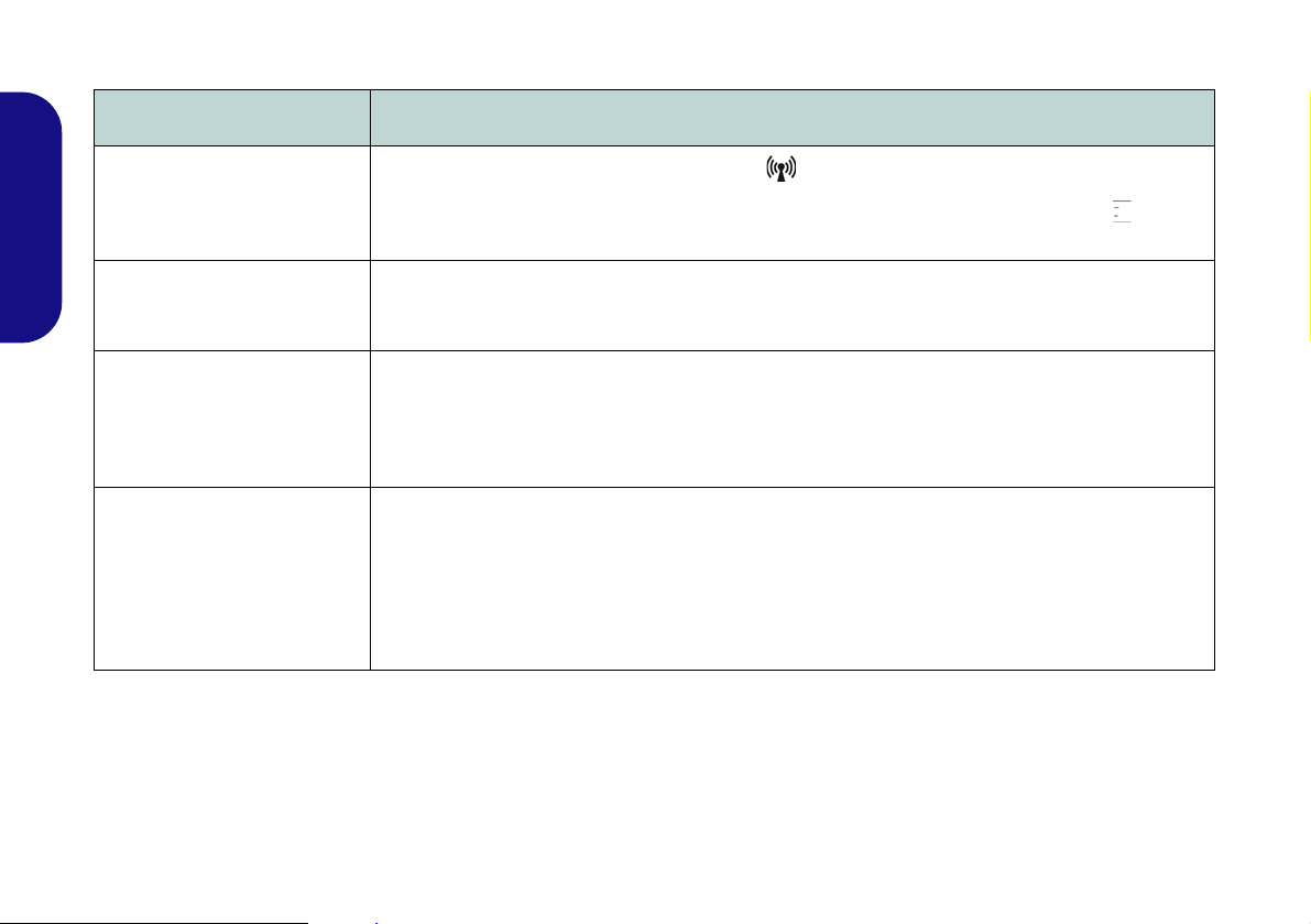
Troubleshooting
Problem Possible Cause - Solution
The Wireless LAN/
Bluetooth/3.75G/HSPA
modules cannot be detected.
English
The Bluetooth module is off
after resuming from Sleep.
A file cannot be copied to/from
a connected Bluetooth
device.
The captured video files from
the PC Camera are taking up
too much disk space.
The modules are off. Check the LED indicator and/or function key indicator to see if the WLAN/
Bluetooth/3.75G/HSPA module is on or off (see Table 2 on page 8 and Table 5 on page 10). If the
LED indicator is off, then press the Fn + F11 (WLAN), Fn + F12 (Bl uetooth) or Fn + (3.75G/
HSPA) in order to enable the modules (see Table 5 on page 10).
The Bluetooth module’s default state will be off after resuming from the Sleep power-saving state.
Use the key combination (Fn + F12) to power on the Bluetooth module after the computer resumes
from Sleep.
Transferring data between the computer and a Bluetooth enabled device is supported in one
direction only (simultaneous data transfer is not supported). If you are copying a file from your
computer to a Bluetooth enabled device, you will not be able to copy a file from the Bluetooth
enabled device to your computer until the file transfer process from the computer has been
completed.
Note that capturing high resolution video files requires a substantial amount of disk space for each
file.
Note that the Windows system requires a minimum of 15GB of free space on t he C: drive system
partition. It is recommended that you save the capture video file to a location other than the C:drive,
limit the file size of the captured video or reduce video resolution (Options > Video Capture Pin... >
Output Size).
20

Specifications
Latest Specification Information
The specifications listed in this here
are correct at the time of going to
press. Certain items (particularly
processor types/speeds) may be
changed, delayed or updated due to
the manufacturer's release schedule. Check with your service center
for details.
Processor Options
Intel® Pentium® Processor
B980 (2.40GHz), B970 (2.30GHz), B960
(2.20GHz), B950 (2.10GHz)
2MB L3 Cache, 32nm, DDR3-1333MHz,
TDP 35W
Intel® Celeron® Processor
B840 (1.90GHz), B820 (1.70GHz), B815
(1.60GHz), B810 (1.60GHz)
2MB L3 Cache, 32nm, DDR3-1333MHz,
TDP 35W
B730 (1.80GHz), B720 (1.70GHz)
1.5MB L3 Cache, 32nm, DDR3-1333MHz,
TDP 35W
Core Logic
Intel® HM70 Chipset
BIOS
One 48Mb SPI Flash ROM
AMI BIOS
Memory
Two 204 Pin SO-DIMM Sockets Supporting
DDR3 1333/1600MHz Memory
Memory Expandable up to 8GB
(The real memory operating frequency
depends on the FSB of the processor.)
LCD
Model A:
14" (35,56cm) HD (Thickness: 5.2mm)
Or
14" (35,56cm) HD (Thickness: 3.6mm)
Model B:
15.6" (39.62cm) HD
Model C:
17.3" (43.94cm) HD+
Video Adapter
Intel HD Graphics
(GPU is Dependent on Processor)
Dynamic Frequency (Intel Dynamic Video
Memory Technology for up to 1.7GB)
Microsoft DirectX®10 Compatible
Storage
(Factory Option) One Changeable
12.7mm(h) Optical Device Type Drive
(Super Multi Drive Module or Blu-Ray
Combo Drive Module)
(Factory Option) Dummy ODD (Some
Designs Only)
One Changeable 2.5" 9.5mm (h) SATA HDD
Security
Security (Kensington® Type) Lock Slot
BIOS Password
English
21

Audio
High Definition Audio Compliant Interface
2 * Built-In Speakers
Built-In Microphone
Pointing Device
Built-in Touchpad
English
Keyboard
Model A:
“WinKey” keyboard (with embedded
numeric keypad)
Models B & C:
Full-size “WinKey” keyboard (with numeric
keypad)
Interface
One HDMI-Out Port
One Headphone-Out Jack
One Microphone-In Jack
One RJ-45 LAN Jack
One External Monitor Port
One USB 2.0 Port
Two USB 3.0 Ports
One DC-in Jack
Communication
Built-In Gigabit Ethernet LAN
(Factory Option) 300K/1.3M Pixels/2M Pix-
els (HD) PC Camera Module
(Factory Option) 3.75G/HSPA Mini-Card
Module (Models A & B Only)
WLAN/ Bluetooth Half Mini-Card
Modules:
(Factory Option) Intel® Centrino® Wireless-N 2230 Wireless LAN (802.11b/g/n) +
Bluetooth 4.0
(Factory Option) Intel® Centrino® Wireless-N 135 Wireless LAN (802.11b/g/n) +
Bluetooth 4.0
(Factory Option) Third-Party Wireless LAN
(802.11b/g/n)
(Factory Option) Third-Party Wireless LAN
(802.11b/g/n) + Bluetooth 4.0
Mini Card Slots
Models A & B:
Slot 1 for WLAN Module or Combo WLAN
and Bluetooth Module
(Factory Option) Slot 2 for 3.75G/HSPA
Module
Model C:
Slot 1 for WLAN Module or Combo WLAN
and Bluetooth Modul
Card Reader
Embedded Multi-In-1 Card Reader
MMC (MultiMedia Card) / RS MMC
SD (Secure Digital) / Mini SD / SDHC/
SDXC
MS (Memory Stick) / MS Pro / MS Duo
Power
6 Cell Smart Lithium-Ion Battery Pack,
48.84WH
(Factory Option) 6 Cell Smart Lithium-Ion
Battery Pack, 62.16WH
Full Range AC/DC Adapter
AC Input: 100 - 240V, 50 - 60Hz
DC Output: 19V, 3.42A or 18.5V, 3.5A (65W)
Environmental Spec
Temperature
Operating: 5°C - 35°C
Non-Operating: -20°C - 60°C
Relative Humidity
Operating: 20% - 80%
Non-Operating: 10% - 90%
22

Dimensions & Weight
Model A:
340mm (w) * 238mm (d) * 26.25 - 34.7mm
(h)
2.2kg (with 48.84WH Battery and ODD)
Or
341mm (w) * 238.5mm (d) * 16 - 34mm (h)
(with 48.84WH Battery and ODD)
2.2kg
Or
340mm (w) * 238mm (d) * 12 - 30.2mm (h)
(with 48.84WH Battery and ODD)
2.15kg
Model B:
374mm (w) * 250mm (d) * 14.3 - 34.1mm (h)
2.3kg (with 48.84WH Battery and ODD)
Or
374mm (w) * 250mm (d) * 20 - 37.2mm (h)
(with 48.84WH Battery and ODD)
2.6kg
Model C:
413mm (w) * 270mm (d) * 14 - 40.5mm (h)
2.9kg (with 48.84WH Battery and ODD)
English
23

English
24

Über das Ausführliche Benutzerhandbuch
Diese Kurzanleitung soll einen Überblick über die Schritte geben, die dazu notwendig s ind, das System zu starten. Dieses ist
nur eine Ergänzung und kein Ersatz für das erweiterte englischsprachige Benutzerhandbuch, das auf der mitgelieferten Disc
Device Drivers & Utilities + User's Manual im Adobe-Acrobat-Format vorliegt. Diese Disc enthält auch die Treiber und
Utility-Programme, die für einen einwandfreien Betrieb des Computers notwendig sind (Hinweis: Das Unternehmen behält
sich das Recht vor, diese Publikation ohne Vorankündigung zu überarbeiten und den Inhalt zu verändern).
Einige oder alle Funktionen des Computers sind bereits eingerichtet worden. Falls das nicht der Fall ist oder wenn Sie einzelne Teile des Systems neu konfigurieren (oder neu installieren) möchten, finden Sie eine Anleitung im erweiterten Benut-
zerhandbuch. Die Disc Device Drivers & Utilities + User's Manual enthält nicht das Betriebssystem.
Einhaltung gesetzlicher Vorschriften und Sicherheitshinweise
Beachten Sie sorgfältig die Hinweise zu gesetzlichen Vorschriften und zu Sicherheitshinweisen im erweiterten Benutzerhandbuch auf der Disc Device Drivers & Utilities + User's Manual.
© April 2012
Warenzeichen
Intel, Pentium und Celeron sind warenzeichen/eingetragenes warenzeichen der Intel Corporation.
Deutsch
21

Hinweise zu Pflege und Betrieb
Das Notebook ist zwar sehr stabil, kann aber dennoch beschädigt werden. Damit es nicht dazu kommt, sollten Sie die
folgenden Hinweise beachten:
• Das Gerät darf nicht herunterfallen und in anderer Form Stößen
ausgesetzt werden. Wenn der Computer fällt, können das Gehäuse und
andere Komponenten beschädigt werden.
• Das Gerät darf nicht nass werden und sich nicht überhitzen. Computer und Netzteil dürfen nicht in der Nähe von Wärmequellen stehen oder
gelagert werden. Dies ist ein elektrisches Gerät. Wenn Wasser oder
andere Flüssigkeiten eindringen, kann der Computer stark beschädigt
werden.
• Vermeiden Sie Interferenzen mit anderen Geräten. Halten Sie den
Computer fern von magnetischen Feldern, die von Stromquellen, Moni-
Deutsch
toren, Magneten etc. erzeugt werden. Die können die Leistung beeinträchtigen und Ihre Daten beschädigen.
• Achten Sie auf die richtige Bedienung des Computers. Schalten Sie
ihn erst aus, wenn alle Programme geschlossen wurden (speichern Sie
Ihre Daten!). Speichern Sie regelmäßig Ihre Daten, da diese verloren
gehen können, wenn der Akku verbraucht ist.
Reparatur
Nehmen Sie vor dem Reinigen des Wenn Sie versuchen, den
Computer selbst zu reparieren, können Ihre Garantieansprüche
verloren gehen. Außerdem besteht Stromschlaggefahr für Ihre
Gesundheit und das Gerät durch frei liegende Teile. Lassen Sie
Reparaturarbeiten nur von qualifizierten Reparaturfachleuten
durchführen, insbesondere wenn folgende Umstände vorliegen:
• Wenn das Netzkabel oder der AC/DC-Adapter beschädigt od er zers ch li s sen sind.
• Wenn der Computer Regen ausgesetzt war oder mit Flüssigkeiten in
Berührung gekommen ist.
• Wenn der Computer unter Beachtung der Bedienungsanweisungen nicht
korrekt arbeitet.
• Wenn der Computer heruntergefallen ist oder beschädigt wurde (berühren Sie nicht die giftige Flüssigkeit des LCD-Bildschirms).
• Wenn ein ungewöhnlicher Geruch, Hitze oder Rauch aus dem Computer
entweicht.
Sicherheitsinformationen
• Verwenden Sie nur einen AC/DC-Adapter, der für die Verwendung mit
diesem Computer zugelassen ist.
• Verwenden Sie nur das Netzkabel und die Akkus, die in diesem Benutzerhandbuch spezifiziert sind
Sie können explodieren. Richten Sie sich nach den regional gültigen Entsorgungsvorschriften.
• Verwenden Sie den Akku nicht mehr , wenn er heruntergefallen ist oder in
anderer Weise beschädigt (z.B. verzogen) ist. Auch wenn der Computer
mit dem beschädigten Akku zu funktionieren schein, können dadurch
Stromkreise beschädigt werden, die schließlich einen Brand verursachen
können.
• Achten Sie darauf, dass Ihr Computer ausgeschaltet ist, wenn Sie es fur
den Transport z.B. wahrend einer Reise in eine Tasche einpakken.
• Nehmen Sie vor dem Reinigen des Computers den Akku heraus, und
trennen Sie es von allen externen Stromquellen, Peripheriegeräten und
Kabeln (einschließlich Telefonkabel) ab.
• Reinigen Sie den Computer mit einem weichen, sauberen Tuch. Tragen
Sie das Reinigungsmittel nicht direkt auf den Computer auf. Verwenden
Sie keine flüchtigen Reinigungsmittel (Petroleumdestillate) oder Scheuermittel zum Reinigen des Computers.
• Versuchen Sie nicht, Akkus zu reparieren. Lassen Sie die Akkupacks
durch den Servicevertreter oder qualifiziertes Fachpersonal reparieren
oder austauschen.
• Beachten Sie, dass das Logo bei den Computern, die über ein galvanisch
beschichtetes LCD-Logo verfügen, von einer Schutzfolie bedeckt ist.
Durch die natürliche Abnutzung kann diese Schutzfolie beschädigt werden oder abgehen und die scharfen Kanten des frei liegenden Logos
freigeben. Seien Sie in solch einem Fall vorsichtig bei der Handhabung
des Computers, und vermeiden Sie es, das herausstehende beschichtete
LCD-Logo zu berühren. Legen Sie keine Gegenstände in die Tragetasche, da diese während des Transports gegen den Computer drücken
können. Wenden Sie sich in einem solchen Fall von Abnutzung an Ihr
Service Center.
. Entsorgen Sie die Akkus nicht in Feuer.
22

Polymer Akku Sicherheitshinweise
Entsorgen der Akkus/ Batterien & Achtung
Das von Ihnen gekaufte Produkt enthält einen aufladbaren Akku. Dier
Akku ist wiederverwertbar. Nach verschiedenen nationa len und regionalen Getzgebungen kann es verboten in, einen nicht mehr
gebrauchsfähigen Akku in den normalen Hausmüll zu werfen. Informieren Sie sich bei Ihrem regionalen Entsorgungsunternehmen über
Recycling-Möglichkeiten oder korrekte Entsorgung.
Wenn ein falscher Akku eingesetzt wird, besteht Explosionsgefahr.
Tauschen Sie den Akku nur durch den gleichen oder einen
baugleichen Typ aus, der vom Hersteller empfohlen wird. Entsorgen
Sie den verbrauchten Akku entsprechend der Anw eisungen des Her-
Beachten Sie die folgenden Hinweise, die sich speziell auf
Polymer Akkus beziehen. Diese Hinweise haben zudem Vorrang gegenüber den Allgemeinen Akku Sicherheitshinweisen.
• Polymer Akkus können sich etwas ausdehnen oder anschwellen. Dies ist
Teil des Sicherheitsmechanismus des Akkus und kein Anlass zur Sorge.
• Seien Sie vernünftig im Umgang mit Polymer Akkus. Verwenden Sie
keine Polymer Akkus in Umgebungen mit hohen Temperaturen und
lagern Sie keine ungenutzten Akkus über längere Zeiträume.
Deutsch
23
 Loading...