

Clevo W130SV Concise User's Guide


Contents
About this Concise User Guide .........................................................1
System Startup ..................................................................................4
System Map: Front View with LCD Panel Open .................... .........5
LED Indicators ..................................................................................6
Keyboard ...........................................................................................7
Control Center ......... ............................. ............................. ................9
System Map: Front, Rear, Bottom & Top Views ...................... .....12
System Map: Left & Right Views .................................... ..............13
Windows 8.1 Control Panel ............................................................14
Windows 8.1 Start Screen & Desktop ............................................14
Apps & Tiles ...................................................................................15
Charms Bar ............................. ........................................................15
Video Features ................................................................................16
Power Options .................................... ............................. ................17
Driver Installation .................................................................. .........18
Fingerprint Reader ..........................................................................19
Trusted Platform Module ................................................................20
Intel® vPro™ Technology ..............................................................22
What to do if you Spill Liquid on the Computer ............................23
3G Module ......................................................................................24
Troubleshooting ..............................................................................25
Specifications ............... ................................. .................................. 26
Inhalt
Über das Ausführliche Benutzerhandbuch .....................................29
Schnellstart ................... ............... .................. .................. ................32
Systemübersicht: Ansicht von vorne mit geöffnetem
LCD-Bildschirm ............................................................................33
LED-Anzeigen ............... ................................................... ..............34
Tastatur ...........................................................................................35
Funktionstasten ...............................................................................36
Control Center (Steuerzentrum) ......................................................37
Systemübersicht: Ansicht von vorne, hinten, unten & oben ...........40
Systemübersicht: Ansicht von links und rechts ...............................41
Windows 8.1 Systemsteuerung .......................................................42
Windows 8.1 Start-Bildschirm und Desktop ...................................42
Apps und Kacheln ...........................................................................43
Charms-Leiste .................................................................................43
Grafikfunktionen ................................................. ............................44
Energieoptionen ..............................................................................45
Installation der Treiber ....................................................................46
Fingerabdruckleser ................. .............................................. ...........47
TPM (Trusted Platform Module) ....................................................48
Intel® vPro™ Technologie .............................................................50
Was Sie tun müssen, wenn eine Flüssigkeit auf dem Computer
verschüttet wurde ............................................................................51
3G-Modul ........................ ............................................. ...................52
Fehlerbehebung ...............................................................................53
Technische Daten ............................................................................54
Sommaire
A propos de ce Guide Utilisateur Concis ........................................57
Guide de démarrage rapide .............................................................60
Carte du système: Vue de face avec l’écran LCD ouvert ... ...........61
Indicateurs LED ....................... ............................. ..........................62
Clavier ...................... .................................................... ...................63
Touches fonction .... ............................. ............................. ...............64
Control Center ................................... ............................. .................65
Carte du système: Vues de face, arrière, dessous & dessus ............68
Carte du système: Vues de gauche & droite ........... ........................69
Panneau de Configuration de Windows 8.1 ....................................70
Écran d'accueil & bureau de Windows 8.1 .....................................70
Applications et Vignettes ............................... ............................. ....71
Barre des charmes ........................... ................................................71
Caractéristiques vidéo .....................................................................72

Options d’alimentation ....................................................................73
Installation du pilote .......................................................................74
Lecteur d'empreintes digitales .........................................................75
TPM (Trusted Platform Module) ....................................................76
Technologie Intel® vPro™ .............................................................78
Que faire si vous répandez un liquide sur l'ordinateur ....................79
Module 3G .................................. ....................................................80
Dépannage .................. ...... ....... .... ....... ..... ...... ..... ...... ....... .... ....... .....81
Spécifications ............... ................................. .................................. 82
Contenidos
Acerca de esta Guía del Usuario Concisa .......................................85
Guía rápida para empezar ...............................................................88
Mapa del sistema: Vista frontal con panel LCD abierto .................89
Indicadores LED ...................................................................... .......90
Teclado ....................... ............. ................ ............... ................ .........91
Control Center (Centro de control) .... ............................... ..............93
Panel de Control de Windows 8.1 ...................................................96
Pantalla Inicio y escritorio de Windows 8.1 ...................................96
Apps y Mosaicos .............................................................................97
Barra Charms ................................... ............................. ..................97
Mapa del sistema: Vistas frontal, posterior, inferior y superior ....98
Mapa del sistema: Vistas izquierda y derecha ................................99
Parámetros de vídeo .............. ........................................................100
Opciones de energía ...................................... ............................. ...101
Instalación de controladores .........................................................102
Lector de huellas digitales ........................................................... .103
TPM (Trusted Platform Module) ..................................................104
Tecnología Intel® vPro™ ... ............................ ............................. .106
Qué hacer si se derrama líquido en el ordenador ..........................107
Módulo 3G ....................................................................................108
Solución de problemas .......... ........................................................109
Especificaciones ............... ................ ............... ................ ..............110
Sommario
Informazioni su questa guida rapida .............................................113
Guida di avvio rapido ....................................................................116
Descrizione del sistema: Vista anteriore con pannello
LCD aperto .................. ............................. .....................................117
Indicatori LED ............. ..................................................................118
Tastiera ................... ............................................. ..........................119
Tasti funzione ................................................................................120
Control Center (Centro di controllo) .............................................121
Descrizione del sistema: Vista anteriore, posteriore, inferiore
e dall'alto ........................ ........................................................ ......124
Descrizione del sistema: Vista sinistra e dest ra ............................125
Pannello di controllo di Windows 8.1 ...........................................126
Schermata Start e Desktop di Windows 8.1 ... ...............................126
App & Titoli ..................................................................................127
Charms Bar ....................................................................................127
Funzioni video . ............................. ............................. ... .................128
Opzioni risparmio energia ........ ............................. .. ......................129
Installazione driver ...... ....................................................... ...........130
Lettore d’impronte digitali .......................................................... .. 131
TPM (Trusted Platform Module) ..................................................132
Tecnologia Intel® vPro™ .............................................................134
Cosa fare se vengono versati liquidi sul computer ........................135
Modulo 3G ....................................................................................136
Risoluzione dei problemi .......................................... ....................137
Specifiche tecniche ........................................................................138

About this Concise User Guide
FCC Statement
This device complies with Part
15 of the FCC Rules. Operation
is subject to the following two
conditions:
1.This device may not cause
harmful interference.
2. This device must accept any
interference received, including interference that may
cause undesired operation.
This quick guide is a brief introduction to getting your system started. This is a s upplement, and not a substitute for the
expanded English language User’s Manual in Adobe Acrobat format on the Device Drivers & Utilities + User’s Manual
disc supplied with your computer. This disc also contains the drivers and utilities necessary for the proper oper ation of
the computer (Note: The company reserves the right to revise this publication or to change its contents without notice).
Some or all of the computer’s features may already have been setup. If they aren’t, or you are planning to re-configure
(or re-install) portions of the system, refer to the expanded User’s Manual. The Device Drivers & Utilities + User’s
Manual disc does not contain an operating system.
Regulatory and Safety Information
Please pay careful attention to the full regulatory notices and safety information contained in the expanded User’s Manual on the Device Drivers & Utilities + User’s Manual disc.
© May 2014
Trademarks
Intel and Intel Core are trademarks/registered trademarks of Intel Corporation.
English
1

Instructions for Care and Operation
The computer is quite rugged, but it can be damaged. To prevent this, follow these suggestions:
• Don’t drop it, or expose it to shock. If the computer falls, the
case and the components could be damaged.
• Keep it dry, and don’t overheat it. Keep the computer and
power supply away from any kind of heating element. This is an
electrical appliance. If water or any other liquid gets into it, the
English
computer could be badly damaged.
• Avoid interfer ence. Keep the computer away from high capacity
transformers, electric motors, and other strong magnetic fields.
These can hinder proper performance and damage your data.
• Follow the proper working procedures for the computer. Shut
the computer down properly and don’t forget to save your work.
Remember to periodically save your data as data may be lost.
Servicing
Do not attempt to service the computer yourself. Doing so may
violate your warranty and expose you and the computer to
electric shock. Refer all servicing to authorized service personnel. Unplug the computer from the power supply. Then refer
servicing to qualified service personnel under any of the fo llowing conditions:
• When the power cord or AC/DC adapter is damaged or frayed.
• If the computer has been exposed to any liquids.
• If the computer does not work normally when you follow the
operating instructions.
• If the computer has been dropped or damaged (do not touch the
poisonous liquid if the LCD panel breaks).
• If there is an unusual odor, heat or smoke coming from your computer.
Safety Information
• Only use an AC/DC adapter approved for use with this computer.
• Use only the power cord and batteries indicated in this manual.
Do not dispose of batteries in a fire. They may explode. Check
with local codes for possible special disposal instructions.
• Do not continue to use a battery that has been dropped, or that
appears damaged (e.g. bent or twisted) in any way. Even if the
computer continues to work with a damaged battery in place, it
may cause circuit damage, which may possibly result in fire.
• Make sure that your computer is completely powered off before
putting it into a travel bag (or any such container).
• Before cleaning the computer, make sure it is disconnected from
any external power supplies, peripherals and cables (including
telephone lines). It is advisable to also remove your battery in
order to prevent accidentally turning the machine on.
• Use a soft clean cloth to clean the computer, but do not apply
cleaner directly to the computer. Do not use volatile (petroleum
distillates) or abrasive cleaners on any part of the computer.
• Do not try to repair a battery pack. Refer any battery pack repair
or replacement to your service representative or qualified service
personnel.
• Note that in computer’s featuring a raised LCD electro-plated
logo, the logo is covered by a protective adhesive. Due to general
wear and tear, this adhesive may deteriorate over time and the
exposed logo may develop sharp edges. Be careful when handling
the computer in this case, and avoid touching the raised LCD
electro-plated logo. Avoid placing any other items in the carrying
bag which may rub against the top of the computer during transport. If any such wear and tear develops contact your service center.
2

Polymer Battery Precautions
Battery Disposal & Caution
The product that you have purchased contains a rechargeable battery. The battery is recyclable. At the end of its useful life, under various state and local laws, it may be illegal
to dispose of this battery into the municipal waste stream.
Check with your local solid waste officials for details in your
area for recycling options or proper disposal.
Danger of explosion if battery is incorrectly replaced. Replace only with the same or equivalent type recommended
by the manufacturer. Discard used battery a ccording to the
manufacturer’s instructions.
Note the following information which is specific to polymer
batteries only, and where applicable, this overrides the general
battery precaution information.
• Polymer batteries may experience a slight expansion or swelling,
however this is part of the battery’s safety mechanism and is not a
cause for concern.
• Use proper handling procedures when using polymer batteries.
Do not use polymer batteries in high ambient temperature environments, and do not store unused batteries for extended periods.
English
3
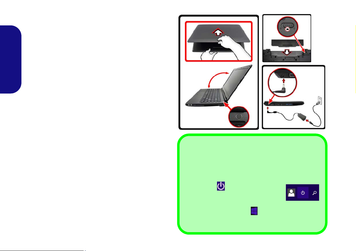
System Startup
130 ゚
Shut Down
Note that you should always shut your computer down by
choosing the Shut down command in Windows (see below).
This will help prevent hard disk or system problems.
Click the icon in the Start Screen and
choose Shut down from the menu.
Or
Right-click the Start button
at the bottom of the Start
Screen or the Desktop and choose Shut down or sign out
> Shut down from the context menu.
1. Remove all packing materials.
2. Place the computer on a stable surface.
3. Insert the battery and make sure it is locked in position.
4. Securely attach any peripherals you want to use with the
computer (e.g. keyboard and mouse) to their ports.
5. Attach the AC/DC adapter to the DC-In jack on the left of the
computer, then plug the AC power cord into an outle t, and
English
connect the AC power cord to the AC/DC adapter.
6. Use one hand to raise the
(do not exceed 130 degrees); use the other hand (as
angle
illustrated in Figure 1) to support the base of the computer
(Note: Never lift the computer by the lid/LCD).
7. Press the power button to turn the computer “on”.
lid/LCD to a comfortable viewing
System Software
Your computer may already come with system software
pre-installed. Where this is not the case, or where you are
re-configuring your computer for a different system, you
will find this manual refers to Microsoft Windows 8.1.
Figure 1 - Opening the Lid/LCD/Computer with AC/DC
Adapter Plugged-In
4
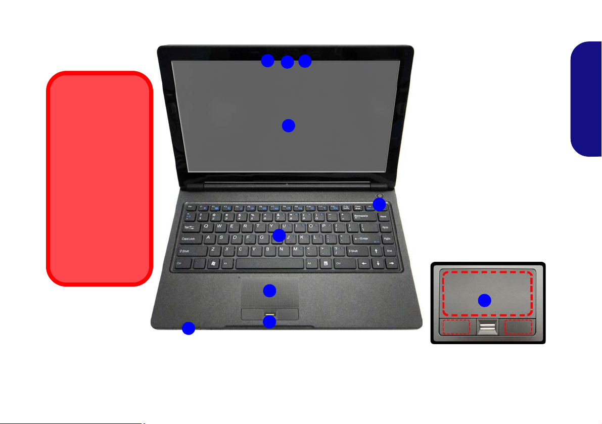
System Map: Front View with LCD Panel Open
Note that the Touchpad and
Buttons valid operational
area is that indicated within
the red dotted lines above.
Figure 2
Front View with LCD Panel
Open
1. PC Camera (Factory
Option)
2. *PC Camera LED
*When the PC camera is in
use, the LED will be
illuminated in red.
3. Built-In Microphone
4. LCD
5. Power Button
6. Keyboard
7. Touchpad & Buttons
8. Fingerprint Reader
9. LED Indicators
Wireless Device
Operation Aboard
Aircraft
The use of any portable electronic transmission devices
aboard aircraft is usually prohibited.
Make sure the WLAN,
Bluetooth & 3G module(s) are OFF if you
are using the computer aboard aircraft by
putting the system in
to Airplane Mode.
2
6
1
5
7
8
9
3
4
7
English
5
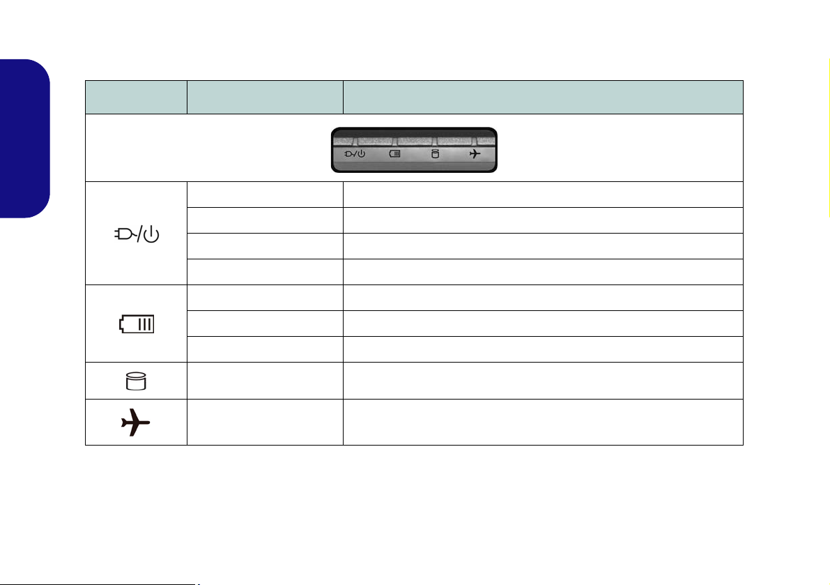
LED Indicators
The LED indicators on the computer display helpful information about the current status of the computer.
Icon Color Description
English
Orange The AC/DC Adapter is Plugged In
Blinking Orange The powered USB 2.0 Port is on (see page 13)
Green The Computer is On
Blinking Green The Computer is in Sleep Mode
Orange The Battery is Charging
Green The Battery is Fully Charged
Blinking Orange The Battery Has Reached Critically Low Power Status
Green The Hard Disk is in use
Green Airplane Mode is ON (the WLAN , Bl ue t oo t h & 3G Modules are OFF)
6
Table 1 - LED Indicators
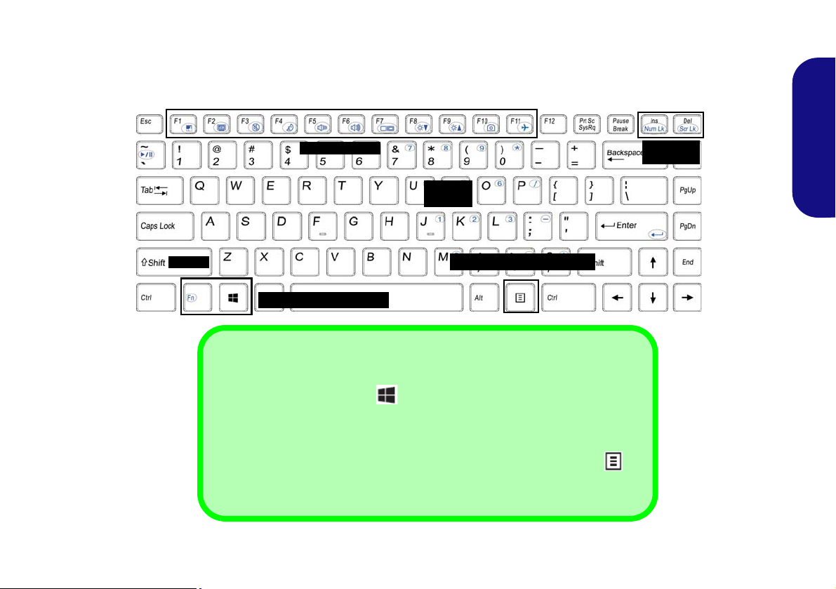
Keyboard
ad
Function Keys
Num Lk &
Scr Lk
Numeric
Keypad
Fn Key
Windows Logo Key
Menu/Application Key
Windows Logo Keyboard Shortcut
Use the Windows Logo Key + D key combination to switch from the Start
screen to the Windows Desktop.
Menu/Application Keyboard Shortcut
When the Desktop app is running you can use the Menu/Application key on
the keyboard to act as a mouse right-click. In the Start screen this function is useful
to quickly display the Customize bar.
The keyboard has a numeric keypad for easy numeric data input. Pressing Fn + Num Lk turns on/off the numeric keypad. It also features function keys to allow you to change operational features instantly.
English
Figure 3 - Keyboard
7
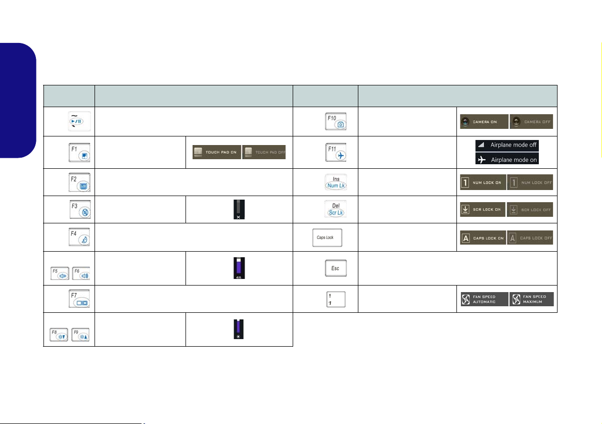
Function Keys & Visual Indicators
The function keys (F1 - F11 etc.) will act as hot keys when pressed while the Fn key is held down. In addition to the
basic function key combinations, some visual indicators are available (in the Windows Desktop application only and
not in the Start Screen) when the hot key driver is installed
Keys Function/Visual Indicators Keys Function/Visual Indicators
Fn +
English
Fn +
Fn +
Fn + Mute Toggle Fn + Scroll Lock Toggle
Fn + Sleep Toggle
Fn +
Fn +
Fn +
Play/Pause (in Audio/Video Programs)
Touchpad Toggle
Turn LCD Backlight Off
(Press a key to or use Touchpad to turn on)
Volume Decrease/
Increase
Change Display Configuration (see page 17)
Brightness Decrease/
Increase
Fn +
Fn +
Fn +
Fn + Control Center Toggle (see page 9)
Fn +
Table 2 - Function Keys & Visual Indicators
PC Camera Power
Airplane Mode Toggle
Number Lock Toggle
Caps Lock Toggle
Fan Automatic Control/
Toggle
Full Power
8
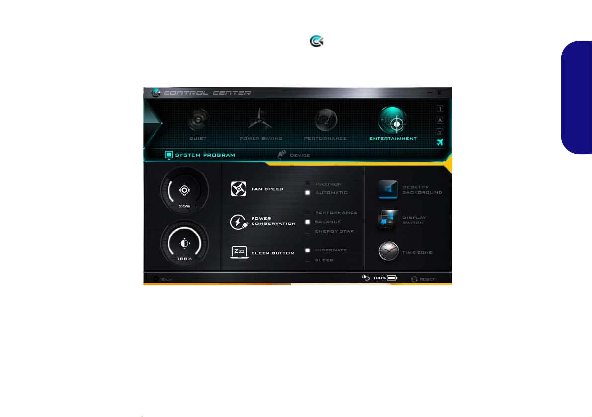
Control Center
Press the Fn + Esc key combination, or double-click the icon in the notification area of the taskbar to toggle the
Control Center on/off. The Control Center gives quick access to frequently used controls and enables you to quickly
turn the camera/Touchpad on/off.
Figure 4 - Control Center
English
Click the Control Center icons to toggle the appropriate function, or hold the mouse button down and move the dial
control where applicable. Certain functions will automatically be adjusted when a power mode is selected.
9
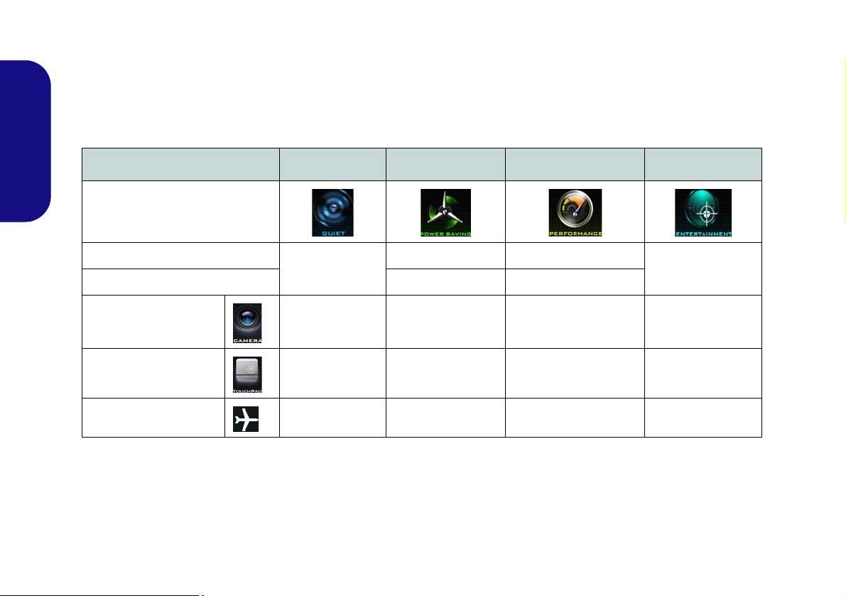
Power Modes
You can set a Power Mode by clicking the appropriate icon at the top of the Control Center. Each power mode will
affect the Power Conservation Mode, Airplane Mode, Power Plan and PC camera power etc.
You can click a Control Center icon to set an overall power mode and then click individual icons in the Control Cen-
ter to power on/off the Touchpad and PC camera.
English
Modes Quiet Power Saving Performance Entertainment
Icon
Power Plan
Balanced
Power Conservation Mode Energy Star Performance
PC Camera ON OFF ON ON
Touchpad ON ON ON ON
Airplane Mode OFF ON OFF OFF
Table 3 - Power Modes
Power Saver High Performance
Balanced
10
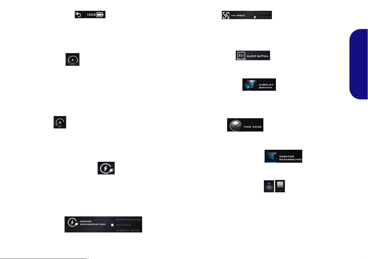
Power Status
The Power Status icon will show whether you are currently powered by the battery, or by the AC/DC adapter
plugged in to a working power outlet. The power status
bar will show the current battery charge state.
Brightness
The Brightness icon will show the current screen brightness level. You can use the slider to adjust the screen
brightness or the Fn + F8/F9 key combinations, or use the
Fn + F2 key combination to turn off the LED backlight
(press any key to turn it on again). Note that screen brightness is also effected by the Power Mode selected.
Fan Speed
The fan speed will adjust itself automatically to control
the heat of the CPU. However you can adjust the setting to
maximum if you prefer.
English
Sleep Button
Click either the Hibernate or Sleep button to have the
computer enter the selected power-saving mode.
Display Switch
Click the Display Switch button to access the menu (or
use the Fn + F7 key combination) and select the appropriate display mode.
Volume
The Volume icon will show the current volume level. You
can use the slider to adjust the volume or the Fn + F5/F6
key combinations, or use the Fn + F3 key combination to
mute the volume.
Power Conservation
This system supports Energy Star power management
features that place computers (CPU, hard drive, etc.) into
a low-power sleep mode after a designated period of inactivity. Click either the Performance, Balanced or Ener-
gy Star button.
Time Zone
Clicking the Time Zone button will access the Date and
Time Windows control panel.
Desktop Background
Clicking the Desktop Background button will allow you
to change the desktop background picture.
Touchpad/PC Camera
Click either of these buttons to toggle the Touchpad or
camera module’s power status. Note that the power status
of the camera module is also effected by the Power Mode
selected.
11
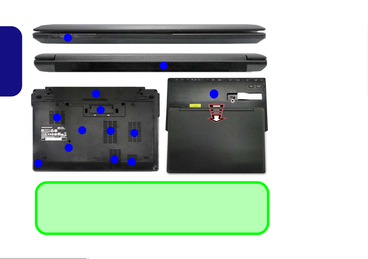
System Map: Front, Rear, Bottom & Top Views
3
4
1
2
Rear
Front
2
7
4
5
6
Figure 5
Front, Rear, Bottom &
Top Views
1. LED Indicators
2. Battery
3. Docking Port
4. Vent
5. Component Bay Cover
6. Drainage Outlet
7. Speakers
8. Docking Station
(Optional)
Docking
If your purchase includes the docking station, open the docking port cover latch and align the
computer with the placeholder on the docking station (see the accompanying docking station for
full details of the docking procedure).
4
4
7
8
English
12
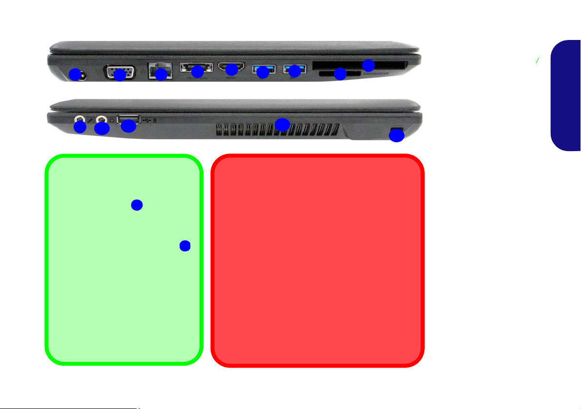
System Map: Left & Right Views
Figure 6
Left & Right Views
1. DC-In Jack
2. External Monitor Port
3. RJ-45 LAN Jack
4. e-SATA Port/USB 2.0
Combo Port
5. HDMI-Out Port
6. 2 * USB 3.0 Ports
7. ExpressCard/54(34)
Slot
8. Multi-in-1 Card
Reader
9. Microphone-In Jack
10. Headphone-Out Jack
11. Powered USB 2.0
Port
12. Vent
13. Security Lock Slot
1
7
8
3
5
2
Right
4
10
11
6
9
Bottom
Left
12
External Monitor Port & RJ-45 LAN Jack
If you are using a VGA cable plugged into the external monitor port, and a network cable connected to
the RJ-45 LAN jack, it is recommended that you insert the VGA cable before inserting the LAN cable.
Docking Port Cover
If your purchase option includes the docking station,
make sure you keep the cover closed when the computer is not docked in the station. This will help prevent foreign objects and/or dust getting in to the
contact area. If your purchase option does not include the docking station, an insert will be provided
to prevent accidentally opening the docking port. Do
not attempt to open the cover or remove the insert in
this case.
USB
The USB 3.0 ports are colored
blue. USB 3.0 will transfer data much
faster than USB 2.0, and is backwards-compatible with USB 2.0.
When the powered USB 2.0 port
is on it will supply power (for charg-
ing devices only, not for operating
devices) when the system is off but
still powered by the AC/DC adapter
plugged into a working outlet, or powered by the battery with a capacity
level above 20% (this may not work
with certain devices - see page 25).
Toggle power to this port by using Fn
+ power button.
6
11
6
13
English
13
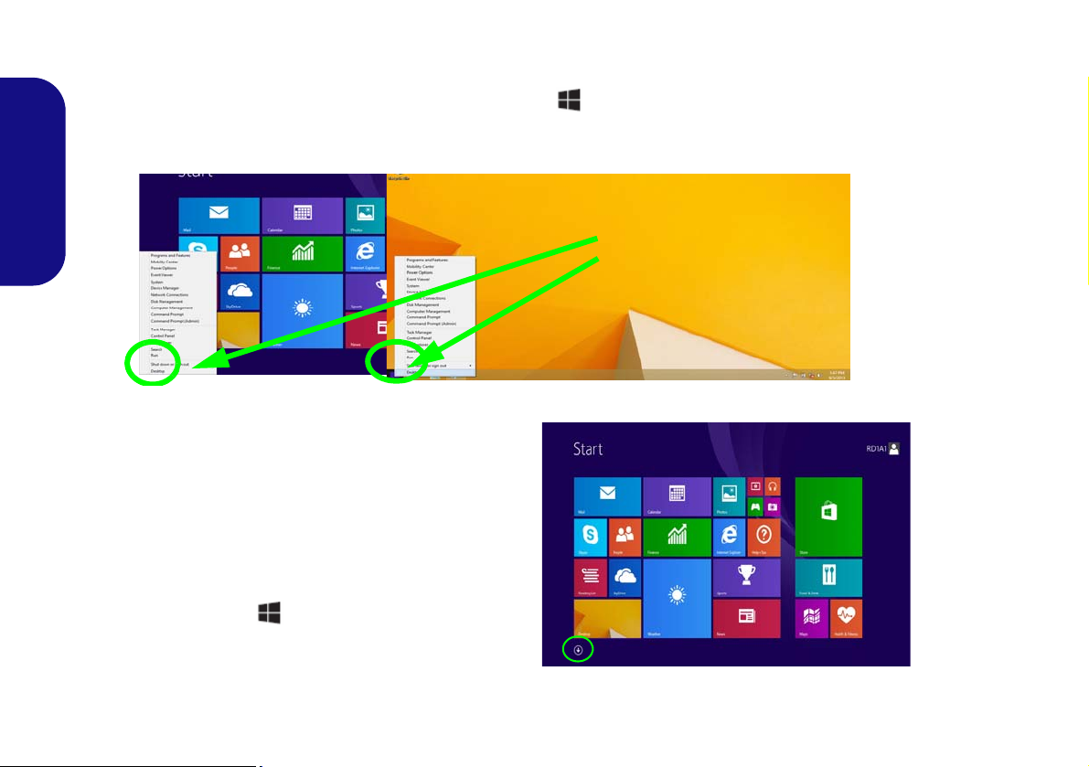
Windows 8.1 Control Panel
Move the mouse to
the bottom left of the
screen and right-click
the Start button to access the menu.
Figure 7
Context
Menu
Figure 8
Start
Screen
Throughout this manual you will see an instruction to open the Control Panel. Right-click the Start button in the
Desktop app or Start screen (or use the Windows Logo Key + X key combination) to bring up an advanced context
menu of useful features such as Control Panel, Programs and Features, Power Options, Task Manager, Search, File Explorer, Command Prompt, Device Manager and Network Connections etc. and then select Control Panel.
English
Windows 8.1 Start Screen & Desktop
The Apps, control panels, utilities and programs within
Windows are accessed from the Start screen and/or
Windows Desktop app. The Desktop (which runs as an
app within the Start screen) can be accessed by clicking
the Desktop item in the Start screen (or by using the
Windows Logo Key + D key combination). The
taskbar is displayed at the bottom of the desktop screen,
and you can see the notification area of the taskbar in the
bottom right of the screen. Click the arrow at the bottom
of the Start screen to access Apps.
14
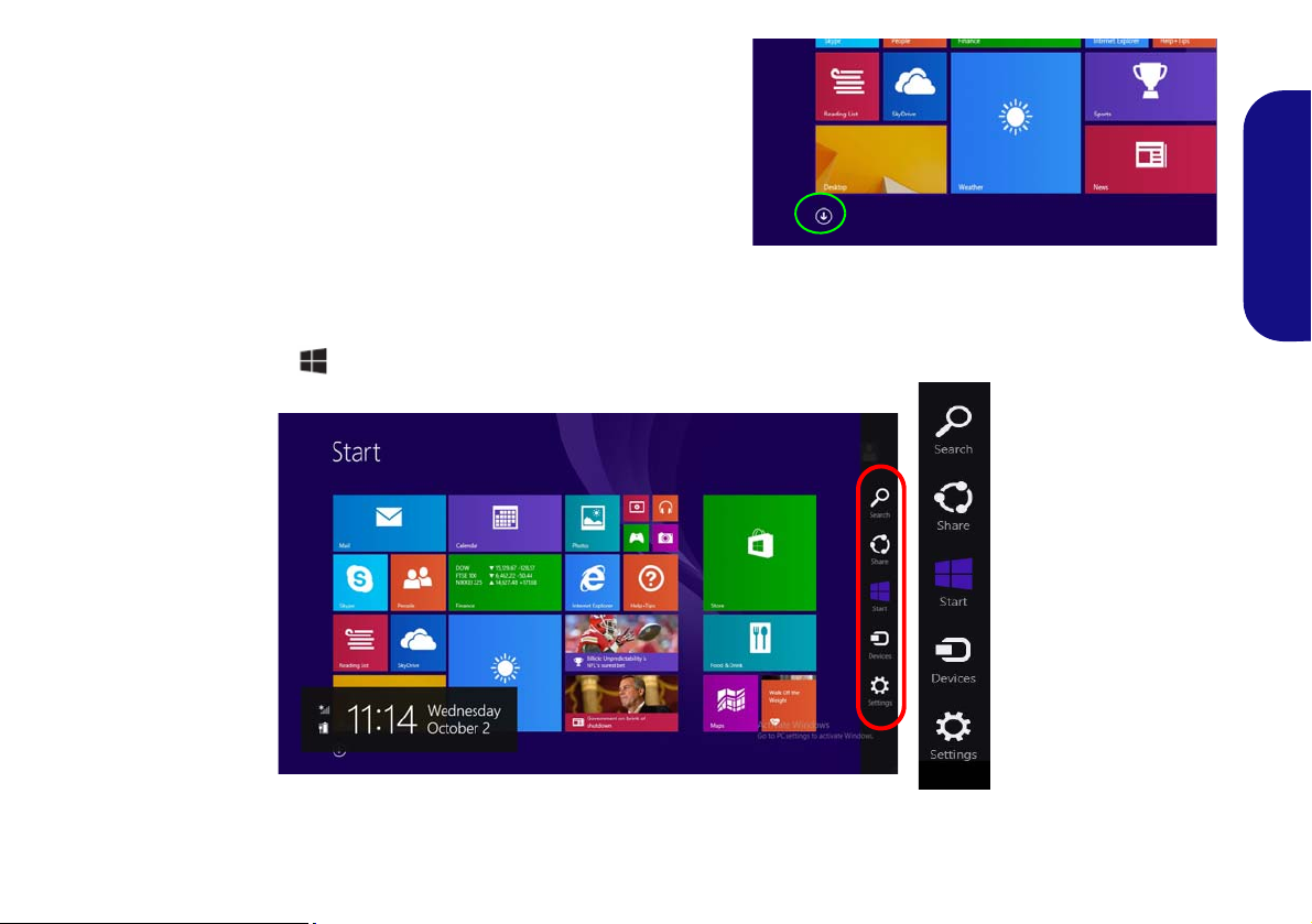
Apps & Tiles
Click the arrow at the bottom of the
screen to access Apps.
The Start screen will contain a number of apps, and many more
will be installed as you add more applications etc. Not all of these
apps can fit on one screen so you will often need use the slider at
the bottom of the screen in order to view all the necessary Apps.
Charms Bar
The right side of the screen displays the Charms Bar. The Charms Bar contains the Search, Share, Start, Devices and
Settings menus. To access up the Charms Bar move the cursor to the upper or lower right corners of the screen, and
then hover over one of the items in the Charms Bar to activate it (the bar will be black when it is active), or use the
Windows Logo Key + C key combination.
English
Figure 9 - Start Screen with Charms Bar
15
Video Features
1
2
2
1
Figure 10
Display
Control
Panel
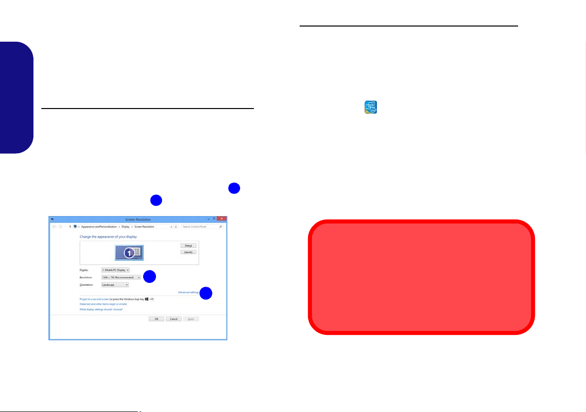
Screen Resolution for Apps (Windows 8.1)
The minimum resolution in which Apps will run is
1024x768.
The minimum resolution required to support all the features of Windows 8.1 (including multitasking with snap)
is 1366x768.
The system features an Intel integrated GPU. You can
switch display devices, and configure display options,
from the Display control panel in Windows as long as the
video driver is installed.
To access the Display control panel in Windows:
1. Go to the Control Panel.
English
2. Click Display (icon) - in the A ppearances and Personalization
category.
3. Click Adjust Screen Resolution/Adjust resolution.
OR
4. Right-click the desktop and select Screen resolution.
5. Use the dropbox to select the screen resolution .
6. Click Advanced settings .
To access the Intel® HD Graphics Control Panel:
1. Go to the Control Panel.
2.
Click Intel® HD Graphics Control Panel in the Classic view.
OR
3. Right-click the desktop and select Graphics Properties from
the menu.
OR
4. Click the icon in the notification area of the Desktop taskbar
and select Graphics Properties from the menu.
Display Devices
Besides the built-in LCD, you can also use an external
VGA monitor (CRT)/external Flat Panel Display or TV
(connected to the external monitor port/HDMI-Out port)
as your display device.
16
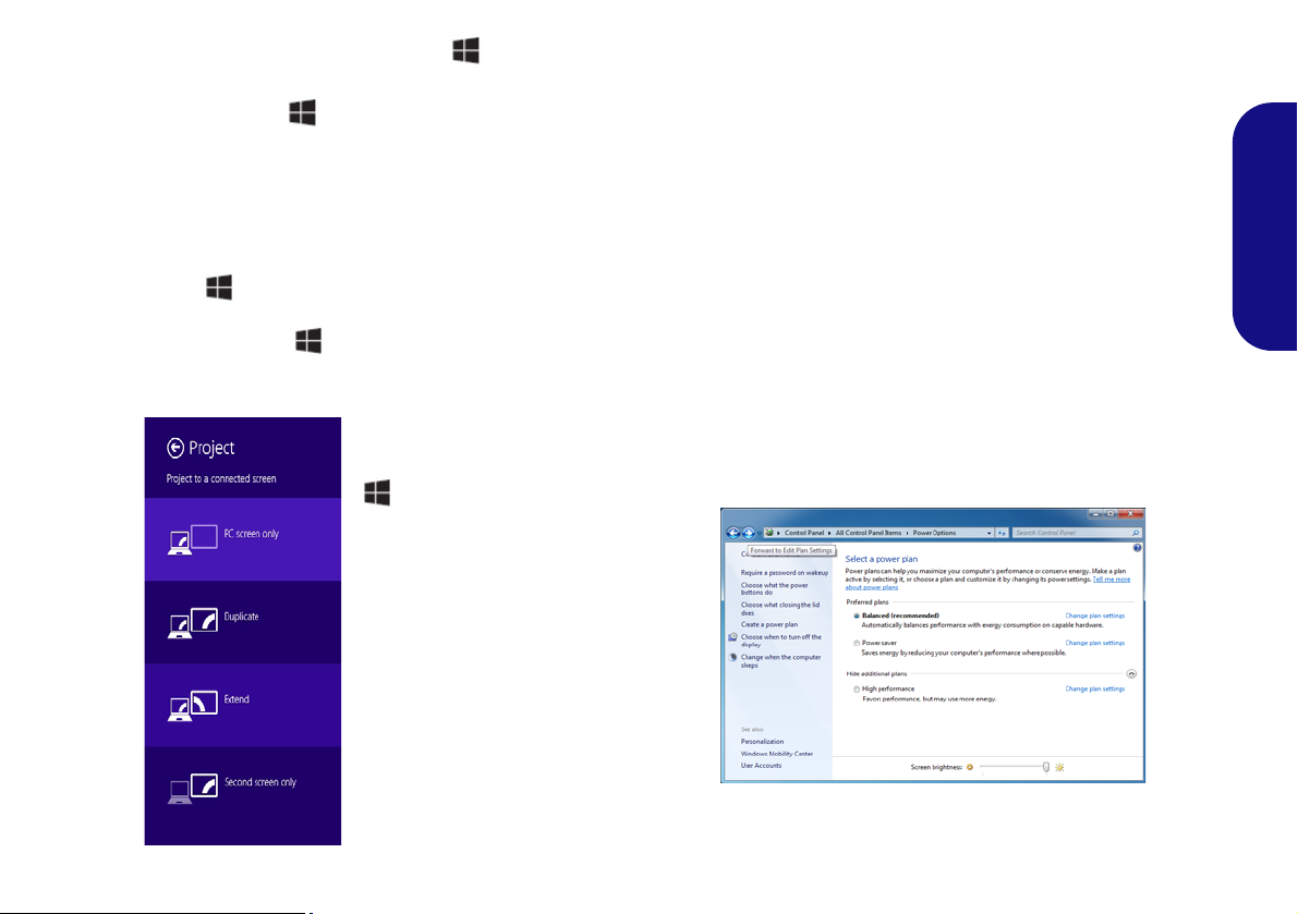
Using the Windows Logo Key + P Key
Figure 11
+ P (Change Display
Configuration)
Figure 12 - Power Options
Combination to Switch Displays
You can also use the + P key combination (or Fn + F7
) to quickly change display configuration and modes (this
is particularly useful when attaching a projector) in Win-
dows.
1. Attach your external display to the external monitor port/HDMIOut port, and turn it on.
2. Press the + P (or Fn + F7) key combination.
3. An on-screen menu will pop up.
4. Use the cursor keys ( + P) to select the appropriate
configuration from the menu, and press Enter to confirm the
selection.
Power Options
The Power Options (Hardware and Sound menu) control panel icon in Windows allows you to configure power
management features for your computer. You can conserve power by means of power plans and configure the
options for the power button, sleep button (Fn + F4),
computer lid (when closed), display and sleep mode (the
default power saving state) from the left menu. Note that
the Power saver plan may have an affect on computer
performance.
Click to select one of the existing plans, or click Create a
power plan in the left menu and select the options to create a new plan. Click Change Plan Settings and click
Change advanced power settings to access further configuration options.
English
17

Driver Installation General
Guidelines
As a general guide follow the
default on-screen instructions for each driver (e.g.
Next > Next > Finish) unless
you are an advanced user. In
many cases a restart is required to install the driver.
Make sure any modules (e.g.
WLAN or Bluetooth) are ON
before installing the appropriate driver.
Windows Update
After installing all the drivers
make sure you enable Win-
dows Update in order to get
all the latest security updates
etc. (all updates will include
the latest hotfixes from Mi-
crosoft).
Driver Installation & Power
When installing drivers make sure your
computer is powered by the AC/DC
adapter connected to a working power
source. Some drivers draw a significant
amount of power during the installation
procedure, and if the remaining battery
capacity is not adequate this may cause
the system to shut down and cause system problems (note that there is no safety issue involved here, and the battery
will be rechargeable within 1 minute).
Figure 13 - Install Drivers
English
18
Driver Installation
The Device Drivers & Utilities + User’s Manual disc contains the drivers and utilities
necessary for the proper operation of the computer. This setup will probably have already been done for you. If this is not the case, insert the disc and click Install Drivers
(button), or Option Drivers (button) to access the Optional driver menu. Install the
drivers in the order indicated in Figure 13. Click to select the drivers you wish to
install (you should note down the drivers as you install them). Note: If you need to
reinstall any driver, you should uninstall the driver first
Manual Driver Installation
Click the Browse CD/DVD button in the Drivers Installer application and browse to
the executable file in the appropriate driver folder.
If a
Found New Hardware
wizard appears
during the installation procedure, click
Cancel, and follow the installation procedure as directed.
.

Fingerprint Reader
Figure 14
Accounts -
Sign-in op-
tions
Install the driver and enroll your fingerprints as instructed
below before use. The fingerprint reader module uses the
Sign-in options configuration of the Windows Account.
Fingerprint Reader Driver Installation
1. Click Option Drivers (button).
2. Click 2.Install Fingerprint Driver > Yes.
3. Click Next > Install.
4. Click Finish.
Fingerprint Module Configuration
1. Go to the Charms Bar.
2. Select Settings and then click Change PC Settings.
3. Click Accounts and then click Sign-in options.
4. You will need to add a Windows password (click Add under
Password).
5. After you have added the password you will need to restart the
computer and use your password to log on to the system.
6. Go to the Charms Bar.
7. Select Settings and then click Change PC Settings.
8. Click Accounts and then click Sign-in options.
9. Click Add under Fingerprint.
English
10. Input the Windows password and click OK.
11. You will then be instructed to swipe the same finger across the
reader a number of times.
Figure 15 - Add a Fingerprint
12. Click Finish.
13. You can choose to Add another finger (this is recommended) or
Remove the current fingerprint reading.
14. You can now scan your fingerprint to log-on to the computer.
19

Trusted Platform Module
Before setting up the TPM functions you must initialize
the security platform.
Activating TPM
1. Restart the computer.
2. Enter the Aptio Setup Utility pressing F2 during the POST.
3. Use the arrow keys to select the Security menu.
English
4. Select TPM Configuration and press Enter.
5. Select TPM Support and press Enter. Select Enable and press
Enter.
6. Select TPM State, press Enter and select Enable to change the
TPM state to enabled. Y ou will then need to press F4 to save the
changes and restart the computer.
7. As the computer restarts press F2 to enter the BIOS again and
go to the TPM Configuration menu.
8. Select Pending operation, press Enter and select the option
you require (if you are initializing TPM you should select Enable
Take Ownership). You will then need to press F4 to save the
changes and restart the computer.
9. You can now install the TPM driver and then initialize the
TPM.
TPM Driver Installation
1. Click Option Drivers (button).
2. Click 4.Install TPM Driver > Yes.
3. Click Next.
4. Click the button to accept the license and click Next.
5. Click Next > Next > Install.
6. Click Finish > Yes to restart the computer.
20
Initializing TPM
Figure 16
Security
Platform
Quick Initial-
ization Wiz-
ard
Figure 17
Infineon Secu-
rity Platform
Settings Tool
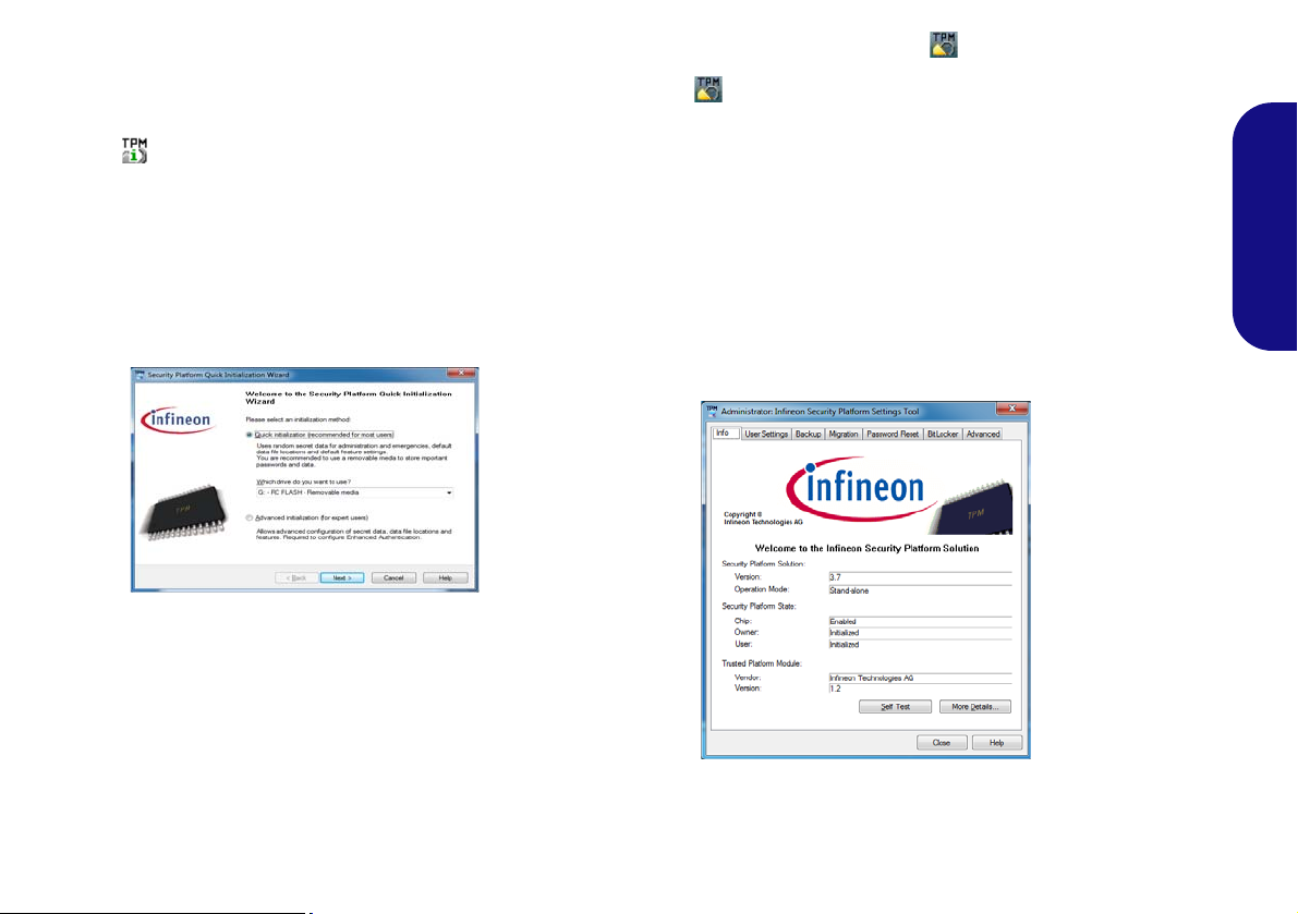
1. Click the icon (Manage Security Platform) on the Apps
screen.
2. Click User Settings (tab) and click Yes, or right-click the icon
in the notification area of the taskbar, and select Security
Platform Initialization (or click the Security Platform State
taskbar bubble).
3. The Quick Initialization method will automatically be selected
for you (if you need to use advanced settings provided by your
network administrator then select Advanced Initialization).
4. You will need to use a removable media (e.g. a USB Flash
Drive) to store passwords and data (keep the media in a safe
place until required).
12. Double-click the taskbar icon to access the Infineon
Security Platform Settings Tool, or right-click the taskbar icon
and select a menu item.
Infineon Security Platform Settings Tool
The Infineon Security Platform Settings Tool allows you
to manage and check the TPM state, manage your password information, and to backup and restore the TPM data. As TPM is usually administered within large
enterprises and organizations, your system administrator
will need to assist you in managing the information here.
English
5. Select the drive you want to use from the drop-down menu and
click Next.
6. Choose the Security Platform Features you want to use by
clicking the appropriate tickbox.
7. Enter a Basic User Password (and re-type to confirm it) and
click Next.
8. Click Next to confirm the settings.
9. The computer will then initialize the settings.
10. Click Finish.
11. Click the tabs and control panels to adjust the settings.
21
Intel® vPro™ Technology
Figure 18 - Intel(R) Management Engine
(Password Creation)
The computer supports Intel® vPro™ Technology. This
set of technology features, built into the computer’s motherboard, allows Information Technology departments remote access to the computer. This allows the IT
department to monitor, maintain and manage computers
regardless of the state of the operating system or the computer’s power state. This can be done over a wired or cor-
English
porate wireless network, or even outside the corporate
firewall through a wired LAN connection.
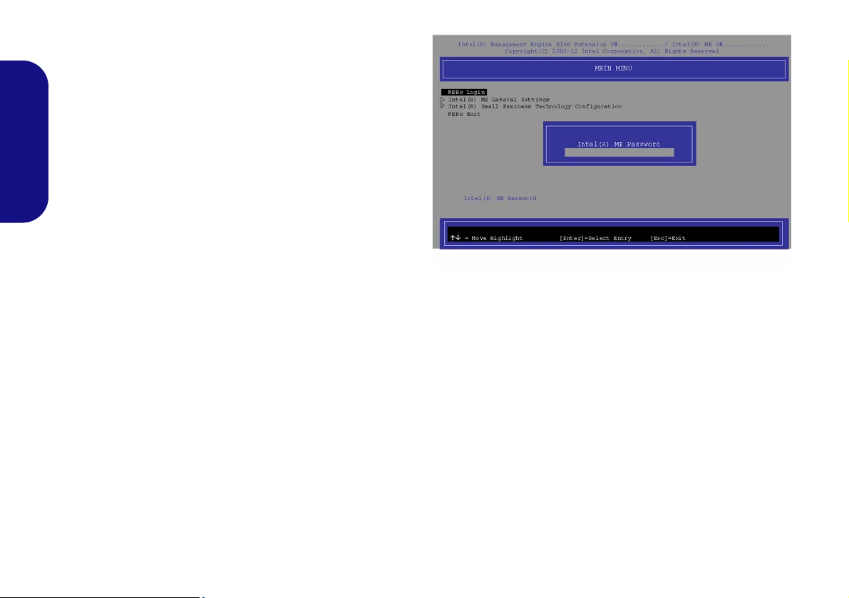
Accessing the Intel Management Engine
To access the Intel Management Engine press Ctrl + P
at startup. Your system administrator will need to assist
you in managing the information as applicable to your enterprise. Note the following password information for the
Intel Management Engine:
• The default password is “admin” (without quotes).
If you get an "Error - Intel(R) ME password change re-
jected" message when creating a new password, then note
the following parameters for creating a password:
• between 8 and 32 characters long
• Contain both upper and lower case Latin characters
• Have at least one numeric character
• Have at least one ASCII non-alphanumeric character (!,
@, #, $,%, ^, &, *)
Select MEBx Login and press “Enter” to access the password screen. Enter the password “admin” (without
quotes) and you will then be prompted to enter your own
password (note the password information above). Once
you have entered the password you will then be taken to
the platform configuration screen.
The platform configuration screen allows you to setup Intel ME as per your requirements (consult your IT administrator for the actual settings required).
22
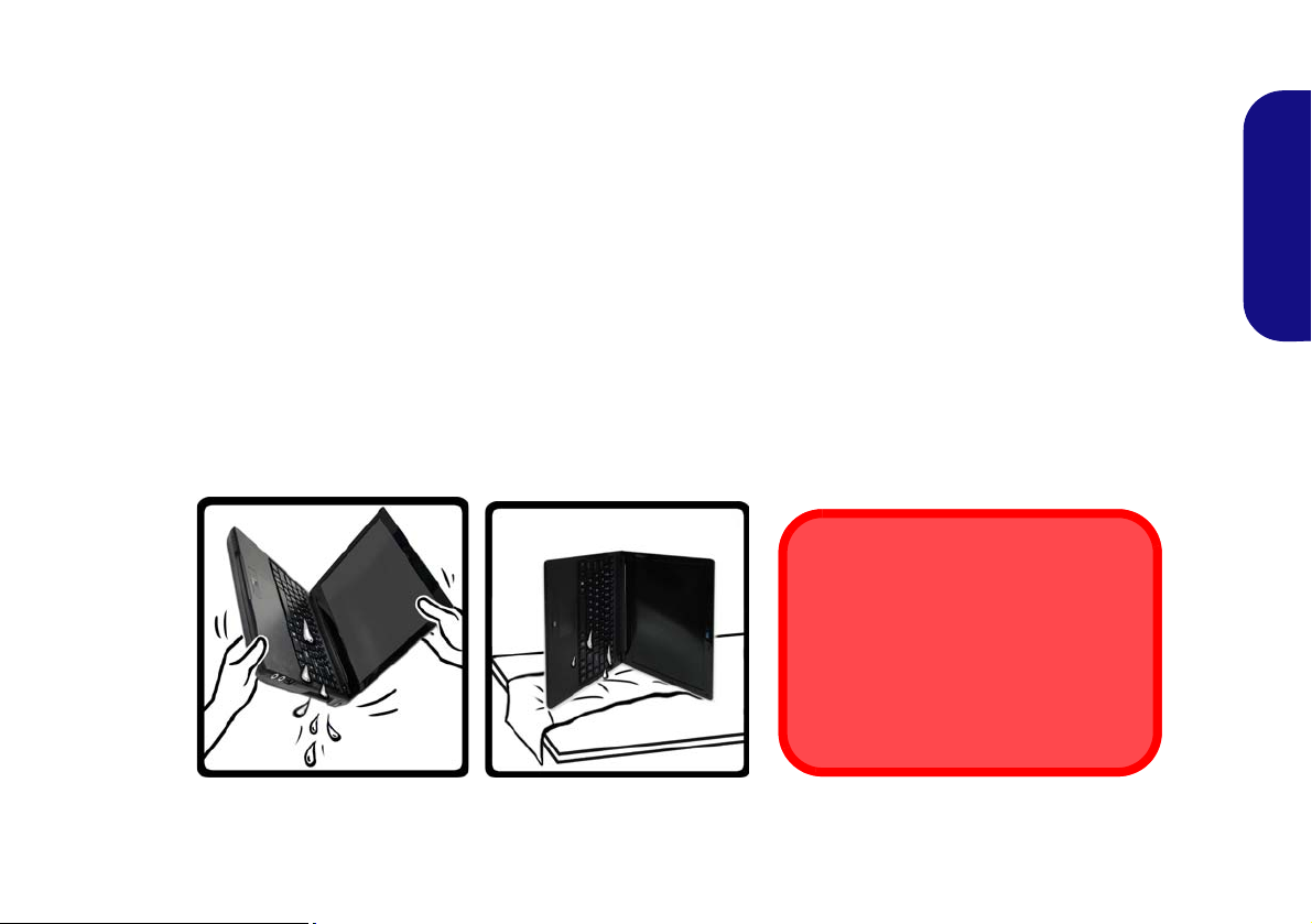
What to do if you Spill Liquid on the Computer
Warranty Warning
Note that the keyboard drainage system
is designed to help prevent and minimize damage from liquid spillages on
the computer keyboard. However damage resulting from spillages is not covered in the warranty.
Figure 19 - Drain any Liquid to the Right Side and
Rest the Computer on the Right Side to Dry
The keyboard incorporates a drainage system that minimizes the chances of liquid spillages on the keyboard penetrating
the inside components of the computer. Liquid spilled on the computer is drained towards the right side of the computer.
There is no guarantee that all water can be prevented from entering the computer, and damage resulting from spillages
is not covered in the warranty. However if you follow the steps outlined here you should be able to prevent water from
entering the sensitive parts of the computer and causing damage.
1. If you spill liquid on the computer immediately save any data required and then shut the computer down and disconnect the AC/DC
adapter.
2. Carefully lift the computer up and tilt it to a 90 degree angle towards the right side (i.e. that right side of the computer should be a t
the bottom to allow the water to dr ain away from the right side and not the left).
3. Move the computer to a dry place and wipe any liquid off the keyboard and bottom of the computer using a clean, soft, dry cloth.
4. Remove the battery.
5. Leave the computer resting on its right side (while placed on a clean, soft, dry cloth) to dry out for about three hours.
6. Contact your service center to have the computer examined for any problems, but do not attempt to turn the computer back on
again until after it has been examined.
English
23
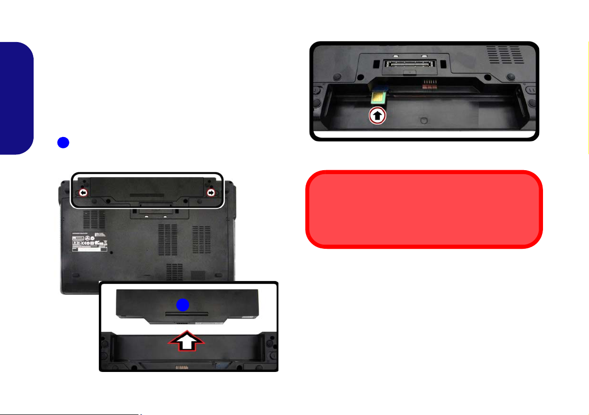
3G Module
1
1
USIM Card Orientation
Note that the USIM card’s readable side (with the gold-colored contacts) should face upwards as illustrated.
If you have included an optional 3G module in your purchase option, follow the instructions below to install the
USIM card (which will be provided by your service provider), and then run the appropriate application supplied
with your module.
USIM Card Insertion
English
1. Turn off the computer , and turn it over and remove the battery
(slide the latches in the direction indicated below and slide
the battery out).
2. Insert the USIM card as illustrated below until it clicks into
position, and replace the battery.
Figure 21 - Insert the USIM Card
24
Figure 20 - Remove the battery

Troubleshooting
Problem Possible Cause - Solution
The Wireless LAN/Bluetooth
modules cannot be detected.
The PC Camera module cannot be
detected.
The captured video files from the PC
Camera are taking up too much disk
space.
The computer is off (or in Sleep Mode)
but powered by the AC/DC adapter
plugged in to a working outlet or
powered by the battery with a capacity
level above 20%. I have plugged a
device into the powered USB port
in order to charge it, but the device is
not charging.
The modules are off as the computer is in Airplane Mode. Check the LED in dicator
to see if it is in Airplane Mode (see Table 1 on page 6). Use the Fn + F11 key
combination to toggle Airplane Mode on/off (see Table 2 on page 8).
The module is off. Press the Fn + F10 key comb inati on in order to enab le th e module (see
Table 2 on page 8). Run the camera application to view the camera picture.
Note that capturing high resolution video files requires a substantial amount of disk space
for each file.
Note that the Windows system requires a minimum of 20GB (64bit) of free space on the
C: drive system partition. It is recommended that you save the capture video file to a
location other than the C:drive, limit the file size of the captured video or reduce video
resolution.
The port is not powered on. Toggle power to the port using the Fn + power button
combination.
This function may not work with certain external USB compliant devices (check your
device’s documentation). If this is the case, power the computer on and connect the
external USB device in order to charge it.
English
25

Specifications
Latest Specification Information
The specifications listed in this here
are correct at the time of going to
press. Certain items (particularly processor types/speeds) may be
changed, delayed or updated due to
the manufacturer's release schedule. Check with your service center
for details.
English
Processor Options
Intel® Core™ i7 Processor
Intel® Core™ i7 Processor
i7-4610M (3.00GHz), i7-46010M (2.90GHz)
4MB L3 Cache, 22nm, DDR3L-1600MHz,
TDP 37W
Intel® Core™ i5 Processor
i5-4340M (2.90GHz), i5-4330M (2.80GHz),
i5-4310M (2.70GHz), i5-4300M (2.60GHz)
3MB L3 Cache, 22nm, DDR3L-1600MHz,
TDP 37W
Core Logic
Intel® QM87 Chipset
BIOS
96Mb SPI Flash ROM
AMI BIOS
26
Memory
Two 204 Pin SO-DIMM Sockets Supporting
DDR3L 1600MHz Memory
Memory Expandable up to 16GB
(The real memory operating frequency
depends on the FSB of the processor.)
Storage
One Changeable 2.5" 7.0mm/9.5mm (h)
SATA HDD
LCD
13,3" (33,78cm) HD (Thickness: 3.0mm)
Video Adapter
Intel GPU (CPU integrated)
Intel HD Graphics 4600
Dynamic Frequency (Intel Dynamic Video
Memory Technology for up to 1.7GB)
Microsoft DirectX®11 Compatible
Audio
High Definition Audio Compliant Interface
2 * Built-In Speakers
Built-In Microphone
Security
Security (Kensington® Type) Lock Slot
BIOS Password
Fingerprint Reader
TPM v1.2
Intel® vPro Technology Support
Keyboard
“WinKey” keyboard (with embedded
numeric keypad)
Pointing Device
Built-in Touchpad
Interface
One Powered USB 2.0 Port
Two USB 3.0 Ports
One eSATA/USB 2.0 Combo Port
One HDMI-Out Port
One Headphone-Out Jack
One Microphone-In Jack
One RJ-45 LAN Jack
One External Monitor Port
One DC-in Jack
One Docking Port
Slots
One ExpressCard/34(54) Slot
Mini Card Slots
Slot 1 for WLAN Module or WLAN and
Bluetooth Combo Module
(Factory Option) Slot 2 for 3G Module
 Loading...