

Clevo W130EV, W130EW Concise User's Guide


Contents
About this Concise User Guide .........................................................1
System Startup ..................................................................................4
System Map: Front View with LCD Panel Open ............... ..............5
LED Indicators ..................................................................................6
System Map: Front, Rear, Bottom & Top Views .................. ...........7
System Map: Left & Right Views ..... ...............................................8
Keyboard & Function Keys ..............................................................9
Control Center .................................................................................10
What to do if you Spill Liquid on the Computer ............................13
3G Module ......................................................................................14
Driver Installation ...........................................................................15
Fingerprint Reader ..........................................................................16
Trusted Platform Module ................................................................17
Intel® vPro™ Technology ..............................................................19
Troubleshooting ..............................................................................20
Specifications ................. .................................... ............................. 21
Inhalt
Über das Ausführliche Benutzerhandbuch .....................................25
Schnellstart ................. ................. ................ ................ ............... .....28
Systemübersicht: Ansicht von vorne mit geöffnetem
LCD-Bildschirm .............................................................................29
LED-Anzeigen ................. ........................................................ .......30
Systemübersicht: Ansicht von vorne, hinten, unten & oben ...........31
Systemübersicht: Ansicht von links und rechts ..............................32
Tastatur & Funktionstasten .............................................................33
Control Center (Steuerzentrum) ............................... .......................34
Was Sie tun müssen, wenn eine Flüssigkeit auf dem Computer ver-
schüttet wurde .................................................................................37
3G-Modul ....................... ................ ............... ................ ..................38
Installation der Treiber ....................................................................39
Fingerabdruckleser .................... ................ ............... ................ .......40
TPM (Trusted Platform Module) ....................................................41
Intel® vPro™ Technology ..............................................................43
Fehlerbehebung ...............................................................................44
Technische Daten ............................................................................45
Sommaire
A propos de ce Guide Utilisateur Concis ........................................49
Guide de démarrage rapide .............................................................52
Carte du système: Vue de face avec l’écran LCD ouvert ...............53
Indicateurs LED ..................... .........................................................54
Carte du système: Vues de face, arrière, dessous & dessus ............55
Carte du système: Vues de gauche & droite ...................................56
Clavier & touches fonction .............................................................57
Control Center (Centre de contrôle) .......................... ......................58
Que faire si vous répandez un liquide sur l'ordinateur ....................61
Module 3G .......................................................................................62
Installation du pilote ........................................................................63
Lecteur d'empreintes digitales ......... ............................... .................64
TPM (Trusted Platform Module) ....................................................65
Technologie Intel® vPro™ .............................................................67
Dépannage ......................... ...................................... ........................68
Spécifications ..................................................................................69
Contenidos
Acerca de esta Guía del Usuario Concisa .......................................73
Guía rápida para empezar ................................................................76
Mapa del sistema: Vista frontal con panel LCD abierto .................77
Indicadores LED .............................................................................78
Mapa del sistema: Vistas frontal, posterior, inferior y superior .....79
Mapa del sistema: Vistas izquierda y derecha ................................80
Teclado & teclas de función ............................................................81
Control Center (Centro de control) .................................................82
Qué hacer si se derrama líquido en el ordenador ............................85

Módulo 3G ......................................................................................86
Instalación de controladores ...........................................................87
Lector de huellas digitales .............................. ................................88
TPM (Trusted Platform Module) ....................................................89
Intel® vPro™ Technology ..............................................................91
Solución de problemas ....................................................................92
Especificaciones .................. ............... ................ ............... ..............93
Sommario
Informazioni sulla Guida Rapida per l'Utente .............. ..................97
Guida di avvio rapido ....................................................................100
Descrizione del sistema: Vista anteriore con pannello
LCD aperto ....................................................................................101
Indicatori LED ..............................................................................102
Descrizione del sistema: Vista anteriore, posteriore, inferiore e
dall'alto .........................................................................................103
Descrizione del sistema: Vista sinistra e destra ............................104
Tastiera & tasti funzione ...............................................................105
Control Center (Centro di controllo) ............... ..............................106
Cosa fare se vengono versati liquidi sul computer .......................109
Modulo 3G ....................................................................................110
Installazione driver ........................................................................111
Lettore d’impronte digitali ........ ....................................................112
TPM (Trusted Platform Module) ..................................................113
Intel® vPro™ Technology ............................................................115
Risoluzione dei problemi ....................................... .......................116
Specifiche tecniche .......................................................................117

About this Concise User Guide
FCC Statement
This device complies with Part
15 of the FCC Rules. Operation
is subject to the following two
conditions:
1.This device may not cause
harmful interference.
2. This device must accept any
interference received, including interference that may
cause undesired operation.
This quick guide is a brief introduction to getting your system started. This is a supplement, and not a substitu te for the
expanded English language User’s Manual in Adobe Acrobat format on the Device Drivers & Utilities + User’s Manual
disc supplied with your computer. This disc also contains the drivers and utilities necessary for the prop er operation of
the computer (Note: The company reserves the right to revise this publication or to change its contents without notice).
Some or all of the computer’s features may already have been setup. If they aren’t, or you are planning to re-configure
(or re-install) portions of the system, refer to the expanded User’s Manual. The Device Drivers & Utilities + User’s
Manual disc does not contain an operating system.
Regulatory and Safety Information
Please pay careful attention to the full regulatory notices and safety information contained in the expanded User’s Manual on the Device Drivers & Utilities + User’s Manual disc.
© October 2012
Trademarks
Intel and Intel Core are trademarks/registered trademarks of Intel Corporation.
English
1

Instructions for Care and Operation
The computer is quite rugged, but it can be damaged. To prevent this, follow these suggestions:
• Don’t drop it, or expose it to shock. If the computer falls, the
case and the components could be damaged.
• Keep it dry, and don’t overheat it. Keep the computer and power
supply away from any kind of heating element. This is an electrical appliance. If water or any other liquid gets into it, the computer
could be badly damaged.
English
• Avoid interference. Keep the compute r away from high capacity
transformers, electric motors, and other strong magnetic fields.
These can hinder proper performance and damage your data.
• Follow the proper working procedures for the computer. Shut
the computer down properly and don’t forget to save your work.
Remember to periodically save your data as data may be lost.
Servicing
Do not attempt to service the computer yourself. Doing so may
violate your warranty and expose you and the computer to
electric shock. Refer all servicing to authorized service personnel. Unplug the computer from the power supply. Then refer
servicing to qualified service personnel under any of the fo llowing conditions:
• When the power cord or AC/DC adapter is damaged or frayed.
• If the computer has been exposed to any liquids.
• If the computer does not work normally when you follow the operating instructions.
• If the computer has been dropped or damaged (do not touch the
poisonous liquid if the LCD panel breaks).
• If there is an unusual odor, heat or smoke coming from your computer.
Safety Information
• Only use an AC/DC adapter approved for use with this computer.
• Use only the power cord and batteries indicated in this manual. Do
not dispose of batteries in a fire. They may explode. Check with
local codes for possible special disposal instructions.
• Do not continue to use a battery that has been dropped, or that
appears damaged (e.g. bent or twisted) in any way. Even if the
computer continues to work with a damaged battery in place, it
may cause circuit damage, which may possibly result in fire.
• Make sure that your computer is completely powered off before
putting it into a travel bag (or any such container).
• Before cleaning the computer, make sure it is disconnected from
any external power supplies, peripherals and cables (including
telephone lines). It is advisable to also remove your battery in
order to prevent accidentally turning the machine on.
• Use a soft clean cloth to clean the computer, but do not apply
cleaner directly to the computer. Do not use volatile (petroleum
distillates) or abrasive cleaners on any part of the computer.
• Do not try to repair a battery pack. Refer any battery pack repair or
replacement to your service representative or qualified service personnel.
• Note that in computer’s featuring a raised LCD electro-pl ated
logo, the logo is covered by a protective adhesive. Due to general
wear and tear, this adhesive may deter iorate over time and the
exposed logo may develop sharp edges. Be careful when handling
the computer in this case, and avoid touching the raised LCD electro-plated logo. Av oid placing any other items in the carrying bag
which may rub against the top of the computer during transport. If
any such wear and tear develops contact your service center.
2

Polymer Battery Precautions
Battery Disposal & Caution
The product that you have purchased contains a rechargeable
battery. The battery is recyclable. At the end of its useful life,
under various state and local laws, it may be illegal to dispose
of this battery into the municipal waste stream. Check with
your local solid waste officials for details in your area for recycling options or proper disposal.
Danger of explosion if battery is incorrectly replaced. Replace
only with the same or equivalent type recommended by the
manufacturer. Discard used battery according to the manufacturer’s instructions.
Note the following information which is specific to poly mer
batteries only, and where applicable, this overrides the general
battery precaution information.
• Polymer batteries may experience a slight expansion or swelling,
however this is part of the battery’s safety mechanism and is not a
cause for concern.
• Use proper handling procedures when using polymer batteries. Do
not use polymer batteries in high ambient temperature environments, and do not store unused batteries for extended periods.
English
3

System Startup
120 ゚
Shut Down
Windows 7
Note that you should always shut your computer down by
choosing Shut Down from the Start menu.
Windows 8
Note that you should always shut your computer down by
clicking Settings in the Charms Bar (use the Windows
Logo Key + C key combination to access the Charms
Bar) and choosing Shut down from the Power menu.
This will help prevent hard disk or system problems.
1. Remove all packing materials.
2. Place the computer on a stable surface.
3. Insert the battery and make sure it is locked in position.
4. Securely attach any peripherals you want to use with the
computer (e.g. keyboard and mouse) to their ports.
5. Attach the AC/DC adapter to the DC-In jack on the left of the
computer, then plug the AC power cord into an outlet, and
English
connect the AC power cord to the AC/DC adapter.
6. Use one hand to raise the
(do not exceed 120 degrees); use the other hand (as illustrated
in Figure 1) to support the base of the computer (Note: Never
lift the computer by the lid/LCD).
7. Press the power button to turn the computer “on”.
lid/LCD to a comfortable viewing angle
System Software
Your computer may already come with system software
pre-installed. Where this is not the case, or where you are
re-configuring your computer for a different system, you
will find this manual refers to Microsoft Windows 7 and
8.
Model Differences
This notebook series includes two different models (see
Specifications on page 21 for details).
4
Figure 1 - Opening the Lid/LCD/Computer with AC/DC
Adapter Plugged-In

System Map: Front View with LCD Panel Open
Figure 2
Front View with LCD Panel
Open
1. PC Camera (Optional)
2. LCD
3. Power Button
4. Keyboard
5. Built-In Microphone
6. LED Indicators
7. Touchpad & Buttons
8. Fingerprint Reader
7
Wireless Device
Operation Aboard
Aircraft
The use of any portab le
electronic transmission
devices aboard aircraft
is usually prohibited.
Make sure the wireless
modules are OFF or in
Airplane mode (for
Windows 8 only) if you
are using the computer
aboard aircraft.
Note that the Touchpad and Buttons
valid operational area is that indicated
within the red dotted lines above.
2
4
1
3
5
6
8
7
English
5

LED Indicators
The LED indicators on the computer display helpful information about the current status of the computer.
Icon Color Description
English
6
Blue Power Button
Orange DC Power is Plugged In
Blinking Orange The powered USB 2.0 Port is on (see page 8)
Green The Computer is On
Blinking Green The Computer is in Sleep Mode
Blinking Orange The PC Camera is In Use
Orange The Battery is Charging
Green The Battery is Fully Charged
Blinking Orange The Battery Has Reached Critically Low Power Status
Green Hard Disk Activity
Green The Wireless LAN Module is Powered On
Win 7 - The Bluetooth Module is Powered On
Orange
Win 8 - The Bluetooth Module is Installed (this is not a power on/off indicator in Win 8)
Table 1 - LED Indicators

System Map: Front, Rear, Bottom & Top Views
3
5
1
2
Rear
Front
3
4
6
5
7
8
8
Figure 3
Front, Rear, Bottom &
Top Views
1. LED Indicators
2. WLAN Switch
3. Battery
4. Docking Port
5. Vent
6. Component Bay Cover
7. Drainage Outlet
8. Speakers
9. Docking Station
(Optional)
WLAN Switch
Use the WLAN
Switch (for Wireless
LAN only) to toggle
power to the WLAN
module. The position
of the WLAN switch
governs the power
status of the WLAN
module at startup,
and upon resuming
from a power saving
state.
Docking
.If your purchase includes the docking station, open the docking port cover latch and align the
computer with the placeholder on the docking station (see the accompanying docking station for
full details of the docking procedure).
5
5
9
English
7

Figure 4
Left & Right Views
1. DC-In Jack
2. External Monitor Port
3. RJ-45 LAN Jack
4. e-SA T A Port/USB 2.0
Combo Port
5. HDMI-Out Port
6. 2 * USB 3.0 Ports
7. ExpressCard/54(34)
Slot
8. Multi-in-1 Card
Reader
9. Microphone-In Jack
10. Headphone-Out Jack
11. Powered USB 2.0
Port
12. Vent
13. Security Lock Slot
1
7
83
5
2
Right
4
10
11
6
9
Bottom
Left
12
External Monitor Port & RJ-45 LAN Jack
If you are using a VGA cable plugged into the external monitor port, and a network cable connected to
the RJ-45 LAN jack, it is recommended that you insert the VGA cable before inserting the LAN cable.
Docking Port Cover
If your purchase option includes the docking station,
make sure you keep the cover closed when the computer is not docked in the station. This will help prevent foreign objects and/or dust getting in to the
contact area. If your purchase option does not include the docking station, an insert will be provided
to prevent accidentally opening the docking port. Do
not attempt to open the cover or remove the insert in
this case.
USB
The USB 3.0 ports are colored
blue. USB 3.0 will transfer data much
faster than USB 2.0, and is backwards-compatible with USB 2.0.
When the powered USB 2.0 port
is on it will supply power (for charg-
ing devices only, not for operating
devices) when the system is off but
still powered by the AC/DC adapter
plugged into a working outlet, or powered by the battery with a capacity
level above 20% (this may not work
with certain devices - see page 20).
Toggle power to this port by using Fn
+ power button.
6
11
6
13
English
System Map: Left & Right Views
8

Keyboard & Function Keys
Function Keys
NumLk &
ScrLk
Numeric
Keypad
Fn Key
3G Module Power Toggle
Figure 5 - Keyboard
The keyboard has a numeric keypad for easy numeric data
input. Pressing the Fn + NumLk keys turns on/off the numeric keypad. It also features function keys to allow you to
change operational features instantly.
The function keys (F1 - F12 etc.) will act as hot keys when
pressed while the Fn key is held down. In addition to the
basic function key combinations, visual indicators (Win-
dows 7 or Windows 8 Desktop only) are available when the
hot key driver is installed.
Keys Function/Visual Indicators Keys Function/Visual Indicators
English
Fn + ~ Play/Pause (in Audio/Video Programs) Fn + F8/F9
Fn +
Fn + F1 Touchpad Toggle Fn + F11
Fn + F2
Fn + F3 Mute Toggle Fn + NumLk Numeric Keypad Toggle
Fn + F4 Sleep Toggle Fn + ScrLk Scroll Lock Toggle
Fn + F5/F6
Fn + F5/F6 Fn + F7 Display Toggle Fn + Esc Control Center Toggle (see page 10)
3G Module Power Tog-
gle
Turn LCD Backlight Off
(Press a key to or use Touchpad to turn on)
Volume Decrease/
Increase
Table 2 - Function Keys & Visual Indicators
Fn + F10
Fn + F12
Fn + Power But-
ton
Brightness Decrease/
Increase
PC Camera Power
Toggle
WLAN Module Power
Toggle
Bluetooth Module
Power Toggle
Powered USB Port Power Toggle (see page 8)
9

Control Center
Windows 7
Windows 8
Press the Fn + Esc key combination, or double-click the icon in the notification area of the taskbar to toggle the
Control Center on/off. The Control Center gives quick access to frequently used controls, and enables you to quickly
turn modules on/off. The Control Center is only accessible from the Windows Desktop (use the Windows Logo Key
+ D key combination) in Windows 8 and not from the Start Screen in the Metro UI.
English
Figure 6 - Control Center
Click on any button to turn any of the modules (e.g. TouchPad, Camera) on/off. Click on Power Conservation to switch
between Performance, Balanced or Energy Star modes. Click on the buttons (or just click and hold the mouse button)
to adjust the slider for Brightness/Volume. Click on Display Switch/Time Zone/ Desktop Background to bring up
the appropriate Windows control panel. Click on the Sleep button to put the computer into Hibernate or Sleep modes.
10

Power Status
The Power Status icon will show whether you are currently powered by the battery, or by the AC/DC adapter plugged
in to a working power outlet. The power status bar will show the current battery charge state.
Brightness
The Brightness icon will show the current screen brightness level. You can use the slider to adjust the screen brightness
or the Fn + F8/F9 key combinations, or use the Fn + F2 key combination to turn off the LED backlight (press any key
to turn it on again). Note that screen brightness is also effected by the Power Mode selected.
Volume
The Volume icon will show the current volume level. You can use the slider to adjust the volume or the Fn + F5/F6
key combinations, or use the Fn + F3 key combination to mute the volume.
Power Conservation
This system supports Energy Star power management features that place computers (CPU, hard drive, etc.) into a lowpower sleep mode after a designated period of inactivity. Click either the Performance, Balanced or Energy Star but-
ton.
Sleep
Click the Sleep button to bring up the Hibernate or Sleep buttons, and click either button to have the computer
enter the appropriate power-saving mode.
English
11

Display Switch
Click the Display Switch button to access the menu (or use the + P key combination) and select the appropriate
display mode.
Time Zone
Clicking the Time Zone button will access the Date and Time Windows control panel.
Desktop Background
English
Clicking the Desktop Background button will allow you to change the desktop background picture.
Touchpad/PC Camera/Wireless LAN Module /Bluetooth/3G Module (Win 7 Only)
Click any of these buttons to toggle the Touchpad or module’s power status. A crossed out icon will appear over the top
left of the icon when it is off
Power Mode selected.
. Note that the power status of a module, and Touchpad power, is also effected by the
Touchpad/PC Camera (Win 8 Only)
Click any of these buttons to toggle the Touchpad or module’s power status. A crossed out icon will appear over the top
left of the icon when it is off
Power Mode selected.
. Note that the power status of a module, and Touchpad power, is also effected by the
Caps Lock/Scroll Lock/ Number Lock
Click the button to toggle the appropriate lock mode.
12

What to do if you Spill Liquid on the Computer
Warranty Warning
Note that the keyboard drainage system
is designed to help prevent and minimize damage from liquid spillages on
the computer keyboard. However damage resulting from spillages is not covered in the warranty.
Figure 7 - Drain any Liquid to the Right Side and
Rest the Computer on the Right Side to Dry
The keyboard incorporates a drainage system that minimizes the chances of liquid spillages on the keyboard penetrating
the inside components of the computer. Liquid spilled on the computer is drained towards the right side of the computer.
There is no guarantee that all water can be prevented from entering the computer, and damage resulting from spillages
is not covered in the warranty. However if you follow the steps outlined here you should be able to prevent water from
entering the sensitive parts of the computer and causing damage.
1. If you spill liquid on the computer immediately save any data required and then shut the computer down and disconnect the AC/DC
adapter.
2. Carefully lift the computer up and tilt it to a 90 degree angle towards the right side (i.e. that right side of the computer should be at
the bottom to allow the water to dr ain away from the right side and not the left).
3. Move the computer to a dry place and wipe any liquid off the keyboard and bottom of the computer using a clean, soft, dry cloth.
4. Remove the battery.
5. Leave the computer resting on its right side (while placed on a clean, soft, dry cloth) to dry out for about three hours.
6. Contact your service center to have the computer examined for any problems, but do not attempt to turn the computer back on
again until after it has been examined.
English
13

3G Module
1
1
USIM Card Orientation
Note that the USIM card’s readable side (with the gold-colored contacts) should face upwards as illustrated.
If you have included an optional 3G module in your purchase option, follow the instructions below to install the
USIM card (which will be provided by your service provider), and then run the appropriate application supplied
with your module.
USIM Card Insertion
English
1. Turn off the computer, and turn it over and remove the battery
(slide the latches in the direction indicated below and slide
the battery out).
2. Insert the USIM card as illustrated below until it clicks into
position, and replace the battery.
Figure 9 - Insert the USIM Card
14
Figure 8 - Remove the battery

Driver Installation
Driver Installation General
Guidelines
As a general guide follow the
default on-screen instructions
for each driver (e.g. Next >
Next > Finish) unless you are
an advanced user. In many
cases a restart is required to
install the driver.
Make sure any modules (e.g.
PC Camera, WLAN or 3G)
are ON before installing the
appropriate driver.
Windows Update
After installing all the drivers
make sure you enable Win-
dows Update in order to get
all the latest security updates
etc. (all updates will include
the latest hotfixes from Microsoft).
Driver Installation & Power
When installing drivers make sure
your computer is powered by the
AC/DC adapter connected to a
working power source. Some drivers draw a significant amount of
power during the installation procedure, and if the remaining battery
capacity is not adequate this may
cause the system to shut down and
cause system problems (note that
there is no safety issue involved
here, and the battery will be rechargeable within 1 minute).
The Device Drivers & Utilities + User’s Manual disc contains the drivers and utilities
necessary for the proper operation of the computer. This setup will probably have already been done for you. If this is not the case, insert the disc and click Install Driv-
ers (button), or Option Drivers (button) to access the Optional driver menu. Install
the drivers in the order indicated in Figure 10. Click to select the drivers you wish
to install (you should note down the drivers as you install them). Note: If you need to
reinstall any driver, you should uninstall the driver first
If the Found New Hardware wizard appears during the installation procedure, click
Cancel to close the window, and follow the installation procedure as directed.
Figure 10 - Install Drivers
.
English
15

Fingerprint Reader
Help
Click the Help icon and select a
help topic from the drop-down menu.
Get more help will provide a more comprehensive list of help topics.
Figure 11
AuthenTec
TrueSuite -
Settings
Install the driver and enroll your fingerprints as instructed
below before use.
Fingerprint Reader Driver Installation
1. Click Option Drivers (button).
2. Click 3.Install Fingerprint Driver > Yes.
English
3. Click Next.
4. Click the button to accept the license and click Next.
5. Click Next > Install.
6. Click Finish > Yes to restart the computer.
User Enrollment
1. Click Start > Programs/All Programs > AuthenTec TrueSuite.
2. Click Yes when you have identified your fingerprint sensor.
3. Click Yes when you are ready to enroll your fingerprints.
4. Click on the fingerprint diagram to select any finger to enroll.
5. You will be required to enter your Windows password (you will
be prompted to create a password if you have not already done
so) at this point (click OK to confirm the password entry).
6. Swipe the finger until the progress bar reaches 100% to enroll
that finger.
7. Y ou will be prompted to select another fing er for enrollment (it is
8. Click the button to continue once you have enrolled a number of
9. Enter the required information and click the button to register
recommended that you enroll a number of fingers).
fingerprints.
your software, or click to register later.
16
10. Your fingerprints will now be enrolled (you may enroll any
additional fingerprints at any time).
Settings
Click the Settings button on the menu bar to access the
personalization settings for AuthenTec TrueSuite. Here
you can choose to enable/disable Website Log On, QuickLaunch, Fast User Switching and the desktop icon. You
can also select the Theme and export/import identities.
Click the Save button to save any changes made.

Trusted Platform Module
Before setting up the TPM functions you must initialize
the security platform.
Activating TPM
1. Restart the computer.
2. Enter the Aptio Setup Utility pressing F2 during the POST.
3. Use the arrow keys to select the Security menu.
4. Select TPM Configuration and press Enter.
5. Select TPM Support and press Enter . Select Enable and press
Enter.
6. Select TPM St ate, press Enter and select Enable to change the
TPM state to enabled. You will then need to press F4 to save
the changes and restart the computer.
7. As the computer restarts press F2 to enter the BIOS again and
go to the TPM Configuration menu.
8. Select Pending TPM operation, press Enter and select the
option you require (if you are initializing TPM you should select
Enable Take Ownership). You will then need to press F4 to
save the changes and restart the computer.
9. You can now install the TPM driver and then initialize the TPM.
TPM Driver Installation
1. Click Option Drivers (button).
2. Click 7.Install TPM Driver > Yes.
3. Click Install > Next.
4. Click the button to accept the license and click Next.
5. Click Next > Next > Install.
6. Click Finish > Yes to restart the computer.
Initializing TPM
1. Run the application from the Infineon Security Platform Solution > Manage Security Platform item in the Start > Programs/All Programs menu.
2. Click User Settings (tab) and click Yes, or right-click the icon
in the notification area of the taskbar, and select Security
Platform Initialization (or click the Security Platform State
taskbar bubble).
3. The Quick Initialization method will automatically be selected
for you (if you need to use advanced settings provided by your
network administrator then select Advanced Initialization).
4. You will need to use a removable media (e.g. a USB Flash
Drive) to store passwords and data (keep the media in a safe
place until required).
Figure 12 - Security Platform Quick Initialization Wizard
5. Select the drive you want to use from the drop-down menu and
click Next.
English
17

6. Choose the Security Platform Features you want to use by
clicking the appropriate tickbox.
7. Enter a Basic User Password (and re-type to confirm it) and
click Next.
8. Click Next to confirm the settings.
9. The computer will then initialize the settings.
10. Click Finish.
11. Click the tabs and control panels to adjust the settings.
12. Double-click the taskbar icon to access the Infineon
English
Security Platform Settings T ool, or rig ht-click the taskbar icon
and select a menu item.
Infineon Security Platform Settings Tool
The Infineon Security Platform Settings Tool allows you
to manage and check the TPM state, manage your password information, and to backup and restore the TPM data. As TPM is usually administered within large
enterprises and organizations, your system administrator
will need to assist you in managing the information here.
18
Figure 13 - Infineon Security Platform Settings Tool
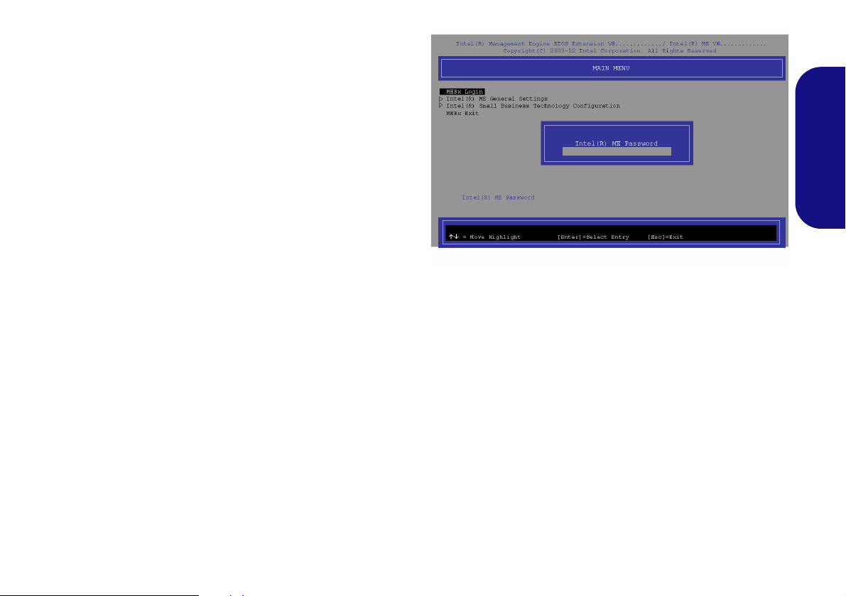
Intel® vPro™ Technology
Figure 14 - Intel(R) Management Engine
(Password Creation)
Intel® vPro™ Technology is supported by Model B
computers only. This set of technology features, built
into the computer’s motherboard, allows Information
Technology departments remote access to the computer.
This allows the IT department to monitor, maintain and
manage computers regardless of the state of the operating
system or the computer’s power state. This can be done
over a wired or corporate wireless network, or even outside the corporate firewall through a wired LAN connection.
Accessing the Intel Management Engine
To access the Intel Management Engine press Ctrl + P
at startup. Your system administrator will need to assist
you in managing the information as applicable to your enterprise. Note the following password information for the
Intel Management Engine:
• The default password is “admin” (without quotes).
If you get an "Error - Intel(R) ME password change re-
jected" message when creating a new password, then note
the following parameters for creating a password:
• between 8 and 32 characters long
• Contain both upper and lower case Latin characters
• Have at least one numeric character
• Have at least one ASCII non-alphanumeric character (!,
@, #, $,%, ^, &, *)
English
Select MEBx Login and press “Enter” to access the password screen. Enter the password “admin” (without
quotes) and you will then be prompted to enter your own
password (note the password information above). Once
you have entered the password you will then be taken to
the platform configuration screen.
The platform configuration screen allows you to setup Intel ME as per your requirements (consult your IT administrator for the actual settings required).
19

Troubleshooting
Problem Possible Cause - Solution
The Bluetooth module is off after
resuming from Sleep.
The captured video files from the PC
Camera are taking up too much disk
English
space.
The computer is off (or in Sleep
Mode) but powered by the AC/DC
adapter plugged in to a working
outlet or powered by the battery with
a capacity level above 20%. I have
plugged a device into the powered
USB port in order to charge it, but
the device is not charging.
I previously turned off the WLAN
module using the Fn + F11 key
combination (or Windows Mobilty
Center button), but upon returning
to the machine the LED indicator
shows the WLAN module is ON.
The Bluetooth module’s default state will be off after resuming from the Sleep power-saving
state. Use the key combination (Fn + F12) to power on the Bluetooth module after the
computer resumes from Sleep.
Note that capturing high resolution video files requ ires a su bstantial amount of disk space for
each file.
Note that the Windows system requires a minimum of 15GB of free space on the C: drive
system partition. It is recommended that you save the capture video file to a location other
than the C:drive, limit the file size of the captured video or reduce video resolution.
The port is not powered on. Toggle power to the port using the Fn + power button
combination.
This function may not work with cert ai n e xte rnal USB comp li ant dev ice s (che ck yo ur dev ice ’s
documentation). If this is the case, power the computer on and connect the external USB
device in order to charge it.
The computer entered a power saving state with the WLAN Switch in the ON position, and
upon resuming from the power saving state the WLAN module turned ON. The position of
the WLAN switch governs the power status of the WLAN module at startup, and upon
resuming from a power saving state. This is the case even if you have previously turned the
module off using the Fn + F11 key combination or Windows Mobilty Center button prior to
the computer entering a power saving state.
20

Specifications
Latest Specification Information
The specifications listed in this here
are correct at the time of going to
press. Certain items (particularly
processor types/speeds) may be
changed, delayed or updated due to
the manufacturer's release schedule. Check with your service center
for details.
CPU
The CPU is not a user serviceable
part. Accessing the CPU in any way
may violate your warranty.
Processor Options
Model A:
Intel® Core™ i7 Processor
i7-3612QM (2.10GHz)
6MB L3 Cache, 22nm, DDR3-1600MHz,
TDP 35W
i7-3520M (2.90GHz)
4MB L3 Cache, 22nm, DDR3-1600MHz,
TDP 35W
Intel® Core™ i5 Processor
i5-3360M (2.80GHz), i5-3320M (2.60GHz),
i5-3210M (2.50GHz)
3MB L3 Cache, 22nm, DDR3-1600MHz,
TDP 35W
Intel® Core™ i3 Processor
i3-3110M (2.40GHz)
3MB L3 Cache, 22nm, DDR3-1600MHz,
TDP 35W
Intel® Core™ i7 Processor
i7-2640M (2.80GHz)
4MB L3 Cache, 32nm, DDR3-1333MHz,
TDP 35W
Intel® Core™ i5 Processor
i5-2540M (2.60GHz), i5-2520M (2.50GHz),
i5-2450M (2.50GHz), i5-2430M (2.40GHz)
3MB L3 Cache, 32nm, DDR3-1333MHz,
TDP 35W
Intel® Core™ i3 Processor
i3-2370M (2.40GHz), i3-2350M (2.30GHz),
3MB L3 Cache, 32nm, DDR3-1333MHz,
TDP 35W
Intel® Pentium™ Processor
B980 (2.40GHz), B970 (2.30GHz), B960
(2.20GHz), B950 (2.10GHz)
2MB L3 Cache, 32nm, DDR3-1333MHz,
TDP 35W
Model B:
Intel® Core™ i7 Processor
i7-3520M (2.90GHz)
4MB L3 Cache, 22nm, DDR3-1600MHz,
TDP 35W
Intel® Core™ i5 Processor
i5-3360M (2.80GHz), i5-3320M (2.60GHz)
3MB L3 Cache, 22nm, DDR3-1600MHz,
TDP 35W
LCD
13.3" (33.78cm) HD LCD
BIOS
AMI BIOS (One 64Mb SPI Flash ROM)
Core Logic
Model A:
Intel® HM77 Chipset
Model B:
Intel® QM77 Chipset
Memory
Two 204 Pin SO-DIMM Sockets Supporting
DDR3 1333/1600MHz Memory
Memory Expandable up to 8GB
(The real memory operating frequency
depends on the FSB of the processor.)
English
21

Video Adapter (Model A)
Intel Integrated GPU
(GPU is Dependent on Processor)
Intel® HD Graphics
Dynamic Frequency (Intel Dynamic Video
Memory Technology for up to 1.7GB)
Microsoft DirectX®10 Compatible
Intel® HD Graphics 3000
Dynamic Frequency (Intel Dynamic Video
English
Memory Technology for up to 1.7GB)
Microsoft DirectX®10 Compatible
Intel® HD Graphics 4000
Dynamic Frequency (Intel Dynamic Video
Memory Technology for up to 1.7GB)
Microsoft DirectX®11 Compatible
Video Adapter (Model B)
Intel® HD Graphics 4000
Dynamic Frequency (Intel Dynamic Video
Memory Technology for up to 1.7GB)
Microsoft DirectX®11 Compatible
Storage
One Changeable 2.5" 9.5 mm (h) SATA
(Serial) HDD
Anti-Shock System
Audio
High Definition Audio Compliant Interface
2 * Built-In Speakers
Built-In Microphone
Security
BIOS Password
Security (Kensington® Type) Lock Slot
Fingerprint Reader
TPM v1.2
Intel vPro (Model B only)
Keyboard
Isolated A4 Size Keyboard with Anti-Spray
Support
Pointing Device
Built-in T ouchpad (scrolling key functionality
integrated)
Interface
One Powered USB 2.0 Port (see page 8)
Two USB 3.0 Ports
One eSATA/USB 2.0 Combo Port
One HDMI-Out Port
One Headphone-Out Jack
One Microphone-In Jack
One RJ-45 LAN Jack
One External Monitor Port
One ExpressCard/34(54) Slot
One DC-in Jack
(Factory Option) One Docking Port
Communication
Built-In Gigabit Ethernet LAN
(Factory Option) 1.3M Pixels/2M Pixels
(HD) PC Camera Module
(Factory Option) 3G Module (UMTS/HSPA
or UMTS/HSPA+)
WLAN/ Bluetooth Half Mini-Card
Modules:
Model A:
(Factory Option) Intel® Centrino® Wireless-N 2230 Wireless LAN (802.11b/g/n) +
Bluetooth 4.0
(Factory Option) Intel® Centrino® Wireless-N 135 Wireless LAN (802.11b/g/n) +
Bluetooth 4.0
(Factory Option) Third-Party Wireless LAN
(802.11b/g/n) + Bluetooth 4.0
(Factory Option) Third-Party Wireless LAN
(802.11b/g/n)
Model B:
(Factory Option) Intel® Centrino®
Advanced-N 6235 Wireless LAN (802.11a/
g/n) + Bluetooth 4.0
(Factory Option) Intel® Centrino®
Advanced-N 6205 Wireless LAN (802.11a/
g/n)
22

Card Reader
Embedded Multi-in-1 Push-Push Card
Reader
MMC (MultiMedia Card) / RS MMC
SD (Secure Digital) / Mini SD / SDHC/
SDXC
MS (Memory Stick) / MS Pro / MS Duo
Mini Card Slots
Slot 1 for WLAN Module or WLAN and
Bluetooth Combo Module
(Factory Option) Slot 2 for 3G Module
Environmental Spec
Temperature
Operating: 5°C - 35°C
Non-Operating: -20°C - 60°C
Relative Humidity
Operating: 20% - 80%
Non-Operating: 10% - 90%
Power
Full Range AC/DC Adapter
AC Input: 100 - 240V, 50 - 60Hz
DC Output: 19V, 3.42A or 18.5V, 3.5A
(65W)
English
6 Cell Smart Lithium-Ion Battery Pack,
62.16WH
Dimensions & Weight
330mm (w) * 225mm (d) * 24.5 - 32mm (h)
1.78kg with 62.16WH Battery
23

English
24

Über das Ausführliche Benutzerhandbuch
Diese Kurzanleitung soll einen Überblick über die Schritte geben, die dazu notwendig s ind, das System zu starten. Dieses ist
nur eine Ergänzung und kein Ersatz für das erweiterte englischsprachige Benutzerhandbuch, das auf der mitgelieferten Disc
Device Drivers & Utilities + User's Manual im Adobe-Acrobat-Format vorliegt. Diese Disc enthält auch die Treiber und
Utility-Programme, die für einen einwandfreien Betrieb des Computers notwendig sind (Hinweis: Das Unternehmen behält
sich das Recht vor, diese Publikation ohne Vorankündigung zu überarbeiten und den Inhalt zu verändern).
Einige oder alle Funktionen des Computers sind bereits eingerichtet worden. Falls das nicht der Fall ist oder wenn Sie einzelne Teile des Systems neu konfigurieren (oder neu installieren) möchten, finden Sie eine Anleitung im erweiterten Benut-
zerhandbuch. Die Disc Device Drivers & Utilities + User's Manual enthält nicht das Betriebssystem.
Einhaltung gesetzlicher Vorschriften und Sicherheitshinweise
Beachten Sie sorgfältig die Hinweise zu gesetzlichen Vorschriften und zu Sicherheitshinweisen im erweiterten Benutzerhandbuch auf der Disc Device Drivers & Utilities + User's Manual.
© Oktober 2012
Warenzeichen
Intel und Intel Core sind warenzeichen/e inget ragenes ware nzeichen der Intel Corporation.
Deutsch
25

Hinweise zu Pflege und Betrieb
Das Notebook ist zwar sehr stabil, kann aber dennoch beschädigt werden. Damit es nicht dazu kommt, sollten Sie die
folgenden Hinweise beachten:
• Das Gerät darf nicht herunterfallen und in anderer Form Stößen
ausgesetzt werden. Wenn der Computer fällt, können das Gehäuse und
andere Komponenten beschädigt werden.
• Das Gerät darf nicht nass werden und sich nicht überhitzen. Compu-
ter und Netzteil dürfen nicht in der Nähe von Wärmequellen stehen oder
gelagert werden. Dies ist ein elektrisches Gerät. Wenn Wasser oder
andere Flüssigkeiten eindringen, kann der Computer stark beschädigt
werden.
• Vermeiden Sie Interferenzen mit anderen Geräten. Halten Sie den
Computer fern von magnetischen Feldern, die von Stromquellen, Monitoren, Magneten etc. erzeugt werden. Die können die Leistung beein-
Deutsch
trächtigen und Ihre Daten beschädigen.
• Achten Sie auf die richtige Bedienung des Computers. Schalten Sie
ihn erst aus, wenn alle Programme geschlossen wurden (speichern Sie
Ihre Daten!). Speichern Sie regelmäßig Ihre Daten, da diese verloren
gehen können, wenn der Akku verbraucht ist.
Reparatur
Nehmen Sie vor dem Reinigen des Wenn Sie versuchen, den
Computer selbst zu reparieren, können Ihre Garantieansprüche
verloren gehen. Außerdem besteht Stromschlaggefahr für Ihre
Gesundheit und das Gerät durch frei liegende Teile. Lassen Sie
Reparaturarbeiten nur von qualifizierten Reparaturfachleuten
durchführen, insbesondere wenn folgende Umstände vorliegen:
• Wenn das Netzkabel oder der AC/DC-Adapter beschädigt od er zers ch li s -
sen sind.
• Wenn der Computer Regen ausgesetzt war oder mit Flüssigkeiten in
Berührung gekommen ist.
• Wenn der Computer unter Beachtung der Bedienungsanweisungen nicht
korrekt arbeitet.
26
• Wenn der Computer heruntergefallen ist oder beschädigt wurde (berühren Sie nicht die giftige Flüssigkeit des LCD-Bildschirms).
• Wenn ein ungewöhnlicher Geruch, Hitze oder Rauch aus dem Computer
entweicht.
Sicherheitsinformationen
• Verwenden Sie nur einen AC/DC-Adapter, der für die Verwendung mit
diesem Computer zugelassen ist.
• Verwenden Sie nur das Netzkabel und die Akkus, die in diesem Benutzerhandbuch spezifiziert sind
Sie können explodieren. Richten Sie sich nach den regional gültigen Entsorgungsvorschriften.
• Verwenden Sie den Akku nicht mehr , wenn er heruntergefallen ist oder in
anderer Weise beschädigt (z.B. verzogen) ist. Auch wenn der Computer
mit dem beschädigten Akku zu funktionieren schein, können dadurch
Stromkreise beschädigt werden, die schließlich einen Brand verursachen
können.
• Achten Sie darauf, dass Ihr Computer ausgeschaltet ist, wenn Sie es fur
den Transport z.B. wahrend einer Reise in eine Tasche einpakken.
• Nehmen Sie vor dem Reinigen des Computers den Akku heraus, und
trennen Sie es von allen externen Stromquellen, Peripheriegeräten und
Kabeln (einschließlich Telefonkabel) ab.
• Reinigen Sie den Computer mit einem weichen, sauberen Tuch. Tragen
Sie das Reinigungsmittel nicht direkt auf den Computer auf. Verwenden
Sie keine flüchtigen Reinigungsmittel (Petroleumdestillate) oder Scheuermittel zum Reinigen des Computers.
• Versuchen Sie nicht, Akkus zu reparieren. Lassen Sie die Akkupacks
durch den Servicevertreter oder qualifiziertes Fachpersonal reparieren
oder austauschen.
• Beachten Sie, dass das Logo bei den Computern, die über ein galvanisch
beschichtetes LCD-Logo verfügen, von einer Schutzfolie bedeckt ist.
Durch die natürliche Abnutzung kann diese Schutzfolie beschädigt werden oder abgehen und die scharfen Kanten des frei liegenden Logos
freigeben. Seien Sie in solch einem Fall vorsichtig bei der Handhabung
des Computers, und vermeiden Sie es, das herausstehende beschichtete
LCD-Logo zu berühren. Legen Sie keine Gegenstände in die Tragetasche, da diese während des Transports gegen den Computer drücken
können. Wenden Sie sich in einem solchen Fall von Abnutzung an Ihr
Service Center.
. Entsorgen Sie die Akkus nicht in Feuer.
 Loading...