

Clevo S210TU service manual

S210TU


Notebook Computer
S210TU
Service Manual
Preface
Preface
I

Preface
Preface
Notice
The company reserves the right to revise this publication or to change its contents without notice. Information contained
herein is for reference only and does not constitute a commitment on the part of the manufacturer or any subsequent vendor. They assume no responsibility or liability for any errors or inaccuracies that may appear in this publication nor are
they in anyway responsible for any loss or damage resulting from the use (or misuse) of this publication.
This publication and any accompanying software may not, in whole or in part, be reproduced, translated, transmitted or
reduced to any machine readable form without prior consent from the vendor, manufacturer or creators of this publication, except for copies kept by the user for backup purposes.
Brand and product names mentioned in this publication may or may not be copyrights and/or registered trademarks of
their respective companies. They are mentioned for identification purposes only and are not intended as an endorsement
of that product or its manufacturer.
Version 1.0
April 2014
Trademarks
Intel and Celeron are trademarks of Intel Corporation.
Windows® is a registered trademark of Microsoft Corporation.
Other brand and product names are trademarks and /or registered trademarks of their respective companies.
II

About this Manual
This manual is intended for service personnel who have completed sufficient training to undertake the maintenance and
inspection of personal computers.
It is organized to allow you to look up basic information for servicing and/or upgrading components of the S210TU series
notebook PC.
The following information is included:
Chapter 1, Introduction, provides general information about the location of system elements and their specifications.
Chapter 2, Disassembly, provides step-by-step instructions for disassembling parts and subsystems and how to upgrade
elements of the system.
Preface
Appendix A, Part Lists
Appendix B, Schematic Diagrams
Appendix C, Updating the FLASH ROM BIOS
Preface
III
Preface
Volume Warning
To prevent possible hearing damage, do not listen at high volume levels for long periods.
Preface
IMPORTANT SAFETY INSTRUCTIONS
Follow basic safety precautions, including those listed below, to reduce the risk of fire, electric shock and injury to persons when using any electrical equipment:
1. Do not use this product near water, for example near a bath tub, wash bowl, kitchen sink or laundry tub, in a wet
basement or near a swimming pool.
2. Avoid using a telephone (other than a cordless type) durin g an ele ctrical sto rm. There may be a remote risk of electrical shock from lightning.
3. Do not use the telephone to report a gas leak in the vicinity of the leak.
4. Use only the power cord and batteries indicated in this manual. Do not dispose of batteries in a fire. They may
explode. Check with local codes for possible special disposal instructions.
5. This product is intended to be supplied by a Listed Power Unit with an AC Input of 100 - 240V, 50 - 60Hz, DC Output
of 5V, 2A (10 Watts) minimum AC/DC Adapter.
IV

FCC RF Radiation Exposure Statement:
Warning
Use only shielded cables to connect I/O devices to this equipment. You are cautioned that changes or modifications not expressly approved by the manufacturer for compliance with the above standard s could void your authority to operate the
equipment.
If your purchase option includes both Wireless LAN and 3G modules, then the appropriate antenna s will be installed. Note
that In order to comply with FCC RF exposure compliance requirements, the antenna must no t be co-located or o perate in
conjunction with any other antenna or transmitter.
Important Notice - 3G & Bluetooth/Wireless LAN Modules
In order to comply with FCC regulations you should NOT operate the 3G module and the Bluetoo th/Wirele ss LAN modules
at the same time as this may disrupt radio frequency, and cause interference. When the 3Gmodule is powered on, make sure
that the Bluetooth/Wireless LAN modules are powered off.
1. This Transmitter must not be co-located or operating in conjunction with any other antenna or transmitter.
2. This equipment complies with FCC RF radiation exposure limits set forth for an uncontrolled environment. This
equipment should be installed and operated with a minimum distance of 20 centimeters between the radiator and
your body.
Preface
Preface
V

Preface
Preface
Instructions for Care and Operation
The notebook computer is quite rugged, but it can be damaged. To prevent this, follow these suggestions:
1. Don’t drop it, or expose it to shock. If the computer falls, the case and the components could be damaged.
• Do not place it on an unstable surface.
• Do not place anything heavy on the computer
2. Keep it dry, and don’t overheat it. Keep the computer and power supply away from any kind of heating element.
This is an electrical appliance. If water or any other liquid gets into it, the computer could be badly damaged.
• Do not expose it to excessive heat.
• Do not leave it in a place where foreign matter or moisture may affect the system.
• Don’t store the computer in a humid environment.
3. Avoid interference. Keep the computer away from high capacity transformers, electric motors, and other strong
magnetic fields. These can hinder proper performance and damage your data.
4. Follow the proper working procedures for the computer. Shut the computer down properly and don’t forget to
save your work.
• Do not turn off the power until you properly shut down all programs.
• Do not turn off any peripheral devices when the computer is on.
• Do not disassemble the computer by yourself.
• Perform routine maintenance on your computer.
VI
5. Take care when using peripheral devices.
• Use only approved brands of peripherals.
• Unplug the power cord before attaching peripheral devices.
Power Safety
Power Safety
Warning
Before you undertake
any upgrade procedures, make sure that
you have turned off the
power, and disconnected all peripherals
and cables (including
telephone lines). It is
advisable to also remove your battery in
order to prevent accidentally turning the
machine on.
The computer has specific power requirements:
• Only use a power adapter approved for use with this computer.
• Your AC adapter may be designed for international travel but it still requires a steady, uninterrupted power supply. If you are
unsure of your local power specifications, consult your service representative or local power company.
• The power adapter may have either a 2-prong or a 3-prong ground ed plug. The third prong is an important safety feature; do
not defeat its purpose. If you do not have access to a compatible outlet, have a qualified electrician install one.
• When you want to unplug the power cord, be sure to disconne ct it by the plug head, not by its wire.
• Make sure the socket and any extension cord(s) you use can support the total current load of all the connected devices.
• Before cleaning the computer, make sure it is disconnected from any external power supplies.
Preface
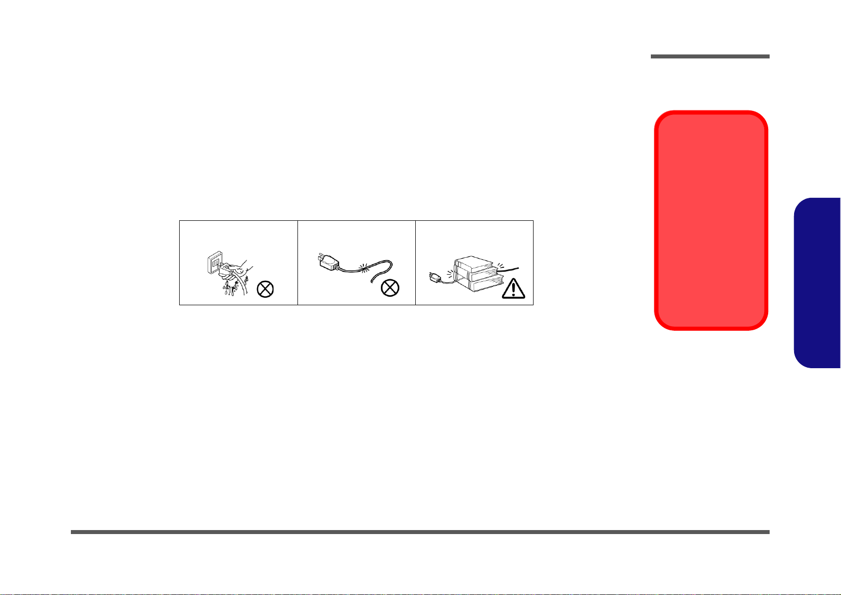
Do not plug in the power
cord if you are wet.
Do not use the power cord if
it is broken.
Do not place heavy objects
on the power cord.
Preface
VII

Preface
Battery Disposal
The product that you have purchased contains a rechargeable battery. The battery is recyclable. At the end of its useful life, under various state and local laws, it may be illegal to dispose of this battery into the municipal waste stream. Check with your local solid waste
officials for details in your area for recycling options or proper disposal.
Caution
Danger of explosion if battery is incorrectly replaced. Replace only with the same or equivalent type recommended by the manufacturer.
Discard used battery according to the manufacturer’s instructions.
Preface
Polymer Battery Precautions
Note the following information which is specific to polymer batteries only, and where applicable, this overrides the general battery precaution information.
• Polymer batteries may experience a slight expansion or swelling, however this is part of the battery’s safety mechanism and is
not a cause for concern.
• Use proper handling procedures when using polymer batteries. Do not use polymer batteries in high ambient temperature environments.
Battery Guidelines
The following can also apply to any backup batteries you may have.
• If you do not use the battery for an extended period, then remove the battery from the computer for storage.
• Before removing the battery for storage charge it to 60% - 70%.
• Check stored batteries at least every 3 months and charge them to 60% - 70%.
VIII
Related Documents
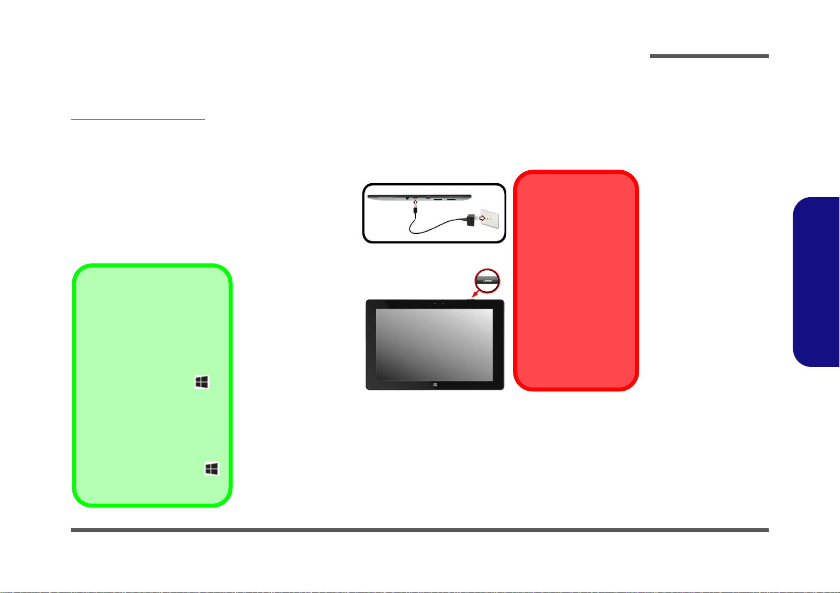
Charging the
Tablet PC
Attach the AC/DC adapter
to the micro USB 2.0 port
on the left of the Tablet PC,
then plug the adapter cord
into the adapter, and the
adapter into a working outlet to charge the tablet PC.
Use only the adapter cord
supplied with the system to
connect to the adapter.
Do not use a computer’s
USB port to attempt to
charge the Tablet PC.
Figure 1
Opening the Lid/LCD/
Computer with AC/DC
Adapter Plugged-In
Shut Down
Note that you should always shut
your computer down by choosing
the Shut down command in Win-
dows (see below). This will help prevent hard disk or system problems.
Tap Settings in the Charms Bar (or
use the Windows Logo Key +
C key combination to access the
Charms Bar if you have an attached
keyboard) and choose Shut down
from the Power menu.
Or
Choose Shut down or sign out >
Shut down from the context menu
(or use the Windows Logo Key
+ X key combination to access the
context menu).
You may also need to consult the following manual for additional information:
User’s Manual on CD/DVD
This describes the notebook PC’s features and the procedures for operating the computer and its ROM-based setup program. It also describes the installation and operation of the utility programs provided with the notebook PC.
System Startup
1. Remove all packing materials.
2. Attach the AC/DC adapter to the micro USB 2.0 port on
the left of the Tablet PC, then plug the adapter cord into
the adapter, and the adapter into a working outlet.
3. Press the power button to turn the computer “on”.
Preface
Preface
IX

Preface
Preface
X

Contents
Preface
Introduction ..............................................1-1
Overview ......................................................................................... 1-1
Specifications ..................................................................................1-2
External Locator - Front View ........................................................1-3
External Locator - Top & Bottom Views ........................................1-4
External Locator - Left Side & Right Side View ............................1-5
External Locator - Rear View .........................................................1-6
Mainboard Overview - Top (Key Parts) .........................................1-7
Mainboard Overview - Bottom (Key Parts) ....................................1-8
Mainboard Overview - Top (Connectors) .......................................1-9
Mainboard Overview - Bottom (Connectors) ...............................1-10
Disassembly ...............................................2-1
Overview ......................................................................................... 2-1
Maintenance Tools ..........................................................................2-2
Connections .....................................................................................2-2
Maintenance Precautions .................................................................2-3
Disassembly Steps ...........................................................................2-4
Removing the Battery ......................................................................2-5
Removing the Wireless LAN Module .............................................2-7
Wireless LAN, Combo, 3G & LTE Module Cables .......................2-8
Part Lists ..................................................A-1
Part List Illustration Location ........................................................A-2
Back ................................................................................................A-3
Schematic Diagrams.................................B-1
System Block Diagram ...................................................................B-2
DDR3L ........................................................................................... B-3
Display ...........................................................................................B-4
SATA, PCIe ...................................................................................B-5
PMU, Clocks, RTC, SPI .................................................................B-6
USB .................................................................................................B-7
Power 1 ...........................................................................................B-8
Power 2 ...........................................................................................B-9
VSS ...............................................................................................B-10
DDR3L SO-DIMM .......................................................................B-11
eDP to LVDS PS8625 ..................................................................B-12
HDMI, USB ..................................................................................B-13
WLAN, 3G, GPS ..........................................................................B-14
Audio Codec .................................................................................B-15
SD Card RTS5229 ........................................................................B-16
USB, CCD, BT, Touch Screen .....................................................B-17
USB, GPS, CCD, 3G ....................................................................B-18
eMMC ...........................................................................................B-19
CCD, RTS5875 .............................................................................B-20
Sensor ...........................................................................................B-21
Panel, Conn, SW ...........................................................................B-22
5VS, 3.3VS, 1.8VS, 1.2VS, 1.35VS .............................................B-23
PWR 1.35V ...................................................................................B-24
PWR PMU ....................................................................................B-25
VCORE .........................................................................................B-26
PWR, VDD5, 12V ........................................................................B-27
ITE8380 BGA ...............................................................................B-28
Power Board .................................................................................B-29
I/O Board ......................................................................................B-30
RF Board .......................................................................................B-31
GPS Board ....................................................................................B-32
Preface
XI

Preface
Preface
XII

Chapter 1: Introduction
Overview
This manual covers the information you need to service or upgrade the S210TU series notebook computer. Information
about operating the computer (e.g. getting started, and the Setup utility) is in the User’s Manual. Information about drivers (e.g. VGA & audio) is also found in the User’s Manual. The manual is shipped with the computer.
Operating systems (e.g. Windows 8.1, etc.) have their own manuals as do application softwares (e.g. word processing and
database programs). If you have questions about those programs, you should consult those manuals.
Introduction
The S210TU series notebook is designed to be upgradeable. See Disassembly on page 2 - 1 for a detailed description of
the upgrade procedures for each specific component. Please take note of the warning and safety information indicated
by the “” symbol.
The balance of this chapter reviews the computer’s technical specifications and features.
1.Introduction
Overview 1 - 1

Introduction
Latest Specification Information
The specifications listed here are correct at the
time of sending them to the press. Certain items
(particularly processor types/speeds) may be
changed, delayed or updated due to the manufacturer's release schedule. Check with your
service center for more details.
CPU
The CPU is not a user serviceable part. Accessing the CPU in any way may violate your
warranty.
Specifications
1.Introduction
Processor
Intel® Celeron™ Processor
N2806 (1.6GHz)
1MB L2 Cache, 22nm, DDR3L-1066MHz, TDP 4.3W
BIOS
64Mb SPI Flash ROM
AMI BIOS
Memory
DDR3L 1066MHz 2GB RAM On Board
(The real memory operating frequency depends on the FSB
of the processor.)
LCD
10.1" (25.58cm) WXGA
Multi Touch
Video Adapter
Intel HD Graphics
Dynamic Frequency (Intel Dynamic Video Memory Technology for up to 1.7GB)
Microsoft DirectX® 11 Compatible
Storage
32GB or 64GB eMMC
Audio
Built-In Speaker
Built-In Microphone
Security
BIOS Password
Keyboard & Pointing Device
(Factory Option) Bluetooth keyboard with touchpad
Interface
One Micro USB 2.0 Port
One Micro HDMI-Out Port
One Two-In-One Audio Jack (Headphone-out/Microphone-
In)
Card Reader
Micro SD Card Reader
- SDHC / SDXC Compatible
Communication
Built-In 1.0M HD Video Camera (Front)
(
Factory Option) Built-In 5.0M FHD Video Camera (Rear
(Factory Option) M.2 3G Module
Built-In 802.11b/g/n Wireless LAN & Bluetooth 4.0 M.2
Combo Module (2230)
Environmental Spec
Temperature
Operating: 5
Non-Operating: -20°C - 60°C
Relative Humidity
Operating: 20% - 80%
Non-Operating: 10% - 90%
°C - 35°C
Power
Full Range AC/DC Adapter
AC Input: 100 - 240V, 50 - 60Hz
DC Output: 5V, 2A (10W)
Dimensions & Weight
258mm (w) * 172.6mm (d) * 10.9mm (h)
0.69kg
)
1 - 2 Specifications
External Locator - Front View
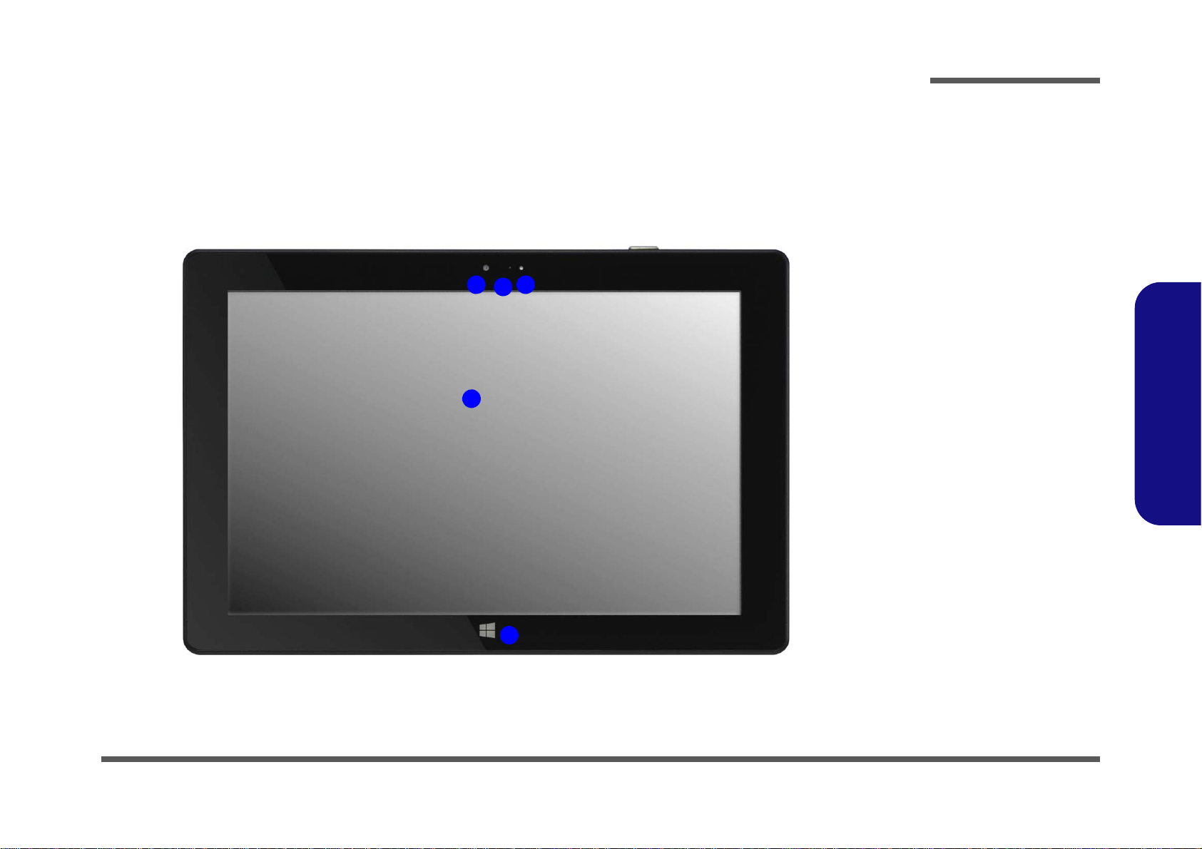
Figure 1
Front View
1. Light Sensor
2. *PC Camera LED
*When the PC
camera is in use,
the LED will be
illuminated in red.
3. 1.0M FHD PC
Camera
4. LCD
5. Windows Logo
Button
2
4
13
5
Introduction
1.Introduction
External Locator - Front View 1 - 3

1.Introduction
Figure 2
Top View
1. Microphone
2. Power Button
Figure 3
Bottom View
1. System Shut
Down Hole
TOP VIEW
1 2
BOTTOM VIEW
1
Introduction
External Locator - Top & Bottom Views
1 - 4 External Locator - Top & Bottom Views

External Locator - Left Side & Right Side View
Figure 4
Left Side View
1. Volume Control
Button
2. 2-In-1 Audio Jack
(Headphone-Out/
Microphone-In)
3. Micro USB 2.0
Port
4. Micro HDMI-Out
Port
5. Micro SD Card
Reader
6. (Factory Option)
Micro SIM Card
Reader (for 3G
SIM Card)
LEFT SIDE VIEW
1
2
3
4
5
6
REAR VIEW
Figure 5
Rear View
/
Introduction
1.Introduction
External Locator - Left Side & Right Side View 1 - 5
1.Introduction
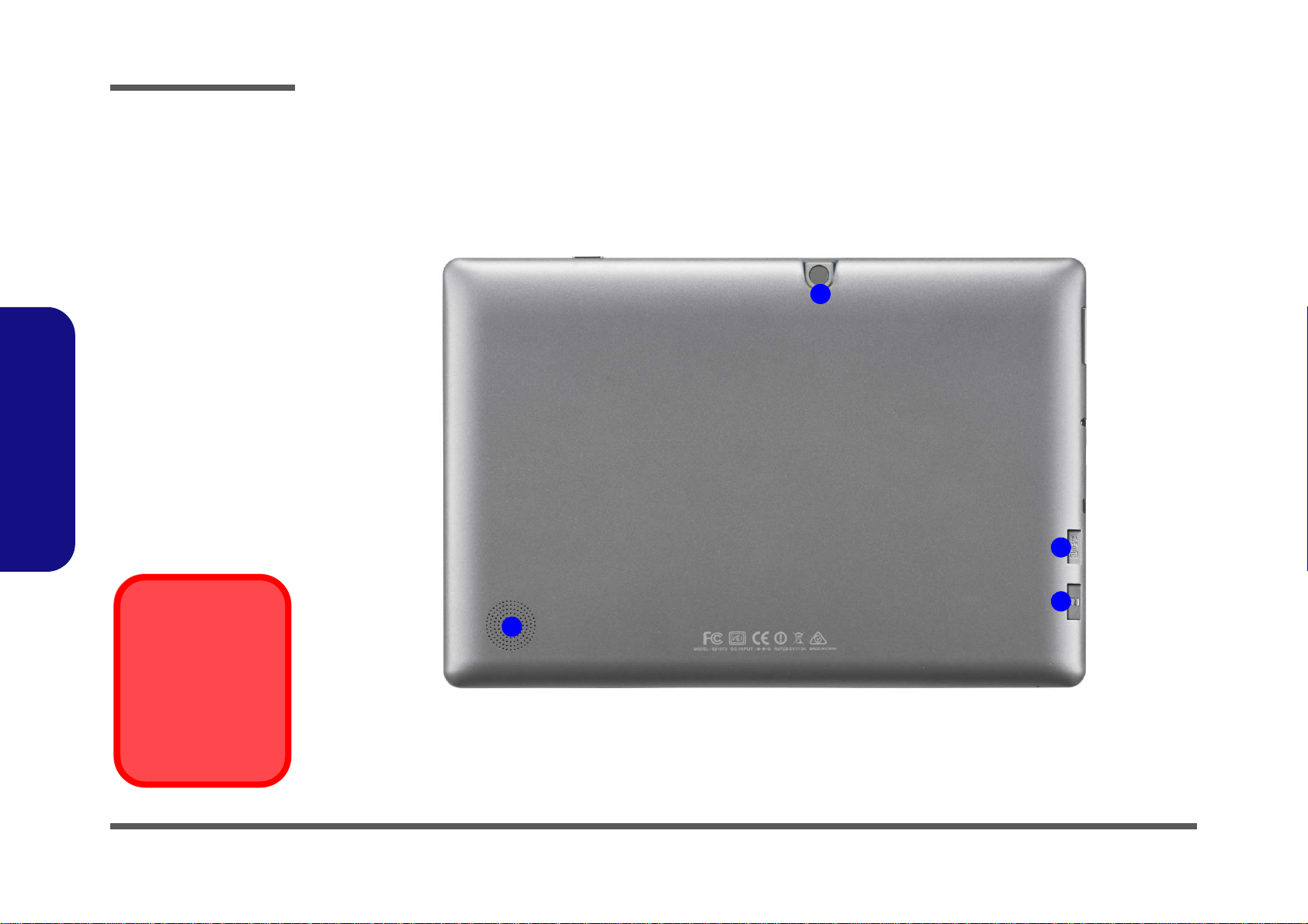
Figure 6
Rear View
1. Micro SD Card
Reader
2. (Factory
Option) Micro
SIM Card Reader
(for 3G SIM
Card)
3. (Factory
Option) Built-In
Rear (Outward
Facing) 5.0M
FHD PC Camera
4. Built-In Speaker
Overheating
To prevent your computer from overheating, make sure nothing blocks any vent
while the computer is
in use.
2
1
3
4
Introduction
External Locator - Rear View
1 - 6 External Locator - Rear View
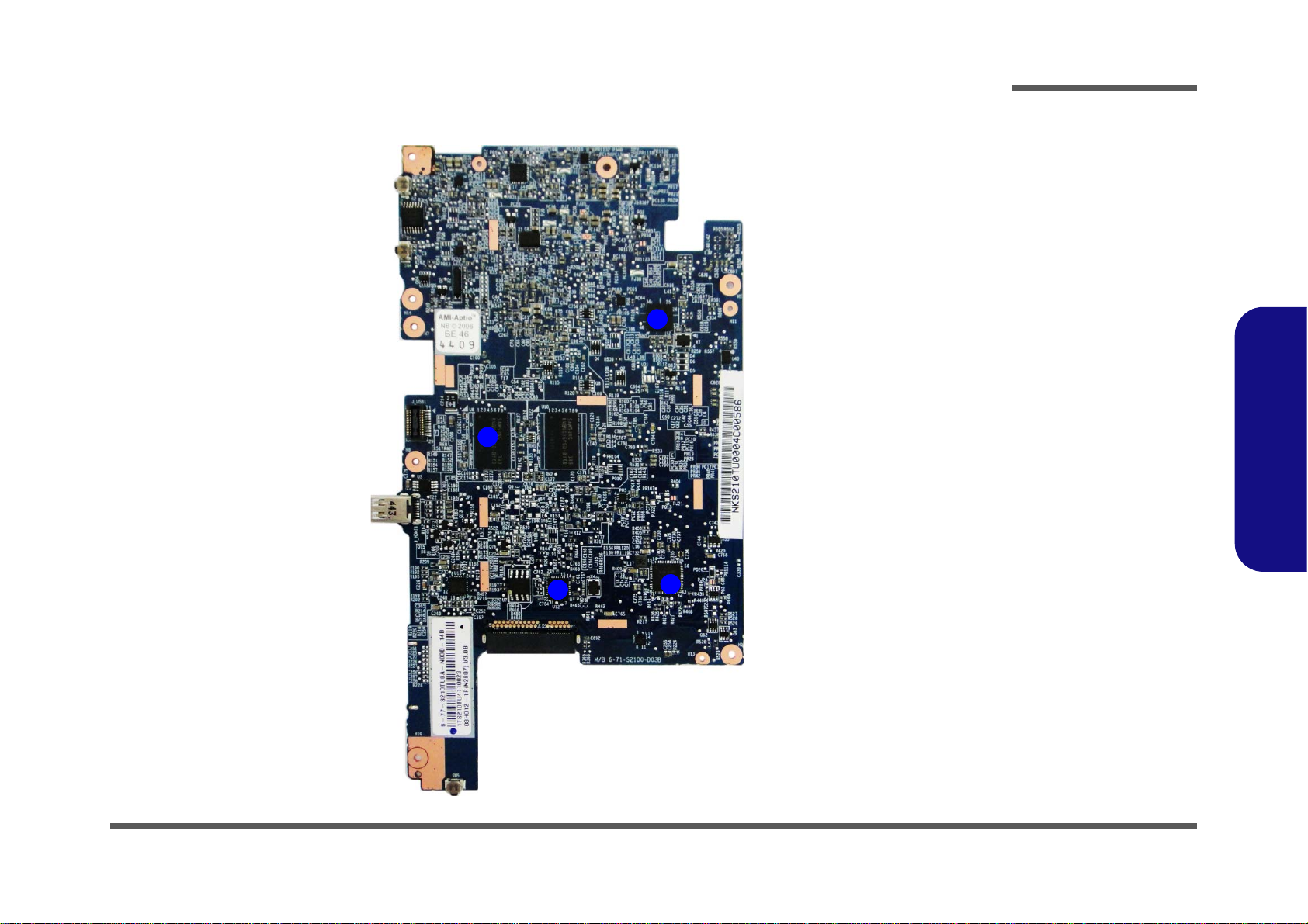
Mainboard Overview - Top (Key Parts)
Figure 7
Mainboard Top
Key Parts
1. Memory - DDR3L
2. USB Hub
3. PS8625
4. RTS5821Z
4
1
2
3
Introduction
1.Introduction
Mainboard Overview - Top (Key Parts) 1 - 7
 Loading...