

Page 1
Page 2

Page 3

Introduction (English)
This Concise User’s Guide introduces the main features
of your computer. The English version of this guide begins on page 1. The expanded User’s Manual is on the
Device Drivers & Utilities + User’s Manual disc.
Einführung (Deutsch)
Dieses Ausführliche Benutzerhandbuch führt Sie in die
Hauptfunktionen des Computers ein. Die deutsche Version des Handbuchs beginnt auf Seite 41. Das erweiterte
Benutzerhandbuch finden Sie auf der Disc für die Gerätetreiber und Hilfsprogramme (Disc Device Drivers &
Utilities + User's Manual).
Présentation (Français)
Ce Guide Utilisateur Concis présente les fonctionnalités
principales de votre ordinateur. La version française de
ce guide commence à la page 81. Le Manuel de l'Utilisa-
teur étendu se trouve sur le disque de Pilotes & Utilitaires + Manuel de l'Utilisateur (disque Device Drivers
& Utilities + User's Manual).
Introducción (Español)
Esta Guía del Usuario Concisa le presenta las características principales de su ordenador. La versión española de
esta guía comienza en la página 121. El Manual del usua-
rio completo se encuentra en el disco de Controladores
del dispositivo y Utilidades + Manual del usuario (disco
Device Drivers & Utilities + User's Manual).
Introduzione (Italiano)
La presente Guida Rapida per l'Utente introduce le caratteristiche principali del computer. La versione italiana di
questa guida inizia da pagina 161. Il Manuale utente
completo si trova nel disco contenente driver e utilità +
Manuale utente (disco Device Drivers & Utilities +
User's Manual).
I
Page 4

Contents
About this Concise User’s Guide ...................................................... 1
System Startup ...................................................................................4
Intel® Optane™ Setup ...................................................................... 5
RAID Setup ....................................................................................... 7
System Map: Front View with LCD Panel Open ..........................10
LED Indicators ................................................................................. 11
Keyboard & Function Keys .............................................................12
System Map: Front, Rear & Bottom Views ..................................... 13
System Map: Left & Right Views ................................................... 14
Control Center ................................................................................. 16
Flexikey® Application ....................................................................20
Keyboard Backlight LED ................................................................ 24
Windows 10 Start Menu, Context Menu, Taskbar, Control Panel
and Settings ...................................................................................... 26
Video Features .................................................................................27
Power Options ................................................................................. 29
PC Camera .......................................................................................29
Audio Features ................................................................................. 30
Driver Installation ............................................................................ 32
Wireless LAN Module (Option) ...................................................... 33
Bluetooth Module (Option) .............................................................33
Fingerprint Reader (Option) ............................................................ 35
TPM (Option) .................................................................................. 36
Troubleshooting ............................................................................... 37
Specifications ................................................................................... 38
Inhalt
Über das Ausführliche Benutzerhandbuch ......................................41
Schnellstart .......................................................................................44
Intel® Optane™ Setup ..................................................................... 45
RAID Setup ...................................................................................... 47
Systemübersicht: Ansicht von vorne mit geöffnetem
LCD-Bildschirm .............................................................................. 50
LED-Anzeigen ................................................................................. 51
Tastatur & Funktionstasten .............................................................. 52
Systemübersicht: Ansicht von vorne, hinten und unten ..................53
Systemübersicht: Ansicht von links und rechts ..............................54
Control Center .................................................................................. 56
Flexikey® Anwendung ....................................................................60
Tastatur Hintergrundlicht-LED ........................................................ 64
Start-Menü, Kontextmenü, Taskleiste, Systemsteuerung und
Einstellungen von Windows 10 .......................................................66
Grafikfunktionen .............................................................................. 67
Energieoptionen ............................................................................... 69
Audiofunktionen .............................................................................. 70
Installation der Treiber ..................................................................... 72
Wireless-LAN-Modul (Option) .......................................................73
Bluetooth-Modul (Option) ............................................................... 73
Fingerabdruckleser (Option) ............................................................ 75
TPM (Option) ..................................................................................76
Fehlerbehebung ................................................................................ 77
Technische Daten .............................................................................78
II
Page 5

Sommaire
A propos de ce Guide Utilisateur Concis ......................................... 81
Guide de démarrage rapide .............................................................. 84
Configuration Intel® Optane™ .......................................................85
Configuration RAID ........................................................................87
Carte du système: Vue de face avec l’écran LCD ouvert ............... 90
Indicateurs LED ............................................................................... 91
Clavier & touches fonction ..............................................................92
Carte du système: Vues de face, arrière et dessous .........................93
Carte du système: Vues de gauche et droite ....................................94
Control Center ................................................................................. 96
Application Flexikey® ..................................................................100
LED du rétroéclairage du clavier ...................................................104
Menu Démarrer, Menu contextuel, Barre des tâches,
Panneau de Configuration et Paramètres de Windows 10 ............. 106
Caractéristiques vidéo ....................................................................107
Options d’alimentation .................................................................. 109
Caméra PC .....................................................................................109
Caractéristiques audio ....................................................................110
Installation du pilote ...................................................................... 112
Module LAN sans fil (Option) ......................................................113
Module Bluetooth (Option) ...........................................................113
Lecteur d'empreintes digitales (Option) ......................................... 115
TPM (Option) ................................................................................ 116
Dépannage ..................................................................................... 117
Spécifications ................................................................................. 118
Contenidos
Acerca de esta Guía del Usuario Concisa ...................................... 121
Guía rápida para empezar ..............................................................124
Configuración de Intel® Optane™ ................................................125
Configuración RAID ...................................................................... 127
Mapa del sistema: Vista frontal con panel LCD abierto ..............130
Indicadores LED ............................................................................131
Teclado & teclas de función .......................................................... 132
Mapa del sistema: Vistas frontal, posterior e inferior ..................133
Mapa del sistema: Vistas izquierda y derecha ..............................134
Control Center ................................................................................ 136
Aplicación Flexikey® .................................................................... 140
LED de retroiluminación del teclado .............................................144
Menú Inicio, Menú contextual, Barra de tareas, Panel de Control y
Configuración de Windows 10 ......................................................146
Parámetros de vídeo .......................................................................147
Opciones de energía .......................................................................149
Cámara PC .....................................................................................149
Características de audio ................................................................. 150
Instalación de controladores ..........................................................152
Módulo LAN Wireless (Opción) ...................................................153
Módulo Bluetooth (Opción) ........................................................... 153
Lector de huellas digitales (Opción) .............................................. 155
TPM (Opción) ................................................................................156
Solución de problemas ................................................................... 157
Especificaciones ............................................................................. 158
III
Page 6

Sommario
Informazioni sulla Guida Rapida per l'Utente ...............................161
Guida di avvio rapido .................................................................... 164
Configurazione Intel® Optane™ ................................................... 165
Configurazione RAID ....................................................................167
Descrizione del sistema: Vista anteriore con pannello LCD aperto ....
170
Indicatori LED ...............................................................................171
Tastiera & tasti funzione ................................................................172
Descrizione del sistema: Vista anteriore, posteriore e inferiore ... 173
Descrizione del sistema: Vista sinistra e destra ............................ 174
Control Center ............................................................................... 176
Applicazione Flexikey® ................................................................ 180
LED di retroilluminazione delle tastiera ........................................ 184
Menu Start, Menu contestuale, Barra delle applicazioni, Pannello di
controllo e Impostazioni di Windows 10 ....................................... 186
Funzioni video ............................................................................... 187
Opzioni risparmio energia .............................................................189
Camera PC .....................................................................................189
Funzionalità audio .........................................................................190
Installazione driver ........................................................................ 192
Modulo LAN Wireless (Opzione) ................................................. 193
Modulo Bluetooth (Opzione) ......................................................... 193
Lettore d’impronte digitali (Opzione) ............................................ 195
TPM (Opzione) .............................................................................. 196
Risoluzione dei problemi ............................................................... 197
Specifiche tecniche ........................................................................198
IV
Page 7

About this Concise User’s Guide
FCC Statement
This device complies with Part
15 of the FCC Rules. Operation
is subject to the following two
conditions:
1. This device may not cause
harmful interference.
2. This device must accept any
interference received, including interference that may
cause undesired operation.
This quick guide is a brief introduction to getting your system started. This is a s upplement, and not a substitute for the
expanded English language User’s Manual in Adobe Acrobat format on the Device Drivers & Utilities + User’s Manual
disc supplied with your computer. This disc also contains the drivers and utilities necessary for the proper oper ation of
the computer (Note: The company reserves the right to revise this publication or to change its contents without notice).
Some or all of the computer’s features may already have been setup. If they aren’t, or you are planning to re-configure
(or re-install) portions of the system, refer to the expanded User’s Manual. The Device Drivers & Utilities + User’s
Manual disc does not contain an operating system.
Regulatory and Safety Information
Please pay careful attention to the full regulatory notices and safety information
contained in the expanded User’s Manual on the Device Drivers & Utilities + Us-
er’s Manual disc.
©
July 2018
Trademarks
Intel is a trademark/registered trademark of Intel Corporation.
Windows is a registered trademark of Microsoft Corporation.
English
1
Page 8

Instructions for Care and Operation
The computer is quite rugged, but it can be damaged. To
prevent this, follow these suggestions:
• Don’t drop it, or expose it to shock. If the computer falls, the
case and the components could be damaged.
• Keep it dry, and don’t overheat it. Keep the computer and
power supply away from any kind of heating element. This is an
English
electrical appliance. If water or any other liquid gets into it, the
computer could be badly damaged.
• Avoid interference. Keep the computer away from high capacity
transformers, electric motors, and other strong magnetic fields.
These can hinder proper performance and damage your data.
• Follow the proper working procedur e s for the computer. Shut
the computer down properly and don’t forget to save your work.
Remember to periodically save your data as data may be lost.
• Note that in computer’s featuring a raised LCD electro-pl ated
logo, the logo is covered by a protective adhesive. Due to general
wear and tear, this adhesive may deter iorate over time and the
exposed logo may develop sharp edges. Be careful when handling
the computer in this case, and avoid touching the raised LCD
electro-plated logo. Avoid placing any other items in the carrying
bag which may rub against the top of the computer during transport. If any such wear and tear develops contact your service center.
Power & Battery Safety
• Only use an AC/DC adapter approved for use with this computer.
• Use only the power cord and batteries indicated in this manual.
• Your AC/DC adapter may be designed for international travel but
it still requires a steady, uninterrupted power supply. If you are
unsure of your local power specifications, consult your service
representative or local power company.
• The AC/DC adapter may have either a 2-prong or a 3-prong
grounded plug. The third prong is an important safety feature; do
not defeat its purpose. If you do not have access to a compatible
outlet, have a qualified electrician install one.
• When you want to unplug the power cord, be sure to disconnect it
by the plug head, not by its wire.
• Make sure the socket and any extension cord(s) you use can support the total current load of all the connected devices.
• Make sure that your computer is completely powered off before
putting it into a travel bag (or any such container).
• Only use batteries designed for this computer. The wrong battery
type may explode, leak or damage the computer.
• Do not continue to use a battery that has been dropped, or that
appears damaged (e.g. bent or twisted) in any way. Even if the
computer continues to work with a damaged battery in place, it
may cause circuit damage, which may possibly result in fire.
• Recharge the batteries using the computer’s system. Incorrect
recharging may make the battery explode.
• Do not try to repair a battery pack. Refer any battery pack repair
or replacement to your service representative or qualified service
personnel.
• Keep children away from, and promptly dispose of a damaged
battery. Always dispose of batteries carefully. Batteri es ma y
explode or leak if exposed to fire, or improperly handled or discarded.
• Keep the battery away from metal appliances.
• Affix tape to the battery contacts bef ore disposing of the battery.
• Do not dispose of batteries in a fire. They may explode. Check
with local codes for possible special disposal instructions.
• Do not touch the battery contacts with your hands or metal
objects.
2
Page 9

Polymer Battery Precautions
Battery Disposal & Caution
The product that you have purchased contains a rechargeable battery. The battery is recyclable. At the end of its useful life, under various state and local laws, it may be illegal
to dispose of this battery into the municipal waste stream.
Check with your local solid waste officials for details in your
area for recycling options or proper disposal.
Danger of explosion if battery is incorrectly replaced. Replace only with the same or equivalent type recommended
by the manufacturer. Discard used battery according to the
manufacturer’s instructions.
Note the following information which is specific to polymer batteries only, and where applicable, this overrides
the general battery precaution information.
• Polymer batteries may experience a slight expansion or swelling,
however this is part of the battery’s safety mechanism and is not a
cause for concern.
• Use proper handling procedures when using polymer batteries.
Do not use polymer batteries in high ambient temperature environments, and do not store unused batteries for extended periods.
Cleaning
• Use a soft clean cloth to clean the computer, but do not apply
cleaner directly to the computer.
• Do not use volatile (petroleum distillates) or abrasive cleaners on
any part of the computer.
• (For Computer Models Supplied with Light Blue Cleaning
Cloth) Some computer models in this series come supplied with a
light blue cleaning cloth. To clean the computer case with this
cloth follow the instructions below.
• Power off the computer and peripherals.
• Disconnect the AC/DC adapter from the computer.
• Use a little water to dampen the cloth slightly.
• Clean the computer case with the cloth.
• Dry the computer with a dry cloth, or allow it time to dry
before turning on.
• Reconnect the AC/DC adapter and turn the computer on.
Servicing
Attempting to service the computer yourself may violate
your warranty and expose you and the computer to electric
shock. Refer all servicing to qualified service personnel,
particularly under any of the following conditions:
• When the power cord or AC/DC adapter is damaged or frayed.
• If the computer has been exposed to any liquids.
• If the computer does not work normally when you follow the
operating instructions.
• If the computer has been dropped or damaged (do not touch the
poisonous liquid if the LCD panel breaks).
• If there is an unusual odor, heat or smoke coming from your computer.
English
3
Page 10
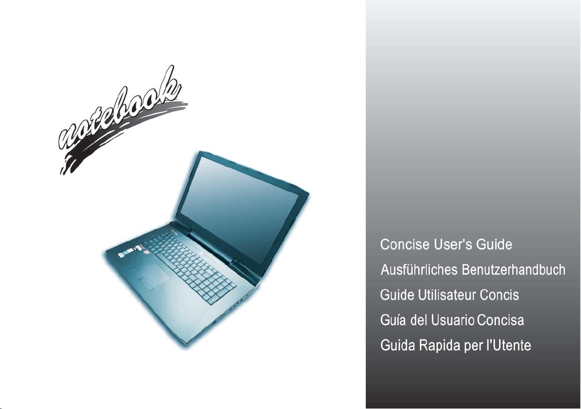
System Startup
Figure 1
Computer with Dual
AC/DC Adapters
Plugged-In to Converter/Opening the
Lid/LCD
134°
Shut Down
Note that you should always shut your computer
down by choosing the
Shut down command in
Windows (see below).
This will help prevent hard
disk or system problems.
1.Click the Start Menu
icon .
2.Click the Power item
.
3.Choose Shut Down
from the menu.
LED Indicators (will be illuminated in green when the AC/
DC adapters are plugged-in
and connected to a working
power outlet)
1. Remove all packing materials.
2. Place the computer on a stable surface.
3. Securely attach any peripherals you want to use with the computer (e.g.
keyboard and mouse) to their ports.
4. You must use the power converter supplied with the dual AC/DC adapters
connected to power this computer. Do not use a single AC/DC adapter to power
the system.
5. When first setting up the computer use the following procedure (as to
English
safeguard the computer during shipping, the battery will be locked to not power
the system until first connected to the
and initially set up as below):
• Attach the power converter to the DC-In jack at the rear of the computer, then
plug the AC/DC adapters into the jacks at the rear of the converter, then plug
the AC power cords into an outlet, and connect the AC power cords to the
AC/DC adapters and leave them there for 6 seconds or longer.
• Remove the adapter cords from the power converter’s DC-In jacks, and then
plug them back in again; the battery will now be unlocked.
6. Use one hand to raise the lid/LCD to a comfortable viewing angle (do not to
exceed 134 degrees);
the base of the computer (Note: Never lift the computer by the lid/LCD).
7. Press the power button to turn the computer “on”.
System Software
Your computer may already come with system software pre-installed. Where this is not the case, or where you are re-configuring
your computer for a different system, you will find this manual refers
to Microsoft Windows 10.
power converter and AC/DC adapters
use the other hand (as illustrated in Figure 1) to support
Intel® Optane™/RAID Support
Note that your system can be set up as a RAID OR to support Intel® Optane™, but it cannot be set to support both
systems. You need to setup Intel
& page 7).
4
® Optane™ or RAID before installing your Windows 10 operating system (see page 5
Page 11

Intel® Optane™ Setup
Intel® Optane™ is a combination of a compatible memory device and Intel Rapid Storage Technology soft-
ware. This combination is designed to speed up your
system performance by caching boot data, executables,
frequently accessed data and system page files to a non
volatile, low latency Intel® Optane™ SSD.
Contact your distributor or supplier to see if your system
supports this technology.
If you are reinstalling a system that has previously been
setup in Intel RST Premium mode, make sure you have
cleared the Intel Optane Memory (see Clearing Intel®
Optane™ on page 6).
Intel® Optane™ Setup Procedure
You need to setup Intel® Optane™ before installing your
Windows 10 operating system, and you will need to prepare the following in order to do so.
• The Microsoft Windows 10 OS DVD.
• An attached external DVD drive.
• An Intel® Optane™ SSD installed in your system.
• The Device Drivers & Utilities + User’s Manual disc.
1. Start-up your notebook computer and press F2 to enter the
BIOS.
2. Go to the Boot menu, select UEFI Setting and press Enter.
3. Set UEFI Boot to “Enabled”.
4. Press Esc to exit the menu and go to the Main menu.
5. Select OffBoard NVMe Controller Configuration and press
Enter to check that an Intel® Optane™ SSD is present.
6. Press Esc to exit the menu and go to the Advanced menu.
7. Select SATA Mode, press Enter and select “Intel RST
Premium...”.
8. Press F4 and <Yes> to “Save Changes and Reset”.
9. As the computer restarts press F2 to enter the BIOS again.
10. Press F4 and <Yes> to “Save Changes and Reset”, however
ensure that the condition in the bulleted point below is met
before doing so.
• Make sure the Windows 10 OS DVD is in the attached DVD
drive, as the computer starts up it will automatically boot from
the Windows 10 OS DVD (you will be prompted to press a key
to boot from the DVD).
11. Click Next > Install Now to continue installing the operating
system as normal (see your Windows documentation if you
need help on installing the Windows OS).
12. Select Custom: Install Windows only (advanced).
13. It is recommended that you select and then delete existing
partitions.
14. Click New to create a partition for Windows.
15. It is very important to make sure that when you create the
partition, leave at least a minimum of unallocated space of 5MB.
16. Follow the on-screen instructions to install the Windows 10
operating system.
17. Install the Windows drivers (see page 32). Make sure you install
the Intel® Rapid Storage Technology (IRST) driver.
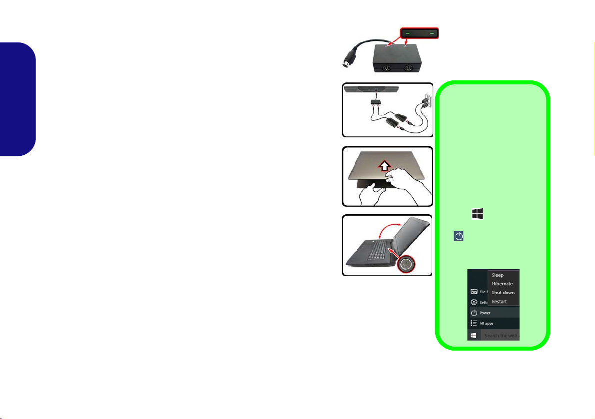
18. Run the Intel® Rapid Storage Technology application.
English
5
Page 12
19. Click Enable.
Figure 2 - Intel® Rapid Storage Technology - Status
English
20. The system will pop-up a message and ask you to select a
compatible fast drive (in this case there should only be one
option).
21. You will need to rest art the computer af ter enabling Optane, and
make sure the system is powered by the powered AC/DC
adapter, and not by battery only.
22. Click Yes to begin the process (this may take some time).
23. After the process has been completed restart the computer.
Clearing Intel® Optane™
If you wish to clear an existing Intel® Optane™ setup
then follow the procedure below to do so. However back-
up up any necessary files and data before clearing an
Intel® Optane™ setup, as doing so will result in the loss
of all data on the volumes.
1. Make sure that Intel® Optane™ is enabled in the Intel® Rapid
Storage Technology application.
2. Start-up your computer and press F2 to enter the BIOS.
3. Go to Intel(R) Rapid Storage Technology (in the Advanced
menu) and press Enter.
4. Select Intel Optane, **** (listed under Optane Volume:) and
press Enter.
5. Select “Deconcatentate” and press Enter.
6. Select Yes from the “Are you sure you want to perform
deconcatentation” option.
7. Select “Start deconcatentation” and press Enter.
8. The system will return to the standard Intel(R) Rapid Storage
Technology menu when complete.
9. You should then select the appropriate SATA Mode for your
system and reinstall the OS.
6
Page 13

RAID Setup
Your hard disks or solid state drives can be set up in RAID
mode (for increased performance or protection). Note
that setting up your hard disks/solid state drives in
RAID mode needs to be done prior to installing the
Windows OS. Do not change the mode unless you intend
to reinstall your operating system, and make sure you back
up all necessary files and data before doing so.
To configure your RAID (Redundant Array of Independent Disks) system in Striping (RAID 0) or Mirroring
(RAID 1) mode (see Table 1) you will require two identical hard disks or solid state drives.
Prepare the following before setting up your SATA hard
disks/SSDs in RAID mode:
•The Microsoft Windows 10 OS disc.
• An attached external DVD drive.
• A hard disk installed in the Primary HDD bay and a second
(identical) hard disk installed in the Secondary HDD bay.
Or
Two identical SATA solid state drives.
•The Device Drivers & Utilities + User’s Manual disc.
Prepare the following before setting up your PCIe SSDs
in RAID mode:
English
RAID Level Description
RAID 0
(at lease two
hard disks/
SSDs
needed)
RAID 1
(at lease two
hard disks/
SSDs
needed)
Identical drives reading and writing data in
parallel to increase performance. RAID 0
implements a striped disk array and the data is
broken into blocks and each block is written to
a separate disk drive.
Identical drives in a mirrored configuration
used to protect data. Should a drive that is
part of a mirrored array fail, the mirrored drive
(which contains identical data) will handle all
the data. When a new replacement drive is
installed, data to the new drive is rebuilt from
the mirrored drive to restore fault tolerance.
Table 1 - RAID Description
•The Microsoft Windows 10 OS disc.
• An attached external DVD drive.
• Two identical PCIe solid state drives.
•The Device Drivers & Utilities + User’s Manual disc.
• A USB flash drive.
• An operable computer (to copy files from the Device Driv-
ers & Utilities + User’s Manual disc to the USB flash
drive).
Note: All hard disks/SSDs in a RAID should be identical
(the same size and brand) in order to prevent unexpected
system behavior.
7
Page 14
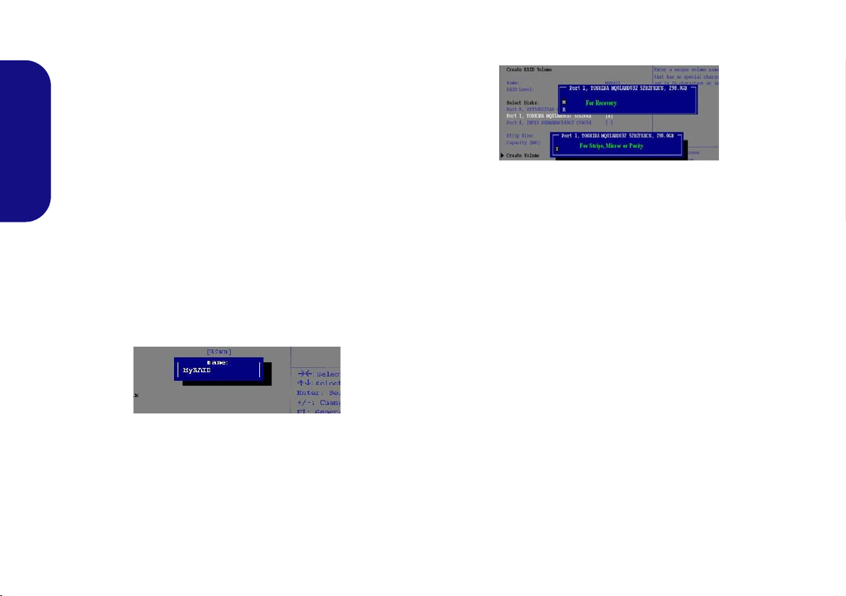
RAID Setup Procedure (SATA HDDs/
Figure 4 - Select Disks
SSDs)
1. Start-up your notebook computer and press F2 to enter the
BIOS.
2. Go to the Boot menu, select UEFI Setting and press Enter.
3. Set UEFI Boot to “Enabled”.
4. Press Esc to exit the menu and go to the Advanced menu.
5. Select SATA Mode, press Enter and select “Intel RST
English
Premium...”.
6. Press F4 and <Yes> to “Save Changes and Reset”.
7. After the computer restarts press F2 to enter the BIOS again.
8. Go to Intel(R) Rapid Storage Technology (in the Advanced
menu) and press Enter.
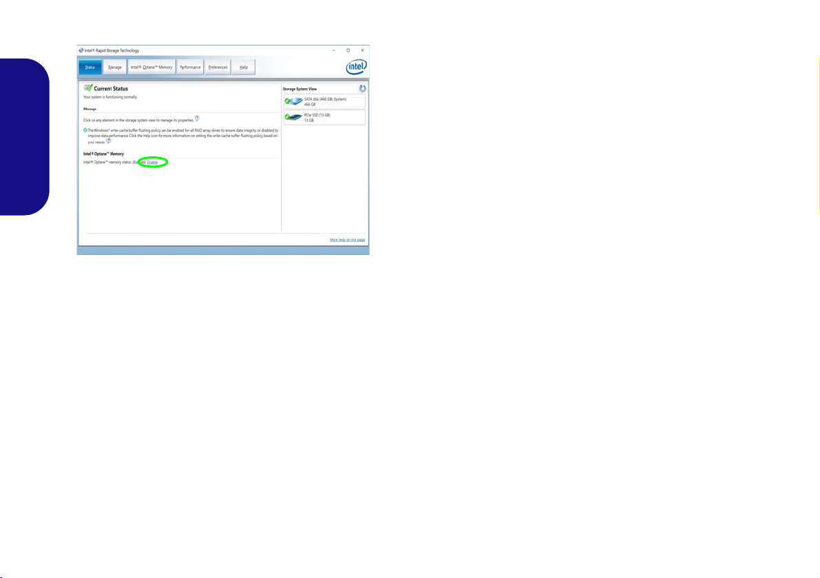
9. Select Create RAID Volume and press Enter.
10. You can now setup your RAID volume using any two installed
disks.
11. Go to Name: and press Enter.
12. Type a name of your choice for your RAID volume and press
Enter.
Figure 3 - Name the RAID Volume (Advanced > Intel(R)
Rapid Storage Technology)
13. Go to RAID Level: and press Enter.
14. Choose the RAID Level required (see Table 1 on page 7) and
press Enter.
• RAID 0 (Stripe)
• RAID 1 (Mirror)
15. Go to any of the disks listed under Select Disks: and select a
disk name and press Enter.
8
16. Move the cursor down (use the arrow keys) onto X (or select the
disk required) and press Enter.
17. You should select two identical disks to form your RAID volume.
18. If you have selected RAID 0 (Stripe) then you can adjust the
“Strip Size” to your requirements (It is recommended that you
set the “Strip Size” to 128KB).
19. Go to Create Volume and press Enter.
20. The RAID volume will then be created and the RAID information
will be displayed under Intel(R) Rapid Storage Technology (in
the Advanced menu).
21. Press Esc to exit the menu.
22. Press F4 and <Yes> to “Save Changes and Reset”, however
ensure that the condition in the bulleted point below is met
before doing so.
• Make sure the Windows 10 OS DVD is in the attached DVD
drive, as the computer starts up it will automatically boot from
the Windows 10 OS DVD (you will be prompted to press a key
to boot from the DVD).
23. Click Next > Install Now to continue installing the operating
system as normal (see your Windows documentation if you need
help on installing the Windows OS).
24. Follow the on-screen instructions to install the Windows 10
operating system.
25. Install the Windows drivers (see page 32). Make sure you install
the Intel® Rapid Storage Technology (IRST) driver.
Page 15

RAID Setup Procedure (PCIe SSDs)
1. Go to the operable computer and insert a USB flash drive.
2. Insert the Device Drivers & Utilities + User’s Manual disc into
the CD/DVD drive of the operable computer.
3. Copy the f6flpy-x64 folder from the location below (D: denotes
your DVD drive) on the Device Drivers & Utilities + User’s
Manual disc to the USB flash drive.
• D:\Options \RAID\f6flpy-x64
4. Start-up your notebook computer and press F2 to enter the
BIOS.
5. Go to the Boot menu, select UEFI Setting and press Enter.
6. Set UEFI Boot to “Enabled”.
7. Press Esc to exit the menu and go to the Advanced menu.
8. Select SATA Mode, press Enter and select “Intel RST
Premium...”.
9. Press F4 and <Yes> to “Save Changes and Reset”.
10. After the computer restarts press F2 to enter the BIOS again.
11. Go to Intel(R) Rapid Storage Technology (in the Advanced
menu) and press Enter.
12. Select Create RAID Volume and press Enter.
13. You can now setup your RAID volume using any two installed
disks.
14. Go to Name: and press Enter (see Figure 3 on page 8).
15. Type a name of your choice for your RAID volume and press
Enter.
16. Go to RAID Level: and press Enter.
17. Choose the RAID Level required (see Table 1 on page 7) and
press Enter.
• RAID 0 (Stripe)
• RAID 1 (Mirror)
18. Go to any of the disks listed under Select Disks: and select a
disk name and press Enter.
19. Move the cursor down (use the arrow keys) onto X (or select the
disk required) and press Enter (see Figure 4 on page 8).
20. You should select two identical disks to form your RAID volume.
21. If you have selected RAID 0 (Stripe) then you can adjust the
“Strip Size” to your requirements (It is recommended that you
set the “Strip Size” to 128KB).
22. Go to Create Volume and press Enter.
23. The RAID volume will then be created and the RAID information
will be displayed under Intel(R) Rapid Storage Technology (in
the Advanced menu).
24. Press Esc to exit the menu.
25. Press F4 and <Yes> to “Save Changes and Reset”, however
ensure that the two conditions in the bulleted points below
are met before doing so.
• Make sure the Windows 10 OS DVD is in the DVD drive and
as the computer starts up it will automatically boot from the
Windows 10 OS DVD (you will be prompted to press a key to
boot from the DVD).
• Make sure your USB flash drive is attached to one of the USB
ports on the computer.
26. Click Next > Install Now to continue installing the operating
system as normal (see your Windows documentation if you need
help on installing the Windows OS).
27. A prompt will appear to ask you to Load Driver.
28. Click Browse and browse to the location you copied the files to
on your USB flash drive (X: denotes your USB flash drive):
• X:\f6flpy-x64
29. Click Next.
30. Follow the on-screen instructions to install the Windows 10
operating system.
31. Install the Windows drivers (see page 32). Make sure you install
the Intel® Rapid Storage Technology (IRST) driver.
English
9
Page 16
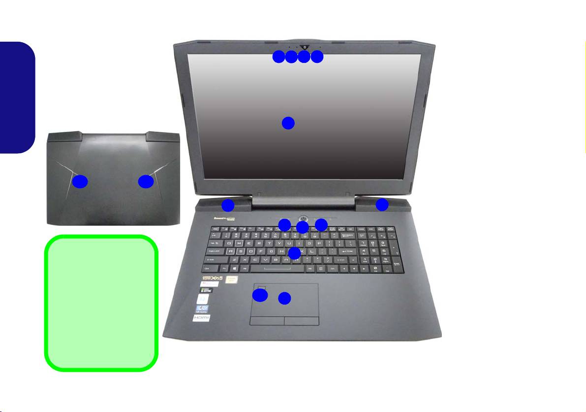
System Map: Front View with LCD Panel Open
2
1
4
3
3
8
7
6
9
5
5
10
7
Figure 5
Front View with LCD
Panel Open
1. PC Camera
2. *PC Camera LED
*When the PC
camera is in use, the
LED will be
illuminated.
3. Built-In Array
Microphone
4. LCD
5. Speakers
6. Power Button
7. LED Indicators
8. Keyboard
9. Touchpad & Buttons
10. Fingerprint Reader
11. Top Case Logo LED
Top Case Logo LED
Note that the Top Case
Logo LED may be toggled On/Off using the Fn
+ 3 key combination. The
Colors may be configured
using the Keyboard
Backlight application
(see page 25).
11 11
English
10
Page 17
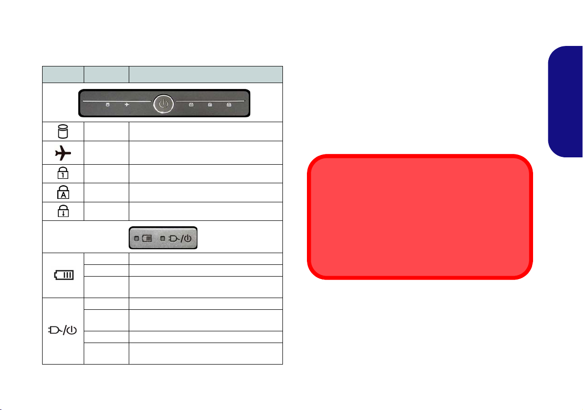
LED Indicators
Wireless Device
Operation Aboard Aircraft
The use of any portable electronic transmission devices
aboard aircraft is usually prohibited.
Make sure the wireless modules are OFF if you are using the computer aboard aircraft by putting the system
in to Airplane Mode.
The LED indicators on the computer display helpful information about the current status of the computer.
Icon Color Description
White The Hard Disk is in use
White
White Number Lock (Numeric Keypad) Activated
White Caps Lock Activated
White Scroll Lock Activated
Orange The Battery is Charging
Green The Battery is Fully Charged
Blinking
Orange
Orange The AC/DC Adapter is Plugged In
Blinking
Orange*
Green The Computer is On
Blinking
Green
Airplane Mode is ON (the WLAN and
Bluetooth Modules are OFF)
The Battery Has Reached Critically Low
The AC/DC adapter is plugged in and the
The Computer is in Sleep Mode
Table 2 - LED Indicators
Power Status
powered USB Port is on*
*The powered USB 3.0 (USB 3.1 Gen 1) port (see
page 14) may be toggled on /off by means of the Fn +
Power Button key combination. When the powered USB
port is on it will supply power (for charging devices only,
not for operating devices) when the system is off but still
powered by the AC/DC adapter plugged into a working
outlet, or powered by the battery with a capacity level
above 20% (this may not work with certain devices - see
page 37).
11
English
Page 18
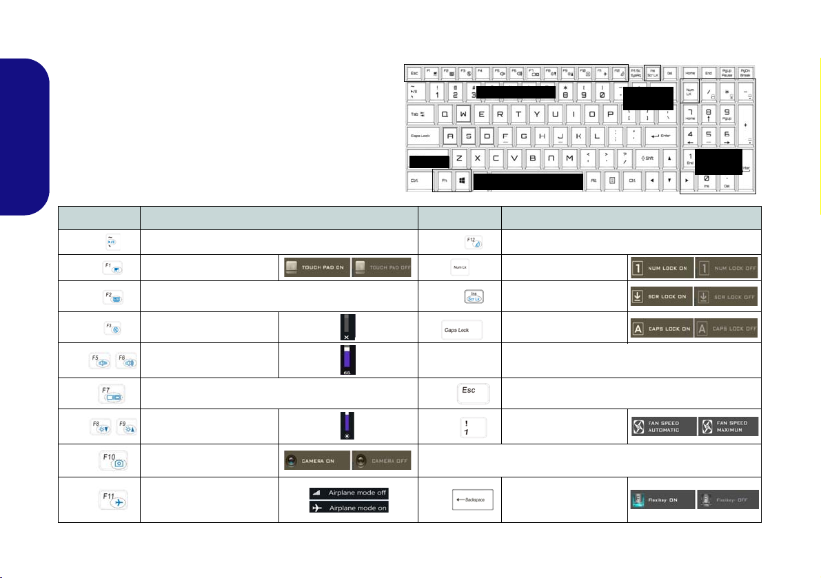
Keyboard & Function Keys
Numeric
Keypad
Fn Key
Windows Logo Key
Scr Lk &
Num Lk
Function Keys
The keyboard includes a numeric keypad for easy numeric data input. Pressing Num Lk turns on/off the numeric keypad. It also features function keys to allow you
to change operational features instantly. The function
keys (F1 - F12 etc.) will act as hot keys when pressed
while the Fn key is held down. In addition to the basic
English
function key combinations, some visual indicators are
available when the Control Center driver is installed.
Keys Function/Visual Indicators Keys Function/Visual Indicators
Fn +
Fn +
Fn +
Fn +
Fn +
Fn + Change Display Configuration (see page 27)
Fn +
Fn +
Fn +
12
Play/Pause (in Audio/Video Programs)
Touchpad Toggle Number Lock Toggle
Turn LCD Backlight Off
(Press a key to or use Touchpad to turn on)
Mute Toggle
Volume Decrease/
Increase
Brightness Decrease/
Increase
PC Camera Power
Toggle
Airplane Mode Toggle
Table 3 - Function Keys & Visual Indicators
Fn +
Fn +
Fn + Power
Button
Fn +
Fn +
*Note: It is recommended that you use Maximum fan speed when
Fn +
Scroll Lock Toggle
Caps Lock Toggle
Powered USB Port Power Toggle (see page 14)
Control Center Toggle (see page 16)
Fan Automatic Control/
Full Power
playing games.
Disable/Enable
Flexikey® (see
page 20)
Sleep Toggle
Page 19
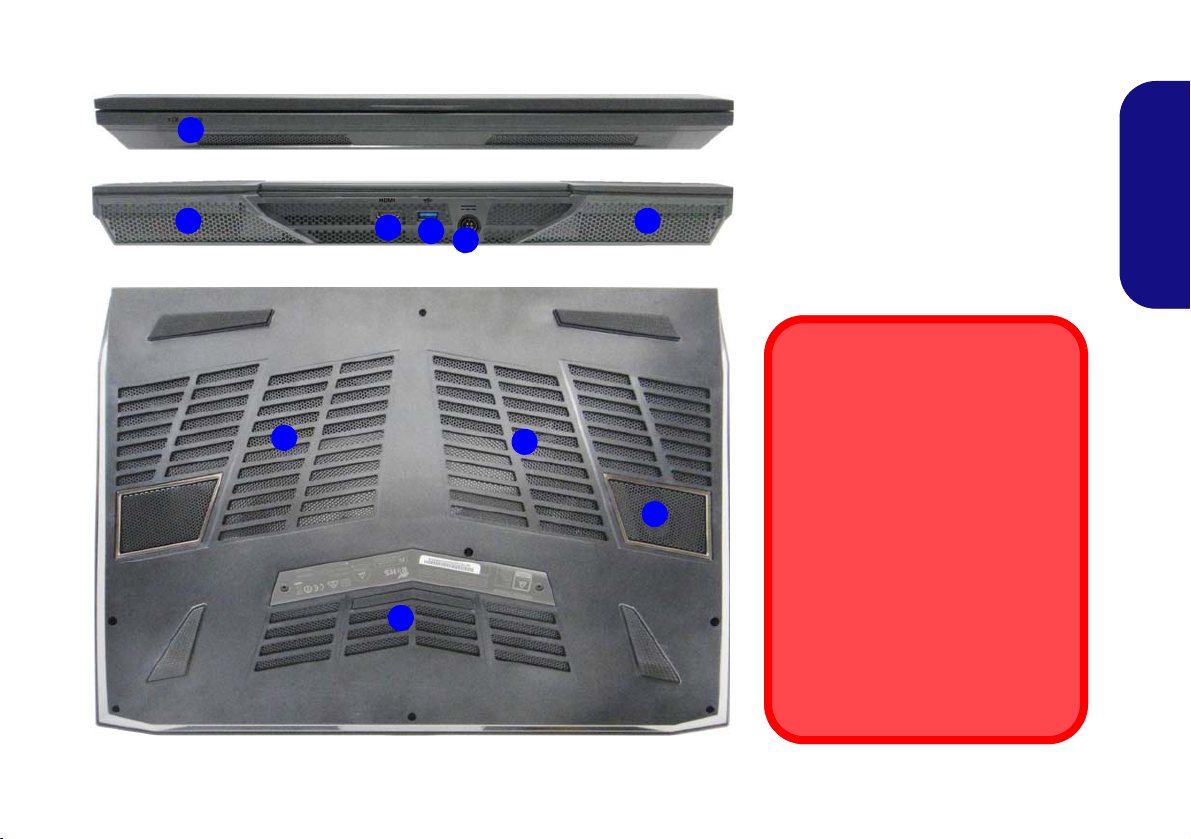
System Map: Front, Rear & Bottom Views
Figure 6
Front, Rear & Bottom Views
1. LED Power Indicators
2. Vent
3. HDMI-Out Port
4. USB 3.0 (USB 3.1 Gen 1) Port
5. DC-In Jack
6. Subwoofer
Bottom Cover Removal Warning
Do not remove any cover(s) and/or
screw(s) for the purposes of device
upgrade as this may violate the terms
of your warranty.
If you need to replace/remove the
hard disk/RAM etc., for any reason,
please contact your distributor/supplier for further information.
Overheating
To prevent your computer from overheating make sure nothing blocks
any vent while the computer is in use.
2
2
2
2 2
1
5
4
3
6
Front
Rear
English
13
Page 20
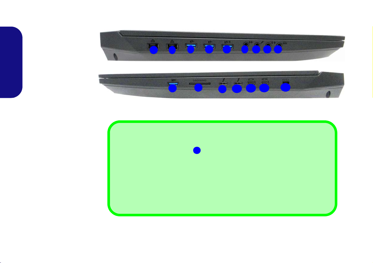
System Map: Left & Right Views
1
3
1
2
Left
Right
12
5106 7
Figure 7
Left & Right Views
1. RJ-45 LAN Jacks
2. USB 3.0 (USB 3.1 Gen
1) Ports
3. Powered USB 3.0 (USB
3.1 Gen 1) Port (See
Below)
4. Line-In Jack
5. Microphone Jack
6. Line-Out Jack
7. 2- In-1 Audio Jack
(Headphone & S/PDIF
Out Combo Jack)
8. Multi-in-1 Card Reader
9. *USB 3.1 Gen 2/
Thunderbolt 3 Combo
Port 1 (Type-C)
10. *USB 3.1 Gen 2/
Thunderbolt 3 Combo
Port 2 (Type-C)
11. *Mini Dis playPort 1
12. *Mini DisplayPort 2
13. Security Lock Slot
*See Thunderbolt Ports for
Display on page 15.
11
13
4
USB
When the powered USB 3.0 port
is on it will supply power (for charging devices only, not
for operating devices) when the system is off but still powered by the AC/DC adapter plugged
into a working outlet, or powered by the battery with a capacity level above 20% (this may not
work with certain devices - see page 37). Toggle power to this port by using Fn + Power But-
ton.
Note that when a single USB device is plugged in to a USB 3.1 Gen 2 port the data transfer
speed will be 10Gbps, however when two devices are plugged in to both USB 3.1 Gen 2 ports,
this bandwidth will be shared between the ports.
3
2
2
9
8
English
14
Page 21
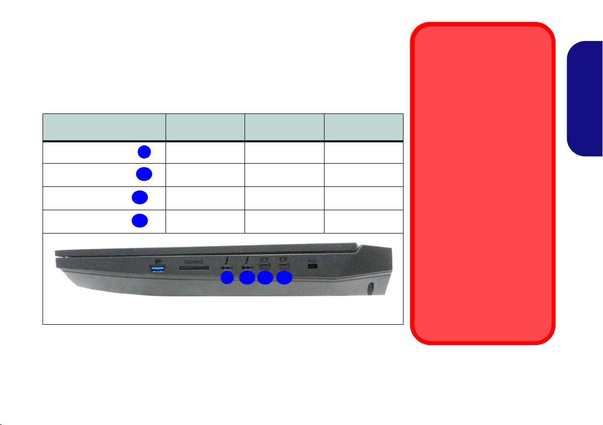
Thunderbolt Ports for Display
Thunderbolt Devices
When plugging a device into a
Thunderbolt port alllow 30 seconds for the system to scan and
recognize the connected device.
Ejecting Thunderbolt Devices
In order to prevent system problems make sure you do not simply pull the cable out from the
Thunderbolt port. The hardware
must be ejected safely:
1. Go to the notification area of
the taskbar and click on the
Safely Remove Hardware
and Eject Media icon.
2. Click on Eject “Thunderbolt
Device Name”.
3. When you see the “Safe to
Remove Hardware” mes-
sage you can remove the
cable after about 20 seconds, to make sure that it is
safe to eject the device.
9
10
11
12
9
1210 11
The display configuration for the Thunderbolt ports and Mini DisplayPorts can be
set up in the BIOS. Restart your notebook computer and press F2 to enter the BIOS
(Advanced menu > Advanced Chipset Control > DDI Control).
The table below outlines which ports will be enabled/disabled when the Thunderbolt ports are set for display only.
Thunderbolt 3 Port #1
Thunderbolt 3 Port #2
Mini DisplayPort #1
Mini DisplayPort #2
Setting
Table 4 - DDI Control (Advanced Menu > Advanced Chipset Control)
DDI to mDP
(Default Setting)
Disabled Enabled Enabled
Disabled Disabled Enabled
Enabled Disabled Disabled
Enabled Enabled Disabled
1 DDI to TBT 2 DDI to TBT
English
15
Page 22
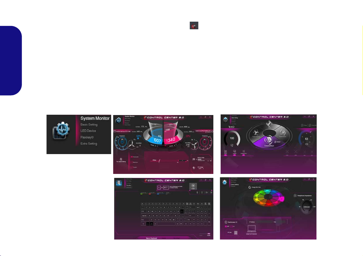
Control Center
Figure 8
Control Center
Press the Fn + Esc key combination, or double-click the icon in the notification area of the taskbar to toggle the
Control Center on/off. The Control Center gives quick access to frequently used controls and enables you to quickly
turn the camera/Touchpad on/off.
Control Center Menus
The Control Center contains 5 menu headings (System Monitor, Basic Setting, LED Device, Flexikey® and Extra
English
Setting). The System Monitor tab provides information on the computer’s GPU and CPU. The Basic Setting tab allows you to adjust the power mode and other system features. The LED Device tab allows you to configure your illuminated keyboard. Flexikey® is a quick hotkey configuration application. The Extra Setting tab allows you to adjust
the app skin color to your choice. Click the menu headings and then click any of the buttons outlined on the following
pages.
16
Page 23
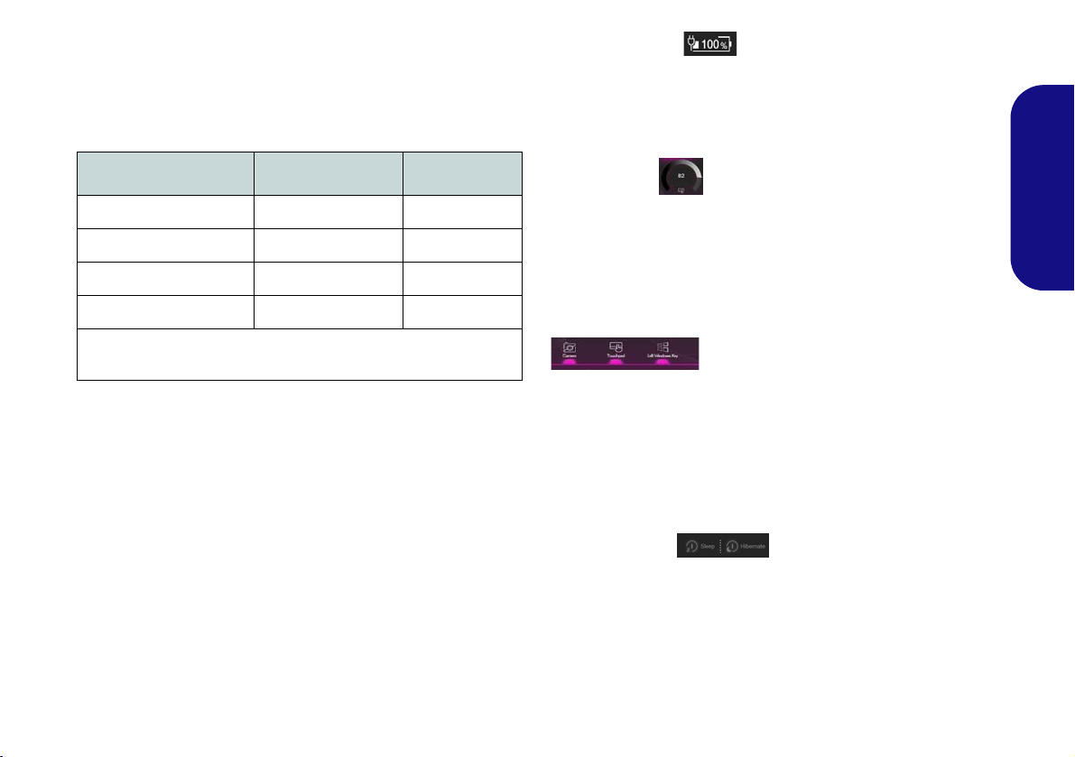
Power Modes
You can set a Power Mode by clicking the appropriate
icon in the center
will affect the Airplane Mode and PC camera power.
of the Control Center. Each power mode
Power Status (Basic Setting)
The Power Status icon will show whether you are currently powered by the battery, or by the AC/DC adapter
plugged in to a working power outlet. The power status
bar will show the current battery charge state.
English
Mode Airplane Mode PC Camera
Power Saving ON OFF
Quiet OFF ON
Performance OFF ON
Entertainment* OFF ON
*Clicking the Default button in Entertainment will reset the default
settings for this mode.
Brightness (Basic Setting)
The Brightness icon will show the current screen brightness level. You can use the dial to adjust the screen brightness or the Fn + F8/F9 key combinations.
Camera/Touchpad/Left Windows Key (Basic
Setting)
Click these buttons to toggle the PC Camera or Touchpad power status, or to turn the Left Windows Key func-
tionality on/off. The button under the icon will appear
highlighted when it is enabled. Note that the power status
of the camera module is also effected by the Power Mode
selected.
Sleep Button (Basic Setting)
Click either the Hibernate or Sleep button to have the
computer enter the selected power-saving mode (you will
receive a warning before the system switches to the power-saving mode and will need to click OK to confirm).
17
Page 24
Volume (Basic Setting)
The Volume icon will show the current volume level. You
can use the dial to adjust the volume or the Fn + F5/F6
key combinations, or use the Fn + F3 key combination to
mute the volume.
Caps Lock/Scroll Lock/Number Lock/Airplane
Mode (Basic Setting)
English
Click the button to toggle the appropriate lock mode and
Airplane Mode.
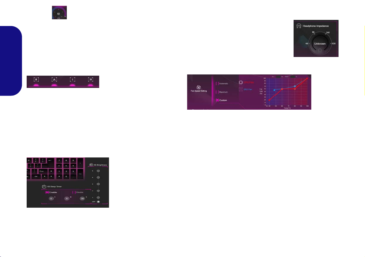
Headphone Impedance (Extra Setting)
The headphone impedance will be automatically detected for any headphones plugged-in (this is not user
adjustable).
Fan (System Monitor)
KB Sleep Timer/KB Brightness (LED Device)
Enable and then select the amount of time for which the
system is idle before the keyboard LED enters sleep mode
(i.e. the LED keyboard illumination will turn off to save
power). You can also adjust the keyboard brightness.
18
You can set the fan speed to Maximum (full power), Au-
tomatic or Custom from this menu item. The fan speed
will adjust itself automatically to control the heat of the
CPU/GPU. You can use the Offset slider to adjust the settings to your preference. However you can adjust the setting to Maximum if you prefer.
The Custom setting allows you to click and drag on any
of the 2 midrange nodes on the graph in order to adjust the
temperature parameters of the CPU Fan or GPU Fan.
All these settings can be overidden by the system, as a
safety precaution, if it requires heavier use of the fan.
Page 25

CPU (System Monitor)
Overclocking Issues
Note overclocking the system (CPU/Memory/GPU) by making alterations to clock frequency and/or voltage may cause
hardware damage, reduce system stability, the useful life of
the system and affect system data integrity. Therefore overclocking the system is enabled at the user’s own risk, and is
not covered in the warranty terms.
Overclocking should only be enabled when powered by a
plugged-in adapter, and not on battery power. A warning
message will appear when you have activated CPU/Memory/GPU overclocking, click OK to activate the changes or
click Cancel to return to the previous settings.
Resetting the System In Case of Errors
If you get any system errors, to reset the computer you can
press and hold the power button to force the system to
shutdown. To restart press and hold the power button
while holding down the Fn + D key combination (for the
CPU reset) or Fn + G (for the GPU reset). This will change
the overclocking settings back to the disabled state.
You can adjust the CPU setting by adjusting the sliders for
the CPU Ratio Override, then click Save to retain the
setting changes.
English
Memory (System Monitor)
You can adjust the Memory setting by clicking the
DIMM Profile for Default, XMP1 or Custom (you can
then adjust individual settings), then click Save to retain
the setting changes.
GPU (System Monitor)
The GPU setting can be used to adjust the GPU C ore Increment and Memory Increment by means of the slid-
ers, then click Save to retain the setting changes.
19
Page 26
Flexikey® Application
Enabling or Disabling the Flexikey® Profile in Use
You can enable or disable any keyboard or mouse profile
functions currently in use by using the Fn + key
combination. Pressing this key combination will toggle you
between the currently selected keyboard or mouse profile
to the standard keyboard and/or mouse settings, and back
again.
Windows Logo Key and P key
Note that you can assign actions to any keyboard key except the Windows Logo Key and P key.
Figure 9
Flexikey -
Profile
The Flexikey® application is a quick hotkey configura-
tion application, which allows you to assign a single key
to launch multiple key combinations, or to launch pro-
grams and applications, to create text macros and to
disable certain keys. The application can also be used to
configure the mouse buttons to create hotkeys for gam-
ing etc. All the configuration settings are retained under
English
(up to12) profiles to which the settings are applied.
Click Flexikey® in the top left of the Control Center to
access the Flexikey® application.
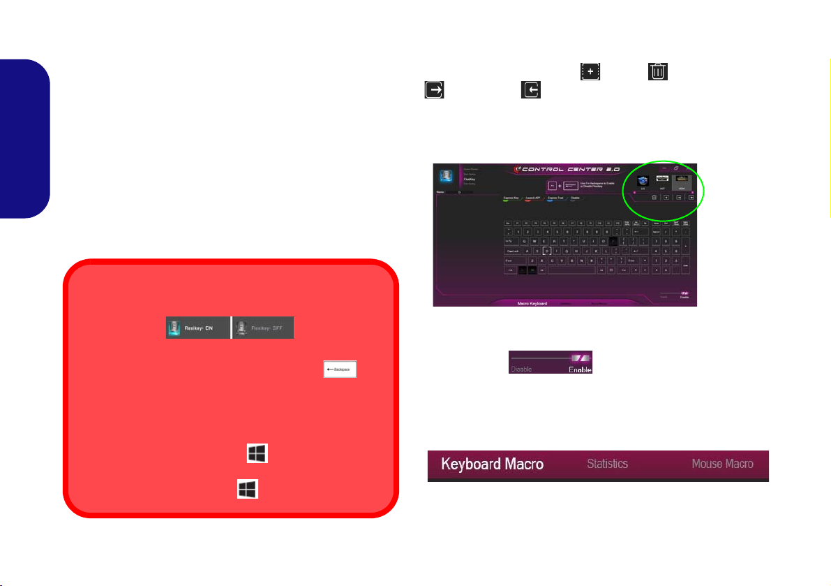
Profiles
The controls at the top right side of the application relate
to Profiles. You can Add /Delete profiles, Export
and Import profiles by clicking on the appropriate
icon. If you double-click on a profile you can change the
profile name, and change an image file (images created
using PNG files).
20
Keyboard and Mouse Settings
Click Enable (at the bottom right of the application window) to create settings for the keyboard and/
or mouse. Clicking on Keyboard Macro or Mouse Mac-
ro will allow you to access the settings page for either the
keyboard or mouse.
Figure 10 - Enable (Keyboard Macro & Mouse Macro)
Page 27
Keyboard Settings
123
4
5
1
2
3
4
5
The keyboard settings allow you to configure actions for
clicking in the Name box, and click in Tool Tips to type
in a note to remind you of the action’s function.
any single key (or a combination of keys). Click the key
and then select the action type (Express Key, Launch
App, Express Text or Disable) from the menu at the top
English
of the page. You can rename the action by clicking in the
Name box, and click in Tool Tips to type in a note to re-
mind you of the action’s function.
Figure 12 - Mouse Configuration
Flexikey® Application Features:
• Express Key - This feature allows you to configure a sin-
gle key (or mouse click) to send multiple key combinations, or to create more useful shortcut keys This is useful
Figure 11 - Keyboard Configuration
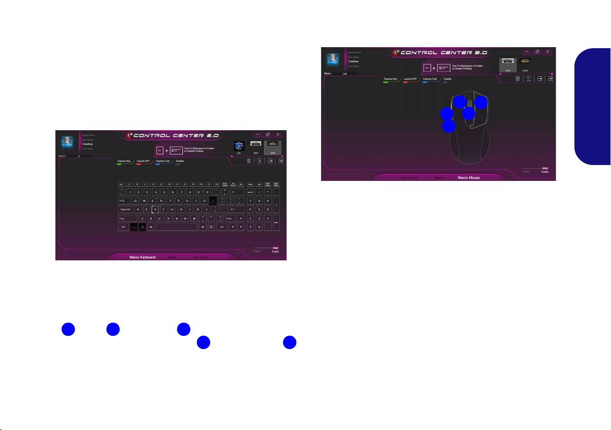
Mouse Settings
The mouse settings allow you to configure actions for the
left , right and middle buttons of any attached
mouse, and also for any forward and backward
buttons if applicable (on a gaming type mouse). Click the
button number and then select the action type (Express
Key, Launch App, Express Text or Disable) from the
menu at the top of the page. You can rename the action by
in gaming or when using applications which have a complex set of keyboard shortcuts.
• Launch App - This simply assigns single keys (or mouse
clicks) to launch any program’s or application’s executable
file.
• Express Text - With this you can assign single keys (or
mouse clicks) to send commonly used strings of text.
• Disable - Use this function to disable any keyboard keys or
mouse buttons.
• Statistics - Use this to quickly record keys in use in any
application, and to disable unused keys.
21
Page 28

Keyboard Settings - Express Key
To configure a single key to send multiple key combinations, or to create more useful shortcut keys, use Express
Key.
1. Enable and select Keyboard Macro under your chosen profile,
click on the chosen key to select it, and then click to select
Express Key.
2. In the following example we want to change an existing game
English
key configuration which uses the left shift key for sprinting, and
the W key for moving forwards, to use the left Ctrl key to
combine this movement to sprint forward.
3. Click the Record
keys (in this case we will press Left Shift and W) required (make
sure you press the key(s) required and do not click on them).
4. Click the Record
and stop recording.
5. Click on the key, and then click in the Tool Tips field and type to
give the key combination a name e.g. “Sprint Fwds”.
6. If you want to remove any individual key click to select it, and
then click Restore.
7. Any assigned Express Keys will appear in green.
button and then press the key or
button again to complete the process
Keyboard Settings - Launch App
You can configure keys to launch any application or program as follows:
1. Enable and select Keyboard Macro under your chosen profile,
click to select a key to launch the appllication, and then click to
select Launch App.
2. Click Browse at the bottom left of the application window.
Figure 13 - Keyboard - Launch App
3. Navigate to the executable file of the application and click Open.
4. The key will now be configured to open the selected application
under your chosen Profile, and the key will appear in red.
5. If you want to remove any Launch App key, select it and click on
Restore.
22
Page 29

Keyboard Settings - Express Text
A single key can be set to send a string of text within any
application using Express Text.
1. Enable and select Keyboard Macro under your chosen profile,
click to select a key, and then click to select Express Text.
2. Click in the Text Content field and type in your message and
click Save.
3. Click the Record
keys to use if required (the Start key is the key used in your
target program to open a text message), or you can leave it
blank if you prefer. Click the Record button again to
stop the process.
Figure 14 - Keyboard - Express Text
button in Start key and press the
5. The key will now be configured to send the text message in the
target program under your chosen Profile, and the key will
appear in blue.
6. If you want to remove any Express Text key, select it and click
on Restore.
English
Keyboard Settings - Disable
You can use the program to disable any keys not required.
1. Enable and select Keyboard Macro under your chosen profile,
click to select a key to disable, and then click to select Disable.
2. The key will now be disabled.
3. If you want to enable the key again, select it and click on
Restore.
4. The key will be disabled under your chosen Profile, and the key
will appear in gray.
4. Click the Record button in Send key if required (the
Send key is the key used in your target program to send a text
message e.g the Enter key would be the most commonly used),
or you can leave it blank if you prefer.
23
Page 30
Keyboard Backlight LED
1
2
3
1
3
2
Figure 15
Keyboard
Backlight
Application
Press Fn plus the key to toggle th e keyboard LED on/
off. The keyboard LED may be configured using the Fn +
key combination outlined in the table below. In addition
press Fn plus the key to launch the keyboard backlight
application to configure the settings.
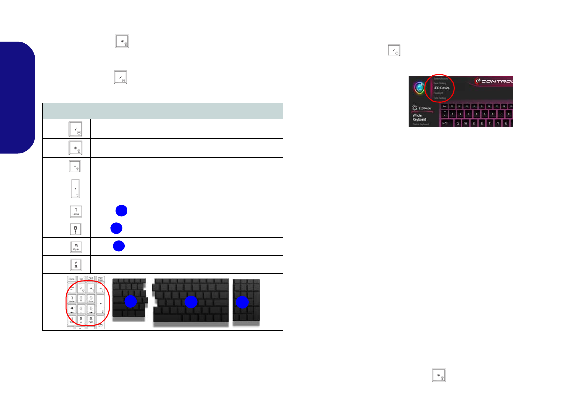
Keyboard Backlight Application
The Keyboard Backlight application can be accessed by
pressing the Fn plus key (or by clicking LED Device
in the top left of the Control Center).
English
Fn +
Fn +
24
Keyboard LED Function key Combinations
Launch the Keyboard Backlight Application
Toggle the Keyboard LED On/Off
Fn +
Fn +
Fn +
Fn +
Fn +
Fn +
Keyboard LED Illumination Decrease
Keyboard LED Illumination Increase
Toggle the Left keyboard LED On/Off
Toggle the Middle keyboard LED On/Off
Toggle the Right keyboard LED On/Off
Toggle the Top Case Logo LED On/Off
Table 5 - Keyboard LEDs
Color Swatch
The color swatch in the middle of the screen allows you to
select a range of colors for your keyboard backlight by
clicking on the color required. Click to select any colors
from the swatch to apply to the whole keyboard (under
Whole Keyboard) or parts of the keyboard (under Partial Keyboard).
KB Sleep Timer
Enable and then select the amount of time for which the
system is idle before the keyboard LED enters sleep mode
(i.e. the LED keyboard illumination will turn off to save
power).
KB Brightness
Click on any of the numbers (1 - 4) on the KB Brightness
bar to set the brightness level of the LED Device. You can
also turn the keyboard backlight off by clicking the OFF
button, or by using the Fn plus key.
Page 31

LED Mode - Whole Keyboard/Partial Keyboard
Figure 17
LOGO
LED
Click either of the headings on the left under LED Mode
to select how the colors will be applied.
• Whole Keyboard - Simply click a color from the outer
band of the swatch, or click one of the color mixes
from the center of the swatch and it will be immediately applied to the whole keyboard.
• Partial Keyboard - Simply click a color from the
outer band of the swatch, or click one of the color
mixes from the center of the swatch, and then click one
of the keyboard section hea ding s (Left, Mid or Right)
to apply the color.
Figure 16 - LED Mode - Partial Keyboard
LED Mode - Keyboard Effect
Click on Keyboard Effect (under LED Mode) and then
click any of the Effect buttons to view the effects on the
keyboard.
Flash Breath
Dance Cycle
Tempo Random
Wave
Table 6 - Keyboard Effects
LED Mode - LOGO LED
The color swatch in the middle of the screen allows you to
select a range of colors for top case Logo LED by clicking
on the color required. Click to select any colors from the
swatch to apply to the top case Logo LED.
English
25
Page 32

Windows 10 Start Menu, Context Menu, Taskbar, Control Panel
Figure 18 - Start Menu, Context Menu, Taskbar, Control Panel and Settings
and Settings
Most of the apps, control panels, utilities and programs within Windows 10 can be accessed from the Start Menu by
clicking the icon in the taskbar in the lower left corner of the screen (or by pressing the Windows Logo Key
on the keyboard).
Right-click the Start Menu icon (or use the Windows Logo Key + X key combination) to bring up an advanced
Context Menu of useful features such as Apps and Features, Power Options, Task Manager, Search, File Explorer, De-
English
vice Manager and Network Connections etc.
The notification area of the taskbar is in the bottom right of the screen. Some of the control panels and applications re-
ferred to throughout the course of this manual can be accessed from here.
Throughout this manual you will see an instruction to open the Control Panel. To access the Control Panel, select Con-
trol Panel under the Windows System item in the Start Menu.
The Settings item in the Start Menu (and also as an App) gives you quick acce ss to a number of system settings control
panels allowing you to adjust settings for System, Devices, Phone, Network & Internet, Personalization, Apps, Accounts, Time & Language, Gaming, Ease of Access, Privacy, Update & Security and Search.
26
Page 33

Video Features
Figure 19
Display (Multiple displays)
You can switch display devices, and configure display options, from the Display control panel in Windows as long
as the video driver is installed.
To access the Display control panel in Windows:
1. Right-click the desktop and select Display settings from the
menu.
2. Choose the required display settings from the menus.
To access the NVIDIA Control Panel:
1. Go to the Control Panel.
2. Click NVIDIA Control Panel (icon) - in the Appearances and
Personalization category.
OR
3. Right-click the desktop and select NVIDIA Control Panel from
the menu.
Display Devices
Note that you can use an HDMI cable connected to the
HDMI-Out port and/or Mini DisplayPort compatible cable connected to a Mini DisplayPort 1.3 to connect an external display. You can also use the Thunderbolt Port
connected to a compatible display device (see Thunder-
bolt Ports for Display on page 15). See your external dis-
play device’s manual to see which formats it supports.
Configuring the Displays in Windows
All external and internal displays (up to 4 active displays)
can be configured from Windows by using the Display or
System (in Settings) control panel or the Project menu.
English
To configure the displays using the Project menu:
1. Attach your external display(s) to the
appropriate port, and turn it(them) on.
2. Press the + P (or Fn + F7) key
combination.
3. Click on any one of the options from the
menu to select PC screen only,
Duplicate, Extend or Second screen
only.
To configure the displays using the Display control panel:
1. Attach your external
display(s) to the
appropriate port, and
turn it (them) on.
2. Right-click the
desktop and select
Display settings
from the menu.
3. Click the Detect
button.
4. The computer will
then detect any
attached displays.
5. You can configure up
to 4 displays from the
Multiple displays
menu.
27
Page 34

Multi GPU Configuration
Figure 20
Set Up G-
SYNC
Setting up G-SYNC
In a multiple display configuration set the G-SYNC capable
display as the Primary Display.
In 3D Settings click Manage 3D Settings > Global Set-
tings, select Vertical sync and then select G-SYNC. Setting G-SYNC in global settings means it will be applied to
all games.
G-SYNC Support
G-SYNC is only supported if you have a G-SYNC capable
display and a GTX series video adapter (contact your distributor or supplier for details).
This computer features NVIDIA Scalable Link Interface (SLI) that improves graphic quality and performance
by combining dual GPUs (two video cards are required)
in a single system.
To enable/disable SLI
1. Go to the NVIDIA Control Panel
English
2. Click “+” next to 3D Settings if its sub-items are not shown and
then click Configure SLI, Surround and PhysX.
3. Click “Maximize 3D Performance” under “SLI configuration”.
4. Click to select “PhysX settings”; Auto-select (recommended)
is the default setting.
5. Click Apply and Restart Now to restart the computer.
Configuration:
.
G-SYNC
Click to put a check in the box to Enable G-SYNC (it is
enabled by default). G-SYNC is designed to provide a
smooth game play experience from your GeForce product
by synchronizing the monitor’s refresh cycle to the GPU’s
render rate, thus removing lag and stutter issues, in order
to have objects appear sharper and scenes display instantly.
28
Page 35

Power Options
Figure 21 - Power Options
The Power Options (Hardware and Sound menu) control panel icon in Windows allows you to configure power
management features for your computer. You can conserve power by means of power plans and configure the
options for the power button, sleep button (Fn + F12),
computer lid (when closed), display and sleep mode (the
default power saving state) from the left menu.
Click Create a power plan in the left menu and select the
options to create a new plan. Click Change Plan Settings
and click Change advanced power settings to access further configuration options.
PC Camera
Use the Fn + F10 key combination to toggle power to the
PC Camera module. When the PC Camera is in use the PC
Camera LED will be illuminated (see page 10).
Camera App
Note that you need to use the Camera app in Win-
dows to take pictures and capture video.
1. Run the Camera app from the Start Menu by clicking on the
Camera app icon in All Apps (you can type “camera” into
the search box to find the Camera app if it is not pinned to the
Start Menu).
2. Click to select either photo
3. Click the photo icon
4. Click on the video icon
5. To stop video capture click the video icon again.
6. Captured photos and videos will be saved to a Camera Roll
folder within the Pictures folder in This PC, and to the Photos
app stored in the Start Menu.
or video mode.
to take a picture.
to start video capture.
English
29
Page 36

Audio Features
Volume Adjustment
The sound volume level can also be set using the volume
control within Windows. Click the Speaker icon in the
taskbar to check the setting
.
You can configure the audio options on your computer
from the Sound control panel in Windows.
The volume may be adjusted by means of the Fn + F5/F6
key combination.
English
Setup for 5.1 or 7.1 Surround Sound
To setup your system for 5.1 or 7.1 surround sound you
will need to connect the audio cables to the Headphone &
S/PDIF Combo jack, Line-In jack, Line-Out jack and Microphone-In jack (note: the Line-Out jack is used for 7.1
surround sound only)
1. Run Realtek Audio Console from the Windows Start menu.
2. Click Device advanced settings.
3. Plug the front speaker cables into the Headphone & S/PDIF
Combo jack.
4. Plug in the cables (you may require an adapter to connect each
cable to the appropriate jack e.g a stereo mini to dual RCA
adapter) from your speakers as follows:
• Headphone & S/PDIF Combo Jack = Front Speaker Out
• Line-In Jack = Rear Speaker Out
• Microphone-In Jack = Center/Subwoofer Speaker Out
• Line-Out Jack = Side Speaker Out (7.1 Surround Sound
only)
5. As you plug in each cable a dialog “Which device did you plug
in?” box will pop up.
.
30
6. Select the appropriate device from the drop-down menu
according to the speaker plugged-in (e.g. Rear Speaker Out),
and then click OK to save the setting.
Page 37

Sound Blaster Audio
The Sound Blaster Connect application allows you to
configure the audio settings to your requirements for the
best performance in games, music and movies.
Sound Blaster Connect Application
Run the Sound Blaster Connect control panel from the
Start menu in Windows.
Figure 22 - Sound Blaster Connect
English
31
Page 38

Driver Installation General
Guidelines
As a general guide follow the
default on-screen instructions for each driver (e.g.
Next > Next > Finish) unless
you are an advanced user. In
many cases a restart is required to install the driver.
Make sure any modules (e.g.
WLAN or Bluetooth) are ON
before installing the appropriate driver.
Windows Update
After installing all the drivers
make sure you enable Win-
dows Update in order to get
all the latest security updates
etc. (all updates will include
the latest hotfixes from Mi-
crosoft).
Driver Installation & Power
When installing drivers make sure
your computer is powered by the AC/
DC adapter connected to a working
power source. Some drivers draw a
significant amount of power during the
installation procedure, and if the remaining battery capacity is not adequate this may cause the system to
shut down and cause system problems (note that there is no safety issue involved here, and the battery will
be rechargeable within 1 minute).
Figure 23 - Install Drivers
English
Driver Installation
The Device Drivers & Utilities + User’s Manual disc contains the drivers and utilities
necessary for the proper operation of the computer. This setup will probably have already been done for you. If this is not the case, insert the disc and click Install Drivers
(button), or Option Drivers (button) to access the Optional driver menu. Install the
drivers in the order indicated in Figure 23. Click to select the drivers you wish to
install (you should note down the drivers as you install them). Note: If you need to
reinstall any driver, you should uninstall the driver first
Manual Driver Installation
Click the Browse CD/DVD button in the Drivers Installer application and browse to
the executable file in the appropriate driver folder.
If a
Found New Hardware
Cancel and follow the installation procedure as directed.
wizard appears
during the installation procedure, click
.
32
Page 39

Wireless LAN Module (Option)
Make sure the Wireless LAN module is turned on (and not
in Airplane Mode) before configuration begins.
Bluetooth Module (Option)
Make sure the Bluetooth module is turned on (and not in
Airplane Mode) before configuration begins.
WLAN Configuration in Windows
1. Click the icon in the notification area of the taskbar.
2. A list of available access points will appear.
3. Double-click an access point to connect to it (or click it and click
Connect).
4. Enter a network security key (password) if required, and click
Next.
5. You can choose to find other devices or not.
6. When you are connected to the network access point it will
display Connected.
7. Select any connected network and click Disconnect to
disconnect from a connected access point.
8. You can click the Airplane Mode button to turn the mode On or
Off.
9. Alternatively you can click the Wi-Fi button to turn just the Wi-Fi
On or Off.
Bluetooth Configuration in Windows
1. Click the Settings item in the Start Menu and then click Devices.
2. Click Bluetooth & other devices.
3. Click Add Bluetooth & other device > Bluetooth and a list of
discovered devices will appear.
4. Double-click the device you want to pair with the computer and
click Connect.
5. Select a device and click Remove Device > Yes to disconnect
from any device.
English
33
Page 40

Wireless Display
AC/AD WLAN Module - Connect to a Wireless Display
When an AC/AD WLAN module is installed you may find
that the “Connect to a wireless display” item at the bottom
of the Project screen does not appear. In this case you will
need to disable one of the wireless adapter items as follows:
1. Click the icon in the notification area of the taskbar.
2. Select “Open Network and Sharing Center”.
3. Click “Change adapter settings” in the menu on the
left.
4. Right-click “WiFi# - Qualcomm Atheros Sparrow
11ad Wireless Network Adapter”.
5. Select Disable to turn off this adapter.
6. Return to the Project menu and click “Connect to a
wireless display”.
Wireless Display (Miracast) uses your Wireless LAN
module/WLAN/Bluetooth Combo module (you need to
make sure that your video adapter/display device is compatible with your particular WLAN/Combo module) in
conjunction with a compatible video adapter/display
device (purchased separately) to allow you to display the
contents of the notebook display on another display (e.g.
English
HDTV), without the need to have cables stretching across
a room. You can then play games, browse the internet, display videos or photo slide shows on your TV/external display without using HDMI or A/V cables.
Before configuring Wireless Display you will need to set
up your compatible adapter with your display. Connect
the adapter using an HDMI or A/V cable and turn on the
display, and then set the display to the appropriate input
channel (see the documentation supplied with your com-
patible adapter for full details).
Wireless Display Configuration
1. Note that no driver or application is required for wireless display
in Windows 10.
2. Press the + P (or Fn + F7) key combination.
3. An on-screen menu will pop up.
4. Click Connect to a wireless display (see sidebar if this does
not appear).
5. The system will then search for compatible display devices (this
may take up to 60 seconds so allow time for this to complete).
6. Double-click any detected display device in the list.
7. The display will then connect (for specific settings for your
display see the documentation supplied with your compatible
adapter/display for full details).
8. Press the + P (or Fn + F7) key combination, click Connect
to a wireless display and then click Disconnect to temporarily
disconnect from the wireless display.
34
Page 41

Fingerprint Reader (Option)
Fingerprint Sign-In Issues
If at the Windows Hello screen, the Fingerprint reader
fails to recognize the fingerprint 3 times it will then block
access to the computer. In this case you will need to use
your PIN (the PIN you used when initially setting up the
fingerprint reader) to access the computer. Alternatively
you can sign-in using your Windows password. After using the PIN code (or Windows Password) to access the
computer you can go to the Settings > Accounts >
Sign-in options if you wish to change any settings.
Figure 24
Accounts
- Sign-in
options
Enroll your fingerprints as instructed below before use.
The fingerprint reader module uses the Sign-in options
configuration of the Windows Account.
Fingerprint Module Configuration
1. Click the Settings item in the Start Menu.
2. Click Accounts and then click Sign-in options.
3. You will need to add a Windows password (click Add under
Password).
4. After you have added the password you will need to also add a
PIN.
5. Under Windows Hello click Set up under Fingerprint.
6. The wizard will then guide you through the set up process to
enroll your fingerprints.
7. You will be instructed to Touch the fingerprint sensor on the
reader a number of times (this may be in excess of 20 times).
8. Try to present different parts of your finger in different positions.
9. Click Close when complete.
10. You can choose to Add an other finger (this is recommended) or
Remove the current fingerprint reading.
11. You can now touch the fingerprint sensor to log-on to the
computer.
35
English
Page 42

TPM (Option)
Figure 25
BitLocker Drive
Encryption
(TPM Admini-
stration)
Figure 26
Trusted Platform Module
(TPM) Manage-
ment on Local
Computer Ad-
ministration
Before setting up the TPM (Trusted Platform Module)
functions you must initialize the security platform.
Activating TPM
1. Restart the computer.
2. Enter the Aptio Setup Utility pressing F2 during the POST.
3. Use the arrow keys to select the Security menu.
English
4. Select TPM Configuration and press Enter.
5. Press Enter to access the Security Device Support menu and
select Enable.
6. You will then need to press F4 to save the changes and restart
the computer.
4. The TPM Management window allows you to configure the TPM
within Windows. As TPM is usually administered within large
enterprises and organizations, your system administrator will
need to assist you in managing the information here.
TPM Management in Windows
You can manage your TPM settings from within Windows:
1. Go to the Control Panel.
2.
Click
3. Click TPM Administration.
36
BitLocker Drive Encryption (System and Security).
TPM Actions
1. Click Prepare the TPM and follow the instructions in the Wizard
to prepare the TPM (this will probably require a restart of the
computer and confirmation of the setting changes after restart by
pressing the appropriate F key).
2. After the restart the TPM will be prepared and you can then use
the Actions menu to T urn TPM off, Change Owner Password,
Clear TPM or Reset TPM Lockout.
3. A wizard will help take you through any setup steps.
Page 43

Troubleshooting
Problem Possible Cause - Solution
The Wireless LAN/
Bluetooth modules cannot
be detected.
The modules are off as the computer is in Airplane Mode. Check the LED indicator to see if it is
in Airplane Mode (see Table 2 on page 11). Use the Fn + F11 key combination to toggle Airplane
Mode on/off (see Table 3 on page 12).
English
The PC Camera module
cannot be detected.
The computer is off (or in
Sleep Mode) but powered
by the AC/DC adapter
plugged in to a working
outlet or powered by the
battery with a capacity level
above 20%. I have
plugged a device into the
powered USB port in order
to charge it, but the device
is not charging.
Gaming performance is
slow.
An external display will not
connect to the Thunderbolt
port.
The module is off. Press the Fn + F10 key combination in order to enable th e mo dul e (s ee Table 3 on
page 12). Run the Camera application to view the camera picture.
The port is not powered on. Toggle power to the port using the Fn + Power Button combination.
This function may not work with certain external USB compliant devices (check your device’s
documentation). If this is the case, power the computer on and connect the external USB device
in order to charge it.
It is recommended that you use Maximum fan speed when playing games. Use the Fn + 1 key
combination to adjust the fan speed.
You have not set the Thunderbolt Port for display devices (see Thunderbolt Ports for Display on
page 15).
37
Page 44

Specifications
Latest Specification Information
The specifications listed in this section are correct at the time of going to
press. Certain items (particularly processor types/speeds) may be
changed, delayed or updated due to
the manufacturer's release schedule.
Check with your service center for details.
Note that this computer model series
may support a range of CPUs and/or
video adapters.
To find out which CPU is installed on
your system go to the Start menu and
select Settings, and then select Sys-
tem and click About. This will also
provide information on the amount of
Installed RAM etc.
To get information on your system’s
video adapter go to the Start menu
and select Settings, and then select
System and click Display > Advanced display settings > Display
adapter properties.
SO-DIMM Memory Types
All SO-DIMM memory modules installed in the system should be identical (the same size and brand) in order
to prevent unexpected system behavior.
Do not mix SO-DIMM memory module
sizes and brands otherwise unexpected system problems may occur
.
English
38
LCD Options
17.3" (43.94cm), 16:9, *UHD (3840x2160)/
*QHD (2560x1440)/FHD (1920x1080)
*Note: UHD/QHD panels are available for
systems with NVIDIA® G-SYNC™Technology only
Memory
Four 260 Pin SO-DIMM Sockets Supporting
DDR4 2400MHz Memory
(The real memory operating frequency
depends on the FSB of the processor.)
Memory Expandable from 8GB (minimum)
up to 64GB (maximum)
Compatible with 4GB, 8GB or 16GB Modules
Supports XMP 2666/3000 MHz
XMP is processor dependent and works with
four DIMMs in dual channel or two DIMMs in
single channel
Core Logic
Intel® Z370 Chipset
BIOS
AMI BIOS (64Mb SPI Flash-ROM)
Pointing Device
Built-In Secure Pad (with Microsoft PTP
Multi Gesture & Scrolling Functionality)
Keyboard
Full Color Illuminated Full-size Winkey
Keyboard (with numeric keypad and antighost keys)
Audio
High Definition Audio Compliant Interface
S/PDIF Digital Output
Two Speakers
Sound BlasterX® Pro-Gaming 360°
ESS™ SABRE HIFI DAC for High Resolu-
tion Headphone Audio
Built-In Array Microphone
Sub-Woofer
Note: External 7.1CH Audio Output Supported by Microphone-In, Line-In and LineOut and Headphone & S/PDIF Combo
Jacks
Page 45

Storage
Two changeable 2.5" (6cm) 7.0mm (h)/
9.5mm (h) SATA (Serial) Hard Disk Drives/
Solid State Drives (SSD) supporting RAID
level 0/1
(Factory Option) Two M.2 SATA 2280
SSDs supporting RAID level 0/1
Or
(Factory Option) Three M.2 PCIe
Gen3 x4 2280 SSDs supporting RAID level
0/1
Security
Security (Kensington® Type) Lock Slot
BIOS Password
Fingerprint Reader Module
Trusted Platform Module 2.0
Intel PTT for Systems Without TPM Hard-
ware
M.2 Slots
Slot 1 for Combo WLAN and Bluetooth
Module
Slot 2 for SATA or PCIe Gen3 x4 SSD
Slot 3 for SATA or PCIe Gen3 x4 SSD
Slot 4 for PCIe Gen3 x4 SSD or Optane
Card Reader
Embedded Multi-In-1 Push-Push Card
Reader
MMC (MultiMedia Card)/RS MMC
SD (Secure Digital)/Mini SD/SDHC/
SDXC (up to UHS-II)
Interface
Five USB 3.0 (USB 3.1 Gen 1) Ports (Including one AC/DC Powered USB port)
Two USB 3.1 Gen 2/Thunderbolt 3 Combo
Ports (Type-C)
Two Mini DisplayPorts (1.3)
One HDMI-Out Port
One 2-In-1 Audio Jack (Headphone & S/
PDIF (Optical) Out Combo Jack)
One Microphone-In Jack
One Line-Out Jack
One Line-In Jack
Two RJ-45 LAN Jacks
One DC-In Jack
Communication
Built-In Qualcomm 10/100/1000Mb Base-TX
Ethernet LAN
2.0M FHD PC Camera Module
WLAN/ Bluetooth M.2 Modules:
(Factory Option) Intel® Wireless-AC 8265
Wireless LAN (802.11ac) + Bluetooth
(Factory Option) Qualcomm® Atheros
Killer™ Wireless-AC 1535 Wireless LAN
(802.11ac) + Bluetooth
(Factory Option) Qualcomm® Atheros
Killer™ Wireless-AC 1550 Wireless LAN
(802.11ac) + Bluetooth
(Factory Option) Qualcomm® Wireless
LAN (802.11ad) + Bluetooth
Features
Supports NVIDIA® G-SYNC™ Technology
(NVIDIA® G-SYNC™ Technology is sup-
ported by some LCD panels and GTX series
video adapters Only)
Intel® Optane™ Technology
Virtual Reality Ready (Processor Depen-
dent)
Supports Windows® 10 Cortana with Voice
(Factory Option) USB Drive
Environmental Spec
Temperature
Operating: 10
Non-Operating: -20°C - 60°C
Relative Humidity
Operating: 20% - 80%
Non-Operating: 10% - 90%
°C - 35°C
English
39
Page 46

Power
CPU Speed & Computer in DC
Mode
Note that when the computer is in DC
mode (powered by the battery only)
the CPU may not run at full speed.
This is a design feature implemented
in order to protect the battery.
Power Converter
You must use the power converter
supplied with the dual AC/DC adapters connected to power this computer. Do not use a single AC/DC
adapter to power the system.
Embedded 8-cell Smart Lithium-Ion Battery
Pack, 89WH
Specification I
Dual Full Range AC/DC Adapters with the
Power Converter Box
Full Range AC/DC Adapter
AC Input: 100 - 240V, 50 - 60Hz
English
DC Output: 19.5V, 11.8A (230W)
Specification II
Dual Full Range AC/DC Adapters with the
Power Converter Box
Full Range AC/DC Adapter
AC Input: 100 - 240V, 50 - 60Hz
DC Output: 19.5V, 16.9A (330W)
Dimensions & Weight
428mm (w) * 308mm (d) * 47.2mm (h)
Specification I
4.8kg (Barebone System with 1 Video Card
and 89WH Battery)
Specification II
5.5kg (Barebone System with 1 Video Card
and 89WH Battery)
40
Page 47

Über das Ausführliche Benutzerhandbuch
Diese Kurzanleitung soll einen Überblick über die Schritte geben, die dazu notwendig s ind, das System zu starten. Dieses ist
nur eine Ergänzung und kein Ersatz für das erweiterte englischsprachige Benutzerhandbuch, das auf der mitgelieferten Disc
Device Drivers & Utilities + User's Manual im Adobe-Acrobat-Format vorliegt. Diese Disc enthält auch die Treiber und
Utility-Programme, die für einen einwandfreien Betrieb des Computers notwendig sind (Hinweis: Das Unternehmen behält
sich das Recht vor, diese Publikation ohne Vorankündigung zu überarbeiten und den Inhalt zu verändern).
Einige oder alle Funktionen des Computers sind bereits eingerichtet worden. Falls das nicht der Fall ist oder wenn Sie einzelne Teile des Systems neu konfigurieren (oder neu installieren) möchten, finden Sie eine Anleitung im erweiterten Benut-
zerhandbuch. Die Disc Device Drivers & Utilities + User's Manual enthält nicht das Betriebssystem.
Einhaltung gesetzlicher Vorschriften und Sicherheitshinweise
Beachten Sie sorgfältig die Hinweise zu gesetzlichen Vorschriften und zu Sicherheitshinweisen im erweiterten Benutzerhandbuch auf der Disc Device Drivers & Utilities + User's Manual.
© Juli 2018
Warenzeichen
Intel ist ein eingetragenes Warenzeichen der Intel Corporation.
Windows ist ein eingetragenes Warenzeichen der Microsoft Corporation.
Deutsch
41
Page 48

Hinweise zu Pflege und Betrieb
Der Computer ist zwar sehr stabil, kann aber dennoch beschädigt werden. Damit es nicht dazu kommt, sollten Sie die
folgenden Hinweise beachten:
• Das Gerät darf nicht herunterfallen und in anderer Form Stößen
ausgesetzt werden. Wenn der Compu ter fällt, können das Gehäuse
und andere Komponenten beschädigt werden.
• Das Gerät darf nicht nass werden und sich nicht überhitzen. Der
Computer und das Netzteil dürfen nicht in der Nähe einer Wärmequelle stehen. Dies ist ein elektrisches Gerät. Wenn Wasser oder
andere Flüssigkeiten eindringen, kann der Computer stark beschädigt
werden.
• Vermeiden Sie Interferenzen mit anderen Geräten. Halten Sie den
Computer fern von magnetischen Feldern, die von Stromquellen,
Monitoren, Magneten etc. erzeugt werden. Die können die Leistung
beeinträchtigen und Ihre Daten beschädigen.
Deutsch
• Achten Sie auf die richtige Bedienung des Computers. Schalten Sie
ihn erst aus, wenn alle Programme geschlossen wurden (speichern Sie
Ihre Daten!). Speichern Sie regelmäßig Ihre Daten, da diese verloren
gehen können, wenn der Akku verbraucht ist.
• Beachten Sie, dass das Logo bei den Computern, die über ein galvanisch beschichtetes LCD-Logo verfügen, von einer Schutzfolie
bedeckt ist. Durch die natürliche Abnutzung kann diese Schutzfolie
beschädigt werden oder abgehen und die scharfen Kanten des frei
liegenden Logos freigeben. Seien Sie in solch einem Fall vorsichtig
bei der Handhabung des Computers, und vermeiden Sie es, das
herausstehende beschichtete LCD-Logo zu berühren. Legen Sie keine
Gegenstände in die Tragetasche, da diese während des Transports
gegen den Computer drücken können. Wenden Sie sich in einem
solchen Fall von Abnutzung an Ihr Service Center.
Strom- und Akkusicherheit
• Verwenden Sie nur einen AC/DC-Adapter , der für die Verwendung mit
diesem Computer zugelassen ist.
• Verwenden Sie nur das Netzkab el und die Akkus, die in diesem Benutzerhandbuch spezifiziert sind.
• Der AC/DC-Adapter kann zwar für internationale Benutzung vorgesehen sein, benötigt aber trotzdem eine gleichmäßige, ununterbro-
42
chene Stromversorgung. Wenn Sie sich über Ihre lokalen
Stromspezifikationen nicht im klaren sind, wenden Sie sich an Ihren
Servicevertreter oder Ihre lokale Stromgellschaft.
• Der AC/DC-Adapter kann einen zwei- oder dreipoligen geerdeten
Netzstecker haben. Der dritte Pol hat eine wichtige Sicherheitsfunktion. Setzen Sie die nicht außer Kraft. Wenn Sie keinen Zugang zu
einer passenden Steckdose haben, lassen Sie von einem qualifizierten
Elektriker eine solche einbauen.
• Fassen Sie das Netzkabel am Stecker und nicht am Kabel an, wenn Sie
es vom Stromnetz trennen möchten.
• Achten Sie darauf, daß die Steckdose und alle verwendeten Verlängerungskabel die Gesamtstromlast aller angeschlossenen Geräte
trägt.
• Achten Sie darauf, dass Ihr Computer ausgeschaltet ist, wenn Sie es
fur den Transport z.B. wahrend einer Reise in eine Tasche einpakken.
• Verwenden Sie nur Akkus, die für diesen Computer entwickelt
wurden. Ein falscher Akku-Typ kann explodieren, auslaufen oder den
Computer beschädigen.
• Verwenden Sie den Akku nicht mehr , wenn er heruntergefallen ist oder
in anderer Weise beschädigt (z.B. verzogen) ist. Auch wenn der Computer mit dem beschädigten Akku zu funktionieren schein, können
dadurch Stromkreise beschädigt werden, die schließlich einen Brand
verursachen können.
• Laden Sie die Akkus über den Computer auf. Durch falsches Laden
kann der Akku explodieren.
• Versuchen Sie nicht, Akkus zu reparieren. Lassen Sie die Akkupacks
durch den Servicevertreter oder qualifiziertes Fachpersonal reparieren
oder austauschen.
• Halten Sie Kinder vom Akku fern und entsorgen Sie beschädigte
Akkus sofort. Seien Sie vorsichtig bei der Entsorgung der Akkus.
Akkus können explodieren oder auslaufen, wenn sie Feuer ausgesetzt
sind oder unsachgemäß behandelt oder entsorgt werden.
• Halten Sie den Akku von Metallgeräten fern.
• Bringen Sie Klebeband auf den Akkukontakten an, bevor Sie den
Akku entsorgen.
• Entsorgen Sie die Akkus nicht in Feuer. Sie können explodieren.
Richten Sie sich nach den regional gültigen Entsorgungsvorschriften.
• Berühren Sie die Akkukontakte nicht mit Ihren Händen oder mit
metallenen Gegenständen.
Page 49

Polymer Akku Sicherheitshinweise
Entsorgen der Akkus/Batterien & Achtung
Das von Ihnen gekaufte Produkt enthält einen aufladbaren
Akku. Dier Akku ist wiederverwertbar. Nach verschiedenen
nationalen und regionalen Getzgebungen kann es verboten in,
einen nicht mehr gebrauchsfähigen Akku in den normalen
Hausmüll zu werfen. Informieren Sie sich bei Ihrem regionalen
Entsorgungsunternehmen über Recycling-Möglichkeiten oder
korrekte Entsorgung.
Wenn ein falscher Akku eingesetzt wird, besteht Explosionsgefahr. Tauschen Sie den Akku nur durch den gleichen oder
einen baugleichen Typ aus, der vom Hersteller empfohlen
wird. Entsorgen Sie den verbrauchten Akku entsprechend der
Anweisungen des Herstellers.
Beachten Sie die folgenden Hinweise, die sich speziell auf
Polymer Akkus beziehen. Diese Hinweise haben zudem Vorrang gegenüber den Allgemeinen Akku Sicherheitshinweisen.
• Polymer Akkus können sich etwas ausdehnen oder anschwellen. Dies
ist Teil des Sicherheitsmechanismus des Akkus und kein Anlass zur
Sorge.
• Seien Sie vernünftig im Umgang mit Polymer Akkus. Verwenden Sie
keine Polymer Akkus in Umgebungen mit hohen Temperaturen und
lagern Sie keine ungenutzten Akkus über längere Zeiträume.
Reinigung
• Reinigen Sie den Computer mit einem weichen, sauberen Tuch.
Tragen Sie das Reinigungsmittel nicht direkt auf den Computer auf.
• Verwenden Sie keine flüchtigen Reinigungsmittel (Petroleumdestillate) oder Scheuermittel zum Reinigen des Computers.
•(Für Computermodelle mit einem hellblauen Reinigungstuch) Bei
einigen Computermodellen dieser Serie ist ein hellblaues Reinigungstuch im Lieferumfang enthalten. Folgen Sie den unten stehenden
Anweisungen, um das Computergehäuse mit diesem Tuch zu reinigen:
• Schalten Sie den Computer und alle Peripheriegeräte ab.
• Trennen Sie den AC/DC-Adapter vom Computer.
• Feuchten Sie das Tuch leicht mit etwas Wasser an.
• Reinigen Sie das Computergehäuse mit dem Tuch.
• Trocknen Sie den Computer mit einem trockenen Tuch, oder lassen
Sie ihn vor dem Einschalten von alleine abtrocknen.
• Schließen Sie den AC/DC-Adapter wieder an und schalten Sie den
Computer ein.
Reparatur
Nehmen Sie vor dem Reinigen des Wenn Sie versuchen, den
Computer selbst zu reparieren, können Ihre Garantieansprüche
verloren gehen. Außerdem besteht Stromschlaggefahr für Ihre
Gesundheit und das Gerät durch frei liegende Teile. Lassen Sie
Reparaturarbeiten nur von qualifizierten Reparaturfachleuten
durchführen, insbesondere wenn folgende Umstände vorliegen:
• Wenn das Netzkabel oder der AC/DC-Adapter beschädigt oder zerschlissen sind.
• Wenn der Computer Regen ausgesetzt war oder mit Flüssigkeiten in
Berührung gekommen ist.
• Wenn der Computer unter Beachtung der Bedienungsanweisungen
nicht korrekt arbeitet.
• Wenn der Computer heruntergefallen ist oder beschädigt wurde
(berühren Sie nicht die giftige Flüssigkeit des LCD-Bildschirms).
• Wenn ein ungewöhnlicher Geruch, Hitze oder Rauch aus dem Computer entweicht.
43
Deutsch
Page 50

Schnellstart
Abb. 1
Computer mit Dual
AC/AD-Adapter
angeschlossen am
Wandler/Öffnung
der Klappe/LCD
Herunterfahren
Bitte beachten Sie, daß
der Computer immer mit
dem Befehl Herunterfah-
ren in Windows (siehe un-
ten) heruntergefahren
werden muß. Dadurch
werden Festplatten- bzw.
Systemprobleme vermieden.
1. Klicken Sie auf das
Startmenü-Symbol .
2. Klicken Sie auf den Eintrag Ein/Aus
.
3. Wählen Sie aus dem
Menü die Option Herun-
terfahren.
LED-Anzeigen (leuchten
grün, wenn die AC/DCAdapter angeschlossen und
mit dem Stromnetz verbunden sind)
134°
1. Entfernen Sie das gesamte Verpackungsmaterial.
2. Legen Sie den Computer auf eine stabile Unterlage.
3. Schließen Sie alle Peripheriegeräte, die Sie mit dem Computer verwenden wollen
(z. B. Tastatur und Maus), an die entsprechenden Schnittstellen an.
4. Sie müssen den Leistungswandler verwenden, der mit dem Dual AC/DC-Adapter
geliefert wurde um den Computer zu betrieben. Verwenden Sie keinen einfachen
AC/DC-Adapter, um das System zu speisen.
5. Gehen Sie bei der erstmaligen Einrichtung des Computers wie folgt vor (um
den Computer während des Versands zu schützen, wird der Akku das System
nicht mit Strom versorgen, bis es das erste Mal mit dem Leistungswandler und
den AC/DC-Adaptern verbunden und wie folgt erstmalig eingerichtet worden ist):
• Verbinden Sie den Leistungswandler mit der DC-Eingangsbuchse an der Rück-
seite des Computers. Daraufhin verbinden Sie die AC/DC-Adapter mit den
Deutsch
Buchsen an der Rückseite des Wandlers. Schließen Sie die AC-Netzkabel an
eine Netzsteckdose und an die AC/DC-Adapter an und lassen Sie sie dort 6
Sekunden oder länger.
• Entfernen Sie die Adapterkabel von den DC-Eingangsbuchsen des Wandlers
und stecken Sie sie anschließend wieder ein. Der Akku wird jetzt entsperrt sein.
6. Klappen Sie den Deckel/LCD vorsichtig mit einer Hand auf, und öffnen Sie ihn auf
einen angenehmen Sichtwinkel (jedoch nicht weiter als 134°). Mit der anderen
Hand halten Sie das Unterteil des Computers fest (siehe Abb. 1) (Hinweis:
Heben Sie den Computer niemals am Deckel/LCD hoch).
7. Drücken Sie auf den Netzschalter, um den Computer einzuschalten.
Systemsoftware
Möglicherweise wurde das Notebook bereits mit vorinstallierter Software
ausgeliefert. Ist das nicht der Fall, oder wenn Sie das Notebook für ein
anderes System neu konfigurieren möchten, finden Sie dazu eine Anleitung in diesem Handbuch zu Microsoft Windows 10.
Intel® Optane™/RAID-Unterstützung
Beachten Sie, dass Ihr System als RAID oder eingerichtet werden kann,
um Intel® Optane™ zu unterstützen, aber es kann nicht für die Unterstützung beider Systeme ein gestellt werden. Sie müssen
Intel® Optane™ oder RAID vor der Installations Ihres Windows 10 Betriebssystems einrichten
44
(siehe Seite 45 & Seite 47).
Page 51

Intel® Optane™ Setup
Intel® Optane™ ist eine Kombination aus einem kompatiblen Speichergerät und Intel® Rapid Storage-Technolo-
gie Software. Diese Kombination wurde entwickelt, um Ihre
Systemleistung zu beschleunigen, indem Sie Bootdaten, ausführbare Dateien, auf häufig zugegriffene Daten und Auslagerungsdateien auf eine nichtflüchtige Intel® Optane™
SSD mit niedriger Latenz aufrufen.
Wenden Sie sich an Ihren Händler oder Lieferanten, um zu
erfahren, ob Ihr System diese Technologie unterstützt.
Wenn Sie ein System neu installieren, das zuvor im Intel
RST Premium Modus eingerichtet wurde, stellen Sie sicher,
dass Sie den Intel Optane Speicher gelöscht haben (siehe
"Intel® Optane™ löschen" auf Seite 46).
Intel® Optane™ Einrichtung
Sie müssen Intel® Optane™ vor der Installations Ihres
Windows 10 Betriebssystems installieren, und Sie müssen
Folgendes vorbereiten, um dies zu tun.
•Die Microsoft Windows 10 Betriebssystem-Disc.
• Ein angeschlossen externes DVD Laufwerk.
• Eine Intel® Optane™ SSD muss in Ihrem System installiert
sein.
•Die Disc Device Drivers & Utilities + User's Manual.
1. Starten Sie den Computer und drücken Sie auf F2, um in das
BIOS zu gelangen.
2. Gehen Sie zum Menü Boot, wählen Sie UEFI Setting und
drücken Sie auf die Eingabetaste.
3. Wählen Sie UEFI Boot, drücken Sie auf die Eingabetaste und
wählen Sie “Enabled”.
4. Drücken Sie auf Esc um das Menü zu verlassen und gehen Sie
zum Menü Main.
5. Wählen Sie OffBoard NVMe Controller Configuration und
drücken Sie die Eingabetaste, um zu überprüfen, ob eine Intel®
Optane™ SSD vorhanden ist.
6. Drücken Sie auf Esc um das Menü zu verlassen und gehen Sie
zum Menü Advanced.
7. Wählen Sie SATA Mode, drücken Sie auf die Eingabetaste und
wählen Sie “Intel RST Premium...”.
8. Drücken Sie auf F4 und <Yes> (Ja), um die Änderungen zu
speichern und das Gerät zurückzusetzen (“Save Changes
and Reset”).
9. Drücken Sie beim Neustart des Computers auf F2, um das BIOS
erneut aufzurufen.
10. Drücken Sie auf F4 und <Yes> (Ja), um die Änderungen zu
speichern und das Gerät zurückzusetzen (“Save Changes
and Reset”), stellen Sie jedoch sicher, dass die Bedingung im
Aufzählungspunkt unten erfüllt ist, bevor Sie dies tun.
• Stellen Sie sicher, dass sich die Windows 10-DVD im ange-
schlossenen DVD Laufwerk befindet. Während der Computer
hochfährt, startet dieser automatisch von der Windows 10-DVD
(Sie werden aufgefordert, eine Taste zu drücken, um den Systemstart von der DVD auszuführen).
11. Drücken Sie auf Weiter > Jetzt installieren, um die Installation
des Betriebssystems wie herkömmlich fortzusetzen (die Anleitung
zur Installation des Windows-Betriebssystems finden Sie in der
Windows- Dokumentation).
12. Wählen Sie Benutzerdefiniert: nur Windows installieren (für
fortgeschrittene Benutzer).
13. Es wird empfohlen, bestehende Partitionen auszuwählen und zu
löschen.
14. Klicken Sie auf Neu, um eine Partition für Windows zu erstellen.
Deutsch
45
Page 52

15. Es ist sehr wichtig sicherzustellen, dass bei der Erstellung der
Abb. 2 - Intel® Rapid Storage-Technologie - Status
Partition ein Minimum von 5MB nicht zugewiesenem
Speicherplatz gelassen wird.
16.Folgen Sie den Anweisungen auf dem Bildschirm, um das
Windows 10-Betriebssystem zu installieren.
17.Installieren Sie die Windows-Treiber (siehe Seite 72). Sollten Sie
den Intel® Rapid Storage-Technologie (IRST) Treiber Installieren.
18. Starten Sie die Intel® Rapid Storage-Technologie Anwendung.
19. Klicken Sie auf Aktivieren.
Deutsch
20. Das System wird eine Meldung anzeigen und Sie bitten, ein
kompatibles schnelles Laufwerk auszuwählen (in diesem Fall
sollte nur eine Option vorhanden sein).
21. Sie müssen den Computer nach dem Aktivieren von Optane neu
starten und sicherstellen, dass das System mit dem
eingeschalteten AC/DC-Adapter und nicht nur mit dem Akku
betrieben wird.
22. Klicken Sie auf Ja, um den Vorgang zu starten (dies kann einige
Zeit dauern).
23. Starten Sie den Computer neu, nachdem der Vorgang
abgeschlossen ist.
Intel® Optane™ löschen
Wenn Sie eine bestehende Intel® Optane™ Einrichtung löschen möchten, gehen Sie wie folgt vor. Sichern Sie jedoch
alle notwendigen Dateien und Daten vor dem Löschen
einer Intel® Optane™ Einrichtung, da dies zu einem Ver-
lust aller Daten auf den Volumes führen wird.
1. Stellen Sie sicher, dass Intel® Optane™ in der Intel® Rapid Sto-
rage-Technologie Anwendung aktiviert ist.
2. Starten Sie den Computer und drücken Sie auf F2, um in das
BIOS zu gelangen.
3. Wechseln Sie zu Intel(R) Rapid Storage Technology (im Menü
Advanced) und drücken Sie auf die Eingabetaste.
4. Wählen Sie Intel Optane, **** (aufgeführt unter Optane Volume:)
und drücken Sie auf die Eingabetaste.
5. Wählen Sie “Deconcatentate” und drücken Sie auf die
Eingabetaste.
6. Wählen Sie <Yes> (Ja) aus der Option “Are you sure you want
to perform deconcatentation”.
7. Wählen Sie “Start deconcatentation” und drücken Sie auf die
Eingabetaste.
8. Das System kehrt zum Standard Intel(R) Rapid Storage
Technology Menü zurück, wenn es fertig ist.
9. Sie sollten dann den entsprechenden SA TA-Modus für Ihr System
auswählen und das Betriebssystem neu installieren.
46
Page 53

RAID Setup
Die Festplatten oder Solid State Laufwerke (SSDs) können
im RAID-Modus (für eine erhöhte Leistung oder Sicherheit)
eingerichtet werden. Die Einrichtung der Festplatten/SSDs
im RAID-Modus muss vor der Installation des Windows-Be-
triebssystems erfolgen. Ändern Sie den Modus nicht, es sei
denn, Sie möchten Ihr Betriebssystem neu installieren.
Stellen Sie zudem sicher, dass Sie sämtliche benötigten Dateien und Daten vorab sichern.
Um RAID-Systeme im Striping (RAID 0) oder Mirroring
(RAID 1) Modus (siehe Tabelle 1) zu konfigurieren benötigen Sie zwei identische Festplatten oder Solid State
Laufwerke.
RAID-Ebene Beschreibung
RAID 0
(mindestens
zwei Fest-
platten/SSDs
erforderlich)
RAID 1
(mindestens
zwei Fest-
platten/SSDs
erforderlich)
Identische Laufwerke lesen und schreiben Daten
parallel, um die Leistung zu verbessern. Bei
RAID 0 wird ein Striped-Disk-Array verwendet, die
Daten werden in Blöcke aufgeteilt, und jeder Block
wird auf ein anderes Laufwerk geschrieben.
Identische Laufwerke mit einer Mirror-Konfiguration zum Schutz von Daten. Wenn ein Laufwerk,
das Teil eines "gespiegelten" Arrays ist, nicht funktionieren, übernimmt das andere Laufwerk (das
dieselben Daten enthält) die weiteren Funktionen.
Wenn ein neues Ersatzlaufwerk installiert wird,
werden die Daten aus dem Mirror-Laufwerk auf
dieses Laufwerk gespielt, um die Fehlertoleranz
wieder herzustellen.
Um die SATA-Festplatten/SSDs im RAID-Modus einrichten können, benötigen Sie Folgendes:
•Die Microsoft Windows 10 Betriebssystem-Disc.
• Ein angeschlossen externes DVD Laufwerk.
• Eine Festplatte im primären HDD-Schacht installiert und eine
zweite (identisch) Festplatte im sekundären HDD-Schacht
installiert.
Oder
Zwei identische SATA SSDs.
•Die Disc Device Drivers & Utilities + User's Manual.
Um die PCIe SSDs im RAID-Modus einrichten können, benötigen Sie Folgendes:
•Die Microsoft Windows 10 Betriebssystem-Disc.
• Ein angeschlossen externes DVD Laufwerk.
• Zwei identische PCIe SSDs.
•Die Disc Device Drivers & Utilities + User's Manual.
•Ein USB-Stick.
• E in Computer, mit dem Sie Dateien von der Disc Device Dri-
vers & Utilities + User's Manual auf den USB-Stick kopieren
können).
Hinweis: Alle Festplatten/SSDs in einem RAID sollten identisch sein (gleiche Größe und Marke), um ein unerwartetes
Systemverhalten zu vermeiden.
Deutsch
Tabelle 1 - RAID-Beschreibung
47
Page 54

Beschreibung des RAID
Abb. 4 - Select Disks (Ausgewählte
Festplatten)
Setup (SATA HDDs/SSDs)
1. Starten Sie den Computer und drücken Sie
auf F2, um in das BIOS zu gelangen.
2. Gehen Sie zum Menü Boot, wählen Sie
UEFI Setting und drücken Sie auf die
Eingabetaste.
3. Wählen Sie UEFI Boot, drücken Sie auf die
Eingabetaste und wählen Sie “Enabled”.
4. Drücken Sie auf Esc um das Menü zu
verlassen und gehen Sie zum Menü
Advanced.
5. Wählen Sie SATA Mode, drücken Sie auf
die Eingabetaste und wählen Sie “Intel RST
Premium...”.
Deutsch
6. Drücken Sie auf F4 und <Yes> (Ja), um die
Änderungen zu speichern und das Gerät
zurückzusetzen (“Save Changes and
Reset”).
7. Drücken Sie beim Neustart des Computers
auf F2, um das BIOS erneut aufzurufen.
8. Wechseln Sie zu Intel(R) Rapid Storage
Technology (im Menü Advanced) und
drücken Sie auf die Eingabetaste.
9. Wählen Sie Create RAID Volume und
drücken Sie auf die Eingabetaste.
10.Jetzt können Sie das RAID-Volumen so
einrichten, dass es zwei beliebige
installierte Festplatten nutzt.
11.Wechseln Sie zu Name: und drücken Sie
auf die Eingabetaste.
12.Geben für das RAID-Volumen einen
beliebigen Namen ein und drücken Sie auf
die Eingabetaste.
Abb. 3 - Benennen Sie das RAID-Vo-
lumen
13.Wechseln Sie zu RAID Level: und drücken
Sie auf die Eingabetaste.
14.Wählen Sie die erforderliche RAID-Ebene
(siehe Tabelle 1 auf Seite 47) und drücken
Sie auf die Eingabetaste.
• RAID 0 (Stripe)/RAID 1 (Mirror)
15.Gehen Sie zu einer der unter Select Disks:
(Ausgewählte Festplatten:) aufgeführten
Festplatten aus, und wählen Sie einen
Festplattennamen und drücken Sie auf die
Eingabetaste.
16.Bewegen Sie den Cursor (mit den
Pfeltasten) nach unten zu X (oder wählen
Sie die erforderliche Festplatte) und
drücken Sie auf die Eingabetaste.
17.Wählen Sie für Ihr RAID-Volumen zwei
identische Festplatten.
18.Wenn Sie RAID 0 (Stripe) gewählt haben,
können Sie die “Strip Size” (Stripe-Größe)
entsprechend den Anforderungen wählen (
Es wird empfohlen, “Strip Size” auf 128KB
einzustellen).
19.Wechseln Sie zu Create Volume und
drücken Sie auf die Eingabetaste.
20.Das RAID-Volumen wird erstellt, und die
RAID-Daten werden unter Intel(R) Rapid
Storage Technology (im Menü Advanced)
angezeigt.
21.Drücken Sie auf Esc um das Menü zu
verlassen.
22.Drücken Sie auf F4 und <Yes> (Ja), um die
Änderungen zu speichern und das Gerät
zurückzusetzen (“Save Changes and
Reset”), stellen Sie jedoch sicher, dass die
Bedingung im Aufzählungspunkt unten
erfüllt ist, bevor Sie dies tun.
• Stellen Sie sicher, dass sich die Windows
10-DVD im angeschlossenen DVD
Laufwerk befindet. Während der Computer hochfährt, startet dieser automatisch
von der Windows 10-DVD (Sie werden
aufgefordert, eine Taste zu drücken, um
den Systemstart von der DVD auszuführen).
23.Drücken Sie auf Weiter > Jetzt
installieren, um die Installation des
Betriebssystems wie herkömmlich
fortzusetzen (die Anleitung zur Installation
des Windows-Betriebssystems finden Sie
in der Windows- Dokumentation).
24.Folgen Sie den Anweisungen auf dem
Bildschirm, um das Windows 10Betriebssystem zu installieren.
25.Installieren Sie die Windows-Treiber (siehe
Seite 72). Sollten Sie den Intel® Rapid
Storage-Technologie (IRST) Treiber
Installieren.
48
Page 55

Beschreibung des RAID Setup (PCIe SSDs)
1. Schließen Sie einen USB-Stick an den
Computer an.
2. Legen Sie die Disc Device Drivers & Utilities
+ User's Manual in das CD/DVD-Laufwerk
de
s Computers.
3. Kopieren Sie mit dem Computer aus dem
unten angegebenen Verzeichnis (D: steht
für das DVD-Laufwerk) der Disc Device
Drivers & Utilities + User's Manual den
Ordner f6flpy-x64 auf den USB-Stick.
• D:\Options\RAID\f6flpy-x64
4. Starten Sie den Computer und drücken Sie
auf F2, um in das BIOS zu gelangen.
5. Gehen Sie zum Menü Boot, wählen Sie
UEFI Setting und drücken Sie auf die
Eingabetaste.
6. Wählen Sie UEFI Boot, drücken Sie auf die
Eingabetaste und wählen Sie “Enabled”.
7. Drücken Sie auf Esc um das Menü zu
verlassen und gehen Sie zum Menü
Advanced.
8. Wählen Sie SATA Mode, drücken Sie auf
die Eingabetaste und wählen Sie “Intel RST
Premium...”.
9. Drücken Sie auf F4 und <Yes> (Ja), um die
Änderungen zu speichern und das Gerät
zurückzusetzen (“Save Changes and
Reset”).
10.Drücken Sie beim Neustart des Computers
auf F2, um das BIOS erneut aufzurufen.
11.Wechseln Sie zu Intel(R) Rapid Storage
Technology (im Menü Advanced) und
drücken Sie auf die Eingabetaste.
12.Wählen Sie Create RAID Volume und
drücken Sie auf die Eingabetaste.
13.Jetzt können Sie das RAID-Volumen so
einrichten, dass es zwei beliebige
installierte Festplatten nutzt.
14.Wechseln Sie zu Name: und drücken Sie
auf die Eingabetaste (siehe Abb. 3 auf
Seite 48).
15.Geben für das RAID-Volumen einen
beliebigen Namen ein und drücken Sie auf
die Eingabetaste.
16.Wechseln Sie zu RAID Level: und drücken
Sie auf die Eingabetaste.
17.Wählen Sie die erforderliche RAID-Ebene
und drücken Sie auf die Eingabetaste.
• RAID 0 (Stripe)/RAID 1 (Mirror)
18.Gehen Sie zu einer der unter Select Disks:
aufgeführten Festplatten aus, und wählen
Sie einen Festplattennamen und drücken
Sie auf die Eingabetaste.
19.Bewegen Sie den Cursor (mit den
Pfeltasten) nach unten zu X (oder wählen
Sie die erforderliche Festplatte) und
drücken Sie auf die Eingabetaste (siehe
Abb. 4 auf Seite 48).
20.Wählen Sie für Ihr RAID-Volumen zwei
identische Festplatten.
21.Wenn Sie RAID 0 (Stripe) gewählt haben,
können Sie die “Strip Size” (Stripe-Größe)
entsprechend den Anforderungen wählen (
Es wird empfohlen, “Strip Size” auf 128KB
einzustellen).
22.Wechseln Sie zu Create Volume und
drücken Sie auf die Eingabetaste.
23.Das RAID-Volumen wird erstellt, und die
RAID-Daten werden unter Intel(R) Rapid
Storage Technology (im Menü Advanced)
angezeigt.
24.Drücken Sie auf Esc um das Menü zu
verlassen.
25.Drücken Sie auf F4 und <Yes> (Ja), um die
Änderungen zu speichern und das Gerät
zurückzusetzen (“Save Changes and
Reset”). Stellen Sie jedoch sicher, dass die
zwei nachfolgend aufgelisteten
Bedingungen erfüllt sind.
• Stellen Sie sicher, dass sich die Windows
10-DVD im DVD-Laufwerk befindet. Wäh-
rend der Computer hochfährt, startet dieser automatisch von der Windows 10DVD (Sie werden aufgefordert, eine T aste
zu drükken, um den Systemstart von der
DVD auszuführen).
• Stellen Sie sicher, dass ein USB-Stick an
einen der USB-Anschlüsse des Computers angeschlossen ist.
26.Drücken Sie auf Weiter > Jetzt
installieren, um die Installation des
Betriebssystems wie herkömmlich
fortzusetzen (die Anleitung zur Installation
des Windows-Betriebssystems finden Sie
in der Windows-Dokumentation).
27.Sie werden dann aufgefordert, den Treiber
zu laden.
28.Klicken Sie auf Durchsuchen , und wählen
Sie das Verzeichnis, in das Sie die Dateien
auf dem USB-Stick gespeichert haben (X:
steht für den USB-Stick):
• X:\f6flpy-x64
29.Klicken Sie auf Weiter.
30.Folgen Sie den Anweisungen auf dem
Bildschirm, um das Windows 10Betriebssystem zu installieren.
31.Installieren Sie die Windows-Treiber (siehe
Seite 72). Sollten Sie den Intel® Rapid
Storage-Technologie (IRST) Treiber
Installieren.
49
Deutsch
Page 56

Systemübersicht: Ansicht von vorne mit geöffnetem LCD-Bild-
2
1
4
3
3
8
7
6
9
5
5
10
7
Abb. 5
Ansicht von vorne mit
geöffnetem LCD-Bild-
schirm
1. PC-Kamera
2. *LED der PC-Kamera
*Wenn die PCKamera verwendet
wird, leuchtet die
LED.
3. Eingebautes ArrayMikrofon
4. LCD-Bildschirm
5. Lautsprecher
6. Netzschalter
7. LED-Anzeigen
8. Tastatur
9. Touchpad mit Tasten
10. Fingerabdruckleser
11. Logo-LED des
Gehäuses
Logo-LED des Gehäuses
Beachten Sie, dass die
Logo-LED des Gehäuses
über die Fn + 3 Tastenkombination Ein/Aus geschaltet werden kann. Die
Farben können über die
Tastatur-Hintergrundlichtanwendung konfiguri-
ert werden (siehe
Seite 65).
11 11
schirm
Deutsch
50
Page 57

LED-Anzeigen
Die Benutzung drahtlos angeschlossener Geräte in
Flugzeugen
In der Regel ist die Benutzung jeglicher tragbarer elektronischer Funkgeräte in Flugzeugen verboten.
Stellen Sie sicher, dass die drahtlosen Module durch Aktivieren des Flugzeugmodus ausgeschaltet sind, wenn Sie
sich an Bord eines Flugzeugs befinden.
Die LED-Anzeigen auf dem Computer zeigen wichtige
Informationen über den aktuellen Status des Computers.
Symbol Farbe Beschreibung
Weiß Es wird auf die Festplatte zugegriffen
Weiß
Weiß Die Nummerntastatur ist aktiviert
Weiß Caps-Lock ist aktiviert
Weiß Scroll-Lock ist aktiviert
Orange Der Akku wird geladen
Grün Der Akku ist voll geladen
Lampe blinkt
orange
Orange Der AC/DC-Adapter ist angeschlossen
Lampe blinkt
Orange*
Grün Der Computer ist angeschaltet
Lampe blinkt
grün
Tabelle 2 - LED-Anzeigen
Flugzeugmodus ist EIN (die Module
WLAN und Bluetooth ausgeschaltet sind)
Der Akku hat einen kritisch niedrigen
Wenn der AC/DC-Adapter angeschlossen
wird, ist der USB-Anschluss eingeschaltet*
Das System ist im konfigurierten Ener-
Stromstatus erreicht
giesparmodus
*Der eingeschaltete USB 3.0 (USB 3.1 Gen 1) Anschluss
(siehe Seite 54) kann mit der Tastenkombination Fn + Netz-
schalter ein- bzw. ausgeschaltet werden. Wenn der eingeschaltete USB Anschluss eingeschaltet ist, kann er andere
Geräte auch bei ausgeschaltetem System mit Strom versorgen (jedoch nur zum Aufladen, nicht für den Betrieb der
Geräte), sofern das System mit dem AC/DC-Adapter mit
dem Stromnetz verbunden oder über einen Akku mit mehr
als 20 % Ladung mit Strom versorgt wird (die Stromversorgung kann bei bestimmten Geräten u. U. nicht funktionieren
- siehe Seite 77).
51
Deutsch
Page 58

Tastatur & Funktionstasten
Funktionstasten
Nummemtastatur
Fn Taste
Windows-Logo-Taste
Num & Rollen
Die Tastatur hat eine eingebettete Nummerntastatur für
einfache Zahleneingabe. Durch Drücken auf Num wird die
Nummerntastatur ein- und ausgeschaltet. Zusätzlich gibt es
Funktionstasten, über die Sie direkt zwischen den Funktionen
umschalten können. Wenn die Funktionstasten (F1 - F12)
gleichzeitig mit der Fn-Taste gedrückt werden, fu nktionieren
sie wie Hotkeys. Neben den Tastenkombinationen für die
Grundfunktionen gibt es einige visuelle Anzeigen, wenn der
Control Center-Treiber installiert ist.
T asten Funktion/Visuelle Anzeigen Tasten Funktion/Visuelle Anzeigen
Deutsch
Fn +
Fn +
Fn +
Fn +
Fn +
Fn +
Fn +
Fn +
52
Fn +
Wiedergabe/Pause (in Audio /Videoprogrammen)
aktivieren/deaktivieren
LCD-Hintergrundlicht ausschalten (zum Einschalten
beliebige Taste drücken oder Touchpad berühren)
Stummschaltung/Stumm-
schaltung aufheben
Audio-Lautstärke
verringern/erhöhen
Wechseln der Anzeigegerate (siehe Seite 67)
LCD-Helligkeit verringern/
aktivieren/deaktivieren
Flugzeugmodus ein-/aus-
Touchpad
erhöhen
PC-Kamera
schalten
Fn +
Ein-/Ausschalten der
Nummerntastatur
Fn +
Fn +
Netzschalter
Fn +
Fn +
*Hinweis: Im Betrieb mit Computerspielen, wird empfohlen die Lüfter-
Fn +
Ein-/Ausschalten des
Scroll-Modus
Ein-/Ausschalten der Fest-
stelltaste
Ein-/Ausschalten des eingeschalteten USB Anschlus-
Ein-/Ausschalten des Control Centers (siehe Seite 56)
Automatische Lüftersteue-
rung/Volle Leistung
geschwindigkeit auf das Maximum zu setzen.
Flexikey® aktivieren/deak-
tivieren (siehe Seite 60)
Tabelle 3 - Funktionstasten & visuelle Anzeigen
Energiesparmodus wechseln
ses (siehe Seite 54)
Page 59

Systemübersicht:
Abb. 6
Ansicht von vorne, hinten und
unten
1. LED-Stromanzeigen
2. Luftungsoffnung
3. HDMI-Ausgangsanschluss
4. USB 3.0 (USB 3.1 Gen 1)
Anschluss
5. DC-Eingangsbuchse
6. Subwoofer
Keine Gehäuseteile entfernen
oder öffnen
Entfernen Sie keine Gehäuseteile
und/oder Schrauben, um das Gerät
aufzurüsten, da anderenfalls Ihre
Garantieansprüche verloren gehen.
Ist es erforderlich, die Festplatte,
den RAM usw. auszuwechseln oder
zu entfernen, wenden Sie sich an
Ihren Vertragshändler/Lieferanten.
Überhitzung
Zum Schutz vor Überhitzung Ihres
Computers dürfen die Luftungsoffnung(en) nicht während das
Notebook in Betrieb ist verdeckt
werden.
2
2
2
2 2
1
5
4
3
6
Vorderseite
Hinterseite
Ansicht von vorne, hinten und unten
Deutsch
53
Page 60

Systemübersicht:
Abb. 7
Ansicht von links, und
rechts
1. RJ-45 LAN-Buchsen
2. USB 3.0 (USB 3.1 Gen 1)
Anschlüsse
3. Eingeschaltete USB 3.0
(USB 3.1 Gen 1)
Anschluss (Siehe
folgenden Hinweis)
4. Line-Eingangsbuchse
5. Mikrofon-Eingangsbuchse
6. Line-Ausgangsbuchse
7. 2-in-1 Audiobuchse
(Kopfhörer und S/PDIF
Ausgang Kombibuchse)
8. Multi-in-1 Kartenleser
9. *USB 3.1 Gen 2/Thunderbolt 3 Kombianschluss 1
(Typ-C)
10. *USB 3.1 Gen 2/Thunderbolt 3 Kombianschluss 2
(Typ-C)
11. *Mini DisplayPort
Anschluss 1
12. *Mini DisplayPort
Anschluss 2
13. S icherheitsschloß-Buchse
*Siehe Thunderbols-
Anschlüsse für Bildschirme
auf Seite 55.
USB
Wenn der eingeschaltete USB 3.0 Anschluss eingeschaltet ist, kann er andere Geräte auch bei
ausgeschaltetem System mit Strom versorgen (jedoch nur zum Aufladen, nicht für den Betrieb
der Geräte), sofern das System mit dem AC/DC-Adapter mit dem Stromnetz verbunden oder über
einen Akku mit mehr als 20 % Ladung mit Strom versorgt wird (die Stromversorgung kann bei bestimmten Geräten u. U. nicht funktionieren - siehe Seite 77). Dieser Anschluss wird mit der
Tastenkombination Fn + Netzschalter eingeschaltet.
Beachten Sie bitte, dass bei der Verwendung eines USB-Gerätes mit dem USB 3.1 Gen 2 Anschluss
eine Datentransferrate von 10Gbps zur Verfügung steht, wenn jedoch zwei Geräte, also jeweils eines
in beiden USB 3.1 Gen 2 Anschlüssen verwendet werden, diese Bandbreite zwischen beiden Anschlüssen geteilt wird.
3
Linke Seite
Rechte Seite
1
3
1
2
12
5106 7
11
13
42
2
9
8
Deutsch
Ansicht von links und rechts
54
Page 61

Thunderbols-Anschlüsse für Bildschirme
Thunderbolt-Geräte
Bei der Verbindung eines Gerätes
über den Thunderbolt-Anschluss
kann es bis zu 30 Sekunden dauern, bis das System die Geräte
überprüft und erkannt hat.
Auswerfen von Thunderbolt-
Geräten
Um Systemprobleme zu vermeiden, sollten Sie das Kabel
nicht einfach aus dem Thunderbolt-Anschluss herausziehen. Zunächst muss die Hardware sicher
entfernt werden.
1. Klicken Sie im Infobereich der
Taskleiste auf das Symbol
Hardware sicher entfernen
und Medium auswerfen.
2. Klicken Sie auf “ThunderboltGerätename” auswerfen.
3. Wenn die Meldung
“Hardware kann jetzt
entfernt werden” erscheint,
können Sie das Kabel nach
ca. 20 Sekunden entfernen,
um sicherzustellen, dass es
sicher ist, das Gerät
auszuwerfen.
9
10
11
12
9
1210 11
Die Bildschirm-Einstellungen für die Thunderbolt-Anschlüsse und Mini DisplayPortAnschlüsse kennen im BIOS vorgenommen werden. Starten Sie das Notebook neu und
drücken Sie auf F2, um in das BIOS zu gelangen (Menü Advanced > Advanced Chip-
set Control > DDI Control).
Aus der unten stehenden Tabelle entnehmen Sie, welche Anschlüsse aktiviert/deaktiviert werden, wenn die Thunderbolt-Anschlüsse nur für Bildschirme aktiviert werden.
Thunderbolt 3 Anschluss #1
Thunderbolt 3 Anschluss #2
Mini DisplayPort Anschluss #1
Mini DisplayPort Anschluss #2
Einstellungen
Tabelle 4 - DDI Control (Menü Advanced > Advanced Chipset Control)
DDI to mDP
(Werkseinstellungen)
Deaktiviert Aktiviert Aktiviert
Deaktiviert Deaktiviert Aktiviert
Aktiviert Deaktiviert Deaktiviert
Aktiviert Aktiviert Deaktiviert
1 DDI to TBT 2 DDI to TBT
Deutsch
55
Page 62

Control Center
Abb. 8
Control Center
Drücken Sie auf die Tastenkombination Fn + Esc, oder doppelklicken Sie auf das Symbol im Infobereich auf der
Taskleiste um das Control Center ein-/auszuschalten. Das Control Center bietet den schnellen Zugriff auf häufig ver-
wendete Funktionen, und Sie haben hier die Möglichkeit, das Touchpad/das Kamera-Modul direkt ein-/auszuschalten.
Control Center Menüs
Das Control Center umfasst 5 Menütitel (Systemüberwachun, Grundeinstellung, LED Gerät, Flexikey® und Extra Einstellung). Die Registerkarte Systemüberwachun liefert Informationen über die GPU und die CPU des Computers. Auf der
Registerkarte Grundeinstellung können Sie den Energiemodus und andere Systemfunktionen einstellen. Auf der Registerkarte LED Gerät können Sie Ihre beleuchtete Tastatur konfigurieren. “Flexikey®” ist eine Direkttasten-Konfigurationsanwendung. Auf der Registerkarte Extra Einstellung können Sie die Hautfarbe der App nach Ihren Wünschen
anpassen. Klicken Sie auf die Menütitel und anschließend auf eine der Schaltflächen der folgenden Seiten.
Deutsch
56
Page 63

Energiemodi
Sie können einen Energiemodus einstellen, indem Sie in der
Mitte des Control Centers auf das entsprechende Symbol
klikken. Jeder Energiemodus wird Einfluss auf den Flugzeugmodus und PC Kamerastrom haben.
Energiestatus (Grundeinstellung)
Das Energiestatus-Symbol zeigt an, ob die Stromversorgung aktuell über den Akku oder über das an das Stromnetz
angeschlossene Netzteil erfolgt. Die Energiestatus-Anzeige
zeigt den aktuellen Akkuladestatus an.
Modus Flugzeugmodus PC Kamera
Stromsparmodus Ein Aus
Lautlosmodus Aus Ein
Leistungsmodus Aus Ein
Unterhaltungsmodus* Aus Ein
*Wenn Sie im Unterhaltungsmodus auf die Schaltfläche Standard
klicken, werden die Standardeinstellungen für diesen Modus
zurückgesetzt.
Helligkeits (Grundeinstellung)
Das Helligkeits-Symbol zeigt die aktuell eingestellte Bildschirmhelligkeit an. Mit dem Einstellrad oder mit der
Tastenkombination Fn + F8/F9 können Sie die Bildschirmhelligkeit einstellen.
Kamera/Touch Pad/Linke Windows Taste (Grundeinstellung)
Klicken Sie auf diese Schaltflächen, um den Betriebsstatus
der PC-Kamera oder des Touchpads umzuschalten oder
die Funktion der linken Windows-Taste ein- und auszuschalten. Beachten Sie, dass der Energiestatus des KameraModuls auch vom ausgewählten Energiemodus abhängen.
Schalter (Grundeinstellung)
Klicken Sie entweder auf die Schaltfläche Ruhezustand
oder Schlaf (Energiesparmodus), um den Computer der ausgewählten Stromsparmodus aufrufen zu lassen
(Sie erhalten
eine Warnung, bevor das System in den Energiesparmodus
wechselt und müssen zur Bestätigung auf OK klicken).
Deutsch
57
Page 64

Volume (Lautstärke) (Grundeinstellung)
Das Lautstärke-Symbol zeigt die aktuelle Lautstärke an. Sie
können die Lautstärke entweder mit dem Einstellrad oder mit
der Tastenkombination Fn + F5/F6 einstellen. Mit der
Tastenkombination Fn + F3 wird der Ton ausgeschaltet.
Feststelltaste/Rollen/Zahlenschloss/Flugzeugmo-
dus
(Grundeinstellung)
Klicken Sie auf die Schaltfläche, um zwischen dem entsprechenden Sperrmodus und dem Flugzeugmodus umzuschalten.
Deutsch
Tastatur Sleeptimer/Helligkeits (LED Gerät)
Aktivieren und wählen Sie anschließend die Zeitdauer der
Leerlaufs, nach der die Tastatur LED den Schlafmodus aufrufen (d.h. die LED Tastaturbeleuchtung wird ausgeschaltet,
um Strom zu sparen). Sie können auch die Tastaturhelligkeit
einstellen.
Kopfhörer-Impedanz (Extra Einstellung)
Die Kopfhörer-Impedanz wird für angeschlossene Kopfhörer automatisch
erkannt (diese kann nicht manuell eingestellt werden).
Lüfter (Systemüberwachun)
In diesem Menü können Sie die Lüftergeschwindigkeit auf
Maximal (volle Leistung), Automatisch oder Benutzerdefiniert stellen. Die Lüftergeschwindigkeit wird sich
automatisch einstellen, um die Temperatur der CPU/GPU zu
regeln. Mit dem Regler "Versatz" können Sie die Einstellungen nach Ihren Wünschen anpassen. Sie können die
Einstellung nach Bedarf auch auf Maximal anpassen.
Die Benutzerdefiniert Einstellung ermöglicht es Ihnen, auf
einen der beiden Mitteltöner im Diagramm zu klicken und zu
ziehen, um die Temperaturparameter des CPU Lüfters oder
des GPU Lüfters anzupassen.
Alle diese Einstellungen können als Sicherheitsvorkehrung vom System überschrieben werden, wenn Sie
den Lüfter zu stark beanspruchen.
58
Page 65

CPU (Systemüberwachun)
Probleme beim Übertakten
Bitte beachten Sie, dass die Übertaktung des Systems (CPU/
Speicher/GPU) durch Änderungen der Taktfrequenz und/oder
der Spannung zu Schäden an der Hardware führen, die Systemstabilität und die Lebensdauer des Systems beeinträchtigen und die Integrität der Systemdaten beeinträchtigen
kann. Die Übertaktung des Systems erfolgt daher auf eigenes
Risiko des Anwenders und ist nicht Bestandteil der
allgemeinen Garantiebestimmungen.
Übertakten sollte nur aktiviert werden, wenn eine Verbindung
mit dem AC/DC-Adapter besteht und nicht bei Akkustrom.
Eine Warnmeldung erscheint, wenn Sie die CPU/Speicher/
GPU-Übertaktung aktiviert haben. Klicken Sie auf OK, um die
Änderungen zu aktivieren, oder auf Abbrechen, um zu den
vorherigen Einstellungen zurückzukehren.
Zurücksetzen des Systems im Fehlerfall
Falls Systemfehler auftreten und Sie den Computer zur ücksetzen müssen,
halten Sie den Netzsch a lt er gedrückt, um das
System zum Abschalten zu zwingen.
Zum Neustart drücken
und halten Sie die Netztaste gedrückt, während Sie die
Tastenkombination Fn + D (für den CPU-Reset) oder Fn + G
(für den GPU-Reset) gedrückt halten.
Sie können die CPU Einstellung anpassen, indem Sie die
Schieberegler für CPU Ratio Überschreiben einstellen und
dann auf Speichern klicken, um die Einstellungsänderungen
beizubehalten.
Speicher (Systemüberwachun)
Sie können die Speicher Einstellung anpassen, indem Sie
auf das DIMM Profil für Standard, XMP1 oder Benut-
zerdefiniert klicken (Sie können dann einzelne Einstellungen anpassen) und dann auf Speichern klicken, um
die Einstellungsänderungen beizubehalten.
GPU (Systemüberwachun)
Deutsch
Die GPU Einstellung kann verwendet werden, um die GPU
Kern Zuwachsrate und die Speicher Zuwachsrate mit
Hilfe der Schieberegler einzustellen (klicken Sie dann auf
Speichern, um die Einstellungsänderungen beizubehalten).
59
Page 66

Flexikey® Anwendung
Das verwendete Flexikey® Profil aktivieren oder deaktivieren
Sie können jede gegenwärtig verwendete Tastatur- oder
Mausprofilfunktion aktivieren oder aktivieren, indem Sie auf
Fn + drücken. Wenn Sie diese Tastenkombination
drücken, können Sie zwischen den aktuell ausgewählten Tastatur- oder Mausprofilen zur Standard Tastatur- bzw. Mauseinstellungen und wieder zurück wechseln.
Windows-Logo-Taste und P Taste
Beachten Sie, dass Sie Aktionen für jede Taste zuweisen
können, außer der Windows-Logo-Taste
und P Taste.
Abb. 9
Flexikey -
Profile
“Flexikey®” ist eine Direkttasten-Konfigurationsan-
wendung, mit der Sie eine Einzeltaste für das Ausführen
mehrerer Tastenkombinationen zuweisen können, oder
um Programme und Anwendungen auszuführen, um
Textmakros zu erstellen und um bestimmte Tasten zu deaktivieren. Die Anwendung kann auch zum Konfigurieren der
Maustasten zum Erstellen von Direkttasten für Gaming
usw. verwendet werden. Sämtliche Konfigurationseinstellungen werden unter (bis zu 12) Profilen gespeichert, für
welche die Einstellungen angewendet werden.
Klicken Sie auf Flexikey® oben links im Control Center,
Deutsch
um auf die Flexikey® Anwendung zuzugreifen.
Profile
Die Bedienelemente oben rechts in der Anwendung beziehen
sich auf Profile. Sie können Profile Hinzufügen
schen
, Profile Exportieren und Importieren ,
indem Sie auf das entsprechende Symbol klicken. Wenn Sie
doppelt auf ein Profil klicken, können Sie den Profilnamen
und eine Bild Datei ändern (mit PNG Dateien erstellte
Bilder).
/Lö-
60
Tastatur- und Mauseinstellungen
Klicken Sie auf Aktivieren (unten rechts im
Anwendungsfenster), um Einstellungen für die Tastatur bzw.
Maus zu erstellen. Wenn Sie auf Tastatur Makro oder
Maus Makro klicken, können Sie auf die Einstellungsseite
für die Tastatur oder Maus zugreifen.
Abb. 10 - Aktivieren (Tastatur Makro & Maus Makro)
Page 67

Tastatureinstellungen
Abb. 11
Ta-
staturkonfig
uration
12354
1
2
3
4
5
Abb. 12
Maus-
konfigu-
ration
Die Tastatureinstellungen erlauben die Konfiguration von
Aktionen für jede einzelne Taste (oder einer Kombination
von Tasten). Klicken Sie auf die Taste und wählen Sie anschließend Aktionstyp (Express-Taste, APP ausführen,
Express-Text oder Deaktivieren) aus dem Menü am oberen
Rand der Seite aus. Sie können die Aktion umbenennen,
indem Sie auf das Kästchen Name und Quick-Infos klicken,
um eine Notiz zu tippen, die Sie an die Funktion der Aktion
erinnert.
Mauseinstellungen
Die Mauseinstellungen ermöglichen Ihnen die Konfigurationen von Aktionen für die linke , rechte und mittlere Taste jeder angeschlossenen Maus, sowie für die
Zurück - und Vorwärtstasten falls verfügbar (bei einer
Gaming-Maus). Klicken Sie auf die Tastennummer und
wählen Sie anschließend Aktionstyp (Express-Taste, APP
ausführen, Express-Text oder Deaktivieren) aus dem
Menü am oberen Rand der Seite aus. Sie können die Aktion
umbenennen, indem Sie auf das Kästchen Name und Quick-
Infos klicken, um eine Notiz zu tippen, die Sie an die Funktion der Aktion erinnert.
Deutsch
Flexikey® Anwendungsfunktionen:
• Express-Taste - Diese Funktion ermöglicht Ihnen die Konfigu-
ration einer einzelnen Taste (oder Mausklick) für das Senden
mehrerer Tastenkombinationen. Dies ist praktisch beim Gaming
oder wenn Sie Anwendungen mit vielen Tastaturkürzeln verwenden.
• APP ausführen - Hiermit werden Einzeltasten (oder Maus-
klicks) für den Start von ausführbaren Dateien von Programmen
oder Anwendungen zugewiesen.
• Express-Text - Hiermit können Sie einzelne Tasten (oder Maus-
klicks) für das Senden von häufig genutzten Textstrings zuweisen.
• Deaktivieren - Mit dieser Funktion können Sie sämtliche
Tastaturtasten oder Maustasten deaktivieren.
• Statistik - Verwenden Sie dies zur schnellen Aufnahme von
Tasten für jede Anwendung und zum Deaktivieren von nicht
verwendeten Tasten.
61
Page 68

Tastatureinstellungen - Express-Taste
Wenn Sie eine einzelne Taste für das Senden mehrerer
Tastenkombinationen konfigurieren möchten, oder um nützlichere Tastenkürzel zu erstellen, verwenden Sie Express-
Taste.
1. Aktivieren und wählen Sie Tastatur Makro unter Ihrem aus-
gewählten Profil aus, klicken Sie zur Auswahl auf die gewünschte
Taste und wählen Sie anschließend Express-Taste.
2. Im folgenden Beispiel möchten wir eine bestehende
Spieltastenkombination, welche die linke Umschalttaste zum
Sprinten und die W Taste zum Vorwärtsbewegen verwendet, auf
die linke Strg-Taste legen, um diese Bewegung als vorwärts
sprinten miteinander zu kombinieren.
3. Klicken Sie auf die Schaltfläche Aufnah
Deutsch
Sie anschließend auf die erforderliche Taste oder Tasten (in
diesem Fall drücken wir die linke Umschalttaste und W) (stellen
Sie sicher, dass Sie erforderliche(n) Taste(n) drücken und nicht
anklicken).
4. Klicken Sie erneut auf die Schaltfläche Aufnah , um den
Vorgang abzuschließen und die Aufnahme zu beenden.
5. Klicken Sie auf die Taste, und klicken Sie auf das Quick-Infos
Feld und geben Sie der Tastenkombinationen einen Namen, z.B.
“Vorwärts sprinten”.
6. Wenn Sie eine einzelne Taste entfernen möchten, klicken Sie zur
Auswahl auf die Taste, und klicken Sie auf Wiederherstellen.
7. Jede zugewiesene Express-Taste wird in Grün angezeigt.
und drücken
Tastatureinstellungen - APP ausführen
Sie können Tasten für den Start von Anwendungen und Programmen wie folgt konfigurieren:
1. Aktivieren und wählen Sie Tastatur Makro unter Ihrem ausgewählten Profil aus, klicken Sie zum Auswahl einer Taste, um die
Anwendung zu starten und wählen Sie anschließend APP aus-
führen.
2. Klicken Sie auf Durchsuchen unten links im Anwendungsfenster.
Abb. 13 - Tastatur - APP ausführen
3. Navigieren Sie zur ausführbaren Datei der Anwendung und
klicken Sie auf Öffnen.
4. Die Taste wird jetzt zum Öffnen der ausgewählten Anwendung in
Ihrem ausgewählten Profil konfiguriert und die Taste in Rot
angezeigt.
5. Wenn Sie eine APP ausführen Taste entfernen möchten, wählen
Sie sie aus und klicken Sie auf Wiederherstellen.
62
Page 69

Tastatureinstellungen - Express-Text
Eine Einzeltaste kann für das Senden eines Textstrings innerhalb jeder Anwendung mit Express-Text eingestellt werden.
1. Aktivieren und wählen Sie Tastatur Makro unter Ihrem aus-
gewählten Profil aus, klicken Sie zur Auswahl auf eine Taste und
wählen Sie anschließend Express-Text.
2. Klicken Sie in das Textnachrichten Feld und geben Sie Ihre
Nachricht ein und klicken Sie auf Speichern.
3. Klicken Sie auf die Schaltfläche Aufnah auf Starttaste
und drücken Sie ggf. auf die Tasten, die verwendet werden sollen
(die Starttaste ist die Taste, die in Ihrem Zielprogramm verwendet
wird, um eine T extnachricht zu öffnen), oder Sie können dies auch
frei lassen. Klicken Sie erneut auf die Schaltfläche Aufnah
, um den Vorgang zu stoppen.
5. Die Taste wird jetzt zum Senden von Textnachrichten im
Zielprogramm in Ihrem ausgewählten Profil konfiguriert und die
Taste in Blau angezeigt.
6. Wenn Sie eine Express-Text Taste entfernen möchten, wählen
Sie sie aus und klicken Sie auf Wiederherstellen.
Tastatureinstellungen - Disable (Deaktivieren)
Sie können das Programm verwenden, um nicht benötigte
Tasten zu deaktivieren.
1. Aktivieren und wählen Sie Tastatur Makro unter Ihrem ausgewählten Profil aus, klicken Sie zur Auswahl einer Taste, die
deaktiviert werden soll und wählen Sie anschließend Deaktivie-
ren.
2. Die Taste wird jetzt deaktiviert.
3. Wenn Sie die T aste erneut aktivieren möchten, wählen Sie sie aus
und klicken Sie auf Wiederherstellen.
4. Die Taste wird jetzt deaktiviert unter Ihrem ausgewählten Profil
und die Taste in Grau angezeigt.
Deutsch
Abb. 14 - Tastatur - Express-Text
4. Klicken Sie auf die Schaltfläche Aufnah auf
Versandtaste ggf. (die Versandtaste ist die Taste, die in Ihrem
Zielprogramm verwendet wird, zum Senden einer Textnachricht
z.B. wird die Enter-T aste dafür am häufigsten verwendet, oder Sie
können dies auch frei lassen.
63
Page 70

Tastatur Hintergrundlicht-LED
123
1
3
2
Figure 15
Tastatur-Hinter-
grundlichtanwendung
Drücken Sie auf die Fn- und die -Taste, um die TastaturLED ein-/auszuschalten. Die Tastatur-LED kann mit einer
Tastenkombination aus Fn + beliebiger Taste wie unten beschrieben konfiguriert werden. Drücken Sie die Fn-Taste
gleichzeitig mit der -Taste zum Starten des Hintergrundlichts, um die Einstellungen zu konfigurieren.
Tastatur-LED Funktionstastenkombinationen
Tastatur-Hintergrundlichtanwendung
Die Tastatur-Hintergrundlichtanwendung kann durch
Drücken von Fn und der -Taste (oder durch Klicken auf
LED Gerät oben links im Control Center) aufgerufen wer-
den.
Fn +
Fn +
Deutsch
Fn +
Fn +
Fn +
Fn +
Fn +
Fn +
64
Startet die Anwendung für das Tastatur-Hintergrundlicht
Tastatur-LED ein-/auszuschalten
Tastatur-LED Beleuchtung verringern
Tastatur-LED Beleuchtung erhöhen
Linke Tastatur-LED Ein/Aus schalten
Mittlere Tastatur-LED Ein/Aus schalten
Rechte Tastatur-LED Ein/Aus schalten
Logo-LED des Gehäuses Ein/Aus schalten
Tabelle 5 - Tastatur-LED
Farbmuster
Über das Farbmuster in der Mitte des Bildschirms können
Sie eine Reihe von Farben für die Hintergrundbeleuchtung
auswählen, indem Sie auf die gewünschte Farbe klicken.
Klicken Sie hier, um eine beliebige Farbe aus dem Muster
auszuwählen, die auf die gesamte Tastatur (unter Gesamte
Tastatur) oder Teile der Tastatur (unter Partielle Tastatur)
angewendet werden soll.
KB Sleep Timer
Aktivieren und wählen Sie anschließend die Zeitdauer der
Leerlaufs, nach der die Tastatur LED den Schlafmodus aufrufen (d.h. die LED Tastaturbeleuchtung wird ausgeschaltet,
um Strom zu sparen).
KB Helligkeit
Klicken Sie auf eine der Zahlen (1 - 4) auf der KB Helligkeit
Leiste, um die Helligkeitsstufe des LED-Geräts einzustellen.
Sie können die Hintergrundbeleuchtung der Tastatur auch
ausschalten, indem Sie auf die Schaltfläche AUS klicken
oder Fn plus die -Taste verwenden.
Page 71
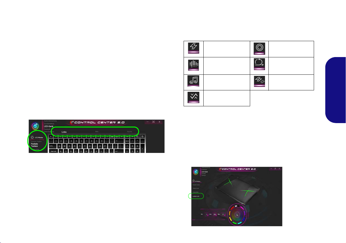
LED Modus - Gesamte Tastatur/Partielle Tastatur
Abb. 17
LOGO LED
Klicken Sie auf eine der Überschriften auf der linken Seite
unter LED Modus, um auszuwählen, wie die Farben
angewendet werden sollen.
LED Modus - Tastatureffekt
Klicken Sie auf Tastatureffekt (unter LED Modus) und
klicken
Sie dann auf eine der Schaltflächen, um die Effekte
auf der Tastatur zu sehen.
• Gesamte Tastatur - Klicken Sie einfach auf eine Farbe aus
dem äußeren Band des Musters, oder klicken Sie auf eine
der Farbmischungen aus der Mitte des Musters und sie wird
sofort auf die gesamte Tastatur angewendet.
• Partielle Tastatur - Klicken Sie einfach auf eine Farbe aus
dem äußeren Band des Musters, oder klicken Sie auf eine
der Farbmischungen aus der Mitte des Musters, und klikken Sie dann auf eine der Überschriften des Tastaturbereichs (Links, Mitte oder Rechts), um die Farbe
anzuwenden.
Abb. 16 - LED Modus - Partielle Tastatur
Blinken Atem
Tanz Zyklus
Tempo Zufall
Welle
Tabelle 6 - Tastatureffekte
LED Modus - LOGO LED
Über das Farbmuster in der Mitte des Bildschirms können
Sie eine Reihe von Farben für die Logo-LED des Gehäuses
auswählen, indem Sie auf die gewünschte Farbe klicken.
Klicken Sie hier, um eine beliebige Farbe aus dem Muster
auszuwählen, die auf die Logo-LED des Gehäuses.
Deutsch
65
Page 72

Start-Menü, Kontextmenü, Taskleiste, Systemsteuerung und Ein-
Abb. 18 - Start-Menü, Kontextmenü, Taskleiste, Systemsteuerung und Einstellunge n
stellungen von Windows 10
Auf die meisten Apps, Control Panels, Utilities und Programme in Windows 10 können Sie über das Start-Menü gelangen.
Klicken Sie dazu auf das Symbol in der Taskleiste in der linken unteren Ecke des Bildschirms (oder drücken Sie auf die
Windows-Logo-Taste der Tastatur).
Klicken Sie mit der rechten Maustaste auf das Startmenü-Symbol (oder verwenden Sie die Tastenkombination
Windows-Logo-Taste + X), um ein erweitertes Kontextmenü der nützlichen Funktionen aufzurufen: Apps und Features,
Energieoptionen, Task-Manager, Suchen, Explorer, Geräte-Manager, Netzwerkverbindungen usw.
Der Infobereich der Taskleiste befindet sich in der rechten unteren Ecke des Bildschirms. Hierüber können Sie manche
Control Panels und Anwendungen aufrufen, die in diesem Handbuch angesprochen werden.
In diesem Handbuch finden Sie eine Anleitung zum Öffnen de r Systemsteuerung. Um die Systemsteuerung aufzurufen, wäh-
Deutsch
len Sie Systemsteuerung unter dem Eintrag Windows-System im Startmenü.
Der Eintrag Einstellungen im Startmenü (auch die App) bietet Ihnen einen schnellen Zugriff auf eine Reihe von Einstellmög-
lichkeiten für das System, die Geräte, das Telefon, das Netzwerk und das Internet, die Personalisierung, die Apps, Konten,
die Zeit und Sprache, die Spiele, die Erleichterte Bedienung, den Datenschutz, Updates und die Sicherheit, Suche.
66
Page 73

Grafikfunktionen
Abb. 19
Anzeige (Mehrere Anzeigen)
Wenn der Grafiktreiber installiert ist, können Sie bei
Windows im Einstellfenster Anzeige die Anzeigegeräte
wechseln und Anzeigeoptionen konfigurieren.
So öffnen Sie in Windows das Einstellfenster Anzeige:
1. Klicken Sie mit der rechten Maustaste auf den Desktop und dann
aus dem Menü die Option Anzeigeeinstellungen wählen.
2. Wählen Sie aus den Menüs die gewünschten
Anzeigeeinstellungen.
So öffnen Sie die NVIDIA Systemsteuerung:
1. Rufen Sie die Systemsteuerung auf.
2. Klicken Sie auf NVIDIA Systemsteuerung (Symbol) - im
Kategorie Darstellung und Anpassung.
Oder
3. Klicken Sie mit der rechten Maustaste auf den Desktop und dann
aus dem Menü die Option NVIDIA Systemsteuerung wählen.
Anzeigegeräte
Sie können ein HDMI-Kabel am HDMI-Ausgangsanschluss
und/oder ein Mini DisplayPort kompatibles Kabel am Mini
DisplayPort 1.3 Anschluss verwenden, um eine externe Anzeige anzuschließen. Sie können auch den Thunderbolt Anschluss zur Verbindung mit einem kompatiblen
Anzeigegerät verwenden (siehe "Thunderbols-Anschlüsse
für Bildschirme" auf Seite 55). Lesen Sie die Anleitung des
Anzeigegerätes, um zu erfahren, welche Formate unterstützt
werden.
Konfigurieren des Anzeigegerätes in Windows
Alle externen und internen Anzeigen (bis zu 4 aktive Anzeigen) können unter Windows konfiguriert werden, indem
Sie die Anzeige oder System (in Einstellungen)
Bedienfenster oder das Projizieren-Menü verwenden.
Konfiguration der Anzeige mit dem Projizieren-Menü:
1. Schließen Sie Ihre externe(n) Anzeige(n) an den
entsprechenden Port an und schalten Sie sie
anschließend ein.
2. Drücken Sie die T astenkombination + P (oder
Fn + F7).
3. Klicken Sie auf eine der Optionen im Menü zur
Auswahl von Nur PC-Bildschirm, Duplizieren,
Erweitern oder Nur zweiter Bildschirm.
Konfiguration der Anzeige im Einstellfenster Anzeige:
1. Schließen Sie Ihre
externe(n) Anzeige(n) an
den entsprechenden Port
an und schalten Sie sie
anschließend ein.
2. Klicken Sie mit der
rechten Maustaste auf
den Desktop und dann
aus dem Menü die Option
Anzeigeeinstellungen
wählen.
3. Klicken Sie auf
Erkennen (Schaltfläche).
4. Der Computer wird die
angeschlossenen Anzeigen anschließend erkennen.
5. Im Menü Mehrere Anzeigen können Sie bis zu 4 Anzeigen
konfigurieren.
67
Deutsch
Page 74

Multi-GPU-Konfiguration
Abb. 20
G-SYNC
einrichten
G-SYNC einrichten
Stellen Sie den G-SYNC fähigen Monitor in einer Konfiguration
mit mehreren Monitoren als Primärer Monitor ein.
Klicken Sie in 3D-Einstellungen auf 3D-Einstellungen ver-
walten > Globale Einstellu ngen, wählen Sie Vertikale Synchronisierung und anschließend G-SYNC. Die Einstellung
von G-SYNC auf globale Einstellungen bedeutet, dass sie auf
sämtliche Spiele angewendet wird.
G-SYNC Unterstützung
G-SYNC wird nur unterstützt, wenn Sie über einen G-SYNC fähigen Monitor und einen Videoadapter der GTX Serie verfügen
(kontaktieren Sie Ihren Händler, um weitere Einzelheiten zu erfahren).
Für eine verbesserte Grafikqualität und -leistung verfügt der
Computer über NVIDIA SLI, bei der zwei GPUs (zwei Videokarten sind erforderlich) in einem System kombiniert
sind.
So wird die SLI-Konfiguration aktiviert/deaktiviert:
1. Gehen Sie in der NVIDIA Systemsteuerung.
2. Klicken Sie auf das "+" neben 3D-Einstellungen (wenn seine
Unterelemente nicht angezeigt werden) und klicken Sie dann auf
SLI, Surround, PhysX konfigurieren.
3. Klicken Sie bei SLI-Konfiguration auf 3D-Performance
maximieren.
4. Wählen Sie PhysX-Einstellungen; standardmasig ist der
Deutsch
Automatische Auswahl (empfohlen) eingestellt.
5. Klicken Sie auf Übernehmen und Jetzt neu starten, um den
Computer neu zu starten.
68
G-SYNC
Klicken Sie, um einen Haken bei G-SYNC aktivieren zu
setzen (ist standardmäßig aktiviert). G-SYNC wurde entwikkelt, um ein flüssiges Gaming-Erlebnis mit Ihrem GeForce
Produkt zu bieten, indem die Aktualisierungsrate des Monitors mit der Renderrate der GPU synchronisiert wird und
somit Verzögerungen behebt, damit Objekte schärfer und
Szenen sofort angezeigt werden.
Page 75

Energieoptionen
Abb. 21 - Energieoptionen
Die Energieoptionen von Windows ermöglichen Ihnen die
Konfiguration der Optionen für das Energiemanagement des
Computers. Sie können Strom sparen, indem Sie Ener-
giesparpläne erstellen und im linken Menü können Sie die
Optionen für den Netzschalter, die Energiespartasten (Fn
+ F12) und Zuklappeinstellung (beim Schließen des
Dekkels), den Bildschirm und den Energiesparmodus (die
Standardeinstellung Energie sparen) konfigurieren.
Klicken Sie im linken Menü auf Energiesparplan erstellen,
und wählen Sie die Optionen, um einen neuen Plan zu erstellen. Klicken Sie auf Energieplaneinstellungen ändern,
und klicken Sie auf Erweiterte Energieeinstellungen
ändern, um weitere Optionen für die Konfiguration aufzurufen.
PC-Kamera
Mit der Tastenkombination Fn + F10 können Sie das PCKameramodul ein- oder ausschalten. Wenn die PC-Kamera
verwendet wird, leuchtet die LED der PC-Kamera (siehe
Seite 50).
Kamera-App
Wenn Sie bei Windows zum Aufnehmen von Fotos und Videos aufnehmen möchten, benötigen Sie die Kamera-App
.
1. Starten Sie die Kamera-App aus dem Startmenü, indem Sie auf
das Symbol der Kamera-App bei Alle Apps klicken (Sie
können auch “Kamera” in das Suchfeld eingeben, um die KameraApp aufzurufen, wenn sie sich nicht im Start-Menü befindet).
2. Wählen Sie den Foto oder Video modus.
3. Klicken Sie auf das Foto-Symbol .
4. Klicken Sie auf das Video-Symbol , um die Videoaufnahme
zu starten.
5. Um die Videoaufnahme zu stoppen, klicken Sie wieder auf das
Video-Symbol .
6. Die aufgenommenen Fotos und Videos werden in einer Eigene
Aufnahmen im Ordner Bilder unter Dieser PC und in der Fotos
App im Startmenü gespeichert.
Deutsch
69
Page 76

Audiofunktionen
Lautstärkeeinstellung
Die Lautstärke kann auch mit den Windows-Lautstärke-
reglern eingestellt werden. Überprüfen Sie die Einstellung,
indem Sie in der Taskleiste auf das Lautsprecher-Symbol
Klicken.
Sie können die Audiooptionen für Ihren Computer über die
Systemsteuerung Sound in Windows konfigurieren.
Die Lautstärke können Sie durch die Tastenkombination Fn
+ F5/F6 ändern.
Deutsch
Einrichten des 5.1 oder 7.1 Surround Sound
Um das System für 5.1 oder 7.1 Surround Sound einzurichten, müssen Sie die Audiokabel an die Line-Eingangsbuchse, die Line-Ausgangsbuchse, die MikrofonEingangsbuchse und die Kopfhörer und S/PDIF Kombibuchse anschließen (Hinweis: Die Line-Ausgangsbuchse wird nur
für 7.1-Surround-Sound verwendet).
1. Starten Sie Realtek Audio Console über das Windows-Startmenü.
2. Klicken Sie auf Erweiterte Geräteeinstellungen.
3. Schließen Sie die Kabel der vorderen Lautsprecher an die
Kopfhörer und S/PDIF Kombibuchse an.
4. Schließen Sie die Kabel an (möglicherweise benötigen Sie einen
Adapter, um die Kabel an die entsprechenden Anschlüsse
anzuschließen (z. B. einen Stereo-mini-auf-dual-RCA-Adapter).
Stellen Sie die folgenden Kabelverbindungen her:
• Kopfhörer und S/PDIF Kombibuchse = Front-Lautsprecher-Aus-
gang
• Line-Eingangsbuchse = Lautsprecherausgang hinten
• Mikrofon-Eingangsbuchse = Mitten-/Subwoofer-Laut-
sprecherausgang
• Line-Ausgangsbuchse = Seitenlautsprecherausgabe (nur 7.1
Surround Sound)
5. Sobald ein Stecker angeschlossen wird, erscheint ein Dialogfeld
“Welches Gerät haben Sie angeschlossen?”.
70
6. Wählen Sie das entsprechende Gerät aus dem Dropdown-Menü
entsprechend dem angeschlossenen Lautsprecher aus (z. B.
Lautsprecherausgang hinten), und speichern Sie die Einstellung
mit OK.
Page 77

Sound Blaster Audio
Mit der Anwendung Sound Blaster Connect können Sie die
Audioeinstellungen nach Ihren Anforderungen konfigurieren, um eine bestmögliche Audioleistung bei Spielen und der
Wiedergabe von Musik und Videos zu erreichen.
Anwendung Sound Blaster Connect
Führen Sie die Sound Blaster Connect-Systemsteuerung
über das Startmenü in Windows aus.
Abb. 22 - Sound Blaster Connect
Deutsch
71
Page 78

Allgemeine Hinweise zur
Treiberinstallation
Wenn Sie keine fortgeschrittenen Kenntnisse
haben, folgen Sie für jeden
Treiber den Anweisungen
auf dem Bildschirm (z. B.
Weiter > Weiter > Fertig
stellen). In vielen Fällen
ist es erforderlich, den
Computer nach der
Treiberinstallation neu zu
starten.
Alle Module (z. B. WLAN
oder Bluetooth) müssen
vor der Treiberinstallation
eingeschaltet werden.
Windows Update
Nachdem Sie alle Treiber
installiert haben, sollten
Sie die Funktion Windows
Update aktualisieren, um
immer die neuesten Sicherheits-Updates usw. zu
erhalten (die Updates enthalten die neuesten
Fehlerbehebungen von
Microsoft).
Treiberinstallation und Stromversorgung
Während die Treiber installiert werden, muss der
Computer über den AC/DC-Adapter mit Strom versorgt werden. Einige Treiber benötigen für den Installationsvorgang sehr viel Strom. Wenn der Akku
nicht mehr über genügend Strom verfügt, kann sich
das System während der Installation ausschalten,
was zu Systemfehlern führen kann (das ist kein Sicherheitsproblem, und der Akku ist innerhalb von
einer Minute wieder aufladbar).
Abb. 23 - Installation der Treiber
Deutsch
Installation der Treiber
Die Disc Device Drivers & Utilities + User's Manual enthält die Treiber und Hilfspro-
gramme, die für das einwandfreie Funktionieren des Computers notwendig sind. Möglicherweise wurden diese bereits vorinstalliert. Ist das nicht der Fall, legen Sie die Disc ein, und
klicken Sie auf Install Drivers (Schaltfläche) oder Option Drivers (Schaltfläche), um das
Treibermenü Optional aufzurufen.
Reihenfolge. Markieren Sie die Treiber, die installiert werden sollen (notieren Sie zum späteren Nachlesen die Treiber, die Sie installiert haben). Hinweis: Muss ein Treiber neu installiert
werden, sollten Sie den alten Treiber zunächst deinstallieren.
Manuelle Treiber-Installation
Klicken Sie in der Anwendung Drivers Installer auf die Schaltfläche Browse CD/DVD und
navigieren Sie zu der ausführbaren Datei in dem Ordner für Ihren Treiber.
Wenn während des Installationsvorgangs das Fenster Neue Hardware gefunden erscheint,
klicken Sie auf Abbrechen, um das Fenster zu schließen. Befolgen Sie dann die Installationsanweisungen.
Installieren Sie die Treiber in der in Abb. 23 angegebenen
72
Page 79

Wireless-LAN-Modul (Option)
Stellen Sie vor der Konfiguration sicher, dass das WLANModul eingeschaltet ist (Flugzeugmodus deaktiviert).
Bluetooth-Modul (Option)
Stellen Sie vor der Konfiguration sicher, dass das BluetoothModul eingeschaltet ist (Flugzeugmodus deaktiviert).
WLAN-Konfiguration in Windows
1. Klicken Sie auf das Symbol im Infobereich auf der Taskleiste.
2. Eine Liste aller verfügbaren Zugriffspunkte wird angezeigt.
3. Klicken Sie doppelt auf einen Zugriffspunkt, um die Verbindung
herzustellen (oder klicken Sie ihn an, und klicken Sie auf
Verbinden).
4. Geben Sie einen Sicherheitsschlüssel für das Netzwerk
(passwort) ein, falls erforderlich, und klicken Sie auf Weiter.
5. Sie können sich entscheiden, ob Sie andere Geräte ausfindig
machen wollen.
6. Wenn die Verbindung zum Netzwerk-Zugriffspunkt besteht, wird
das Verbunden Symbol angezeigt.
7. Um die Verbindung zu einem Zugriffspunkt zu trennen, wählen Sie
das verbundene Netzwerk, und klicken Sie auf Trennen.
8. Klicken Sie auf die Schaltfläche Flugzeugmodus, um den
Flugzeugmodus ein- oder auszuschalten.
9. Alternativ können Sie auf die Schaltfläche WiFi klicken, um nur
das Wi-Fi ein- oder auszuschalten.
Bluetooth-Konfiguration in Windows
1. Klicken Sie auf den Eintrag Einstellungen im Startmenü und klikken Sie dann auf Geräte.
2. Klicken Sie auf Bluetooth- und andere Geräte.
3. Klicken Sie auf Bluetooth- oder anderes Gerät hinzufügen >
Bluetooth und eine Liste der gefundenen Geräte angezeigt wird.
4. Klicken Sie doppelt auf das Gerät, das mit dem Computer
gekoppelt werden soll, und klicken Sie auf Verbinden.
5. Wählen Sie ein Gerät aus und klicken Sie auf Gerät entfernen >
Ja, für eine Trennung von jedem Gerät.
Deutsch
73
Page 80

Wireless-Display
AC/AD WLAN-Modul - Mit drahtloser Anzeige verbinden
Sollte ein AC/AD WLAN-Modul installiert sein, kann es sein,
dass am unteren Bildschirmrand des Projizieren-Bildschirms
der Hinweis "Mit drahtloser Anzeige verbinden" nicht erscheint. In diesem Fall müssen Sie eine Funktion des kabellosen Adapters wie folgt deaktivieren:
1. Klicken Sie auf das Symbol im Infobereich auf der
Taskleiste.
2. Wählen Sie “Netzwerk- und Freigabecenter öffnen".
3. Klicken Sie im linken Menü auf "Adaptereinstellungen
ändern".
4. Klicken Sie mit der rechten Maustaste auf “WiFi# -
Qualcomm Atheros Sparrow 11ad Wireless Network
Adapter".
5. Wählen Deaktivieren um den Adapter auszuschalten.
6. Kehren Sie zum Projizieren Menü zurück und klicken Sie
auf "Mit drahtloser Anzeige verbinden".
Das Wireless-Display (Miracast) verwendet Ihr Wireless
LAN-Modul/WLAN/Bluetooth-Combo-Modul (Sie müssen
sicherstellen, dass Ihre Grafikkarte/Anzeige-Gerät kompatibel mit Ihrem speziellen WLAN/Combo-Modul ist) in
Verbindung mit einer bzw. einem kompatiblen Grafikkar-
te/Anzeige-Gerät (separat erhältlich), um den Inhalt des
Notebook-Displays auf einem anderen Display (zB- HDTV)
anzeigen zu können, ohne die Notwendigkeit, Kabel quer
durchs Zimmer zu ziehen. Sie können dann auf dem TV/externen Monitor ohne HDMI- oder A/V-Kalbelverbindung
Games spielen, im Internet browsen oder Videos oder Fotos
ansehen.
Deutsch
Bevor Sie das Wireless-Display konfigurieren, müssen Sie
den kompatiblen Adapter an den Monitor anschließen und
einrichten. Schließen Sie den Adapter mit einem HDMIoder A/V-Kabel an, und schalten Sie den Monitor ein.
Schalten Sie dann den Monitor auf den entsprechenden
Eingangskanal (Angaben dazu finden Sie in der Dokumentation, die Sie zusammen mit dem kompatiblen Adapter erhalten haben).
Wireless-Display-Konfiguration
1. Bitte beachten Sie, dass kein Treiber bzw. keine Applikation notwendig ist, um das Wireless-Display unter Windows 10 zu
betreiben.
2. Drücken Sie die Tastenkombination + P (oder Fn + F7).
3. Auf dem Bildschirm erscheint ein Menü.
4. Klicken Sie auf Mit drahtloser Anzeige verbinden (sollte dies
nicht erscheinen, schauen Sie in der Seitenleiste nach).
74
5. Das System wird dann nach kompatiblen Display-Geräten (dies
kann bis zu 60 Sekunden dauern, was Sie bitte bei der
Fertigestellung einberechnen).
6. Doppelklicken Sie jegliches angezeigtes Display-Gerät in der Liste
an.
7. Das Display wird dann eine Verbindung herstellen (für bestimmte
Einstellungen für Ihren Bildschirm siehe bitte die Dokumentation
zu Ihrem kompatiblen Adapter/Display für volle Details im
Lieferumfang enthalten).
8. Drücken Sie die Tastenkombination + P (oder Fn + F7),
klicken Sie auf Mit drahtloser Anzeige verbinden und klicken
Sie auf Trennen um eine zeitweilige Trennung vom WirelessDisplay durchzuführen.
Page 81

Fingerabdruckleser (Option)
Probleme beim Anmelden mit dem Fingerabdruck
Sollte der Fingerabdruckleser während des WindowsBegrüßungsbildschirms den Fingerabdruck 3-mal nicht erkennen können, wird der Computerzugriff gesperrt. In diesem Falle benötigen Sie Ihren PIN-Code (den Sie bei der
ursprünglichen Einrichtung des Fingerabdrucklesers
eingegeben haben), um wieder auf den Computer zugreifen zu können. Alternativ können Sie auch Ihr WindowsKennwort zur Anmeldung verwenden. Nachdem Sie den
PIN-Code (oder das Windows-Kennwort) zur Anmeldung
verwandt haben, können Sie unter Einstellungen > Kon-
ten > Anmeldeoptionen Ihre Einstellungen ändern.
Abb. 24
Konten -
Anmeldeop-
tionen
Melden Sie Ihre Fingerabdrücke vor dem Benutzen wie unten beschrieben an. Das Fingerabdrucklesemodul verwendet
die Anmeldeoption Konfiguration des Windows Kontos.
Fingerabdruckmodulkonfiguration
1. Klicken Sie auf den Eintrag Einstellungen im Startmenü.
2. Klicken Sie dann auf Konten und klicken Sie auf
Anmeldeoptionen.
3. Sie müssen ein Windows Kennwort hinzufügen (klicken Sie auf
Hinzufügen unter Kennwort).
4. Nachdem Sie das Passwort hinzugefügt haben, müssen Sie auch
eine PIN eingeben.
5. Klicken Sie bei Windows Hello unter Fingerabdruck auf
Einrichten.
6. Der Assistent führt Sie dann durch den Setup-Vorgang, um Ihre
Fingerabdrücke zu registrieren.
7. Sie werden angewiesen, den Fingerabdrucksensor mehrmals
auf den Leser zu berühren (Dies kann mehr als 20 Mal sein).
8. Versuchen Sie es, indem Sie verschiedene Fingerteile in
unterschiedlichen Stellungen zeigen.
9. Klicken Sie abschließend auf Schließen.
10. Sie können Einen weiteren Finger hinzufügen auswählen
(empfohlen) oder Den aktuellen Fingerabdruck entfernen.
11. Sie können nun den Fingerabdrucksensor berühren, um sich am
Computer anzumelden.
Deutsch
75
Page 82

TPM (Option)
Abb. 25
BitLocker-Laufwerk-
verschlüsselung
(TPM-Verwaltung)
Abb. 26
“Trusted Plat-
form Module”-
Management
(TPM) auf dem
lokalen Compu-
ter
Bevor Sie die TPM (Trusted Platform Module)-Funktionen
einrichten, müssen Sie die Sicherheitsplattform initialisieren.
Aktivieren der TPM-Funktionen
1. Starten Sie das Notebook neu.
2. Rufen Sie das Aptio Setup Utility auf, indem Sie während des
POST-Vorgangs auf F2 drücken.
3. Wählen Sie mit den Pfeiltasten das Menü
4. Wählen Sie TPM Configuration und drücken Sie auf die
Eingabetaste.
5. Drücken Sie auf die Eingabetaste, um auf das Menü Security
Device Support zuzugreifen und wählen Sie Enable (Aktivieren).
6. Sie müssen anschließend auf F4 drücken, um die Änderungen zu
Deutsch
speichern und den Computer neu zu starten.
Security.
4. Im Fenster TPM-Verwaltung können Sie TPM unter Windows
verwalten. Da ein TPM normalerweise in großen Unternehmen
und Organisationen verwaltet wird, benötigen Sie bei der
Verwaltung der hiesigen Informationen die Hilfe Ihres
Systemadministrators.
TPM Verwaltung in Windows
Sie können Ihre TPM Einstellungen unter
1. Rufen Sie die Systemsteuerung auf.
2. Klicken Sie auf
und Sicherheit).
3. Klicken Sie auf TPM-Verwaltung.
76
BitLocker-Laufwerkverschlüsselung (System
Windows
verwalten:
TPM Aktionen
1. Klicken Sie auf TPM vorbereiten und folgen Sie den Anweisungen des Assistenten, um TPM vorzubereiten (dabei wird möglicherweise ein Neustart des Computers und eine Bestätigung der
Einstellungsänderungen nach dem Neustart durch Drücken der
entsprechenden F-Taste erforderlich sein).
2. Nach dem Neustart wird TPM vorbereitet und Sie können
anschließend das Menü Aktionen verwenden für TPM
ausschalten, Besitzerkennwort ändern, TPM löschen oder
TPM-Sperre zurücksetzen.
3. Ein Assistent wird Sie durch die Einrichtungsschritte leiten.
Page 83

Fehlerbehebung
Problem Mögliche Ursache - Lösung
Die Module Wireless-LAN/Bluetooth
können nicht erkannt werden.
Das PC-Kamera-Modul kann nicht
erkannt werden.
Der Computer ist ausgeschaltet (oder im
Energiesparmodus), wird aber über den
an das Stromnetz angeschlossenen AC/
DC-Adpater mit Strom versorgt oder über
einen Akku mit mehr als 20 % Ladung mit
Strom versorgt wird. Ich habe ein Gerät
an den eingeschalteten USB Anschluss
angeschlossen, um es aufzuladen, was
aber nicht geschieht.
Niedrige Gaming-Leistung. Im Betrieb mit Computerspielen, wird empfohlen die Lüftergeschwindigkeit auf
Ein externer Bildschirm lässt sich nicht
über den Thunderbolt-Anschluss
ansprechen.
Im Flugzeugmodus sind die Module ausgeschaltet. Prüfen Sie der LED-Anzeige , ob
der Computer im Flugzeugmodus ist (siehe Tabelle 2 auf Seite 51). Mit der
Tastenkombination Fn + F11 können Sie den Flugzeugmodus ein- oder ausschalten
(siehe Tabelle 3 auf Seite 52).
Das ist ausgeschaltet. Mit der Tastenkombination Fn + F10 können Sie das PCKamera-Modul einschalten (siehe Tabelle 3 auf Seite 52). Starten Sie die Kamera-
Anwendung, um das Kamerabild zu sehen.
Der Anschluss ist nicht eingeschaltet. Schalten Sie den Anschluss mit der
Tastenkombination Fn + Netzschalter ein.
Bei manchen externen USB-Geräten funktioniert die Stromversorgung nicht (lesen Sie
dazu in der Dokumentation zum Gerät nach). Ist das der Fall, schließen Sie das
externe USB-Gerät an, und laden Sie es bei eingeschaltetem Computer auf.
das Maximum zu setzen. Verwenden Sie die Fn + 1 Tastenkombination um die
Lüftergeschwindigkeit zu regulieren.
Sie haben den Thunderbolt-Anschluss nicht für Bildschirm-Geräte konfiguriert (siehe
"Thunderbols-Anschlüsse für Bildschirme" auf Seite 55).
Deutsch
77
Page 84

Technische Daten
Aktualität der technischen Daten
Die in diesem Teil aufgeführten technischen Daten sind zum Zeitpunkt der
Druckstellung richtig. Bestimmte
Elemente (insbesondere Prozessortypen/-geschwindigkeiten) können im
Rahmen des Entwicklungsplans des Herstellers zwischenzeitlich geändert oder
aktualisiert werden. Detailinformationen
erhalten Sie bei Ihrem Servicezentrum.
Bitte beachten Sie, dass diese Reihe von
Computer-Modellen eine Vielzahl an Prozessoren und/oder Grafikkarten unterstützen kann.
Um herauszufinden welcher Prozessor/
CPU in Ihrem System verbaut ist,
begeben Sie sich zum Start-Menü und
wählen dort Einstellungen, und dann
wählen Sie System und klicke auf Info.
Hier finden Sie ebenfalls Information
über die Größe des installierten RAM
u.v.m.
Um Informationen über den in Ihrem System verwendeten Videoadapter zu er-
halten gehen Sie zum Start-Menü, wo
Sie Einstellungen wählen, dann wählen
Sie auf System und klicken auf Bild-
schirm > Erweiterte Anzeigeeinstellungen > Adaptereigenschaften
anzeigen.
SO-DIMM Speichertypen
Sämtliche im System installierten SODIMM Speichermodule sollten identisch sein (dieselbe Größe und Marke), um unvergesehenes
Systemverhalten zu vermeiden.
Mischen Sie keine SO-DIMM
Speichermodulgrößen und Marken,
da es ansonsten zu unvorgesehenem
Systemverhalten kommen könnte.
Deutsch
78
LCD-Optionen
17,3" (43,94cm), 16:9, *UHD (3840x2160)/
*QHD (2560x1440)/FHD (1920x1080)
*Hinweis: UHD/QHD-Panels sind nur für
Systeme mit NVIDIA® G-SYNC™
Technology verfügbar
Speicher
Quatre 260-Pin SODIMM-Sockel, Unterstützung von DDR4 2400MHz Speicher
(Die tatsächliche Speicherarbeitsfrequenz
hängt vom FSB des Prozessors ab.)
Speicher erweiterbar von 8GB (Minimum)
bis zu 64GB (Maximum)
Mit 4GB, 8GB oder 16GB Modulen
kompatibel
Unterstützt XMP 2666/3000MHz
XMP hängt vom Prozessor abhängig und
funktioniert mit vier DIMMs im Dual Channel
oder mit zwei DIMMs im Einzelkanal
Core Logic
Intel® Z370 Chipsatz
BIOS
AMI BIOS (64Mb SPI Flash-ROM)
Zeigegerät
Eingebautes Secure Pad (mit Microsoft PTP
Multi Gesture & Scrolling Functionality)
Tastatur
Vollfarbig beleuchtete WinkeyTastatur in
Originalgröße mit Nummerntastatur und
Anti-Ghost Tasten
Audio
High-Definition-Audio-kompatible
Schnittstelle
S/PDIF Digtalausgang
Zwei Lautsprecher
Sound BlasterX® Pro-Gaming 360°
ESS™ SABRE HIFI DAC für High
Resolution Kopfhöreraudio
Eingebautes Array-Mikrofon
Subwoofer
Hinweis: Externe 7.1CH-Audioausgabe bei
Line-Ausgang, Mikrofon-Eingang, LineEingang, und 2-in-1 (Kopfhörer und S/PDIF)
Audiobuchsen
Page 85

Speichereinheiten
Zwei austauschbare (7,0 mm/9,5 mm Höhe)
SATA-2,5"-Festplatten/SSDs, die RAID
Level 0/1 unterstützen
(Werkseitige Option) Zwei M.2 SATA 2280
SSDs, die RAID Level 0/1 unterstützen
Oder
(Werkseitige Option) Drei M.2 PCIe Gen3
x4 2280 SSDs, die RAID Level 0/1
unterstützen
Sicherheit
Öffnung für Sicherheitsschloß (Typ
Kensington)
BIOS-Paßwort
Fingerabdruckleser
TPM 2.0
Intel PTT für Systeme ohne Hardware TPM
M.2-Steckplätze
Steckplatz 1 für Kombinierte Bluetooth und
WLAN-Modul
Steckplatz 2 für SATA oder PCIe Gen3 x4
SSD
Steckplatz 3 für SATA oder PCIe Gen3 x4
SSD
Steckplatz 4 für PCIe Gen3 x4 SSD oder
Optane
Kartenleser
Festes Multi-in-1 Push-Push KartenleserModul
MMC (MultiMedia Card)/RS MMC
SD (Secure Digital)/Mini SD/SDHC/
SDXC (bis zu UHS-II)
Schnittstellen
Fünf USB 3.0 (USB 3.1 Gen 1) Anschlüsse
(Verfügt über einen über den USBAnschluss mit Strom versorgten USBAnschluss)
Zwei USB 3.1 Gen 2/Thunderbolt 3
Kombianschlüsse (Typ-C)
Zwei Mini DisplayPort (1.3) Anschlüsse
Ein HDMI-Ausgangsanschluss
Eine 2-in-1 Audiobuchse (Kopfhörer und S/
PDIF (optischer) Ausgang Kombibuchse)
Eine Mikrofon-Eingangsbuchse
Eine Line-Ausgangsbuchse
Eine Line-Eingangsbuchse
Zwei RJ-45 LAN-Buchsen
Eine DC-Eingangsbuchse
Charakteristika
Unterstützt NVIDIA® G-SYNC™
Technologie
(NVIDIA® G-SYNC™ Technologie wird nur
von einigen LCD-Bildschirmen und
Grafikkarten der GTX Serie unterstützt)
Intel® Optane™ Technik
Bereit für Virtual Reality (Prozessor-
abhängig)
Unterstützt Windows® 10 Cortana mit
Stimme
(Werkseitige Option) USB-Laufwerk
Kommunikation
Eingebautes Qualcomm 10/100/1000Mb
Base-TX Ethernet LAN
2,0M FHD PC-Kamera-Modul
WLAN/ Bluetooth M.2 Module:
(Werkseitige Option) Intel® Wireless-AC
8265 WLAN (802.11ac) und Bluetooth
(Werkseitige Option) Qualcomm® Atheros
Killer™ Wireless-AC 1535 WLAN
(802.11ac) und Bluetooth
(Werkseitige Option) Qualcomm® Atheros
Killer™ Wireless-AC 1550 WLAN
(802.11ac) und Bluetooth
(Werkseitige Option) Qualcomm® WLAN
(802.11ad) und Bluetooth
Umgebungsbedingungen
Temperatur
In Betrieb: 10ºC – 35ºC
Bei Aufbewahrung: -20ºC – 60ºC
Relative Luftfeuchtigkeit
In Betrieb: 20 – 80 %
Bei Aufbewahrung: 10 – 90 %
Deutsch
79
Page 86

Stromversorgung
CPU Geschwindigkeit & Computer
im DC Modus
Beachten Sie, dass wenn sich der
Computer im DC Modus (nur vom
Akku betrieben) befindet, die CPU
nicht mit voller Geschwindigkeit laufen
könnte. Dies ist eine Funktion, um den
Akku zu schützen.
Leistungswandler
Sie müssen den Leistungswandler
verwenden, der mit dem Dual AC/DCAdapter geliefert wurde um den Computer zu betrieben. Verwenden Sie
keinen einfachen AC/DC-Adapter, um
das System zu speisen.
Integrierter 8 Zellen-Smart Lithium-IonenAkku, 89WH
Spezifikation I
Dual-Vollspektrum AC/DC-Adapter mit
Leistungswandler-Box
AC/DC-Adapter für den gesamten
Spannungsbereich
AC-Eingang: 100-240V, 50-60Hz
DC-Ausgang: 19,5V, 11,8A (230W)
Spezifikation II
Dual-Vollspektrum AC/DC-Adapter mit
Leistungswandler-Box
Deutsch
AC/DC-Adapter für den gesamten
Spannungsbereich
AC-Eingang: 100-240V, 50-60Hz
DC-Ausgang: 19,5V, 16,9A (330W)
Umgebungsbedingungen
428 (B) x 308 (T) x 47,2(H) mm
Spezifikation I
4,8kg (Barebone mit 1 Video Karte und
89WH-Akku)
Spezifikation II
5,5kg (Barebone mit 1 Video Karte und
89WH-Akku)
80
Page 87

A propos de ce Guide Utilisateur Concis
Ce guide rapide est une brève introduction à la mise en route de votre système. Il s’agit d’un supplément, et non pas d’une
alternative au Manuel de l’Utilisateur en Anglais complet au format Adobe Acrobat s ur le disque Device Drivers & Utilities
+ User's Manual fourni avec votre ordinateur . Ce disque contient aussi les pilo tes et utilitaires nécessaires au fonctionnement
correct de votre ordinateur (Remarque: La compagni e se réserve le droit de revoir cette publication ou de modifier son contenu sans préavis).
Certains ou tous les éléments de l’ordinateur peuvent avoir été déjà installés. Si ce n’est pas le cas, ou si vous avez l’intention
de reconfigurer (ou réinstaller) des portions du système, reportez-vous au Manuel de l’Utilisateur complet. Le disq ue Device
Drivers & Utilities + User’s Manual ne contient pas de système d’exploitation.
Informations de réglementation et de sécurité
Prêtez attention aux avis réglementaires et informations de sécurité contenus dans le Manuel de l'Utilisateur se trouvant sur
le disque Device Drivers & Utilities + User’s Manual.
© Juillet 2018
Marques déposées
Intel est une marque enregistrée d’Intel Corporation.
Windows est une marque enregistrée de Microsoft Corporation.
Français
81
Page 88

Instructions d’entretien et d’utilisation
L’ordinateur est robuste, mais il peut toutefois être endommagé. Afin d’éviter ceci, veuillez suivre ces recommandations :
• Ne le laissez pastomber. Ne l’exposez à aucun choc ou vibration. Si
l’ordinateur tombe, le boîtier et d’autres éléments pourraient être
endommagés.
• Gardez-le sec. Ne le laisser pas surchauffer. T enez l’ordinateur et son
alimentation externe à distance de toute source de chaleur. Il s’agit d’un
appareil électrique. Si de l’eau ou tout autre liquide venait à pénétrer à
l’intérieur de votre ordinateur, il pourrait être sérieusement endommagé.
• Evitez les interférences. Tenez l’ordinateur à distance de transforma-
teurs à haute capacité, moteurs électriques, et autres appareils générateurs de champs magnétiques importants. Ceux-ci peuvent gêner ses
performances normales et endommager vos données.
• Suivez les procédures appropriées d’utilisation de votre ordinateur .
Arrêtez l’ordinateur correctement, et fermez tous vos programmes
(n’oubliez pas d’enregistrer votre travail). N’oubliez pas d’enregistrer
vos données régulièrement puisqu’elles peuvent être perdues si la batterie est vide.
• Notez que dans les ordinateurs ayant un logo fixé par dépôt électrolytique, le logo est recouvert par une protection adhésive. À cause de
Français
l’usure générale, cette protection adhésive se détériore avec le temps et
le logo exposé peut former des angles coupants. Faites bien attention
lorsque vous manipulez l'ordinateur, et évitez de toucher le logo fixé par
dépôt électrolytique. Dans la sacoche de voyage, ne mettez pas d’autres
objets qui risquent de se frotter contre l’ordinateur pendant le transport.
En cas d’une telle usure, contactez votre centre de services.
Sécurité de l'alimentation et de la batterie
• Utilisez uniquement un adaptateur AC/DC agréé avec votre ordinateur.
• Utilisez uniquement le cordon d’alimentation et les batteries indiqués
dans ce manuel.
• Votre adaptateur AC/DC peut avoir été conçu pour les voyages internationaux mais il lui faut tout de même une source de courant régulière et
ininterrompue. Si vous n’êtes pas sûr des caractèristiques du réseau
électrique local, consultez notre représentant de service ou la compagnie
électrique locale.
• L’adaptateur AC/DC que vous utilisez, peut être à 2 broches ou à 3
broches, comprenant une prise de terre. Cette prise de terre est un des
éléments de sécurité importants, ne vous en passez pas ! Si une prise
murale compatible n’est pas disponible, demandez à un électricien qualifié de vous en installez une.
• Quand vous voulez débrancher le cordon d’alimentation, ne tirez pas
sur le fil, mais attrapez la tête de la prise.
• Assurez-vous que la prise murale et la (les) rallonge(s) que vous utilisez
peuvent supporter la consommation électrique de tous les appareils qui
y sont reliées.
• Assurez-vous que votre ordinateur est complètement éteint avant de le
mettre dans un sac de voyage (ou tout autre bagage similaire).
• Utilisez uniquement des batteries conçues pour votre ordinateur. Un
mauvais type de batterie peut provoquer des explosions, des fuites et/ou
endommager votre ordinateur.
• Ne continuez pas d'utiliser une batterie qui est tombée, ou qui paraît
endommagée (ex: tordue ou vrillée) d'une manière quelconque. Même
si l'ordinateur continue de fonctionner avec la batterie en place, cela
peut détériorer le circuit, pouvant déclencher un incendie.
• Rechargez les batteries en utilisant le système de l’ordinateur. Un
rechargement incorrect peut provoquer l’explosion de la batterie.
• N’essayez jamais de réparer la batterie. Au cas où votre batterie aurait
besoin d’être réparée ou changée, veuillez vous adresser à votre représentant de service ou à des professionnels qualifiés.
• Gardez les batteries endommagées hors de portée des enfants et débarrassez-vous en le plus vite possible. Veuillez toujours jeter les batteries
avec précautions. Les batteries peuvent exploser ou se mettre à fuire si
elles sont exposées au feu ou si elles sont manipulées ou jetées d’une
façon non appropriée.
• Gardez la batterie loin des appareils métalliques.
• Placez un morceau de scotch sur les contacts de la batterie avant de la
jeter.
• Ne jetez pas les batteries dans le feu. Elles peuvent exploser. Consultez
la réglementation locale pour des instructions de recyclage possibles.
• Ne touchez pas les contacts de la batterie avec les mains ou avec des
objects en métal.
82
Page 89

Précautions concernant les batteries polymères
Elimination de la batterie & avertissement
Le produit que vous venez d’acheter contient une batterie rechargeable. Cette batterie est recyclable. Quand elle n’est
plus utilisable, en fonction des lois locales des différents états
et pays, il peut être illégal de s’en débarrasser en la jetant
avec les ordures ménagères normales. Vérifiez auprès du
responsable local de l’élimination des déchets solides de
votre quartier pour vous informer des possibilités de recyclage ou de la manière appropriée de la détruire.
Il existe un danger d’explosion si la batterie est remise de façon incorrecte. Remplacez-la uniquement par des batteries
de même type ou de type équivalent, recommandées par le
fabricant. Eliminez les batteries usagées selon les instructions du fabricant.
Notez les informations suivantes spécifiques aux batteries polymères, et le cas échéant, celles-ci remplacent les informations générales de précaution sur les batteries.
• Les batteries polymères peuvent présenter une légère dilatation ou gonflement, mais cela est inhérent au mécanisme de sécurité de la batterie
et ne représente pas une anomalie.
• Manipulez les batteries polymères de façon appropriée lors de leur utilisation. Ne pas utiliser de batteries polymères dans des environnements
présentant une température ambiante élevée, et ne pas stocker les batteries non utilisées pendant de longues périodes.
Nettoyage
• Utilisez un chiffon propre et doux pour nettoyer l'ordinateur, mais
n'appliquez pas d'agent de nettoyage directement sur l'ordinateur.
• N’utilisez pas de pro duit de nettoyage volatil (des distillés pétrôle) o u
abrasifs sur aucun des éléments de l’ordinateur.
•(Pour les modèles d'ordinateurs fournis avec un chiffon de ne t-
toyage bleu clair) Certains modèles d'ordinateurs de cette série sont
fournis avec un chiffon d e nettoyage b leu clair . Pour nettoyer le boîtier
de l'ordinateur avec ce chiffon, suivez les instructions ci-dessous :
• Eteignez l’ordinateur et les périphériques.
• Débranchez l'adaptateur AC/DC de l'ordinateur.
• Humidifiez légèrement le chiffon avec un peu d'eau.
• Nettoyez le boîtier de l'ordinateur avec le chiffon.
• Essuyez l'ordinateur avec un chiffon sec, ou laissez le sécher avant
de l'allumer.
• Rebranchez l'adaptateur AC/DC et allumez l'ordinateur.
Révision
Si vous essayez de réparer l'ordinateur par vous-même, votre
garantie sera annulée et vous risquez de vous exposer et d'exposer l'ordinateur à des chocs électriques. Confiez toute réparation à un technicien qualifié, particulièrement dans les cas
suivants:
• Si le cordon d’alimentation ou l’adaptateur AC/DC est endommagé,
abimé ou effiloché.
• Si votre ordinateur a été exposé à la pluie ou tout autre liquide.
• Si votre ordinateur ne fon ctionne pas normalem ent bien que vous ayez
suivi les instructions de mise en marche à la lettre.
• Si votre ordinateur est tombé par terre ou a été endommagé (si l'écran
LCD est cassé, ne touchez pas le liquide car il contient du poison).
• Si une odeur inhabituel, de la chaleur ou de la fumée apparaissait sortant de votre ordinateur.
83
Français
Page 90

Guide de démarrage rapide
Figure 1
Ordinateur avec
doubles adaptateurs
AC/DC branchés au
convertisseur/Ouver-
ture du couvercle/
LCD
134°
Arrêt
Veuillez noter que vous
devriez toujours éteindre
votre ordinateur en utilisant la commande Arrê-
ter dans Windows (voir
ci-dessous). Cette précaution évite des problèmes de disque dur ou
de système.
1. Cliquez sur l'icône du
menu Démarrer .
2. Cliquez sur l'élément
Marche/Arrêt .
3. Sélectionnez Arrêter
dans el menu.
Les indicateurs (lumineux
s’allument en vert lorsque les
adaptateurs AC/DC sont branchés et connectés à une prise
de courant)
1. Enlevez tous les emballages.
2. Posez l’ordinateur sur une surface stable.
3. Connectez fermement les périphériques que vous souhaitez utiliser avec votre
ordinateur (par ex. clavier et souris) à leurs ports respectifs.
4. Vous devez utiliser le convertisseur d'alimentation fourni avec les doubles
adaptateurs
d'adaptateur
5. Lors de la première installation de l'ordinateur utilisez la procédure
suivante (afin de protéger l'ordinateur, la batterie sera verrouillée lors de
l'expédition afin de ne pas alimenter le système avant la première connexion au
convertisseur d'alimentation et aux adaptateurs AC/DC et initialement installée
comme ci-dessous) :
• Branchez le convertisseur d’alimentation à la prise d'entrée DC à l’arrière de
l’ordinateur, puis branchez les adaptateurs
du convertisseur. Branchez les cordons d’alimentation secteur dans une prise
de courant, et connectez les cordons d’alimentation secteur aux adaptateurs
AC/DC et laissez-les ainsi pendant au moins 6 secondes.
• Débranchez les cordons d’adaptateurs des prises d'entrée DC du convertis-
seur, puis rebranchez-les; la batterie est maintenant déverrouillée.
6. D'une main, soulevez soigneusement le couvercle/LCD pour obtenir un angle de
Français
vision confortable (ne pas dépasser 134 degrés), de l'autre main (comme illustré
dans la Figure 1) maintenez la base de l'ordinateur (Remarque : Ne soulevez
jamais l'ordinateur par le couvercle/LCD).
7. Pressez le bouton d'alimentation pour allumer.
Logiciel système
Votre ordinateur peut être livré avec un logiciel système pré-installé. Si
ce n’est pas le cas, ou si vous re-configurez votre ordinateur pour un
système différent, vous constaterez que ce manuel fait référence à Mi-
crosoft Windows 10.
Prend en charge Intel® Optane™/RAID
Notez que votre système peut être configuré en RAID ou pour prendre en charge Intel® Optane™, mais il ne peut pas être
configuré pour prendre en charge les deux systèmes. Vous devez configurer Intel® Optane™ ou RAID avant d'installer votre
système d'exploitation Windows 10 (voir la page 85 & la page 87).
84
AC/DC connectés pour alimenter cet ordinateur. N'utilisez pas
AC/DC pour alimenter le système.
AC/DC dans les prises à l’arrière
Page 91

Configuration
Intel® Optane™
Intel® Optane™ est la combinaison d'un périphérique de
mémoire compatible et du logiciel Technologie de stockage
Intel® Rapid. Cette combinaison est conçue pour accélérer
les performances de votre système en mettant en cache les
données de démarrage, les exécutables, les données accessibles fréquemment et les fichiers de page système sur un
SSD Intel® Optane™ non volatil et à faible latence.
Contactez votre distributeur ou fournisseur pour voir si votre
système prend en charge cette technologie.
Si vous réinstallez un système qui a déjà été configuré en
mode Intel RST Premium, assurez-vous d'avoir effacé la mémoire Intel Optane (reportez-vous à "Suppression de Intel®
Optane™" à la page 86).
Procédure de configuration Intel® Optane™
Vous devez configurer Intel® Optane™ avant d'installer
votre système d'exploitation Windows 10 et, pour ce faire,
vous devrez préparer ce qui suit.
• Le disque de SE Microsoft Windows 10.
• Un lecteur DVD externe connecté.
• Un SSD Intel® Optane™ installé dans votre système.
• Le disque Device Drivers & Utilities + User’s Manual.
1. Allumez l’ordinateur et appuyez sur F2 pour aller dans le BIOS.
2. Allez au menu Boot, sélectionnez UEFI Setting et appuyez sur
Entrée.
3. Paramétrez UEFI Boot sur «Enabled».
4. Appuyez sur Échap pour sortir du menu et allez au menu Main.
5. Sélectionnez OffBoard NVMe Controller Configuration et
appuyez sur Entrée pour vérifier qu'un SSD Intel® Optane™ est
présent.
6. Appuyez sur Échap pour sortir du menu et allez au menu
Advanced.
7. Sélectionnez SATA Mode, appuyez sur Entrée et sélectionnez
“Intel RST Premium...”.
8. Appuyez sur F4 et <Yes> (Oui) pour “Enregistrer les
modifications et réinitialiser” (
9. Pendant le redémarrage de l’ordinateur, appuyez sur F2 pour
accéder au BIOS.
10. Appuyez sur F4 et <Yes> (Oui) pour “Enregistrer les
modifications et réinitialiser” (
mais assurez-vous que la condition dans le point à puce ci-
dessous est remplie avant de le faire.
• Vérifiez que le DVD du SE Windows 10 est dans le lecteur
DVD connecté, ainsi l'ordinateur démarrera automatiquement à
partir du DVD du SE Windows 10 (vous serez invité à appuyer
sur une touche pour démarrer à partir du DVD).
11. Appuyez sur Suivant > Installer maintenant pour continuer à
installer le système d'exploitation normalement (voir votre
documentation de Windows si vous avez besoin d'instructions
pour installer le Système d'Exploitation Windows).
12.
Sélectionnez Personnalisé: Installer uniquement Windows
(avancé).
13. Il est recommandé de sélectionner, puis de supprimer les
partitions existantes.
14. Cliquez sur Nouveau pour créer une partition pour Windows.
15. Il est très important de vous assurer que lorsque vous créez la
partition, vous laissez un minimum d'espace non alloué de 5Mo.
16. Suivez les instructions à l'écran pour installer le SE Windows 10.
“Save Changes and Reset”).
“Save Changes and Reset”),
Français
85
Page 92

17. Installez les pilotes Windows (voir la page 112). Vérifiez que vous
Figure 2 - Technologie de stockage Intel® Rapid - état
avez installé le pilote Technologie de stockage Intel® Rapid
(IRST).
18. Exécutez l'application Technologie de stockage Intel® Rapid.
19. Cliquez sur Activer.
Français
20. Le système affichera un message et vous demandera de
sélectionner un lecteur rapide compatible (dans ce cas, il ne
devrait y avoir qu'une seule option).
21. Vous devrez redémarrer l'ordinateur après avoir activé Optane, et
vous assurer que le système est alimenté par l'adaptateur AC/DC,
et non par batterie uniquement.
22. Cliquez sur Oui pour commencer le processus (cela peut prendre
un certain temps).
23. Une fois le processus terminé, redémarrez l'ordinateur.
Suppression de Intel® Optane™
Si vous souhaitez supprimer une configuration Intel® Optane™ existante, suivez la procédure ci-dessous pour le
faire. Cependant, sauvegardez tous les fichiers et données
nécessaires avant de supprimer une configuration Intel®
Optane™, car cela entraînera la perte de toutes les données
sur les volumes.
1. Assurez-vous que Intel® Optane™ est activé dans l'application
Technologie de stockage Intel® Rapid.
2. Allumez l’ordinateur et appuyez sur F2 pour aller dans le BIOS.
3. Allez à Intel(R) Rapid Storage Technology (dans le menu
Advanced) et appuyez sur Entrée.
4. Sélectionnez Intel Optane, **** (répertoriée sous Optane
Volume:) et appuyez sur Entrée.
5. Sélectionnez “Deconcatentate” et appuyez sur Entrée.
6. Sélectionnez <Yes> (Oui) dans l'option “Are you sure you want
to perform deconcatentation”.
7. Sélectionnez “Start deconcatentation” et appuyez sur Entrée.
8. Le système retournera au menu standard Intel(R) Rapid Storage
Technology lorsqu'il aura terminé.
9. Vous devez ensuite sélectionner le mode SATA approprié pour
votre système et réinstaller le système d'exploitation.
86
Page 93

Configuration RAID
Vos disques durs ou disques SSD peuvent être configurés en
mode RAID (pour améliorer les performances ou la protection). Notez que la configuration de vos disques durs/
disques SSD en mode RAID doit être faite avant d'installer le SE Windows. Ne modifiez pas le mode, sauf si vous
envisagez de réinstaller votre système d'exploitation, et prenez soin de sauvegarder tous les fichiers et données nécessaires avant de le faire.
Pour configurer votre système RAID en mode Entrelacement
(RAID 0) ou Miroir (RAID 1) (voir le Tableau 1) , vous aurez besoin de deux disques durs ou disques SSD identiques.
Niveau RAID Description
RAID 0
(deux disques
durs/SSD mini-
mum sont néces-
saires)
RAID 1
(deux disques
durs/SSD mini-
mum sont néces-
saires)
Disques identiques lisant et écrivant des données en parallèle pour améliorer les perfor-
mances. RAID 0 implémente une matrice de
disques agrégés et les données sont décomposées en blocs et chaque bloc est écrit sur un
disque séparé.
Des disques identiques dans une configuration
en miroir utilisée pour protéger les données.
Si un disque faisant partie d'une matrice en
miroir tombe en panne, le disque en miroir (qui
contient des données identiques) gèrera toutes
les données. Quand un nouveau disque de
rechange est installé, les données sont reconstruites sur le nouveau disque à partir du disque
en miroir pour rétablir la tolérance de faute.
A vant de configurer vos disques durs (HDD)/SSD SA TA en
mode RAID, vous devrez préparer ce qui suit :
• Le disque de SE Microsoft Windows 10.
• Un lecteur DVD externe connecté.
• Un disque dur installé dans la baie du disque dur primaire et un
second (identique) disque dur installé dans la baie du disque dur
secondaire.
Ou
Deux SSD SATA identiques.
• Le disque Device Drivers & Utilities + User’s Manual.
A vant de configurer vos SSD PCIe en mode RAID, vous devrez préparer ce qui suit :
• Le disque de SE Microsoft Windows 10.
• Un lecteur DVD externe connecté.
• Deux SSD PCIe identiques.
• Le disque Device Drivers & Utilities + User’s Manual.
• Un lecteur flash USB.
• Un ordinateur opérationnel (pour copier des fichiers à partir du
disque Device Drivers & Utilities + User’s Manual sur le lecteur flash USB).
Remarque: Tous les disques durs/SSD en configuration
RAID doivent être identiques (même capacité et même
marque) afin d’éviter tout comportement inattendu du système.
Français
Tableau 1 - Description RAID
87
Page 94

Procédure de configuration
Figure 4 - Select Disks (Sélec-
tionner les disques)
RAID (HDD/SSD SATA)
1. Allumez l’ordinateur et appuyez sur F2
pour aller dans le BIOS.
2. Allez au menu Boot, sélectionnez UEFI
Setting et appuyez sur Entrée.
3. Paramétrez UEFI Boot sur «Enabled».
4. Appuyez sur Échap pour sortir du menu et
allez au menu Advanced.
5. Sélectionnez SATA Mode, appuyez sur
Entrée et sélectionnez “Intel RST
Premium...”.
6. Appuyez sur F4 et <Yes> (Oui) pour
“Enregistrer les modifications et
réinitialiser” (
Reset”
7. Pendant le redémarrage de l’ordinateur,
appuyez sur F2 pour accéder au BIOS.
8. Allez à Intel(R) Rapid Storage
Français
Technology (dans le menu Advanced) et
appuyez sur Entrée.
9. Sélectionnez Create RAID Volume et
appuyez sur Entrée.
10. Vous pouvez maintenant configurer votre
volume RAID à l'aide des deux disques
installés.
11. Allez à Name: et appuyez sur Entrée.
12. Tapez un nom de votre choix pour votre
volume RAID et appuyez sur Entrée.
Figure 3 - Nommer le volume RAID (Ad-
vanced > Intel(R) Rapid Storage Tech-
88
“Save Changes and
).
nology)
13. Allez à RAID Level: et appuyez sur
Entrée.
14. Choisissez le niveau RAID requis (voir le
Tableau 1 à la page 87) et appuyez sur
Entrée.
• RAID 0 (Stripe)/ RAID 1 (Mirror)
15. Allez à l'un des disques énumérés sous
Select Disks: (Sélectionner les disques:)
et sélectionnez un nom de disque et
appuyez sur Entrée.
16. Déplacez le curseur (utilisez les touches
fléchées) vers le bas sur X (ou
sélectionnez le disque requis) et appuyez
sur Entrée.
17. Vous devez sélectionner deux disques
identiques pour former votre volume
RAID.
18. Si vous avez sélectionné RAID 0 (Stripe)
(Bande) alors vous pouvez ajuster la
«Strip Size» (Taille de bande) pour
qu'elle corresponde à vos besoins (Il est
recommandé de configurer la « Taille de
bande » à 128Ko).
19. Allez à Create Volume (Créer un volume)
et appuyez sur Entrée.
20. Le volume RAID sera alors créé et les
informations RAID seront affichées sous
Intel(R) Rapid Storage Technology
(dans le menu Advanced).
21. Appuyez sur Échap pour sortir du menu.
22. Appuyez sur F4 et <Yes> (Oui) pour
“Enregistrer les modifications et
réinitialiser” (
Reset”
condition dans le point à puce cidessous est remplie avant de le faire.
• Vérifiez que le DVD du SE Windows 10
est dans le lecteur DVD connecté, ainsi
l'ordinateur démarrera automatiquement à partir du DVD du SE Windows
10 (vous serez invité à appuyer sur une
touche pour démarrer à partir du DVD).
23. Appuyez sur Suivant > Installer
maintenant pour continuer à installer le
système d'exploitation normalement (voir
votre documentation de Windows si vous
avez besoin d'instructions pour installer le
Système d'Exploitation Windows).
24. Suivez les instructions à l'écran pour
installer le SE Windows 10.
25. Installez les pilotes Windows (voir la
page 112). Vérifiez que vous avez installé
le pilote Technologie de stockage Intel®
Rapid (IRST).
“Save Changes and
), mais assurez-vous que la
Page 95

Procédure de configuration RAID (SSD PCIe)
1. Allez à l'ordinateur utilisable et insérez un
lecteur flash USB.
2. Insérez le disque Device Drivers & Utilities
+ User’s Manual dans le lecteur de CD/
DVD de l’ordinateur utilisable.
3. Copiez le dossier f6flpy-x64 depuis
l'emplacement ci-dessous (D: représente
votre lecteur de DVD) du disque Device
Drivers & Utilities + User’s Manual sur le
lecteur flash USB.
• D:\Options\RAID\f6flpy-x64
4. Allumez l’ordinateur et appuyez sur F2
pour aller dans le BIOS.
5. Allez au menu Boot, sélectionnez UEFI
Setting et appuyez sur Entrée.
6. Paramétrez UEFI Boot sur «Enabled».
7. Appuyez sur Échap pour sortir du menu et
allez au menu Advanced.
8. Sélectionnez SATA Mode, appuyez sur
Entrée et sélectionnez “Intel RST
Premium...”.
9. Appuyez sur F4 et <Yes> (Oui) pour
“Enregistrer les modifications et
réinitialiser” (
Reset”
10. Pendant le redémarrage de l’ordinateur,
appuyez sur F2 pour accéder au BIOS.
11. Allez à Intel(R) Rapid Storage
Technology (dans le menu Advanced) et
appuyez sur Entrée.
12. Sélectionnez Create RAID Volume et
appuyez sur Entrée.
“Save Changes and
).
13. Vous pouvez maintenant configurer votre
volume RAID à l'aide des deux disques
installés.
14. Allez à Name: et appuyez sur Entrée (voir
la Figure 3 à la page 88).
15. Tapez un nom de votre choix pour votre
volume RAID et appuyez sur Entrée.
16. Allez à RAID Level: et appuyez sur
Entrée.
17. Choisissez le niveau RAID requis (voir le
Tableau 1 à la page 87) et appuyez sur
Entrée.
• RAID 0 (Stripe)/ RAID 1 (Mirror)
18. Allez à l'un des disques énumérés sous
Select Disks: (Sélectionner les disques:)
et sélectionnez un nom de disque et
appuyez sur Entrée.
19. Déplacez le curseur (utilisez les touches
fléchées) vers le bas sur X (ou
sélectionnez le disque requis) et appuyez
sur Entrée (voir la Figure 4 à la page 88).
20. Vous devez sélectionner deux disques
identiques pour former votre volume RAID.
21. Si vous avez sélectionné RAID 0 (Stripe)
(Bande) alors vous pouvez ajuster la
«Strip Size» (Taille de bande) pour
qu'elle corresponde à vos besoins (Il est
recommandé de configurer la « Taille de
bande » à 128Ko).
22. Allez à Create Volume (Créer un volume)
et appuyez sur Entrée.
23. Le volume RAID sera alors créé et les
informations RAID seront affichées sous
Intel(R) Rapid Storage Technology
(dans le menu Advanced).
24. Appuyez sur Échap pour sortir du menu.
25. Appuyez sur F4 et <Yes> (Oui) pour
“Enregistrer les modifications et réini-
tialiser” (
cependant veillez à ce que les deux
conditions dans les points à puces suivantes soient remplies avant de le faire.
• Vérifiez que le DVD du SE Windows 10
• Assurez-vous que votre lecteur Flash
26. Appuyez sur Suivant > Installer
maintenant pour continuer à installer le
système d'exploitation normalement (voir
votre documentation de Windows si vous
avez besoin d'instructions pour installer le
Système d'Exploitation Windows).
27. Un message s'affichera pour vous
demander de charger le pilote.
28. Cliquez sur Parcourir et allez à
l'emplacement où vous avez copié les
fichiers sur votre lecteur flash USB (X:
représente votre lecteur flash USB):
• X:\f6flpy-x64
29. Cliquez sur Suivant.
30. Suivez les instructions à l'écran pour
installer le SE Windows 10.
31. Installez les pilotes Windows (voir la
page 112). Vérifiez que vous avez installé
le pilote Technologie de stockage Intel®
Rapid (IRST).
“Save Changes and Reset”),
est dans le lecteur de DVD, ainsi l'ordinateur démarrera automatiquement à
partir du DVD du SE Windows 10 (vous
serez invité à appuyer sur une touche
pour démarrer à partir du DVD).
USB est branché à l'un des ports USB
de l'ordinateur.
Français
89
Page 96

Carte du système: Vue de face avec l’écran LCD ouvert
Figure 5
Vue de face avec l’écran
LCD ouvert
1. Caméra PC
2. *Indicateur LED de
caméra PC
*Quand la caméra PC est
en cours d'utilisation le
Indicateur LED sera
illuminé.
3. Réseau de microphones
intégré
4. Écran LCD
5. Haut-parleurs
6. Bouton d'alimentation
7. Indicateurs LED
8. Clavier
9. Touchpad et boutons
10. Lecteur d'empreintes
digitales
11. LED du logo du haut du
boîtier
2
1
4
3 3
8
7
6
9
5 5
10
7
LED du logo du haut du
boîtier
Remarquez que la LED du
logo du haut du boîtier peut
être allumée/éteinte à
l'aide de la combinaison de
touches Fn + 3. Les couleurs peuvent être configurés à l'aide de l'application
de rétroéclairage du clavier (voir la page 105).
11 11
Français
90
Page 97

Indicateurs LED
Utilisation des appareils sans fil à bord d'un avion
L'utilisation de tout appareil électronique de transmission
est généralement interdite à bord d'un avion.
Vérifiez que les modules sans fil sont désactivés si vous
utilisez l'ordinateur à bord d'un avion en mettant le système en Mode Avion.
Les indicateurs LED sur votre ordinateur affichent des infor mations utiles sur l’état actuel de votre ordinateur.
Icône Cou leur Description
Blanc Le disque dur est en cours d'utilisation
Blanc
Blanc
Blanc Verrouillage majuscule activé
Mode Avion activé (les modules WLAN
et Bluetooth sont désactivés)
Verrouillage numérique (pavé numé-
rique) activé
*Le port USB 3.0 (USB 3.1 Gen 1) alimenté (voir la
page 94) peut être activé/désactivé par le biais de la combi-
naison de touches Fn + Bouton d’alimentation. Lorsque le
port USB alimenté est activé il fournit du courant (pour
charger les appareils uniquement, pas pour les faire fonctionner) lorsque le système est éteint mais toujours alimenté
par l'adaptateur AC/DC branché sur une prise qui fonctionne
ou alimenté par la batterie avec un niveau de capacité supérieur à 20% (ceci peut ne pas fonctionner avec certains appareils - voir la page 117).
Français
Blanc
Orange La batterie est en charge
Vert La batterie est complètement chargée
Orange
clignotant
Orange L'adaptateur AC/DC est branché
Orange
clignotant*
Vert L’ordinateur est allumé
Vert
clignotant
Tableau 2 - Indicateurs LED
Verrouillage défilement activé
La batterie a atteint le niveau bas cri-
tique
L'adaptateur AC/DC est branché et le
port USB alimenté est activé*
Le système est dans le mode de Veille
configuré
91
Page 98

Clavier & touches fonction
Touches Fonction
Touche Fn
Pavé
numérique
Verr Num &
ArrêtDét
Touche du logo Windows
Le clavier est doté d'un pavé numérique intégré pour une saisie
des données numériques plus facile. Le fait d'appuyer sur Verr
Num active ou désactive le pavé numérique. Il est également
doté de touches fonction pour vous permettre de changer instantanément de mode opérationnel.Les touches de fonctions (F1 -
F12 etc.) agiront comme touches de raccourci quand pressée en
maintenant la touche Fn appuyée. En plus des combinaisons des
touches de fonction de base, des indicateurs visuels sont disponibles quand le pilote Control Center est installé.
Touches Fonction/ indicateurs visuels T ouches Fonction/ indicateurs visuels
Français
Fn +
Fn +
Fn +
92
Fn +
Fn +
Fn +
Fn +
Fn +
Fn +
Lecture/Pause (dans les programmes audio/vidéo)
Activer/Désactiver le
Eteindre le rétroéclairage LCD (Appuyez sur une
touche ou utilisez le Touchpad pour allumer)
Allume/Éteind le son
Diminution/Augmentation
du volume sonore
Alternance d'affichage (voir la page 107)
Diminution/Augmentation de
la luminosité de l’écran LCD
Activer/Désactiver le
module caméra PC
Activer/Désactiver le Mode
Touchpad
Avion
Fn +
Activer/Désactiver le pavé
numérique
Fn +
Fn + Bouton
d’alimenta-
tion
Fn +
Fn +
*Remarque : Il est recommandé d'utiliser la vitesse maximale du
Fn +
Tableau 3 - Touches de fonctions & indicateurs visuels
Activer/Désactiver l'arrêt
défilement
Basculer entre majuscule et
minuscule
Permutation de l’alimentation du port USB alimenté
Activer/Désactiver le Control Center (voir la page 96)
Contrôle Automatique du
Ventilateur /Pleine Puis-
ventilateur pour jouer à des jeux.
Activer/Désactiver Flexikey®
(voir la page 100)
Permutation veille
(voir la page 94)
Page 99

Carte du système: Vues de face, arrière et dessous
Figure 6
Vues de face, arrière et dessous
1. Indicateurs d’alimentation LED
2. Ventilation
3. Prise de sortie HDMI
4. Port USB 3.0 (USB 3.1 Gen 1)
5. Prise d'entrée DC
6. Caisson de basses
Avertissement de retrait du capot
inférieur
Ne pas retirer le(s) capot(s) et/ou la
(les) vis dans le but de mettre à niveau
l'appareil car cela pourrait enfreindre
les termes de votre garantie.
Si vous avez besoin de remplacer/supprimer le disque dur/RAM etc., pour
une raison quelconque, contactez votre
distributeur/fournisseur pour plus d'informations.
Surchauffe
Afin de ne pas causer une surchauffe
de votre ordinateur, verifiez que rien ne
bouche la (les) ventilation(s) quand le
systeme est allumé.
2
2
2
2 2
1
5
4
3
6
Face
Arrière
Français
93
Page 100

Carte du système: Vues de gauche et droite
Figure 7
Vues de gauche et droite
1. Prises réseau RJ-45
2. Ports USB 3.0 (USB 3.1
Gen 1)
3. Port USB 3.0 (USB 3.1
Gen 1) alimenté
(Voir la remarque cidessous)
4. Prise d'entrée de ligne
5. Prise d'entrée de
microphone
6. Prise de sortie de ligne
7. Prise audio 2-en-1 (Prise
combo de sortie casque
et S/PDIF)
8. Lecteur de carte Multi-en1
9. *Port combo 1 USB 3.1
Gen 2/Thunderbolt 3
(Type-C)
10. *Port combo 2 USB 3.1
Gen 2/Thunderbolt 3
(Type-C)
11. *Mini DisplayPort 1
12. *Mini DisplayPort 2
13. Fente de verrouillage de
sécurité
*Reportez-vous à "Ports
Thunderbolt pour l'affichage" à la page 95.
USB
Lorsque le port USB 3.0 alimenté est activé il fournit du courant (pour charger les appareils uniquement, pas pour les faire fonctionner) lorsque le système est éteint mais toujours alimenté par
l'adaptateur AC/DC branché sur une prise qui fonctionne ou alimenté par la batterie avec un niveau
de capacité supérieur à 20% (ceci peut ne pas fonctionner avec certains appareils - voir la page 117).
Basculer l’alimentation sur ce port en utilisant la combinaison Fn + Bouton d’alimentation.
Notez que quand un seul appareil USB est branché à un port USB 3.1 Gen 2 la vitesse de transfert
des données est de 10Gbps, cependant lorsque deux appareils sont branchés à la fois sur les ports
USB 3.1 Gen 2, cette bande passante est partagée entre les ports.
3
Gauche
Droit
1
3
1
2
12
5106 7
11
13
42
2
9
8
Français
94
 Loading...