

Clevo P775DM2, P775DM2 -G User guide


Introduction (English)
This Concise User’s Guide introduces the main features
of your computer. The English version of this guide begins on page 1. The expanded User’s Manual is on the
Device Drivers & Utilities + User’s Manual disc.
Einführung (Deutsch)
Dieses Ausführliche Benutzerhandbuch führt Sie in die
Hauptfunktionen des Computers ein. Die deutsche Version des Handbuchs beginnt auf Seite 47. Das erweiterte
Benutzerhandbuch finden Sie auf der Disc für die Gerätetreiber und Hilfsprogramme (Disc Device Drivers &
Utilities + User's Manual).
Présentation (Français)
Ce Guide Utilisateur Concis présente les fonctionnalités
principales de votre ordinateur. La version française de
ce guide commence à la page 93. Le Manuel de l'Utilisa-
teur étendu se trouve sur le disque de Pilotes & Utilitaires + Manuel de l'Utilisateur (disque Device Drivers
& Utilities + User's Manual).
Introducción (Español)
Esta Guía del Usuario Concisa le presenta las características principales de su ordenador. La versión española de
esta guía comienza en la página 139. El Manual del usua-
rio completo se encuentra en el disco de Controladores
del dispositivo y Utilidades + Manual del usuario (disco
Device Drivers & Utilities + User's Manual).
Introduzione (Italiano)
La presente Guida Rapida per l'Utente introduce le caratteristiche principali del computer. La versione italiana di
questa guida inizia da pagina 185. Il Manuale utente
completo si trova nel disco contenente driver e utilità +
Manuale utente (disco Device Drivers & Utilities +
User's Manual).
I

Contents
About this Concise User Guide ......................................................... 1
System Startup ...................................................................................4
RAID Setup ....................................................................................... 6
System Map: Front View with LCD Panel Open
(Models A, B, C & D) ...................................................................... 9
LED Indicators ................................................................................. 10
Keyboard & Function Keys .............................................................11
System Map: Front, Left, Right & Rear Views (Models A & B) .... 12
System Map: Front, Left, Right & Rear Views (Models C & D) .... 13
System Map: Bottom Views ............................................................ 14
3G/4G Module ................................................................................. 15
Control Center ................................................................................. 16
CPU/Memory Overclocking Support ..............................................19
GPU Overclocking Support ............................................................. 21
Flexikey® Application .................................................................... 23
Keyboard Backlight LED ................................................................27
Windows 10 Start Menu, Context Menu, Taskbar, Control Panel
and Settings ...................................................................................... 29
Video Features .................................................................................30
Power Options ................................................................................. 32
PC Camera .......................................................................................32
Audio Features ................................................................................. 33
Driver Installation ............................................................................ 35
Wireless LAN Module (Option) ...................................................... 37
Fingerprint Reader ...........................................................................39
Bluetooth Module (Option) .............................................................40
TPM ................................................................................................. 41
Troubleshooting ............................................................................... 42
Specifications ................................................................................... 43
Inhalt
Über das Ausführliche Benutzerhandbuch ...................................... 47
Schnellstart .......................................................................................50
RAID Setup ...................................................................................... 52
Systemübersicht: Ansicht von vorne mit geöffnetem
LCD-Bildschirm (Modelle A, B, C & D) ........................................ 55
LED-Anzeigen ................................................................................. 56
Tastatur & Funktionstasten .............................................................. 57
Systemübersicht: Ansicht von vorne, links, rechts und hinten
(Modelle A & B) ..............................................................................58
Systemübersicht: Ansicht von vorne, links, rechts und hinten
(Modelle C & D) ..............................................................................59
Systemübersicht: Ansicht von unten ................................................ 60
3G/4G-Modul ................................................................................... 61
Control Center .................................................................................. 62
Unterstützung für CPU/Speicher-Übertaktung ................................ 65
Unterstützung für GPU Übertaktung ...............................................67
Flexikey® Anwendung ....................................................................69
Tastatur-Hintergrundlicht-LED ....................................................... 73
Start-Menü, Kontextmenü, Taskleiste, Systemsteuerung und
Einstellungen von Windows 10 .......................................................75
Grafikfunktionen .............................................................................. 76
PC-Kamera .......................................................................................78
Audiofunktionen .............................................................................. 79
Sound Blaster Audio ........................................................................80
Installation der Treiber ..................................................................... 81
Wireless-LAN-Modul (Option) .......................................................83
Fingerabdruckleser ...........................................................................85
Bluetooth-Modul (Option) ............................................................... 86
TPM ................................................................................................. 87
Fehlerbehebung ................................................................................ 88
Technische Daten .............................................................................89
II

Sommaire
A propos de ce Guide Utilisateur Concis ......................................... 93
Guide de démarrage rapide .............................................................. 96
Configuration RAID ........................................................................ 98
Carte du système: Vue de face avec l’écran LCD ouvert
(Modèles A, B, C & D) ..................................................................101
Indicateurs LED ............................................................................. 102
Clavier & touches fonction ............................................................103
Carte du système: Vues de face, gauche, droite et arrière
(Modèles A & B) ........................................................................... 104
Carte du système: Vues de face, gauche, droite et arrière
(Modèles C & D) ........................................................................... 105
Carte du système: Vues du dessous ...............................................106
Module 3G/4G ...............................................................................107
Control Center ............................................................................... 108
Prise en charge du surfréquençage du CPU/Mémoire ................... 111
Prise en charge du surfréquençage du GPU ................................... 113
Application Flexikey® .................................................................. 115
LED du rétroéclairage du clavier ...................................................119
Menu Démarrer, Menu contextuel, Barre des tâches, Panneau de
Configuration et Paramètres de Windows 10 ................................121
Caractéristiques vidéo ....................................................................122
Options d’alimentation ..................................................................124
Caméra PC .....................................................................................124
Caractéristiques audio ....................................................................125
Installation du pilote ...................................................................... 127
Module LAN sans fil (Option) ...................................................... 129
Lecteur d'empreintes digitales ....................................................... 131
Module Bluetooth (Option) ...........................................................132
TPM ............................................................................................... 133
Dépannage ..................................................................................... 134
Spécifications ................................................................................. 135
Contenidos
Acerca de esta Guía del Usuario Concisa ...................................... 139
Guía rápida para empezar .............................................................. 142
Configuración RAID ...................................................................... 144
Mapa del sistema: Vista frontal con panel LCD abierto
(Modelos A, B, C & D) ................................................................. 147
Indicadores LED ............................................................................148
Teclado & teclas de función ..........................................................149
Mapa del sistema: Vistas frontal, izquierda, derecha y posterior
(Modelos A & B) ...........................................................................150
Mapa del sistema: Vistas frontal, izquierda, derecha y posterior
(Modelos C & D) ...........................................................................151
Mapa del sistema: Vistas inferiores ...............................................152
Módulo 3G/4G ............................................................................... 153
Control Center ................................................................................ 154
Soporte de Overclocking de CPU/Memoria .................................. 157
Soporte para Overclocking de GPU ............................................... 159
Aplicación Flexikey® .................................................................... 161
LED de retroiluminación del teclado .............................................165
Menú Inicio, Menú contextual, Barra de tareas, Panel de Control y
Configuración de Windows 10 ...................................................... 167
Parámetros de vídeo .......................................................................168
Opciones de energía .......................................................................170
Cámara PC .....................................................................................170
Características de audio ................................................................. 171
Instalación de controladores ..........................................................173
Módulo LAN Wireless (Opción) ...................................................175
Lector de huellas digitales .............................................................177
Módulo Bluetooth (Opción) ........................................................... 178
TPM ............................................................................................... 179
Solución de problemas ................................................................... 180
Especificaciones ............................................................................. 181
III

Sommario
Informazioni sulla Guida Rapida per l'Utente ............................... 185
Guida di avvio rapido ....................................................................188
Configurazione RAID ....................................................................190
Descrizione del sistema: Vista anteriore con pannello LCD aperto
(Modelli A, B, C & D) ................................................................... 193
Indicatori LED ...............................................................................194
Tastiera & tasti funzione ................................................................195
Descrizione del sistema: Vista anteriore, sinistra, destra e posteriore
(Modelli A & B) ............................................................................196
Descrizione del sistema: Vista anteriore, sinistra, destra e posteriore
(Modelli C & D) ............................................................................197
Descrizione del sistema: Vista inferiore ........................................198
Control Center ............................................................................... 200
Supporto di overclock di CPU/memoria ........................................ 203
Supporto per Overclocking GPU ................................................... 205
Applicazione Flexikey® ................................................................ 207
LED di retroilluminazione delle tastiera ........................................ 211
Menu Start, Menu contestuale, Barra delle applicazioni, Pannello
di controllo e Impostazioni di Windows 10 ...................................213
Funzioni video ............................................................................... 214
Opzioni risparmio energia .............................................................216
Camera PC .....................................................................................216
Funzionalità audio ......................................................................... 217
Installazione driver ........................................................................219
Modulo LAN Wireless (Opzione) ................................................. 221
Lettore d’impronte digitali .............................................................223
Modulo Bluetooth (Opzione) ......................................................... 224
TPM ............................................................................................... 225
Risoluzione dei problemi ............................................................... 226
Specifiche tecniche ........................................................................ 227
IV

About this Concise User Guide
FCC Statement
This device complies with Part
15 of the FCC Rules. Operation
is subject to the following two
conditions:
1. This device may not cause
harmful interference.
2. This device must accept any
interference received, including interference that may
cause undesired operation.
This quick guide is a brief introduction to getting your system started. This is a s upplement, and not a substitute for the
expanded English language User’s Manual in Adobe Acrobat format on the Device Drivers & Utilities + User’s Manual
disc supplied with your computer. This disc also contains the drivers and utilities necessary for the proper oper ation of
the computer (Note: The company reserves the right to revise this publication or to change its contents without notice).
Some or all of the computer’s features may already have been setup. If they aren’t, or you are planning to re-configure
(or re-install) portions of the system, refer to the expanded User’s Manual. The Device Drivers & Utilities + User’s
Manual disc does not contain an operating system.
Regulatory and Safety Information
Please pay careful attention to the full regulatory notices and safety information
contained in the expanded User’s Manual on the Device Drivers & Utilities + Us-
er’s Manual disc.
© March 2017
Trademarks
Intel and Intel Core are trademarks/registered trademarks of Intel Corporation.
English
1

Instructions for Care and Operation
The computer is quite rugged, but it can be damaged. To
prevent this, follow these suggestions:
• Don’t drop it, or expose it to shock. If the computer falls, the
case and the components could be damaged.
• Keep it dry, and don’t overheat it. Keep the computer and
power supply away from any kind of heating element. This is an
English
electrical appliance. If water or any other liquid gets into it, the
computer could be badly damaged.
• Avoid interference. Keep the computer away from high capacity
transformers, electric motors, and other strong magnetic fields.
These can hinder proper performance and damage your data.
• Follow the proper working procedur e s for the computer. Shut
the computer down properly and don’t forget to save your work.
Remember to periodically save your data as data may be lost.
• Note that in computer’s featuring a raised LCD electro-pl ated
logo, the logo is covered by a protective adhesive. Due to general
wear and tear, this adhesive may deter iorate over time and the
exposed logo may develop sharp edges. Be careful when handling
the computer in this case, and avoid touching the raised LCD
electro-plated logo. Avoid placing any other items in the carrying
bag which may rub against the top of the computer during transport. If any such wear and tear develops contact your service center.
Power & Battery Safety
• Only use an AC/DC adapter approved for use with this computer.
• Use only the power cord and batteries indicated in this manual.
• Your AC/DC adapter may be designed for international travel but
it still requires a steady, uninterrupted power supply. If you are
unsure of your local power specifications, consult your service
representative or local power company.
• The AC/DC adapter may have either a 2-prong or a 3-prong
grounded plug. The third prong is an important safety feature; do
not defeat its purpose. If you do not have access to a compatible
outlet, have a qualified electrician install one.
• When you want to unplug the power cord, be sure to disconnect it
by the plug head, not by its wire.
• Make sure the socket and any extension cord(s) you use can support the total current load of all the connected devices.
• Make sure that your computer is completely powered off before
putting it into a travel bag (or any such container).
• Only use batteries designed for this computer. The wrong battery
type may explode, leak or damage the computer.
• Do not continue to use a battery that has been dropped, or that
appears damaged (e.g. bent or twisted) in any way. Even if the
computer continues to work with a damaged battery in place, it
may cause circuit damage, which may possibly result in fire.
• Recharge the batteries using the computer’s system. Incorrect
recharging may make the battery explode.
• Do not try to repair a battery pack. Refer any battery pack repair
or replacement to your service representative or qualified service
personnel.
• Keep children away from, and promptly dispose of a damaged
battery. Always dispose of batteries carefully. Batteri es ma y
explode or leak if exposed to fire, or improperly handled or discarded.
• Keep the battery away from metal appliances.
• Affix tape to the battery contacts bef ore disposing of the battery.
• Do not dispose of batteries in a fire. They may explode. Check
with local codes for possible special disposal instructions.
• Do not touch the battery contacts with your hands or metal
objects.
2

Polymer Battery Precautions
Battery Disposal & Caution
The product that you have purchased contains a rechargeable battery. The battery is recyclable. At the end of its useful life, under various state and local laws, it may be illegal
to dispose of this battery into the municipal waste stream.
Check with your local solid waste officials for details in your
area for recycling options or proper disposal.
Danger of explosion if battery is incorrectly replaced. Replace only with the same or equivalent type recommended
by the manufacturer. Discard used battery according to the
manufacturer’s instructions.
Note the following information which is specific to polymer batteries only, and where applicable, this overrides
the general battery precaution information.
• Polymer batteries may experience a slight expansion or swelling,
however this is part of the battery’s safety mechanism and is not a
cause for concern.
• Use proper handling procedures when using polymer batteries.
Do not use polymer batteries in high ambient temperature environments, and do not store unused batteries for extended periods.
Cleaning
• Use a soft clean cloth to clean the computer, but do not apply
cleaner directly to the computer.
• Do not use volatile (petroleum distillates) or abrasive cleaners on
any part of the computer.
• (For Computer Models Supplied with Light Blue Cleaning
Cloth) Some computer models in this series come supplied with a
light blue cleaning cloth. To clean the computer case with this
cloth follow the instructions below.
• Power off the computer and peripherals.
• Disconnect the AC/DC adapter from the computer.
• Use a little water to dampen the cloth slightly.
• Clean the computer case with the cloth.
• Dry the computer with a dry cloth, or allow it time to dry
before turning on.
• Reconnect the AC/DC adapter and turn the computer on.
Servicing
Attempting to service the computer yourself may violate
your warranty and expose you and the computer to electric
shock. Refer all servicing to qualified service personnel,
particularly under any of the following conditions:
• When the power cord or AC/DC adapter is damaged or frayed.
• If the computer has been exposed to any liquids.
• If the computer does not work normally when you follow the
operating instructions.
• If the computer has been dropped or damaged (do not touch the
poisonous liquid if the LCD panel breaks).
• If there is an unusual odor, heat or smoke coming from your computer.
English
3
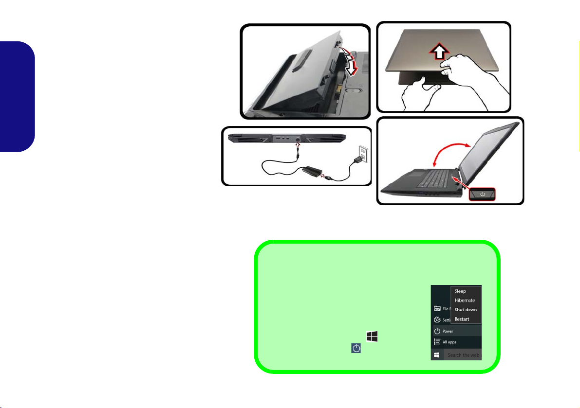
System Startup
135°
Figure 1 - Opening the Lid/LCD/Computer with AC/DC Adapter
Plugged-In
Shut Down
Note that you should always shut your computer down by choosing the Shut down
command in Windows (see below). This will
help prevent hard disk or system problems.
1.Click the Start Menu icon .
2.Click the Power item .
3.Choose Shut Down from the menu.
1. Remove all packing materials.
2. Place the computer on a stable surface.
3. Insert the battery and make sure it is locked
in position.
4. Securely attach any peripherals you want to
use with the computer (e.g. keyboard and
mouse) to their ports.
5. When first setting up the computer use the
English
following procedure (as to safeguard the
computer during shipping, the battery will be
locked to not power the system until first
connected to the AC/DC adapter and initially
set up as below):
•
Attach the AC/DC adapter cord to the
DC-In jack at the rear of the computer,
then plug the AC power cord into an outlet, and connect the AC power cord to the
AC/DC adapter and leave it there for 6
seconds or longer.
• Remove the adapter cord from the com-
puter’s DC-In jack, and then plug it back in
again; the battery will now be unlocked.
6. Use one hand to raise the lid/LCD to a
comfortable viewing angle (do not to
exceed 135 degrees);
(as illustrated in Figure 1) to support the
base of the computer (Note: Never lift the
computer by the lid/LCD).
7. Press the power button to turn the computer
“on”.
use the other hand
4

Model Differences
This notebook series includes four different models that vary slightly in design style, color and general appearance. Not
all the model variants, colors, configurations, buttons etc., are pictured in this manual. Note that though your computer
may look slightly different from that pictured throughout this manual, all ports, jacks (other than those indicated below
and in specification) and general functions are the same for all the design styles (see Specifications for further details).
Feature Model A Model B Model C Model D
English
Display Type
3G/4G Module
Sub Woofer
Power
15.6" (39.62cm), 16:9, UHD (3840x2160)/FHD
(1920x1080)
Factory Option No
No Yes
DC Output: 19.5V, 11.8A
(230W)
DC Output: 19.5V , 16.9A
(330W)
Table 1 - Model Differences
17.3" (43.94cm), 16:9, UHD (3840x2160)/QHD
(2560x1440)/FHD (1920x1080)
DC Output: 19.5V , 1 1.8 A
(230W)
DC Output: 19.5V, 16.9A
(330W)
System Software
Your computer may already come with system software pre-installed. Where this is not the case, or where you are reconfiguring your computer for a different system, you will find this manual refers to Microsoft Windows 10.
5

RAID Setup
Your hard disks or solid state drives (SSDs) can be set up
in RAID mode (for increased performance or protection).
Note that setting up your hard disks/solid state drives
in RAID mode needs to be done prior to installing the
Windows OS. Do not change the mode unless you intend
to reinstall your operating system, and make sure you back
up all necessary files and data before doing so.
English
To configure your RAID (Redundant Array of Independent Disks) system in Striping (RAID 0) or Mirroring
(RAID 1) mode (see Table 2) you will require two identical hard disks or solid state drives.
RAID Level Description
RAID 0
(at lease two
hard disks/
SSDs
needed)
RAID 1
(at lease two
hard disks/
SSDs
needed)
Identical drives reading and writing data in
parallel to increase performance. RAID 0
implements a striped disk array and the data is
broken into blocks and each block is written to
a separate disk drive.
Identical drives in a mirrored configuration
used to protect data. Should a drive that is
part of a mirrored array fail, the mirrored drive
(which contains identical data) will handle all
the data. When a new replacement drive is
installed, data to the new drive is rebuilt from
the mirrored drive to restore fault tolerance.
Prepare the following before setting up your SATA hard
disks/SSDs in RAID mode:
•The Microsoft Windows 10 OS disc.
• An attached external DVD drive.
• A hard disk installed in the Primary HDD bay and a second
(identical) hard disk installed in the Secondary HDD bay.
Or
Two identical SATA solid state drives.
•The Device Drivers & Utilities + User’s Manual disc.
Prepare the following before setting up your PCIe SSDs
in RAID mode:
•The Microsoft Windows 10 OS disc.
• An attached external DVD drive.
• Two identical PCIe solid state drives.
•The Device Drivers & Utilities + User’s Manual disc.
• A USB flash drive.
• An operable computer (to copy files from the Device Driv-
ers & Utilities + User’s Manual disc to the USB flash
drive).
Note: All hard disks/SSDs in a RAID should be identical
(the same size and brand) in order to prevent unexpected
system behavior.
6
Table 2 - RAID Description
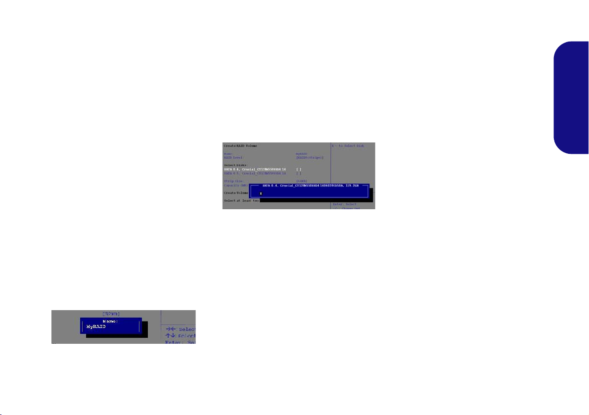
RAID Setup Procedure
Figure 3 - Select Disks
(SATA HDDs/SSDs)
1. Start-up your notebook computer and
press F2 to enter the BIOS.
2. Go to the Boot menu, select UEFI
Setting and press Enter.
3. Set UEFI Boot to “Enabled”.
4. Press Esc to exit the menu and go to the
Advanced menu.
5. Select SATA Mode, press Enter and
select “Intel RST Premium”.
6. Press F4 and <Yes> to “Save Changes
and Reset”.
7. After the computer restarts press F2 to
enter the BIOS again.
8. Go to Intel(R) Rapid Storage
Technology (in the Advanced menu)
and press Enter.
9. Select Create RAID Volume and press
Enter.
10. You can now setup your RAID volume
using any two installed disks.
11. Go to Name: and press Enter.
12. Type a name of your choice for your
RAID volume and press Enter.
Figure 2 - Name the RAID Volume (Advanced > Intel(R) Rapid Storage Tech-
nology)
13. Go to RAID Level: and press Enter.
14. Choose the RAID Level required (see
Table 2 on page 6) and press Enter.
• RAID 0 (Stripe)
• RAID 1 (Mirror)
15. Go to any of the disks listed under
Select Disks: and select a disk name
and press Enter.
16. Move the cursor down (use the arrow
keys) onto X (or select the disk required)
and press Enter.
17. You should select two identical disks to
form your RAID volume.
18. If you have selected RAID 0 (Stripe)
then you can adjust the “Strip Size” to
your requirements (It is recommended
that you set the “Strip Size” to 128KB).
19. Go to Create Volume and press Enter.
20. The RAID volume will then be created
and the RAID information will be
displayed under Intel(R) Rapid Storage
Technology (in the Advanced menu).
21. Press Esc to exit the menu.
22. Press F4 and <Yes> to “Save Changes
and Reset”.
23. Make sure the Windows 10 OS DVD is
in the attached DVD drive and as the
computer starts up it will automatically
boot from the Windows 10 OS DVD
(you will be prompted to press a key to
boot from the DVD).
24. Click Next > Install Now to continue
installing the operating system as
normal (see your Windows
documentation if you need help on
installing the Windows OS).
25. Follow the on-screen instructions to
install the Windows 10 operating system.
26. Install the Windows drivers as per
Table 7 on page 35. Make sure you
install the Intel® Rapid Storage
Technology (IRST) driver (see
page 36).
English
7

RAID Setup Procedure (PCIe SSDs)
1. Go to the operable computer and insert
a USB flash drive.
2. Insert the Device Drivers & Utilities +
User’s Manual disc into the CD/DVD
drive of the operable computer.
3. Copy the f6flpy-x64 folder from the
English
location below (D: denotes your DVD
drive) on the Device Drivers & Utilities
+ User’s Manual disc to the USB flash
drive.
• D:\Options\RAID\f6flpy-x64
4. Start-up your notebook computer and
press F2 to enter the BIOS.
5. Go to the Boot menu, select UEFI
Setting and press Enter.
6. Set UEFI Boot to “Enabled”.
7. Press Esc to exit the menu and go to the
Advanced menu.
8. Select SATA Mode, press Enter and
select “Intel RST Premium”.
9. Press F4 and <Yes> to “Save Changes
and Reset”.
10. After the computer restarts press F2 to
enter the BIOS again.
11. Go to Intel(R) Rapid Storage
Technology (in the Advanced menu)
and press Enter.
12. Select Create RAID Volume and press
Enter.
13. You can now setup your RAID volume
using any two installed disks.
14. Go to Name: and press Enter (see
Figure 2 on page 7).
15. Type a name of your choice for your
RAID volume and press Enter.
16. Go to RAID Level: and press Enter.
17. Choose the RAID Level required (see
Table 2 on page 6) and press Enter.
• RAID 0 (Stripe)
• RAID 1 (Mirror)
18. Go to any of the disks listed under
Select Disks: and select a disk name
and press Enter.
19. Move the cursor down (use the arrow
keys) onto X (or select the disk required)
and press Enter
7)
.
20. You should select two identical disks to
form your RAID volume.
21. If you have selected RAID 0 (Stripe)
then you can adjust the “Strip Size” to
your requirements (It is recommended
that you set the “Strip Size” to 128KB).
22. Go to Create Volume and press Enter.
23. The RAID volume will then be created
and the RAID information will be
displayed under Intel(R) Rapid Storage
Technology (in the Advanced menu).
24. Press Esc to exit the menu.
25. Press F4 and <Yes> to “Save Changes
and Reset”.
(see Figure 3 on page
26. Make sure your USB flash drive is
attached to one of the USB ports on the
computer.
27. Make sure the Windows 10 OS DVD is
in the attached DVD drive and as the
computer starts up it will automatically
boot from the Windows 10 OS DVD
(you will be prompted to press a key to
boot from the DVD).
28. Click Next > Install Now to continue
installing the operating system as
normal (see your Windows
documentation if you need help on
installing the Windows OS).
29. A prompt will appear to ask you to Load
Driver.
30. Click Browse and browse to the location
you copied the files to on your USB flash
drive (X: denotes your USB flash drive):
• X:\f6flpy-x64
31. Click Next.
32. Follow the on-screen instructions to
install the Windows 10 operating system.
33. Install the Windows drivers as per
Table 7 on page 35. Make sure you
install the Intel® Rapid Storage
Technology (IRST) driver (see
page 36).
8
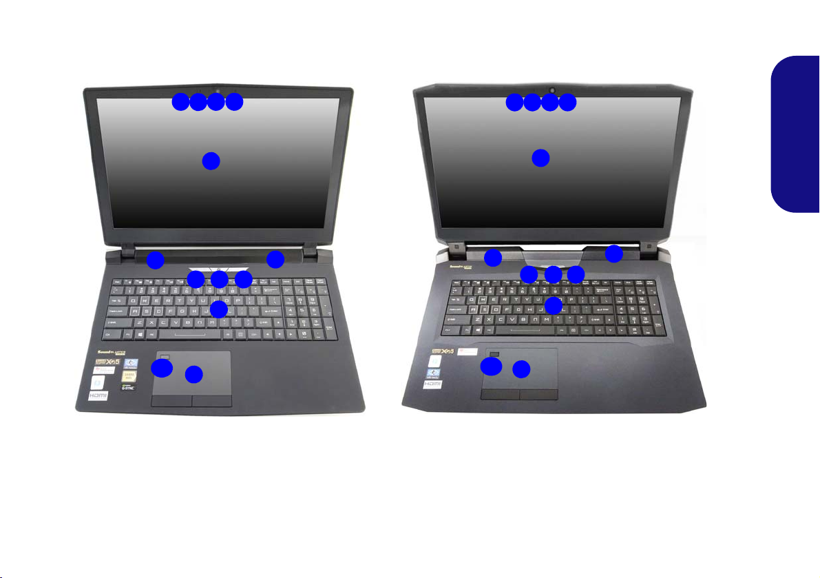
System Map: Front View with LCD Panel Open
2
1
4
3
Figure 4 - Front View with LCD Panel Open (Models A, B, C & D)
1. PC Camera
2. *PC Camera LED
*When the PC camera is in use, the
LED will be illuminated.
3. Built-In Array Microphone
4. LCD
5. Speakers
6. Power Button
7. LED Indicators
8. Keyboard
9. Touchpad & Buttons
10. Fingerprint Reader
3
2 1
4
3 3
Models A & B
Models C & D
15.6” (39.62cm)
17.3” (43.94cm)
8
7
6
9
8
7
6
5
5
5
5
9
10
10
7
7
(Models A, B, C & D)
English
9
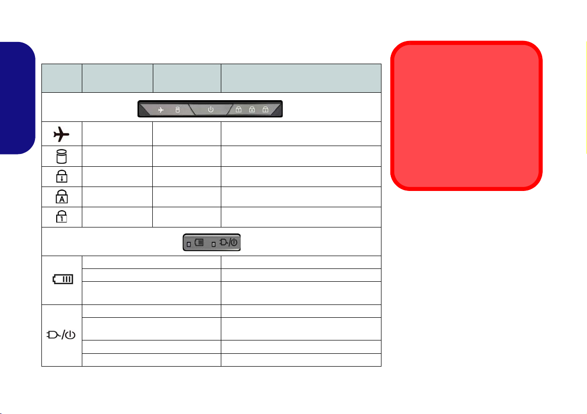
LED Indicators
*The powered USB 3.0 port (see
page 12) may be toggled on /off by
means of the Fn + Power Button
key combination. When the powered USB port is on it will supply
power (for charging devices only,
not for operating devices) when
the system is off but still powered
by the AC/DC adapter plugged
into a working outlet, or powered
by the battery with a capacity level
above 20% (this may not work
with certain devices - see
page 42).
Wireless Device
Operation Aboard Aircraft
The use of any portable electronic
transmission devices aboard aircraft is usually prohibited.
Make sure the wireless modules
are OFF if you are using the computer aboard aircraft by putting the
system in to Airplane Mode.
The LED indicators on the computer display helpful information about the current status of the computer.
Icon
English
Color
(Models A & B)
Green White
Green White The Hard Disk is in use
Green White Scroll Lock Activated
Green White Caps Lock Activated
Green White Number Lock (Numeric Keypad) Activated
Orange The Battery is Charging
Green The Battery is Fully Charged
Blinking Orange
Orange The AC/DC Adapter is Plugged In
Blinking
Orange*
Green The Computer is On
Blinking Green The Computer is in Sleep Mode
10
Color
(Models C & D)
Airplane Mode is ON (the WLAN, Bluetooth
The Battery Has Reached Critically Low
The AC/DC adapter is plugged in and the
Table 3 - LED Indicators
Description
and 3G/4G Modules are OFF)
Power Status
powered USB Port is on*
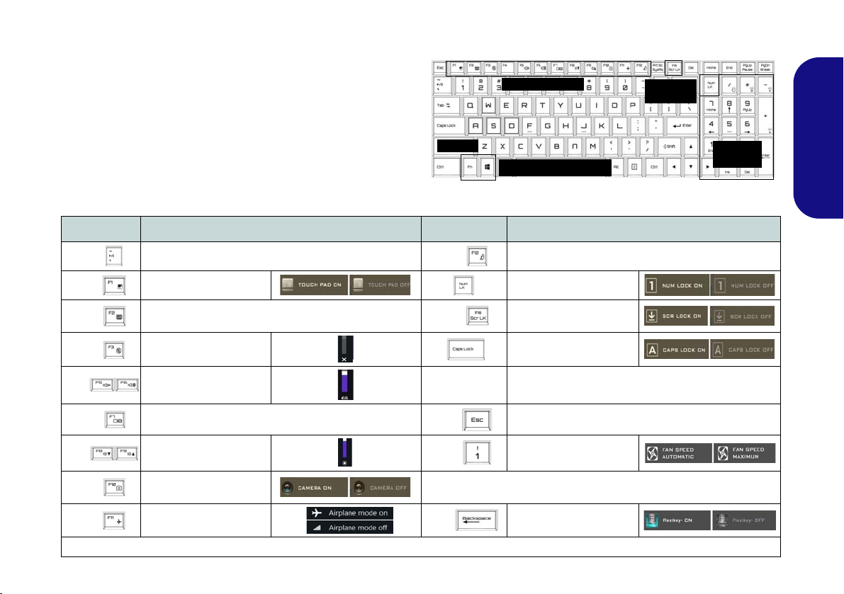
Keyboard & Function Keys
Function Keys
Numeric
Keypad
Fn Key
Windows Logo Key
ScrLk &
NumLk
Figure 5 - Keyboard
The keyboard includes a numeric keypad for easy numeric
data input. Pressing NumLk turns on/off the numeric keypad. It also features function keys to allow you to change
operational features instantly. The function keys (F1 -
F12 etc.) will act as hot keys when pressed while the Fn
key is held down. In addition to the basic function key
combinations, some visual indicators are available when
the Control Center driver is installed.
Keys Function/Visual Indicators Keys Function/Visual Indicators
English
Fn +
Fn +
Fn +
Fn +
Fn +
Fn +
Fn +
Fn +
Fn +
Play/Pause (in Audio/Video Programs)
Touchpad Toggle Number Lock Toggle
Turn LCD Backlight Off
(Press a key to or use Touchpad to turn on)
Mute Toggle
Volume Decrease/
Increase
Change Display Configuration (see page 30)
Brightness Decrease/
Increase
Toggle
Table 4 - Function Keys & Visual Indicators
PC Camera Power
Airplane Mode Toggle
Fn +
Fn +
Fn + Power But-
ton
Fn +
Fn +
*Note: It is recommended that you use Maximum fan speed when playing games.
Fn +
Scroll Lock Toggle
Caps Lock Toggle
Powered USB Port Power Toggle (see page 12)
Control Center Toggle (see page 16)
Fan Automatic Control/
Full Power
Disable/Enable Flexikey®
(see page 23)
Sleep Toggle
11
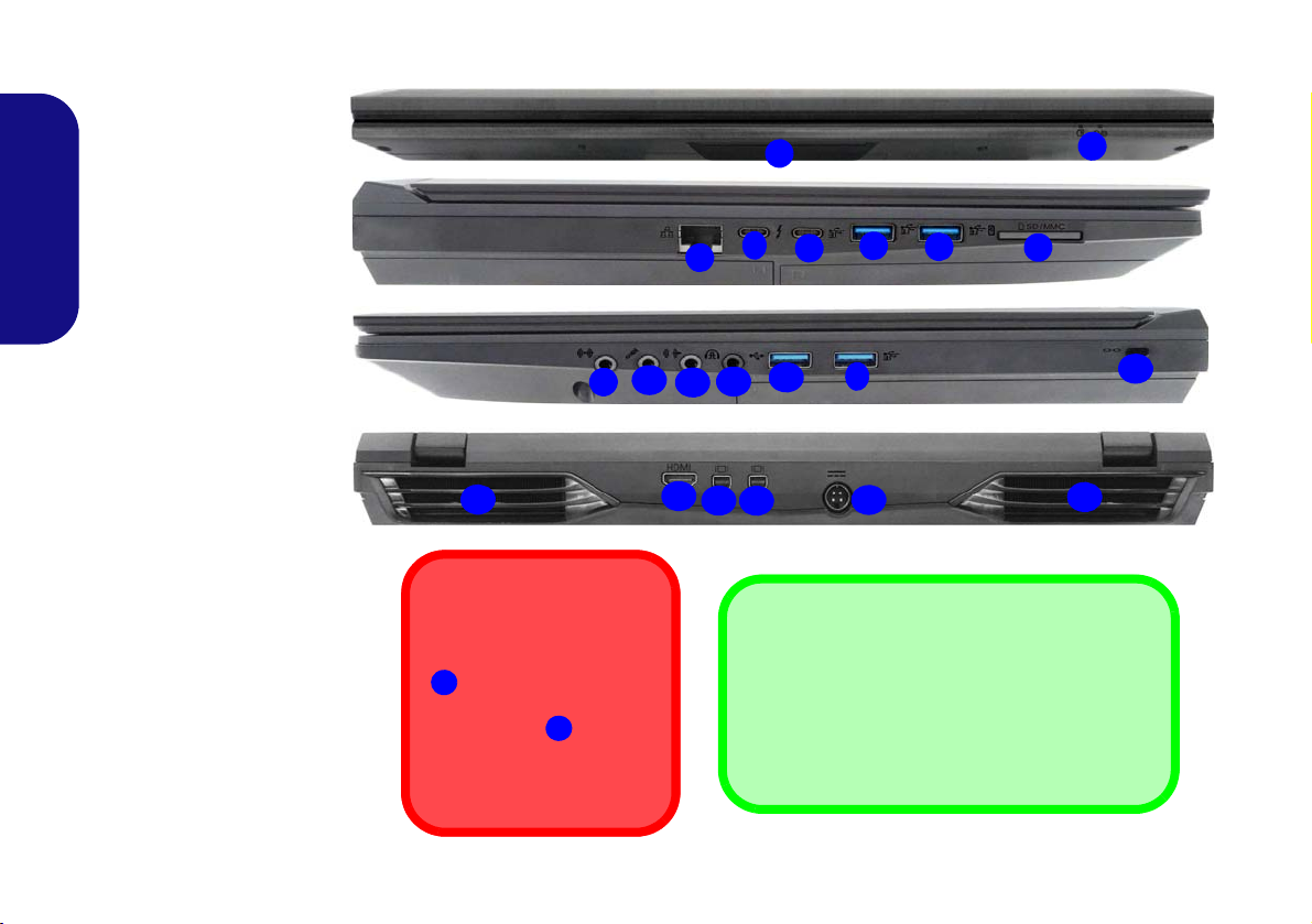
System Map: Front, Left, Right & Rear Views (Models A & B)
3
6
6
5
1
Front
Left
Right
11
14
7
13
12
10
2
8
9
Figure 6
Front, Left, Right & Rear
Views (Models A & B)
1. Lightbar
2. LED Power Indicators
3. RJ-45 LAN Jack
4. USB 3.1 Gen 2/
Thunderbolt 3 Combo
Port (Type-C) (see
page 15)
5. USB 3.1 Gen 2 Type-C
Port
6. USB 3.0 (USB 3.1 Gen 1)
Ports
7. Powered USB 3.0 (USB
3.1 Gen 1) Port
(see page 10)
8. Multi-in-1 Card Reader
9. Line-In Jack
10. Microphone Jack
11. Line-Out Jack
12. 2- In-1 Audio Jack
(Headphone & S/PDIF
Out Combo Jack)
13. USB 2.0 Port
14. Security Lock Slot
15. Vent
16. HDMI-Out Port
17. Mini DisplayPort 1
18. Mini DisplayPort 2
19. DC-In Jack
19
USB 3.1 Gen 2
Note that when a single USB device is plugged in
to a USB 3.1 Gen 2 port the data transfer speed
will be 10Gbps, however when two devices are
plugged in to both USB 3.1 Gen 2 port ports, this
bandwidth will be shared between the ports.
16
15
Rear
4
1817
15
Mini DisplayPort 1
When the Thunderbolt port
is set to be used for display only, then Mini Dis-
playPort 1 will be
disabled (see Thunderbolt
Port Set for Display on
page 15).
4
17
English
12
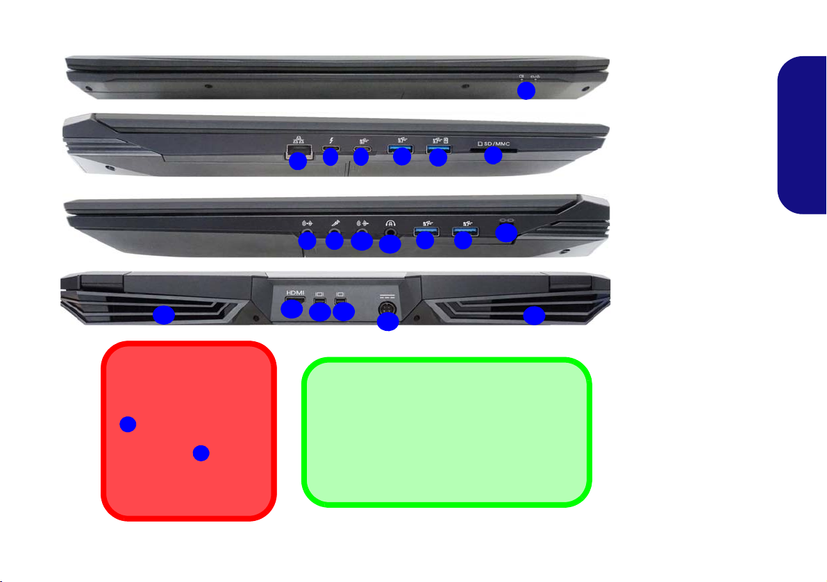
System Map: Front, Left, Right & Rear Views (Models C & D)
6
3
5
1
Front
Left
Right
11
15
7
13
12
10
2
8 9
Figure 7
Front, Left, Right & Rear
Views (Models C & D)
1. LED Power Indicators
2. RJ-45 LAN Jack
3. USB 3.1 Gen 2/
Thunderbolt 3 Combo
Port (Type-C) (see
page 15)
4. USB 3.1 Gen 2 Type-C
Port
5. USB 3.0 (USB 3.1 Gen
1) Ports
6. Powered USB 3.0 (USB
3.1 Gen 1) Port
(see page 10)
7. Multi-in-1 Card Reader
8. Line-In Jack
9. Microphone Jack
10. Line-Out Jack
11. 2- In-1 Audio Jack
(Headphone & S/PDIF
Out Combo Jack)
12. Security Lock Slot
13. Vent
14. HDMI-Out Port
15. Mini DisplayPort 1
16. Mini DisplayPort 2
17. DC-In Jack
14
13
17
16
Rear
4
5
5
Mini DisplayPort 1
When the Thunderbolt port
is set to be used for display only, then Mini Dis-
playPort 1 will be
disabled (see Thunderbolt
Port Set for Display on
page 15).
3
15
USB 3.1 Gen 2
Note that when a single USB device is plugged in
to a USB 3.1 Gen 2 port the data transfer speed
will be 10Gbps, however when two devices are
plugged in to both USB 3.1 Gen 2 port ports, this
bandwidth will be shared between the ports.
13
English
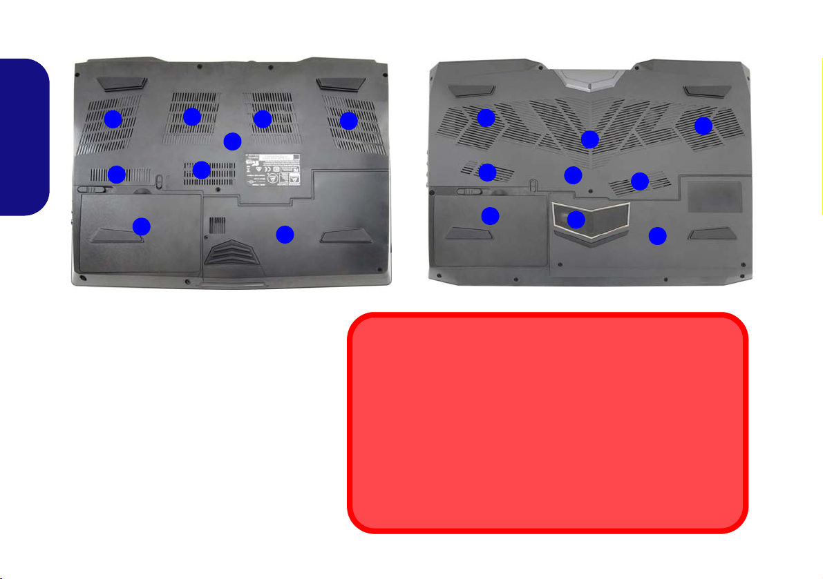
System Map: Bottom Views
Figure 8
Bottom Views
(Models A, B, C & D)
1. Vent
2. Component Bay Cover
3. Battery
4. Sub Woofer
(Models C & D Only)
5. HDD Bay
1
1
3
1
1
1
1
1
1
1
Models C & D
Models A & B
1
1
3
4
5
5
Bottom Cover Removal Warning
Do not remove any cover(s) and/or screw(s) for the purposes of device
upgrade as this may violate the terms of your warranty.
If you need to replace/remove the hard disk/RAM etc., for any reason,
please contact your distributor/supplier for further information.
Overheating
To prevent your computer from overheating make sure nothing blocks
any vent while the computer is in use.
2
2
English
14

Thunderbolt Port Set for Display
17
15
Thunderbolt™ Devices
When plugging a device into a Thunderbolt port alllow 30
seconds for the system to scan and recognize the connected device.
Ejecting Thunderbolt Devices
In order to prevent system problems make sure you do not
simply pull the cable out from the Thunderbolt port. The
hardware must be ejected safely:
1. Go to the notification area of the taskbar and click on the
Safely Remove Hardware and Eject Media icon.
2. Click on Eject “Thunderbolt Device Name”.
3. When you see the “Safe to Remove Hardware” message you can remove the cable.
1
USIM Card Orientation
Note that the USIM card’s readable side (with the goldcolored contacts) should face upwards as illustrated.
1
The display configuration for the Thunderbolt port and
Mini DisplayPorts can be set up in the BIOS (Advanced
menu > Advanced Chipset Control > DDI Control). If
you want to use the Thunderbolt Port for connecting display devices then set the DDI Control to “DDI to TBT”.
Restart your notebook computer and press F2 to enter the
BIOS.
When the Thunderbolt port is set to be used for display only, then Mini DisplayPort 1 ( in Figure 6 on page 12/
in Figure 7 on page 13) will be disabled.
3G/4G Module
(Optional for Models A & B Only)
If you have included an optional 3G/4G module in your
purchase option, follow the instructions below to install
the USIM card (which will be provided by your service
provider).
USIM Card Insertion
1. Turn off the computer, and turn it over and remove the battery
.
2. Insert the USIM card as illustrated below until it clicks into
position, and replace the battery.
English
Figure 9 - Remove the battery and Insert the USIM Card
15
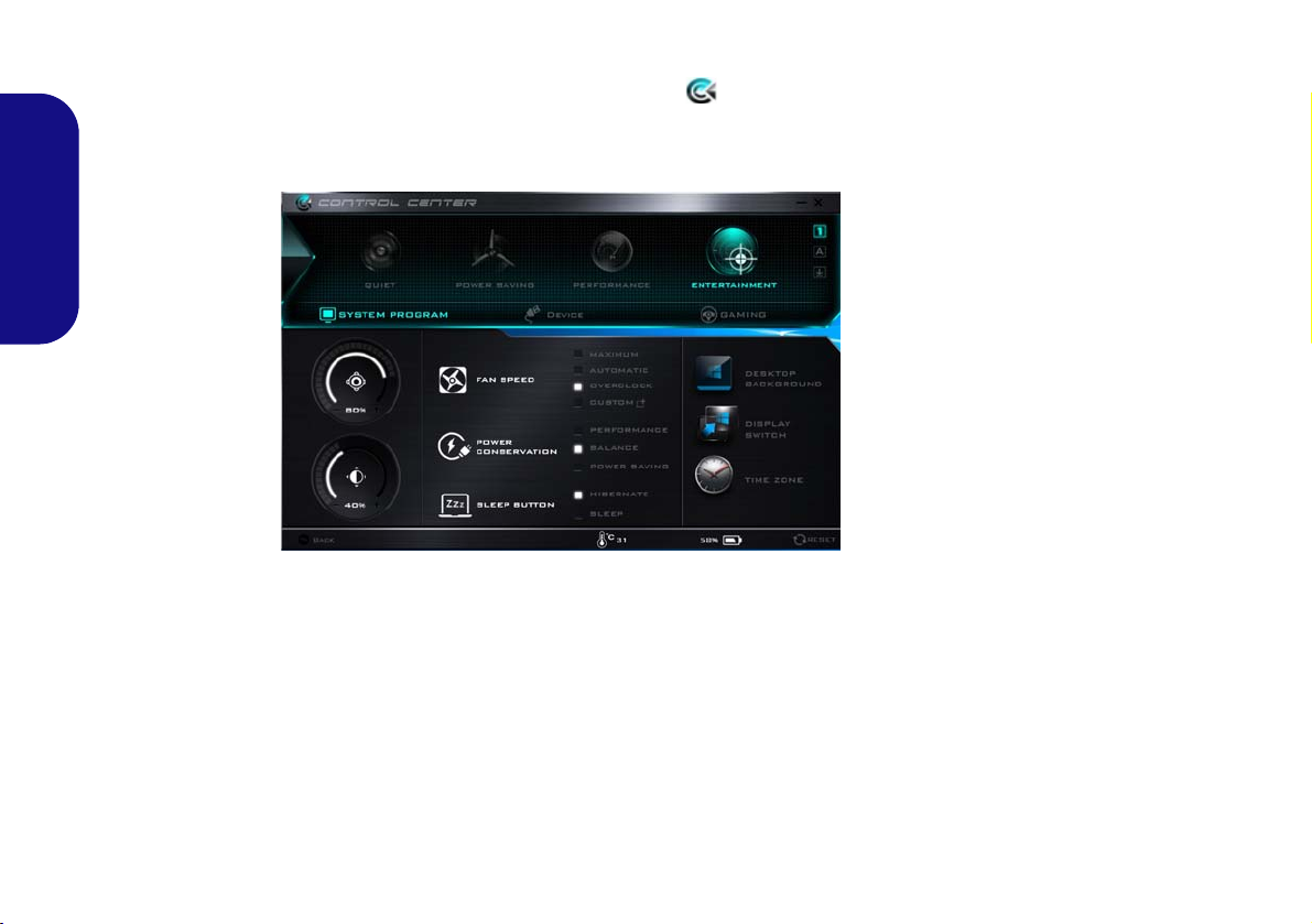
Control Center
Figure 10
Control Center
Press the Fn + Esc key combination, or double-click the icon in the notification area of the taskbar to toggle the
Control Center on/off. The Control Center gives quick access to frequently used controls and enables you to quickly
turn the camera/Touchpad on/off.
English
Power Modes
You can set a Power Mode by clicking the appropriate icon at the top of the Control Center. Each power mode will
affect the Power Conservation Mode, Airplane Mode, Power Plan and PC camera power etc.
Control Center Menus
The Control Cent er contains 3 menu headings (System Program, Device and Gaming) under the Power Modes. Click
the Control Center icons to toggle the appropriate function, or hold the mouse button down and move the dial control
where applicable. Certain functions will automatically be adjusted when a power mode is selected. Click the menu headings and then click any of the buttons outlined on the following page(s).
16
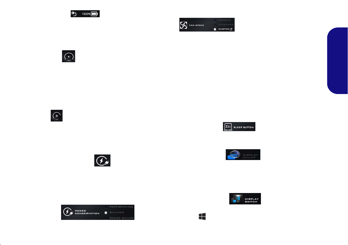
Power Status
The Power Status icon will show whether you are currently powered by the battery, or by the AC/DC adapter
plugged in to a working power outlet. The power status
bar will show the current battery charge state.
Brightness
The Brightness icon will show the current screen brightness level. You can use the slider to adjust the screen
brightness or the Fn + F8/F9 key combinations, or use the
Fn + F2 key combination to turn off the LED backlight
(press any key to turn it on again). Note that screen brightness is also effected by the Power Mode selected.
Volume
The Volume icon will show the current volume level. You
can use the slider to adjust the volume or the Fn + F5/F6
key combinations, or use the Fn + F3 key combination to
mute the volume.
Power Conservation
This system supports Energy Star power management
features that place computers (CPU, hard drive, etc.) into
a low-power sleep mode after a designated period of inactivity. Click either the Performance, Balanced or Power
Saving button.
Fan Speed
You can set the fan speed to Maximum (full power), Automatic, Custom or Overclock from this menu item. The
fan speed will adjust itself automatically to control the heat
of the CPU. However you can adjust the setting to maximum if you prefer. Select Custom and click on the sliders
to adjust the settings to your preference, however these settings can be overidden by the system, as a safety precaution,
if it requires heavier use of the fan.
Overclock will be selected automatically if you have enabled CPU or GPU overclocking (in this case do not
change the setting).
Sleep Button
Click either the Hibernate or Sleep button to have the
computer enter the selected power-saving mode.
Display Utility
The Display Utility icon will only appear in the System
Program menu if your display’s resolution is QHD or
above. The Display Utility allows you to adjust text size
on the screen to make it easier to view.
Display Switch
Click the Display Switch button to access the menu (or
use the + P key combination) and select the appropriate display mode.
English
17
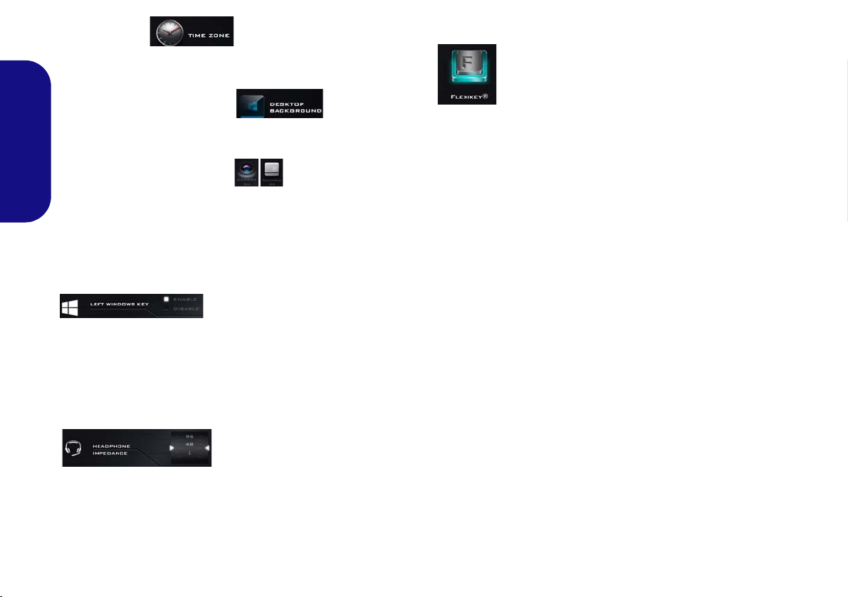
Time Zone
Clicking the Time Zone button will access the Date and
Time Windows control panel.
Flexikey®
Desktop Background
Clicking the Desktop Background button will allow you
to change the desktop background picture.
English
Touchpad/PC Camera
Click either of these buttons to toggle the Touchpad or
camera module’s power status. Note that the power status
of the camera module is also effected by the Power Mode
selected.
Left Windows Key
Click Disable to disable the Windows Logo Key on the
left side of the keyboard. This may be useful if you are using the gaming keys (W, A, S & D) and wish to avoid accidentally triggering menus with the Windows Logo Key.
Headphone Impedance
The headphone impedance will be automatically detected
for any headphones plugged-in (this is not user adjustable).
Click the button to access the Flexikey® application.
18

CPU/Memory Overclocking Support
CPU Overclocking Issues
If you get any system errors, e.g. a black screen, to reset the computer press and hold the power button to
force the system to shutdown. To restart press and
hold the power button while holding down the Fn +
D keys. This will change the overclocking settings back
to the disabled state.
Note overclocking the system (CPU/Memory/GPU) may
cause hardware damage and is enabled at the user’s
own risk, and is not covered in the warranty terms.
Fan Speed
If you have enabled CPU overclocking the Fan Speed
will also automatically be set to Overclock (do not adjust
this fan speed setting if you have enabled CPU overclocking).
Note that the CPU Memory Overclocking and GPU Overclocking items will only appear for systems supporting these features.
Figure 11
Access the CPU
Memory Over-
clocking Utility
You can enable overclocking support for systems with a compatible CPU (contact your distributor/supplier for details)
and Memory. This can be done in the BIOS or by using the Control Center utility (make sure you have installed the
Control Center AP).
Note that making alterations to clock frequency and/or voltage can cause system instability, cause components to
fail, cause heat damage and result in data loss, and any changes made may affect the processor warranty.
You can access the CPU Memory Overclocking utility from the Control Center or taskbar notification area.
English
19
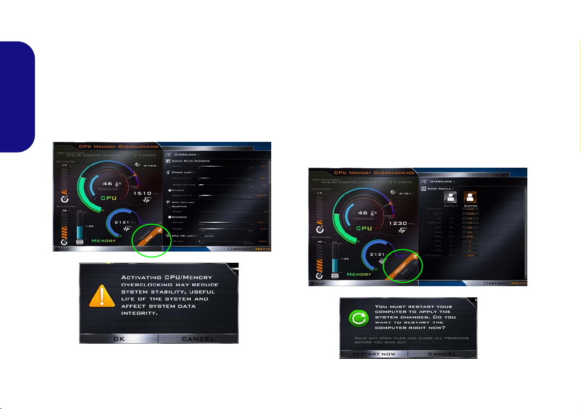
CPU Overclocking
1. Click the CPU tab at the bottom right of the screen and the CPU
overclocking tab will pop out to allow adjustments to be made.
2. Click Save to retain the settings.
3. A warning will pop-up to remind that activating CPU
overclocking may cause system instability.
4. Click OK to retain the saved changes or Cancel to return to the
utility.
5. You can click Default to go back to the standard default
English
settings.
Memory Overclocking
1. Click the Memory tab at the bottom right of the screen and the
Memory overclocking tab will pop out to allow adjustment s to be
made.
2. Click Custom to adjust any settings from the drop-down
menus.
3. Click Save to retain the settings.
4. A warning will pop-up to remind that you will need to restart the
system (make sure you save any open files).
5. Click Restart Now to restart the system or Cancel to return to
the utility.
6. You can click Default to go back to the standard default
settings.
20
Figure 12 - CPU Overclocking
Figure 13 - Memory Overclocking

GPU Overclocking Support
Figure 14
Gaming with
GPU Overclock
GPU Overclocking Issues
If you get any system errors, to reset the computer press
and hold the power button to force the system to shutdown. To restart press and hold the power button while
holding down the Fn + G keys. This will change the over-
clocking settings back to the disabled state.
After restart, if your system supports Optimized GPU Over-
clocking then click Reset in the Control Center to return
to the optimized settings. If your system supports Standard
GPU Overclocking then you can adjust the settings to your
preferences.
You can access the GPU Overclock utility from the Control Center or taskbar notification area.
Click the GPU Overclock button to access the Graphics
Processing Unit (or GPU) overclocking menu for certain
types of CPU and GPU (contact your distributor or supplier to see if this is applicable to your model). Overclocking
the GPU involves running your graphics processor at a
faster speed than originally intended. GPU overclocking
is useful when undertaking intensive graphic tasks e.g. 3D
rendering and gaming, without dropping framerates etc.
Overclocking should only be enabled when powered
by a plugged-in AC/DC adapter, and not on battery
power. The Fan Speed will also automatically be set to
Overclock (do not adjust this fan speed setting if you
have enabled GPU overclocking).
GPU Overclocking Versions
There are two versions of overlcocking available for this
series of computer models, and the version available is dependent on your video adapter specification (contact you
distributor/supplier for details).
• Standard GPU Overclocking: With this version you are
free to adjust the sliders to adjust the settings for Core
Increment, Memory Increment and Fan Speed Offset.
Some settings however may cause system instability,
reduce the useful life of the system and may affect the system integrity.
• Optimized GPU Overclocking: With this version, while
you are still free to adjust the sliders to adjust the settings
for Core Increment, Memory Increment and Fan Speed
Offset, the optimized default settings have been optimized
for the best, and most stable, performance for intensive
graphics tasks such as gaming etc.
21
English

GPU Overclocking
Warning Message
The message highlights the fact that
while overclocking the GPU offers a
boost to graphics performance, it
can cause system instability in certain circumstances as the harder
you push the processor, the more
power you will need to supply to it,
and the hotter the system will run.
Therefore it is not recommended
that you enable GPU overclocking
for extended periods, only as and
when specifically required.
GPU Overclocking Off Using the Taskbar Icon
Move the cursor over the GPU Overclock
icon in the taskbar, and right-click it and select Turn off GPU overclocking.
Figure 15
Click to Reset to
Optimized Default
GPU Overclocking
Settings
Power Modes & Optimized GPU Overclocking
If you click on either the Quiet or Power Saving power
modes in the Control Center, then the optimized GPU overclocking will be turned off.
If you click on either the Performance or Entertainment
power modes in the Control Center then the optimized GPU
overclocking will be turned on.
1. Click On to enable GPU overclocking.
2. Use the sliders to adjust the settings for Core Increment,
Memory Increment and Fan Speed Offset (However if your
system supports Optimized GPU Overclocking then the
presets are customized for the best and most stable
system performance).
3. Click Save to
English
retain the setting
changes, and then
click OK when the
system warning
message appears,
or Cancel to return
to the utility.
4. Clicking Off will
return to the
standard default
settings.
22
Optimized GPU Overclocking Notes:
The following applies only to systems supporting optimized GPU overclocking.
If you wish to use settings other than the preset optimized
settings you are free to do so. However should you wish to
return to the optimized presets at any time you can click
Reset at the bottom right of the Control Center.
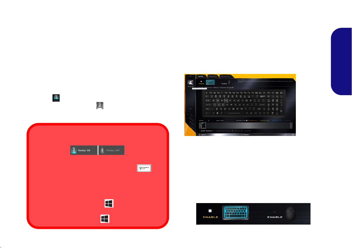
Flexikey® Application
Enabling or Disabling the Flexikey® Profile in Use
You can enable or disable any keyboard or mouse profile
functions currently in use by using the Fn + key
combination. Pressing this key combination will toggle you
between the currently selected keyboard or mouse profile
to the standard keyboard and/or mouse settings, and back
again.
Windows Logo Key and P key
Note that you can assign actions to any keyboard key except the Windows Logo Key and P key.
Figure 16
Flexikey®
Applica-
tion
The Flexikey® application is a quick hotkey configura-
tion application, which allows you to assign a single key
to launch multiple key combinations, or to launch pro-
grams and applications, to create text macros and to
disable certain keys. The application can also be used to
configure the mouse buttons to create hotkeys for gam-
ing etc. All the configuration settings are retained under
(up to12) profiles to which the settings are applied.
The Flexikey® application can be accessed by clicking
the button
ter or by clicking the icon
the desktop taskbar.
in the Gaming section of the Control Cen-
in the notification area of
Profiles
The menus on the left side of the application relate to Profiles. You can Add or Delete profiles (you can maintain
12 active Profiles), Export and Import profiles from the
menus. If you double-click on a profile you can change the
Profile Name, and change an Image file (images created
using PNG files).
English
Keyboard and Mouse Settings
Click Enable to create settings for the keyboard and/or
mouse by clicking the button on the top left of the screen
(e.g. you may wish to create a profile with settings only
for the mouse or keyboard). Clicking on the keyboard or
mouse icons will allow you to access the settings page for
either the keyboard or mouse.
Figure 17 - Enable (Keyboard & Mouse)
23
123
4
5
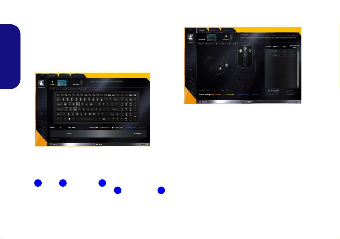
Keyboard Settings
The keyboard settings allow you to configure actions for
any single key (or a combination of keys). Click the key
and then select the Action Type (Express Key, Launch
App, Express Text or Disable) from the menu at the bottom of the page. You can rename the action by clicking in
the Name box, and click in Tool Tips to type in a note to
remind you of the action’s function.
English
Figure 18 - Keyboard Configuration
Mouse Settings
The mouse settings allow you to configure actions for the
left , right and middle buttons of any attached
mouse, and also for any backward and forward
buttons if applicable (on a gaming type mouse). Click the
button number and then select the Action Type (Express
Key, Launch App, Express Text or Disable) from the
menu at the bottom of the page. You can rename the action
24
by clicking in the Name box, and click in Tool Tips to
type in a note to remind you of the action’s function.
Figure 19 - Mouse Configuration
Flexikey® Application Features:
• EXPRESS KEY - This feature allows you to configure a
single key (or mouse click) to send multiple key combinations, or to create more useful shortcut keys This is useful
in gaming or when using applications which have a complex set of keyboard shortcuts.
• LAUNCH APP - This simply assigns single keys (or
mouse clicks) to launch any program’s or application’s
executable file.
• EXPRESS TEXT - With this you can assign single keys
(or mouse clicks) to send commonly used strings of text.
• DISABLE - Use this function to disable any keyboard
keys or mouse buttons.
• STATISTICS - Use this to quickly record keys in use in
any application, and to disable unused keys.
 Loading...