

Clevo P570WM User Manual


Introduction (English)
This Concise User’s Guide introduces the main features
of your computer. The English version of this guide begins on page 1. The expanded User’s Manual is on the
Device Drivers & Utilities + User’s Manual disc.
Einführung (Deutsch)
Dieses Ausführliche Benutzerhandbuch führt Sie in die
Hauptfunktionen des Computers ein. Die deutsche Version des Handbuchs beginnt auf Seite 39. Das erweiterte
Benutzerhandbuch finden Sie auf der Disc für die Gerätetreiber und Hilfsprogramme (Disc Device Drivers &
Utilities + User's Manual).
Présentation (Français)
Ce Guide Utilisateur Concis présente les fonctionnalités
principales de votre ordinateur. La version française de
ce guide commence à la page 77. Le Manuel de l'Utilisa-
teur étendu se trouve sur le disque de Pilotes & Utilitaires + Manuel de l'Utilisateur (disque Device Drivers
& Utilities + User's Manual).
Introducción (Español)
Esta Guía del Usuario Concisa le presenta las características principales de su ordenador. La versión española de
esta guía comienza en la página 115. El Manual del usua-
rio completo se encuentra en el disco de Controladores
del dispositivo y Utilidades + Manual del usuario (disco
Device Drivers & Utilities + User's Manual).
Introduzione (Italiano)
La presente Guida Rapida per l'Utente introduce le caratteristiche principali del computer. La versione italiana di
questa guida inizia da pagina 153. Il Manuale utente
completo si trova nel disco contenente driver e utilità +
Manuale utente (disco Device Drivers & Utilities +
User's Manual).
I

Contents
About this Concise User Guide .........................................................1
System Startup ..................................................................................4
RAID Setup .......................................................................................6
System Map: Front View with LCD Panel Open ............... ..............9
Keyboard & Function Keys ............................................................11
Keyboard LED ................................................................................12
Control Center ......... ............................................... .........................13
System Map: Front, Left & Right Views ........................................15
System Map: Rear & Bottom Views ..............................................16
Windows 8.1 Control Panel ............................................................17
Windows 8.1 Start Screen & Desktop ............................................17
Apps & Tiles ...................................................................................18
Charms Bar ......................... ............................................................18
Video Features ................................................................................19
Power Options .................................................................................23
Audio Features ................................................................................24
PC Camera ......................................................................................27
Driver Installation ... ........................................................................28
Wireless LAN Module (Option) .....................................................30
Fingerprint Reader ..........................................................................31
Bluetooth Module (Option) .............................................................32
Trusted Platform Module ................................................................33
Troubleshooting ..............................................................................35
Specifications ............... ................................. .................................. 36
Inhalt
Über das Ausführliche Benutzerhandbuch ......................................39
Schnellstart .................. ............................................ ........................42
RAID Setup .....................................................................................44
Systemübersicht: Ansicht von vorne mit geöffnetem
LCD-Bildschirm ................... ........................ ........................ ...........47
Tastatur & Funktionstasten .............................................................49
Tastatur-LED ............... ............... ................ ............. ................ ........50
Control Center (Steuerzentrum) ................. .....................................51
Systemübersicht: Ansicht von vorne, links und rechts ...................53
Systemübersicht: Ansicht von hinten und unten .................. ...........54
Windows 8.1 Systemsteuerung .......................................................55
Windows 8.1 Start-Bildschirm und Desktop ...................................55
Apps und Kacheln ...........................................................................56
Charms-Leiste .................................................................................56
Grafikfunktionen .................................................................. ...........57
Energieoptionen ..............................................................................61
Audiofunktionen ..............................................................................62
PC-Kamera ...................... ............................................. ...................65
Installation der Treiber ....................................................................66
Wireless-LAN-Modul (Option) .......................................................68
Fingerabdruckleser ................. .............................................. ...........69
Bluetooth-Modul (Option) ..............................................................70
TPM (Trusted Platform Module) ....................................................71
Fehlerbehebung ...............................................................................73
Technische Daten ............................................................................74
II

Sommaire
A propos de ce Guide Utilisateur Concis ........................................77
Guide de démarrage rapide .............................................................80
Configuration RAID .......................................................................82
Carte du système: Vue de face avec l’écran LCD ouvert ...............85
Clavier & touches fonction ............................................................87
LED du clavier ................................................................................88
Control Center (Centre de contrôle) ...............................................89
Carte du système: Vues de face, gauche & droite ..........................91
Carte du système: Vues arrière & du dessous ...... ...........................92
Panneau de Configuration de Windows 8.1 ....................................93
Écran d'accueil & bureau de Windows 8.1 .......... ...........................93
Applications et Vignettes ................................................................94
Barre des charmes ........................................................... .. ..............94
Caractéristiques vidéo .....................................................................95
Options d’alimentation ....................................................................99
Caractéristiques audio ...................................................................100
Caméra PC ....................................................................................103
Installation du pilote .....................................................................104
Module LAN sans fil (Option) .. ............................................... .....106
Lecteur d'empreintes digitales .......................................................107
Module Bluetooth (Option) .............. .. ...........................................108
TPM (Trusted Platform Module) ................ ..................................109
Dépannage .................... .... ....... .... ....... ....... .... ....... ....... .... ....... .... ...111
Spécifications ............... ................................. ................................ 112
Contenidos
Acerca de esta Guía del Usuario Concisa .....................................115
Guía rápida para empezar ..............................................................118
Configuración RAID .....................................................................120
Mapa del sistema: Vista frontal con panel LCD abierto ...............123
Teclado & teclas de función ..........................................................125
LED del teclado .............................................................................126
Control Center (Centro de control) ...............................................127
Mapa del sistema: Vistas frontal, izquierda, y derecha .................129
Mapa del sistema: Vistas posterior e inferior ................................130
Panel de Control de Windows 8.1 .................................................131
Pantalla Inicio y escritorio de Windows 8.1 .................................131
Apps y Mosaicos ...........................................................................132
Barra Charms ................... ..............................................................132
Parámetros de vídeo ......................................................................133
Opciones de energía ......................................................................137
Características de audio .................................................................138
Cámara PC .....................................................................................141
Instalación de controladores ..........................................................142
Módulo LAN Wireless (Opción) ...................................................144
Lector de huellas digitales .............................................................145
Módulo Bluetooth (Opción) ..........................................................146
TPM (Trusted Platform Module) ..................................................147
Solución de problemas ............................. .. ...................................149
Especificaciones ................ ............................................... .............150
III

Sommario
Informazioni sulla Guida Rapida per l'Utente .............. .. ..............153
Guida di avvio rapido ....................................................................156
Configurazione RAID ................................. ..................................158
Descrizione del sistema: Vista anteriore con pannello
LCD aperto ....................................................................................161
Tastiera & tasti funzione ...............................................................163
LED della tastiera .........................................................................164
Control Center (Centro di controllo) .............................................165
Descrizione del sistema: Vista anteriore, sinistra e destra ............167
Descrizione del sistema: Vista posteriore e inferiore ..................168
Pannello di controllo di Windows 8.1 ...........................................169
Schermata Start e Desktop di Windows 8.1 ..................................169
App & Titoli .............................................. ....................................170
Charms Bar ...................................................................................170
Funzioni video ...... ........................................................................171
Opzioni risparmio energia ..... ........................................................175
Funzionalità audio . ........................................................................176
Camera PC ....................................................................................179
Installazione driver ........................................................................180
Modulo LAN Wireless (Opzione) ................................................182
Lettore d’impronte digitali ........................ ....................................183
Modulo Bluetooth (Opzione) ........................................................184
TPM (Trusted Platform Module) ................ ..................................185
Risoluzione dei problemi ........ ............................................... .......187
Specifiche tecniche .......................................................................188
IV

About this Concise User Guide
FCC Statement
This device complies with Part
15 of the FCC Rules. Operation
is subject to the following two
conditions:
1.This device may not cause
harmful interference.
2. This device must accept any
interference received, including interference that may
cause undesired operation.
This quick guide is a brief introduction to getting your system started. This is a s upplement, and not a substitute for the
expanded English language User’s Manual in Adobe Acrobat format on the Device Drivers & Utilities + User’s Manual
disc supplied with your computer. This disc also contains the drivers and utilities necessary for the proper oper ation of
the computer (Note: The company reserves the right to revise this publication or to change its contents without notice).
Some or all of the computer’s features may already have been setup. If they aren’t, or you are planning to re-configure
(or re-install) portions of the system, refer to the expanded User’s Manual. The Device Drivers & Utilities + User’s
Manual disc does not contain an operating system.
Regulatory and Safety Information
Please pay careful attention to the full regulatory notices and safety information
contained in the expanded User’s Manual on the Device Drivers & Utilities + Us-
er’s Manual disc.
© November 2013
Trademarks
Intel and Intel Core are trademarks/registered trademarks of Intel Corporation.
English
1

Instructions for Care and Operation
The computer is quite rugged, but it can be damaged. To
prevent this, follow these suggestions:
• Don’t drop it, or expose it to shock. If the computer falls, the
case and the components could be damaged.
• Keep it dry, and don’t overheat it. Keep the computer and
power supply away from any kind of heating element. This is an
English
electrical appliance. If water or any other liquid gets into it, the
computer could be badly damaged.
• Avoid interference. Keep the computer away from high capac-
ity transformers, electric motors, and other strong magnetic
fields. These can hinder proper performance and damage your
data.
• Follow the proper working procedures for the computer.
Shut the computer down properly and don’t forget to save your
work. Remember to periodically save your data as data may be
lost.
• Note that in computer’s featuring a raised LCD electro-plated
logo, the logo is covered by a protective adhesive. Due to general wear and tear, this adhesive may deteriorate over time and
the exposed logo may develop sharp edges. Be careful when
handling the computer in this case, and avoid touching the raised
LCD electro-plated logo. Avoid placing any other items in the
carrying bag which may rub against the top of the computer during transport. If any such wear and tear develops contact your
service center.
Power & Battery Safety
• Only use an AC/DC adapter approved for use with this computer.
• Use only the power cord and batteries indicated in this manual.
• Your AC/DC adapter may be designed for international travel
but it still requires a steady, uninterrupted power supply. If you
are unsure of your local power specifications, consult your service representative or local power company.
• The AC/DC adapter may have either a 2-prong or a 3-prong
grounded plug. The third prong is an important safety feature;
do not defeat its purpose. If you do not have access to a compatible outlet, have a qualified electrician install one.
• When you want to unplug the power cord, be su re to disconnect
it by the plug head, not by its wire.
• Make sure the socket and any extension cord(s) you use can support the total current load of all the connected devices.
• Make sure that your computer is completely powered off before
putting it into a travel bag (or any such container).
• Only use batteries designed for this computer. The wrong battery type may explode, leak or damage the computer.
• Do not continue to use a battery that has been dropped, or that
appears damaged (e.g. bent or twisted) in any way. Even if the
computer continues to work with a damaged battery in place, it
may cause circuit damage, which may possibly result in fire.
• Recharge the batteries using the computer’s system. Incorrect
recharging may make the battery explode.
• Do not try to repair a battery pack. Refer any battery pack repair
or replacement to your service representative or qualified service personnel.
• Keep children away from, and promptly dispose of a damaged
battery. Always dispose of batteries carefully. Batteries may
explode or leak if exposed to fire, or improperly handled or discarded.
• Keep the battery away from metal appliances.
• Affix tape to the battery contacts before disposing of the battery.
• Do not dispose of batteries in a fire. They may explode. Check
with local codes for possible special disposal instructions.
• Do not touch the battery contacts with your hand s or metal
objects.
2

Polymer Battery Precautions
Battery Disposal & Caution
The product that you have purchased contains a rechargeable battery. The battery is recyclable. At the end of its useful life, under various state and local laws, it may be illegal
to dispose of this battery into the municipal waste stream.
Check with your local solid waste officials for details in your
area for recycling options or proper disposal.
Danger of explosion if battery is incorrectly replaced. Replace only with the same or equivalent type recommended
by the manufacturer. Discard used battery according to the
manufacturer’s instructions.
Note the following information which is specific to polymer batteries only, and where applicable, this overrides
the general battery precaution information.
• Polymer batteries may experience a slight expansion or swelling, however this is part of the battery’s safety mechanism and is
not a cause for concern.
• Use proper handling procedures when using polymer batteries.
Do not use polymer batteries in high ambient temperature environments, and do not store unused batteries for extended periods.
Cleaning
• Use a soft clean cloth to clean the computer, but do not apply
cleaner directly to the computer.
• Do not use volatile (petroleum distillates) or abrasive cleaners
on any part of the computer.
• Before cleaning the computer remove the battery and make sure
the computer is disconnected from any external power supplies,
peripherals and cables (including telephone lines).
Servicing
Attempting to service the computer yourself may violate
your warranty and expose you and the computer to electric
shock. Refer all servicing to qualified service personnel,
particularly under any of the following conditions:
• When the power cord or AC/DC adapter is damaged or frayed.
• If the computer has been exposed to any liquids.
• If the computer does not work normally when you follow the
operating instructions.
• If the computer has been dropped or damaged (do not touch the
poisonous liquid if the LCD panel breaks).
• If there is an unusual odor, heat or smoke coming from your
computer.
English
3
System Startup
Figure 1
Opening the Lid/LCD/Com-
puter with AC/DC Adapter
Plugged-In
135
o
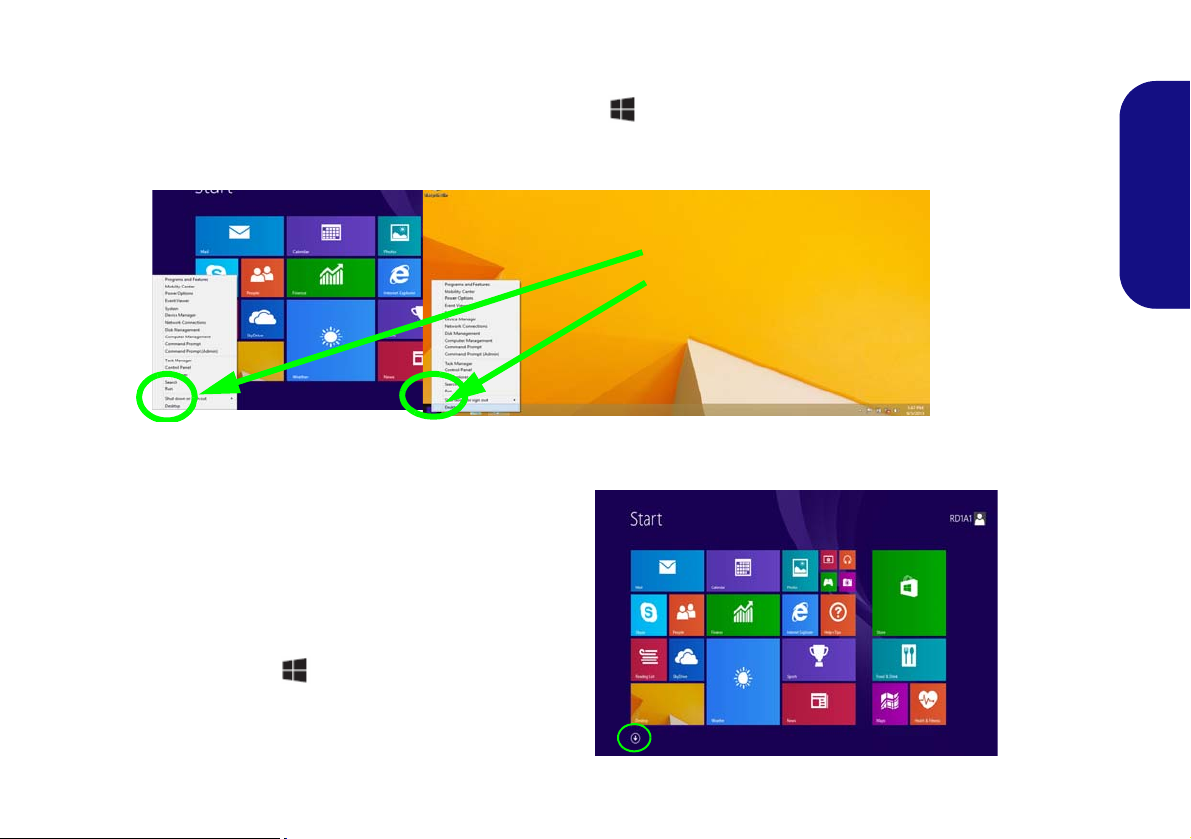
Shut Down
Note that you should always shut your
computer down by choosing the Shut
down command in Windows (see below).
This will help prevent hard disk or system
problems.
Click Settings in the Charms Bar (use the
Windows Logo Key + C key combi-
nation to access the Charms Bar) and
choose Shut down from the Power menu.
Or
Choose Shut down or sign out > Shut
down from the context menu (use the Windows Logo Key + X key combination
to access the context menu).
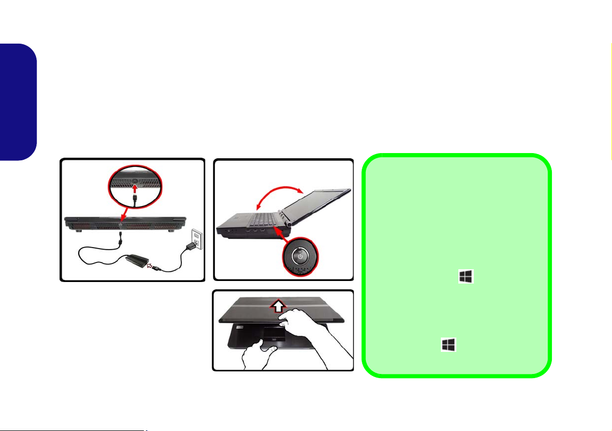
1. Remove all packing materials.
2. Place the computer on a stable surface.
3. Insert the battery and tighten the screws.
4. Securely attach any peripherals you want to use with the computer (e.g. keyboard and mouse) to their ports.
5. Attach the AC/DC adapter to the DC-In jack at the rear of the computer, then plug the AC power cord into an outlet, and connect the AC
power cord to the AC/DC adapter.
6. Use one hand to raise the lid/LCD to a comfortable viewing angle (do not to exceed 135 degrees);
English
Figure 1) to support the base of the computer (Note: Never lift the computer by the lid/LCD) .
7. Press the power button to turn the computer “on”.
use the other hand (as illustrated in
4

Model Differences
This notebook series includes two different model types
that mainly differ as indicated in the table below.
Feature Model A Model B
System Software
Your computer may already come with system software
pre-installed. Where this is not the case, or where you are
re-configuring your computer for a different system, you
will find this manual refers to Microsoft Windows 8.1.
English
3D
Video Adapters
Supported
Not Supported Supported
See "Specifications" on page 36 for a full
list of video adapters supported by each
model.
Table 1 - Model Differences
HDD RAID Support
Your hard disk(s) can be set up in AHCI mode or RAID
mode (for increased performance or protection). Note that
setting up your hard disk(s) in RAID mode needs to be
done prior to installing the Windows OS.
RAID Setup
See RAID Setup on page 6.
5

RAID Setup
You may use your hard disks in combination with Striping
(RAID 0), Mirroring (RAID 1), Parity Across Disks
(RAID 5) or Recovery for either fault tolerance or performance.
RAID Level Description
English
RAID 0
(at lease two
hard disks
needed)
RAID 1
(at lease two
hard disks
needed)
RAID 5
(three hard
disks
needed)
Recovery
(at lease two
hard disks
needed)
Identical drives reading and writing data in parallel to increase performance. RAID 0 implements a striped disk array and the data is
broken into blocks and each block is written to
a separate disk drive.
Identical drives in a mirrored configuration used
to protect data. Should a drive that is part of a
mirrored array fail, the mirrored drive (which
contains identical data) will handle all the data.
When a new replacement drive is installed,
data to the new drive is rebuilt from the mirrored drive to restore fault tolerance.
Identical drives (at least three drives must be
used) in a parity across disks configuration are
used to protect data and increase perfor-
mance. A RAID 5 array can withstand a single
disk failure without losing access to data.
Two Identical drives copying data between a
master and a recovery disk. This provides more
control over how data is copied between the
master and recovery drives, fast volume updates
and the ability to view the data in Windows
Explorer.
Prepare the following before setting up your serial ATA
hard disks in RAID mode:
1. The Microsoft Windows 8.1 OS disc.
2. A ha r d disk installed in the Primary HDD bay.
AND
For RAID levels 0/1/Recovery: A second (identical) hard disk
installed in the Primary HDD bay.
For RAID level 5: A third (identical) hard disk installed in the
Secondary HDD bay.
3. The Device Drivers & Utilities + User’s Manual disc.
4. A USB flash drive.
5. An operable computer (to copy files from the Device Drivers &
Utilities + User’s Manual disc to the USB flash drive).
Note: All hard disks in a RAID should be identical (the
same size and brand) in order to prevent unexpected system behavior.
6
Table 2 - RAID Description
RAID Setup Procedure
Before setting up the system you will need to copy a driver
folder (on the Device Drivers & Utilities + User’s Manual
disc) to a USB flash drive or external USB hard disk.
However you will need to go to an operable computer and
copy the driver folder to a USB Flash drive or external
USB hard disk.
1. Go to the operable computer and insert a USB Flash drive or
external USB hard disk.
2. Insert the Device Drivers & Utilities + User’s Manual disc into
the CD/DVD drive of the operable computer.
3. Copy the f6flpy-x64 folder from the location below (D: denotes
your DVD drive) on the Device Drivers & Utilities + User’s
Manual disc to the USB flash drive or external USB hard disk.
• Windows 8.1 64bit
D:\Options\00_IRST\f6flpy\f6flpy-x64
4. Start-up your notebook computer and press <F2> to enter the
BIOS.
5. Go to the Boot menu, select UEFI Setting and press <Enter>.
6. Set UEFI Boot to “Enabled”.
7. Press <Esc> to exit the menu and go to the Advanced menu.
8. Select SATA Mode, press <Enter> and select “RAID Mode”.
9. Press <F4> and <Yes> to “Save Changes and Reset”.
10. After computer restarts press <F2> to enter the BIOS again.
11. Go to Intel(R) Rapid Storage Technology (in the Advanced
menu) and press <Enter>.
12. Select Create RAID Volume and press <Enter>.
13. You can now setup your RAID volume using any two installed
disks.
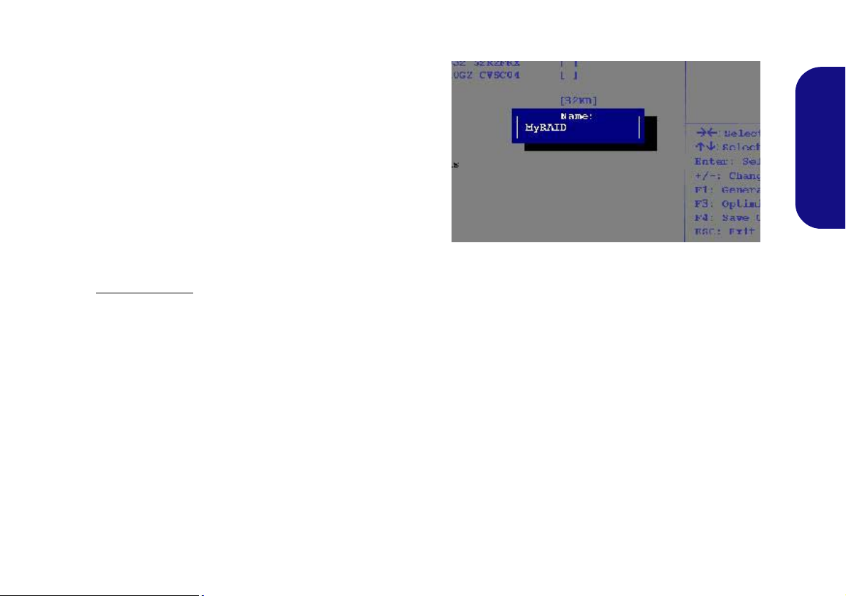
14. Go to Name: and press <Enter>.
15. Type a name of your choice for your RAID volume and press
<Enter>.
English
Figure 2 - Name the RAID Volume (Advanced > Intel(R)
Rapid Storage Technology)
16. Go to RAID Level: and press <Enter>.
17. Choose the RAID Level required (see Table 2 on page 6) and
press <Enter>.
• RAID 0 (Stripe)/RAID 1 (Mirror)/RAID 5 (Parity)
• Recovery
18. Go to any of the disks listed under Select Disks: and select a
disk name and press <Enter>.
19. Move the cursor down (use the arrow keys) onto to X (o select
the disk required) and press <Enter>.
7
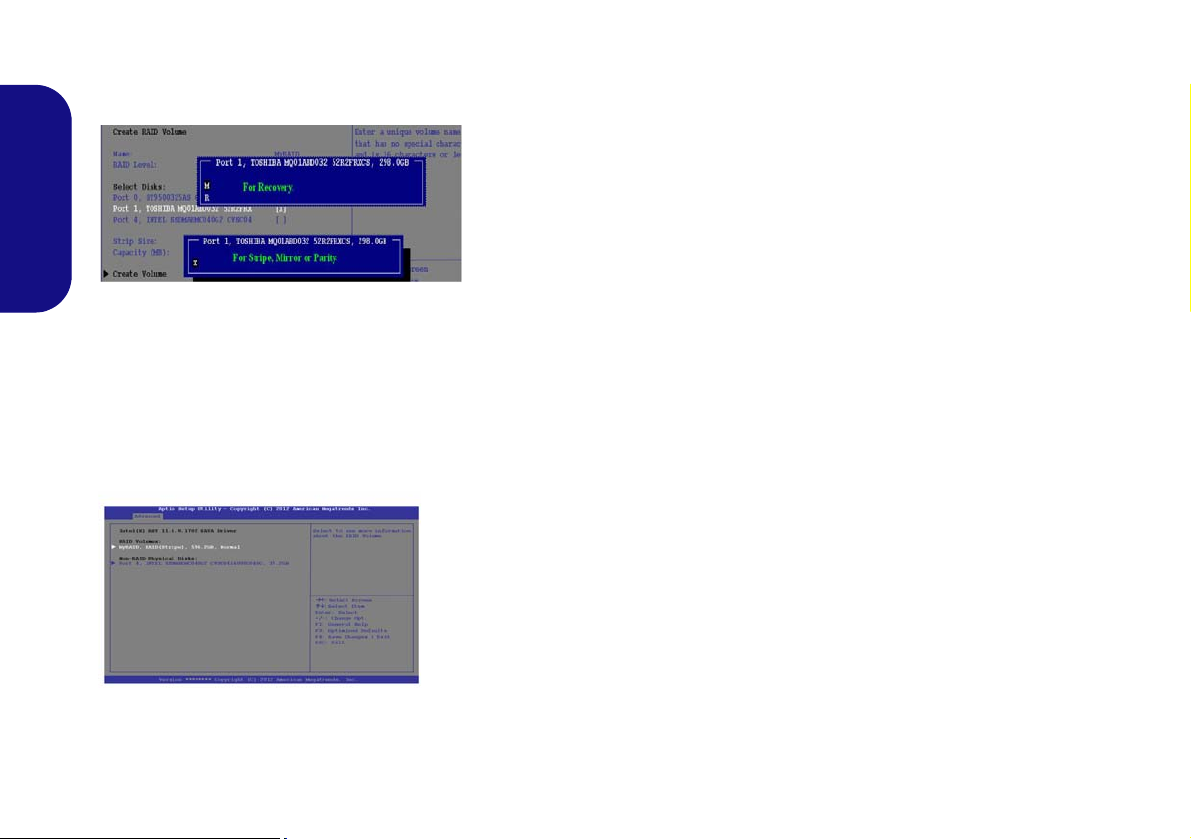
If you have selected a Recovery level RAID then you
Figure 3
Select
Disks
Figure 4
RAID Informa-
tion (Advanced >
Intel(R) Rapid
Storage Technol-
ogy)
need to select one disk to be Master disk (M) and one
disk to be the Recovery disk (R).
English
20. Y ou should select two iden tical disks to form your RAID volume.
21. If you have selected RAID 0 (Stripe) then you can adjust the
“Strip Size” to your requirements.
22. If you have selected Recovery then you can adjust the
Synchronization to “On Request” or “Continuous”.
23. Go to Create Volume and press <Enter>.
24. The RAID volume will then be created and the RAID information
will be displayed under Intel(R) Rapid Stor age Technology (in
the Advanced menu).
• Make sure the W indows 8.1 OS DVD is in the DVD drive and
as the computer starts up it will automatically boot from the
Windows 8.1 OS DVD (you will be prompted to press a key
to boot from the DVD).
• Make sure your USB Flash drive or external USB hard disk is
attached to one of the USB ports on the computer.
27. Press <F7> as the computer starts up to bring up the boot
device menu.
28. Select the DVD drive containing the Windows 8.1 OS DVD and
press <Enter>.
29. Press a key at system startup to begin installing Windows from
your Microsoft Windows 8.1 disc.
30. Click Next > Install Now to continue installing the operating
system as normal (see your Windows documentation if you
need help on installing the Windows OS).
31. A prompt will appear to ask you to Load Driver.
32. Click Browse and browse to the location you copied the files to
on your USB Flash drive or external USB hard disk (X: denotes
your USB Flash drive or external USB hard disk):
• X:\f6flpy-x64
33. Click Next.
34. Follow the on-screen instructions to install the Windows 8.1
operating system.
35. Install the Windows drivers as per Table 8 on page 28. Make
sure you install the Intel Rapid Storage Technology (IRST)
driver (see page 29).
25. Press <Esc> to exit the menu.
26. Press <F4> and <Yes> to “Save Changes and Reset”,
however ensure that the two conditi ons in the bulleted
points below are met before doing so.
8
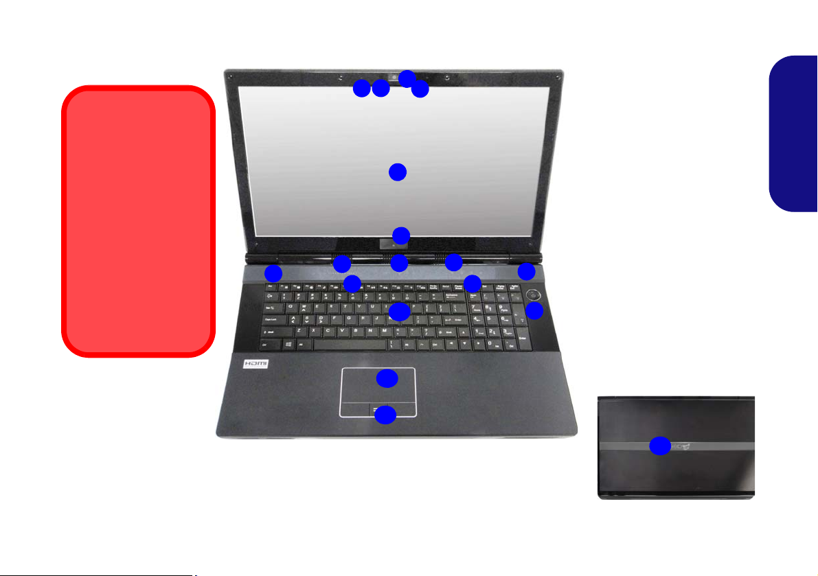
System Map: Front View with LCD Panel Open
Figure 5
Front View with LCD
Panel Open
1. PC Camera (Optional)
2. Built-In Microphone
3. *PC Camera LED
*When the PC camera
is in use, the LED will
be illuminated in red.
4. LCD
5. LED Status Indicators
6. Touch Sensor Instant
Keys
7. Speakers
8. 3D IR Emitter (Model B
Only)
9. Power Button
10. Keyboard
11. Touchpad & Buttons
12. Fingerprint Reader
13. LCD Panel Color LED
13
2
1
6
8
9
5
3
Wireless Device
Operation Aboard
Aircraft
The use of any portable
electronic transmission
devices aboard aircraft
is usually prohibited.
Make sure the WLAN &
Bluetooth module(s) are
OFF if you are using the
computer aboard aircraft by putting the system in to Airplane Mode.
10
4
2
7
7
7
11
7
12
7
English
9
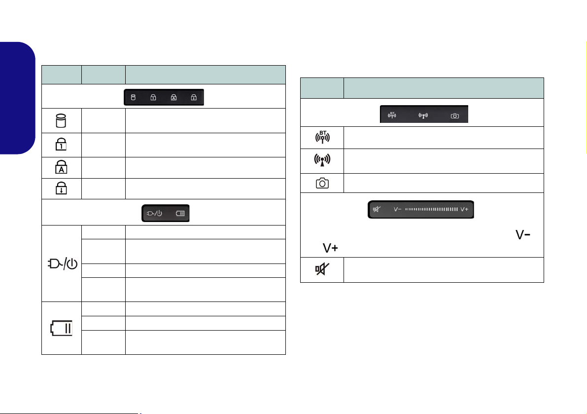
LED Indicators
The LED indicators on the computer display helpful information about the current status of the computer.
Icon
Color Description
Touch Sensor Instant Keys
Press the touch sensor instant keys on the computer to toggle the appropriate function on/off. When a module is installed the appropriate icon will be highlighted blue.
Icon Description
English
10
Blinking
Blue
Blue
Blue Caps Lock Activated
Blue Scroll Lock Activated
Orange The AC/DC Adapter is Plugged In
Blinking
Orange
Green The Computer is On
Blinking
Green
Orange The Battery is Charging
Green The Battery is Fully Charged
Blinking
Orange
The Hard Disk/Optical Device is in use
Number Lock (Numeric Keypad) Acti-
vated
The powered USB 3.0 Port is on
(see page 15)
The Computer is in Sleep Mode
The Battery Has Reached Critically Low
Power Status
Table 3 - LED Indicators
The Bluetooth Module is Installed
The Wireless LAN Module is Installed
PC Camera Module Power Toggle
Volume Control (Press and hold your finger at either end /
of the volume control to adjust the system volume)
Mute Toggle
Table 4 - Touch Sensor Instant Keys
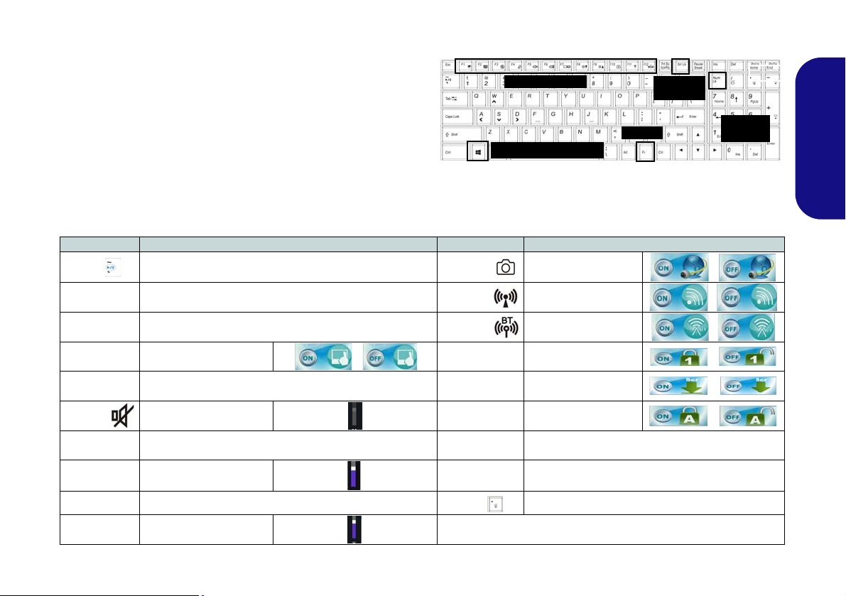
Keyboard & Function Keys
Function Keys
Numeric
Keypad
Fn Key
ScrLk &
NumLk
Windows Logo Key
Figure 6 - Keyboard
The keyboard includes a numeric keypad (on the right side of
the keyboard) for easy numeric data input. Pressing Fn +
NumLk turns on/off the numeric keypad. It also features
function keys to allow you to change operational features instantly. The function keys (F1 - F12 etc.) will act as hot keys
when pressed while the Fn key is held down. In addition to
the basic function key combinations, some visual indicators
are available (in the Windows Desktop application only
and not in the Start screen) when the hot key driver is installed.
Keys Function/Visual Indicators Keys Function/Visual Indicators
Fn +
Fn + 1 Fan Automatic Control/ Full Power
Fn + 5
Fn + F1 Touchpad Toggle Fn + NumLk Number Lock Toggle
Fn + F2
Fn + F3/
Fn + F4 Sleep Toggle
Fn + F5/F6
Fn + F7 Change Display Configuration (see page 26)
Fn + F8/F9
Audio Toggle - Toggle between Standard and Enhanced
Play/Pause (in Audio/Video Programs)
Audio (see page 24)
Turn LCD Backlight Off
(Press a key to or use Touchpad to turn on)
Mute Toggle Caps Lock Caps Lock Toggle
Volume Decrease/
Increase
Brightness Decrease/
Increase
Fn + F10/
Fn + F11/
Fn + F12/
Fn + ScrLk Scroll Lock Toggle
Fn + Power
Button
Fn + Esc Control Center Toggle (see page 13)
Fn +
Table 5 - Function Keys & Visual Indicators
PC Camera Power
Toggle
WLAN Module Power
Toggle
Bluetooth Module
Power Toggle
Powered USB Port Power Toggle (see page 15)
Keyboard LED Toggle (see page 12)
English
11
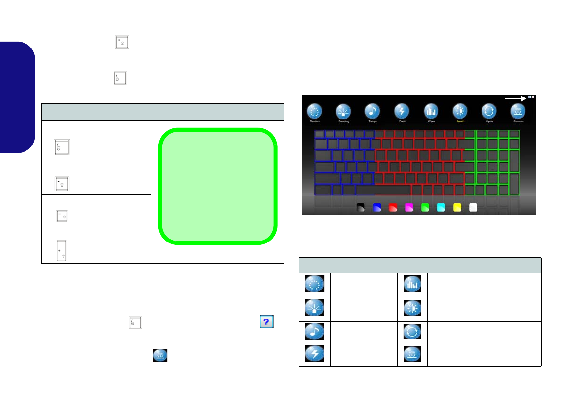
Keyboard LED
*Illumination Keys
Note that the keyboard illumination (increase/decrease) keys may be
used to configure the keyboard LED in Custom
Mode only.
Help Button
Keyboard Sections
Effect Buttons
Color Swatches
Press Fn plus the key to toggle the keyboard LED on /
off. The keyboard LED may be configured using the Fn +
key combination outlined in the table below. In addition
press Fn plus the key to launch the keyboard backlight
application to configure the settings.
• Click a section of the keyboard and the color buttons will
be displayed.
• Click a color swatch to apply the color to the selected section when not overidden by any effect applied.
• Click on any of the effect buttons to apply random colors,
wave or flashing effects etc.
English
Keyboard Backlight Application
The Keyboard Backlight application can be accessed by
pressing the Fn plus key. Click the Help button in
the application to display the configuration keys.
• Click the Custom button to display the three sections
12
Keyboard LED Function key Combinations
Fn +
Fn +
Fn +
Fn +
Launch the
Keyboard
Backlight
Application
Toggle the
Keyboard LED
On/Off
*Keyboard LED
Illumination
Decrease
*Keyboard LED
Illumination
Increase
Table 6 - Keyboard LEDs
of the keyboard which may be configured.
Figure 7 - Keyboard Backlight Application
Effect Buttons & Help
LED Effect Buttons
Random Color Up/Down Wave
Dancing Effect Breathing (All Col ors)
Tempo Beat
Flashing
Table 7 - LED Effect Buttons
Cycle (Colors as Selected in
RGB)
Custom - Display & Configure
Keyboard Sections & Colors
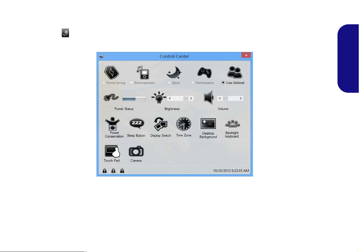
Control Center
When in the Windows Desktop application (not in the Start screen), press the Fn + Esc key combination, or doubleclick the icon in the notification area of the taskbar to toggle the Control Center on/off. The Control Center gives
quick access to frequently used controls, and enables you to quickly turn modules on/off.
Figure 8 - Control Center
English
Click on any button to turn any of the modules (e.g. Touchpad, Camera) on/off. Click on Power Conservation to switch
between Performance, Balanced or Energy Star modes. Click on the buttons (or just click and hold the mouse button)
to adjust the slider for Brightness/Volume. Click on Display Switch/Time Zone/ Desktop Background to bring up
the appropriate Windows control panel. Click on the Sleep button to put the computer into Hibernate or Sleep mode.
13
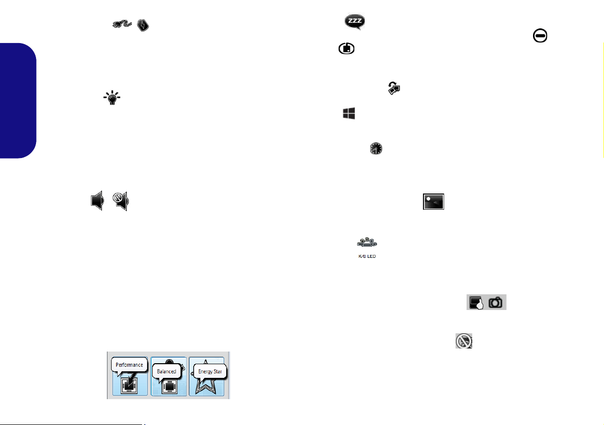
Power Status
The Power Status icon will show whether you are currently powered by the battery, or by the AC/DC adapter
plugged in to a working power outlet. The power status
bar will show the current battery charge state.
Brightness
The Brightness icon will show the current screen bright-
English
ness level. You can use the slider to adjust the screen
brightness or the Fn + F8/F9 key combinations, or use the
Fn + F2 key combination to turn off the LED backlight
(press any key to turn it on again). Note that screen brightness is also effected by the Power Mode selected.
Sleep
Click the Sleep button to bring up the Hibernate or
Sleep buttons, and click either button to have the
computer enter the appropriate power-saving mode.
Display Switch
Click the Display Switch button to access the menu (or
use the + P key combination) and select the appropriate display mode.
Time Zone
Clicking the Time Zone button will access the Date and
Time Windows control panel.
Volume
The Volume icon will show the current volume level. You
can use the slider to adjust the volume or the Fn + F5/F6
key combinations, or use the Fn + F3 key combination to
mute the volume.
Power Conservation
This system supports Energy Star power management
features that place computers (CPU, hard drive, etc.) into
a low-power sleep mode after a designated period of inactivity. Click either the Performance, Balanced or Ener-
gy Star button.
14
Desktop Background
Clicking the Desktop Background button will allow you
to change the desktop background picture.
K/B LED
Click to access the keyboard setting control to configure
the keyboard LED.
Touchpad/PC Camera Module
Click either of these buttons to toggle the Touchpad or
camera module’s power status. A crossed out icon will appear over the top left of the icon when it is off
. Note
that the power status of the camera is also effected by the
Power Mode selected.
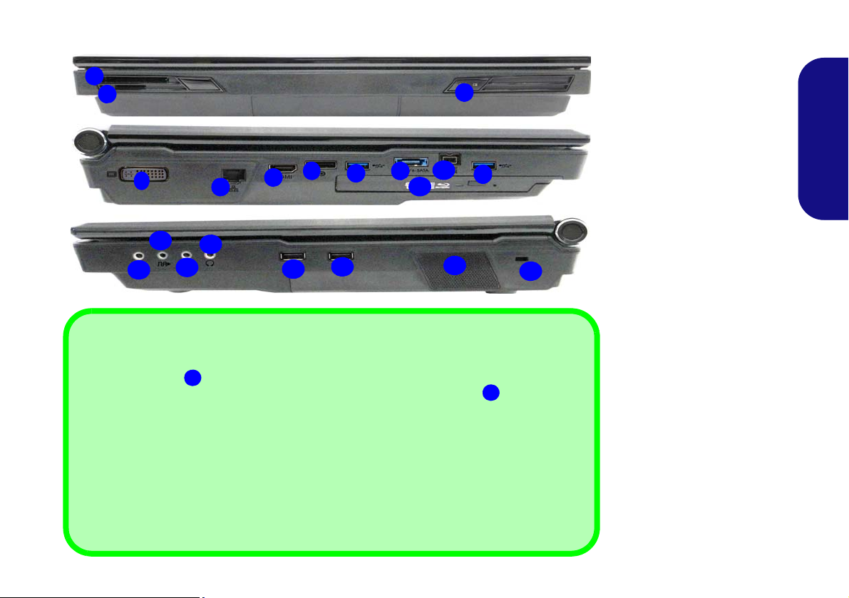
System Map: Front, Left & Right Views
Figure 9
Front, Left & Right Views
1. LED Power Indicators
2. ExpressCard Slot (54/34)
3. Multi-In-1 Card Reader
4. DVI-Out Port
5. RJ-45 LAN Jac k
6. HDMI-Out Port
7. DisplayPort
8. USB 3.0 Ports
9. Combined eSATA/Powered
USB 3.0 Port (See Below)
10. Mini-IEEE 1394b Port
11. Optical Device Drive Bay
12. Line-In Jack
13. S/PDIF-Out Jack
14. Microphone-In Jack
15. Headphone-In Jack
16. USB 2.0 Ports
17. Sub Woofer
18. Security Lock Slot
3
6
4
5
7
2
1
Front
Left
Right
12
17
16
15
14
10
18
11
USB
The USB 3.0 ports
are colored blue. USB 3.0 will transfer data much faster than USB 2.0,
and is backwards-compatible with USB 2.0. When the powered USB 3.0 port
is o n it will sup-
ply power (for charging devices only, not for operating devices) when the system is off but
still powered by the AC/DC adapter plugged into a working outlet, or powered by the battery with
a capacity level above 20% (this may not work with certain devices - see page 35). Toggle power
to this port by using Fn + power button.
Display Devices
Besides the built-in LCD, you can also use an external VGA monitor (CRT)/external Flat Panel
Display or TV (connected to the DVI-Out port/HDMI-Out port/DisplayPort) as your display device.
8
9
9
8
13
8
16
English
15
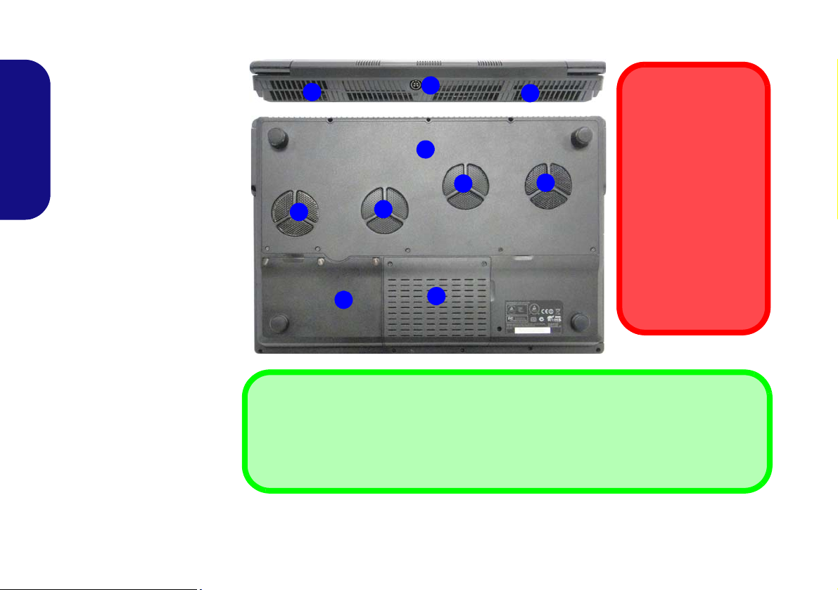
System Map: Rear & Bottom Views
Figure 10
Rear & Bottom Views
1. DC-In Jack
2. Vent
3. Component Bay Cover
4. Battery
5. Hard Disk Bay Cover
CPU
The CPU is not a user
serviceable part. Accessing the CPU in any
way may violate your
warranty.
Overheating
To prevent your computer from overheating
make sure nothing
blocks any vent while
the computer is in use.
2
2
1
3
5
2
2
Battery Information
Always completely discharge, then fully charge, a new battery before using it. Completely discharge and charge the battery at least once every 30 days or after about 20 partial discharges
(see the expanded User’s Manual on the Device Drivers & Utilities + User’s Manual disc).
4
2
2
English
16
Windows 8.1 Control Panel
Move the mouse to
the bottom left of the
screen and right-click
the Start button to access the menu.
Figure 11
Context
Menu
Figure 12
Start
Screen
Throughout this manual you will see an instruction to open the Control Panel. Right-click the Start button in the
Desktop app or Start screen (or use the Windows Logo Key + X key combination) to bring u p an advanced context
menu of useful features such as Control Panel, Programs and Features, Power Options, Task Manager, Search, File Explorer, Command Prompt, Device Manager and Network Connections etc. and then select Control Panel.
Windows 8.1 Start Screen & Desktop
The Apps, control panels, utilities and programs within
Windows are accessed from the Start screen and/or
Windows Desktop app. The Desktop (which runs as an
app within the Start screen) can be accessed by clicking
the Desktop item in the Start screen (or by using the
Windows Logo Key + D key combination). The
taskbar is displayed at the bottom of the desktop screen,
and you can see the notification area of the taskbar in the
bottom right of the screen. Click the arrow at the bottom
of the Start screen to access Apps.
17
English

Apps & Tiles
Click the arrow at the bottom of the
screen to access Apps.
The Start screen will contain a number of apps, and many more
will be installed as you add more applications etc. Not all of these
apps can fit on one screen so you will often need use the slider at
the bottom of the screen in order to view all the necessary Apps.
Charms Bar
English
The right side of the screen displays the Charms Bar. The Charms Bar contains the Search, Share, Start, Devices and
Settings menus. To access up the Charms Bar move the cursor to the upper or lower right corners of the screen, and
then hover over one of the items in the Charms Bar to activate it (the bar will be black when it is active), or use the
Windows Logo Key + C key combination.
18
Figure 13 - Start Screen with Charms Bar

Video Features
This computer features two different (either NVIDIA or
AMD) video options. You can switch display devices, and
configure display options, from the Display control panel
in Windows as long as the video driver is installed.
To access Display control panel in Windows:
1. Go to the Control Panel.
2. Click Display (icon) - in the Appearances and
Personalization category.
3. Click Adjust Screen Resolution/Adjust resolution.
OR
4. Right-click the desktop (use the Windows Logo Key + D
key combination to access the desktop) and select Screen
resolution.
5. Use the dropbox to select the screen resolution.
6. Click Advanced settings.
To access the NVIDIA Control Panel:
1. Go to the Control Panel.
2. Click NVIDIA Control Panel (icon) - in the Appearances and
Personalization category.
OR
3. Right-click the desktop (use the Windows Logo Key + D
key combination to access the desktop) and select NVIDIA
Control Panel from the menu.
To access the Catalyst Control Center:
1. Right-click the desktop (use the Windows Log o Key + D
key combination to access the desktop) and select Graphics
Properties.
OR
2.
Double-click the icon (or right-click the icon and select
Configure Graphics
sure “
Enable System Tray Menu
) in the notification area of the taskbar (make
” is clicked in
Preferences
).
Multi GPU Configuration
This computer features NVIDIA Scalable Link Interface (SLI)/AMD CrossFireX that improves graphic
quality and performance by combining dual GPUs (two
video cards are required) in a single system.
To enable/disable SLI
1. Go to the NVIDIA Control Panel
2. Click “+” next to 3D Settings if its sub-items are not shown and
then click Set SLI and PhysX configuration.
3. Click “
4. Click to select “PhysX settings; Auto-select (recommended)
5. Click Apply and Restart Now to restart the computer.
Maximize 3D Performance
is the default setting.
To enable/disable CrossFireX Configuration:
1. Go to the Catalyst Control Center.
2. Click “>” next to Gaming if its sub-items are not shown and then
click AMD CrossFireX.
3. Make sure the option “Enable AMD CrossFireX™” is selected.
Configuration:
.
” under “
SLI configuration:”
English
.
19
Display Devices
Screen Resolution for Apps (Windows 8.1)
The minimum resolution in which Apps will run is
1024x768.
The minimum resolution required to support all the features of Windows 8.1 (including multitasking with snap)
is 1366x768.
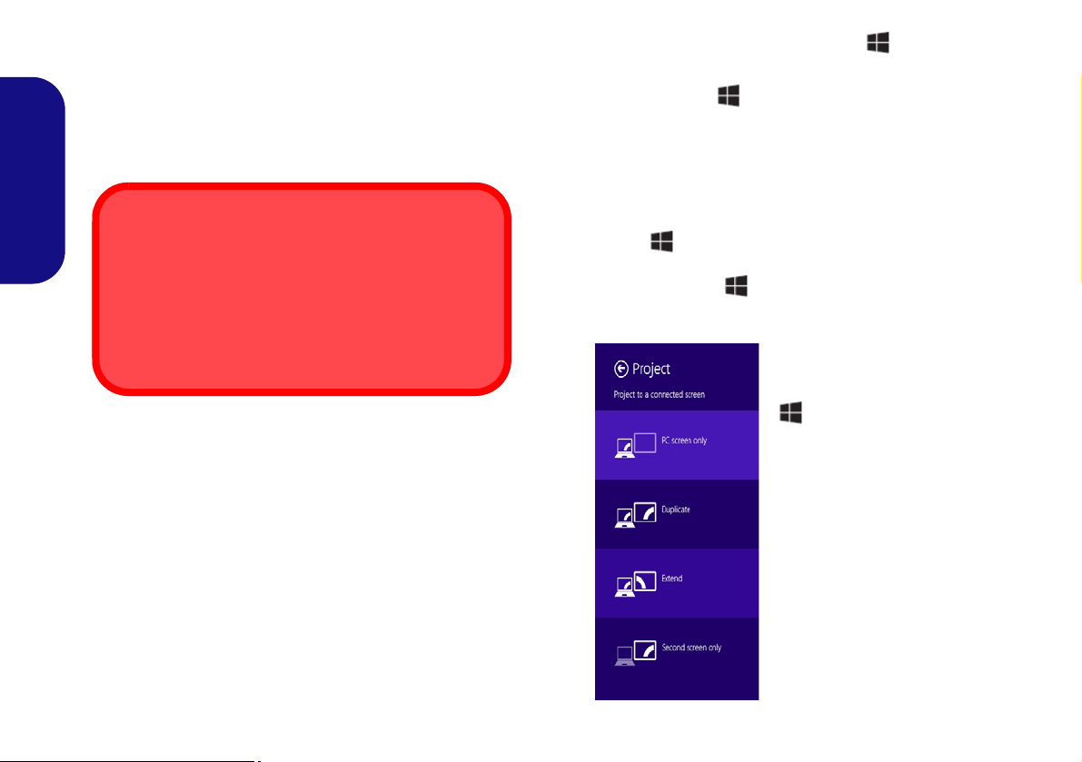
Figure 14
+ P (Change Display
Configuration)
Besides the built-in LCD, you can also use an external
VGA monitor (CRT)/external Flat Panel Display or TV
(connected to the DVI-Out port/HDMI-Out port/DisplayPort) as your display device.
English
Using the Windows Logo Key + P Key
Combination to Switch Displays
You can also use the + P key combination (or Fn + F7
) to quickly change display configuration and modes (this
is particularly useful when attaching a projector) in Win-
dows.
1. Attach your external display to the DVI-Out port/HDMI-Out port/
DisplayPort, and turn it on.
2. Press the + P (or Fn + F7) key combination.
3. An on-screen menu will pop up.
4. Use the cursor keys ( + P) to select the appropriate
configuration from the menu, and press Enter to confirm the
selection.
20
NVIDIA 3D VISION Shutter Glasses Kit
Important Safety Instructions
Make sure you read all the enclosed safety instructions and
precautions included in the NVIDIA 3D Vision Kit before
setting up the 3D Glasses and IR Emitter. Follow the setup
instructions provided in the documentation to set up the 3D
Vision kit safely and take the “User Vision Test,” which will
initiate when you turn on your GeForce 3D Vision for the
first time. If you cannot see the image in 3D during the test,
you should DISCONTINUE USE IMMEDIATELY. Continued use may result in health-related complications.
3D Icon
USB Connection & 3D Glasses
The light on the glasses will flash amber while charging, and solid amber when fully charged.
The glasses hold approximately 40 hours of viewing per
full charge. Flashing red indicates that less than 2 hours
of charge are remaining.
The indicator light displays for about 30 seconds after
turning the glasses on.
The NVIDIA 3D VISION shutter glasses kit is supported
only by models which include the built-in 3D emitter and
shutter glasses kit.
The NVIDIA 3D VISION shutter glasses kit is supplied
with a single pair of shutter glasses and all necessary cables etc. Set up the hardware (run the set up wizard as indicated on page 22) as instructed in the manual supplied
with the kit, however make sure you have installed the
NVIDIA driver (see "NVIDIA Video (VGA)" on
page 29) from the Device Drivers & Utilities + User’s
Manual disc. For further details contact your service cen-
ter.
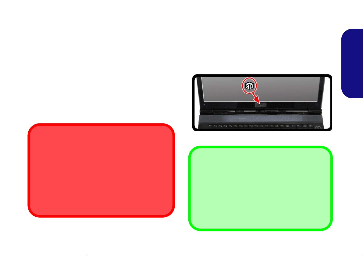
Stereoscopic 3D Hardware Setup
If your computer model features a built-in 3D IR emitter
the location is illustrated below. The effective viewing angles of the emitter are illustrated in Figure 16 on page 22.
Make sure that you are viewing the notebook screen within the area highlighted in order to get the proper stereoscopic 3D effect.
Figure 15 - IR Emitter Location
English
21
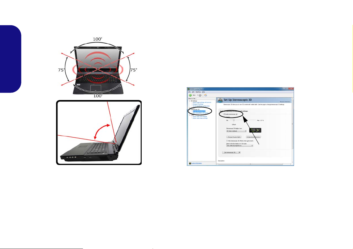
Viewing Angles
75°
Figure 17
Set Up
Stereo-
scopic 3D
Enable sterescopic 3D
The emitter’s horizontal viewing angle is 100 degrees.
The emitter’s vertical viewing angle is 75 degrees.
English
3. Double-click Stereoscopic 3D (if the sub-menus are not
visible), and then click Set up stereoscopic 3D.
4. Click Enable stereoscopic 3D (tickbox) to enable 3D Vision.
5. Click Apply to save the setting.
6. Select the drop-down menu at the bottom of the screen to Test
sterescopic 3D.
7. Select Run Setup Wizard from the drop-down menu (you can
also select Run Medical Image Tes t from this menu).
8. Follow the on-screen instructions to set up 3D Vision and click
“Next” to progress through the steps (this notebook has a builtin emitter).
Figure 16 - Emitter - Viewing Angles
Set Up Stereoscopic 3D
After the NVIDIA driver has been installed you can setup
NVIDIA 3D Vision.
1. Go to the Control Panel.
2. Double-click NVIDIA Control Panel (click "Icon View" from the
left of the menu if you are in Control Panel Home).
22
9. During the setup procedure you will need to click to answer
questions on what you see in 3D on the screen.
10. Configure the stereoscopic 3D from the control panels (make
sure you charge the 3D shutter glasses by plugging them into
one of the computer’s USB ports using the USB cable
provided).
11. The stereoscopic depth may be adjusted by using the control
panel slider.
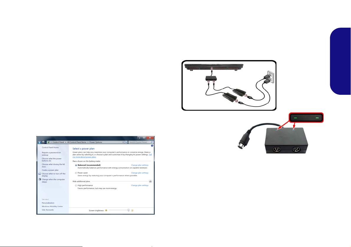
Power Options
Figure 18 - Power Options
Figure 19
Dual Power
Adapters &
Converter Box
The Power Options (Hardware and Sound menu) control panel icon in Windows allows you to configure power
management features for your computer. You can conserve power by means of power plans and configure the
options for the power button, sleep button (Fn + F4),
computer lid (when closed), display and sleep mode (the
default power saving state) from the left menu. Note that
the Power saver plan may have an affect on computer
performance.
Click to select one of the existing plans, or click Create a
power plan in the left menu and select the options to create a new plan. Click Change Plan Settings and click
Change advanced power settings to access further configuration options.
Multi GPU Configuration & Power
Note that due to the high power and system demands created by enabling SLI/CrossFireX Configuration, you
should not power the system using the battery only and
you will require identical dual power adapters, connected
to a power converter box, to power the system.
English
• Only enable SLI/CrossFir eX configuration if the system
is powered by identical dual power adapters connected
by means of the power converter box.
• If the computer is currently powered by battery only do not
enable SLI/CrossFireX configuration.
• If you have currently enabled SLI/CrossFireX configura-
tion, and the computer is powered by the AC/DC adapter,
do not switch to battery power only (or go to the
NVIDIA Control Panel/Catalyst Control Center and
disable SLI/CrossFireX configuration before switching to
battery power only).
23

Audio Features
Figure 20
Sound
Playback
Options
You can configure the audio options on your computer
from the Sound control panel in Windows, or from the
Realtek HD Audio Manager
tion area/control panel (right-click the notification area
icon to bring up an audio menu). The volume may also
be adjusted by means of the Fn + F5/F6 key combination.
English
Audio Notes (Fn + 5)
This computer features the Fn + 5 key combination to toggle between standard audio and enhanced audio. Note the
following which applies to software mode audio configuration through the computer’s internal speakers only (this
does not apply to surround sound when configured
through external Quadrophonic, 5.1 or 7.1 speaker systems):
• When the Speaker Configuration in Realtek HD Audio
Manager is set to Stereo, you can use the Fn + 5 key combination to help increase the volume through the speakers.
• When the Speaker Configuration in Realtek HD Audio
Manager is set to Quadrophonic, 5.1/7.1 Speaker, the
best audio configuration will be obtained with the combination of the Speaker Configuration set to Quadro-
phonic, 5.1/7.1 Speaker, and the THX TruStudio AP
turned ON.
/ icon in the notifica-
Audio Setup for HDMI
HDMI supports video and audio signals. In some cases it
will be necessary to go to the Sound control panel and
manually configure the HDMI audio output.
1. Go to the Control Panel.
2. Click Sound (Hardware and Sound).
3. Click Playback (tab).
4. The playback device will be selected.
5. In some cases you may need to select the audio device and
click Set Default (button).
6. Double-click the device to access the control panel tabs.
7. Adjust the HDMI settings from the control panel tabs.
8. Click OK to close the Sound control panel.
Note that the Fn + 5 key combination is a toggle so you
will need to press the key combination to test if the affect
is applied or not.
24
 Loading...