


Introduction (English)
This Concise User’s Guide introduces the main features
of your computer. The English version of this guide begins on page 1. The expanded User’s Manual is on the
Device Drivers & Utilities + User’s Manual disc.
Einführung (Deutsch)
Dieses Ausführliche Benutzerhandbuch führt Sie in die
Hauptfunktionen des Computers ein. Die deutsche Version des Handbuchs beginnt auf Seite 37. Das erweiterte
Benutzerhandbuch finden Sie auf der Disc für die Gerätetreiber und Hilfsprogramme (Disc Device Drivers &
Utilities + User's Manual).
Présentation (Français)
Ce Guide Utilisateur Concis présente les fonctionnalités
principales de votre ordinateur. La version française de
ce guide commence à la page 73. Le Manuel de l'Utilisa-
teur étendu se trouve sur le disque de Pilotes & Utilitaires + Manuel de l'Utilisateur (disque Device Drivers
& Utilities + User's Manual).
Introducción (Español)
Esta Guía del Usuario Concisa le presenta las características principales de su ordenador. La versión española de
esta guía comienza en la página 109. El Manual del usua-
rio completo se encuentra en el disco de Controladores
del dispositivo y Utilidades + Manual del usuario (disco
Device Drivers & Utilities + User's Manual).
Introduzione (Italiano)
La presente Guida Rapida per l'Utente introduce le caratteristiche principali del computer. La versione italiana di
questa guida inizia da pagina 145. Il Manuale utente
completo si trova nel disco contenente driver e utilità +
Manuale utente (disco Device Drivers & Utilities +
User's Manual).
I

Contents
About this Concise User Guide .........................................................1
Instructions for Care and Operation ..................................................2
System Startup ..................................................................................4
RAID Setup (Model C Only) ............................................................5
System Map: Front View with LCD Panel Open ............... ..............7
LED Indicators ..................................................................................8
Keyboard & Function Keys ..............................................................9
Control Center .................................................................................11
System Map: Front, Left, Right & Rear Views (Models A & B) ...14
System Map: Front, Left, Right & Rear Views (Model C) ............15
System Map: Bottom Views ..... ......................................................16
Video Features ................................................................................17
Power Options .................................................................................18
Audio Features ................................................................................18
Driver Installation ...........................................................................21
PC Camera (Option) .......................................................................23
Wireless LAN Module (Option) .....................................................25
Intel® Wireless Display Application ..............................................26
Fingerprint Reader (Option) ...........................................................28
Bluetooth Module (Option) .............................................................29
Intel® Rapid Storage Technology Driver .......................................30
Intel® Rapid Start Technology Driver ............................................31
Troubleshooting ..............................................................................33
Specifications ................. .................................... ............................. 34
Inhalt
Über das Ausführliche Benutzerhandbuch ......................................37
Hinweise zu Pflege und Betrieb ......................................................38
Schnellstart .................... ............................................ ......................40
RAID Setup (Nur Modell C) ...........................................................41
Systemübersicht: Ansicht von vorne mit geöffnetem
LCD-Bildschirm ................... .......................... ........................... ......43
LED-Anzeigen ................................................................................44
Tastatur & Funktionstasten .............................................................45
Control Center (Steuerzentrum) ................. .....................................47
Systemübersicht: Ansicht von vorne, links, rechts und hinten
(Modelle A & B) .............................................................................50
Systemübersicht: Ansicht von vorne, links, rechts und hinten
(Modell C) ............................ ...........................................................51
Systemübersicht: Ansicht von unten ...............................................52
Grafikfunktionen ...................... ....................................................... 53
Energieoptionen ..............................................................................54
Audiofunktionen ..............................................................................54
Installation der Treiber ....................................................................57
PC-Kamera (Option) .......................................................................59
Wireless-LAN-Modul (Option) .......................................................61
Intel® Wireless Display Application ..............................................62
Fingerabdruckleser (Option) ...........................................................64
Bluetooth-Modul (Option) ..............................................................65
Intel® Rapid Storage Technology Driver .......................................66
Intel® Rapid Start Technology Driver ............................................67
Fehlerbehebung ...............................................................................69
Technische Daten ............................................................................70
II

Sommaire
A propos de ce Guide Utilisateur Concis ........................................73
Instructions d’entretien et d’utilisation ...........................................74
Guide de démarrage rapide .............................................................76
Configuration RAID .......................................................................77
Carte du système: Vue de face avec l’écran LCD ouvert ...............79
Indicateurs LED ..............................................................................80
Clavier & touches fonction ....... ......................................................81
Control Center (Centre de contrôle) ...............................................83
Carte du système: Vues de face, gauche, droite & arrière
(Modèles A & B) ............................................................................86
Carte du système: Vues de face, gauche, droite & arrière
(Modèle C) ......................................................................................87
Carte du système: Vues du dessous .............................. ..................88
Caractéristiques vidéo .....................................................................89
Options d’alimentation ....................................................................90
Caractéristiques audio .....................................................................90
Installation du pilote .......................................................................93
Caméra PC (Option) ............. ..........................................................95
Module LAN sans fil (Option) ........................................................97
Application Intel® Wireless Display ..............................................98
............................. ....... .... ....... ...... ....... ....... .... ....... ....... ...... ..... ...... ...99
Lecteur d'empreintes digitales .......................................................100
Module Bluetooth (Option) .............. .............................................101
Intel® Rapid Storage Technology Driver .....................................102
Intel® Rapid Start Technology Driver ..........................................103
Dépannage .................... ....... ...... ....... .... ....... ....... ...... ..... ...... ....... ...105
Spécifications ................. .................................... ........................... 106
Contenidos
Acerca de esta Guía del Usuario Concisa .....................................109
Instrucciones para el cuidado y funcionamiento ...........................110
Guía rápida para empezar ..............................................................112
Configuración RAID (sólo Modelo C) ..........................................113
Mapa del sistema: Vista frontal con panel LCD abierto ...............115
Indicadores LED ...........................................................................116
Teclado & teclas de función ......................................... .................117
Control Center (Centro de control) ...............................................119
Mapa del sistema: Vistas frontal, izquierda, derecha, y posterior
(Modelos A & B) ...........................................................................122
Mapa del sistema: Vistas frontal, izquierda, derecha, y posterior
(Modelo C) ....................................................................................123
Mapa del sistema: Vistas inferior ..................................................124
Parámetros de vídeo ......................................................................125
Opciones de energía ......................................................................126
Características de audio .................................................................126
Instalación de controladores ..........................................................129
Cámara PC (Opción) .....................................................................131
Módulo LAN Wireless (Opción) ...................................................133
Intel® Wireless Display Application ............................................134
Lector de huellas digitales .............................................................136
Módulo Bluetooth (Opción) ..........................................................137
Intel® Rapid Storage Technology Driver .....................................138
Intel® Rapid Start Technology Driver ..........................................139
Solución de problemas ............................... ...................................141
Especificaciones ................ ................................................. ...........142
III

Sommario
Informazioni sulla Guida Rapida per l'Utente ..............................145
Istruzioni per la custodia e il funzionamento ................................146
Guida di avvio rapido ....................................................................148
Configurazione RAID (solo Modello C) ......................................149
Descrizione del sistema: Vista anteriore con pannello
LCD aperto ....................................................................................151
Indicatori LED ..............................................................................152
Tastiera & tasti funzione ...............................................................153
Control Center (Centro di controllo) ............... ..............................155
Descrizione del sistema: Vista anteriore, sinistra, destra e posteriore
(Modelli A & B) .................... ........................................................158
Descrizione del sistema: Vista anteriore, sinistra, destra e posteriore
(Modello C) ...................................................................................159
Descrizione del sistema: Vista inferiore .......................................160
Funzioni video ...... ........................................................................161
Opzioni risparmio energia .............................................................162
Funzionalità audio .........................................................................162
Installazione driver ........................................................................165
Camera PC (Opzione) ...................................................................167
Modulo LAN Wireless (Opzione) ................................................169
Intel® Wireless Display Application ............................................170
Lettore d’impronte digitali ............................................................172
Modulo Bluetooth (Opzione) ........................................................173
Intel® Rapid Storage Technology Driver .....................................174
Intel® Rapid Start Technology Driver ..........................................175
Risoluzione dei problemi ........ ......................................................177
Specifiche tecniche .......................................................................178
IV

About this Concise User Guide
FCC Statement
This device complies with Part
15 of the FCC Rules. Operation
is subject to the following two
conditions:
1.This device may not cause
harmful interference.
2. This device must accept any
interference received, including interference that may
cause undesired operation.
This quick guide is a brief introduction to getting your system started. This is a supplement, and not a substitu te for the
expanded English language User’s Manual in Adobe Acrobat format on the Device Drivers & Utilities + User’s Manual
disc supplied with your computer. This disc also contains the drivers and utilities necessary for the prop er operation of
the computer (Note: The company reserves the right to revise this publication or to change its contents without notice).
Some or all of the computer’s features may already have been setup. If they aren’t, or you are planning to re-configure
(or re-install) portions of the system, refer to the expanded User’s Manual. The Device Drivers & Utilities + User’s
Manual disc does not contain an operating system.
Regulatory and Safety Information
Please pay careful attention to the full regulatory notices and safety information
contained in the expanded User’s Manual on the Device Drivers & Utilities + Us-
er’s Manual disc.
© July 2012
Trademarks
Intel and Intel Core are trademarks/registered trademarks of Intel Corporation.
English
1

Instructions for Care and Operation
The computer is quite rugged, but it can be damaged. To
prevent this, follow these suggestions:
• Don’t drop it, or expose it to shock. If the computer falls, the case
and the components could be damaged.
• Keep it dry, and don’t overheat it. Keep the computer and power
English
supply away from any kind of heating element. This is an electrical
appliance. If water or any other liquid gets into it, the computer
could be badly damaged.
• Avoid interference. Keep the computer away from high capacity
transformers, electric motors, and other strong magnetic fields.
These can hinder proper performance and damage your data.
• Follow the proper working procedures for the computer. Shut
the computer down properly and don’t forget to save your work.
Remember to periodically save your data as data may be lost.
• Note that in computer’s featuring a raised LCD electro-plated logo,
the logo is covered by a protective adhesive. Due to general wear
and tear, this adhesive may deteriorate over time and the exposed
logo may develop sharp edges. Be careful when handling the computer in this case, and avoid touching the raised LCD electro-plated
logo. Av oid pl acing any ot her items in the carrying bag which may
rub against the top of the computer during transport. If any such
wear and tear develops contact your service center.
Power & Battery Safety
• Only use an AC/DC adapter approved for use with this computer.
• Use only the power cord and batteries indicated in this manual.
• Y our AC/D C adapter may be designed for international travel but it
still requires a steady, uninterrupted power supply. If you are
unsure of your local power specifications, consult your service representative or local power company.
• The AC/DC adapter may have either a 2-prong or a 3-prong
grounded plug. The third prong is an important safety feature; do
not defeat its purpose. If you do not have access to a compatible
outlet, have a qualified electrician install one.
• When you want to unplug the power cord, be sure to disconnect it
by the plug head, not by its wire.
• Make sure the socket and any extension cord(s) you use can support the total current load of all the connected devices.
• Make sure that your computer is completely powered off before
putting it into a travel bag (or any such container).
• Only use batteries designed for this computer. The wrong battery
type may explode, leak or damage the computer.
• Do not continue to use a battery that has been dropped, or that
appears damaged (e.g. bent or twisted) in any way. Even if the
computer continues to work with a damaged battery in place, it
may cause circuit damage, which may possibly result in fire.
• Recharge the batteries using the computer’s system. Incorrect
recharging may make the battery explode.
• Do not try to repair a battery pack. Refer any battery pack repair or
replacement to your service representative or qualified service personnel.
• Keep children away from, and promptly dispose of a damaged battery. Always dispose of batteries carefully. Batteries may explode
or leak if exposed to fire, or improperly handled or discarded.
• Keep the battery away from metal appliances.
• Affix tape to the battery contacts before disposing of the battery.
• Do not dispose of batteries in a fire. They may explode. Check with
local codes for possible special disposal instructions.
• Do not touch the battery contacts with your hands or metal objects.
2

Polymer Battery Precautions
Battery Disposal & Caution
The product that you have purchased contains a rechargeable battery. The battery is recyclable. At the end of its useful life, under various state and local laws, it may be illegal
to dispose of this battery into the municipal waste stream.
Check with your local solid waste officials for details in your
area for recycling options or proper disposal.
Danger of explosion if battery is incorrectly replaced. Replace only with the same or equivalent type recommended
by the manufacturer. Discard used battery according to the
manufacturer’s instructions.
Note the following information which is specific to polymer batteries only, and where applicable, this overrides
the general battery precaution information.
• Polymer batteries may experience a slight expansion or swelling,
however this is part of the battery’s safety mechanism and is not a
cause for concern.
• Use proper handling procedures when using polymer batteries. Do
not use polymer batteries in high ambient temperature environments, and do not store unused batteries for extended periods.
Cleaning
• Use a soft clean cloth to clean the computer, but do not apply
cleaner directly to the computer.
• Do not use volatile (petroleum distillates) or abrasive cleaners on
any part of the computer.
• Before cleaning the computer remove the battery and make sure the
computer is disconnected from any external power supplies,
peripherals and cables (including telephone lines).
Servicing
Attempting to service the computer yourself may violate
your warranty and expose you and the computer to electric
shock. Refer all servicing to qualified service personnel,
particularly under any of the following conditions:
English
• When the power cord or AC/DC adapter is damaged or frayed.
• If the computer has been exposed to any liquids.
• If the computer does not work normally when you follow the operating instructions.
• If the computer has been dropped or damaged (do not touch the
poisonous liquid if the LCD panel breaks).
• If there is an unusual odor, heat or smoke coming from your computer.
3

System Startup
135 ゚
Figure 1
Opening the Lid/LCD/
Computer with AC/DC
Adapter Plugged-In
1. Remove all packing materials.
2. Place the computer on a stable surface.
3. Insert the battery and make sure it is locked in position.
4. Securely attach any peripherals you want to use with the
computer (e.g. keyboard and mouse) to their ports.
5. Attach the AC/DC adapter to the DC-In jack at the rear of the
computer, then plug the AC power cord into an outlet, and
English
connect the AC power cord to the AC/DC adapter.
6. Use one hand to raise the lid/LCD to a comfortable viewing
angle (do not to exceed 135 degrees);
illustrated in Figure 1) to support the base of the computer
(Note: Never lift the computer by the lid/LCD).
7. Press the power button to turn the computer “on”.
use the other hand (as
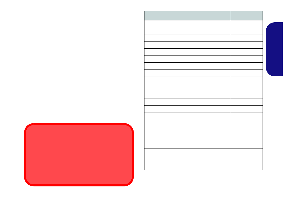
Model Differences
This notebook series includes three different model types
that mainly differ as indicated in the table below.
Feature Model A Model B Model C
Video A dapt-
ers Supported
Display Type
Illuminated
Keyboard
RAID
AC/DC
Adapter
See Specifications on page 34 for a full list of
video adapters supported by each model.
17.3"
15.6" (39.62cm) FHD (1920 *
1080)
Yes No Yes
Not Supported
19V, 9.47A
(180W)
19V, 6.3A
(120W)
(43.94cm)
FHD (1920 *
1080)
RAID Level 0/
1/Recovery
Supported
19V, 11.57A
(220W)
Table 1 - Model Differences
4
System Software
Your computer may already come with system software
pre-installed. Where this is not the case, or where you are
re-configuring your computer for a different system, you
will find this manual refers to Microsoft Windows 7.

RAID Setup (Model C Only)
HDD RAID Support
Your hard disk(s) can be set up in AHCI mode or RAID
mode (for increased performance or protection). Note th at
setting up your hard disk(s) in RAID mode needs to be
done prior to installing the Windows OS.
You may use your hard disks in combination with Striping
(RAID 0), Mirroring (RAID 1), or Recovery for either
fault tolerance or performance.
RAID Level Description
Identical drives reading and writing data in p aral-
RAID 0
(at lease two
hard disks
needed)
RAID 1
(at lease two
hard disks
needed)
Recovery
(at lease two
hard disks
needed)
lel to increase performance. RAID 0 implements a striped disk array and the data is broken
into blocks and each block is written to a separate disk drive.
RAID 0 (a striped array) is not fault-tolerant. The
failure of one drive will result in the loss of all
data in the array.
Identical drives in a mirrored configuration used
to protect data. Should a drive that is part of a
mirrored array fail, the mirrored drive (which
contains identical data) will handle all the data.
When a new replacement drive is installed, data
to the new drive is rebuilt from the mirrored drive
to restore fault tolerance.
RAID 1 (mirrored array) provides full data protection, as data can simply be copied from a
healthy disk to a replacement for any failed disk.
Two identical drives copying data between a
master and a recovery disk. This provides more
control over how data is copied between the
master and recovery drives, fast volume
updates and the ability to view the data in Win-
dows Explorer.
Table 2 - RAID Description
English
Prepare the following before setting up your serial ATA
hard disks in RAID mode:
•The Microsoft Windows 7 OS disc.
•The Device Drivers & Utilities + User’s Manual disc.
Note: All hard disks in a RAID should be identical (the
same size and brand) in order to prevent unexpected system behavior.
RAID Setup Procedure
Part I: BIOS
1. Start-up your computer and press F2 to enter the BIOS.
2. Go to the Advanced menu, select SATA Mode and press
Enter.
3. Select RAID Mode.
4. Press Esc and go to the Boot menu.
5. Set the CD/DVD-ROM Drive (make sure the Microsoft
Windows OS disc is inserted) as the first device in the boot
order from the Boot menu.
6. Select Save Changes and Reset from the Exit menu (or press
F4) and press Enter to exit the BIOS and reboot the computer.
5

Part II: Intel Matrix
Figure 2
RAID
Created
1. Press Ctrl + i to enter RAID configuration menu.
2. Select 1.Create RAID Volume and press Enter.
3. Type the RAID volume name and then press Tab or Enter to
advance to the next field.
4. Specify (use the up and down arrow keys) the RAID level
(RAID 0 or RAID 1 or Recovery - see Table 2) and then press
Tab or Enter to advance to the next field.
5. Press Enter and the system will select the physical disks to use.
English
6. Press Enter and select (if applicable) the Strip Size (best set to
default).
7. Press Enter and select the Capacity size (best set to default).
8. Press Enter to select Create Volume.
9. Press Enter to create the volume, and confirm the selection by
pressing Y.
10. This will now return to the main menu.
Windows 7 OS DVD (you will be prompted to press a key to
boot from the DVD).
13. Press Enter to continue installing the operating system as
normal (see your Windows documentation if you need help on
installing the Windows OS).
11. Select 6.Exit and press Enter, then press Y to exit the RAID
configuration menu.
12. Make sure the Windows 7 OS DVD is in the DVD drive and as
the computer starts up it will automatically boot from the
6

System Map: Front View with LCD Panel Open
2
1
8
9
7
3
6
5
4
5
Note that the Touchpad and
Buttons valid operational
area is that indicated within
the red dotted lines above.
8
Figure 3
Front View with LCD
Panel Open
1. PC Camera (Optional)
2. LCD
3. LED Indicators
4. Power Button
5. Speakers
6. Keyboard
7. Built-In Microphone
8. Touchpad and Buttons
9. Fingerprint Reader
(Optional)
3
2
1
8
9
7
6
5
4
5
3
Models A & B
15.6” (39.62cm)
17.3” (43.94cm)
Model C
Wireless Device
Operation Aboard Aircraft
The use of any portable electronic transmission devices (e.g. WLAN or Bluetooth) aboard aircraft is usually prohibited. Make sure any wireless modules are OFF if you are using the computer aboard aircraft.
Use the appropriate function key combination to toggle power to any wireless modules, and
check the indicators to see if any modules are powered on or not (see Table 3 on page 8).
English
7
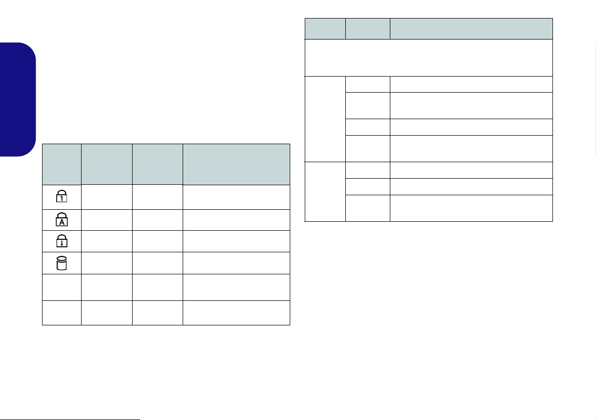
LED Indicators
Models A & B
Model C
The LED indicators on the computer display helpful information about the current status of the computer.
English
Icon
Color
(Models A
& B)
Blue White
Blue White Caps Lock Activated
Blue White Scroll Lock Activated
Blue White Hard Disk Activity
Blue White
Blue Orange
Table 3 - LED Status Indicators
Color
(Model C)
Description
Number Lock (Numeric
Keypad) Activated
Wireless LAN Module
Power Toggle
Bluetooth Module Power
Toggle
Icon Color Description
Orange The AC/DC Adapter is Plugged In
Blinking
Orange*
Green The Computer is On
Blinking
Green
Orange The Battery is Charging
Green The Battery is Fully Charged
Blinking
Orange
Table 4 - LED Power Indicators
The AC/DC adapter is plugged in and the
powered USB Port is on*
The Computer is in Sleep Mode
The Battery Has Reached Critically Low
Power Status
*The powered USB 3.0 port may be toggled on /off by
means of the Fn + Power Button key combination. When
the powered USB port is on it will supply power when the
system is off but still powered by the AC/DC adapter
plugged into a working outlet (this may not work with certain devices - see
page 33).
8
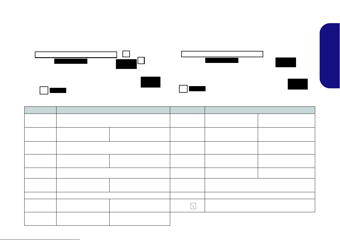
Keyboard & Function Keys
Function Keys
Numeric
Keypad
Fn Key
ScrLk &
NumLk
Figure 4 - Keyboard
Models A & C
Model B
Function Keys
Numeric
Keypad
Fn Key
ScrLk &
NumLk
The keyboard includes a numeric keypad for easy numeric data input. Pressing Fn + NumLk turns on/off the numeric
keypad. It also features function keys to allow you to change operational features instantly. The function keys (F1 -
F12 etc.) will act as hot keys when pressed while Fn is held down. In addition to the basic function key combinations,
visual indicators are available when the hot key driver is installed.
Keys Function/Visual Indicators Keys Function/Visual Indicators
Fn + ~ Play/Pause (in Audio/Video Programs) Fn + F11
Fn + F1 Touchpad Toggle Fn + F12
Fn + F2
Fn + F3 Mute Toggle Fn + ScrLk Scroll Lock Toggle
Fn + F4 Sleep Toggle Caps Lock Cap s Lock Toggle
Fn + F5/F6
Fn + F7 Display Toggle Fn + Esc Control Center Toggle (see page 11)
Fn + F8/F9
Fn + F10
(Press a key to or use Touchpad to turn on)
Volume Decrease/
Brightness Decrease/
PC Camera Power
Turn LCD Backlight Off
Increase
Increase
Toggle
Fn + NumLk Number Lock Toggle
Fn + Power
Button
Fn +
Table 5 - Function Keys & Visual Indicators
WLAN Module Power
Toggle
Bluetooth Module
Power Toggle
Powered USB Port Power Toggle (see page 14)
Keyboard LED Toggle (see page 10)
English
9
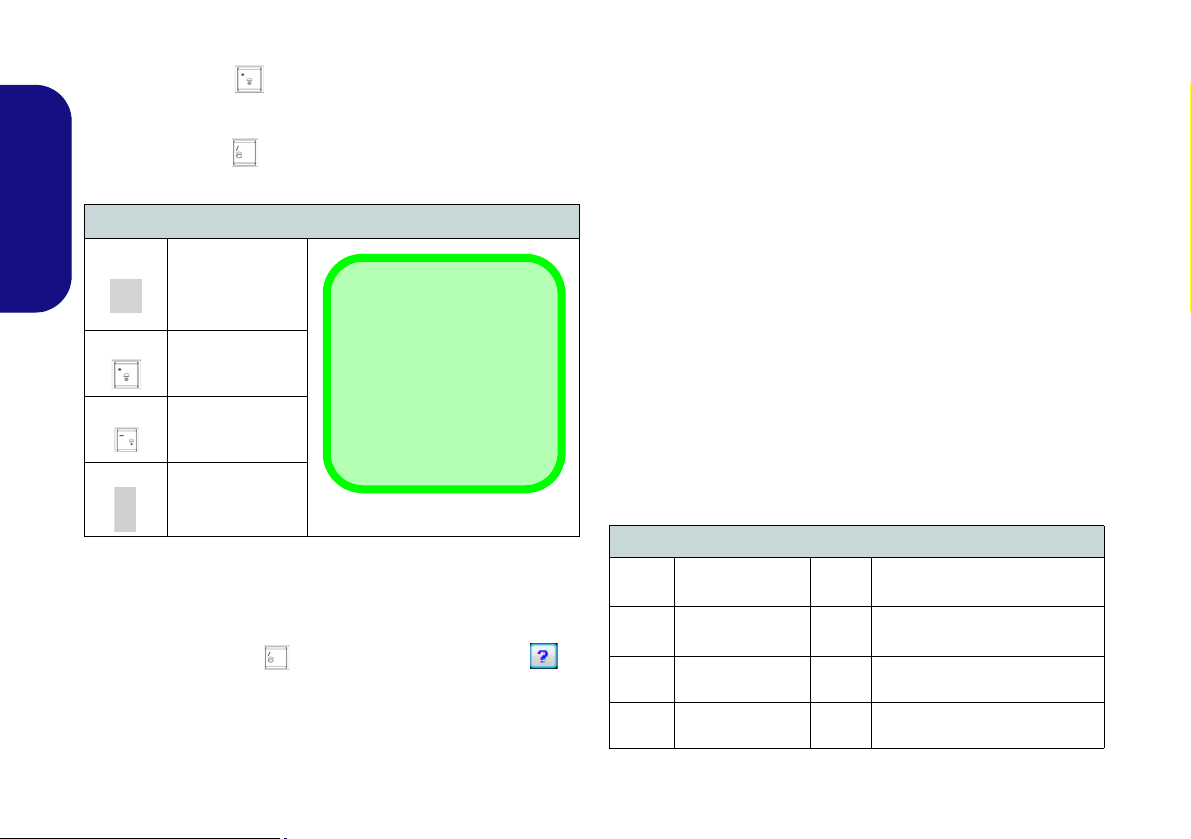
Keyboard LED (Models A & C Only)
*Illumination Keys
Note that the keyboard illumination (increase/decrease) keys may be
used to configure the keyboard LED in Custom
Mode only.
Help Button
Keyboard Sections
Effects Buttons
Color Swatches
Press Fn plus the key to toggle the keyboard LED on/
off. The keyboard LED may be configured using the Fn +
key combination outlined in the table below. In addition
press Fn plus the key to launch the keyboard backlight
application to configure the settings.
Keyboard LED Function key Combinations
English
Fn +
Fn +
Fn +
Fn +
Keyboard Backlight Application
The Keyboard Backlight application can be accessed by
pressing the Fn plus key. Click the Help button in
the application to display the configuration keys.
• Click the Custom button to display the three sections
of the keyboard which may be configured.
10
Launch the
Keyboard
Backlight
Application
Toggle the
Keyboard LED
On/Off
*Keyboard LED
Illumination
Decrease
*Keyboard LED
Illumination
Increase
Table 6 - Keyboard LEDs
• Click a section of the keyboard and the color buttons will
be displayed.
• Click a color swatch to apply the color to the selected section when not overidden by any effect applied.
• Click on any of the effect buttons to apply random colors,
wave or flashing effects etc.
Figure 5 - Keyboard Backlight Application
Effects Buttons & Help
LED Effects Buttons
Random Color Up/Down Wave
Dancing Effect Breathing (All Colors)
Tempo Beat
Flashing
Table 7 - LED Effects Buttons
Cycle (Colors as Selected in
RGB)
Custom - Display & Configure
Keyboard Sections & Colors

Control Center
Press the Fn + Esc key combination, or double-click the icon in the notification area of the taskbar to toggle the
Control Center on/off. The Control Center gives quick access to frequently used controls, and enables you to quickly
turn modules on/off.
Figure 6 - Control Center
Click on any button to turn any of the modules (e.g. Touchpad, Camera) on/off. Click on Power Conservation to switch
between Performance, Balanced or Energy Star modes. Click on the buttons (or just click and hold the mouse button)
to adjust the slider for Brightness/Volume. Click on Display Switch/Time Zone/ Desktop Background to bring up
the appropriate Windows control panel. Click on the Sleep button to put the computer into Hibernate or Sleep modes.
English
11
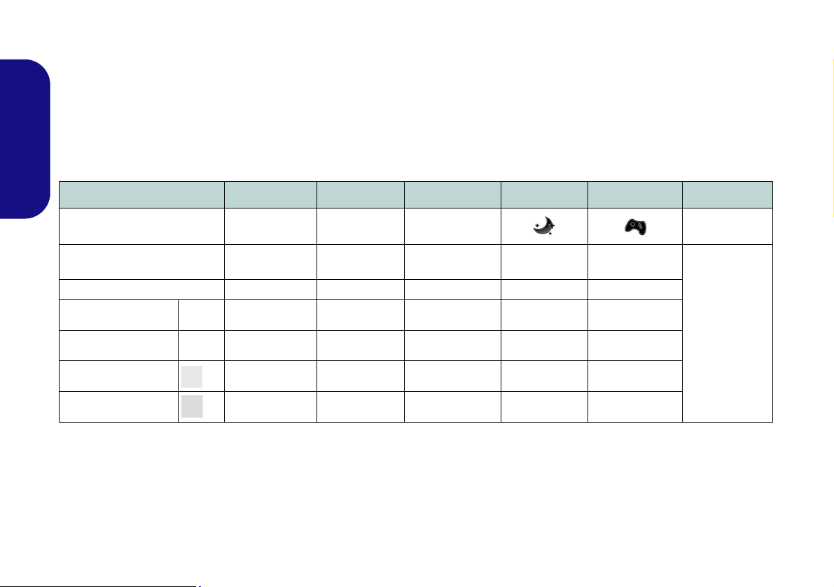
Power Modes
You can set a Power Mode by clicking the appropriate icon at the top of the Control Center. Each power mode will
affect the power status of modules (e.g. WLAN or Camera), screen brightness, Touchpad power and Silent Mode. You
can click a Control Center icon to set an overall power mode and then click individual icons in the Control Center to
power on/off any modules etc.
Table 8 illustrates the basic settings for each power mode. If you choose User Defined the settings will correspond to
your selected system settings.
English
Modes Power Saving Flight Entertainment Quiet Performance User Defined
Icon
Power Plan Power Saver Balanced Power Saver Power Saver
Power Conservation Mode Energy Star BIOS Default Energy Star Energy Star Performance
Brightness 14 42 100 42 100
WLAN OFF OFF ON ON ON
PC Camera OFF OFF OFF ON ON
Touchpad ON ON ON ON ON
Table 8 - Power Modes
High Perfor-
mance
12
User Defined

Power Status
The Power Status icon will show
whether you are currently powered by
the battery, or by the AC/DC adapter
plugged in to a working power outlet.
The power status bar will show the
current battery charge state.
Brightness
The Brightness icon will show the
current screen brightness level. You
can use the slider to adjust the screen
brightness or the Fn + F8/F9 key combinations, or use the Fn + F2 key combination to turn off the LED backlight
(press any key to turn it on again).
Note that screen brightness is also effected by the Power Mode selected.
Volume
The Volume icon will show the current volume level. You can use the
slider to adjust the Volume or the Fn +
F5/F6 key combinations, or use the
Fn + F3 key combination to mute the
volume.
Power Conservation
This system supports Energy Star
power management features that place
computers (CPU, hard drive, etc.) into
a low-power sleep mode after a designated period of inactivity. Click either
the Performance, Balanced or Ener-
gy Star button.
Sleep
Click the Sleep button to bring up the
Hibernate or Sleep buttons,
and click either button to have the
computer enter the appropriate powersaving mode.
Display Switch
Click the Display Switch button to access the menu (or use the + P key
combination) and select the appropriate attached display mode.
Time Zone
Clicking the Time Zone button will
access the Date and Time Windows
control panel.
Desktop Background
Clicking the Desktop Background
button will allow you to change the
desktop background picture.
K/B LED
Click to access the keyboard setting
control to configure the keyboard
LED.
TouchPad/PC Camera/Wireless
LAN Module /Bluetooth Module
Click any of these buttons to toggle
the Touchpad or module’s power status. A crossed out icon will appear
over the top left of the icon when
it is off
. Note that the power status of a
module, and Touchpad power, is also
effected by the Power Mode selected.
English
13

System Map: Front, Left, Right & Rear Views (Models A & B)
5
8
6
7
1
2
3
Front
Left
Right
10
11
13
12
USB
The USB 3.0 ports are colored blue. USB 3.0 will transfer data much faster than USB 2.0,
and is backwards-compatible with USB 2.0. When the powered USB 3.0 por t
is on it will
supply power (for charging devices only, not for operating devices) when the system is
off but still powered by the AC/DC adapter plugged into a working outlet, or powered by the
battery with a capacity level above 20% (this may not work with certain devices - see page
33). Toggle power to this port by using Fn + power button.
4
9
4
15
17
14
16
20
Rear
18
19
Figure 7
Front, Left, Right & Rear
Views (Models A & B)
1. LED Power Indicators
2. Mini-IEEE 1394a Port
3. RJ-45 LAN Jack
4. Powered USB 3.0 Port
(See Below)
5. USB 3.0 Port
6. Combined eSATA/ USB 3.0
Port
7. Multi-in-1 Card Reader
8. Optical Device Drive Bay
9. Emergency Eject Hole
10. Headphone Jack
11. Microphone Jack
12. S/PDIF-Out Jack
13. Line-In Jack
14. USB 2.0 Port
15. Security Lock Slot
16. Vent
17. D isplayPort
18. HDMI-Out Port
19. DVI-Out Port
20. DC-In Jack
16
English
14

System Map: Front, Left, Right & Rear Views (Model C)
Front
Figure 8
Front, Left, Right & Rear
Views (Model C)
1. LED Power Indicators
2. Mini-IEEE 1394a Port
3. RJ-45 LAN Jack
4. Powered USB 3.0 Port (See
Below)
5. USB 3.0 Port
6. Combined eSATA/ USB 3.0
Port
7. Multi-in-1 Card Reader
8. Optical Device Drive Bay
9. Emergency Eject Hole
10. Headphone Jack
11. Microphone Jack
12. S/PDIF-Out Jack
13. Line-In Jack
14. USB 2.0 Port
15. Security Lock Slot
16. Vent
17. DisplayPort
18. HDMI-Out Port
19. DVI-Out Port
20. DC-In Jack
5
7
8
1
2
3
10
12
11
4
14
16
13
15
20
17
18
19
Front
Left
Right
Rear
USB
The USB 3.0 ports are colored blue. USB 3.0 will transfer data much faster than USB 2.0, and
is backwards-compatible with USB 2.0. When the powered USB 3.0 port is o n it will supply
power (for charging devices only, not for operating devices) when the system is off but
still powered by the AC/DC adapter plugged into a working outlet, or powered by the battery
with a capacity level above 20% (this may not work with certain devices - see page 33). Toggle
power to this port by using Fn + power button.
4
6
9
16
English
15

System Map: Bottom Views
3
2
1
4
5
Battery Information
Always completely discharge, then fully charge, a new
battery before using it. Completely discharge and charge
the battery at least once every 30 days or after about 20
partial discharges (see the expanded User’s Manual on
the Device Drivers & Utilities + User’s Manual disc).
HDMI
Note that the HDMI Port supports video and audio signals to attached external displays (Note THX Tru Studio
Pro will be disabled when you are connectin g to an external display through an HDMI connection -
see
page 20).
1
1
1
Figure 9
Bottom Views
1. Vent
2. Component Bay Cover
3. Sub Woofer
4. HDD Bay
5. Battery
6. Secondary HDD Bay
CPU
The CPU is not a user serviceable part. Accessing
the CPU in any way may violate your warranty.
Overheating
To prevent your computer
from overheating make
sure nothing blocks any
vent while the computer is
in use.
3
2
1
4
5
1
1
1
6
Models A & B
Model C
English
16

Video Features
The system features both an Intel’s
Integrated GPU (for power-saving)
and an NVIDIA’s discrete GPU/
AMD’s discrete GPU (for perfor-
mance). You can switch display devices, and configure display options,
from the Display control panel in
Windows as long as the video driver is
installed.
NVIDIA® Optimus™ Technology/AMD PowerXpress 5
NVIDIA® Optimus™ technology/
AMD PowerXpress 5™ technology is
a seamless technology designed to get
best performance from the graphics
system while allowing longer battery
life, without having to manually
change settings. The computer will
automatically and seemlessly switch
between the integrated UMA (Unified
Memory Architecture) GPU (iGPU)
and the discrete GPU (dGPU) when
required by the applications in use.
™ Technology
To access Display control panel in
Windows:
1. Click Start, and click Control Panel (or
point to Settings and click Control
Panel).
2. Click Display (icon) - in the
Appearances and Personalization
category.
3. Click Adjust Screen Resolution/Adjust
resolution.
OR
4. Alternatively you can right-click the
desktop and select Screen resolution.
5. Use the dropbox to select the screen
resolution.
6. Click Advanced settings.
To access the Intel® Graphics and
Media Control Panel:
1. Click Start, and click Control Panel (or
point to Settings and click Control
Panel).
2. Click Intel(R) Graphics and Media in
the icon view.
OR
3. Right-click the desktop and select
Graphics Properties from the menu.
4. Choose the application mode (Basic,
Advanced or Wizard).
To access the NVIDIA Control Panel:
1. Click Start, and click Control Panel (or
point to Settings and click Control
Panel).
2. Click NVIDIA Control Panel (icon) - in
the Appearances and Personalization
category.
OR
3. Right-click the desktop and select
NVIDIA Control Panel from the menu.
To access the Catalyst™ Control
Center:
1. Right-click the desktop and select
Graphics Properties.
OR
2. Double-click the icon in the
Windows taskbar (or right-click the icon
and select Configure Graphics).
Display Devices
Besides the built-in LCD, you can also
use an external VGA monitor
(CRT)/external Flat Panel Display
or TV (connected to the DVI-Out port/
HDMI-Out port/DisplayPort) as your
display device.
English
17

Power Options
Figure 10 - Power Options
The Power Options (Hardware and Sound menu) control panel icon in Windows allows you to configure power
management features for your computer. You can conserve power by means of power plans and configure the
options for the power button, sleep button (Fn + F4),
computer lid (when closed), display and sleep mode (the
default power saving state) from the left menu. Note that
English
the Power saver plan may have an affect on computer
performance.
Click to select one of the existing plans, or click Create a
power plan in the left menu and select the options to create a new plan. Click Change Plan Settings and click
Change advanced power settings to access further configuration options.
Audio Features
You can configure the audio options on your computer
from the Sound control panel in Windows, or from the
Realtek HD Audio Manager
tion area/control panel (right-click the notification area
icon to bring up an audio menu). The volume may also
be adjusted by means of the Fn + F5/F6 key combination.
Audio Setup for HDMI
HDMI supports video and audio signals. In some cases it
will be necessary to go to the Sound control panel and
manually configure the HDMI audio output.
1. Click Start, and click Control Panel (or point to Settings and
click Control Panel).
2. Click Sound (Hardware and Sound).
3. Click Playback (tab).
4. The playback device will be selected.
5. In some cases you may need to select the audio device and
click Set Default (button).
6. Double-click the device to access the control panel tabs.
7. Adjust the HDMI settings from the control panel tabs.
8. Click OK to close the Sound control panel.
/ icon in the notifica-
18

Setup for Audio Recording
Figure 11
Realtek HD
Audio Man-
ager - Re-
cording
Setup
Figure 12
Speaker Con-
figuration
To record audio sources on your computer at optimum
quality follow the instructions below:
3. Click Speakers (tab) and click Speaker Configuration (tab).
4. Select 5.1 Speaker or 7.1 Speaker from the Speaker
Configuration pull-down menu.
1. Click Start, and click Control Panel (or point to Settings and
click Control Panel).
2. Click Realtek HD Audio Manager (or right-click the notification
area icon
3. Click Microphone Effects (tab) in Microphone (tab), and then
click to select Noise Suppression (button), or adjust the
Recording Volume level to around 60, to obtain the optimum
recording quality.
4. Click OK to close the Sound control panel.
and select Sound Manager).
Setup for 5.1 or 7.1 Surround Sound
To setup your system for 5.1 or 7.1 surround sound you
will need to connect the audio cables to the Line-In, Headphone-Out, Microphone-In and S/PDIF-Out jacks (7.1
Speaker only).
1. Click Start, and click Control Panel (or point to Settings and
click Control Panel) and make sure you are in Classic View.
2. Click Realtek HD Audio Manager (or right-click the notification
area icon
and select Sound Manager).
English
5. Plug the front speaker cables into the Headphone-Out Jack.
6. Plug in the cables (you may require an adapter to connect each
cable to the appropriate jack e.g a stereo mini to dual RCA
adapter) from your speakers as follows:
• Line-In Jack = Side Speaker Out
• Microphone-In Jack = Center/Subwoofer Speaker Out
• S/PDIF-Out Jack = Rear Speaker Out (7.1 Speaker only)
7. As you plug in each cable a dialog box will pop up.
8. Click to put a tick in the appropriate box according to the
speaker plugged-in (e.g. Rear Speaker Out), and the n click OK
to save the setting.
9. Click OK to exit Realtek HD Audio Manager.
Figure 13 - Connected Device Auto Popup
19

THX TruStudio Pro Audio
Menu
Figure 14 - THX TruStudio Pro HDMI Display Warning
THX Audio & HDMI
Note that the THX audio effects do not apply to
audio generated through an HDMI connection.
Install the THX TruStudio AP to allow you to configure
the audio settings to your requirements for the best performance in games, music and movies.
THX TruStudio Pro Application
The application can be run from the shorcut in the Start
menu (Start > All Programs > Creative > THX TruSt-
udio Pro Settings).
THX TruStudio Pro AP Installation
1. Click Option Drivers (button).
2. Click 6.Install THX TruStudio AP > Yes.
English
3. Choose the language you prefer and click Next.
4. Click Yes to accept the license.
5. Click Next > Full Installation (button).
6. Click Next > Finish to restart the computer.
THX TruStudio Pro Activation
On the first run of THX TruStudio Pro you will need to activate the application.
1. To activate the application you will need to be connected to the
internet.
2. Double-click the THX Activate icon on the desktop and
click the Activate button.
3. The program will connect to the internet to verify the activation
key.
4. Click Finish to complete the application activation.
5. Restart the computer.
THX Tru Studio Pro & HDMI
1. When you connect an HDMI display to the HDMI-Out port, the
THX TruStudio Pro controls will be disabled.
2. A warning box will pop-up and will prompt “Do you want to
select another audio device now?”.
3. Click No to continue using the HDMI audio output from your
external display (do not attempt to select another audio device
when connected to the external HDMI display).
20
Driver Installation
Driver Installation & Power
When installing drivers make sure your computer is
powered by the AC/DC adapter connected to a working
power source. Some drivers draw a significant amount
of power during the installation procedure, and if the remaining battery capacity is not adequate this may cause
the system to shut down and cause system problems
(note that there is no safety issue involved here, and the
battery will be rechargeable within 1 minute).
The Device Drivers & Utilities + User’s Manual disc con-
tains the drivers and utilities necessary for the proper operation of the computer. Insert the disc and click Install
Drivers (button), or Option Drivers (button) to access
the Optional driver menu (only install drivers for modules included in your purchase option). Install the drivers
in the order indicated in Table 9. After installing each
driver it will become grayed out (if you need to reinstall
any driver, click Unlock).
Manual Driver Installation
Click the Browse CD/DVD button in the Drivers Installer application and browse to the executable file in the ap-
propriate driver folder.
If a
Found New Hardware
stallation procedure, click Cancel and follow the installation procedure as directed.
wizard appears
during the in-
Driver (Windows 7 with SP1)* Page#
Chipset page 22
Video page 22
LAN page 22
CardReader page 22
Touchpad page 22
Hot Key page 22
USB 3.0 page 22
Intel MEI page 22
Audio page 22
PC Camera (Optional) page 23
Wireless LAN Module (Optional)
WiDi page 26
Fingerprint Reader (Optional) page 28
Bluetooth Module (Optional)
THX Tru St udio Pro Audio page 20
Intel Rapid Storage Technology page 30
Intel Rapid Start Technology page 31
Enable Windows Update
*Note all drivers provided are for Windows 7 with Service Pack 1.
**After installing all the drivers make sure you enable Windows
Update in order to get all the latest security updates etc. (all
updates will include the latest hotfixes from Microsoft).
Table 9 - Driver Installation
**
page 25
page 29
English
21

Chipset
1. Click Install Drivers (button).
2. Click 1.Install Chipset Driver >
Yes.
3. Click Next > Yes > Next > Next.
4. Click Finish to restart the computer.
Video (Intel)
English
1. Click 2.Install VGA Driver > Yes.
2. Click Next > Yes > Next > Next.
3. Click Finish to restart the computer.
NVIDA Video
1. Click 3.Install NVIDIA VGA
Driver > Yes.
2. Click AGREE AND CONTINUE
(button) to accept the terms of the
license agreement.
3. Click Next.
4. Click REST AR T NOW to restart the
computer.
Video (AMD)
1. Click 2.Install VGA Driver > Yes.
2. Click Next > Install (button).
3. Click the Express (or Custom if you
prefer to manually configure the
driver installation settings) button
and click Next.
22
4. Click Accept (button) and click Yes.
5. Click Finish > Yes to restart the com-
puter.
LAN
1. Click 4.Install LAN Driver > Yes.
2. Click Install Drivers and Software
(button).
3. Click Next.
4. Click the button to accept the license
agreement and click Next.
5. Click Next > Install > Finish.
CardReader
1. Click 5.Install Cardreader Driver >
Yes.
2. Click Install > Finish.
Touchpad
1. Click 6.Install Touchpad Driver >
Yes.
2. Click Next.
3. Click the button to accept the license
and click Next.
4. Click Finish > Restart Now to
restart the computer.
Hot Key
1. Click 7.Install Hotkey AP > Yes.
2. Click Next > Next.
3. Click Finish > Finish to restart the
computer.
USB 3.0
1. Click 8.Install USB 3.0 Driver >
Yes.
2. Click Next > Yes > Next > Next.
3. Click Finish to restart the computer.
Intel MEI
1. Click 9.Install MEI Driver > Yes.
2. Click Next > Yes > Next > Next.
3. Click Finish.
Audio
1. Click 10.Install Audio Driver > Yes.
2. Click Next > Finish to restart the
computer.
Intel® Rapid Storage Technology
1. Click Option Drivers (button).
2. Click 7.Install IRST Driver > Yes.
3. Click Next > Yes > Next > Next.
Click Finish to restart the computer
4.
(you will need to restart the system
again after the computer has
rebooted)
.

PC Camera (Option)
Before installing the PC Camera driver, make sure the
PC Camera module is powered on. Use the Fn + F10 key
combination
When the PC Camera module is powered on, the onscreen visual indicator will briefly be displayed.
PC Camera Driver Installation
1. Click Option Drivers (button).
2. Click 1.Install WebCam Driver > Yes.
3. Click Finish to restart the computer.
OR
Click Next > Finish.
4. Run the camera application from the desktop shortcut.
to toggle power to the PC Camera module.
PC Camera Audio Setup
If you wish to capture video & audio with your camera, it
is necessary to setup the audio recording options in Win-
dows.
English
1. Click Start, and click Control Panel (or point to Settings and
click Control Panel).
2. Click Sound (H ardware and Sound).
3. Click Recording (tab).
4. Right-click Microphone (Realtek High Definition Audio) and
make sure the item is not disabled.
5. Double-click Microphone (or select Properties from the rightclick menu).
6. Click Levels (tab), and adjust the Microphone and
Microphone Boost sliders to the level required.
7. Click OK and close the control panels.
8. Run the camera application from the desktop shortcut.
9. Go to the Devices menu heading and select Microphone
(Realtek....) (it should have a tick alongside it).
10. Go to the Capture menu heading and select Capture Audio (it
should have a tick alongside it).
11. To obtain the best sound recording quality enable Noise
Supression in the Realtek HD Audio Manager control panel
(see Setup for Audio Recording on page 19).
23

Camera Application
The camera application is a video viewer useful for general purpose video viewing and testing, and can capture video files to .avi format.
1. Run the camera application from the desktop shortcut (it is recommended that you Set Capture File before the capture process - see “Set Capture File” below).
2. Go to the Capture menu heading (if you wish to capture audio
English
check PC Camera Audio Setup on page 23 ) and select Start
Capture.
3. Click OK (the file location will be di splayed in the pop-up b ox) to
start capturing the video, and press Esc to stop the capture
(you can view the file using the Windows Media Player).
Set Capture File
Prior to capturing video files you may select the Set Capture File... option in the File menu, and set the file name
and location before capture (this will help avoid accidentally overwriting files). Set the name and location then
click Open, then set the “Capture file size:” and click OK.
You can then start the capture process as above.
Reducing Video File Size
Note that capturing high resolution video files requires a
substantial amount of disk space for each file. After recording video, check the video file size (right-click the file
and select Properties) and the remaining free space on
your hard disk (go to Computer, right-click the hard disk,
and select Properties). If necessary you can remove the
recorded video file to a removable medium e.g. CD, DVD
or USB Flash drive.
Note that the Windows system requires a minimum of
15GB of free space on the C: drive system partition. In
order to prevent system problems it is recommended that
you save the captured video file to a location other than
the C: drive, limit the file size of the captured video or reduce video resolution.
To Reduce Video Resolution Output Size:
1. Run the camera application from the desktop shortcut.
2. Go to Options and scroll down to select Video Capture Pin....
3. Click the Output Size drop box and select a lower resolution
size in order to reduce the captured file size.
24

Wireless LAN Module (Option)
Before installing the Wireless LAN driver, use the Fn +
F11 key combination to power ON the WLAN module.
When the Wireless LAN module is powered on, the
LED will be highlighted and the on-screen visual indicator will briefly be displayed.
WLAN Driver Installation
Follow the instructions below:
WLAN/WLAN and Bluetooth Combo (Intel)
1. Click Option Drivers (button).
2. Click 2.Install WLAN Driver > Yes.
3. Click Next > Next.
4. Click the button to accept the license and click Next.
5. Click Typical (buttom) or Custom (buttom).
6. Click Install > Finish.
WLAN/WLAN and Bluetooth 3.0 Combo (Third Party)
1. Click Option Drivers (button).
2. Click 2.Install WLAN Driver > Yes.
3. Choose the language you prefer and click Next > Next
> Install.
4. Click Finish to restart the computer.
3. Click Next.
4. Click Finish to restart the computer.
Connecting to a Wireless Network
The operating system is the default setting for Wireless
LAN control in Windows. Make sure the Wireless LAN
module is turned on.
1. Click the taskbar wireless icon , and then double-click an
access point to connect to or click to Open Network and Shar-
ing Center if you do not see a network you want to connect to
in the taskbar menu (a list of options will appear allowing setting
changes, and creating a new network)
2. You may need to enter a security key for any access point to
which you are trying to connect.
3. Click to selct a network location (e.g. Home, Work or Public).
4. Click “View or change settings in Network and Sharing
Center” to access further options for the connection.
5. Click the taskbar icon to see any currently connected
networks.
6. To disconnect from the wireless network you can click the
taskbar wireless icon , click the active connection and then
click Disconnect (button).
.
English
WLAN and Bluetooth 4.0 Combo (Third Party)
1. Click Option Drivers (button).
2. Click 2.Install WLAN Driver > Yes.
25
 Loading...