


For Windows 8.1
V13.9.10(W81)


Preface
Notice
The company reserves the right to revise this publication or to change its contents without notice. Information
contained herein is for reference only and does not constitute a commitment on the part of the manufacturer or
any subsequent vendor. They assume no responsibility or liability for any errors or inaccuracies that may appear
in this publication nor are they in anyway responsible for any loss or damage resulting from the use (or misuse)
of this publication.
This publication and any accompanying software may not, in whole or in part, be reproduced, translated, transmitted or reduced to any machine readable form without prior consent from the vendor, manufacturer or creators
of this publication, except for copies kept by the user for backup purposes.
Brand and product names mentioned in this publication may or may not be copyrights and/or registered trademarks of their respective companies. They are mentioned for identification purposes only and are not intended
as an endorsement of that product or its manufacturer.
©October 2013
Trademarks
Intel and Intel Core are trademarks/registered trademarks of Intel Corporation.
I

Preface
R&TTE Directive
This device is in compliance with the essential requirements and other relevant provisions of the R&TTE Directive 1999/5/EC.
This device will be sold in the following EEA countries: Austria, Italy, Belgium, Liechtenstein, Denmark, Luxembourg, Finland, Netherlands, France, Norway, Germany, Portugal, Greece, Spain, Iceland, Sweden, Ireland,
United Kingdom, Cyprus, Czech Republic, Estonia, Hungary, Latvia, Lithuania, Malta, Slovakia, Poland, Slovenia.
ErP Off Mode Power Consumption Statement:
The figures below note the power consumption of this computer in compliance with European Commission (EC)
regulations on power consumption in off mode:
• Off Mode < 0.5W
II

Preface
CE Marking
This device has been tested to and conforms to the regulatory requirements of the European Union and has attained CE Marking. The CE Mark is a conformity marking consisting of the letters “CE”. The CE Mark applies
to products regulated by certain European health, safety and environmental protection legislation. The CE Mark
is obligatory for products it applies to: the manufacturer affixes the marking in order to be allowed to sell his
product in the European market.
This product conforms to the essential requirements of the R&TTE directive 1999/5/EC in order to attain CE
Marking. A notified body has determined that this device has properly demonstrated that the requirements of the
directive have been met and has issued a favorable certificate of expert opinion. As such the device will bear the
notified body number 0560 after the CE mark.
The CE Marking is not a quality mark. Foremost, it refers to the safety rather than to the quality of a product.
Secondly, CE Marking is mandatory for the product it applies to, whereas most q uality marking s are vo lu ntary.
III

Preface
FCC Statement
(Federal Communications Commission)
You are cautioned that changes or modifications not expressly approved by the party responsible for compliance
could void the user's authority to operate the equipment.
This equipment has been tested and found to comply with the limits for a Class B digital device, pursuant to Part
15 of the FCC Rules. These limits are designed to provide reasonable protection against harmful interference in
a residential installation. This equipment generates, uses and can radiate radio frequency energy and, if not installed and used in accordance with the instructions, may cause harmful interference to radio communications.
However, there is no guarantee that interference will not occur in a particular installation. If this equipment does
cause harmful interference to radio or television reception, which can be determined by turning the equipment
off and on, the user is encouraged to try to correct the interference by one or more of the following measures:
• Re orient or relocate the receiving antenna.
• Increase the separation between the equipment and receiver.
• Connect the equipment into an outlet on a circuit different from that to which the receiver is connected.
• Consult the service representative or an experienc ed radio/TV technician for help.
Operation is subject to the following two conditions:
1. This device may not cause interference.
And
2. This device must accept any interference, including interfer ence that may cause undesired operation of the
device.
IV

Preface
Warning
Use only shielded cables to connect I/O devices to this equipment. You are cautioned that changes or modifications not expressly approved by the manufacturer for compliance with the above standard s could void your authority to operate the
equipment.
FCC RF Radiation Exposure Statement:
1. This Transmitter must not be co-located or operating in conjunction with any other antenna or transmitter.
2. This equipment complies with FCC RF radiation exposure limits set forth for an uncontrolled environment. This
equipment should be installed and operated with a minimum distance of 20 centimeters between the radiator
and your body.
V

Preface
IMPORTANT SAFETY INSTRUCTIONS
Follow basic safety precautions, including those listed below, to reduce the risk of fire, electric shock, and injury
to persons when using any electrical equipment:
1. Do not use this product near water, for example n ear a ba th tub, wash bowl, kitchen sink or laundry tu b, in a wet
basement or near a swimming pool.
2. Avoid using this equipment with a telephone line (other than a cordless type) during an electrical storm. There
may be a remote risk of electrical shock from lightning.
3. Do not use the telephone to report a gas leak in the vicinity of the leak.
4. Use only the power cord and batteries indicated in this manual. Do not dispose of batteries in a fire. They may
explode. Check with local codes for possible special disposal instructions.
5. This product is intended to be supplied by a Listed Power Unit:
• Models A & B - Full Range AC/DC Adapter - AC Input 100 - 240V, 50 - 60Hz, DC Output 19.5V, 9.2A & 19V, 9.5A
(180W) minimum.
• Model C - Full Range AC/DC Adapter - AC Input 100 - 240V, 50 - 60Hz, DC Output 19.5V, 6.1 5A (120W) mini-
mum.
• Models D & E - Full Range AC/DC Adapter - AC Input 100 - 240V, 50 - 60Hz, DC Output 19.5V, 11.8A (230W)
minimum.
This Computer’s Optical Device is a Laser Class 1 Product
VI

Preface
Instructions for Care and Operation
The notebook computer is quite rugged, but it can be damaged. To prevent this, follow these suggestions:
1. Don’t drop it, or expose it to shock. If the computer falls, the case and the components could be damaged.
Do not expose the computer
to any shock or vibration.
Do not place it on an unstable
surface.
Do not place anything heavy
on the computer.
2. Keep it dry, and don’t overheat it. Keep the computer and power supply away from any kind of heating ele-
ment. This is an electrical appliance. If water or any other liquid gets into it, the computer could be badly damaged.
Do not expose it to excessive
heat or direct sunlight.
Do not leave it in a place where
foreign matter or moisture may
affect the system.
Don’t use or store the computer
in a humid environment.
Do not place the computer on
any surface that will block the
Vents/Fan Intakes.
VII

Preface
3. Avoid interference. Keep the computer away from high capacity transformers, electric motors, and other
strong magnetic fields. These can hinder proper performance and damage your data.
4. Follow the proper workin g procedu res for t he computer. Shut the computer down properly and don’t forget
to save your work. Remember to periodically save your data as data may be lost if the battery is depleted.
Do not turn off the power until
you properly shut down all programs.
Do not turn off any peripheral
devices when the computer is
on.
5. Take care when using peripheral devices.
Use only approved brands of
peripherals.
VIII
Do not disassemble the computer by yourself.
Unplug the power cord befor e
attaching peripheral devices.
Perform routine maintenance
on your computer.

Power Safety
Power Safety
Warning
Before you undertake
any upgrade procedures, make sure that
you have turned off the
power, and disconnected all peripherals
and cables (including
telephone lines and
power cord).
You must also remove
your battery in order to
prevent accidentally
turning the machine
on. Before removing
the battery disconnect the AC/DC
adapter from the
computer.
The computer has specific power requirements:
• Only use a power adapter approved for use with this computer.
• Your AC/DC adapter may be designed for international travel but it still requires a
steady , uninterru pted power suppl y. If you are unsure of your local power specifications,
consult your service representative or local power company.
• The power adapter may have either a 2-prong or a 3-prong grounded plug. The third
prong is an important safety feature; do not defeat its purpose. If you do not have access
to a compatible outlet, have a qualified electrician install one.
• When you want to unplug the power cord, be sure to disconnect it by the plug head, not
by its wire.
• Make sure the socket and any extension cord(s) you use can support the total current
load of all the connected devices.
• Before cleaning the computer, make sure it is disconnected from any external power
supplies (i.e. AC/DC adapter or car adapter).
Do not plug in the power
cord if you are wet.
Do not use the power cord if
it is broken.
Do not place heavy objects
on the power cord.
Preface
IX

Preface
Polymer Battery Precautions
Note the following information which is specific to polymer batteries only, and where applicable, this overrides
the general battery precaution information overleaf.
• Polymer batteries may experience a slight expansion or swelling, however this is part of the battery’s safety mecha-
nism and is not a cause for concern.
• Use proper handling procedures when using polymer batteries. Do not use polymer batteries in high ambient tempera-
ture environments, and do not store unused batteries for extended periods.
See also the general battery precautionary information overleaf for further information.
X

General Battery Precautions
Battery Disposal & Caution
The product that you have purchased contains a rechargeable battery. The battery is recyclable. At the end of its useful life,
under various state and local laws, it may be illegal to dispose of this battery in to the municipal waste stream. Check with
your local solid waste officials for details in your area for recycling options or proper disposal.
Danger of explosion if battery is incorrectly replaced. Replace only with the same or equivalen t type recommended by the
manufacturer. Discard used battery according to the manufacturer’s instructions.
• Only use batteries designed for this computer. The wrong battery type may explode, leak or damage the computer.
• Do not remove any batteries from the computer while it is powered on.
• Do not continue to use a battery that has been dropped, or that appears damaged (e.g. bent or twisted) in any way. Even
if the computer continues to work with a damaged battery in place, it may cause circuit damage, which may possibly
result in fire.
• If you do not use the battery for an extended period, then remove the battery from the computer for storage.
• Recharge the batteries using the notebook’s system. Incorrect recharging may make the battery explode.
• Do not try to repair a battery pack. Refer any battery pack repa ir or replacemen t to you r service repre sentati ve or qu al-
ified service personnel.
• Keep children away from, and promptly dispose of a damaged battery. Always dispose of batteries carefully. Batteri es
may explode or leak if exposed to fire, or improperly handled or discarded.
• Keep the battery away from metal appliances.
• Affix tape to the battery contacts before disposing of the battery.
• Do not touch the battery contacts with your hands or metal objects.
Preface
XI

Preface
Removal Warning
When removing any cover(s) and screw(s) for the purposes of device upg rade, remember to replace the cover(s) and
screw(s) before restoring power to the system.
Also note the following when the cover is removed:
• Hazardous moving parts.
• Keep away from moving fan blades.
Cleaning
Do not apply cleaner directly to the computer; use a soft clean cloth.
Do not use volatile (petroleum distillates) or abrasive cleaners on any part of the computer.
Servicing
Do not attempt to service the computer yourself. Doing so may violate your warranty and expose you and the
computer to electric shock. Refer all servicing to authorized service personnel. Unplug the computer from the
power supply. Then refer servicing to qualified service personnel under any of the following conditions:
• When the power cord or AC/DC adapter is damaged or frayed.
• If the computer has been exposed to rain or other liquids.
• If the computer does not work normally when you follow the operating instructions.
• If the computer has been dropped or damaged (do not touch the poisonous liquid if the LCD panel breaks).
• If there is an unusual odor, heat or smoke coming from your computer.
XII

Preface
Power Off Before Traveling
Make sure that your notebook is completely powered off before putting it into a travel bag (or any such container). Putting a
notebook which is powered on in a travel bag may cause the Vents/Fan Intakes to be blocked. To pre vent your computer
from overheating make sure nothing blocks the Vent/Fan Intakes while the computer is in use.
Travel Considerations
Packing
As you get ready for your trip, run through this list to make sure the system is ready to go:
1. Check that the battery pack and any spares are fully charged.
2. Power off the computer and peripherals.
3. Close the display panel and make sure it’s latched.
4. Disconnect the AC/DC adapter and cables. Stow them in the carrying bag.
5. The AC/DC adapter uses volt ages from 100 to 240 volt s so you won’t need a second volt age adapter. However,
check with your travel agent to see if you need any socket adapters.
6. Put the notebook in its carrying bag and secure it with the bag’s straps.
7. If you’re taking any perip herals (e.g. a printer, mouse or digital camera), pack them and those devices’ adapters
and/or cables.
8. Anticipate customs - Some jurisdictions may have import restrictions or require proof of ownership for both
hardware and software. Make sure your “papers” are handy.
XIII

Preface
On the Road
In addition to the general safety and maintenance suggestions in this preface, and Chapter 8: Troubleshooting,
keep these points in mind:
Hand-carry the notebook - For security, don’t let it out of your sight. In some areas, computer theft is very
common. Don’t check it with “normal” luggage. Baggage handlers may not be sufficiently careful. Avoid knocking the computer against hard objects.
Beware of Electromagnetic fields - Devices such as metal detectors & X-ray machines can damage the computer, hard disk, floppy disks, and other media. They may also destroy any stored data - Pass your computer and
disks around the devices. Ask security officials to hand-inspect them (you may be asked to turn it on). Note:
Some airports also scan luggage with these devices.
Fly safely - Most airlines have regulations about the use of computers and other electronic devices in flight.
These restrictions are for your safety, follow them. If you stow the notebook in an overhead compartment, make
sure it’s secure. Contents may shift and/or fall out when the compartment is opened.
Get power where you can - If an electrical outlet is available, use the AC/DC adapter and keep your battery(ies)
charged.
Keep it dry - If you move quickly from a cold to a warm location, water vapor can condense inside the computer.
Wait a few minutes before turning it on so that any moisture can evaporate.
XIV

Preface
Developing Good Work Habits
Developing good work habits is important if you need to work in fron t of the computer for long periods of time.
Improper work habits can result in discomfort or serious injury from repetitive strain to your hands, wrists or
other joints. The following are some tips to reduce the strain:
• Adjust the height of the chair and/or desk so that the keyboard is at or slightly below the
level of your elbow. Keep your forearms, wrists, and hands in a relaxed position.
• Your knees should be slightly higher than your hips. Place your feet flat on the floor or on
a footrest if necessary.
• Use a chair with a back and adjust it to support your lower back comfortably.
• Sit straight so that your knees, hips and elbows form approximately 90-degree angles
when you are working.
• Take periodic breaks if you are using the computer for long periods of time.
Remember to:
• Alter your posture frequently.
• Stretch and exercise your body several times a day.
• Take periodic breaks when you work at the computer for long periods of time. Frequent
and short breaks are better than fewer and longer breaks.
XV

Preface
Lighting
Proper lighting and a comfortable viewing angle can reduce eye strain and shoulder and neck muscle fatigue.
• Position the display to avoid glare or reflections from overhead lighting or outside sources of light.
• Keep the display screen clean and set the brightness and contrast to levels that allow you to see the screen clearly.
• Position the display directly in front of you at a comfortable viewing distance.
• Adjust the display-viewing angle to find the best position.
LCD Screen Care
To prevent image persistence on LCD monitors (caused by the continuous display of graphics on the screen for
an extended period of time) take the following precautions:
• Set the Windows Power Plans to turn the screen off after a few minutes of screen idle time.
• Use a rotating, moving or blank screen saver (this prevents an image from being displayed too long).
• Rotate desktop background images every few days.
• Turn the monitor off when the system is not in use.
LCD Electro-Plated Logos
Note that in computers featuring a raised LCD electro-plated logo, the logo is covered by a protective adhesive.
Due to general wear and tear, this adhesive may deteriorate over time and the exposed logo may develop sharp
edges. Be careful when handling the computer in this case, and avoid touching the raised LCD electro-plated
logo. Avoid placing any other items in the carrying bag which may rub against the top of the computer during
transport. If any such wear and tear develops contact your distributor/supplier.
XVI

Preface
Contents
Notice .............................................................................................................................................................I
ErP Off Mode Power Consumption Statement: ...........................................................................................II
FCC Statement ............................................................................................................................................IV
FCC RF Radiation Exposure Statement: .....................................................................................................V
Instructions for Care and Operation ......................................................................................................... VII
Power Safety ...............................................................................................................................................IX
Polymer Battery Precautions .......................................................................................................................X
General Battery Precautions .......................................................................................................................XI
Cleaning .................................................................................................................................................... XII
Servicing ................................................................................................................................................... XII
Travel Considerations ..............................................................................................................................XIII
Quick Start Guide
Overview ....................................................................................................................................................1-1
Advanced Users .........................................................................................................................................1-2
Beginners and Not-So-Advanced Users ....................................................................................................1-2
Warning Boxes ..........................................................................................................................................1-2
Not Included ..............................................................................................................................................1-3
System Software ........................................................................................................................................1-4
Model Differences .....................................................................................................................................1-5
System Startup ...........................................................................................................................................1-6
XVII

Preface
LCD Panel Open - Models A & C .............................................................................................................1-7
LCD Panel Open - Model B ......................................................................................................................1-8
LCD Panel Open - Model D ......................................................................................................................1-9
LCD Panel Open - Model E .....................................................................................................................1-10
LED Indicators .........................................................................................................................................1-11
Illuminated LED Keyboard - Models A, B, D & E .................................................................................1-12
Keyboard LED - Models A, B, D & E ....................................................................................................1-13
Effects Buttons & Help (Models A, B, D & E) .......................................................................................1-15
Keyboard - Model C ................................................................................................................................1-16
Keyboard Shortcuts .................................................................................................................................1-17
Function Keys & Visual Indicators .........................................................................................................1-18
Control Center .........................................................................................................................................1-19
Front & Rear Views (Models A, B & C) .................................................................................................1-20
Front & Rear Views (Models D & E) ......................................................................................................1-21
Right View ...............................................................................................................................................1-22
Left View .................................................................................................................................................1-23
Bottom View - Models A & C .................................................................................................................1-25
Bottom View - Model B ..........................................................................................................................1-26
Bottom View - Model D ..........................................................................................................................1-27
Bottom View - Model E ..........................................................................................................................1-28
Windows 8.1 Control Panel .....................................................................................................................1-29
Windows 8.1 Start Screen & Desktop .....................................................................................................1-31
XVIII

Preface
Apps & Tiles ............................................................................................................................................1-32
Desktop Application ................................................................................................................................1-33
The Charms Bar .......................................................................................................................................1-34
Windows 8.1 Control Panel .....................................................................................................................1-36
Windows 8.1 Taskbar ..............................................................................................................................1-39
Video Features .........................................................................................................................................1-40
NVIDIA® Optimus™ Technology / AMD Enduro™ Technology ........................................................1-40
AMD Catalyst Control Center .................................................................................................................1-44
Configuring External Displays ................................................................................................................1-45
Power Options .........................................................................................................................................1-46
Running Apps ..........................................................................................................................................1-47
Storage Devices, Mouse, & Audio
Overview ....................................................................................................................................................2-1
Hard Disk Drive .........................................................................................................................................2-2
Optical Device ...........................................................................................................................................2-3
Loading Discs ............................................................................................................................................2-3
Handling CDs or DVDs .............................................................................................................................2-4
DVD Regional Codes ................................................................................................................................2-5
Multi-in-1 Card Reader ..............................................................................................................................2-6
Audio Features ...........................................................................................................................................2-7
Setup for Audio Recording ........................................................................................................................2-8
XIX

Preface
Setup for 5.1 or 7.1 Surround Sound .........................................................................................................2-9
Touchpad and Buttons/Mouse .................................................................................................................2-11
Touchpad Configuration for Models A, C, D & E ..................................................................................2-13
Gestures and Device Settings ..................................................................................................................2-14
Touchpad Configuration for Model B .....................................................................................................2-18
Finger Sensing Pad Configurator .............................................................................................................2-19
Power Management
Overview ....................................................................................................................................................3-1
The Power Sources ....................................................................................................................................3-2
AC/DC Adapter .........................................................................................................................................3-2
Battery ........................................................................................................................................................3-2
Turning On the Computer ..........................................................................................................................3-3
Shutting the Computer Down ....................................................................................................................3-4
Power Plans ...............................................................................................................................................3-5
Power-Saving States ..................................................................................................................................3-7
Sleep ..........................................................................................................................................................3-7
Hibernate ....................................................................................................................................................3-8
Shut down ..................................................................................................................................................3-8
Configuring the Power Buttons .................................................................................................................3-9
Resuming Operation ................................................................................................................................3-11
Power Conservation Modes .....................................................................................................................3-12
XX

Preface
Battery Information .................................................................................................................................3-14
Battery Power ..........................................................................................................................................3-14
Conserving Battery Power .......................................................................................................................3-15
Battery Life ..............................................................................................................................................3-16
New Battery .............................................................................................................................................3-16
Recharging the Battery with the AC/DC Adapter ...................................................................................3-16
Proper handling of the Battery Pack ........................................................................................................3-17
Battery FAQ .............................................................................................................................................3-18
Drivers & Utilities
What to Install ............................................................................................................................................4-1
Module Driver Installation ........................................................................................................................4-1
Driver Installation ......................................................................................................................................4-2
Updating/Reinstalling Individual Drivers ..................................................................................................4-4
User Account Control ................................................................................................................................4-5
Windows Security Message .......................................................................................................................4-5
New Hardware Found ................................................................................................................................4-5
Driver Installation Procedure .....................................................................................................................4-6
Chipset .......................................................................................................................................................4-6
Video (VGA) .............................................................................................................................................4-6
NVIDIA Video (VGA) ..............................................................................................................................4-6
AMD Video (VGA) ...................................................................................................................................4-6
XXI

Preface
LAN ...........................................................................................................................................................4-7
Card Reader ...............................................................................................................................................4-7
TouchPad ...................................................................................................................................................4-7
Airplane .....................................................................................................................................................4-7
Hot Key ......................................................................................................................................................4-7
MEI Driver .................................................................................................................................................4-7
Audio .........................................................................................................................................................4-7
Optional Drivers ........................................................................................................................................4-9
BIOS Utilities
Overview ....................................................................................................................................................5-1
The Power-On Self Test (POST) ...............................................................................................................5-2
Failing the POST .......................................................................................................................................5-3
Fatal Errors ................................................................................................................................................5-3
Non-Fatal Errors ........................................................................................................................................5-3
The Setup Utility ........................................................................................................................................5-4
Entering Setup ...........................................................................................................................................5-4
Setup Screens .............................................................................................................................................5-5
Main Menu .................................................................................................................................................5-6
System Time & Date (Main Menu) ...........................................................................................................5-6
SATA Port # (Main Menu) ........................................................................................................................5-7
System/Extended Memory (Main Menu) ..................................................................................................5-7
XXII

Preface
MB Series / BIOS Revision / KBC/EC firmware Revision (Main Menu) ................................................5-7
Advanced Menu .........................................................................................................................................5-8
Intel(R) Rapid Start Technology (Advanced Menu) .................................................................................5-8
Intel(R) Rapid Storage Technology (Advanced Menu) .............................................................................5-9
Intel Anti-Theft Technology (Advanced Menu) ........................................................................................5-9
SATA Mode (Advanced Menu) ................................................................................................................5-9
Boot Logo (Advanced Menu) ..................................................................................................................5-10
Power On Boot Beep (Advanced Menu) .................................................................................................5-10
Battery Low Alarm Beep (Advanced Menu) ...........................................................................................5-10
Security Menu ..........................................................................................................................................5-11
Set Supervisor Password (Security Menu) ..............................................................................................5-11
Set User Password (Security Menu) ........................................................................................................5-12
Password on boot: (Security Menu) ........................................................................................................5-12
Secure Boot (Security Menu) ..................................................................................................................5-13
TPM Configuration (Security Menu) ......................................................................................................5-14
TPM State (Security Menu > Security Device Support Enabled) ...........................................................5-15
Pending TPM operation (Security Menu > Security Device Support Enabled & TPM State Enabled) .5-16
Boot Menu ...............................................................................................................................................5-17
Boot Option Priorities (Boot Menu) ........................................................................................................5-18
UEFI Boot (Boot Menu) ..........................................................................................................................5-18
Exit Menu ................................................................................................................................................5-19
XXIII

Preface
Upgrading The Computer
Overview ....................................................................................................................................................6-1
When Not to Upgrade ................................................................................................................................6-2
Removing the Battery ................................................................................................................................6-3
Removing The Battery from Model A, B & C Computers ........................................................................6-4
Removing The Battery from Model D & E Computers ............................................................................6-5
Upgrading the Optical Device ...................................................................................................................6-6
Upgrading the Optical Device (Models A/C) ............................................................................................6-7
Upgrading the Optical Device (Model B) .................................................................................................6-8
Upgrading the Optical Device (Models D & E) ........................................................................................6-9
Upgrading the Hard Disk Drive(s) ..........................................................................................................6-10
Removing the Cover from the Primary HDD Bay (Models A & C) .......................................................6-11
Removing the Cover from the HDD/ODD Bay (Model B) .....................................................................6-12
Removing the Cover from the Primary HDD Bay (Models D & E) .......................................................6-13
Removing the Primary HDD Assembly ..................................................................................................6-14
Removing the Hard Disk from the Caddy HDD Bay (Models A & C) ...................................................6-17
Removing the Hard Disk from the Secondary HDD Bay (Model B) ......................................................6-18
Removing the Hard Disk from the Secondary HDD Bay (Models D & E) ............................................6-21
Upgrading the System Memory (RAM) ..................................................................................................6-24
Removing the Component Cover (Models A & C) .................................................................................6-25
Removing the Component Cover (Model B) ...........................................................................................6-26
Removing the Component Cover (Model D) ..........................................................................................6-27
XXIV

Preface
Removing the Component Cover (Model E) ...........................................................................................6-28
System Memory (RAM) Module Removal .............................................................................................6-29
Replacing the Component Bay Cover .....................................................................................................6-30
Modules
Overview ....................................................................................................................................................7-1
Setting Up SATA RAID or AHCI Mode ..................................................................................................7-2
AHCI Mode ...............................................................................................................................................7-2
RAID ..........................................................................................................................................................7-2
Intel® Rapid Storage Technology Application .........................................................................................7-2
SATA RAID Setup Procedure (Windows 8.1) ..........................................................................................7-4
IRST Driver Installation ..........................................................................................................................7-10
Deleting a RAID (Windows 8.1) .............................................................................................................7-11
PC Camera Module ..................................................................................................................................7-12
PC Camera Audio Setup ..........................................................................................................................7-13
Camera App .............................................................................................................................................7-14
Camera Options .......................................................................................................................................7-15
Taking Pictures/Capturing Video ............................................................................................................7-16
Camera Roll .............................................................................................................................................7-17
Wireless LAN Module .............................................................................................................................7-21
3rd Party 802.11b/g/n Driver Installation ................................................................................................7-22
Intel® WLAN Driver Installation ............................................................................................................7-22
XXV

Preface
Qualcomm Atheros WLAN Combo Driver Installation ..........................................................................7-23
Qualcomm Atheros Killer Network Manager .........................................................................................7-24
WLAN Configuration in Windows .........................................................................................................7-30
Fingerprint Reader Module ......................................................................................................................7-33
AuthenTec TrueSuite Fingerprint Reader Driver Installation .................................................................7-35
BioExcess Fingerprint Reader Driver Installation ...................................................................................7-35
AuthenTec Fingerprint Module Configuration ........................................................................................7-36
BioExcess Application .............................................................................................................................7-38
Bluetooth & WLAN Combo Module ......................................................................................................7-49
3rd Party Bluetooth (V4.0) Combo Driver Installation ...........................................................................7-50
Intel Bluetooth Combo Driver Installation ..............................................................................................7-50
Bluetooth Configuration in Windows ......................................................................................................7-51
Trusted Platform Module .........................................................................................................................7-54
Enabling & Activating TPM ....................................................................................................................7-55
Trusted Platform Module (TPM) Driver Installation ..............................................................................7-57
Initializing TPM .......................................................................................................................................7-58
Infineon Security Platform Settings Tool ................................................................................................7-60
Intel® Rapid Storage Technology ...........................................................................................................7-68
IRST Driver Installation ..........................................................................................................................7-68
Intel® Rapid Storage Technology for RAID Systems ............................................................................7-69
RAID Volume Data Verification and Repair ..........................................................................................7-71
Replacing and Reverting Recovery and Master Volumes .......................................................................7-71
XXVI

Preface
Intel® Rapid Start Technology Driver ....................................................................................................7-74
Intel® Rapid Start Technology Configuration ........................................................................................7-75
Intel® Rapid Start Technology Driver Installation .................................................................................7-81
Sound Blaster Audio ................................................................................................................................7-82
Sound Blaster X-Fi MB-3 Audio AP Installation ....................................................................................7-82
Wireless Display ......................................................................................................................................7-91
Wireless Display Configuration ..............................................................................................................7-92
Troubleshooting
Overview ....................................................................................................................................................8-1
Basic Hints and Tips ..................................................................................................................................8-2
Backup and General Maintenance .............................................................................................................8-3
Viruses .......................................................................................................................................................8-4
Upgrading and Adding New Hardware/Software ......................................................................................8-5
Problems and Possible Solutions ...............................................................................................................8-7
Interface (Ports & Jacks)
Overview ...................................................................................................................................................A-1
Ports and Jacks ..........................................................................................................................................A-2
Card Reader ..............................................................................................................................................A-2
DC-In Jack ................................................................................................................................................A-2
DisplayPort / .............................................................................................................................................A-2
Mini DisplayPort ......................................................................................................................................A-2
XXVII

Preface
e-SATA / USB 3.0 Combo Port ...............................................................................................................A-2
HDMI-Out Port .........................................................................................................................................A-3
Headphone-Out Jack .................................................................................................................................A-3
Line-In Jack ..............................................................................................................................................A-3
Microphone-In Jack ..................................................................................................................................A-3
Mini-IEEE 1394a Port ..............................................................................................................................A-4
RJ-45 LAN Jack .......................................................................................................................................A-4
S/PDIF-Out Jack .......................................................................................................................................A-4
Security Lock Slot ....................................................................................................................................A-4
USB 2.0/1.1 Ports .....................................................................................................................................A-5
USB 3.0 Port .............................................................................................................................................A-5
Powered USB 3.0 Port ..............................................................................................................................A-5
Control Center
Overview ...................................................................................................................................................B-1
Power Modes ............................................................................................................................................B-2
Power Status .............................................................................................................................................B-3
Brightness .................................................................................................................................................B-3
Volume .....................................................................................................................................................B-3
Power Conservation ..................................................................................................................................B-3
Sleep ........................................................................................................................................................B-4
Display Switch .........................................................................................................................................B-4
XXVIII

Preface
Time Zone ................................................................................................................................................B-4
Desktop Background ...............................................................................................................................B-4
TouchPad/PC Camera ..............................................................................................................................B-4
Caps Lock/Scroll Lock/ Number Lock ....................................................................................................B-4
Video Driver Controls
Overview ...................................................................................................................................................C-1
Switchable Graphics Technology .............................................................................................................C-2
Video Driver Installation ..........................................................................................................................C-4
Video (VGA) ............................................................................................................................................C-4
NVIDIA Video (VGA) .............................................................................................................................C-4
Intel® HD Graphics Control Panel ...........................................................................................................C-5
Display Devices & Options ....................................................................................................................C-20
Attaching Other Displays .......................................................................................................................C-21
Attaching Other Displays - Devices (Charms Bar) ................................................................................C-23
Configuring an External Display In Windows .......................................................................................C-24
HDMI Audio Configuration ...................................................................................................................C-26
NVIDIA Control Panel ...........................................................................................................................C-29
Optimus™ Customization Options .........................................................................................................C-31
Set PhysX® Configuration .....................................................................................................................C-35
Video Settings .........................................................................................................................................C-36
AMD Catalyst™ Control Center ............................................................................................................C-37
XXIX

Preface
Catalyst™ Control Center Preferences ...................................................................................................C-38
Switchable Graphics ...............................................................................................................................C-44
Specifications
Processor ...................................................................................................................................................D-2
Core Logic ................................................................................................................................................D-2
Memory .....................................................................................................................................................D-2
Display ......................................................................................................................................................D-2
Video Adapter Options .............................................................................................................................D-3
Storage ......................................................................................................................................................D-4
BIOS .........................................................................................................................................................D-4
Audio ........................................................................................................................................................D-4
Keyboard & Pointing Device ....................................................................................................................D-4
Indicators ..................................................................................................................................................D-4
Interface ....................................................................................................................................................D-4
Security .....................................................................................................................................................D-5
Slots ..........................................................................................................................................................D-5
Card Reader ..............................................................................................................................................D-5
Communication .........................................................................................................................................D-5
Operating System ......................................................................................................................................D-5
Features .....................................................................................................................................................D-5
Power Management ..................................................................................................................................D-6
XXX

Preface
Power ........................................................................................................................................................D-6
Environmental Spec ..................................................................................................................................D-6
Physical Dimensions & Weight ................................................................................................................D-6
XXXI

Preface
XXXII

Quick Start Guide
Chapter 1: Quick Start Guide
Overview
This Quick Start Guide is a brief introduction to the basic features of your computer, to navigating around the
computer and to getting your system started. The remainder of the manual covers the following:
• Chapter 2 A guide to using some of the main features of the computer e.g. the storage devices (hard disk,
optical device, card reader), TouchPad & Mouse & Audio Features.
• Chapter 3 The computer’s power management options.
• Chapter 4 The installation of the drivers and utilities essential to the operation or improvement of some of the
computer’s subsystems.
• Chapter 5 An outline of the computer’s built-in software or BIOS (Basic Input Output System).
• Chapter 6 Instructions for upgrading your computer.
• Chapter 7 A quick guide to the computer’s PC Camera, Wireless LAN, Fingerprint, Bluetooth & WLAN
Combo, Sound Blaster Audio and Intel modules (some of which may be optional depending on
your purchase configuration).
• Chapter 8 A troubleshooting guide.
• Appendix A Definitions of the interface, ports/jacks which allow your computer to communicate with external
devices.
• Appendix B Information on the Control Center .
• Appendix C Information on the Video driver controls.
• Appendix D The computer’s specification.
1
Overview 1 - 1

1
Notes
Check the light colored
boxes with the mark
above to find detailed
information about the
computer’s features.
Quick Start Guide
Advanced Users
If you are an advanced user you may skip over most of this Quick Start Guide. However you may find it useful
to refer to “Drivers & Utilities” on page 4 - 1, “BIOS Utilities” on page 5 - 1 and “Upgrading The Computer”
on page 6 - 1 in the User’s Manual. You may also find the notes marked with a
of interest to you.
Beginners and Not-So-Advanced Users
If you are new to computers (or do not have an advanced knowledge of them) then
the information contained in this Quick Start Guide should be enough to get you up
and running. Eventually you should try to look through all the documentation (more
detailed descriptions of the functions, setup and system controls are covered in the
remainder of the User’s Manual), but do not worry if you do not understand everything the first time. Keep this manual nearby and refer to it to learn as you go. You
may find it useful to refer to the notes marked with a
as indicated in the margin.
For a more detailed description of any of the interface ports and jacks see “Interface
(Ports & Jacks)” on page A - 1.
Warning Boxes
No matter what your level please pay careful attention to the warning and safety information indicated by the
symbol. Also please note the safety and handling instructions as indicated in the Preface.
1 - 2 Overview

Quick Start Guide
Drivers
If you are installing new system software, or are re-configuring your computer for a different system, you will need to install
the appropriate drivers. Drivers are programs which act as an interface between the computer and a hardware component
e.g. a wireless network module. It is very important that you install the drivers in the order listed in Table 4 - 1, on page 4
- 3. You will be unable to use most advanced controls until the necessary drivers and utilities are properly installed. If your
system hasn’t been properly configured (your service representative may have already done that for you), refer to “Drivers
& Utilities” on page 4 - 1 for installation instructions.
Ports and Jacks
See “Ports and Jacks” on page A - 2 for a description of the interface (ports & jacks) which allow your computer to communicate with external devices, connect to the internet etc.
Not Included
Operating Systems (e.g. Windows 8.1) and applications (e.g. word processing, spreadsheet and database programs) have their own manuals, so please consult the appropriate manuals.
1
Overview 1 - 3

1
Windows Versions
Note that the information included on the following pages is for Windows 8.1 only.
The Windows 8 interface is slightly different in appearance and in methods of navigation, and a separate manual is pro -
vided on the Device Drivers & Manual Disc for Windows 8.
Windows OS
In order to run Windows 8/8.1 (32 Bit) without limitations or decreased performance, yo ur computer requires a minimum
1GB of system memory (RAM), however if you are running Windows 8/8.1 (64 bit) your computer requires a minimum
2GB of system memory (RAM).
Quick Start Guide
System Software
Your computer may already come with system software pre-installed. Where this is not the case, or where you
are re-configuring your computer for a different system, you will find the Windows 8.1 o perating system is supported.
Note: In order to run Windows without limitations or decreased performance, your computer requires a mini-
mum 1GB of system memory (RAM).
1 - 4 Overview
Quick Start Guide
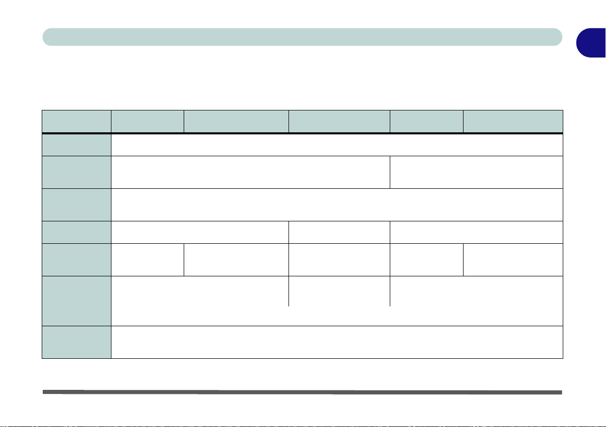
Model Differences
This notebook series includes five different model types that mainly differ as indicated in the table below. Note that
your model may appear slightly different from those pictured in this manual.
Feature Model A Model B Model C Model D Model E
1
CPUs Supported
Display Type
Supported
Video Adapters
Supported
Keyboard LED
Illuminated
Touchpad
Power Supply
Dimensions &
Weight
See “Processor” on page D - 2 for more details
15.6" (39.62cm) FHD (1920 * 1080) 16:9 Backlit Panel
See “Video Adapter Options” on page D - 3 for more details
Keyboard LED Supported Not Supported Keyboard LED Supported
Not Supported
AC/DC Adapter – (180 Watts)
Illuminated Touchpad
Supported
See “Power” on page D - 6 for more details
See “Physical Dimensions & Weight” on page D - 6 for more details
Not Supported Not Supported
AC/DC Adapter – (120
Watts)
17.3" (43.94cm) FHD (1920 * 1080) 16:9
Backlit Panel
AC/DC Adapter – (230 Watts)
Table 1 - 1 - Model Differences
Model Differences 1 - 5
Illuminated Touchpad
Supported

1
135°
Shutdown
Note that you should always
shut your computer down by
choosing the Shut Down
command in Windows (see
page 1 - 46). This will help
prevent hard disk or system
problems.
Quick Start Guide
System Startup
1. Remove all packing mate ria ls, and plac e th e com p ut er on a stable surface.
2. Securely attach any peripherals you want to use with the notebook (e.g. keyboard and mouse) to their ports.
3. Attach the AC/DC adapter to the DC-In jack at the rear of the computer, then plug the AC power cord into an
outlet, and connect the AC power cord to the AC/DC adapter.
4. Use one hand to raise the
the other hand (as illustrated in Figure 1 - 1 below) to support the base of the computer (Note: Never lif t the
computer by the lid/LCD).
5. Raise the lid/LCD to a comfortable viewing angle, and press the power button on the top left of the computer for
about 2 - 3 seconds to turn the computer “on” (note that the power LED on the front of the computer will turn
from orange to green when the computer powers on).
Figure 1 - 1 - Computer with AC/DC Adapter Plugged-In/Opening the Lid/LCD
1 - 6 System Startup
lid/LCD to a comfortable viewing angle (it is preferable not to exceed 135 degrees);
use

LCD Panel Open - Models A & C
Figure 1 - 2
LCD Panel Open
Models A & C
1. Built-In PC Camera
2. PC Camera LED
3. Built-In Microphone
4. LCD
5. Speakers
6. Power Button
7. LED Lock Indicators
8. LED Status Indicators
9. Keyboard (Model A
supports an
Illuminated Keyboard)
10.TouchPad and
Buttons
11. Fingerprint Reader
(Optional)
Note that the keyboard for
Models A & C are different,
and only Model A is pic-
tured (see Table 1 - 1, on
page 1 - 5).
4
1
10
9
5
8
6
7
11
2
5
Note that the Touchpad and
Buttons has a valid operational area indicated within the
red dotted lines above.
3
Quick Start Guide
1
LCD Panel Open - Models A & C 1 - 7

1
Figure 1 - 3
LCD Panel Open
Model B
1. Built-In PC Camera
2. PC Camera LED
3. Built-In Microphone
4. LCD
5. Speakers
6. Power Button
7. LED Indicators
8. Illuminated Keyboard
9. Illuminated
TouchPad and
Buttons
10.Fingerprint Reader
(Optional)
3
1
9
10
8
7
5
6
2
4
Note that the Illuminated
Touchpad has a defined valid
operational area of sensitivity
indicated within the sensor
area of the illustration below.
See “Illuminated Touchpad
Sensitivity” on page 2 - 12.
5
Quick Start Guide
LCD Panel Open - Model B
1 - 8 LCD Panel Open - Model B

LCD Panel Open - Model D
Figure 1 - 4
LCD Panel Open
Model D
1. Built-In PC Camera
2. PC Camera LED
3. Built-In Microphone
4. LCD
5.
Speakers
6.
LED Indicators
7. Power Button
8. Illuminated Keyboard
9. TouchPad and
Buttons
10.Fingerprint Reader
(Optional)
4
1
9
10
5
8
7
6
5
2
3
Note that the Touchpad and
Buttons has a valid operational area indicated within the
red dotted lines above.
Quick Start Guide
1
LCD Panel Open - Model D 1 - 9

1
Figure 1 - 5
LCD Panel Open
Model E
1. Built-In PC Camera
2. PC Camera LED
3. Built-In Microphone
4. LCD
5.
Speakers
6.
LED Indicators
7. Power Button
8. Illuminated Keyboard
9. TouchPad and
Buttons
10.Fingerprint Reader
(Optional)
4
1
9
10
5
8
7
6
5
2
3
Note that the Illuminated Touchpad has a
defined valid operational area of sensitivity indicated within the
sensor area of the illustration below. See
Quick Start Guide
LCD Panel Open - Model E
1 - 10 LCD Panel Open - Model E

LED Indicators
Wireless Device
Operation Aboard
Aircraft
The use of any portable
electronic transmission devices (e.g. WLAN or Bluetooth) aboard aircraft is
usually prohibited. Make
sure any wireless modules
are OFF (i.e. the system is
in Airplane Mode) if you
are using the computer
aboard aircraft.
Use Fn + F11 Airplane
Mode key combination to
toggle Airplane Mode On/
Off, and check the LED indicator for the power status.
The LED indicators display helpful information about the current status of the computer.
Icon Color Description Icon Color Description
Number Lock is Activated
Blue / White
Orange The Battery is Charging
Quick Start Guide
1
Blue / White
Blue / White
Blue / White Hard Disk Activity Orange
Blue / White
Blue / White
Off
Caps Lock is Activated
Scroll Lock is Activated
Airplane Mode is ON (the
WLAN & Bluetooth
Modules are OFF)
Integrated GPU (iGPU)
Activated
Discrete GPU (dGPU)
Activated
Table 1 - 2 - LED Indicators
Blinking
Orange
Green
Blinking
Orange*
Green The Computer is On
Blinking
Green
The Battery has Reached
Critically Low Power
Status
The Battery is Fully
Charged
AC/DC Power is Plugged
The Powered USB Port is On
(see
Powered USB 2.0 Port” on
The Computer is in Sleep
In
“USB 3.0 Ports &
page 1 - 24
)
Mode
LCD Panel Open - Model E 1 - 11

1
Other Keyboards
If your keyboard is damaged or you just want to
make a change, you can
use any standard USB
keyboard. The system will
detect and enable it automatically. However special functions/hot-keys
unique to the system’s
regular keyboard may not
work.
Num Lk & Scr Lk
Hold down the Fn Key
and Scr Lk/Num Lk to enable scroll lock/number
lock, and check the LED
indicator for status.
Numerical
Play/Pause Key
Function Keys
Scr Lk Key
Fn Key
Keypad
Game Control Keys
Num Lk Key
Windows Logo Key
Special Characters
Some software applications allow the number-keys to be used with Alt to produce special characters.
These special characters can only be produced by using the numeric keypad. Regular number keys (in
the upper row of the keyboard) will not work. Make sure that NumLk is on.
Quick Start Guide
Illuminated LED Keyboard - Models A, B, D & E
The illuminated keyboard has an embedded numerical keypad for easy numeric data
input, and features function keys to allow you to change operational features instantly. See Table 1 - 6, on page 1 - 18 for full function key combination details.
Figure 1 - 6 - Illuminated LED Keyboard - Models A, B, D & E
1 - 12 Illuminated LED Keyboard - Models A, B, D & E

Quick Start Guide
2
1
1
2 3
4
1
2
3
4
Keyboard LED - Models A, B, D & E
Press Fn plus the key to toggle the keyboard LED on/off. The keyboard LED may be configured using
the Fn + key combination outlined in the table below. In addition press Fn plus the
keyboard backlight application to configure the settings (see overleaf).
Keyboard LED Function key Combinations
key to launch the
1
Fn +
Fn +
Fn +
Fn +
(for Custom Mode only - see Table 1 - 4, on page 1 - 15)
(for Custom Mode only - see Table 1 - 4, on page 1 - 15)
Launch the Keyboard Backlight Application
Toggle the Keyboard Backlight On/Off
Keyboard LED Illumination Decrease
Keyboard LED Illumination Increase
Table 1 - 3 - Keyboard LEDs - Models A, B, D & E
Keyboard LED - Models A, B, D & E 1 - 13

1
Help Button
Keyboard Sections
Color Swatches
Effects Buttons
Illuminated
Touchpad
Note that Models B &
E support an illumi-
nated Touchpad
which may also be
configured by using
the Keyboard Backlight Application.
Quick Start Guide
Keyboard Backlight Application (Models A, B. D & E)
The keyboard Backlight application can be accessed by pressing the Fn plus key. Click the Help button
in the application to display the configuration keys.
• Click the Custom button to display the three sections of the keyboard which may be configured.
• Click a section of the keyboard and the color buttons will be displayed.
• Click a color swatch to apply the color to the selected section when not overridden by any effect applied.
• Click on any of the effect buttons to apply random colors, wave or flashing effects etc (see over).
Figure 1 - 7 - Keyboard Backlight Application
1 - 14 Keyboard LED - Models A, B, D & E
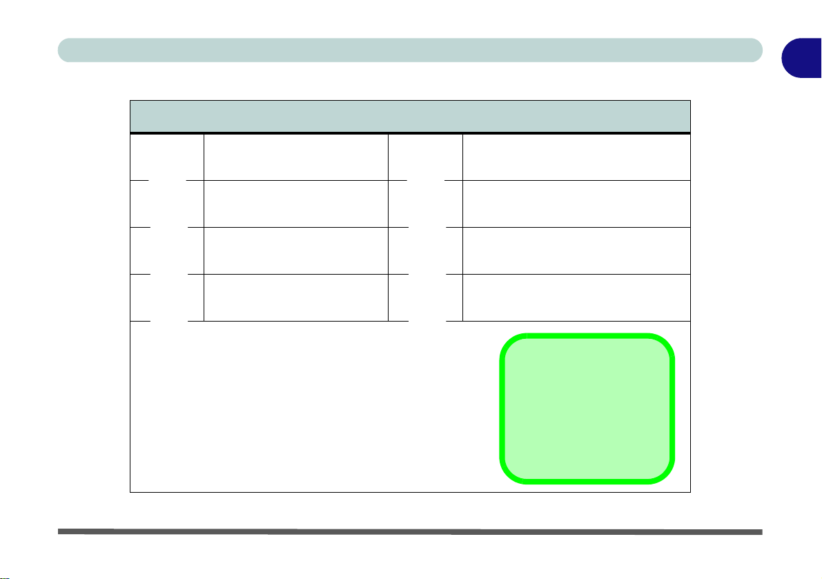
Effects Buttons & Help (Models A, B, D & E)
Illumination Keys
Note that the keyboard illumination (increase/decrease)
keys may be used to configure the keyboard LED in Cus-
tom Mode only.
LED Effects Buttons
Quick Start Guide
1
Random Color
Dancing Effect
Tempo Beat
Flashing
Cycle (Colors as Selected in RGB)
Custom Mode - Display & Configure
Up/Down Wave
Breathing (All Colors)
Keyboard Sections & Colors
Table 1 - 4 - LED Effects Buttons & Help
Keyboard LED - Models A, B, D & E 1 - 15
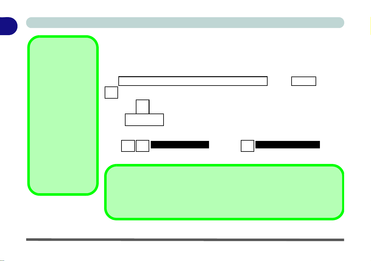
1
Other Keyboards
If your keyboard is damaged or you just want to
make a change, you can
use any standard USB
keyboard. The system will
detect and enable it automatically. However special functions/hot-keys
unique to the system’s
regular keyboard may not
work.
Num Lk & Scr Lk
Hold down the Fn Key
and Scr Lk/Num Lk to enable scroll lock/number
lock, and check the LED
indicator for status.
Numerical
Play/Pause Key
Function Keys
Num Lk &
Scr Lk Keys
Fn Key
Keypad
Game Control Keys
Windows Logo Key Menu/Application Key
Special Characters
Some software applications allow the number-keys to be used with Alt to produce special characters.
These special characters can only be produced by using the numeric keypad. Regular number keys (in
the upper row of the keyboard) will not work. Make sure that NumLk is on.
Quick Start Guide
Keyboard - Model C
The keyboard has an embedded numerical keypad for easy numeric data input, and
features function keys to allow you to change operational features instantly. See
Table 1 - 6, on page 1 - 18 for full function key combination details.
1 - 16 Keyboard - Model C
Figure 1 - 8 - Keyboard - Model C
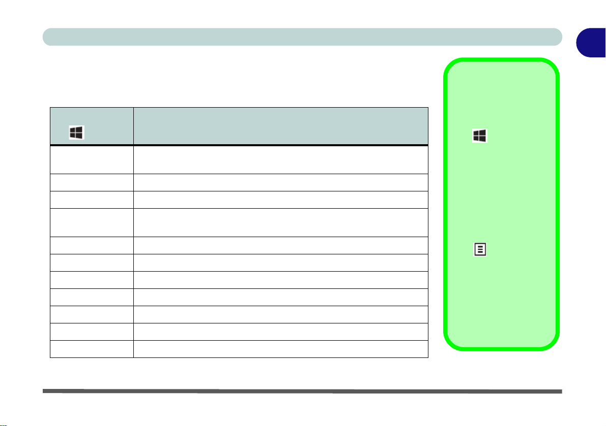
Keyboard Shortcuts
Windows Logo
Keyboard Shortcut
Use the Windows logo
key + D key com-
bination to switch between the Start screen
and Windows Desktop.
Menu/Application
Keyboard Shortcut
When the Desktop app
is running you can use
the Menu/Application
key on the Model
C keyboard to display
the context menu as
per a mouse rightclick. In the Start
screen this function is
useful to quickly display the All Apps icon.
The following Windows Logo Key (Winkey) keyboard shortcuts are useful for navigation/operation in
Windows Logo
Key +
Tap Winkey
CDisplay Charms menu
D Switch to the Windows Desktop and toggle show Desktop
E
F Display file Search
I Open the Settings charm
K Open the Connect charm
L Lock the computer and display the Lock screen
P Display the Second Screen menu (see Figure 1 - 34 on page 1 - 45)
R Switch to the Windows Desktop and display the Run dialog box
Z Access the Customize Bar (see Figure 1 - 21 on page 1 - 32)
Windows 8.1
.
Description
Toggle between the Start screen and the foremost running app or the
Windows Desktop
Switch to the Windows desktop and launch Windows Explorer with
Computer displayed
Table 1 - 5 - Keyboard Shortcuts
Quick Start Guide
1
Keyboard - Model C 1 - 17

1
Quick Start Guide
Function Keys & Visual Indicators
The function keys (F1 - F12 etc.) will act as hot keys when pressed while the Fn key is held down. Visual indicators (see the table below) are available when the Hot Key driver is installed.
Keys Function/Visual Indicators Keys Function/Visual Indicators
Fn + ~ Play/Pause (in Audio/Video Programs) Fn + Esc Control Center Toggle (see over)
Fn + F1
Fn + F2
Fn + F3 Mute Toggle Fn + F11 Airplane Mode Toggle
Fn + F4 Sleep Toggle
Fn +F5/F6 Volume Decrease/Increase
Fn + F7 Display Toggle
Touchpad Toggle
Turn LCD Backlight Off
(Press a key to or use Touchpad to turn on)
See also Table 1 - 2, on page 1 - 11 for Number Lock, Caps Lock and Scroll Lock indicators
Fn +F8/F9 Brightness Decrease/Increase
Fn + F10
Fn + Power
Button
Fn +
PC Camera Power Toggle
Powered USB 3.0 Port Power Toggle
Keyboard LED (Models A, B. D & E) Toggle
Table 1 - 6 - Function Keys & Visual Indicators
1 - 18 Keyboard - Model C
(see page 1 - 15)

Quick Start Guide
Control Center
Click on any button to turn any of the modules (e.g.
TouchPad, Camera) on/off.
Click on the power conservation modes to switch between Performance, Balanced or Energy Star modes
(see page 3 - 12). To remove the Power Conservation
Modes screen just click in a blank area of the icon or
press a key on the keyboard.
Click on the buttons (or just click and hold the mouse
button) to adjust the slider for Brightness/Volume.
Click on Display Switch and click to choose a display
mode from the menu (see page C - 23).
Control Center
When in the Windows Desktop application (not in the Start screen) press the Fn + Esc key combination, or
double-click the icon
trol Center gives quick access to frequently used controls and enables you to quickly turn the camera/Touch
Pad on/off (see Appendix B for full details).
in the notification area of the taskbar to toggle the Control Center on/off. The Con-
1
Figure 1 - 9 - Control Center
Control Center 1 - 19

1
Figure 1 - 10
Front & Rear Views
Models A, B & C
1. LED Power Indicators
2. Vent/Fan Intake
3. Display Port
4. HDMI-Out Port
5. Mini Display Port
6. DC-In Jack
1
3
4
6
2
5
2
HDMI Port
Note that the HDMI Port supports video and audio signals to attached external displays (see
“HDMI Audio Configuration” on page C - 26).
Note that Sound Blaster X-Fi MB3 audio will be disabled when you are connecting to an
external display through an HDMI connection.
Models A & C
Models A & C
1
3
4
6
2
5
2
Model B
Model B
Quick Start Guide
Front & Rear Views (Models A, B & C)
1 - 20 Front & Rear Views (Models A, B & C)

Front & Rear Views (Models D & E)
Figure 1 - 11
Front & Rear Views
Models D & E
1. LED Power Indicators
2. Vent/Fan Intake
3. Display Port
4. HDMI-Out Port
5. Mini Display Port
6. DC-In Jack
7. Security Lock Slot
1
3
4
6
2
5
2
HDMI Port
Note that the HDMI Port supports video and audio signals to attached external displays (see
“HDMI Audio Configuration” on page C - 26).
Note that Sound Blaster X-Fi MB3 audio will be disabled when you are connecting to an
external display through an HDMI connection.
Model D
Model D
1
3
4
6
2
5
2
Model E
7
Model E
7
Quick Start Guide
1
Front & Rear Views (Models D & E) 1 - 21

1
Figure 1 - 12
Right View
1. Optical Device
Drive Bay
2. Headphone Jack
3. Microphone Jack
4. S/PDIF-Out Jack
5. Line-In Jack
6. 1 * USB 2.0 Port
7. Security Lock Slot
(Models A, B & C
Only)
USB Ports
Note that the connections
to the USB ports only fit
one way, do not force
them.
USB 3.0 ports are denoted by their blue color;
USB 2.0 ports are colored
black.
1
3 42 6
7
5
1
3 42 65
Models A & C
Model D
1 3 42 65
7
Model B
Model E
1
3
42
6
5
Quick Start Guide
Right View
1 - 22 Right View

Left View
Figure 1 - 13
Left View
1. Mini-IEEE 1394a
Port
2. RJ-45 LAN Jack
3. 1 * Powered USB
3.0 Port
4. 1 * USB 3.0 Port
5. Combined
eSATA/ USB 3.0
Port
6. Multi-in-1 Card
Reader
Mini-IEEE 1394a
Port
The Mini-IEEE 1394a
port only supports SELF
POWERED IEEE 1394
devices.
1
2
4
5
6
3
Models A & C
1
2
4
5
6
3
Model D
1
2
4
5
6
3
Model E
1
2
4
5
6
3
Model B
Quick Start Guide
1
Left View 1 - 23

1
USB 3.0 Ports & Powered USB 2.0 Port
USB 3.0 ports are denoted by their blue color; USB 2.0 ports are colored bl ack. Note that
the USB 3.0 port is not operational under DOS and does not support wake on USB. The
powered USB 3.0 ( in Figure 1 - 13 on page 1 - 23) port can supply power (for charging
devices only, not for operating devices) when the system is off but still powered by the
AC/DC adapter plugged into a working outlet, or powered by the battery with a capacity level
above 20% (this may not work with certain devices - see page 8 - 12). Toggle power to this
port by using Fn + power button.
Multi-in-1 Card Reader
The card reader allows you to use the most popular digital storage card formats:
MMC (MultiMedia Card) / RSMMC
SD (Secure Digital) / Mini SD / SDHC / SDXC
MS (Memory Stick) / MS Pro / MS Duo
3
Quick Start Guide
1 - 24 Left View

Bottom View - Models A & C
Figure 1 - 14
Bottom View
1. Sub Woofer
2. Fan Outlet/Intake
3. Component Bay
Cover
4. HDD Bay
5. Battery
Overheating
To prevent your computer from overheating make
sure nothing blocks the
vent(s)/fan intake(s)
while the computer is in
use.
1
2
4
5
Battery Information
Always completely discharge, then fully charge, a new battery before using it. Completely
discharge and charge the battery at least once every 30 days or after about 20 partial discharges. See “Battery Information” on page 3 - 14 for full instructions.
3
2
2
2
Quick Start Guide
1
Bottom View - Models A & C 1 - 25

1
Figure 1 - 15
Bottom View
1. Sub Woofer
2. Fan Outlet/Intake
3. Compon e nt Bay
Cover
4. HDD/ODD Bay
5. Battery
Overheating
To prevent your computer from overheating make
sure nothing blocks the
vent(s)/fan intake(s)
while the computer is in
use.
1
2
4 5
Battery Information
Always completely discharge, then fully charge, a new battery before using it. Completely
discharge and charge the battery at least once every 30 days or after about 20 partial discharges. See “Battery Information” on page 3 - 14 for full instructions.
3
2
2
2
2
Quick Start Guide
Bottom View - Model B
1 - 26 Bottom View - Model B
Bottom View - Model D
Figure 1 - 16
Bottom View
1. Sub Woofer
2. Fan Outlet/Intake
3. Component Bay
Cover
4. Primary HDD Bay
5. Secondary HDD
Bay
6. Battery
Overheating
To prevent your computer from overheating make
sure nothing blocks the
vent(s)/fan intake(s)
while the computer is in
use.
1
2
4
5
Battery Information
Always completely discharge, then fully charge, a new battery before using it. Completely
discharge and charge the battery at least once every 30 days or after about 20 partial discharges. See “Battery Information” on page 3 - 14 for full instructions.
3
2
2
2
6
Quick Start Guide
1
Bottom View - Model D 1 - 27

1
Figure 1 - 17
Bottom View
1. Sub Woofer
2. Fan Outlet/Intake
3. Compon e nt Bay
Cover
4. Primary HDD Bay
5. Secondary HDD
Bay
6. Battery
Overheating
To prevent your computer from overheating make
sure nothing blocks the
vent(s)/fan intake(s)
while the computer is in
use.
1
2
4
5
Battery Information
Always completely discharge, then fully charge, a new battery before using it. Completely
discharge and charge the battery at least once every 30 days or after about 20 partial discharges. See “Battery Information” on page 3 - 14 for full instructions.
3
2
2
2
6
Quick Start Guide
Bottom View - Model E
1 - 28 Bottom View - Model E

Windows 8.1 Control Panel
Windows Versions
Note that the information included on the following pages is for
Windows 8.1 only.
The Windows 8 interface is slightly different
in appearance and in
methods of navigation,
and a separate manual
is provided on the De-
vice Drivers & Manual
Disc with reference to
Windows 8.
Move the mouse to the bottom left
Start ScreenDesktop app
of the screen and right-click to
access the menu.
Throughout this manual you will see an instruction to open the Control Panel.
R
ight-click the lower left hot corner to bring up the context menu (or use the Win-
dows Logo Key + X key combination)
Desktop app or Start screen.
and select Control Panel in both the
Quick Start Guide
1
Figure 1 - 18 - Windows Context Menu
Windows 8.1 Control Panel 1 - 29

1
Display Most
Recently Used
Apps
If you are in the Start
screen, Desktop or an
app you can move your
mouse to the upper left
corner of the screen to
get back to the most recently used app.
To view all the most recently used Apps hover
over the top left of the
screen and then move
the mouse down along
the left side of the
screen to display the
list.
Move the mouse to the bottom left of the screen
and right-click the Start button to access the menu.
Quick Start Guide
Right-click the Start button in the Desktop app (or use the Windows Logo Key
+ X key combination) to bring up an advanced context menu of useful features
such as Control Panel, Programs and Features, Power Options, Task Manager,
Search, File Explorer, Command Prompt, Device Manager and Network Connections etc.
Figure 1 - 19 - Advanced Context Menu (Right-Click Start Button)
1 - 30 Windows 8.1 Control Panel

Quick Start Guide
Desktop App
Windows 8.1 Start Screen & Desktop
The Apps, control panels, utilities and programs within Windows are accessed from the Start screen and/or
Windows Desktop app. The Desktop (which runs as an app within the Start screen) can be accessed by clicking
the Desktop item in the Start screen (or by using the Windows Logo Key + D key combination). Click the
arrow at the bottom of the Start screen to access Apps.
1
Figure 1 - 20 - Windows Start Screen
Windows 8.1 Start Screen & Desktop 1 - 31

1
Click the arrow at the bottom of the
screen to access All Apps
Quick Start Guide
Apps & Tiles
The Start screen will contain a number of apps, and many more will be installed as you add more applications
etc. Not all of these apps can fit on one screen so you will often need use the slider at the bottom of the screen
in order to view all the necessary Apps.
Accessing Pining/Unpinning All Apps
You can add and remove the tiles for apps and control panels in the Start screen. Right-click on a blank area
of the Start screen, and you will see the Customize icon. Click the Customize icon to display all the installed
applications etc. Right-click any icon to bring up the menu at the bottom of the screen and you can then click the
appropriate icon to pin the App to (or unpin from) the Start screen, or to the taskbar in the Desktop applica-
tion (you can also open the app in a new window, run as administrator or open the file location).
Figure 1 - 21 - Customize Apps
1 - 32 Windows 8.1 Start Screen & Desktop

Quick Start Guide
Move the mouse to the bottom left of the screen and click to switch
back to the Start screen.
Desktop Application
When the Desktop app is running (click the app in the Start screen or use the Windows Logo Key + D key
combination) you can use lower left hot corner to switch between the Start screen and the Windows Desktop
app. To do so move your mouse to hover over the bottom left corner of the Desktop app and left-click.
When you move to the lower left hot corner in the Start screen it will take you back to your most recently used
app (if one is running).
1
Figure 1 - 22 - Desktop
Windows 8.1 Start Screen & Desktop 1 - 33
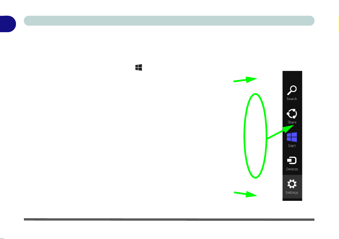
1
Move the mouse over a Charms Bar icon to activate the menu
Move the mouse to the top/lower right icons to activate the Charms Bar
Move the mouse to the top/lower right icons to activate the Charms Bar
Quick Start Guide
The Charms Bar
The right side of the screen displays the Charms Bar. The Charms Bar contains the Search, Share, Start, Devices and Settings menus. To access up the Charms Bar move the cursor to the upper or lower right corners of
the screen, and then hover over one of the items in the Charms Bar to activate it (the bar will be black when it
is active), or use the Windows Logo Key + C key combination.
Figure 1 - 23 - Start Screen with Charms Bar
1 - 34 Windows 8.1 Start Screen & Desktop

Quick Start Guide
Charms Bar - TouchPad Access
To quick access the Charms Bar using the TouchPad:
1. Place your finger off the TouchPad (slightly to the right of the
pad resting on the computer).
2. Move your finger across to the left on to the TouchPad.
3. The Charms Bar will then pop-up.
Charms Bar Items
• Search : You can search for any file, application, Apps and control panel settings with instantaneous
results.
•Share : This button is used to share information with people via mail or social networks.
•Start : Click to bring up the Start screen (the same function as pressing the Windows Logo Key or click-
ing the bottom left of the screen).
• Devices : Click this button to change connected peripheral device settings e.g. an external display.
• Settings : This button gives instant access to the computer settings, such as Network, Audio, Notifications, Power and Keyboard (click Change PC Settings to activate the PC Settings menu).
1
Figure 1 - 24 - Settings Menu
Windows 8.1 Start Screen & Desktop 1 - 35
1
Quick Start Guide
Windows 8.1 Control Panel
In many instances throughout this manual you will see an instruction to open the Control Panel. The Control
Panel can be accessed in a number of ways in Windows 8.1.
•Click Search in the Windows Charms Bar (see previous page) and the search pane will pop out. Type
Control Panel and select it from the results to the left.
Figure 1 - 25 - Search (Control Panel)
• Click on This PC (in Apps, or you can to pin This PC to the Start screen), click on Computer in the
top menu and select Open Control Panel from the ribbon.
Figure 1 - 26 - Open Control Panel (Computer)
1 - 36 Windows 8.1 Control Panel

Quick Start Guide
• When in the Desktop app (this does not apply to the Start screen) click on Settings in the Windows
Charms Bar and select Control Panel from the menu.
Figure 1 - 27 - Settings Charms Bar (Desktop App Only)
• Click the arrow at the bottom of the Start screen and click Control Panel in Apps (Windows System).
1
Figure 1 - 28 - All Apps - Control Panel
Windows 8.1 Control Panel 1 - 37

1
Keyboard Shortcut to Control Panel
You can also use keyboard shortcuts to access the Contro l Pa nel. Press th e Win dows logo key and X to bring up
the context menu, and then press P to bring up the Control Panel. Alternatively press the Windows logo key an d R
to bring up the Run dialog box, and then type “Control Panel” and press Enter to access the Control Panel.
Quick Start Guide
• Right-c lick the Start button to bring up the menu and select Control Panel (see Figure 1 - 19 on page 1
- 30).
1 - 38 Windows 8.1 Control Panel

Quick Start Guide
Windows 8.1 Taskbar
In many instances throughout this manual you will see an instruction to access the notification area of the taskbar (system tray). In Windows 8.1 the taskbar is accessed from the Desktop application; if you are in the Start
screen you will need to switch to the Desktop.
The taskbar is displayed at the bottom of the Desktop screen, and you can see the notification area (system
tray) of the taskbar in the bottom right of the screen. Some of the control panels and applications referred to
during the course of this manual can be accessed from here.
Figure 1 - 29 - Desktop Taskbar & Notification Area (System Tray)
You can pin/unpin apps to/from the taskbar in much the same way as you can to the Start screen (see “Accessing
Pining/Unpinning All Apps” on page 1 - 32).
1
Windows 8.1 Control Panel 1 - 39

1
Quick Start Guide
Video Features
You can switch display devices, and configure display options, from the Display control panel (in Appearances
and Personalization) in Windows 8 when running the Desktop app (see “Desktop Application” on page 1 -
33).
NVIDIA® Optimus™ Technology / AMD Enduro™ Technology
Your computer will feature either NVIDIA® Optimus™ OR AMD En duro™ switchable graphics technology.
These seamless technologies are designed to get best performance from the graphics system while allowing longer battery life, without having to manually change settings. The computer will automatically switch between
the integrated UMA (Unified Memory Architecture) GPU (iGPU) and the discrete GPU (dGPU) when required
by the applications in use. This switch is seamless to the user (see Appendix C).
Icon Color Description
Off Integrated GPU (iGPU) Activated
Blue/White Discrete GPU (dGPU) Activated
Table 1 - 7 - GPU Mode LED Indicator
1 - 40 Video Features

Quick Start Guide
1
3
2
Right-Click Desktop App
1. You can right-click the
desktop and select
Screen resolution
(Figure 1 - 30).
2. Use the dropbox to
select the screen
Resolution (Figure
1 - 30).
3.Click Advanced
settings (Figure 1 -
30) to bring up the
Advanced properties
tabs.
123
1
To access Display (Control Panel) and Screen Resolution in Windows 8:
1. Go to the Control Panel.
2. Click Display (icon) - In the Appearance and Personalization category.
3. Adjust resolution.
Figure 1 - 30 - Screen Resolution
Video Features 1 - 41

1
3
4
4
Quick Start Guide
To access the Intel(R) Graphics Control Panel:
1. Click Advanced settings (Figure 1 - 30 on page 1 - 41) in the Screen Resolution control panel in Windows.
2. Click the Intel(R)... tab and click Graphics Properties (button) (Figure 1 - 31 on page 1 - 42) .
OR
3. Right-click the desktop and select Graphics Properties from the menu.
OR
4. Click the icon in the notification area of the Desktop taskbar and select Graphics Properties from the menu.
Figure 1 - 31 - Intel Graphics Control Panel
1 - 42 Video Features

To access the NVIDIA Control Panel:
5
6
5
6
1. Right-click the desktop and select NVIDIA Control Panel (Figure 1 - 32).
OR
2. Double-click the icon (Figure 1 - 32) in the Windows control panel.
Quick Start Guide
1
Figure 1 - 32 - NVIDIA Control Panel
Video Features 1 - 43

1
123
1
3
Right-Click
for Menu
2
Quick Start Guide
AMD Catalyst Control Center
You can access the AMD CatalystTM Control Center as follows:
1. Right-click the desktop and select Graphics Properties (at the top of the desktop menu) (Figure 1 - 3 3).
OR
2. Double-click (or right-click the icon and select Graphics Properties) the icon (Figure 1 - 33) in the
Windows system tray notification area (make sure “Enable Syst em T r ay Menu” is clicked in Preferences ).
3. See “AMD Catalyst™ Control Center ” on page C - 37 for full details on control panels etc.
Figure 1 - 33 - Catalyst Control Center Access
1 - 44 Video Features

Quick Start Guide
Configuring External Displays
It is possible to quickly configure external displays from the Devices menu item in the Charms Bar (see “The
Charms Bar” on page 1 - 34).
To Configure Displays from Devices (Charms Bar):
1. Attach your display to the appropriate port, and turn it on.
2. Go the Charms Bar, select Devices.
3. Click Project (you may need to click Second Screen).
4. Click on any one of the options from the menu to select PC screen only, Duplicate, Extend or Second screen
only.
1
Figure 1 - 34- Devices (Project)
Video Features 1 - 45

1
Charms Bar Desktop App Start Screen
Quick Start Guide
Power Options
Power Options (Hardware and Sound) can be accessed from the Control Panel. The Power Menu item in Set-
tings in the Charms Bar in Windows 8.1 may be used to Shut down or Restart (you can also add Hibernate/
Sleep to the menu - see “Adding Hibernate/Sleep to the Power Menu” on page 3 - 10). You can also use the
context menu (Shut down or sign out) shut the computer down/restart etc.
Shut Down, Restart or Sleep (Charms Bar)
1. Go to the Charms Bar and click Settings.
2. Click Power .
3. Select Sleep, Shut Down or Restart .
1 - 46 Power Options
Figure 1 - 35 - Shut Down/Restart

Quick Start Guide
Screen Resolution for Apps
(Windows 8/8.1)
The minimum resolution in which Apps will run is 1024x768.
The minimum resolution required to support a ll the features of
Windows 8 (including multitasking with snap) is 1366x768.
These specs are the minimum screen resolution that supports
all the features of Windows 8.1 on a useful physical size.
Running Apps
To run apps in Windows 8.1 you will need to check that the Screen Resolution and User Account Control Settings are compatible with the system requirements.
Screen Resolution Settings
1. Switch to the Windows Desktop (click the app or use the Windows logo key + D key combination).
2. Right-click a blank area of the Windows Desktop and select Screen Resolution. Adjust the Resolution to
make sure that it is at least 1024 * 768, although preferably 1366 * 768 or above (see sidebar).
1
Figure 1 - 36 - Screen Resolution
Running Apps 1 - 47

1
Quick Start Guide
User Account Control Settings
If your computer meets the minimum screen resolution requirements, and still you can't run apps, then that you
have to check the status of User Account Control (UAC). Apps may fail to open when the UAC is turned off.
To check whether the UAC is on or off, follow the instructions below.
1. Open the Control Panel.
2. Click on User Accounts and then click on Change User Account Control settings (or click System and
Security and click Change User Account Control Settings under Action Center).
3. If the slider is in the Never notify position, then the UAC is disabled.
4. To enable or turn on the UAC, move the slider to Always notif y or Notify me when apps try to make changes
to my computer (default) position, and then click OK.
1 - 48 Running Apps
Figure 1 - 37 - User Account Control

Storage Devices, Mouse, & Audio
Chapter 2: Storage Devices, Mouse, & Audio
Overview
Read this chapter to learn more about the following main features and components
of the computer:
•Hard Disk Drive
• Optical Device
• Multi-in-1 Card Reader
• Audio Features
• Touchpad and Buttons/Mouse
2
Overview 2 - 1

Storage Devices, Mouse, & Audio
Power Safety
Before attempting to access any of the internal
components of your
computer please ensure
that the machine is not
connected to the AC
power, and that the machine is turned off. Also
ensure that all peripheral cables, including
phone lines, are disconnected from the computer.
Figure 2 - 1
Primary Hard Disk
Location
1
Model A/B Model C
Models A & C Model B
Models D & E
2
Hard Disk Drive
The hard disk drive(s) is used to store your data in the computer. The hard disks) can
be taken out to accommodate other 2.5" serial (SATA) hard disk drives with a height
of 9.5 mm. The primary hard disk bay is accessible from the bottom of your computer as seen below.
Further details on removing and inserting the hard disk are available in “Upgrading
the Hard Disk Drive(s)” on page 6 - 10.
Model B/D/E computers feature a primary and secondary hard disk bay (you may
have a second hard disk installed as part of a RAID). Model A/B computers may
have a secondary hard disk drive installed in an optional caddy bay.
2 - 2 Hard Disk Drive

Storage Devices, Mouse, & Audio
Sound Volume
Adjustment
How high the sound volume can be set depends
on the setting of the volume control within Win-
dows. Click the Volume
icon on the notification
area to check the setting.
Peripherals must be
connected before you
turn on the system.
Figure 2 - 2
Optical Device
123
1
2
3
Optical Device
There is a bay for a 5.25" optical (CD/DVD) device (12.7mm height). The actual device will depend on the model you purchased (see “Storage” on page D - 4). The
optical device is usually labeled “Drive D:” and may be used as a boot device if
properly set in the BIOS (see “Boot Menu” on page 5 - 17).
Loading Discs
To insert a CD/DVD, press the open button and carefully place a CD/DVD onto
the disc tray with label-side facing up (use just enough force for the disc to click onto
the tray’s spindle). Gently push the CD/DVD tray in until its lock “clicks” and you
are ready to start. The busy indicator will light up while data is being accessed,
or while an audio/video CD, or DVD, is playing. If power is unexpectedly interrupted, insert an object such as a straightened paper clip into the emergency eject hole
to open the tray.
2
Optical Device 2 - 3

Storage Devices, Mouse, & Audio
CD Emergency Eject
If you need to manually
eject a CD (e.g. due to
an unexpected power
interruption) you may
push the end of a
straightened paper clip
into the emergency eject
hole. However please
do NOT use a sharpened pencil or similar
object that may break
and become lodged in
the hole.
Disk Eject Warning
Don’t try to remove a
CD/DVD while the system is accessing it. This
may cause the system
to “crash”.
2
2 - 4 Optical Device
Handling CDs or DVDs
Proper handling of your CDs/DVDs will prevent them from being damaged. Please
follow the advice below to make sure that the data stored on your CDs/DVDs can be
accessed.
Note the following:
• Hold the CD or DVD by the edges; do not touch the surface of the disc.
• Use a clean, soft, dry cloth to remove dust or fingerprints.
• Do not write on the surface with a pen.
• Do not attach paper or other materials to the surface of the disc.
• Do not store or place the CD or DVD in high-temperature areas.
• Do not use benzene, thinner, or other cleaners to clean the CD or DVD.
• Do not bend the CD or DVD.
• Do not drop or subject the CD or DVD to shock.

Storage Devices, Mouse, & Audio
DVD Region Note
DVD region detection is
device dependent, not
OS-dependent. You can
select your module’s region code 5 times. The
fifth selection is permanent. This cannot be altered even if you change
your operating system
or you use the module in
another computer.
Figure 2 - 3
DVD Region Codes
• Region 1 - USA & Canada
• Region 2 - Western Europe, Japan,
South Africa, Middle East & Egypt
• Region 3 - South-East Asia, Taiwan,
South Korea, The Philippines, Indonesia, Hong Kong
• Region 4 - South & Central Amer-
ica, Mexico, Australia, New Zealand
• Region 5 - N Korea, Russia, Eastern
Europe, India & Most of Africa
• Region 6 - China
DVD Regional Codes
To change the DVD regional codes:
1. Go to the Control Panel
2. Double-click Device Manager (Hardware and Sound), then click the + next to
DVD/CD-ROM drives.
3. Double-click on the DVD-ROM device to bring up the Properties dialog box, and
select the DVD Region (tab) to bring up the control p anel to allow you to adjust the
regional code.
2
Optical Device 2 - 5

Storage Devices, Mouse, & Audio
Card Reader Cover
Make sure you keep the
cover in the card reader
when not in use. This
will help prevent foreign
objects and/or dust getting in to the card reader.
Push-Push Card
Reader
The card reader features a push-in/push-out
card insertion and ejection mechanism. Simply
push the card to insert
and eject it, however Ms
Duo cards require an
adapter.
Figure 2 - 4
Left View
1. Card Reader
• MMC (MultiMedia Card) / RSMMC
• SD (Secure Digital) / Mini SD / SDHC / SDXC
• MS (Memory Stick) / MS Pro / MS Duo
1
Models A & C
Model B
1
1
1
Model D
Model E
2
Multi-in-1 Card Reader
The card reader allows you to use some of the latest digital storage cards. Push the
card into the slot and it will appear as a removable device, and can be accessed in
the same way as your hard disk (s). Make sure you install the Card Reader driver
2 - 6 Multi-in-1 Card Reader
(see “Card Reader” on page 4 - 7).
Note: Some of these cards require PC adapters that are usually supplied with the
cards.
Storage Devices, Mouse, & Audio
Volume Adjustment
The sound volume level is
set using the volume control within Windows (and
the volume function keys
on the computer). Click the
volume icon in the notification area to check the setting.
Headphone
Configuration
It is recommended that you
set the Speaker Configu-
ration to Stereo (not to 5.1
or 7.1 Speaker) when listening through headphones
in order to maximize audio
quality.
Figure 2 - 5
Realtek Audio
Manager
Right-click the icon
to access the menu
above.
See “HDMI Audio Configuration” on page C - 26 for a description of the audio configuration when connecting an HDMI supported display device.
See “Sound Blaster Audio & HDMI” on page 7 - 90 for more information on the THX TruStudio Pro Audio setup.
Audio Features
You can configure the audio options on your computer from the Sound control
panel in Windows, or from the Realtek HD Audio Manager icon in the notification area/control panel (right-click the notification area icon to bring up an audio menu). The volume may also be adjusted by means of the Fn + F5/F6 key
combination (see Table 1 - 6, on page 1 - 18).
2
Audio Features 2 - 7

Storage Devices, Mouse, & Audio
Figure 2 - 6
Realtek Audio
Manager -
Recording Setup
2
Setup for Audio Recording
To record audio sources on your computer at optimum quality follow the instructions below:
1. Click
2. Click Realtek HD Audio Manager (or right-click the notification area icon and
3. Click Microphone Effects (tab) in Microphone (tab), and then click to select
4. Click OK to close the control panel and save the settings.
Control Panel
select Sound Manager).
Noise Suppression (button), or adjust the Recording Volume level to around 60,
to obtain the optimum recording quality.
and make sure you are in
Classic View
.
2 - 8 Audio Features
Storage Devices, Mouse, & Audio
Sound Blaster Audio &
HDMI
Note that the Sound Blaster
audio effects do not apply
to audio generated through
an HDMI connection (see
page 7 - 82.).
Figure 2 - 7
Speaker
Configuration (7.1)
Auto Popup Dialog
You should enable the
auto popup dialog to automatically detect when a
device has been
plugged-in. If disabled,
double-click connector
settings and click the
box to enable the auto
popup detection of
plugged-n devices.
Connector Settings
Setup for 5.1 or 7.1 Surround Sound
To setup your system for 5.1 or 7.1 surround sound you will need to connect the audio cables to the Headphone-Out, Line-In, Microphone-In jack and S/PDIF-Out
jacks (note: the S/PDIF jack is used for 7.1 surround sound only).
1. Click
2. Click Realtek HD Audio Manager (or right-click the notification area icon and
3. Click Speakers (tab) and click Speaker Configuration (tab).
4. Select 5.1 or 7.1 Speaker from the Speaker Configuration pull-down menu.
Start
and make sure you are in
select Sound Manager).
, and click
Control Panel
Classic View
(or point to
.
Settings
and click
Control Panel
2
)
Audio Features 2 - 9

Storage Devices, Mouse, & Audio
Figure 2 - 8
Connected Device
Auto Popup
Note: Side Speaker Out is required for 7.1 Surround only.
2
5. Plug the front speaker cables into the Headphone-Out Jack.
6. Plug in the other cables (you may require an adapter to connect each cable to the
appropriate jack e.g a stereo mini to dual RCA adapter) from your speakers as
follows:
• Line-In Jack = Rear Speaker Out
• Microphone-In Jack = Center/Subwoofer Speaker Out
• S/PDIF-Out Jack = Side Speaker Out (for 7.1 Surround Sound Only)
7. As you plug in each cable a dialog box will pop up (see “Auto Popup Dialog” on
page 2 - 9).
8. Click to put a tick in the appropriate box according to the speaker plugged-in (e.g.
Rear Speaker Out), and then click OK to save the setting.
9. Click OK to exit Realtek HD Audio Manager.
2 - 10 Audio Features

Storage Devices, Mouse, & Audio
Mouse Driver
If you are using an external mouse your operating system may be
able to auto-configure
your mouse during its
installation or only enable its basic functions.
Be sure to check the
device’s user documentation for details.
Touchpad and Buttons/Mouse
The Touchpad is an alternative to the mouse; however, you can also add a mouse to
your computer through one of the USB ports. The Touchpad buttons function in
much the same way as a two-button mouse.
The Touchpad driver installed on your system will be dependent on your computer
model. See overleaf for Touchpad sensitivity information, and see the pages indicated below for configuration information.
• See pages 2 - 13 to 2 - 17 for Touchpad information for Models A, C, D & E.
• See pages 2 - 18 to 2 - 27 for Touchpad information for Model B.
2
Touchpad and Buttons/Mouse 2 - 11

Storage Devices, Mouse, & Audio
Standard Touchpad
Sensitivity
The standard Touchpad (featured in Model
A, C & D computers)
also have a valid operational area is that indicated within the red
dotted lines above.
Figure 2 - 9
Touchpad
Sensitivity
Model B Computers Model E Computers
2
Illuminated Touchpad Sensitivity
Note that the illuminated Touchpad (Models B & E) has a defined valid operational
area of sensitivity indicated within the sensor area of the illustration below:
• Model B Computers - 4 mm from th e top/bottom o f the tou chpad edges, and 5
mm from the left/right sides of the touchpad.
• Model E Computers - 5 mm from the top of the touchpad edges, and 5 mm
from the left/right sides of the touchpad.
The standard Touchpad (featured in Model A, C & D computers) also have a valid
operational area is that indicated within the red dotted lines above.
2 - 12 Touchpad and Buttons/Mouse

Storage Devices, Mouse, & Audio
TouchPad Scrolling
This computer model series may feature different
TouchPad versions.
These TouchPads may
differ in their vertical
scrolling function in most
scrollable windows.
Some TouchPads require
sliding the finger up and
down on the right of the
TouchPad to scroll the
window. Other versions
require tapping/holding
down the finger at the top
right or bottom right of the
TouchPad to scroll the
window.
Figure 2 - 10
Mouse Properties
Touchpad Configuration for Models A, C, D & E
Once you have installed the TouchPad driver (see “TouchPad” on page 4 - 7) you
can configure the functions from the Mouse control panel in Windows, or by d oubleclicking the TouchPad driver icon in the notification area of the taskbar in the
Desktop app. You may then configure the TouchPad tapping, buttons, scrolling,
pointer motion and sensitivity options to your preferences. You will find further information at www.synaptics.com.
2
Touchpad Configuration for Models A, C, D & E 2 - 13
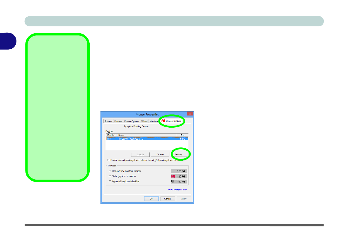
Storage Devices, Mouse, & Audio
Show Video
You can get a clearer
view of the gestures involved by clicking the
Show Video option for
each gesture item.
Select the gesture (Pinch
Zoom, Rotating, Three
Fingers Down and
Three Finger Flick) in the
Device Settings > Settings left tree menu
and click the Show Video
button to see the demonstration video.
For more details on any of
the gestures see the help
in the lower part of the
right menu window.
Figure 2 - 11
Mouse Properties -
Device Settings
2
Gestures and Device Settings
The Synaptics Gestures Suite application allows you to use a specific gesture (action) on the surface of the Touchpad to perform specific actions to manipulate documents, objects and applications.
You can configure the settings from the Device Settings tab in Mouse Properties:
1. Go to the
2. Click Mouse (Hardware and Sound).
3. Click Device Settings (tab) and click Settings.
4. Use the menu tree on the lef t to access the user configurable settings.
Control Panel
.
2 - 14 Touchpad Configuration for Models A, C, D & E
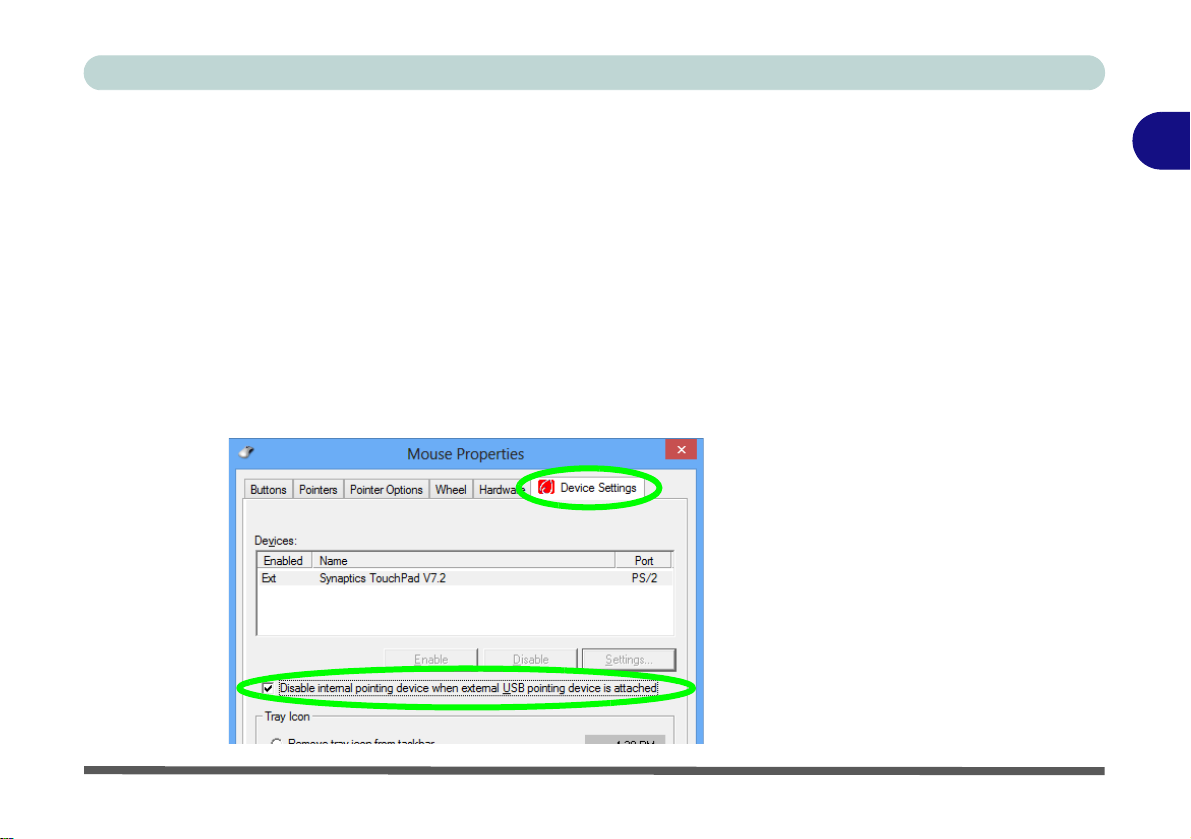
Storage Devices, Mouse, & Audio
Figure 2 - 12
Mouse Properties
(Disable Touchpad)
Disabling the Touchpad
If you need to disable the Touchpad for any reason (e.g. you may find that when using the computer’s internal keyboard you accidentally trigger the Touchpad when
resting your wrists or palms on it) you can do so by using Fn + F1 key combination.
You can also set the system to automatically disable the internal Touchpad when an
external USB point device (e.g a USB mouse) is attached.
1. Go to the Mouse Properties control panel.
2. Click to select Device Settings (tab).
3. Click to place a tick in the “Disable internal pointing device when external USB
pointing device is attached” tickbox.
4. Click OK to save the setting.
2
Touchpad Configuration for Models A, C, D & E 2 - 15

Storage Devices, Mouse, & Audio
Figure 2 - 13
Scrolling Gesture
Figure 2 - 14
Zooming Gesture
2
Scrolling
The Two-Finger scrolling feature works in most scrollable windows an d allows you
to scroll horizontally and vertically. Place two fingers, slightly separated, on the
TouchPad surface and slide both fingers in the direction required (in a straight continuous motion).
Zooming
The Pinch Zoom gesture can be used to perform the same function as a scroll wheel
in Windows applications that support CTRL + scroll wheel zoom functionality.
Place two fingers on the TouchPad (for best results use the tips of the fingers) and
slide them apart to zoom in, or closer together to zoom out.
2 - 16 Touchpad Configuration for Models A, C, D & E

Storage Devices, Mouse, & Audio
Figure 2 - 15
Rotating Gesture
Figure 2 - 16
Flick/Press
Gesture
Rotating
Use the Pivot Rotate gesture to rotate objects (e.g. photos) in 90 degree increments.
Place a finger down on the left “target” zone and keep it stationary. Place another
finger near the middle of the TouchPad and slide it in a circular motion around the
stationary finger (clockwise or counterclockwise) to rotate the object.
Three Finger-Flick/Three Fingers Down (Press)
The Three Finger-Flick gesture may be used to enhance navigation with a variety of
applications such as browsing the Internet or scrolling through a photo viewer. The
Three Fingers Down gesture may be used to launch user-selectable applications.
2
Touchpad Configuration for Models A, C, D & E 2 - 17

Storage Devices, Mouse, & Audio
Tray Icon
Make sure that the
Touchpad driver icon
in the notification
area of the Desktop
taskbar.
Go to the control panel
(Mouse control panel
in Windows), click
Finger Sensing Pad
(tab), click Tray Icon
and then make sure
Show Tray Icon is
clicked.
Figure 2 - 17
Mouse Properties
2
Touchpad Configuration for Model B
Once you have installed the Touchpad driver (see “TouchPad” on page 4 - 7) you
can configure the functions by double-clicking the Touchpad driver icon in the
notification area of the Desktop taskbar, or from the Mouse control panel in Win-
dows. You may then configure the Touchpad tapping, buttons, scrolling (see sidebar), pointer motion and sensitivity options to your preferences.
2 - 18 Touchpad Configuration for Model B
 Loading...