

Page 1

Page 2

Page 3

Introduction (English)
This Concise User’s Guide introduces the main features
of your computer. The English version of this guide begins on page 1. The expanded User’s Manual is on the
Device Drivers & Utilities + User’s Manual disc.
Einführung (Deutsch)
Dieses Ausführliche Benutzerhandbuch führt Sie in die
Hauptfunktionen des Computers ein. Die deutsche Version des Handbuchs beginnt auf Seite 47. Das erweiterte
Benutzerhandbuch finden Sie auf der Disc für die Gerätetreiber und Hilfsprogramme (Disc Device Drivers &
Utilities + User's Manual).
Présentation (Français)
Ce Guide Utilisateur Concis présente les fonctionnalités
principales de votre ordinateur. La version française de
ce guide commence à la page 93. Le Manuel de l'Utilisa-
teur étendu se trouve sur le disque de Pilotes & Utilitaires + Manuel de l'Utilisateur (disque Device Drivers
& Utilities + User's Manual).
Introducción (Español)
Esta Guía del Usuario Concisa le presenta las características principales de su ordenador. La versión española de
esta guía comienza en la página 139. El Manual del usua-
rio completo se encuentra en el disco de Controladores
del dispositivo y Utilidades + Manual del usuario (disco
Device Drivers & Utilities + User's Manual).
Introduzione (Italiano)
La presente Guida Rapida per l'Utente introduce le caratteristiche principali del computer. La versione italiana di
questa guida inizia da pagina 185. Il Manuale utente
completo si trova nel disco contenente driver e utilità +
Manuale utente (disco Device Drivers & Utilities +
User's Manual).
I
Page 4

Contents
About this Concise User Guide ................................................................... 1
System Startup ............................................................................................ 4
RAID Setup ................................................................................................. 5
System Map: Front View with LCD Panel Open ........................................8
(Models A, B, C & D) ................................................................................. 8
System Map: Front View with LCD Panel Open (Models E & F) ............. 9
LED Indicators ..........................................................................................10
Keyboard & Function Keys ......................................................................11
Control Center ........................................................................................... 12
Flexikey® Application .............................................................................. 15
System Map: Front, Left, Right & Rear Views (Models A, C & D) ........ 21
System Map: Front, Left, Right & Rear Views (Model B) ....................... 22
System Map: Front, Left, Right & Rear Views (Models E & F) .............. 23
System Map: Bottom Views (Models A, B, C & D) ................................24
System Map: Bottom Views (Models E & F) ........................................... 25
Windows 8.1 Start Screen, Desktop and Charms Bar .............................. 26
Windows 8.1 Control Panel ...................................................................... 26
Video Features ..........................................................................................28
Audio Features .......................................................................................... 29
Power Options ........................................................................................... 31
PC Camera .................................................................................... ....... ..... 31
Driver Installation ..................................................................................... 32
Wireless LAN Module (Option) ............................................................... 34
Fingerprint Reader (Option) ...................................................................... 36
Bluetooth Module (Option) ....................................................................... 37
Trusted Platform Module (Option) ........................................................... 38
Intel® Smart Response Technology ......................................................... 40
Intel® Rapid Start Technology ................................................................. 41
Troubleshooting ........................................................................................ 43
Specifications ......................................................................... ................... 44
Inhalt
Über das Ausführliche Benutzerhandbuch ................................................47
Schnellstart ............................................................. ................................... 50
RAID Setup ............................................................................................... 51
Systemübersicht: Ansicht von vorne mit geöffnetem LCD-Bildschirm
(Modelle A, B, C & D) .............................................................................. 54
Systemübersicht: Ansicht von vorne mit geöffnetem LCD-Bildschirm
(Modelle E & F) ........................................................................................55
LED-Anzeigen .......................................................................................... 56
Tastatur & Funktionstasten ....................................................................... 57
Control Center ........................................................................................... 58
Flexikey® Anwendung ............................ ....... ....... ....... ....... ....... ....... ....... 61
Systemübersicht: Ansicht von vorne, links, rechts und hinten
(Modelle A, C & D) ...................................................... ....... ....... ....... ....... 67
Systemübersicht: Ansicht von vorne, links, rechts und hinten
(Modell B) ................................................................................................. 68
Systemübersicht: Ansicht von vorne, links, rechts und hinten
(Modelle E & F) ........................................................................................69
Systemübersicht: Ansicht von unten (Modelle A, B, C & D) ................... 70
Systemübersicht: Ansicht von unten (Modelle E & F) .............................71
Windows 8.1 Start-Bildschirm, Desktop und Charms-Leiste ................... 72
Windows 8.1 Systemsteuerung .................................................................73
Grafikfunktionen .................................................... ................................... 74
Audiofunktionen ....................................................................................... 75
Energieoptionen ........................................................................................ 77
PC-Kamera ............................................................. ................................... 77
Installation der Treiber .............................................................................. 78
Wireless-LAN-Modul (Option) .................................................. ....... ....... 80
Fingerabdruckleser (Option) .....................................................................82
Bluetooth-Modul (Option) ........................................................................ 83
TPM (Trusted Platform Module) (Option) ............................................... 84
Intel® Smart Response-Technologie ........................................................86
Intel® Rapid Start-Technologie ................................................................ 87
Fehlerbehebung ...................................................... ................................... 89
Technische Daten ................................................................. ..................... 90
II
Page 5

Sommaire
A propos de ce Guide Utilisateur Concis .................................................. 93
Guide de démarrage rapide ....................................................................... 96
Configuration RAID .................................................................................. 97
Carte du système: Vue de face avec l’écran LCD ouvert
(Modèles A, B, C & D) .......................................................................... 100
Carte du système: Vue de face avec l’écran LCD ouvert
(Modèles E & F) ...................................................................................... 101
Indicateurs LED ...................................................................................... 102
Clavier & touches fonction ..................................................................... 103
Control Center ......................................................................................... 104
Application Flexikey® ............................................................................ 107
Carte du système: Vues de face, gauche, droite & arrière
(Modèles A, C & D) ................................................................................ 113
Carte du système: Vues de face, gauche, droite & arrière (Modèle B) ... 114
Carte du système: Vues de face, gauche, droite & arrière
(Modèles E & F) ...................................................................................... 115
Carte du système: Vues du dessous (Modèles A, B, C & D) .................. 116
Carte du système: Vues du dessous (Modèles E & F) ............................ 117
Écran d'accueil, bureau et Barre des charmes de Windows 8.1 ............. 118
Panneau de Configuration de Windows 8.1 ............................................ 119
Caractéristiques vidéo .......................................................................... ... 120
Caractéristiques audio ................................................................... ....... ... 121
Options d’alimentation ............................................................................ 123
Caméra PC ..............................................................................................123
Installation du pilote ................................................................................ 124
Module LAN sans fil (Option) ................................................................ 126
Lecteur d'empreintes digitales (Option) .................................................. 128
Module Bluetooth (Option) ..................................................................... 129
TPM (Trusted Platform Module) (Option) .............................................130
Technologie Intel® Smart Response ...................................................... 132
Technologie Intel® Rapid Start .............................................................. 133
Dépannage ................................................................ ............................... 135
Spécifications ......................................................................... ................. 136
Contenidos
Acerca de esta Guía del Usuario Concisa ............................................... 139
Guía rápida para empezar .............................................. ....... ....... ....... ..... 142
Configuración RAID ............................................................................... 143
Mapa del sistema: Vista frontal con panel LCD abierto
(Modelos A, B, C & D) ........................................................................... 146
Mapa del sistema: Vista frontal con panel LCD abierto
(Modelos E & F) ..................................................................................... 147
Indicadores LED .....................................................................................148
Teclado & teclas de función .................................................................... 149
Control Center ......................................................................................... 150
Aplicación Flexikey® ............................................................................. 153
Mapa del sistema: Vistas frontal, izquierda, derecha y posterior
(Modelos A, C & D) ................................................................................ 159
Mapa del sistema: Vistas frontal, izquierda, derecha y posterior
(Modelo B) ..............................................................................................160
Mapa del sistema: Vistas frontal, izquierda, derecha y posterior
(Modelos E & F) ..................................................................................... 161
Mapa del sistema: Vista inferior (Modelos A, B, C & D) ...................... 162
Mapa del sistema: Vista inferior (Modelos E & F) ................................. 163
Pantalla Inicio, escritorio y barra Charms de Windows 8.1 ................... 164
Panel de Control de Windows 8.1 ........................................................... 165
Parámetros de vídeo ................................................................................ 166
Características de audio ...........................................................................167
Opciones de energía ................................................................................ 169
Cámara PC .................................................................................. ....... ..... 169
Instalación de controladores .................................................................... 170
Módulo LAN Wireless (Opción) ............................................................172
Lector de huellas digitales (Opción) ....................................................... 174
Módulo Bluetooth (Opción) .................................................................... 175
TPM (Trusted Platform Module) (Opción) ..... ....... ....... ....... ....... ....... ..... 176
Tecnología Intel® Smart Response ........................................................ 178
Tecnología Intel® Rapid Start ................................................................ 179
Solución de problemas ............................................................................ 181
Especificaciones ................................................................... ................... 182
III
Page 6

Sommario
Informazioni sulla Guida Rapida per l'Utente .........................................185
Guida di avvio rapido .............................................................................. 188
Configurazione RAID ............................................................................. 189
Descrizione del sistema: Vista anteriore con pannello LCD aperto
(Modelli A, B, C & D) ............................................................................ 192
Descrizione del sistema: Vista anteriore con pannello LCD aperto
(Modelli E & F) ............................................................... ....... ....... ....... ... 193
Indicatori LED .............................................................................. ....... ... 194
Tastiera & tasti funzione ......................................................................... 195
Control Center ......................................................................................... 196
Applicazione Flexikey® .........................................................................199
Descrizione del sistema: Vista anteriore, sinistra, destra e posteriore
(Modelli A, C & D) ................................................................................. 205
Descrizione del sistema: Vista anteriore, sinistra, destra e posteriore
(Modello B) ............................................................................................. 206
Descrizione del sistema: Vista anteriore, sinistra, destra e posteriore
(Modelli E & F) ............................................................... ....... ....... ....... ... 207
Descrizione del sistema: Vista inferiore (Modelli A, B, C & D) ............ 208
Descrizione del sistema: Vista inferiore (Modelli E & F) ......................209
Schermata Start, Desktop e Charms Bar di Windows 8.1 .......................210
Pannello di controllo di Windows 8.1 ..................................................... 211
Funzioni video ......................................................................................... 212
Funzionalità audio ................................................................................... 213
Opzioni risparmio energia ................... ....... ....... ....... ....... ....... ....... ....... ... 215
Camera PC ..............................................................................................215
Installazione driver .................................................................................. 216
Modulo LAN Wireless (Opzione) ................................................. .......... 218
Lettore d’impronte digitali (Opzione) ..................................................... 220
Modulo Bluetooth (Opzione) ..................................................................221
TPM (Trusted Platform Module) (Opzione) ........................................... 222
Tecnologia Intel® Smart Response ........................................................ 224
Tecnologia Intel® Rapid Start ................................................................ 225
Risoluzione dei problemi ........................................................................ 227
Specifiche tecniche ..................................................................................228
IV
Page 7

About this Concise User Guide
FCC Statement
This device complies with Part
15 of the FCC Rules. Operation
is subject to the following two
conditions:
1.This device may not cause
harmful interference.
2. This device must accept any
interference received, including interference that may
cause undesired operation.
This quick guide is a brief introduction to getting your system started. This is a s upplement, and not a substitute for the
expanded English language User’s Manual in Adobe Acrobat format on the Device Drivers & Utilities + User’s Manual
disc supplied with your computer. This disc also contains the drivers and utilities necessary for the proper oper ation of
the computer (Note: The company reserves the right to revise this publication or to change its contents without notice).
Some or all of the computer’s features may already have been setup. If they aren’t, or you are planning to re-configure
(or re-install) portions of the system, refer to the expanded User’s Manual. The Device Drivers & Utilities + User’s
Manual disc does not contain an operating system.
Regulatory and Safety Information
Please pay careful attention to the full regulatory notices and safety information
contained in the expanded User’s Manual on the Device Drivers & Utilities + Us-
er’s Manual disc.
© February 2014
Trademarks
Intel and Intel Core are trademarks/registered trademarks of Intel Corporation.
English
1
Page 8

Instructions for Care and Operation
The computer is quite rugged, but it can be damaged. To
prevent this, follow these suggestions:
• Don’t drop it, or expose it to shock. If the computer falls, the
case and the components could be damaged.
• Keep it dry, and don’t overheat it. Keep the computer and
power supply away from any kind of heating element. This is an
English
electrical appliance. If water or any other liquid gets into it, the
computer could be badly damaged.
• Avoid interference. Keep the computer away from high capacity
transformers, electric motors, and other strong magnetic fields.
These can hinder proper performance and damage your data.
• Follow the proper working procedur e s for the computer. Shut
the computer down properly and don’t forget to save your work.
Remember to periodically save your data as data may be lost.
• Note that in computer’s featuring a raised LCD electro-pl ated
logo, the logo is covered by a protective adhesive. Due to general
wear and tear, this adhesive may deter iorate over time and the
exposed logo may develop sharp edges. Be careful when handling
the computer in this case, and avoid touching the raised LCD
electro-plated logo. Avoid placing any other items in the carrying
bag which may rub against the top of the computer during transport. If any such wear and tear develops contact your service center.
Power & Battery Safety
• Only use an AC/DC adapter approved for use with this computer.
• Use only the power cord and batteries indicated in this manual.
• Your AC/DC adapter may be designed for international travel but
it still requires a steady, uninterrupted power supply. If you are
unsure of your local power specifications, consult your service
representative or local power company.
• The AC/DC adapter may have either a 2-prong or a 3-prong
grounded plug. The third prong is an important safety feature; do
not defeat its purpose. If you do not have access to a compatible
outlet, have a qualified electrician install one.
• When you want to unplug the power cord, be sure to disconnect it
by the plug head, not by its wire.
• Make sure the socket and any extension cord(s) you use can support the total current load of all the connected devices.
• Make sure that your computer is completely powered off before
putting it into a travel bag (or any such container).
• Only use batteries designed for this computer. The wrong battery
type may explode, leak or damage the computer.
• Do not continue to use a battery that has been dropped, or that
appears damaged (e.g. bent or twisted) in any way. Even if the
computer continues to work with a damaged battery in place, it
may cause circuit damage, which may possibly result in fire.
• Recharge the batteries using the computer’s system. Incorrect
recharging may make the battery explode.
• Do not try to repair a battery pack. Refer any battery pack repair
or replacement to your service representative or qualified service
personnel.
• Keep children away from, and promptly dispose of a damaged
battery. Always dispose of batteries carefully. Batteri es ma y
explode or leak if exposed to fire, or improperly handled or discarded.
• Keep the battery away from metal appliances.
• Affix tape to the battery contacts bef ore disposing of the battery.
• Do not dispose of batteries in a fire. They may explode. Check
with local codes for possible special disposal instructions.
• Do not touch the battery contacts with your hands or metal
objects.
2
Page 9

Polymer Battery Precautions
Battery Disposal & Caution
The product that you have purchased contains a rechargeable battery. The battery is recyclable. At the end of its useful life, under various state and local laws, it may be illegal
to dispose of this battery into the municipal waste stream.
Check with your local solid waste officials for details in your
area for recycling options or proper disposal.
Danger of explosion if battery is incorrectly replaced. Replace only with the same or equivalent type recommended
by the manufacturer. Discard used battery according to the
manufacturer’s instructions.
Note the following information which is specific to polymer batteries only, and where applicable, this overrides
the general battery precaution information.
• Polymer batteries may experience a slight expansion or swelling,
however this is part of the battery’s safety mechanism and is not a
cause for concern.
• Use proper handling procedures when using polymer batteries.
Do not use polymer batteries in high ambient temperature environments, and do not store unused batteries for extended periods.
Cleaning
• Use a soft clean cloth to clean the computer, but do not apply
cleaner directly to the computer.
• Do not use volatile (petroleum distillates) or abrasive cleaners on
any part of the computer.
• Before cleaning the computer remove the battery and make sure
the computer is disconnected from any external power supplies,
peripherals and cables (including telephone lines).
Servicing
Attempting to service the computer yourself may violate
your warranty and expose you and the computer to electric
shock. Refer all servicing to qualified service personnel,
particularly under any of the following conditions:
English
• When the power cord or AC/DC adapter is damaged or frayed.
• If the computer has been exposed to any liquids.
• If the computer does not work normally when you follow the
operating instructions.
• If the computer has been dropped or damaged (do not touch the
poisonous liquid if the LCD panel breaks).
• If there is an unusual odor, heat or smoke coming from your computer.
3
Page 10
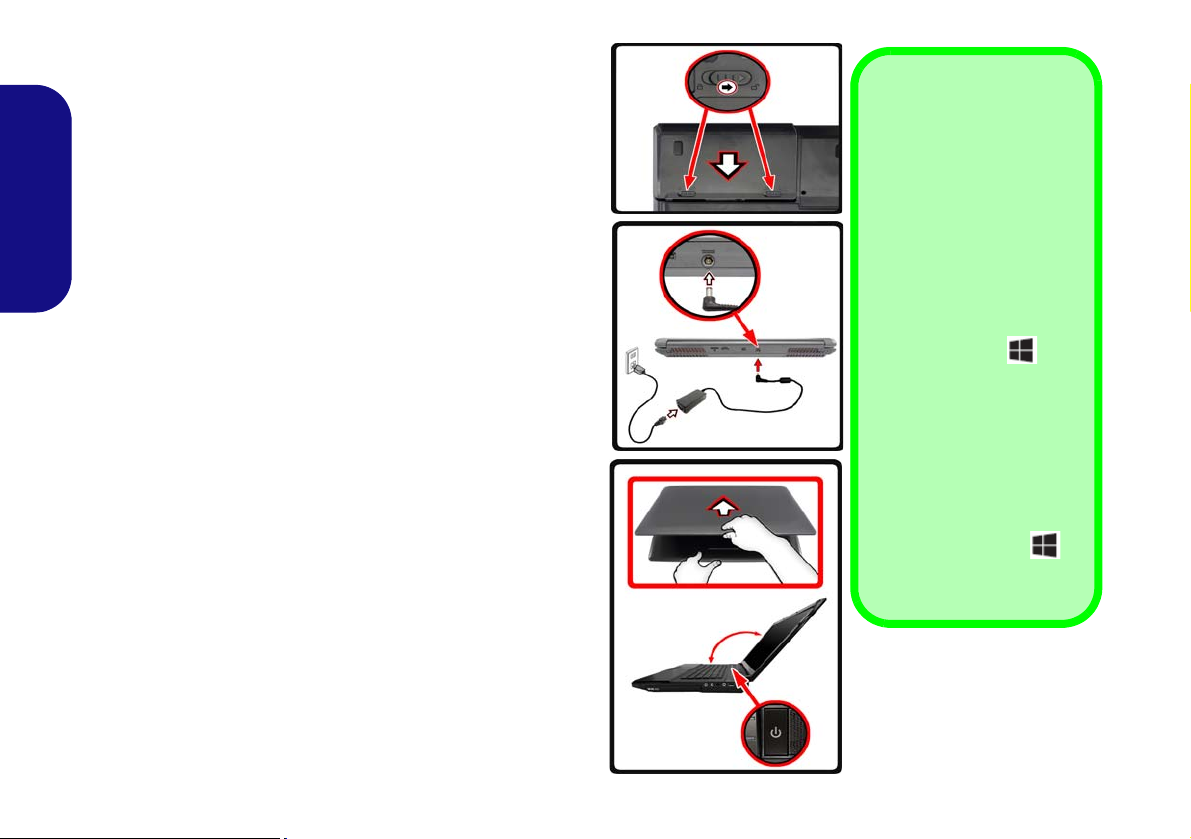
System Startup
135°
Shut Down
Note that you should always shut your computer
down by choosing the Shut
down command in Windows (see below). This will
help prevent hard disk or
system problems.
Click Settings in the
Charms Bar (use the Windows Logo Key + C
key combination to access
the Charms Bar) and
choose Shut down from
the Power menu.
Or
Choose Shut down or
sign out > Shut down from
the context menu (use the
Windows Logo Key +
X key combination to ac-
cess the context menu).
Figure 1
Opening the Lid/LCD/Com-
puter with AC/DC Adapter
Plugged-In
1. Remove all packing materials.
2. Place the computer on a stable surface.
3. Insert the battery and make sure it is locked in position.
4. Securely attach any peripherals you want to use with the
computer (e.g. keyboard and mouse) to their ports.
5. Attach the AC/DC adapter to the DC-In jack at the rear of the
computer, then plug the AC power cord into an outlet, and
English
connect the AC power cord to the AC/DC adapter.
6. Use one hand to raise the lid/LCD to a comfortable viewing angle
(do not to exceed 135 degrees);
in Figure 1) to support the base of the computer (Note: Never lif t
the computer by the lid/LCD).
7. Press the power button to turn the computer “on”.
System Software
Your computer may already come with system software
pre-installed. Where this is not the case, or where you are
re-configuring your computer for a different system, you
will find this manual refers to Microsoft Windows 8.1.
HDD RAID Support
Your hard disk(s) can be set up in AHCI mode or RAID
mode (for increased performance or protection). Note that
setting up your hard disk(s) in RAID mode needs to be done
prior to installing the Windows OS.
use the other hand (as illustrated
4
Page 11
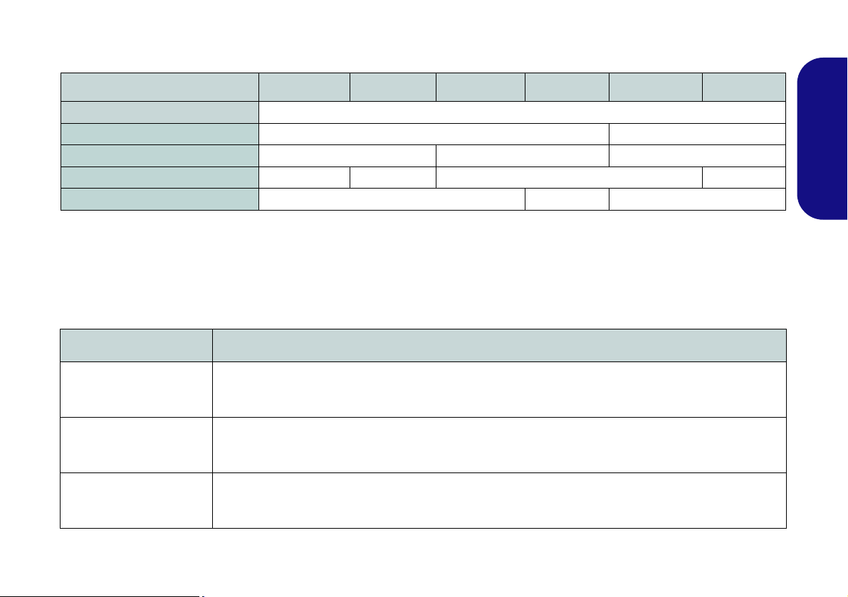
Model Differences
This notebook series includes six different model types that mainly differ as indicated in the table below.
Feature Model A Model B Model C Model D Model E Model F
Video Adapters Supported
Display Type 15.6" (39.62cm) FHD 17.3" (43.94cm) FHD
Illuminated Keyboard Yes No Yes
Illuminated Touchpad No Yes No Yes
AC/DC Adapter 180W 120W 230W
See Specifications on page 44 for a full list of video adapters supported by each model.
Table 1 - Model Differences
RAID Setup
You may use your hard disks in combination with Striping (RAID 0), Mirroring (RAID 1) or Recovery for either fault
tolerance or performance.
RAID Level Description
English
RAID 0
(at lease two hard disks/
SSDs needed)
RAID 1
(at lease two hard disks/
SSDs needed)
Recovery
(at lease two hard disks/
SSDs needed)
Identical drives reading and writing data in p arallel to inc rease performance. RA ID 0 impleme nt s a stripe d
disk array and the data is broken into blocks and each block is written to a separate disk drive.
Identical drives in a mirrored configuration used to protect data. Should a drive that is part of a mirrored
array fail, the mirrored drive (which contains identical data) will handle all the data. When a new replacement drive is installed, data to the new drive is rebuilt from the mirrored drive to restore fault tolerance.
Two Identical drives copying data between a master and a recovery disk. This provides more control over how
data is copied between the master and recovery drives, fast volume updates and the ability to view the data in
Windows Explorer.
Table 2 - RAID Description
5
Page 12

Prepare the following before setting up your serial ATA
Figure 2
Name the RAID
Volume (Ad-
vanced > Intel(R)
Rapid Storage
Technology)
hard disks in RAID mode:
1. The Microsoft Windows 8.1 OS disc.
2. A hard disk installed in the Primary HDD bay.
3. A second (identical) hard disk installed in the Secondary HDD
bay.
4. The Device Drivers & Utilities + User’s Manual disc.
5. A USB flash drive.
English
6. An operable computer (to copy files from the Device Drivers &
Utilities + User’s Manual disc to the USB flash drive).
Note: All hard disks in a RAID should be identical (the
same size and brand) in order to prevent unexpected system behavior.
RAID Setup Procedure
Before setting up the system you will need to copy a driver
folder (on the Device Drivers & Utilities + User’s Manual
disc) to a USB flash drive or external USB hard disk.
However you will need to go to an operable computer and
copy the driver folder to a USB flash drive or external
USB hard disk.
1. Go to the operable computer and insert a USB flash drive or
external USB hard disk.
2. Insert the Device Drivers & Utilities + User’s Manual disc into
the CD/DVD drive of the operable computer.
3. Copy the f6flpy-x64 folder from the location below (D: denotes
your DVD drive) on the Device Drivers & Utilities + User’s
Manual disc to the USB flash drive or external USB hard disk.
• D:\Options\RAID\f6flpy-x64 (Windows 8.1 64bit)
6
4. Start-up your notebook computer and press <F2> to enter the
BIOS.
5. Go to the Boot menu, select UEFI Setting and press <Enter>.
6. Set UEFI Boot to “Enabled”.
7. Press <Esc> to exit the menu and go to the Advanced menu.
8. Select SATA Mode, press <Enter> and select “RAID Mode”.
9. Press <F4> and <Yes> to “Save Changes and Reset”.
10. After the computer restarts press <F2> to enter the BIOS again.
11. Go to Intel(R) Rapid Storage Technology (in the Advanced
menu) and press <Enter>.
12. Select Create RAID Volume and press <Enter>.
13. You can now setup your RAID volume using any two installed
disks.
14. Go to Name: and press <Enter>.
15. Type a name of your choice for your RAID volume and press
<Enter>.
16. Go to RAID Level: and press <Enter>.
17. Choose the RAID Level required (see Table 2 on page 5) and
press <Enter>.
• RAID 0 (Stripe)/RAID 1 (Mirror)/Recovery
18. Go to any of the disks listed under Select Disks: and select a
disk name and press <Enter>.
Page 13
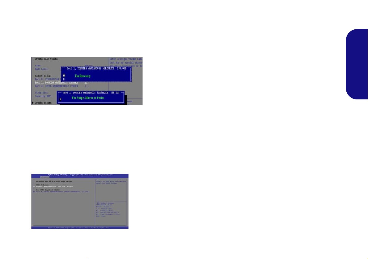
19. Move the cursor down (use the arrow keys) onto X (o select the
Figure 3
Select
Disks
Figure 4
RAID Informa-
tion (Advanced >
Intel(R) Rapid
Storage Technol-
ogy)
disk required) and press <Enter>.
If you have selected a Recovery level RAID then you
need to select one disk to be Master disk (M) and one
disk to be the Recovery disk (R).
20. Y ou should select two iden tical disks to form your RAID volume.
21. If you have selected RAID 0 (Stripe) then you can adjust the
“Strip Size” to your requirements.
22. If you have selected Recovery then you can adjust the
Synchronization to “On Request” or “Continuous”.
23. Go to Create Volume and press <Enter>.
24. The RAID volume will then be created and the RAID information
will be displayed under Intel(R) Rapid Stor age Technology (in
the Advanced menu).
25. Press <Esc> to exit the menu.
26. Press <F4> and <Yes> to “Save Changes and Reset”,
however ensure that the two conditions in the bulleted
points below are met before doing so.
• Make sure the W indows 8.1 OS DVD is in the DVD drive and
as the computer starts up it will automatically boot from the
Windows 8.1 OS DVD (you will be prompted to press a key
to boot from the DVD).
• Make sure your USB flash drive or external USB hard disk is
attached to one of the USB ports on the computer.
27. Press <F7> as the computer starts up to bring up the boot
device menu.
28. Select the DVD drive containing the Windows 8.1 OS DVD and
press <Enter>.
29. Press a key at system startup to begin installing Windows from
your Windows 8.1 OS DVD.
30. Click Next > Install Now to continue installing the operating
system as normal (see your Windows documentation if you
need help on installing the Windows OS).
31. A prompt will appear to ask you to Load Driver.
32. Click Browse and browse to the location you copied the files to
on your USB flash drive or external USB hard disk (X: denotes
your USB flash drive or external USB hard disk):
• X:\f6flpy-x64 (for Windows 8.1 64bit)
33. Click Next.
34. Follow the on-screen instructions to install the Windows 8.1
operating system.
35. Install the Windows drivers as per Table 8 on page 32. Make
sure you install the Intel® Rapid Storage Technology (IRST)
driver (see page 40).
English
7
Page 14
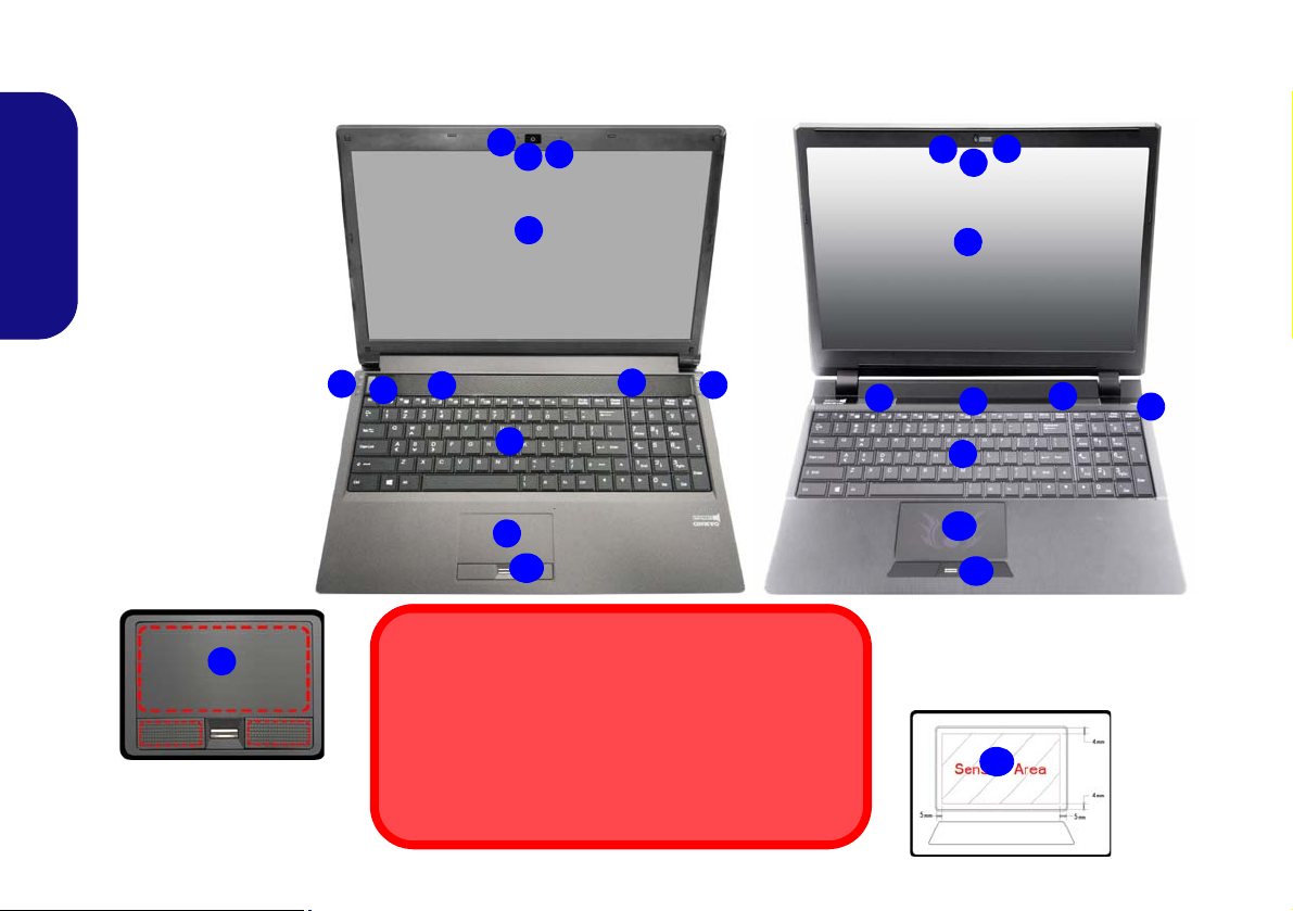
System Map: Front View with LCD Panel Open
2
1
8
6
5
7
5
Note that the Touchpad and
Buttons valid operational area
is that indicated within the red
dotted lines above.
Figure 5 - Front View
with LCD Panel Open
(Models A, B, C & D)
1. PC Camera
2. *PC Camera LED
*When the PC camera
is in use, the LED will
be illuminated in red.
3. Built-In Microphone
4. LCD
5. Speakers
6. Power Button
7. LED Indicators
8. Keyboard
9. Touchpad and Buttons
10. Illuminated Touchpad
and Buttons
11. Fingerprint Reader
(Optional)
3
2
1
3
8
5
6
Models A, C & D
15.6” (39.62cm)
Model B
Wireless Device Operation Aboard Aircraft
The use of any portable electronic transmission devices
aboard aircraft is usually prohibited.
Make sure the WLAN & Bluetooth module(s) are OFF if
you are using the computer aboard aircraft by putting
the system in to Airplane Mode.
4
11
4
7
11
15.6” (39.62cm)
5
10
Note that the Illuminated Touchpad
has a defined valid operational area of
sensitivity indicated within the sensor
area of the illustration below.
10
9
9
7
(Models A, B, C & D)
English
8
Page 15
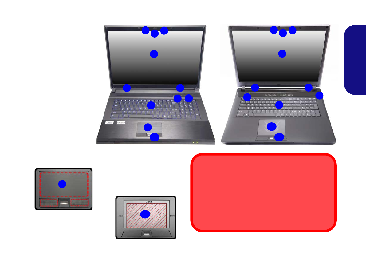
System Map: Front View with LCD Panel Open (Models E & F)
Figure 6 - Front View
with LCD Panel Open
(Models E & F)
1. PC Camera
2. *PC Camera LED
*When the PC camera
is in use, the LED will
be illuminated in red.
3. Built-In Microphone
4. LCD
5. Speakers
6. Power Button
7. LED Indicators
8. Keyboard
9. Touchpad and Buttons
10. Illuminated Touchpad
and Buttons
11. Fingerprint Reader
(Optional)
2
1
8
9
7
4
5
Model E
3
5
11
17.3” (43.94cm)
4
6
Wireless Device
Operation Aboard Aircraft
The use of any portable electronic transmission devices
aboard aircraft is usually prohibited.
Make sure the WLAN & Bluetooth module(s) are OFF if
you are using the computer aboard aircraft by putting the
system in to Airplane Mode.
5
2
1
8
7
Model F
3
5
11
17.3” (43.94cm)
4
6
5
Note that the Illuminated Touchpad has a defined valid operational area of sensitivity indicated
within the sensor area of the illustration below.
Note that the Touchpad and
Buttons valid operational
area is that indicated within
the red dotted lines above.
10
9
10
English
9
Page 16
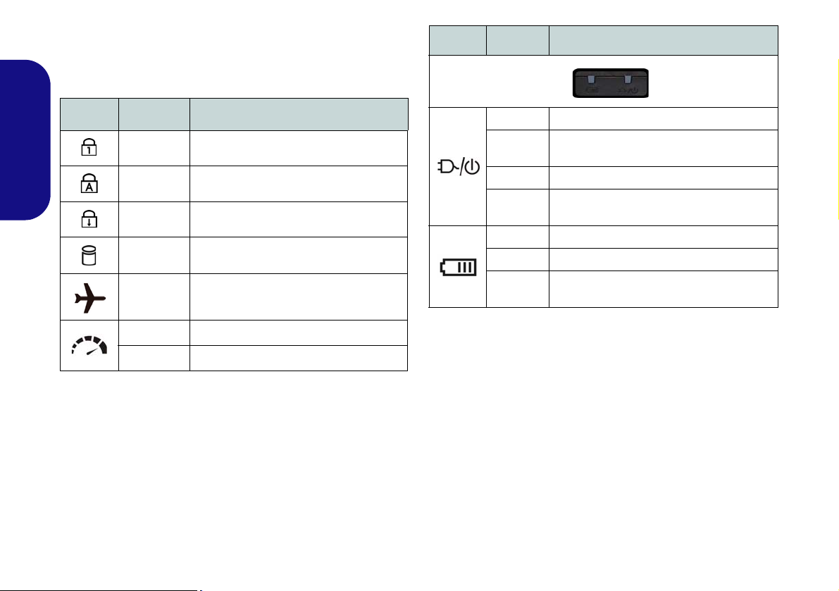
LED Indicators
The LED indicators on the computer display helpful information about the current status of the computer.
Icon Color Description
Icon Color Description
Blue/ White Number Lock (Numeric Keypad) Activated
English
Blue/ White Caps Lock Activated
Blue/ White Scroll Lock Activated
Blue/ White The Hard Disk/Optical Device is in use
Blue/ White
Off Integrated GPU (iGPU) Activated
Blue/ White Discrete GPU (dGPU) Activated
Table 3 - LED Status Indicators
Airplane Mode is ON (the WLAN & Blue-
tooth Modules are OFF)
Orange The AC/DC Adapter is Plugged In
Blinking
Orange*
Green The Computer is On
Blinking
Green
Orange The Battery is Charging
Green The Battery is Fully Charged
Blinking
Orange
Table 4 - LED Power Indicators
The AC/DC adapter is plugged in and the
powered USB Port is on*
The Computer is in Sleep Mode
The Battery Has Reached Critically Low
Power Status
*The powered USB 3.0 port may be toggled on/off by
means of the Fn + Power Button key combination. When
the powered USB port is on it will supply power (for
charging devices only, not for operating devices) when
the system is off but still powered by the AC/DC adapter
plugged into a working outlet, or powered by the battery
with a capacity level above 20% (this may not work with
certain devices - see page 43).
10
Page 17
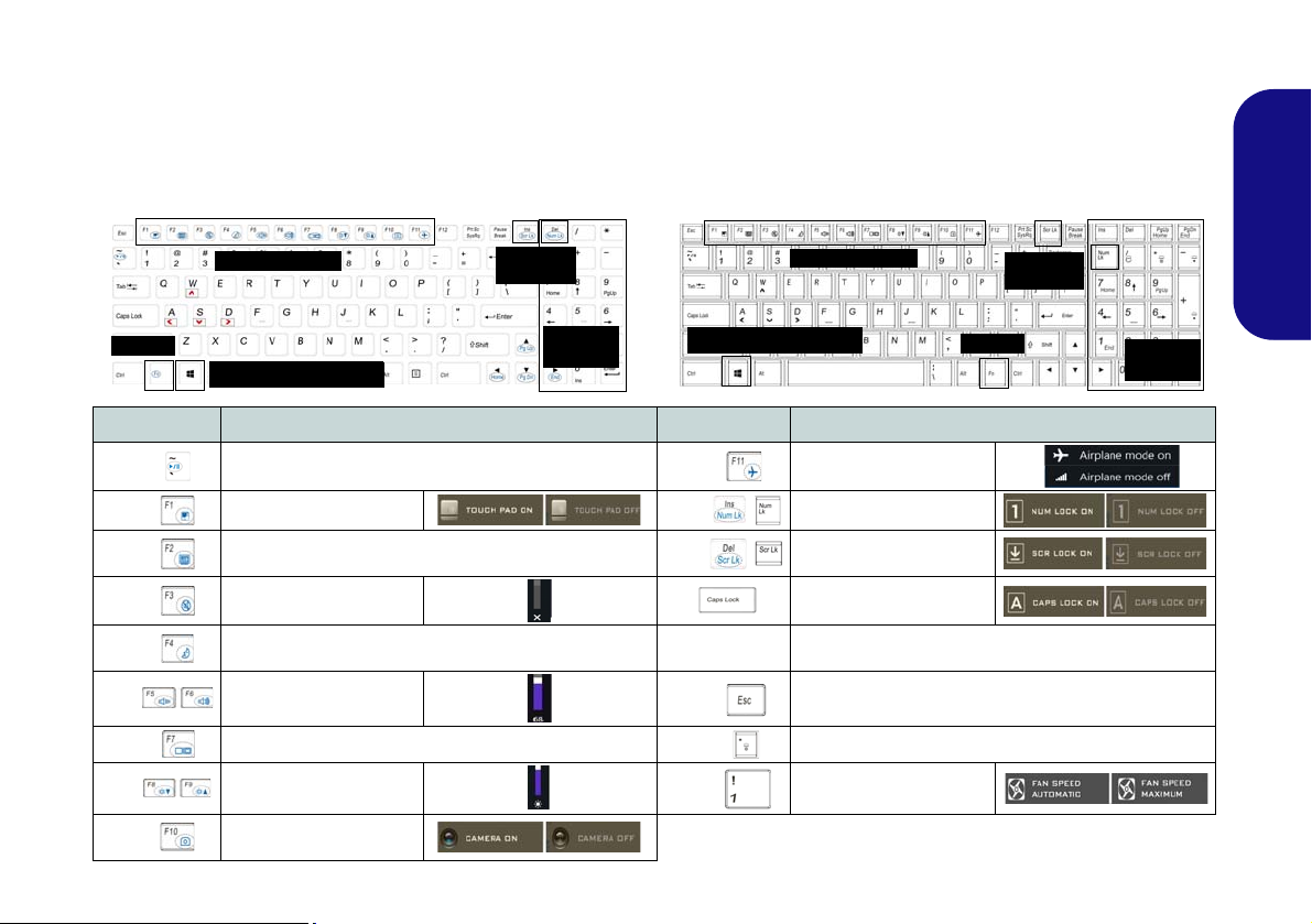
Keyboard & Function Keys
Function Keys
Numeric
Keypad
Fn Key
Models C & D
Models A, B, E & F
Function Keys
Numeric
Keypad
Fn Key
Windows Logo Key
Windows Logo Key
ScrLk &
NumLk
ScrLk &
NumLk
The keyboard includes a numeric keypad for easy numeric data input. Pressing Fn + NumLk turns on/off the numeric
keypad. It also features function keys to allow you to change operational features instantly. The function keys (F1 -
F11 etc.) will act as hot keys when pressed while the Fn key is held down. In addition to the basic function key combinations, some visual indicators are available (in the Windows Desktop application only and not in the Start
screen) when the hot key driver is installed.
Keys Function/Visual Indicators Keys Function/Visual Indicators
English
Fn +
Fn +
Fn +
Fn +
Fn +
Fn +
Fn +
Fn +
Fn +
Play/Pause (in Audio/Video Programs)
Touchpad Toggle
Turn LCD Backlight Off
(Press a key to or use Touchpad to turn on)
Mute Toggle
Sleep Toggle
Volume Decrease/
Increase
Change Display Configuration
Brightness Decrease/
Increase
PC Camera Power
Toggle
Fn +
Fn + /
Fn + /
Fn + Power But-
ton
Fn +
Fn +
Fn +
Table 5 - Function Keys & Visual Indicators
Airplane Mode Toggle
Number Lock Toggle
Scroll Lock Toggle
Caps Lock Toggle
Powered USB Port Power Toggle (see page 21)
Control Center Toggle (see page 12)
Keyboard LED Toggle (see page 19)
Fan Automatic Control/
Full Power
11
Page 18
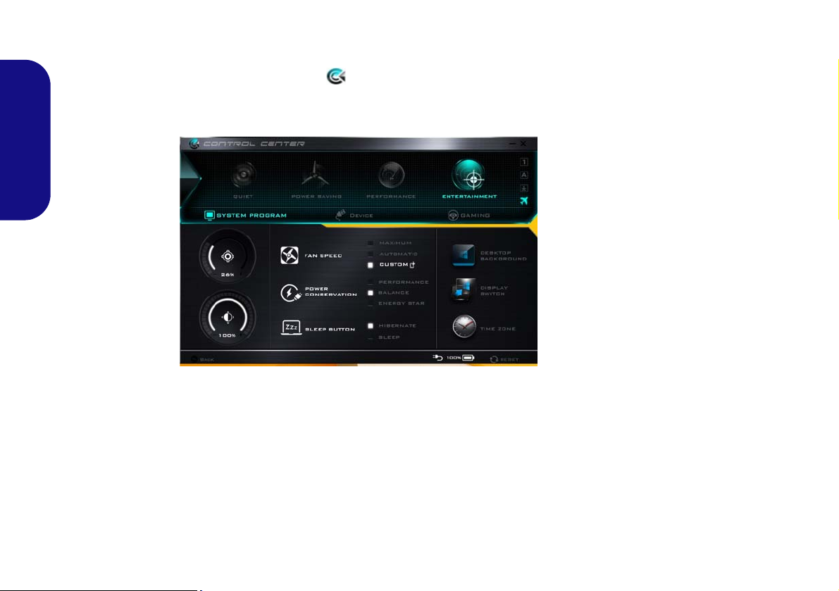
Control Center
Figure 7
Control Center
The Control Center in Windows 8.1 works under the Desktop app and not under the Start screen. Press the Fn + Esc
key combination, or double-click the icon in the notification area of the taskbar to toggle the Control Center
on/off. The Control Center gives quick access to frequently used controls and enables you to quickly turn the camera/
Touchpad on/off.
English
Power Modes
You can set a Power Mode by clicking the appropriate icon at the top of the Control Center. Each power mode will
affect the Power Conservation Mode, Airplane Mode, Power Plan and PC camera power etc.
Control Center Menus
The Control Cent er contains 3 menu headings (System Program, Device and Gaming) under the Power Modes. Click
the Control Center icons to toggle the appropriate function, or hold the mouse button down and move the dial control
where applicable. Certain functions will automatically be adjusted when a power mode is selected. Click the menu headings and then click any of the buttons outlined on the following page(s).
12
Page 19

Power Status
The Power Status icon will show whether you are currently powered by the battery, or by the AC/DC adapter
plugged in to a working power outlet. The power status
bar will show the current battery charge state.
Brightness
The Brightness icon will show the current screen brightness level. You can use the slider to adjust the screen
brightness or the Fn + F8/F9 key combinations, or use the
Fn + F2 key combination to turn off the LED backlight
(press any key to turn it on again). Note that screen brightness is also effected by the Power Mode selected.
Fan Speed
The fan speed will adjust itself automatically to control
the heat of the CPU. However you can adjust the setting to
maximum if you prefer. Select Custom and click on the
sliders to adjust the settings to your preference, however
these settings can be overidden by the system, as a safety
precaution, if it requires heavier use of the fan.
Sleep Button
Click either the Hibernate or Sleep button to have the
computer enter the selected power-saving mode.
English
Volume
The Volume icon will show the current volume level. You
can use the slider to adjust the volume or the Fn + F5/F6
key combinations, or use the Fn + F3 key combination to
mute the volume.
Power Conservation
This system supports Energy Star power management
features that place computers (CPU, hard drive, etc.) into
a low-power sleep mode after a designated period of inactivity. Click either the Performance, Balanced or Ener-
gy Star button.
Display Switch
Click the Display Switch button to access the menu (or
use the + P key combination) and select the appropriate display mode.
Time Zone
Clicking the Time Zone button will access the Date and
Time Windows control panel.
Desktop Background
Clicking the Desktop Background button will allow you
to change the desktop background picture.
13
Page 20
Touchpad/PC Camera
Click either of these buttons to toggle the Touchpad or
camera module’s power status. Note that the power status
of the camera module is also effected by the Power Mode
selected.
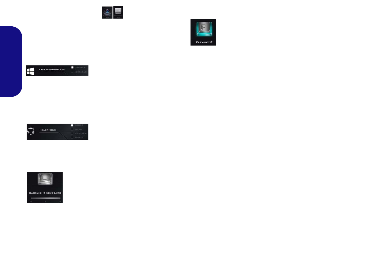
Left Windows Key
English
Click Disable to disable the Windows Key on the left side
of the keyboard. This may be useful if you are using the
gaming keys (W, A, S & D) and wish to avoid accidental-
ly triggering menus with the Windows Key.
Headphone
The headphones may be set for different effects using this
menu.
Backlight Keyboard
Flexikey®
Click the button to access the Flexikey® application.
Click the numbers under the Backlight Keyboard icon to
adjust the brightness of the keyboard backlight LED.
14
Page 21
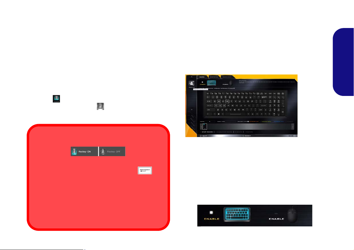
Flexikey® Application
Enabling or Disabling the Flexikey® Profile in Use
You can enable or disable any keyboard or mouse profile
functions currently in use by using the Fn + key
combination. Pressing this key combination will toggle you
between the currently selected keyboard or mouse profile
to the standard keyboard and/or mouse settings, and back
again.
Windows key and P key
Note that you can assign actions to any keyboard key except the Windows key and P key.
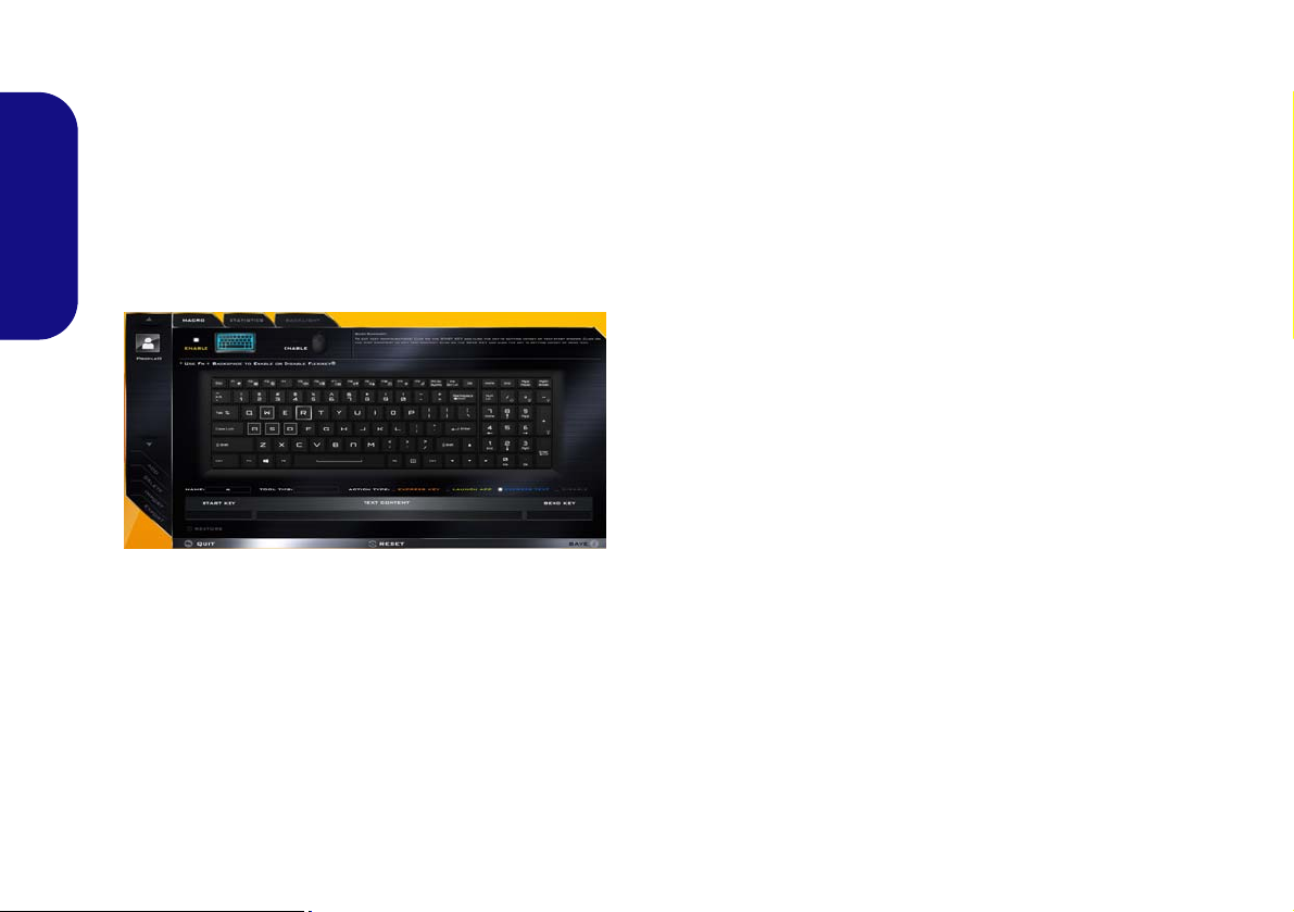
Figure 8
Flexikey®
Applica-
tion
The Flexikey® application is a quick hotkey configura-
tion application, which allows you to assign a single key
to launch multiple key combinations, or to launch pro-
grams and applications, to create text macros and to
disable certain keys. The application can also be used to
configure the mouse buttons to create hotkeys for gam-
ing etc. All the configuration settings are retained under
(up to12) profiles to which the settings are applied.
The Flexikey® application can be accessed by clicking
the button
ter or by clicking the icon
the desktop taskbar.
in the Gaming section of the Control Cen-
in the notification area of
Profiles
The menus on the left side of the application relate to Profiles. You can Add or Delete profiles (you can maintain
12 active Profiles), Export and Import profiles from the
menus. If you double-click on a profile you can change the
Profile Name, and change an Image file (images created
using PNG files).
English
Keyboard and Mouse Settings
Click Enable to create settings for the keyboard and/or
mouse by clicking the button on the top left of the screen
(e.g. you may wish to create a profile with settings only
for the mouse or keyboard). Clicking on the keyboard or
mouse icons will allow you to access the settings page for
either the keyboard or mouse.
Figure 9 - Enable (Keyboard & Mouse)
15
Page 22
English
123
4
5
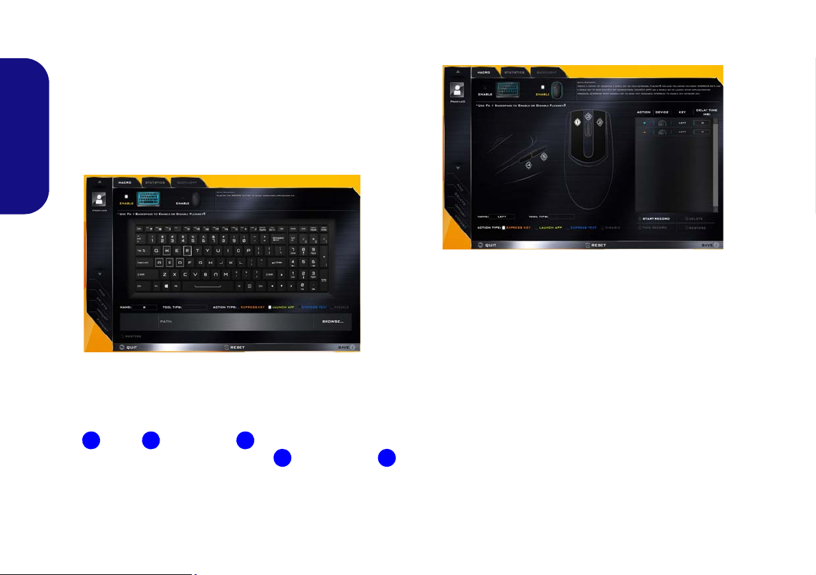
Keyboard Settings
The keyboard settings allow you to configure actions for
any single key (or a combination of keys). Click the key
and then select the Action Type (Express Key, Launch
App, Express Text or Disable) from the menu at the bottom of the page. You can rename the action by clicking in
the Name box, and click in Tool Tips to type in a note to
remind you of the action’s function.
Figure 10 - Keyboard Configuration
Mouse Settings
The mouse settings allow you to configure actions for the
left , right and middle buttons of any attached
mouse, and also for any backward and forward
buttons if applicable (on a gaming type mouse). Click the
button number and then select the Action Type (Express
Key, Launch App, Express Text or Disable) from the
menu at the bottom of the page. You can rename the action
16
by clicking in the Name box, and click in Tool Tips to
type in a note to remind you of the action’s function.
Figure 11 - Mouse Configuration
Flexikey® Application Features:
• EXPRESS KEY - This feature allows you to configure a
single key (or mouse click) to send multiple key combinations, or to create more useful shortcut keys This is useful
in gaming or when using applications which have a complex set of keyboard shortcuts.
• LAUNCH APP - This simply assigns single keys (or
mouse clicks) to launch any program’s or application’s
executable file.
• EXPRESS TEXT - With this you can assign single keys
(or mouse clicks) to send commonly used strings of text.
• DISABLE - Use this function to disable any keyboard
keys or mouse buttons.
• STATISTICS - Use this to quickly record keys in use in
any application, and to disable unused keys.
Page 23
Keyboard Settings - Express Key
To configure a single key to send multiple key combinations, or to create more useful shortcut keys, use Express
Key.
1. Enable and select the keyboard under your chosen profile, click
on a key to select it, and then click to select Express Key in
Action Type.
2. In the following example we want to change an existing game
key configuration which uses the left shift key for sprinting, and
the W key for moving forwards, to use the left Ctrl key to
combine this movement to sprint forward.
3. Click on the chosen key for the shortcut action.
4. Click in the Tool Tips field and type to give the key combination
a name e.g. “Sprint Fwds”, then click back in the Name field (to
avoid adding the recorded keys to the Tool Tips name).
5. Click Start Record and then press the key or keys (in this case
we will press Left Shift and W) required (make sure you press
the key(s) required and do not click on them).
6. Click Stop Record to complete the process.
9. If you want to clear all the settings click Restore to return to the
default key setting.
10. Any assigned Express Keys will appear in orange.
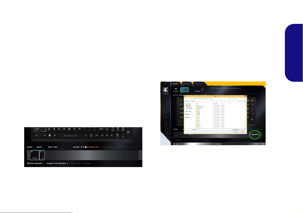
Keyboard Settings - Launch App
You can configure keys to launch any application or program as follows:
1. Enable and select the keyboard under your chosen profile, click
to select a key to launch the appllication, and then click to select
Launch App in Action Type.
2. Click Browse... at the bottom right of the application window.
Figure 13 - Keyboard - Launch App
English
Figure 12 - Keyboard - Express Key
7. Click Save to save the settings within your chosen profile.
8. If you want to remove any individual key click to select it, and
then click Delete.
3. Navigate to the executable file of the application and click
Open.
4. The key will now be configured to open the selected application
under your chosen Profile, and the key will appear in green.
5. If you want to remove any Launch App key, select it and click
on Restore.
6. Click Save to save the settings within your chosen profile.
17
Page 24
Keyboard Settings - Express Text
A single key can be set to send a string of text within any
application using Express Text.
1. Enable and select the keyboard under your chosen profile, click
to select a key, and then click to select Express Text in Action
Type.
2. Click in Start key if required (the Start key is the key used in
your target program to open a text message), or you can leave
English
it blank if you prefer.
3. Click in the Click to type field and type in your message.
Figure 14 - Keyboard - Express Text
4. Click in Send key if required (the Send key is the key used in
your target program to send a text message e.g the Enter key
would be the most commonly used), or you can leave it blank if
you prefer.
5. The key will now be configured to send the text message in the
target program under your chosen Profile, and the key will
appear in blue.
6. If you want to remove any Express Text key, select it and click
on Restore.
7. Click Save to save the settings within your chosen profile.
Keyboard Settings - Disable
You can use the program to disable any keys not required.
1. Enable and select the keyboard under your chosen profile, click
to select a key to disable, and then click to select Disable in
Action Type.
2. The key will now be disabled.
3. If you want to enable the key again, select it and click on
Restore.
4. Click Save to save the settings within your chosen profile.
5. The key will be disabled under your chosen Profile, and the key
will appear in gray.
18
Page 25
Keyboard LED
123
4
1
4
3
2
Figure 15
Keyboard
Backlight Ap-
plication
(Models A, B, E & F Only)
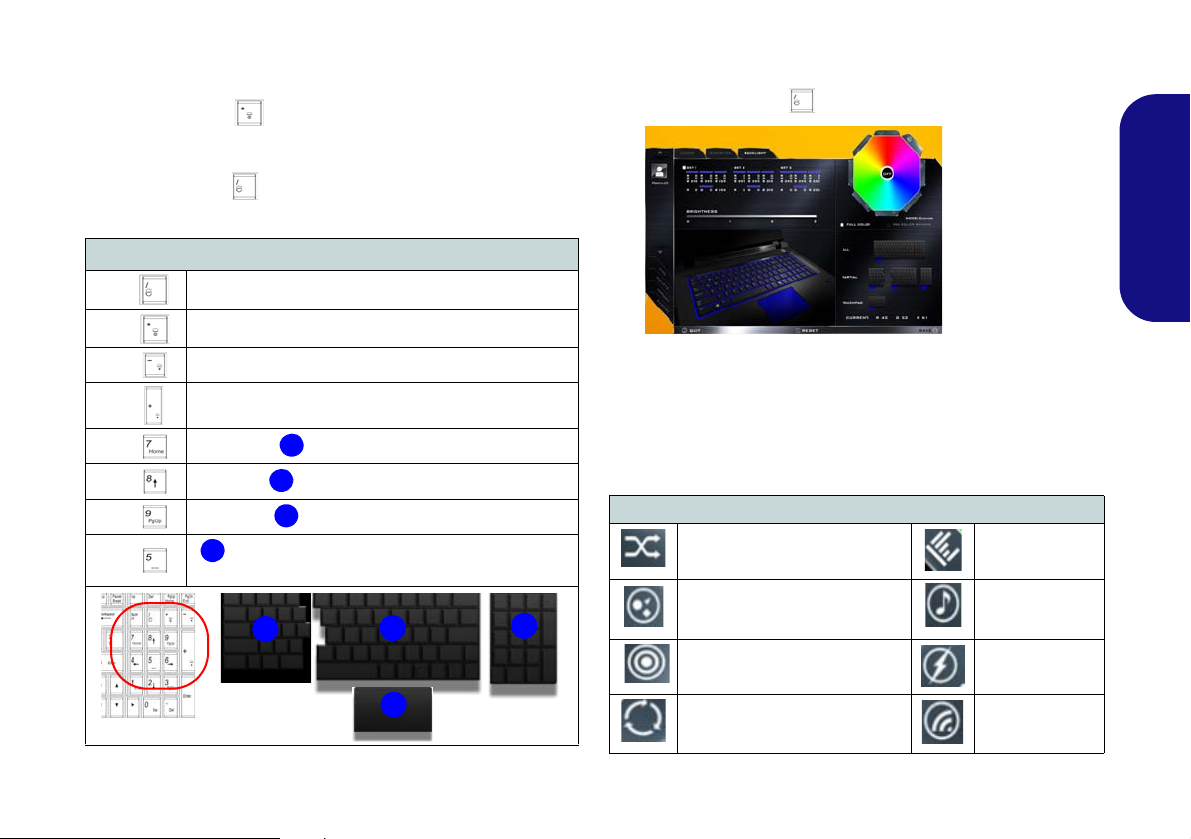
Press Fn plus the key to toggle the keyboard LED on/
off. The keyboard LED may be configured using the Fn +
key combination outlined in the table below. In addition
press Fn plus the key to launch th e keyboard backlight
application to configure the settings.
Keyboard LED Function key Combinations
Keyboard Backlight Application
The Keyboard Backlight application can be accessed by
pressing the Fn plus key.
English
Fn +
Fn +
Fn +
Fn +
Fn +
Fn +
Fn +
Fn +
Launch the Keyboard Backlight Application
Toggle the Keyboard LED On/Off
Keyboard LED Illumination Decrease
Keyboard LED Illumination Increase
Left keyboard LED on/off
Middle keyboard LED on/off
Right keyboard LED on/off
T ouchp ad LED on/off (for models supporting an
illuminated touchpad)
Table 6 - Keyboard LEDs
Modes
The buttons surrounding the swatch allow you to alter the
effects of the keyboard backlight. Click on any of the buttons to view the effects on the keyboard. Click Save when
exiting the application to retain the setting.
Mode Buttons
Random Color Wave Up/Down
Custom - Display & Configure
Keyboard Sections & Colors
Breathe (All Colors) Tempo Beat
Cycle Colors
Table 7 - Mode Buttons
Dancing Effect
Flashing
19
Page 26
Brightness
Figure 17
Preview
Figure 18
Keyboard
Sections
Click on any of the numbers (0 - 3) on the brightness bar
to set the brightness level of the keyboard backlight.
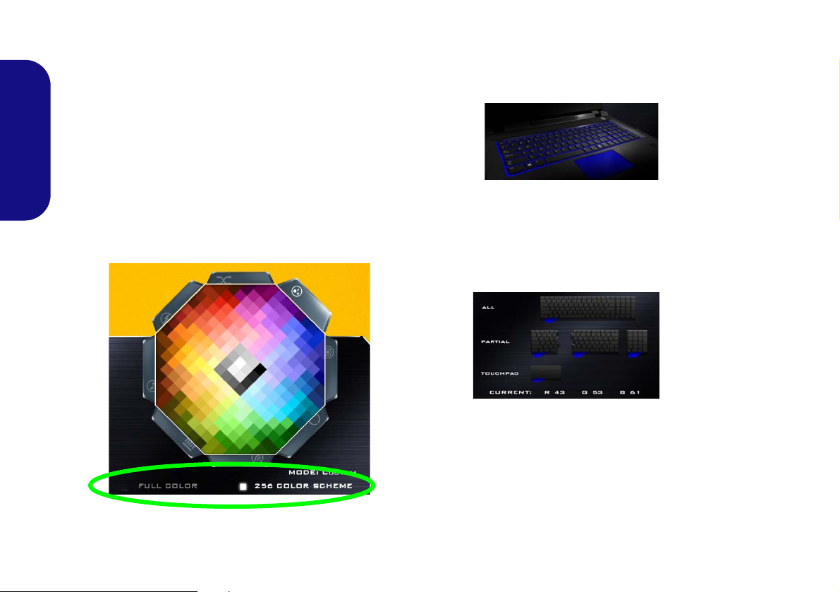
Color Swatch
The color swatch in the top right of the screen allows you
to select a range of colors for your keyboard backlight by
clicking on the color required. You can choose to display
English
the swatch either in Full Color or as an 256 Color
Scheme. Click the Custom mode button to select any col-
ors from the swatch and to apply your chosen colors to
parts of the keyboard (and touchpad if applicable).
Preview
The bottom left section of the application allows you to
preview the setting changes made to colors on the keyboard and touchpad (if applicable).
Keyboard (and Touchpad) Sections
The bottom right section of the application allows you to
select partial areas, or all, of the keyboard (and touchpad
if applicable) on which to apply the color changes and effects.
Sets
The application allows you to save up to 3 sets of color
and effect combinations. Click Save when exiting the application to retain the settings.
20
Figure 16 - Color Swatch
Save & Exit
Click Exit to quit the application without saving, or Save
to exit and retain the settings.
Page 27
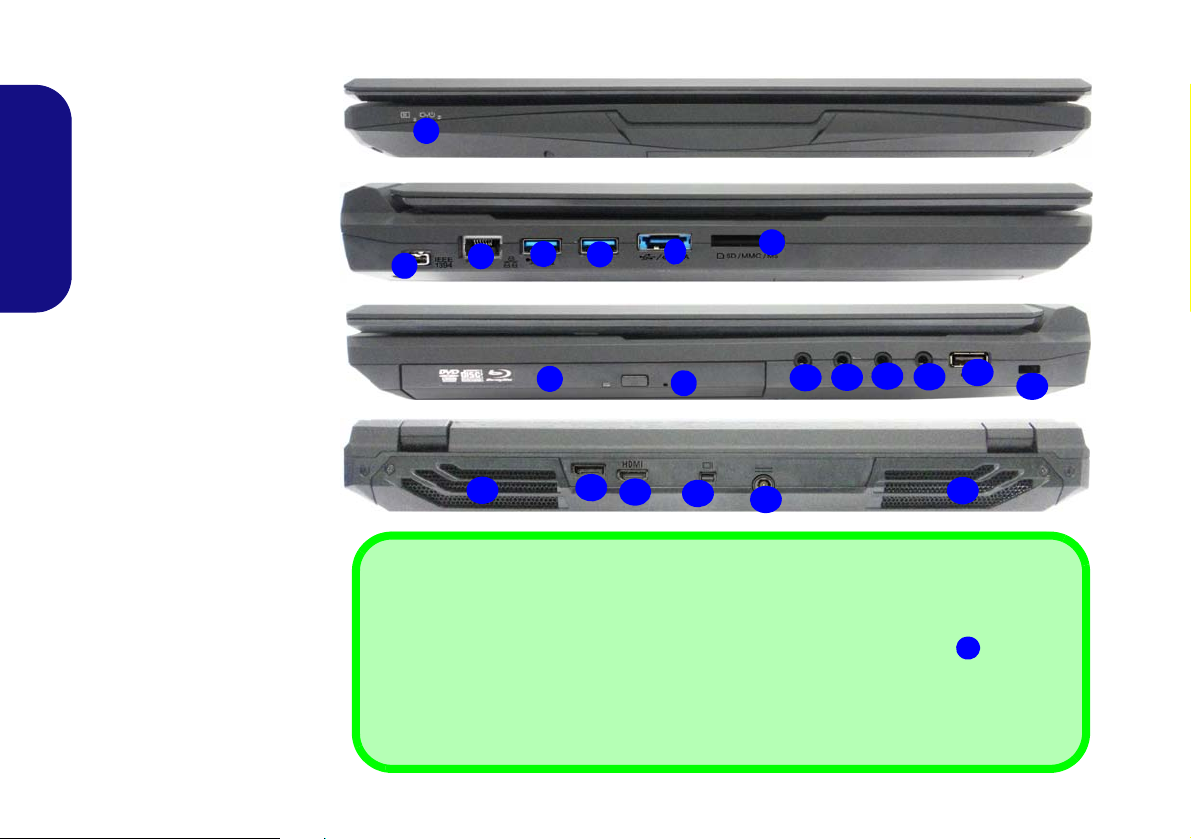
System Map: Front, Left, Right & Rear Views (Models A, C & D)
5
8
6
7
1
2
3
Front
Left
Right
10
11
13
12
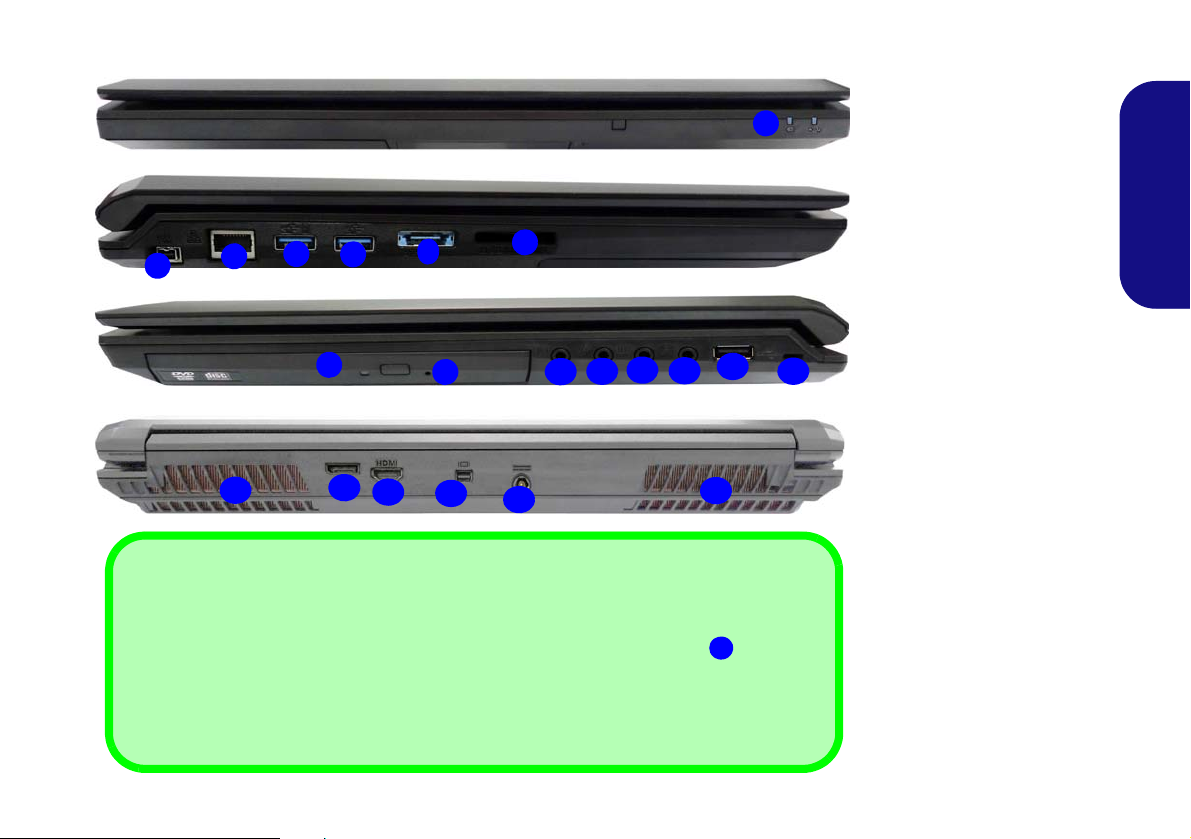
USB
The USB 3.0 ports
are colored blue. USB 3.0 will transfer data much faster than USB 2.0,
and is backwards-compatible with USB 2.0. When the powered USB 3.0 port
is on it will
supply power (for charging devices only, not for operating devices) when the system is
off but still powered by the AC/DC adapter plugged into a working outlet, or powered by the
battery with a capacity level above 20% (this may not work with certain devices - see
page 43). Toggle power to this port by using Fn + power button.
4
9
4
15
17
14
16
20
Rear
18
19
Figure 19
Front, Left, Right & Rear
Views (Models A, C & D)
1. LED Power Indicators
2. Mini-IEEE 1394a Port
3. RJ-45 LAN Jack
4. Powered USB 3.0 Port
(See Below)
5. USB 3.0 Port
6. Combined eSATA/ USB
3.0 Port
7. Multi-in-1 Card Reader
8. Optical Device Drive Bay
9. Emergency Eject Hole
10. Headphone Jack
11. Microphone Jack
12. S/PDIF-Out Jack
13. Line-In Jack
14. USB 2.0 Port
15. Security Lock Slot
16. Vent
17. DisplayPort
18. HDMI-Out Port
19. Mini DisplayPort
20. DC-In Jack
16
English
21
Page 28
System Map: Front, Left, Right & Rear Views (Model B)
5
8
6
7
1
2
3
Front
Left
Right
10
11
13
12
USB
The USB 3.0 ports
are colored blue. USB 3.0 will transfer data much faster than USB 2.0,
and is backwards-compatible with USB 2.0. When the powered USB 3.0 por t
is on it will
supply power (for charging devices only, not for operating devices) when the system is
off but still powered by the AC/DC adapter plugged into a working outlet, or powered by the
battery with a capacity level above 20% (this may not work with certain devices - see
page 43). Toggle power to this port by using Fn + power button.
4
9
4
15
17
14
16
20
Rear
18
19
Figure 20
Front, Left, Right & Rear
Views (Model B)
1. LED Power Indicators
2. Mini-IEEE 1394a Port
3. RJ-45 LAN Ja c k
4. Powered USB 3. 0 Po rt
(See Below)
5. USB 3.0 Port
6. Combined eSATA/ USB
3.0 Port
7. Multi-in-1 Card Reader
8. Optical Device Drive Bay
9. Emergency Eject Hole
10. Headphone Jack
11. Microphone Jack
12. S/PDIF-Out Jack
13. Line-In Jack
14. USB 2.0 Port
15. Security Lock Slot
16. Vent
17. D isplayPort
18. HDMI-Out Port
19. Mini DisplayPort
20. DC-In Jack
16
English
22
Page 29
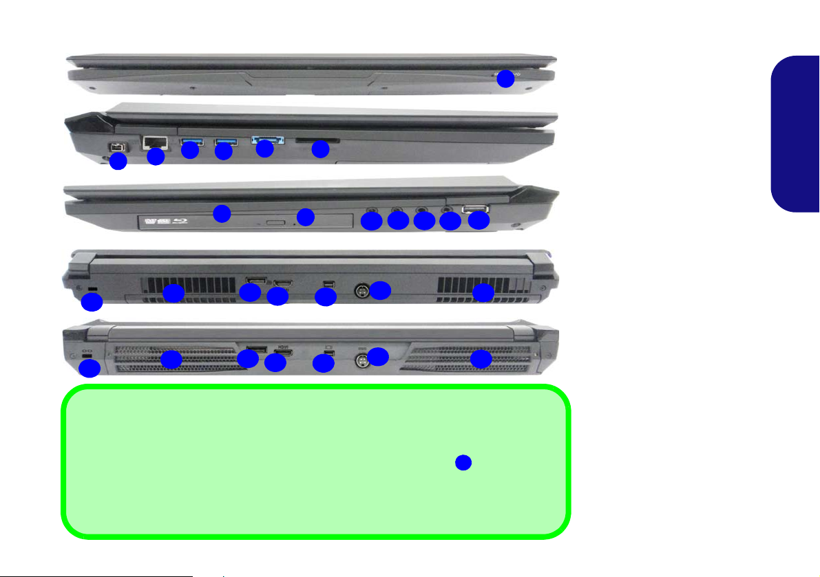
System Map: Front, Left, Right & Rear Views (Models E & F)
Front
Figure 21
Front, Left, Right & Rear
Views (Models E & F)
1. LED Power Indicators
2. Mini-IEEE 1394a Port
3. RJ-45 LAN Jack
4. Powered USB 3.0 Port
(See Below)
5. USB 3.0 Port
6. Combined eSATA/ USB 3.0
Port
7. Multi-in-1 Card Reader
8. Optical Device Drive Bay
9. Emergency Eject Hole
10. Headphone Jack
11. Microphone Jack
12. S/PDIF-Out Jack
13. Line-In Jack
14. USB 2.0 Port
15. Security Lock Slot
16. Vent
17. DisplayPort
18. HDMI-Out Port
19. Mini DisplayPort
20. DC-In Jack
5
7
8
1
2
3
10
12
11
4
14
16
13
15
20
17
18
19
Left
Right
Rear (Model E)
6
9
16
USB
The USB 3.0 ports
are colored blue. USB 3.0 will transfer data much faster than USB 2.0, and
is backwards-compatible with USB 2.0. When the powered USB 3.0 port
is on it will sup-
ply power (for charging devices only, not for operating devices) when the system is off
but still powered by the AC/DC adapter plugged into a working outlet, or powered by the battery with a capacity level above 20% (this may not work with certain devices - see page 43).
Toggle power to this port by using Fn + power button.
4
16
15
20
17
18
19
Rear (Model F)
16
English
23
Page 30
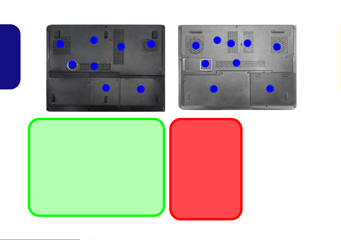
System Map: Bottom Views (Models A, B, C & D)
3
2
1
4
6
Battery Information
Always completely discharge, then fully charge, a new
battery before using it. Completely discharge and charge
the battery at least once every 30 days or after about 20
partial discharges (see the expanded User’s Manual on
the Device Drivers & Utilities + User’s Manual disc).
Display Devices
Besides the built-in LCD, you can also use an external Flat
Panel Display or TV (connected to the HDMI-Out port/DisplayPort/Mini DisplayPort) as your display device.
1
1
1
Figure 22
Bottom Views (Models
A, B, C & D)
1. Vent
2. Component Bay Cover
3. Sub Woofer
4. HDD Bay
5. HDD/ODD Bay
6. Battery
CPU
The CPU is not a user serviceable part. Accessing
the CPU in any way may violate your warranty.
Overheating
To prevent your computer
from overheating make
sure nothing blocks any
vent while the computer is
in use.
3
2
1
6
1
1
1
5
Models A, C & D
Model B
1
English
24
Page 31

System Map: Bottom Views (Models E & F)
3
2
1
4
5
Battery Information
Always completely discharge, then fully charge, a new
battery before using it. Completely discharge and charge
the battery at least once every 30 days or after about 20
partial discharges (see the expanded User’s Manual on
the Device Drivers & Utilities + User’s Manual disc).
Display Devices
Besides the built-in LCD, you can also use an external Flat
Panel Display or TV (connected to the HDMI-Out port/DisplayPort/Mini DisplayPort) as your display device.
1
1
1
Figure 23
Bottom Views (Models
E & F)
1. Vent
2. Component Bay Cover
3. Sub Woofer
4. HDD Bay
5. Battery
6. Secondary HDD Bay
CPU
The CPU is not a user serviceable part. Accessing
the CPU in any way may violate your warranty.
Overheating
To prevent your computer
from overheating make
sure nothing blocks any
vent while the computer is
in use.
3
2
1
4
5
1
1
1
6
Model E
Model F
6
English
25
Page 32

Windows 8.1 Start Screen,
Figure 24 - Start Screen (Windows 8.1)
Figure 25 - Start Screen with Charms Bar (Win-
dows 8.1)
Desktop and Charms Bar
The Apps, control panels, utilities and programs within
Windows 8.1 are accessed from the Start screen and/or
Windows Desktop app. The Desktop (which runs as an
app within the Start screen) can be accessed by clicking
the Desktop item in the Start screen (or by using the Win-
English
dows Logo Key + D key combination). The taskbar is
displayed at the bottom of the desktop screen, and you can
see the notification area of the taskbar in the bottom right
of the screen. Click the arrow at the bottom of the Start
screen to access Apps.
The right side of the screen displays the Charms Bar. The
Charms Bar contains the Search, Share, Start, Devices
and Settings menus. To access up the Charms Bar move
the cursor to the upper or lower right corners of the screen,
and then hover over one of the items in the Charms Bar to
activate it (the bar will be black when it is active), or use
the Windows Logo Key + C key combination.
Windows 8.1 Control Panel
26
Page 33

Throughout this manual you will see an instruction to
Move the mouse to the bottom left of the
screen and right-click the Start button to
access the menu.
Figure 26 - Context Menu (Windows 8.1)
open the Control Panel. Right-click the Start button
in the Desktop app or Start screen (or use the Windows
Logo Key + X key combination) to bring up an advanced context menu of useful features such as Control
Panel, Programs and Features, Power Options, Task Manager, Search, File Explorer, Command Prompt, Device
Manager and Network Connections etc. and then select
Control Panel.
English
27
Page 34
Video Features
The system features both an Intel’s Integrated GPU (for
power-saving) and an NVIDIA’s discrete GPU/AMD’s
discrete GPU (for performance). You can switch display devices, and configure display options, fro m the Display con-
trol panel in Windows as long as the video driver is installed.
Microsoft Hybrid Graphics
English
Microsoft Hybrid Graphics is a seamless technology
designed to get best performance from the graphics system while allowing longer battery life, without having to
manually change settings. The computer will automatically and seamlessly switch between the integrated UMA
(Unified Memory Architecture) GPU (iGPU) and the discrete GPU (dGPU) when required by the applications in
use.
To access the Display control panel in Windows:
1. Go to the Control Panel.
2. Click Display (icon) - in the Appearances and
Personalization category.
3. Click Adjust Screen Resolution/Adjust resolution.
OR
4. Right-click the desktop (use the Windows Logo Key + D
key combination to access the desktop) and select Screen
resolution.
5. Use the dropbox to select the screen resolution.
6. Click Advanced settings.
To access the Intel® HD Graphics Control Panel:
1. Click the icon (Intel® HD Graphics Control Panel) on the
Apps screen.
OR
2. Right-click the desktop (use the Windows Logo Key + D
key combination to access the desktop) and select Graphics
Properties from the menu.
OR
3. Click the icon in the notification area of the Desktop
taskbar and select Graphics Properties from the menu.
To access the NVIDIA Control Panel:
1. Go to the Control Panel.
2. Click NVIDIA Control Panel (icon) - in the Appearances and
Personalization category.
OR
3. Right-click the desktop (use the Windows Logo Key + D
key combination to access the desktop) and select NVIDIA
Control Panel from the menu.
4.
To access the Catalyst™ Control Center:
1. Click the icon (Catalyst Control Center) on the Apps screen.
OR
2. Double-click the icon in the notification area of the
Desktop taskbar (use the Windows Logo Key + D key
combination to access the desktop).
28
Page 35

Audio Features
Volume Adjustment
The sound volume level can also be set using the volume
control in the Settings menu in the Charms Bar (on the
Start screen) or the Speaker icon in the desktop taskbar.
Figure 27
Realtek HD
Audio Man-
ager - Re-
cording
Setup
You can configure the audio options on your computer
from the Sound control panel in Windows, or from the
Realtek HD Audio Manager
tion area/control panel (right-click the notification area
icon to bring up an audio menu). The volume may also
be adjusted by means of the Fn + F5/F6 key combination.
Audio Setup for HDMI
HDMI supports video and audio signals. In some cases it
will be necessary to go to the Sound control panel and
manually configure the HDMI audio output.
1. Go to the Control Panel.
2. Click Sound (Hardware and Sound).
3. Click Playback (tab).
4. The playback device will be selected.
5. In some cases you may need to select the audio device and
click Set Default (button).
6. Double-click the device to access the control panel tabs.
7. Adjust the HDMI settings from the control panel tabs.
8. Click OK to close the Sound control panel.
/ icon in the notifica-
Setup for Audio Recording
To record audio sources on your computer at optimum
quality follow the instructions below:
1. Go to the Control Panel.
2. Click Realtek HD Audio Manager (or right-click the notification
area icon
3. Click Microphone Effects (tab) in Microphone (tab), and then
click to select Noise Suppression (button), or adjust the
Recording Volume level to around 60, to obtain the optimum
recording quality.
4. Click OK to close the Sound control panel.
and select Sound Manager).
Setup for 5.1 or 7.1 Surround Sound
To setup your system for 5.1 or 7.1 surround sound you
will need to connect the audio cables to the Line-In, Headphone-Out, Microphone-In and S/PDIF-Out jacks (7.1
Speaker only).
1. Go to the Control Panel.
2. Click Realtek HD Audio Manager (or right-click the notification
area icon
3. Click Speakers (tab) and click Speaker Configuration (tab).
and select Sound Manager).
29
English
Page 36

4. Select 5.1 Speaker or 7.1 Speaker from the Speaker
Figure 28
Speaker Con-
figuration
Sound Blaster & HDMI
Note that the Sound Blaster
audio effects do not apply to
audio generated through an
HDMI connection.
Configuration pull-down menu.
English
5. Plug the front speaker cables into the Headphone-Out Jack.
6. Plug in the cables (you may require an adapter to connect each
cable to the appropriate jack e.g a stereo mini to dual RCA
adapter) from your speakers as follows:
• Line-In Jack = Side Speaker Out
• Microphone-In Jack = Center/Subwoofer Speaker Out
• S/PDIF-Out Jack = Rear Speaker Out (7.1 Speaker only)
7. As you plug in each cable a dialog box will pop up.
8. Click to put a tick in the appropriate box according to the
speaker plugged-in (e.g. Rear Speaker Out), and then click OK
to save the setting.
9. Click OK to exit Realt e k HD Audio Manager.
Sound Blaster Audio
Install the Sound Blaster application to allow you to
configure the audio settings to your requirements for the
best performance in games, music and movies.
Sound Blaster X-Fi MB3 AP Installation
1. Click Option Drivers (button).
2. Click 7.Install SBX-Fi MB 3 AP > Yes.
3. Choose the language you prefer and click Next.
4. Click Yes to accept the license.
5. Click Next > Full Installation (button).
6. Click Next > Finish to restart the computer.
Sound Blaster X-Fi MB3 Application
Run the Sound Blaster control panel from the notification
area of the taskbar (or from the item in the Apps screen).
Click on the tabs to access any of the control panel menus.
30
Figure 29 - Connected Device Auto Popup
Figure 30 - Sound Blaster X-Fi MB3
(Taskbar Notification Area Icon)
Page 37

Power Options
Figure 31 - Power Options
The Power Options (Hardware and Sound menu) control panel icon in Windows allows you to configure power
management features for your computer. You can conserve power by means of power plans and configure the
options for the power button, sleep button (Fn + F4),
computer lid (when closed), display and sleep mode (the
default power saving state) from the left menu. Note that
the Power saver plan may have an affect on computer
performance.
Click to select one of the existing plans, or click Create a
power plan in the left menu and select the options to create a new plan. Click Change Plan Settings and click
Change advanced power settings to access further configuration options.
PC Camera
When the PC Camera is in use the LED indicator to the
left of the camera will be illuminated in red (see page 8/
page 9).
Camera App
1. Run the Camera app from the Start screen by clicking on the Camera icon .
2. The camera interface will display two buttons on the
right side of the screen.
3. The upper button is used to record video, and
the lower button is used to t ake still pictures.
4. Right-click on the screen to bring up menu buttons
at the bottom of the screen.
5. These buttons enable you to access the Camera
roll (where captured pictures and video are displayed), set the
timer (the time period before capture begins) and set the
exposure level using the slider to obtain the best results.
Taking Pictures/Capturing Video
1. Run the Camera app from the Start screen by clicking on the
Camera icon .
2. Click to select the timer if you require a countdown before
capture.
3. Click to select either photo
4. Click in the appropraite icon to take a picture or start video
capture (if video capture begins a timer will appear in the
bottom corner of the screen).
5. To stop video capture click the main window again (or click the
stop icon ).
6. Captured photos and videos will be saved to a Camera Roll
folder within the Pictures folder.
or video mode.
English
31
Page 38

Driver Installation
Driver Installation & Power
When installing drivers make sure your computer is
powered by the AC/DC adapter connected to a working
power source. Some drivers draw a significant amount
of power during the installation procedure, and if the remaining battery capacity is not adequate this may cause
the system to shut down and cause system problems
(note that there is no safety issue involved here, and the
battery will be rechargeable within 1 minute).
The Device Drivers & Utilities + User’s Manual disc con-
tains the drivers and utilities necessary for the proper operation of the computer. Insert the disc and click Install
Drivers (button), or Option Drivers (button) to access
the Optional driver menu. Install the drivers in the order
indicated in Table 8. Click to select the drivers you wish
to install (you should note down the drivers as you install
English
them). Note: If you need to reinstall any driver, you
should uninstall the driver first.
Manual Driver Installation
Click the Browse CD/DVD button in the Drivers Installer application and browse to the executable file in the ap-
propriate driver folder.
If a
Found New Hardware
stallation procedure, click Cancel and follow the installation procedure as directed.
32
wizard appears
during the in-
Driver Page#
Chipset page 33
Video (Intel) page 33
Video (NVIDIA) page 33
Video (AMD) page 33
LAN page 33
CardReader page 33
Touchpad page 33
Airplane page 33
Hot Key page 33
Intel MEI page 33
Audio page 33
Wireless LAN Module (Optional) page 34
Fingerprint Reader (Optional) page 36
Bluetooth Module (Optional) page 37
TPM (Optional) page 38
Intel® Rapid Storage Technology (IRST) page 40
Intel® Rapid Start Technology page 42
Sound Blaster Audio page 30
Enable Windows Update
*After installing all the drivers make sure you enable Windows
Update in order to get all the latest security updates etc. (all
updates will include the latest hotfixes from Microsoft).
*
Table 8 - Driver Installation
Page 39

Chipset
1. Click Install Drivers (button).
2. Click 1.Install Chipset Driver >
Yes.
3. Click Next > Yes > Next > Next.
4. Click Finish to restart the computer.
Video (Intel)
1. Click 2.Install VGA Driver > Yes.
2. Click Next > Yes > Next > Next.
3. Click Finish to restart the computer.
Video (NVIDA)
1. Click 3.Install NVIDIA VGA
Driver > Yes.
2. Click AGREE AND CONTINUE
(button) to accept the terms of the
license agreement.
3. Click Next.
4. Click Close.
Video (AMD)
1. Click 4.Install AMD VGA Driver >
Yes.
2. Click Next > Install (button).
3. Click the Express (or Custom if you
prefer to manually configure the
driver installation settings) button
and click Next.
4. Click Accept (button) and click Yes.
5. Click Finish > Yes to restart the com-
puter.
LAN
1. Click 5.Install LAN Driver > Yes.
2. Click Next > Install > Finish.
CardReader
1. Click 6.Install Cardreader Driver
> Yes.
2. Click Finish.
Touchpad
1. Click 7.Install Touchpad Driver >
Yes.
2. Click Next.
3. Click Finish > Restart Now to
restart the computer.
Airplane
1. Click 8.Install Airplane Driver >
Yes.
2. Click Next.
3. Click Finish to restart the computer.
Hot Key
1. Click 9.Install Hotkey AP > Yes.
2. Click Next > Next.
3. Click Finish > Finish to restart the
computer (After restart a c ontrol
panel will pop-up to allow you to
select the type of keyboard for your
system).
Intel MEI
1. Click 10.Install MEI Driver >
Yes.
2. Click Next > Yes > Next.
3. Click Finish.
Audio
1. Click 11.Install Audio Driver >
Yes.
2. Click Next > Finish to restart the
computer.
English
33
Page 40

Wireless LAN Module (Option)
Make sure the Wireless LAN module is turned on (and not
in Airplane Mode).
WLAN Configuration in Windows
Make sure the Wireless LAN module is turned on (and not
in Airplane Mode) before configuration begins.
WLAN Driver Installation
Follow the instructions below:
English
(Intel) WLAN/WLAN and Bluetooth Combo
1. Click Option Drivers (button).
2. Click 1.Install WLAN Driver > Yes.
3. Click Next > Next.
4. Click the button to accept the license and click Next.
5. Click Typical (buttom) or Custom (buttom).
6. Click Install > Finish.
(Third Party) WLAN 802.11b/g/n and Bluetooth 4.0
Combo
1. Click Option Drivers (button).
2. Click 1.Install WLAN Driver > Yes.
3. Click Next.
4. Click Finish to restart the computer.
(Third Party) WLAN 802.11a/b/g/n and Bluetooth 4.0
Combo
1. Click Option Drivers (button).
2. Click 1.Install WLAN Driver > Yes.
3. Click Next > Yes > Next.
4. Click Install > Yes to restart the computer.
Desktop Mode
1. Switch to the Windows Desktop (click the Desktop item in the
Start screen or use the Windows Logo Key + D key com-
bination).
2. Click the icon in the notification area of the t askbar.
3. A list of available access points will appear.
Or
Charms Bar
1. Go to the Charms Bar.
2. Select Settings and then click the Wi-Fi icon (it should read
Available under the icon and Airplane mode should be Off).
3. A list of available access points will appear.
4. Double-click an access point to connect to it (or click it and click
Connect).
5. Enter a network security key (password) if required, and click
Next.
6. You can choose to find other devices or not.
7. When you are connected to the network access point it will
display Connected.
8. Select any connected network and click Disconnect to
disconnect from a connected access point.
9. You can click the Airplane Mode button to turn the mode On or
Off.
10. Alternatively you can click the Wi-Fi button to turn just the Wi-Fi
On or Off.
34
Page 41

Wireless Display
Wireless Display uses your Wireless LAN module/
WLAN/Bluetooth Combo module (you need to make sure
that your video adapter/display device is compatible with
your particular WLAN/Combo module) in conjunction
with a compatible video adapter/display device (purchased separately) to allow you to display the contents of
the notebook display on another display (e.g. HDTV),
without the need to have cables stretching across a room.
You can then play games, browse the internet, display videos or photo slide shows on your TV/external display
without using HDMI or A/V cables.
Before configuring Wireless Display you will need to set
up your compatible adapter with your display. Connect
the adapter using an HDMI or A/V cable and turn on the
display, and then set the display to the appropriate input
channel (see the documentation supplied with your com-
patible adapter for full details).
Note that no driver or application is required for wireless
display in Windows 8.1.
Wireless Display Configuration
1. Note that no driver or application is required for wireless display
in Windows 8.1.
2. Go the Charms Bar, and select Devices.
3. Click Project.
4. Click Add a wireless display.
5. The system will then search for compatible display devices
(this may take up to 60 seconds so allow time for this to
complete).
6. Double-click any detected display device in the list.
7. You may then need to input a pin number for the device to
which you are connecting.
8. Click Next.
9. The display will then connect (for specific settings for your
display see the documentation supplied with your compatible
adapter/display for full details).
10. Go to the Project menu (Charms Bar > Devices) and click
Disconnect to temporarily disconnect from the wireless di splay.
11. To permanently disconnect from the display (you will need to go
back through the connection process again) you can select it in
PC and Devices > Devices and click Remove Device > Yes.
English
35
Page 42

Fingerprint Reader (Option)
Figure 32
Accounts Sign-in op-
tions
Install the driver and enroll your fingerprints as instructed
below before use. The fingerprint reader module uses the
Sign-in options configuration of the Windows Account.
Fingerprint Reader Driver Installation
1. Click Option Drivers (button).
English
2. Click 2.Install Fingerprint Driver > Yes.
3. Click Next > Finish to restart the computer.
Or
4. Click Next > Install > Finish.
Fingerprint Module Configuration
1. Go to the Charms Bar.
2. Select Settings and then click Change PC Settings.
3. Click Accounts and then click Sign-in options.
4. You will need to add a Windows password (click Add under
Password).
5. After you have added the password you will need to restart the
computer and use your password to log on to the system.
6. Go to the Charms Bar.
7. Select Settings and then click Change PC Settings.
8. Click Accounts and then click Sign-in options.
9. Click Add under Fingerprint.
10. Input the Windows password and click OK.
11. Y ou will then be instructed to swipe the same finger across the
reader a number of times.
Figure 33 - Add a Fingerprint
12. Click Finish.
13. You can choose to Add another finger (this is recommended)
or Remove the current fingerprint reading.
14. You can now scan your fingerprint to log-on to the computer.
36
Page 43

Bluetooth Module (Option)
Make sure the Bluetooth module is turned on (and not in
Airplane Mode).
Bluetooth Configuration
Make sure the Bluetooth module is turned on (and not in
Airplane Mode) before configuration begins.
Bluetooth Driver Installation
Note that you need to install both the WLAN & Bluetooth
drivers for the WLAN & Bluetooth Combo modules,
however the third party WLAN 802.11a/b/g/n + Bluetooth
Combo module only requires the WLAN driver installation.
Follow the instructions below:
(Intel) WLAN and Bluetooth Combo
1. Click Option Drivers (button).
2. Click 3.Install Combo BT Driver > Yes.
3. Click Next > Next.
4. Click the button to accept the license and click Next.
5. Click Next > Finish.
(Third Party) WLAN 802.11b/g/n and Bluetooth 4.0
Combo
1. Click Option Drivers (button).
2. Click 3.Install Combo BT Driver > Yes.
3. Click Next.
4. Click Finish to restart the computer.
Desktop Mode
1. Switch to the Windows Desktop (click the Desktop item in the
Start screen or use the Windows Logo Key + D key com-
bination).
2. Click the notification area of the taskbar and double-click the
Bluetooth icon (or click and select Show Bluetooth
Devices).
3. The Bluetooth item in PC and devices will appear.
Or
Charms Bar
1. Go to the Charms Bar.
2. Select Settings and then click Change PC Settings.
3. The Bluetooth item in PC and Devices will appear .
4. Select the Bluetooth item in PC and devices.
5. Make sure that Bluetooth is turned on and a list of discovered
devices will appear.
6. Double-click the device you want to pair with the computer and
click Pair.
7. On first connection the computer will provide you with a pairing
code to be entered onto the device.
8. Enter the code into your Bluetooth enabled device and click Yes
on the computer to complete the pairing.
9. Select a device and click Remove Device to disconnect from
any device.
English
37
Page 44

Trusted Platform Module (Op-
tion)
Before setting up the TPM functions you must initialize
the security platform.
Activating TPM
1. Restart the computer.
English
2. Enter the Aptio Setup Utility pressing F2 during the POST.
3. Use the arrow keys to select the Security menu.
4. Select TPM Configuration and press Enter.
5. Select TPM Support and press Enter. Select Enable and press
Enter.
6. Select TPM State, press Enter and select Enable to change the
TPM state to enabled. You will then need to press F4 to save
the changes and restart the computer.
7. As the computer restarts press F2 to enter the BIOS again and
go to the TPM Configuration menu.
8. Select Pending TPM operation, press Enter and select the
option you require (if you are initializing TPM you should select
Enable Take Ownership). You will then need to press F4 to
save the changes and restart the computer.
9. You can now install the TPM driver and then initialize the
TPM.
TPM Driver Installation
1. Click Option Drivers (button).
2. Click 4.Install TPM Driver > Yes.
3. Click Install > Next.
4. Click the button to accept the license and click Next.
5. Click Next > Next > Install.
6. Click Finish > Yes to restart the computer.
38
Page 45
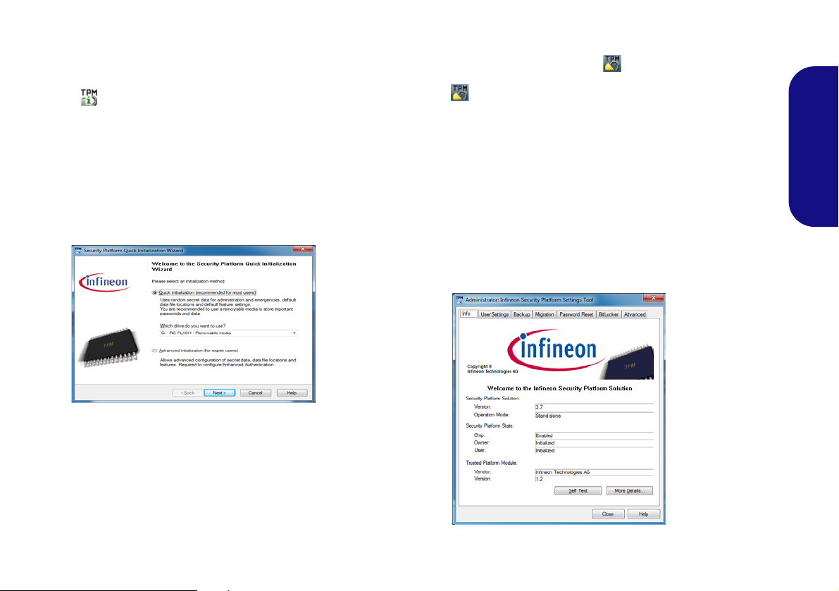
Initializing TPM
Figure 34
Security
Platform
Quick Initial-
ization Wiz-
ard
Figure 35
Infineon Secu-
rity Platform
Settings Tool
1. Click the icon (Manage Security Platform) on the Apps
screen.
2. Click User Settings (tab) and click Yes, or right-click the icon
in the notification area of the taskbar, and select Security
Platform Initialization (or click the Security Platform State
taskbar bubble).
3. The Quick Initialization method will automatically be selected
for you (if you need to use advanced settings provided by your
network administrator then select Advanced Initialization).
4. You will need to use a removable media (e.g. a USB Flash
Drive) to store passwords and data (keep the media in a safe
place until required).
5. Select the drive you want to use from the drop-down menu and
click Next.
6. Choose the Security Platform Features you want to use by
clicking the appropriate tickbox.
7. Enter a Basic User Password (and re-type to confirm it) and
click Next.
8. Click Next to confirm the settings.
9. The computer will then initialize the settings.
10. Click Finish.
11. Click the tabs and control panels to adjust the settings.
12. Double-click the taskbar icon to access the Infineon
Security Platform Settings Tool, or right-click the taskbar icon
and select a menu item.
English
Infineon Security Platform Settings Tool
The Infineon Security Platform Settings Tool allows you
to manage and check the TPM state, manage your password information, and to backup and restore the TPM data. As TPM is usually administered within large
enterprises and organizations, your system administrator
will need to assist you in managing the information here.
39
Page 46

Intel® Smart Response Technology
Intel® Smart Response Technology is an Intel® Rapid Storage Technology (RST) caching feature that accelerates computer system performance by using the SSD as cache memory between the hard disk drive and system memory. If you have an Solid State Drive (SSD) module
English
included in your purchase option you may configure Intel® Smart Response Technology for your system.
System Requirements to support Intel® Smart Response
Technology:
• S ystem BIOS with SATA mode set to RAID Mode.
• Intel® Rapid Storage Technology (IRST) software
installed.
• A Solid State Drive (SSD) with a minimum capacity of
18.6GB (or with a partition on the drive formatted to more
than 18.6GB e.g a 20GB partition set on the SSD). Note
that the SSD requires at least 5MB of free unpartitioned
and unallocated space (if you have used all the disk space
for the partition you will need to shrink some of space for
the cache memory’s use).
IRST Driver Installation
1. Click Option Drivers (button).
2. Click 5.Install IRST Driver > Yes.
3. Click Next.
4. Click the tickbox to accept the license and click Next.
5. Click Next > Next > Next.
6. Click Finish to restart the computer (you will need to
restart the system again after the computer has
rebooted)
.
Enabling Intel Smart Response Technology
1. Click the icon (Intel® Rapid Storage Technology) on the
Apps screen.
2. Click Enable acceleration under Performance > Smart
Response T echnology (note that you will need at least 5MB of
free unpartitioned and unallocated space on the SSD otherwise
the Smart Response Technology item will not appear).
3. Select the SSD to be used as a cache device.
4. Select the size from the SSD to be allocated for the cache
memory (any remaining space on the SSD can be used for data
storage using the simple data single-disk RAID 0 volume that is
automatically created).
5. Select the HDD (or RAID volume) to be accelerated (it is highly
recommended that you accelerate the system volume or
system disk for maximum performance).
6. Select the acceleration mode (Enhanced mode is selected by
default).
Note: Enhanced mode (default): Acceleration optimized for
data protection.
Maximized mode: Acceleration optimized for input/output performance.
7. The page will refresh and report the new configuration under
Performance > Smart Response Technology.
40
Page 47

Intel® Rapid Start Technology
Intel® Rapid Start Technology can resume power from Hibernation within 5 to 6 seconds and can remember your computer's previous state with zero power.
System Requirements to support Intel® Rapid Start
Technology:
• Rapid Start Technology should be enabled in the BIOS’s
Advanced menu.
• Intel® Rapid Storage Technology software installed.
• A Solid State Drive (SSD) with a minimum capacity of
18.6GB.
Intel® Rapid Start Technology Configuration
1. Enable/disable Intel(R) Rapid Start Technology from the
BIOS.
2. Go the Windows control panel and double-click
Administrative Tools (System and Security) > Computer
Management > Storage > Disk Management.
3. Right-click the SSD and select Shrink Volume from the menu.
4. Enter the figure, which should be equal to amount of system
memory (RAM) in your computer, in “Enter the amount of
space to shrink in MB”.
5. Click Shrink (any unallocated file space may be formatted for
storage use).
6. Run the Desktop app and right-click the lower left hot corner (or
use the Windows Logo Key + X key combination) and
select Command Prompt (Admin).
7. Type “DISKPART”.
8. At the DISKPART command type “list disk”.
9. Type “select disk #” (# is disk number where you want to
create the store partition, so refer to the results obtained from
"list disk" for exact disk number).
10. The message “Disk # is now the selected disk.” will appear.
11. Type “create partition primary”.
12. A “DiskPart succeeded in creating the specified partition.”
message should appear.
English
13. Type “detail disk”.
41
Page 48

14. Type “select Volume #” (# is volume of your storage partition
so refer to results obtained from "detail disk" for the exact
volume number).
15. The message “Volume # is now the selected volume.” will
appear.
16. (MBR)
Type “set id=84 override” (the id must be set to 84).
(GPT)
Type “set id=D3BFE2DE-3DAF-11DF-BA40-E3A556D89593”.
17. The message “DiskPart successfully set the partition ID.”
English
will appear.
18. Close the CMD window.
19. Go the Windows control panel and double-click
Administrative Tools (System and Security) > Computer
Management > Storage > Disk Management.
20. The disk partition should read Hea lthy (Hiberna tion Partition) .
21. Restart the computer.
22. Install the driver (see below).
Intel® Rapid Start Technology Driver Installation
1. Click Option Drivers (button).
2. Click 6.Install Rapid Start Drive r > Yes.
3. Click Next >Next > Yes > Next > Next.
4. Click Finish to restart the computer.
42
Page 49

Troubleshooting
Problem Possible Cause - Solution
The Wireless LAN/Bluetooth
modules cannot be detected.
The PC Camera module
cannot be detected.
The captured video files from
the PC Camera are taking up
too much disk space.
The computer is off (or in
Sleep Mode) but powered by
the AC/DC adapter plugged in
to a working outlet or powered
by the battery with a capacity
level above 20%. I have
plugged a device into the
powered USB port in order to
charge it, but the device is not
charging.
The modules are off as the computer is in Airplane Mode. Check the LED indicator and/or
function key indicator to see if it is in Airplane Mode (see Table 3 on page 10). Use the Fn + F11
key combination to toggle Airplane Mode on/off (see Table 5 on page 11).
The module is off. Press the Fn + F10 key combination in order to enable the module (see Table 5
on page 11). Run the camera application to view the camera picture.
Note that capturing high resolution video files requires a substantial amount of disk space for each
file.
Note that the Windows system requires a minimum of 20GB (64bit) of free space on the C: drive
system partition. It is recommended that you save the capture video f ile to a loc ati on other than the
C:drive, limit the file size of the captured video or reduce video resolution.
The port is not powered on. Toggle power to the port using the Fn + power button combination.
This function may not work with certain external USB compliant devices (check your device’s
documentation). If this is the case, power the computer on and connect the external USB
device in order to charge it.
English
43
Page 50

Specifications
Latest Specification Information
The specifications listed in this section are correct at the time of going to
press. Certain items (particularly processor types/speeds) may be
changed, delayed or updated due to
the manufacturer's release schedule.
Check with your service center for
details.
English
Processor Options
Models A, B, C, E & F Only:
Intel® Core™ i7 Processor
i7-4940MX (3.10GHz), i7-4930MX (3.00GHz)
8MB L3 Cache, 22nm, DDR3L-1600MHz,
TDP 57W
All Models:
Intel® Core™ i7 Processor
i7-4910MQ (2.90GHz), i7-4900MQ
(2.80GHz)
8MB L3 Cache, 22nm, DDR3L-1600MHz,
TDP 47W
i7-4810MQ (2.80GHz), i7-4800MQ
(2.70GHz), i7-4700MQ (2.40GHz)
6MB L3 Cache, 22nm, DDR3L-1600MHz,
TDP 47W
44
i7-4610M (3.00GHz), i7-4600M (2.90GHz)
4MB L3 Cache, 22nm, DDR3L-1600MHz,
TDP 37W
Intel® Core™ i5 Processor
i5-4340M (2.90GHz), i5-4330M (2.80GHz),
i5-4310M (2.70GHz), i5-4300M (2.60GHz),
i5-4200M (2.50GHz)
3MB L3 Cache, 22nm, DDR3L-1600MHz,
TDP 37W
Intel® Core™ i3 Processor
i3-4100M (2.50GHz), i3-4000M (2.40GHz)
3MB L3 Cache, 22nm, DDR3L-1600MHz,
TDP 37W
LCD
Models A, B, C & D:
15.6" (39.62cm) FHD LCD
Models E & F:
17.3" (43.94cm) FHD LCD
Memory
Four 204 Pin SO-DIMM Sockets Supporting
DDR3L 1600MHz Memory
(The real memory operating frequency
depends on the FSB of the processor.)
Memory Expandable up to 16GB/32GB
Note: Four SO-DIMMs are only supported
by Quad-Core CPUs; Dual-Core CPUs support two SO-DIMMs maximum
Core Logic
Intel® HM87 Express Chipset
Storage
Models A, C & D:
(Factory Option) One 12.7mm(h) Optical
Device Type Drive (Super Multi Drive/BluRay Combo Drive/Blu-Ray Writer Drive)
One Changeable 2.5" (6cm) 9.5mm (h)
SATA (Serial) Hard Disk Drive/SSD
(Factory Option) 9.5mm 2nd HDD caddy
(Factory Option) Two mSATA Solid State
Drives (SSD) supporting RAID Level 0/1
Model B:
(Factory Option) One 12.7mm(h) Optical
Device Type Drive (Super Multi Drive/BluRay Combo Drive/Blu-Ray Writer Drive)
Two Changeable 2.5" (h) SATA (Serial) Hard
Disk Drives (HDDs)/SSDs (1st: 9.5mm (h)
& 2nd: 7mm (h)) supporting RAID Level 0/1
(Factory Option) Two mSATA Solid State
Drives (SSD) supporting RAID Level 0/1
Models E & F:
(Factory Option) One 12.7mm(h) Optical
Device Type Drive (Super Multi Drive/BluRay Combo Drive/Blu-Ray Writer Drive)
Two Changeable 2.5" (h) SATA (Serial) Hard
Disk Drives (HDDs)/SSDs supporting RAID
Level 0/1
(Factory Option) Two mSATA Solid State
Drives (SSD) supporting RAID Level 0/1
BIOS
AMI BIOS (48Mb SPI Flash-ROM)
Video Adapter
Page 51

Models A, B, C, E & F:
Intel® Integrated GPU and NVIDIA®
Discrete GPU
Supports Microsoft Hybrid Graphics
Intel Integrated GPU
Intel HD Graphics 4600
Dynamic Frequency (Intel Dynamic Video
Memory Technology for up to 1.7GB)
Microsoft DirectX® 11 Compatible
NVIDIA® Discrete GPU
NVIDIA® GeForce GTX 860M PCIe Video
Card
4GB GDDR5 Video RAM on board
Microsoft DirectX® 11.1 Compatible
NVIDIA® GeForce GTX 870M PCIe Video
Card
6GB GDDR5 Video RAM on board
Microsoft DirectX® 11.1 Compatible
NVIDIA® GeForce GTX 880M PCIe Video
Card
8GB GDDR5 Video RAM on board
Microsoft DirectX® 11.1 Compatible
NVIDIA® GeForce GTX 970M PCIe Video
Card
6GB GDDR5 Video RAM on board
Microsoft DirectX® 12 Compatible
NVIDIA® GeForce GTX 980M PCIe Video
Card
8GB GDDR5 Video RAM on board
Microsoft DirectX® 12 Compatible
NVIDIA® GeForce GTX 965M PCIe Video
Card
4GB GDDR5 Video RAM on board
Microsoft DirectX® 12 Compatible
NVIDIA® Quadro K1100M PCIe Video Card
2GB GDDR5 Video RAM on board
Microsoft DirectX® 11.1 Compatible
NVIDIA® Quadro K3100M PCIe Video Card
4GB GDDR5 Video RAM on board
Microsoft DirectX® 11.1 Compatible
AMD Radeon™ R9 M290X PCIe Video
Card
4GB GDDR5 Video RAM on board
Microsoft DirectX® 11.1 Compatible
Model D:
Intel® Integrated GPU and NVIDIA®
Discrete GPU
Supports Microsoft Hybrid Graphics
Intel HD Graphics 4600
Dynamic Frequency (Intel Dynamic Video
Memory Technology for up to 1.7GB)
Microsoft DirectX® 11 Compatible
NVIDIA® Discrete GPU
NVIDIA® GeForce GTX 860M PCIe Video
Card
2GB GDDR5 Video RAM on board
Microsoft DirectX® 11.1 Compatible
NVIDIA® Quadro K1100M PCIe Video Card
2GB GDDR5 Video RAM on board
Microsoft DirectX® 11.1 Compatible
NVIDIA® Quadro K3100M PCIe Video Card
4GB GDDR5 Video RAM on board
Microsoft DirectX® 11.1 Compatible
NVIDIA® GeForce GTX 965M PCIe Video
Card
4GB GDDR5 Video RAM on board
Microsoft DirectX® 12 Compatible
Security
Security (Kensington® Type) Lock Slot
BIOS Password
(Factory Option) Fingerprint Reader Mod-
ule
(Factory Option) TPM 1.2
Mini-Card Slots
Slot 1 for WLAN Module or Combo WLAN
and Bluetooth Module
Slots 2 & 3 for mSATA SSD
Pointing Device
Models B & F:
Built-in Illuminated Touchpad (scrolling key
functionality integrated)
Models A, C, D & E:
Built-in Touchpad (scrolling key functionality
integrated)
Keyboard
Models A, B, E & F:
Illuminated Full-size “WinKey” keyboard
(with numeric keypad)
Models C & D:
Full-size “WinKey” keyboard (with numeric
keypad)
English
45
Page 52

Audio
High Definition Audio Compliant Interface
S/PDIF Digital Output
Two Speakers
One Sub Woofer
Built-In Microphone
Sound Blaster Audio
ANSP™ 3D sound technology on headphone output
English
Interface
Two USB 3.0 Ports (Including one AC/DC
Powered USB port)
One USB 2.0 Port
One eSATA Port (USB 3.0 Port Combined)
One HDMI-Out Port
One DisplayPort (1.1a)
Mini DisplayPort
One
One S/PDIF Out Jack
One Headphone/Speaker-Out Jack
One Microphone-In Jack
One Line-In Jack
One Mini-IEEE1394a Port
One RJ-45 LAN Jack
One DC-In Jack
Note: External 7.1CH Audio Output Supported by Headphone, Microphone, Line-In
and S/PDIF Out Jacks
Card Reader
Embedded Multi-In-1 Push-Push Card
Reader
MMC (MultiMedia Card) / RS MMC
SD (Secure Digital) / Mini SD / SDHC/
SDXC
MS (Memory Stick) / MS Pro / MS Duo
Communication
Built-In Gigabit Ethernet LAN
2,0M FHD PC Camera Module
WLAN/ Bluetooth Half Mini-Card
Modules:
(Factory Option) Intel® Centrino® Ultimate-N 6300 Wireless LAN (802.11a/g/n)
(Factory Option) Intel® Wireless-AC 7260
Wireless LAN (802.11a/c) + Bluetooth 4.0
(Factory Option) Intel® Wireless-N 7260
Wireless LAN (802.11b/g/n) + Bluetooth 4.0
(Factory Option) Intel® Wireless-N 3160
Wireless LAN (802.11ac) + Bluetooth 4.0
(Factory Option) Wireless LAN (802.11b/g/
n) + Bluetooth 4.0
(Factory Option) Wireless LAN (802.11a/b/
g/n) + Bluetooth 4.0
Environmental Spec
Temperature
Operating: 5°C - 35°C
Non-Operating: -20°C - 60°C
Relative Humidity
Operating: 20% - 80%
Non-Operating: 10% - 90%
Power
Removable 8-cell Smart Lithium-Ion Battery
Pack, 76.96WH
Full Range AC/DC Adapter
AC Input: 100 - 240V, 50 - 60Hz
Models A, B & C:
DC Output: 19.5V, 9.2A/ 19V, 9.47A (180W)
Model D:
DC Output: 19.5V, 6.15A (120W)
Models E & F :
DC Output: 19.5V, 11.8A (230W)
Dimensions & Weight
Models A, C & D:
376mm (w) * 256mm (d) * 35 - 43mm (h)
Around 3.1kg with Battery and ODD
Model B:
375mm (w) * 268mm (d) * 22 - 45mm (h)
Around 3.3kg with Battery and ODD
Model E:
412mm (w) * 276mm (d) * 45.4 - 41.8mm (h)
Around 3.9kg with Battery and ODD
Model F:
414mm (w) * 286mm (d) * 25.3 - 46.1mm (h)
Around 4.1kg with Battery and ODD
46
Page 53

Über das Ausführliche Benutzerhandbuch
Diese Kurzanleitung soll einen Überblick über die Schritte geben, die dazu notwendig s ind, das System zu starten. Dieses ist
nur eine Ergänzung und kein Ersatz für das erweiterte englischsprachige Benutzerhandbuch, das auf der mitgelieferten Disc
Device Drivers & Utilities + User's Manual im Adobe-Acrobat-Format vorliegt. Diese Disc enthält auch die Treiber und
Utility-Programme, die für einen einwandfreien Betrieb des Computers notwendig sind (Hinweis: Das Unternehmen behält
sich das Recht vor, diese Publikation ohne Vorankündigung zu überarbeiten und den Inhalt zu verändern).
Einige oder alle Funktionen des Computers sind bereits eingerichtet worden. Falls das nicht der Fall ist oder wenn Sie einzelne Teile des Systems neu konfigurieren (oder neu installieren) möchten, finden Sie eine Anleitung im erweiterten Benut-
zerhandbuch. Die Disc Device Drivers & Utilities + User's Manual enthält nicht das Betriebssystem.
Einhaltung gesetzlicher Vorschriften und Sicherheitshinweise
Beachten Sie sorgfältig die Hinweise zu gesetzlichen Vorschriften und zu Sicherheitshinweisen im erweiterten Benutzerhandbuch auf der Disc Device Drivers & Utilities + User's Manual.
© Februar 2014
Warenzeichen
Intel und Intel Core sind warenzeichen/eingetragenes warenzeichen der Intel Corporation.
Deutsch
47
Page 54

Hinweise zu Pflege und Betrieb
Der Computer ist zwar sehr stabil, kann aber dennoch beschädigt werden. Damit es nicht dazu kommt, sollten Sie die
folgenden Hinweise beachten:
• Das Gerät darf nicht herunterfallen und in anderer Form Stößen
ausgesetzt werden. Wenn der Compu ter fällt, können das Gehäuse
und andere Komponenten beschädigt werden.
• Das Gerät darf nicht nass werden und sich nicht überhitzen. Der
Computer und das Netzteil dürfen nicht in der Nähe einer Wärmequelle stehen. Dies ist ein elektrisches Gerät. Wenn Wasser oder
andere Flüssigkeiten eindringen, kann der Computer stark beschädigt
werden.
• Vermeiden Sie Interferenzen mit anderen Geräten. Halten Sie den
Computer fern von magnetischen Feldern, die von Stromquellen,
Monitoren, Magneten etc. erzeugt werden. Die können die Leistung
beeinträchtigen und Ihre Daten beschädigen.
Deutsch
• Achten Sie auf die richtige Bedienung des Computers. Schalten Sie
ihn erst aus, wenn alle Programme geschlossen wurden (speichern Sie
Ihre Daten!). Speichern Sie regelmäßig Ihre Daten, da diese verloren
gehen können, wenn der Akku verbraucht ist.
• Beachten Sie, dass das Logo bei den Computern, die über ein gal-
vanisch beschichtetes LCD-Logo verfügen, von einer Schutzfolie
bedeckt ist. Durch die natürliche Abnutzung kann diese Schutzfolie
beschädigt werden oder abgehen und die scharfen Kanten des frei
liegenden Logos freigeben. Seien Sie in solch einem Fall vorsichtig
bei der Handhabung des Computers, und vermeiden Sie es, das
herausstehende beschichtete LCD-Logo zu berühren. Legen Sie keine
Gegenstände in die Tragetasche, da diese während des Transports
gegen den Computer drücken können. Wenden Sie sich in einem
solchen Fall von Abnutzung an Ihr Service Center.
Strom- und Akkusicherheit
• V erwenden Sie nur einen AC/DC-Ada pter , der für die Verwendung mit
diesem Computer zugelassen ist.
• Verwenden Sie nur das Netzkabel und die Akkus, die in diesem Benut-
zerhandbuch spezifiziert sind.
• Der AC/DC-Adapter kann zwar für internationale Benutzung vorge-
sehen sein, benötigt aber trotzdem eine gleichmäßige, ununterbro-
48
chene Stromversorgung. Wenn Sie sich über Ihre lokalen
Stromspezifikationen nicht im klaren sind, wenden Sie sich an Ihren
Servicevertreter oder Ihre lokale Stromgellschaft.
• Der AC/DC-Adapter kann einen zwei- oder dreipoligen geerdeten
Netzstecker haben. Der dritte Pol hat eine wichtige Sicherheitsfunktion. Setzen Sie die nicht außer Kraft. Wenn Sie keinen Zugang zu
einer passenden Steckdose haben, lassen Sie von einem qualifizierten
Elektriker eine solche einbauen.
• Fassen Sie das Netzkabel am Stecker und nicht am Kabel an, wenn Sie
es vom Stromnetz trennen möchten.
• Achten Sie darauf, daß die Steckdose und alle verwendeten Verlängerungskabel die Gesamtstromlast aller angeschlossenen Geräte
trägt.
• Achten Sie darauf, dass Ihr Computer ausgeschaltet ist, wenn Sie es
fur den Transport z.B. wahrend einer Reise in eine Tasche einpakken.
• Verwenden Sie nur Akkus, die für diesen Computer entwickelt
wurden. Ein falscher Akku-Typ kann explodieren, auslaufen oder den
Computer beschädigen.
• V erwenden Sie den Akku nicht mehr , wenn er herunter gefallen ist oder
in anderer Weise beschädigt (z.B. verzogen) ist. Auch wenn der Computer mit dem beschädigten Akku zu funktionieren schein, können
dadurch Stromkreise beschädigt werden, die schließlich einen Brand
verursachen können.
• Laden Sie die Akkus über den Computer auf. Durch falsches Laden
kann der Akku explodieren.
• Versuchen Sie nicht, Akkus zu reparieren. Lassen Sie die Akkupacks
durch den Servicevertreter oder qualifiziertes Fachpersonal reparieren
oder austauschen.
• Halten Sie Kinder vom Akku fern und entsorgen Sie beschädigte
Akkus sofort. Seien Sie vorsichtig bei der Entsorgung der Akkus.
Akkus können explodieren oder auslaufen, wenn sie Feuer ausgesetzt
sind oder unsachgemäß behandelt oder entsorgt werden.
• Halten Sie den Akku von Metallgeräten fern.
• Bringen Sie Klebeband auf den Akkukontakten an, bevor Sie den
Akku entsorgen.
• Entsorgen Sie die Akkus nicht in Feuer. Sie können explodieren.
Richten Sie sich nach den regional gültigen Entsorgungsvorschriften.
• Berühren Sie die Akkukontakte nicht mit Ihren Händen oder mit
metallenen Gegenständen.
Page 55

Polymer Akku Sicherheitshinweise
Entsorgen der Akkus/Batterien & Achtung
Das von Ihnen gekaufte Produkt enthält einen aufladbaren
Akku. Dier Akku ist wiederverwertbar. Nach verschiedenen
nationalen und regionalen Getzgebungen kann es verboten in,
einen nicht mehr gebrauchsfähigen Akku in den normalen
Hausmüll zu werfen. Informieren Sie sich bei Ihrem regionalen
Entsorgungsunternehmen über Recycling-Möglichkeiten oder
korrekte Entsorgung.
Wenn ein falscher Akku eingesetzt wird, besteht Explosionsgefahr. Tauschen Sie den Akku nur durch den gleichen oder
einen baugleichen Typ aus, der vom Hersteller empfohlen
wird. Entsorgen Sie den verbrauchten Akku entsprechend der
Anweisungen des Herstellers.
Beachten Sie die folgenden Hinweise, die sich speziell auf
Polymer Akkus beziehen. Diese Hinweise haben zudem Vorrang gegenüber den Allgemeinen Akku Sicherheitshinweisen.
• Polymer Akkus können sich etwas ausdehnen oder anschwellen. Dies
ist Teil des Sicherheitsmechanismus des Akkus und kein Anlass zur
Sorge.
• Seien Sie vernünftig im Umgang mit Polymer Akkus. Verwenden Sie
keine Polymer Akkus in Umgebungen mit hohen Temperaturen und
lagern Sie keine ungenutzten Akkus über längere Zeiträume.
Reparatur
Nehmen Sie vor dem Reinigen des Wenn Sie versuchen, den
Computer selbst zu reparieren, können Ihre Garantieansprüche
verloren gehen. Außerdem besteht Stromschlaggefahr für Ihre
Gesundheit und das Gerät durch frei liegende Teile. Lassen Sie
Reparaturarbeiten nur von qualifizierten Reparaturfachleuten
durchführen, insbesondere wenn folgende Umstände vorliegen:
• Wenn das Netzkabel oder der AC/DC-Adapter beschädigt oder zerschlissen sind.
• Wenn der Computer Regen ausgesetzt war oder mit Flüssigkeiten in
Berührung gekommen ist.
• Wenn der Computer unter Beachtung der Bedienu ngsanweisungen
nicht korrekt arbeitet.
• Wenn der Computer heruntergefallen ist oder beschädigt wurde
(berühren Sie nicht die giftige Flüssigkeit des LCD-Bildschirms).
• Wenn ein ungewöhnlicher Geruch, Hitze oder Rauch aus dem Computer entweicht.
Reinigung
• Reinigen Sie den Computer mit einem weichen, sauberen Tuch.
Tragen Sie das Reinigungsmittel nicht direkt auf den Computer auf.
• Verwenden Sie keine flüchtigen Reinigungsmittel (Petroleumdestillate) oder Scheuermittel zum Reinigen des Computers.
• Nehmen Sie vor dem Reinigen des Computers den Akku heraus, und
trennen Sie es von allen externen Stromquellen, Peripheriegeräten und
Kabeln (einschließlich Telefonkabel) ab.
Deutsch
49
Page 56

Schnellstart
135°
Herunterfahren
Bitte beachten Sie, daß der
Computer immer mit dem
Befehl Herunterfahren in
Windows (siehe unten) herun-
tergefahren werden muß.
Dadurch werden Festplattenbzw. Systemprobleme vermieden.
Klicken auf Einstellungen in
der Charms-Leiste aus (die
Charms-Leiste wird aufgerufen,
indem Sie die Windows Logo-
Taste
und gleichzeitig auf
C drücken). Wählen Sie dann
aus dem
Ein/Aus-Menü die
Option Herunterfahren.
Oder
Wählen Sie aus dem Kontextmenü Herunterfahren oder
abmelden > Herunterfahren
(das Kontextmenü wird aufgerufen, indem Sie die Windows
Logo-Taste
und gleichzei-
tig auf X drücken).
Abb. 1
Öffnen des Dekkels/LCD/
Computers mit angeschlos-
senem AC/DC-Adapter
1. Entfernen Sie das gesamte Verpackungsmaterial.
2. Legen Sie den Computer auf eine stabile Unterlage.
3. Setzen Sie den Akku ein, und stellen Sie sicher, dass sie fest
sitzt.
4. Schließen Sie alle Peripheriegeräte, die Sie mit dem Computer
verwenden wollen (z. B. Tastatur und Maus), an die
entsprechenden Schnittstellen an.
5. Schließen Sie den AC/DC-Adapter an die DC-Eingangsbuchse
an der Rückseite de
Netzkabel mit einer Netzsteckdose und dem AC/DC-Adapter.
6. Klappen Sie den Deckel/LCD vorsichtig mit einer Hand auf, und
öffnen Sie ihn auf einen angenehmen Sichtwinkel (jedoch nicht
weiter als 135°). Mit der anderen Hand halten Sie das Unterteil
Deutsch
des Computers fest (siehe Abb. 1) (Hinweis: Heben Sie den
Computer niemals am Deckel/LCD hoch).
7. Drücken Sie auf den Netzschalter, um den Computer
einzuschalten.
Systemsoftware
Möglicherweise wurde das Notebook bereits mit vorinstallierter Software ausgeliefert. Ist das nicht der Fall, oder
wenn Sie das Notebook für ein anderes System neu konfigurieren möchten, finden Sie dazu eine Anleitung in diesem
Handbuch zu Microsoft Windows 8.1.
HDD RAID-Unterstützung
Die Festplatte(n) können im AHCI-Modus und im RAIDModus (für eine erhöhte Leistung oder Sicherheit)
s Computers an. Verbinden Sie dann das
eingerichtet werden. Die Einrichtung der Festplatte(n) im
RAID-Modus muss vor der Installation des Windows-Be-
triebssystems erfolgen.
50
Page 57

Modellunterschiede
Diese Notebookserie umfasst sechs verschiedene Modelltypen, die sich hauptsächlich in Folgendem unterscheiden.
Funktion Modell A Modell B Modell C Modell D Modell E Modell F
Videoadaptern unterstützt
LCD-Typ 15,6" (39,62cm) FHD 17,3" (43,94cm) FHD
Unter "Technische Daten" auf Seite 90 finden Sie eine vollständige Liste von Videoadaptern, die von
den einzelnen Modellen unterstützt werden.
Beleuchtete Tastatur
Beleuchtete Touchpad
AC/DC-Adapter 180W 120W 230W
Nein Ja Nein Ja
Ja Nein Ja
Tabelle 1 - Modellunterschiede
RAID Setup
Sie können Ihre Festplatten für jede beliebige Fehlertoleranz oder Leistung in Kombinati on mit Striping (RAID 0), Mirroring
(RAID 1) oder Recovery verwenden.
RAID-Ebene Beschreibung
RAID 0
(mindestens zwei Fest-
platten/SSDs erforderlich)
RAID 1
(mindestens zwei Fest-
platten/SSDs erforderlich)
Recovery
(mindestens zwei Fest-
platten/SSDs erforderlich)
Identische Laufwerke lesen und schreiben Daten parallel, um die Leistung zu verbessern. Bei RAID 0 wird ein
Striped-Disk-Array verwendet, die Daten werden in Blöcke aufgeteilt, und jeder Block wird auf ein anderes
Laufwerk geschrieben.
Identische Laufwerke mit einer Mirror-Konfiguration zum Schutz von Daten. Wenn ein Laufwerk, das Teil eines
"gespiegelten" Arrays ist, nicht funktionieren, übernimmt das andere Laufwerk (das dieselben Daten enthält) die
weiteren Funktionen. Wenn ein neues Ersatzlaufwerk installiert wird, werden die Daten aus dem Mirror-Laufwerk
auf dieses Laufwerk gespielt, um die Fehlertoleranz wieder herzustellen.
Zwei identische Laufwerke kopieren Daten zwischen einer Master- und einer Recovery-Disk. Auf diese Weise
können Sie besser steuern, wie Daten zwischen dem Master- und dem Recovery-Laufwerk kopiert werden,
schnelle Laufwerksaktualisierungen durchführen, und Sie können sich die Daten im Windows Explorer ansehen.
Tabelle 2 - RAID-Beschreibung
51
Deutsch
Page 58

Um die Serial ATA-Festplatten im RAID-Modus einrichten
Abb. 2
Benennen Sie das RAID-
Volumen (Advanced > In-
tel(R) Rapid Storage
Technology)
können, benötigen Sie Folgendes:
1. Die Microsoft Windows 8.1 Betriebssystem-Disc.
2. Eine Festplatte im primären HDD-Schacht installiert.
3. Eine zweite (identisch) Festplatte im sekundären HDD-Schacht
installiert.
4. Die Disc Device Drivers & Utilities + User's Manual.
5. Ein USB-Stick.
6. Ein Computer, mit dem Sie Dateien von der Disc Device Drivers
& Utilities + User's Manual auf den USB-Speicher kopieren
können).
Hinweis: Alle Festplatten in einem RAID sollten identisch
sein (gleiche Größe und Marke), um ein unerwartetes Systemverhalten zu vermeiden.
Deutsch
Beschreibung des RAID Setup
Bevor Sie das System einrichten, müssen Sie einen TreiberOrdner (auf der Disc Device Drivers & Utilities + User's
Manual) auf einen USB-Speicher oder eine externe USBFestplatte kopieren. Dazu müssen Sie den Treiber-Ordner
zunächst von einem Computer auf einen USB-Stick oder
eine externe USB-Festplatte kopieren.
1. Schließen Sie einen USB-Stick oder eine externe USB-Festplatte
an den Computer an.
2. Legen Sie die Disc Device Drivers & Utilities + User's Manual in
das CD/DVD-Laufwerk de
3. Kopieren Sie mit dem Computer aus dem unten angegebenen
Verzeichnis (D: steht für das DVD-Laufwerk) der Disc Device
Drivers & Utilities + User's Manual den Ordner f6flpy-x64 auf den
USB-Stick oder auf eine externe USB-Festplatte.
• D:\Options\RAID\f6flpy-x64 (Windows 8.1 64bit)
52
s Computers.
4. Starten Sie den Computer und drücken Sie auf die T aste <F2>, um
in das BIOS zu gelangen.
5. Gehen Sie zum Menü Boot, wählen Sie UEFI Setting und
drücken Sie auf die Eingabetaste.
6. Wählen Sie UEFI Boot, drücken Sie auf die Eingabetaste und
wählen Sie “Enabled”.
7. Drücken Sie auf <Esc> um das Menü zu verlassen und gehen Sie
zum Menü Advanced.
8. Wählen Sie SATA Mode, drücken Sie auf die Eingabetaste und
wählen Sie "RAID Mode".
9. Drücken Sie auf <F4> und <Yes> (Ja), um die Änderungen zu
speichern und das Gerät zurückzusetzen.
10. Drücken Sie beim Neustart des Computers auf <F2>, um das
BIOS erneut aufzurufen.
11. Wechseln Sie zu Intel(R) Rapid Storage Technology (im Menü
Advanced) und drücken Sie auf die Eingabetaste.
12. Wählen Sie Create RAID Volume und drücken Sie auf die
Eingabetaste.
13. Jetzt können Sie das RAID-Volumen so einrichten, dass es zwei
beliebige installierte Festplatten nutzt.
14. Wechseln Sie zu Name: und drücken Sie auf die Eingabetaste.
15. Geben für das RAID-Volumen einen beliebigen Namen ein und
drücken Sie auf die Eingabetaste.
16. Wechseln Sie zu RAID Level: und drücken Sie auf die
Eingabetaste.
17. Wählen Sie die erforderliche RAID-Ebene (siehe Tabelle 2 auf
Seite 51) und drücken Sie auf die Eingabetaste.
• RAID 0 (Stripe)/RAID 1 (Mirror)/Recovery
Page 59

18. Gehen Sie zu einer der unter Select Disks: (Ausgewählte
Abb. 3
Select Disks
(Ausgewählte
Festplatten)
Abb. 4
RAID-Daten (Ad-
vanced > Intel(R)
Rapid Storage
Technology)
Festplatten:) aufgeführten Festplatten aus, und wählen Sie einen
Festplattennamen und drücken Sie auf die Eingabetaste.
19. Bewegen Sie den Cursor (mit den Pfeltasten) nach unten zu X
(oder wählen Sie die erforderliche Festplatte) und drücken Sie auf
die Eingabetaste.
Wenn Sie eine RAID-Wiederherstellungsebene ausgewählt
haben, müssen Sie eine Festplatte als Master-Festplatte (M) und
die andere als Wiederherstellungs-Festplatte (R) festlegen.
20. Wählen Sie für Ihr RAID-Volumen zwei identische Festplatten.
21. Wenn Sie RAID 0 (Stripe) gewählt haben, können Sie die “Strip
Size” (Stripe-Größe) entsprechend den Anforderungen wählen.
22. Wenn Sie Recovery (Wiederherstellung) gewählt haben, können
Sie die Synchronization (Synchronisierung) auf “On Request”
(Nach Bedarf) oder “Continuous” (Kontinuierlich) einstellen.
23. Wechseln Sie zu Create Volume und drücken Sie auf die
Eingabetaste.
24. Das RAID-Volumen wird erstellt, und die RAID-Daten werden
unter Intel(R) Rapid Storage Technology (im Menü Advanced)
angezeigt.
25. Drücken Sie auf <Esc> um das Menü zu verlassen.
26. Drücken Sie auf <F4> und <Yes> (Ja), um die Änderungen zu
speichern und das Gerät zurückzusetzen. Stellen Sie jedoch
sicher, dass die zwei nachfolgend aufgelisteten Bedingungen
erfüllt sind.
• Stellen Sie sicher, dass sich die Windows 8.1-DVD im DVD-Laufwerk
befindet. Während der Computer hochfährt, startet dieser automatisch
von der Windows 8.1-DVD (Sie werden aufgefordert, eine Taste zu
drücken, um den Systemstart von der DVD auszuführen).
• Stellen Sie sicher , dass ein USB-Stick oder eine externe USB-Fest-
platte an einen der USB-Anschlüsse des Computers angeschlossen ist.
27. Drücken Sie während des Computerstarts auf <F7>, um das Menü
zum Festlegen des Bootgeräts aufzurufen.
28. Legen Sie das DVD-Laufwerk fest, in dem sich die DVD mit dem
Betriebssystem Windows 8.1 befindet und drücken Sie auf die
Eingabetaste.
29. Drücken Sie während des Systemstarts auf eine Taste, um die
Installation von Windows von der Microsoft Windows 8.1-DVD
zu starten.
30. Drücken Sie auf Weiter > Jetzt installieren, um die Installation
des Betriebssystems wie herkömmlich fortzusetzen (die Anleitung
zur Installation des Windows-Betriebssystems finden Sie in der
Windows- Dokumentation).
31. Sie werden dann aufgefordert, den Treiber zu laden.
32. Klicken Sie auf Durchsuchen, und wählen Sie das V erzeichnis, in
das Sie die Dateien auf dem USB-Stick oder auf der externen
USB-Festplatte gespeichert haben (X: steht für den USB-Stick
oder die externe USB-Festplatte):
• X:\f6flpy-x64 (Windows 8.1 64bit)
33. Klicken Sie auf Weiter.
34. Folgen Sie den Anweisungen auf dem Bildschirm, um das
Windows 8.1-Betriebssystem zu installieren.
35. Installieren Sie die Windows-Treiber entsprechend Tabelle 8 auf
Seite 78. Sollten Sie den Intel® Rapid Storage-Technologie
(IRST) Treiber Installieren (siehe Seite 86).
53
Deutsch
Page 60
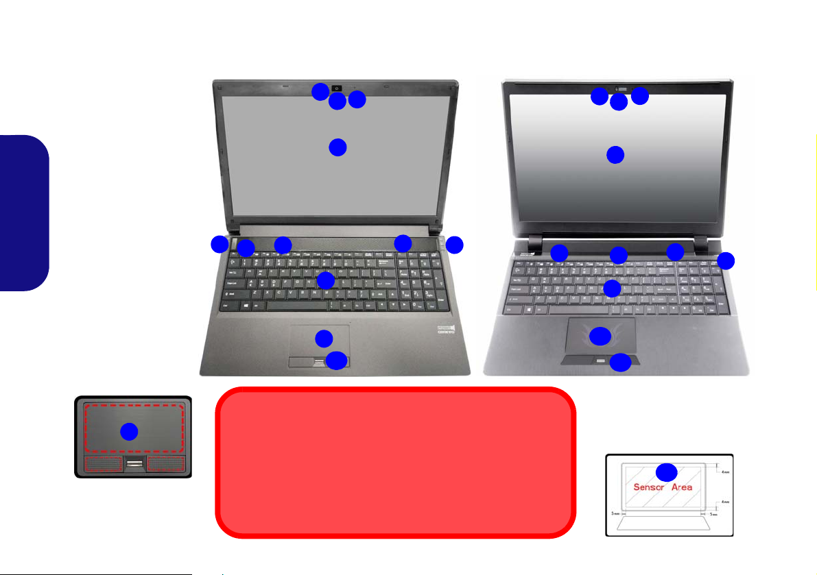
Systemübersicht: Ansicht von vorne mit geöffnetem LCD-Bild-
9
Die Benutzung drahtlos angeschlossener Geräte in Flugzeugen
In der Regel ist die Benutzung jeglicher tragbarer elektronischer
Funkgeräte in Flugzeugen verboten.
Stellen Sie sicher, dass das WLAN- und das Bluetooth-Modul durch
Aktivieren des Flugzeugmodus ausgeschaltet sind, wenn Sie sich
an Bord eines Flugzeugs befinden.
Beachten Sie, dass der Funktionsbereich des Touchpads
und der Tasten innerhalb der
rot gepunkteten Linien liegt.
Modelle A, C & D
15,6” (39,62cm)
Modell B
15,6” (39,62cm)
Abb. 5 - Ansicht von
vorne mit geöffnetem
LCD-Bildschirm
(
Modelle A, B, C & D)
1. PC-Kamera
2. *LED der PC-Kamera
*Wenn die PC-Kamera
verwendet wird, leuchtet die LED rot.
3. Mikrofon
4. LCD-Bildschirm
5. Lautsprecher
6. Netzschalter
7. LED-Statusanzeigen
8. Tastatur
9. Touchpad mit Tasten
10. Beleuchtete Touchpad
mit Tasten
11. Fingerabdruckleser
(optional)
Beachten Sie, dass das beleuchtete Touchpad einen definierten
Empfindlichkeitsbereich hat, der in
der Abbildung unten dargestellt ist.
10
2
1
8
6
5
7
5
3
2
1
3
8
5
6
4
11
4
7
11
5
10
9
7
schirm (Modelle A, B, C & D)
Deutsch
54
Page 61
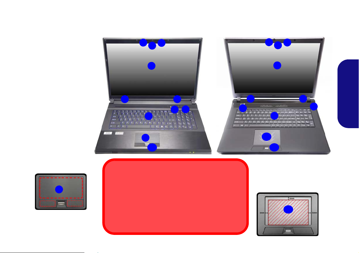
Systemübersicht: Ansicht von vorne mit geöffnetem LCD-Bild-
Die Benutzung drahtlos angeschlossener Geräte in
Flugzeugen
In der Regel ist die Benutzung jeglicher tragbarer elektronischer Funkgeräte in Flugzeugen verboten.
Stellen Sie sicher, dass das WLAN- und das Bluetooth-Modul
durch Aktivieren des Flugzeugmodus ausgeschaltet sind,
wenn Sie sich an Bord eines Flugzeugs befinden.
Abb. 6
Ansicht von vorne mit geöffnetem LCD-Bildschirm
(Modelle E & F)
1. PC-Kamera
2. *LED der PC-Kamera
*Wenn die PC-Kamera
verwendet wird, leuchtet
die LED rot.
3. Mikrofon
4. LCD-Bildschirm
5. Lautsprecher
6. Netzschalter
7. LED-Statusanzeigen
8. Tastatur
9. Touchpad mit Tasten
10. Beleuchtete Touchpad
mit Tasten
11. Fingerabdruckleser
(optional)
2
1
8
9
7
4
5
Modell E
3
5
11
17,3” (43,94cm)
4
6
5
2
1
8
7
Modell F
3
5
11
17,3” (43,94cm)
4
6
5
10
Beachten Sie, dass das beleuchtete Touchpad einen definierten
Empfindlichkeitsbereich hat, der in
der Abbildung unten dargestellt ist.
10
9
Beachten Sie, dass der Funktionsbereich des Touchpads
und der Tasten innerhalb der
rot gepunkteten Linien liegt.
schirm (Modelle E & F)
Deutsch
55
Page 62

LED-Anzeigen
Die LED-Anzeigen auf dem Computer zeigen wichtige
Informationen über den aktuellen Status des Computers.
Symbol Farbe Beschreibung
Symbol Farbe Beschreibung
Blaw/ Weiß Die Nummerntastatur ist aktiviert
Blaw/ Weiß Caps-Lock ist aktiviert
Blaw/ Weiß Scroll-Lock ist aktiviert
Deutsch
Blaw/ Weiß
Blaw/ Weiß
Aus Integrierte GPU (iGPU) von Intel aktiviert
Blaw/ Weiß
Es wird auf die Festplatte/das optische
Laufwerk zugegriffen
Flugzeugmodus ist EIN (das WLAN- und
das Bluetooth-Modul ausgeschaltet sind)
Diskrete GPU (dGPU) von NVIDIA
Tabelle 3 - LED-Statusanzeigen
aktiviert
Orange
Lampe blinkt
Orange*
Grün Der Computer ist angeschaltet
Lampe blinkt
grün
Orange Der Akku wird geladen
Grün Der Akku ist voll geladen
Lampe blinkt
orange
Der AC/DC-Adapter ist angeschlos-
sen
Wenn der AC/DC-Adapter ange-
schlossen wird, ist der USB-
Anschluss eingeschaltet*
Das System ist im konfigurierten
Energiesparmodus
Der Akku hat einen kritisch niedrigen
Stromstatus erreicht
Tabelle 4 - LED-Stromanzeigen
*Der eingeschaltete USB 3.0 Anschluss kann mit der
Tastenkombination Fn + Netzschalter ein- bzw. ausgeschal-
tet werden. Wenn der eingeschaltete USB Anschluss eingeschaltet ist, kann er andere Geräte auch bei ausgeschaltetem
System mit Strom versorgen (jedoch nur zum Aufladen,
nicht für den Betrieb der Geräte), sofern das System mit
dem AC/DC-Adapter mit dem Stromnetz verbunden oder
über einen Akku mit mehr als 20 % Ladung mit Strom versorgt wird (die Stromversorgung kann bei bestimmten Geräten u. U. nicht funktionieren - siehe Seite 89).
56
Page 63

Numeric
Funktionstasten
Nummemtastatur
Fn Taste
Num & Rollen
Funktionstasten
Nummemtastatur
Fn Taste
Num & Rollen
Modelle C & D
Modelle A, B, E & F
Windows-Logo-Taste
Windows-Logo-Taste
Tastatur & Funktionstasten
Die Tastatur hat eine eingebettete Nummerntastatur für einfache Zahleneingabe. Durch Drücken auf Fn + Num wird die
Nummerntastatur ein- und ausgeschaltet. Zusätzlich gibt es Funktionstasten, über die Sie direkt zwischen den Funktionen
umschalten können. Wenn die Funktionstasten (F1 - F11) gleichzeitig mit der Fn-Taste gedrückt werden, funktionieren sie
wie Hotkeys. Neben den Tastenkombinationen für die Grundfunktionen gibt es einige visuelle Anzeigen (nur bei der
Windows Desktop-Anwendung, aber nicht im Start-Bildschirm), wenn der Hotkey Treiber installiert ist.
Tasten Funktion/Visuelle Anzeigen Tasten Funktion/Visuelle Anzeigen
Fn + Wiedergabe/Pause (in Audio /Videoprogrammen)
Fn +
Fn +
Fn +
Fn +
Fn +
Fn +
Fn +
Fn +
Stummschaltung/Stummschal-
LCD-Helligkeit verringern/erhö-
Touchpad
aktivieren/deaktivieren
LCD-Hintergrundlicht ausschalten (zum Einschalten
beliebige Taste drücken oder Touchpad berühren)
tung aufheben
Wechsel Schlaf/Wiederaufnahme
Audio-Lautstärke
verringern/erhöhen
Wechseln der Anzeigegerate
hen
PC-Kamera
aktivieren/deaktivieren
Fn +
Fn + /
Fn + /
Fn +
Netzschalter
Fn +
Fn +
Fn +
Tabelle 5 - Funktionstasten & vis ue lle An zeigen
Flugzeugmodus ein-/
ausschalten
Ein-/Ausschalten der
Nummerntastatur
Ein-/Ausschalten des
Scroll-Modus
Ein-/Ausschalten der
Feststelltaste
Ein-/Ausschalten des eingeschalteten USB
Anschlusses (siehe Seite 67)
Ein-/Ausschalten des Control Center (Steuerzent-
rum) (siehe Seite 67)
Ein-/Ausschalten der Tastatur-LED (siehe Seite 58)
Automatische Lüfter-
steuerung/Volle Leistung
57
Deutsch
Page 64
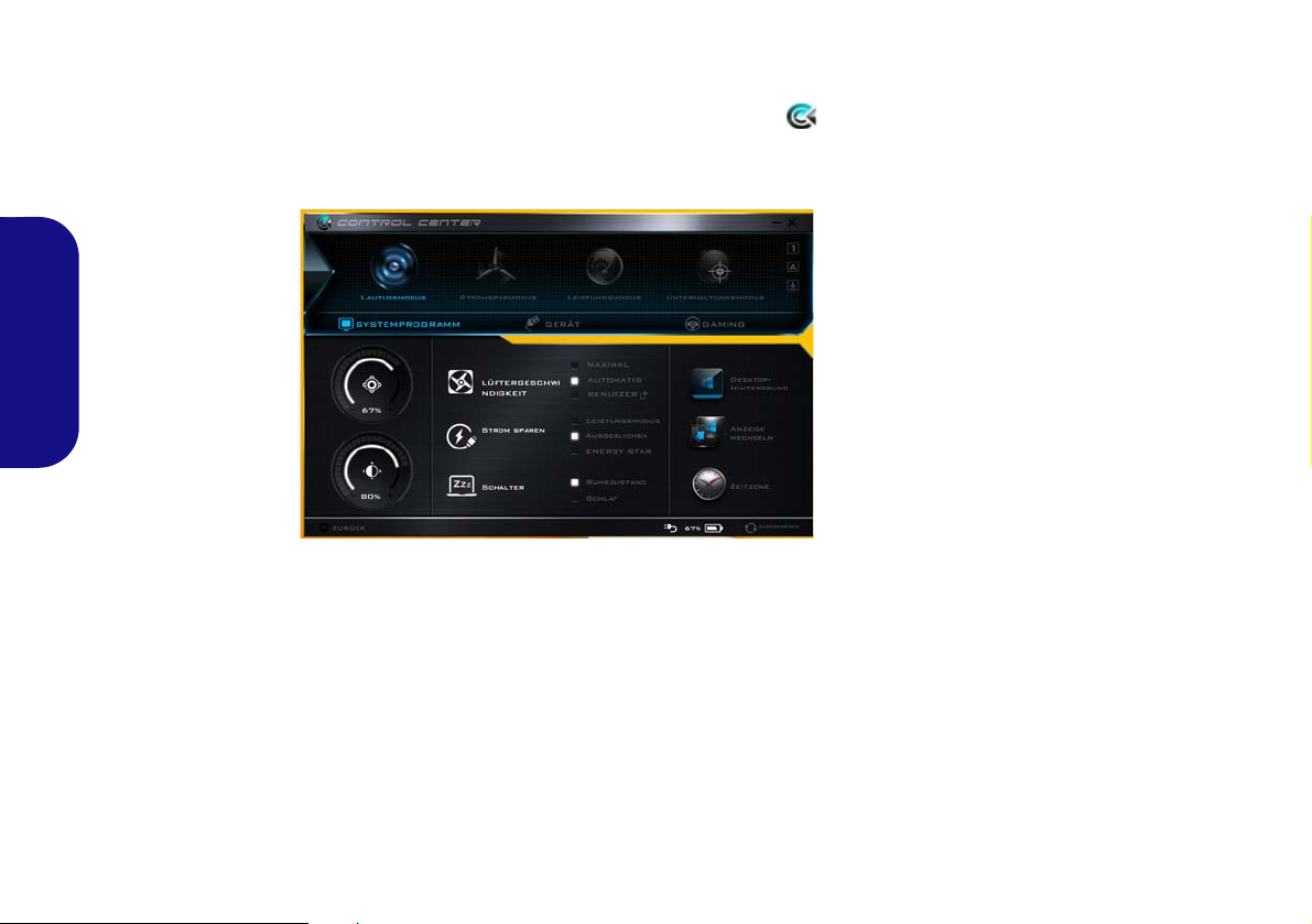
Control Center
Abb. 7
Control Center
Das Control Center in Windows 8.1 funktioniert in der Desktop App und nicht auf dem Start-Bildschirm. Drücken Sie auf
die Tastenkombination Fn + Esc, oder doppelklicken Sie auf das Symbol im Infobereich auf der Taskleiste um das
Control Center ein-/auszuschalten. Das Control Center bietet den schnellen Zugriff auf häufig verwendete Funktionen, und
Sie haben hier die Möglichkeit, das Touchpad/das Kamera-Modul direkt ein-/auszuschalten.
Deutsch
Energiemodi
Sie können einen Energiemodus einstellen, indem Sie im Control Center auf das entsprechende Symbol klicken. Jeder
Energiemodus wird Einfluss auf den Energiesparmodus, Flugzeugmodus, Energiesparpl an und PC Kamerastrom usw. haben.
Control Center Menüs
Das Control Center umfasst 3 Menütitel (Systemprogramm, Gerät und Gaming) für die Strommodi. Klicken Sie auf die
Symbole des Control Center, um die entsprechende Funktion zu wählen, oder halten Sie die Maustaste gedrückt und verschieben Sie den Regler, falls vorhanden. Bestimmte Funktionen werden automatisch angepasst, wenn ein Strommodus ausgewählt ist. Klicken Sie auf die Menütitel und anschließend auf eine der Schaltflächen der folgenden Seite(n).
58
Page 65

Energiestatus /
Das Energiestatus-Symbol zeigt an, ob die Stromversorgung aktuell über den Akku oder über das an das Stromnetz
angeschlossene Netzteil erfolgt. Die Energiestatus-Anzeige
zeigt den aktuellen Akkuladestatus an.
Helligkeits
Das Helligkeits-Symbol zeigt die aktuell eingestellte Bildschirmhelligkeit an.Sie können die Bildschirmhelligkeit entweder mit dem Schieberegler oder mit der
Tastenkombination Fn + F8/F9 ändern. Mit der
Tastenkombination Fn + F2 wird das LED-Hintergrundlicht
ausgeschaltet (drücken Sie auf eine beliebige Taste, um es
wieder einzuschalten). Beachten Sie, dass die Bildschirmhelligkeit auch vom eingestellten Energiemodus abhängt.
Lautstärke
Das Lautstärke-Symbol zeigt die aktuelle Lautstärke an.Sie
können die Lautstärke entweder mit dem Schieberegler oder
mit der Tastenkombination Fn + F5/F6 einstellen. Mit der
Tastenkombination Fn + F3 wird der Ton ausgeschaltet.
Strom sparen
Dieses System unterstützt die Energy Star-Stromsparfunktionen, die Computer (CPU, Festplatte usw.) nach einer
längeren Zeit der Inaktivität in einen Ruhemodus versetzen,
bei dem weniger Strom verbraucht wird. Klicken Sie entweder auf die Taste Leistungsmodus, Ausgeglichen oder
Energy Star.
Lüftergeschwindigkeit
Die Lüftergeschwindigkeit wird sich automatisch einstellen,
um die Temperatur der CPU zu regeln. Sie können die Einstellung nach Bedarf auch auf die maximale Einstellung anpassen. Wählen Sie Benutzer und klicken Sie auf die Regler,
um die Einstellungen nach Ihren Wünschen anzupassen.
Diese Einstellungen können allerdings als Sicherheitsvorkehrung vom System überschrieben werden, wenn Sie den
Lüfter zu stark beanspruchen.
Schalter
Klicken Sie entweder auf die Schaltfläche Ruhezustand
oder Schlaf, um den Computer der aus gewählten Stromsparmodus aufrufen zu lassen.
Anzeige wechseln
Klicken Sie auf die Taste zum Wechseln des Anzeigegeräts,
um das Menü aufzurufen (Sie können dazu auch die
Tastenkombination und P verwenden), und wählen Sie
einen Anzeigemodus aus.
Zeitzone
Wenn Sie auf die Schaltfläche Zeitzone klicken, wird das
Windows-Systemsteuerungsfenster Datum und Uhrzeit
aufgerufen.
Deutsch
59
Page 66

Desktop-Hintergrund
Wenn Sie auf die Schaltfläche Desktop-Hintergrund klikken,
können Sie das Bild für den Desktophintergrund einstellen.
Beleuchtete Tastatur
Touchpad/PC-Kamera-Modul
Klicken Sie auf eine dieser Tasten, um das Touchpad oder
das Kamera-Modul ein- oder auszuschalten. Beachten Sie,
dass der Energiestatus des Kamera-Moduls auch vom ausgewählten Energiemodus abhängen.
Linke Windows Taste
Deutsch
Klicken Sie auf Deaktiviere, um die Windows-Taste auf der
linken Seite der Tastatur zu deaktivieren. Dies könnte hilfreich sein, wenn Sie die Gaming-Tasten (W, A, S & D) benutzen und eine versehentliche Aktivierung von Menüs über
die Windows-Taste vermeiden möchten.
Kopfhörer
Die Kopfhörer können in diesem Menü für verschiedene
Effekte eingestellt werden.
Klicken Sie auf die Zahlen unter den Beleuchtete Tastatursymbol, um die Helligkeit der Tastatur-HintergrundlichtLED anzupassen.
Flexikey®
Klicken Sie auf die Schaltfläche, um auf die Flexikey® An-
wendung zuzugreifen.
60
Page 67

Flexikey® Anwendung
Das verwendete Flexikey® Profil aktivieren oder deaktivieren
Sie können jede gegenwärtig verwendete Tastatur- oder
Mausprofilfunktion aktivieren oder aktivieren, indem Sie auf
Fn + drücken. Wenn Sie diese Tastenkombination
drücken, können Sie zwischen den aktuell ausgewählten Tastatur- oder Mausprofilen zur Standard Tastatur- bzw. Mauseinstellungen und wieder zurück wechseln.
Windows Taste und P Taste
Beachten Sie, dass Sie Aktionen für jede Taste zuweisen
können, außer der Windows Taste und P Taste.
Abb. 8
Flexikey® Anwendung
“Flexikey®” ist eine Direkttasten-Konfigurationsan-
wendung, mit der Sie eine Einzeltaste für das Ausführen
mehrerer Tastenkombinationen zuweisen können, oder
um Programme und Anwendungen auszuführen, um
Textmakros zu erstellen und um bestimmte Tasten zu deaktivieren. Die Anwendung kann auch zum Konfigurieren der
Maustasten zum Erstellen von Direkttasten für Gaming
usw. verwendet werden. Sämtliche Konfigurationseinstellungen werden unter (bis zu 12) Profilen gespeichert, für
welche die Einstellungen angewendet werden. Die Flexi-
key® Anwendung kann durch Klicken der Schaltfläche
im Gaming Abschnitt des Control Center oder durch Klikken des Symbols
Taskleiste aufgerufen werden.
im Infobereich auf der Desktop-
Profile
Die Menüs auf der linken Seite der Anwendung gelten für
Profile. Sie können Profile in den Menüs Hinzufügen oder
Löschen (Sie können 12 aktive Profile speichern), Exportieren und Importieren. Wenn Sie doppelt auf ein Profil
klicken, können Sie den Profilnamen und eine Bild Datei
ändern (mit PNG Dateien erstellte Bilder).
Deutsch
Tastatur- und Mauseinstellungen
Klicken Sie auf Aktivieren, um Einstellungen für die Tastatur bzw. Maus zu erstellen, indem Sie auf die Taste ganz
links klicken (z.B. wenn Sie ein Profil nur mit Einstellungen
die Maus oder Tastatur erstellen möchten). Wenn Sie auf die
Tastatur- oder Maussymbole klicken, können Sie auf die
Einstellungsseite für die Tastatur oder Maus zugreifen.
Abb. 9 - Aktivieren (Tastatur & Maus)
61
Page 68

Deutsch
Abb. 10 - Tastaturkonfiguration
12345
Abb. 11 - Mauskonfiguration
Tastatureinstellungen
Die Tastatureinstellungen erlauben die Konfiguration von
Aktionen für jede einzelne Taste (oder einer Kombination
von Tasten). Klicken Sie auf die Taste und wählen Sie anschließend Aktionstyp (Express-Taste,
APP ausführen,
Express-Text oder Deaktivieren) aus dem Menü unten auf
der Seite aus. Sie können die Aktion umbenennen, indem Sie
auf das Kästchen Name und Quick-Infos klicken, um eine
Notiz zu tippen, die Sie an die Funktion der Aktion erinnert.
Mauseinstellungen
Die Mauseinstellungen ermöglichen Ihnen die Konfigurationen von Aktionen für die linke , rechte und mittlere Taste jeder angeschlossenen Maus, sowie für die
Zurück - und Vorwärtstasten falls verfügbar (bei einer
Gaming-Maus). Klicken Sie auf die Tastennummer und
wählen Sie anschließend Aktionstyp (Express-Taste,
APP
ausführen, Express-Text oder Deaktivieren) aus dem
Menü unten auf der Seite aus. Sie können die Aktion
umbenennen, indem Sie auf das Kästchen Name und Quick-
62
Infos klicken, um eine Notiz zu tippen, die Sie an die Funktion der Aktion erinnert.
Flexikey® Anwendungsfunktionen:
• Express-Taste - Diese Funktion ermöglicht Ihnen die Konfigu-
ration einer einzelnen Taste (oder Mausklick) für das Senden
mehrerer Tastenkombinationen. Dies ist praktisch beim Gaming
oder wenn Sie Anwendungen mit vielen Tastaturkürzeln verwenden.
• APP ausführen - Hiermit werden Einzeltasten (oder Maus-
klicks) für den Start von ausführbaren Dateien von Programmen
oder Anwendungen zugewiesen.
• Express-Text - Hiermit können Sie einzelne Tasten (oder Maus-
klicks) für das Senden von häufig genutzten Textstrings zuweisen.
ktivieren - Mit dieser Funktion können Sie sämtliche
• Dea
Tastaturtasten oder Maustasten deaktivieren.
• Statistik - Verwenden Sie dies zur schnellen Aufnahme von
Tasten für jede Anwendung und zum Deaktivieren von nicht
verwendeten Tasten.
Page 69

Tastatureinstellungen - Express-Taste
Abb. 12
Tastatur -
Express-
Taste
Wenn Sie eine einzelne Taste für das Senden mehrerer
Tastenkombinationen konfigurieren möchten, oder um nützlichere Tastenkürzel zu erstellen, verwenden Sie Express-
Taste.
1. Aktivieren und wählen Sie die Tastatur unter Ihrem ausgewählten
Profil aus, klicken Sie zur Auswahl auf eine Taste und wählen Sie
anschließend Express-Taste unter Aktionstyp aus.
2. Im folgenden Beispiel möchten wir eine bestehende
Spieltastenkombination, welche die linke Umschalttaste zum
Sprinten und die W Taste zum Vorwärtsbewegen verwendet, auf
die linke Strg-Taste legen, um diese Bewegung als vorwärts
sprinten miteinander zu kombinieren.
3. Klicken Sie auf die gewünschte Taste für die verknüpfte Aktion.
4. Klicken Sie auf das Quick-Infos Feld und geben Sie der
Tastenkombinationen einen Namen, z.B. “Vorwärts sprinten”.
Klicken Sie anschließend wieder in das Feld Name (um zu
vermeiden, dass die gespeicherten Tasten zum Quick-Info
hinzugefügt werden).
5. Klicken Sie auf Aufnahme starten und drücken Sie anschließend
auf die erforderliche Taste oder Tasten (in diesem Fall drücken wir
die linke Umschalttaste und W) (stellen Sie sicher, dass Sie
erforderliche(n) Taste(n) drücken und nicht anklicken).
6. Klicken Sie auf Aufnahme stoppen, um den Vorgang
abzuschließen.
8. Wenn Sie eine einzelne Taste entfernen möchten, klicken Sie zur
Auswahl auf die Taste, und klicken Sie auf Löschen.
9. Wenn Sie sämtliche Einstellungen löschen möchten, klicken Sie
auf Wiederherstellen, um zu den Standard Tasteneinstellungen
zurückzukehren.
10. Jede zugewiesene Express-Taste wird in Orange angezeigt.
Tastatureinstellungen - APP ausführen
Sie können Tasten für den Start von Anwendungen und Programmen wie folgt konfigurieren:
1. Aktivieren und wählen Sie die Tastatur unter Ihrem ausgewählten
Profil aus, klicken Sie zum Auswahl einer Taste, um die
Anwendung zu starten und wählen Sie anschließend APP aus-
führen unter Aktionstyp aus.
2. Klicken Sie auf Durchsuchen unten rechts im
Anwendungsfenster.
Deutsch
7. Klicken Sie auf Speichern, um die Einstellungen in Ihrem
gewählten Profil zu speichern.
Abb. 13 - Tastatur - APP ausführen
3. Navigieren Sie zur ausführbaren Datei der Anwendung und
klicken Sie auf Öffnen.
63
Page 70

4. Die Taste wird jetzt zum Öffnen der ausgewählten Anwendung in
Ihrem ausgewählten Profil konfiguriert und die Taste in Grün
angezeigt.
5. Wenn Sie eine APP ausführen Taste entfernen möchten, wählen
Sie sie aus und klicken Sie auf Wiederherstellen.
6. Klicken Sie auf Speichern, um die Einstellungen in Ihrem
gewählten Profil zu speichern.
5. Die Taste wird jetzt zum Senden von Textnachrichten im
Zielprogramm in Ihrem ausgewählten Profil konfiguriert und die
Taste in Blau angezeigt.
6. Wenn Sie eine Express-Text Taste entfernen möchten, wählen
Sie sie aus und klicken Sie auf Wiederherstellen.
7. Klicken Sie auf Speichern, um die Einstellungen in Ihrem
gewählten Profil zu speichern.
Tastatureinstellungen - Express-Text
Eine Einzeltaste kann für das Senden eines Textstrings innerhalb jeder Anwendung mit Express-Text eingestellt werden.
1. Aktivieren und wählen Sie die Tastatur unter Ihrem ausgewählten
Profil aus, klicken Sie zur Auswahl auf eine Taste und wählen Sie
Deutsch
anschließend Express-Text unter Aktionstyp aus.
2. Klicken Sie ggf. auf die Starttaste (die Starttaste ist die Taste, die
in Ihrem Zielprogramm verwendet wird, um eine Textnachricht zu
öffnen), oder Sie können dies auch frei lassen.
3. Klicken Sie in das Textnachrichten Feld und geben Sie Ihre
Nachricht ein.
Abb. 14 - Tastatur - Express-Text
4. Klicken Sie ggf. auf Versandtaste (die Versandtaste ist die Taste,
die in Ihrem Zielprogramm verwendet wird, zum Senden einer
Textnachricht z.B. wird die Enter-Taste dafür am häufigsten
verwendet, oder Sie können dies auch frei lassen.
64
Tastatureinstellungen - Deaktivieren
Sie können das Programm verwenden, um nicht benötigte
Tasten zu deaktivieren.
1. Aktivieren und wählen Sie die Tastatur unter Ihrem ausgewählten
Profil aus, klicken Sie zur Auswahl einer Taste, die deaktiviert werden soll und wählen Sie anschließend Deaktivieren unter
Aktionstyp aus.
2. Die Taste wird jetzt deaktiviert.
3. Wenn Sie die Taste erneut aktivieren möchten, wählen Sie sie aus
und klicken Sie auf Wiederherstellen.
4. Klicken Sie auf Speichern, um die Einstellungen in Ihrem
gewählten Profil zu speichern.
5. Die Taste wird jetzt deaktiviert unter Ihrem ausgewählten Profil
und die Taste in Grau angezeigt.
Page 71

Tastatur-LED
123
4
1
4
3
2
Abb. 15
Tastatur-Hinter-
grundlichtan-
wendung
(Nur Modelle A, B, E & F)
Drücken Sie auf die Fn- und die -Taste, um die Tast aturLED ein-/auszuschalten. Die Tastatur-LED kann mit einer
Tastenkombination aus Fn + beliebiger Taste wie unten beschrieben konfiguriert werden. Drücken Sie die Fn-Taste
gleichzeitig mit der -Taste zum Starten des Hintergrundlichts, um die Einstellungen zu konfigurieren.
Tastatur-LED Funktionstastenkombinationen
Tastatur-Hintergrundlichtanwendung
Die Tastatur-Hintergrundlichtanwendung kann durch Drükken von Fn und der -Taste (oder durch Klicken der
Schaltfläche im Gaming Abschnitt des Control Center)
aufgerufen werden.
Deutsch
Fn +
Fn +
Fn +
Fn +
Startet die Anwendung für das Tastatur-Hintergrundlicht
Schaltet das Tastatur-Hintergrundlicht ein/aus
Tastatur-LED Beleuchtung verringern
Tastatur-LED Beleuchtung erhöhen
Modi
Mit den Schaltflächen neben dem Muster können Sie die
Effekte der Tastatur-Hintergrundbelichtung ändern. Klicken
Sie auf eine der Schaltflächen, um die Effekte auf der Tastatur zu sehen. Klicken Sie auf Save (Speichern) wenn Sie
Fn +
Fn +
Fn +
Fn +
Touchpad-LED ein/aus (bei Modellen mit beleuchte-
Linke Tastatur-LED ein/aus
Mittlere Tastatur-LED ein/aus
Rechte Tastatur-LED ein/aus
tem Touchpad)
Tabelle 6 - Tastatur-LED
die Anwendung verlassen, um die Einstellung beizubehalten.
Modusschaltflächen
Zufallsfarbe
Custom (Benutzerdefiniert):
Tastaturbereiche und –farben
anzeigen und konfigurieren
Atem (alle Farben) Taktschlag
Zyklus
Tabelle 7 - Modusschaltflächen
Auf- und Abbe-
wegung
Tanzeffekt
Blinken
65
Page 72

Brightness (Helligkeits)
Abb. 17
Preview
(Vorschau)
Abb. 18
Tastatur
Abschnitte
Klicken Sie auf eine der Zahlen (0 - 3) auf der Helligkeitsleiste, um die Helligkeitsstufe der Hintergrundbeleuchtung
einzustellen.
Color Swatch (Farbmuster)
Über das Farbmuster oben rechts können Sie eine Reihe von
Farben für die Hintergrundbeleuchtung auswählen, indem
Sie auf die gewünschte Farbe klicken. Sie können das Farbmuster entweder in Vollfarben oder als ein 256 Farbschema
anzeigen lassen. Klicken Sie auf die Modustaste Custom
(Benutzerdefiniert) um vom Swatch Farben auszuwählen
und diese Bereichen der Tastatur (und des Touchpads, falls
Deutsch
verfügbar) zuzuweisen.
Preview (Vorschau)
Im unteren linken Abschnitt der Anwendung können Sie die
an Farben vorgenommenen Änderungen für die Tastatur und
das Touchpad (falls verfügbar) sehen.
Tastatur (und Touchpad) Abschnitte
Im unteren rechten Abschnitt der Anwendung können Sie
Teilbereiche oder sämtliche Bereiche der Tastatur (und des
Touchpad falls vorhanden) auswählen, in denen die Farbänderungen und Effekte angewendet werden.
Sätze
In der Anwendung können bis zu 3 Sätze von Farb- und
Effektkombinationen gespeichert werden. Klicken Sie auf
Save (Speichern) wenn Sie die Anwendung verlassen, um
die Einstellung beizubehalten.
66
Abb. 16 - Color Swatch (Farbmuster)
Save (Speichern) & Exit (Beenden)
Klicken Sie auf Exit (Beenden), um die Anwendung ohne
speichern zu beenden oder auf Save (Speichern), um die Anwendung zu beenden und die Einstellungen beizubehalten.
Page 73

Systemübersicht:
5
8
6
7
1
2
3
10
11
13
12
USB
Die USB 3.0 Anschlüsse sind blau. Die Datenübertragung ist bei USB 3.0 viel schneller als bei USB
2.0, und USB 3.0 ist rückwärts kompatibel mit USB 2.0. Wenn der eingeschaltete USB 3.0 Anschluss
eingeschaltet ist, kann er andere Geräte auch bei ausgeschaltetem System mit Strom versorgen
(jedoch nur zum Aufladen, nicht für den Betrieb der Geräte), sofern das System mit dem AC/DCAdapter mit dem Stromnetz verbunden oder über einen Akku mit mehr als 20 % Ladung mit Strom
versorgt wird (die Stromversorgung kann bei bestimmten Geräten u. U. nicht funktionieren - siehe
Seite 89). Dieser Anschluss wird mit der Tastenkombination Fn + Netzschalter eingeschaltet.
4
9
4
15
17
14
16
16
18
19
Abb. 19
Ansicht von vorne, links,
rechts und hinten (Modelle
A, C & D)
1. LED-Stromanzeigen
2. Mini-IEEE 1394a Anschluss
3. RJ-45 LAN-Buchse
4. Eingeschaltete USB 3.0
Anschluss (Siehe folgenden
Hinweis)
5. USB 3.0 Anschluss
6. Kombinierter eSATA/USB
3.0 Anschluss
7. Multi-in-1 Kartenleser
8. Schacht für optisches
Laufwerk
9. Notauswurfloch
10. Kopfhörer-Ausgangsbuchse
11. Mikrofon-Eingangsbuchse
12. S/PDIF-Ausgang-Buchse
13. Line-Eingangsbuchse
14. USB 2.0 Anschluss
15. Sicherheitsschloß-Buchse
16. Luftungsoffnung
17. DisplayPort
18. HDMI-Ausgangsanschluss
19. Mini DisplayPort
20. DC-Eingangsbuchse
Vorderseite
Linke Seite
Rechte Seite
Hinterseite
20
(Modelle A, C & D)
Ansicht von vorne, links, rechts und hinten
Deutsch
67
Page 74

Systemübersicht:
USB
Die USB 3.0 Anschlüsse sind blau. Die Datenübertragung ist bei USB 3.0 viel schneller als bei USB
2.0, und USB 3.0 ist rückwärts kompatibel mit USB 2.0. Wenn der eingeschaltete USB 3.0 Anschluss
eingeschaltet ist, kann er andere Geräte auch bei ausgeschaltetem System mit Strom versorgen
(jedoch nur zum Aufladen, nicht f ür den B etrieb der Geräte), sofern das System mit dem AC/DCAdapter mit dem Stromnetz verbunden oder über einen Akku mit mehr als 20 % Ladung mit Strom
versorgt wird (die Stromversorgung kann bei bestimmten Geräten u. U. nicht funktionieren - siehe
Seite 89). Dieser Anschluss wird mit der Tastenkombination Fn + Netzschalter eingeschaltet.
4
Abb. 20
Ansicht von vorne, links,
rechts und hinten (Modell B)
1. LED-Stromanzeigen
2. Mini-IEEE 1394a Anschluss
3. RJ-45 LAN-Buchse
4. Eingeschaltete USB 3.0
Anschluss (Siehe folgenden
Hinweis)
5. USB 3.0 Anschluss
6. Kombinierter eSATA/USB
3.0 Anschluss
7. Multi-in-1 Kartenleser
8. Schacht für optisches
Laufwerk
9. Notauswurfloch
10. Kopfhörer-Ausgangsbuchse
11. Mikrofon-Eingangsbuchse
12. S/PDIF-Ausgang-Buchse
13. Line-Eingangsbuchse
14. USB 2.0 Anschluss
15. Sicherheitsschloß-Buchse
16. Luftungsoffnung
17. DisplayPort
18. HDMI-Ausgangsanschluss
19. Mini DisplayPort
20. DC-Eingangsbuchse
5
8
6
7
1
2
3
10
11
13
12
9
4
15
17
14
16
20
18
19
16
Vorderseite
Linke Seite
Rechte Seite
Hinterseite
(Modell B)
Ansicht von vorne, links, rechts und hinten
Deutsch
68
Page 75
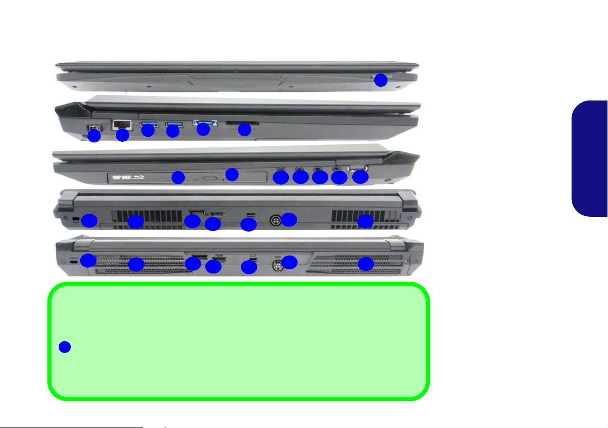
Systemübersicht:
Abb. 21
Ansicht von vorne, links,
rechts und hinten (Modelle E
& F)
1. LED-Stromanzeigen
2. Mini-IEEE 1394a Anschluss
3. RJ-45 LAN-Buchse
4. Eingeschaltete USB 3.0
Anschluss (Siehe folgenden
Hinweis)
5. USB 3.0 Anschluss
6. Kombinierter eSATA/USB
3.0 Anschluss
7. Multi-in-1 Kartenleser
8. Schacht für optisches
Laufwerk
9. Notauswurfloch
10. Kopfhörer-Ausgangsbuchse
11. Mikrofon-Eingangsbuchse
12. S/PDIF-Ausgang-Buchse
13. Line-Eingangsbuchse
14. USB 2.0 Anschluss
15. Sicherheitsschloß-Buchse
16. Luftungsoffnung
17. DisplayPort
18. HDMI-Ausgangsanschluss
19. Mini DisplayPort
20. DC-Eingangsbuchse
5
7
8
1
2
3
10
12
11
4
14
16
13
15
20
17
18
19
6
9
16
16
15
20
17
18
19
16
USB
Die USB 3.0 Anschlüsse sind blau. Die Datenübertragung ist bei USB 3.0 viel schneller als bei USB
2.0, und USB 3.0 ist rückwärts kompatibel mit USB 2.0. Wenn der eingeschaltete USB 3.0 Anschluss
eingeschaltet ist, kann er andere Geräte auch bei ausgeschaltetem System mit Strom versorgen
(jedoch nur zum Aufladen, nicht für den Betrieb der Geräte), sofern das System mit dem AC/DCAdapter mit dem Stromnetz verbunden oder über einen Akku mit mehr als 20 % Ladung mit Strom
versorgt wird (die Stromversorgung kann bei bestimmten Geräten u. U. nicht funktionieren - siehe
Seite 89). Dieser Anschluss wird mit der Tastenkombination Fn + Netzschalter eingeschaltet.
4
Vorderseite
Linke Seite
Rechte Seite
Hinterseite (Modell F)
Hinterseite (Modell E)
Ansicht von vorne, links, rechts und hinten
(Modelle E & F)
Deutsch
69
Page 76

Systemübersicht:
3
2
1
4
6
1
1
1
3
2
1
6
1
1
1
5
1
Hinweis zum Akku
Ein neuer Akku sollte bei seiner ersten Verwendung zuerst
einmal vollständig entladen und dann komplett wieder
geladen werden. Entladen und laden Sie den Akku mindestens einmal im Monat oder nach etwa 20 Teilentladungen
einmal
vollständig (siehe das erweiterte Benutzerhandbuch
auf der Disc Device Drivers & Utilities + User's Manual).
Anzeigegeräte
Neben dem integrierten LCD-Monitor können Sie auch einen
externen Flachbildschirm oder ein Fernsehgerät (an den
HDMI-Ausgangsanschluss/DisplayPort/Mini DisplayPort
angeschlossen) als Anzeigegerät anschließen.
Abb. 22
Ansicht von unten
(
Modelle A, B, C & D)
1. Luftungsoffnung
2. Komponentenfachabdekkung
3. Subwoofer
4. HDD-Schacht
5. HDD/ODD-Schacht
6. Akku
CPU
Die CPU darf nicht vom Anwender repariert werden.
Jeglicher Zugriff auf die CPU
führt zum Verlust der Garantieansprüche.
Überhitzung
Zum Schutz vor Überhitzung
Ihres Computers dürfen die
Luftungsoffnung(en) nicht
während das Notebook in Betrieb ist verdeckt werden.
Modelle A, C & D
Modell B
Ansicht von unten (Modelle A, B, C & D)
Deutsch
70
Page 77

Systemübersicht:
Hinweis zum Akku
Ein neuer Akku sollte bei seiner ersten Verwendung zuerst
einmal vollständig entladen und dann komplett wieder
geladen werden. Entladen und laden Sie den Akku mindestens einmal im Monat oder nach etwa 20 Teilentladungen
einmal
vollständig (siehe das erweiterte Benutzerhandbuch
auf der Disc Device Drivers & Utilities + User's Manual).
Anzeigegeräte
Neben dem integrierten LCD-Monitor können Sie auch einen
externen Flachbildschirm oder ein Fernsehgerät (an den
HDMI-Ausgangsanschluss/DisplayPort/Mini DisplayPort
angeschlossen) als Anzeigegerät anschließen.
Abb. 23
Ansicht von unten
(Modelle E & F)
1. Luftungsoffnung
2. Komponentenfachabdekkung
3. Subwoofer
4. HDD-Schacht
5. Akku
6. Zweite HDD-Schacht
CPU
Die CPU darf nicht vom Anwender repariert werden.
Jeglicher Zugriff auf die CPU
führt zum Verlust der Garantieansprüche.
Überhitzung
Zum Schutz vor Überhitzung
Ihres Computers dürfen die
Luftungsoffnung(en) nicht
während das Notebook in Betrieb ist verdeckt werden.
3
2
1
4
5
1
1
1
3
2
1
4
5
1
1
1
6
Modell E
Modell F
6
Ansicht von unten (Modelle E & F)
Deutsch
71
Page 78

Windows 8.1 Start-Bildschirm,
Abb. 24 - Start-Bildschirm (Windows 8.1)
Abb. 25 - Start-Bildschirm mit Charms-Leiste
(Windows 8.1)
Desktop und
Die Apps, Bedienfenster, Dienstprogramme und andere
Software erreichen Sie bei Windows über den Start-Bild-
schirm und/oder die Windows Desktop-App. Der Desktop
(der im Start-Bildschirm eine App startet) wird geöffnet
durch Anklicken des Desktop-Eintrags im Start-Bildschirm
(oder durch Drükken der Tastenkombination Windows-
Logo-Taste + D). Die Taskleiste wird am unteren Rand
des Desktop-Bildschirms angezeigt. Der Infobereich
befindet sich in der rechten unteren Ecke des Bildschirms.
Klicken Sie auf den Pfeil unten auf dem Start-Bildschirm,
Deutsch
um auf die Apps zuzugreifen.
An der rechten Seite des Bildschirms wird die Charms-Leiste
angezeigt. Die Charms-Leiste enthält die Menüs Suchen,
Teilen, Start, Geräte und Einstellungen. Um eines der Me-
nüs aus der Charms-Leiste aufzurufen, bewegen Sie den Cursor in die unteren rechten Ecken des Bildschirms und dann
über den jeweiligen Eintrag in der Charms-Leiste, um diesen
zu aktivieren (ein aktivierter Eintrag wird schwarz dargestellt) oder drücken Sie auf die Tastenkombination
Windows-Logo-Taste + C.
Charms-Leiste
72
Page 79

Windows 8.1 Systemsteuerung
Abb. 26 - Kontextmenü (Windows 8.1)
Verschieben Sie die Maus in die linke untere Ecke
des Bildschirms, und klikken Sie mit der rechten
Maustaste auf die Start-Taste darauf, um das
Menü aufzurufen.
In diesem Handbuch finden Sie eine Anleitung zum Öffnen
der Systemsteuerung. Klicken Sie mit der rechten Maustas-
te auf die Start-Taste
Start-Bildschirm (oder verwenden Sie die Tastenkombina-
tion Windows-Logo-Taste + X), um ein erweitertes
Kontextmenü der nützlichen Funktionen aufzurufen: Systemsteuerung, Programme und Funktionen, Energieoptionen, Task-Manager, Suche, Datei-Explorer,
Eingabeaufforderung, Geräte-Manager, Netzwerkverbindungen usw. Wählen Sie dann Systemsteuerung.
in der Desktop-App oder auf dem
Deutsch
73
Page 80

Grafikfunktionen
Dieses System verfügt sowohl über eine integrierte GPU
von Intel (zum Energie sparen) und eine diskrete GPU von
NVIDIA/diskrete GPU von AMD (für die Leistung). Wenn
der Grafiktreiber installiert ist, können Sie bei Windows im
Einstellfenster Anzeige die Anzeigegeräte wechseln und An-
zeigeoptionen konfigurieren.
Microsoft Hybrid Graphics
Microsoft Hybrid Graphics ist eine nahtlose Technologie,
mit der bei längerer Akkubetriebsdauer die höchstmögliche
Leistung des Grafiksystems erreicht wird, ohne manuell die
Einstellungen ändern zu müssen. Der Computer wechselt au-
Deutsch
tomatisch übergangslos zwischen der integrierten UMA
(Unified Memory Architecture) GPU (iGPU) und der diskreten GPU (dGPU), wenn dieses von der verwendeten Anwendung erfordert wird.
So öffnen Sie in Windows das Einstellfenster Anzeige:
1. Rufen Sie die Systemsteuerung auf.
2. Klicken Sie auf Anzeige (Symbol) - im Kategorie Darstellung und
Anpassung.
3. Klicken Sie auf Bildschirmauflösung anpassen/Auflösung
anpassen.
Oder
4. Klicken Sie mit der rechten Maustaste auf den Desktop (der
Desktop wird aufgerufen, indem Sie die Windows Logo-Taste
und gleichzeitig auf D drücken) und dann die Option
Bildschirmauflösung wählen.
5. Wählen Sie aus dem Drop-down-Menü die Bildschirmauflösung .
6. Klicken Sie auf Erweiterte Einstellungen.
So rufen Sie die Steuerung für Intel® HD-Grafik auf:
1. Klicken Sie auf das Symbol (Steuerung für Intel® HD-Grafik) auf
dem Apps-Bildschirm.
Oder
2. Klicken Sie mit der rechten Maustaste auf den Desktop (der
Desktop wird aufgerufen, indem Sie die Windows Logo-Taste
und gleichzeitig auf D drücken) und dann aus dem Menü die
Option Grafikeigenschaften wählen.
Oder
3. Klicken Sie auf das Symbol im Infobereich auf der DesktopTaskleiste und dann aus dem Menü die Option
Grafikeigenschaften wählen.
So öffnen Sie die
1. Rufen Sie die Systemsteuerung auf.
2. Klicken Sie auf NVIDIA Systemsteuerung (Symbol) - im
Kategorie Darstellung und Anpassung.
NVIDIA Systemsteuerung :
Oder
3. Klicken Sie mit der rechten Maustaste auf den Desktop (der
Desktop wird aufgerufen, indem Sie die Windows Logo-Taste
und gleichzeitig auf D drücken) und dann aus dem Menü die
Option NVIDIA Systemsteuerung wählen.
So öffnen Sie das Catalyst Control Center:
1. Klicken Sie auf das Symbol (Catalyst Control Center) auf dem
Apps-Bildschirm.
Oder
2. Klicken Sie doppelt auf das Symbol im Infobereich auf der
Desktop-Taskleiste (der Desktop wird aufgerufen, indem Sie die
Windows Logo-Taste
und gleichzeitig auf D drücken).
74
Page 81

Audiofunktionen
Lautstärkeeinstellung
Die Lautstärke kann auch mit den Lautstärkeeinstellung im
Menü Einstellungen in der Charms-Bar (auf dem StartBildschirm) oder über das Lautsprecher-Symbol in der
Desktop-Taskleiste eingestellt werden.
Die Audioeinstellungen können Sie bei Windows durch Anklicken des Soundsymbols oder des Realtek HD Audio
Manager -Symbols / im Infobereich/in der System-
steuerung aufrufen (wenn Sie mit der rechten Maustaste auf
das Symbol im Infobereich klikken, wird das Audiomenü
aufgerufen). Die Lautstärke können Sie durch Drücken der
Tastenkombination Fn + F5/F6 ändern.
Audio-Setup für HDMI
HDMI unterstützt Video- und Audiosignale. Es gibt Fälle, in
denen Sie in der Systemsteuerung bei Sound manuell die
HDMI-Audioausgabe konfigurieren müssen.
1. Rufen Sie die Systemsteuerung auf.
2. Klicken Sie auf Sound (Hardware und Sound).
3. Klicken Sie auf Wiedergabe (Registerkarte).
4. Das Wiedergabegerät wird ausgewählt.
5. In manchen Fällen muss das Audiogerät ausgewählt werden und
klicken Sie Als Standard (Schaltfläche).
6. Klicken Sie doppelt auf das Gerät, um die Registerkarten aufzurufen.
7. Konfigurieren Sie in den Registerkarten die HDMI-Einstellungen.
8. Klicken Sie auf OK, um das Fenster Sound zu schließen.
Einrichten der Audioaufnahme
Wenn Sie auf Ihrem Computer Audioaufnahmen mit optimaler Qualität machen möchten, führen Sie die folgenden
Schritte aus:
1. Rufen Sie die Systemsteuerung auf.
2. Klicken Sie auf Realtek HD Audio-Manager (oder klicken Sie mit
der rechten Maustaste auf das Symbol
wählen Sie Sound-Manager).
3. Klicken Sie bei Mikrofon (Registerkarte) auf Mikrofoneffekt
(Registerkarte). Klicken Sie dann auf Rauschunterdrückung
(Schaltfläche), oder regeln Sie die Lautstärke bei
Aufnahmelautstärke auf ca. 60. So erhalten Sie eine optimale
Aufnahmequalität.
4. Klicken Sie auf OK, um das Fenster Sound zu schließen.
im Infobereich, und
Einrichten des 5.1 oder 7.1 Surround Sound
Um das System für 5.1 oder 7.1 Surround Sound einzurichten, müssen Sie die Audiokabel an die Anschlüsse LineEingangsbuchse, die Kopfhörer-Ausgangsbuchse, die Mikrofon-Eingangsbuchse und S/PDIF-Ausgangsbuchse (nur
7.1 Lautsprecher) anschließen.
1. Rufen Sie die Systemsteuerung auf.
2. Klicken Sie auf Realtek HD Audio-Manager (oder klicken Sie mit
der rechten Maustaste auf das Symbol
wählen Sie Sound-Manager).
3. Klicken Sie auf Lautsprecher (Registerkarte) und klicken Sie auf
Lautsprecherkonfiguration (Registerkarte).
im Infobereich und
75
Deutsch
Page 82
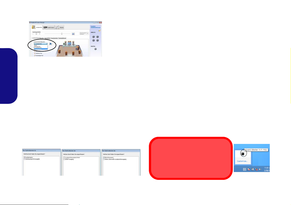
4. Wählen Sie bei Lautsprecherkonfiguration die Option 5.1
Abb. 27
Laut-
sprecherkonfig
uration
Sound Blaster & HDMI
Die Sound Blaster-Audioeffekte können
nicht verwendet werden, wenn der Klang
über einen HDMI-Anschluss erzeugt wird.
Lautsprecher oder 7.1 Lautsprecher.
5. Schließen Sie die Kabel der vorderen Lautsprecher an die
Kopfhörer-Ausgangsbuchse an.
6. Schließen Sie die Kabel an (möglicherweise benötigen Sie einen
Adapter, um die Kabel an die entsprechenden Anschlüsse
anzuschließen (z. B. einen Stereo-mini-auf-dual-RCA-Adapter).
Deutsch
Stellen Sie die folgenden Kabelverbindungen her:
• Line-Eingangsbuchse = Seitenlautsprecherausgabe
• Mikrofon-Eingangsbuchse = Mitten-/Subwoofer-Lautsprecheraus-
gang
• S/PDIF-Ausgang = Lautsprecherausgang hinten (nur 7.1 Laut-
sprecher)
7. Sobald ein Stecker angeschlossen wird, erscheint ein Dialogfeld.
8. Setzen Sie ein Häkchen in die Felder der angeschlossenen
Lautsprecher (z. B. Lautsprecherausgang hinten), und speichern
Sie die Einstellung mit OK.
9. Klicken Sie auf OK, um den Realtek HD Audio-Manager zu
verlassen.
Sound Blaster Audio
Mit der Anwendung Sound Blaster können Sie die Audioeinstellungen nach Ihren Anforderungen konfigurieren, um
eine bestmögliche Audioleistung bei Spielen und der
Wiedergabe von Musik und Videos zu erreichen.
Installation der Anwendung Sound Blaster XFi MB3
1. Klicken Sie auf Option Drivers (Schaltfläche).
2. Klicken Sie auf 7.
3. Wählen Sie eine Sprache und klicken auf Weiter > Ja.
4. Klicken Sie auf Weiter > Vollinstallation
5. Klicken Sie auf Weiter > Fertig stellen, um den
Computer neu zu starten.
Anwendung Sound Blaster X-Fi MB3
Starten Sie das Sound Blaster-Bedienfenster aus dem
Infobereich der Taskleiste heraus (oder über das entsprechende Symbol auf dem Apps-Bildschirm). Klicken Sie
auf die Registerkarten, um in die entsprechenden Menüs des
Bedienfensters zu gelangen.
Install SBX-Fi MB3 AP > Ja.
(Schaltfläche).
Abb. 28 - Entsprechend den angeschlossenen Geräten au-
tomatisch angezeigtes Dialogfeld
76
Abb. 29 - Sound Blaster X-Fi MB3 (Symbol im Infobereich
der Taskleiste)
Page 83

Energieoptionen
Abb. 30 - Energieoptionen
Die Energieoptionen von Windows ermöglichen Ihnen die
Konfiguration der Optionen für das Energiemanagement des
Computers. Sie können Strom sparen, indem Sie Ener-
giesparpläne erstellen und im linken Menü können Sie die
Optionen für den Netzschalter, die Energiespartasten (Fn
+ F4) und Zuklappeinstellung (beim Schließen des
Dekkels) und den Anzeige- und Energiesparmodus (die
Standardeinstellung Energie sparen) konfigurieren.
Beachten Sie, dass sich die Energiesparpläne (Ener-
giesparmodus) auf die Computerleistung auswirken.
Wählen Sie einen bestehenden Plan aus, oder klicken Sie im
linken Menü auf Energiesparplan erstellen, und wählen Sie
die Optionen, um einen neuen Plan zu erstellen. Klicken Sie
auf Energieplaneinstellungen ändern, und klicken Sie auf
Erweiterte Energieeinstellungen ändern, um weitere Optionen für die Konfiguration aufzurufen.
PC-Kamera
Wenn die PC-Kamera verwendet wird, leuchtet die LED links
neben der Kamera rot (siehe Seite 54/Seite 55).
Kamera-App
1. Führen Sie die Kamera-App von dem Start-Bildschirm
aus durch Klicken auf das Kamera-Symbol .
2. Die Kamera-Schnittstelle wird zwei Schaltflächen auf
der rechten Seite des Bildschirms zeigen.
3. Die obere Schaltfläche
Videos aufzunehmen, und die untere Schaltfläche
dient zum Aufnehmen von Standbildern.
4. Rechtsklicken Sie auf den Bildschirm, um die MenüSchaltflächen an der Unterseite des Bildschirms aufzurufen.
5. Diese Schaltflächen ermöglichen es Ihnen, auf die Eigene
Aufnahmen zuzugreifen (wo aufgenommene Bilder und Videos
angezeigt werden), den Timer (der Zeitraum, bevor die Aufnahme
beginnt) einzustellen und die Belichtung mit dem Schieberegler
einzustellen, um die besten Ergebnisse zu erzielen.
Aufnehmen von Bildern/Videos
1. Führen Sie die Kamera-App von dem Start-Bildschirm aus durch
Klicken auf das Kamera-Symbol .
2.
Klicken Sie für die Auswahl des Timers, wenn Sie vor der
Aufnahme einen Countdown benötigen.
3. Wählen Sie den Foto oder Video modus.
4. Klicken Sie auf das passende Symbol, um ein Foto aufzunehmen
oder die Videoaufnahme zu starten (wenn die Videoaufnahme
beginnt, erscheint ein Timer in der unteren rechten Ecke des
Bildschirms).
5. Um die Videoaufnahme zu stoppen, klicken Sie erneut auf das
Hauptfenster (oder klicken Sie auf das Symbol Anhalten ).
6. Die aufgenommenen Fotos und Videos werden im Ordner Eigene
Aufnahmen im Ordner Bilder gespeichert.
wird verwendet, um
77
Deutsch
Page 84

Installation der Treiber
Treiberinstallation und Stromversorgung
Während die Treiber installiert werden, muss der Computer
über den AC/DC-Adapter mit Strom versorgt werden. Einige
Treiber benötigen für den Installationsvorgang sehr viel Strom.
Wenn der Akku nicht mehr über genügend Strom verfügt, kann
sich das System während der Installation ausschalten, was zu
Systemfehlern führen kann (das ist kein Sicherheitsproblem,
und der Akku ist innerhalb von einer Minute wieder aufladbar).
Die Disc Device Drivers & Utilities + User's Manual enthält
die Treiber und Hilfsprogramme, die für das einwandfreie
Funktionieren des Computers notwendig sind. Möglicherweise
wurden diese bereits vorinstalliert. Ist das nicht der Fall, legen
Sie die Disc ein, und klicken Sie auf Install Drivers oder Op-
tion Drivers, um das Treibermenü Optional aufzurufen. Installieren Sie die Treiber in der in Tabelle 8 angegebenen
Reihenfolge. Markieren Sie die Treiber, die installiert werden
sollen (notieren Sie zum späteren Nachlesen die Treiber, die
Sie installiert haben). Hinweis: Muss ein Treiber neu installiert
werden, sollten Sie den alten Treiber zunächst deinstallieren.
Deutsch
Manuelle Treiber-Installation
Klicken Sie in der Anwendung Drivers Installer auf die
Schaltfläche Browse CD/DVD und navigieren Sie zu der
ausführbaren Datei in dem Ordner für Ihren Treiber. Wenn
während des Installationsvorgangs der Assistent Neue
Hardware gefunden erscheint, klicken Sie auf Abbrechen.
Befolgen Sie dann die Installationsanweisungen.
78
Treiber Seite#
Chipsatz Seite 79
Video (Intel) Seite 79
Video (NVIDIA) Seite 79
Video (AMD) Seite 79
LAN Seite 79
Kartenleser Seite 79
Touchpad Seite 79
Airplane Seite 79
Hot-Key
Intel MEI Seite 79
Audio Seite 79
Wireless-LAN-Modul (Option)
Fingerabdruckleser (Option) Seite 82
Bluetooth-Modul
TPM Seite 84
Intel® Rapid Storage-Technologie (IRST) Seite 86
Intel(R) Rapid Start-Technologie Seite 88
Sound Blaster Audio Seite 76
Windows Update aktivieren*
*Nachdem Sie alle Treiber installiert haben, sollten Sie die Funktion
Windows Update aktualisieren, um immer die neuesten Sicherheits-
Updates usw. zu erhalten (die Updates enthalten die neuesten Fehlerbehebungen von Microsoft).
l (Option) Seite 83
Tabelle 8 - Installationsvorgang
Seite 79
Seite 80
Page 85

Chipsatz
1. Klicken Sie auf Install Drivers.
2. Klicken Sie auf 1.Install Chipset
Driver > Ja.
3. Klicken Sie auf Weiter > Ja >
Weiter > Weiter.
4. Klicken Sie auf Fertig stellen, um
den Computer neu zu starten.
Video (Intel)
1. Klicken Sie auf 2.Install VGA Driver > Ja.
2. Klicken Sie auf Weiter > Ja >
Weiter > Weiter.
3. Klicken Sie auf Fertig stellen, um
den Computer neu zu starten.
Video (NVIDA)
1. Klicken Sie auf 3.Install NVIDIA
VGA Driver > Ja.
2. Klicken Sie auf ZUSTIMMEN
UND FORTFAHREN
(Schaltfläche), um die Bedingungen
der Lizenzvereinbarung zu
akzeptieren.
3. Klicken Sie auf WEITER.
4. Klicken Sie auf SCHLIESSEN.
Video (AMD)
1. Klicken Sie auf 4.Install AMD VGA
Driver > Ja.
2. Klicken Sie auf Weiter >
Installieren
3. Klicken Sie entweder auf Express
oder Benutzerdefiniert (wenn Sie die
Treiberinstallationseinstellungen
manuell konfigurieren möchten) und
klicken auf Weiter.
4. Klicken Sie auf Akzeptieren
klicken auf Ja.
5. Klicken Sie auf Fertig stellen > Ja,
um das Notebook neu zu
starten(Nach dem erneuten
Hochfahren des Computers muss das
System neu gestartet werden).
LAN
1. Klicken Sie auf 5.Install LAN Driver > Ja.
2. Klicken Sie auf Weiter >
Installieren > Fertig stellen.
Kartenleser
1. Klicken Sie auf 6.Install Cardreader Driver > Ja.
2. Klicken Sie auf Fertig stellen.
Touchpad
1. Klicken Sie auf 7.Install Touchpad
Driver > Ja.
2. Klicken Sie auf Weiter.
3. Klicken Sie auf Fertig stellen > Jetzt
neu starten, um den Computer neu
zu starten.
(Schaltfläche).
und
Airplane
1. Klicken Sie auf 8.Install Airplane
Driver > Ja.
2. Klicken Sie auf Next
3. Klicken Sie auf Finish, um den
Computer neu zu starten.\
Hot-Key
1. Klicken Sie auf 9.Install Hotkey AP
> Ja.
2. Klicken Sie auf Next
3. Klicken Sie auf Finish > Finish, um
den Computer neu zu starten (Nach
dem Neustart wird ein Steuerungsfeld
eingeblendet, um die Art der T astatur
für Ihr System auszuwählen).
Intel MEI
1. Klicken Sie auf 10.Install MEI Driver > Ja.
2. Klicken Sie auf Weiter > Ja >
Weiter > Fertig stellen.
Audio
1. Klicken Sie auf 11.Install Audio
Driver > Ja.
2. Klicken Sie auf Weiter > Fertig
stellen, um den Computer neu zu
starten.
.
> Next.
79
Deutsch
Page 86

Wireless-LAN-Modul (Option)
Stellen Sie sicher, dass das WLAN-Modul eingeschaltet ist
(Flugzeugmodus deaktiviert).
WLAN-Konfiguration in Windows
Stellen Sie vor der Konfiguration sicher, dass das WLANModul eingeschaltet ist (Flugzeugmodus deaktiviert).
Installieren des WLAN-Treibers
Führen Sie die folgenden Schritte aus:
(Intel) WLAN/WLAN und Bluetooth Combo
1. Klicken Sie auf Option Drivers (Schaltfläche).
2. Klicken Sie auf 1.Install WLAN Driver > Ja.
3. Klicken Sie auf Weiter > Weiter.
4. Klicken Sie auf die Schaltfläche Ich akzeptiere die
Bedingungen der Lizenzvereinbarung, und dann auf
Weiter.
Deutsch
5. Klicken Sie auf Standard (Schaltfläche) oder
Benutzerdefiniert (Schaltfläche).
6. Klicken Sie auf
(Dritthersteller) WLAN 802.11b/g/n und Bluetooth 4.0
Combo
1. Klicken Sie auf Option Drivers (Schaltfläche).
2. Klicken Sie auf 1.Install WLAN Driver > Ja.
3. Klicken Sie auf Weiter.
4. Klicken Sie auf Fertig stellen, um den Computer neu zu
starten.
(Dritthersteller) WLAN 802.11a/b/g/n und Bluetooth 4.0
Combo
1. Klicken Sie auf Option Drivers (Schaltfläche).
2. Klicken Sie auf 1.Install WLAN Driver > Ja.
3. Klicken Sie auf Weiter > Ja > Weiter.
4. Klicken Sie auf
starten.
80
Installieren > Fertig stellen.
Installieren > Ja, um den Computer neu zu
Desktop-Modus
1. Wechseln Sie zum Windows-Desktop (klicken Sie auf den Desktop-Eintrag im Start-Bildschirm oder verwenden Sie die
Tastenkombination Windows-Logo-Taste + D).
2. Klicken Sie auf das Symbol im Infobereich auf der Taskleiste.
3. Eine Liste aller verfügbaren Zugriffspunkte wird angezeigt.
Oder
Charms-Leiste
1. Rufen Sie die Charms-Leiste auf.
2. Wählen Sie Einstellungen und klicken Sie dann auf das WiFi-
Symbol (unter dem Symbol steht Verfügbar, und der
Flugzeugmodus muss Aus sein).
3. Eine Liste aller verfügbaren Zugriffspunkte wird angezeigt.
4. Klicken Sie doppelt auf einen Zugriffspunkt, um die Verbindung
herzustellen (oder klicken Sie ihn an, und klicken Sie auf
Verbinden).
5. Geben Sie einen Sicherheitsschlüssel für das Netzwerk
(passwort) ein, falls erforderlich, und klicken Sie auf Weiter.
6. Sie können sich entscheiden, ob Sie andere Geräte ausfindig
machen wollen.
7. Wenn die Verbindung zum Netzwerk-Zugriffspunkt besteht, wird
das Verbunden Symbol angezeigt.
8. Um die Verbindung zu einem Zugriffspunkt zu trennen, wählen Sie
das verbundene Netzwerk, und klicken Sie auf Trennen.
9. Klicken Sie auf die Schaltfläche Flugzeugmodus, um den
Flugzeugmodus ein- oder auszuschalten.
10. Alternativ können Sie auf die Schaltfläche WiFi klicken, um nur
das Wi-Fi ein- oder auszuschalten.
Page 87

Wireless-Display
Das Wireless-Display verwendet Ihr Wireless LAN-Modul/
WLAN/Bluetooth-Combo-Modul (Sie müssen sicherstellen,
dass Ihre Grafikkarte/Anzeige-Gerät kompatibel mit Ihrem
speziellen WLAN/Combo-Modul ist) in Verbindung mit
einer bzw. einem kompatiblen Grafikkarte/Anzeige-
Gerät (separat erhältlich), um den Inhalt des Notebook-Displays auf einem anderen Display (zB- HDTV) anzeigen zu
können, ohne die Notwendigkeit, Kabel quer durchs Zimmer
zu ziehen. Sie können dann auf dem TV/externen Monitor
ohne HDMI- oder A/V-Kalbelverbindung Games spielen, im
Internet browsen oder Videos oder Fotos ansehen.
Bevor Sie das Wireless-Display konfigurieren, müssen Sie
den kompatiblen Adapter an den Monitor anschließen und
einrichten. Schließen Sie den Adapter mit einem HDMIoder A/V-Kabel an, und schalten Sie den Monitor ein.
Schalten Sie dann den Monitor auf den entsprechenden
Eingangskanal (Angaben dazu finden Sie in der Dokumentation, die Sie zusammen mit dem kompatiblen Adapter erhalten haben).
Bitte beachten Sie, dass kein Treiber bzw. keine Applikation
notwendig ist, um das Wireless-Display unter Windows 8.1
zu betreiben.
Wireless-Display-Konfiguration
1. Bitte beachten Sie, dass kein Treiber bzw. keine Applikation not-
wendig ist, um das Wireless-Display unter Windows 8.1 zu
betreiben.
2. Rufen Sie die Charms-Leiste auf und wählen Sie Geräte.
3. Klicken Sie auf Projizieren.
4. Klicken Sie auf Drahtlose Anzeige hinzufügen.
5. Das System wird dann nach kompatiblen Display-Geräten (dies
kann bis zu 60 Sekunden dauern, was Sie bitte bei der
Fertigestellung einberechnen).
6. Doppelklicken Sie jegliches angezeigtes Display-Gerät in der
Liste an.
7. Danach müssen Sie eventuell eine Pin-Nummer für das Gerät
eingeben, mit dem Sie sich verbinden.
8. Klicken Sie auf Weiter.
9. Das Display wird dann eine Verbindung herstellen (für bestimmte
Einstellungen für Ihren Bildschirm siehe bitte die Dokumentation
zu Ihrem kompatiblen Adapter/Display für volle Details im
Lieferumfang enthalten).
10. Gehen Sie zum Menü Projizieren (Charms-Leiste > Geräte) und
klicken Sie auf Trennen um eine zeitweilige Trennung vom
Wireless-Display durchzuführen.
11. Zur permanenten Trennung vom Display (Sie werden den
Verbindungsprozess wiederholen müssen) können Sie es unter
PC und Geräte > Geräte auswählen und auf Gerät entfernen >
Ja klicken.
Deutsch
81
Page 88

Fingerabdruckleser (Option)
Abb. 31
Konten -
Anmeldeop-
tionen
Installieren Sie die Treiber und melden Sie Ihre Fingerabdrücke vor dem Benutzen wie unten beschrieben an. Das
Fingerabdrucklesemodul verwendet die Anmeldeoption
Konfiguration des Windows Kontos.
Installieren des FingerabdruckleserTreibers
1. Klicken Sie auf Option Drivers (Schaltfläche).
2. Klicken Sie auf 2.Install Fingerprint Driver > Ja.
3. Klicken Sie auf Next > Finish, um den Computer neu zu
Deutsch
starten.
Oder
4. Klicken Sie auf Next > Install > Finish.
Fingerabdruckmodulkonfiguration
1. Rufen Sie die Charms-Leiste auf.
2. Wählen Sie Einstellungen und klicken Sie dann auf PC-
Einstellungen ändern.
3. Klicken Sie auf Konten und klicken Sie dann auf
Anmeldeoptionen.
4. Sie müssen ein Windows Kennwort hinzufügen (klicken Sie auf
Hinzufügen unter Kennwort).
5. Nach dem Hinzufügen des Kennwortes müssen Sie den Computer
neu starten und Ihr Kennwort für die Anmeldung am System
verwenden.
6. Rufen Sie die Charms-Leiste auf.
7. Wählen Sie Einstellungen und klicken Sie dann auf PC-
Einstellungen ändern.
8. Klicken Sie auf Konten und klicken Sie dann auf
Anmeldeoptionen.
9. Klicken Sie auf Hinzufügen unter Fingerabdruck.
10. Geben Sie das Windows Kennwort ein und klicken Sie auf OK.
11. Sie werden anschließend aufgefordert, mit Ihrem Finger
mehrere Male über den Leser zu streichen.
Abb. 32 - Einen Fingerabdruck hinzufügen
12. Klicken Sie auf Fertig stellen.
13. Sie können Einen weiteren Finger hinzufügen auswählen
(empfohlen) oder Den aktuellen Fingerabdruck entfernen.
14. Sie können nun Ihren Fingerabdruck scannen lassen, um sich am
Computer anzumelden.
82
Page 89

Bluetooth-Modul (Option)
Stellen Sie sicher, dass das Bluetooth-Modul eingeschaltet
ist (Flugzeugmodus deaktiviert).
Bluetooth-Konfiguration in Windows
Stellen Sie vor der Konfiguration sicher, dass das BluetoothModul eingeschaltet ist (Flugzeugmodus deaktiviert).
Installieren des Bluetooth-Treibers
Beachten Sie, dass Sie die WLAN & Bluetooth Treiber für
das WLAN & Bluetooth Combo Modul installieren müssen.
Für das WLAN 802.11a/b/g/n + Bluetooth Combo Modul
des Drittherstellers ist hingegen nur die WLAN Treiberinstallation erforderlich.
Führen Sie die folgenden Schritte aus:
(Intel) WLAN und Bluetooth Combo
1. Klicken Sie auf Option Drivers (Schaltfläche).
2. Klicken Sie auf 3.Install Combo BT Driver > Ja.
3. Klicken Sie auf Weiter > Weiter.
4. Klicken Sie auf die Schaltfläche, um die Lizenzvereinbarung
anzunehmen und klicken Sie dann auf Weiter.
5. Klicken Sie auf Weiter > Fertig stellen.
(Dritthersteller) WLAN 802.11b/g/n und Bluetooth 4.0
Combo
1. Klicken Sie auf Option Drivers (Schaltfläche).
2. Klicken Sie auf 3.Install Combo BT Driver > Ja.
3. Klicken Sie auf Weiter.
4. Klicken Sie auf Fertig stellen, um den Computer neu zu
starten.
Desktop-Modus
1. Wechseln Sie zum Windows-Desktop (klicken Sie auf den Desktop-Eintrag im Start-Bildschirm oder verwenden Sie die
Tastenkombination Windows-Logo-Taste + D).
2. Klicken Sie im Infobereich der Taskleiste und doppelklicken Sie
auf das Bluetooth-Symbol (oder klicken Sie auf und wählen Sie
Bluetooth-Netzwerkgeräte anzeigen).
3. Der Eintrag Bluetooth erscheint in den PC und Geräte.
Oder
Charms-Leiste
1. Rufen Sie die Charms-Leiste auf.
2. Wählen Sie Einstellungen und klicken Sie dann auf PC-
Einstellungen ändern.
3. Der Eintrag Bluetooth erscheint in den PC und Geräte.
4. Wählen Sie den Eintrag Bluetooth in den PC und Geräte.
5. Stellen Sie sicher, dass die Bluetooth-Funktion eingeschaltet ist
und eine Liste der gefundenen Geräte angezeigt wird.
6. Klicken Sie doppelt auf das Gerät, das mit dem Computer
gekoppelt werden soll, und klicken Sie auf Koppeln.
7. Wenn Sie das erste Mal eine Verbindung mit dem Computer
herstellen mochten, mussen einen Kopplungscode in das Gerät
eingeben.
8. Geben Sie den Code in das Gerät mit aktivierter BluetoothFunktion ein, und klicken Sie auf dem Computer auf Ja, um die
Kopplung abzuschliesen.
9. Wählen Sie ein Gerät aus und klicken Sie auf Gerät ent fer nen für
eine Trennung von jedem Gerät.
Deutsch
83
Page 90

TPM (Trusted Platform Module) (Option)
Bevor Sie die TPM-Funktionen einrichten, müssen Sie die
Sicherheitsplattform initialisieren.
Aktivieren der TPM-Funktionen
1. Starten Sie das Notebook neu.
2. Rufen Sie das Aptio Setup Utility auf, indem Sie während des
POST-Vorgangs auf F2 drücken.
3. Wählen Sie mit den Pfeiltasten das Menü
4. Wählen Sie TPM Configuration und drücken Sie auf die
Eingabetaste.
5. Wählen Sie TPM Support und drücken Sie auf die Eingabetaste.
Deutsch
Wählen Sie Enable und drücken Sie auf die Eingabetaste.
6. Wählen Sie TPM State, drücken Sie auf die Eingabetaste und
wählen Sie Enable (Aktivieren), um den TPM Status auf Aktiviert
zu setzen. Sie müssen anschließend auf F4 drücken, um die
Änderungen zu speichern und den Computer neu zu starten.
7. Drücken Sie beim Neustart des Computers auf F2, um das BIOS
erneut aufzurufen und gehen Sie zum Menü TPM Configuration.
8. Wählen Sie Pending TPM operation (Laufende TPM Operation),
drücken Sie auf die Eingabetaste und wählen Sie die benötigte
Option aus (wenn Sie TPM initialisieren, sollten Sie Enable Take
Ownership (Besitz übernehmen aktivieren) auswählen). Sie
müssen anschließend auf F4 drücken, um die Änderungen zu
speichern und den Computer neu zu starten.
9. Sie können jetzt den TPM Treiber installieren und anschließend
den TPM initialisieren.
Security.
Installieren des TPM-Treibers
1. Klicken Sie auf Option Drivers (Schaltfläche).
2. Klicken Sie auf 4.Install TPM Driver > Ja.
3. Klicken Sie auf Installieren > Weiter.
4. Klicken Sie auf die Schaltfläche, um die
Lizenzvereinbarung anzunehmen und klicken Sie dann auf
Weiter.
5. Klicken Sie auf Weiter > Weiter >Installieren.
6. Klicken Sie auf Fertig stellen > Ja, um den Computer neu
zu starten.
84
Page 91

Initialisieren des TPM
Abb. 33
Assistent
für die
schnelle Ini-
tialisierung
der Security
Platform
Abb. 34
Parametrierungs-
tool der Infineon
Security Platform
1. Klicken Sie auf das Symbol (Security Platform verwalten) auf
dem Apps-Bildschirm.
2. Klicken Sie auf Benutzereinstellungen, und dann auf Ja, oder
klicken Sie mit der rechten Maustaste auf das Symbol im
Benachrichtigungsbereich der T askleiste und wählen Sie Security
Platform-Initialisierung (oder klicken Sie auf die Sprechblase
des Security Platform-Status in der Taskleiste).
3. Die Schnelle Initialisierung Methode wird automatisch für Sie
ausgewählt (falls Sie die erweiterten Einstellungen Ihres
Netzwerkadministrators verwenden müssen, wählen Sie
Erweiterte Initialisierung).
4. Sie müssen einen Wechseldatenträger (z.B. ein USB FlashLaufwerk) zum Speichern von Kennwörtern und Daten verwenden
(bewahren Sie das Medium an einem sicheren Ort auf, bevor Sie
es benötigen).
10. Klicken Sie auf Fertig stellen.
11. Klicken Sie auf die Registerkarten und Fenster, um die
Einstellungen anzupassen.
12. Klicken Sie doppelt auf das Taskleisten-Symbol zum Aufruf
des Parametrierungstools der Infineon Security Platform oder
klicken Sie mit der rechten Maustaste auf das T askleisten-Symbol
und wählen eine Menüoption.
Parametrierungstool der Infineon Security Platform
Mit dem Parametrierungstool der Infineon Security Platform
können Sie den TPM Status verwalten und überprüfen, Ihre
Kennwortinformationen verwalten und Ihre TPM Daten sichern und wiederherstellen. Da ein TPM normalerweise in
großen Unternehmen und Organisationen verwaltet wird, benötigen Sie bei der Verwaltung der hiesigen Informationen
die Hilfe Ihres Systemadministrators.
Deutsch
5. Wählen Sie das zu benutzende Laufwerk aus der Liste aus und
klicken Sie auf Weiter .
6. Wählen Sie die gewünschten Funktionen der Security Platform
durch Anklicken der entsprechenden Kästchen aus.
7. Geben Sie ein Basic User Password (Benutzerkennwort) ein
(und ein zweites Mal zur Bestätigung) und klicken Sie auf Weiter.
8. Klicken Sie auf Weiter , um die Einstellungen zu bestätigen.
9. Der Computer wird die Einstellungen anschließend initialisieren.
85
Page 92

Intel® Smart Response-Technologie
Die Intel® Smart Response-Technologie ist eine CachingFunktion der Intel® Rapid Storage-Technologie (RST), mit der die Systemleistung des Computers durch die Verwendung des SSD-Laufwerks als Cache-Speicher zwischen der Festplatte und dem Systemspeicher beschleunigt wird. Wenn das von Ihnen erworbene Gerät über ein SSD-
Laufwerk verfügt (optional) können Sie die Intel® Smart
Response-Technologie konfigurieren für das System.
Systemvoraussetzungen für die Unterstutzung der Intel®
Smart Response-Technologie:
Deutsch
• System-BIOS mit SAT A Mode (SATA-Modus) eingestellt auf
RAID Mode.
• Intel® Rapid Storage-Technologi e (IRST)-Software installiert.
• Ein SSD-Laufwerk mit einer Mindestkapazitat von 18,6GB
(oder mit einer Partition auf dem Laufwerk, das mit mehr als
18,6GB formatiert ist (z. B. eine Partition mit 20GB auf der
SSD). Die SSD benötigt mindestens 5MB freien, nicht partitionierten und nicht zugewiesenen Speicherplatz (wenn Sie den
gesamten Speicherplatz für die Partition verwendet haben, müssen Sie einen Teil des Speicherplatzes für den Cache-Speicher
verringern).
Installieren des IRST-Treibers
1. Klicken Sie auf Option Drivers (Schaltfläche).
2.
Klicken Sie auf 5.Install IRST Driver > Ja.
3. Setzen Sie ein Häkchen in die Felder, um die Lizenzvereinbarung anzunehmen und klicken Sie dann auf Weiter.
4. Klicken Sie auf Weiter > Weiter > Weiter.
5. Klicken Sie auf Fertig stellen, um den Comput er neu zu
starten (Nach dem erneuten Hochfahren des Computers
muss das System neu gestartet werden).
Aktivieren der Intel® Smart ResponseTechnologie
1. Klicken Sie auf das Symbol (Intel® Rapid Storage-Technologie)
auf dem Apps-Bildschirm.
2. Klicken Sie bei Leistung > Smart Response-Technologie auf
Beschleunigung aktivieren (Sie benötigen mindestens 5MB
nicht partitionierten und nicht zugewiesenen Speicher auf der
SSD, da anderenfalls der Eintrag Smart Response-Technologie
nicht erscheint).
3. Wahlen Sie das SSD-Laufwerk aus, das als Cache-Gerat
verwendet werden soll.
4. Wahlen Sie den Grosenanteil der SSD, der dem Cache-Speicher
zugewiesen werden soll (der restliche Speicherplatz auf dem
SSD-Laufwerk kann mit dem einfachen Einzeldisc-Volumen RAID
0, der automatisch erzeugt wird, zum Speichern von Daten
verwendet werden).
5. Wahlen Sie die Festplatte (oder das RAID-Volumen) aus, die
beschleunigt werden soll (um die maximale Leistung zu erreichen,
wird dringend empfohlen, das Systemvolumen oder die
Systemfestplatte zu beschleunigen)
6. Wahlen Sie den Beschleunigungsmodus aus (standardmasig ist
der Erweiterte Modus eingestellt).
Hinweis: Erweiterter Modus (Standard): Für Datenschutz
optimierte Beschleunigung
Maximierter Modus: Für Eingangs-/Ausgangsleistung
optimierte Beschleunigung.
7. Diese Seite wird aktualisiert und sie zeigt die neue Konfiguration
bei Leistung > Smart Response-Technologie an.
86
Page 93

Intel® Rapid Start-Technologie
Die Intel(R) Rapid Start-Technologie aktiviert den Status
vor einem Ruhezustand ohne Strom innerhalb von 5 bis 6
Sekunden wieder.
Systemvoraussetzungen fur die Unterstutzung der Intel®
Rapid Start-Technologie:
• Rapid Start Technology (Rapid Start-Technologie) muss im
BIOS-Menu Advanced aktiviert werden.
• Intel® Rapid Storage-Technologi e (IRST)-Software installiert.
• Ein SSD-Laufwerk mit einer Mindestkapazitat von 18,6GB.
Konfiguration der Intel® Rapid StartTechnologie
1. Aktivieren/deaktivieren Sie die Intel(R) Rapid Start Technology
im BIOS.
2. Rufen Sie die Windows-Systemsteuerung auf, und klicken Sie
doppelt auf Verwaltung (System und Sicherheit) >
Computerverwaltung > Speicher > Datentragerverwaltung.
3. Klicken Sie mit der rechten Maustaste auf SSD, und wahlen Sie
aus dem Menu die Option Volume verkleinern.
4. Geben Sie bei “Zu verkleinernder Speicherplatz in MB:” einen
Wert ein. Dieser sollte mit der Grose des Systemspeichers (RAM)
Ihres Computers ubereinstimmen.
5. Klicken Sie auf Verkleinern (jeder nicht zugewiesene
Speicherbereich kann fur die Speicherverwendung formatiert
werden).
6.
Starten Sie die Desktop-App und klicken Sie mit der rechte n
Maustaste in die linke untere Hot Corner (oder verwenden Sie
die Tastenkombination Windows-Logo-Taste + X) und
wählen Sie Eingabeaufforderung (Administrator).
7. Type “DISKPART”.
8. Geben Sie beim Befehlstyp DISKPART "list disk" ein.
9. Geben Sie “select disk # ” ein (# ist die Laufwerksnummer, auf
der Sie eine Speicherpartition erstellen mochten. Die genaue
Laufwerksnummer mussen Sie deshalb aus der bei “list disk”
erzeugten Liste der Suchergebnisse entnehmen).
10. Die Meldung “Datenträger # ist jetzt der gewählte Datenträger.”
wird jetzt angezeigt.
11. Geben Sie "create partition primary" ein.
12. Die Meldung “Die angegebene Partition wurde erfolgreich
erstellt.” erscheint.
Deutsch
87
Page 94

13. Geben Sie "detail disk" ein.
14. Geben Sie "select Volume #" ein (# ist das Volumen Ihrer
Speicherpartition. Entnehmen Sie deshalb die genaue
Volumennummer auf die mit "detail disk" ermittelten
Suchergebnisse).
15. Die Meldung “Volume # ist jetzt das gewählte Volume.” wird
jetzt angezeigt.
16.
(MBR)
Geben Sie “set id=84 override” ein (die id muss auf 84 eingestellt
werden).
(GPT)
Geben Sie “set id=D3BFE2DE-3DAF-11DF-BA40-
E3A556D89593
17. Die Meldung “Die Partitions-ID wurde erfolgreich festgelget.”
wird jetzt angezeigt.
18. Schliesen Sie das CMD-Fenster.
19. Rufen Sie die Windows-Systemsteuerung auf, und klicken Sie
doppelt auf Verwaltung (System und Sicherheit) >
Computerverwaltung > Speicher > Datentragerverwaltung.
20. Diese Laufwerkspartition tragt nun die Bezeichnung Fehlerfrei
(Ruhezustandpartition).
”.
Installieren des Intel® Rapid Start-Technologie Treibers
1. Klicken Sie auf Option Drivers (Schaltfläche).
2. Klicken Sie auf 6.
3. Klicken Sie auf Weiter > Weiter > Ja > Weiter >
Weiter.
4. Klicken Sie auf Fertig stellen, um den Comput er neu zu
starten.
Install Rapid Start Driver > Ja.
Deutsch
21. Starten Sie den Computer neu.
22. Installieren Sie die Treiber (siehe unten).
88
Page 95

Fehlerbehebung
Problem Mögliche Ursache - Lösung
Die Module Wireless-LAN/Bluetooth
können nicht erkannt werden.
Das PC-Kamera-Modul kann nicht
erkannt werden.
Die mit der PC-Kamera aufgenommenen
Dateien benötigen zu viel Speicherplatz.
Der Computer ist ausgeschaltet (oder im
Energiesparmodus), wird aber über den
an das Stromnetz angeschlossenen AC/
DC-Adpater mit Strom versorgt oder über
einen Akku mit mehr als 20 % Ladung mit
Strom versorgt wird. Ich habe ein Gerät
an den eingeschalteten USB Anschluss
angeschlossen, um es aufzuladen, was
aber nicht geschieht.
Im Flugzeugmodus sind die Module ausgeschaltet. Prüfen Sie der LED-Anzeige
und/oder Funktionstastenanzeige, ob der Computer im Flugzeugmodus ist (siehe
Tabelle 3 auf Seite 56). Mit der Tastenkombination Fn + F11 können Sie den
Flugzeugmodus ein- oder ausschalten (siehe Tabelle 5 auf Seite 57).
Das ist ausgeschaltet. Mit der Tastenkombination Fn + F10 können Sie das PCKamera-Modul einschalten (siehe Tabelle 5 auf Seite 57). Starten Sie die Kamera-
Anwendung, um das Kamerabild zu sehen.
Videodateien, die mit hoher Auflösung aufgenommen werden, erfordern sehr viel
Speicherplatz.
Beachten Sie, dass das Betriebssystem Windows mindestens 20GB (64bit) freien
Speicher im Laufwerk C: der Systempartition benötigt. Es wird empfohlen, die
aufgenommenen Videodateien in einem anderen Laufwerk als C: zu speichern, die
Dateigröße der Aufnahmedateien zu beschränken oder die Auflösung der Videos zu
verringern.
Der Anschluss ist nicht eingeschaltet. Schalten Sie den Anschluss mit der
Tastenkombination Fn + Netzschalter ein.
Bei manchen externen USB-Geräten funktioniert die Stromversorgung nicht (lesen Sie
dazu in der Dokumentation zum Gerät nach). Ist das der Fall, schließen Sie das
externe USB-Gerät an, und laden Sie es bei eingeschaltetem Computer auf.
Deutsch
89
Page 96

Technische Daten
Aktualität der technischen Daten
Die in diesem Anhang aufgeführten
technischen Daten sind zum Zeitpunkt
der Druckstellung richtig. Bestimmte
Elemente (insbesondere Prozessortypen/-geschwindigkeiten) können im
Rahmen des Entwicklungsplans des
Herstellers zwischenzeitlich geändert
oder aktualisiert werden. Detailinformationen erhalten Sie bei Ihrem Servicezentrum.
Deutsch
Prozessor-Optionen
Nur Modelle A, B, C, E & F:
Intel® Core™ i7 Prozessor
i7-4940MX (3.10GHz), i7-4930MX
(3.00GHz)
8MB L3 Cache, 22nm, DDR3L-1600MHz,
TDP 57W
Alle Modelle:
Intel® Core™ i7 Prozessor
i7-4910MQ (2.90GHz), i7-4900MQ
(2.80GHz)
8MB L3 Cache, 22nm, DDR3L-1600MHz,
TDP 47W
i7-4810MQ (2.80GHz), i7-4800MQ
(2.70GHz), i7-4700MQ (2.40GHz)
6MB L3 Cache, 22nm, DDR3L-1600MHz,
TDP 47W
90
i7-4610M (3.00GHz), i7-4600M (2.90GHz)
4MB L3 Cache, 22nm, DDR3L-1600MHz,
TDP 37W
Intel® Core™ i5 Prozessor
i5-4340M (2.90GHz), i5-4330M (2.80GHz),
i5-4310M (2.70GHz), i5-4300M (2.60GHz),
i5-4200M (2.50GHz)
3MB L3 Cache, 22nm, DDR3L-1600MHz,
TDP 37W
Intel® Core™ i3 Prozessor
i3-4100M (2,50GHz), i3-4000M (2,40GHz)
3MB L3 Cache, 22nm, DDR3L-1600MHz,
TDP 37W
LCD
Modelle A, B, C & D:
15,6" (39,62cm) FHD LCD
Modelle E & F:
17,3" (43,94cm) FHD LCD
Speicher
Quatre 204-Pin SODIMM-Sockel, Unterstützung von DDR3L 1600MHz Speicher
(Die tatsächliche Speicherarbeitsfrequenz
hängt vom FSB des Prozessors ab.)
Speicher auf bis zu 16GB/32GB erweiterbar
Hinweis: Vier SO-DIMMs werden nur von
Quad-Core CPUs unterstützt; Dual-Core
CPUs unterstützen maximal zwei SO-DIMMs
Core Logic
Intel® HM87 Chipsatz
BIOS
AMI BIOS (48Mb SPI Flash-ROM)
Speicher
Modelle A, C & D:
(Werkseitige Option) Ein austauschbares
optisches Laufwerk (12,7 mm Höhe) (Super
Multi-Laufwerk/kombinierte Blu-RayLaufwerk/Blu-Ray-Writer-Laufwerk)
Eine Austauschbare SATA-2,5"-Festplatte/
SSD (9,5mm Höhe)
(Werkseitige Option) 9,5mm zweiter HDDCaddy
(Werkseitige Option) Zwei mSATA-SSDs,
die RAID Level 0/1 unterstützen
Modell B:
(Werkseitige Option) Ein austauschbares
optisches Laufwerk (12,7 mm Höhe) (Super
Multi-Laufwerk/kombinierte Blu-RayLaufwerk/Blu-Ray-Writer-Laufwerk)
Zwei austauschbare, 2,5" (6cm)-SATA-
Festplatten/SSDs (primär: 9,5mm hohe,
sekundär: 7mm hohe), die RAID Level 0/1
unterstützen
(Werkseitige Option) Zwei mSATA-SSDs,
die RAID Level 0/1 unterstützen
Modelle E & F:
(Werkseitige Option) Ein austauschbares
optisches Laufwerk (12,7 mm Höhe) (Super
Multi-Laufwerk/kombinierte Blu-RayLaufwerk/Blu-Ray-Writer-Laufwerk)
Zwei austauschbare, 9,5mm hohe 2,5"
(6cm)-SATA-Festplatten/SSDs, die RAID
Level 0/1 unterstützen
(Werkseitige Option) Zwei mSATA-SSDs,
die RAID Level 0/1 unterstützen
Page 97

Videoadapter
Modelle A, B, C, E & F:
Integrierte GPU von Intel® und Diskrete
GPU von NVIDIA®
Unterstützt Microsoft Hybrid Graphics
Integrierte GPU von Intel®
Intel HD Graphics 4600
Dynamische Frequenz (Intel Dynamic Video
Memory Technology für bis zu 1,7GB)
Kompatibel mit MS DirectX® 11
Diskrete GPU von NVIDIA®
NVIDIA® GeForce GTX 860M PCI-E Video
Karte
4GB GDDR5 Video-RAM On Board
Kompatibel mit MS DirectX® 11.1
NVIDIA® GeForce GTX 870M PCI-E Video
Karte
6GB GDDR5 Video-RAM On Board
Kompatibel mit MS DirectX® 11.1
NVIDIA® GeForce GTX 880M PCI-E Video
Karte
8GB GDDR5 Video-RAM On Board
Kompatibel mit MS DirectX® 11.1
NVIDIA® GeForce GTX 970M PCI-E Video
Karte
6GB GDDR5 Video-RAM On Board
Kompatibel mit MS DirectX® 12
NVIDIA® GeForce GTX 980M PCI-E Video
Karte
8GB GDDR5 Video-RAM On Board
Kompatibel mit MS DirectX® 12
NVIDIA® GeForce GTX 965M PCI-E Video
Karte
4GB GDDR5 Video-RAM On Board
Kompatibel mit MS DirectX® 12
NVIDIA® Quadro K1100M PCI-E Video Karte
2GB GDDR3 Video-RAM On Board
NVIDIA® Quadro K3100M PCI-E Video Karte
4GB GDDR5 Video-RAM On Board
Kompatibel mit MS DirectX® 11.1
AMD Radeon R9 M290X PCI-E Video Karte
4GB GDDR5 Video-RAM On Board
Kompatibel mit MS DirectX® 11.1
Modell D:
Integrierte GPU von Intel® und Diskrete
GPU von NVIDIA®
Unterstützt Microsoft Hybrid Graphics
Integrierte GPU von Intel®
Intel HD Graphics 4600
Dynamische Frequenz (Intel Dynamic Video
Memory Technology für bis zu 1,7GB)
Kompatibel mit MS DirectX® 11
Diskrete GPU von NVIDIA®
NVIDIA® GeForce GTX 860M PCI-E Video
Karte
2GB GDDR5 Video-RAM On Board
Kompatibel mit MS DirectX® 11.1
NVIDIA® GeForce GTX 965M PCI-E Video
Karte
4GB GDDR5 Video-RAM On Board
Kompatibel mit MS DirectX® 12
NVIDIA® Quadro K1100M PCI-E Video Karte
2GB GDDR3 Video-RAM On Board
NVIDIA® Quadro K3100M PCI-E Video Karte
4GB GDDR5 Video-RAM On Board
Kompatibel mit MS DirectX® 11.1
Sicherheit
Öffnung für Sicherheitsschloß (Typ
Kensington)
BIOS-Paßwort
(Werkseitige Option) Fingerabdruckleser
(Werkseitige Option) TPM 1.2
Zeigegerät
Modelle B & F:
Beleuchtete Touchpad (integrierte
Rolltastenfunktion)
Modelle A, C, D & E:
Touchpad (integrierte Rolltastenfunktion
Tastatur
Modelle A, B, E & F:
Beleuchtete Tastatur in Originalgröße mit
Nummerntastatur
Modelle C & D:
Tastatur in Originalgröße mit
Nummerntastatur
Audio
High-Definition-Audio-kompatible
Schnittstelle
S/PDIF Digtalausgang
Zwei Lautsprecher
Ein Subwoofer
Eingebautes Mikrofon
Sound Blaster Audio
Deutsch
91
Page 98

ANSP™ 3D-Soundtechnologie am
Kopfhörerausgang
Schnittstellen
Zwei USB 3.0-Anschlüsse (Verfügt über
einen über den USB-Anschluss mit Strom
versorgten USB-Anschluss)
Ein USB 2.0-Anschluss
Ein eSATA-Anschluss (kombinierter USB
3.0-Anschluss)
Ein HDMI-Ausgangsanschluss
Ein DisplayPort (1.1a)
Ein Mini DisplayPort
Eine S/PDIF-Ausgangsbuchse
Eine Kopfhörer-Ausgangsbuchse
Deutsch
Eine Mikrofon-Eingangsbuchse
Eine Line-Eingangsbuchse
Ein Mini-IEEE 1394a-Anschluss
Ein Mini-IEEE 1394a-Anschluss
Eine RJ-45 LAN-Buchse
Eine DC-Eingangsbuchse
Hinweis: Externe 7.1CH-Audioausgabe bei
Kopfhörer-, Mikrofon-, Line-Eingang, und S/
PDIF-Ausgangsbuchsen
Kartenleser
Festes Multi-in-1 Push-Push KartenleserModul
MMC (MultiMedia Card) / RS MMC
SD (Secure Digital) / Mini SD / SDHC/
SDXC
MS (Memory Stick) / MS Pro / MS Duo
Mini-Card-Steckplätze
Steckplatz 1 für Wireless-LAN-Modul oder
Kombinierte Bluetooth und WLAN-Modul
Steckplätze 2 & 3 für mSATA-SSD-Laufwerk
Kommunikation
Gbit PCI-Express Fast-Ethernet-LAN
2,0M FHD PC-Kamera-Modul
WLAN/ Bluetooth Half Mini-Card Module:
(Werkseitige Option) Intel® Centrino®
Ultimate-N 6300 Wireless LAN (802.11a/g/n)
(Werkseitige Option) Intel® Wireless-AC
7260 Wireless LAN (802.11ac) und
Bluetooth 4.0
(Werkseitige Option) Intel® Wireless-N
7260 Wireless LAN (802.11b/g/n) und
Bluetooth 4.0
(Werkseitige Option) Intel® Wireless-N
3160 WLAN (802.11ac) und Bluetooth 4.0
(Werkseitige Option) Wireless LAN
(802.11b/g/n) und Bluetooth 4.0
(Werkseitige Option) Wireless LAN
(802.11a/b/g/n) und Bluetooth 4.0
Umgebungsbedingungen
Temperatur
In Betrieb: 5ºC – 35ºC
Bei Aufbewahrung: -20ºC – 60ºC
Relative Luftfeuchtigkeit
In Betrieb: 20 – 80 %
Bei Aufbewahrung: 10 – 90 %
Stromversorgung
8 Zellen-smart Lithium-Ionen-Akkupack,
76,96WH
AC/DC-Adapter für den gesamten
Spannungsbereich
Modelle A, B & C:
AC-Eingang: 100-240V, 50-60Hz
DC-Ausgang: 19,5V, 9,2A/ 19V, 9,47A
(180W)
Modell D:
AC-Eingang: 100-240 V, 50-60Hz
DC-Ausgang: 19,5V, 6,15A (120W)
Modelle E & F:
AC-Eingang: 100-240 V, 50-60Hz
DC-Ausgang: 19,5V, 11,8A (230W)
Abmessungen und Gewicht
Modelle A, C & D:
376 (B) x 256 (T) x 35 - 43 (H) mm
Ca. 3,1kg mit Akku und optischem Laufwerk
Modell B:
375 (B) x 268 (T) x 22 - 45 (H) mm
Ca. 3,3kg mit Akku und optischem Laufwerk
Modell E:
412 (B) x 276 (T) x 45,4 - 41,8 (H) mm
Ca. 3,9kg mit Akku und optischem Laufwerk
Modell F:
414 (B) x 286 (T) x 25,3 - 46,1 (H) mm
Ca. 4,1kg mit Akku und optischem Laufwerk
92
Page 99

A propos de ce Guide Utilisateur Concis
Ce guide rapide est une brève introduction à la mise en route de votre système. Il s’agit d’un supplément, et non pas d’une
alternative au Manuel de l’Utilisateur en Anglais complet au format Adobe Acrobat s ur le disque Device Drivers & Utilities
+ User's Manual fourni avec votre ordinateur . Ce disque contient aussi les pilo tes et utilitaires nécessaires au fonctionnement
correct de votre ordinateur (Remarque: La compagni e se réserve le droit de revoir cette publication ou de modifier son contenu sans préavis).
Certains ou tous les éléments de l’ordinateur peuvent avoir été déjà installés. Si ce n’est pas le cas, ou si vous avez l’intention
de reconfigurer (ou réinstaller) des portions du système, reportez-vous au Manuel de l’Utilisateur complet. Le disq ue Device
Drivers & Utilities + User’s Manual ne contient pas de système d’exploitation.
Informations de réglementation et de sécurité
Prêtez attention aux avis réglementaires et informations de sécurité contenus dans le Manuel de l'Utilisateur se trouvant sur
le disque Device Drivers & Utilities + User’s Manual.
© Février 2014
Marques déposées
Intel et Intel Core sont des marques déposées ou enregistrées d’Intel Corporation.
Français
93
Page 100

Instructions d’entretien et d’utilisation
L’ordinateur est robuste, mais il peut toutefois être endommagé. Afin d’éviter ceci, veuillez suivre ces recommandations :
• Ne le laissez pastomber. Ne l’exposez à aucun choc ou vibration. Si
l’ordinateur tombe, le boîtier et d’autres éléments pourraient être
endommagés.
• Gardez-le sec. Ne le laisser pas surchauffer . Tenez l’ordinateur et son
alimentation externe à distance de toute source de chaleur. Il s’agit d’un
appareil électrique. Si de l’eau ou tout autre liquide venait à pénétrer à
l’intérieur de votre ordinateur, il pourrait être sérieusement endommagé.
• Evitez les interférences. Tenez l’ordinateur à distance de transforma-
teurs à haute capacité, moteurs électriques, et autres appareils générateurs de champs magnétiques importants. Ceux-ci peuvent gêner ses
performances normales et endommager vos données.
• Suivez les procédures appropriées d’utilisation de votre ordinateur.
Arrêtez l’ordinateur correctement, et fermez tous vos programmes
(n’oubliez pas d’enregistrer votre travail). N’oubliez pas d’enregistrer
vos données régulièrement puisqu’elles peuvent être perdues si la batterie est vide.
• Notez que dans les ordinateurs ayant un logo fixé par dépôt électrolytique, le logo est recouvert par une protection adhésive. À cause de
Français
l’usure générale, cette protection adhésive se détériore avec le temps et
le logo exposé peut former des angles coupants. Faites bien attention
lorsque vous manipulez l'ordinateur, et évitez de toucher le logo fixé par
dépôt électrolytique. Dans la sacoche de voyage, ne mettez pas d’autres
objets qui risquent de se frotter contre l’ordinateur pendant le transport.
En cas d’une telle usure, contactez votre centre de services.
Sécurité de l'alimentation et de la batterie
• Utilisez uniquement un adaptateur AC/DC agréé avec votre ordinateur.
• Utilisez uniquement le cordon d’alimentation et les batteries indiqués
dans ce manuel.
• Votre adaptateur AC/DC peut avoir été conçu pour les voyages internationaux mais il lui faut tout de même une source de courant régulière et
ininterrompue. Si vous n’êtes pas sûr des caractèristiques du réseau
électrique local, consultez notre représentant de service ou la compagnie
électrique locale.
• L ’adaptateur AC/DC que vous utilisez, peut être à 2 broches ou à 3
broches, comprenant une prise de terre. Cette prise de terre est un des
éléments de sécurité importants, ne vous en passez pas ! Si une prise
murale compatible n’est pas disponible, demandez à un électricien qualifié de vous en installez une.
• Quand vous voulez débrancher le cordon d’alimentation, ne tirez pas
sur le fil, mais attrapez la tête de la prise.
• Assurez-vous que la prise murale et la (les) rallonge(s) que vous utilisez
peuvent supporter la consommation électrique de tous les appareils qui
y sont reliées.
• Assurez-vous que votre ordinateur est complètement éteint avant de le
mettre dans un sac de voyage (ou tout autre bagage similaire).
• Utilisez uniquement des batteries conçues pour votre ordinateur . Un
mauvais type de batterie peut provoquer des explosions, des fuites et/ou
endommager votre ordinateur.
• Ne continuez pas d'utiliser une batterie qui est tombée, ou qui paraît
endommagée (ex: tordue ou vrillée) d'une manière quelconque. Même
si l'ordinateur continue de fonctionner avec la batterie en place, cela
peut détériorer le circuit, pouvant déclencher un incendie.
• Rechargez les batteries en utilisant le système de l’ordinateur. Un
rechargement incorrect peut provoquer l’explosion de la batterie.
• N’essayez jamais de réparer la batterie. Au cas où votre batterie aurait
besoin d’être réparée ou changée, veuillez vous adresser à votre représentant de service ou à des professionnels qualifiés.
• Gardez les batteries endommagées hors de portée des enfants et débarrassez-vous en le plus vite possible. Veuillez toujours jeter les batteries
avec précautions. Les batteries peuvent exploser ou se mettre à fuire si
elles sont exposées au feu ou si elles sont manipulées ou jetées d’une
façon non appropriée.
• Gardez la batterie loin des appareils métalliques.
• Placez un morceau de scotch sur les contacts de la batterie avant de la
jeter.
• Ne jetez pas les batteries dans le feu. Elles peuvent exploser. Consultez
la réglementation locale pour des instructions de recyclage possibles.
• Ne touchez pas les contacts de la batterie avec les mains ou avec des
objects en métal.
94
 Loading...