

Page 1

Page 2

Page 3

Notebook Computer
D900C/D901C
Service Manual
Preface
Preface
I
Page 4

Preface
Preface
Notice
The company reserves the right to revise this publication or to change its contents without notice. Information contained
herein is for reference only and does not constitute a commitment on the part of the manufacturer or any subsequent vendor. They assume no responsibility or liability for any errors or inaccuracies that may appear in this publication nor are
they in anyway responsible for any loss or damage resulting from the use (or misuse) of this publication.
This publication and any accompanying software may not, in whole or in part, be reproduced, translated, transmitted or
reduced to any machine readable form without prior consent from the vendor, manufacturer or creators of this publication, except for copies kept by the user for backup purposes.
Brand and product names mentioned in this publication may or may not be copyrights and/or registered trademarks of
their respective companies. They are mentioned for identification purposes only and are not intended as an endorsement
of that product or its manufacturer.
Version 1.0
June 2007
Trademarks
Intel and Intel Core are trademarks/registered trademarks of Intel Corporation.
Windows® is a registered trademark of Microsoft Corporation.
Other brand and product names are trademarks and./or registered trademarks of their respective companies.
II
Page 5

About this Manual
This manual is intended for service personnel who have completed sufficient training to undertake the maintenance and
inspection of personal computers.
It is organized to allow you to look up basic information for servicing and/or upgrading components of the D900C/
D901C series notebook PC.
The following information is included:
Chapter 1, Introduction, provides general information about the location of system elements and their specifications.
Chapter 2, Disassembly, provides step-by-step instructions for disassembling parts and subsystems and how to upgrade
elements of the system.
Preface
Appendix A, Part Lists
Appendix B, Schematic Diagrams
Preface
III
Page 6

Preface
IMPORTANT SAFETY INSTRUCTIONS
Follow basic safety precautions, including those listed below, to reduce the risk of fire, electric shock and injury to persons when using any electrical equipment:
1. Do not use this product near water, for example near a bath tub, wash bowl, kitchen sink or laundry tub, in a wet
basement or near a swimming pool.
2. Avoid using a telephone (other than a cordless type) during an electrical storm. There may be a remote risk of electrical shock from lightning.
3. Do not use the telephone to report a gas leak in the vicinity of the leak.
4. Use only the power cord and batteries indicated in this manual. Do not dispose of batteries in a fire. They may
explode. Check with local codes for possible special disposal instructions.
5. This product is intended to be supplied by a Listed Power Unit (Full Range 220W AC/DC Adapter – AC Input 100 240V, 50 - 60Hz DC Output 20V, 11A).
CAUTION
Preface
IV
Always disconnect all telephone lines from the wall outlet before servicing or disassembling this equipment.
TO REDUCE THE RISK OF FIRE, USE ONLY NO. 26 AWG OR LARGER,
TELECOMMUNICATION LINE CORD
This Computer’s Optical Device is a Laser Class 1 Product
Page 7
Instructions for Care and Operation
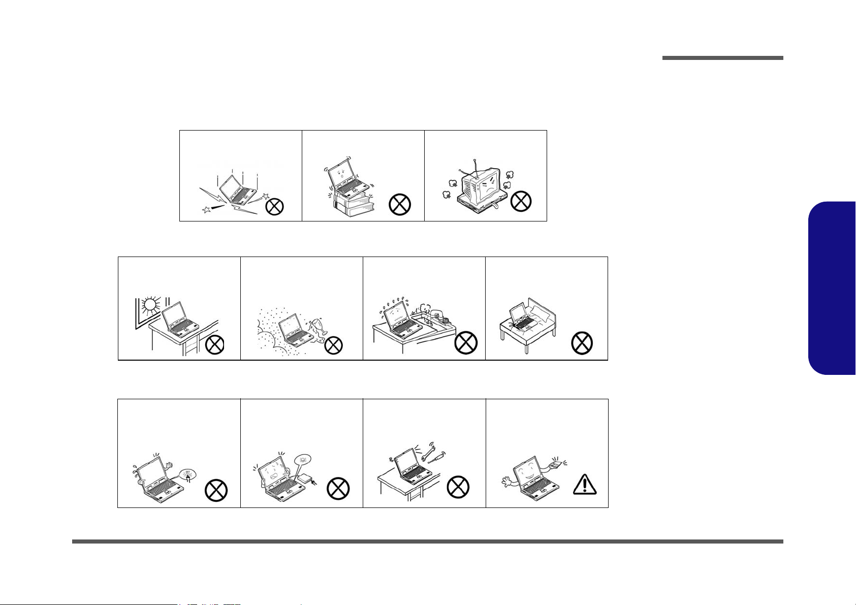
The notebook computer is quite rugged, but it can be damaged. To prevent this, follow these suggestions:
1. Don’t drop it, or expose it to shock. If the computer falls, the case and the components could be damaged.
Preface
Do not expose the computer
to any shock or vibration.
Do not place it on an unstable
surface.
Do not place anything heavy
on the computer.
2. Keep it dry, and don’t overheat it. Keep the computer and power supply away from any kind of heating element. This
is an electrical appliance. If water or any other liquid gets into it, the computer could be badly damaged.
Do not expose it to excessive
heat or direct sunlight.
Do not leave it in a place
where foreign matter or moisture may affect the system.
Don’t use or store the computer in a humid environment.
Do not place the computer on
any surface which will block
the vents.
3. Follow the proper working procedures for the computer. Shut the computer down properly and don’t forget to save
your work. Remember to periodically save your data as data may be lost if the battery is depleted.
Do not turn off the power
until you properly shut down
all programs.
Do not turn off any peripheral
devices when the computer is
on.
Do not disassemble the computer by yourself.
Perform routine maintenance
on your computer.
Preface
V
Page 8
Preface
Power Safety
Warning
Before you undertake
any upgrade procedures, make sure that
you have turned off the
power, and disconnected all peripherals
and cables (including
telephone lines). It is
advisable to also remove your battery in
order to prevent accidentally turning the
machine on.
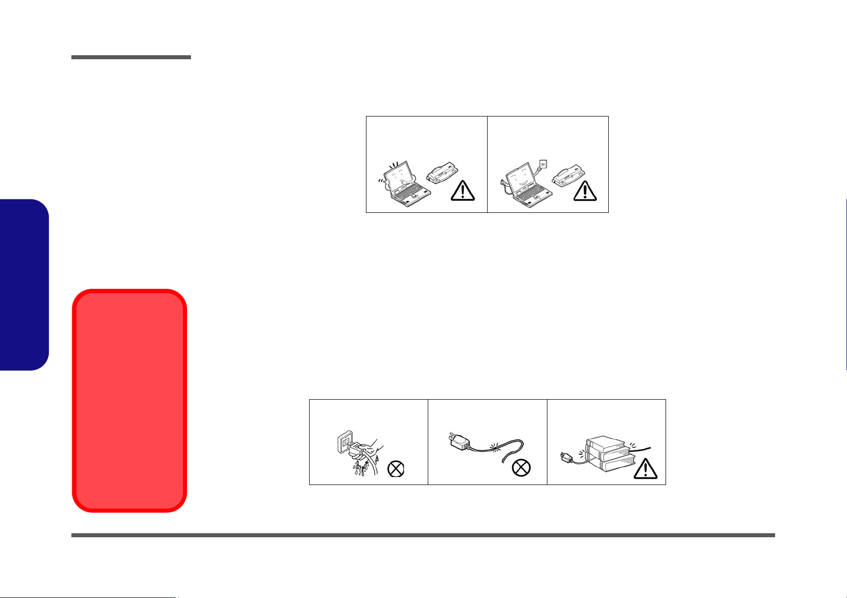
4. Avoid interference. Keep the computer away from high capacity transformers, electric motors, and other strong mag-
netic fields. These can hinder proper performance and damage your data.
5. Take care when using peripheral devices.
Preface
VI
Use only approved brands of
peripherals.
Unplug the power cord before
attaching peripheral devices.
Power Safety
The computer has specific power requirements:
• Only use a power adapter approved for use with this computer.
• Your AC adapter may be designed for international travel but it still requires a steady, uninterrupted power supply. If you are
unsure of your local power specifications, consult your service representative or local power company.
• The power adapter may have either a 2-prong or a 3-prong grounded plug. The third prong is an important safety feature; do
not defeat its purpose. If you do not have access to a compatible outlet, have a qualified electrician install one.
• When you want to unplug the power cord, be sure to disconnect it by the plug head, not by its wire.
• Make sure the socket and any extension cord(s) you use can support the total current load of all the connected devices.
• Before cleaning the computer, make sure it is disconnected from any external power supplies.
Do not plug in the power
cord if you are wet.
Do not use the power cord if
it is broken.
Do not place heavy objects
on the power cord.
Page 9

Battery Precautions
Battery Disposal
The product that you have purchased contains a rechargeable battery. The battery is recyclable. At the end of
its useful life, under various state and local laws, it may be illegal to dispose of this battery into the municipal
waste stream. Check with your local solid waste officials for details in your area for recycling options or proper
disposal.
Caution
Danger of explosion if battery is incorrectly replaced. Replace only with the same or equivalent type recommended by the manufacturer. Discard used battery according to the manufacturer’s instructions.
• Only use batteries designed for this computer. The wrong battery type may explode, leak or damage the computer.
• Do not continue to use a battery that has been dropped, or that appears damaged (e.g. bent or twisted) in any way. Even if the
computer continues to work with a damaged battery in place, it may cause circuit damage, which may possibly result in fire.
• Recharge the batteries using the notebook’s system. Incorrect recharging may make the battery explode.
• Do not try to repair a battery pack. Refer any battery pack repair or replacement to your service representative or qualified service
personnel.
• Keep children away from, and promptly dispose of a damaged battery. Always dispose of batteries carefully. Batteries may explode
or leak if exposed to fire, or improperly handled or discarded.
• Keep the battery away from metal appliances.
• Affix tape to the battery contacts before disposing of the battery.
• Do not touch the battery contacts with your hands or metal objects.
Preface
Preface
VII
Page 10

Preface
Preface
Related Documents
You may also need to consult the following manual for additional information:
User’s Manual on CD
This describes the notebook PC’s features and the procedures for operating the computer and its ROM-based setup program. It also describes the installation and operation of the utility programs provided with the notebook PC.
VIII
Page 11

Contents
Preface
Introduction ..............................................1-1
Overview .........................................................................................1-1
System Specifications .....................................................................1-2
External Locator - Top View with LCD Panel Open ......................1-6
External Locator - Front & Rear Views ......................................... 1-7
External Locator - Left & Right Side View ....................................1-8
External Locator - Bottom View .....................................................1-9
Mainboard Overview - Top (Key Parts) .......................................1-10
Mainboard Overview - Bottom (Key Parts) ..................................1-11
Mainboard Overview - Top (Connectors) .....................................1-12
Mainboard Overview - Bottom (Connectors) ...............................1-13
Disassembly ...............................................2-1
Overview .........................................................................................2-1
Maintenance Tools ..........................................................................2-2
Connections .....................................................................................2-2
Maintenance Precautions .................................................................2-3
Disassembly Steps ...........................................................................2-4
Removing the Battery ......................................................................2-5
Removing the Optical (CD/DVD) Device ......................................2-6
Removing the Hard Disk Drive ....................................................... 2-7
Removing the System Memory (RAM) .......................................... 2-9
Removing the Processor ................................................................2-11
Removing the VGA Card ..............................................................2-12
Installing the VGA Card ...............................................................2-14
Removing the Keyboard ................................................................2-15
Removing the Wireless LAN Module ........................................... 2-16
Removing the Bluetooth Module ..................................................2-17
Removing the Modem ...................................................................2-18
Removing the TV Tuner Card ....................................................... 2-19
Part Lists ..................................................A-1
Part List Illustration Location ........................................................ A-2
TOP (D900C/D901C) .................................................................... A-3
BOTTOM (D900C/D901C) ........................................................... A-4
LCD (D900C/D901C) ................................................................... A-5
MB - One VGA only (D900C/D901C) ......................................... A-6
MB (D900C/D901C) ..................................................................... A-7
HDD (D900C/D901C) ................................................................... A-8
2nd HDD (D900C/D901C) ............................................................ A-9
COMBO (D900C/D901C) ........................................................... A-10
DVD-DUAL RW (D900C/D901C) ............................................. A-11
Preface
Schematic Diagrams................................. B-1
BLOCK DIAGRAM .......................................................................B-2
CLOCK GENERATOR ..................................................................B-3
CPU-1 .............................................................................................B-4
CPU-2 ............................................................................................B-5
Intel P965 CPU Interface 1/4 ..........................................................B-6
Intel P965 PCI- E I/F 2/4 ................................................................B-7
Intel P965 Memory I/F 3/4 .............................................................B-8
DDRII SODIMM ............................................................................B-9
Intel P965 Power 4/4 ....................................................................B-10
ICH8 PCI, DMI, CPU, IRQ ..........................................................B-11
ICH8 LPC, ATA, USB, GPIO ......................................................B-12
ICH8 Power ..................................................................................B-13
MXM PCI-E CON1 ......................................................................B-14
MXM PCI-E CON2 ......................................................................B-15
BR03 PCI-E & Straps 1/3 .............................................................B-16
BR03 PCI-E Interface 2/3 .............................................................B-17
BR03 Power & GND 3/3 ..............................................................B-18
IX
Page 12

Preface
DVI/ CRT ..................................................................................... B-19
Panel CON/ LED Indicator .......................................................... B-20
1394/ Card Reader (TI PCI7402) ................................................. B-21
GLAN RTL8111B ........................................................................ B-22
Audio ALC888/ Amplifier ........................................................... B-23
KBC-H8/2111 .............................................................................. B-24
JM368 PCIE to PATA .................................................................. B-25
Mini Card & TV Out/ Video In .................................................... B-26
Daughter Connection .................................................................... B-27
CCD/ BT/ FAN/ ROM ................................................................. B-28
Mini PCI/ MDC/ New Card ......................................................... B-29
AC-In, Charger ............................................................................. B-30
Power 1.2V/ 1.25V ....................................................................... B-31
Power 1.5V/ 1.05V/ 2.5V ............................................................. B-32
Power 1.8V/ 0.9V/ 12V ................................................................ B-33
Power 3.3V/ 5V ............................................................................ B-34
Preface
VCore Power ................................................................................ B-35
Audio Board ................................................................................. B-36
Card Reader Board ....................................................................... B-37
Click Board .................................................................................. B-38
HotKey Board .............................................................................. B-39
Switch Board ................................................................................ B-40
USB Board ................................................................................... B-41
X
Page 13

1: Introduction
Overview
This manual covers the information you need to service or upgrade the D900C/D901C series notebook computer. Information about operating the computer (e.g. getting started, and the Setup utility) is in the User’s Manual. Information
about drivers (e.g. VGA & audio) is also found in User’s Manual. That manual is shipped with the computer.
Operating systems (e.g. Windows XP, Windows Vista, etc.) have their own manuals as do application software (e.g. word
processing and database programs). If you have questions about those programs, you should consult those manuals.
Introduction
The D900C/D901C series notebook is designed to be upgradeable. See “Disassembly” on page 2 - 1 for a detailed de-
scription of the upgrade procedures for each specific component. Please note the warning and safety information indicated by the “” symbol.
The balance of this chapter reviews the computer’s technical specifications and features.
1.Introduction
Overview 1 - 1
Page 14
Introduction
System Specifications
Feature Specification
1.Introduction
Processor Types Intel® Core™ 2 Duo Processor
LGA775 Package (775-pin)
E6300/ E6400
Intel® Core™ 2 Duo Processor
LGA775 Package (775-pin)
E6600/ E6700
Intel® Core™ 2 Extreme Processor
LGA775 Package (775-pin)
X6800
Core Logic Intel P965 + ICH8-R
LCD 17" Glare Type Flat Panel TFT (For One of the Following Options)
WXGA (1440 * 900)
OR
WSXGA+ (1680 * 1050)
OR
WUXGA (1920 * 1200)
Security Security (Kensington® Type) Lock Slot BIOS Password
Memory Two 200 Pin SO-DIMM Sockets Supporting DDRII (DDR2) 533/667/800 MHz
64-bit Wide DDRII (DDR2) Data Channels
Memory Expandable up to 4GB (512/ 1024/ 2048 MB DDRII Modules)
(Note: Do Not Use Other Module Types)
65nm (65 Nanometer) Process Technology
2MB On-die L2 Cache & 1066MHz FSB
1.86/ 2.13 GHz
65nm (65 Nanometer) Process Technology
4MB On-die L2 Cache & 1066MHz FSB
2.40/ 2.66 GHz
65nm (65 Nanometer) Process Technology
4MB On-die L2 Cache & 1066MHz FSB
2.93 GHz
TPM Supported
BIOS One 16Mbit Flash ROM Phoenix BIOS
1 - 2 System Specifications
Page 15
Feature Specification
Video Card Options
Note that card types, specifications and drivers
are subject to continual updates and changes.
Check with your service center for the latest details on video cards supported.
Video Card NVIDIA GeForceGo 7950 GTX (G71GM-UU +MXM IV)
SLI Module
PCI-Express Video Card
Windows Vista SLI Support
At the time of going to press Windows Vista did not
support more than one SLI video card. Check with
your service center for the latest information.
Introduction
Storage Options One Changeable 12.7 mm (h) Optical Device Drive Bay (see“Optional” on page 1 - 5)
Up to Three Changeable 9.5 mm (h) SATA II Hard Disk Drives
Supports RAID 0, RAID 1, RAID 5 HDD Fault Tolerance System
(Optional) External USB 1.44MB Floppy Disk Drive
Card Reader Embedded 7-in-1 Card Reader (MS/ MS Pro/ SD/ Mini SD/ MMC/ RS MMC/ MS Duo)
Note: MS Duo/ Mini SD/ RS MMC Cards Require a PC Adapter
Audio UAA (Universal Audio Architecture)
Integrated Azalia Compliant Interface
Keyboard &
Pointing Device
ExpressCard Slot ExpressCard/34/54 Slot
Full Size Winkey Keyboard with Numeric Keypad
Two Game Hot Keys
S/PDIF Digital Output
Built-In Microphone
4 * Built-In Speakers
Built-In TouchPad (Scroll Functionality Included)
1.Introduction
System Specifications 1 - 3
Page 16
Introduction
Feature Specification
1.Introduction
I/O Ports Four USB 2.0 Ports
One Mini-IEEE1394 Port
One S-Video-Out Jack for TV & HDTV Output
One DVI-Out Port (with DVI-Dual Link Support)
One External Monitor Port
One Headphone/Speaker-Out Jack
One Microphone-In Jack
One S/PDIF Out Jack
One Line-In Jack for Audio Input
Communication AZALIA MDC 56K Modem (V.90 & V.92 Compliant)
1GB PCIe Fast Ethernet LAN Module
Intel PRO/Wireless 3945ABG PCIe Wireless LAN Module
(Option)
Intel PRO/Wireless 4965AGN PCIe Wireless LAN Module
(Option)
Operating
Systems
Supported
Power
Management
Windows XP SP2 Windows Vista 64bit
Supports ACPI 2.0
Battery Low Suspend
Supports Resume from Modem Ring
One RJ-11 Modem Jack
One RJ-45 Gigabit LAN Jack
One DC-In Jack
One CATV Antenna (Analog/Digital) Jack (Functions with
Optional TV Tuner Module)
One S-Video-In Jack
(Functions with Optional TV Tuner Module)
One Consumer Infrared Transceiver
(Functions with Optional TV Tuner Module)
USB 2.0 Bluetooth Class II Module (Option)
1.3M Pixel USB 2.0 PC Camera Module (Factory
Option)
Home Premium/ Business/ Enterprise/ Ultimate
Supports Suspend to RAM (S3)
Supports Suspend to Disk (S4)
Power
Environmental
Spec
1 - 4 System Specifications
Full Range 220W AC/DC Adapter – AC Input 100 - 240V, 50 - 60Hz, DC Output 20V, 11A
Easy Changeable 12-Cell Smart Lithium-Ion 6600mAH
Temperature
Operating: 5°C ~ 35°C
Non-Operating: -20°C ~ 60°C
Relative Humidity
Operating: 20% ~ 80%
Non-Operating: 10% ~ 90%
Page 17
Feature Specification
Introduction
Physical
Dimensions &
Weight
Optional Optical Drive Module Options:
397mm (w) * 298mm (d) * 51 ~ 60mm (h) 5.4kg
DVD-Super Multi Drive Module
External USB 1.44MB Floppy Disk Drive
Analog TV Tuner Module with Mini-PCI Interface
OR
Hybrid TV Tuner Module with Mini-PCI Interface
Intel PRO/Wireless 3945ABG PCIe Wireless LAN Module
OR
Intel PRO/Wireless 4965AGN PCIe Wireless LAN Module
USB 2.0 Bluetooth Class II Module
1.3M Pixel USB 2.0 PC Camera Module (Factory
Option)
1.Introduction
DVD Player Software
System Specifications 1 - 5
Page 18
Introduction
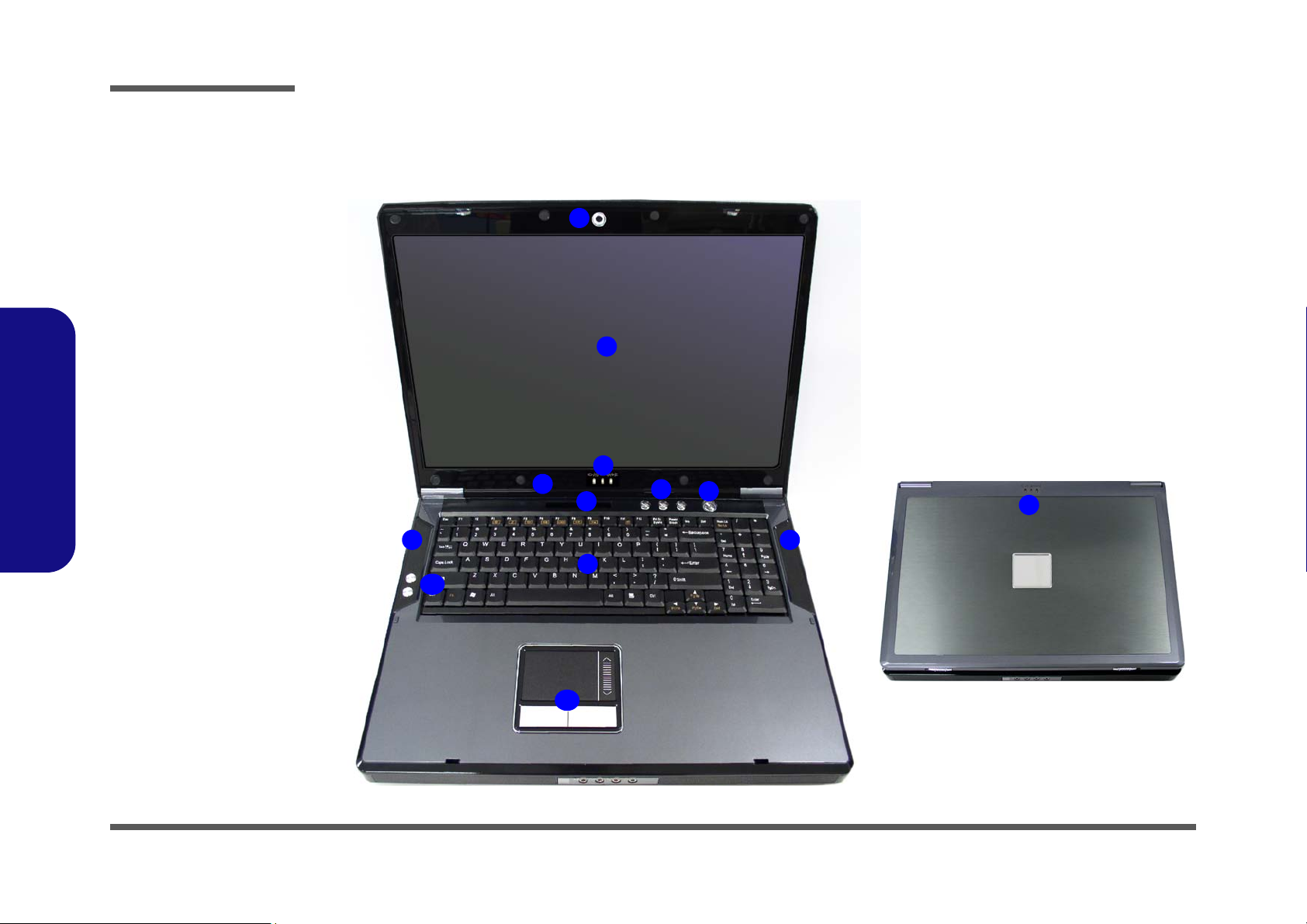
Figure 1
Top View
1. Optional Built-In
PC Camera
2. LCD
3. LED Power &
Communication
Indicators
4. Built-In
Microphone
5. LED Status
Indicators
6. Hot Key Buttons
7. Power Button
8. Keyboard
9. Speakers
10. Game Hot Keys
11. TouchPad and
Buttons
2
1
6
9
7
4
3
9
11
5
8
10
3
External Locator - Top View with LCD Panel Open
1.Introduction
1 - 6 External Locator - Top View with LCD Panel Open
Page 19
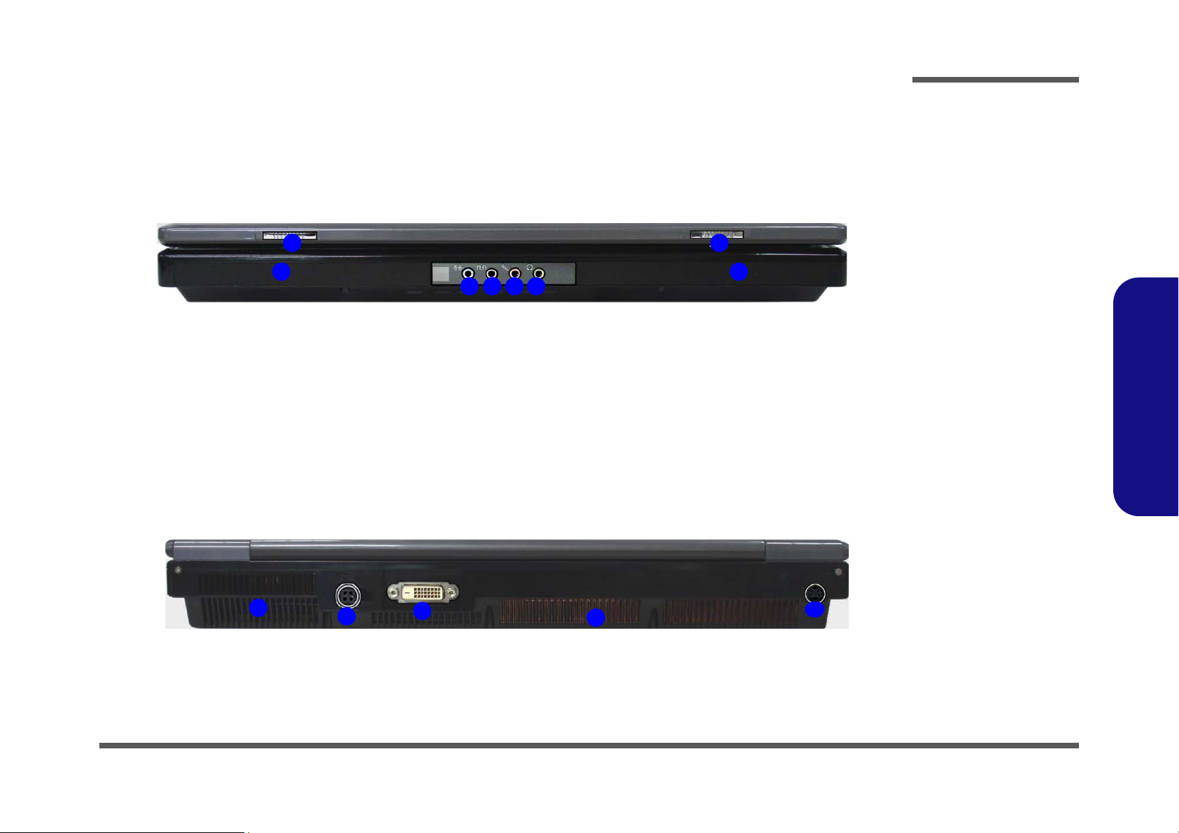
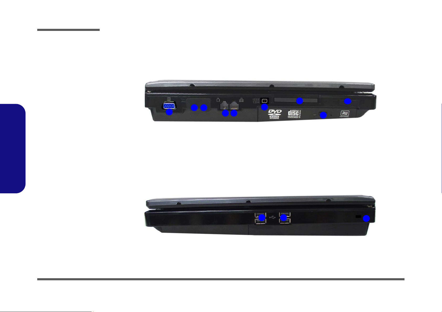
External Locator - Front & Rear Views
Figure 2
Front Views
1. LCD Latches
2. Line-In Jack
3. S/PDIF-Out Jack
4. Microphone-In Jack
5. Headphone-Out
Jack
6. Speakers
Figure 3
Rear Views
1. Vent/Fan Intake
2. DC-In Jack
3. DVI-Out Port
4. S-Video-In Jack
*
*Enabled with Optional Mini-
PCI TV Tuner Only
1
2
1
5
6
3 4
6
1
2
3
4
1
Introduction
1.Introduction
External Locator - Front & Rear Views 1 - 7
Page 20
Introduction
3
1
5
2
4
6
7
8
9
Figure 4
Left Side View
1. External Monitor
Port
2. S-Video-Out Jack
3. Cable (CATV)
Antenna Jack
4. RJ-11 Phone Jack
5. RJ-45 LAN Jack
6. Mini-IEEE 1394
Port
7. Express Card Slot
8. Optical Device
Drive Bay (for CD/
DVD Device)
9. 7-in-1 Card
Reader
1 1
2
Figure 5
Right Side View
1. USB Ports
2. Security Lock Slot
1.Introduction
External Locator - Left & Right Side View
1 - 8 External Locator - Left & Right Side View
Page 21
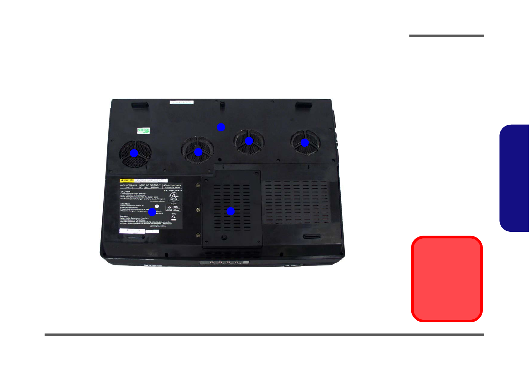
External Locator - Bottom View
Figure 6
Bottom View
1. Battery
(Secondary HDD
Bay - HDD3)
2. Fan Outlet/Intake
3. Primary HDD Bay
(HDD1 & HDD2)
4. Component Bay
Cover
Overheating
To prevent your computer from overheating
make sure nothing
blocks the vent/fan intakes while the computer is in use.
1
2
2
2
2
3
4
Introduction
1.Introduction
External Locator - Bottom View 1 - 9
Page 22
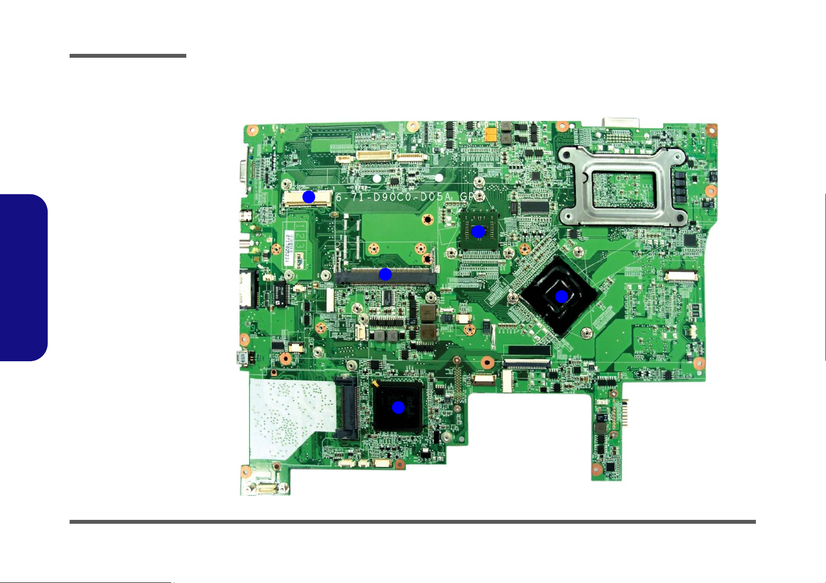
Introduction
Figure 7
Mainboard Top
Key Parts
1. WLAN Module
Socket
2. TV Module
Socket
3. SLI Chip (BR03)
4. Northbridge
(P965)
5. Southbridge
(ICH8R)
2
1
4
3
5
1.Introduction
Mainboard Overview - Top (Key Parts)
1 - 10 Mainboard Overview - Top (Key Parts)
Page 23
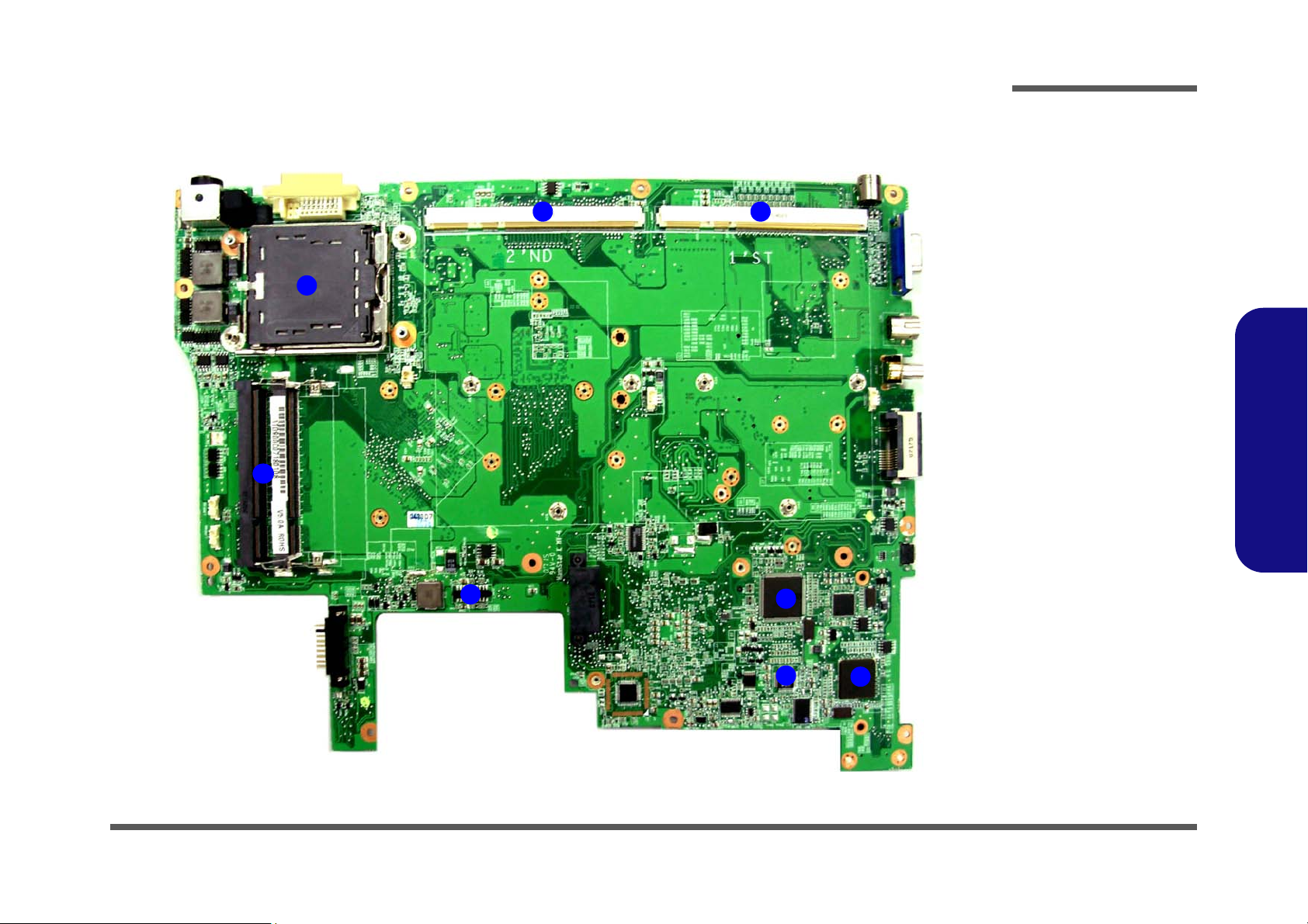
Mainboard Overview - Bottom (Key Parts)
Figure 8
Mainboard Bottom
Key Parts
1. CPU Socket (no
CPU installed)
2. VGA sockets
3. Memory Slots
DDR So-DIMM
4. HDD Socket
5. KBC IC (H8S/
2111BV)
6. Audio Codec IC
(ALC883)
7. IEEE1394/Card
Reader IC
(PCI7402)
1
5
2
4
3
2
6
7
Introduction
1.Introduction
Mainboard Overview - Bottom (Key Parts) 1 - 11
Page 24
Introduction
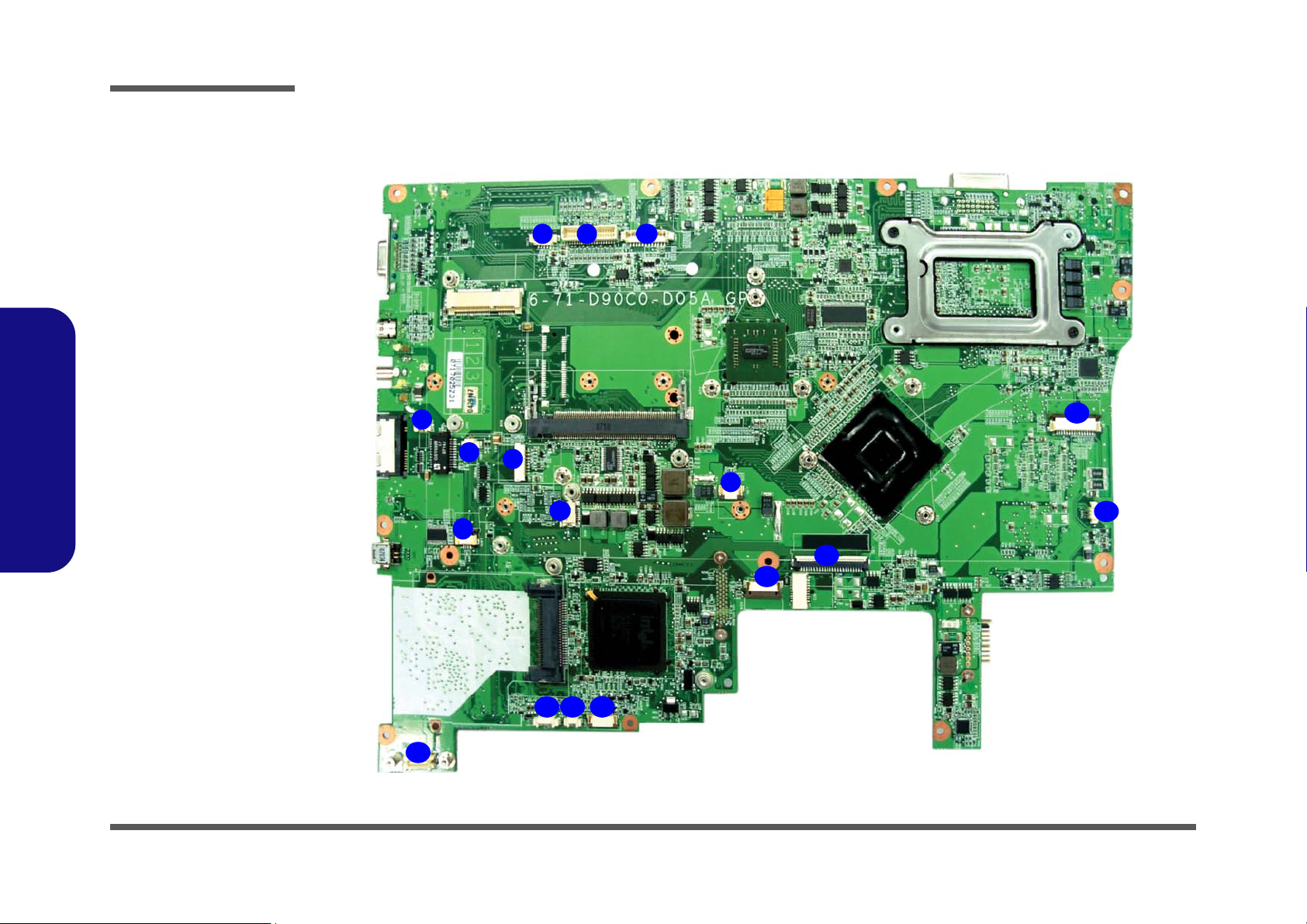
Figure 9
Mainboard Top
Connectors
1. CCD Cable
Connector
2. LCD Connector
3. LED Connector
4. Wire Cable 2Pin
Connector (M/B to
MDC Module)
5. SPK 1 Connector
6. Bluetooth Module
Connector
7. MDC Module
Connector
8. AP-Key Cable
Connector
9. Touch Pad Connector
10. SW1 Connector
11. SPK 2 Connector
12. Keyboard Cable
Connector
13. USB Cable
Connector
14. Audio Cable
Connector
15. RTC Battery
Connector
16. SPK Sub Cable
Connector
17. Card Reader Board
Connector
1
5
6
7
9
2
4
3
8
10
11
12
13
17
15 1416
1.Introduction
1 - 12 Mainboard Overview - Top (Connectors)
Mainboard Overview - Top (Connectors)
Page 25
Mainboard Overview - Bottom (Connectors)
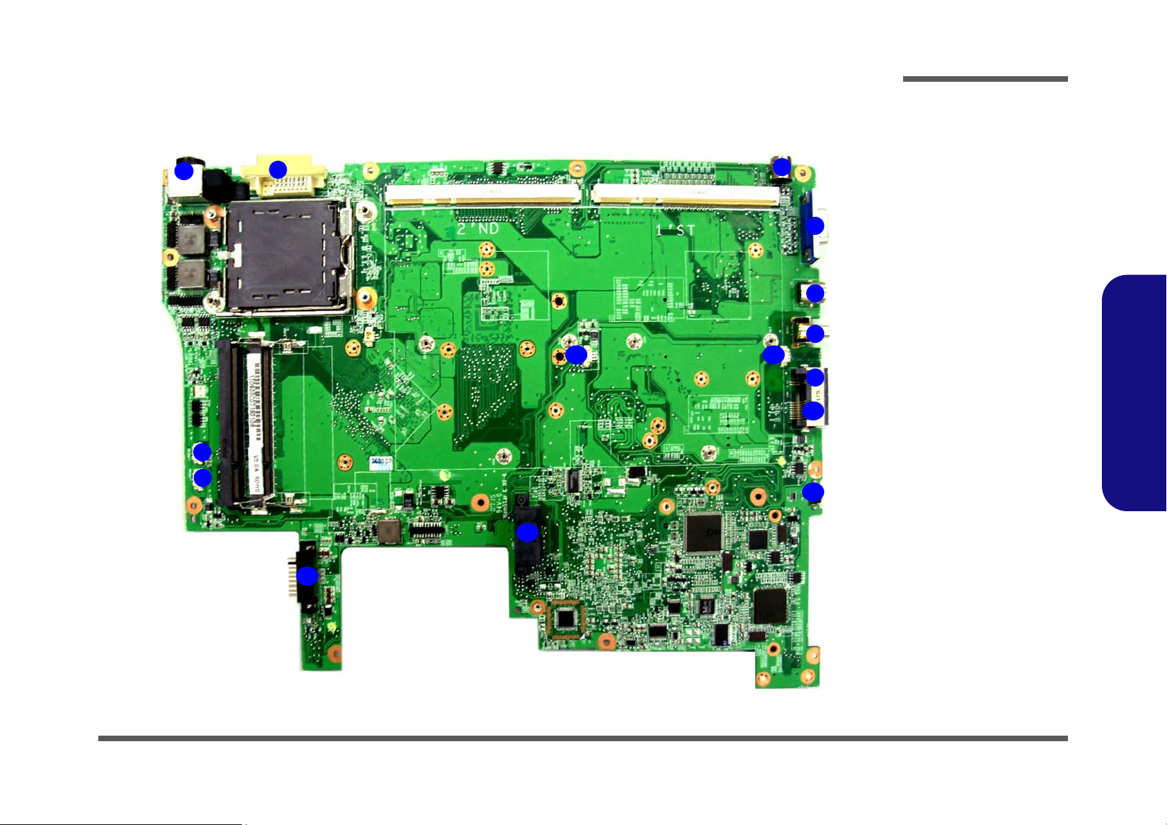
Figure 10
Mainboard Bottom
Connectors
1. CPU Fan Cable
Connector
2. RAM Fan Cable
Connector
3. DC-In Jack
4. DVI-Out Port
5. S-Video-In Jack
6. Serial Port
7. S-Video-Out Jack
8. CATV Jack*
9. RJ-11 Phone
Jack
10. RJ-45 LAN Jack
11. 1394a Connector
12. VGA Fan Cable
Connector
13. Optical Device
Connector
14. Battery
Connector
1
6
5
2
4
3
7
8
9
10
14
12
11
12
13
Introduction
1.Introduction
Mainboard Overview - Bottom (Connectors) 1 - 13
Page 26

Introduction
1.Introduction
1-14
Page 27
2: Disassembly
Information
Warning
Overview
This chapter provides step-by-step instructions for disassembling the D900C/D901C series notebook’s parts and subsystems. When it comes to reassembly, reverse the procedures (unless otherwise indicated).
We suggest you completely review any procedure before you take the computer apart.
Disassembly
Procedures such as upgrading/replacing the RAM, CD device and hard disk are included in the User’s Manual but are
repeated here for your convenience.
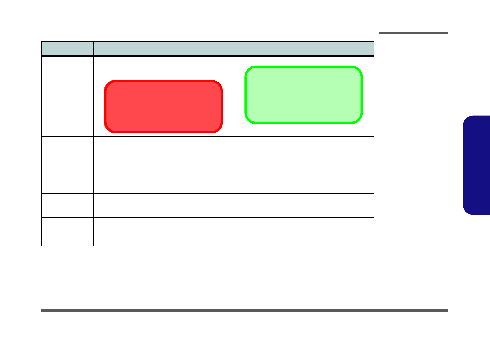
To make the disassembly process easier each section may have a box in the page margin. Information contained under
the figure # will give a synopsis of the sequence of procedures involved in the disassembly procedure. A box with a
lists the relevant parts you will have after the disassembly process is complete. Note: The parts listed will be for the dis-
assembly procedure listed ONLY, and not any previous disassembly step(s) required. Refer to the part list for the previous disassembly procedure. The amount of screws you should be left with will be listed here also.
A box with a will also provide any possible helpful information. A box with a contains warnings.
An example of these types of boxes are shown in the sidebar.
2.Disassembly
Overview 2 - 1
Page 28

Disassembly
2.Disassembly
NOTE: All disassembly procedures assume that the system is turned OFF, and disconnected from any power supply (the
battery is removed too).
Maintenance Tools
The following tools are recommended when working on the notebook PC:
• M3 Philips-head screwdriver
• M2.5 Philips-head screwdriver (magnetized)
• M2 Philips-head screwdriver
• Small flat-head screwdriver
• Pair of needle-nose pliers
• Anti-static wrist-strap
Connections
Connections within the computer are one of four types:
Locking collar sockets for ribbon connectors To release these connectors, use a small flat-head screwdriver to
gently pry the locking collar away from its base. When replacing the connection, make sure the connector is oriented in the
same way. The pin1 side is usually not indicated.
2-2Overview
Pressure sockets for multi-wire connectors To release this connector type, grasp it at its head and gently
rock it from side to side as you pull it out. Do not pull on the
wires themselves. When replacing the connection, do not try to
force it. The socket only fits one way.
Pressure sockets for ribbon connectors To release these connectors, use a small pair of needle-nose pli-
ers to gently lift the connector away from its socket. When replacing the connection, make sure the connector is oriented in
the same way. The pin1 side is usually not indicated.
Board-to-board or multi-pin sockets To separate the boards, gently rock them from side to side as
you pull them apart. If the connection is very tight, use a small
flat-head screwdriver - use just enough force to start.
Page 29

Maintenance Precautions
Power Safety
Warning
Before you undertake
any upgrade procedures, make sure that
you have turned off the
power, and disconnected all peripherals
and cables (including
telephone lines). It is
advisable to also remove your battery in
order to prevent accidentally turning the
machine on.
The following precautions are a reminder. To avoid personal injury or damage to the computer while performing a removal and/or replacement job, take the following precautions:
1. Don't drop it. Perform your repairs and/or upgrades on a stable surface. If the computer falls, the case and other
components could be damaged.
2. Don't overheat it. Note the proximity of any heating elements. Keep the computer out of direct sunlight.
3. Avoid interference. Note the proximity of any high capacity transformers, electric motors, and other strong mag-
netic fields. These can hinder proper performance and damage components and/or data. You should also monitor
the position of magnetized tools (i.e. screwdrivers).
4. Keep it dry. This is an electrical appliance. If water or any other liquid gets into it, the computer could be badly
damaged.
5. Be careful with power. Avoid accidental shocks, discharges or explosions.
•Before removing or servicing any part from the computer, turn the computer off and detach any power supplies.
•When you want to unplug the power cord or any cable/wire, be sure to disconnect it by the plug head. Do not pull on the wire.
6. Peripherals – Turn off and detach any peripherals.
7. Beware of static discharge. ICs, such as the CPU and main support chips, are vulnerable to static electricity.
Before handling any part in the computer, discharge any static electricity inside the computer. When handling a
printed circuit board, do not use gloves or other materials which allow static electricity buildup. We suggest that
you use an anti-static wrist strap instead.
8. Beware of corrosion. As you perform your job, avoid touching any connector leads. Even the cleanest hands pro-
duce oils which can attract corrosive elements.
9. Keep your work environment clean. Tobacco smoke, dust or other air-born particulate matter is often attracted
to charged surfaces, reducing performance.
10. Keep track of the components. When removing or replacing any part, be careful not to leave small parts, such as
screws, loose inside the computer.
Cleaning
Do not apply cleaner directly to the computer, use a soft clean cloth.
Do not use volatile (petroleum distillates) or abrasive cleaners on any part of the computer.
Disassembly
2.Disassembly
Overview 2 - 3
Page 30

Disassembly
Disassembly Steps
The following table lists the disassembly steps, and on which page to find the related information. PLEASE PERFORM
THE DISASSEMBLY STEPS IN THE ORDER INDICATED.
2.Disassembly
To remove the Battery:
1. Remove the battery page 2 - 5
To remove the Optical Device:
1. Remove the battery page 2 - 5
2. Remove the Optical device page 2 - 6
To remove the HDD:
1. Remove the battery page 2 - 5
2. Remove the HDD page 2 - 7
To remove the System Memory:
1. Remove the battery page 2 - 5
2. Remove the System Memory page 2 - 9
To remove the Processor:
1. Remove the battery page 2 - 5
2. Remove the Processor page 2 - 11
To remove the VGA card:
1. Remove the battery page 2 - 5
2. Remove the VGA card page 2 - 12
To remove the Keyboard:
1. Remove the battery page 2 - 5
2. Remove the Keyboard page 2 - 15
3.
To remove the Wireless LAN Module:
1. Remove the battery page 2 - 5
2. Remove the Keyboard page 2 - 15
3. Remove the Wireless LAN page 2 - 16
To remove the Bluetooth Module:
1. Remove the battery page 2 - 5
2. Remove the Keyboard page 2 - 15
3. Remove the Bluetooth page 2 - 17
To remove the Modem:
1. Remove the battery page 2 - 5
2. Remove the Keyboard page 2 - 15
3. Remove the Modem page 2 - 18
To remove the TV Tuner Card:
1. Remove the battery page 2 - 5
2. Remove the Keyboard page 2 - 15
3. Remove the TV tuner card page 2 - 19
2 - 4 Disassembly Steps
Page 31

Removing the Battery
4. Battery
•3 Screws
1
3
4
Figure 1
Battery Removal
a. Loosen screws.
b. Release the battery.
c. Lift the battery out of the
bay as indicated.
4
a.
c.
4
b.
1
2
3
1. Turn the computer off, and turn it over.
2. Loosen screws - .
3. Release the battery.
4. Lift the battery (Figure b) out of the bay as indicated.
Disassembly
2.Disassembly
Removing the Battery 2 - 5
Page 32

Disassembly
Figure 2
Optical Device
Removal
a. Remove the screws.
b. Remove the cover.
c. Remove the screw and
push the optical device
out of the computer at
point 8.
145
678
5. Hard Disk Bay Cover
7. Optical Device
•5 Screws
a. b.
1
3
2
4
6
8
7
c.
5
5
Removing the Optical (CD/DVD) Device
1. Turn off the computer, and turn it over and remove the battery (page 2 - 5).
2. Locate the hard disk bay cover and remove screws - , and remove the bay cover .
3. Remove screw .
4. Use the screwdriver to push the optical device out of the computer at point .
5. Reverse the process to install the new device.
2.Disassembly
2 - 6 Removing the Optical (CD/DVD) Device
Page 33

Removing the Hard Disk Drive
Figure 3
HDD Assembly
Removal
a. Remove the screws.
b. Remove the cover
c. Release the cable and lift
the hard disk assembly
up out off the computer.
d. Remove the screws and
separate the HDD(s)
from the bracket and
connector.
5. Hard Disk Bay Cover
10. Hard Disk Assembly
19. HDD Braket
21. HDD
• 15 Screws
14568
91011
18
21
19
20
6
7
8
9
12
18
17
15
16
13
14
2
3
4
10
19
a.
b.
d.
1
c.
5
20
11
21
The hard disk drive is mounted in a removable case and can be taken out to accommodate other 2.5" SATA hard disk
drives with a height of 9.5mm (h). Follow your operating system’s installation instructions, and install all necessary drivers and utilities (as outlined in Chapter 4 of the User’s Manual) when setting up a new hard disk.
Hard Disk Upgrade Process
1. Turn off the computer, and turn it over and remove the battery (page 2 - 5).
2. Locate the hard disk bay cover and remove screws - .
3. Remove the bay cover .
4. Remove screws
5. Remove screws - .
6. Separate the hard disk(s) from the bracket and connector cable .
7. Reverse the process to install a new hard disk(s).
- release the cable and lift the hard disk assembly out of the computer.
Disassembly
2.Disassembly
Removing the Hard Disk Drive 2 - 7
Page 34

Disassembly
3. Hard Disk Assembly
•1 Screw
Figure 4
Secondary HDD
Assembly Removal
a. Remove the screws and
slide the hard disk assembly in the direction fo
the arrow.
b. Lift the hard disk assem-
bly out off the computer.
123
2
1
3
a.
b.
Removing the Hard Disk(s) in the Secondary HDD Bay
1. Turn off the computer, and turn it over and remove the battery.
2. The secondary hard disk bay is located under the battery compartment.
3. Remove screw .
4. Slide the hard disk assembly in the direction of the arrow .
5. Lift the hard disk assembly out of the compartment.
6. Remove the screws to release the hard disk from the case.
2.Disassembly
2 - 8 Removing the Hard Disk Drive
Page 35

Removing the System Memory (RAM)
Figure 5
RAM Module
Removal
a. Remove the screws.
b. Lift off the bay cover.
c. Remove the screws.
d. Disconnect the fan
cable and remove the
RAM fan.
11. Bay Cover
15. RAM Fan
• 13 Screws
1
101112
14
15
a. b. c.
1
3
2
45
7
6
89
10
RAM Fan
12
14
13
d.
15
11
The computer has two memory sockets for 200 pin Small Outline Dual In-line Memory Modules (SO-DIMM) DDR II
(DDR2) supporting 533/667/800 MHz. The main memory can be expanded up to 4GB. The SO-DIMM modules supported are 512MB, 1024MB and 2048MB DDR Modules. The total memory size is automatically detected by the POST
routine once you turn on your computer.
Memory Upgrade Process
1. Turn off the computer, and turn it over and remove the battery (page 2 - 5).
2. Locate the memory (RAM) bay cover and remove screws - .
3. Lift off the bay cover .
4. Remove screws - from the RAM fan.
5. Disconnect the fan cable and remove the RAM fan .
Disassembly
2.Disassembly
Removing the System Memory (RAM) 2 - 9
Page 36

Disassembly
16
17
18
Figure 6
RAM Module
Removal (cont’d.)
e. Pull the release
latch(es).
d. Remove the mod-
ule(s).
Contact Warning
Be careful not to touch
the metal pins on the
module’s connecting
edge. Even the cleanest
hands have oils which
can attract particles, and
degrade the module’s
performance.
e. f.
17
16
18
18. RAM Module(s)
2.Disassembly
6. Gently pull the two release latches & on the sides of the memory socket in the direction indicated by the
arrows (Figure e).
7. The RAM module will pop-up (Figure f), and you can then remove it.
.
8. Pull the latches to release the second module if necessary.
9. Insert a new module holding it at about a 30° angle and fit the connectors firmly into the memory slot.
10. The module will only fit one way as defined by its pin alignment. Make sure the module is seated as far into the slot
as it will go. DO NOT FORCE IT; it should fit without much pressure.
11. Press the module in and down towards the mainboard until the slot levers click into place to secure the module.
12. Replace the RAM fan, cover and screws.
13. Restart the computer to allow the BIOS to register the new memory configuration as it starts up.
2 - 10 Removing the System Memory (RAM)
Page 37

Removing the Processor
145
6
6. Heat Sink
10. CPU
•4 Screws
7
8
9
10
a.
b.
c.
8
9
7
e.
d.
13
2 4
5
10
6
Caution
The heat sink, and CPU
area in general, contains parts which are
subject to high temperatures. Allow the area
time to cool before removing these parts.
Figure 7
Processor Removal
a. Remove the screws in
the order indicated and
b. Disconnect the connector
and remove the heat
sink.
c. Press and hold the latch.
d. Move the latch and
bracket fully in the direc-
tion to unlock the CPU.
e. Lift the CPU out of the
socket.
1. Turn off the computer, and turn it over, remove the battery (page 2 - 5) and RAM fan (page 2 - 9).
2. Locate the CPU heatsink and remove screws - from the heat sink in the order indicated on the label.
3. Disconnect the connector from the mainboard and lift the heat sink (Figure b) up off the computer.
4. Press down and hold the latch (with the latch held down you will be able to release it).
5. Move the latch and bracket fully in the direction indicated to unlock the CPU.
6. Carefully (it may be hot) lift the CPU up out of the socket (Figure b).
7. Reverse the process to install a new CPU.
8. When re-inserting the CPU, pay careful attention to the pin alignment, it will fit only one way (DO NOT FORCE IT!).
Disassembly
2.Disassembly
Removing the Processor 2 - 11
Page 38

Disassembly
1
10
11
121718
192021
24
b. d.
a. c.
e.
20
1
3
2
45
7
6
89
10
VGA Card Fans
12
14
13
18
11
23
24
15
17
16
19
20
21
22
Slot ASlot B
Notes
Two VGA cards are pictured. If you are installing a single VGA card, it
should be installed in
Slot A.
11. Bay Cover
20. VGA card fans
• 20 Screws
Figure 8
VGA Card Removal
a. Remove the screws.
b. Remove the cover.
c. Remove the screws and
disconnect the cable(s).
d. Release the VGA card
fans.
e. Remove the screws.
Removing the VGA Card
1. Turn off the computer, and turn it over and remove the battery (page 2 - 5).
2. Locate the VGA bay cover and remove screws - .
3. Lift off the bay cover .
4. Remove screws - from the VGA card fans.
5. Disconnect the fan cable(s) & .
6. Remove the VGA card fan .
7. Remove screws - from the VGA card module(s).
2.Disassembly
2 - 12 Removing the VGA Card
Page 39

8. Grip the handle and carefully lift the VGA card module in slot A.
25
26
27
h.f.
g.
22
25
24
26
27
Re-Installing Two VGA
Cards
Make sure you connect
the SLI cable to both
VGA cards when re-installing two VGA cards.
25. VGA Card Module
26. SLI Cable
27. VGA Card Module
Figure 9
VGA Card Removal
(cont’d.)
f. Remove the VGA mod-
ule from slot A.
g. Disconnect the cable.
h. Remove the VGA mod-
ulefrom slot B.
9. If two VGA cards are installed, disconnect the SLI cable from the VGA card modules.
10. Carefully remove the VGA card module in slot B from the mainboard.
Disassembly
2.Disassembly
Removing the VGA Card 2 - 13
Page 40

Disassembly
252423
a.
25
25. VGA card
Figure 10
VGA Card
Installation
a. Carefully Insert the VGA
Card.
2.Disassembly
Installing the VGA Card
1. Prepare to fit the VGA card into the slot by holding it at about a 30° angle.
2. The card needs to be fully into the slot, and the VGA card and socket have a guide-key and pin which align to allow
the card to fit securely.
3. Fit the connectors firmly into the socket, straight and evenly.
4. DO NOT attempt to push one end of the card in ahead of the other.
5. The card’s pin alignment will allow it to only fit one way. Make sure the module is seated as far into the socket
as it will go (none of the gold colored contact should be showing). DO NOT FORCE the card; it should fit without
much pressure.
6. Secure the card with screw (Figure 9g on page 2 - 13).
7. Place the heatsink back on the card, and secure the screws in the order indicated in Figure 8 on page 2 - 12.
8. Attach the VGA card fan and secure with the screws as indicated in Figure 8 on page 2 - 12.
9. Reinsert the component bay cover, and secure with the screws as indicated in Figure 8 on page 2 - 12.
2 - 14 Removing the VGA Card
Page 41

Removing the Keyboard
5
6
6
7
5
Figure 11
Keyboard Removal
a. Press the four latches to
release the keyboard.
b. Lift the keyboard up.
c. Disconnect the cable
from the locking collar.
d. Remove the keyboard.
a.
c.
b.
Keyboard Tabs
d.
1 3
6
7
5
2
4
5
5. Keyboard
Re-Inserting the Key-
board
When re-inserting the
keyboard firstly align
the five keyboard tabs
at the bottom (Figure
b) at the bottom of the
keyboard with the slots
in the case.
1. Turn off the computer, and turn it over and remove the battery (page 2 - 5).
2. Press the four keyboard latches at the top of the keyboard to elevate the keyboard from its normal position (you
may need to use a small screwdriver to do this).
3. Carefully lift the keyboard up, being careful not to bend the keyboard ribbon cable (Figure c).
4. Disconnect the keyboard ribbon cable from the locking collar socket .
5. Carefully lift up the keyboard (Figure d) off the computer.
Disassembly
2.Disassembly
Removing the Keyboard 2 - 15
Page 42

Disassembly
Figure 12
Wireless LAN
Module Removal
a. Remove the screws.
b. Remove the keyboard
shielding.
c. Disconnect the cables
and remove the screws.
d. Remove the WLAN
module.
Note: Make sure you
reconnect the antenna
cables to the “Main”
and “BT” socket (Fig-
ure c).
123
45678
9
7
5
b.
a.
4
2
3
c.
1
d.
6
9
8
9
3. Keyboard Shielding
9. Wireless LAN Module
•4 Screws
Removing the Wireless LAN Module
1. Turn off the computer, and turn it over, remove the battery (page 2 - 5) and keyboard (page 2 - 15).
2. Remove screws - from the keyboard shielding
3. Remove the keyboard shielding , the Wireless LAN Module will be visible at point .
4. Carefully disconnect cables & and remove screws - .
5. The Wireless LAN Module
(Figure c) will pop-up, and you can remove it.
.
2.Disassembly
2 - 16 Removing the Wireless LAN Module
Page 43

Removing the Bluetooth Module
Figure 13
Bluetooth Module
Removal
a. Disconnect the cables
and remove the screw.
b. Remove the Bluetooth
module.
Note: Make sure you
reconnect the antenna
cables to the socket
(Figure a).
12345
b.
a.
4
3
5
2
1
5. Bluetooth Module
•1 Screw
1. Turn off the computer, and turn it over, remove the battery (page 2 - 5), keyboard (page 2 - 15) and keyboard
shielding (page 2 - 16).
2. The Bluetooth module is visible at point .
3. Carefully disconnect cables & and remove the screw .
4. Lift the Bluetooth module off the computer.
Disassembly
2.Disassembly
Removing the Bluetooth Module 2 - 17
Page 44

Disassembly
Figure 14
Modem Removal
a. Remove the screws and
disconnect the cable.
b. Lift the modem up off
the socket.
1
2
345
6
6. Modem
•2 Screws
b.
a.
4
3
6
1
2
5
4
Removing the Modem
1. Turn off the computer, and turn it over, remove the battery (page 2 - 5), keyboard (page 2 - 15) and keyboard
shielding (page 2 - 16).
2. The modem is visible at point .
3. Remove the screws - from the modem module and disconnect cable .
4. Lift the modem up off the socket .
5. Lift the modem up and off the computer.
2.Disassembly
2 - 18 Removing the Modem
Page 45

Removing the TV Tuner Card
Figure 15
TV Tuner Card
Removal
a. Disconnect the cable
and pull the release
latches.
b. The TV tuner card will
pop up and remove it.
12345
b.
a.
2
3
1
4
5
5
b.
5. TV tuner card
1. Turn off the computer, and turn it over, remove the battery (page 2 - 5), keyboard (page 2 - 15) and keyboard
shielding (page 2 - 16).
2. The TV tuner card is visible at point .
3. Carefully disconnect the cable and then gently pull the two release latches - on the sides of the module
socket.
4. The TV tuner card
.
will pop-up and and you can remove it.
Disassembly
2.Disassembly
Removing the TV Tuner Card 2 - 19
Page 46

Disassembly
2.Disassembly
2-20
Page 47

Appendix A:Part Lists
This appendix breaks down the D900C/D901C series notebook’s construction into a series of illustrations. The component part numbers are indicated in the tables opposite the drawings.
Note: This section indicates the manufacturer’s part numbers. Your organization may use a different system, so be sure
to cross-check any relevant documentation.
Note: Some assemblies may have parts in common (especially screws). However, the part lists DO NOT indicate the
total number of duplicated parts used.
Part Lists
Note: Be sure to check any update notices. The parts shown in these illustrations are appropriate for the system at the
time of publication. Over the product life, some parts may be improved or re-configured, resulting in new part numbers.
A.Part Lists
A-1
Page 48

Part Lists
Table A - 1
Part List Illustration
Location
Part List Illustration Location
The following table indicates where to find the appropriate part list illustration.
Part D900C/D901C
TOP (D900C/D901C)
page A - 3
A.Part Lists
BOTTOM (D900C/D901C)
LCD (D900C/D901C)
MB - one VGA only (D900C/D901C)
MB (D900C/D901C)
HDD (D900C/D901C)
2nd HDD (D900C/D901C)
COMBO (D900C/D901C)
DVD-DUAL RW (D900C/D901C)
page A - 4
page A - 5
page A - 6
page A - 7
page A - 8
page A - 9
page A - 10
page A - 11
A - 2 Part List Illustration Location
Page 49

TOP (D900C/D901C)
Figure A - 1
TOP (D900C/
D901C)
無鉛
耐熱 無鉛
無鉛
無鉛
無鉛
無鉛
無鉛
無鉛
寶石藍 無鉛
無鉛
寶石藍 無鉛
無鉛
無鉛
無鉛
無鉛
無鉛
無鉛
無鉛
無鉛
無鉛
無鉛
無鉛
無鉛
無鉛
無鉛
無鉛
無鉛
Part Lists
A.Part Lists
TOP (D900C/D901C) A - 3
Page 50

Part Lists
Figure A - 2
BOTTOM (D900C/
D901C)
無鉛
無鉛
無鉛
無鉛
無鉛
無鉛
無鉛
無鉛
無鉛
無鉛
無鉛
無鉛
無鉛
無鉛
外 無鉛
無鉛
無鉛
無鉛
無鉛
無鉛
無鉛
無鉛
無鉛
無鉛
無鉛
無鉛
無鉛
A.Part Lists
BOTTOM (D900C/D901C)
A - 4 BOTTOM (D900C/D901C)
Page 51

LCD (D900C/D901C)
Figure A - 3
LCD (D900C/
D901C)
無鉛
無鉛
無鉛
無鉛
無鉛
無鉛
無鉛
無鉛
無鉛
無鉛
無鉛
無鉛
無鉛
無鉛
無鉛
無鉛
無鉛 (增加卡角度)
無鉛(增加卡勾角度)
無鉛
無鉛
(黑色) 惠貿 無鉛
無鉛
精乘 無鉛
無鉛
無鉛
無鉛
無鉛
廠商改變" 無鉛
無鉛
無鉛
無鉛
無鉛
無鉛
無鉛
無鉛
Part Lists
A.Part Lists
LCD (D900C/D901C) A - 5
Page 52

Part Lists
無鉛
無鉛
無鉛
藍天2 互億 無鉛
無鉛
無鉛
無鉛
無鉛
無鉛
無鉛
無鉛
無鉛
無鉛
無鉛
無鉛
無鉛
無鉛
無鉛
無鉛
無鉛
無鉛
無鉛
無鉛
無鉛
無鉛
無鉛
無鉛
無鉛
無鉛
無鉛
無鉛
無鉛
無鉛
變更 無鉛
無鉛
無鉛
無鉛
無鉛
無鉛
無鉛
無鉛
無鉛
無鉛
Figure A - 4
MB - One VGA only
(D900C/D901C)
A.Part Lists
A - 6 MB - One VGA only (D900C/D901C)
MB - One VGA only (D900C/D901C)
Page 53

MB (D900C/D901C)
無鉛
無鉛
無鉛
藍天2 互億 無鉛
無鉛
無鉛
無鉛
無鉛
無鉛
無鉛
無鉛
變更 無鉛
無鉛
無鉛
無鉛
無鉛
無鉛
無鉛
無鉛
無鉛
無鉛
無鉛
無鉛
無鉛
無鉛
無鉛
無鉛
無鉛
無鉛
無鉛
無鉛
無鉛
無鉛
無鉛
無鉛
無鉛
無鉛
無鉛
無鉛
無鉛
無鉛
無鉛
Figure A - 5
MB (D900C/D901C)
Part Lists
A.Part Lists
MB (D900C/D901C) A - 7
Page 54

Part Lists
無鉛
無鉛
無鉛
Figure A - 6
HDD (D900C/
D901C)
A.Part Lists
HDD (D900C/D901C)
A - 8 HDD (D900C/D901C)
Page 55

2nd HDD (D900C/D901C)
無鉛
無鉛
Figure A - 7
2nd HDD (D900C/
D901C)
Part Lists
A.Part Lists
2nd HDD (D900C/D901C) A - 9
Page 56

Part Lists
無鉛
無鉛
無鉛
無鉛
無鉛
Figure A - 8
COMBO (D900C/
D901C)
A.Part Lists
COMBO (D900C/D901C)
A - 10
Page 57

DVD-DUAL RW (D900C/D901C)
無鉛
無鉛
無鉛
無鉛
無鉛
Figure A - 9
DVD-DUAL RW
(D900C/D901C)
Part Lists
A.Part Lists
DVD-DUAL RW (D900C/D901C) A - 11
Page 58

Part Lists
A.Part Lists
A - 12
Page 59

Appendix B:Schematic Diagrams
Table B - 1
Schematic
Diagrams
Version Note
The schematic diagrams in this chapter
are based upon version 6-7P-D90C7-006.
If your mainboard (or
other boards) are a later version, please
check with the Service
Center for updated diagrams (if required).
This appendix has circuit diagrams of the D900C/D901C notebook’s PCB’s. The following table indicates where to find
the appropriate schematic diagram.
Diagram - Page Diagram - Page Diagram - Page
BLOCK DIAGRAM - Page B - 2 BR03 PCI-E & Straps 1/3 - Page B - 16 AC-In, Charger - Page B - 30
CLOCK GENERATOR - Page B - 3 BR03 PCI-E Interface 2/3 - Page B - 17 Power 1.2V/ 1.25V - Page B - 31
CPU-1 - Page B - 4 BR03 Power & GND 3/3 - Page B - 18 Power 1.5V/ 1.05V/ 2.5V - Page B - 32
CPU-2 - Page B - 5 DVI/ CRT - Page B - 19 Power 1.8V/ 0.9V/ 12V - Page B - 33
Intel P965 CPU Interface 1/4 - Page B - 6 Panel CON/ LED Indicator - Page B - 20 Power 3.3V/ 5V - Page B - 34
Intel P965 PCI- E I/F 2/4 - Page B - 7 1394/ Card Reader (TI PCI7402) - Page B - 21 VCore Power - Page B - 35
Intel P965 Memory I/F 3/4 - Page B - 8 GLAN RTL8111B - Page B - 22 Audio Board - Page B - 36
DDRII SODIMM - Page B - 9 Audio ALC888/ Amplifier - Page B - 23 Card Reader Board - Page B - 37
Schematic Diagrams
B.Schematic Diagrams
Intel P965 Power 4/4 - Page B - 10 KBC-H8/2111 - Page B - 24 Click Board - Page B - 38
ICH8 PCI, DMI, CPU, IRQ - Page B - 11 JM368 PCIE to PATA - Page B - 25 HotKey Board - Page B - 39
ICH8 LPC, ATA, USB, GPIO - Page B - 12 Mini Card & TV Out/ Video In - Page B - 26 Switch Board - Page B - 40
ICH8 Power - Page B - 13 Daughter Connection - Page B - 27 USB Board - Page B - 41
MXM PCI-E CON1 - Page B - 14 CCD/ BT/ FAN/ ROM - Page B - 28
MXM PCI-E CON2 - Page B - 15 Mini PCI/ MDC/ New Card - Page B - 29
B-1
Page 60

Sheet 1 of 40
BLOCK DIAGRAM
USB Port 2CCD Camera
BGA508
Blue Tooth
DDR2 SODIMM
VGA
DAUGHTER
BOARD
TPM
P965
CARD
READER
BOARD
AUDI O-J ACK
BOARD
SPI
SPI BIOS
HDD
WAN
SLB963 5TT
PCI-E X 16
2 IN 1
Azali a
DVI
MDC
LPC
USB Port 4
CLICK
BOARD
BGA1040
533/667MHZ
USB Port 1
Keyboard
PCI EXPRESS X16
CARD READER
533/800/ 1066 MHz
TV OUT
INTEL
X1PCI-EXPRESS INTERFACE
INTEL
1394
SPDIF
VRD 11.0
LCD
DMI
SATA INTERFACE
PCI
NEW
CARD
BATT.X1
MINICARD
USB Port 3
HDD
MINI CARD
FAN X4
Audio
Codec
ALC883
PCI-E X 16
JMB368
CLOCK GEN
H8
KBC
2111
MINI PCI
SLOT
FOR
TV-TUNER
SWITCH
BOARD
15. BR03 PCI-E & STRAPS
LGA 775
VGA
DAUGHTER
BOARD
LINE-IN
USB
BOARD
TI 7402
FSB
NF-BR03
SPEAKER
x4
ICS9 LPR36 3
D900C BLOCK DIAGRAM
TOUCH PAD
USB 2.0
BOARD
DDR2 SODIMM
GIGA LAN
SPK-OUT
CONROE
FUNCTION
HDTV OUT
82801
ODD
HDD
MIC-IN
Schematic Diagrams
BLOCK DIAGRAM
B.Schematic Diagrams
B - 2 BLOCK DIAGRAM
Page 61

Sheet 2 of 40
CLOCK
GENERATOR
PCL KMI NI1
CLK48_CARDBUS
RP9 4P2R_33_04
1
2 3
4
R151 10K_04
FSA
C186 10P/ 50V_04(R)
C185 10P/ 50V_04(R)
PM_STPCPU# 11
R113 10K_04
0
DOTCLK96#
R153 10K_04
0
R145 10K_04
SRCCLK#2
PCIE_CLK_UWB#
Q11
2N3904
B
E C
R139 33_04
CPU MHz
200.00
CPUCLK# 1
SRCCLK 1
C199 10P/ 50V_04(R)
CKVDD
FSBSEL04
Q9
2N3904
B
E C
1
MCHCL K #
PCI E_C LK_N EW CAR D
R132 1K_04
U4
ICS9LPR363DGLF
50
21
28
11
1
7
56
2
6
13
29
37
46
10
55
54
58
57
47
16
61
6412
44
43
41
40
36
35
19
20
22
23
24
25
26
27
30
31
33
32
14
15
3
4
5
8
9
42
45
34
53
59
17
18
39
38
48
49
52
51
60
62
63
VDDCPU
VDDPCIEX
VDDPCIEX
VDD48
VDDPCI
VDDPCI
VDDREF
GND
GND
GND
GND
GND
GNDA
VttPWR_GD/PD#
SDATA
SCLK
X1
X2
VREF
FSLB/TEST_MODE
REF1/FSLC/TEST_SEL
PCICLK0/ REQ_SELFSLA/USB_48MHz
CPUITPT_L2/PCIeT_L8
CPUITPC_L2/PCI eC_L8
PEREQ1#/PCIeT_L7
PEREQ2#/PCIeC_L7
PCIeT_L5
PCIeC_L5
PCIeT_L1
PCIeC_L1
PCIeT_L2
PCIeC_L2
PCIeT_L3
PCIeC_L3
SATACLKT_L
SATACLKTC_L
PCIeT_L4
PCIeC_L4
PEREQ4#
PEREQ3#
DOT_96MHz
DOT#_96MHz
PCICLK1
PCICLK2
PCICLK3
ITP_EN/ PCICLK_F4
PCICLK_F5
VDDPCIEX
VDDA
PWRSAVE#
GND
GND
PCIeT_L0
PCIeC_L0
PCIeT_L6
PCIeC_L6
CPUC_L1F
CPUT_L1F
CPUT_L0
CPUC_L0
REF0
CPU_STOP#
PCI/PCI EX_STOP#
0 100.00
PCL KMI NI1
SRCCLK#4
R120 0_04
0
SMBDATA
C182
.01U_04
400.00
Q10
2N3904
B
E C
C213 10P/ 50V_04(R)
RP7 4P2R_33_04
1
23
4
C207 22P_0 4
SRCCLK_ICH
CKVDD
CK_ PWRSA V E#
REQ_SEL
SRCCLK#6
0
100.00
CPUCLK0
T
FSC
3VS
C187
.1U_X7R_04
100.00
SATACLK #
PCIE_CLK_BR03
3VS
3VS
USBCLK48
FSBSEL0
C215
.1U_X7R_04
PCICL K4
C196
.01U_04
0
DOTCLK96
0
100.00
CKVDD
UWB_CLKREQ#13
SMBDATA8,11,13,24,25, 28
ICHCLK14
FSA
RP1 4P2R_33_04
1
23
4
RP10
4P2R_33_04
1
23
4
C190 10P/ 50V_04(R)
C208 22P_0 4
SRCCLK 4
0
100.00
CPUCLK1
FSB
PCIE_CLK_NEWCARD# 28
PCIE_CLK_WAN
3VS
PCIE_CLK_UWB
R160 22_04
333.33
PCIE_CLK_GLAN# 21
CPUCLK #
PCIE_CLK_JMB368#
0
100.00
3VS
L15
HCB1608K-121T25
1 2
R163 10K_04
PCLK_TPM
PCIE_CLK_NEWCARD 28
SATACLK
FSA
L8
HCB2012KF-121T30
1 2
R127
1K_04
166.66
WAN_ CLKREQ# 25
UWB_ CL KREQ#
RP5 4P2R_33_04
1
23
4
RP4 4P2R_33_04
1
23
4
SRCCLK_MCH#
R135 4.7K_04
C217
10U/ 10V_ 08
0
33.33
1
PCIE_CLK_GLAN 21
REF0
DOTCLK # 6
CPUCLK #
Q8
2N3904
B
E C
R146 1K_04(R)
FSBSEL1
R124 22_04
SRCCLK_MCH# 6
RP3 4P2R_33_04
1
23
4
200.00
PCICL K1
FSBSEL2
RP11 4P2R_33_04
1
2 3
4
33.33
1
MCHCLK#
R121 1K_04(R)
PM_S TPPC I# 11
SRCCLK0#
PCI E_C LK_N EW CAR D#
3VS
PCICL K3
RP6
4P2R_33_04
1
23
4
SRCCLK 2
133.33
SRCCLK_MCH 6
CPUCLK
R112 10K_04
RP8 4P2R_33_04
1
23
4
SRCCLK 6
33.33
1
CK_ PWRSA V E#11
PCICL K
DOTCL K#
C172
.1U_X7R_04
C212 10P/ 50V_04(R)
0
ICHCLK 14 11
3VS
SRCCLK_SATA#
NEWCA RD_CL K REQ#
RP31 4P2R_33_04(R)
1
23
4
3VS
ICHCLK 14
266.66
CPUCLK# 4
SRCCLK_MCH
PCICL K2
SRCCLK8#
R118 220_04
R148 4.7K_04
33.33
1
MCHCL K # 5
CK_ PWRGD
MCHCL K
C214 10P/ 50V_04(R)
0
R138 22_04
FSBSEL14
C203 10P/ 50V_04(R)
FSC
1
CPUCLK 4
PM_S TPPCI #
C200
100P_04(R)
R141 1K _04
33.33
1
PCIE_CLK_WAN# 25
PCLK1394 2 0
FSBSEL24
SRCCLK 0
MCHCL K 5
3VS
PCLK MINI 1 28
PCIE_CLK_BR03 1 5
PCIE_CLK_UWB# 13
SRCCLK#3
PCIE_CLK_GLAN
USBCL K4 811
PCICL K5
C210
.1U_X7R_04
R162 22_04
1
DOTCLK 6
C188 10P/ 50V_04(R)
R144 22_04
1
NEWCA RD_CL KREQ# 28
PCIE_CLK_WAN 25
SRCCLK_SATA# 11
CLK48_CARDBUS20
DOTCL K
MCHCLK
L16
HCB2012KF-121T30
1 2
KBC_PCLK 23
PCLK_TPM 25
PCIE_CLK_UWB 13
SRCCLK_SATA
SRCCLK#5
1
PCIE_CLK_JMB368 24
KBC_PCLK
SRCCLK 8
C183
.01U_04
R133
1K_04
C194
.1U_X7R_04
R161 22_04
SRCCLK_ICH# 10
PCIE_CLK_JMB368# 24
CPUCLK
X1
14.31MHz
1 2
PCIEX MHz
100.00
C161
10U/10V_08
CK_P WRGD11
FSC
33.33
SRCCLK_SATA 11
PCIE_CLK_BR03# 15
R156 1K _04
PCICL K
FSB
1
PCICL K 10
PM_S TPCPU #
R128 22_04
FSBSEL24
SRCCLK_ICH#
SRCCLK1#
100.00
SRCCLK_ICH 10
USBCLK48
PCLK1394
33.33
3VS
SRCCLK 3
PCIE_CLK_GLAN#
WA N_CL KREQ #
R115 10K_04C205
.01U_04
RP2 4P2R_33_04
1
23
4
1
FSC
SMBCLK
C167
1U_04
PCI MHz
100.00
KBC_PCLK
PCIE_CLK_WAN#
C192 10P/ 50V_04(R)
FSC
PCIE_CLK_JMB368
C197
100P_04(R)
33.33
CPUCLK# 0
3VS
3VS 6,8..15,17..22,24..28,31,33
SRCCLK 5
SMBCLK8,11,13,24,25, 28
R116 1K_04
FSBSEL04
PCLK1394
PCIE_CLK_BR03#
C159
.1U_X7R_04
CLOCK GENERATOR
Schematic Diagrams
B.Schematic Diagrams
CLOCK GENERATOR B - 3
Page 62

Schematic Diagrams
VCORE
C123
33P_04
PLEASE COLSE TO Pin-H1
CPU_D#27
C45 . 1U_ X7R_0 4
C488
10U/10V _08
C485
10U/10V _08
CPU_D#25
CPU_DEFER#5
PECI
CPU_D#23
CPU_D#53
C92
.1U_X7R_04
CPU_DSTBP0# 5
CPU_D#15
CPU_D#31
CPU_A#33
C492
10U/10V _08
CPU_BPRI#5
CPU_A#8
R47
210_1%_06( R )
CPU_D#3
CPU_A#19
C81 . 1U_ X7R_0 4
CPU_D#58
VCORE
CPU_DBI0#
CPU_A#27
CPU_A#21
CPU_A#32
C108
.1U_X7R_04
CPU_ADSTB0#
CPU_D#45
CPU_DSTBN0# 5
VCORE
CPU_A#15
CPU_A#10
CPU_D#42
C482
10U/10V _08
CPU_REQ#4
CPU_GTLREF3
C114 .1U_ X7R_0 4
CPU_D#4
CPU_A#5
CPU_D#47
CPU_D#11
CPU_GTLREF2_DIVIDER
CPU_D#46
CPU_DSTBN2# 5
CPU_D#29
CPU_ADSTB1#
R88
210_1%_06
CPU_DBI3# 5
C493
10U/10V _08
CPU_LOCK#5
+
C71
470UF/ 2.5V _D 2( R)
12
CPU_D#21
TESTHI_10
CPU_GTLREF2
CPU_HIT#5
CPU_D#18
R79 62_1%_06
CPU_D#60
U19D
CPU LGA775-P4_21
AM29
AM30
AM8
AM9
AN11
AN12
AN14
AN15
AN18
AN19
AN21
AN22
AN25
AN26
AN29
AN30
AN8
AN9
J10
J11
J12
J13
J14
J15
J18
J19
J20
J21
J22
N25
N26
N27
N28
N29
N30
N8
P8
R8
T23
T24
T25
T26
T27
T28
T29
T30
T8
U23
U24
J23
J24
J25
J26
J27
J28
J29
J30
J8
J9
K23
K24
K25
K26
K27
K28
K29
K30
K8
L8
M23
M24
M25
M26
U25
U26
U27
U28
U29
U30
U8
V8
W23
W24
W25
W26
W27
W28
W29
W30
W8
Y23
Y24
Y25
Y26
Y27
Y28
Y29
Y30
Y8
M29
M30
M8
N23
N24
M27
M28
VCC
VCC
VCC
VCC
VCC
VCC
VCC
VCC
VCC
VCC
VCC
VCC
VCC
VCC
VCC
VCC
VCC
VCC
VCC
VCC
VCC
VCC
VCC
VCC
VCC
VCC
VCC
VCC
VCC
VCC
VCC
VCC
VCC
VCC
VCC
VCC
VCC
VCC
VCC
VCC
VCC
VCC
VCC
VCC
VCC
VCC
VCC
VCC
VCC
VCC
VCC
VCC
VCC
VCC
VCC
VCC
VCC
VCC
VCC
VCC
VCC
VCC
VCC
VCC
VCC
VCC
VCC
VCC
VCC
VCC
VCC
VCC
VCC
VCC
VCC
VCC
VCC
VCC
VCC
VCC
VCC
VCC
VCC
VCC
VCC
VCC
VCC
VCC
VCC
VCC
VCC
VCC
VCC
VCC
VCC
VCC
VCC
VCC
VCC
VCC
VCC
VCC
VCC
VCC
VCC
VCC
VCORE
CPU_A#9
CPU_D#59
CPU_RS#1
C496
10U/10V _08
CPU_A#11
CPU_BNR#
HOST DATAHOST DATA
HOST ADDRESS
U19A
CPU LGA775-P4_21
L5
P6
M5
L4
M4
R4
T5
U6
T4
U5
U4
V5
V4
W5
N4
P5
K4
J5
M6
K6
J6
R6
G5
AB6
W6
Y6
Y4
AA4
AD6
AA5
AB5
AC5
AB4
AF5
AF4
AG6
AG4
AG5
AH4
AH5
AJ5
AJ6
AD5
D2
C2
D4
H4
G8
B2
C1
E4
AB2
P3
C3
E3
AD3
G7
F2
AB3
U2
U3
F3
G3
G4
H5
J16
H15
H16
J17
H1
G23
B3
F5
A3
B4
C5
A4
C6
A5
B6
B7
A7
A10
A11
B10
C11
D8
B12
C12
D11
A8
C8
B9
G16
E15
E16
G18
G17
F17
F18
E18
E19
F20
E21
F21
G21
E22
D22
G22
D19
G20
G19
G9
F8
F9
E9
D7
E10
D10
F11
F12
D13
E13
G13
F14
G14
F15
G15
G11
G12
E12
D20
D17
A14
C15
C14
B15
C18
B16
A17
B18
C21
B21
B19
A19
A22
B22
C20
A16
C17
G1
A03#
A04#
A05#
A06#
A07#
A08#
A09#
A10#
A11#
A12#
A13#
A14#
A15#
A16#
RSVD
RSVD
REQ0#
REQ1#
REQ2#
REQ3#
REQ4#
ADSTB0 #
PC_REQ #
A17#
A18#
A19#
A20#
A21#
A22#
A23#
A24#
A25#
A26#
A27#
A28#
A29#
A30#
A31#
A32#
A33#
A34#
A35#
ADSTB1 #
ADS#
BNR#
HIT#
RSP#
BPRI#
DBSY#
DRDY#
HITM#
IERR#
INIT#
LOCK#
TRDY#
BINIT #
DEFER#
EDRD Y#
MCERR#
AP0#
AP1#
BR0#
TESTHI08
TESTHI09
TESTHI10
DP0#
DP1#
DP2#
DP3#
GTLREF
RESET#
RS0#
RS1#
RS2#
D00#
D01#
D02#
D03#
D04#
D05#
D06#
D07#
D08#
D09#
D10#
D11#
D12#
D13#
D14#
D15#
DBI0#
DSTBN0#
DSTBP0#
D32#
D33#
D34#
D35#
D36#
D37#
D38#
D39#
D40#
D41#
D42#
D43#
D44#
D45#
D46#
D47#
DBI2#
DSTBN2#
DSTBP2#
D16#
D17#
D18#
D19#
D20#
D21#
D22#
D23#
D24#
D25#
D26#
D27#
D28#
D29#
D30#
D31#
DBI1#
DSTBN1#
DSTBP1#
D48#
D49#
D50#
D51#
D52#
D53#
D54#
D55#
D56#
D57#
D58#
D59#
D60#
D61#
D62#
D63#
DBI3#
DSTBN3#
DSTBP3#
RSVD
CPU_D#61
TP_CPU _G1
CPU_D#32
VTT_OUT_RI GHT
C91
.1U_X7R_04
VTT_OUT_RIGHT
CPU _AD ST B1#5
VTT_OL 4
CPU_D#34
1.2VS
CPU_ ADS#5
CPU_A#25
CPU_REQ#2
C106
.1U_X7R_04
CPU_D#[0..15] 5
CPU_D#[32..47] 5
CPU_D#50
CPU_D#7
CPU_D#10
CPU_INIT#
1.2VS 4. . 6,9, 12,15 ..1 7,30
CPU_D#17
CPU_DBI3#
VCORE
VCORE
CPU_A#13
CPU_A#18
R81 51_04
C132
1U_04
VCORE 34
TESTHI_9
CPU_GTLREF3_DIVIDER
CPU_DBI0# 5
CPU_D#30
CPU_HITM#5
CPU_DSTBN1# 5
CPU_A#12
CPU_D#56
R68 62_1%_06
CPU_A#14
CPU_DBSY#
CPU_A#31
C494
10U/10V _08
CPU_DSTBP3# 5
CPU_D#55
CPU_A#23
CPU_RS#0
C115
220P_04(R)
C498
.1U_X7R_04
CPU_D#37
C104
10U/10V _08
C490
10U/10V _08
C528
1U_04(R)
CPU_GTLREF3 4
CPU_DSTBN2#
CPU_D#40
U19C
CPU LGA77 5-P4_21
AA8
AB8
AC23
AC24
AC25
AC26
AC27
AC28
AC29
AC30
AC8
AD23
AD24
AD25
AD26
AD27
AD28
AD29
AD30
AD8
AE11
AE12
AE14
AE15
AE18
AE19
AE21
AE22
AE23
AE9
AF11
AF12
AF14
AF15
AF18
AF19
AF21
AF22
AF8
AF9
AG11
AG12
AG14
AG15
AG18
AG19
AG21
AG22
AG25
AG26
AG27
AG28
AG29
AG30
AG8
AG9
AH11
AH12
AH14
AH15
AH18
AH19
AH21
AH22
AH25
AH26
AH27
AH28
AH29
AH30
AH8
AH9
AJ11
AJ12
AJ14
AJ15
AJ18
AJ19
AJ21
AJ22
AJ25
AJ26
AJ8
AJ9
AK11
AK12
AK14
AK15
AK18
AK19
AK21
AK22
AK25
AK26
AK8
AK9
AL11
AL12
AL14
AL15
AL18
AL19
AL21
AL22
AL25
AL26
AL29
AL30
AL8
AL9
AM11
AM12
AM14
AM15
AM18
AM19
AM21
AM22
AM25
AM26
VCC
VCC
VCC
VCC
VCC
VCC
VCC
VCC
VCC
VCC
VCC
VCC
VCC
VCC
VCC
VCC
VCC
VCC
VCC
VCC
VCC
VCC
VCC
VCC
VCC
VCC
VCC
VCC
VCC
VCC
VCC
VCC
VCC
VCC
VCC
VCC
VCC
VCC
VCC
VCC
VCC
VCC
VCC
VCC
VCC
VCC
VCC
VCC
VCC
VCC
VCC
VCC
VCC
VCC
VCC
VCC
VCC
VCC
VCC
VCC
VCC
VCC
VCC
VCC
VCC
VCC
VCC
VCC
VCC
VCC
VCC
VCC
VCC
VCC
VCC
VCC
VCC
VCC
VCC
VCC
VCC
VCC
VCC
VCC
VCC
VCC
VCC
VCC
VCC
VCC
VCC
VCC
VCC
VCC
VCC
VCC
VCC
VCC
VCC
VCC
VCC
VCC
VCC
VCC
VCC
VCC
VCC
VCC
VCC
VCC
VCC
VCC
VCC
VCC
VCC
VCC
VCC
VCC
VCC
VCC
PECI10
CPU_DSTBN0#
C497
.1U_X7R_04
C483
10U/10V _08
CPU_BR0#5
CPU_DBI2# 5
CPU_GTLREF0 4
CPU_D#35
CPU_D#48
CPU_A#30
CPU_REQ#1
C484
10U/10V _08
CPU_GTLREF3
R83
124_1%_04
C78
10U/10V _08
CPU_D#2
C94
1U_04( R)
VCORE
CPU_A#29
CPU_DSTBP1# 5
CPU_RS#[0..2]5
CPU_D#6
VTT_OUT_RIGHT
CPU_ ADST B0#5
CPU_DRDY#5
CPU_D#12
TESTHI_8
C95 .1U_X7R_04
CPU_D#20
R50 10_04(R )
CPU_HITM#
CPU_A#3
CPU_A#22
+
C47
470UF/ 2.5V _D 2( R)
12
CPU_ A#[17. .35 ]5
CPU_BPRI#
R497 51_04
VCORE
CPU_D#22
R48
124_1%_04( R )
VTT_OUT_LEFT
CPU_ADS#
CPU_REQ#[0..4]
C93
10U/10V _08
CPU_BNR#5
CPU_D#[48..63] 5
VTT_OR 4,34
C489
10U/10V _08
CPU_A#26
CPU_DSTBP3#
CPU_D#43
C88
.1U_X7R_04
C110
220P_04(R )
VTT_OUT_RIGHT
CPU_DBI1# 5
CPU_HIT#
CPU_DSTBN3#
R54 0_04(R)
VTT_OU T _RI GHT
CPU_TRDY#
CPU_LOCK#
VTT_OUT_LEF T
R80 51_04
VTT_OUT_LEF T
CPU_GTLREF2
CPU_D#62
CPU_DSTBP0#
CPU_A#34
+
C124
470UF/ 2.5V _D2 ( R)
12
CPU_D#0
CPU_D#49
CPU_D#36
C59 .1U_X7R_04
CPU_A#4
CPU_GTLREF0
CPU_GTLREF0_DIVIDER
CPU_D#28
C80
10U/10V_08
C56
.1U_X7R_04
C486
10U/10V _08
C99
.1U_X7R_04
CPU_D#51
CPU_D#33
C79 . 1U_ X7R_0 4
CPU_IERR#
CPU_A#20
CPU_REQ#0
VCORE
VCORE
CPU_DSTBP2#
CPU_A#6
CPU_D#9
CPU_REQ#[0..4]5
CPU_DBI2#
CPU_D#54
C131
220P_04
VTT_OUT_LEF T
CPU_DEFER#
C495
10U/10V _08
C107 .1U_X7R_04
R507
124_1%_04( R )
CPU_D#1
CPU_BR0#
R76 51_04
C487
10U/10V _08
C481
10U/10V _08
CPU_A#24
CPU_RS#2
CPU_D#52
R75 10_04(R)
CPU_DSTBP1#
CPU_D#24
CPU_D#13
C103
10U/10V _08
CPU_D#[16..31] 5
CPU_DSTBP2# 5
CPU_RST#
R34 62_1%_06
CPU_TRDY#5
CPU_A#28
CPU_D#63
CPU_A#35
R84 10_04
VCORE
CPU_DSTBN3# 5
CPU_GTLREF2
CPU_A#16
CPU_D#38
CPU_D#8
CPU_DBI1#
CPU_RS#[0..2]
CPU_GTLREF0
VCORE
CPU_A#[3..16]5
CPU_D#26
CPU_DSTBN1#
CPU_D#41
C105
.1U_X7R_04
CPU_REQ#3
CPU_D#16
CPU_D#5
CPU_D#39
C75
10U/10V _08
R511
210_1%_06( R )
CPU_RST#5
CPU_D#57
CPU_D#44
CPU_DBSY#5
+
C98
470UF/ 2.5V _D2( R)
12
CPU_INIT#10
CPU_D#19
CPU_A#7
CPU_A#17
CPU_DRDY#
CPU_D#14
Sheet 3 of 40
CPU-1
CPU-1
B.Schematic Diagrams
B - 4 CPU-1
Page 63

CPU-2
Sheet 4 of 40
CPU-2
CPU_STPCLK#10
R500 49.9_1%_04
R499 150_1% _04
R474
4.7K_04
H_TDO
CPU_COMP7
THERMDC
TESTHI_2- 7
Near to
F75383M
VTT_PK GSENSE
C57 10U/10V_08
C125 .1U_X7R_04
C988
.1U_X7R_04(R)
1.5VS 9. .13 ,25, 28,3 3
VCC_SENSE
FSBSEL22
R493 47_04
R85 0_04(R)
1.5VS
C67 10U/ 10V_08
MCH_ BSEL1
U19B
CPU LGA775 -P4_21
P2
K3
R3
K1
L1
N2
M3
A23
B23
D23
C23
AE8
AM2
AL5
AM3
AL6
AK4
AL4
AM5
F28
G28
AL1
AK1
AN3
AN4
AN5
AN6
F29
AE1
AD1
AF1
AC1
AG1
AJ2
AJ1
AD2
AG2
AF2
AG3
AC2
AK3
AJ3
G29
H30
G30
F26
W3
P1
W2
F25
G25
G27
G26
AK6
G6
L2
AH2
N1
AL2
M2
A13
T1
G2
R1
Y1
V2
AA2
A25
A26
A27
A28
A29
A30
B25
B26
B27
B28
B29
B30
C25
C26
C27
C28
C29
C30
D25
D26
D27
D28
D29
D30
AM6
AA1
J1
F27
G24
F24
N5
AE6
C9
G10
D16
A20
E23
E24
F23
H2
J3
AC4
AE3
AE4
D1
D14
E5
E6
E7
F6
B13
T2
V1
W1
Y3
U1
J2
SMI#
A20M#
FERR #/PBE#
LINT0
LINT1
IGNNE#
STPCLK#
VCCA
VSSA
VCC_PLL
VCCIO PLL
SKTOCC #
VID0
VID1
VID2
VID3
VID4
VID5
VID6
BCLK0
BCLK1
THERMDA
THERMDC
VCC_SEN SE
VSS_SENSE
RSVD
RSVD
VTT_PKG SENSE /RS VD
TCK
TDI
TDO
TMS
TRST#
BPM0#
BPM1#
BPM2#
BPM3#
BPM4#
BPM5#
DBR#
ITP_CLK0
ITP_CLK1
BSEL0
BSEL1
BSEL2
TESTHI00
TESTHI01
TESTHI11
TESTHI12
TESTHI02
TESTHI03
TESTHI04
TESTHI05
RSVD
RSVD
TESTHI13
RSVD
PWRGOOD
PROCH OT#
THERMTRIP#
COMP0
COMP1
COMP2
COMP3
BOOTSELECT
LL_ID0
LL_ID1
VTT
VTT
VTT
VTT
VTT
VTT
VTT
VTT
VTT
VTT
VTT
VTT
VTT
VTT
VTT
VTT
VTT
VTT
VTT
VTT
VTT
VTT
VTT
VTT
VTTPWRG D
VTT_OUT
VTT_OUT
VTT_SEL
TESTHI06
TESTHI07
SPARE0
SPARE4
SPARE1
RSVD
NC_DSS2
NC_DSS3
NC
NC
EXTBGR EF
NC
ACLKPH
RSVD
COMP7
RSVD
HFPLL
SFRAN AD
DCLKPH
SFRAN AC
SPARE2
RSVD
COMP8
COMP5
RSVD
RSVD
COMP6
RSVD
COMP4
TESTH I_11
D05
CPU_COMP3
CPU_STPCLK#
VDD3
CPU_BPM#1
CPU_NMI
CPU_NMI
T
R487 49 .9_1 %_04
L4
LB2012T100M
THERM_RST#
T
T
H_FORCEPH_N 34
CPU_THERMTRIP#
CPU_THERMTRIP#
CPU_COMP1
1.2VS
VTT_OUT_RI GHT
THM_VDD
H_ITPCLK
CPU_MSID1
R62 49.9_1% _04
CPU_GT LREF0
R495 49.9_1%_04
+
C83
22U_08
12
VTT_O UT_ RI G HT
CPU_IGNNE#10
R491 62 _1%_06
R488 51_04
C510
2200P_04
1.2VS
CPU_VID4
R485 62_1% _06
C982
.1U_04(R)
R66 100_04( R)
CPUCLK#
CPU_COMP7
VCCIO PLL
C77
1U_04
THM_VDD
R501 47_04
R67 0_04
FSBSEL12
CPU_BPM#4
TESTH I_12
R69 47_04
VTT_OL 3
TESTHI_13 10
CPU_IGNNE#
THE RMD C
VCC_MB_REG
R63
1K_04
CPUCLK2
U20
G781-1
8
7
6
54
3
2
1
SCLK
SDATA
ALERT#
GNDTHERM#
D-
D+
VDD
CPU_FERR#
MCH_ BSEL2
Q38
AO3409(R )
G
DS
R732
0_04
C32 10U/10V_08
H_TCK
SMD_THER M
R78 51_1%_04
CPUPWRGD
R41 0_06
R86
10_04
CPUPWRGD 11
CPU_GTLREF3 3
CPU_NMI
CPU_COMP8
R42
0_04
C126 10U/10V_08
C58 .1U_X7R_04
CPU_BPM#5
FSBSEL2
R72 47_04
C509
1000P_04
1.2VS
VTT_O UT_ R IG HT
CPU_FERR#10
H_PROCHOT_N
CPU_SMI#
C129 .1U_X7R_04
R77 0_04(R)
VTT_O UT_ LEF T
CPU_VID7 34
MCH _BSEL0 6
C82
10U/10V_08
R71 49.9_1% _04
10 MILE
VTT_ OUT_ R IG HT
CPU_GTLREF1
CPU_MSID0
R11 470_06
R74 0_04(R)
H_CPU_PD_F6
THE RMD A
C130
220P_04
R486 51_04
VTT_OUT_RIGHT 3,34
CPU_VID6
1.2VS
CPU_CORE_FB+34
CPU_VID3
R57 51_04
10mil
C506
1U_06
R494 49 .9_1 %_04
R504
210_1%_06
VTT_OUT_LEFT3
R471 0_04
R479 62_04
CPU_MCH_GTLREF 5
TESTH I_13
R56 124_1%_04( R)
THERM_RST#23
VTT_ OUT_R IGHT
R475
4.7K_04
CPU_VID[0..6]34
MCH _BSEL1 6
R32 is Reserved for ADT1 03 2AR M
VRM_PWRGD 11,34
VCCIOPLL
VSS_SENSE
R43 24.9_ 1%_04
FSBSEL1
CPU_V IDS EL 34
12 MIL TRACE
VTT_OUT_LEFT
C34 10U/10V_08
R466
0_04(R)
20 mil
CPU_CORE_FB-34
CPU_BPM#0
CPU_COMP6
CPU_THERMTRIP# 10
T
SYS_RST #11
MCH _BSEL2 6
CPU_COMP0
FSBSEL0
MCH_ BSEL0
CPUCLK
TESTHI_0
CPU_FERR#
VTT_OUT_RIGH T
CPU_NMI10
VDD3 1 3,1 9,23, 25. .27, 29,3 2,33
FSBSEL1
R465
100K_04( R)
1.2VS
3V
Do'nt cross to high speed signal
CPU_INTR10
CPU_GTLREF1
R502 150_1% _04
CPU_COMP2
CPU_INTR
C31 .1U_X7R_04
CPU_BPM#2
R15 10K_04
1.5VS
CPU_VID2
T
R464 124_04 (R )
R60 1K_04
R9 10K_04
SMC_THERM 14,23
C511
1000P_04
VDD3
VTT_OR 3,34
H_FOR CEPH _N
C48 10U/10V_08
DIFF PAIR
Layout Note:
Route H_THERMDA and
H_THERMDC on same layer.
10 mil trace on 10 mil
spacing.
CPU_A20M#10
U19F
CPU LGA775-P4_21
AN20
AN23
AN24
AN27
AN28
AN7
B1
B11
B14
B17
B20
B24
B5
B8
C10
C13
C16
C19
C22
C24
C4
C7
D12
D15
D18
D21
D24
D3
D5
D6
D9
E11
E14
E17
E2
E20
E25
E26
E27
E28
E29
E8
F10
F13
F16
F19
F22
F4
F7
H10
H11
H12
H13
H14
H17
H18
H19
H20
H21
H22
H23
H24
H25
H26
H27
H28
H29
H7
H8
H9
J4
J7
K2
K5
K7
L23
L24
L25
L26
L27
L28
L29
L30
L3
L6
L7
M1
M7
N3
N6
N7
P23
P24
P25
P26
P27
P28
P29
P30
P4
P7
R2
R23
R24
R25
R26
R27
R28
R29
R30
R5
R7
T3
T6
T7
U7
V23
V24
V25
V26
V27
V28
V29
V30
V3
V6
V7
W4
W7
Y2
Y5
Y7
H3
H6
VSS
VSS
VSS
VSS
VSS
VIDSELEC T
VSS
VSS
VSS
VSS
VSS
VSS
VSS
VSS
VSS
VSS
VSS
VSS
VSS
VSS
VSS
VSS
VSS
VSS
VSS
VSS
VSS
VSS
VSS
VSS
VSS
VSS
VSS
VSS
VSS
VSS
VSS
VSS
VSS
VSS
VSS
VSS
VSS
VSS
VSS
VSS
VSS
VSS
VSS
VSS
VSS
VSS
VSS
VSS
VSS
VSS
VSS
VSS
VSS
VSS
VSS
VSS
VSS
VSS
VSS
VSS
GTLRE F_SEL
VSS
VSS
VSS
VSS
VSS
VSS
VSS
VSS
VSS
VSS
VSS
VSS
VSS
VSS
VSS
VSS
VSS
VSS
VSS
VSS
VSS
VSS
VSS
VSS
VSS
VSS
VSS
VSS
VSS
VSS
VSS
VSS
VSS
VSS
VSS
VSS
VSS
VSS
VSS
VSS
VSS
VSS
VSS
VSS
VSS
VSS
VSS
VSS
VSS
VSS
VSS
VSS
VSS
VSS
VSS
VSS
VSS
VSS
VSS
VSS
VSS
VSS
VSS
VSS
VSS
VSS
VSS
C120
.01U_0 4
VTT_O UT_ LE FT
SYS_RST#
THERMDA
CPU_COMP4
CPU_COMP5
VCCPLL
C524
1U_04
R467 100 K_04( R )
VTT_O UT_ LE FT
SMD_THERM 14,23
FSBSEL0
R8 470_06
R476 0_04(R)
C61
1U_04
R483 51_1% _04
As close as possible to CPU socket
1.2VS 5, 6,9 ,12, 15.. 17,3 0
CPU_COMP5
FSBSEL2
VCCA
R82 51_1%_04
T
CPU_BPM#3
VCCPLL
R482 62_1% _06
CPU_VID5
CPU_INTR
CPU_VSSA
THERM_ALER T# 23
3V 6,10..13,21,25..28,30..33
THERM_AL ERT#
VTT_OUT_LEFT
CPU_GTLREF1
1.2VS
H_TDI
R496
124_1%_04
R478 51_1% _04
R470 10K_04
CPU_VID1
L5
LB2012T100M
10 MILE
C133 10U/10V_08
3V
VCCPLL
C53
.01U_04
CPU_SMI#10
CPU_GTLREF03
VRM_PWR GD
R70 0_04
R14 470_06
R477 51_1% _04
R22 51_04
H_TRST_N
1.2VS
TP_V2
CPU_COMP6
R498 49 .9_1 %_04
R12 10K_04
C60
.01U_0 4
CPUCLK#2
VTT_OU T_R IGH T3,34
BOOTSEL
C36 .1U_X7R_04
R21 47_04
C55 .1U_X7R_04
R44 49.9_1%_04
CPU_COMP4
THE RMD C
VCCA_VSSA_VCOREPLL Trace width donesn't less than 12 Mil
CPU_GTLREF3
CPU_GTLREF1_DIVIDER
R480 51_1% _04
R489 51_04
CPU_VSSA
R55 62_1%_06
H_ITPCLK#
H_PROCHOT_N 10,34
TESTHI_1
H_PROCHOT_N
TP_AA2
VCCPLL
Q39
2N7002W( R)
G
DS
R490 51_04
C127
.01U_04
D05
1.2VS
C54
.01U_04
VTT_O UT_ R IG HT
3V
THE RMD A
R73 51_1%_04
U19E
CPU LGA7 75-P4_ 21
A12
A15
A18
A2
A21
A24
A6
A9
AA23
AA24
AA25
AA26
AA27
AA28
AA29
AA3
AA30
AA6
AA7
AB1
AB23
AB24
AB25
AB26
AB27
AB28
AB29
AB30
AB7
AC3
AC6
AC7
AD4
AD7
AE10
AE13
AE16
AE17
AE2
AE20
AE24
AE25
AE26
AE27
AE28
AE29
AE30
AE5
AE7
AF10
AF13
AF16
AF17
AF20
AF23
AF24
AF25
AF26
AF27
AF28
AF29
AF30
AF3
AF6
AF7
AG10
AG13
AG16
AG17
AG20
AG23
AG24
AG7
AH1
AH10
AH13
AH16
AH17
AH20
AH23
AH24
AH3
AH6
AH7
AJ10
AJ13
AJ16
AJ17
AJ20
AJ23
AJ24
AJ27
AJ28
AJ29
AJ30
AJ4
AJ7
AK10
AK13
AK16
AK17
AK2
AK20
AK23
AK24
AK27
AK28
AK29
AK30
AK5
AK7
AL10
AL13
AL16
AL17
AL20
AL23
AL24
AL27
AL28
AL3
AL7
AM1
AM10
AM13
AM16
AM17
AM20
AM23
AM24
AM27
AM28
AM4
AM7
AN1
AN10
AN13
AN16
AN17
AN2
VSS
VSS
VSS
VSS
VSS
VSS
VSS
VSS
VSS
VSS
VSS
VSS
VSS
VSS
VSS
VSS
VSS
VSS
VSS
VSS
VSS
VSS
VSS
VSS
VSS
VSS
VSS
VSS
VSS
VSS
VSS
VSS
VSS
VSS
VSS
VSS
VSS
VSS
VSS
VSS
VSS
VSS
VSS
VSS
VSS
VSS
VSS
VSS
VSS
VSS
VSS
VSS
VSS
VSS
VSS
VSS
VSS
VSS
VSS
VSS
VSS
VSS
VSS
VSS
VSS
VSS
VSS
VSS
VSS
VSS
VSS
VSS
VSS
VSS
VSS
VSS
VSS
VSS
VSS
VSS
VSS
VSS
VSS
VSS
VSS
VSS
VSS
VSS
VSS
VSS
VSS
VSS
VSS
VSS
VSS
VSS
VSS
VSS
VSS
VSS
VSS
VSS
VSS
VSS
VSS
VSS
VSS
VSS
VSS
VSS
VSS
VSS
VSS
VSS
VSS
VSS
VSS
VSS
VSS
VSS
VSS
VSS
VSS
VSS
VSS
VSS
VSS
VSS
VSS
VSS
VSS
VSS
VSS
VID7/ VSS
VSS
VSS
VSS
VSS
VSS
VSS
CPU_VID0
CPU_A20M#
VTT_OU T_R IGH T
VSS_MB_REG
R860
10_04(R )
to H8 & S.B.
VTT_OUT_LEFT
H_TMS
C128
.01U_04
FSBSEL02
VCCA
Schematic Diagrams
CPU-2 B - 5
B.Schematic Diagrams
Page 64

Schematic Diagrams
Sheet 5 of 40
Intel P965 CPU
Interace
1/4
CPU_BPRI#3
CPU_D# 17
CPU_A#2 9
CPU_D# 40
CPU_DRDY#3
CPU_A#1 4
CPU_BR0#
CPU_D# 23
CPU_DSTBP0#3
CPU_A#2 1
CPU_D# 46
HXSWING S/B 1/ 4*VTT +/-2%
C538
2.7P_04
CPU_A#1 5
CPU_A#1 0
CPU_D# 55
R103 49.9_ 1%_06
CPU_D# 32
CPU_REQ#4
CPU_D# 4
CPU_D# 7
CPU_ADSTB0#3
CPU_D# 36
CPU_DBI1#
CPU_A#3 4
MCH_ GT L REF
CPU_ADSTB1#3
C147
1U_04
SPACE 10 MIL
CPU_DSTBN2#3
CPU_DSTBP0#
CPU_D# 12
CPU_DBI2#
CPU_DEFER#
CPU_A#9
CPU_D# 51
CPU_D# 13
CPU_DBI2#3
CPU_A#3 0
CPU_MCH_ GT LREF
R109
301_1%_06
SPACE 7 MIL
HXSC OMPB
CPU_D# 63
CPU_HIT#
R105 51_1%_ 06
CPU_RST#
CPU_D# 22
1.2VS
R523 16.5 _1%_04
TRACE 10 MIL
CPU_DBI0#3
CPU_D# 27
CPU_D# 56
CPU_A#1 7
CPU_A#1 1
CPU_D# 29
CPU_D# 41
CPU_REQ#2
CPU_D# 3
CPU_D# 53
CPU_DSTBN1#
CPU_A#3 5
CPU_D# 33
CPU_D# 50
CPU_RST#3
CPU_A#2 5
MCH_GTLRE F VOLTAGE SHOULD BE 0.63*VTT=0.8V
CPU_ADSTB1#
CPU_TRDY#
CPU_D# [ 0. .6 3]
CPU_D# 10
CPU_D# 42
CPU_D# 59
CPU_DSTBP3#
CPU_A#6
CPU_D# 47
C150
1U_04
R518 49. 9_1%_0 4
CPU_RS#[0..2]3
CPU_D# 14
CPU_RS#[0..2]
CPU_A#3 1
1.2VS
HXSC OMP
CLOSE MCH
CPU_A#2 6
CPU_LOCK#
CPU_BNR#3
CPU_A#2 3
CPU_BPRI#
CPU_DSTBP3#3
CPU_D# 21
CPU_DSTBP1#3
CPU_D# 37
CPU_D# 26
CPU_D# 30
CPU_A#1 8
CPU_D# 44
CPU_REQ#1
CPU_DBI0#
HXSC OMP
CPU_A#3
CPU_A#8
CPU_D# 2
Z0502
CPU_DBSY#3
CPU_D# 34
CPU_D# 49
CPU_ADSTB0#
HXSW ING
CPU_REQ#[0..4]
C146
220P_04
CPU_D# 9
CPU_DSTBN2#
CPU_A#7
CPU_D# 15
Z0501
1.2VS
CPU_A#2 7
CPU_DSTBN3#3
CPU_A#2 2
C532
2.7P_04
CPU_REQ#[0..4]3
CPU_D# 60
CPU_DBSY#
MCH_GTL REF
C165
.1U_X7R_04
R104
100_1%_04
CPU_ADS#3
CPU_A#1 2
GND
7 OF 7
U3G
82P965
BC37
BC32
BC28
BC24
BC10
BC5
BB7
AY41
AY4
AW43
AW41
AW1
AV37
AV35
AV27
AV23
AV21
AV17
AV11
AV9
AV7
AU42
AU38
AU32
AU24
AU20
AU6
AU2
AT31
AT29
AT15
AT13
AT12
AR38
AR33
AR32
AR27
AR26
AR23
AR21
AR20
AR17
AR9
AR6
AP43
AP24
AP18
AP1
AN38
AN31
AN29
AN24
AN23
AN20
AN15
AN13
AN12
AN11
AN4
AM42
AM40
AM36
AM33
AM29
AM24
AM23
AM20
AM11
AM9
AM7
AM4
AM2
AM1
AL36
AL33
AK43
AJ39
AJ36
AJ33
AH42
AG37
AG34
AF43
AF37
AF36
AF10
AF9
AF8
AF7
AF6
AF5
AF3
AF2
AF1
AD42
AD39
AD37
AD35
AD33
AD25
AD23
AD21
AD19
AC38
AC35
AC24
AC22
AC20
AC10
AC7
AC5
AB43
AB25
AB23
AB21
AB19
AB2
AB1
AA38
AA35
AA24
AA22
AA20
AA8
AA5
Y42
Y37
Y35
Y33
Y25
Y23
Y21
Y19
Y10
Y7
Y5
Y1
W3
V43
V39
V37
V34
V32
V11V8V5V2U38
U35U8U7U5T42T1R36
R33
R31
R11R8R5R3P43
P30
P21
P18
P17P2N36
N33
N31
N27
N21
N13
N10N7N5
M42
M37
M35
M33
M27
M21
M17
M15
M10M7M1
L33
L32
L31
L29
L21
L20
L11L7L5L3K43
K26
K21
K18
K13
K12K2J38
J35
J32
J27
J21J9J7
H31
H29
H21
H20
H17
H15
H13
G42
G38
G32
G21
G13
G12
G11G9G7G1F37
F35
F27
F21
F18F3E43
E32
E21
E20
E15
E13
E11
E9
E3
D40
D31
D21
D17
D3
C26
C11
C6
C5
C4
B37
B32
B31
B26
B23
B22
B19
B14
B10
A39
A34
A26
A18
A12
A7
BC41
BC3
BA1
AY40
AE24
AE22
AE20
AE18
AC18
AA18
W24
W22
W20
R21E1C43
A41A5A3
AF19
AF21
AF23
C1
J5
E24
VSS_1
VSS_2
VSS_3
VSS_4
VSS_5
VSS_6
VSS_7
VSS_8
VSS_9
VSS_10
VSS_11
VSS_12
VSS_13
VSS_14
VSS_15
VSS_16
VSS_17
VSS_18
VSS_19
VSS_20
VSS_21
VSS_22
VSS_23
VSS_24
VSS_25
VSS_26
VSS_27
VSS_28
VSS_29
VSS_30
VSS_31
VSS_32
VSS_33
VSS_34
VSS_35
VSS_36
VSS_37
VSS_38
VSS_39
VSS_40
VSS_41
VSS_42
VSS_43
VSS_44
VSS_45
VSS_46
VSS_47
VSS_48
VSS_49
VSS_50
VSS_51
VSS_52
VSS_53
VSS_54
VSS_55
VSS_56
VSS_57
VSS_58
VSS_59
VSS_60
VSS_61
VSS_62
VSS_63
VSS_64
VSS_65
VSS_66
VSS_67
VSS_68
VSS_69
VSS_70
VSS_71
VSS_72
VSS_73
VSS_74
VSS_75
VSS_76
VSS_77
VSS_78
VSS_79
VSS_80
VSS_81
VSS_82
VSS_83
VSS_84
VSS_85
VSS_86
VSS_87
VSS_88
VSS_89
VSS_90
VSS_181
VSS_182
VSS_183
VSS_184
VSS_185
VSS_186
VSS_187
VSS_188
VSS_189
VSS_190
VSS_191
VSS_192
VSS_193
VSS_194
VSS_195
VSS_196
VSS_197
VSS_198
VSS_199
VSS_200
VSS_201
VSS_202
VSS_203
VSS_204
VSS_205
VSS_206
VSS_207
VSS_208
VSS_209
VSS_210
VSS_211
VSS_212
VSS_213
VSS_214
VSS_215
VSS_216
VSS_217
VSS_218
VSS_219
VSS_220
VSS_221
VSS_222
VSS_223
VSS_224
VSS_225
VSS_226
VSS_227
VSS_228
VSS_229
VSS_230
VSS_231
VSS_232
VSS_233
VSS_234
VSS_235
VSS_236
VSS_237
VSS_238
VSS_239
VSS_240
VSS_241
VSS_242
VSS_243
VSS_244
VSS_245
VSS_246
VSS_247
VSS_248
VSS_249
VSS_250
VSS_251
VSS_252
VSS_253
VSS_254
VSS_255
VSS_256
VSS_257
VSS_258
VSS_259
VSS_260
VSS_261
VSS_262
VSS_263
VSS_264
VSS_265
VSS_266
VSS_267
VSS_268
VSS_269
VSS_270
VSS_91
VSS_92
VSS_93
VSS_94
VSS_95
VSS_96
VSS_97
VSS_98
VSS_99
VSS_100
VSS_101
VSS_102
VSS_103
VSS_104
VSS_105
VSS_106
VSS_107
VSS_108
VSS_109
VSS_110
VSS_111
VSS_112
VSS_113
VSS_114
VSS_115
VSS_116
VSS_117
VSS_118
VSS_119
VSS_120
VSS_121
VSS_123
VSS_124
VSS_125
VSS_126
VSS_127
VSS_128
VSS_129
VSS_130
VSS_131
VSS_132
VSS_133
VSS_134
VSS_135
VSS_136
VSS_137
VSS_138
VSS_139
VSS_140
VSS_141
VSS_142
VSS_143
VSS_144
VSS_145
VSS_146
VSS_147
VSS_149
VSS_150
VSS_151
VSS_152
VSS_153
VSS_154
VSS_155
VSS_156
VSS_157
VSS_158
VSS_159
VSS_160
VSS_161
VSS_162
VSS_163
VSS_164
VSS_165
VSS_166
VSS_167
VSS_168
VSS_169
VSS_170
VSS_171
VSS_172
VSS_173
VSS_174
VSS_175
VSS_176
VSS_177
VSS_178
VSS_179
VSS_180
VSS_271
VSS_272
VSS_273
VSS_274
VSS_278
VSS_279
VSS_280
VSS_281
VSS_282
VSS_283
VSS_284
VSS_285
VSS_286
VSS_287
VSS_288
VSS_289
VSS_291
VSS_292
VSS_293
VSS_277
VSS_276
VSS_275
VSS_290
VSS_122
VSS_148
CPU_D# 20
CPU_D# 48
MCHC LK #
CPU_D# 28
CPU_BR0#3
CPU_D# 24
CPU_A#1 9
CPU_DSTBP1#
R114 0_06
CPU_DSTBN0#3
CPU_REQ#0
1.2VS
CPU_D# 1
CPU_ADS#
FSB
1 OF 7
U3B
82P965
J42
L39
J40
L37
L36
K42
N32
N34
M38
N37
M36
R34
N35
N38
U37
N39
R37
P42
R39
V36
R38
U36
U33
R35
V33
V35
Y34
V42
V38
Y36
Y38
Y39
AA37
F40
L35
L38
G43
J37
M34
U34
L40
M43
G35
H33
G27
H27
B38
D38
M40
W40
Y40
W41
T43
Y43
U42
V41
AA42
J33
G29
E33
W42
G39
U40
U41
AA41
U39
C31
R40
P41
R41
N40
R42
M39
N41
N42
L41
J39
L42
J41
K41
G40
F41
F42
C42
D41
F38
G37
E42
E39
E37
C39
B39
G33
A37
F33
E35
K32
H32
B34
J31
F32
M31
E31
K31
G31
K29
F31
J29
F29
L27
K27
H26
L26
J26
M26
C33
C35
E41
B41
D42
C40
D35
B40
C38
D37
B33
D33
C34
B35
A32
D32
B25
D23
C25
D25
D24
B24
R32
U32
HA3#
HA4#
HA5#
HA6#
HA7#
HA8#
HA9#
HA10#
HA11#
HA12#
HA13#
HA14#
HA15#
HA16#
HA17#
HA18#
HA19#
HA20#
HA21#
HA22#
HA23#
HA24#
HA25#
HA26#
HA27#
HA28#
HA29#
HA30#
HA31#
HA32#
HA33#
HA34#
HA35#
HREQ0#
HREQ1#
HREQ2#
HREQ3#
HREQ4#
HADSTB0#
HADSTB1#
HDST BP0#
HDST BN0#
HDST BP1#
HDST BN1#
HDST BP2#
HDST BN2#
HDST BP3#
HDST BN3#
HDINV#0
HADS#
HTRDY#
HDRDY#
HDEF ER#
HITM#
HHIT#
HLOCK#
HBREQ0#
HDINV#1
HDINV#2
HDINV#3
HBNR#
HBPRI#
HDBSY#
HRS0#
HRS1#
HRS2#
HCPURST#
HD0
HD1
HD2
HD3
HD4
HD5
HD6
HD7
HD8
HD9
HD10
HD11
HD12
HD13
HD14
HD15
HD16
HD17
HD18
HD19
HD20
HD21
HD22
HD23
HD24
HD25
HD26
HD27
HD28
HD29
HD30
HD31
HD32
HD33
HD34
HD35
HD36
HD37
HD38
HD39
HD40
HD41
HD42
HD43
HD44
HD45
HD46
HD47
HD48
HD49
HD50
HD51
HD52
HD53
HD54
HD55
HD56
HD57
HD58
HD59
HD60
HD61
HD62
HD63
HSWING
HRCOMP
HSCOMP
HSCOMP#
HDVREF
HAVREF
HCLKP
HCLKN
CPU_DSTBN1#3
CPU_TRDY#3
CPU_D# 35
C180
.1U_X7R_04
CPU_D# 6
CPU_D# 45
CPU_D# 52
CPU_D# 62
TRACE 10 MIL
CPU_D# 61
MCHCLK# 2
CPU_MCH_GTLREF 4
CPU_D# 38
CPU_REQ#3
R108
124_1%_04
CPU_DBI1#3
CPU_A#3 2
CPU_D# 8
CPU_LOCK#3
CPU_A#5
CPU_D# 16
CPU_D# 39
CPU_DBI3#
HXSW ING
MCHCLK 2
CPU_DEFER#3
CPU_D# 57
CPU_HITM#
CPU_RS#1
R117
210_1%_06
CPU_A#2 8
CPU_A#[3..35]
CPU_A#[3..35]3
CPU_A#2 4
CPU_A#1 3
CPU_BNR#
CPU_HIT#3
1.2V S 4,6,9,12 ,15..17,3 0
CPU_D# 18
MCHC LK
CPU_DBI3#3
CPU_HITM#3
CPU_D# 25
CPU_D# 43
CPU_DSTBN0#
HXSC OMPB
CPU_D#[0. .63] 3
CPU_A#2 0
CPU_DSTBP2#3
CPU_A#1 6
CPU_D# 0
R516 49. 9_1%_0 4
CPU_D# 31
CPU_D# 54
CPU_D# 5
CPU_D# 19
CPU_DSTBP2#
CLOSE MCH
CPU_A#3 3
CPU_RS#2
NEAR VTT
CPU_A#4
Z0503
CPU_D# 11
CPU_D# 58
CPU_DSTBN3#
CPU_RS#0
CPU_DRDY#
Intel P965 CPU Interface 1/4
B.Schematic Diagrams
B - 6 Intel P965 CPU Interface 1/4
Page 65

Intel P965 PCI- E I/F 2/4
Sheet 6 of 40
Intel P965 PCI-E I/F
2/4
5VS
Z0679
C890 .1U_X7R_04
PE0_RX#10
PE0_ TX C # 0
+
C542
470UF /2. 5V_D 2( R)
12
C887 .1U_X7R_04
C521
.1U_X7 R_04
T
5VS
PE0 _ R X # 9
CL_ RS T #
R457 4.7K_04
1.25VS
MCH_BSEL24
PE0 _ R X 3
CL_DATA11,13,25
Z0602
C892 .1U_X7R_04
C901 .1U_X7R_04
C517
.1U_X7R_04
DOTCLK 2
Z0601
DMI_TX2
PE0 _ R X # 3
T
C503
.1U_X7R_04
DAC_ VSYN C 1 8
PE0 _ R X 8
Z0655
T
T
PE0 _ R X # 5
PE0 _ R X 1 0
PE0_ TX C # 1
C504
.1U_X7R_04
T
PLTRST#
DDR FAN_ ON
Z0620
T
C505
.1U_X7R_04
DAC_GREEN
PE0_TXC#10
C520
.1U_X7R_04
+
-
U1B
GM358
5
6
7
Z0636
PE0_ TX C 6
PE0_TXC#15
Z0611
T
T
R753 0_04(R)
C886 .1U_X7R_04
PE0 _ R X 0
+
C516
470UF /2. 5V_D 2( R)
12
DMI_RX# 1
C899 .1U_X7R_04
C513
.1U_X7R_04
R756 0_04
1.25VS
1.25VS
Z0642
Z0654
Z0625
C155
10U/10 V_08
C526
10U/10 V_08
T
VCORE
Z0683
R751 0_04(R)
R39 1K_04
R750 0_04(R)
PWROKICH10,11
Z0615
R3 10K_04
T
DAC_HSYNC 18
Z0649
Z0605
C519
10U/10 V_08
Z0659
DAC_DDCADATA
PE0_ TX C 1 2
Z0630
R468 0_04
J_DDRFAN1
85205-0300
1
2
3
R91
1K_1%_04
3
DAC_DDCACLK
Z0610
C882 .1U_X7R_04
1.25VS
Z0674
PE0_ TX C 1 4
Z0633
C512
.1U_X7R_04
PE0 _ R X # 2
R503 2.2K_ 1%_04
DMI_RX# 3
DMI_TX3
CL_V REF_ MCH
DAC_HSYNC
T
R752 0_04(R)C905 .1U_X7R_04
DMI_TX#2
DMI_RX3
PE0_ TX C # 7
C184
10U/10 V_08
DMI_TX[0..3] 10
PE0_ TX C 1 5
R29 47.5K_1%_06
D20 SCS551V
AC
R799 75_04
PE0 _ R X # 6
PE0_RX#[0..15]
PE0 _ R X # 1
PE0_RX#13
C533
10U/10 V_08
C508
10U/10 V_08
DAC_GREEN 18
Z0681
DDRFAN_DC_VOL
Z0619
CL_PWROK 11
PE0_ TX C # 9
C902 .1U_X7R_04
C895 .1U_X7R_04
1.25V S9,12, 30
Z0635
Z0664
PE0_ TX C 1 1
C507
.1U_X7R_04
T
DMI_TX#1
DAC_BLUE
C531
10U/10 V_08
C879 .1U_X7R_04
DMI_TX1
Z0624
C898 .1U_X7R_04
R800 75_04
CL_RST#11,13, 25
MXM_PRES ENT1 #14,15,23
SRCCLK_MCH#
PE0_RX#11
Z0653
Z0685
T
PCIE
DMI
2 OF 7
U3A
82P965
F15
G15
K15
J15
F12
E12
J12
H12
J11
H11
F7
E7
E5
F6
C2
D2
G6
G5
L9
L8
M8
M9
M4
L4
M5
M6
R9
R10
T4
R4
R6
R7
W2
V1
Y8
Y9
AA7
AA6
AB3
AA4
B12
B13
G17
E17
D11
D12
B11
A10
C10
D9
B9
B7
D7
D6
B5
B6
B3
B4
F2
E2
F4
G4
J4
K3
L2
K1
N2
M2
P3
N4
R2
P1
U2
T2
V3
U4
V7
V6
W4
Y4
AC8
AC9
Y2
AA2
AC11
AC12
EXP_RXP0
EXP_RXN0
EXP_RXP1
EXP_RXN1
EXP_RXP2
EXP_RXN2
EXP_RXP3
EXP_RXN3
EXP_RXP4
EXP_RXN4
EXP_RXP5
EXP_RXN5
EXP_RXP6
EXP_RXN6
EXP_RXP7
EXP_RXN7
EXP_RXP8
EXP_RXN8
EXP_RXP9
EXP_RXN9
EXP_RXP10
EXP_RXN10
EXP_RXP11
EXP_RXN11
EXP_RXP12
EXP_RXN12
EXP_RXP13
EXP_RXN13
EXP_RXP14
EXP_RXN14
EXP_RXP15
EXP_RXN15
DMI_RXP0
DMI_RXN0
DMI_RXP1
DMI_RXN1
DMI_RXP2
DMI_RXN2
DMI_RXP3
DMI_RXN3
GCLKP
GCLKN
SDV0_CTRLDATA
SDVO_CTRLCLK
EXP_TXP 0
EXP_TXN 0
EXP_TXP 1
EXP_TXN 1
EXP_TXP 2
EXP_TXN 2
EXP_TXP 3
EXP_TXN 3
EXP_TXP 4
EXP_TXN 4
EXP_TXP 5
EXP_TXN 5
EXP_TXP 6
EXP_TXN 6
EXP_TXP 7
EXP_TXN 7
EXP_TXP 8
EXP_TXN 8
EXP_TXP 9
EXP_TXN 9
EXP_TXP10
EXP_TXN10
EXP_TXP11
EXP_TXN11
EXP_TXP12
EXP_TXN12
EXP_TXP13
EXP_TXN13
EXP_TXP14
EXP_TXN14
EXP_TXP15
EXP_TXN15
DMI_TXP0
DMI_TXN0
DMI_TXP1
DMI_TXN1
DMI_TXP2
DMI_TXN2
DMI_TXP3
DMI_TXN3
EXP_COMPO
EXP_COMPI
T
PE0_ TX C # 8
Z0614
Q5
2N3904
B
E C
DOTCLK#
Z0604
C152
10U/10 V_08
R509 1K_04( R )
R30 301 _1%_0 6
5VS12..14,18,19,22,24,26..28,33
Z0629
R27 2.4 9K_1% _04
C153
10U/10 V_08
1.25VS
MCH_BSEL14
DAC_RED 18
Z0677
Z0663
PE0_ TX C 7
PE0_ TX C # 3
Z0609
R798 39_04(R)
T
T
3V
DMI_RX2
Z0647
R745
150_04
CL_V REF_MCH
C156
10U/10 V_08
PE0 _ R X 9
Z0673
R807 10K_04
5VS
DMI_RX#[ 0. .3 ]
MCH_B S EL2
CL_CLK
C903 .1U_X7R_04
PE0_ TX C 0
T
DAC_DDCADATA 18
DMI_RX0
Z0648
Z0676
PWROKICH
C909 .1U_X7R_04
R801 75_04
1.25VS
PE0_TXC#[0..15]
PE0_ TX C 9
DMI_RX# 0
Z0646
Z0658
PE0 _ R X 1 1
DMI_TX#[0..3]
Z0618
L68
HCB2012KF-121T30
T
DMI_RX#[0..3] 10
PE0_TXC#13
R33 10K_1%_04
DAC_RED
C514
.1U_X7R_04
Z0662
PE0_ TX C 1 0
PE0_RX#[0..15] 15
PE0 _ R X # 4
T
MCH_BSEL04
DMI_TX[ 0. .3 ]
Z0652
PE0_ TX C 4
C158
10U/10 V_08
1.25VS
SRCCLK_MCH2
DOTCLK# 2
DAC_BLUE 18
PE0 _ R X # 7
Z0638
Z0667
C891 .1U_X7R_04
SLP_M
C888 .1U_X7R_04
C515
10U/10 V_08
C523
10U/10 V_08
VCORE3,34
DAC_DDCACLK 18
PE0_RX#15
PE0_ TX C 1
C893 .1U_X7R_04
C537
10U/10 V_08
R32
1K_04
PE0 _ R X 6
C16
.1U_50 V_04
T
PE0 _ R X 1 2
Z0628
T
GRCOMP
PE0 _ R X 1 5
Z0608
C897 .1U_X7R_04
T
C907 .1U_X7R_04
1
R754 0_04(R)
5VS
Z0623
C154
10U/10 V_08
R469 0_04( R)
DDRFAN_ON23
DMI_TX#3
MCH_B S EL1
CL_DA TA
Z0669
Z0665
PE0_ TX C 3
T
DMI_RX[0..3] 10
PE0_TXC[0..15] 15
C910 .1U_X7R_04
PLTRST# 10,15,2 4,28
DMI_RX# 2
PE0 _ R X 4
Z0675
Z0613
1.25VS
Z0645
Z0657
DAC_VSYNC
PE0_ TX C 2
Z0603
R481 24.9 _1%_06
PE0 _ R X 2
PE0 _ R X 1 3
Z0617
T
D19
SCS551V
A C
R797 39_04(R)
PE0_RX#14
PE0 _ R X 1
Z0672
PE0_ TX C # 4
R492 2.2K_ 1%_04
C906 .1U_X7R_04
1.2VS
PWROKICH 10,11
Z0682
Z0668
T
ICH_SYNC#
DDRFAN_DC_VOL
Z0632
C900 .1U_X7R_04
R508 0_04(R)
JFAN
3VS2,8.. 15,17 ..22, 24.. 28,31 ,33
DMI_TX#0
Z0637
PE0_ TX C 8
+
-
U1A
GM358
3
2
1
84
CL_PWROK
1.2VS
SRCCLK_MCH#2
ICH_SYNC# 11
PE0 _ R X # 0
Z0644
Z0622
C530
10U/10 V_08
Z0684
R90
392_1%_06
3VS
DMI_ TX # [ 0 . . 3 ] 10
PE0 _ R X 7
ICH_SLP_M#
Z0670
Z0627
C145
10U/10 V_08
1.25VS
Z0607
R35 1K_04
Z0661
Z0678
PE0_ TX C 1 3
SRCCLK_MCH
Z0651
C883 .1U_X7R_04
3V
CL_C LK11, 13, 25
MCH_B S EL0
PE0_ TX C # 5
R805 0_04
DMI_TX0
R515 1K_04
R757 0_04
Q37
NDS352AP
G
D S
C522
.1U_X7R_04
PE0_RX[0..15] 15
PE0 _ R X 5
PE0_ TX C 5
Z0612
DDR_FANSEN23
Z0656
CL_PWROK
PE0_TXC#14
DMI_RX1
PE0 _ R X # 8
C880 .1U_X7R_04
PE0_RX#12
PE0_TXC[0..15]
Z0666
DOTCLK
C142
.1U_X7R_04
C889 .1U_X7R_04
C894 .1U_X7R_04
C881 .1U_X7R_04
C529
10U/10 V_08
3VS
Z0671
Z0650
T
PE0_TXC#12
T
T
3VS
PWROKICH
T
+
C473
100UF/6.3V_B
12
Z0621
PE0_TXC#[0..15] 15
Z0639
PE0_ TX C # 6
R759 1.3K_1%_04
DMI_RX[0..3]
PE0_ TX C # 2
Z0634
C525
10U/10 V_08
C896 .1U_X7R_04
R2
4.99K_1% _06
1.25VS
PE0 _ R X 1 4
T
Z0643
T
Q4
2N3904
B
E C
C884 .1U_X7R_04
R7
1K_1%_04
60MIL
3V4,10..13,21,25..28,30..33
Z0680
Z0626
C908 .1U_X7R_04
C904 .1U_X7R_04
PE0_RX[0..15]
Z0616
C885 .1U_X7R_04
3VS
1.2VS4,5,9,12,15..17,30
PE0_TXC#11
Z0606
C518
.1U_X7 R_04
C472
10U_10V_08
R505 0_04
ICH_SLP_M#11
Z0641
Z0660
Z0640
Z0631
T
MISC VGA
5 OF 7
U3E
82P965
L17
N17
N18
N15
M20
L15
L18
M18
AA10
AA9
AA11
Y12
U30
U31
R29
R30
U12
U11
R12
R13
G20
J20
J18
K20
F20
G18
E18
K17
J17
H18
AD12
AD13
AM5
AA12
AM15
C15
D15
B18
C19
B20
C18
D19
D20
L13
M13
A20
C14
D13
L12
M11
F13
F17
A14
AM18
AM17
J13
A42
BC43
BC1
A43
N20
BC42
BC2
BB43
BB1
B43
B42
B2
RESERVED_1
RESERVED_2
RESERVED_3
RESERVED_4
RESERVED_5
RESERVED_6
RESERVED_7
RESERVED_8
RESERVED_9
RESER VED _10
RESER VED _11
RESER VED _12
RESER VED _13
RESER VED _14
RESER VED _15
RESER VED _16
RESER VED _17
RESER VED _18
RESER VED _19
RESER VED _20
BSEL0
BSEL1
BSEL2
ALLZTE ST
XORTE ST
MTYPE
EXP_SLR
RESER VED _25
EXP_EN
RESERVED
CL_DATA
CL_CLK
CL_VERF
CL_RST#
CL_PWROK
HSYNC
VSYNC
RED
GREEN
BLUE
RED#
GREEN#
BLUE#
DDC_DATA
DDC_CLK
REFSET
DREFCLKP
DREFCLKN
VCC
VSS
RESERVED_001
RESERVED_23
TESTIN#
RSTIN#
PWROK
ICH_SYNC#
NC
TEST2
TEST1
TEST0
NC_1
NC_2
NC_3
NC_4
NC_5
NC_6
NC_7
NC_8
Schematic Diagrams
B.Schematic Diagrams
Intel P965 PCI- E I/F 2/4 B - 7
Page 66

Schematic Diagrams
Sheet 7 of 40
Intel P965
Memory I/F
3/4
MEM_0 A _ W E#
MEM_0A_BA1
MEM_0_DATA56
C37
.1U_X7R_04
C62
.1U_X7R_04
MEM_0 A _ C LK 1 #
MEM_ 0B _ A DD0
MEM_1_DQ S#5
MEM_1_DATA51
C10
.1U_X7R_04
T
MEM_ 0B _ C L K1
MEM_0_DATA1
MEM_ 0B _ A DD9
MCH_V REF
MEM_0_DQS7
MEM_0_DATA28
MEM_0_DQM2
C143
.1U_X7R_04
MEM_0 A _ CL K08
MEM_0_DATA24
MEM_ 0B _ A DD4
MEM_0B_ADD7
MEM_0_DATA21
MEM_1_DA TA 6
MEM_1_DA TA 8
MEM_ 0B _ O DT 0
Z0741
MEM_0A_ADD1
MEM_0_DATA47
MEM_1_DATA15
MEM_1_DATA19
T
MEM_0A_ADD2
MEM_0A_ADD13
MEM_0_DATA9
MEM_1_DATA43
C64
.1U_X7R_04
0.9VS
MEM_0A_ADD10
Z0711
MEM_1_DATA57
MEM_0A_CAS#8
MEM_0B_CLK1#8
Z0704
R472
1K_1%_04
MEM_0 A _ CKE18
MEM_0B_ADD[0..14]8
MEM_0B_ADD6
T
MEM_0_DATA10
MEM_1 _ D QM3
MEM_1_DATA50
C12
.1U_X7R_04
MEM_0 A _ C LK 0
MEM_0B_CKE0
MEM_0B_ADD1
MEM_1_DQ S0
R87 20_1%_06
T
MEM_1_DQS#[0..7]8
MEM_ 0B _ B A 2
MEM_1_DATA30
MEM_1_DATA36
T
MEM_1_DATA[0..63]8
MEM_0_DQM6
R102
3.01K_1% _06
MEM_1_DQS[0..7]
MEM_0B_CS#1
MEM_0A_ADD9
MEM_1_DQ S4
MEM_1_DATA54
C66
.1U_X7R_04
RN6
8P4R_33_ 04
8 1
7 2
653
4
MEM_0A_BA28
MEM_0 A _ B A 2
SRCOMP1
RCOMPVO H
MEM_0A_ADD11
MEM_0B_ADD13
Z0732
MEM_0_DATA18
RN8
33_06_04
8 1
7 2
653
4
1.8V
MEM_0 A _ C S# 1
MEM_0 _ DQ S 3
MEM_0_DQM4
C42
.1U_X7R_04
R473
1K_1%_04
C33
.1U_X7R_04
MEM_0B_CLK18
Z0723
MEM_1_DA TA 5
MEM_1_DATA60
R101
1K_1%_04
T
MEM_0_DATA41
RN3
8P4R_33_ 04
8 1
7 2
653
4
MEM_0 A _ C LK 1
Z0728
MEM_0A_ADD4
MEM_0_DATA62
MEM_1 _ D QM6
T
Z0714
Z0736
MEM_0_DATA15
MEM_0_DATA6
MEM_1_DQ S#2
MEM_1_DATA24
MEM_1_DATA37
MEM_1_DATA63
T
T
MEM_0B_CKE18
MEM_0A_BA1
MEM_ 0B _ A DD7
MEM_ 0B _ C L K0 #
MEM_0B_CKE1
MEM_0A_CS#0
MEM_0A_ODT1
MEM_0_DATA20
1.8V
MEM_0_DQS#7
MEM_0_DATA32
MEM_0_DATA30
MEM_1_DATA10
T
Z0718
MEM_0B_ADD5
MEM_1_DA TA 1
MEM_1_DATA20
T
T
RN4
8P4R_33_ 04
8 1
7 2
653
4
MEM_0A_CLK1#8
MEM_0_DATA[0..63]
MEM_ 0B _ C KE1
Z0721
MEM_0A_ADD12
MEM_0_DQM5
MEM_1 _ D QM1
MEM_0A_ADD1
MEM_0A_ADD6
MEM_0B_CLK0#8
Z0703
Z0709
MEM_1_DQ S7
C65
.1U_X7R_04
DDR_1
4 OF 7
U3D
82P965
BB17
AY17
BA17
BC16
AW15
BA15
BB15
BA14
AY15
BB14
AW18
BB13
BA13
AY29
AY13
BA27
AW29
AW26
AY19
BA18
BC12
BB27
BB30
AY27
AY31
AY12
AW12
BB11
BA11
BA29
BA30
BB29
BB31
AV31
AW31
AU27
AT27
AV32
AT32
AU29
AR29
AV29
AW27
AN33
AP32
AM21
AV6
AU5
AR7
AN7
AN8
AW5
AW7
AN5
AN6
AN9
AU7
AR12
AP12
AW9
AT11
AU11
AP13
AR13
AR11
AU9
AV12
AU12
AP15
AR15
AW13
AU15
AV13
AU17
AT17
AU13
AM13
AV15
AW17
AT24
AU26
AP23
AV24
AT23
AT26
AP26
AU23
AW23
AR24
AN26
AW39
AU39
AU37
AW37
AV38
AN36
AN37
AU35
AR35
AN35
AR37
AL35
AL34
AM37
AM35
AM38
AJ34
AL38
AR39
AM34
AL37
AL32
AG35
AG36
AG39
AG38
AJ38
AF35
AF33
AJ37
AJ35
AG33
AF34
AC36
AC37
AD38
AD36
AC33
AA34
AA36
AD34
AF38
AC34
AA33
BB2
AW42
AN32
AM31
AG32
AF32
AP21
AA39
AN2
BA40
BB40
AM8
AM10
BB19
AM6
AN3
SMA_B0
SMA_B1
SMA_B2
SMA_B3
SMA_B4
SMA_B5
SMA_B6
SMA_B7
SMA_B8
SMA_B9
SMA_B10
SMA_B11
SMA_B12
SMA_B13
SMA_B14
SWE_B#
SCAS_B#
SRAS_B#
SBS_B0
SBS_B1
SBS_B2
SCS_B0#
SCS_B1#
SCS_B2#
SCS_B3#
SCKE_B0
SCKE_B1
SCKE_B2
SCKE_B3
SODT_B0
SODT_B1
SODT_B2
SODT_B3
SCLK_B0
SCLK_B 0#
SCLK_B1
SCLK_B 1#
SCLK_B2
SCLK_B 2#
SCLK_B3
SCLK_B 3#
SCLK_B4
SCLK_B 4#
SCLK_B5
SCLK_B 5#
RESERVED_7
SDQS_B0
SDQS_B0#
SDM_B0
SDQ_B0
SDQ_B1
SDQ_B2
SDQ_B3
SDQ_B4
SDQ_B5
SDQ_B6
SDQ_B7
SDQS_B1
SDQS_B1#
SDM_B1
SDQ_B8
SDQ_B9
SDQ_B10
SDQ_B11
SDQ_B12
SDQ_B13
SDQ_B14
SDQ_B15
SDQS_B2
SDQS_B2#
SDM_B2
SDQ_B16
SDQ_B17
SDQ_B18
SDQ_B19
SDQ_B20
SDQ_B21
SDQ_B22
SDQ_B23
SDQS_B3
SDQS_B3#
SDM_B3
SDQ_B24
SDQ_B25
SDQ_B26
SDQ_B27
SDQ_B28
SDQ_B29
SDQ_B30
SDQ_B31
SDQS_B4
SDQS_B4#
SDM_B4
SDQ_B32
SDQ_B33
SDQ_B34
SDQ_B35
SDQ_B36
SDQ_B37
SDQ_B38
SDQ_B39
SDQS_B5
SDQS_B5#
SDM_B5
SDQ_B40
SDQ_B41
SDQ_B42
SDQ_B43
SDQ_B44
SDQ_B45
SDQ_B46
SDQ_B47
SDQS_B6
SDQS_B6#
SDM_B6
SDQ_B48
SDQ_B49
SDQ_B50
SDQ_B51
SDQ_B52
SDQ_B53
SDQ_B54
SDQ_B55
SDQS_B7
SDQS_B7#
SDM_B7
SDQ_B56
SDQ_B57
SDQ_B58
SDQ_B59
SDQ_B60
SDQ_B61
SDQ_B62
SDQ_B63
RESERVED_1
RESERVED_2
RESERVED_3
RESERVED_4
RESERVED_5
RESERVED_6
RESERVED_003
RESERVED_004
SRCOMP0
SRCOMP3
SRCOMP2
SMRCOMPVOL
SMRCOMPVOH
RESERVED
SVREF
SRCOMP1
MEM_0_DATA[0..63]8
MEM_1 _ D QM5
T
T
MEM_0 _ DQ S #[ 0. . 7 ]8
MEM_0B_ADD11
MEM_1_DATA31
MEM_1_DQ S6
MEM_0_DATA58
MEM_0_DATA38
MEM_0 A _ O DT 1
MEM_0B_ADD8
MEM_0_DATA0
MEM_1_DATA35
MEM_0A_ADD5
MEM_ 0B _ B A 1
MEM_0B_ADD4
MEM_0_DATA48
MEM_0B_CKE08
MEM_0B_ODT1
MEM_0_DATA33
MEM_1_DATA29
MEM_0B_ BA 18
MEM_ 0B _ A DD3
MEM_0A_ADD11
T
T
T
MEM_0A_ADD0
MEM_1_DATA41
R38 39_04
MEM_0 A _ C S# 0
MEM_0B_ADD12
Z0731
MEM_0_DATA16
MEM_0_DATA13
C7
.1U_X7R_04
R59 20_1%_06
C43
.1U_X7R_04
RCOMPVOL:0.2*DDRVCC
MEM_0_DATA34
MEM_0_DATA2
MEM_0B_WE#8
Z0722
MEM_0A_CKE0
Z0738
MEM_0_DATA40
T
MEM_0 A _ C LK 0 #
MEM_1_DATA52
Z0727
MEM_0_DATA57
MEM_0_DATA5
MEM_1_DATA14
MEM_1_DATA25
MEM_1_DQ S#4
MEM_0B_ BA 08
Z0713
MEM_ 0B _ A DD8
Z0735
MEM_0A_RAS#
MEM_0_DQS#2
MEM_1_DATA62
MEM_ 0B _ C L K0
MEM_0B_ADD13
MEM_0A_ADD10
MEM_0_DQS5
MEM_0_DATA27
MEM_1_DATA55
RCOMPVOH:0.8*DDRVCC
MEM_1 _ D QM2
T
C22
.1U_X7R_04
Z0717
MEM_0B_ADD12
MEM_0A_BA2
MEM_1_DA TA 2
T
T
MEM_0A_ADD3
MEM_0 _ DQ S [0 . .7 ]
MEM_ 0B _ C KE0
Z0720
MEM_0_DATA45
MEM_0_DQM3
C14
.1U_X7R_04
C11
.1U_X7R_04
MEM_0A_ADD4
Z0702
MEM_1_DATA61
T
Z0708
MEM_0B_ADD[0..14]
MEM_1_DATA23
MEM_1_DQ S5
T
MEM_1_DQ S3
MEM_1_DATA49
MEM_0 A _ B A 0
MEM_0B_ADD14
MEM_0_DATA29
MEM_0_DATA11
MEM_0 A _ CKE08
MEM_0 B _ RA S #8
MEM_0B_ADD3
MEM_1 _ D QM4
MEM_0_DQS[0..7]8
MEM_0A_ADD7
MEM_ 0B _ B A 0
MEM_0B_ADD0
MEM_0_DATA49
MEM_0_DQM0
C144
.1U_X7R_04
T
MEM_0 _ DQ S 4
MEM_0B_CS#18
MEM_0A_ADD13
MEM_0A_ADD14
MEM_0_DQS#6
MEM_1_DATA12
MEM_1_DQ S#3
0.9VS 32
MEM_0A_ADD9
MEM_ 0B _ A DD2
MEM_1_DATA[0..63]
MEM_0_DQM1
MEM_1_DATA44
MEM_0B_ADD11
Z0730
MEM_1_DQ S#6
C44
.1U_X7R_04
Z0737
MEM_0_DATA44
MEM_0_DATA25
MEM_0 A _ CS# 08
MEM_0B_CLK08
Z0715
MEM_1_DQ S#1
MEM_0_DQS0
MEM_1_DA TA 9
MEM_1_DATA38
RN9
8P4R_33_04
8 1
7 2
653
4
MEM_0 A _ O DT 0
MEM_ 0B _ A DD6
Z0726
RCOMPV OL
MEM_0_DATA60
MEM_0_DATA19
MEM_1_DQ S#0
R16 33_04
MEM_1_DQS[0..7]8
Z0712
MEM_0B_RAS#
MEM_1 _ D QM7
T
MEM_0 A _ CS# 18
MEM_0A_CAS#
MEM_0_DATA36
T
MEM_0B_CAS#
MEM_1_DATA47
R58 20_1%_06
MEM_0 A _ R A S #
Z0706
SRCOMP3
MEM_0A_ADD8
R5 39_04
MEM_0A_ADD12
MEM_0A_ADD[0..14]
Z0716
MEM_0B_BA2
MEM_0_DATA51
MEM_0_DQS#0
C23
.1U_X7R_04
MEM_0 A _ CL K18
MEM_0B_ODT08
Z0701
MEM_ 0B _ C S# 1
Z0719
MEM_0_DQM7
MEM_0_DATA37
MEM_1_DATA59
C38
.1U_X7R_04
C24
.1U_X7R_04
MEM_1_DATA46
C9
.1U_X7R_04
MEM_1_DATA16
MEM_1_DATA28
T
MEM_0 _ DQ M[ 0 . . 7 ]
MEM_0B_ADD2
MEM_0 _ DQ S #3
T
T
T
CLOSE MCH
MEM_1 _ DQ M[ 0 . . 7 ]8
MEM_0B_BA0
MEM_0_DATA52
MEM_0_DATA8
MEM_0_DATA4
MEM_1_DATA26
C13
.1U_X7R_04
Z0707
MEM_ 0B _ R A S #
MEM_0B_ODT0
T
MEM_0A_ADD[0..14]8
MEM_0A_ODT08
MEM_0A_WE#
MEM_0_DATA43
MEM_1_DATA21
RN7
8P4R_33_04
8 1
7 2
653
4
C502
.1U_X7R_04
MEM_0A_ADD0
MEM_0_DATA46
MEM_1_DATA13
C6
.1U_X7R_04
T
0.9VS
MEM_0_DATA55
MEM_1 _ D QM0
DDR_0
3 OF 7
U3C
82P965
BA31
BB25
BA26
BA25
AY25
BA23
AY24
AY23
BB23
BA22
AY33
BB22
AW21
AY38
BA21
AU4
AR3
AR2
AR5
AR4
AV3
AV2
AP3
AP2
AU1
AV4
BB3
BA4
BA2
AY2
AY3
BB5
AY6
AW2
AW3
BA5
BB4
BB9
BA9
AY9
AY7
BC7
AW11
AY11
BB6
BA6
BA10
BB10
AT20
AU18
AN18
AT18
AR18
AU21
AT21
AP17
AN17
AP20
AV20
AR41
AR40
AU43
AV42
AU40
AP42
AN39
AV40
AV41
AR42
AP41
AL41
AL40
AM43
AN41
AM39
AK42
AK41
AN40
AN42
AL42
AL39
AG42
AG41
AG40
AJ40
AH43
AF39
AE40
AJ42
AJ41
AF41
AF42
AC42
AC41
AC40
AD40
AD43
AB41
AA40
AE42
AE41
AC39
AB42
BB34
AY35
BB33
BA33
AW32
BB21
AW35
BA35
BA34
BB38
BC20
AY20
AY21
BA19
AY37
BA38
BB35
BA39
AU31
AP27
AV33
AP29
AM26
AT33
AR31
AN27
AW33
AP31
AM27
AU33
AN21
SMA_A0
SMA_A1
SMA_A2
SMA_A3
SMA_A4
SMA_A5
SMA_A6
SMA_A7
SMA_A8
SMA_A9
SMA_A10
SMA_A11
SMA_A12
SMA_A13
SMA_A14
SDQS_A0
SDQS_A0#
SDM_A0
SDQ_A0
SDQ_A1
SDQ_A2
SDQ_A3
SDQ_A4
SDQ_A5
SDQ_A6
SDQ_A7
SDQS_A1
SDQS_A1#
SDM_A1
SDQ_A8
SDQ_A9
SDQ_A10
SDQ_A11
SDQ_A12
SDQ_A13
SDQ_A14
SDQ_A15
SDQS_A2
SDQS_A2#
SDM_A2
SDQ_A16
SDQ_A17
SDQ_A18
SDQ_A19
SDQ_A20
SDQ_A21
SDQ_A22
SDQ_A23
SDQS_A3
SDQS_A3#
SDM_A3
SDQ_A24
SDQ_A25
SDQ_A26
SDQ_A27
SDQ_A28
SDQ_A29
SDQ_A30
SDQ_A31
SDQS_A4
SDQS_A4#
SDM_A4
SDQ_A32
SDQ_A33
SDQ_A34
SDQ_A35
SDQ_A36
SDQ_A37
SDQ_A38
SDQ_A39
SDQS_A5
SDQS_A5#
SDM_A5
SDQ_A40
SDQ_A41
SDQ_A42
SDQ_A43
SDQ_A44
SDQ_A45
SDQ_A46
SDQ_A47
SDQS_A6
SDQS_A6#
SDM_A6
SDQ_A48
SDQ_A49
SDQ_A50
SDQ_A51
SDQ_A52
SDQ_A53
SDQ_A54
SDQ_A55
SDQS_A7
SDQS_A7#
SDM_A7
SDQ_A56
SDQ_A57
SDQ_A58
SDQ_A59
SDQ_A60
SDQ_A61
SDQ_A62
SDQ_A63
SWE_A#
SCAS_A#
SRAS_A#
SBS_A0
SBS_A1
SBS_A2
SCS_A0#
SCS_A1#
SCS_A2#
SCS_A3#
SCKE_A0
SCKE_A1
SCKE_A2
SCKE_A3
SODT_A0
SODT_A1
SODT_A2
SODT_A3
SCLK_A0
SCLK_A1
SCLK_A2
SCLK_A3
SCLK_A4
SCLK_A5
SCLK_A0#
SCLK_A1#
SCLK_A2#
SCLK_A3#
SCLK_A4#
SCLK_A5#
RESERVED
R17 39_04
C39
.1U_X7R_04
T
MEM_0B_CS#08
MEM_ 0B _ A DD1
MEM_0_DQS1
C5
.1U_X7R_04
R26 39_04
MEM_1_DATA32
MEM_1_DQS#[0..7]
MEM_0_DATA7
0.9VS
MEM_0_DQS6
MEM_0_DATA31
R89 20_1%_06
MEM_0_DQM[ 0. .7 ]8
Z0734
MEM_0A_ADD3
MEM_0_DATA14
MEM_1_DATA11
MEM_1_DATA34
T
RN10
8P4R_33_04
8 1
7 2
653
4
MEM_0A_BA08
RCOMPV OH
MEM_0A_BA0
MEM_0_DATA61
MEM_0_DATA53
MEM_0_DQS#5
MEM_0 _ DQ S #[ 0 . . 7 ]
MEM_0 A _ C KE1
Z0725
MEM_0A_ADD5
MEM_0_DQS2
MEM_1_DA TA 0
RN11
8P4R_33_04
8 1
7 2
653
4
1.8V
Z0710
Z0740
MEM_0A_CLK0#8
MEM_0A_CKE1
MEM_0A_ADD2
MEM_0A_CS#1
T
MEM_0 A _ C A S #
SRCOMP1
MEM_0B_WE#
MEM_1_DATA42
MEM_0A_WE#8
MEM_0A_ADD6
MEM_ 0B _ C L K1 #
MEM_0_DATA3
MEM_1_DATA48
T
MEM_0B_ADD10
Z0729
MEM_1_DATA56
MEM_ 0B _ C S# 0
MEM_0_DATA59
MEM_0 _ DQ S #4
MEM_1_DATA40
RN1
8P4R_33_ 04
8 1
7 2
653
4
MEM_0A_ODT18
MEM_1_DA TA 4
T
MEM_0B_ BA 28
MEM_ 0B _ A DD5
MEM_0B_BA1
MEM_0_DATA35
MEM_0_DATA23
MEM_1_DQ S1
MEM_1_DATA17
MEM_0A_RAS#8
MEM_0B_ADD10
MEM_1_DATA18
1.8V 8,9,32, 33
MEM_ 0B _ C A S #
MEM_0B_CS#0
MEM_0_DATA17
MEM_0_DQS#1
MEM_1_DQ S#7
R92
1K_1%_04
MEM_0A_ADD8
MEM_ 0B _ W E#
MEM_1_DQ S2
C63
.1U_X7R_04
MEM_0A_BA18
MEM_0 B _ CA S #8
Z0705
MEM_ 0B _ O DT 1
MEM_0_DATA39
T
MEM_1_DATA58
MEM_0B_ODT18
RCOMPVO L
MEM_0B_ADD9
MEM_0A_ODT0
MEM_0_DATA12
MEM_1_DA TA 7
RN2
8P4R_33_ 04
8 1
7 2
653
4
1.8V
MEM_1_DATA22
MEM_1_DATA27
MEM_1_DATA33
MEM_1 _ D QM[ 0 . . 7 ]
MEM_0_DATA50
MEM_1_DATA53
RN5
8P4R_33_ 04
8 1
7 2
653
4
C40
.1U_X7R_04
T
MEM_1_DATA39
C41
.1U_X7R_04
MEM_0B_ADD14
Z0733
SRCOMP3
MEM_0_DATA63
MEM_0_DATA54
MEM_0A_ADD14
MEM_0_DATA26
MEM_0_DATA22
R37 33_04
MEM_0 A _ C KE0
Z0724
MEM_1_DA TA 3
RN12
8P4R_33_04
8 1
7 2
653
4
Z0739
MEM_0A_ADD7
MEM_0_DATA42
MEM_1_DATA45
Intel P965 Memory I/F 3/4
B.Schematic Diagrams
B - 8 Intel P965 Memory I/F 3/4
Page 67

DDRII SODIMM
MEM_1_DATA2
MEM_0_DATA10
MEM_0_DATA36
MEM_0_DATA60
C4 1 0P/50V _04( R)
MEM_ 0B_ AD D7
MEM_ 1_D QS #0
MEM_1_DATA22
MEM_0_DQS#7
C479
.1U_X7R_04
MEM_0B_ADD 12
MEM_0_DATA49
MEM_0_DQM0
C475
.1U_X7R_04
MEM_ 0B_ CL K1
MEM_0_DQS1
C84
10U/10V _08
C20
1U_04
MEM_0A _ADD [0. .14]7
MEM_ 0B_ AD D6
MEM_ 1_D QS #7
MEM_0_DATA33
C27
10U/10V_ 08
SA1: 0
MEM_ 0_D ATA [0 .. 63 ]
MEM_ 1_D QS 1
MEM_0_DQS0
MEM_0A_ADD9
MEM_ 1_D QM2
MEM_0_DATA21
MEM_1_DATA[0. .63]
MEM_ 0B_ CK E0MEM_0A_CKE1
MEM_1_DATA43
C18
.1U_X7R_04
MEM_0A_CLK07
MEM_0A_CLK1#
MEM_0A_CKE0
DIMM 0
MEM_0_DATA63
MEM_1_DATA61
R4 10K_04
SMBCLK2,11,13,24,25,28
MEM_1_DATA42
MEM_1_DATA32
MEM_ 1_D QM6
EP1
SMD79X1 97R
MEM_0A_ADD10
20 mil
3VS
3VS 2,6 ,9..15,17..22,24..28,31, 33
MEM_ 1_D QS 3
MEM_0_DATA14
3VS
MEM_1_DQM[0..7]7
MEM_ 0B_ WE #
MEM_0A_ADD2
MEM_1_DATA52
C112
220U/4V_ D2( R)
MEM_0_ DAT A[0. .63]7
MEM_0A_CAS#7
MEM_0B_CLK1#
MEM_ 0B_ AD D5
MEM_1_DATA51
MEM_0_DATA50
MEM_1_DATA5
MEM_0_DATA 2
C35
10U/10V_0 8
C51
.1U_X7R _04
DIMM 1
MEM_0A_ODT07
MEM_1_DQM[0. .7]
MEM_1_DATA1
MEM_0B_WE #7
MEM_ 0B_ AD D8
MEM_ 1_D QM4
MEM_0_DATA12
C474 10P/50V_04( R )
C19
.1U_X7R _04
20 mil
VDDSPD
MEM_0B_A DD [0.. 14]7
MEM_ 0B_ RA S#
MEM_ 0B_ CS #0
MEM_0B_ADD 13
MEM_0_DATA43
C72
.1U_X7R_04
MEM_0_DATA45
MEM_0_DATA20
MEM_ 1_D QM7
MEM_1_DATA50
MEM_0A_WE#7
ADDR 1A/CMD 1A/CNTL 1A
DATA 0
VDDSPD
MEM_0B_CS #17
MEM_0B_CLK0#
MEM_ 0B_ AD D4
MEM_0A_BA1
MEM_0_DQM1
MEM_0B_CLK1#
MEM_0_DQS#3
MEM_0_DATA 9
MEM_1_DATA20
MEM_0_DATA38
MEM_0_DATA52
EP2
SMD79X 197R
MEM_0A_BA07
MEM_0_DATA 8
MEM_0_DATA27
MEM_1_DATA3
C476
.1U_X7R_04
20 mil
DIMM_VREF_CH1
MEM_0_DQS2
MEM_ 0B_ CA S#
MEM_ 0B_ AD D9
MEM_0_DATA57
MEM_0_DATA15
MEM_1_DATA54
MEM_0A_BA0
MEM_1_DATA57
MEM_0A_CKE07
MEM_0B_CS #07
1.8V 7,9,32,33
DIMM_VREF_CH0
ADDR 0A/CMD 0A/CNTL 0A
MEM_0B_CLK1#7
MEM_0_DQS#4
MEM_ 1_D QS #5
MEM_0_DATA17
J_DIM1
CA0123- 200N 32
102
101
100
99
98
97
94
92
93
91
105
90
89
107
106
5
7
17
19
4
6
14
16
23
25
35
37
20
22
36
38
43
45
55
57
44
46
56
58
61
63
73
75
62
64
74
76
123
125
135
137
124
126
134
136
141
143
151
153
140
142
152
154
157
159
173
175
158
160
174
176
179
181
189
191
180
182
192
194
112
111
1179695
11881828710388104
149
47
133
183771248184787172121
122
196
1938162
150
1384028
18244153425459656066127
139
128
145
165
171
172
187
178
1909213315534132
144
156
168231527
83
120
50
69
163
86
39
198
200
161
1
177
199
116
11
29
49
68
129
146
167
186
10
26
52
67
130
147
170
185
84
13
31
51
70
131
148
169
188
85
108
109
113
110
115
79
80
30
164
114
32
166
119
195
197
A0
A1
A2
A3
A4
A5
A6
A7
A8
A9
A10/AP
A11
A12
BA0
BA1
DQ0
DQ1
DQ2
DQ3
DQ4
DQ5
DQ6
DQ7
DQ8
DQ9
DQ10
DQ11
DQ12
DQ13
DQ14
DQ15
DQ16
DQ17
DQ18
DQ19
DQ20
DQ21
DQ22
DQ23
DQ24
DQ25
DQ26
DQ27
DQ28
DQ29
DQ30
DQ31
DQ32
DQ33
DQ34
DQ35
DQ36
DQ37
DQ38
DQ39
DQ40
DQ41
DQ42
DQ43
DQ44
DQ45
DQ46
DQ47
DQ48
DQ49
DQ50
DQ51
DQ52
DQ53
DQ54
DQ55
DQ56
DQ57
DQ58
DQ59
DQ60
DQ61
DQ62
DQ63
VDD
VDD
VDD
VDD
VDD
VDD
VDD
VDD
VDD
VDD
VDD
VDD
VSS
VSS
VSS
VSS
VSS
VSS
VSS
VSS
VSS
VSS
VSS
VSS
VSS
VSS
VSS
VSS
VSS
VSS
VSS
VSS
VSS
VSS
VSS
VSS
VSS
VSS
VSS
VSS
VSS
VSS
VSS
VSS
VSS
VSS
VSS
VSS
VSS
VSS
VSS
VSS
VSS
VSS
VSS
VSS
VSS
VSS
VSS
VSS
VSS
VSS
VSS
VSS
VSS
VSS
NC1
NC2
NC3
NC4
NCTEST
A14
VSS
SA0
SA1
VSS
VREF
VSS
VDDSPD
A13
DQS#0
DQS#1
DQS#2
DQS#3
DQS#4
DQS#5
DQS#6
DQS#7
DM0
DM1
DM2
DM3
DM4
DM5
DM6
DM7
A15
DQS0
DQS1
DQS2
DQS3
DQS4
DQS5
DQS6
DQS7
A16/BA2
RAS#
WE#
CAS#
S0#
S1#
CKE0
CKE1
CK0
CK1
ODT0
CK0#
CK1#
ODT1
SDA
SCL
MEM_0B_CLK0#
MEM_1_DATA38
20 mil
MEM_0A_CS#07
MEM_1_DQS#[ 0..7]
DIMM_VREF_CH1
MEM_0_DATA40
MEM_1_DATA13
C74
.1U_X7R_04
MEM_ 0B_ AD D1
MEM_ 0_D QM[ 0. .7 ]
MEM_ 1_D QS 7
MEM_0_DQM5
MEM_1_DATA44
MEM_ 0A_ CL K1#
MEM_0_DQM2
MEM_1_DATA24
C100
10U/10V_0 8
C69
10U/10V_0 8
MEM_0_DATA34
NEAR DIMM PIN
SMBDATA2,11,13,24,25,28
MEM_0A_CLK1#7
MEM_0A_CS#0
MEM_0_DATA58
MEM_1_DATA62
MEM_0_DATA22
DATA 1
SMBDATA
SMBCLK
20 mil
MEM_ 0B_ CL K0
MEM_ 0_D QS [0 .. 7]
MEM_0A_CLK0#
MEM_0_DATA26
C87
10U/10V _08
MEM_0A_CKE17
MEM_0A_ADD0
MEM_ 1_D QS 6
MEM_0A_ADD5
MEM_ 0B_ CL K0
MEM_0_DATA31
MEM_ 1_D QS 5
R6 10K_04
MEM_0B_CLK0#7
MEM_ 1_D QM0
C70
.1U_X7R_04
MEM_0_DATA29
MEM_1_DATA0
C480
.1U_X7R_04
C73
.1U_X7R_04
Module ID: Nvidia(C51 MV)
MEM_0_DATA32
MEM_0_DATA51
MEM_1_DATA63
C28 10P/50 V_04( R)
MEM_ 0B_ OD T1
MEM_1_DATA40
MEM_0_DATA62
MEM_1_DATA39
C76
.1U_X7R_04
MEM_0_DATA44
MEM_1_DATA31
MEM_0_DATA25
MEM_0_DATA48
C478
.1U_X7R _04
C117
.1U_X7R_04
MEM_0B_CLK17
MEM_0A_ODT0
MEM_0_DQM7
3VS
MEM_0A_CLK17
MEM_0B_OD T17
MEM_0B_CK E07
MEM_ 0B_ OD T0
MEM_0A_CLK1
MEM_0A_ADD14
MEM_0_DQM4
MEM_ 1_D QS #3
MEM_0_DQM3
C477
.1U_X7R_04
SA0: 1
MEM_1_DQS[ 0..7]
MEM_0A_CAS#
MEM_0_DATA 7
C86
.1U_X7R_04
MEM_0_DATA53
MEM_0_DATA 6
MEM_0_DATA30
C49
.1U_X7R_04
C46 10P/50 V_04( R)
MEM_ 0A_ CL K0#
MEM_ 0B_ AD D3
MEM_0_DATA61
MEM_0A_WE#
MEM_1_DATA37
MEM_1_DATA11
MEM_0_DQS6
MEM_0_DATA47
C85
10U/10V_0 8
MEM_0B_OD T07
MEM_0A_ADD6
1.8V
MEM_1_DATA26
1.8V
MEM_0A_CLK0#7
SMBDATA
MEM_0A_ADD [0..14]
MEM_0A_ADD3
MEM_ 1_D QM3
MEM_1_DATA55
MEM_0_DQS5
C8
10U/10V _08
MEM_ 0B_ CL K1
MEM_0A_CS#1
MEM_0_DATA19
MEM_0_DQS#0
MEM_1_DATA34
R18
75_1%_04
MEM_0_DQM[0..7]7
MEM_0B_BA27
MEM_ 0B_ AD D2
MEM_0A_ODT1
MEM_1_DATA10
MEM_0_DATA23
MEM_0_DATA46
C25
.1U_X7R_04
C26
10U/10V_0 8
R31 10K_04
MEM_1_DATA19
J_DIM2
CA0122- 200N3 2
102
101
100
99
98
97
94
92
93
91
105
90
89
107
106
5
7
17
19
4
6
14
16
23
25
35
37
20
22
36
38
43
45
55
57
44
46
56
58
61
63
73
75
62
64
74
76
123
125
135
137
124
126
134
136
141
143
151
153
140
142
152
154
157
159
173
175
158
160
174
176
179
181
189
191
180
182
192
194
112
111
1179695
11881828710388104
149
47
133
183771248184787172121
122
196
1938162
150
1384028
18244153425459656066127
139
128
145
165
171
172
187
178
1909213315534132
144
156
168231527
83
120
50
69
163
86
39
198
200
161
1
177
199
116
11
29
49
68
129
146
167
186
10
26
52
67
130
147
170
185
84
13
31
51
70
131
148
169
188
85
108
109
113
110
115
79
80
30
164
114
32
166
119
195
197
A0
A1
A2
A3
A4
A5
A6
A7
A8
A9
A10/AP
A11
A12
BA0
BA1
DQ0
DQ1
DQ2
DQ3
DQ4
DQ5
DQ6
DQ7
DQ8
DQ9
DQ10
DQ11
DQ12
DQ13
DQ14
DQ15
DQ16
DQ17
DQ18
DQ19
DQ20
DQ21
DQ22
DQ23
DQ24
DQ25
DQ26
DQ27
DQ28
DQ29
DQ30
DQ31
DQ32
DQ33
DQ34
DQ35
DQ36
DQ37
DQ38
DQ39
DQ40
DQ41
DQ42
DQ43
DQ44
DQ45
DQ46
DQ47
DQ48
DQ49
DQ50
DQ51
DQ52
DQ53
DQ54
DQ55
DQ56
DQ57
DQ58
DQ59
DQ60
DQ61
DQ62
DQ63
VDD
VDD
VDD
VDD
VDD
VDD
VDD
VDD
VDD
VDD
VDD
VDD
VSS
VSS
VSS
VSS
VSS
VSS
VSS
VSS
VSS
VSS
VSS
VSS
VSS
VSS
VSS
VSS
VSS
VSS
VSS
VSS
VSS
VSS
VSS
VSS
VSS
VSS
VSS
VSS
VSS
VSS
VSS
VSS
VSS
VSS
VSS
VSS
VSS
VSS
VSS
VSS
VSS
VSS
VSS
VSS
VSS
VSS
VSS
VSS
VSS
VSS
VSS
VSS
VSS
VSS
NC1
NC2
NC3
NC4
NCTEST
A14
VSS
SA0
SA1
VSS
VREF
VSS
VDDSPD
A13
DQS#0
DQS#1
DQS#2
DQS#3
DQS#4
DQS#5
DQS#6
DQS#7
DM0
DM1
DM2
DM3
DM4
DM5
DM6
DM7
A15
DQS0
DQS1
DQS2
DQS3
DQS4
DQS5
DQS6
DQS7
A16/BA2
RAS#
WE#
CAS#
S0#
S1#
CKE0
CKE1
CK0
CK1
ODT0
CK0#
CK1#
ODT1
SDA
SCL
MEM_0_DQS[0..7]7
NEAR DIMM PIN
MEM_0A_RAS#7
MEM_0B_BA07
MEM_1_DATA16
MEM_1_DATA14
R36
75_1%_04
MEM_0B_CLK07
MEM_1_DATA53
MEM_0_DATA13
SMBCLK2,11,13,24, 25,28
MEM_1_DATA30
MEM_1_DATA15
C50
.1U_X7R_04
1.8V
MEM_0_DQS#[0..7]7
MEM_0_DQS#5
MEM_1_DATA21
MEM_0_DATA56
addr =1010 000b
MEM_0B_ADD 14
MEM_0_DATA 0
MEM_1_DATA35
MEM_1_DATA25
MEM_0A_CS#17
MEM_1_DATA17
MEM_1_D QS[ 0.. 7]7
MEM_1_DQS#[0..7]7
MEM_0B_CK E17
MEM_ 0B_ CK E1
MEM_0_DATA 1
C52
.1U_X7R_04
MEM_1_DATA56
MEM_1_DATA6
MEM_0A_ADD1
MEM_0A_CLK0
MEM_1_DATA9
MEM_0A_CLK0
MEM_0A_RAS#
MEM_1_DATA49
MEM_1_DATA45
MEM_0_DATA35
MEM_1_DATA48
C21
.1U_X7R_04
addr =1010010b
MEM_1_DATA4
MEM_1_DATA59
MEM_0A_BA27
MEM_0A_ADD4
MEM_0_DQM6
MEM_1_DATA29
MEM_0B_ADD 11
MEM_ 0B_ BA1
MEM_0_DATA 4
MEM_ 1_D QM1
MEM_ 1_D QS #2
C101
10U/10V _08
MEM_0_DATA37
MEM_0_DQS3
VDDSPD
1.8V
MEM_0_DATA42
MEM_0A_ADD11
MEM_0A_ADD12
MEM_1_DATA28
MEM_0_DATA 3
MEM_0A_ODT17
MEM_ 1_D QS 4
MEM_0_DATA 5
MEM_0A_BA17
MEM_0B_RA S#7
MEM_ 0B_ AD D0
MEM_1_DATA41
MEM_1_DATA60
R23
75_1%_04
1.8V
MEM_ 1_D QS #4
MEM_1_DATA18
MEM_0_DQS#6
MEM_0_DATA11
MEM_0_DQS7
MEM_1_DATA47
SMBCLK
MEM_0_DATA54
MEM_0_DQS4
MEM_1_DATA27
MEM_0_DATA24
MEM_0A_CLK1
MEM_0B_ADD 10
MEM_1_DATA33
MEM_1_DATA8
MEM_ 1_D QS 0
C89
.1U_X7R_04
SMBDATA2,11, 13,24, 25,28
MEM_1_DATA46
MEM_ 1_D QS 2
MEM_0_DATA18
C68
1U_04
MEM_0B_BA17
MEM_0A_ADD13
MEM_0A_BA2
MEM_0A_ADD8
MEM_0_DQS#1
MEM_1_DATA12
D5
SCS751V- 40
A C
DIMM_VREF_CH0
MEM_1_DATA[0..63]7
MEM_ 0B_ BA2
MEM_1_DATA23
MEM_ 1_D QS #6
MEM_0B_CA S#7
MEM_ 0_D QS #[ 0.. 7 ]
MEM_0_DATA55
MEM_0_DATA28
MEM_1_DATA7
MEM_0_DATA59
MEM_0A_ADD7
C111
220U/4V_D 2( R)
MEM_ 0B_ CS #1
MEM_ 0B_ BA0
MEM_0_DATA41
MEM_1_DATA36
MEM_0_DQS#2
R40
75_1%_04
MEM_ 1_D QS #1
MEM_1_DATA58
MEM_0_DATA16
R28 10K_04
MEM_0B_ADD [0..14]
MEM_0_DATA39
MEM_ 1_D QM5
Sheet 8 of 40
DDRII SODIMM
Schematic Diagrams
B.Schematic Diagrams
DDRII SODIMM B - 9
Page 68

Schematic Diagrams
3VS
3VS
1.25VS
L11
HCB201 2KF- 121T 30
Z0904
R110 1_0 4
VCCA_HPLL
C151
.1U_X7R_04
VCCD_CRT
1.25VS
L14 HCB2012KF-121T30
1.25VS
1.2VS
VCCA_GPLL
VCCA_DAC
C178
10U/10V_08
R484 0_ 04
6 OF 7
POWER
U3F
82P965
AG14
AG15
AG17
AG18
AG19
AG20
AG21
AG25
AF14
AF15
AF17
AF18
AF26
AF20
AF22
AF24
AF25
AE25
AE26
AE27
AE17
AE19
AE21
AE23
AD14
AD15
AD17
AD18
AD26
AD27
AC14
AC15
AC17
AC26
AC27
AB17
AB18
AB26
AB27
AA14
AA15
AA27
AA17
AA26
Y14
Y15
Y27
Y17
Y18
Y26
W17
W18
W19
W26
W21
W27
W23
W25
V14
V15
V17
V18
V19
V20
V21
V22
V23
V24
V25
V26
V27
U14
U15
U17
U18
U19
U20
U21
U22
U23
U24
U25
U26
R14
R15
P14
R17
R18
P15
R20
P20
Y32
B15
C23
V31
A24
A22
C22
B17
AJ12
AJ11
AJ10
AJ9
AJ8
AJ7
AJ6
AJ5
AJ4
AJ3
AJ2
AH4
AH2
AH1
AG13
AG12
AG11
AG10
AG9
AG8
AG7
AG6
AG5
AG4
AG3
AG2
AF13
AF12
AF11
AD24
AD22
AD20
AC25
AC23
AC21
AC19
AC13
AC6
AB24
AB22
AB20
AA25
AA23
AA21
AA19
AA13
AA3
Y24
Y22
Y20
Y13Y6V13
V12
V10V9U13
U10U9U6U3N12
N11N9N8N6N3L6J6J3J2G2F11F9D4
C13C9Y11
AL26
AL24
AL23
AL21
AL20
AL18
AL17
AL15
AK30
AK29
AK27
AJ31
AG31
AF31
AD32
AC32
AA32
AJ30
AJ29
AJ27
AG30
AG29
AG27
AG26
AF30
AF29
AF27
AD30
AD29
AC30
AC29
AL12
AL11
AL10
AL9
AL8
AL7
AL6
AL5
AL4
AL3
AL2
AK26
AK24
AK23
AK21
AK20
AK18
AK17
AK15
AK3
AK2
AK1
AJ13
AD31
AC31
AA31
Y31
AJ26
AJ24
AJ23
AJ21
AJ20
AJ18
AJ17
AJ15
AJ14
AA30
AA29
Y30
Y29
V30
V29
U29
U27
AL13
AK14
AL29
AL27
BB41
BA42
AY42
BB42
BA43
AL31
AJ32
P29
P27
P26
P24
P23
N29
N26
N24
N23
M29
M24
M23
L24
L23
K24
K23
J24
J23
H24
H23
G26
G24
G23
F26
F24
F23
E29
E27
E26
E23
D29
D28
D27
C30
C29
C27
B30
B29
B28
B27
A30
A28
R27
R26
R24
R23
BC39
BC34
BC30
BC26
BC22
BC18
BC14
BB39
BB37
BB32
BB28
BB26
BB24
BB20
BB18
BB16
BB12
AY32
AW24
AW20
AV26
AV18
AD11
AD10
AD9
AD8
AD7
AD6
AD5
AD4
AD2
AD1
AC4
AC3
AC2
AE4
AE3
AE2
C17
B16
A16
C21
B21
D16
AG24
AG23
AG22
VCC_88
VCC_87
VCC_86
VCC_85
VCC_84
VCC_83
VCC_82
VCC_81
VCC_98
VCC_97
VCC_96
VCC_95
VCC_89
VCC_94
VCC_93
VCC_91
VCC_90
VCC_101
VCC_100
VCC_99
VCC_105
VCC_104
VCC_103
VCC_102
VCC_111
VCC_110
VCC_109
VCC_108
VCC_107
VCC_106
VCC_116
VCC_115
VCC_114
VCC_113
VCC_112
VCC_120
VCC_119
VCC_118
VCC_117
VCC_125
VCC_124
VCC_121
VCC_123
VCC_122
VCC_131
VCC_130
VCC_126
VCC_129
VCC_128
VCC_127
VCC_139
VCC_138
VCC_137
VCC_133
VCC_136
VCC_132
VCC_135
VCC_134
VCC_152
VCC_151
VCC_150
VCC_149
VCC_148
VCC_147
VCC_146
VCC_145
VCC_144
VCC_143
VCC_142
VCC_141
VCC_140
VCC_164
VCC_163
VCC_162
VCC_161
VCC_160
VCC_159
VCC_158
VCC_157
VCC_156
VCC_155
VCC_154
VCC_153
VCC_169
VCC_168
VCC_171
VCC_167
VCC_166
VCC_170
VCC_165
VCC_7 8
VCC_ CL_PLL
VCCA _EXPPLL
VCCA_HPLL
RESER VED_002
VCCA_MPLL
VCCA_DPLLA
VCCA_DPLLB
VCC33
VCC_1
VCC_2
VCC_3
VCC_4
VCC_5
VCC_6
VCC_7
VCC_8
VCC_9
VCC_10
VCC_11
VCC_12
VCC_13
VCC_1 4
VCC_1 5
VCC_16
VCC_17
VCC_18
VCC_19
VCC_20
VCC_21
VCC_22
VCC_23
VCC_24
VCC_25
VCC_2 6
VCC_2 7
VCC_2 8
VCC_29
VCC_30
VCC_31
VCC_32
VCC_80
VCC_34
VCC_35
VCC_36
VCC_37
VCC_38
VCC_3 9
VCC_4 0
VCC_41
VCC_42
VCC_43
VCC_44
VCC_45
VCC_46
VCC_47
VCC_48
VCC_49
VCC_50
VCC_5 1
VCC_5 2
VCC_5 3
VCC_54
VCC_55
VCC_56
VCC_57
VCC_58
VCC_59
VCC_60
VCC_61
VCC_62
VCC_63
VCC_6 4
VCC_6 5
VCC_66
VCC_67
VCC_68
VCC_69
VCC_70
VCC_71
VCC_72
VCC_73
VCC_74
VCC_75
VCC_7 6
VCC_7 7
VCC_79
VCC_C L_1
VCC_C L_2
VCC_CL_3
VCC_CL_4
VCC_CL_5
VCC_CL_6
VCC_CL_7
VCC_CL_8
VCC_CL_9
VCC_CL_10
VCC_CL_11
VCC_CL_12
VCC_CL_13
VCC_C L_14
VCC_CL_15
VCC_CL_16
VCC_CL_17
VCC_CL_18
VCC_CL_19
VCC_CL_20
VCC_CL_21
VCC_CL_22
VCC_CL_23
VCC_CL_24
VCC_CL_25
VCC_C L_26
VCC_C L_27
VCC_CL_28
VCC_CL_29
VCC_CL_30
VCC_CL_31
VCC_CL_32
VCC_CL_33
VCC_CL_34
VCC_CL_35
VCC_CL_36
VCC_CL_37
VCC_CL_38
VCC_C L_39
VCC_CL_40
VCC_CL_41
VCC_CL_42
VCC_CL_43
VCC_CL_44
VCC_CL_45
VCC_CL_46
VCC_CL_47
VCC_CL_48
VCC_CL_49
VCC_CL_50
VCC_C L_51
VCC_C L_52
VCC_CL_53
VCC_CL_54
VCC_CL_55
VCC_CL_56
VCC_CL_57
VCC_CL_58
VCC_CL_59
VCC_CL_60
VCC_CL_61
VCC_CL_62
VCC_CL_63
VCC_C L_64
VCC_CL_65
VCC_CL_66
VCC_CL_67
VCC_CL_68
VCC_CL_69
VCC_CL_70
VCC_CL_71
VCC_CL_72
VCC_CL_73
VCC_CL_74
VCC_CL_75
VCC_C L_76
VCC_C L_77
VCC_CL_78
VCC_CL_79
VCC_SMCLK_1
VCC_SMCLK_2
VCC_SM CLK _3
VCC_SM CLK _4
VCC_SMCLK_5
RESERV ED_1
RESERVED_2
VTT_1
VTT_2
VTT_3
VTT_4
VTT_5
VTT_6
VTT_7
VTT_8
VTT_9
VTT_10
VTT_11
VTT_12
VTT_13
VTT_14
VTT_15
VTT_16
VTT_17
VTT_18
VTT_19
VTT_20
VTT_21
VTT_22
VTT_23
VTT_24
VTT_25
VTT_26
VTT_27
VTT_28
VTT_29
VTT_30
VTT_31
VTT_32
VTT_33
VTT_34
VTT_35
VTT_36
VTT_37
VTT_38
VTT_39
VTT_40
VTT_41
VTT_42
VTT_43
VTT_44
VTT_45
VTT_46
VCCSM_1
VCCSM_2
VCCSM_3
VCCSM_4
VCCSM_5
VCCSM_6
VCCSM_7
VCCSM_8
VCCSM_9
VCCSM_10
VCCSM_11
VCCSM_12
VCCSM_13
VCCSM_14
VCCSM_15
VCCSM_16
VCCSM_17
VCCSM_18
VCCSM_19
VCCSM_20
VCCSM_21
VCCSM_22
VCC_EXP_1
VCC_EXP_2
VCC_EXP_3
VCC_EXP_4
VCC_EXP_5
VCC_EXP_6
VCC_EXP_7
VCC_EXP_8
VCC_EXP_9
VCC_EXP_10
VCC_EXP_11
VCC_EXP_12
VCC_EXP_13
VCC_EXP_14
VCC_EXP_15
VCC_EXP_16
VCCA_DAC_17
VCCA_DAC_18
VCCA_EXP_19
VCCD_CRT_20
VCCDQ_CRT_21
VSS_1
VCC_172
VCC_173
VCC_174
1.25VS
3VS2,6,8,10..15,17..22,24..28,31,33
C148
.1U_X7R _04
C547
4.7U_08
L9 HC B2012KF-121T30
1.25VS
1.5VS4,10.. 13,25,2 8,33
L12 HCB2012KF-121T30
C121
.1U_X7R_04
R64
1_04
C170
10U/10V_ 08
1.2VS
VCCA_GPLL
L7 HCB2012KF - 121T 30
1.5VS
1.8V7, 8,32,33
VCCA_DPLLB
Z0906
VCCA _DPLLB
R65
1_04
1.8V
1.8V
1.8V
C157
10U/10V_08
C174
.1U_X7R_04
1.25VS
C179
10U/1 0V_08
C535
1U_04
1.2VS4..6,12,15..17,30
Z0901
C164
.1U_X7R _04
VCCD_CRT
C176
.1U_X7R_04
1.5VS
V_CKDDR
3VS
Z0905
C163
10U/10V_08
1.25VS
L13 HCB2012KF-121T30
L6 HCB2012KF - 121T 30
VCCA _DPLLA
C175
.1U_X7R_04
Z0902
Z0907
VCCA_MPLL
VCCA_DPLLA
L10 HCB2012KF-121T30
T
C171
2.2U_08
C173
.1U_X7R_04
C116
10U/10V_ 08
C534
.1U_X7R_04
VCCD_CRT
R106
1_04
R111 1_0 4
R107
1_04
1.25VS
VCCA_HPLL
C122
.1U_X7R_04
T
VCCA_MPLL
1.25VS
1.25VS6,12,30
V_ CKDDR
T
VCCA_DAC
Z0903
Sheet 9 of 40
Intel P965 Power
4/4
Intel P965 Power 4/4
B.Schematic Diagrams
B - 10 Intel P965 Power 4/4
Page 69

ICH8 PCI, DMI, CPU, IRQ
Sheet 10 of 40
ICH8 PCI, DMI,
CPU, IRQ
INT#D20
PE1_RX_NEW 28
AD31
SPI_CS0#
PE3_ R X_ W A N
DEVSEL#
R295 0_ 04
2
PE2_TX_GLAN
PM_PWR OK
PE5_ R X_ U W B
SPI_CLK
LAN_PWROK
PE4_TX_JMB368# 2 4
PREQ#2
THERM# 1 1
CPU_INIT# 3
INT#A
AD13
DMI_TX #0
Q52
2N3904
B
E C
RP23
8P4R_1K_04(R)
81
72
653
4
SPIDBG
GA20
PERR #
PAR
5VS
3VS 2,6,8,9,11..15,17..22,24..28,31,33
AD22
SPI_MISO
AD9
PGNT#2
T
3VS
PE1_T X_N EW 28
PE4_RX _J MB36 8 24
DMI_RX #3
PLTRST#
R320
8.2K_04(R )
DMI_TX 3
R552
8.2K_04( R )
T
CPU_A20M# 4
INT#E
AD17
PREQ#1
PREQ#0
PE4_TX_JMB368#
R746 8. 2K_ 04
3V
SPI_CS0#
R545
8.2K_04( R )
3VS
PE1_T X_N EW# 2 8
AD20
SPI_MOSI
AD26
PE5_ T X _ UW B
DMI_RX[0.. 3] 6
INT#C
R348 15_04
R542 15_0 4
C309
.1U_04
PREQ#0
INT#B
R554 0_ 04
R733
100K_04
1.5VS
PE5_ R X_ U W B#
Q53
2N3904
B
E C
PE1_TX_NEW#
INT#B20
PE3_RX _W A N 25
A20GATE
INT#E
DMI_RX #2
PECI 3
PREQ#3
PREQ#3
R329 47_04
C314
.1U_04
FWH_INIT#
TESTH I _13
CPU_SMI# 4
AD10
PE1_RX_NEW
PE4_RX_JMB368
C310
.1U_04
KB_RC_IN#
SPI_MOSI
3VS
PGNT#[0. .3]20,28
PE2_TX_GLA N# 21
FRAME#
INT#F
SERI RQ
AD24
PGNT#2
AD19
C843
0.1u_04
HOLD
AD27
C352
33P_04(R )
C/BE#[0..3]20,28
PGNT#1
C/B E#1
R734
10K_04
PE2_TX_GLA N 21
AD21
3VS
CPU_IGNNE# 4
AD29
PE5_ T X _ UW B #
RP21
8P4R_2.7 K_04
81
72
653
4
PME#20, 23,28
THERM#
PWROK ICH
FRAME#20, 28
BUF _P LT_ RS T#
PCIC LK
CPU_NMI
AD7
R296 24.9_1%_04
PE2_RX_GLA N 2 1
SRCC LK_ICH
R349 1K_04
CPU_NMI 4
KBC_RST#
PCICLK2
INT#G
TESTHI_13 4
DMI_TX#[0..3] 6
C313
.1U_04
SPI_MOSI
PE2_TX_GLAN#
PE1_TX_NEW
DMI_TX #2
PCIR ST#
D51
RB751V(R)
A C
PWRO KICH 6,1 1
A20GATE
SPI_CLK
C/B E#0
T
SPIWP#11
C/B E#3
U8
74AHC1G08GW
2
1
4
3
5
PE3_TX_WA N 25
KB_RC_ IN#
INT#H
C390
33P_04( R)
DMI_TX#[0..3]
AD[0. .31]20,28
PCI INTERFACE INTERRUPT
CPU
LAN
PCI EXPRESS
DIRECT MEDIA
ICH 8
PART 1/3
SPI
U9A
ICH8 R 8280 1HR
AG9
AD23
AC24
AB22
AC22
AB19
AH28
AC23
AB20
AB23
AF10
AG10
AC12
AG28
AF23
AF26
F24
F22
F15F7F2
E28
E27
E24
E21E9D26
D25
D22
D19
D16
D12D6D4D2C28
C27
C22
B24
B20
B17
B14
B11B8B2
A28
A24
A5
F25
G18
G13
G10G6G4G1F26
N25
N26
M28
M27
L25
L26
K28
K27
J26
J25
H28
H27
G26
G25
F28
F27
E26
E25
D28
D27
C26
C25
B28
B27
U26
U25
T28
T27
W26
W25
V28
V27
AA25
AA24
Y28
Y27
AC26
AC25
AB28
AB27
R25
R24
AD27
AD28
E22
E20
AF17
E19
C19
D20
C20
C18
D18
D21
B19
C21
A19
A18
C4
C5
A3
A8
D5
F10
G11
F9
A4
C15
D17
B9
E8
C16
B16
A9
B10
E3
B12
E16
B6
A7
D15
D9
D11
E6
C9
D3
G16
A10
C12
A12
E18
A16
A14
A17
B13
F18
E17
C17
A13
C14
E14
C13
E15
F16
A11
D10
C11
E13
E12
D13
F14
E11
D8
D7
C7
F13
B7
C6
B5
F12
F8
E7
SERIRQ
A20M#
CPUSLP#
FERR#
IGNNE#
INIT#
INTR
NMI
SMI#
STPCLK#
RCIN#
A20GATE
INIT 3_3V#
THRMTRIP#
PLTRST #
PECI
VSS_032
VSS_031
VSS_030
VSS_029
VSS_028
VSS_027
VSS_026
VSS_025
VSS_024
VSS_023
VSS_022
VSS_021
VSS_020
VSS_019
VSS_018
VSS_017
VSS_016
VSS_015
VSS_014
VSS_013
VSS_012
VSS_011
VSS_010
VSS_009
VSS_008
VSS_007
VSS_006
VSS_005
VSS_004
VSS_003
VSS_002
VSS_001
VSS_033
VSS_040
VSS_039
VSS_038
VSS_037
VSS_036
VSS_035
VSS_034
PERN_1
PERP_1
PETN_1
PETP_1
PERN_2
PERP_2
PETN_2
PETP_2
PERN_3
PERP_3
PETN_3
PETP_3
PERN_4
PERP_4
PETN_4
PETP_4
PERN_5
PERP_5
PETN_5
PETP_5
PERN_6/GLAN_RXN
PERP_6/G LAN_R XP
PETN_6/ GLAN _TXN
PETP_6/G LAN _TXP
DMI_0RXN
DMI_0RXP
DMI_0TXN
DMI_0TXP
DMI_1RXN
DMI_1RXP
DMI_1TXN
DMI_1TXP
DMI_2RXN
DMI_2RXP
DMI_2TXN
DMI_2TXP
DMI_3RXN
DMI_3RXP
DMI_3TXN
DMI_3TXP
DMI_CLKN
DMI_CLKP
DMI_ZCOMP
DMI_IRCOMP
GLAN_CLK
LAN_RS TSY NC
LAN_RST#
LAN_RXD0
LAN_RXD1
LAN_RXD2
LAN_TXD0
LAN_TXD1
LAN_TXD2
SPI_MO SI
SPI_MI SO
SPI_CS0 #
SPI_CLK
SPI_CS1 #
PIRQA#
PIRQB#
PIRQC#
PIRQD#
PIRQE#/ GPI O2
PIRQF #/GP IO3
PIRQG# /GPI O4
PIRQH#/GPIO5
GNT0#
GNT1#/GPIO51
GNT2#/GPIO53
GNT3#/GPIO55
REQ0#
REQ1#/GPIO50
REQ2#/GPIO52
REQ3#/GPIO54
PCIC LK
PCIR ST#
DEVSEL#
FRAM E#
IRDY#
TRDY#
STOP#
PAR
PLOCK#
SERR#
PERR#
PME#
C/BE0#
C/BE1#
C/BE2#
C/BE3#
AD0
AD1
AD2
AD3
AD4
AD5
AD6
AD7
AD8
AD9
AD10
AD11
AD12
AD13
AD14
AD15
AD16
AD17
AD18
AD19
AD20
AD21
AD22
AD23
AD24
AD25
AD26
AD27
AD28
AD29
AD30
AD31
CPU_FERR# 4
PE3_RX _W A N# 2 5
PECI
R548 15_0 4
STOP#20, 28
H_PROCHOT_N4,34
STOP#
PE5_RX_UWB 13
SPI_MISO
3VS
3VS
1.5VS 4,9,11..13,25,28,33
PE3_ R X_ W A N#
DMI_RX 1
RP27
8P4R_2.7 K_04
81
72
653
4
PE3_T X_W A N# 2 5
KB C_RS T# 23
AD0
DMI_RX 2
R328 1K_04
IRDY#20,28
DMI_RX#[0..3]
DMI_TX[0.. 3]
INT#F
1
3V
PLTRST # 6, 15,2 4,28
AD30
D04
TRD Y #
INT#H
SPIDBG1
SPUFZ-10S3-B-0-B
12
34
56
78
910
5VS 6,12..14,18,19,22,24,26..28,33
IRDY#
PGNT#3
RP20
8P4R_8.2K_04
81
72
653
4
DMI_RX[0.. 3]
SPI_CLK
AD1
CPU_A20M#
DEVSEL#
PREQ#[ 0..3]20,28
DMI_TX[0. .3] 6
SPI_MISO
C353
33P_04(R )
3VS
INT#A
PE2_RX_GLAN
DMI_TX #3
R748 1K_04
HOLD
C/B E#2
AD6
CPU_SMI#
T
3V
PREQ#1
DMI_RX #0
PE2_RX_GLA N# 21
BUF_PLT _R ST# 13,21,24,25 ,28
SPI_CS0#
R747
8.2K_04
PE5_RX _UW B# 13
PREQ#2
PGNT#1
DMI_RX 3
DMI_TX 0
PLTRST#
PE2_RX_GLAN#
CPU_IGNNE#
NEAR
ICH8
INT#E28
TRDY #20 ,28
R537 0_ 04
U10
25VF016B
1
2
3
4
5
6
7
8
CE#
SO
WP#
VSS
SI
SCK
HOLD#
VDD
1.5VS
DMI_TX 1
CPU_FERR#
DMI_RX #1
AD5
AD8
PLOCK#
U39
G690L293T 73
1
2
3
GND
RST#
VCC
CPU_STPCLK# 4
PLOCK#
INT#B
PE3_ T X _ WA N
R331 0_04
FRAME#
PGNT#0
SERR#20,28
POWER OK
PE5_TX_UWB 13
R330 47_04
AD11
INT#D
AD16
AD4
SRCC LK_ICH #
PAR20,28
SERR #
PE1_RX_NEW#
PGNT#0
SPIWP#
PME#
T
PCIRS T#11,2 0,23, 28
GA20 23
IRDY#
CPU_INIT#
DMI_TX #1
INT#D
R571 0_04
INT#C
AD25
(IMP809)
A20GATE11
PE5_T X_U WB# 13
CPU_INTR
AD28
C391
33P_04(R )
CPU_THERMTRIP# 4
KB_RC_IN#11
AD2
DMI_RX#[0. .3] 6
INT#G
DMI_RX 0
SRCC LK_IC H 2
TRD Y #
RP25
8P4R_8.2K_ 04
8 1
7 2
653
4
SERIRQ11,20, 23,25
C325
.1U_X7R_04
3VS
PE1_RX _NEW # 2 8
SERR #
DMI_TX 2
3VS
3V
INT#C20
AD18
AD15
AD14
DEVSEL#20,28
PERR#20,28
3V 4,6,11..13,21,25..28,30..33
PGNT#3
STOP#
AD12
RP30
8P4R_2.7 K_04
81
72
653
4
10
PE4_TX_JMB368
PE3_ T X _ WA N#
9
INT#A20
SRCC LK_IC H# 2
PE4_TX_JMB368 24
PERR #
PE4_RX_JMB368#
R549 15_0 4
PM_PWROK 1 1
AD3
CPU_INTR 4
PE4_RX_JMB368# 24
AD23
Schematic Diagrams
B.Schematic Diagrams
ICH8 PCI, DMI, CPU, IRQ B - 11
Page 70

Sheet 11 of 40
ICH8 LPC, ATA,
USB, GPIO
USBP4
SWI#
BATLOW#
3VS
SRCCLK_SATA 2
USBP2
ACZ_SDIN0
T
3VS
OC#4
R567 33_04
R568 10K_04
T
RP22
8P4R_8.2K_04
8 1
7 2
653
4
R350 22.6_1%_04
SWI# 23
SATA_LED#
SATA _RX# 2
R351 10K_04
R563 33_04
RTCRST# 26
CPUPWROK
SMLINK1
T
D04
LPC_AD0
LINK_ALT
R578
10K_04
T
LPC_AD323,25
USBP426
PWROKICH6,10
SATA_RX#0 27
OC#3
SWI#
USBN8
LPC_FRAME#23,25
SYS_RST#4
SMLINK1
SYS_RST#
OC#6
T
SATA_RX0
OC#5
SATA_RX0 27
SYS_RST#
SM_DAT A
RTCX2
BID0
PANEL_ID0
USBN5
R315 4.7K_04(R)
RTCVDD
ICH_SLP_M#6
ICH_SYNC#
VRM_PWRGD
R543
453_1%_06
SATA _RX# 1
GPIO13
SATA_RX2 27
1.5VS 4,9,10,12,13, 25,28,33
SATA _RX2
R559 33_04
D03
R332
10K_04
T
R314
4.7K_04
USBN3
RTCX1
R317 4.7K_04
R558 20K_04(R)
T
USBP226
SMBCLK 2,8,13,24,25,28
R570 10K_04
3V
USBN725
PM_S TPPCI# 2
CL_RST#
3VS
CL_DATA 6,13,25
SUSC#23
OC#3
T
ICHCLK142
R540 330K_04
R333 10K_04
ACZ_SDIN3
R577 10K_04
R579
10K_04
THERM#10
ICHSPK
LPC_AD2
USBN6
RTCRST#
C305 10P/50V_04
RI#
OC#1
OC#9
SB_MUTE#
R544 10K_04
PCIRST# 10,20,23,28
OC#0
R539 8.2K_04(R)
C842
.1U_04
VDD3 4,13,19,23,25. .27, 29,32,33
SMLINK0
R551 10K_04
PAN EL_ ID0 19
T
T
3V
3VS
USBN527
ACZ_SDIN128
SCI#
3VS
THERM #
TP6
C306 10P/50V_04
USBN426
SATA_TX#0 2 7
USBN4
Q19
2N7002W
G
DS
T
3VS
1.5VS
RTCVDD
ICH_VRMPWRGD
T
Q24
2N3904
B
E C
R310
4.7K_04
3VS
SATA_RX#1 27
R311
4.7K_04
R301 330K_04
ICH_SYNC#6
A20GATE
GPIO13
R546 4.7K_04(R)
R547 4.7K_04
LPC_AD1
RP24 8P4R_8.2K_04
81
72
653
4
R324 20K_04(R)
CL_PWROK
PM_STPCPU#
SWBKON
Q22
2N3904
B
E C
ICHSPK27
SRCCLK_SATA# 2
OC#2
SPIWP#
RP26 8P4R_8.2K_04
81
72
653
4
R809 1K_04(R)
T
RP18
8P4R_8.2K_04
81
72
653
4
SATA _TX1
SATA _TX2
PWROKICH
T
3VS
SATA_RX1 27
SATA_RX#2 27
SMLINK0
Q26 2N 7002W
G
SD
3V
3VS
ACZ_SDIN3
BATLOW #
CL_V REF
T
R346 24.9_1%_04
USBP6
R318 8.2K_04
LPC_AD023,25
CL_CLK 6,13,25
A20GATE10
USBP3
LPC_FRAME#
RTCX2
OC#8
R572 10K_04
SATA_TX0 27
SATA _TX# 2
TP6
PM_STPC PU#
T
R555 4.7K_04
SM_DATA
RP19
8P4R_8.2K_04
8 1
7 2
653
4
T
RSMRST#23
USBN1
SATA _TX# 1
SMBALRT#
R297
10M
ACZ_SDOUT22,28
ICH_VRMPWRGD
OC#8
GPIO10
T
USBN626
USBP5
R580
10_04(R)
R316
10K_04
ACZ_SDIN1
PANEL_ID2
ACZ_RST#22,28
ICH_SLP_M#
GPIO10
Q15
2N7002W
G
DS
SWBKON 1 9
OC#9
3VS
SATA_TX0
USBP328
ACZ_SYNC22,28
SMBALRT#
SRCCLK_SATA
LPC_DRQ#
OC#1
PANEL_ID1
R564 10K_04
CLOSE ICH8
PE_WAKE#13,21,25,28
SCI# 23
ICH_V RMPWRGD
R535 0_04
RTCVDD
PM_S TPCPU# 2
SB_MUTE#
T
CK_PWRSAVE# 2
CK_PWRGD
D11RB751V
AC
ACZ_SDIN2
SM_CLK
SUS_ST#
PE_WAKE#
RTCX1
RP28
8P4R_8.2K_04
81
72
653
4
1.5VS
SATA_TX#1 2 7
R808 1K_04
R562 1K_04
T
VRM_PWRGD4,34
CL_DATA
GATE_PCIRST#
3VS 2,6,8..10,12. .15,17. .22, 24.. 28,31,33
USBP8
SATA_LED# 19
USBN0
USBP1
SATA _RX1
R556 220_04
USBP127
ICH_SYNC#
THER M#
R557 8.2K_04
3V 4,6, 10,12,13,21,25. .28,30.. 33
OC#7
SATA_RX#0
KB_RC_IN#
T
LPC_AD223,25
ACZ_SDIN2
CL_V REF
PM_STPPCI#
T
T
SMBDATA 2,8,13,24, 25,28
USBN813
GPIO9
OC#2
R561 20K_04(R)
R325
10K_04
T
3VS
USBN7
PCIR S T#
OC#7
3VS
3V
3VS
OC#328
PANEL_ID2
Y1
32.768KHz
1 2
PM_PWROK10
SCI#
3V
ICHCLK14
SM_CLK
PWROKICH
SWI#
R573
10_04(R)
RTCVDD
ACZ_BITCLK22,28
SUS_ST#25
SB_MUTE# 22
R566 10K_04
R327 33_04
BID0
OC#0
PANEL_ID0
R538 24.9_1%_04
U38
74AHC1G08GW
2
1
4
3
5
3V
3V
CL_RST# 6,13,25
KB_RC_IN#10
R581 10K_04
USBP725
USBN127
SATA_TX1 27
SPIWP# 10
SUSC#
CK_PWRGD2
USBN2
ACZ_SDIN1
BID1
SERIRQ
R541
3.24K_04
3VS
3VS
USBN328
PANEL _ ID2 19
USBCLK48
USBP626
SMI# 23
USBN226
CL_CLK
SRCCLK_SATA#
RP29
8P4R_8.2K_04
81
72
653
4
R334
10K_04
PWR_BTN#23
GPIO9
PM_PWR OK
T
3V
SERIRQ10,20,23,25
USBP0
GATERST#20,21
RI#
R536 1M_04
3V
GATERS T#
USBP026
SATA_TX2 27
LPC_AD3
LINK_ALT
OC#5
SATA_TX#0
OC#4
T
LPC_AD123,25
USBP7
SUS_ST#
GATE_PCIRST#
OC#6
T
USBN026
SATA_TX#2 2 7
T
VDD3
USBP813
SUSB#
PANEL_ID1
R565 10K_04
USBP527
RSMRST#
BID1
T
R345 0_04
CL_PWROK 6
PANEL _ ID1 19
PWR_BTN#
USBCLK482
C578 .1U_04
R749 10K_04
ACZ_SDIN022
CPUPWRGD4
SUSB#13,23,28,33
T
PWROKICH
S-ATA
PART 2/3
ICH 8
GPIO
RTC
MISCPOWER MGNTSM BUSUSB
AC-LINKLPC
AMTAFSC
U9B
ICH8R 82801HR
AG6
B1
AF13
AH10
AF12
AH11
AE13
AC14
F6
F5
G9
E5
B3
G8
C3
AH12
N15
N14
N13
N12
N11N5N4N1M26
M25
M22
M17
M16
M15
M14
M13
M12M3L28
L27
L15
L13L5L4L1K26
K25K7K6K3J28
J27J5J4J1H26
H25
H24
H23H7H6H3G28
G27
G24
AD13
G2
G3
H5
H4
H1
H2
J3
J2
K5
K4
K1
K2
L3
L2
M5
M4
M2
M1
N2
N3
AF15
AH14
AG14
AG15
AH15
AE15
AG13
AF14
AD14
AG16
E1
E2
AF21
AD19
AB18
AH21
AE19
AG21
AD22
AF25
AG24
AH9
AC16
AE10
A1
AG17
G7
E4
AF16
AH18
AF24
AE24
AA22
AF6
AF22
AH23
AC17
AG22
F1
AE22
AE25
AD24
AD16
AH26
AH27
AD21
AG26
AF9
AE16
AG18
AF20
AC19
AF18
AH24
AE21
AE11
AC11
AG8
AG23
AH17
AH25
AD20
AD15
AH7
AG7
AG12
AD12
AC5
AC4
AE4
AE3
AF1
AF2
AH2
AH1
W5
W4
AA3
AA4
AB1
AB2
AD2
AD1
Y1
Y2
U3
U4
T1
T2
V2
V1
AG3
AG4
AB10
R2
R1
AB11
AD8
AF8
AD9
AD10
AE9
C24
D24
F21
AH20
G21
AE18
B21
AG20
C2
AG19
AB6
AD6
AB8
AC7
AF5
AE6
AC8
AD17
AE7
AH6
AC10
AF7
CLK14
CLK48
ACZ_RST#
ACZ_SYNC
ACZ_BCLK
ACZ_SDOUT
ACZ_SDIN_0
ACZ_SDIN_1
LAD0
LAD1
LAD2
LAD3
LFRAME#
LDRQ_0#
LDRQ_1#/GPIO23
ACZ_SDIN_2
VSS_085
VSS_084
VSS_083
VSS_082
VSS_081
VSS_080
VSS_079
VSS_078
VSS_077
VSS_076
VSS_075
VSS_074
VSS_073
VSS_072
VSS_071
VSS_070
VSS_069
VSS_068
VSS_067
VSS_066
VSS_065
VSS_064
VSS_063
VSS_062
VSS_061
VSS_060
VSS_059
VSS_058
VSS_057
VSS_056
VSS_055
VSS_054
VSS_053
VSS_052
VSS_051
VSS_050
VSS_049
VSS_048
VSS_047
VSS_046
VSS_045
VSS_044
VSS_043
VSS_042
VSS_041
ACZ_SDIN_3
USBP_0N
USBP_0P
USBP_1N
USBP_1P
USBP_2N
USBP_2P
USBP_3N
USBP_3P
USBP_4N
USBP_4P
USBP_5N
USBP_5P
USBP_6N
USBP_6P
USBP_7N
USBP_7P
USBP_8N
USBP_8P
USBP_9N
USBP_9P
OC0#
OC1#/GPIO40
OC2#/GPIO41
OC3#/GPIO42
OC4#/GPIO43
OC5#/GPIO29
OC6#/GPIO30
OC7#/GPIO31
OC8#
OC9#
USBRBIASN
USBRBIASP
SMBALERT#/GPIO11
SMBCLK
SMBDATA
LINKALERT#
SMLINK0
SMLINK1
RSMRST#
CPUPWRGD/GPIO49
LAN100_SLP
THRM#
VRMPWRGD
MCH_SYNC#
PWRBTN#
RI#
SUS_STAT#/LPCPD#
SUSCLK
SYS_RESET#
WAKE#
INTRUDER#
PWROK
INTVRMEN
SPKR
SLP_S3#
SLP_S4#
SLP_S5#
SLP_M#
CK_PWRGD
TP0
TP1
TP2
TP3
RTCX1
RTCX2
RTCRST#
VCCRTC
BMBUSY#/PMSYNC#/ GPIO0
GPIO8
WOL_ENABLE/GPIO9
GLGPIO1/GPIO10
GP12
GPIO13
CLGPIO2/GPIO14
GPIO15
GPIO16
GPIO18
GPIO20
CLGPIO0/GPIO24
GPIO25
S4_STATE#/GPIO26
QRT_STATE0/GPI O27
QRT_STATE1/GPI O28
GPIO32
GPIO33
GPIO34
SATAC LK R EQ# / GP I O3 5
SATA_ 0R X N
SATA_0 R XP
SATA_0TXN
SATA_0TXP
SATA_ 1R X N
SATA_1 R XP
SATA_1TXN
SATA_1TXP
SATA_ 2R X N
SATA_2 R XP
SATA_2TXN
SATA_2TXP
SATA_ 3R X N
SATA_3 R XP
SATA_3TXN
SATA_3TXP
SATA_ 4R X N
SATA_4 R XP
SATA_4TXN
SATA_4TXP
SATA_ 5R X N
SATA_5 R XP
SATA_5TXN
SATA_5TXP
SATA_CLKN
SATA_CLKP
SATALED#
SATARBIASN
SATABIASP
SATA0GP/GPIO21
SATA1GP/GPIO19
SATA2GP/GPIO36
SATA3GP/GPIO37
SATA4GP
SATA5GP
GLAN_COMPO
GLAN_COMPI
CL_CLK0
TP5
CL_DATA0
TP4
CL_VREF0
TP6
CL_PWROK
CL_RST#
FAN_PWM0
FAN_PWM1
FAN_PWM2
TACH0/GPIO17
TACH1/GPIO1
TACH2/GPIO6
TACH3/GPIO7
SST
SCLOCK/GPIO22
SLOAD/GPIO38
SDATAOUT0/GPI O39
SDATAOUT1/GPI O48
R319
4.7K_04
T
B.Schematic Diagrams
Schematic Diagrams
ICH8 LPC, ATA, USB, GPIO
B - 12 ICH8 LPC, ATA, USB, GPIO
Page 71

ICH8 Power
Sheet 12 of 40
ICH8 Power
C571 .01U_04
C618 10U/10V_08
C323
.1U_X7R_04
C591 10U/10V_08
PART 3/3
ICH 8
U9C
ICH8R 82801HR
N16
N17
N18
N27
N28
P12
P13
P14
P15
P16
P17
P22
P27
R11
R12
R13
R14
R15
R16
R17
R18T3T4T5T6
T12
T13
T14
T15
T16
T17
T22
T25
T26U1U2
U12
U13
U14
U15
U16
AA2
AA23
AB12
AB24
AB25
AB26
AC6
AC9
AC15
AC18
AC21
AC27
AC28
AD3
AD4
AD5
AD11
AD26
AE1
AE2
AE5
AE8
AE14
AE17
AE20
AE23
AF3
AF4
AG1
AG2
AG5
AG11
AG25
AG27
AH3
AH4
AH13
AH16
AH19
AH22
U17
U27
U28V7V13
V15
V22
V25
V26
W27
W28Y3Y4Y5AA1
AH8
AF27P4F4
B22
T7
U5
U6
V3
V4
V5
W1
W2
W3
U7
V6
W6
Y6
AA5
AA6
AB3
AB4
AB5
AC1
AC2
AC3
J22
J23
J24
K22
K23
K24
L22
L23
L24
M23
M24
N22
N23
N24
P23
P24
P25
P26
R22
R23
R26
R27
R28
T23
T24
U22
U23
U24
V23
V24
W22
W23
W24
Y23
Y24
Y25
Y26
AA26
AA27
AA28
AE27
AE28
B26
B25
A27
A26
C1
AH5
P28
A25
F3
G20
F20
Y22
AB9
AB13
A21
AB14
AC13
AB7
AD7
AE12
AF11
G12
G15
A15
A2
F17
G17
D1
L6
L7
M6
M7
W7
Y7
AA7
A23
B23
C23
D23
E23
F23
G22
G23
H22
L11
L12
L14
L16
L17
L18
M11
M18
P11
P18
T11
T18
U11
U18
V11
V12
V14
V16
V17
V18
AD25
AE26
AF28
P5
A22
A6
B4
B15
B18
C8
C10
D14
E10
F11
G14
F19
G19
G5
N6
N7
P1
P2
P3
P6
P7
R3
R4
R5
R6
R7
AB16
AB21
AC20
AD18
AF19
J6
AB17
A20
AB15
J7
VSS_086
VSS_087
VSS_088
VSS_089
VSS_090
VSS_091
VSS_092
VSS_093
VSS_094
VSS_095
VSS_096
VSS_097
VSS_098
VSS_099
VSS_100
VSS_101
VSS_102
VSS_103
VSS_104
VSS_105
VSS_106
VSS_107
VSS_108
VSS_109
VSS_110
VSS_111
VSS_112
VSS_113
VSS_114
VSS_115
VSS_116
VSS_117
VSS_118
VSS_119
VSS_120
VSS_121
VSS_122
VSS_123
VSS_124
VSS_125
VSS_126
VSS_142
VSS_143
VSS_144
VSS_145
VSS_146
VSS_147
VSS_148
VSS_149
VSS_150
VSS_151
VSS_152
VSS_153
VSS_154
VSS_155
VSS_156
VSS_157
VSS_158
VSS_159
VSS_160
VSS_161
VSS_162
VSS_163
VSS_164
VSS_165
VSS_166
VSS_167
VSS_168
VSS_169
VSS_170
VSS_171
VSS_172
VSS_173
VSS_174
VSS_175
VSS_176
VSS_177
VSS_178
VSS_179
VSS_180
VSS_181
VSS_127
VSS_128
VSS_129
VSS_130
VSS_131
VSS_132
VSS_133
VSS_134
VSS_135
VSS_136
VSS_137
VSS_138
VSS_139
VSS_140
VSS_141
VSS_ICH DET
VSSKUMBG
VSSAUBG
VSSASATABG
VSSA3GBG
VCC1_5_A
VCC1_5_A
VCC1_5_A
VCC1_5_A
VCC1_5_A
VCC1_5_A
VCC1_5_A
VCC1_5_A
VCC1_5_A
VCC1_5_A
VCC1_5_A
VCC1_5_A
VCC1_5_A
VCC1_5_A
VCC1_5_A
VCC1_5_A
VCC1_5_A
VCC1_5_A
VCC1_5_A
VCC1_5_A
VCC1_5_A
VCC1_5_B
VCC1_5_B
VCC1_5_B
VCC1_5_B
VCC1_5_B
VCC1_5_B
VCC1_5_B
VCC1_5_B
VCC1_5_B
VCC1_5_B
VCC1_5_B
VCC1_5_B
VCC1_5_B
VCC1_5_B
VCC1_5_B
VCC1_5_B
VCC1_5_B
VCC1_5_B
VCC1_5_B
VCC1_5_B
VCC1_5_B
VCC1_5_B
VCC1_5_B
VCC1_5_B
VCC1_5_B
VCC1_5_B
VCC1_5_B
VCC1_5_B
VCC1_5_B
VCC1_5_B
VCC1_5_B
VCC1_5_B
VCC1_5_B
VCC1_5_B
VCC1_5_B
VCC1_5_B
VCC1_5_B
VCC1_5_B
VCC1_5_B
VCC1_5_B
VCCDMI
VCCDMI
VCCGLAN 1_5
VCCGLAN 1_5
VCCGLAN 1_5
VCCGLAN 1_5
VCCUSBPLL
VCCSATAPLL
VCCDMIPLL
VCCGLAN PLL
VCCSUS3_3
VCCC L3_3
VCCC L3_3
VCC1_5_A
VCC1_5_A
VCC1_5_A
VCC_C L_1_5
VCCSUSHDA
VCCHDA
VCC3_3
VCC3_3
VCC3_3
VCC3_3
VCC1_5_A
VCC1_5_A
V5REF
V5REF_SUS
VCCLAN 1_05
VCCLAN 1_05
VCC1_5_A
VCC1_5_A
VCC1_5_A
VCC1_5_A
VCC1_5_A
VCC1_5_A
VCC1_5_A
VCC1_5_A
VCC1_05
VCC1_05
VCC1_05
VCC1_05
VCC1_05
VCC1_05
VCC1_05
VCC1_05
VCC1_05
VCC1_05
VCC1_05
VCC1_05
VCC1_05
VCC1_05
VCC1_05
VCC1_05
VCC1_05
VCC1_05
VCC1_05
VCC1_05
VCC1_05
VCC1_05
VCC1_05
VCC1_05
VCC1_05
VCC1_05
VCC1_05
VCC1_05
VCC1_05
V_CPU_I O
V_CPU_I O
VCC3_3
VCC3_3
VCCGLAN3_3
VCC3_3
VCC3_3
VCC3_3
VCC3_3
VCC3_3
VCC3_3
VCC3_3
VCC3_3
VCC3_3
VCC3_3
VCCLAN3_3
VCCLAN3_3
VSS
VCCSUS3_3
VCCSUS3_3
VCCSUS3_3
VCCSUS3_3
VCCSUS3_3
VCCSUS3_3
VCCSUS3_3
VCCSUS3_3
VCCSUS3_3
VCCSUS3_3
VCCSUS3_3
VCCSUS3_3
VCCSUS3_3
VCCSUS3_3
VCCSUS3_3
VCCSUS3_3
VCCSUS3_3
VCCSU S1_05
VCCSU S1_05
VCCCL1_05
VCCSUS1_5
VCCSUS1_5
C331
10U/10V_08
3V
C619
4.7U/ 10V_08
C597 .1U/10V_X7R_04
C626 .1U_X7R_04
C608 10U/10V_08
C632 .1U_X7R_04
C596 10U/10V_08
C615 10U/10V_08
1.5VS
1.05VS
C580 .1U_X7R_04
VCCSATAP LL
C590 10U/10V_08
C600 10U/10V_08
C387 10U/10V_08
VCCD MIPLL
C644
.1U_X7R _04
C606
.1U_X7R_04
5VREF
C646 .1U_X7R_04
R342 1 0_06
1.5VS
C582 .1U_X7R_04
C625 .1U_X7R_04
5V
R560 1 0_06
C360
.1U_X7R_04
3VS
C630 .1U_X7R_04
3VS
5V 13,23,26, 27,30. .34
C581 .1U_X7R_04
C319 1U_04
3VS
C368
10U/10V_08
C609 10U/10V_08
C605 1U_04
C315 .1U_X7R_04
C388 .1U_X7R_04
C616 10U/10V_08
VCCSATAPLL
C385 10U/10V_08
C302
10U/10V_08
3V
C384 10U/10V_08
1.25VS
L33 HC B3216KF -8 00T30
C589 10U/10V_08
C645 .1U_X7R_04
C631 10U/10V_08
1.05VS 31
V_1P5_SB_IN T
C308 10U/10V_08
V_1P5_CL_IN T
C350
1U_04
VCCDMIPLL
C326
10U/10V_08
C307
10U/10V_08
R550 0_04
5VS 6,13,14, 18,19, 22,24, 26.. 28,33
C303 10U/10V_08
1.5VS
5V
5VREF_SU S
C595 10U/10V_08
C304 10U/10V_08
3VS
Q18
2N3904
C639 .1U_X7R_04
1.5VS 4,9.. 11,13, 25, 28,33
C624 .01U/25V_04
1.25VS
C572 .1U_X7R_04
C628 10U/10V_08
1.5VS
C583 1U_04
1.2VS 4. .6,9,15..17,3 0
L18 HC B3216KF -8 00T30
1.5VS
C377 .1U_X7R_04
3V
1.5VS
C328
.1U/10V_X7R_04
V_1P05EP_IN T
C601
1U_04
L17 HC B3216KF -8 00T30
5VS
3V 4,6,10,11 ,13,21 ,25. .28, 30.. 33
C627 .1U_X7R_04
C577 .1U_X7R_04
C594 .1U_X7R_04
Q27
2N3904
C322 .1U_X7R_04
3VS 2,6,8.. 11,13. .15, 17. .22,2 4..28, 31,33
V_1P5_CL_IN T
5VS
C617 10U/10V_08
C623 .1U/10V_X7R_04
3V
GLAN_PLL
C318
.1U_X7R _04
C316
.1U_X7R_04
3V
C320 .1U_X7R_04
5VREF
C347 10U/10V_08
1.25VS 6,9,3 0
C603 1U_04
1.05VS
C579 1U_04
1.5VS
C576
.1U_X7R_04
C575
1U_04
VCCSUS_1_05
GLAN_PLL
5VREF & 5VREF_SUS Sequencing Circuit
5VREF _SUS
3VS
1.5VS
C588 10U/10V_08
1.5VS
C614 10U/10V_08
C598 .1U_X7R_04
Schematic Diagrams
B.Schematic Diagrams
ICH8 Power B - 13
Page 72

5V
SMD_BA T123,29
PEX_ D1 _ R X# 1 3
DAC1_B 18
TXUP0#18
DDCB_CLK
VGAPWRGD
2.5VS
VGA1THRM#23
SLI1214
VGA2_FANSEN23
DVI_B _HPD18
LVDS_UN2
LVDS_LN3
PEX_D1_TX#[0..15]
T
>>>WLAN_EN: Connect to H8
TXN218
TXUP1#18
SLI19
TXP0
PEX_ D1 _ R X1 4
PEX_ D1 _ R X1 3
PEX_ D1 _ R X# 1 5
KEY
JMINI2
88910-5204( R )
3
5
7
9
11
13
1
15
23
25
21
27
31
33
29
17
19
20
37
39
41
43
45
47
49
51
44
42
18
16
14
2
12
10
8
6
4
22
24
26
28
30
32
34
36
38
40
46
48
50
52
35
BT_DATA
BT_CHC LK
CLKREQ#
GND0
REFCLKREFCLK+
WAKE#
GND1
PETn0
PETp0
GND2
GND3
PERn0
PERp0
GND4
NC3
NC4
W_DISABLE#
NC6
NC7
NC8
NC9
NC10
NC11
NC12
NC13
LED_WLAN#
NC( LED _WWAN # )
GND6
UIM_VPP
UIM_RESET
3.3V_0
UIM_CLK
UIM_DATA
UIM_PWR
1.5V_0
GND5
PERSET #
3.3VAUX
GND7
1.5V_1
NC(SMB_CLK)
NC(SMB_DATA)
GND8
NC(USB_D-)
NC(USB_D+)
GND9
NC(LED_WPAN#)
1.5V_2
GND10
3.3V_1
GND11
MXM_VIN 14
SLI12
PEX_D1_TX9
R854 0_04( R )
R856 0_04( R )
VDD3
TXCN18
SMBDATA 2,8,11, 24,25,28
TV_DACA_COMP
PEX_ D1 _ R X0
D05
3VS
ENABKL
PEX_D1_TX#5
PEX_D1_REFCLK #
C357
.1U/50V_06
5VS
LVDS_UN2 19
LVDS_UN0 19
TXUP118
DAC1_G
LVDS_LCLKN 19
VGA1THRM#23
>>>High level ( ON ); Low level ( OFF )
DDC1DATA18
RUNPWROK# 1 4, 31
PEX_ D1 _ R X2
PJ17
10A
12
0.5A
SLI0814
ENABKL 1 9
SLI01
PEX_D1_TX6
PE5_TX_UWB #
1.8VS
1.5VS
TV_DACA_COMP 25
VGA1THRM#
2.5VS
SMC_BA T123,29
MXM_VIN
LVDS_LN0
PEX_D1_TX#14
PEX_D1_TX#0
3VS 2, 6,8.. 12, 14,15, 17. .22 ,24.. 28, 31,33
USBP8 11
PEX_ D1 _ R X# 3
C665
.1U/16V_04
R855 0_04( R )
TXUP1#
DAC1_ V SY NC
PEX_D1_TX#8
AC/BATL#
D05
VIN
LVDS_UN3 19
SLI13
DDCB_DA T
RUNPWROK#
SLI0614
DAC1_ HSY NC18
LVDS_UP2
SLI18
PEX_ D1 _ R X# 6
PEX_ D1 _ R X7
R731
4.99K_1%_06
SMBCLK 2,8,11,24,25,28
UWB_DET#23
SLI06
PEX_ D1 _ R X1
TXN0
SUSB#
3V
PE5_RX_UWB10
DAC1_R
SMD_BAT1
TV_DACB_Y
PEX_ D1 _ R X# 2
PE5_RX_UWB#
1.5VS
TXP218
PEX_D1_TX10
PEX_ D1_RX#[0..15 ]
DAC1_ HSY NC
SLI0214
SLI0914
DDCC_DAT
PEX_ D1 _ R X# 4
PEX_ D1 _ R X# 1 2
MXM_VIN
LVDS_LN2 19
MXM_ P RES EN T 2 # 1 5 ,2 3
VGAFAN2_DC_VOL
40MIL
LVDS_UP1 19
LVDS_LN1
C671
.1U/16V_04
PEX_D1_REFCL K#16
SLI03
PEX_D1_TX3
PEX_D1_TX15
C840
.1U/16V _04
C976
.1U_04( R)
LVDS_LP3 19
DVI_HPD18
SLI16
PCIE_CLK_UWB#2
3V 4,6,10.. 12,21,25..28,30..33
DAC1_ V SY NC18
PEX_D1_RX[ 0.. 15]16
TXN2
C649
10U/10V_08
SLI1414
LVDS_LN2
PEX_ D1 _ R X8
PEX_ D1 _ R X1 1
PEX_D1_TX5
PEX_D1_TX11
PCI-EXPRESS MODULE BOARD CONNECTOR
J_MXM2
MXM-HE_048H
1
3
5
7
9
11
13
15
17
19
21
23
37
39
41
43
45
47
49
51
53
55
57
59
61
63
65
67
69
71
73
75
77
79
81
83
85
87
89
91
93
95
97
99
101
103
105
107
109
111
113
115
117
119
121
123
125
127
129
131
133
135
137
139
141
143
145
147
149
151
153
155
157
159
161
163
165
167
169
171
173
175
177
179
181
183
185
187
189
191
193
195
197
199
201
203
205
207
209
211
213
215
217
219
221
223
225
227
229
231
233
235
237
239
241
2
4
6
8
10
12
14
16
18
20
22
24
38
40
42
44
46
48
50
52
54
56
58
60
62
64
66
68
70
72
74
76
78
80
82
84
86
88
90
92
94
96
98
100
102
104
106
108
110
112
114
116
118
120
122
124
126
128
130
132
134
136
138
140
142
144
146
148
150
152
154
156
158
160
162
164
166
168
170
172
174
176
178
180
182
184
186
188
190
192
194
196
198
200
202
204
206
208
210
212
214
216
218
220
222
224
226
228
230
232
234
236
238
240
242
243
245
247
249
251
253
255
257
259
261
263
265
267
269
271
273
275
277
279
281
283
285
287
289
291
293
295
244
246
248
250
252
254
256
258
260
262
264
266
268
270
272
274
276
278
280
282
284
286
288
290
292
294
296
PWR_SRC
PWR_SRC
PWR_SRC
PWR_SRC
PWR_SRC
PWR_SRC
PWR_SRC
PWR_SRC
GND
GND
GND
GND
PEX_RX15#
PEX_RX15
GND
PEX_RX14#
PEX_RX14
GND
PEX_RX13#
PEX_RX13
GND
PEX_RX12#
PEX_RX12
GND
PEX_RX11#
PEX_RX11
GND
PEX_RX10#
PEX_RX10
GND
PEX_RX9#
PEX_RX9
GND
PEX_RX8#
PEX_RX8
GND
PEX_RX7#
PEX_RX7
GND
PEX_RX6#
PEX_RX6
GND
PEX_RX5#
PEX_RX5
GND
PEX_RX4#
PEX_RX4
GND
PEX_RX3#
PEX_RX3
GND
PEX_RX2#
PEX_RX2
GND
PEX_RX1#
PEX_RX1
GND
PEX_RX0#
PEX_RX0
GND
PEX_REFCLK#
PEX_REFCLK
CLK_REQ#
PEX_RST#
SLI
SLI
SMB_DAT
SMB_CLK
THERM#
VGA_HSYNC
VGA_VSYNC
DDCA_CLK
DDCA_DAT
SLI
SLI
SLI
SLI
SLI
AC/BATL#
SLI
SLI
SLI
SLI
SLI
SLI
SLI
SLI
SLI
SLI
SLI
DVI_B_HPD/GND
SLI
SLI
GND
IGP_LTX2#/DVI_B_TX2#
IGP_LTX2/DVI_B_TX2
GND
IGP_LTX1#/DVI_B_TX1#
IGP_LTX1/DVI_B_TX1
GND
IGP_LTX0#/DVI_B_TX0#
IGP_LTX0/DVI_B_TX0
DVI_A_HPD
DVI_A_CLK#
DVI_A_CLK
GND
DVI_A_TX2#
DVI_A_TX2
GND
DVI_A_TX1#
DVI_A_TX1
GND
DVI_A_TX0#
DVI_A_TX0
GND
1V8RUN
1V8RUN
1V8RUN
1V8RUN
1V8RUN
1V8RUN
1V8RUN
RUNPWROK#
5VRUN
GND
GND
GND
PRSNT2#
PEX_TX15#
PEX_TX15
GND
PEX_TX14#
PEX_TX14
GND
PEX_TX13#
PEX_TX13
GND
PEX_TX12#
PEX_TX12
GND
PEX_TX11#
PEX_TX11
GND
PEX_TX10#
PEX_TX10
GND
PEX_TX9#
PEX_TX9
GND
PEX_TX8#
PEX_TX8
GND
PEX_TX7#
PEX_TX7
GND
PEX_TX6#
PEX_TX6
GND
PEX_TX5#
PEX_TX5
GND
PEX_TX4#
PEX_TX4
GND
PEX_TX3#
PEX_TX3
GND
PEX_TX2#
PEX_TX2
GND
PEX_TX1#
PEX_TX1
GND
PEX_TX0#
PEX_TX0
PRSNT1#
TV_C/HDTV_Pr
GND
TV_Y/HDTV_Y
GND
TV_CVBS/HDTV_Pb
GND
VGA_RE D
GND
VGA_GRN
GND
VGA_BLU
GND
LVDS_UCLK #
LVDS_UCLK
GND
LVDS_UTX3#
LVDS_UTX3
GND
LVDS_UTX2#
LVDS_UTX2
GND
LVDS_UTX1#
LVDS_UTX1
GND
LVDS_UTX0#
LVDS_UTX0
GND
LVDS_LCLK#
LVDS_LCL K
GND
LVDS_LTX3#
LVDS_LTX3
GND
LVDS_LTX2#
LVDS_LTX2
GND
LVDS_LTX1#
LVDS_LTX1
GND
LVDS_LTX0#
LVDS_LTX0
GND
DDCC_DAT
DDCC_CLK
LVDS_PPEN
LVDS_BL_BR GHT
LVDS_BLEN
DDCB_DAT
DDCB_CLK
2V5RUN
GND
3VRUN
3VRUN
3VRUN
PWR_SRC
PWR_SRC
PWR_SRC
PWR_SRC
PWR_SRC
PWR_SRC
PWR_SRC
PWR_SRC
PWR_SRC
PWR_SRC
PWR_SRC
PWR_SRC
PWR_SRC
PWR_SRC
PWR_SRC
PWR_SRC
PWR_SRC
PWR_SRC
PWR_SRC
PWR_SRC
PWR_SRC
PWR_SRC
PWR_SRC
PWR_SRC
PWR_SRC
PWR_SRC
PWR_SRC
GND
GND
GND
GND
GND
GND
GND
GND
GND
GND
GND
GND
GND
GND
GND
GND
GND
GND
GND
GND
GND
GND
GND
GND
GND
GND
GND
C607
.1U/16V_04
2.5VS
D54 SCS551V
AC
LVDS_LP2
TXUP2
PEX_D1_TX#13
Q55
2N7002
G
DS
R815 10K_04( R )
LVDS_LN0 19
DDCC_DAT 19
VGAFAN2_ON23
PEX_D1_TX#9
D05
C648
10U/10V_08
C841
10U/10V_08
5VS
PE_WAKE#11,21,25,28
SLI14
+
C839
100UF/6 .3V_B
12
3VS
5VS 6, 12,14, 18, 19,22 ,24,2 6.. 28,33
VIN 19,26,29..34
LVDS_UCLKN
D50
SCS551V
A C
C656
.1U/16V_04
SLI1814
JFAN
LVDS_UCLKP 19
SLI17
PEX_ D1 _ R X# 1 0
PEX_ D1 _ R X1 2
R589 0_04(R)
TXP1
LVDS_UCLKN 19
C979 .1U_X7R _04( R )
3VS
PEX_D1_REFCL K16
PEX_D1_TX12
PEX_ D1_RX[0..15]
C599
.1U/16V_04
LVDS_LP0
C367
.1U/50V_06
PEX_D1_TX[0..15]16
PEX_D1_RX#[0..15]16
C981
10U/10V_08( R )
+
-
U37B
GM358
5
6
7
3VS
LVDS_LP3
PEX_ D1 _ R X# 1 1
C470
.1U/16V_04
5VS
SLI15
CL_CLK
C469
.1U/16V_04
5V
LVDS_UCLKP
SLI11
PEX_D1_TX#15
PEX_D1_TX#3
TV_DAC B_Y 25
1.5VS 4,9..12,25 ,28,3 3
LVDS_UP3
5VS
LVDS_UN1 19
TV_DACC_C
PEX_ D1 _ R X3
VIN
LVDS_UP0
PCIE_CLK_UWB#
VGAFAN2 _ON
T
C977
.1U_04(R)
Q57
SI4835BDY- T 1- E3
4
62
5731
8
MINI CARD for Ultra -Wide Band
TXCP
PEX_D1_TX0
R832 0_04
3
SLI1014
TXN118
PEX_D1_TX#[0..15]16
UWB_CLK REQ#2
Q51
NDS352AP
G
D S
TXP018
UWB_EN 23
LVDS_UP1
TXUP2#
PEX_ D1 _ R X1 0
PEX_ D1 _ R X4
PEX_D1_TX2
PEX_D1_TX#1
C373
.1U/50V_06
R592 10K_04
LVDS_LCLKN
DDC1DATA
R835
20K_04
SLI0414
SLI0714
SUSB# 11,23 ,28,33
5V 12,23 ,26, 27,30 .. 34
SLI10
PCIE_CLK_UWB
PEX_ D1 _ R X6
DAC1_G 18
PEX_D1_TX#7
VDD3 4,19,23,25..27,29,32,33
SLI07
PEX_ D1 _ R X9
SLI2014
PE5_TX_UW B10
TXN1
VGAPWRGD
C647
10U/10V_08
R430 1K_04
1.5A
SLI1614
ENA V DD 1 9
PEX_D1_REFCLK
PEX_D1_TX#11
D49 SCS551V
AC
R833 100K_04
LVDS_UP0 19
CL_RST#6,1 1,25
D55 SCS551V
AC
R816 10K_04 (R )
LVDS_LP0 19
DDCB_DAT 18
C354
.1U/50V_06
VDD3
LVDS_LP2 19
PE5_RX_UWB#10
PEX_D1_TX[0..15]
MXM_ V IN
DDC1CLK18
SLI09
PEX_ D1 _ R X1 5
CL_DATA
C370
10U/25V_12
L94 FCM1 608K- 121 T06_06 (R )
SLI20
PEX_D1_TX13
MXM_PRESENT2#
3.5A
LVDS_UN3
R730 10K_04
L88
HCB2012KF-121T30
PEX_D1_TX#6
C355
10U/25V_12
LVDS_LP1 19
TXUP018
CL_CLK6,11,25
LVDS_LCLKP
MXM_VIN
LVDS_UN0
PEX_D1_TX8
C471
10U/10V_08
USBN8 11
TXCN
1
TXUP0#
3VS
1.8VS 14,33
PEX_ D1 _ R X# 8
PEX_ D1 _ R X# 0
PEX_D1_TX14
PE5_RX_UWB
4A
SLI1914
AC/BATL#14
LVDS_UN1
LVDS_LP1
SLI05
1.8VS
LVDS_LN3 19
J_VGAFAN2
85205-0300
1
2
3
2.5VS 14,31
ENAV DD
PEX_D1_TX#10
AC/BATL#
R729 4.7K_0 4
VGAPWRGD23
TXUP218
PEX_ D1 _ R X# 1
PEX_ D1 _ R X# 1 4
R834 100K_04
TXUP2#18
TXUP0
C661
.1U/16V_ 04
3V
SLI1514
PEX_D1_TX#2
0.5A
DDCB_CLK 18
PCIE_CLK_UWB2
AC_IN29
C340
10U/25V_12
LVDS_UP3 19
C604
.1U/16V_ 04
LVDS_LCLKP 19
SLI0114
DDC1CLK
C978 .1U_X7R _04( R )
1.5VS
DAC1_R 18
SLI04
PEX_ D1 _ R X# 5
PEX_ D1 _ R X# 7
TV_DACC_C 25
SLI1314
SLI08
PEX_D1_TX1
C341
.1U/50V_06
LVDS_UP2 19
TXCP18
SMC_BAT1
CL_RST#
T
3VS
LVDS_LN1 19
H8_AC/BATL#23
DAC1_B
TXP2
PEX_D1_TX7
PEX_ D1 _ R ST #
BUF_PLT_RST# 10,21,24,25,28
1.8VS
DDCC_CLK 19
PEX_D1_RST#16
PE5_TX_UWB#10
CL_ DA TA6,11,25
SLI1714
PEX_ D1 _ R X# 9
DVI_HPD
DDCC_CLK
DVI_B _HPD
R431 10K_04
C610
.1U/16V_04
3V
SLI1114
VGAFAN2_DC_VOL
PEX_D1_TX#12
PE5_TX_UWB
TXN018
D05A
SLI0514
SLI02
UWB_DET#
TXP118
C980
10U/10V_08 (R )
3VS
PEX_D1_TX#4
PEX_D1_TX4
SLI0314
TXUP1
Q56
SI4835BDY- T 1- E3
4
62
5731
8
5VS
3VS
3VS
VGA 1T HRM#
PEX_ D1 _ R X5
R590 0_04
C337
.1U/50V_06
Sheet 13 of 40
MXM PCI-E CON1
B.Schematic Diagrams
Schematic Diagrams
MXM PCI-E CON1
B - 14 MXM PCI-E CON1
Page 73

MXM PCI-E CON2
Sheet 14 of 40
MXM PCI-E CON2
SMC_THERM4, 23
PEX_ D0 _ T X 2
SMD_THERM4, 23
PEX_D0_RX10
PEX_D0_RX4
PEX_D0_RX#4
C169
.1U/50V_06
D28
SCS551V
A C
C181
10U/25V_12
PEX_D0_TX#[0..15]16
C554
10U/10V_08
T
T
T
SLI0513
T
SLI16
PEX_D0_RX3
PEX_ D0 _ T X # 2
C177
.1U/50V_06
5VS
SLI07
PEX_D0_RX5
PEX_D0_TX#14
PEX_D0_RX#3
PEX_D0_TX#13
3VS
MXM_VIN
PEX_D0_RX#6
3VS
SLI1113
PEX_D0_TX#15
T
T
T
1.8VS 13,33
PEX_D0_RX12
PEX_ D0 _ T X 1 1
T
VGA 2T HRM#
C193
.1U/50V_06
T
T
T
T
MXM_ VI N
C168
.1U/50V_06
2.5VS
SLI2013
SLI1913
PEX_D0_RX#12
PEX_ D0 _ T X 1 2
MXM_ PRES E NT 1 #
R722
4.99K_1%_06
SLI0413
PEX_D0_RX6
PEX_ D0 _ T X # 0
1.5A
PEX_D0_ REFCLK #16
PEX_D0_RX#7
T
T
1.8VS
SLI08
RUNPWROK#
T
T
SLI1513
SLI01
C189
.1U/50V_06
SLI0313
PEX_D0_ REFCLK16
D27 SCS551V
AC
SLI1313
3VS 2,6,8. .13,15, 17.. 22,24.. 28,31,33
PEX_D0_TX#11
SLI0213
SLI1213
SLI05
PEX_D0_RX13
PEX_ D0 _ T X # 6
T
T
PEX_D0_RST#
SLI1613
VGAFAN1_D C_VOL
T
T
SLI14
PEX_D0_TX#[0..15]
C602
10U_10V_08
Q41
NDS352AP
G
D S
T
T
T
C838
.1U_50V_04
R259 10K_04
0.5A
SLI11
+
-
U37A
GM358
3
2
1
84
PEX_ D0 _ T X 1
T
SLI0613
C202
10U/25V_12
T
VGA 2T HRM#23
SLI0913
PEX_ D0 _ T X 4
2.5VS
1.8VS
VGAFAN1_ ON
PEX_D0_RX#15
+
C612
100UF/6.3V_B
12
T
PEX_ D0 _ T X 3
C551
.1U/16V_04
0.5A
T
SLI0713
AC/BATL#
PEX_D0_TX[0..15]
T
SLI13
T
40MIL
C552
.1U/16V_04
C541
.1U/16V_04
MXM_V I N
C162
.1U/50V_06
C546
.1U/16V_04
5VS 6,12,13,18, 19,22,24 ,26.. 28,33
4A
PEX_ D0 _ T X 1 5
PEX_ D0 _ T X 1 0
R724 10K_04
PEX_D0_RX#11
PEX_ D0 _ T X 9
SLI20
3VS
C294
.1U/16V_04
C557
.1U/16V_04
JFAN
SLI09
PEX_D0_RX#13
SLI12
C545
.1U/16V_04
3VS
SLI04
PEX_ D0 _ T X # 9
PEX_ D0 _ T X # 5
T
C550
.1U/16V_04
3.5A
3VS
5VS
RUNPWROK# 13, 31
PEX_D0_RX #[ 0. . 15 ]
SLI0813
PEX_D0_RX9
PEX_ D0 _ T X 1 4
SLI0113
SLI19
J_VGAF AN 1
85205-0300
1
2
3
T
5VS
SLI15
T
SLI17
PEX_ D0 _ T X # 8
VGAFAN1_ DC_VOL
L69
HCB2012KF-121T30
T
PCI-EXPRESS MODULE BOARD CONNECTOR
J_MXM1
MXM-HE_048H
1
3
5
7
9
11
13
15
17
19
21
23
37
39
41
43
45
47
49
51
53
55
57
59
61
63
65
67
69
71
73
75
77
79
81
83
85
87
89
91
93
95
97
99
101
103
105
107
109
111
113
115
117
119
121
123
125
127
129
131
133
135
137
139
141
143
145
147
149
151
153
155
157
159
161
163
165
167
169
171
173
175
177
179
181
183
185
187
189
191
193
195
197
199
201
203
205
207
209
211
213
215
217
219
221
223
225
227
229
231
233
235
237
239
241
2
4
6
8
10
12
14
16
18
20
22
24
38
40
42
44
46
48
50
52
54
56
58
60
62
64
66
68
70
72
74
76
78
80
82
84
86
88
90
92
94
96
98
100
102
104
106
108
110
112
114
116
118
120
122
124
126
128
130
132
134
136
138
140
142
144
146
148
150
152
154
156
158
160
162
164
166
168
170
172
174
176
178
180
182
184
186
188
190
192
194
196
198
200
202
204
206
208
210
212
214
216
218
220
222
224
226
228
230
232
234
236
238
240
242
243
245
247
249
251
253
255
257
259
261
263
265
267
269
271
273
275
277
279
281
283
285
287
289
291
293
295
244
246
248
250
252
254
256
258
260
262
264
266
268
270
272
274
276
278
280
282
284
286
288
290
292
294
296
PWR_SRC
PWR_SRC
PWR_SRC
PWR_SRC
PWR_SRC
PWR_SRC
PWR_SRC
PWR_SRC
GND
GND
GND
GND
PEX_RX15#
PEX_RX15
GND
PEX_RX14#
PEX_RX14
GND
PEX_RX13#
PEX_RX13
GND
PEX_RX12#
PEX_RX12
GND
PEX_RX11#
PEX_RX11
GND
PEX_RX10#
PEX_RX10
GND
PEX_RX9#
PEX_RX9
GND
PEX_RX8#
PEX_RX8
GND
PEX_RX7#
PEX_RX7
GND
PEX_RX6#
PEX_RX6
GND
PEX_RX5#
PEX_RX5
GND
PEX_RX4#
PEX_RX4
GND
PEX_RX3#
PEX_RX3
GND
PEX_RX2#
PEX_RX2
GND
PEX_RX1#
PEX_RX1
GND
PEX_RX0#
PEX_RX0
GND
PEX_REFCLK#
PEX_REFCLK
CLK_REQ#
PEX_RST#
SLI
SLI
SMB_DAT
SMB_CLK
THERM#
VGA_HSYNC
VGA_VSYNC
DDCA_CLK
DDCA_DAT
SLI
SLI
SLI
SLI
SLI
AC/BATL#
SLI
SLI
SLI
SLI
SLI
SLI
SLI
SLI
SLI
SLI
SLI
DVI_B_HPD/GND
SLI
SLI
GND
IGP_LTX2#/DVI_B_TX2#
IGP_LTX2/DVI_B_TX2
GND
IGP_LTX1#/DVI_B_TX1#
IGP_LTX1/DVI_B_TX1
GND
IGP_LTX0#/DVI_B_TX0#
IGP_LTX0/DVI_B_TX0
DVI_A_HPD
DVI_A_CLK#
DVI_A_CLK
GND
DVI_A_TX2#
DVI_A_TX2
GND
DVI_A_TX1#
DVI_A_TX1
GND
DVI_A_TX0#
DVI_A_TX0
GND
1V8RUN
1V8RUN
1V8RUN
1V8RUN
1V8RUN
1V8RUN
1V8RUN
RUNPWROK#
5VRUN
GND
GND
GND
PRSNT2#
PEX_TX15#
PEX_TX1 5
GND
PEX_TX14#
PEX_TX1 4
GND
PEX_TX13#
PEX_TX1 3
GND
PEX_TX12#
PEX_TX1 2
GND
PEX_TX11#
PEX_TX1 1
GND
PEX_TX10#
PEX_TX1 0
GND
PEX_TX9 #
PEX_TX9
GND
PEX_TX8 #
PEX_TX8
GND
PEX_TX7 #
PEX_TX7
GND
PEX_TX6 #
PEX_TX6
GND
PEX_TX5 #
PEX_TX5
GND
PEX_TX4 #
PEX_TX4
GND
PEX_TX3 #
PEX_TX3
GND
PEX_TX2 #
PEX_TX2
GND
PEX_TX1 #
PEX_TX1
GND
PEX_TX0 #
PEX_TX0
PRSNT1#
TV_C/HDTV_Pr
GND
TV_Y/HDTV_Y
GND
TV_CVBS/HDTV_Pb
GND
VGA_RED
GND
VGA_GRN
GND
VGA_BLU
GND
LVDS_UCLK#
LVDS_UCLK
GND
LVDS_UTX3#
LVDS_UTX3
GND
LVDS_UTX2#
LVDS_UTX2
GND
LVDS_UTX1#
LVDS_UTX1
GND
LVDS_UTX0#
LVDS_UTX0
GND
LVDS_LCLK#
LVDS_LCLK
GND
LVDS_LTX3#
LVDS_LTX3
GND
LVDS_LTX2#
LVDS_LTX2
GND
LVDS_LTX1#
LVDS_LTX1
GND
LVDS_LTX0#
LVDS_LTX0
GND
DDCC_DAT
DDCC_CLK
LVDS_PPEN
LVDS_BL_BRGHT
LVDS_BLEN
DDCB_DAT
DDCB_CLK
2V5RUN
GND
3VRUN
3VRUN
3VRUN
PWR_SRC
PWR_SRC
PWR_SRC
PWR_SRC
PWR_SRC
PWR_SRC
PWR_SRC
PWR_SRC
PWR_SRC
PWR_SRC
PWR_SRC
PWR_SRC
PWR_SRC
PWR_SRC
PWR_SRC
PWR_SRC
PWR_SRC
PWR_SRC
PWR_SRC
PWR_SRC
PWR_SRC
PWR_SRC
PWR_SRC
PWR_SRC
PWR_SRC
PWR_SRC
PWR_SRC
GND
GND
GND
GND
GND
GND
GND
GND
GND
GND
GND
GND
GND
GND
GND
GND
GND
GND
GND
GND
GND
GND
GND
GND
GND
GND
GND
T
C556
.1U/16V_04
SLI1413
PEX_ D0 _ T X # 7
T
PEX_D0_RX15
PEX_D0_RST#16
PEX_ D0 _ T X # 4
T
PEX_D0_RX#[0..15]16
PEX_D0_RX[0..15]
PEX_D0_RX#0
PEX_ D0 _ T X 8
1
1.8VS
SMC_THERM
SLI10
PEX_D0_RX7
C543
.1U/16V_04
SLI03
PEX_D0_RX#10
PEX_ D0 _ T X 6
T
2.5VS
MXM_PRES ENT1 # 6 , 15 , 2 3
PEX_D0_RX1
T
T
T
SLI18
PEX_D0_RX#2
T
3
5VS
PEX_D0_RX[0..15]16
PEX_ D0 _ T X # 3
SLI1713
SMD_THERM
PEX_D0_RX#9
PEX_ D0 _ T X 1 3
C555
10U/10V_08
C553
10U/10V_08
T
5VS
PEX_ D0 _ REFCL K #
T
T
T
T
2.5VS 13,31
VGA2THRM#
PEX_D0_RX#8
PEX_ D0 _ T X # 1
T
SLI02
MXM_ VI N
PEX_D0_TX[0..15]16
MXM_VIN 13
T
T
SLI1013
PEX_D0_RX14
PEX_ D0 _ T X 0
SLI1813
VGA2THRM#23
PEX_D0_RX11
AC/BATL#13
PEX_D0_TX#12
R553 4.7K_04
PEX_D0_RX8
PEX_D0_TX#10
T
SLI06
PEX_ D0 _ T X 7
T
T
VGAFAN1_ON23
PEX_D0_RX0
PEX_ D0 _ T X 5
PEX_ D0 _ REFCL K
T
C544
10U/10V_08
VGA1_FANSEN23
PEX_D0_RX#5
PEX_D0_RX2
PEX_D0_RX#14
T
PEX_D0_RX#1
T
C149
10U/25V_12
Schematic Diagrams
B.Schematic Diagrams
MXM PCI-E CON2 B - 15
Page 74

Schematic Diagrams
1.2VS4..6,9, 12,16 ,17, 30
Z1567
Z1528
T
C920 .1U_X7R_04
PE0_ RX 1 0
PE0_ RX # 1 5
DP1_PEX_OVERIDE2
DP0_PEX_OVERIDE2
PE0_TXC#7
T
3VS
BR03_STR AP3
PE0_TXC12
PE0_ RX # 1 2
Z1507
Z1523
Z1529
PE0_ RX 1
PE0_TXC#15
T
T
U15
74AHC1G08GW
2
1
4
3
5
R792 2K_04
PCIE_CLK_BR03#
C919 .1U_X7R_04
Z1560
T
Z1545
PE0_TXC#[0..15]
Z1502
Z1514
PLT RST #
T
C941 .1U_X7R_04
3VS
PE0_TXC#9
C969
4.7U_08
PE0_TXC6
R790 2K_04
Z1547
Z1553
BR03_STRAP1
Z1573
BR03_STR AP0
PE0_ RX 3
C933 .1U_X7R_04
R786 2 K_04( R)
Z1561
Z1579
PE0_TXC5
PE0_ RX # 1 4
C966
1U_04
T
BR03_STRAP5
Z1530
Z1531
T
T
T
C944
.1UF_1 0V_04
Z1541
Z1532
PE0_ RX # 0
C935 .1U_X7R_04
Z1555
R777 2K_04
T
PE0_RX[0..15] 6
Z1569
3VS
PE0_TXC#4
T
C912 .1U_X7R_04
T
3VS
DP1_PEX_OVERIDE1
DP1_PEX_OVERIDE1
PE0_TXC0
PE0_ RX # 1
PE0_ RX 0
Z1511
BR03_STR AP2
PE0_ RX # 1 0
T
T
T
Z1506
R781 2 K_04( R)
C939 .1U_X7R_04
PE0_TXC11
MXM_PRESENT1#
PE0_TXC#14
Z1517
T
Z1533
Z1519
C925 .1U_X7R_04
DP0_PEX_OVERIDE2
Z1501
T
PE0_TXC7
PE0_TXC15
R780 2 K_04( R)
T
R849 2K_04
C937 .1U_X7R_04
C911 .1U_X7R_04
Z1542
Z1572
PE0_ RX 4
Z1554
PE0_TXC#0
Z1512
Z1526
R778 2 K_04( R)
Z1562
BR03_STRAP4
PE0_ RX 8
Z1536
PEX_RESET#
PE0_ RX 7
C936 .1U_X7R_04
R766 10K _04
C913 .1U_X7R_04
DP0_PEX_OVERIDE1
PLT R S T #6,10,24,28
Z1577
PE0_TXC[0..15]
PE0_ RX 6
R774 200_ 04
PCIE_CLK_BR03#2
PE0_TXC4
Z1510
C918 .1U_X7R_04
DP0_PEX_OVERIDE1
PE0_TXC#12
R772 180_ 04( R)
PE0_TXC#[0..15] 6
BR03_STR AP1
R769 10K _04
Z1518
T
T
PE0_ RX # 2
Z1505
C926 .1U_X7R_04
Z1576
PCIE_CLK_BR032
MXM_PRESENT2#
PE0_TXC10
16 LANE PCI-E
EMULATION
MISC
U42A
NF-BR03
Y14
AF13
AF15
AF14
AE2
AE3
AD2
AC2
AE5
AE6
AD6
AC6
AE8
AE9
AD9
AC9
AE11
AE12
AD12
AC12
AC16
AD16
AE16
AE17
AC19
AD19
AE19
AE20
AC22
AD22
AE22
AE23
AE25
AE26
AD26
AC26
AF1
AF2
AG2
AG3
AF4
AF5
AG5
AG6
AF7
AF8
AG8
AG9
AF10
AF11
AG11
AG12
AG16
AG17
AF17
AF18
AG19
AG20
AF20
AF21
AG22
AG23
AF23
AF24
AG25
AG26
AF26
AF27
AB2
AB1
AG14
W14
R19
P19
N20
P24
P25
N19
M20
J20
H20
J19
H19
J18
H18
J17
H17
H16
P9
N8
P4
P3
N9
M8
L9
L8
H8
J9
H9
J10
H10
J11
H11
H12
L19
L20
J8
T19
R9
T9
Y13
J12
J16
Y15
W16
Y16
Y8
W8
U8
U9
U19
U20
Y12
W17
Y18
W19
Y19
W20
Y20
Y17
W9
W12
Y10
Y11
W11
Y9
UP0_PEX_TSTCLK_OUT
UP0_PEX_PLL_DVDD
UP0_PEX_PLL_AVDD
UP0_PEX_PLL_D VSS
UP0_PEX_TX0
UP0_PEX_TX0#
UP0_PEX_TX1
UP0_PEX_TX1#
UP0_PEX_TX2
UP0_PEX_TX2#
UP0_PEX_TX3
UP0_PEX_TX3#
UP0_PEX_TX4
UP0_PEX_TX4#
UP0_PEX_TX5
UP0_PEX_TX5#
UP0_PEX_TX6
UP0_PEX_TX6#
UP0_PEX_TX7
UP0_PEX_TX7#
UP0_PEX_TX8
UP0_PEX_TX8#
UP0_PEX_TX9
UP0_PEX_TX9#
UP0_PEX_TX10
UP0_PEX_TX10#
UP0_PEX_TX11
UP0_PEX_TX11#
UP0_PEX_TX12
UP0_PEX_TX12#
UP0_PEX_TX13
UP0_PEX_TX13#
UP0_PEX_TX14
UP0_PEX_TX14#
UP0_PEX_TX15
UP0_PEX_TX15#
UP0_PEX_RX0
UP0_PEX_RX0#
UP0_PEX_RX1
UP0_PEX_RX1#
UP0_PEX_RX2
UP0_PEX_RX2#
UP0_PEX_RX3
UP0_PEX_RX3#
UP0_PEX_RX4
UP0_PEX_RX4#
UP0_PEX_RX5
UP0_PEX_RX5#
UP0_PEX_RX6
UP0_PEX_RX6#
UP0_PEX_RX7
UP0_PEX_RX7#
UP0_PEX_RX8
UP0_PEX_RX8#
UP0_PEX_RX9
UP0_PEX_RX9#
UP0_PEX_RX10
UP0_PEX_RX10#
UP0_PEX_RX11
UP0_PEX_RX11#
UP0_PEX_RX12
UP0_PEX_RX12#
UP0_PEX_RX13
UP0_PEX_RX13#
UP0_PEX_RX14
UP0_PEX_RX14#
UP0_PEX_RX15
UP0_PEX_RX15#
UP_PEX_REFCLK_IN
UP_PEX_REFCLK_IN#
UP0_PEX_ PLL_AVS S
UP0_PEX_TSTCLK_OUT#
NPX_TX0
NPX_TX1
NPX_TX2
NPX_TX3
NPX_TX4
NPX_TX5
NPX_TX6
NPX_TX7
NPX_TX8
NPX_TX9
NPX_TX10
NPX_TX11
NPX_TX12
NPX_TX13
NPX_TX14
NPX_TX15
NPX_RX0
NPX_RX1
NPX_RX2
NPX_RX3
NPX_RX4
NPX_RX5
NPX_RX6
NPX_RX7
NPX_RX8
NPX_RX9
NPX_RX10
NPX_RX11
NPX_RX12
NPX_RX13
NPX_RX14
NPX_RX15
NPX_TX_DATA_EN0
NPX_TX_DATA_EN1
NPX_CLK_10X_0
NPX_CLK_10X_1
NPX_RX_STAT0
NPX_RX_STAT1
PEX_PWR_GOOD
DP0_CARD_PRESENT
DP1_CARD_PRESENT
UP0_PEX_OVERIDE0
UP0_PEX_OVERIDE1
UP0_PEX_OVERIDE2
DP0_PEX_OVERIDE0
DP0_PEX_OVERIDE1
DP0_PEX_OVERIDE2
DP1_PEX_OVERIDE0
DP1_PEX_OVERIDE1
DP1_PEX_OVERIDE2
STRAP0
STRAP1
STRAP2
STRAP3
STRAP4
STRAP5
STRAP6
GPIO3
TESTMODE
JTAG_TRST_N
JTAG_TMS
JTAG_TDO
JTAG_TDI
JTAG_TCK
PEX_ RESE T#
R789 2 K_04( R)
1.2VS
UP0_PEX_OVERIDE1
C927 .1U_X7R_04
R784 2 K_04( R)
PE0_ RX 9
PE0_ RX # 3
PE0_ RX # 8
C914 .1U_X7R_04
T
T
Z1543
DP1_PEX_OVERIDE3
R793 2K _1%_04
T
Z1549
Z1563
PE0_TXC3
T
Z1538
PE0_ RX # 5
Z1556
Z1568
Z1522
Z1570
BR03_STRAP0
PE0_TXC9
T
C928 .1U_X7R_04
C845
.01UF_16V_04
PE0_ RX # 6
Z1537
L90
HCB1608KF-121T25
C916 .1U_X7R_04
BR03_STR AP6
PE0_ RX 1 5
Z1520
DP1_PEX_OVERIDE3
PE0_TXC#1
PE0_TXC8
Z1578
T
PE0_TXC14
PE0_ RX # 9
Z1504
T
R791 2K_04
UP0_PEX_OVERIDE2
Z1527
C917 .1U_X7R_04
Z1509
DP1_PEX_OVERIDE2
PE0_TXC13
R782 2 K_04( R)
UP0_PEX_OVERIDE0
T
C922 .1U_X7R_04
Z1575
PE0_ RX # 4
PE0_ RX 1 2
PE0_ RX 1 1
Z1544
BR03_STRAP6
R788 2 K_04( R)
R776 270_ 04
T
T
R783 2 K_04( R)
Z1558
PE0_RX#[0..15]
C934 .1U_X7R_04
C938 .1U_X7R_04
Z1534
Z1550
PE0_TXC#5
C942 .1U_X7R_04
Z1513
Z1521
C932 .1U_X7R_04
3VS2,6,8 ..14, 17.. 22, 24.. 28,31 ,33
Z1557
Z1566
PE0_TXC2
T
Z1564
UP0_PEX_OVERIDE0
Z1535
T
C930 .1U_X7R_04
PE0_RX#[0..15] 6
Z1571
BR03_STRAP3
Z1524
C915 .1U_X7R_04
Z1546
PE0_TXC#8
C929 .1U_X7R_04
MXM_PRESENT2# 13,23
PE0_TXC#6
Z1515
1.2VS
C931 .1U_X7R_04
PE0_TXC[0..15] 6
Z1516
R785 2 K_04( R)
C921 .1U_X7R_04
T
PE0_ RX # 7
PE0_ RX # 1 3
C923 .1U_X7R_04
MXM_PRESENT1# 6,14,23
DP0_PEX_OVERIDE3
PE0_TXC#11
Z1508
R779 2 K_04( R)
3VS
BR03_STR AP5
UP0_PEX_OVERIDE2
PE0_TXC#3
PE0_ RX 1 3
R768 10K _04
3VS
UP0_PEX_OVERIDE1
Z1574
PE0_ RX # 1 1
PE0_ RX 5
T
R787 2 K_04( R)
Z1539
DP0_PEX_OVERIDE3
PCIE_CLK_BR03
T
Z1559
PE0_ RX 1 4
Z1503
Z1525
C967
4.7U_08
Z1551
PE0_RX[0..15]
PE0_TXC#10
PE0_TXC#13
C924 .1U_X7R_04
C442
.1U_04
Z1548
PE0_TXC#2
Z1552
R794 2 K_1%_04
Z1565
MXM_PRESENT1#
BR03_STRAP2
BR03_STR AP4
C940 .1U_X7R_04
PE0_TXC1
R767 10K _04
T
Z1540
PE0_ RX 2
T
T
R758 0_04(R)
C968
4.7U_08
Sheet 15 of 40
BR03 PCI-E & Strap
1/3
BR03 PCI-E & Straps 1/3
B.Schematic Diagrams
B - 16 BR03 PCI-E & Straps 1/3
Page 75

BR03 PCI-E Interface 2/3
Sheet 16 of 40
BR03 PCI-E
Interface 2/3
PEX_D1_RX#[0..15]
Z1661
C752 .1U_X7R_04
PEX_D1_RX#2
Z1637
Z1630
C408 .1U_X7R_04
C846
.1U_04
C746 .1U_X7R_04
PEX_D0_TX#15
Z1601
PEX_D1_TX1
C256 .1U_X7R_04
C232 .1U_X7R_04
C222 .1U_X7R_04
C416 .1U_X7R_04
Z1616
Z1670
U42B
NF-BR03
E16
D16
H13
C16
C17
E19
D19
C19
C20
E22
D22
C22
C23
E25
F25
A19
A20
B20
B21
A22
A23
B23
B24
A25
A26
B26
B27
D26
E26
F24
F23
E27
F27
H25
J25
G26
H26
J24
J23
H27
J27
L25
M25
K26
L26
M24
M23
L27
M27
T23
T24
T27
U27
T25
U25
U26
V26
W23
W24
W27
Y27
W25
Y25
Y26
AA26
C15
B15
D14
H14
H15
AB3
AC3
B13
C13
D13
E13
DP0_PEX_RX0
DP0_PEX_RX0#
PEX0_RESET#
DP0_PEX_RX1
DP0_PEX_RX1#
DP0_PEX_RX2
DP0_PEX_RX2#
DP0_PEX_RX3
DP0_PEX_RX3#
DP0_PEX_RX4
DP0_PEX_RX4#
DP0_PEX_RX5
DP0_PEX_RX5#
DP0_PEX_RX6
DP0_PEX_RX6#
DP0_PEX_TX0
DP0_PEX_TX0#
DP0_PEX_TX1
DP0_PEX_TX1#
DP0_PEX_TX2
DP0_PEX_TX2#
DP0_PEX_TX3
DP0_PEX_TX3#
DP0_PEX_TX4
DP0_PEX_TX4#
DP0_PEX_TX5
DP0_PEX_TX5#
DP0_PEX_TX6
DP0_PEX_TX6#
DP0_PEX_RX7
DP0_PEX_RX7#
DP0_PEX_TX7
DP0_PEX_TX7#
DP0_PEX_RX8
DP0_PEX_RX8#
DP0_PEX_TX8
DP0_PEX_TX8#
DP0_PEX_RX9
DP0_PEX_RX9#
DP0_PEX_TX9
DP0_PEX_TX9#
DP0_PEX_RX10
DP0_PEX_RX10#
DP0_PEX_TX10
DP0_PEX_TX10#
DP0_PEX_RX11
DP0_PEX_RX11#
DP0_PEX_TX11
DP0_PEX_TX11#
DP0_PEX_RX12
DP0_PEX_RX12#
DP0_PEX_TX12
DP0_PEX_TX12#
DP0_PEX_RX13
DP0_PEX_RX13#
DP0_PEX_TX13
DP0_PEX_TX13#
DP0_PEX_RX14
DP0_PEX_RX14#
DP0_PEX_TX14
DP0_PEX_TX14#
DP0_PEX_RX15
DP0_PEX_RX15#
DP0_PEX_TX15
DP0_PEX_TX15#
DP0_PEX_REFCLK_OUT
DP0_PEX_REFCLK_OUT#
DPO_CLK_RSET_GND
DP_PEX_TSTCLK_OUT
DP_PEX_TSTCLK_OUT#
DP_PEX_REFCLK_IN
DP_PEX_REFCLK_IN#
DP_PEX_PLL_AVDD
DP_PEX_PLL_DVDD
DP_PEX_PLL_AVSS
DP_PEX_PLL_DVSS
PEX_D0_RX#9
PEX_D0_TX1
PEX_D0_RX1
PEX_D 0_ T X# 4
PEX_D1_TX#1
PEX_D1_TX#9
PEX_D1_RX11
PEX_D1_TX13
PEX_D0_TX#2
Z1611
PEX_D1_TX11
C411 .1U_X7R_04
Z1623
Z1662
PEX_D1_TX5
C744 .1U_X7R_04
PEX_D0_RST#
PEX_D0_RX3
Z1620
PEX_D1_RX15
PEX_D1_RX#15
PEX_D0_RX14
Z1629
Z1657
C430 .1U_X7R_04
1.2VS
PEX_D0_REFCLK#
Z1647
PEX_D0_RX6
Z1650
PEX_D1_RX#4
Z1641
C848
.1U_04
Z1645
PEX_D 0_ T X# 1 3
PEX_D1_RX14
Z1655
PEX_D 0_ T X1 0
PEX_D0_RX#7
PEX_D0_RX#[0..15]
Z1634
PEX_D1_RST#
Z1665
C410 .1U_X7R_04
PEX_D0_TX#3
PEX_D1_RX7
Z1602
Z1643
C970
4.7U_08
PEX_D0_TX15
PEX_D1_RX12
PEX_D1_RX#7
Z1615
PEX_D1_TX[0..15]13
Z1669
PEX_D1_TX#15
Z1639
PEX_D0_RX2
PEX_D1_RX3
C269 .1U_X7R_04
C435 .1U_X7R_04
PEX_D 0_ T X7
Z1610
Z1652
C233 .1U_X7R_04
PEX_D0_RX#11
PEX_D 0_ T X# 0
C739 .1U_X7R_04
PEX_D0_RX#3
PEX_D0_TX#8
C428 .1U_X7R_04
C438 .1U_X7R_04
C946
.47U_04
Z1619
Z1644
Z1628
PEX_D1_RX#10
PEX_D1_TX#[0..15]13
PEX_D0_TX[0..15]14
PEX_D0_RX#13
PEX_D1_TX[0..15]
PEX_D1_RX#13
C755 .1U_X7R_04
PEX_D0_REFCLK
PEX_D0_RX#0
Z1664
Z1646
Z1663
PEX_D1_RX#12
PEX_D 0_ T X# 7
Z1654
PEX_D 0_ T X1 2
C423 .1U_X7R_04
PEX_D 0_ T X# 1 0
PEX_D0_RX#5
Z1653
PEX_D1_RX#6
PEX_D0_RX#6
Z1627
NF-BR03
U42C
Y3
W3
J14
W4
W5
U3
T3
T4
T5
M5
M4
M3
L3
J5
J4
AA2
Y2
Y1
W1
V2
U2
U1
T1
M1
L1
L2
K2
J1
H1
J3
H3
H2
G2
F5
F4
F1
E1
F3
E3
E2
D2
C5
C6
B1
B2
D6
E6
A2
A3
C8
C9
B4
B5
D9
E9
A5
A6
C11
C12
B7
B8
D12
E12
A8
A9
AB5
AB4
E14
DP1_PEX_RX0
DP1_PEX_RX0#
PEX1_RESET#
DP1_PEX_RX1
DP1_PEX_RX1#
DP1_PEX_RX2
DP1_PEX_RX2#
DP1_PEX_RX3
DP1_PEX_RX3#
DP1_PEX_RX4
DP1_PEX_RX4#
DP1_PEX_RX5
DP1_PEX_RX5#
DP1_PEX_RX6
DP1_PEX_RX6#
DP1_PEX_TX0
DP1_PEX_TX0#
DP1_PEX_TX1
DP1_PEX_TX1#
DP1_PEX_TX2
DP1_PEX_TX2#
DP1_PEX_TX3
DP1_PEX_TX3#
DP1_PEX_TX4
DP1_PEX_TX4#
DP1_PEX_TX5
DP1_PEX_TX5#
DP1_PEX_TX6
DP1_PEX_TX6#
DP1_PEX_RX7
DP1_PEX_RX7#
DP1_PEX_TX7
DP1_PEX_TX7#
DP1_PEX_RX8
DP1_PEX_RX8#
DP1_PEX_TX8
DP1_PEX_TX8#
DP1_PEX_RX9
DP1_PEX_RX9#
DP1_PEX_TX9
DP1_PEX_TX9#
DP1_PEX_RX10
DP1_PEX_RX10#
DP1_PEX_TX10
DP1_PEX_TX10#
DP1_PEX_RX11
DP1_PEX_RX11#
DP1_PEX_TX11
DP1_PEX_TX11#
DP1_PEX_RX12
DP1_PEX_RX12#
DP1_PEX_TX12
DP1_PEX_TX12#
DP1_PEX_RX13
DP1_PEX_RX13#
DP1_PEX_TX13
DP1_PEX_TX13#
DP1_PEX_RX14
DP1_PEX_RX14#
DP1_PEX_TX14
DP1_PEX_TX14#
DP1_PEX_RX15
DP1_PEX_RX15#
DP1_PEX_TX15
DP1_PEX_TX15#
DP1_PEX_REFCLK_OUT
DP1_PEX_REFCLK_OUT#
DP1_CLK_RSET_GND
C228 .1U_X7R_04
C225 .1U_X7R_04
PEX_D0_RX#[0..15]14
C245 .1U_X7R_04
C257 .1U_X7R_04
1.2VS
PEX_D1_RX[0..15]13
PEX_D0_RX5
Z1614
PEX_D1_TX#11
PEX_D1_RX8
PEX_D1_TX#10
PEX_D0_RX#2
PEX_D1_TX#12
C259 .1U_X7R_04
PEX_D1_RST# 13
Z1609
PEX_D1_RX2
PEX_D1_TX#14
PEX_D1_TX#13
PEX_D1_RX#9
C248 .1U_X7R_04
C263 .1U_X7R_04
Z1605
Z1651
C244 .1U_X7R_04
PEX_D0_RX11
PEX_D0_RX0
PEX_D0_TX8
C251 .1U_X7R_04
Z1608
PEX_D0_RX#4
PEX_D 0_ T X# 5
C691 .1U_X7R_04
R775 200_04
C240 .1U_X7R_04
PEX_D0_RST# 14
PEX_D1_RX4
C729 .1U_X7R_04
C686 .1U_X7R_04
PEX_D1_RX#[0..15]13
PEX_D1_RX1
PEX_D1_RX10
C241 .1U_X7R_04
PEX_D0_RX13
PEX_D0_RX#1
PEX_D0_RX#15
PEX_D1_TX12
PEX_D1_TX#5
C682 .1U_X7R_04
C267 .1U_X7R_04
C229 .1U_X7R_04
PEX_D1_RX#8
PEX_D1_RX9
C433 .1U_X7R_04
C693 .1U_X7R_04
PEX_D0_RX9
Z1626
C219 .1U_X7R_04
PEX_D 0_ T X# 9
PEX_D 0_ T X1 1
PEX_D0_TX3
Z1660
PEX_D0_TX#[0..15]14
C713 .1U_X7R_04
C254 .1U_X7R_04
PEX_D0_TX#14
C270 .1U_X7R_04
PEX_D 0_ T X4
Z1671
C717 .1U_X7R_04
C432 .1U_X7R_04
Z1635
R771 10K_04
Z1613
PEX_D1_TX#8
Z1668
PEX_D1_TX8
C237 .1U_X7R_04
PEX_D 0_ T X9
PEX_D1_TX#4
PEX_D0_RX#8
PEX_D1_TX14
PEX_D1_TX3
C734 .1U_X7R_04
C420 .1U_X7R_04
Z1606
PEX_D0_RX[0..15]
C701 .1U_X7R_04
PEX_D0_RX#10
PEX_D 0_ T X0
Z1607
Z1656
Z1618
PEX_D1_TX15
Z1666
PEX_D1_TX#2
PEX_D0_TX2
PEX_D1_RX6
C725 .1U_X7R_04
L91
HCB1608KF-121T25
PEX_D0_RX#12
PEX_D1_REFCLK
PEX_D1_TX6
PEX_D0_RX15
PEX_D0_TX[0..15]
Z1648
Z1640
PEX_D1_RX#5
PEX_D 0_ T X5
PEX_D1_TX0
Z1622
Z1632
C945
.22U_04
Z1625
PEX_D1_TX2
PEX_D 0_ T X# 1 1
PEX_D1_RX#0
PEX_D1_TX#7
Z1603
PEX_D1_RX[0..15]
C707 .1U_X7R_04
R770 10K_04
PEX_D0_TX14
PEX_D1_ TX#[0..1 5]
PEX_D1_TX10
PEX_D1_TX4
C414 .1U_X7R_04
PEX_D1_RX#3
C260 .1U_X7R_04
PEX_D 0_ T X6
Z1638
PEX_D1_TX#3
C250 .1U_X7R_04
PEX_D0_RX8
Z1624
C236 .1U_X7R_04
R796
2K_1%_04
PEX_D1_RX#1
C247 .1U_X7R_04
C276 .1U_X7R_04
PEX_D0_REFCLK# 14
PEX_D0_TX#[0..15]
Z1642
PEX_D1_RX0
PEX_D0_RX10
PEX_D0_TX#1
Z1617
PEX_D1_RX#14
Z1667
Z1659
PEX_D0_RX[0..15]14
PEX_D0_RX4
PEX_D1_RX5
PEX_D1_TX9
PEX_D1_TX#6
R795
2K_1%_04
PEX_D1_REFCLK 13
Z1612
PEX_D1_RX13
PEX_D 0_ T X# 6
Z1636
C253 .1U_X7R_04
PEX_D0_RX12
Z1658
C971
4.7U_08
PEX_D0_RX#14
PEX_D 0_ T X# 1 2
C847
.1U_04
PEX_D0_REFCLK 14
Z1621
Z1633
C415 .1U_X7R_04
C412 .1U_X7R_04
C266 .1U_X7R_04
Z1631
C275 .1U_X7R_04
1.2VS4..6,9,12,15,17,30
PEX_D1_TX#0
PEX_D1_REFCLK# 13
PEX_D0_RX7
Z1649
PEX_D1_RX#11
C264 .1U_X7R_04
1.2VS
Z1604
PEX_D1_TX7
C409 .1U_X7R_04
PEX_D 0_ T X1 3
C221 .1U_X7R_04
Schematic Diagrams
BR03 PCI-E Interface 2/3 B - 17
B.Schematic Diagrams
Page 76

Schematic Diagrams
C855
.1U_0 4
C943
.1UF/10V_04
C862
.1U_04
C852
.1U_04
C954
10U/10V_08
C864
.1U_04
BR03VDD
1.2VS
C850
.1U_0 4
Z1701
C960
10U/10V_08
+
C989
100U/6. 3V_B(R)
C856
.1U_04
C957
10U/10V_08
C950
10U/10V_08
3VS
C865
.1U_04
C958
10U/10V_08
C853
.1U_04
D05
1.2VS
C860
.1U_04
C959
10U/10V_08
C849
.1U_04
C866
.1U_04
3VS
L92 HCB3216KF-800T30
C857
.1U_04
C868
.1U_04
C952
10U/10V_08
C955
10U/10V_08
C870
.1U_04
C962
10U/10V_08
3VS
1.2VS
C951
10U/10V_08
C859
.1U_0 4
3VS2,6,8..15,18.. 22,24..28,31,33
C863
.1U_0 4
C858
.1U_04
1.2VS
C851
.1U_0 4
C867
.1U_04
U42D
NF-BR03
K10
L10
M10
N10
P10
R10
T10
U10
V10
K11
V11
K12
V12
K13
V13
K14
V14
K15
V15
K16
V16
K17
V17
K18
L18
M18
N18
P18
R18
T18
U18
V18
E5
H5
L5
P5
U5
Y5
AC5
E8
AC8
E11
AC11
AC14
E17
AC17
E20
AC20
E23
H23
L23
P23
U23
Y23
AC23
K8
K20
P8
R8
V8
P20
R20
V20
E4G4K4V4AA4
AC4
AD4D5G5K5N5R5V5
AA5D7E7
AC7
AD7
D10
E10
AC10
AD10
AC13
AD13
AC15
AD15
D18
E18
AC18
AD18
D21
E21
AC21
AD21
D23
G23
K23
N23
R23
V23
AA23
E24
G24
K24
V24
AA24
AC24
AD24
P16
R16
T16
AF16
A17
B17
D17
AD17
B18
W18
B19
K19
M19
V19
AF19
D20
T20
AD20
B22
AF22
AB23
AD23
D24
H24
L24
N24
R24
U24
Y24
AB24
B25
C25
N25
R25
AB25
AC25
AF25
C26
F26
J26
M26
N26
P26
R26
T26
W26
AB26
C27
P27
AB27
AC27
AE27
C1
P1
AC1
AE1
C2
F2
J2
M2
N2
P2
R2
T2
W2
B3C3N3R3AF3D4H4L4N4R4U4Y4AD5B6AF6D8T8
AD8B9K9M9V9
AF9
B10
W10
A11
B11
D11
AD11
A12
B12
M12
N12
P12
R12
T12
AF12
J13
M13
N13
P13
R13
T13
W13
AE13
A16
B16
M16
N16
A14
B14
C14
M14
N14
P14
R14
T14
AD14
AE14
D15
E15
J15
M15
N15
P15
R15
T15
W15
AE15
VDD
VDD
VDD
VDD
VDD
VDD
VDD
VDD
VDD
VDD
VDD
VDD
VDD
VDD
VDD
VDD
VDD
VDD
VDD
VDD
VDD
VDD
VDD
VDD
VDD
VDD
VDD
VDD
VDD
VDD
VDD
VDD
PEX_IOVDD
PEX_IOVDD
PEX_IOVDD
PEX_IOVDD
PEX_IOVDD
PEX_IOVDD
PEX_IOVDD
PEX_IOVDD
PEX_IOVDD
PEX_IOVDD
PEX_IOVDD
PEX_IOVDD
PEX_IOVDD
PEX_IOVDD
PEX_IOVDD
PEX_IOVDD
PEX_IOVDD
PEX_IOVDD
PEX_IOVDD
PEX_IOVDD
PEX_IOVDD
PEX_IOVDD
PEX_IOVDD
DP_CLKVDDQ
DP_CLKVDDQ
VDD_3V3
VDD_3V3
VDD_3V3
VDD_3V3
VDD_3V3
VDD_3V3
PEX_IOVDDQ
PEX_IOVDDQ
PEX_IOVDDQ
PEX_IOVDDQ
PEX_IOVDDQ
PEX_IOVDDQ
PEX_IOVDDQ
PEX_IOVDDQ
PEX_IOVDDQ
PEX_IOVDDQ
PEX_IOVDDQ
PEX_IOVDDQ
PEX_IOVDDQ
PEX_IOVDDQ
PEX_IOVDDQ
PEX_IOVDDQ
PEX_IOVDDQ
PEX_IOVDDQ
PEX_IOVDDQ
PEX_IOVDDQ
PEX_IOVDDQ
PEX_IOVDDQ
PEX_IOVDDQ
PEX_IOVDDQ
PEX_IOVDDQ
PEX_IOVDDQ
PEX_IOVDDQ
PEX_IOVDDQ
PEX_IOVDDQ
PEX_IOVDDQ
PEX_IOVDDQ
PEX_IOVDDQ
PEX_IOVDDQ
PEX_IOVDDQ
PEX_IOVDDQ
PEX_IOVDDQ
PEX_IOVDDQ
PEX_IOVDDQ
PEX_IOVDDQ
PEX_IOVDDQ
PEX_IOVDDQ
PEX_IOVDDQ
PEX_IOVDDQ
PEX_IOVDDQ
PEX_IOVDDQ
PEX_IOVDDQ
PEX_IOVDDQ
PEX_IOVDDQ
GND
GND
GND
GND
GND
GND
GND
GND
GND
GND
GND
GND
GND
GND
GND
GND
GND
GND
GND
GND
GND
GND
GND
GND
GND
GND
GND
GND
GND
GND
GND
GND
GND
GND
GND
GND
GND
GND
GND
GND
GND
GND
GND
GND
GND
GND
GND
GND
GND
GND
GND
GND
GND
GND
GND
GND
GND
GND
GND
GND
GND
GND
GND
GND
GND
GND
GND
GND
GND
GND
GND
GND
GND
GND
GND
GND
GND
GND
GND
GND
GND
GND
GND
GND
GND
GND
GND
GND
GND
GND
GND
GND
GND
GND
GND
GND
GND
GND
GND
GND
GND
GND
GND
GND
GND
GND
GND
GND
GND
GND
GND
GND
GND
GND
GND
GND
GND
GND
GND
GND
GND
GND
GND
GND
GND
GND
GND
GND
GND
GND
GND
GND
GND
GND
BR03VDD
C956
10U/10V_08
3VS
BR03VDD
C869
.1U_04
C871
.1U_04
C873
.1U_04
1.2VS
C949
10U/10V_08
C961
10U/10V_08
C854
.1U_0 4
1.2VS
C872
.1U_04
L93
HCB1608KF-121T25
1.2VS4..6,9,12, 15,16,30
C963
10U/10V_08
C861
.1U_0 4
C953
10U/10V_08
3VS
1.2VS
C964
10U/10V_08
Sheet 17 of 40
BR03 Power & GND
3/3
BR03 Power & GND 3/3
B.Schematic Diagrams
B - 18 BR03 Power & GND 3/3
Page 77

DVI/ CRT
Sheet 18 of 40
DVI/ CRT
TXP1
R848 20K_04(R)
FRED
C462
10P/50V_04
C140 10P/50V_04(R)
DAC_GREEN6
FGRN
DVI_ B_ HPD
L65
FCM160 8K-12 1T06_06
D44
BAV99(R)
A
C
AC
CRT PORT
R460
100K_04
R19 4.7K_04
C468
1000P/50V_06
D05
DDCBCLK
TXCP
D21
F01J2E
A C
L59 F CM1 608K- 121T06_0 6
5VS
5VS
C90 10P/50V_04(R )
DV I_HPD13
TXUP213
3VS
C138 1 0P/50V_04 (R )
C465
1000P/50V_06
DDCDATA
L2 F C M1608K- 121 T06_06
PLEASE CLOSE TO CONNECTOR
R459 20K_04
R93 0_04
C455
22P_04
DAC1_B13
Place D17, R349 for PR100
C491
.1U/16V_ 04
TXCN13
R448
150_1%_04
DVI PORT
TXP213
DAC1_VSYNC13
L3 F C M1608K- 121 T06_06
DAC1_R13
R13 4.7K_04
C113 1 0P/50 V_04( R)
VSYNC
C135 1 0P/50V_04 (R )
Ra, Rb , Rc(? ? ? ? ? 7 5O)? ?
Intel Solution?, ???NB??
Connector?????150O??
D05
DAC1_B
5VS
TXUP113
C454
22P_04
R449 4.7K_04
R96 0_04
DAC_RED
R820 0_04(R)
5VS
3VS
TXUP0#
VGADDC CLK
C97 10P/50V_04(R )
R52 0_04
DDCBDATA
R823 0_04(R)
DDC1CLK13
TXN0
R94 0_04
5VS
TXUP013
TXP113
DAC1_HSYNC13
TXUP1#
24 mil
DDC1DATA13
TXUP0
R819 0_04(R)
R98 0_04
C467
1000P/50V_06
5VS
C29
10P/50V_04
R840 1K_04
Q2
2N7002W
G
DS
L61 F CM1 608K- 121T06_0 6
TXN213
TXUP2#13
DAC1_HSYNC
DDCLK
TXUP1
DDCB_CLK13
3VS
C137 1 0P/50V_04 (R )
C30
10P/50V_04
DDCB_DAT13
R25 100_06
R10 4.7K_04
R49 0_04
R447
150_1%_04
R446
150_1%_04
DAC1_G13
Ra
5VS
DAC1_VSYNC
D15
BAV99
A
C
AC
D53
SCS751V- 40
AC
R841 1K_04
3VS
2.5VS 13, 14,31
TXP0
C141 10P/50V_04(R)
TXCN
DAC_GREEN
R725
1K_1%_04
C96 10P/50V_04(R )
C109 10P/50V_04(R)
TXN013
Rc
D46
SCS751V-40
AC
TXP013
Q3 2N7002W
G
DS
TXN1
5VS
TXCP13
D18
SCS751V-40
AC
R45 0_04
Close to DVI PORT
TXUP1#13
TXN2
5VS 6,12. .14,19,22,24,26 ..28,33
DAC_DDCADATA6
L62
FCM160 8K-12 1T06_06
J_CRT1
C70605- X15
8
7
6
5
4
3
2
1
9
10
11
12
13
14
15
GND2
GND1
Q31
2N7002W
G
DS
Close to DVI PORT
TXUP2#
?: R13,R19Pull_High??????CHIP_SET
?????,?:Intel?945GM?2.5VS
?: D14,D15,D16????????CHIP_SET
?????,?:Intel?945GM?2.5VS
5VS
Q33
2N7002W
G
DS
L64
FCM160 8K-12 1T06_06
HSYNC
2.5VS
C463
10P/50V_04
DAC_DDCACLK6
3VS
TXN113
L63
FCM160 8K-12 1T06_06
D3
BAV99(R )
A
C
AC
R821 0_04(R)
DAC_HSYNC6
VSYNC
D17
BAV99
A
C
AC
DAC_BLUE
R99 0_04
FBLU
R450 4.7K_04
Close to DVI PORT
5VS
DVI_HPD
DVI_B_ HPD13
DAC1_G
R97 0_04
C464
10P/50V_04
DAC_VSYNC6
R824 0_04(R)
HSYNC
TXUP0#13
R53 0_04
DDCLK
TXUP2
C134 1 0P/50V_04 (R )
R100 0_04
R95 0_04
D48
BAV99(R)
A
C
AC
D22
SCS751V- 40
AC
C102 1 0P/50 V_04( R)
Q34 2N 7002W
G
DS
DAC_RED6
DDC1DATA
R20 4.7K_04
R822 0_04(R)
C453
22P_04
D47
BAV99(R)
A
C
AC
C136 1 0P/50V_04 (R )
R818 0_04(R)
R859 100K_04
C466
1000P/50V_06
D SUB
DVI
J_DVI1
QH11121-C P1
1
2
3
4
5
6
7
8
9
10
11
12
13
14
15
16
17
18
19
20
21
22
23
24
M3
M1
C1
C2
C3
C4 M4
M2
C5
C6
TMDS DATA 2TMDS DATA 2+
TMDS 2/ 4 Shield
TMDS DATA 4TMDS DATA 4+
DDC Clk
DDC Data
V SYNC
TMDS DATA 1TMDS DATA 1+
TMDS DATA 1/3 Shield
TMDS DATA 3TMDS DATA 3+
+5V POWER
GND (ANALOG)
HOT PLUG DETECT
TMDS DATA 0TMDS DATA 0+
TMDS DATA 0/5 Shield
TMDS DATA 5TMDS DATA5+
TMDS CLK Shield
TMDS CLK +
TMDS Clk -
CASE
CASE
RED
GREEN
BLUE
H SYNC CASE
CASE
GND
GND
5VS
D16
BAV99
A
C
AC
DDCDATA
L60 F CM1 608K- 121T06_0 6
DAC_BLUE6
R24 100_06
Q32
2N7002W
G
DS
Rb
3VS 2,6,8..15,17,19..22,24..28,31,33
TXP2
DAC1_R
R51 0_04
R46 0_04
D45
BAV99(R)
A
C
AC
C139 1 0P/50V_04 (R )
DDCB_DAT
DDCB_CLK
DVI_HPD
D4
BAV99(R)
A
C
AC
Schematic Diagrams
B.Schematic Diagrams
DVI/ CRT B - 19
Page 78

Schematic Diagrams
Sheet 19 of 40
Panel Con/
LED Indicator
VDD3
LVDS_UN1 13
SWBKON
BT_EN23,27
LED_BAT_FULL23
LVDS_LP1
TXCLK-LP
D7
1SS355
AC
LVDS_LN2 13
BRIGHT NE SS23
TXOUT-UP 0
L21 0
3VS
LED_BAT_CHG23
LVDS_UP1 13
LVDS_UP2 13
INTMIC
L29 0
D52
F01J2E
AC
LVDS_UP0 13
TXCLK-UN
5VS
TXOUT-LN1
L27 0
12V 3 2,34
LVDS_UN0 13
L26 0
TXOUT-UN0
L24 0
60 mil
ENAVDD
C363
10P/50V_04
C327
.1U_04
C397
10P/50V_04
LVDS_UP2
LVDS_UP0
TXOUT-LP0
C356
10P/50V_04
L42 0
LED_ACIN
D8
F01J2E
AC
LVDS_LP3
TXOUT-UN1
LCDVCC
TXCLK-UN
60 mil
VIN
LCDVCC
TXOUT-LN1
L25 0
L19
HCB2012KF- 121T30
LVDS_UN0
TXOUT-LP3
C334
.1U_04
C335
4.7U/10V_08
LVDS_UN1
R304 10K_04(R)
TXCLK-LN
C393
10P/50V_04
C348
10P/50V_04
R313
10_08
JLED1
85205-1200
1
2
3
4
5
6
7
8
9
10
11
12
C333
.1U_04
VDD3 4,13,23,25. .27,29,32, 33
LVDS_UN3 13
HDD_LED# 26
BKL_EN23
TXOUT-UN2
R302
10K_04(R)
5VS
Q13
2N7002W
G
DS
L32 0
SATA_LED#11
TXOUT-LN3
PA NEL _ ID 2
C386
10P/50V_04
C351
10P/50V_04
R323
0_04
TXOUT-UP3
TXOUT-UN3
PANEL _ID0 11
TXOUT-LN0
SWBKON11
PANEL_EN
DDCC_CLK
D6
F01J2E
AC
R825 10K_04
12V
LVDS_UCLKN 13
LVDS_LN1
TXOUT-UN3
L28 0
CD_DASP#24
LED_BAT_CHG
LVDS_UP3 13
TXCLK-UP
PANEL _ID211
TXOUT-LN2
3VS
ENABKL13
LVDS_UN3
TXOUT-UN1
LVDS_UCLKP 13
30 mi l
R300 10K_04
3VS
PANEL _ID1 11
TXOUT-LN3
LVDS_UP3
C349
10P/50V_04
DDCC_ DA T13
C362
10P/50V_04
TXOUT-LN2
L38
0
C389
10P/50V_04
R299 10K_04
LVDS_LN3 13
DDCC_DAT
CD_DASP#
L40 0
PANEL _ID1
JLCD1
87216-4000
1
3
5
7
9
11
13
15
17
19
21
23
25
27
29
31
33
35
37
39
2
4
6
8
10
12
14
16
18
20
22
24
26
28
30
32
34
36
38
40
1
3
5
7
9
11
13
15
17
19
21
23
25
27
29
31
33
35
37
39
2
4
6
8
10
12
14
16
18
20
22
24
26
28
30
32
34
36
38
40
L34 0
LVDS_LN0
LVDS_UCLKN
TXCLK-UP
5VS 6,12..14,18,22,24, 26..28,33
LVDS_LP1 13
L36 0
INTMIC 22
DDCC_CLK13
L35 0
PWR/SUS_LED
LVDS_UP1
VDD3
TXOUT-UP 1
HDD_LED#
U6
74AHC1G08GW
2
1
4
3
5
L22 0
LVDS_LCLKN
TXOUT-UP1
L30 0
C374
10P/50V_04
C345
10P/50V_04
VDD5
LVDS_LCLKP
TXOUT-UP 2
C339
.1U_04
C369
10P/50V_04
LVDS_LN1 13
VDD5 23,26,30,31, 33
TXCLK-LN
L20
HCB2012KF -121T30
VIN 13,26,29..34
TXOUT-LP0
R312
47K_04
TXOUT-UP2
L23 0
C342
.1U_04
C394
10P/50V_04
C358
10P/50V_04
WLAN_EN
TXOUT-LP2
R306
10K_04(R)
C399
10P/50V_04
LVDS_LP3 13
R308
10K_04
C359
10P/50V_04
LVDS_LCLKP 13
TXOUT-LN0
Z245
LVDS_UN2 13
PANEL _ID0
Q14
2N7002W
G
DS
C344
.1U_04
LVDS_LN0 13
TXCLK-LP
C983 .1U/50V_06(R)
5VS
BT_ EN
ENAVDD13
LID_SW#23,26
LED_BAT_FULL
5VS
Q17
SI4800BDY
4
8
5
1
3
7
6
2
12V
3VS 2,6,8..15,17,18,2 0..22,24..28,31,33
BKL_EN
L39 0
LVDS_LP0 13
LVDS_LCLKN 13
LVDS_LN2
LVDS_LP0
TXOUT-UP 3
LID_SW#
C321 .1U/50V_06
TXOUT-UN0
Q12
2N7002W
G
DS
LED_ACIN23
U7
74AHC1G08GW
2
1
4
3
5
LVDS_LP2 13
TXOUT-UN2
LVDS_UCLKP
TXOUT-LP1
LVDS_UN2
LVDS_LN3
C346
4.7U/10V_08
D05
VIN
TXOUT-LP1
PWR/ S US _ L ED23
SATA_LED#
C404
10P/50V_04
LCDVCC
WLAN_EN23,25
L31 0
D9
1SS355
AC
R303 10K_04
C379
10P/50V_04
TXOUT-LP3
ENABKL
TXOUT-LP2
L37 0
TXOUT-UP0
VDD5
PANEL_EN
C378
10P/50V_04
BRIGHTNESS
LVDS_LP2
R309
10K_04
R307 0_04
Panel CON/ LED Indicator
B.Schematic Diagrams
B - 20 Panel CON/ LED Indicator
Page 79

1394/ Card Reader (TI PCI7402)
Sheet 20 of 40
1394/ Card Reader
(TI PCI7402)
C771
10U/10V_08
T
T
CA RD_ PWREN #26
SERIRQ
T
T
T
C832
.1U/16V_04
AD25
3VS
AD29
MS/SD _D3
MS/SD_D2
INT#B10
AD31
T
R706 47K_04(R )
CLOSE TO 1394 CONNECTOR
CLOSE TO TI7412
AVDD33
C816
.1U/16V_04
C776
10U/10V_08
T
AD23
AD23
TRD Y#
T
VDDPLL33
R694 0_04
3VS
AD14
AD6
R685 56. 2_04
C785
.1U/16V_04
3VS
TPB0-
T
R691 6.34K_1% _04
R705 0_04
PREQ#010
INT#D
R683 56.2_04
C784
10U/10V_08
3V 4,6,10.. 13,21, 25.. 28,30. .33
PCIRST #10,11,23,28
AD27
T
AD18
MS_CD#
T
AD3
T
T
INT#A10
MS/SD_D0
R697 220_04
J_1394
AD30
MS_CD#
TPB0+
DEVSEL#10,28
PAR
PREQ#0
T
3VS 2,6,8..15,17..19,21,22,24..28,31,33
C788 .1U/16V_04
C787
1000P/50V_06
T
J-1
AF4MS004K0
1
2
3
4
GND1
GND2
TPB#
TPB
TPA#
TPA
SH1
SH2
R728 47K_04
PHYSDATA
T
PERR#10,28
4
24 mil
AD0
IRDY#
CLK48_CARDBUS
C/BE#[0..3]
R707 0_04( R)
CLK48_CARDBUS2
C831
10P/50V_04
AD7
FRAME#10,28
PME#
T
T
3VS
STOP#
R693 0_04
R720 0_04
T
AD24
AD28
3VS
C805 1U_04
T
STOP#10,28
AD2
T
C773
.1U/16V_04
T
3VS
AD2310,28
T
C/BE#1
MS/SD _D0
SD_WP
T
T
PME#10,23, 28
INT#C
PERR#
R701
47K_04
C834 .1U/16V_04
R684 56.2_04
... .
L58
CM-4M 3216-181JT
1 8
2 7
3 6
54
SERR#10,28
CLK48_CAR DBU S
T
60 mil
AD13
T
R695 0_04( R)
PCI7412
PCI BUS I/F
CardBus
Ground
VCC/VPP
FlashMedia
IEEE1394
Texas Instruments
Miscellaneous
U34
PCI7402ZH K
C5
A4
B4D1E3
E2F5E1
F3
G3
G2
F1
E9
A8
B8
A3
C8
F8
E8
A7
B7
C7
A6
B6
E7
C6A5B5
E6
G1
H5
H2
H1
J1
J2
J3
H3
A9
C9
B9
L2
L3
N5
R6
V5
U6
W5
W6
V6
R7
U7
P2
U5
V7
W10
L5
L1
K3
K5
R11
P11
U11
V11
W11
R10
U10
V10
R9
U9
V9
W9
V8
U8
R8
W7
W4
T2
T1
R3
P5
R2
R1
P3
N3
N2
N1
M5
M6
M3
M2
M1
P13
P14
U15
U19
R19
R18
W8
P1
T18
T19
R12
P12
R17
U13
U14
R14
V14
W14
R13
V13
W13
V16
W16
W17
V15
W15
K2
K1
K19
G6
P15
B10
C15
C14
J19
A15
B16
C12
M19
H17
G15
A12
G18
G19
H14
F17
E12
G17
E19
F19
A11
F18
E13
E18
H18
L17
H15
B12
A13
B11
N15
P19
N18
N17
M15
N19
M18
M17
L19
L18
L15
K18
K17
K15
J18
J15
J17
H19
F15
E17
D19
A16
E14
B15
B14
A14
C13
B13
C11
E11
F11
A10
C10
F7
F10
F13
G14
K14
M14P9P7N6K6
H6
J6
L6
P6
P8
P10
L14
J14
F14
F12
F9
F6
P17
G5
E10
C4
F2
U12
V12
W12
J5
SD_CM D//S M_ALE// SC_GPI O2
SD_CLK//SM_RE#//SC_GPIO1
SM_CLE/ /SC_GPI O0
SM_R/B#//SC_RFU
SM_PH YS_WP# //SC _FC B
SC_CLK
SC_RST
SC_DAT A
SC_CD #
SDA
SCL
CLK_48
SD_CD#
MS_CD#
SM_CD#
XD_CD #// SM_PH YS_WP#
MC_PWR_CTR L_0
MC_PWR_CTR L_1// SM_R /B#
MS_BS//SD_CMD//SM_WE#
MS_CLK// SD_CLK/ /SM _EL_WP#
MS_DATA0/ /SD_D AT0/ /SM_D 0
MS_DATA1/ /SD_D AT1/ /SM_D 1
MS_DATA2/ /SD_D AT2/ /SM_D 2
MS_DATA3/ /SD_D AT3/ /SM_D 3
SD_WP//SM _CE#
SD_DAT0//SM_D4//SC_GPIO6
SD_DAT1//SM_D5//SC_GPIO5
SD_DAT 2//SM _D6/ /SC_GPI O4
SD_DAT 3//S M_D7/ /SC_GP IO3
MFUNC0
MFUNC1
MFUNC2
MFUNC3
MFUNC4
MFUNC5
MFUNC6
SPKROUT
CLOCK//VD1//VCCD0#
LATCH//VD3//VPPD0
DATA// VD2 //VPP D1
GNT#
REQ#
IDSEL
FRAME#
IRDY#
DEVSEL#
TRDY#
SERR#
STOP#
PERR#
PAR
CBE3
CBE2
CBE1
CBE0
RI_OUT#
PCLK
PRST#
GRST#
AD00
AD01
AD02
AD03
AD04
AD05
AD06
AD07
AD08
AD09
AD10
AD11
AD12
AD13
AD14
AD15
AD16
AD17
AD18
AD19
AD20
AD21
AD22
AD23
AD24
AD25
AD26
AD27
AD28
AD29
AD30
AD31
AVDD33_00
AVDD33_01
AVDD33_02
VDDPLL33
XI
XO
VCCP_01
VCCP_00
R0
R1
CPS
TEST0
VSSPLL
AGND_00
AGND_01
AGND_02
TPA0P
TPA0N
TPBIAS0
TPB0P
TPB0N
TPA1P
TPA1N
TPBIAS1
TPB1P
TPB1N
VR_EN#
1.5V_00
1.5V_01
SC_VCC5
VDDPLL15
RSVD_04/ /D2
CRST#
CREQ#//INPACK#
VCCCB_00
VCCCB_01
CVS2// VS2#
CSERR#//WAIT#
RSVD_01//D 14
RSVD_02// A18
CTRDY#
CSTSCHG
CSTOP#
CPERR#
CPAR
CIRDY
CINT#
CGRANT#
CFRAME#
CDEVSEL #
CCLKRUN#
CCLK
CCBE3
CCBE2
CCBE1
CCBE0
CBLOCK#
CAUDIO
CVS1// VS1#
CCD2#//CD2#
CCD1#//CD1#
CAD00
CAD01
CAD02
CAD03
CAD04
CAD05
CAD06
CAD07
CAD08
CAD09
CAD10
CAD11
CAD12
CAD13
CAD14
CAD15
CAD16
CAD17
CAD18
CAD19
CAD20
CAD21
CAD22
CAD23
CAD24
CAD25
CAD26
CAD27
CAD28
CAD29
CAD30
CAD31
GND_10
GND_09
GND_08
GND_07
GND_06
GND_05
GND_04
GND_03
GND_02
GND_01
GND_00
VCC33_00
VCC33_01
VCC33_02
VCC33_03
VCC33_04
VCC33_05
VCC33_06
VCC33_07
VCC33_08
VCC33_09
VCC33_10
PHY_TEST _MA
SC_PW R_CT RL
USB_EN
RSVD_03//VD0/ /VCC D1#//PS_MO DE
SC_OC#
PC0_RSVD
PC1_RSVD
PC2_RSVD
SUSPEND#
T
C774 1U_04
3VS
SPKROU T
AD19
MS/SD _C LK
1394_WP#
T
T
J_CR1
88025-200L
12
34
56
78
910
11 12
13 14
15 16
17 18
19 20
T
AD8
TPA0-
C/BE#[0..3]10,28
T
PCLK13942
T
T
MS_BS/SD_CMD
R678 1K_04
AD4
R703 0_04
TRD Y#10,28
CLK_SD
T
SD_CD#
MS/SD _D2
SD_WP
R721
2.7K_04
FRAME#
R700 0_04
R709 47K_04
PGNT#0
T
3VS
MS/SD_D3
C819
10U/10V_08
AD10
MS/SD _D1
R727 47_04
CARD_PWREN#
3VS
AD12
AVDD33
CLK_SD
INT#B
SERR#
D03
3VS
AD15
C803
18P_04
AD[0..31]
AD5
C790
.1U/16V_04
T
T
PM_RST#
T
AD17
AD16
C799
.1U/16V_04
C833 1U_04
U36
CAT24WC02
1
2
3
45
6
7
8
AD0
AD1
AD2
GNDSDA
SCL
WE#
VCC
L81
FCM1608K- 121T 06_06
1
AD[0..31]10,28
C/BE#0
C807 1U_04
T
C789
.01U_04
DEVSEL#
R687 330_04
PGNT#010
C806 .1U/16V_04
3
R680 1K_04
T
T
L80
FCM1608K- 121T0 6_06
R692 100_04
C820 10P/50V_04
AD26
AD11
SD_CD#
R690 0_04( R)
R696 4.7K_04
T
CARD_PWREN#
SPKROU T27
T
INT#A
R677 1K_04
C798
18P_04
T
2
T
R686 56. 2_04
AD1
AD20
T
PAR10,28
AD22
MS/SD_D1
C775 220P_04
C796
.1U/16V_04
T
T
VDDPLL33
1394_WP#
C/BE#3
C/BE#2
SERIR Q10,11, 23,25
R698 10K_04
T
R813 0_04( R)
R710
2.7K_04
IRDY #10 ,28
TPA0+
T
T
3VS
3V
GATERST#11, 21
PHYSCLK
CLK_SD
T
T
T
AD9
PCLK1394
T
T
T
C786
1000P/50V_06
T
PM_RST#
MS_BS/ SD_C MD
T
T
X5
24.576MHz
INT#D10
R704 0_04
T
T
R679 5. 1K_04
INT#C10
AD21
R699 47K_04( R)
Schematic Diagrams
1394/ Card Reader (TI PCI7402) B - 21
B.Schematic Diagrams
Page 80

Sheet 21 of 40
GLAN RTL8111B
3V 4,6,10..13,25..28,30..33
CTRL18
R682 0_04
C439
.01U_04
R437 75_1%_04
C821
10U/10V_08
LAN_VDD3
R708
10K_04(R)
C830
.1U_04
C783
10U/10V _08
MA0/ EE DO
C793
10U/10V _08
L82
HCB2012KF-121T30
21
L53
FCM1608K-121T06_06
C770
10U/1 0V_ 08
3VS 2,6,8..15,17..20,22,24..28,31,33
C797
.1U_04
C777
.1U_04
PE2_TX_GLAN
40 mil
Q50
2SB1188
B
E C
MDI O3 +
C814 1U_04
C443
.01U_04
3V
PIN 65~73 =GND
MDI O0 -
C440
.01U_04
C791
.1U_04
3V
L52
CM-4M3216-181JT
1
2
3
4 5
6
7
8
PCIE_CLK_GLAN#2
R702
2.49K_1%_04
R688
1K_04
C794
.1U_04
3VS
C802
.1U_04
+
C764
100U/6.3V_B
60 mil
MDI O2 +
EECS
PCIE_CLK_GLAN#
LAN_VD D3
3V
C800
.1U_04
LANVDD15
BUF_PLT_RST#
CN1
88266-0200
1
2
3V
V_DAC
R429 0_04( R)
MA1/ EE DI
C782
.1U_04
C795
10U/1 0V_ 08
40 mil
R432 75_1%_04
C818
.1U_04
LAN_AVDD18
CTRL18
40 mil
R438 75_1%_04
MA2/EESK
LAN_AVD D 3
PE2_RX_GLAN
C810
.1U_04
40 mi l
PE2_TX_GLAN #
C822 .1U_04
C769
10U/10V_08
LANVDD18
PE_WAKE#
MDIO3-
C449
1000P/2KV_12
40 mil
LANVDD15
LANVDD18
PCIE_CLK_GLAN
RING
TIP
C809
.1U_04
L83
HCB2012KF-121T30
2 1
60 mil
PE_WAKE#11,13,25,28
MDI O1 +
C804
.1U_04
MDI O0 +
L86
FCM2012VF-121T08
2 1
T71
GST5009LF
1
2
3
4
5
6
7
8
9
10
11
12 13
14
15
16
17
18
19
20
21
22
23
24
TCT1
TD1+
TD1TCT2
TD2+
TD2TCT3
TD3+
TD3TCT4
TD4+
TD4- MX4-
MX4+
MCT4
MX3-
MX3+
MCT3
MX2-
MX2+
MCT2
MX1-
MX1+
MCT1
C812
22P_04
C808
.1U_04
C780
.1U_04
LANVDD18
40 mil
PE2_RX _G LAN #10
RSTB
C813
22P_04
C815 .1U_04
RING
+
C836
100U/6.3V_B
C778 .1U_04
C781
.1U_04
PE2_RX_GLAN#
Q49
2SB1188
B
E C
C441
.01U_04
R689
15K_04
TIP
X6 25MHz
R711
3.65K_04
PE2_RX _G LAN10
JLAN1
C100B9
1
2
3
4
5
6
7
8
9
10
11
12
DA+
DA-
DB+
DC+
DC-
DB-
DD+
DD-
TIP
RING
GND
GND
C792
.1U_04
C835
10U/1 0V_ 08
LAN_EVDD18
PCIE_CLK_GLAN2
C779 .1U_04
R681 0_04( R)
CTRL15
L84
FCM2 012VF - 121T 08
21
C811
.1U_04
R439 75_1%_04
C801
.1U_04
3V
GATERST#
C772
.1U_04
3VS
GATERST#11,20
PE2_TX_GLAN #10
U33
IC RTL8111B-GR
18
19
20
21
22
23
24
25
26
27
28
29
30
31
32
1
2
3
4
5
6
7
8
9
10
11
12
13
14
15
16
48
47
46
45
44
4342
41
40
39
38
37
36
35
34
33
64
63
62
61
60
595853
52
51
50
49
17
54
55
56
57
NC
LANWAKEB
PERSTB
VDD15
EVDD18
HSIP
HSIN
EGND
REFCLK_P
REFCLK_N
EVDD18
HSOP
HSON
EGND
VDD15
VCTRL18
AVDD33
MDIP0
MDIN0
AVDD18
MDIP1
MDIN1
AVDD18
MDIP2
MDIN2
AVDD18
MDIP3
MDIN3
AVDD18
VDD15
VDD33
EESK
EEDI
VDD33
EEDO
EECS
VDD15NC
VDD1
NC
NC
VDD15
VDD33
ISOLATEB
NC
NC
VDD15
RSET
VCTRL15
GVDD
CKTAL2
CKTAL1
AVDD33
VDD15
VDD33
VDD15
NC
NC
VDD15
NC
LED3
LED2
LED1
LED0
MDI O2 -
L51
CM-4M3216-181JT
1
2
3
4 5
6
7
8
U35
CAT93 C46 S- 2 649 0T
1
2
3
4
7
6
5
8
CS
SK
DI
DO
NC
NC
GND
VCC
C827
10U/10V_08
CTRL15
MDI O1 -
PE2_TX_GLAN10
BUF_PLT_RST#10,13,24,25,28
L54
FCM1608K-121T06_06
LANVDD18
B.Schematic Diagrams
Schematic Diagrams
B - 22 GLAN RTL8111B
GLAN RTL8111B
Page 81

Audio ALC888/ Amplifier
Sheet 22 of 40
Audio ALC888/
Amplifier
MIC1-VREF_L
R601
3K_04
APGN D
L72
HCB2012KF-121T30
Q54
2N7002W
G
DS
GPIO0
Power Plane
ACZ_BITCLK
C650 1U_06
APGN D
C716
1U_04
VDDA
3VS
C733
1U_04
R760 100K_04
Cb
MSPKR
C712
10U/ 10V_08
CD_R24
C673
.1U_04
R764 10K_04
R634 4.7K_04
VDDA
C629
.1U_04
C875
.1U_04
NEAR IC
MIC1_L
AGN D
????
R850 4.7K_04
C722
.1U_04
ACZ_BITCLK11,28
ACZ_SDOUT
R761 10K_04
TV_LINE_L28
R629 4.7K_04(R)
R645 22_04
AGN D
AMP_MUTE
U24
TPA4411
572
17
10
16
4
12
6
14
13
15
20
1
3 11
9
19
18
8
PVss
PVss
PGND
SGND
SVDD
NC
NC
NC
NC
SHDN R
INL
INR
NC
C1P
C1N OUTR
OUTL
PVDD
SHDN L
NC
R844
1K_04(R)
BEEP
MIC 1-V RE F_ L
C620 1U_06
C698
10U/10V_08
MSPKL
L46
FCM1608K-121T06
U31
ALC883
1
2
3
4
5
6
7
8
9
10
11
12
13
14
15
16
17
18
19
20
21
22
23
24
26
27
28
29
30
31
32
33
34
35
36
37
39
40
41
42
43
44
45
46
47
48
38
25
DVDD1
GPIO0/XTLI
GPIO1/ XTL O
DVSS1
SDATA- OU T
BIT- CLK
DVSS2
SDATA- I N
DVDD2
SYNC
RESET#
PCBEEP
Sense A( JD 1)
LINE2- L/ AU X-L
LINE2- R /AU X- R
MIC2-L
MIC2-R
CD-L
CD-GND
CD-R
MIC1-L
MIC1-R
LINE1 -L
LINE1 -R
AVSS1
VREF
MIC1-VREFO-L
LINE1- VR EF O- L
MIC2-VREFO
LINE2-VREFO
MIC1-VREFO-R
DCVOL
Sense B( JD 2)
FRONT-OUT-L
FRONT-OUT- R
LINE1- VR EF O- R
SURR-OUT-L
JDREF
SURR-OUT-R
AVSS2
CEN-OUT
LFE- OU T
SurrBack-L/GPIO0
Surr Bac k- R/ XTLSE L
SPDIF I/E APD
SPDIFO
AVDD2
AVDD1
C758
10P_04
3VS
C751
1U_04
R343 1K_04
SPDIF -O UT
APGN D
R603
10K_04
D05
TV_L IN E _L
TV_LINE_R28
MSPKL 26
APGN D
APG N D
C365
.01U_04( R )
VDDA
AUDIOGPIO1#
APG N D
MIC1-VREF_R
Ra
SPKL-
C679
.1U_04
J_SPK1
CON4
1
2
3
4
R648 10K_04
R336 1K_04
AGND
APGN D
SB_MUT E#11
AMP_MUTE
SPKR-
R647 1K_04
VDDA
ACZ_RST#
R773 1K_04
VO=VREF(R2+R1)/R2
AGND
C727
.01U_04
C361
1U_04
R608
0_04
U40D
74LVC0 8PW
12
13
11
147
MIC1_R 26
Surr Bac k- L
MSPKL
L71
FCM1608K-121T06
C728
1U_04
R340 2.2K_04
C732
.1U_04
AGN D
AUDIOGPIO1#
C738
1U_04
APGN D
TV_LINE_R
LINE_OUT_R
LINE_OUT_R
T
INTMIC
+
C986
47U/6.3V_B(R)
C710
.01U_04( R )
R599
1K_04
U41
APA2020AR L
18
21
7
22
20 15
19
3
10
11
14
1
16
9
8
6
5
4
2
17
23
12
13
24
252627282930313233
RVdd
RLINEIN
LVdd
ROUT+
RHPIN ROUT-
RBYPASS
LOUT+
LOUT-
MUTE IN
SE/BTL
GND/HS
HP/LINE
MUTE OUT
SHUTDOWN
LBYPASS
LHPIN
LLINEIN
TJ
NC
NC
GND/HS
GND/HS
GND/HS
THREM/GND
THREM/GND
THREM/GND
THREM/GND
THREM/GND
THREM/GND
THREM/GND
THREM/GND
THREM/GND
SurrBack-R
T
AGN D
U27
AME8804A EEY
1
2
34
5
6
VIN
GND
ENPG
ADJ
VOUT
R2
MIC1_R
C765
.1U_04
C876
.1U_04(R)
R842 0_04
C684
.1U_04
C965
10U_10V_08
PIN21~ 24 =N C
AGND
ACZ_SDOUT11,28
LINE-R
L47
FCM1608K-121T06
SPDIF -O UT 26
T
VDDAC
ACZ_SYNC11,28
ACZ_RST#11,28
C704
.01U_04
AGND
MIC1L
C689
.1U_04
R762
10K_04
R851 4.7K_04
CD_L24
R335
4.7K_04
U40A
74LVC08P W
1
2
3
147
C621
10U/10 V_08
C745
.01U_04(R)
ACZ_SDIN011
C763
10U/10V_08
L66
FCM1608K-121T06
C718
.1U_04
C657
.1U_04
C708
.01U_04
L76 HCB2012 KF- 121 T30 (R )
MSPKR 26
C633
.1U_04
3VS5VS
SPKR+
C723
.01U_04
R400
10K_04(R )
APGN D
R631
4.7K_04
C652 10U/10V_08
C651
1U_04
INTMIC19
Surr Bac k- R
MSPKR
AGND
C730
.1U_04
ACZ_SDIN0
MIC1L
C676
.1U_04
C877
.1U_04
C702
.01U_04(R)
3VS 2,6,8..15,17..21,24..28,31,33
MIC2- V REF
C655
.1U_04
R763 10K_04
R646 22_04
3VS
BEEP27
C743
1U_04( R)
U40C
74LVC08 PW
9
10
8
147
C737
.1U_04
AGN D
C688
10U/10V_08
C375
470P_X7R04
C742
.01U_04(R)
T
AMP_M UT E_M 26
LINE_OUT_L
L43
FCM1608K-121T06
C972
470P_50V_04
C724 1U_04
R843 0_04
VOL_MUTE#23
JD_SENSE
D05
R628 20K_04C709
1U_04
R337
4.7K_04
AGN D
5VS
AGND
APGN D
5VS 6,12..14,18,19,24,26..28,33
R635 10K_04
U40B
74LVC08PW
4
5
6
147
INTMIC
C372
470P_X7R04
R339 2.2K_04
C985
0.1U _06
MIC2-VREF
C984
0.1U _06
R594 120K_04
C874
.1U_04
L70
HCB201 2KF - 121T 30
3VS
APGN D
CD_G24
MUTE IN
C366
1U_04
L77
HCB2012KF-121T30
3VS
3VS
MIC1_L 26
C741
1U_04( R)
R616 4.7K_04
C622
.1U_04
Rb
MUTE IN#
C740
.01U_04(R)
R620
4.7K_04
R765 10K_04
R575 10K_04
L78
HCB2012KF-121T30
R1
Power Plane
CD_G
C750 10P/50V_04(R)
T
C699
10U/ 10V_08
C611
.1U_04
ACZ_SYNC
SPKL+
C948 1000P_X7R _04
L67
FCM1608K-121T06
R845
1K_04( R)
LINE-R26
MIC 1-V RE F_ R
C613 1U_06
C654
.1U_04
Cb
AGN D
MIC1R
AMP_MUTE_M
C719
1U_04
J_RSPK1
HEADER 2
1
2
C947 1000P_X7R _04
APGN D
C703
.1U_04
VREF=1.215V
LINE-L26
CD_L
5VS
R625 4.7K_04
J_LSPK1
HEADER 2
1
2
AGN D
APG N D
MUTE_OU T
R596 100K_04
VDDAC
L44
FCM1608K-121T06
C653
10U/1 0V_08
Ca
C634
10U/10V_08
JD_SENSE26
EAPD_M UT E
C749
.1U_04
C878
.1U_04
CD_R
MIC1R
R802
2.2K_04
D05
LINE_OUT_L
T
3VS
SurrBack-L
MUTE IN#
AMP_MUTE
L45
FCM1608K-121T06
+
C987
47U/6.3V_B(R)
L48
FCM1608K-121T06
LINE-L
C715
.1U_04
Schematic Diagrams
B.Schematic Diagrams
Audio ALC888/ Amplifier B - 23
Page 82

Schematic Diagrams
Sheet 23 of 40
KBC-H8/2111
VDD3
SUSB#11,13,28,33
SERIRQ
KBD_DATA
R658 10K _04
R632 100K_04
R649
10K_04
PWR/SUS_LED 19
WEB2#
WEB1#
DDR_FANSEN
HOTKEY 1#
SMI#
VOL_MUTE# 22
TP_DATA26
KB-SI7
KBC_ RESET#
MODEL_I D
D35
BAV99
A
C
AC
UWB_DET# 13
SUSB#
R613 10K_04
H8_RST# 27
MXM_PRESENT1# 6,14,15
KB-SO0
KBC_BEEP
VCORE_ON34
SMD_BAT1
UWB_EN
2
CHG_EN29
WEB2#
80PORT_DET#
VGAPWRGD
VGAFAN2
LED_NUM 26
LPC_A D0
VGA2_FANSEN
H8_SMI#
KB-SI6
KB-SO4
CHG_CURSEN
CHG_CUR
3V
5V 12,13,26,27,30..34
KBC_RXD1
D05
PME# 10,20,28
DD_ON
C761
.1U/16V_04
KB-SO15
KB-SO14
C677
1U_04
3IN1
H8_RRST#
VDD5 19,26,30,3 1,33
H8_PB#
WEB1#
PCI RST#
BAT2_DET
R611 10K_04
C17
.1U_04
R598 10K_ 04
KB-SI5
H8_P74
KBC_PC LK
10
SWI#11
H8_SWI#
R674 10K_ 04
H8_A C/ BA TL# 13
VDD5
KBD_CLK
KBD_ DATA
80PORT_DET#
H8_P75
C692 1U_04
KB-SO1
KB-SO6
MXM_ PR ESEN T2 #
R806 0_04
R812 120K_04
R597
100K_04
KBC_BEEP 27
KB-SI6
SWI#
VDD3
SMI#11
KB-SO5
C700 1U_04
VDD3
VDD5
LED_BAT_CHG 19
VDD3 4,13,19,25..27,29,32,33
BT_EN
DDRFAN
R853 10K_04
D05
C675
.1U/ 16V_04
SMC_THERM4,14
BKL_EN 19
KBC_TXD1
SMC_BAT1
VDD3
SMC_BAT1
CHG_CURSEN
KBC_VD D
BT_DET# 27
PWR_BTN#11
CCD_DET#
KBC_RXD1
KB-SI2
R664 10K_04
R641
10M_06
THERM_RST#4
LED_ CAP
CIR_EN
R656 10K_04
PCIRST#10,11,20,28
KB-SO6
KB-SI7
KBC_ PCLK
GA20
BAT1_DET
UWB_DET#
PWR_SW#
R595
10K_04
MODEL_ ID
R636 10K_04
AC#/ DC_CHA
KB-SO15
R609 100_04
C837
.1U_04
VDD3
VDD3
SMC_BAT113,29
NMI
RSMRST#
BAT2_VOLT
R826 120K_04
KB-SO7
KB-SO13
AC3V_IN
KBC_MD1
R604 100K_0 4( R)
R612 100_04
Q47
2N7002W
G
DS
THERM_ALERT#4
PME#
R644 10K _04
KBC_VDD
LPC_A D2
KBC_PCLK2
VGA2_F AN SEN 13
AUX_DATA
KBC_ MD1
THE R M_R ST #
R655 10K_04
WLAN_E N 1 9, 25
1
3IN1
KB-SO5
R828 0_04
R831 0_04
VGA2THRM# 14
CIR_RX
WEB0#
TP_ CL K
UWB_DET#
C747
22P_04
DD_ON32,33
H8_SMI#
R827 0_04
R614 10K_04(R)
D05
SMD_BAT113,29
PWR_SW#32
H8_P75
SMC_TH ERM
H8_P74
R600 2.2M( R)
BT_EN 19,27
BAT1_VOLT
KB-SI5
C762
.1U/16V_04
VDD3
VGAFAN1_ON 14
UWB_EN 13
KB-SO12
LED_ BAT_FU LL
H8_106
KBD_ CLK
VCOR E_ON
R618 10K_04(R)
J_KB1
85202-24051
24
23
22
14
12
11
21
8
20
19
6
5
18
4
17
10
9
7
3
2
1
16
15
13
25
26
INT. K/B
Debug Port
South
Bridge
Theraml
Battery
PS2
Power
Management
Consumer IR
LED
Indi cat or
PWM
output
Clock
GPIO
U30
HD64F2111BVTE10BV
9
10
16
15
66
68
69
70
71
72
73
74
75
2
3
4
129
130
131
132
133
134
135
121
122
123
124
125
126
127
128
8
142
11
12
120
119
118
117
116
115
114
113
67
1119542
7
767736
1
13
58
57
56
55
54
53
52
51
78
79
80
81
82
83
84
85
43
44
45
46
47
48
49
50
24
23
22
21
20
19
18
17
136
137
138
5
6
143
41
40
39
38
37
35
34
33
14
25
26
27
28
29
30
31
32
139 86
65
64
63
62
61
60
59
87
88
89
90
91
92
93
94
96
97
98
99
100
101
102
103
144
104
105
106
107
108
109
110
112
140
141
MD1
MD0
P50/ExTxD1*
P51/ExRxD1*
PD0
P70/AN0
P71/AN1
P72/AN2
P73/AN3
P74/AN4
P75/AN5
P76
P77
P43/TMC11
P44/TMO1
P45/TM R 11
P80/PME#
P81// CS 2#/ GA20
P82/CLKRUN#/HIFSD
P83/LPCPD#
P84/IRQ3#/TxD1
P85/IRQ4#/RxD1
P86/IRQ5#/SCK1/SCL1
P30/D8/HDB0/LAD0
P31/D9/HDB1/LAD1
P32/D10/HDB2/LAD2
P33/D11/HDB3/LAD3
P34/D12/HDB4/LFRAME#
P35/D13/HDB5/LRESET#
P36/D14/HDB6/LCLK
P37/D15/HDB7/SERIRQ
RESET#
RESET_OUT#
NMI
STBY#
PB0/D0/WUE0#/LSMI#
PB1/D1/WUE1#/LSCI
PB2/WUE 2#
PB3/WUE 3#
PB4/WUE 4#
PB5/WUE5#
PB6/WUE6#
PB7/WUE7#
AVSS
VSS
VSS
VSS
VSS
AVCC
AVref
VCCB
VCC
VCL
PG0
PG1
PG2
PG3
PG4/ExSD AA*
PG5/ExSC LA*
PG6/ExSD AB*
PG7/ExSC LB*
P60/FTCI/KIN0#/TMIX
P61/FTOA/KIN1#
P62/FTIA/KIN2#/TMIY
P63/FTIB/KIN3#
P64/FTIC/KIN4#
P65/FTID/KIN5#
P66/FTOB/KIN6#/IRQ6#
P67/TMOX/KIN7#/IRQ7#
PF7/T MO Y*
PF6/ ExTM OX*
PF5/ExTMIY*
PF4/ExTMIX*
PF3/TMOB
PF2/TMOA
PF1/TMIB
PF0/TMIA
P90/IRQ2#/ADTRG#
P91/IRQ1#
P92/IRQ0#
P93
P94
P95
P96/EXCL
P97SDA0
P40/TMCI0
P41/TMO0
P42/TMRI0/SDA1
P46
P47
XTAL
PA0/KIN8#
PA1/KIN9#
PA2/KIN10#/PS2AC
PA3/KIN11#/PS2AD
PA4/KIN12#/PS2BC
PA5/KIN13#/PS2BD
PA6/KIN14#/PS2CC
PA7/KIN15#/PS2CD
P52/ExSCK1*/SCL0
PE7
PE6
PE5
PE4
PE3
PE2
PE1
PE0
VSS VCC
PD1
PD2
PD3
PD4
PD5
PD6
PD7
PC7
PC6
PC5
PC4
PC3
PC2
PC1
PC0
P27
P26
P25
P24
P23
P22
P21
P20
EXTAL
P17/PW7
P16/PW6
P15/PW5
P14/PW4
P13/PW3
P12/PW2
P11/PW1
P10/PW0
X1
X2
R675 4.7K_04
VGA1THRM# 13
H8_RCIN#
TOTAL_CU R
H8_GA20
H8_SWI#
R661 10K_ 04
C706 1U_04
R667 10K_04
DDRFAN_O N 6
VGAFAN2_ON 13
KB-SI2
WLAN_DET#
AC_I N#
R663 4.7K_04
CPU_FANSEN 27
DDR _F ANSEN 6
80CLK
CCD_EN
R651 100K_04
RN14
10P8R_10K_04
1
2
3
4
5
10
9
8
7
6
1
2
3
4
5
10
9
8
7
6
AC3V_IN 29
MD0_BOOT_FLASH
KB-SO3
9
VDD3
KB-SO12
KB-SI1
VGAPWRGD 13
SCI#
BAT1_DET
KB-SO14
80CLK
KB-SI3
KB-SI0
VGA1_FANSEN
KB-SO8
KBC_MD1
KB-SO8
MXM_ PR ESEN T1 #
SMD_TH ERM
CHG_EN
LED_ EMAIL
H8_PB#
AUX_CLK
LPC_A D1
DDRFAN_O N
C685
.1U/16V_04
R615 10K_04
KB-SO9
LPC_FRAME#
J_KB
VA 29,32
KB-SI1
KB-SO4
80POR T_DET#
H8_107
R666 10K_04(R)
R662 100_04
D31
BAV99
A
C
AC
VDD3
LED_ NUM
KBC_RESET#
VDD3
R665 10K_04
VDD3
H8_SCI#
24
GA2010
KBC_RST#10
RSMRST#11
C678
10U/10 V_08
TP_ DA TA
KBC_ TXD1
R668 10K_04
R617 10K_04(R)
KB-SI3
KB-SO9
C720 10P/ 50V_04
D40
BAV99
A
C
AC
R659
100K_04
KBC_STBY#
U28
CM2831SIM25
1
2
3
4
5
VIN
GNDSDBP
VO
C680 .1U_04
KB-SO1
LED_ SCRO LL
KBC_PWRGD
RN15
10P8R_10K_04
1
2
3
4
5
10
9
8
7
6
1
2
3
4
5
10
9
8
7
6
D41
BAV99
A
C
AC
CIR_RX26, 28
LED_BAT_FULL 19
WLAN_D ET# 25
SMC_BAT1
SUSC#
R830 0_04
BT_DET#
HOTKEY 2#
PWR _SW#
R829 0_04
C690
.1U/ 16V_04
NEAR H8
PME#
H8_A C/ BA TL #
PWR/SUS_LED
LED_ ACIN
H8_P70
R626 10K_04(R)
5V
SUSC#11
CCD_DET# 27
BAT1_VOLT
X4
10MHz
C53 6
.1U_04
R817 10K_04(R)
R640 10K _04
SCI#11
BRIGHTNESS 19
H8_SCI#
H8_P71
R654 10K_04
VDD5
LID_SW#19,26
KB-SI4
LPC_AD 311,25
BAT1_VOLT29
AC# /DC_ CHA 29
KB-SO1 0
SMD_BAT1
H8_A C/ BA TL#
TOTAL_CUR29
CPU_FANSEN
KB-SO10
CPU_FANON
R633 10K_04
3IN1
KBC_RST#
D36
BAV99
A
C
AC
R602 120K_0 4
R657 10K_04
LPC_AD 011,25
WEB1# 26
KBC_ RXD1
THERM_ALERT#
VGAFAN1_ON
LPC_F RAM E#11,25
WLAN_EN
VGAFAN1
R810 120K_04
C759
.1U /16V_ 04
D30 1SS355
AC
JH8DBG1
SPUFZ-10S3-B-0-B
12
34
56
78
910
5V
HOTKEY2# 26
AUX_DA TA
H8_RRST#
MD0_BOO T_FLASH
BKL_EN
C825
.1U_04
LED_CAP 26
KBC_TXD1
KB-SO7
LED_SCROLL 26
BAT1_D ET29
80CLK
KB-SI4
RESET_OUT#
C748
22P_04
D34
BAV99
A
C
AC
KB-SO0
KB-SO13
H8_48
LPC_A D3
VGA1THRM#
JH8DBG
KBC_LPCPD#
C674
10U/10 V_08
VA
KB-SO2
LID_ SW#
R607 100K_0 4( R)
L75
FCM2012V-121_08(R)
R650 10K_04
KB-SO11
PM_CLK RUN #
PWR_BTN#
H8_15
C760
1U_04
3V 4,6,10..13,21,25..28,30..33
CCD_DET#
C681
10U/10V_08
24 mil
VGA1_F AN SEN 14
BAT1_DET
R653 10K_04(R)
Q48
2N7002W
G
S D
WEB2# 26
BT_DET#
CPUFAN
U26
AAT351 0IGV - 2.93 -C - C -T 1
3
5
2
1
4
MR#
VCC
GND
RESET#
WDI
SERIR Q10,11,20,25
CHG_CURSEN29
SMD_BAT1
LPC_AD 211,25
KB-SI0
VOL_MUTE#
D32 SCS751V-40
A C
R630 0_04
SMD_THERM4,14
VGA2THRM#
R627 10K_04(R)
RN13
10P8R_10K_04
1
2
3
4
5
10
9
8
7
6
1
2
3
4
5
10
9
8
7
6
R676 10K_04
LED_ACIN 19
AC_I N#29
AUX_CL K
LED_BAT_CHG
HOTKEY1# 26
WEB0#
VGAFAN2_ON
WEB0# 26
KB-SO2
H8_RCIN#
R652 100_04
1
MXM_PRESENT2# 13,15
MD0_BOOT_FLASH
C683
.01U_04
R811 120K_04
CPU_FANON 27
CCD_EN 27
TOTAL_CU R
R622 10_04
KB-SO3
KB-SO1 1
H8_P71
WLAN_DET#
R642 10K _04
LPC_AD 111,25
TP_CLK26
H8_GA20
D05
KBC-H8/2111
B.Schematic Diagrams
B - 24 KBC-H8/2111
Page 83

JM368 PCIE to PATA
PHD10
PH_IORD Y
Signal:Space = 1:1
IDE_RST#
H_PDIAG#
HD9
PE4_ RX _ J MB3 6 8 #
HD1
SMBDATA
Signal:Space = 1:1
H_CS#0
H_DIOR#
X2
25MHz(R)
C293
.1U/16V_04
PHD11
PHD0
C566
.1U_04
Close to JMB361 IC
3VS
3VS
PH_IORD Y
PHD5
From
CD-ROM
PCIE_REXT1
RP17 8P4R_33_04
1 8
2 7
3 6
4 5
RP16
8P4R_33_04
1 8
2 7
3 6
4 5
H_DA0
PCIE_REXT 1
368_PCIE_TX
H_PDIAG#
CD_R & CD_G & CD_L mu st parallel
routing to Audio Code c. The wide is
12mils and space must be equal.
PE4_TX_JMB368#10
PHD8
H_DRVREQ
RP15 8P4R_33_04
1 8
2 7
3 6
4 5
R532 12K_04
PHD0
368_PCIE_TX
PH_DA0
C562
10U/ 10V _0 8( R )
Signal:Space = 1:2
PE4_TX_JMB36810
GND
GND
PHD11
H_DMACK#
C570
18pF( R )
PHD6
HD4
C561
1000P_04
R804
220_04
CD-ROM
PHD15
C587
.1U/16V_04
C565
.1U/16V_04
DVDD1.8
3VS
HD13
PE4_TX_JMB368#
HD3
H_IDEINT
3VS
CD_G22
PHD13
HD9
Signal:Space = 1:2
HD8
H_CS#1
R298 12K_04
3VS
H_IDEINT
HD10
H_IDEINT
To
AUDIO
CODEC
DVDD1.8
3VS 2,6,8 ..15,17..22,25..28,3 1,33
368_PCIE_TX#
PHD14 HD8
H_CS#0
PH_DA0
GND
PCIE_CLK_JM B368
GND
+
C297
100U/6.3V_B
PHD7
PHD8
PHD1
PH_DMACK#
CLOSE JMB361
PIN 22
SMBCLK2,8,11,13,25,28
5VS
PHD4
H_DRVREQ
3V
PH_DIOW #
HD7
PH_CS#1
PH_DA1
XTAL I
PHD3
IDE_RST#
R258 10K_04
PCIE_CLK_JMB368#2
PH_DA0
HD5
C573
.1U/16V_04
PH_DIOR #
3VS
BUF_PLT_RST#
PE4_ TX _ JM B3 6 8
PH_DIOR #
HD15
J_ODD1
C12462-106
12
34
56
78
910
11 12
13 14
15 16
17 18
19 20
21 22
23 24
25 26
27 28
29 30
31 32
33 34
35 36
37 38
39 40
41 42
43 44
45 46
47 48
49 50
HD7
PHD10
RP14
8P4R_33_04
1 8
2 7
3 6
4 5
3VS
DVDD1.8
3VS
CD_DASP#19
H_DIOR#
DVDD1.8
HD6
PHD3
H_DA1
PCIE_CLK_JM B368#
Layout note :
PHD10
SMBCLK
PH_DIOW #
3VS
HD14
R256
33_04
3VS
5VS 6,12. .14,18,19,22,26..28,33
H_IORDY
CD_G
DVDD1.8
H_DA2
HD1
PHD6
NEAR JMB361
3VS
DVDD1.8
DVDD1.8
3V 4, 6,10..13,21,25..28,30. .33
PH_IDEI NT
HD7
C593
10U/10V_08
PE4_RX_JMB36810
PH_DRVREQ
GND
RP12
8P4R_22_04
1 8
2 7
3 6
4 5
GND
CD_L
PH_DA2
CD_DASP#
PH_DRVREQ
Close to JMB361 IC
H_IORD Y
GND
PE4_TX_JM B368
3VS
PHD15
PHD7
HD14
C973
.1U/16V_04
H_CS#1
C298
.1U/16V_04
PH_CS#0
PH_DIOW #
PCIE_CLK_JMB368
HD11
HD10
5VS
3VS
CD_G
HD12
HD4
GND
C272
.1U/ 16V _04
PCIE_R EXT1
PH_DA2
HD3
R528 12K_04
R526 82_1%_06
+
C975
100U/6.3V_B(R)
3VS
GND
PHD13
HD0
U43
CM1117
3
1
2
VIN
ADJ
VOUT
H_DMACK#
R531
5.6K_04
C289
.1U/16V_04
C273
.1U/16V_04
Close to JMB361 IC
PCIE_CLK_JMB3682
PE4_RX_JMB368#10
HD6
HD2
C567
.1U_04
C330
.1U/16V_04
CD_R 22
PHD5
PLTRST#
PH_IDE INT
R257
10K_04(R)
DVDD1.8
PHD6
H_DA0
PHD12
PHD13
C974
.1U/16V_04
C290
10U/10V_08
HD2
GND
IDE_RST#
PE4_TX_JM B368#
R803
100_04
DVDD1.8
HD5
CD_L
RP13 8P4R_22_04
1 8
2 7
3 6
4 5
R534 1M_04( R)
R533 82_1%_06
SMBDATA2,8,11,13,25,28
PHD7
PHD2
PH_CS#1
CD_R
CD_L22
PH_DA2
3VS
HD13
C563
.1U/16V_04
PHD14
PH_DMAC K#
PHD9
PH_CS#0
C564
10U/10V_08
PH_DMACK#
PHD2
C574
.1U/16V_04
R252 0_04
PHD4
HD0
GND
C586
.1U/16V_04
DVDD1.8
PHD0
SATA_REXT1
HD11
PHD14
PH_DA1
C568
.1U/16V_04
PHD12
368_PCIE_TX#
H_IORDY
H_DA1
C569
18pF(R)
R530 82_1%_06
PHD11
PH_CS#0
PE4_ RX _ J MB3 6 8
H_PDIAG#
SATA_REXT1
C295
1U_04
PH_DIOR #
PH_IDE INT
3VS
PHD2
PCIE_CLK_JMB368#
JMB361
U22
JMB361(R)
12345678910111213141516171819202122232425
62636465666769707374757172
26
27
28
29
30
31
32
33
34
35
36
37
38
5152535455565758596061
40
41
42
43
44
45
46
47
48
49
50
39
76
77
78
79
80
81
82
83
84
85
86
87
88
89
90
91
92
93
94
95
96
97
98
99
100
68
ZIDD3A
ZIDD11A
ZIDD4A
ZIDD10A
DG33
DV33
ZIDD5A
DV18
DV18
ZIDD9A
ZIDD6A
ZIDD8A
ZIDD7A
YIRST nA
ACPLKN
ACPLKP
APV18
APG18
APREXT
APRXP
APRXN
APV18
APG18
APTXN
APTXP
YICS1nA
YICS0nA
YIDA2A
YIDA0A
YIDA1A
XICBLIDA
DG33
DV33
ZGPIO0
ZGPIO1
ZGPIO2
DV18
DV18
NC
NC
NC
NC
DV18
DG18
DG33
DV33
NC
NC
NC
NC
NC
ASG33
NC
ASV33
ASG33
ASREXT1
ASRXP1
ASRXN1
ASV18
ASG18
ASTXN1
ASTXP1
ASXIN0
ASXOUT0
ASV33
ASG33
ASREXT0
ASRXP0
ASRXN0
ASV18
ASG18
ASTXN0
ASTXP0
NC
ZGPIO3
YROMCSn
YIDMACKnA
XIIORDYA
YIDIORn A
DG18
YIDIOWnA
XIDMRAQA
ZIDD15A
XTEST
YHDLEDn
DV18
DG18
DG33
DV33
XSMBCLK
XSMBDAT
XRSTn
ZIDD0A
DG18
ZIDD14A
ZIDD1A
ZIDD13A
ZIDD2A
ZIDD12A
XINTRQA
BUF_PLT_RST#10,13,21,25,28
C592
10U/10V_08
DVDD1.8
DVDD1.8
PHD9
H_DA2
PHD3
PHD4
BUF_PLT_RST#
GND
C285
.1U/16V_04
Other Signal
PHD5
H_DRV REQ
PHD1
PHD15
U5
74AHC1G08GW(R)
2
1
4
3
5
PH_DRVREQ
R529
4.7K_04
R527
10K_04
XTAL O
H_DIOW#
H_DIOW#
GND
C585
.1U/16V_04
GND
DVDD1.8
PH_DA1
HD15
PLTRST#6,10, 15 , 28
PHD1
PHD9
CD_CABSEL
CD_RESET#
DVDD1.8
HD12
C584
.1U/16V_04
CLOSE JMB361
PIN 17
PHD12
PH_IORD Y
PH_CS#1
PHD8
GND
JMB368
U23
JMB368
24
23
21
20
22
19
18
17
16
15
23456789101112 25
2627282930
3214363534
33
37
38
13
39
40
41
42
43
44
45
46
47
48
31
1
ZIDD3A
ZIDD11A
ZIDD4A
ZIDD10A
DV33
ZIDD5A
ZIDD9A
ZIDD6A
ZIDD8A
ZIDD7A
ACPLKN
ACPLKP
APV18
APG18
APREXT
APRXP
APRXN
APV18
APG18
APTXN
APTXP YICS1nA
YICS0nA
YIDA2A
YIDA0A
YIDA1A
XICBLI DA
DV18
YROMCSn
YIDMAC KnA
XIIORD YA
YIDIOR nA
YIDIOWn A
XIDMRAQA
ZIDD15A
XTEST
DV33
XSMBCLK
XSMBDAT
XRSTn
ZIDD0A
ZIDD14A
ZIDD1A
ZIDD13A
ZIDD2A
ZIDD12A
XINTRQA
DGND33
Other Signal
Sheet 24 of 40
JM368 PCIE to
PATA
Schematic Diagrams
B.Schematic Diagrams
JM368 PCIE to PATA B - 25
Page 84

Schematic Diagrams
Sheet 25 of 40
Mini Card & TV Out/
Video In
LPC_FRAME#11,23
TPM_P D#
1.5VS
L56 FC M1 608K- 121T 06_06
HI : 4E/4F h
LOW : 2E / 2F
h
PE3_TX_WAN
L89
HCB4532KF-800T60
C817
82P_04
LPC_AD211,23
R669 10K_04(R)
3VS
TV_DACC_C13
TZ2502
3VS
3VS
SERIR Q10,11,20,23
1.5VS 4, 9..13,28,33
PE3_RX_WA N#
VDD3
T
R637 0_04
LPCPD# inactive to LRST# inactive 32~96us
PE3_TX_WAN10
C735
.1U_04
R838 0_0 4(R )
C768
.1U_04
TPM_PP
CL_C LK
PIN GND1~2 =GND
TV_DACA_COMP13
CL_RST#
C767
.1U_04(R)
R837
0_04(R )
J_TVO1
C10863- 107B5
1
34
2
6 5
7
CN2
C10886-101
4
2
1
3
GND2
GND1
CRMA
GND
GND
LUMA
SLD
SLD
USBN7
1.5VS 4, 9..13,28,33
C451
68P/50V_06
C450
68P/50V_06
CL_RST#6,11,13
R858 0_04
L55 FC M1 608K- 121T 06_06
TV-GND
Rb
SMBDATA 2,8,11, 13,24, 28
LPC_AD311,23
PE3_TX_WAN#
Svideo_C
U32
SSX35
17
26
23
20
10
13
24
19
22
21
16
27
15
4
11
18
25
6
2
14
8
9
7
1
3
12
28
5
LAD3
LAD0
LAD1
LAD2
VDD1
XTALI
VDD3
VDD2
LFRAM E#
LCLK
LRESET#
SERIRQ
CLKRUN#
GND_1
GND_2
GND_3
GND_4
GPIO
GPIO2
XTALO
TESTI
TESTBI/BADD
PP
NC_1
NC_2
NC_3
LPCPD#
VSB
C824
82P_04
LPC reset timing:
3VS
LPC_AD111,23
CL_CLK6,11,13
WLAN_DET#
PCIE_CLK_WAN2
1.5VS
TV_DACB_Y13
L1
TPM_PP
VDD3 4,13,19,23,26,27,29,32,33
C826
82P_04
T
L1
3VS
1.5VS
3V
R857 0_04
C311
.1U_X7R_04
>>>High level ( ON ); Low leve l ( OFF )
PE3_TX_WAN#10
C458
8.2P/50V _06( R)
C444
10U/10V_0 8
3V 4,6,10 ..13 ,21, 26.. 28,30. .33
PE3_RX_WA N
TPM_PP
T
Z2513
C754 10P/50V_ 04( R)
C312
.1U_X7R_04
>>>WLAN_EN: Connect to H8
L1
TP M _BA DD
CABLE_TV
R836 0_04(R)
USBP7 11
TV_DACC_C
Z2508
PCIE_CLK_WAN#2
R441
150_1%_06
WLAN_EN 19,23
CIR_RX_M
C757 12P_04(R )
VIDEO IN
3VS
X3
32.768KH Z( R)
1 2
R814 1 00K_04
C460
68P/50V_06
R726
75_1%_04
R428 0_04
3VS 2,6, 8..15,17..22,24,26..28,31, 33
MINI CARD for WAN
SUS_ST#11
CL_DATA
JTC1
RF_HRS_UFL-R-SMT
1
2
3
asserted before entering S3
R839 10 0
TZ2503
R670 10K_04(R)
L1:Trac e Length Max= 0.5"
L2:Trac e Length Max= 0.5"
Rc
JRCA1
FR- 004D
1
GND1
GND2
GND3
VDD3
WLAN_DET#23
C456
8.2P/50V _06( R)
L95 F CM 1608K- 121T06 _06
BUF_PLT_RST# 10,13,21,24,28
TZ2504
C844 .1U_04
TPM 1.2
TPM_BADD
PE3_RX_WA N10
L85
BK2125HS121
R638 0 _04
R723
75_1%_04
C426
.1U_04
3VS
Svideo_Y
T
C459
68P/50V_06
3V
p? FILTER
C736
.1U_04
R639 1 0K_04( R)
( Internal PD )
Z2512
SMBCLK 2,8,11,13,24,28
TZ2505
CIR_RX_M28
R442
150_1%_06
Ra
Ra, Rb, Rc(?????75O)??
Intel Solution? , ? ? ? NB? ?
Connector?????150O??
1.5VS
TV_DACA_COMP
PE_WAKE#11, 13,21, 28
WAN_CLKREQ#2
R673 0_04
C756
.1U_04
C766
1U_04
C452
68P/50V_06
L57 FC M1 608K- 121T 06_06
L2
Svideo_C28
CL_DA TA6,11,13
TV-GND
3V
R643 33_04( R )
USBN7 11
L87
BK2125HS121
TV OUT
SUS_ST#
L2
C461
68P/50V_06
C823 0
Svideo_Y28
PCLK_ TPM2
R671 10K_04
R443
150_1%_06
HI : ACCESS
LOW : NORMAL
PCLK_TPM
T
TZ2501
C457
8.2P/50V _06( R)
L2
R672 0_04
3V
TV-GND
USBP7
R861 0_04(R)
C753 12P_04(R )
KEY
JMINI1
88910-5 204
3
5
7
9
11
13
1
15
23
25
21
27
31
33
29
17
19
20
37
39
41
43
45
47
49
51
44
42
18
16
14
2
12
10
8
6
4
22
24
26
28
30
32
34
36
38
40
46
48
50
52
35
BT_DAT A
BT_CH CLK
CLKREQ#
GND0
REFCLKREFCLK+
WAKE #
GND1
PETn0
PETp0
GND2
GND3
PERn0
PERp0
GND4
NC3
NC4
W_DI S A BL E #
NC6
NC7
NC8
NC9
NC10
NC11
NC12
NC13
LED_WLAN #
NC(LED_WWAN#)
GND6
UIM_VPP
UIM_RESET
3.3V_0
UIM_CLK
UIM_DATA
UIM_PWR
1.5V_0
GND5
PERSET #
3.3VAU X
GND7
1.5V_1
NC(SMB_CLK)
NC(SMB_DATA)
GND8
NC(USB_D-)
NC(USB_D+)
GND9
NC( LED _WPAN #)
1.5V_2
GND10
3.3V_1
GND11
C829
82P_04
BUF_PLT_RST#10,13,21, 24,28
TPM_BADD
C445
10U/10 V_08
D05A
PE3_RX_WAN#10
LPC_AD011,23
TV_DACB_Y
C828 0
Mini Card & TV Out/ Video In
B.Schematic Diagrams
B - 26 Mini Card & TV Out/ Video In
Page 85

Daughter Connection
GND GND
LED_CAP
VDD3
GND
5V
AMP_MUTE_M
16
GND
LED_NUM23
LINE-R22
WEB0#23
H10
H10_0D4_7
GND
H3
C158D158N
GND
SPDIF-OUT22
RTCRST# 1 1
1
H29
C276D146-5
2
3 4
5
61
WEB2#23
RTCRST#
GND
MIC1_R22
VDD5 19,23,30 ,31,33
1
H36
C276D146-5
2
3 4
5
61
1
MSPK L22
USB N011
H8
C130D130
H43
C315D111
H9
H10_0D4_7
GND
JCBAT1
GND
1
H61
C276D146-5
2
3 4
5
61
3V 4,6,10..13, 21,25,27,28, 30..33
C283
.1U/16V_04
M2
C-MARK1
GND
M8
C-MARK1
GND
3VS 2,6,8..15, 17..22, 24,25,27,28,31, 33
M6
C-MARK1
PHONE JACK BOARD
VDD3
MIC1_ L
GND
H34
C315D111
GND
GND
MSPKR22
WEB1#
H33
C315D111
1
H42
C276D146-5
2
3 4
5
61
H14
HOLE3_4
1
H47
C276D146-5
2
3 4
5
61
HDD_LED#19
USBN6 11
H54
C158D158N
1
H25
C276D146-5
2
3 4
5
61
VIN
GND
APG ND
5V 12,13,23,27,30..34
RTCVDD
LED_ CA P23
FJ_USB4
88107-2000
12
34
56
78
910
11 1 2
13 1 4
15 1 6
17 1 8
19 2 0
H6
C315D111
GND
USBN2
GNDGND
LINE-L
TP_CLK
R255
10K_04
C277
47P_04
M5
C-MARK1
USBP6
JD_SENSE22
TP_CLK 23
WEB2#
5VS
GND
CIR_RX23,28
PWRS
MSPKL
H57
SQ-31G
3VS
CIR_RX
HOTKEY1#
1
H26
C276D146-5
2
3 4
5
61
J_AUDIO1
1
2
3
4
5
6
7
8
9
10
11
12
13
14
15
16
17
18
H2
C158D158N
CARD_PWREN#
1
H32
C276D146-5
2
3 4
5
61
J_TP1
85201-0405
1
2
3
4
1
2
3
4
2
D04
GND
GNDGND
GND
HOTK EY 2#23
M7
C-MARK1
M1
C-MARK1
H58
SQ-31G
GND
1
H22
C276D146-5
2
3 4
5
61
1
H20
C276D146-5
2
3 4
5
61
87151-1807
D04
GND
USBP4
TP_DATA 23
USBN6
GND
GND
USBN4USBN0
H5
C315D111
HOTK EY 1#23
LID_SW #
T
C280
47P_04
GND
1
H44
C276D146-5
2
3 4
5
61
M3
C-MARK1
5VS 6, 12..14,18,1 9,22,24,27,28, 33
R427
10K_04
H38
H7_0D3_7
GND
VIN 13,19,29..34
H16
H10_0D4_7
USB BOARD
MSPKR
HOTKEY2#
LED_NUM
H15
H10_0D4_7
1
H35
C276D146-5
2
3 4
5
61
R426
10K_04
GND
GND
GND
5VS
GND
GND
GND
H7
C315D111
GND
USBP4 1 1
LED_SC ROLL
J_KEY1
85201-0405
1
2
3
4
J_SW1
85201-1505
1
2
3
4
5
6
7
8
9
10
11
12
13
14
15
GND
USBP6 1 1
VDD5
LED_SCROLL23
SWITCH BOARD
(? ? ? )
GND
AMP_MUTE_M22
USBP2
USBP0
H13
C315D111
MIC1_L22
1
H37
C276D146-5
2
3 4
5
61
H30
H7_0D3_7
VDD5
H1
C158D158N
1
H19
C276D146-5
2
3 4
5
61
M4
C-MARK1
GND
JD_SENSE
1
H31
C276D146-5
2
3 4
5
61
H50
C315D111
LINE-R
20MIL
WEB1#23
H27
C130D130
3VS
R358 180K_1%_04
1
PWRS32
R254
10K_04
USB N211
H52
C315D111
D02
GND
1
H41
C276D146-5
2
3 4
5
61
JADJ1
HOTKEY BOARD
VIN
GND
USBN4 11
GND
USB P011
3V
H64
SU-27 AS
D13 SCS751V-40
A C
GND
1
H40
C276D146-5
2
3 4
5
61
H51
C315D111
USB P211
H17
C315D111
D12 SCS751V-40
A C
H53
C158D158N
CLICK BOARD
GNDGND
GNDGND
H55
C158D158N
R361 1K_04
JCBAT1
85204-0200
1
2
1
H63
C276D107-5
2
3 4
5
61
H56
C158D158N
H59
SQ-31G
H65
SU-27 AS
C403
.1U_04
1
H11
C276D146-5
2
3 4
5
61
GND
TP_DATA
C401
1U_04
1
H60
C276D146-5
2
3 4
5
61
CA RD_PW REN#20
GND
HDD_LED#
MIC1_ R
H23
C315D111
5V
RTC BATTERY
5VS
GND
LID_SW#19,23
H4
C158D158N
LINE-L22
3V
GND
SPDIF-OUT
WEB0#
1
H12
C276D146-5
2
3 4
5
61
GND
VDD3 4,13,19, 23,25,27,29,32, 33
1
H62
C276D107-5
2
3 4
5
61
1
H18
C276D146-5
2
3 4
5
61
JOPEN1
OPEN_10m il-1MM(R)
12
1
H39
C276D146-5
2
3 4
5
61
Sheet 26 of 40
Daughter
Connection
Schematic Diagrams
B.Schematic Diagrams
Daughter Connection B - 27
Page 86

Sheet 27 of 40
CCD/ BT/ FAN/
ROM
BT_EN19,23
C643
.1U_X7R_04
48 mil
Shutdown_st b_power 33
R436 100K_ 04(R )
C419 .1U/16 V_04
R513
4.99K_1%_04
3VS
R433 10K _04
5V 12,13,2 3,26, 30.. 34
SATA_RX111
R373 10K_04
8
SPKROUT20
CCD_DET#23
J_CPUFAN1
85205-030 0
1
2
3
Bluetooth
SATA_RX2 11
SATA _RX1
R440 0_04
BT_DET#
JBT1
88266-0800
1
2
3
4
5
6
7
8
+3.3v
GND
USBUSB+
DETECT#
BT_ON#
N.C
N.C
3
R852
100K_04
R357
68K_1%_04
5VS
C527
.1U_ 04
L1
HCB2012K F- 121T3 0
C446
.1U_04
D05A
CPU_FANON23
U11
74AHC1G14GW
1
2
53
4
D05A
C422
1U_04
SPKROUT
Normal : 0
VDD3
C448
10U/10V_08
5VS
D2
SCS551V
A C
1
KBC_BEEP23
C402
10U/10V_08
USBP511
H8_RST#
SATA _TX#0
SATA _TX#111
VDD5
USBP1
C637
.1U_X7R_04
C638
.1U_X7R_04
C642
.1U_X7R_04
C405 1U _04
CPUFAN_DC_VOL
USBN1
BT_EN#
10mil
--->
3V
C407
10U/10V_08
+
-
U21A
GM358
3
2
1
84
design value
depends on the
temperature
+
C560
100U/10V (D)(R)
R434
0_04
JRT1
ACES- 85204 -2P
1
2
USBP5
SATA _TX#1
C641
.1U_X7R_04
Q1
NDS352A P
G
D S
C418
2200P_04
C417
1U_04
5VS 6,12.. 14,18 ,19, 22,2 4,26, 28,33
BEEP 22
ICH SPK
R396 1M_04
Q40
2N7002W
G
DS
C381
.1U_X7R_04
+
-
U21B
GM358
5
6
7
5VS
3VS
BT_DET #23
R522
100K _04
C160
10U/1 0V_08
D24
F01J2E(R)
AC
R512 0_04
C447
.1U_04
5V
SATA_RX#2 11
R520
10K_04
R514 470K_04
Active : 1
C380
.1U_X7R_04
60MIL
ICHSPK11
R519
100K_04
J_SATA1
1
2
3
4
5
6
7
8
9
10
11
12
13
14
15
16
17
18
D25
F01J2E
A C
D1 SCS551V
AC
J_CCD1
SATA _RX0
SATA_RX0 11
C1
10U/10V_ 08
C539
.1U_0 4
1
5V
SATA_TX0 11
CCD_EN23
3V
H8_RST # 23
1
D05A
USBN5
C540
.1U_04
USBP111
SATA_TX111
SATA _TX0
Thermistor
SATA _TX1
5V
Q30
2N7002W
G
DS
VDD3
C382
.1U_X7R_04
CPU_FANSEN23
VDD3
Q29
AO3409
G
DS
C640
.1U_X7R_04
SATA _RX#111
R1 4. 7K_04
SATA_TX#2 11
BT_EN
J_BT1
SATA HDD CON
BT_EN#
U12
74AHC1G 08GW
1
2
5
4
3
Q28
2N7002W
G
DS
5VS
C549
10U/1 0V_08
SATA _RX#0
SATA _RX#1
C636
.1U_X7R_04
3V_BT
R359 330K_04
R370 0_0 4
C635
.1U_X7R_04
D05
KBCBEEP
C558
.1U_04
L50
HCB2012KF-121T30
C383
.1U_X7R_04
PC BEEP
JFAN
SATA_TX#0 11
3VS 2,6,8..15,17..22,24..26,28,31,33
FROM H8 def HI
From H8 default HI
C406
.1U/16V _04
L41
HCB2012KF-121T30
USBN111
SATA_RX#0 11
CPUFAN_DC_VOL
R510
1.37K 1%_06
C559
4.7U/1 0V_08
--->
SATA _RX2
L49
WCM3216F2 S- 161T0 3
1
4
2
3
R397
10K_04
3VS
5V_CCD
R435
100K_04
5
J_SATA2
SQPOFZ- 20S2
1
3
5
7
9
2
4
6
8
10
11
13
15
17
19
12
14
16
18
20
1
3
5
7
9
2
4
6
8
10
11
13
15
17
19
12
14
16
18
20
J_CCD1
85205-0500
1
2
3
4
5
VDD5 19, 23,26 ,30,3 1,33
R367 0_0 4
C15
.1U/16V_04
3V_BT
D05A
+
C3
100UF/6 .3V_B
12
SATA _TX2
C548
.1U_04
SATA _RX#2
3V 4,6,10. .13, 21, 25,26, 28,30 .. 33
R521
100K _04
+
C166
100U/10V (D)(R)
VDD3 4, 13,19, 23,25 ,26, 29,3 2,33
R517 10K_04
CCD
5VS
C427
.1U/16V _04
R363
100K_04
3VS
BEEP
CPU FAN CONTROL
60MIL
NTC
KBC_BEEP
VDD3
SATA_TX2 11
USBN 511
SATA _TX#2
C425
1U_04
B.Schematic Diagrams
Schematic Diagrams
B - 28 CCD/ BT/ FAN/ ROM
CCD/ BT/ FAN/ ROM
Page 87

Mini PCI/ MDC/ New Card
5VS
CIR_RX
R355 0_04
AD13
C338
4.7U/10V_08
3VS
NC_1.5V
ACZ_SDI N111
PE_WAKE#11,13,21,25
R583 0_04(R )
STOP#
R391 100K_04(R)
C431 .1U/ 16V_04
PE1_TX_NEW#10
AD10
AD15
AD11
U13
P2231THLFC1
2
3
4
6
5 8
7
9
1
11
14
15
16
17
18
19
20
21
22
23
10
12
13
24 25
SYSRST#
SHDN#
STBY#
3.3VIN
3.3VIN 3.3VOUT
3.3VOU T
PERST#
NC
GND
CPUSB#
CPPE#
1.5VOU T
1.5VOU T
1.5VIN
1.5VIN
AUXOUT
AUXIN
RCLKEN
OC#
NC
NC
NC
NC GND
PERR#10,20
J_MDC1
88018-1200
1
3
5
7
9
11 12
10
8
6
4
2
GND
Azali a_SDO
GND
Azali a_SYNC
Azali a_SDI
Azalia_RST# Azali a_BCLK
GND
GND
3.3V Main/aux
RESERVED
RESERVED
3V
ACZ_SDOUT
ACZ_RST#
AD3
1
JMINIPCI1
20251-310
12
34
56
78
910
11 12
13 14
15 16
17 18
19 20
21 22
23 24
25 26
27 28
29 30
31 32
33 34
35 36
37 38
39 40
41
43
45
47
49
42
44
46
48
50
51 52
53 54
55 56
57 58
59 60
61 62
63 64
65 66
67 68
69 70
71 72
73 74
75 76
77 78
79 80
81 82
83 84
85 86
87 88
89 90
91 92
93 94
95 96
97 98
99 100
101 102
103 104
105 106
107 108
109 110
111 112
113 114
115 116
117 118
119 120
121 122
123 124
J_NEW1
13080151-9
17
1
10
26
20
23
4
19
18
22
21
25
24
14
15
12
9
13
11
8
7
16
5
6
3
2
CPPE#
GND
+1.5V
GND
GND
GND
CPUSB#
REFCLK+
REFCLK-
PERp0
PERn0
PETp0
PETn0
+3.3V
+3.3V
+3.3VAUX
+1.5V
PERST#
WAKE#
SMB_DATA
SMB_CLK
CLKREQ#
RESERVED
RESERVED
USB_D+
USB_D-
USBN3
C726 .1U/ 16V_04
48 mil
DEVSEL# 10,20
PE1_RX_NEW10
TRDY #
AD18
NC_CPUSB#
C396 .1U/16V_04
PGNT#1 10
3VS
Svideo_C
AD[0:31] 10,20
AD8
C421 .1U/16V_04
TRDY# 10,20
AD17
C/BE#2
R354 0_04
IRDY#10,20
AD21
NC_RST#
ACZ_SYNC11,22
ACZ_SDOU T11 ,2 2
INT#E 10
PE1_TX_NEW10
PERR#
OC#311
D03
NC_PERST#
PCIE_CLK_NEWCARD#
AD2
AD29
R381 10K_04(R)
3V
NEWCARD_CLKREQ#2
AD4
C317
.1U_04
NC_3V
C400
.1U_04
PCIRST# 10,11,20,23
TV_LI NE_ L 22
SUSB#11,13,23,33
MDC
Svideo_C
3VS
SERR#10,20
>>>Near to S.B. for Inte l platform
SMBCLK2,8, 11, 13, 2 4, 25
AD24
SERR#
NC_CPPE#
BUF_PLT_RST#10,13,21,24,25
AD12
C/BE#1
TV_LINE_R
NEWCARD_CLKREQ#
OC#3
L74
FCM1608K-121T06
AD0
BUF_PLT_RST#
3VS 2, 6,8..15,17.. 22,24..27,31,33
AD[0: 31]
IRDY#
SUSB#
Z2009
C336
.1U_04
5VS
R326 100_04
PIN GND1~4 =GND
1.5VS
BUF_PLT_RST#10,13,21,24, 25
PCIE_CLK_NEWCARD
3VS
3V
C392
.1U_04
C429 .1U/16V_04
C371
.1U_04
C146, C147:
PCIE_CLK_NEWCARD#2
USBP3
C395 .1U/16V_04
AD1
R356 0_04
>>>Near to J_NEW1 for Nv idia platform
3V
R341 22_04
NEW CARD
AD25
R409 100K_04(R)
AD6
AD5
PE1_RX_NEW#10
TV_LINE_R
Svideo_Y
C364
.1U_04
R344 10_04
R347 10_04(R)
For TV_TUNER
C/BE#0
R584 0_04(R )
20 mil
ENE P2231 pin3,4,15, 22
has internally
pulled high (170Kohm )
AD16
TV_LINE_L
R364 10K_04
ACZ_BITCLK
C343
.1U_04
PREQ#110
CIR_RX23,26
D14
1SS355
AC
USBN311
FRAME#
SMBCLK
PME# 10,20, 23
AD7
R380 100K_04(R)
PAR 10, 20
5VS 6, 12..14,18,19,22,24,26,27, 33
3V
ACZ_SYN C
AD20
AD27
PE_WAKE#
TV_LI NE_ R 2 2
AD14
Svideo_Y
3V
NC_3VAUX
CIR_RX _M
IDSEL2
C424 .1U/ 16V_04
R338 0_04
C/BE#210,20
PLTRST # 6, 10, 15 ,2 4
C/BE#0 10,20
SMBDATA2, 8, 11, 13 ,2 4, 25
AD22
Co-lay Common Choke? 0 O
??,??Cost
_Down? ?
PCLKMINI 12
1.5VS 4,9..13,25,33
36 mil
Svideo_C
Svideo_Y 25
CIR_RX_M 25
CIR_RX _M
C667
.1U/16V_04
C329
4.7U/10V_08
48 mil
U14
74AHC1G08GW
1
2
5
4
3
11
PCLKMINI1
C398
.1U_04
10mil
ACZ_RST#11,22
SMBDATA
3V
AD28
L73
WCM3216F2S-161T03
1
4
2
3
ACZ_SDIN 1
C413 .1U/16V_04
5VS
R582 0_04
3V 4, 6,10..13,21,25. .27,30..33
AD19
C/BE#3
J_MDC1
ACZ_BITC LK 11,22
PAR
3V
AD26
C376
.1U_04
Svideo_C 25
Z2010
C658
22P_04(R)
R353 0_04
5VS
1.5VS
TV_LINE_L
STOP# 10,20
DEVSEL#
3VS
C/BE#310,20
AD9
C332
.1U_04
C434 .1U/16V_04
FRAME# 10,20
USBP311
R352 0_04
C324 .1U_04
AD30
AD17
R413 100K_04(R)
C/BE#110,20
PCIE_CLK_NEWCARD2
12
Svideo_Y
AD31
BUF_PLT_RST#
2
AD23
R388 10K_04(R)
Sheet 28 of 40
Mini PCI/ MDC/
New Card
Schematic Diagrams
B.Schematic Diagrams
Mini PCI/ MDC/ New Card B - 29
Page 88

PC194
*22P_50V_04
D05
PC32 . 1U_50V_06
PC15610U_25V_12
PC25
.1U_50V_06
VA
PR18
10m_25
PR55 39K_1%_04
AC5V_IN
PD24
FM5822
A C
PQ58
2N7002W
G
DS
CTL
PR62
10K_04
PC33 1u_25V_08
AC5V_IN
SYS5V
VIN 13, 19,26,30..34
PR140
0_04
C501
30p_04
8/8
BAT1_DET23
SGND7
PR56 0_04
PC29
.0068U_50V_04
BAT
PC150
.1U_50V_06
4A
SYS5V
PR180 0_04(R )
PC196
.1U/16V_04(R)
VIN
PR54
47K_1%_04
PC198
.1U_10V_04
PR51
47K_1%_04
PR134
200K_04
VA
PR19
10m_25
PC26
.1U_50V_06
PR142
30K_1%_04
C119
10u_12
PC193
*47P_50V_04
PC158
.1U_50V_06
PR139
100K_1%_04
PC27
.1U_50V_06
SYS5V
PC15510U_25V_12
PC197
.1U_10V_04
PC30
.0022U_50V_04
PR184
100_04
Total Power 255W
SMC_BAT113,23
VDD3 4, 13,19,23,25..27,32,33
PR50 0_06PC152
.1U_50V_06
PQ59 DTA114EUA
CE
B
VIN
VIN
CHG_CURSEN23
PQ54
2N3904
B
E C
Charge Volta ge 16.8V
SGND7
JAC1
ACIN_CON
1
2
3
4
PIN29=SGND7
PC15410U_25V_12
PR137
100K_04
C118
10u_12
PQ10
2N7002W
G
DS
PD21
UDZ18B
A C
VDD3
PR141
6.8K_1%_04
AC_IN#
SGND7
PR186
1K_04
PC149
.1U_10V_04
PR2
100K_1%_04
AC3V_IN 23
Charge Curre nt 3.2A
D05
PR128 100K_04
8/31
C2
10u_12
AC_IN# 23
AC#/DC_CHA 23
PR3
10K_08
0.735V/1A
PR57
30m_20
0.125V/1A
PL8 H CB4532KF-800T60
J_SW2
BTE-P-V
13
24
PD22
*SBM1040
A1A2C
BAT
PR130
10K_06
PR49
10K_1%_04
PR47
100K_1%_04
PC139. 1U_50V_06
PQ7
SI4800BDY
4
6257318
PD29
UDZ16B
AC
D05
SGND7
CTL
PQ70
DTD114EK
CE
B
SGND7
PC140. 1U_50V_06
CHG_EN23
R61
17.4K_1%_04
PR46
10K_1%_04
VDD3
PQ57
2N7002W
G
DS
+
PC34 15u/ 25V_V
PR58
0_04
PC195
.01U_50V_04
VDD3
C500
30p_04
VA
PC4 .1U_50V_06
SMD_BAT113,23
PR135 510K_04
PD3
FM0540-N
AC
PR52
52.3K _1% _04
PC159
.1U_10V_04
PR45
33K_1%_04
U2
MB39A119
1
2
3
4
5
6
7
891011121314
15
16
17
18
19
20
21
22232425262728
VCC
-INC1
+INC1
ACIN
ACOK
CVM
+INE1
-INE1
OUTC 2
+INC2
-INC 2
+INE2
-INE2
FB123
-INE3
OUTD
CS
RT
VREF
GND
CTL
XACOK
PGND
OUT-2
VB
VS
OUT-1
CB
PF1
10A/12 5V
PR178
100K_1%_04
TOTAL _CUR23
R461
100_04
PC151 10U_25V_12
CTL
PL9 H CB4532KF-800T60
JBATT1
CON8_BATT
GND1
GND2
1
2
3
4
5
6
7
8
GND
GND
Q7
AM4835P
4
62
5731
8
PC142 .1U_50V_06
AC_IN 13
PC15710U_25V_12
PL1
4.7U_7*7*3.5
1 2
R463
100_04
BAT
Q35
AM4835P
4
6 2
5
7 3
1
8
PC160.1U _50V_06
Q36
AM4835P
4
6 2
5
7 3
1
8
C499
30p_04
PR1
20K_1%_04
PIN GND1~5 =GND
BAT1_V OLT 23
R462
100_04
PQ9
2N7002W
G
DS
PQ8
SI4800BDY
4
6 2
5
7 3
1
8
PR53
100K_1%_04
Q6
AM4835P
4
62
5731
8
PC153
.1U_50V_06
PC28
.0068 U_ 50V _04
PR179 0 _04
SGND7
VA 32
PR48
300K_1%_04
PR138
200K_04
R458
10K_04
VDD3
PC31 0.22u_04
VA
PC35 .1U_50V_06
PJ12
40mil
12
AC3V_IN
Sheet 29 of 40
AC-In, Charger
B.Schematic Diagrams
Schematic Diagrams
B - 30 AC-In, Charger
AC-In, Charger
Page 89

Power 1.2V/ 1.25V
+
PC109
15u/25V_V
1.2VS
SGND5
1.25VS 6,9,12
PR98
10K_1%_04
VIN
PQ38
IRF7 821T RPB F
4
6257318
3A
PR161
10K_1%_04
SGND5
SGND 3
PD27
FM0540-N
AC
PC173
*.1U_10V_04
PQ67
2N7002 W
G
DS
2A
PR163
0_06
SUSBL31..3 3
PC180
.1U_50V_06
Rb
5V 12,13,23,26,27,31..34
SGND5
1.2VS 4..6,9,12,15..17
PC112
10U_25V_12
VDD5 19,23,26,31,33
PR168 0_06
PC177
.001U_50V_04
PR166 10_04
PL5 2. 5U_ 10*1 0*4. 0
Ra
PC115
10U_2 5V_1 2
VTTPWGD34
3V 4,6,10..13,21,25..28,31..33
Power Plane
SGND 5
PR159 750K_04
PC184 1U_10V_06
SGND3
VIN 13,1 9,26, 29,31. .34
PJ8
8mm
1 2
Power Plane
SGND3
3V
V1.2 34
PQ28
IRF7831TRPBF
4
6257318
PD15
FM58 22
A C
V1.25S
5V
18A
VIN
PC178
.1U_10V_04
PC183
.001U_50V_04
V1.2
12A
PR165 10K_04
3V
12A
1.2VS
PC176 1U_10V_06
SC413
PU7
1
2
3
4
5
6
7
8
9
10
11
12
13
14
15
16
17
18
19
20
21
22
23
24
25
26
27
28
PGND1
DL1
VDDP1
ILIM1
LX1
DH1
BST1
EN/PSV2
TON2
VOUT2
VCCA2
FBK2
PGOOD2
AGND2
PGND2
DL2
VDDP2
ILIM2
LX2
DH2
BST2
EN/PSV1
TON1
VOUT 1
VCCA1
FBK1
PGOOD1
AGND1
Rb
PC179
20P_50V_04
D05
PR157 47K_04
PC17 4 1U_10V_06
1.25VS
PJ5
15mm
1 2
SGND5
VDD5
SGND3
PC106
10U_25V_12
SGND3
PC18 6 1U_10V_06
+
PC86
470U_2.5V_D
PQ36
IRF7 831T RPB F
4
6257318
SGND3
PQ69
2N7002 W
G
DS
PR160 10K_1%_04
V1.2
PR162
15K_1%_04
PC175 .1U_50V _06
PC116
10U_25V _12
PC111
10U_25V_12
PD28
FM05 40- N
AC
PR158
0_06
PR169
100K_04
PR99
14K_1%_04
9/25
1.25VS
Ra
PQ37
IRF7 821T RPB F
4
6257318
PC185 .1U_50V_06
PD14
FM5822
A C
VDD5
PC92
100P_50V_04
PQ35
IRF7831TRPBF
4
6257318
PL4 1. 0U_ 10*10 *4. 0
PR156 10_04
PC110
.1U_50V_06
PR164 4.7K_1%_04
PR167 1M _04
+
PC78
470U_2.5V_D
5V
9/25
Sheet 30 of 40
Power 1.2V/ 1.25V
Schematic Diagrams
B.Schematic Diagrams
Power 1.2V/ 1.25V B - 31
Page 90

Schematic Diagrams
VIN
PC128
*10U_25V_12
PC189
.1U_50V_06
PD17
FM5822
A C
PC119 1U_10V_06
PC131 1U_10V_06
9/25
PC126
.1U_10V_04
PC188
20P_50V_04
PC117 .1U_50V_06
SGND1
PQ40
2N7002W
G
DS
PR119 100K_04
SGND2
PD19
FM0540-N
AC
Rb
SGND2
PR124
100K_04
SC413
PU5
1
2
3
4
5
6
7
8
9
10
11
12
13
14
15
16
17
18
19
20
21
22
23
24
25
26
27
28
PGND1
DL1
VDDP1
ILIM1
LX1
DH1
BST1
EN/PSV2
TON2
VOUT2
VCCA2
FBK2
PGOOD2
AGND2
PGND2
DL2
VDDP2
ILIM2
LX2
DH2
BST2
EN/PSV1
TON1
VOUT1
VCCA1
FBK1
PGOOD1
AGND1
PR117 15K_1%_04
Power Plane
2.5VS13,14
PR96
1K_1%_06
PC120
.001U_50V_04
PQ41
SI4800BDY
4
6257318
+
PC191
220U_2.5V_V
60 mil
PC123
10U_25V_12
PR113 15K_1%_04
PR122 10_04
PQ43
SI4800BDY
4
6257318
VIN
SGND2
3VS
RUNPWROK#
60 mil
VDD5
DD_ON#32,33
PQ45
2N7002W
G
DS
3V
PR121 1M_04
PR115 750K_04
PC124
10U_25V_12
1A
SGND2
SGND1
PR173
11K_1%_04
3VS2,6,8..15, 17..22,24. .28,33
V1.05S
VDD5
SGND2
3V
Vout = 1.24V ( 1 + Ra / Rb )
2.5VS
1.5V
PQ44
SI4800BDY
4
6257318
PJ14
8mm
1 2
VIN13,19,26,29,30,32..34
RUNPWROK #13,14
PR174
10K_1%_04
+
PC192
220U_2.5V_V
PR185 1K_04(R)
Power Plane
PC133
10U_25V_12
Max output curr en t is 1A
PC121
*10U_25V_12
1.5V
SUSBL30,32,33
PL7
1.5U_7*7*3.5
SGND1
5V
SUSBL
PC94
10U_10V_08
PQ46
2N7002 W
G
DS
PC199
.1U_10V_04
PC135
*.1U_1 0V_04
D05
V1.5
2A
2A
1.5V33
PR172
10K_1%_04
SGND1
3V4,6,10..13,2 1,25..28,30,32, 33
D05
DD_ON#
PC130 .1U_50V_06
PR187 10K_04
Ra
V DD519,23,26,30,33
+
PC97
100U_6.3V_B
PR95
976_1%_06
PR116
10K_04
5V
PC129 1U_10V_06
5V12 ,13,23,26,27,30, 32..34
PR114
0_06
PR171
20K_1%_04
1A
PR123 10K_04
PC190
100P_50V_04
5V
SGND2
Ra
3VS
PU4 GL39102-AS8R
1
635
4
2
7
8
EN
GND
VOUT
GND
ADJ
VIN
GND
GND
PR112 10_04
SGND1
D05
1.05VS
1.05VS12
PC114
.1U_10V_04
2.5VS
PC134
10U_25V_12
PD16
FM0540-N
AC
PL6
2.2U_7*7*3.5
1 2
Rb
PQ42
SI4800BDY
4
6257318
PC118 1U_10V_06
Ra
1.05VS
PD18
FM5822
A C
PC96
.01U_50V_04
6A
PC125
.1U_50V_06
SGND1
Rb
6A
PJ15
6mm
1 2
PR118
0_06
PR120 0_06
PC95
*10U_10V_08
PC127
.001U_50V_04
Sheet 31 of 40
Power 1.5V/ 1.05V/
2.5V
Power 1.5V/ 1.05V/ 2.5V
B.Schematic Diagrams
B - 32 Power 1.5V/ 1.05V/ 2.5V
Page 91

Power 1.8V/ 0.9V/ 12V
1.8V
PD25 SCS140P
A C
PC45
100P_50V_04
PQ11
2N7002 W
G
DS
0.5A
PC161
*.1U_10V_04
PC162
1000P_50V_06
3V
1.8V 7..9,33
SUSBL
PC171
10U_25V_12
VSSA
PR145
100K_04
PR66
0_06
10A
PC46
10U_25V_12
VIN1
VIN
PR155
100K_04
PL12 2.5U_10*10*4.0
PC170
.1U_10V_04
5V
12V
PC40
1U_10V _06
PR72
0_06
PC50
.1U_10V_04
VDD3 4,13,19,23,25..27,29,33
PQ64
2N7002 W
G
DS
PC164
1U_10V_0 6
PR63 0_06
1.5A
VIN
PC49
10U_25 V_12
Error output
PQ13
IRF7831TR PBF
4
6257318
PU2
SC486
11
2
3
4
5
6
7
8
9
10
1
12
13
14
15
16
17
18
19
20
21
22
23
24
VTTEN
TON
VDDQS
VSSA
VCCA
FB
PGD
REF
COMP
VTTS
EN/PSV
VDDP2
VDDP2
VTT
VTT
PGND1
PGND2
PGND1
DL
VDDP1
ILIM
LX
DH
BST
PR149 47K_04
PC165
.1U_10V_04
Rb
VSSA
PR70
10_06
PR151
100K_04
1.8V
PC43
.1U_50V_06
SUSBL30,31, 33
PR152 1 00K_04
PC37
1U_10V_1 2
VA
+
PC166
*220U _2.5 V_V
PC172
10U_25V _12
5V 1 2,13,23,26,27,30,31,33,34
VA
5V
VA 29
PQ65
2N7002W
G
DS
PC41
.068U_50V_06
PR61
20K_1%_06
12V 19,34
PJ18
1mm
1 2
VIN
DD_ON#31,33
DD_ON#
PR143
10_06
PR146
10K_04
PWR_SW#23
5V
PQ62
2N7002W
G
DS
PD4
FM0540-N
AC
PQ12
IRF7821TR PBF
4
6257318
Ra
V1.8
VIN 13,19,26 ,29..31,33,34
VTTEN
PC44
.1U_50 V_06
+
PC167
470U_2. 5V_D
PR67
1.5M_06
PR68
10K_1%_06
PR144 20K_ 1%_04
VDD3
D05A
0.9VS 7
PJ13
OPEN_8A
1 2
1.8V_PWRGD
+
PC38
*150U _4V_B
D05
PJ3
OPEN_3A
12
0.9VS
5V
3V
PC42
1U/10 V_06
PC39
10U_10V_12
D05
PD26 SCS140P
A C
PU6
LP2951CDR2G
8
7
1
3
4
6
5
2
VIN
FB
Vout
SD
GND
Vo T
Error
SNS
VIN
PC163
.1U_10V_04
PC48
1U_10V _06
PWRS26
3V 4 ,6,10..13,21,25..28,30,3 1,33
5V
12V
VIN2
V1.8
0.9VS
DD_ON#
VDD3
PC169
.01U_50V_04
+
PC36
150U_4V_B
PR64
7.15K_1%_06
PR154 787K_1%_04
PR71 47K _04
PR69
2.2K_1%_06
PQ63
2N7002W
G
DS
DD_ON 23,33
PQ60
AO3409
G
DS
PR150 10_06
PQ61
2N7002W
G
DS
V1.8
PR148
100K_04
PR65
10_06
PC47
1U_10V _06
PR147 10_06
VIN2
PD7
FM5822
A C
PR153100K_1%_04
Sheet 32 of 40
Power 1.8V/ 0.9V/
12V
Schematic Diagrams
Power 1.8V/ 0.9V/ 12V B - 33
B.Schematic Diagrams
Page 92

Schematic Diagrams
PC168
.1U_50V_06
VDD5 19,23, 26,30 ,31
PC65
*180P_50V_04
PC79
.1U_50V_04
PD8 FM0540-N
AC
VDD3
PC71
220P_50V_04
1.8VS
1.8V 7..9,32
PR87
20K_1%_04
SYS15V
PR80
1M_04
PR81 10_04
4A
D05
SGND 4
RUN/SS2
PC73
1U_16V_ 06
PR90 15K_1% _04
PC58
.1U_50V_06
DD_ON23,32
PR78 0_06
PR183
10_08
PC98
10U_10V_ 08
PQ23
SI4800B DY
4
6 2
5
7 3
1
8
SGND4
RUN/SS2
PD11 FM 0540-N
A C
PC56
.1U_50V_06
Power Plane
D05
INTVCC2
PR107
100K_04
PR105
100K_04
3V
VDD5
+
PC76
220U_6.3V_V
PR101
240K_04
PD10 FM0540-N
AC
RUN_SS1
PQ30
2N7002W
G
DS
PR102
1M_04
PR106
10K_04
PD6
FM0540-N
AC
5V
PR74
*0_04
PR85
63.4K_1% _04
4A
SYS5V
VDD5
5V 12, 13,23, 26,27 ,30.. 32,34
3V 4, 6,10. .13,2 1,25. .28,30 ..32
PQ26
SI4800BD Y
4
6 2
5
7 3
1
8
PQ19
SI4800BDY
4
6257318
PC55
1U_10V_06
PQ71
2N7002W
G
S D
PD12
FM5822
A C
PC105
.1U_10 V_04
PC104
.01U_50V_04
SGND4
5VS 6,12..14,18,19,22,24,26..28
PC84
10U_10V_ 08
PJ11
40mil
12
PQ17
SI4800BD Y
4
6 257 318
PR97
560K_04
3A
SYS3V
1.8V
PR108
10K_04
PR88 *0_ 04
PR79
0_04
PR91 15K_1% _04
PQ68
2N7002W
G
S D
PC89
.1U_10 V_04
DEL 1.2VS
1.5V
1.8VS 1 3,14
PJ10
40mil
1 2
PQ22
SI4800BDY
4
6 2
5
7 3
1
8
PQ21
SI4800B DY
4
6 2
5
7 3
1
8
PR89 0_04
Ra
Power Plane
SGND4
5VS
VDD3
3VS
1.5VS
PQ14
2N7002W
G
DS
5V
PC67 .0 1U_5 0V_04
1.5VS
PC57 .1U_50V_06
Rb
3A
PD5
FM0540-N
AC
PU3
LTC3728LXCUH
28
30
31
1
2
3
4
5
6
15
17
14
19
20
21
22
23
24
27
187
8
9
11
12 13
25
26
32
29
10
16
RUN/SS1
SENSE1+
SENSE1-
VOSENSE 1
PLLFLT R
PLLIN
FCB
ITH1
SGND
SW2
BOOST 2
TG2
PGND
INTVCC
EXTVCC
BG1
VIN
BOOST 1
PGOOD
BG23.3VOUT
ITH2
VOSENSE 2
SENSE2-
SENSE2+ RUN/SS2
SW1
TG1
NC
NC
NC
NC
PQ73
2N7002W
G
S D
PR182
10_08
5VS
PQ31
2N7002W
G
DS
D05
SYS5V
1.5V 31
PR83 10_04
INTVCC2
PC66
*30P_50V_04
PC60
.001U_50V_04
3A
4A
DD_ON#
PR109
100K_04
PC102
.0015U_50V_04
Power Plane
PJ4
JUMP
21
PJ7
4A
1 2
PC63
.001U_50V_04
PC113
2200P_50V_04
PR104
1M_04
3A
Power Plane
SYS3V
PQ25
2N7002W
G
S D
RUN_SS1
PC59
.01U_50V_04
PQ66
SI4800BD Y
4
6 2
5
7 3
1
8
PR181
10_08
PC61
10U_25V_ 12
PC103
2200P_50V_04
VIN
+
PC77
220U_6.3V_V
RUN/SS2
PR84 10_04
PR86 105K_1%_04
PR94
8m_25
PQ18
SI4800BD Y
4
6257318
Power Plane
4A
1.8V
PC69
*30P_50V_04
Power Plane
VDD5
DD_ON
PR75 1M_04
SGND4
PQ16
2N7002W
G
DS
DD_ON# 31,32
PL3
4.7U_7*7*3.5
1 2
3A
PC101
.01U_50V_04
PR110
100K_04
PR92 20K_1% _04
EN_15VS
PD9 FM0540-N
A C
0V:220KHz
5V:640KHz
PR176 0 _04
7A
VIN
SYS10V
5V
PQ29
2N7002W
G
DS
VIN1
SUSBL30. .32
PJ9
40mil
12
PR82 10_04
VDD5
Shutdown_stb _power 27
PC70
220P_50V_04
3A
VDD5
PC68
.01U_50V_04
PC51
4.7U_1 0V_08
PQ72
2N7002W
G
S D
PC53
10U_25V_1 2
D05
Ra
1.5V
PC62
10U_25V_12
PC108
.1U_10 V_04
PC52
10U_25V_12
PC82
.1U_50V_04
PR93
10m_12
PJ6
7A
1 2
3A
EN_15V
SYS15V
SGND4
1.5VS 4,9..13,25,28
VIN 13,19,26,29..32,34
PC181
.1U_50V_06
PR73
10_04
PC83
.1U_1 0V_04
PD13
FM5822
AC
PQ39
SI4800B DY
4
6 2
5
7 3
1
8
Rb
9/25
D05
? VDD3 VDD5 High Side ? ? ? ? 2pcs 10u_25V
D05
PR111
560K_04
EN_15V
3VS 2,6,8..15,17..22,24..28,31
PL2
4.7U_7*7*3.5
1 2
PC100
*.01U _50V_04
3A
PR103
0_04
PC64
*.001U_50V_04
PQ20
SI4800BD Y
4
6 257 318
3VS
PC74
.01U_50V_06
SYS15V
PQ34
2N7002W
G
S D
PC88
*.01U_50V_04
PC75
0.1U_50V_06
5V
SUSBL 30..32SUSB#11,13, 23,2 8
VDD3 4,13,19,23,25..27,29,32
SUSBL
PC187
.022U_04
9/25
D05
3V
DD_ON#
PC107
10U_10V_ 08
SYS5V
VDD3
VDD3
DD_ON#
PQ32
2N7002W
G
S D
PC90
.1U_1 0V_04
PC72
.01U_50V_06
PC54
.1U_50V _06
1.8VS
PQ33
2N7002W
G
S D
9/25
5V
PC93
10U_10V_ 08
Sheet 33 of 40
Power 3.3V/ 5V
Power 3.3V/ 5V
B.Schematic Diagrams
B - 34 Power 3.3V/ 5V
Page 93

VCore Power
t
RTH2
68K_06
12
EN
PC16
.1U_10V_04
PR26 0_04
CS3
5V
PC136
.1U_50 V_06
CPU_CORE_FB-4
+
PC5
15u/25V_V
5V
PR30 680_04
SGND6
PR17 2K_1%_0 4
PC8
.0047U_ 50V_04
+
PC148 470U _2.5V_D
1.2VS4..6,9,12,15. .17,30
PL11 0 .82U 1 3*13* 6.7
PR11
4.7_08
VIN
VTT_OUT_RIGHT
CPU_VID54
PR12
4.7_08
CPU_VID24
PC10 .1U_25V_06_X7R
SGND6
VIN13,19,26,29..33
V1.2 30
+
PC19 470U_2.5V_D
Place
close to
inductor
U17
NCP3488D R2 G
1
4 8
2
6
53
7
BST
VCC DRVH
IN
PGND
DRVLOD
SWN
CS1
PQ53
IRF7 831T RPB F
4
6257318
PQ50
IRF7821TRPBF
4
6257318
PD1
FM5822
A C
PR31 0_06
Place
close to
hottest
MOSFET
SGND 6
V1.2
PC146
.1U_10V_04
PQ56
IRF7831PBF
4
6257318
PR7 6.2K_1%_04
CPU_CORE_FB+4
PC143
4.7U_ 10V_08
PR44
100K_04
VCORE
PC138
10U_25V_1 2
CPU_VIDSEL4
PC15.0015U_50V_04
5V
VR_HOT
PR133 0_06
VIN
CS1
PR129
2.2_06
PR39 2K_04
PC145
4.7U_ 10V_08
PR41 2K_04
VCORE
PR42 0_04
PC141
0.22U _16V_0 6
PR14 750_04
H_PROCHOT_N 4,10
CPU_VID04
PQ48
IRF7821TRPBF
4
6257318
PJ1
40mil
1 2
PC2
10U_25V_12
PR20 1K_1%_04
CS3
EN
PR24 0_04
+
PC147 470U _2.5V_D
D05
+
PC20 470U_2.5V_D
D04
PR126 0_06
12V
CPU_VID64
PR16
2.2_06
PR127 0_06
PC7
10U_25V_12
D03
PQ3
2N3904
B
E C
PR43
100K_04
PC17
.1U_10V_04
PQ49
IRF7821TRPBF
4
6257318
5V
SGND6
VRM_PWRGD4,11
CS3N
PD2
FM5822
A C
BOTTOM PAD
CONNECT TO
GND Through
4 VIAs
D04
SGND6
PR131 *10K_06
PD23 FM0540- N
A C
PR40 2K_04
VCORE
CPU_VID14
PC23
.1U_10V_04
+
PC21 470U_2 .5V_D
PR13 15K_1% _04
PC3
.1U_50 V_06
PR6 100K_ 04
PR136
2.2_06
PQ47
IRF7821TRPBF
4
6257318
VIN
CPU_VID44
CPU_VID74
PJ2
40mil
1 2
PQ2
2N3904
B
E C
CPU_VID34
1.2VS
PR5 100K_ 04
55A
VR_HOT
PC24
*0.1 u_04
PR8
0_04
PC144
0.22U _16V_0 6
PC12 .0 022U_ 50V_04
VTTPWGD30
PR32 130_04
SYS3V
PR38 2K_04
PQ52
IRF7 831T RPB F
4
6257318
VTT_OR 3,4
PC18
.01U_50V_04
PQ51
IRF7831TRPBF
4
6257318
PR28
36.5K_1%_04
t
RTH1 10K_06
1 2
PQ55
IRF7831PBF
4
6257318
About
185Khz
Fsw
SGND6
PR35 2K_04
PU1
NCP5388MNGR
24
12
36
19
37
4
3
5
18
15
31
30
22
17
16
40
26
32
28
33
2
20
25
21
23
27
1
7
10
39
14
8
9
6
38
11
35
34
13
29
41
CS2
ROSC
VCC
VFB
VR_RD Y
VID2
VID1
VID3
COMP
VS+
G2
G1
CS1
DIFFOUT
VS-
VR_HOT
CS3
G3
CS4
G4
VID0
VDRP
CS3N
CS1N
CS2N
CS4N
EN
VID5
VR10/1 1
VR_FAN
AGND
VID6
VID7
VID4
NTC
SS
DGND
VREF
ILIM
DRVON
PAD_GND
CS1N
PR21 75_04
PR22 1K_04
PR34 2K_04
PC11
680P_50V_04
PJ16
40mil
1 2
PD20 FM0540- N
A C
D04
PR10
*100K_04
+
PC1
15u/25V_V
12V
PR23
10_04
PR4 6.2K_1%_04
PR9 5. 11K_1% _04
VCORE_ON23
U18
NCP3488D R2 G
1
4 8
2
6
53
7
BST
VCC DRVH
IN
PGND
DRVLOD
SWN
PC9 .1U_25V_06_X7R
PC137
10U_25V_12
+
PC22 470U_2 .5V_D
5V12,13,23,26,27,30..33
PL10 0 .82U 1 3*13* 6.7
PR37 2K_04
PR125 *10K_06
CS1N
PQ5
2N7002W
G
DS
VCORE3
PC14
22P_50V_04
VTT_OUT_RIGHT
H_FORCEPH_N 4
PR177 0 _04( R)
PR33 2K_04
PC6
10U_25V_12
VTT_OUT_RIGHT
PR27 130_04
PR29
19.1K_1%_04
PQ4
2N7002W
G
DS
PQ1
IRF7831TRPBF
4
6257318
12V19,32
PC13
.0047U_ 50V_04
V1.2
PR25
10_04
VTT_OUT_RIGHT
CS3N
PR15 4.7K_04
PR132 0_06
PR36 2K_04
Sheet 34 of 40
VCore Power
Schematic Diagrams
B.Schematic Diagrams
VCore Power B - 35
Page 94

SPDIF-OUT_A
4
SPDIF
OUT
LINE- L_A
MIC 1_L_A
3
AMP_MUTE_A
AMP_MUTE_A
LINE_SENSE_A
VDD5_ A
1
D02
AC6
680P
GND_A
A_AGND
GND_A
AH2
C48D48N
BR3
100_08
C.IR
AU1
O
G
V
PINK
5
LINE-L_A
GND_A
AR1 39.2K_1%_04
2
4
MIC1_L_A
18
CIR_RX_A
LINE IN
(SURR)
3
AC2
.1U_04
AL2 HCB2012KF-121T30
MIC1_R_A
AR2 20K_04
MIC1 _R_A
AL4 F CM1608K-121T06
AC7
330P
AJAUDIO2
2SJ-S870-010
2
6
5
3
1
4
AR3 10K_04
MIC_SENSE_A
MSPKR_A
2
AL1 HCB2012KF-121T30
A_AGND
HP_SEN SE_A
SPEAKER OUT
(FRONT)
(Audio Board)
AH4
C48D48N
AC9
.1U_04
AC3
680P
AL6 HCB2012KF-121T30
MSPKR_A
A_AGND
AC10
4.7U/10V_08
HP_SENSE_A
AC4
680P
IRM-V038/TR1
AC8
330P
GND_A
1
AL7 HCB2012KF-121T30
JADJ1
AJADJ 1
1
2
3
4
5
6
7
8
9
10
11
12
13
14
15
16
17
18
MSPKL_A
CIR_RX_A
AH1
H6_0D2_3
GND_A
SOLDER SIDE VIEW
MIC_SENSE_A
AL3 F CM1608K-121T06
LINE-R_A
LINE_ SENSE_A
AC5
680P
6
AJAUD I O4
2SJ-S 870-010
2
6
5
3
1
4
BLACK
MSPKL_A
LINE- R_A
VDD5_A
A_AGND
MIC IN
(CENTER)
JD_SENSE_A
GREE N
GND_A
AL5 F CM1608K-121T06
SPDIF- OUT_A
AC1
680P
AJAUDIO1
2SJ-S870-010
2
6
5
3
1
4
AJAUDIO3
2SJ-S870-010
2
6
5
3
1
4
AH3
H6_0D2_3
JD_SENSE_A
BLUE
1
Sheet 35 of 40
Audio Board
B.Schematic Diagrams
Schematic Diagrams
Audio Board
B - 36
Page 95

Card Reader Board
CARD_PWREN#_B
GND_ B
MS/SD_D2_B
MS/ SD _D 0_ B
MS/SD_D1_B
BC2
10U/10V_08
GND_ B
SD_CD #_B
BC1
.1U/16V_04
Card Reader Power
BR1
100K_04
MS/ SD _D 2_ BCLK_SD_B
SD_WP_ B
VCC_CARD
BH2
H7_0D2_8
CLK_SD_B
BR2
100K_04
GND_ B
MS/ SD _D 1_ B
GND_ B
SD_WP_ B
MS_BS/SD_C MD_B
MS/SD_D0_B
BH3
HOLE3_4
MS/SD_D3_B
SD_CD #_B
MS_ CD #_ B
CARD_PWREN#_B
GND_ B
3VS_B
BH4
H6_0D2_3
MS_BS/SD_C MD_B
BH1
H6_0D2_3
BJ_CR1
MDR019H-05-A
P2
P21 P3
P4
P5
P6 P7
P8
P9
P10
P11
P12
P13
P14
P15
P16
P17
P18
P19
P20
P1
P23
P22
DAT2_SD
VSS_MS D AT3_SD
CMD_SD
VSS_SD
VDD_SD CLK_SD
VSS_SD
DAT0_SD
DAT1_SD
WP_S D
VSS_MS
VCC_MS
CLK_MS
DAT3_MS
INS_MS
DAT2_MS
DAT0_MS
DAT1_MS
BS_MS
CD_SD
GND
GND
GND_ B
VCC_CARD
GND_ B
MS_ CD #_ B
MS/ SD _D 3_ B
BJ1
88028-2010
12
34
56
78
910
11 12
13 14
15 16
17 18
19 20
BQ1
AO3409
G
DS
3VS_B
60 mil
Sheet 36 of 40
Card Reader Board
Schematic Diagrams
B.Schematic Diagrams
Card Reader Board B - 37
Page 96

Schematic Diagrams
VC1
120P
VCC5_C
GND_C
TPADCLK_C
VC2
120P
SW_L
GND_C
CH3
C48D48N
SW_R
VR4 0_04(R)
GND_C
VCC5_C
10MIL
10MIL
CH2
H6_0D2_3
VCN1
85202-0405
1
2
3
4
1
2
3
4
TPADDATA_C
VCC5_C
SW_L
GND_C
VSW EB 2
HCH STS-05-A
1 3
2 4
CH4
H6_0D2_3
VR1
10K_04
VC4
.1U_06
VR5
10K_04
plan
GND_C
TPADCLK_C
TPADDATA_C
VR2
10K_04
VC3
120P
SW_R
10MIL
VSWEB1
HCH STS-05-A
1 3
2 4
(? )
VCC5_C
VCN2
87152-1207
12
11
10
9
8
7
6
5
4
3
2
1
12
11
10
9
8
7
6
5
4
3
2
1
VR3
10K_04
CH1
C48D 48N
GND_C
Sheet 37 of 40
Click Board
Click Board
B.Schematic Diagrams
B - 38 Click Board
Page 97

HotKey Board
SPI_TOOL1
SXUAZ- 10S2- B
12
34
56
78
910
GND_D
HOTKEY1#_D
HOTKEY2#_D
GND_D
DH2
H6_0D2_3
DWEB1
HCH STS-05-A
1 3
2 4
HOTKEY2#_D
GND_D
DH3
C48D48N
DH1
H6_0D2_3
PLACE TOP SIDE
DSWEB1
HCH STS-05-A
1 3
2 4
SPI FLASH TOOL
HOTKEY1#_D
DJ_KEY1
85202-0405
1
2
3
4
(Hotkey Board)
PLACE BOTTOM SIDE
SPI_TOOL2
SBHZ- 10S1- B
12
34
56
78
910
GND_D
GND_D
Sheet 38 of 40 HotKey Board
Schematic Diagrams
B.Schematic Diagrams
HotKey Board B - 39
Page 98

Schematic Diagrams
+3V_E
CR_LED_1#
GND_E
NUMLOCK_1
TV_DVD_ON_1
+3VS_E
D04
WEB2#_1
LID_SW#_1
GND_E
TV_DVD_ON_1
ED6
1SS355
CA
ER8
220_08
VIN_E
+3VS_E
GND_E
VIN _ E
SCROLLOCK_1
CAPSLOCK_1
NUMLOCK_1
GND_E
ER2 220_08
GND_ E
WEB1#_1
ED7
1SS355
CA
ER5
100K_04
(Switch Board)
ED4
SML- 010MTT 86
AC
GND_E
EQ1
2SB1198KR/T 146L/P NP
B
E C
EH2
C48D48N
WEB2#_1
WEB1#_1
ED3
SML- 010MTT 86
AC
EH6
C48D48N
ESWEB3
HCH STS-05-A
1 3
2 4
EH4
C48D48N
ED2
SML- 010MTT 86
AC
ED1
SML- 010MTT 86
AC
EH3
H6_0D2_3
ESWEB2
HCH STS-05-A
1 3
2 4
CAP SLOCK _1
ESWEB1
HCH STS-05-A
1 3
2 4
VIN_E
+3V_E
EH7
H6_0D2_3
GND_E
ED10
SML- 010MTT 86
A C
WEB0#_1
+3VS_E
HDD_LED_1
ER7
220_08
ED9
1SS355
CA
EU1
TLE 4917DS
1
2
3
46
5
VS
GND
Q
GNDPRG
GND
SCR O LL O CK _ 1
ESW1
HCH STS-05-A
1 3
2 4
ER10
100K_04
ED8
1SS355
CA
EH1
H6_0D2_3
EC1
.1U_50V_06
PWRS_1
EC2
1000P_04
GND_ E
LID_SW#_1
EQ2
2N3906
B
E C
GND_E
CR_LED_1#
HDD_LED_ 1
GND_E
WEB0#_1
ER3 220_08
PWRS_1
EJSW1
85201-1505
1
2
3
4
5
6
7
8
9
10
11
12
13
14
15
GND_E
ER6
100K_04
ER4 220_08
GND_E
ER9
2.7K_04
07/21
ER1
220_08
EH5
H6_0D2_3
ED5
KPC- 3216QBC- C
AC
20MIL
Sheet 39 of 40
Switch Board
Switch Board
B.Schematic Diagrams
B - 40 Switch Board
Page 99

USB Board
GND_F
USBP2_F
FC8
10U/10V_08
FL2 H CB2 012KF- 121T30
USBN0_F
??USB_Port????100U
??,??? ??Device??
? Restart? ?
FH5
C59D59N
USBVCC2
USBVCC?????5V
~5.25V??,????
4.9V,???????
Device? Eye Pattern Test
fail??????
60 mil
USBP4_F
GND_F
USBN2_F
FL1 H CB20 12KF- 121T30
FC9
10U/10V_08
60 mil
FH4
C59D59N
USBVCC1
FH3
H6_0D2_3
GND_F
USBN2_F
FJ_USB1
87216-2000
12
34
56
78
910
11 12
13 14
15 16
17 18
19 20
USBVCC15VS_F
USBN6_F
60 mil
USBVCC2
USBP6_F
+
FC11
100U/6.3V_B
USBN6_F
FC4
.1U/16V_04
EMI solution,when placement
near to USB Por t?
USBP4_F
FC3
.1U/16V_04
FU1
RT9701-CPL
1
2
3
4
5
VOUT
GND
VIN
VIN
VOUT
(? )
USBP2_F
USBN0_F
5VS_F
GND_F
USBVCC?????5V
~5.25V??,????
4.9V,???????
Device? Eye Pattern Test
fail??????
GND_F
GND_F
GND_F
USBP0_F
??USB_Port????100U
??,?????Device??
? Restart? ?
FL3 HCB2012KF -121T 30
FJ_USB3
C10792-1080 3-00D
1
2
3
4
9
10
5
6
7
8
11
12
VCC0
DATA0-
DATA0+
GND0
GND
GND
VCC1
DATA1-
DATA1+
GND1
GND
GND
... .
FL6
CM- 4M3216- 181J T
1 8
2 7
3 6
54
FC7
.1U/16V_04
60 mil
GND_F
FC6
10U/10V_08
USBP6_F
60 mil
FC10
.1U/16V_04
GND_F
FC1
.1U/16V_04
+
FC12
100U/ 6.3V_B
FH1
H8_0D2_8
FC2
.1U/16V_04
FJ_USB2
C10792-10803 -00D
1
2
3
4
9
10
5
6
7
8
11
12
VCC0
DATA0-
DATA0+
GND0
GND
GND
VCC1
DATA1-
DATA1+
GND1
GND
GND
FH2
H6_0D2_3
FC13
.1U/16V_04
FL4 HCB2012KF-121T30
60 mil
USBVCC1
GND_F
5VS_F
FC5
10U/10V _08
USBN4_F
EMI solution ,wh en plac e me nt
near to USB Port?
FU2
RT9701- CPL
1
2
3
4
5
VOUT
GND
VIN
VIN
VOUT
GND_F
USBN4_F
USBP0_F
USBVCC2
... .
FL5
CM- 4M3216- 181J T
1 8
2 7
3 6
54
FC14
.1U/16V_04
GND_F
Sheet 40 of 40
USB Board
Schematic Diagrams
B.Schematic Diagrams
USB Board B - 41
Page 100

Schematic Diagrams
B.Schematic Diagrams
B - 42
 Loading...