

Page 1
Page 2

Notebook Computer
8880/888E Series
Service Manual
Preface
Preface
I
Page 3

Preface
Preface
Notice
The company reserves the right to revise this publication or to change its contents without notice. Information contained
herein is for reference only and does not constitute a commitment on the part of the manufacturer or any subsequent vendor. They assume no responsibility or liability for any errors or inaccuracies that may appear in this publication nor are
they in anyway responsible for any loss or damage resulting from the use (or misuse) of this publication.
This publication and any accompanying software may not, in whole or in part, be reproduced, translated, transmitted or
reduced to any machine readable form without prior consent from the vendor, manufacturer or creators of this publication, except for copies kept by the user for backup purposes.
Brand and product names mentioned in this publication may or may not be copyrights and/or registered trademarks of
their respective companies. They are mentioned for identification purposes only and are not intended as an endorsement
of that product or its manufacturer.
Version 1.0
February 2003
Trademarks
Intel® and Pentium® are registered trademarks of Intel Corporation.
Windows® is a registered trademark of Microsoft Corporation.
Other brand and product names are trademarks and/or registered trademarks of their respective companies.
II
Page 4

About this Manual
This manual is intended for service personnel who have completed sufficient training to undertake the maintenance and
inspection of personal computers.
It is organized to allow you to look up basic information for servicing and/or upgrading components of the notebook PC.
The following information is included:
Chapter 1, Introduction, provides general information about the location of system elements and their specifications.
Chapter 2, Disassembly, provides step-by-step instructions for disassembling parts and subsystems and how to upgrade
elements of the system.
Appendices A & B, Part Lists
Appendices C & D, Schematic Diagrams
Appendix E, Flash ROM BIOS
Preface
Preface
III
Page 5

Preface
Preface
Related Documents
You may also need to consult the following manual for additional information:
User’s Manual on CD
This describes the notebook PC’s features and the procedures for operating the computer and its ROM-based setup program. It also describes the installation and operation of the utility programs provided with the notebook PC.
IV
Page 6

Contents
Introduction ........................................................... 1-1
Overview ............................................................................................................. 1-1
System Specifications ......................................................................................... 1-2
Processor Options ................................................................................................ 1-2
Core Logic ........................................................................................................... 1-2
Structure .............................................................................................................. 1-2
Security ............................................................................................................... 1-3
Memory ............................................................................................................... 1-3
BIOS .................................................................................................................... 1-3
LCD ..................................................................................................................... 1-3
Display ................................................................................................................ 1-3
Storage ................................................................................................................. 1-4
Audio ................................................................................................................... 1-5
Keyboard ............................................................................................................. 1-5
PC Card ............................................................................................................... 1-5
Interface ............................................................................................................... 1-6
Communication ................................................................................................... 1-6
Power Management ............................................................................................. 1-7
Power ................................................................................................................... 1-7
Indicators ............................................................................................................. 1-7
Environmental Spec ............................................................................................ 1-7
Physical Dimensions ........................................................................................... 1-7
Weight ................................................................................................................. 1-7
Optional ............................................................................................................... 1-8
External Locator - Top Views ............................................................................. 1-9
External Locator - Front View & Left Side View ............................................. 1-10
External Locator - Right Side & Rear Views .................................................... 1-11
External Locator - Bottom View ....................................................................... 1-12
Mainboard Overview - Top ............................................................................... 1-13
Preface
Preface
V
Page 7

Preface
Preface
Key Parts ........................................................................................................... 1-13
Mainboard Overview - Bottom ......................................................................... 1-14
Key Parts ........................................................................................................... 1-14
Mainboard Overview - Top ............................................................................... 1-15
Connectors ......................................................................................................... 1-15
Mainboard Overview - Bottom ......................................................................... 1-16
Connectors ......................................................................................................... 1-16
Disassembly ............................................................ 2-1
Overview ............................................................................................................. 2-1
Maintenance Tools .............................................................................................. 2-2
Connections ......................................................................................................... 2-2
Maintenance Precautions .................................................................................... 2-3
Cleaning ...............................................................................................................2-3
Disassembly Steps ............................................................................................... 2-4
Removing the Battery ......................................................................................... 2-6
Removing the Primary Drive Bay (Bay One) CD Device .................................. 2-7
Removing the Modular Drive Bay (Bay Two) Device ....................................... 2-8
Removing the Primary Hard Disk ....................................................................... 2-9
Removing the Hard Disk Drive in Bay Two ..................................................... 2-10
Removing the Hard Disk Drive in Bay Three ................................................... 2-11
Removing the TV Tuner Module ...................................................................... 2-12
Removing the Keyboard ................................................................................... 2-13
Removing the System Memory ......................................................................... 2-14
Removing the CPU ........................................................................................... 2-15
Removing the Wireless LAN Module ............................................................... 2-17
Removing the Switch Keyboard Assembly ...................................................... 2-18
Removing the Bottom Case Assembly ............................................................. 2-19
Removing the HDD & MP3 Converter Board .................................................. 2-21
Removing the Audio Board .............................................................................. 2-22
Removing the Chip Heat Sink and Modem Module ......................................... 2-23
Removing the Mainboard .................................................................................. 2-24
VI
Page 8

Removing the Fan Module ................................................................................ 2-25
Removing the Cardbus Modules ....................................................................... 2-26
Removing the Floppy Disk Drive Assembly .................................................... 2-27
Removing the TouchPad Module ...................................................................... 2-28
Removing the Inverter Board ............................................................................ 2-29
Removing the LCD ........................................................................................... 2-30
Part Lists for 888E ............................................... A-1
Part List Illustration Location ............................................................................ A-2
Top (888E) ......................................................................................................... A-3
Bottom (888E) .................................................................................................... A-4
LCD 15" (888E) ................................................................................................. A-5
LCD 15.7" (888E) .............................................................................................. A-6
LCD 16" (888E) ................................................................................................. A-7
Battery (888E) .................................................................................................... A-8
Center Cover (888E) .......................................................................................... A-9
Center Cover Finger (888E) ............................................................................. A-10
CD-ROM Drive (888E) .................................................................................... A-11
CD-RW Drive (888E) ...................................................................................... A-12
Combo Drive (888E) ........................................................................................ A-13
DVD-ROM Drive (888E) ................................................................................ A-14
Audio DJ (888E) .............................................................................................. A-15
Floppy Disk Drive (888E) ................................................................................ A-16
First Hard Disk Drive (888E) ........................................................................... A-17
Second Hard Disk Drive (888E) ...................................................................... A-18
Third Hard Disk Drive (888E) ......................................................................... A-19
Third Hard Disk - Dummy (888E) ................................................................... A-20
IP Sharing Module (888E) ............................................................................... A-21
MP3 Player (888E) ........................................................................................... A-22
Preface
Preface
Part Lists for 8880..................................................B-1
Part List Illustration Location .............................................................................B-2
VII
Page 9

Preface
Preface
Top (8880) ...........................................................................................................B-3
Bottom (8880) .....................................................................................................B-4
LCD 15" (8880) ..................................................................................................B-5
LCD 15.7" (8880) ...............................................................................................B-6
Battery (8880) .....................................................................................................B-7
Center Cover (8880) ............................................................................................B-8
Center Cover Finger (8880) ................................................................................B-9
CD-ROM Drive (8880) .....................................................................................B-10
CD-RW Drive (8880) ........................................................................................B-11
Combo Drive (8880) .........................................................................................B-12
DVD-ROM Drive (8880) ..................................................................................B-13
Audio DJ (8880) ................................................................................................B-14
Floppy Disk Drive (8880) .................................................................................B-15
First Hard Disk Drive (8880) ............................................................................B-16
Second Hard Disk Drive (8880) ........................................................................B-17
Third Hard Disk Drive (8880) ...........................................................................B-18
Third Hard Disk - Dummy (8880) ....................................................................B-19
IP Sharing Module (8880) .................................................................................B-20
MP3 Player (8880) ............................................................................................B-21
VIII
Schematic Diagrams for 888E.............................. C-1
System Block Diagram ....................................................................................... C-2
CPU (Northwood) 1 of 2 ..................................................................................... C-3
CPU (Northwood) 2 of 2 ..................................................................................... C-4
CPU Decoupling ................................................................................................. C-5
MCH (Host, AGP, Hub) ...................................................................................... C-6
MCH (Voltage, PLL, VSS) ................................................................................. C-7
MCH (DDR) ........................................................................................................ C-8
DDR Termination ................................................................................................ C-9
DDR SODIMM ................................................................................................. C-10
CLK ................................................................................................................... C-11
Mobility M9 - P ................................................................................................. C-12
Page 10

Mobility M9 - P Mem A/B ................................................................................ C-13
VGA DDR DRAM Channel A ......................................................................... C-14
VGA DDR DRAM Termination ....................................................................... C-15
VGA DDR DRAM Channel B .......................................................................... C-16
Moblility M9-P Power ...................................................................................... C-17
TV CRT & LVDS ............................................................................................. C-18
ICH3 1 of 2 ........................................................................................................ C-19
ICH3 2 of 2 ........................................................................................................ C-20
USB RTC .......................................................................................................... C-21
USB 2.0 ............................................................................................................. C-22
HDD & CD-R/W & MP3 CNN & IP Share ..................................................... C-23
AMP TPA0132/ALC201A 1 of 2 ..................................................................... C-24
AMP TPA0132/ALC201A 2 of 2 ..................................................................... C-25
Audio DJ CD-ROM .......................................................................................... C-26
Fan Control ........................................................................................................ C-27
Flash ROM LPT1 .............................................................................................. C-28
LPC Bridge & Super I/O ................................................................................... C-29
I/O Connector .................................................................................................... C-30
KBC H8 ............................................................................................................. C-31
Mini PCI/MDC .................................................................................................. C-32
PCI 1520 ............................................................................................................ C-33
PCMCIA Connector .......................................................................................... C-34
1394 TSB43AB21 ............................................................................................. C-35
LAN RTL8100B ............................................................................................... C-36
LED Indicator .................................................................................................... C-37
Power Plane ....................................................................................................... C-38
TV Tuner / Fingerchip ...................................................................................... C-39
W83518D Media Reader ................................................................................... C-40
System Power 1 SCH ........................................................................................ C-41
System Power 2 SCH ........................................................................................ C-42
VCORE ............................................................................................................. C-43
Charger-PWM ................................................................................................... C-44
Preface
Preface
IX
Page 11

Preface
Preface
3VH8 VDD1.8 .................................................................................................. C-45
Schematic Diagrams For 8880 ............................ D-1
System Block Diagram ....................................................................................... D-2
CPU (Northwood) 1 of 2..................................................................................... D-3
CPU (Northwood) 2 of 2..................................................................................... D-4
CPU Decoupling ................................................................................................. D-5
MCH (Host, AGP, Hub)...................................................................................... D-6
MCH (Voltage, PLL, VSS)................................................................................. D-7
MCH (DDR)........................................................................................................ D-8
DDR Termination................................................................................................ D-9
DDR SODIMM................................................................................................. D-10
CLK................................................................................................................... D-11
Mobility M7 - P................................................................................................. D-12
Mobility M7 - P Mem A/B................................................................................ D-13
VGA DDR DRAM Channel A ......................................................................... D-14
VGA DDR DRAM Channel A Termination..................................................... D-15
VGA DDR DRAM Channel B.......................................................................... D-16
VGA DDR DRAM Channel B Termination..................................................... D-17
Moblility M7-P Power ...................................................................................... D-18
TV CRT & LVDS ............................................................................................. D-19
Video In 7114.................................................................................................... D-20
ICH3 1 of 2........................................................................................................ D-21
ICH3 2 of 2........................................................................................................ D-22
USB RTC .......................................................................................................... D-23
HDD & CD-R/W & MP3 CNN & IP Share ..................................................... D-24
AMP TPA0132/ALC201A 1 of 2 ..................................................................... D-25
AMP TPA0132/ALC201A 2 of 2 ..................................................................... D-26
Audio DJ CD-ROM .......................................................................................... D-27
Fan Control........................................................................................................ D-28
Flash ROM LPT1.............................................................................................. D-29
LPC Bridge & Super I/O................................................................................... D-30
X
Page 12

I/O Connector.................................................................................................... D-31
KBC H8............................................................................................................. D-32
Mini PCI/MDC.................................................................................................. D-33
PCI 1520............................................................................................................ D-34
PCMCIA Connector.......................................................................................... D-35
1394 TSB43AB21............................................................................................. D-36
LAN RTL8100B ............................................................................................... D-37
LED Indicator.................................................................................................... D-38
Power Plane....................................................................................................... D-39
TV Tuner / Fingerchip ...................................................................................... D-40
W83518D Media Reader................................................................................... D-41
System Power 1 SCH ........................................................................................ D-42
System Power 2 SCH ........................................................................................ D-43
VCORE ............................................................................................................. D-44
Charger-PWM ................................................................................................... D-45
3VH8 VDD1.8 .................................................................................................. D-46
Updating the FLASH ROM BIOS .......................E-1
Preface
Preface
XI
Page 13

Preface
Preface
XII
Page 14

1: Introduction
Overview
This manual covers the information you need to service or upgrade the 8880/888E series notebook computer. Information about operating the computer (e.g. getting started, and the Setup utility) is in the User’s Manual. Information about
drivers (e.g. VGA & audio) is also found in User’s Manual. That manual is shipped with the computer.
Operating systems (e.g. DOS, Windows 9x, Windows NT 4.0, Windows 2000, Windows XP, OS/2 Warp, UNIX, etc.) have
their own manuals as do application software (e.g. word processing and database programs). If you have questions about
those programs, you should consult those manuals.
The 8880/888E series notebook is designed to be upgradeable. See “Disassembly” on page 2 - 1 for a detailed description of the upgrade procedures for each specific component. Please note the warning and safety information indicated by
the “” symbol.
The balance of this chapter reviews the computer’s technical specifications and features.
Introduction
1.Introduction
Overview 1 - 1
Page 15
1.Introduction
Introduction
Model Differences
You may identify if the
computer is an 8880 or
888E from the video
card. After you have installed the video driver
go to the Advanced
Display Properties
and check the card
type. If the card is a
MOBILITY RADEON
7500, then the ma-
chine is an 8880. If the
video card is a MOBIL-
ITY RADEON 9000
then the machine is an
888E, and supports
USB 2.0.
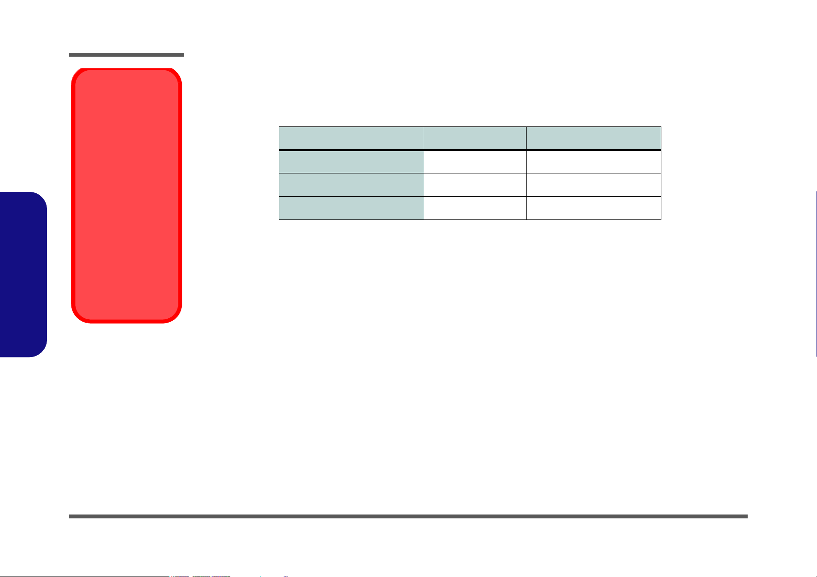
System Specifications
The differences between the 8880 and 888E notebook computer series are as follows:
Feature 8880 Series 888E Series
Video Card ATI Radeon7500 ATI Radeon 9000
Direct X Compliance Direct X 6 Direct X 8.1
USB Port Type 1.1 2.0
Table 1 - 1 - Model Differences
Processor Options
• Intel Pentium® 4 Processor - 2.0/ 2.2/ 2.4/2.6 GHz (400MHz FSB)
•(
µ0.13) 0.13 Micron Process Technology
• CPU Package - FC-PGA2 (478-pin)
• 512K L2 Cache (on die)
• Intel Pentium® 4 Processor - 2.26/ 2.4/ 2.53/ 2.66/ 2.8/ 3.06* GHz (533MHz FSB*)
•(
µ0.13) 0.13 Micron Process Technology
• CPU Package - FC-PGA2 (478-pin)
•512K L2 Cache
* Only 888E notebooks with processors of 3.06GHz support Hyper-Threading (see “Hyper-Threading” on page E - 2).
Core Logic
• Intel® 845E + ICH3
Structure
• Fully PC99 Compliant
• ACPI 1.0B Compliant
• PC2001 Compliant
1 - 2 System Specifications
Page 16

Security
• Security (Kensington® Type) Lock Slot
• BIOS Password
Memory
• 64 bit data bus system memory
• Two 200-pin DDR SODIMM sockets, supporting DDR SDRAM SODIMM (2.5V) - DDR200 or DDR266 compliant
• Expandible memory up to 1GB (128/256/512MB SODIMM Modules)
BIOS
• One 256KB Flash ROM
• Insyde BIOS with smart battery
• Plug and Play (1.0a), ACPI 1.0B
Introduction
1.Introduction
LCD
• 15.0" 1600 x 1200 UXGA TFT (8880)
• 15.7" 1280 x 1024 SXGA TFT (8880 & 888E)
• 16.0" 1600 x 1200 UXGA TFT (888E)
• 16.0" 1280 x 1024 SXGA TFT (888E)
Display
• ATI Mobility M7 (8880)
• ATI Mobility M9 (888E)
64MB DDR graphic memory on board
OR
128MB DDR graphic memory on board
4 * UltraAGP™
128-bit 2D/3D graphics engine
Motion compensation and IDCT for DVD content playback
accelerator
Fully DirectX 6 compliant graphics engine (8880)
Fully DirectX 8.1 compliant graphics engine (888E)
CRT resolution up to 1920*1200 * 16M
Model Differences
You may identify if the
computer is an 8880 or
888E from the video
card. After you have installed the video driver
go to the Advanced
Display Properties
and check the card
type. If the card is a
MOBILITY RADEON
7500, then the ma-
chine is an 8880. If the
video card is a MOBIL-
ITY RADEON 9000
then the machine is an
888E, and supports
USB 2.0.
System Specifications 1 - 3
Page 17

1.Introduction
Introduction
Jumper Settings for
Multiple Hard Disk
Use
If you are using more
than one hard disk in
your computer, make
sure to set the jumpers
on all your hard disks
to the cable select op-
tion in order for the
system to recognize all
the disks (see your
hard disk manual or
the information printed
on the hard disk itself
for details on the jumper settings).
Storage
• One fixed FDD 9.5/12.7mm
• One changeable 2.5" 9.5mm primary HDD
• Changeable primary drive (Bay One) for one of the following:
DVD-ROM (12.7mmH) 8X
CD-ROM (12.7mmH) 24X
CD-RW (12.7mmH) 8X/ 4X/ 24X
Combo Drive (DVD-ROM + CD-RW) 8X/ 8X/ 8X/ 24X
DVD-RW (12.7mmH) 1X/1X/12X/16X/24X
• Built-in modular drive (Bay Two) for one of the following:
DVD-ROM (12.7mmH) 8X
CD-ROM (12.7mmH) 24X
CD-RW (12.7mmH) 8X/ 4X/ 24X
Combo Drive (DVD-ROM + CD-RW) 8X/ 8X/ 8X/ 24X
DVD-RW (12.7mmH) 1X/1X/12X/16X/24X
3rd HDD
IP sharing module
• Changeable drive (Bay Three) for one of the following:
2nd HDD (optional)
TV-Tuner (optional)
• One portable MP3 player (optional)
Make sure the MP3 player is not in the slot when installing operating systems, and any of the drivers listed in User’s Manual.
1 - 4 System Specifications
Software Installation Warning
Page 18

Audio
• AC'97 2.2 compliant interface
• Compatible with Sound-Blaster PRO™ 16
• S/PDIF Digital output (5.1 CH) for DVD content and Stereo Audio
• Built-in microphone
•Audio DJ
• Advanced Wavetable Synthesizer
• 2 built-in speakers
• Virtual AC3
• Full Duplex
• Direct Sound™ 3D Accelerator
Introduction
Keyboard
• “Win Key” keyboard including a numeric keyboard
• Built-in 3 instant keys, www, email, and player
PC Card
• Two type II PCMCIA 3.3V/5V sockets, OR one type III PCMCIA 3.3V/5V socket (no Zoomed Video support)
1.Introduction
System Specifications 1 - 5
Page 19

1.Introduction
Introduction
Interface
• Built-in TouchPad (PS/2)
• Four USB ports
USB 2.0 ports for 888E (USB 1.1 compatible)
USB 1.1 ports for 8880
• One IEEE 1394 port
• One S-Video-Out jack for TV output
• One S-Video-In jack (
• One parallel port (LPT1), supporting ECP / EPP 1.7 and 1.9
• One COM port
• Fast Infrared (FIR) file transfer IrDA 1.1
• One external CRT monitor
• One external keyboard/mouse (through Y cable) PS/2 port
• One line-in jack
• One microphone-in jack
(You must use the Y-cable provided to enable the S/PDIF Out and Microphone-In functions (S/PDIF connection is to
the longer end of the cable.)
• One Sony Memory Stick™ socket
• One RJ-11 jack for 56k MDC modem
• One RJ-45 jack for 100M/10M LAN
• One S/PDIF out port
(You must use the Y-cable provided to enable the S/PDIF Out and Microphone-In functions (S/PDIF connection is to
the longer end of the cable.)
• DC-in jack
The S-Video in jack will only be available if you have the Optional TV Tuner installed.)
Communication
• Wireless Infrared transfer IrDA 1.1, 1cm~1M operating distance, 4Mbps FIR
• 10/100Mb Ethernet LAN built-in
• 802.11b Wireless LAN, Mini-PCI interface (optional)
• 56K MDC modem V.90 compliant (V.92 software driver upgradeable)
• IP sharing module for xDSL or Cable Modem (optional)
1 - 6 System Specifications
Page 20

Power Management
• Supports ACPI v1.0B
• Supports APM v1.2
• Soft Off by system power button
• Supports suspend to disk
• Battery low suspend
• Resume from alarm
• Close-cover switch
Power
• Full Range 120 watts AC adapter - AC in 100~240V, 47~63Hz
• Supports Smart Lithium-Ion battery 12 cells
Indicators
• LED indicator (HDD, power status, Num Lock, Caps Lock, Scroll Lock, AC-In, battery charging, e-mail)
• Audio DJ control display (power, MP3, Audio, Play/Pause, FWD, RWD, Stop, Volume+, Volume-, EQ)
Environmental Spec
• TemperatureRelative Humidity
• Operating: 5
• Non-Operating: -20
°C~ 35°C Operating: 20% ~ 80%
°C ~ 60°CNon-Operating: 10% ~ 90%
Introduction
1.Introduction
Physical Dimensions
• 329 (w) x 299 (d) x 54.5 (h) mm
Weight
• 4.9 kg with 12-cell Lithium-Ion battery
System Specifications 1 - 7
Page 21

1.Introduction
Introduction
Optional
• DVD-ROM Drive (12.7mmH)
•CD-RW Drive (12.7mmH)
• Combo Drive (DVD-ROM and CD-RW, 12.7mmH)
• DVD-RW Drive (12.7mmH)
• Portable MP3 player
• Mini PCI Wireless LAN module
• Software DVD player
• IP sharing module
• TV-Tuner module
1 - 8 System Specifications
Page 22
Introduction
7
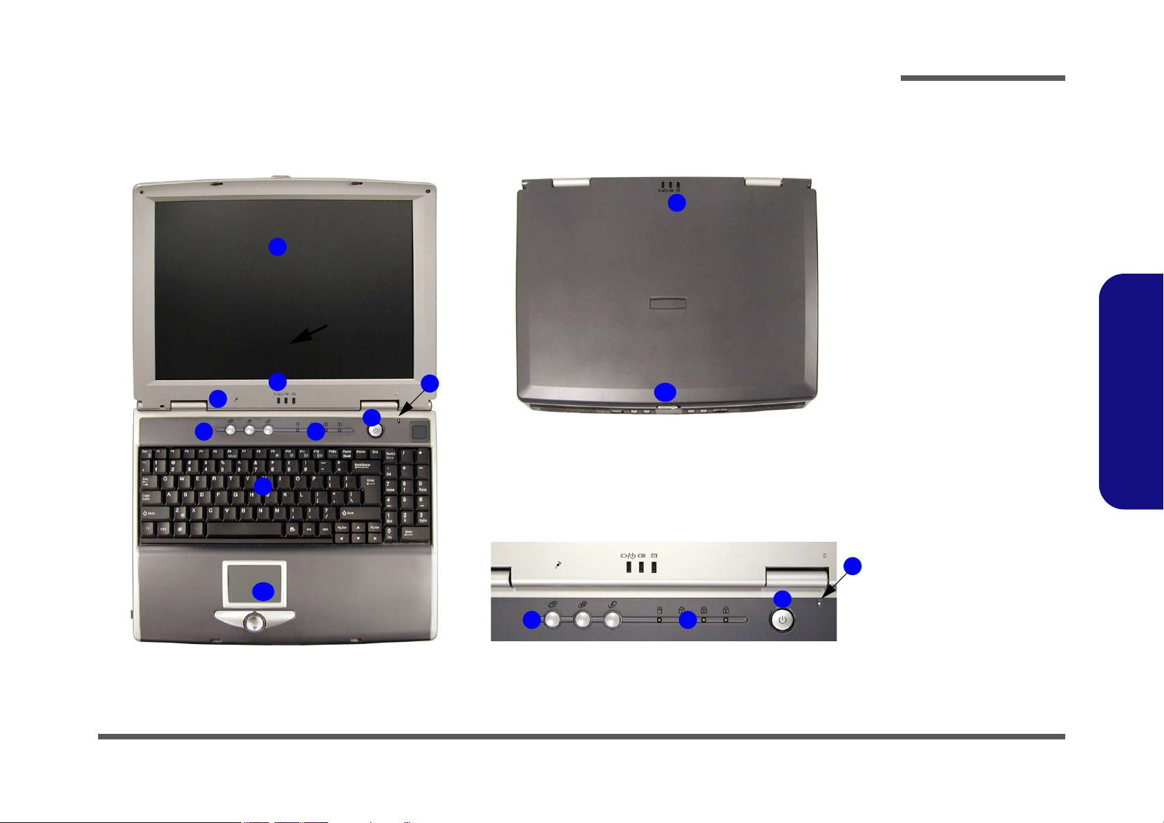
External Locator - Top Views
1
2
3
4
8
5
6
7
10
Figure 1 - 1
Top Views
1. LCD
2. LED Power,
2
Battery & E-Mail
Status Indicators
3. Built-In
Microphone
4. Hot-Key buttons
5. LED Status
Indicators
6. Power Button
7. Close Cover
Switch
8. Keyboard
9. TouchPad and
Buttons
10. LCD Latch
1.Introduction
9
4
5
6
External Locator - Top Views 1 - 9
Page 23
Introduction
1.Introduction
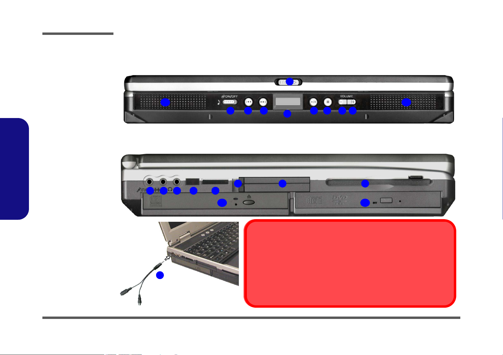
Figure 1 - 2
Front View
1. LCD Latch
2. Audio “DJ” CD
Player Control
Panel On/Off
Switch
3. Previous Track
4. Next Track
5. LCD
6. Play/Pause
7. Stop
8. Volume Down
9. Volume Up
10. Speakers
Figure 1 - 3
Left Side View
1. S/PDIF Out Port/
Microphone-In
Jack
2. Y-Cable
3. Line-In Jack
4. Headphone-Out
Jack
5. Infrared
Transceiver
6. Sony Memory
Stick™ Socket
7. PC Card Slot
Eject Buttons
8. PC Card Slot
9. FDD
10. Drive BayOne
11. Drive Bay Two
External Locator - Front View & Left Side View
1
2 876
1
3
54
6
11
43
5
S/PDIF Out & Microphone-In Functions
You must use the Y-cable provided to enable the S/PDIF Out and MicrophoneIn functions (S/PDIF connection is to the longer end of the cable).
2
With the TV Tuner installed, the line-in jack will only be functional while the TV Studio
software is running.
Line-In Function with TV Tuner Installed
1010
9
987
10
1 - 10 External Locator - Front View & Left Side View
Page 24
Introduction
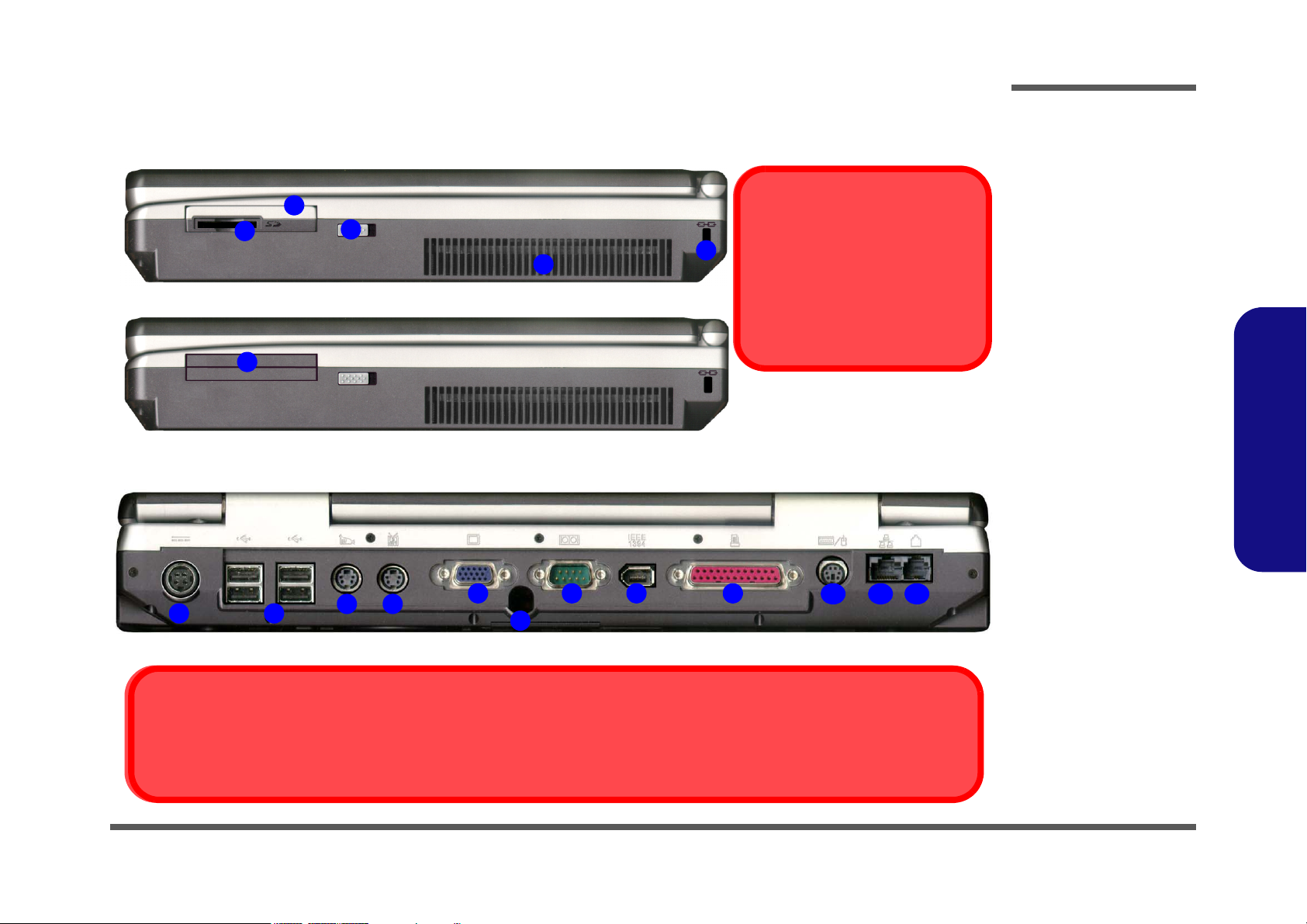
External Locator - Right Side & Rear Views
1
2
6
1
2
3
4
3
4
5
6
7 8 9
S-Video-In Port
The S-Video-In port will only be available if you have the Optional TV Tuner installed.
Figure 1 - 4
Right Side View
1. MP3 Player
Software Installation Warning
5
Make sure the MP3 player is not in
the slot when installing operating
systems, and any of the drivers
listed in User’s Manual.
(Optional)
2. MP3 Player SD/
MMC Slot
3. MP3 Player
Release Switch
4. Vent
5. Kensington Lock
6. MP3 Player Slot
(no MP3 Player
installed)
1.Introduction
Figure 1 - 5
Rear View
1. DC-In Jack
2. 4 * USB Ports
3. S-Video-In Port
(Optional)
4. S-Video-Out Port
5. External Monitor
10
11 12
(CRT) Port
6. Coaxial TV
Antenna Input
(Optional)
7. Serial Port
8. IEEE 1394 Port
9. Parallel Port
10. PS/2 Type Port
11. RJ-45 LAN Jack
12. RJ-11 Phone
Jack
External Locator - Right Side & Rear Views 1 - 11
Page 25
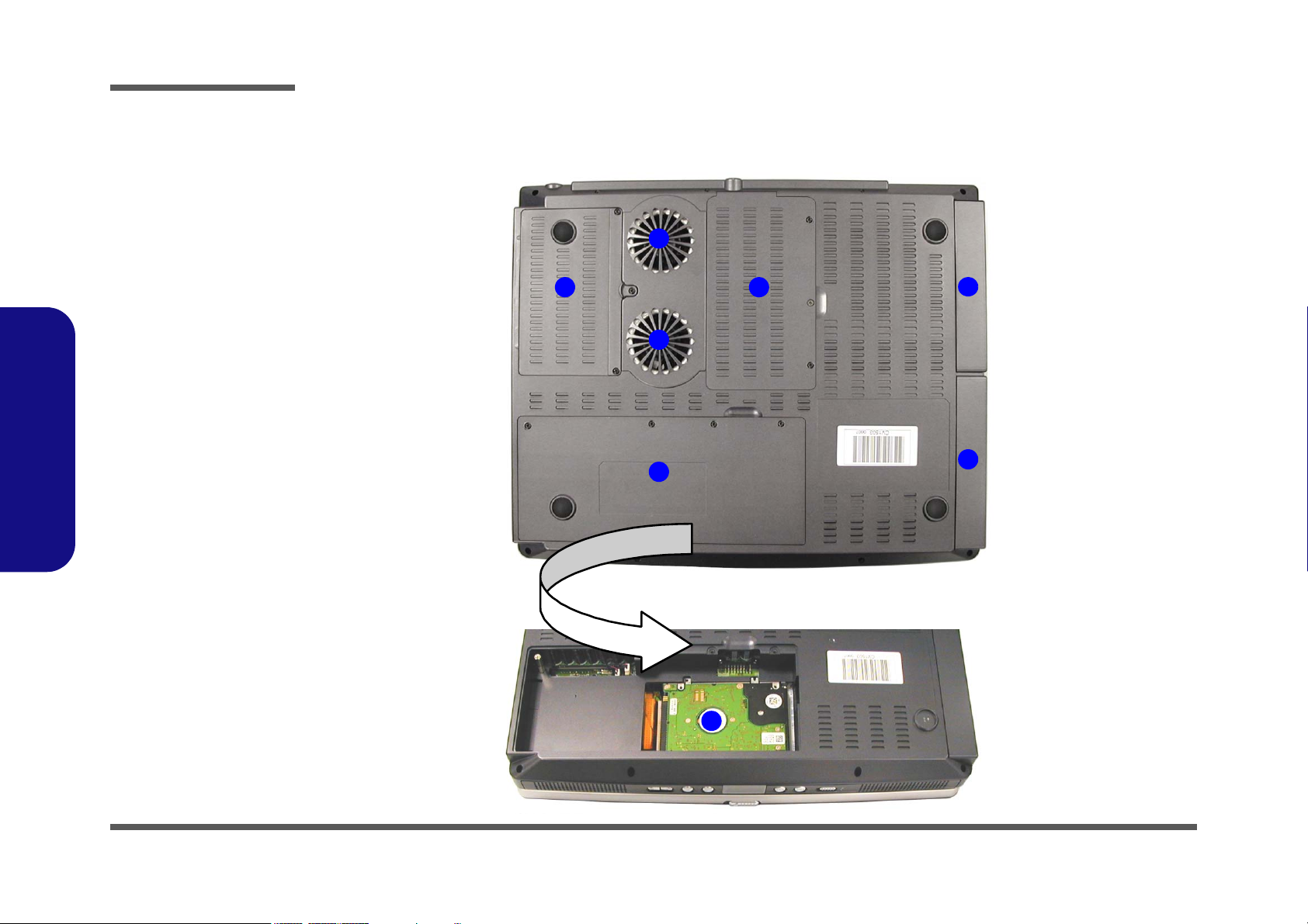
Introduction
1.Introduction
Figure 1 - 6
Bottom View
1. Vent/Fan Outlets
2. CPU Cover
3. Battery (the
primary HDD is
located under the
battery)
4. Primary Hard
Disk
5. Changeable
Drive Bay 3 (for
TV Tuner or
HDD)
6. Modular Drive Bay Two
7. Primary Drive Bay One
External Locator - Bottom View
1
2
1
3
5
6
7
1 - 12 External Locator - Bottom View
4
Page 26
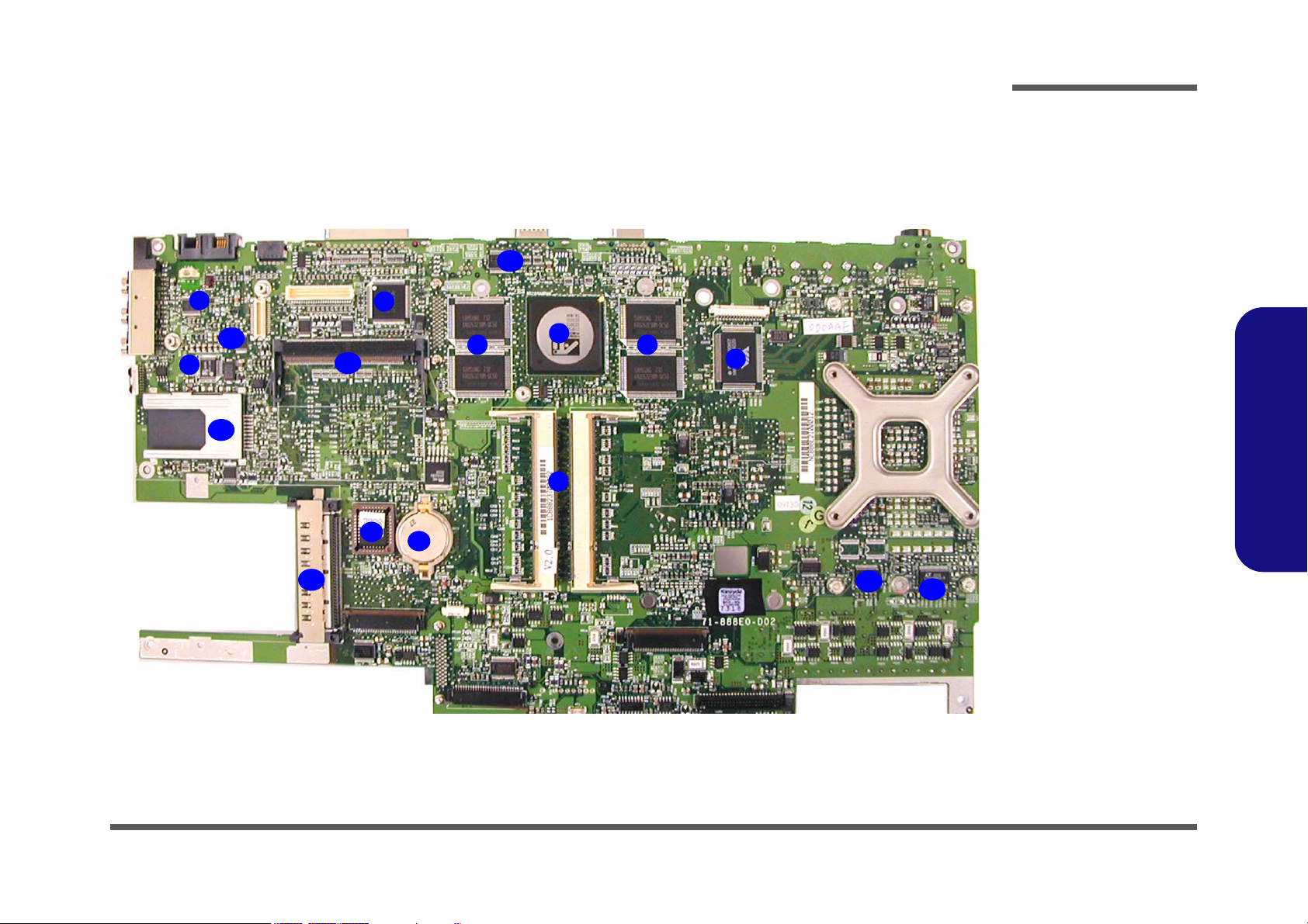
Introduction
Mainboard Overview - Top
Key Parts
9
11
8
14
13
15
4
6
5
Figure 1 - 7
Mainboard Top
Key Parts
1. Memory Sockets
(no memory
10
3
2
1
3
7
12
12
installed)
2. ATI Mobility
M9-P (or M7-P
for 8880 models)
3. DDR-SGRAM
4. 1394 Controller TSB43AB21
5. CMOS Battery
6. Flash ROM BIOS
7. USB 2.0
8. ALC201A
9. TPA0132
10. I/O Connector
11. LED Indicator
12. VCORE
13. CARDBUS
14. Memory Stick
Socket
15. Wireless LAN
Module Socket
1.Introduction
Mainboard Overview - Top 1 - 13
Page 27
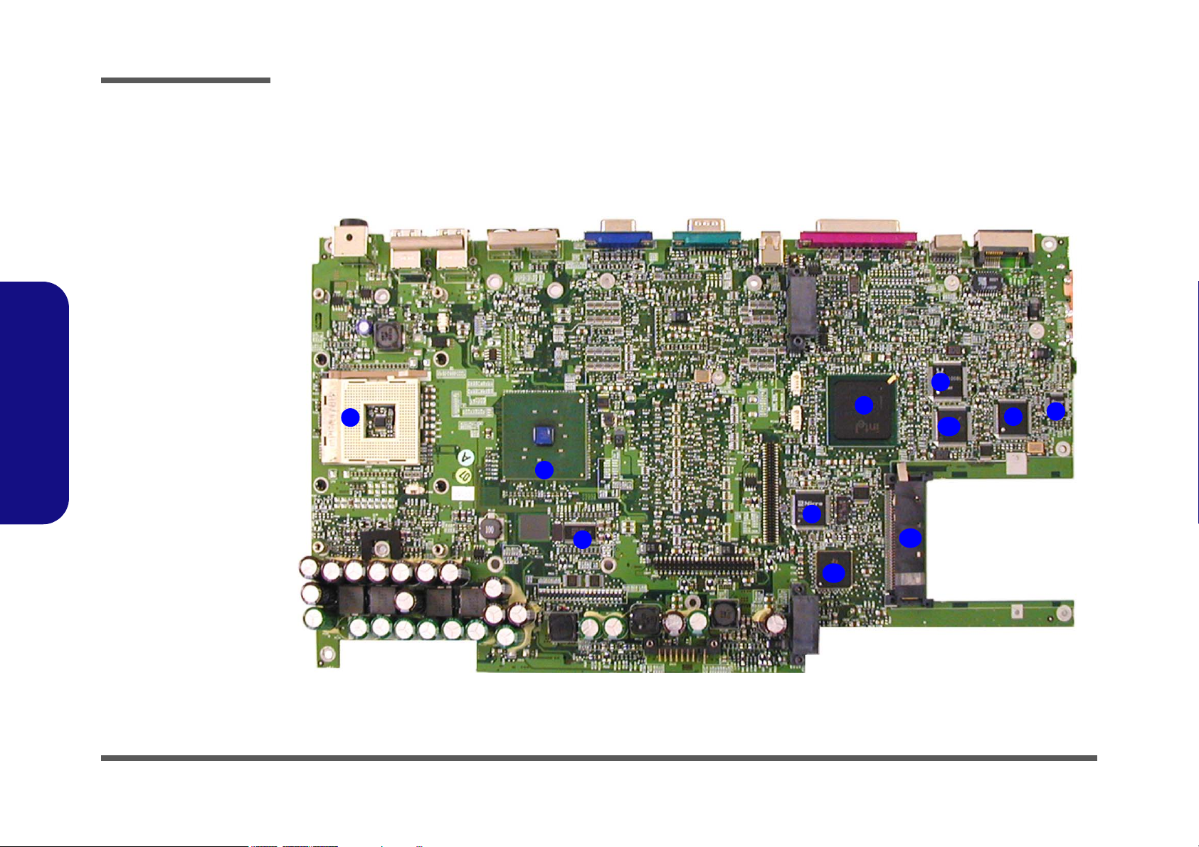
Introduction
1.Introduction
Figure 1 - 8
Mainboard Bottom
Key Parts
1. CPU Socket (no
CPU installed)
2. MCH
3. Clock
4. ICH3-M
5. Realtek RTL8100
6. Media Reader
W83518D
7. Audio DJ
Controller
8. LPC Bridge &
Super I/O
9. KBC H8
10. PCI 1520
11. Cardbus
Mainboard Overview - Bottom
Key Parts
1
2
3
5
4
9
7
11
8
6
1 - 14 Mainboard Overview - Bottom
10
Page 28
Introduction
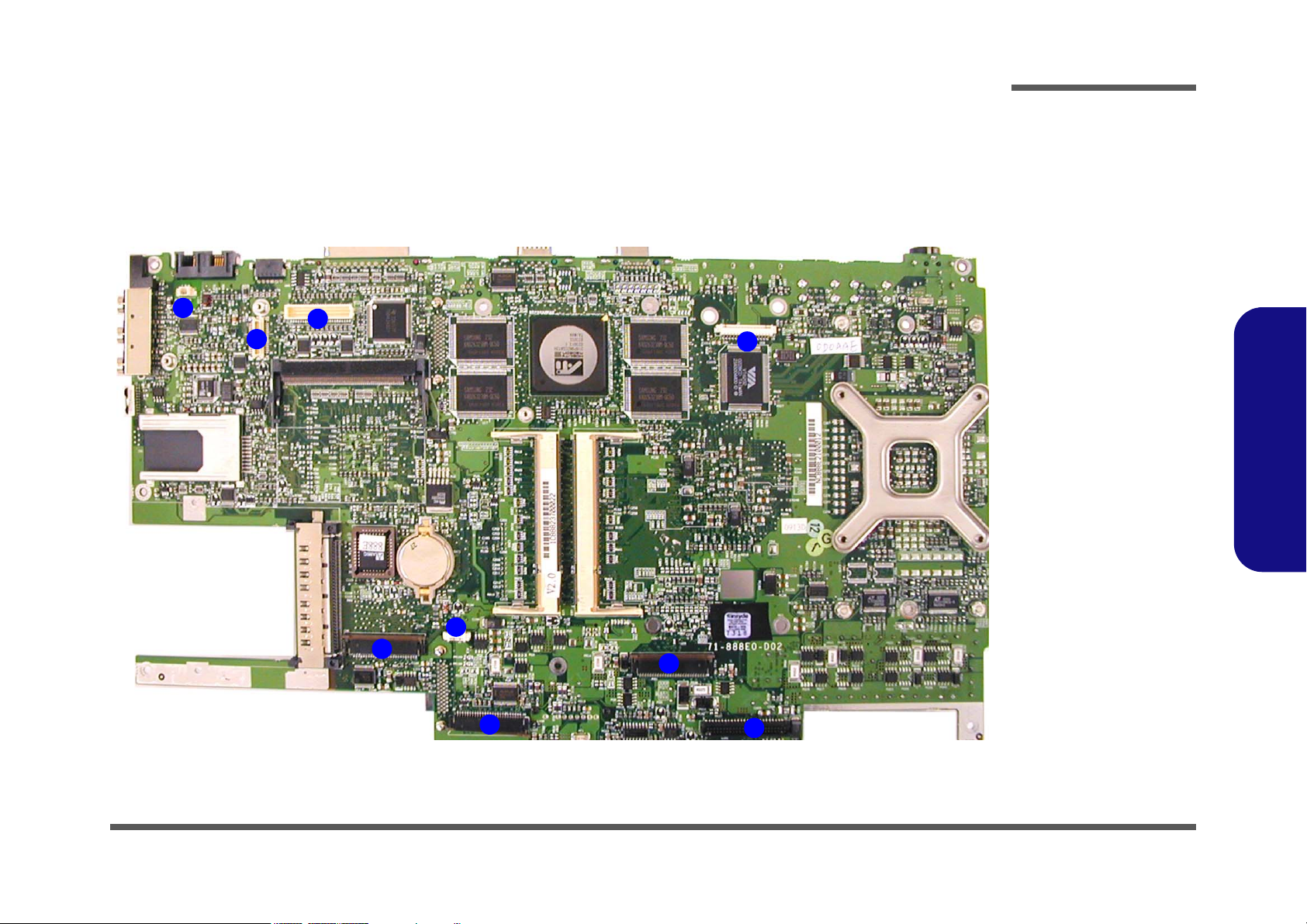
Mainboard Overview - Top
Connectors
1
2
3
4
Figure 1 - 9
Mainboard Top
Connectors
1. Modem Power
(JFAN1)
2. Modem
Connector
(JMDC1)
3. LCD/Inverter
connector (CN4)
9
6
7
4. Floppy Disk
Drive Connector
(CN6)
5. Audio Board
Connector (J2)
6. TouchPad
Connector (J1)
7. Keyboard
Connector
(JKB1)
8. Hard Disk Drive
& MP3 Board
Connector
(CON1)
9. Switch Keyboard
Connector(J3)
1.Introduction
5
8
Mainboard Overview - Top 1 - 15
Page 29
Introduction
1.Introduction
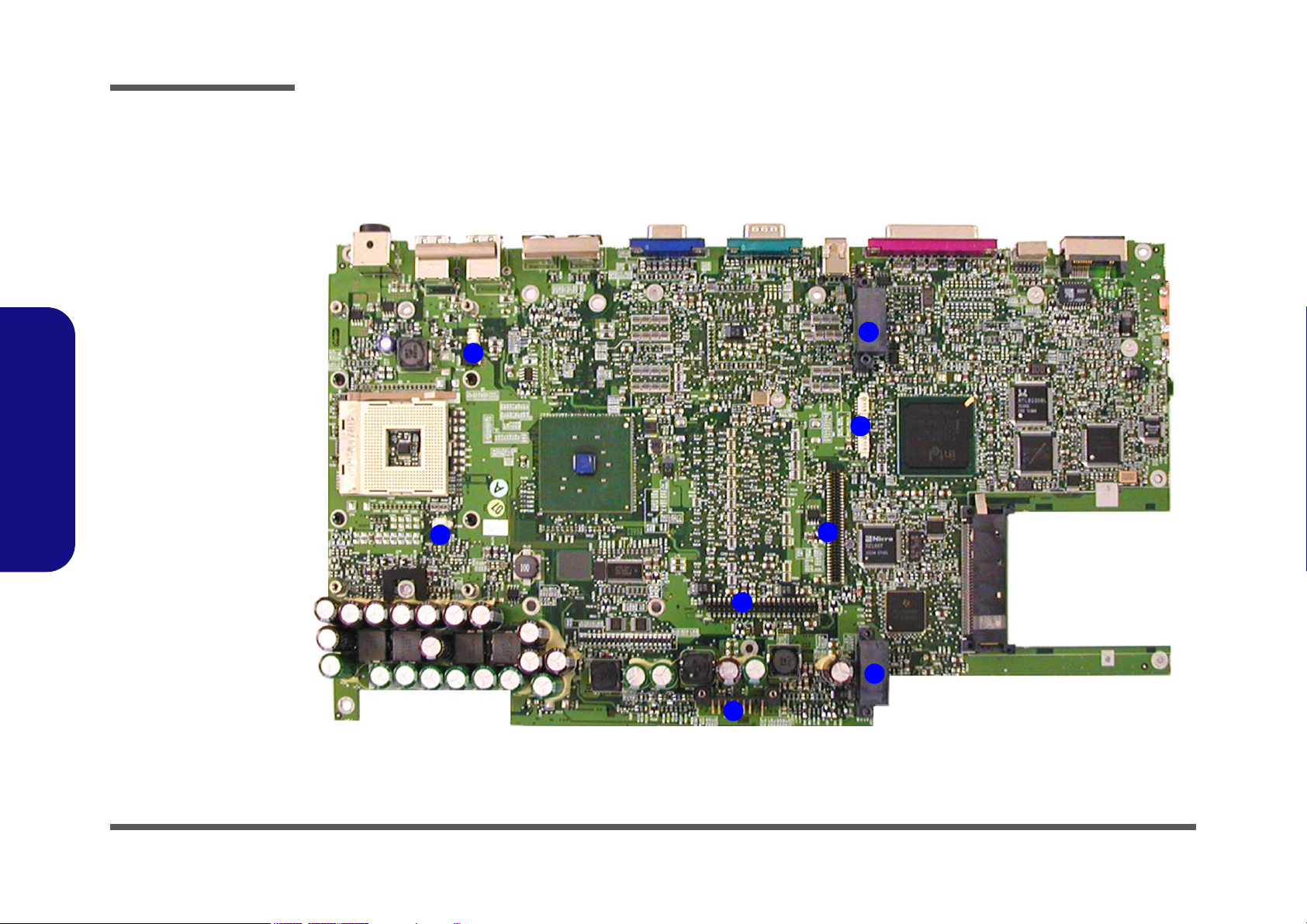
Figure 1 - 10
Mainboard Bottom
Connectors
1. Fan Connector
(JFAN2)
2. Fan Connector
(JFAN3)
3. Battery
Connector
(CN15)
4. Hard Disk
Connector
(JHDD1)
5. TV Tuner
Connector
(CN17)
6. IP Sharing
Module Jumper
(J6 & J7)
Note: J6 & J7 must
have a terminator inserted in order to use
the IP sharing module.
Mainboard Overview - Bottom
Connectors
2
1
1
7
6
5
4
7. Bay Two Device
Connector
(CON2)
8. Bay One Device
Connector
(JCD1)
1 - 16 Mainboard Overview - Bottom
8
3
Page 30

2: Disassembly
Overview
This chapter provides step-by-step instructions for disassembling parts and subsystems. When it comes to reassembly,
reverse the procedures (unless otherwise indicated).
We suggest you completely review any procedure before you take the computer apart.
Disassembly
Component Parts
Procedures such as upgrading/replacing the RAM, CD device and hard disk are included in the User’s Manual but are
repeated here for your convenience.
To make the disassembly process easier each section may have a box in the page margin. Information contained under
the figure # will give a synopsis of the sequence of procedures involved in the disassembly procedure. A box with a
lists the relevant parts you will have after the disassembly process is complete. Note: The parts listed will be for the disassembly procedure listed ONLY, and not any previous disassembly step(s) required. Refer to the part list for the previous disassembly procedure. The amount of screws you should be left with will be listed here also.
A box with a 5 will provide any possible helpful information. A box with a contains warnings.
An example of these types of boxes are shown in the sidebar.
2.Disassembly
5
Information
Warning
Overview 2 - 1
Page 31

Disassembly
2.Disassembly
NOTE: All disassembly procedures assume that the system is turned OFF, and disconnected from any power supply (the
battery is removed too).
Maintenance Tools
The following tools are recommended when working on the notebook PC:
• M3 Philips-head screwdriver
• M2.5 Philips-head screwdriver (magnetized)
• M2 Philips-head screwdriver
• Small flat-head screwdriver
• Pair of needle-nose pliers
• Anti-static wrist-strap
Connections
Connections within the computer are one of four types:
Locking collar sockets for ribbon connectors To release these connectors, use a small flat-head screwdriver to gently pry
the locking collar away from its base. When replacing the connection, make
sure the connector is oriented in the same way. The pin1 side is usually not
indicated.
2 - 2 Overview
Pressure sockets for multi-wire connectors To release this connector type, grasp it at its head and gently rock it from side
to side as you pull it out. Do not pull on the wires themselves. When replacing
the connection, do not try to force it. The socket only fits one way.
Pressure sockets for ribbon connectors To release these connectors, use a small pair of needle-nose pliers to gently
lift the connector away from its socket. When replacing the connection, make
sure the connector is oriented in the same way. The pin1 side is usually not
indicated.
Board-to-board or multi-pin sockets To separate the boards, gently rock them from side to side as you pull them
apart. If the connection is very tight, use a small flat-head screwdriver - use
just enough force to start.
Page 32

Maintenance Precautions
The following precautions are a reminder. To avoid personal injury or damage to the computer while performing a removal and/or replacement job, take the following precautions:
1. Don't drop it. Perform your repairs and/or upgrades on a stable surface. If the computer falls, the case and other
components could be damaged.
2. Don't overheat it. Note the proximity of any heating elements. Keep the computer out of direct sunlight.
3. Avoid interference. Note the proximity of any high capacity transformers, electric motors, and other strong mag-
netic fields. These can hinder proper performance and damage components and/or data. You should also monitor
the position of magnetized tools (i.e. screwdrivers).
4. Keep it dry. This is an electrical appliance. If water or any other liquid gets into it, the computer could be badly
damaged.
5. Be careful with power. Avoid accidental shocks, discharges or explosions.
•Before removing or servicing any part from the computer, turn the computer off and detach any power supplies.
•When you want to unplug the power cord or any cable/wire, be sure to disconnect it by the plug head. Do not pull on the wire.
6. Peripherals – Turn off and detach any peripherals.
7. Beware of static discharge. ICs, such as the CPU and main support chips, are vulnerable to static electricity.
Before handling any part in the computer, discharge any static electricity inside the computer. When handling a
printed circuit board, do not use gloves or other materials which allow static electricity buildup. We suggest that
you use an anti-static wrist strap instead.
8. Beware of corrosion. As you perform your job, avoid touching any connector leads. Even the cleanest hands produce oils which can attract corrosive elements.
9. Keep your work environment clean. Tobacco smoke, dust or other air-born particulate matter is often attracted
to charged surfaces, reducing performance.
10. Keep track of the components. When removing or replacing any part, be careful not to leave small parts, such as
screws, loose inside the computer.
Disassembly
Power Safety
Warning
Before you undertake
any upgrade procedures, make sure that
you have turned off the
power, and disconnected all peripherals
and cables (including
telephone lines). It is
advisable to also remove your battery in
order to prevent accidentally turning the
machine on.
2.Disassembly
Cleaning
Do not apply cleaner directly to the computer, use a soft clean cloth.
Do not use volatile (petroleum distillates) or abrasive cleaners on any part of the computer.
Overview 2 - 3
Page 33

Disassembly
Disassembly Steps
The following table lists the disassembly steps, and on which page to find the related information. PLEASE PERFORM
THE DISASSEMBLY STEPS IN THE ORDER INDICATED.
To remove the Battery:
1. Remove the battery page 2 - 6
To remove the Keyboard:
1. Remove the battery page 2 - 6
2. Remove the keyboard page 2 - 13
2.Disassembly
To remove the Bay One Device:
1. Remove the battery page 2 - 6
2. Remove the Bay One device page 2 - 7
To remove the Bay Two Device:
1. Remove the battery page 2 - 6
2. Remove the Bay Two device page 2 - 8
To remove the Primary HDD:
1. Remove the battery page 2 - 6
2. Remove the primary HDD page 2 - 9
To remove the HDD in Bay Two:
1. Remove the battery page 2 - 6
2. Remove the HDD in Bay Two page 2 - 10
To remove the HDD in Bay Three:
1. Remove the battery page 2 - 6
2. Remove the HDD in Bay Three page 2 - 11
To remove the TV Tuner Module:
1. Remove the battery page 2 - 6
2. Remove the TV Tuner module page 2 - 12
To remove the System Memory:
1. Remove the battery page 2 - 6
2. Remove the keyboard page 2 - 13
3. Remove the memory page 2 - 14
To remove the CPU:
1. Remove the battery page 2 - 6
2. Remove the CPU page 2 - 15
To remove the Wireless LAN Module:
1. Remove the battery page 2 - 6
2. Remove the keyboard page 2 - 13
3. Remove the WLAN module page 2 - 17
To remove the Switch Keyboard Assembly:
1. Remove the battery page 2 - 6
2. Remove the keyboard page 2 - 13
3. Remove the switch keyboard assembly page 2 - 18
To remove the Bottom Case Assembly:
1. Remove the battery page 2 - 6
2. Remove the Bay One device page 2 - 7
3. Remove the Bay Two device page 2 - 8
2 - 4 Disassembly Steps
Page 34

Disassembly
4. Remove the primary HDD page 2 - 9
5. Remove the HDD in Bay Two page 2 - 10
6. Remove the HDD in Bay Three page 2 - 11
7. Remove the TV Tuner Module page 2 - 12
8. Remove the keyboard page 2 - 13
9. Remove the memory page 2 - 14
10. Remove the CPU page 2 - 15
11. Remove the WLAN module page 2 - 17
12. Remove the switch keyboard assembly page 2 - 18
13. Remove the bottom case assembly page 2 - 19
To remove the HDD & MP3 Converter Board:
1. Remove the battery page 2 - 6
2. Remove the bottom case assembly page 2 - 19
3. Remove the HDD & MP3 con board page 2 - 21
To remove the Audio Board:
1. Remove the battery page 2 - 6
2. Remove the bottom case assembly page 2 - 19
3. Remove the audio board page 2 - 22
To remove the Fan Module:
1. Remove the battery page 2 - 6
2. Remove the bottom case assembly page 2 - 19
3. Remove the fan module page 2 - 25
To remove the Cardbus Module:
1. Remove the battery page 2 - 6
2. Remove the bottom case assembly page 2 - 19
3. Remove the cardbus module page 2 - 26
To remove the Floppy Disk Drive Assembly:
2.Disassembly
1. Remove the battery page 2 - 6
2. Remove the bottom case assembly page 2 - 19
3. Remove the FDD assembly page 2 - 27
To remove the TouchPad Module:
1. Remove the battery page 2 - 6
2. Remove the bottom case assembly page 2 - 19
3. Remove the TouchPad module page 2 - 28
To remove the Chip Heat Sink & Modem:
1. Remove the battery page 2 - 6
2. Remove the bottom case assembly page 2 - 19
3. Remove the chip heat sink and modem page 2 - 23
To remove the Mainboard:
1. Remove the battery page 2 - 6
2. Remove the bottom case assembly page 2 - 19
3. Remove the mainboard page 2 - 24
To remove the Inverter Board:
1. Remove the battery page 2 - 6
2. Remove the bottom case assembly page 2 - 19
3. Remove the inverter board page 2 - 29
To remove the LCD:
1. Remove the battery page 2 - 6
2. Remove the bottom case assembly page 2 - 19
3. Remove the inverter board page 2 - 29
4. Remove the LCD page 2 - 30
Disassembly Steps 2 - 5
Page 35
Disassembly
Figure 2 - 1
Battery Removal
Sequence
a. Remove the 4
screws.
b. Apply pressure at
point 5 to push the
battery out.
2.Disassembly
Removing the Battery
1. Turn the computer OFF and turn it over.
2. Remove screws - in Figure 2 - 1a.
3. Apply gentle pressure at point to push the battery up and out of the computer.
1 4
5
a.
21 3 4
b.
5
6. Battery
•4 Screws
2 - 6 Removing the Battery
6
Page 36

Disassembly
Removing the Primary Drive Bay (Bay One) CD Device
1. Turn the computer OFF, remove the battery (page 2 - 6) and turn it over.
2. Remove screws - in (Figure 2 - 2a), then lift the cover off the changeable drive bay and set it aside.
3. Remove screw (Figure 2 - 2b), then gently push the device out of the bay (you may need to use a screwdriver to
do this).
a.
b.
1 3 4
5
1
4
2
3
c.
Figure 2 - 2
Primary Drive (Bay
One) CD Device
Removal
Sequence
a. Remove the screws
from the changeable
drive bay cover.
b. Remove screw 5.
c. Push the device out
of the computer.
2.Disassembly
6
4. Drive bay cover
5
Removing the Primary Drive Bay (Bay One) CD Device 2 - 7
6. CD device
•4 Screws
Page 37

Disassembly
Figure 2 - 3
Modular Drive (Bay
Two) Device
Removal
Sequence
a. Remove the screws
from the changeable
drive bay cover.
b. Remove screw 5.
c. Push the device out
of the computer.
2.Disassembly
Removing the Modular Drive Bay (Bay Two) Device
1. Turn the computer OFF, remove the battery (page 2 - 6) and turn it over.
2. Remove screws - in (Figure 2 - 3a), then lift the cover off the changeable drive bay and set it aside.
3. Remove screw (Figure 2 - 3b), then gently push the device out of the bay (you may need to use a screwdriver).
a.
b.
1 3 4
5
1
4
2
3
c.
5
4. Drive bay cover
6. CD device
•4 Screws
2 - 8 Removing the Modular Drive Bay (Bay Two) Device
6
Page 38

Disassembly
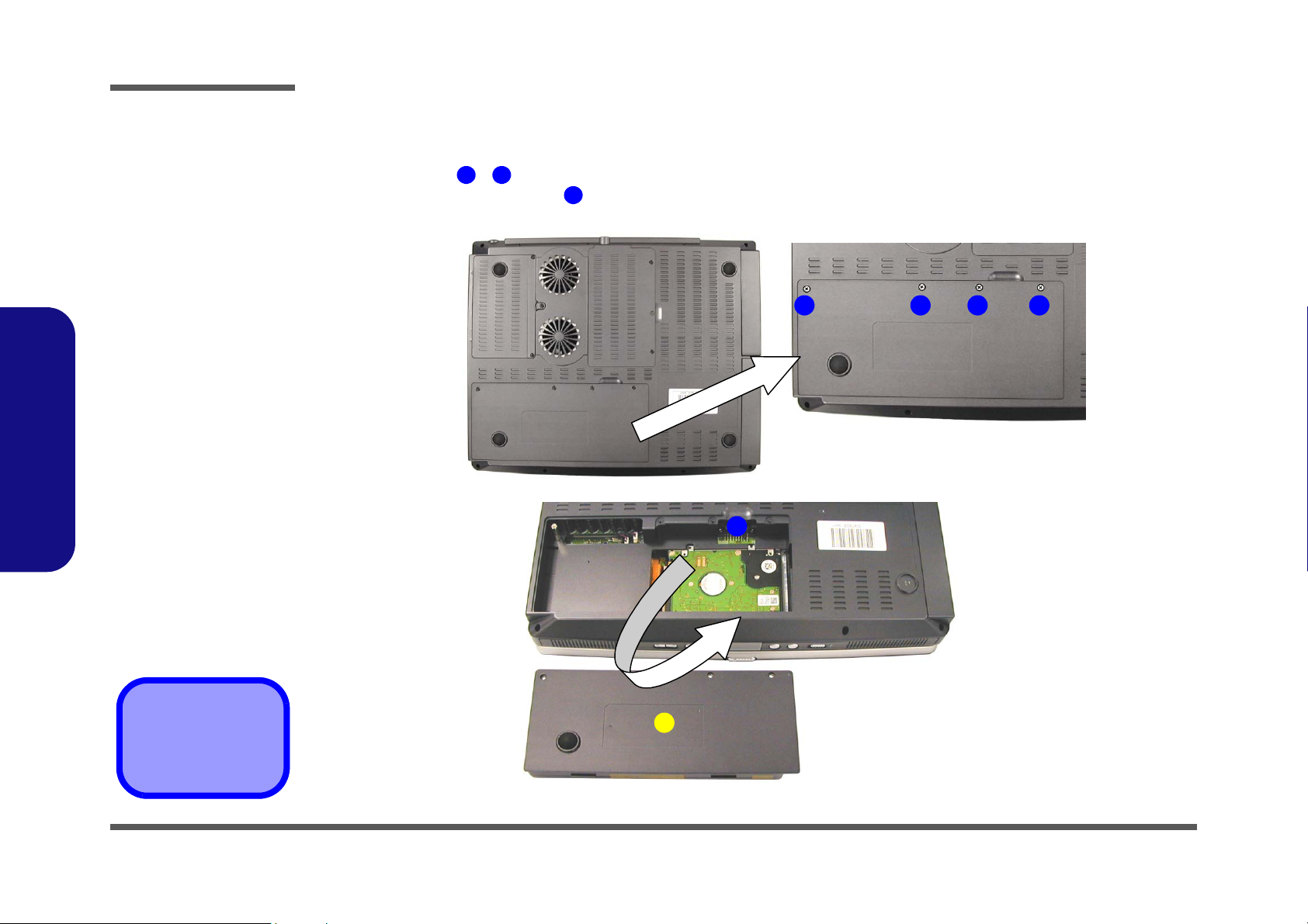
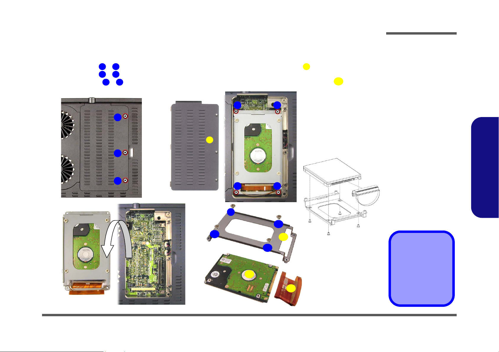
Removing the Primary Hard Disk
1. Turn the computer OFF, remove the battery (page 2 - 6) and turn it over.
2. Remove screws and (Figure 2 - 4a) and release the HDD connector cable .
3. Remove the HDD assembly from the bay.
4. Remove screws and (Figure 2 - 4c) and the HDD connector cable .
a.
c.
1 2 3
5 8 3
b.
21
3
4
3
5
Figure 2 - 4
Primary Hard Disk
Removal
Sequence
a. Remove the 2 screws
and release the HDD
cable
b. Remove the HDD as-
sembly.
c. Remove the 4 screws
and HDD cable.
2.Disassembly
HDD Cables
The illustrated HDD
cable may differ from
4
the one in your model
depending on the configuration purchased.
Be careful not to bend
the pins on the hard
disk when removing
the cable.
6
9
3. HDD cable
8
7
4. HDD
9. HDD case
•6 Screws
Removing the Primary Hard Disk 2 - 9
Page 39
Disassembly
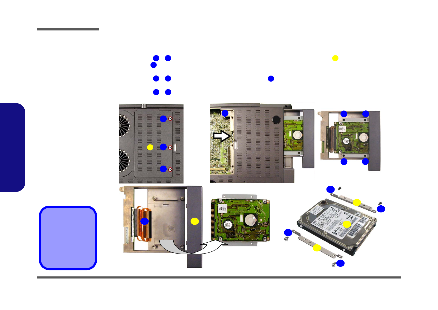
Figure 2 - 5
Bay Two HDD
Removal
Sequence
a. Remove the screws
from the changeable
drive bay cover.
b. Remove screw 5 and
push the device out
of the computer.
c. Remove the 4 screws
from the HDD case.
d. Disconnect the cable
and remove the HDD
assembly.
e. Remove the screws
from the assembly
brackets.
2.Disassembly
Removing the Hard Disk Drive in Bay Two
1. Turn the computer OFF, remove the battery (page 2 - 6) and turn it over.
2. Remove screws - (Figure 2 - 5a), then lift the cover off the changeable drive bay and set it aside.
3. Remove screw (Figure 2 - 5b), then gently push the device out of the bay (you may need to use a screwdriver to
do this).
4. Remove screws - (Figure 2 - 5c), and disconnect cable (Figure 2 - 5d), then take the HDD assembly out
of the case.
5. Remove screws - (Figure 2 - 5e) from the HDD assembly (note the disk orientation within the brackets).
a.
d.
1 3 4
5
6 9
12 15
10
b.
5
1
2
4
3
e.
c.
12
6
7
89
10
4. Drive bay cover
11. Drive case
16. HDD
17. Assembly brackets
•9 Screws
2 - 10 Removing the Hard Disk Drive in Bay Two
11
17
13
16
15
17
14
Page 40
Disassembly
Removing the Hard Disk Drive in Bay Three
1. Turn the computer OFF, remove the battery (page 2 - 6) and turn it over.
2. Remove screws - (Figure 2 - 6a), then lift the cover off the changeable drive bay and set it aside.
3. Remove screws - (Figure 2 - 6b), then lift the HDD assembly out of the bay.
4. Remove screws - (Figure 2 - 6d) to separate the HDD from the case, and disconnect cable .
a.
c.
1 3 4
5 8
9 12
b.
5
6
1
4
2
3
8
7
d.
9
13
Figure 2 - 6
Bay Three HDD
Removal
Sequence
a. Remove the screws
from the changeable
drive bay cover.
b. Remove the 4
screws.
c. Lift the HDD assem-
bly out of the bay.
d. Remove the 4 screws
from the HDD case,
and disconnect the
cable.
2.Disassembly
12
15
11
10
14
4. Drive bay cover
13. HDD cable
14. Drive case
15. HDD
13
Removing the Hard Disk Drive in Bay Three 2 - 11
•11 Screws
Page 41
Disassembly
Figure 2 - 7
TV Tuner Module
Removal
Sequence
a. Remove the screws
from the changeable
drive bay cover.
b. Remove cable con-
nector and the 4
screws.
c. Lift the TV Tuner
module out of the
computer.
2.Disassembly
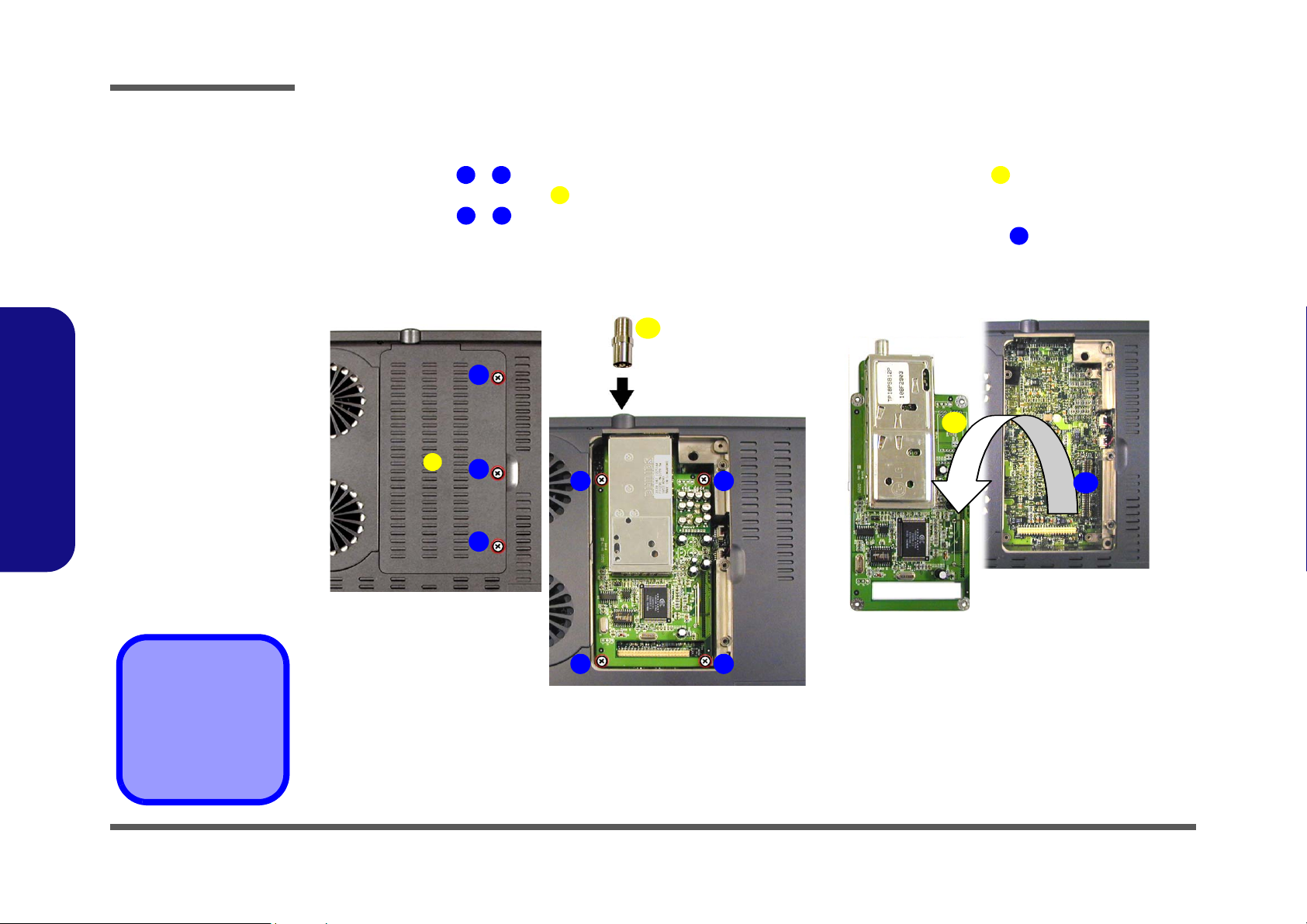
Removing the TV Tuner Module
1. Turn the computer OFF, remove the battery (page 2 - 6) and turn it over.
2. Remove screws - (Figure 2 - 7a), then lift the cover off the changeable drive bay and set it aside.
3. Remove the cable connector (Figure 2 - 7b).
4. Remove screws - (Figure 2 - 7b), and carefully lift the TV tuner module out of the computer.
1
3
5
6
9
5. When re-inserting the TV tuner, the module should align with the connecting pins at point (push firmly down to
make sure the module is secure).
a.
b. c.
1
4
2
6 7
3
5
10
4
11
11
4. Drive bay cover
5. Cable connector
10. TV tuner module
•7 Screws
2 - 12 Removing the TV Tuner Module
89
Page 42
Disassembly
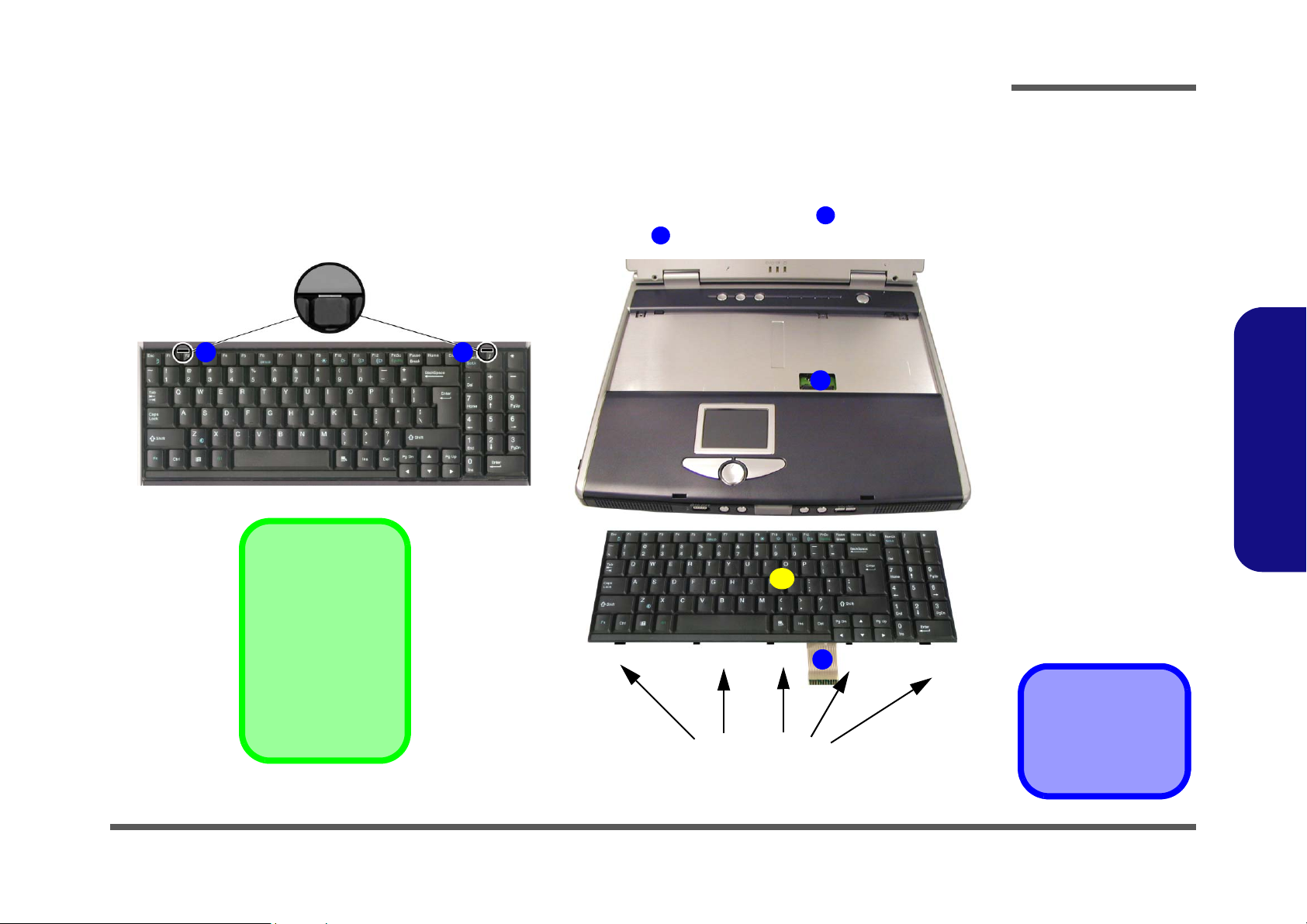
Removing the Keyboard
1. Turn the computer OFF and remove the battery (page 2 - 6).
2. Press the two keyboard latches at the top of the keyboard to elevate the keyboard from its normal position (you may
need to use a small screwdriver to do this).
3. Carefully lift the keyboard up and out, being careful not to bend the keyboard ribbon cable (Figure 2 - 8b).
4. Disconnect the keyboard ribbon cable from the locking collar socket (Figure 2 - 8b).
a.
1
2
b.
4
3
4
5
Re-Inserting the
Keyboard
5
Figure 2 - 8
Keyboard Removal
Sequence
a. Press the two latches
to release the keyboard.
b. Lift the keyboard out
and disconnect the
cable from the locking collar.
2.Disassembly
When re-inserting the
keyboard firstly align
the five keyboard tabs
(Figure 2 - 5b) at the
bottom of the keyboard
with the slots in the
case.
3
5. Keyboard
Keyboard Tabs
Removing the Keyboard 2 - 13
Page 43

Disassembly
Figure 2 - 9
Memory Removal
Sequence
a. Remove the screws
from the shielding
plate.
b. Remove the shield-
ing plate.
c. Pull the latches on
the memory sockets
to release the module(s). When the
module pops up, lift it
out.
Contact Warning
Be careful not to touch
2.Disassembly
the metal pins on the
module’s connecting
edge. Even the cleanest hands have oils
which can attract particles, and degrade the
module’s performance.
Removing the System Memory
1. Turn the computer OFF, remove the battery (page 2 - 6) and keyboard (page 2 - 13).
2. Remove screws - (Figure 2 - 9a) from the shielding plate (Figure 2 - 9b), and lift the plate up off the com-
puter.
3. Locate the memory sockets & (Figure 2 - 9c), and gently pull the latches & (and/or & ) on the
memory socket toward the front and rear of the computer as indicated.
4. The module (Figure 2 - 9c) will pop-up, and you can remove it.
5. Insert a new module holding it at about a 30° angle and fit the connectors firmly into the memory slot.
a.
c.
1 3 4
5 6 8
7
1
2
3
c.
10
9
7
5 6
9 10 11
b.
5 6
4
4. Shielding plate
7. Memory module(s)
•3 Screws
2 - 14 Removing the System Memory
11
8
Page 44
Disassembly
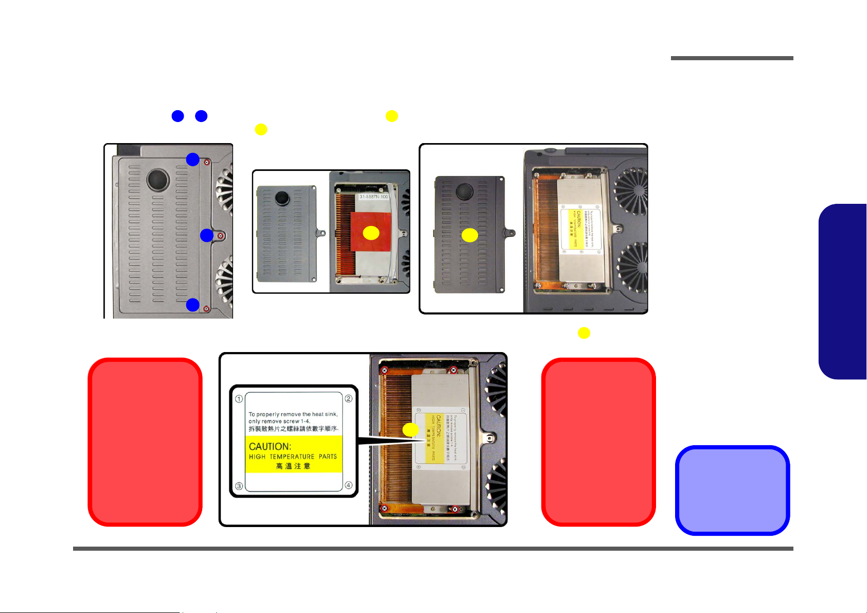
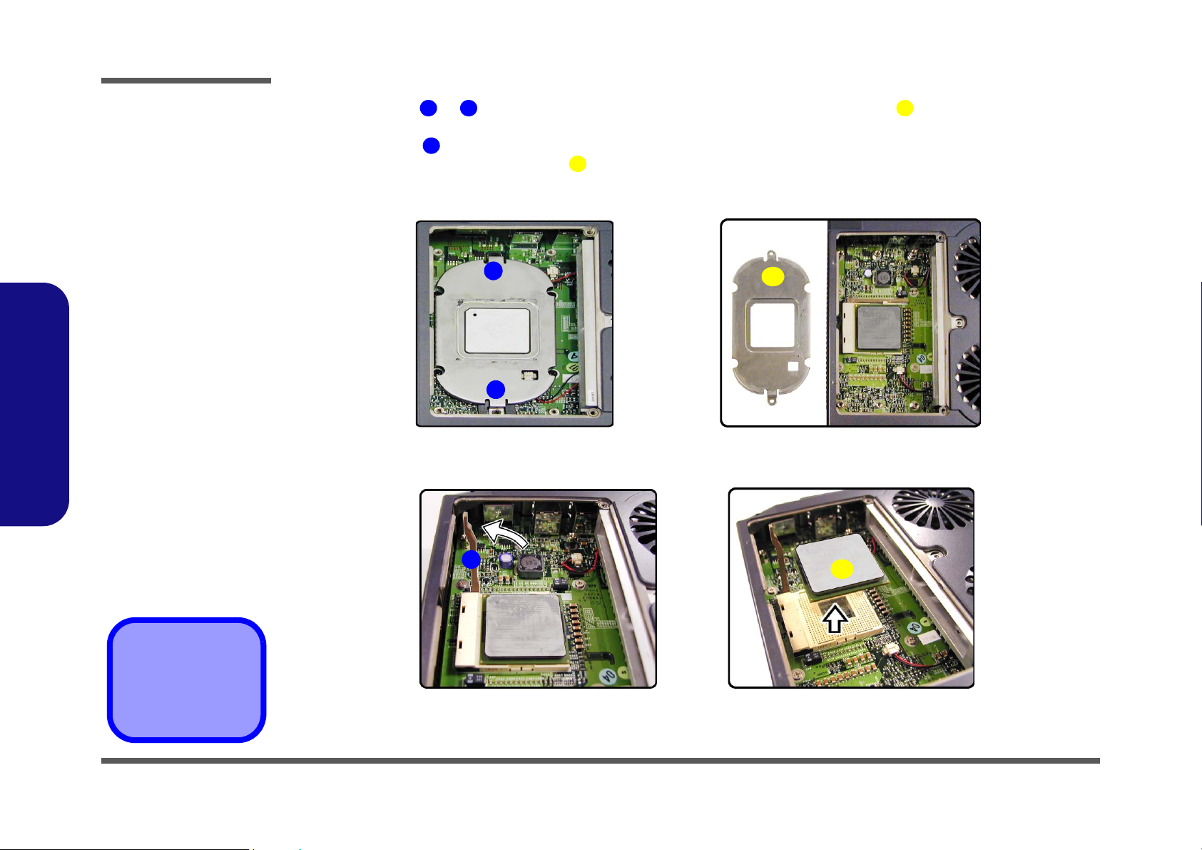
Removing the CPU
1. Turn the computer OFF, remove the battery (page 2 - 6) and turn it over.
2. Remove screws - (Figure 2 - 10a), and lift the cover (Figure 2 - 10c) up off the computer (it may be necessary to lift up the cover sticker (Figure 2 - 10b) in order to reveal the heat sink caution label).
a.
3. Remove the four screws from the heat sink in order indicated on the label, and lift out the heat sink Figure 2 - 11.
Caution
The heat sink, and
CPU area in general,
contains parts which
are subject to high
temperatures. Allow
the area time to cool
before removing these
parts.
1 3 5
4
b.
1
2
4
3
c.
5
6
Reassembly Screw
Order
6
When replacing the
heat sink, make sure
you insert the screws
in the same order indicated on the label.
Figure 2 - 10
Processor
Removal
Sequence
a. Remove the three
screws from the CPU
cover.
b. Remove the CPU
cover
c. Lift up the cover stick-
er if necessary.
.
2.Disassembly
Figure 2 - 11
Processor
Removal
Sequence (cont’d)
Remove the four
screws from the heat
sink in the order in-
dicated.
5. CPU Cover
6. Heat Sink
•7 Screws
Removing the CPU 2 - 15
Page 45
Disassembly
Figure 2 - 12
Processor
Removal
Sequence
(cont’d)
a. Remove the screws
from the bracket.
b. Lift the bracket up.
c. Raise the latch to un-
lock the CPU.
d. Lift the CPU out of
the socket.
2.Disassembly
4. Remove screws & (Figure 2 - 12a) from the CPU bracket, then lift the bracket off the CPU (Figure 2 -
1 2 3
12b).
5. Fully raise latch in the direction indicated in Figure 2 - 12c to unlock the CPU.
6. Carefully (it may be hot) lift the CPU up out of the socket. (Figure 2 - 12d).
4
5
7. When re-inserting the CPU pay careful attention to the pin alignment, it will fit only one way (don’t force it!).
a.
1
2
c.
b.
3
d.
3. CPU bracket
5. CPU
•2 Screws
2 - 16 Removing the CPU
4
5
Page 46
Disassembly
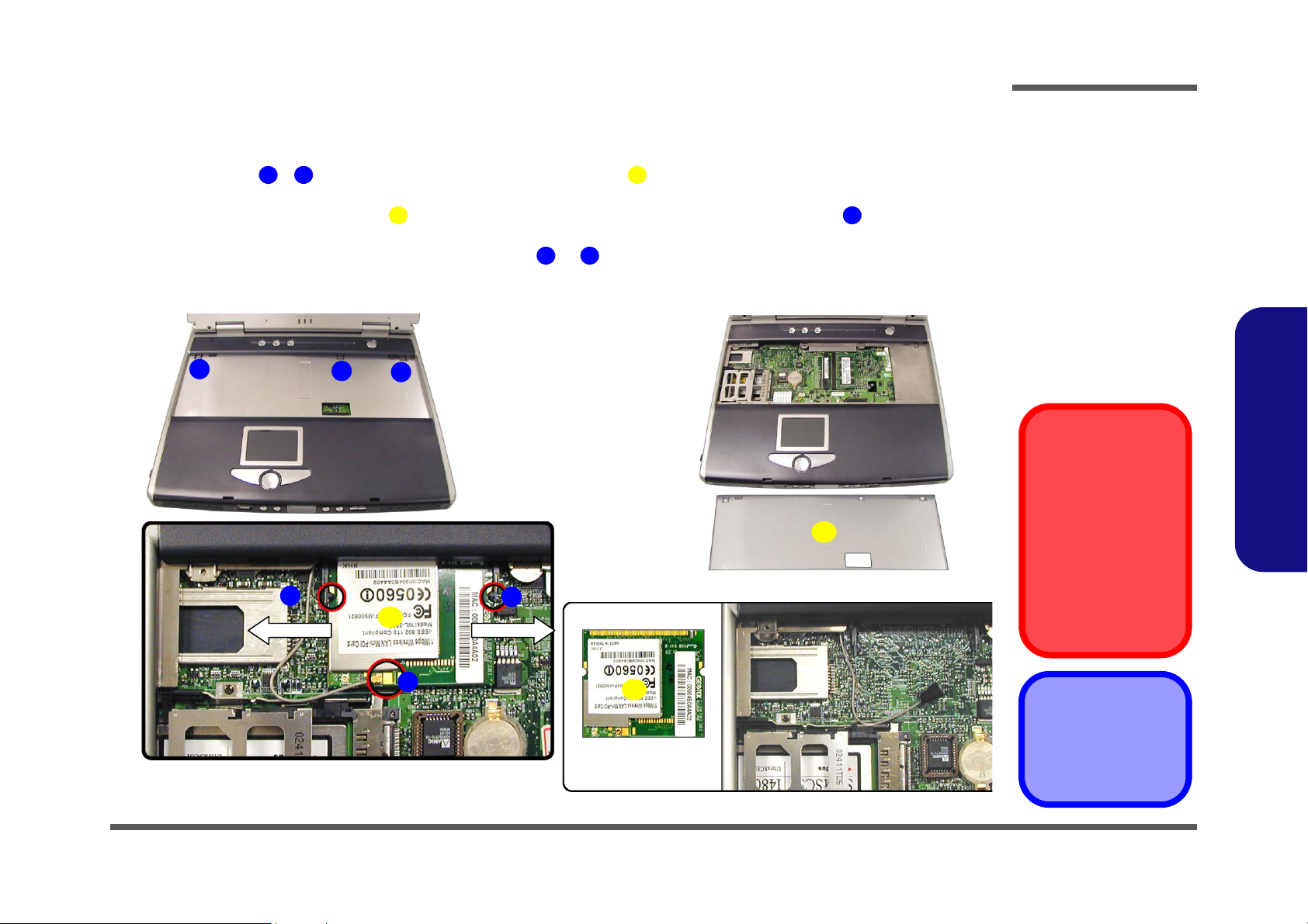
Removing the Wireless LAN Module
1. Turn the computer OFF, remove the battery (page 2 - 6) and keyboard (page 2 - 13).
2. Remove screws - (Figure 2 - 13a) from the shielding plate (Figure 2 - 13b), and lift the plate up off the
computer.
3. Locate the Wireless LAN module (Figure 2 - 13c) and disconnect the antenna cable at point . (See sidebar for
information on which connection point on the WLAN module is to be connected to the antenna cable.)
4. Pull the levers in the direction of the arrows at points & (Figure 2 - 13c) and carefully lift the Wireless LAN
module out of the computer.
a.
1
c.
1 3 4
5 6
7 8
2
7
3
8
5
b.
4
d.
Figure 2 - 13
WLAN Removal
Sequence
a. Remove the screws
from the shielding
plate.
b. Remove the shield-
ing plate.
c. Disconnect the an-
tenna cable.
d. Pull the latches on
the WLAN socket to
release the module
and lift it out.
Antenna Cable
Connection
When re-inserting a
Wireless LAN module,
make sure the antenna
cable connects to the
connector J7 which is
indicated as point 6 in
Figure 2 - 13c.
2.Disassembly
6
5
4. Shielding plate
5. WLAN module
•3 Screws
Removing the Wireless LAN Module 2 - 17
Page 47
Disassembly
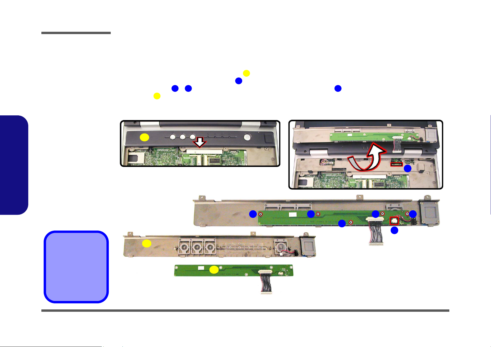
Figure 2 - 14
Switch Keyboard
Assembly
Removal
Sequence
a. Slide the center cov-
er assembly forward.
b. Disconnect the cable
and lift off the cover
assembly.
c. Remove the screws
and disconnect the
cable from the switch
keyboard assembly.
d. Lift the switch key-
board assembly off
the center cover assembly.
2.Disassembly
Removing the Switch Keyboard Assembly
1. Turn the computer OFF, remove the battery (page 2 - 6), keyboard (page 2 - 13), memory (page 2 - 14) and Wireless
LAN module (page 2 - 17).
2. Carefully slide the center cover assembly (Figure 2 - 14a) forward.
3. Carefully disconnect the cable at point (Figure 2 - 14b) and lift the center cover assembly out of the computer.
4. Remove screws - (Figure 2 - 14c) and disconnect the cable at point , then lift up the switch keyboard
assembly .
a.
d.
9
1
3 7 8
c.
1
2
b.
2
3
d.
4
6
7
5
8
1. Center cover assembly
9. Switch keyboard
assembly
1
•5 Screws
2 - 18 Removing the Switch Keyboard Assembly
9
Page 48
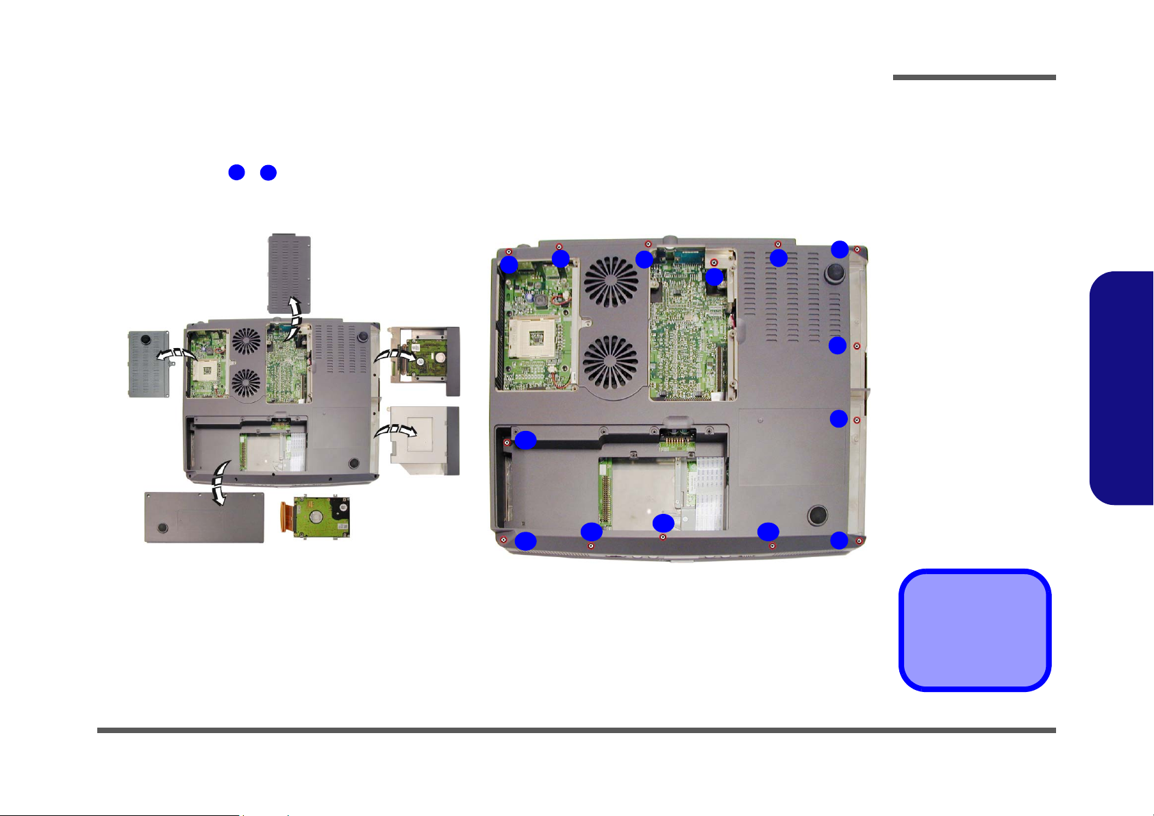
Disassembly
Removing the Bottom Case Assembly
1. Turn the computer OFF, remove the battery (page 2 - 6), and all applicable devices listed in the previous pages
(from page 2 - 7 to page 2 - 18,).
2. Remove screws - (Figure 2 - 15b) from the bottom of the computer.
a.
1
14
b.
1
3
2
14
3
4
5
6
7
8
Figure 2 - 15
Bottom Case
Assembly
Removal
Sequence
a. Remove all the previ-
ously listed devices
and components prior to this page (as applicable).
b. Remove the 14
screws from the bottom of the computer.
2.Disassembly
13
12
11
10
9
•14 Screws
Removing the Bottom Case Assembly 2 - 19
Page 49

Disassembly
Figure 2 - 16
Bottom Case
Assembly
Removal
Sequence (cont’d)
a. Disconnect the ca-
bles and remove the
screw from inside the
top case assembly.
b. Remove the 11
screws from the rear
of the computer
c. Carefully lift the top
case assembly up
and off the bottom
case assembly.
2.Disassembly
3. Turn the computer back over and disconnect cables - (Figure 2 - 16a), and remove screw .
4. Remove screws - (Figure 2 - 16b) from the rear of the computer.
5. Carefully ease the top case assembly (Figure 2 - 16c) off the bottom case assembly .
a.
5
15
16 17
1
3
c.
4
1
16
3
2
4
16. Top case assembly
17. Bottom case assembly
b.
5
•12 Screws
2 - 20 Removing the Bottom Case Assembly
17
6
7 8
9
101112131415
Page 50
Disassembly
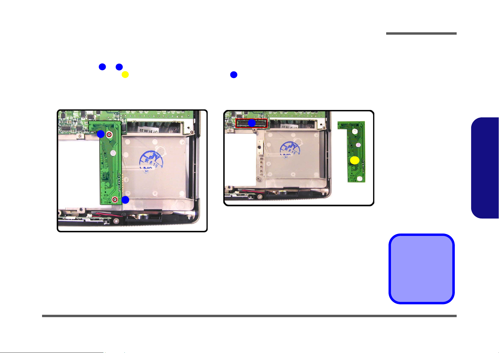
Removing the HDD & MP3 Converter Board
1. Turn the computer OFF, remove the battery (page 2 - 6), and the bottom case assembly (page 2 - 19).
2. Remove screws & (Figure 2 - 17a) from the HDD & MP3 converter board.
3. Lift the converter board (Figure 2 - 17b) off the connector on the mainboard.
a.
1
2
3
b.
1
2
4
4
Figure 2 - 17
HDD & MP3
Converter Board
Removal
Sequence
a. Remove the 2
screws.
b. Lift the HDD & MP3
converter board off
the connector.
2.Disassembly
3
3. HDD & MP3 converter board
•2 Screws
Removing the HDD & MP3 Converter Board 2 - 21
Page 51

Disassembly
Figure 2 - 18
Audio Board
Removal
Sequence
a. Remove the screw
and disconnect the
cable.
b. Lift the Audio DJ be-
zel out of the computer and remove the
connector cable.
c. Remove the screws
and cables from the
rear of the audio
board.
d. Remove the audio
board from the Audio
DJ bezel.
2.Disassembly
Removing the Audio Board
1. Turn the computer OFF, remove the battery (page 2 - 6), and the bottom case assembly (page 2 - 19).
2. Remove screw (Figure 2 - 18a) and disconnect cable from the mainboard.
3. Lift the Audio DJ bezel module (Figure 2 - 18b) out off the computer, and remove cable .
4. Remove screws - (Figure 2 - 18c), and disconnect cables & .
5. Lift the audio board (Figure 2 - 18d) off the Audio DJ bezel.
a.
c.
12
5
1
3 4
5
10 11 12
13
2
b.
2
1
12
6
7
11
10
8
3
4
9
d.
3. Audio DJ bezel
4. Audio DJ cable
13. Audio board
•7 Screws
2 - 22 Removing the Audio Board
3
13
Page 52
Disassembly
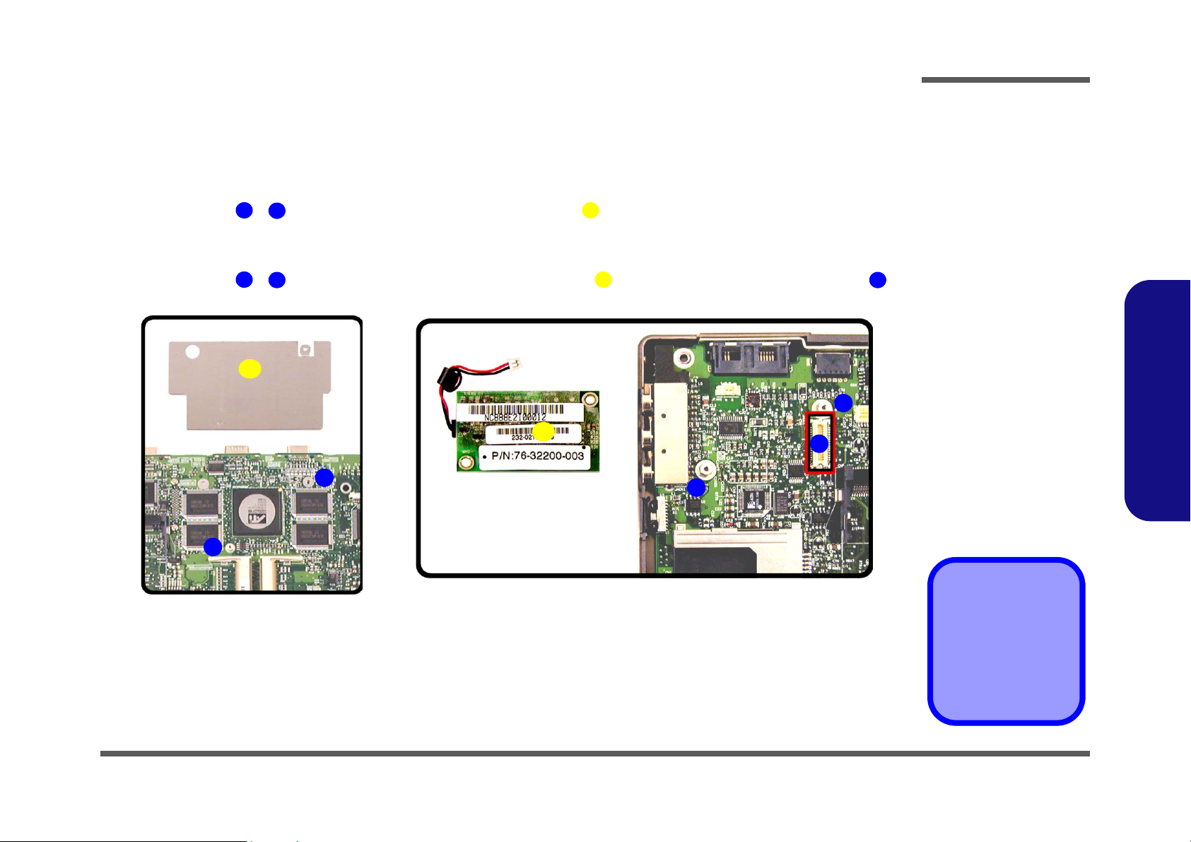
Removing the Chip Heat Sink and Modem Module
1. Turn the computer OFF, remove the battery (page 2 - 6), and the bottom case assembly (page 2 - 19).
To Remove the Chip Heat Sink:
2. Remove screws - (Figure 2 - 19a) and lift the chip heat sink off the mainboard.
1
2
To Remove the Modem Module:
3. Remove screws - (Figure 2 - 19b) and lift the modem module off the mainboard modem connector .
a.
4
5
b.
3
7
1
3
7
6
5
6
4
Figure 2 - 19
Chip Heat Sink &
Modem Module
Removal
Sequence
a. Remove the screws
and lift the chip heat
sink off the mainboard.
b. Remove the screws
and lift the modem
module off the mainboard.
2.Disassembly
2
3. Chip heat sink
7. Modem module
•4 Screws
Removing the Chip Heat Sink and Modem Module 2 - 23
Page 53

Disassembly
Figure 2 - 20
Mainboard
Removal
Sequence
a. Carefully lift the main-
board off the bottom
case.
b. Separate the rear I/O
bracket and bottom
case assembly.
2.Disassembly
Removing the Mainboard
1. Turn the computer OFF, remove the battery (page 2 - 6), bottom case assembly (page 2 - 19) and HDD & MP3 con-
verter board (page 2 - 21).
2. Carefully lift the mainboard (Figure 2 - 20b) off the bottom case assembly.
3. Separate the rear I/O bracket , and bottom case assembly (Figure 2 - 20b).
a. b.
1
2 3
1
2
1. Mainboard
2. Rear I/O bracket
3. Bottom case assembly
2 - 24 Removing the Mainboard
3
Page 54

Disassembly
Removing the Fan Module
1. Turn the computer OFF, remove the battery (page 2 - 6), the bottom case assembly (page 2 - 19) and the mainboard
(page 2 - 24).
2. Remove screws - (Figure 2 - 21a) on the top of the mainboard.
3. While holding the fan, carefully turn the mainboard over, and disconnect cables & (Figure 2 - 21b).
4. Lift the fan module (Figure 2 - 21c) off the mainboard.
a. b.
1
4
5
6
7
21
5
6
4
3
Figure 2 - 21
Fan Module
Removal
Sequence
a. Remove the 4
screws.
b. Hold the fan module,
turn the mainboard
over, and disconnect
the cables.
c. Lift the fan module off
the mainboard.
2.Disassembly
c.
7
7. Fan module
•4 Screws
Removing the Fan Module 2 - 25
Page 55

Disassembly
Figure 2 - 22
Cardbus Modules
Removal
Sequence
a. Remove the screws.
b. Apply pressure at the
illustrated points to
carefully prize the
module off the mainboard.
2.Disassembly
Removing the Cardbus Modules
1. Turn the computer OFF, remove the battery (page 2 - 6), the bottom case assembly (page 2 - 19) and the mainboard
(page 2 - 24).
2. Remove screws - (Figure 2 - 22a) on the cardbus assembly.
3. Carefully, but firmly, apply pressure with your thumb and forefinger at point or (Figure 2 - 22a) to ease the
cardbus assembly off the mainboard (it is advantageous to have the eject mechanism in the out position so as
not to interfere with the separation process).
4. Turn the mainboard over and repeat the process for the other side (Figure 2 - 22b).
a.
5
1
2
3
4
6
5
b.
1
3
6
4
2
6. Cardbus module
(top)
7. Cardbus module
(bottom)
•2 Screws
2 - 26 Removing the Cardbus Modules
1
5
3
7
4
2
Page 56
Disassembly
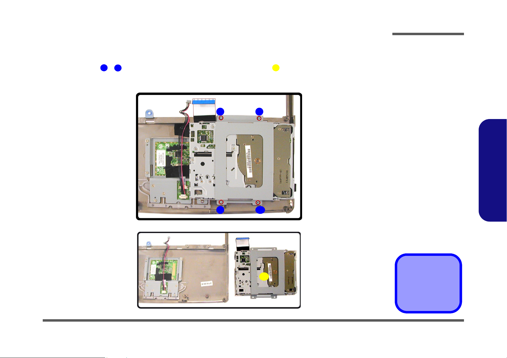
Removing the Floppy Disk Drive Assembly
1. Turn the computer OFF, remove the battery (page 2 - 6) and the bottom case assembly (page 2 - 19).
2. Remove screws - (Figure 2 - 23a) on the floppy disk drive assembly (located under the top casse assem-
1
4
bly).
3. Lift the floppy disk drive assembly off the top case.
a.
3 4
5
21
Figure 2 - 23
Floppy Disk Drive
Assembly
Removal
Sequence
a. Remove the 4
screws.
b. Lift the FDD assem-
bly off the top case.
2.Disassembly
b.
5
Removing the Floppy Disk Drive Assembly 2 - 27
5. FDD assembly
4 Screws
Page 57
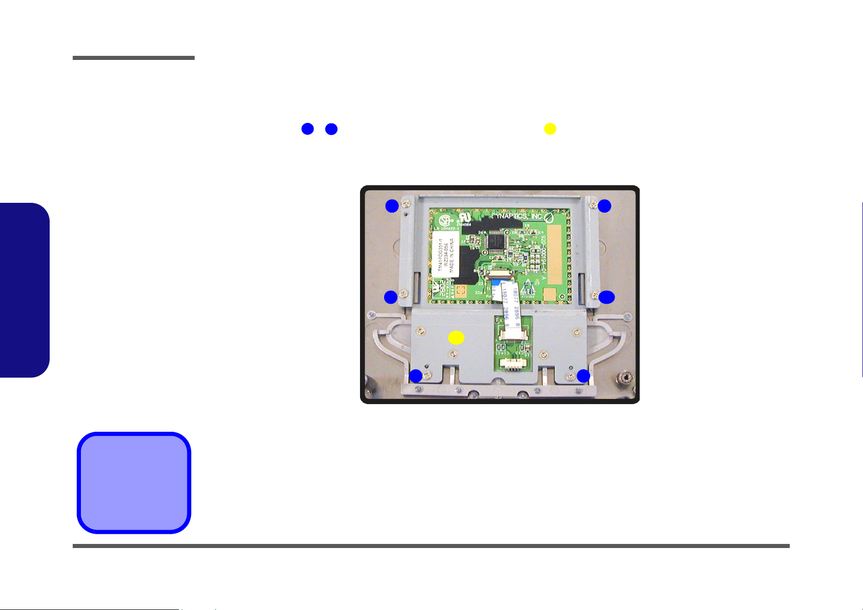
Disassembly
Figure 2 - 24
TouchPad Module
Removal
Sequence
Remove the 6 screws
and lift the TouchPad
module off the top
case.
2.Disassembly
Removing the TouchPad Module
1. Turn the computer OFF, remove the battery (page 2 - 6), the bottom case assembly (page 2 - 19) and the floppy disk
drive assembly (page 2 - 27).
2. Remove screws - (Figure 2 - 24) on the TouchPad module .
1
6
3. Lift the TouchPad module off the top case.
3 4
7
5 6
7
21
7. TouchPad module
•6 Screws
2 - 28 Removing the TouchPad Module
Page 58
Disassembly
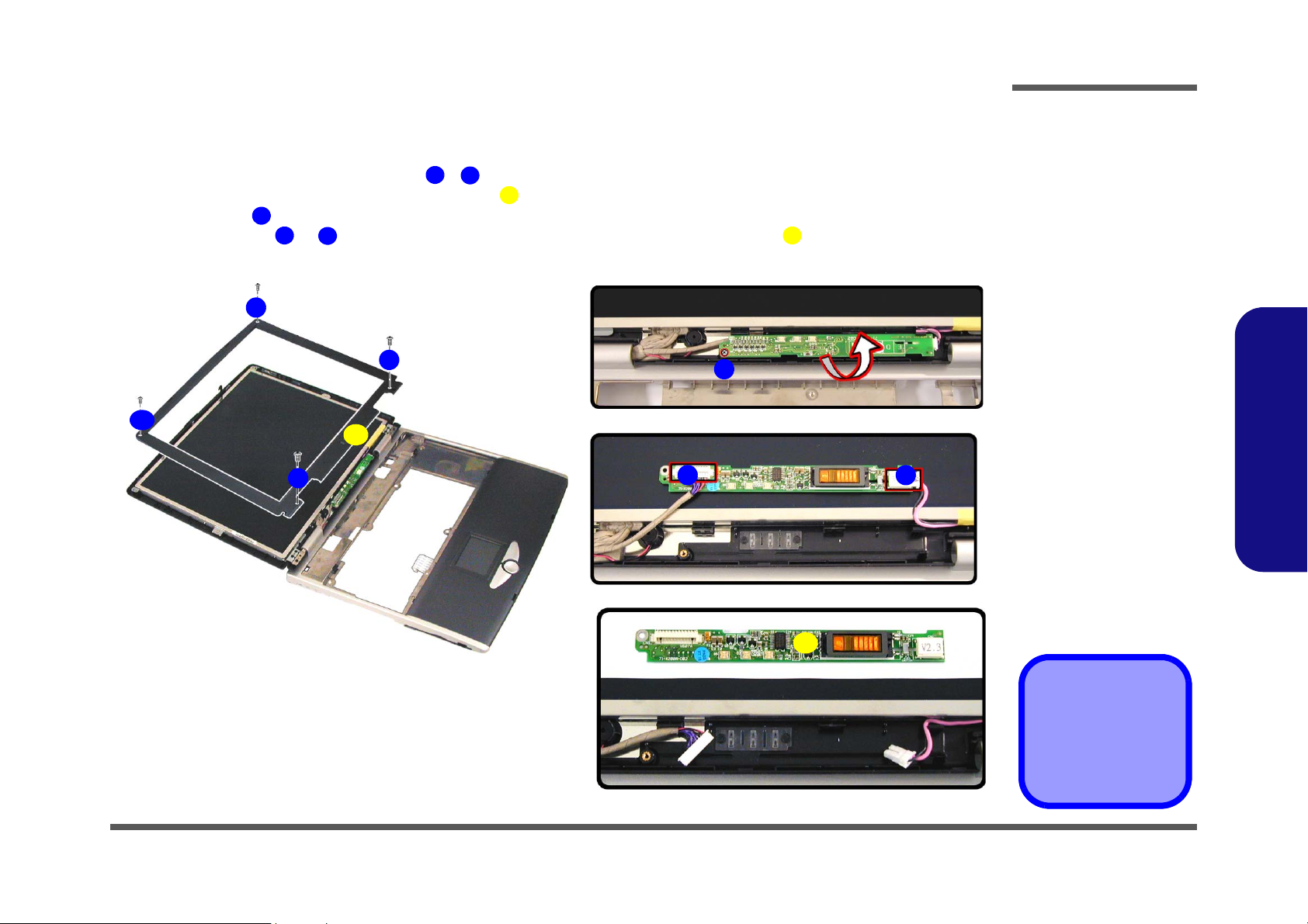
Removing the Inverter Board
1. Turn the computer OFF, remove the battery (page 2 - 6) and the bottom case assembly (page 2 - 19).
2. Remove any rubber covers and screws - (Figure 2 - 25a), then run your finger around the middle of the frame
to carefully unsnap the LCD front panel module from the back.
3. Remove screw (Figure 2 - 25b) from the inverter, and carefully lift the inverter board up slightly.
4. Disconnect cables & (Figure 2 - 25c) from the inverter, then remove the inverter (Figure 2 - 25d) from the
6
7
8
top case assembly.
a. b.
4
1
5
3
1
4
5
9
2
6
c.
7 8
Figure 2 - 25
Inverter Board
Removal
Sequence
a. Remove the 4 screws
and unsnap the LCD
front panel module
from the back.
b. Remove the screw
from the inverter
board and lift the
board up slightly.
c. Disconnect the ca-
bles from the inverter.
d. Remove the inverter.
2.Disassembly
d.
9
5. LCD front panel
9. Inverter board
•5 Screws
Removing the Inverter Board 2 - 29
Page 59

Disassembly
Figure 2 - 26
LCD Removal
Sequence
a. Remove the 8 screws
from the LCD.
b. Disconnect the cable
and lift up the LCD.
d. Remove the screws
and separate the
brackets from the
LCD.
2.Disassembly
Removing the LCD
1. Turn the computer OFF, remove the battery (page 2 - 6), the bottom case assembly (page 2 - 19) and the inverter
board (page 2 - 29).
2. Remove screws - (Figure 2 - 26a) from the LCD.
3. Disconnect the cable at point (Figure 2 - 26b), then lift the LCD up off the display back panel and top
case module.
4. Remove screws - (Figure 2 - 26c) from the LCD brackets & , then separate the LCD from the brack-
ets.
a. b.
1
1
8
13 18
9
10 11
19 20
10
9
11
12
2
10. LCD
11. Display back panel
12. Top case module
19. LCD bracket
20. LCD bracket
•14 Screws
2 - 30 Removing the LCD
786
16
3
4
c.
19
17
18
5
13
14
20
15
Page 60

Appendix A:Part Lists for 888E
This appendix breaks down the 888E model notebook’s construction into a series of illustrations. The component part
numbers are indicated in the tables opposite the drawings.
Note: This section indicates the manufacturer’s part numbers. Your organization may use a different system, so be sure
to cross-check any relevant documentation.
Note: Some assemblies may have parts in common (especially screws). However, the part lists DO NOT indicate the
total number of duplicated parts used.
Note: Be sure to check any update notices. The parts shown in these illustrations are appropriate for the system at the
time of publication. Over the product life, some parts may be improved or re-configured, resulting in new part numbers.
Part Lists
888E Part Lists
A-1
Page 61

Part Lists
Table A- 1
Part List Illustration
Location
Part List Illustration Location
The following table indicates where to find the appropriate part list illustration.
Part 888E Part 888E
Top
page A - 3
Combo Drive
page A - 13
888E Part Lists
Bottom
LCD 15"
LCD 15.7"
LCD 16"
Battery
Center Cover
Center Cover Finger
CD-ROM Drive
CD-RW Drive
page A - 4
page A - 5
page A - 6
page A - 7
page A - 8
page A - 9
page A - 10
page A - 11
page A - 12
DVD-ROM Drive
Audio DJ
Floppy Disk Drive
First Hard Disk Drive
Second Hard Disk Drive
Third Hard Disk Drive
Third Hard Disk - Dummy
IP Sharing Module
MP3 Player
page A - 14
page A - 15
page A - 16
page A - 17
page A - 18
page A - 19
page A - 20
page A - 21
page A - 22
A - 2 Part List Illustration Location
Page 62
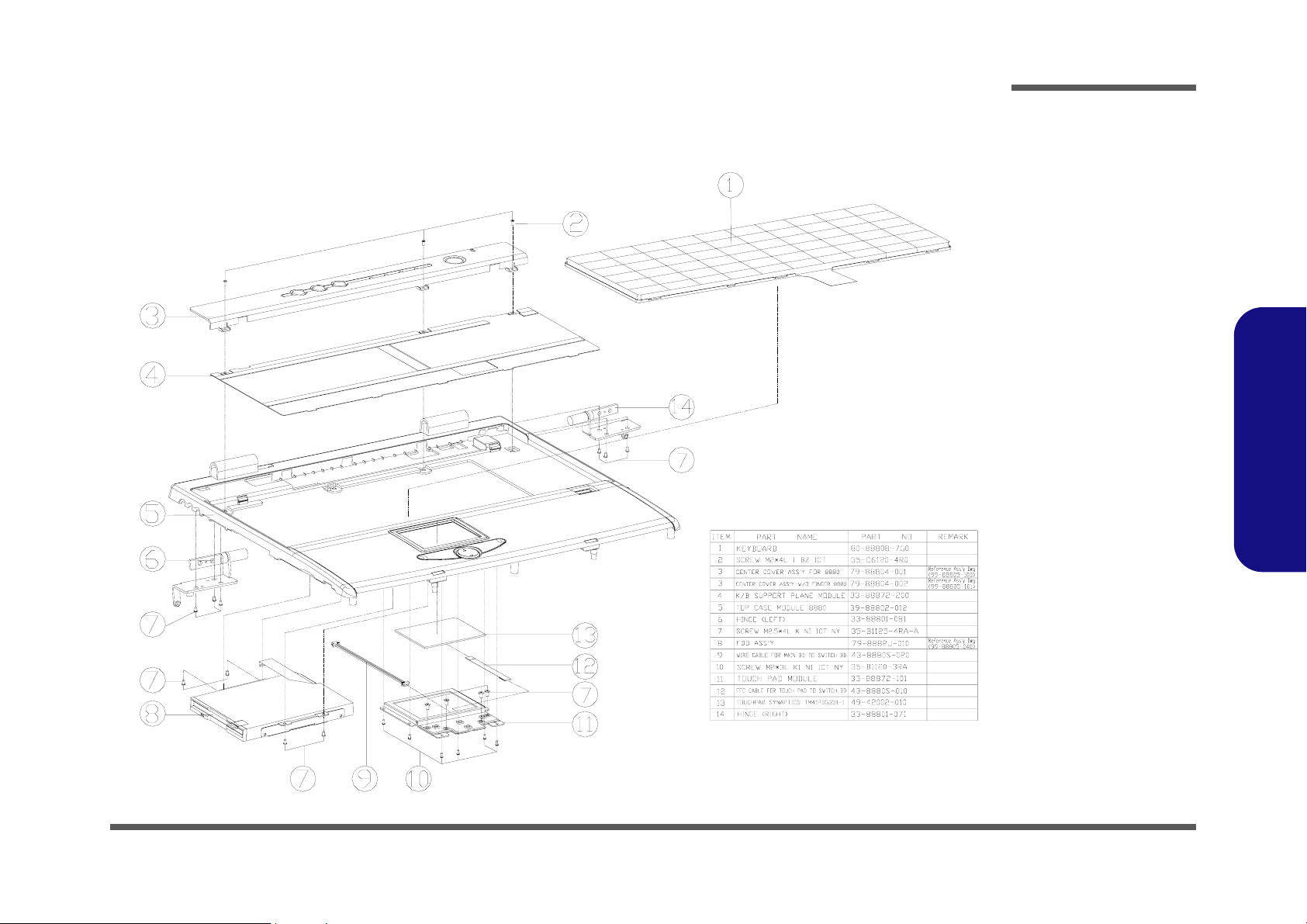
Top (888E)
Part Lists
Figure A-1
Top (888E)
888E Part Lists
Top (888E) A - 3
Page 63
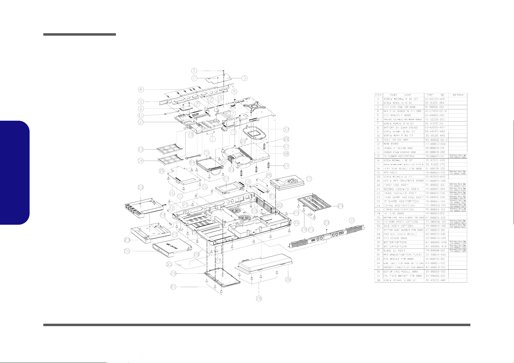
Part Lists
Figure A-2
Bottom (888E)
888E Part Lists
Bottom (888E)
A - 4 Bottom (888E)
Page 64

LCD 15" (888E)
Part Lists
Figure A-3
LCD 15" (888E)
888E Part Lists
LCD 15" (888E) A - 5
Page 65

Part Lists
Figure A-4
LCD 15.7" (888E)
888E Part Lists
LCD 15.7" (888E)
A - 6 LCD 15.7" (888E)
Page 66

LCD 16" (888E)
Part Lists
Figure A-5
LCD 16" (888E)
888E Part Lists
LCD 16" (888E) A - 7
Page 67

Part Lists
Figure A-6
Battery (888E)
888E Part Lists
Battery (888E)
A - 8 Battery (888E)
Page 68
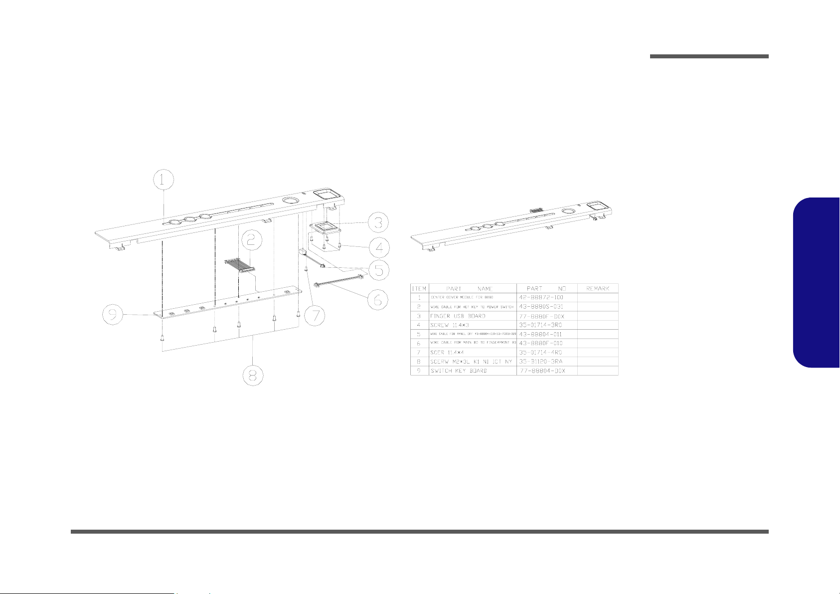
Center Cover (888E)
Part Lists
Figure A-7
Center Cover
(888E)
888E Part Lists
Center Cover (888E) A - 9
Page 69
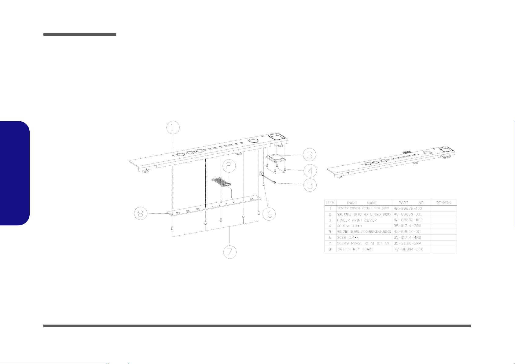
Part Lists
Figure A-8
Center Cover Fin-
ger
(888E)
888E Part Lists
Center Cover Finger (888E)
A - 10 Center Cover Finger (888E)
Page 70
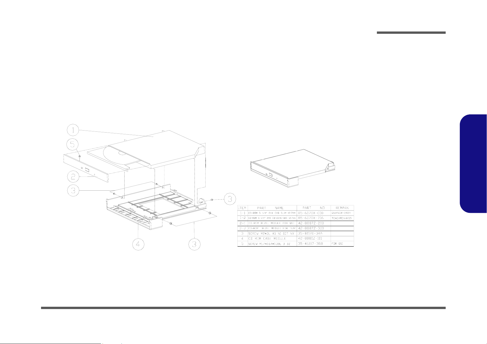
CD-ROM Drive (888E)
Part Lists
Figure A-9
CD-ROM Drive
(888E)
888E Part Lists
CD-ROM Drive (888E) A - 11
Page 71

Part Lists
Figure A-10
CD-RW Drive
(888E)
888E Part Lists
CD-RW Drive (888E)
A - 12 CD-RW Drive (888E)
Page 72

Combo Drive (888E)
Part Lists
Figure A-11
Combo Drive
(888E)
888E Part Lists
Combo Drive (888E) A - 13
Page 73
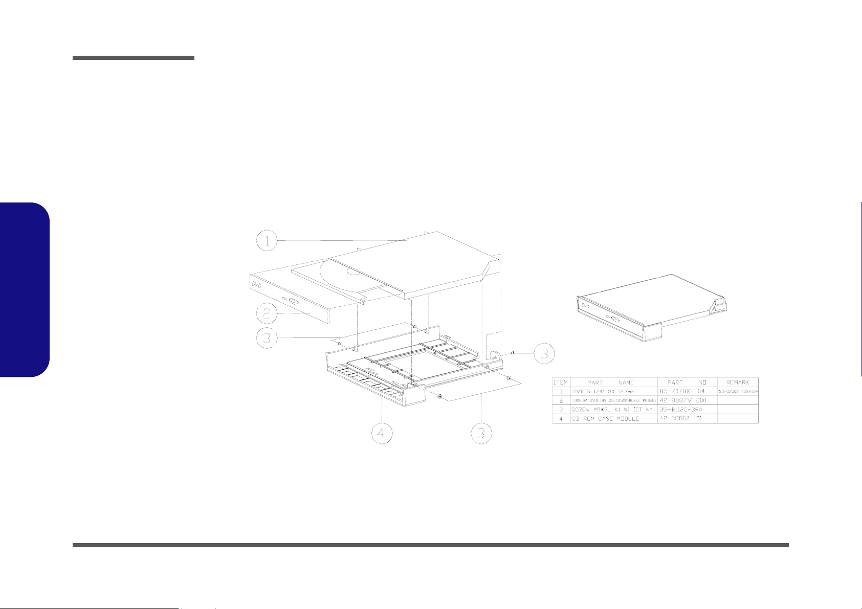
Part Lists
Figure A-12
DVD-ROM Drive
(888E)
888E Part Lists
DVD-ROM Drive (888E)
A - 14 DVD-ROM Drive (888E)
Page 74
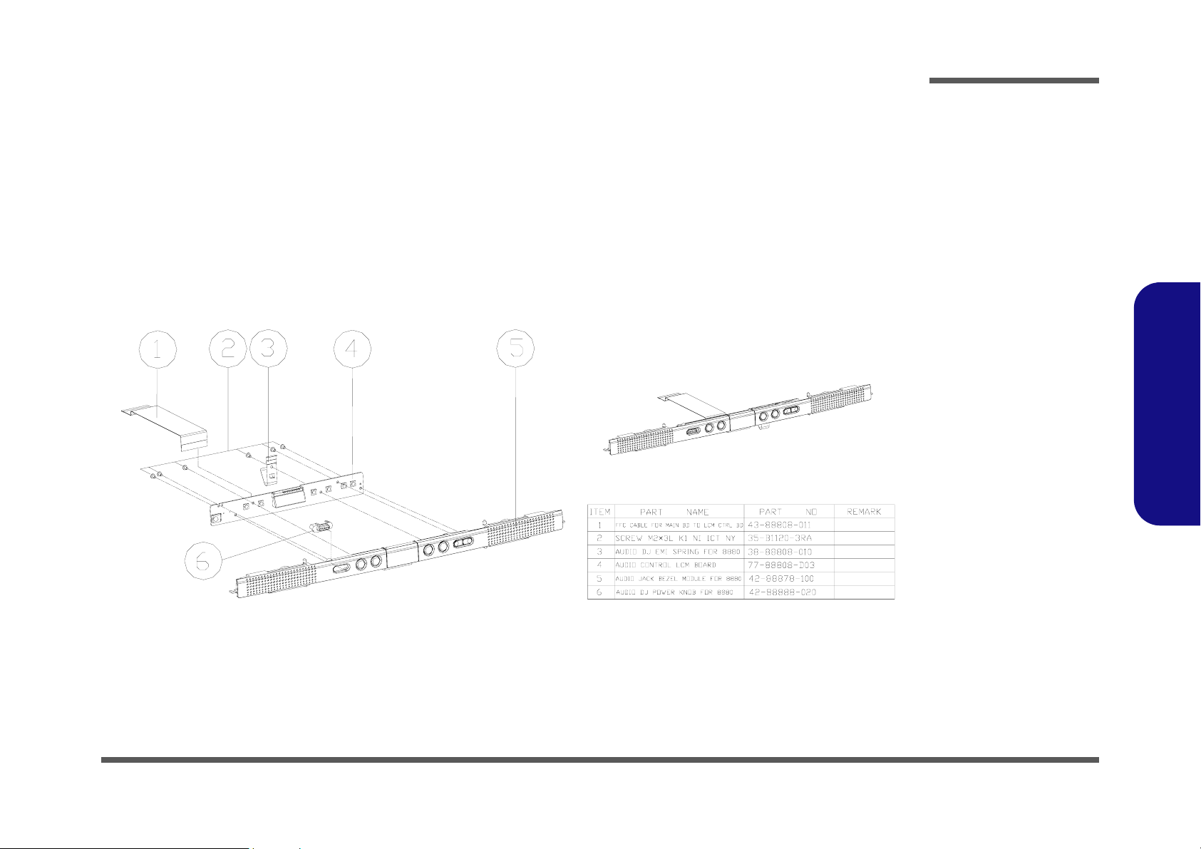
Audio DJ (888E)
Part Lists
Figure A-13
Audio DJ (888E)
888E Part Lists
Audio DJ (888E) A - 15
Page 75

Part Lists
Figure A-14
Floppy Disk Drive
(888E)
888E Part Lists
Floppy Disk Drive (888E)
A - 16 Floppy Disk Drive (888E)
Page 76

First Hard Disk Drive (888E)
Part Lists
Figure A-15
First HDD Drive
(888E)
888E Part Lists
First Hard Disk Drive (888E) A - 17
Page 77
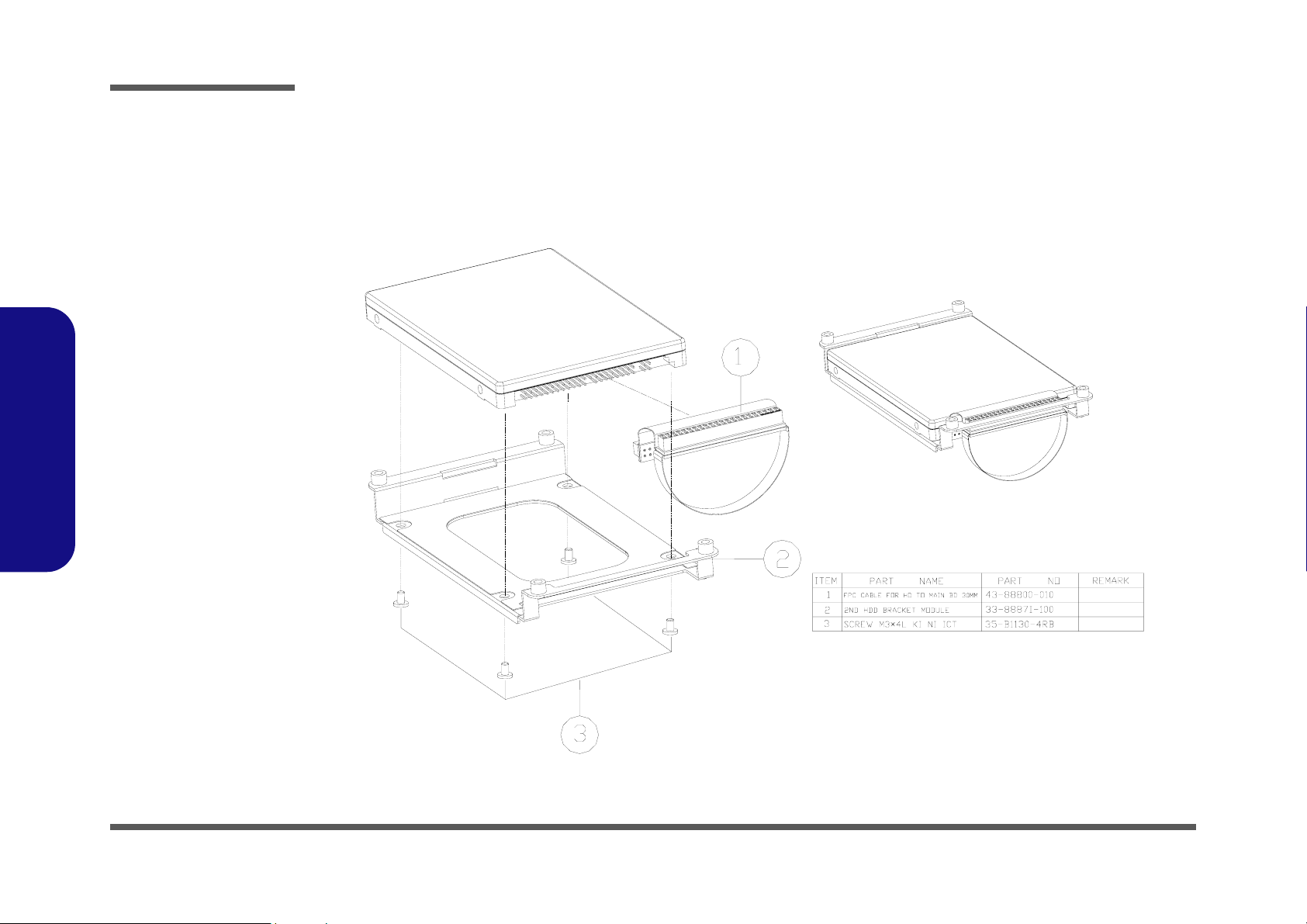
Part Lists
Figure A-16
Second HDD Drive
(888E)
888E Part Lists
Second Hard Disk Drive (888E)
A - 18 Second Hard Disk Drive (888E)
Page 78
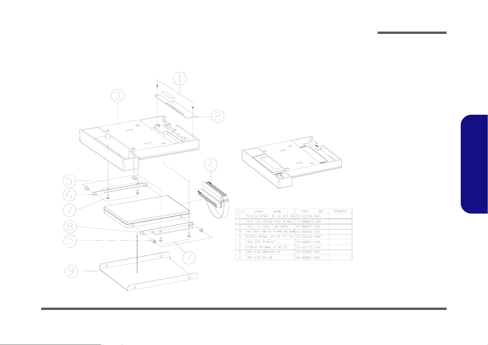
Third Hard Disk Drive (888E)
Part Lists
Figure A-17
Third Hard Disk
Drive
(888E)
888E Part Lists
Third Hard Disk Drive (888E) A - 19
Page 79

Part Lists
Figure A-18
Third Hard Disk -
Dummy (888E)
888E Part Lists
Third Hard Disk - Dummy (888E)
A - 20 Third Hard Disk - Dummy (888E)
Page 80
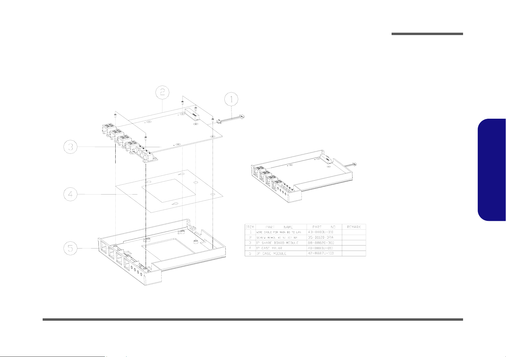
IP Sharing Module (888E)
Part Lists
Figure A-19
IP Sharing Module
(888E)
888E Part Lists
IP Sharing Module (888E) A - 21
Page 81

Part Lists
Figure A-20
MP3 Player
(888E)
888E Part Lists
MP3 Player (888E)
A - 22 MP3 Player (888E)
Page 82

Appendix B:Part Lists for 8880
This appendix breaks down the 8880 model notebook’s construction into a series of illustrations. The component part
numbers are indicated in the tables opposite the drawings.
Note: This section indicates the manufacturer’s part numbers. Your organization may use a different system, so be sure
to cross-check any relevant documentation.
Note: Some assemblies may have parts in common (especially screws). However, the part lists DO NOT indicate the
total number of duplicated parts used.
Note: Be sure to check any update notices. The parts shown in these illustrations are appropriate for the system at the
time of publication. Over the product life, some parts may be improved or re-configured, resulting in new part numbers.
Part Lists
8880 Part Lists
B-1
Page 83
Part Lists
Table B - 1
Part List Illustration
Location
Part List Illustration Location
The following table indicates where to find the appropriate part list illustration.
Part 8880 Part 8880
Top
page B- 3
DVD-ROM Drive
page B- 13
8880 Part Lists
Bottom
LCD 15"
LCD 15.7"
Battery
Center Cover
Center Cover Finger
CD-ROM Drive
CD-RW Drive
Combo Drive
page B- 4
page B- 5
page B- 6
page B- 7
page B- 8
page B- 9
page B- 10
page B- 11
page B- 12
Audio DJ
Floppy Disk Drive
First Hard Disk Drive
Second Hard Disk Drive
Third Hard Disk Drive
Third Hard Disk - Dummy
IP Sharing Module
MP3 Player
page B- 14
page B- 15
page B- 16
page B- 17
page B- 18
page B- 19
page B- 20
page B- 21
B - 2 Part List Illustration Location
Page 84

Top (8880)
Part Lists
Figure B-1
Top (8880)
8880 Part Lists
Top (8880) B - 3
Page 85
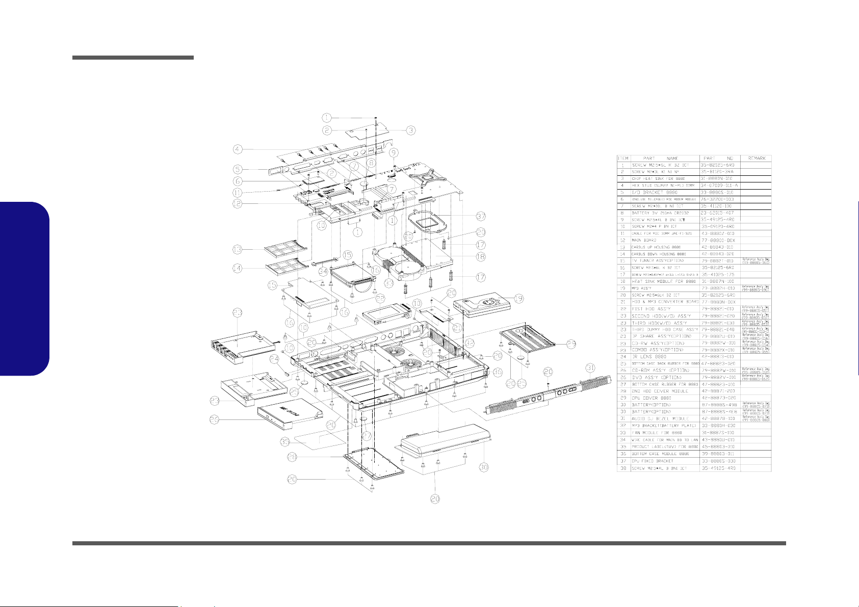
Part Lists
Figure B-2
Bottom (8880)
8880 Part Lists
Bottom (8880)
B - 4 Bottom (8880)
Page 86

LCD 15" (8880)
Part Lists
Figure B-3
LCD 15" 8880
8880 Part Lists
LCD 15" (8880) B - 5
Page 87
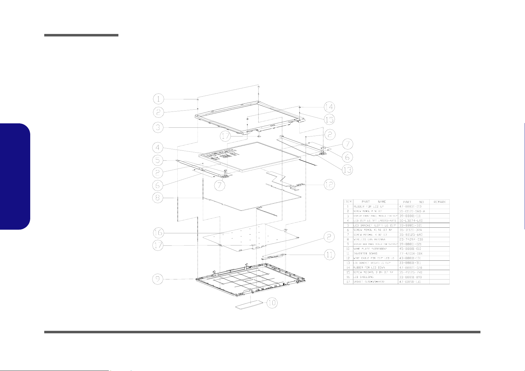
Part Lists
Figure B-4
LCD 15.7" 8880
8880 Part Lists
LCD 15.7" (8880)
B - 6 LCD 15.7" (8880)
Page 88

Battery (8880)
Part Lists
Figure B-5
Battery (8880)
8880 Part Lists
Battery (8880) B - 7
Page 89

Part Lists
Figure B-6
Center Cover
(8880)
8880 Part Lists
Center Cover (8880)
B - 8 Center Cover (8880)
Page 90
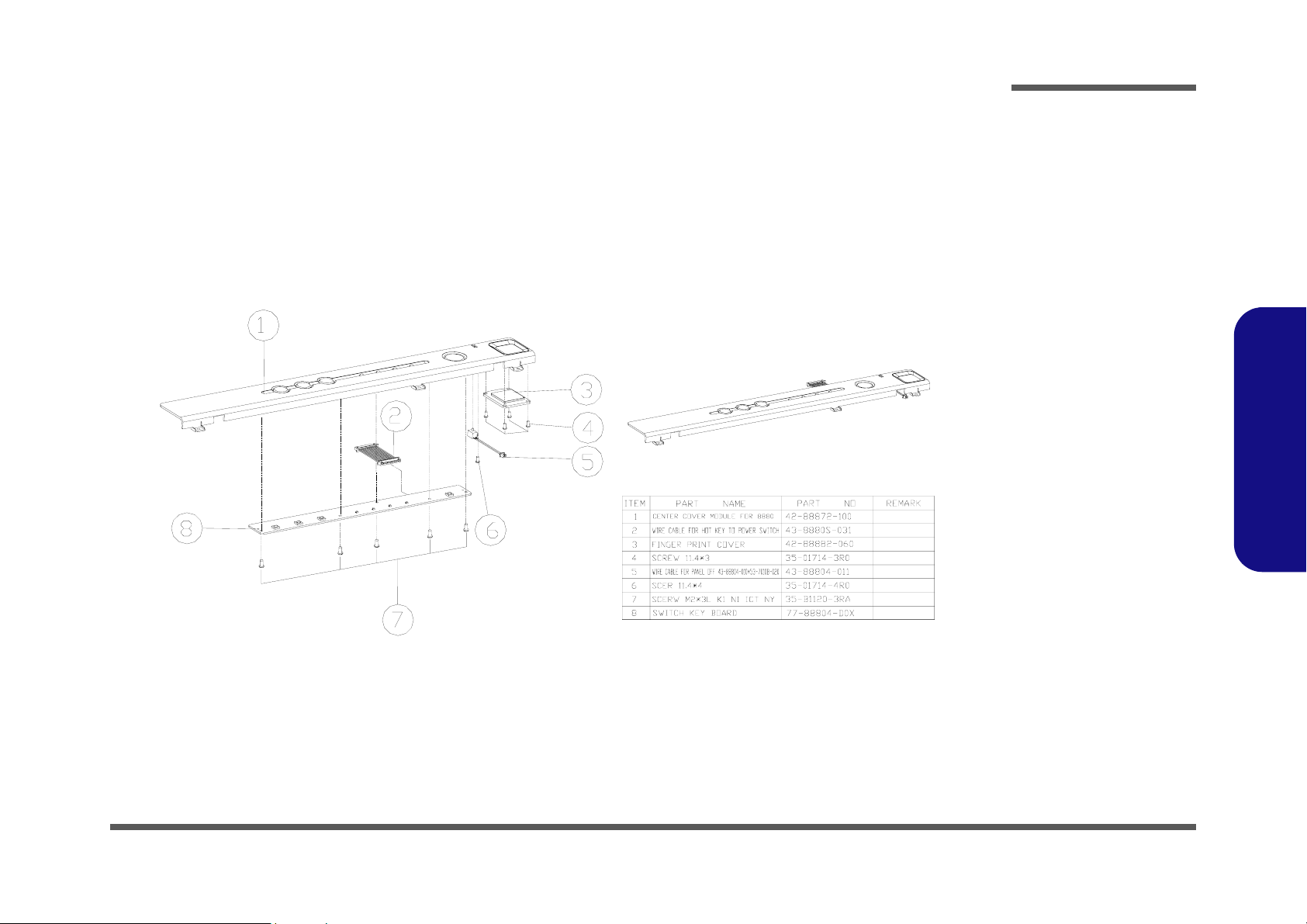
Center Cover Finger (8880)
Part Lists
Figure B-7
Center Cover Fin-
ger
(8880)
8880 Part Lists
Center Cover Finger (8880) B - 9
Page 91

Part Lists
Figure B-8
CD-ROM Drive
(8880)
8880 Part Lists
CD-ROM Drive (8880)
B - 10 CD-ROM Drive (8880)
Page 92

CD-RW Drive (8880)
Part Lists
Figure B-9
CD-RW Drive
(5600P)
8880 Part Lists
CD-RW Drive (8880) B - 11
Page 93

Part Lists
Figure B-10
Combo Drive
(8880)
8880 Part Lists
Combo Drive (8880)
B - 12 Combo Drive (8880)
Page 94

DVD-ROM Drive (8880)
Part Lists
Figure B-11
DVD-ROM Drive
(8880)
8880 Part Lists
DVD-ROM Drive (8880) B - 13
Page 95

Part Lists
Figure B-12
Audio DJ (8880)
8880 Part Lists
Audio DJ (8880)
B - 14 Audio DJ (8880)
Page 96

Floppy Disk Drive (8880)
Part Lists
Figure B-13
Floppy Disk Drive
(8880)
8880 Part Lists
Floppy Disk Drive (8880) B - 15
Page 97

Part Lists
Figure B-14
First HDD Drive
(8880)
8880 Part Lists
First Hard Disk Drive (8880)
B - 16 First Hard Disk Drive (8880)
Page 98
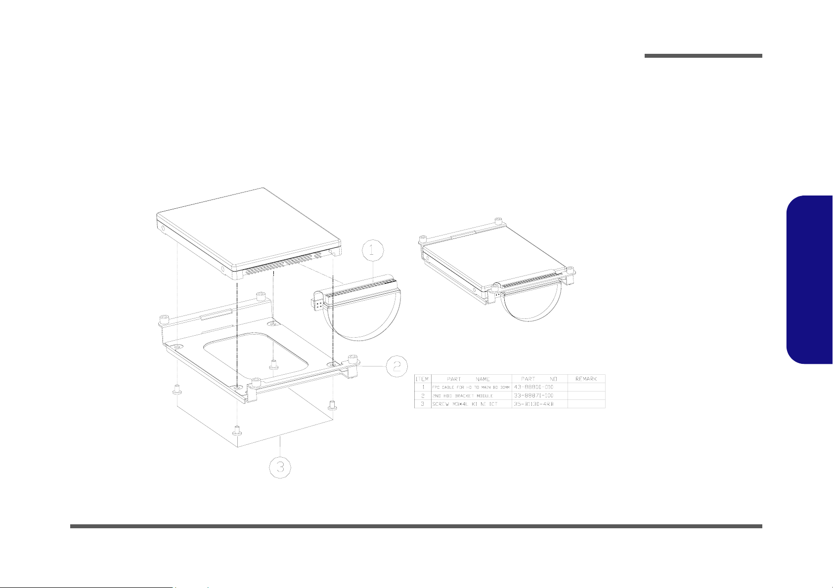
Second Hard Disk Drive (8880)
Part Lists
Figure B-15
Second HDD Drive
(8880)
8880 Part Lists
Second Hard Disk Drive (8880) B - 17
Page 99

Part Lists
Figure B-16
Third Hard Disk
Drive
(8880)
8880 Part Lists
Third Hard Disk Drive (8880)
B - 18 Third Hard Disk Drive (8880)
Page 100

Third Hard Disk - Dummy (8880)
Part Lists
Figure B-17
Third Hard Disk -
Dummy (5620P)
8880 Part Lists
Third Hard Disk - Dummy (8880) B - 19
 Loading...