


Contents
About this Concise User Guide ......................................................... 1
System Startup ..................................................................................4
Intel® Optane™ ................................................................................5
System Map: Front View with LCD Panel Open (Model A) ..........7
System Map: Front View with LCD Panel Open (Model B) ........... 8
LED Indicators ..................................................................................9
Keyboard ......................................................................................... 10
Control Center .................................................................................12
System Map: Front, Left & Right Views (Model A) ......................14
System Map: Front, Left & Right Views (Model B) ......................15
System Map: Bottom & Rear Views .............................................. 16
Windows 10 Start Menu, Context Menu, Taskbar, Control Panel
and Settings .....................................................................................17
Video Features ................................................................................18
Audio Features ................................................................................ 19
Power Options .................................................................................19
Driver Installation ........................................................................... 20
TPM (Option) ..................................................................................21
3G/4G Module (Option) .................................................................22
Troubleshooting ..............................................................................23
Specifications ..................................................................................24
Inhalt
Über das Ausführliche Benutzerhandbuch .....................................27
Schnellstart ......................................................................................30
Intel® Optane™ .............................................................................. 31
Systemübersicht: Ansicht von vorne mit geöffnetem
LCD-Bildschirm (Modell A) .......................................................33
Systemübersicht: Ansicht von vorne mit geöffnetem
LCD-Bildschirm (Modell B) ........................................................ 34
LED-Anzeigen ................................................................................35
Tastatur ...........................................................................................36
Control Center .................................................................................38
Systemübersicht: Ansicht von vorne, links und rechts (Modell A) 40
Systemübersicht: Ansicht von vorne, links und rechts (Modell B) .41
Systemübersicht: Ansicht von unten und hinten .............................42
Start-Menü, Kontextmenü, Taskleiste, Systemsteuerung und Einstel-
lungen von Windows 10 ..................................................................43
Grafikfunktionen .............................................................................44
Audiofunktionen ..............................................................................45
Energieoptionen ..............................................................................45
Installation der Treiber ....................................................................46
TPM (Option) ..................................................................................47
3G/4G-Modul (Option) ...................................................................48
Fehlerbehebung ...............................................................................49
Technische Daten ............................................................................50
Sommaire
A propos de ce Guide Utilisateur Concis ........................................53
Guide de démarrage rapide .............................................................56
Intel® Optane™ ..............................................................................57
Carte du système: Vue de face avec l’écran LCD ouvert
(Modèle A) .....................................................................................59
Carte du système: Vue de face avec l’écran LCD ouvert
(Modèle B) .....................................................................................60
Indicateurs LED ..............................................................................61
Clavier .............................................................................................62
Control Center .................................................................................64
Carte du système: Vues de face, gauche et droite (Modèle A) .......66
Carte du système: Vues de face, gauche et droite (Modèle B) .......67
Carte du système: Vues de dessous et arrière .................................68
Menu Démarrer, Menu contextuel, Barre des tâches, Panneau de
Configuration et Paramètres de Windows 10 ..................................69
Caractéristiques vidéo .....................................................................70

Caractéristiques audio .....................................................................71
Options d’alimentation ....................................................................71
Installation du pilote ....................................................................... 72
TPM (Option) ..................................................................................73
Module 3G/4G (Option) .................................................................74
Dépannage .......................................................................................75
Spécifications ..................................................................................76
Contenidos
Acerca de esta Guía del Usuario Concisa ....................................... 79
Guía rápida para empezar ...............................................................82
Intel® Optane™ .............................................................................. 83
Mapa del sistema: Vista frontal con panel LCD abierto
(Modelo A) ......................................................................................85
Mapa del sistema: Vista frontal con panel LCD abierto
(Modelo B) ......................................................................................86
Indicadores LED .............................................................................87
Teclado ............................................................................................88
Control Center .................................................................................90
Mapa del sistema: Vistas frontal, izquierda y derecha
(Modelo A) .....................................................................................92
Mapa del sistema: Vistas frontal, izquierda y derecha
(Modelo B) ..................................................................................... 93
Mapa del sistema: Vistas inferior y posterior .................................94
Menú Inicio, Menú contextual, Barra de tareas, Panel de Control
y Configuración de Windows 10 ....................................................95
Parámetros de vídeo ........................................................................ 96
Características de audio ..................................................................97
Opciones de energía ........................................................................97
Instalación de controladores ...........................................................98
TPM (Opción) .................................................................................99
Módulo 3G/4G (Opción) ...............................................................100
Solución de problemas ..................................................................101
Especificaciones ............................................................................102
Informazioni su questa guida rapida .............................................105
Sommario
Guida di avvio rapido ....................................................................108
Intel® Optane™ ............................................................................109
Descrizione del sistema: Vista anteriore con pannello LCD aperto
(Modello A) ...................................................................................111
Descrizione del sistema: Vista anteriore con pannello LCD aperto
(Modello B) ...................................................................................112
Indicatori LED ...............................................................................113
Tastiera ..........................................................................................114
Control Center ...............................................................................116
Descrizione del sistema: Vista anteriore, sinistra e destra ............118
(Modello A) .................................................................................118
Descrizione del sistema: Vista anteriore, sinistra e destra ............119
(Modello B) .................................................................................119
Descrizione del sistema: Vista inferiore e posteriore ....................120
Menu Start, Menu contestuale, Barra delle applicazioni, Pannello
di controllo e Impostazioni di Windows 10 ..................................121
Funzioni video ...............................................................................122
Funzionalità audio .........................................................................123
Opzioni risparmio energia .............................................................123
Installazione driver ........................................................................124
TPM (Opzione) .............................................................................125
Modulo 3G/4G (Opzione) .............................................................126
Risoluzione dei problemi ..............................................................127
Specifiche tecniche ........................................................................128

About this Concise User Guide
FCC Statement
This device complies with Part
15 of the FCC Rules. Operation
is subject to the following two
conditions:
1. This device may not cause
harmful interference.
2. This device must accept any
interference received, including interference that may
cause undesired operation.
This quick guide is a brief introduction to getting your system started. This is a supplement, and not a substitute for the
expanded English language User’s Manual in Adobe Acrobat format on the Device Drivers & Utilities + User’s Manual
disc supplied with your computer. This disc also contains the drivers and utilities necessary for the proper operation of
the computer (Note: The company reserves the right to revise this publication or to change its contents without notice).
Some or all of the computer’s features may already have been setup. If they aren’t, or you are planning to re-configure
(or re-install) portions of the system, refer to the expanded User’s Manual. The Device Drivers & Utilities + User’s
Manual disc does not contain an operating system.
Regulatory and Safety Information
Please pay careful attention to the full regulatory notices and safety information contained in the expanded User’s Manual on the Device Drivers & Utilities + User’s Manual disc.
©
August 2017
Trademarks
Intel and Intel Core are trademarks/registered trademarks of Intel Corporation.
English
1

Instructions for Care and Operation
The computer is quite rugged, but it can be damaged. To prevent this, follow these suggestions:
• Don’t drop it, or expose it to shock. If the computer falls, the
case and the components could be damaged.
• Keep it dry, and don’t overheat it. Keep the computer and
power supply away from any kind of heating element. This is an
electrical appliance. If water or any other liquid gets into it, the
English
computer could be badly damaged.
• Avoid interference. Keep the computer away from high capacity
transformers, electric motors, and other strong magnetic fields.
These can hinder proper performance and damage your data.
• Follow the proper working procedures for the computer. Shut
the computer down properly and don’t forget to save your work.
Remember to periodically save your data as data may be lost.
Servicing
Do not attempt to service the computer yourself. Doing so may
violate your warranty and expose you and the computer to
electric shock. Refer all servicing to authorized service personnel. Unplug the computer from the power supply. Then refer
servicing to qualified service personnel under any of the following conditions:
• When the power cord or AC/DC adapter is damaged or frayed.
• If the computer has been exposed to any liquids.
• If the computer does not work normally when you follow the
operating instructions.
• If the computer has been dropped or damaged (do not touch the
poisonous liquid if the LCD panel breaks).
• If there is an unusual odor, heat or smoke coming from your computer.
Safety Information
• Only use an AC/DC adapter approved for use with this computer.
• Use only the power cord and batteries indicated in this manual.
Do not dispose of batteries in a fire. They may explode. Check
with local codes for possible special disposal instructions.
• Do not continue to use a battery that has been dropped, or that
appears damaged (e.g. bent or twisted) in any way. Even if the
computer continues to work with a damaged battery in place, it
may cause circuit damage, which may possibly result in fire.
• Make sure that your computer is completely powered off before
putting it into a travel bag (or any such container).
• Before cleaning the computer, make sure it is disconnected from
any external power supplies, peripherals and cables. It is advisable to also remove your battery in order to prevent accidentally
turning the machine on.
• Use a soft clean cloth to clean the computer, but do not apply
cleaner directly to the computer. Do not use volatile (petroleum
distillates) or abrasive cleaners on any part of the computer.
• Do not try to repair a battery pack. Refer any battery pack repair
or replacement to your service representative or qualified service
personnel.
• Note that in computer’s featuring a raised LCD electro-plated
logo, the logo is covered by a protective adhesive. Due to general
wear and tear, this adhesive may deteriorate over time and the
exposed logo may develop sharp edges. Be careful when handling
the computer in this case, and avoid touching the raised LCD
electro-plated logo. Avoid placing any other items in the carrying
bag which may rub against the top of the computer during transport. If any such wear and tear develops contact your service center.
2

Polymer Battery Precautions
Battery Disposal & Caution
The product that you have purchased contains a rechargeable battery. The battery is recyclable. At the end of its useful life, under various state and local laws, it may be illegal
to dispose of this battery into the municipal waste stream.
Check with your local solid waste officials for details in your
area for recycling options or proper disposal.
Danger of explosion if battery is incorrectly replaced. Replace only with the same or equivalent type recommended
by the manufacturer. Discard used battery according to the
manufacturer’s instructions.
Note the following information which is specific to polymer
batteries only, and where applicable, this overrides the general
battery precaution information.
• Polymer batteries may experience a slight expansion or swelling,
however this is part of the battery’s safety mechanism and is not a
cause for concern.
• Use proper handling procedures when using polymer batteries.
Do not use polymer batteries in high ambient temperature environments, and do not store unused batteries for extended periods.
English
3
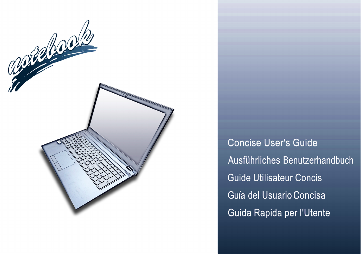
System Startup
Figure 1 - Opening the Lid/LCD/Computer with
AC/DC Adapter Plugged-In
130 ゚
Shut Down
Note that you should always shut
your computer down by choosing the
Shut down command in Windows
(see below). This will help prevent
hard disk or system problems.
1. Click the Start Menu icon .
2. Click the Power item .
3. Choose Shut Down from the
menu.
1. Remove all packing materials.
2. Place the computer on a stable surface.
3. Insert the battery and make sure it is locked in position.
4. Securely attach any peripherals you want to use with the computer (e.g.
keyboard and mouse) to their ports.
5. When first setting up the computer use the following procedure (as
English
to safeguard the computer during shipping, the battery will be locked to
not power the system until first connected to the AC/DC adapter and
initially set up as below):
• Attach the AC/DC adapter cord to the DC-In jack on the left of the
computer, then plug the AC power cord into an outlet, and connect
the AC power cord to the AC/DC adapter and leave it there for 6
seconds or longer.
• Remove the adapter cord from the computer’s DC-In jack, and then
plug it back in again; the battery will now be unlocked.
6. Use one hand to raise the
exceed 130 degrees); use the other hand (as illustrated in Figure 1) to
support the base of the computer (Note: Never lift the computer by the
lid/LCD).
7. Press the power button to turn the computer “on”.
System Software
Your computer may already come with system software pre-installed. Where this is not the case, or where you are re-configuring your computer for a different system, you will find this
manual refers to Microsoft Windows 10.
Intel® Optane™ Support
You need to setup Intel® Optane™ before installing your Windows 10 operating system (see Intel® Optane™ on page 5).
4
lid/LCD to a comfortable viewing angle
(do not

Intel® Optane™
Intel® Optane™ is a combination of a compatible memory device and Intel Rapid Storage Technology soft-
ware. This combination is designed to speed up your
system performance by caching boot data, executables,
frequently accessed data and system page files to a non
volatile, low latency Intel® Optane™ SSD.
Contact your distributor or supplier to see if your system
supports this technology.
If you are reinstalling a system that has previously been
setup in Intel RST Premium mode, make sure you have
cleared the Intel Optane Memory (see Clearing Intel®
Optane™ on page 6).
Intel® Optane™ Setup Procedure
You need to setup Intel® Optane™ before installing your
Windows 10 operating system, and you will need to prepare the following in order to do so.
•The Microsoft Windows 10 OS DVD.
• An attached external DVD drive.
• An Intel® Optane™ SSD installed in your system.
•The Device Drivers & Utilities + User’s Manual disc.
1. Start-up your notebook computer and press <F2> to enter the
BIOS.
2. Go to the Boot menu, select UEFI Setting and press <Enter>.
3. Set UEFI Boot to “Enabled”.
4. Press <Esc> to exit the menu and go to the Main menu.
5. Select OffBoard NVMe Controller Configuration and press
<Enter> to check that an Intel® Optane™ SSD is present.
6. Press <Esc> to exit the menu and go to the Advanced menu.
7. Select SATA Mode, press <Enter> and select “Intel RST
Premium...”.
8. Press <F4> and <Yes> to “Save Changes and Reset”.
9. As the computer restarts press <F2> to enter the BIOS again.
10. Press <F4> and <Yes> to “Save Changes and Reset”, however
ensure that the condition in the bulleted point below is met
before doing so.
• Make sure the Windows 10 OS DVD is in the attached DVD
drive, as the computer starts up it will automatically boot from
the Windows 10 OS DVD (you will be prompted to press a
key to boot from the DVD).
11. Click Next > Install Now to continue installing the operating
system as normal (see your Windows documentation if you
need help on installing the Windows OS).
12. Select Custom: Install Windows only (advanced).
13. It is recommended that you select and then delete existing
partitions.
14. Click New to create a partition for Windows.
15. It is very important to make sure that when you create the
partition, leave at least a minimum of unallocated space of 5MB.
16. Follow the on-screen instructions to install the Windows 10
operating system.
17. Install the Windows drivers. Make sure you install the Intel®
Rapid Storage Technology (IRST) driver.
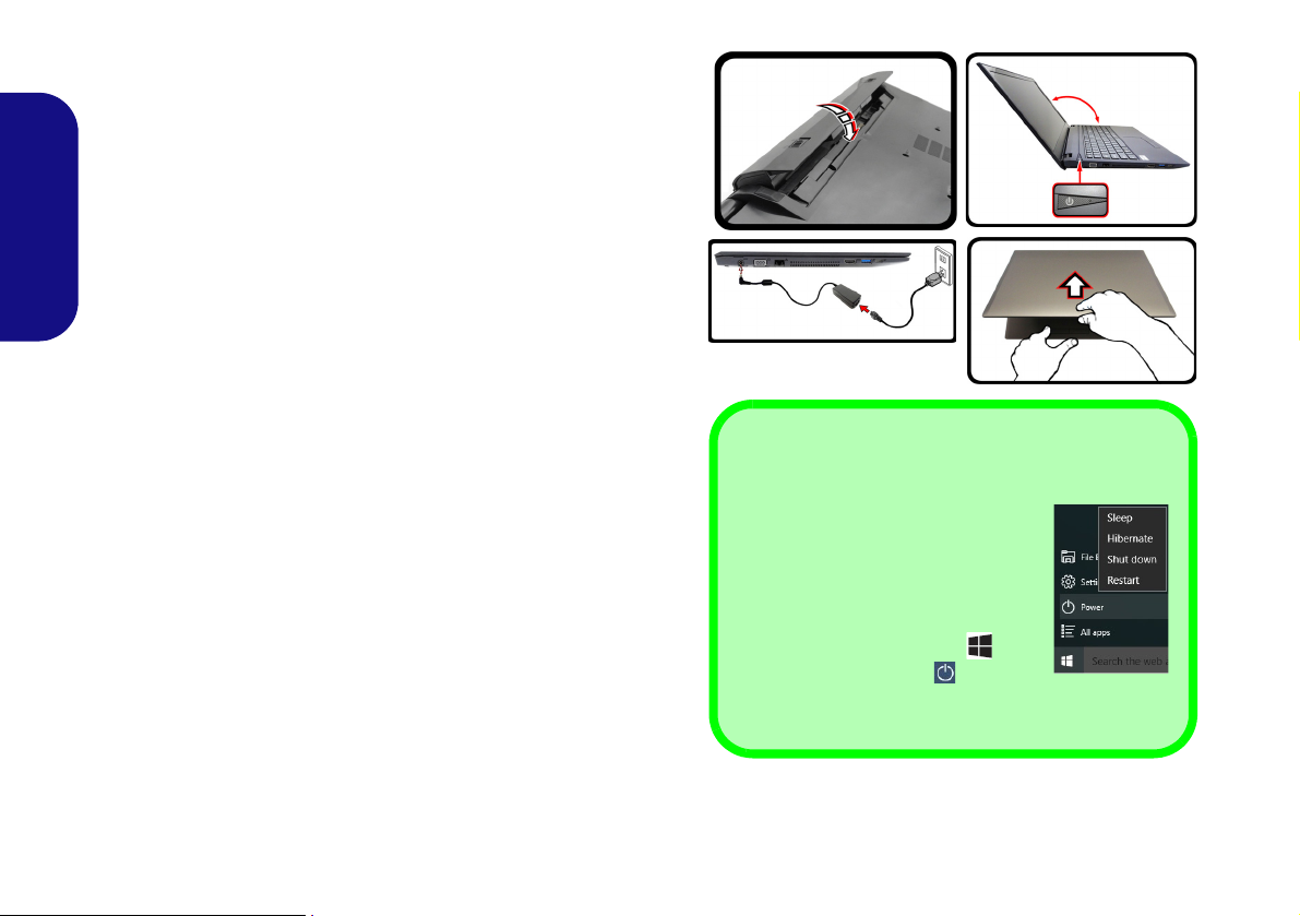
18. Run the Intel® Rapid Storage Technology application.
English
5
19. Click Enable.
Figure 2 - Intel® Rapid Storage Technology - Status
English
20. The system will pop-up a message and ask you to select a
compatible fast drive (in this case there should only be one
option).
21. You will need to restart the computer after enabling Optane, and
make sure the system is powered by the powered AC/DC
adapter, and not by battery only.
22. Click Yes to begin the process (this may take some time).
23. After the process has been completed restart the computer.
Clearing Intel® Optane™
If you wish to clear an existing Intel® Optane™ setup
then follow the procedure below to do so. However back-
up up any necessary files and data before clearing an
Intel® Optane™ setup, as doing so will result in the loss
of all data on the volumes.
1. Make sure that Intel® Optane™ is enabled in the Intel® Rapid
Storage Technology application.
2. Start-up your computer and press <F2> to enter the BIOS.
3. Go to Intel(R) Rapid Storage Technology (in the Advanced
menu) and press <Enter>.
4. Select Intel Optane, **** (listed under Optane Volume:) and
press <Enter>.
5. Select “Deconcatentate” and press <Enter>.
6. Select Yes from the “Are you sure you want to perform
deconcatentation” option.
7. Select “Start deconcatentation” and press <Enter>.
8. The system will return to the standard Intel(R) Rapid Storage
Technology menu when complete.
9. You should then select the appropriate SATA Mode for your
system and reinstall the OS.
6
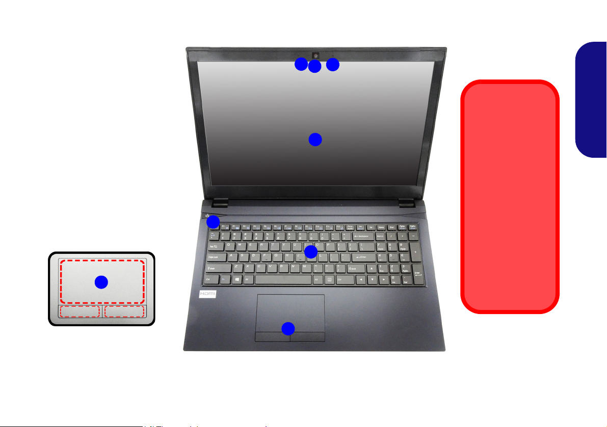
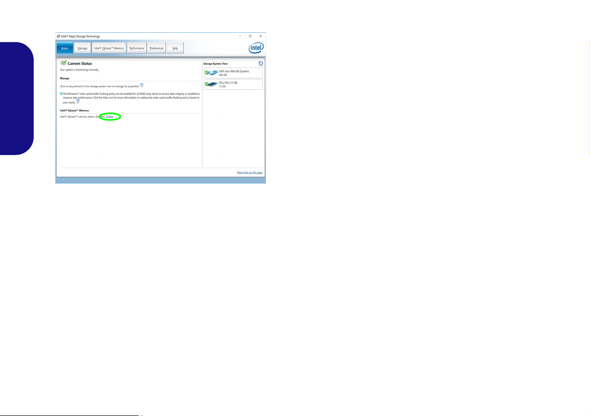
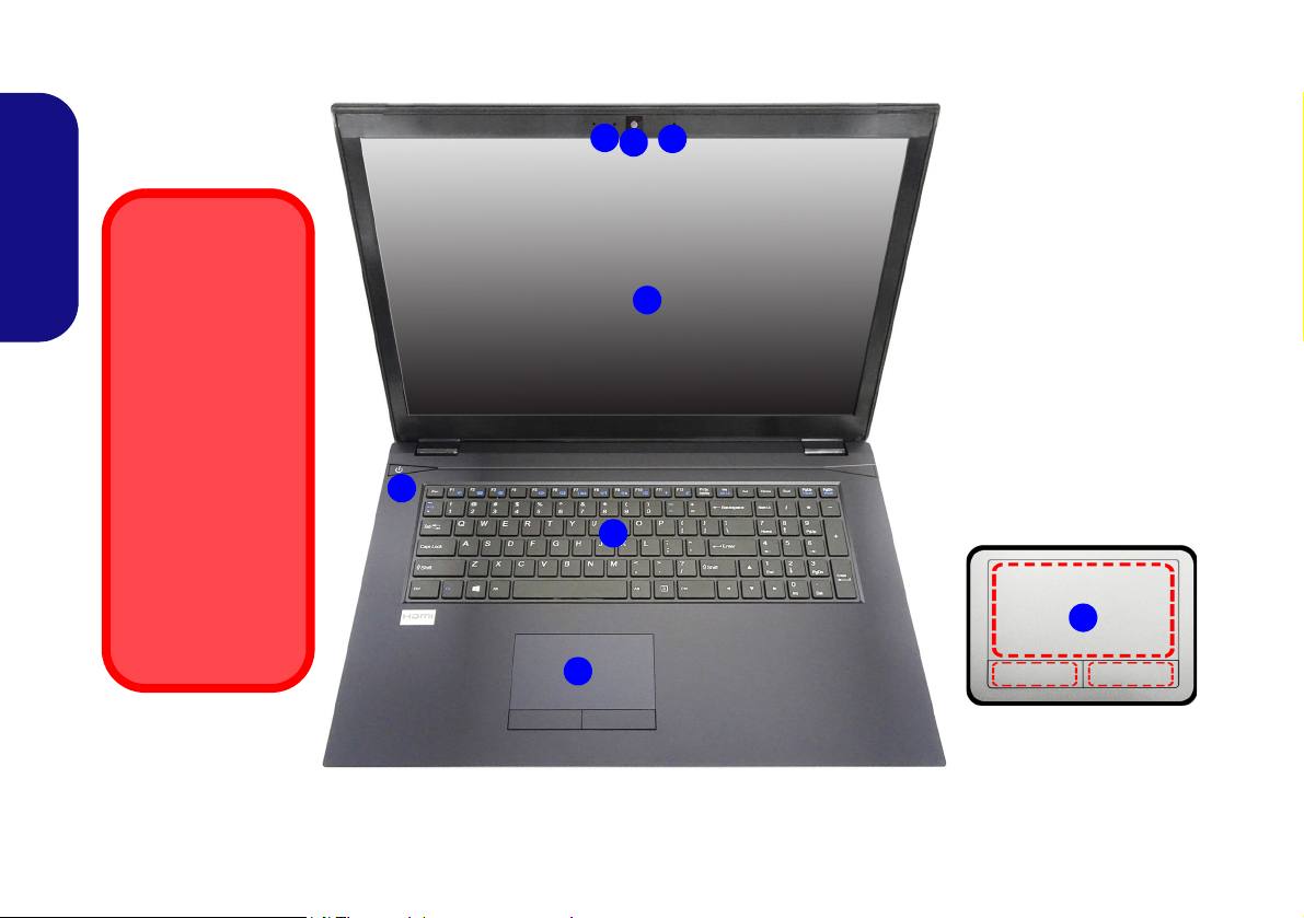
System Map: Front View with LCD Panel Open (Model A)
Note that the Touchpad
and Buttons valid operational area is that indicated within the red
dotted lines above.
Figure 3
Front View with LCD
Panel Open (Model A)
1. PC Camera
2. *PC Camera LED
*When the PC camera is
in use, the LED will be
illuminated.
3. Built-In Microphone
4. LCD
5. Power Button
6. Keyboard
7. Touchpad & Buttons
5
7
6
2
1
3
7
4
Wireless Device
Operation Aboard
Aircraft
The use of any portable electronic
transmission devices aboard aircraft is
usually prohibited.
Make sure the
WLAN, Bluetooth &
3G/4G module(s)
are OFF if you are
using the computer
aboard aircraft by
putting the system
in to Airplane Mode.
7
15,6” (39,62cm)
English
7
System Map: Front View with LCD Panel Open (Model B)
Note that the Touchpad
and Buttons valid operational area is that indicated within the red
dotted lines above.
Figure 4
Front View with LCD
Panel Open (Model B)
1. PC Camera
2. *PC Camera LED
*When the PC camera is
in use, the LED will be
illuminated.
3. Built-In Microphone
4. LCD
5. Power Button
6. Keyboard
7. Touchpad & Buttons
5
7
6
2
1
3
4
Wireless Device
Operation Aboard
Aircraft
The use of any portable electronic
transmission devices aboard aircraft is
usually prohibited.
Make sure the
WLAN, Bluetooth &
3G/4G module(s)
are OFF if you are
using the computer
aboard aircraft by
putting the system
in to Airplane Mode.
7
17,3” (43,94cm)
English
8
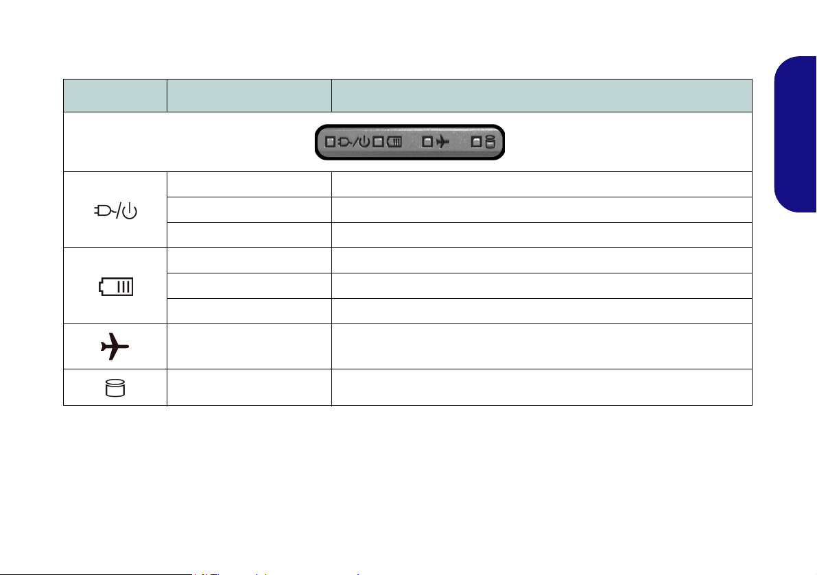
LED Indicators
The LED indicators on the computer display helpful information about the current status of the computer.
Icon Color Description
Orange The AC/DC Adapter is Plugged In
Green The Computer is On
Blinking Green The Computer is in Sleep Mode
Orange The Battery is Charging
Green The Battery is Fully Charged
Blinking Orange The Battery Has Reached Critically Low Power Status
Green Airplane Mode is ON (the WLAN, 3G/4G & Bluetooth Modules are OFF)
Green The Hard Disk/Optical Device is in use
Table 1 - LED Indicators
English
9
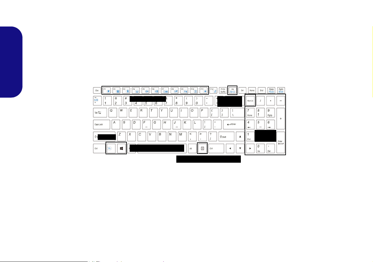
Keyboard
Function Keys
Numeric
Keypad
Num Lk &
Scr Lk
Fn Key
Menu/Application Key
Windows Logo Key
The keyboard includes a numeric keypad (on the right side of the keyboard) for easy numeric data input. Pressing
Num Lk turns on/off the numeric keypad. It also features function keys to allow you to change operational features
instantly.
(Illuminated keyboard - Optional) The keyboard illumination level may be adjusted, or turned off/on, by using the
Fn + F4 keys.
English
Figure 5 - Keyboard
10

Function Keys & Visual Indicators
The function keys (F1 - F12 etc.) will act as hot keys when pressed while the Fn key is held down. In addition to the
basic function key combinations, some visual indicators are available when the Control Center driver is installed (after
restart a control panel will pop-up to allow you to select the type of keyboard for your system).
Keys Function/Visual Indicators Keys Function/Visual Indicators
English
Fn +
Fn + Touchpad Toggle
Fn +
Fn +
Fn +
Fn +
Fn + Change Display Configuration (see page 18)
Fn +
Play/Pause (in Audio/Video Programs)
Turn LCD Backlight Off
(Press a key to or use Touchpad to turn on)
Mute Toggle Number Lock Toggle
Toggle Keyboard Illumi-
nation/Adjust Brightness
Level (Illuminated key-
boards only)
Volume Decrease/
Increase
Brightness Decrease/
Increase
Table 2 - Function Keys & Visual Indicators
Fn +
Fn +
Fn +
Fn +
Fn +
Fn +
PC Camera Power
Toggle
Airplane Mode Tog-
gle
Sleep Toggle
Scroll Lock Toggle
Caps Lock Toggle
Control Center Toggle (see page 12)
Fan Automatic Con-
trol/ Full Power
11
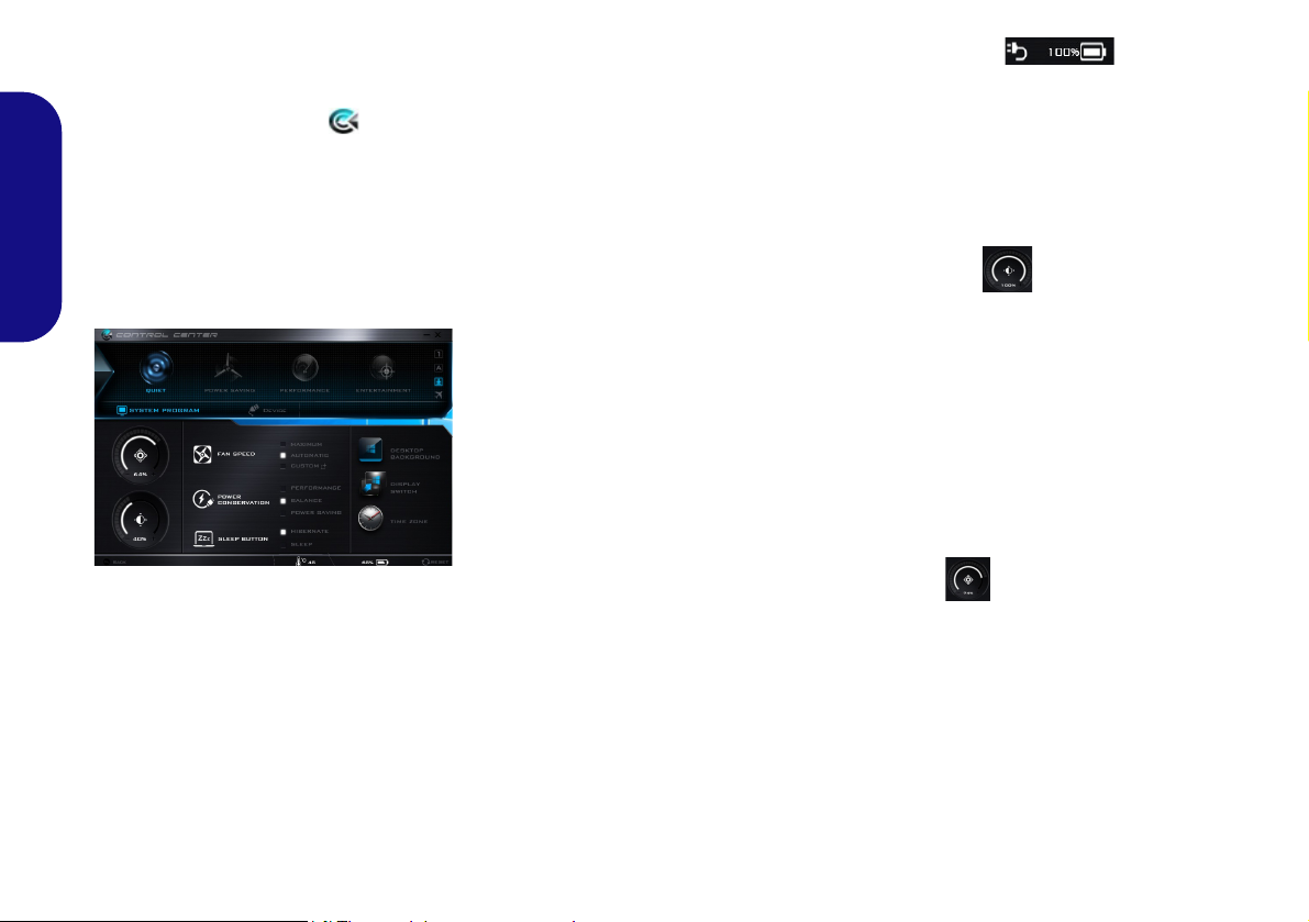
Control Center
Figure 6 - Control Center
Press the Fn + Esc key combination,
or double-click the icon in the no-
tification area of the taskbar to toggle the Control Center on/off. The
Control Center gives quick access to
frequently used controls and enables
you to quickly turn the camera/Touch-
English
pad on/off.
Power Modes
You can set a Power Mode by clicking the appropriate icon at the top of
the Control Center. Each power
mode will affect the Power Conservation Mode, Airplane Mode, Power
Plan and PC camera power etc.
Control Center Menus
The Control Center contains two
menu headings (System Program and
Device) under the Power Modes.
Click the Control Center icons to
toggle the appropriate function, or
hold the mouse button down and move
the dial control where applicable. Certain functions will automatically be
adjusted when a power mode is selected. Click the menu headings and then
click any of the buttons.
Power Status
The Power Status icon will show
whether you are currently powered by
the battery, or by the AC/DC adapter
plugged in to a working power outlet.
The power status bar will show the
current battery charge state.
Brightness
The Brightness icon will show the
current screen brightness level. You
can use the slider to adjust the screen
brightness or the Fn + F8/F9 key combinations, or use the Fn + F2 key combination to turn off the LED backlight
(press any key to turn it on again).
Note that screen brightness is also effected by the Power Mode selected.
Volume
The Volume icon will show the current volume level. You can use the
slider to adjust the volume or the Fn +
F5/F6 key combinations, or use the
Fn + F3 key combination to mute the
volume.
12
Power Conservation
This system supports Energy Star
power management features that place
computers (CPU, hard drive, etc.) into
a low-power sleep mode after a designated period of inactivity. Click either
the Performance, Balanced or Pow-
er Saving button.
Fan Speed
The fan speed will adjust itself automatically to control the heat of the
CPU. However you can adjust the setting to maximum if you prefer. Select
Custom and click on the sliders to adjust the settings to your preference,
however these settings can be overidden by the system, as a safety precaution, if it requires heavier use of the fan.
Sleep Button
Click either the Hibernate or Sleep
button to have the computer enter the
selected power-saving mode.
Display Switch
Click the Display Switch button to access the menu (or use the + P key
combination) and select the appropriate display mode.
Time Zone
Clicking the Time Zone button will
access the Date and Time Windows
control panel.
Desktop Background
Clicking the Desktop Background
button will allow you to change the
desktop background picture.
Touchpad/PC Camera
Click either of these buttons to toggle
the Touchpad or camera module’s
power status. Note that the power status of the camera module is also effected by the Power Mode selected.
Backlight Keyboard
Click the numbers under the
Backlight Keyboard icon to
adjust the brightness of the
keyboard backlight LED.
English
13
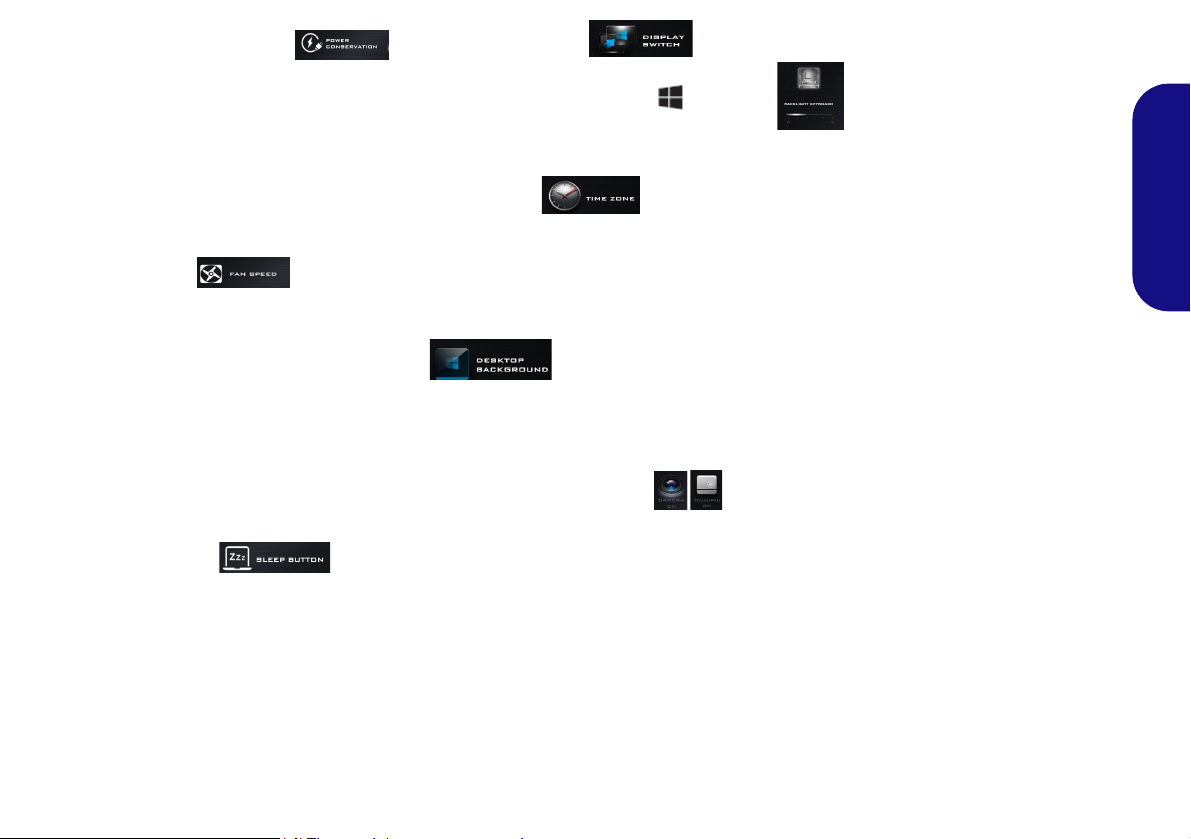
System Map: Front, Left & Right Views (Model A)
1
Front
14
13
Figure 7 - Front, Left & Right Views (Model A)
1. LED Indicators
2. Multi-in-1 Card Reader
3. DC-In Jack
4. External Monitor Port
5. RJ-45 LAN Jack
6. Vent
7. HDMI-Out Port
8. USB 3.0 (USB 3.1 Gen 1)
Type-A Port
9. USB 3.0 (USB 3.1 Gen 1) Type-C Port
or
(Factory Option) USB 3.1 Gen 2 Type-C Port
10. Headphone-Out Jack
11. Microphone-In Jack
12. USB 2.0 Ports
13. Optical Device Drive Bay
14. Emergency Eject Hole
15. Security Lock Slot
6
7
3
5
2
Right
4
10
12
9
8
11
Disc Emergency
Eject
If you need to manually eject a disc (e.g.
due to an unexpected
power interruption)
you may push the end
of a straightened paper clip into the emergency eject hole. Do
not use a sharpened
pencil or similar object
that may break and
become lodged in the
hole.
Overheating
To prevent your computer from overheating make sure nothing
blocks any vent while
the computer is in use.
Left
Right
15
English
14
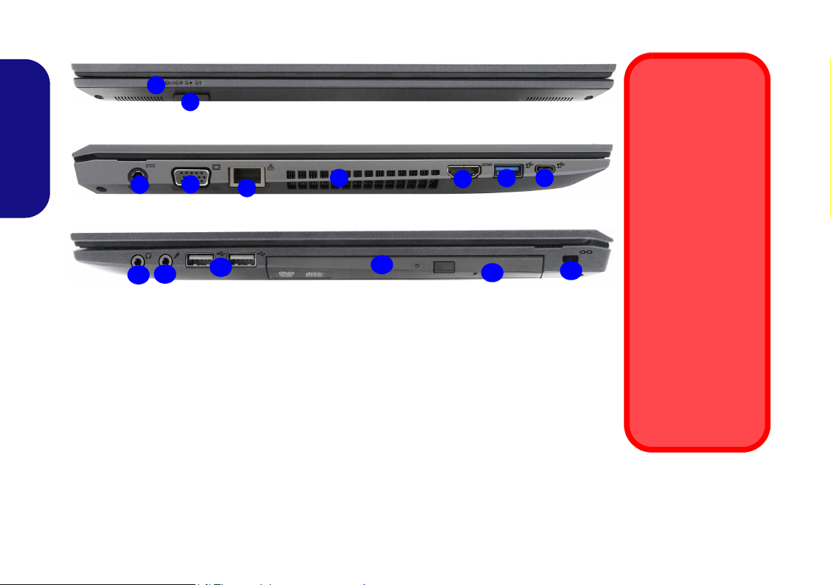
System Map: Front, Left & Right Views (Model B)
1
Front
Figure 8 - Front, Left & Right Views (Model B)
1. LED Indicators
2. Multi-in-1 Card Reader
3. DC-In Jack
4. External Monitor Port
5. RJ-45 LAN Jack
6. Vent
7. HDMI-Out Port
8. USB 3.0 (USB 3.1 Gen 1)
Type-A Port
9. USB 3.0 (USB 3.1 Gen 1) Type-C Port
or
(Factory Option) USB 3.1 Gen 2 Type-C Port
10. Headphone-Out Jack
11. Microphone-In Jack
12. USB 2.0 Ports
13. Optical Device Drive Bay
14. Emergency Eject Hole
15. Security Lock Slot
6
7
3
5
2
Right
4
10
9
8
11
Disc Emergency
Eject
If you need to manually eject a disc (e.g.
due to an unexpected
power interruption)
you may push the end
of a straightened paper clip into the emergency eject hole. Do
not use a sharpened
pencil or similar object
that may break and
become lodged in the
hole.
Overheating
To prevent your computer from overheating make sure nothing
blocks any vent while
the computer is in use.
Left
Right
14
13
12
15
English
15
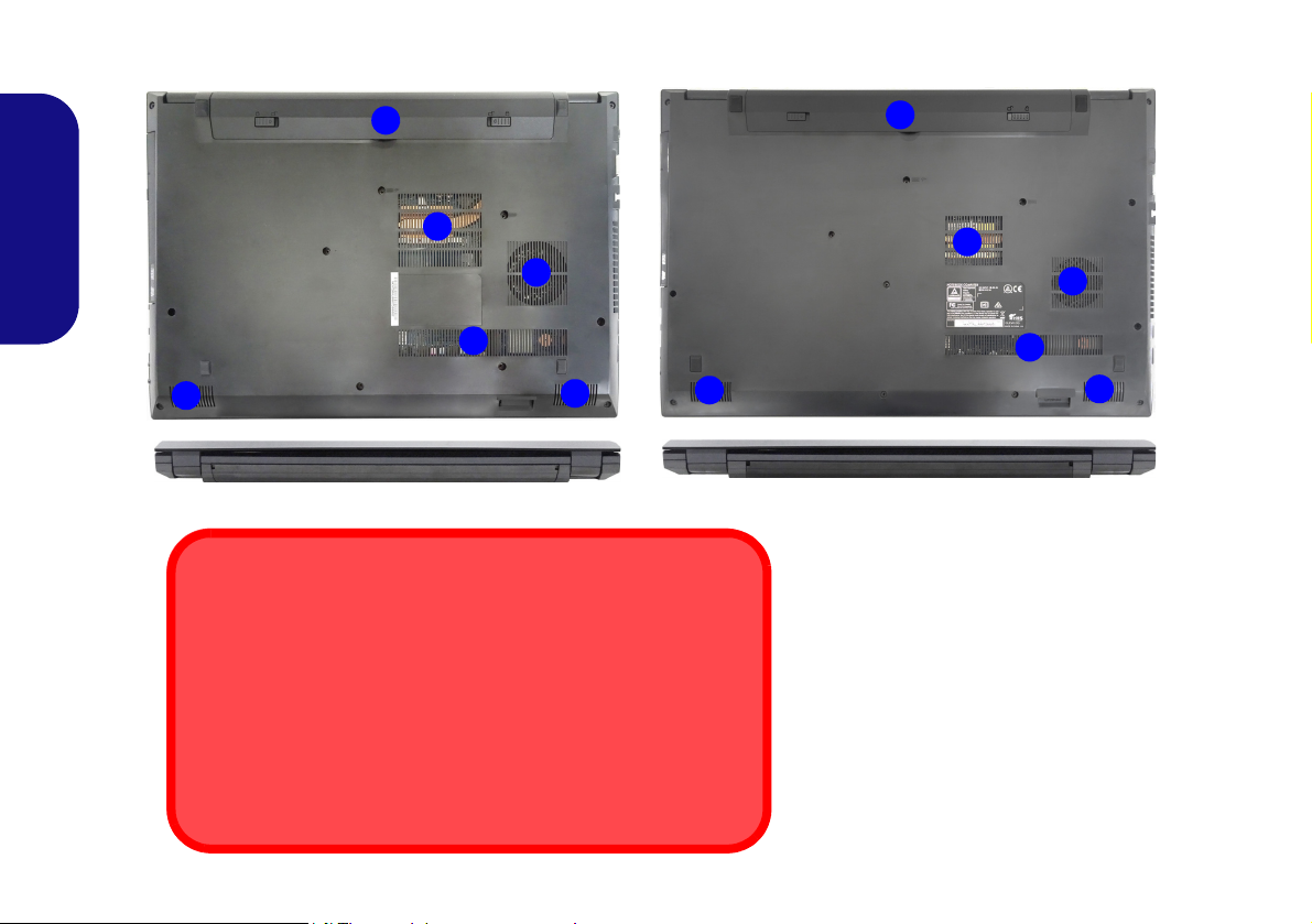
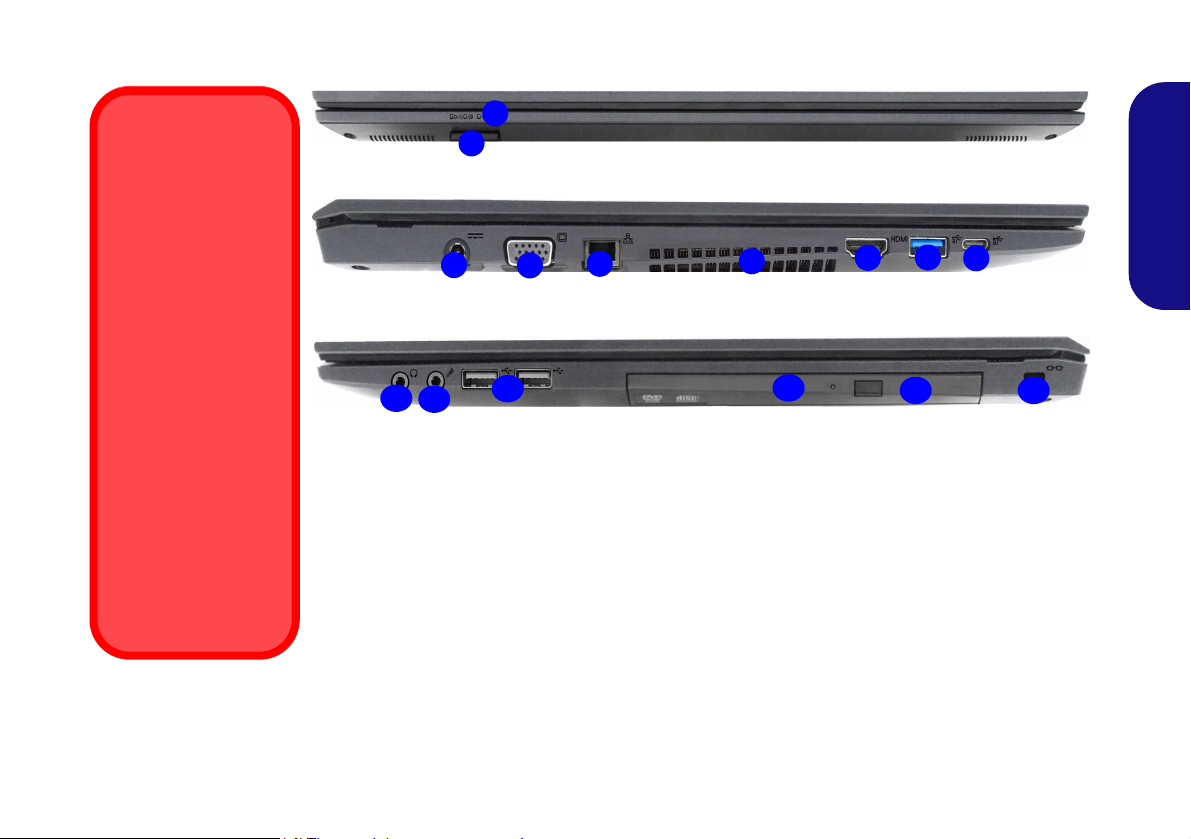
System Map: Bottom & Rear Views
Figure 9
Bottom & Rear Views
1. Battery
2. Vent
3. Speakers
2
1
3
2
2
3
Bottom Cover Removal Warning
Do not remove any cover(s) and/or screw(s) for the purposes of device upgrade as this may violate the terms of your warranty. If you
need to replace/remove the hard disk/RAM/CPU etc., for any reason, please contact your distributor/supplier for further information.
Overheating
To prevent your computer from overheating make sure nothing
blocks any vent while the computer is in use.
Model A
Model B
2
1
3
2
2
3
English
16
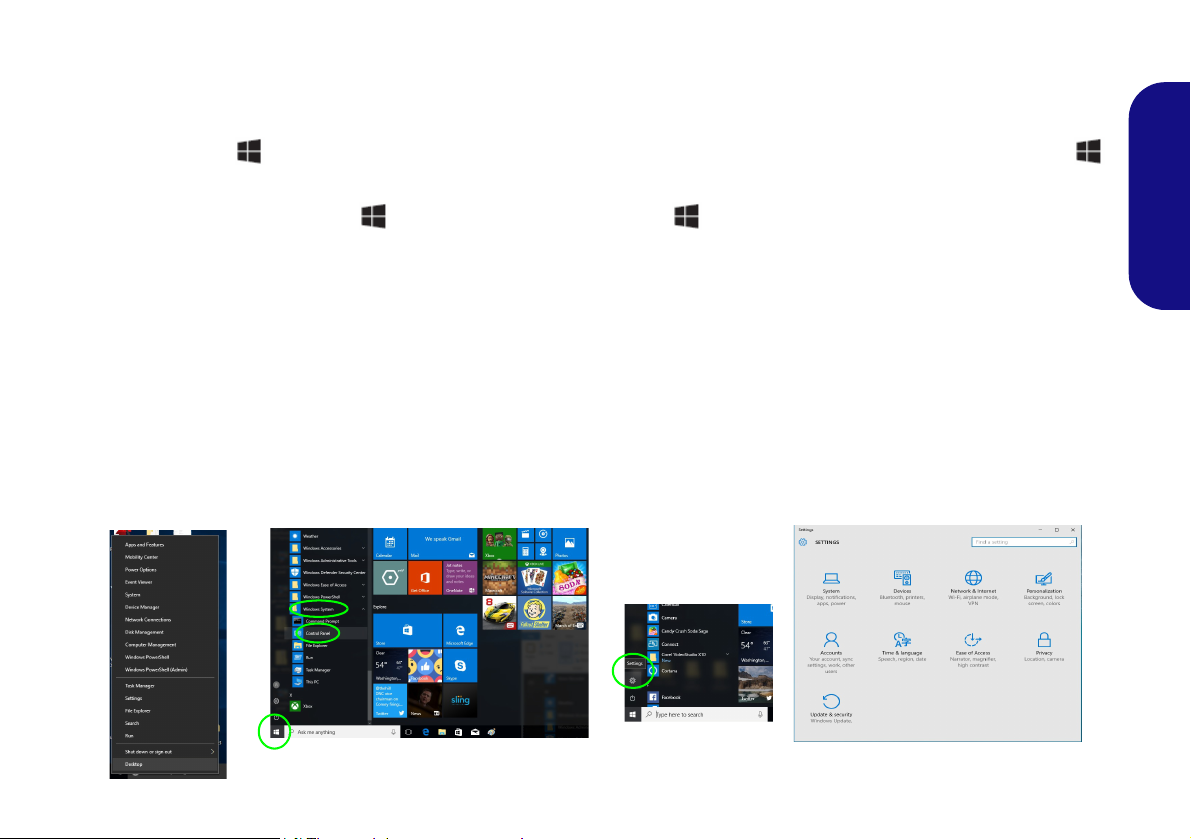
Windows 10 Start Menu, Context Menu, Taskbar, Control Panel
Figure 10 - Start Menu, Context Menu, Taskbar, Control Panel and Settings
and Settings
Most of the apps, control panels, utilities and programs within Windows 10 can be accessed from the Start Menu by
clicking the icon in the taskbar in the lower left corner of the screen (or by pressing the Windows Logo Key
on the keyboard).
Right-click the Start Menu icon (or use the Windows Logo Key + X key combination) to bring up an advanced
Context Menu of useful features such as Programs and Features, Power Options, Task Manager, Search, File Explorer,
Command Prompt, Device Manager and Network Connections etc.
The notification area of the taskbar is in the bottom right of the screen. Some of the control panels and applications referred to throughout the course of this manual can be accessed from here.
Throughout this manual you will see an instruction to open the Control Panel. To access the Control Panel, select Control Panel under the Windows System item in the Start Menu.
The Settings item in the Start Menu (and also as an App) gives you quick access to a number of system settings control
panels allowing you to adjust settings for System, Devices, Network & Internet, Personalization, Accounts, Time & language, Ease of Access, Privacy and Update & security.
English
17

Video Features
Figure 11
Project
The system features an Intel integrated GPU. You can
switch display devices, and configure display options,
from the Display control panel in Windows as long as the
video driver is installed.
To access the Display control panel in Windows:
1. Right-click the desktop and select Display settings from the
English
menu.
2. Choose the required display settings from the menus.
3. Click Apply to save the settings.
To access the Intel® HD Graphics Control Panel:
1. Right-click the desktop and select Graphics Properties from the
menu.
OR
2. Click the icon in the notification area of the Desktop taskbar
and select Graphics Properties from the menu.
Display Devices
Note that you can use external displays connected to the
HDMI-Out port and/or external monitor port. See your
display device manual to see which formats are supported.
In Windows it is possible to quickly configure external
displays from the Project menu (press the Windows
Logo Key and the P key or press the Fn + F7 key
combination).
To configure the displays using the Project menu:
1. Attach your external
display device to the
appropriate port, and
then turn it on.
2. Press the + P (or
Fn + F7) key
combination.
3. Click on any one of the
options from the menu
to select PC screen
only, Duplicate,
Extend or Second
screen only.
18
Audio Features
Volume Adjustment
The sound volume level can also be set using the volume control within Windows. Click the Speaker icon in
the taskbar to check the setting
.
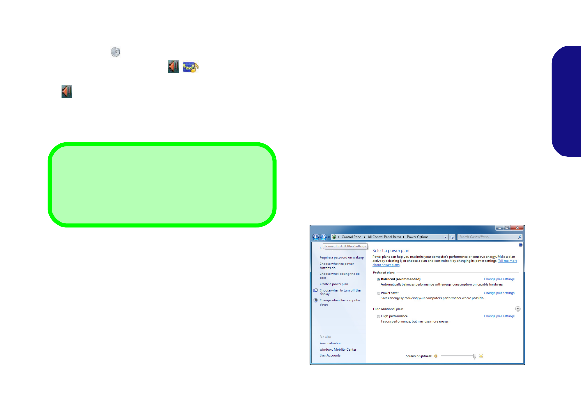
Figure 12 - Power Options
You can configure the audio options on your computer
from the Sound control panel in Windows, or from the
Realtek HD Audio Manager
tion area/control panel (right-click the notification area
icon to bring up an audio menu).
The volume may be adjusted by means of the Fn + F5/F6
key combination.
/ icon in the notifica-
Power Options
The Power Options (Hardware and Sound menu) control panel icon in Windows allows you to configure power
management features for your computer. You can conserve power by means of power plans and configure the
options for the power button, sleep button (Fn + F12),
computer lid (when closed), display and sleep mode (the
default power saving state) from the left menu. Note that
the Power saver plan may have an affect on computer
performance.
Click to select one of the existing plans, or click Create a
power plan in the left menu and select the options to create a new plan. Click Change Plan Settings and click
Change advanced power settings to access further configuration options.
English
19
Driver Installation General
Guidelines
As a general guide follow the
default on-screen instructions for each driver (e.g.
Next > Next > Finish) unless
you are an advanced user. In
many cases a restart is required to install the driver.
Make sure any modules (e.g.
WLAN or Bluetooth) are ON
before installing the appropriate driver.
Windows Update
After installing all the drivers
make sure you enable Win-
dows Update in order to get
all the latest security updates
etc. (all updates will include
the latest hotfixes from Mi-
crosoft).
Driver Installation & Power
When installing drivers make sure
your computer is powered by the AC/
DC adapter connected to a working
power source. Some drivers draw a
significant amount of power during the
installation procedure, and if the remaining battery capacity is not adequate this may cause the system to
shut down and cause system problems (note that there is no safety issue involved here, and the battery will
be rechargeable within 1 minute).
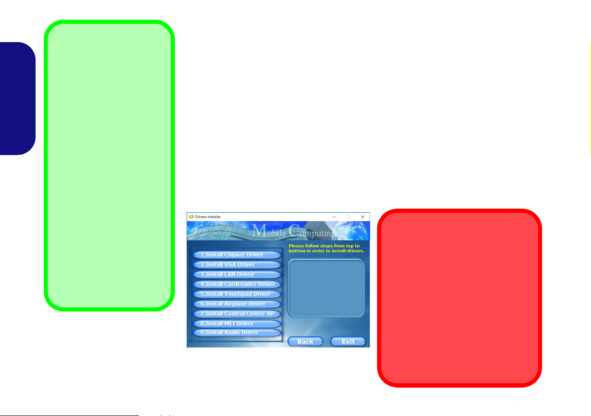
Figure 13 - Install Drivers
English
Driver Installation
The Device Drivers & Utilities + User’s Manual disc contains the drivers and utilities
necessary for the proper operation of the computer. This setup will probably have already been done for you. If this is not the case, insert the disc and click Install Drivers
(button), or Option Drivers (button) to access the Optional driver menu. Install the
drivers in the order indicated in Figure 13. Click to select the drivers you wish to
install (you should note down the drivers as you install them). Note: If you need to
reinstall any driver, you should uninstall the driver first
Manual Driver Installation
Click the Browse CD/DVD button in the Drivers Installer application and browse to
the executable file in the appropriate driver folder.
If a
Found New Hardware
Cancel and follow the installation procedure as directed.
wizard appears
during the installation procedure, click
.
20
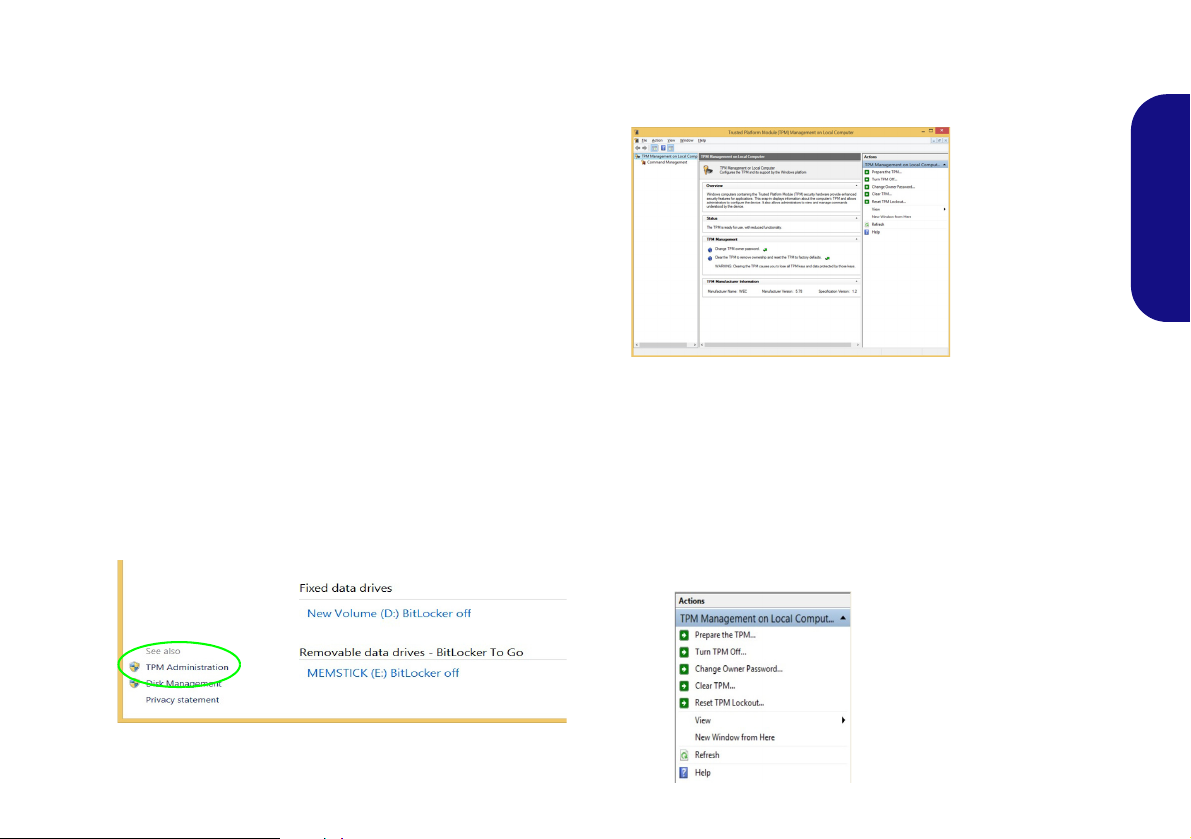
TPM (Option)
Figure 14 - BitLocker Drive Encryption
(TPM Administration)
Figure 15
Trusted Platform Module
(TPM) Manage-
ment on Local
Computer Ad-
ministration
Figure 16
Actions Menu
Before setting up the TPM (Trusted Platform Module)
functions you must initialize the security platform.
4. The TPM Management window allows you to configure the TPM
within Windows. As TPM is usually administered within large
enterprises and organizations, your system administrator will
need to assist you in managing the information here.
Activating TPM
1. Restart the computer.
2. Enter the Aptio Setup Utility pressing F2 during the POST.
3. Use the arrow keys to select the Security menu.
4. Select TPM Configuration and press Enter.
5. Press Enter to access the Security Device Support menu and
select Enable.
6. You will then need to press F4 to save the changes and restart
the computer.
TPM Management in Windows
You can manage your TPM settings from within Windows:
1. Go to the Control Panel.
2.
Click
BitLocker Drive Encryption (System and Security).
3. Click TPM Administration.
English
TPM Actions
1. Click Prepare the TPM and follow the instructions in the Wizard
to prepare the TPM (this will probably require a restart of the
computer and confirmation of the setting changes after restart by
pressing the appropriate F key).
2. After the restart the TPM will be prepared and you can then use
the Actions menu to Turn TPM off, Change Owner Password,
Clear TPM or Reset TPM Lockout.
3. A wizard will help take you through any setup steps.
21
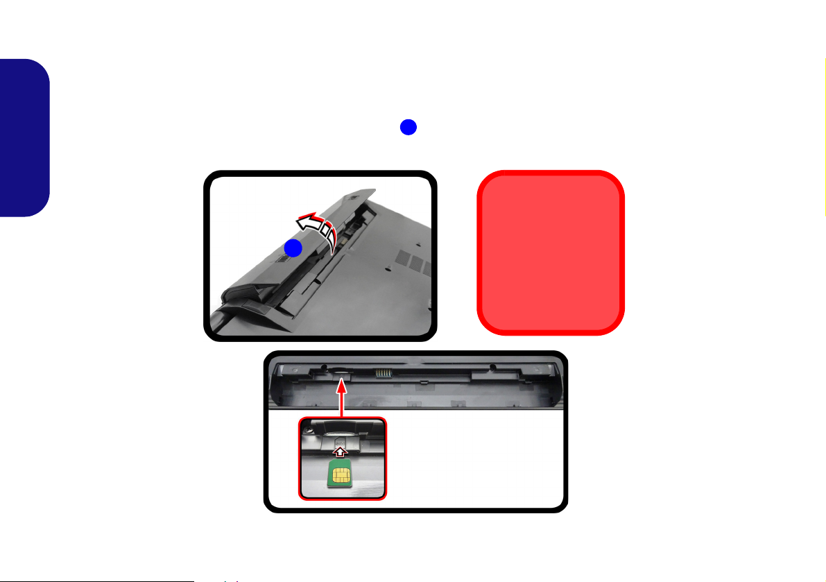
3G/4G Module (Option)
1
USIM Card
Orientation
Note that the USIM
card’s readable side
(with the gold-colored
contacts) should face
upwards as illustrated.
1
If you have included an optional 3G/4G module in your purchase option, follow the instructions below to install the
USIM card (which will be provided by your service provider).
USIM Card Insertion
1. Turn off the computer, and turn it over and remove the battery .
2. Insert the USIM card as illustrated below until it clicks into position, and replace the battery.
English
Figure 17 - Remove the battery and Insert the USIM Card
22

Troubleshooting
Problem Possible Cause - Solution
The Wireless LAN/Bluetooth
modules cannot be detected.
The PC Camera module cannot be
detected.
The captured video files from the PC
Camera are taking up too much disk
space.
The modules are off as the computer is in Airplane Mode. Check the LED indicator
to see if it is in Airplane Mode (see Table 1 on page 9). Use the Fn + F11 key
combination to toggle Airplane Mode on/off (see Table 2 on page 11).
The module is off. Press the Fn + F10 key combination in order to enable the module (see
Table 2 on page 11). Run the camera application to view the camera picture.
Note that capturing high resolution video files requires a substantial amount of disk space
for each file.
Note that the Windows system requires a minimum of 20GB (64bit) of free space on the
C: drive system partition. It is recommended that you save the capture video file to a
location other than the C:drive, limit the file size of the captured video or reduce video
resolution.
English
23

Specifications
Latest Specification Information
The specifications listed in this section are correct at the time of going to
press. Certain items (particularly processor types/speeds) may be
changed, delayed or updated due to
the manufacturer's release schedule.
Check with your service center for details.
Note that this computer model series
may support a range of CPUs and/or
video adapters.
To find out which CPU is installed on
your system go to the Start menu and
select Settings, and then select Sys-
tem and click About. This will also
provide information on the amount of
Installed RAM etc.
To get information on your system’s
video adapter go to the Start menu
and select Settings, and then select
System and click Display > Advanced display settings > Display
adapter properties.
English
LCD Options
Model A:
15.6" (39.62cm), 16:9, HD (1366x768)/FHD
(1920x1080) (Thickness: 3.2mm)
Model B:
17.3" (43.94cm), 16:9, HD+ (1600x900)/
FHD (1920x1080) (Thickness: 4.0mm)
Memory
Two 260 Pin SO-DIMM Sockets Supporting
DDR4 2400MHz Memory
Memory Expandable up to 32GB
Compatible with 4GB, 8GB or 16GB Mod-
ules
(The real memory operating frequency
depends on the FSB of the processor.)
BIOS
64Mb SPI Flash ROM
AMI BIOS
Audio
High Definition Audio Compliant Interface
2 * Built-In Speakers
Built-In Microphone
(Factory Option) Built-In Array Microphone
Storage
One Changeable 2.5" 7mm (h) SATA HDD/
SSD
(Factory Option) One 9.0/9.5mm(h) Optical Device Type Drive (DVD Writer)
Or
(Factory Option) Dummy ODD
Or
(Factory Option) 7mm (h) 2nd HDD/SSD
Caddy
(Factory Option) One M.2 SATA/PCIe
Gen3 x4 Solid State Drive (SSD)
Pointing Device
Built-in Touchpad
Keyboard
Full-size “WinKey” keyboard (with numeric
keypad)
Or
(Factory Option) Full-size “WinKey” Illumi-
nated White-LED Keyboard (with numeric
keypad)
Security
Security (Kensington® Type) Lock Slot
BIOS Password
Intel PTT for Systems Without TPM Hard-
ware
(Factory Option) TPM 2.0
24

M.2 Slots
Slot 1 for WLAN and Bluetooth Combo
Module
Slot 2 for SATA/PCIe Gen3 x4 SSD
(Factory Option) Slot 3 for 3G/4G Module
Card Reader
Embedded Multi-In-1 Card Reader
MMC (MultiMedia Card) / RS MMC
SD (Secure Digital) / Mini SD / SDHC/
SDXC
Interface
One USB 3.0 (USB 3.1 Gen 1) Type-C Port*
Or
(Factory Option) One USB 3.1 Gen 2
Type-C Port*
*The maximum amount of current supplied
by USB Type-C ports is 500mA (USB 2.0)/
900mA (USB 3.1).
Communication
Built-In 10/100/1000Mb Base-TX Ethernet
LAN
1.0M HD PC Camera Module Module
(Factory Option) 3G or 4G M.2 Module
WLAN/ Bluetooth M.2 Modules:
(Factory Option) Intel® Wireless-AC 8265
Wireless LAN (802.11ac) + Bluetooth
(Factory Option) Intel® Wireless-AC 3168
Wireless LAN (802.11ac) + Bluetooth
Features
Intel® Optane™ Technology
Supports Windows® 10 Cortana with Voice
Power
Full Range AC/DC Adapter
AC Input: 100 - 240V, 50 - 60Hz
DC Output: 19V, 2.1A (40W)
Dimensions & Weight
Model A:
377mm (w) * 259mm (d) * 24.8mm (h)
(Height Excluding Battery Area)
2.2kg (Barebone with 31WH Battery)
Model B:
418.5mm (w) * 287mm (d) * 26.4mm (h)
(Height Excluding Battery Area)
2.5kg (Barebone with 31WH Battery)
English
One USB 3.0 (USB 3.1 Gen 1) Type-A Port
Two USB 2.0 Ports
One HDMI-Out Port
One External Monitor Port
One Microphone-In Jack
One Headphone-Out Jack
One RJ-45 LAN Jack
One DC-in Jack
Removable 4 Cell Smart Lithium-Ion Battery Pack, 31WH
(Factory Option) Removable 4 Cell Smart
Lithium-Ion Battery Pack, 44WH
Environmental Spec
Temperature
Operating: 5
Non-Operating: -20°C - 60°C
Relative Humidity
Operating: 20% - 80%
Non-Operating: 10% - 90%
°C - 35°C
25

English
26

Über das Ausführliche Benutzerhandbuch
Diese Kurzanleitung soll einen Überblick über die Schritte geben, die dazu notwendig sind, das System zu starten. Dieses ist
nur eine Ergänzung und kein Ersatz für das erweiterte englischsprachige Benutzerhandbuch, das auf der mitgelieferten Disc
Device Drivers & Utilities + User's Manual im Adobe-Acrobat-Format vorliegt. Diese Disc enthält auch die Treiber und
Utility-Programme, die für einen einwandfreien Betrieb des Computers notwendig sind (Hinweis: Das Unternehmen behält
sich das Recht vor, diese Publikation ohne Vorankündigung zu überarbeiten und den Inhalt zu verändern).
Einige oder alle Funktionen des Computers sind bereits eingerichtet worden. Falls das nicht der Fall ist oder wenn Sie einzelne Teile des Systems neu konfigurieren (oder neu installieren) möchten, finden Sie eine Anleitung im erweiterten Benut-
zerhandbuch. Die Disc Device Drivers & Utilities + User's Manual enthält nicht das Betriebssystem.
Einhaltung gesetzlicher Vorschriften und Sicherheitshinweise
Beachten Sie sorgfältig die Hinweise zu gesetzlichen Vorschriften und zu Sicherheitshinweisen im erweiterten Benutzerhandbuch auf der Disc Device Drivers & Utilities + User's Manual.
© August 2017
Warenzeichen
Intel und Intel Core sind warenzeichen/eingetragenes warenzeichen der Intel Corporation.
Deutsch
27

Hinweise zu Pflege und Betrieb
Das Notebook ist zwar sehr stabil, kann aber dennoch beschädigt werden. Damit es nicht dazu kommt, sollten Sie die
folgenden Hinweise beachten:
• Das Gerät darf nicht herunterfallen und in anderer Form Stößen
ausgesetzt werden. Wenn der Computer fällt, können das Gehäuse und
andere Komponenten beschädigt werden.
• Das Gerät darf nicht nass werden und sich nicht überhitzen. Computer und Netzteil dürfen nicht in der Nähe von Wärmequellen stehen oder
gelagert werden. Dies ist ein elektrisches Gerät. Wenn Wasser oder
andere Flüssigkeiten eindringen, kann der Computer stark beschädigt
werden.
• Vermeiden Sie Interferenzen mit anderen Geräten. Halten Sie den
Computer fern von magnetischen Feldern, die von Stromquellen, Moni-
Deutsch
toren, Magneten etc. erzeugt werden. Die können die Leistung beeinträchtigen und Ihre Daten beschädigen.
• Achten Sie auf die richtige Bedienung des Computers. Schalten Sie
ihn erst aus, wenn alle Programme geschlossen wurden (speichern Sie
Ihre Daten!). Speichern Sie regelmäßig Ihre Daten, da diese verloren
gehen können, wenn der Akku verbraucht ist.
Reparatur
Nehmen Sie vor dem Reinigen des Wenn Sie versuchen, den
Computer selbst zu reparieren, können Ihre Garantieansprüche
verloren gehen. Außerdem besteht Stromschlaggefahr für Ihre
Gesundheit und das Gerät durch frei liegende Teile. Lassen Sie
Reparaturarbeiten nur von qualifizierten Reparaturfachleuten
durchführen, insbesondere wenn folgende Umstände vorliegen:
• Wenn das Netzkabel oder der AC/DC-Adapter beschädigt oder zerschlissen sind.
• Wenn der Computer Regen ausgesetzt war oder mit Flüssigkeiten in
Berührung gekommen ist.
• Wenn der Computer unter Beachtung der Bedienungsanweisungen nicht
korrekt arbeitet.
• Wenn der Computer heruntergefallen ist oder beschädigt wurde (berühren Sie nicht die giftige Flüssigkeit des LCD-Bildschirms).
• Wenn ein ungewöhnlicher Geruch, Hitze oder Rauch aus dem Computer
entweicht.
Sicherheitsinformationen
• Verwenden Sie nur einen AC/DC-Adapter, der für die Verwendung mit
diesem Computer zugelassen ist.
• Verwenden Sie nur das Netzkabel und die Akkus, die in diesem Benutzerhandbuch spezifiziert sind
Sie können explodieren. Richten Sie sich nach den regional gültigen Entsorgungsvorschriften.
• Verwenden Sie den Akku nicht mehr, wenn er heruntergefallen ist oder in
anderer Weise beschädigt (z.B. verzogen) ist. Auch wenn der Computer
mit dem beschädigten Akku zu funktionieren schein, können dadurch
Stromkreise beschädigt werden, die schließlich einen Brand verursachen
können.
• Achten Sie darauf, dass Ihr Computer ausgeschaltet ist, wenn Sie es fur
den Transport z.B. wahrend einer Reise in eine Tasche einpakken.
• Nehmen Sie vor dem Reinigen des Computers den Akku heraus, und
trennen Sie es von allen externen Stromquellen, Peripheriegeräten und
Kabeln ab.
• Reinigen Sie den Computer mit einem weichen, sauberen Tuch. Tragen
Sie das Reinigungsmittel nicht direkt auf den Computer auf. Verwenden
Sie keine flüchtigen Reinigungsmittel (Petroleumdestillate) oder Scheuermittel zum Reinigen des Computers.
• Versuchen Sie nicht, Akkus zu reparieren. Lassen Sie die Akkupacks
durch den Servicevertreter oder qualifiziertes Fachpersonal reparieren
oder austauschen.
• Beachten Sie, dass das Logo bei den Computern, die über ein galvanisch
beschichtetes LCD-Logo verfügen, von einer Schutzfolie bedeckt ist.
Durch die natürliche Abnutzung kann diese Schutzfolie beschädigt werden oder abgehen und die scharfen Kanten des frei liegenden Logos
freigeben. Seien Sie in solch einem Fall vorsichtig bei der Handhabung
des Computers, und vermeiden Sie es, das herausstehende beschichtete
LCD-Logo zu berühren. Legen Sie keine Gegenstände in die Tragetasche, da diese während des Transports gegen den Computer drücken
können. Wenden Sie sich in einem solchen Fall von Abnutzung an Ihr
Service Center.
. Entsorgen Sie die Akkus nicht in Feuer.
28

Polymer Akku Sicherheitshinweise
Entsorgen der Akkus/ Batterien & Achtung
Das von Ihnen gekaufte Produkt enthält einen aufladbaren
Akku. Dier Akku ist wiederverwertbar. Nach verschiedenen nationalen und regionalen Getzgebungen kann es verboten in,
einen nicht mehr gebrauchsfähigen Akku in den normalen
Hausmüll zu werfen. Informieren Sie sich bei Ihrem regionalen
Entsorgungsunternehmen über Recycling-Möglichkeiten oder
korrekte Entsorgung.
Wenn ein falscher Akku eingesetzt wird, besteht Explosionsgefahr. Tauschen Sie den Akku nur durch den gleichen oder einen
baugleichen Typ aus, der vom Hersteller empfohlen wird. Entsorgen Sie den verbrauchten Akku entsprechend der Anweisungen des Herstellers.
Beachten Sie die folgenden Hinweise, die sich speziell auf Polymer Akkus beziehen. Diese Hinweise haben zudem Vorrang
gegenüber den Allgemeinen Akku Sicherheitshinweisen.
• Polymer Akkus können sich etwas ausdehnen oder anschwellen. Dies ist
Teil des Sicherheitsmechanismus des Akkus und kein Anlass zur Sorge.
• Seien Sie vernünftig im Umgang mit Polymer Akkus. Verwenden Sie
keine Polymer Akkus in Umgebungen mit hohen Temperaturen und
lagern Sie keine ungenutzten Akkus über längere Zeiträume.
Deutsch
29

Schnellstart
Abb. 1 - Öffnen des Dekkels/LCD/Compu-
ters mit angeschlossenem AC/DC-Adapter
Herunterfahren
Bitte beachten Sie, daß der Computer immer mit dem Befehl Herunter-
fahren in Windows (siehe unten)
heruntergefahren werden muß.
Dadurch werden Festplatten- bzw.
Systemprobleme vermieden.
1. Klicken Sie auf das StartmenüSymbol .
2. Klicken Sie auf den Eintrag Ein/Aus
.
3. Wählen Sie aus dem Menü die Option
Herunterfahren.
130 ゚
1. Entfernen Sie das gesamte Verpackungsmaterial.
2. Legen Sie den Computer auf eine stabile Unterlage.
3. Setzen Sie den Akku ein, und stellen Sie sicher, dass sie fest sitzt.
4. Schließen Sie alle Peripheriegeräte, die Sie mit dem Computer verwenden
wollen (z. B. Tastatur und Maus), an die entsprechenden Schnittstellen an.
5. Gehen Sie bei der erstmaligen Einrichtung des Computers wie folgt vor
(um den Computer während des Versands zu schützen, wird der Akku das
System nicht mit Strom versorgen, bis es das erste Mal mit dem AC/DCAdapter verbunden und wie folgt erstmalig eingerichtet worden ist):
• Bringen Sie das AC/DC-Adapterkabel an die DC-Eingangsbuchse an der
linken Seite des Computers an und verbinden Sie das AC-Netzkabel
anschließend mit einer Steckdose. Schließen Sie das AC-Netzkabel an
den AC/DC-Adapter an und lassen Sie es dort 6 Sekunden oder länger.
Deutsch
• Entfernen Sie das Adapterkabel von der DC-Eingangsbuchse des Compu-
ters und stecken Sie es anschließend wieder ein. Der Akku wird jetzt entsperrt sein.
6. Klappen Sie den Deckel/LCD vorsichtig mit einer Hand auf, und öffnen Sie
ihn auf einen angenehmen Sichtwinkel (jedoch nicht weiter als 130°). Mit der
anderen Hand halten Sie das Unterteil des Computers fest (siehe Abb. 1)
(Hinweis: Heben Sie den Computer niemals am Deckel/LCD hoch).
7. Drücken Sie auf den Netzschalter, um den Computer einzuschalten.
Systemsoftware
Möglicherweise wurde das Notebook bereits mit vorinstallierter Software ausgeliefert. Ist das nicht der Fall, oder wenn Sie das Notebook
für ein anderes System neu konfigurieren möchten, finden Sie dazu
eine Anleitung in diesem Handbuch zu Microsoft Windows 10.
Intel® Optane™-Unterstützung
Sie müssen Intel® Optane™ vor der Installations Ihres Windows 10
Betriebssystems installieren
30
(siehe "Intel® Optane™" auf Seite 31).

Intel® Optane™
Intel® Optane™ ist eine Kombination aus einem kompatiblen Speichergerät und Intel® Rapid Storage-Technolo-
gie Software. Diese Kombination wurde entwickelt, um Ihre
Systemleistung zu beschleunigen, indem Sie Bootdaten, ausführbare Dateien, auf häufig zugegriffene Daten und Auslagerungsdateien auf eine nichtflüchtige Intel® Optane™
SSD mit niedriger Latenz aufrufen.
Wenden Sie sich an Ihren Händler oder Lieferanten, um zu
erfahren, ob Ihr System diese Technologie unterstützt.
Wenn Sie ein System neu installieren, das zuvor im Intel
RST Premium Modus eingerichtet wurde, stellen Sie sicher,
dass Sie den Intel Optane Speicher gelöscht haben (siehe
"Intel® Optane™ löschen" auf Seite 32).
Intel® Optane™ Einrichtung
Sie müssen Intel® Optane™ vor der Installations Ihres
Windows 10 Betriebssystems installieren, und Sie müssen
Folgendes vorbereiten, um dies zu tun.
•Die Microsoft Windows 10 Betriebssystem-Disc.
• Ein angeschlossen externes DVD Laufwerk.
• Eine Intel® Optane™ SSD muss in Ihrem System installiert
sein.
•Die Disc Device Drivers & Utilities + User's Manual.
1. Starten Sie den Computer und drücken Sie auf F2, um in das
BIOS zu gelangen.
2. Gehen Sie zum Menü Boot, wählen Sie UEFI Setting und
drücken Sie auf die Eingabetaste.
3. Wählen Sie UEFI Boot, drücken Sie auf die Eingabetaste und
wählen Sie “Enabled”.
4. Drücken Sie auf Esc um das Menü zu verlassen und gehen Sie
zum Menü Main.
5. Wählen Sie OffBoard NVMe Controller Configuration und
drücken Sie die Eingabetaste, um zu überprüfen, ob eine Intel®
Optane™ SSD vorhanden ist.
6. Drücken Sie auf Esc um das Menü zu verlassen und gehen Sie
zum Menü Advanced.
7. Wählen Sie SATA Mode, drücken Sie auf die Eingabetaste und
wählen Sie “Intel RST Premium...”.
8. Drücken Sie auf F4 und <Yes> (Ja), um die Änderungen zu
speichern und das Gerät zurückzusetzen (“Save Changes
and Reset”).
9. Drücken Sie beim Neustart des Computers auf F2, um das BIOS
erneut aufzurufen.
10. Drücken Sie auf F4 und <Yes> (Ja), um die Änderungen zu
speichern und das Gerät zurückzusetzen (“Save Changes
and Reset”), stellen Sie jedoch sicher, dass die Bedingung im
Aufzählungspunkt unten erfüllt ist, bevor Sie dies tun.
• Stellen Sie sicher, dass sich die Windows 10-DVD im ange-
schlossenen DVD Laufwerk befindet. Während der Computer
hochfährt, startet dieser automatisch von der Windows 10-DVD
(Sie werden aufgefordert, eine Taste zu drücken, um den Systemstart von der DVD auszuführen).
11. Drücken Sie auf Weiter > Jetzt installieren, um die Installation
des Betriebssystems wie herkömmlich fortzusetzen (die Anleitung
zur Installation des Windows-Betriebssystems finden Sie in der
Windows- Dokumentation).
12. Wählen Sie Benutzerdefiniert: nur Windows installieren (für
fortgeschrittene Benutzer).
13. Es wird empfohlen, bestehende Partitionen auszuwählen und zu
löschen.
14. Klicken Sie auf Neu, um eine Partition für Windows zu erstellen.
Deutsch
31

15. Es ist sehr wichtig sicherzustellen, dass bei der Erstellung der
Abb. 2 - Intel® Rapid Storage-Technologie - Status
Partition ein Minimum von 5MB nicht zugewiesenem
Speicherplatz gelassen wird.
16. Folgen Sie den Anweisungen auf dem Bildschirm, um das
Windows 10-Betriebssystem zu installieren.
17. Installieren Sie die Windows-Treiber. Sollten Sie den Intel® Rapid
Storage-Technologie (IRST) Treiber Installieren.
18. Starten Sie die Intel® Rapid Storage-Technologie Anwendung.
19. Klicken Sie auf Aktivieren.
Deutsch
20. Das System wird eine Meldung anzeigen und Sie bitten, ein
kompatibles schnelles Laufwerk auszuwählen (in diesem Fall
sollte nur eine Option vorhanden sein).
21. Sie müssen den Computer nach dem Aktivieren von Optane neu
starten und sicherstellen, dass das System mit dem
eingeschalteten AC/DC-Adapter und nicht nur mit dem Akku
betrieben wird.
22. Klicken Sie auf Ja, um den Vorgang zu starten (dies kann einige
Zeit dauern).
23. Starten Sie den Computer neu, nachdem der Vorgang
abgeschlossen ist.
Intel® Optane™ löschen
Wenn Sie eine bestehende Intel® Optane™ Einrichtung löschen möchten, gehen Sie wie folgt vor. Sichern Sie jedoch
alle notwendigen Dateien und Daten vor dem Löschen
einer Intel® Optane™ Einrichtung, da dies zu einem Ver-
lust aller Daten auf den Volumes führen wird.
1. Stellen Sie sicher, dass Intel® Optane™ in der Intel® Rapid Storage-Technologie Anwendung aktiviert ist.
2. Starten Sie den Computer und drücken Sie auf F2, um in das
BIOS zu gelangen.
3. Wechseln Sie zu Intel(R) Rapid Storage Technology (im Menü
Advanced) und drücken Sie auf die Eingabetaste.
4. Wählen Sie Intel Optane, **** (aufgeführt unter Optane Volume:)
und drücken Sie auf die Eingabetaste.
5. Wählen Sie “Deconcatentate” und drücken Sie auf die
Eingabetaste.
6. Wählen Sie <Yes> (Ja) aus der Option “Are you sure you want
to perform deconcatentation”.
7. Wählen Sie “Start deconcatentation” und drücken Sie auf die
Eingabetaste.
8. Das System kehrt zum Standard Intel(R) Rapid Storage
Technology Menü zurück, wenn es fertig ist.
9. Sie sollten dann den entsprechenden SATA-Modus für Ihr System
auswählen und das Betriebssystem neu installieren.
32

Systemübersicht: Ansicht von vorne mit geöffnetem LCD-Bild-
7
Beachten Sie, dass der Funktionsbereich des Touchpads
und der Tasten innerhalb der
rot gepunkteten Linien liegt.
Abb. 3
Ansicht von vorne mit ge-
öffnetem LCD-Bildschirm
(Modell A)
1. PC-Kamera
2. *LED der PC-Kamera
*Wenn die PC-Kamera verwendet wird, leuchtet die
LED.
3. Mikrofon
4. LCD-Bildschirm
5. Netzschalter
6. Tastatur
7. Touchpad mit Tasten
Die Benutzung
drahtlos
angeschlossener
Geräte in
Flugzeugen
In der Regel ist die
Benutzung jeglicher
tragbarer elektronischer Funkgeräte in
Flugzeugen verboten.
Stellen Sie sicher,
dass das WLAN-, das
Bluetooth- und 3G/
4G-Modul durch Aktivieren des Flugzeugmodus
ausgeschaltet sind,
wenn Sie sich an Bord
eines Flugzeugs
befinden.
5
7
6
2
1
3
4
15,6” (39,62cm)
schirm (Modell A)
Deutsch
33

Systemübersicht: Ansicht von vorne mit geöffnetem LCD-Bild-
7
Beachten Sie, dass der
Funktionsbereich des
Touchpads und der Tasten
innerhalb der rot gepunkteten
Linien liegt.
Abb. 4
Ansicht von vorne mit geöffnetem LCD-Bildschirm
(Modell B)
1. PC-Kamera
2. *LED der PC-Kamera
*Wenn die PC-Kamera
verwendet wird, leuchtet
die LED.
3. Mikrofon
4. LCD-Bildschirm
5. Netzschalter
6. Tastatur
7. Touchpad mit Tasten
Die Benutzung
drahtlos
angeschlossener
Geräte in Flugzeugen
In der Regel ist die Benutzung jeglicher
tragbarer elektronischer Funkgeräte in
Flugzeugen verboten.
Stellen Sie sicher, dass
das WLAN-, das Bluetooth- und 3G/4G-Modul durch Aktivieren
des Flugzeugmodus
ausgeschaltet sind,
wenn Sie sich an Bord
eines Flugzeugs
befinden.
5
7
6
2
1
3
4
17,3” (43,94cm)
schirm (Modell B)
Deutsch
34

LED-Anzeigen
Die LED-Anzeigen auf dem Computer zeigen wichtige Informationen über den aktuellen Status des Computers.
Symbol Farbe Beschreibung
Orange Der AC/DC-Adapter ist angeschlossen
Grün Der Computer ist angeschaltet
Lampe blinkt grün Das System ist im konfigurierten Energiesparmodus
Orange Der Akku wird geladen
Grün Der Akku ist voll geladen
Lampe blinkt orange Der Akku hat einen kritisch niedrigen Stromstatus erreicht
Grün
Grün Es wird auf die Festplatte/das optische Laufwerk zugegriffen
Flugzeugmodus ist EIN (die Module WLAN, Bluetooth und 3G/4G ausgeschaltet
sind)
Tabelle 1 - LED-Anzeigen
Deutsch
35

Tastatur
Nummemtastatur
Num & Rollen
Funktionstasten
Menü/Anwendungstaste
Windows-Logo-Taste
Fn Taste
Die Tastatur umfasst eine Nummerntastatur (an der rechten Seite der Tastatur) für die Eingabe von Zahlen. Durch Drücken
auf Num wird die Nummerntastatur ein- und ausgeschaltet. Zusätzlich gibt es Funktionstasten, über die Sie direkt zwischen
den Funktionen umschalten können.
(Beleuchtete Tastatur - Optional) Die Stufe der Tastaturbeleuchtung kann angepasst oder aus-/eingeschaltet werden, indem
Sie die Fn + F4 Tasten verwenden.
Deutsch
Abb. 5 - Tastatur
36

Funktionstasten & visuelle Anzeigen
Wenn die Funktionstasten (F1 - F12) gleichzeitig mit der Fn-Taste gedrückt werden, funktionieren sie wie Hotkeys. Neben
den Tastenkombinationen für die Grundfunktionen gibt es einige visuelle Anzeigen, wenn der Control Center-Treiber installiert ist (nach dem Neustart wird ein Steuerungsfeld eingeblendet, um die Art der Tastatur für Ihr System auszuwählen).
Tas ten Funktion/ Visuelle Anzeigen Tasten Funktion/ Visuelle Anzeigen
Fn +
Fn +
Fn +
Fn +
Fn +
Fn +
Fn +
Fn +
Wiedergabe/Pause (in Audio /Videoprogrammen)
Touchpad aktivieren/deak-
tivieren
LCD-Hintergrundlicht ausschalten (zum Einschalten
beliebige Taste drücken oder Touchpad berühren)
Stummschaltung/Stumm-
schaltung aufheben
Tastaturbeleuchtung
wechseln/Helligkeitsstufe
anpassen (Nur Beleuch-
tete Tastaturen)
Audio-Lautstärke
verringern/erhöhen
Ändern der Anzeigeeinstellungen (siehe Seite 44)
LCD-Helligkeit verringern/
erhöhen
Tabelle 2 - Funktionstasten & visuelle Anzeigen
Fn +
Fn +
Fn +
Fn +
Fn +
Fn +
PC-Kamera aktivieren/
deaktivieren
Flugzeugmodus ein-/
ausschalten
Energiesparmodus wechseln
Ein-/Ausschalten der
Nummerntastatur
Ein-/Ausschalten des
Scroll-Modus
Ein-/Ausschalten der
Feststelltaste
Ein-/Ausschalten des Control Center (siehe
Seite 38)
Automatische Lüftersteuerung/Volle Leis-
tung
Deutsch
37

Control Center
Abb. 6 - Control Center
Drükken Sie auf die Tastenkombination
Fn + Esc, oder doppelklicken Sie auf
das Symbol im Infobereich auf
der Taskleiste um das Control Center
ein-/auszuschalten. Das Control Center bietet den schnellen Zugriff auf
häufig verwendete Funktionen, und Sie
haben hier die Möglichkeit, das
Touchpad/das Kamera-Modul direkt
ein-/auszuschalten.
Deutsch
Energiemodi
Sie können einen Energiemodus einstellen, indem Sie im Control Center
auf das entsprechende Symbol klicken.
Jeder Energiemodus wird Einfluss auf
den Energiesparmodus, Flugzeugmodus, Energiesparplan und PC
Kamerastrom usw. haben.
Control Center Menüs
Das Control Center umfasst zwei Menütitel (Systemprogramm und Gerät)
für die Strommodi. Klicken Sie auf die
Symbole des Control Center, um die
entsprechende Funktion zu wählen, oder
halten Sie die Maustaste gedrückt und
verschieben Sie den Regler, falls vorhanden. Bestimmte Funktionen werden
automatisch angepasst, wenn ein
Strommodus ausgewählt ist. Klicken
Sie auf die Menütitel und anschließend
auf eine der Schaltflächen.
Energiestatus
Das Energiestatus-Symbol zeigt an, ob
die Stromversorgung aktuell über den
Akku oder über das an das Stromnetz
angeschlossene Netzteil erfolgt. Die
Energiestatus-Anzeige zeigt den aktuellen Akkuladestatus an.
Helligkeits
Das Helligkeits-Symbol zeigt die aktuell eingestellte Bildschirmhelligkeit
an.Sie können die Bildschirmhelligkeit
entweder mit dem Schieberegler oder
mit der Tastenkombination Fn + F8/F9
ändern. Mit der Tastenkombination Fn
+ F2 wird das LED-Hintergrundlicht
ausgeschaltet (drücken Sie auf eine
beliebige Taste, um es wieder einzuschalten). Beachten Sie, dass die Bildschirmhelligkeit auch vom eingestellten
Energiemodus abhängt.
Lautstärke
Das Lautstärke-Symbol zeigt die aktuelle Lautstärke an.Sie können die Lautstärke entweder mit dem Schieberegler
oder mit der Tastenkombination Fn +
F5/F6 einstellen. Mit der
Tastenkombination Fn + F3 wird der
Ton ausgeschaltet.
38

Strom sparen
Dieses System unterstützt die Energy
Star-Stromsparfunktionen, die Compu-
ter (CPU, Festplatte usw.) nach einer
längeren Zeit der Inaktivität in einen
Ruhemodus versetzen, bei dem weniger
Strom verbraucht wird. Klicken Sie entweder auf die Taste Leistungsmodus,
Ausgeglichen oder Stromsparmodus.
Lüftergeschwindigkeit
Die Lüftergeschwindigkeit wird sich
automatisch einstellen, um die Temperatur der CPU zu regeln. Sie können
die Einstellung nach Bedarf auch auf die
maximale Einstellung anpassen. Wäh-
len Sie Benutzer und klicken Sie auf die
Regler, um die Einstellungen nach Ihren
Wünschen anzupassen. Diese Einstellungen können allerdings als Sicherheitsvorkehrung vom System
überschrieben werden, wenn Sie den
Lüfter zu stark beanspruchen.
Schalter
Klicken Sie entweder auf die Schaltfläche Ruhezustand oder Schlaf (Energiesparmodus), um den Computer der
ausgewählten Stromsparmodus aufrufen zu lassen.
Anzeige wechseln
Klicken Sie auf die Taste zum Wechseln
des Anzeigegeräts, um das Menü aufzurufen (Sie können dazu auch die
Tastenkombination und P ver-
wenden), und wählen Sie einen Anzeigemodus aus.
Zeitzone
Wenn Sie auf die Schaltfläche Zeitzone
klicken, wird das Windows-Systemsteuerungsfenster Datum und Uhrzeit
aufgerufen.
Desktop-Hintergrund
Wenn Sie auf die Schaltfläche DesktopHintergrund klikken, können Sie das
Bild für den Desktophintergrund einstellen.
Touchpad/PC-Kamera
Klicken Sie auf eine dieser Tasten, um
das Touchpad oder das Kamera-Modul
ein- oder auszuschalten. Beachten Sie,
dass der Energiestatus des Kamera-Moduls auch vom ausgewählten Ener-
giemodus abhängen.
Beleuchtete Tastatur
Klicken Sie auf die Zahlen unter den Beleuchtete Tastatursymbol, um die Helligkeit der
Tastatur-HintergrundlichtLED anzupassen.
Deutsch
39

Systemübersicht:
1
2
Disc-Notauswurf
Wenn eine Disc manuell entnommen werden
muß (z.B. wegen eines
Stromausfalls) können
Sie mit dem Ende einer
geradegebogenen Büroklammer in das
Notauswurfloch drükken. Verwenden Sie
hierzu aber keinen spitzen Bleistift oder
ähnliche Objekte, die
im Loch abbrechen und
darin stekkenbleiben
könnten.
Überhitzung
Zum Schutz vor Überhitzung Ihres Computers dürfen die
Luftungsoffnung(en)
nicht während das
Notebook in Betrieb ist
verdeckt werden.
Abb. 7 - Ansicht von vorne, links und rechts (Modell A)
1. LED-Anzeigen
2. Multi-in-1 Kartenleser
3. DC-Eingangsbuchse
4. Schnittstelle für externen Monitor
5. RJ-45 LAN-Buchse
6. Luftungsoffnung
7. HDMI-Ausgangsanschluss
8. USB 3.0 (USB 3.1 Gen 1) Typ-A
Anschluss
9. USB 3.0 (USB 3.1 Gen 1) Typ-C Anschluss
Oder
(Werkseitige Option) USB 3.1 Gen 2 Typ-C Anschluss
10. Kopfhörer-Ausgangsbuchse
11. Mikrofon-Eingangsbuchse
12. USB 2.0 Anschlüsse
13. Schacht für optisches Laufwerk
14. Notauswurfloch
15. Sicherheitsschloß-Buchse
Vorderseite
Linke Seite
Rechte Seite
14
13
6
7
3
5
Right
4
10
12
9
8
11
15
Ansicht von vorne, links und rechts (Modell A)
Deutsch
40

Systemübersicht:
Abb. 8 - Ansicht von vorne, links und rechts (Modell B)
1. LED-Anzeigen
2. Multi-in-1 Kartenleser
3. DC-Eingangsbuchse
4. Schnittstelle für externen Monitor
5. RJ-45 LAN-Buchse
6. Luftungsoffnung
7. HDMI-Ausgangsanschluss
8. USB 3.0 (USB 3.1 Gen 1) Typ-A
Anschluss
9. USB 3.0 (USB 3.1 Gen 1) Typ-C Anschluss
Oder
(Werkseitige Option) USB 3.1 Gen 2 Typ-C Anschluss
10. Kopfhörer-Ausgangsbuchse
11. Mikrofon-Eingangsbuchse
12. USB 2.0 Anschlüsse
13. Schacht für optisches Laufwerk
14. Notauswurfloch
15. Sicherheitsschloß-Buchse
1
6
7
3
5
2
Right
4
10
9
8
11
14
13
12
15
Vorderseite
Linke Seite
Rechte Seite
Disc-Notauswurf
Wenn eine Disc manuell entnommen werden
muß (z.B. wegen eines
Stromausfalls) können
Sie mit dem Ende einer
geradegebogenen Büroklammer in das
Notauswurfloch drükken. Verwenden Sie
hierzu aber keinen spitzen Bleistift oder
ähnliche Objekte, die
im Loch abbrechen und
darin stekkenbleiben
könnten.
Überhitzung
Zum Schutz vor Überhitzung Ihres Computers dürfen die
Luftungsoffnung(en)
nicht während das
Notebook in Betrieb ist
verdeckt werden.
Ansicht von vorne, links und rechts (Modell B)
Deutsch
41

Systemübersicht:
Keine Gehäuseteile entfernen oder öffnen
Entfernen Sie keine Gehäuseteile und/oder Schrauben, um das Gerät aufzurüsten,
da anderenfalls Ihre Garantieansprüche verloren gehen. Ist es erforderlich, die
Festplatte, den RAM, die CPU usw. auszuwechseln oder zu entfernen, wenden Sie
sich an Ihren Vertragshändler/Lieferanten.
Überhitzung
Zum Schutz vor Überhitzung Ihres Computers dürfen die Luftungsoffnung(en) nicht
während das Notebook in Betrieb ist verdeckt werden.
Abb. 9
Ansicht von unten und
hinten
1. Akku
2. Luftungsoffnung
3. Lautsprecher
2
1
1
3
2
2
3
Modell A
Modell B
2
1
3
2
2
3
Ansicht von unten und hinten
Deutsch
42

Start-Menü, Kontextmenü, Taskleiste, Systemsteuerung und Ein-
Abb. 10 - Start-Menü, Kontextmenü, Taskleiste, Systemsteuerung und Einstellungen
stellungen von Windows 10
Auf die meisten Apps, Control Panels, Utilities und Programme in Windows 10 können Sie über das Start-Menü gelangen.
Klicken Sie dazu auf das Symbol in der Taskleiste in der linken unteren Ecke des Bildschirms (oder drücken Sie auf die
Windows-Logo-Taste der Tastatur).
Klicken Sie mit der rechten Maustaste auf das Startmenü-Symbol (oder verwenden Sie die Tastenkombination
Windows-Logo-Taste + X), um ein erweitertes Kontextmenü der nützlichen Funktionen aufzurufen: Programme und
Funktionen, Energieoptionen, Task-Manager, Suche, Datei-Explorer, Eingabeaufforderung, Geräte-Manager, Netzwerkverbindungen usw.
Der Infobereich der Taskleiste befindet sich in der rechten unteren Ecke des Bildschirms. Hierüber können Sie manche
Control Panels und Anwendungen aufrufen, die in diesem Handbuch angesprochen werden.
In diesem Handbuch finden Sie eine Anleitung zum Öffnen der Systemsteuerung. Um die Systemsteuerung aufzurufen, wählen Sie Systemsteuerung unter dem Eintrag Windows-System im Startmenü.
Der Eintrag Einstellungen im Startmenü (auch die App) bietet Ihnen einen schnellen Zugriff auf eine Reihe von Einstellmöglichkeiten für das System, die Geräte, das Netzwerk und das Internet, die Personalisierung, Konten, die Uhrzeit und Sprache,
die erleichterte Bedienung, den Datenschutz, Updates und die Sicherheit.
Deutsch
43

Grafikfunktionen
Abb. 11
Projizieren
Dieses System verfügt über eine integrierte GPU von Intel.
Wenn der Grafiktreiber installiert ist, können Sie bei
Windows im Einstellfenster Anzeige die Anzeigegeräte
wechseln und Anzeigeoptionen konfigurieren.
Anzeigegeräte
Beachten Sie, dass Sie externe Anzeigen nutzen können, die
an den HDMI-Ausgangsanschluss und/oder an die Schnittstelle für externen Monitor angeschlossen sind. Lesen Sie die
Anleitung des Anzeigegerätes, um zu erfahren, welche Formate unterstützt werden.
So öffnen Sie in Windows das Einstellfenster Anzeige:
1. Klicken Sie mit der rechten Maustaste auf den Desktop und dann
aus dem Menü die Option Anzeigeeinstellungen wählen.
2. Wählen Sie aus den Menüs die gewünschten
Anzeigeeinstellungen.
3. Klicken Sie auf Übernehmen, um die Einstellungen zu speichern.
Deutsch
So rufen Sie die Steuerung für Intel® HD-Grafik auf:
1. Klicken Sie mit der rechten Maustaste auf den Desktop und dann
aus dem Menü die Option Grafikeigenschaften wählen.
Oder
2. Klicken Sie auf das Symbol im Infobereich auf der Desktop-
Taskleiste und dann aus dem Menü die Option
Grafikeigenschaften wählen.
Bei Windows ist es möglich, schnell externe Monitore über
das Projizieren Menü zu konfigurieren (drücken Sie auf die
Windows-Logo-Taste und gleichzeitig auf P oder drükken Sie die Tastenkombination Fn + F7).
Konfiguration der Anzeige mit dem Projizieren Menü:
1. Schließen Sie das
externe Anzeigegerät an
den entsprechenden
Anschluss an und
schalten Sie es anschließend ein.
2. Drücken Sie die
Tastenkombination +
P (oder Fn + F7).
3. Klicken Sie auf eine der
Optionen im Menü zur
Auswahl von Nur PC-
Bildschirm, Duplizieren,
Erweitern oder Nur
zweiter Bildschirm.
44

Audiofunktionen
Lautstärkeeinstellung
Die Lautstärke kann auch mit den Windows-Lautstärke-
reglern eingestellt werden. Überprüfen Sie die Einstellung,
indem Sie in der Taskleiste auf das Lautsprecher-Symbol
Klicken.
Abb. 12 - Energieoptionen
Die Audioeinstellungen können Sie bei Windows durch Anklicken des Soundsymbols oder des Realtek HD Audio
Manager -Symbols / im Infobereich/in der Systemsteuerung aufrufen (wenn Sie mit der rechten Maustaste auf
das Symbol im Infobereich klicken, wird das Audiomenü
aufgerufen).
Die Lautstärke können Sie durch die Tastenkombination Fn
+ F5/F6 ändern.
Energieoptionen
Die Energieoptionen von Windows ermöglichen Ihnen die
Konfiguration der Optionen für das Energiemanagement des
Computers. Sie können Strom sparen, indem Sie Ener-
giesparpläne erstellen und im linken Menü können Sie die
Optionen für den Netzschalter, die Energiespartasten (Fn
+ F12) und Zuklappeinstellung (beim Schließen des
Dekkels), den Bildschirm und den Energiesparmodus (die
Standardeinstellung Energie sparen) konfigurieren.
Beachten Sie, dass sich die Energiesparpläne (Ener-
giesparmodus) auf die Computerleistung auswirken.
Wählen Sie einen bestehenden Plan aus, oder klicken Sie im
linken Menü auf Energiesparplan erstellen, und wählen Sie
die Optionen, um einen neuen Plan zu erstellen. Klicken Sie
auf Energieplaneinstellungen ändern, und klicken Sie auf
Erweiterte Energieeinstellungen ändern, um weitere Optionen für die Konfiguration aufzurufen.
Deutsch
45

Allgemeine Hinweise zur
Treiberinstallation
Wenn Sie keine fortgeschrittenen Kenntnisse
haben, folgen Sie für jeden
Treiber den Anweisungen
auf dem Bildschirm (z. B.
Weiter > Weiter > Fertig
stellen). In vielen Fällen
ist es erforderlich, den
Computer nach der
Treiberinstallation neu zu
starten.
Alle Module (z. B. WLAN
oder Bluetooth) müssen
vor der Treiberinstallation
eingeschaltet werden.
Windows Update
Nachdem Sie alle Treiber
installiert haben, sollten
Sie die Funktion Windows
Update aktualisieren, um
immer die neuesten Sicherheits-Updates usw. zu
erhalten (die Updates enthalten die neuesten
Fehlerbehebungen von
Microsoft).
Treiberinstallation und Stromversorgung
Während die Treiber installiert werden, muss der
Computer über den AC/DC-Adapter mit Strom versorgt werden. Einige Treiber benötigen für den Installationsvorgang sehr viel Strom. Wenn der Akku
nicht mehr über genügend Strom verfügt, kann sich
das System während der Installation ausschalten,
was zu Systemfehlern führen kann (das ist kein Sicherheitsproblem, und der Akku ist innerhalb von
einer Minute wieder aufladbar).
Abb. 13 - Installation der Treiber
Deutsch
Installation der Treiber
Die Disc Device Drivers & Utilities + User's Manual enthält die Treiber und Hilfspro-
gramme, die für das einwandfreie Funktionieren des Computers notwendig sind. Möglicherweise wurden diese bereits vorinstalliert. Ist das nicht der Fall, legen Sie die Disc ein, und
klicken Sie auf Install Drivers (Schaltfläche) oder Option Drivers (Schaltfläche), um das
Treibermenü Optional aufzurufen.
Reihenfolge. Markieren Sie die Treiber, die installiert werden sollen (notieren Sie zum späteren Nachlesen die Treiber, die Sie installiert haben). Hinweis: Muss ein Treiber neu installiert
werden, sollten Sie den alten Treiber zunächst deinstallieren.
Manuelle Treiber-Installation
Klicken Sie in der Anwendung Drivers Installer auf die Schaltfläche Browse CD/DVD und
navigieren Sie zu der ausführbaren Datei in dem Ordner für Ihren Treiber.
Wenn während des Installationsvorgangs das Fenster Neue Hardware gefunden erscheint,
klicken Sie auf Abbrechen, um das Fenster zu schließen. Befolgen Sie dann die Installationsanweisungen.
Installieren Sie die Treiber in der in Abb. 13 angegebenen
46

TPM (Option)
Abb. 14 - BitLocker-Laufwerkverschlüsselung
(TPM-Verwaltung)
Abb. 15
“Trusted Plat-
form Module”-
Management
(TPM) auf dem
lokalen Compu-
ter
Abb. 16
Menü Aktionen
Bevor Sie die TPM (Trusted Platform Module)-Funktionen
einrichten, müssen Sie die Sicherheitsplattform initialisieren.
Aktivieren der TPM-Funktionen
1. Starten Sie das Notebook neu.
2. Rufen Sie das Aptio Setup Utility auf, indem Sie während des
POST-Vorgangs auf F2 drücken.
3. Wählen Sie mit den Pfeiltasten das Menü
4. Wählen Sie TPM Configuration und drücken Sie auf die
Eingabetaste.
5. Drücken Sie auf die Eingabetaste, um auf das Menü Security
Device Support zuzugreifen und wählen Sie Enable (Aktivieren).
6. Sie müssen anschließend auf F4 drücken, um die Änderungen zu
speichern und den Computer neu zu starten.
TPM Verwaltung in Windows
Sie können Ihre TPM Einstellungen unter
1. Rufen Sie die Systemsteuerung auf.
2. Klicken Sie auf
und Sicherheit).
3. Klicken Sie auf TPM-Verwaltung.
BitLocker-Laufwerkverschlüsselung (System
Security.
Windows
verwalten:
4. Im Fenster TPM-Verwaltung können Sie TPM unter Windows
verwalten. Da ein TPM normalerweise in großen Unternehmen
und Organisationen verwaltet wird, benötigen Sie bei der
Verwaltung der hiesigen Informationen die Hilfe Ihres
Systemadministrators.
Deutsch
TPM Aktionen
1. Klicken Sie auf TPM vorbereiten und folgen Sie den Anweisungen des Assistenten, um TPM vorzubereiten (dabei wird möglicherweise ein Neustart des Computers und eine Bestätigung der
Einstellungsänderungen nach dem Neustart durch Drücken der
entsprechenden F-Taste erforderlich sein).
2. Nach dem Neustart wird TPM vorbereitet und Sie können
anschließend das Menü Aktionen verwenden für TPM
ausschalten, Besitzerkennwort ändern, TPM löschen oder
TPM-Sperre zurücksetzen.
3. Ein Assistent wird Sie durch die Einrichtungsschritte leiten.
47

3G/4G-Modul (Option)
1
Ausrichtung der USIM-
Karte
Die lesbare Seite der
USIM-Karte (die Seite,
auf der sich die
Goldkontakte befinden)
muss wie abgebildet
nach oben zeigen.
1
Wenn Ihr Modell das optionale 3G/4G-Modul enthält, folgen Sie den nachfolgenden Anweisungen, um die USIM-Karte zu
installieren (Sie erhalten sie von Ihrem Dienstanbieter).
Einsetzen der USIM-Karte
1. Schalten Sie den Computer aus, drehen Sie es herum, und nehmen Sie den Akku heraus.
2. Schieben Sie die USIM-Karte wie unten abgebildet hinein, und lassen Sie sie einrasten. Setzen Sie den Akku wieder ein.
Deutsch
Abb. 17 - Herausnehmen des Akkus und einsetzen der USIM-Karte
48

Fehlerbehebung
Problem Mögliche Ursache - Lösung
Die Module Wireless-LAN/
Bluetooth können nicht erkannt
werden.
Das PC-Kamera-Modul kann nicht
erkannt werden.
Die mit der PC-Kamera
aufgenommenen Dateien benötigen
zu viel Speicherplatz.
Im Flugzeugmodus sind die Module ausgeschaltet. Prüfen Sie der LED-Anzeige , ob der
Computer im Flugzeugmodus ist (siehe Tabelle 1 auf Seite 35). Mit der Tastenkombination
Fn + F11 können Sie den Flugzeugmodus ein- oder ausschalten (siehe Tabelle 2 auf Seite
37).
Das ist ausgeschaltet. Mit der Tastenkombination Fn + F10 können Sie das PC-KameraModul einschalten (siehe Tabelle 2 auf Seite 37). Starten Sie die Kamera-Anwendung, um
das Kamerabild zu sehen.
Videodateien, die mit hoher Auflösung aufgenommen werden, erfordern sehr viel
Speicherplatz.
Beachten Sie, dass das Betriebssystem Windows mindestens 20GB (64bit) freien Speicher
im Laufwerk C: der Systempartition benötigt. Es wird empfohlen, die aufgenommenen
Videodateien in einem anderen Laufwerk als C: zu speichern, die Dateigröße der
Aufnahmedateien zu beschränken oder die Auflösung der Videos zu verringern.
Deutsch
49

Technische Daten
Aktualität der technischen Daten
Die in diesem Teil aufgeführten technischen Daten sind zum Zeitpunkt der
Druckstellung richtig. Bestimmte
Elemente (insbesondere Prozessortypen/-geschwindigkeiten) können im
Rahmen des Entwicklungsplans des Herstellers zwischenzeitlich geändert oder
aktualisiert werden. Detailinformationen
erhalten Sie bei Ihrem Servicezentrum.
Bitte beachten Sie, dass diese Reihe von
Computer-Modellen eine Vielzahl an Prozessoren und/oder Grafikkarten unterstützen kann.
Um herauszufinden welcher Prozessor/
CPU in Ihrem System verbaut ist,
begeben Sie sich zum Start-Menü und
wählen dort Einstellungen, und dann
wählen Sie System und klicke auf Info.
Hier finden Sie ebenfalls Information
über die Größe des installierten RAM
u.v.m.
Um Informationen über den in Ihrem System verwendeten Videoadapter zu er-
halten gehen Sie zum Start-Menü, wo
Sie Einstellungen wählen, dann wählen
Sie auf System und klicken auf Bild-
schirm > Erweiterte Anzeigeeinstellungen > Adaptereigenschaften
anzeigen.
Deutsch
50
LCD-Optionen
Modell A:
15,6" (39,62cm), 16:9, HD (1366x768)/FHD
(1920x1080) (Dicke: 3,2mm)
Modell B:
17,3" (43,94cm), 16:9, HD+ (1600x900)/
FHD (1920x1080) (Dicke: 4,0mm)
Speicher
Zwei 260-Pin SODIMM-Sockel,
Unterstützung von DDR4 2400MHz
Speicher
Speicher auf bis zu 32GB erweiterbar
Mit 4GB, 8GB oder 16GB Modulen
kompatibel
(Die tatsächliche Speicherarbeitsfrequenz
hängt vom FSB des Prozessors ab.)
BIOS
AMI BIOS (64Mb SPI Flash-ROM)
Audio
High-Definition-Audio-kompatible
Schnittstelle
2 eingebaute Lautsprecher
Eingebautes Mikrofon
(Werkseitige Option)
Mikrofon
Eingebautes Array-
Speichereinheiten
Eine austauschbare SATA-2,5"-Festplatte/
SSD (7mm Höhe)
(Werkseitige Option) Ein austauschbares
optisches Laufwerk (9,0/9,5mm Höhe) (DVD
Schreiber)
Oder
(Werkseitige Option) Dummy-Laufwerk
Oder
(Werkseitige Option) 7mm zweiter HDD/
SSD-Caddy
(Werkseitige Option) Ein M.2 SATA/PCIe
Gen3 x4-SSD-Laufwerk
Zeigegerät
Eingebautes Touchpad
Tastatur
"Win Key"-Tastatur (mit Nummerntastatur) in
Normalgröße
Oder
(Werkseitige Option) Mit weißen LED
beleuchtete "Win Key"-Tastatur in
Originalgröße (mit Nummerntastatur)
Sicherheit
Öffnung für Sicherheitsschloß (Typ
Kensington)
BIOS-Paßwort
Intel PTT für Systeme ohne Hardware TPM
(Werkseitige Option) TPM v2.0

M.2-Steckplätze
Steckplatz 1 für Kombinierte Bluetooth und
WLAN-Modul
Steckplatz 2 für SATA/PCIe Gen3 x4-SSD-
Laufwerk
(Werkseitige Option) Steckplatz 3 für 3G/
4G-Modul
Kartenleser
Festes Multi-in-1 Kartenleser-Modul
MMC (MultiMedia Card)/RS MMC
SD (Secure Digital)/Mini SD/SDHC/
SDXC
Schnittstellen
Ein USB 3.0 (USB 3.1 Gen 1) Typ-C
Anschluss*
Oder
(Werkseitige Option) Ein USB 3.1 Gen 2
Typ-C Anschluss*
*Die maximale Strommenge, die von USB
Typ-C Anschlüssen geliefert wird, beträgt
500mA (USB 2.0)/900mA (USB 3.1).
Ein USB 3.0 (USB 3.1 Gen 1)
Anschluss
Zwei USB 2.0 Anschlüsse
Ein HDMI-Ausgangsanschluss
Eine Schnittstelle für externen Monitor
Eine Mikrofon-Eingangsbuchse
Eine Kopfhörer-Ausgangsbuchse
Eine RJ-45 LAN-Buchse
Eine DC-Eingangsbuchse
Typ-A
Kommunikation
Eingebautes 10/100/1000Mb Base-TX
Ethernet LAN
1,0M HD PC-Kamera-Modul
(Werkseitige Option)
Modul
WLAN/ Bluetooth M.2 Module:
(Werkseitige Option) Intel® Wireless-AC
8265 WLAN (802.11ac) und Bluetooth
(Werkseitige Option) Intel® Wireless-AC
3168 WLAN (802.11ac) und Bluetooth
M.2 3G- oder
4G-
Charakteristika
Intel® Optane™ Technik
Unterstützt Windows® 10 Cortana mit
Stimme
Stromversorgung
AC/DC-Adapter für den gesamten
Spannungsbereich
AC-Eingang: 100-240 V, 50-60Hz
DC-Ausgang: 19V, 2,1A (40W)
Abnehmbarer 4-Zellen Smart Lithium-Ion
Akku
, 31WH
(Werkseitige Option) Abnehmbarer 4Zellen Smart Lithium-Ion Akku
, 44WH
Umgebungsbedingungen
Temperatur
In Betrieb: 5ºC – 35ºC
Bei Aufbewahrung: -20ºC – 60ºC
Relative Luftfeuchtigkeit
In Betrieb: 20 – 80 %
Bei Aufbewahrung: 10 – 90 %
Abmessungen und Gewicht
Modell A:
377 (B) x 259 (T) x 24,8 (H) mm (Höhe
ohne Akkubereich)
2,2kg (Barebone mit 31WH-Akku)
Modell B:
418,5 (B) x 287 (T) x 26,4 (H) mm (Höhe
ohne Akkubereich)
2,5kg (Barebone mit 31WH-Akku)
Deutsch
51

Deutsch
52

A propos de ce Guide Utilisateur Concis
Ce guide rapide est une brève introduction à la mise en route de votre système. Il s’agit d’un supplément, et non pas d’une
alternative au Manuel de l’Utilisateur en Anglais complet au format Adobe Acrobat sur le disque Device Drivers & Utilities
+ User's Manual fourni avec votre ordinateur. Ce disque contient aussi les pilotes et utilitaires nécessaires au fonctionnement
correct de votre ordinateur (Remarque: La compagnie se réserve le droit de revoir cette publication ou de modifier son contenu sans préavis).
Certains ou tous les éléments de l’ordinateur peuvent avoir été déjà installés. Si ce n’est pas le cas, ou si vous avez l’intention
de reconfigurer (ou réinstaller) des portions du système, reportez-vous au Manuel de l’Utilisateur complet. Le disque Device
Drivers & Utilities + User’s Manual ne contient pas de système d’exploitation.
Informations de réglementation et de sécurité
Prêtez attention aux avis réglementaires et informations de sécurité contenus dans le Manuel de l'Utilisateur se trouvant sur
le disque Device Drivers & Utilities + User’s Manual.
© Août 2017
Marques déposées
Intel et Intel Core sont des marques déposées ou enregistrées d’Intel Corporation.
Français
53

Instructions d’entretien et d’utilisation
L’ordinateur est robuste, mais il peut toutefois être endommagé. Afin d’éviter ceci, veuillez suivre ces recommandations :
• Ne le laissez pastomber. Ne l’exposez à aucun choc ou vibration.
Si l’ordinateur tombe, le boîtier et d’autres éléments pourraient être
endommagés.
• Gardez-le sec. Ne le laisser pas surchauffer. Tenez l’ordinateur et
son alimentation externe à distance de toute source de chaleur. Il
s’agit d’un appareil électrique. Si de l’eau ou tout autre liquide venait
à pénétrer à l’intérieur de votre ordinateur, il pourrait être sérieusement endommagé.
• Evitez les interférences. Tenez l’ordinateur à distance de transfor-
mateurs à haute capacité, moteurs électriques, et autres appareils
générateurs de champs magnétiques importants. Ceux-ci peuvent
gêner ses performances normales et endommager vos données.
• Suivez les procédures appropriées d’utilisation de votre ordina-
teur. Arrêtez l’ordinateur correctement, et fermez tous vos programmes (n’oubliez pas d’enregistrer votre travail). N’oubliez pas
d’enregistrer vos données régulièrement puisqu’elles peuvent être
Français
perdues si la batterie est vide.
Révision
Si vous essayez de réparer l'ordinateur par vous-même, votre
garantie sera annulée et vous risquez de vous exposer et d'exposer l'ordinateur à des chocs électriques. Confiez toute réparation à un technicien qualifié, particulièrement dans les cas
suivants:
• Si le cordon d’alimentation ou l’adaptateur AC/DC est endommagé,
abimé ou effiloché.
• Si votre ordinateur a été exposé à la pluie ou tout autre liquide.
• Si votre ordinateur ne fonctionne pas normalement bien que vous
ayez suivi les instructions de mise en marche à la lettre.
• Si votre ordinateur est tombé par terre ou a été endommagé (si l'écran
LCD est cassé, ne touchez pas le liquide car il contient du poison).
• Si une odeur inhabituel, de la chaleur ou de la fumée apparaissait sortant de votre ordinateur.
Informations de sécurité
• Utilisez uniquement un adaptateur AC/DC agréé avec votre ordinateur.
• Utilisez uniquement le cordon d’alimentation et les batteries indiqués
dans ce manuel. Ne jetez pas les batteries dans le feu. Elles peuvent
exploser. Consultez la réglementation locale pour des instructions de
recyclage possibles.
• Ne continuez pas d'utiliser une batterie qui est tombée, ou qui paraît
endommagée (ex: tordue ou vrillée) d'une manière quelconque.
Même si l'ordinateur continue de fonctionner avec la batterie en
place, cela peut détériorer le circuit, pouvant déclencher un incendie.
• Assurez-vous que votre ordinateur est complètement éteint avant de
le mettre dans un sac de voyage (ou tout autre bagage similaire).
• Avant de nettoyer l'ordinateur, retirez la batterie et assurez-vous que
l'ordinateur est débranché de toute alimentation électrique externe,
périphériques et câbles.
• Utilisez un chiffon propre et doux pour nettoyer l'ordinateur, mais
n'appliquez pas d'agent de nettoyage directement sur l'ordinateur.
N’utilisez pas de produit de nettoyage volatil (des distillés pétrôle) ou
abrasifs sur aucun des éléments de l’ordinateur.
• N’essayez jamais de réparer la batterie. Au cas où votre batterie
aurait besoin d’être réparée ou changée, veuillez vous adresser à
votre représentant de service ou à des professionnels qualifiés.
• Notez que dans les ordinateurs ayant un logo fixé par dépôt électrolytique, le logo est recouvert par une protection adhésive. À cause de
l’usure générale, cette protection adhésive se détériore avec le temps
et le logo exposé peut former des angles coupants. Faites bien attention lorsque vous manipulez l'ordinateur, et évitez de toucher le logo
fixé par dépôt électrolytique. Dans la sacoche de voyage, ne mettez
pas d’autres objets qui risquent de se frotter contre l’ordinateur pendant le transport. En cas d’une telle usure, contactez votre centre de
services.
54

Précautions concernant les batteries polymères
Elimination de la batterie & avertissement
Le produit que vous venez d’acheter contient une batterie rechargeable. Cette batterie est recyclable. Quand elle n’est plus
utilisable, en fonction des lois locales des différents états et
pays, il peut être illégal de s’en débarrasser en la jetant avec les
ordures ménagères normales. Vérifiez auprès du responsable
local de l’élimination des déchets solides de votre quartier pour
vous informer des possibilités de recyclage ou de la manière appropriée de la détruire.
Il existe un danger d’explosion si la batterie est remise de façon
incorrecte. Remplacez-la uniquement par des batteries de
même type ou de type équivalent, recommandées par le fabricant. Eliminez les batteries usagées selon les instructions du fabricant.
Notez les informations suivantes spécifiques aux batteries polymères, et le cas échéant, celles-ci remplacent les informations générales de précaution sur les batteries.
• Les batteries polymères peuvent présenter une légère dilatation ou
gonflement, mais cela est inhérent au mécanisme de sécurité de la
batterie et ne représente pas une anomalie.
• Manipulez les batteries polymères de façon appropriée lors de leur
utilisation. Ne pas utiliser de batteries polymères dans des environnements présentant une température ambiante élevée, et ne pas stocker
les batteries non utilisées pendant de longues périodes.
Français
55

Guide de démarrage rapide
Figure 1 - Ouvrir le couvercle/LCD/ordinateur
avec un adaptateur AC/DC branché
Arrêt
Veuillez noter que vous devriez toujours éteindre votre ordinateur en utilisant la commande Arrêter dans
Windows (voir ci-dessous). Cette précaution évite des problèmes de disque
dur ou de système.
1. Cliquez sur l'icône du Menu Démarrer .
2. Cliquez sur l'élément Marche/Arrêt .
3. Sélectionnez Arrêter dans el menu.
130 ゚
1. Enlevez tous les memballages.
2. Posez l’ordinateur sur une surface stable.
3. Installez la batterie et assurez-vous qu’elle correctement positionnée.
4. Connectez fermement les périphériques que vous souhaitez utiliser avec
votre ordinateur (par ex. clavier et souris) à leurs ports respectifs.
5. Lors de la première installation de l'ordinateur utilisez la procédure
suivante (afin de protéger l'ordinateur, la batterie sera verrouillée lors de
l'expédition afin de ne pas alimenter le système avant la première
connexion à l'adaptateur AC/DC et initialement installée comme ci-dessous) :
• Branchez le cordon de l’adaptateur AC/DC à la prise d'entrée DC sur la
gauche de l’ordinateur, branchez ensuite le cordon d'alimentation AC à
une prise murale, puis connectez le cordon d'alimentation AC à l’adaptateur AC/DC et laissez-le ainsi pendant au moins 6 secondes.
• Débranchez le cordon de l'adaptateur de la prise d'entrée DC de l'ordi-
nateur, puis rebranchez-le; la batterie est maintenant déverrouillée.
6. D'une main, soulevez soigneusement le couvercle/LCD pour obtenir un
angle de vision confortable (ne pas dépasser 130 degrés), de l'autre main
Français
(comme illustré dans la Figure 1) maintenez la base de l'ordinateur
(Remarque : Ne soulevez jamais l'ordinateur par le couvercle/LCD).
7. Pressez le bouton de mise en marche pour allumer.
Logiciel système
Votre ordinateur peut être livré avec un logiciel système pré-installé.
Si ce n’est pas le cas, ou si vous re-configurez votre ordinateur pour
un système différent, vous constaterez que ce manuel fait référence
à Microsoft Windows 10.
Prend en charge Intel® Optane™
Vous devez configurer Intel® Optane™ avant d'installer votre système d'exploitation Windows 10 (voir "Intel® Optane™" à la
page 57).
56

Intel® Optane™
Intel® Optane™ est la combinaison d'un périphérique de
mémoire compatible et du logiciel Technologie de stockage
Intel® Rapid. Cette combinaison est conçue pour accélérer
les performances de votre système en mettant en cache les
données de démarrage, les exécutables, les données accessibles fréquemment et les fichiers de page système sur un
SSD Intel® Optane™ non volatil et à faible latence.
Contactez votre distributeur ou fournisseur pour voir si votre
système prend en charge cette technologie.
Si vous réinstallez un système qui a déjà été configuré en
mode Intel RST Premium, assurez-vous d'avoir effacé la mémoire Intel Optane (voir "Suppression de Intel® Op-
tane™" à la page 58).
Procédure de configuration Intel® Optane™
Vous devez configurer Intel® Optane™ avant d'installer
votre système d'exploitation Windows 10 et, pour ce faire,
vous devrez préparer ce qui suit.
• Le disque de SE Microsoft Windows 10.
• Un lecteur DVD externe connecté.
• Un SSD Intel® Optane™ installé dans votre système.
• Le disque Device Drivers & Utilities + User’s Manual.
1. Allumez l’ordinateur et appuyez sur F2 pour aller dans le BIOS.
2. Allez au menu Boot, sélectionnez UEFI Setting et appuyez sur
Entrée.
3. Paramétrez UEFI Boot sur «Enabled».
4. Appuyez sur Échap pour sortir du menu et allez au menu Main.
5. Sélectionnez OffBoard NVMe Controller Configuration et
appuyez sur Entrée pour vérifier qu'un SSD Intel® Optane™ est
présent.
6. Appuyez sur Échap pour sortir du menu et allez au menu
Advanced.
7. Sélectionnez SATA Mode, appuyez sur Entrée et sélectionnez
“Intel RST Premium...”.
8. Appuyez sur F4 et <Yes> (Oui) pour “Enregistrer les modifica-
tions et réinitialiser” (
9. Pendant le redémarrage de l’ordinateur, appuyez sur F2 pour
accéder au BIOS.
10. Appuyez sur F4 et <Yes> (Oui) pour “Enregistrer les modifica-
tions et réinitialiser” (
rez-vous que la condition dans le point à puce ci-dessous est
remplie avant de le faire.
• Vérifiez que le DVD du SE Windows 10 est dans le lecteur
DVD connecté, ainsi l'ordinateur démarrera automatiquement à
partir du DVD du SE Windows 10 (vous serez invité à appuyer
sur une touche pour démarrer à partir du DVD).
11. Appuyez sur Suivant > Installer maintenant pour continuer à
installer le système d'exploitation normalement (voir votre documentation de Windows si vous avez besoin d'instructions pour
installer le Système d'Exploitation Windows).
12.
Sélectionnez Personnalisé: Installer uniquement Windows
(avancé).
13. Il est recommandé de sélectionner, puis de supprimer les partitions existantes.
14. Cliquez sur Nouveau pour créer une partition pour Windows.
15. Il est très important de vous assurer que lorsque vous créez la
partition, vous laissez un minimum d'espace non alloué de 5Mo.
16. Suivez les instructions à l'écran pour installer le SE Windows 10.
17. Installez les pilotes Windows. Vérifiez que vous avez installé le
pilote Technologie de stockage Intel® Rapid (IRST).
“Save Changes and Reset”).
“Save Changes and Reset”), mais assu-
Français
57

18. Exécutez l'application Technologie de stockage Intel® Rapid.
Figure 2 - Technologie de stockage Intel® Rapid - état
19. Cliquez sur Activer.
20. Le système affichera un message et vous demandera de sélec-
Français
tionner un lecteur rapide compatible (dans ce cas, il ne devrait y
avoir qu'une seule option).
21. Vous devrez redémarrer l'ordinateur après avoir activé Optane, et
vous assurer que le système est alimenté par l'adaptateur AC/DC,
et non par batterie uniquement.
22. Cliquez sur Oui pour commencer le processus (cela peut prendre
un certain temps).
23. Une fois le processus terminé, redémarrez l'ordinateur.
Suppression de Intel® Optane™
Si vous souhaitez supprimer une configuration Intel® Optane™ existante, suivez la procédure ci-dessous pour le
faire. Cependant, sauvegardez tous les fichiers et données
nécessaires avant de supprimer une configuration Intel®
Optane™, car cela entraînera la perte de toutes les données
sur les volumes.
1. Assurez-vous que Intel® Optane™ est activé dans l'application
Technologie de stockage Intel® Rapid.
2. Allumez l’ordinateur et appuyez sur F2 pour aller dans le BIOS.
3. Allez à Intel(R) Rapid Storage Technology (dans le menu
Advanced) et appuyez sur Entrée.
4. Sélectionnez Intel Optane, **** (répertoriée sous Optane
Vol ume: ) et appuyez sur Entrée.
5. Sélectionnez “Deconcatentate” et appuyez sur Entrée.
6. Sélectionnez <Yes> (Oui) dans l'option “Are you sure you want
to perform deconcatentation”.
7. Sélectionnez “Start deconcatentation” et appuyez sur Entrée.
8. Le système retournera au menu standard Intel(R) Rapid Storage
Technology lorsqu'il aura terminé.
9. Vous devez ensuite sélectionner le mode SATA approprié pour
votre système et réinstaller le système d'exploitation.
58

Carte du système: Vue de face avec l’écran LCD ouvert (Modèle A)
7
Figure 3
Vue de face avec l’écran
LCD ouvert (Modèle A)
1. Caméra PC
2. *Indicateur LED de
caméra PC
*Quand la caméra PC
est en cours
d'utilisation le
Indicateur LED sera
illuminé.
3. Microphone
4. Écran LCD
5. Bouton d'alimentation
6. Clavier
7. Touchpad et boutons
Remarquez que la zone d’utilisation valide du Touchpad
et des boutons est celle indiquée à l’intérieur des lignes
en pointillé rouges ci-dessus.
Utilisation des
appareils sans fil à
bord d'un avion
L'utilisation de tout
appareil électronique
de transmission est
généralement interdite à bord d'un avion.
Vérifiez que les modules WLAN, Bluetooth et 3G/4G sont
désactivés si vous utilisez l'ordinateur à
bord d'un avion en
mettant le système en
Mode Avion.
7
5
7
6
2
1
3
4
15,6” (39,62cm)
Français
59

Carte du système: Vue de face avec l’écran LCD ouvert (Modèle B)
Figure 4
Vue de face avec l’écran
LCD ouvert (Modèle B)
1. Caméra PC
2. *Indicateur LED de
caméra PC
*Quand la caméra PC
est en cours
d'utilisation le
Indicateur LED sera
illuminé.
3. Microphone
4. Écran LCD
5. Bouton d'alimentation
6. Clavier
7. Touchpad et boutons
Remarquez que la zone d’utilisation valide du Touchpad
et des boutons est celle indiquée à l’intérieur des lignes
en pointillé rouges ci-dessus.
Utilisation des
appareils sans fil à
bord d'un avion
L'utilisation de tout
appareil électronique
de transmission est
généralement interdite à bord d'un avion.
Vérifiez que les modules WLAN, Bluetooth et 3G/4G sont
désactivés si vous utilisez l'ordinateur à
bord d'un avion en
mettant le système en
Mode Avion.
7
5
7
6
2
1
3
4
17,3” (43,94cm)
Français
60

Indicateurs LED
Les indicateurs LED sur votre ordinateur affichent des informations utiles sur l’état actuel de votre ordinateur.
Icône Couleur Description
Orange L'adaptateur AC/DC est branché
Vert L’ordinateur est allumé
Vert
clignotant
Orange La batterie est en charge
Vert La batterie est complètement chargée
Orange
clignotant
Vert Mode Avion activé (les modules WLAN, 3G/4G et Bluetooth sont désactivés)
Vert Le disque dur/périphérique optique est en cours d'utilisation
Tableau 1 - Indicateurs LED
Le système est dans le mode de Veille configuré
La batterie a atteint le niveau bas critique
Français
61

Clavier
Touches Fonction
Pavé
numérique
Touche Fn
Touche du logo Windows
Touche Menu/Application
Verr Num &
ArrêtDétl
Le clavier comporte un pavé numérique (sur le côté droit du clavier) permettant une entrée facile de données numériques.
Le fait d'appuyer sur Verr Num active ou désactive le pavé numérique. Il est également doté de touches fonction pour vous
permettre de changer instantanément de mode opérationnel.
(Clavier lumineux - Optionnel) Le niveau d'éclairage du clavier peut être réglé, ou allumé/éteint, à l'aide des touches Fn +
F4.
Français
Figure 5 - Clavier
62

Touches fonction & indicateurs visuels
Les touches de fonctions (F1 - F12 etc.) agiront comme touches de raccourci (hot-key) quand pressée en maintenant la touche
Fn appuyée. En plus des combinaisons des touches de fonction de base, des indicateurs visuels sont disponibles quand le pi-
lote Control Center est installé (après le redémarrage un panneau de configuration s'affichera pour vous permettre de sélectionner le type de clavier pour votre système).
Touches Fonction/ indicateurs visuels Touches Fonction/ indicateurs visuels
Fn +
Fn +
Fn +
Fn +
Fn +
Fn +
Fn +
Fn +
Lecture/Pause (dans les programmes audio/vidéo)
Activer/Désactiver le
Touchpad
Eteindre le rétroéclairage LCD (Appuyez sur une
touche ou utilisez le Touchpad pour allumer)
Allume/Éteind le son
Allumer ou éteindre l’éclai-
rage du clavier/Ajuster le
niveau de luminosité (Cla-
viers lumineux seulement)
Diminution/Augmentation du
volume sonore
Modifiez la configuration de l'affichage (voir la
page 70)
Diminution/Augmentation de
la luminosité de l’écran LCD
Tableau 2 - Touches de fonctions & indicateurs visuels
Fn +
Fn +
Fn +
Fn +
Fn +
Fn +
Activer/Désactiver le
module caméra PC
Activer/Désactiver le
Mode Avion
Permutation veille
Activer/Désactiver le pavé
numérique
Activer/Désactiver l'arrêt
défilement
Basculer entre majuscule
et minuscule
Activer/Désactiver le Control Center (voir la
page 64)
Contrôle Automatique du
Ventilateur /Pleine Puis-
sance
Français
63

Control Center
Figure 6 - Control Center
Appuyez sur la combinaison de touches
Fn + Échap ou double-cliquez sur
l'icône dans la zone de notification
de la barre des tâches pour activer/dé-
sactiver le Control Center. Le Control
Center donne un accès rapide aux com-
mandes fréquemment utilisées, et vous
permet de rapidement d'activer/désactiver le touchpad/le module caméra PC.
Français
Modes d’alimentation
Vous pouvez définir un Mode d’alimentation en cliquant sur l'icône appro-
priée au dessus du Control Center.
Chaque mode d'alimentation aura une
incidence sur le mode Economie d'énergie, le mode Avion, la gestion de l'alimentation et l'alimentation de la caméra
PC de l'ordinateur, etc.
Menus du Control Center
Le Control Center contient deux ru-
briques du menu (Programme système
et Appareil) dans les modes d'alimenta-
tion. Cliquez sur les icônes du Control
Center pour activer la fonction correspondante, ou maintenez le bouton de la
souris enfoncé et déplacez le curseur à
l'endroit approprié. Certaines fonctions
sont automatiquement ajustées lorsque
le mode d'alimentation est sélectionné.
Cliquez sur les rubriques du menu, puis
cliquez sur l'un des boutons.
État d'alimentation
L'icône État d'alimentation indique si
vous êtes actuellement alimenté par la
batterie, ou par l'adaptateur AC/DC
branché à une prise de courant. La barre
d’état d’alimentation indiquera l'état de
charge actuel de la batterie.
Luminosité
L'icône Luminosité indiquera le niveau
de luminosité actuel de l'écran. Vous
pouvez utiliser le curseur pour ajuster la
luminosité de l'écran ou les combinaisons de touches Fn + F8/F9, ou utiliser
la combinaison de touches Fn + F2 pour
éteindre le rétroéclairage LED (appuyez
sur une touche pour le rallumer). Notez
que la luminosité de l'écran est également affectée par le Mode d'alimenta-
tion choisi.
Volume
L'icône Volume indiquera le niveau du
volume actuel. Vous pouvez utiliser le
curseur pour régler le volume ou les
combinaisons de touches Fn + F5/F6,
ou utiliser les combinaisons de touches
Fn + F3 pour couper le volume.
64

Économie d'énergie
Ce système prend en charge les fonctionnalités de gestion d’alimentation
Energy Star qui placent les ordinateurs
(CPU, disque dur, etc.) dans des modes
veille à faible consommation d'énergie
après une période d'inactivité donnée.
Cliquez sur le bouton Performances,
Equilibré ou Économie d'énergie.
Vitesse du ventilateur
La vitesse du ventilateur s'ajuste automatiquement pour contrôler la chaleur
du CPU. Cependant, vous pouvez ajuster le réglage au maximum si vous préférez. Sélectionnez Personnalisée et
cliquez sur les curseurs pour ajuster les
paramètres selon vos préférences, cependant, ces paramètres peuvent être
supplantés par le système, par mesure de
sécurité, si une utilisation plus intensive
du ventilateur est nécessaire.
Bouton Veille
Cliquez sur le bouton Veille Prolongée
ou Veille pour que l'ordinateur entre
dans le mode d'économie d'énergie sélectionné.
Permutation d’affichage
Cliquez sur le bouton Permutation
d’affichage pour accéder au menu (ou
utilisez la combinaison de touches +
P) et sélectionnez le mode d'affichage
joint approprié.
Fuseau horaire
Cliquer sur le bouton Fuseau horaire
permet d’accéder au panneau de configuration de Date et heure de Windows.
Fond d'écran du bureau
Cliquer sur le bouton Fond d'écran du
bureau vous permettra de changer
l'image du fond d'écran du bureau.
Touchpad/caméra PC
Cliquez sur l’un de ces boutons pour
permuter l’état d’alimentation du TouchPad ou du module caméra. Notez que
l'état de l'alimentation du module caméra est également affecté par le mode
d'alimentation choisi.
Clavier rétroéclairé
Cliquez sur les chiffres sous
l'icône du Clavier rétroéclairé pour régler la luminosité
de la LED du rétroéclairage
du clavier.
Français
65

Carte du système: Vues de face, gauche et droite (Modèle A)
1
14
13
6
7
3
5
2
Right
4
10
12
9
8
11
15
Ejection d’urgence du
disque
Si vous devez éjecter
manuellement un
disque (par ex. suite à
une coupure de courant) vous pouvez enfoncer l’extrémité d’un
trombone redressé
dans le trou d’ejection
d’urgence. N’utilisez
pas la pointe d’un
crayon, ou tout autre
objet similaire qui pourrait se casser et rester
coincé dans le trou.
Surchauffe
Afin de ne pas causer
une surchauffe de votre
ordinateur, verifiez que
rien ne bouche la (les)
ventilation(s) quand le
systeme est allumé.
Figure 7 - Vues de face, gauche et droite (Modèle A)
1. Indicateurs LED
2. Lecteur de carte Multi-en-1
3. Prise d'entrée DC
4. Port moniteur externe
5. Prise réseau RJ-45
6. Ventilation
7. Prise de sortie HDMI
8. Port USB 3.0 (USB 3.1 Gen 1)
Type-A
9. Port USB 3.0 (USB 3.1 Gen 1) Type-C
Ou
(Option d’usine) Port USB 3.1 Gen 2 Type-C
10. Prise de sortie casque
11. Prise d'entrée de microphone
12. Ports USB 2.0
13. Baie de périphérique optique
14. Trou d’ejection d’urgence
15. Fente de verrouillage de sécurité
Face
Gauche
Droit
Français
66

Carte du système: Vues de face, gauche et droite (Modèle B)
Ejection d’urgence du
disque
Si vous devez éjecter
manuellement un
disque (par ex. suite à
une coupure de courant) vous pouvez enfoncer l’extrémité d’un
trombone redressé
dans le trou d’ejection
d’urgence. N’utilisez
pas la pointe d’un
crayon, ou tout autre
objet similaire qui pourrait se casser et rester
coincé dans le trou.
Surchauffe
Afin de ne pas causer
une surchauffe de votre
ordinateur, verifiez que
rien ne bouche la (les)
ventilation(s) quand le
systeme est allumé.
Figure 8 - Vues de face, gauche et droite (Modèle B)
1. Indicateurs LED
2. Lecteur de carte Multi-en-1
3. Prise d'entrée DC
4. Port moniteur externe
5. Prise réseau RJ-45
6. Ventilation
7. Prise de sortie HDMI
8. Port USB 3.0 (USB 3.1 Gen 1)
Type-A
9. Port USB 3.0 (USB 3.1 Gen 1) Type-C
Ou
(Option d’usine) Port USB 3.1 Gen 2 Type-C
10. Prise de sortie casque
11. Prise d'entrée de microphone
12. Ports USB 2.0
13. Baie de périphérique optique
14. Trou d’ejection d’urgence
15. Fente de verrouillage de sécurité
1
6
7
3
5
2
Right
4
10
9
8
11
14
13
12
15
Face
Gauche
Droit
Français
67

Carte du système: Vues de dessous et arrière
Figure 9
Vues de dessous et arrière
1. Batterie
2. Ventilation
3. Haut-parleurs
Avertissement de retrait du capot inférieur
Ne pas retirer le(s) capot(s) et/ou la (les) vis dans le but de mettre à niveau l'appareil car cela pourrait enfreindre les termes de votre garantie. Si vous avez besoin de remplacer/supprimer le disque dur/RAM/CPU etc., pour une raison
quelconque, contactez votre distributeur/fournisseur pour plus d'informations.
Surchauffe
Afin de ne pas causer une surchauffe de votre ordinateur, verifiez que rien ne
bouche la (les) ventilation(s) quand le systeme est allumé.
2
1
1
3
2
2
3
Modèle A
Modèle B
2
1
3
2
2
3
Français
68

Menu Démarrer, Menu contextuel, Barre des tâches, Panneau de
Figure 10 - Menu Démarrer, Menu contextuel, Barre des tâches, Panneau de Configuration et Paramètres
Configuration et Paramètres de Windows 10
La plupart des applications, panneaux de configuration, utilitaires et programmes dans Windows 10 sont accessibles depuis
le Menu Démarrer en cliquant sur l'icône dans la barre des tâches dans le coin inférieur gauche de l'écran (ou en appuyant
sur la Touche du logo Windows sur le clavier).
Faites un clic droit sur l'icône du Menu Démarrer (ou utilisez la combinaison de touches Touche du logo Windows
+ X) pour faire apparaître un menu contextuel avancé de fonctionnalités utiles telles que Programmes et fonctionnalités, Options d'alimentation, Gestionnaire de tâches, Rechercher, Explorateur de fichiers, Invite de commandes, Gestionnaire de périphériques et Connexions réseau.
La zone de notification de la barre des tâches se trouve en bas à droite de l'écran. Certains panneaux de configuration et certaines applications auxquels il est fait référence tout au long de ce manuel sont accessibles à partir d'ici.
Tout au long de ce manuel, vous verrez une instruction pour ouvrir le Panneau de Configuration. Pour accéder au Panneau de
configuration, sélectionnez Panneau de configuration sous l'élément Système Windows dans le Menu Démarrer.
L'élément Paramètres dans le Menu Démarrer (et aussi comme une application) vous donne un accès rapide à un certain
nombre de panneaux de configuration de paramètres du système vous permettant de régler les paramètres pour Système, Périphériques, Réseau et Internet, Personnalisation, Comptes, Heure et langue, Options d'ergonomie, Confidentialité et Mise à
jour et sécurité.
Français
69

Caractéristiques vidéo
Figure 11
Projeter
Le système comporte un GPU intégré Intel. Vous pouvez
permuter les dispositifs d'affichage et configurer les options
d'affichage depuis le panneau de contrôle Affichage dans
Windows, à partir du moment où le pilote vidéo est installé.
Pour accéder au panneau de contrôle Affichage:
1. Cliquez-droit sur le bureau et sélectionnez Paramètres d'affichage dans le menu.
2. Choisissez les paramètres d’affichage requis dans les menus.
3. Cliquez sur Appliquer pour enregistrer les paramètres.
Pour accéder au Panneau de configuration des graphiques
HD Intel®:
1. Cliquez-droit sur le bureau et sélectionnez Propriétés graphiques dans le menu.
OU
2. Cliquez sur l'icône dans la zone de notification de la barre des
Français
tâches du bureau et sélectionnez Propriétés graphiques dans le
menu.
Périphériques d’affichage
Vous pouvez utiliser des écrans externes connectés à la prise
de sortie HDMI et/ou au port moniteur externe. Consultez le
manuel de votre périphérique d'affichage pour connaître les
formats pris en charge.
Dans Windows il est possible de configurer rapidement des
écrans externes dans le menu Projeter (appuyez sur la
Touche du logo Windows et la touche P ou appuyez sur
la combinaison de touches Fn + F7).
Pour configurer les affichages en utilisant le menu Projeter:
1. Connectez votre périphérique d'affichage
externe au port approprié, puis allumez-le.
2. Appuyez sur la combinaison de touches
+ P (ou Fn + F7).
3. Cliquez sur l'une des
options du menu pour
sélectionner Écran du
PC uniquement,
Dupliquer, Étendre
ou Deuxième écran
uniquement.
70

Caractéristiques audio
Réglages du Volume Sonore
Le niveau du volume sonore aussi peut également être réglé à l'aide du contrôle de volume dans Windows. Cliquez
sur l'icône Haut-parleurs dans la barre des tâches pour
vérifier le réglage.
Figure 12 - Options d’alimentation
Vous pouvez configurer les options audio sur votre ordinateur
à partir du panneau de configuration de
ou à partir de l'icône du
dans la zone de notification/dans le Panneau de Configuration (faites un clic droit sur l'icône de la zone de notification pour faire apparaître un menu audio).
Le volume peut être réglé à l'aide de la combinaison de
touches Fn + F5/F6.
Gestionnaire audio DD Realtek
Sons
dan
Windows
Options d’alimentation
Le panneau de configuration Options d'alimentation de
Windows vous permet de configurer la gestion d'alimenta-
,
tion de votre ordinateur. Vous pouvez économiser de l'éner-
/
gie à l'aide de modes de gestion de l'alimentation et
configurer les options pour le bouton d'alimentation, bou-
ton de veille (Fn + F12), couvercle de l'ordinateur (lorsqu'il est fermé), écran et mode Veille (l'état d'économie
d'énergie par défaut) dans le menu de gauche. Remarquez
que le mode de gestion d'économie d'énergie peut avoir un
impact sur les performances de l'ordinateur.
Cliquez pour sélectionner l'un des modes existants, ou cliquez sur Créer un mode de gestion d'alimentation dans le
menu gauche et sélectionnez les options pour créer un nouveau mode. Cliquez sur Modifier les paramètres du mode
et cliquez sur Modifier les paramètres d'alimentation
avancés pour accéder à plus d'options de configuration.
Français
71

Directives générales pour
l'installation du pilote
D'une manière générale,
suivez les instructions par
défaut à l'écran pour chaque
pilote (par exemple Suivant
> Suivant > Terminer) à
moins que vous ne soyez un
utilisateur avancé. Dans la
plupart des cas, un redémarrage est nécessaire
pour installer le pilote.
Assurez-vous que les modules (par exemple, WLAN
ou Bluetooth) sont allumés
avant d'installer le pilote correspondant.
Windows Update
Après avoir installé tous les
pilotes vérifiez que vous
avez activé Windows
Update afin d'obtenir toutes
les dernières mises à jour de
sécurité etc. (toutes les
mises à jour incluront les
derniers correctifs de Microsoft).
Installation des pilotes et alimentation
Lors de l'installation des pilotes assurez-vous
que votre ordinateur est alimenté par l'adaptateur CA/CC connecté à une source d'alimentation. Certains pilotes consomment une quantité
importante d'énergie pendant la procédure
d'installation, et si la capacité restante de la batterie n'est pas suffisante cela peut provoquer
l'arrêt du système et entraîner des problèmes
de système (à noter qu'il n'y a pas ici de problème de sécurité en cause, et la batterie sera
rechargeable en 1 minute).
Figure 13 - Installation du pilote
Français
72
Installation du pilote
Le disque Device Drivers & Utilities + User’s Manual contient les pilotes et les utilitaires
nécessaires pour un bon fonctionnement de votre ordinateur. Cette installation aura probablement déjà été faite pour vous. Si ce n'est pas le cas, insérez le disque et cliquez sur Install
Drivers (bouton), ou Option Drivers (bouton) pour accéder au menu des pilotes Optionnels. Installez les pilotes en respectant l'ordre indiqué dans la Figure 13. Cliquez pour sé-
lectionner les pilotes que vous désirez installer (vous devez noter les pilotes lorsque vous
les installez). Remarque: Si vous devez réinstaller un pilote, vous devez d’abord le désinstaller.
Installation manuelle du pilote
Cliquez le bouton Browse CD/DVD dans l'application Drivers Installer et naviguer jusqu'au fichier exécutable dans le dossier de pilote approprié.
Si l’assistant Nouveau matériel détecté apparaît pendant la procédure d'installation, cliquez
sur Annuler pour fermer l’assistant, et suivez la procédure d'installation comme indiqué.

TPM (Option)
Figure 14 - Chiffrement de lecteur BitLocker
(Administration du TPM)
Figure 15
Gestion de mo-
dule de plate-
forme sécurisée
sur l’ordinateur
local
Figure 16
Menu Actions
Avant de paramétrer les fonctions TPM (Module de plateforme sécurisée) vous devez initialiser la plateforme de sécurité.
Activer TPM
1. Redémarrez l’ordinateur.
2. Entrez dans l'
POST.
3. Utilisez les touches fléchées pour sélectionner le menu
4. Sélectionnez TPM Configuration, puis appuyez sur Entrée.
5. Appuyez sur Entrée pour accéder au menu Security Device Sup-
port et sélectionnez Enable.
6. Appuyez ensuite sur F4 pour enregistrer les modifications et redé-
marrer l’ordinateur.
Gestion du TPM dans Windows
Vous pouvez gérer vos paramètres du TPM depuis Windows:
1. Allez au Panneau de Configuration.
2. Cliquez sur
Sécurité).
3. Cliquez sur Administration du TPM.
Aptio Setup Utility en appuyez sur F2 pendant le
Security.
Chiffrement de lecteur BitLocker (Système et
4. La fenêtre de gestion du TPM vous permet de configurer le TPM
dans Windows. Comme le TPM est généralement administré au
sein de larges enterprises et organisations, votre administrateur
système devra vous assister pour la gestion des données.
Français
Actions du TPM
1. Cliquez sur Préparer le module de plateforme sécurisée (TPM)
et suivez les instructions de l'Assistant pour préparer le TPM (cela
nécessitera probablement un redémarrage de l'ordinateur et la
confirmation des modifications des paramètres après le redémarrage en appuyant sur la touche F appropriée).
2. Après le redémarrage, le TPM sera préparé et vous pourrez alors
utiliser le menu Actions pour Désactiver le module de plate-
forme sécurisée, Modifier le mot de passe du propriétaire,
Effacer le module de plateforme sécurisée ou Réinitialiser le
verrouillage du module de plateforme sécurisée.
3. Un assistant vous guidera au long de toutes les étapes de configuration.
73

Module 3G/4G (Option)
1
Orientation de la
carte USIM
Notez que le côté lisible de la carte
USIM (avec les
contacts dorés) doit
être orienté vers le
haut comme illustré.
Figure 17
Retirer la batterie
et insérer la carte
USIM
1
Si votre option d'achat comporte un module 3G/4G optionnel, suivez les instructions ci-dessous pour installer la carte USIM
(qui vous sera fournie par votre fournisseur de service).
Insérer la carte USIM
1. Eteignez l'ordinateur, retournez-le et retirez la batterie .
2. Insérez la carte USIM comme illustré ci-dessous jusqu'à ce qu'elle se clique en position, et remettez la batterie.
Français
74

Dépannage
Problème Cause possible - résolution
Les modules LAN sans fil/
Bluetooth ne peuvent pas être
détectés.
Le module caméra PC ne peut
pas être détecté.
Les fichiers vidéo capturés depuis
la caméra PC prennent trop de
place sur le disque.
Les modules sont désactivés quand l'ordinateur est en Mode Avion. Vérifiez l'indicateur LED
pour voir si l'ordinateur est en Mode Avion (voir le Tableau 1 à la page 61). Utilisez la
combinaison de touches Fn + F11 pour activer ou désactiver le Mode Avion (voir le Tableau 2
à la page 63).
Le module est désactivé. Utilisez la combinaison de touches Fn + F10 pour activer le module
(voir le Tableau 2 à la page 63). Exécutez l’application Caméra pour voir l'image de l'appareil
photo.
Notez que la capture de fichiers vidéo à haute résolution nécessite un espace substantiel sur le
disque pour chaque fichier.
Notez que le système Windows nécessite un minimum de 20Go (64bit) d'espace libre sur la
partition système du lecteur C:. Il vous est recommandé d'enregistrer le fichier vidéo capturé
dans un autre emplacement que le lecteur C:, limitez la taille du fichier de la vidéo capturée ou
réduisez la résolution vidéo.
Français
75

Spécifications
Dernières informations de
spécification
Les spécifications énumérées dans cette
section sont correctes à l'heure de la
mise sous presse. Certains éléments
(particulièrement les types de processeur/vitesse unique) peuvent être modifiés ou mis à niveau en fonction du
calendrier des parutions du fabricant.
Voyez auprès de votre service clientèle
pour les détails.
Notez que cette série de modèles d'ordinateurs peut prendre en charge une
gamme de CPU et/ou d'adaptateurs vidéo.
Pour savoir quel est le CPU installé sur
votre système allez dans le menu Dé-
marrer et sélectionnez Paramètres,
puis sélectionnez Système et cliquez sur
Informations système. Cela permettra
également de fournir des informations
sur la quantité de RAM installée, etc.
Pour obtenir des informations sur l'adap-
tateur vidéo de votre système allez
dans le menu Démarrer et sélectionnez
Paramètres, puis sélectionnez Système, puis cliquez sur Affichage > Paramètres d'affichage avancés > Afficher
les propriétés de l'adaptateur.
Français
76
Options de LCD
Modèle A:
15,6" (39,62cm), 16:9, HD (1366x768)/FHD
(1920x1080) (épaisseur: 3,2mm)
Modèle B:
17,3" (43,94cm), 16:9, HD+ (1600x900)/
FHD (1920x1080) (épaisseur: 4,0mm)
Mémoire
Deux emplacements SODIMM 260
broches, supportant la mémoire DDR4
2400MHz
Mémoire extensible jusqu’à 32Go
Compatible avec les modules de 4Go, 8Go
ou 16Go
(La fréquence réelle d’opération de la
mémoire dépend du FSB du processeur.)
BIOS
AMI BIOS (SPI Flash ROM de 64Mb)
Son
Interface conforme HDA (Son Haute
Définition)
2 haut-parleurs intégrés
Microphone intégré
(Option d’usine) Réseau de microphones
intégré
Stockage
Un disque dur/SSD SATA échangeable de
2,5" 7mm (H)
(Option d’usine)
(9,0/9,5mm) échangeable (Graveur
optique
DVD)
Ou
(Option d’usine) Dummy ODD
Ou
(Option d’usine) 2nd HDD/SSD caddy
7mm
(Option d’usine pour ) Un lecteur SSD
SATA/PCIe Gen3 x4
Un module de lecteur
Dispositif de pointage
Touchpad intégré
Clavier
Clavier "Win Key" pleine taille (avec pavé
numérique)
Ou
(Option d’usine) Clavier "Win Key" LED
blanc illuminé pleine taille avec pavé
numérique
Sécurité
Fente de verrouillage de sécurité (type
Kensington)
Mot de Passe du BIOS
Intel PTT pour les systèmes sans TPM
matériel
(Option d’usine) TPM V2.0

Logements M.2
Logement 1 pour module combo Bluetooth
et LAN sans fil
Logement 2 pour lecteur SSD SATA/PCIe
Gen3 x4
(Option d’usine) Logement 3 pour module
3G/4G
Lecteur de carte
Lecteur de carte multi-en-1
MMC (MultiMedia Card)/RS MMC
SD (Secure Digital)/Mini SD/SDHC/
SDXC
Interface
Un port USB 3.0 (USB 3.1 Gen 1) Type-C*
Ou
(Option d’usine) Un port USB 3.1 Gen 2
Type-C*
*La quantité maximale de courant fournie
par les ports USB Type-C est 500mA (USB
2.0)/900mA (USB 3.1).
Un port USB 3.0 (USB 3.1 Gen 1) Type-A
Deux ports USB 2.0
Un port de sortie HDMI
Un port moniteur externe
Une prise d'entrée de microphone
Une prise de sortie casque
Une prise réseau RJ-45
Une prise d’entrée en DC
Communication
LAN Ethernet 10/100/1000Mb Base-TX
intégré
1,0M HD Caméra PC
(Option d’usine) Module M.2 3G ou
Modules M.2 LAN sans fil/Bluetooth:
(Option d’usine) Bluetooth 4.1 et LAN
sans fil (802.11ac) Intel® Wireless-AC 8265
(Option d’usine) Bluetooth 4.0 et LAN
sans fil (802.11ac) Intel® Wireless-AC 3168
4G
Caractéristiques
Technologie Intel® Optane™
Prise en charge de Windows® 10 Cortana
avec voix
Mise en marche
Adaptateur AC/DC pleine bande
Entrée AC: 100-240V, 50-60Hz
Sortie DC: 19V, 2,1A (40W)
Batterie amovible Smart Lithium-Ion à 4
éléments
(Option d’usine) Batterie amovible Smart
Lithium-Ion à 4 éléments
, 31WH
, 44WH
Spécifications environnementales
Température
En fonction : 5
Eteint : -20
Humidité relative
En fonction : 20% - 80%
Eteint : 10% - 90%
°C- 35°C
°C - 60°C
Dimensions physiques & poids
Modèle A:
377 (l) x 259 (p) x 24,8 (h) mm (Hauteur
hors zone de batterie)
2,2kg (Barebone avec batterie 31WH)
Modèle B:
418,5 (l) x 287 (p) x 26,4 (h) mm (Hauteur
hors zone de batterie)
2,5kg (Barebone avec batterie 31WH)
Français
77

Français
78

Acerca de esta Guía del Usuario Concisa
Esta guía rápida es una breve introducción para poner su sistema en funcionamiento. Es un suplemento y no un sustituto del
Manual del usuario completo en inglés en formato Adobe Acrobat del disco Device Drivers & Utilities + User's Manual
suministrado con el ordenador. En este disco también se encuentran los controladores y utilitarios necesarios para utilizar el
ordenador correctamente (Nota:
previo aviso).
Algunas o todas las características del ordenador pueden haberse configurado de antemano. Si no lo están, o si desea
reconfigurar (o reinstalar) partes del sistema, consulte el Manual del usuario completo. El disco Device Drivers & Utilities
+ User’s Manual no contiene un sistema operativo.
Información de regulación y seguridad
Por favor, preste especial atención a todos los avisos de regulación e información de seguridad contenidos en el Manual del
usuario completo del disco Device Drivers & Utilities + User’s Manual.
© Agosto del 2017
La compañía se reserva el derecho a revisar esta publicación o cambiar su contenido sin
Marcas registradas
Intel y Intel Core son marcas/marcas registradas de Intel Corporation.
Español
79

Instrucciones para el cuidado y funcionamiento
El ordenador portátil es muy robusto, pero puede dañarse. Para
evitar esto, siga estas sugerencias:
• No lo deje caer ni lo exponga a golpes fuertes. Si el ordenador se
cae, la carcasa y los componentes podrían dañarse.
• Manténgalo seco y no lo sobrecaliente. Mantenga el ordenador y
fuente de alimentación alejados de cualquier tipo de fuente de
calor. Esto es un aparato eléctrico. Si se derrama agua u otro líquido
en su interior, el ordenador podría dañarse seriamente.
• Evite las interferencias. Mantenga el ordenador alejado de trans-
formadores de alta capacidad, motores eléctricos y otros campos
magnéticos fuertes. Éstos pueden dificultar el correcto funcionamiento y dañar los datos.
• Siga las instrucciones apropiadas de manejo del ordenador.
Apague el ordenador correctamente y no olvide guardar su trabajo.
Recuerde guardar periódicamente sus datos, pues los datos pueden
perderse si la batería se descarga.
Servicio
Si intenta reparar el ordenador usted mismo, podría anular la
garantía y exponerse usted y el ordenador a descarga eléctrica.
Deje que sea personal de reparación cualificado el que realice
las reparaciones, especialmente bajo cualquiera de estas condi-
Español
ciones:
• Cuando el cable de alimentación o adaptador AC/DC esté dañado o
pelado.
• Si el ordenador ha estado expuesto a la lluvia u otros líquidos.
• Si el ordenador no funciona con normalidad tras seguir las instrucciones de uso.
• Si el ordenador se ha caído o dañado (no toque el líquido venenoso
si el panel LCD se rompe).
• Si hay un olor fuera de lo normal, calor o humo que sale del ordenador.
Información de seguridad
• Utilice solamente un adaptador de alimentación aprobado para su
uso con este ordenador.
• Utilice solamente el cable de corriente y las baterías indicados en
este manual. No tire las baterías al fuego. Podrían explotar. Consulte los códigos locales para posibles instrucciones para desechos
especiales.
• Nunca utilice una batería que se haya caído o que parezca dañada
(p. ej. doblada o retorcida). Incluso si el ordenador sigue funcionando con una batería dañada, puede provocar daños en el circuito
que podrían causar fuego.
• Compruebe que su ordenador esté completamente apagado antes de
introducirlo en una bolsa de viaje (o en cualquier funda).
• Antes de limpiar el ordenador, quite la batería y asegúrese de que el
ordenador esté desconectado de cualquier fuente de alimentación
externa, periféricos y cables.
• Utilice un trapo limpio y suave para limpiar el ordenador, pero no
aplique limpiador directamente en el ordenador. No utilice limpiadores volátiles (derivados del petróleo) o limpiadores abrasivos en
ningún lugar del ordenador.
• No intente reparar baterías. Solicite la reparación o la sustitución a
su representante de servicio o a personal de servicio cualificado.
• Tenga en cuenta que en ordenadores con logotipos de LCD etiquetados eléctricamente en relieve, el logotipo está recubierto por un
adhesivo protector. Debido al desgaste y rotura normales, este
adhesivo puede deteriorarse con el tiempo y en el logotipo expuesto
pueden formarse bordes afilados. Tenga cuidado al manipular el
ordenador en este caso y evite tocar el logotipo del LCD etiquetado
eléctricamente. Evite colocar cualquier elemento en la bolsa de
transporte que pueda rozar la parte superior del ordenador durante
el transporte Si ocurre un desgaste o rotura, contacte con el centro
de servicios.
80

Precauciones para baterías de polímero
Eliminación de la batería & Cuidado
El producto que usted ha comprado contiene una batería
recargable. La batería es reciclable Terminada su vida útil,
según las leyes locales y estatales, puede ser ilegal
desecharla junto con los residuos ordinarios. Verifique con las
autoridades locales responsables de los desechos sólidos
cuáles son las opciones de eliminación y reciclado existentes
en su zona.
Peligro de explosión si la batería está mal colocada.
Sustitúyala con un tipo de batería igual o equivalente al
recomendado por el fabricante. Elimine la batería usada de
conformidad con las instrucciones del fabricante.
Tenga en cuenta la información siguiente específica para baterías de polímero; además, donde corresponda, invalida la información sobre precauciones para baterías normales.
• Las baterías pueden aumentar o hincharse ligeramente, sin embargo,
esto es parte del mecanismo de seguridad de la batería y o supone un
problema.
• Utilice los procedimientos de manejo apropiados cuando utilice
baterías de polímero. No utilice baterías de polímero en entornos
con temperatura ambiental alta y no guarde las baterías sin usar
durante mucho tiempo.
Español
81

Guía rápida para empezar
Figura 1
Abrir la tapa/LCD/ordenador con el adaptador
AC/DC enchufado
Apagar
Por favor, tenga en cuenta que debería siempre apagar el ordenador eligiendo la opción Apagar en Windows
(ver abajo). Esto le ayudará a evitar
problemas con el disco duro o el sistema.
1. Haga clic en el icono del menú
Inicio .
2. Haga clic en la opción Iniciar/Apagar .
3. Elige la opción Apagar desde el menú.
130 ゚
1. Quite todos los materiales del embalaje.
2. Coloque el ordenador en una superficie estable.
3. Inserte la batería y asegúrese de que quede bloqueada en su posición.
4. Conecte en los puertos correspondientes los periféricos que desee
utilizar con el ordenador (p. ej. teclado y ratón).
5. Al configurar el ordenador por primera vez, siga este proceso (para
proteger el ordenador durante el transporte, la batería será bloqueada
para que no alimente al sistema hasta que se conecte por primera vez al
adaptador AC/DC y se configure por primera vez como sigue):
• Coloque el cable del adaptador AC/DC en el conector de entrada DC
que está del lado izquierdo del ordenador, luego enchufe el cable de
alimentación AC en una toma de corriente, y conecte el cable de
alimentación AC al adaptador AC/DC y espere 6 segundos o más.
• Quite el cable del adaptador del conector de entrada DC y vuelva a
enchufarlo; la batería será desbloqueada.
6. Utilice una mano para levantar con cuidado la tapa/LCD a un ángulo de
visión cómodo (no exceder 130 grados), mientras utiliza la otra mano
(como se muestra en la Figura 1) para sostener la base del ordenador
(Nota: Nunca levante el ordenador por la tapa/LCD).
7. Presione el botón de encendido para “encender”.
Software de sistema
Puede ser que su ordenador tenga instalado un software de sistema.
Español
Si no es el caso, o si desea reconfigurarlo con otro sistema, este
manual se refiere a Microsoft Windows 10.
Soporte para Intel® Optane™
Es necesario configurar Intel® Optane™ antes de instalar el
sistema operativo Windows 10 (
página 83
82
).
consulte "Intel® Optane™" en la

Intel® Optane™
Intel® Optane™ es la combinación de un dispositivo de
memoria compatible con el software Tecnología de
almacenamiento Intel® Rapid. Esta combinación ha sido
diseñada para acelerar el rendimiento del sistema mediante el
almacenamiento en caché de los datos de inicio, archivos
ejecutables, datos de acceso frecuente y archivos de
paginación del sistema en un SSD Intel® Optane™ de baja
latencia no volátil.
Contacte con su distribuidor o proveedor para ver si su
sistema es compatible con esta tecnología.
Si está reinstalando un sistema previamente configurado en
el modo Intel RST Premium, asegúrese de haber borrado la
memoria Intel Optane (consulte "Borrar Intel® Optane™"
en la página 84).
Proceso de configuración de Intel® Optane™
Es necesario configurar Intel® Optane™ antes de instalar el
sistema operativo Windows 10 y, para ello, deberá preparar
lo siguiente.
• El disco del SO Microsoft Windows 10.
• Una unidad de DVD externa conectada.
• Un SSD Intel® Optane™ instalado en su sistema.
•El disco Device Drivers & Utilities + User’s Manual.
1. Inicie su ordenador y pulse F2 para entrar en la BIOS.
2. Vaya al menú Boot, seleccione UEFI Setting y pulse Entrar.
3. Ajuste UEFI Boot a “Enabled”.
4. Pulse Esc para salir del menú y vaya al menú Main.
5. Seleccione OffBoard NVMe Controller Configuration y pulse
Entrar para comprobar si hay el SSD Intel® Optane™ está
presente.
6. Pulse Esc para salir del menú y vaya al menú Advanced.
7. Seleccione SATA Mode, pulse Entrar y seleccione “Intel RST
Premium...”.
8. Presione F4 y <Yes> (Sí) para Guardar cambios y reiniciar
(“Save Changes and Reset”).
9. Cuando el ordenador reinicie presione F2 para entrar en la BIOS
de nuevo.
10. Presione F4 y <Yes> (Sí) para Guardar cambios y reiniciar
(“Save Changes and Reset”), pero asegúrese de que la
condición en el punto con viñetas de abajo se cumple antes
de hacerlo.
• Asegúrese de que el DVD del SO Windows 10 esté en la
unidad de DVD externa. Cuando el ordenador se inicie,
arrancará automáticamente desde el DVD del SO Windows 10
(Se le pedirá que presione una tecla para iniciar desde el DVD).
11. P ulse Siguiente > Instalar ahora para continuar instalando el
sistema operativo normalmente (consulte su documentación de
Windows si necesita instrucciones sobre la instalación del SO
Windows).
12. Seleccione Personalizada: Instalar solo Windows (avanzado).
13. Se recomienda que seleccione y luego elimine las particiones
existentes.
14. Haga clic en Nuevo para crear una partición para Windows.
15. Es muy importante asegurarse de que al crear la partición, deje al
menos un mínimo de espacio no asignado de 5MB.
16. Siga las instrucciones en pantalla para instalar el SO Windows
10.
17. Instale los controladores de Windows. Asegúrese de instalar el
controlador
(IRST).
Tecnología de almacenamiento Intel® Rapid
Español
83

18. Ejecute la aplicación Tecnología de almacenamiento Intel®
Figura 2 - Tecnología de almacenamiento Intel® Rapid - estado
Rapid.
19. Haga clic en Activar.
20. El sistema mostrará un mensaje y le pedirá que seleccione una
unidad rápida compatible (en este caso sólo debería haber una
opción).
21. Tendrá que reiniciar el equipo después de habilitar Optane y
asegurarse de que el sistema esté alimentado por el adaptador
AC/DC y no sólo por la batería.
22. Haga clic en Sí para iniciar el proceso (esto puede llevar algún
Español
tiempo).
23. Una vez finalizado el proceso, reinicie el ordenador.
Borrar Intel® Optane™
Si desea borrar una configuración de Intel® Optane™ siga
el procedimiento que se describe a continuación. Sin
embargo, haga una copia de seguridad de los archivos y
datos necesarios antes de borrar una configuración de
Intel® Optane™, ya que al hacerlo, se perderán todos los
datos de los volúmenes.
1. Asegúrese de que Intel® Optane™ esté activado en la aplicación
Tecnología de almacenamiento Intel® Rapid.
2. Inicie su ordenador y pulse F2 para entrar en la BIOS.
3. Vaya a Intel(R) Rapid Storage Technology (en el menú
Advanced) y presione Entrar.
4. Seleccione Intel Optane, **** (en Optane Volume:) y presione
Entrar.
5. Seleccione “Deconcatentate” y presione Entrar.
6. Seleccione <Yes> (Sí) en la opción “Are you sure you want to
perform deconcatentation”.
7. Seleccione “Start deconcatentation” y presione Entrar.
8. El sistema volverá al menú estándar de Intel(R) Rapid Storage
Technology cuando haya terminado.
9. A continuación, debe seleccionar el modo SATA adecuado para
su sistema y volver a instalar el sistema operativo.
84

Mapa del sistema: Vista frontal con panel LCD abierto (Modelo A)
7
Figura 3
Vista frontal con panel
LCD abierto (Modelo A)
1. Cámara PC
2. *LED de cámara PC
*Cuando la cámara PC
esté en uso, el LED se
iluminará.
3. Micrófono incorporado
4. Panel LCD
5. Botón de encendido
6. Teclado
7. Touchpad y botones
Tenga en cuenta que el
área válida de operación
del Touchpad y los botones
es la indicada dentro de las
líneas de puntos de arriba.
Uso de dispositivos
inalámbricos a bordo
El uso de dispositivos
electrónicos portátiles
a bordo de un avión
suele estar prohibido.
Asegúrese de que los
módulos WLAN,
Bluetooth y 3G/4G
estén apagados si
utiliza el equipo en un
avión ajustando el
sistema al Modo de
avión.
5
7
6
2
1 3
4
15,6” (39,62cm)
Español
85

Mapa del sistema: Vista frontal con panel LCD abierto (Modelo B)
7
Figura 4
Vista frontal con panel
LCD abierto (Modelo B)
1. Cámara PC
2. *LED de cámara PC
*Cuando la cámara PC
esté en uso, el LED se
iluminará.
3. Micrófono incorporado
4. Panel LCD
5. Botón de encendido
6. Teclado
7. Touchpad y botones
Tenga en cuenta que el
área válida de operación
del Touchpad y los botones
es la indicada dentro de las
líneas de puntos de arriba.
Uso de dispositivos
inalámbricos a bordo
El uso de dispositivos
electrónicos portátiles
a bordo de un avión
suele estar prohibido.
Asegúrese de que los
módulos WLAN,
Bluetooth y 3G/4G
estén apagados si
utiliza el equipo en un
avión ajustando el
sistema al Modo de
avión.
5
7
6
2
1
3
4
17,3” (43,94cm)
Español
86

Indicadores LED
Los indicadores LED en su ordenador muestran una valiosa información sobre el estado actual del ordenador.
Icono Color Descripción
Naranja El adaptador AC/DC está conectado
Verde El ordenador está encendido
Verde parpa-
deante
Naranja La batería se está cargando
Verde La batería está completamente cargada
Naranja parpa-
deante
Verde El modo Avión está activado (los módulos WLAN, 3G/4G y Bluetooth están apagados)
Verde El disco duro/dispositivo óptico está en uso
La batería ha alcanzado el estado crítico de poca energía
Tabla 1 - Indicadores LED
El ordenador está en modo Suspensión
Español
87

Teclado
Teclas de función
Tecla Fn
Teclado
numérico
Tecla Menú/Aplicación
Tecla del logotipo de Windows
Bloq Num &
Bloq Despl
El teclado incluye un teclado numérico (en la parte derecha del teclado) para una entrada fácil de datos numéricos. Al
presionar Bloq Num el teclado numérico se habilita o inhabilita. También incluye las teclas de función para permitirle
cambiar las características operacionales al instante.
(Teclado iluminado - Opcional) Puede ajustar el nivel de iluminación del teclado, o apagarlo y encenderlo, utilizando las
teclas Fn + F4.
Figura 5 - Teclado
Español
88

Teclas de función & indicadores visuales
Las teclas de función (F1 - F12 etc.) actuarán como teclas directas (Hot-Key) cuando se pulsan junto con la tecla Fn. Además
de las combinaciones de teclas de función básicas algunos indicadores visuales están disponibles cuando el controlador de
Control Center está instalado (tras reiniciar aparecerá un panel de control que le permitirá seleccionar el tipo de teclado para
su sistema).
Teclas Función/indicadores visuales Teclas Función/indicadores visuales
Fn +
Fn +
Fn +
Fn +
Fn +
Fn +
Reproducir/pausar (en los programas audio/vídeo)
Activar/desactivar el
Touchpad
Apagar luz de fondo del LCD (presione una tecla o
utilice el Touchpad para encenderlo)
Conmutación mudo
Encender o apagar la ilu-
minación del teclado/Ajus-
tar el nivel del brillo (Sólo
teclados iluminados)
Reducción/aumento volu-
men de sonido
Fn +
Fn +
Fn +
Fn +
Activar/desactivar el
módulo cámara PC
Activar/desactivar el
Modo de avión
Cambiar modo Suspensión
Activar/disactivar el
teclado numérico
Cambiar el bloqueo de
desplazamiento
Cambio Bloq. Mayús-
culas
Español
Fn +
Fn +
Cambiar la configuración de pantalla (ver la
página 96)
Reducción/aumento brillo
LCD
Tabla 2 - Teclas de función & indicadores visuales
Fn +
Fn +
Activar/desactivar el Control Center (ver la
página 90)
Control automático del
ventilador/potencia
completa
89

Control Center
Figura 6 - Control Center
Presione la combinación de teclas Fn +
Esc o haga doble clic en el icono en
el área de notificación de la barra de
tareas para activar o desactivar el
Control Center. El Control Center
ofrece un acceso rápido a los controles
usados con más frecuencia y le permite
activar, y desactivar el touchpad/el
módulo cámara rápidamente.
Español
Modos de energía
Puede ajustar el Modo de energía
haciendo clic en el icono apropiado en la
parte superior del Control Center.
Cada modo de energía afectará al Modo
ahorro de energía, Modo de avión, Plan
de energía y a la Energía de cámara PC,
etc.
Menús del Control Center
El Control Center tiene dos menús
principales (Programas del Sistema y
Dispositivo) en Modos de energía. Haga
clic en los iconos del Control Center
para cambiar a la función apropiada o
mantenga presionado el botón del ratón
y nueva el control dial a la posición
deseada. Algunas funciones serán
ajustadas automáticamente al
seleccionar un modo de energía. Haga
clic en los menús y luego en cualquiera
de los botones.
Estado de energía
El icono Estado de energía mostrará si
la alimentación actual viene dada por la
batería o por el adaptador AC/DC
enchufado en una toma de corriente. La
barra de estado de energía muestra el
estado actual de la carga de la batería.
Brillo
El icono Brillo mostrará el nivel actual
del brillo de la pantalla. Puede usar el
control deslizante para ajustar el brillo
de la pantalla o las combinaciones de
teclas Fn + F8/F9 o usar la combinación
de teclas Fn + F2 para apagar la
retroiluminación LED (presione una
tecla para volver encenderla). Tenga en
cuenta que Modo de energía también
puede afectar el brillo de la pantalla.
Volumen
El icono Volumen mostrará el nivel
actual del volumen. También puede usar
el control deslizante para ajustar el
volumen o las combinaciones de teclas
Fn + F5/F6 o la combinación de teclas
Fn + F3 para silenciar el volumen.
90

Ahorro de energía
Este sistema soporta las características de
administración de energía Energy Star
que hace que los equipos (CPU, disco
duro, etc.) entren en modos de ahorro de
energía y suspensión tras el período de
tiempo de inactividad designado. Haga
clic en el botón Rendimiento,
Equilibrado o Ahorro de energía.
Velocidad del ventilador
Esto ajustará la velocidad del ventilador
automáticamente para controlar el calor
de la CPU. Sin embargo, puede ajustar
la configuración al máximo si lo desea.
Seleccione Personalizada y haga clic
en los controles deslizantes para ajustar
la configuración según sus preferencias,
aunque la configuración puede ser
anulada por el sistema, como medida de
precaución, si necesita un uso mayor del
ventilador.
Botón Suspender
Haga clic en el botón Hibernar o
Suspender para que el equipo entre en
el modo de ahorro de energía
seleccionado.
Cambiar pantalla
Haga clic en el botón Cambiar pantalla
para acceder al menú (o utilice la
combinación de teclas + P) y
seleccione el modo de pantalla
apropiado.
Zona horaria
Si hace clic en el botón Zona horaria
accederá al panel de control Fecha y
hora de Windows.
Fondo de pantalla
Si hace clic en el botón Fondo de
pantalla podrá cambiar la imagen del
fondo del escritorio.
Touchpad/cámara PC
Haga clic en cualquiera de estos botones
para cambiar el estado de energía del
Touchpad o del módulo cámara. Tenga
en cuenta que el estado de energía del
módulo cámara también queda afectado
por el Modo de energía seleccionado.
Teclado con retroiluminación
Haga clic en los números
bajo el icono de Teclado con
retroiluminación para
ajustar el brillo del LED de
retroiluminación del
teclado.
Español
91

Mapa del sistema: Vistas frontal, izquierda y derecha (Modelo A)
Expulsión de
emergencia del disco
Si necesita expulsar un
disco manualmente (p.
ej. por un corte de corriente inesperado)
puede introducir la punta de un clip en el orificio de expulsión de
emergencia. No utilice
la punta de un lápiz u
otros objetos que puedan romperse y quedar
atrapados en el orificio.
Recalentamiento
Para evitar que su ordenador se recaliente
compruebe que nada
bloquea la(s) rejilla(s)
con el equipo encendido.
Figura 7 - Vistas frontal, izquierda y derecha (Modelo A)
1. Indicadores LED
2. Lector de tarjetas Multi en 1
3. Conector de entrada DC
4. Puerto para monitor externo
5. Conector LAN RJ-45
6. Rejilla
7. Puerto de salida de HDMI
8. Puerto USB 3.0 (USB 3.1 Gen 1)
Tipo-A
9. Puerto USB 3.0 (USB 3.1 Gen 1) Tipo-C
O
(Opción de fábrica) Puerto USB 3.1 Gen 2 Tipo-C
10. Conector de salida de auriculares
11. Conector de entrada para micrófono
12. Puertos USB 2.0
13. Bahía de dispositivo óptico
14. Orificio de expulsión de emergencia
15. Ranura del cierre de seguridad
Parte frontal
Lateral izquierdo
Lateral derecho
1
14
13
6
7
3
5
2
Right
4
10
12
9
8
11
15
Español
92

Mapa del sistema: Vistas frontal, izquierda y derecha (Modelo B)
Expulsión de
emergencia del disco
Si necesita expulsar un
disco manualmente (p.
ej. por un corte de corriente inesperado)
puede introducir la punta de un clip en el orificio de expulsión de
emergencia. No utilice
la punta de un lápiz u
otros objetos que puedan romperse y quedar
atrapados en el orificio.
Recalentamiento
Para evitar que su ordenador se recaliente
compruebe que nada
bloquea la(s) rejilla(s)
con el equipo encendido.
1
6
7
3
5
2
Right
4
10
9
8
11
14
13
12
15
Parte frontal
Lateral izquierdo
Lateral derecho
Figura 8 - Vistas frontal, izquierda y derecha (Modelo B)
1. Indicadores LED
2. Lector de tarjetas Multi en 1
3. Conector de entrada DC
4. Puerto para monitor externo
5. Conector LAN RJ-45
6. Rejilla
7. Puerto de salida de HDMI
8. Puerto USB 3.0 (USB 3.1 Gen 1)
Tipo-A
9. Puerto USB 3.0 (USB 3.1 Gen 1) Tipo-C
O
(Opción de fábrica) Puerto USB 3.1 Gen 2 Tipo-C
10. Conector de salida de auriculares
11. Conector de entrada para micrófono
12. Puertos USB 2.0
13. Bahía de dispositivo óptico
14. Orificio de expulsión de emergencia
15. Ranura del cierre de seguridad
Español
93

Mapa del sistema: Vistas inferior y posterior
Figura 9
Vistas inferior y posterior
1. Batería
2. Rejilla
3. Altavoces incorporados
Advertencia sobre quitar la tapa inferior
No quite ninguna tapa y/o tornillo para actualizar el dispositivo, pues podría violar los
términos de su garantía. Si necesita colocar o quitar el disco duro/RAM/CPU, etc. por
cualquier razón, contacte con su distribuidor o vendedor para más información.
Recalentamiento
Para evitar que su ordenador se recaliente compruebe que nada bloquea la(s)
rejilla(s) con el equipo encendido.
2
1
1
3
2
2
3
2
1
3
2
2
3
Modelo A
Modelo B
Español
94

Menú Inicio, Menú contextual, Barra de tareas, Panel de Control y
Figura 10 - Menú Inicio, Menú contextual, Barra de tareas, Panel de Control y Configuración
Configuración de Windows 10
Se puede acceder a la mayoría de las apps, paneles de control, utilidades y programas en Windows 10 desde el menú Inicio
haciendo clic en el icono de la barra de tareas en la esquina inferior izquierda de la pantalla (o pulsando la Tecla del
logotipo de Windows en el teclado).
Haga clic con el botón derecho en el icono del menú Inicio (o utilice la combinación Tecla del logotipo de Windows
+ tecla X) para abrir un menú contextual avanzado con características útiles como Programas y características, Opciones
de energía, Administrador de tareas, Buscar, Explorador de archivos, Símbolo del sistema, Administrador de dispositivos,
Conexiones de red, etc.
El área de notificación de la barra de tareas está en la esquina inferior derecha de la pantalla. Desde aquí se puede acceder a
algunos de los paneles de control y aplicaciones a los que se hace mención a lo largo de este manual.
A lo largo de este manual verá una instrucción para abrir el Panel de Control. Para acceder al Panel de control, seleccione
Panel de control debajo del elemento Sistema de Windows en el menú Inicio.
La opción Configuración en el menú Inicio (y también como App) proporciona acceso directo a un número de paneles de
control de configuración del sistema para ajustar Sistema, Dispositivos, Red e internet, Personalización, Cuentas, Hora e
idioma, Accesibilidad, Privacidad y Actualización y seguridad.
Español
95

Parámetros de vídeo
Figura 11
Proyectar
El sistema incluye una GPU integrada de Intel. Puede
cambiar los dispositivos de pantalla y configurar las
opciones de pantalla desde el panel de control Pantalla en
Windows siempre que tenga instalado el controlador de
vídeo.
Para acceder al panel de control Pantalla:
1. Haga clic con el botón derecho en el escritorio y seleccione
Configuración de pantalla en el menú.
2. Elija los ajustes de pantalla requeridos en los menús.
3. Haga clic en Aplicar para guardar la configuración.
Para acceder al Panel de control de gráficos HD Intel®:
1. Haga clic con el botón derecho en el escritorio y seleccione
Propiedades de gráficos en el menú.
O
2. Haga clic en el icono en el área de notificación de la barra
de tareas del escritorio y seleccione Propiedades de gráficos
en el menú.
Español
Dispositivos de pantalla
Tenga en cuenta que puede usar pantallas externas
conectadas al puerto de salida de HDMI y/o al puerto para
monitor externo. Consulte el manual de su dispositivo de
pantalla para ver qué formatos son compatibles.
En Windows puede configurar rápidamente pantallas
externas desde el el menú Proyectar (presione la Tecla del
logotipo de Windows y la tecla P o presione la
combinación de teclas Fn + F7).
Configurar las pantallas usando el menú Proyectar:
1. Conecte su
dispositivo de
pantalla externo al
puerto apropiado y
luego enciéndalo.
2. Pulse la combinación
de teclas + P (o
Fn + F7).
3. Haga clic en una de
las opciones del
menú para
seleccionar Solo
pantalla de PC,
Duplicado, Ampliar
o Solo segunda
pantalla.
96
 Loading...