

Page 1
Page 2

Page 3

Contents
About this Concise User Guide ...........................................................1
System Startup .....................................................................................4
System Map: Front View with LCD Panel Open
(Models A, B & C) ............................................................... ...............6
LED Indicators ....................................................................................7
Keyboard & Function Keys .................................................................8
Control Center .....................................................................................9
Flexikey® Application ......................................................................12
System Map: Front, Left & Right Views (Model A) ........................16
System Map: Front, Left & Right Views (Model B) .........................17
System Map: Front, Left & Right Views (Model C) .........................18
System Map: Bottom & Rear Views (Models A & B) ......................19
System Map: Bottom & Rear Views (Model C) ...............................20
Windows 10 Start Menu, Context Menu, Taskbar, Control
Panel and Settings ..............................................................................21
Video Features ...................................................................................22
Audio Features ................................................................... ................25
PC Camera ............................................................ .............................26
Power Options ...................................... ................................... ..........26
Driver Installation ............................................... .. .............................27
Fingerprint Reader (Option) ............... ...............................................28
TPM (Option) .......................... .................................. ........................29
Troubleshooting .................................................................................30
Specifications ....................................................................................31
Inhalt
Über das Ausführliche Benutzerhandbuch ........................................35
Schnellstart ........................................................................................38
Systemübersicht: Ansicht von vorne mit geöffnetem LCD-Bildschirm
(Modelle A, B & C) ...........................................................................40
LED-Anzeigen ...................................................................................41
Tastatur & Funktionstasten ................................................................42
Control Center ...................................................................................43
Flexikey® Anwendung .....................................................................46
Systemübersicht: Ansicht von vorne, links und rechts
(Modell A) ...................................................... ..................................50
Systemübersicht: Ansicht von vorne, links und rechts (Modell B) .51
Systemübersicht: Ansicht von vorne, links und rechts (Modell C) .52
Systemübersicht: Ansicht von unten und hinten (Modelle A & B) ..53
Systemübersicht: Ansicht von unten und hinten (Modell C) ............54
Start-Menü, Kontextmenü, Taskleiste, Systemsteuerung und
Einstellungen von Windows 10 ........................................................55
Grafikfunktionen ............................................................................... 56
PC-Kamera ........................................................................................ 59
Energieoptionen ................................................................................59
Audiofunktionen ...............................................................................60
Installation der Treiber ......................................................................61
Fingerabdruckleser (Option) .............................................................62
TPM (Option) .................................................................. ..................63
Fehlerbehebung .................................................................................64
Technische Daten .................................................... ..........................65
Sommaire
A propos de ce Guide Utilisateur Concis ..........................................69
Guide de démarrage rapide ...............................................................72
Carte du système: Vue de face avec l’écran LCD ouvert
(Modèles A, B & C) ..........................................................................74
Indicateurs LED ...................................................................... ..........75
Clavier & touches fonction ..................................................... ..........76
Control Center ...................................................................................77
Application Flexikey® ......................................................................80
Carte du système: Vues de face, gauche et droite (Modèle A) ........ 84
Carte du système: Vues de face, gauche et droite (Modèle B) ........ 85
Carte du système: Vues de face, gauche et droite (Modèle C) ........ 86
Carte du système: Vues de dessous et arrière (Modèles A & B) ......87
Carte du système: Vues de dessous et arrière (Modèle C) ...............88
Menu Démarrer, Menu contextuel, Barre des tâches, Panneau de
Configuration et Paramètres de Windows 10 ....................................89
Page 4

Caractéristiques vidéo .......................................................................90
Caractéristiques audio .......................................................................93
Caméra PC .........................................................................................94
Options d’alimentation ......................................................................94
Installation du pilote ..........................................................................95
Lecteur d'empreintes digitales (Option) ....................................... .....96
TPM (Option) ............................................................ ........................97
Dépannage .........................................................................................98
Spécifications ....................................................................................99
Contenidos
Acerca de esta Guía del Usuario Concisa ........................................103
Guía rápida para empezar ................................................................106
Mapa del sistema: Vista frontal con panel LCD abierto
(Modelos A, B & C) .......................................................................108
Indicadores LED ................................................. .............................109
Teclado & teclas de función ............................................................110
Control Center .................................................................................111
Aplicación Flexikey® ......................................................................114
Mapa del sistema: Vistas frontal, izquierda y derecha
(Modelo A) ......................................................................................118
Mapa del sistema: Vistas frontal, izquierda y derecha
(Modelo B) ......................................................................................119
Mapa del sistema: Vistas frontal, izquierda y derecha
(Modelo C) ......................................................................................120
Mapa del sistema: Vistas inferior y posterior (Modelos A & B) ....121
Mapa del sistema: Vistas inferior y posterior (Modelo C) ..............122
Menú Inicio, Menú contextual, Barra de tareas, Panel de Control
y Configuración de Windows 10 ..................................... ................123
Parámetros de vídeo ........................................................................124
Características de audio ...................................................................127
Cámara PC .......................................................................................128
Opciones de energía .......................................................... ..............128
Instalación de controladores ............................................................129
Lector de huellas digitales (Opción) ................................................130
TPM (Opción) ............................ .....................................................131
Solución de problemas ............................ ........................................132
Especificaciones ..............................................................................133
Sommario
Informazioni sulla Guida Rapida per l'Utente .................................137
Guida di avvio rapido ......................................................................140
Descrizione del sistema: Vista anteriore con pannello LCD aperto
(Modelli A, B & C) .........................................................................142
Indicatori LED ................................................................................ 143
Tastiera & tasti funzione .................................................................144
Control Center .................................................................................145
Applicazione Flexikey® ...................................................... ...........148
Descrizione del sistema: Vista anteriore, sinistra e destra ..............152
(Modello A) .....................................................................................152
Descrizione del sistema: Vista anteriore, sinistra e destra ..............153
(Modello B) .....................................................................................153
Descrizione del sistema: Vista anteriore, sinistra e destra ..............154
(Modello C) .....................................................................................154
Descrizione del sistema: Vista inferiore e posteriore
(Modelli A & B) ..............................................................................155
Descrizione del sistema: Vista inferiore e posteriore
(Modello C) ....................................................................................156
Menu Start, Menu contestuale, Barra delle applicazioni, Pannello di
controllo e Impostazioni di Windows 10 ........................................157
Funzioni video .................................................................................158
Funzionalità audio ...........................................................................161
Camera PC ...................................................................................... 162
Opzioni risparmio energia ...............................................................162
Installazione driver ..........................................................................163
Lettore d’impronte digitali (Opzione) .............................................164
TPM (Opzione) ...............................................................................165
Risoluzione dei problemi ..................................................... ...........166
Specifiche tecniche ..........................................................................167
Page 5

About this Concise User Guide
FCC Statement
This device complies with Part
15 of the FCC Rules. Operation
is subject to the following two
conditions:
1.This device may not cause
harmful interference.
2. This device must accept any
interference received, including interference that may
cause undesired operation.
This quick guide is a brief introduction to getting your system started. This is a s upplement, and not a substitute for the
expanded English language User’s Manual in Adobe Acrobat format on the Device Drivers & Utilities + User’s Manual
disc supplied with your computer. This disc also contains the drivers and utilities necessary for the proper oper ation of
the computer (Note: The company reserves the right to revise this publication or to change its contents without notice).
Some or all of the computer’s features may already have been setup. If they aren’t, or you are planning to re-configure
(or re-install) portions of the system, refer to the expanded User’s Manual. The Device Drivers & Utilities + User’s
Manual disc does not contain an operating system.
Regulatory and Safety Information
Please pay careful attention to the full regulatory notices and safety information
contained in the expanded User’s Manual on the Device Drivers & Utilities + Us-
er’s Manual disc.
© May 2016
Trademarks
Intel and Intel Core are trademarks/registered trademarks of Intel Corporation.
English
1
Page 6

Instructions for Care and Operation
The computer is quite rugged, but it can be damaged. To
prevent this, follow these suggestions:
• Don’t drop it, or expose it to shock. If the computer falls, the
case and the components could be damaged.
• Keep it dry, and don’t overheat it. Keep the computer and
power supply away from any kind of heating element. This is an
English
electrical appliance. If water or any other liquid gets into it, the
computer could be badly damaged.
• Avoid interference. Keep the computer away from high capacity
transformers, electric motors, and other strong magnetic fields.
These can hinder proper performance and damage your data.
• Follow the proper working procedur e s for the computer. Shut
the computer down properly and don’t forget to save your work.
Remember to periodically save your data as data may be lost.
• Note that in computer’s featuring a raised LCD electro-pl ated
logo, the logo is covered by a protective adhesive. Due to general
wear and tear, this adhesive may deter iorate over time and the
exposed logo may develop sharp edges. Be careful when handling
the computer in this case, and avoid touching the raised LCD
electro-plated logo. Avoid placing any other items in the carrying
bag which may rub against the top of the computer during transport. If any such wear and tear develops contact your service center.
Power & Battery Safety
• Only use an AC/DC adapter approved for use with this computer.
• Use only the power cord and batteries indicated in this manual.
• Your AC/DC adapter may be designed for international travel but
it still requires a steady, uninterrupted power supply. If you are
unsure of your local power specifications, consult your service
representative or local power company.
• The AC/DC adapter may have either a 2-prong or a 3-prong
grounded plug. The third prong is an important safety feature; do
not defeat its purpose. If you do not have access to a compatible
outlet, have a qualified electrician install one.
• When you want to unplug the power cord, be sure to disconnect it
by the plug head, not by its wire.
• Make sure the socket and any extension cord(s) you use can support the total current load of all the connected devices.
• Make sure that your computer is completely powered off before
putting it into a travel bag (or any such container).
• Only use batteries designed for this computer. The wrong battery
type may explode, leak or damage the computer.
• Do not continue to use a battery that has been dropped, or that
appears damaged (e.g. bent or twisted) in any way. Even if the
computer continues to work with a damaged battery in place, it
may cause circuit damage, which may possibly result in fire.
• Recharge the batteries using the computer’s system. Incorrect
recharging may make the battery explode.
• Do not try to repair a battery pack. Refer any battery pack repair
or replacement to your service representative or qualified service
personnel.
• Keep children away from, and promptly dispose of a damaged
battery. Always dispose of batteries carefully. Batteries may
explode or leak if exposed to fire, or improperly handled or discarded.
• Keep the battery away from metal appliances.
• Affix tape to the battery contacts bef ore disposing of the battery.
• Do not dispose of batteries in a fire. They may explode. Check
with local codes for possible special disposal instructions.
• Do not touch the battery contacts with your hands or metal
objects.
2
Page 7

Polymer Battery Precautions
Battery Disposal & Caution
The product that you have purchased contains a rechargeable battery. The battery is recyclable. At the end of its useful life, under various state and local laws, it may be illegal
to dispose of this battery into the municipal waste stream.
Check with your local solid waste officials for details in your
area for recycling options or proper disposal.
Danger of explosion if battery is incorrectly replaced. Replace only with the same or equivalent type recommended
by the manufacturer. Discard used battery according to the
manufacturer’s instructions.
Note the following information which is specific to polymer batteries only, and where applicable, this overrides
the general battery precaution information.
• Polymer batteries may experience a slight expansion or swelling,
however this is part of the battery’s safety mechanism and is not a
cause for concern.
• Use proper handling procedures when using polymer batteries.
Do not use polymer batteries in high ambient temperature environments, and do not store unused batteries for extended periods.
Cleaning
• Use a soft clean cloth to clean the computer, but do not apply
cleaner directly to the computer.
• Do not use volatile (petroleum distillates) or abrasive cleaners on
any part of the computer.
• (For Computer Models Supplied with Light Blue Cleaning
Cloth) Some computer models in this series come supplied with a
light blue cleaning cloth. To clean the computer case with this
cloth follow the instructions below.
• Power off the computer and peripherals.
• Disconnect the AC/DC adapter from the computer.
• Use a little water to dampen the cloth slightly.
• Clean the computer case with the cloth.
• Dry the computer with a dry cloth, or allow it time to dry
before turning on.
• Reconnect the AC/DC adapter and turn the computer on.
Servicing
Attempting to service the computer yourself may violate
your warranty and expose you and the computer to electric
shock. Refer all servicing to qualified service personnel,
particularly under any of the following conditions:
• When the power cord or AC/DC adapter is damaged or frayed.
• If the computer has been exposed to any liquids.
• If the computer does not work normally when you follow the
operating instructions.
• If the computer has been dropped or damaged (do not touch the
poisonous liquid if the LCD panel breaks).
• If there is an unusual odor, heat or smoke coming from your computer.
English
3
Page 8
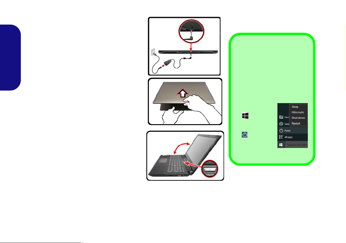
System Startup
Figure 1
Opening the Lid/LCD/
Computer with AC/DC
Adapter Plugged-In
Shut Down
Note that you should always shut
your computer down by choosing
the Shut down command in Win-
dows (see below). This will help
prevent hard disk or system problems.
1. Click the Star t
Menu icon
.
2. Click the
Power item
.
3. Choose Shut
Down from
the menu.
135°
1. Remove all packing materials.
2. Place the computer on a stable surface.
3. Securely attach any peripherals you want to use
with the computer (e.g. keyboard and mouse) to
their ports.
4. Attach the AC/DC adapter to the DC-In jack on the
rear of the computer, then plug the AC power cord
English
into an outlet, and connect the AC power cord to
the AC/DC adapter (make sure you use the
adapter when first setting up the computer, as
to safeguard the computer during shipping the
battery will be locked to not power the system until
first connected to the AC/DC adapter).
5. Use one hand to raise the lid/LCD to a comfortable
viewing angle (do not to exceed 135 degrees);
the other hand (as illustrated in Figure 1) to
support the base of the computer (Note: Never lift
the computer by the lid/LCD).
6. Press the power button to turn the computer “on”.
System Software
Your computer may already come with system
software pre-installed. Where this is not the
case, or where you are re-configuring your
computer for a different system, you will find
this manual refers to Microsoft Windows 10.
use
4
Page 9
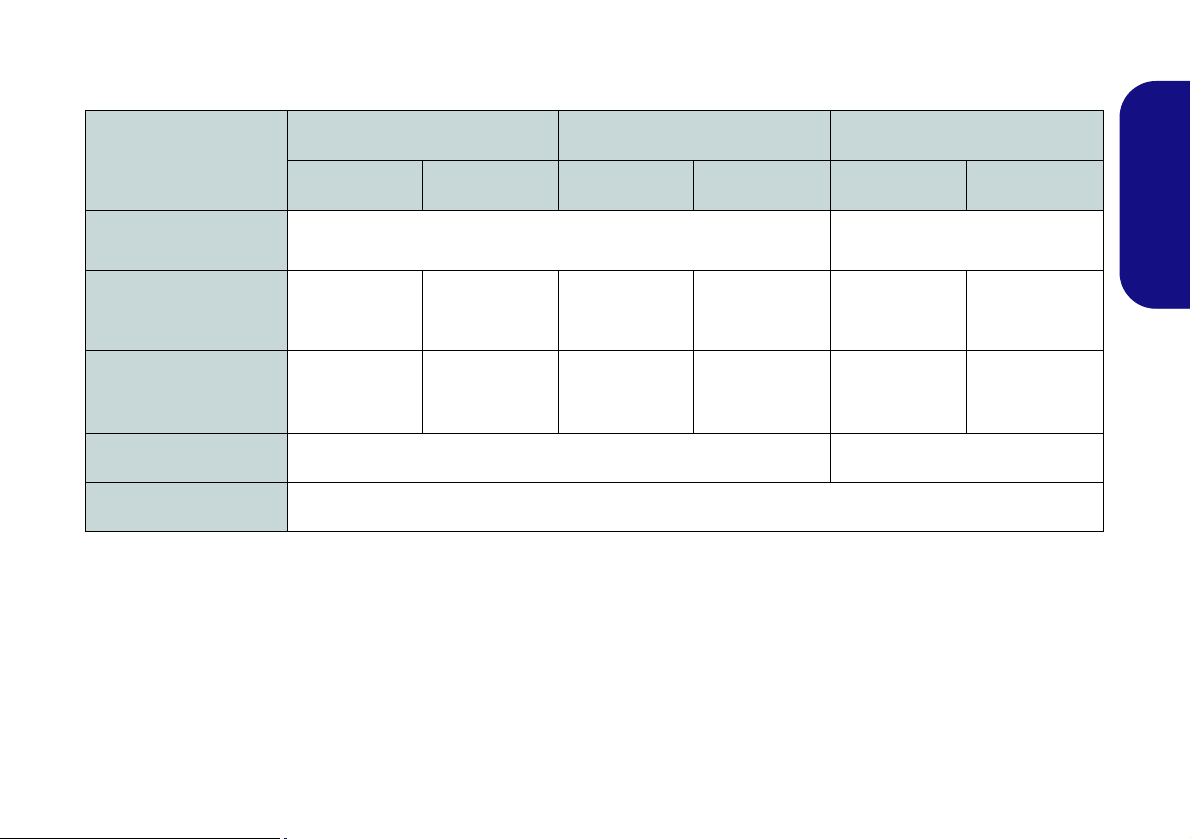
Model Differences
This notebook series includes three different model types that mainly differ as indicated in the table below.
Feature
Display Type
NVIDIA® Discrete GPU
USB Type C Port
3G/4G Module
Dimensions & Weight
Model A Model B Model C
Specification I Specification II Specification I Specification II Specification I Specification II
15.6" (39.62cm), 16:9, QFHD (3840x2160)/FHD (1920x1080)
NVIDIA®
GeForce GTX
965M
One USB 3.1
Gen 2 Type C
Port
NVIDIA®
GeForce GTX
960M
One USB 3.0
(USB 3.1 Gen 1)
Type C P ort
Factory Option No
See Dimensions & Weight on page 33 for details.
NVIDIA®
GeForce GTX
965M
One USB 3.1
Gen 2 Type C
Port
NVIDIA®
GeForce GTX
960M
One USB 3.0
(USB 3.1 Gen 1)
Type C Port
17.3" (43.94cm)
(1920x1080)
NVIDIA®
GeForce GTX
965M
One USB 3.1
Gen 2 Type C
Port
, 16:9, FHD
NVIDIA®
GeForce GTX
960M
One USB 3.0
(USB 3.1 Gen 1)
Type C Port
Table 1 - Model Differences
English
5
Page 10
System Map: Front View with LCD Panel Open
2
1
9
8
4
Figure 2 - Front View with LCD Panel Open (Models A, B & C)
1. PC Camera
2. Built-In Array Microphone
3. *PC Camera LED
*When the PC camera is in use, the
LED will be illuminated.
4. LCD
5. Power Button
6. Speakers
7. LED Indicators
8. Keyboard
9. Touchpad & Buttons
10. Fingerprint Reader (Optional)
2
15.6” (39.62cm)
17.3” (43.94cm)
6
6
8
5
4
9
Model A
15.6” (39.62cm)
6
6
Model C
9
5
6
6
5
7
8
4
Model B
10
10
10
3
2
1
2
3
2
1
2
3
(Models A, B & C)
English
6
Page 11
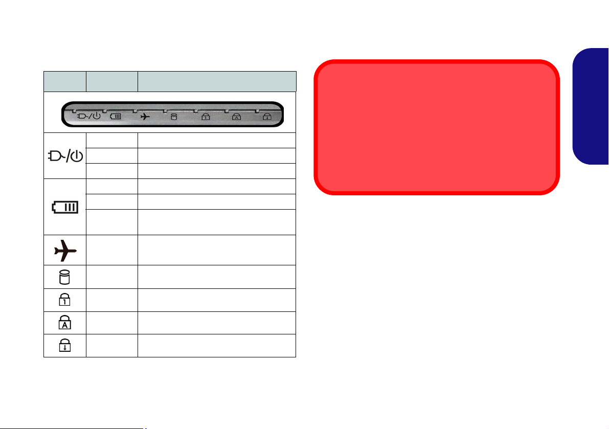
LED Indicators
Wireless Device
Operation Aboard Aircraft
The use of any portable electronic transmission devices
aboard aircraft is usually prohibited.
Make sure the wireless modules are OFF if you are using
the computer aboard aircraft by putting the system in to Airplane Mode.
The LED indicators on the computer display helpful information about the current status of the computer.
Icon Color Description
Orange The AC/DC Adapter is Plugged In
White The Computer is On
White The Computer is in Sleep Mode
Orange The Battery is Charging
White The Battery is Fully Charged
Blinking
Orange
White
White The Hard Disk/Optical Device is in use
White Number Lock (Numeric Keypad) Activated
White Caps Lock Activated
White Scroll Lock Activated
The Battery Has Reached Critically Low
Power Status
Airplane Mode is ON (the WLAN, Blue-
tooth and 3G/4G Modules are OFF)
Table 2 - LED Indicators
English
7
Page 12
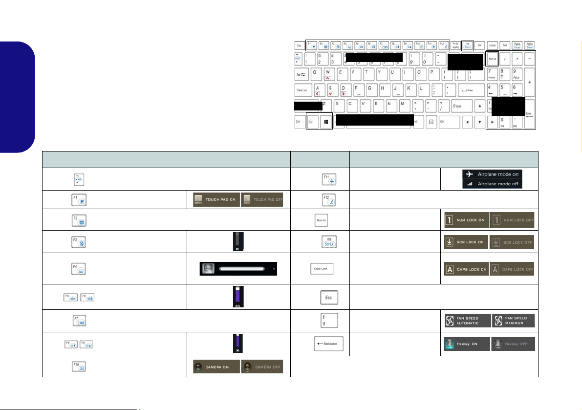
Keyboard & Function Keys
Function Keys
Numeric
Keypad
Fn Key
Windows Logo Key
ScrLk &
NumLk
Figure 3 - Keyboard
The keyboard includes a numeric keypad for easy numeric
data input. Pressing NumLk turns on/off the numeric keypad. It also features function keys to allow you to change
operational features instantly. The function keys (F1 -
F12 etc.) will act as hot keys when pressed while the Fn
key is held down. In addition to the basic function key
combinations, some visual indicators are available when
English
the Control Center driver is installed.
Keys Function/Visual Indicators Keys Function/Visual Indicators
Fn +
Fn +
Fn +
Fn +
Fn +
Fn +
Fn +
Fn +
Fn +
8
Play/Pause (in Audio/Video Programs)
Touchpad Toggle
(Press a key to or use Touchpad to turn on)
Mute Toggle
Toggle Keyboard Illumi-
nation/Adjust Brightness
Volume Decrease/
Change Display Configuration (see page 23)
Brightness Decrease/
PC Camera Power
Turn LCD Backlight Off
Level
Increase
Increase
Toggle
Fn +
Fn +
Fn +
Fn +
Fn +
Fn +
Airplane Mode Toggle
Sleep Toggle
Number Lock Toggle
Scroll Lock Toggle
Caps Lock Toggle
Control Center Toggle (see page 9)
Fan Automatic Control/
Full Power
Disable/Enable Flexikey®
(see page 12)
Table 3 - Function Keys & Visual Indicators
Page 13

Control Center
Figure 4 - Control Center
Press the Fn + Esc key combination, or double-click the
icon in the notification area of the taskbar to toggle
the Control Center on/off. The Control Center gives
quick access to frequently used controls and enables you
to quickly turn the camera/Touchpad on/off.
Power Modes
You can set a Power Mode by clicking the appropriate
icon at the top of the Control Center. Each power mode
will affect the Power Conservation Mode, Airplane Mode,
Power Plan and PC camera power etc.
Control Center Menus
The Control Center contains 3 menu headings (System
Program, Device and Gaming) under the Power Modes.
Click the Control Center icons to toggle the appropriate
function, or hold the mouse button down and move the
dial control where applicable. Certain functions will automatically be adjusted when a power mode is selected.
Click the menu headings and then click any of the buttons.
English
9
Page 14

Power Status
The Power Status icon will show whether you are currently powered by the battery, or by the AC/DC adapter
plugged in to a working power outlet. The power status
bar will show the current battery charge state.
Brightness
The Brightness icon will show the current screen bright-
English
ness level. You can use the slider to adjust the screen
brightness or the Fn + F8/F9 key combinations, or use the
Fn + F2 key combination to turn off the LED backlight
(press any key to turn it on again). Note that screen brightness is also effected by the Power Mode selected.
Volume
The Volume icon will show the current volume level. You
can use the slider to adjust the volume or the Fn + F5/F6
key combinations, or use the Fn + F3 key combination to
mute the volume.
Power Conservation
This system supports Energy Star power management
features that place computers (CPU, hard drive, etc.) into
a low-power sleep mode after a designated period of inactivity. Click either the Performance, Balanced or Ener-
gy Star button.
Fan Speed
The fan speed will adjust itself automatically to control the
heat of the CPU. However you can adjust the setting to
maximum if you prefer. Select Custom and click on the
sliders to adjust the settings to your preference, however
these settings can be overidden by the system, as a safety
precaution, if it requires heavier use of the fan.
Sleep Button
Click either the Hibernate or Sleep button to have the
computer enter the selected power-saving mode.
Display Utility
The Display Utility icon will only appear in the System
Program menu if your display’s resolution is QHD or
above. The Display Utility allows you to adjust text size
on the screen to make it easier to view.
Display Switch
Click the Display Switch button to access the menu (or
use the + P key combination) and select the appropriate display mode.
Time Zone
Clicking the Time Zone button will access the Date and
Time Windows control panel.
10
Page 15

Desktop Background
GPU Switch
Clicking the Desktop Background button will allow you
to change the desktop background picture.
Touchpad/PC Camera
Click either of these buttons to toggle the Touchpad or
camera module’s power status. Note that the power status
of the camera module is also effected by the Power Mode
selected.
Left Windows Key
Click Disable to disable the Windows Logo Key on the
left side of the keyboard. This may be useful if you are using the gaming keys (W, A, S & D) and wish to avoid accidentally triggering menus with the Windows Logo Key.
Headphone
The headphones may be set for different effects using this
menu.
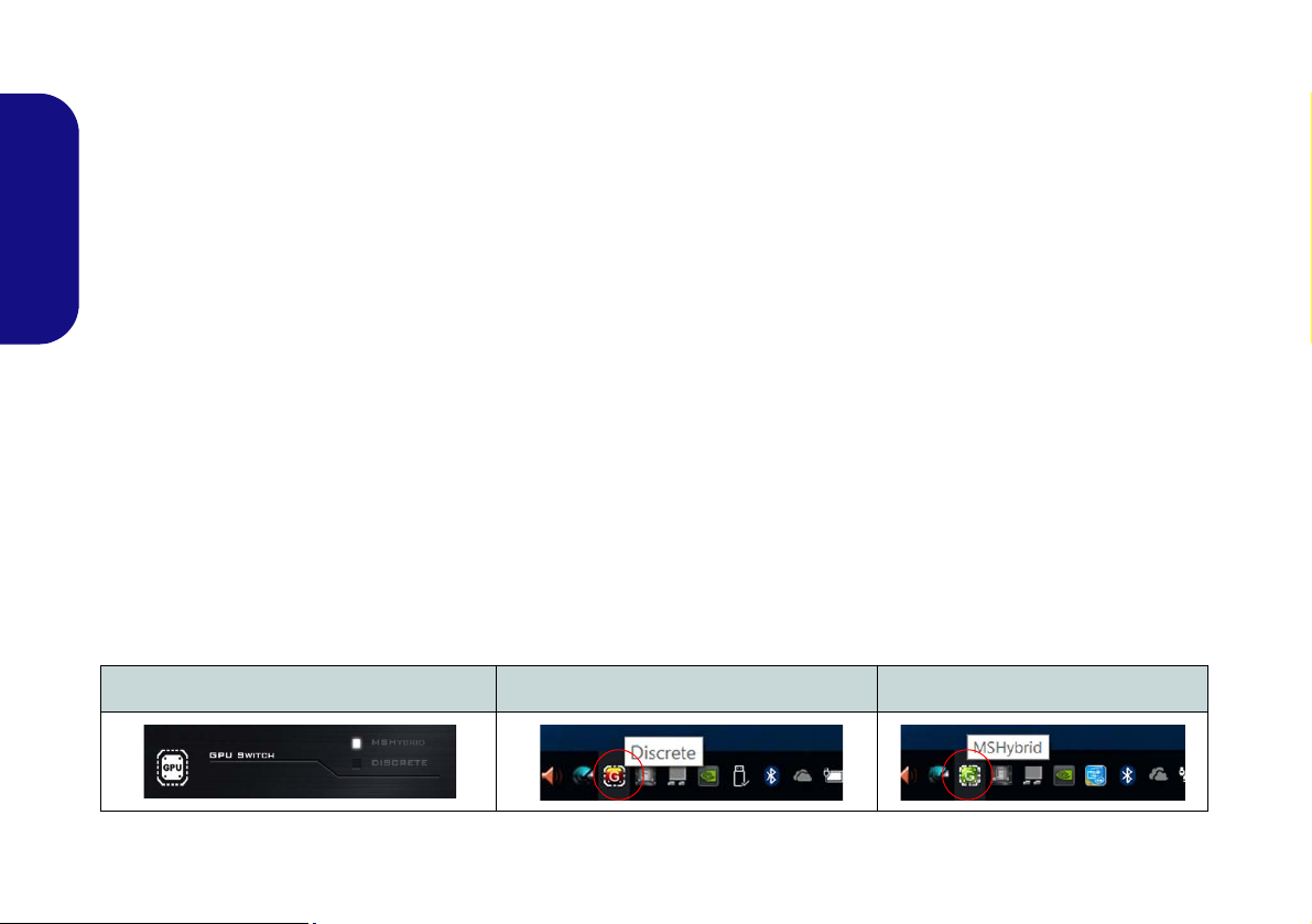
Select if the system uses either Microsoft Hybrid
Graphics Mode (MSHYBRID) or Discrete Graphics
Mode (DISCRETE). MSHYBRID is selected by de-
fault. After selecting MSHYBRID, the computer’s operating system (and some applications) will automatically
switch between the integrated GPU and the discrete GPU
when required by the applications in use. Selecting DIS-
CRETE graphics will force the system to use the dedicat-
ed Graphics Processing Unit (GPU). After any changes in
the setting you will be required to confirm a system restart.
Backlight Keyboard
Click the numbers under the Backlight Keyboard icon to adjust the brightness of the keyboard backlight LED.
Flexikey®
Click the button to access the Flexikey® application.
English
11
Page 16
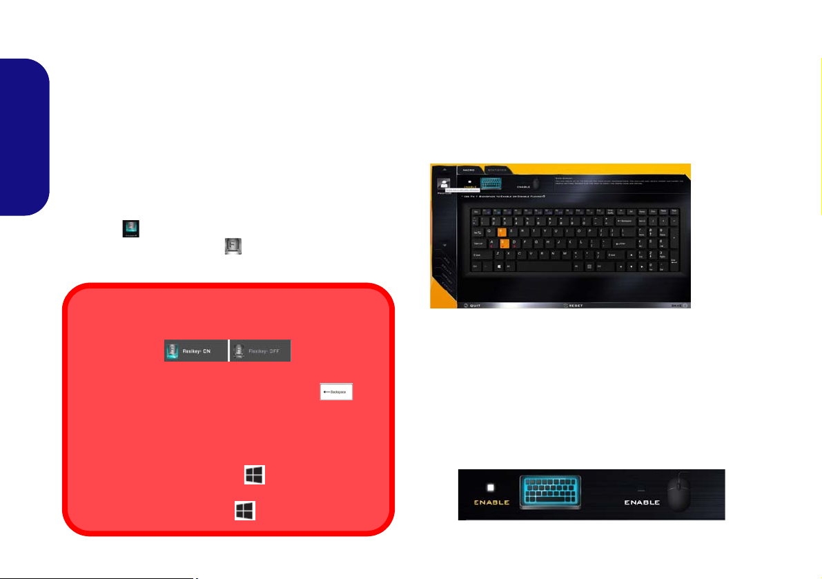
Flexikey® Application
Enabling or Disabling the Flexikey® Profile in Use
You can enable or disable any keyboard or mouse profile
functions currently in use by using the Fn + key
combination. Pressing this key combination will toggle you
between the currently selected keyboard or mouse profile
to the standard keyboard and/or mouse settings, and back
again.
Windows Logo Key and P key
Note that you can assign actions to any keyboard key except the Windows Logo Key and P key.
Figure 5
Flexikey®
Applica-
tion
The Flexikey® application is a quick hotkey configura-
tion application, which allows you to assign a single key
to launch multiple key combinations, or to launch pro-
grams and applications, to create text macros and to
disable certain keys. The application can also be used to
configure the mouse buttons to create hotkeys for gam-
ing etc. All the configuration settings are retained under
English
(up to12) profiles to which the settings are applied.
The Flexikey® application can be accessed by clicking
the button
ter or by clicking the icon
the desktop taskbar.
in the Gaming section of the Control Cen-
in the notification area of
Profiles
The menus on the left side of the application relate to Profiles. You can Add or Delete profiles (you can maintain
12 active Profiles), Export and Import profiles from the
menus. If you double-click on a profile you can change the
Profile Name, and change an Image file (images created
using PNG files).
12
Keyboard and Mouse Settings
Click Enable to create settings for the keyboard and/or
mouse by clicking the button on the top left of the screen
(e.g. you may wish to create a profile with settings only
for the mouse or keyboard). Clicking on the keyboard or
mouse icons will allow you to access the settings page for
either the keyboard or mouse.
Figure 6 - Enable (Keyboard & Mouse)
Page 17
Keyboard Settings
123
4
5
The keyboard settings allow you to configure actions for
by clicking in the Name box, and click in Tool Tips to
type in a note to remind you of the action’s function.
any single key (or a combination of keys). Click the key
and then select the Action Type (Express Key, Launch
App, Express Text or Disable) from the menu at the bot-
English
tom of the page. You can rename the action by clicking in
the Name box, and click in Tool Tips to type in a note to
remind you of the action’s function.
Figure 8 - Mouse Configuration
Flexikey® Application Features:
• EXPRESS KEY - This feature allows you to configure a
single key (or mouse click) to send multiple key combinations, or to create more useful shortcut keys This is useful
Figure 7 - Keyboard Configuration
Mouse Settings
The mouse settings allow you to configure actions for the
left , right and middle buttons of any attached
mouse, and also for any backward and forward
buttons if applicable (on a gaming type mouse). Click the
button number and then select the Action Type (Express
Key, Launch App, Express Text or Disable) from the
menu at the bottom of the page. You can rename the action
in gaming or when using applications which have a complex set of keyboard shortcuts.
• LAUNCH APP - This simply assigns single keys (or
mouse clicks) to launch any program’s or application’s
executable file.
• EXPRESS TEXT - With this you can assign single keys
(or mouse clicks) to send commonly used strings of text.
• DISABLE - Use this function to disable any keyboard
keys or mouse buttons.
• STATISTICS - Use this to quickly record keys in use in
any application, and to disable unused keys.
13
Page 18
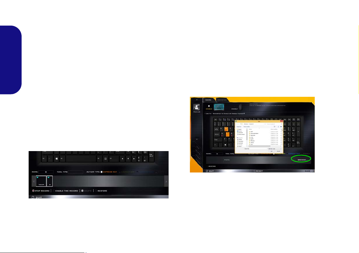
Keyboard Settings - Express Key
To configure a single key to send multiple key combinations, or to create more useful shortcut keys, use Express
Key.
1. Enable and select the keyboard under your chosen profile, click
on a key to select it, and then click to select Express Key in
Action Type.
2. In the following example we want to change an existing game
English
key configuration which uses the left shift key for sprinting, and
the W key for moving forwards, to use the left Ctrl key to
combine this movement to sprint forward.
3. Click on the chosen key for the shortcut action.
4. Click in the Tool Tips field and type to give the key combination
a name e.g. “Sprint Fwds”, then click back in the Name field (to
avoid adding the recorded keys to the Tool Tips name).
5. Click Start Record and then press the key or keys (in this case
we will press Left Shift and W) required (make sure you press
the key(s) required and do not click on them).
6. Click Stop Record to complete the process.
9. If you want to clear all the settings click Restore to return to the
default key setting.
10. Any assigned Express Keys will appear in orange.
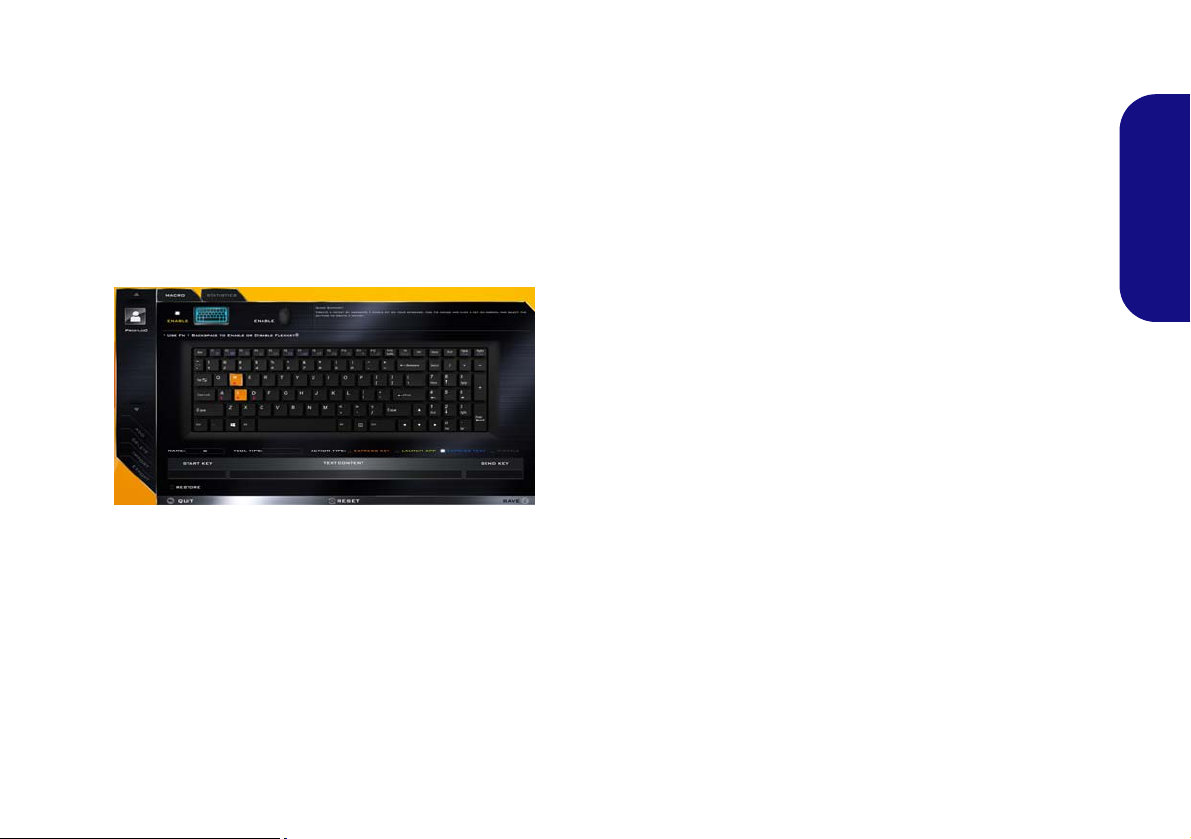
Keyboard Settings - Launch App
You can configure keys to launch any application or program as follows:
1. Enable and select the keyboard under your chosen profile, click
to select a key to launch the appllication, and then click to select
Launch App in Action Type.
2. Click Browse... at the bottom right of the application window.
Figure 10 - Keyboard - Launch App
Figure 9 - Keyboard - Express Key
7. Click Save to save the settings within your chosen profile.
8. If you want to remove any individual key click to select it, and
then click Delete.
14
3. Navigate to the executable file of the application and click
Open.
4. The key will now be configured to open the selected application
under your chosen Profile, and the key will appear in green.
5. If you want to remove any Launch App key, select it and click
on Restore.
6. Click Save to save the settings within your chosen profile.
Page 19
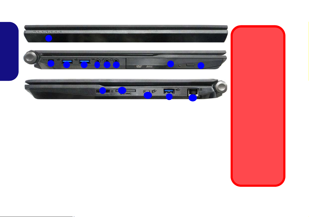
Keyboard Settings - Express Text
A single key can be set to send a string of text within any
application using Express Text.
1. Enable and select the keyboard under your chosen profile, click
to select a key, and then click to select Express Text in Action
Type.
2. Click in Start key if required (the Start key is the key used in
your target program to open a text message), or you can leave
it blank if you prefer.
3. Click in the Click to type field and type in your message.
Figure 11 - Keyboard - Express Text
4. Click in Send key if required (the Send key is the key used in
your target program to send a text message e.g the Enter key
would be the most commonly used), or you can leave it blank if
you prefer.
5. The key will now be configured to send the text message in the
target program under your chosen Profile, and the key will
appear in blue.
6. If you want to remove any Express Text key, select it and click
on Restore.
7. Click Save to save the settings within your chosen profile.
Keyboard Settings - Disable
You can use the program to disable any keys not required.
1. Enable and select the keyboard under your chosen profile, click
to select a key to disable, and then click to select Disable in
Action Type.
2. The key will now be disabled.
3. If you want to enable the key again, select it and click on
Restore.
4. Click Save to save the settings within your chosen profile.
5. The key will be disabled under your chosen Profile, and the key
will appear in gray.
English
15
Page 20
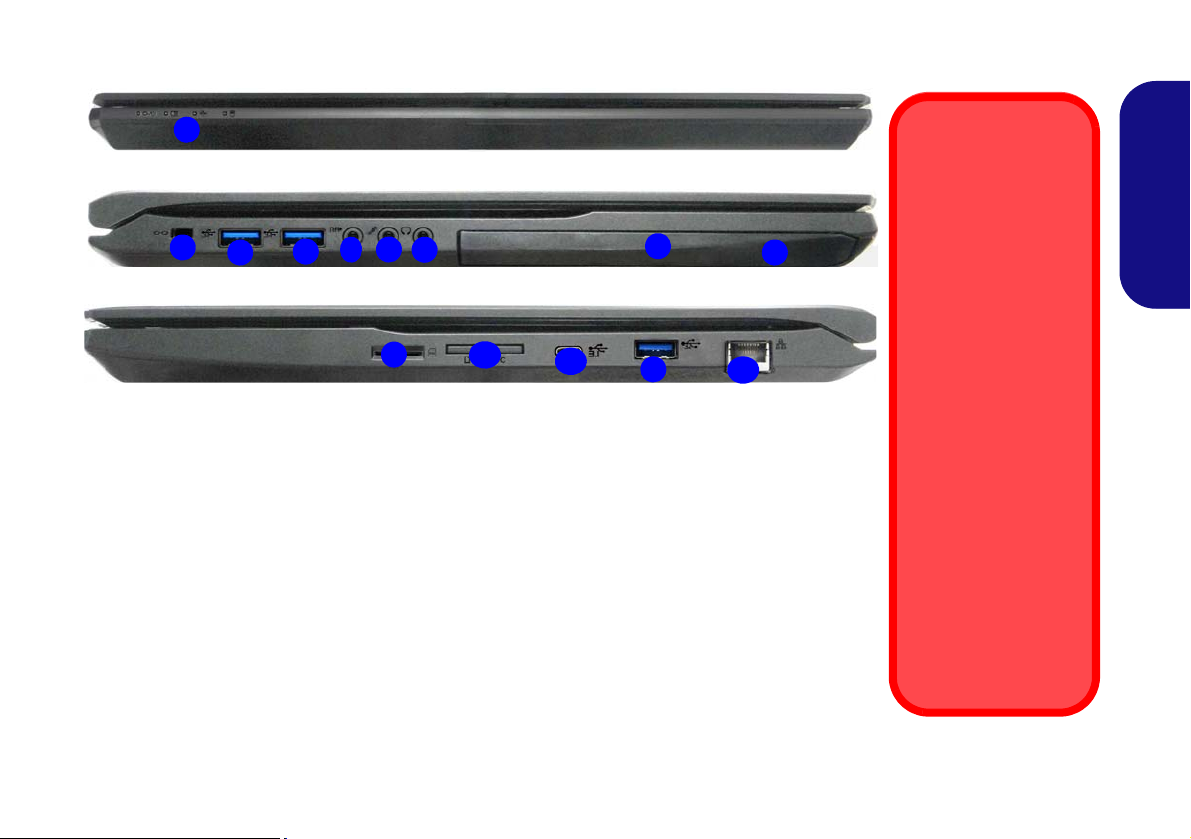
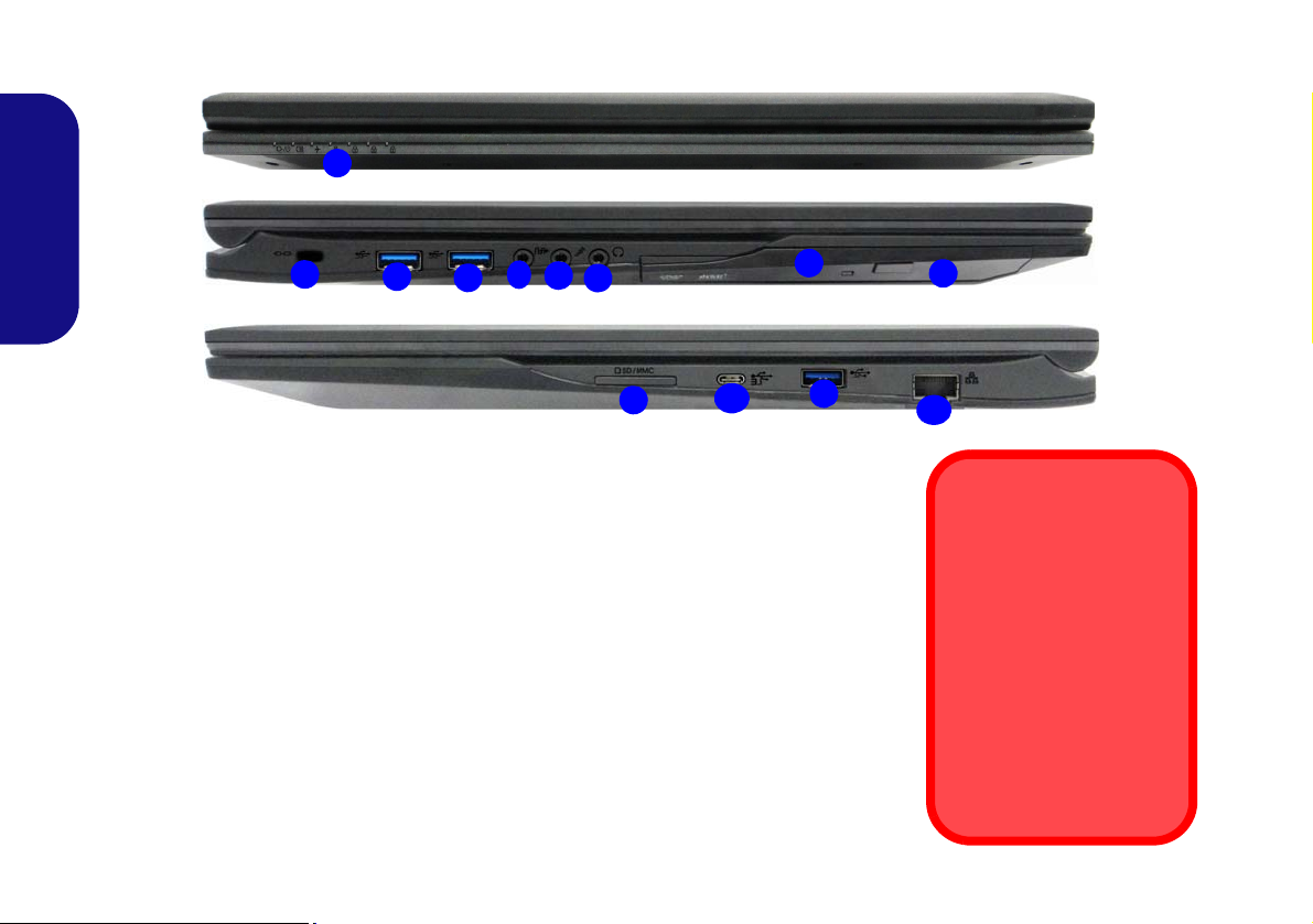
System Map: Front, Left & Right Views (Model A)
3
6
4
5
1
Front
Left
Right
11
7
10
2
Figure 12 - Front, Left & Right Views (Model A)
1. LED Indicators
2. Security Lock Slot
3. USB 3.0 (USB 3.1 Gen 1) Ports
4. S/PDIF-Out Jack
5. Microphone Jack
6. Headphone Jack
7. Optical Device Drive Bay
8. Emergency Eject Hole (see page 18)
9. USIM Card Reader (for 3G/4G USIM Cards)
10. Multi-in-1 Card Reader
11. (Specification I) USB 3.1 Gen 2 Type C Port
(Specification II) USB 3.0 (USB 3.1 Gen 1)
Type C Port
12. RJ-45 LAN Jack
8
9
3
USIM Card Ejection
Simply press on the
USIM card to eject it,
however do not do
this while a connection is in progress.
If you do eject the card
while a 3G/4G connection is ongoing,
you will need to shut
down the system, reinsert the USIM card,
restart the system and
then reestablish the
3G/4G connection.
If you wish to change
USIM cards then you
will also need to shut
down the system, reinsert the USIM card,
restart the system and
then reestablish the
3G/4G connection.
12
3
English
16
Page 21
System Map: Front, Left & Right Views (Model B)
3
6
4
5
1
Front
Left
Right
11
7
12
10
2
8
9
3
USIM Card Ejection
Simply press on the
USIM card to eject it,
however do not do
this while a connection is in progress.
If you do eject the card
while a 3G/4G connection is ongoing,
you will need to shut
down the system, reinsert the USIM card,
restart the system and
then reestablish the
3G/4G connection.
If you wish to change
USIM cards then you
will also need to shut
down the system, reinsert the USIM card,
restart the system and
then reestablish the
3G/4G connection.
Figure 13 - Front, Left & Right Views (Model B)
1. LED Indicators
2. Security Lock Slot
3. USB 3.0 (USB 3.1 Gen 1) Ports
4. S/PDIF-Out Jack
5. Microphone Jack
6. Headphone Jack
7. Optical Device Drive Bay
8. Emergency Eject Hole (see page 18)
9. USIM Card Reader (for 3G/4G USIM Cards)
10. Multi-in-1 Card Reader
11. (Specification I) USB 3.1 Gen 2 Type C Port
(Specification II) USB 3.0 (USB 3.1 Gen 1)
Type C P ort
12. RJ-45 LAN Jack
3
English
17
Page 22
System Map: Front, Left & Right Views (Model C)
3
6
4
5
1
Front
Left
Right
10
7
2
Figure 14 - Front, Left & Right Views (Model C)
1. LED Indicators
2. Security Lock Slot
3. USB 3.0 (USB 3.1 Gen 1) Ports
4. S/PDIF-Out Jack
5. Microphone Jack
6. Headphone Jack
7. Optical Device Drive Bay
8. Emergency Eject Hole
9. Multi-in-1 Card Reader
10. (Specification I) USB 3.1 Gen 2 Type C Port
(Specification II) USB 3.0 (USB 3.1 Gen 1)
Type C Port
11. RJ-45 LAN Jack
8
9
3
Disc Emergency Eject
If you need to manually
eject a disc (e.g. due to an
unexpected power interruption) you may push the
end of a straightened paper clip into the emergency eject hole. Do not use a
sharpened pencil or similar object that may break
and become lodged in the
hole.
11
3
English
18
Page 23
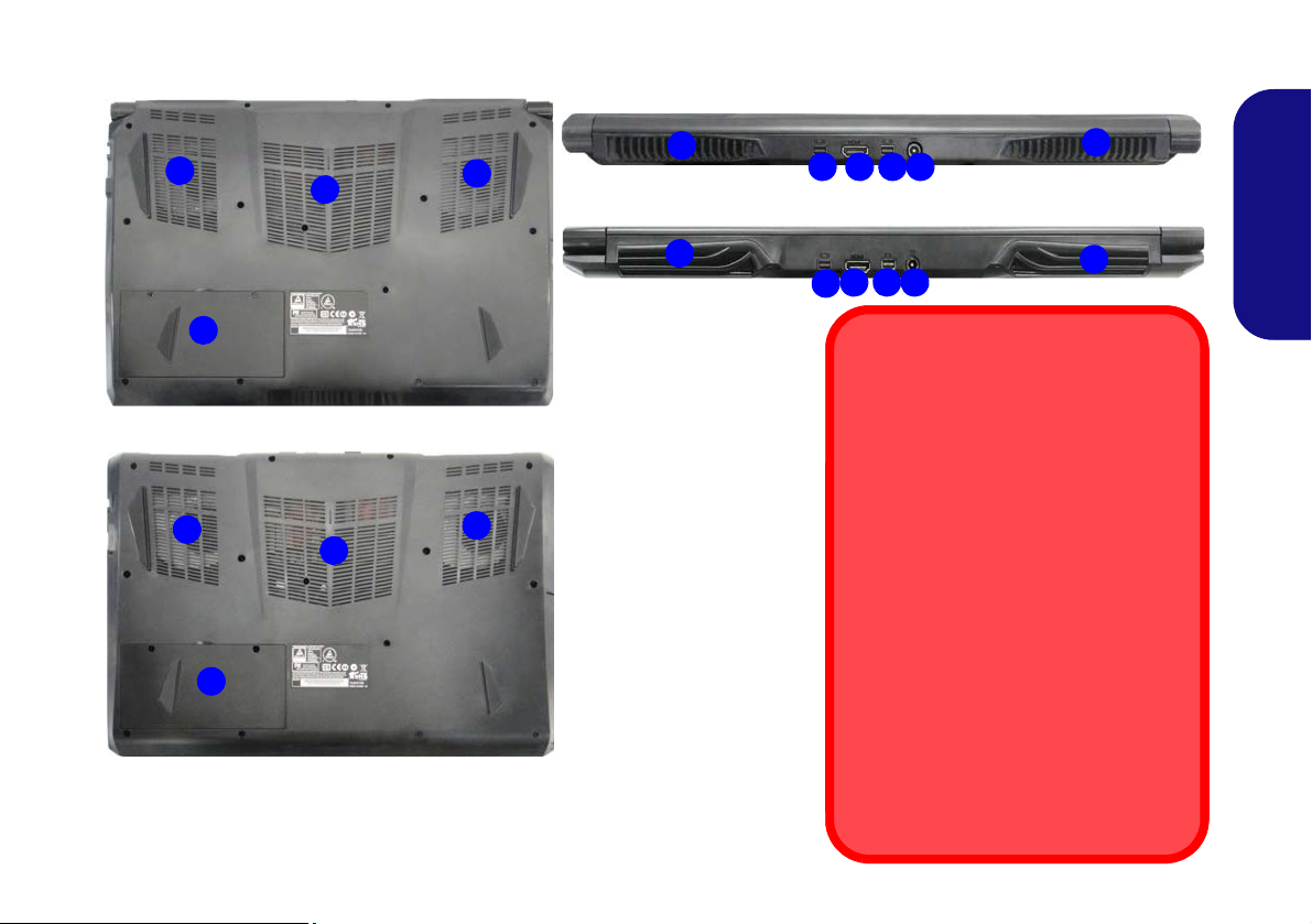
System Map: Bottom & Rear Views (Models A & B)
Figure 15
Bottom & Rear Views
(Models A & B)
1. Vent
2. Battery
3. Mini DisplayPorts
4. HDMI-Out Port
5. DC-In Jack
Overheating
To prevent your computer from overheating make sure nothing blocks any
vent while the computer is in use.
Battery Removal
Note that the built-in battery is not user
removable. Removing the battery will violate the terms of your warranty.
Bottom Cover Removal Warning
Do not remove any cover(s) and/or
screw(s) for the purposes of device upgrade as this may violate the terms of
your warranty.
If you need to replace/remove the hard
disk/RAM/battery etc., for any reason,
please contact your distributor/supplier
for further information.
1
2
1
1
3 4 5
2
1
1
1
Model B
Model A
1
Model A
3
1
Model B
3
4 513
1
English
19
Page 24
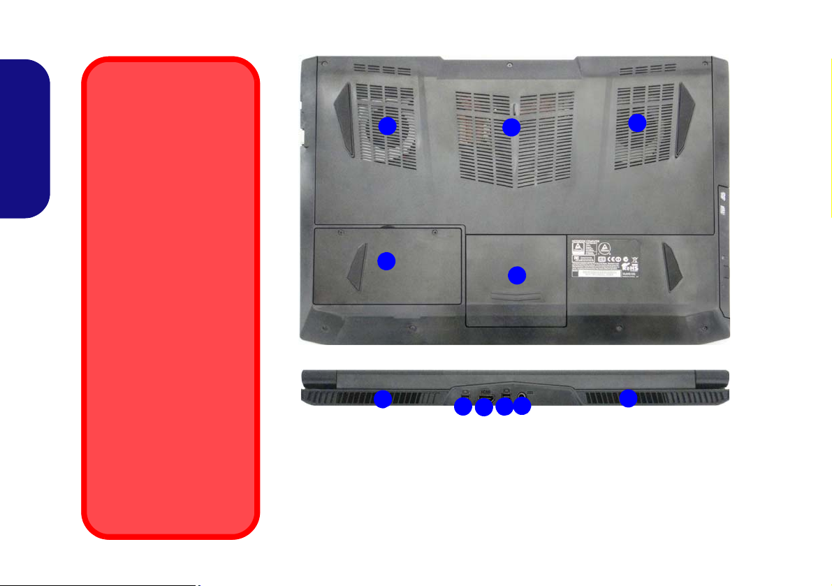
System Map: Bottom & Rear Views (Model C)
1
Overheating
To prevent your computer
from overheating make
sure nothing blocks any
vent while the computer is
in use.
Battery Removal
Note that the built-in battery
is not user removable. Removing the battery will violate the terms of your
warranty.
Bottom Cover Removal
Warning
Do not remove any cover(s)
and/or screw(s) for the purposes of device upgrade as
this may violate the terms of
your warranty.
If you need to replace/remove the hard disk/RAM/
battery etc., for any reason,
please contact your distributor/supplier for further information.
1
1
2
5
Rear
4
4
3
6
Figure 16 - Bottom & Rear Views (Model C)
1. Vent
2. Battery
3. HDD Bay
4. Mini DisplayPorts
5. HDMI-Out Port
6. DC-In Jack
1
1
English
20
Page 25
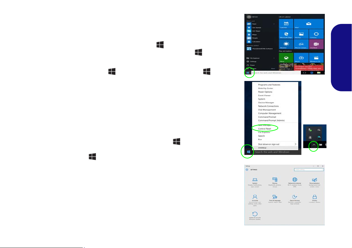
Windows 10 Start Menu, Context Menu, Taskbar, Control Panel and Settings
Most of the apps, control panels, utilities and programs within Windows 10 can be
accessed from the Start Menu by clicking the icon in the taskbar in the lower
left corner of the screen (or by pressing the Windows Logo Key on the keyboard).
Right-click the Start Menu icon (or use the Windows Logo Key + X key
combination) to bring up an advanced Context Menu of useful features such as
Control Panel, Programs and Features, Power Options, Task Manager, Search, File
Explorer, Command Prompt, Device Manager and Network Connections etc.
The notification area of the taskbar is in the bottom right of the screen. Some of the
control panels and applications referred to throughout the course of this manual can
be accessed from here.
Throughout this manual you will see an instruction to open the Control Panel. To
access the Control Panel, right-click the Start Menu icon
lower left corner of the screen and select Control Panel from the menu. Or, press
the Windows L ogo Key on your keyboard and X to bring up the context menu,
and then press P to bring up the Control Panel.
The Settings item in the Start Menu (and also as an App) gives you quick access
to a number of system settings control panels allowing you to adjust settings for
System, Devices, Network & Internet, Personalization, Accounts, Time & language, Ease of Access, Privacy and Update & security.
in the taskbar in the
English
Figure 17 - Start Menu, Context Menu, Taskbar, Control Panel and Settings
21
Page 26
Video Features
You can switch display devices, and configure display options, from the Display control panel in Windows as long as
the video drivers are installed.
Microsoft Hybrid Graphics Or Discrete Graphics Mode
Your computer features a dedicated Discrete Graphics Mode (DISCRETE), and a Microsoft Hybrid Graphics
Mode
(MSHYBRID) featuring switchable graphics technology.
English
Microsoft Hybrid Graphics Mode
the graphics system while allowing longer battery life, without having to manually change settings. The computer’s operating system (and some applications) will automatically switch between the integrated GPU(iGPU) and the discrete
GPU (dGPU) when required by the applications in use. This switch is seamless to the user. This mode is selected by
default.
(MSHybrid)- This seamless technology is designed to get best performance from
Discrete Graphics Mode
(GPU) which is more powerful, and therefore more suitable for playing games, watching HD video or running GPUbased applications.
You can choose either DISCRETE mode or MSHYBRID mode by selecting the appropriate option from GPU Switch
in the Control Center, or in the BIOS. You will need to restart the system after making changes to the selected graphics mode. Moving the mouse pointer over the taskbar icon will indicate the current GPU mode (double-click the icon
to go to the Control Center).
GPU Switch Button (Control Center) Discrete (Taskbar Icon) MSHybrid (Taskbar Icon)
(DISCRETE) - Discrete Graphics Mode will use the dedicated Graphics Processing Unit
Table 4 - GPU Mode Indicator
22
Page 27
To access the Display control panel in Windows:
Figure 18
Project
1. Go to the Control Panel.
2. Click Display (icon) - in the Appearances and
Personalization category.
3. Make the required changes from the Display, Resolution,
Orientation or Multiple display menus.
4. Click Apply to save the settings.
To access the Intel® HD Graphics Control Panel:
1. Right-click the desktop and select Graphics Properties from
the menu.
OR
2. Click the icon in the notification area of the Desktop
taskbar and select Graphics Properties from the menu.
To access the NVIDIA Control Panel:
1. Go to the Control Panel.
2. Click NVIDIA Control Panel (icon) - in the Appearances and
Personalization category.
OR
3. Right-click the desktop and select NVIDIA Control Panel from
the menu.
Display Devices
Note that you can use external displays connected to the
HDMI-Out port and/or Mini DisplayPort 1.2. See your
display device manual to see which formats are supported.
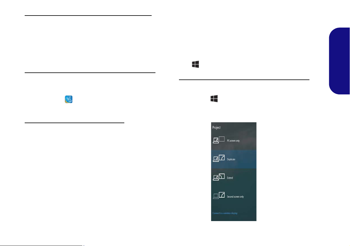
In Windows it is possible to quickly configure external
displays from the Project menu (press the Windows Logo
Key and the P key).
To configure the displays using the Project menu:
1. Attach your external display device to the appropriate port, and
then turn it on.
2. Press the + P (or Fn + F7) key combination.
3. Click on any one of the options from the menu to select PC
screen only, Duplicate, Extend or Second screen only.
English
23
Page 28
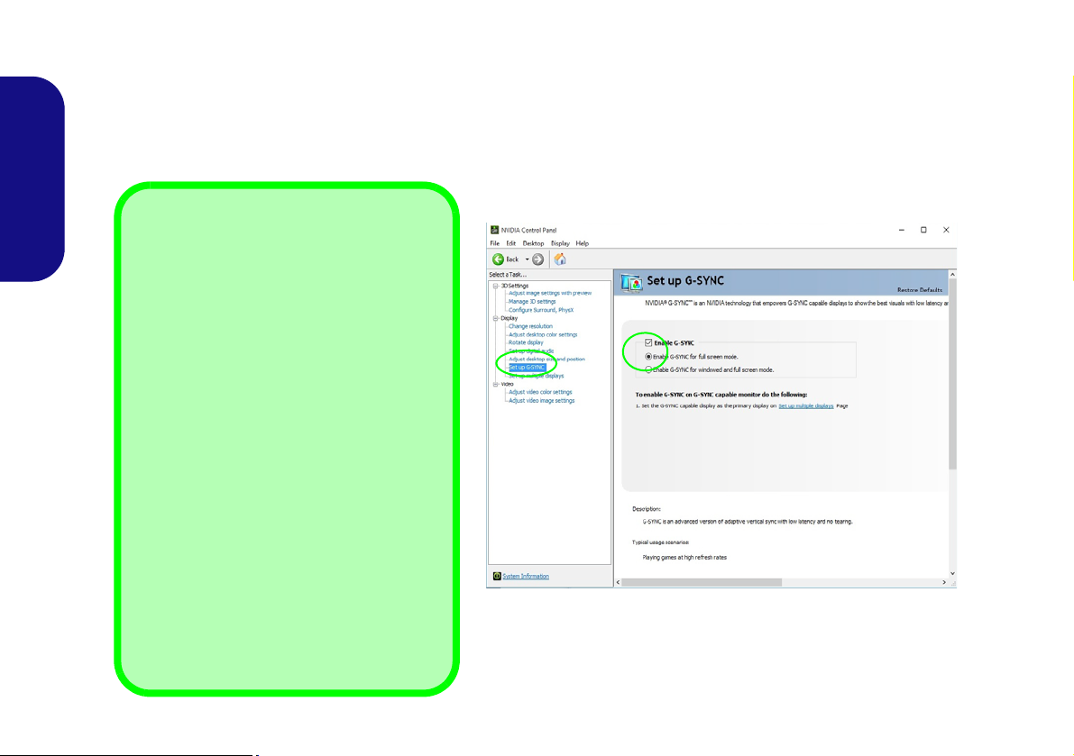
G-SYNC
G-SYNC Support
G-SYNC is only supported if you have a GSYNC capable display and a GTX series video adapter (contact your distributor or supplier for details).
G-SYNC is also only supported when the
computer is in Discrete Mode (G-SYNC is not
supported in MSHybrid Mode). Use the GPU
Switch in the Control Center to switch to Discrete Mode before enabling G-SYNC (see
Table 4 on page 22).
Setting up G-SYNC
In a multiple display configuration set the GSYNC capable display as the Primary Display.
In 3D Settings click Manage 3D Settings >
Global Settings, select Vertical sync and
then select G-SYNC. Setting G-SYNC in
global settings means it will be applied to all
games.
Figure 19 - Set Up G-SYNC
(Specification I Only)
Click to put a check in the box to Enable G-SYNC (it is enabled by default). G-SYNC is designed to provide a smooth
game play experience from your GeForce product by synchronizing the monitor’s refresh cycle to the GPU’s render
rate, thus removing lag and stutter issues, in order to have objects appear sharper and scenes display instantly.
English
24
Page 29

Audio Features
Volume Adjustment
The sound volume level can also be set using the volume control within Windows. Click the Speaker icon in
the taskbar to check the setting
.
Sound Blaster Cinema 2 & HDMI/Mini DisplayPort
Note that the Sound Blaster Cinema 2 audio effects do
not apply to audio generated through an HDMI/Mini
DisplayPort connection.
You can configure the audio options on your computer
from the Sound control panel in Windows, or from the
Realtek HD Audio Manager
tion area/control panel (right-click the notification area
icon to bring up an audio menu).
The volume may be adjusted by means of the Fn + F5/F6
key combination.
/ icon in the notifica-
Sound Blaster Cinema 2
Install the Sound Blaster Cinema application to allow
you to configure the audio settings to your requirements
for the best performance in games, music and movies.
English
Sound Blaster Cinema 2 Application
Run the Sound Blaster Cinema control panel from the
notification area of the taskbar. Click on the tabs to access
any of the control panel menus.
Figure 20 - Sound Blaster Cinema 2
(Taskbar Notification Area Icon)
25
Page 30
PC Camera
Figure 21 - Power Options
Use the Fn + F10 key combination to toggle power to the
PC Camera module. When the PC Camera is in use the PC
Camera LED will be illuminated (see System Map: Front
View with LCD Panel Open (Models A, B & C) on
page 6).
Camera App
English
Note that you need to use the Camera app in Windows to take pictures and capture video.
1. Run the Camera app from the Start menu by clicking on the
Camera app icon
the search box to find the Camera app if it is not pinned to the
Start menu).
2. Click to select either photo
3. Click the photo icon
briefly turn yellow as the picture is taken.
4. Click on the video icon
capture begins a timer will appear at the bottom of the screen
and the icon will turn yellow).
5. To stop video capture click the video icon again.
6. Captured photos and videos will be saved to a Camera Roll
folder within the Pictures folder in This PC, and to the Photos
app stored in the Start menu.
in All Apps (you can type “camera” into
or video mode.
to take a picture, and the icon will
to start video capture (if video
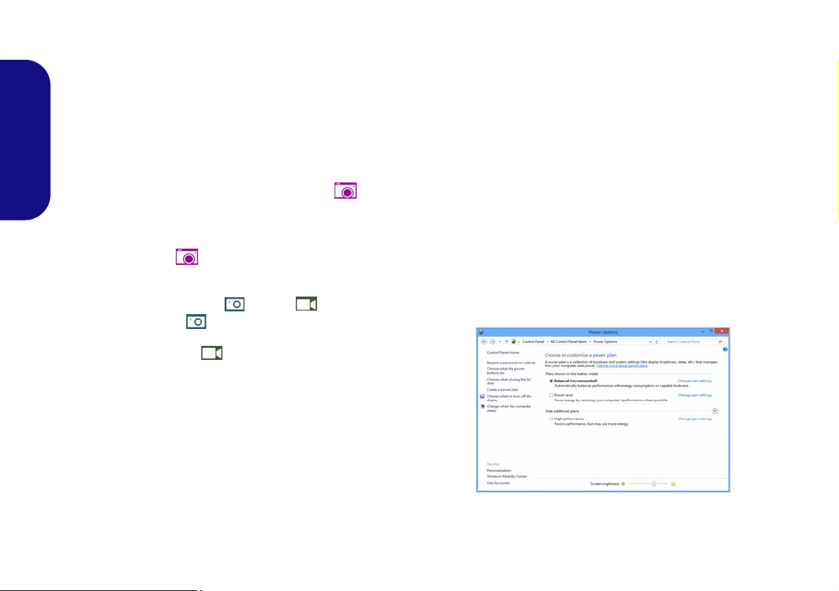
Power Options
The Power Options (Hardware and Sound menu) control panel icon in Windows allows you to configure power
management features for your computer. You can conserve power by means of power plans and configure the
options for the power button, sleep button (Fn + F12),
computer lid (when closed), display and sleep mode (the
default power saving state) from the left menu. Note that
the Power saver plan may have an affect on computer
performance.
Click to select one of the existing plans, or click Create a
power plan in the left menu and select the options to create a new plan. Click Change Plan Settings and click
Change advanced power settings to access further configuration options.
26
Page 31

Driver Installation
Driver Installation General
Guidelines
As a general guide follow the
default on-screen instructions for each driver (e.g.
Next > Next > Finish) unless
you are an advanced user. In
many cases a restart is required to install the driver.
Make sure any modules (e.g.
WLAN or Bluetooth) are ON
before installing the appropriate driver.
Windows Update
After installing all the drivers
make sure you enable Win-
dows Update in order to get
all the latest security updates
etc. (all updates will include
the latest hotfixes from Mi-
crosoft).
Driver Installation & Power
When installing drivers make sure
your computer is powered by the AC/
DC adapter connected to a working
power source. Some drivers draw a
significant amount of power during the
installation procedure, and if the remaining battery capacity is not adequate this may cause the system to
shut down and cause system problems (note that there is no safety issue involved here, and the battery will
be rechargeable within 1 minute).
Figure 22 - Install Drivers
The Device Drivers & Utilities + User’s Manual disc contains the drivers and utilities
necessary for the proper operation of the computer. This setup will probably have already been done for you. If this is not the case, insert the disc and click Install Drivers
(button), or Option Drivers (button) to access the Optional driver menu. Install the
drivers in the order indicated in Figure 22. Click to select the drivers you wish to
install (you should note down the drivers as you install them). Note: If you need to
reinstall any driver, you should uninstall the driver first
Manual Driver Installation
Click the Browse CD/DVD button in the Drivers Installer application and browse to
the executable file in the appropriate driver folder.
If a
Found New Hardware
Cancel, and follow the installation procedure as directed.
wizard appears
during the installation procedure, click
.
English
27
Page 32

Fingerprint Reader (Option)
Figure 23
Accounts Sign-in op-
tions
Install the driver and enroll your fingerprints as instructed
below before use. The fingerprint reader module uses the
Sign-in options configuration of the Windows Account.
Fingerprint Reader Driver Installation
1. Click Option Drivers (button).
English
2. Click 2.Install Fingerprint Driver > Yes.
3. Click Next > Install > Finish.
Fingerprint Module Configuration
1. Click the Settings item in the Start Menu.
2. Click Accounts and then click Sign-in options.
3. You will need to add a Windows password (click Add under
Password).
4. After you have added the password you will need to also add a
PIN.
5. Under Windows Hello click Set up under Fingerprint.
6. The wizard will then guide you through the set up process to
scan your fingerprints.
7. You will be instructed to swipe the same finger across the
reader a number of times.
8. Click Close when complete.
9. You can choose to Add another finger (this is recommended)
or Remove the current fingerprint reading.
10. You can now scan your fingerprint to log-on to the computer.
28
Page 33

TPM (Option)
Figure 24 - BitLocker Drive Encryption
(TPM Administration)
Figure 25
Trusted Plat-
form Module
(TPM) Manage-
ment on Local
Computer Ad-
ministration
Figure 26
Actions Menu
Before setting up the TPM (Trusted Platform Module)
functions you must initialize the security platform.
4. The TPM Management window allows you to configure the
TPM within Windows. As TPM is usually administered within
large enterprises and organizations, your system administrator
will need to assist you in managing the information here.
Activating TPM
1. Restart the computer.
2. Enter the Aptio Setup Utility pressing F2 during the POST.
3. Use the arrow keys to select the Security menu.
4. Select TPM Configuration and press Enter.
5. Press Enter to access the Security Device Support menu and
select Enable.
6. You will then need to press F4 to save the changes and restart
the computer.
TPM Management in Windows
You can manage your TPM settings from within Windows:
1. Go to the Control Panel.
2.
Click
BitLocker Drive Encryption (System and Security).
3. Click TPM Administration.
English
TPM Actions
1. Click Prepare the TPM and follow the instructions in the Wizard
to prepare the TPM (this will probably require a restart of the
computer and confirmation of the setting changes after restart
by pressing the appropriate F key).
2. After the restart the TPM will be prepared and you can then use
the Actions menu to Turn TPM off, Change Owner
Password, Clear TPM or Reset TPM Lockout.
3. A wizard will help take you through any setup steps.
29
Page 34

Troubleshooting
Problem Possible Cause - Solution
The Wireless LAN/Bluetooth
modules cannot be detected.
The PC Camera module
cannot be detected.
English
The captured video files from
the PC Camera are taking up
too much disk space.
The modules are off as the computer is in Airplane Mode. Check the LED indicator to see if it
is in Airplane Mode (see Table 2 on page 7). Use the Fn + F11 key combination to toggle
Airplane Mode on/off (see Table 3 on page 8).
The module is off. Press the Fn + F10 key combination in order to enable the module (see Table 3
on page 8). Run the camera application to view the camera picture.
Note that capturing high resolution video files requires a substantial amount of disk space for each
file.
Note that the Windows system requires a minimum of 20GB (64bit) of free space on the C: drive
system partition. It is recommended that you save the capture video f ile to a loc ati on other than the
C:drive, limit the file size of the captured video or reduce video resolution.
30
Page 35

Specifications
Latest Specification Information
The specifications listed in this section are correct at the time of going to
press. Certain items (particularly processor types/speeds) may be
changed, delayed or updated due to
the manufacturer's release schedule.
Check with your service center for details.
G-SYNC Support
(Specification I Only)
G-SYNC is only supported if you have
a G-SYNC capable display and a
GTX series video adapter (contact
your distributor or supplier for details).
G-SYNC is also only supported when
the computer is in Discrete Mode (GSYNC is not supported in MSHybrid
Mode). Use the GPU Switch in the
Control Center to switch to Discrete
Mode before enabli ng G-SYNC (see
Table 4 on page 22).
Processor Options
Intel® Core™ i7 Processor
i7-6700HQ (2.60GHz)
8MB Smart Cache, 14nm, DDR4-2133MHz,
TDP 45W
Intel® Core™ i5 Processor
i5-6440HQ (2.60GHz), i5-6300HQ (2.30GHz)
6MB Smart Cache, 14nm, DDR4-2133MHz,
TDP 45W
Core Logic
Intel® HM170 Chipset
BIOS
64Mb SPI Flash ROM
AMI BIOS
Memory
Two 260 Pin SO-DIMM Sockets Supporting
DDR4 2133MHz Memory
Memory Expandable up to 32GB
(The real memory operating frequency
depends on the FSB of the processor.)
Storage
One Changeable 2.5" 9.5mm/7.0mm (h)
SATA HDD/SSD
(Factory Option) One 9.5mm(h) Optical
Device Type Drive (Super Multi Drive)
Or
(Factory Option) 2.5" 7.0mm 2nd HDD/
SSD caddy
(Factory Option) One M.2 SATA/PCIe
Gen3 x4 Solid State Drive (SSD)
LCD Options
Models A & B:
15.6" (39.62cm), 16:9, QFHD (3840x2160)/
HD (1920x1080)
F
Model C:
17.3" (43.94cm), 16:9, FHD (1920x1080)
Video Adapter (Specification I)
Microsoft Hybrid Graphics Mode or
Discrete Graphics Mode
Supports up to 4 Active Displays
Supports NVIDIA Surround View via HDMI x
1 and MiniDP x2
Supports NVIDIA G-SYNC Technolgy in
dGPU Mode
Virtual Reality Ready
Intel Integrated GPU
Intel® HD Graphics 530
Dynamic Frequency
Intel Dynamic Video Memory Technology
Microsoft DirectX®12 Compatible
NVIDIA® Discrete GPU
NVIDIA® GeForce GTX 965M
4GB GDDR5 Video RAM
Microsoft DirectX®12 Compatible
English
31
Page 36

Video Adapter (Specification II)
Microsoft Hybrid Graphics Mode or
Discrete Graphics Mode
Supports up to 4 Active Displays
Supports NVIDIA Surround View via HDMI x
1 and MiniDP x2
Virtual Reality Ready
Intel Integrated GPU
English
Intel® HD Graphics 530
Dynamic Frequency
Intel Dynamic Video Memory Technology
Microsoft DirectX®12 Compatible
NVIDIA® Discrete GPU
NVIDIA® GeForce GTX 960M
2GB GDDR5 Video RAM
Microsoft DirectX®12 Compatible
Audio
High Definition Audio Compliant Interface
2 * Built-In Speakers
ANSP™ 3D sound technology on headphone output
Built-In Array Microphone
Sound Blaster
™
Cinema 2
Security
Security (Kensington® Type) Lock Slot
BIOS Password
(Factory Option) Fingerprint Reader
(Factory Option) TPM v2.0
Intel PTT for systems without hardware TPM
Keyboard
Full-size Winkey Illuminated White-LED
Keyboard (with numeric keypad)
Pointing Device
Built-in Touchpad
M.2 Slots
Models A & B:
Slot 1 for Combo WLAN and Bluetooth
Slot 2 for SATA/PCIe Gen3 x4 SSD
(Factory Option) Slot 3 for 3G/4G Module
Model C:
Slot 1 for Combo WLAN and Bluetooth
Slot 2 for SATA/PCIe Gen3 x4 SSD
Card Reader
Embedded Multi-In-1 Card Reader
MMC (MultiMedia Card) / RS MMC
SD (Secure Digital) / Mini SD / SDHC/
SDXC
Interface
Two Mini DisplayPorts 1.2
One HDMI-Out Port
One Headphone-Out Jack
One Microphone-In Jack
One S/PDIF Out Jack
One RJ-45 LAN Jack
One DC-in Jack
Three USB 3.0
(Specification I) One USB 3.1
(USB 3.1 Gen 1) Ports
Gen 2 Type
C Port
(Specification II) One USB 3.0 (USB 3.1
Gen 1) Type C Port
Communication
Built-In Gigabit Ethernet LAN
2.0M FHD PC Camera Module
(Factory Option - Models A & B Only) M.2
3G or 4G Module
WLAN/ Bluetooth M.2 Modules:
(Factory Option) Intel® Wireless-AC 8260
Wireless LAN (802.11ac) + Bluetooth 4.1
(Factory Option) Intel® Wireless-AC 3165
Wireless LAN (802.11ac) + Bluetooth 4.0
(Factory Option) Intel® Wireless-N 7265
Wireless LAN (802.11b/g/n) + Bluetooth 4.0
(Factory Option) Qualcomm® Atheros
Killer™ Wireless-AC 1535 Wireless LAN
(802.11ac) + Bluetooth 4.1
(Factory Option) Third-Party Wireless LAN
(802.11b/g/n) + Bluetooth 4.0
32
Page 37

Environmental Spec
Temperature
Operating: 5
Non-Operating: -20°C - 60°C
Relative Humidity
Operating: 20% - 80%
Non-Operating: 10% - 90%
°C - 35°C
Power
Full Range AC/DC Adapter
AC Input: 100 - 240V, 50 - 60Hz
DC Output: 19.5V, 6.15A (120W)
Built-in 6 Cell Smart Lithium-Ion Battery
Pack, 62WH
Dimensions & Weight
Models A & B:
385mm (w) * 268mm (d) * 28.5mm (h)
2.5kg (Barebone with 62WH Battery)
Model C:
413mm (w) * 285mm (d) * 31.9mm (h)
2.9kg (Barebone with 62WH Battery)
English
33
Page 38

English
34
Page 39

Über das Ausführliche Benutzerhandbuch
Diese Kurzanleitung soll einen Überblick über die Schritte geben, die dazu notwendig s ind, das System zu starten. Dieses ist
nur eine Ergänzung und kein Ersatz für das erweiterte englischsprachige Benutzerhandbuch, das auf der mitgelieferten Disc
Device Drivers & Utilities + User's Manual im Adobe-Acrobat-Format vorliegt. Diese Disc enthält auch die Treiber und
Utility-Programme, die für einen einwandfreien Betrieb des Computers notwendig sind (Hinweis: Das Unternehmen behält
sich das Recht vor, diese Publikation ohne Vorankündigung zu überarbeiten und den Inhalt zu verändern).
Einige oder alle Funktionen des Computers sind bereits eingerichtet worden. Falls das nicht der Fall ist oder wenn Sie einzelne Teile des Systems neu konfigurieren (oder neu installieren) möchten, finden Sie eine Anleitung im erweiterten Benut-
zerhandbuch. Die Disc Device Drivers & Utilities + User's Manual enthält nicht das Betriebssystem.
Einhaltung gesetzlicher Vorschriften und Sicherheitshinweise
Beachten Sie sorgfältig die Hinweise zu gesetzlichen Vorschriften und zu Sicherheitshinweisen im erweiterten Benutzerhandbuch auf der Disc Device Drivers & Utilities + User's Manual.
© Mai 2016
Warenzeichen
Intel und Intel Core sind warenzeichen/eingetragenes warenzeichen der Intel Corporation.
Deutsch
35
Page 40

Hinweise zu Pflege und Betrieb
Der Computer ist zwar sehr stabil, kann aber dennoch beschädigt werden. Damit es nicht dazu kommt, sollten Sie die
folgenden Hinweise beachten:
• Das Gerät darf nicht herunterfallen und in anderer Form Stößen
ausgesetzt werden. Wenn der Compu ter fällt, können das Gehäuse
und andere Komponenten beschädigt werden.
• Das Gerät darf nicht nass werden und sich nicht überhitzen. Der
Computer und das Netzteil dürfen nicht in der Nähe einer Wärmequelle stehen. Dies ist ein elektrisches Gerät. Wenn Wasser oder
andere Flüssigkeiten eindringen, kann der Computer stark beschädigt
werden.
• Vermeiden Sie Interferenzen mit anderen Geräten. Halten Sie den
Computer fern von magnetischen Feldern, die von Stromquellen,
Monitoren, Magneten etc. erzeugt werden. Die können die Leistung
beeinträchtigen und Ihre Daten beschädigen.
Deutsch
• Achten Sie auf die richtige Bedienung des Computers. Schalten Sie
ihn erst aus, wenn alle Programme geschlossen wurden (speichern Sie
Ihre Daten!). Speichern Sie regelmäßig Ihre Daten, da diese verloren
gehen können, wenn der Akku verbraucht ist.
• Beachten Sie, dass das Logo bei den Computern, die über ein galvanisch beschichtetes LCD-Logo verfügen, von einer Schutzfolie
bedeckt ist. Durch die natürliche Abnutzung kann diese Schutzfolie
beschädigt werden oder abgehen und die scharfen Kanten des frei
liegenden Logos freigeben. Seien Sie in solch einem Fall vorsichtig
bei der Handhabung des Computers, und vermeiden Sie es, das
herausstehende beschichtete LCD-Logo zu berühren. Legen Sie keine
Gegenstände in die Tragetasche, da diese während des Transports
gegen den Computer drücken können. Wenden Sie sich in einem
solchen Fall von Abnutzung an Ihr Service Center.
Strom- und Akkusicherheit
• Verwenden Sie nur einen AC/DC-Adapter , der für die Verwendung mit
diesem Computer zugelassen ist.
• Verwenden Sie nur das Netzkab el und die Akkus, die in diesem Benutzerhandbuch spezifiziert sind.
• Der AC/DC-Adapter kann zwar für internationale Benutzung vorgesehen sein, benötigt aber trotzdem eine gleichmäßige, ununterbro-
36
chene Stromversorgung. Wenn Sie sich über Ihre lokalen
Stromspezifikationen nicht im klaren sind, wenden Sie sich an Ihren
Servicevertreter oder Ihre lokale Stromgellschaft.
• Der AC/DC-Adapter kann einen zwei- oder dreipoligen geerdeten
Netzstecker haben. Der dritte Pol hat eine wichtige Sicherheitsfunktion. Setzen Sie die nicht außer Kraft. Wenn Sie keinen Zugang zu
einer passenden Steckdose haben, lassen Sie von einem qualifizierten
Elektriker eine solche einbauen.
• Fassen Sie das Netzkabel am Stecker und nicht am Kabel an, wenn Sie
es vom Stromnetz trennen möchten.
• Achten Sie darauf, daß die Steckdose und alle verwendeten Verlängerungskabel die Gesamtstromlast aller angeschlossenen Geräte
trägt.
• Achten Sie darauf, dass Ihr Computer ausgeschaltet ist, wenn Sie es
fur den Transport z.B. wahrend einer Reise in eine Tasche einpakken.
• Verwenden Sie nur Akkus, die für diesen Computer entwickelt
wurden. Ein falscher Akku-Typ kann explodieren, auslaufen oder den
Computer beschädigen.
• Verwenden Sie den Akku nicht mehr , wenn er heruntergefallen ist oder
in anderer Weise beschädigt (z.B. verzogen) ist. Auch wenn der Computer mit dem beschädigten Akku zu funktionieren schein, können
dadurch Stromkreise beschädigt werden, die schließlich einen Brand
verursachen können.
• Laden Sie die Akkus über den Computer auf. Durch falsches Laden
kann der Akku explodieren.
• Versuchen Sie nicht, Akkus zu reparieren. Lassen Sie die Akkupacks
durch den Servicevertreter oder qualifiziertes Fachpersonal reparieren
oder austauschen.
• Halten Sie Kinder vom Akku fern und entsorgen Sie beschädigte
Akkus sofort. Seien Sie vorsichtig bei der Entsorgung der Akkus.
Akkus können explodieren oder auslaufen, wenn sie Feuer ausgesetzt
sind oder unsachgemäß behandelt oder entsorgt werden.
• Halten Sie den Akku von Metallgeräten fern.
• Bringen Sie Klebeband auf den Akkukontakten an, bevor Sie den
Akku entsorgen.
• Entsorgen Sie die Akkus nicht in Feuer. Sie können explodieren.
Richten Sie sich nach den regional gültigen Entsorgungsvorschriften.
• Berühren Sie die Akkukontakte nicht mit Ihren Händen oder mit
metallenen Gegenständen.
Page 41

Polymer Akku Sicherheitshinweise
Entsorgen der Akkus/Batterien & Achtung
Das von Ihnen gekaufte Produkt enthält einen aufladbaren
Akku. Dier Akku ist wiederverwertbar. Nach verschiedenen
nationalen und regionalen Getzgebungen kann es verboten in,
einen nicht mehr gebrauchsfähigen Akku in den normalen
Hausmüll zu werfen. Informieren Sie sich bei Ihrem regionalen
Entsorgungsunternehmen über Recycling-Möglichkeiten oder
korrekte Entsorgung.
Wenn ein falscher Akku eingesetzt wird, besteht Explosionsgefahr. Tauschen Sie den Akku nur durch den gleichen oder
einen baugleichen Typ aus, der vom Hersteller empfohlen
wird. Entsorgen Sie den verbrauchten Akku entsprechend der
Anweisungen des Herstellers.
Beachten Sie die folgenden Hinweise, die sich speziell auf
Polymer Akkus beziehen. Diese Hinweise haben zudem Vorrang gegenüber den Allgemeinen Akku Sicherheitshinweisen.
• Polymer Akkus können sich etwas ausdehnen oder anschwellen. Dies
ist Teil des Sicherheitsmechanismus des Akkus und kein Anlass zur
Sorge.
• Seien Sie vernünftig im Umgang mit Polymer Akkus. Verwenden Sie
keine Polymer Akkus in Umgebungen mit hohen Temperaturen und
lagern Sie keine ungenutzten Akkus über längere Zeiträume.
Reinigung
• Reinigen Sie den Computer mit einem weichen, sauberen Tuch.
Tragen Sie das Reinigungsmittel nicht direkt auf den Computer auf.
• Verwenden Sie keine flüchtigen Reinigungsmittel (Petroleumdestillate) oder Scheuermittel zum Reinigen des Computers.
•(Für Computermodelle mit einem hellblauen Reinigungstuch) Bei
einigen Computermodellen dieser Serie ist ein hellblaues Reinigungstuch im Lieferumfang enthalten. Folgen Sie den unten stehenden
Anweisungen, um das Computergehäuse mit diesem Tuch zu reinigen:
• Schalten Sie den Computer und alle Peripheriegeräte ab.
• Trennen Sie den AC/DC-Adapter vom Computer.
• Feuchten Sie das Tuch leicht mit etwas Wasser an.
• Reinigen Sie das Computergehäuse mit dem Tuch.
• Trocknen Sie den Computer mit einem trockenen Tuch, oder lassen
Sie ihn vor dem Einschalten von alleine abtrocknen.
• Schließen Sie den AC/DC-Adapter wieder an und schalten Sie den
Computer ein.
Reparatur
Nehmen Sie vor dem Reinigen des Wenn Sie versuchen, den
Computer selbst zu reparieren, können Ihre Garantieansprüche
verloren gehen. Außerdem besteht Stromschlaggefahr für Ihre
Gesundheit und das Gerät durch frei liegende Teile. Lassen Sie
Reparaturarbeiten nur von qualifizierten Reparaturfachleuten
durchführen, insbesondere wenn folgende Umstände vorliegen:
• Wenn das Netzkabel oder der AC/DC-Adapter beschädigt oder zerschlissen sind.
• Wenn der Computer Regen ausgesetzt war oder mit Flüssigkeiten in
Berührung gekommen ist.
• Wenn der Computer unter Beachtung der Bedienungsanweisungen
nicht korrekt arbeitet.
• Wenn der Computer heruntergefallen ist oder beschädigt wurde
(berühren Sie nicht die giftige Flüssigkeit des LCD-Bildschirms).
• Wenn ein ungewöhnlicher Geruch, Hitze oder Rauch aus dem Computer entweicht.
37
Deutsch
Page 42

Schnellstart
Abb. 1
Öffnen des Dekkels/LCD/
Computers mit angeschlos-
senem AC/DC-Adapter
Herunterfahren
Bitte beachten Sie, daß der Computer immer mit dem Befehl Herunter-
fahren in Windows (siehe unten)
heruntergefahren werden muß.
Dadurch werden Festplatten- bzw.
Systemprobleme vermieden.
1. Klicken Sie auf
das StartmenüSymbol .
2. Klicken Sie auf
den Eintrag
Ein/Aus
.
3. Wählen Sie
aus dem Menü
die Option
Herunterfahren.
135°
1. Entfernen Sie das gesamte Verpackungsmaterial.
2. Legen Sie den Computer auf eine stabile Unterlage.
3. Schließen Sie alle Peripheriegeräte, die Sie mit dem
Computer verwenden wollen (z. B. Tastatur und
Maus), an die entsprechenden Schnittstellen an.
4.
Schließen Sie den AC/DC-Adapter an die DCEingangsbuchse an der
Verbinden Sie dann das Netzkabel mit einer
Netzsteckdose und dem AC/DC-Adapter
Sie bei der Ersteinrichtung des Computers den
Adapter, da der Akku des Computers während des
Transports so geschützt ist, dass er den Computer
bis zum ersten Anschluss des AC/DC-Adapter nicht
Deutsch
starten kann).
5. Klappen Sie den Deckel/LCD vorsichtig mit einer Hand
auf, und öffnen Sie ihn auf einen angenehmen
Sichtwinkel (jedoch nicht weiter als 135°). Mit der
anderen Hand halten Sie das Unterteil des Computers
fest (siehe Abb. 1) (Hinweis: Heben Sie den
Computer niemals am Deckel/LCD hoch).
6. Drücken Sie auf den Netzschalter, um den Computer
einzuschalten.
Systemsoftware
Möglicherweise wurde das Notebook bereits mit
vorinstallierter Software ausgeliefert. Ist das nicht
der Fall, oder wenn Sie das Notebook für ein anderes System neu konfigurieren möchten, finden Sie
dazu eine Anleitung in diesem Handbuch zu
Microsoft Windows 10.
38
Rückseite des Computers an.
(benutzen
Page 43

Modellunterschiede
Diese Notebookserie umfasst drei verschiedene Modelltypen, die sich hauptsächlich in Folgendem unterscheiden.
Modell A Modell B Modell C
Funktion
Spezifikation I Spezifikation II Spezifikation I Spezifikation II Spezifikation I Spezifikation II
LCD-Typ
Diskrete GPU
von NVIDIA®
USB Typ C
Anschluss
3G/4G-Modul
Abmessungen
und Gewicht
15,6" (39,62cm), 16:9, QFHD (3840x2160)/FHD (1920x1080)
NVIDIA®
GeForce GTX
965M
Ein USB 3.1
Gen 2 Typ C
Anschluss
Eine ausführliche Beschreibung finden Sie unter "Abmessungen und Gewicht" auf Seite 67.
NVIDIA®
GeForce GTX
960M
Ein USB 3.0
(USB 3.1 Gen 1)
Typ C Anschluss
Werkseitige Option Nein
NVIDIA®
GeForce GTX
965M
Ein USB 3.1
Gen 2 Typ C
Anschluss
Tabelle 1 - Modellunterschiede
NVIDIA®
GeForce GTX
Ein USB 3.0
(USB 3.1 Gen 1)
Typ C Anschluss
960M
17,3" (43,94cm), 16:9, FHD
(1920x1080)
NVIDIA®
GeForce GTX
965M
Ein USB 3.1
Gen 2 Typ C
Anschluss
GeForce GTX
Ein USB 3.0
(USB 3.1 Gen 1)
Typ C Anschluss
NVIDIA®
Deutsch
960M
39
Page 44

Systemübersicht: Ansicht von vorne mit geöffnetem LCD-Bild-
Abb. 2 - Ansicht von vorne mit geöffnetem LCD-Bildschirm (Modelle A, B & C)
1. PC-Kamera
2. Eingebautes Array-Mikrofon
3. *LED der PC-Kamera
*Wenn die PC-Kamera verwendet
wird, leuchtet die LED.
4. LCD-Bildschirm
5. Netzschalter
6. Lautsprecher
7. LED-Anzeigen
8. Tastatur
9. Touchpad mit Tasten
10. Fingerabdruckleser (optional)
9
8
4
15,6” (39,62cm)
17,3” (43,94cm)
6
6
8
5
4
9
Modell A
15,6” (39,62cm)
6
6
Modell C
9
5
6
6
5
7
8
4
Modell B
10
10
10
2
1
2
3
2
1
2
3
2
1
2
3
schirm (Modelle A, B & C)
Deutsch
40
Page 45

LED-Anzeigen
Die Benutzung drahtlos angeschlossener Geräte in
Flugzeugen
In der Regel ist die Benutzung jeglicher tragbarer elektronischer Funkgeräte in Flugzeugen verboten.
Stellen Sie sicher, dass die drahtlosen Module durch Aktivieren des Flugzeugmodus ausgeschaltet sind, wenn Sie sich an
Bord eines Flugzeugs befinden.
Die LED-Anzeigen auf dem Computer zeigen wichtige
Informationen über den aktuellen Status des Computers.
Symbol Farbe Beschreibung
Orange Der AC/DC-Adapter ist angeschlossen
Weiß Der Computer ist angeschaltet
Weiß
Orange Der Akku wird geladen
Weiß Der Akku ist voll geladen
Lampe
blinkt
orange
Weiß
Weiß
Weiß Die Nummerntastatur ist aktiviert
Weiß Caps-Lock ist aktiviert
Weiß Scroll-Lock ist aktiviert
Das System ist im konfigurierten Ener-
giesparmodus
Der Akku hat einen kritisch niedrigen
Stromstatus erreicht
Flugzeugmodus ist EIN (Die Module
WLAN, Bluetooth und 3G/4G ausge-
schaltet sind)
Es wird auf die Festplatte/das optische
Laufwerk zugegriffen
Tabelle 2 - LED-Anzeigen
Deutsch
41
Page 46

Deutsch
Funktionstasten
Nummemtastatur
Fn Taste
Num & Rollen
Windows-Logo-Taste
Abb. 3 - Tastatur
Tastatur & Funktionstasten
Die Tastatur hat eine eingebettete Nummerntastatur für
einfache Zahleneingabe. Durch Drücken auf Num wird die
Nummerntastatur ein- und ausgeschaltet. Zusätzlich gibt es
Funktionstasten, über die Sie direkt zwischen den Funktionen umschalten können. Wenn die Funktionstasten (F1 -
F12) gleichzeitig mit der Fn-Taste gedrückt werden, funktionieren sie wie Hotkeys. Neben den Tastenkombinationen für
die Grundfunktionen gibt es einige visuelle Anzeigen, wenn
der Control Center-Treiber installiert ist.
Tasten Funktion/Visuelle Anz eigen Tasten Funktion/Visuelle Anzeigen
Fn +
Fn +
Fn +
Fn +
Fn +
Fn +
Fn +
Fn +
Fn +
42
Wiedergabe/Pause (in Audio /Videoprogrammen)
aktivieren/deaktivieren
LCD-Hintergrundlicht ausschalten (zum Einschalten
beliebige Taste drücken oder Touchpad berühren)
Stummschaltung/Stummschal-
Tastaturbeleuchtung wechseln/
Helligkeitsstufe anpassen
LCD-Helligkeit verringern/erhö-
aktivieren/deaktivieren
Touchpad
tung aufheben
Audio-Lautstärke
verringern/erhöhen
Wechseln der Anzeigegerate (siehe Seite 57)
hen
PC-Kamera
Fn +
Fn +
Fn +
Fn +
Fn +
Fn +
Flugzeugmodus ein-/aus-
schalten
Energiesparmodus wechseln
Ein-/Ausschalten der
Nummerntastatur
Ein-/Ausschalten des
Scroll-Modus
Ein-/Ausschalten der Fest-
stelltaste
Ein-/Ausschalten des Control Center (siehe Seite 43)
Automatische Lüftersteue-
rung/Volle Leistung
Flexikey® aktivieren/deak-
tivieren (siehe Seite 46)
Tabelle 3 - Funktionstasten & visuelle Anzeigen
Page 47

Control Center
Abb. 4 - Control Center
Drücken Sie auf die Tastenkombination Fn + Esc, oder doppelklicken Sie auf das Symbol im Infobereich auf der
Taskleiste um das Control Center ein-/auszuschalten. Das
Control Center bietet den schnellen Zugriff auf häufig ver-
wendete Funktionen, und Sie haben hier die Möglichkeit, das
Touchpad/das Kamera-Modul direkt ein-/auszuschalten.
Energiemodi
Sie können einen Energiemodus einstellen, indem Sie im
Control Center auf das entsprechende Symbol klicken.
Jeder Energiemodus wird Einfluss auf den Energiesparmodus, Flugzeugmodus, Energiesparplan und PC Kamerastrom
usw. haben.
Control Center Menüs
Das Control Center umfasst 3 Menütitel (Systemprogramm, Gerät und Gaming) für die Strommodi. Klicken
Sie auf die Symbole des Control Center, um die entsprechende Funktion zu wählen, oder halten Sie die Maustaste gedrückt und verschieben Sie den Regler, falls vorhanden.
Bestimmte Funktionen werden automatisch angepasst, wenn
ein Strommodus ausgewählt ist. Klicken Sie auf die Menütitel und anschließend auf eine der Schaltflächen.
Deutsch
43
Page 48

Energiestatus
Das Energiestatus-Symbol zeigt an, ob die Stromversorgung aktuell über den Akku oder über das an das Stromnetz
angeschlossene Netzteil erfolgt. Die Energiestatus-Anzeige
zeigt den aktuellen Akkuladestatus an.
Helligkeits
Das Helligkeits-Symbol zeigt die aktuell eingestellte Bildschirmhelligkeit an.Sie können die Bildschirmhelligkeit entweder mit dem Schieberegler oder mit der
Tastenkombination Fn + F8/F9 ändern. Mit der
Tastenkombination Fn + F2 wird das LED-Hintergrundlicht
ausgeschaltet (drücken Sie auf eine beliebige Taste, um es
wieder einzuschalten). Beachten Sie, dass die Bildschir-
Deutsch
mhelligkeit auch vom eingestellten Energiemodus abhängt.
Lüftergeschwindigkeit
Die Lüftergeschwindigkeit wird sich automatisch einstellen,
um die Temperatur der CPU zu regeln. Sie können die Einstellung nach Bedarf auch auf die maximale Einstellung anpassen. Wählen Sie Benutzer und klicken Sie auf die Regler,
um die Einstellungen nach Ihren Wünschen anzupassen.
Diese Einstellungen können allerdings als Sicherheitsvorkehrung vom System überschrieben werden, wenn Sie den
Lüfter zu stark beanspruchen.
Schalter
Klicken Sie entweder auf die Schaltfläche Ruhezustand
oder Schlaf, um den Computer der aus gewählten Stromsparmodus aufrufen zu lassen.
Lautstärke
Das Lautstärke-Symbol zeigt die aktuelle Lautstärke an.Sie
können die Lautstärke entweder mit dem Schieberegler oder
mit der Tastenkombination Fn + F5/F6 einstellen. Mit der
Tastenkombination Fn + F3 wird der Ton ausgeschaltet.
Strom sparen
Dieses System unterstützt die Energy Star-Stromsparfunktionen, die Computer (CPU, Festplatte usw.) nach einer
längeren Zeit der Inaktivität in einen Ruhemodus versetzen,
bei dem weniger Strom verbraucht wird. Klicken Sie entweder auf die Taste Leistungsmodus, Ausgeglichen oder
Energy Star.
44
Anzeigehilfsprogramm
Das Anzeigehilfsprogramm Symbol wird nur im
Systemprogramm Menü angezeigt, wenn die Bildschirmauflösung QHD oder höher ist. Das Systemprogramm ermöglicht Ihnen die Anpassung der Textgröße auf dem
Bildschirm, um das Lesen zu vereinfachen.
Anzeige wechseln
Klicken Sie auf die Taste zum Wechseln des Anzeigegeräts,
um das Menü aufzurufen (Sie können dazu auch die
Tastenkombination und P verwenden), und wählen Sie
einen Anzeigemodus aus.
Page 49

Zeitzone
GPU Switch (GPU-Wechsel)
Wenn Sie auf die Schaltfläche Zeitzone klicken, wird das
Windows-Systemsteuerungsfenster Datum und Uhrzeit
aufgerufen.
Desktop-Hintergrund
Wenn Sie auf die Schaltfläche Desktop-Hintergrund klicken,
können Sie das Bild für den Desktophintergrund einstellen.
Touchpad/PC-Kamera
Klicken Sie auf eine dieser Tasten, um das Touchpad oder
das Kamera-Modul ein- oder auszuschalten. Beachten Sie,
dass der Energiestatus des Kamera-Moduls auch vom ausgewählten Energiemodus abhängen.
Linke Windows Taste
Klicken Sie auf Deaktiviere, um die Windows-Logo-Taste
auf der linken Seite der Tastatur zu deaktivieren. Dies könnte
hilfreich sein, wenn Sie die Gaming-Tasten (W, A, S & D)
benutzen und eine versehentliche Aktivierung von Menüs
über die Windows-Logo-Taste vermeiden möchten.
Kopfhörer
Wählen Sie, ob das System den Microsoft Hybrid
Grafikmodus (MSHYBRID) oder Separater Grafikmodus (DISCRETE) nutzen soll. MSHYBRID ist
standardmäßig ausgewählt. Nach Auswahl von MSHYBRID wird das Betriebssystem des Computers (und einige
Anwendungen) automatisch bei Bedarf der genutzten Anwendungen zwischen der integrierten GPU und der
separaten GPU wechseln. Die Auswahl von SEPARATER
Grafik wird das System dazu zwingen, die separate Graphics Processing Unit (GPU) zu verwenden. Nach einer der
Änderung der Einstellung müssen Sie das System neu
starten.
Beleuchtete Tastatur
Klicken Sie auf die Zahlen unter den Beleuchtete
Tastatursymbol, um die Helligkeit der TastaturHintergrundlicht-LED anzupassen.
Flexikey®
Klicken Sie auf die Schaltfläche, um auf die Flexikey® Anwendung zuzugreifen.
Deutsch
Die Kopfhörer können in diesem Menü für verschiedene Effekte
eingestellt werden.
45
Page 50

Flexikey® Anwendung
Das verwendete Flexikey® Profil aktivieren od er deaktivieren
Sie können jede gegenwärtig verwendete Tastatur- oder
Mausprofilfunktion aktivieren oder aktivieren, indem Sie auf Fn
+ drücken. Wenn Sie diese Tastenkombination drücken,
können Sie zwischen den aktuell ausgewählten Tastatur- oder
Mausprofilen zur Standard Tastatur- bzw. Mauseinstellungen
und wieder zurück wechseln.
Windows-Logo-Taste und P Taste
Beachten Sie, dass Sie Aktionen für jede Taste zuweisen
können, außer der Windows-Logo-Taste und P Taste.
Abb. 5
Flexikey® Anwendung
“Flexikey®” ist eine Direkttasten-Konfigurationsan-
wendung, mit der Sie eine Einzeltaste für das Ausführen
mehrerer Tastenkombinationen zuweisen können, oder
um Programme und Anwendungen auszuführen, um
Textmakros zu erstellen und um bestimmte Tasten zu deaktivieren. Die Anwendung kann auch zum Konfigurieren der
Maustasten zum Erstellen von Direkttasten für Gaming
usw. verwendet werden. Sämtliche Konfigurationseinstellungen werden unter (bis zu 12) Profilen gespeichert, für
welche die Einstellungen angewendet werden. Die Flexi-
key® Anwendung kann durch Klicken der Schaltfläche
im Gaming Abschnitt des Control Center oder durch Klik-
Deutsch
ken des Symbols
Taskleiste aufgerufen werden.
46
im Infobereich auf der Desktop-
Profile
Die Menüs auf der linken Seite der Anwendung gelten für
Profile. Sie können Profile in den Menüs Hinzufügen oder
Löschen (Sie können 12 aktive Profile speichern), Exportieren und Importieren. Wenn Sie doppelt auf ein Profil
klicken, können Sie den Profilnamen und eine Bild Datei
ändern (mit PNG Dateien erstellte Bilder).
Tastatur- und Mauseinstellungen
Klicken Sie auf Aktivieren, um Einstellungen für die Tastatur bzw. Maus zu erstellen, indem Sie auf die Taste ganz
links klicken (z.B. wenn Sie ein Profil nur mit Einstellungen
die Maus oder Tastatur erstellen möchten). Wenn Sie auf die
Tastatur- oder Maussymbole klicken, können Sie auf die
Einstellungsseite für die Tastatur oder Maus zugreifen.
Abb. 6 - Aktivieren (Tastatur & Maus)
Page 51

Tastatureinstellungen
Abb. 7 - Tastaturkonfiguration
12345
Abb. 8 - Mauskonfiguration
Die Tastatureinstellungen erlauben die Konfiguration von
Infos klicken, um eine Notiz zu tippen, die Sie an die Funktion der Aktion erinnert.
Aktionen für jede einzelne Taste (oder einer Kombination
von Tasten). Klicken Sie auf die Taste und wählen Sie anschließend Aktionstyp (Express-Taste,
APP ausführen,
Express-Text oder Deaktivieren) aus dem Menü unten auf
der Seite aus. Sie können die Aktion umbenennen, indem Sie
auf das Kästchen Name und Quick-Infos klicken, um eine
Notiz zu tippen, die Sie an die Funktion der Aktion erinnert.
Deutsch
Flexikey® Anwendungsfunktionen:
• Express-Taste - Diese Funktion ermöglicht Ihnen die Konfigu-
ration einer einzelnen Taste (oder Mausklick) für das Senden
mehrerer Tastenkombinationen. Dies ist praktisch beim Gaming
oder wenn Sie Anwendungen mit vielen Tastaturkürzeln verwenden.
Mauseinstellungen
Die Mauseinstellungen ermöglichen Ihnen die Konfigurationen von Aktionen für die linke , rechte und mittlere Taste jeder angeschlossenen Maus, sowie für die
Zurück - und Vorwärtstasten falls verfügbar (bei einer
Gaming-Maus). Klicken Sie auf die Tastennummer und
wählen Sie anschließend Aktionstyp (Express-Taste,
ausführen, Express-Text oder Deaktivieren) aus dem
Menü unten auf der Seite aus. Sie können die Aktion
umbenennen, indem Sie auf das Kästchen Name und Quick-
APP
• APP ausführen - Hiermit werd en Einzeltasten (oder Maus-
klicks) für den Start von ausführbaren Dateien von Programmen
oder Anwendungen zugewiesen.
• Express-Text - Hiermit können Sie einzelne Tasten (oder Ma us-
klicks) für das Senden von häufig genutzten Textstrings zuweisen.
ktivieren - Mit dieser Funktion können Sie sämtliche
• Dea
Tastaturtasten oder Maustasten deaktivieren.
• Statistik - Verwenden Sie dies zur schnellen Aufnahme von
Tasten für jede Anwendung und zum Deaktivieren von nicht
verwendeten Tasten.
47
Page 52

Tastatureinstellungen - Express-Taste
Abb. 9
Tastatur -
Express-
Taste
Wenn Sie eine einzelne Taste für das Senden mehrerer
Tastenkombinationen konfigurieren möchten, oder um nützlichere Tastenkürzel zu erstellen, verwenden Sie Express-
Taste.
1. Aktivieren und wählen Sie die T astatur unter Ihrem ausgewählten
Profil aus, klicken Sie zur Auswahl auf eine Taste und wählen Sie
anschließend Express-Taste unter Aktionstyp aus.
2. Im folgenden Beispiel möchten wir eine bestehende
Spieltastenkombination, welche die linke Umschalttaste zum
Sprinten und die W Taste zum Vorwärtsbewegen verwendet, auf
die linke Strg-Taste legen, um diese Bewegung als vorwärts
sprinten miteinander zu kombinieren.
3. Klicken Sie auf die gewünschte Taste für die verknüpfte Aktion.
Deutsch
4. Klicken Sie auf das Quick-Infos Feld und geben Sie der
Tastenkombinationen einen Namen, z.B. “Vorwärts sprinten”.
Klicken Sie anschließend wieder in das Feld Name (um zu
vermeiden, dass die gespeicherten Tasten zum Quick-Info
hinzugefügt werden).
5. Klicken Sie auf Aufnahme starten und drücken Sie anschließend
auf die erforderliche Taste oder Tasten (in diesem Fall drücken wir
die linke Umschalttaste und W) (stellen Sie sicher, dass Sie
erforderliche(n) Taste(n) drücken und nicht anklicken).
6. Klicken Sie auf Aufnahme stoppen, um den Vorgang
abzuschließen.
8. Wenn Sie eine einzelne Taste entfernen möchten, klicken Sie zur
Auswahl auf die Taste, und klicken Sie auf Löschen.
9. Wenn Sie sämtliche Einstellungen löschen möchten, klicken Sie
auf Wiederherstellen, um zu den Standard Tasteneinstellungen
zurückzukehren.
10. Jede zugewiesene Express-Taste wird in Orange angezeigt.
Tastatureinstellungen - APP ausführen
Sie können Tasten für den Start von Anwendungen und Programmen wie folgt konfigurieren:
1. Aktivieren und wählen Sie die Tastatur unter Ihrem ausgewählten
Profil aus, klicken Sie zum Auswahl einer Taste, um die
Anwendung zu starten und wählen Sie anschließend APP aus-
führen unter Aktionstyp aus.
2. Klicken Sie auf Durchsuchen unten rechts im
Anwendungsfenster.
7. Klicken Sie auf Speichern, um die Einstellungen in Ihrem
gewählten Profil zu speichern.
48
Abb. 10 - Tastatur - APP ausführen
3. Navigieren Sie zur ausführbaren Datei der Anwendung und
klicken Sie auf Öffnen.
Page 53

4. Die Taste wird jetzt zum Öffnen der ausgewählten Anwendung in
Ihrem ausgewählten Profil konfiguriert und die Taste in Grün
angezeigt.
5. Wenn Sie eine APP ausführen Taste entfernen möchten, wählen
Sie sie aus und klicken Sie auf Wiederherstellen.
6. Klicken Sie auf Speichern, um die Einstellungen in Ihrem
gewählten Profil zu speichern.
5. Die Taste wird jetzt zum Senden von Textnachrichten im
Zielprogramm in Ihrem ausgewählten Profil konfiguriert und die
Taste in Blau angezeigt.
6. Wenn Sie eine Express-Text Taste entfernen möchten, wählen
Sie sie aus und klicken Sie auf Wiederherstellen.
7. Klicken Sie auf Speichern, um die Einstellungen in Ihrem
gewählten Profil zu speichern.
Tastatureinstellungen - Express-Text
Eine Einzeltaste kann für das Senden eines Textstrings innerhalb jeder Anwendung mit Express-Text eingestellt werden.
1. Aktivieren und wählen Sie die T astatur unter Ihrem ausgewählten
Profil aus, klicken Sie zur Auswahl auf eine Taste und wählen Sie
anschließend Express-Text unter Aktionstyp aus.
2. Klicken Sie ggf. auf die Starttaste (die Starttaste ist die Taste, die
in Ihrem Zielprogramm verwendet wird, um eine Textnachricht zu
öffnen), oder Sie können dies auch frei lassen.
3. Klicken Sie in das Textnachrichten Feld und geben Sie Ihre
Nachricht ein.
Abb. 11 - Tastatur - Express-Text
4. Klicken Sie ggf. auf Versandtaste (die Versandtaste ist die Taste,
die in Ihrem Zielprogramm verwendet wird, zum Senden einer
Textnachricht z.B. wird die Enter-Taste dafür am häufigsten
verwendet, oder Sie können dies auch frei lassen.
Tastatureinstellungen - Deaktivieren
Sie können das Programm verwenden, um nicht benötigte
Tasten zu deaktivieren.
1. Aktivieren und wählen Sie die Tastatur unter Ihrem ausgewählten
Profil aus, klicken Sie zur Auswahl einer Taste, die deaktiviert werden soll und wählen Sie anschließend Deaktivieren unter
Aktionstyp aus.
2. Die Taste wird jetzt deaktiviert.
3. Wenn Sie die T aste erneut aktivieren möchten, wählen Sie sie aus
und klicken Sie auf Wiederherstellen.
4. Klicken Sie auf Speichern, um die Einstellungen in Ihrem
gewählten Profil zu speichern.
5. Die Taste wird jetzt deaktiviert unter Ihrem ausgewählten Profil
und die Taste in Grau angezeigt.
49
Deutsch
Page 54

Systemübersicht:
USIM Kartenauswurf
Drücken Sie einfach auf
die USIM-Karte, um sie
auszuwerfen. Tun Sie
dies allerdings nicht,
wenn gerade eine Verbindung besteht.
Wenn Sie die Karte bei
einer bestehenden 3G/
4G-Verbindung auswerfen, müssen Sie
das System herunterfahren, die USIM-Karte
neu einsetzen, das
System neu starten und
die 3G/4G-Verbindung
anschließend wiederherstellen.
Wenn Sie die USIMKarten wechseln
möchten, müssen Sie
das System ebenfalls
herunterfahren, die
USIM-Karte neu einsetzen, das System neu
starten und die 3G/4GVerbindung anschließend wiederherstellen.
Abb. 12 - Ansicht von vorne, links und rechts (Modell A)
1. LED-Anzeigen
2. Sicherheitsschloß-Buchse
3. USB 3.0 (USB 3.1 Gen 1) Anschlüsse
4. S/PDIF-Ausgang-Buchse
5. Mikrofon-Eingangsbuchse
6. Kopfhörer-Ausgangsbuchse
7. Schacht für optisches Laufwerk
8. Notauswurfloch (siehe Seite 52)
9. USIM-Kartenleser (für 3G/4G USIM-Karte)
10. Multi-in-1 Kartenleser
11. (Spezifikation I) USB 3.1 Gen 2 Typ C Anschluss
(Spezifikation II) USB 3.0 (USB 3.1 Gen 1) Typ C
Anschluss
12. RJ-45 LAN-Buchse
3
6
4
5
1
11
7
12
10
2
8
9
3
3
Vorderseite
Linke Seite
Rechte Seite
Deutsch
50
Ansicht von vorne, links und rechts (Modell A)
Page 55

Systemübersicht:
USIM Kartenauswurf
Drücken Sie einfach auf
die USIM-Karte, um sie
auszuwerfen. Tun Sie
dies allerdings nicht,
wenn gerade eine Verbindung besteht.
Wenn Sie die Karte bei
einer bestehenden 3G/
4G-Verbindung auswerfen, müssen Sie
das System herunterfahren, die USIM-Karte
neu einsetzen, das
System neu starten und
die 3G/4G-Verbindung
anschließend wiederherstellen.
Wenn Sie die USIMKarten wechseln
möchten, müssen Sie
das System ebenfalls
herunterfahren, die
USIM-Karte neu einsetzen, das System neu
starten und die 3G/4GVerbindung anschließend wiederherstellen.
3
6
4
5
1
11
7
12
10
2
8
9
3
3
Vorderseite
Linke Seite
Rechte Seite
Abb. 13 - Ansicht von vorne, links und rechts (Modell B)
1. LED-Anzeigen
2. Sicherheitsschloß-Buchse
3. USB 3.0 (USB 3.1 Gen 1) Anschlüsse
4. S/PDIF-Ausgang-Buchse
5. Mikrofon-Eingangsbuchse
6. Kopfhörer-Ausgangsbuchse
7. Schacht für optisches Laufwerk
8. Notauswurfloch (siehe Seite 52)
9. USIM-Kartenleser (für 3G/4G USIM-Karte)
10. Multi-in-1 Kartenleser
11. (Spezifikation I) USB 3.1 Gen 2 Typ C Anschluss
(Spezifikation II) USB 3.0 (USB 3.1 Gen 1) Typ C
Anschluss
12. RJ-45 LAN-Buchse
Ansicht von vorne, links und rechts (Modell B)
Deutsch
51
Page 56

System
Abb. 14 - Ansicht von vorne, links und rechts (Modell C)
1. LED-Anzeigen
2. Sicherheitsschloß-Buchse
3. USB 3.0 (USB 3.1 Gen 1)
Anschlüsse
4. S/PDIF-Ausgang-Buchse
5. Mikrofon-Eingangsbuchse
6. Kopfhörer-Ausgangsbuchse
7. Schacht für optisches Laufwerk
8. Notauswurfloch
9. Multi-in-1 Kartenleser
10. (Spezifikation I) USB 3.1 Gen 2 Typ C Anschluss
(Spezifikation II) USB 3.0 (USB 3.1 Gen 1) Typ C
Anschluss
11. RJ-45 LAN-Buchse
3
6
4
5
1
10
7
11
2
8
9
3
3
Vorderseite
Linke Seite
Rechte Seite
Disc-Notauswurf
Wenn eine Disc manuell entnommen werden muß (z.B.
wegen eines Stromausfalls)
können Sie mit dem Ende
einer geradegebogenen Büroklammer in das Notauswurfloch drükken.
Verwenden Sie hierzu aber
keinen spitzen Bleistift oder
ähnliche Objekte, die im
Loch abbrechen und darin
stekkenbleiben könnten.
Deutsch
übersicht: Ansicht von vorne, links und rechts (Modell C)
52
Page 57

Systemübersicht:
Abb. 15
Ansicht von unten und
hinten
(Modelle A & B)
1. Luftungsoffnung
2. Akku
3. Mini DisplayPort
Anschlüsse
4. HDMI-Ausgangsanschluss
5. DC-Eingangsbuchse
Überhitzung
Zum Schutz vor Überhitzung Ihres Computers
dürfen die Luftungsoffnung(en) nicht während
das Notebook in Betrieb ist verdeckt werden.
Akku entfernen
Beachten Sie, dass der interne Akku nicht entfernt werden kann. Das Entfernen des Akkus
wird die Bedingungen Ihrer Garantie verletzen.
Keine Gehäuseteile entfernen oder öffnen
Entfernen Sie keine Gehäuseteile und/oder
Schrauben, um das Gerät aufzurüsten, da
anderenfalls Ihre Garantieansprüche verloren
gehen.
Ist es erforderlich, die Festplatte, den RAM, den
Akku usw. auszuwechseln oder zu entfernen,
wenden Sie sich an Ihren Vertragshändler/
Lieferanten.
1
2
1
1
3 4 5
2
1
1
1
Modell B
Modell A
1
Modell A
3
1
Modell B
3
4 513
1
Ansicht von unten und hinten (Modelle A & B)
Deutsch
53
Page 58

Systemübersicht:
Überhitzung
Zum Schutz vor Überhitzung
Ihres Computers dürfen die
Luftungsoffnung(en) nicht während das Notebook in Betrieb
ist verdeckt werden.
Akku entfernen
Beachten Sie, dass der interne
Akku nicht entfernt werden
kann. Das Entfernen des Akkus
wird die Bedingungen Ihrer Garantie verletzen.
Keine Gehäuseteile
entfernen oder öffnen
Entfernen Sie keine Gehäuseteile und/oder Schrauben, um
das Gerät aufzurüsten, da
anderenfalls Ihre Garantieansprüche verloren gehen.
Ist es erforderlich, die Festplatte, den RAM, den Akku usw.
auszuwechseln oder zu entfernen, wenden Sie sich an Ihren Vertragshändler/
Lieferanten.
1
1
1
2
3
Abb. 16 - Ansicht von unten und hinten (Modell C)
1. Luftungsoffnung
2. Akku
3. HDD-Schacht
4. Mini DisplayPort Anschlüsse
5. HDMI-Ausgangsanschluss
6. DC-Eingangsbuchse
5
4
4
6
1
1
Deutsch
Ansicht von unten und hinten (Modell C)
54
Page 59

Start-Menü, Kontextmenü, Taskleiste, Systemsteuerung und Einstellungen von Windows 10
Auf die meisten Apps, Control Panels, Utilities und Programme in Windows 10 können
Sie über das Start-Menü gelangen. Klicken Sie dazu auf das Symbol in der
Taskleiste in der linken unteren Ecke des Bildschirms (oder drücken Sie auf die
Windows-Logo-Taste der Tastatur).
Klicken Sie mit der rechten Maustaste auf das Startmenü-Symbol (oder verwenden Sie die Tastenkombination Windows-Logo-Taste + X), um ein erweitertes Kontextmenü der nützlichen Funktionen aufzurufen: Systemsteuerung, Programme
und Funktionen, Energieoptionen, Task-Manager, Suche, Datei-Explorer,
Eingabeaufforderung, Geräte-Manager, Netzwerkverbindungen usw.
Der Infobereich der Taskleiste befindet sich in der rechten unteren Ecke des Bildschirms. Hierüber können Sie manche Control Panels und Anwendungen aufrufen, die in
diesem Handbuch angesprochen werden.
In diesem Handbuch finden Sie eine Anleitu ng zum Öffnen der Systemsteuerung. Um
die Systemsteuerung aufzurufen, klikken Sie mit der rechten Maustaste auf das Startmenü-Symbol , und wählen aus dem Menü die Option Systemsteuerung. Alternativ
können Sie auf die Windows-Logo-Taste der Tastatur und gleichzeitig auf X
drücken, um das Kontextmenü aufzurufen. Drücken Sie dann auf P, um die Systemsteuerung aufzurufen.
Der Eintrag Einstellungen im Startmenü (auch die App) bietet Ihnen einen schnellen
Zugriff auf eine Reihe von Einstellmöglichkeiten für das System, die Geräte, das Netzwerk und das Internet, die Personalisierung, Konten, die Uhrzeit und Sprache, die erleichterte Bedienung, den Datenschutz, Updates und die Sicherheit.
Abb. 17 - Start-Menü, Kontextmenü, Taskleiste, Systemsteu erung und Einstellungen
Deutsch
55
Page 60

Grafikfunktionen
Wenn die Grafiktreiber installiert sind, können Sie bei Windows im Einstellfenster Anzeige die Anzeigegeräte wechseln und
Anzeigeoptionen konfigurieren.
Microsoft Hybrid Grafikmodus oder Separate Grafikmodus
Ihr Computer verfügt über einen Separaten Grafikmodus (DISCRETE), und einen Microsoft Hybrid Grafikmodus (MSHYBRID) mit wechselbarer Grafiktechnologie.
Microsoft Hybrid Grafikmodus (MSHYBRID) - Mit dieser nahtlosen Technologie kann bei längerer Akkubetriebsdauer
die höchstmögliche Leistung des Grafiksystems erreicht werden, ohne manuell die Einstellung en ändern zu müssen. Das Betriebssystem des Computers (und einige Anwendungen) automatisch bei Bedarf der genutzten Anwendungen zwischen der
integrierten GPU (iGPU) und der separaten GPU (dGPU) wechseln. Dieser Wechsel geht für den Anwender nahtlos vonstatten. Dieser Modus ist standardmäßig ausgewählt.
Deutsch
Separate Grafikmodus (DISCRETE) - Der Separate Grafikmodus wird die eigenst ändige Graphics Processing Unit (GPU)
nutzen, welche leistungsfähiger und daher besser geeignet für Spiele, HD-Videos oder die Ausführung von GPU-lastigen Anwendungen ist.
Sie können entweder den DISCRETE Modus oder MSHYBRID Modus durch Auswahl der entsprechenden Option beim
GPU-Wechsel im Control Center oder im BIOS auswählen. Sie müssen das System nach dem Vornehmen von
Änderungen im ausgewählten Grafikmodus neu starten. Wenn Sie den Mauszeiger über das Taskleistensymbol schieben,
wird der aktuelle GPU Modus angezeigt (klicken Sie doppelt auf das Symbol, um das Control Center aufzurufen).
GPU-Wechsel-Schaltfläche (GPU Switch)
(Control Center)
56
Discrete (Taskleistensymbol) MSHybrid (Taskleistensymbol)
Tabelle 4 - GPU Modusanzeige
Page 61

So öffnen Sie in Windows das Einstellfenster Anzeige:
Abb. 18
Projizieren
1. Rufen Sie die Systemsteuerung auf.
2. Klicken Sie auf Anzeige (Symbol) - im Kategorie Darstellung und
Anpassung.
3. Wählen Sie die gewünschten Einstellungen in den Menüs
Anzeige, Auflösung, Ausrichtung und Mehrere Anzeigen.
4. Klicken Sie auf Übernehmen, um die Einstellungen zu
speichern.
So rufen Sie die Steuerung für Intel® HD-Grafik auf:
1. Klicken Sie mit der rechten Maustaste auf den Desktop und dann
aus dem Menü die Option Grafikeigenschaften wählen.
Oder
2. Klicken Sie auf das Symbol im Infobereich auf der DesktopTaskleiste und dann aus dem Menü die Option
Grafikeigenschaften wählen.
So öffnen Sie die
1. Rufen Sie die Systemsteuerung auf.
2. Klicken Sie auf NVIDIA Systemsteuerung (Symbol) - im
Kategorie Darstellung und Anpassung.
NVIDIA Systemsteuerung:
Oder
3. Klicken Sie mit der rechten Maustaste auf den Desktop und dann
aus dem Menü die Option NVIDIA Systemsteuerung wählen.
Anzeigegeräte
Beachten Sie, dass Sie externe Anzeigen nutzen können, die
an den HDMI-Ausgangsanschluss, an die Schnittstelle für
und/oder an den Mini DisplayPort 1.2 Anschluss angeschlossen sind. Lesen Sie die Anleitung des Anzeigegerätes, um zu
erfahren, welche Formate unterstützt werden.
Bei Windows ist es möglich, schnell externe Monitore über
das Projizieren Menü zu konfigurieren (drücken Sie auf die
Windows-Logo-Taste und gleichzeitig auf P).
Konfiguration der Anzeige mit dem Projizieren Menü:
1. Schließen Sie das externe Anzeigegerät an den entsprechenden
Anschluss an und schalten Sie es anschließend ein.
2. Drücken Sie die Tastenkombination + P (oder Fn + F7).
3.
Klicken Sie auf eine der Optionen im Menü zur Auswahl von Nur
PC-Bildschirm, Duplizieren, Erweitern oder Nur zweiter
Bildschirm
.
Deutsch
57
Page 62

G-SYNC
G-SYNC Unterstützung
G-SYNC wird nur unterstützt, wenn Sie über einen GSYNC fähigen Monitor und eine Grafikkarte der GTX
Serie verfügen (kontaktieren Sie Ihren Händler, um weitere Einzelheiten zu erfahren).
G-SYNC wird nur unterstützt, wenn sich der Computer im
Discrete Modus befindet (G-SYNC wird im MSHybrid Modus nicht unterstützt). Verwenden Sie den GPU Wechsel
Schalter im Control Center, um zum Discrete Modus zu
wechseln, bevor Sie G-SYNC aktivieren (siehe Tabelle 4
auf Seite 56).
G-SYNC einrichten
Stellen Sie den G-SYNC fähigen Monitor in einer Konfiguration mit mehreren Monitoren als Primärer Monitor ein.
Klicken Sie in 3D-Einstellungen auf 3D-Einstellungen
verwalten > Globale Einstellungen, wählen Sie Vertikale Synchronisierung und anschließend G-SYNC.
Die Einstellung von G-SYNC auf globale Einstellungen
bedeutet, dass sie auf sämtliche Spiele angewendet wird.
Abb. 19 - G-SYNC einrichten
(Nur Spezifikation I)
Klicken Sie, um einen Haken bei G-SYNC aktivieren zu setzen (ist standardmäßig aktiviert). G-SYNC wurde entwikkelt,
um ein flüssiges Gaming-Erlebnis mit Ihrem GeForce Produkt zu bieten, indem die Aktualisieru ngsrate des Monitors mit der
Renderrate der GPU synchronisiert wird und somit Verzögerungen behebt, damit Objekte schärfer und Szenen sofort angezeigt werden.
Deutsch
58
Page 63

PC-Kamera
Abb. 20 - Energieoptionen
Mit der Tastenkombination Fn + F10 können Sie das PCKameramodul ein- oder ausschalten. Wenn die PC-Kamera
verwendet wird, leuchtet die LED der PC-Kamera (siehe
"Systemübersicht: Ansicht von vorne mit geöffnetem LCDBildschirm (Modelle A, B & C)" auf Seite 40).
Kamera-App
Wenn Sie bei Windows zum Aufnehmen von Fotos und Videos aufnehmen möchten, benötigen Sie die Kamera-App
.
1. Starten Sie die Kamera-App aus dem Startmenü, indem Sie auf
das Symbol der Kamera-App bei Alle Apps klicken (Sie
können auch “Kamera” in das Suchfeld eingeben, um die KameraApp aufzurufen, wenn sie sich nicht im Start-Menü befindet).
2. Wählen Sie den Foto oder Video modus.
3. Klicken Sie auf das Foto-Symbol , um ein Bild aufzunehmen.
Während das Foto aufgenommen wird, wird das Symbol kurz gelb
4. Klicken Sie auf das Video-Symbol , um die Videoaufnahme zu
starten (wenn die Videoaufnahme beginnt, erscheint ein Timer am
unteren Rand des Bildschirms, und das Symbol wird gelb).
5. Um die Videoaufnahme zu stoppen, Klicken Sie wieder auf das
Video-Symbol .
6. Die aufgenommenen Fotos und Videos werden in einer Eigene
Aufnahmen im Ordner Bilder unter Dieser PC und in der Fotos
App im Startmenü gespeichert.
Energieoptionen
Die Energieoptionen von Windows ermöglichen Ihnen die
Konfiguration der Optionen für das Energiemanagement des
Computers. Sie können Strom sparen, indem Sie Ener-
giesparpläne erstellen und im linken Menü können Sie die
Optionen für den Netzschalter, die Energiespartasten (Fn
+ F12) und Zuklappeinstellung (beim Schließen des
Dekkels) und den Anzeige- und Energiesparmodus (die
Standardeinstellung Energie sparen) konfigurieren.
Beachten Sie, dass sich die Energiesparpläne (Ener-
giesparmodus) auf die Computerleistung auswirken.
Wählen Sie einen bestehenden Plan aus, oder klicken Sie im
linken Menü auf Energiesparplan erstellen, und wählen Sie
die Optionen, um einen neuen Plan zu erstellen. Klicken Sie
auf Energieplaneinstellungen ändern, und klicken Sie auf
Erweiterte Energieeinstellungen ändern, um weitere Optionen für die Konfiguration aufzurufen.
Deutsch
59
Page 64

Audiofunktionen
Lautstärkeeinstellung
Die Lautstärke kann auch mit den Windows-Lautstärke-
reglern eingestellt werden. Überprüfen Sie die Einstellung,
indem Sie in der Taskleiste auf das Lautsprecher-Symbol
Klicken.
Sound Blaster Cinema 2 & HDMI/Mini DisplayPort
Die Sound Blaster Cinema 2-Audioeffekte können nicht
verwendet werden, wenn der Klang über einen HDMI/Mini
DisplayPort-Anschluss erzeugt wird.
Die Audioeinstellungen können Sie bei Windows durch Anklicken des Soundsymbols oder des Realtek HD Audio
Manager -Symbols
steuerung aufrufen (wenn Sie mit der rechten Maustaste auf
das Symbol im Infobereich klicken, wird das Audiomenü
aufgerufen).
Die Lautstärke können Sie durch die Tastenkombination Fn
+ F5/F6 ändern.
Deutsch
/ im Infobereich/in der System-
Sound Blaster Cinema 2
Mit der Anwendung Sound Blaster Cinema 2 können Sie
die Audioeinstellungen nach Ihren Anforderungen konfigurieren, um eine bestmögliche Audioleistung bei Spielen und
der Wiedergabe von Musik und Videos zu erreichen.
Anwendung Sound Blaster Cinema 2
Starten Sie das Sound Blaster Cinema-Bedienfenster aus
dem Infobereich der Taskleiste heraus. Klicken Sie auf die
Registerkarten, um in die entsprechenden Menüs des
Bedienfensters zu gelangen.
60
Abb. 21 - Sound Blaster Cinema 2
(Symbol im Infobereich der Taskleiste)
Page 65

Installation der Treiber
Allgemeine Hinweise zur
Treiberinstallation
Wenn Sie keine fortgeschrittenen Kenntnisse
haben, folgen Sie für jeden
Treiber den Anweisungen
auf dem Bildschirm (z. B.
Weiter > Weiter > Fertig
stellen). In vielen Fällen
ist es erforderlich, den
Computer nach der
Treiberinstallation neu zu
starten.
Alle Module (z. B. WLAN
oder Bluetooth) müssen
vor der Treiberinstallation
eingeschaltet werden.
Windows Update
Nachdem Sie alle Treiber
installiert haben, sollten
Sie die Funktion Windows
Update aktualisieren, um
immer die neuesten Sicherheits-Updates usw. zu
erhalten (die Updates enthalten die neuesten
Fehlerbehebungen von
Microsoft).
Treiberinstallation und Stromversorgung
Während die Treiber installiert werden, muss der
Computer über den AC/DC-Adapter mit Strom versorgt werden. Einige Treiber benötigen für den Installationsvorgang sehr viel Strom. Wenn der Akku
nicht mehr über genügend Strom verfügt, kann sich
das System während der Installation ausschalten,
was zu Systemfehlern führen kann (das ist kein Sicherheitsproblem, und der Akku ist innerhalb von
einer Minute wieder aufladbar).
Abb. 22 - Installation der Treiber
Die Disc Device Drivers & Utilities + User's Manual enthält die Treiber und Hilfspro-
gramme, die für das einwandfreie Funktionieren des Computers notwendig sind. Möglicherweise wurden diese bereits vorinstalliert. Ist das nicht der Fall, legen Sie die Disc ein, und
klicken Sie auf Install Drivers (Schaltfläche) oder Option Drivers (Schaltfläche), um das
Treibermenü Optional aufzurufen.
Reihenfolge. Markieren Sie die Treiber, die installiert werden soll en (notieren Si e zum späteren Nachlesen die Treiber, die Sie installiert haben). Hinweis: Muss ein Treiber neu installiert
werden, sollten Sie den alten Treiber zunächst deinstallieren.
Manuelle Treiber-Installation
Klicken Sie in der Anwendung Drivers Installer auf die Schaltfläche Browse CD/DVD und
navigieren Sie zu der ausführbaren Datei in dem Ordner für Ihren Treiber.
Wenn während des Installationsvorgangs das Fenster Neue Hardware gefunden erscheint,
klicken Sie auf Abbrechen, um das Fenster zu schließen. Befolgen Sie dann die Installationsanweisungen.
Installieren Sie die Treiber in der in Abb. 22 angegebenen
Deutsch
61
Page 66

Fingerabdruckleser (Option)
Abb. 23
Konten -
Anmeldeop-
tionen
Installieren Sie die Treiber und melden Sie Ihre Fingerabdrücke vor dem Benutzen wie unten beschrieben an. Das
Fingerabdrucklesemodul verwendet die Anmeldeoption
Konfiguration des Windows Kontos.
Installieren des FingerabdruckleserTreibers
1. Klicken Sie auf Option Drivers (Schaltfläche).
2. Klicken Sie auf 2.Install Fingerprint Driver > Ja.
3. Klicken Sie auf Next > Install > Finish.
Deutsch
Fingerabdruckmodulkonfiguration
1. Klicken Sie auf den Eintrag Einstellungen im Startmenü.
2. Klicken Sie dann auf Konten und klicken Sie auf
Anmeldeoptionen.
3. Sie müssen ein Windows Kennwort hinzufügen (klicken Sie auf
Hinzufügen unter Kennwort).
4. Nachdem Sie das Passwort hinzugefügt haben, müssen Sie auch
eine PIN eingeben.
5. Klicken Sie bei Windows Hello unter Fingerabdruck auf
Einrichten.
6. Der Assistent führt Sie dann durch den Setup-Vorgang, um Ihre
Fingerabdrücke zu scannen.
7. Sie werden anschließend aufgefordert, mit Ihrem Finger
mehrere Male über den Leser zu streichen.
8. Klicken Sie abschließend auf Schließen.
9. Sie können Einen weiteren Finger hinzufügen auswählen
(empfohlen) oder Den aktuellen Fingerabdruck entfernen.
10. Sie können nun Ihren Fingerabdruck scannen lassen, um sich am
Computer anzumelden.
62
Page 67

TPM (Option)
Abb. 24 - BitLocker-Laufwerkverschlüsselung
(TPM-Verwaltung)
Abb. 25
“Trusted Plat-
form Module”-
Management
(TPM) auf dem
lokalen Compu-
ter
Abb. 26
Menü Aktionen
Bevor Sie die TPM (Trusted Platform Module)-Funktionen
einrichten, müssen Sie die Sicherheitsplattform initialisieren.
Aktivieren der TPM-Funktionen
1. Starten Sie das Notebook neu.
2. Rufen Sie das Aptio Setup Utility auf, indem Sie während des
POST-Vorgangs auf F2 drücken.
3. Wählen Sie mit den Pfeiltasten das Menü
4. Wählen Sie TPM Configuration und drücken Sie auf die
Eingabetaste.
5. Drücken Sie auf die Eingabetaste, um auf das Menü Security
Device Support zuzugreifen und wählen Sie Enable (Aktivieren).
6. Sie müssen anschließend auf F4 drücken, um die Änderungen zu
speichern und den Computer neu zu starten.
TPM Verwaltung in Windows
Sie können Ihre TPM Einstellungen unter
1. Rufen Sie die Systemsteuerung auf.
2. Klicken Sie auf
und Sicherheit).
3. Klicken Sie auf TPM-Verwaltung.
BitLocker-Laufwerkverschlüsselung (System
Security.
Windows
verwalten:
4. Im Fenster TPM-Verwaltung können Sie TPM unter Windows
verwalten. Da ein TPM normalerweise in großen Unternehmen
und Organisationen verwaltet wird, benötigen Sie bei der
Verwaltung der hiesigen Informationen die Hilfe Ihres
Systemadministrators.
Deutsch
TPM Aktionen
1. Klicken Sie auf TPM vorbereiten und folgen Sie den Anweisungen des Assistenten, um TPM vorzubereiten (dabei wird möglicherweise ein Neustart des Computers und eine Bestätigung der
Einstellungsänderungen nach dem Neustart durch Drücken der
entsprechenden F-Taste erforderlich sein).
2. Nach dem Neustart wird TPM vorbereitet und Sie können
anschließend das Menü Aktionen verwenden für TPM
ausschalten, Besitzerkennwort ändern, TPM löschen oder
TPM-Sperre zurücksetzen.
3. Ein Assistent wird Sie durch die Einrichtungsschritte leiten.
63
Page 68

Fehlerbehebung
Problem Mögliche Ursache - Lösung
Die Module Wireless-LAN/Bluetooth
können nicht erkannt werden.
Das PC-Kamera-Modul kann nicht
erkannt werden.
Die mit der PC-Kamera aufgenommenen
Dateien benötigen zu viel Speicherplatz.
Deutsch
Im Flugzeugmodus sind die Module ausgeschaltet. Prüfen Sie der LED-Anzeige , ob
der Computer im Flugzeugmodus ist (siehe Tabelle 2 auf Seite 41). Mit der
Tastenkombination Fn + F11 können Sie den Flugzeugmodus ein- oder ausschalten
(siehe Tabelle 3 auf Seite 42).
Das ist ausgeschaltet. Mit der Tastenkombination Fn + F10 können Sie das PCKamera-Modul einschalten (siehe Tabelle 3 auf Seite 42). Starten Sie die Kamera-
Anwendung, um das Kamerabild zu sehen.
Videodateien, die mit hoher Auflösung aufgenommen werden, erfordern sehr viel
Speicherplatz.
Beachten Sie, dass das Betriebssystem Windows mindestens 20GB (64bit) freien
Speicher im Laufwerk C: der Systempartition benötigt. Es wird empfohlen, die
aufgenommenen Videodateien in einem anderen Laufwerk als C: zu speichern, die
Dateigröße der Aufnahmedateien zu beschränken oder die Auflösung der Videos zu
verringern.
64
Page 69

Technische Daten
Aktualität der technischen Daten
Die in diesem Anhang aufgeführten
technischen Daten sind zum Zeitpunkt
der Druckstellung richtig. Bestimmte
Elemente (insbesondere Prozessortypen/-geschwindigkeiten) können im
Rahmen des Entwicklungsplans des
Herstellers zwischenzeitlich geändert
oder aktualisiert werden. Detailinformationen erhalten Sie bei Ihrem Servicezentrum.
G-SYNC Unterstützung
(Nur Spezifikation I )
G-SYNC wird nur unterstützt, wenn Sie
über einen G-SYNC fähigen Monitor
und eine Grafikkarte der GTX Serie verfügen (kontaktieren Sie Ihren Händler,
um weitere Einzelheiten zu erfahren).
G-SYNC wird nur unterstützt, wenn sich
der Computer im Discrete Modus
befindet (G-SYNC wird im MSHybrid
Modus nicht unterstützt). Verwenden
Sie den GPU Wechsel Schalter im
Control Center, um zum Discrete Modus zu wechseln, bevor Sie G-SYNC
aktivieren (siehe Tabelle 4 auf Seite
56).
Prozessor-Optionen
Intel® Core™ i7 Prozessor
i7-6700HQ (2,60GHz)
6MB Smart Cache, 14nm, DDR4-2133MHz,
TDP 45W
Intel® Core™ i5 Prozessor
i5-6440HQ (2,60GHz), i5-6300HQ
(2,30GHz)
6MB Smart Cache, 14nm, DDR4-2133MHz,
TDP 45W
Core Logic
Intel® HM170 Chipsatz
BIOS
AMI BIOS (64Mb SPI Flash-ROM)
Speicher
Zwei 260-Pin SODIMM-Sockel,
Unterstützung von DDR4 2133MHz
Speicher
Speicher auf bis zu 32GB erweiterbar
(Die tatsächliche Speicherarbeitsfrequenz
hängt vom FSB des Prozessors ab.)
LCD-Optionen
Modelle A & B:
15,6" (39,62cm), 16:9, QFHD (3840x2160)/
FHD (1920x1080)
Modell C:
17,3" (43,94cm), 16:9, FHD (1920x1080)
Speichereinheiten
Eine austauschbare SATA-2,5"-Festplatte/
SSD (9,5mm/7,0mm Höhe)
(Werkseitige Option) Ein austauschbares
optisches Laufwerk (9,5mm Höhe) (Super
Multi-Laufwerk)
Order
(Werkseitige Option) 2,5” 7,0mm zweiter
HDD/SSD-Caddy
(Werkseitige Option) Ein M.2 SATA/PCIe
Gen3 x4-SSD-Laufwerk
Videoadapter (Spezifikation I)
Microsoft Hybrid Grafikmodus oder
Separate Grafikmodus
Unterstützt bis zu 4 aktive Bildschirme
Unterstützt NVIDIA® Surround View Via
HDMI * 1 und miniDP * 2
Unterstützt NVIDIA® G-SYNC™
Technologie im dGPU Modus
Bereit für Virtual Reality
Integrierte GPU von Intel®
Intel® HD Graphics 530
Dynamische Frequenz
Intel Dynamic Video Memory Technology
Kompatibel mit MS DirectX® 12
Diskrete GPU von NVIDIA®
NVIDIA® GeForce GTX 965M
4GB GDDR5 Video-RAM On Board
Kompatibel mit MS DirectX® 12
Deutsch
65
Page 70

Videoadapter (Spezifikation II)
Microsoft Hybrid Grafikmodus oder
Separate Grafikmodus
Unterstützt bis zu 4 aktive Bildschirme
Unterstützt NVIDIA® Surround View Via
HDMI * 1 und miniDP * 2
Bereit für Virtual Reality
Integrierte GPU von Intel®
Intel® HD Graphics 530
Dynamische Frequenz
Intel Dynamic Video Memory Technology
Kompatibel mit MS DirectX® 12
Deutsch
Diskrete GPU von NVIDIA®
NVIDIA® GeForce GTX 960M
2GB GDDR5 Video-RAM On Board
Kompatibel mit MS DirectX® 12
Audio
High-Definition-Audio-kompatible
Schnittstelle
2 eingebaute Lautsprecher
ANSP™ 3D-Soundtechnologie am
Kopfhörerausgang
Eingebautes Array-Mikrofon
Sound Blaster™ Cinema 2
Sicherheit
Öffnung für Sicherheitsschloß (Typ
Kensington)
BIOS-Paßwort
(Werkseitige Option) Fingerabdruckleser
(Werkseitige Option) TPM v2.0
Intel PTT für Systeme ohne Hardware TPM
Tastatur
Mit weißen LED beleuchtete
WinkeyTastatur in Originalgröße (mit
Nummerntastatur)
Zeigegerät
Eingebautes Touchpad
M.2-Steckplätze
Modelle A & B:
Steckplatz 1 für Kombinierte Bluetooth und
WLAN-Modul
Steckplatz 2 für SATA/PCIe Gen3 x4-SSD-
Laufwerk
(Werkseitige Option) Steckplatz 3 für 3G/
4G-Modul
Modell C:
Steckplatz 1 für Kombinierte Bluetooth und
WLAN-Modul
Steckplatz 2 für SATA/PCIe Gen3 x4-SSD-
Laufwerk
Kartenleser
Festes Multi-in-1 Kartenleser-Modul
MMC (MultiMedia Card) / RS MMC
SD (Secure Digital) / Mini SD / SDHC/
SDXC
Schnittstellen
Zwei Mini DisplayPort 1.2 Anschlüsse
Ein HDMI-Ausgangsanschluss
Eine Lautsprecher/Kopfhörer-
Ausgangsbuchse
Eine Mikrofon-Eingangsbuchse
Eine S/PDIF-Ausgangsbuchse
Eine RJ-45 LAN-Buchse
Eine DC-Eingangsbuchse
Drei USB 3.0
(Spezifikation I) Ein USB 3.1 Gen 2 Typ C
Anschluss
(Spezifikation II) Ein USB 3.0
Gen 1)
(USB 3.1 Gen 1) Anschlüsse
(USB 3.1
Typ C Anschluss
66
Page 71

Kommunikation
Gbit Ethernet-LAN eingebaut
2,0M FHD PC-Kamera-Modul
(Werkseitige Option - Nur Modelle A & B)
M.2 3G/4G-Modul
Stromversorgung
AC/DC-Adapter für den gesamten
Spannungsbereich
AC-Eingang: 100-240 V, 50-60Hz
DC-Ausgang: 19,5V, 6,15A (120W)
WLAN/ Bluetooth M.2 Module:
(Werkseitige Option) Intel® Wireless-AC
8260 WLAN (802.11ac) und Bluetooth 4.1
(Werkseitige Option) Intel® Wireless-AC
3165 WLAN (802.11ac) und Bluetooth 4.0
(Werkseitige Option) Intel® Wireless-N
7265 WLAN (802.11b/g/n) und Bluetooth
4.0
(Werkseitige Option) Qualcomm® Atheros
Killer™ Wireless-AC 1535 WLAN
(802.11ac) und Bluetooth 4.1
(Werkseitige Option) Wireless LAN
(802.11b/g/n) und Bluetooth 4.0 (andere
Hersteller
Umgebungsbedingungen
Temperatur
In Betrieb: 5ºC – 35ºC
Bei Aufbewahrung: -20ºC – 60ºC
Relative Luftfeuchtigkeit
In Betrieb: 20 – 80 %
Bei Aufbewahrung: 10 – 90 %
Integrierter 6 Zellen-Smart Lithium-IonenAkku, 62WH
Abmessungen und Gewicht
Modelle A & B:
385 (B) x 268 (T) x 28,5 (H) mm
2,5kg (Barebone mit
62WH-Akku)
Modell C:
413 (B) x 285 (T) x 31,9 (H) mm
2,9kg (Barebone mit 62WH-Akku)
Deutsch
67
Page 72

Deutsch
68
Page 73

A propos de ce Guide Utilisateur Concis
Ce guide rapide est une brève introduction à la mise en route de votre système. Il s’agit d’un supplément, et non pas d’une
alternative au Manuel de l’Utilisateur en Anglais complet au format Adobe Acrobat s ur le disque Device Drivers & Utilities
+ User's Manual fourni avec votre ordinateur . Ce disque contient aussi les pilo tes et utilitaires nécessaires au fonctionnement
correct de votre ordinateur (Remarque: La compagni e se réserve le droit de revoir cette publication ou de modifier son contenu sans préavis).
Certains ou tous les éléments de l’ordinateur peuvent avoir été déjà installés. Si ce n’est pas le cas, ou si vous avez l’intention
de reconfigurer (ou réinstaller) des portions du système, reportez-vous au Manuel de l’Utilisateur complet. Le disq ue Device
Drivers & Utilities + User’s Manual ne contient pas de système d’exploitation.
Informations de réglementation et de sécurité
Prêtez attention aux avis réglementaires et informations de sécurité contenus dans le Manuel de l'Utilisateur se trouvant sur
le disque Device Drivers & Utilities + User’s Manual.
© Mai 2016
Marques déposées
Intel et Intel Core sont des marques déposées ou enregistrées d’Intel Corporation.
Français
69
Page 74

Instructions d’entretien et d’utilisation
L’ordinateur est robuste, mais il peut toutefois être endommagé. Afin d’éviter ceci, veuillez suivre ces recommandations :
• Ne le laissez pastomber. Ne l’exposez à aucun choc ou vibration.
Si l’ordinateur tombe, le boîtier et d’autres éléments pourraient être
endommagés.
• Gardez-le sec. Ne le laisser pas surchauffer. Tenez l’ordinateur et
son alimentation externe à distance de toute source de chaleur. Il s’agit
d’un appareil électrique. Si de l’eau ou tout autre liquide venait à
pénétrer à l’intérieur de votre ordinateur, il pourrait être sérieusement
endommagé.
• Evitez les interférences. Tenez l’ordinateur à distance de transforma-
teurs à haute capacité, moteurs électriques, et autres appareils générateurs de champs magnétiques importants. Ceux-ci peuvent gêner ses
performances normales et endommager vos données.
• Suivez les procédures appropriées d’utilisation de votre ordina-
teur. Arrêtez l’ordinateur correctement, et fermez tous vos programmes (n’oubliez pas d’enregistrer votre travail). N’oubliez pas
d’enregistrer vos données ré gulière ment puis qu’ elles peuve nt ê tre p erdues si la batterie est vide.
• Notez que dans les ordinateurs ayant un logo fixé par dépôt électroly-
Français
tique, le logo est recouvert par une protection adhésive. À cause de
l’usure générale, cette protection adhésive se détériore avec le temps
et le logo exposé peut former des angles coupants. Faites bien attention lorsque vous manipulez l'ordinateur, et évitez de toucher le logo
fixé par dépôt électrolytique. Dans la sacoche de vo yage, ne mettez
pas d’autres objets qui risquent de se frotter contre l’ordinateur pendant le transport. En cas d’une telle usure, contactez votre centre de
services.
Sécurité de l'alimentation et de la batterie
• Utilisez uniquement un adaptateur AC/DC agréé avec votre ordinateur.
• Utilisez uniquement le cordon d’alimentation et les batteries indiqués
dans ce manuel.
• Votre adaptateur AC/DC peut avoir été conçu pour les voyages internationaux mais il lui faut tout de même une source de courant régulière et ininterrompue. Si vous n’êtes pas sûr des caractèristiques du
70
réseau électrique local, consultez notre représentant de service ou la
compagnie électrique locale.
• L’adaptateur AC/DC que vous utilisez, peut être à 2 broches ou à 3
broches, comprenant une prise de terre. Cette prise de terre est un des
éléments de sécurité importants, ne vous en passez pas ! Si une prise
murale compatible n’est pas disponible, demandez à un électricien
qualifié de vous en installez une.
• Quand vous voulez débrancher le cordon d’alimentation, ne tirez pas
sur le fil, mais attrapez la tête de la prise.
• Assurez-vous que la prise murale et la (les) rallonge(s) que vous utilisez peuvent supporter la consommation électrique de tous les appareils qui y sont reliées.
• Assurez-vous que votre ordinateur est complètement éteint avant de le
mettre dans un sac de voya ge (ou tout autre bagage similaire).
• Utilisez uniquement des batteries conçues pour votre ordinateur. Un
mauvais type de batterie peut provoquer des explosions, des fuites et/
ou endommager votre ordinateur.
• Ne continuez pas d'utiliser une batterie qui est tombée, ou qui paraît
endommagée (ex: tordue ou vrillée) d' une manière q uelconque. Même
si l'ordinateur continue de fonctionner avec la batterie en place, cela
peut détériorer le circuit, pouvant déclencher un incendie.
• Rechargez les batteries en utilisant le système de l’ordinateur. Un
rechargement incorrect peut provoquer l’explosion de la batterie.
• N’essayez jamais de réparer la batterie. Au cas où votre batterie aurait
besoin d’être réparée ou chang ée, veuillez vous adresser à votre re pr ésentant de service ou à des professionnels qualifiés.
• Gardez les batteries endommagées hors de portée des enfants e t débar rassez-vous en le plus vite possible. Veuillez toujours jeter les batteries avec précautions. Les batteries peuvent exploser ou se mettre à
fuire si elles sont exposées au feu ou si elles sont ma nipulées ou jetées
d’une façon non appropriée.
• Gardez la batterie loin des appareils métalliques.
• Placez un morceau de scotch sur les contacts de la batterie av an t de la
jeter.
• Ne jetez pas les batteries dans le feu. Elles peuvent exploser. Consultez
la réglementation locale pour des instructions de recyclage possibles.
• Ne touchez pas les contacts de la batterie avec les mains ou avec des
objects en métal.
Page 75

Précautions concernant les batteries polymères
Elimination de la batterie & avertissement
Le produit que vous venez d’acheter contient une batterie rechargeable. Cette batterie est recyclable. Quand elle n’est
plus utilisable, en fonction des lois locales des différents états
et pays, il peut être illégal de s’en débarrasser en la jetant
avec les ordures ménagères normales. Vérifiez auprès du
responsable local de l’élimination des déchets solides de
votre quartier pour vous informer des possibilités de recyclage ou de la manière appropriée de la détruire.
Il existe un danger d’explosion si la batterie est remise de façon incorrecte. Remplacez-la uniquement par des batteries
de même type ou de type équivalent, recommandées par le
fabricant. Eliminez les batteries usagées selon les instructions du fabricant.
Notez les informations suivantes spécifiques aux batteries polymères, et le cas échéant, celles-ci remplacent les informations générales de précaution sur les batteries.
• Les batteries polymères peuvent présenter une légère dilatation ou
gonflement, mais cela est inhérent au mécanisme de sécu rité de la batterie et ne représente pas une anomalie.
• Manipulez les batteries polymères de façon appropriée lors de leur utilisation. Ne pas utilis er de batteries polymères dans des environnements présentant une température ambiante élevée, et ne pas stocker
les batteries non utilisées pendant de longues périodes.
Nettoyage
• Utilisez un chiffon propre et doux pour nettoyer l'ordinateur, mais
n'appliquez pas d'agent de nettoyage directement sur l'ordinateur.
• N’utilisez pas de produit de nettoyage volatil (des distillés pé trô le) ou
abrasifs sur aucun des éléments de l’ordinateur.
•(Pour les modèles d'ordinateurs fournis avec un chiffon de net-
toyage bleu clair) Certains modèles d'ordinateurs de cette série sont
fournis avec un chiffon d e nettoyage b leu clair . Pour nettoyer le boîtier
de l'ordinateur avec ce chiffon, suivez les instructions ci-dessous :
• Eteignez l’ordinateur et les périphériques.
• Débranchez l'adaptateur AC/DC de l'ordinateur.
• Humidifiez légèrement le chiffon avec un peu d'eau.
• Nettoyez le boîtier de l'ordinateur avec le chiffon.
• Essuyez l'ordinateur avec un chiffon sec, ou laissez le sécher avant
de l'allumer.
• Rebranchez l'adaptateur AC/DC et allumez l'ordinateur.
Révision
Si vous essayez de réparer l'ordinateur par vous-même, votre
garantie sera annulée et vous risquez de vous exposer et d'exposer l'ordinateur à des chocs électriques. Confiez toute réparation à un technicien qualifié, particulièrement dans les cas
suivants:
• Si le cordon d’alimentation ou l’adaptateur AC/DC est endommagé,
abimé ou effiloché.
• Si votre ordinateur a été exposé à la pluie ou tout autre liquide.
• Si votre ordinateur ne fonctionne pas normalement bien que vous ayez
suivi les instructions de mise en marche à la lettre.
• Si votre ordinateur est tombé par terre ou a été endommagé (si l'écran
LCD est cassé, ne touchez pas le liquide car il contient du poison).
• Si une odeur inhabituel, de la chaleur ou de la fumée apparaissait sortant de votre ordinateur.
71
Français
Page 76

Guide de démarrage rapide
Figure 1
Ouvrir le couvercle/LCD/
ordinateur avec un adapta-
teur AC/DC branché
Arrêt
Veuillez noter que vous devriez toujours éteindre votre ordinateur en
utilisant la commande Arrêter dans
Windows (voir ci-dessous). Cette
précaution évite des problèmes de
disque dur ou de système.
1. Cliquez sur
l'icône du Menu
Démarrer .
2. Cliquez sur
l'élément
Marche/Arrêt
.
3. Sélectionnez
Arrêter dans el
menu.
135°
1. Enlevez tous les emballages.
2. Posez l’ordinateur sur une surface stable.
3. Connectez fermement les périphériques que vous
souhaitez utiliser avec votre ordinateur (par ex. clavier
et souris) à leurs ports respectifs.
4.
Branchez l'adaptateur AC/DC à la prise d’entrée DC
située à l’arrière de l’ordinateur
cordon secteur à une prise murale, puis à
l’adaptateur AC/DC (prenez soin d'utilisez
l'adaptateur lors de la configuration de
l'ordinateur, car pour des raisons de sécurité pour
l'ordinateur, la batterie sera verrouillée lors de
l'expédition afin de ne pas alimenter le système avant
la première connexion à l'adaptateur AC/DC).
5. D'une main, soulevez soigneusement le couvercle/
LCD pour obtenir un angle de vision confortable (ne
pas dépasser 135 degrés), de l'autre main (comme
illustré dans la Figure 1) maintenez la base de
l'ordinateur (Remarque : Ne soulevez jamais
Français
l'ordinateur par le couvercle/LCD).
6. Pressez le bouton d'alimentation pour allumer.
Logiciel système
Votre ordinateur peut être livré avec un logiciel
système pré-installé. Si ce n’est pas le cas, ou si
vous re-configurez votre ordinateur pour un système différent, vous constaterez que ce manuel fait
référence à Microsoft Windows 10.
, branchez ensuite le
72
Page 77

Différences de modèles
Cette série d’ordinateurs portables inclut trois types de modèles dont les principales différences sont indiquées d ans le tableau
ci-dessous
Caractéristique
.
Modèle A Modèle B Modèle C
Spécification I Spécification II Spécification I Spécification II Spécification I Spécification II
Type de LCD
GPU discret
NVIDIA
Port USB Type C
Module 3G/4G
Dimensions
physiques &
poids
15,6" (39,62cm), 16:9, QFHD (3840x2160)/FHD (1920x1080)
NVIDIA® GeForce
GTX 965M
Un port USB 3.1
Gen 2 Type C
NVIDIA® GeForce
GTX 960M
Un port USB 3.0
(USB 3.1 Gen 1)
Type C
Voir "Dimensions physiques & poids" à la page 101 pour détails.
NVIDIA® GeForce
GTX 965M
Un port USB 3.1
Gen 2 Type C
Option d’usine Non
NVIDIA® GeForce
GTX 960M
Un port USB 3.0
(USB 3.1 Gen 1)
Type C
Tableau 1 - Différences de modèles
17,3" (43,94cm)
(1920x1080)
NVIDIA® GeForce
GTX 965M
Un port USB 3.1
Gen 2 Type C
, 16:9, FHD
NVIDIA® GeForce
GTX 960M
Français
Un port USB 3.0
(USB 3.1 Gen 1)
Type C
73
Page 78

Carte du système: Vue de face avec l’écran LCD ouvert
15,6” (39,62cm)
15,6” (39,62cm)
Modèle C
Modèle B
Figure 2 - Vue de face avec l’écran LCD ouvert (Modèles A, B & C)
1. Caméra PC
2. Réseau de microphones intégré
3. *Indicateur LED de caméra PC
*Quand la caméra PC est en cours
d'utilisation le Indicateur LED sera illuminé.
4. Écran LCD
5. Bouton d'alimentation
6. Haut-parleurs
7. Indicateurs LED
8. Clavier
9. Touchpad et boutons
10. Lecteur d'empreintes digitales
(optionnel)
Modèle A
9
8
4
17,3” (43,94cm)
6
6
8
5
4
9
6
6
9
5
6
6
5
7
8
4
10
10
10
2
1
2
3
2
1
2
3
2
1
2
3
(Modèles A, B & C)
Français
74
Page 79

Indicateurs LED
Utilisation des appareils sans fil à bord d'un avion
L'utilisation de tout appareil électronique de transmission est
généralement interdite à bord d'un avion.
Vérifiez que les modules sans fil sont désactivés si vous utilisez l'ordinateur à bord d'un avion en mettant le système en
Mode Avion.
Les indicateurs LED sur votre ordinateur affichent des infor mations utiles sur l’état actuel de votre ordinateur.
Icône Couleur Description
Orange L'adaptateur AC/DC est branché
Blanc L’ordinateur est allumé
Blanc
Orange La batterie est en charge
Blanc La batterie est complètement chargée
Orange
clignotant
Blanc
Blanc
Blanc
Blanc Verrouillage majuscule activé
Blanc Verrouillage défilement activé
Tableau 2 - Indicateurs LED
Le système est dans le mode de
Veille configuré
La batterie a atteint le niveau bas cri-
tique
Mode Avion activé (les modules
WLAN, Bluetooth et 3G/4G sont
désactivés)
Le disque dur/périphérique optique
est en cours d'utilisation
Verrouillage numérique (pavé numé-
rique) activé
Français
75
Page 80

Français
Touches Fonction
Touche Fn
Pavé
numérique
Verr Num &
ArrêtDét
Touche du logo Windows
Figure 3 - Clavier
Clavier & touches fonction
Le clavier est doté d'un pavé numérique intégré pour une saisie des données numériques plus facile. Le fait d'appuyer sur
Verr Num active ou désactive le pavé numérique. Il est également doté de touches fonction pour vous permettre de changer instantanément de mode opérationnel. Les touches de
fonctions (F1 - F12 etc.) agiront comme touches de raccourci
quand pressée en maintenant la touche Fn appuyée. En plus
des combinaisons des touches de fonction de base, des indicateurs visuels sont disponibles quand le pilote Control Center
est installé.
Touches Fonction/ indicateurs visuels Touches Fonction/ indicateurs visuels
Fn +
Fn +
Fn +
Fn +
Fn +
Fn +
Fn +
Fn +
Fn +
Lecture/Pause (dans les programmes audio/vidéo)
Activer/Désactiver le
Eteindre le rétroéclairage LCD (Appuyez sur une touche
Allume/Éteind le son
Allumer ou éteindre l’éclai-
rage du clavier/Ajuster le
niveau de luminosité
Diminution/Augmentation
du volume sonore
Diminution/Augmentation de
la luminosité de l’écran LCD
Activer/Désactiver le
module caméra PC
Touchpad
ou utilisez le Touchpad pour allumer)
Alternance d'affichage (voir la page 91)
Fn +
Fn +
Fn +
Fn +
Fn +
Fn +
Tableau 3 - Touches de fonctions & indicateurs visuels
Activer/Désactiver le Mode
Avion
Permutation veille
Activer/Désactiver le pavé
numérique
Activer/Désactiver l'arrêt
défilement
Basculer entre majuscule et
minuscule
Activer/Désactiver le Control Center (voir la page 77)
Contrôle Automatique du Ven-
tilateur /Pleine Puissance
Activer/Désactiver Flexikey®
(voir la page 80)
76
Page 81

Control Center
Figure 4 - Control Center
Appuyez sur la combinaison de touches Fn + Échap ou
double-cliquez sur l'icône dans la zone de notification
de la barre des tâches pour activer/désactiver le Control
Center. Le Contr ol Center donne un accès rapide aux com-
mandes fréquemment utilisées, et vous permet de rapidement
d'activer/désactiver le touchpad/le module caméra PC.
Modes d’alimentation
Vous pouvez définir un Mode d’alimentation en cliquant
sur l'icône appropriée au dessus du Control Center. Chaque
mode d'alimentation aura une incidence sur le mode Economie d'énergie, le mode Avion, la gestion de l'alimentation et
l'alimentation de la caméra PC de l'ordinateur, etc.
Menus du Control Center
Le Control Center contient trois rubriques du menu (Programme système, Appareil et Jeux) dans les modes d'ali-
mentation. Cliquez sur les icônes du Control Center pour
activer la fonction correspondante, ou maintenez le bouton
de la souris enfoncé et déplacez le curseur à l'endroit approprié. Certaines fonctions sont automatiquement ajustées
lorsque le mode d'alimentation est sélectionné. Cliquez sur
les rubriques du menu, puis cliquez sur l'un des boutons.
Français
77
Page 82

État d'alimentation
L'icône État d'alimentation indique si vous êtes actuellement alimenté par la batterie, ou par l'adaptateur AC/DC
branché à une prise de courant. La barre d’état d’alimentation indiquera l'état de charge actuel de la batterie.
Luminosité
L'icône Luminosité indiquera le niveau de luminosité actuel
de l'écran. Vous pouvez utiliser le curseur pour ajuster la luminosité de l'écran ou les combinaisons de touches Fn + F8/
F9, ou utiliser la combinaison de touches Fn + F2 pour
éteindre le rétroéclairage LED (appuyez sur une touche pour
le rallumer). Notez que la luminosité de l'écran est également
affectée par le Mode d'alimentation choisi.
Volume
L'icône Volume indiquera le niveau du volume actuel. Vous
pouvez utiliser le curseur pour régler le volume ou les combinaisons de touches Fn + F5/F6, ou utiliser les combinai-
Français
sons de touches Fn + F3 pour couper le volume.
Économie d'énergie
Ce système prend en charge les fonctionnalités de gestion
d’alimentation Energy Star qui placent les ordinateurs
(CPU, disque dur, etc.) dans des modes veille à faible
consommation d'énergie après une période d'inactivité donnée. Cliquez sur le bouton Performances, Equilibré ou En-
ergy Star.
Vitesse du ventilateur
La vitesse du ventilateur s'ajuste automatiquement pour
contrôler la chaleur du CPU. Cependant, vous pouvez ajuster
le réglage au maximum si vous préférez. Sélectionnez Per-
sonnalisée et cliquez sur les curseurs pour ajuster les paramètres selon vos préférences, cependant, ces paramètres
peuvent être supplantés par le système, par mesure de sécurité, si une utilisation plus intensive du vent ilateur est nécessaire.
Bouton Veille
Cliquez sur le bouton Veille Prolongée ou Veille pour que
l'ordinateur entre dans le mode d'économie d'énergie sélectionné.
Utilitaire d'affichage
L'icône Utilitaire d'affichage apparaîtra seulement dans le
menu Programme système si la résolution de votre affichage
est QHD ou supérieure. L'Utilitaire d'affichage vous permet
de régler la taille du texte à l'écran pour en faciliter la lecture.
Permutation d’affichage
Cliquez sur le bouton Permutation d’affichage pour accéder au menu (ou utilisez la combinaison de touches + P)
et sélectionnez le mode d'affichage joint approprié.
78
Page 83

Fuseau horaire
GPU Switch (Commutateur du GPU)
Cliquer sur le bouton Fuseau horaire permet d’accéder au
panneau de configuration de Date et heure de Windows.
Fond d'écran du bureau
Cliquer sur le bouton Fond d'écran du bureau vous permettra de changer l'image du fond d'écran du bureau.
Touchpad/caméra PC
Cliquez sur l’un de ces boutons pour permuter l’état d’alimentation du TouchPad ou du module caméra. Notez que
l'état de l'alimentation du module caméra est également affecté par le mode d'alimentation choisi.
Touche Windows gauche
Cliquez sur Désactiver pour désactiver la Touche du logo
Windows sur le côté gauche du clavier. Cela peut être utile si
vous utilisez les touches de jeu (W, A, S & D ) et que vous
souhaitez éviter de déclencher les menus accidentellement
avec la Touche du logo Windows.
Casque
Les casques peuvent être réglés pour des effets différents à
l'aide de ce menu.
Sélectionnez, selon que le système utilise Mode Graphique
Hybride Microsoft (MSHYBRID) ou Mode Graphique
Discret (DISCRETE). MSHYBRID est sélectionné par dé-
faut. Après avoir sélectionné MSHYBRID, le système d'ex-
ploitation de l'ordinateur (et certaines applications)
basculeront automatiquement entre le GPU intégré et le
GPU discret lorsque requis par les applications en cours
d'utilisation. Sélectionner Graphique DISCRET forcera le
système à utiliser l'Unité de traitement graphique (GPU) dédiée. Après tout changement dans le réglage, vous serez invité à confirmer un redémarrage du système.
Clavier rétroéclairé
Cliquez sur les chiffres sous l'icône du Clavier
rétroéclairé pour régler la luminosité de la LED
du rétroéclairage du clavier.
Flexikey®
Cliquez sur le bouton pour accéder à l'application
Flexikey®.
Français
79
Page 84

Application Flexikey®
Activer ou désactiver le profil Flexikey® en cours
d'utilisation
Vous pouvez activer ou désactiver des fonctions de profil du
clavier ou de la souris en cours d'utilisation en utilisant
Fn +
. Cette combinaison de touches vous permettra de
passer du profil du clavier ou de la souris actuellement sélectionné aux paramètres standard du clavier et/ou de la souris,
et vice-versa.
Touche du logo Windows et touche P
Notez que vous pouvez associer des actions aux touches du
clavier à l'exception de la Touche du logo Windows et
de la touche P.
Figure 5
Applica-
tion
Flexikey®
« Flexikey® » est une application de configuration de
touches de raccourci rapide, qui vous permet d'attribuer une
touche unique aux combinaisons de plusieurs touches de
lancement, ou aux programmes et applications de lancement, pour créer des macros de texte et pour désactiver cer-
taines touches. L'application peut être utilisée pour
configurer les boutons de la souris pour créer des raccour-
cis clavier pour les jeux, etc. Tous les paramètres de configuration sont conservés dans des (jusqu'à 12) profils auxquels
les paramètres sont appliqués. L'application Flexikey® est
accessible en cliquant sur le bouton
du Control Center ou en cliquant sur l'icône
zone de notification de la barre des tâches du bureau.
dans la section Jeux
dans la
Profils
Les menus sur le côté gauche de l'application portent sur les
Profils. Vous pouvez Ajouter ou Supprimer des Profils
(vous pouvez conserver 12 profils actifs), Exporter et Im-
porter des profils dans les menus. Si vous double-cliquez sur
un Profil, vous pouvez modifier le Nom du profil, et modifier un fichier Image (images créées à l'aide des fichiers
PNG).
Français
80
Paramètres du clavier et de la souris
Cliquez sur Activer pour créer des paramètres pour le clavier
et/ou la souris en cliquant sur le bouton en haut à gauche de
l'écran (par exemple, vous pouvez créer un profil avec des
paramètres uniquement pour la souris ou le clavier). En cliquant sur les icônes du clavier ou de la souris vous pourrez
accéder à la page des paramètres pour le clavier ou la souris.
Figure 6 - Activer (clavier et souris)
Page 85

Paramètres du clavier
Figure 7
Configu-
ration du
clavier
12345
Figure 8
Configuration de
la souris
Les paramètres du clavier vous permettent de configurer des
actions pour toute touche unique (ou une combinaison de
touches). Cliquez sur la touche, puis sélectionnez le Type
d'action (Touche Express, Lancer APP, Texte Express ou
Désactiver) dans le menu au bas de la page. Vous pouvez re-
nommer l'action en cliquant dans la zone Nom, puis cliquez
dans les Info-Bulles pour taper dans une note pour vous rappeler la fonction de l'action.
zone Nom, puis cliquez dans les Info-Bulles pour taper dans
une note pour vous rappeler la fonction de l'action.
Caractéristiques de l'application
Français
Flexikey® :
• Touche Expr ess - Cette fonction vous permet de configurer une
seule touche (ou le clic de la souris) pour envoyer plusieurs
combinaisons de touches. Ceci est utile dans les jeux ou lors de
l'utilisation d'applications ayant un ensemble complexe de raccourcis clavier .
• Lancer APP - Ceci affecte simplement des touches uniques (ou
Paramètres de la souris
Les paramètres de la souris vous permettent de configurer
des actions pour les boutons de gauche , de droite et
du milieu d'une souris connectée, et aussi pour les boutons retour arrière et avance le cas échéant (sur une
souris de type jeu). Cliquez sur le chiffre du bouton, puis sélectionnez le Type d'action (T ouche Express, Lancer APP,
Te xt e Ex p re ss ou Désactiver) dans le menu au bas de la
page. Vous pouvez renommer l'action en cliquant dans la
les clics de la souris) pour le lancement de tout fichier exécutable de programme ou d'application.
• Text e Express - Cela vous permet d'affecter des touches uniques
(ou les clics de la souris) pour envoyer des chaînes de texte couramment utilisées.
• Désactiver - Utilisez cette fonction pour désactiver des touches
du clavier ou les boutons de la souris.
• Statistiques - Utilisez cette fonction pour enregistrer rapidement
les touches utilisées dans une quelconque application, et pour
désactiver les touches non utilisées.
81
Page 86

Paramètres du clavier - Touche Express
Pour configurer une touche unique pour envoyer plusieurs
combinaisons de touches, ou pour créer les touches de raccourci les plus utiles, utilisez Touche Express.
1. Activez et sélectionnez le clavier sous votre profil choisi, cliquez
sur une touche pour la sélectionner, puis cliquez pour sélectionner
Touche Express dans Type d'action.
2. Dans l'exemple suivant, nous voulons changer une configuration
de touches de jeu existante qui utilise la touche Maj gauche pour
le sprint, et la touche W pour se déplacer vers l'avant, pour utiliser
la touche Ctrl gauche pour combiner ce mouvement au sprint
avant.
3. Cliquez sur la touche choisie pour l'action de raccourci.
4. Cliquez dans le champ Info-Bulles et tapez pour donner un nom à
la combinaison de touches, par exemple « Sprint Avant », puis
cliquer à nouveau dans le champ Nom (pour éviter d'ajouter des
touches enregistrées au nom Info-bulles).
5. Cliquez sur Démarrer l'enregistrement puis appuyez sur la
touche ou les touches requise(s) (dans ce cas, nous allons
Français
appuyer sur Maj gauche et W) (assurez-vous que vous appuyez
sur la touche ou les touches requise(s) et ne cliquez pas sur
celles-ci).
6. Cliquez sur Arrêter l'enregistrement pour terminer le processus.
7. Cliquez sur Sauvegarder pour enregistrer les paramètres de votre
profil choisi.
8. Si vous voulez retirer une touche individuelle cliquez pour la
sélectionner, puis cliquez sur Supprimer.
9. Si vous voulez effacer tous les paramètres, cliquez sur Restaurer
pour revenir au paramétrage de touche par défaut.
10. Les Touches Express attribuées apparaîtront en orange.
Paramètres du clavier - Lancer APP
Vous pouvez configurer des touches pour lancer une application ou un programme comme suit :
1. Activez et sélectionnez le clavier sous votre profil choisi, clliquez
pour sélectionner une touche pour lancer l'application, puis cliquez
pour sélectionner Lancer APP dans Type d'action.
2. Cliquez sur Naviguer en bas à droite de la fenêtre de l'application.
82
Figure 10 - Clavier - Lancer APP
3. Localisez le fichier exécutable de l'application et cliquez sur
Ouvrir.
Figure 9 - Clavier - Touche Express
Page 87

4. La touche est maintenant configurée pour ouvrir l'application
sélectionnée sous votre Profil choisi, et la touche s'affichera en
vert.
5. Si vous voulez retirer une touche Lancer APP, sélectionnez-la et
cliquez sur Restaurer.
6. Cliquez sur Sauvegarder pour enregistrer les paramètres de votre
profil choisi.
Paramètres du clavier - Texte Express
Une touche unique peut être configurée pour envoyer une
chaîne de texte dans n'importe quelle application en utilisant
Texte Express.
1. Activez et sélectionnez le clavier sous votre profil choisi, cliquez
sur une touche pour la sélectionner, puis cliquez pour sélectionner
Texte Express dans Type d'action.
2. Cliquez sur la touche Démarrer si nécessaire (la touche
Démarrer est la touche utilisée dans votre programme cible pour
ouvrir un message texte), ou vous pouvez la laisser vide si vous
préférez.
3. Cliquez dans le champ Contenu Texte et tapez votre message.
4. Cliquez sur la touche Envoyer si nécessaire (la touche Envoyer
est la touche utilisée dans votre programme cible destinée à
envoyer un message texte, par exemple la touche Entrée serait la
plus couramment utilisée), ou vous pouvez la laisser vide si vous
préférez.
5. La touche est maintenant configurée pour envoyer le message
texte dans le programme cible sous votre Profil choisi), et la
touche s'affichera en bleu.
6. Si vous voulez retirer une touche Texte Express, sélectionnez-la
et cliquez sur Restaurer.
7. Cliquez sur Sauvegarder pour enregistrer les paramètres de votre
profil choisi.
Paramètres du clavier - Désactiver
Vous pouvez utiliser le programme pour désactiver les
touches non requises.
1. Activez et sélectionnez le clavier sous votre profil choisi, cliquez
pour sélectionner une touche à désactiver, puis cliquez pour
sélectionner Désactiver dans Type d'action.
2. La touche sera alors désactivée.
3. Si vous voulez activer à nouveau la touche, sélectionnez-la et
cliquez sur Restaurer.
4. Cliquez sur Sauvegarder pour enregistrer les paramètres de votre
profil choisi.
5. La touche sera désactivée sous votre Profil choisi, et la touche
s'affichera en gris.
Français
Figure 11 - Clavier - Texte Express
83
Page 88

Carte du système: Vues de face, gauche et droite (Modèle A)
Ejection de la carte
USIM
Il suffit d'appuyer sur la
carte USIM pour l'éjecter, cependant ne faites
pas cela lorsqu'une
connexion est en
cours.
Si vous éjectez la carte
alors qu'une connexion
3G/4G est en cours,
vous devrez arrêter le
système, réinsérer la
carte USIM, redémarrer le système, puis rétablir la connexion 3G/
4G.
Si vous souhaitez
changer de carte
USIM, vous devrez
également arrêter le
système, réinsérer la
carte USIM, redémarrer le système, puis rétablir la connexion 3G/
4G.
Figure 12 - Vues de face, gauche et droite (Modèle A)
1. Indicateurs LED
2. Fente de verrouillage de sécurité
3. Ports USB 3.0 (USB 3.1 Gen 1)
4. Prise de sortie S/PDIF
5. Prise d'entrée de microphone
6. Prise de sortie casque
7. Baie de périphérique optique
8. Trou d’ejection d’urgence (voir la page 86)
9. Lecteur de cartes USIM (pour carte USIM 3G/4G)
10. Lecteur de carte Multi-en-1
11. (Spécification I) Port USB 3.1 Gen 2 Type C
(Spécification II) Port USB 3.0 (USB 3.1 Gen 1)
Type C
12. Prise réseau RJ-45
3
6
4
5
1
11
7
12
10
2
8
9
3
3
Face
Gauche
Droit
Français
84
Page 89

Carte du système: Vues de face, gauche et droite (Modèle B)
Ejection de la carte
USIM
Il suffit d'appuyer sur la
carte USIM pour l'éjecter, cependant ne faites
pas cela lorsqu'une
connexion est en
cours.
Si vous éjectez la carte
alors qu'une connexion
3G/4G est en cours,
vous devrez arrêter le
système, réinsérer la
carte USIM, redémarrer le système, puis rétablir la connexion 3G/
4G.
Si vous souhaitez
changer de carte
USIM, vous devrez
également arrêter le
système, réinsérer la
carte USIM, redémarrer le système, puis rétablir la connexion 3G/
4G.
3
6
4
5
1
11
7
12
10
2
8
9
3
3
Face
Gauche
Droit
Figure 13 - Vues de face, gauche et droite (Modèle B)
1. Indicateurs LED
2. Fente de verrouillage de sécurité
3. Ports USB 3.0 (USB 3.1 Gen 1)
4. Prise de sortie S/PDIF
5. Prise d'entrée de microphone
6. Prise de sortie casque
7. Baie de périphérique optique
8. Trou d’ejection d’urgence (voir la page 86)
9. Lecteur de cartes USIM (pour carte USIM 3G/4G)
10. Lecteur de carte Multi-en-1
11. (Spécification I) Port USB 3.1 Gen 2 Type C
(Spécification II) Port USB 3.0 (USB 3.1 Gen 1)
Type C
12. Prise réseau RJ-45
Français
85
Page 90

Carte du système: Vues de face, gauche et droite (Modèle C)
Figure 14 - Vues de face, gauche et droite (Modèle C)
1. Indicateurs LED
2. Fente de verrouillage de sécurité
3. Ports USB 3.0 (USB 3.1 Gen 1)
4. Prise de sortie S/PDIF
5. Prise d'entrée de microphone
6. Prise de sortie casque
7. Baie de périphérique optique
8. Trou d’ejection d’urgence
9. Lecteur de carte Multi-en-1
10. (Spécification I) Port USB 3.1 Gen 2 Type C
(Spécification II) Port USB 3.0 (USB 3.1 Gen 1)
Type C
11. Prise réseau RJ-45
3
6
4
5
1
10
7
11
2
8
9
3
3
Face
Gauche
Droit
Ejection d’urgence du
disque
Si vous devez éjecter manuellement un disque (par
ex. suite à une coupure de
courant) vous pouvez enfoncer l’extrémité d’un trombone
redressé dans le trou d’ejection d’urgence. N’utilisez pas
la pointe d’un crayon, ou tout
autre objet similaire qui pourrait se casser et rester coincé
dans le trou.
Français
86
Page 91

Carte du système: Vues de dessous et arrière (Modèles A & B)
Figure 15
Vues de dessous et
arrière (Modèles A &
B)
1. Ventilation
2. Batterie
3. Mini DisplayPorts
4. Prise de sortie HDMI
5. Prise d'entrée DC
Surchauffe
Afin de ne pas causer une surchauffe de votre
ordinateur, verifiez que rien ne bouche la (les)
ventilation(s) quand le systeme est allumé.
Retrait de la batterie
Notez que la batterie intégrée ne peut pas être
retirée par l'utilisateur. Le fait de retirer la batterie représenterait une violation des termes de
votre garantie.
Avertissement de retrait du capot inférieur
Ne pas retirer le(s) capot(s) et/ou la (les) vis
dans le but de mettre à niveau l'appareil car cela
pourrait enfreindre les termes de votre garantie.
Si vous avez besoin de remplacer/supprimer le
disque dur/batterie/RAM etc., pour une raison
quelconque, contactez votre distributeur/fournisseur pour plus d'informations.
1
2
1
1
3 4 5
2
1
1
1
Modèle B
Modèle A
1
3
1
3
4 513
1
Modèle B
Modèle A
Français
87
Page 92

Carte du système: Vues de dessous et arrière (Modèle C)
Surchauffe
Afin de ne pas causer une surchauffe de votre ordinateur, verifiez que rien ne bouche la (les)
ventilation(s) quand le systeme
est allumé.
Retrait de la batterie
Notez que la batterie intégrée
ne peut pas être retirée par l'utilisateur. Le fait de retirer la batterie représenterait une
violation des termes de votre
garantie.
Avertissement de retrait du
capot inférieur
Ne pas retirer le(s) capot(s) et/
ou la (les) vis dans le but de
mettre à niveau l'appareil car
cela pourrait enfreindre les
termes de votre garantie.
Si vous avez besoin de remplacer/supprimer le disque dur/batterie/RAM etc., pour une raison
quelconque, contactez votre
distributeur/fournisseur pour
plus d'informations.
1
1
1
2
5
Rear
4
4
3
6
Figure 16 - Vues de dessous et arrière (Modèle C)
1. Ventilation
2. Batterie
3. Baie du disque dur
4. Mini DisplayPorts
5. Prise de sortie H DM I
6. Prise d'entrée DC
1
1
Français
88
Page 93

Menu Démarrer, Menu contextuel, Barre des tâches, Panneau de Configuration et Paramètres de Windows 10
La plupart des applications, panneaux de configuration, utilitaires et programmes dans
Windows 10 sont accessibles depuis le Menu Démarrer en cliquant sur l'icône dans la
barre des tâches dans le coin inférieur gauche de l'écran (ou en appuyant sur la Touche
du logo Windows sur le clavier).
Faites un clic droit sur l'icône du Menu Démarrer (ou utilisez la combinaison de
touches Touche du logo Windows + X) pour faire apparaître un menu contextuel
avancé de fonctionnalités utiles telles que Panneau de configuration, Programmes et
fonctionnalités, Options d'alimentation, Gestionn aire de tâches, Rechercher , Explorateur
de fichiers, Invite de commandes, Gestionnaire de périphériques et Connexions réseau.
La zone de notification de la barre des tâches se trouve en bas à droite de l'écran. Certains
panneaux de configuration et certaines applications auxquels il est fait référence tout au
long de ce manuel sont accessibles à partir d'ici.
T out au long de ce manuel, vous verrez une inst ruction pour ouvrir le Panneau de Configuration. Pour accéder au Panneau de configuration, faites un clic droit sur l'icône du
Menu Démarrer et sélectionnez Panneau de configuration dans le menu. Vous pouvez
également appuyer sur la Touche du logo Windows et X pour faire apparaître le
menu contextuel, puis appuyer sur P pour faire apparaître le Panneau de configuration.
L'élément Paramètres dans le Menu Démarrer (et aussi comme une application) vous
donne un accès rapide à un certain nombre de panneaux de configuration de paramètres
du système vous permettant de régler les paramètres pour Système, Périphériques, Réseau et Internet, Personnalisation, Comptes, Heure et langue, Options d'ergonomie,
Confidentialité et Mise à jour et sécurité.
Français
Figure 17 - Menu Démarrer, Menu contextuel, Barre des tâches, Panneau de Configu-
ration et Paramètres
89
Page 94

Caractéristiques vidéo
Vous pouvez permuter les dispositifs d'affichage et configurer les options d'affichage depuis le panneau de contrôle Affichage
dans Windows, à partir du moment où les pilotes vidéo sont installés.
Mode Graphique Hybride Microsoft ou mode Graphique Discret
Votre ordinateur dispose d'un Mode Graphique Discret (DISCRETE) dédié et d'un Mode Graphique Hybride Microsoft
(MSHYBRID) intégrant la technologie graphique commutable.
Mode Graphique Hybride Microsoft (MSHYBRID) - Cette technologie transparente est conçue pour tirer les meilleures
performances du système graphique tout en permettant une plus longue durée de batterie, sans avoir à changer manuellement
les paramètres. Le système d'exploitation de l'ordinateur (et certaines applications) basculeront automatiquement entre le
GPU intégré (iGPU) et le GPU discret (dGPU) lorsque requis par les applications en cours d'ut ilisation. Ce commutateur est
transparent pour l'utilisateur. Ce mode est sélectionné par défaut.
Mode Graphique Discret (DISCRETE) - Le mode Graphique discret va utiliser l'Unité de traitement graphique (GPU) dédiée qui est plus puissante, et donc plus adaptée pour jouer à des jeux, regarder des vidéos HD ou exécuter des applications
de GPU.
Vous pouvez choisir le mode DISCRETE ou le mode MSHYBRID en sélectionnant l'option appropriée dans le commuta-
Français
teur du GPU dans le Control Center, ou dans le BIOS. Vous aurez besoin de redémarrer le système après avoir apporté
des modifications au mode graphique sélectionné. Déplacer le pointeur de la souris sur l'icône de la barre des tâches indiquera le mode GPU actuel (double-cliquez sur l'icône pour accéder au Control Center).
Bouton de Commutateur du GPU (GPU
Switch) (Control Center)
90
Discrete (icône de la barre des tâches) MSHybrid (icône de la barre des tâch es)
Tableau 4 - Indicateur de mode GPU
Page 95

Pour accéder au panneau de contrôle Affichage:
Figure 18
Projeter
1. Allez au Panneau de Configuration.
2. Cliquez sur Affichage dan Apparence et personnalisation
(catégorie).
3. Apportez les modifications nécessaires à partir des menus
Affichage, Résolution, Orientation ou Affichage multiple.
4. Cliquez sur Appliquer pour enregistrer les paramètres.
Pour accéder au Panneau de configuration des graphiques
Intel® HD:
1. Cliquez-droit sur le bureau et sélectionnez Propriétés graphiques dans le menu.
OU
2. Cliquez sur l'icône dans la zone de notification de la barre
des tâches du bureau et
dans le menu.
sélectionnez Propriétés graphiques
Pour accéder au Panneau de configuration NVIDIA:
1. Allez au Panneau de Configuration.
2. Cliquez sur Panneau de configuration NVIDIA dan Apparence
et personnalisation (catégorie).
OU
3. Cliquez-droit sur le bureau et sélectionnez Panneau de
configuration NVIDIA dans le menu.
Périphériques d’affichage
Vous pouvez utiliser des écrans externes connectés à la prise
de sortie HDMI et/ou au Mini DisplayPort 1.2. Consultez le
manuel de votre périphérique d'affichage pour connaître les
formats pris en charge.
Dans Windows il est possible de configurer rapidement des
écrans externes dans le menu Projeter (appuyez sur la
Touche du logo Windows et la touche P).
Pour configurer les affichages en utilisant le menu Projeter:
1. Connectez votre périphérique d'affichage externe au port approprié, puis allumez-le.
2.
Appuyez sur la combinaison de touches + P (ou Fn + F7).
3. Cliquez sur l'une des options du menu pour sélectionner Écran du
PC uniquement, Dupliquer, Étendre ou Deuxième écran
uniquement.
Français
91
Page 96

G-SYNC
Prise en charge de G-SYNC
G-SYNC est uniquement pris en charge si vous avez
un affichage compatible G-SYNC et un adaptateur série vidéo GTX (contacter votre distributeur ou votre
fournisseur pour plus de détails).
G-SYNC est de plus uniquement pris en charge
lorsque l'ordinateur est en mode Discrete (G-SYNC
n'est pas prise en charge en mode MSHybrid). Utilisez
le commutateur de GPU dans le Control Center pour
passer en mode Discrete avant d'activer G-SYNC (voir
le Tableau 4 à la page 90).
Configurer G-SYNC
Dans une configuration à affichages multiples définissez l'affichage G-SYNC comme Affichage principal.
Dans Paramètres 3D cliquez sur Gérer les para-
mètres 3D > Paramètres globaux, sélectionnez Synchronisation verticale puis sélectionnez G-SYNC.
Configurer G-SYNC dans les paramètres globaux signifie qu'il sera appliqué à tous les jeux.
Figure 19 - Configuration de G-SYNC
(Spécification I seulement)
Cliquez pour cocher la case Activer G-SYNC (elle est activée par défaut). G-SYNC est conçu pour offrir une expéri-
ence de jeu fluide à partir de votre produit GeForce en synchronisant le cycle de rafr aîchissement de l'écran avec le taux
de rendu du GPU, supprimant ainsi les problèmes de décalage et saccad e, de sor te qu e le s obje ts ap paraissent plus nets
et que les scènes s'affichent instantanément.
Français
92
Page 97

Caractéristiques audio
Réglages du Volume Sonore
Le niveau du volume sonore aussi peut également être réglé à l'aide du contrôle de volume dans Windows. Cliquez
sur l'icône Haut-parleurs dans la barre des tâches pour
vérifier le réglage.
Sound Blaster Cinema 2 & HDMI/Mini DisplayPort
A noter que les effets audio Sound Blaster Cinema 2
ne s'appliquent pas à l'audio généré via une
connexion HDMI/Mini DisplayPort.
Vous pouvez configurer les options au dio sur votre ordinateur
à partir du panneau de configuration de
ou à partir de l'icône du
dans la zone de notification/dans le Panneau de Configu-
ration (faites un clic droit sur l'icône de la zone de notification pour faire apparaître un menu audio).
Le volume peut être réglé à l'aide de la combinaison de
touches Fn + F5/F6.
Gestionnaire audio DD Realtek
Sons
dan
Windows
/
Sound Blaster Cinema 2
Installez l'application Sound Blaster Cinema 2 afin de
pouvoir configurer les paramètres audio adéquats permettant
,
d’obtenir les meilleures performances de jeux, de musique et
de films.
Application Sound Blaster Cinema 2
Exécutez le panneau de configuration Sound Blaster Cinema 2 dans la zone de notification de la barre des tâches. Cli-
quez sur les onglets pour accéder aux menus du panneau de
configuration.
Français
Figure 20 - Sound Blaster Cinema 2
(Icône de zone de notification de la barre des tâches)
93
Page 98

Caméra PC
Figure 21 - Options d’alimentation
Utilisez la combinaison de touches Fn + F10 pour basculer
l'alimentation sur le module de caméra PC. Quand la caméra
PC est en cours d'utilisation le indicateur LED de caméra PC
s'allumera (reportez-vous à "Carte du système: Vue de face
avec l’écran LCD ouvert (Modèles A, B & C)" à la
page 74).
Application Caméra
Notez que vous devez utiliser l’application Caméra dans
Windows prendre des photos et enregistrer des vidéos.
1. Exécutez l'application Caméra à partir du menu Démarrer en cli-
quant sur l'icône de l'application Caméra dans Toutes les
applications (vous pouvez taper « Caméra » dans la boîte de
recherche pour trouver l'application Caméra si elle n'apparaît pas
dans le menu Démarrer).
2. Cliquez pour sélectionner les modes photo ou vidéo .
Français
3. Cliquez sur l'icône
devient brièvement jaune lors de la prise de la photo.
4. Cliquez sur l'icône
(si la capture vidéo commence une minuterie apparaît au bas de
l'écran et l'icône devient jaune).
5. Pour arrêter la capture vidéo cliquez à nouveau sur l'icône
vidéo.
6. Les photos et vidéos capturées seront enregistrées dans un
dossier Pellicule dans le dossier Images dans Ce PC, et sur
l'application Photos stockée dans le menu Démarrer.
de photo pour prendre une photo, et l'icône
de vidéo pour démarrer la capture vidéo
Options d’alimentation
Le panneau de configuration Options d'alimentation de
Windows vous permet de configurer la gestion d'alimentation de votre ordinateur. Vous pouvez économiser de l'énergie à l'aide de modes de gestion de l'alimentation et
configurer les options pour le bouton d'alimentation, bou-
ton de veille (Fn + F12), couvercle de l'ordinateur (lorsqu'il est fermé), mode Affichage et Veille (l'état d'économie
d'énergie par défaut) dans le menu de gauche. Remarquez
que le mode de gestion d'économie d'énergie peut avoir un
impact sur les performances de l'ordinateur.
Cliquez pour sélectionner l'un des modes existants, ou cliquez sur Créer un mode de gestion d'alimentation dans le
menu gauche et sélectionnez les options pour créer un nouveau mode. Cliquez sur Modifier les paramètres du mode
et cliquez sur Modifier les paramètres d'alimentation
avancés pour accéder à plus d'options de configuration.
de
94
Page 99

Installation du pilote
Directives générales pour
l'installation du pilote
D'une manière générale,
suivez les instructions par
défaut à l'écran pour chaque
pilote (par exemple Suivant
> Suivant > Terminer) à
moins que vous ne soyez un
utilisateur avancé. Dans la
plupart des cas, un redémarrage est nécessaire
pour installer le pilote.
Assurez-vous que les modules (par exemple WLAN
ou Bluetooth) sont allumés
avant d'installer le pilote correspondant.
Windows Update
Après avoir installé tous les
pilotes vérifiez que vous
avez activé Windows
Update afin d'obtenir toutes
les dernières mises à jour de
sécurité etc. (toutes les
mises à jour incluront les
derniers correctifs de Microsoft).
Installation des pilotes et alimentation
Lors de l'installation des pilotes assurez-vous
que votre ordinateur est alimenté par l'adaptateur CA/CC connecté à une source d'alimentation. Certains pilotes consomment une quantité
importante d'énergie pendant la procédure
d'installation, et si la capacité restante de la batterie n'est pas suffisante cela peut provoquer
l'arrêt du système et entraîner des problèmes
de système (à noter qu'il n'y a pas ici de problème de sécurité en cause, et la batterie sera
rechargeable en 1 minute).
Figure 22 - Installation du pilote
Le disque Device Drivers & Utilities + User’s Manual contient les pilotes et les utilitaires
nécessaires pour un bon fonctionnement de votre ordinateur. Cette installation aura probablement déjà été faite pour vous. Si ce n'est pas le cas, insérez le disque et cliquez sur Install
Drivers (bouton), ou Option Drivers (bouton) pour accéder au menu des pilotes Option-
nels. Installez les pilotes en respectant l'ordre indiqué dans la Figure 22. Cliquez pour sé-
lectionner les pilotes que vous désirez installer (vous devez noter les pilotes lorsque vous
les installez). Remarque: Si vous devez réinstaller un pilote, vous devez d’abord le désinstaller.
Installation manuelle du pilote
Cliquez le bouton Browse CD/DVD dans l'application Drivers Installer et naviguer jus-
qu'au fichier exécutable dans le dossier de pilote approprié.
Si l’assistant Nouveau matériel détecté apparaît pendant la procédure d'installation, cliquez
sur Annuler pour fermer l’assistant, et suivez la procédure d'installation comme indiqué.
Français
95
Page 100

Lecteur d'empreintes digitales
Figure 23
Comptes -
Options de
connexion
(Option)
Installez le pilote et enregistrez vos empreintes digitales
comme indiqué ci-dessus avant utilisation. Le module de lecteur d'empreintes digitales utilise la configuration Options
de connexion du Compte Windows.
Installation du pilote du lecteur d'empreintes digitales
1. Cliquez sur Option Drivers (bouton).
2. Cliquez sur 2.Install Fingerprint Driver > Oui.
3. Cliquez sur Next > Install > Finish
Français
.
Configuration du module d'empreinte digitale
1. Cliquez sur l'élément Paramètres dans le Menu Démarrer.
2. Cliquez sur Comptes et cliquez sur Options de connexion.
3. Vous devrez ajouter un mot de passe Windows (cliquez sur
Ajouter sous Mot de passe).
4. Après avoir ajouté le mot de passe, vous devrez ajouter
également un code PIN.
5. Sous Windows Hello cliquez sur Configurer sous Empreinte
digitale.
6. L'assistant vous guidera dans le processus de configuration pour
scanner vos empreintes digitales.
7. Vous serez alors invité à faire glisser le même doigt à travers le
lecteur plusieurs fois.
8. Cliquez sur Fermer lorsque vous avez terminé.
9. Vous pouvez choisir d'Ajouter un autre doigt (ce qui est
recommandé) ou de Supprimer la lecture actuelle de l'empreinte.
10. Vous pouvez maintenant scanner votre empreinte pour ouvrir une
session sur l'ordinateur.
96
 Loading...