

Page 1

Page 2

Page 3

Notebook Computer
M740S/M741S/M745S/M760S/M765S/M766S/M767S
Service Manual
Preface
Preface
I
Page 4

Preface
Preface
Notice
The company reserves the right to revise this publication or to change its contents without notice. Information contained
herein is for reference only and does not constitute a commitment on the part of the manufacturer or any subsequent vendor. They assume no responsibility or liability for any errors or inaccuracies that may appear in this publication nor are
they in anyway responsible for any loss or damage resulting from the use (or misuse) of this publication.
This publication and any accompanying software may not, in whole or in part, be reproduced, translated, transmitted or
reduced to any machine readable form without prior consent from the vendor, manufacturer or creators of this publication, except for copies kept by the user for backup purposes.
Brand and product names mentioned in this publication may or may not be copyrights and/or registered trademarks of
their respective companies. They are mentioned for identification purposes only and are not intended as an endorsement
of that product or its manufacturer.
Version 1.0
May 2008
Trademarks
Intel, Celeron and Intel Core are trademarks of Advanced Micro Devices, Inc.
Windows® is a registered trademark of Microsoft Corporation.
Other brand and product names are trademarks and./or registered trademarks of their respective companies.
II
Page 5

About this Manual
This manual is intended for service personnel who have completed sufficient training to undertake the maintenance and
inspection of personal computers.
It is organized to allow you to look up basic information for servicing and/or upgrading components of the M740S/
M741S/M745S/M760S/M765S/M766S/M767S series notebook PC.
The following information is included:
Chapter 1, Introduction, provides general information about the location of system elements and their specifications.
Chapter 2, Disassembly, provides step-by-step instructions for disassembling parts and subsystems and how to upgrade
elements of the system.
Preface
Appendix A, Part Lists
Appendix B, Schematic Diagrams
Preface
III
Page 6

Preface
Preface
IMPORTANT SAFETY INSTRUCTIONS
Follow basic safety precautions, including those listed below, to reduce the risk of fire, electric shock and injury to persons when using any electrical equipment:
1. Do not use this product near water, for example near a bath tub, wash bowl, kitchen sink or laundry tub, in a wet
basement or near a swimming pool.
2. Avoid using a telephone (other than a cordless type) during an electrical storm. There may be a remote risk of electrical shock from lightning.
3. Do not use the telephone to report a gas leak in the vicinity of the leak.
4. Use only the power cord and batteries indicated in this manual. Do not dispose of batteries in a fire. They may
explode. Check with local codes for possible special disposal instructions.
5. This product is intended to be supplied by a Listed Power Unit (DC Output 19V, 3.42A or 18.5V, 3.5A (65W) minimum AC/DC Adapter).
CAUTION
Always disconnect all telephone lines from the wall outlet before servicing or disassembling this equipment.
IV
TO REDUCE THE RISK OF FIRE, USE ONLY NO. 26 AWG OR LARGER,
TELECOMMUNICATION LINE CORD
This Computer’s Optical Device is a Laser Class 1 Product
Page 7
Instructions for Care and Operation
The notebook computer is quite rugged, but it can be damaged. To prevent this, follow these suggestions:
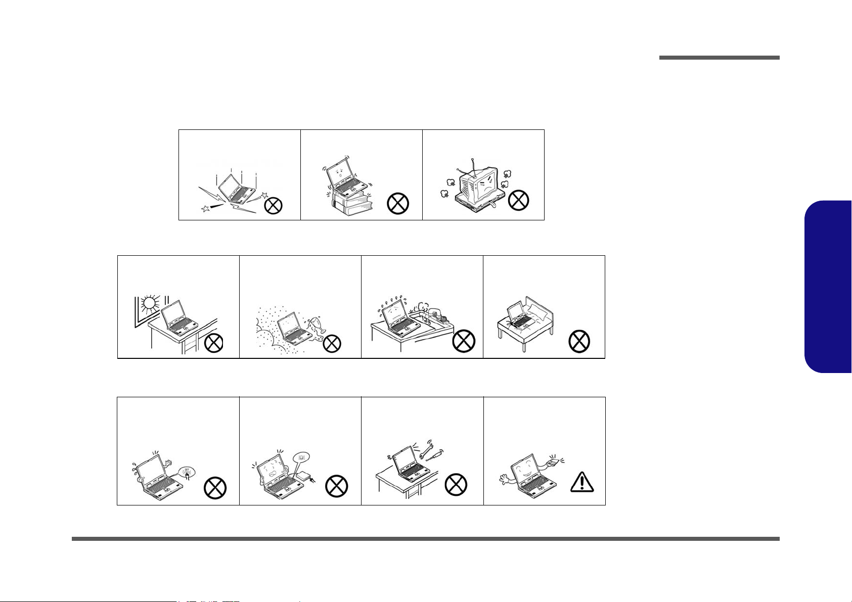
1. Don’t drop it, or expose it to shock. If the computer falls, the case and the components could be damaged.
Preface
Do not expose the computer
to any shock or vibration.
Do not place it on an unstable
surface.
Do not place anything heavy
on the computer.
2. Keep it dry, and don’t overheat it. Keep the computer and power supply away from any kind of heating element. This
is an electrical appliance. If water or any other liquid gets into it, the computer could be badly damaged.
Do not expose it to excessive
heat or direct sunlight.
Do not leave it in a place
where foreign matter or moisture may affect the system.
Don’t use or store the computer in a humid environment.
Do not place the computer on
any surface which will block
the vents.
3. Follow the proper working procedures for the computer. Shut the computer down properly and don’t forget to save
your work. Remember to periodically save your data as data may be lost if the battery is depleted.
Do not turn off the power
until you properly shut down
all programs.
Do not turn off any peripheral
devices when the computer is
on.
Do not disassemble the computer by yourself.
Perform routine maintenance
on your computer.
Preface
V
Page 8
Preface
Power Safety
Warning
Before you undertake
any upgrade procedures, make sure that
you have turned off the
power, and disconnected all peripherals
and cables (including
telephone lines). It is
advisable to also remove your battery in
order to prevent accidentally turning the
machine on.
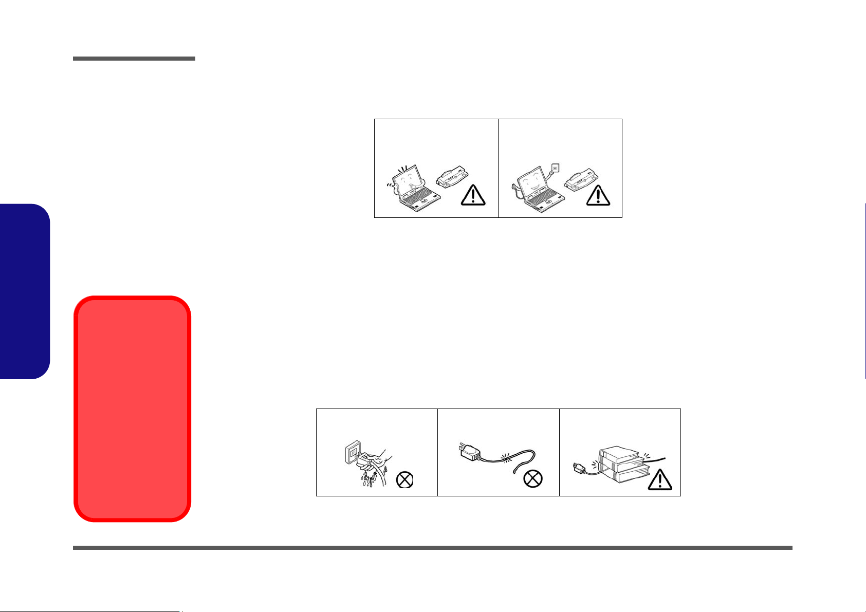
4. Avoid interference. Keep the computer away from high capacity transformers, electric motors, and other strong mag-
netic fields. These can hinder proper performance and damage your data.
5. Take care when using peripheral devices.
Preface
VI
Use only approved brands of
peripherals.
Unplug the power cord before
attaching peripheral devices.
Power Safety
The computer has specific power requirements:
• Only use a power adapter approved for use with this computer.
• Your AC adapter may be designed for international travel but it still requires a steady, uninterrupted power supply. If you are
unsure of your local power specifications, consult your service representative or local power company.
• The power adapter may have either a 2-prong or a 3-prong grounded plug. The third prong is an important safety feature; do
not defeat its purpose. If you do not have access to a compatible outlet, have a qualified electrician install one.
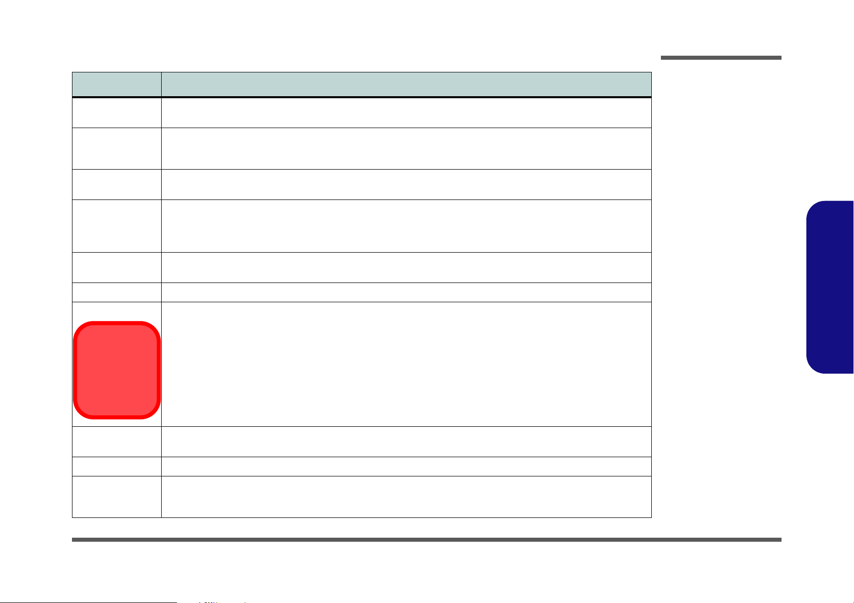
• When you want to unplug the power cord, be sure to disconnect it by the plug head, not by its wire.
• Make sure the socket and any extension cord(s) you use can support the total current load of all the connected devices.
• Before cleaning the computer, make sure it is disconnected from any external power supplies.
Do not plug in the power
cord if you are wet.
Do not use the power cord if
it is broken.
Do not place heavy objects
on the power cord.
Page 9

Battery Precautions
Battery Disposal
The product that you have purchased contains a rechargeable battery. The battery is recyclable. At the end of
its useful life, under various state and local laws, it may be illegal to dispose of this battery into the municipal
waste stream. Check with your local solid waste officials for details in your area for recycling options or proper
disposal.
Caution
Danger of explosion if battery is incorrectly replaced. Replace only with the same or equivalent type recommended by the manufacturer. Discard used battery according to the manufacturer’s instructions.
• Only use batteries designed for this computer. The wrong battery type may explode, leak or damage the computer.
• Do not remove any batteries from the computer while it is powered on.
• Do not continue to use a battery that has been dropped, or that appears damaged (e.g. bent or twisted) in any way. Even if the
computer continues to work with a damaged battery in place, it may cause circuit damage, which may possibly result in fire.
• Recharge the batteries using the notebook’s system. Incorrect recharging may make the battery explode.
• Do not try to repair a battery pack. Refer any battery pack repair or replacement to your service representative or qualified service
personnel.
• Keep children away from, and promptly dispose of a damaged battery. Always dispose of batteries carefully. Batteries may explode
or leak if exposed to fire, or improperly handled or discarded.
• Keep the battery away from metal appliances.
• Affix tape to the battery contacts before disposing of the battery.
• Do not touch the battery contacts with your hands or metal objects.
Preface
Preface
VII
Page 10

Preface
Preface
Related Documents
You may also need to consult the following manual for additional information:
User’s Manual on CD
This describes the notebook PC’s features and the procedures for operating the computer and its ROM-based setup program. It also describes the installation and operation of the utility programs provided with the notebook PC.
VIII
Page 11

Contents
Preface
Introduction ..............................................1-1
Overview .........................................................................................1-1
System Specifications ................................. 1-2
External Locator - Top View with LCD Panel Open ......................1-5
External Locator - Front & Right side Views .................................1-6
External Locator - Left Side & Rear View .....................................1-7
External Locator - Bottom View .....................................................1-8
Mainboard Overview - Top (Key Parts) .........................................1-9
Mainboard Overview - Bottom (Key Parts) ..................................1-10
Mainboard Overview - Top (Connectors) .....................................1-11
Mainboard Overview - Bottom (Connectors) ...............................1-12
Disassembly ...............................................2-1
Overview .........................................................................................2-1
Maintenance Tools ..........................................................................2-2
Connections .....................................................................................2-2
Maintenance Precautions .................................................................2-3
Disassembly Steps ...........................................................................2-4
Removing the Battery ......................................................................2-5
Removing the Hard Disk Drive ....................................................... 2-6
Removing the Optical (CD/DVD) Device ...................................... 2-9
Removing the System Memory (RAM) ........................................ 2-11
Removing the Inverter Board ........................................................2-13
Removing and Installing the Processor .........................................2-14
Removing the Wireless LAN Module ........................................... 2-17
Removing the Bluetooth Module ..................................................2-18
Removing the Keyboard ................................................................2-19
Removing the Modem ...................................................................2-20
Part Lists ..................................................A-1
Part List Illustration Location ........................................................A-2
Top without Fingerprint (M740S) ................................................. A-3
Top without Fingerprint (M741S/M745S) .................................... A-4
Bottom (M740S/M741S/M745S) .................................................. A-5
LCD (M740S/M741S/M745S) ...................................................... A-6
HDD (M740S/M741S/M745S) ..................................................... A-7
COMBO (M740S/M741S/M745S) ............................................... A-8
DVD-Dual Drive (M740S/M741S/M745S) .................................. A-9
Top without Fingerprint (M760S) ............................................... A-10
Top without Fingerprint (M765S) ............................................... A-11
Top without Fingerprint (M766S/M767S) .................................. A-12
Bottom (M760S/M765S/M766S/M767S) ................................... A-13
LCD (M760S) .............................................................................. A-14
LCD (M765S) .............................................................................. A-15
LCD (M766S/M767S) ................................................................. A-16
HDD (M760S/M765S/M766S/M767S) ....................................... A-17
COMBO (M760S/M765S/M766S/M767S) ................................. A-18
DVD-Dual Drive (M760S/M765S/M766S/M767S) ................... A-19
Schematic Diagrams................................. B-1
System Block Diagram ...................................................................B-2
Penryn (Socket-P) 1/2 .....................................................................B-3
Penryn (Socket-P) 2/2 .....................................................................B-4
SiSM672 Host, PCIE 1/5 ................................................................B-5
SiSM672 DRAM 2/5 ......................................................................B-6
SiSM672 MuTIOL VGA 3/5 ..........................................................B-7
SiSM672 PWR 4/5 .........................................................................B-8
SiSM672 GND 5/5 .........................................................................B-9
DDRII SO-DIMM - 1 ...................................................................B-10
DDRII SO-DIMM - 2 ...................................................................B-11
SiS307ELV ...................................................................................B-12
Panel, CRT ....................................................................................B-13
Preface
IX
Page 12

Preface
Inverter, Bluetooth, Fan ............................................................... B-14
968 PCI, IDE, MuTIOL, SPI 1/4 ................................................. B-15
968 PCIE, LAN, GPIO 2/4 ........................................................... B-16
968 USB SATA 3/4 ...................................................................... B-17
968 PWR, GND 4/4 ..................................................................... B-18
Clock Generator & Clock Buffer ................................................. B-19
PHY Realtek 8201CL ................................................................... B-20
KBC ITE8512E ............................................................................ B-21
ENE MR510, Card Reader ........................................................... B-22
Audio Codec ALC662 .................................................................. B-23
Audio AMP .................................................................................. B-24
SATA HDD, PWR, LID .............................................................. B-25
Multi I/O, ODD, 3G, Click BD for M74 ...................................... B-26
New Card, Mini PCIE, USB ........................................................ B-27
LED, PC Beep, TP, FP ................................................................. B-28
System/Ext-VGA Power .............................................................. B-29
Preface
AC-IN, Charger ............................................................................ B-30
VCORE ........................................................................................ B-31
VDD3, VDD5) ............................................................................. B-32
1.05VS, 1.2V, 1.5V ...................................................................... B-33
1.8V, 0.9VS .................................................................................. B-34
Click BD, Finger BD for M76 ..................................................... B-35
Multi Function Board ................................................................... B-36
Audio Board ................................................................................. B-37
Finger Sensor Board ..................................................................... B-38
Power Switch Board for M74 ....................................................... B-39
External ODD Board for M76 ...................................................... B-40
Power Switch Board for M76 ....................................................... B-41
X
Page 13

Chapter 1: Introduction
Overview
This manual covers the information you need to service or upgrade the M740S/M741S/M745S/M760S/M765S/M766S/
M767S series notebook computer. Information about operating the computer (e.g. getting started, and the Setup utility)
is in the User’s Manual. Information about drivers (e.g. VGA & audio) is also found in User’s Manual. That manual is
shipped with the computer.
Operating systems (e.g. Windows XP, Windows Vista, etc.) have their own manuals as do application software (e.g. word
processing and database programs). If you have questions about those programs, you should consult those manuals.
The M740S/M741S/M745S/M760S/M765S/M766S/M767S series notebook is designed to be upgradeable. See “Disas-
sembly” on page 2 - 1 for a detailed description of the upgrade procedures for each specific component. Please note the
warning and safety information indicated by the “” symbol.
The balance of this chapter reviews the computer’s technical specifications and features.
Introduction
1.Introduction
Overview 1 - 1
Page 14
Introduction
System Specifications
Feature Specification
1.Introduction
Processor Intel® Core™2 Duo Processor
(478-pin) Micro-FC-PGA Package, Socket P
T8100/ T8300
Intel® Core™2 Duo Processor
(478-pin) Micro-FC-PGA Package, Socket P
T9300/ T9500
Intel® Core™2 Duo Processor
(478-pin) Micro-FC-PGA Package, Socket P
T7100/ T7250
Intel® Core™2 Duo Processor
(478-pin) Micro-FC-PGA Package, Socket P
T7300/ T7500/ T7700/ T7800
Intel® Celeron® M Processor
(478-pin) Micro-FCPGA Package, Socket P
530/ 540/ 550/ 560
Core Logic SiS M672 + SiS968 Chipset
LCD M740S/M741S/M745S
14.1" WXGA/ WXGA+ Glare Type TFT LCD
Video Adapter SIS M672 Integrated Video
High Preference 3D/2D Graphic Accelerator
Shared Memory Architecture (up to 256MB dynamically allocated from system memory where needed)
Supports DirectX 9.0
Supports Vertex Shader 2.0 and Pixel Shader 2.0
45nm (45 Nanometer) Process Technology
3MB On-die L2 Cache & 800MHz FSB
2.1/ 2.4 GHz
45nm (45 Nanometer) Process Technology
6MB On-die L2 Cache & 800MHz FSB
2.5/ 2.6 GHz
65nm (65 Nanometer) Process Technology
2MB On-die L2 Cache & 800MHz FSB
1.80/ 2.0 GHz
65nm (65 Nanometer) Process Technology
4MB On-die L2 Cache & 800MHz FSB
2.0/ 2.2/ 2.4/ 2.6 GHz
65nm (65 Nanometer) Process Technology
1MB On-die L2 Cache & 533MHz FSB
1.73/ 1.86/ 2.0/ 2.13 GHz
M760S/M765S/M766S/M767S
15.4" WXGA/ WXGA+/ WSXGA+ Glare Type TFT LCD
Memory 64-bit Wide DDRII (DDR2) Data Channel
Security Security (Kensington® Type) Lock Slot BIOS Password
BIOS One 8Mb SPI Flash ROM Phoenix™ BIOS
1 - 2 System Specifications
Two 200 Pin SO-DIMM Sockets Supporting DDRII (DDR2) 667MHz
Memory Expandable up to 2GB (1024MB/ 2048MB DDRII Modules)
Page 15
Feature Specification
UMTS Modes
Note that UMTS
modes CAN
NOT be used in
North America.
Storage One Changeable 12.7mm(h) PATA Optical Device (CD/DVD) Type Drive (see “Optional” on page 1 - 4) Easy
Changeable 2.5" 9.5 mm (h) SATA (Serial) HDD
Introduction
Audio High Definition Audio (HDA)
Compliant with Microsoft UAA (Universal Audio
Architecture)
Keyboard &
Pointing Device
Interface Three USB 2.0 Ports
Card Reader Embedded 7-in-1 Card Reader (MS/ MS Pro/ SD/ Mini SD/ MMC/ RS MMC/ MS Duo) Note: MS Duo/ Mini SD/ RS
ExpressCard Slot One ExpressCard/34(54) Slot
Communication 10M/100Mb Base-T Ethernet LAN
Winkey Keyboard Built-In TouchPad with Scrolling Function
One Headphone-Out Jack
One Microphone-In Jack
One S/PDIF-Out Jack
MMC Cards require a PC adapter
56K MDC Modem V.90 & V.92 Compliant
3rd Party 802.11b/g Wireless LAN Mini-Card Module with USB interface (Option)
Bluetooth 2.0 + EDR (Enhanced Data Rate) Module (Factory Option)
1.3M (UVC or non UVC) or 2.0M Pixel USB PC Camera Module (Factory Option)
3.5G Module:
UMTS/HSPDA-based 3.5G Module with Mini-Card Interface (Factory Option)
Quad-band GSM/GPRS (850 MHz, 900 MHz, 1800 MHz, 1900 MHz)
UMTS WCDMA FDD (2100 MHz)
Direct Sound 3D™ Compatible
2 * Built-In Speakers
Built-In Microphone
One RJ-11 Modem Jack
One RJ-45 LAN Jack
One DC-In Jack
One External Monitor Port
1.Introduction
Power
Management
Power Full Range AC/DC Adapter AC input 100 - 240V, 50 - 60Hz, DC Output 19V, 3.42A OR 18.5V, 3.5A (65 Watts)
Battery 6 Cell Smart Lithium-Ion Battery Pack, 4000mAH OR 4400mAH
Supports ACPI 3.0
Supports Wake on LAN
9 Cell Smart Lithium-Ion Battery Pack, 7200mAH (Option)
Supports Wake on USB
Supports Resume from Modem Ring
System Specifications 1 - 3
Page 16

Introduction
Feature Specification
1.Introduction
Environmental
Spec
Dimensions
& Weight
Optional Optical Drive Module Options:
Temperature
Operating: 5°C - 35°C
Non-Operating: -20°C - 60°C
M740S/M741S/M745S
336mm (w) * 250mm (d) * 24.8-35.7mm (h)
2.2 kg With 6 Cell Battery & ODD
DVD-ROM/CD-RW Combo Drive Module
DVD Dual (Super Multi) Drive Module
3rd Party 802.11b/g Wireless LAN Mini-Card Module with
USB interface
9 Cell Smart Lithium-Ion Battery Pack
1.3M (UVC or non UVC) or 2.0M Pixel USB PC Camera
Module (Factory Option)
Relative Humidity
Operating: 20% - 80%
Non-Operating: 10% - 90%
M760S/M765S/M766S/M767S:
359mm (w) * 268mm (d) * 24.8-37mm (h)
2.5 kg With 6 Cell Battery & ODD
Bluetooth 2.0 + EDR (Enhanced Data Rate) Module
(Factory Option)
UMTS/HSPDA-based 3.5G Module with Mini-Card
Interface (Factory Option)
Quad-band GSM/GPRS (850 MHz, 900 MHz, 1800 MHz,
1900 MHz)
UMTS WCDMA FDD (2100 MHz)
UMTS Modes
Note that UMTS modes CAN NOT be used in
North America.
1 - 4 System Specifications
Page 17
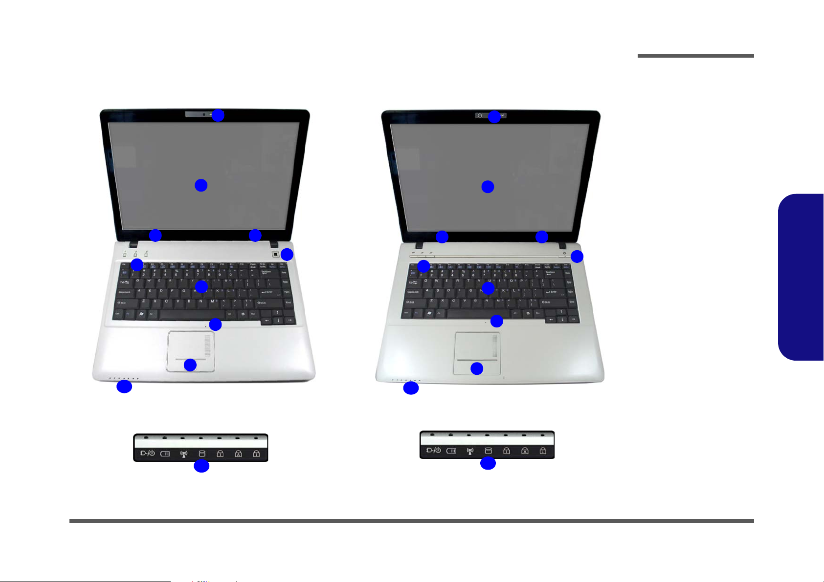
External Locator - Top View with LCD Panel Open
Figure 1
Top View
1. Optional Built-In
PC Camera
2. LCD
3. Speakers
4. Power Button
5. Hot Key Buttons
6. Keyboard
7. Built-In
Microphone
8. Touchpad &
Buttons
9. LED Indicators
M740S/M741S/M745S M760S/M765S/M766S/M767S
2
5
1
7
8
4
6
33
9
10
10
2
5
1
7
8
4
6
33
9
Introduction
1.Introduction
External Locator - Top View with LCD Panel Open 1 - 5
Page 18
Introduction
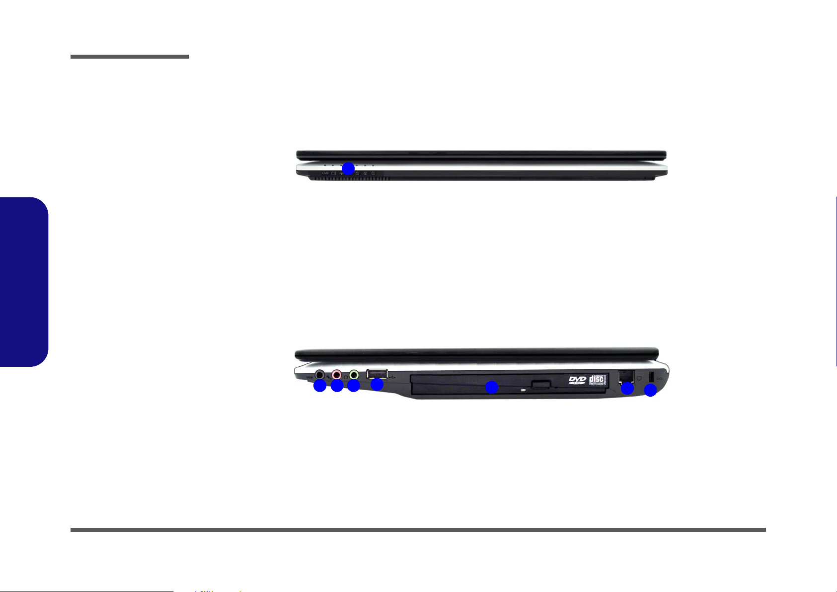
Figure 2
Front Views
1. LED Power &
Communication
Indicators
Figure 3
Right Side Views
1. S/PDIF-Out Jack
2. Microphone-In
Jack
3. Headphone-Out
Jack
4. USB 2.0 Port
5. Optical Device
Drive Bay
6. RJ-11 Phone
Jack
7. Security Lock
Slot
1
15243
6
7
1.Introduction
External Locator - Front & Right side Views
1 - 6 External Locator - Front & Right side Views
Page 19
External Locator - Left Side & Rear View
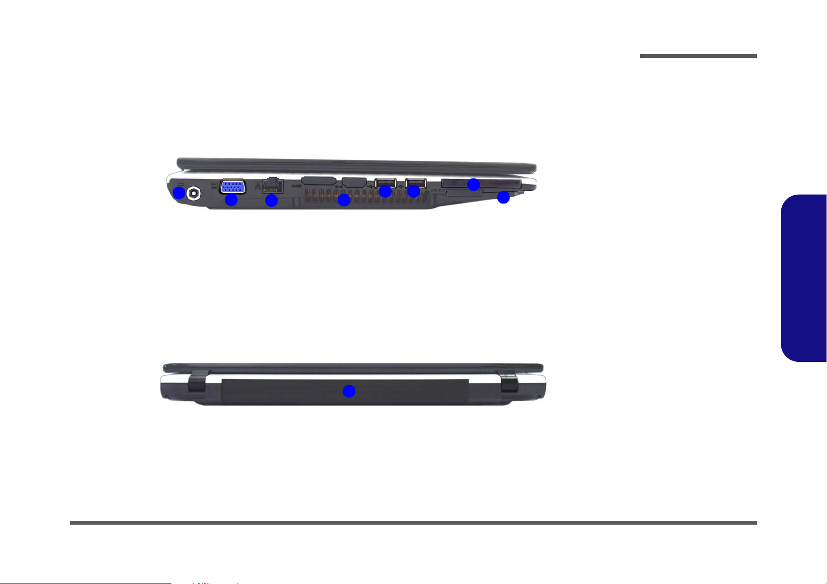
Figure 4
Left Side View
1. DC-In Jack
2. External Monitor
Port
3. RJ-45 LAN Jack
4. Vent/Fan Intake/
Outlet
5. 2 * USB 2.0 Ports
6. ExpressCard Slot
7. 7-in-1 Card
Reader
1
4
3
5
2
6
5
7
Figure 5
Rear View
1. Battery
1
Introduction
1.Introduction
External Locator - Left Side & Rear View 1 - 7
Page 20
Introduction
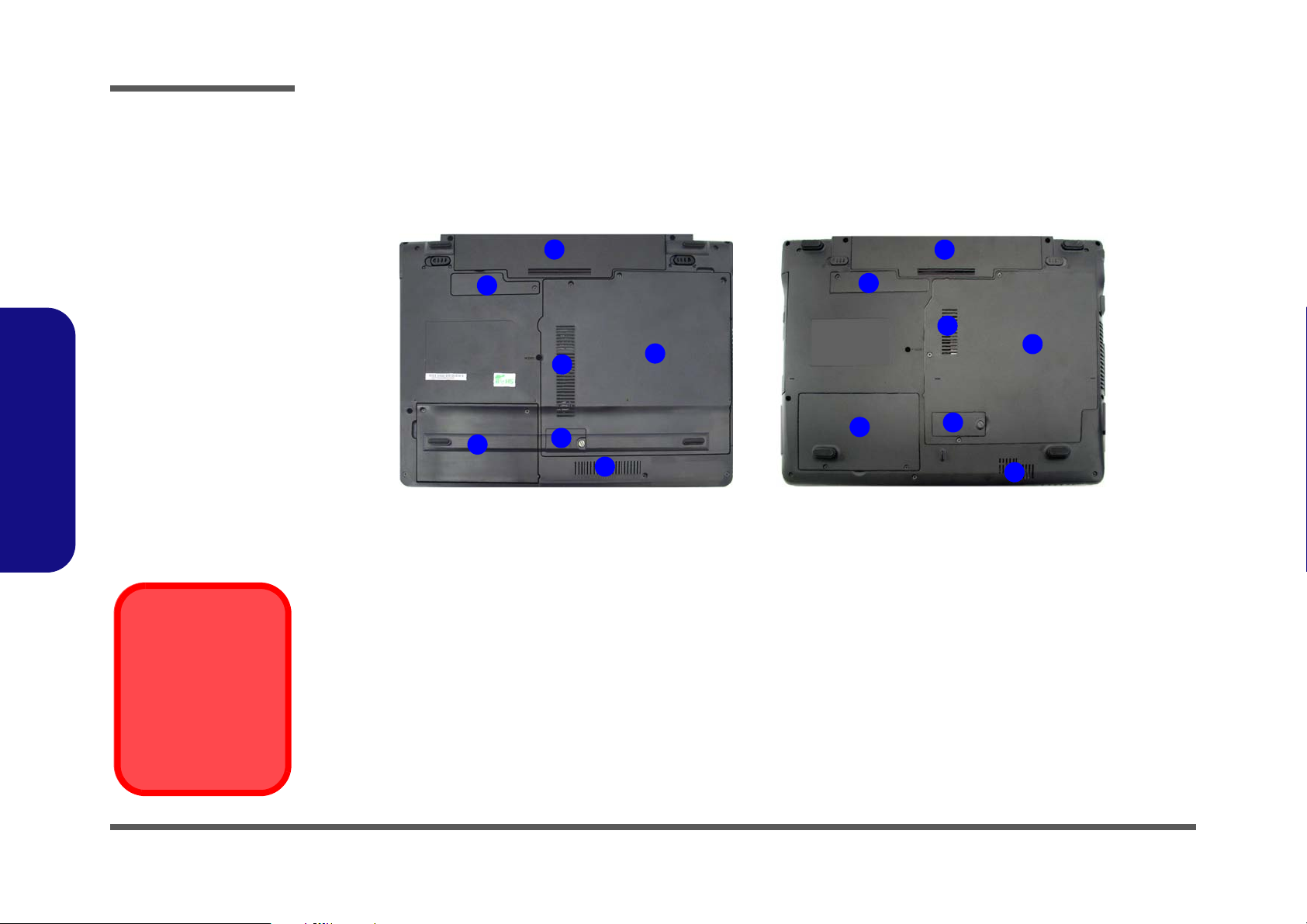
Figure 6
Bottom View
1. Battery
2. Bluetooth
Module Cover
3. RAM & CPU Bay
Cover
4. Vent/Fan Intake/
Outlet
5. Hard Disk Bay
Cover
6. 3.5G USIM Card
Location
Overheating
To prevent your computer from overheating
make sure nothing
blocks the vent/fan intakes while the computer is in use.
M740S/M741S/M745S M760S/M765S/M766S/M767S
2
3
1
4
4
5
6
2
3
1
4
4
5
6
External Locator - Bottom View
1.Introduction
1 - 8 External Locator - Bottom View
Page 21
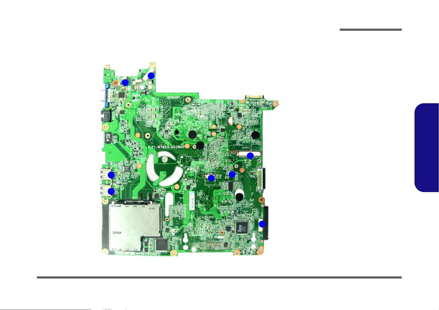
Mainboard Overview - Top (Key Parts)
Figure 7
Mainboard Top
Key Parts
1. Transformer
2. RTL8201CL
3. ExpressCard
Connector
4. ENE MR510
5. KBC ITE IT8512E
1
2
3
4
5
Introduction
1.Introduction
Mainboard Overview - Top (Key Parts) 1 - 9
Page 22
Introduction
1
2
3
4
5
6
10
7
8
9
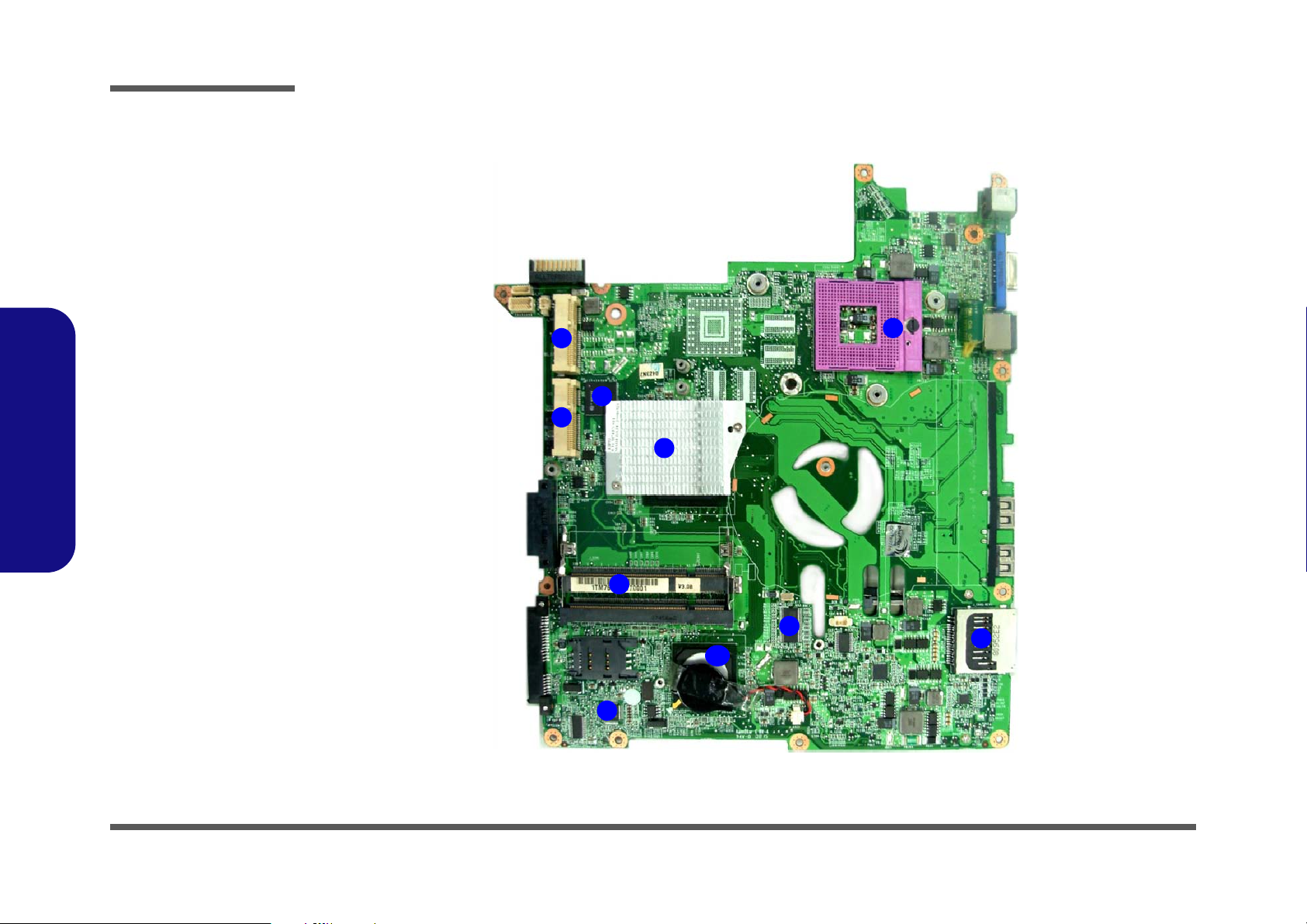
Figure 8
Mainboard Bottom
Key Parts
1. CPU Socket (no
CPU installed)
2. SiSM672
3. Memory Slots
DDR2 SO-DIMM
4. ICS
9LPR600CGLF
5. Card Reader
Socket
6. SiS307ELV
7. Audio Codec
ALC62
8. Mini-Card
Connector (WLAN
Module)
9. Mini-Card
Connector (3G
Module)
10. SiS968
1.Introduction
Mainboard Overview - Bottom (Key Parts)
1 - 10 Mainboard Overview - Bottom (Key Parts)
Page 23
Mainboard Overview - Top (Connectors)
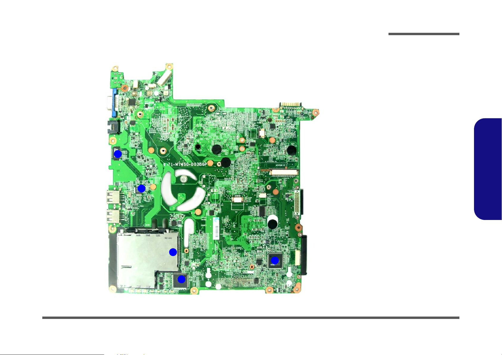
Figure 9
Mainboard Top
Connectors
1. USB Port
2. Inverter
Connector
3. LCD Cable
Connector
4. Keyboard Cable
Connector
5. Audio Board
Connector
6. Microphone
Cable Connector
7. TouchPad Cable
Connector
6
5
7
1
1
4
2
3
Introduction
1.Introduction
Mainboard Overview - Top (Connectors) 1 - 11
Page 24
Introduction
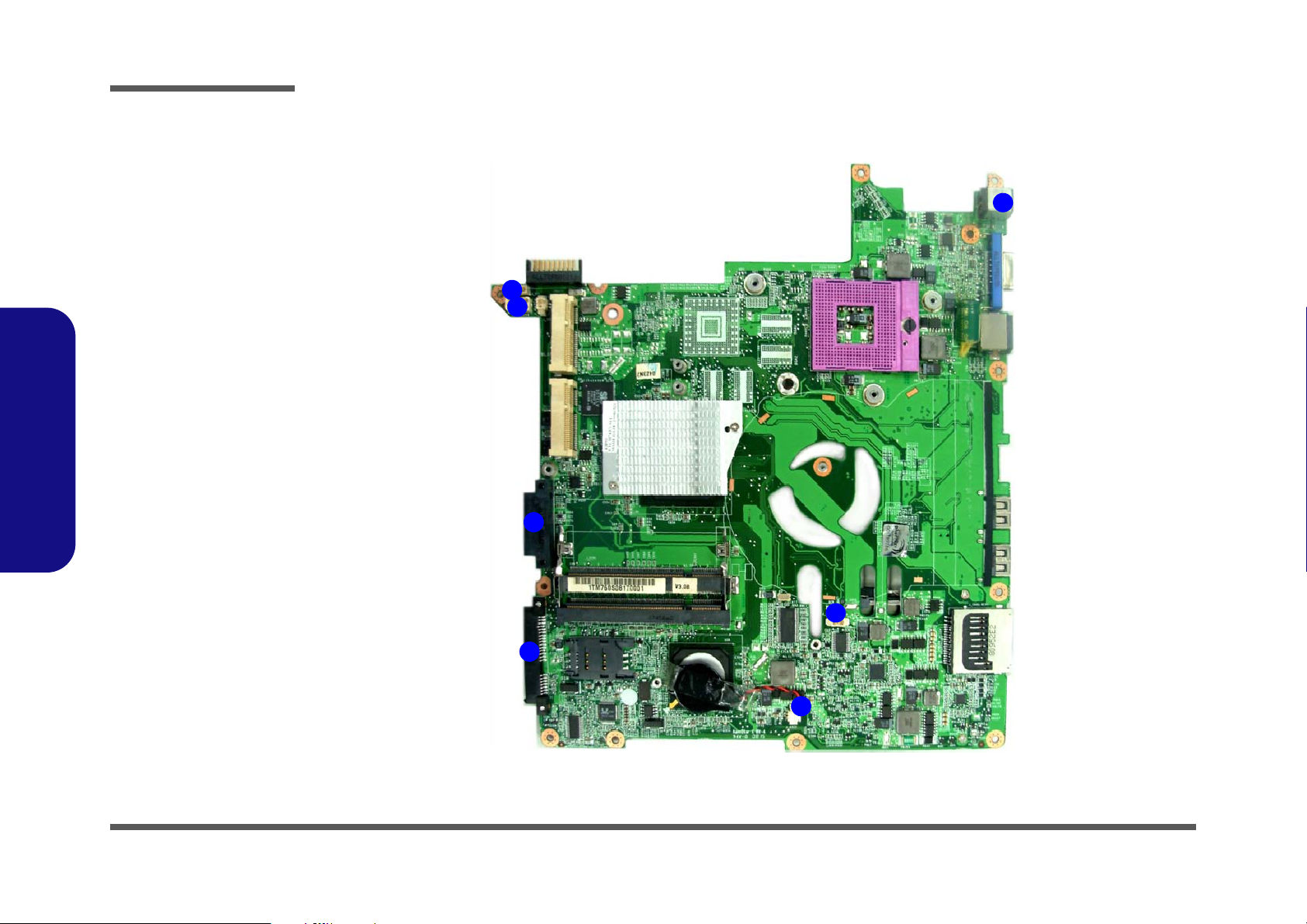
Figure 10
Mainboard Bottom
Connectors
1. BT Cable
Connector
2. Multi Board
Connector
3. CD-ROM
Connector
4. HDD Connector
5. CMOS Bat.
Connector
6. CPU Fan Cable
Connector
7. DC-In Jack
1
2
3
4
5
6
7
Mainboard Overview - Bottom (Connectors)
1.Introduction
1 - 12 Mainboard Overview - Bottom (Connectors)
Page 25
Chapter 2: Disassembly
Information
Warning
Overview
This chapter provides step-by-step instructions for disassembling the M740S/M741S/M745S/M760S/M765S/M766S/
M767S series notebook’s parts and subsystems. When it comes to reassembly, reverse the procedures (unless otherwise
indicated).
We suggest you completely review any procedure before you take the computer apart.
Disassembly
Procedures such as upgrading/replacing the RAM, optical device and hard disk are included in the User’s Manual but are
repeated here for your convenience.
To make the disassembly process easier each section may have a box in the page margin. Information contained under
the figure # will give a synopsis of the sequence of procedures involved in the disassembly procedure. A box with a
lists the relevant parts you will have after the disassembly process is complete. Note: The parts listed will be for the dis-
assembly procedure listed ONLY, and not any previous disassembly step(s) required. Refer to the part list for the previous disassembly procedure. The amount of screws you should be left with will be listed here also.
A box with a will also provide any possible helpful information. A box with a contains warnings.
An example of these types of boxes are shown in the sidebar.
2.Disassembly
Overview 2 - 1
Page 26

Disassembly
2.Disassembly
NOTE: All disassembly procedures assume that the system is turned OFF, and disconnected from any power supply (the
battery is removed too).
Maintenance Tools
The following tools are recommended when working on the notebook PC:
• M3 Philips-head screwdriver
• M2.5 Philips-head screwdriver (magnetized)
• M2 Philips-head screwdriver
• Small flat-head screwdriver
• Pair of needle-nose pliers
• Anti-static wrist-strap
Connections
Connections within the computer are one of four types:
Locking collar sockets for ribbon connectors To release these connectors, use a small flat-head screwdriver to
gently pry the locking collar away from its base. When replacing the connection, make sure the connector is oriented in the
same way. The pin1 side is usually not indicated.
2-2Overview
Pressure sockets for multi-wire connectors To release this connector type, grasp it at its head and gently
rock it from side to side as you pull it out. Do not pull on the
wires themselves. When replacing the connection, do not try to
force it. The socket only fits one way.
Pressure sockets for ribbon connectors To release these connectors, use a small pair of needle-nose pli-
ers to gently lift the connector away from its socket. When replacing the connection, make sure the connector is oriented in
the same way. The pin1 side is usually not indicated.
Board-to-board or multi-pin sockets To separate the boards, gently rock them from side to side as
you pull them apart. If the connection is very tight, use a small
flat-head screwdriver - use just enough force to start.
Page 27

Maintenance Precautions
Power Safety
Warning
Before you undertake
any upgrade procedures, make sure that
you have turned off the
power, and disconnected all peripherals
and cables (including
telephone lines). It is
advisable to also remove your battery in
order to prevent accidentally turning the
machine on.
The following precautions are a reminder. To avoid personal injury or damage to the computer while performing a removal and/or replacement job, take the following precautions:
1. Don't drop it. Perform your repairs and/or upgrades on a stable surface. If the computer falls, the case and other
components could be damaged.
2. Don't overheat it. Note the proximity of any heating elements. Keep the computer out of direct sunlight.
3. Avoid interference. Note the proximity of any high capacity transformers, electric motors, and other strong mag-
netic fields. These can hinder proper performance and damage components and/or data. You should also monitor
the position of magnetized tools (i.e. screwdrivers).
4. Keep it dry. This is an electrical appliance. If water or any other liquid gets into it, the computer could be badly
damaged.
5. Be careful with power. Avoid accidental shocks, discharges or explosions.
•Before removing or servicing any part from the computer, turn the computer off and detach any power supplies.
•When you want to unplug the power cord or any cable/wire, be sure to disconnect it by the plug head. Do not pull on the wire.
6. Peripherals – Turn off and detach any peripherals.
7. Beware of static discharge. ICs, such as the CPU and main support chips, are vulnerable to static electricity.
Before handling any part in the computer, discharge any static electricity inside the computer. When handling a
printed circuit board, do not use gloves or other materials which allow static electricity buildup. We suggest that
you use an anti-static wrist strap instead.
8. Beware of corrosion. As you perform your job, avoid touching any connector leads. Even the cleanest hands pro-
duce oils which can attract corrosive elements.
9. Keep your work environment clean. Tobacco smoke, dust or other air-born particulate matter is often attracted
to charged surfaces, reducing performance.
10. Keep track of the components. When removing or replacing any part, be careful not to leave small parts, such as
screws, loose inside the computer.
Cleaning
Do not apply cleaner directly to the computer, use a soft clean cloth.
Do not use volatile (petroleum distillates) or abrasive cleaners on any part of the computer.
Disassembly
2.Disassembly
Overview 2 - 3
Page 28

Disassembly
Disassembly Steps
The following table lists the disassembly steps, and on which page to find the related information. PLEASE PERFORM
THE DISASSEMBLY STEPS IN THE ORDER INDICATED.
2.Disassembly
To remove the Battery:
1. Remove the battery page 2 - 5
To remove the HDD:
1. Remove the battery page 2 - 5
2. Remove the HDD page 2 - 6
To remove the Optical Device:
1. Remove the battery page 2 - 5
2. Remove the Optical device page 2 - 9
To remove the System Memory:
1. Remove the battery page 2 - 5
2. Remove the system memory page 2 - 11
To remove the Inverter Board:
1. Remove the battery page 2 - 5
2. Remove the inverter board page 2 - 13
To remove and install a Processor:
To remove the Wireless LAN Module:
1. Remove the battery page 2 - 5
2. Remove the wireless LAN page 2 - 17
To remove the Bluetooth Modules:
1. Remove the battery page 2 - 5
2. Remove the Bluetooth page 2 - 18
To remove the Keyboard:
1. Remove the battery page 2 - 5
2. Remove the keyboard page 2 - 19
To remove the Modem:
1. Remove the battery page 2 - 5
2. Remove the HDD page 2 - 6
3. Remove the system memory page 2 - 11
4. Remove the Optical device page 2 - 9
5. Remove the processor page 2 - 14
6. Remove the keyboard page 2 - 19
7. Remove the modem page 2 - 20
1. Remove the battery page 2 - 5
2. Remove the processor page 2 - 14
3. Install the processor page 2 - 16
2 - 4 Disassembly Steps
Page 29
3. Battery
12634
a.
3
b.
2
4
1
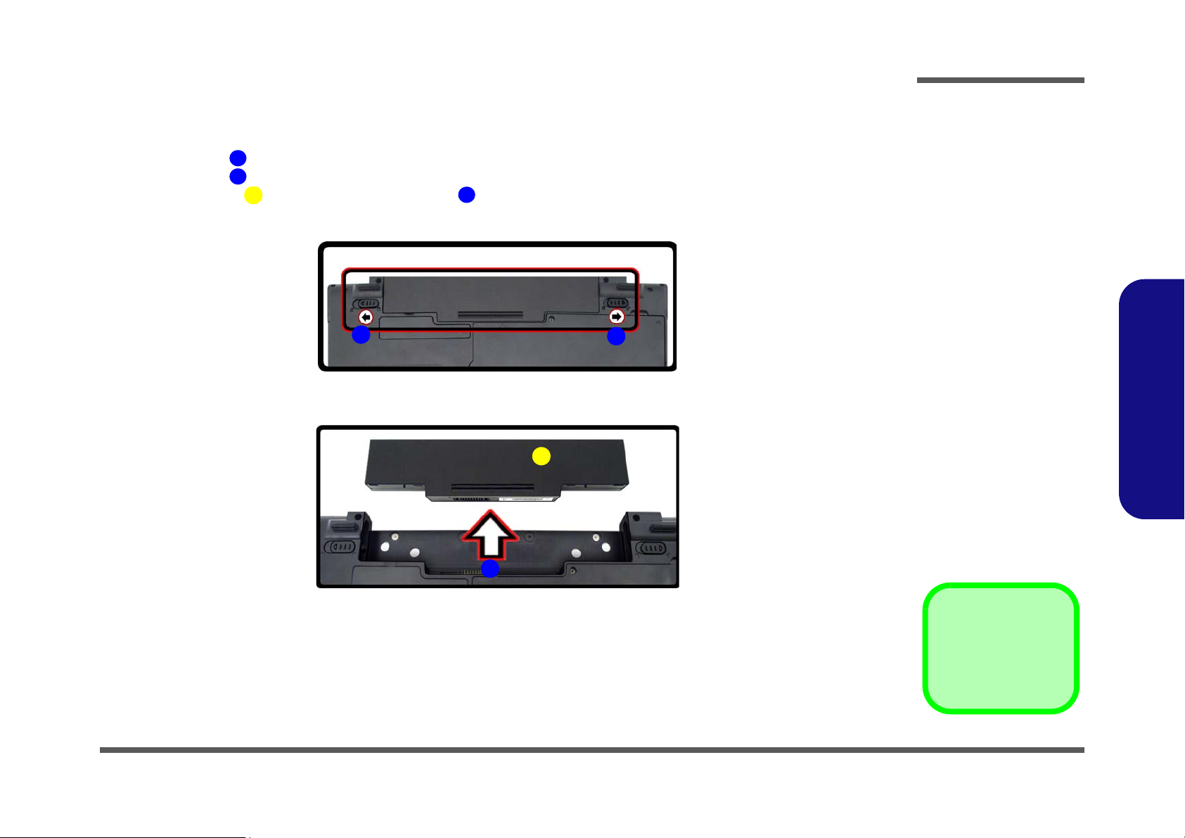
Figure 1
Battery Removal
a. Slide the latch and hold
in place.
b. Slide the battery in the di-
rection of the arrow.
Disassembly
Removing the Battery
1. Turn the computer off, and turn it over.
2. Slide the latch in the direction of the arrow.
3. Slide the latch in the direction of the arrow, and hold it in place.
4. Slide the battery in the direction of the arrow .
2.Disassembly
Removing the Battery 2 - 5
Page 30
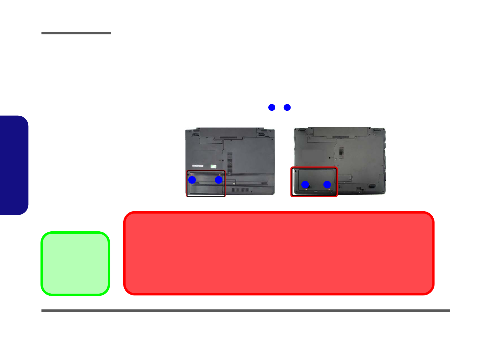
Disassembly
Figure 2
HDD Assembly
Removal
a. Locate the HDD bay
cover and remove the
screw(s).
•2 Screws
1
2
21
21
a.
HDD System Warning
New HDD’s are blank. Before you begin make sure:
You have backed up any data you want to keep from your old HDD.
You have all the CD-ROMs and FDDs required to install your operating system and programs.
If you have access to the internet, download the latest application and hardware driver updates for the operating system you plan
to install. Copy these to a removable medium.
M740S/M741S/M745S M760S/M765S/M766S/M767S
2.Disassembly
Removing the Hard Disk Drive
The hard disk drive can be taken out to accommodate other 2.5" serial (SATA) hard disk drives with a height of 9.5mm
(h). Follow your operating system’s installation instructions, and install all necessary drivers and utilities (as outlined in
Chapter 4 of the User’s Manual) when setting up a new hard disk.
Hard Disk Upgrade Process
1. Turn off the computer, and remove the battery (page 2 - 5).
2. Locate the hard disk bay cover and remove screw & .
2 - 6 Removing the Hard Disk Drive
Page 31

63456
676
8
4
b.
c.
e.
5
6
d.
3
7
8
3. HDD Bay Cover
7. Adhesive Cover
8. HDD
•1 Screw
Figure 3
HDD Assembly
Removal (cont’d.)
b. Remove the HDD bay
cover.
c. Grip the tab and slide the
HDD in the direction of
the arrow.
d. Lift the HDD assembly
out of the bay.
e. Remove the screw and
adhesive cover.
Disassembly
For M740S/M741S/M745S computers:
3. Remove the hard disk bay cover .
4. Grip the tab and slide the hard disk in the direction of arrow .
5. Lift the hard disk out of the bay .
6. Remove the screw and the adhesive cover from the hard disk .
7. Reverse the process to install a new hard disk (do not forget to replace all the screws and covers).
2.Disassembly
Removing the Hard Disk Drive 2 - 7
Page 32

Disassembly
634567686
9
3. HDD Bay Cover
8. Adhesive Covere
9. HDD
•2 Screws
7
6
4
8
9
i.
g.
f.
5
3
h.
Figure 4
HDD Assembly
Removal (cont’d.)
f. Remove the HDD Bay
Cover.
g. Grip the tab and slide the
HDD in the direction of
the arrow.
h. Lift the HDD assembly
out of the bay.
i. Remove the screw and
adhesive cover.
For M760S/M765S/M766S/M767S computers:
8. Remove the hard disk bay Cover .
9. Grip the tab and slide the hard disk in the direction of arrow .
10. Lift the hard disk out of the bay .
11. Remove the screws & and the adhesive cover from the hard disk .
12. Reverse the process to install a new hard disk (do not forget to replace all the screws and covers).
2.Disassembly
2 - 8 Removing the Hard Disk Drive
Page 33

Removing the Optical (CD/DVD) Device
Figure 5
Optical Device
Removal
a. Remove the screws.
b. Disconnect the fan cable
and remove the cover.
c. Remove the screw.
d. Push the optical device
out off the computer at
point 7.
12451
687
1. Component Bay Cover
8. Optical Device
•4 Screws
5
2
4
3
c.
d.
c.
M740S/M741S/M745S
8
1
1
6
7
a.
b.
1. Turn off the computer, and remove the battery (page 2 - 5).
2. M740S/M741S/M745S: (see over for M760S/M765S/M766S/M767S)
remove screws
3. Carefully (a fan and cable are attached to the under side of the cover) lift up the bay cover.
4. Carefully disconnect the fan cable , and remove the cover
5. Remove the screw at point , and use a screwdriver to carefully push out the optical device at point .
6. Insert the new device and carefully slide it into the computer (the device only fits one way. DO NOT FORCE IT; The
screw holes should line up).
7. Restart the computer to allow it to automatically detect the new device.
- .
Locate the component bay cover and
.
Disassembly
2.Disassembly
Removing the Optical (CD/DVD) Device 2 - 9
Page 34

Disassembly
1231687
1. HDD Bay Cover
8. Optical Device
•3 Screws
6
7
7
32
g.
h.
M760S/M765S/M766S/M767S
8
1
1
e.
f.
Figure 6
Optical Device
Removal (cont’d.)
e. Remove the screws.
f. Remove the cover.
g. Remove the screw.
h. Push the optical device
out off the computer at
point 7.
8. M760S/M765S/M766S/M767S: Locate the hard disk bay cover and loosen screws & .
9. Remove the hard disk bay cover .
10. Remove the screw at point , and use a screwdriver to carefully push out the optical device
at point .
11. Insert the new device and carefully slide it into the computer (the device only fits one way. DO NOT FORCE IT; The
screw holes should line up).
12. Restart the computer to allow it to automatically detect the new device.
2.Disassembly
2 - 10 Removing the Optical (CD/DVD) Device
Page 35

Removing the System Memory (RAM)
Figure 7
RAM Module
Removal
a. Remove the screws.
b. Remove the cover.
Contact Warning
Be careful not to touch
the metal pins on the
module’s connecting
edge. Even the cleanest hands have oils
which can attract particles, and degrade the
module’s performance.
12451
1. Component Bay
Cover
•3 Screws
2
4
3
2
3
4
a.
M740S/M741S/M745S
b.
1
1
M760S/M765S/M766S/M767S
5
1
Note:
Only one model is pictured
here, however the component locations are the same
for both models.
The computer has two memory sockets for 200 pin Small Outline Dual In-line Memory Modules (SO-DIMM) supporting
DDR2 667MHz. The main memory can be expanded up to 2GB. The SO-DIMM modules supported are 1024MB, and
2048MB and DDRII Modules. The total memory size is automatically detected by the POST routine once you turn on
your computer.
Memory Upgrade Process
1. Turn off the computer, remove the battery (page 2 - 5).
2. Locate the component bay cover , and remove screws - .
3. Carefully (a fan and cable are attached to the under side of the cover) lift up the bay cover.
4. Carefully disconnect the fan cable , and remove the cover
Disassembly
.
2.Disassembly
Removing the System Memory (RAM) 2 - 11
Page 36

Disassembly
6
7
d.
8
6 7
c.
Figure 8
RAM Module
Removal (cont’d.)
c. Pull the release
latch(es).
d. Remove the module(s).
e. Properly re-insert the
bay cover pins.
8. RAM Module(s)
8
9121
9
e.
10
11
12
1
2.Disassembly
5. Gently pull the two release latches ( & ) on the sides of the memory socket in the direction indicated by the
arrows (Figure 8c).
6. The RAM module(s) will pop-up (Figure 8d), and you can then remove it.
7. Pull the latches to release the second module if necessary.
8. Insert a new module holding it at about a 30° angle and fit the connectors firmly into the memory slot.
9. The module’s pin alignment will allow it to only fit one way. Make sure the module is seated as far into the slot as it
will go. DO NOT FORCE the module; it should fit without much pressure.
10. Press the module in and down towards the mainboard until the slot levers click into place to secure the module.
11. Replace the bay cover and screws (make sure you reconnect the fan cable before screwing down the bay
cover).
Note for M760S/M765S/M766S/M767S computers that there are four - cover pins which need to be aligned
with slots in the case, to insure a proper cover fit, before screwing down the bay cover .
2 - 12 Removing the System Memory (RAM)
12. Restart the computer to allow the BIOS to register the new memory configuration as it starts up.
Page 37

Removing the Inverter Board
Figure 9
Inverter Board
Removal
a. Remove the 6 screws
and unsnap the LCD
front panel module from
the back.
b. Remove the screw and
discharge the remaining
power from the inverter
board and lift the board
up slightly.
c. Disconnect the cables
from the inverter.
d. Remove the inverter.
16789
10
11
7. LCD Front Panel
11. Inverter Board
•6 Screws
a. b.
11
Inverter Power Warning
In order to prevent a short circuit when removing the inverter it is necessary to discharge any remaining system power. To do
so, press the computer’s power button for a
few seconds before disconnecting the inverter cable.
1
9
2 5
3
4
6
c.
d.
10
8
7
1. Turn off the computer, and remove the battery (page 2 - 5).
2. Remove any rubber covers, screws - (Figure 9a), then run your finger around the middle of the frame to
carefully unsnap the LCD front panel module from the back.
3. Discharge the remaining system power (see “Inverter Power Warning” below).
4. Remove screw (Figure 9b) from the inverter, and carefully lift the inverter board up slightly.
5. Disconnect cables & (Figure 9c) from the inverter, then remove the inverter (Figure 9d) from the top
case assembly.
Disassembly
2.Disassembly
Removing the Inverter Board 2 - 13
Page 38

Disassembly
124
5
Figure 10
Processor Removal
a. Remove the cover and
Iocate the heat sink.
b. Remove the screws in
the order indicated.
c. Remove the heat sink.
5. Heat Sink
•3 Screws
a.
5
4
3
2
1
b. c.
Note:
Only one model is pictured
here, however the component locations are the same
for both models.
2.Disassembly
Removing and Installing the Processor
Processor Removal Procedure
1. Turn off the computer, remove the battery (page 2 - 5) and the component bay cover (page 2 - 11).
2. The CPU heat sink will be visible at point on the mainboard.
3. Remove screws
4. Carefully lift up the heat sink (Figure 10c) off the computer.
- (Figure 10b) from the heat sink in the order indicated.
2 - 14 Removing and Installing the Processor
Page 39

5. Turn the release latch towards the unlock symbol , to release the CPU (Figure 11a).
6
7
Figure 11
Processor Removal
(cont’d)
d. Turn the release latch to
unlock the CPU.
e. Lift the CPU out of the
socket.
Caution
The heat sink, and CPU area in
general, contains parts which are
subject to high temperatures. Allow the area time to cool before removing these parts.
6
d.
7
e.
Unlock
Lock
6
7. CPU
6. Carefully (it may be hot) lift the CPU up out of the socket (Figure 11b).
7. See page 2 - 16 for information on inserting a new CPU.
8. When re-inserting the CPU, pay careful attention to the pin alignment, it will fit only one way (DO NOT FORCE IT!).
Disassembly
2.Disassembly
Removing and Installing the Processor 2 - 15
Page 40

Disassembly
123
4
5
7
c.
5
4
b.
6
7
d.
2
1
a.
3
4
Figure 12
Processor
Installation
a. Insert the CPU.
b. Turn the release latch to-
wards the lock symbol.
c. Remove the sticker from
the heat sink and insert
the heat sink.
d. Tighten the screws.
1. CPU
4. Heat Sink
•3 Screws
Processor Installation Procedure
1. Insert the CPU , pay careful attention to the pin alignment, it will fit only one way (DO NOT FORCE IT!), and turn
the release latch towards the lock symbol (Figure 12b).
2. Remove the sticker (Figure 12c) from the heat sink.
3. Insert the heat sink
4. Tighten screws
5. Replace the component bay cover and tighten the screws (page 2 - 14).
as indicated in Figure 12c.
- in the order indicated on the label.
2.Disassembly
2 - 16 Removing and Installing the Processor
Page 41

Removing the Wireless LAN Module
Figure 13
Wireless LAN
Module Removal
a. Remove the cover.
b. Disconnect the cable
and remove the screw.
c. The WLAN module will
pop up.
d. Lift the WLAN module
out.
Note: Make sure you
reconnect the antenna
cable to “1” + “2”
socket (Figure b).
1
2
3
4
5
5
4
b.
c.
a.
d.
2
3
5
1
Note:
Only one model is pictured here, however the
component locations are the same for both
models.
5. WLAN Module.
•1 Screw
1. Turn off the computer, remove the battery (page 2 - 5) and the component bay cover (page 2 - 11).
2. The Wireless LAN module will be visible at point on the mainboard.
3. Carefully disconnect cables - , then remove screw from the module socket.
4. The Wireless LAN module will pop-up.
5. Lift the Wireless LAN module (Figure 13d) up and off the computer.
Disassembly
2.Disassembly
Removing the Wireless LAN Module 2 - 17
Page 42

Disassembly
Figure 14
Bluetooth Module
Removal
a. Remove the screw.
b. Lfit the cover and remove
the screw.
c. Disconnect the cable and
the connector.
d. Lift the Bluetooth module
up off the socket.
12345
6
a.
b.
1
3
4
6
c.
d.
5
2
2. Cover
6. Bluetooth Module
•2 Screws
Removing the Bluetooth Module
1. Turn off the computer, remove the battery (page 2 - 5).
2. Locate the Bluetooth bay cover, and remove the screw and cover .
3. Remove the screw and turn the module over.
4. Carefully separate the Bluetooth module from the connector
5. Lift the Bluetooth module
(Figure 14c) up and off the computer.
and disconnect the cable .
2.Disassembly
2 - 18 Removing the Bluetooth Module
Page 43

Removing the Keyboard
5
6
7
Figure 15
Keyboard Removal
a. Press the four latches to
release the keyboard.
b. Lift the keyboard up and
disconnect the cable
from the locking collar.
c. Remove the keyboard.
Re-Inserting the Key-
board
When re-inserting the
keyboard firstly align
the four keyboard tabs
at the bottom of the
keyboard with the slots
in the case.
a.
c.
b.
1
2
4
6
7
5
5
3
5. Keyboard
1. Turn off the computer, and remove the battery (page 2 - 5).
2. Press the four keyboard latches at the top of the keyboard to elevate the keyboard from its normal position (you
may need to use a small screwdriver to do this).
3. Carefully lift the keyboard up, being careful not to bend the keyboard ribbon cable (Figure 15b).
4. Disconnect the keyboard ribbon cable from the locking collar socket .
Disassembly
2.Disassembly
Removing the Keyboard 2 - 19
Page 44

Disassembly
1
18
21
222324
26
27
28
• 20 Screws
(M740S/M741S/
M745S)/ 24
Screws (M760S/
M765S/M766S/
M767S)
3
a.
b.
11
22
1
2
4
6
5
7
8
9
12
13
10
14
15
16
17
18
23
25
24
1
2
3
4
5
6
7
8
9
10
11
12
13
14
15
16
17
18
19
M760S/M765S/M766S/M767SM740S/M741S/M745S
26
22
23
24
25
26
c.
27 28
20
2121
Figure 16
Modem Removal
a. Remove the screws and
diconnect the cable.
b. Turn the computer over,
remove the screws and
disconnect the cable.
c. Remove the screws.
Removing the Modem
1. Turn off the computer, remove the battery (page 2 - 5), HDD (page 2 - 6), component bay cover (page 2 - 11),
optical device (page 2 - 9), CPU (page 2 - 14), bluetooth (page 2 - 18) and keyboard (page 2 - 19).
2. Remove screws - from the bottom case and carefully disconnect the cable from the mainboard (Figure
17a).
3. Turn the computer over, remove screws - and disconnect cables - (Figure 17b).
4. For M760S/M765S/M766S/M767S only - remove screws - (Figure 17c) from the rear of the computer.
2.Disassembly
2 - 20 Removing the Modem
Page 45

27
2830313233
34
27. Top Case
34. Modem
• 5 Screws (M740S/
M741S/M745S/
M760S/M765S/
M766S/M767S)
e.
27
34
28
30
29
d.
M740S/M741S/M745S
M760S/M765S/M766S/M767S
f.
g.
27
M760S/M765S/M766S/M767SM740S/M741S/M745S
34
28
30
29
32
31
33
31
32
33
Figure 17
Modem Removal
(cont’d.)
d. Lift the cover off the
computer.
e. Remove the screws.
f. Remove the screws and
disconnect the connec-
tor.
g. Lift the modem out.
5. Carefully lift the top case up and off the computer (Figure 17d).
6. Remove screws - (Figure 17e) from the computer.
7. Remove screws - (Figure 17f) from the modem module.
8. Lift the modem up and separate the modem from the connector .
9. Lift the modem off the computer.
Disassembly
2.Disassembly
Removing the Modem 2 - 21
Page 46

Disassembly
2.Disassembly
2-22
Page 47

Appendix A: Part Lists
This appendix breaks down the M740S/M741S/M745S/M760S/M765S/M766S/M767S series notebook’s construction
into a series of illustrations. The component part numbers are indicated in the tables opposite the drawings.
Note: This section indicates the manufacturer’s part numbers. Your organization may use a different system, so be sure
to cross-check any relevant documentation.
Note: Some assemblies may have parts in common (especially screws). However, the part lists DO NOT indicate the
total number of duplicated parts used.
Part Lists
Note: Be sure to check any update notices. The parts shown in these illustrations are appropriate for the system at the
time of publication. Over the product life, some parts may be improved or re-configured, resulting in new part numbers.
A.Part Lists
A-1
Page 48

Part Lists
Table A- 1
Part List Illustration
A.Part Lists
Part List Illustration Location
The following table indicates where to find the appropriate part list illustration.
Location
Parts M740S M741S/M745S M760S M765S M766S/M767S
Top without Fingerprint page A - 3 page A - 4 page A - 10 page A - 11 page A - 12
Bottom page A - 5 page A - 13
LCD page A - 6 page A - 14 page A - 14 page A - 14
HDD page A - 7 page A - 17
COMBO page A - 8 page A - 18
DVD-Dual Drive page A - 9 page A - 19
A - 2 Part List Illustration Location
Page 49

Top without Fingerprint (M740S)
無鉛
無鉛
無鉛
無鉛
無鉛
無鉛
無鉛
無鉛
無鉛
白色 (無鉛)
無鉛
無鉛
無鉛
無鉛
Figure A - 1
Top without
Fingerprint
(M740S)
Part Lists
A.Part Lists
Top without Fingerprint (M740S) A - 3
Page 50

Part Lists
無鉛
無鉛
無鉛
無鉛
無鉛
無鉛
無鉛
無鉛
無鉛
白色 (無鉛)
無鉛
無鉛
無鉛
無鉛
Figure A - 2
Top without
Fingerprint
(M741S/M745S)
A.Part Lists
Top without Fingerprint (M741S/M745S)
A - 4 Top without Fingerprint (M741S/M745S)
Page 51

Bottom (M740S/M741S/M745S)
無鉛
無鉛
無鉛
無鉛
凱碩 無鉛
無鉛
無鉛
無鉛
無鉛
無鉛
無鉛
無鉛
無鉛
無鉛
外 無鉛
無鉛
無鉛
無鉛
無鉛
無鉛
無鉛
無鉛
無鉛
無鉛
藍天3 互億 無鉛
無鉛
無鉛
海華 無鉛
無鉛
無鉛
無鉛
無鉛
無鉛
無鉛
無鉛
無鉛
無鉛
無鉛
無鉛
無鉛
無鉛
外 無鉛
無鉛
無鉛
無鉛
無鉛
無鉛
無鉛
無鉛
無鉛
無鉛
無電鍍 無鉛
無電鍍 無鉛
無電鍍 無鉛
無鉛
無鉛
無鉛
無鉛
無電鍍 無鉛
無鉛
無鉛
無鉛
無鉛
無鉛
道康宁 道康宁 無鉛
無鉛
Figure A - 3
Bottom
(M740S/M741S/
M745S)
Part Lists
A.Part Lists
Bottom (M740S/M741S/M745S) A - 5
Page 52

Part Lists
無鉛
無鉛
無鉛
精乘 無鉛
無鉛
無鉛
無鉛
無鉛
無鉛
無鉛
無鉛
精乘 無鉛
無鉛
無鉛
無鉛
無鉛
無鉛
無鉛
無鉛
無鉛
無鉛
無鉛
無鉛
無鉛
無鉛
無鉛
無鋁箔 無鉛
無鉛
中性 電鑄薄膜鍍亮鉻) 無鉛
無鉛
無鉛
精乘 無鉛
精乘 無鉛
無鉛
無鋁箔 無鉛
太極 無鉛
中性 無鉛
無鉛
(不需重工高壓線)(無鉛)
Figure A - 4
LCD
(M740S/M741S/
M745S)
A.Part Lists
LCD (M740S/M741S/M745S)
A - 6 LCD (M740S/M741S/M745S)
Page 53

HDD (M740S/M741S/M745S)
無鉛
(無鉛)
Figure A - 5
HDD
(M740S/M741S/
M745S)
Part Lists
A.Part Lists
HDD (M740S/M741S/M745S) A - 7
Page 54

Part Lists
無鉛
*(非耐落) 無鉛
無鉛
無鉛
無鉛
無鉛
Figure A - 6
COMBO
(M740S/M741S/
M745S)
A.Part Lists
COMBO (M740S/M741S/M745S)
A - 8 COMBO (M740S/M741S/M745S)
Page 55

DVD-Dual Drive (M740S/M741S/M745S)
無鉛
*(非耐落) 無鉛
無鉛
無鉛
無鉛
Figure A - 7
DVD-Dual Drive
(M740S/M741S/
M745S)
Part Lists
A.Part Lists
DVD-Dual Drive (M740S/M741S/M745S) A - 9
Page 56

Part Lists
無鉛
非耐落 無鉛
無鉛
無鉛
無鉛
白色 (無鉛)
無鉛
無鉛(背膠變更)
白色 無鉛
無鉛
白色 無鉛
無鉛
無鉛
無鉛
無鉛
無鉛
無鉛
無鉛
噴藍黑漆 設變 無鉛
無鉛
無鉛
黑色
無鉛
Figure A - 8
Top without
Fingerprint
(M760S)
A.Part Lists
Top without Fingerprint (M760S)
A - 10 Top without Fingerprint (M760S)
Page 57

Top without Fingerprint (M765S)
無鉛
非耐落 無鉛
無鉛
無鉛
無鉛
無鉛
無鉛(背膠變更)
黑色 無鉛
無鉛
黑色 未遮噴 無鉛
無鉛
無鉛
無鉛
黑色 無鉛
無鉛
無鉛
Figure A - 9
Top without
Fingerprint
(M765S)
Part Lists
A.Part Lists
Top without Fingerprint (M765S) A - 11
Page 58

Part Lists
無鉛
非耐落 無鉛
無鉛
無鉛
無鉛
無鉛
無鉛(背膠變更)
黑色 無鉛
無鉛
黑色 未遮噴 無鉛
無鉛
無鉛
無鉛
黑色 無鉛
無鉛
無鉛
無鉛
無鉛
Figure A - 10
Top without
Fingerprint
(M766S/M767S)
A.Part Lists
Top without Fingerprint (M766S/M767S)
A - 12 Top without Fingerprint (M766S/M767S)
Page 59

Bottom (M760S/M765S/M766S/M767S)
無鉛
無鉛
無鉛
無鉛
凱碩 無鉛
無鉛
無鉛
無鉛
無鉛
黑色 後設變咬花 無鉛
無鉛
無鉛
無鉛
無鉛
無鉛
無鉛
無鉛
無鉛
無鉛
(黑色) 無鉛
無鉛
無鉛
藍天3 互億 無鉛
外 無鉛
無鉛
無鉛
海華 無鉛
無鉛
無鉛
無鉛
無鉛
無鉛
無鉛
度,黑色 無鉛
無鉛
無鉛
無鉛
無鉛
無鉛
外 無鉛
無鉛
無鉛
無鉛
無鉛
(黑色) 無鉛
無鉛
無鉛
無鉛
非耐落 無鉛
無鉛
無鉛
無鉛
(黑色)(無鉛)
無鉛)
無鉛
無鉛
無鉛
(黑色) 無鉛
無鉛
無鉛
無鉛
Figure A - 11
Bottom
(M760S/M765S/
M766S/M767S)
Part Lists
A.Part Lists
Bottom (M760S/M765S/M766S/M767S) A - 13
Page 60

Part Lists
無鉛
無鉛
無鉛
精乘 無鉛
無鉛
無鉛
無鉛
頭徑 頭厚 號穴 鍍白鎳 頭 無鉛
無鉛
無鉛
無鉛
無鉛
無鉛
無鉛
無鉛
(非耐落) 無鉛
無鉛
無鉛
無鉛
無鉛
無鉛
無鉛
無鉛
無鉛
無鉛
無鉛
中性 電鑄薄膜鍍亮鉻) (偉鎮) 無鉛
黑色 惠貿 無鉛
黑色 惠貿 無鉛
無鉛
無鉛
無鉛
無鉛
外噴 無鉛
無鉛
噴藍黑漆 無 鉛
Figure A - 12
LCD
(M760S)
A.Part Lists
LCD (M760S)
A - 14 LCD (M760S)
Page 61

LCD (M765S)
無鉛
無鉛
無鉛
精乘 無鉛
無鉛
無鉛
無鉛
頭徑 頭厚 號穴 鍍白鎳 頭 無鉛
無鉛
無鉛
無鉛
無鉛
無鉛
無鉛
無鉛
(非耐落) 無鉛
無鉛
無鉛
無鉛
無鉛
無鉛
無鉛
無鉛
無鉛
無鉛
無鉛
中性 電鑄薄膜鍍亮鉻) 無鉛
黑色 惠貿 無鉛
黑色 惠貿 無鉛
未遮噴 無鉛
無鉛
Figure A - 13
LCD
(M765S)
Part Lists
A.Part Lists
LCD (M765S) A - 15
Page 62

Part Lists
無鉛
無鉛
無鉛
精乘 無鉛
無鉛
無鉛
無鉛
頭徑 頭厚 號穴 鍍白鎳 頭 無鉛
無鉛
無鉛
無鉛
無鉛
無鉛
無鉛
無鉛
(非耐落) 無鉛
無鉛
無鉛
無鉛
無鉛
無鉛
無鉛
無鉛
無鉛
無鉛
無鉛
中性 電鑄薄膜鍍亮鉻) (偉鎮)無鉛
黑色 惠貿 無鉛
黑色 惠貿 無鉛
未遮噴 無鉛
無鉛
無鉛
無鉛
Figure A - 14
LCD
(M766S/M767S)
A.Part Lists
LCD (M766S/M767S)
A - 16 LCD (M766S/M767S)
Page 63

HDD (M760S/M765S/M766S/M767S)
無鉛
(無鉛)
Figure A - 15
HDD
(M760S/M765S/
M766S/M767S)
Part Lists
A.Part Lists
HDD (M760S/M765S/M766S/M767S) A - 17
Page 64

Part Lists
無鉛
*(非耐落) 無鉛
黑色 無鉛
無鉛
無鉛
Figure A - 16
COMBO
(M760S/M765S/
M766S/M767S)
A.Part Lists
COMBO (M760S/M765S/M766S/M767S)
A - 18 COMBO (M760S/M765S/M766S/M767S)
Page 65

DVD-Dual Drive (M760S/M765S/M766S/M767S)
無鉛
*(非耐落) 無鉛
黑色 無鉛
無鉛
無鉛
無鉛
Figure A - 17
DVD-Dual Drive
(M760S/M765S/
M766S/M767S)
Part Lists
A.Part Lists
DVD-Dual Drive (M760S/M765S/M766S/M767S) A - 19
Page 66

Part Lists
A.Part Lists
A - 20
Page 67

Appendix B: Schematic Diagrams
Table B - 1
Schematic
Diagrams
Version Note
The schematic diagrams in this chapter
are based upon version 6-7P-M74S9003A. If your mainboard (or other boards)
are a later version,
please check with the
Service Center for updated diagrams (if required).
This appendix has circuit diagrams of the M740S/M741S/M745S/M760S/M765S/M766S/M767S notebook’s PCB’s.
The following table indicates where to find the appropriate schematic diagram.
Diagram - Page Diagram - Page Diagram - Page
System Block Diagram - Page B - 2 968 PCIE, LAN, GPIO 2/4 - Page B - 16 AC-IN, Charger - Page B - 30
Penryn (Socket-P) 1/2 - Page B - 3 968 USB SATA 3/4 - Page B - 17 VCORE - Page B - 31
Penryn (Socket-P) 2/2 - Page B - 4 968 PWR, GND 4/4 - Page B - 18 VDD3, VDD5) - Page B - 32
SiSM672 Host, PCIE 1/5 - Page B - 5 Clock Generator & Clock Buffer - Page B - 19 1.05VS, 1.2V, 1.5V - Page B - 33
SiSM672 DRAM 2/5 - Page B - 6 PHY Realtek 8201CL - Page B - 20 1.8V, 0.9VS - Page B - 34
SiSM672 MuTIOL VGA 3/5 - Page B - 7 KBC ITE8512E - Page B - 21 Click BD, Finger BD for M76 - Page B - 35
SiSM672 PWR 4/5 - Page B - 8 ENE MR510, Card Reader - Page B - 22 Multi Function Board - Page B - 36
SiSM672 GND 5/5 - Page B - 9 Audio Codec ALC662 - Page B - 23 Audio Board - Page B - 37
Schematic Diagrams
B.Schematic Diagrams
DDRII SO-DIMM - 1 - Page B - 10 Audio AMP - Page B - 24 Power Switch Board for M74 - Page B - 38
DDRII SO-DIMM - 2 - Page B - 11 SATA HDD, PWR, LID - Page B - 25 External ODD Board for M76 - Page B - 39
SiS307ELV - Page B - 12 Multi I/O, ODD, 3G, Click BD for M74 - Page B - 26 Power Switch Board for M76 - Page B - 40
Panel, CRT - Page B - 13 New Card, Mini PCIE, USB - Page B - 27
Inverter, Bluetooth, Fan - Page B - 14 LED, PC Beep, TP, FP - Page B - 28
968 PCI, IDE, MuTIOL, SPI 1/4 - Page B - 15 System/Ext-VGA Power - Page B - 29
B-1
Page 68

Schematic Diagrams
Sheet 1 of 48
System Block
Diagram
Sy na pt ic
SPI
FING ER PRIN TER BOAR D
28pins SSOP
Intel Penryn
N ew Ca rd
CRT
AUD IO A MP
USB2.0
14 *1 4* 1. 6m m
PCI BUS
32.768 KHz
ICS 9P 93 5
INT . K/ B
SATA HDD,
LID
AC-IN,CHARGER
10 /1 00 M P HY
LCD C ON NECTOR,
INV ER TE R
24.576
MHz
35*35*2.7mm
PROCESSOR
33 MHz
Memory Termination
IT E 851 2E
EC SMBUS
Clo ck B uffer
RTL8201CL
M7 6S U
SM AR T
BA TT ERY
13* 1 3* 1.7 m m
GMAC
PCIE
9.8*6.4*1.2mm
5 33/6 67(/ 800) MHz
MODEM, CCD
H EA DPH ON E
12 MHz
1.05VS,1.5V,1.2V
Si S30 7E LV
48pins LQFP
MIC
IN
AZALIA LINK
CA RD RE AD ER
9*9*1.6m m
169balls BGA
667/800 MHz
SPK_R, RJ-11
USB, SPDIF, MIC IN
LPC
17. 1* 8. 1* 1.2 m m
7 IN1
INT MIC
MuTIOL 1G
INT SPK
Audio Board
F7 538 3M
128-pin LQFP
VDD3,VDD5,3.3V,5V
570b alls mBGA
14. 318 MHz
SMART
FAN
USB & Phone
Jack B'd
SOC KET
USB 2
NO RT H BR ID GE
HP
OUT
MULTI I/O BOARD
128pins LQFP
56p ins TSSO P
SY STE M PO WE R, GPU C OR E
C ol ck Generator
32.768KHz
Re al te k
AL C6 62
SiS968
SO CKE T
Mini PCIE
( USB 1)
24pins TSSOP
(Optional)
AZALIA
MDC
MODULE
14 *1 4*1. 4m m
S OCK ET
(US B0)
ICS9LPR600
25 MHz
SPDIF
OUT
(U SB 5)
TO UC H PAD
EC
US B6
MR510
810602-1703
(U SB 3)
852balls TEBGA
DDRII
48 pi ns LQ FP
33 MHz
1 7.1* 8.1*1 .2 mm
GO LAN
En E
U SB4
(USB7)
SiSM672
SO-DIMM0
CC D
3 G CAR D
OD D
27 *2 7* 2. 5m m
LV DS (T V)
479 pins socket P
Az ali a Co dec
RJ-45
2 3* 23* 2.5mm
FSB
PATA-133
SO-DIMM1
9* 9*1. 7mm
MINI PCIE
RJ-11
24 MHz
CL ICK BOAR D
53 3 bal ls BG A
SOUTH BRIDGE
35*35*2.4mm
(Optional)
CLEVO M740S System Block Diagram
ANPAC
APA2056A
1.8V,0.9VS
100 MHz
NV 9400M-GS
F in ger Pr int
+VCORE
MDC CON
TH ERM AL
SE NSO R
DDRII
SATA I/II 3.0Gb/s
Bl ue too th
480 Mbps
EX TE RNA L VGA
System Block Diagram
B.Schematic Diagrams
B - 2 System Block Diagram
Page 69

Penryn (Socket-P) 1/2
Sheet 2 of 48
Penryn (Socket-P)
1/2
H_D#[63:0]4
H_SMI#
H_D# 38
H_PW RG D
H_F ER R#
H _D#[63:0] 4
COMP0
H_TMS
H_D# 19
H_D# 18
Z0214
H_ADS TB# 04
COM P1
H_T DO
R 1 22 56 _ 0 4
H _DINV #3 4
COMP3
U7
ASC 75 25
1
2
3
4
5
6
7
8
VD D
D+
D-
TH ERM
GND
ALERT
SD ATA
SC LK
C 1 54 1 0 0P _5 0 V _ 04
Layout Note:
H _STPC LK #22
H_D# 35
CPU_BSEL1
R151
*330K_04
H_D# 27
H_D# 10
H_D# 6
H_TH RMTR IP#
H_A#33
R 101 51_1%_04
R449
27.4_1%_04
H_DSTBN#2 4
H_PREQ #
R155 *0 _04
R 1 31 56 _ 0 4
H _DINV #2 4
H_A# 9
DATA GRP 0
DATA GRP 1
DATA GRP 2DATA GRP 3
MISC
JSKT1B
Pen ryn
R26
U26
AA1
Y1
E22
F24
J24
J23
H22
F26
K22
H23
N22
K25
P26
R23
E26
L23
M2 4
L22
M2 3
P25
P23
P22
T24
R24
L25
G22
T25
N25
Y22
AB24
V24
V26
V23
T22
U25
U23
F23
Y25
W22
Y23
W24
W25
AA23
AA24
AB25
AE24
AD 24
G25
AA21
AB22
AB21
AC 26
AD 20
AE22
AF23
AC 25
AE21
AD 21
E25
AC 22
AD 23
AF22
AC 23
E23
K24
G24
AF1
H25
N24
U22
AC 20
E5
B5
D24
J26
L26
Y26
AE25
H26
M2 6
AA26
AF24
AD26
AE6
D6
D7
C24
B22
B23
C21
D25
AF26
A26
C23
C3
CO MP[0]
CO MP[1]
CO MP[2]
CO MP[3]
D[0]#
D[1]#
D[10 ]#
D[11 ]#
D[12 ]#
D[13 ]#
D[14 ]#
D[15 ]#
D[16 ]#
D[17 ]#
D[18 ]#
D[19 ]#
D[2]#
D[20 ]#
D[21 ]#
D[22 ]#
D[23 ]#
D[24 ]#
D[25 ]#
D[26 ]#
D[27 ]#
D[28 ]#
D[29 ]#
D[3]#
D[30 ]#
D[31 ]#
D[32]#
D[33]#
D[34]#
D[35]#
D[36]#
D[37]#
D[38]#
D[39]#
D[4]#
D[40]#
D[41]#
D[42]#
D[43]#
D[44]#
D[45]#
D[46]#
D[47]#
D[48]#
D[49]#
D[5]#
D[50]#
D[51]#
D[52]#
D[53]#
D[54]#
D[55]#
D[56]#
D[57]#
D[58]#
D[59]#
D[6]#
D[60]#
D[61]#
D[62]#
D[63]#
D[7]#
D[8]#
D[9]#
TEST5
DIN V[0]#
DIN V[1]#
D INV[2]#
D INV[3]#
DPRSTP#
DPSLP#
DPWR#
DSTB N [0]#
DSTB N [1]#
DSTB N[2]#
DSTB N[3]#
DSTBP[0]#
DSTBP[1]#
DSTBP[2]#
DSTBP[3]#
GTL REF
PSI#
PW RG OOD
SLP#
TEST3
BSEL[0]
BSEL[1]
BSEL[2]
TEST2
TEST4
TEST6
TEST1
TEST7
R oute H_TH ERMDA and
H_THERMDC on same layer.
10 mil trace on 10 mil spacing.
V_TH ERM
R142 0_06
Close to Thermal IC
3.3V 12,19,20,22,23,24,26,31,32,33,38,39,40
H_A#29
C552
.01U_16V_X7R_04
C686 Close to TEST4 (Pin AF26)
H_DPW R #_RH_NM I
H_DIN V# 04
H_D# 56
H_IE R R#
H_A#11
R156 *10K_04
H_A#31
Z0201
H_T HER MD A
R 88 56_1%_04
H_D E FER# 4
H_D# 11
H_D# 30
R12 6 * 1K_04
R 1 57 4 . 7K _0 4
ADM1032 1000p
F75383M 2200p
H_DPRSTP# 6,37
H_B N R# 4
H_D# 5
Layout Note:
H_H IT# 4
H_IGN NE#22
H_D# 54
H_D# 4
H_T DI
H_B R 0#
Z0223
H_A#21
1.05VS 3,4,6,7,24,39
H_NM I22
H_D #14
IF US ED D esk to p CPU , H_ CPU RS T# ,H_ PW RG D, H_B RD ,n eed
ad d p ul l hig h re sis to r
H_H ITM# 4
R 1 18 10 _ 0 4
H_DST BP#14
H_PROCHOT# 22
H_NM I
H_D# 20
H_REQ#4
H_IERR #
H_INT R
R 1 32 56 _ 0 4
H_CLK_CPU 25
THER M_AL ERT# 27
H_T MS
Z0212
H_PW RG D
H_A#17
R 1 17 56 _ 0 4
H_T RD Y# 4
H_INTR22
Z0204
Q10
*2N7002W
G
DS
H_DPW R # 4
H_SMI#22
H_D# 29
CPU_BSEL0
H_D# 26
H_A#22
H_A#32
Thermal IC
H_D# 7
H_D# 21
COM P0
H_D#[63:0]4
H_DPW R #_R
H_A#25
C180
* .01U _16V_X7R _04
H_D STB N#14
H_CLK_CPU# 25
H_R S #0 4
C PU_BSEL1
H_THERMDA
H_SM I#
R 1 15 56 _ 0 4
SMC_ CPU_T HERM 27
H_REQ#2
R 92 51_1%_04
H _DSTBP#2 4
H_D# 15
H_A#10
CP U_BSEL225
H_R S #1 4
H_D# 47
H_DPSLP#
H_D# 17
H_T RST#
H_D# 57
C PU_BSEL0
H_P R DY #
H_D STB N#04
H_CPUS LP# 22
H_REQ#1
H_PR OC HOT #
( Si S Re co m ma nd at ion 2 00 p)
H_D# 1
H_A#28
Z0216
H_INT R
R44 1
54.9_1%_04
VDD 3
H_D# 12
H_IN IT#
R 1 50 1K _0 4
1.05VS
H_DSTBN#3 4
H_AD S# 4
R 1 30 56 _ 0 4
CPU_GRFE=0.7V
H_B R 0# 4
H_D# 3
H_BR0 #
H_INIT #
H_DPW R #_R
R 89 56_04
R152
*1 00K_ 0 4
Layout Note:
H _AD STB#14
H_PWRGD 4
H_A#35
R 4 60 1K _0 4
H_D# 44
COM P3
R 1 25 56 _ 0 4
R 1 14 56 _ 0 4
H_D# 50
H_STPCLK#
H_TC K
R13 5
*100K_04
R 4 59 1K _0 4
H_D# 59
H_PW RG D
R120 *0_04
PS I# 37
H_A#[35:3]4
H_A#15
R 106 *51_04
H_D# 28
C163
.1U_10V_X7R_04
R 1 27 56 _ 0 4
Lay out note:
R 1 13 56 _ 0 4
H_A20M#22
H_D# 32
C554 * .1U_10V_X7R_04
R 116 *330_04
H_D# 2
H_A# 8
H_A#19
R406
2K_1%_04
H_D# 48
H_A#18
COMP1
H_A#14
CP U_BSEL125
56_04
H_D# 8
R74
54.9_1%_04
C164
1000P_50V _04
1. 05 V S
H_D# 25
H_D# 34
H_A#12
H_A#27
H_DPSLP#
1. 0 5 V S
H_D# 0
H_C P UR ST#
Z0208
H_CPU S LP #
Q9
* NDS 35 2AP_NL
G
DS
H_THRMTRIP #
Z0226
H_A#30
H_REQ#0
Z0209
H_CPU S LP #
Z0215
H_P R EQ#
R 1 48 15 0 _ 1% _ 0 4
6-14-5603B-11B
CPU_GTLREF
H_A#[35:3]4
SMD_ CPU_T HERM 27
R 58 39.2_1%_04
C PU_BSEL2
H_D# 49
H_B PM1 #
Z0203
H_D RDY # 4
H_D# 43
R 65 27.4_1%_04
R 1 47 56 _ 0 4
ADDR
GROUP_0
ADDR
GROUP_1
CONTROL
XDP/ITP SIGNALS
H C LK
THERMAL
RESERVE D
ICH
JSKT1 A
Penryn
N3
P5
P2
L2
P4
P1
R1
Y2
U5
R3
W6
U4
Y5
U1
R4
T5
T3
W2
W5
Y4
J4
U2
V4
M4
N5
T2
V3
B2
D2
D22
L5
L4
K5
M3
N2
J1
A6
H1
M1
V1
D3
A22
A21
E2
AD4
AD3
AD1
AC4
G5
F1
C20
E1
H5
F21
A5
G6
E4
D20
C4
B3
C6
B4
H4
AC2
AC1
D21
K3
H2
K2
J3
L1
C1
F3
F4
G3
A3
D5
AC5
AA6
AB3
C7
A24
B25
AB5
G2
AB6
W3
AA4
AB2
AA3
F6
A[10]#
A[11]#
A[12]#
A[13]#
A[14]#
A[15]#
A[16]#
A[17]#
A[18]#
A[19]#
A[20]#
A[21]#
A[22]#
A[23]#
A[24]#
A[25]#
A[26]#
A[27]#
A[28]#
A[29]#
A[3]#
A[30]#
A[31]#
R SVD[01]
R SVD[02]
R SVD[03]
R SVD[04]
R SVD[05]
R SVD[06]
R SVD[07]
A[4]#
A[5]#
A[6]#
A[7]#
A[8]#
A[9]#
A20M#
AD S#
AD STB[0]#
AD STB[1]#
R SVD[08]
BC LK[0]
BC LK[1]
BNR #
BPM [0]#
BPM [1]#
BPM [2]#
BPM [3]#
BPR I#
BR0#
DBR #
DBSY #
DEFER #
DR DY #
FER R#
HIT#
HI TM #
IERR #
IG NN E#
IN IT#
LINT0
LINT1
LOCK#
PR DY #
PREQ #
PRO CH OT#
REQ[0]#
REQ[1]#
REQ[2]#
REQ[3]#
REQ[4]#
R ESET#
R S[0]#
R S[1]#
R S[2]#
SM I#
STPC LK#
TCK
TDI
TDO
THE RMTR IP#
THERM DA
TH ERMDC
TMS
TR D Y #
TR S T #
A[32]#
A[33]#
A[34]#
A[35]#
R SVD[09]
H_TR ST#
H_D# 37
R 66 51_1%_04
H_PRO CH OT #
Z0210
H_B PM3 #
H_F ERR #
R 1 49 68 _ 0 4
R 108 *51_04
H_D# 63
H_D# 41
H_D# 51
Z0213
H_DST BP#04
VDD3 20,23,27,34,35,36,38,40
H_D# 45
R45 8 * 1K_04
1.05VS
H_D# 33
H_A# 4
H_D# 42
H _DPSLP# 6
Z0211
H_D# 60
H_A#13
COMP0, COMP2: 0.5" Max, Zo=27.4 Ohms(20mil)
COMP1, COMP3: 0.5" Max, Zo=55 Ohms(5mil)
Best estimate is 18 mils wide trace for outer
layers and 14 mils wide trace if on internal
layers.
H_IGN NE#
R 1 58 4 . 7K _0 4
3.3V
H_THERMDC
H_A#16
H_A#23
R 80 54.9_1%_04
THERM_RST#27
H_TD I
H _DSTBP#3 4
H_A2 0M #
VDD 3
H_BPR I# 4
H_D# 62
H_D# 13
H_STPCLK#
H_T CK
H_REQ#3
R 1 34 56 _ 0 4
0.5" max, Zo= 55 Ohms
H_DIN V# 14
H_D BSY# 4
H_B PM2 #
H_B PM0 #
H_A#20
R 119 *56_04
CPU to SB interface
H _D#[63:0] 4
H_IGN NE#
COM P2
H_CPU RS T#
H_A# 7
H_DBR #
H_D# 53
Z0205
CP U_BSEL025
H_D# 61
H_A20M#
H_R S #2 4
COMP2
CPU_BSEL2
Z0225
Lay out Note:
H_D# 58
H_D# 39
H_D# 9
H_A#34
R138 1 0K_0 4
H _ TH R M TR I P # 2 2
If PR OC HO T# is rout ed betw ee n CPU , IM VP an d MC H,
pu ll- up r esi st or ha s to be 6 8 ohm ? 5 %. If n ot
us e, pu ll -up r es ist or h as to b e 5 6 oh m ? 5 %
If u se d M6 72
th an d el R 3
H_D# 31
H_A# 6
H_C P URS T# 4
H_F ERR #22
H_D# 46
H_D# 52
H_A# 5
H_D# 40
H_D# 55
R 407 1K_1% _04
H_L OC K# 4
H_D# 16
Z0202
Z0224
H_A# 3
H_A#26
R85
27.4_1%_04
H _REQ# [4:0]4
H_D B R#
I f us ed M6 72 th an
d el R 40 an d add R42
H_D# 22
H_D# 24
R 100 51_1%_04
H_IN IT# 22
PSI#
H_T HER MD C
20MIL
H_D# 36
Z0206
Z0207
H_A#24
C553
1U_6.3V_X5R_06
R 57 680_04
V_THERM
R 1 37 * 1 0m i l_ s h or t
H_D# 23
R 73 150_1%_04
Schematic Diagrams
B.Schematic Diagrams
Penryn (Socket-P) 1/2 B - 3
Page 70

Schematic Diagrams
C141
.1U _10V _X7R_04
C88
1U _6.3V_X5R_06
C58 4
1U _ 6 . 3V _X 5 R _0 6
VC ORE
Power Plane
C129
10U_6.3V_X5R _08
VSSSEN SE
C56 4
10U _6.3V_X5R_08
H_VID2
C86
.1U_10V_X7R _04
C124
1U_6.3V_X5R _06
C100
1U_6.3V_X5R _06
H _ V I D [6 : 0] 37
C161
.01U_16V_X7R _04
VC ORE
C51
1U_6.3V_X5R _06
PLACE NEAR CPU
C111
.1U_10V_X7R_04
C95
10U_6.3V_X5R _08
C566
10U _6.3V_X5R_08
C85
.1U_10V_X7R _04
H_VID1
C585
1U _ 6. 3V _X 5 R _ 0 6
Check cap for santa rosa platform
VCC SEN SE 3 7
C577
10U_6.3V_X5R _08
C12 6
.1U_10V _X7R_04
1.05VS
C62
.1U_10V_X7R _04
C128
1U _6.3V_X5R_06
H_VID3
C582
.1U_10V_X7R _04
C593
10U _6.3V _X5R_08
C159
10U_6.3V_X5R _08
C50
10U _6.3V_X5R_08
C49
1U _ 6. 3V _X 5 R _ 0 6
H_VID4
C572
.1U_10V_X7R_04
C59
10U _6.3V_X5R_08
C581
.1U _10V _X7R_04
+
C57 4
15 0 U _4 V _ B 2
VSSSEN SE 3 7
C568
10U _6.3V _X5R_08
VC ORE
VC ORE
R21
100_1% _04
PLACE NEAR CPU
H_VID5
C75
1U_6.3V_X5R _06
C46
.1U _10V _X7R_04
1 . 05 V S 2, 4,6 , 7 , 2 4 , 3 9
C68
1U_6.3V_X5R _06
2A
6-07-10611-7C0
VCO RE 3 7
C67
.1U_10V_X7R _04
N ea r pi n B2 6
H_VID6
C155
.1U_10V_X7R _04
Ro ut e VC CS EN SE a nd
V SSSE NS E tr ac es at 27 .4
oh ms w it h 50 m il s sp ac in g.
Pl ac e PU a nd P D wi th in 1
inch of CPU.
C65
10U_6.3V_X5R _08
L1 2
HCB1608KF-121T25
VC ORE
VC ORE
Layout note:
1.05VS
C580
10U_6.3V_X5R _08
C116
.1U_10V_X7R _04
C61
10U _6.3V_X5R_08
1. 5V S
C565
10U _6.3V_X5R_08
C146
10U _6.3V _X5R_08
Layout note:
C594
10U_6.3V_X5R _08
JSKT1C
Pen ryn
.
A7
A9
A10
A12
A13
A15
A17
A18
A20
B7
B9
B10
B12
B14
B15
B17
B18
B20
C9
C10
C12
C13
C15
C17
C18
D9
D10
D12
D14
D15
D17
D18
E7
E9
E10
E12
E13
E15
E17
E18
E20
F7
F9
F10
F12
F14
F15
F17
F18
F20
AA7
AA9
AA10
AA12
AA13
AA15
AA17
AA18
AA20
AB9
AC 10
AB10
AB12
AB14
AB15
AB17
AB18
AB20
AB7
AC 7
AC 9
AC 12
AC 13
AC 15
AC 17
AC 18
AD 7
AD 9
AD 10
AD 12
AD 14
AD 15
AD 17
AD 18
AE9
AE10
AE12
AE13
AE15
AE17
AE18
AE20
AF9
AF10
AF12
AF14
AF15
AF17
AF18
AF20
B26
J6
K6
M6
J21
K21
M2 1
N21
N6
R21
R6
T21
T6
V21
W21
AF7
AD 6
AF5
AE5
AF4
AE3
AF3
AE2
AE7
C26
G21
V6
VCC [00 1]
VCC [00 2]
VCC [00 3]
VCC [00 4]
VCC [00 5]
VCC [00 6]
VCC [00 7]
VCC [00 8]
VCC [00 9]
VCC [01 0]
VCC [01 1]
VCC [01 2]
VCC [01 3]
VCC [01 4]
VCC [01 5]
VCC [01 6]
VCC [01 7]
VCC [01 8]
VCC [01 9]
VCC [02 0]
VCC [02 1]
VCC [02 2]
VCC [02 3]
VCC [02 4]
VCC [02 5]
VCC [02 6]
VCC [02 7]
VCC [02 8]
VCC [02 9]
VCC [03 0]
VCC [03 1]
VCC [03 2]
VCC [03 3]
VCC [03 4]
VCC [03 5]
VCC [03 6]
VCC [03 7]
VCC [03 8]
VCC [03 9]
VCC [04 0]
VCC [04 1]
VCC [04 2]
VCC [04 3]
VCC [04 4]
VCC [04 5]
VCC [04 6]
VCC [04 7]
VCC [04 8]
VCC [04 9]
VCC [05 0]
VCC [05 1]
VCC [05 2]
VCC [05 3]
VCC [05 4]
VCC [05 5]
VCC [05 6]
VCC [05 7]
VCC [05 8]
VCC [05 9]
VCC [06 0]
VCC [06 1]
VCC [06 2]
VCC [06 3]
VCC [06 4]
VCC [06 5]
VCC [06 6]
VCC [06 7]
VCC[068]
VCC[069]
VCC[070]
VCC[071]
VCC[072]
VCC[073]
VCC[074]
VCC[075]
VCC[076]
VCC[077]
VCC[078]
VCC[079]
VCC[080]
VCC[081]
VCC[082]
VCC[083]
VCC[084]
VCC[085]
VCC[086]
VCC[087]
VCC[088]
VCC[089]
VCC[090]
VCC[091]
VCC[092]
VCC[093]
VCC[094]
VCC[095]
VCC[096]
VCC[097]
VCC[098]
VCC[099]
VCC[100]
VCC A[01]
VCC P[03]
VCC P[04]
VCC P[05]
VCC P[06]
VCC P[07]
VCC P[08]
VCC P[09]
VCC P[10]
VCC P[11]
VCC P[12]
VCC P[13]
VCC P[14]
VCC P[15]
VCC P[16]
VCCSENSE
VID [0]
VID [1]
VID [2]
VID [3]
VID [4]
VID [5]
VID [6]
VSS SENS E
VCC A[02]
VCC P[01]
VCC P[02]
1.05VS
Z 0301
C140
1U_6.3V_X5R _06
C130
.1U_10V_X7R _04
C575
10U_6.3V_X5R _08
130mA
1 . 5V S 6 , 3 3, 3 5
VCORE
C11 3
1U _ 6 . 3V _X 5 R _0 6
V CC SENSE
C118
10U_6.3V_X5R _08
JSKT 1D
Penryn
.
P6
AE11
A8
A11
A14
A16
A19
A23
AF2
B6
B8
B11
B13
B16
B19
B21
B24
C5
C8
C11
C14
C16
C19
C2
C22
C25
D1
D4
D8
D11
D13
D16
D19
D23
D26
E3
E6
E8
E11
E14
E16
E19
E21
E24
F5
F8
F11
F13
F16
F19
F2
F22
F25
G4
G1
G23
G26
H3
H6
H21
H24
J2
J5
J22
J25
K1
K4
K23
K26
L3
L6
L21
L24
M2
M5
M22
M25
N1
N4
N23
N26
P3 A25
AF21
AF19
AF16
AF13
AF11
AF8
AF6
A2
AE26
AE23
AE19
P21
P24
R2
R5
R22
R25
T1
T4
T23
T26
U3
U6
U21
U24
V2
V5
V22
V25
W1
W4
W23
W26
Y3
Y21
Y24
AA2
AA5
AA8
AA11
AA14
AA16
AA19
AA22
AA25
AB1
AB4
AB8
AB11
AB13
AB16
AB19
AB23
AB26
AC3
AC6
AC8
AC11
AC14
AC16
AC19
AC21
AC24
AD2
AD5
AD8
AD11
AD13
AD16
AD19
AD22
AD25
AE1
AE4
Y6
A4
AE14
AE16
AE8
AF25
VSS [08 2]
VSS [14 8]
VSS[002]
VSS[003]
VSS[004]
VSS[005]
VSS[006]
VSS[007]
VSS[008]
VSS[009]
VSS[010]
VSS[011]
VSS[012]
VSS[013]
VSS[014]
VSS[015]
VSS[016]
VSS[017]
VSS[018]
VSS[019]
VSS[020]
VSS[021]
VSS[022]
VSS[023]
VSS[024]
VSS[025]
VSS[026]
VSS[027]
VSS[028]
VSS[029]
VSS[030]
VSS[031]
VSS[032]
VSS[033]
VSS[034]
VSS[035]
VSS[036]
VSS[037]
VSS[038]
VSS[039]
VSS[040]
VSS[041]
VSS[042]
VSS[043]
VSS[044]
VSS[045]
VSS[046]
VSS[047]
VSS[048]
VSS[049]
VSS[050]
VSS[051]
VSS[052]
VSS[053]
VSS[054]
VSS[055]
VSS[056]
VSS[057]
VSS[058]
VSS[059]
VSS[060]
VSS[061]
VSS[062]
VSS[063]
VSS[064]
VSS[065]
VSS[066]
VSS[067]
VSS[068]
VSS[069]
VSS[070]
VSS[071]
VSS[072]
VSS[073]
VSS[074]
VSS[075]
VSS[076]
VSS[077]
VSS[078]
VSS[079]
VSS[080]
VSS[081] VSS[162]
VSS [16 1]
VSS [16 0]
VSS [15 9]
VSS [15 8]
VSS [15 7]
VSS [15 6]
VSS [15 5]
VSS [15 4]
VSS [15 3]
VSS [15 2]
VSS [15 1]
VSS [08 3]
VSS [08 4]
VSS [08 5]
VSS [08 6]
VSS [08 7]
VSS [08 8]
VSS [08 9]
VSS [09 0]
VSS [09 1]
VSS [09 2]
VSS [09 3]
VSS [09 4]
VSS [09 5]
VSS [09 6]
VSS [09 7]
VSS [09 8]
VSS [09 9]
VSS [10 0]
VSS [10 1]
VSS [10 2]
VSS [10 3]
VSS [10 4]
VSS [10 5]
VSS [10 7]
VSS [10 8]
VSS [10 9]
VSS [11 0]
VSS [11 1]
VSS [11 2]
VSS [11 3]
VSS [11 4]
VSS [11 5]
VSS [11 6]
VSS [11 7]
VSS [11 8]
VSS [11 9]
VSS [12 0]
VSS [12 1]
VSS [12 2]
VSS [12 3]
VSS [12 4]
VSS [12 5]
VSS [12 6]
VSS [12 7]
VSS [12 8]
VSS [12 9]
VSS [13 0]
VSS [13 1]
VSS [13 2]
VSS [13 3]
VSS [13 4]
VSS [13 5]
VSS [13 6]
VSS [13 7]
VSS [13 8]
VSS [13 9]
VSS [14 0]
VSS [14 1]
VSS [14 2]
VSS [14 3]
VSS [14 4]
VSS [14 5]
VSS [14 6]
VSS [10 6]
VSS[001]
VSS [14 9]
VSS [15 0]
VSS [14 7]
VSS [16 3]
H_VID0
C58 3
.1U_10V _X7R_04
C123
10U_6.3V_X5R _08
R22
100_1% _04
5/10
VCO RE
C77
.1U_10V_X7R_04
VC ORE
Sheet 3 of 48
Penryn (Socket-P)
2/2
B.Schematic Diagrams
B - 4 Penryn (Socket-P) 2/2
Penryn (Socket-P) 2/2
Page 71

SiSM672 Host, PCIE 1/5
PE0R X5 #12
NB_G T LR EF
H_BNR#2
H _D#61
H _DS TB N# 3 2
Z0406
EXTERNAL VGA ( M760SU ) : 0.1U
H_A#29
H _D#59
NB_COMP#
Z0453
H_CLK_NB#25
H_HITM#2
PE0R X0 #12
PE0R X612
H _D#53
H _D#27
H_A# 4
1. 8V S 5,6,7,11,13, 14,15,17,19,21, 22,23,24,25,35
HD VAP 0 1 1
Z0401
C4XAVDD
Z0413
C619 *.1U _10V_X7R_04
PE0R X412
HD VBP 1 1 1
C631 *.1U _10V_X7R_04
PE 0TX3 # 1 2
H D VBN2 1 1
H _D#11
H_D#0
H _D#38
H_A#15
H _D#56
Z0444
H _DI NV #3 2
Z0463
PCIE _WAKE #23,33
H _D#32
Z0439
C4XAVSS
PE0R X012
H_A#23
H_A#11
H_A#19
Z0402
PE0R X2 #12
H _D#18
H_R EQ #3
H _D#23
H_R S# 12
PCIE_CLK _NB# 25
PE 0TX3 1 2
H_D#8
H_R EQ #1
H_DS TBP#1 2
H_A#26
H _D#30
H _D#40
C264
.01U_16V_X7R_ 04
PC I_INT #A6,21,28
Place under M671MX
solder side
H _DI NV #1 2
H_A# 8
Z0452
N C 10 N C _0 4
C624 *.1U _10V_X7R_04
H _D#49
H _D#57
C 1XAVD D
H_R S# 02
H _D#51
H _D#16
C240
.01U_16V_X7R_04
H_PWRGD2
H _D#25
H_AD S#2
H_A#18
Z0451
C620 *.1U _10V_X7R_04
PE0R X4 #12
PE 0TX0 # 1 2
PE 0TX6 1 2
Z0409
1.05VS
H_D#7
H_A# 7
1. 2 V S
H_A#27
Z0405
PE 0TX7 # 1 2
NC2 NC_04
H D VAN2 1 1
H _D#62
Z0438
C23 0
.1U_1 0V_X7R_ 04
H_L OC K#2
PE0R X712
H _D#55
H _A DSTB#12
H _D#28
PE 0TX5 # 1 2
H_A# 5
C606
.01U_16V_X7R_ 04
H _D#21
H _D#33
H _DI NV #2 2
H_R EQ #0
H _DS TB N# 1 2
Z0443
C 598
10U _10V_08
H_D#9
H_A#32
Z0417
H _DI NV #0 2
H_B R0 #2
PE0R X512
L18 H CB1005KF-121T20
H _D#12
Z0450
C622 *.1U _10V_X7R_04
C255
.1U_10V_X7R_04
NB_PCREQ#
Z0412
L65 H CB 1005KF-121T20
H_D#4
H _D#50
H _D#52
C260
. 0 1U _ 1 6V _ X7 R _ 04
H _DR DY #2
H _D#45
H_D#3
C605
.1U_10V_X7R_04
C615 *.1U _10V_X7R_04
C4XAVS S
H_HIT#2
Z0410
Z0416
C617 *.1U _10V_X7R_04
C1XAVDD
PE 0TX2 # 1 2
H _D#44
H_A#10
Z0404
C618 *.1U _10V_X7R_04
H_BPRI#2
PE0R X3 #12
HD VAP 2 1 1
R 178 110_1% _06
Z0411
C616 *.1U _10V_X7R_04
1.05VS
H_D#6
H _D#41
Z0447
PE0R X6 #12
PE 0TX1 1 2
H _D#43
Z0446
L23
H CB1005KF-121T20
H _D#39
H _A#[35:3]2
H _CP UR ST #2
PE0R X312
PE 0TX2 1 2
Host
U32C
SiSM 672
R34
E21
P32
B16
C17
A17
B18
F18
G18
P31
N30
P33
L32
P30
P28
F21
K34
M31
K33
M33
M32
L34
N32
N34
M34
T34
R30
R29
R32
P34
U34
AA 34
N29
M30
M28
L30
L29
K28
K31
K30
H31
G34
H32
G32
K32
F34
F33
F32
H28
J30
H30
G29
J29
G30
F30
D33
D34
B32
B33
C34
D31
A32
A31
C31
B30
C30
A30
D28
G28
C29
C28
E28
E27
C27
G26
E26
D26
B26
A26
C26
G22
C24
A25
B24
C25
A24
E23
E25
G24
D22
C22
E22
C23
A23
A22
B22
T32
T28
T31
T33
T30
U32
U30
V34
U29
V33
V32
V28
V31
W34
Y33
W32
V30
W30
Y34
Y28
W29
Y32
Y30
Y31
AA 32
AA 30
AA 29
AB 33
AB 34
AB 32
AC 34
AB 30
AB 31
J32
E32
F27
F23
H33
E31
B28
D24
H34
D32
A28
E24
A21
C21
W24
U24
R24
N24
L21
PC REQ#
NC 2 (D PW R #)
ED RD Y#
C1XAVD D
C1XAVS S
C4XAVD D
C4XAVS S
CP UC L K
CP UC L K#
HTR DY #
BPR I#
BR EQ0#
HLO CK #
DE FER #
CP UPW RG D
CP UR ST #
RS 0#
RS 1#
RS 2#
DR D Y#
BN R#
DB SY#
HIT#
HITM #
AD S#
HR EQ 0#
HR EQ 1#
HR EQ 2#
HR EQ 3#
HR EQ 4#
HA STB 0#
HA STB 1#
HD0#
HD1#
HD2#
HD3#
HD4#
HD5#
HD6#
HD7#
HD8#
HD9#
H D10#
H D11#
H D12#
H D13#
H D14#
H D15#
H D16#
H D17#
H D18#
H D19#
H D20#
H D21#
H D22#
H D23#
H D24#
H D25#
H D26#
H D27#
H D28#
H D29#
H D30#
H D31#
H D32#
H D33#
H D34#
H D35#
H D36#
H D37#
H D38#
H D39#
H D40#
H D41#
H D42#
H D43#
H D44#
H D45#
H D46#
H D47#
H D48#
H D49#
H D50#
H D51#
H D52#
H D53#
H D54#
H D55#
H D56#
H D57#
H D58#
H D59#
H D60#
H D61#
H D62#
H D63#
HA 3#
HA 4#
HA 5#
HA 6#
HA 7#
HA 8#
HA 9#
HA 10#
HA 11#
HA 12#
HA 13#
HA 14#
HA 15#
HA 16#
HA 17#
HA 18#
HA 19#
HA 20#
HA 21#
HA 22#
HA 23#
HA 24#
HA 25#
HA 26#
HA 27#
HA 28#
HA 29#
HA 30#
HA 31#
HA 32#
HA 33#
HA 34#
HA 35#
DBI0#
DBI1#
DBI2#
DBI3#
HDSTBN0#
HDSTBN1#
HDSTBN2#
HDSTBN3#
H D STBP0#
H D STBP1#
H D STBP2#
H D STBP3#
HPCOMP
HN CO M P
HV REF
HV REF
HV REF
HV REF
HV REF
NB_P CIE_1.2VS
PE0R X212
Z0448
Z0442
R 1 96 * 5 6 _ 04
H _D#60
H _D#42
H D VBN0 1 1
H_A#21
H _D#46
H_A#34
H _A DSTB#02
PE 0TX1 # 1 2
Z0403
PE0R X7 #12
C273
.01U_16V_X7R_ 04
C627 *.1U _10V_X7R_04Z0449
C210
10U_10V_08
H_D E FER #2
H_A#28
H _DS TB N# 0 2
H_RE Q#[4:0]2
1. 2V S 7 , 3 5
H_A#30
H _D#15
H_A#17
PE 0TX5 1 2
H_R EQ #4
H_A# 6
Z0408
H_A#22
1.8VS
H_D BSY #2
H _D#63
Z0462
HD VAP 1 1 1
H _D#20
H_A#13
H_R S# 22
H _D#54
C1XAVS S
H_A#31
Z0414
C630 *.1U _10V_X7R_04
R19 5
75_1% _04
PCIE
U32D
SiSM 672
E4
E5
F1
G1
H3
H2
H1
J1
V1
V6
W4
W1
W2
Y1
Y6
AA4
AA 1
AB 1 AB6
AC4
AB 2
AC 1
AD 1
AD6
AE4
AE 1
AE 2
AF 1
AG 1
T2
U1
K1
K2
L1
M1
N1
N2
P1
R1
T1
J6
G6
G4
J4
L6
M4
P6
P4
H6
G5
K6
J5
M6
M5
R6
P5
W6
W5
AA6
AA5
AC6
AC5
AE6
AE5
P7
R7
T7
U7
V7
D7
G16
T5
T4
PER P0
PER N 0
PER P1
PER N 1
PER P2
PER N 2
PER P3
PER N 3
PER N 9
PETP8
PETP9(H DV BP2)
PER P10
PER N 10
PER P11
PETP10(H DVBP1)
PETP11(H DVBP0)
PER N 11
PERP12 PETP12
PETP13(H DVAP2)
PER N 12
PER P13
PER N 13
PETP14(H DVAP1)
PETP15(H DVAP0)
PER P14
PER N 14
PER P15
PER N 15
PER N 8
PER P9
PER P4
PER N 4
PER P5
PER N 5
PER P6
PER N 6
PER P7
PER N 7
PER P8
PETP2
PETP0
PETP1
PETP3
PETP4
PETP5
PETP6
PETP7
PE TN 0
PE TN 1
PE TN 2
PE TN 3
PE TN 4
PE TN 5
PE TN 6
PE TN 7
PE TN 8
PETN 9(HD VBN2 )
PE TN 10 (HD VBN 1)
PE TN 11 (HD VBN 0)
PETN12
PE TN 13 (HD VAN 2)
PE TN 14 (HD VAN 1)
PE TN 15 (HD VAN 0)
PC IEAVD D
PC IEAVD D
PC IEAVD D
PC IEAVD D
PC IEAVD D
PM E#
IN TX #
REFCLK+
REFCLK-
PE 0TX4 # 1 2
1. 05 V S
H D VAN0 1 1
H _D#24
H_A#12
Z0415
PE 0TX0 1 2
H _D#36
C629 *.1U _10V_X7R_04
R 183 10_1% _04
H_DS TBP#0 2
H D VAN1 1 1
Z0441
Z0454
H_D#5
H _D#31
C625 *.1U _10V_X7R_04
C4XAVDD
H_A#25
NB_GTLREF
PE 0TX4 1 2
C623 *.1U _10V_X7R_04
1. 05VS 2,3,6,7,24, 39
H _D#22
H _D#48
H_A#14
1.8VS
H_D#2
PCIE_CLK _NB 25
H _D#13
H_A#16
Z0407
HD VBP 2 1 1
H_R EQ #2
H _D#29
NB_COMP
C1XAVSS
PE0R X1 #12
PE 0TX7 1 2
H _D#17
C628 *.1U _10V_X7R_04
IN TERN AL VGA ( M 740S ) : R
H _D#58
H _D#[63:0] 2
H _D#19
H _D#34
H _D#35
Z0455
R19 2
150_1% _04
H_DS TBP#3 2
H _D#14
H _DS TB N# 2 2
H_A# 9
H_D#1
H_DPWR#2
HD VBP 0 1 1
H _D#47
H _D#26
Z0445
NB_GTLREF=0.7V
PE 0TX6 # 1 2
H_DS TBP#2 2
H D VBN1 1 1
H_A#35
Z0440
H_A#33
H_T RDY #2
H_A#20
H _D#37
NB_PCREQ#
77mA
H_CLK_NB25
H_A# 3
PE0R X112
H_A#24
C 262
. 1U _10V_X7R _04
C621 *.1U _10V_X7R_04
H _D#10
Sheet 4 of 48
SiSM672 Host,
PCIE 1/5
Schematic Diagrams
B.Schematic Diagrams
SiSM672 Host, PCIE 1/5 B - 5
Page 72

Schematic Diagrams
D4XAVSS
D1XAVSS
M_D QS 59, 1 0
D 1XAVD D
M_A _DQ36
M_A _DQ25
M_A _DQ6
C 290 * 10P_50V_04
M_WE# 9,10
M_A _DQ14
M_A_A4
M_D QS 79, 1 0
M_ODT1 9,10
M_A _DQ41
M_A _DQ32
M_A _DQ4
R205 36_1%_06
Place close to
M671MX
M_ O C D V RE F _P
M_C OMP_P
M_DDRVREF
M_CKE3 10
M_CKE2 10
M_A _DQ58
M_A _DQ59
M_A_A0
M_ FW D S D CL K OA _D
M_A _DQ11
M_A _DQ42
????
M_D QS 69, 1 0
R224 40.2_1%_04
D 1XAV SS
R208
1K_1%_04
M_ D QS 5 #9,10
C 658
. 1U _10V_X7R_0 4
M_ A_ DQ [6 3: 0]9,10
M_ A_ DQ [6 3: 0]9,10
M_A _DQ13
M_A _DQ44
M_A _DQ0
NC12 NC_04
M_ D QS 7 #9,10
R211 40.2_1%_04
M_A_A2
M _A_A[1 7: 0] 9,10
M_CS2# 10
M_A_A17
C289
.1U _10V_X7R_ 04
M_OCDVREF_N
M_A _DQ63
M_A _DQ19
M_A _DQ10
M_A _DQ51
M_A _DQ31
M_A _DQ49
1. 8 V
M_A _DQ55
M_A _DQ2
M_A_A8
M_A _DQ50
D1XAV DD
M_A _DQ61
M_ D QS 6 #9,10
M_DM09, 10
M_A _DQ33
M_COMP_P
R220 *10m il_s hort
M_FW DSDCLKOA_D C291 * 10P_50V_04
M_ D QS 0 #9,10
M_CKE1 9,10
M_A _DQ22
1. 8V 7, 9,10,22,23,24,35,39,40
M_A_A10
M_DM19, 10
M_A _DQ28
M _FW DS DC LK OA_ D _R
M_DM49, 10
M_A _DQ39
DRAM
U32B
SiS M672
AM15
AM17
AM18
AD28
AD30
AD31
AE29
AE30
AE32
AF31
AF32
AF33
AF34
AG34
AH24
AH32
AH33
AH34
AJ25
AK21
AK25
AK26
AK33
AL25
AL34
AM25
AM26
AM30
AM31
AN24
AN26
AN28
AN32
AP21
AP25
AP26
AP29
AJ30
AH16
AL19
AP24
AM28
AM27
AP27
AP28
AK24
AK19
AL17
AL15
AJ29
AH28
AF28
AJ34
AH31
AG30
AF30
AG32
AJ32
AJ31
AK34
AH30
AL32
AM33
AK32
AG29
AM34
AL31
AM32
AP32
AP31
AM29
AK30
AK29
AJ27
AK28
AK20
AM20
AM19
AJ19
AN20
AJ21
AP19
AH20
AK18
AJ17
AK17
AP16
AH18
AP18
AN18
AP17
AN16
AK16
AN14
AJ15
AP15
AM16
AK15
AP14
AL13
AM13
AM12
AJ13
AM14
AK14
AN12
AH14
AK13
AP12
AP13
B15
A15
AP10
AP11
AM23
AP22
AJ23
AK12
AH12
AP23
AH22
AM22
AM21
AK22
AP20
AN22
AL21
AN30
AP30
AH26
AK27
B6
AD18
AD23
D QS6A#
D QS5A#
DQM5A
DQM0A
MD1A
MD0A
MD3A
MD7A
MD4A
MD6A
DQS0A
D QS0A#
MD5A
MD2A
MA0 A
DQS1A
D QS1A#
DQM1A
DDRCOMP
DQM4A
MA7 A
DD RC OM N
DQS2A
MA3 A
D QS2A#
MA2 A
MA5 A
DQS3A
D QS3A#
MA11A
MA6 A
MA15A
DQM3A
MA16A
MA1 A
MA4 A
MA17A
DQM2A
DQM6A
D QS4A#
MA12A
MA13A
MA14A
MA8 A
MA9 A
MA10A
DQS4A
DQS5A
DQS6A
OCD VREFN
OC DV R EF P
MD8A
MD9A
MD10A
MD11A
MD12A
MD13A
MD14A
MD15A
MD16A
MD17A
MD18A
MD19A
MD20A
MD21A
MD22A
MD23A
MD24A
MD25A
MD26A
MD27A
MD28A
MD29A
MD30A
MD31A
MD32A
MD33A
MD34A
MD35A
MD36A
MD37A
MD38A
MD39A
MD40A
MD41A
MD42A
MD43A
MD44A
MD45A
MD46A
MD47A
MD48A
MD49A
MD50A
MD51A
MD52A
MD53A
MD54A
MD55A
MD56A
MD57A
MD58A
MD59A
MD60A
MD61A
MD62A
MD63A
DQM7A
DQS7A
D QS7A#
D1XAVSS
D1X AVD D
D4XAVSS
D4X AVD D
R ASA#
C ASA#
WEA#
FW DS DC LK OA
FWD SDC LKOA#
CS0 A#
CS1 A#
CS2 A#
CS3 A#
ODT0A
ODT1A
ODT2A
ODT3A
C KEA0
C KEA1
C KEA2
C KEA3
S3AUXSW #
DD RV REF 0
DD RV REF 1
Place under M671MX
solder side
M_CAS# 9,10
M_A _DQ26
NB_S3AUXSW# 31
M_A_A11
L67 H CB1005K F-121 T20
M_CKE0 9,10
M_A _DQ16
M_A _DQ9
R206 36_1%_06
R207
1K_1%_04
M_OCDVREF_N=0.969V
M_DM59, 10
M_A _DQ15
M_A _DQ60
M_A _DQ43
M_A _DQ40
C65 5
.01U _16V_X7R_04
M_DM39, 10
M_A _DQ7
M_A _DQ1
M_A _DQ48
M_A_A13
C287
.1U_10V_X7R_04
M_ D QS 4 #9,10
M_A _DQ35
M_A _DQ21
M_OCDVREF_P=0.874V
1.8V S
M_A _DQ47
M_A_A14
M_A _DQ18
M_A_A1
M_CS0# 9,10
M _FW DS DC LK OA_ D #_ R
M_A _DQ23
M_ODT2 10
M_FW DSDCLKOA_D 25
R219 *10m il_s hort
R213 36_1%_06
C656
10U_10V _08
M_DDRVREF=0.9V
M_A _DQ34
M_A _DQ20
M_A _DQ8
D4XAV DD
M_D QS 19, 1 0
M_ODT3 10
M_A _DQ45
M_A _DQ53
M_DD RV REF
M_ FW DS D C L KO A_ D # 2 5
D 4XAV SS
M_D QS 49, 1 0
M_ODT0 9,10
M_DM79, 10
M_OCDVREF_P
M_A _DQ3
M_ D QS 1 #9,10
M_A _DQ56
M_D QS 39, 1 0
M_D QS 09, 1 0
M_ D QS 3 #9,10
M_A _DQ30
M_A_A7
M_A _DQ24
M_A_A3
M_A_A15
M_A _DQ38
M_COMP_N
M_A _DQ27
M_A _DQ29
C61 2
.01U _16V_X7R_04
1.8V
M_CS1# 9,10
M_A_A5
L64 H CB1005K F-121 T20
D 4XAVD D
M_ O C D V RE F _N
M_A _DQ5
M_ FW D S D CL K OA _D #
M_A_A16
1. 8 V
M_A _DQ46
M_DM29, 10
D03
M_A _DQ37
1.8V S
1. 8V S 4,6, 7,11,13,14,15,17,19,21,22,23,24,25,35
NC13 NC_04
M_DM69, 10
M_A_A12
C 611
. 1U _10V_X7R_0 4
M_ A_ DQ [6 3: 0]9,10
M_A _DQ57
M_A_A6
M_ A_ DQ [6 3: 0]9,10
M_A _DQ52
M_C OMP_N
C288
.1U _10V_X7R_ 04
1. 8 V
R222 36_1%_06
M_ D QS 2 #9,10
M_CS3# 10
M_FW DSDCLKOA_D#
M_ A_ DQ [6 3: 0]9,10
M_A _DQ12
M_A_A9
M_A _DQ62
C597
10U_10V _08
M_ A_ DQ [6 3: 0]9,10
M_ A_ DQ [6 3: 0]9,10
M_RAS# 9,10
M_A _DQ54
M_ A_ DQ [6 3: 0]9,10
M_D QS 29, 1 0
M_A _DQ17
Sheet 5 of 48
SiSM672 DRAM 2/5
SiSM672 DRAM 2/5
B.Schematic Diagrams
B - 6 SiSM672 DRAM 2/5
Page 73

SiSM672 MuTIOL VGA 3/5
Z_CLK025
C331
.1U_10V_X7R _04
AU X_PW ROK 22 ,26
VBC AD 1 1
ZAD 14
DPR STP#_IN V
ECLKAVDD
DAC _GR EEN
C60 9
.1U_10V_X7R_04
R162 1K_1%_04
Z_CO MP_ N
D AC_ DD CAD AT
Z0625
R172
33_04
Level Shitt
DAC _ RED19
DAC_DDCADAT19
Z0618
Z0622
L17 HC B1005 KF-121T20
1.8VS
M7 60 SU ? ? ?
VCOMP
DAC _ RED
C16 9
*100P_50V_04
1. 8V S
3.3VS
ZAD 11
L26 HC B1005 KF-121T20
R 468 56_04
DACAVDD2
DAC_DDCACLK19
Z0624
C245 .1U_16V _04
73mA
ZAD 15
C211
10U_10V_08
AU X_PWR OK
D ACAVS S1
VAC LK 11
M760SU ? ? ?
3.3VS
H_DP SLP#2
DPRSTP#_INV
VBVSY NC 11
Z06 14
VVBWN
U9
P CA9306DC UR
1
2
3
4
8
7
6
5
GND
VR EF1
SC L1
SD A1
EN
VR EF2
SCL2
SD A2
1.05V <=> 3.3 V
10mA
1. 8V S
ZSTB_D#021
R177
33_04
ZAD 12
3. 3 V S
Z06 13
DAC _GRE E N19
NB_T ESTM OD E1
ZSTB_D#121
C 237 .1U_10V_X7R_04
DAC_HSYNC19
C 812 *10P_50V_04
ZSTB_D021
PCI_INT#A4, 21 , 2 8
Z0619
C20 8
10U _10V_08
73mA
Z_C OMP_N
Z0601
H_DP R STP#2,37
C223
.01U_16V_X7R_04
VBC LK 11
C229
.1U_1 0V_ X7R_04
1. 5 V S
ZAD 6
6- 01 -74 10 8- Q61
5mA
Z_V REF
3.3VS
R141 *0_04
3.3VS
ZAD 9
VRS ET
R21 4
49.9_1%_04
C 236 .1U_10V_X7R_04
R 175 150_1%_04
1.05VS 2,3,4,7,24,39
Z06 08
AG PSTO P# 22
R160 200K_04
U8
74LVC 1G 08G W
1
2
5
4
3
Z4XAVD D
NC 11 N C_0 4
For SiS VB 307
use only
5m A
Z06 03
R185 *0_04
C16 8
.1U_ 10V_X 7R_04
C LK_14M_671MX25
ZAD 0
ZAD 8
Z06 29
R191 *0_04
Z0623
AU X_PW ROK
R194 *0_04
C227
.01U_16V_X7R_04
R 1 76 * 1 0m i l_ s h or t
R139
33_04
1.5VS 3,33,35
N EAR S IS M67 2
Z0617
DAC_VSYNC
C 251 *.1U_16V_04
1. 8 V S
C LK_14M_671M X
3. 3V S
C 249 *.1U_16V_04
C329
.01U_16V_X7R_04
1. 8V S
ZAD[16:0]21
NB_T ESTM OD E2
C526
.1U_ 10V_X 7R_04
AG PBUSY # 22
ZAD 16
R189 *0_04
1. 8V S
ZAD 13
Z06 07
L63 HC B1005 KF-121T20
D ACAVS S2
1.8VS 4,5,7,11,13,14,15,17,19,21,22,23,24,25,35
ZAD 5
C244
100P_50V_04
Z06 06ZAD 1
C610
.1U_10V_X7R_04
VBH SYN C 1 1
3. 3 V S
DAC _BLU E19
L1 9
H CB1005KF-121T20
3.3VS 10,11,19,20,21,22,23,24,25,27,28,29,30,31,32,33,34,35,37
H _DPSLP#_LS
NEA R SI SM6 72
DAC AVSS2
Z06 05
DELAY_PWRGD
M760SU ? ?
R184 *0_04
U26
74LVC1G14GW
1
2
53
4
ASL
U32A
SiSM 672
AM8
AM9
AM10
AN8
AN10
AP4
AP5
AP8
AP9
AH10
AL7
AL9
AM7
AK10
AM6
AK11
AJ11
AP7
AJ9
AP6
AN6
AK9
AM4
AK6
AK8
AN4
AK7
AL5
AM5
D13
C12
C13
G12
F12
D11
E12
D15
C14
C15
F11
F13
A12
B12
A13
B13
B10
A11
A9
F15
D16
E16
F16
D17
E17
F17
AC32
AD34
AB28
AD32
AD33
AE34
AC30
AC29
A5
C6
A7
A6
D9
C8
E9
E7
D8
F7
AH2
AG3
B8
G1 4
ZAD 16
ZCMP_N
Z4XAVDD
ZUREQ
Z4XAVSS
ZSTB1
ZSTB1#
ZDREQ
ZCMP_P
ZCLK
ZSTB0#
ZVR EF
ZSTB0
ZAD 0
ZAD 1
ZAD 2
ZAD 3
ZAD 4
ZAD 5
ZAD 6
ZAD 7
ZAD 8
ZAD 9
ZAD 10
ZAD 11
ZAD 12
ZAD 13
ZAD 14
ZAD 15
RO UT
GO UT
BOU T
VSY NC
HSY NC
VGP IO0
VGP IO1
VCO MP
VRS ET
VVBWN
VOS CI
INTA#
DAC AVDD1
DAC AVSS1
DAC AVDD2
DAC AVSS2
DC LKAVDD
DC LKAVSS
ECLKAVD D
EN TEST
TESTM OD E0
TESTM OD E1
TESTM OD E2
TR AP0
TR AP1
TR AP2
TR AP3
TR AP4
TR AP5
TR AP6
TR AP7
TR AP8
TR AP9
TR A P 1 0
AUXOK
PW ROK
PC IRST#
AG PBUSY #
VAC LK
VBC LK
VBCAD
VBHC LK
VBVSY NC
VBHSY NC
NC 0
NC 1
ECLKAVS S
AGPS TO P#
CPU _STP#22
ZAD 4
ZSTB_D121
DAC _ HSYN C
R187 0_04
1. 8V S
DAC _ GREE N
ZD REQ21
DAC _ RED
H _D PSLP# _L SZ0621
C241
.1U_10V _X7R_04
DC LK AV DD
3.3VS
Z0627
R22 1
150_1%_04
Z0626
Z_CO MP_ P
D ACAV DD1
NB_R ST# 11,31
SB_D PRSLPVR22
Z06 10
C 798 *10P_50V_04
R168
33_04
U10
74A HC1G32GW
4
53
1
2
Z06 02
VVBWN
C239
.1U_10V_X7R _04
R180 121_1%_04
Z_VR EF
C228
.1U_10V_X7R _04
Z06 09
ZAD 7
U12
74 L V C 1 G1 7 G W
1
2
53
4
CPUSTP# 25
C60 0
10U _10V_08
R 467 56_04
Z0620
DAC _ BLU E
NB_ EN TEST
R365
33_04
C30 7
.1U_10V_X7R_04
DACAVDD1
C604
.01U_16V_X7R_04
Z_C OMP_P
C608
.1U_10V_X7R_04
VCO MP
U11
74 L V C 1 G1 7 G W
1
2
53
4
NB_ENTEST
R186 *4.7K_04
DAC _V SYN C19
ZAD 10
C224
.1U_10V_X7R_04
N C1 NC_04
PM_DPRSLPVR 37
Z06 04
C242 .1U_16V _04
R 193 4.7K_04
C 797 *10P_50V_04
1.05VS
VBH CLK 11
C243
.1U_10V _X7R_04
C 246 *.1U_16V_04
C206
.01U_16V_X7R_04
R179
499_1%_04
C33 3
10U _10V_08
L62
*HC B1005KF-121T20
C51 9
*100P_50V_04
SB_D PRSTP#22
Z06 12
DELA Y _P WR GD
R161 1K_1%_04
NB_T ESTM OD E0
R146
33_04
DCLKAVD D
C595
10U_10V_08
Z06 11
Z0601
C30 1
.1U_10V_X7R_04
R352
33_04
Z0628
U6
74LVC1G17GW
1
2
53
4
D AC_ DD CAC LK
ECLKAVD D
DAC _ BLU E
L61
H CB1005KF -121T20
R 1 73 * 1 0m i l_ s h or t
ZAD 2
R 174 150_1%_04
Z4XAVD D
ZU REQ21
C LK_14M_671MX
ZAD 3
R364
*33_04
C233
*100P_50V_04
DACAVDD2
D ACA VSS1
DELAY_PWRGD 31,37
Sheet 6 of 48
SiSM672 MuTIOL
VGA 3/5
Schematic Diagrams
SiSM672 MuTIOL VGA 3/5 B - 7
B.Schematic Diagrams
Page 74

Schematic Diagrams
C659
1U_10V_06
C286
1U_10V_06
2024mA
C802
10U_10V_08
C283
1U_10V_06
1.2V 35,39
1.2VS
1.2VS 4,35
C662
1U_10V_06
2024mA
1.2VS
C247
.1U_ 10V_X7R_04
1.8VS
80mA
C808
.1U_10V_X7R_04
C267
1U_10V_06
1.2VS
80mA
C275
1U_10V_06
1.2VS
1 .8V 5,9,10,22, 23, 24, 35,39,40
C261
.1U_10V_X7R_04
1.2VS
1.8V
1 .8VS 4,5, 6, 11, 13,14, 15, 17, 19,21, 22,23 , 24,25,35
C257
10U_10V_08
C664
10U_10V_08
392mA
392mA
1.8VS
1.8VS
1.8VS
C807
.1U_10V_X7R_04
C602
10U_10V_08
1.8VS
664mA
C297
1U_10V_06
C311
.1 U _ 10 V_ X7R _0 4
664mA
876mA
C259
.1U_10V _X7R_04
1.2V
1mA
C278
.1U_1 0V_X7R_04
C284
.1U_10V_X7R_04
1.8V
C274
1U_10V_06
876mA
1 .05VS 2,3, 4, 6, 24,39
92mA
1. 2VS
C306
1U_10V_06
C298
1U_10V_06
C276
1U_10V_06
392mA
C647
.1 U_ 10 V_X7 R _0 4
C253
.1U_10V_X7R_04
C268
10U_10V_08
C653
1U_10V_06
C263
.1U_10V_X7R_04
C234
1U_10V_06
C265
.1U_10V _X7R_04
C272
10U_10V_08
PWR
U32E
Si S M672
AB12
AB13
AC1 2
AC1 3
AC1 4
AC1 5
AH6
AH7
AJ4
AJ5
AJ6
AJ7
AN2
AK4
AK5
AL1
AL2
AL3
AL4
AM1
AM2
AM3
AN3
AN5
AN7
AN9
E8
E10
F9
F10
F8
AB 1 8
AB 2 0
P20
P22
R21
T22
U21
V22
M11
N11
P11
R11
T11
U11
V11
W11
Y11
AA11
AB11
D6
G8
N19
N21
W23
Y23
AA23
AB23
AC2 3
AC1 8
AC2 0
AC1 6
AD1 6
AD1 7
AD1 9
AD2 0
AD2 1
AD2 2
AJ2 2
AJ2 4
AL2 3
AN2 1
AN2 3
AN2 5
AN2 7
AN2 9
AA 1 3
AA 2 2
AB 1 4
AB 1 5
AB 1 6
AB 2 2
AF 6
AF 7
AK 3
AG4
AG5
AG6
AG7
R13
AH3
AH4
AH5
AJ 1
AJ 2
AJ 3
AK 1
AK 2
AC2 2
AC2 1
AC1 9
AC1 7
A1 9
A2 0
B1 9
B2 0
C19
C20
D19
D20
E1 9
E2 0
F1 9
F2 0
G19
G20
L18
L19
L20
M20
M21
M22
M23
N23
P2 3
R23
T23
U23
V2 3
M12
N12
P1 2
R12
T12
U12
V1 2
W12
Y12
AA 1 2
AP3
M13
M14
M15
M16
M17
M18
M19
N16
N17
N18
N20
R22
N22
N13
P1 3
Y13
Y22
T13
U13
U22
V1 3
W13
W22
C5
B5
AL2 6
VCC1.8
VCC1.8
VCC1.8
VCC1.8
VCC1.8
VCC1.8
VCC1.8
VCC1.8
VCC1.8
VCC1.8
VCC1.8
VCC1.8
VCC1.8
VCC1.8
VCC1.8
VCC1.8
VCC1.8
VCC1.8
VCC1.8
VCC1.8
VCC1.8
VCC1.8
VCC1.8
VCC1.8
VCC1.8
VCC1.8
VDDVB1.8
VDD1.8
VDDVB1.8
VDD1.8
VDDVB1.8
IVDD
IVDD
PV D DH
PV D DH
PV D DH
PV D DH
PV D DH
PV D DH
VDDPEX
VDDPEX
VDDPEX
VDDPEX
VDDPEX
VDDPEX
VDDPEX
VDDPEX
VDDPEX
VDDPEX
VDDPEX
AUX_ I V D D
AUX1 . 8
PV D DH
PV D DH
VCCM
VCCM
VCCM
VCCM
VCCM
VCCM
VCCM
VCCM
VCCM
VCCM
VCCM
VCCM
VCCM
VCCM
VCCM
VCCM
VCCM
VCCM
VCCM
VCCM
VCCM
VCCM
IVDD
IVDD
IVDD
IVDD
IVDD
IVDD
IVDD
IVDD
IVDD
IVDD
IVDD
IVDD
IVDD
IVDD
IVDD
IVDD
IVDD
IVDD
IVDD
IVDD
IVDD
IVDD
IVDD
IVD
D
IVDD
IVDD
VTT
VTT
VTT
VTT
VTT
VTT
VTT
VTT
VTT
VTT
VTT
VTT
VTT
VTT
VTT
VTT
VTT
VTT
VTT
VTT
VTT
VTT
VTT
VTT
VTT
VTT
VTT
VTTP
VTTP
VTTP
VTTP
VTTP
VTTP
VTTP
VTTP
VTTP
VTTP
VCC1.8
IVDD
IVDD
IVDD
IVDD
IVDD
IVDD
IVDD
IVDD
IVDD
IVDD
IVDD
IVDD
IVDD
IVDD
IVDD
IVDD
IVDD
IVDD
IVDD
IVDD
IVDD
IVDD
IVDD
AUX_ I V D D
AUX_ I V D D
VCCM
C300
.1U_10V_X7R_04
392mA
C256
1U_10V_06
C601
.1U_10V_X7R_04
C805
.1U_10V_X7R_04
C280
10U_10V_08
C810
*. 1U_10V_X7R_04
C285
.1U_10V _X7R_04
C649
1U_10V_06
C271
.1 U _ 10 V_ X7R _0 4
1.8VS
392mA
C238
.1U_10V_X7R_04
C294
1U_10V_06
1.05VS
C648
10U_10V_08
1.8V
C305
10U_10V_08
C277
10U_10V_08
D02
1. 8V
C661
1U_10V_06
1.05VS
1.8V
C809
*. 1U_10V_X7R_04
1.8V
FOR EMI
C252
. 1U_10 V_X7R_04
C603
1U_10V_06
1.8VS
C309
.1U_10V_X7R_04
C806
*.1U_10V_ X7R_04
2024mA
1.8V
C235
1U_10V_06
C250
1U_10V_06
C258
.1U_10V _X7R_04
2024mA
C266
1U_10V_06
C248
.01U_16V_X7R_04
C254
1U_10V_06
Sheet 7 of 48
SiSM672 PWR 4/5
B.Schematic Diagrams
B - 8 SiSM672 PWR 4/5
SiSM672 PWR 4/5
Page 75

SiSM672 GND 5/5
S5
SMD1 92X7 3SR
1
1
1
H19
MTH315D111
2
3
4
5 6
7
8
9
M11
M-MARK1
H27
C355B264D 186
M74? ? ?
M1
M-MARK1M2M-MARK1
H18
C237
H15
C23 7
S3
SMD192X73SR
1
1
M1 0
M-M A RK 1
1
H4
MTH315D111
2
3
4
5 6
7
8
9
H1
H4_0
1
H17
MTH315D111
2
3
4
5 6
7
8
9
M7
M-MARK1
H34
C256B185D 146
1
H3
MTH 315D 111
2
3
4
5 6
7
8
9
M74? ? ?
H36
C178D79
M5
M-MARK1
H38
C296D 166
M1 2
M-M A RK 1
M6
M-MARK1
H28
C 355B264D186
M13
M-MARK1
H30
C217D111
H2
H 4_0
1
H6
MTH315D111
2
3
4
5 6
7
8
9
H22
C 67D67
H29
C354B197D 185
1
H20
MTH 315D 111
2
3
4
5 6
7
8
9
S7
S MD 192X73SR
1
1
H32
C217D111
1
H8
MTH315D111
2
3
4
5 6
7
8
9
? ? 6-34-M52GS-020
M14
M-MARK1
M9
M-MARK1
H10
C237
? ? 6-34-M52NS-020
H14
C237
1
H5
MTH315D111
2
3
4
5 6
7
8
9
S6
SMD 73X136R
1
1
1
H21
MTH 315D 111
2
3
4
5 6
7
8
9
M3
M-MARK1
H31
C 354B197D185
H11
C237
H35
C25 6B1 85D 1 46
H12
C276B193D185
1
H23
MTH315D111
2
3
4
5 6
7
8
9
S4
SMD192X73SR
1
1
H33
C35 5B2 64 D 186
GND
U32 F
SiSM 672
A3
B2
B3
B4
AA16
AA 17
AA18
AA19
AA 20
AA21
AA31
AA33
AB3
AB 4
AB5
AG2
AG31
AG 33
AH 29
B21
B23
B25
B27
B29
B31
C1
C2
C3
C4
AB7
AB29
AC2
AC 3
AC 31
AC33
AD 2
AD3
AD4
AD 5
AD7
AD 29
AE3
AE31
AE33
AF2
AF 3
AF4
AF5
AF29
AJ8
AJ10
AJ1 2
AJ14
AJ1 6
AJ1 8
AJ20
AJ2 6
AJ28
AJ3 3
AK31
AL6
AL8
AL1 0
AL12
AL1 4
AL16
AL1 8
AL2 0
AL2 8
AL30
AL3 3
AN 11
AN13
AN 15
AN17
AH1
T29
U2
U3
U4
U5
U6
U14
U15
U16
U17
U18
U19
U20
U31
U33
V2
V3
V4
V5
V14
V15
V16
V17
V18
V19
V20
V29
AN 33
AN 31
AN 19
W3
W14
W15
W16
W17
W18
W19
W20
W21
W31
W33
Y2
Y3
Y4
Y5
Y7
Y14
Y15
Y16
Y17
Y18
Y19
Y20
Y21
Y29
AA2
AA3
AA14
AA15
H5
H29J2J3J7J3 1
J33K3K4K5K29L2L3L4L5L7L31
L33M2M3
M29N3N4N5N6N7N14
N15
N31
N33P2P3
P14
P15
P16
P17
P18
P29R2R3R4R5
R14
R15
R16
R17
R18
R19
R20
R31
R33T3T6
T14
T15
T16
T17
T18
T19
T20
G31
G33
H4
C9
C10
C11
C16
C18
C32
C33
D1
D2
D3
D4
D5
D10
D12
D21
D23
D25
D27
D29
E1
E2
E3
E6
E11
E13
E14
E18
E29
E30
E33
F2
F3
F4
F5
F6
F14
F22
F24
F26
F28
G2
G3
G7
G1 0 AB17
AB19
AB21
P19
P21
T2 1
V21
VS S
VS S
VS S
VS S
VSS
VSS
VSS
VSS
VSS
VSS
VSS
VS S
VSS
VSS
VSS
VSS
VSS
VSS
VSS
VS S
VS S
VS S
VS S
VS S
VS S
VS S
VS S
VS S
VS S
VSS
VS S
VSS
VSS
VSS
VSS
VS S
VSS
VSS
VSS
VSS
VSS
VSS
VSS
VS S
VSS
VSS
VSS
VSS
VS S
VSS
VSS
VS S
VSS
VSS
VSS
VSS
VS S
VSS
VSS
VSS
VSS
VS S
VSS
VSS
VS S
VSS
VSS
VSS
VS S
VSS
VSS
VSS
VSS
VS S
VSS
VSS
VS S
VS S
VS S
VS S
VS S
VS S
VS S
VS S
VS S
VS S
VS S
VS S
VS S
VS S
VS S
VS S
VS S
VS S
VS S
VS S
VS S
VS S
VS S
VS S
VS S
VS S
VS S
VS S
VS S
VS S
VS S
VS S
VS S
VS S
VS S
VS S
VS S
VS S
VS S
VS S
VS S
VS S
VS S
VS S
VS S
VS S
VS S
VS S
VS S
VS S
VS S
VS S
VS S
VS S
VS S
VS S
VS S
VS S
VS S
VSS
VSS
VSS
VSS
VS S
VSS
VSS
VSS
VSS
VS S
VSS
VSS
VSS
VSS
VS S
VSS
VSS
VSS
VSS
VSS
VSS
VSS
VS S
VSS
VSS
VSS
VSS
VS S
VSS
VSS
VSS
VSS
VSS
VSS
VSS
VS S
VSS
VSS
VSS
VSS
VS S
VSS
VSS
VSS
VSS
VS S
VSS
VSS
VS S
VSS
VSS
VSS
VSS
VS S
VSS
VSS
VSS
VSS
VS S
VSS
VSS
VSS
VSS
VS S
VS S
VS S
VS S
VS S
VS S
VS S
VS S
VS S
VS S
VS S
VS S
VS S
VS S
VS S
VS S
VS S
VS S
VS S
VS S
VS S
VS S
VS S
VS S
VS S
VS S
VS S
VS S
VS S
VS S
VS S
VS S
VS S
VS S
VS S
VS S
VS S
VS S
VS S
VS S
VS S
VS S
VS S
VS S VS S
VS S
VS S
VS S
VS S
VS S
VS S
1
H7
MTH315D111
2
3
4
5 6
7
8
9
S2
SM D19 2X73 SR
1
1
H37
C17 8D 7 9
H26
C 67D67
H16
C31 5D1 11
M8
M-M A RK 1
M4
M-M A RK 1
H24
H4_0
H9
C23 7
H25
H4_0
H13
C237
Sheet 8 of 48
SiSM672 GND 5/5
Schematic Diagrams
B.Schematic Diagrams
SiSM672 GND 5/5 B - 9
Page 76

Schematic Diagrams
Sheet 9 of 48
DDRII SO-DIMM - 1
S_C LK10, 22,25,33
M_ A_ DQ 5 1
M_ DM 15,10
M_ DM 45,10
1. 8 V
M_CLK _DD R1#25
M_ A_ DQ 5 6
M_ DM 65,10
M_DQS3#5,10
M_ A_ DQ 4 7
M_ A_ DQ 6 2
M_DQS55,10
R471
1K_1%_04
M_ A_ DQ 2 2
M_ CA S #
R472
1K_1%_04
C396
10U_10V_08
M_A_A16
M_ A_ DQ 0
M_ A_ DQ 4 8
M_DQS35,10
M_ W E#
M_ A_ DQ 5 8
M_ A_ DQ 2 5
M_DQS05,10
M_CLK_DDR0#
M_ A_ DQ 1 5
M_A_A8
M_ A_ DQ 1 1
J_DIM1
AS0A421-N2AN-4F
102
101
100
99
98
97
94
92
93
91
105
90
89
107
106
5
7
17
19
4
6
14
16
23
25
35
37
20
22
36
38
43
45
55
57
44
46
56
58
61
63
73
75
62
64
74
76
123
125
135
137
124
126
134
136
141
143
151
153
140
142
152
154
157
159
173
175
158
160
174
176
179
181
189
191
180
182
192
194
112
111
1179695
11 881828710 38810 4
149
47
13 3
183771248184787172121
122
196
1938162
150
1384028
1824415342545965606612 7
139
12 8
145
16 5
171
17 2
187
178
1909213315534132
144
156
168231527
83
120
50
69
163
86
39
198
200
16 1
1
177
199
116
11
29
49
68
129
146
167
186
10
26
52
67
130
147
170
185
84
13
31
51
70
131
148
169
188
85
108
109
113
110
115
79
80
30
164
114
32
166
119
195
197
A0
A1
A2
A3
A4
A5
A6
A7
A8
A9
A10/AP
A11
A12
BA0
BA1
DQ0
DQ1
DQ2
DQ3
DQ4
DQ5
DQ6
DQ7
DQ8
DQ9
DQ10
DQ11
DQ12
DQ13
DQ14
DQ15
DQ16
DQ17
DQ18
DQ19
DQ20
DQ21
DQ22
DQ23
DQ24
DQ25
DQ26
DQ27
DQ28
DQ29
DQ30
DQ31
DQ32
DQ33
DQ34
DQ35
DQ36
DQ37
DQ38
DQ39
DQ40
DQ41
DQ42
DQ43
DQ44
DQ45
DQ46
DQ47
DQ48
DQ49
DQ50
DQ51
DQ52
DQ53
DQ54
DQ55
DQ56
DQ57
DQ58
DQ59
DQ60
DQ61
DQ62
DQ63
VD D
VDD
VD D
VDD
VD D
VDD
VD D
VDD
VD D
VDD
VD D
VDD
VSS
VSS
VSS
VS S
VSS
VS S
VSS
VSS
VSS
VSS
VSS
VSS
VSS
VSS
VSS
VSS
VSS
VSS
VSS
VSS
VSS
VSS
VSS
VSS
VSS
VSS
VSS
VSS
VSS
VSS
VSS
VSS
VSS
VSS
VSS
VSS
VS S
VSS
VSS
VSS
VSS
VSS
VSS
VSS
VSS
VSS
VSS
VSS
VSS
VSS
VSS
VSS
VSS
VSS
NC1
NC2
NC3
NC4
N CTEST
A14
VSS
SA0
SA1
VSS
VREF
VS S
VDD SPD
A13
DQ S#0
DQ S#1
DQ S#2
DQ S#3
DQ S#4
DQ S#5
DQ S#6
DQ S#7
DM 0
DM 1
DM 2
DM 3
DM 4
DM 5
DM 6
DM 7
A15
DQ S0
DQ S1
DQ S2
DQ S3
DQ S4
DQ S5
DQ S6
DQ S7
A16/BA 2
RAS#
WE#
CAS#
S0#
S1#
CKE0
CKE1
CK0
CK1
OD T0
CK0#
CK1#
OD T1
SDA
SCL
M_A_A9
M_A_A15
M_ A_ DQ 5 0
C365
.1U_10V_X7R _04
M_A_DQ [63:0] 5,10
M_A_A0
C360
.1U _10V_X7R_ 04
M_ A_ DQ 2 7
C364
*3.3P_50V_04
M_ CS 0#
M_ A_ DQ 3 5
M_A_A17
M_CLK _DD R1#
1.8V
M_ A_ DQ 3
M_ A_ DQ 1 6
M_ CS 1#
M_DQS1#5,10
M_ A_ DQ 1 9
M_ A_ DQ 1
M_ A_ DQ 8
M_ A_ DQ 6 1
M_A_A13
M_ DM 75,10
M_A_A12
C667
.1U_10V_X7R_04
M_ A_ DQ 6 3
M_ RA S #
MV RE F1
M_ A_ DQ 3 4
Z0901
M _C KE05,10
C395
10U _10V_08
M_ A_ DQ 2 8
M_ DM 25,10
M_CS1#5,10
M_A_A3
M_DQS4#5,10
M_ A_ DQ 3 6
M_ A_ DQ 2 1
C359
1U _6.3V_X5R_06
M_CLK_DDR0 M_CLK_DDR1
M_ A_ DQ 3 2
M_CLK _DD R0#
M_A_A5
3.3VS_ SPD 1 0
M_DQS6#5,10
M_ A_ DQ 5 9
C672
.1U_10V_X7R_04
M_ A_ DQ 1 2
M_CLK_DDR1#
+
C397
150U_4V_B2
M_ A_ DQ 3 0
M_ OD T 0
M_CS0#5,10
C304
.1U_10V_X7R_04
C668
.1U _1 0V_X7R _04
M_ A_ DQ 5 4
M_ CK E 1
C367
10U_10V _08
M_A_A [17:0]5,10
M_ A_ DQ 1 8
1.8V 5,7,10,22,23,24,35,39,40
M_ A_ DQ 1 7
???????!
M_DQS15,10
Z0902
M_ A_ DQ 4
M_ OD T 1
M_ A_ DQ 4 0
M_DQS7#5,10
M_A_A4
M_ A_ DQ 2 4
C366
*3.3P_50V_04
M_DQS25,10
M_ A_ DQ 2 6
M_ A_ DQ 4 2
M_ A_ DQ 4 3
M_CLK _DD R0
M_DQS2#5,10
M_ A_ DQ 6
C392
.1U_ 10V _X7 R _0 4
M_ A_ DQ 2 9
M_DQS65,10
M_A_A2
+
C712
*150U_4V_B 2
C315
.1U_10V_X7R _04
M_CLK _DD R1
M_ A_ DQ 2 3
M_ A_ DQ 9
M_ A_ DQ 5 7
M_A_A14
M_ A_ DQ 2
M_ A_ DQ 1 3
M _C KE15,10
M_CLK_DDR125
MVR E F1
SO-DIMM 1
M_DQS5#5,10
M_ A_ DQ 2 0
M_ A_ DQ 1 4
M_ A_ DQ 7
M_ A_ DQ 3 8
M_ A_ DQ 5 2
C303
.1U_10V_X7R_04
M_A_A7
R259 10K_04
M_ DM 05,10
M_ DM 55,10
M_DQS75,10
M_DQS45,10
M_A_A1
M_ A_ DQ 3 7
M_ODT05,10
M_A_A10
M_ A_ DQ 5
R258 10K_04
M_CLK _DD R0#25
M _CAS#5,10
M_A_A11
M_A_A6
C671
.1U_10V_X7R_04
M_ CK E 0
M_ A_ DQ 1 0
S_D AT10, 22,25,33
M_ A_ DQ 4 9
M_ A_ DQ 5 5
M _RAS#5,10
M_DQS0#5,10
M_ A_ DQ 3 3
M_ A_ DQ 4 5
M_ W E#5,10
M_ A_ DQ 6 0
M_ A_ DQ 4 6
M_ A_ DQ 5 3
C371
10U_10V_08
M_CLK_DDR025
M_ A_ DQ 4 4
M_ A_ DQ 4 1
3.3VS_SP D
M_ODT15,10
M_ A_ DQ 3 1
C403
. 1U _10V_X7R _04
1.8V
M_ DM 35,10
C368
10U _10V_08
M_ A_ DQ 3 9
DDRII SO-DIMM - 1
B.Schematic Diagrams
B - 10 DDRII SO-DIMM - 1
Page 77

DDRII SO-DIMM - 2
Sheet 10 of 48
DDRII SO-DIMM - 2
M_ A_ A1 6
M_ A_ D Q 60
M_CLK_DDR3#25
M_ A_ D Q 28
M_C LK_ D DR2#
M_ A_ D Q 20
M_ A_ D Q 5
M_ A_ D Q 52
M_ DQ S 65,9
M_ OD T 2
M_A_A4
M_ A_ D Q 51
RN 24
8P4R X56_04
1
2
3456
7
8
M_ A_ D Q 9
M_A_A[17:0]5,9
M_CLK _DD R225
C296
10U _10V_08
M_ DQ S6 #5,9
M_A_A1
M_A_A2
C695 .1U_10V_X7R_04
M_ A_ D Q 53
C383
*3. 3P_50V_04
R486 10K_04
J_ D IM 2
A S0A421-N2RN-4F
102
101
100
99
98
97
94
92
93
91
105
90
89
107
106
5
7
17
19
4
6
14
16
23
25
35
37
20
22
36
38
43
45
55
57
44
46
56
58
61
63
73
75
62
64
74
76
123
125
135
137
124
126
134
136
141
143
151
153
140
142
152
154
157
159
173
175
158
160
174
176
179
181
189
191
180
182
192
194
11 2
111
1179695
11881828710388104
149
47
133
183771248184787172121
12 2
196
19 3816 2
150
13 84028
18244153425459656066127
139
128
145
165
171
172
18 7
178
19 09213315 53413 2
144
15 6
168231527
83
120
50
69
163
86
39
198
200
161
1
177
199
116
11
29
49
68
129
146
167
186
10
26
52
67
130
147
170
185
84
13
31
51
70
131
148
169
188
85
108
109
113
110
115
79
80
30
164
114
32
166
119
195
197
A0
A1
A2
A3
A4
A5
A6
A7
A8
A9
A10/AP
A11
A12
BA0
BA1
DQ0
DQ1
DQ2
DQ3
DQ4
DQ5
DQ6
DQ7
DQ8
DQ9
DQ 10
DQ 11
DQ 12
DQ 13
DQ 14
DQ 15
DQ 16
DQ 17
DQ 18
DQ 19
DQ 20
DQ 21
DQ 22
DQ 23
DQ 24
DQ 25
DQ 26
DQ 27
DQ 28
DQ 29
DQ 30
DQ 31
DQ 32
DQ 33
DQ 34
DQ 35
DQ 36
DQ 37
DQ 38
DQ 39
DQ 40
DQ 41
DQ 42
DQ 43
DQ 44
DQ 45
DQ 46
DQ 47
DQ 48
DQ 49
DQ 50
DQ 51
DQ 52
DQ 53
DQ 54
DQ 55
DQ 56
DQ 57
DQ 58
DQ 59
DQ 60
DQ 61
DQ 62
DQ 63
VDD
VD D
VDD
VD D
VDD
VD D
VDD
VD D
VDD
VDD
VDD
VDD
VSS
VS S
VSS
VS S
VSS
VS S
VSS
VSS
VSS
VSS
VSS
VSS
VSS
VSS
VSS
VSS
VSS
VSS
VSS
VSS
VSS
VSS
VSS
VSS
VSS
VSS
VSS
VSS
VSS
VSS
VSS
VSS
VSS
VSS
VS S
VSS
VS S
VSS
VSS
VSS
VSS
VSS
VSS
VSS
VSS
VSS
VSS
VSS
VSS
VSS
VSS
VSS
VSS
VSS
NC1
NC2
NC3
NC4
NCTEST
A14
VSS
SA0
SA1
VSS
VR EF
VS S
VD DSPD
A13
DQS#0
DQS#1
DQS#2
DQS#3
DQS#4
DQS#5
DQS#6
DQS#7
DM0
DM1
DM2
DM3
DM4
DM5
DM6
DM7
A15
DQS0
DQS1
DQS2
DQS3
DQS4
DQS5
DQS6
DQS7
A16/BA2
RAS#
WE #
CAS#
S0#
S1#
CKE0
CKE1
CK0
CK1
ODT0
CK0#
CK1#
ODT1
SD A
SC L
M_CLK _DD R3#
M_ A_ D Q 56
M_ A_ D Q 6
C67 5
.1U _10V_X7R _04
M_ O DT 15,9
M_ A_ D Q 23
M_ A_ A1
M_A_A10
C321
.1U_10V_X7R_04
M_ CKE 3
R483 56_04
M_ DQ S3 #5,9
M_ R A S#5,9
R256 56_04
SO-DIMM 2
M_ C K E05,9
M_ A_ A8
RN 6
8P4R X56_04
1
2
3456
7
8
M_ A_ D Q 13
M_ A_ D Q 8
1.8V
M_CLK _DD R2
M_ A_ D Q 48
1.8V 5,7,9,22,23,24,35,39,40
C685 .1U_10V_X7R_04
C361
10U_10V _08
M_ DQ S 75,9
C362
10U_10V_08
1.8V
3.3VS
M_ A_ D Q 11
R488 10K_04
RN 22
8P4R X56_04
1
2
3456
7
8
M_ DQ S 05,9
M_CLK _DD R3
M_ OD T 3
M_ A_ D Q 33
M_ A_ D Q 19
M_ A_ D Q 0
3.3VS_SPD
M_ DQ S 55,9
M_ D M05,9
M_ A_ A1 2
C387 .1U_10V_X7R_04
M_ A_ D Q 37
C389 .1U_10V_X7R_04
M_ O DT 35
???????!
M_ A_ D Q 62
M_ A_ D Q 41
M_ A_ D Q 38
C357
.1U_10V_X7R_04
C694 .1U_10V_X7R_04
M_ A_ D Q 47
+
C673
150U _4V_B2
M_A_A14
M_ CS3 #
M_A_A9
C37 0
1U_6.3V_X5R_06
RN 23
8P4R X56_04
1
2
3456
7
8
M_ A_ A1 7
M_ A_ D Q 44
M_ A_ D Q 14
M_ A_ D Q 61
Z1001
M_ A_ A1 5 M_A_A0
S_C LK9,22,25,33
M_A_A17
La yo ut N ot e:
M_ A_ A0
M_ A_ D Q 15
M_ A_ D Q 7
C690 10U_10V_08
M_A _DQ[63:0] 5,9
C295
.1U _10 V_X7R _04
C39 3
*3.3P_50V_04
M_ D M35,9
M_ C A S#5,9
M_CLK_DDR3#
M_ A_ D Q 54
1.8V
C31 2
.1U_10V_X7R_04
M_ A_ D Q 34
M_ A_ D Q 49 C379 .1U_10V_X7R_04
M_ C S 1#5,9
M_ A_ D Q 3
C683 .1U_10V_X7R_04
M_ DQ S 45,9
M_ A_ D Q 12
RN 8
8P4R X56_04
1
2
3456
7
8
M_ DQ S 35,9
M_A_A5
RN 9
8P4R X56_04
1
2
3456
7
8
M_ O DT 05,9
M_ A_ D Q 27
M_ A_ D Q 43
C698 .1U_10V_X7R_04
M_ A_ D Q 40
M_ A_ D Q 22
0. 9 V S
C666
.1U_10V_X7R_04
M_CLK_DDR2#25
M_ A_ D Q 2
3.3VS_ SPD 9
M_ A_ D Q 50
M_ C S 0#5,9
R255 56_04
3. 3 V S
M_ A_ D Q 63
C686 .1U_10V_X7R_04
Two pieces of 56 ohms must use one
0.1U bypass capacitor.
M_ CS2 #
M_ A_ D Q 35
C696 .1U_10V_X7R_04M_ A_ D Q 1
MVR E F 2
M_ D M25,9
M_ A_ D Q 58
C681 .1U_10V_X7R_04
M_CLK_DDR3
M_ A_ A1 0
M_A_A3
R473
1K_1%_04
RN 10
8P4R X56_04
1
2
3456
7
8
M_ A_ D Q 36
M_ A_ D Q 32
M_ A_ A7
M_A_A8
D 7 SCS551 V-30
AC
M_ DQ S0 #5,9
M_ C S 3#5
M_ A_ A1 3
M_ C K E35
M_A_A15
C684 .1U_10V_X7R_04
M_ CAS #
M_ D M45,9
M_ CKE 2
M_ A_ D Q 21
M_ O DT 25
Z1002
M_ A_ D Q 17
M_ A_ D Q 31
M_ A_ D Q 55
M_ DQ S7 #5,9
M_ A_ D Q 18
M_ A_ D Q 10
R474
1K_1%_04
M_ C K E25
M_ A_ A2
S_D AT9,22,25,33
M_ W E#5,9
M_A_A12
M_ W E#
M_ A_ D Q 59
C680 .1U_10V_X7R_04
C313
.1U _10V_ X7R _04
M_ A_ A4
M_ DQ S1 #5,9
M_ DQ S2 #5,9
M_ A_ A9
M_A_A6
C382 .1U_10V_X7R_04
C665
.1U_ 10V_ X7R_0 4
M_ D M15,9
M_ RAS #
M_CLK _DD R325
M_ A_ D Q 30
3.3VS_SPD
M_A_A16
M_ A_ D Q 29
M_ A_ D Q 26
RN 7
8P4R X56_04
1
2
3456
7
8
M_ A_ D Q 39
M_ A_ D Q 4
C67 4
.1U _10V_X7R _04
M_ C K E15,9
M_ A_ D Q 45
C386 .1U_10V_X7R_04
M_ D M65,9
3.3VS 6,11,19,20,21,22,23,24,25,27,28,29,30,31,32,33,34,35,37
M_ DQ S5 #5,9
M_ A_ A3
M_ DQ S 25,9
M_ A_ D Q 57
C369
10U_10V_08
M_ D M55,9
M_CLK _DD R2#
M_ A_ A6
M_ A_ D Q 24
C697 .1U_10V_X7R_04
C28 2
10 U _1 0 V _ 08
M_ A_ A1 1
M_A_A13
M_ A_ D Q 42
M_A_A11
C37 4
.1U_10V_ X7R_04
0.9VS 40
M_ DQ S4 #5,9
M_A_A7
M_ A_ D Q 25
C687 1U_10V_06
M_ D M75,9
+
C310
*1 50U _4V _B 2
M_C LK_ D DR2
M_ DQ S 15,9
M_ A_ A1 4
M_ A_ D Q 46
M_ A_ A5
C354
.1U_10 V_X7R_0 4
M_A_A[17:0]5,9
C388 .1U_10V_X7R_04
R257 56_04
MVREF 2
M_ C S 2#5
M_ A_ D Q 16
C682 .1U_10V_X7R_04
Schematic Diagrams
B.Schematic Diagrams
DDRII SO-DIMM - 2 B - 11
Page 78

Schematic Diagrams
3. 3 V S
C175
. 1U _10V_X7R _04
C188
.1U_10V_X7R_04
C633 .1U_1 0V_ X7R_04
VB_PCI EVDD
LVDS-LC LKN19
LVDS-U 1N
C177
1U _ 6. 3 V _ X 5R _ 06
VB_PL L1VD D
VBVSYN C 6
LVDS -L1N19
Z1126
HD VAP2_R
VBCAD 6
3.3VS 6,10,1 9,2 0,21,22 ,23,24 ,25,27,2 8,2 9,30,31 ,32 ,33,34,3 5,37
VB_H DVR SET0
L14 H CB1005KF-121T20
C645 .1U_1 0V_ X7R_04
C186
*.1U_10V_X7R _04
LVDS -L2P19
LVDS -L1P19
VB_DAC VDD
HD VBN0 4
LV D S - U 0 P19
LV D S - U 0 N19
LV D S - U 2 N19
C21 9
.1U_10V_X7R_04
P_DD C_DATA 1 9
Z1131
L22 HCB 1005K F-121T20
VB_D ACVSS
C644 .1U_1 0V_ X7R_04
C215
.01U_16V_X7R_04
1.8VS
1.8VS
Z1102
R14 0
6.04K_1%_04
R 166 *10mil_short
3.3VS
HD VBP2_R
VBC LK_R
V B_D ACVSS
Z1110
LVDS-LCLKN
C643 .1U_1 0V_ X7R_04
VBHC LK 6
C181
*10U _10V_08
C22 5
.1U_1 0V_ X7R_04
C635 .1U_1 0V_ X7R_04
V B_L AVDD
VB_H DVR SET1
Z1106
Z1115
C202
.1U_10V_X7R _04
C636 .1U_1 0V_ X7R_04
VB_DAC VDD
VB_D ACVD D
Z1130
C221
.01U_16V_X7R _04
C19 1
.1U_1 0V_ X7R_04
3.3V S
LVDS-U 2N
L13 HCB 1005K F-121T20
LVDS-U 1P
LV DS-U CLKN
P_DD C_CLK 1 9
3.3VS
Z1109
HDV Signal s
LV DS-U CLKP
C21 7
.1U_ 10 V_X7R _04
HD VBP1_R
LVDS-LCLKP
C214
. 1U _10V_X7R _04
D0 3A
Z1125
VB_VD D3V
C20 7
.1U_1 0V_ X7R_04
C638 .1U_1 0V_ X7R_04
L1<=400mils
R 1 64 49 9 _ 1% _ 0 4
HD VAN1 4
Z1105
Z1116
LVDS-LC LKP19
HD VAP1 4
Z113 4
Z1129
R154 *20mil_short
VB_LVDSPL LVD D
HD VAP1_R
Close to 307 side
C198
10U_10V_08
HD VBP2 4
HD VAN0_R
C19 6
10U _10V_08
C213
10 U _ 1 0 V _0 8
LVDS -L0N19
LV DS-U CLKP19
LV DS-U CLKN19
L15 HC B1608KF-121T25
V B_L VDSPLLVD D
3. 3 V S
LVDS-L1P
Z1108
C639 .1U_1 0V_ X7R_04
C204
10U_10V_08
General I/O Power
307ELV
U31
SiS307EL V
C13
A12
A13
C11
C12
A10
A11C9C10A8A9C7C8A6A7C5C6A4A5C3C4E5E6E7E8E9B3A2A3B4B5B6B7B8B9
B10
B11
B12
B13
D10
D11
F12
E13
E12
H10
G10
G2
H2
H1
G1
G13
G12
F11
F3
G3
B2
B1
D2
D1
E2
E1
F2
F1
H3
J3
C2
K2
J2
J1
K1
C1
E3
F4
N6N7N4N5N2
N3
K13
J12
K11
J11
L13
L12
F13
E11
E10
F10
G11
L7
L8
L4
L5
L11
L9
L2
L1 0
N12
M4
J5
K3
M2
M1 1
M8
J7
L6
M5
M9
J6N9L3N1M1
M12
N8K4N10
N13
M3J8M7
M1 3
J9
L1
M6
N11
M10
H4
J4
F5
F6
F7
F8
F9
G5
G6
G7
G8
G9
H5
H6
H7
H8
H9
G4
D12
D13
H11
H12
H13
K5K6K7K8K9
K10
K12
D3
E4
D4D5D6D7D8
D9
J1 0
EXT SWING
LX3P//N C5
LX3 N//N C6
LX 2P / / N C 1 1
LX2 N//N C12
LX1 P//N C3
LX1 N//N C4
LX0 P//N C9
LX0 N//NC 10
LX C 1P/ /NC1
LX C1N//N C2
LXC 2P//D XC1P
LX C2N//D XC1N
LX4 P//DX0 P
LX 4N / / D X 0 N
LX5 P//DX1 P
LX5 N //DX1N
LX6 P//DX2 P
LX6 N //DX2N
LX7 P//NC 7
LX7 N//N C8
LVDSPH YVDD //TM DSPH YVDD
LVD SPHYVD D//TM DS PHYVDD
LVDSPH YVDD //TM DSPH YVDD
LVD SPHYVD D//TM DSP HYVDD
LV DSPH YVDD//TMD SPHYV DD
LVDSPLL VDD//TM DSPLLVDD
LVD SPLLVSS //TMD SPLLV SS
LVDSPH YVSS//TM DSP HYVSS
LVD SPHYVSS/ /TMD SPHYV SS
LVDSPH YVSS//TM DSPH YVSS
LVD SPHYVSS//T MD SPHYVS S
LV DSPH YVSS//TM DSPH YVSS
LVDS PHYVSS//TM D SPHYVSS
LVD SPHY VSS//TM DSPH YVSS
LVDSP HYVSS//TM D SPHYVSS
LVD SPHYV SS//TM DSPH YVSS
LVDSPH YVSS//TM DS PHYVSS
LVD SPHYVS S//TM DSPHY VSS
LVDSP HYVD D//TM DSPH YVDD
LVD SPHY VDD// TMDSP HYVDD
LDID DCC L K//DVID DC CLK
LDIDD CD AT A//DVID DCD ATA
BL_ADJ//DVIHPD
IVD D
VD D33
GP I OA
GP I OB
GP I OC
GP I OD
LCDVDD_EN//GPIOG
BL_EN//G PIOH
GP I OI
GP I OJ
GP I OK
DACR SET
DACC OM P
TV D A C R
TV D A C G
TVDACB
TVCSY NC
GP I OL
GP I OM
GP I ON
GP I OO
DAC VDD
CO REPLL VDD
VBR CLK
VBO SCO
CO REPLL VSS
DAC VSS
DAC VSS
DAC VSS
HD VAN2
H DVAP2
HD VAN1
H DVAP1
HD VAN0
H DVAP0
VA CLK
VB CLK
VBHSY NC
VBVSY NC
VBH CAD
VBH CLK
EXTR STN
GPIO F/DVIN TN
PFTE STO
PFTEST1
PFTEST2
HDV REF C LKN
HD VREFC LKP
HD VRSET0
HD VRSET1
VSS
HDVPLLVSS
HD VPHYV D D
VSS
HD VBN2
VSS
H DVPH YVDD
H DVPH YVDD
VSS
VSS
VSS
HD VPHY V DD
HD VPLLVD D
VS S
VSS
HDVP HYV D D
HD VBP0
H DVPH YVDD
VSS
HD VPHYV D D
VSS
HDVBN 0
HDV PHYV D D
HDV BN1
H DVBP2
VSS
H DVPH YVDD
VSS
VSS
HD VPHYV D D
H DVPH YVDD
VSS
HD VBP1
VSS
IVD D
IVD D
VSS
VSS
VSS
VSS
VSS
VSS
VSS
VSS
VSS
VSS
VSS
VSS
VSS
VSS
VSS
IVD D
LVDSPH YVDD //TM DSPH YVDD
LVD SPHYV DD//TM DSP HYVDD
IVD D
IVD D
IVD D
VSS
VSS
VSS
VSS
VSS
VS S
VSS
DAC VSS
DAC VSS
LVDSPH YVSS//TM DSP HYVSS
LVD SPHYVSS //TMD SPHYV SS
LVDSPH YVSS//TM DSPH YVSS
LVD SPHYVSS//T MD SPHYVS S
LVDSPH YVSS//TM DSPH YVSS
LVDS PHYVSS//TM D SPHYVSS
VSS
L1
R461 *10mil_short
C641 .1U_1 0V_ X7R_04
NB_RS T# 6,31
LVDS-L0P
HD VBN1_R
C634 .1U_1 0V_ X7R_04
L21 H CB1005KF-121T20
307_BLON20
Z1127
C22 6
.1U _10V_ X7R _04
HD VAP0 4
L20 HCB1608KF-121T25
LVDS-U 2P
P CIE_CLK_HDV# 25
Z1114
LVDS-U 0N
HD VBP1 4
Z1104
Z1124
Z1128
C646 .1U_1 0V_ X7R_04
HD VBP0_R
VB_PCIEAVD D
HD VAN0 4
C L K _ 1 4M _3 0 7 E LV 25
LV D S - U 1 N19
HD VBN2 4
LV D S - U 2 P19
HD VAP0_R
R144
24K_1%_04
Side-Band
Signals
LVDS-L0N
C189
.1U_10V _X7R_04
V B_L AVDD
1. 8 V S
C171
.01U_16V_X7R_04
C19 0
.1U_1 0V_ X7R_04
1.8VS
Z1112
HD VBP0 4
HD VAP2 4
LVDS-L1N
C20 0
.1U_1 0V_ X7R_04
VACLK 6
HD VBN0_R
HD VAN2_R
C21 6
.1U_1 0V_ X7R_04
C205
.1U_10V_X7R _04
Z1107
VBR CLK
HD VAN2 4
VB_PL L1VD D
VBHSY NC 6
Z1103
LVDS-L2N
R163 *20mil_short
C60 7
10U _10V_08
C632 .1U_1 0V_ X7R_04
P CIE_CLK_HDV 25
VBCLK 6
Z1113
C18 4
.1U_ 10V_X7 R_04
D03A
VB_PC IEAVDD
HD VBN1 4
Z1117
LV D S - U 1 P19
Z1118
VB_D ACVSS
LC DVDD_EN19
HD VBN2_R
LVDS-U 0P
LVDS -L0P19
C220
.1U _10V_X7R _04
R 1 65 12 4 _ 1% _ 0 4
Z1111
C20 9
.1U_10V_X7R _04
C18 5
.01U_16V_X7R _04
1.8VS 4,5,6,7 ,13 ,14,15,1 7,19,2 1,22,23 ,24 ,25 ,35
LVDS-L2P
EXTSWING
LVDS -L2N19
HD VAN1_R
Sheet 11 of 48
SiS307ELV
SiS307ELV
B.Schematic Diagrams
B - 12 SiS307ELV
Page 79

Panel, CRT
3.3V 2,12,20,22,23,24,26,31,32,33,38,39,40
NV_ LVDS-U 2P 1 7
LV D S - L 0N 11
HSY NC
5VS
LVDSLP1
LV D S LP 1
R 416 0_04
CRT_ DD CADAT
LV D S U N 0
LV D S - U 0 N 1 1
DAC_ R ED_R
5V S
LV D S - L C L K P
R14
75_1% _04
LV D S - L 0N
NV_LV DS-L1P
LV D S - L 1P
SYS 15 V
LVDS-UCLKN 11
LVDSLN 2
R 404 1K_04
R 38 0_04
VSY NC
LVDSLCLKN
LVDSLP1
NV_LV DS-U2N
J_ L CD 1
88107-30001
1 2
3 4
5 6
7 8
9 10
11 12
13 14
15 16
17 18
19 20
21 22
23 24
25 26
27 28
29 30
12
34
56
78
910
11 12
13 14
15 16
17 18
19 20
21 22
23 24
25 26
27 28
29 30
LVDS UC LKP
R 84 0_04
R 415 *0_04
R396
2.2K_04
3.3VS
NV_LVDS-LCLKP 17
HSY NC
NV_LV DS-U2P
NV_LV DS-L1N
DAC_R ED_ R
D25 SC S 75 1V-40
AC
LV D S U N 2
R394
2. 2 K _ 04
R5
200_1% _06
C3
.1U_ 10 V_X7 R _0 4
3. 3 V S
RED
LVDSUP0
C22
22P_50V_04
LV D S - U 2 P 1 1
CR T_DD CA DAT_R
M740S/M 760S ? 75_1%
M760SU ? 150_1%
LV D S - U 1 P 1 1
CRT_VSYNC
LV D S - U 0 N
R 40 0_04
C15
1000P_50V_04
P_D DC_D ATA 11
LV D S L P 2
R170 0_04
GR EE N
LV D SUCLKN
7/ 13
Modify C4 from 0.1uF change to
0.01uF for LVDS power time.
RED
LVDSCLK
NV_L VDS-L2N 1 7
DAC _BLUE_ R
CRT_DDCACLK
U3
SN74AH C1G125DCKR
125
4
3
P_DDC_CLK
R 49 0_04
LV D S - U 2 N 1 1
DAC_VSYN C 6
LVDSUP1
NV_LV DS-L2N
U2
SN 74 AHC 1G 125DC KR
125
4
3
R 32 *0_04
DAC_ GRE EN_R
R 403 1K_04
2A
I2C C_SCL
C9
.01 U_1 6V_X7 R_04
R12
1M _0 4
R 62 0_04
LV D S - U 0 P
R171 0_04
LVDSLC LKP
R 83 *0_04
R 81 *0_04
LV D S - L 1P 1 1
LV D S - U 2 P
R450 *0 _04
R452 *0 _04
C549
1000P_50V_04
R 51 *0_04
CR T_VSYN C_R
Q20
SI3456BD V-T1-E3
3
2
1
4
5
6
G
D
D
S
D
D
LVDSLN 0
P_DDC_DATA
R 47 0_04
CP 1
*8 P4 CX 1 0P
123
4 5
678
Zo=75 Ohm
R 36 0_04
VGA_EN AVDD 1 8
DAC_ GRE EN_R
LV D S U N 0
D26
BAV99
A
C
AC
CP2
*8 P4 CX 1 0P
123
4 5
678
Z1705
CRT_DDCADAT
LV D S LC L K N
R 33 0_04
DAC_ DD CAC LK 6
Z170 6
C13
.1U_ 10 V_X7R_0 4
C 14 .1U_10V_X7R _04
R190 0_04
5VS
NV_ LVDS-U 0N 1 7
V_H SY 1 6
I2C C_SDA
LV D S - L 1N
LV D S L N 2
LV D S LP 2
NV_LV DS-UC LKP
R 11 0_04
D24 * BAV99
A
C
AC
R169 0_04
R448 *0 _04
R399 2.2K_04
CRT
1.8VS 4,5,6,7,11,13,14,15,17,21,22,23,24,25,35
NV_L VDS-L0N 1 7
ED ID_CLK
LV D S - L C L K P 11
VGA_ DDC DATA 18
LVDSLN1
R 82 0_04
R 60 0_04
LVDSLP2
CP4
*8 P4 CX 10P
123
4 5
678
3.3VS
CRT_ HSYN C_R
LVDS UP1
R 419 *0_04
C19
22P_50V_04
LVDS-UCLKP
CR T_DD CA CLK_R
LV D S - L 2N 11
R 69 *0_04
C5
.1U_50V_06
R 402 4.7K_04
2A
LV D S - L 1N 11
NV_LV DS-U0N
P_D DC_C LK 11
LC D V D D _ E N
R 52 0_04
SY S15 V
DAC_ HSY NC 6
R 53 *0_04
Q22
2N7002W
G
D S
LV D S LN 1
Q5
DTC1 14E UA
CE
B
Q3
2N7002W
G
DS
R 30 *0_04
R8
390_06
VIN 20,35,36,37,38,39,40
R400 2.2K_04
LVDSLC LKN
E D I D _C LK
LV D SUN1
LV D SUN0
LV D S LN 2
R 42 0_04
D23 * BAV99
A
C
AC
LV D S - L 0P 1 1
CRT_ DDCA DAT_R
D21 * BAV99
A
C
AC
NV_L VDS-L0P 1 7
DAC _GRE EN _R
LV D S - U 2 N
LV D S - L C L K N
R 39 *0_04
VSYN C
R4
200_1%_06
D4
BAV99
A
C
AC
LV D S - U 1 N 1 1
LV D S U P 1
LV D S U P 2
C24
22 P _ 50 V _ 0 4
Default : M740S/M760S * : M760SU
LV D S LN 0
R23
75_1% _04
R29 *0_04
D3
BAV99
A
C
AC
SYS15V 35,38
LVDS-UCLKP 11
Z17 03
DD CACLK
LV D SUN2
R 72 0_04
R 61 *0_04
NV_ LVDS-U 1P 1 7
NV_L VDS-L1N 1 7
DAC_ GR EEN 6
LV D S - L C L K N 1 1
LVDS UC LKN
R 401 4.7K_04
J _CRT1
C10509-91505-L
8
7
6
5
4
3
2
1
9
10
11
12
13
14
15
GND 2
GND1
R 35 *0_04
R 417 0_04
DAC_ BLUE_ R
R 59 *0_04
D03 A
CR T_VSYN C
NV_LV DS-LCLKN
LV D S - U 1 P
3.3VS
NV_L VDS-L1P 1 7
LV D S - L 2P
CRT_VSYNC
C21
47 P _ 50 V _ 04
NV_LVDS-LCLKN 17
VGA_B 16
R 31 0_04
D1 * BAV99
A
C
AC
DAC_RED_R
LV D S D A T A
R181 0_04
R3
*1 00 K_ 0 4
DAC _R ED 6
C17
47P_50V_04
R13
1M _0 4
R397 *10mil_short
VGA_ DDC CLK 18
CRT_DDCACLK
EDID _D AT
LV D S LP 0
CRT_ HSY NC_R
5VS 20,29,30,31,32,34,35
VGA_G 1 6
BLUE
NV_LV DS-LCLKP
C18
47P_50V_04
C6
4.7U _10V_08
DDC ACL K
DAC_ BLUE_ R
LVDSLP0
LVDS-UCLKN
PANEL
Z1707
NV_LV DS-UC LKN
VGA_ENAVD D
VGA_R 16
CRT_HSYNC
LV D S - U 1 N
LV D S U P 0
NV_LV DS-L0N
Q4
2N7002W
G
DS
DD CADA T
LV D S U C LK P
D2
*SCS751V-40
AC
NV_LV DS-L0P
3.3VS
LV D S - U 0 P 1 1
NV_LV DS-U1N
C550
220P_50V_04
CR T_HS Y NC
Q21
2N7002W
G
D S
R 41 *0_04
R 48 *0_04
Zo =75 Ohm
1.8VS
LV D S U C LK N
C16 .1U _10V_X7R_04
3.3V
Z170 1
LVDSUP2
LVDSDATA
R27
75_1%_04
CR T_DD CA C LK
ENAVDD
NV_LV DS-L2P
NV_ LVDS-U 1N 1 7
CRT_HSYNC
NV_LV DS-U1P
LVDSLP0
LV D S U N 1
R34 *0_04
LCDVDD_EN 11
CRT_VSYN C_R
NV_ LVDS-U 0P 1 7
LV D S U N 2
LV D S - L 0P
R443 *0 _04
LV D SUCLKP
R 54 0_04
LP2
FCA3216KF4-12 1T03
1
2
346
5
7
8
D22
SC S751V-40
AC
I2CC _SC L 18
V_VSY 16
LV D S U P 2
LV D S - L 2N
DAC_ DD CAD AT 6
CRT_ DDCA CLK_R
R 10 *0_04
R 46 *0_04
R9
390_06
R 37 *0_04
EN AVDD
LVDSLCLKP
LVDSLN 1
C551
220P_50V_04
CP3
*8 P4 CX 10P
123
4 5
678
3.3VS
NV_L VDS-L2P 1 7
NV_ LVDS-U CLK P 1 7
DAC _BLUE 6
Z1704
NV_LV DS-U0P
R395 *10mil_short
3 . 3V S 6, 1 0 , 11 , 2 0, 2 1 , 2 2, 2 3 , 24 , 2 5, 27 , 2 8, 2 9 , 30 , 3 1 , 32 , 3 3, 3 4 , 35 , 3 7
LV D S LC L K P
CR T_DD CA D AT
R442 *0 _04
GR E EN
LP1
FCA3216KF4-12 1T03
1
2
346
5
7
8
R182 0_04
3.3VS
LV D S C L K
R 71 *0_04
NV_ LVDS-U 2N 1 7
NV_ LVDS-U CLK N 1 7
R 70 0_04
PLVDD
LVDS UN 1
R188 0_04
PLVD D
LV D S - L 2P 1 1
BLUE
DDC ADAT
LVDSLN0
LV D S U P 0
I2CC _SD A 18
ED ID_DAT
Sheet 12 of 48
Panel, CRT
Schematic Diagrams
B.Schematic Diagrams
Panel, CRT B - 13
Page 80

Schematic Diagrams
VDD 3
1
D03A
CPU_F AN27
Q11
NDS 352AP_N L
G
D S
US B_PN 4_RZ1808
FAN_DC_VOL
VIN _INV
6
L54 Fo r M76 0SU
5VS
3.3V
L52 F or M74 0S /M7 60S
Q2
2N7002W
G
DS
SW 1
TJG-533-S-T/R
3
1
4
2
5
6
FAN_DC_VOL_R
J_BT1
87212-06G0(M)_L
1
2
3
4
5
6
SB_BLO N22
R24 10K_04
4
WEB_WW W# 27
CPU _FAN S EN27
R252
10K_1%_04
R327
100K_04
J_INV1
A P_KEY 40
WEB_WWW#
R7
10K_04
U28B
74LVC08PW
4
5
6
147
3. 3 V
J_INV1
87213-0600G
1
2
3
4
5
6
R251
4.99K_1%_06
5VS_F AN
Z1804
C23
.1U _10V_X7R_0 4
Z180 2
40 mil
LCD_BRIGHTNESS27
307_BLO N_3V
C358
.1U_10V_X7R _0 4
1
D6
SCS551V-30
A C
C4
*1 00 P _ 50 V _ 0 4
6
INV_BLON
C54 7
.1U_ 50 V_06
C355
10U_10V_08
M74? ?
BT_DET#27
SB_PWROK22 , 3 1
Bluetooth
3
USB_PN423
IN V_BL ON_R
D 28 SCS551V-30
AC
3VS_BT
BT_EN#
R26 *10 mil_short
3
Z1801
SW 4
* TJ G -53 3-S-T/R
3
1
4
2
5
6
C7
.1U_10V _X7R_04
M74? ?
BT_ EN27,34
Z180 3
BKL_EN27
WEB_EMAIL# 2 7
VIN
R565
1M _0 4
Q1
DTC114EUA
CE
B
Q6
2N 7002W
G
DS
L1 0_04
Z1811
L53 HCB1608KF-121T25
MAIL KEY
1
L31
H CB1608KF-800T30
C548
.1U_10V_X7R _0 4
SW5
TJG -533-S-T/R
3
1
4
2
5
6
U28A
74LVC08PW
1
2
3
147
J_FAN1
85205-03001_L
1
2
3
5VS 19,29,30,31,32,34,35
Z1807
C80 1
.47U_10V_04
J_BT1
40 MIL
6- 20- 41A 10 -10 6
VIN
Z1809
FAN_DC_VO L
+
C36 3
100 U_6.3V_B2
C10
.1U_1 0V_ X7R _04
L54
*0 _ 04
SW 3
TJG-533-S-T/R
3
1
4
2
5
6
IN TERN ET KEY
307_BLON11
R398 10 0K_04
50 mil
PSW1~8
307_BLON_3V
WEB_ EMAIL#
R386
100K_04
USB_PP423
L2
0_04
SILENT KEY
1
6 -20 -41 A1 0-1 0 6
3.3V
BT_EN#
2
Z1810
R564 10K_04
HO T KE Y
M76? ?
3.3V 2,12,19,22,23,24,26,31,32,33,38,39,40
US B_PP4 _R
L52 0_04
L5
HCB1005KF-121T20
3.3VS 6,10,11,19,21,22,23,24,25,27,28,29,30,31,32,33,34,35,37
R477 4. 7K_04
+
-
U16A
GM35 8S 8R
3
2
1
84
SW 2
* TJ G -53 3-S-T/R
3
1
4
2
5
6
3.3V
3.3V
U28 D
74LVC08PW
12
13
11
147
R6
10 K _ 04
R25 *10 mil_short
F AN CO NT RO L
M76? ?
VGA_BKLTE N18
U28C
74LVC08PW
9
10
8
147
3.3V
3.3VS
R2
*1 M_ 04
C25
10U _10V_08
C8
.1U_10V _X7R_04
C2
.1U_ 50V_ 06
VDD3 2,23,27,34,35,36,38,40
VIN 35,36,37, 38,39,40
LI D _S W #27 , 3 1
INVERTER CONNECTOR
J_FAN1
Sheet 13 of 48
Inverter, Bluetooth,
Fan
Inverter, Bluetooth, Fan
B.Schematic Diagrams
B - 14 Inverter, Bluetooth, Fan
Page 81

968 PCI, IDE, MuTIOL, SPI 1/4
PCI_AD[31:0] 28
Z1904
ID E_P D D1 0
NC17 NC_04
3.3VS
Z1901
IDE_PDA1 32
PCI_AD28
SP I_M OS I
3.3VS
IDE_PDA2 32
PC I_AD25
PCI_AD 19
L37 H CB1608K F-121T25
IDE_PDCS3# 32
PCI _SE RR #
PCI_AD 24
ID E_P D D1
PCI_C /BE#328
PCI _PLO CK#
Z1905
PCI _AD 15
0:LPC Internal Pull down
1:SPI External Pull up
IDE_PDD[15:0]32
3.3V 2,12,19,20,22,23,24,26,31,32,33,38,39,40
ZAD 2
PCI_REQ#3
ZAD3
RN 29
8P4R X4. 7K_04
1
2
3456
7
8
ZAD1
PCI_AD 12
PCI_AD 10
SB_PC IRST#12,31
P CI_INT #A
PC I_A D20
RN 14
8P4R X8. 2K_04
1
2
3
4 5
6
7
8
ZA D11
PCI_C /BE#228
P CI_INT #C
C462
10U_10V_08
3.3V S 6,10,11,19,20,22,23, 24,25,27,28,29,30,31,32,33,34,35, 37
R29 1 56_ 04
PCI_IN T #B28
ID E_P D D1 2
IDE _IR Q 32
PCI _AD 8
ID E_P D D1 1
ZSTB_D#06
C441
.01U_16V_X7R _04
PC I_FRAM E#28
ZAD 7
C770
.1U_10V_X7R _04
PCI _R EQ#4
R286
150_1% _04
Z_CLK125
PCI_REQ#1
ZAD 9
ZDR EQ6
1.8V S 4,5, 6,7,11,13, 14,15,17,19,22,23,24,25,35
ZAD 12
PCI _AD 22
ZA D[16:0]6
L73 H CB1608K F-121T25
ZUR EQ6
P CI_INT #B
NC4 NC_04
R 535 8.2K_04
AVD D_SZ4X
PCI _IN T#D
PCI_AD 3
Z1907
SP I_C S0#
PC I_AD2
ZAD 0
ID E_P D D2
C769
.01U_16V_X7R _04
PCI_IN T #A4,6,28
SZVR EF
PCI_PAR28
PC I_AD30
PC I_AD16
ID E_P D D9
PCI _IN T#C
R307 10K_04
ZAD 5
R28 7 56_ 04
PC I_A D29
ID E_P D D6
PCI _R EQ#0
R290
49.9_1%_04
1.8VS
SZC MP_N
P CI_FR AME#
PCI_PLOCK#
PC I_A D13
SP I_M ISO
AVSS_SZ4 X
IDE_PDDREQ 32
P CI_INT #D
PCI_AD 17
Z1902
PC I_G NT#028
PC I_AD4
PCI _R EQ#3
RN 15
8P4R X8. 2K_04
1
2
3
4 5
6
7
8
PC I_AD27
PC I_SER R#28
PCI_REQ#4
PC I_AD18
6-16-47238-45A
1.8V S
PCI _IN T#A
PC I_REQ #028
PC I_I RD Y#28
ZSTB_D06
ID E_A VDD
PC I_AD0
PCI
MuTIOL
IDESPI
U36 A
SiS968
H5J4J3K1K2J5K4K3L2K5L4L3M1M2L5M4P3R1R2P5R4R3T1T2T4T3U1U2T5U4U3
V1
H2
H1
G3
G4
G2
J2
J1
H3
H4
G5
L1
M3
N5
R5
F5
F4
F3
G1
N1
N2
M5
N3
P2
P4
N4
P1
V2
D5
AC 26
V22
V23
V25
V26
AA23
AA24
AB24
AB25
AA22
AB23
AB26
AA26
Y22
Y25
Y23
W21
Y26
W22
W24
W25
U21
U24
U22
T22
U25
T23
T25
T26
AE19
AD 18
AC 17
AF18
AB16
AE17
AD 16
AF16
AE16
AF17
AC 16
AD 17
AE18
AB17
AF19
AC 18
AC 21
AB21
AD 21
AD 20
AB20
AF20
AD 19
AC 19
V3
V4
AE20
AB18
AB19
AC 20
AE21
AF21
AD 22
AF22
AE22
AF23
AD 31
AD30
AD 29
AD28
AD 27
AD26
AD 25
AD24
AD23
AD 22
AD21
AD 20
AD19
AD 18
AD17
AD16
AD 15
AD14
AD 13
AD12
AD 11
AD10
AD9
AD 8
AD7
AD 6
AD5
AD 4
AD3
AD 2
AD 1
AD0
PREQ 4#
PREQ 3#
PREQ 2#
PREQ 1#
PREQ 0#
PGN T4#
PGN T3#
PGN T2#
PGN T1#
PGN T0#
C/BE 3#
C/BE 2#
C/BE 1#
C/BE 0#
INTA#
INTB#
INTC #
INTD #
FRAME#
IRD Y#
TR D Y #
STOP#
SERR #
PAR
DEVS E L#
PLOC K#
PCIC LK
PCIR ST#
ZCLK
ZSTB0
ZSTB0#
ZSTB1
ZSTB1#
ZUR EQ
ZDR EQ
ZCMP_N
ZCMP_P
AVDD _Z4X
AVSS_Z4 X
ZVRE F
ZA D16
ZAD 0
ZAD1
ZA D2
ZAD 3
ZAD4
ZAD 5
ZAD6
ZAD 7
ZAD8
ZA D9
ZAD 10
ZAD11
ZAD 12
ZAD13
ZAD 14
ZAD15
ID A0
ID A1
ID A2
ID A3
ID A4
ID A5
ID A6
ID A7
ID A8
ID A9
IDA10
IDA11
IDA12
IDA13
IDA14
IDA15
IDEC SA1 #
IDEC SA0 #
ID SAA2
ID SAA1
ID SAA0
IIOR A#
IIO WA#
IDACKA#
AVDD_IDE
AVSS_ID E
IC HR DY A
IDR EQ A
IIRQA
CBLID A
SPI_CS0N
SPI_CS1N
SPI_DO
SPI _C LK
SPI_D I
SPI_HAR DW ARE_T RA P
AV SS_SZ4 X
1.8VS
PC I_TRD Y#28
PCI_AD21
ID E_P D D7
PCI_REQ#0
RN 13
8P4R X4. 7K_04
1
2
3
4 5
6
7
8
PCI _FR AME#
PCI _IR DY #
IDE_ AV DD
PC I_ RE Q# 0
PC I_ GN T# 0
FO R MR 51 0
ZAD 16
ID E_P D D5
PC I_S TO P#28
C434
.1U_1 0V_X7R_ 04
PCI_TRDY#
PC I_AD9
C766
.1U_10V_X7R_04
1.8VS
PC I_AD11
PCI_AD7
C437
.1U_10V_X7R _04
PCI _R EQ#2
PCI_AD 1
ID E_P D D1 3
IDE_ AV SS
ID E_P D D1 5
ZAD15
SPI_C LK
PC I_AD23
ZAD8
IDE_PDDACK# 32
SZC MP_P
P CI_IRD Y#
ZAD10
IDE_PDIOW# 32
Z1903
PCI_C /BE#028
PCI_AD 26
IDE_PDIOR# 32
SZVR EF
PCI_D EVSEL#28
ZAD6
ID E_P D D4
PCI_C /BE#128
ZSTB_D16
ZA D4
PCI_AD 31
P CI_DE VSEL#
PCI_STOP#
ID E_P D D8
PCI _STO P#
ID E_P D D0
ID E_AVSS
PCI _R EQ#1
PCI _IN T#B
ZAD13
SPI_TRAP
PCI_REQ#2
PCI_AD5
R30 5 *4.7 K_04
IDE_PDA0 32
PCI _D EVSEL#
ZAD 14
PCI _TR DY #
ZSTB_D#16
PCI_AD14
ID E_P D D1 4
PCLK_SB25
IDE_PDCS1# 32
PCI_SERR#
AVD D_SZ4X
PC I_A D6
IDE_PDIORDY 32
ID E_P D D3
Sheet 14 of 48
968 PCI, IDE,
MuTIOL, SPI 1/4
Schematic Diagrams
B.Schematic Diagrams
968 PCI, IDE, MuTIOL, SPI 1/4 B - 15
Page 82

Schematic Diagrams
1.8 VS 4, 5,6 ,7,11,13 ,14 ,15,17,19 ,21 ,23 ,24 ,25,35
H_P ROCH OT#2
R505 56_04
CPU_STP#6
TXD3_PH Y 26
AVD D_PEXTR X
LPC_AD 227
AZ_SD IN029
AU X_PW R OK 6,26
RXD3_PHY 26
SB_PW ROK
RGMVREF
C76 3
.1U_10V_X7R _04
For EMI
3.3V
TXCLK_P HY 26
PM_CLKRUN#
R542
*330K_04
AZ_BITCLK29,32
AUX_PWRO K6, 2 6
EECS
SB_PW ROK
C413
.01U_16V_X7R _04
AVSS_PEXT R X
H_SMI#2
Z2013
SB_KBCR ST#
X5
25MHz
1 2
R 3 54 10 K _ 0 4
PC IE_R XN1_W LAN 33
R541 * 10mil_sh ort
R534 *10mil_s hort
L42 H CB1005KF-121T20
R 509 *10mil_short
Z2014
P-RSET0
30 mA
V_L AN
Z2005
PME#
R 3 56 10 K _ 0 4
RGMVREF
GA2 0#
R566
*10mil_short
U37
C A T 93 C 46 S - 2 6 49 0 T
1
2
3
4
8
7
6
5
CS
SK
DI
DO
VCC
DC
ORG
GND
RN12 8P 4R X10K_04
1
2
3
4 5
6
7
8
C765 15P_50V_04
SB_DP RSTP#6
PC IE_R XP1_W LAN 3 3
EEDI
S_CLK
S_DAT
LPC_AD 327
R 3 47 10 K _ 0 4
EESK
AV DD_ GMA CC MP
PME#
PWR_ BTN#
R361 * 10m il_short
R520 4.7K_04
RGMCMP_N
AVSS_PEXTRX
Z2009
R 5 18 10 K _ 0 4
H _INIT #2
LCDID 1
1.8VS
PC IE_RST#12
LPC_AD 027
PC IE_C LK_SB 25
AGPB USY#
PSON #31
RGMCMP_P
VC C_RT C
PC IE_TXP0 _N EW_ CAR D 3 3
PC IE_R XP0_ NE W_C ARD 33
H_PROCHOT#
R303 * 10K_04
PC IE_TXN1 _WL AN 3 3
LPC_ LDRQ #
C489
.01U_16V_X7R _04
AZ_R ST#29,30,32
Lane 1
AG PSTOP#6
P-RSET1
R 3 04 49 9 _ 1% _ 0 4
R357 *0 _04
R314
*8.2K_04
LP C_SIRQ27,28
VC C_ RTC 23
R540
10M_04
R511
*1M_04
AZ_SD OUT29,32
GA2 0#27
GA2 0#
R543
*2.2K_04
1.8V 5,7,9,10,23,24,35,39,40
PC IE_TXN0 _NEW_ CAR D 33
PCIE_RXN0_NEW_CARD 33
EEDO
C779
*10U_10V_08
SENTEST
CLKRUN#
Lane 0
3.3VS
SB _D PRSLPVR6
EESK
RTC_CLKI
SB_DPR SLPVR
R321
1 5 0_ 1 % _0 4
EECS
RN16 8P 4R X10K_04
1
2
3
4 5
6
7
8
R 349 *10K_04
C422
.1U_ 10V_X7 R_04
TXER_PH Y
D03A
AVD D_PEXTR X
Z2008
LPC_FR AME#27
PM _T HR MTRIP# 38
SB_KBCR ST#
Z2016
D38
*SCS751V-40
A C
3. 3 V
PCIE_PRSNT0
C736 22P_50V_04
H_STPCLK#2
PC IE_TXP1 _WL AN 33
GPIO 0
SB_DPR SLP VR
?????PHY>>1.5V
PM _THR MTRIP#
AZ_SY NC29,32
RXD0_PHY 26
PSON #
C518
1U_6.3V_04
L34 H CB1005KF-121T20
H_F ERR #2
RXD1_PHY 26
Z2012
NC 8 NC _04
X6
32.768KHz-200
1 4
32
RXD2_PHY 26
EEDI
PCI-Express X1
1.8VS
AVD D_GMACC MP
PCIE_PRSNT0
R 5 14 4. 7 K _ 0 4
3.3V
LPC_AD 127
SWI#
H_IGNNE#2
EEDO
LPC_SIRQ
R 3 60 1K _ 0 4
D0 3A
3. 3 V
H_INTR2
RTC_CLKI
AU X_PW R OK
V_LAN
SB_PW ROK20,31
LPC_LDRQ#
SB_THERM#
R504 56_04
NC 3 NC _04
3.3V
Z200 1
AUX_PWRO K
R 3 62 10 K _ 0 4
SC I#27
SMI#
AV SS_G MACCM P
3.3VS 6, 10,11,19,20,21,23,24,25,27,28,29,30,31,32,33,34,35,37
PME#27 , 2 8
SB_BLON 20
D03
H_A2 0M#2
CO L_PH Y 26
Z2007
AGPS TO P#
AZ_SD IN132
CR S_PHY 26
SCI#
Q1 7
*2N7002W
G
DS
R317
1 5 0_ 1 % _0 4
R 3 69 1K _ 0 4
PWR_BT N#
6-22-32R76-0B1,H=2.4
H_CPUSLP#2
R319
*8.2K_04
SM I# 2 7
Z2011
EXTCLK_PHY
Min i C a rd( Wir ele s s L AN)
CLK_14M_96825
SB_SU SC#31
SPKRO UT34
R 5 13 10 K _ 0 4
PC IE_C LK_SB# 25
S_D AT 9,1 0,25,33
PCIE_R ST#
PCIE_R ST#
R 3 53 10 K _ 0 4
GPIO0
SENTEST
H_NMI2
PC IE_PR SNT0 3 3
S_DAT
PWR_BT N#27
SMI#
New Card
RXER _PH Y 26
Z2002
3. 3 V
C466
.1U_10 V_X7R_0 4
PCI-Express
MD I O_ P H Y 2 6
SB_M UTE#30
RTC_CLKO
AG PBUSY #
PSON #
S_CLK
R 3 00 4. 7 K _ 0 4
C803
*33P_50V_04
RXDV_PHY 26
TXD0_PH Y 26
D0 3
LCDID 0
Z2003
RTC_ PWR OK23
AGPSTO P#
CPU_S
APIC
LPC
RTC
HD Audio
ACPI/Others
GPIO
GMACPCI-Express
MAIN POWERAUX POWER
U36 B
SiS968
AC23
AE26
AD23
AC22
AE25
AE24
AF24
AF25
AD24
Y5
AA4
AB2
AB3
AB1
AB4
AA5
F1
E4
D1
D2
W5
Y4
E5
C4
Y3
Y2
B3
Y1
AA2
F2
AA1
E6
A6
E7
C3
A5
D3
B5
C7
B7
D7
B4
D4
F6
C2
C6
C12
D12
A13
B13
C13
A11
C10
E12
A10
C9
B9
A9
E10
E11
E14
E13
U5
V5
W4
W3
W2
W1
D6
A4
C11
A14
C14
B14
A8
B8
M2 6
M2 5
N24
N23
K26
K25
L24
L23
P25
P26
R25
R26
P22
P21
E2
E1
J23
J24
H25
H26
G2 3
G2 4
F25
F26
D8
F8
E8
A7
B11
A12
F14
C8
D9
R21
R23
AB5
AC24
AD25
AE23
INIT#
A20 M#
SMI#
INTR
NMI
IGNN E#
FERR#
STPC LK#
CPUS LP#/CP USTOP#
LA D 0
LA D 1
LA D 2
LA D 3
LF R A M E #
LD R Q #
SIRQ
BATO K
PWRO K
RTCVD D
RTCVSS
GPIO2 0
GPIO1 9
HDA_S D IN0
HDA_S D IN1
HDA_S D OUT
HDA_S Y NC
HDA_R ESET#
HDA_B IT_CL K
OSCI
ENTEST
SPK
PWRBTN#
PME#
PSON #
AUXOK
ACPILED
GPIO13/DP RS LPVR
GPIO14 /AGP STO P#/S3AU XSW #
SLP_ S3#
GPIO16/DP RS TP#
GPIO17/GA2 0#
GPIO18/K BD RST#
GPIO12/CP US TP#
GPIO11/S TP_PCI# /AGPSTO P#
SLP_ S5#
GPIO9/H DA_SDIN 2
TXE N
TXD0
TXD1
TXD2
TXD3
RXCL K
RXDV
RXER
RXD0
RXD1
RXD2
RXD3
COL
CR S
MD C
MDI O
GPIO0
GPIO2/THER M#
GPIO3/EXTSMI#
GP I O4/C LK RU N#
GPIO5/PREQ5#
GPIO6/PGN T5#
GPIO7/G PWAK#
GPIO8 /R IN G
TXE R
RGMCMP_N
RG MVR EF
RG MC MP_ P
OSC25MHI
OSC25MHO
PR X0+
PRX0PTX0 +
PTX0 -
PR X1+
PRX1PTX1 +
PTX1 -
PCLK100N
PCLK100P
AVDD_PEXTRX
AVSS_PEXTRX
RSET 0
RSET 1
OSC3 2K HO
OSC3 2K HI
NC4
NC5
NC6
NC7
NC8
NC9
NC10
NC11
GPIO2 1
GPIO2 2
GPIO2 3
GPIO2 4
TXCLK
GTX CLK
EXTCLK
AVSS _G MAC CMP18
AVDD _G MACCMP18
PCIE PRSNT1
PCIE PRSNT0
GPIO1/LDR Q1#/PCIE_HO TPLU G
PROCHO T#
TH E R M TR I P #
BMBUSY#
CPU _ST P#
Pu t cl ose d to 96 8
V_LAN 24
SB_KBC RST#27
RXC LK_PH Y 2 6
Z2010
G T XC LK _P H Y _ R
Z2004
TXD2_PH Y 26
SWI#
RTC_CLKO
R 3 01 12 4 _ 1% _ 0 4
TXEN_PHY 26
Z2006
AUX_PW RO K
C743 22P_50V_04
A VSS_G MACCM P
SB_TH ERM #
Z2015
R 3 68 10 K _ 0 4
1.8V
AGPBU SY#6
SCI#
LC DID0
EEPROM
C764 .1U_10V_X7R_04
C782 15P_50V_04
3.3 V 2,1 2,1 9,2 0,23,24 ,26,31 ,32,33,3 8,3 9,40
PM_CLKRUN#27
LC DID1
R 3 23 10 K _ 0 4
Q16
*2 N7 00 2W
G
DS
H_T HRMT RIP#2
C486
.1U_ 10V_X7 R_04
SWI#27
TXD1_PH Y 26
C767 .1U_10V_X7R_04
S_C LK 9,10 ,25,3 3
CPU _STP#
SB_SU SB#31
MD C _ PH Y 2 6
KBC _AUXPWRO K 2 7
Sheet 15 of 48
968 PCIE, LAN,
GPIO 2/4
968 PCIE, LAN, GPIO 2/4
B.Schematic Diagrams
B - 16 968 PCIE, LAN, GPIO 2/4
Page 83

968 USB SATA 3/4
AVDD _S ATA PLL3 3
SATARXP0
C456
.01U_16V _X7R_04
Z2111
D36 SCS751V-40
A C
US B_P N033
USB_ OC # 1
7/ 18
C775 from 10uF_10V_08 change
to 22uF_6.3V_08 for RTC tim e
issue .
US B_P N133
C689
. 1U _10V_X7R_ 04
C75 5
22U_6.3V_X5R_08
NC 7 NC_0 4
USB3:
UVD D33
R 322 1K_04
L39 H CB1005K F-121T20
C43 6
.1U_ 10V _X7R_0 4
3.3VS 6,10, 11,19,20,21,22,24,25,27,28,29,30,31,32,33,34,35,37
USB _OC# 033
US B_OC# 4
US B_OC# 1
USB5:
FINGER PRINTER
US B_P N732
C46 1
.1U_ 10V _X7 R_04
UVD D33
PCIE_WAKE #
6mA
AVSS_SATAPLL 33
C500
.01U_16V _X7R_04
USBC MPAV DD18
R302 1 27_1%_04
L71 H CB1005K F-121T20
USB1:
US B_P N333
USB4:
PORT1
R 537 1K_04
L69 H CB1005K F-121T20
8mA
1.8V
R499 10K_04
R 529 0_04
BLUETOOTH OR 3G
AVD D_SATARX
U SBCMPAVSS3 3
L41 H CB1005K F-121T20
USBPVD D18
CLK_ SATA25
Z210 7
L35 H CB1005K F-121T20
CCD
ISW 0
R 536 1K_04
US B_P N533
C757
1U _6.3V_04
USB
SATA
U36 C
SiS 968
D26
D25
E24
E23
A20
B20
C19
D19
A18
B18
A23
F21
A24
B24
C23
C22
F20
B26
B25
D22
C17
D17
A16
B16
A25
C24
AF14
AF15
AC9
AD9
AC8
AD8
AF7
AC 6
AD 6
AF5
AE5
AE8
E22
F16
E16
J19
H18
E18
H17
H16
F15
H15
J15
E21
E20
D21
C21
F17
F19
F22
AA3
B23
C15
D15
AE15
AD 15
A22
B22
AC 1
AD 1
AF12
AE12
AC 13
AD 13
AF8
D10
E9
UV0+
UV0-
UV1+
UV1-
UV2+
UV2-
UV3+
UV3-
UV4+
UV4-
OC0#
OC1#
OC2#
OC3#
OC4#
IPB_ OUT1
USBR EF
AVD D_U SBPLL18
AVSS_U SBPLL18
IPB_ OUT0
UV5+
UV5-
UV6+
UV6-
OC6#
OC5#
AV DD _SATAR X
AV SS_SATARX
AV DD _SATAPL L33
AV DD _SATAPL L33
AV SS_SATAPL L33
AV SS_SATAPL L33
REXT
STX1 +
STX1 -
SR X1+
SRX1-
XI N
TRAP0
UVDD18
UVDD18
UVDD18
UVDD18
UVDD18
UVDD18
UVDD18
UVDD18
UVDD18
UVDD18
AVDD_USBCMP18
AVSS_USBC MP18
AVDD_USBCMP33
AVSS_USBC MP33
UVDD33
UVDD33
UVDD33
HD ACT
OC7#
UV7+
UV7-
CLK100P
CLK100N
OSC12MHI
OSC12MHO
ISW ITC HO PEN1
ISW ITC HO PEN0
SR X0+
SRX0-
STX0 +
STX0 -
XO U T
ATRAP
PCIEW AKE
284mA
AVSS_SATAPLL33
US B_P P033
MINI CARD
PCIE _WA KE#
RN28
8P4RX10K_04
1
2
3
4 5
6
7
8
C729
.01U_16V _X7R_04
RTC_ PWR OK 2 2
US B_P P234
3.3VS
C46 7
.1U_ 10V _X7 R_04
NEW CARD
SATATXN 0 31
US B_P P533
NC 9 NC _04
US B_OC# 7
UVDD18
C LK_SATA #25
Z2110
NC 5 NC _04
D 37 SCS751V-40
AC
R528 1K_04
PORT2
3.3V
R497 10K_04
UVDD33
CLK_ 12 M _U SB 2 5
SATA_LED# 32
3.3V
USB2:
C75 3
1U _ 6. 3 V _ 0 4
R 296 *10K_04
Z2112
PORT0
VDD3 2,20, 27,34,35,36,38,40
USB7:
VC C_ RTC 2 2
SOSC 25M HO
NO1
NO_04
USB_ OC # 3
C45 3
.1U_10V_X7R_04
AVSS_SATA RX
Z210 4
USB0:
VC C_RT C
USB6:
AV SS_SATARX
US B_P P133
J_RTC1
85204-02001_R
1
2
ISW 1
AVD D_SATAPLL33
VD D3
1.8V
SATA RXN0 31
ZCLK_SEL
US B_P P333
Zo=90 Ohm
1.8VS 4,5,6,7,11,13, 14,15,17,19,21,22,24,25,35
Z210 5
C435
.01U _16V_X7R _04
US B_P P732
US B_P P632
ZCLK_SEL
NC15 NC_04
C771
10U_10V_08
3.3V
C688
.01U_16V _X7R_04
US BCMPAVSS1 8
C465
.01U_16V _X7R_04
SATA_LED#
8mA
1.8V
PCIE_WAKE# 4,33
41mA
C739 22P _50V_04
SATARE XT
Z210 3
L38 H CB1005K F-121T20
??? ??
US B_P N420
US B_OC# 0
R 53 0 10 K _ 1 % _0 4
USB_ OC # 7
SOSC 25M HI
SATARXN 0
US B_P P420
USB_ OC # 0
Z210 8
UVD D18
1.8V 5,7,9,10,22,24,35,39,40
C490
. 1U _10V_X7R_ 04
USBP V DD 18
SATAR EXT
D35 SCS751V-40
A C
R 5 08 * 1 0m i l _s h o r t
USB_ OC # 4
3.3V
AVD D_SATARX
US B_P N632
NC14 NC_04
USBC MPAV SS18
R507 12K_1%_04
8mA
SATATXN 0
MuTIOL Clock Select (ZCLK)
133MHz : Interanl Pull down
66MHz : External Pull up
Z2101
C730
. 1U _10V_X7R_ 04
1.8VS
USBC MPAV DD18
US B_P N234
USBPVS S18
SATARXP0 31
284mA
3.3V 2,12,19,20, 22,24,26,31,32,33,38, 39,40
USB_ OC # 5
Z210 2
US B_OC# 5
USBR EF
U SBPVSS18
USB_ O C#2633
SATATXP0
US B_OC# 3
SATATXP0 31
Z210 6
R 316 10K_04
C457
. 01U_16V_X7R _04
Sheet 16 of 48
968 USB SATA 3/4
Schematic Diagrams
B.Schematic Diagrams
968 USB SATA 3/4 B - 17
Page 84

Schematic Diagrams
C495
.1U_10V_X7R_04
1. 8V S
1.8V
C768
.1U_10V_X7R_04
C47 4
.1U_10V_X7R_04
22mA
1.8VS
3. 3V
C531
1U_10V_06
C443
. 1U _10V_X7R _04
C481
1U_10V_06
C448
10U _10V_08
C533
.1U _10 V_X7R _0 4
C511
.1U_10V_X7R _04
1. 8V S
C476
.1U_10V_X7R_04
R 320 0_08
C732
.1U_10V_X7R_04
C733
.1U_10V_X7R_04
C450
.1U_10V _X7R_04
C470
.1U_10V_X7R_04
V_AVD D_SATA
V_AVDD _SBPCIE
V_LAN 22
C497
10U_10V_08
C482
1U_10V_06
V_LAN
C442
.1U_10V_X7R_04
C464
1U _10V_06
C774
10U _10V_08
1.8V 5,7,9,10,22,23,35,39,40
C669
.1U _10V_X7R _04
Power/Ground
U36D
SiS968
U26
W26
P18
R18
N18
V17
V16
N9
P9
W18
V15
J18
J17
H19
H9
J9
AA25
R24
L10
L1 1
L12
M10
M11
M12
N10
N11
N12
N13
N14
K10
K11
K12
P10
P11
P12
P13
D14
E15
A15
B15
C16
D16
A17
B17
E17
C18
D18
A19
B19
E19
C20
D20
A21
B21
D23
D24
C25
C26
AF3
AF4
AF2
AE11
AE9
AE7
AE3
AE4
AE1
AD 12
AD 3
AD 2
AC 12
K13
K14
K15
L13
L1 4
M13
P14
R10
R11
T10
U10
L15
L1 6
M14
M15
R13
P16
V24
Y24
M9
K9
V10
V11
V12
V14
T8
N8
L9
W17
W16
W15
W14
W13
W12
K8
L8
M8
P8
R8
U8
V8
AA21
AB22
J16
B12
H8
L17
T24
R17
T18
U18
V18
V19
W19
R9
T9
U9
J14
J12
J10
J8
H10
H11
H12
J11
D11
H13
J13
R14
T14
U14
U15
AC 2
AC 3
AC 4
AC 5
M1 7
N17
P17
M16
N16
N15
F7
E25
E26
F23
F24
G25
G26
H23
H24
J2 5
J26
K23
K24
L25
L26
G22
J22
K22
L22
M23
M24
N25
N26
N22
P23
P24
K16
K17
V13
K18
L18
L19
M18
M19
N19
H21
J21
K21
L21
M21
N21
M22
H22
AE2
AC 25
AD 26
B10
D13
AF9
AF11
R12
T11
T12
T13
U11
U12
U13
AB6
AB7
AB 8
AB 9
AC 10
AC 11
AD 10
AD 11
AE10
AF10
V9
W8
W9
W10
W11
U23
W23
R22
T21
V21
Y21
T15
P15
T17
R15
R16
T16
U16
U17
AB13
AB14
AB15
AE13
AC 14
AC 15
AD 14
AF13
AE14
AB12
AC 7
AD 7
AD 4
AD 5
AE6
AF6
AB10
AB11
V DDZ
V DDZ
V DDZ
IVDD
V DDZ
IVDD
PVDD
IVDD
IVDD
V DDZ
PVDD
I VDD_ AU X
I VDD_ AU X
O VDD _AUX
O VDD _AUX
I VDD_ AU X
V DDZ
V DDZ
VSS
VSS
VSS
VSS
VSS
VSS
VSS
VSS
VSS
VSS
VSS
VSS
VSS
VSS
VSS
VSS
VSS
VSS
U SBVSS
U SBVSS
U SBVSS
U SBVSS
U SBVSS
U SBVSS
U SBVSS
U SBVSS
U SBVSS
U SBVSS
U SBVSS
U SBVSS
U SBVSS
U SBVSS
U SBVSS
U SBVSS
U SBVSS
U SBVSS
U SBVSS
U SBVSS
U SBVSS
U SBVSS
AVSS_SATA
AVSS_SATA
AVSS_SATA
AVSS_SATA
AVSS_SATA
AVSS_SATA
AVSS_SATA
AVSS_SATA
AVSS_SATA
AVSS_SATA
AVSS_SATA
AVSS_SATA
AVSS_SATA
U SBVSS
U SBVSS
U SBVSS
U SBVSS
VSS
VSS
VSS
VSS
VSS
VSS
VSS
VSS
VSS
VSS
VSS
VSS
AVSSP EX
V DDZ
V DDZ
IVDD
IVDD
IVDD
IVDD
IVDD
PVDD
PVDD
PVDD
PVDD
OVDD
OVDD
OVDD
OVDD
OVDD
OVDD
OVDD
OVDD
OVDD
OVDD
OVDD
OVDD
OVDD
VTT
VTT
I VDD_ AU X
VSS
O VDD _AUX
U SBVSS
V DDZ
IVDD
IVDD
V DDZ
V DDZ
V DDZ
V DDZ
IVDD
IVDD
IVDD
IVDD
O VDD _AUX
I VDD_ AU X
I VDD_ AU X
G MIIV DD_AU X
G MIIV DD_AU X
G MIIV DD_AU X
O VDD _AUX
VSS
G MIIV DD_AU X
G MIIV DD_AU X
VSS
VSS
VSS
VSS
AVSS_SATA
AVSS_SATA
AVSS_SATA
AVSS_SATA
AVSSPEX
AVSSP EX
AVSSPEX
AVSSP EX
AVSSPEX
AVSSPE X
O VDD _AUX
AVSSPEX
AVSS PEX
AVSSPEX
AVSS PEX
AVSSPEX
AVS SPEX
AVSSPEX
AVS SPEX
AVSSPEX
AV SSPEX
AVSSPEX
AV SSPEX
AVSSPEX
AV SSPEX
AVSSPEX
A VSSPEX
AVSSPEX
A VSSPEX
AVSSPE X
AVSSPEX
AVSSPE X
AVSSPEX
AVSSP EX
AVSSPEX
AVSSP EX
U SBVSS
U SBVSS
IVDD
AVDDPEX
AVDDPEX
AVDDPEX
AVDDPEX
AVDDPEX
AVDDPEX
AVDDPEX
AVDDPEX
AVDDPEX
AVDDPEX
AVDDPEX
AVDDPEX
AVDDPEX
AVDDPEX
AVSS_SATA
VSS
VSS
VSS
VSS
AVSS_SATA
AVSS_SATA
VSS
VSS
VSS
VSS
VSS
VSS
VSS
AVSS_SATA
AVSS_SATA
AVDD_SATA
AVDD_SATA
AVDD_SATA
AVDD_SATA
AVDD_SATA
AVDD_SATA
AVDD_SATA
AVDD_SATA
AVDD_SATA
AVDD_SATA
AVDD_SATA
AVDD_SATA
AVDD_SATA
VSSZ
VSSZ
VSSZ
VSSZ
VSSZ
VSSZ
V SSZ
VSSZ
V SSZ
VSSZ
VS SZ
VSSZ
VS SZ
VSSZ
AVSS_SATA
AVSS_SATA
AVSS_SATA
AVSS_SATA
AVSS_SATA
AVSS_SATA
AVSS_SATA
AVSS_SATA
AVSS_SATA
AVSS_SATA
AVSS_SATA
AVSS_SATA
AVSS_SATA
AVSS_SATA
AVSS_SATA
AVSS_SATA
AVDD_SATA
AVDD_SATA
3.3V
V_A VDD _SATA
C472
1U_10V _06
C72 4
1U_10V_06
C487
.1U_10V_X7R_0 4
1.8V
C498
1U _10V_06
V_LAN
C734
10U_10V_08
C491
.01U _16V_X7R _04
C484
.01U_16V _X7R_04
2 .5 V cha ng e to 3. 3V
C494
. 1U _10V_X7R _04
C471
1U _10V_06
3.3VS 6,10,11,19,20,21,22,23,25,27,28,29,30,31,32,33,34, 35,37
C52 3
.1U_10V_X7R_04
C455
.01U_16V _X7R_04
C45 9
.1U_10V_X7R_04
3.3V
3. 3 V S
V_AVDD _SB PCIE
3.3V 2,12,19,20,22,23,26,31,32,33,38,39,40
C428
.1U _10V_X7R _04
1.8VS 4,5,6,7,11,13, 14,15,17,19,21,22,23,25,35
V _AVD D_SATA
1.05VS 2,3,4,6,7,39
C488
1U _10V_06
19 0m A
C449
.01U _16V_X7R _04
1. 8V S
P ut un de r Si S9 68 s ol de r si de
C440
.1U_10V_X7R_04
C460
.1U_10V_X7R_04
3.3VS
15 3m A
C469
.1U_10V_X7R_04
C524
.1U _10V_X7R _0 4
C525
.1U_10V_X7R_04
C67 0
.1U_10V_X7R_04
L40 H CB1608KF-121T25
1.05VS
C480
.1U_10V_X7R _04
C475
.1U _10V_X7R _0 4
C73 1
1U_10V_06
4mA
C477
.1U_10V_X7R_04
C468
10U_10V_08
C493
.1U_10V_X7R_04
C452
1U _10V_06
C478
. 1U _10V_X7R _04
C463
10U_10V_08
C483
.1U_10V_X7R_04
19mA
1.05V S
C718
.1U_10V_X7R_04
3. 3V S
C492
.1U _10 V_X7R _0 4
C496
.1U_10V_X7R_0 4
29mA
1. 05 V S
1. 8 V S
V_AVDD _SB PCIE
V_LAN
R 310 0_08
52 2m A
1.8V
Sheet 17 of 48
968 PWR, GND 4/4
B.Schematic Diagrams
B - 18 968 PWR, GND 4/4
968 PWR, GND 4/4
Page 85

Clock Generator & Clock Buffer
CLK_SATA 23
PCIE_CLK_VGA 12
M_ C LK_ D DR 0 9
0
SUSB#12,28,31,33,35,39,40
R260 M760SU ? ? ?
P CIE_CLK_MINI#_R
R 278 22_04
C411 * 10P_50V _04
Z_C LK1 21
Z2307
3. 3V S
S_DA T9,10,22,33
M_CLK _DD R3#
RN 20
4P2RX33_04
1 4
2 3
Q12
2N7002W
G
DS
PCIE_CLK_N B#
P CIE_CLK_NB#_R
RN2
4P2RX0_04
1 4
2 3
FB_INA
PCLK_SB
P CIE_VGA_R #
M_CLK _DDR2
U15
IC S9P 93 5
1
2
3
4
5
6
7
8
9
10
11
12
13
14
28
27
26
25
24
23
22
21
20
19
18
17 16
15
DD RC0
DDRT0
VDD 1.8
DDRT1
DD RC1
GN D
VDD A1.8
GN D
CLK _INT
CLK _INC
VDD 1.8
DDRT2
DD RC2
GN D
GN D
DD RC5
DDRT5
VDD 1.8
GN D
DD RC4
DDRT4
VDD 1.8
SDATA
SCLK
FB_IN
FB_OUT DDRT3
DD RC3
0
PCIE_CLK_SB 22
P CIE_CLK_NEW_R
M_CLK _DD R2#
C67 6
33P_50V_04
C342
.1U_1 0V_ X7R_04
Clock Generator Pin 15
Z_CLK0
M_CLK _DD R2
C377 * 10P_50V _04
(LO)Non-STUFF
B SEL 2
PECLKREQ1#
RN 21
4P2RX33_04
1 4
2 3
L68 H CB1005KF-121T20
BS EL 0
KBC _PCLK
PCIE_CLK_M INI#
C384
.1U_10V_X7R_04
1
CLKGEN_FSL1
PCICLK6
H_CL K_CPU # 2
CLK_14M_968
C376
.1U _10V_X7R_04
PC LK _CARD
CLK_ 48M _C ARD
M_CLK_DDR1#_R
C677
33P_50V_04
PCIE_CLK_SB# 22
M_CLK_DDR3#_R
STP_PC I#
P CIE_VGA_R
C654
10U_10V_08
C349 * 10P_50V _04
M_CLK_DDR2_R
1
R 478 33_04
S_CLK9,10,22,33
Z2305
CLK_ SATA #
R 274 10K_04
R 481 33_04
10 0 M Hz
1.8VS
M_ C LK_ D DR 2 # 1 0
C390 * 10P_50V _04
R247 *0_04
RN4
4P2RX0_04
1 4
2 3
RESET#
M_ C LK_ D DR 2 1 0
PCIE_CLK_N B
Z_CLK0
CLK_14M_671M X 6
PCLK_CAR D
C41 4
1U_10V_06
RN 18
4P2RX33_04
1 4
2 3
Pin 1
3.3VS
C678 * 10P_50V _04
3.3VS
CPUSTP#6
R268 *2.7K_04
Host Clock
0
CLKGEN_MODE
RN 11
4P2RX33_04
1 4
2 3
C LKBU F_AVDD
CLK_48M_CARD
C404 * 10P_50V _04
PCIE_CLK_M INI
C722
10U_10V_08
(HI)PULLl-UP
RN 25
4P2RX33_04
1 4
2 3
CLKGE N_ VDD
CLKE N
M_CLK _DD R1#
R482 1 0K_ 04
CPU _BSEL0 2
PCLK_SB 21
M_CLK _DDR1#
P CIE_CLK_NB_R
R 267 *10K_04
RN 26
4P2RX33_04
1 4
2 3
CPU _BSEL1 2
M_ C LK_ D DR 3 # 1 0
C715
10U_10V _08
CPU_STOP#
0
PCIE_CLK_HDV 11
R262 *0_04
L66
H CB1608KF-121T25
Mobile mode
M_CLK _DDR3#
M_CLK _DD R1
C341 * 10P_50V _04
STP_PCI#
P CLK_D EBU G_R
Z2301
C40 2
.1U _10V_ X7R _ 04
PCIE_CLK_NEW # 33
0
M_CLK _DDR0
C391 * 10P_50V _04
CLK_ SATA
Z2304
20 0 M Hz
Z_C LK0 6
PCIE_CLK_SB
C LK_SA TA_ R
R475 *1K_04
Status
Z_CLK1
C LK_12M_USB_R
RN5
4P2RX0_04
1 4
2 3
C66 0
10U _10V_08
PCICLK5
R261 10K_04
R494 *10mil_short
X3
14.318MH Z
12
34
1
M_ C LK_ D DR 1 # 9
CLK_14M_307ELV 11
C401 * 10P_50V _04
PCI_STOP#Pin 12
1
CPU _BSEL2 2
S EL24_48#
M_CLK _DD R0
C39 8
.1U_1 0V_ X7R_04
C400 * 10P_50V _04
C345 * 10P_50V _04
H_CL K_CPU #
CLK_SATA#
C LKGEN _FSL 1
PE CLKREQ 0#
R 264 2.2K _04
C424 * 10P_50V _04
3. 3 V S
H_CL K_NB 4
RN 19
4P2RX33_04
1 4
2 3
PCICLK3
1
1.8V S
CLKGEN_FSL0
CLKGEN_FS4
M_CLK_DDR1_R
M_F WDSD CLKOA_D #5
C LK_SA TA# _R
L33
HCB 1005K F-121T20
R 266 *10mil_short
C408 * 10P_50V _04
13 3 M Hz
C34 4
10P_50V _04
P lace CRYS TAL W ithi n 500
mils of ICS9LPR600
Z _C LK1_R
PE CLKREQ 1#
Z2303
R 487 10K_04
PECLKREQ1#
CLK_12M_USB
C340 * 10P_50V _04
1.8VS 4,5,6,7,11,13,14,15,17,19,21,22,23,24,35
PCIE_CLK_HDV# 11
C418 * 10P_50V _04
MINI_CARD_CLKREQ#33
Z _C LK0_R
H _CL K_NB# _R
R563 *2.7K_04
C70 6
1U _10V_06
M_ C LK_ D DR 1 9
PCIE_CLK_H DV
R 493 33_04
1
CLK_14M _968
C378
.1U _10V_X7R_04
P CIE_CLK_SB#_R
Pin 17
CLKBU F_AV DD
C657
.1U_1 0V_ X7R_04
M_CLK_DDR3_R
M_CLK_DDR0_R
R485 *0_04
C385 * 10P_50V _04
C407 * 10P_50V _04
NEW_CARD_CLKR EQ# 33
M_CLK _DDR0#
C381 * 10P_50V _04
F req ue nc y
0
3.3VS
C372 * 10P_50V _04
C394 * 10P_50V _04
Mode
CLK_STOP#
PCLK_CAR D 28
H_CL K_CPU
M_CLK _DDR2#
C429 * 10P_50V _04
PCIE_CLK_MIN I 33
PCIE_CLK_VGA# 12
R 476 2.2K _04
0
PCIE_CLK_NB# 4
PECLKREQ0#
Z_CLK1
R 270 33_04C380
.01U _16V_X7R_04
C347 * 10P_50V _04
R 491 22_04
CLK_ 48M_ C ARD 28
FB_OUTA
PCIE_CLK_SB#
H _CL K_CPU _R
RN3
4P2RX0_04
1 4
2 3
C35 6
.1U_10V _X7R_04
PCIE_CLK_NB 4
CLK_14M _671MX
M_CLK _DDR1
CLK_SATA
M_CLK _DD R3
R246 22_04
1
FS 3
C LKGEN _FSL 2
H_CL K_NB#
CLK_ 12M _U SB
C399 * 10P_50V _04
R 260 33_04
0
R271 *0_04
C338 * 10P_50V _04
R 492 33_04
C679 * 10P_50V _04
P CIE_CLK_HDV_R
P CIE_CLK_SB_R
C LKGEN _FSL 0
FS4
M_FWDSDCLKOA_D5
S_C LK9,10,22,33
H _CL K_CPU #_R
C35 1
.1U_10V _X7R_04
PECLKREQ0#
H_CL K_NB# 4
C416 * 10P_50V _04
0
CLKEN#37
PCIE_CLK_H DV#
C337 * 10P_50V _04
KBC_PC LK
CLKGE N_ MO DE
C346
.1U_1 0V_X7R_0 4
16 6 M Hz
S_D AT9,10,22,33
P CIE_CLK_HDV#_R
L70 HC B1608KF-121T25
P CIE_CLK_MINI_R
CLKGEN_FS3
C410 * 10P_50V _04
1
R 269 *10mil_short
CLK BU F_V DD
R248 *0_04
Des ktop mode
R 479 2.2K _04
RN 17
4P2RX33_04
1 4
2 3
10
3.3V S
M_ C LK_ D DR 3 1 0
Z2302
C375 * 10P_50V _04
C705 * 10P_50V _04
C352
.1U_ 10 V_X7R_ 04
H _CL K_NB_ R
CLK_ 12M_ U SB 2 3
PCIE_CLK_N EW
C701 * 10P_50V _04
CLKG EN_VDD A
CLK_14M_968 22
CLK_14M _307ELV
M_CLK_DDR2#_R
C LKGEN _FS3
U33
ICS9LPR600CGLF
1
2
3
4
5
6
7
8
9
10
11
12
13
14
15
16
17
18
19
20
21
22
23
24
25
26
27
28
56
55
54
53
52
51
50
49
48
47
46
45
44
43
42
41
40
39
38
37
36
35
34
33
32
31
30
29
(CL K_S TOP# )/VT TPW RG D/P D #
VD DREF
**FSL0/R EF0_2x
*FSL1/REF1_2x
X1
X2
GN DR EF
GN DP C I
**FSL2/PC ICLK0_2xF
**FS3/PC ICLK1_2xF
**FS 4/P C I CL K2
* (PCI_STOP#)/PC ICLK3
GN DP C I
VD DPCI
** MO D E/ PC ICL K 4
(PE CLKREQ0#)/PC ICLK5
(PE CLKREQ1#)/PC ICLK6
PC ICLK7
VD DPCI
GN DZ
ZCLK0
ZCLK1
VD DZ
VD D48
12MHz
**SEL24_48#/24_48MHz
GN D4 8
*(C PU_STOP#)/R ESET#
VD DCPU
CPU T_L0 F
CPUC_L0F
GN DC PU
CPU T_L1
CPUC_L1
VD DA
SA TAC LKT_L
SATACLKC_L
GN DA
SC LK
SD ATA
PC IET_L 0
PCIEC _L0
GN DP C IEX
PC IET_L 1
PCIEC _L1
VD DPCI EX
PC IET_L 2
PCIEC _L2
PC IET_L 3
PCIEC _L3
PC IET_L 4F
PCIEC_L4F
GN DP C IEX
PC IET_L 5F
PCIEC_L5F
VD DPCI EX
RN 27
4P2RX33_04
1 4
2 3
Pin 28
PCIE_CLK_NEW 33
R 265 33_04
VTTOWRGD/PD#
1
H_CL K_NB
M_CLK _DD R0#
Z2306
PCIE_CLK_N EW#
CLK_14M_671MX
PC LK _SB
P CIE_CLK_NEW#_R
M_CLK_DDR0#_R
CLK_SATA # 23
H_CL K_CPU 2
C LK_14M_307ELV
R 480 2.7K _04
R 263 33_04
3.3VS 6,10,11,19,20,21,22,23,24,27,28,29,30,31,32,33,34,35 ,37
M_CLK _DDR3
KBC_PCLK 27
PCIE_CLK_MIN I# 33
C373 * 10P_50V _04
M_ C LK_ D DR 0 # 9
C LKGEN _FS4
C704 * 10P_50V _04
Pin 16
CLKGEN_FSL2
C353 * 10P_50V _04
C663
.01U_16V _X7R_04
BSEL1
Sheet 18 of 48
Clock Generator &
Clock Buffer
Schematic Diagrams
B.Schematic Diagrams
Clock Generator & Clock Buffer B - 19
Page 86

MDI1-
MDIO_PHY
PWFBO UT
MLMX1+
PHY_ XT A L 1
TXCLK_PHY22
R201 2K_1%_04
DC_NP
TD_CT
LED3
R200
49.9_1%_04
COL_PHY
R239 * 10mil_short
R215 * 10mil_short
R98
75_1%_04
D03A
PWFBO UT
RXD1_P HY22
C317
.1U_10V_X7R_04
LED_TX
C320
.1U_10V_X7R_04
PHY_ XT A L 2
R204 5.1K_04
R96
75_1%_04
R212 5.1K_04
RXD3_P HY22
DUPLEX
TX_CT
PHY Address : 01
R197
49.9_1%_04
RN1 8P4RX10K_04
1
2
3456
7
8
C269
.1U_10V_X7R_04
RXCLK_PHY_R
MLMX1+
R223 * 10mil_short
TXD2_PHY22
RXD2_P HY22
MLMX0+_R
R199
49.9_1%_04
R454 *10mil_short
MLMX0-_R
C334
10U_6.3V_X5R_0 8
RXD1 _PHY_R
C326
10U_6.3V_X5R_08
R159
0_04
MLMX0+
D03A
R90
75_1%_04
MDI1+
MLMX1-_R
RX_C T
X2
FSX5M_ 25MHZ
12
34
LED2
CLOSE TO TRANSFORMAL
MLMX0-
R97
75_1%_04
PHY_ XT AL 2
D0 3A
Z2408
R231 * 10mil_short
R232 5.1K_04
L59
*WCM2012F2S-161T03
1
4
2
3
LED_TX
LAN_RST#
R228 22_04
RXER_PHY22
RXER _PH Y
CLO SE TO LAN CHI P
LED4
TXCLK_PHY _R
MII/SINB
SPEED
MDI0 -
C218
.01U_16V_X7R_0 4
MLMX1-_R
CRS_PHY
C66
1000P_2KV_12
PWFBI N
RXER_ PHY
MLMX1-
CRS_PHY
MLMX1+_R
Z2405
Close to RTL8201CL
DD_NP
L25
HCB1608KF-121T25
LED2
V_LAN_3.3
CRS_PHY22
RPTR
Z2402
PWFBI N
RXD0 _PHY_R
R227 * 10mil_short
R240 22_04
CLOSE TO
PWFBIN
C319
27P_50V_04
R233 5.1K_04
RXD3 _PHY_R
C330
10U_6.3V_X5R_08
MII /SINB
RPTR
MDI0 +
LDPS
R225
5.1K_04
MLMX0+
RXD2 _PHY_R
C194
.01U_16V_X7R_04
U13
RTL8201CL-VD-LF
25
26
6
5
4
3
2
7
22
21
20
19
18
16
1
23
46
47
9
10
12
13
15
8
14
11
17
32
36
48
29
35
45
24
27
34
33
31
30
28
43
40
42
39
38
37
41
44
MDC
MDIO
TXD0
TXD1
TXD2
TXD3
TXEN
TXC
RXDV
RXD0
RXD1
RXD2
RXD3
RXC
COL
CRS
X1
X2
LED0/PHYAD0
LED1/PHYAD1
LED2/PHYAD2
LED3/PHYAD3
LED4/PHYAD4
PWFBI N
DVDD33
DGND0
DGND1
PWFBOUT
AVDD33
DVDD33
AGND
AGND
DGND2
RXER/FXEN
NC1
TPTX+
TPTX-
TPRX+
TPRX-
RTSET
ISOLATE
RPTR
RESE TB
SPEED
DUPLEX
ANE
LDPS
MII/SNIB/RTT3
ISOLATE
C1099-108A4
J_RJ45
8
7
6
5
4
3
2
1 GND1
GND2
DD-
DD+
DB-
DC-
DC+
DB+
DA-
DA+ shi eld
shield
ANE
TXEN_PHY_R
MLMX0-
MDI1 -
C279
.1U_10V_X7R_04
R238 5.1K_04
R455 *10mil_short
Z2404
6-19-21001-026
RXD0_P HY22
MDC_PHY22
TXD3_PHY22
MLMX0+_R
V_LAN_3.3
ANE
COL_PHY22
MLMX1+_R
R209 5.1K_04
L16
NS0013LF
1
2
16
15
3 14
4 12
5
6
7
13
98
11
10
RD+
RD-
RX+
RX-
RD_CTRX_CT
NCNC
NC
TD_CT
TD+
NC
TX-TD-
TX_CT
TX+
MDIO_PHY
C327
27P_50V_04
DUPLEX
3.3V
RXCLK_PHY22
LAN_RTSET
LED4
MDI0+
COL_PHY
L60
*WCM2012F2S-161T03
1
4
2
3
LED1
ISOLATE
LAN_RST#
Z2406
Z2401
PHY_ XT AL 1
R218 5.1K_04
R456 *10mil_short
R198
49.9_1%_04
MDI1 +
Z2407
Z2403
R202 1.5K_04
V_LAN_3.3
C332
.1U_10V_X7R _04
R216 * 10mil_short
R453 *10mil_short
V_LAN_3.3
3.3V 2,12,19, 20,22,23, 24,31, 32,33,38,39,40
L27 H CB1608KF-121T25
R167
0_04
V_LAN_3.3
PWFBOUT
RXDV_PHY22
LAN_RT SET
RXDV_ PHY_ R
TXD0_PHY22
MDIO_PHY22
C270
.1U_10V_X7R_04
LED1
R229 * 10mil_s hort
M540JE? ? ?
RD_CT
MDI0-
R203 5.1K_04
C299
.1U_10V_X7R_04
SPEED
TXEN_PHY22
TXD1_PHY22
R241 5.1K_04
D03A
R210 5.1K_04
AUX_ PWROK 6,22
LED3
LDPS
MLMX1-
MLMX0-_R
R217 5.1K_04
Sheet 19 of 48
PHY Realtek
8201CL
B.Schematic Diagrams
Schematic Diagrams
B - 20 PHY Realtek 8201CL
PHY Realtek 8201CL
Page 87

3G_DET#
C 501 * 33P_50V_04
J_SPI1
SPNZ-08S3-B-C -0-P
12
34
56
78
CHG _E N 36
KBC_AUXPWRO K 2 2
KB-SI5
KBC_ SPI_S CLK
J_KB1_74S
85201-24051
24
23
22
14
12
11
21
8
20
19
6
5
18
4
17
10
9
7
3
2
1
16
15
13
VDD 3
SPI_VDD
E C _V G A _ A LE R T#
C479
.1U _1 0V_X7 R_0 4
D34
BA V99
A
C
AC
U22
A A T 3 51 0 I G V - 2 . 9 3- C - C - T 1
3
5
2
1
4
MR#
VC C
GND
RESET#
WDI
R 5 0 3 10 K _ 04
KBC_AVDD
LPC_R ST#31,33
C 454 * .1U_16V_04
VDD 3
3G _ D E T #32
R324 15_1%_04
SB_KBCRST# 22
KBC_ SPI_CE #_R
KB-SI0
BAT_ D ET
9
LPC_SIRQ22,28
KB-SO9
KB-SO15
VD D3
BAT1_VOLT
80PORT_DET#
KB-SO7W EB_AP#
F or M7 40S
CH G_CU RSE N
K BC_ AGND
CCD _E N 3 2
MOD EL _ID
3G _E N
BR IGH TN ESS
R 2 97 4 . 7K _ 0 4
KB-SO9
KBC_SPI_SO
PJ7
20m il
1 2
KBC _BEE P34
KB-SO13
J_H8DBG 1
SPUFZ-10S3-VB-0-B
12
34
56
78
910
KBC_FL ASH
3IN1
CPU _FAN20
LED_BAT_FU LL#34
C446
.1U _10V_X7R_04
For M 760 S
KB-SI6
WEB_ EMAIL #20
BAT_VO LT_R
CC D_DET #
KB-SO1
KBC_SPI_CE#
R506 4.7K_04
LPC_FRAME#22
KBC_ RST#
1
TOTAL_C UR_R
C44 4
.1U _10V_ X7R_ 04
WEB_ EMAIL #
LED_CAP#34
PWR_BTN#22
CCD _EN
SMC_BAT
KBC_SPI_SI
KBC_SW I#
TH ERM _ALERT#2
C741
1U_10V_06
C50 2
.1U_ 10V_X7R _04
KBC_G A20 #
D29
* BAV99
A
C
AC
PM_CLKRU N#
KBC_SPI_SO_R
MO D EL _ID
BEEP_EC
R326 1 K_0 4
Z2506
R309 *10mil_short
DD_ON 38
BAT_D ET
3IN1
KBC _SPI_SO _R
KB-SO11
KB-SO8
AC_IN#
C504
12P_50V_04
NC 16
NC _0 4
C692 *1U_10V_06
SM D_CPU _TH ERM2
SMD_VG A_T HERM
SM D_VGA_THERM18
SMD_BAT
KBC_PCLK
BKL_ EN
R299 47_04
1
VDD3
3.3V 2,12,19,20,22,23,24,26,31,32,33,38,39,40
WEB_W WW#20
KB-SO14
KB-SI1
2
LPC_AD122
R510 10K_04
KBC _SPI_SC LK _R
KB-SI7
KBC_R SMRST#
SM D_BAT36
PM_CLKRU N# 22
BAT_ VO LT_ R
C 499 * 33P_50V_04
KB-SO11
80C LK
SMD_BAT
KBC _W R ESET#
Z250 4
KBC_R ST#
SM C_VGA_THERM18
KB-SO0
TH E R M _R S T#
BT_ DE T# 20
KB-SI1
KBC_SMI#
R334 *10M_04
KBC_WRESET#
VD D3
3.3VS
WLAN_EN33 , 3 4
KBC_MU TE#
KBC_SUSC # 31
BT_ DET#
KBC_SPI_SCL K
KB-SI2
C 426 1U_10V_06
WD_DISABLE
CCD_DET#
CR X0
R512
100K_04
M74 0S
10 K
LE D _S C R O LL #34
C451 1U _10V_06
N C6 NC_04
BAT_DET36
CH G_CUR SE N
WDT_EN
KB-SO1
WLAN_EN
J_KB2_76S
*85201-24051
24
23
22
14
12
11
21
8
20
19
6
5
18
4
17
10
9
7
3
2
1
16
15
13
LCD_BRIGHTNESS20
KB-SI7
CCD_DET#32
CTX1
KBC_SM I#
C445
.1U_1 0V_ X7R _0 4
KB-SO7
KB-SO3
D8
* BAV99
A
C
AC
R332 4.7K_04
TO TA L _ C U R _ R
X
X
3G _D E T #
VDD 3
TP _ D A TA32,34
GA20# 22
Z2508
KB-SO8
R 3 08 12 0 K _0 4
WEB0--->AP KEY
WEB1--->EMAILKEY
WEB2--->WWW KEY
KB-SI3
KB-SO14
SMC_VG A_T HERM
WEB_WWW#
KB-SI5
J_KB1/J_KB2
VDD 3 2,20,23,34,35,36,38,40
LE D _B A T _ C H G#34
PM E#22 , 2 8
KB-SI6
KBC _SW I#
LE D_NU M#34
KB-SO0
D33
BA V99
A
C
AC
C425 *1U_10V_06
10 K
3.3VS 6,10,11,19,20,21,22,23,24,25,28,29,30,31,32,33,34,35,37
KB-SO4
KB-SO12
KB-SO15
KB-SO5
J_S PI1 PIN ? ? LV220 J SPIDB G
VD D3
CTX0
THER M_ALER T#
R331 10K_04
LPC_AD222
KBC_SPI_SI_R
THERM _RST#2
WLAN_PWR33
SM I# 22
W D_DISABLE
KBC_SPI_*_R = 0.1"~0.5"
LED_PWR#34
BKL_ EN20
TOTAL_CU R
PME #
KBC_SCI#
R325 15_1%_04
RB
10
M76 0SU
VCOR E_ON 3 7
KBC _SPI_SI_ R
LED_THROTTLE#
R329
10K_04
8Mb it
KB-SO10
KB-SO12
VDD3
BAT_DET
R312 *10mil_short
R284 *100_04
R 2 8 9 10 K _ 04
KBC_PCLK
X4 32 . 7 6 8 K H z- 2 00
14
3 2
KB-SO4
C485
.1U _10V_X7R_04
BT_E N20,34
KB-SO2
CPU_F AN _R
KB-SO2
SWI# 2 2
SMC_ BAT
KBC_ RSM RST#
7/13
ITE8512 E pin4 and pin16 swap
for LED driver circuit.
SPI_VDD
R318 *10mil_short
SMC_BAT
R490 *100_04
R333 *10mil_short
VDD3
KBC _P CLK25
SM C_CPU _TH ERM2
KB-SO5
R 2 8 5 10 K _ 04
Z2509
KB-SI4
KB-SI2
R283 100_04
L36
HCB1005KF-121T20
KB-SI3
KBC_PW R BTN #
???
KB-SO6
Q18
2N7002W
G
DS
KBC_AGND
KBC_SPI_SI
K/B MATRIX
FLASH
LPC
SMBUS
PS/2
PWM
UART
DAC
CLOCK
IT8512E
CI R
ADC
WAKE UP
PWM/COUNTER
LPC/WAKE UP
EXT GPIO
GP INTERRUPT
W AKE UP
GPIO
U20
IT8512E
14
13
10
9
8
7
6
17
5
15
23
12 6
4
58
59
60
61
62
63
64
65
36
37
38
39
40
41
42
43
44
45
46
51
52
53
54
55
11265092114
12 7
121374
85
86
87
120
124
22
35
12 5
18
21
112
10 9
10 8
123
88
89
90
47
48
24
25
28
29
30
31
32
34
66
67
68
69
70
71
72
73
1122749122
11 3
75
2
128
79
78
77
76
83
84
82
33
20
91
81
80
16
119
56
57
93
94
95
96
97
98
99
107
11 0
11 1
11 5
11 6
11 7
11 8
100
101
102
103
104
105
106
19
WRST#
LP CCL K
LA D 0
LA D 1
LA D 2
LA D 3
LF R A M E #
( PD )LPC PD #/W UI6 /GPE 6
SERIR Q
ECSM I#/G PD4( PU )
ECSC I#/G PD3( PU )
GA2 0/ GPB5
KBRST#/GPB6( PU )
KSI0/STB #
KSI1/AFD #
KSI2/IN IT#
KSI3/SL IN #
KS I4
KS I5
KS I6
KS I7
KSO0/PD 0
KSO1/PD 1
KSO2/PD 2
KSO3/PD 3
KSO4/PD 4
KSO5/PD 5
KSO6/PD 6
KSO7/PD 7
KSO8/ACK #
KSO 9/BU SY
KSO 10/PE
KSO11/ERR #
KSO12/SL C T
KSO 13
KSO 14
KSO 15
VCC
VSTBY
VSTBY
VSTBY
VSTBY
VSTBY
VSTB Y
VBAT
AVCC
PS2CLK0/GPF0 ( PU )
PS2DAT0/G PF1( PU )
PS2CLK1/GPF2 ( PU )
( PD )TMR I0/W UI2/GPC 4
( PD )TMR I1/W UI3/GPC 6
LP CRST #/W UI4/GPD 2( P U )
( PD )W UI5 /GPE 5
PWRSW /GPE4 ( PU )
RI1# /WUI0 /GPD 0( PU )
RI2# /WUI1 /GPD 1( PU )
( PD )R ING#/PWR FAIL#/LPCR ST#/GPB 7
TXD /GPB1( PU )
RXD/G PB0( P U )
( PD )C TX/GPB 2
PS2DAT1/G PF3( PU )
PS2CLK2/GPF4 ( PU )
PS2DAT2/G PF5( PU )
( PD )T AC H0 /GPD 6
( PD )T AC H1 /GPD 7
PWM0/GPA0( PU )
PWM1/GPA1( PU )
PWM2/GPA2( PU )
PWM3/GPA3( PU )
PWM4/GPA4( PU )
PWM5/GPA5( PU )
PWM6/GPA6( PU )
PWM7/GPA7( PU )
ADC 0/G PI0
ADC 1/G PI1
ADC 2/G PI2
ADC 3/G PI3
ADC 4/G PI4
ADC 5/G PI5
ADC 6/G PI6
ADC 7/G PI7
VSS
VSS
VSS
VSS
VSS
VSS
AVSS
CK32KE
CK32K
DAC 3/GP J3
DAC 2/GP J2
DAC 1/GP J1
DAC 0/GP J0
( PD )E GCS #/GPE 2
( PD )E GCL K/GPE 3
( PD )E G AD/GPE 1
GIN T/G PD5 ( PU )
L80LLAT/GPE 7( PU )
VSS
DAC 5/GP J5
DAC 4/GP J4
PWUR EQ#/GPC 7( PU )
( PD )C R X/GPC 0
( PD )KSO16/GPC 3
( PD )KSO17/GPC 5
( PD )GP H0/ID 0
( PD )GP H1/ID 1
( PD )GP H2/ID 2
( PD )GP H3/ID 3
( PD )GP H4/ID 4
( PD )GP H5/ID 5
( PD )GP H6/ID 6
( PD )GP G1/ID 7
SMC LK0 /GPB 3
SMD AT0/GPB 4
SMC LK1 /GPC 1
SMD AT1/GPC 2
SMC LK2/GPF 6( PU )
SMD AT2/GPF 7( PU )
FLF R AME# /GPG 2
FLAD0/SCE #
FLAD1/SI
FLAD2 /SO
FLAD3/GPG 6
FLCLK/SCK
( PD )FL RST#/W UI7 /GPG0/TM
( PD )L8 0H LAT /GPE 0
C427
.1U _1 0V_X7 R_0 4
D31
BA V99
A
C
AC
LED_ACIN#34
KB-SO6
BRIGH TNESS
KBC_ PWRBT N#
RA
KBC_M UTE#30
KBC _G A20#
LPC_AD322
TP _ C LK32,34
Z2511
KBC_ SPI_CE #
KB-SO3
Z2507
WDT_EN
C 458 .1U _10V_X7R_04
R501 *10K_04
24
TOTAL_C UR
LID_SW#
LPC_AD022
KBC_SUSB# 31
80CLK
PWR _SW #
SC I# 22
80 P O R T _D E T#
C473 *10P_50V_04
R315 *10_04
R311 *10mil_short
RB
LOW ACTIVE
PWR _SW #40
BT_ EN
C 439 * 33P_50V_04
KBC_SPI_SO
R 306 *10mil_short
BAT1_VOLT
U21
W25X80VSSIG
1
2
3
4
5
6
7
8
CE#
SO
WP#
VSS
SI
SCK
HO LD #
VDD
R313 *10mil_short
SM C_BAT36
CH G_CU RSEN_ R
LID_SW#20,31
AC _I N#18 , 3 6
EC_VGA_ALERT#18
WEB_ AP#40
Z2510
KBC_SPI_CE#_R
KB-SI4
R328
100K_04
BAT1_VOLT36
CPU_ FAN SEN 2 0
3IN1
C447
.1U_1 0V_X7R_04
CHG_CURSEN_R
RA
SMD_ BAT
CPU_FAN_R
KB-SI0
C50 3
12P_ 50V_0 4
KB-SO10
R298 47_04
C738
10U_10V_08
KBC_SPI_SCLK_ R
D30
BA V99
A
C
AC
J_H8DBG1
WLAN _D ET#
KBC_SC I#
R295 *10mil_short
WLAN _DET# 33
WLAN_PWR
3G _E N 3 2
KB-SO13
WDT_EN
C 438 * 33P_50V_04
R 2 9 3 10 K _ 04
MO DE L_I D
Sheet 20 of 48
KBC ITE8512E
KBC ITE8512E
Schematic Diagrams
B.Schematic Diagrams
KBC ITE8512E B - 21
Page 88

Schematic Diagrams
VC C_CA RD
Z 2611
SM _CD #
PC I_C/BE#321
M FUN C4
3. 3V S
CAR D_P WR EN#
PC I_A D29
Z2608
C LOS E TO C HI P
SD_C LK
SD _D0
PC I_A D24
R 551 100_04
PC I_PAR 21
CARD_PW REN#
Z26 13
PC I_A D27
J_ CAR D-R EV1
MD R019-C0-0010(Rev erse)
P2
P21
P3
P4
P5
P6
P7
P8
P9
P10
P11
P12
P13
P14
P15
P16
P17
P18
P19
P20
P1
P23
P22
DAT2 _SD
VSS_MS
CD /DAT3 _SD
CM D_SD
VSS_SD
VDD _SD
CLK _SD
VSS_SD
DAT0 _SD
DAT1 _SD
WP_SD
VSS_MS
VCC _MS
SCLK_MS
DAT3 _MS
INS_M S
DAT2 _MS
SDIO /DA T0 _MS
DAT1 _MS
BS_MS
CD _S D
GN D
GN D
PC I_C/BE #2 2 1
SD _D1
Z2616
M FUN C4
MS_INS#
SD_D 1
3.3VS
MS_D3
MS_D0
MS_BS
PC I_AD14
R 5 31 47 K _ 0 4
MS_ D 0
M FUN C5
SD _C MD
3.3VS 6,10,11,19,20,21,22,23,24,25,27,29,30,31,32,33,34, 35,37
C772
10P_ 50V_ 04
SM _CD #
XD SMC E#
MS_ IN S #
Z2601
Z2602
PC M_IDS EL
R550 *100_04
3.3VS
VC C_C A RD
PC I_PERR #
PC I_AD8
VCC_CARD
PC I_AD11
C51 6
.1U_10V_X7R_04
D02
3.3VS
SD _CM D
PC I_A D21
R523 *0_04
MS_CLK
Z2618
M FUN C2
PCI_R ST#31, 32,33
M FUN C2
XD_BSY #
3.3V S
SD _D3
R 3 66 47 K _ 0 4
C ar d Re ad er P ow er
M FUN C1
XM DAT4B
Z2620
R 3 45 47 K _ 0 4
Z2625
PC I_AD7
LPC_SIRQ
C773
.1U_10V_X7R_04
MS_D2
PCI _R ST# 31,32,33
PC I_A D26
R 3 44 47 K _ 0 4
SD_D 3
R 5 58 47 K _ 0 4
Z2622
CLK_ 48 M_CA R D25
SDC LK
PCI_AD 18
R 3 59 47 K _ 0 4
SD _WP
SD_C MD
PC I_AD9
C51 7
.1U_10V_X7R_04
SD_WP
PC I_FRAM E# 21
MS_BS
PC I_C/BE#0 21
PC I_ IRD Y# 21
M FUN C1
Z2629
R 3 46 47 K _ 0 4
C747
.1U_10V_X7R _04
XD _BS Y#
MS_ D 2
PC M_IDS EL
Z2606
Z2624
R 3 43 47 K _ 0 4
SD_D 2
R 3 39 47 K _ 0 4
SD _CD #
SD _C LK
PC I_AD15
SD _D 3
R 5 27 47 K _ 0 4
S U S B # 12 , 2 5 , 3 1, 3 3 , 3 5, 39 , 4 0
PCI _AD 17
Z2614
R 5 59 47 K _ 0 4
3. 3V S
PC I_SERR # 21
MS_ C LK
SD _C LK
PC I_AD0
R 5 17 47 K _ 0 4
C74 8
.1U_ 10V _X7 R_0 4
VCC _CAR D
SD _D2
SD _W P
Z2604
MS_D1
XDWP #
3.3VS
PM E# 22,27
MS_ D 1
PC I_AD6
PC I_AD3
MS _D 2
C78 8
.1U _10V_X7R_0 4
PC I_A D20
R539 22_04
Z2605
PCI_AD16
C74 6
*.1U_16V_04
MS_ IN S #
Z2619
R 5 56 47 K _ 0 4
PC I_STOP# 21
PC I_AD10
PC I_AD13
PC I_A D30
PC I_AD4
R 3 37 47 K _ 0 4
C781
.1U _1 0V_X7R_ 04
PC I_AD12
C544
.1U_10V_X7R_04
VC C_C ARD
M FUN C7
XD SMC E#
R 3 48 47 K _ 0 4
3.3V S
MS _D 0
C775
*10U _10V_08
PC I_INT#B 21
MSC L K
XM DAT4 B
MS_CLK
SD CLK
PCI_AD 22
PCI_AD 20
SD _D 2
PC I_A D25
CARD_PW REN#
SD_D 0
MS_ D 3
R 3 40 47 K _ 0 4
R341 *0_04
C54 3
18P _50V_04
R 3 55 47 K _ 0 4
3. 3V S
R53 8
470_04
PC I_ INT#A 4 ,6,2 1
PC I_A D28
PCI _PE RR#
SD _C D#
C789
.1U _1 0V_X7R_ 04
VCC _C ARD
LPC_SIR Q 22,27
PC I_TRDY # 21
MS _D 3
Z2623
VCC _C ARD
VCC_CARD
M FUN C6
R54 6
100K_04
M FUN C5
Z2607
Z2603 PC I_AD5
SD _D 0
Z2627
PC I_A D31
Z262 1
30 mil
PC I_DEVS EL# 21
R 5 57 47 K _ 0 4
M FUN C6
Z2610
Q30
2N7002W
G
DS
PCI _R EQ#021
PC I_AD[31:0]
Z2626
P CI_AD[31:0]21
PC I_AD1
Q27
AO3409
G
DS
SD_C D#
SD_C D#
C75 0
.1U _10V_X7R_04
Z2612
PC I_AD19
EN EINT
30 mil
R 3 63 47 K _ 0 4
SD _D 1
MS _D 1
R 5 60 47 K _ 0 4
PCLK_CAR D25
Z26 15
R387 22_04
PCI_GN T#021
Z2617
PC I_A D23
Z2609
R 3 50 47 K _ 0 4
PC I_A D23
Near Cardreader CONN
MS_INS#
U24
MR 5 10
1
2
3
4
5
6
7
8
9
10
11
12
13
14
15
16
17
18
19
20
21
22
23
24
25
26
27
28
29
30
31
32
33343536373839404142434445464748495051525354555657585960616263
64
65
66
67
68
69
70
71
72
73
74
75
76
77
78
79
80
81
82
83
84
85
86
87
88
89
90
91
92
93
94
95
96
979899
100
101
10 2
103
10 4
105
10 6
107
10 8
109
110
111
112
113
114
115
116
117
118
11 9
120
12 1
122
12 3
124
12 5
126
127
128
XS D P W R 33 O Z
NC
GN D_ SD
SDD AT2SM CLE
SDDAT3SMDAT4
SDCMDSMALE
SDC LK SMWEO Z
SDDAT0SMDAT7
SDDAT1SMDAT0
VCC _S D
NC
NC
NC
NC
NC
PCIR EQOZ
PCIGNTIZ
PCIAD 31
PCIAD 30
PCIAD 29
VSS
PCIAD 28
PCIAD 27
PCIAD 26
PCIAD 25
PCIAD 24
PCIC BE3Z
PCIIDSEL I
VCC
NC
NC
NC
PC IAD23
PCIAD 22
PC IAD21
PCIAD 20
PC IRST IZ
PCIC LKI
PC IAD19
PCIA D18
SD CLKI
VCC
VSSNCNC
PC IAD17
PCIAD 16
PC ICBE2Z
PCIFR AMEZNCNC
VC C
PCIIRDYZ
PC ITRDYZ
PCID EVSELZ
PC ISTOPZ
PCIP ERRZ
PC ISERRO Z
PCI PAR
P CICBE1 Z
VSSNCNC
NC
PCIAD 15
PCIAD 14
PCIAD 13
PCIAD 12
VC C
PCIAD 11
PCIAD 10
PCIAD9
PCIAD8
PC ICBE 0Z
NC
NC
NC
NC
NC
VSS
VC C
PCIAD7
PCIAD6
PCIAD5
PCIAD4
PCIAD3
PCIAD2
PCIAD1
SMCDIZ
MS IN SIZ
PCIAD0
VSS
RI OUT Z_ PM EOZ
MFUNC0
MS_SMPWROZ
M SBSO SMD AT1
VSS
XM DAT 7BS MC EOZ
XMDAT4B
XM FUNC1 B
VC C
XM FUNC2 B
XM FU NC 3B
XGR STIZ
XM FU NC 4B
XM FUNC5 B
XM FU NC 6B
XSUSP END IZ
GND _SD
XM FUNC7 B
XM DA T6B SM BSYIZ
XMD AT5BSM WPO Z
VC C_SD
X MS DAT1BSM D AT6B
XM SDA T0B SM DAT2 B
X MSD AT2BSM DA T5B
XM SDA T3B SMD AT3B
XM SCL KOSM R EOZ
VSS
VC C
XSDW PISM WPD IZ
XSD CD IZ
NC
NC
XPM PWR_VC C
XPM PWR _O
XPM PWR_EN IZ
NC
R 3 36 47 K _ 0 4
C535
*.1U _16V_04
XD WP#
MS_ B S
R521 *10mil_short
C77 6
.1U _10V_ X7R_ 04
MS CL K
PC I_AD2
Z2628
R 3 51 47 K _ 0 4
R 3 74 47 K _ 0 4
CL OSE T O CH IP
PC I_C/BE #1 2 1
M FUN C7
R 3 58 47 K _ 0 4
Sheet 21 of 48
ENE MR510,
Card Reader
ENE MR510, Card Reader
B.Schematic Diagrams
B - 22 ENE MR510, Card Reader
Page 89

R567 1K_04
5V 32,33,34,35,37,38,39,40
Z2746
Z2704
R553 22_04
V er y cl os e to Audi o Co de c
Z2743
MIC 1 -L32
AZ_SDIN022
C 7 5 2 4. 7U _ 6. 3V _0 6
C 7 5 4 4. 7U _ 6. 3V _0 6
C53 2
10U _10V _08
L49 HCB1005KF-121T20
Z2701
INT_ MIC _ R
J_INTMIC1
Layout Note:
R549 22_04
3.3VS 6,10,11,19,20,21,22,23,24,25,27,28,30,31,32,33,34,35, 37
JD_SEN SE_HP
AU DG
AZ_BITC LK22 , 3 2
SPDI FO18,32
M IC 1-V RE FO -R
Z2712
AZ_SD IN0_ R
C749 1U _10V_06
AUD G
Z2719
AU DG
Z2718
D 9 *SCS551V-30
AC
C537
. 1U _10V_X7R_ 04
C521 . 1U _10V_ X7R_04
Z2710
C536
.1U_1 0V_X7R _04
R_H P_O U T_A
C50 9
680P_50V_04
R237
2.2K_04
1
Layout Note:
Z2709
Z2709
Codec pin 1 ~ pin 11 and pin 47 and pin 48
a re Di gi ta l si gnal s.
The others are Analog signals.
AZ_R ST#_ R
C 7 5 8 1U _ 1 0V _0 6
R524 75_04
5V S3.3VS
Z2708
C538
.1U _10V_X7 R_0 4
AUD G
Z2724
AZ_BITC LK _R
C520 . 1U _10V_ X7R_04
Z2744
IN T_MIC
Z2721
C514 . 1U _10V_ X7R_04
Z2711
5VS 19,20,30,31,32,34,35
MIC2-VREFO
2
AUD G
R516
2.2K_04
DIGITAL
ANALOG
U38
ALC66 2-GR
1
2
3
4
5
6
789
10
11
12
13
14
15
16
17
18
19
20
21
22
23
24
26
27
28
29
30
31
32
33
34
35
36
37
39
40
41
42
43
44
45
46
47
48
38
25
DVDD1
GPIO 0
GPIO 1
DVSS1
SDATA- OU T
BIT-CLK
DVSS2
SDATA- IN
DVDD2
SYN C
RESE T#
PCBE EP
S e ns e A (J D 1)
LI N E 2 - L
LI N E 2 - R
MIC 2 -L
MIC 2 -R
CD -L
CD -GN D
CD -R
MIC 1 -L
MIC 1 -R
LINE1-L
LI N E 1 - R
AVSS1
VREF
MIC1-VREFO-L
LINE1-VR EFO -L
MIC2-VREFO
LI N E 2 - V R E F O
MIC 1-V R EF O - R
DCVOL
S e ns e B (J D 2)
FR ON T -OU T -L
FRONT-OUT-R
LINE 1-V REFO-R
SU R R -OU T -L
JDREF
S UR R-O UT -R
A VSS2
CEN-OUT
LF E - O U T
SID ESURR -OU T-L
SIDESURR-OUT-R
SPDI FI/EAPD
SPDI FO
AVDD2
AVD D1
M IC1 -VR E FO -L
MIC2-VREFO
MIC1-VREFO-L
Z2715
R 569 39.2K_1%_04
AU DG
AU D G
Z2733
Z2702
C52 8
1U _10V_06
SPD IFO
R547 10K_04
C 778 *100P_50V _04
R522
100K_04
JD_SEN SE_MIC_R
C515
680P_50V_04
C75 6
*.1U_16V_04
AU DG
MIC 1 -R
AZ_SY NC _R
AU DG
C 7 6 2 1U _ 1 0V _0 6
AZ_SD OU T22 , 3 2
Z2720
JD _S ENSE _M IC
Z2703
M IC1 -VR E FO -R
Z2716
INT_ MIC
C744 10U _10V_08
Layout Note:
Z2747
C316
680P _50V_04
FRONT-R 30
3.3VS_AUD
AZ_RST#22,30,32
Z2745
C 784 22P_50V _04
C 7 7 7 1U _ 1 0V _0 6
5V
R552 33_04
JD _S ENSE
C510 . 1U _10V_ X7R_04
R525 20K _1% _04
AU DG
R_HP_OUT_A30
AZ_SDOUT_R
C751 1U _10V_06
MIC 1 -R32
JD _S ENSE32
MIC1-L
BEEP34
R519
100K_04
R526 75_04
Z2710
JD _SENSE_MIC _R
R545 33_04
Z2723
C512
.1U _1 0V_X7R_ 04
JD_SENSE_HP
C74 5
.1U _ 10V _X7R_ 04
Z2711
AU DG
Very close to Audio Codec
Z2713
J _IN TM IC 1
88266-02001_R
P C B F o ot pr i n t = 8 8 26 6 - 2 R
2
1
R544 1K_04
C50 6
10U _10V_08
R548 33_04
R 568 20K_1%_04
L_HP_OUT_A
U23
*G 92 4
1
23
4 5
SH DN#
GN DBY P
OU T VIN
C50 8
10U _10V_08
AUD G
Z2725
5VS _AUD
FRONT-L 30
EAP D_MODE
R51 5
2 . 2K _0 4
L43 HC B1005KF- 121T20
AZ_SY NC22,32
JD _S ENSE _M IC32
Z2708
Z2722
L_HP_O UT_A30
Z2717
Sheet 22 of 48
Audio Codec
ALC662
Audio Codec ALC662
Schematic Diagrams
B.Schematic Diagrams
Audio Codec ALC662 B - 23
Page 90

Schematic Diagrams
Sheet 23 of 48
Audio AMP
R53 2
10 0 K _ 0 4
AU DG
C541 4.7u_6.3V_06
6-01-74108-V60
MUTEAPM#
R378
10K_04
C794
1u_6.3V _04
5VS_AMP
Z2823
L4 F CM1005KF -121T03
J_ SPK1
85204-02001
PCB Footprint = 85204-02R
2
1
D10 SCS355V
AC
R376 *10mil_short
1
5VS 19,20,29,31,32,34,35
R_HP_OUT_C
R379 *10K_04
C787 1u_6.3V_04
C513 * .1U_10V_X7R _04
Z280 3
Z2816
L -> H
6-06-00355-061
AU D G
Z2809
AZ_RST#2 2 , 2 9, 32
C540
1u_6.3V _04
D03A
5VS_AMP
L_OU T-_C
3. 3 V S
R_HP_OUT_A29
Z280 6
SP KOU TR+
KBC_MUTE#
SP KOU TL+
R554 *10K_04
AUDG
Z280 2
SP KOU TL-
SPKO UTL+
L46 *10m il_short
H -> H
Q28
2N 7002W
G
DS
D03A
Z2809
SB_MUTE#22
Z2811
L50 *10m il_short
C760
1u_6.3V_04
C780
. 1U _16V _04
De fa ult ( L = M ut e )
C53 0
.1U_16V_04
C 799 *68P _50V_04
AU DG
Z2814
L3 F CM1005KF -121T03
C522
1u_6.3V_04
SP KOU TR- 3 2
Z280 5
L_ HP _O UT_ C
Z2817
5VS_AMP
5VS
SPK _H P#32
Z2818
R 3 71 * 1 0K _0 4
Z280 1
C783
.1U _10V_X7 R_0 4
C796
*.1U_10V_X7R _04
R56 2
100K _04
L -> H
Z2819
R57 3
*5 10 K _04
J_SPK1
L76 HCB1608KF-121T25
L_HP_O UT_A29
AZ_RST#
Z2810
C790 * .1U_10V_X7R _04
C12
180P_50V _04
AUD G
D03A
L45 *10m il_short
C546
*. 1U _ 1 0V _X 7 R _ 04
C786 1u_6.3V_04
R370 *10mil_short
D20 SCS355V
AC
C534
.1U _16 V_04
C785
*.1U_10V_X7R _04
FRONT-L29
Z2813
SP KOU TR-
Z280 4
R377 39K_04
L -> H
HE ADP HONE- R
C539 4.7u_6.3V_06
SB_MUTE#
AUDIO EARPHONE
ISSUE
KBC_MUTE#27
SP KOU TR+ 3 2
3.3VS 6,10,11,19,20,21,22,23,24, 25,27,28,29,31,32,33,34,35, 37
Z2820
C761 * .1U_10V_X7R _04
R_HP_OUT_C
C527 * .1U_10V_X7R _04
2
Z280 8
Z2821
L72
H CB1005KF-121T20
Z2822
L_HP_O UT_C
AU DIOG PI O 0#
HEA DPH ON E-L 32
A PA2 056A
U39
APA 20 56A
6
4
19
11
26
13
17
18
15
9
27
25
8
21
22
3
12
14
16
24
5
28120
10
2
7
23
29
L_IN_H P
R_IN_HP
H PVD D
C PVD D
SD#
CPG ND
R_HP_OUT
L_HP_OUT
C PVSS
L_O U T-
AM P_EN #
BYP ASS
L_OUT+
R_OUT-
R_OUT+
R_IN_AMP
CP+
CP-
H PVSS
HP_EN
L_IN_A MP
BEEP
VDD
PV DD
PVD D
GN D
PG ND
PGN D
GN D
HEA DPH ON E-R 3 2
R 5 55 * 1 0K _0 4
L44
HCB1005K F-121T20
F OR EM I
D0 3A
C792
*10U_10V_08
R39 3
100K_04
AUD G
FRONT-R29
C545 *.1U _10V _X7R _04
AU DG
OPMUTEAPM#
R_OUT-_C
C11
180P_50V_04
L51 * HC B1005K F-121T20
3.3V 2,12,19,20, 22,23,24,26,31,32,33,38,39,40
Q29
2N 7002W
G
DS
R375 39K_04
AUDG
HE ADP HONE- L
40mils
C54 2
.1U_16V_04
C795
.1U _1 0V_X7 R_04
C 800 *68P _50V_04
C505 * .1U_10V_X7R _04
C759
1u_6.3V_04
R 372 7.5K_04
C nea r CP + a nd CP-
C791
10U _10V_08
L47 H CB 1005KF-121T20
R_OUT+_C
R533
10 0 K _ 0 4
AUDG
3.3VS
5V 29,32,33,34,35,37,38,39, 40
R561
10K_04
5VS
Z2812
R 373 7.5K_04
C529
.1U_16V_04
L74 *10m il_short
6-02-02056-AL0
Z2810
L75 *10m il_short
C 793 .1U _16V_04
D03A
D0 3A
U27
74AHC1G08G W
1
2
5
4
3
L_OU T+_C
Z280 7
L48 *10m il_short
SPKO UTL-
5V S
Audio AMP
B.Schematic Diagrams
B - 24 Audio AMP
Page 91

SATA HDD, PWR, LID
Sheet 24 of 48
SATA HDD, PWR,
LID
3.3V 2,12,19,20,22,23,24,26,32,33,38,39,40
U25 A
74LVC08PW
1
2
3
147
PO WE R GO OD & RE SE T
SB_PC IRST#12,21
C72 6
*.01U_16V_ X7R _04
S3AUXSW#
LID_SW# 20,27
Z2912
R294
*10K_04
3. 3 V
M_ BTN #40
R1 10K_04
0
R28 2
*10K_04
R33 8 33_ 04
U25 C
74LVC08PW
9
10
8
147
J_ S W 1
85201-04051_R
1
2
3
4
R273 *10m il_short
1. 5 V _ P W R G D39
1
Z2901
M_ BT N#
R33 5 33_ 04
J_SW1
1
3.3V
U25 D
74LVC08PW
12
13
11
147
KBC_SUSB# 27
C 740 .01U_16V_X7R _04
U19
*7 4 A H C 1G 08 G W
1
2
5
4
3
SATA HDD
C430
*.1U_16V_04
5VS
Q13
*2N7002W
G
DS
S4/S5
POWER SWITCH CONNECTER
1. 8 V _ P W R G D40
D ELAY_PW RGD6,37
1
C 742 .01U_16V_X7R _04
SIS????
?????
Con ne cto r
PSON#22
SA TAR XP0 2 3
PCI_ RST# 28,32 ,33
NB_RS T# 6,1 1
Z2908
PSU1, PSU2
C41 5
*.1U_16V_04
0
3. 3V
PIN GN D1~ 2=G ND
5VS 19,20,29,30, 32,34,35
C699
1 U _1 0 V _0 6
SB_PW R OK 20,22
LI D SW IT CH IC
C42 0
.1U_10V_ X7R _0 4
LP C_ RST# 2 7,33
S0/S1
SATARXN0_R
3
D0 3A
1
3.3V S 6,10,11,19,20,21,22,23,24,25,27,28,29,30,32,33,34,35,37
Z2903
SA TATXP0 2 3
+
C709
100U_ 6.3V_ B2
C 507 * .1U _10V_X7R_04
C72 7
*10U_10V_08
Q15
*2N7002W
G
DS
R342
100K_04
P OWE R MA NA GME NT
2
3. 3 V
SATATXN 0_R
R367
10 K _ 0 4
R27 6
*4 .7 K_0 4
R27 2
*4 .7 K_0 4
1
D03 A
Q14
*2N7002W
G
DS
C42 1
.1U_10V_ X7R _0 4
4
Z2904
R33 0 33_ 04
3.3V
S3
Z291 0
R27 7
100K_04
R275 *10m il_short
3.3V
NB_S 3AUXSW #5
SA TATXN0 23
R279 *10m il_short
Z2905
Z2902
Z290 7
C71 1
10U _10V_08
1.05 VS_PWR GD39
SUSB# 12, 25,28,33,35,39,40
LID_SW#
VCORE Power Good delay
3ms and Notice SB
D03 A
3.3V
3. 3 V
C40 9
*.1U_16V_04
R28 0
*100K_04
J_HD D1
91907-0220C
S1
S2
S3
S4
S5
S6
S7
P1
P2
P3
P4
P5
P6
P7
P8
P9
P10
P11
P12
P13
P14
P15
C710
.1U_10V_X7R_04
D03 A
SATATXP0_R
Q26
*D TC 11 4 EU A
CE
B
3.3VS
SA TARXN0 23
If ne ed PSO N#
th an use d 1 00 K
an d 0 .1U
KBC_SUSC # 27
Z2911
Z2913
PSON#
For NB control and Level shift
All Power Good and
Notice SB
SB_SUSC# 22
SB_SUSB# 22
SIGNAL
Close to SIS968
D0 3A
C 735 .01U_16V_X7R _04
1
R48 9
*0_04
Z2906
C1
.1U _10V_X7R_04
C 737 .01U_16V_X7R _04
3.3V 3. 3V
SATARXP0_R
U1
MH-2 4 8
1 2
3
VCC O UT
GN D
3. 3 V S
Z290 9
U25 B
74LVC08PW
4
5
6
147
Schematic Diagrams
B.Schematic Diagrams
SATA HDD, PWR, LID B - 25
Page 92

Schematic Diagrams
Sheet 25 of 48
Multi I/O, ODD, 3G,
Click BD for M74
TP B U T TO N _ L
MU I M_ PW R
MU IM_CLK
IDE_PD A2 21
1
12
U SB_PN7
J_ O D D 1
C 15061-15001-L
12
34
56
78
910
11 12
13 14
15 16
17 18
19 20
21 22
23 24
25 26
27 28
29 30
31 32
33 34
35 36
37 38
39 40
41 42
43 44
45 46
47 48
49 50
5V 29,33,34,35,37,38,39,40
IDE_PD IOR # 21
JD_S EN SE_MIC
MU I M_ VP P
VDD3 2,20,23,27,34,35,36,38,40
SATA_LED#23
ID E_ PDD 3
R250 33_04
IDE_PDA021
MIC1-L
3.3V
Z3012
J_TP1
87151-1207G
1
2
3
4
5
6
7
8
9
10
11
12
D03 A
SW6
TJG -533-S-T/R
3
1
4
2
5
6
C28 1
.1U_ 10 V_X7R _04
C232
10U_10V_08
IDE_P DD8
Z3002
C323
.1U_10V _X7R_04
IDE_P DD9
SPDIFO18 , 2 9
H EADPH ONE-L
2
J_MULTI1
87216-1606
12
34
56
78
910
11
13
15
12
14
16
ID E_ PDD 2
TP_DATA
ID E_PDD7
3.3VS 6,10,11,19,20,21,22,23,24,25,27,28,29,30,31,33,34,35,37
PC I_R ST#28 , 3 1 , 33
USB _PP6 23
KEY
J_ 3 G2
88910-5204
3
5
7
9
11
13
1
15
23
25
21
27
31
33
29
17
19
20
37
39
41
43
45
47
49
51
44
42
18
16
14
2
12
10
8
6
4
22
24
26
28
30
32
34
36
38
40
46
48
50
52
35
BT_DATA
B T_CHCLK
C LKREQ #
GND 0
REFCLKREFCLK+
WAKE#
GND 1
PETn0
PETp0
GND 2
GND 3
PERn0
PERp0
GND 4
NC3
NC4
W_ DISABL E#
NC6
NC7
NC8
NC9
NC10
NC11
NC12
NC13
LED_WLAN #
NC(LED_WWAN#)
GND 6
UIM_VPP
UIM_RESET
3.3V_0
UIM_C LK
UIM_D ATA
UIM_PWR
1.5V_0
GND 5
PER SET#
3.3VAU X
GND 7
1.5V_1
NC (SMB_C LK)
NC (SMB_D ATA)
GND 8
NC (USB_D-)
NC (USB _D +)
GND 9
NC(LED_WPAN#)
1.5V_2
GN D1 0
3.3V_1
GND 11
H EADPH ONE-L30
H EADPH ONE-R
R234 *10mil_short
C728
*22P_50V_04
TP_DATA 27,34
MULTI I/O CONN
AZ _BITC LK22,29
3G _USB_PP4
IDE_ PDIO RD Y21
J_3G2
CD_RST#
Z3011
J_AUDIO1
87213-1200G_R
1
2
3
4
5
6
7
8
9
10
11
12
C32 4
.1U_10V_X7R_04
R43 0_04
ID E_ IRQ21
HD_LED#
ID E_ PDD 7
3G_DET#27
IDE_P DD1 1
ID E_ PDD 6
MIC1-R
Z3008
C650
.1U_10V_X7R_04
LIFT
KEY
D0 3A
IDE_PD CS3# 21
IDE_P DD1 0
(T OP VI EW )
LOC K
OP EN
J_SIM1
1770661-1
C7
C6
C5C1
C2
C3
UI M_DAT A
UIM_VPP
UIM_GNDUIM _PW R
UIM _RST
UIM _CL K
3. 3V
TP_CLK 27,34
IDE_P DD1 3
MUIM_DATA
+
C328
100U _6.3V_B2
AZ_SD IN1
JD _SEN SE_MIC29
USB _PN 6 23
SPKOU TR +
Z 3010
IDE_PD DR EQ 2 1
R466
*10K_04
CLICK BOARD
R470
*10K_04
5V
5V S
Z3001
C651
.1U_10V_X7R_04
U SB_PP723
TP _SCROLL_DOWN
3.3VS
3G _USB_PN4
SPDIFO
SPK_HP#30
C725
*2 2P _50 V _04
AZ_RST#22,29,30
ID E_ PDD 5
Layou t?
1. SIM????????(10mil)
2. ???? ???? GND
3. SIM hold ?????GND??
4.SIM CO NN ? ? M INI CARD CONN
R469 *10K_04
3
I DE_PDIOW #21
Z3003
CD_D ASP#
SPKOU TR -
MU I M_ RS T
FOR EMI
C23 1
.1U_10V _X7R_04
MUIM_CLK
USB_PN6
SPK_H P#
C804
47P _50V_04
6- 20 -9 4A2 0- 112
R495 *10mil_short
5VS
CCD _E N 2 7
C72 3
*22P_50V_04
C 652 *.01U_16V_X7R _04
AZ_SDIN 122
C813
33P_50V_04
CD _DASP#
3. 3V S
IDE_P DD1 2
TPBU TTO N_R
D03
5V
IDE_P DD1 5
MUIM_RST
TP_CLK
IDE_ PD D[15 :0]21
IDE_P DD[15:0]
TPBU TTO N_L
U SB_PP7
USB_PP6
Z3007
D5 SCS75 1V-40
AC
Z300 4
CCD _E N
D0 3A
Z 3009
H EADPH ONE-R30
IDE_PD DAC K# 21
U SB_PN723
Z3013
For M740S
TP B U T TO N _ R
3.3VS
MIC 1- R29
C719
*2 2P _ 5 0 V _0 4
D27 SCS 751 V-40
AC
SW7
TJG -533-S-T/R
3
1
4
2
5
6
1
MIC 1- L29
AZ_SY NC
AZ_SYN C22 , 2 9
CCD _DE T#
MU I M_ DA TA
C32 5
10U _10V_08
20 mil
3.3V 2,12,19,20,22,23 ,24,26,31,33,38,39,40
3G _U SB_PP4
3G _U SB_PN4
R 249 5.6K_04
J_TP2
Z300 5
C D_CA BSEL
SPKO UTR+ 3 0
ID E_PDDIA G#
1
D03
IDE_PDA121
3G_EN 27
TP _SC RO LL_UP
PIN GND1~GND2=GND
I DE_PDC S1#21
C32 2
1U _10V_06
R502 *10mil_short
+
C62 6
220U_4V_V
CC D_DE T# 2 7
AZ_RS T#
AZ_SD OUT
2
CSW1~2
4
JD _SEN SE29
IDE_P DD1 4
SPKOU TR- 30
ID E_ PDD 4
L77
FCM1005KF -102T02
FOR E MI
ODD
HD_L ED# 3 4
AZ_ SDO UT22 , 2 9
ID E_ PDD 1
5VS 19,20,29,30,31,34,35
R570 F CM1005KF-121T03
MUIM_PWR
RIGHT
KEY
MU I M_ VP P
5V
JD_S EN SE
C814
1000P_50V_04
+
C61 4
220U_4V_V
J_3G1
85205-02001_L
2
1
Z3006
ID E_ PDD 0
C199
.1U _10V_ X7 R _0 4
3.3VS
MUIM_VPP
R496 *4.7K_04
3G
B.Schematic Diagrams
B - 26 Multi I/O, ODD, 3G, Click BD for M74
Multi I/O, ODD, 3G, Click BD for M74
Page 93

Sheet 26 of 48
New Card,
Mini PCIE, USB
Z3109
C640
10U_10V _08
60 mil
U SB PO RT
20 mil
P C I E _C L K _N E W #25
PCIE_CLK_N EW25
U SB_PP3_R
R 500 *100K_04
3.3V
PC IE_TXN0 _NEW_ CAR D_R
USB_PN323
C350
10U_10V_08
PC I_RS T# 2 8,31,32
UIM_CLK
1.5V S 3,6,35
USBVCC 3 5
PC IE_TXN0 _NEW_ CAR D22
Z3106
USB_PP5_ R
C63 7
.1U_ 10V_X7R _0 4
+
C339
100U_6.3V_B2
C707 .1U _10 V_X7R_0 4
U SB_VC C35_1
PCIE_RXP0_NEW_CARD22
3.3VS_WLAN
5V 29,32,34,35,37,38,39,40
C693 .1U _10 V_X7 R_04
NEW_CARD_CLKREQ#25
LPC_RST#
P CIE_RXN0_N EW_CARD22
3. 3 V S _ W L A N
C691 .1U _10 V_X7R_0 4
Q2 5
*2 N7 0 02W
G
DS
20 mil
LPC_RST#27,31
S_C LK9,10,22,25
U SB_PN 1 2 3
Z3110
5V
PC IE_WAKE#4,23
R24 4
560K_04
3.3V S 6,10,11,19,20,21,22,23 ,24,25,27,28,29,30,31,32,34,35,37
C343
10U_10V_08
L 2 4 H C B 1 6 08 K F - 1 21 T 2 5
NC _3.3 VS
3.3V
3.3VS_WLAN
R 484 *10K_04
Z3113
3.3V
USB_PN1
R463
*100K_04
C11 7
.1U _10V_ X7 R_04
40 mil
C335
.1U_1 0V_ X7R_04
D03 A
LPC_RST#
U14
R T9701-C PL
1
2
3
4
5
VOU T
GND
VIN
VIN
VOU T
USB_PN 523
Z3102
EN E P22 31 pi n3, 4,1 4, 15, 22
has internally pulled high
( 17 0K ohm S )
U SB_PN 0
USB_PP1
KEY
J_ M I N I 1
88908-5204
3
5
7
9
11
13
1
15
23
25
21
27
31
33
29
17
19
20
37
39
41
43
45
47
49
51
44
42
18
16
14
2
12
10
8
6
4
22
24
26
28
30
32
34
36
38
40
46
48
50
52
35
BT_DATA
BT_CH CLK
CLKREQ#
GND0
REFCLKREFCLK+
WAKE #
GND1
PETn0
PETp0
GND2
GND3
PER n0
PER p0
GND4
NC3
NC4
W_ DISABLE#
NC6
NC7
NC8
NC9
NC10
NC11
NC12
NC13
LE D _ W LA N #
NC(LED _WWAN#)
GND 6
UIM _VP P
UIM _R ES ET
3.3V_0
UIM _C LK
UIM _D ATA
UIM_PW R
1.5V_0
GND 5
PERSET#
3.3VAUX
GND 7
1.5V_1
N C ( S M B _C LK )
N C(SM B_D ATA)
GND 8
NC (US B_D-)
NC(USB_D+)
GND 9
NC(LED _W PAN#)
1.5V_2
GN D1 0
3.3V_1
GND11
1. 5 V S
NC _R ST#
R46 5
*1 00K _04
N EW CA RD
WLAN_EN
WLAN_EN 27,34
Z3104
USB_ OC# 2623
C700 .1U _10 V_X7R_0 4
3.3V 2,12,19,20,22,23,24,26,31,32,38,39,40
S_D AT9,10,22,25
U SB_PP 0
C34 8
.1U _10V_ X7 R_04
40 mil
N C_CPPE#
UIM_DATA
J_ N EW 1
13 0 8 01 - 1
17
1
10
26
20
23
4
19
18
22
21
25
24
14
15
12
9
13
11
8
7
16
5
6
3
2
CPPE#
GN D
+1.5V
GN D
GN D
GN D
CPUSB#
REFCLK+
REFCLK-
PERp0
PERn0
PETp0
PETn0
+3.3V
+3.3V
+3.3VAUX
+1.5V
PERST#
WAKE#
SMB_DATA
SMB_CLK
C LKREQ#
RESER VED
RESER VED
USB_D+
USB_D-
C29 3
.1U_ 10V_ X7 R_0 4
R123 *0_04
3. 3V S
PCIE_TXN 1_W LAN22
C 7 17 *. 1 U _ 10 V _ X 7R _0 4
C43 2 .1U _10V_X7R_0 4
6 -01 -74 10 8-Q 61
PC IE_TXP0 _N EW_ CARD22
SU SB#12,25,28,31,35,39,40
USBVCC35
WLAN_DET#27
PC IE_RXN1_WL AN22
R254 *10mil_short
L32
*WCM2012F2S-161T03
1
4
2
3
3.3VS_WLAN
1.5VS
C70 3
.1U_1 0V_ X7R _0 4
NC _C PPE#
Z3105
GN D1 ~4 =G N D
R124 *0_04
PCIE_PRSN T022
P C IE _C LK _ M I N I25
C708 .1U _10 V_X7R_0 4
USBVCC 3 5
U35
74AH C1G08GW
1
2
5
4
3
C721 .1U _10 V_X7 R_04
PC IE_W AKE#
C714
10U_10V_08
J_U SB1
USB-04RS1
1
GN D1
2
3
4
GN D2
V+
GN D1
DATA _L
DATA _H
GN D
GN D2
C720 .1U _10 V_X7 R_04
U SB_VC C35_2
PC IE_R XP1 _WLAN22
PC IE_TXP1_WL AN_R
P C IE _C LK_ MI N I #25
D0 3A
Z3101
NC _1.5 VS
WLAN _PWR 27
U SB_PP1 23
20 mil
R253 *10mil_short
R464
*3 30K _0 4
UIM_VPP
C702 .1U _10 V_X7R_0 4
Q24
*AO3409
G
D S
MINI_CARD_CLKREQ#25
R24 2 *10mi l_s hort
R46 2 0_08
S_DAT 9,10,22,25
Z3112
C642
* . 1U _1 0 V _ X7 R _ 0 4
USB_ OC# 023
UIM_PWR
U34
P2231THLFC1
2
3
4
6
5 8
7
9
1
11
14
15
16
17
18
19
20
21
22
23
10
12
13
24 25
SYSR ST#
SH DN#
STB Y#
3. 3 V I N
3.3VIN 3.3VOU T
3.3VOUT
PER ST#
NC
GND
CPU SB#
CP PE#
1.5VOUT
1.5VOUT
1. 5 V I N
1. 5 V I N
AUXOUT
AUXIN
RCLKEN
OC#
NC
NC
NC
NC G ND
???????
3.3VS_WLAN
3.3VS
J_U SB2
USB-04RS1
1
GN D1
2
3
4
GN D2
V+
GN D1
DATA _L
DATA _H
GN D
GN D2
R24 5
10 K _ 0 4
PC IE_TXP0 _N EW_CA RD_R
PC IE_TXN1 _W LAN _R
C713 .1U _10 V_X7 R_04
USB_PP023
C417
.1U _10V_ X7 R_04
3.3VS_W LAN
NC _3.3 V
USB_PP323
L28
*W C M20 12 F2 S -1 61T 03
1
4
2
3
+
C292
100U_6.3V_B2
40 mil
PC IE_W AKE#
U SB_PN3_R
1.5VS
D32 SC S7 51V -40
A C
Z3103
C412 .1U _10V_X7R_04
3.3V
MINI CARD
UIM_RST
C31 8
.1U _10V_ X7 R_04
PC IE_TXP1_WLAN22
20 mil
1.5VS
USB_PN 5_R
R24 3 *10mi l_s hort
60 mil
N C_PERST#
R 498 *100K_04
100 MIL
N C_CPUSB#
USB_PN023
20 mil
C43 1 .1U _10V_X7R_0 4
L 3 0 H C B 1 6 08 K F - 1 21 T 2 5
C716 .1U _10 V_X7 R_04
S_CLK 9,10,22,25
USB_PP523
New Card, Mini PCIE, USB
Schematic Diagrams
B.Schematic Diagrams
New Card, Mini PCIE, USB B - 27
Page 94

Schematic Diagrams
LED _BAT_ CH G#27
Z3209
D18
KP-2012SGC
AC
HD_LED# 32
R390
220_04
5V
USB_P P2 23
VDD 3
C423
*2200P_50V_04
TP_D ATA 27 ,32
Z321 2
Q32
DTC1 14 EUA
CE
B
5V S
Z3220
3.3VS
6
VD D3
C405
*.1U_16V_04
HDD/CD-ROM
LE D
3.3V S
3.3V S 6,10,11,19,20,21,22,23,24,25,27,28,29,30,31,32,33,35,37
Z3211
Z3218
C314
1U_10V_06
LED_ACIN#27
HD _LED #
C811
1U_10V_06
6-0 1-7 41 08- Q61
R38 8
220_04
NUM LOCK
LE D
KBC_BEEP27
Z320 6
Z32 02
Z3221
D16
KP-2012SG C
AC
1
SCROLL
LOCK
LED
TP_CLK 27,32
LED_SCR OLL# 27
C30 2
47P_50V_04
WLAN_EN 27,33
CAPS LOCK
LED
5VS_TP
5V 29,32,33,35,37,38,39,40
SG
Y
D13
KPB-302 5YSGC
1
3
2
4
3.3VS
LED_ PWR# 27
SG
Y
D12
KPB-302 5YSG C
1
3
2
4
VDD3
Z321 0
J_FP1
LE D _S C RO LL #
C33 6
.1U_ 10 V_X7R _04
WLAN/BT LED
SPKR OUT22
R236 *20m il_short
C43 3
1U _1 0 V _ 06
R389
220_04
VDD 3 2,20,23,27,35,36,38,40
R382
220_04
SG
Y
D11
KP B-30 25Y SGC
1
3
2
4
KBC _BEEP_R
R292 * 10mil_short
LED_NUM#
U17
*7 4L V C 1 G 14 G W
1
2
53
4
PC BEEP
R383
220_04
Z3216
AC IN/POWER ON LED
LED_BAT_FULL# 27
LED
3.3V S
R38 0
220_04
5VS
R 288 *10K_04
CLICK CONN For M76
BT_EN20,27
J_TP2
*85201 -06051
1
2
3
4
5
6
B AT CHAR GE/ FULL LE D
U18
*7 4 A H C 1G 08 G W
1
2
5
4
3
VDD3
5V S
R38 4
470_04
4
3.3VS_F P
R 281 *1M_04
R385
470_04
BEEP 29
Z3217
R230
10K_04
1
5VS 19,20,29,30, 31,32,35
Z3201
R22 6
10K_04
3.3VS
FP CO NN
C41 9
1U _1 0 V _ 06
R235 *0_06
D 03A
J_F P1
85201-04051_L
1
2
3
4
USB_P N2 23
D15
KP-2012SGC
AC
C406
*.1U_16V_04
D17
KP-2012SGC
AC
C308
47P_50V_04
LED_ CAP #
3. 3 V S
J_TP1
LED_N UM# 27
LED_ CAP# 2 7
Q31
DTC1 14 EU A
CE
B
L2 9
HCB1005KF-121T20
Z3205
R38 1
220_04
3.3VS
Z3222
R391
220_04
Sheet 27 of 48
LED, PC Beep, TP,
FP
LED, PC Beep, TP, FP
B.Schematic Diagrams
B - 28 LED, PC Beep, TP, FP
Page 95

System/Ext-VGA Power
NVVDD
PC 109
.03 3U _16V _04
NV_VCCSUSB
PC41
*4 .7 U_ 25 V_ 0 8
5VS 19,20,29,30,31,32,34
Z3305
1.5A
1.8VS
3.3VS
VDD 3 2,20,23,27,34,36,38,40
PC 44
*1 U_ 10V _0 6
PQ 37
2N7002W
G
DS
5V S
PQ62
2N 70 0 2W
G
DS
PR114
100K_04
3A
PC 110
10U_10V_08
3.3VS 1.8V
1.8V 5,7,9,10,22,23,24,39,40
+
PC103 *330U _2.5V_D
12
+
PC102 *330U _2.5V_D
12
Vout = 0.75V ( 1 + Ra / Rb )
PU3
*SC 41 2A
1
2
3
4
567
8
9
10
11
12
131415
16
17
LX
BST
VCC
DL
GN D
RTN
N.C
N.C
FB
VO UT
PG D
EN
ILIM
N.C
N.C
DH
PAD
PR 78
100K_04
PD 10
*FM5822
A C
PC 63
.1U_ 16V _04
PQ26
AO446 8
4
6 2
5
7 3
1
8
SU SB
4A
Z3304
PC 50
*30P_50V_04
SYS15V 19,38
P R 67 * 1 0 mi l _s h or t
PR54
100K_04
PL8 *1.0U_7*7*3.5
1 2
PQ 22
2N7002W
G
DS
PR25 *15mil_short
PC 62
.033U _16V_04
10A
5V 29,32,33,34,37,38,39,40
PR45
*4.87K_1%_06
1.2V
PJ12
1m m
12
PQ 15
2N7002W
G
DS
VDD5
1.5VS 3,6,33
PC 57
.01U_50V_X7R _04
PC 73
.01U_50V_X7R _04
SGN D2
1.2VS
SY S15V
Z330 7
PC52
*1 U_ 1 0V _0 6
PR 66
1M_04
4A
SY S15 V
PC 56
.1U_ 16V _04
PC59
10U _10V_08
5V
V1.1
PC51
*.0 1U _ 50V _X7R _ 04
Z3313
Rb
D03
VD D5
SUSB#12,25,28,31,33,39,40
SY S15 V
PR 77
100K_04
SU SB
3A
SG ND 2
Z3314
PR 56
1M_04
PQ35
*AO4 4 74
4
62738
5
1
1.5V 39
PC43
*.1U_25V_X7R_06
PC191
.1U _16V_ 04
PR 115
1M_04
PQ23
AO446 8
4
6 2
5
7 3
1
8
PR64 *0_04
VIN 20,36,37,38,39,40
Z3302
PR 18 1
100K_04
PQ 25
2N7002W
G
DS
4A
PR80
100K_04
VD D3
PR 79
1M_04
NV_PWR_CL#
SU SB
PC 45
*4.7U_25V_08
SG ND 2
Z3311
PR28 * 4.3K_1%_06
PR 42
*10m il_short
1.2V 7,39
PC64
10U _10V_08
1.5A
Ra
SUSB
PQ58
AO4468
4
6 2
5
7 3
1
8
PR 65
*1 0 K _1 % _ 06
1.5VS
VIN
SU SB
PR44
*1 0 K _1 % _ 06
M760US ? ? ?
PR43
*100K_1%_04
SGN D2
Z3309
PC 75
10U_10V_08
NV_ PGOOD
PR190
1M _0 4
Z33 01
PQ 11
*2N 7002W
G
DS
1 . 8V S 4 , 5 , 6, 7, 1 1 , 13 , 1 4, 1 5 , 1 7, 1 9 , 21 , 2 2, 2 3 , 2 4, 2 5
PQ 24
2N 7002W
G
DS
NV_P GO OD
PR68
100K_04
PC 108
.1U _16V _0 4
Z330 6
3.3V 2,12,19,20,22,23,24, 26 ,31,32,33,38,39,40
NVVDD 12,13,18
PD3
*FM 054 0-N
AC
Z3310
Z3303
SU SB
PC 194
10U_10V_08
PQ38
AO446 8
4
6 2
5
7 3
1
8
Ra = 3.6K --> 1.020V
PJ1
OPE N -8mm
1 2
NV_ VC C
1.2VS,1.5VS,1.8VS,3.3VS,5VS
SY S15 V
PC 104 * .1U _1 6V_04
PC 198
2200P_50V_04
3A
Z3312
4A
PR26
*15mil_short
SY S15 V
3A
1.5V
3.3VS 6,10,11,19,20,21,22,23,24,25,27,28,29,30,31,32,33,34,37
1.2VS 4,7
PC 74
.1U _16V _0 4
VDD 5 38
PC48
*.1U_25 V_X7R _0 6
PQ16
AO446 8
4
6 2
5
7 3
1
8
PQ36
*AO4 4 56
4
62738
5
1
Sheet 28 of 48
System/Ext-VGA
Power
Schematic Diagrams
B.Schematic Diagrams
System/Ext-VGA Power B - 29
Page 96

V_BAT
BAT
PC 97
30 P_50V_ 04
PC37
.1U_50V_06
SYS5V
PM BAT1
BAT CO N
1
2
3
4
5
6
7
8
9
PC 304.7U_25V_08
PR24
*10mil_short
PR88
10 K _ 0 8
PQ 3
2N 70 0 2 W
G
DS
Total Power 60W
VA
PR23 100K_04
PR 84
100K_04
Ch arg e Cu rre nt 2. 0A
PR21
200K_1%_04
BAT_DET27
PR38
10 0 K _ 0. 5 % _ 04
PC96
30 P _ 50 V _ 0 4
PQ1
2N3904
B
E C
PC35
4. 7U _2 5 V _ 08
PC42
.022U_16V_04
Z341 2
P L3 HC B1005KF-121T20
PC46
6800P_50V_04
PQ34B
S P 8K 10 S F D 5T B
4
3
5
6
Ch arg e Vo lta ge 12 .6 V
Z341 3
VIN 20,35,37,38,39,40
PR31 *10mil_short
BAT
Z341 0
Z3439
P L4 HC B1005KF-121T20
PC23
.1U _5 0V_06
PR 85
20K_1%_04
PC344.7U_25V_08
PF1
7A
PC18
.1U_ 50 V_06
PC49 .22U_10V_04
SYS5V
SG ND5
+I N E 2
Z3423
Z34 07
PC22
47P _50V_04
CTL
PC 40 .1U_2 5V_X7 R_06
CHG _EN27
PR83 30m_20
Z3430
PC 15
4.7U_25V _08
PC39
6800P_50V_04
PR1
100K_04
SG ND5
PD 4 FM0540-N
AC
PR51
10K_04
Z3421
A C _IN # 18 , 2 7
SGND5
Z3417
PR34
27K_1%_04
Z3440
PR36 39.2K_1% _04
PQ 4
D TA11 4EUA
CE
B
PC53 1U_25V_08
PC 47
.1U_50V_06
PR29
10K_1%_04
PC38
. 1U _ 50 V _ 06
P L5 HC B1005KF-121T20
Z3425
PC324.7U_25V_08
Z3420
PR 19
30m_20
VIN
PC28
.1U _50V_ 06
PQ34A
SP8K10SFD5TB
7
8
1
2
PR 22
100K_04
Z340 4
Z3408
SMC_BAT27
PR20
30K_1%_04
PC 334.7U_25V_08
PR35 = 47K for M760SU
(Total Power Limit: 80W)
PC25
.1U_ 50 V_06
PR 15
*15m il_short
SGN D5
VA
Z3431
PD7
UDZ16B
A C
PC76
.1U_50V_06
Z3438
PR37
113K_1%_04
PR16
6.04K_1% _04
PJ13
1m m
12
VA
Z3427
PC 1
.1U_50V_06
PR39
90.9K_1%_04
Z3433
Z3432
PL6
4.7UH 5.5A 6.8*7.3* 3.5
Z3436
PR50 1M_04
Z3424PR27
100K_1% _04
PQ31
AM483 5P
4
62
5731
8
PC 2
.1U _50V_ 06
PL1
H CB4532KF-800T60
Z340 3
SY S5V
Z3422
Z3437
Z3401
Z340 6
Z3426
PQ5
2N7002W
G
DS
PC 26
.1U_50V_06
VDD3
PR 49
2 0 0K _0 4
PR 17
33K_1%_04
BAT1 _VOLT 27
Z3419
SMD_BAT27
Z3415
Z341 6
Z3405
BAT
PC17
22P_ 50V_ 04
PC27
.1U _50V_ 06
PC36
4. 7 U _2 5 V _0 8
Z34 34
CTL
Z3418
PR32 *10mil_short
PC 16
.1U_ 50 V_06
PR87
10K_1%_04
PC19
4.7U_25V_08
VDD3 2,20,23,27,34,35,38,40
Z3435
PR35
22.1K_1%_04
PR82
100K_04
BAT
VIN
PC 21
2200P_50V_04
Z341 1
PQ13
2N7002W
G
DS
PQ6
2N7002W
G
DS
9V~12.6V
PQ 28
SI4835BD Y
4
6 2
5
7 3
1
8
PR 33
* 20 5 K _1 % _ 04
Z3409
PR14
*15mil_short
J_ D C - J A C K 1
2D C - G 21 3 - B 2 00
GND 2
GND 1
2
1
GND 4
GND 3
SGN D5
PR55 * 15m il_short
PC98
30P_ 50V_0 4
PR86
20K_04
TRERMAL PAD
PU2
MB3 9 A 119
1
2
3
4
5
6
7
891011121314
15
16
17
18
19
20
21
22232425262728
29
VC C
-IN C1
+INC1
AC IN
AC OK
CVM
+INE1
-IN E 1
OUT C 2
+INC 2
-I NC2
+INE2
-IN E 2
FB123
-INE 3
OUTD
CS
RT
VREF
GN D
CTL
XACO K
PG ND
OU T -2
VB
VS
OUT-1
CB
SGN D
PR30
10 K _ 1 %_ 0 4
Bttery Voltage:
SYS5V 38
Z3429
Z34 28
PC 20
.1U_16V_04
Sheet 29 of 48
AC-IN, Charger
B.Schematic Diagrams
Schematic Diagrams
B - 30 AC-IN, Charger
AC-IN, Charger
Page 97

VCORE
+
PC93
33 0 U _2 . 5 V _ D 3
PQ 32
IRF7832
4
62738
5
1
PR100 100_1%_04
PR112
10_06
PD 2
FM0540-N
AC
PR 40 10K_ 04
VC ORE_ VREF
VC ORE_ VREF
PL7
.5U H
PU4
*74AHC T1G02GW
4
53
1
2
VCO R E FOR PEN RY N CP U
3.3VS
PR93
28K_1%_04
PR103 220K_1%_04
PM _D PR SLPVR6
CS2P
3.3VS 6,10,11,19,20,21,22,23,24,25,27,28,29,30,31,32,33,34,35
H_VI D 13
Z35 09
PR7 10_04
5/10
PR109
47K_04
DELA Y _PW RG D6,31
PR 6
10_06
DPRSL_S TP
VPN 1
PD 9
FM5822
A C
Z3512
PR 2 * 0_0 4
H_VI D 23
PR107 47K_04
P R101
7.5K_1% _04
H_VID2
PC 14
1U_25V_08
3.3VS
DA C
E-R C
PC87 100P_50V_04
5V 29,32,33,34,35,38,39,40
DR P_ L2
VCORE
VIN
Z3504
PRT1
100K_N TC _06
12
SG ND3
PC29
4.7U_25V_08
H_VI D 33
H_VI D 53
H_VID1
PC95 * 100P_50V_04
PR 13
*680_04
+
PC100
330U_2.5V_D3
TG 2
PC 55
*.1U_16V_04
3.3VS 6,10,11,19,20,21,22,23,24,25,27,28,29,30,31,32,33,34,35
PC 81
1U_10V_06
PR47 *10m il_short
SG ND3
SG ND3
Z3502
P R 10 8 * 1 5 m il _ s h or t
PR 89
10_06
PR3 0_04
PR94
17.4K_1%_04
H_DPRSTP#2,6
PC94 .033U_16V_04
SG ND3
PC80
1U _25V_08
PC83
.1U _25V _X7R_06
5V
DR N1
PR 48 *0_04
PR12 *10m il_short
CS1 N
PQ8
IR F741 3Z PBF
4
62738
5
1
DR N1
5V
PC105
10 0 0 P _ 5 0V _0 6
Z3507
+
PC 99
15U_25V_D2
PR96
1 3 0K _1 % _ 0 4
+
PC 91
15U _25V _D 2
CLKEN #
PR98 7.5K_1% _04
H_VI D 03
V-RC1
DCR_DR2
TRERMAL PAD
PU1
SC 452
1
2
3
4
5
6
7
8
9
10
11
15161718192021
22
23
24
25
26
27
28
29
30
31
32
33
3435363738394041424344
141312
45
C LKEN #
VREF
HYS
C LSET
VID6
VID5
VID4
VID3
VID2
VID1
VID0
BST2
TG 2
DR N2
BG 2
V5_ 2
PSI#
FB+
FB-
DRP-
DRP+
SS
DAC
AGN D
VC CA
ER ROU T
CS2+
CS2-
CS1-
CS1+
ISH
DPRSTP#
EN
V5_1
BG 1
DR N1
TG 1
BST1
VIN 1
VP N1
DPR SL
VIN 2
VP N2
PWR GD
GND
VIN
PC 6 1 00P_ 50 V_04
? C4 ? PR91 Del
H_VI D 63
H_VID4
5V
FB-
VC ORE 3
V SSSEN SE3
H_VID0
SGND3
PR8 10_04
CLKEN #25
H_VID6
close to IMVP6
Z3510
Z3511
PR53 *0_04
5V
PC77
4.7U_25V_08
VC_SS
PC 11
1U_10V_06
DCR_DR1
CS1N
DR P+
DR P+
EN_VCORE
PR11
1K _0 4
+
PC202
680U_25V_10* 16
Z3515
PC84
1000P_50V _04
PS I#2
PC7 1U_1 0V _06
PR105
9.1K_1%_06
PC85 .015U_50V_06
PQ 14
*2N7002W
G
DS
SG ND3
BG1
PR 99
100_1% _04
PD8
FM0540-N
AC
PC78
4. 7U _ 25 V _ 0 8
PR113 0_06
PC13
1000P_50V _04
5/10
PC8 .01U _16V _X7R _04
CLKEN #
VC CAH_VID5
DR P_ L1
CS2N
Z3501
VPN 2
PR106
47K_04
20A
BG1
PC 4 1 00P_50V_04
3.3VS
BG2
PR92 *10mil_short
BS T1
PC3 1500P_50V_04
FB+
Z3508
VIN 20,35,36,38,39, 40
CS2N
CS2N
7/ 24 Po wer P R11 5
fr om 30 0K_ 1% _04
ch ang e to
220K_1%_04.
BG1
PR104 47K_04
40A
DR P-
Z3514
PR4
680_04
VIN
Z3503
PD 1
FM5822
A C
PQ 2
*IRF7832
4
62738
5
1
DR N1
PR102 33K_1%_04
PQ12
2N 7002W
G
DS
PC24
4.7U_25V _08
PC9 1000P_50V_04
PR18 *10m il_short
VC ORE_ HY S
VC ORE_ CLSET
+
PC107
33 0 U _2 . 5 V _ D 3
20A
BG1
PC 79
.1U _50V _06
PR110
28K_1%_04
PL2
.5UH
P R95 0_06
PR41
*10K_04
PC12 *100P _50V_04
DR N2
PC90 * 100P_50V _04
VIN
TG1DPRSL
PR9 *10m il_short
D03A
BG1
+
PC 101
*330U _2.5V_D3
DR P-
DR N2
VC_SS
PC 82
1000P_50V_06
PR97
1 3 0K _1 % _ 0 4
PC 92
6 8 0P _5 0 V _ 0 4
SG ND3
SGND3
EN _ VCO RE
PC31
.1U _5 0V _06
PR10 *10m il_shortZ3506
Z3516
PC5 1000P _50V_04
D0 3A
VCORE_ON27
PC54
*.022U_16V_X7R _04
P C10 * 100P_50V_04
PC89
.015U_50V_06
PQ30
IRF7832
4
62738
5
1
PJ1 4
1mm
12
DPR SL _STP
VCC SENSE3
DPR SL
V-R C2
PR91 *0_04
PQ 33
*IRF7832
4
62738
5
1
CS1N
PR52 *0_04
PR46
100K_04
SG ND3
ISH
PC88 .033U_16V_04
P R111
17.4K_1%_04
PRT2
100K_NTC _06
12
SGND3
PR5
1K_1%_04
+
PC106
330U_2.5V_D3
+
PC 86
*330U _2.5V_D3
PQ 9
2N 7002W
G
DS
PQ29
IR F741 3Z PBF
4
62738
5
1
PR 90
* 15m il_sho rt
H_VI D 43
Z3513
Z3505
H_VID3
BST2
Sheet 30 of 48
VCORE
Schematic Diagrams
B.Schematic Diagrams
VCORE B - 31
Page 98

Schematic Diagrams
PQ47
AO4468
4
6257318
SY S10 V
V D D 3 2, 2 0 , 2 3, 27 , 3 4 , 35 , 3 6 , 40
Z3605
Rb
Z3601
EN_3V
PQ54
AO4468
4
6 2
5
7 3
1
8
SGN D4
PC200
.1U_10V_04
PC188 *30P_50V_04
INTVCC 2
PC 157
.1U _16V_04
PD18 FM0540-N
A C
PR 18 0
20K_1%_04
SGN D4
Z3610
PR191
10K_04
PR158 10_06
VIN
VIN 20,35,36,37,39,40
SYS5V
Z3616
PC 181
1000P_50V_04
PR166 10K_04
Z3629
PC 184
.01U_16V _X7R_04
VIN
Z3604
PC 180
2200P_50V_04
DD _O N#
Z3612
PR192
10 0 K _ 0 4
SG ND4
+
PC 196
150U _6.3V_V
Ra
SY S15 V
PQ 27
AO4468
4
6 2
5
7 3
1
8
PD20 FM0540-N
A C
PJ1 0
40mil
12
PQ 60
AO 446 8
4
6257318
SG ND 4
Z3617
PR194
8m_25
VDD 5
PD22 FM0540-N
AC
PQ65
AO 446 8
4
6257318
Ra
SY S5V
PD 23
FM 5822
A C
Z3607
Z3621
PC199
.1U_ 16V_04
VD D3
PR160 *0_04
Z3624
PD 16
FM0540-N
AC
PR 169 3.3 K_1% _04
SGND 4
PR165 *10mil_short
PQ 59
2N 7002W
G
DS
4A
Z3633
Z3627
Z3634
Z3628
DD _O N#
Z361 5
SGN D4
VDD 3
8A
PC166
2200P_50V_06
PQ 63
2N7002W
G
DS
Z3619
PC146
2200P_50V_06
PR187
10 0 K _ 04
PR183
63 . 4 K _ 1% _ 0 4
PD 15
FM5822
A C
PD19 FM0540-N
AC
PC 192 220P_50V_04
VIN1 40
PR177 *0_04
PQ 64
2N7002W
G
DS
DD_ON27
EN_5V
PR184 47K_04PC 190
*180P_50V_04
5V 29,32,33,34,35,37,39, 40
PC179
10 0 0P _5 0 V _ 04
P R 17 9 1 5K _ 0 4
SGN D4
PR 171 10_ 04
PR 193
1M_04
DD_O NH
TK/ SS2
PR150 *15mil_short
Power Plane
SGN D4
5V
Z3611
PR164 *10mil_short
PC168
1U _10V_06
PQ 55
DTA11 4EUA
C E
BPC 185
.01U_16V_X7R_04
IN TV C C2
INTVCC 2
PC 16 4
.1U_ 50V _0 6
SY S5V
PC151
4. 7 U _1 0 V _ 08
4A
PR 161
100K_04
PJ1 5
1mm
12
Z3613
SG ND 4
PC 177
.022U_16V_04
PC 201
.01U_50V_X7R_04
PC 163
.1U_25V_X7R_06
PL1 2
4.7UH 5.5A 6.8*7.3*3.5
3.3V
VI N2
PJ11
6mm
1 2
SYS15V
SGN D4
Z3626
PC 195
4.7U_25V_08
P ower Plane
SY S3V
Z361 9
Z3618
PR 185
20K_1%_04
Z3625
EN _3V
PC 154
.1U_25V_X7R _06
TK/SS2
Z3632
PR 16 7
10m_12
Z3602
PQ 67
2N 7002W
G
DS
PR189
10 K _ 0 4
SYS 5V
SGN D4
PC 170
.01U_50V _X7R_04
PC197
4. 7 U _2 5 V _ 08
3A
VDD 5 35
PR 172 10_ 04
PQ 66
2N7002W
G
DS
PC187
*1000P_50V_04
SY S15V
PN C1 NC_0 4
5V
SG ND 4
Z3603
PD 17
FM0540-N
AC
3A
VI N1
PM _TH RMTR IP# 22
+
PC 172
150U_6. 3V_V
PC 167
.01U_50V _X7R_04
Z3614
PR174
*0_04
INTVC C2
Z3609
PR168
*1 0K _0 4
PC 18 2
.1U_ 16 V_0 4
DD _O N#39 , 4 0
Z3631
PR175 10_04
PC176
. 0 1 U _ 5 0 V _X 7R _0 4
4A
DD_ONH 40
PL1 3
2. 5 UH + / - 2 0% _ 1 0* 10 * 4
PU 8
LTC3850
5
10
9
25
15
13
14
1720
18
23
22
11226
21
19
2
6
3
11
16
4
24
8
7
27
28
ITH2
ILIM
RUN2
FR EQ/PLLFLTR
BOO ST2
SW2
TG2
BG2BG 1
INTV CC
SW1
TG1
TK /SS1
PG OO D
RUN1
BOOST1
VIN
ITH1
TK /SS2
VFB1
EXTVCC
PGND
VFB2
M ODE /PLLIN
SENSE2+
SEN SE2-
SEN SE1+
SEN SE1-
SYS 5V 3 6
PR178
200K_04
DD_O N#
PR173 10_04
PC186 *100P_50V_04
PIN 29=SGND4
SYS 15V 19,35
PC 134
4.7U_25V _08
PR 18 2
1 0 5K _1 % _ 06
PQ 56
2N7002W
G
DS
EN _5V
PR 176
1M_04
PJ8
5m m
12
PC 13 6
.1U_50V _06
5V
3.3V 2,12,19,20,22,23,24,26,31,32,33,39 ,40
Z3623
PR 81
100K_04
PC189 220P_50V_04
Rb
VDD 5
Z3622
PQ48
AO4468
4
6257318
PC193
4.7U _25V_08
Sheet 31 of 48
VDD3, VDD5
VDD3, VDD5)
B.Schematic Diagrams
B - 32 VDD3, VDD5)
Page 99

1.05VS, 1.2V, 1.5V
V1.2
SGND
Z3726
PC 1 24
4.7U_25V_08
PR63
17 . 4K _1 %_0 4
Vo=0.8 (1+R1/Rg)
5V
Z3706
PR 1 30
10 0K _0 4
PC 1 32
.1U_25V_X7R_06
5V
PU6
APL5913
1
6
3
5
4
2
7
8
9
GND
VCNTL
VOUT
VI N
VOUT
VFB
PO K
EN
VI N
PR17 0 100K_04
PC 1 6215 00p _5 0V _ 0 4
PR15 730 0K _1 % _0 4
P R 15 1 1 50 _1 %_0 4
5V
Z3710
PC 1 55150 0p _50 V _ 04
PR1 39 * 10 m i l_ sh ort
PC 1 15
10U _ 10 V_ 08
PC11 2
. 1 U _16 V _04
6A
PC 1 604. 7n _5 0V _0 4
VREF
DD_ON#38 , 40
PQ42
AO4474
4
6257318
PR 1 27 1. 4 K_ 1 %_ 0 4
PR116
19 .6K_1%_06
PC 1 4447 p_5 0V _0 4
Z3 71 7
VIN
P C 148 6 8p _50 V _04
Vo=0.8 (1+R1/Rg)
SGND
Z3 71 5
3A
Z3 72 5
Z3739
PL9
2.5UH +/-2 0%
Z3741
PC 1 37
.1U_25 V_X7 R_06
PC152
22 00 p_ 5 0V _0 4
PR 1 3233 K_ 1% _ 04
PC158
1U_10V_06
SGND
Z3729
PC 1 39
.1U_10V_X5R_04
P C 153
68 p_ 50 V_ 04
5V
VREF
1. 05 VS_ PW R G D31
PC123
4. 7 U _25 V _08
=1.0528V
P R 123 1 0_0 6
PC111
1U_10V_06
PC12 7
4.7 U _2 5V _0 8
PJ3
5m m
1 2
PR12 0
*1 0m il_s hor t
VI N 20 ,35,36,37,38,40
Z37 14
Z3731
PQ39
2N7002W
G
DS
PR154 10_06
1.5V
PQ 4 0 A
SP8 K10SFD5TB
7
8
1
2
=1.208V
Z3737
PC16 14.7n_50V_04
V1.05
SGND
Z3732
PC 1 31
1U _ 1 0V _0 6
PR125
*10mil_short
2 V i a
PJ2
3m m
1 2
PR134 73.2K_1%_04
PR133 1.4K_1%_04
Z3743
P R 11 7 1 0K _0 4
1. 2V 7, 35
Z3707
PC11 7
. 1 U _16 V_ 04
PC14 54 7p _ 50 V_ 04
PQ 4 0 B
SP8K10SFD5TB
4
3
5
6
P R 14 0 * 1 0m i l _sh ort
2 Via
1. 8V
PC12 5
.1U_50 V_06
3.3V
VI N
Z3742
PQ46
2N 7 002 W
G
DS
Z3727
P R 15 6 10 K _04
PR1413.24K_1%_04
=0.8(1+5. 1K/10K)
Z3 72 1
PR13 810K_1%_04
PJ 16
1mm
12
+
PC12 2
220U_4V_D2
1. 5V _P W R GD31
Z3 70 5
PD 1 2
FM0 540 - N
AC
=0.8(1+3. 16K/10K)
VREF
Z3 70 3
P R 12 4 *10 m i l_s ho r t
Z3 70 4
5V
P C 14 7 22 00p _5 0V _0 4
PC61
82 P_ 50 V_ 04
PR13 533K_1%_04
Z3722
Z3 71 6
PU7
NCP5215
7
518
34629
10
11
12
13
14
15
16
17
18
19
20
212223242526272829
30
31
32
33
34
35
36
37
38
39
40
41
EN1
PGOOD1
FSET
EN2
AG N D
VREF
PGOOD2
VCC
SS 1
SS2
TR E S ET 2
COMP2
INV2
FB2
VDRP2
ILIM2
CS2-/VO2
CS2 +
SWN2
TG2
BST2
VC C P 2
BG2
PGND2
FP W M#
VIN
PGND1
BG 1
VCCP1
BST1
TG 1
SW N 1
CS1 +
CS1 -/VO1
ILIM1
VDRP 1
FB 1
INV1
COMP1
TRESET1
Th ermal Pad/AGND
Z3730
PC149
. 1U _ 16 V_ 04
PR 1 46
100K_04
Z3709
1.2V
1. 5V 35
PC1591 U _1 0V _0 6
Z3 71 2
PR11 9
*1 0mil_ short
PC11 8
.1U_ 16 V_04
3. 3V 2, 12 , 19, 2 0, 22 , 23, 2 4, 26 , 31, 3 2, 33 , 38, 4 0
PQ45
2N7002W
G
DS
P R 137 30 . 1K _1 % _0 4
PR14 5 5 .1K_1%_0 4
PR 1 26
100 K _04
Z 370 1
SG N D
3. 3V
1. 8V 5, 7, 9 ,10,22,23,24,35,40
PL10
2.5UH +/-20%
5V 2 9, 32 , 33, 3 4, 35 , 37 ,38,40
Z3728
PC17 8
. 1U _ 16 V_ 04
Z3 72 0
DD_ON#38, 4 0
Z3733
PR 1 4210 K_ 1% _ 04
V1.5
PC119.1U_ 16V_0 4
Z37 38
PD11
FM582 2
A C
PR14930 K_ 1% _ 04
PR12 2
*10mil_short
+
PC12 02 20U _ 4V _D 2
Z3724
Z3 71 8
PR15 230K_1%_04
PC11 4
10U_10V_08
Z3 73 4
PC128
4. 7 U _25 V _08
Z3708
PC 1 26
4. 7U _ 25 V_ 08
PC 1 13
10 U _10 V_ 08
PR12 1
*10mil_short
PC12 1
. 1U _ 50 V_ 06
PQ 4 1
AO4456
4
6257318
5V
1. 8V 5, 7, 9 ,10,22,23,24,35,40
PD 1 4
FM0 54 0- N
AC
SUSB# 1 2,25,28,31,33,35,40
P R 14 4 150 _1 % _0 4
Z3735
P R 15 5 * 1 5m i l _sh or t
1.5A
SG N D
Z3719
Z 370 2
VIN
SGND
Z37 11
Z3740
PR16 2300K_1%_04
1.5A
PR163 10K_04
Z3 73 6
Z3713
P R 11 8 4 7K _0 4
PC133
.1U_ 25V_X7R_06
1.05VS
PJ4
3m m
12
PQ57
2N7002W
G
DS
1. 05 VS 2, 3, 4 ,6 , 7, 24
Z3723
PC13 8
.1U_10 V_X5 R_04
PC116
.1U_16V_04
Sheet 32 of 48
1.05VS, 1.2V, 1.5V
Schematic Diagrams
B.Schematic Diagrams
1.05VS, 1.2V, 1.5V B - 33
Page 100

Sheet 33 of 48
1.8V, 0.9VS
PD 21
FM5822
A C
PR 129
3.65K_1% _04
PC175
4.7U _25V_08
0. 9 V S 1 0
5V
PR128
*15mil_sho rt
1.8V 5,7,9,10,22,23, 24,35,39
Z3807
PC 16 9
4.7U_10V_08
PQ 52
AO4456
4
6257318
PQ 21
2N7002W
G
DS
VIN 20,35,36,37,38,39
Rb
Z3801
PR60 100K_04
PQ 53
AO4474
4
6257318
+
PC 69
*150U_4V_B2
Z3806
PD6 SC S140P
A C
Z3823
Z3811
PR 15 9
2.2K_1% _04
PC67
10U _10V_08
PC 140
.1U_16V_04
PJ1 7
1mm
12
WEB_ AP# 2 7
8A
3.3V 2,12,19,20,22,23,24,26,31,32,33,38,39
PC 135
.1U_25V_X7R _06
PR61
10K_04
PR 153
100K_04
PR 73
10K_1%_04
Z3818
7/24 pow er PC103 from
220U_4V_D2
change to 470U_2.5V _D3.
A D D P C 19 0 4.7 U_1 0V _0 8.
PC 174
4.7U_25V _08
PR 70
1M_04
DD_ON#38,39
PR147 47K_04
PQ43
2N7002W
G
DS
PC 129
.01U_50V_X7R_04
5/10
PR71
20K _1%_04
PJ6
8mm
1 2
VIN1 38
VS SA
PC 15 6
10U_10V_08
PW R_SW #27
Z3820
P R58 20K_1%_04
PC58
.1U_50V_06
PR69
*15mil_sho rt
1.8VEN
VSSA
PC72
1U_10V _06
Q33
2N 7002
G
DS
1.5A
PC 13 0
.1U_16V_04
PR148
10_06
1. 8 V
PQ50
2N7002W
G
DS
PC 65
1U_10V_06
5V
PR 72
*15mil_short
PC 165
.1U_16V_04
Z3804
Z3802
Q19
2N 7002
G
DS
PR57 10K_04
PC171
100P_50V_04
VTTEN
PC70
. 0 68 U _1 0 V _ 04
PJ5
3mm
12
PL11
2.5UH +/ -20% _10*10*4
DD_O NH 38
3.3V
PQ49
2N 7002W
G
DS
Z3821
PC 68
4.7U_10V_08
PC150
1U_10V_06
PD5 SC S140P
A C
Z3814
PR136 47K_04
Z 3809
PC66
1000P_50V_04
PQ17
N DS352AP_NL
G
DS
VIN
Z3812
S USB#12,25, 28,31,33,35,39
Z3810
Z3808
PC 143
1U_10V_06
PR74
100K_04
PR59 100K_04
PQ 18
D TA 114EUA
CE
B
P C183
.1U_50V_06
M_ BT N#31
PD 13
FM0540-N
AC
PC141
1U _10V_06
5V
AP_K EY 20
VIN
+
PC173
220U _4V_D2
V1.8
Z3816
PU 5
SC486
11
2
3
4
5
6
7
8
9
10
1
12
13
14
15
16
17
18
19
20
21
22
23
24
25
VTTEN
TO N
VDD QS
VSSA
VCC A
FB
PG D
REF
CO MP
VTTS
EN/PS V
VDD P2
VDD P2
VTT
VTT
PG ND1
PG ND2
PG ND1
DL
V DDP 1
ILIM
LX
DH
BS T
PG ND2
PR76
10_06
VDD 3
PR62
100K_04
Z3805
Z3813
Z3819
Ra
VA
VDD 3 2,20,23,27,34,35,36,38
PQ20
2N 7 00 2 W
G
DS
PQ 19
2N7002W
G
DS
V1.8
Z3803
PC 60
.1U_50V_06
VIN
PR75
10_06
V1.8
PC 142
1U_10V_06
5V 29,32,33,34,35,37,38, 39
PR143 10_06
Z3817
1.8V_PWRGD 31
5V
VIN
0.9V S
Z3822
Z3815
VIN 1
PC 71
*.1U_10V_04
PR131 * 15m il_s hort
D0 3
B.Schematic Diagrams
Schematic Diagrams
B - 34 1.8V, 0.9VS
1.8V, 0.9VS
 Loading...