


Concise User’s Guide
Notice
The company reserves the right to revise this publication or to change its contents without notice. Information
contained herein is for reference only and does not constitute a commitment on the part of the manufacturer or
any subsequent vendor. They assume no responsibility or liability for any errors or inaccuracies that may appear
in this publication nor are they in anyway responsible for any loss or damage resulting from the use (or misuse)
of this publication.
This publication and any accompanying software may not, in whole or in part, be reproduced, translated, transmitted or reduced to any machine readable form without prior consent from the vendor, manufacturer or creators
of this publication, except for copies kept by the user for backup purposes.
Brand and product names mentioned in this publication may or may not be copyrights and/or registered trademarks of their respective companies. They are mentioned for identification purposes only and are not intended
as an endorsement of that product or its manufacturer.
©May 2007
Trademarks
This product incorporates copyright protection technology that is protected by method claims of certain U.S. patents and other intellectual property rights owned by Macrovision Corporation and other rights owners. Use of
this copyright protection technology must be authorized by Macrovision Corporation, and is intended fo r home
or other limited viewing uses only unless otherwise authorized by Macrovision Corporation. Reverse engineering or disassembly is prohibited.
Intel, Celeron, and Intel Core are trademarks/registered trademarks of Intel Corporation.
Notice - 1

Concise User’s Guide
About this Concise User Guide
This quick guide is a brief introduction to getting your system started. This is a supplement, and not a substitute for
the expanded English language User’s Manual in Adobe Acrobat format on the Device Drivers & Utilities + User’s
Manual CD-ROM supplied with your computer. This CD-ROM also contains the drivers and utilities necessary for
the proper operation of the computer.
Some or all of the computer’s features may already have been setup. If they aren’t, or you are planning to re-configure
(or re-install) portions of the system, refer to the expanded User’s Manual. The Device Drivers & Utilities + User’s
Manual CD-ROM does not contain an operating system.
Regulatory Information
Regulatory notices and information are contained in the expanded User’s Manual on the Device Drivers & Utilities
+ User’s Manual CD-ROM.
Wireless Device Operation Aboard Aircraft
The use of any portable electronic transmission devices aboard aircraft is usually prohibited. Make sure the Wireless LAN, Bluetooth and
3.5G modules are OFF if you are using the computer aboard aircraft.
2 - About this Concise User Guide

Concise User’s Guide
Instructions for Care and Operation
The computer is quite rugged, but it can be damaged. To prevent this, follow these suggestions:
• Don’t drop it, or expose it to shock. If the computer falls, the case and the components could be damaged.
• Keep it dry, and don’t overheat it. Keep the computer and power supply away from any kind of heating element.
This is an electrical appliance. If water or any other liquid gets into it, the computer could be badly damaged.
• A void interference. Keep the computer away from high capacity transformers, electric motors, and other strong mag-
netic fields. These can hinder proper performance and damage your data.
• Follow the proper working procedures for the computer. Shut the computer down properly and don’t forget to
save your work. Remember to periodically save your data as data may be lost.
• Take care when using peripheral devices.
Servicing
Do not attempt to service the computer yourself. Doing so may violate your warranty and expose you and the computer to electric shock. Refer all servicing to authorized service personnel. Unplug the computer from the power supply. Then refer servicing to qualified service personnel under any of the following conditions:
• When the power cord is damaged or frayed.
• If the computer has been exposed to any liquids.
• If the computer does not work no rmally when you follow the operating instructions.
• If the computer has been dropped or damaged (do not touch the poisonous liquid if the LCD panel breaks).
• If there is an unusual odor, heat or smoke coming from your computer.
Instructions for Care and Operation - 3

Concise User’s Guide
Power Safety
The computer has specific power requirements:
• Only use an AC/DC adapter ap proved for use with this compu ter.
• Your AC/DC adapter may b e designed for international travel but it still requires a steady, u ninterrupted power supply.
If you are unsure of your local power specifications, consult your service representative or local power company.
• The AC/DC adapter may have either a 2-prong or a 3-prong grounded plug. The third prong is an important safety feature; do not defeat its purpose. If you do not have access to a compatible outlet, have a qualified electrician install one.
• When you want to unplug the power cord, be sure to disconnect it by the plug head, not by its wire.
• Make sure the socket and any extension cord(s) you use can support the total current load of all the connected devices.
• Before cleaning the computer, make sure it is disconnected from any external power supplies.
Power Safety Warning
Before you undertake any upgrade procedures, make sure that you have turned off the power, and disconnected all peripherals and cables
(including telephone lines). It is advisable to also remove your battery in order to prevent accidentally turning the machine on.
Power Off Before Traveling
Make sure that your notebook is completely powered off before putting it into a travel bag (or any such container). Putting a notebook which
is powered on in a travel bag may cause the vent(s) to be blocked. To prevent your computer from overheating make sure nothing blocks
the vent(s) while the computer is in use.
Cleaning
Do not apply cleaner directly to the computer, use a soft clean cloth. Do not use volatile (petroleum distillates) or
abrasive cleaners on any part of the computer.
4 - Instructions for Care and Operation

Concise User’s Guide
Battery Precautions
• Only use batteries designed for this computer. The wrong battery type may explode, leak or damage the computer.
• Do not continue to use a battery that has been dropped, or that appears damaged (e.g. bent or twisted) in any way.
Even if the computer continues to work with a damaged battery in place, it may cause circuit damage, which may possibly result in fire.
• Recharge the batteries using the notebook’s system. Incorrect recharging may make the battery explode.
• Do not try to repair a battery pack. Refer any battery pac k repair or replacement to your servi ce representative or qualified service personnel.
• Keep children away from, and promptly dispose of a damaged battery. Always dispose of batteries carefully . Batteries
may explode or leak if exposed to fire, or improperly handled or discarded.
• Keep the battery away from metal appliances.
• Affix tape to the battery contacts before disposing of the battery.
• Do not touch the battery contacts with your hands or metal objects.
Battery Disposal & Caution
The product that you have purchased contains a rechargeable battery. The battery is recyclable. At the end of its useful life, under various
state and local laws, it may be illegal to dispose of this battery into the municipal waste stream. Check with your local solid waste officials
for details in your area for recycling options or proper disposal.
Danger of explosion if battery is incorrectly replaced. Replace only with the same or equivalent type recommended by the manufacturer.
Discard used battery according to the manufacturer’s instructions.
Instructions for Care and Operation - 5
Concise User’s Guide
Shut Down
Note that you should always shut your computer
down by choosing the
Shut Down command
from the Lock Button
Menu in Windows Vista.
This will help prevent hard
disk or system problems.
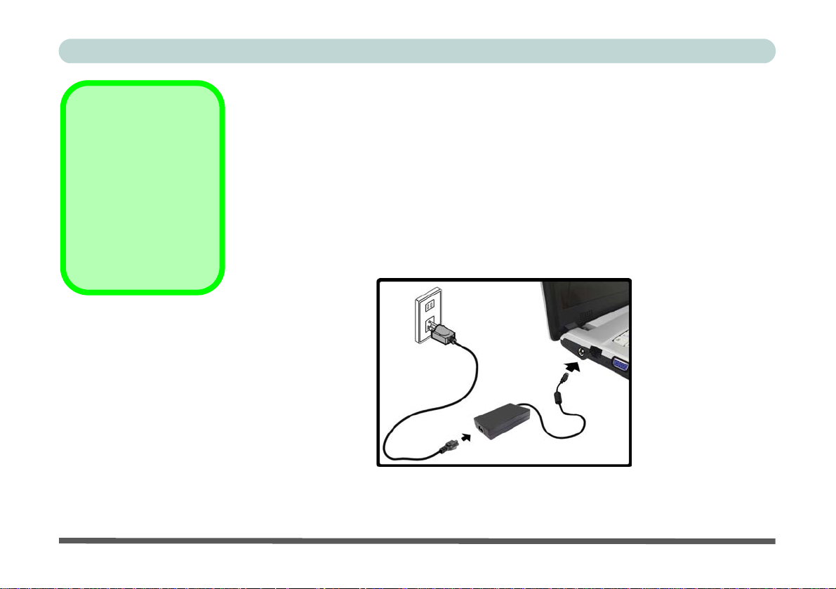
Figure 1
Computer with
AC/DC Adapter
Plugged-In
System Startup
1. Remove all packing materials.
2. Place the computer on a stable surface.
3. Securely attach any peripherals you want to use with the notebook (e.g. keyboard and
mouse) to their ports.
4. Attach the AC/DC adapter to the DC-In jack on the left of the computer, then plug the AC
power cord into an outlet, and connect the AC power cord to the AC/DC adapter.
5. Raise the lid/LCD to a comfortable viewing angle, and press the power button to turn the
computer “on”.
6. Adjust the LCD panel to a comfortable viewing angle.
7. The LED indicators show the power and battery status of the computer.
6 - System Startup

Concise User’s Guide
System Software
Your computer may already come with system software
pre-installed. Where this is not the case, or where you are
re-configuring your computer for a different system, you
will find this manual refers to the Microsoft Windows
Vista operating system
the drivers and utilities is available in Chapters 4 & 7 of
the expanded User’s Manual on the Device Drivers &
Utilities + User’s Manual CD-ROM.
*For information on the Windows XP OS see the Device
Drivers & Utilities + User’s Manual CD-ROM.
If you are installing/re-installing new system software, you will need
to install the appropriate drivers. D rivers ar e progra ms which ac t as
an interface between the computer and a hardware component e.g.
a wireless network module. It is very important that you install the
drivers in the order listed in Table 8, on page 22. You will be unable to use most advanced controls until the necessary drivers and
utilities are properly installed.
. Further information on installing
Drivers
Operating Systems Supported
Operating System &
Version Supported
In order to run Windows XP
*Windows XP
(Home or Professional)
Windows Vista (32-bit)
Home Basic Edition
without limitations or decreased
performance, your computer
requires a minimum 512MB of
system memory (RAM)
In order to run Windows Vista
without limitations or decreased
performance, your computer
requires a minimum 1GB of sys-
tem memory (RAM)
Table 1 - Operating Systems Supported
Note
Not Included
Operating Systems (e.g. Windows Vista/Windows XP)
and applications (e.g. word processing, spreadsheet and
database programs) have their own manuals, so please
consult the appropriate manuals.
System Software - 7
Concise User’s Guide
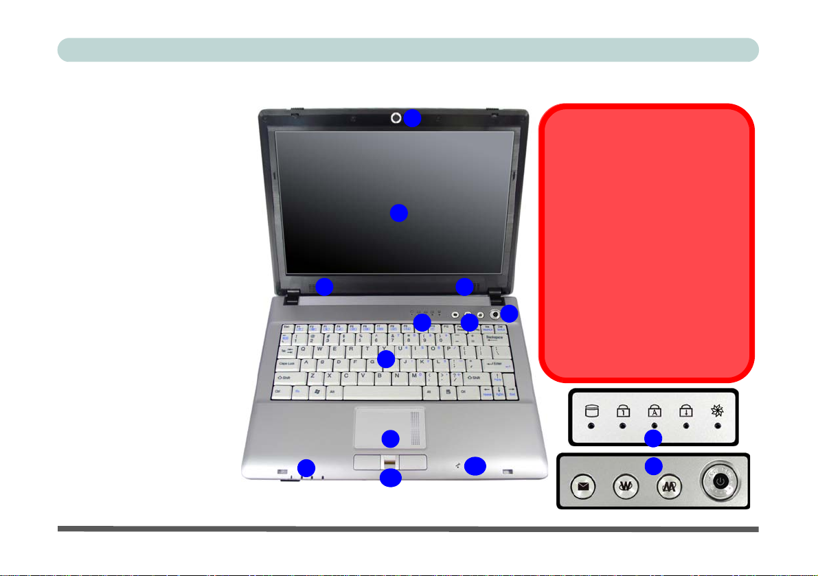
Figure 2
LCD Panel Open
1. Built-In PC Camera
(Optional)
2. LCD
3. Speakers
4. Power Button
5. Hot Key Buttons
6. LED Status Indicators
7. Keyboard
8. Touchpad & Buttons
9. LED Power &
Communication
Indicators
10. Fingerprint Module
(Optional)
11. Built-In Microphone
System Map: LCD Panel Open
1
The use of any portable electronic
2
33
4
6
5
7
8
9
10
11
transmission devices aboard aircraft is
usually prohibited. Make sure the module(s) are OFF if you are using the
computer aboard aircraft.
Use the key combinations to toggle
power to the 3.5G/WLAN/Bluetooth
modules, and check the LED indicator
icon to see if the modules are powered
on or not (see Table 5, on page 11/
Table 3, on page 9).
Wireless Device
Operation Aboard Aircraft
6
5
8 - System Map: LCD Panel Open
Concise User’s Guide
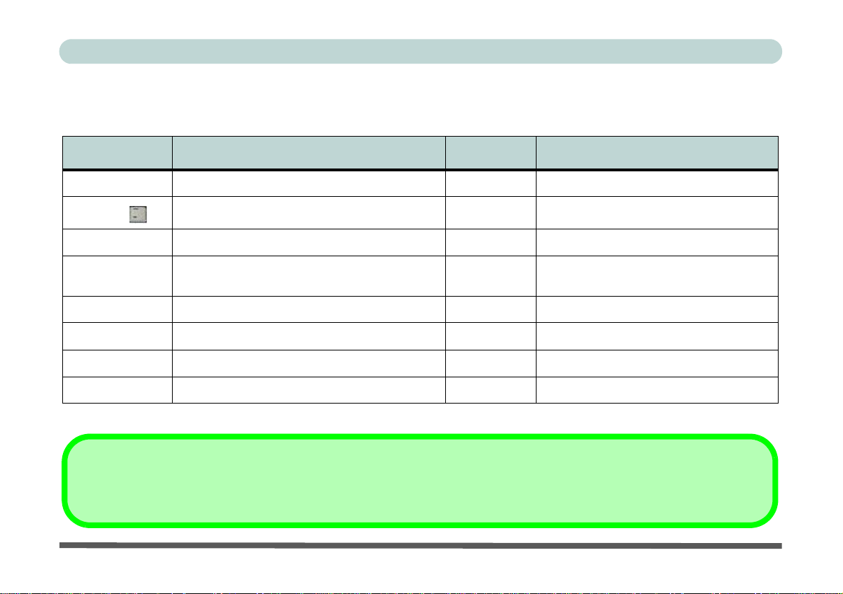
LED Indicators
The two sets of LED indicators (LED Status Indicators
and LED Power & Communication Indicators) on the
computer display helpful information about the current
status of the computer.
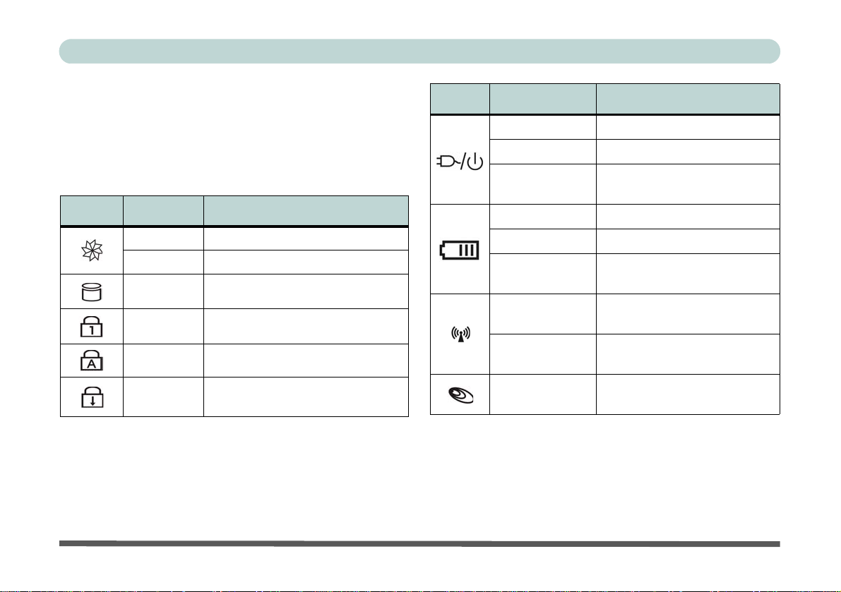
Icon Color Description
Green Silent Mode Activated (see over)
Off Normal Mode Activated (see over)
Green Hard Disk Activity
Green Number Lock Activated
Green Caps Lock Activated
Green
Table 2 - LED Status Indicators
Scroll Lock Activated (to activate
press Fn & Scr Lk)
Icon Color Description
Orange DC Power is Plugged In
Green The Computer is On
Blinking Green
Orange The Battery is Charging
Green The Battery is Fully Charged
Blinking Orange
Green
Orange
Green
The Computer is in Sleep
Mode
The Battery Has Reached
Critically Low Power Status
The (optional) Wireless LAN
Module is Powered On
The (optional) Bluetooth Mod-
ule is Powered On
The (optional) 3.5G Module is
Powered On
Table 3 - LED Power & Communication Indicators
System Map: LCD Panel Open - 9
Concise User’s Guide
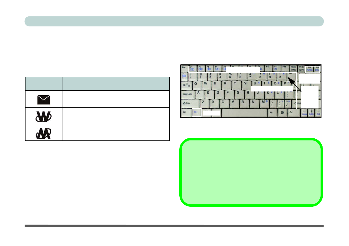
Hot Key Buttons & Keyboard
These buttons give instant access to the default Internet
browser and e-mail program, and allow you to toggle the
Silent Mode on/off with one quick button press.
Hot Key Function
Activate the Default E-Mail Browser
Activate the Default Internet Program
Toggle *Silent Mode (for power saving)
Table 4 - Hot Key Buttons
*When enabled, Silent Mode will reduce fan noise and
save power consumption. Note this may reduce computer
performance.
The keyboard has a numerical keypad for easy numeric
data input, and features Function Keys to allow you to
change operational features instantly.
Keypad
Function Keys
NumLk &
ScrLk
Numerical Keypad
Fn Key
3.5G
Module
Power
Toggle
Figure 3 - Keyboard
Other Keyboards
If your keyboard is damaged or you just want to make a
change, you can use any standard USB keyboard. The system will detect and enable it automatica lly. However special
functions/hot keys unique to the system’s regular keyboard
may not work.
10 - Hot Key Buttons & Keyboard
Concise User’s Guide
Function Keys
The function keys (F1 - F12 etc.) will act as hot keys when pressed while the Fn key is held down.
Fn Keys Function Fn Keys Function
Fn + ~ Play/Pause (in Audio/Video Programs) Fn + F7 Display Toggle
Fn + _
Fn + F1 TouchPad Toggle Fn + F9 Increase LCD Brightness
Fn + F2
Fn + F3 Mute Toggle Fn + F11 Wireless LAN Module Power Toggle
Fn + F4 Sleep Toggle Fn + F12 Bluetooth Module Power Toggle
Fn + F5 Decrease Audio Volume Fn + NumLk Number Lock Toggle
Fn + F6 Increase Audio Volume Fn + ScrLk Scroll Lock Toggle
(Press a key to or use TouchPad to turn on)
3.5G Module Power Toggle Fn + F8 Decrease LCD Brightness
Turn LCD Backlight Off
Fn + F10 PC Camera Module Power Toggle
Table 5 - Function Keys
Special Characters
Some software applications allow the number-keys to be used with Alt to produce special characters. These spe cial characters can only be produ ced by using
the numeric keypad. Regular number keys (in the upper row of the keyboard) will not work. Make sure that NumLk is on.
Function Keys - 11
Concise User’s Guide
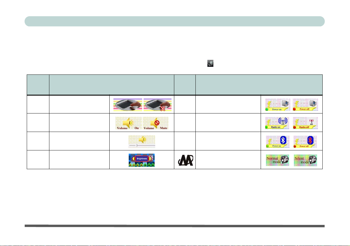
Function/Hot Key Indicators
The function keys (F1 - F12 etc.) will act as hot keys when pressed while the Fn key is held down. In addition to the
basic function key combinations; visual indicators (see the table below) are available when the hot key utility is installed (see “Hot Key” on page 24). After installing the driver an icon will appear in the taskbar.
Fn
Keys
Fn +
F1
Fn +
F3
Fn +
F5/F6
Fn +
F8/F9
Function
TouchPad Toggle
Mute Toggle
Volume Decrease/
Increase
Brightness Decrease/
Increase
Fn
Keys
Fn +
F10
Fn +
F11
Fn +
F12
Function
PC Camera Power
Toggle
WLAN Module Power
Toggle
Bluetooth Module Power
Toggle
*Silent Mode Toggle
Table 6 - Function/Hot Key Combo Indicators
*When enabled, Silent Mode will reduce fan noise and save power consumption. Note this may reduce computer performance.
12 - Function/Hot Key Indicators
Concise User’s Guide
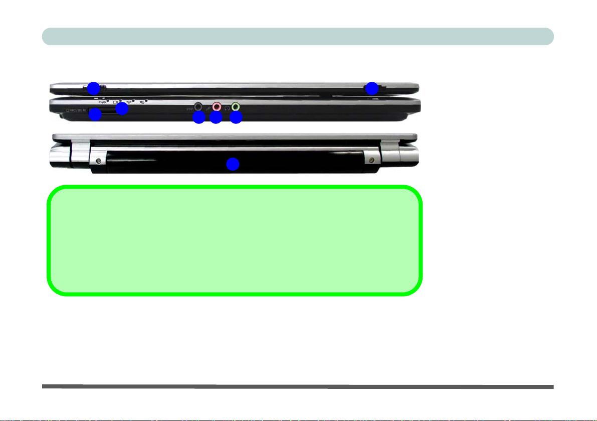
System Map: Front & Rear Views
1 1
2
3
The card reader allows you to use the most popular digital storage card formats:
MMC (MultiMedia Card) / SD (Secure Digital) / MS (Memory Stick) /
MS Pro (Memory Stick Pro) / MS Duo (requires PC adapter) /
Mini SD (requires PC adapter) / RS MMC (requires PC adapter)
54
6
7
7-in-1 Card Reader
Figure 4
Front & Rear Views
1. LCD Latches
2. LED Power &
Communication
Indicators
3. 7-in-1 Card Reader
4. S/PDIF-Out Jack
5. Microphone-In Jack
6. Headphone-Out Jack
7. Battery
System Map: Front & Rear Views - 13
Concise User’s Guide
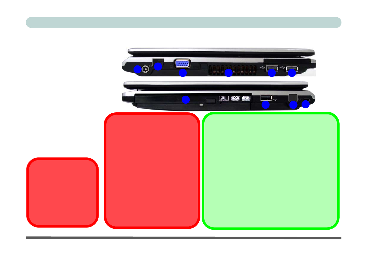
Figure 5
Left & Right Views
1. DC-In Jack
2. RJ-45 LAN Jack
3. External Monitor
Port
4. Vent/Fan Intake/
Outlet
5. 3 * USB 2.0 Ports
6. Optical Device Drive
Bay
7. RJ-11 Phone Jack
8. Security Lock Slot
Overheating
To prevent your computer
from overheating make sure
nothing blocks the vent(s)/
fan intake(s) while the computer is in use.
System Map: Left & Right Views
2
3 5
4
6
5
Changing DVD Regional Codes
Go to the Control Panel and double-click Device
Manager (Hardware and Sound), then click the +
next to DVD/CD-ROM drives. Double-click on the
DVD-ROM device to bring up the Properties dialog
box, and select the DVD Region (tab) to bring up the
control panel to allow you to adjus t the regional code.
DVD region detection is device dependent, not OSdependent. You can select your module’s region
code 5 times. The fifth selection is permanent. This
cannot be altered even if you change your operating
system or you use the module in another computer.
1
CD Emergency Eject
If you need to manually eject a CD/
DVD (e.g. due to an unexpected power
interruption) you may push the end of a
straightened paper clip into the emergency eject hole. Do not use a sharpened pencil or similar object that may
break and become lodged in the hole.
Media Warning
Don’t try to remove a floppy disk/CD/
DVD while the system is accessing it.
This may cause the system to “crash”.
5
8
7
14 - System Map: Left & Right Views

Concise User’s Guide
System Map: Bottom View
CPU
The CPU is not a user serviceable
part. Opening this compartment, or accessing the CPU in any way, may violate your warranty.
Overheating
To prevent your computer from overheating make sure nothing blocks the
Vent/Fan Intake while the computer is
in use.
2
Battery Information
Always completely discharge, then fully charge, a new battery before using it. Completely discharge and charge the battery at least once every 30 days or after about 20 partial discha rges.
1
Figure 6
Bottom View
1. Battery
2. Hard Disk Bay Cover
(3.5G Module
3
Location)
3. RAM & CPU Bay
Cover
System Map: Bottom View - 15

Concise User’s Guide
Windows Vista Start Menu & Control Panel
Most of the control panels, utilities and programs within Windows Vista (and most other Windows versions) are accessed from the Start menu. When you install programs and utilities they will be installed on your hard disk drive,
and a shortcut will usually be placed in the Start menu and/or the desktop. Right-click the Start menu icon , and
then select Properties if you want to customize the appearance of the Start menu.
Click here to toggle Classic View
Figure 7 - Start Menu & Control Panel
In many instances throughout this manual you will see an instruction to open the Control Panel. The Control Panel
is accessed from the Start menu, and it allows you to configure the settings for most of the key features in Windows
(e.g. power, video, network, audio etc.). Windows Vista provides basic controls for many of the features, however
many new controls are added (or existing ones are enhanced) when you install the drivers listed in Table 8, on
page 22. To see all controls it may be necessary to toggle to Classic View on.
16 - Windows Vista Start Menu & Control Panel

Concise User’s Guide
Video Features
You can switch display devices, and configure display options, from the Display Settings control panel (in Personalization) in Windows Vista and/or the SiS VGA Control Center.
To access Windows Vista Display Settings:
1. Click Start, and click Control Panel (or point to Settings and click Control Panel).
2. Click Adjust screen resolution under the Appearance and Personalization menu (or double-click Personalization >
Display Settings).
3. Move the slider to the preferred setting in Resolution: (Figure 8 on page 18).
4. Click the arrow, and scroll to the preferred setting In Colors: (Figure 8 on page 18).
5. Click Advanced Settings (button) (Figure 8 on page 18) to bring up the Advanced Settings tabs.
3
To access the SiS VGA Control Center:
1. Click Start, and click Control Panel (or point to Settings and click Control Panel).
2. Click SiS VGA Control Center (or click Appearance and Personalization > SiS VGA Control Center).
3. Click the top menu icons to bring up the appropriate control panel to adjust the settings.
4. You can also acc ess SiS VGA Control Center by right-clicking the SIS T ray t askbar icon , and selecting Control Center.
4
Video Memory
The system does not feature dedicated video memory, but automatically and dynamically allocates as much (up to
256MB maximum) system memory (RAM) as needed to the video system. The system returns whatever memory is
no longer needed to the operating system.
1
2
Video Features - 17

Concise User’s Guide
1
4
18 - Video Features
2
3
4
Figure 8 - Display Settings & SiS VGA Control Center
Multi-Mode
Clone

Concise User’s Guide
Display Devices & Options
Besides the built-in LCD, you can also use an external VGA monitor (CRT) or external Flat Panel Display connected to the external monitor port as your display device. The following display setting modes are available.
Display Setting Mode Description
Single
Clone
Multi-Mode
One of the connected displays is used as the display device
Both connected displays output the same view and may be configured independently
Both connected displays are treated as separate devices, may be configured independently
and act as a virtual desktop (this is similar to Extended Desktop in Windows)
Table 7 - Display Setting Mode
To Enable a Display Setting Mode
1. Attach your external display to the external monitor port and turn it on.
2. Go to the SIS VGA Control Center.
3. Click the appropriate icon for the display setting mode you wish to use.
4. Click Yes with 15 seconds in order to save the setting change.
5. You can adjust the display mode, change the status and clone Device 1 from the device list menu.
6. Click Apply > Yes to save any changes.
Video Features - 19

Concise User’s Guide
Power Options
The Power Options (Hardware and Sound menu) control panel icon in Windows (see page 16) allows you to
configure power management features for your computer. You can conserve power by means of power plans
and configure the options for the power button, sleep button, computer lid (when closed), display and sleep
mode from the left menu. Note that the Power saver plan may have an affect on computer performance.
Click to select one of the existing plans, or click Create a power plan in the left menu and select the options to
create a new plan. Click Change Plan Settings and click Change advanced power settings to access further con-
figuration options.
20 - Power Options
Note: Sleep is the default power saving state in Windows Vista
Figure 9 - Power Options

Concise User’s Guide
Audio Features
You can configure the audio options on your comp uter from the Sound control panel
in Windows, or from the Realtek HD Audio Manager icon in the taskbar/control
panel (right-click the taskbar icon to bring up an audio menu). The vo lume may a l so
be adjusted by means of the Fn + F5/F6 key combination.
Right-click the icon
to access the menu
above.
Sound Volume
Adjustment
The sound volume level is
set using the volume control within Windows (and
the volume function keys
on the computer). Click
the volume icon in the
taskbar to check the setting.
Figure 10
Realtek Audio
Manager
Audio Features - 21

Concise User’s Guide
Driver Installation
The Device Drivers & Utilities + User’s Manual CDROM (Win Vista) contains the drivers and utilities
necessary for the proper operation of the computer.
Table 8 lists what you need to install, and it is very im-
portant that the drivers are installed in the order in-
dicated.
Installation Methods
You may choose to install the drivers from the autorun
program, or install them manually.
Manual Driver Installation
Click the Browse CD button in the Drivers Installer application and browse to the executable file in the appropriate driver folder.
Driver Page
Video
Audio
Modem
LAN
TouchPad
CardReader
Hot Key
PC Camera Module
Wireless LAN Module
Bluetooth Module
3.5G Module
Fingerprint Reader Module
Table 8 - Driver Installation
page 23
page 23
page 23
page 23
page 24
page 24
page 24
page 25
page 28
page 29
page 33
page 36
22 - Driver Installation

Concise User’s Guide
Driver Installation Procedure
Insert the Device Drivers & Utilities + User’s Manual
CD-ROM and click Install Drivers (button)/Optional
(button).
Click to select the driver you wish to install, after installing each driver it will become grayed out (if you need to
reinstall any driver, click the Unlock button).
Video
1. Click 1.Install VGA Driver > Yes.
2. Click Yes (click Yes if you want to view the ReadMe
file).
3. Click Yes to restart the computer.
Audio
1. Click 2.Install Audio Driver > Yes.
2. Click Next.
3. Click Finish to restart the computer.
Modem
1. Click 3.Install Modem Driver > Yes.
2. Click OK.
3. The modem is ready for dial-up configuration.
Modem Country Selection
Go to the Phone and Modem Options control panel (Hard-
ware and Sound) and make sure the modem country se-
lection is appropriate for you.
LAN
1. Click 4.Install LAN Driver > Yes.
2. Click Next.
3. Click Finish > Finish to restart the computer.
4. The network settings can mow be configured.
Driver Installation - 23

Concise User’s Guide
TouchPad
1. Click 5.Install Touchpad Driver > Yes.
2. Click Next.
3. Click Finish > Restart Now to restart the computer.
CardReader
1. Click 6.Install Cardreader Driver > Yes.
2. Click Next > Next.
3. Click Finish to restart the computer.
Hot Key
1. Click 7.Install HOTKEY Driver > Yes.
2. Click Next > Install.
3. Click Finish > Finish to restart the computer.
Module Drivers
See the following pages for the driver installation procedures for any optional modules included in your purchase option.
Wireless Device
Operation Aboard Aircraft
The use of any portable electronic transmission devices aboard
aircraft is usually prohibited. Make sure the module(s) are OFF
if you are using the computer aboard aircraft.
Use the key combinations to toggle power to the WLAN/Blue-
tooth/3.5G modules, and check the LED indicator icon to see
if the modules are powered on or not.
24 - Driver Installation

Concise User’s Guide
PC Camera Module
There are 3 camera options available for this computer.
The 300K and 1.3M pixel camera modules use the
BisonCap application to capture video files, and the
2.0M pixel camera module uses the Video View appli-
cation to capture video files.
Before installing the driver. Use the Fn + F10 key combination to toggle power to the WLAN module.
PC Camera Driver Installation
1. Make sure the module is powered on, and then insert
the Device Drivers & Utilities + User’s Manual CD-
ROM into the CD/DVD drive.
2. Click Optional (button).
3. Click 1.PC Camera Driver, Web cam > Yes.
For the 1.3M or 300K Pixel Camera Module:
1. Choose the language you prefer and click Next >
Next.
2. Click Finish to restart the computer.
3. Run the BisonCap application program from the
BisonCam shortcut on the desktop, or from the
BisonCam item in the Start > Programs/All
Programs menu (if the hardware is turned off use the
Fn + F10 key combination to turn it on again).
For the 2.0M Pixel Camera Module:
1. Click Install.
2. Click to select Yes or No in answer to the power
system question.
3. Click to select Yes or No to enable/disable the
Digital Zoom function.
4. Click Finish > Finish to restart the computer.
5. Run the Video View application program from the
Video View shortcut on the desktop, or from the
USB2.0 PC Camera item in the Start > Programs/
All Programs menu (if the hardware is turned off
use the Fn + F10 key combination to turn it on
again).
PC Camera Module - 25

Concise User’s Guide
BisonCap/Video View
The BisonCap (for 300K and 1.3M pixel cameras) and
Video View (for 2.0M pixel camera) applications are
video viewers useful for general purpose video viewing
and testing, and can capture video files to .avi format.
1. Run the BisonCap/Video View program from the Start >
Programs/All Programs > BisonCam/USB2.0 PC Camera menu (it is recommended that you Set Capture File
from the File menu).
2. Go to the Capture menu heading and select Start
Capture (see
3. Click OK to start capturing the video, and press Esc to
stop the capture.
4. If you wish to, you may go to the File menu and select
Save Captured Video As..., choose a file name and
location, and then click Open (you can view the file using
the Windows Media Player).
*Note: On the first run of the BisonCap program (if you have
not set the captured file) you will be asked to cho ose a file
name and size for the captured file. Click Start Capture again.
*note below for BisonCap only).
PC Camera Audio Setup (all camera modules)
If you wish to capture video & audio with your camera,
it is necessary to setup the audio recording options in
Windows.
1. Click Start, and click Control Panel (or point to Settings
and click Control Panel).
2. Click Sound (Hardware and Sound).
3. Click Recording (tab).
4. Right-click Microphone (Realtek High Definition Audio)
and make sure the item is not disabled.
5. Double-click Microphone (or select Properties from the
right-click menu).
6. Click Levels (tab), and adjust the Microphone and
Microphone Boost sliders to the level required.
7. Click OK and close the control panels.
8. Ru n the BisonCap application program from the Start >
Programs/All Programs > BisonCam menu.
9. Go to the Devices menu heading and select Microphone
(Realtek....) (it should have a tick alongside it).
10. Go to the Capture menu heading and select Capture
Audio (it should have a tick alongside it).
26 - PC Camera Module

Concise User’s Guide
Zoom (Video View for 2.0M Pixel Camera only)
If you have enabled digital zoom when installing the
2.0M Pixel Camera driver you may use the Options >
Setting menu to zoom the camera in and out.
1. Run the Video View program.
2. Go to Options and scroll down to select Setting.
3. Use the slider to adjust the zoom level, and click OK to
save the setting.
Figure 11 - Setting
Snapshot (
Video View for 2.0M Pixel Camera only
You can capture still images by using the Snapshot command from the Capture menu.
1. Run the Video View program.
2. Go to Capture and select Snapshot.
3. The picture (in JPEG format) will be placed in the
Snapshot folder (do not move or rename the folder) on
the desktop.
Eliminating Screen Flicker
If you find that the video screen in the BisonCap/Video
View program is flickering, you can try to adjust the set-
ting in the Video Capture Filter options.
1. Ru n the BisonCap/Video View program.
2. Go to Options and scroll down to select Video Capture
Filter....
For Bison Cap:
3. Click either 50Hz or 60Hz under Frequency in Property
Page (tab).
For Video View:
4. Click either 50Hz or 60Hz under Flickering Reduction in
Image (tab).
)
PC Camera Module - 27

Concise User’s Guide
Wireless LAN Module
If you have included an 802.11b/g USB WLAN mod-
ule in your purchase option, make sure that the module
is on before installing the driver. Use the Fn + F11 key
combination to toggle power to the Wireless LAN
module.
802.11 b/g WLAN Driver Installation
1. Insert the Device Drivers & Utilities + User’s Manual CD-ROM into the CD/DVD drive.
2. Click Optional (button).
3. Click 2.Wireless Lan > Yes.
4. Click Finish to complete the installation.
Note: The operating system is the default setting for
Wireless LAN control in Windows Vista (see overleaf).
Connecting to a Wireless Network
Make sure the Wireless LAN module is turned on.
1. Click the taskbar wireless icon , and then click Connect
to a network (or right-click the icon , and then click
Connect to a network).
2. In the Show list, click to choose Wireless from the dropdown menu.
3. A list of currently availab le networks will appear.
4. Click a network, and then click Connect.
5. If you do not see a network you want to connect to, click
Set up a connection or network (a list of options will
appear allowing manual searching, and creating a new
network).
6. Move the cursor over the taskbar icon to see the
connection status (see below).
7. To disconnect from the wireless network you can click the
taskbar wireless icon , an d then select Connect or
disconnect to access the network menu, and click
Disconnect (or right-click the icon , and then click
Disconnect from).
28 - Wireless LAN Module

Bluetooth Module
If you have included a Bluetooth module in your purchase configuration, make sure that the module is on before installing the driver. Use the Fn + F12 key
combination to toggle power to the WLAN module.
Bluetooth Driver Installation
1. Insert the Device Drivers & Utilities + User’s Manual CD-ROM into the CD/DVD drive.
2. Click Optional (button).
3. Click 3.Bluetooth > Yes.
4. Choose the language you prefer, and click OK >
Next.
5. Click the button to accept the license agreement, and
then click Next.
6. Click Next > Install.
7. Click Finish, and the BlueSoleil icon will appear
on the desktop.
8. You can configure the settings at any time by going
to the IVT Corporation BlueSoleil - Main Window
(Start > Programs/All Programs > IVT BlueSoleil
> BlueSoleil), or by clicking the desktop icon .
Concise User’s Guide
b
Figure 12 - BlueSoleil Main Window & Help
Bluetooth Module - 29

Concise User’s Guide
Bluetooth Local Area Connection
You can check the Bluetooth connection status from the
Network and Sharing Center:
1. Use the Fn + F12 key combination to turn on the Bluetooth
module.
2. Run the IVT Corporation BlueSoleil program from the
desktop icon or Start menu.
3. Click Start, and click Control Panel (or point to Settings
and click Control Panel).
4. Double-click Network and Sharing Center (Network and
Internet).
5. Click Manage network connections.
6. The Bluetooth connection status will then be displayed in
the control panel.
7. To disconnect click File from the IVT Corporation
BlueSoleil - Main Window, and select Exit (the Local
Area Connection will then display “Network cable
unplugged”).
8. Do not use the close button or Fn + F12 key
combination before clicking File > Exit or the correct
status will not be displayed.
9. You can then use the Fn + F12 key combination to turn off
the Bluetooth module (check the LED icon for the
Bluetooth module power status).
Disconnecting
In order to have the Local Area Connection icon display the correct connection status, you will need to exit the IVT Corpora-
tion BlueSoleil - Main Window by clicking the File menu and
selecting Exit.
After exiting the program you can then use the Fn + F12 key
combination to turn off the Bluetooth module.
If you use the close button, or turn off the Bluetooth module (by
using the Fn + F12) the icon will not display the correct status.
30 - Bluetooth Module

Concise User’s Guide
3.5G Module
If you have included an optional 3.5G module in your
purchase option,follow the instructions below to install
the SIM card (which will be provided by your service
provider), and then install the application.
Power Safety Warning
Before you undertake any installation procedures, make sure
that you have turned off the power, and disconnected all peripherals and cables (including telephone lines). It is advisable
to also remove your battery in order to prevent accidentally
turning the machine on.
1. Turn off the computer, and turn it over and remove the
battery.
2. Locate the hard disk bay cover and remove screws &
.
2
3. Remove the hard disk bay cover .
4. Grip the tab and slide the hard disk in the direction of
4
arrow to remove it.
3
1
1
2
3
4
Figure 13 - Hard Disk Removal
5. Insert the SIM card as you would into your mobile phone.
6. The 3.5G module is pictured on the left, and the
installed SIM card on the right in Figure 14.
5
6
5
6
Figure 14 - Module & SIM Card Location
3.5G Module - 31

Concise User’s Guide
7. Slide the SIMLOCK in the direction of the arrow
(Figure 15) in order to release the lock and lift it up.
7
7
Figure 15 - SIMLOCK Unlock
8. Insert the SIM card as illustrated in (Figure 16) and close
the SIMLOCK.
9. Cl ose the SIMLOCK by pushing it in the direction of the
arrow in Figure 17.
Figure 17 - SIMLOCK Lock
10. Replace the hard disk assembly, cover, screws and
battery etc.
3G Watcher Application
With the 3.5G module and SIM card (provided by your
service provider) installed you may then install the 3G
Watcher application. The 3.G Watcher application allows you to directly access your 3.5G internet service
from the computer.
Figure 16 - Insert the SIM Card
32 - 3.5G Module

Concise User’s Guide
3G Watcher Application Installation
1. Make sure you enable power to the module by press-
ing the Fn + _( ) key combination (the icon
will be green).
2. Insert the Device Drivers & Utilities + User’s
Manual CD-ROM into the CD/DVD drive.
3. Click Optional (button).
4. Click 4.3GWatcher > Yes.
5. Click Next.
6. Choose your region, and click Next.
7. Click the button to accept the license agreement, and
then click Next.
8. Click Next > Install.
9. Click Finish, and the 3G Watcher icon will
appear on the desktop.
10.Y ou can access the 3G Watcher application from the
Start menu (Start > Programs/All Programs >
Sierra Wireless > 3G Watcher), or by clicking the
desktop icon .
Connecting to the Service Provider
1. Power on the 3.5 G modul e using the Fn + _() key
combination (the icon will be green).
2. You can access the 3G Watcher appli cation from the Start
menu (Start > Programs/All Programs > Sierra
Wireless > 3G Watcher), or by clicking the icon .
3. The software will run and display the service provider name
(connection information is obtained from the SIM card).
Figure 18 - 3G Watcher
4. Click Connect to begin the connection process.
5. The 3G Watcher application will then display the
connection information in the window.
Figure 19 - Connecting
3.5G Module - 33

Concise User’s Guide
6. When the connection is successful a taskbar notification
will appear (as below).
Figure 20 - Connected Taskbar Notification
7. You can then access the internet, download e-mail etc. as
per any internet connection.
8. While you are connected the taskbar icon will be green
(it will be red when the program is running but not
connected).
9. To disconnect click the Disconnect icon.
Figure 21 - 3G Watcher Connected
10. The program will disconnect from the service provider.
11. The module will still be on, and you will need to press the
() key combination (the icon will be off when
Fn + _
disconnected).
12. If you click the 3G Watcher close icon a message will
be displayed asking you to click OK to confirm the
program exit.
Figure 22 - Exit Warning
13. Exiting the program DOES NOT turn off the 3.5G mo du l e ,
and you will need to press the Fn + _
combination to turn off the module (pay careful attention to
this aboard aircraft - see “Wireless Device Operation
Aboard Aircraft” on page 8).
14. If the module is on and the computer enters a powersaving state, then the power status of the module on
resuming from the power-saving state will be as indicated
overleaf:
() key
34 - 3.5G Module

Concise User’s Guide
3.5G Module Power Status
• If the 3.5G module is on and the computer is Shut
Down; the module will be off when the computer starts
up.
• If the 3.5G module is on and the computer enters
Sleep; the module will be on when the computer
resumes from sleep.
• If the 3.5G module is on and the computer enters
Hibernate; the module will be off when the computer
starts up.
• If the 3.5G module is on and you Restart the computer; the module will be on when the computer starts
up.
Short Messaging Service
In addition to standard internet services you may also
send and receive SMS text messages using the 3G
Watcher program.
SMS
1. The SMS message indicator in the main window will
notify you of any new messages received.
2. Double-click the icon or select Tools > SM S Express.
3. Select the inbox folder and select any message to read it,
or Select File > New Message or click the New button to
prepare a new message.
For more details on SMS see 3GWatcher Online Help
from the Help > Help Topics menu.
3G Watcher Online Help
For further details on the 3G Watcher application you can
access the Online Help from the Help > Help Topics menu.
Click on any topic from the Contents window t o display details.
3.5G Module - 35

Concise User’s Guide
Help & Manual
Right-click the taskbar icon
to bring up the menu to
select Help.
Fingerprint Reader Module
If you have included the fingerprint reader in your purchase option (for Model B computers only) you will need to install the driver as per the instructions below.
Make sure you have administrator’s rights to your computer, and have a Windows password enabled for full security protection.
Insert the Device Drivers
& Utilities + User’s Manual CD-ROM and click op-
tional (button). Click
Unlock (button) and then
click 5.Fingerprint > Yes.
Before beginning the enrollment process it is recommended that you go through the fingerprint tutorial. To run the tutorial click Start > Programs/All Programs > Protector
Suite QL > Fingerprint Tutorial after installing the driver.
Fingerprint Reader Driver Installation
1. Insert the Device Drivers & Utilities + User’s Manual CD-ROM into the
Click Documentation to
open the folder containing
the manual in .pdf format.
CD/DVD drive.
2. Click Optional (button).
3. Click 5.Fingerprint > Yes.
To install the Adobe Acrobat Reader software to
read the file, i
vice Drivers & Utilities +
User’s Manual CD-ROM
and click User’s Manual
(button), and click Install
Acrobat Reader (button).
nsert the De-
4. Click Software Installation.
5. Click Next > Next > Next.
6. Click Finish > Yes to restart the computer.
36 - Fingerprint Reader Module

User Enrollment
1. Click Start > Programs/All Programs > Protector Suite QL > User Enrollment, or double
click the taskbar icon .
2. On the first run of the program you will be asked to click the button to accept the license, and
then click OK.
3. Click Next and select “Enrollment to the hard disk”, and click Finish.
4. If you have not set a Windows password you will be prompted to do so (note: If you have not
set a password Protector Suite QL cannot secure access to your computer).
5. Click Next.
6. You will then be pr ompted to enter your Windows password.
7. Click Next > Next (if you have the “Run interactive tutorial” tickbox selected you will run
through the Fingerprint Tutorial).
8. Click Next for each window of the tutorial (you can click the button to “skip tutorial” at any
time).
Concise User’s Guide
Figure 23
Enroll to the
Hard Disk
Fingerprint Reader Module - 37

Concise User’s Guide
Fingerprint
Enrollment
Note that it is strongly recommended that you enroll
more than one finger in
case of injury etc.
Figure 24
Fingerprint
Enrollment
9. Click the button above any of the fingers to begin the enrollment process for that finger.
10. Swipe the finger three times to enroll that finger.
11. Repeat the process for all the fingers you wish to enroll (see sidebar), and then click Next.
12. Click Finish.
13. Click any of the headings under “Learn more about:” to get more information on any topic.
14. Click Close.
15. Restart the computer.
16. Right-click the taskbar icon to bring up the menu that allows you to Edit Fingerprints,
Start Control Center, access the Help menu etc. You can also run the Control Center etc.
from the Protector Suite QL item in the Programs/All Programs menu.
38 - Fingerprint Reader Module

17. See “Help & Manual” on page 36 for further details.
18. If you swipe your finger over the reader at any time you can access the Biomenu to lock the
computer, register websites, open the Control Center and access the Help menu.
19. The Control Center allows you to change the Settings, enroll Fingerprints and get Help.
Concise User’s Guide
Figure 25
Control Center &
Biomenu
Fingerprint Reader Module - 39

Concise User’s Guide
Troubleshooting
Problem Possible Cause - Solution
The DVD regional codes
can no longer be changed.
The sound cannot be
heard or the volume is
very low.
The TouchPad doesn’t
work.
The Wireless LAN/
Bluetooth/3.5G modules
cannot be detected.
The PC Camera module
cannot be detected.
The Wireless LAN/
Bluetooth/3.5G or PC
Camera modules cannot
be configured.
40 - Troubleshooting
The code has been changed the maximum 5 times. DVD region detection i s device depen dent,
not OS-dependent. You can select your module’s region code 5 times. The fifth selection is
permanent. This cannot be altered even if you change yo ur operating system or you use the
module in another computer.
The volume might be set too low. Check the volume control in the Volume Control Panel in the
Windows taskbar, or use the key combination Fn + F5 and F6 (see “Audio Features” on
page 21) to adjust.
The Touchpad has been disabled. Press the Touchpad toggle (Fn + F1) key combination (make
sure you have installed the Touchpad driver.
The modules are off. Check the LED indicators / to see if the WLAN/Bluetooth/3.5G
module is on or off. If the LED indicator is off, then press the Fn + F11 (WLAN), Fn + F12
(Bluetooth) or Fn + _
The module is off. Press the Fn + F10 key combination in order to enable the module. Run the
BisonCap program to view the camera picture.
The driver(s) for the module(s) have not been installed. Make sure you have installed the driver
for the appropriate module.
(3.5G) key combination(s) in order to enable the modules.

Concise User’s Guide
Specifications
Latest Specification Information
The specifications listed in this Appendix are correct at t he time of going to press. Certain it ems (particularly processor types/speeds
and CD/DVD device types) may be changed, delayed or updated due to t he manufacturer's rel ease schedule. Check with y our service center for details.
Feature Specification
Processor Intel® Core™2 Duo Processor
(478-pin) Micro-FC-PGA Package
T7200/ T7400/ T7600
Intel® Core™2 Duo Processor
(478-pin) Micro-FC-PGA Package
T5500/ T5600
Intel® Core™ Duo Processor
(478-pin) Micro-FC-PGA Package
T2300/ T2400/ T2500/ T2600/ T2700
Intel® Celeron® M Processor
(478-pin) Micro-FCPGA Package
410/ 420/ 430/ 440/ 450
65nm (65 Nanometer) Process Technology
4MB On-die L2 Cache & 667MHz FSB
2.0/ 2.16/ 2.33 GHz
65nm (65 Nanometer) Process Technology
2MB On-die L2 Cache & 667MHz FSB
1.66/ 1.83 GHz
65nm (65 Nanometer) Process Technology
2MB On-die L2 Cache & 667MHz FSB
1.66/ 1.83/ 2.0/ 2.16/ 2.33 GHz
65nm (65 Nanometer) Process Technology
1MB On-die L2 Cache & 533MHz FSB
1.46/ 1.60/ 1.73/ 1.86/ 2.0 GHz
Specifications - 41

Concise User’s Guide
Feature Specification
Core Logic SiS M671 + SiS968 Chipset
LCD 12.1" WXGA (1280 * 800) Glare / Non Glare TFT LCD
Memory Two 200 Pin SO-DIMM Sockets Supporting DDRII (DDR2) 533/667 MHz
64-bit Wide DDRII (DDR2) Data Per Channel
Memory Expandable up to 4GB (256/ 512/ 1024/ 2048 MB DDRII Modules)
Video Adapter SiS M671 Integrated Video
High Performance 2D/3D Graphics Accelerator
Shared Memory Architecture up to 256MB
Supports Microsoft DirectX 9.0
Supports Vertex Shader 2.0 and Pixel Shader 2.0
Security Security (Kensington® Type) Lock Slot
Fingerprint ID Reader Module (Factory Option)
BIOS One 8Mb SPI Flash ROM Phoenix™ BIOS
Storage One Changeable 12.7mm(h) Optical Device (CD/DVD) Type Drive (see “Optional” on page 44 for
drive options)
Easy Changeable 2.5" 9.5 mm (h) SATA (Serial) HDD
BIOS Password
42 - Specifications

Feature Specification
Concise User’s Guide
Audio High Definition Audio (HDA)
Compliant with Microsoft UAA (Universal Audio
Architecture)
Direct Sound 3D™ Compatible
EAX™ 1.0 & 2.0 Compatible
Keyboard &
Pointing Device
Interface Three USB 2.0 Ports
Card Reader Embedded 7-in-1 Card Reader (MS/ MS Pro/ SD/ Mini SD/ MMC/ RS MMC/ MS Duo) Note: MS Duo/
ExpressCard Slot One ExpressCard/34(54) Slot
Communication 10M/100Mb Base-T Ethernet LAN
Winkey Keyboard Built-In TouchPad with Scrolling Function
One Headphone-Out Jack
One Microphone-In Jack
One S/PDIF Out Jack
One Internal Microphone
Mini SD/ RS MMC Cards require a PC adapter
56K MDC Modem V.90 & V.92 Compliant
802.11 b/g USB Wireless LAN Module (Option)
Bluetooth 2.0 + EDR (Enhanced Data Rate) Module (Factory Option)
300K, 1.3M or 2.0M Pixel USB PC Camera Module (Factory Option)
UMTS/HSPDA-based 3.5G Module with Mini Card Interface (Factory Option)
A3D™ Compatible
S/PDIF Digital Output
2 * Built-In Speakers
Built-In Microphone
One RJ-11 Modem Jack
One RJ-45 LAN Jack
One DC-in Jack
One External Monitor Port
Specifications - 43

Concise User’s Guide
Feature Specification
Power
Management
Power Full Range AC/DC Adapter AC input 100 - 240V, 50 - 60Hz, DC Output 19V, 3.42A (65 Watts)
Battery 4 Cell Smart Lithium-Ion Battery Pack, 14.8V/2.4AH
Environmental
Spec
Dimensions
& Weight
Optional Optical Drive Module Options:
Supports ACPI 3.0 Supports Wake on LAN
Supports Wake on USB
Supports Resume from Modem Ring
8 Cell Smart Lithium-Ion Battery Pack, 14.8V/4.4AH (Option)
Temperature
Operating: 5°C ~ 35°C
Non-Operating: -20°C ~ 60°C
299mm (w) * 219mm (d) * 26.5-35.7mm (h) 1.8 kg With 4 Cell Battery and ODD
DVD/CD-RW Combo Drive Module
Super Multi Drive Module
USB Floppy Disk Drive
802.11 b/g USB Wireless LAN Module
8 Cell Smart Lithium-Ion Battery Pack
Relative Humidity
Operating: 20% ~ 80%
Non-Operating: 10% ~ 90%
300K, 1.3M or 2.0M Pixel USB PC Camera
Module (Factory Option)
Bluetooth 2.0 + EDR (Enhanced Data Rate)
Module (Factory Option)
UMTS/HSPDA-based 3.5G Module with Mini Card
Interface (Factory Option)
Fingerprint ID Reader Module (Factory Option)
44 - Specifications
 Loading...