

Clevo M570RU, M571RU service manual

Notebook Computer
M570RU/M571RU
Service Manual
Preface
Preface
I

Preface
Preface
Notice
The company reserves the right to revise this publication or to change its contents without notice. Information contained
herein is for reference only and does not constitute a commitment on the part of the manufacturer or any subsequent vendor. They assume no responsibility or liability for any errors or inaccuracies that may appear in this publication nor are
they in anyway responsible for any loss or damage resulting from the use (or misuse) of this publication.
This publication and any accompanying software may not, in whole or in part, be reproduced, translated, transmitted or
reduced to any machine readable form without prior consent from the vendor, manufacturer or creators of this publication, except for copies kept by the user for backup purposes.
Brand and product names mentioned in this publication may or may not be copyrights and/or registered trademarks of
their respective companies. They are mentioned for identification purposes only and are not intended as an endorsement
of that product or its manufacturer.
Version 1.0
July 2007
Trademarks
Intel Core is a trademarks/registered trademarks of Intel Corporation.
is a trademark of SRS Labs, Inc.
Other brand and product names are trademarks and./or registered trademarks of their respective companies.
II
WOW
technology is incorporated under license from SRS Labs, Inc.

About this Manual
This manual is intended for service personnel who have completed sufficient training to undertake the maintenance and
inspection of personal computers.
It is organized to allow you to look up basic information for servicing and/or upgrading components of the M570RU/
M571RU series notebook PC.
The following information is included:
Chapter 1, Introduction, provides general information about the location of system elements and their specifications.
Chapter 2, Disassembly, provides step-by-step instructions for disassembling parts and subsystems and how to upgrade
elements of the system.
Preface
Appendix A, Part Lists
Appendix B, Schematic Diagrams
Preface
III

Preface
IMPORTANT SAFETY INSTRUCTIONS
Follow basic safety precautions, including those listed below, to reduce the risk of fire, electric shock and injury to persons when using any electrical equipment:
1. Do not use this product near water, for example near a bath tub, wash bowl, kitchen sink or laundry tub, in a wet
basement or near a swimming pool.
2. Avoid using a telephone (other than a cordless type) during an electrical storm. There may be a remote risk of electrical shock from lightning.
3. Do not use the telephone to report a gas leak in the vicinity of the leak.
4. Use only the power cord and batteries indicated in this manual. Do not dispose of batteries in a fire. They may
explode. Check with local codes for possible special disposal instructions.
5. This product is intended to be supplied by a Listed Power Unit (DC Output 20V, 6A minimum AC/DC Adapter).
Preface
IV
CAUTION
Always disconnect all telephone lines from the wall outlet before servicing or disassembling this equipment.
TO REDUCE THE RISK OF FIRE, USE ONLY NO. 26 AWG OR LARGER,
TELECOMMUNICATION LINE CORD
This Computer’s Optical Device is a Laser Class 1 Product
Instructions for Care and Operation
The notebook computer is quite rugged, but it can be damaged. To prevent this, follow these suggestions:
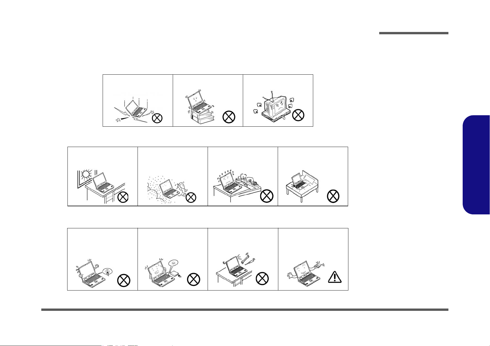
1. Don’t drop it, or expose it to shock. If the computer falls, the case and the components could be damaged.
Preface
Do not expose the computer
to any shock or vibration.
Do not place it on an unstable
surface.
Do not place anything heavy
on the computer.
2. Keep it dry, and don’t overheat it. Keep the computer and power supply away from any kind of heating element. This
is an electrical appliance. If water or any other liquid gets into it, the computer could be badly damaged.
Do not expose it to excessive
heat or direct sunlight.
Do not leave it in a place
where foreign matter or moisture may affect the system.
Don’t use or store the computer in a humid environment.
Do not place the computer on
any surface which will block
the vents.
3. Follow the proper working procedures for the computer. Shut the computer down properly and don’t forget to save
your work. Remember to periodically save your data as data may be lost if the battery is depleted.
Do not turn off the power
until you properly shut down
all programs.
Do not turn off any peripheral
devices when the computer is
on.
Do not disassemble the computer by yourself.
Perform routine maintenance
on your computer.
Preface
V
Preface
Power Safety
Warning
Before you undertake
any upgrade procedures, make sure that
you have turned off the
power, and disconnected all peripherals
and cables (including
telephone lines). It is
advisable to also remove your battery in
order to prevent accidentally turning the
machine on.
4. Avoid interference. Keep the computer away from high capacity transformers, electric motors, and other strong mag-
netic fields. These can hinder proper performance and damage your data.
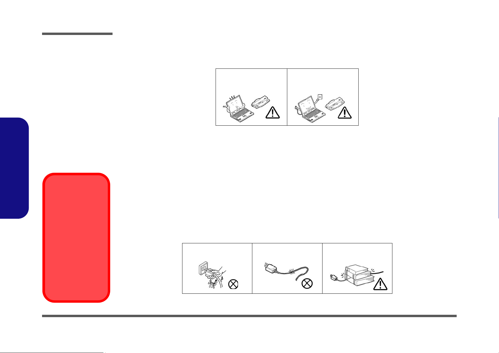
5. Take care when using peripheral devices.
Preface
VI
Use only approved brands of
peripherals.
Unplug the power cord before
attaching peripheral devices.
Power Safety
The computer has specific power requirements:
• Only use a power adapter approved for use with this computer.
• Your AC adapter may be designed for international travel but it still requires a steady, uninterrupted power supply. If you are
unsure of your local power specifications, consult your service representative or local power company.
• The power adapter may have either a 2-prong or a 3-prong grounded plug. The third prong is an important safety feature; do
not defeat its purpose. If you do not have access to a compatible outlet, have a qualified electrician install one.
• When you want to unplug the power cord, be sure to disconnect it by the plug head, not by its wire.
• Make sure the socket and any extension cord(s) you use can support the total current load of all the connected devices.
• Before cleaning the computer, make sure it is disconnected from any external power supplies (i.e. AC/DC adapter or car
adapter).
Do not plug in the power
cord if you are wet.
Do not use the power cord if
it is broken.
Do not place heavy objects
on the power cord.

Battery Precautions
Battery Disposal
The product that you have purchased contains a rechargeable battery. The battery is recyclable. At the end of
its useful life, under various state and local laws, it may be illegal to dispose of this battery into the municipal
waste stream. Check with your local solid waste officials for details in your area for recycling options or proper
disposal.
Caution
Danger of explosion if battery is incorrectly replaced. Replace only with the same or equivalent type recommended by the manufacturer. Discard used battery according to the manufacturer’s instructions.
• Only use batteries designed for this computer. The wrong battery type may explode, leak or damage the computer.
• Do not remove any batteries from the computer while it is powered on.
• Do not continue to use a battery that has been dropped, or that appears damaged (e.g. bent or twisted) in any way. Even if the
computer continues to work with a damaged battery in place, it may cause circuit damage, which may possibly result in fire.
• Recharge the batteries using the notebook’s system. Incorrect recharging may make the battery explode.
• Do not try to repair a battery pack. Refer any battery pack repair or replacement to your service representative or qualified service
personnel.
• Keep children away from, and promptly dispose of a damaged battery. Always dispose of batteries carefully. Batteries may explode
or leak if exposed to fire, or improperly handled or discarded.
• Keep the battery away from metal appliances.
• Affix tape to the battery contacts before disposing of the battery.
• Do not touch the battery contacts with your hands or metal objects.
Preface
Preface
VII

Preface
Preface
Related Documents
You may also need to consult the following manual for additional information:
User’s Manual on CD
This describes the notebook PC’s features and the procedures for operating the computer and its ROM-based setup program. It also describes the installation and operation of the utility programs provided with the notebook PC.
VIII

Contents
Preface
Introduction ..............................................1-1
Overview .........................................................................................1-1
System Specifications .....................................................................1-2
External Locator - Top View with LCD Panel Open ......................1-6
External Locator - Front & Rear View ............................................1-7
External Locator - Left & Right Side View ...................................1-8
External Locator - Bottom View .....................................................1-9
Mainboard Overview - Top (Key Parts) .......................................1-10
Mainboard Overview - Bottom (Key Parts) ..................................1-11
Mainboard Overview - Top (Connectors) .....................................1-12
Mainboard Overview - Bottom (Connectors) ...............................1-13
Disassembly ...............................................2-1
Overview .........................................................................................2-1
Maintenance Tools ..........................................................................2-2
Connections .....................................................................................2-2
Maintenance Precautions .................................................................2-3
Disassembly Steps ...........................................................................2-4
Removing the Battery ......................................................................2-5
Removing the Hard Disk Drive ....................................................... 2-6
Removing the Optical (CD/DVD) Device ......................................2-8
Removing the System Memory (RAM) .......................................... 2-9
Removing the Processor ................................................................2-10
Removing the VGA Card ..............................................................2-12
Removing the Wireless LAN Module ........................................... 2-13
Removing the TV Tuner Card ....................................................... 2-14
Removing the Bluetooth Module ..................................................2-15
Removing the Keyboard ................................................................2-16
Removing the Modem ...................................................................2-17
Part Lists ..................................................A-1
Part List Illustration Location ........................................................ A-2
Top ................................................................................................. A-3
Top without Fingerprint ................................................................. A-4
Bottom ........................................................................................... A-5
LCD ............................................................................................... A-6
VGA ............................................................................................... A-7
DVD-Dual RW Drive .................................................................... A-8
Combo Drive ................................................................................. A-9
Schematic Diagrams................................. B-1
SYSTEM BLOCK DIAGRAM ......................................................B-2
Merom 1/2 ......................................................................................B-3
Merom 2/2 ......................................................................................B-4
Crestline 1/5 Host ...........................................................................B-5
Crestline 2/5 PEG ...........................................................................B-6
Crestline 3/5 DDR ..........................................................................B-7
Crestline 4/5 GND ..........................................................................B-8
Crestline 5/5 Power .........................................................................B-9
DDRII SO-DIMM 0 .....................................................................B-10
DDRII SO-DIMM 1 .....................................................................B-11
LCD, CPU Fan ..............................................................................B-12
ICH8-M 1/4 SATA .......................................................................B-13
ICH8-M 2/4 (PCI, USB) ...............................................................B-14
ICH8-M 3/4 FWH .........................................................................B-15
ICH8-M 4/4 ..................................................................................B-16
CD-ROM, PC-Beep, T-P, USB2.0*4 ...........................................B-17
Clock Generator, CCD ..................................................................B-18
PCI-E LAN RTL8111B ................................................................B-19
Card Reader MR510 .....................................................................B-20
New Card ......................................................................................B-21
KBC-ITE IT8512 ..........................................................................B-22
Preface
IX

Preface
Mini Card, TPM, Super I/O ......................................................... B-23
LED .............................................................................................. B-24
Azalia Codec ALC883 ................................................................. B-25
Audio Amp ................................................................................... B-26
CRT, INV, MDC, BT, PWRGD .................................................. B-27
Power GPU/1.25VS ..................................................................... B-28
Power 1.5VS/1.05VS ................................................................... B-29
Power 1.8V/0.9V .......................................................................... B-30
Power 3.3V/5V ............................................................................. B-31
Power, Hole .................................................................................. B-32
VCORE for Merom CPU ............................................................. B-33
Mini -PCI, S-Video, CIR .............................................................. B-34
MXM PCI-E Type-IV .................................................................. B-35
CHARGER, DC-IN ...................................................................... B-36
Board to Board Connector ............................................................ B-37
Button Board ................................................................................ B-38
Preface
COM Port Board .......................................................................... B-39
Click Board .................................................................................. B-40
Second SATA HDD Board .......................................................... B-41
FingerPrint Board ......................................................................... B-42
IEEE 1394 VT6311S .................................................................... B-43
SRS ............................................................................................... B-44
Updating the FLASH ROM BIOS......... C-1
X

1: Introduction
Overview
This manual covers the information you need to service or upgrade the M570RU/M571RU series notebook computer.
Information about operating the computer (e.g. getting started, and the Setup utility) is in the User’s Manual. Information
about drivers (e.g. VGA & audio) is also found in User’s Manual. That manual is shipped with the computer.
Operating systems (e.g. Windows XP, etc.) have their own manuals as do application software (e.g. word processing and
database programs). If you have questions about those programs, you should consult those manuals.
Introduction
The M570RU/M571RUseries notebook is designed to be upgradeable. See “Disassembly” on page 2 - 1 for a detailed
description of the upgrade procedures for each specific component. Please note the warning and safety information indicated by the “” symbol.
The balance of this chapter reviews the computer’s technical specifications and features.
1.Introduction
Overview 1 - 1
Introduction
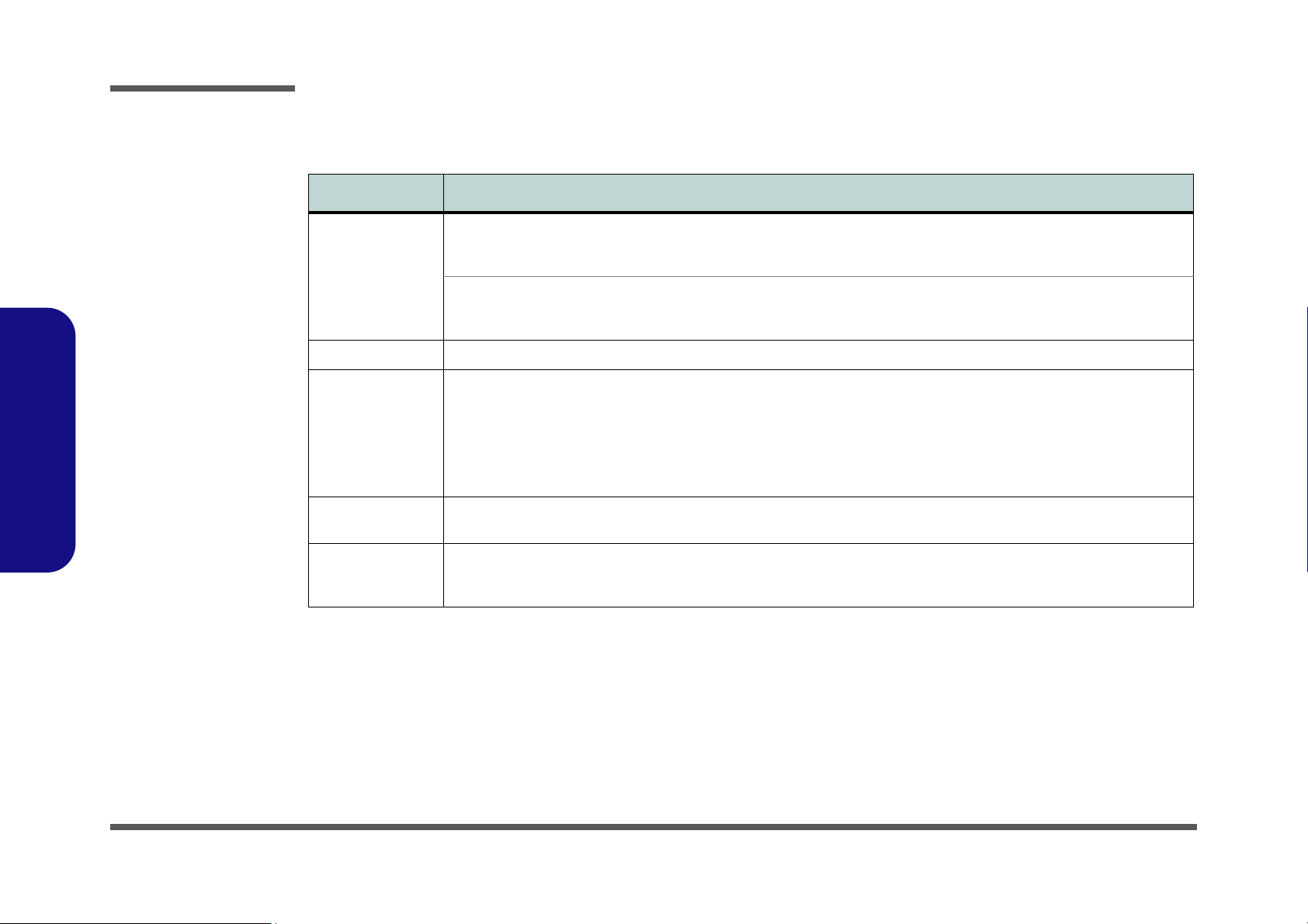
System Specifications
Feature Specification
1.Introduction
Processor Types Intel® Core™2 Duo Processor
(478-pin) Micro-FC-PGA Package, Socket P
T7100
Intel® Core™2 Duo Processor
(478-pin) Micro-FC-PGA Package, Socket P
T7300/ T7500/ T7700
Core Logic Intel(R) PM965 + ICH8M Chipset
LCD Flat Panel TFT (For One of the Following Options)
17" WXGA (1280 * 800) TFT LCD (Glare Type or Non Glare Type)
OR
17" WSXGA+ (1600 * 1050) TFT LCD (Glare Type)
OR
17" WUXGA (1920 * 1200) TFT LCD (Glare Type)
Security Security (Kensington® Type) Lock Slot
Trusted Platform Module V1.2 (Factory Option)
Memory Two 200 Pin SO-DIMM Sockets Supporting DDRII (DDR2) 533 / 667 MHz
64-bit Wide DDRII (DDR2) Data Channel
Memory Expandable up to 4GB (256/ 512/ 1024/ 2048 MB DDRII Modules)
65nm (65 Nanometer) Process Technology
2MB On-die L2 Cache & 800MHz FSB
1.80 GHz
65nm (65 Nanometer) Process Technology
4MB On-die L2 Cache & 800MHz FSB
2.0/ 2.2/ 2.4 GHz
BIOS Password
Fingerprint Reader Module (Factory Option)
1 - 2 System Specifications
Feature Specification
Video Card Options
Note that card types, specifications and drivers
are subject to continual updates and changes.
Check with your service center for the latest details on video cards supported.
Introduction
Video Adapter
Options
BIOS One 8Mb Flash ROM Phoenix™ BIOS
Storage One Changeable 12.7mm(h) Optical Device (CD/DVD) Type Drive (see “Optional” on page 1 - 5 for drive options)
Card Reader Embedded 7-in-1 Card Reader (MS/ MS Pro/ SD/ Mini SD/ MMC/ RS MMC/ MS Duo)
Audio Intel® High Definition Audio Interface (HDA)
NVIDIA GeForceGo 7950
G71GM-UU Modular
512MB DDR3 Video Ram On Board
PCI-Express * 16
MS DirectX® 9.0 compatible
MXM-IV
NVIDIA GeForce 8700M GT
NB8E-SE Modular
512MB DDR3 Video Ram On Board
PCI-Express * 16
MS DirectX® 10.0 compatible
MXM-III
Supports HDCP
Easy Changeable 2.5" 9.5 mm (h) HDD with SATA (Serial) Interface
Note: MS Duo/ Mini SD/ RS MMC Cards Require a PC Adapter
S/PDIF Digital Output 7.1CH
3D Stereo Enhanced Sound System
SRS WOW Surround Sound Technology Inside
Sound-Blaster PRO™ Compatible
Built-In Microphone
3 * Built-In Speakers
(Two 1.5W, 8
Ω, One Sub Woofer 1.5W 8Ω,)
1.Introduction
Keyboard &
Pointing Device
ExpressCard Slot ExpressCard/34/54 Slot
Full Size Winkey Keyboard with Numeric Keypad Built-In TouchPad (Scroll Functionality Included)
System Specifications 1 - 3
Introduction
Feature Specification
1.Introduction
I/O Ports Four USB 2.0 Ports
One DVI-Out Port (Supports Dual Link)
One Headphone/Speaker-Out Jack
One Microphone-In Jack
One S/PDIF Out Jack
One Line-In Jack for Audio Input
One Serial Port
One Mini-IEEE1394a Port
One Infrared Transceiver
Communication Built-In 56K MDC Modem with V.90 & V.92 Compliant
Built-In Gigabit Ethernet LAN
Wireless LAN Module:
Intel® Wireless LAN WiFi Link 4965AGN with MiniCard,
PCIe Interface (Option)
Operating
Systems
Supported
Power
Management
Power
Windows XP SP2 Windows Vista 64bit
Supports ACPI 3.0 Supports Resume from Modem Ring
Full Range AC/DC Adapter – AC in 100 - 240V, 50 - 60Hz DC Output 20V, 6.A (120 Watts)
One RJ-11 Modem Jack
One RJ-45 Giga LAN Jack
One DC-In Jack
One 7-Pin S-Video-Out Jack for TV & HDTV Output
One CATV Antenna (Analog/Digital) Jack (Functions with
Optional TV Tuner Module)
One Consumer Infrared Transceiver
(Functions with Optional TV Tuner Module)
TV Tuner Module (Hybrid OR Windows MCE options) with
Mini-PCI Interface (Factory Option)
Bluetooth 2.0 + EDR (Enhanced Data Rate) Module
(Factory Option)
1.3M Pixel USB 2.0 PC Camera Module (Factory
Option)
Home Premium/ Business/ Enterprise/ Ultimate
Supports Wake on LAN
Environmental
Spec
Physical
Dimensions &
Weight
1 - 4 System Specifications
Easy Changeable 8-Cell Smart Lithium-Ion 4400mAH Main Battery
Tempera tur e
Operating: 5°C ~ 35°C
Non-Operating: -20°C ~ 60°C
397mm (w) * 280.5mm (d) * 25.6 ~ 45.6mm (h) Around 3.95kg (+/- 5%) with 8 Cell Battery
Relative Humidity
Operating: 20% ~ 80%
Non-Operating: 10% ~ 90%
Feature Specification
Introduction
Optional Optical Drive Module Options:
DVD/CD-RW Combo Drive Module
DVD-Super Multi Drive Module
Intel® Wireless LAN WiFi Link 4965AGN with MiniCard,
PCIe Interface
Bluetooth 2.0 + EDR (Enhanced Data Rate) Module
(Factory Option)
1.3M Pixel USB 2.0 PC Camera Module (Factory
Option)
Trusted Platform Module TGC V1.2 Compliant (Factory
Option)
Fingerprint Reader Module (Factory Option)
TV Tuner Module Options:
(All Factory Options):
Hybrid (Digital & Analog) TV Tuner Module with Mini-PCI
Interface
OR
MCE TV Tuner Module with Mini-PCI Interface for
Windows Vista/XP Media Center Edition
1.Introduction
System Specifications 1 - 5
Introduction
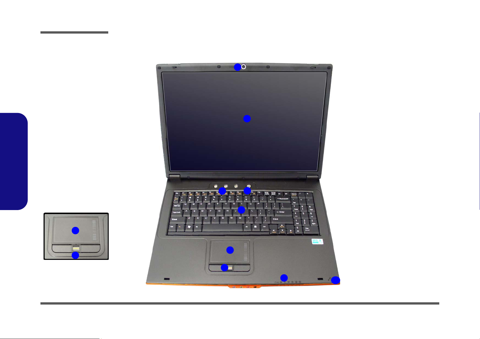
Figure 1
Top View
1. Optional Built-In PC
Camera
2. LCD
3. Hot Key Buttons
4. Power Button
5. Keyboard
6. TouchPad and
Buttons
7. Fingerprint Reader
Module (optional)
8. LED Indicators
9. Built-In Microphone
7
6
5
8
9
4
3
1
2
7
6
External Locator - Top View with LCD Panel Open
1.Introduction
1 - 6 External Locator - Top View with LCD Panel Open
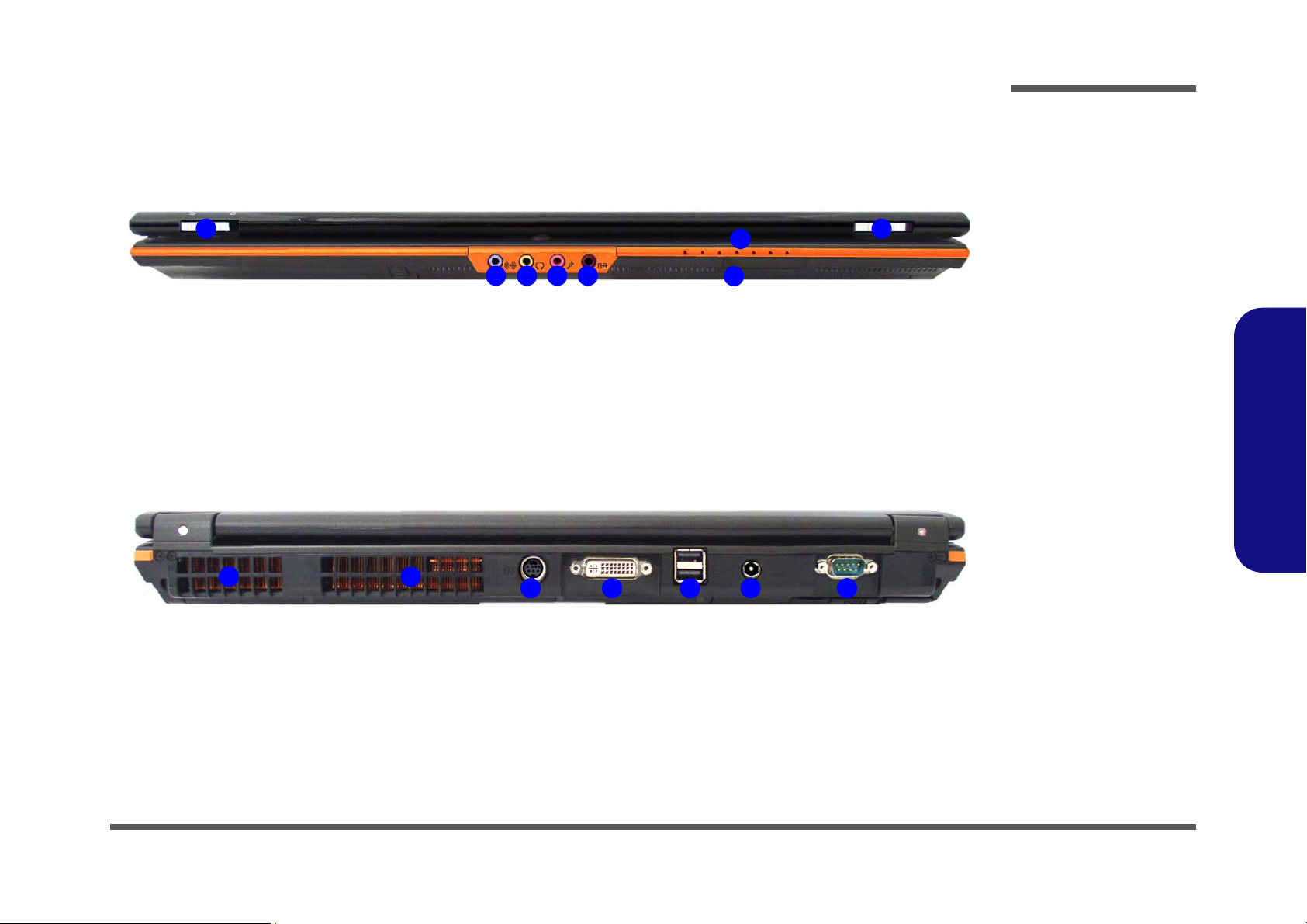
External Locator - Front & Rear View
Figure 2
Front View
1. LCD Latches
2. Line-In Jack
3. Headphone-Out
Jack
4. Microphone-In Jack
5. S/PDIF-Out Jack
6. LED Indicators
7. Infrared &
Consumer Infrared
Transceiver
1 1
2 3 4 5
6
7
Figure 3
Rear View
1. Vent/Fan Intake/
Outlet
2. 7-Pin S-Video-Out
Jack
3. DVI-Out Port
4. 2 * USB 2.0 Ports
5. DC-In Jack
6. Serial Port
2
1 1
43 5 6
Introduction
1.Introduction
External Locator - Front & Rear View 1 - 7
Introduction
2
1
3
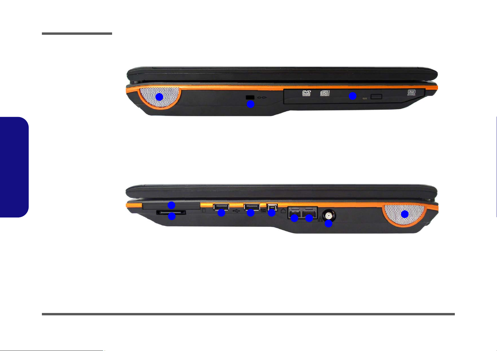
Figure 4
Left Side View
1. Speaker
2. Security Lock Slot
3. Device Bay
(for CD/DVD
Device)
1
2
3 4
5 6
7
3
8
Figure 5
Right Side View
1. Express Card Slot
2. 7-in-1 Card Reader
3. 2 * USB 2.0 Ports
4. Mini-IEEE 1394
Port
5. RJ-11 Phone Jack
6. RJ-45 LAN Jack
7. CATV Antenna
Jack (Enabled With
TV Tuner Only)
8. Speaker
1.Introduction
External Locator - Left & Right Side View
1 - 8 External Locator - Left & Right Side View
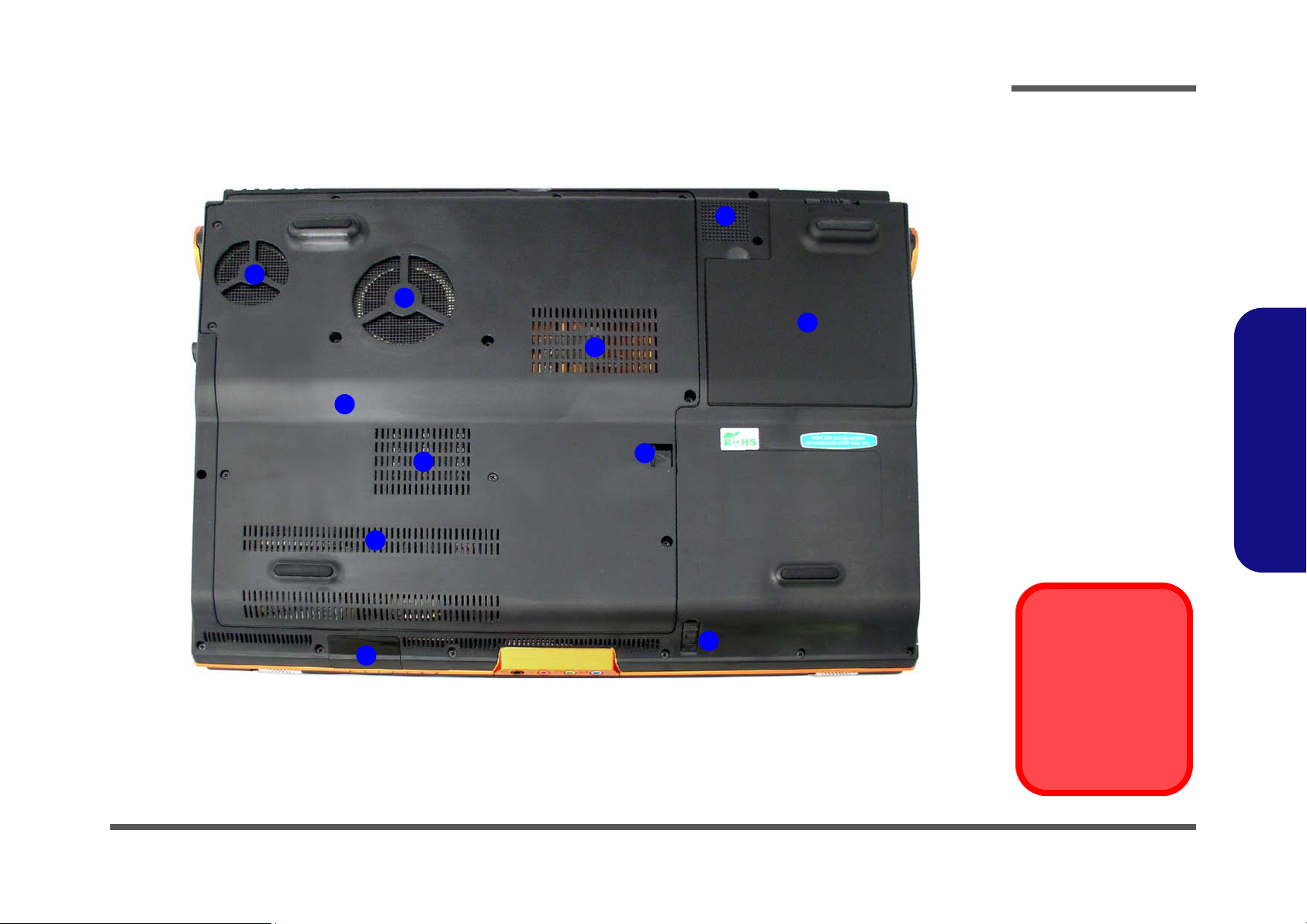
External Locator - Bottom View
Figure 6
Bottom View
1. Vent/Fan Intake/
Outlet
2. Battery
3. Optical Device
Release Latches
4. Component Bay
Cover
5. Infrared &
Consumer Infrared
Transceiver
6. Sub Woofer
Overheating
To prevent your computer from overheating
make sure nothing
blocks the vent/fan intakes while the computer is in use.
1
2
3
4
5
1
6
1
1
3
1
Introduction
1.Introduction
External Locator - Bottom View 1 - 9
Introduction
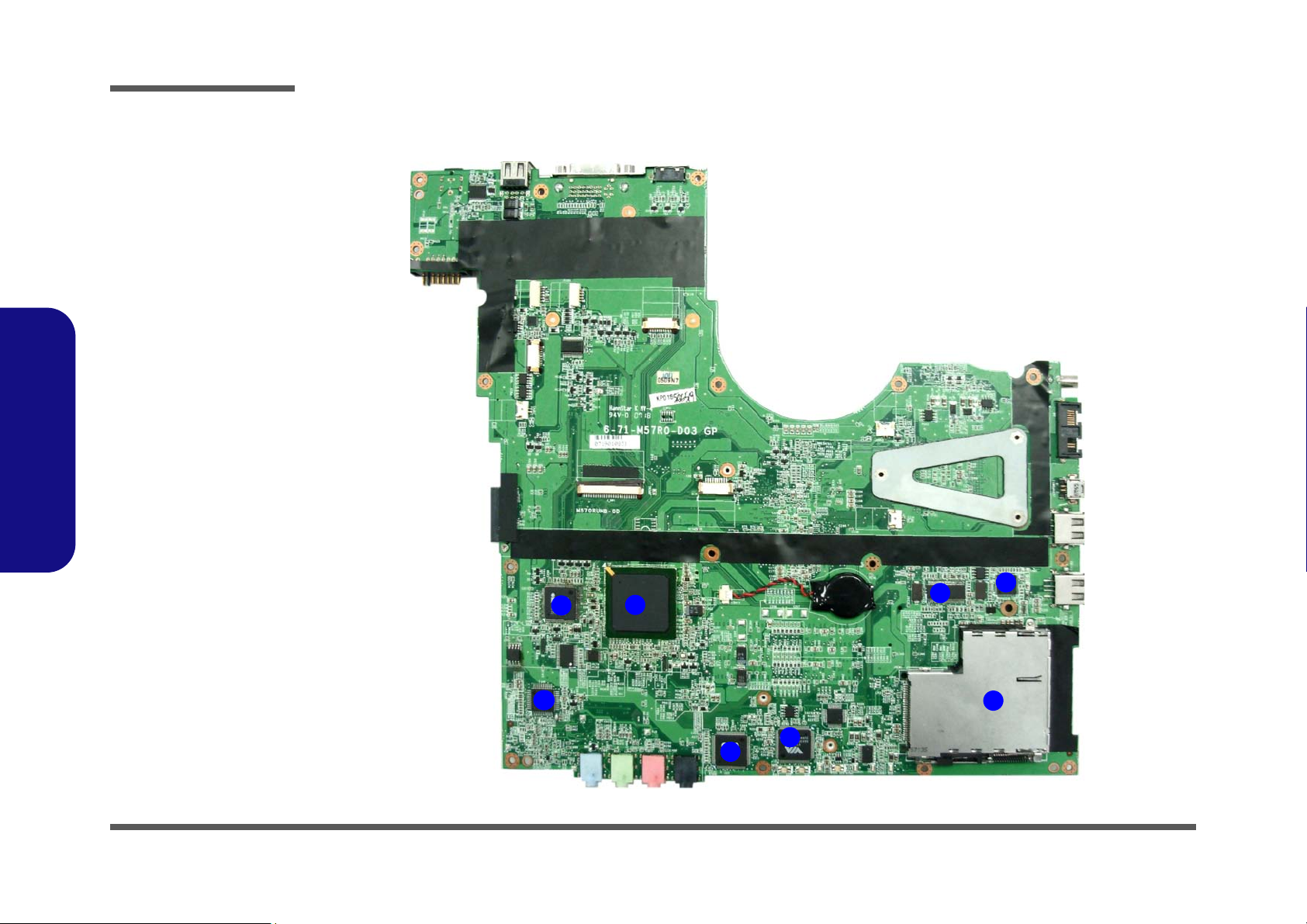
Figure 7
Mainboard Top
Key Parts
1. LAN Transformer
2. Super I/O
3. Audio “DJ”
4. LAN
5. Flash BIOS ROM
6. New Card
Assembly
7. Clock Generator
8. 1394 and Card
Reader
2
1
7
5
4
3
8
6
1.Introduction
Mainboard Overview - Top (Key Parts)
1 - 10 Mainboard Overview - Top (Key Parts)
Mainboard Overview - Bottom (Key Parts)
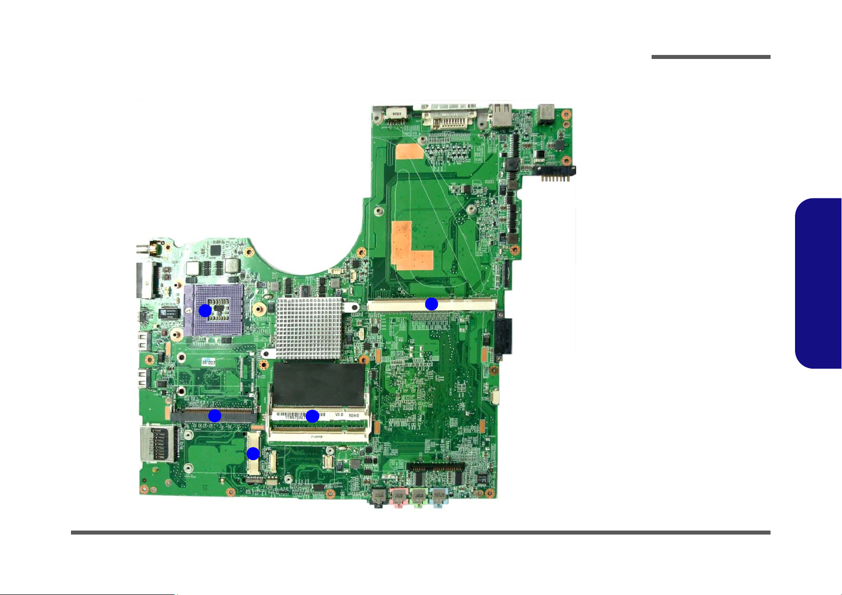
Figure 8
Mainboard Bottom
Key Parts
1. CPU Socket (no
CPU installed)
2. VGA Socket
3. Memory Slots
DDR2 So-DIMM
4. Mini-PCIe Socket
(Wireless Lan
Module)
5. Mini-PCI Socket
(TV Tuner Card)
1
5
2
4
3
Introduction
1.Introduction
Mainboard Overview - Bottom (Key Parts) 1 - 11
Introduction
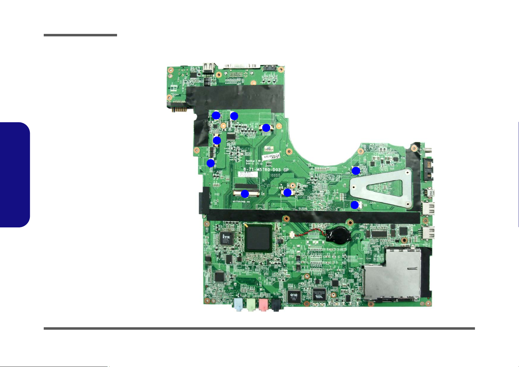
Figure 9
Mainboard Top
Connectors
1. LED Cable
Connector
2. CCD Cable
Connector
3. Inverter Board
Cable Connector
4. COM Port Cable
Connector
5. Speaker-left Cable
Connector
6. Keyboard Cable
Connector
7. TouchPad Cable
Connector
8. Speaker-right
Cable Connector
9. Mic Connector
1
6
7
8
5
2
3
9
4
1.Introduction
Mainboard Overview - Top (Connectors)
1 - 12 Mainboard Overview - Top (Connectors)
Mainboard Overview - Bottom (Connectors)
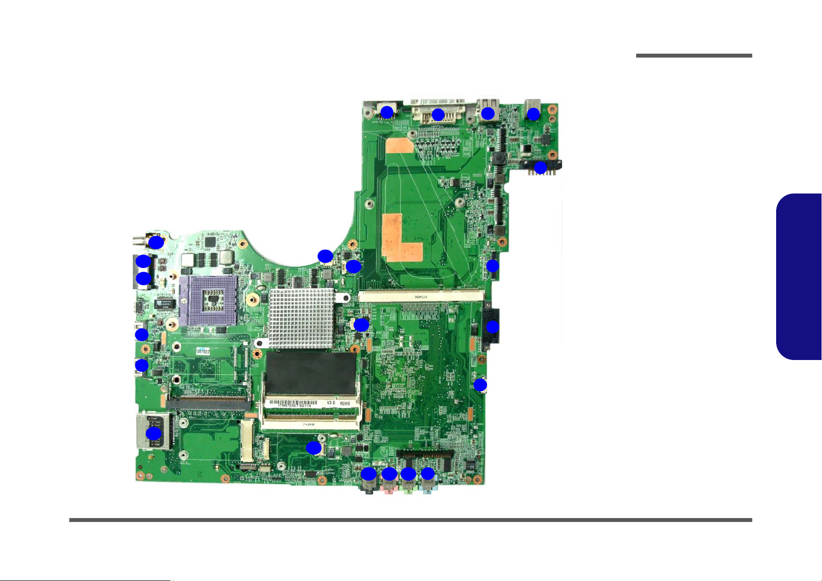
Figure 10
Mainboard Bottom
Connectors
1. 7-Pin S-Video-Out
Jack
2. DVI-Out Port
3. USB Port
4. DC-In Jack
5. Battery Connector
6. LVDS Connector
7. ODD Connector
8. HDD Connector
9. Line-In Jack
10. Headphone Jack
11. Microphone Jack
12. S/PDIF-Out Jack
13. Bluetooth Cable
Connector
14. Speaker Connector
15. VGA Fan
Connector
16. Fan Connector
17. 7-in-1 Card Reader
Connector
18. RJ-11 Jack
19. RJ-45 Jack
20. TV Connector
1
6
7
8
5
2
4
3
9
11 1012
13
14
16
15
3
3
17
18
19
20
Introduction
1.Introduction
Mainboard Overview - Bottom (Connectors) 1 - 13

Introduction
1.Introduction
1-14

2: Disassembly
Information
Warning
Overview
This chapter provides step-by-step instructions for disassembling the M570RU/M571RU series notebook’s parts and
subsystems. When it comes to reassembly, reverse the procedures (unless otherwise indicated).
We suggest you completely review any procedure before you take the computer apart.
Disassembly
Procedures such as upgrading/replacing the RAM, CD device and hard disk are included in the User’s Manual but are
repeated here for your convenience.
To make the disassembly process easier each section may have a box in the page margin. Information contained under
the figure # will give a synopsis of the sequence of procedures involved in the disassembly procedure. A box with a
lists the relevant parts you will have after the disassembly process is complete. Note: The parts listed will be for the dis-
assembly procedure listed ONLY, and not any previous disassembly step(s) required. Refer to the part list for the previous disassembly procedure. The amount of screws you should be left with will be listed here also.
A box with a will also provide any possible helpful information. A box with a contains warnings.
An example of these types of boxes are shown in the sidebar.
2.Disassembly
Overview 2 - 1

Disassembly
2.Disassembly
NOTE: All disassembly procedures assume that the system is turned OFF, and disconnected from any power supply (the
battery is removed too).
Maintenance Tools
The following tools are recommended when working on the notebook PC:
• M3 Philips-head screwdriver
• M2.5 Philips-head screwdriver (magnetized)
• M2 Philips-head screwdriver
• Small flat-head screwdriver
• Pair of needle-nose pliers
• Anti-static wrist-strap
Connections
Connections within the computer are one of four types:
Locking collar sockets for ribbon connectors To release these connectors, use a small flat-head screwdriver to
gently pry the locking collar away from its base. When replacing the connection, make sure the connector is oriented in the
same way. The pin1 side is usually not indicated.
2-2Overview
Pressure sockets for multi-wire connectors To release this connector type, grasp it at its head and gently
rock it from side to side as you pull it out. Do not pull on the
wires themselves. When replacing the connection, do not try to
force it. The socket only fits one way.
Pressure sockets for ribbon connectors To release these connectors, use a small pair of needle-nose pli-
ers to gently lift the connector away from its socket. When replacing the connection, make sure the connector is oriented in
the same way. The pin1 side is usually not indicated.
Board-to-board or multi-pin sockets To separate the boards, gently rock them from side to side as
you pull them apart. If the connection is very tight, use a small
flat-head screwdriver - use just enough force to start.

Maintenance Precautions
Power Safety
Warning
Before you undertake
any upgrade procedures, make sure that
you have turned off the
power, and disconnected all peripherals
and cables (including
telephone lines). It is
advisable to also remove your battery in
order to prevent accidentally turning the
machine on.
The following precautions are a reminder. To avoid personal injury or damage to the computer while performing a removal and/or replacement job, take the following precautions:
1. Don't drop it. Perform your repairs and/or upgrades on a stable surface. If the computer falls, the case and other
components could be damaged.
2. Don't overheat it. Note the proximity of any heating elements. Keep the computer out of direct sunlight.
3. Avoid interference. Note the proximity of any high capacity transformers, electric motors, and other strong mag-
netic fields. These can hinder proper performance and damage components and/or data. You should also monitor
the position of magnetized tools (i.e. screwdrivers).
4. Keep it dry. This is an electrical appliance. If water or any other liquid gets into it, the computer could be badly
damaged.
5. Be careful with power. Avoid accidental shocks, discharges or explosions.
•Before removing or servicing any part from the computer, turn the computer off and detach any power supplies.
•When you want to unplug the power cord or any cable/wire, be sure to disconnect it by the plug head. Do not pull on the wire.
6. Peripherals – Turn off and detach any peripherals.
7. Beware of static discharge. ICs, such as the CPU and main support chips, are vulnerable to static electricity.
Before handling any part in the computer, discharge any static electricity inside the computer. When handling a
printed circuit board, do not use gloves or other materials which allow static electricity buildup. We suggest that
you use an anti-static wrist strap instead.
8. Beware of corrosion. As you perform your job, avoid touching any connector leads. Even the cleanest hands pro-
duce oils which can attract corrosive elements.
9. Keep your work environment clean. Tobacco smoke, dust or other air-born particulate matter is often attracted
to charged surfaces, reducing performance.
10. Keep track of the components. When removing or replacing any part, be careful not to leave small parts, such as
screws, loose inside the computer.
Cleaning
Do not apply cleaner directly to the computer, use a soft clean cloth.
Do not use volatile (petroleum distillates) or abrasive cleaners on any part of the computer.
Disassembly
2.Disassembly
Overview 2 - 3

Disassembly
Disassembly Steps
The following table lists the disassembly steps, and on which page to find the related information. PLEASE PERFORM
THE DISASSEMBLY STEPS IN THE ORDER INDICATED.
2.Disassembly
To remove the Battery:
1. Remove the battery page 2 - 5
To remove the HDD:
1. Remove the battery page 2 - 5
2. Remove the HDD page 2 - 6
To remove the Optical Device:
1. Remove the battery page 2 - 5
2. Remove the Optical device page 2 - 8
To remove the System Memory:
1. Remove the battery page 2 - 5
2. Remove the system memory page 2 - 9
To remove the Processor:
1. Remove the battery page 2 - 5
2. Remove the processor page 2 - 10
To remove the VGA Card:
1. Remove the battery page 2 - 5
2. Remove the VGA Card page 2 - 12
To remove the Wireless LAN Module:
1. Remove the battery page 2 - 5
2. Remove the WLAN module page 2 - 13
To remove the TV Tuner Card:
1. Remove the battery page 2 - 5
2. Remove the TV Tuner Card page 2 - 14
To remove the Bluetooth Module:
1. Remove the battery page 2 - 5
2. Remove the Bluetooth Module page 2 - 15
To remove the Keyboard:
1. Remove the battery page 2 - 5
2. Remove the keyboard page 2 - 16
To remove the Modem:
1. Remove the battery page 2 - 5
2. Remove the HDD page 2 - 6
3. Remove the Optical device page 2 - 8
4. Remove the system memory page 2 - 9
5. Remove the processor page 2 - 10
6. Remove the VGA Card page 2 - 12
7. Remove the WLAN module page 2 - 13
8. Remove the TV Tuner Card page 2 - 14
9. Remove the Bluetooth Module page 2 - 15
10. Remove the keyboard page 2 - 16
11. Remove the Modem page 2 - 17
2 - 4 Disassembly Steps
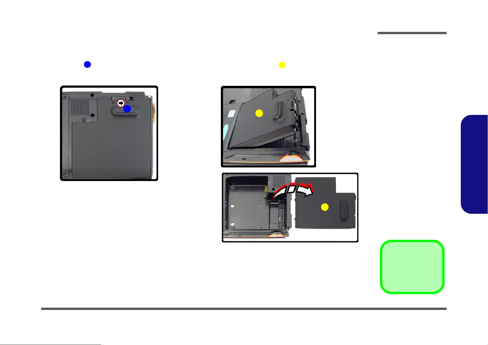
Removing the Battery
2. Battery
1
2
Figure 1
Battery Removal
a. Slide latch at point 1 to-
wards the unlock symbol
and hold it in place.
b. Lift the battery out.
1
a.
b.
2
2
1. Turn the computer off, and turn it over.
2. Slide latch towards the unlock symbol and hold it in place, and lift the battery up and out of the battery bay.
Disassembly
2.Disassembly
Removing the Battery 2 - 5
 Loading...