

Clevo M540SE, M550SE Service Manual


Notebook Computer
M540SE/M550SE
Service Manual
Preface
Preface
I

Preface
Preface
Notice
The company reserves the right to revise this publication or to change its contents without notice. Information contained
herein is for reference only and does not constitute a commitment on the part of the manufacturer or any subsequent vendor. They assume no responsibility or liability for any errors or inaccuracies that may appear in this publication nor are
they in anyway responsible for any loss or damage resulting from the use (or misuse) of this publication.
This publication and any accompanying software may not, in whole or in part, be reproduced, translated, transmitted or
reduced to any machine readable form without prior consent from the vendor, manufacturer or creators of this publication, except for copies kept by the user for backup purposes.
Brand and product names mentioned in this publication may or may not be copyrights and/or registered trademarks of
their respective companies. They are mentioned for identification purposes only and are not intended as an endorsement
of that product or its manufacturer.
Version 1.0
February 2007
Trademarks
Intel, Celeron and Intel Core are trademarks of Advanced Micro Devices, Inc.
Windows® is a registered trademark of Microsoft Corporation.
Other brand and product names are trademarks and./or registered trademarks of their respective companies.
II

About this Manual
This manual is intended for service personnel who have completed sufficient training to undertake the maintenance and
inspection of personal computers.
It is organized to allow you to look up basic information for servicing and/or upgrading components of the M540SE/
M550SE series notebook PC.
The following information is included:
Chapter 1, Introduction, provides general information about the location of system elements and their specifications.
Chapter 2, Disassembly, provides step-by-step instructions for disassembling parts and subsystems and how to upgrade
elements of the system.
Preface
Appendix A, Part Lists
Appendix B, Schematic Diagrams
Preface
III

Preface
Preface
IMPORTANT SAFETY INSTRUCTIONS
Follow basic safety precautions, including those listed below, to reduce the risk of fire, electric shock and injury to persons when using any electrical equipment:
1. Do not use this product near water, for example near a bath tub, wash bowl, kitchen sink or laundry tub, in a wet
basement or near a swimming pool.
2. Avoid using a telephone (other than a cordless type) durin g an ele ctrical sto rm. There may be a remote risk of electrical shock from lightning.
3. Do not use the telephone to report a gas leak in the vicinity of the leak.
4. Use only the power cord and batteries indicated in this manual. Do not dispose of batteries in a fire. They may
explode. Check with local codes for possible special disposal instructions.
5. This product is intended to be supplied by a Listed Power Unit (DC Output 19V, 3.42A or 18.5V, 3.5A (65W) minimum AC/DC Adapter).
CAUTION
Always disconnect all telephone lines from the wall outlet before servicing or disassembling this equipment.
IV
TO REDUCE THE RISK OF FIRE, USE ONLY NO. 26 AWG OR LARGER,
TELECOMMUNICATION LINE CORD
This Computer’s Optical Device is a Laser Class 1 Product
Instructions for Care and Operation
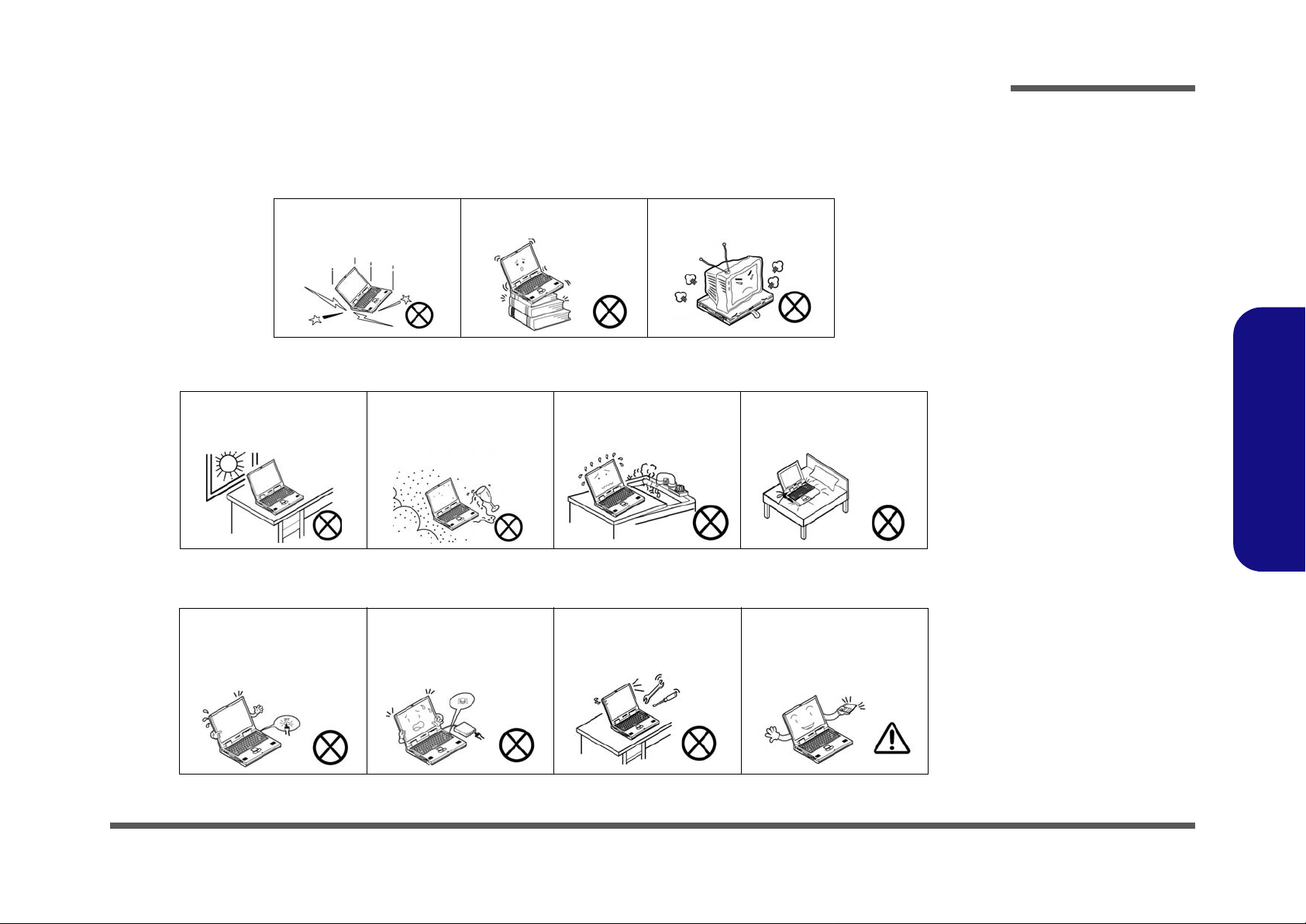
The notebook computer is quite rugged, but it can be damaged. To prevent this, follow these suggestions:
1. Don’t drop it, or expose it to shock. If the computer falls, the case and the components could be damaged.
Preface
Do not expose the computer
to any shock or vibration.
Do not place it on an unstable
surface.
Do not place anything heavy
on the computer.
2. Keep it dry, and don’t overheat it. Keep the computer and power supply away from any kind of heating element. This
is an electrical appliance. If water or any other liquid gets into it, the co mputer could be badly damaged.
Do not expose it to excessive
heat or direct sunlight.
Do not leave it in a place
where foreign matter or moisture may affect the system.
Don’t use or store the computer in a humid environment.
Do not place the computer on
any surface which will block
the vents.
3. Follow the proper working procedures for the computer. Shut the computer down properly and don’t forget to save
your work. Remember to periodically save your data as data may be lost if the battery is depleted.
Do not turn off the power
until you properly shut down
all programs.
Do not turn off any peripheral
devices when the computer is
on.
Do not disassemble the computer by yourself.
Perform routine maintenance
on your computer.
Preface
V
Preface
4. Avoid interference. Keep the computer away from high capacity transformers, electric motors, and oth er strong mag-
netic fields. These can hinder proper performance and damage your data.
5. Take care when using peripheral devices.
Preface
Power Safety
Warning
Before you undertake
any upgrade procedures, make sure that
you have turned off the
power, and disconnected all peripherals
and cables (including
telephone lines). It is
advisable to also remove your battery in
order to prevent accidentally turning the
machine on.
Use only approved brands of
peripherals.
Unplug the power cord befor e
attaching peripheral devices.
Power Safety
The computer has specific power requirements:
• Only use a power adapter approved for use with this computer.
• Your AC adapter may be designed for international travel but it still requires a steady, uninterrupted power supply. If you are
unsure of your local power specifications, consult your service representative or local power company.
• The power adapter may have either a 2-prong or a 3-prong grounded plug. The third prong is an important safety feature; do
not defeat its purpose. If you do not have access to a compatible outlet, have a qualified electrician install one.
• When you want to unplug the power cord, be sure to disconn ect it by the plug head, not by its wire.
• Make sure the socket and any extension cord(s) you use can support the total current load of all the connected devices.
• Before cleaning the computer, make sure it is disconnected from any external power supplies.
Do not plug in the power
cord if you are wet.
Do not use the power cord if
it is broken.
Do not place heavy objects
on the power cord.
VI

Battery Precautions
• Only use batteries designed for this computer. The wrong battery type may explode, leak or damage the computer.
• Do not continue to use a battery that has been dropped, or that appears damaged (e.g. bent or twisted) in any way. Even if the
computer continues to work with a damaged battery in place, it may cause circuit damage, which may possibly result in fire.
• Recharge the batteries using the notebook’s system. Incorrect recharging may make the battery explode.
• Do not try to repair a battery pack. Refer any battery pack repair or replacement to your service representative or qualified service
personnel.
• Keep children away from, and promptly dispose of a damaged battery. Always dispose of batteries carefully. Batteries may explode
or leak if exposed to fire, or improperly handled or discarded.
• Keep the battery away from metal appliances.
• Affix tape to the battery contacts before disposing of the battery.
• Do not touch the battery contacts with your hands or metal objects.
Battery Disposal
The product that you have purchased contains a rechargeable b attery. The battery is recycl able. At the end of
its useful life, under various state and local laws, it may be illegal to dispose of this battery into the municipal
waste stream. Check with your local solid waste officials for details i n your area for recycling options or p roper
disposal.
Preface
Preface
Caution
Danger of explosion if battery is incorrectly replaced. Replace only with the same or equivalent type recommended by the manufacturer. Discard used battery according to the manufacturer’s instructions.
VII

Preface
Preface
Related Documents
You may also need to consult the following manual for additional information:
User’s Manual on CD
This describes the notebook PC’s features and the procedures for operating the computer and its ROM-based setup program. It also describes the installation and operation of the utility programs provided with the notebook PC.
VIII

Contents
Preface
Introduction ..............................................1-1
Overview .........................................................................................1-1
System Specifications ................................. 1-2
Model Differences ........................................................................... 1-5
External Locator - Top View with LCD Panel Open ......................1-6
External Locator - Front & Right side Views .................................1-7
External Locator - Left Side & Rear View .....................................1-8
External Locator - Bottom View .....................................................1-9
M540SE Mainboard Overview - Top (Key Parts) ........................1-10
M540SE Mainboard Overview - Bottom (Key Parts) ...................1-11
M540SE Mainboard Overview - Top (Connectors) ......................1-12
M540SE Mainboard Overview - Bottom (Connectors) ................1-13
M550SE Mainboard Overview - Top (Key Parts) ........................1-14
M550SE Mainboard Overview - Bottom (Key Parts) ...................1-15
M550SE Mainboard Overview - Top (Connectors) ......................1-16
M550SE Mainboard Overview - Bottom (Connectors) ................1-17
Disassembly ...............................................2-1
Overview .........................................................................................2-1
Maintenance Tools ..........................................................................2-2
Connections .....................................................................................2-2
Maintenance Precautions .................................................................2-3
Disassembly Steps ...........................................................................2-4
Removing the Battery ......................................................................2-5
Removing the Hard Disk Drive .......................................................2-6
Removing the System Memory (RAM) ..........................................2-9
Removing the Optical (CD/DVD) Device ....................................2-11
Removing and Installing the Processor .........................................2-12
Removing the Wireless LAN Module ...........................................2-15
Removing the Bluetooth Module ..................................................2-16
Removing the Modem .................................................................. 2-17
Removing the Keyboard ............................................................... 2-19
Part Lists ..................................................A-1
Part List Illustration Location ........................................................ A-2
Top (M550SE) ............................................................................... A-3
Bottom (M550SE) ......................................................................... A-4
LCD (M550SE) ............................................................................. A-5
COMBO (M550SE) ....................................................................... A-6
DVD-RW Drive (M550SE) ........................................................... A-7
Top (M540SE) ............................................................................... A-8
Bottom (M540SE) ......................................................................... A-9
LCD (M540SE) ........................................................................... A-10
COMBO (M540SE) ..................................................................... A-11
DVD-RW Drive (M540SE) ......................................................... A-12
Top (M540SE-C) ......................................................................... A-13
Bottom (M540SE-C) ................................................................... A-14
LCD (M540SE-C) ....................................................................... A-15
COMBO (M540SE-C) ................................................................. A-16
DVD-RW Drive (M540SE-C) ..................................................... A-17
Schematic Diagrams.................................B-1
System Block Diagram ...................................................................B-2
PROCESSOR 1/2 ...........................................................................B-3
PROCESSOR 2/2 ...........................................................................B-4
VN896 1/4 ......................................................................................B-5
VN896 2/4 ......................................................................................B-6
VN896 3/4 ......................................................................................B-7
VN896 4/4 ......................................................................................B-8
DDR2-1 ...........................................................................................B-9
DDR2-2 .........................................................................................B-10
Preface
IX

Preface
CLOCK GENERATOR ...............................................................B-11
PANEL, FAN ............................................................................... B-12
VIA LVDS VT-1634AL .............................................................. B-13
VT8237 1/3 .................................................................................. B-14
VT8237 2/3 .................................................................................. B-15
VT8237 3/3 .................................................................................. B-16
MINI PCI, MINI Card, USB2.0*2, FP ........................................ B-17
SATA HDD, CD-ROM, H8 BEEP, CCD .................................... B-18
LAN PHY ..................................................................................... B-19
LPC ROM, TOUCH PAD, LED .................................................. B-20
H8-2111 ........................................................................................B-21
MDC, USB BT, PWRGD, DDB CON .........................................B-22
Audio VT1708A/ALC883 ............................................................B-23
AUDIO AMP, USB2.0*2 .............................................................B-24
PCI ENE MR510 .......................................................................... B-25
NEW CARD, 3-IN-1 SOCKET ................................................... B-26
Preface
5V, 3V, 5VS, 3VS, 2.5V, 2.5VS .................................................. B-27
+1.8V, +VTT_MEM ....................................................................B-28
VCORE ........................................................................................ B-29
+1.05VS, 1.5V, 1.5VS ................................................................. B-30
+VDD3, +VDD5 ..........................................................................B-31
D/D BD (CRT, INVERTER, CCD, RJ-11) ................................. B-32
D/D BD (CHARGER, DC IN) ..................................................... B-33
AUDIO BD (PHONE JACK, USB, RJ-11) .................................B-34
HOT KEY BD (HOT KEY, LED, LID) ......................................B-35
LED BOARD ...............................................................................B-36
CLICK BOARD ........................................................................... B-37
RJ-45 BOARD ............................................................................. B-38
USB DONGLE BOARD .............................................................. B-39
FINGERPRINT BOARD ............................................................. B-40
X

Chapter 1: Introduction
Overview
This manual covers the information you need to service or upgrade the M540SE/M550SE series notebook computer.
Information about operating the computer (e.g. getting started, and the Setup utility) is in the User’s Manual. Information
about drivers (e.g. VGA & audio) is also found in User’s Manual. That manual is shipped with the computer.
Operating systems (e.g. Windows XP, Windows Vista, etc.) have their own manuals as do application software (e.g. word
processing and database programs). If you have questions about those programs, you should consult those manuals.
Introduction
The M540SE/M550SE series notebook is designed to be upgradeable. See “Disassembly” on page 2 - 1 for a detailed
description of the upgrade procedures for each specific component. Please note the warning and safety information indicated by the “” symbol.
The balance of this chapter reviews the computer’s technical specifications and features.
1.Introduction
Overview 1 - 1
Introduction
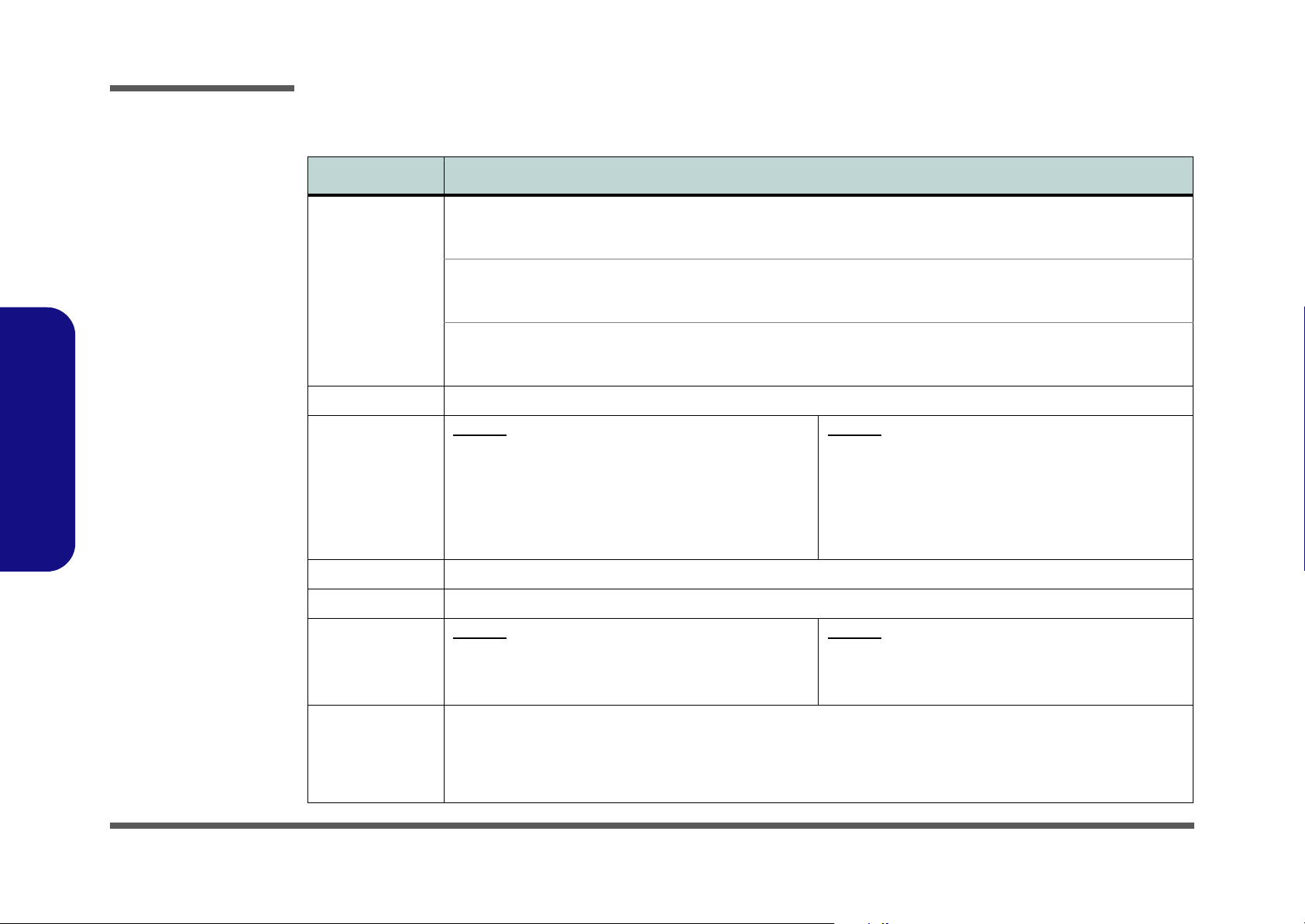
System Specifications
Feature Specification
1.Introduction
Processor Intel® Core™2 Duo Processor
(478-pin) Micro-FC-PGA Package
T7200/ T7400/ T7600
Intel® Core™2 Duo Processor
(478-pin) Micro-FC-PGA Package
T5500/ T5600
Intel® Celeron® M Processor
(478-pin) Micro-FCPGA Package
410/ 420/ 430/ 440/ 450
Core Logic VIA VN896 + VT8237A Chipset
Memory M550SE
Two 200 Pin SO-DIMM Sockets Supporting DDRII
(DDR2) 533/667 MHz
64-bit Wide DDRII (DDR2) Data Channel
Memory Expandable up to 2GB (256/ 512/ 1024 MB
DDRII Module)
(Note: Do Not Use Other Module Types)
Security Security (Kensington® Type) Lock Slot BIOS Password
BIOS One 4Mb Flash ROM Phoenix™ BIOS
LCD M550SE
15.0" XGA (1024*768) Flat Panel TFT
OR
15.0" XGA (1024*768) Glare Type Flat Panel TFT
65nm (65 Nanometer) Process Tech nology
4MB On-die L2 Cache & 667MHz FSB
2.0/ 2.16/ 2.33 GHz
65nm (65 Nanometer) Process Tech nology
2MB On-die L2 Cache & 667MHz FSB
1.66/ 1.83 GHz
65nm (65 Nanometer) Process Tech nology
1MB On-die L2 Cache & 533MHz FSB
1.46/ 1.60/ 1.73/ 1.86/ 2.0 GHz
M540SE
One 200 Pin SO-DIMM Socket Supporting DDRII (DDR2)
533/667 MHz
64-bit Wide DDRII (DDR2) Data Channel
Memory Expandable up to 1GB (256/ 512/ 1024 MB
DDRII Module)
(Note: Do Not Use Other Module Types)
M540SE
14.1" WXGA (1280*800) Flat Panel TFT
14.1" WXGA (1280*800) Glare Type Flat Panel TFT
OR
Video Adapter VIA VN896 Integrated Video System
1 - 2 System Specifications
Chrome9 HC™ Pro 2D/3D Graphics
Integrated 128bit 2D/3D Graphic Engine and Clock up to 250MHz
Supports CRT Resolutions up to 2048 * 1536 at 75Hz
Supports Microsoft DirectX 9.0

Feature Specification
Storage One Changeable 12.7mm(h) Optical Device (CD/DVD) Type Drive (see “Optional” on page 1 - 4 for drive options)
Easy Changeable 2.5" 9.5 mm (h) HDD with SATA (Serial) Interface
Introduction
Audio Integrated Azalia Compliant Interface
3D Stereo Enhanced Sound System
Sound-Blaster PRO™ Compatible
Keyboard &
Pointing Device
Interface Three USB 2.0 Ports
Card Reader Embedded 7-in-1 Card Reader (MS/ MS Pro/ SD/ Mini SD/ MMC/ RS MMC/ MS Duo)
ExpressCard Slot One ExpressCard/34/54 Slot
Communication 56K Plug & Play Fax/Modem v90/92 Compliant
Power
Management
Winkey Keyboard Built-In TouchPad with Scrolling Function
One External Monitor Port
One Headphone-Out Jack
One Microphone-In Jack
One Line-In Jack
Note: MS Duo/ Mini SD/ RS MMC Cards require a PC adapter
10M/100M Base-TX Ethernet
(Factory Option) 300K or 1.3M Pixel PC Camera with USB Interface
(Factory Option) Bluetooth Module - Version 2.0
(Option) 802.11b/g Wireless LAN Module with USB Interface
Supports ACPI 2.0
Supports Suspend to RAM (S3)
Supports Suspend to Disk (S4)
Supports Soft Off (S5)
2 * Built-In Speake rs
Built-In Microphone
One S/PDIF Output Jack
One RJ-11 Modem Jack
One RJ-45 LAN Jack
One DC-in Jack
Supports Battery Low Suspend
Supports Resume from Modem Ring
Supports Wake on LAN
1.Introduction
Power Full Range AC/DC Adapter 19V, 3.42A or 18.5V, 3.5A (65 Watts), 100~240V, 47~63Hz
6 Cell Smart Lithium-Ion Battery Pack, 4000mAH (44.4W)
Environmental
Spec
Temperature
Operating: 5°C ~ 35°C
Non-Operating: -20°C ~ 60°C
Relative Humidity
Operating: 20% ~ 80%
Non-Operating: 10% ~ 90%
System Specifications 1 - 3
Introduction
Feature Specification
1.Introduction
Physical
Dimensions &
Weight
Optional Optical Drive Module Options:
M550SE
333mm (w) * 276mm (d) * 24-33mm (h)
2.5 kg With 6 Cell Battery
DVD-ROM Drive Module
DVD/CD-RW Combo Drive Module
DVD-Dual Drive Module
M540SE
333mm (w) * 243mm (d) * 24-33mm (h)
2.2 kg With 6 Cell Battery
802.11b/g Wireless LAN Module with USB Interface
(Factory Option) PC Camera with USB Interface
(Factory Option) Bluetooth Module - Version 2.0
1 - 4 System Specifications
Model Differences
This notebook series includes two different model types (each model includes two design styles). The models differ
slightly in design style including the LCD type, and the location of the card reader (the easiest way to differentiate between the model types is the location of the card reader).
Feature M550SE M540SE
Introduction
LCD Type
Card Reader
Location
Design Styles
15.0" XGA (1024*768) Flat Panel TFT
OR
15.0" XGA (1024*768) Glare Type Flat Panel TFT
Left Side Front
M550SE M555SE
14.1" WXGA (1280*800) Flat Panel TFT
OR
14.1" WXGA (1280*800) Glare T ype Fla t Panel TFT
1.Introduction
Table 1 - 1
Model difference
M540SE M545SE
Model Differences 1 - 5
Introduction
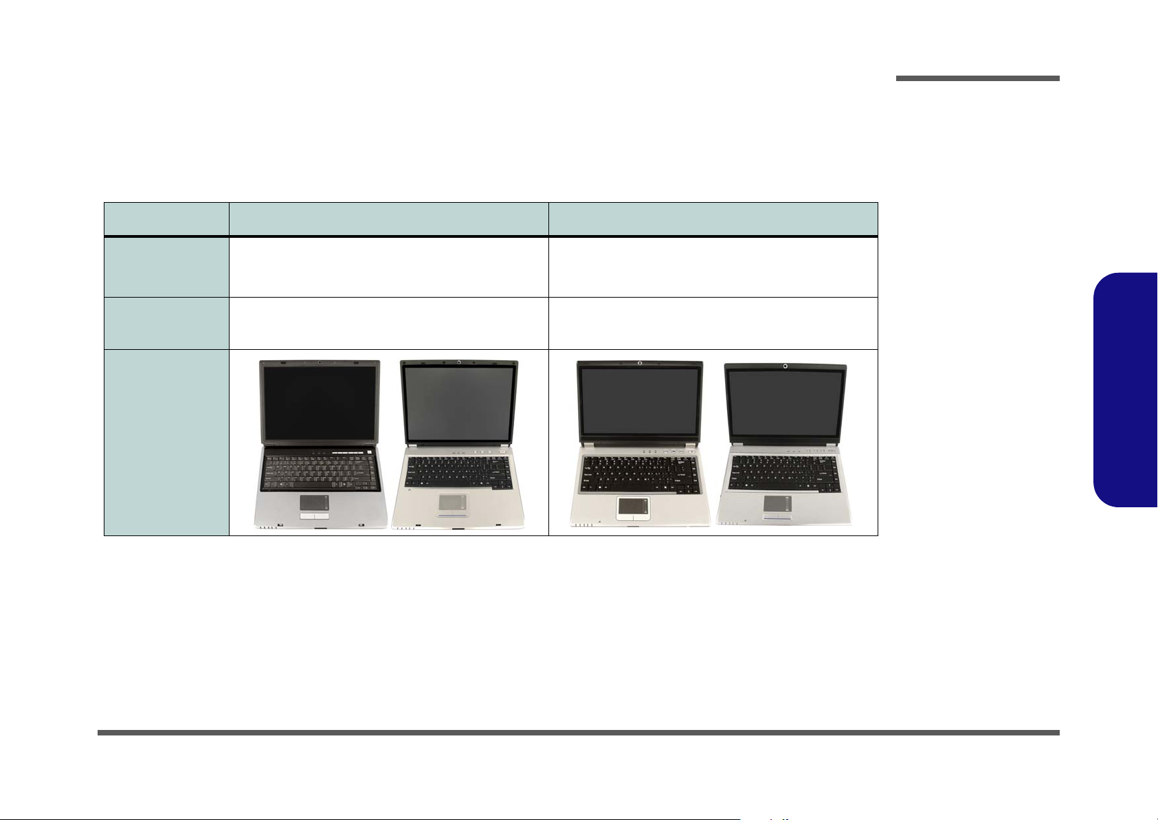
Figure 1
Top View
1. Optional Built-In
PC Camera
2. LCD
3. LED Status
Indicators
4. Hot Key Buttons
5. Power Button
6. Keyboard
7. Built-In
Microphone
8. TouchPad and
Buttons
9. LED Power &
Communication
Indicators
1.Introduction
10.Speaker
External Locator - Top View with LCD Panel Open
1
2
3
6
7
8
9
4
5
9
7
1
2
10
6
8
3
4
5
M550SE M540SE
4
1 - 6 External Locator - Top View with LCD Panel Open
3
5
4
3
5
Introduction
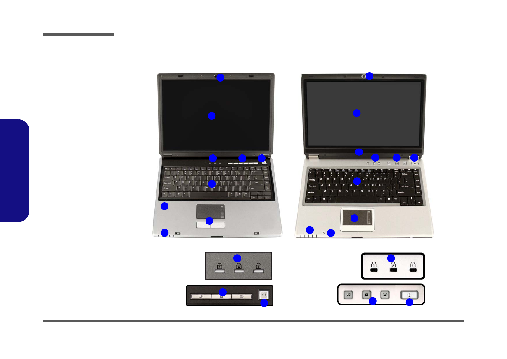
External Locator - Front & Right side Views
1
1
1
32
4
2
M550SE
3
M540SE
5
Figure 2
Front Views
1. LED Power &
Communication
Indicators
2. LCD Latch
(M550SE Only)
3. 7-in-1 Card
Reader (M540SE
Only)
1.Introduction
Figure 3
Right Side Views
1. Headphone-Out
Jack
2. Microphone-In
6
Jack
3. USB 2.0 Port
4. RJ-11 Modem
Jack
5. Optical Device
Drive Bay
6. DC-In Jack
External Locator - Front & Right side Views 1 - 7
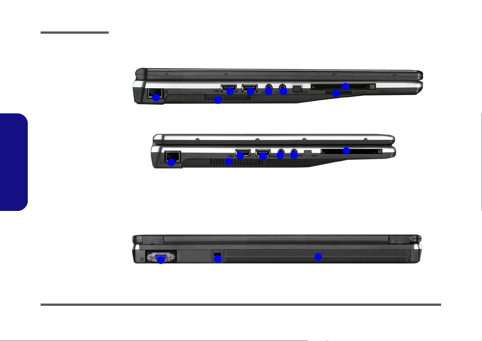
Introduction
Figure 4
Left Side View
1. RJ-45 LAN Jack
2. Vent/Fan Intake
3. 2 * USB 2.0 Ports
4. S/PDIF-Out Jack
5. Line-In Jack
6. ExpressCard Slot
7. 7-in-1 Card
Reader (M550SE
Only)
1.Introduction
External Locator - Left Side & Rear View
M550SE
4
4
3
5
1
M540SE
3 3 5
2
3
1
2
6
7
6
Figure 5
Rear View
1. External Monitor
Port
2. Security Lock Slot
3. Battery
1
1 - 8 External Locator - Left Side & Rear View
2
3
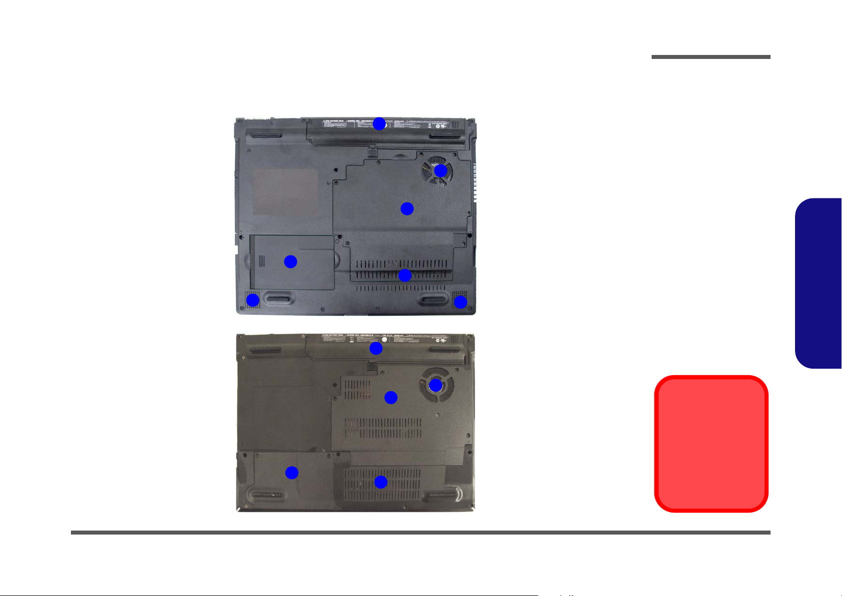
External Locator - Bottom View
M550SE
4
Introduction
Figure 6
2
1
3
Bottom View
1. Vent/Fan Intake
2. Battery
3. Component Bay
Cover
4. Hard Disk Cover
5. Speakers
(M550SE Only)
1.Introduction
1
5
M540SE
5
2
1
3
To prevent your computer from overheating
make sure nothing
4
1
blocks the vent/fan intakes while the computer is in use.
Overheating
External Locator - Bottom View 1 - 9
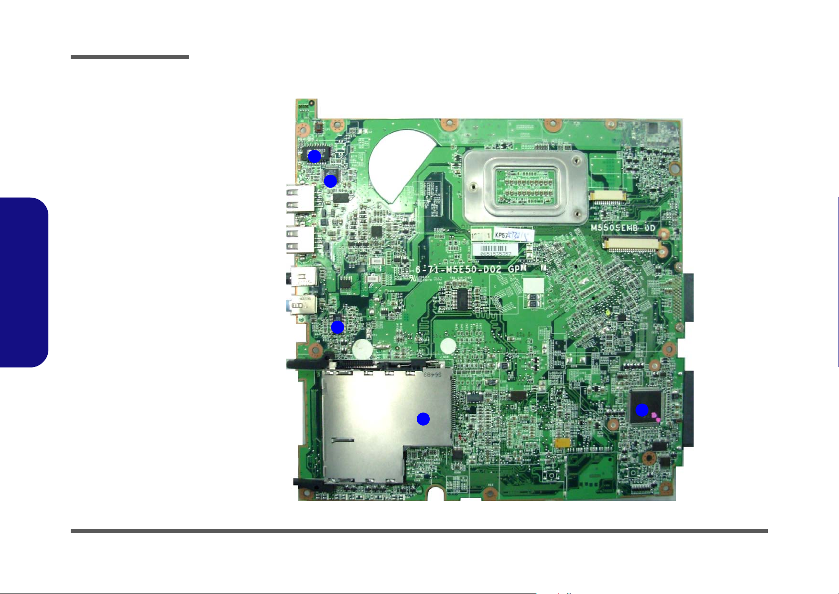
Introduction
Figure 7
Mainboard Top
Key Parts
1. Transformer
2. VIA LVDS
VT-1634
3. PWM Controller
(+1.05VS, +1.5V)
4. ExpressCard
Connector
5. H8-2111
1.Introduction
M540SE Mainboard Overview - Top (Key Parts)
1
2
3
1 - 10 M540SE Mainboard Overview - Top (Key Parts)
5
4
Introduction
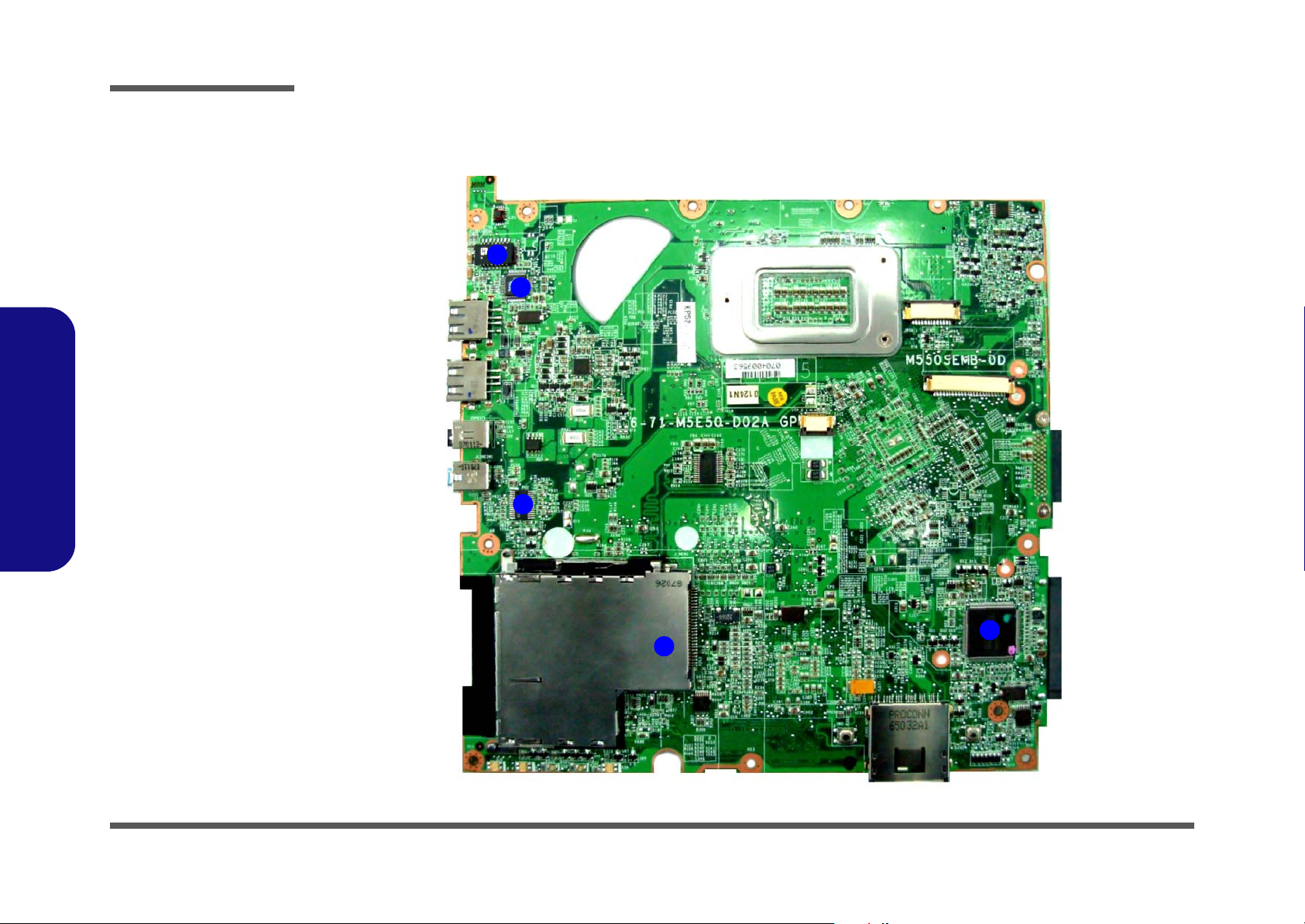
M540SE Mainboard Overview - Bottom (Key Parts)
1
2
9
8
3
Figure 8
Mainboard Bottom
Key Parts
1. CPU Socket (no
CPU installed)
2. Clock Generator
3. Memory Slots
DDR2 SO-DIMM
4. VIA VT1708
5. NR510
6. VIA VT8237A
7. Flash BIOS ROM
8. Mini-Card
Connector (WLAN
Module)
9. North Bridge
VIA VN896
1.Introduction
7
6
5
4
M540SE Mainboard Overview - Bottom (Key Parts) 1 - 11
Introduction
Figure 9
Mainboard Top
Connectors
1. Line-In Jack
2. S/PDIF-Out Jack
3. USB Port
4. LAN Board
Connector
5. Hot-key board
Connector
6. Keyboard Cable
Connector
7. TouchPad Cable
Connector
8. Card Reader
Socket
1.Introduction
M540SE Mainboard Overview - Top (Connectors)
4
3
3
7
2
1
5
6
1 - 12 M540SE Mainboard Overview - Top (Connectors)
8
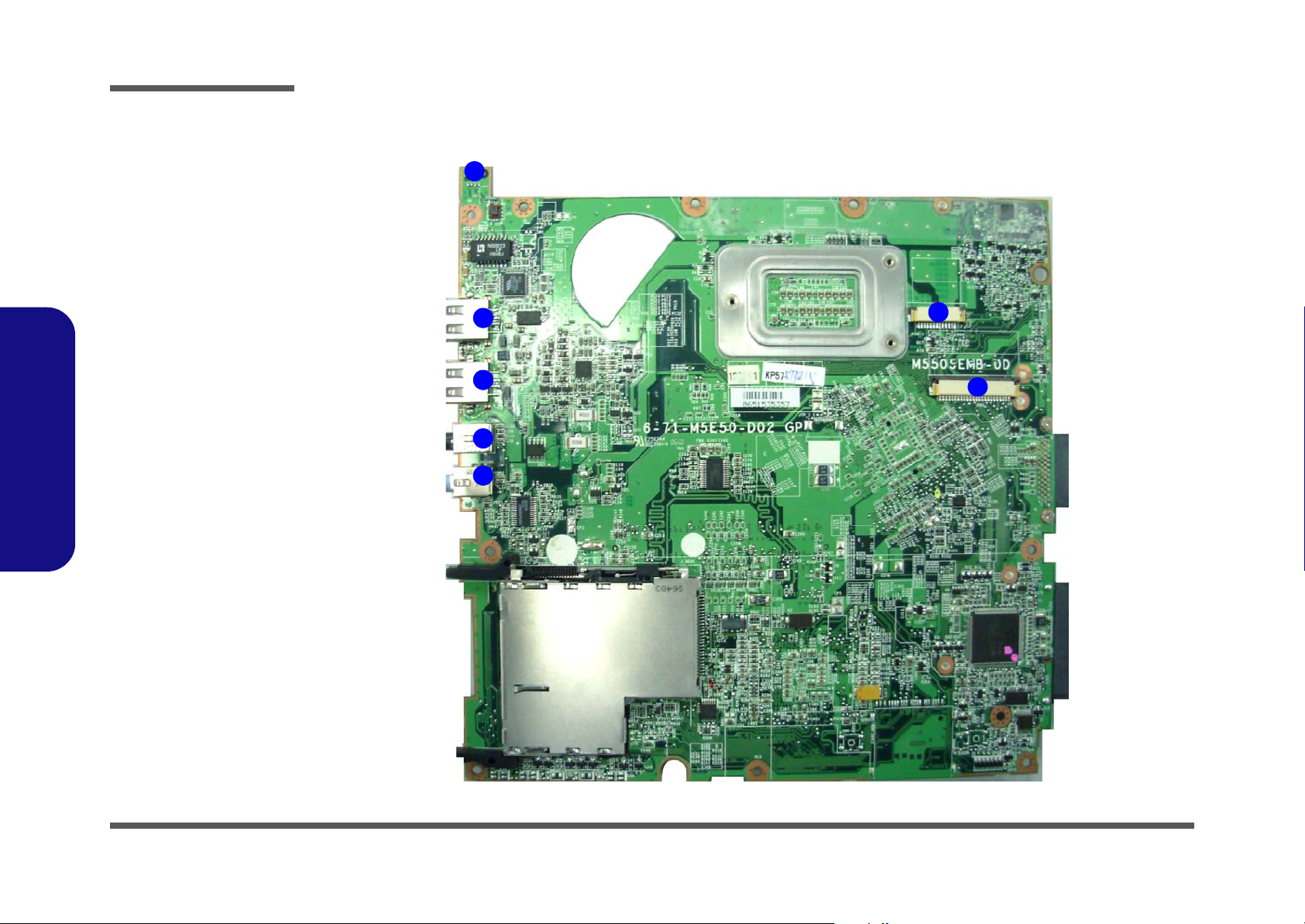
Introduction
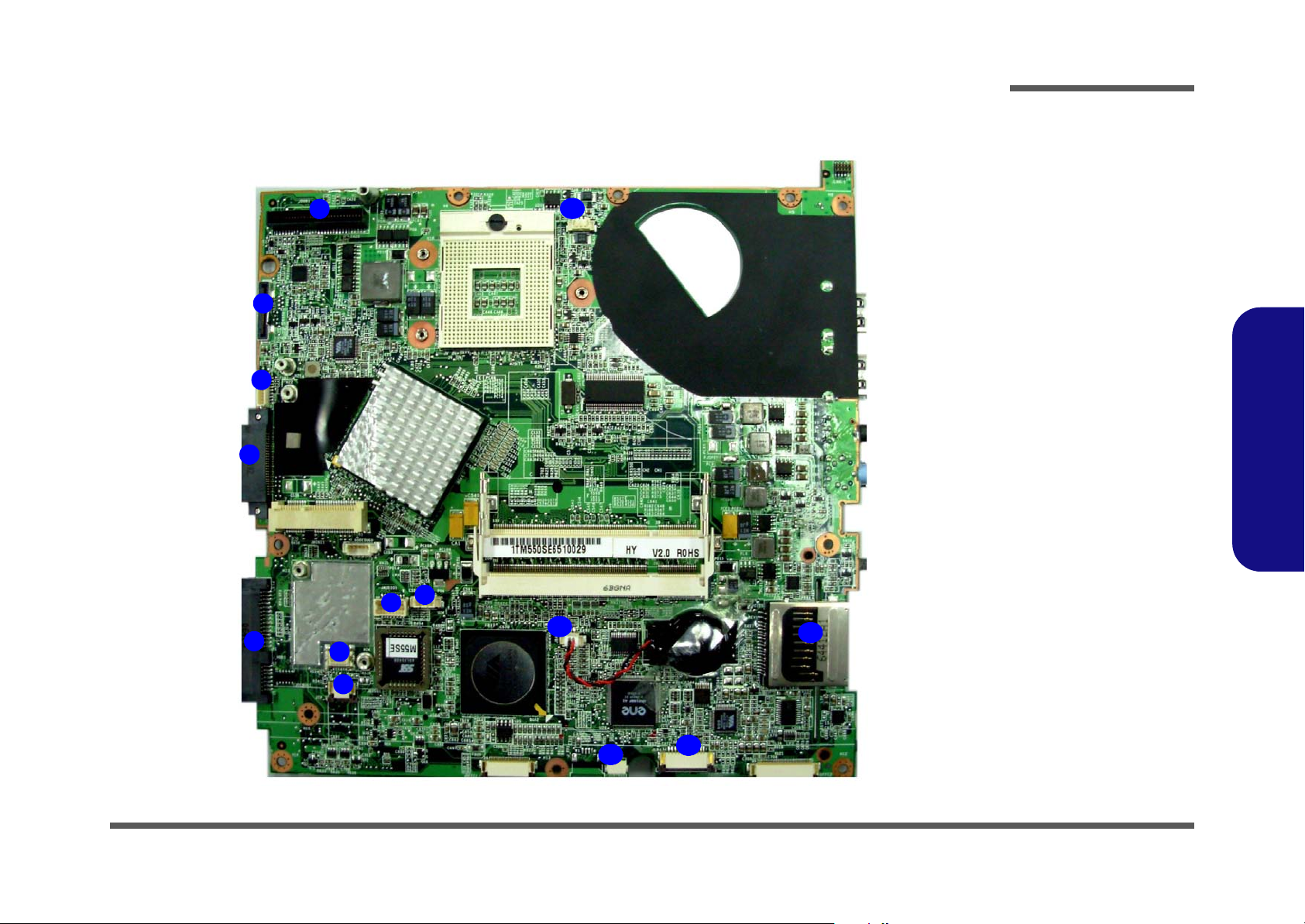
M540SE Mainboard Overview - Bottom (Connectors)
1
2
3
4
10
Figure 10
Mainboard Bottom
Connectors
1. D/D Board
Connector
2. LCD Connector
3. BT Cable
Connector
4. CD-ROM
Connector
5. HDD Connector
6. Audio Board
Connector
7. Modem Module
Connector
8. CMOS Bat.
Connector
9. Microphone
Cable Connector
10.CPU Fan Cable
Connector
1.Introduction
6
5
7
8
9
M540SE Mainboard Overview - Bottom (Connectors) 1 - 13
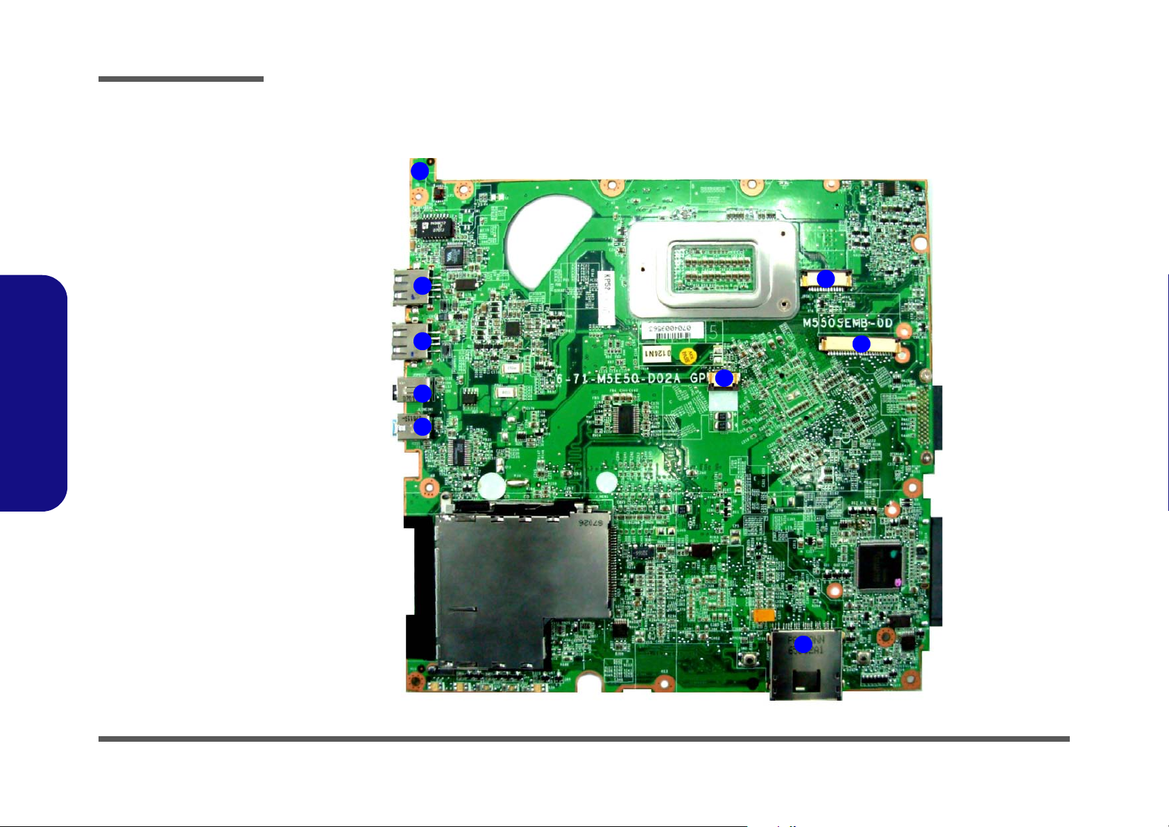
Introduction
Figure 11
Mainboard Top
Key Parts
1. Transformer
2. VIA LVDS
VT-1634
3. PWM Controller
(+1.05VS, +1.5V)
4. ExpressCard
Connector
5. H8-2111
1.Introduction
M550SE Mainboard Overview - Top (Key Parts)
1
2
3
1 - 14 M550SE Mainboard Overview - Top (Key Parts)
4
5

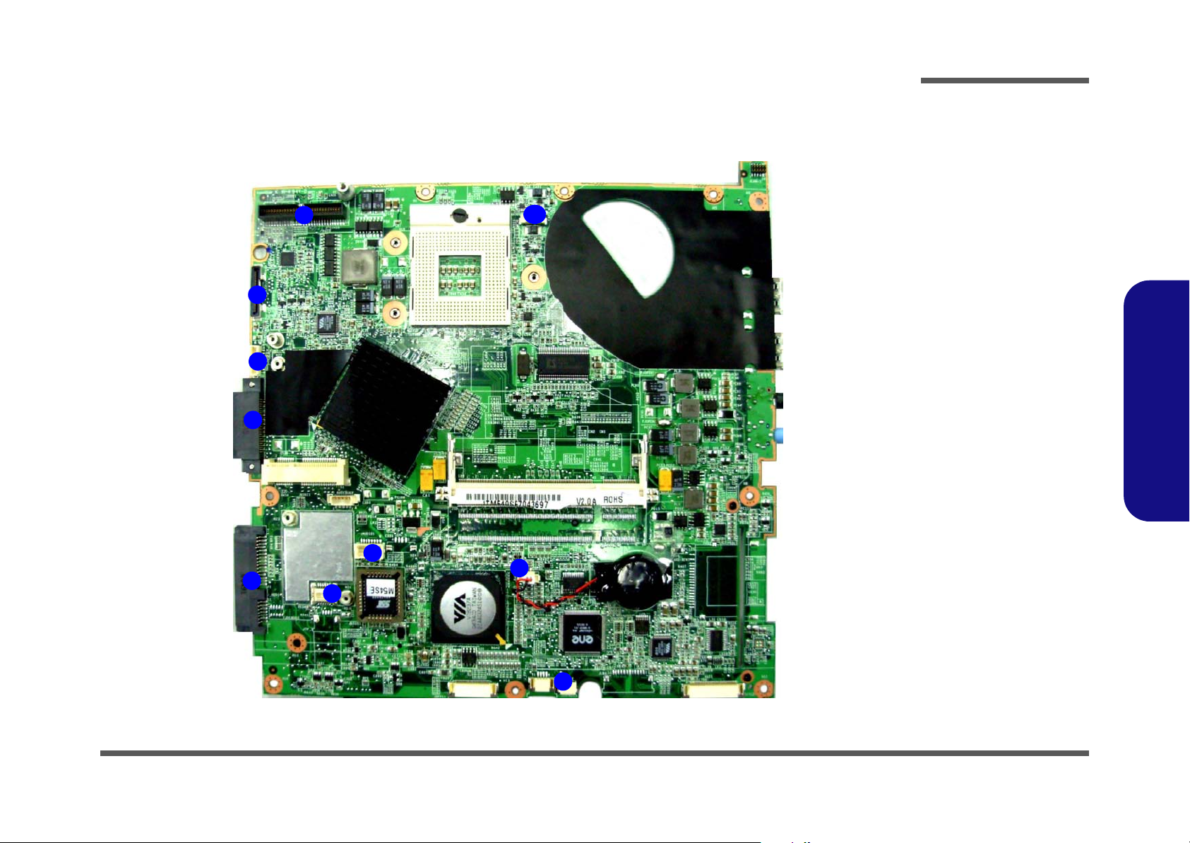
Introduction
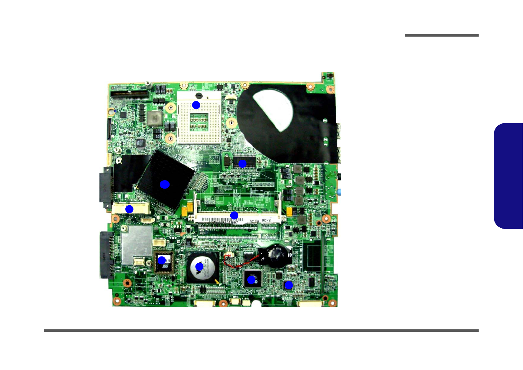
M550SE Mainboard Overview - Bottom (Key Parts)
1
2
9
8
3
Figure 12
Mainboard Bottom
Key Parts
1. CPU Socket (no
CPU installed)
2. Clock Generator
3. Memory Slots
DDR2 SO-DIMM
4. VIA VT1708
5. NR510
6. VIA VT8237
7. Flash BIOS ROM
8. Mini-Card
Connector (WLAN
Module)
9. North Bride
VIA VN896
1.Introduction
7
6
5
4
M550SE Mainboard Overview - Bottom (Key Parts) 1 - 15
Introduction
Figure 13
Mainboard Top
Connectors
1. Line-In Jack
2. S/PDIF-Out Jack
3. USB Port
4. LAN Board
Connector
5. Hot-key board
Connector
6. Keyboard Cable
Connector
1.Introduction
M550SE Mainboard Overview - Top (Connectors)
4
3
3
2
1
5
6
1 - 16 M550SE Mainboard Overview - Top (Connectors)
Introduction
M550SE Mainboard Overview - Bottom (Connectors)
1
2
3
4
7
6
5
8
9
14
10
13
Figure 14
Mainboard Bottom
Connectors
1. D/D Board
Connector
2. LCD Connector
3. BT Cable
Connector
4. CD-ROM
Connector
5. HDD Connector
6. Audio Board
Connector
7. Speaker Cable
Connector
8. Modem Module
Connector
9. TouchPad Cable
Connector
10.CMOS Bat.
Connector
11. Microphone
Cable Connector
12.LED Board Cable
Connector
13.Card Reader
Socket
14.CPU Fan Cable
Connector
1.Introduction
11
12
M550SE Mainboard Overview - Bottom (Connectors) 1 - 17

Introduction
1.Introduction
1-18
 Loading...