

Page 1
Page 2

Page 3

Notebook Computer
M350H/ M360H/ M362H/ M363H
Service Manual
Preface
Preface
I
Page 4

Preface
Preface
Notice
The company reserves the right to revise this publication or to change its contents without notice. Information contained
herein is for reference only and does not constitute a commitment on the part of the manufacturer or any subsequent vendor. They assume no responsibility or liability for any errors or inaccuracies that may appear in this publication nor are
they in anyway responsible for any loss or damage resulting from the use (or misuse) of this publication.
This publication and any accompanying software may not, in whole or in part, be reproduced, translated, transmitted or
reduced to any machine readable form without prior consent from the vendor, manufacturer or creators of this publication, except for copies kept by the user for backup purposes.
Brand and product names mentioned in this publication may or may not be copyrights and/or registered trademarks of
their respective companies. They are mentioned for identification purposes only and are not intended as an endorsement
of that product or its manufacturer.
Version 1.0
December 2004
Trademarks
Intel® and Pentium® are registered trademarks of Intel Corporation.
Windows® is a registered trademark of Microsoft Corporation.
Other brand and product names are trademarks and./or registered trademarks of their respective companies.
II
Page 5

About this Manual
This manual is intended for service personnel who have completed sufficient training to undertake the maintenance and
inspection of personal computers.
It is organized to allow you to look up basic information for servicing and/or upgrading components of the M350H/
M360H/ M362H/ M363H series notebook PC.
The following information is included:
Chapter 1, Introduction, provides general information about the location of system elements and their specifications.
Chapter 2, Disassembly, provides step-by-step instructions for disassembling parts and subsystems and how to upgrade
elements of the system.
Preface
Appendix A, Part Lists
Appendix B, Schematic Diagrams
Preface
III
Page 6

Preface
IMPORTANT SAFETY INSTRUCTIONS
When using your telephone equipment, basic safety precautions should always be followed to reduce the risk of fire, electric shock and injury to persons, including the following:
1. Do not use this product near water, for example near a bath tub, wash bowl, kitchen sink or laundry tub, in a wet
basement or near a swimming pool.
2. Avoid using a telephone (other than a cordless type) during an electrical storm. There may be a remote risk of electrical shock from lightning.
3. Do not use the telephone to report a gas leak in the vicinity of the leak.
4. Use only the power cord and batteries indicated in this manual. Do not dispose of batteries in a fire. They may
explode. Check with local codes for possible special disposal instructions.
5. This product is intended to be supplied by a Listed Power Unit (DC Output 20V, 3.25A).
CAUTION
Preface
IV
Always disconnect all telephone lines from the wall outlet before servicing or disassembling this equipment.
TO REDUCE THE RISK OF FIRE, USE ONLY NO. 26 AWG OR LARGER,
TELECOMMUNICATION LINE CORD
This computer’s optical device is a Class I Laser product.
Page 7
Instructions for Care and Operation
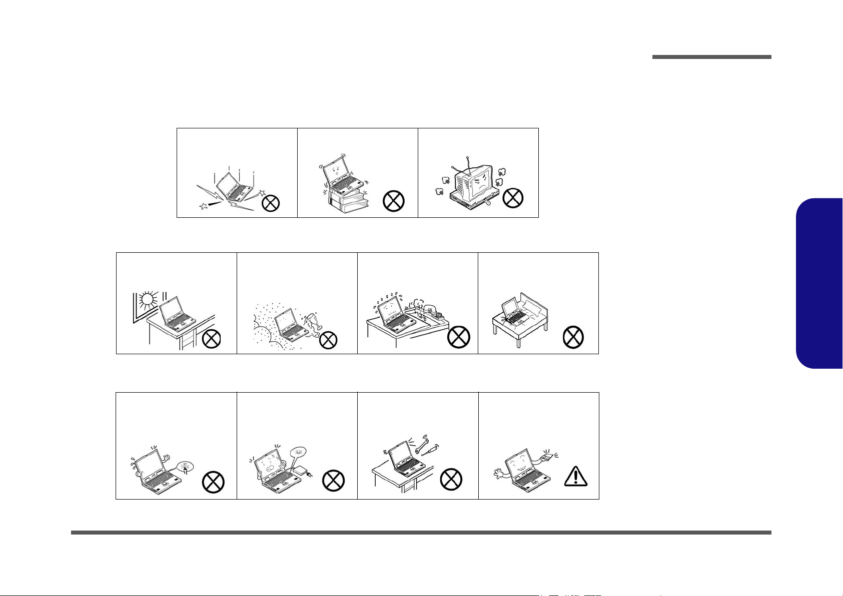
The notebook computer is quite rugged, but it can be damaged. To prevent this, follow these suggestions:
1. Don’t drop it, or expose it to shock. If the computer falls, the case and the components could be damaged.
Preface
Do not expose the computer
to any shock or vibration.
Do not place it on an unstable
surface.
Do not place anything heavy
on the computer.
2. Keep it dry, and don’t overheat it. Keep the computer and power supply away from any kind of heating element. This
is an electrical appliance. If water or any other liquid gets into it, the computer could be badly damaged.
Do not expose it to excessive
heat or direct sunlight.
Do not leave it in a place
where foreign matter or moisture may affect the system.
Don’t use or store the computer in a humid environment.
Do not place the computer on
any surface which will block
the vents.
3. Follow the proper working procedures for the computer. Shut the computer down properly and don’t forget to save
your work. Remember to periodically save your data as data may be lost if the battery is depleted.
Do not turn off the power
until you properly shut down
all programs.
Do not turn off any peripheral
devices when the computer is
on.
Do not disassemble the computer by yourself.
Perform routine maintenance
on your computer.
Preface
V
Page 8
Preface
4. Avoid interference. Keep the computer away from high capacity transformers, electric motors, and other strong mag-
netic fields. These can hinder proper performance and damage your data.
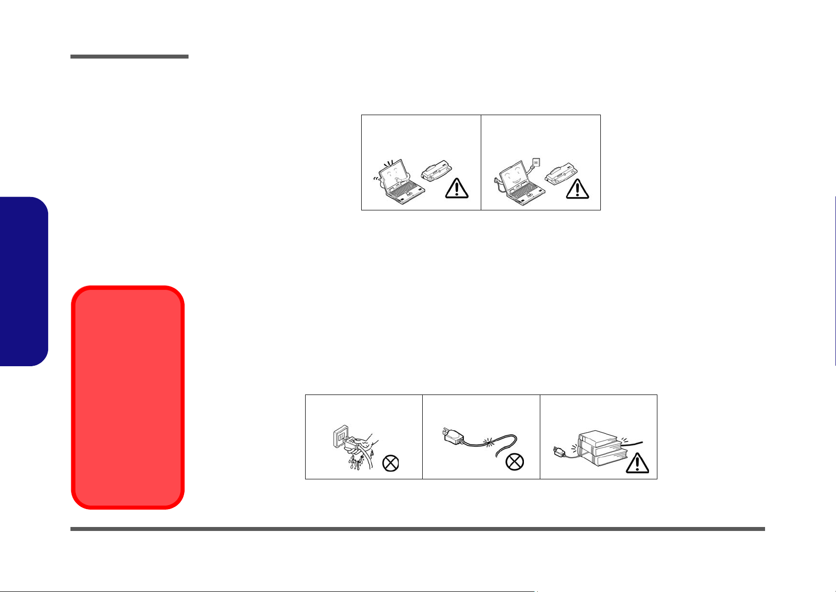
5. Take care when using peripheral devices.
Preface
Power Safety
Warning
Before you undertake
any upgrade procedures, make sure that
you have turned off the
power, and disconnected all peripherals
and cables (including
telephone lines). It is
advisable to also remove your battery in
order to prevent accidentally turning the
machine on.
Use only approved brands of
peripherals.
Unplug the power cord before
attaching peripheral devices.
Power Safety
The computer has specific power requirements:
• Only use a power adapter approved for use with this computer.
• Your AC adapter may be designed for international travel but it still requires a steady, uninterrupted power supply. If you are
unsure of your local power specifications, consult your service representative or local power company.
• The power adapter may have either a 2-prong or a 3-prong grounded plug. The third prong is an important safety feature; do
not defeat its purpose. If you do not have access to a compatible outlet, have a qualified electrician install one.
• When you want to unplug the power cord, be sure to disconnect it by the plug head, not by its wire.
• Make sure the socket and any extension cord(s) you use can support the total current load of all the connected devices.
• Before cleaning the computer, make sure it is disconnected from any external power supplies.
Do not plug in the power
cord if you are wet.
Do not use the power cord if
it is broken.
Do not place heavy objects
on the power cord.
VI
Page 9

Battery Precautions
• Only use batteries designed for this computer. The wrong battery type may explode, leak or damage the computer.
• Recharge the batteries using the notebook’s system. Incorrect recharging may make the battery explode.
• Do not try to repair a battery pack. Refer any battery pack repair or replacement to your service representative or qualified service
personnel.
• Keep children away from, and promptly dispose of a damaged battery. Always dispose of batteries carefully. Batteries may explode
or leak if exposed to fire, or improperly handled or discarded.
• Keep the battery away from metal appliances.
• Affix tape to the battery contacts before disposing of the battery.
• Do not touch the battery contacts with your hands or metal objects.
Battery Disposal
The product that you have purchased contains a rechargeable battery. The battery is recyclable. At the end of
its useful life, under various state and local laws, it may be illegal to dispose of this battery into the municipal
waste stream. Check with your local solid waste officials for details in your area for recycling options or proper
disposal.
Caution
Danger of explosion if battery is incorrectly replaced. Replace only with the same or equivalent type recommended by the manufacturer. Discard used battery according to the manufacturer’s instructions.
Preface
Preface
VII
Page 10

Preface
Preface
Related Documents
You may also need to consult the following manual for additional information:
User’s Manual on CD
This describes the notebook PC’s features and the procedures for operating the computer and its ROM-based setup program. It also describes the installation and operation of the utility programs provided with the notebook PC.
VIII
Page 11

Contents
Preface
Introduction ..............................................1-1
Overview .........................................................................................1-1
System Specifications .....................................................................1-2
Design Differences .......................................................................... 1-5
Gloss Style Top Cover Designs ......................................................1-6
External Locator - Top View ..........................................................1-7
External Locator - Front & Left Side Views ...................................1-8
External Locator - Right Side & Rear Views .................................. 1-9
External Locator - Bottom View ...................................................1-10
Mainboard Overview - Top (Key Parts) .......................................1-11
Mainboard Overview - Bottom (Key Parts) ..................................1-12
Mainboard Overview - Top (Connectors) .....................................1-13
Mainboard Overview - Bottom (Connectors) ...............................1-14
Disassembly ...............................................2-1
Overview .........................................................................................2-1
Maintenance Tools ..........................................................................2-2
Connections ..................................................................................... 2-2
Maintenance Precautions .................................................................2-3
Disassembly Steps ...........................................................................2-4
Removing the Battery ......................................................................2-7
Removing the Hard Disk Drive ....................................................... 2-8
Removing the System Memory (RAM) ........................................2-10
Removing the Optical Device .......................................................2-12
Removing the Processor ................................................................2-13
Removing the Keyboard ................................................................2-15
Removing the Wireless LAN ........................................................2-16
Removing the Bottom Case ...........................................................2-17
Removing the Modem ...................................................................2-18
Removing the Audioboard ............................................................2-19
Removing the Multi-function board ............................................. 2-20
Removing the Mainboard ............................................................. 2-21
Removing the TouchPad and Click Board ................................... 2-22
Removing the Inverter .................................................................. 2-23
Removing the Speakers ................................................................ 2-24
Removing the LCD Panel ............................................................. 2-25
Removing the PC Camera Module ............................................... 2-25
Part Lists ..................................................A-1
Part List Illustration Location ........................................................ A-2
Top (M350H) ................................................................................. A-3
Bottom (M350H) ........................................................................... A-4
LCD (M350H) ............................................................................... A-5
CD-ROM Drive - QSI (M350H) ................................................... A-6
CD-ROM Drive - SAMSUNG (M350H) ...................................... A-7
CD-RW Drive - KME (M350H) .................................................... A-8
CD-RW Drive - TEAC (M350H) .................................................. A-9
Combo Drive - QSI (M350H) ...................................................... A-10
Combo Drive - TEAC-SAMSUNG (M350H) ............................. A-11
DVD-ROM Drive - QSI (M350H) .............................................. A-12
DVD-ROM Drive - TOSHIBA (M350H) ................................... A-13
Top (M360H) ............................................................................... A-14
Bottom (M360H) ......................................................................... A-15
LCD (M360H) ............................................................................. A-16
CD-ROM Drive - QSI (M360H) ................................................. A-17
CD-ROM Drive - SAMSUNG (M360H) .................................... A-18
CD-RW Drive - KME (M360H) .................................................. A-19
CD-RW Drive - TEAC (M360H) ................................................ A-20
Combo Drive - QSI (M360H) ...................................................... A-21
Combo Drive - TEAC-SAMSUNG (M360H) ............................. A-22
DVD-ROM Drive - QSI (M360H) .............................................. A-23
Preface
IX
Page 12

Preface
DVD-Dual Drive (M360H) .......................................................... A-24
Top (M362H) ...............................................................................A-25
Bottom (M362H) ..........................................................................A-26
LCD (M362H) .............................................................................. A-27
CD-ROM Drive - QSI (M362H) .................................................. A-28
CD-ROM Drive - SAMSUNG (M362H) ..................................... A-29
CD-RW Drive - KME (M362H) .................................................. A-30
CD-RW Drive - TEAC (M362H) ................................................. A-31
Combo Drive - QSI (M362H) ...................................................... A-32
Combo Drive - TEAC-SAMSUNG (M362H) .............................A-33
DVD-ROM Drive - QSI (M362H) ............................................... A-34
DVD-Dual Drive (M362H) .......................................................... A-35
Top (M363H) ...............................................................................A-36
Bottom (M363H) ..........................................................................A-37
LCD (M363H) .............................................................................. A-38
CD-ROM Drive - QSI (M363H) .................................................. A-39
Preface
CD-ROM Drive - SAMSUNG (M363H) ..................................... A-40
CD-RW Drive - KME (M363H) .................................................. A-41
CD-RW Drive - TEAC (M363H) ................................................. A-42
Combo Drive - QSI (M363H) ...................................................... A-43
Combo Drive - TEAC-SAMSUNG (M363H) .............................A-44
DVD-ROM Drive - QSI (M363H) ............................................... A-45
DVD-Dual Drive (M363H) .......................................................... A-46
Schematic Diagrams................................. B-1
System Block Diagram ................................................................... B-2
Socket 479 - 1 of 2 ......................................................................... B-3
Socket 479 - 2 of 2 ......................................................................... B-4
Montara GM-1 ................................................................................ B-5
Montara GM-2 ................................................................................ B-6
Montara GM-3 ................................................................................ B-7
DDRAM ......................................................................................... B-8
DDR Termination ...........................................................................B-9
Clock Generator ............................................................................B-10
LVDS; CRT ..................................................................................B-11
ICH4-1 (1 of 3) .............................................................................B-12
ICH4-2 (2 of 3) .............................................................................B-13
ICH4-3 (3 of 3) .............................................................................B-14
USB 2.0, Wireless LAN ...............................................................B-15
MDC, BT, CCT ............................................................................B-16
HDD, CDROM .............................................................................B-17
LAN RTL8100B ...........................................................................B-18
ROM .............................................................................................B-19
TI1394 (TSB43AB21) ..................................................................B-20
Hitachi H8S ..................................................................................B-21
CON; Mini-PCI ............................................................................B-22
Audio Codec ALC202 ..................................................................B-23
PCMCIA (ENE1410) ....................................................................B-24
PCMCIA Socket ...........................................................................B-25
AC IN; Power Button ...................................................................B-26
CH7011; TV-Out ..........................................................................B-27
V_CORE .......................................................................................B-28
Charger .........................................................................................B-29
Multi-Function Board ...................................................................B-30
Audio Jack Board .........................................................................B-31
5V, 3.3V, 12VS, +1.2V ................................................................B-32
+2.5V, +1.25V, +1.5V ..................................................................B-33
Click Board ...................................................................................B-34
X
Page 13

1: Introduction
Overview
This manual covers the information you need to service or upgrade the M350H/ M360H/ M362H/ M363H series notebook computer. Information about operating the computer (e.g. getting started, and the Setup utility) is in the User’s
Manual. Information about drivers (e.g. VGA & audio) is also found in User’s Manual. That manual is shipped with the
computer.
Operating systems (e.g. DOS, Windows 9x, Windows NT 4.0, Windows 2000, Windows XP, OS/2 Warp, UNIX, etc.) have
their own manuals as do application software (e.g. word processing and database programs). If you have questions about
those programs, you should consult those manuals.
The M350H/ M360H/ M362H/ M363H series notebook is designed to be upgradeable. See “Disassembly” on page 2 -
1 for a detailed description of the upgrade procedures for each specific component. Please note the warning and safety
information indicated by the “” symbol.
The balance of this chapter reviews the computer’s technical specifications and features.
Introduction
1.Introduction
Overview 1 - 1
Page 14

Introduction
System Specifications
Latest Specification Information
The specifications listed in this Appendix are correct at the time of going to press. Certain items (particularly processor types/speeds)
may be changed or updated due to the manufacturer's release schedule. Check with your service center for details.
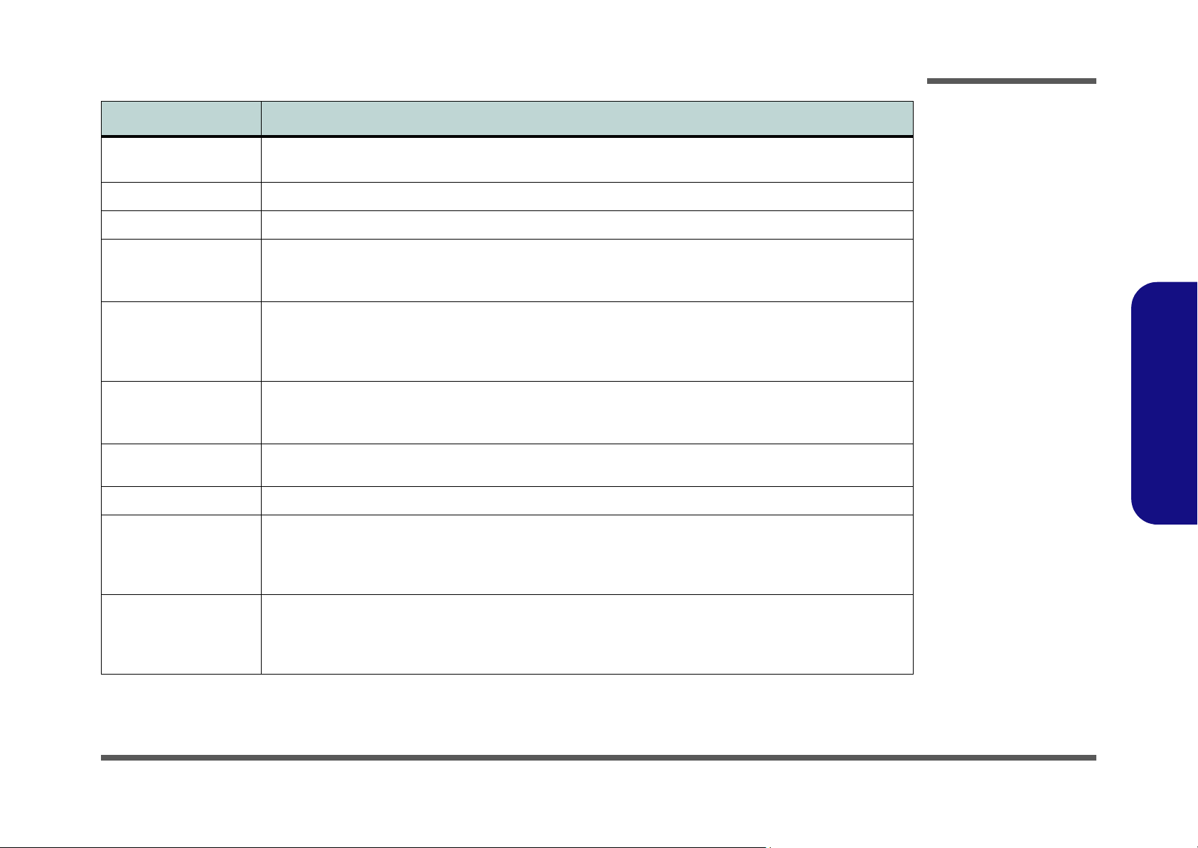
Feature Specifications
1.Introduction
1 - 2 System Specifications
Processor Types
Core Logic
Structure
Security
Intel Pentium® M - (478-pin) Micro-FCPGA package
Intel Pentium® M - (478-pin) Micro-FCPGA package
Intel Celeron® M - (478-pin) Micro-FCPGA package
Intel Celeron® M - (478-pin) Micro-FCPGA package
Intel 852GM + 82801 DBM ICH4-M
PC2001 Compliant
PCI 2.2 Compliant
Security (Kensington® Type) Lock Slot BIOS Password
(
µ0.13) 0.13 Micron Process Technology, 1MB
On-die L2 Cache & 400MHz FSB -
1.3/ 1.4/ 1.5/ 1.6/ 1.7 GHz
(
µ0.09) 0.09 Micron Process Technology, 2MB
On-die L2 Cache & 400MHz FSB 715/ 725/ 735 (1.5 ~ 1.7 GHz)
(
µ0.13) 0.13 Micron Process Technology, 512KB
On-die L2 Cache & 400MHz FSB - 320/ 330/ 340
(1.3 ~ 1.5 GHz)
(
µ0.09) 0.09 Micron Process Technology, 1MB
On-die L2 Cache & 400MHz FSB 350/ 360/ 370 (1.3 ~ 1.5 GHz)
ACPI 2.0 Compliant
Page 15
Feature Specifications
Introduction
Memory
BIOS
LCD
Display
Storage
Audio
Keyboard & Pointing
Device
PCMCIA
Interface
Two 200-pin SODIMM sockets, supporting 266
MHz DDR modules
Memory expandable up to 2GB (128/ 256/ 512/
1024 MB DDR modules)
One 512KB Flash ROM Insyde BIOS, Plug and Play (1.0a)
14.1" XGA Flat Panel TFT (1024*768)
Dynamic Video Memory Technology (Shared
Memory up to 64MB)
Fully DirectX 7/8 Compliant Graphics Engine
Supports VESA DDCI, DDC2 Specifications
High quality 2D/3D Graphics Engine
One changeable 12.7mm(h) Optical Device (CD/DVD) Type Drive
Easy changeable 2.5" 9.5 mm (h) HDD
Supports Master Mode IDE
Supports PIO Mode 4
AC’97 2.2 Compliant
Advanced Wavetable Synthesizer
DirectSound™ 3D Accelerator
Full-Duplex
Built-In Microphone
2 Built-In Speakers
A4 Size Keyboard Built-In TouchPad with Scrolling Function
One Type-II PCMCIA 3.3V/5V Socket
Two USB 2.0/1.1 Ports
One External VGA Monitor Port
One Headphone-Out Jack
One Microphone-In Jack
One S/PDIF Output Jack
One RJ-11 Jack for Plug & Play Fax/Modem
One RJ-45 Jack for 100M (Max) Fast Ethernet
One DC-in Jack
1.Introduction
Communication
56K Plug & Play Fax/Modem V.90/92 Compliant
100M (Max) Fast Ethernet (IEEE 802.3 and
802.3u Standard Compliant)
PC Camera with USB Interface (optional)
Bluetooth & MDC Modem Combo Module
(optional)
(802.11b/g) Mini PCI WLAN Module (optional)
System Specifications 1 - 3
Page 16
Introduction
Feature Specifications
1.Introduction
Power Management
Power
Environmental Spec
Physical Dimensions &
Weight
Optional
Supports ACPI 2.0
Power Button as Sleep/Resume Key
Supports Hibernate Mode
Supports Standby Mode
Full Range AC Adapter
AC-Input 100~240V, 47~63Hz
DC Output 20V, 3.25A (65W)
One 4 cell, 32 Watt, Smart Lithium-Ion Battery Pack - Approx 2 Hours battery life
One 6 cell, 48 Watt, Smart Lithium-Ion Battery Pack (optional) - Approx 3 Hours battery life
Temperature
Operating: 5
Non-Operating: -20°C ~ 60°C
312mm (w) * 263mm (d) * 27.5mm (h) Min 2.2 kg without Battery
Bluetooth & MDC Modem Combo Module
6 cell, 48 Watt, Smart Lithium-Ion Battery Pack Approx 3 Hours battery life
°C ~ 35°C
Supports Battery Low Sleep Mode
Supports Resume From Modem Ring
Supports Wake on LAN
Relative Humidity
Operating: 20% ~ 80%
Non-Operating: 10% ~ 90%
PC Camera with USB Interface
(802.11b/g) Mini PCI WLAN Module
Software DVD Player
1 - 4 System Specifications
Page 17

Design Differences
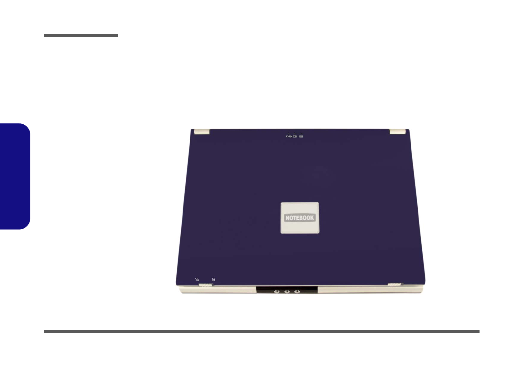
This manual refers to the two notebook designs pictured below. The designs vary slightly in external design. Photographs
used throughout this manual are of Design I. In addition to the basic designs, there are also two colored (red and blue)
gloss style top cover designs. See Figure 2 for an illustration. Note the specific care instructions for this type of cover.
Introduction
Figure 1
Design Differences
1.Introduction
Design I
Design II
System Specifications 1 - 5
Page 18
Introduction
Figure 2
Gloss Style Top
Cover
1.Introduction
Gloss Style Top Cover Designs
There are two colored (red and blue) gloss style top cover designs incorporated within the design styles of this notebook
model. Note the following guidelines for care and attention of this type of top cover.
• Remove the protective cover slowly and carefully. Do not forcibly tear off the protective cover as this may damage the surface
of the top cover.
• Do not use pointed objects on the surface of the top cover, and do not place objects on top of it.
• Do not expose the top cover to excessive heat or direct sunlight.
• Only use the soft cloth provided for cleaning the top cover, and do not use abrasive cleaners.
1 - 6 System Specifications
Page 19
Introduction
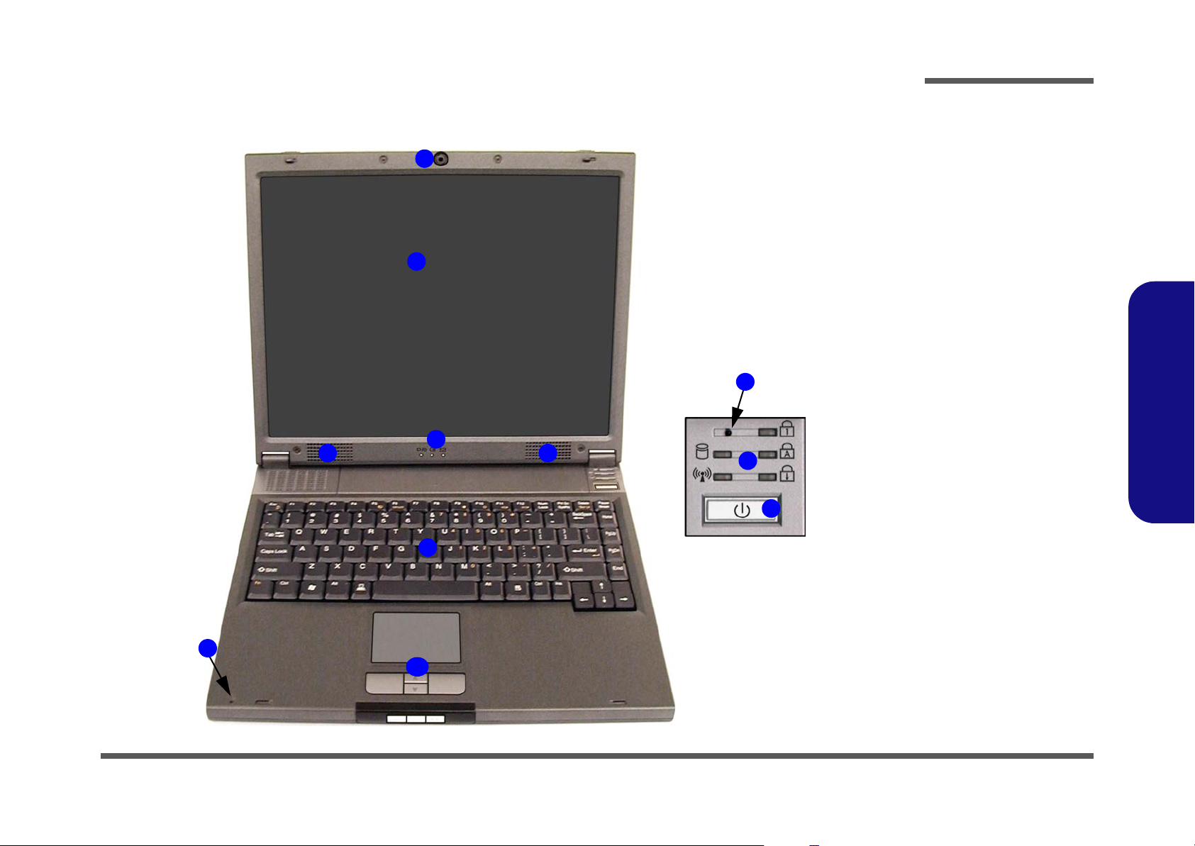
External Locator - Top View
1
2
4 4
Figure 3
Top View
1. Optional Built-In
PC Camera
2. LCD
3. LED Power &
Communication
Indicators
4. Speakers
5. Lid Sensor
6. LED Status
Indicators
7. Power Button
5
3
6
7
8. Keyboard
9. Built-In
Microphone
10. TouchPad and
Buttons
1.Introduction
8
9
10
External Locator - Top View 1 - 7
Page 20
Introduction
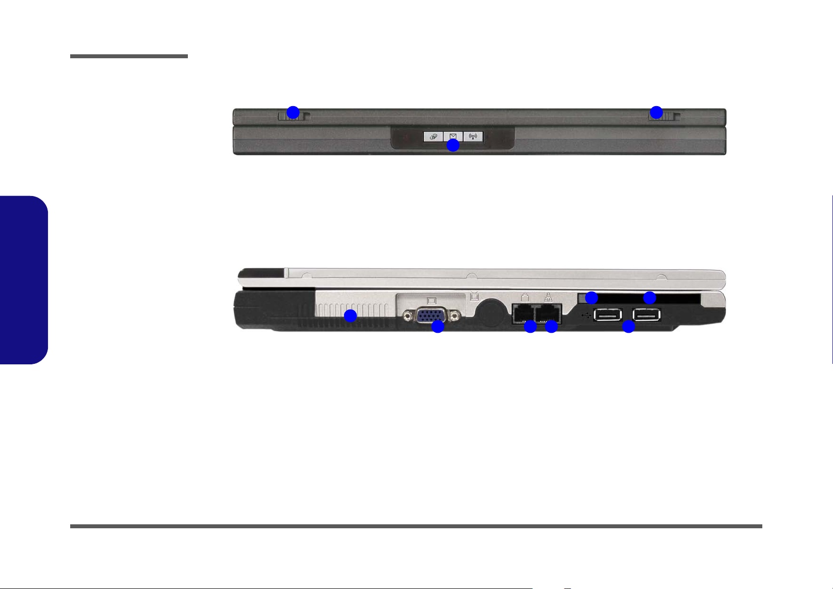
Figure 4
Front View
1. LCD Latches
2. Hot-Key Buttons
Figure 5
Left Side View
1.Introduction
1. Vent
2. External Monitor
(CRT) Port
3. RJ-11 Phone Jack
4. RJ-45 LAN Jack
5. 2 * USB 2.0 Ports
6. PC Card Slot
Eject Button
7. PC Card Slot
External Locator - Front & Left Side Views
1
2
1
2 3 4 5
1
6
7
1 - 8 External Locator - Front & Left Side Views
Page 21
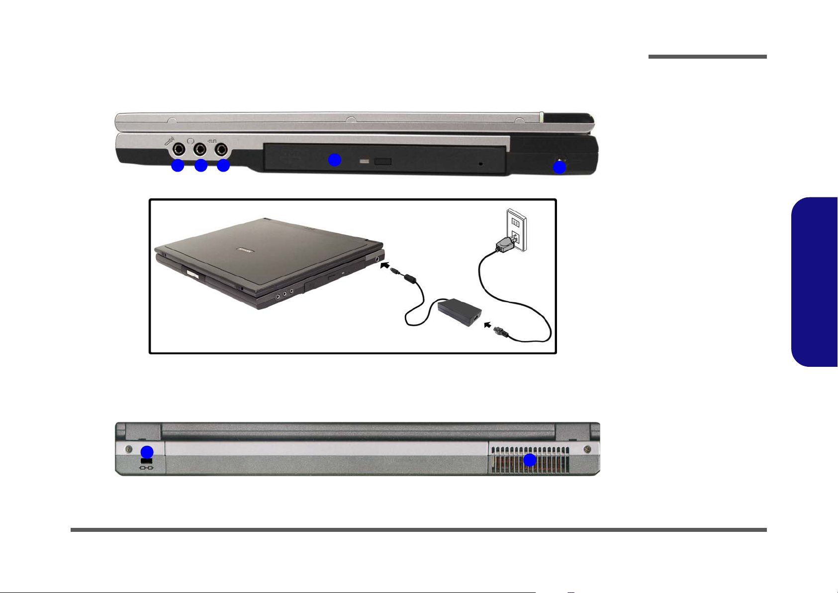
External Locator - Right Side & Rear Views
Introduction
Figure 6
Right Side View
1 2 3
4
5
1. Microphone-In
Jack
2. Headphone-Out
Jack
3. S/P DIF Output
Jack
4. Optical Device
Bay
5. DC-In Jack
1.Introduction
Figure 7
Rear View
1
2
1. Security Lock Slot
2. Vent
External Locator - Right Side & Rear Views 1 - 9
Page 22
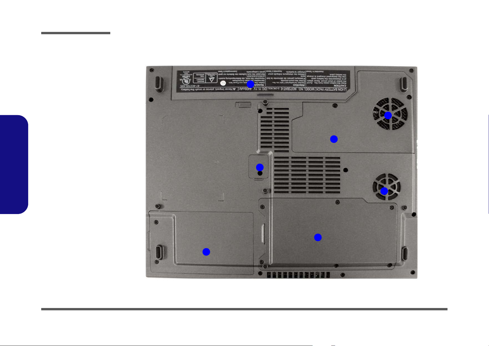
Introduction
Figure 8
Bottom View
External Locator - Bottom View
1. Vent/Fan Intakes
2. Battery
3. CPU Cover
4. RAM & WLAN
Module Cover
5. Optical Device
Screw Cover
6. Hard Disk
Module Cover
1.Introduction
2
1
3
5
1
4
1 - 10 External Locator - Bottom View
6
Page 23
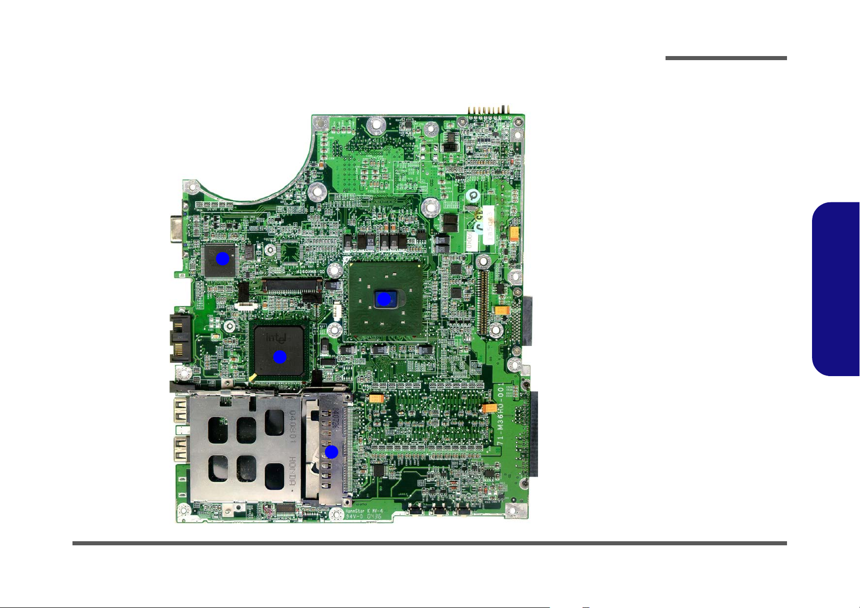
Introduction
Mainboard Overview - Top (Key Parts)
4
3
2
Figure 9
Mainboard Top
Key Parts
1. PC Card
Assembly
2. Southbridge Intel 82801DB
3. Northbridge Intel 82852GM
4. H8 Keyboard
Controller
1.Introduction
1
Mainboard Overview - Top (Key Parts) 1 - 11
Page 24
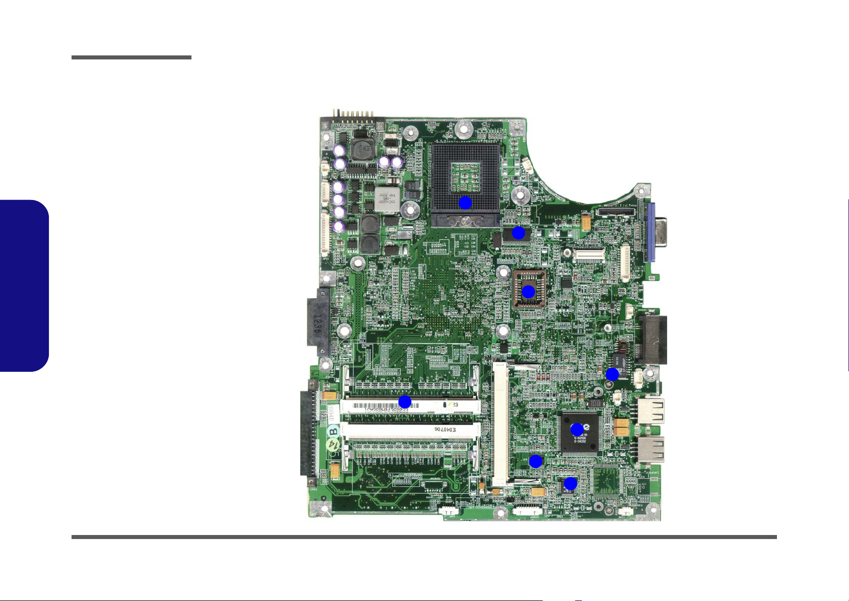
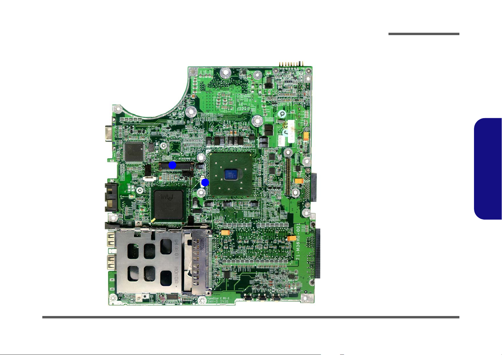
Introduction
Figure 10
Mainboard Bottom
Key Parts
1. Memory Sockets
(no memory
installed)
2. CPU Socket (no
CPU installed)
3. Clock Generator
4. BIOS EEPROM
5. LAN Transformer
6. CardBus ENE
1410
7. ALC202 - Audio
Codec
8. Audio Amplifier
1.Introduction
Mainboard Overview - Bottom (Key Parts)
2
3
4
1 - 12 Mainboard Overview - Bottom (Key Parts)
5
1
6
8
7
Page 25
Introduction
Mainboard Overview - Top (Connectors)
2
1
Figure 11
Mainboard Top
Connectors
1. TouchPad Cable
Connector (JTP1)
2. Keyboard
Connector (JKB1)
1.Introduction
Mainboard Overview - Top (Connectors) 1 - 13
Page 26
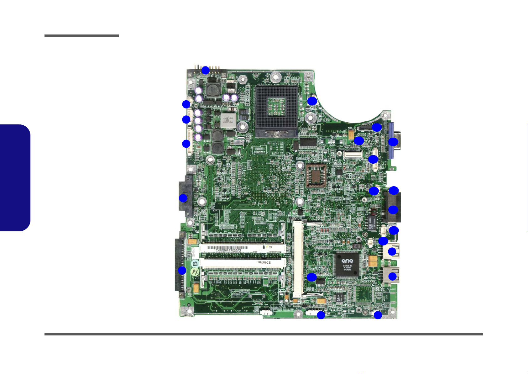
Introduction
Figure 12
Mainboard Bottom
Connectors
1. Battery Connector
(JBATT1)
2. RTC (JBAT1)
3. Power Cable Connector
(JPWR1)
4. Multi-function Board
Cable Connector
(JMFC1)
5. CD-ROM Connector
(JCD1)
6. Hard Disk Connector
(JHDD1)
7. Audio Board Cable
Connector (JAUDIO1)
8. Int. MIC (JMIC1)
9. USB Connector (JUSB1
& JUSB2)
10. Int. Speaker Cable
1.Introduction
Connector (JSPK2)
11. Int. Speaker Cable
Connector (JSPK1)
12. LAN Connector
(JMLAN1)
13. Modem Cable Connector
(JMODEM1)
14. TV-Out Connector
(JSVIDEO1)
15. Inverter Connector
(JINV1)
16. VGA-Out Connector
(JVGA1)
17. LCD (LVDS) Connector
(JLCD1)
18. Modem Connector
(JMDC1)
19. Fan Cable Connector
(JFAN1)
Mainboard Overview - Bottom (Connectors)
1
2
3
4
5
6
19
20
7 8
18
15
14
17
16
13
12
11
10
9
9
1 - 14 Mainboard Overview - Bottom (Connectors)
Page 27

2: Disassembly
Overview
This chapter provides step-by-step instructions for disassembling the M350H/ M360H/ M362H/ M363H series notebook’s parts and subsystems. When it comes to reassembly, reverse the procedures (unless otherwise indicated).
We suggest you completely review any procedure before you take the computer apart.
Disassembly
Procedures such as upgrading/replacing the RAM, optical device and hard disk are included in the User’s Manual but are
repeated here for your convenience.
To make the disassembly process easier each section may have a box in the page margin. Information contained under
the figure # will give a synopsis of the sequence of procedures involved in the disassembly procedure. A box with a
lists the relevant parts you will have after the disassembly process is complete. Note: The parts listed will be for the disassembly procedure listed ONLY, and not any previous disassembly step(s) required. Refer to the part list for the previous disassembly procedure. The amount of screws you should be left with will be listed here also.
A box with a will also provide any possible helpful information. A box with a contains warnings.
An example of these types of boxes are shown in the sidebar.
2.Disassembly
Information
Warning
Overview 2 - 1
Page 28

Disassembly
2.Disassembly
NOTE: All disassembly procedures assume that the system is turned OFF, and disconnected from any power supply (the
battery is removed too).
Maintenance Tools
The following tools are recommended when working on the notebook PC:
• M3 Philips-head screwdriver
• M2.5 Philips-head screwdriver (magnetized)
• M2 Philips-head screwdriver
• Small flat-head screwdriver
• Pair of needle-nose pliers
• Anti-static wrist-strap
Connections
Connections within the computer are one of four types:
Locking collar sockets for ribbon connectors To release these connectors, use a small flat-head screwdriver to
gently pry the locking collar away from its base. When replacing the connection, make sure the connector is oriented in the
same way. The pin1 side is usually not indicated.
2 - 2 Overview
Pressure sockets for multi-wire connectors To release this connector type, grasp it at its head and gently
rock it from side to side as you pull it out. Do not pull on the
wires themselves. When replacing the connection, do not try to
force it. The socket only fits one way.
Pressure sockets for ribbon connectors To release these connectors, use a small pair of needle-nose pli-
ers to gently lift the connector away from its socket. When replacing the connection, make sure the connector is oriented in
the same way. The pin1 side is usually not indicated.
Board-to-board or multi-pin sockets To separate the boards, gently rock them from side to side as
you pull them apart. If the connection is very tight, use a small
flat-head screwdriver - use just enough force to start.
Page 29

Maintenance Precautions
The following precautions are a reminder. To avoid personal injury or damage to the computer while performing a removal and/or replacement job, take the following precautions:
1. Don't drop it. Perform your repairs and/or upgrades on a stable surface. If the computer falls, the case and other
components could be damaged.
2. Don't overheat it. Note the proximity of any heating elements. Keep the computer out of direct sunlight.
3. Avoid interference. Note the proximity of any high capacity transformers, electric motors, and other strong mag-
netic fields. These can hinder proper performance and damage components and/or data. You should also monitor
the position of magnetized tools (i.e. screwdrivers).
4. Keep it dry. This is an electrical appliance. If water or any other liquid gets into it, the computer could be badly
damaged.
5. Be careful with power. Avoid accidental shocks, discharges or explosions.
•Before removing or servicing any part from the computer, turn the computer off and detach any power supplies.
•When you want to unplug the power cord or any cable/wire, be sure to disconnect it by the plug head. Do not pull on the wire.
6. Peripherals – Turn off and detach any peripherals.
7. Beware of static discharge. ICs, such as the CPU and main support chips, are vulnerable to static electricity.
Before handling any part in the computer, discharge any static electricity inside the computer. When handling a
printed circuit board, do not use gloves or other materials which allow static electricity buildup. We suggest that
you use an anti-static wrist strap instead.
8. Beware of corrosion. As you perform your job, avoid touching any connector leads. Even the cleanest hands produce oils which can attract corrosive elements.
9. Keep your work environment clean. Tobacco smoke, dust or other air-born particulate matter is often attracted
to charged surfaces, reducing performance.
10. Keep track of the components. When removing or replacing any part, be careful not to leave small parts, such as
screws, loose inside the computer.
Disassembly
Power Safety
Warning
Before you undertake
any upgrade procedures, make sure that
you have turned off the
power, and disconnected all peripherals
and cables (including
telephone lines). It is
advisable to also remove your battery in
order to prevent accidentally turning the
machine on.
2.Disassembly
Cleaning
Do not apply cleaner directly to the computer, use a soft clean cloth.
Do not use volatile (petroleum distillates) or abrasive cleaners on any part of the computer.
Overview 2 - 3
Page 30

Disassembly
Disassembly Steps
The following table lists the disassembly steps, and on which page to find the related information. PLEASE PERFORM
THE DISASSEMBLY STEPS IN THE ORDER INDICATED.
2.Disassembly
To remove the Battery:
1. Remove the battery page 2 - 7
To remove the HDD:
1. Remove the battery page 2 - 7
2. Remove the HDD page 2 - 8
To remove the System Memory:
1. Remove the battery page 2 - 7
2. Remove the system memory page 2 - 10
To remove the Optical Device:
1. Remove the battery page 2 - 7
2. Remove the optical device page 2 - 12
To remove the Processor:
1. Remove the battery page 2 - 7
2. Remove the processor page 2 - 13
To remove the Keyboard:
1. Remove the battery page 2 - 7
2. Remove the keyboard page 2 - 15
To remove the Wireless LAN:
1. Remove the battery page 2 - 7
2. Remove the processor page 2 - 13
3. Remove the wireless LAN page 2 - 16
To remove the Bottom Case:
1. Remove the battery page 2 - 7
2. Remove the HDD page 2 - 8
3. Remove the system memory page 2 - 10
4. Remove the optical device page 2 - 12
5. Remove the processor page 2 - 13
6. Remove the bottom case page 2 - 17
To remove the Modem:
1. Remove the battery page 2 - 7
2. Remove the bottom case page 2 - 17
3. Remove the modem page 2 - 18
To remove the Audioboard:
1. Remove the battery page 2 - 7
2. Remove the HDD page 2 - 8
3. Remove the optical device page 2 - 12
4. Remove the processor page 2 - 13
5. Remove the bottom case page 2 - 17
6. Remove the audioboard page 2 - 19
2 - 4 Disassembly Steps
Page 31

Disassembly
To remove the Multi-function board:
1. Remove the battery page 2 - 7
2. Remove the HDD page 2 - 8
3. Remove the optical device page 2 - 12
4. Remove the processor page 2 - 13
5. Remove the bottom case page 2 - 17
6. Remove the multi-function board page 2 - 20
To remove the Mainboard:
1. Remove the battery page 2 - 7
2. Remove the HDD page 2 - 8
3. Remove the system memory page 2 - 10
4. Remove the optical device page 2 - 12
5. Remove the modem page 2 - 18
6. Remove the processor page 2 - 13
7. Remove the keyboard page 2 - 15
8. Remove the bottom case page 2 - 17
9. Remove the audioboard page 2 - 19
10. Remove the multi-function board page 2 - 20
11. Remove the mainboard page 2 - 21
To remove the TouchPad & Click Board:
1. Remove the battery page 2 - 7
2. Remove the HDD page 2 - 8
3. Remove the system memory page 2 - 10
4. Remove the optical device page 2 - 12
5. Remove the modem page 2 - 18
6. Remove the processor page 2 - 13
7. Remove the keyboard page 2 - 15
8. Remove the bottom case page 2 - 17
9. Remove the audioboard page 2 - 19
10. Remove the multi-function board page 2 - 20
11. Remove the mainboard page 2 - 21
12. Remove the touchpad & click board page 2 - 22
To remove the Inverter:
1. Remove the battery page 2 - 7
2. Remove the inverter page 2 - 23
To remove the Speakers:
1. Remove the battery page 2 - 7
2. Remove the HDD page 2 - 8
3. Remove the optical device page 2 - 12
4. Remove the processor page 2 - 13
5. Remove the bottom case page 2 - 17
6. Remove the multi-function board page 2 - 20
7. Remove the mainboard page 2 - 21
8. Remove the inverter page 2 - 23
9. Remove the speakers page 2 - 24
2.Disassembly
Disassembly Steps 2 - 5
Page 32

Disassembly
2.Disassembly
To remove the LCD Panel:
1. Remove the battery page 2 - 7
2. Remove the HDD page 2 - 8
3. Remove the optical device page 2 - 12
4. Remove the processor page 2 - 13
5. Remove the bottom case page 2 - 17
6. Remove the multi-function board page 2 - 20
7. Remove the inverter page 2 - 23
8. Remove the LCD panel page 2 - 25
To remove the PC Camera:
1. Remove the battery page 2 - 7
2. Remove the inverter page 2 - 23
3. Remove the PC Camera page 2 - 25
2 - 6 Disassembly Steps
Page 33

Removing the Battery
1. Turn the computer off, and turn it over.
2. Locate the battery bay at point
3. Slide the battery lock in the direction of the arrow (towards the unlock symbol ), and hold it in place (Figure
1b).
4. Slide the Battery
a.
2
3
out of the computer’s battery bay (Figure 1c).
1
(Figure 1a).
b.
Disassembly
Figure 1
Battery Removal
a. Locate the battery re-
lease latch.
b. Slide the battery lock to
the left and hold.
c. Slide the battery out.
1
2
c.
3
2.Disassembly
3. Battery
Removing the Battery 2 - 7
Page 34

Disassembly
Removing the Hard Disk Drive
Figure 2
HDD Assembly
Removal
a. Remove the 2 screws.
b. Remove the cover.
2.Disassembly
The hard disk drive is mounted in a removable case and can be taken out to accommodate other 2.5" IDE hard disk drives
with a height of 9.5mm (h). Follow your operating system’s installation instructions, and install all necessary drivers and
utilities (as outlined in Chapter 4 of the User’s Manual) when setting up a new hard disk.
Hard Disk Upgrade Process
1. Turn off the computer, turn it over and remove the battery (page 2 - 7).
2. Remove screws
1 2 3
& (Figure 2a) from the hard disk cover, and remove the cover .
a. b.
HDD System Warning
New HDD’s are blank. Before you begin make sure:
You have backed up any
data you want to keep from
your old HDD.
You have all the CD-ROMs
and FDDs required to install your operating system
and programs.
1
3
If you have access to the
3. Hard Disk Cover
•2 Screws
internet, download the latest application and hardware driver updates for the
operating system you plan
to install. Copy these to a
removable medium.
2 - 8 Removing the Hard Disk Drive
2
Page 35

Disassembly
3. Pull the tab to slide the hard disk assembly in the direction of the arrow (Figure 3a).
4. Lift the hard disk assembly up out off the computer
5. Remove screws - , and separate the hard disk cover from the hard disk (Figure 3c).
1 2
3
4 7 8 9
(Figure 3b).
6. Reverse the process to install a new hard disk.
a.
c.
4
1
2
7
8
6
b.
9
Figure 3
HDD Assembly
Removal (Cont.)
a. Slide out the HDD as-
sembly.
b. Lift the HDD assembly
out of the bay.
5
c. Remove the screws to
separate the HDD and
cover.
2.Disassembly
3
9. Hard Disk
•4 Screws
Removing the Hard Disk Drive 2 - 9
Page 36

Disassembly
Removing the System Memory (RAM)
Figure 4
Memory Socket
Cover Removal
a. Remove the screws.
b. Carefully lift the cover off
the computer.
2.Disassembly
The computer has two memory sockets for 200 pin (SO-DIMM) Small Outline Dual In-line Memory Modules supporting DDR 266MHz (see “Memory” on page 1 - 3). The main memory can be expanded up to 2GB. The SO-DIMM modules supported are 128MB, 256MB, 512MB and 1024MB. The total memory size is automatically detected by the POST
routine once you turn on your computer.
Memory Upgrade Process
1. Turn off the computer, turn it over and remove the battery (page 2 - 7).
2. Remove screws - (Figure 4a) from the memory socket cover
3. Carefully lift up the memory socket cover off the computer (Figure 4b).
4. If there is a module currently installed which needs to be upgraded/replaced then remove it.
a.
1 6
.
7
b.
1
2
3
5. Socket Cover
•4 Screws
2 - 10 Removing the System Memory (RAM)
7
6
5
4
Page 37

Disassembly
5. Gently pull the two release latches ( & in Figure 5a) on the sides of the memory socket toward the sides of
1 2
the computer.
b.a.
3
1
6. The module (Figure 5b) will pop-up, and you can remove it.
3
2
7. Pull the latches to release the second module if necessary.
8. Insert a new module holding it at about a 30° angle and fit the connectors firmly into the memory slot.
9. The module’s pin alignment will allow it to only fit one way. Make sure the module is seated as far into the slot as
it will go. DO NOT FORCE IT; it should fit without much pressure.
10. Press the module in and down towards the mainboard until the slot levers click into place to secure the module.
11. Replace the memory socket cover and the 6 screws (see Figure 4).
12. Restart the computer.
13. The BIOS will register the new memory configuration as it starts up.
Figure 5
Removing/
Installing a RAM
Module
a. Pull the release
latches.
b. Remove the mod-
ule.
2.Disassembly
Contact Warning
Be careful not to touch
the metal pins on the
module’s connecting
edge. Even the cleanest hands have oils
which can attract particles, and degrade the
module’s performance.
3. RAM Module
Removing the System Memory (RAM) 2 - 11
Page 38

Disassembly
Removing the Optical Device
Figure 6
Optical Device
Removal
a. Remove the screws.
b. Carefully lift the cover off
the computer.
c. Push the optical device
out off the computer at
point 2.
d. Remove the optical de-
vice.
2.Disassembly
1. Turn off the computer, turn it over and remove the battery (page 2 - 7).
2. Remove screw (Figure 6a) and carefully lift up the optical device removal cover (Figure 6b).
3. Use a screwdriver to carefully push the optical device assembly out of the computer at point (Figure 6c).
1 2
3 4
4. Insert the new device and carefully slide it into the computer (the device only fits one way. DO NOT FORCE IT; The
screw holes should line up.
5. Replace the optical device removal cover and the screw.
6. Restart the computer to allow it to automatically detect the new device.
a.
b.
2
1
c.
2. Optical Device Removal Cover
3. Optical Device
•1 Screw
2 - 12 Removing the Optical Device
4
3
Page 39

Removing the Processor
1. Turn off the computer, remove the battery (page 2 - 7) and turn it over.
2. Remove screws - from the CPU cover
3. Carefully lift up the CPU cover off the computer.
4. Remove screws
5. Carefully lift up the heat sink (Figure 7c) off the computer.
6. Remove screws
7. Carefully lift up the fan cover (Figure 7d) off the computer.
a.
1 2
3
- (Figure 7c) from the heat sink in the order indicated on the label.
4 6
7
- (Figure 7d) from the fan cover.
8 10
11
.
2
b.
1
6
Disassembly
Figure 7
Processor Removal
a. Remove the screws.
b. Carefully lift the cover off
and remove the screws
in the order indicated.
c. Remove the heat sink
and remove the screws.
d. Carefully lift the fan cov-
er off the computer.
3
2.Disassembly
c.
10
4
5
d.
8
7
9
11
3. CPU Cover
7. Heat Sink
11. Fan shield cover
•8 Screws
Removing the Processor 2 - 13
Page 40

Disassembly
Figure 8
Processor Removal
(cont’d)
a. Turn the release latch to
unlock the CPU.
b. Lift the CPU out of the
socket.
2.Disassembly
8. Turn the release latch towards the unlock symbol , to release the CPU (Figure 8a).
9. Carefully (it may be hot) lift the CPU up out of the socket (Figure 8b).
1
2
10. When re-inserting the CPU, pay careful attention to the pin alignment; it will fit only one way (don’t force it!).
a.
1
LockedUnlocked
b.
2. CPU
2 - 14 Removing the Processor
Caution
2
The heat sink, and
CPU area in general,
contains parts which
are subject to high
temperatures. Allow
the area time to cool
before removing these
parts.
Page 41

Removing the Keyboard
1. Turn off the computer, remove the battery (page 2 - 7).
2. Press the three keyboard latches at the top of the keyboard to elevate the keyboard from its normal position (you
may need to use a small screwdriver to do this).
3. Carefully lift the keyboard up and out, being careful not to bend the keyboard ribbon cable (Figure 9b).
4. Disconnect the keyboard ribbon cable from the locking collar socket (Figure 9b) and lift the keyboard up out
2 3
of the computer.
5. Remove screw and disconnect the cables
a.
4
- .
5 6
c.
1
Disassembly
Figure 9
Keyboard Removal
a. Press the latches to ele-
vate the keyboard.
b. Disconnect the keyboard
cable from the locking
collar.
c. Remove the keyboard.
d. Remove screw and dis-
connect the cables.
2.Disassembly
b.
3
1
d.
4
3. Keyboard
6
•1 Screw
5
Removing the Keyboard 2 - 15
Page 42

Disassembly
Figure 10
Wireless LAN
Removal
a. Pull the release latches,
and disconnect the cable
b. Remove the module.
2.Disassembly
Removing the Wireless LAN
1. Turn off the computer, turn it over and remove the battery (page 2 - 7), and RAM cover (page 2 - 10).
2. Gently pull the two release latches ( & in Figure 10a) on the sides of the wireless LAN toward the sides of
the computer, and carefully disconnect the antenna cable .
3. The module (Figure 10b) will pop-up, and you can remove it (Figure 10c).
a. b.
4
1
2
1 2
3
3
4
4. Wireless LAN
Module
.
2 - 16 Removing the Wireless LAN
4
Page 43

Removing the Bottom Case
Disassembly
1. Turn off the computer, remove the battery (page 2 - 7), hard disk (page 2 - 8), RAM (page 2 - 10), Optical Device
(page 2 - 12), and CPU (page 2 - 13).
2. Remove screws
3. Remove screws
4. Carefully lift the bottom case
- (Figure 11a) from the bottom of the computer and disconnect cable .
1 13 14
- (Figure 11b).
15 16
17 18
off the LCD and top case assembly (Figure 11c).
a.
1
10
11
12
2
14
3
13
9
8
7
6
4
5
b.
15
16
Figure 11
LCD & Bottom Case
Removal
a. Remove the screws from
the bottom of the computer and disconnect the
cable.
b. Remove the screws from
the side of the computer.
c. Lift the bottom case off
the LCD and top case
assembly.
2.Disassembly
c.
17
18
17. LCD & top case
18. Bottom case
•15 Screws
Removing the Bottom Case 2 - 17
Page 44

Disassembly
Figure 12
Modem Removal
a. Remove the screws.
b. Carefully disconnect the
cables and connector,
and remove the modem.
2.Disassembly
Removing the Modem
1. Turn off the computer, turn it over and remove the battery (page 2 - 7), hard disk (page 2 - 8), RAM (page 2 - 10),
Optical Device (page 2 - 12), CPU (page 2 - 13) and bottom case (page 2 - 17).
2. Remove screws - (Figure 12a).
3. Carefully disconnect cables -
a. b.
1 2
3 4 5
1
2
and connector , and lift the modem (Figure 12b) off the computer.
6
5
4
6
3
6. Modem
.
•2 Screws
2 - 18 Removing the Modem
Page 45

Removing the Audioboard
Disassembly
1. Turn off the computer, remove the battery (page 2 - 7), hard disk (page 2 - 8), RAM (page 2 - 10), Optical Device
(page 2 - 12), CPU (page 2 - 13), and bottom case (page 2 - 17).
2. Remove screws
3. Lift the audioboard off the mainboard assembly (Figure 15b).
1 2 3 4
- and disconnect cables & .
5
a.
1
3
b.
2
4
Figure 13
Audioboard
Removal
a. Remove screws and dis-
connect the cables.
d. Lift the audioboard off
the mainboard.
2.Disassembly
5
6
5. Audioboard
6. Audio Cable
•2 Screws
Removing the Audioboard 2 - 19
Page 46

Disassembly
Removing the Multi-function board
Figure 14
Multi-function board
Removal
a. Remove screws and dis-
connect the cables.
d. Lift the multi-function-
board and bracket off the
mainboard assembly.
2.Disassembly
1. Turn off the computer, remove the battery (page 2 - 7), hard disk (page 2 - 8), RAM (page 2 - 10), Optical Device
(page 2 - 12), CPU (page 2 - 13), and bottom case (page 2 - 17).
2. Remove screws
3. Lift the multi-function board and bracket off the mainboard assembly (Figure 15b).
a. b.
3
4
1 2 3 8
& and disconnect cables - (Figure 15a).
9 10
1
5
2
6
7
8
10
9
9. Multi-function
board
10. Bracket
•2 Screws
2 - 20 Removing the Multi-function board
Page 47

Removing the Mainboard
Disassembly
1. Turn off the computer, remove the battery (page 2 - 7), hard disk (page 2 - 8), RAM (page 2 - 10), Optical Device
(page 2 - 12), modem (page 2 - 18), CPU (page 2 - 13), keyboard (page 2 - 15), bottom case (page 2 - 17), and
audioboard (page 2 - 19).
2. Remove screws
3. Disconnect cables - and remove screws - (Figure 15c).
4. Separate the mainboard , and top case , then disconnect the TouchPad cable (Figure 15d).
1 3
- and lift the DC/DC board from the mainboard .
6
9 10 11
5 12
4 5
13
a. b.
1
5
4
2
3
c. d.
11
6
7
Figure 15
Mainboard Removal
a. Remove screws.
b. Lift the DC/DC board off
the mainboard.
c. Disconnect the cables
and remove the screws.
d. Separate the mainboard,
and top case. Disconnect the TouchPad cable.
2.Disassembly
10
12
5
8
9
13
4. DC/DC board
5. Mainboard
12. Top case
•5 Screws
Removing the Mainboard 2 - 21
Page 48

Disassembly
Removing the TouchPad and Click Board
Figure 16
TouchPad and Click
Board Removal
a. Remove the screws.
b. Separate the click board
from the top case.
c. Remove the screws.
d. Separate the touchpad
from the top case.
2.Disassembly
1. Turn off the computer, remove the battery (page 2 - 7), hard disk (page 2 - 8), RAM (page 2 - 10), Optical Device
(page 2 - 12), modem (page 2 - 18), CPU (page 2 - 13), keyboard (page 2 - 15), bottom case (page 2 - 17), audioboard (page 2 - 19), and mainboard (page 2 - 21).
2. Remove screws - (Figure 16a) and disconnect cables
1 4 5 6
& from the click board assembly , and lift
7
the click board off the top case (Figure 16b).
3. Remove screws
4. Lift the TouchPad
a.
8
- (Figure 16c).
10
11
off the top case and separate the TouchPad from its casing (Figure 16d).
12
b.
2
6
1
5
3
4
7
9
c.
10
d.
8
7. Click Board
11. TouchPad
12. Casing
•7 Screws
2 - 22 Removing the TouchPad and Click Board
11
12
Page 49

Removing the Inverter
Disassembly
1. Turn off the computer, remove the battery (page 2 - 7).
2. Remove the rubber covers and screws - from the LCD (Figure 17a).
3. Run your finger around the middle of the frame to carefully unsnap the LCD front panel module from the back.
4. Remove screw
5. Lift the inverter off the LCD assembly (Figure 17d).
a.
6 7 8
from the inverter over and disconnect the cables & from the rear of the inverter .
9
1
1 4
5
2
b.
5
3
4
c.
6
Figure 17
Inverter Removal
a. Remove the rubber cov-
ers and screws.
b. Unsnap the frame from
the LCD front panel
module.
c. Remove screw from in-
verter and disconnect
the cables.
c. Lift the inverter off the
LCD assembly.
2.Disassembly
d.
7
8
9
5. LCD Front Panel
9. Inverter
• 4 Rubber covers
•5 Screws
Removing the Inverter 2 - 23
Page 50

Disassembly
Removing the Speakers
Figure 18
Speakers Removal
a. Remove the screws.
b. Separate the speakers
from the LCD front panel
assembly.
2.Disassembly
1. Turn off the computer, remove the battery (page 2 - 7), hard disk (page 2 - 8), Optical Device (page 2 - 12), CPU
(page 2 - 13), bottom case (page 2 - 17), mainboard (page 2 - 21), and inverter (page 2 - 23).
2. Remove the screws - (Figure 18a) from the speakers.
3. Separate the speakers (Figure 18b) from the LCD front panel assembly.
a.
b.
1 4
5
1
4
2
5
3
5
5. Speakers
•4 Screws
2 - 24 Removing the Speakers
Page 51

Removing the LCD Panel
Disassembly
1. Turn off the computer, remove the battery (page 2 - 7), hard disk (page 2 - 8), Optical Device (page 2 - 12), CPU
(page 2 - 13), bottom case (page 2 - 17), mainboard (page 2 - 21), and inverter (page 2 - 23).
2. Remove screws - from the side of the LCD panel (Figure 19a).
3. Gently lift the LCD panel off the LCD assembly (Figure 19b).
a. b.
1
2
1 4
7
3
7
4
Removing the PC Camera Module
1. Turn off the computer, remove the battery (page 2 - 7), and inverter (page 2 - 23).
2. Disconnect cable from the PC camera module (Figure 20a).
3. Lift the PC camera module (Figure 20b) off the LCD assembly.
a.
1
2
b.
2
1
Figure 19
LCD Panel Removal
a. Remove screws from the
side of the LCD panel.
b. Lift the LCD panel off the
LCD assembly.
7. LCD Panel
•4 Screws
Figure 20
PC Camera Removal
a. Disconnect the cable.
b. Lift the PC Camera off
the LCD assembly.
2.Disassembly
2. PC Camera
Removing the LCD Panel 2 - 25
Page 52

Disassembly
2.Disassembly
2-26
Page 53

Appendix A:Part Lists
This appendix breaks down the M350H/ M360H/ M362H/ M363H series notebook’s construction into a series of illustrations. The component part numbers are indicated in the tables opposite the drawings.
Note: This section indicates the manufacturer’s part numbers. Your organization may use a different system, so be sure
to cross-check any relevant documentation.
Note: Some assemblies may have parts in common (especially screws). However, the part lists DO NOT indicate the
total number of duplicated parts used.
Part Lists
Note: Be sure to check any update notices. The parts shown in these illustrations are appropriate for the system at the
time of publication. Over the product life, some parts may be improved or re-configured, resulting in new part numbers.
A.Part Lists
A-1
Page 54

Part Lists
Table 1 - 1
Part List Illustration
Location
Part List Illustration Location
The following table indicates where to find the appropriate part list illustration.
Part M350H M360H M362H M363H
Top
page A - 3 page A - 14 page A - 25 page A - 36
A.Part Lists
Bottom
LCD
CD-ROM Drive - QSI
CD-ROM Drive - SAMSUNG
CD-RW Drive - KME
CD-RW Drive - TEAC
Combo Drive - QSI
Combo Drive - TEAC-SAMSUNG
DVD-ROM Drive - QSI
DVD-ROM Drive - TOSHIBA
DVD-Dual Drive
page A - 4 page A - 15 page A - 26 page A - 37
page A - 5 page A - 16 page A - 27 page A - 38
page A - 6 page A - 17 page A - 28 page A - 39
page A - 7 page A - 18 page A - 29 page A - 40
page A - 8 page A - 19 page A - 30 page A - 41
page A - 9 page A - 20 page A - 31 page A - 42
page A - 10 page A - 21 page A - 32 page A - 43
page A - 11 page A - 22 page A - 33 page A - 44
page A - 12 page A - 23 page A - 34 page A - 45
page A - 13 ---
- page A - 24 page A - 35 page A - 46
A - 2 Part List Illustration Location
Page 55

Top (M350H)
Part Lists
Figure 1
Top (M350H)
A.Part Lists
Top (M350H) A - 3
Page 56

Part Lists
Bottom (M350H)
A.Part Lists
Bottom (M350H)
Figure 2
A - 4 Bottom (M350H)
Page 57

LCD (M350H)
Part Lists
Figure 3
LCD (M350H)
A.Part Lists
LCD (M350H) A - 5
Page 58

Part Lists
CD-ROM Drive -
QSI (M350H)
A.Part Lists
CD-ROM Drive - QSI (M350H)
Figure 4
A - 6 CD-ROM Drive - QSI (M350H)
Page 59

CD-ROM Drive - SAMSUNG (M350H)
Part Lists
Figure 5
CD-ROM Drive -
SAMSUNG
(M350H)
A.Part Lists
CD-ROM Drive - SAMSUNG (M350H) A - 7
Page 60

Part Lists
CD-RW Drive -
KME (M350H)
A.Part Lists
CD-RW Drive - KME (M350H)
Figure 6
A - 8 CD-RW Drive - KME (M350H)
Page 61

CD-RW Drive - TEAC (M350H)
Part Lists
Figure 7
CD-RW Drive TEAC (M350H)
A.Part Lists
CD-RW Drive - TEAC (M350H) A - 9
Page 62

Part Lists
Combo Drive - QSI
A.Part Lists
Combo Drive - QSI (M350H)
Figure 8
(M350H)
A - 10 Combo Drive - QSI (M350H)
Page 63

Combo Drive - TEAC-SAMSUNG (M350H)
Part Lists
Figure 9
Combo Drive -
TEAC-SAMSUNG
(M350H)
A.Part Lists
Combo Drive - TEAC-SAMSUNG (M350H) A - 11
Page 64

Part Lists
Figure 10
DVD-ROM Drive -
QSI (M350H)
A.Part Lists
DVD-ROM Drive - QSI (M350H)
A - 12 DVD-ROM Drive - QSI (M350H)
Page 65

DVD-ROM Drive - TOSHIBA (M350H)
Part Lists
Figure 11
DVD-ROM Drive -
TOSHIBA (M350H)
A.Part Lists
DVD-ROM Drive - TOSHIBA (M350H) A - 13
Page 66

Part Lists
Top (M360H)
A.Part Lists
Top (M360H)
Figure 12
A - 14 Top (M360H)
Page 67

Bottom (M360H)
Part Lists
Figure 13
Bottom (M360H)
A.Part Lists
Bottom (M360H) A - 15
Page 68

Part Lists
LCD (M360H)
A.Part Lists
LCD (M360H)
Figure 14
A - 16 LCD (M360H)
Page 69

CD-ROM Drive - QSI (M360H)
Part Lists
Figure 15
CD-ROM Drive -
QSI (M360H)
A.Part Lists
CD-ROM Drive - QSI (M360H) A - 17
Page 70

Part Lists
Figure 16
CD-ROM Drive -
SAMSUNG
A.Part Lists
CD-ROM Drive - SAMSUNG (M360H)
(M360H)
A - 18 CD-ROM Drive - SAMSUNG (M360H)
Page 71

CD-RW Drive - KME (M360H)
Part Lists
Figure 17
CD-RW Drive -
KME (M360H)
A.Part Lists
CD-RW Drive - KME (M360H) A - 19
Page 72

Part Lists
Figure 18
CD-RW Drive -
TEAC (M360H)
A.Part Lists
CD-RW Drive - TEAC (M360H)
A - 20 CD-RW Drive - TEAC (M360H)
Page 73

Combo Drive - QSI (M360H)
Part Lists
Figure 19
Combo Drive - QSI
(M360H)
A.Part Lists
Combo Drive - QSI (M360H) A - 21
Page 74

Part Lists
Figure 20
Combo Drive -
TEAC-SAMSUNG
A.Part Lists
Combo Drive - TEAC-SAMSUNG (M360H)
(M360H)
A - 22 Combo Drive - TEAC-SAMSUNG (M360H)
Page 75

DVD-ROM Drive - QSI (M360H)
Part Lists
Figure 21
DVD-ROM Drive -
QSI (M360H)
A.Part Lists
DVD-ROM Drive - QSI (M360H) A - 23
Page 76

Part Lists
Figure 22
DVD-Dual Drive
A.Part Lists
DVD-Dual Drive (M360H)
(M360H)
A - 24 DVD-Dual Drive (M360H)
Page 77

Top (M362H)
Part Lists
Figure 23
Top (M362H)
A.Part Lists
Top (M362H) A - 25
Page 78

Part Lists
Bottom (M362H)
A.Part Lists
Bottom (M362H)
Figure 24
A - 26 Bottom (M362H)
Page 79

LCD (M362H)
Part Lists
Figure 25
LCD (M362H)
A.Part Lists
LCD (M362H) A - 27
Page 80

Part Lists
CD-ROM Drive -
QSI (M362H)
A.Part Lists
CD-ROM Drive - QSI (M362H)
Figure 26
A - 28 CD-ROM Drive - QSI (M362H)
Page 81

CD-ROM Drive - SAMSUNG (M362H)
Part Lists
Figure 27
CD-ROM Drive -
SAMSUNG
(M362H)
A.Part Lists
CD-ROM Drive - SAMSUNG (M362H) A - 29
Page 82

Part Lists
Figure 28
CD-RW Drive -
KME (M362H)
A.Part Lists
CD-RW Drive - KME (M362H)
A - 30 CD-RW Drive - KME (M362H)
Page 83

CD-RW Drive - TEAC (M362H)
Part Lists
Figure 29
CD-RW Drive TEAC (M362H)
A.Part Lists
CD-RW Drive - TEAC (M362H) A - 31
Page 84

Part Lists
Figure 30
Combo Drive - QSI
A.Part Lists
Combo Drive - QSI (M362H)
(M362H)
A - 32 Combo Drive - QSI (M362H)
Page 85

Combo Drive - TEAC-SAMSUNG (M362H)
Part Lists
Figure 31
Combo Drive -
TEAC-SAMSUNG
(M362H)
A.Part Lists
Combo Drive - TEAC-SAMSUNG (M362H) A - 33
Page 86

Part Lists
Figure 32
DVD-ROM Drive -
QSI (M362H)
A.Part Lists
DVD-ROM Drive - QSI (M362H)
A - 34 DVD-ROM Drive - QSI (M362H)
Page 87

DVD-Dual Drive (M362H)
Part Lists
Figure 33
DVD-Dual Drive
(M362H)
A.Part Lists
DVD-Dual Drive (M362H) A - 35
Page 88

Part Lists
Top (M363H)
A.Part Lists
Top (M363H)
Figure 34
A - 36 Top (M363H)
Page 89

Bottom (M363H)
Part Lists
Figure 35
Bottom (M363H)
A.Part Lists
Bottom (M363H) A - 37
Page 90

Part Lists
LCD (M363H)
A.Part Lists
LCD (M363H)
Figure 36
A - 38 LCD (M363H)
Page 91

CD-ROM Drive - QSI (M363H)
Part Lists
Figure 37
CD-ROM Drive -
QSI (M363H)
A.Part Lists
CD-ROM Drive - QSI (M363H) A - 39
Page 92

Part Lists
Figure 38
CD-ROM Drive -
SAMSUNG
A.Part Lists
CD-ROM Drive - SAMSUNG (M363H)
(M363H)
A - 40 CD-ROM Drive - SAMSUNG (M363H)
Page 93

CD-RW Drive - KME (M363H)
Part Lists
Figure 39
CD-RW Drive -
KME (M363H)
A.Part Lists
CD-RW Drive - KME (M363H) A - 41
Page 94

Part Lists
Figure 40
CD-RW Drive -
TEAC (M363H)
A.Part Lists
CD-RW Drive - TEAC (M363H)
A - 42 CD-RW Drive - TEAC (M363H)
Page 95

Combo Drive - QSI (M363H)
Part Lists
Figure 41
Combo Drive - QSI
(M363H)
A.Part Lists
Combo Drive - QSI (M363H) A - 43
Page 96

Part Lists
Figure 42
Combo Drive -
TEAC-SAMSUNG
A.Part Lists
Combo Drive - TEAC-SAMSUNG (M363H)
(M363H)
A - 44 Combo Drive - TEAC-SAMSUNG (M363H)
Page 97

DVD-ROM Drive - QSI (M363H)
Part Lists
Figure 43
DVD-ROM Drive -
QSI (M363H)
A.Part Lists
DVD-ROM Drive - QSI (M363H) A - 45
Page 98

Part Lists
Figure 44
DVD-Dual Drive
A.Part Lists
DVD-Dual Drive (M363H)
(M363H)
A - 46 DVD-Dual Drive (M363H)
Page 99

Appendix B:Schematic Diagrams
This appendix has circuit diagrams of the M350H/ M360H/ M362H/ M363H notebook’s PCB’s. The following table
indicates where to find the appropriate schematic diagram.
Schematic Diagrams
Diagram - Page Diagram - Page
System Block Diagram - Page B - 2 ROM - Page B - 19
Socket 479 - 1 of 2 - Page B - 3 TI1394 (TSB43AB21) - Page B - 20
Socket 479 - 2 of 2 - Page B - 4 Hitachi H8S - Page B - 21
Montara GM-1 - Page B - 5 CON; Mini-PCI - Page B - 22
Montara GM-2 - Page B - 6 Audio Codec ALC202 - Page B - 23
Montara GM-3 - Page B - 7 PCMCIA (ENE1410) - Page B - 24
DDRAM - Page B - 8 PCMCIA Socket - Page B - 25
DDR Termination - Page B - 9 AC IN; Power Button - Page B - 26
Clock Generator - Page B - 10 CH7011; TV-Out - Page B - 27
LVDS; CRT - Page B - 11 V_CORE - Page B - 28
ICH4-1 (1 of 3) - Page B - 12 Charger - Page B - 29
ICH4-2 (2 of 3) - Page B - 13 Multi-Function Board - Page B - 30
ICH4-3 (3 of 3) - Page B - 14 Audio Jack Board - Page B - 31
USB 2.0, Wireless LAN - Page B - 15 5V, 3.3V, 12VS, +1.2V - Page B - 32
Table 1
Schematic
Diagrams
B.Schematic Diagrams
MDC, BT, CCT - Page B - 16 +2.5V, +1.25V, +1.5V - Page B - 33
HDD, CDROM - Page B - 17 Click Board - Page B - 34
LAN RTL8100B - Page B - 18
B-1
Page 100

Schematic Diagrams
System Block Diagram
Sheet 1 of 29
System Block
Diagram
B.Schematic Diagrams
POWER BOARD
CLICK BOARD
AUDIO BOARD
CLOCK
GEN.
CCD
TOUCH PAD CONN
Wireless
Lan
CPU CORE
POEWR
(VCORE)
CRT OUT
LVDS
LCD CONN(LVDS)
USB 1USB 2USB 3
SM BUS
TEMP
SENSOR
USB2.0
CPU
FAN
Banias
Processor
479 uFCPGA
PG3,4
Montara-GML
GMCH 732
uFCBGA
HUB LINK
INTEL ICH4
421 BGA
KB CTRL.
H8 2211
SYSTEM
BIOS
BATTERY
SM BUS
AC'97 LINK
PCI BUS
Pri. IDE
Sec. IDE
FWM
CD-ROM/DVD/CD-RW
O'ning *3357
MEMORY TERMINATIONS
DDR SDRAM SOCKET
SO-DIMM0 SO-DIMM1
RJ-11
DDR VR
33MHz
ATA-100
(50 Pin)
H.D.D.
MDC &
BT
MODULE
MDC CONN.
MiniPCI SOCKET
Wireless
Lan
Multi Function Board
ACIN;POWER BUTTON
Charger
MICINSPK
SPDIF
OUT
AC'97
CODEC
(ALC202)
OUT
AUDIO
AMP.
(APA2020A)
(PCI-1) (PCI-2)
LAN
RTL8100B
RJ-45
CARD
BUS
ENE-1410
PCMCIA
SOCKET*1
B - 2
KBC CONN
 Loading...