

CLEVO M22ES, M27ES, D22ES, D27ES Service manual


Notebook Computer
M22ES / M27ES / D22ES /D27ES
Service Manual
Preface
Preface
I

Preface
Preface
Notice
The company reserves the right to revise this publication or to change its contents without notice. Information contained
herein is for reference only and does not constitute a commitment on the part of the manufacturer or any subsequent vendor. They assume no responsibility or liability for any errors or inaccuracies that may appear in this publication nor are
they in anyway responsible for any loss or damage resulting from the use (or misuse) of this publication.
This publication and any accompanying software may not, in whole or in part, be reproduced, translated, transmitted or
reduced to any machine readable form without prior consent from the vendor, manufacturer or creators of this publication, except for copies kept by the user for backup purposes.
Brand and product names mentioned in this publication may or may not be copyrights and/or registered trademarks of
their respective companies. They are mentioned for identification purposes only and are not intended as an endorsement
of that product or its manufacturer.
Version 1.0
February 2003
Trademarks
Intel® and Pentium® are registered trademarks of Intel Corporation.
Windows® is a registered trademark of Microsoft Corporation.
Other brand and product names are trademarks and/or registered trademarks of their respective companies.
II

About this Manual
This manual is intended for service personnel who have completed sufficient training to undertake the maintenance and
inspection of personal computers.
It is organized to allow you to look up basic information for servicing and/or upgrading components of the computer.
The following information is included:
Chapter 1, Introduction, provides general information about the location of system elements and their specifications.
Chapter 2, Disassembly, provides step-by-step instructions for disassembling parts and subsystems and how to upgrade
elements of the system.
Appendix A, Part Lists
Appendix B, Schematic Diagrams
Appendix C, Updating the FLASH ROM BIOS
Preface
Preface
III

Preface
Related Documents
You may also need to consult the following manual for additional information:
User’s Manual on CD
This describes the computer’s features and the procedures for operating the computer and its ROM-based setup program.
It also describes the installation and operation of the utility programs provided with the computer.
Preface
IV

Preface
Contents
Introduction ........................................ 1-1
Overview .................................................................................1-1
System Specifications ..............................................................1-2
Mobile or Desktop CPU ..........................................................1-2
Processor ..................................................................................1-2
Core Logic ...............................................................................1-2
Structure ..................................................................................1-2
Security ....................................................................................1-3
Memory ...................................................................................1-3
BIOS ........................................................................................1-3
Display .....................................................................................1-3
LCD .........................................................................................1-3
Storage .....................................................................................1-4
Audio .......................................................................................1-4
Interface ...................................................................................1-5
Communication .......................................................................1-5
Power Management .................................................................1-5
Power .......................................................................................1-6
Indicators .................................................................................1-6
Environmental Spec .................................................................1-6
Physical Dimensions ...............................................................1-6
Weight .....................................................................................1-6
Optional ...................................................................................1-6
External Locator - Top Views .................................................1-7
External Locator - Right Side View & Left Side View ...........1-8
External Locator - Rear & Bottom Views ...............................1-9
Mainboard Overview - Top ...................................................1-10
Key Parts ...............................................................................1-10
Mainboard Overview - Bottom .............................................1-11
Key Parts ...............................................................................1-11
Mainboard Overview - Top .................................................. 1-12
Cable Connectors and Switches ............................................ 1-12
Mainboard Overview - Bottom ............................................. 1-13
Cable Connectors and Switches ............................................ 1-13
Disassembly .........................................2-1
Overview ................................................................................. 2-1
Maintenance Tools .................................................................. 2-2
Connections ............................................................................. 2-2
Maintenance Precautions ........................................................ 2-3
Disassembly Steps .................................................................. 2-4
Removing the Battery ............................................................. 2-6
Removing the System Memory .............................................. 2-7
Removing the Keyboard .........................................................2-8
Removing the Hard Disk Drive .............................................. 2-9
Removing the CPU ............................................................... 2-10
Removing the Modem ........................................................... 2-12
Removing the CD Device ..................................................... 2-12
Removing the Bottom Case .................................................. 2-13
Removing the Floppy Disk Drive Assembly ........................ 2-15
Removing the Mainboard ..................................................... 2-16
Removing the Inverter ..........................................................2-17
Removing the LCD Panel ..................................................... 2-18
Part Lists ............................................A-1
Part List Illustration Location ................................................ A-2
Top (M22ES) .........................................................................A-3
Bottom (M22ES) .................................................................... A-4
LCD 14" (M22ES) ................................................................. A-5
CD-ROM Drive - Toshiba (M22ES) ..................................... A-6
CD-RW Drive - Toshiba (M22ES) ........................................ A-7
Preface
V

Preface
Preface
Combo Drive - QSI (M22ES) .................................................A-8
DVD-ROM Drive - QSI (M22ES) .........................................A-9
Floppy Disk Drive (M22ES) ................................................A-10
Hard Disk Drive (M22ES) ....................................................A-11
Top (D22ES) ........................................................................A-12
Bottom (D22ES) ...................................................................A-13
LCD 14" (D22ES) ................................................................A-14
CD-ROM Drive - Toshiba (D22ES) .....................................A-15
CD-RW Drive - Toshiba (D22ES) .......................................A-16
Combo Drive - QSI (D22ES) ...............................................A-17
DVD-ROM Drive - QSI (D22ES) ........................................A-18
Floppy Disk Drive (D22ES) .................................................A-19
Hard Disk Drive (D22ES) ....................................................A-20
Top (M27ES) ........................................................................A-21
Bottom (M27ES) ..................................................................A-22
LCD 14" (M27ES) ................................................................A-23
CD-ROM Drive - QSI (M27ES) ..........................................A-24
CD-RW Drive - Toshiba (M27ES) .......................................A-25
Combo Drive - QSI (M27ES) ...............................................A-26
DVD-ROM Drive - QSI (M27ES) .......................................A-27
Floppy Disk Drive (M27ES) ................................................A-28
Hard Disk Drive (M27ES) ....................................................A-29
Top (D27ES) ........................................................................A-30
Bottom (D27ES) ...................................................................A-31
LCD 14" (D27ES) ................................................................A-32
CD-ROM Drive - QSI (D27ES) ...........................................A-33
CD-RW Drive - Toshiba (D27ES) .......................................A-34
Combo Drive - QSI (D27ES) ...............................................A-35
DVD-ROM Drive - QSI (D27ES) ........................................A-36
Floppy Disk Drive (D27ES) .................................................A-37
Hard Disk Drive (D27ES) ....................................................A-38
Schematic Diagrams ........................... B-1
System Block Diagram .......................................................... B-2
Table ...................................................................................... B-3
CPU (Socket 478) 1 of 2 ........................................................ B-4
CPU (Socket 478) 2 of 2 ........................................................ B-5
Clock Generator ..................................................................... B-6
650-1 (Host/AGP) - 1 of 4 ..................................................... B-7
650-2 (Memory for DDR) - 2 of 4 ......................................... B-8
650-3 (HyperZip/VGA/Misc) - 3 of 4 ................................... B-9
650-4 (Power) - 4 of 4 .......................................................... B-10
DDR SDRAM DIMM 1 & DIMM2 ................................... B-11
DDR SSTL-2 Termination Resistors ................................... B-12
LVDS Interface (SiS301/2LV) ............................................ B-13
961A-1 (PCI/IDE/HyperZip) - 1 of 4 .................................. B-14
961A-2 (Misc Signals) - 2 of 4 ............................................ B-15
961A-3 (USB) - 3 of 4 ......................................................... B-16
961A-4 (Power & RTC) - 4 of 4 .......................................... B-17
IDE, LVDS, Inverter Conn .................................................. B-18
PCI LAN RTL8100B ........................................................... B-19
PCMCIA PCI1410 ............................................................... B-20
1394 TSB43AB21 ................................................................ B-21
LPC Super I/O NS393 ......................................................... B-22
LPC H8 ................................................................................ B-23
Audio Codec & AMP ........................................................... B-24
Fan & Modem Conn ............................................................ B-25
CPU VCORE ....................................................................... B-26
System Power 1 SCH (+3V, +5V, +12V) ............................ B-27
System Power 2 SCH (+2.5V, +1.25V) ............................... B-28
+1.8V, 3VH8, VCCID, PWRSW ......................................... B-29
Charger-PWM ...................................................................... B-30
Hole ...................................................................................... B-31
VI

Inverter Board ....................................................................... B-32
Updating the FLASH ROM BIOS.....C-1
To update the FLASH ROM BIOS you must: .......................C-1
Preface
Preface
VII

Preface
Preface
VIII

1: Introduction
Overview
This manual covers the information you need to service or upgrade the notebook computer. Information about operating
the computer (e.g. getting started, and the Setup utility) is in the User’s Manual. Information about drivers (e.g. VGA &
audio) is also found in User’s Manual. That manual is shipped with the computer.
Operating systems (e.g. DOS, Windows 9x, Windows 2000, Windows XP, etc.) have their own manuals as do application
software (e.g. word processing and database programs). If you have questions about those programs, you should consult
those manuals.
The notebook computer is designed to be upgradeable. See “Disassembly” on page 2 - 1 for a detailed description of the
upgrade procedures for each specific component. Please note the warning and safety information indicated by the “”
symbol.
The balance of this chapter reviews the computer’s technical specifications and features.
Introduction
1.Introduction
Overview 1 - 1

Introduction
AC Adapter
Warning
The AC adapter rated
at 90W (for desktop
CPU) will power a mobile CPU. However,
the AC adapter rated
at 65W (for mobile
CPU) will NOT power a
desktop CPU.
1.Introduction
System Specifications
Mobile or Desktop CPU
The computer designs incorporate both mobile and desktop CPUs. To tell if you have a mobile or desktop CPU model,
look at the DC output rating on the bottom of the AC adapter:
• Mobile: DC-Output 20V, 3.25A, 65w
• Desktop: DC-Output 20V, 4.5A, 90w
Processor
Desktop Model
• Intel Pentium 4 Processor - (478-pin) FC-PGA2 package
(
µ0.13) 0.13 Micron Process Technology, 512KB L2 Cache & 400MHz FSB - 1.8~2.4 GHz
• Intel Celeron Processor - (478-pin) FC-PGA2 package
(
µ0.13) 0.13 Micron Process Technology, 256KB L2 Cache & 400MHz FSB - 2.0 GHz
Mobile Model
• Mobile Intel Pentium 4 Processor - (478-pin) Micro-FCPGA package
µ0.13) 0.13 Micron Process Technology, 512KB L2 Cache & 400MHz FSB - 1.4~2.4 GHz
(
• Mobile Intel Celeron Processor - (478-pin) Micro-FCPGA package
(µ0.13) 0.13 Micron Process Technology, 256KB L2 Cache & 400MHz FSB - 1.4~2.0 GHz
(You can also check the heat sink type to differentiate between the desktop and mobile CPU models.)
Core Logic
• SIS650 + 962L
Structure
• Fully PC99 Compliant
• ACPI 1.0B Compliant
1 - 2 System Specifications

Security
• Security (Kensington® type) Lock Slot
• BIOS Password
Memory
• 64-bit data bus system memory
• Expandable memory up to 1GB (depending 128/256/512MB SODIMM Modules)
• Two 200-pin DDR SODIMM sockets, supporting DDR SDRAM SODIMM (2.5V) - DDR266 compliant
BIOS
• One 4MB Flash ROM
• Phoenix BIOS with Smart Battery, Plug-and-Play (1.0a), ACPI 1.0B
Display
• UMA Architecture with 16/32/64 MB System Memory sharable as Display Memory
• UltraAGP™
• Integrated 128-bit 2D/3D graphics engine
• Motion compensation and IDCT accelerator for DVD Content Playback Accelerator
• Fully DirectX8 compliant graphic engine
• CRT resolution up to 1920 x 1200 x 16M
Video Memory Note: The system allocates or "shares" a portion of system memory for video use. "Shared" memory is
user-configurable via the SCU. The default setting is set to 32MB, and in addition, may be
adjusted to 16MB or 64MB.
Introduction
1.Introduction
LCD
• 13.3" XGA TFT (1024*768)
OR
• 14.1" XGA TFT (1024*768)
System Specifications 1 - 3

Introduction
Storage
• One fixed 3.5" 3-mode FDD
• One changeable drive for DVD-ROM (12.7mmH)/ 24X speed CD-ROM/CD-RW/Combo Drive (DVD-ROM + CD-RW)
• One changeable 2.5" 9.5/12.7mm (h) HDD
Supports DMA mode 2
Supports PIO mode 4
Supports ATA-33/ATA-66/ATA-100 IDE HDD
Audio
• AC'97 2.1 compliant interface
• Compatible with Sound-Blaster PRO™ 16
• Advanced Wavetable Synthesizer
• DirectSound™ 3D Accelerator
• Full-duplex
• Virtual AC3
• Built-in microphone
• Built-in 2 speakers
1.Introduction
1 - 4 System Specifications
Keyboard
• A4-Size Win98 keyboard included numeric keypad
• 3 application hot keys for Email, Browser and AP1
PC Card
• One Type II PCMCIA 3.3V/5V socket
• Support CardBus (PC Card95)

Interface
• Built-in TouchPad (PS/2)
• Dual USB2.0 ports (USB1.1 compatible)
• One IEEE 1394 port
• One parallel port (LPT1), supporting ECP / EPP 1.7 and 1.9
• One external CRT monitor port
• One external keyboard/mouse (PS/2 type) port
• One speaker-out jack
• One microphone-in or S/PDIF output jack for Y- cable
• One RJ-11 jack for modem
• One RJ-45 jack for 100M/10M LAN
• One DC-in jack
Communication
• 10/100Mb Ethernet LAN on board
• 56K MDC modem V.90 compliant (V.92 upgradeable by S/W Driver)
• Wireless Infrared transfer IrDA 1.1, 1cm~1M operating distance, 4Mbps FIR
Power Management
• Supports ACPI v1.0B
• Supports APM v1.2
• Soft Off by system power button
• Supports suspend to disk
• Battery low suspend
• Resume from alarm time
Introduction
1.Introduction
System Specifications 1 - 5

Introduction
AC Adapter
Warning
The AC adapter rated
at 90W (for desktop
CPU) will power a mobile CPU. However,
the AC adapter rated
at 65W (for mobile
CPU) will NOT power a
desktop CPU.
1.Introduction
Power
Desktop Model
• Full range AC adapter
AC Input: 100~240V, 47~63Hz
DC Output: 20V, 4.5A, 90W
• Supports smart Lithium-Ion battery
Mobile Model
• Full range AC adapter
AC Input: 100~240V, 47~63Hz
DC Output: 20V, 3.25A, 65W
• Supports smart Lithium-Ion battery
Indicators
• LED indicators (HDD, Power status, FDD status, Num Lock, Caps Lock, Scroll Lock, AC, Battery Icon)
Environmental Spec
• Temperature Relative Humidity
• Operating: 5
• Non-Operating: -20
°C~ 35°C Operating: 20% ~ 80%
°C ~ 60°C Non-Operating: 10% ~ 90%
Physical Dimensions
• 308 (w) x 254 (d) x 37.5 (h) mm
Weight
• 2.9 kg ~ 3.25 kg (with battery)
Optional
• DVD-ROM Drive (12.7mmH)
•CD-RW Drive (12.7mmH)
• Combination Drive (DVD-ROM and CD-RW, 12.7mmH)
• Software DVD player
• Smart Lithium-Ion battery pack
1 - 6 System Specifications
Introduction
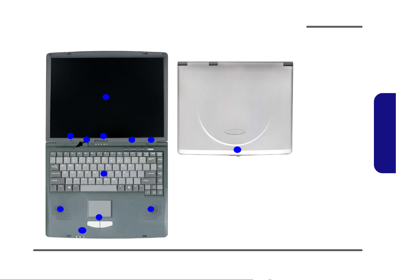
External Locator - Top Views
1
2
3
4
5 6
11
Figure 1
Top Views
1. LCD Panel
2. Microphone (builtin)
3. Close Cover
Switch
4. LED Status
Indicators
5. Hot-Key Buttons
6. Power Button
7. Keyboard
8. Speakers
9. TouchPad and
Buttons
10.LED Power
Indicators
11.LCD Latch
1.Introduction
7
8
9
10
8
External Locator - Top Views 1 - 7
Introduction
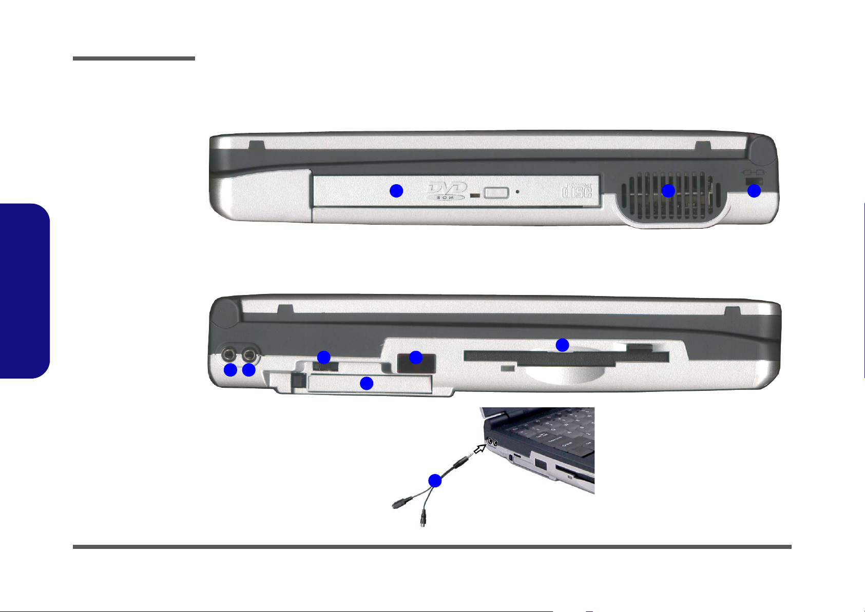
Figure 2
Right Side View
1. Security Lock
Slot
2. Vent
3. CD Device
Figure 3
Left Side View
1.Introduction
1. S/PDIF Out Port/
Microphone-In Jack
2. Headphone-Out
Jack
3. Volume Control
Knob
4. PC Card Slot
5. Infrared
Transceiver
6. Floppy Disk Drive
7. Y-cable for S/PDIF
Out/Microphone-In
External Locator - Right Side View & Left Side View
6
3
1
2
4
5
7
123
1 - 8 External Locator - Right Side View & Left Side View
Introduction
External Locator - Rear & Bottom Views
1
2 3 4 5 6 7 8 9
2
1
10
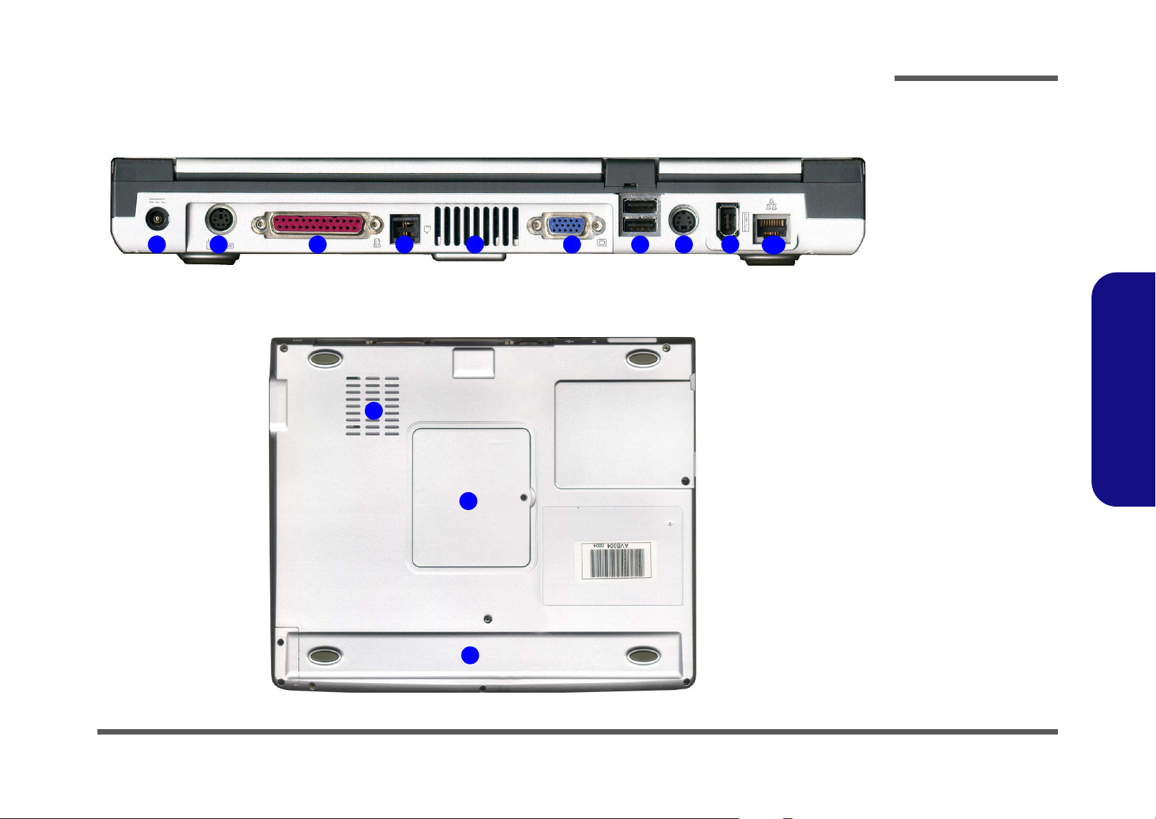
Figure 4
Rear View
1. DC-In Jack
2. PS/2 Type Port
3. Parallel Port
4. RJ-11 Phone
Jack
5. Vent
6. External Monitor
(CRT) Port
7. Dual USB Ports
8. S-Video Port
9. IEEE 1394 Port
10.RJ-45 LAN Jack
Figure 5
Bottom View
1. RAM Cover
2. Vent/Fan Outlets
3. Battery
1.Introduction
3
External Locator - Rear & Bottom Views 1 - 9
Introduction
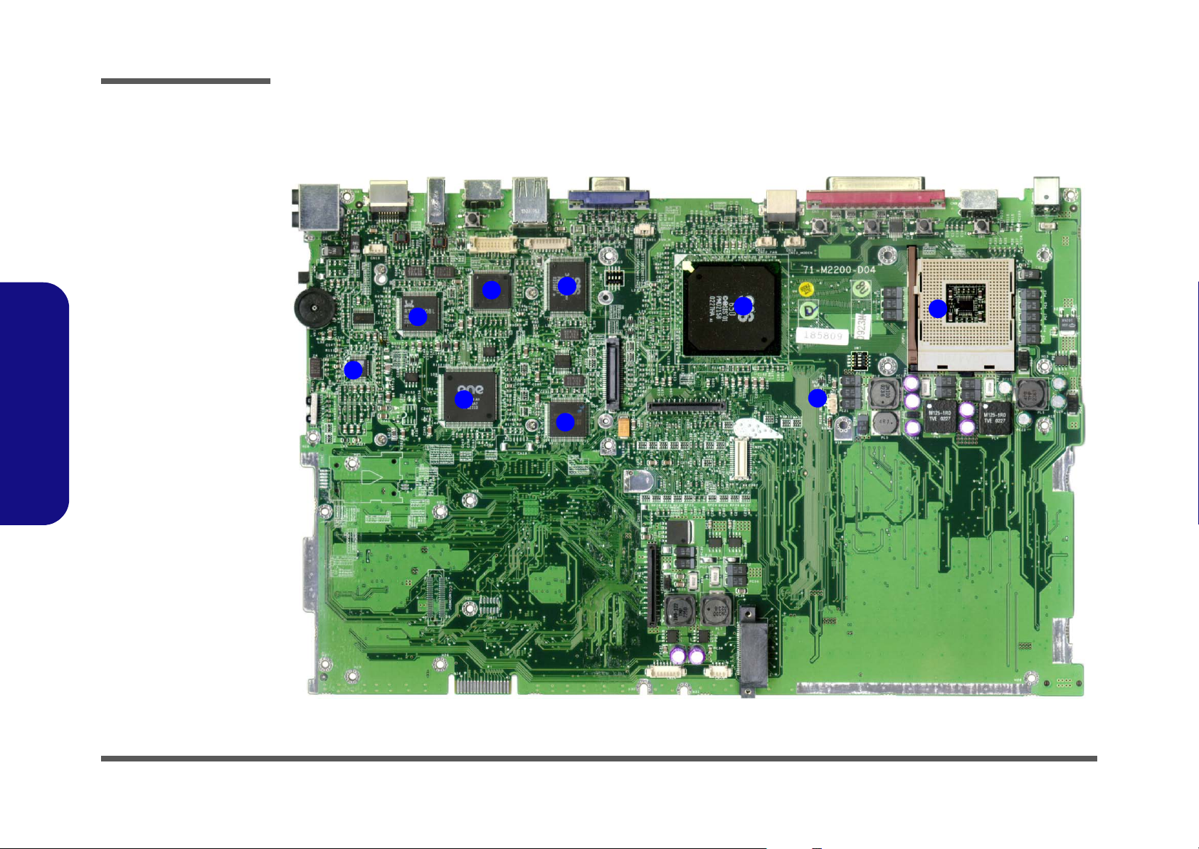
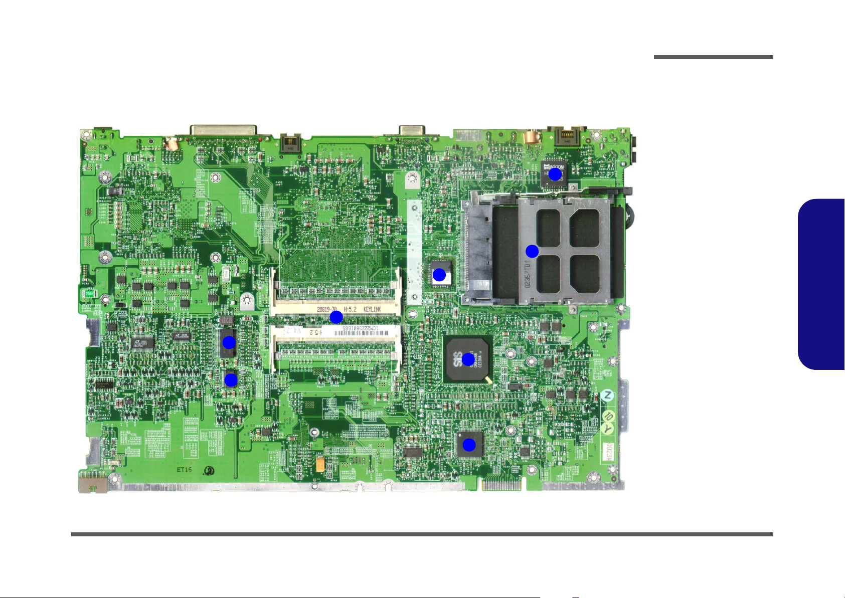
Figure 6
Mainboard
Overview - Top Key
Parts
1. CPU Socket (no
CPU Installed)
2. Northbridge SiS
650
3. SiS 301 (LVDS
Interface)
4. TSB41AB21 1394 PHY
(IEEE1394 Controller)
5. RTL8100BL LAN
Controller
6. ALC201 - AC’97
Audio Codec
1.Introduction
7. Cardbus Controller
8. H8 Keyboard
Controller
9. CMOS Battery
Mainboard Overview - Top
Key Parts
4
5
6
7
3
8
2
9
1
1-10
Introduction
Mainboard Overview - Bottom
Key Parts
7
Figure 7
Mainboard
Overview - Bottom
Key Parts
1. Super I/O Controller
4
3
5
6
2
2. Southbridge SiS
961
3. PCMCIA
4. LAN Transformer
5. Flash BIOS ROM
6. 2 * DIMM Sockets
7. Clock Generator
8. Clock Buffer
1.Introduction
8
1
Mainboard Overview - Bottom 1 - 11
Introduction
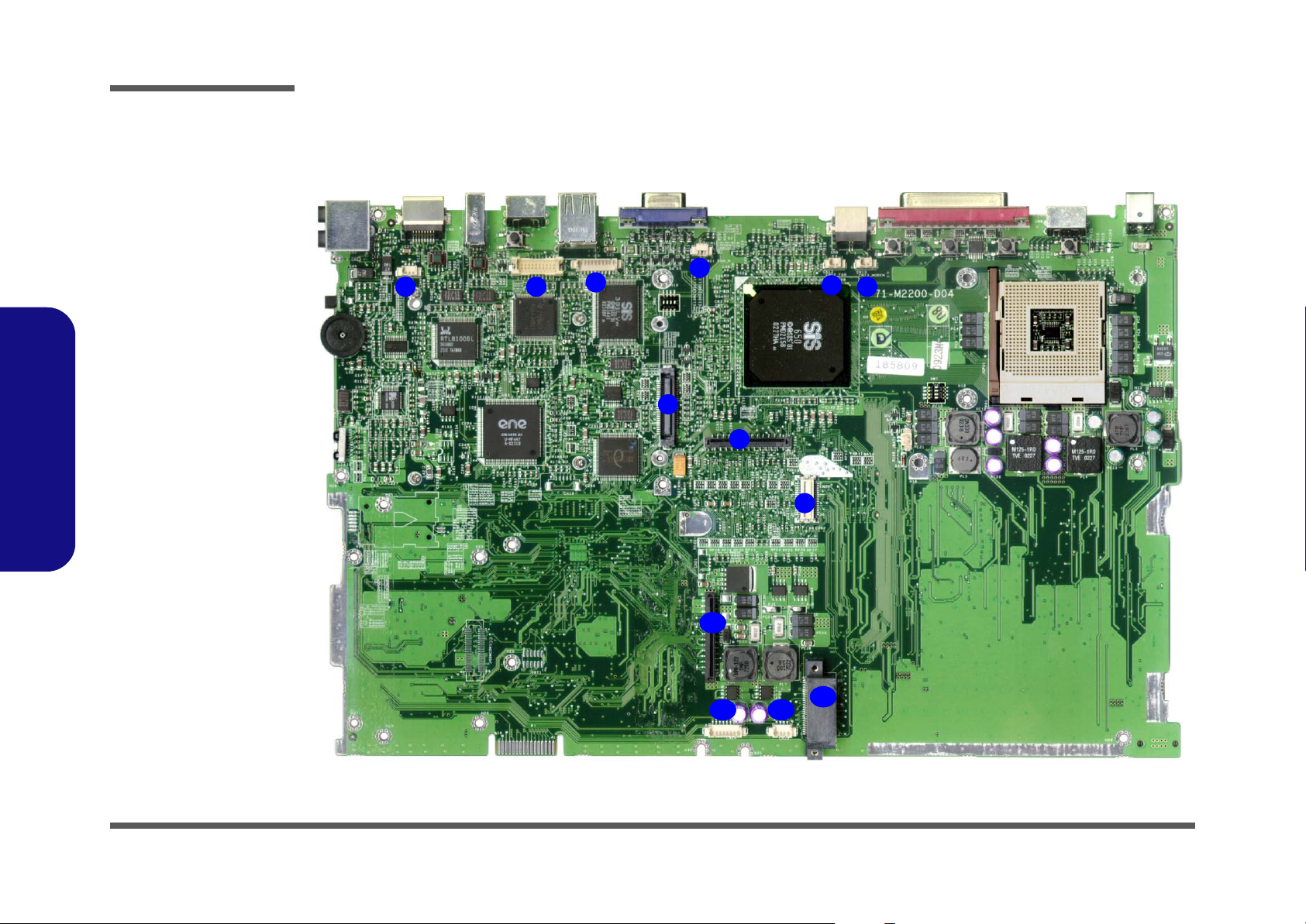
Figure 8
Mainboard Top
Cable Connectors &
Switches
1. CN16 (Microphone Cable)
2. CN15 (LCD Cable)
3. CN14 (Inverter
Cable)
4. CN11 (CPU Fan
Cable)
5. CN12 (CPU Fan
Cable)
6. CN13 (Modem
Cable)
7. CN17 (HDD Connector)
8. CN18 (Keyboard
1.Introduction
Connector)
9. CN20 (Modem
Module)
10.CN22 (FDD Cable)
11.CN24 (Touchpad
Cable)
12.CN25 (Speaker
Cable)
13.CN23 (CDROM
Connector)
Mainboard Overview - Top
Cable Connectors and Switches
1
2
3
4
5
6
7
8
9
10
11 12
13
1 - 12 Mainboard Overview - Top

Introduction
Mainboard Overview - Bottom
Cable Connectors and Switches
Figure 9
Mainboard Bottom
Cable Connectors
& Switches
1. PCMCIA Module
2. Battery Connector
1.Introduction
1
2
Mainboard Overview - Bottom 1 - 13

Introduction
1.Introduction
1-14

2: Disassembly
Overview
This chapter provides step-by-step instructions for disassembling parts and subsystems. When it comes to reassembly,
reverse the procedures (unless otherwise indicated).
We suggest you completely review any procedure before you take the computer apart.
Disassembly
Procedures such as upgrading/replacing the RAM, CD device and hard disk are included in the User’s Manual but are
repeated here for your convenience.
To make the disassembly process easier each section may have a box in the page margin. Information contained under
the figure # will give a synopsis of the sequence of procedures involved in the disassembly procedure. A box with a
lists the relevant parts you will have after the disassembly process is complete. Note: The parts listed will be for the disassembly procedure listed ONLY, and not any previous disassembly step(s) required. Refer to the part list for the previous disassembly procedure. The amount of screws you should be left with will be listed here also.
A box with a will provide any possible helpful information. A box with a contains warnings.
An example of these types of boxes are shown in the sidebar.
2.Disassembly
Information
Warning
Overview 2 - 1

Disassembly
2.Disassembly
NOTE: All disassembly procedures assume that the system is turned OFF, and disconnected from any power supply (the
battery is removed too).
Maintenance Tools
The following tools are recommended when working on the notebook PC:
• M3 Philips-head screwdriver
• M2.5 Philips-head screwdriver (magnetized)
• M2 Philips-head screwdriver
• Small flat-head screwdriver
• Pair of needle-nose pliers
• Anti-static wrist-strap
Connections
Connections within the computer are one of four types:
Locking collar sockets for ribbon connectors To release these connectors, use a small flat-head screwdriver to
gently pry the locking collar away from its base. When replacing the connection, make sure the connector is oriented in the
same way. The pin1 side is usually not indicated.
2 - 2 Overview
Pressure sockets for multi-wire connectors To release this connector type, grasp it at its head and gently
rock it from side to side as you pull it out. Do not pull on the
wires themselves. When replacing the connection, do not try to
force it. The socket only fits one way.
Pressure sockets for ribbon connectors To release these connectors, use a small pair of needle-nose pli-
ers to gently lift the connector away from its socket. When replacing the connection, make sure the connector is oriented in
the same way. The pin1 side is usually not indicated.
Board-to-board or multi-pin sockets To separate the boards, gently rock them from side to side as
you pull them apart. If the connection is very tight, use a small
flat-head screwdriver - use just enough force to start.

Maintenance Precautions
The following precautions are a reminder. To avoid personal injury or damage to the computer while performing a removal and/or replacement job, take the following precautions:
1. Don't drop it. Perform your repairs and/or upgrades on a stable surface. If the computer falls, the case and other
components could be damaged.
2. Don't overheat it. Note the proximity of any heating elements. Keep the computer out of direct sunlight.
3. Avoid interference. Note the proximity of any high capacity transformers, electric motors, and other strong mag-
netic fields. These can hinder proper performance and damage components and/or data. You should also monitor
the position of magnetized tools (i.e. screwdrivers).
4. Keep it dry. This is an electrical appliance. If water or any other liquid gets into it, the computer could be badly dam-
aged.
5. Be careful with power. Avoid accidental shocks, discharges or explosions.
• Before removing or servicing any part from the computer, turn the computer off and detach any power supplies.
• When you want to unplug the power cord or any cable/wire, be sure to disconnect it by the plug head. Do not pull on the
wire.
6. Peripherals – Turn off and detach any peripherals.
7. Beware of static discharge. ICs, such as the CPU and main support chips, are vulnerable to static electricity.
Before handling any part in the computer, discharge any static electricity inside the computer. When handling a
printed circuit board, do not use gloves or other materials which allow static electricity buildup. We suggest that you
use an anti-static wrist strap instead.
8. Beware of corrosion. As you perform your job, avoid touching any connector leads. Even the cleanest hands produce oils which can attract corrosive elements.
9. Keep your work environment clean. Tobacco smoke, dust or other air-born particulate matter is often attracted to
charged surfaces, reducing performance.
10.Keep track of the components. When removing or replacing any part, be careful not to leave small parts, such as
screws, loose inside the computer.
Disassembly
Power Safety
Warning
Before you undertake
any upgrade procedures, make sure that
you have turned off the
power, and disconnected all peripherals
and cables (including
telephone lines). It is
advisable to also remove your battery in
order to prevent accidentally turning the
machine on.
2.Disassembly
Cleaning
Do not apply cleaner directly to the computer, use a soft clean cloth.
Do not use volatile (petroleum distillates) or abrasive cleaners on any part of the computer.
Overview 2 - 3

Disassembly
Disassembly Steps
The following table lists the disassembly steps, and on which page to find the related information. PLEASE PERFORM
THE DISASSEMBLY STEPS IN THE ORDER INDICATED.
2.Disassembly
To remove the Battery:
1. Remove the battery page 2 - 6
To remove the System Memory:
1. Remove the battery page 2 - 6
2. Remove the memory page 2 - 7
To remove the Keyboard:
1. Remove the battery page 2 - 6
2. Remove the keyboard page 2 - 8
To remove the HDD:
1. Remove the battery page 2 - 6
2. Remove the keyboard page 2 - 8
3. Remove the HDD page 2 - 9
To remove the CPU:
1. Remove the battery page 2 - 6
2. Remove the keyboard page 2 - 8
3. Remove the CPU page 2 - 10
To remove the Modem:
1. Remove the battery page 2 - 6
2. Remove the keyboard page 2 - 8
3. Remove the modem page 2 - 12
To remove the CD Device:
1. Remove the battery page 2 - 6
2. Remove the keyboard page 2 - 8
3. Remove the CD device page 2 - 12
To remove the Bottom Case:
1. Remove the battery page 2 - 6
2. Remove the keyboard page 2 - 8
3. Remove the HDD page 2 - 9
4. Remove the CPU page 2 - 10
5. Remove the CD device page 2 - 12
6. Remove the bottom case page 2 - 13
To remove the FDD:
1. Remove the battery page 2 - 6
2. Remove the keyboard page 2 - 8
3. Remove the HDD page 2 - 9
4. Remove the CPU page 2 - 10
5. Remove the modem page 2 - 12
6. Remove the CD device page 2 - 12
7. Remove the bottom case page 2 - 13
8. Remove the FDD page 2 - 15
2 - 4 Disassembly Steps

To remove the Mainboard:
1. Remove the battery page 2 - 6
2. Remove the keyboard page 2 - 8
3. Remove the HDD page 2 - 9
4. Remove the CPU page 2 - 10
5. Remove the modem page 2 - 12
6. Remove the CD device page 2 - 12
7. Remove the bottom case page 2 - 13
8. Remove the FDD page 2 - 15
9. Remove the mainboard page 2 - 16
Disassembly
To remove the Inverter:
1. Remove the battery page 2 - 6
2. Remove the keyboard page 2 - 8
3. Remove the HDD page 2 - 9
4. Remove the CPU page 2 - 10
5. Remove the modem page 2 - 12
6. Remove the CD device page 2 - 12
7. Remove the bottom case page 2 - 13
8. Remove the inverter page 2 - 17
To remove the LCD Panel:
1. Remove the battery page 2 - 6
2. Remove the keyboard page 2 - 8
3. Remove the HDD page 2 - 9
4. Remove the CPU page 2 - 10
5. Remove the modem page 2 - 12
6. Remove the CD device page 2 - 12
7. Remove the bottom case page 2 - 13
8. Remove the inverter page 2 - 17
9. Remove the LCD page 2 - 18
2.Disassembly
Disassembly Steps 2 - 5
Disassembly
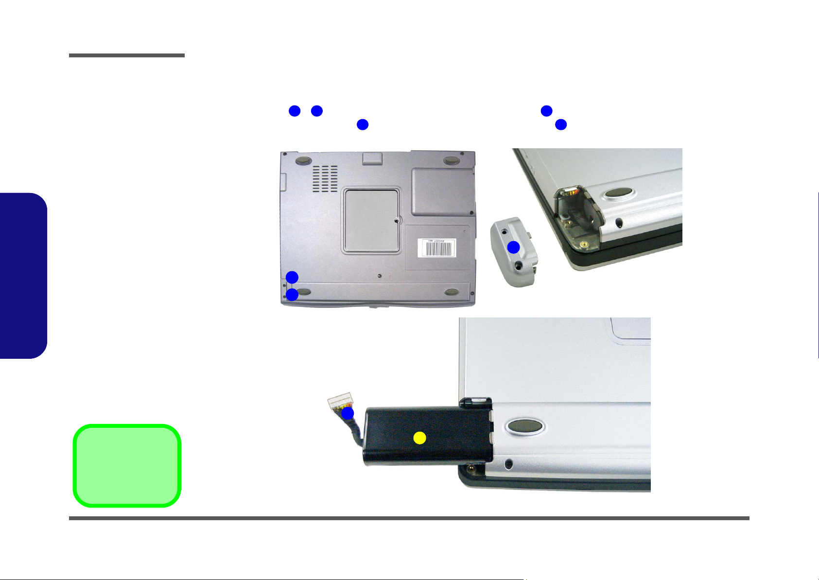
Figure 2 - 1
Battery Removal
Sequence
a. Remove the two
screws and release
the battery cover.
b. Release connector
and pull battery out.
2.Disassembly
Removing the Battery
1. Turn the computer OFF and turn it over.
2. Remove screws - in Figure 2 - 1a and release the battery cover .
3. Separate the battery connector from the computer and pull the battery out.
a.
1 2 3
4 5
3
1
2
b.
5. Battery
•2 Screws
2 - 6 Removing the Battery
4
5
 Loading...