

Clevo M190S, M192S Service Manual

Preface
I
Preface
Notebook Computer
M190S/M192S
Service Manual

Preface
II
Preface
Notice
The company reserves the right to revise this publication or to change its contents without notice. Information contained
herein is for reference only and does not constitute a commitment on the part of the manufacturer or any subsequent vendor. They assume no responsibility or liability for any errors or inaccuracies that may appear in this publication nor are
they in anyway responsible for any loss or damage resulting from the use (or misuse) of this publication.
This publication and any accompanying software may not, in whole or in part, be reproduced, translated, transmitted or
reduced to any machine readable form without prior consent from the vendor, manufacturer or creators of this publication, except for copies kept by the user for backup purposes.
Brand and product names mentioned in this publication may or may not be copyrights and/or registered trademarks of
their respective companies. They are mentioned for identification purposes only and are not intended as an endorsement
of that product or its manufacturer.
Version 1.0
April 2003
Trademarks
Intel® and Pentium® are registered trademarks of Intel Corporation.
Windows® is a registered trademark of Microsoft Corporation.
Other brand and product names are trademarks and./or registered trademarks of their respective companies.

Preface
III
Preface
About this Manual
This manual is intended for service personnel who have completed sufficient training to undertake the maintenance and
inspection of personal computers.
It is organized to allow you to look up basic information for servicing and/or upgrading components of the Notebook PC.
The following information is included:
Chapter 1, Introduction, provides general information about the location of system elements and their specifications.
Chapter 2, Disassembly, provides step-by-step instructions for disassembling parts and subsystems and how to upgrade
elements of the system.
Appendix A, Part Lists
Appendix B, Schematic Diagrams

Preface
IV
Preface
Related Documents
You may also need to consult the following manual for additional information:
User’s Manual on CD
This describes the notebook PC’s features and the procedures for operating the computer and its ROM-based setup program. It also describes the installation and operation of the utility programs provided with the notebook PC.

Preface
V
Preface
Contents
Introduction ........................................ 1-1
Overview .................................................................................1-1
System Specifications .............................................................1-2
Structure .............................................................................1-2
Processor .............................................................................1-2
Memory ..............................................................................1-2
Core Logic ..........................................................................1-2
BIOS ...................................................................................1-2
LCD ....................................................................................1-2
Display ................................................................................1-3
Storage ................................................................................1-3
Security ...............................................................................1-3
Audio ..................................................................................1-4
Keyboard ............................................................................1-4
PC Card Sockets .................................................................1-4
Interface ..............................................................................1-4
Communication ..................................................................1-5
Power Management ............................................................1-5
Power ..................................................................................1-5
Indicator ..............................................................................1-5
Environmental Spec ............................................................1-5
Physical ...............................................................................1-6
Weight ................................................................................1-6
Optional ..............................................................................1-6
External Locator - Top Views .................................................1-7
External Locator - Front and Rear View .................................1-8
External Locator - Right View ................................................1-9
External Locator - Left View ................................................1-10
External Locator - Bottom View ...........................................1-11
Mainboard Overview - Top .................................................. 1-12
Key Parts .......................................................................... 1-12
Mainboard Overview - Bottom ............................................. 1-13
Key Parts .......................................................................... 1-13
Mainboard Overview - Top .................................................. 1-14
Cable Connectors ............................................................. 1-14
Mainboard Overview - Bottom ............................................. 1-15
Cable Connectors ............................................................. 1-15
Disassembly ......................................... 2-1
Overview ................................................................................. 2-1
Maintenance Tools ............................................................. 2-2
Connections ........................................................................ 2-2
Maintenance Precautions ................................................... 2-3
Disassembly Steps .................................................................. 2-4
Removing the Battery ............................................................. 2-6
Removing the Hard Disk Drive Assembly ............................. 2-7
Removing the System Memory in Socket Two ...................... 2-8
Removing the Keyboard ......................................................... 2-9
Removing the System Memory in Socket One ..................... 2-10
Removing the CPU ............................................................... 2-11
Removing the Modem .......................................................... 2-12
Removing the GSM/CDMA Modem .................................... 2-12
Removing the LCD Assembly .............................................. 2-13
Removing the Mainboard and CRT board ............................ 2-15
Removing the Inverter .......................................................... 2-16
Removing the LCD .............................................................. 2-17
Removing the PCMCIA Assembly ..................................... 2-18

Preface
VI
Preface
Part Lists ............................................ A-1
Part List Illustration Location ................................................A-2
Top (M190S) ..........................................................................A-3
Bottom (M190S) ....................................................................A-4
LCD (M190S) ........................................................................A-5
Combo Drive - CDRW-CD (M190S) ....................................A-6
Combo Drive - CDRW-DVD (M190S) .................................A-7
Combo Drive - FDD-CD (M190S) ........................................A-8
Combo Drive - FDD-CDRW (M190S) .................................A-9
Combo Drive - FDDT-DVDQ (M190S) ..............................A-10
Top (M192S) ........................................................................A-11
Bottom (M192S) ..................................................................A-12
LCD (M192S) ......................................................................A-13
Combo Drive - CDRW-CD (M192S) ..................................A-14
Combo Drive - CDRW-DVD (M192S) ...............................A-15
Combo Drive - FDD-CD (M192S) ......................................A-16
Combo Drive - FDD-CDRW (M192S) ................................A-17
Combo Drive - FDDT-DVDQ (M192S) ..............................A-18
Schematic Diagrams............................B-1
System Block Diagram ........................................................... B-3
Socket 478 - 1 of 2 .................................................................B-4
Socket 478 - 2 of 2 .................................................................B-5
Clock Generator .....................................................................B-6
650-1 (Host/AGP) - 1 of 4 ...................................................... B-7
650-2 (DDR Memory) - 2 of 4 ............................................... B-8
DDR Memory DIMM ............................................................B-9
SSTL-2 Termination Resistors ............................................. B-10
650-3 (LVDS Interface) - 3 of 4 ........................................... B-11
Panel Interface / LED Indicator ........................................... B-12
650-4 (Powers) - 4 of 4 ........................................................ B-13
961A-1 (PCI / IDE / HyperZip) - 1 of 4 ...............................B-14
HDD / Combo CON .............................................................B-15
961A-2 (Misc Signals) - 2 of 4 .............................................B-16
961A-3 (USB) - 3 of 4 ..........................................................B-17
961A-4 (Power & RTC) - 4 of 4 ...........................................B-18
PCMCIA ENE1410 ..............................................................B-19
PCM PWR & Bluetooth Interface ........................................B-20
TI1394 TSB43AB21 .............................................................B-21
LPC Super I/O ......................................................................B-22
LAN RTL8100BL ................................................................B-23
LPC - H8 ...............................................................................B-24
Fan Control & SpeedStep .....................................................B-25
System Power Control Board ...............................................B-26
Audio Codec .........................................................................B-27
Audio Out / GPRS Connector ...............................................B-28
V_Core ..................................................................................B-29
+3V, +5V, +12V ...................................................................B-30
+2.5V, +1.25V ......................................................................B-31
+1.8V, 3VH8, VDD 1.8, VCCID .........................................B-32
Charger - PWM .....................................................................B-33
CRT Board ............................................................................B-34
Hot-Key ................................................................................B-35
Power & Lid Switch Board ...................................................B-36

Introduction
Overview 1 - 1
1.Introduction
1: Introduction
Overview
This manual covers the information you need to service or upgrade the M190S/M192S notebook computer. Information
about operating the computer (e.g. getting started, and the Setup utility) is in the User’s Manual. Information about drivers (e.g. VGA & audio) is also found in User’s Manual. That manual is shipped with the computer.
Operating systems (e.g. DOS, Windows 9x, Windows NT 4.0, Windows 2000, Windows XP, OS/2 Warp, UNIX, etc.) have
their own manuals as do application software (e.g. word processing and database programs). If you have questions about
those programs, you should consult those manuals.
The M190S/M192S notebook is designed to be upgradeable. See “Disassembly” on page 2 - 1 for a detailed description
of the upgrade procedures for each specific component. Please note the warning and safety information indicated by the
“” symbol.
The balance of this chapter reviews the computer’s technical specifications and features.

Introduction
1 - 2 System Specifications
1.Introduction
System Specifications
Structure
• PC 99 Compliant
Processor
• Mobile Intel Pentium 4 Processor-M (478-pin) uFC-PGA package
0.13 Micron Process Technology - 1.4/1.5/1.6/1.7/1.8/1.9/2.0 GHz
• Mobile Intel Celeron Processor (478-pin) uFC-PGA package
0.13 Micron Process Technology - 1.4/1.5/1.6/1.7/1.8 GHz
Memory
• Two 200-pin SODIMM sockets, supporting DDR200/266MHz DRAM
• Expandable memory up to 1024MB (128/256/512 MB SODIMM Modules supported)
Core Logic
• SIS650 chipset
BIOS
• One 256KB Flash ROM
•Phoenix BIOS
LCD
• 12.1" XGA TFT flat panel (1024 * 768)

Introduction
System Specifications 1 - 3
1.Introduction
Display
• Integrated 128-bit 2D/3D Graphics Accelerator
Advanced HW Acceleration for DVD Playback
Fully DirectX 8 Compliant Graphics Engine
• Shared memory up to 16/32/64MB DDR SDRAM
• Dual-view Display Monitor
Storage
•External IDE Combo Drive for the following combination options:
CD-ROM & FDD
DVD-ROM & FDD
CD-R/ CD-RW/ CD-ROM & FDD
CD-R/ CD-RW/ CD-ROM & CD-ROM
CD-R/ CD-RW/ CD-ROM & DVD-ROM
DVD/ CD-R/ CD-RW/ CD-ROM Combi & FDD
• Easy changeable 2.5" 9.5 mm (h) HDD
Supports Master mode IDE
Supports LBA mode
Supports PIO mode 4
ATA-33/66/100
Ultra DMA
Security
• Security (Kensington® Type) Lock Slot
• BIOS Password

Introduction
1 - 4 System Specifications
1.Introduction
Audio
• AC'97 2.1 Compliant Interface
• 3D stereo enhanced sound system
• Compatible with Sound-Blaster PRO
• S/PDIF digital output (51.CH)
• Built-in microphone
• 2 built-in speakers
Keyboard
• WinKEY multi-language keyboard
PC Card Sockets
• One type-II (PCI) PCMCIA 3.3V/5V socket
Interface
• Built-in Touchpad with scrolling function
• One PS2 port
• Two USB 2.0 ports
• One mini- IEEE 1394 port
• One external IDE connector for Combo Drive
• One infrared file transfer IrDA1.1, SIR/ FIR /ASKIR
• One external CRT monitor port
• One headphone-out jack
• One microphone-in jack
• One S/P DIF Output jack
• One GSM/CDMA headphone/speaker jack
• One RJ-11 jack for Plug & Play Fax/Modem
• One RJ-45 jack for 10M/ 100M Fast Ethernet
• DC-in jack
• Three built-in instant keys - email/internet/application

Introduction
System Specifications 1 - 5
1.Introduction
Communication
• 56K Plug & Play Fax/Modem V.90 & V.92 compliant
• 10M/100M Fast Ethernet (IEEE 802.3 and 802.3u Standard Compliant)
• Infrared file transfer IrDA1.1, FIR/SIR/ASKIR
• CDMA modem module (optional)
• GPRS modem module (optional)
Power Management
• Supports ACPI v1.0b
• Supports Hibernate mode
• Supports Standby mode
• Supports battery low sleep
• Supports resume from modem ring
Power
• Full Range AC adapter -65W, AC-in 100~240V, 50~60Hz,
• DC output 20V
• Main battery smart Li-ion 44.4W (removable)
• Ultra battery smart Li-ion 88.8W (removable)
Indicator
• LED indicators (GSM/GPRS/CDMA, Power/Sleep, Charger, FDD/ CD-ROM, HDD, Num Lock, Caps Lock, Scroll Lock)
Environmental Spec
• Temperature:
Operating: 5ºC ~ 35ºC
Non-Operating: -20ºC ~ 60ºC
• Relative Humidity:
Operating: 20% ~ 80%
Non-Operating: 10% ~ 90%

Introduction
1 - 6 System Specifications
1.Introduction
Physical
• 274(w) x 230(d) x 31(h) mm
Weight
• 1.95kg
Optional
• Standard smart Li-ion battery pack, 44.4 Watt
• Ultra smart Li-ion battery pack, 88.8 Watt
• External IDE Combo Drive Options:
CD-ROM & FDD
DVD-ROM & FDD
CD-R/ CD-RW/ CD-ROM & FDD
CD-R/ CD-RW/ CD-ROM & CD-ROM
CD-R/ CD-RW/ CD-ROM & DVD-ROM
DVD/ CD-R/ CD-RW/ CD-ROM Combi & FDD
• Internal CDMA module
• Internal GPRS module
Introduction
External Locator - Top Views 1 - 7
1.Introduction
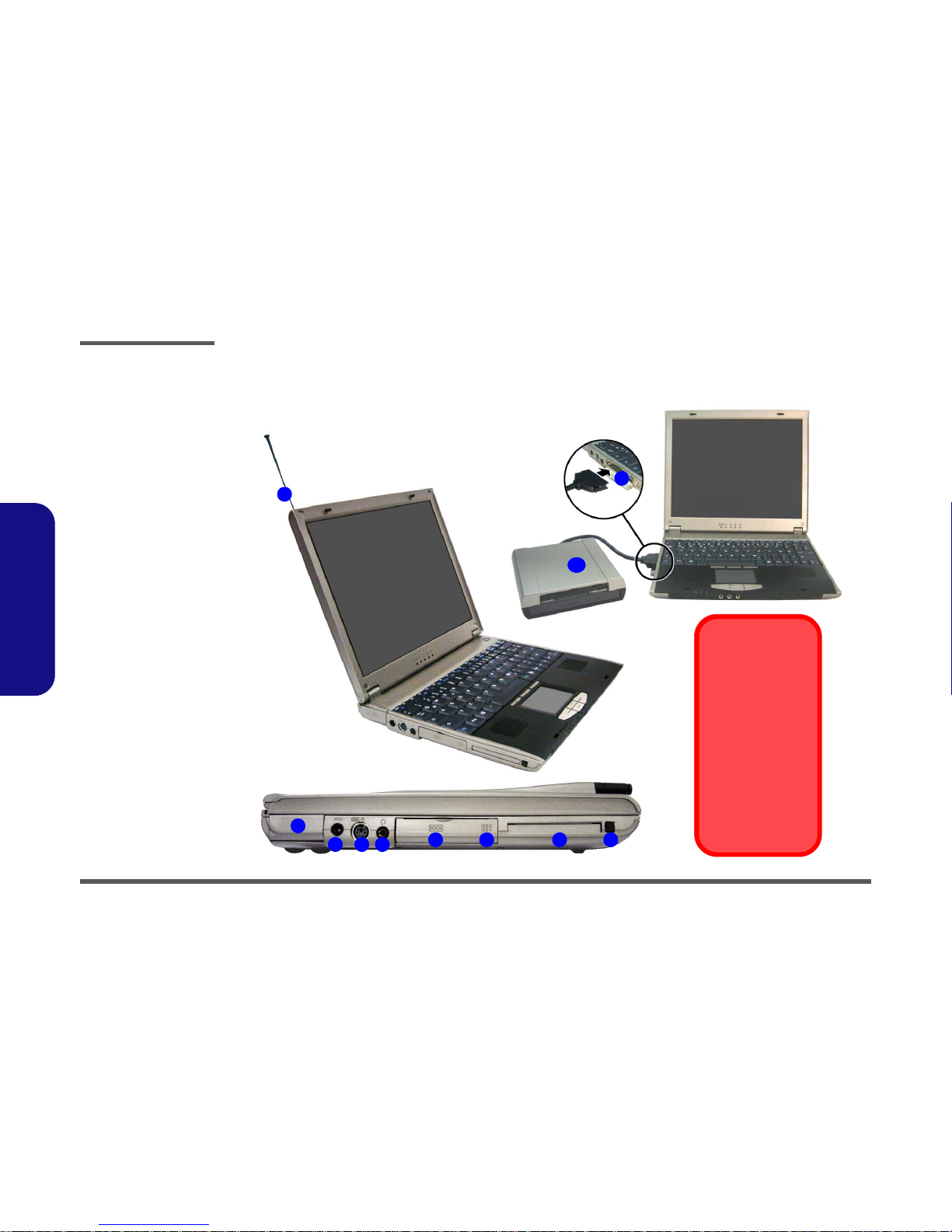
External Locator - Top Views
5
6
7
8
9
10
1
2
4
3
7
11
12
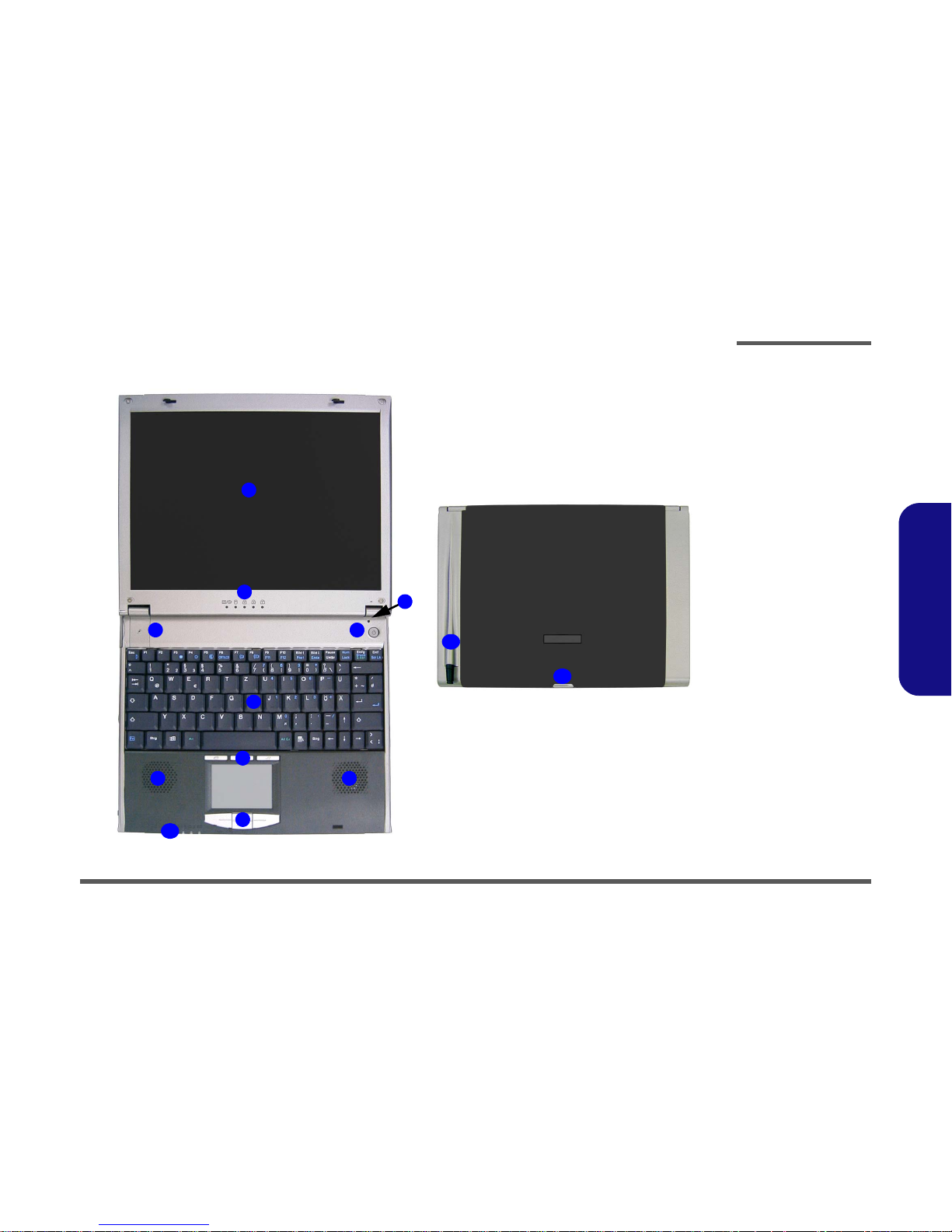
Figure 1 - 1
Top Views
1. LCD Panel
2. LED Status Indicators
3. Close Cover
Switch
4. Power Button
5. Built-In
Microphone
6. Keyboard
7. Speakers
8. Hot-Key Buttons
9. TouchPad &
Buttons
10.LED Power &
Communication
Indicators
11.Phone Antenna
12.LCD Latch
Introduction
1 - 8 External Locator - Front and Rear View
1.Introduction
External Locator - Front and Rear View
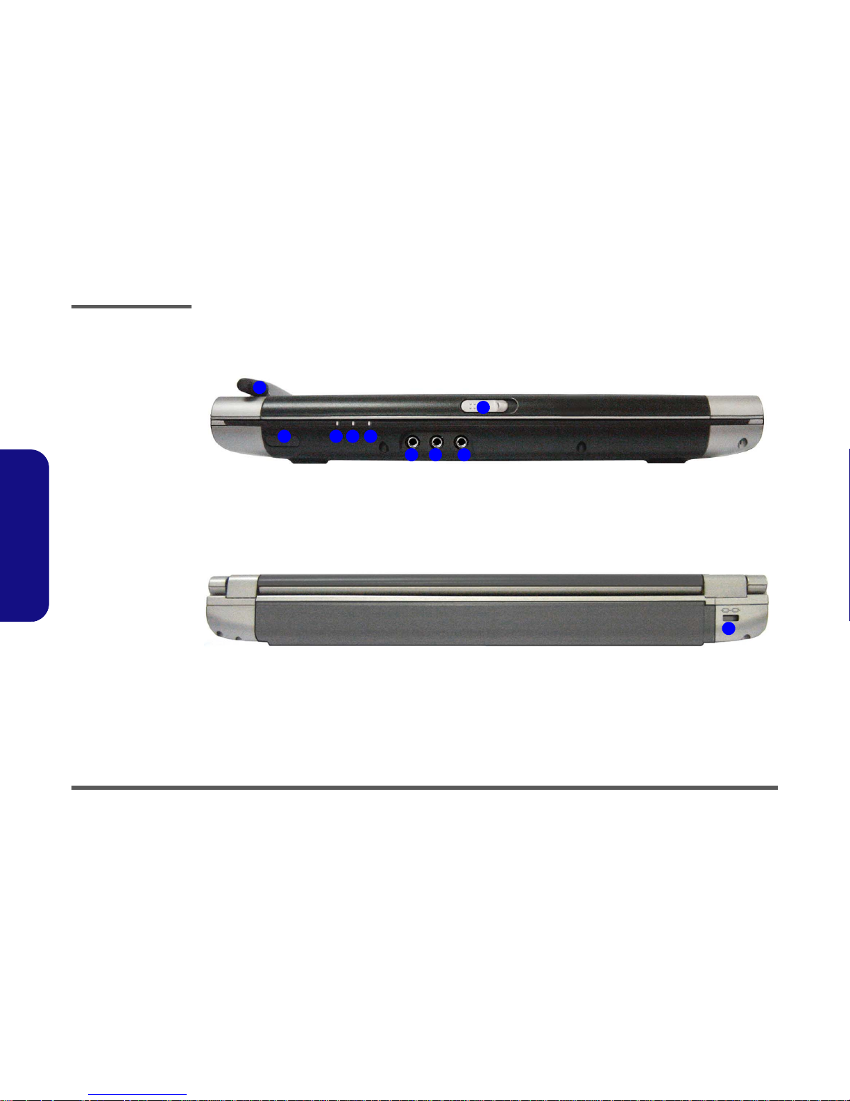
Figure 1 - 2
Front View
1. Phone Antenna
2. Infrared
Transceiver
3. Communication
LED
4. Power LED
5. Battery LED
6. S/PDIF Port
7. Microphone-In Port
8. Headphone-Out
Port
9. LCD Latch
Figure 1 - 3
Rear View
1. Security Lock
43
1
2
876
5
9
1
Introduction
External Locator - Right View 1 - 9
1.Introduction
External Locator - Right View
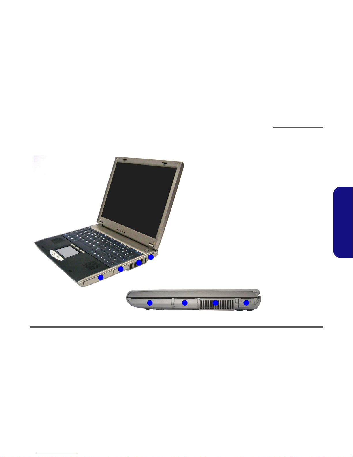
Figure 1 - 4
Right View
1. Hard Disk Bay
2. Dual USB Ports
3. Vent
4. Modem & LAN
Jacks
4
3
1
2
1
2 3 4
Introduction
1 - 10 External Locator - Left View
1.Introduction
External Locator - Left View
Figure 1 - 5
Left View
1. Antenna Raised
2. External Monitor
(CRT) Port
3. DC-In Jack
4. PS/2 Port
5. Telephone Headset
Jack
6. External IDE
Device Port
7. Mini IEEE 1394
Port
8. PC Card Slot
9. PC Card Eject
Button
10. External IDE
Combo Device
2
4
6 7 8 9
6
1
3 5
10
Bay Manager Driver
Please make you have
installed the Bay Manager driver (See What
to Install on page 4-2
of the User’s Manual)
to enable you to connect/disconnect the
drive while the computer is on. If the driver is
not installed the drive
must be connected before you start-up the
computer.
Introduction
External Locator - Bottom View 1 - 11
1.Introduction
External Locator - Bottom View
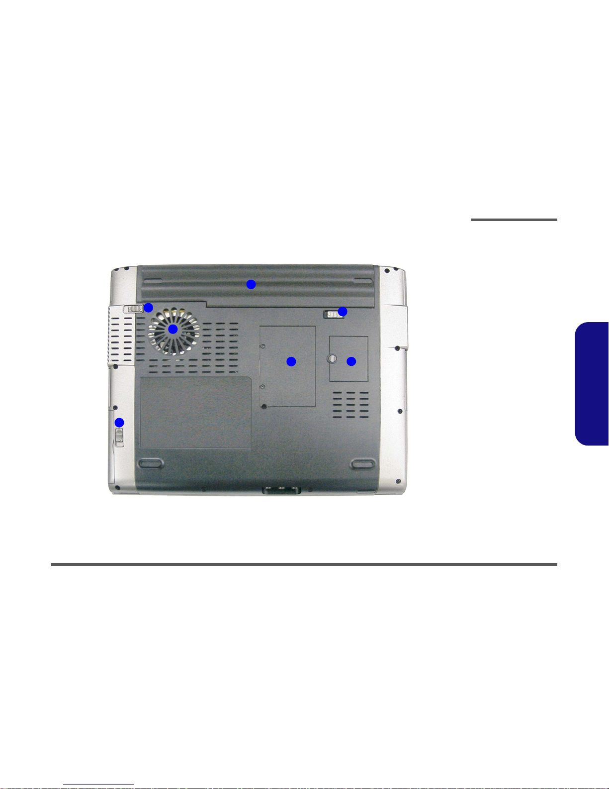
Figure 1 - 6
Bottom View
1. Battery
2. Battery Release
Latches
3. Hard Disk Release
Latch
4. Fan Outlet
5. RAM Cover
6. SIM Card Cover
1
2
3
4
5 6
2
Introduction
1 - 12 Mainboard Overview - Top
1.Introduction
Mainboard Overview - Top
Key Parts
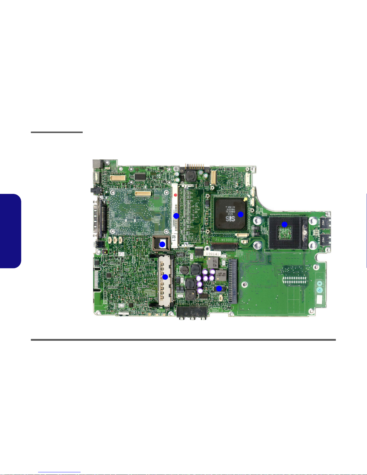
Figure 1 - 7
Mainboard Top
Key Parts - 1
1. CPU Socket (no
CPU installed)
2. SiS650 Chipset
3. 1 * SO-DIMM
socket
4. Flash ROM BIOS
5. V_Core
6. PCMCIA
1
2
4
5
6
3
Introduction
Mainboard Overview - Bottom 1 - 13
1.Introduction
Mainboard Overview - Bottom
Key Parts
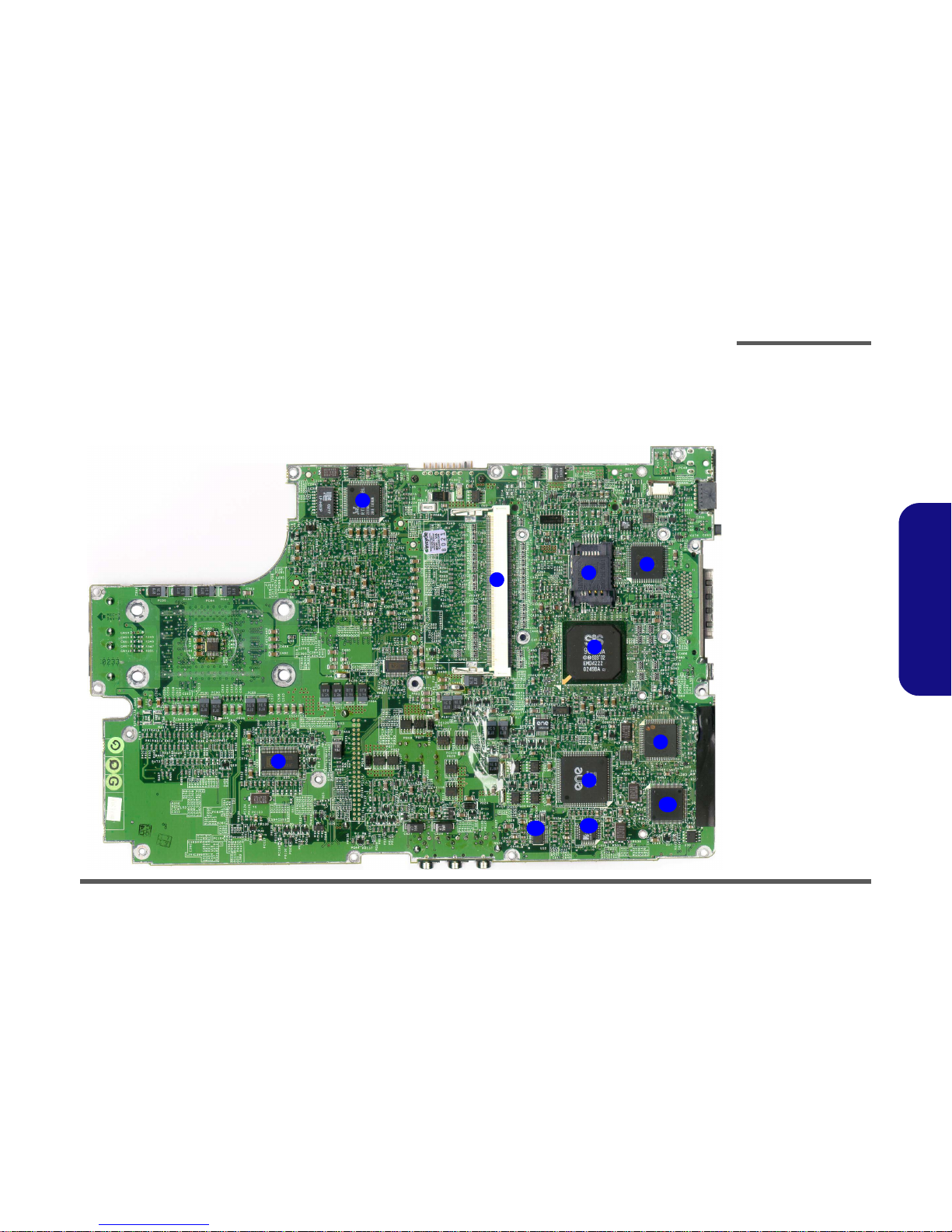
Figure 1 - 8
Mainboard Bottom
Key Parts
1. Realtek
RTL8100L Lan
Controller
2. 1 * SO-DIMM
socket
3. H8 Keyboard
Controller
4. SIM Card Slot
5. SiS962
6. LPC Super I/O
(NSPC87393)
7. Cardbus
(ENE1410)
8. Clock Generator
9. PCMCIA Power
10. Audio Codec
(ALC201A)
11. TI1394
TSB43AB22
1
2
3
4
5
6
7
8
9
10
11
Introduction
1 - 14 Mainboard Overview - Top
1.Introduction
Mainboard Overview - Top
Cable Connectors
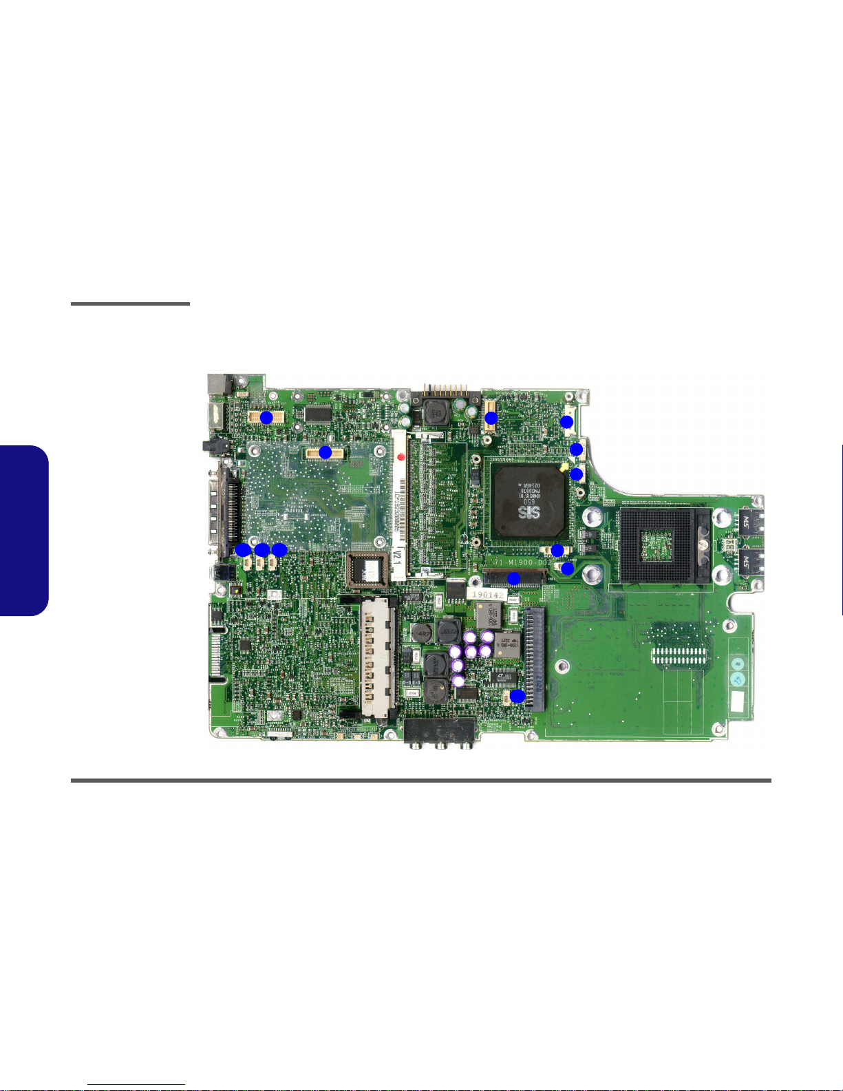
Figure 1 - 9
Mainboard Top
Cable Connectors
1. JLVDS1 (Inverter
Connector)
2. JGSMCON1
(Wireless Modem
Connector)
3. JMDC1 (Modem
Connector)
4. JLAN1 (Lan
Connector)
5. JP1 (Power
Connector connect
to a DIP Switch)
6. JFAN1 (CPU Fan
Connector)
7. JTP1 (TouchPad
Connector)
8. JSPK2 (Speaker
Connector)
9. JKB1 (Keyboard
Connector)
10. JGSMMIC1
(Microphone
Connector)
11. JSPK1 (Speaker
Connector Battery
Connector)
12.
JBAT1 (CMOS
Battery Connector)
13. JMIC1(Microphone
Connector)
2
5
7
8
10
4
6
1
3
9
111213
Introduction
Mainboard Overview - Bottom 1 - 15
1.Introduction
Mainboard Overview - Bottom
Cable Connectors
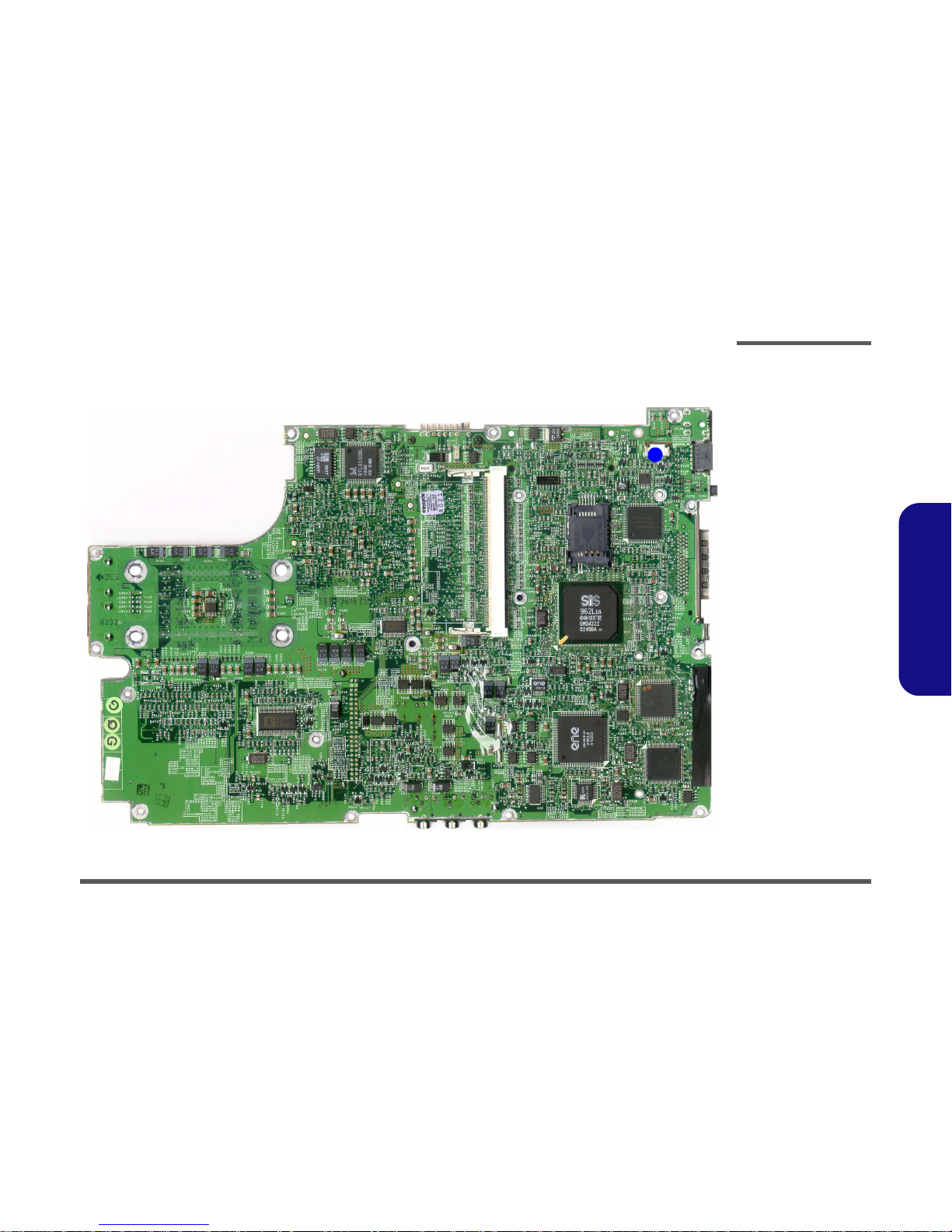
Figure 1 - 10
Mainboard Bottom
Cable Connectors
1. JCRT1 (CRT
Board Connector)
1

Introduction
1 - 16 Mainboard Overview - Bottom
1.Introduction

Disassembly
Overview 2 - 1
2.Disassembly
2: Disassembly
Overview
This chapter provides step-by-step instructions for disassembling parts and subsystems. When it comes to reassembly,
reverse the procedures (unless otherwise indicated).
We suggest you completely review any procedure before you take the computer apart.
Procedures such as upgrading/replacing the RAM and hard disk are included in the User’s Manual but are repeated here
for your convenience.
To make the disassembly process easier each section may have a box in the page margin. Information contained under
the figure # will give a synopsis of the sequence of procedures involved in the disassembly procedure. A box with a
lists the relevant parts you will have after the disassembly process is complete. Note: The parts listed will be for the disassembly procedure listed ONLY, and not any previous disassembly step(s) required. Refer to the part list for the previous disassembly procedure. The amount of screws you should be left with will be listed here also.
A box with a will provide any possible helpful information. A box with a contains warnings.
An example of these types of boxes are shown in the sidebar.
Information
.
Warning

Disassembly
2 - 2 Overview
2.Disassembly
NOTE: All disassembly procedures assume that the system is turned OFF, and disconnected from any power supply (the
battery is removed too).
Maintenance Tools
The following tools are recommended when working on the notebook PC:
• M3 Philips-head screwdriver
• M2.5 Philips-head screwdriver (magnetized)*
• M2 Philips-head screwdriver
• Small flat-head screwdriver
• Pair of needle-nose pliers
• Anti-static wrist-strap
Connections
Connections within the computer are one of four types:
Locking collar sockets for ribbon connectors To release these connectors, use a small flat-head screwdriver to
gently pry the locking collar away from its base. When replacing the connection, make sure the connector is oriented in the
same way. The pin1 side is usually not indicated.
Pressure sockets for multi-wire connectors To release this connector type, grasp it at its head and gently
rock it from side to side as you pull it out. Do not pull on the
wires themselves. When replacing the connection, do not try to
force it. The socket only fits one way.
Pressure sockets for ribbon connectors To release these connectors, use a small pair of needle-nose pli-
ers to gently lift the connector away from its socket. When replacing the connection, make sure the connector is oriented in
the same way. The pin1 side is usually not indicated.
Board-to-board or multi-pin sockets To separate the boards, gently rock them from side to side as
you pull them apart. If the connection is very tight, use a small
flat-head screwdriver - use just enough force to start.

Disassembly
Overview 2 - 3
2.Disassembly
Maintenance Precautions
The following precautions are a reminder. To avoid personal injury or damage to the computer while performing a removal and/or replacement job, take the following precautions:
1. Don't drop it. Perform your repairs and/or upgrades on a stable surface. If the computer falls, the case and other
components could be damaged.
2. Don't overheat it. Note the proximity of any heating elements. Keep the computer out of direct sunlight.
3. Avoid interference. Note the proximity of any high capacity transformers, electric motors, and other strong magnetic fields. These can hinder proper performance and damage components and/or data. You should also monitor
the position of magnetized tools (i.e. screwdrivers).
4. Keep it dry. This is an electrical appliance. If water or any other liquid gets into it, the computer could be badly dam-
aged.
5. Be careful with power. Avoid accidental shocks, discharges or explosions.
• Before removing or servicing any part from the computer, turn the computer off and detach any power supplies.
• When you want to unplug the power cord or any cable/wire, be sure to disconnect it by the plug head. Do not pull on the
wire.
6. Peripherals – Turn off and detach any peripherals.
7. Beware of static discharge. ICs, such as the CPU and main support chips, are vulnerable to static electricity.
Before handling any part in the computer, discharge any static electricity inside the computer. When handling a
printed circuit board, do not use gloves or other materials which allow static electricity buildup. We suggest that you
use an anti-static wrist strap instead.
8. Beware of corrosion. As you perform your job, avoid touching any connector leads. Even the cleanest hands produce oils which can attract corrosive elements.
9. Keep your work environment clean. Tobacco smoke, dust or other air-born particulate matter is often attracted to
charged surfaces, reducing performance.
10.Keep track of the components. When removing or replacing any part, be careful not to leave small parts, such as
screws, loose inside the computer.
Cleaning
Do not apply cleaner directly to the computer, use a soft clean cloth.
Do not use volatile (petroleum distillates) or abrasive cleaners on any part of the computer.
Power Safety
Warning
Before you undertake
any upgrade procedures, make sure that
you have turned off the
power, and disconnected all peripherals
and cables (including
telephone lines). It is
advisable to also remove your battery in
order to prevent accidentally turning the
machine on.

Disassembly
2 - 4 Disassembly Steps
2.Disassembly
Disassembly Steps
The following table lists the disassembly steps, and on
which page to find the related information. PLEASE
PERFORM THE DISASSEMBLY STEPS IN THE
ORDER INDICATED.
To remove the battery:
1. Remove the battery page 2 - 6
To remove the hard disk drive assembly:
1. Remove the battery page 2 - 6
2. Remove the hard disk drive assembly page 2 - 7
To remove the system memory (socket 2):
1. Remove the battery page 2 - 6
2. Remove the memory (socket 2) page 2 - 8
To remove the keyboard:
1. Remove the battery page 2 - 6
2. Remove the keyboard page 2 - 9
To remove the system memory (socket 1):
1. Remove the battery page 2 - 6
2. Remove the keyboard page 2 - 9
3. Remove the memory (socket 1) page 2 - 10
To remove the CPU:
1. Remove the battery page 2 - 6
2. Remove the keyboard page 2 - 9
3. Remove the CPU page 2 - 11
To remove the modem:
1. Remove the battery page 2 - 6
2. Remove the keyboard page 2 - 9
3. Remove the modem page 2 - 12
To remove the GSM/CDMA modem:
1. Remove the battery page 2 - 6
2. Remove the keyboard page 2 - 9
3. Remove the GSM/CDMA modem page 2 - 12
To remove the LCD assembly:
1. Remove the battery page 2 - 6
2. Remove the hard disk drive assembly page 2 - 7
3. Remove the memory (socket 2) page 2 - 8
4. Remove the keyboard page 2 - 9
5. Remove the memory (socket 1) page 2 - 10
6. Remove the CPU page 2 - 11
7. Remove the modem page 2 - 12
8. Remove the GSM/CDMA modem page 2 - 12
9. Remove the LCD assembly page 2 - 13
To remove the mainboard and CRT board:
1. Remove the battery page 2 - 6
2. Remove the hard disk drive assembly page 2 - 7
3. Remove the memory (socket 2) page 2 - 8
4. Remove the keyboard page 2 - 9
5. Remove the memory (socket 1) page 2 - 10
6. Remove the CPU page 2 - 11
7. Remove the modem page 2 - 12
8. Remove the GSM/CDMA modem page 2 - 12
9. Remove the LCD assembly page 2 - 13
10. Remove the mainboard & CRT board page 2 - 15

Disassembly
Disassembly Steps 2 - 5
2.Disassembly
To remove the inverter:
1. Remove the battery page 2 - 6
2. Remove the hard disk drive assembly page 2 - 7
3. Remove the memory (socket 2) page 2 - 8
4. Remove the keyboard page 2 - 9
5. Remove the memory (socket 1) page 2 - 10
6. Remove the CPU page 2 - 11
7. Remove the modem page 2 - 12
8. Remove the GSM/CDMA modem page 2 - 12
9. Remove the LCD assembly page 2 - 13
10. Remove the inverter page 2 - 16
To remove the LCD:
1. Remove the battery page 2 - 6
2. Remove the hard disk drive assembly page 2 - 7
3. Remove the memory (socket 2) page 2 - 8
4. Remove the keyboard page 2 - 9
5. Remove the memory (socket 1) page 2 - 10
6. Remove the CPU page 2 - 11
7. Remove the modem page 2 - 12
8. Remove the GSM/CDMA modem page 2 - 12
9. Remove the LCD assembly page 2 - 13
10. Remove the inverter page 2 - 16
11. Remove the LCD page 2 - 17
To remove the PCMCIA assembly:
1. Remove the battery page 2 - 6
2. Remove the hard disk drive assembly page 2 - 7
3. Remove the memory (socket 2) page 2 - 8
4. Remove the keyboard page 2 - 9
5. Remove the memory (socket 1) page 2 - 10
6. Remove the CPU page 2 - 11
7. Remove the modem page 2 - 12
8. Remove the GSM/CDMA modem page 2 - 12
9. Remove the LCD assembly page 2 - 13
10. Remove the mainboard & CRT board page 2 - 15
11. Remove the PCMCIA assembly page 2 - 18
Disassembly
2 - 6 Removing the Battery
2.Disassembly
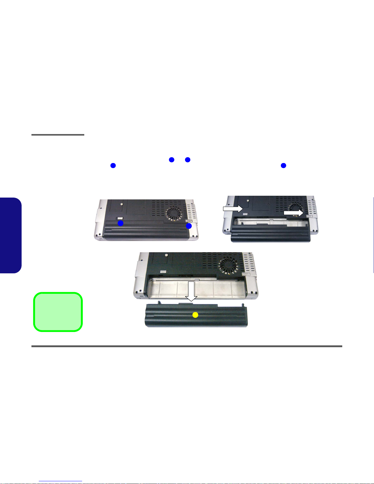
Removing the Battery
1. Shut the computer down and turn it over.
2. Locate the battery release latches and (Figure 2 - 1a).
3. Latch should slide to the right and remain in place, and you will need to hold latch in place as you slide the
battery out towards you.
4. Slide the battery out.
Figure 2 - 1
Battery Removal
Sequence
a. Locate the battery
release latches.
b. Slide latch 1 to the
right, then slide and
hold latch 2 to the
right and hold.
c. Slide the battery out.
1 2
1 2
3. Battery
1
a. b.
c.
2
3
 Loading...