

Page 1

Page 2

LCD Computer
LV22C/LV22N/LV19C/LV19N Series
Service Manual
Preface
Preface
I
Page 3

Preface
Preface
Notice
The company reserves the right to revise this publication or to change its contents without notice. Information contained
herein is for reference only and does not constitute a commitment on the part of the manufacturer or any subsequent vendor. They assume no responsibility or liability for any errors or inaccuracies that may appear in this publication nor are
they in anyway responsible for any loss or damage resulting from the use (or misuse) of this publication.
This publication and any accompanying software may not, in whole or in part, be reproduced, translated, transmitted or
reduced to any machine readable form without prior consent from the vendor, manufacturer or creators of this publication, except for copies kept by the user for backup purposes.
Brand and product names mentioned in this publication may or may not be copyrights and/or registered trademarks of
their respective companies. They are mentioned for identification purposes only and are not intended as an endorsement
of that product or its manufacturer.
Version 1.0
March 2007
Trademarks
Intel®, Celeron and Intel® Core are registered trademarks of Intel Corporation.
Windows® is a registered trademark of Microsoft Corporation.
Other brand and product names are trademarks and/or registered trademarks of their respective companies.
II
Page 4

About this Manual
This manual is intended for service personnel who have completed sufficient training to undertake the maintenance and
inspection of personal computers.
It is organized to allow you to look up basic information for servicing and/or upgrading components of the LV22C/
LV22N/LV19C/LV19N computer.
The following information is included:
Chapter 1, Introduction, provides general information about the location of system elements and their specifications.
Chapter 2, Disassembly, provides step-by-step instructions for disassembling parts and subsystems and how to upgrade
elements of the system.
Appendix A, Part Lists
Appendix B, Schematic Diagrams
Preface
Preface
III
Page 5

Preface
Related Documents
You may also need to consult the following manual for additional information:
User’s Manual on CD
This describes the computer’s features and the procedures for operating the computer and its ROM-based setup program.
It also describes the installation and operation of the utility programs provided with the computer.
Preface
IV
Page 6

Contents
Preface
Introduction ..............................................1-1
Overview .........................................................................................1-1
System Specifications .....................................................................1-2
External Locator - Front View & Top View ................................... 1-5
External Location - Left & Right Side Views .................................1-6
External Locator - Rear View .........................................................1-7
Mainboard Overview - Top (Key Parts) .........................................1-8
Mainboard Overview - Bottom (Key Parts) ....................................1-9
Mainboard Overview - Top (Cable Connectors & Switches) ....... 1-10
Mainboard Overview - Bottom (Cable Connectors & Switches) .1-11
Disassembly ...............................................2-1
Overview .........................................................................................2-1
Maintenance Tools ..........................................................................2-2
Connections .....................................................................................2-2
Maintenance Precautions .................................................................2-3
Disassembly Steps ...........................................................................2-4
Removing the Hard Disk Drive Assembly ...................................... 2-5
Removing the System Memory .......................................................2-7
Removing and Installing the Processor ...........................................2-9
Removing the Modem ...................................................................2-11
Removing the Wireless LAN Module ........................................... 2-12
Removing the TV Tuner Module .................................................. 2-13
Removing the Bluetooth Module ..................................................2-14
Removing the LCD Back Cover ...................................................2-15
Removing the Optical Device Assembly ......................................2-17
Part Lists ..................................................A-1
Part List Illustration Location ........................................................A-2
LV22C/LV22N - Front Cover ........................................................A-3
LV22C/LV22N - Back ................................................................... A-4
LV22C/LV22N - Combo Drive ..................................................... A-5
LV22C/LV22N - DVD-Dual Drive ............................................... A-6
LV22C/LV22N - HDD .................................................................. A-7
LV22C - MB .................................................................................. A-8
LV22N - MB .................................................................................. A-9
LV19C/LV19N - Front Cover ..................................................... A-10
LV19C/LV19N - Back ................................................................ A-11
LV19C/LV19N - Combo Drive ................................................... A-12
LV19C/LV19N - DVD-Dual Drive ............................................. A-13
LV19C/LV19N - HDD ................................................................ A-14
LV19C - MB ................................................................................ A-15
LV19N - MB ................................................................................ A-16
Schematic Diagrams................................. B-1
System Block Diagram ...................................................................B-2
Clock Generator ..............................................................................B-3
CPU - 1 of 3 ....................................................................................B-4
CPU - 2 of 3 ....................................................................................B-5
CPU - 3 of 3 ....................................................................................B-6
Intel P965 1/5 CPU Interface ..........................................................B-7
Intel P965 2/5 PCI-E I/F .................................................................B-8
Intel P965 3/5 Memory I/F .............................................................B-9
Intel P965 4/5 GND ......................................................................B-10
Intel P965 5/5 Power ....................................................................B-11
DDRII SO-DIMM 1/2 ..................................................................B-12
DDRII SO-DIMM 2/2 ..................................................................B-13
MXM PCI-E CONN .....................................................................B-14
BIOS, USB K/B, TPM ..................................................................B-15
Panel, CPU Fan .............................................................................B-16
ICH8 1/3 (PCI, DMI, CPU, IRQ) .................................................B-17
ICH8 2/3 (LPC, ATA, USB, GPIO) .............................................B-18
Preface
V
Page 7

Preface
ICH8 3/3 (Power) ......................................................................... B-19
JM361 PCI-E TO PATA, eSATA ................................................ B-20
CD-ROM, SATA, PC-Beep, LED ............................................... B-21
VGA Fan, CCD, Power OK ......................................................... B-22
LAN 82566 ................................................................................... B-23
PCI7402 ........................................................................................ B-24
TV Tuner, CardReader, CIR ........................................................ B-25
ITE IT8512 ................................................................................... B-26
Mini Card, New Card ................................................................... B-27
USB 2.0 ........................................................................................ B-28
AZALIA Codec ALC883/ALC888 .............................................. B-29
Audio AMP, SRS, Woofer ........................................................... B-30
MDC, BT, PWRGD, Inverter Connector ..................................... B-31
System Power ............................................................................... B-32
3.3V/5V ........................................................................................ B-33
12VS, AC-In ................................................................................. B-34
Preface
1.8V/0.9V ..................................................................................... B-35
1.5VS,1.05VS ............................................................................... B-36
1.2VS/1.25VS ............................................................................... B-37
VCORE ........................................................................................ B-38
LED Board ................................................................................... B-39
Power Board ................................................................................. B-40
CIR Board .................................................................................... B-41
CD-ROM Board ........................................................................... B-42
Video Connector Board ................................................................ B-43
CRT Connector Board .................................................................. B-44
VI
Page 8

1: Introduction
Overview
This manual covers the information you need to service or upgrade the LV22C/LV22N/LV19C/LV19N LCD computer.
Information about operating the computer (e.g. getting started, and the Setup utility) is in the User’s Manual. Information
about drivers (e.g. VGA & audio) is also found in User’s Manual. That manual is shipped with the computer.
Operating systems (e.g. Windows XP, Windows Vista, etc.) have their own manuals as do application software (e.g. word
processing and database programs). If you have questions about those programs, you should consult those manuals.
Introduction
The LV22C/LV22N/LV19C/LV19N LCD computer is designed to be upgradeable. See “Disassembly” on page 2 - 1 for
a detailed description of the upgrade procedures for each specific component. Please note the warning and safety information indicated by the “” symbol.
The balance of this chapter reviews the computer’s technical specifications and features.
1.Introduction
Overview 1 - 1
Page 9
Introduction
Table 1 - 1
System
Specifications
System Specifications
Latest Specification Information
The specifications listed in this Appendix are correct at the time of going to press. Certain items (particularly processor types/speeds
and CD/DVD device types) may be changed or updated due to the manufacturer's release schedule. Check with your service center for
details.
Feature Specification
Processor Intel® Core™ 2 Duo Desktop Processor
LGA775 Package (775-pin)
E6300/ E6400
65nm (65 Nanometer) Process Technology
2MB On-die L2 Cache & 1066MHz FSB
1.86/ 2.13 GHz
1.Introduction
1 - 2 System Specifications
Intel® Core™ 2 Duo Desktop Processor
LGA775 Package (775-pin)
E6600/ E6700
Core Logic Intel G965 +ICH8-DH Chipset
Memory 64-bit Wide DDR2 Data Channel
Two 200 Pin SO-DIMM Sockets Supporting DDR2 533 / 667 MHz
Memory Expandable up to 4GB (256/ 512/ 1024/ 2048 MB DDR2 Modules)
Security Security (Kensington® Type) Lock Slot BIOS Password
BIOS One 1024KB Flash ROM Phoenix™ BIOS, Plug and Play
LCD Model A Computers Model B Computers
19" Wide Screen WXGA+ (1440*900)
16:10 Wide Screen Flat Panel TFT
65nm (65 Nanometer) Process Technology
4MB On-die L2 Cache & 1066MHz FSB
2.40/ 2.67 GHz
22" Wide Screen WSXGA+ (1680*1050)
16:10 Wide Screen Flat Panel TFT
Page 10
Feature Specification
Introduction
Video Adapter
Options
Storage One Changeable 12.7mm(h) Optical Device (CD/DVD) Type Drive
Audio Supports 7.1 CH Audio Output Via S/PDIF Port
Keyboard &
Pointing Device
ExpressCard
Slot
Interface Four USB 2.0 Ports
Integrated Video Option
Intel G965 Integrated Video
Shared Memory Architecture of up to 376MB of
Dynamically Allocated Video Memory
Fully Supports DirectX 9.0
(see “Optional” on page 1 - 4 for drive options)
Two Changeable Bays for 3.5" 26mm (h) Serial-ATA (SATA) Hard Disk Drives
Supports RAID 0, RAID 1, HDD Fault Tolerance System in SATA Configuration
Integrated AZALIA Compliant Interface (HDA)
3D Stereo Enhanced Sound System
Sound-Blaster PRO™ Compatible
RF Winkey Keyboard (Option)
RF Mouse (Option)
ExpressCard/34/54 Slot
One USB 2.0 Port (for RF KB & Mouse)
One E-SATA Port
One Mini-IEEE1394 Port
One Headphone-Out Jack
One Microphone-In Jack
One Line-In Jack
One S/PDIF Output Jack (5.1CH)
One S-Video-In Jack
One Composite Video-In Jack
Discrete Video Option
NVIDIA GF-GO7600-N-B1 (w/o HDMI)
PCI-E MXM II Video Card
256MB DDR2 Video RAM on Board
PCI-Express X16
Fully Supports DirectX 9.0
MXM Modular Design
S/PDIF Output
2 * Built-In 3W Speakers
Built-In 6W Sub Woofer
Built-In Microphone
USB I/F Receiver Dongle (Option)
Two CATV-In Jacks (for TV Tuner Cards)
One RJ-11 Jack for Plug & Play Fax/Modem
One RJ-45 Jack for 10Mb/ 100Mb/ 1000Mb Fast Ethernet
One DC-in Jack
One Brightness Button
One Power Switch
One A.P. Key (For Media Center)
One CIR Port (Optional for TV Tuner)
1.Introduction
Card Reader Embedded 7-in-1 Card Reader (MS/ MS Pro/ SD/ Mini SD/ MMC/ RS MMC/ MS Duo)
Note: MS Duo/ Mini SD/ RS MMC Cards Require a PC Adapter
System Specifications 1 - 3
Page 11
Introduction
Feature Specification
Communication AZALIA MDC 56K Plug & Play Fax/Modem v.90/92 Compliant
1GB PCI Fast Ethernet
Intel PRO/Wireless 3945ABG PCIe Wireless LAN Module (Option)
USB 2.0 Bluetooth + EDR (Enhanced Data Rate) Module - Version 2.0 (Factory Option)
1.3M PC Camera with USB Interface (Factory Option)
11 Hot Keys for Internet & Multimedia via RF KB (Factory Option)
1.Introduction
Power
Management
Power Full Range AC/DC Adapter - AC Input 100 - 240V, 50 - 60Hz / DC Output
Environmental
Spec
Physical
Dimensions &
Weight
Optional Optical Drive Module Options:
Supports ACPI 2.0
Power Button as Sleep/Resume Key
Supports Hibernate Mode
Supports Sleep/Stand by Mode
Temperature
Operating: 5°C ~ 35°C
Non-Operating: -20°C ~ 60°C
625.5mm (w) * 396.9mm (d) * 110mm (h) including hinge assembly
11kg Approximately
DVD/CD-RW Combo Drive Module (Factory Option)
DVD Super Multi Drive Module (Factory Option)
USB Floppy Disk Drive Module
Intel PRO/Wireless 3945ABG PCIe Wireless LAN Module
Hybrid TV Tuner Card Module with Remote Control Unit
RF Keyboard & RF Mouse with USB Receiver
Supports Resume from Modem Ring
Supports Resume from Alarm
Relative Humidity
Operating: 20% ~ 80%
Non-Operating: 10% ~ 90%
1.3M PC Camera with USB Interface
USB 2.0 Bluetooth + EDR (Enhanced Data Rate) Module Version 2.0 (Factory Option)
802.11b/g USB (Mini Card) Wireless LAN Module
2nd SATA RAID Hard Disk Drive
20V, 9.0A (
180
Watts)
(
Factory Option
)
1 - 4 System Specifications
Page 12
Introduction
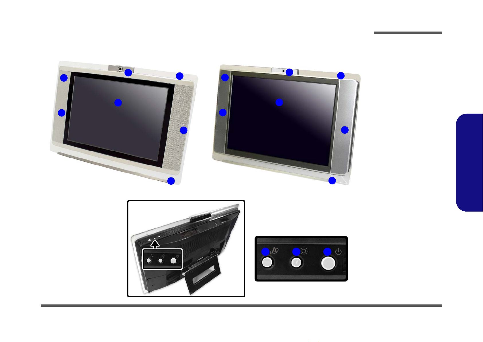
External Locator - Front View & Top View
3
1
4
6
LV19C/LV19N LV22C/LV22N
2
6
5
3
6
Figure 1 - 1
Front View
1
4
2
6
5
1. Optional Built-In
PC Camera
2. Power LED
3. Consumer
Infrared
Transceiver
(Communicates
with Optional TV
Remote)
4. LCD
5. LED Indicators
6. Speakers
7. Power Button
8. Brightness Hot
Key Button
9. Application Hot
Key Button
1.Introduction
9
78
External Locator - Front View & Top View 1 - 5
Page 13
Introduction
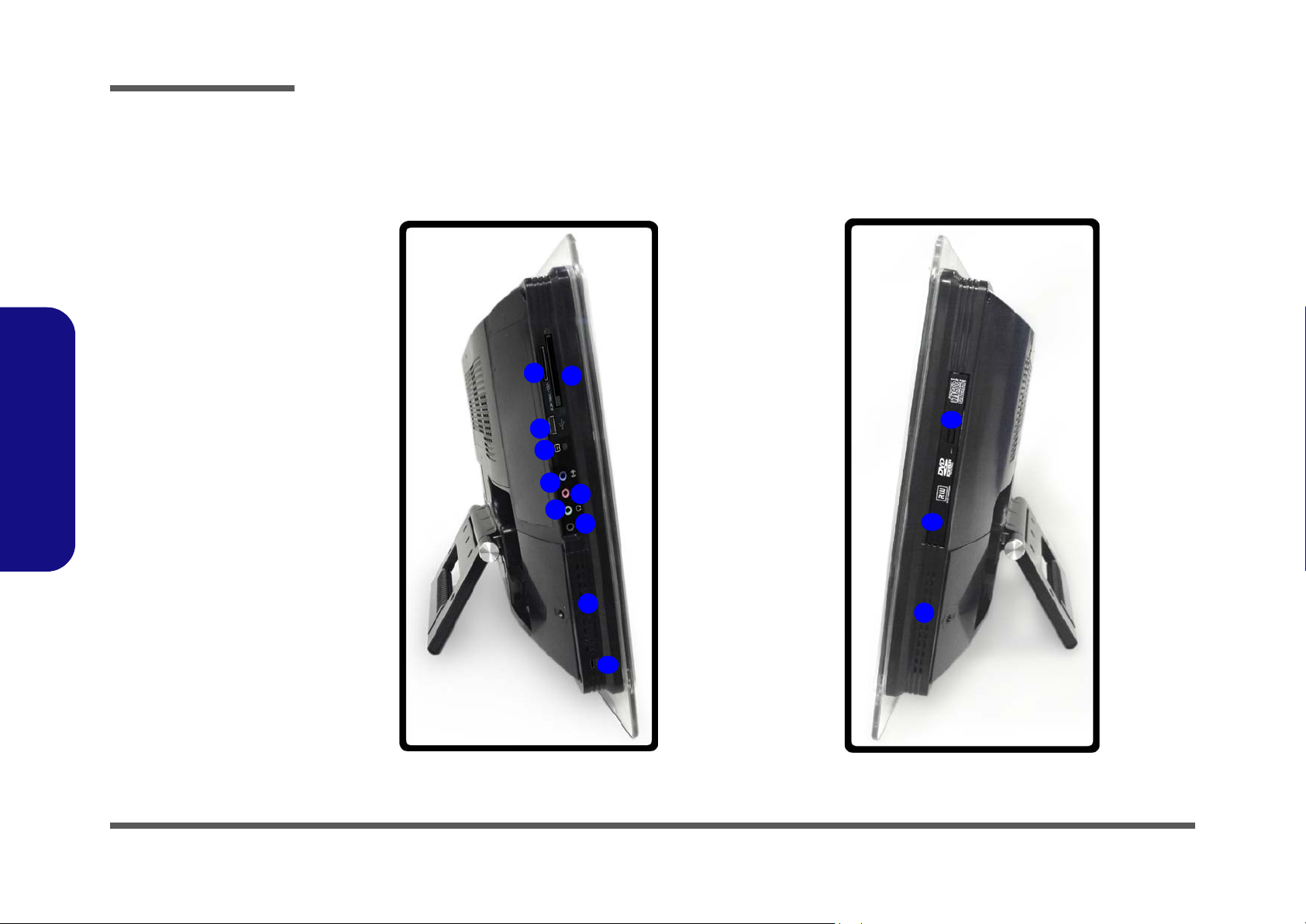
Figure 1 - 2
Left & Right Views
1. ExpressCard
Slot 54/34
2. 7-in-1 Card
Reader
3. 1 * USB 2.0 Port
4. Mini-IEEE 1394
Port
5. Line-In Jack
(Blue)
6. Microphone-In
Jack (Pink)
7. Headphone-Out
Jack (Green)
8. S/PDIF-Out Jack
(Black)
9. Vent/Fan Intake/
1.Introduction
Outlet
10. Security Lock
Slot
11. Optical (CD/
DVD) Device
12. CD Emergency
Eject
External Location - Left & Right Side Views
Left Right
2
1
3
4
5
6
7
8
9
11
12
9
1 - 6 External Location - Left & Right Side Views
10
Page 14
Introduction
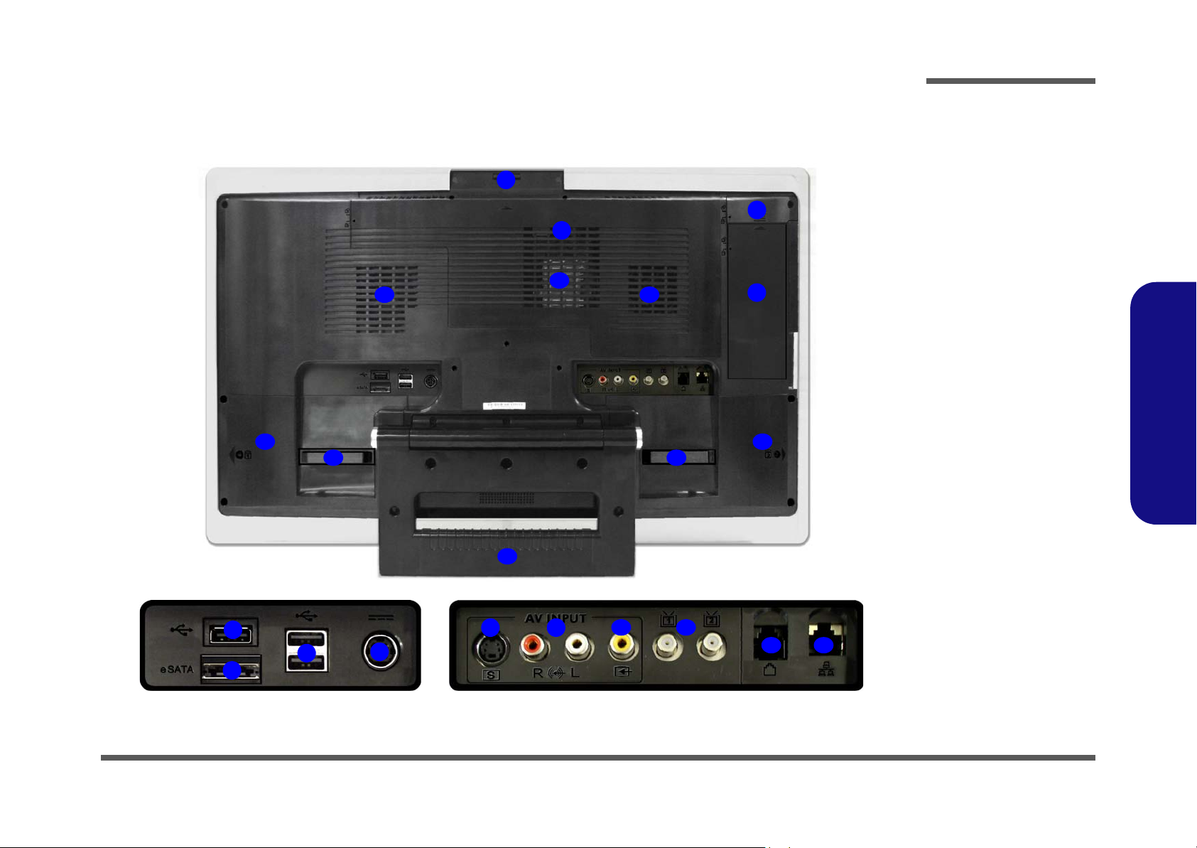
External Locator - Rear View
15
16
17
5
5
6
7
Figure 1 - 3
Rear View
1
2
4
15
15
17
14
8
9
10
11
3
16
12 13
1. Camera Angle
Switch
2. USB Port Cover
3. Module Cover
4. Rear Component
Cover
5. 3 * USB 2.0
Ports
6. 1 External SATA
Port
7. DC-In Jack
8. S-Video-In Jack
9. Audio-In Jacks
10. Composite
Video-In Jack
11. CATV-In Jacks
12. RJ-11 Phone
Jack
13. RJ-45 LAN Jack
14. Stand
15. Vent/Fan Intake/
Outlet
16. Hard Disk
Covers
17. Cable Holders
(To Secure
Audio/Video/
USB Cables etc.)
1.Introduction
External Locator - Rear View 1 - 7
Page 15
Introduction
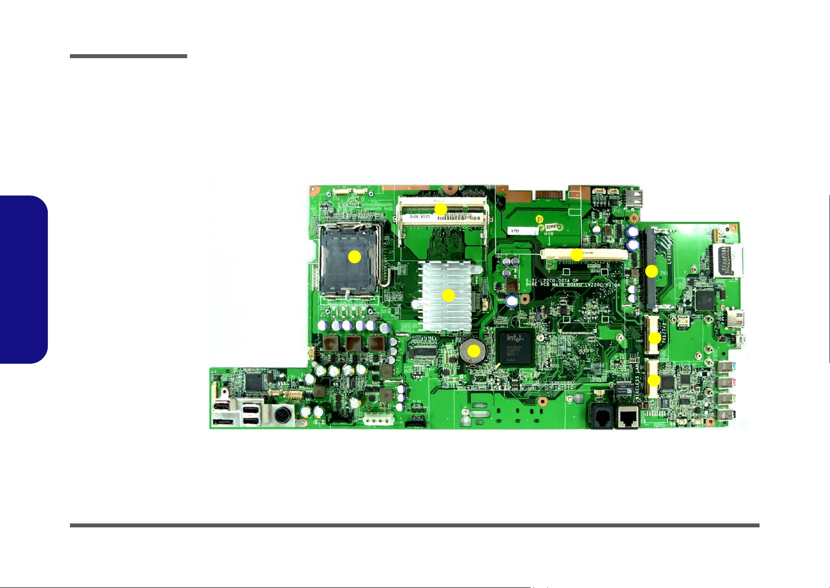
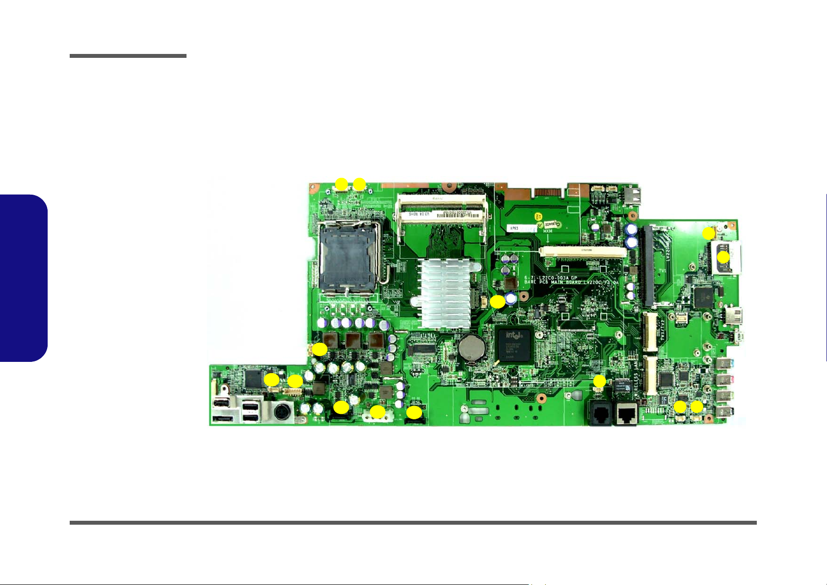
Figure 1 - 4
Mainboard Over-
view - Top
Key Parts
1. CPU Socket (no
CPU Installed)
2. RAM Sockets
3. Intel 965 (North
Bridge)
4. CMOS Battery
5. Video Card
Socket
6. Mini PCI Socket
for TV
7. Mini PCI Ext.
Socket for
WLAN and TV
1.Introduction
Mainboard Overview - Top (Key Parts)
2
1
3
4
5
6
7
1 - 8 Mainboard Overview - Top (Key Parts)
7
Page 16
Introduction
Mainboard Overview - Bottom (Key Parts)
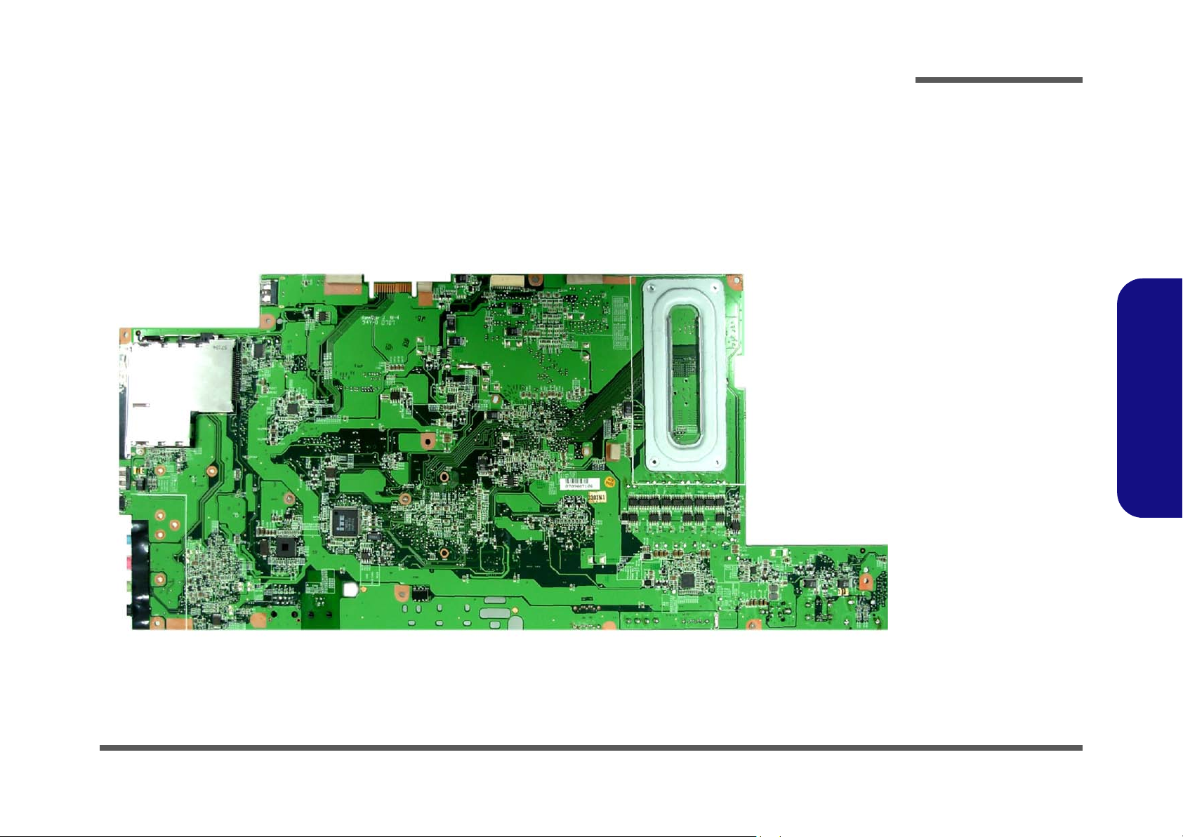
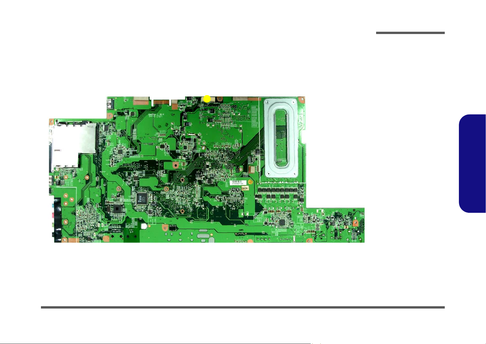
Figure 1 - 5
Mainboard Over-
view - Bottom
Key Parts
1.Introduction
1
4
3
2
5
Mainboard Overview - Bottom (Key Parts) 1 - 9
Page 17
Introduction
Figure 1 - 6
Mainboard Top
Cable Connectors &
Switches
1. Power
2. CCD Connector
3. VGA Fan
4. Bluetooth
5. Card Reader
6. Microphone
7. Woofer
8. Modem Module
9. SATA HDD
10. SATA Power
11. CPU Fan
12. Inverter
13. LED
1.Introduction
Mainboard Overview - Top (Cable Connectors & Switches)
1
2
3
11
4
5
13
12
9
10
9
1 - 10 Mainboard Overview - Top (Cable Connectors & Switches)
8
6
7
Page 18
Introduction
Mainboard Overview - Bottom (Cable Connectors & Switches)
1
1
Figure 1 - 7
Mainboard Bottom
Cable Connectors &
Switches
1. LCD
1.Introduction
Mainboard Overview - Bottom (Cable Connectors & Switches) 1 - 11
Page 19

Introduction
1.Introduction
1-12
Page 20

2: Disassembly
Overview
This chapter provides step-by-step instructions for disassembling parts and subsystems. When it comes to reassembly,
reverse the procedures (unless otherwise indicated).
We suggest you completely review any procedure before you take the computer apart.
Disassembly
Procedures such as upgrading/replacing the RAM, CD device and hard disk are included in the User’s Manual but are
repeated here for your convenience.
To make the disassembly process easier each section may have a box in the page margin. Information contained under
the figure # will give a synopsis of the sequence of procedures involved in the disassembly procedure. A box with a
lists the relevant parts you will have after the disassembly process is complete. Note: The parts listed will be for the disassembly procedure listed ONLY, and not any previous disassembly step(s) required. Refer to the part list for the previous disassembly procedure. The amount of screws you should be left with will be listed here also.
A box with a will provide any possible helpful information. A box with a contains warnings.
An example of these types of boxes are shown in the sidebar.
2.Disassembly
Information and
Component Parts
Warning
Overview 2 - 1
Page 21

Disassembly
2.Disassembly
NOTE: All disassembly procedures assume that the system is turned OFF, and disconnected from any power supply,
and that all peripheral cables are disconnected (including telephone lines and network cables).
Maintenance Tools
The following tools are recommended when working on the computer:
• M3 Philips-head screwdriver
• M2.5 Philips-head screwdriver (magnetized)
• M2 Philips-head screwdriver
• Small flat-head screwdriver
• Pair of needle-nose pliers
• Anti-static wrist-strap
Connections
Connections within the computer are one of four types:
Locking collar sockets for ribbon connectors To release these connectors, use a small flat-head screwdriver to gently pry the
locking collar away from its base. When replacing the connection, make sure
the connector is oriented in the same way. The pin1 side is usually not indicated.
2 - 2 Overview
Pressure sockets for multi-wire connectors To release this connector type, grasp it at its head and gently rock it from side
to side as you pull it out. Do not pull on the wires themselves. When replacing
the connection, do not try to force it. The socket only fits one way.
Pressure sockets for ribbon connectors To release these connectors, use a small pair of needle-nose pliers to gently lift
the connector away from its socket. When replacing the connection, make sure
the connector is oriented in the same way. The pin1 side is usually not indicated.
Board-to-board or multi-pin sockets To separate the boards, gently rock them from side to side as you pull them
apart. If the connection is very tight, use a small flat-head screwdriver - use
just enough force to start.
Page 22

Maintenance Precautions
The following precautions are a reminder. To avoid personal injury or damage to the computer while performing a removal and/or replacement job, take the following precautions:
1. Don't drop it. Perform your repairs and/or upgrades on a stable surface. If the computer falls, the case and other
components could be damaged.
2. Don't overheat it. Note the proximity of any heating elements. Keep the computer out of direct sunlight.
3. Avoid interference. Note the proximity of any high capacity transformers, electric motors, and other strong mag-
netic fields. These can hinder proper performance and damage components and/or data. You should also monitor
the position of magnetized tools (i.e. screwdrivers).
4. Keep it dry. This is an electrical appliance. If water or any other liquid gets into it, the computer could be badly
damaged.
5. Be careful with power. Avoid accidental shocks, discharges or explosions.
•Before removing or servicing any part from the computer, turn the computer off and detach any power supplies.
•When you want to unplug the power cord or any cable/wire, be sure to disconnect it by the plug head. Do not pull on the wire.
6. Peripherals – Turn off and detach any peripherals.
7. Beware of static discharge. ICs, such as the CPU and main support chips, are vulnerable to static electricity.
Before handling any part in the computer, discharge any static electricity inside the computer. When handling a
printed circuit board, do not use gloves or other materials which allow static electricity buildup. We suggest that
you use an anti-static wrist strap instead.
8. Beware of corrosion. As you perform your job, avoid touching any connector leads. Even the cleanest hands produce oils which can attract corrosive elements.
9. Keep your work environment clean. Tobacco smoke, dust or other air-born particulate matter is often attracted
to charged surfaces, reducing performance.
10. Keep track of the components. When removing or replacing any part, be careful not to leave small parts, such as
screws, loose inside the computer.
Disassembly
Power Safety
Warning
Before you undertake
any upgrade procedures, make sure that
you have turned off
the power, and disconnected all peripherals and cables
(including telephone
lines). It is advisable
to also remove your
battery in order to prevent accidentally turning the machine on.
2.Disassembly
Cleaning
Do not apply cleaner directly to the computer, use a soft clean cloth.
Do not use volatile (petroleum distillates) or abrasive cleaners on any part of the computer.
Overview 2 - 3
Page 23

Disassembly
Disassembly Steps
The following lists the disassembly steps, and on which page to find the related information. PLEASE PERFORM THE
DISASSEMBLY STEPS IN THE ORDER INDICATED.
2.Disassembly
To remove the hard disk drive assembly:
1. Remove the hard disk drive assembly page 2 - 5
To remove the system memory:
1. Remove the system memory page 2 - 7
To remove the processor:
1. Remove the system memory page 2 - 7
2. Remove the processor page 2 - 9
To remove the modem:
1. Remove the modem page 2 - 11
To remove the WLAN module:
1. Remove the modem page 2 - 11
2. Remove the WLAN module page 2 - 12
To remove the TV Tuner module:
1. Remove the modem page 2 - 11
2. Remove the TV Tuner module page 2 - 13
To remove the Bluetooth module:
1. Remove the modem page 2 - 11
2. Remove the TV Tuner module page 2 - 13
3. Remove the bluetooth module page 2 - 14
To remove the LCD back cover:
1. Remove the system memory page 2 - 7
2. Remove the modem page 2 - 11
1. Remove the LCD back cover page 2 - 15
To remove the Optical Device:
1. Remove the system memory page 2 - 7
2. Remove the modem page 2 - 11
3. Remove the LCD back cover page 2 - 15
4. Remove the optical device page 2 - 17
2 - 4 Disassembly Steps
Page 24
Disassembly
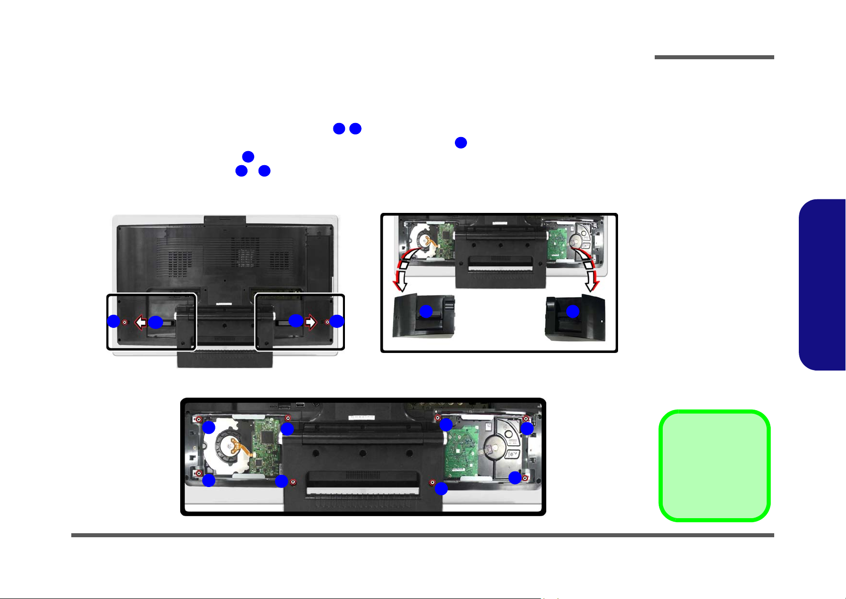
Removing the Hard Disk Drive Assembly
1. Turn the computer off and disconnect all peripherals and cables (including telephone lines).
2. Place the computer on a flat stable surface, preferably on a protective covering to avoid damage to the LCD screen.
3. Locate the hard disk bay cover and remove screw / , depending on which hard disk you want to replace.
4. Remove the hard disk cover(s) by sliding it(them) in the direction of arrow .
5. Remove the hard disk cover(s) .
6. Remove the hard disk screws - from the hard disk(s) you want to replace.
a.
1 2
3
4
5 8
3
1 2
3
b.
4 4
Figure 2 - 1
Hard Disk Removal
Sequence (con’td)
a. Remove the screw(s)
from the HDD BayCover.
b. Remove the HDD
Cover.
c. Remove the screws
from the HDD.
2.Disassembly
c.
5
6
8
7
5
6
8
3. HDD Bay Cover
•5 Screws
7
Removing the Hard Disk Drive Assembly 2 - 5
Page 25
Disassembly
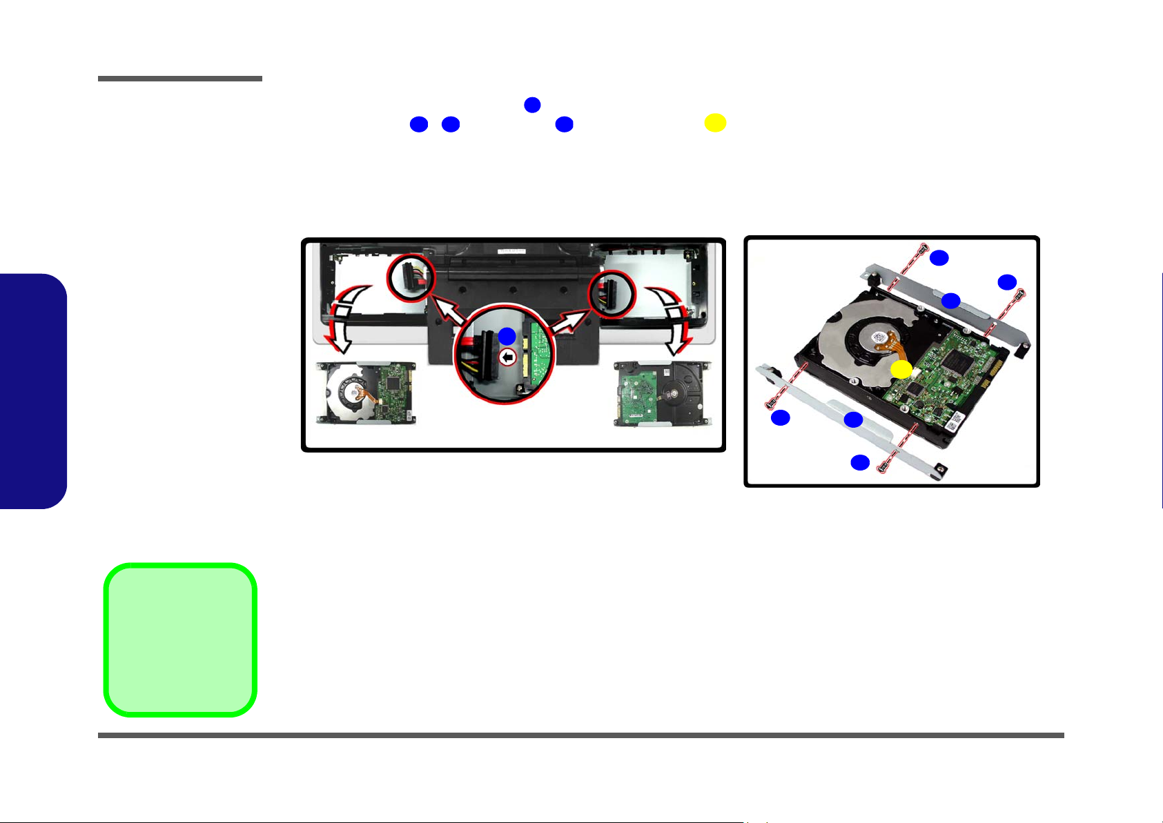
Figure 2 - 1
Hard Disk Removal
Sequence
d. Disconnect the cables
from the HDD.
e. Remove the screws
and separate the HDD
from the bracket.
2.Disassembly
7. Carefully disconnect the cable(s) from the hard disk(s) you want to replace.
8. Remove screws - , and brackets from the hard disk .
10 13 14
9
15
9. Reverse the removal procedure to install any new hard disk.
d. e.
9
10
13
12
14
15
14
11
14. HDD Bracket
15. HDD
•4 Screws
2 - 6 Removing the Hard Disk Drive Assembly
Page 26
Disassembly
Removing the System Memory
1. Turn the computer off and disconnect all peripherals and cables (including telephone lines).
2. Place the computer on a flat stable surface, preferably on a protective covering to avoid damage to the LCD screen.
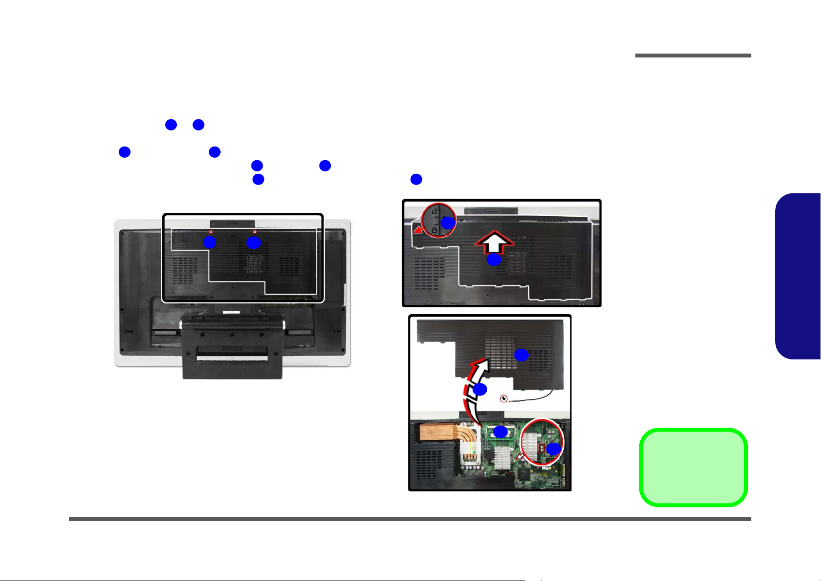
3. Remove screws & from the rear component cover.
4. Carefully (a fan and cable are attached to the under side of the cover) slide the component cover in the direction of
arrow , until the arrow aligns with the unlock symbol.
3 4
5. Carefully disconnect the fan cable from point on the mainboard.
6. Remove the rear component cover and locate the memory socket .
a. b.
1 2
5 6
7 8
4
1
2
3
c.
7
Figure 2 - 2
Memory Removal
Sequence (cont’d)
a. Remove the screws.
b. Slide the cover as indi-
cated by the arrow.
c. Disconnect the cable
and remove the component cover from the
computer.
2.Disassembly
5
8
6
•2 Screws
Removing the System Memory 2 - 7
Page 27
Disassembly
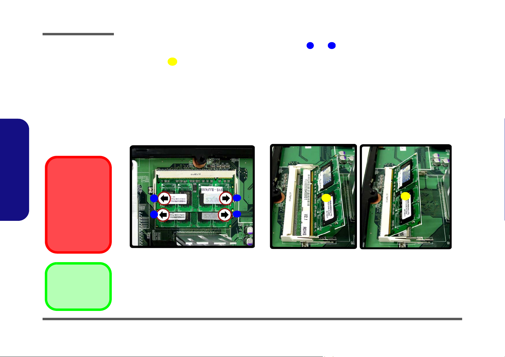
Figure 2 - 3
Memory Removal
Sequence
d. Pull the latch(es) on
the memory sockets to
release the module(s).
e. The module will pop-
up., and you can
remove the module.
Contact Warning
Be careful not to touch
2.Disassembly
the metal pins on the
module’s connecting
edge. Even the cleanest hands have oils
which can attract particles, and degrade the
module’s performance.
7. For each module you want to replace, gently push the latches and toward the sides of the socket to release the
9 10
module. Push the latches to release the second module if necessary.
8. The module will pop-up, and you can remove it.
11
9. Insert the new module. The module will only fit one way as defined by the pin alignment.
10. Make sure the module is seated as far into the slot as it will go (DO NOT FORCE IT). The latches will click into
place on the sides of the module. Make sure they are secure.
11. Reverse the procedures to put the computer back together (don’t forget to reconnect the fan cable), and do not
forget all the screws. When you restart the computer the new memory configuration should be registered.
12. If the system doesn’t properly detect the new memory, and you are sure they are properly “seated”, you may
need to run the Setup utility.
d. e.
9
9
10
10
11
11
14. Memory Module(s)
2 - 8 Removing the System Memory
Page 28
Disassembly
Removing and Installing the Processor
1. Remove the rear component cover (page 2 - 7).
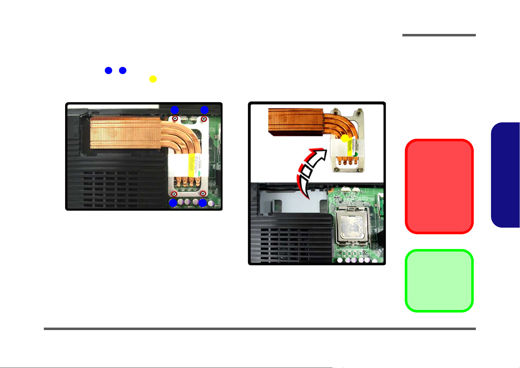
2. Remove screws - from the CPU heat sink unit (in the order indicated in Figure 2 - 5a).
3. Lift out the CPU heat sink unit from the mainboard.
a.
1 4
5
3
2
1
4
b.
Figure 2 - 4
Processor
Removal
Sequence
a. Remove the screws
from the CPU heat
sink unit.
b. Lift the heat sink unit
out.
5
2.Disassembly
Caution
The heat sink, and
CPU area in general,
contains parts which
are subject to high
temperatures - Please
allow the area time to
cool before removing
these parts.
5. Heat Sink
•4 Screws
Removing and Installing the Processor 2 - 9
Page 29
Disassembly
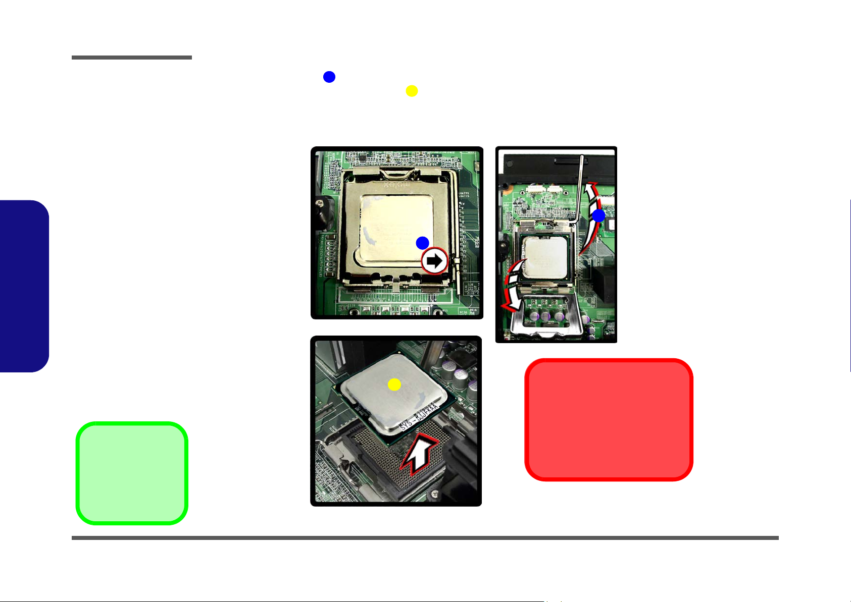
Figure 2 - 5
Processor
Removal
Sequence (cont’d)
c. Lift the release latch to
unlock the CPU.
d. Lift the CPU out of the
socket.
2.Disassembly
4. Lift the release latch to release the CPU (Figure 2 - 5c).
5. Carefully (it may be hot) lift the CPU up out of the socket (Figure 2 - 5d).
6
7
6. When re-inserting the CPU, pay careful attention to the pin alignment, it will fit only one way (DO NOT FORCE
IT!).
c.
6
6
d.
7. CPU
2 - 10 Removing and Installing the Processor
7
The heat sink, and CPU area in
general, contains parts which are
subject to high temperatures. Allow
the area time to cool before removing these parts.
Caution
Page 30
Disassembly
Removing the Modem
1. Turn the computer off and disconnect all peripherals and cables (including telephone lines).
2. Place the computer on a flat stable surface, preferably on a protective covering to avoid damage to the LCD screen.
3. Remove screw from the USB port component cover and slide the cover in the direction of arrow , until the
arrow aligns with the unlock symbol.
3
4. Remove the USB port component cover and then slide the module cover until the arrow aligns with the
unlock symbol.
5. Remove the module cover .
6. Remove screws and from the modem module.
7. Remove the modem module from the connector socket , and disconnect the modem cable at point .
8. Lift the modem off the mainboard.
a. b.
1 2
4 5 6
5
7 8
9
2
1
10 11
4
3
6
5
Figure 2 - 6
Modem Removal
Sequence
a. Remove the screw.
b. Remove the covers.
c. Remove the screws
from the modem
module.
d. Remove the modem
from the connector
and disconnect the
cable.
e. Lift the modem off the
mainboard.
2.Disassembly
c.
d. e.
7
8
11
10
9
9. Modem module
9
•3 Screws
Removing the Modem 2 - 11
Page 31

Disassembly
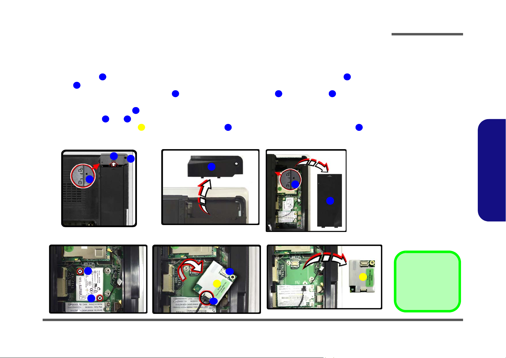
Figure 2 - 7
Wireless LAN
Module Removal
Sequence
a. Disconnect the cable
and remove the 2
screws.
b. The WLAN module will
pop-up.
c. Remove the WLAN
module.
2.Disassembly
Removing the Wireless LAN Module
1. Remove the modem module (page 2 - 11).
2. Carefully disconnect cable , then remove screws & from the module socket.
3. The wireless LAN module will pop-up.
4. Lift the wireless LAN module up and off the computer.
a.
b.
1 2 3
4
4
c.
2
1
3
4
4. WLAN Module
•2 Screws
2 - 12 Removing the Wireless LAN Module
4
Page 32

Disassembly
Removing the TV Tuner Module
1. Remove the USB port & module covers (page 2 - 11).
2. Carefully disconnect cable , then gently push the latches and toward the sides of the socket to release the
1
module.
3. The TV Tuner module will pop-up.
4. Lift the TV Tuner module up and off the computer.
a.
3
2
4
4
1
2 3
b.
4
Figure 2 - 8
TV Tuner Module
Removal
Sequence
a. Pull the latch(es) on
the module socket to
release the module.
b. The module will pop-
up.
c. Lift the module off the
mainboard.
2.Disassembly
c.
4
4. TV Tuner Module
Removing the TV Tuner Module 2 - 13
Page 33

Disassembly
Figure 2 - 9
Bluetooth Module
Removal
Sequence
a. Remove the screw.
b. Disconnect the cable.
c. Lift the Bluetooth
module off the
mainboard.
2.Disassembly
Removing the Bluetooth Module
1. Remove the USB port & module covers (page 2 - 11) and TV Tuner module (page 2 - 13).
2. Remove screw and then carefully disconnect the connector & cable from the module socket.
3. Lift the Bluetooth module up and off the computer.
a.
1 2 3
4
b.
1
c.
2
3
4. Bluetooth Module
•1 Screw
2 - 14 Removing the Bluetooth Module
4
Page 34

Disassembly
Removing the LCD Back Cover
1. Remove the 3 component covers (page 2 - 7 and page 2 - 11).
2. Set the hinge support to its transport position.
3. Remove screws - from the hinge support.
4. Lift the hinge support from the main unit and set it aside.
a.
2 7
8
b.
1
Figure 2 - 10
LCD Back Cover
Removal
Sequence
a. Set the hinge support
to its transport position.
a. Remove the screws
2
3
5
from the hinge support.
b. Lift the hinge support
and set it aside.
2.Disassembly
4
6
7
c.
8
8. Hinge
•6 Screws
Removing the LCD Back Cover 2 - 15
Page 35

Disassembly
Figure 2 - 11
LCD Back Cover
Removal
Sequence (cont’d)
d. Remove the screws
from the LCD back
cover.
e. Lift the cover out and
set it aside.
Card Reader/PC Card
Slots
2.Disassembly
Make sure you remove
any cards or covers in
the 7-in-1 Card Reader
and PC Card slot before removing the rear
case cover.
5. Remove screws - from the LCD back cover and slide it up towards the top of the computer.
6. Carefully remove the LCD back cover from the main unit and set it aside.
d.
8
9
10
8 15
16
e.
15
14
13
11 12
16
16. LCD back cover
•8 Screws
2 - 16 Removing the LCD Back Cover
Page 36

Disassembly
Removing the Optical Device Assembly
1. Remove the rear component cover (page 2 - 7) USB port and module cover (page 2 - 11) and LCD back cover
(page 2 - 15).
2. Remove screws - , and disconnect connector , from the optical device.
3. Remove the optical device , and remove the screws ( - ) in order to separate the optical device from the
bracket .
11
4. Reverse the removal procedures to intall the new optical device.
a.
1 4 5
6
1 2
4
3
7 10
c.
7
8
11
Figure 2 - 12
Optical Device
Assembly
Removal
Sequence
a. Remove the screws
and disconnect the
cable.
b. Remove the Optical
Device.
c. Remove the screws
and separate the
bracket from the optical device.
2.Disassembly
b.
6
11
10
9
Removing the Optical Device Assembly 2 - 17
5. Optical Device
11. Brackets
•8 Screws
Page 37

Disassembly
2.Disassembly
2-18
Page 38

Appendix A: Part Lists
This appendix breaks down the LV22C/LV22N/LV19C/LV19N computer’s construction into a series of illustrations.
The component part numbers are indicated in the tables opposite the drawings.
Note: This section indicates the manufacturer’s part numbers. Your organization may use a different system, so be sure
to cross-check any relevant documentation.
Note: Some assemblies may have parts in common (especially screws). However, the part lists DO NOT indicate the
total number of duplicated parts used.
Part Lists
Note: Be sure to check any update notices. The parts shown in these illustrations are appropriate for the system at the
time of publication. Over the product life, some parts may be improved or re-configured, resulting in new part numbers.
A.Part Lists
A-1
Page 39

Part Lists
Part List Illustration Location
The following table indicates where to find the appropriate part list illustration.
Part LV22 C/LV2 2N LV19C /LV1 9N
Front Cover page A - 3 page A - 10
Table A - 1
Part List Illustration
A.Part Lists
Back page A - 4 page A - 11
Combo page A - 5 page A - 12
Location
DVD-Dual page A - 6 page A - 13
HDD page A - 7 page A - 14
MB (LV22C/LV19C) page A - 8 page A - 15
MB (LV22N/LV19N) page A - 9 page A - 16
A - 2 Part List Illustration Location
Page 40

LV22C/LV22N - Front Cover
無鉛
力致
惠貿 無鉛
(隔音棉) 無鉛
惠貿 LV220C 無鉛
無鉛
(隔音棉) 無鉛
無鉛
導電布 無鉛
Part Lists
無鉛
無鉛
無鉛
無鉛
無鉛
無鉛
無鉛
無鉛
無鉛
無鉛
無鉛
無鉛
無鉛
無鉛
無鉛
無鉛
無鉛
無鉛
無鉛
無鉛
無鉛
無鉛
無鉛
無鉛
無鉛
無鉛
無鉛
無鉛
無鉛
無鉛
無鉛
無鉛
無鉛
無鉛
無鉛
無鉛
無鉛
無鉛
無鉛
無鉛
無鉛
Figure A - 1
LV22C/LV22N -
Front
A.Part Lists
LV22C/LV22N - Front Cover A - 3
Page 41

Part Lists
Figure A - 2
LV22C/LV22N -
A.Part Lists
Back
LV22C/LV22N - Back
無鉛
無鉛
無鉛
無鉛
昆山 無鉛
無鉛
無鉛
無鉛
無鉛
無鉛
無鉛
無鉛
無鉛
無鉛
無鉛
無鉛
無鉛
無鉛
無鉛
無鉛
無鉛
無鉛
無鉛
無鉛
A - 4 LV22C/LV22N - Back
Page 42

LV22C/LV22N - Combo Drive
Part Lists
Figure A - 3
A.Part Lists
LV22C/LV22N -
Combo Drive
無鉛
無鉛
無鉛
無鉛
無鉛
LV22C/LV22N - Combo Drive A - 5
Page 43

Part Lists
Figure A - 4
LV22C/LV22N -
DVD-Dual Drive
A.Part Lists
LV22C/LV22N - DVD-Dual Drive
A - 6 LV22C/LV22N - DVD-Dual Drive
無鉛
無鉛
無鉛
無鉛
無鉛
無鉛
Page 44

LV22C/LV22N - HDD
Part Lists
Figure A - 5
A.Part Lists
LV22C/LV22N -
HDD
無鉛
無鉛
無鉛
LV22C/LV22N - HDD A - 7
Page 45

Part Lists
Figure A - 6
LV22C - MB
A.Part Lists
LV22C - MB
A - 8 LV22C - MB
精乘
藍天2 互億 無鉛
無鉛
無鉛
無鉛
無鉛
無鉛
無鉛
無鉛
無鉛
無鉛
無鉛
無鉛
無鉛
無鉛
無鉛
無鉛
無鉛
無鉛
無鉛
無鉛
無鉛
無鉛
無鉛
無鉛
無鉛
無鉛
無鉛
Page 46

LV22N - MB
Part Lists
無鉛
精乘
藍天2 互億 無鉛
Figure A - 7
A.Part Lists
LV22N - MB
無鉛
無鉛
無鉛
無鉛
無鉛
無鉛
無鉛
無鉛
無鉛
無鉛
無鉛
無鉛
無鉛
無鉛
無鉛
無鉛
無鉛
無鉛
無鉛
無鉛
無鉛
無鉛
無鉛
無鉛
LV22N - MB A - 9
Page 47

Part Lists
Figure A - 8
LV19C/LV19N -
Front Cover
A.Part Lists
LV19C/LV19N - Front Cover
無鉛
力致
惠貿 LV220C 無鉛
(隔音棉) 無鉛
惠貿 無鉛
無鉛
(隔音棉) 無鉛
無鉛
導電布 無鉛
無鉛
無鉛
無鉛
無鉛
無鉛
無鉛
無鉛
無鉛
無鉛
無鉛
無鉛
無鉛
無鉛
無鉛
無鉛
無鉛
無鉛
無鉛
無鉛
無鉛
無鉛
無鉛
無鉛
無鉛
無鉛
無鉛
無鉛
無鉛
無鉛
無鉛
無鉛
無鉛
無鉛
無鉛
無鉛
無鉛
無鉛
無鉛
無鉛
無鉛
A - 10 LV19C/LV19N - Front Cover
Page 48

LV19C/LV19N - Back
Part Lists
昆山 無鉛
無鉛
無鉛
無鉛
無鉛
Figure A - 9
A.Part Lists
LV19C/LV19N -
Back
無鉛
無鉛
無鉛
無鉛
無鉛
無鉛
無鉛
無鉛
無鉛
無鉛
無鉛
無鉛
無鉛
無鉛
無鉛
無鉛
無鉛
無鉛
無鉛
LV19C/LV19N - Back A - 11
Page 49

Part Lists
Figure A - 10
LV19C/LV19N -
Combo Drive
A.Part Lists
LV19C/LV19N - Combo Drive
A - 12 LV19C/LV19N - Combo Drive
無鉛
無鉛
無鉛
無鉛
無鉛
Page 50

LV19C/LV19N - DVD-Dual Drive
Part Lists
Figure A - 11
A.Part Lists
LV19C/LV19N -
DVD-Dual Drive
無鉛
無鉛
無鉛
無鉛
無鉛
無鉛
LV19C/LV19N - DVD-Dual Drive A - 13
Page 51

Part Lists
Figure A - 12
LV19C/LV19N -
A.Part Lists
LV19C/LV19N - HDD
HDD
A - 14 LV19C/LV19N - HDD
無鉛
無鉛
無鉛
Page 52

LV19C - MB
Part Lists
精乘
藍天2 互億 無鉛
Figure A - 13
A.Part Lists
LV19C - MB
無鉛
無鉛
無鉛
無鉛
無鉛
無鉛
無鉛
無鉛
無鉛
無鉛
無鉛
無鉛
無鉛
無鉛
無鉛
無鉛
無鉛
無鉛
無鉛
無鉛
無鉛
無鉛
無鉛
無鉛
無鉛
無鉛
LV19C - MB A - 15
Page 53

Part Lists
Figure A - 14
LV19N - MB
A.Part Lists
LV19N - MB
A - 16 LV19N - MB
無鉛
精乘
藍天2 互億 無鉛
無鉛
無鉛
無鉛
無鉛
無鉛
無鉛
無鉛
無鉛
無鉛
無鉛
無鉛
無鉛
無鉛
無鉛
無鉛
無鉛
無鉛
無鉛
無鉛
無鉛
無鉛
無鉛
無鉛
無鉛
Page 54

Appendix B: Schematic Diagrams
This appendix has circuit diagrams of the LV22C/LV22N/LV19C/LV19N computer’s PCB’s. The following table indicates where to find the appropriate schematic diagram.
Schematic Diagrams
Diagram - Page Diagram - Page Diagram - Page
System Block Diagram - Page B - 2 ICH8 1/3 (PCI, DMI, CPU, IRQ) - Page B - 17 System Power - Page B - 32
Clock Generator - Page B - 3 ICH8 2/3 (LPC, ATA, USB, GPIO) - Page B - 18 3.3V/5V - Page B - 33
CPU - 1 of 3 - Page B - 4 ICH8 3/3 (Power) - Page B - 19 12VS, AC-In - Page B - 34
CPU - 2 of 3 - Page B - 5 JM361 PCI-E TO PATA, eSATA - Page B - 20 1.8V/0.9V - Page B - 35
CPU - 3 of 3 - Page B - 6 CD-ROM, SATA, PC-Beep, LED - Page B - 21 1.5VS,1.05VS - Page B - 36
Intel P965 1/5 CPU Interface - Page B - 7 VGA Fan, CCD, Power OK - Page B - 22 1.2VS/1.25VS - Page B - 37
Intel P965 2/5 PCI-E I/F - Page B - 8 LAN 82566 - Page B - 23 VCORE - Page B - 38
Intel P965 3/5 Memory I/F - Page B - 9 PCI7402 - Page B - 24 LED Board - Page B - 39
Intel P965 4/5 GND - Page B - 10 TV Tuner, CardReader, CIR - Page B - 25 Power Board - Page B - 40
Intel P965 5/5 Power - Page B - 11 ITE IT8512 - Page B - 26 CIR Board - Page B - 41
DDRII SO-DIMM 1/2 - Page B - 12 Mini Card, New Card - Page B - 27 CD-ROM Board - Page B - 42
DDRII SO-DIMM 2/2 - Page B - 13 USB 2.0 - Page B - 28 Video Connector Board - Page B - 43
MXM PCI-E CONN - Page B - 14 AZALIA Codec ALC883/ALC888 - Page B - 29 CRT Connector Board - Page B - 44
BIOS, USB K/B, TPM - Page B - 15 Audio AMP, SRS, Woofer - Page B - 30
Panel, CPU Fan - Page B - 16
MDC, BT, PWRGD, Inverter Connector Page B - 31
Table B - 1
Schematic Diagram
B.Schematic Diagrams
Version Note
The schematic diagrams in this chapter
are based upon version 6-71-LV220C-
D03A. If your mainboard (or other boards)
are a later version,
please check with the
Service Center for updated diagrams (if required).
B-1
Page 55

Schematic Diagrams
Sheet 1 of 43
Schematic Diagram
B.Schematic Diagrams
System Block Diagram
Serial
Flash
SATA
HDD*3
10 MHz
512K
EXT VGA CARD
MXM Go7600
SDVO
CHRONTEL
CH7308
ITE/IT8512
THERMAL
SENSOR
ADM1032
CCD
USB6
BT
USB4
CLEVO LV220C System Block Diagram
CLOCK GEN.
ICS9LPR363
LCD CONN(LVDS)
MXM
EC
EC SMBUS
SMART
FAN
PATA-33/66/100
KEYBOARD
USB7
33 MHz
LPC
TPM
SATA-150
USB8
Serial
Flash
16M
USB9
PCIE
SPI
PROCESSOR
Core 2 Duo
LGA775
NORTH BRIDGE
G965
1226 FCBGA
SOUTH BRIDGE
ICH8 DH
652 BGA
USB2.0
USB0
USB1
FSB
533/800/1066 MHz
DMI
Mini PCIE1
SOCKET
USB2
Mini Card
Intel
GOLAN
533/667 MHz
SYSTEM SMBUS
PCIE
Mini PCIE2
SOCKET
USB3
TV2
CD-ROM/
CD-RW/
DVD-COMBO/
DVD-ROM/
DVD+-RW
MEMORY TERMINATIONS
DDR2 SDRAM S OC KE T
SO-DIMM0
SO-DIMM1
DDRII
AZALIA LINK
24 MHz
GLCI
PCI BUS
MASTER
JM361
CD-ROM
ESATA
*1
NEW
CARD
33 MHz
USB5
RJ-11
AZALIA
MDC
MODULE
MDC CONN.
Mini PCI
Slot
for TV Tuner
TV1
VIDEO-IN
MINI DIN 7
3.3V,5V,3.3VS,5VS,1.5VS,
1.8VS,2.5VS
1.8V,0.9VS,1.5VS
VCORE
1.05VS,1.5V
12VS
1.2V,1.25VS
VDD3,VDD5
SPDIF
OUT
MIC
IN
AUDIO AMP.
TPA 3005D2
SRS
AP8202Q
WOOFER
TPA3007D1
24.576
MHz
48 MHz
IEEE
1394
HP
OUT
G-LAN
Intel
82566
RJ-45
LINE
IN
7.1 CHANNEL OUT
AZALIA
CODEC
ALC883
TI
PCI7402
4IN 1
CARD
READER
MMC/SD/MS/MS Pro
INT.
SPK
25 MHz
B - 2
Page 56

Clock Generator
3.3VS
CPU_BSEL04
L15 HCB2012KF-121T30
12
C228
0.1u_X7R_04
3.3VS
ICH_SMBDAT11,12,17,19,26
ICH_SMBCLK11,12,17,19, 26
C217
10u_10V_08
L45 HCB2012KF-121T3012
C662
0.1u_X7R_04
CK_PWRSAVE#17
1u_10V_06
Z0205
C219
CLK_PCM4823
USB_CLK4817
CPU_BSEL04
CPU_BSEL14
CPU_BSEL24
CKVDD
C198
C199
0.1u_X7R_04
0.1u_X7R_04
C197
C643
0.1u_X7R_04
10u_10V_08
L14 HCB1608KF-121T251 2
3.3VS
3.3VS
CK_PWRSAVE#
CK_PWRGD17
SWLAN _C LKR EQ#26
MXM_CLK _R EQ#13
C619
C620
*100p_04
*100p _04
1002
3.3V S
CLK_PCM48
USB_CLK48
CPU_BSEL0
CPU_BSEL1
CPU_BSEL2
3.3VS
R230
1K_04
Z0206
Q21
B
B
2N3904
E C
C216
0.01u_16V_04
C213
0.01u_16V_04
C215
0.1u_X7R_04
R446 10K_04
R445 *0_04
R478 1K_04
MXM_CLK _R EQ#
ICH_SMBDAT
ICH_SMBCLK
C633 2 2p_50V_04
C640 2 2p_50V_04
R461 1K_1%_04
R466 274_1%_04
R221 22_04
R227 22_04
R226 *0_04
R205 1K_04
R163 *0_04
Z0207
R220 1K_04
Q20
2N3904
E C
C200
0.01u_16V_04
C214
0.01u_16V_04
X3
14.318MHz
1 2
CPU_BSEL24
VDDPCI
VDD48
Z0214
CLK_PWRGD
Z0201
Z0202
Z0203
FSA
FSB
FSC
FSA
U12
21
VDDPCIEX
28
VDDPCIEX
42
VDDPCIEX
45
VDDA
50
VDDCPU
1
VDDPCI
7
VDDPCI
56
VDDREF
11
VDD48
2
GND
6
GND
13
GND
29
GND
37
GND
46
GNDA
53
GND
59
GND
34
PWRSAVE#
10
VttPWR_GD/ PD#
32
PEREQ3#
33
PEREQ4#
55
SDATA
54
SCLK
58
X1
57
X2
47
VREF
16
FSLB/TEST_MODE
61
REF1/FSLC/TEST_SEL
ICS9LPR363
R447 4. 7K_04R229 4.7K_04
CPUT_L0
CPUC_L0
CPUT_L1F
CPUC_L1F
CPUITPT_L2/PCIeT_L8
CPUITPC_L2/PCI eC_L8
PEREQ1#/PCIeT_L7
PEREQ2#/PC IeC_L7
PCIeT_L6
PCIeC_L6
PCIeT_L5
PCIeC_L5
PCIeT_L4
PCIeC_L4
PCIeT_L3
PCIeC_L3
PCIeT_L2
PCIeC_L2
PCIeT_L1
PCIeC_L1
PCIeT_L0
PCIeC_L0
SATACLKT_L
SATACLKTC_L
DOT_96MHz
DOT#_96MHz
PCICLK1
PCICLK2
PCICLK3
ITP_EN/PCICLK_F4
PCICLK_F5
PCICLK0/ REQ_SELFSLA/USB_48MHz
PCI/ PCIEX_STOP#
CPU_STOP#
3.3VS
Z0208
B
Schematic Diagrams
Sheet 2 of 43
ICH_CLK14
USB_CLK48
CPUCLK0
CPUCLK#0
CPUCLK1
CPUCLK#1
SRCCLK8
SRCCLK#8
NEWCARD_CLKREQ#
WLAN_CLKREQ#
SRCCLK6
SRCCLK#6
SRCCLK5
SRCCLK#5
SRCCLK4
SRCCLK#4
SRCCLK3
SRCCLK#3
SRCCLK2
SRCCLK#2
SRCCLK1
SRCCLK1#
SRCCLK0
SRCCLK0#
SATACLKT
SATACLKC
DOTCLK96
DOTCLK96#
PCICLK1
PCICLK2
PCICLK3
Z0204
PCICLK5
REF0
REQ_SEL
PM_STPCPU#
PM_STPPCI#
Z0210
Q47
B
2N3904
E C
RN4 33_04_4P2R
1
4
CLK_CPU_BCLK
2 3
CLK_CPU_BCLK#
1
4
MCH C LK
2 3
1
2 3
4
4
4
4
4
4
4
4
4
MCH C LK #
4
CPU_ITPCLK
CPU_ITPCLK#
23
PCIE_CLK_JMB368
PCIE_CLK_JMB368#
1
23
SRCCLK_MCH
1
SRCCLK_MCH #
1
SRCCLK_I CH
SRCCLK_I CH#
23
1
PCIE_CLK_MXM
23
PCIE_CLK_MXM#
SPCIE_CL K_MINI
1
23
SPCIE_CL K_MINI#
1
PCIE_CLK_MINI
23
PCIE_CLK_MINI#
CLK_PCIE _NEW_CAR D
1
CLK_PCIE _NEW_CAR D#
23
1
CLK_SATA
23
CLK_SATA#
DOTCLK
1
DOTCLK#
23
1130
RN5 33_04_4P2R
RN34 33_04_4P2R
RN6 33_04_4P2R
RN7 33_04_4P2R
RN31 33_04_4P2R
RN33 33_04_4P2R
RN40 33_04_4P2R
RN35 33_04_4P2R
RN36 33_04_4P2R
RN32 33_04_4P2R
RN37 33_04_4P2R
R201 22_04
R202 22_04
R203 22_04
R479 10K_04
R213 10K_04
R212 *10K_04
R653 *22_04
R204 22_04
R214 10K_04
R164 33_04
R160 10K_04
R161 4.7K_04
R162 4.7K_04
R448 1K_04
PCLK_PCM
PCLK_MINI
KBC_PCLK
PCLK_IC H
1225
ICH_CLK14
FSC
PCLK_TPM
CPU_BSEL14
CLK_CPU_BCLK 3
CLK_CPU_BCLK# 3
MCH CLK 6
MCH CLK # 6
CPU_ITPCLK 4
CPU_ITPCLK# 4
NEWCARD_CLKREQ# 26
WLAN_CLKREQ# 26
PCIE_CLK_JMB368 19
PCIE_CLK_JMB368# 19
SRCCLK_MCH 7
SRCCLK_MCH# 7
SRCCLK_ICH 16
SRCCLK_ICH# 16
PCIE_CLK_MXM 13
PCIE_CLK_MXM# 13
SPCIE_CLK_MINI 26
SPCIE_CLK_MINI# 26
PCIE_CLK_MINI 26
PCIE_CLK_MINI# 26
CLK_PCIE_NEW_CARD 26
CLK_PCIE_NEW_CARD# 26
CLK_SATA 17
CLK_SATA# 17
DOTCLK 7
DOTCLK# 7
PCLK_PCM 23
PCLK_MINI 24
KBC_PCLK 25
3.3VS
3.3VS
PCLK_TPM 14
PCLK_ICH 16
3.3VS
ICH_CLK14 17
3.3VS
3.3VS
3.3VS
R206 *4.7K_04
Z0211
3.3V 4,7,14,16, 17,18,21,22,24,26, 30,31,34,36
3.3VS 7,10,11,12, 13,14,15,16,17,18, 19,20,21,23,24,25, 26,28,29,30,31,37
52
51
49
48
44
43
41
40
39
38
36
35
30
31
24
25
22
23
19
20
17
18
26
27
14
15
3
4
5
8
9
60
REF0
6412
63
62
R443
1K_04
Z0209
Q46
2N3904
E C
PCLK_PCM
KBC_PCLK
PCLK_MINI
PCLK_ICH
PCLK_TPM
3.3VS
R431
*1K_04
Z0212
Q51
B
*2N3904
E C
C607 *10p_50V_04
C246 *10p_50V_04
C225 *10p_50V_04
C227 *10p_50V_04
C226 *10p_50V_04
C235 *10p_50V_04
C808 *10p_50V_04
1130
Z0213
R211 *1K_04
Q19
B
*2N3904
E C
FSB
Clock Generator
B.Schematic Diagrams
Clock Generator B - 3
Page 57

Schematic Diagrams
CPU - 1 of 3
Sheet 3 of 43
CPU 1 of 3
B.Schematic Diagrams
H_A#[35:3]6
H_ADSTB#06
H_ADSTB#16
H_REQ#[4:0]6
H_SMI#16
H_A20M#16
H_FERR#16
H_INTR16
H_NMI16
H_IGNNE#16
H_STPCLK#16
C31 33P_50V_04
H_VID[ 7:0]37
VR_SEL37
CLK_C PU_BCLK2
CLK_C PU_BCLK#2
H_THERMDA4
H_THERMDC4
VCCSE NSE37 VDD3 4, 13,15,21, 25,31,32
VSSSENSE37
DIFF PAIR
R38 51.1_1%_04
H_A#3
H_A#3
H_A#4
M5
H_A#5
H_A#6
M4
H_A#7
R4
H_A#8
H_A#9
U6
H_A#10
H_A#11
U5
H_A#12
U4
H_A#13
V5
H_A#14
H_A#15
V4
W5
H_A#16
AB6
H_A#17
W6
H_A#18
Y6
H_A#19
Y4
H_A#20
AA4
H_A#21
AD6
H_A#22
AA5
H_A#23
AB5
H_A#24
AC5
H_A#25
AB4
H_A#26
H_A#27
AF5
AF4
H_A#28
AG6
H_A#29
H_A#30
AG4
AG5
H_A#31
H_A#32
AH4
AH5
H_A#33
AJ5
H_A#34
H_A#35
AJ6
Z0301
AC4
Z0302
AE4
N4
Z0303
P5
Z0304
R6
H_ADSTB# 0
H_ADSTB# 1
AD5
K4
H_REQ#0
H_REQ#1
H_REQ#2
M6
H_REQ#3
K6
H_REQ#4
VCCPLL
R69 *0_04
R71 *0_04
R70 0_04
R73 0_04
VCORE
PECI16
U3A
L5
A<3>*
P6
A<4>*
A<5>*
L4
A<6>*
A<7>*
A<8>*
T5
A<9>*
A<10>*
T4
A<11>*
A<12>*
A<13>*
A<14>*
A<15>*
A<16>*
A<17>*
A<18>*
A<19>*
A<20>*
A<21>*
A<22>*
A<23>*
A<24>*
A<25>*
A<26>*
A<27>*
A<28>*
A<29>*
A<30>*
A<31>*
A<32>*
A<33>*
A<34>*
A<35>*
RSVD_1
RSVD_2
RSVD_3
RSVD_4
ADSTB<0>*
ADSTB<1>*
REQ<0>*
J5
REQ<1>*
REQ<2>*
REQ<3>*
J6
REQ<4>*
75319-0115
H_SMI#
H_A20M#
H_FERR#
H_INTR
H_NMI
H_IGNNE#
H_STPCLK#
VCCA
VSSA1
VCCIOPLL
VCCPLL
12 MIL TRACE
H_VID0
H_VID1
H_VID2
H_VID3
H_VID4
H_VID5
H_VID6
H_VID7
Z0318
Z0319
Z0320
Z0321
Z0322
VTT_PKGSENSE
H_CPU_PD_F6
Z0323
PECI
Z0324
DBSY*
DRDY*
LOCK*
TRD Y*
DEFER*
IERR*
BINI T*
MCER R *
AP<0>*
AP<1>*
DP<0>*
DP<1>*
DP<2>*
DP<3>*
BR<0>*
TESTH I_8
TESTH I_9
TESTHI_10
GTLREF0
GTLREF1
GTLREF2
GTLREF_SEL
RESET*
RS<0>*
RS<1>*
RS<2>*
1 OF 8
P2
K3
R3
K1
L1
N2
M3
A23
B23
C23
D23
AM2
AL5
AM3
AL6
AK4
AL4
AM5
AM7
AN7
F28
G28
AE8
AL1
AK1
AJ7
AH7
AN3
AN4
AN5
AN6
AL8
AL7
F29
F6
G6
G5
AL3
D2
H_ADS#
ADS*
C2
H_BNR#
BNR*
H_HIT#
D4
HIT*
G8
H_BPR I#
BPRI*
B2
H_DBSY#
H_DRDY#
C1
E4
H_HITM#
HITM*
C3
H_LOCK#
H_TRDY#
E3
G7
H_DEFER#
AB2
H_IERR#
P3
H_INIT#
INIT*
Z0305
H4
RSP*
Z0306
AD3
AB3
Z0307
U2
Z0308
U3
Z0309
J16
Z0310
H15
Z0311
H16
Z0312
J17
Z0313
F3
H_BR0#
TESTH I_ 8
G3
TESTH I_ 9
G4
TESTHI_10
H5
CPU_GTLREF0
H1
CPU_GTLREF1
H2
E24
GTLREF_SEL
H29
G23
B3
H_RS#0
H_RS#1
F5
A3
H_RS#2
U3B
SMI*
A20M*
FERR*/PBE*
LINT0
LINT1
IGNNE*
STPCLK*
VCCA
VSSA
VCCIOPLL
VCC_PLL
VID<0>
VID<1>
VID<2>
VID<3>
VID<4>
VID<5>
VID<6>
VID<7>
VID_ SELECT
BCLK<0>
BCLK<1>
SKTOCC*
THER MDA
THER MDC
THERMDA_2
THER MDC _2
VCC_SENSE
VSS_SENSE
VCC_MB_REGULATION
VSS_MB_REGU LATION
VCC_D_SENSE
VSS_D_SENSE
VTT_PK GSEN SE
Z60_50*
SLEW_CTRL*
SST_LV*
MPG_NOBOOT*
2 OF 8
75319-0115
H_CPURST#
H_ADS# 6
H_BNR# 6
H_HIT# 6
H_BPRI # 6
H_DBSY# 6
H_DRDY# 6
H_HITM# 6
H_LOCK# 6
H_TRDY# 6
H_DEFER# 6
R40 62_1%_06
C30
33P_50V_04
R44 62_1%_06
R22 51.1_1%_04
R54 51.1_1%_04
R55 51.1_1%_04
CPU_MCH_GTLREF 6
R25 62_1%_06
H_CPURST# 6
H_RS#0 6
H_RS#1 6
H_RS#2 6
LGA775_C
TESTH I_0
TESTH I_1
TESTH I_1 1
TESTH I_1 2
TESTH I_1 3
TESTH I_2
TESTH I_3
TESTH I_4
TESTH I_5
TESTH I_6
TESTH I_7
FORCEPH
PWRGOOD
PROCHOT*
THER MTRI P*
COMP<0>
COMP<1>
COMP<2>
COMP<3>
COMP<4>
COMP<5>
COMP<6>
COMP<7>
COMP<8>
RC1
RC2
RC4
RC5
RSVD_1
RSVD_2
PSMI*
MSI D<1 >
MSI D<0 >
CPU_B OOT
LL_ID<0>
LL_ID<1>
F26
W3
P1
W2
L2
F25
G25
G27
G26
G24
F24
AK6
N1
AL2
M2
A13
T1
G2
R1
J2
T2
Y3
AE3
B13
G1
U1
A24
E29
F2
G10
AH2
V1
W1
Y1
V2
AA2
VTT_OR
VTT_OL
H_BR0# 6
VTT_OL
VTT_OR
TESTH I_ 0
TESTHI _1
TESTHI_11
TESTHI_12
Z0325
TESTHI_2-7
H_FORCEPR_N
H_PROCHOT#
H_THERMTRIP#
CPU_COMP0
CPU_COMP1
CPU_COMP2
CPU_COMP3
CPU_COMP4
CPU_COMP5
CPU_COMP6
CPU_COMP7
CPU_COMP8
TP_CPU_G1
TESTHI _M
Z0326
Z0327
CPU_GTLREF2
CPU_GTLREF3
Z0328
CPU_MSID1
CPU_MSID0
BOOTSEL
TP_V2
TP_AA2
H_INIT# 16
LGA775_C
VCCA_VSSA_VCOREPLL Trace width donesn't less than 12 Mil
VTT_1.2VS
NEAR H1/H2
C32
C33
220p_50V_04
220p_50V_04
R357 51_04
R56 51_04
R57 51_04
R58 51_04
R15 51_04
R29 *0_04
R355 51.1_1%_04
R32 *100_04
H_PWRGD 17
R88 49.9_1%_04
R51 49.9_1%_04
R21 49.9_1%_04
R53 49.9_1%_04
R27 49.9_1%_04
R52 49.9_1%_04
R48 49.9_1%_04
R47 49.9_1%_04
R89 24.9_1%_04
R20 47_04
R50 51.1_1%_04
R354 *1K_04
R49 51.1_1%_04
R59 51.1_1%_04
As close as possible to CP U socke t
L37
LB2012T100M_08
L38
LB2012T100M_08
C533 0.1u_16V_04
VTT_1. 2VS
VTT_OL
TESTHI_13 16
VTT_1.2VS
H_FORCEPR_N 37
VTT_OL
H_PROCHOT# 17,37
H_THERMTRIP# 16
C16 0.1u_16V_04
C13 0.1u_16V_04
VTT_OL
C515
1u_10V_06
C509
1u_10V_06
1.5VS
C511
*10u_10V_08
VTT_OL
VTT_OR
R417 0_06
+
C510
100u_10V_D
VSSA1
VTT_OR
VTT_OR
VTT_OR
VTT_OR
C542 10u_10V_08
C519 0.01u_16V_04
VCCA
R346
*0_04
VCCI OPLL
R14 124_1%_04
R13 124_1%_04
R24 *124_1%_04
R23 *124_1%_04
VCCPLL
VTT_OR
VTT_1.2VS
H_NMI
H_IGNNE#
H_SMI#
H_INTR
H_A20M#
R77 1K_04 VR_SEL
R66 *130_1%_04
R72 *130_1%_04
C26 10u_10V_08
C12 0.1u_X7R_04
C22 0.01u_16V_04
1225
R41 62_04
R43 62_04
R61 10_04
Z0314
R28
C28
210_1%_06
1u_10V_06
R60 10_04
Z0315
R33
C27
210_1%_06
1u_10V_06
Z0316
R37 *10_04
C19
R17
*1u_10V_06
*210_1%_06
R36 *10_04
Z0317
R16
C18
*210_1%_06
*1u_10V_06
C809 *0.1u_X7R_04
C810 *47nF_10V_X7R_04
C811 *47nF_10V_X7R_04
C812 *47nF_10V_X7R_04
C813 *47PF_NPO_04
VCCPLL 10
3.3VS 2, 7,10,11,12, 13,14,15,16, 17,18,19, 20,21,23,24,25 ,26,28,29, 30,31,37
VTT_1.2VS 4,5,6, 7,10,18,36, 37
VTT_OR 4
VTT_OL 4
1.5VS 16, 17,18,26,35
VCORE 5,37
3.3VS 2, 7,10,11,12, 13,14,15,16, 17,18,19, 20,21,23,24, 25,26,28,29, 30,31,37
H_PROCHOT#
H_FORCEPR_N
H_THERMTRIP#
H_FERR#
CPU_GTLREF1
R34
*0_04
CPU_GTLREF0
CPU_GTLREF3
R45
*0_04
CPU_GTLREF2
1130
B - 4 CPU - 1 of 3
Page 58

CPU - 2 of 3
VTT_OL
R42 62_1%_06
R35 62_1%_06
R18 51. 1_1%_04
R39 62_1%_06
R30 51. 1_1%_04
R64 51. 1_1%_04
R65 51. 1_1%_04
R19 51. 1_1%_04
R62 51. 1_1%_04
R46 51. 1_1%_04
R63 51. 1_1%_04
R31 0_04
R68 * 0_04
R67 * 0_04
R11 47_04
0927
VTT_OR
SYS_RST#17
CPU_ITPCLK2
CPU_ITPCLK#2
H_TCK
H_TRST#
H_TDI
H_TDO
H_TMS
H_BPM0#
H_BPM1#
H_BPM2#
H_BPM3#
H_BPM4#
H_BPM5#
SYS_RST1#
H_ITPCLK
H_ITPCLK#
CPU_BSEL0
CPU_BSEL1
CPU_BSEL2
TEST
Z0401
Z0402
Z0403
Z0404
Z0405
Z0406
AE1
AG1
AD1
AF1
AC1
AJ2
AJ1
AD2
AG2
AF2
AG3
AC2
AK3
AJ3
G29
H30
G30
N5
C9
E7
AE6
D16
A20
E23
U3C
TCK
TRST*
TDI
TDO
TMS
BPM<0>*
BPM<1>*
BPM<2>*
BPM<3>*
BPM<4>*
BPM<5>*
DBR*
ITPCLK<0>
ITPCLK<1>
BSEL<0>
BSEL<1>
BSEL<2>
SPARE0
SPARE1
SPARE2
SPARE4
NC_DSS2
NC_DSS3
NC
3 OF 8
75319-0115
LGA775_C
VTT_1
VTT_2
VTT_3
VTT_4
VTT_5
VTT_6
VTT_7
VTT_8
VTT_9
VTT_10
VTT_11
VTT_12
VTT_13
VTT_14
VTT_15
VTT_16
VTT_17
VTT_18
VTT_19
VTT_20
VTT_21
VTT_22
VTT_23
VTT_24
VTT_PWRGD
VTT_OUT_1
VTT_OUT_2
VTT_SEL
EXTBGREF
SFRANAD
SFRANAC
DCLKPH
ACLKPH
HFPLL
Schematic Diagrams
Sheet 4 of 43
Yonah CPU 2 of 3
VTT_1.2VS
A29
B25
B29
B30
C29
A26
B27
C28
A25
A28
A27
C30
A30
C25
C26
C27
B26
D27
D28
D25
D26
B28
D29
D30
AM6
AA1
J1
VTT_SEL
F27
Z0407
F23
Z0408
D14
Z0409
E6
Z0410
E5
Z0411
J3
D1
Z0412
VTT_OR
R74
1K_1%_04
C35 0.01u_16V_04
VTT_OR
VTT_OL
VRM_PWRGD 30, 37
H_D#[63:0]6
H_DBI0#6
H_DSTBN0#6
H_DSTBP0#6 H_DSTBP2# 6
H_D#[63:0]6
H_DBI1#6
H_DSTBN1#6
H_DSTBP1#6
H_D#0
H_D#1
H_D#2
H_D#3
H_D#4
H_D#5
H_D#6
H_D#7
H_D#8
H_D#9
H_D#10
H_D#11
H_D#12
H_D#13
H_D#14
H_D#15
H_D#16
H_D#17
H_D#18
H_D#19
H_D#20
H_D#21
H_D#22
H_D#23
H_D#24
H_D#25
H_D#26
H_D#27
H_D#28
H_D#29
H_D#30
H_D#31
A10
A11
B10
C11
B12
C12
D11
E10
D10
F11
F12
D13
E13
G13
F14
G14
F15
G15
G11
G12
E12
B4
C5
A4
C6
A5
B6
B7
A7
D8
A8
C8
B9
G9
F8
F9
E9
D7
U3D
75319-0115
D<0>*
D<1>*
D<2>*
D<3>*
D<4>*
D<5>*
D<6>*
D<7>*
D<8>*
D<9>*
D<10>*
D<11>*
D<12>*
D<13>*
D<14>*
D<15>*
DB1<0>*
DSTBN<0>*
DSTBP<0>
D<16>*
D<17>*
D<18>*
D<19>*
D<20>*
D<21>*
D<22>*
D<23>*
D<24>*
D<25>*
D<26>*
D<27>*
D<28>*
D<29>*
D<30>*
D<31>*
DB1<1>*
DSTBN<1>*
DSTBP<1>
LGA775_C
4 OF 8
D<32>*
D<33>*
D<34>*
D<35>*
D<36>*
D<37>*
D<38>*
D<39>*
D<40>*
D<41>*
D<42>*
D<43>*
D<44>*
D<45>*
D<46>*
D<47>*
DBI<2>*
DSTBN<2>*
DSTBP<2>
D<48>*
D<49>*
D<50>*
D<51>*
D<52>*
D<53>*
D<54>*
D<55>*
D<56>*
D<57>*
D<58>*
D<59>*
D<60>*
D<61>*
D<62>*
D<63>*
DBI<3>*
DSTBN<3>*
DSTBP<3>
G16
H_D#32
E15
H_D#33
E16
H_D#34
G18
H_D#35
G17
H_D#36
H_D#37
F17
F18
H_D#38
E18
H_D#39
E19
H_D#40
H_D#41
F20
E21
H_D#42
H_D#43
F21
G21
H_D#44
E22
H_D#45
D22
H_D#46
H_D#47
G22
D19
G20
G19
H_D#48
D20
H_D#49
D17
A14
H_D#50
H_D#51
C15
C14
H_D#52
H_D#53
B15
C18
H_D#54
B16
H_D#55
A17
H_D#56
B18
H_D#57
C21
H_D#58
H_D#59
B21
H_D#60
B19
H_D#61
A19
H_D#62
A22
H_D#63
B22
C20
A16
C17
H_D#[63:0] 6
H_DBI2# 6
H_DSTBN2# 6
H_D#[63:0] 6
H_DBI3# 6
H_DSTBN3# 6
H_DSTBP3# 6
B.Schematic Diagrams
3.3V
THERM_ RST#25
Layout Note:
Route H_THERMDA and
H_THERMDC on same layer.
10 mil trace on 10 mil
spacing.
NDS352AP_NL
C783 0.1u_X7R_04
R8 100K_04
G
Q3
Z0417
G
Z0414
DS
DS
R647
20K_1%_04
Q2
2N7002
Z0413
1212
R9 0_04
H_THERMDA3
H_THERMDC3
3.3V
R621
*0_04
R10
100K_04
Layout Note:
Near to The rmal
IC
V_THRM
C17
1u_10V_06
C34
1000p_X7R_04
U1
1
VDD
2
D+
3
D-
5
GND
ADM1032ARM
R26
10K_04
THER M
ALERT
SDATA
SCLK
Z0415
VTT_1.2 VS
CPU_BSEL02
CPU_BSEL12
CPU_BSEL22
VDD3
R3
R4
4.7K_04
4
R622 0_04
6
R623 * 0_04
Z0416
7
8
4.7K_04
CPU_BSEL0
CPU_BSEL1
CPU_BSEL2
1130
R5
*10K_04
R142 470_04
R136 470_04
R141 470_04
THERMAL_ALERT# 25
SMD_THERM 25
SMC_THERM 25
R134 10K_04
R135 10K_04
R133 10K_04
VTT_OL
C11 10u_10V_08
C24 0.1u_X7R_04
C23 0.01u_16V_04
MCH_BSEL0
MCH_BSEL1
MCH_BSEL2
VTT_OR
3.3V 7,14,16,17,18,21,22, 24,26,30,31,34,36
3.3VS 2,7,10,11,12,13,14, 15,16,17,18,19,20,21,23,24,25, 26,28,29,30,31,37
VDD3 13,1 5,21,25, 31,32
VTT_OR 3
VTT_OL 3
VTT_1.2VS 3,5,6, 7,10,18,36,37
C15 10u_10V_08
C20 0.1u_X7R_04
C21 0.01u_16V_04
MCH_BSEL0 7
MCH_BSEL1 7
MCH_BSEL2 7
CPU - 2 of 3 B - 5
Page 59

Schematic Diagrams
Sheet 5 of 43
Yonah CPU 3 of 3
B.Schematic Diagrams
CPU - 3 of 3
U3E
GND_1
GND_2
GND_3
GND_4
GND_5
GND_6
GND_7
GND_8
GND_9
GND_10
GND_11
GND_12
GND_13
GND_14
GND_15
GND_16
GND_17
GND_18
GND_19
GND_20
GND_21
GND_22
GND_23
GND_24
GND_25
GND_26
GND_27
GND_28
GND_29
GND_30
GND_31
GND_32
GND_33
GND_34
GND_35
GND_36
GND_37
GND_38
GND_39
GND_40
GND_41
GND_42
GND_43
GND_44
GND_45
GND_46
GND_47
GND_48
GND_49
GND_50
GND_51
GND_52
GND_53
GND_54
GND_55
GND_56
GND_57
GND_58
GND_59
GND_60
GND_61
GND_62
GND_63
GND_64
GND_65
GND_66
GND_67
GND_68
GND_69
GND_70
75319-0115
LGA775_C
5 OF 8
GND_71
GND_72
GND_73
GND_74
GND_75
GND_76
GND_77
GND_78
GND_79
GND_80
GND_81
GND_82
GND_83
GND_84
GND_85
GND_86
GND_87
GND_88
GND_89
GND_90
GND_10 0
GND_10 2
GND_10 3
GND_10 4
GND_10 5
GND_10 6
GND_10 7
GND_10 8
GND_10 9
GND_11 0
GND_11 1
GND_11 2
GND_11 3
GND_11 4
GND_11 5
GND_11 6
GND_11 7
GND_11 8
GND_11 9
GND_12 0
GND_12 1
GND_12 2
GND_12 3
GND_12 4
GND_12 5
GND_12 6
GND_12 7
GND_12 8
GND_12 9
GND_13 0
GND_13 1
GND_13 2
GND_13 3
GND_13 4
GND_13 5
GND_13 6
GND_13 7
GND_13 8
GND_13 9
GND_14 0
AE5
AH23
AE7
AM13
AH24
AJ30
AJ10
AF3
AK5
AJ16
AF6
AK29
AJ17
F22
AH3
AK10
AM10
F16
AJ23
F13
AG7
L26
AD4
H11
L24
L23
AM23
A15
AH10
B24
L3
H27
A21
AE2
AJ29
AK27
AK28
B20
AM20
H26
B17
H25
H24
AA3
AA7
H23
AA6
H10
H22
H21
H20
H19
H18
AB7
H17
AJ24
AM17
AC3
H14
P28
C10
D12
C24
K2
C22
AN1
B14
K7
AE16
B11
AL10
AK23
H12
AF7
AK7
H7
E14
L28
Y5
E11
AL16
AL24
AK13
D21
AL20
D18
AN2
AK16
AK20
AM27
AM1
AL13
AL17
C19
E28
AK30
D24
AL23
A12
L25
J7
AE28
AE29
K5
J4
AE30
AN20
AF10
AE24
AM24
AN23
H9
H8
H13
AC6
AC7
AH6
C16
AM16
AE25
AE27
AJ28
F19
AH13
AD7
AH16
AK17
E17
AH17
AH20
VCORE
LGA775_C
U3F
V6
GND_141
AK2
GND_142
P27
GND_143
P26
GND_144
AM28
GND_145
AJ13
GND_146
W4
GND_147
P25
GND_148
AJ20
GND_149
W7
GND_150
P23
GND_151
C7
GND_152
L30
GND_153
L29
GND_154
D15
GND_155
AL27
GND_156
Y7
GND_157
L27
GND_158
AA29
GND_159
N6
GND_160
N7
GND_161
AA28
GND_162
AN13
GND_163
AA27
GND_164
AA26
GND_165
P4
GND_166
AA25
GND_167
AA24
GND_168
P7
GND_169
E26
GND_170
V30
GND_171
R2
GND_172
V29
GND_173
V28
GND_273
R5
GND_174
V27
GND_175
R7
GND_176
E20
GND_177
AN10
GND_178
V25
GND_179
T3
GND_180
V24
GND_181
V23
GND_182
T6
GND_183
E25
GND_184
R29
GND_185
R28
GND_186
R27
GND_187
R26
GND_188
R25
GND_189
U7
GND_190
R24
GND_191
R23
GND_192
P30
GND_193
V3
GND_194
P29
GND_195
AF16
GND_196
AE10
GND_197
AF13
GND_198
H6
GND_199
A18
GND_200
A2
GND_201
E2
GND_202
D9
GND_203
C4
GND_204
A6
GND_205
D6
GND_206
D5
GND_207
A9
GND_208
D3
GND_209
B1
GND_210
75319-0115
6 OF 8
GND_211
GND_212
GND_213
GND_214
GND_215
GND_216
GND_217
GND_218
GND_219
GND_220
GND_221
GND_222
GND_223
GND_224
GND_225
GND_226
GND_227
GND_228
GND_229
GND_230
GND_231
GND_232
GND_233
GND_234
GND_235
GND_236
GND_237
GND_238
GND_239
GND_240
GND_241
GND_242
GND_243
GND_244
GND_245
GND_246
GND_247
GND_274
GND_248
GND_249
GND_250
GND_251
GND_252
GND_253
GND_254
GND_255
GND_256
GND_257
GND_258
GND_259
GND_260
GND_261
GND_262
GND_263
GND_264
GND_265
GND_266
GND_267
GND_268
GND_269
GND_270
GND_271
GND_272
GND_101
VCORE
AG22
AM26
AE12
AE11
AC25
AN14
AD28
AC29
AC27
AM18
AM19
AC26
AF15
AE14
AC24
AC23
AN26
AN25
AN11
AN18
AD24
AE23
AE22
AN19
AE21
AM30
AE19
AC30
AE15
k29
W23
W24
W25
T25
Y28
AL18
W30
Y30
Y26
M29
U24
J23
AB8
J28
T30
AM9
AC8
N23
W29
U29
Y23
Y27
Y25
U27
M30
K27
M24
J8
V8
K8
U3G
VCCP_1
VCCP_2
VCCP_3
VCCP_4
VCCP_5
VCCP_6
VCCP_7
VCCP_8
VCCP_9
VCCP_10
VCCP_11
VCCP_12
VCCP_13
VCCP_14
VCCP_15
VCCP_16
VCCP_17
VCCP_18
VCCP_19
VCCP_20
VCCP_21
VCCP_22
VCCP_23
VCCP_24
VCCP_25
VCCP_26
VCCP_27
VCCP_28
VCCP_29
VCCP_30
VCCP_31
VCCP_32
VCCP_33
VCCP_34
VCCP_35
VCCP_36
VCCP_37
VCCP_38
VCCP_39
VCCP_40
VCCP_41
VCCP_42
VCCP_43
VCCP_44
VCCP_45
VCCP_46
VCCP_47
VCCP_48
VCCP_49
VCCP_50
VCCP_51
VCCP_52
VCCP_53
VCCP_54
VCCP_55
VCCP_56
VCCP_57
VCCP_58
VCCP_59
VCCP_60
7 OF 8
75319-0115
B5
B8
AJ4
AE26
AH1
V7
C13
AK24
AB30
L6
L7
AB29
M1
AB28
AN17
AB27
AB26
AN16
M7
AB25
AB24
AB23
N3
AA30
F4
AG10
AE13
AF30
H28
F7
AF29
AF28
AF27
AF26
AF25
AN28
AN27
AF24
AF23
AG24
AF17
AN24
H3
Y2
P24
AE20
AE17
E27
T7
R30
AJ27
AB1
AM4
V26
AA23
AL28
AF20
AG23
AG20
E8
AG17
AG16
AG13
F10
LGA775_C
VCCP_61
VCCP_62
VCCP_63
VCCP_64
VCCP_65
VCCP_66
VCCP_67
VCCP_68
VCCP_69
VCCP_70
VCCP_225
VCCP_71
VCCP_72
VCCP_73
VCCP_74
VCCP_75
VCCP_76
VCCP_77
VCCP_78
VCCP_79
VCCP_80
VCCP_81
VCCP_82
VCCP_83
VCCP_84
VCCP_85
VCCP_86
VCCP_87
VCCP_88
VCCP_89
VCCP_90
VCCP_91
VCCP_92
VCCP_93
VCCP_94
VCCP_95
VCCP_96
VCCP_97
VCCP_98
VCCP_99
VCCP_100
VCCP_101
VCCP_102
VCCP_103
VCCP_104
VCCP_105
VCCP_106
VCCP_107
VCCP_108
VCCP_109
VCCP_110
VCCP_111
VCCP_112
VCCP_113
VCCP_114
VCCP_115
VCCP_116
VCCP_117
VCCP_118
VCCP_119
VCCP_120
VCORE
VCORE
AN21
AN8
T8
AH14
AC28
N25
AE18
W26
AD25
M8
N30
AD26
AJ26
AM29
M25
M26
L8
U25
Y8
AJ12
AD27
U23
M23
AG29
N27
AM22
U28
K28
U8
AK18
AD8
K24
AH28
AH21
AK12
AH22
T29
AM14
AM25
AE9
Y29
AK25
AK19
AG15
J22
T24
AG21
AM21
J25
U30
AL21
AG25
AJ18
J19
AH30
J15
AG12
AJ22
J20
AH18
AH26
W27
AL25
T23
R8
AK22
AN29
AG11
AK26
J10
AJ15
AG26
AN9
AH15
AF18
AL15
J26
J18
J21
AG27
AK15
AF11
AD23
AM15
AF8
AK21
AG30
AJ21
AM11
AL11
AJ11
K30
AL14
AN30
AH25
AL12
AJ9
AK11
AG14
N29
AL30
AJ25
AH9
J29
J11
K25
P8
K23
AL19
AM8
T26
N28
AH12
AL22
AN15
AJ8
U26
AJ19
T27
AK8
AN12
U3H
VCCP_121
VCCP_122
VCCP_123
VCCP_124
VCCP_125
VCCP_126
VCCP_127
VCCP_128
VCCP_129
VCCP_130
VCCP_131
VCCP_132
VCCP_133
VCCP_134
VCCP_135
VCCP_136
VCCP_137
VCCP_138
VCCP_139
VCCP_140
VCCP_141
VCCP_142
VCCP_143
VCCP_144
VCCP_145
VCCP_146
VCCP_147
VCCP_148
VCCP_149
VCCP_150
VCCP_151
VCCP_152
VCCP_153
VCCP_154
VCCP_155
VCCP_156
VCCP_157
VCCP_158
VCCP_159
VCCP_160
VCCP_161
VCCP_162
VCCP_163
VCCP_164
VCCP_165
VCCP_166
VCCP_167
VCCP_168
VCCP_169
VCCP_170
VCCP_171
VCCP_172
VCCP_173
VCCP_174
VCCP_175
VCCP_176
VCCP_177
VCCP_178
VCCP_179
VCCP_180
75319-0115
LGA775_C
8 OF 8
VCCP_181
VCCP_182
VCCP_183
VCCP_184
VCCP_185
VCCP_186
VCCP_187
VCCP_188
VCCP_189
VCCP_190
VCCP_191
VCCP_192
VCCP_193
VCCP_194
VCCP_195
VCCP_196
VCCP_197
VCCP_198
VCCP_199
VCCP_200
VCCP_201
VCCP_202
VCCP_203
VCCP_204
VCCP_205
VCCP_206
VCCP_207
VCCP_208
VCCP_209
VCCP_210
VCCP_211
VCCP_212
VCCP_213
VCCP_214
VCCP_215
VCCP_216
VCCP_217
VCCP_218
VCCP_219
VCCP_220
VCCP_221
VCCP_222
VCCP_223
VCCP_224
VCOR E
AG9
N26
AF9
AF22
AH11
AJ14
AH19
AH29
VCORE
AH27
AG28
AL26
AM12
J24
J13
T28
W28
J12
J27
AG19
AL9
AD30
AF21
Y24
AK14
J9
M27
VCORE
AF14
J30
AG18
AA8
AG8
AL29
AD29
W8
AH8
N24
AN22
J14
K26
AF19
N8
AF12
M28
AK9
VCORE
VCORE
C52
22u_6.3V_12
C72
*22u_6.3V_12
C78
*22u_6.3V_12
C142
10u_10V_08
C131
10u_10V_08
C64
22u_6.3V_12
C71
*22u_6.3V_12
C54
22u_6.3V_12
C133
10u_10V_08
C132
10u_10V_08
C61
22u_6.3V_12
C68
*22u_6.3V_12
C49
22u_6.3V_12
C152
10u_10V_08
C141
10u_10V_08
C70
22u_6. 3V_12
C69
22u_6. 3V_12
C65
22u_6. 3V_12
C51
10u_10V_08
C59
0.1u_X7R_04
C66
22u_6.3V_12
C87
22u_6.3V_12
C53
22u_6.3V_12
C50
10u_10V _08
C60
0.1u_X7R_04
C76
*22u_6.3V_12
C84
*22u_6.3V_12
C48
22u_6.3V_12
C140
10u_10V_08
C116
0.1u_X7R_04
B - 6 CPU - 3 of 3
C551 10u_10V_08
C559 10u_10V_08
C538 0.1u_X7R_04
C535 0.1u_X7R_04
VTT_1.2VS
C547 10u_10V_08
C543 0.1u_X7R_04
C534 0.1u_X7R_04
C544 0.01u_16V_04C545 0.01u_16V_04
C118 0.1u_X7R_04
C120 0.1u_X7R_04
C122 0.1u_X7R_04
VCOR E
C117 0.1u_ X7R_04C550 10u_10V_08
C119 0.1u_ X7R_04
C115 0.1u_ X7R_04
C121 0.1u_ X7R_04
VCORE
+
C139
*100UF_D
+
C138
*100UF_D
+
C137
*100UF_D
+
C136
*100UF_D
VCOR E 3, 37
VTT_1.2VS 3,4,6,7,10,18,36,37
Page 60

Intel P965 1/5 CPU Interface
Schematic Diagrams
H_REQ#[4:0]3
H_A#[ 35:3]3
H_REQ#[4:0]
H_AD STB#03
H_AD STB#13
H_DSTBP0#4
H_DSTBN0#4
H_DBI0#4
H_DSTBP1#4
H_DSTBN1#4
H_DBI1#4
H_DSTBP2#4
H_DSTBN2#4
H_DBI2#4
H_DSTBP3#4
H_DSTBN3#4
H_DBI3#4
H_ADS#3
H_TRDY#3
H_DRDY#3
H_DEFER#3
H_HITM#3
H_HIT#3
H_LOCK#3
H_BR0#3
H_BNR#3
H_BPRI#3
H_DBSY#3
H_RS#03
H_RS#13
H_RS#23
H_CPURST#3
H_REQ#0
H_REQ#1
H_REQ#2
H_REQ#3
H_REQ#4
H_ADSTB#0
H_ADSTB#1
H_DSTBP0#
H_DSTBN0#
H_DBI0#
H_DSTBP1#
H_DSTBN1#
H_DBI1#
H_DSTBP2#
H_DSTBN2#
H_DBI2#
H_DSTBP3#
H_DSTBN3#
H_DBI3#
H_ADS#
H_TRDY#
H_DRDY#
H_DEFER#
H_HITM#
H_HIT#
H_LOCK#
H_BR0#
H_BNR#
H_BPRI#
H_DBSY#
H_RS#0
H_RS#1
H_RS#2
H_CPURST#
H_A#3
H_A#4
H_A#5
H_A#6
H_A#7
H_A#8
H_A#9
H_A#10
H_A#11
H_A#12
H_A#13
H_A#14
H_A#15
H_A#16
H_A#17
H_A#18
H_A#19
H_A#20
H_A#21
H_A#22
H_A#23
H_A#24
H_A#25
H_A#26
H_A#27
H_A#28
H_A#29
H_A#30
H_A#31
H_A#32
H_A#33
H_A#34
H_A#35
AA37
W40
W41
AA42
W42
AA41
J42
L39
J40
L37
L36
K42
N32
N34
M38
N37
M36
R34
N35
N38
U37
N39
R37
P42
R39
V36
R38
U36
U33
R35
V33
V35
Y34
V42
V38
Y36
Y38
Y39
F40
L35
L38
G43
J37
M34
U34
L40
M43
M40
G35
H33
J33
G27
H27
G29
B38
D38
E33
Y40
T43
Y43
U42
V41
G39
U40
U41
U39
C31
U6B
HA3#
HA4#
HA5#
HA6#
HA7#
HA8#
HA9#
HA10#
HA11#
HA12#
HA13#
HA14#
HA15#
HA16#
HA17#
HA18#
HA19#
HA20#
HA21#
HA22#
HA23#
HA24#
HA25#
HA26#
HA27#
HA28#
HA29#
HA30#
HA31#
HA32#
HA33#
HA34#
HA35#
HREQ0#
HREQ1#
HREQ2#
HREQ3#
HREQ4#
HADSTB0#
HADSTB1#
HDSTBP0 #
HDSTBN 0#
HDINV0#
HDSTBP1 #
HDSTBN 1#
HDINV1#
HDSTBP2 #
HDSTBN 2#
HDINV2#
HDSTBP3 #
HDSTBN 3#
HDINV3#
HADS#
HTRDY#
HDRDY#
HDEFER#
HHITM#
HHIT#
HLOCK#
HBREQ0#
HBNR#
HBPRI#
HDBSY #
HRS0#
HRS1#
HRS2#
HCPURST#
82G965
FSB
HSWING
HRCOMP
HSCOMP
HSCOMP#
HDVREF
HACCVREF
HCLKP
HCLKN
2 OF 9
HD0#
HD1#
HD2#
HD3#
HD4#
HD5#
HD6#
HD7#
HD8#
HD9#
HD10#
HD11#
HD12#
HD13#
HD14#
HD15#
HD16#
HD17#
HD18#
HD19#
HD20#
HD21#
HD22#
HD23#
HD24#
HD25#
HD26#
HD27#
HD28#
HD29#
HD30#
HD31#
HD32#
HD33#
HD34#
HD35#
HD36#
HD37#
HD38#
HD39#
HD40#
HD41#
HD42#
HD43#
HD44#
HD45#
HD46#
HD47#
HD48#
HD49#
HD50#
HD51#
HD52#
HD53#
HD54#
HD55#
HD56#
HD57#
HD58#
HD59#
HD60#
HD61#
HD62#
HD63#
R40
P41
R41
N40
R42
M39
N41
N42
L41
J39
L42
J41
K41
G40
F41
F42
C42
D41
F38
G37
E42
E39
E37
C39
B39
G33
A37
F33
E35
K32
H32
B34
J31
F32
M31
E31
K31
G31
K29
F31
J29
F29
L27
K27
H26
L26
J26
M26
C33
C35
E41
B41
D42
C40
D35
B40
C38
D37
B33
D33
C34
B35
A32
D32
B25
D23
C25
D25
D24
B24
R32
U32
H_D#0
H_D#1
H_D#2
H_D#3
H_D#4
H_D#5
H_D#6
H_D#7
H_D#8
H_D#9
H_D#10
H_D#11
H_D#12
H_D#13
H_D#14
H_D#15
H_D#16
H_D#17
H_D#18
H_D#19
H_D#20
H_D#21
H_D#22
H_D#23
H_D#24
H_D#25
H_D#26
H_D#27
H_D#28
H_D#29
H_D#30
H_D#31
H_D#32
H_D#33
H_D#34
H_D#35
H_D#36
H_D#37
H_D#38
H_D#39
H_D#40
H_D#41
H_D#42
H_D#43
H_D#44
H_D#45
H_D#46
H_D#47
H_D#48
H_D#49
H_D#50
H_D#51
H_D#52
H_D#53
H_D#54
H_D#55
H_D#56
H_D#57
H_D#58
H_D#59
H_D#60
H_D#61
H_D#62
H_D#63
HXSWING
Z0601
R411 16.5_1%_04
HXSCOMP
HXSCOMPB
MCH _GT LRE F
MCHCLK
MCHCLK#
SPACE 10 MIL
MCHCLK 2
MCHCLK# 2
H_D#[63:0] 4
VTT_1.2VS
R406
C540
1u_10V_06
124_1%_04
Z0602
R388
210_1%_06
R359 0_04
R390 51.1_1%_04
C574
0.1u_ X7R_04
TRACE 10 MIL
SPACE 7 MIL
MCH_GTLREF VOLTAGE SHOULD BE 0.63 *VTT=0 .8V
VTT_1.2V S
R366
R372
49.9_1%_04
49.9_1%_04
R137 49.9_1%_04
CLOSE MCH
C167
C557
C546
2.7p_50V_04
2.7p_50V_04
1u_10V_06
CPU_MCH_GTLREF
MCH_GTLREF
C575
C573
0.1u_X7R_04
CLOSE MCH
220p_50V_04
NEAR VTT
C181
0.01u_X7R_04
HXSWING S/B 1/4*VTT +/-2%
CPU_MCH_GTLREF 3
VTT_1.2V S
R145
301_1%_04
Z0603
R146
100_1%_04
U1MCH
Sheet 6 of 43
Intel P965 1/5
CPU Interface
B.Schematic Diagrams
VTT_1.2VS 3,4,5,7,10,18,36,37
Intel P965 1/5 CPU Interface B - 7
Page 61

Schematic Diagrams
Intel P965 2/5 PCI-E I/F
Sheet 7 of 43
Intel P965 2/5
PCI-E I/F
B.Schematic Diagrams
PE0_RX[0..15]13
PE0_RX#[0..15]13
PE0_TXC[0..15]13
PE0_TXC#[0..15]13
SRCCLK_ MCH2
SRCCLK_MCH#2
SDVO_CTRLD ATA13
SDVO_CTRLC LK13
VTT_1.2VS
C556
10u_10V_08
1.8V
C491
10u_10V_08
1.25VS
C523
0.1u_X7R_04
PE0_RX[0..15]
PE0_RX#[0..15]
PE0_TXC[0..15]
PE0_TXC#[0..15]
U1MCH
U6A
F15
PE0_RX0
PE0_RX#0
PE0_RX1
PE0_RX#1
PE0_RX2
PE0_RX#2
PE0_RX3
PE0_RX#3
PE0_RX4
PE0_RX#4
PE0_RX5
PE0_RX#5
PE0_RX6 Z0740
PE0_RX#6
PE0_RX7
PE0_RX#7
PE0_RX8
PE0_RX#8
PE0_RX9
PE0_RX#9
PE0_RX10
PE0_RX#10
PE0_RX11
PE0_RX#11
PE0_RX12
PE0_RX#12
PE0_RX13
PE0_RX#13
PE0_RX14
PE0_RX#14
PE0_RX15
PE0_RX#15
DMI_RX016
DMI_RX#016
DMI_RX116
DMI_RX#116
DMI_RX216
DMI_RX#216
DMI_RX316
DMI_RX#316
SRCCLK_ MCH
SRCCLK_ MCH#
SDVO_CTRLDATA
SDVO_CTRLCLK
C190
C580
10u_10V_08
10u_10V_08
C499
C497
10u_10V_08
10u_10V_08
C528
0.1u_X7R_0 4
C564
10u_10V_08
C500
10u_10V_08
C537
0.1u_X7R_04
EXP_RXP0
G15
EXP_RXN0*
K15
EXP_RXP1
J15
EXP_RXN1*
F12
EXP_RXP2
E12
EXP_RXN2*
J12
EXP_RXP3
H12
EXP_RXN3*
J11
EXP_RXP4
H11
EXP_RXN4*
F7
EXP_RXP5
E7
EXP_RXN5*
E5
EXP_RXP6
F6
EXP_RXN6*
C2
EXP_RXP7
D2
EXP_RXN7*
G6
EXP_RXP8
G5
EXP_RXN8*
L9
EXP_RXP9
L8
EXP_RXN9*
M8
EXP_RXP10
M9
EXP_RXN10*
M4
EXP_RXP11
L4
EXP_RXN11*
M5
EXP_RXP12
M6
EXP_RXN12*
R9
EXP_RXP13
R10
EXP_RXN13*
T4
EXP_RXP14
R4
EXP_RXN14*
R6
EXP_RXP15
R7
EXP_RXN15*
W2
DMI_RXP0
V1
DMI_RXN0*
Y8
DMI_RXP1
Y9
DMI_RXN1*
AA7
DMI_RXP2
AA6
DMI_RXN2*
AB3
DMI_RXP3
AA4
DMI_RXN3*
B12
GCLKP
B13
GCLKN*
G17
SDVO_CTRLDATA
E17
SDVO_CTRLCLK
82G965
C188
10u_10V_08
C492
10u_10V_08
C532
0.1u_X7R_0 4
DMI
C186
10u_10V_08
C496
10u_10V_08
C536
0.1u_X7R_04
PCIE
EXP_TXP0
EXP_TXN0*
EXP_TXP1
EXP_TXN1*
EXP_TXP2
EXP_TXN2*
EXP_TXP3
EXP_TXN3*
EXP_TXP4
EXP_TXN4*
EXP_TXP5
EXP_TXN5*
EXP_TXP6
EXP_TXN6*
EXP_TXP7
EXP_TXN7*
EXP_TXP8
EXP_TXN8*
EXP_TXP9
EXP_TXN9*
EXP_TXP10
EXP_TXN10*
EXP_TXP11
EXP_TXN11*
EXP_TXP12
EXP_TXN12*
EXP_TXP13
EXP_TXN13*
EXP_TXP14
EXP_TXN14*
EXP_TXP15
EXP_TXN15*
DMI_TXP0
DMI_TXN0*
DMI_TXP1
DMI_TXN1*
DMI_TXP2
DMI_TXN2*
DMI_TXP3
DMI_TXN3*
EXP_COMPO
EXP_COMPI
1 OF 9
1.25VS
C495
0.1u_X7R_04
C75
10u_10V_08
C531
0.1u_X7R_04
D11
D12
B11
A10
C10
D9
B9
B7
D7
D6
B5
B6
B3
B4
F2
E2
F4
G4
J4
K3
L2
K1
N2
M2
P3
N4
R2
P1
U2
T2
V3
U4
V7
V6
W4
Y4
AC8
AC9
Y2
AA2
AC11
AC12
C147 0.1u_X7R_04
Z0701
C146 0.1u_X7R_04
Z0702
C161 0.1u_X7R_04
Z0703
Z0704
C148 0.1u_X7R_04
Z0705
C149 0.1u_X7R_04
Z0706
Z0707
C163 0.1u_X7R_04
C164 0.1u_X7R_04
Z0708
C150 0.1u_X7R_04
Z0710
C151 0.1u_X7R_04
Z0711
C124 0.1u_X7R_04
C127 0.1u_X7R_04
Z0712
C111 0.1u_X7R_04
Z0713
C123 0.1u_X7R_04
Z0714
C109 0.1u_X7R_04
Z0715
C112 0.1u_X7R_04
Z0716
C110 0.1u_X7R_04
Z0717
C107 0.1u_X7R_04
Z0718
C106 0.1u_X7R_04
Z0719
Z0720
C104 0.1u_X7R_04
C102 0.1u_X7R_04
Z0721
C105 0.1u_X7R_04
Z0722
C99 0.1u_X7R_04
Z0723
C101 0.1u_X7R_04
Z0724
C98 0.1u_X7R_04
Z0725
Z0726
C100 0.1u_X7R_04
Z0727
C95 0.1u_X7R_04
C97 0.1u_X7R_04
Z0728
C92 0.1u_X7R_04
Z0729
C96 0.1u_X7R_04
Z0730
C90 0.1u_X7R_04
Z0731
C91 0.1u_X7R_04
Z0732
GRCOMP
C539
10u_10V_08
C493
0.1u_X7R_0 4
DMI_TX0 16
DMI_TX#0 16
DMI_TX1 16
DMI_TX#1 16
DMI_TX2 16
DMI_TX#2 16
DMI_TX3 16
DMI_TX#3 16
R356 24.9_1%_06
C562
10u_10V_08
C494
0.1u_X7R_04
C521
0.1u_X7R_04
PE0_TXC0
PE0_TXC#0
PE0_TXC1
PE0_TXC#1C162 0.1u_X7R_04
PE0_TXC2
PE0_TXC#2
PE0_TXC3
PE0_TXC#3
PE0_TXC4Z0709
PE0_TXC#4
PE0_TXC5
PE0_TXC#5
PE0_TXC6
PE0_TXC#6
PE0_TXC7
PE0_TXC#7
PE0_TXC8
PE0_TXC#8
PE0_TXC9
PE0_TXC#9
PE0_TXC10
PE0_TXC#10
PE0_TXC11
PE0_TXC#11
PE0_TXC12
PE0_TXC#12
PE0_TXC13
PE0_TXC#13
PE0_TXC14
PE0_TXC#14
PE0_TXC15
PE0_TXC#15
C524
10u_10V_08
C498
0.1u_X7R_04
C520
0.1u_X7R_04
C527
0.1u_16 V_04
C548
10u_10V_08
Z0738
C541
0.1u_X7R_04
1.25VS
C526
10u_10V_08
C507
0.1u_X7R_04
EXP_SLR13
R353
1K_1%_04
R348
392_1%_06
C79
10u_10V_08
MCH_BSEL04
MCH_BSEL14
MCH_BSEL24
VTT_1.2VS
C512
0.1u_X7R_04
BK2125HS121
+
C522
100u_10V_D
C77
10u_10V_08
12
+
C444
330u/2.5V
C525
0.1u_X7R_04
R597 *1K_04
R598 *1K_04
CL_DATA17
CL_CLK17
CL_RST#17
L36
MCH _BS EL0
MCH _BS EL1
MCH _BS EL2
R147 *1K_04
R416 1K_04
CL_ DA TA
CL_ CLK
CL_ VR EF_MCH
CL_ RST#
CL_ PWROK
1.25VS
12
C514
10u_10V_08
1218
C530
0.1u_X7R_04
+
C549
*470u/2.5V
T
T
T
T
T
T
T
T
T
T
T
T
Z0748
T
Z0749
T
Z0750
T
T
Z0752
T
Z0753
T
Z0754
T
Z0755
T
Z0756
T
Z0757
T
Z0758
T
Z0759
T
C529
0.1u_X7R_04
Z0733
Z0734
Z0735
Z0736
Z0737
Z0781
Z0739
Z0741
Z0742
Z0743
Z0744
Z0745
Z0746
Z0747
G20
J20
J18
K20
F20
G18
E18
K17
J17
H18
L17
N17
N18
N15
M20
L15
L18
M18
AD12
AD13
AM5
AA12
AM15
AA10
AA9
AA11
Y12
U30
U31
R29
R30
U12
U11
R12
R13
U6E
BSEL0
BSEL1
BSEL2
ALLZTEST
XORTEST
RESERVED _24
EXP_SLR
RESERVED _25
EXP_EN
RESERVED
RESERVED _1
RESERVED _2
RESERVED _3
RESERVED _4
RESERVED _5
RESERVED _6
RESERVED _7
RESERVED _8
CL_DATA
CL_CLK
CL_VREF
CL_RST#
CL_PWROK
RESERVED _9
RESERVED _10
RESERVED _11
RESERVED _12
RESERVED _13
RESERVED _14
RESERVED _15
RESERVED _16
RESERVED _17
RESERVED _18
RESERVED _19
RESERVED _20
82G965
1.25VS
1.8V
ICH_SL P_M#17
5 OF 9
R407 10K_1%_04
R374 1K_1%_04
1130
5V
U9B
LM358-01
5
+
7
6
-
4 8
HSYNC
VSYNC
GREEN
GREEN#
BLUE#
DDC_DATA
DDC_CLK
REFSET
DREFCLKP
DREFCLKN
RESERVED_001
RESERVED _23
RESERVED _26
RSTIN#
PWROK
ICH_SYNC#
MISC VGA
C153
10u_10V_08
R155 1K_04
C784
0.1u_16V_0 4
C15
D15
B18
RED
C19
B20
BLUE
C18
RED#
D19
D20
L13
M13
A20
C14
D13
L12
VCC
M11
VSS
F13
F17
A14
AM18
AM17
J13
A42
NC
BC43
TEST0
BC1
TEST1
A43
TEST2
N20
NC_1
BC42
NC_2
BC2
NC_3
BB43
NC_4
BB1
NC_5
B43
NC_6
B42
NC_7
B2
NC_8
R397 47. 5K_1%_06
Z0774
3
Z0775
2
R371
1K_1%_04
Z0779
Z0760
Z0761
Z0762
Z0763
Z0764
Z0765
Z0766
Z0780
R377 1.3K_1%_04
DOTCLK
DOTCLK#
1.25VS
3.3VS
Z0767
T
Z0768
T
Z0769
T
Z0770
Z0771
T
Z0772
T
Z0773Z0751
T
ICH_VRMPWRGD13,17, 21,30
Z0776
5V
U9A
LM358-01
+
1
-
3.3V
4 8
B
C592
E C
1u_10V_06
R139 39_04
DAC_HSYNC
R138 39_04
DAC_VSYNC
R130 *0_04
R129 *0_04
DAC_RED
R401 0_04
R379 0_04
DAC_GR EEN
R399 0_04
DAC_BLUE
R402 75_04
R380 75_04
R378 75_04
R386 2.2K_1%_0 4
R385 2.2K_1%_0 4
DAC_DDCADATA
R396 0_04
R395 0_04
DAC_DDCACLK
DOTCLK 2
DOTCLK# 2
3.3VS
R387
R383
1K_04
*1K_04
R384 *0_04
C570
1000p_X7R_04
R404 *0_0 4
R394 49.9_1%_04
R156
150_1%_04
Z0778
R391 1K_04
Q14
2N3904
3.3V 4,14, 16,17,18,21, 22,24,26,30,31, 34,36
5V 13, 14,18, 21,24, 27,28,3 1,32,34 ,35,37
VTT_1.2VS 3,4,5,6,10,18,36,37
1.8V 8,10, 11,12,31,34
5VS 13,15,18, 19,20,21,24, 28,29,31
1.25VS 10,18, 36
3.3VS 2,10, 11,12,13,14, 15,16,17,18,19 ,20,21,23,24, 25,26,28,29,30 ,31,37
VCORE 3,5,37
2.5VS 13,29, 31
3.3VS
PLT_ RS T# 1 4, 16 ,2 1, 25
SB_PWROK 13, 17,21
ICH_SYNC# 17
CL_PWROK
R408
1K_1%_04
B
Z0777
DAC_HSYNC 13,15
DAC_VSY NC 1 3,15
DAC_RED 13,15
DAC_GREEN 13,15
DAC_BLUE 13,15
DAC_DD CADATA 13,15
DAC_ DDCA CLK 13, 15
Q38
2N3904
E C
CL_PWROK 17
NEAR 965 POWER PLANE
B - 8 Intel P965 2/5 PCI-E I/F
Page 62

Intel P965 3/5 Memory I/F
Schematic Diagrams
U1MCH
MEM_0A_WE#11
MEM_0A_CAS#11
MEM_0A_RAS#11
MEM_0A_BA011
MEM_0A_BA111
MEM_0A_BA211
MEM_0A _C S# 011
MEM_0A _C S# 111
MEM_0A _C KE 011
MEM_0A _C KE 111
MEM_0A_ODT011
MEM_0A_ODT111
MEM_0A _C LK 011
MEM_0A _C LK 0#11
MEM_0A _C LK 111
MEM_0A _C LK 1#11
MEM_1_DATA[0..63]12
MEM_0B_AD D[0 .. 14]12
MEM_0_DATA[0..63]11
MEM_0A_AD D[0 .. 14]11
MEM_0 _D QM[ 0. . 7]11
MEM_0_ DQ S[ 0. . 7 ]11
MEM_0_ DQ S# [0 . . 7]11
MEM_1_DQM[0..7]12
MEM_1_DQS[0..7]12
MEM_1_DQS#[0..7]12
MEM_0A _A DD 0
MEM_0A _A DD 1
MEM_0A _A DD 2
MEM_0A _A DD 3
MEM_0A _A DD 4
MEM_0A _A DD 5
MEM_0A _A DD 6
MEM_0A _A DD 7
MEM_0A _A DD 8
MEM_0A _A DD 9
MEM_0A _A DD 10
MEM_0A _A DD 11
MEM_0A _A DD 12
MEM_0A _A DD 13
MEM_0A _A DD 14
MEM_0A_WE#
MEM_0A_CAS#
MEM_0A_RAS#
MEM_0A_BA0
MEM_0A _BA 1
MEM_0A_BA2
MEM_0A_CS#0
MEM_0A_CS#1
T
T
MEM_0A_CKE0
MEM_0A_CKE1
T
T
MEM_0A_ODT0
MEM_0A_ODT1
T
T
MEM_0A_CLK0
MEM_0A_CLK0#
MEM_0A_CLK1
MEM_0A_CLK1#
T
T
T
T
T
T
T
T
MEM_1 _D ATA [0 .. 6 3]
MEM_0B_ADD[0.. 14]
MEM_0 _D ATA [0 .. 6 3]
MEM_0A_ADD[0..14]
MEM_0 _D QM[ 0. . 7]
MEM_0 _D QS[ 0 .. 7 ]
MEM_0 _D QS# [ 0. . 7]
MEM_1_DQM[0..7]
MEM_1_DQS[0..7]
MEM_1_DQS#[0..7]
U6C
BA31
SMA_A0
BB25
SMA_A1
BA26
SMA_A2
BA25
SMA_A3
AY25
SMA_A4
BA23
SMA_A5
AY24
SMA_A6
AY23
SMA_A7
BB23
SMA_A8
BA22
SMA_A9
AY33
SMA_A10
BB22
SMA_A11
AW21
SMA_A12
AY38
SMA_A13
BA21
SMA_A14
BB34
SWE_A #
AY35
SCAS _A#
BB33
SRAS _A#
BA33
SBS_A0
AW32
SBS_A1
BB21
SBS_A2
AW35
SCS_ A0#
BA35
SCS_ A1#
Z0801
BA34
SCS_ A2#
Z0802
BB38
SCS_ A3#
BC20
SCKE _A0
AY20
SCKE _A1
Z0803
AY21
SCKE _A2
Z0804
BA19
SCKE _A3
AY37
SODT_ A0
BA38
SODT_ A1
Z0805
BB35
SODT_ A2
Z0806
BA39
SODT_ A3
AU31
SCLK _A0
AR31
SCLK_A0#
AP27
SCLK _A1
AN27
SCLK_A1#
Z0807
AV33
SCLK _A2
Z0808
AW33
SCLK_A2#
Z0809
AP29
SCLK _A3
Z0810
AP31
SCLK_A3#
Z0811
AM26
SCLK _A4
Z0812
AM27
SCLK_A4#
Z0813
AT33
SCLK _A5
Z0814
AU33
SCLK_A5#
DDR_0
Z0841
AN21 AD40
RESERVED SDQ_A56
T
3 OF 9
82G965
SDQS_ A0
SDQS_A0#
SDM_A0
SDQ_A0
SDQ_A1
SDQ_A2
SDQ_A3
SDQ_A4
SDQ_A5
SDQ_A6
SDQ_A7
SDQS_ A1
SDQS_A1#
SDM_A1
SDQ_A8
SDQ_A9
SDQ_A10
SDQ_A11
SDQ_A12
SDQ_A13
SDQ_A14
SDQ_A15
SDQS_ A2
SDQS_A2#
SDM_A2
SDQ_A16
SDQ_A17
SDQ_A18
SDQ_A19
SDQ_A20
SDQ_A21
SDQ_A22
SDQ_A23
SDQS_ A3
SDQS_A3#
SDM_A3
SDQ_A24
SDQ_A25
SDQ_A26
SDQ_A27
SDQ_A28
SDQ_A29
SDQ_A30
SDQ_A31
SDQS_ A4
SDQS_A4#
SDM_A4
SDQ_A32
SDQ_A33
SDQ_A34
SDQ_A35
SDQ_A36
SDQ_A37
SDQ_A38
SDQ_A39
SDQS_ A5
SDQS_A5#
SDM_A5
SDQ_A40
SDQ_A41
SDQ_A42
SDQ_A43
SDQ_A44
SDQ_A45
SDQ_A46
SDQ_A47
SDQS_ A6
SDQS_A6#
SDM_A6
SDQ_A48
SDQ_A49
SDQ_A50
SDQ_A51
SDQ_A52
SDQ_A53
SDQ_A54
SDQ_A55
SDQS_ A7
SDQS_A7#
SDM_A7
SDQ_A57
SDQ_A58
SDQ_A59
SDQ_A60
SDQ_A61
SDQ_A62
SDQ_A63
AU4
AR3
AR2
AR5
AR4
AV3
AV2
AP3
AP2
AU1
AV4
BB3
BA4
BA2
AY2
AY3
BB5
AY6
AW2
AW3
BA5
BB4
BB9
BA9
AY9
AY7
BC7
AW11
AY11
BB6
BA6
BA10
BB10
AT20
AU18
AN18
AT18
AR18
AU21
AT21
AP17
AN17
AP20
AV20
AR41
AR40
AU43
AV42
AU40
AP42
AN39
AV40
AV41
AR42
AP41
AL41
AL40
AM43
AN41
AM39
AK42
AK41
AN40
AN42
AL42
AL39
AG42
AG41
AG40
AJ40
AH43
AF39
AE40
AJ42
AJ41
AF41
AF42
AC42
AC41
AC40
AD43
AB41
AA40
AE42
AE41
AC39
AB42
MEM_0_DQS0
MEM_0_DQS#0
MEM_0_ DQ M0
MEM_0_DATA0
MEM_0_DATA1
MEM_0_DATA2
MEM_0_DATA3
MEM_0_DATA4
MEM_0_DATA5
MEM_0_DATA6
MEM_0_DATA7
MEM_0_DQS1
MEM_0_DQS#1
MEM_0_ DQ M1
MEM_0_DATA8
MEM_0_DATA9
MEM_0_DATA10
MEM_0_DATA11
MEM_0_DATA12
MEM_0_DATA13
MEM_0_DATA14
MEM_0_DATA15
MEM_0_DQS2
MEM_0_DQS#2
MEM_0_ DQ M2
MEM_0_DATA16
MEM_0_DATA17
MEM_0_DATA18
MEM_0_DATA19
MEM_0_DATA20
MEM_0_DATA21
MEM_0_DATA22
MEM_0_DATA23
MEM_0_DQS3
MEM_0_DQS#3
MEM_0_ DQ M3
MEM_0_DATA24
MEM_0_DATA25
MEM_0_DATA26
MEM_0_DATA27
MEM_0_DATA28
MEM_0_DATA29
MEM_0_DATA30
MEM_0_DATA31
MEM_0_ D QS4
MEM_0_ D QS# 4
MEM_0_ D QM4
MEM_0_DATA32
MEM_0_DATA33
MEM_0_DATA34
MEM_0_DATA35
MEM_0_DATA36
MEM_0_DATA37
MEM_0_DATA38
MEM_0_DATA39
MEM_0_D QS5
MEM_0_D QS# 5
MEM_0_D QM5
MEM_0_DATA40
MEM_0_DATA41
MEM_0_DATA42
MEM_0_DATA43
MEM_0_DATA44
MEM_0_DATA45
MEM_0_DATA46
MEM_0_DATA47
MEM_0_D QS6
MEM_0_D QS# 6
MEM_0_D QM6
MEM_0_DATA48
MEM_0_DATA49
MEM_0_DATA50
MEM_0_DATA51
MEM_0_DATA52
MEM_0_DATA53
MEM_0_DATA54
MEM_0_DATA55
MEM_0_D QS7
MEM_0_D QS# 7
MEM_0_D QM7
MEM_0_DATA56
MEM_0_DATA57
MEM_0_DATA58
MEM_0_DATA59
MEM_0_DATA60
MEM_0_DATA61
MEM_0_DATA62
MEM_0_DATA63
1.8V
R347
1K_1%_04
R349
3.01K_1%_06
R350
1K_1%_04
1.8V
R343
1K_1%_04
R351
1K_1%_04
R344 20_1%_06
R341 20_1%_06
MEM_0B _W E#12
MEM_0B _C AS #12
MEM_0B _R AS #12
MEM_0 B_B A012
MEM_0 B_B A112
MEM_0 B_B A212
MEM_0B _C S# 012
MEM_0B _C S# 112
MEM_0B _C KE 012
MEM_0B _C KE 112
MEM_0B _OD T012
MEM_0B _OD T112
MEM_0B_CLK012
MEM_0B_CLK0#12
MEM_0B_CLK112
MEM_0B_CLK1#12
RCOMPVOH
RCOMPVOL
MCH_VREF
C513
0.01u_X7R_04
RCOMPVOH:0.8*DDRVCC
RCOMPVOL:0.2*DDRVCC
C518
0.01u_X7R_04
C516
0.1u_X7R_04
CLOSE MCH
MEM_0B_ADD0
MEM_0B_ADD1
MEM_0B_ADD2
MEM_0B_ADD3
MEM_0B_ADD4
MEM_0B_ADD5
MEM_0B_ADD6
MEM_0B_ADD7
MEM_0B_ADD8
MEM_0B_ADD9
MEM_0B_ADD10
MEM_0B_ADD11
MEM_0B_ADD12
MEM_0B_ADD13
MEM_0B_ADD14
MEM_0B _W E#
MEM_0B _C AS #
MEM_0B _R AS #
MEM_0B _B A0
MEM_0B _B A1
MEM_0B _B A2
MEM_0B _C S# 0
MEM_0B _C S# 1
T
T
MEM_0B _C KE 0
MEM_0B _C KE 1
T
T
MEM_0B _O DT 0
MEM_0B _O DT 1
T
T
MEM_0B _C L K0
MEM_0B_CLK0#
MEM_0B _C L K1
MEM_0B_CLK1#
T
T
T
T
T
T
T
T
T
T
T
T
T
T
T
T
T
Z0838
SRCOMP1
Z0839
SRCOMP3
RCOMPVOL
RCOMPVOH
T
Z0815
Z0816
Z0817
Z0818
Z0819
Z0820
Z0821
Z0822
Z0823
Z0824
Z0825
Z0826
Z0827
Z0828
Z0829
Z0830
Z0831
Z0832
Z0833
Z0834
Z0835
Z0836
Z0837
Z0840
AW15
AW18
AW29
AW26
AW12
AW31
AW27
AW42
BB17
AY17
BA17
BC16
BA15
BB15
BA14
AY15
BB14
BB13
BA13
AY29
AY13
BA27
AY19
BA18
BC12
BB27
BB30
AY27
AY31
AY12
BB11
BA11
BA29
BA30
BB29
BB31
AV31
AU27
AT27
AV32
AT32
AU29
AR29
AV29
AN33
AP32
BB2
AN32
AM31
AG32
AF32
AP21
AA39
AM21
AM6
AN2
AN3
BB40
BA40
AM8
AM10
BB19
U6D
SMA_B0
SMA_B1
SMA_B2
SMA_B3
SMA_B4
SMA_B5
SMA_B6
SMA_B7
SMA_B8
SMA_B9
SMA_B10
SMA_B11
SMA_B12
SMA_B13
SMA_B14
SWE_B#
SCAS_B #
SRAS_B #
SBS_B0
SBS_B1
SBS_B2
SCS_B0#
SCS_B1#
SCS_B2#
SCS_B3#
SCKE_B 0
SCKE_B 1
SCKE_B 2
SCKE_B 3
SODT_B0
SODT_B1
SODT_B2
SODT_B3
SCLK_B0
SCLK_B0#
SCLK_B1
SCLK_B1#
SCLK_B2
SCLK_B2#
SCLK_B3
SCLK_B3#
SCLK_B4
SCLK_B4#
SCLK_B5
SCLK_B5#
RESERVED_1
RESERVED_2
RESERVED_3
RESERVED_4
RESERVED_5
RESERVED_6
RESERVED_9
RESERVED_8
DDR_1
RESERVED_7
SVREF
SRCOMP0
SRCOMP1
SRCOMP2
SRCOMP3
SMRCOMPVOL
SMRCOMPVOH
RESERVED
82G965
4 OF 9
U1MCH
SDQS_B0
SDQS_B 0#
SDM_B0
SDQ_B0
SDQ_B1
SDQ_B2
SDQ_B3
SDQ_B4
SDQ_B5
SDQ_B6
SDQ_B7
SDQS_B1
SDQS_B 1#
SDM_B1
SDQ_B8
SDQ_B9
SDQ_B10
SDQ_B11
SDQ_B12
SDQ_B13
SDQ_B14
SDQ_B15
SDQS_B2
SDQS_B 2#
SDM_B2
SDQ_B16
SDQ_B17
SDQ_B18
SDQ_B19
SDQ_B20
SDQ_B21
SDQ_B22
SDQ_B23
SDQS_B3
SDQS_B 3#
SDM_B3
SDQ_B24
SDQ_B25
SDQ_B26
SDQ_B27
SDQ_B28
SDQ_B29
SDQ_B30
SDQ_B31
SDQS_B4
SDQS_B 4#
SDM_B4
SDQ_B32
SDQ_B33
SDQ_B34
SDQ_B35
SDQ_B36
SDQ_B37
SDQ_B38
SDQ_B39
SDQS_B5
SDQS_B 5#
SDM_B5
SDQ_B40
SDQ_B41
SDQ_B42
SDQ_B43
SDQ_B44
SDQ_B45
SDQ_B46
SDQ_B47
SDQS_B6
SDQS_B 6#
SDM_B6
SDQ_B48
SDQ_B49
SDQ_B50
SDQ_B51
SDQ_B52
SDQ_B53
SDQ_B54
SDQ_B55
SDQS_B7
SDQS_B 7#
SDM_B7
SDQ_B56
SDQ_B57
SDQ_B58
SDQ_B59
SDQ_B60
SDQ_B61
SDQ_B62
SDQ_B63
AV6
AU5
AR7
AN7
AN8
AW5
AW7
AN5
AN6
AN9
AU7
AR12
AP12
AW9
AT11
AU11
AP13
AR13
AR11
AU9
AV12
AU12
AP15
AR15
AW13
AU15
AV13
AU17
AT17
AU13
AM13
AV15
AW17
AT24
AU26
AP23
AV24
AT23
AT26
AP26
AU23
AW23
AR24
AN26
AW39
AU39
AU37
AW37
AV38
AN36
AN37
AU35
AR35
AN35
AR37
AL35
AL34
AM37
AM35
AM38
AJ34
AL38
AR39
AM34
AL37
AL32
AG35
AG36
AG39
AG38
AJ38
AF35
AF33
AJ37
AJ35
AG33
AF34
AC36
AC37
AD38
AD36
AC33
AA34
AA36
AD34
AF38
AC34
AA33
MEM_1_ D QS0
MEM_1_ D QS# 0
MEM_1_ D QM0
MEM_1 _D ATA 0
MEM_1 _D ATA 1
MEM_1 _D ATA 2
MEM_1 _D ATA 3
MEM_1 _D ATA 4
MEM_1 _D ATA 5
MEM_1 _D ATA 6
MEM_1 _D ATA 7
MEM_1_ D QS1
MEM_1_ D QS# 1
MEM_1_ D QM1
MEM_1_ DA TA8
MEM_1_ DA TA9
MEM_1_ DA TA10
MEM_1_ DA TA11
MEM_1_ DA TA12
MEM_1_ DA TA13
MEM_1_ DA TA14
MEM_1_ DA TA15
MEM_1_ DQ S2
MEM_1_ DQ S# 2
MEM_1_ DQ M2
MEM_1_ DA TA16
MEM_1_ DA TA17
MEM_1_ DA TA18
MEM_1_ DA TA19
MEM_1_ DA TA20
MEM_1_ DA TA21
MEM_1_ DA TA22
MEM_1_ DA TA23
MEM_1_ D QS3
MEM_1_ D QS# 3
MEM_1_ D QM3
MEM_1_ D ATA2 4
MEM_1_ D ATA2 5
MEM_1_ D ATA2 6
MEM_1_ D ATA2 7
MEM_1_ D ATA2 8
MEM_1_ D ATA2 9
MEM_1_ D ATA3 0
MEM_1_ D ATA3 1
MEM_1_ D QS4
MEM_1_ D QS# 4
MEM_1_ D QM4
MEM_1_ D ATA3 2
MEM_1_ D ATA3 3
MEM_1_ D ATA3 4
MEM_1_ D ATA3 5
MEM_1_ D ATA3 6
MEM_1_ D ATA3 7
MEM_1_ D ATA3 8
MEM_1_ D ATA3 9
MEM_1_ D QS5
MEM_1_ D QS# 5
MEM_1_ D QM5
MEM_1_ D ATA4 0
MEM_1_ D ATA4 1
MEM_1_ D ATA4 2
MEM_1_ D ATA4 3
MEM_1_ D ATA4 4
MEM_1_ D ATA4 5
MEM_1_ D ATA4 6
MEM_1_ D ATA4 7
MEM_1_ D QS6
MEM_1_ D QS# 6
MEM_1_ D QM6
MEM_1_ D ATA4 8
MEM_1_ D ATA4 9
MEM_1_ D ATA5 0
MEM_1_ D ATA5 1
MEM_1_ D ATA5 2
MEM_1_ D ATA5 3
MEM_1_ D ATA5 4
MEM_1_ D ATA5 5
MEM_1_ D QS7
MEM_1_ D QS# 7
MEM_1_ D QM7
MEM_1_ D ATA5 6
MEM_1_ D ATA5 7
MEM_1_ D ATA5 8
MEM_1_ D ATA5 9
MEM_1_ D ATA6 0
MEM_1_ D ATA6 1
MEM_1_ D ATA6 2
MEM_1_ D ATA6 3
SRCOMP1
SRCOMP3
1.8V 7,10,11,12,31,34
R345 20_1%_06
R342 20_1%_06
Sheet 8 of 43
Intel P965 3/5
Memory I/F
B.Schematic Diagrams
1.8V
C501
1u_10V_06
1.8V
C502
1u_10V_06
Intel P965 3/5 Memory I/F B - 9
Page 63

Schematic Diagrams
Intel P965 4/5 GND
Sheet 9 of 43
Intel P965 4/5 GND
B.Schematic Diagrams
BC37
BC32
BC28
BC24
BC10
AY41
AW43
AW41
AV37
AV35
AV27
AV23
AV21
AV17
AV11
AU42
AU38
AU32
AU24
AU20
AR38
AR33
AR32
AR27
AR26
AR23
AR21
AR20
AR17
AP43
AP24
AP18
AN38
AN31
AN29
AN24
AN23
AN20
AN15
AN13
AN12
AN11
AM42
AM40
AM36
AM33
AM29
AM24
AM23
AM20
AM11
AK43
AH42
AG37
AG34
AF43
AF37
AF36
AF10
BC5
AY4
AW1
AU6
AU2
AT31
AT29
AT15
AT13
AT12
AR9
AR6
AN4
AM9
AM7
AM4
AM2
AM1
AL36
AL33
AJ39
AJ36
AJ33
U6H
VSS_1
VSS_2
VSS_3
VSS_4
VSS_5
VSS_6
BB7
VSS_7
VSS_8
VSS_9
VSS_10
VSS_11
VSS_12
VSS_13
VSS_14
VSS_15
VSS_16
VSS_17
VSS_18
VSS_19
AV9
VSS_20
AV7
VSS_21
VSS_22
VSS_23
VSS_24
VSS_25
VSS_26
VSS_27
VSS_28
VSS_29
VSS_30
VSS_31
VSS_32
VSS_33
VSS_34
VSS_35
VSS_36
VSS_37
VSS_38
VSS_39
VSS_40
VSS_41
VSS_42
VSS_43
VSS_44
VSS_45
VSS_46
VSS_47
AP1
VSS_48
VSS_49
VSS_50
VSS_51
VSS_52
VSS_53
VSS_54
VSS_55
VSS_56
VSS_57
VSS_58
VSS_59
VSS_60
VSS_61
VSS_62
VSS_63
VSS_64
VSS_65
VSS_66
VSS_67
VSS_68
VSS_69
VSS_70
VSS_71
VSS_72
VSS_73
VSS_74
VSS_75
VSS_76
VSS_77
VSS_78
VSS_79
VSS_80
VSS_81
VSS_82
VSS_83
VSS_84
VSS_85
VSS_86
AF9
VSS_87
AF8
VSS_88
AF7
VSS_89
AF6
VSS_90
M27
VSS_91
M21
VSS_92
8 OF 9
82G965
M17
VSS_93
M15
VSS_94
M10
VSS_95
M7
VSS_96
M1
VSS_97
L33
VSS_98
L32
VSS_99
L31
VSS_100
L29
VSS_101
L21
VSS_102
L20
VSS_103
L11
VSS_104
L7
VSS_105
L5
VSS_106
L3
VSS_107
K43
VSS_108
K26
VSS_109
K21
VSS_110
K18
VSS_111
K13
VSS_112
K12
VSS_113
K2
VSS_114
J38
VSS_115
J35
VSS_116
J32
VSS_117
J27
VSS_118
J21
VSS_119
J9
VSS_120
J7
VSS_121
J5
VSS_122
H31
VSS_123
H29
VSS_124
H21
VSS_125
H20
VSS_126
H17
VSS_127
H15
VSS_128
H13
VSS_129
G42
VSS_130
G38
VSS_131
G32
VSS_132
G21
VSS_133
G13
VSS_134
G12
VSS_135
G11
GND
VSS_136
G9
VSS_137
G7
VSS_138
G1
VSS_139
F37
VSS_140
F35
VSS_141
F27
VSS_142
F21
VSS_143
F18
VSS_144
F3
VSS_145
E43
VSS_146
E32
VSS_147
E24
VSS_148
E21
VSS_149
E20
VSS_150
E15
VSS_151
E13
VSS_152
E11
VSS_153
E9
VSS_154
E3
VSS_155
D40
VSS_156
D31
VSS_157
D21
VSS_158
D17
VSS_159
D3
VSS_160
C26
VSS_161
C11
VSS_162
C6
VSS_163
C5
VSS_164
C4
VSS_165
B37
VSS_166
B32
VSS_167
B31
VSS_168
B26
VSS_169
B23
VSS_170
B22
VSS_171
B19
VSS_172
B14
VSS_173
B10
VSS_174
A39
VSS_175
A34
VSS_176
A26
VSS_177
A18
VSS_178
A12
VSS_179
A7
VSS_180
AD42
AD39
AD37
AD35
AD33
AD25
AD23
AD21
AD19
AC38
AC35
AC24
AC22
AC20
AC10
AB43
AB25
AB23
AB21
AB19
AA38
AA35
AA24
AA22
AA20
U6I
AF5
VSS_181
AF3
VSS_182
AF2
VSS_183
AF1
VSS_184
VSS_185
VSS_186
VSS_187
VSS_188
VSS_189
VSS_190
VSS_191
VSS_192
VSS_193
VSS_194
VSS_195
VSS_196
VSS_197
VSS_198
VSS_199
AC7
VSS_200
AC5
VSS_201
VSS_202
VSS_203
VSS_204
VSS_205
VSS_206
AB2
VSS_207
AB1
VSS_208
VSS_209
VSS_210
VSS_211
VSS_212
VSS_213
AA8
VSS_214
AA5
VSS_215
Y42
VSS_216
Y37
VSS_217
Y35
VSS_218
Y33
VSS_219
Y25
VSS_220
Y23
VSS_221
Y21
VSS_222
Y19
VSS_223
Y10
VSS_224
Y7
VSS_225
Y5
VSS_226
Y1
VSS_227
W3
VSS_228
V43
VSS_229
V39
VSS_230
V37
VSS_231
V34
VSS_232
V32
VSS_233
V11
VSS_234
V8
VSS_235
V5
VSS_236
V2
VSS_237
9 OF 9
82G965
U38
VSS_238
U35
VSS_239
U8
VSS_240
U7
VSS_241
U5
VSS_242
T42
VSS_243
T1
VSS_244
R36
VSS_245
R33
VSS_246
R31
VSS_247
R11
VSS_248
R8
VSS_249
R5
VSS_250
R3
VSS_251
P43
VSS_252
P30
VSS_253
P21
VSS_254
P18
VSS_255
P17
VSS_256
P2
VSS_257
N36
VSS_258
N33
VSS_259
N31
VSS_260
N27
VSS_261
N21
GND
VSS_262
N13
VSS_263
N10
VSS_264
N7
VSS_265
N5
VSS_266
M42
VSS_267
M37
VSS_268
M35
VSS_269
M33
VSS_270
BC41
VSS_271
BC3
VSS_272
BA1
VSS_273
AY40
VSS_274
AF23
VSS_275
AF21
VSS_276
AF19
VSS_277
AE24
VSS_278
AE22
VSS_279
AE20
VSS_280
AE18
VSS_281
AC18
VSS_282
AA18
VSS_283
W24
VSS_284
W22
VSS_285
W20
VSS_286
R21
VSS_287
E1
VSS_288
C43
VSS_289
C1
VSS_290
A41
VSS_291
A5
VSS_292
A3
VSS_293
B - 10 Intel P965 4/5 GND
Page 64

Intel P965 5/5 Power
Schematic Diagrams
R358 0_04
T
1.25VS
Z1001
VCCA_GPLL
VCCA_HPLL
Z1002
VCCA_MPLL
VCCA_DPLLA
VCCA_DPLLB
3.3VS
AJ12
AJ11
AJ10
AG13
AG12
AG11
AG10
AF13
AF12
AF11
AD24
AD22
AD20
AC25
AC23
AC21
AC19
AC13
AB24
AB22
AB20
AA25
AA23
AA21
AA19
AA13
AJ9
AJ8
AJ7
AJ6
AJ5
AJ4
AJ3
AJ2
AH4
AH2
AH1
AG9
AG8
AG7
AG6
AG5
AG4
AG3
AG2
AC6
AA3
Y24
Y22
Y20
Y13
Y6
V13
V12
V10
V9
U13
U10
U9
U6
U3
N12
N11
N9
N8
N6
N3
L6
J6
J3
J2
G2
F11
F9
D4
C13
C9
P20
Y11
Y32
B15
C23
V31
A24
A22
C22
B17
U6F
VCC_1
VCC_2
VCC_3
VCC_4
VCC_5
VCC_6
VCC_7
VCC_8
VCC_9
VCC_10
VCC_11
VCC_12
VCC_13
VCC_14
VCC_15
VCC_16
VCC_17
VCC_18
VCC_19
VCC_20
VCC_21
VCC_22
VCC_23
VCC_24
VCC_25
VCC_26
VCC_27
VCC_28
VCC_29
VCC_30
VCC_31
VCC_32
VCC_80
VCC_34
VCC_35
VCC_36
VCC_37
VCC_38
VCC_39
VCC_40
VCC_41
VCC_42
VCC_43
VCC_44
VCC_45
VCC_46
VCC_47
VCC_48
VCC_49
VCC_50
VCC_51
VCC_52
VCC_53
VCC_54
VCC_55
VCC_56
VCC_57
VCC_58
VCC_59
VCC_60
VCC_61
VCC_62
VCC_63
VCC_64
VCC_65
VCC_66
VCC_67
VCC_68
VCC_69
VCC_70
VCC_71
VCC_72
VCC_73
VCC_74
VCC_75
VCC_76
VCC_77
VCC_78
VCC_79
VCC_CL_PLL
VCCA_E XPPLL
VCCA_H PLL
RESERVED_002
VCCA_MPLL
VCCA_DPLLA
VCCA_DPLLB
VCC3_3
82G965
6 OF 9
VCC_81
VCC_172
VCC_173
VCC_174
VCC_82
VCC_83
VCC_84
VCC_85
VCC_86
VCC_87
VCC_88
VCC_89
VCC_90
VCC_91
VCC_93
VCC_94
VCC_95
VCC_96
VCC_97
VCC_98
VCC_99
VCC_100
VCC_101
VCC_102
VCC_103
VCC_104
VCC_105
VCC_106
VCC_107
VCC_108
VCC_109
VCC_110
VCC_111
VCC_112
VCC_113
VCC_114
VCC_115
VCC_116
VCC_117
VCC_118
VCC_119
VCC_120
VCC_121
VCC_122
VCC_123
VCC_124
VCC_125
VCC_126
VCC_127
VCC_128
VCC_129
VCC_130
VCC_131
VCC_132
VCC_133
VCC_134
VCC_135
VCC_136
VCC_137
VCC_138
VCC_139
VCC_140
VCC_141
VCC_142
VCC_143
VCC_144
VCC_145
VCC_146
VCC_147
VCC_148
VCC_149
VCC_150
VCC_151
VCC_152
VCC_153
VCC_154
VCC_155
VCC_156
VCC_157
VCC_158
VCC_159
VCC_160
VCC_161
VCC_162
VCC_163
VCC_164
VCC_165
VCC_166
VCC_167
VCC_168
VCC_169
VCC_170
VCC_171
Sheet 10 of 43
C503
0.1u_X7R_04
C558
10u_10V_08
C572
0.1u_X7R_04
C583
10u_10V_08
C157
10u_10V_08
L42 0_06
C165
10u_10V_08
R340
1_1%_06
R373 1_1%_06
R389 1_1%_06
R398
1_1%_06
Z1008
C156
10u_10V_08
C582
10u_10V_08
Z1006
C490
10u_10V_08
L40 0_06
L7 0_06
R128
1_1%_06
C587
10u_10V_08
L9 0_06
L8 0_06
3.3VS
L35 0_0 8
R339
1_1%_06
Intel P956 5/5 Power
1.8V
B.Schematic Diagrams
1.25VS
1.25VS
1.25VS
1.25VS
VCCA_DAC
C568
0.1u_X7R_04
V_CKDDR
C504
0.1u_X7R_04
VCCA_HPLL
C561
2.2u_6.3V_06
VCCA_GPLL
C565
0.1u_X7R_04
VCCA_MPLL
C579
0.1u_X7R_04
VCCA_DPLLA
C166
0.1u_X7R_04
VCCA_DPLLB
C589
0.1u_X7R_04
VTT_1.2VS 3,4,5, 6,7,18,36, 37
VCCPLL 3
1.8V 7, 8,11,12,31, 34
1.25VS 7, 18,36
3.3VS 2, 7,11,12,13, 14,15,16,17, 18,19,20,21 ,23,24,25, 26,28,29, 30,31,37
VCORE 3,5,37
3.3V 4, 7,14,16,17, 18,21,22,24, 26,30,31, 34,36
1.25VS
1.8V
VTT_1.2VS
Z1003
Z1004
Z1005
C145
0.1u_X7R_04
AW24
AW20
BC39
BC34
BC30
BC26
BC22
BC18
BC14
BB39
BB37
BB32
BB28
BB26
BB24
BB20
BB18
BB16
BB12
AY32
AV26
AV18
AD11
AD10
P29
P27
P26
P24
P23
N29
N26
N24
N23
M29
M24
M23
L24
L23
K24
K23
J24
J23
H24
H23
G26
G24
G23
F26
F24
F23
E29
E27
E26
E23
D29
D28
D27
C30
C29
C27
B30
B29
B28
B27
A30
A28
R27
R26
R24
R23
AD9
AD8
AD7
AD6
AD5
AD4
AD2
AD1
AC4
AC3
AC2
AE4
AE3
AE2
C17
B16
A16
C21
B21
D16
U6G
VTT_1
VTT_2
VTT_3
VTT_4
VTT_5
VTT_6
VTT_7
VTT_8
VTT_9
VTT_10
VTT_11
VTT_12
VTT_13
VTT_14
VTT_15
VTT_16
VTT_17
VTT_18
VTT_19
VTT_20
VTT_21
VTT_22
VTT_23
VTT_24
VTT_25
VTT_26
VTT_27
VTT_28
VTT_29
VTT_30
VTT_31
VTT_32
VTT_33
VTT_34
VTT_35
VTT_36
VTT_37
VTT_38
VTT_39
VTT_40
VTT_41
VTT_42
VTT_43
VTT_44
VTT_45
VTT_46
VCCSM_1
VCCSM_2
VCCSM_3
VCCSM_4
VCCSM_5
VCCSM_6
VCCSM_7
VCCSM_8
VCCSM_9
VCCSM_10
VCCSM_11
VCCSM_12
VCCSM_13
VCCSM_14
VCCSM_15
VCCSM_16
VCCSM_17
VCCSM_18
VCCSM_19
VCCSM_20
VCCSM_21
VCCSM_22
VCC_EXP_1
VCC_EXP_2
VCC_EXP_3
VCC_EXP_4
VCC_EXP_5
VCC_EXP_6
VCC_EXP_7
VCC_EXP_8
VCC_EXP_9
VCC_EXP_10
VCC_EXP_11
VCC_EXP_12
VCC_EXP_13
VCC_EXP_14
VCC_EXP_15
VCC_EXP_16
VCCA_D AC_17
VCCA_D AC_18
VCCA_E XP
VCCD_ CRT
VCCDQ _CRT
VSS_1
82G965
VCC_CL_1
VCC_CL_2
VCC_CL_3
VCC_CL_4
VCC_CL_5
VCC_CL_6
VCC_CL_7
VCC_CL_8
VCC_CL_9
VCC_CL_10
VCC_CL_11
VCC_CL_12
VCC_CL_13
VCC_CL_14
VCC_CL_15
VCC_CL_16
VCC_CL_17
VCC_CL_18
VCC_CL_19
VCC_CL_20
VCC_CL_21
VCC_CL_22
VCC_CL_23
VCC_CL_24
VCC_CL_25
VCC_CL_26
VCC_CL_27
VCC_CL_28
VCC_CL_29
VCC_CL_30
VCC_CL_31
VCC_CL_32
VCC_CL_33
VCC_CL_34
VCC_CL_35
VCC_CL_36
VCC_CL_37
VCC_CL_38
VCC_CL_39
VCC_CL_40
VCC_CL_41
VCC_CL_42
VCC_CL_43
VCC_CL_44
VCC_CL_45
VCC_CL_46
VCC_CL_47
VCC_CL_48
VCC_CL_49
VCC_CL_50
VCC_CL_51
VCC_CL_52
VCC_CL_53
VCC_CL_54
VCC_CL_55
VCC_CL_56
VCC_CL_57
VCC_CL_58
VCC_CL_59
VCC_CL_60
VCC_CL_61
VCC_CL_62
VCC_CL_63
VCC_CL_64
VCC_CL_65
VCC_CL_66
VCC_CL_67
VCC_CL_68
VCC_CL_69
VCC_CL_70
VCC_CL_71
VCC_CL_72
VCC_CL_73
VCC_CL_74
VCC_CL_75
VCC_CL_76
VCC_CL_77
VCC_CL_78
VCC_CL_79
VCC_SMCLK_1
VCC_SMCLK_2
VCC_SMCLK_3
VCC_SMCLK_4
VCC_SMCLK_5
RESER VED_1
RESER VED_2
7 OF 9
AL26
AL24
AL23
AL21
AL20
AL18
AL17
AL15
AK30
AK29
AK27
AJ31
AG31
AF31
AD32
AC32
AA32
AJ30
AJ29
AJ27
AG30
AG29
AG27
AG26
AF30
AF29
AF27
AD30
AD29
AC30
AC29
AL12
AL11
AL10
AL9
AL8
AL7
AL6
AL5
AL4
AL3
AL2
AK26
AK24
AK23
AK21
AK20
AK18
AK17
AK15
AK3
AK2
AK1
AJ13
AD31
AC31
AA31
Y31
AJ26
AJ24
AJ23
AJ21
AJ20
AJ18
AJ17
AJ15
AJ14
AA30
AA29
Y30
Y29
V30
V29
U29
U27
AL13
AK14
AL29
AL27
BB41
BA42
AY42
BB42
BA43
AL31
AJ32
1.25VS
R352 0_06
Z1007
V_CKDD R
C517
0.1u_X7R_04
1.25VS
AG25
AG24
AG23
AG22
AG21
AG20
AG19
AG18
AG17
AG15
AG14
AF26
AF25
AF24
AF22
AF20
AF18
AF17
AF15
AF14
AE27
AE26
AE25
AE23
AE21
AE19
AE17
AD27
AD26
AD18
AD17
AD15
AD14
AC27
AC26
AC17
AC15
AC14
AB27
AB26
AB18
AB17
AA27
AA26
AA17
AA15
AA14
Y27
Y26
Y18
Y17
Y15
Y14
W27
W26
W25
W23
W21
W19
W18
W17
V27
V26
V25
V24
V23
V22
V21
V20
V19
V18
V17
V15
V14
U26
U25
U24
U23
U22
U21
U20
U19
U18
U17
U15
U14
R20
R18
R17
R15
R14
P15
P14
VCCPLL
L6 0_06
R412 0_04
VCCA_DAC
R410 *0_04
R409 0_06
C590
0.1u_X7R_04
Intel P965 5/5 Power B - 11
Page 65

Schematic Diagrams
Sheet 11 of 43
DDRII SO-DIMM 1/2
B.Schematic Diagrams
DDRII SO-DIMM 1/2
SO-DIMM 0
Layout Note:
signal/space/signal:
9 / 5 / 9
MEM_0A_ADD[0..14]8
MEM_0A_ BA28
MEM_0A_ BA08
MEM_0A_ BA18
MEM_0A_C S#08
MEM_0A_C S#18
MEM_0A_C LK08
MEM_0A_C LK0#8
MEM_0A_C LK18
MEM_0A_C LK1#8
MEM_0A_C KE08
MEM_0A_C KE18
MEM_0A_C AS#8
MEM_0A_R AS#8
MEM_0A_W E#8
ICH_SMBCLK2,12, 17,19 ,26
ICH_SMBDAT2,12,17,19,26
MEM_0A_OD T08
MEM_0A_OD T18
MEM_0A_ADD0
MEM_0A_ADD1
MEM_0A_ADD2
MEM_0A_ADD3
MEM_0A_ADD4
MEM_0A_ADD5
MEM_0A_ADD6
MEM_0A_ADD7
MEM_0A_ADD8
MEM_0A_ADD9
MEM_0A_ADD10
MEM_0A_ADD11
MEM_0A_ADD12
MEM_0A_ADD13
MEM_0A_ADD14
MEM_0A_BA2
MEM_0A_BA0
MEM_0A_BA1
MEM_0A_CS#0
MEM_0A_CS#1
MEM_0A_CLK0
MEM_0A_CLK0#
MEM_0A_CLK1
MEM_0A_CLK1#
MEM_0A_CKE0
MEM_0A_CKE1
MEM_0A_CAS# R316 39_04
MEM_0A_RAS#
MEM_0A_WE#
MEM_0A_ODT0
MEM_0A_ODT1
MEM_0_D QM0
MEM_0_D QM1
MEM_0_D QM2
MEM_0_D QM3
MEM_0_D QM4
MEM_0_D QM5
MEM_0_D QM6
MEM_0_D QM7
MEM_0_DQS0
MEM_0_DQS1
MEM_0_DQS2
MEM_0_DQS3
MEM_0_DQS4
MEM_0_DQS5
MEM_0_DQS6
MEM_0_DQS7
MEM_0_DQS#0
MEM_0_DQS#1
MEM_0_DQS#2
MEM_0_DQS#3
MEM_0_DQS#4
MEM_0_DQS#5
MEM_0_DQS#6
MEM_0_DQS#7
JDIMM-2A
102
A0
101
A1
100
A2
99
A3
98
A4
97
A5
94
A6
92
A7
93
A8
91
A9
105
A10/AP
90
A11
89
A12
116
A13
86
A14
84
A15
85
A16_BA2
107
BA0
106
BA1
110
S0#
115
S1#
30
CK0
32
CK0#
164
CK1
166
CK1#
79
CKE0
80
CKE1
113
CAS#
108
RAS#
109
WE#
198
SA0
200
SA1
197
SCL
195
SDA
114
ODT0
119
ODT1
10
DM0
26
DM1
52
DM2
67
DM3
130
DM4
147
DM5
170
DM6
185
DM7
13
DQS0
31
DQS1
51
DQS2
70
DQS3
131
DQS4
148
DQS5
169
DQS6
188
DQS7
11
DQS0#
29
DQS1#
49
DQS2#
68
DQS3#
129
DQS4#
146
DQS5#
167
DQS6#
186
DQS7#
AS0A421-NASN-4F
DQ10
DQ11
DQ12
DQ13
DQ14
DQ15
DQ16
DQ17
DQ18
DQ19
DQ20
DQ21
DQ22
DQ23
DQ24
DQ25
DQ26
DQ27
DQ28
DQ29
DQ30
DQ31
DQ32
DQ33
DQ34
DQ35
DQ36
DQ37
DQ38
DQ39
DQ40
DQ41
DQ42
DQ43
DQ44
DQ45
DQ46
DQ47
DQ48
DQ49
DQ50
DQ51
DQ52
DQ53
DQ54
DQ55
DQ56
DQ57
DQ58
DQ59
DQ60
DQ61
DQ62
DQ63
VTT_MEM RESISTORS
16-56034-45A
RN26 33_04_8P4R
MEM_0A_ADD5
MEM_0A_ADD12
MEM_0A_ADD9
MEM_ 0_ DA TA0
5
DQ0
7
MEM_ 0_ DA TA1
DQ1
MEM_ 0_ DA TA2
17
DQ2
MEM_ 0_ DA TA3
19
DQ3
MEM_ 0_ DA TA4
4
DQ4
6
MEM_ 0_ DA TA5
DQ5
MEM_ 0_ DA TA6
14
DQ6
MEM_ 0_ DA TA7
16
DQ7
23
MEM_ 0_ DA TA8
DQ8
MEM_ 0_ DA TA9
25
DQ9
MEM_ 0_ DA TA1 0
35
37
MEM_ 0_ DA TA1 1
20
MEM_ 0_ DA TA1 2
22
MEM_ 0_ DA TA1 3
MEM_ 0_ DA TA1 4
36
MEM_ 0_ DA TA1 5
38
43
MEM_ 0_ DA TA1 6
45
MEM_ 0_ DA TA1 7
55
MEM_ 0_ DA TA1 8
57
MEM_ 0_ DA TA1 9
44
MEM_ 0_ DA TA2 0
46
MEM_ 0_ DA TA2 1
56
MEM_ 0_ DA TA2 2
58
MEM_ 0_ DA TA2 3
61
MEM_ 0_ DA TA2 4
MEM_ 0_ DA TA2 5
63
73
MEM_ 0_ DA TA2 6
75
MEM_ 0_ DA TA2 7
62
MEM_ 0_ DA TA2 8
64
MEM_ 0_ DA TA2 9
MEM_ 0_ DA TA3 0
74
76
MEM_ 0_ DA TA3 1
MEM_ 0_ DA TA3 2
123
125
MEM_ 0_ DA TA3 3
135
MEM_ 0_ DA TA3 4
137
MEM_ 0_ DA TA3 5
MEM_ 0_ DA TA3 6
124
126
MEM_ 0_ DA TA3 7
134
MEM_ 0_ DA TA3 8
136
MEM_ 0_ DA TA3 9
141
MEM_ 0_ DA TA4 0
143
MEM_ 0_ DA TA4 1
151
MEM_ 0_ DA TA4 2
153
MEM_ 0_ DA TA4 3
140
MEM_ 0_ DA TA4 4
142
MEM_ 0_ DA TA4 5
MEM_ 0_ DA TA4 6
152
154
MEM_ 0_ DA TA4 7
157
MEM_ 0_ DA TA4 8
159
MEM_ 0_ DA TA4 9
173
MEM_ 0_ DA TA5 0
175
MEM_ 0_ DA TA5 1
158
MEM_ 0_ DA TA5 2
160
MEM_ 0_ DA TA5 3
174
MEM_ 0_ DA TA5 4
176
MEM_ 0_ DA TA5 5
MEM_ 0_ DA TA5 6
179
MEM_ 0_ DA TA5 7
181
189
MEM_ 0_ DA TA5 8
191
MEM_ 0_ DA TA5 9
180
MEM_ 0_ DA TA6 0
182
MEM_ 0_ DA TA6 1
192
MEM_ 0_ DA TA6 2
194
MEM_ 0_ DA TA6 3
MEM_0_DATA[0..63] 8
3.3VS
MVREF_DIM0
C386
0.1u_X7R_04
C410
0.1u_X7R_04
1.8V
JDIMM-2B
112
VDD1
111
VDD2
117
VDD3
96
VDD4
95
VDD5
118
VDD6
81
VDD7
82
VDD8
87
VDD9
103
VDD10
88
VDD11
104
VDD12
199
VDDSPD
83
NC1
120
NC2
50
NC3
69
NC4
163
NCTEST
1
VREF
201
GND0
202
GND1
47
VSS1
133
VSS2
183
VSS3
77
VSS4
12
VSS5
48
VSS6
184
VSS7
78
VSS8
71
VSS9
72
VSS10
121
VSS11
122
VSS12
196
VSS13
193
VSS14
8
VSS15
AS0A421-NASN-4F
VSS16
VSS17
VSS18
VSS19
VSS20
VSS21
VSS22
VSS23
VSS24
VSS25
VSS26
VSS27
VSS28
VSS29
VSS30
VSS31
VSS32
VSS33
VSS34
VSS35
VSS36
VSS37
VSS38
VSS39
VSS40
VSS41
VSS42
VSS43
VSS44
VSS45
VSS46
VSS47
VSS48
VSS49
VSS50
VSS51
VSS52
VSS53
VSS54
VSS55
VSS56
VSS57
18
24
41
53
42
54
59
65
60
66
127
139
128
145
165
171
172
177
187
178
190
9
21
33
155
34
132
144
156
168
2
3
15
27
39
149
161
28
40
138
150
162
MEM_0A_BA2
RN28 33_04_8P4R
MEM_0A_WE#
MEM_0A_CAS#
MEM_0A_ADD10
RN27 33_04_8P4R
MEM_0A_BA0
MEM_0A_ADD3
MEM_0A_ADD1
MEM_0A_ADD8
RN30 33_04_8P4R
MEM_0A_BA1
MEM_0A_ADD4
MEM_0A_ADD0
MEM_0A_ADD2
RN29 33_04_8P4R
MEM_0A_ADD7
MEM_0A_ADD6
MEM_ 0A_AD D 14
MEM_0A_ADD11
MEM_0A_ADD13
R324 33_04
MEM_0A_RAS#
R321 33_04
MEM_0A_ODT0
R322 39_04
MEM_0A_ODT1
R323 39_04
MEM_0A_CS#0
MEM_0A_CS#1
R315 39_04
MEM_0A_CKE0
R317 39_04
MEM_0A_CKE1
R320 39_04
Layout note:
Place one cap close to every 2 pull-up resistors
terminated to +VTT_MEM
R314 1K_1%_04
1.8V
VTT_MEM
1
8
2
7
3
6
4 5
1
8
2
7
3
6
4 5
1
8
2
7
3
6
4 5
1
8
2
7
3
6
4 5
1
8
2
7
3
6
4 5
CLOSE TO SO-DIMM_0
R311
1K_1%_04
C394 0.1u_X7R_04
C397 0.1u_X7R_04
C414 0.1u_X7R_04
C418 0.1u_X7R_04
C419 0.1u_X7R_04
C393 0.1u_X7R_04
C415 0.1u_X7R_04
C396 0.1u_X7R_04
C416 0.1u_X7R_04
C395 0.1u_X7R_04
C399 0.1u_X7R_04
C398 0.1u_X7R_04
C417 0.1u_X7R_04
C413 0.1u_X7R_04
C785
+
100u_10V_D
MVREF_DIM0
C422
C412
0.1u_X7R_0 4
1u_10V_06
B - 12 DDRII SO-DIMM 1/2
VTT_MEM
MEM_0_DQM[0..7]8
MEM_0_DQS#[0..7]8
C392
10u_10V_08
MEM_0_DQM[0..7]
+
C431
100u_10V_D
MEM_0_D QS[ 0..7 ]
MEM_0_DQS#[0..7]
+
C485
*220 u/4V_ V
C388
10u_10V_08
C433
10u_10V_08
C436
10u_10V_08
C389
10u_10V_08
C387
10u_10V_08
C384
0.1u_X7 R_04
C6
0.1u_X7R_04
C404
0.1u_X7R_04
C7
0.1u_X7R_0 4
C408
0.1u_X7R_04
C5
0.1u_X7R_04
C401
0.1u_ X7R_04
C402
0.1u_X7R_04
1.8V 7,8,10 ,12, 31,3 4
3.3VS 2,7,10,12,13,14,15,16,17,18,19,20,21,23,24,25,26,28,29,30,31,37
VTT_MEM 12,34
MEM_0_D QS[ 0..7 ]8
1.8V
Page 66

DDRII SO-DIMM 2/2
SO-DIMM 1
Layout Note:
signal/space/signal:
9 / 5 / 9
R305
10K_04
3.3VS
MEM_0B_A DD[ 0.. 14]8
MEM_0B_CS#08
MEM_0B_CS#18
MEM_0B_CLK08
MEM_0B_CLK0#8
MEM_0B_CLK18
MEM_0B_CLK1#8
MEM_0B_CKE08
MEM_0B_CKE18
MEM_0B_CAS#8
MEM_0B_RAS#8
MEM_0B_WE#8
MEM_0B_ODT08
MEM_0B_ODT18
MEM_0B_A DD0
MEM_0B_A DD1
MEM_0B_A DD2
MEM_0B_A DD3
MEM_0B_A DD4
MEM_0B_A DD5
MEM_0B_A DD6
MEM_0B_A DD7
MEM_0B_A DD8
MEM_0B_A DD9
MEM_0B_A DD1 0
MEM_0B_A DD1 1
MEM_0B_A DD1 2
MEM_0B_A DD1 3
MEM_0B_A DD1 4
MEM_0B_B A28
MEM_0B_B A08
MEM_0B_B A18
ICH_SMBCLK2,11, 17,19, 26
ICH_SMBDAT2,11,17,19,26
MEM_0B_B A2
MEM_0B_B A0
MEM_0B_B A1
MEM_0B_C S#0
MEM_0B_C S#1
MEM_0B_CLK0
MEM_0B_CLK0#
MEM_0B_CLK1
MEM_0B_CLK1#
MEM_0B_C KE0
MEM_0B_C KE1
MEM_0B_C AS#
MEM_0B_R AS#
MEM_0B_W E#
SA1_DIM1
MEM_0B_O DT0
MEM_0B_O DT1
MEM_1_D QM0
MEM_1_D QM1
MEM_1_D QM2
MEM_1_D QM3
MEM_1_D QM4
MEM_1_D QM5
MEM_1_D QM6
MEM_1_D QM7
MEM_1_D QS0
MEM_1_D QS1
MEM_1_D QS2
MEM_1_D QS3
MEM_1_D QS4
MEM_1_D QS5
MEM_1_D QS6
MEM_1_D QS7
MEM_1_D QS#0
MEM_1_D QS#1
MEM_1_D QS#2
MEM_1_D QS#3
MEM_1_D QS#4
MEM_1_D QS#5
MEM_1_D QS#6
MEM_1_D QS#7
102
101
100
99
98
97
94
92
93
91
105
90
89
116
86
84
85
107
106
110
115
30
32
164
166
79
80
113
108
109
198
200
197
195
114
119
10
26
52
67
130
147
170
185
13
31
51
70
131
148
169
188
11
29
49
68
129
146
167
186
JDI MM-1A
A0
A1
A2
A3
A4
A5
A6
A7
A8
A9
A10/AP
A11
A12
A13
A14
A15
A16_BA2
BA0
BA1
S0#
S1#
CK0
CK0#
CK1
CK1#
CKE0
CKE1
CAS#
RAS#
WE#
SA0
SA1
SCL
SDA
ODT0
ODT1
DM0
DM1
DM2
DM3
DM4
DM5
DM6
DM7
DQS0
DQS1
DQS2
DQS3
DQS4
DQS5
DQS6
DQS7
DQS0#
DQS1#
DQS2#
DQS3#
DQS4#
DQS5#
DQS6#
DQS7#
AS0A421-N2SN-4F
DQ10
DQ11
DQ12
DQ13
DQ14
DQ15
DQ16
DQ17
DQ18
DQ19
DQ20
DQ21
DQ22
DQ23
DQ24
DQ25
DQ26
DQ27
DQ28
DQ29
DQ30
DQ31
DQ32
DQ33
DQ34
DQ35
DQ36
DQ37
DQ38
DQ39
DQ40
DQ41
DQ42
DQ43
DQ44
DQ45
DQ46
DQ47
DQ48
DQ49
DQ50
DQ51
DQ52
DQ53
DQ54
DQ55
DQ56
DQ57
DQ58
DQ59
DQ60
DQ61
DQ62
DQ63
Schematic Diagrams
Sheet 12 of 43
VTT_ MEM RESIST ORS
16-56034-45A
RN24 33_04_8P4R
MEM_0B_A DD7
MEM_ 1_D ATA 0
5
DQ0
7
MEM_ 1_D ATA 1
DQ1
17
MEM_ 1_D ATA 2
DQ2
19
MEM_ 1_D ATA 3
DQ3
4
MEM_ 1_D ATA 4
DQ4
6
MEM_ 1_D ATA 5
DQ5
MEM_ 1_D ATA 6
14
DQ6
MEM_ 1_D ATA 7
16
DQ7
23
MEM_ 1_D ATA 8
DQ8
25
MEM_ 1_D ATA 9
DQ9
MEM_ 1_D ATA 10
35
MEM_ 1_D ATA 11
37
MEM_ 1_D ATA 12
20
MEM_ 1_D ATA 13
22
36
MEM_ 1_D ATA 14
MEM_ 1_D ATA 15
38
43
MEM_ 1_D ATA 16
45
MEM_ 1_D ATA 17
MEM_ 1_D ATA 18
55
57
MEM_ 1_D ATA 19
MEM_ 1_D ATA 20
44
46
MEM_ 1_D ATA 21
MEM_ 1_D ATA 22
56
MEM_ 1_D ATA 23
58
MEM_ 1_D ATA 24
61
MEM_ 1_D ATA 25
63
73
MEM_ 1_D ATA 26
MEM_ 1_D ATA 27
75
MEM_ 1_D ATA 28
62
MEM_ 1_D ATA 29
64
MEM_ 1_D ATA 30
74
MEM_ 1_D ATA 31
76
MEM_ 1_D ATA 32
123
125
MEM_ 1_D ATA 33
135
MEM_ 1_D ATA 34
MEM_ 1_D ATA 35
137
124
MEM_ 1_D ATA 36
126
MEM_ 1_D ATA 37
MEM_ 1_D ATA 38
134
136
MEM_ 1_D ATA 39
MEM_ 1_D ATA 40
141
MEM_ 1_D ATA 41
143
MEM_ 1_D ATA 42
151
153
MEM_ 1_D ATA 43
MEM_ 1_D ATA 44
140
142
MEM_ 1_D ATA 45
152
MEM_ 1_D ATA 46
154
MEM_ 1_D ATA 47
157
MEM_ 1_D ATA 48
MEM_ 1_D ATA 49
159
173
MEM_ 1_D ATA 50
175
MEM_ 1_D ATA 51
MEM_ 1_D ATA 52
158
MEM_ 1_D ATA 53
160
174
MEM_ 1_D ATA 54
176
MEM_ 1_D ATA 55
179
MEM_ 1_D ATA 56
181
MEM_ 1_D ATA 57
MEM_ 1_D ATA 58
189
191
MEM_ 1_D ATA 59
180
MEM_ 1_D ATA 60
182
MEM_ 1_D ATA 61
MEM_ 1_D ATA 62
192
194
MEM_ 1_D ATA 63
MEM_1_DATA[0..63] 8
3.3V S
C411
0.1u_X7R_04
MVREF_DIM1
C391
0.1u_X7R _04
1.8V
JDIMM-1B
112
VDD1
111
VDD2
117
VDD3
96
VDD4
95
VDD5
118
VDD6
81
VDD7
82
VDD8
87
VDD9
103
VDD10
88
VDD11
104
VDD12
199
VDDSPD
83
NC1
120
NC2
50
NC3
69
NC4
163
NCTEST
1
VREF
201
GND0
202
GND1
47
VSS1
133
VSS2
183
VSS3
77
VSS4
12
VSS5
48
VSS6
184
VSS7
78
VSS8
71
VSS9
72
VSS10
121
VSS11
122
VSS12
196
VSS13
193
VSS14
8
VSS15
AS0A421- N2SN -4F
VSS16
VSS17
VSS18
VSS19
VSS20
VSS21
VSS22
VSS23
VSS24
VSS25
VSS26
VSS27
VSS28
VSS29
VSS30
VSS31
VSS32
VSS33
VSS34
VSS35
VSS36
VSS37
VSS38
VSS39
VSS40
VSS41
VSS42
VSS43
VSS44
VSS45
VSS46
VSS47
VSS48
VSS49
VSS50
VSS51
VSS52
VSS53
VSS54
VSS55
VSS56
VSS57
18
24
41
53
42
54
59
65
60
66
127
139
128
145
165
171
172
177
187
178
190
9
21
33
155
34
132
144
156
168
2
3
15
27
39
149
161
28
40
138
150
162
MEM_0B_A DD6
MEM_0B_ADD14
MEM_0B_ADD11
MEM_0B_W E#
MEM_0B_C AS#
MEM_0B_B A0
MEM_0B_B A1
MEM_0B_A DD0
MEM_0B_A DD2
MEM_0B_A DD4
MEM_0B_A DD1
MEM_0B_ADD10
MEM_0B_A DD5
MEM_0B_A DD3
MEM_0B_A DD9
MEM_0B_A DD8
MEM_0B_ADD12
MEM_0B_B A2
MEM_0B_ADD13
MEM_0B_R AS#
MEM_0B_O DT0
MEM_0B_O DT1
MEM_0B_C S#0
MEM_0B_C S#1
MEM_0B_C KE0
MEM_0B_C KE1
1.8V
1
2
3
4 5
RN23 33_04_8P4R
1
2
3
4 5
RN25 33_04_8P4R
1
2
3
4 5
RN22 33_04_8P4R
1
2
3
4 5
RN21 33_04_8P4R
1
2
3
4 5
R309 33_04
R308 33_04
R310 39_04
R304 39_04
R307 39_04
R303 39_04
R302 39_04
R306 39_04
1218
Layout note:
Place one cap close to every 2 pull-up resistors
termin ated to +VTT _MEM
CLOSE TO SO-DIMM_1
R301 1K_1%_04
VTT_MEM
C428 0.1u_X7R_04
8
7
6
C445 0.1u_X7R_04
8
C448 0.1u_X7R_04
7
6
C447 0.1u_X7R_04
C449 0.1u_X7R_04
8
7
6
C429 0.1u_X7R_04
C450 0.1u_X7R_04
8
7
6
C451 0.1u_X7R_04
8
C423 0.1u_X7R_04
7
6
C424 0.1u_X7R_04
C425 0.1u_X7R_04
C426 0.1u_X7R_04
C427 0.1u_X7R_04
C446 0.1u_X7R_04
C826
+
*100u_10V_D
MVREF_DIM1
C390
R300
1K_1%_ 04
1u_10V_06
C385
0.1u_X7R _04
DDRII So-DIMM 2/2
B.Schematic Diagrams
1.8V
MEM_1_D QM[0. .7]8
MEM_1_D QS[0. .7]8
MEM_1_DQS#[0..7]8
C443
+
*100u_10V_D
C487
+
*100u/10V_D
MEM_1_D QM[0. .7]
MEM_1_D QS[0. .7]
MEM_1_DQS#[0..7]
C400
+
100u_10V_D
C432
+
*100u/10V_D
C409
10u_10V_08
C434
10u_10V_08
C435
10u_10V_08
C405
10u_10V_08
C406
10u_10V_08
Layout note:
SO-DIMM_1 is placed farther from
the GMCH than SO-DIMM_0
C407
0.1u_X7R_04
C442
0.1u_X7R_04
C441
0.1u_X7R_04
C440
0.1u_X7R_04
C403
0.1u_X7R_04
C438
0.1u_X7R_04
C437
0.1u_X7R_04
C439
0.1u_X7R _04
1.8V 7,8,10,1 1,31,3 4
3.3VS 2,7,10,11,13,14,15,16,17,18,19,20,21,23,24,25,26,28,29,30,31,37
VTT_MEM 11 ,34
DDRII SO-DIMM 2/2 B - 13
Page 67

Schematic Diagrams
Sheet 13 of 43
MXM PCI-E CONN
B.Schematic Diagrams
MXM PCI-E CONN
PCIE_C LK_MXM2
BUF_PLT_RST#19,21,26
DAC_RED7, 15
DAC_BLUE7,15
1130
PE0_RX[0..15]
PE0_RX#[0..15]
PE0_TXC[0..15]
PE0_ T X C# [ 0 . . 1 5 ]
PE0_TXC0
PE0_TXC#0
PE0_TXC1
PE0_TXC#1
PE0_TXC2
PE0_TXC#2
PE0_TXC3
PE0_TXC#3
PE0_TXC4
PE0_TXC#4
PE0_TXC5
PE0_TXC#5
PE0_TXC6
PE0_TXC#6
PE0_TXC7
PE0_TXC#7
PE0_TXC8
PE0_TXC#8
PE0_TXC9
PE0_TXC#9
PE0_TXC10
PE0_TXC#10
PE0_TXC11
PE0_TXC#11
PE0_TXC12
PE0_TXC#12
PE0_TXC13
PE0_TXC#13
PE0_TXC14
PE0_TXC#14
PE0_TXC15
PE0_TXC#15
PCIE_C LK_MXM
PCIE_C LK_MXM#
AC/BATL#25
VDD3
VGA1THRM#25
EX_ENAVDD15
EX_BLON30
1130
VDD3
3.3VS
BUF_ PLT_R ST#
R599 *75_04
R600 *75_04
R601 *75_04
R84 * 0_04
R85 * 0_04
R332 *0_04
R333 *0_04
R334 *0_04
R602 10K_04
R662 0_04
R663 *0_04
R603 10K_04
R86 0_04
R87 0_04
EDID_CLK
EDID_DATA
SMC_THERM_VGA
SMD_THERM_VGA
R604 4.7K_04
R605 4.7K_04
EX_ENAVDD
AC/BATL#
RUNPWROK
VGA1THRM#
EXP_SLR7
MXM_CLK_REQ#2
DAC_DDCACLK7,15
DAC_DDCADATA7,15
EDID _CLK15
EDID_DATA15
SMC_THER M_VGA25
SMD_THER M_VGA25
JMXMA
132
PE_TP0
126 127
PE_TP1 PE_RN0
120 121
PE_TP2 PE_RN1
114 115
PE_TP3 PE_RN2
108 109
PE_TP4 PE_RN3
102 103
PE_TP5 PE_RN4
96 97
PE_TP6 PE_RN5
90 91
PE_TP7 PE_RN6
84 85
PE_TP8 PE_RN7
78 79
PE_TP9 PE_RN8
72 73
PE_TP10 PE_RN9
66 67
PE_TP11 PE_RN10
60 61
PE_TP12 PE_RN11
54 55
PE_TP13 PE_RN12
48 49
PE_TP14 PE_RN13
42 43
PE_TP15 PE_RN14
135
PE_REFC LKP
133
PE_REFC LKN
139
PE_RST*
134
PRSNT1 *
38
PRSNT2 *
SDTV HD TV
140
TV_Y HDTV_Y
136
TV_C HDTV_PR
144
TV_CVBS HDTV_PB
Z1301
151
VGA_HSYN C
Z1302
153
VGA_VSYNC
148
Z1303
VGA_RED
152
Z1304
VGA_GREEN
156
Z1305
VGA_BLUE
224
LVDS_PP EN
228
LVDS_BL EN
226
LVDS_BL _BR IG HT
169
AC/BATT *
16
RUNPWROK
149
THERM*
137
CLK_REQ*
217
DVI_A_HPD
Z1306
155
DDC_A_CLK
157
Z1307
DDC_A_DAT
193
DVI_B_HPD
232
DDC_B_CLK
230
DDC_B_DAT
222
DDC_C_CLK
220
DDC_C_DAT
147
SMCLK
145
SMDAT
141
RESERVED
143
RESERVED
88882-2DXXA MXM CON
PE0_RX [0. .15 ]7
PE0_RX#[0..15]7
PE0_ T X C[ 0 . . 1 5]7
PE0_TXC#[0..15]7
PCIE_CLK_MXM#2
DAC_HSYNC7,15
DAC_VSYNC7,15
DAC_GREEN7,15
1130
ICH_VRMPWRGD7,17,21,30
SB_PWROK7, 17, 21
1212
CON230_MXM_GFX
PE_RP10PE_TN10
PE_RP11PE_TN11
PE_RP12PE_TN12
PE_RP13PE_TN13
PE_RP14PE_TN14
PE_RP15PE_TN15
PE_RN15
DVI_A_TXP2
DVI_A_TXN2
DVI_A_TXP1
DVI_A_TXN1
DVI_A_TXP0
DVI_A_TXN0
DVI_A_C LKP
DVI_A_CLKN
IGP LVDSMXM DVI-B
RESERVED
RESERVED
IGP_UT XP2
IGP_UT XN2
IGP_UT XP1
IGP_UT XN1
IGP_UT XP0
IGP_UT XN0
IGP_UCLKP
IGP_UCLKN
RESERVED
RESERVED
DVI_B_TXP2 IGP_LTXP2
DVI_B_TXN2 IGP_LTXN2
DVI_B_TXP1 IGP_LTXP1
DVI_B_TXN1 IGP_LTXN1
DVI_B_TXP0 IGP_LTXP0
DVI_B_TXN0 IGP_LTXN0
DVI_B_CLKP IGP_LCLKP
DVI_B_C LKN I GP_LCLKN
LVDS_UT XP3
LVDS_UT XN3
LVDS_UT XP2
LVDS_UT XN2
LVDS_UT XP1
LVDS_UT XN1
LVDS_UT XP0
LVDS_UT XN0
LVDS_UC LKP
LVDS_UC LKN
LVDS_L TX P3
LVDS_L TX N3
LVDS_L TX P2
LVDS_L TX N2
LVDS_L TX P1
LVDS_L TX N1
LVDS_L TX P0
LVDS_L TX N0
LVDS_L CL KP
LVDS_LCLK N
PJ124A
1 2
Q63
JMXMB
CON230_MXM_GFX
GND
17
GND
19
GND
20
GND
21
GND
22
GND
23
GND
24
GND
Z1309
Z1310
Z1311
EX_LVDS_L3P 15
EX_LVDS_L2P 15
EX_LVDS_L1P 15
EX_LVDS_LCLKP 15
EX_LVDS_LCLKN 15
41
44
47
50
53
56
59
62
65
68
71
74
77
80
83
86
89
92
95
98
101
104
107
110
113
116
119
122
125
128
131
138
142
146
150
154
158
163
164
170
175
176
181
182
GND
GND
GND
GND
GND
GND
GND
GND
GND
GND
GND
GND
GND
GND
GND
GND
GND
GND
GND
GND
GND
GND
GND
GND
GND
GND
GND
GND
GND
GND
GND
GND
GND
GND
GND
GND
GND
GND
GND
GND
GND
GND
GND
88882-2DXXA
129130
123124
117118
111112
105106
99100
9394
8788
8182
7576
6970
6364
5758
5152
4546
3940
37
227
225
233
231
239
237
221
219
165
167
173
171
179
177
185
183
161
159
195
Z1316
197
203
201
209
207
215
213
191
189
168
166
174
172
180
178
186
184
162
160
198
196
204
202
210
208
216
214
192
190
PE0_RX0
PE0_RX#0
PE0_RX1
PE0_RX#1
PE0_RX2
PE0_RX#2
PE0_RX3
PE0_RX#3
PE0_RX4
PE0_RX#4
PE0_RX5
PE0_RX#5
PE0_RX6
PE0_RX#6
PE0_RX7
PE0_RX#7
PE0_RX8
PE0_RX#8
PE0_RX9
PE0_RX#9
PE0_RX10
PE0_RX#10
PE0_RX11
PE0_RX#11
PE0_RX12
PE0_RX#12
PE0_RX13
PE0_RX#13
PE0_RX14
PE0_RX#14
PE0_RX15
PE0_RX#15
For SDVO Card
SDVO_C TRLCLK 7
SDVO_C TRLDATA 7
R631 1K_04
EX_LVDS_U 3P
EX_LVDS_U 3N
EX_LVDS_U 2P
EX_LVDS_U 2N
EX_LVDS_U 1P
EX_LVDS_U 1N
EX_LVDS_U 0P
EX_LVDS_U 0N
EX_LVDS_U CLKP
EX_LVDS_U CLKN
EX_LVDS_L3P
EX_LVDS_L3N
EX_LVDS_L2P
EX_LVDS_L2N
EX_LVDS_L1P
EX_LVDS_L1N
EX_LVDS_L0P
EX_LVDS_L0N
EX_LVDS_LC LKP
EX_LVDS_LC LKN
VGA_CARD_DET# 25
LVDS
EX_LVDS_U3P 15
EX_LVDS_U3N 15
EX_LVDS_U2P 15
EX_LVDS_U2N 15
EX_LVDS_U1P 15
EX_LVDS_U1N 15
EX_LVDS_U0P 15
EX_LVDS_U0N 15
EX_LVDS_UCLKP 15
EX_LVDS_UCLKN 15
EX_LVDS_L3N 15
EX_LVDS_L2N 15
EX_LVDS_L1N 15
EX_LVDS_L0P 15
EX_LVDS_L0N 15
PE_RP0PE_TN0
PE_RP1PE_TN1
PE_RP2PE_TN2
PE_RP3PE_TN3
PE_RP4PE_TN4
PE_RP5PE_TN5
PE_RP6PE_TN6
PE_RP7PE_TN7
PE_RP8PE_TN8
PE_RP9PE_TN9
PWR_SRC
PWR_SRC
PWR_SRC
PWR_SRC
PWR_SRC
PWR_SRC
PWR_SRC
PWR_SRC
+1.8V_RUN
+1.8V_RUN
+1.8V_RUN
+1.8V_RUN
+1.8V_RUN
+1.8V_RUN
+1.8V_RUN
+3.3V_RUN
+3.3V_RUN
+3.3V_RUN
+2.5V_RUN
+5V_RUN
MECH_PAD1
MECH_PAD2
MXM CON
4A
Z1312
1
3
5
7
9
11
13
15
2
4
6
8
10
12
14
238
240
242
234
18
GND
187
GND
188
GND
194
GND
199
GND
200
GND
205
GND
206
GND
211
GND
212
GND
218
GND
223
GND
229
GND
235
GND
236
GND
241
243
244
C62
10u_25V_12
3.5A
1.5A
C475
0.1u_16V_04
0.5A
0.5A
C469
0.1u_16V_04
5VS
1.8VS
1.8VS
C56
1000p_X7R_04
5V
C463
1000p_X7R_04
C478
1000p_X7R_04
C467
0.1u_16V _04
C482
0.1u_16V _04
C481
0.1u_16V _04
1130
SI4835BDY-T1-E3
8
7 3
6 2
5
C57
R645
0.1u_25V_06
10K_08
1.8VS
R629
Z1315
G
R630
0_06
100K_06
C476
C45
0.1u _16V_0 4
10u_10V_08
C46
5VS
0.1u _16V_0 4
2.5VS
C466
1000p_X7R_04
C483
1000p_X7R_04
C484
1000p_X7R_04
VDD3 4,15,21,2 5,31,32
3.3V 4 ,7,14,1 6,17,18, 21,22,24, 26,30,31 ,34,36
5V 7,14,18,21,24,27,28,31,32,34,35,37
1.8VS 31,35
VIN 20,30, 31,3 2,33, 34,3 6,37
3.3VS 2,7,10,11,12,14,15,16,17,18,19,20,21,23,24,25,26,28,29,30,31,37
2.5VS 29,31
5VS 15,18,19,20,21,24,28,29,31
1
Z1313
4
R628
Z1314
DS
Q64
2N70 02
2.5VS
C47
0.1u _16V_0 4
C473
10u_10V_08
C470
10u_10V_08
20K_06
C462
1000p_X7R_04
C465
1000p_X7R_04
VIN
R627
100K_0 6
C464
1000p_X7R _04
C472
10u_10V _08
C471
10u_10V _08
3.3VS
C44
10u_10V_08
B - 14 MXM PCI-E CONN
Page 68

BIOS, USB K/B, TPM
USB KEYBOARD
5V
USB_OC4#17
USB_PN417
USB_PP417
R6 10K_04
R7 15K_1%_04
R664 *0_04
L1
4
3
1
2
WCM3216F2S-161T03
R665 *0_04
1212
+
C10
100u_10V_D
Z1405
Z1406
C9
0.1u_16V_04
JUSB1
1
VCC
2
DATA-
3
DATA+
4
GND
USB-04RMX
GND1
GND2
GND3
GND4
GND1
GND2
GND3
GND4
5V
USB CON.
F1 SMDC110-1.1A
1 2
USB_OC8#17
USB_PN817
USB_PP817
R606 10K_ 04
R607 15K_ 1%_04
1
4
L55
2
3
WCM3216F2S-161T03
+
C768
100u_10V_D
Z1401
Z1402
Z1403
C769
0.1u_1 6V_04
1002
JUSB5
1
VCC
2
DATA-
3
DATA+
4
GND
C107B3-10403-Y
GND1
GND2
GND3
GND4
GND1
GND2
GND3
GND4
Schematic Diagrams
Sheet 14 of 43
BIOS, USB K/B, TPM
B.Schematic Diagrams
TPM 1.2
LPC_AD017,25
LPC_AD117,25
LPC_AD217,25
LPC_AD317,25
PCLK_TPM2
LPC_F RAME #17, 25
PLT_RST#7,16,21,25
INT_SERIRQ16,23,25
TPM_PP
TPM_BADD
H2
C158D158
H5
C166D166
H6
C166D166
R654 *10K_04
HI : ACCESS
LOW : NORMAL ( Internal PD )
HI : 4E/4 F h
LOW : 2E / 2F h
H16
C276B237D114
H14
C166D166
3.3VS
LPC_P D#17
asserted before entering S3
LPC reset timing:
LPCPD# inactive to LRST# inactive 32~96us
H1
H33
C158D158
C158D158
H17
H12
C237D107
C237D107
H23
C276 B237D 114
H15
C166 D166
Z1409
TPM_ BAD D
TPM_ PP
TPMN C1
TPMN C2
TPMN C3
H7
C126D126
26
23
20
17
21
22
16
27
15
28
9
7
1
3
12
8
H28
C276B237D114
H30
C126D126
U38
LAD0
LAD1
LAD2
LAD3
LCLK
LFR AME#
LRESET#
SERI RQ
CLKRUN#
LPCPD #
TESTBI/BADD
PP
NC_1
NC_2
NC_3
TES TI
*SLB9635TT
H43
C237B118D67
VDD1
VDD2
VDD3
GPIO2
XTA L I
XTA L O
GND_1
GND_2
GND_3
GND_4
VSB
GPIO
8
3
7
SPIHO LD#
SSPI_CLK
SSPI_MOSI
R125
1K_04
SPIWP#
SPIHOLD#
3.3V
C786
0.1u_1 6V_04
R120
1K_04
SPIWP# 17
3.3V
SPI
Rb NEAR SPI
Ra,Rc,Rd NEAR ICH8
C126
*33p_50V_04
R432 15_1%_04
R119 15_1%_04
R433 15_1%_04
R435 15_1%_04
C143
*33p_50V_ 04
SPI_MO SI16
SPI_MISO16
SPI_CS0#16
SPI_CLK16
C130
*33p_5 0V_04
C113
*33p_50V_04
Ra
Rb
Rc
Rd
SSPI_MOS I
SSPI_MI SO
SSPI_CS0#
SSPI_CLK
SSPI_CS0#
SSPI_MISO
SPIWP#
U8
5
SI
2
SO
1
CE#
6
SCK
4
VSS
SST 25VF016B
VDD
WP#
HOLD#
JSPIDBG
12
34
56
78
910
SPUFZ-10S3-VB-0-B
1212
H20
C40D40
H9
C40D40
M4
M-MARK1
H24
C40D40
H13
C40D40
M10
M-MARK 1
H10
C40D40
M3
M-MA RK1
H11
C40D40
M5
M-MARK1
H8
L315X276D106
H26
C276 B237D 114
M12
M-MARK1
M11
M-MA RK 1
H42
U315X315D110
H18
C256D126
M1
M-MARK 1
H29
U315 X354D110
H41
U315X354BC315D110
M6
M-MAR K1
H32
U315X354D91
H40
C197B 118D1 18
M2
M-MARK1
H35
U315 X354BC31 5D110
M13
M-MARK1
H39
C197B118D118
M14
M-MAR K1
H38
C197B 118D1 18
M8
M-MARK 1
H19
C256D126
M9
M-MAR K1
H37
U315X354BC315D 110
H36
C197B118D118
M7
M-MA RK 1
H25
C237D107
H34
C158D158
1130
10
19
C814
*0.1 u_16V_04
Z1407
C818 * 15p_NPO_04
32
Z1408
X7
*32. 768KH z
1 4
C819 * 15p_NPO_04
R656 *33_04
R657 *10K_04
R658 *10K_04
R659 *10K_04
H4
H3
C130D130
C130D130
C815
*0.1u_16V_04
C816
*0.1u_16 V_04
C817
*0.1u_16V_04
Z1410
C823
*1u_10 V_06
3.3V
C820 *10p_N PO_0 4
3.3VS
3.3VS
24
5
TPMGPIO1
6
TPMGPIO2
2
13
14
4
11
18
25
PCLK _TPM
TPM_PP
TPM_BADD
H44
C237B118D67
1130
3.3VS 2,7,10,11,12,13,15,16,17,18,19,20,21,23,24,25,26,28,29,30,31,37
5V 7,13,18,21,24,27,28,31,32,34,35,37
3.3V 4,7,16,17,18,21,22,24,26,30,31,34,36
3.3VS
BIOS, USB K/B, TPM B - 15
Page 69

Schematic Diagrams
Sheet 15 of 43
Panel, CPU Fan
B.Schematic Diagrams
Panel, CPU Fan
PANEL
VDD5
R289
10K_04
Z1502
R297
0_04
EX_ENAVDD13
Z1512
CRT CONNECTOR
JCRT1
A1
U
A2
U
A3
U
A4
U
A5
U
A6
U
A7
U
A8
U
A9
U
A10
U
A11
U
A12
U
A13
U
A14
U
A15
U
A16
U
GPF32
TO LCD PANEL
EX_LVDS_L0N13
EX_LVDS_L0P13
EX_LVDS_L1N13
EX_LVDS_L1P13
EX_LVDS_L2N13
EX_LVDS_L2P13
EX_LVDS_LCLKN13
EX_LVDS_LCLKP13
EX_LVDS_L3N13
EX_LVDS_L3P13
EX_LVDS_ U0N13
EX_LVDS_ U0P13
EX_LVDS_L0N
EX_LVDS_L0P
EX_LVDS_L1N
EX_LVDS_L1P
EX_LVDS_L2N
EX_LVDS_L2P
EX_LVDS_LCLKN
EX_LVDS_LCLKP
EX_LVDS_L3N
EX_LVDS_L3P
EX_LVDS_U0N
EX_LVDS_U0P
EX_LVDS_U3P
EX_LVDS_U3N
R299
1K_04
L
L
L
L
L
L
L
L
L
L
L
L
L
L
L
L
G
B1
B2
B3
B4
B5
B6
B7
B8
B9
B10
B11
B12
B13
B14
B15
B16
Q33
2N7002
S D
123
678
CP1
10p_12_8 P4C
5VS
DAC_DDCADATA
DAC_DDCACLK
DAC_VSYNC
DAC_HSYNC
BOT SIDE
123
45
CP3
10p_12_8P4C
VDD5
2A
R298
1M_1%_04
Q32
2N7002
Z1503
Q1
1
D
2
D
3
G
SI3456 DV-T1- E3
C382
2200p_X7R_04
1218
6
D
5
D
4
S
C3
0.1u_16V_04
VDD5
Power Plane
C1
10u_10V_08
SYS15V
G
S D
1218
3.3VS
DAC_DDCADATA 7,13
DAC_DDCACLK 7,13
DAC_VSYNC 7,13
DAC_HSYNC 7,13
DAC_RED 7,13
DAC_GREEN 7,13
DAC_BLUE 7,13
Z1503
COLAY Q1
DS
Q65
*SI4800BDY
8
7 3
6 2
5
R288
200_1%_06
Z1504
Q29
2N7002G
1
4
2A
PLVDD
R285
200_1%_06
PLVDD
PANEL ID SELECTOR
1212
+
C824
100u_10V_D
CPU FAN CONTROL
FAN_DC_VOL
1014
R460 1. 5K_04
CPU_FAN25
CPU_FAN_SEN#25
VDD3
R453
4.99K_1%_06
R434 51_04
R191 10K_04
AC
D3 SCS4148WS
C615
0.1u_16 V_04
Z1507
3.3VS
678
RN14
Q45
2N7002
10K_04_8 P4R
123
4 5
12VS
C627
10u_25V_12
G
D S
5VS
R437
10K_04
G
SW_LCDID1
4
5
43
3
6
7
8
3
2
Z1506
2
Z1513
ON
Z1514
1
12
NHDS-04-T
6-53-40518-CD0
12VS
U27A
LM358-01
+
1
Z1508 JFAN1
-
4 8
Z1501
DS
RN43
8
7
1K_04_8P4R
Q48
NDS352AP_NL
FAN_DC_VOL
C224
100U/ 25V_DI P
Z1505
1
2
3456
D2
FM0540-N
A C
12VS
5
+
6
-
4 8
1
GND1
2
GND2
3
88290-03 0G
JFAN
3
1
U27B
LM358-01
LCDI D2 17
LCDI D1 17
LCDI D0 17
7
GND1
GND2
1130
PLVDD
678
45
123
45
678
CP4
10p_12_8P4C
Z1511
JLCD1
1
RXO0-
3
RXO0+
5
RXO1-
7
RXO1+
9
RXO2-
11
RXO2+
13
GND
15
RXOC-
17
RXOC+
19
GND
21
RXO3-
23
RXO3+
25
RXE0-
27
RXE0+
29
NC/TEST
R293
88107-30 001
0_06
RXE1+
RXE2+
RXECRXEC+
RXE3+
NC/DE OUT
NC/SELLVDS
2
RXE1-
4
6
RXE2-
8
10
GND
12
14
16
GND
18
RXE3-
20
22
24
26
VCC
28
VCC
30
VCC
R294 *0_06
Z1509
R292 *0_06
Z1510
C2
*10u_10V_08
123
CP2
10p_12_8P4C
C4
0.1u_ 16V_04
GND(6)/SPAC(6)/SIGNAL(8)/SPAC(10)/SGINAL(8)/SPAC(6)/GND(6)
EX_LVDS_U1N
EX_LVDS_U1P
EX_LVDS_U2N
EX_LVDS_U2P
EX_LVDS_UCLKN
EX_LVDS_UCLKP
EX_LVDS_U3N
EX_LVDS_U3P
45
678
EX_LVDS_U1N 13
EX_LVDS_U1P 13
EX_LVDS_U2N 13
EX_LVDS_U2P 13
EX_LVDS_UCLKN 13
EX_LVDS_UCLKP 13
EX_LVDS_U3N 13
EX_LVDS_U3P 13
EDID_DATA 13
EDID_CLK 13
5VS 13,18,19,20,21,24,28,29,31
12VS 20,29, 30,33,35,37
3.3VS 2,7,10,11, 12,13,14,16,17,18 ,19,20,21,23, 24,25,26,28,29,30,31 ,37
VDD3 4,13,21,25,31,32
VDD5 17,20,24,31,32,36
B - 16 Panel, CPU Fan
Page 70

ICH8 1/3 (PCI, DMI, CPU, IRQ)
U11A
PCI_AD0
PCI _AD [3 1. .0]23,2 4
PCLK_ICH2
PCI_RST#23, 24
3.3V
RN3 *8P4RX8.2K_04
R451 8.2K_04
PCI_C/ BE0#23,24
PCI_C/ BE1#23,24
PCI_C/ BE2#23,24
PCI_C/ BE3#23,24
PCI_DEVSEL#23,24
PCI_FRAME#23,24
PCI_IRDY#23,24
PCI_TRDY #23,2 4
PCI_STOP#23,2 4
PCI_PAR23,24
T
PCI_SERR#23,24
PCI_PERR#23,24
PCI_PME#23,24,25
PCLK _I CH
PCI _RS T#
R239 22_ 04
PCI_REQ0#23
PCI_REQ1#24
PCI_GNT0#23
PCI_GNT1#24
PCI_INTA#23
PCI_INTB#23,24
PCI_INTC#23,24
PCI_INTD#23
PCI_INTE#24
INT_SERIRQ14, 23,25
8
7
PCI_R EQ0#
PCI_R EQ1#
PCI_R EQ2#
T
PCI_R EQ3#
T
PCI_G NT0#
PCI_G NT1#
PCI_G NT2#
T
PCI_G NT3#
T
PCI_I N TA#
PCI_I N TB#
PCI_I N TC#
PCI_I N TD#
PCI_I N TE#
PCI_I N TF#
T
PCI_I N TG#
T
PCI_I N TH#
T
INT_SERIRQ
SPI_MOSI14
SPI_MISO14
SPI_CS0#14
SPI_CLK14
SPI_CLK
1
SPI_MISO
2
SPI_CS0#
3456
SPI_MOSI
SPI_CS1#
PCI_RST#
C273
*10p_50V_04
PCI_AD1
PCI_AD2
PCI_AD3
PCI_AD4
PCI_AD5
PCI_AD6
PCI_AD7
PCI_AD8
PCI_AD9
PCI_AD10
PCI_AD11
PCI_AD12
PCI_AD13
PCI_AD14
PCI_AD15
PCI_AD16
PCI_AD17
PCI_AD18
PCI_AD19
PCI_AD20
PCI_AD21
PCI_AD22
PCI_AD23
PCI_AD24
PCI_AD25
PCI_AD26
PCI_AD27
PCI_AD28
PCI_AD29
PCI_AD30
PCI_AD31
PCI_C/BE0#
PCI_C/BE1#
PCI_C/BE2#
PCI_C/BE3#
PCI_DEVSEL#
PCI_FRAME#
PCI_IRDY#
PCI_TRDY#
PCI_STOP#
PCI_PAR
PCI_LOCK#
PCI_SERR#
PCI_PERR#
PCI_PME#
SPI_MOS I
SPI_MI SO
SPI_C S0#
SPI_C LK
SPI_CS1#
Z1601
E18
A16
A14
A17
B13
F18
E17
C17
A13
C14
E14
C13
E15
F16
A11
D10
C11
E13
E12
D13
F14
E11
D8
D7
C7
F13
B7
C6
B5
F12
F8
E7
G16
A10
C12
A12
B12
E16
B6
A7
D15
D9
D11
E6
C9
D3
B10
E3
E8
C16
B16
A9
A4
C15
D17
B9
C4
C5
A3
A8
D5
F10
G11
F9
AG9
D21
B19
C21
A19
A18
82801HD
AD0
AD1
AD2
AD3
AD4
AD5
AD6
AD7
AD8
AD9
AD10
AD11
AD12
AD13
AD14
AD15
AD16
AD17
AD18
AD19
AD20
AD21
AD22
AD23
AD24
AD25
AD26
AD27
AD28
AD29
AD30
AD31
C/BE0#
C/BE1#
C/BE2#
C/BE3#
DEVSEL#
FRAME#
IRDY#
TRDY #
STOP#
PAR
PLOCK#
SERR#
PERR#
PME#
PCICLK
PCIRST#
REQ0#
REQ1#/GPIO50
REQ2#/GPIO52
REQ3#/GPIO54
GNT0#
GNT1#/GPIO51
GNT2#/GPIO53
GNT3#/GPIO55
PIRQA#
PIRQB#
PIRQC#
PIRQD#
PIRQE#/GPIO2
PIRQF#/GPI O3
PIRQG#/GPIO4
PIRQH#/GPIO5
SERIRQ
SPI_MOSI
SPI_MISO
SPI_CS0#
SPI_CLK
SPI_CS1#
VSS_001
A5
CPU
PCI INTERFACE INTERRUPT
ICH 8
PART 1/3
SPI
VSS_020
VSS_019
VSS_018
VSS_017
VSS_016
VSS_015
VSS_014
VSS_013
VSS_012
VSS_011
VSS_010
VSS_009
VSS_008
VSS_007
VSS_006
VSS_005
VSS_004
VSS_003
VSS_002
C22
B24
B20
B17
B14
B11B8B2
A28
A24
D25
D22
D19
D16
D12D6D4D2C28
C27
PCI EXPRESS
DIRECT MEDIA
LAN
VSS_032
VSS_031
VSS_030
VSS_029
VSS_028
VSS_027
VSS_026
VSS_025
VSS_024
VSS_023
VSS_022
VSS_021
E21E9D26
VSS_033
F24
F22
F15F7F2
E28
E27
E24
F25
CPUSLP#
FERR#
IGNNE#
INIT3_3V#
STPCLK#
RCIN#
A20GATE
THRMTRI P#
PLTRST #
PERN_1
PERP_1
PETN_1
PETP_1
PERN_2
PERP_2
PETN_2
PETP_2
PERN_3
PERP_3
PETN_3
PETP_3
PERN_4
PERP_4
PETN_4
PETP_4
PERN_5
PERP_5
PETN_5
PETP_5
PERN_6/GLAN_RXN
PERP_6/GLAN_RXP
PETN_6/ GLAN _TXN
PETP _6/ G LAN _ TXP
DMI_0RXN
DMI_0RXP
DMI_0TXN
DMI_0TXP
DMI_1RXN
DMI_1RXP
DMI_1TXN
DMI_1TXP
DMI_2RXN
DMI_2RXP
DMI_2TXN
DMI_2TXP
DMI_3RXN
DMI_3RXP
DMI_3TXN
DMI_3TXP
DMI_CLKN
DMI_CLKP
DMI_ZCOMP
DMI_IRCOMP
GLAN_CLK
LAN_R STSY NC
LAN_RST#
LAN_RXD0
LAN_RXD1
LAN_RXD2
LAN_TXD0
LAN_TXD1
LAN_TXD2
VSS_040
VSS_039
VSS_038
VSS_037
VSS_036
VSS_035
VSS_034
G18
G13
G10G6G4G1F26
A20M#
Schematic Diagrams
Sheet 16 of 43
ICH8 H/W STRAPS
SIGNAL
H
GNT2
AD23
H_A20M#
AC24
TEST H I _1 3
AB22
H_FERR#
H_IGNNE#
AC22
AB19
H_INIT#
INIT#
FWH_INIT#
AC12
AH28
INTR
AC23
NMI
AB20
SMI#
AB23
AF10
AG10
AG28
AF26
PECI
AF23
N25
N26
M28
M27
L25
L26
K28
K27
J26
J25
H28
H27
G26
G25
F28
F27
E26
E25
D28
D27
C26
C25
B28
B27
U26
U25
T28
T27
W26
W25
V28
V27
AA25
AA24
Y28
Y27
AC26
AC25
AB28
AB27
R25
R24
AD27
AD28
E22
E20
AF17
E19
C19
D20
C20
C18
D18
H_INTR
H_NMI
H_SMI#
Z1607
R140 0_04
KBC_RST#
H_A20GATE
PECI
PLT_RST#
Z1609
C179 0. 1u_X7R _04
Z1610
C178 0. 1u_X7R _04
Z1611
C177 0. 1u_X7R _04
Z1612
C176 0. 1u_X7R _04
Z1613
C175 0. 1u_X7R _04
Z1614
C174 0. 1u_X7R _04
Z1617
C173 0. 1u_X7R _04
Z1618
C172 0. 1u_X7R _04
Z1619
Z1620
Z1621
Z1622
Z1623
C171 0. 1u_X7R _04
Z1624
C170 0. 1u_X7R _04
DMI_TX#0
DMI_TX0
DMI_RX#0
DMI_RX0
DMI_TX#1
DMI_TX1
DMI_RX#1
DMI_RX1
DMI_TX#2
DMI_TX2
DMI_RX#2
DMI_RX2
DMI_TX#3
DMI_TX3
DMI_RX#3
DMI_RX3
SRCCLK_ICH#
SRCCLK_ICH
Z1625
R144 24.9_1%_04
LAN_P WROK
T
T
T
T
T
PCI E_R XN1_ WLA N
PCI E_R XP1_W LAN
PCIE_TXN1_WLAN
PCIE_TXP1_WLAN
PCIE_RXN2_NEW_CARD
PCIE_RXP2_NEW_CARD
PCIE_TXN2_NEW_CARD
PCIE_TXP2_NEW_CARD
PCI E_R XN3_ ID E
PCI E_R XP3_I DE
PCIE_TXN3_IDE
PCIE_TXP3_IDE
SPCIE_RXN4_WLAN
SPCIE_RXP4_WLAN
SPCIE_TXN4_WLAN
SPCIE_TXP4_WLAN
PCIE_RXN_GLAN
PCIE_RXP_GLAN
PCIE_TXN_GLAN
PCIE_TXP_GLAN
ICH_LAN_CLK 22
ICH_LAN_RST 22
ICH_LANRX0 22
ICH_LANRX1 22
ICH_LANRX2 22
ICH_LANTX0 22
ICH_LANTX1 22
ICH_LANTX2 22
H_A20M# 3
TEST H I_ 1 3 3
H_FERR# 3
H_IGNNE# 3
H_INIT# 3
H_INTR 3
H_NMI 3
H_SMI# 3
H_STPCLK# 3
KBC_RST# 25
H_A20GATE 25
H_THERMTRIP# 3
PECI 3
DMI_TX#0 7
DMI_TX0 7
DMI_RX#0 7
DMI_RX0 7
DMI_TX#1 7
DMI_TX1 7
DMI_RX#1 7
DMI_RX1 7
DMI_TX#2 7
DMI_TX2 7
DMI_RX#2 7
DMI_RX2 7
DMI_TX#3 7
DMI_TX3 7
DMI_RX#3 7
DMI_RX3 7
SRCCLK_ICH# 2
SRCCLK_ICH 2
1.5VS
R173 *1K_04
R170 0_04
PLT_RST# 7,14,21,25
PCIE_RXN1_WLAN 26
PCIE_RXP1_WLAN 26
PCIE_TXN1_WLAN 26
PCIE_TXP1_WLAN 26
PCIE_RXN2_NEW_CARD 26
PCIE_RXP2_NEW_CARD 26
PCIE_TXN2_NEW_CARD 26
PCIE_TXP2_NEW_CARD 26
PCIE_RXN3_IDE 19
PCIE_RXP3_IDE 19
PCIE_TXN3_IDE 19
PCIE_TXP3_IDE 19
SPCIE_RXN4_WLAN 26
SPCIE_RXP4_WLAN 26
SPCIE_TXN4_WLAN 26
SPCIE_TXP4_WLAN 26
PCIE_RXN_GLAN 22
PCIE_RXP_GLAN 22
PCIE_TXN_GLAN 22
PCIE_TXP_GLAN 22
3.3V
RSMRS T# 17, 21,2 5
N/A
GNT3
DIS
PCI_GNT2#
PCI_GNT3#
BOOT SELECT STRAPS
BOOT DEVICE GNT0 SPI_CS1#
FWH 1 1
SPI 0 1
PCI 1 0
PCI_GNT0#
VTT_1.2VS 3,4,5, 6,7,10,18,36,37
VDD3 4,13,15,21,25,31,32
5VS 13,15, 18,19,20,21,24,28,29,31
1.5VS 3,17,18,26,35
3.3VS 2,7,10,11,12,13,14,15,17,18,19,20,21,23,24,25, 26,28,29,30,31,37
3.3V 4,7,14,17,18,21,22,24,26,30,31,34,36
L
SET
PCIE PORT CONFIG 2
BIT
BIT 0 (5-6)
A16 OVERIDE
EN
R467 *1K_04
R483 *1K_04
R501 1K_04
PCI_PAR
PCI_DEVSEL#
PCI_REQ2#
PCI_REQ1#
PCI_FRAME#
PCI_REQ3#
PCI_STOP#
PCI_PERR#
PCI_LOCK#
PCI_SERR#
PCI_REQ0#
PCI_TRDY#
PCI_IRDY#
1130
PCI_GNT0#
PCI_GNT1#
PCI_GNT2#
PCI_GNT3#
PCI_INTA#
PCI_INTB#
PCI_INTC#
PCI_INTD#
PCI_INTE#
PCI_INTF#
PCI_INTG#
PCI_INTH#
H_A20GATE
KBC_RST#
INT_SERIRQ
DES.
R481 2.7K_1%_04
RN8 8. 2K_04_8P4R
1
8
2
7
3
6
4 5
RN2 8. 2K_04_8P4R
1
8
2
7
3
6
4 5
RN10 8.2K_04_8P4R
1
8
2
7
3
6
4 5
R505 *8.2K_04
R471 *8.2K_04
R462 *8.2K_04
R484 *8.2K_04
RN13 8.2K_04_8P4R
1
8
2
7
3
6
4 5
RN12 8.2K_04_8P4R
1
8
2
7
3
6
4 5
RN11 8.2K_04_8P4R
1
8
2
7
3
6
4 5
(PCI, DMI, CPU, IRQ)
3.3VS
3.3VS
ICH8 1/3
B.Schematic Diagrams
ICH8 1/3 (PCI, DMI, CPU, IRQ) B - 17
Page 71

Schematic Diagrams
ICH8 2/3 (LPC, ATA, USB, GPIO)
Sheet 17 of 43
ICH8 2/3
(LPC, ATA, USB,
GPIO)
B.Schematic Diagrams
1130
1225
AZ_BITCLK28,30
AZ_RST#28, 30
LPC_PD #14
RTCVDD
RTCVDD
AZ_SDOUT28,30
AZ_SYNC28,30
ICH_VRMPWRGD7,13,21,30
PCIE_WAKE#26
LPC_AD[3:0]14,25
LPC_FRAME#14, 25
C203 * 10p_50V_04
AZ_SD IN028
AZ_SD IN130
USB_PN027
USB_PP027
USB_PN127
USB_PP127
USB_PN226
USB_PP226
USB_PN326
USB_PP326
USB_PN414
USB_PP414
USB_PN526
USB_PP526
USB_PN621
USB_PP621
USB_PN730
USB_PP730
USB_PN814
USB_PP814
USB_PN927
USB_PP927
USB_OC0#27
USB_OC1#27
USB_OC4#14
USB_OC5#26
USB_OC8#14
USB_OC9#27
ICH _SMBCL K2, 11,12,19,26
ICH _SMBDA T2,11,1 2,19,26
RSMRST#16 ,2 1, 25
PWR_BTN#25
SB_PWR OK7,13,21
H_PWRGD3
CK_PWRGD2
SYS_RST#4
ICH_SUSB#21
ICH_SUSC#21
ICH_SLP_M#7
R152 390K_1%_06
R660 *0_04
R428 *0_04
R151 1M_1%_04
ICH_THRM#
ICH_SYNC#7
ICH_SPKR28
ICH_CLK142
USB_CLK482
U11B
F6
LPC_AD0
LPC_AD1
LPC_AD2
LPC_AD3
LPC_DRQ0#
T
Z1701
T
LPC_FRAME#
R180 33_04
R177 33_04
AZ_SD IN 0
AZ_SD IN 1
AZ_SD IN 2
T
AZ_SD IN 3
T
R181 33_04
R186 33_04
USB_PN0
USB_PP0
USB_PN1
USB_PP1
USB_PN2
USB_PP2
USB_PN3
USB_PP3
USB_PN4
USB_PP4
USB_PN5
USB_PP5
USB_PN6
USB_PP6
USB_PN7
USB_PP7
USB_PN8
USB_PP8
USB_PN9
USB_PP9
USB_OC0#
USB_OC1#
USB_OC2#
T
USB_OC3# Z1752
T
USB_OC4#
USB_OC5#
USB_OC6#
T
USB_OC7#
T
USB_OC8#
USB_OC9#
R240 22.6_1%_04
ICH_SMBCLK
ICH_SMBDAT
SMBALERT#
SMB_LINK0
SMB_LINK1
LINK_ALERT#
RSMRST#
PWR_BTN#
SB_PWROK
ICH_VRMPWRGD
CK_PWRGD
SYS_RST#
ICH_SUSB#
ICH_SUSC#
ICH_SLP_M#
LAN100SLP_EN
SB_SUS STAT#
T
PCIE_WAKE#
RI#
ICH_THRM#
ICH_TP0
ICH_SYNC#
ICH_SPKR
ICH_CLK14
USB_CLK48
LAD0
F5
LAD1
G9
LAD2
E5
LAD3
G8
LDRQ_0#
C3
LDRQ_1#/GPIO23
B3
LFRAME#
AF12
Z1702
ACZ_BCLK
AF13
Z1703
ACZ_RST#
AE13
ACZ_SDIN_0
AC14
ACZ_SDIN_1
AH12
ACZ_SDIN_2
AD13
ACZ_SDIN_3
AH11
Z1704
ACZ_SDOUT
AH10
Z1705
ACZ_SYNC
G2
USBP_0N
G3
USBP_0P
H5
USBP_1N
H4
USBP_1P
H1
USBP_2N
H2
USBP_2P
J3
USBP_3N
J2
USBP_3P
K5
USBP_4N
K4
USBP_4P
K1
USBP_5N
K2
USBP_5P
L3
USBP_6N
L2
USBP_6P
M5
USBP_7N
M4
USBP_7P
M2
USBP_8N
M1
USBP_8P
N2
USBP_9N
N3
USBP_9P
AF15
OC0#
AH14
OC1#/ GPI O40
AG14
OC2#/ GPI O41
AG15
OC3#/ GPI O42
AH15
OC4#/ GPI O43
AE15
OC5#/ GPI O29
AG13
OC6#/ GPI O30
AF14
OC7#/ GPI O31
AD14
OC8#
AG16
OC9#
Z1706
E1
USBRBIASN
E2
USBRBIASP
AD19
SMBCLK
AB18
SMBDATA
AF21
SMBALERT#/GPIO11
AE19
SMLINK0
AG21
SMLINK1
AH21
LINKALERT#
AD22
RSMRST#
A1
PWRBTN#
AE24
PWROK
AC16
VRMPWRGD
AF25
CPUPW R GD/ GPI O49
F1
CK_PWRGD
AF16
SYS_RESET#
AF22
SLP_S3#
AH23
SLP_S4#
AC17
SLP_S5#
AG22
SLP_M#
AG24
LAN100_SLP
G7
SUS_STAT#/LPCPD#
Z1751
E4
SUSCLK
Z1707
AF24
INTRUDER#
AH18
WAKE#
AG17
RI#
AH9
THRM#
AE22
TP0
AE10
MCH_SYNC#
AF6
SPKR
AE25
TP1
AD24
TP2
AD16
TP3
AG6
CLK14
B1
CLK48
VSS_045
VSS_044
VSS_043
VSS_042
VSS_041
82801H D
G27
G24
VSS_049
VSS_048
VSS_047
VSS_046
H25
H24
H23H7H6H3G28
AC-LINKLPC
PART 2/3
MISCPOWER MGNTSM BUSUSB
VSS_057
VSS_056
VSS_055
VSS_054
VSS_053
VSS_052
VSS_051
VSS_050
J27J5J4J1H26
ICH 8
VSS_064
VSS_063
VSS_062
VSS_061
VSS_060
VSS_059
VSS_058
L15
L13L5L4L1K26
K25K7K6K3J28
S-ATA
BMBUSY #/P MSYN C#/ GPIO 0
WOL_ENABLE/GPIO9
QRT_STATE0/GPIO27
QRT_STATE1/GPIO28
GPIO
SATACLKREQ#/GPIO35
SDATAOU T0/GP IO39
SDATAOU T1/GP IO48
AMTAFSC
RTC
VSS_080
VSS_079
VSS_078
VSS_077
VSS_076
VSS_075
VSS_074
VSS_073
VSS_072
VSS_071
VSS_070
VSS_069
VSS_068
VSS_067
VSS_066
VSS_065
L27
M25
M22
M17
M16
M15
M14
M13
M12M3L28
SATA_0RXN
SATA_0RXP
SATA_0TXN
SATA_0TXP
SATA_1RXN
SATA_1RXP
SATA_1TXN
SATA_1TXP
SATA_2RXN
SATA_2RXP
SATA_2TXN
SATA_2TXP
SATA_3RXN
SATA_3RXP
SATA_3TXN
SATA_3TXP
SATA_4RXN
SATA_4RXP
SATA_4TXN
SATA_4TXP
SATA_5RXN
SATA_5RXP
SATA_5TXN
SATA_5TXP
SATA_CLK N
SATA_CLK P
SATARBIASN
SATABIASP
SATALED#
SATA0GP/GPIO21
SATA1GP/GPIO19
SATA2GP/GPIO36
SATA3GP/GPIO37
SATA4GP
SATA5GP
GPIO8
GLGPIO1/GPIO10
GPIO13
CLGPIO2/GPIO14
GPIO15
GPIO16
GPIO18
GPIO20
CLGPIO0/GPIO24
GPIO25
S4_STATE#/GPIO26
GPIO32
GPIO33
GPIO34
SCLOC K/GP IO22
SLOAD /GP IO3 8
GLAN_COMPO
GLAN_COMPI
CL_CLK0
CL_DATA0
CL_VREF0
CL_PWROK
CL_RST#
FAN_PWM0
FAN_PWM1
FAN_PWM2
TACH0 /GP IO1 7
TACH1/GPIO1
TACH2/GPIO6
TACH3/GPIO7
VCCRTC
INTVRMEN
RTCRST#
RTCX1
RTCX2
VSS_085
VSS_084
VSS_083
VSS_082
VSS_081
N15
N14
N13
N12
N11N5N4N1M26
AC5
Z1709
AC4
AE4
AE3
AF1
AF2
AH2
AH1
W5
W4
AA3
AA4
AB1
AB2
AD2
AD1
Y1
Y2
U3
U4
T1
T2
V2
V1
AG3
AG4
R2
R1
AB10
AB11
AD8
AF8
AD9
AD10
AE9
AF9
AE16
AG18
AF20
AC19
GP12
AF18
AH24
AE21
AE11
AC11
AG8
AG23
AH17
AH25
AD20
AD15
AH7
AG7
AG12
AD12
AE7
AH6
AC10
AF7
C24
D24
F21
AH20
TP5
G21
AE18
TP4
B21
AG20
TP6
C2
AG19
AB6
AD6
AB8
AC7
AF5
AE6
AC8
AD17
SST
AG26
AA22
AD21
AH26
AH27
T
Z1710
T
Z1711
T
Z1712
T
C372 0.1u_X7R_04
Z1713
C371 0.1u_X7R_04
Z1714
C373 0.1u_X7R_04
Z1715
C374 0.1u_X7R_04
Z1716
Z1717
T
Z1718
T
Z1719
T
Z1720
T
Z1721
T
Z1722
T
Z1723
T
Z1724
T
C340 0. 1u_X7R_0 4
Z1725
C339 0. 1u_X7R_0 4
Z1726
C341 0. 1u_X7R_0 4
Z1727
C342 0. 1u_X7R_0 4
Z1728 ICH_SPKR
C159 0. 1u_X7R_0 4
Z1729
C158 0. 1u_X7R_0 4
Z1730
C169 0. 1u_X7R_0 4
Z1731
C183 0. 1u_X7R_0 4
Z1732
CLK_SATA#
CLK_SATA
CLOSE ICH8
Z1733
R242 24.9_1%_04
SATA_LED#
R182 8.2K_04
Z1734
R197 8.2K_04
Z1735
Z1736
R198 8.2K_04
R194 8.2K_04
Z1737
R189 8.2K_04
Z1738
Z1739
R195 8.2K_04
LCDID0
SB_SMI#
GPIO9
GPIO10
SB_SWI#
GPIO13
SB_SCI#
LAN_DISABLE
CK_PWRSAVE#
SWBKON
SPIWP#
Z1741
T
Z1740
T
SB_MUTE
Z1742
R199 8.2K_04
Z1743
R207 8.2K_04
Z1744
R196 8.2K_04
Z1745
R200 8.2K_04
Z1746
R153 24.9_1%_04
CL_CLK
CL_DATA
CL_VREF0
TP6
CL_PWROK
CL_RST#
LCDID2
LCDID1
C187 0.1u_16V_04
Z1748
RTCRST#
RTCX1
RTCX2
C184
15p_50V_04
R439 390K_1%_06
R438 *8.2K_04
R148 10M_04
X2
1 4
32.768 KHz
32
1214
SATARXN1
SATARXN1 20
SATARXP1
SATARXP1 20
SATATXN1
SATATXN1 20
SATATXP1
SATATXP1 20
1214
SATARXN4
SATARXN4 20
SATARXP4
SATARXP4 20
SATATXN4
SATATXN4 20
SATATXP4
SATATXP4 20
SATARXN5
SATARXN5 20
SATARXP5
SATARXP5 20
SATATXN5
SATATXN5 20
SATATXP5
SATATXP5 20
CLK_SATA# 2
CLK_SATA 2
SATA_LED# 2 0
3.3VS
LCDID0 15
SB_SMI# 25
SB_SWI# 25
SB_SCI# 25
LAN_DISABLE 22
CK_PWRSAVE# 2
SWBKON 20
SPIWP# 14
QRT_SA TAE0 25
QRT_SA TAE1 25
SB_MUTE 29
3.3VS
1.5VS
CL_CLK 7
CL_DATA 7
CL_PWROK 7
CL_RST# 7
LCDID2 15
LCDID1 15
C185
15p_50V_04
RTC BATTERY
RTCVDD
RTCVDD
1.5VS 3,16,18,26,35
VDD3 4,13,15,21,25, 31,32
3.3V 4,7,14,16,18,21,22, 24,26,30,31,34,36
VDD5 15,20,24,31,32,36
3.3VS 2,7,10,11,12,13,14 ,15,16,18,19,20,21, 23,24,25,26,28,29, 30,31,37
1214
H_PROCHOT#3,37
GPIO9
GPIO13
SB_SMI#
SB_SWI#
SB_SCI#
USB_OC3#
USB_OC7#
USB_OC2#
USB_OC6#
AZ_SDOUT
AZ_SYNC
TP6
RTCRST#
JOPEN1
12
*OPEN_10mil-1MM
ICH8 H/W STRAPS
INTVRMEN/
LAN100_SLP
HDA_SDOUT
R219 8.2K_04
R454 8.2K_04
R455 8.2K_04
R179 4.7K_04
R176 4.7K_04
R154 4.7K_04
RN9 8.2K_04_8P4R
1
8
2
7
3
6
4 5
R185 *1K_04
R187 *1K_04
R171 *1K_04
R167 1K_04
R157
20K_1%_04
C194
0.1u_16V_04
SIGNAL L
SATALED
HDA_SYNC
SPKR
DIS
EN
NORM
DFX/
PCIE
SET
BIT
Z1753
3.3V
3.3VS
3.3V
RTCVDD
D6 SCS751V-40
C291
4.7u_10V_08
H
Z1704
Z1705
B
D5
SCS4148WS
DES.
EN
REBOOT
INT VRM
(VccSus1_05,1_5,VccCL1_5)
DIS
(VccLAN1_05,VccCL1_05)
REVERSE
PCIE 0-3 ORDER
N/A
XOR MODE/PCIE PORT
CONFIG BIT 1
PCIE PORT CONFIG
N/A
BIT 0 (1-4)
R209 *8.2K_04
R184 *8.2K_04
R183 *8.2K_04
3.3VS
R215
8.2K_04
Q18
B
2N3904
E C
ICH_SMBCLK
ICH_SMBDAT
PWR_BTN#
ICH_TP0
RI#
SB_SUSSTAT#
ICH_SMBCLK
ICH_SMBDAT
SMBALERT#
PCIE_WAKE#
SMB_LINK0
SMB_LINK1
LINK_ALERT#
GPIO10
SYS_RST#
CL_VREF0
C605
0.1u_16V_04
R633
560_1%_06
Z1755
AC
20mil
Z1749
AC
R249 1K_04
3.3VS
3.3VS
R188
8.2K _04
ICH_THRM#
Q15
2N3904
E C
R624 2.2K_04
R625 2.2K_04
R608 *0_04
R609 *0_04
R228 *8.2K_04
R159 8.2K_04
R178 8.2K_04
R499 8.2K_04
R449 *8.2K_04
R456 *8.2K_04
R165 8.2K_04
R169 8.2K_04
R175 8.2K_04
R172 8.2K_04
R168 8.2K_04
R166 8.2K_04
R174 220_04
R440 3.24K_1%_06
R450 453_1%_06
R632
750_1%_06
Z1754
R634
1.91K_1%_06
20mil
Z1750
3.3VS
SMB_LINK0
SMB_LINK1
3.3V
3.3V
VDD5
JCBAT1
1
2
GAP-AAA-BA T-014-K01
B - 18 ICH8 2/3 (LPC, ATA, USB, GPIO)
Page 72

ICH8 3/3 (Power)
Schematic Diagrams
5VREF & 5VREF_SUS Sequencing Circuit
Q50
2N3904
R475 10_04
3.3V
R210 10_04
C610
1u_10V_06
C614
0.1u_ X7R_04
Z1802
Z1803
Z1804
B
C639 0.1u_X7R_04
E C
5VREF
Q16
2N3904
B
C229 0.1u_X7R_04
E C
5VREF_SUS
V_1P5_CL_INT
C195
10u_10V_08
V_1P05EP_INT
C196
1u_10V_06
1.25VS
R225 0_06
VCCSATAPLL
C233
1u_10V_06
R132 0_06
R429 0_06
VCCDMIPLL
C155
10u_10V_08
GLAN _PLL
C593
2.2u_6.3V_06
5V 7,13,14,21,24, 27,28,31,32,34, 35,37
VTT_1.2VS 3,4,5,6,7,10,36,37
1.05VS 35
VDD5 15,17,20,24,31,32,36
5VS 13,15,19,20,21, 24,28,29,31
3.3VS 2, 7,10,11,12,13,14,15,16,17,19,20,21,23,24,25,26,28,29,30,31,37
3.3V 4 ,7, 14, 16,17 ,21, 22, 24, 26,3 0,31 ,34, 36
1.25VS 7,10,36
1.5VS 3,16,17,26, 35
1.5VS
1.5VS
1.5VS
3.3VS
5VS
5V
L16
HCB16 08KF -121T25
L4
HCB16 08KF -121T25
L44
HCB16 08KF -121T25
R131 0_06
C223
10u_10V _08
C154
0.01u_X7R_04
C596
10u_10V _08
1.5VS
1.5VS
C168
22u_6. 3V_12
3.3V
3.3VS
1.5VS
C259 10u_10V_08
C272 10u_10V_08
C598 0.1u_X7R_04
C675 0.1u_X7R_04
C674 0.1u_X7R_04
C648 0.1u_X7R_04
C647 0.1u_X7R_04
C263 0.1u_X7R_04
C180
0.1u_X7R_04
C189 10u_10V_08
C269 10u_10V_08
C631 0.1u_X7R_04
C646 0.1u_X7R_04
C653 0.1u_X7R_04
C652 0.1u_X7R_04
C261 0.1u_X7R_04
C260 0.1u_X7R_04
5VREF
5VREF_SUS
V_1P5_CL_INT
V_1P05EP_INT
VCCSATAPLL
VCCDMIPLL
GLAN_PLL
Z1801
AB14
AC13
W22
W23
W24
AA26
AA27
AA28
AE27
AE28
AB13
A15
A2
A21
A20
C1
AH5
P28
A25
J22
J23
J24
K22
K23
K24
L22
L23
L24
M23
M24
N22
N23
N24
P23
P24
P25
P26
R22
R23
R26
R27
R28
T23
T24
U22
U23
U24
V23
V24
Y23
Y24
Y25
Y26
M7
M6
L7
L6
D1
T7
U5
U6
V3
V4
V5
W1
W2
W3
U7
V6
W6
Y6
AA5
AA6
AB3
AB4
AB5
AC1
AC2
AC3
G12
G15
Y22
AB9
U11C
V5REF
V5REF_SUS
VCC_CL_1_5
VCCCL1_05
VCCSUSHDA
VCCHDA
VCCUSBPLL
VCCSATAPLL
VCCDMIPLL
VCCGLANPLL
VCC1_5_B
VCC1_5_B
VCC1_5_B
VCC1_5_B
VCC1_5_B
VCC1_5_B
VCC1_5_B
VCC1_5_B
VCC1_5_B
VCC1_5_B
VCC1_5_B
VCC1_5_B
VCC1_5_B
VCC1_5_B
VCC1_5_B
VCC1_5_B
VCC1_5_B
VCC1_5_B
VCC1_5_B
VCC1_5_B
VCC1_5_B
VCC1_5_B
VCC1_5_B
VCC1_5_B
VCC1_5_B
VCC1_5_B
VCC1_5_B
VCC1_5_B
VCC1_5_B
VCC1_5_B
VCC1_5_B
VCC1_5_B
VCC1_5_B
VCC1_5_B
VCC1_5_B
VCC1_5_B
VCC1_5_B
VCC1_5_B
VCC1_5_B
VCC1_5_B
VCCDMI
VCCDMI
VCC1_5_A
VCC1_5_A
VCC1_5_A
VCC1_5_A
VCC1_5_A
VCC1_5_A
VCC1_5_A
VCC1_5_A
VCC1_5_A
VCC1_5_A
VCC1_5_A
VCC1_5_A
VCC1_5_A
VCC1_5_A
VCC1_5_A
VCC1_5_A
VCC1_5_A
VCC1_5_A
VCC1_5_A
VCC1_5_A
VCC1_5_A
VCC1_5_A
VCC1_5_A
VCC1_5_A
VCC1_5_A
VCC1_5_A
VCC1_5_A
VCC1_5_A
VCC1_5_A
VCC1_5_A
VCC1_5_A
82801HD
3.3V
C661
C618
0.1u_X7R_04
R458 0_06
R444 0_06
1218
C611 10u_10V_08
C191 10u_10V_08
C612 10u_10V_08
C637 10u_10V_08
C635 0.1u_X7R_04
C624 0.1u_X7R_04
C634 0.1u_X7R_04
C636 0.1u_X7R_04
C625 0.1u_X7R_04
C616 0.1u_X7R_04
C617 0.1u_X7R_04
C265 10u_10V_08
C236 10u_10V_08
C638 0.1u_X7R_04
C664 0.1u_X7R_04
C654 0.1u_X7R_04
C621 0.1u_X7R_04
C651 0.1u_X7R_04
C650 0.1u_X7R_04
C606 0.1u_X7R_04
C623 0.1u_X7R_04
C268 10u_10V_08
C267 10u_10V_08
C655 *0.1u_X7R_04
C613 *0.1u_X7R_04
0.1u_X7R _04
C601
0.1u_X7R _04
Z1807
C609 0.1u_X7R_04
1.05VS
C144 10u_10V_08
C160 0.1u_X7R_04
3.3VS
3.3V
C644
4.7u_1 0V_08
C599
0.1u_X7R_04
0.1u_X7R_04
C262 0.1u_X7R_04
C602 0.1u_X7R_04
C600 0.1u_X7R_04
VTT_1.2VS 3,4,5,6,7,10,36,37
C641
0.1u_16V_04
C649
0.1u_X7R_04
C266 10u_10V_08C608
C628 0.1u_X7R_04
1.5VS
C603
0.1u_X7R_04
3.3V
1.5V S
3.3VS
N16
N17
N18
N27
N28
P12
P13
P14
P15
P16
P17
P22
P27
R11
R12
R13
R14
R15
R16
R17
R18T3T4T5T6
T12
T13
T14
T15
T16
T17
T22
T25
T26U1U2
U12
U13
U14
U15
U16
U17
U27
U28V7V13
V15
V22
VSS_086
VSS_087
VSS_088
VSS_089
VSS_090
VSS_091
VSS_092
VSS_093
VSS_094
VSS_095
VSS_096
VSS_097
VSS_098
VSS_099
VSS_100
VSS_101
VSS_102
VSS_103
VSS_104
VSS_105
VSS_106
VSS_107
VSS_108
VSS_109
VSS_110
VSS_111
VSS_112
VSS_113
VSS_114
VSS_115
VSS_116
VSS_117
VSS_118
VSS_119
VSS_120
VSS_121
VSS_122
VSS_123
VSS_124
VSS_125
VSS_126
VSS_127
VSS_128
VSS_129
VSS_130
VSS_131
VSS_132
VSS_133
ICH 8
PART 3/3
VSS_134
VSS_135
VSS_136
VSS_137
VSS_138
VSS_139
VSS_140
VSS_141
VSS_142
VSS_143
VSS_144
VSS_145
VSS_146
VSS_147
VSS_148
VSS_149
VSS_150
VSS_151
VSS_152
VSS_153
VSS_154
VSS_155
VSS_156
VSS_157
VSS_158
VSS_159
VSS_160
VSS_161
VSS_162
VSS_163
VSS_164
VSS_165
VSS_166
VSS_167
VSS_168
VSS_169
VSS_170
VSS_171
VSS_172
VSS_173
VSS_174
VSS_175
VSS_176
VSS_177
VSS_178
VSS_179
VSS_180
VSS_181
VSS
VSS_ICHDET
VSSKUMBG
VSSAUBG
VSSASATABG
V25
V26
W27
W28Y3Y4Y5AA1
AA2
AA23
AB12
AB24
AB25
AB26
AC6
AC9
AC15
AC18
AC21
AC27
AC28
AD3
AD4
AD5
AD11
AD26
AE1
AE2
AE5
AE8
AE14
AE17
AE20
AE23
AF3
AF4
AG1
AG2
AG5
AG11
AG25
AG27
AH3
AH4
AH13
VSSA3GBG
AH16
AH19
AH22G5AH8
AF27P4F4
B22
VCCCL3_3
VCCCL3_3
VCCGLAN1_5
VCCGLAN1_5
VCCGLAN1_5
VCCGLAN1_5
VCCGLAN3_3
VCCLA N1_ 05
VCCLA N1_ 05
VCCLAN3_3
VCCLAN3_3
VCC1_5_A
VCC1_5_A
VCC1_5_A
VCC1_05
VCC1_05
VCC1_05
VCC1_05
VCC1_05
VCC1_05
VCC1_05
VCC1_05
VCC1_05
VCC1_05
VCC1_05
VCC1_05
VCC1_05
VCC1_05
VCC1_05
VCC1_05
VCC1_05
VCC1_05
VCC1_05
VCC1_05
VCC1_05
VCC1_05
VCC1_05
VCC1_05
VCC1_05
VCC1_05
VCC1_05
VCC1_05
VCC1_05
V_CPU_IO
V_CPU_IO
VCC3_3
VCC3_3
VCC3_3
VCC3_3
VCC3_3
VCC3_3
VCC3_3
VCC3_3
VCC3_3
VCC3_3
VCC3_3
VCC3_3
VCC3_3
VCC3_3
VCC3_3
VCC3_3
VCCSUS3_3
VCCSUS3_3
VCCSUS3_3
VCCSUS3_3
VCCSUS3_3
VCCSUS3_3
VCCSUS3_3
VCCSUS3_3
VCCSUS3_3
VCCSUS3_3
VCCSUS3_3
VCCSUS3_3
VCCSUS3_3
VCCSUS3_3
VCCSUS3_3
VCCSUS3_3
VCCSUS3_3
VCCSUS3_3
VCCSUS1_05
VCCSUS1_05
VCCSUS1_5
VCCSUS1_5
F20
G20
A26
A27
B25
B26
A22
F17
G17
F19
G19
W7
Y7
AA7
A23
B23
C23
D23
E23
F23
G22
G23
H22
L11
L12
L14
L16
L17
L18
M11
M18
P11
P18
T11
T18
U11
U18
V11
V12
V14
V16
V17
V18
AD25
AE26
AF28
P5
A6
B4
B15
B18
C8
C10
D14
E10
F11
G14
AB7
AD7
AF11
AE12
N6
N7
P1
P2
P3
P6
P7
R3
R4
R5
R6
R7
AB16
AB21
AC20
AD18
AF19
F3
J6
AB17
AB15
J7
Z1805
Z1806
VCCSUS_1_05
Z1808
V_1P5_SB_INT
Sheet 18 of 43
ICH8 3/3
(Power)
B.Schematic Diagrams
ICH8 3/3 (Power) B - 19
Page 73

Schematic Diagrams
JM361 PCI-E TO PATA, eSATA
Sheet 19 of 43
JM361 PCI-E TO
PATA, eSATA
B.Schematic Diagrams
DVDD1.8VS
C328
10u_10V_08
3.3VS
C773
10u_10V_08
3.3VS
0.22u_X7R_06
1222
DVDD1.8VS
DVDD1.8VS
PHD4
PHD10
PHD5
PHD9
PHD6
PHD8
PHD7
PHD11
PHD12
PHD2
PHD13
PHD1
C788
1225
C832
0.1u_16V_04
C806
0.1u_16V_04
1225
C694
10u_10V_08
CLOSE JMB368
PIN 4
3.3VS
C787
+
*100u_10V_D
C789
0.22u_X7R_06
DVDD1.8VS
3.3VS
BUF _PLT_R ST#13,21, 26
1225
DVDD1.8VS
C807
0.1u_16V_04
1225
RN19 33_04_8P4R
1
8
HD4
2
7
HD10
HD5
3
6
4 5
HD9
RN20 33_04_8P4R
HD6
1
8
HD8
2
7
HD7
3
6
HD11
4 5
RN18 33_04_8P4R
1
8
HD12
HD2
2
7
3
6
HD13
4 5
HD1
C325
0.1u_16V_04
CLOSE JMB368
PIN 9
GPIO3
PH_DMACK#
PH_IORDY
PH_DIOR#
GND
PH_DIOW#
PH_DRVREQ
PHD15
XTES T
HD_LEDn
GND
GND
JMB361_SMBCLK
JMB361_SMBDAT
BUF_PLT_RST#
PHD0
GND
PHD14
PHD1
PHD13
PHD2
PHD12
ICH_SMBCLK2,11,12,17,26
ICH_SMBDAT2,11,12,17,26
PH_CS#1
PH_DIOW#
PH_DIOR#
PH_DMACK#
C308
0.1u_16V_04
76
77
78
79
80
81
82
83
84
85
86
87
88
89
90
91
92
93
94
95
96
97
98
99
100
PCIE_CLK_JMB368#2
PCIE_CLK_JMB3682
PCI E_TXP3_I DE16
PCIE_TXN3_IDE16
PCIE_RXN3_IDE16
PCIE_RXP3_IDE16
RN16 82_04_8P4R
1
PH_CS#0
PH_DA1
2
3
PH_DA2
4 5
PH_DA0
RN15 82_04_8P4R
1
2
3
4 5
RN17 33_04_8P4R
1
PHD14
PHD0
2
3
PHD15
4 5
PHD3
3.3VS
C304
1000p_X7R_04
C295
0.1u_16V_04
Close to JMB368 IC
DVDD1.8VS
1225
U17
ZGPIO3
YROMCSn
YIDMACKn A
XIIORDYA
YIDIORnA
DG18
YIDIOWnA
XIDMRAQA
ZIDD15A
XTEST
YHDLEDn
DV18
DG18
DG33
DV33
XSM B CL K
XSM B DA T
XR S T n
ZIDD0A
DG18
ZIDD14A
ZIDD1A
ZIDD13A
ZIDD2A
ZIDD12A
1225
3.3VS
GPIO0
GPIO2
GPIO1
H_PDIAG#
PH_IDEI NT
PH_DA1
PH_CS#1
PH_DA2
PH_DA0
PH_CS#0
GND
62636465666769707374757172
68
DV33
DV18
DV18
DG33
YIDA2A
YID A0 A
YIDA1A
ZGPIO0
ZGPIO1
ZGPIO2
YIC S0n A
XINTRQA
XICBLIDA
JMB363
ZIDD3A
ZIDD11A
ZIDD4A
ZIDD10A
DG33
DV33
ZIDD5A
DV18
DV18
ZIDD9A
ZIDD6A
ZIDD8A
GND
PHD9
PHD5
PHD6
3.3VS
DVDD1.8VS
PCIE_CLK_JMB368#
PCIE_CLK_JMB368
PCI E_TXP3_I DE
PCIE_TXN3_IDE
PCIE_RXN3_IDE
PCIE_RXP3_ID E
ZIDD7A
PHD7
PHD8
RESETnA
C326 0. 1u_X7R_04
C327 0. 1u_X7R_04
JMB361_SMBCLK
JMB361_SMBDAT
GPIO1
HD7
PCIE_REXT1
SATA_REXT0
GPIO0
GPIO2
GPIO3
XTEST
JMB361
12345678910111213141516171819202122232425
PHD3
PHD4
PHD10
PHD11
0927
R610 *0_04
R612 *0_04
8
H_CS#0
7
H_DA1
6
H_DA2
H_DA0
8
H_CS#1
7
H_DIOW#
6
H_DIOR#
H_DMACK#
HD14
8
HD0
7
HD15
6
HD3
ASTXP1
ASTXN1
YICS1nA
YIRSTnA
ACPLKN
ACPLKP
C287
0.1u_16V_04
DVDD1.8VS
GND
ASV18
ASG18
ASRXP1
ASRXN1
ASREXT1
APV18
APG18
APREXT
APRXP
APRXN
PCIE_REXT1
GND
DVDD 1.8VS
DVDD1.8VS
R611 4.7K_04
R613 4.7K_04
R614 4.7K_04
R579 10K_04
R271 12K_04
R615 12K_04
R616 4.7K_04
R617 4.7K_04
R618 4.7K_04
R619 4.7K_04
3.3VS
GND
ASG33
APV18
C692
0.1u_16V_04
NC
ASV33
ASREXT0
ASXOUT0
APG18
APTXN
PCIE_TX#
GND
1225
GND
5152535455565758596061
ASG33
ASTXP0
ASTXN0
ASG18
ASV18
ASRXN0
ASRXP0
ASG33
ASV33
ASXIN0
DV33
DG33
DG18
DV18
APTXP
PCIE_TX
NC
NC
NC
NC
NC
NC
NC
NC
NC
NC
1225
C716
0.1u_16V_04
50
49
48
47
46
45
44
43
42
41
40
39
38
37
36
35
34
33
32
31
30
29
28
27
26
3.3VS
eSATATXP
eSATATXN
GND
eSATARXN
eSATARXP
SATA_R EXT0
GND
XTA L O
XTA L I
GND
GND
18p_50V_04
XTAL I
XTAL O
C283
BUF _PLT_R ST#13,21,26
3.3VS
U39
3
Vin
C833
10u_10V_08
1225
DVDD1.8VS
3.3VS
3.3VS
DVDD1.8VS
R247 1M_1%_04
X4
25MHz
PH_IOR DY
PH_IDEI NT
PH_DRVREQ
CM1117CM223
2
Out
4
GND
Gnd/Adj
1
Z1903
1225
3.3VS
5VS
1225
R244 22_04
R252 22_04
R262 22_04
DVDD1.8VS
1A
R671
220_1%_04
R672
100_1%_04
C827
C828
10u_10V_08
*0.22u_X7R_06
C285
C284
0.1u_16V_04
0.1u_16V_04
C293
18p_50V_04
3.3VS
5
1
2
U18
*74AHC1G08
3
R256 *0_04
R253 4.7K_04
R251
10K_04
R263
5.6K_04
C834
10u_10V_08
eSATATXP
eSATATXN
eSATARXN
eSATARXP
4
IDE_RST#
C297
*20p_50V_04
C309
*20p_50V_04
1222
C698
0.1u_16V_04
H_IORDY
H_IDEINT
H_DRVREQ
C829
0.1u_16V_04
C830
0.1u_16V_04
C699
0.1u_16V_04
C774 0. 01u_X7R_04
C775 0. 01u_X7R_04
C776 0. 01u_X7R_04
C777 0. 01u_X7R_04
3.3VS
C700
1u_10V_06
RESETnA
C831
0.1u_16V_04
SATATXP
SATATXN
SATARXN
SATARXP
CD_L
CD_L28
CD_R
CD_R28
CD_G
CD_G28
IDE_RST#
R264 82_04
R248 10K_04
3.3VS
CD_DASP#20
C697
+
10u_10V_08
R649 0_04
L10
*WCM3216F2S-161T03
TXP
1
2
TXN
4
3
R650 0_04
R651 0_04
R652 0_04
R270 4.7K_04
RXN
1
2
RXP
4
3
L5
*WCM3216F2S-161T03
5VS 13,15,18,20,21,24,28, 29,31
3.3V 4,7,14,16,17,18,21,22,24,26,30,31,34,36
3.3VS 2,7,10,11,12, 13,14,15,16,17,18,20,21, 23,24,25,26,28,29,30,31,37
C289
100u_10V_D
Z1901
B
CD_RESET#
HD8
HD7
HD9
HD6
HD10
HD5
HD11
HD4
HD12
HD3
HD13
HD2
HD14
HD1
HD15
HD0
H_DRVREQ
H_DIOR#
H_DIOW#
H_IORDY
H_DMACK#
H_IDEINT
H_DA1
H_PDIAG#
H_DA0
H_DA2
H_CS#0
H_CS#1
CD_DASP#
eSATA
eSATA
1
GND
2
TXP
3
TXN
4
GND
5
RXN
6
RXP
7
GND
WAT2M-07D2L1BUW
3.3VS
R571
4.7K_04
Z1902
Q60
2N3904
E C
JCD1
1
2
3
4
5
6
7
8
9
10
11
12
13
14
15
16
17
18
19
20
21
22
23
24
25
26
27
28
29
30
31
32
33
34
35
36
37
38
39
40
87151-4007G
GND1
GND1
GND2
GND2
5VS
R553
4.7K_04
IDE_RST#
Q57
B
2N3904
E C
B - 20 JM361 PCI-E TO PATA, eSATA
Page 74

CD-ROM, SATA, PC-Beep, LED
Schematic Diagrams
SATA HDD
5VS
12VS
C352
C353
0.1u_25V_06
0.1u_25V_06
12VS
Within 200mil
5VS
C351
0.1u_25V_06
JSATA_PWR1
1
+12V
2
GND
3
GND
4
+5V
5050-04W
C348
0.1u_25V_06
JSATA1
1
GND
4
GND
7
GND
CD011D00A015-G
JSATA2
1
GND
4
GND
7
GND
CD011D00A015-G
JSATA3
1
GND
4
GND
7
GND
*CD011D00A015-G
Sheet 20 of 43
LED
CD-ROM, SATA,
PC-Beep, LED
3.3VS
C313
SATATXP1
2
TXP
3
SATATXN1
TXN
5
SATARXN1
RXN
SATARXP1
6
RXP
SATATXP1 17
SATATXN1 1 7
SATARXN1 17
SATARXP1 17
WLAN_EN25,26
0.1u_16V_04
BT_EN25,30
1222
R668 10K_04
3.3VS
2
TXP
TXN
RXN
RXP
TXP
TXN
RXN
RXP
SATATXP4
3
SATATXN4
SATARXN4
5
6
SATARXP4
SATATXP5
2
SATATXN5
3
5
SATARXN5
SATARXP5
6
SATATXP4 17
SATATXN4 1 7
SATARXN4 17
SATARXP4 17
SA TA TXP5 17
SA TA TXN 5 17
SATARXN5 17
SATARXP5 17
1214
SWBKON17
3.3VS
SATA_LED#17
5VS
CD_DASP#19
R548 10K_04
R564 10K_04
PWRSW31
BRIGHTNESS _SW#25
APKEY#25
ACIN_LE D25
ON_SU S_LED25
C379
0.1u_16V_04
R670 1K_04
D20 SCS751V-40
D22 SCS751V-40
VIN
R287
100K_04
Z2004
VDD5
Z2001
B
Z2002
AC
AC
JPWR1
8
1
JPWR1
1
2
3
4
5
6
7
8
85204-08001
E C
HD_LED#
Q66
2N3904
1
R669
*0_04
JLB1
5
JLB1
1
2
3
4
5
85205-05001
B.Schematic Diagrams
VIN 13, 30,31,32,33,34,36,37
3.3V 4,7, 14,16,17,18,21,22,24, 26,30,31,34,36
3.3VS 2,7,10, 11,12,13,14,15,16,17, 18,19,21,23,24,25,26, 28,29,30,31,37
12VS 15,29,30,33,35, 37
VDD5 15,17,24, 31,32,36
5VS 13,15,18,19, 21,24,28,29,31
CD-ROM, SATA, PC-Beep, LED B - 21
Page 75

Schematic Diagrams
Sheet 21 of 43
VGA Fan, CCD,
Power OK
VGA Fan, CCD, Power OK
CCD
5V
HCB201 2KF-50 0T40
C377
10u_10V_ 08
L34
R2 *330K_1%_04
C8 *1u_10V_06
CCD_EN25
From H8 default HI
R290 0_06
Z2101
G
Q30
*AO3409
G
Z2102
R1
*68K_1 %_04
Z2103
DS
Q31
*2N7002
DS
R291
100K_04
C381
0.1u_16V_04
C383
10u_10V_08
CCD_DET#25
48 mil
USB_ PN617
USB_PP617
VDD3
USB_PN6
USB_PP6
R626 100K_04
CCD_VCC
JCCD1
1
2
3
4
5
85204-05 001
1
J_CCD1
5
B.Schematic Diagrams
VGA FAN
CONTROL
VGAFA N_D C_VOL
RSMRST#16,17,25
ICH_SUSB#17
R150 10K_04
C584 0.1u_16V_04
PLT_RST#7, 14,16, 25
VGA_FAN _SEN#25
VGA_F AN_ON25
R149
4.99K_1%_06
D10
FM0540-N
A C
VGAFA N_DC _VOL
PM_PWR OK30
ICH_VRMPWRGD7,13,1 7,30
5
6
5VS
+
-
4 8
3
1
U10B
LM358-01
7
JVGAFAN1
1
2
3
85205-03001_L
JFAN
9
10
12
13
3.3V
3.3V
147
147
U26C
74LVC08PW
8
U26D
74LVC08PW
11
R635
*100K_04
Z2109
R393 0_04
R392
10K_1%_04
SUSC# 25
1130
SB_PWR OK
SB_PW ROK 7,13,17
3.3VS
C578
0.1u_16V_04
PM_PWROK
3.3VS
R375
10K_04
R376
100K_04
POWER OK
U25
2
RST#
3
VCC
1
GND
G690L293T73
(IMP809)
5V 7,13 ,14, 18,24,2 7,28,31 ,32,3 4,35,37
3.3V 4,7,14, 16,17,1 8,22, 24,26,3 0,31,34 ,36
VDD5 15,17,20,24,31,32,36
VDD3 4,13, 15,25,3 1,32
3.3VS 2,7,10, 11,12, 13,14, 15,16, 17,18, 19,20, 23,24, 25,26,2 8,29,3 0,31,3 7
5VS 13,15,18,19,20,24,28,29,31
PM_PWROK 30
5VS
5VS
C182
0.1u_1 6V_04
U10A
LM358-01
3
Z2114
+
1
2
-
4 8
VDD3
3.3V
U26A
147
74LVC08PW
1
3
2
3.3V
147
4
5
U26B
74LVC08PW
6
R426
100K_04
R427
*100K_04
C586
10u_10V_ 08
Z2115
R506 4.7K_04
D16 SCS751V-40
BUF _ PL T_R ST# 13, 19, 26
SUSB# 25,26,30,31
G
Q39
NDS352AP_NL
D S
+
C576
100u_10V _D
AC
RSMRST#16,17,25
ICH_SUSC#17
B - 22 VGA Fan, CCD, Power OK
Page 76

LAN 82566
Schematic Diagrams
LAN_MDI 0+
LAN_MDI 0LAN_MDI 1+
LAN_MDI 1-
LAN_MDI 2+
LAN_MDI 2LAN_MDI 3+
LAN_MDI 3-
PCIE_RXP_GLAN16
PCIE_RXN_GLAN16
PCIE_TXP_GLAN16
PCIE_TXN_GLAN16
LAN_DISABLE17
STUFF NINEVEH
EMPTY EKRON
LAN_VDD33
STUFF 1K FOR EKRON
EMPTY NINEVEH
Z2229
R542
49.9_1 %_04
R535
49.9_1 %_04
Z2231
C231 0. 1u_X7R_04
C232 0. 1u_X7R_04
CTRL_1.0
CTRL_1.8
R491 *1K_04
R492 *1K_04
R521
1.4 K_1%_ 04
STUFF NINEVEH
EMPTY EKRON
R520 *1K_04
STUFF 0ohm for EKRON
EMPTY for NINEVEH
R522 100_1%_04
STUFF BOTH
EKRON &
NINEVEH
R515 *100_04
STUFF FOR KUMERAN ONLY MODE
EMPTY FOR KUM + JORDAN MODE
Z2201
Z2202
T158
Z2203
T159
Z2204
GLCI_RCOMP_DP
GLCI_RCOMP_DN
R241 1.4K_1%_04
R526 * 0_04
C704
0.1u_16V_04
R541
49.9_1%_04
Z2205
T160
Z2206
T161
Z2207
Z2208
Z2209
T162
Z2210
Z2211
T163
Z2212
Z2213
Z2230
R540
49.9_1%_04
CLOSE TO LAN CHIP
R537
R536
49.9_1%_04
49.9_1%_04
Z2232
C701
0.1u_16V_04
GLCI_RC OMP_DP
GLCI_RC OMP_DN
H_ADV10
LAN_TESTEN
H_JORDAN_EN
U29A
H2
GLAN_ TXP
J2
GLAN_ TXN
J4
GLAN_ RXP
H4
GLAN_ RXN
J6
RESERVED
J7
RESERVED
G7
KBIAS_P
H7
KBIAS_N
E7
RBIAS_P
E6
RBIAS_N
C3
CTRL_10
B2
CTRL_18
A2
THER M_ D_ P
A3
THER M_ D_ N
A7
IEEE_ TEST_P
B7
IEEE_ TEST_N
G1
JTAG_TCK
H1
JTAG_TDI
G3
JTAG_TDO
G2
JTAG_TMS
1 of 2
82566DC
C703
0.1u_16V_04
R539
49.9_1%_04
R538
49.9_1%_04
C702
0.1u_16V_04
MDI _ 0 P
MDI _0N
MDI _ 1 P
MDI _1N
MDI _ 2 P
MDI _2N
MDI _ 3 P
MDI _3N
JTXD0
JTXD1
JTXD2
JRXD0
JRXD1
JRXD2
JKCLK
JRSTSYNC
TEST_ EN
RESERVED
RESERVED
RESERVED
XTAL 1
XTAL 2
LED0
LED1
LED2
LAN_VDD1.0
LAN_VDD33
B8
B9
D9
D8
F9
F8
H8
H9
D1
F3
F1
D3
D2
C1
E2
E3
A4
B4
A5
H6
H5
B6
B5
A6
C5
C258
C256
0.1u_16V_04
0.1u_16 V_04
C211
C210
10u_10V_08
10u_10V_08
LAN_MDI0+
LAN_MDI0LAN_MDI1+
LAN_MDI1LAN_MDI2+
LAN_MDI2LAN_MDI3+
LAN_MDI3-
Z2214
R487 0_04
R485 0_04
Z2215
R493 0_04
Z2216
Z2217
R496 0_04
Z2218
R495 0_04
R488 0_04
Z2219
R486 33_1%_04
Z2220
R494 0_04
Z2221
Z2222
Z2223
LAN_TESTEN
H_JORDAN_EN
H_ADV10
Z2224
T164
C709
0.01u_16V_04
CLOSE TO TRANSFORMAL
R557 0_04
C710
C711
0.01u_ 16V_04
0.01u_16V_04
C242
0.1u_16V_04
HCB3216KF-800T30
C241
0.1u_16V_04
C712
0.01u_1 6V_04
LAN_VDD1.8
C243
0.1 u_16V _04
L46
ICH_LANTX0 16
ICH_LANTX1 16
ICH_LANTX2 16
ICH_LANRX0 16
ICH_LANRX1 16
ICH_LANRX2 16
ICH_LAN_CLK 16
ICH_LAN_RST 16
C679 18p_50V_04
X6
25MHz
C676 18p_50V_04
Z2233
C255
0.1u_16V_04
CTRL_1.0
3.3V
L23
12 13
TD4- MX4-
11
TD4+
MX4+
9
TD3-
MX3-
8
TD3+
MX3+
6
TD2-
MX2-
5
TD2+
MX2+
3
TD1-
MX1-
2
TD1+
MX1+
10
TCT4
MCT4
7
TCT3
MCT3
4
TCT2
MCT2
1
TCT1
MCT1
LG-2413S-1
LAN_VDD33
B
14
16
17
19
20
22
23
15
18
21
24
R192
1_1%_06
Z2225
EC
Q17
2SB1188
C218
4.7u_10V_08
STUFF TO USE ON-DIE 1.0V VR
EMPTY TO USE EXT PNP 1.0V
VR
MLMX4MLMX4+
MLMX3MLMX3+
MLMX2MLMX2+
MLMX1MLMX1+
Z2242
Z2243
Z2244
Z2245
R572
75_1%_04
C632
C658
0.1u_16V_04
4.7u_10V_08
LAN_VDD1.0
R208
1_1%_06
Z2227
C264
C234
0.1u_16V_04
10u_10V_0 8
STUFF TO U SE ON-DIE 1.0V VR
EMPTY TO USE EXT PNP 1. 0V
VR
LAN_VDD 33
C221
0.1u_16V_04
6-19-41001-253
LP4 944CM-0051
Z2234
5
346
Z2235
Z2236
2
7
1
8
Z2237
LP5 944CM-0051
Z2238
5
346
Z2239
2
7
Z2240
Z2241
1
8
R574
R573
75_1%_04
75_1%_04
Z2246
C290
1000p_2KV_12
LAN_VDD1.8
C230
4.7u_10V_08
C209
22u_6.3 V_12
C257
0.1u_16V_04
JLAN1
1
2
3
4
5
6
7
8
5J1.0037.808GP
R575
75_1%_04
DA+
DADB+
DC+
DCDBDD+
DD-
R498
10K_04
CTRL_1.8
C660
10u_10V_08
LAN_V1P0 _OUT
LAN_VDD1.0
GND1
GND2
GND3
GND4
R497 *0_04
C642 0. 1u_16V_04
GND1
GND2
GND3
GND4
LAN_VDD 33
C659
R476
4.7u_10V_08
1_1%_06
Z2226
EC
Q49
B
2SB1188
R480
1_1%_0 6
Z2228
C629
C630
4.7u_10V_08
10u_10V_08
U29B
B1
V1P0_O UT
D4
VCC
E4
VCC
G4
VCC1P0
D7
VDD1P0
E8
VDD1P0
F7
VDD1P0
E5
VCCF1P0
H3
VCCFC1P0
C2
VCC1P8
D5
VCC1P8
F5
VCC1P8
G5
VCC1P8
B3
VCC3P3
F2
VCC3P3
2 of 2
82566DC
3.3V 4,7,14,16,17 ,18,21,24,26,30, 31,34,36
VSSA
VSSA
VSSA
VSSA
VSSA
VSSA
VSSA
VSSA
VSSA
VSSA
VSSA
VSSA
VSSA
VSSA
VSSA
VSSA
VSSA
Sheet 22 of 43
LAN 82566
C656
C245
0.1u_16V_04
LAN_VDD1.8
C657
0.1u_16V_04
A1
VSS
C4
VSS
E1
VSS
F4
VSS
J9
J8
J5
J3
J1
G9
G8
G6
F6
E9
D6
C9
C8
C7
C6
A9
A8
22u_6.3V_12
C253
0.1u_16V_04
C212
10u_10V_08
B.Schematic Diagrams
LAN 82566 B - 23
Page 77

Schematic Diagrams
PCI7402
Sheet 23 of 43
PCI7402
B.Schematic Diagrams
R367
6.34K_1%_06
Z2390
T18
U7B
R0
RSVD
RSVD
RSVD
RSVD
RSVD
RSVD
RSVD
RSVD
RSVD
NC
NC
NC
GND0
GND1
GND2
GND3
GND4
GND5
GND6
GND7
GND8
GND9
GND10
MS_SDIO(DATA0)/SD_DATA0/SM_D0
PHY_TEST_MA
SD_WP/SM_CE#
SD_DAT3/SM_D7
SD_DAT2/SM_D6
SD_DAT1/SM_D5
SD_DAT0/SM_D4
SD_CLK/SM_RE#
SD_CMD/SM_ALE
MS_DATA3/SD_DAT3/SM_D3
MS_DATA2/SD_DAT2/SM_D2
MS_DATA1/SD_DAT1/SM_D1
MS_B S/ SD _C MD/ S M_W E#
MS_CLK/SD_CLK/SM_EL_WP#
MC_PWR_CTRL0
MC_P WR _C TR L1 /S M_R / B#
XD_CD#/SM_PHYS_WP#
OUTPUT
PCI7402ZHK
R364 10_04
R110 *R_06
Z23124
R365 *0_04
Z2391
T19
R1
XI
XO
CPS
TPBIAS0
TPA0P
TPA0N
TPB0P
TPB0N
TPA1P
TPA1N
TPBIAS1
TPB1P
TPB1N
SD_CD#
MS_CD#
SM_CD#
SM_CLE
VCC0
VCC1
VCC2
VCC3
VCC4
VCC5
VCC6
VCC7
VCC8
VCC9
VCC10
VDDPLL33
VCCP1
VCCP0
VCCCB0
VCCCB1
AVDD0
AVDD1
AVDD2
AGND2
AGND1
AGND0
VR_PORT1
VR_PORT2
VDDPLL15
VSSPLL
PCI_R ST# 16,24
C94 * C_06
R19
R18
R12
R13
V14
W14
V13
W13
V16
W16
W17
V15
W15
P17
E7
E9
E6
B5
A5
C6
A4
C5
B6
A6
C7
B7
E8
A7
A8
C8
F8
B8
B4
A3
P10
P8
P6
L14
L6
J14
J6
F14
F12
F9
F6
U19
P1
W8
J19
A15
P13
P14
U15
R14
U14
U13
K1
K19
P15
R17
1394_XI
1394_XO
1394_XCPS
1394_TPBIAS0
1394_TPA0+
1394_TPA01394_TPB0+
1394_TPB0-
Z2397
Z2398
1394_TPBIAS1
1394_TPB1+
1394_TPB1-
Z2399
Z23100
Z23101
Z23102
Z23103
Z23104
Z23105
Z23106
Z23107
Z23108
Z23109
Z23110
Z23111
Z23112
Z23113
Z23114
Z23115
Z23116
Z23117
Z23118
Z23121
Z23122
Z23123
3.3VS
C93 18p_50V_04
12
C89 18p_50V_04
R361 1K_04
3.3VS
R99
*47_04
CARD_PWREN# 24
C560
0.01u_16V_04
3.3VS
R100 *0_06
Z23120
C554
1000p_X7R_04
C552
0.1u_16V_04
X1
24.576MHz
R368 1K_04
C595 1u_10V_06
R419 56 .2_1%_06
R420 56 .2_1%_06
R422 56 .2_1%_06
R421 56 .2_1%_06
R430 5. 1K_1%_04
C594 220p_50V_04
Z2396
Layout note:
Close to PCI7412
3.3VS
C80
0.1u_16V_04
C567
1000p_X7R_04
Z23119
C553
0.1u_16V_04
PCM_AGND
C85
1u_10V_06
U7A
R11
AD0
P11
AD1
U11
AD2
V11
AD3
W11
AD4
R10
AD5
U10
AD6
V10
AD7
R9
AD8
U9
AD9
V9
AD10
W9
AD11
V8
AD12
U8
AD13
R8
AD14
W7
AD15
W4
AD16
T2
AD17
T1
AD18
R3
AD19
P5
AD20
R2
AD21
R1
AD22
P3
AD23
N3
AD24
N2
AD25
N1
AD26
M5
AD27
M6
AD28
M3
AD29
M2
AD30
M1
AD31
W10
CBE0#
V7
CBE1#
U5
CBE2#
P2
CBE3#
L1
PCIC LK
U7
PAR
R6
FRAME#
V5
IRDY#
W5
TRDY#
U6
DEVSEL#
V6
STOP#
R7
PERR#
W6
SERR#
L3
PCIR EQ#
L2
PCIGN T#
N5
IDSEL
K5
GRST#
K3
PRST#
J5
SUSPEND#
L5
RI_OUT#/PME#
H3
SPKROUT
C9
LATCH/VD3/VPPD0
B9
DATA/VD2/VPPD1
A9
CLOCK/VD1/VCCD0#
C4
RSVD/VD0/VCCD1#
K2
VR_EN#
E10
USB_EN#
P12
TEST0
G1
MFUNC0
H5
MFUNC1
H2
MFUNC2
H1
MFUNC3
J1
MFUNC4
J2
MFUNC5
J3
MFUNC6
F1
CLK_48
PCI7402ZHK
R101 2. 7K_1%_04
R95 2. 7K_1%_04
PCI_AD[31..0]
CAD31/D10
CAD30/D9
CAD29/D1
CAD28/D8
CAD27/D0
CAD26/A0
CAD25/A1
CAD24/A2
CAD23/A3
CAD22/A4
CAD21/A5
CAD20/A6
CAD19/A25
CAD18/A7
CAD17/A24
CAD16/A17
CAD15/IOWR#
CAD14/A9
CAD13/IORD#
CAD12/A11
CAD11/OE#
CAD10/CE2#
CAD9/A10
CAD8/D15
CAD7/D7
CAD6/D13
CAD5/D6
CAD4/D12
CAD3/D5
CAD2/D11
CAD1/D4
CAD0/D3
CCBE0#/CE1#
CCBE1#/A8
CCBE2#/A12
CCBE3#/REG#
CPAR/A13
CCLKRUN#/WP/IOIS16#
CFRAME#/A23
CIRDY#/A15
CTRDY#/A22
CDEVSEL#/A21
CSTOP#/A20
CPERR#/A14
CSERR#/WAIT#
CREQ#/I NPACK#
CGNT#/WE#
CBLOCK#/A19
CINT#/READY/IREQ#
CSTSCHG/BVD1/STSCHG#
CAUDIO/BVD 2/SPKR#
CCLK/A16
CRST#/RESET
RSVD/D14
RSVD/A18
RSVD/D2
CCD1#/CD1#
CCD2#/CD2#
CVS1/VS1#
CVS2/VS2
3.3VS
U5
8
VCC
6
SCL
5
SDA
4
GND
CAT24WC02
Z2318
C10
A10
Z2319
F11
Z2320
E11
Z2321
Z2322
C11
Z2323
B13
Z2324
C13
A14
Z2325
B14
Z2326
B15
Z2327
E14
Z2328
Z2329
A16
D19
Z2330
Z2331
E17
F15
Z2332
Z2333
H19
J17
Z2334
Z2335
J15
J18
Z2336
K15
Z2337
K17
Z2338
K18
Z2339
L15
Z2340
L18
Z2341
Z2342
L19
M17
Z2343
M18
Z2344
N19
Z2345
Z2346
M15
Z2347
N17
Z2348
N18
P19
Z2349
Z2350
L17
H18
Z2351
Z2352
E18
Z2353
E13
H14
Z2354
Z2355
A11
Z2356
E19
Z2357
F17
G15
Z2358
Z2359
F19
Z2360
G18
G19
Z2361
Z2362
C12
Z2363
C14
Z2364
G17
H15
Z2365
Z2366
E12
A12
Z2367
B12
Z2368
Z2369
F18
Z2370
C15
Z2371
M19
H17
Z2372
B10
Z2373
Z2374
N15
Z2375
B11
Z2376
A13
B16
Z2377
PCM_SCL
G2
SCL
G3
PCM_SDA
SDA
MFUNC5
7
WP
1
A0
2
A1
3
A2
Z2378
Z2379
Z2380
Z2381
Z2382
Z2383
Z2384
Z2385
Z2386
Z2387
Z2388
Z2389
PCM_RST#
PCM_48
G6
D1
E3
E2
E1
F5
F3
F2
G5
W12
V12
U12
F7
F10
F13
G14
H6
K6
K14
M14
N6
P7
P9
PCI_AD[31..0]16,24
PCI_AD0
PCI_AD1
PCI_AD2
PCI_AD3
PCI_AD4
PCI_AD5
PCI_AD6
PCI_AD7
PCI_AD8
PCI_AD9
PCI_AD10
PCI_AD11
PCI_AD12
PCI_AD13
PCI_AD14
PCI_AD15
PCI_AD16
PCI_AD17
PCI_AD18
PCI_AD19
PCI_AD20
PCI_AD21
PCI_AD22
PCI_AD23
PCI_AD24
PCI_AD25
PCI_AD26
PCI_AD27
PCI_AD28
PCI_AD29
PCI_AD30
PCI_AD31
PCI_C/BE0#16,24
PCI_C/BE1#16,24
PCI_C/BE2#16,24
INT_SERIRQ14,16,25
CLK_PCM482
3.3V S
C88
*0.01u_X7R_04
3.3VS
PCI_PME#16, 24,25
PCMSPK28
PCI_INTA#16
PCI_INTB#16,24
PCI_INTC#16 ,24
PCI_INTD#16
OSC1
4
VDD
1
OE
*48MHz
22-48R00-1BA
PCI_DEVSEL#16,24
PCI_AD23
PCM_RST#
R362 47K_ 04
3.3VS
3.3VS
3.3VS
3
OUT
2
GND
PCI_C/BE3#16,24
PCLK_PCM2
PCI_FR AME#16, 24
PCI_IRDY#16,24
PCI_TRDY#16,2 4
PCI_STOP#16,24
PCI_PERR#16,24
PCI_SERR#16,24
PCI_REQ0#16
PCI_GNT0#16
R108 100_1%_04
R363 0_04
R109 0_04
R103 47K_04
R96 47K_04
R370 220_04
R369 330_06
R107 0_04
R102 0_04
R104 0_04
R106 0_04
R360 0_04
R94 47K_04
R105 47K_04
R111 0_04
PCI_PAR16, 24
Z2317
PCLK_PCM
PCM_IDSEL
Z2301
Z2302
Z2303
Z2304
Z2305
Z2306
Z2307
Z2308
Z2309
Z2310
Z2311
Z2312
Z2313
Z2314
Z2315
MFUNC5
Z2316
PCM_48
R112 * 0_04
PCM_SCL
PCM_SDA
1394_TPBIAS1
C569 0.1u_16V_04
R381 1K_04
1394_TPB1+
R382 1K_04
1394_TPB1-
Layout note:
Crys tal must be place as clos e as
possible to t he Chip. Keep t races
all on one PCB lay er.
8
7
5
8
7
6
C571
10u_10V_08
L41
Z2392
Z2393
Z2393
Z2394
Z2395
3.3VS
J1394
4
TPA+
3
TPA-
2
TPB+
1
TPB-
C13116-104A1
SD_WP 24
SD_CD# 24
SD_CLK 24
MS_D 3 2 4
MS_D 2 2 4
MS_D 1 2 4
MS_D 0 2 4
MS_B S 2 4
MS_CLK 24
MS_I N S# 24
C577
*10u_10V_08
3.3VS
LP8
944CM-0051
1
2
346
Layout note:
Close to 1394 CONN.
3.3VS
4 in 1 card reader
MMC/SD/MS/MS Pro
R92 47_04
RN1 0_04_8P4R
1
2
3
4 5
R98 0_04
R93 47_04
R97 0_04
C82
C81
0.1u_16V_04
0.1u_16V_04
HCB1608KF-121T25
C585
C566
10u_10V_08
0.1u_16V_04
L39
HCB1608KF-121T25
C563
10u_10V_08
C555
1u_10V_06
L43
0_08
3.3VS 2,7, 10,11,12,13,14, 15,16,17,18, 19,20,21,24, 25,26,28,29,30 ,31,37
shield
shield
J1394
GND1
GND2
1
2
3
4
B - 24 PCI7402
Page 78

TV Tuner, CardReader, CIR
R329 0_04
PCI_INTB#
C480
C486
0.1u_16 V_04
0.1u_16V_04
C479
C477
0.1u_16V_04
0.1u_16 V_04
3.3VS
C508
0.1u_16V_04
C506
0.1u_16V_04
PCI_C/BE3#16,23
PCI_C/BE2#16,23
PCI _IRD Y#16,23
PCI_SERR#16 ,23
PCI_PERR#16 ,23
PCI_C/BE1#16,23
PCI_INTB#16,23
5VS
CIR_RX
C505
0.1u_16 V_04
C83
0.1u_16 V_04
PCLK_MINI2
PCI_R EQ1#16
D1
*SCS751V-40
C86
0.1u_16V_04
5V
AC
Z2437
R648
*0_04
SVID EO_C
SVID EO_Y
SVID EO_Y
PCLK _MINI
PCI _REQ1 #
PCI _AD31
PCI _AD29
PCI _AD27
PCI _AD25
Z2407
PCI _AD23
PCI _AD21
PCI _AD19
PCI _AD17
PCI _IRD Y#
Z2408
PCI _SERR #
PCI _PERR #
PCI _AD14
PCI _AD12
PCI _AD10
PCI _AD8
PCI _AD7
PCI _AD5
COMPOSITE
PCI _AD3
PCI _AD1
Z2409
Z2410
Z2411
Z2412
Z2413
Z2414
AUDIO_L
C468
0.1u_16 V_04
R79 *10K_04
M1_IRQ
3.3VS
JMINIPCI1
Z2401
12
Z2402
34
56
Z2403
78
910
Z2404
11 12
Z2405
13 14
Z2406
15 16
M1_ IR Q
17 18
19 20
21 22
23 24
25 26
27 28
29 30
31 32
33 34
35 36
37 38
39 40
41
42
43
44
45
46
47
48
49
50
51 52
53 54
55 56
57 58
59 60
61 62
63 64
65 66
67 68
69 70
71 72
73 74
75 76
77 78
79 80
81 82
83 84
85 86
87 88
90
89
91 92
93 94
95 96
97 98
99 100
101 102
103 104
105 106
107 108
109 110
111 112
113 114
115 116
117 118
119 120
121 122
123 124
NC3NC4
1734069-1
FOR TV-TUNER
Z2415
Z2436
Z2417
Z2418
Z2419
Z2420
Z2421
Z2422
3.3VS
R646 0_04
C103 0.1u_16V_04
AUDIO_R
AUDIO_L
SVIDEO_C
3.3V
PCI_GNT1#
Z2423
Z2424
PCI_AD30
PCI_AD28
PCI_AD26
PCI_AD24
IDSEL_TV
PCI _AD22
PCI _AD20
PCI_PAR
PCI _AD18
PCI _AD16
PCI_FRAME#
PCI_TRDY#
PCI_STOP#
PCI_DEVSEL#
PCI _AD15
PCI _AD13
PCI _AD11
PCI _AD9
PCI _AD6
PCI _AD4
PCI _AD2
PCI _AD0
Z2425
Z2426
Z2427
Z2428
Z2429
Z2430
AUD IO_R
Z2431
Z2432
C474
0.1u_16V_04
PCI_AD[31..0]16,23
5VS
PCI_GNT1# 16
R336 0_04
R338 100_1%_04
3.3V
SVIDEO_C
R326 *33_04
R327 33_04
R335 10_04
PCI_PAR 16,23
PCI_FRAME# 16,23
PCI _TRDY # 1 6,23
PCI_STOP# 16,23
PCI_DEVSEL# 16,23
PCI_C/BE0# 16,23
PCI_AD[31..0]
PCI _PME#
PCI _AD20
PCI_INTE#
PCI_INTC#
PCI_RST#
PCI_INTE# 16
PCI_INTC# 16,23
PCI_R ST# 16,23
PCI_PME# 16,23,25
Card Reader Powe r
3.3VS
CARD_PWREN#23
R82
100K_04
Q7
NDS352AP_NL
DS
G
C58
0.1u_16V_04
4 IN 1 SOCKET
SD/MMC/MS /MS
Pro
SD_CD#23
VCC_CARD
SD_CLK23
SD_WP23
VCC_CARD
MS_CLK23
MS_D323
MS_IN S#23
MS_D223
MS_D023
MS_D123
MS_BS23
SD_CD#
MS_D2
MS_D3
MS_BS
SD_CLK
MS_D0
MS_D1
SD_WP
MS_CLK
JCARD-REV1
P1
CD_SD
P2
DAT2_SD
P3
CD/DAT3_SD
P4
CMD_SD
P5
VSS_SD
P6
VDD_SD
P7
CLK_SD
P8
VSS_SD
P9
DAT0_SD
P10
DAT1_SD
P11
WP_SD
P12
VSS_MS
P13
VCC_MS
P14
SCLK_MS
P15
DAT3_MS
P16
INS_MS
P17
DAT2_MS
P18
SDIO/DAT0_MS
P19
DAT1_MS
P20
BS_MS
P21
VSS_MS
MDR019 -C0-0 010
CIR
C378
0.1u_1 6V_04
CIR_RX
Z2435
C380
4.7u_10V_08
VDD 5
CIR_RX25
R286 100_1%_04
R83
100K_04
GND
GND
VCC_CARD
P22
P23
VCC_CARD
Close to MS socket
Close to SD socket
JCIR1
1
2
3
85205-03 001
C63
0.1u_16V_04
MS_C LK
R91
0_06
Z2433
C74
10p_50V_04
SD_CLK
R90
0_06
Z2434
C73
10p_50V_04
C55
10u_10V_08
Schematic Diagrams
Sheet 24 of 43
TV Tuner,
CardReader, CIR
B.Schematic Diagrams
VIDEO CONNECTOR
J5
SVIDEO_C
SVIDEO_Y
AUDIO_L
5
1
6
2
7
3
8
4
SPTFF-08-VB-1
COMPOSITE
AUDIO_R
5V 7, 13,14, 18,21 ,27,28 ,31,3 2,34, 35,37
VDD 5 15, 17,20, 31,32, 36
3.3V 4,7,14,16,17,18,21,22,26,30,31,34,36
3.3VS 2,7,10,11,12,13,14,15,16,17,18,19,20,21,23,25,26,28,29,30,31,37
5VS 13,15,18,19,20,21,28,29,31
TV Tuner, CardReader, CIR B - 25
Page 79

Schematic Diagrams
ITE IT8512
Sheet 25 of 43
ITE IT8512
B.Schematic Diagrams
LPC_AD[3:0]14,17
PLT_RST#7,14,16,21
KBC_PCLK2
LPC_FRAME#14,17
INT_SERIRQ14,16,23
H_A20GATE16
SB_SMI#17
SB_SCI #17
KBC_RST#16
SWLAN_EN26
SMC_THERM4
SMD_THERM4
SMC_THERM_VGA13
SMD_THERM_VGA13
Z2516
R508 *100_1%_04
R509 *100_1%_04
Z2517
VOL_MUTE29
THER M_RST#4
AC/BATL#13
VGA_FA N_ON21
CPU_FAN15
Z2518
R468 * 100_1%_04
Z2519
R459 * 100_1%_04
Z2520
Z2521
R457 * 100_1%_04
WOW_CNTL#29
1130
PWR_SW#31
BRIGHTNESS_SW#20
PCI_PME#16,23,24
VDD3
CIR_RX24
VDD3
VGA_CARD_DET#13
VGA_CARD_DET#
LOW = INT. V GA CARD
HIGH = EXT. VGA CARD
3.3VS
C645
0.1u_16V_04
LPC_AD[3:0]
APKEY#20
A C
D17 SCS751V-40
A C
D13 SCS751V-40
A C
D11 SCS751V-40
A C
D14 SCS751V-40
SUSB#21,26,30,31
SUSC#21
R524 10K_04
CIR_RX
R636 100K_04
VDD3
C207
0.1u_16V_04
LPC_AD 0
LPC_AD 1
LPC_AD 2
LPC_AD 3
LPC_FRAME#
APKEY#
KBC_GA20
SMI#
SCI#
H8_RCIN#
KBC_RESET#
WDT_EN
MODEL_I D
P80IN
BAT2_TEMP
BAT2_V
BAT_TOTAL_ CUR
BAT_CU RSEN
BAT0_V
BAT0_TEMP
3IN1
80CLK
Z2515
TP_C LK
TP_D ATA
PWR_ SW#
UART_RXD
UART_TXD
Z2502
Z2503
C604
0.1u_ 16V_04
10
9
8
7
22
13
6
5
17
126
15
23
4
16
14
110
111
115
116
117
118
81
80
79
78
77
76
73
72
71
70
69
68
67
66
85
86
87
88
89
90
125
18
21
35
112
108
109
119
123
U28
IT8512E
C622
10u_10V_08
11265092114
VCC
LAD0
LAD1
LAD2
LAD3
LPCRST#/WUI4/GPD2
LPCCLK
LFR AME#
SERI RQ
LPCPD#/WUI6/GPE6
GA20/GPB5
ECSMI#/GPD4
ECSCI#/GPD3
KBRS T#/GP B6
PWUREQ#/GPC7
WRST#
SMCL K0/GP B3
SMDAT 0/GPB 4
SMCL K1/GP C1
SMDAT 1/GPC 2
SMCL K2/GP F6
SMDAT 2/GPF 7
DAC5/GPJ5
DAC4/GPJ4
DAC3/GPJ3
DAC2/GPJ2
DAC1/GPJ1
DAC0/GPJ0
ADC7/GPI7
ADC6/GPI6
ADC5/GPI5
ADC4/GPI4
ADC3/GPI3
ADC2/GPI2
ADC1/GPI1
ADC0/GPI0
PS2C LK0/ GPF0
PS2D AT0/G PF1
PS2C LK1/ GPF2
PS2D AT1/G PF3
PS2C LK2/ GPF4
PS2D AT2/G PF5
PWR SW/ GPE4
RI1#/WUI0/GPD0
RI2#/WUI1/GPD1
WUI5/GP E5
RING#/PWRF AIL#/LPCRST#/GPB7
RXD/GPB0
TXD/ GP B 1
GPC0/CRX
GPB2/CTX
VSTBY
LPC
SM BUS
D/A
A/D
PS/2
UART
CIR
1122749122
121374
VBAT
VSTBY
VSTBY
VSTBY
VSTBY
IT8512
FLASH
PWMWAKE UP
VSS
VSS
VSS
VSS
VSS
VSS
113
91
L12
HCB1608KF-121T25
1 2
Z2505
C201
0.1u_16V_04
Z2514
127
AVCC
VSTBY
KSI0/STB#
KSI1/AFD#
KSI2/INIT#
KSI3/SLIN#
KSO0/PD0
KSO1/PD1
KSO2/PD2
KBMX
KSO3/PD3
KSO4/PD4
KSO5/PD5
KSO6/PD6
KSO7/PD7
KSO8/ AC K#
KSO9/BUSY
KSO10/P E
KSO11/ERR#
KSO12/SLCT
GPE3/ISCLK
GPE2/ISAS
GPE1/ISAD
GPIO
KSO16/GPC3
KSO17/GPC5
GINT/GPD5
L80HLAT/GPE0
L80LLAT/GPE7
GPG1/ID7
GPH6/ID6
GPH5/ID5
GPH4/ID4
GPH3/ID3
GPH2 /ID2 /BAD DR1
GPH1 /ID1 /BAD DR0
GPH0/ID0/SHBM
FLF RAME#/G PG2
FLAD0/SCE#
FLAD1/SI
FLAD2/SO
FLAD3/GPG6
FLCLK/SCK
FLRST#/WUI7/GPG0/TM
TMR1/WUI3/GPC6
TMR0/WUI2/GPC4
TACH1/GPD7
TACH0/GPD6
PWM7/GPA7
PWM6/GPA6
PWM5/GPA5
PWM4/GPA4
PWM3/GPA3
PWM2/GPA2
PWM1/GPA1
PWM0/GPA0
CK32KE
CLOCK
VSS
AVSS
75
VDD3
L11
HCB1608KF-121T25
1 2
C202
0.1u_16V_04
L13
HCB1608KF-121T25
KB-SI0
58
59
KB-SI1
60
KB-SI2
KB-SI3
61
62
KB-SI4
KSI4
63
KB-SI5
KSI5
64
KB-SI6
KSI6
65
KB-SI7
KSI7
36
KB-SO0 WLAN_DET#
37
KB-SO1
38
KB-SO2
KB-SO3
39
40
KB-SO4
KB-SO5
41
KB-SO6
42
43
KB-SO7
44
KB-SO8
45
KB-SO9
46
KB-SO10
51
KB-SO11
KB-SO12
52
53
KB-SO13
KSO13
54
KB-SO14
KSO14
KB-SO15
55
KSO15
84
83
82
56
57
33
19
SWI#
20
107
BT_EN
99
98
CCD_EN
WLAN_EN
97
96
EC_PW RBTN #
95
RSMRST#
94
93
FLFRAME#
100
101
SPI_C E#
102
SPI_SI
SPI_SO
103
104
SPI_SC LK
105
106
124
120
48
47
34
32
31
EMAIL_LED
CAP_LED
30
NUM_LED
29
SCROLL_LED
28
25
24
Z2510
2
Z2511
128
CK32K
R500 *10M_06
X5
C222
10p_5 0V_04
1 2
C208
0.1u_16V_04
JINTKB1
4
5
6
8
11
12
14
15
1
2
3
7
9
10
13
16
17
18
19
20
21
22
23
24
85201-24051
D12 SCS751V -40AC
D15 SCS751V-40ACR463 * 100_1%_04
R507 100K_04
1 4
32
32.768KHz
VER.
V2.0
V3.0
V4.0
V5.0
V6.0
C220
10p_50V_04
RX
47K
100K_1%
200K
470K
X
21K_1%
SWLAN_DET# 26
BT_DET# 30
WLAN_DET# 26
QRT_SATAE0 17
QRT_SATAE1 17
AC_IN# 31
BT_EN 20,30
CCD_EN 21
WLAN_EN 20,26
BKL_EN 30
PWR_BTN# 17
RSMRST# 16,17,21
DD_ON 31
THERMAL_ALERT# 4
VGA1THRM# 13
VGA_FAN_SEN# 2 1
CPU_FAN_SEN# 15
ACIN_LED 20
ON_SUS_LED 20
KBC_BEEP 28
BRIGHTNESS 30
VOLTAGE
1.06VV1.0
1.65V
2.20V
2.72V
3.30V
0.57V
CCD_DET# 21
SB_SWI# 17
1016
SPI_SI
SPI_SO
SPI_CE#
SPI_SCLK
WDT_EN
UART_TXD
3IN1
C683
*33p_50V_04
MODEL_ID
RX
JH8DBG1
SPUFZ-10S3-VB-0-B
JH8DBG
1
2
9
10
C670
*33p_50V_04
VDD3
12
34
56
78
910
R472
100K_ 04
R470
100K_ 04
UART_RXD
80CLK
P80IN
C672
*33p_50V_04
VDD3
VDD3
VDD3
R528 47_04
R512 15_1%_04
R513 15_1%_04
R532 47_04
C671
*33p_50V_04
R533
10K_04
Z2512
1130
R661
10K_04
WDT_EN
Q53
U31
3
MR#
RESET#
5
VCC
2
GND
AAT3510IGV-2.93-C-C-T1
SSPI_SI
SSPI_SO
SSPI_CE#
SSPI_SCLK
G
2N7002
Z2513
DS
1
4
WDI
VOL_MUTE
BT_DET#
SWLAN_DET#
BT_EN
CCD_EN
WLAN_EN
EC_PWRBTN#
H8_RCIN #
KBC_GA20
VGA1THRM#
SWI#
APKEY#
SWLAN_EN
SMI#
3IN1
SCI#
THER M_RST#
WDT_EN
3.3V 4,7,14,16,17,18,21,22,24,26,30,31,34,36
3.3VS 2,7,10,11,12,13,14,15,16,17,18,19,20,21,23,24,26,28,29,30,31,37
5V 7,13,14,18,21,24,27,28,31,32,34,35,37
VDD5 15,17,20,24,31,32,36
VDD3 4,13,15,21,31,32
5VS 13,15,18,19,20,21,24,28,29,31
VIN 13,20,30,31,32,33,34,36,37
3IN1
RN39 10K_04_8P4R1
RN41 10K_04_8P4R1
RN42 10K_04_8P4R1
RN38 10K_04_8P4R1
R489 10K_04
R474 10K_04
R477 10K_04
R482 *0_04
U30
5
SI
2
SO
1
CE#
6
SCK
4
VSS
SST25VF512A
8
7
2
3
4 5
2
3
4 5
2
3
4 5
VDD
WP#
HOLD#
2
3456
8
7
6
8
7
6
8
7
6
VDD3
R525
150K_06
KBC_RESET#
C680
1u_10V_06
VDD3
VDD3
8
R511
R510
1K_04
3
Z2522
7
Z2523
1K_04
B - 26 ITE IT8512
Page 80

Mini Card, New Card
MINI CARD
PCIE_WAKE#17
WLAN_CLKREQ#2
PCIE_CLK_MINI#2
PCIE _CLK_MINI2
3.3VS
PCIE_RXN1_WLAN16
PCIE_RXP1_WLAN16
PCIE_TXN1_WLAN16
PCIE_TXP1_WLAN16
WLAN_DET#25
PCIE_W AKE#
R222 10K_04
R246 0_04
JMINI1
1
WAKE#
3
BT_DATA
5
BT_CHCLK
7
CLKR EQ#
9
GND0
11
REFCLK-
13
REFCLK+
15
GND1
17
NC3
19 20
NC4 W_DISABLE#
21
GND2
23
PERn0
25
PERp0
27
GND3
29
GND4
31
PETn0
33
PETp0
35
Z2605
GND11
37
NC6
39
NC7
41
NC8
43
NC9
45
NC10
47
NC11
49
NC12
51
NC13
88908- 5204
3.3V_0
GND5
1.5V_0
UIM_PWR
UIM_DATA
UIM_CLK
UIM_RESET
UIM_VPP
KEY
GND6
PERSET#
3.3VAUX
GND7
1.5V_1
NC(SMB_CLK)
NC(SMB_DATA)
GND8
NC(USB_D-)
NC(USB_D+)
GND9
NC(LED_WWAN#)
LED_W LAN #
NC(LED_WPAN#)
1.5V_2
GND10
3.3V_1
2
4
6
8
10
12
14
16
18
22
24
26
28
30
32
34
36
38
40
42
44
46
48
50
52
Z2607
Z2608
Z2609
Z2610
Z2611
C791 0 .1u_16V _04
C723
0.1u_16V_04
3.3VS
1.5VS
3.3V
1023
1.5VS
3.3VS
3.3VS
C663
10u_10V_08
WLAN_ EN 20, 25
BUF _PLT_R ST# 13, 19,21
ICH _SMBCLK 2, 11,12,17, 19
ICH _SMBDAT 2, 11,12,17, 19
USB_PN2 17
USB_PP2 17
C690
0.1u_16V_ 04
1.5VS
C666
10u_10V_08
Schematic Diagrams
Sheet 26 of 43
Mini Card,
JMINI2
1
PCIE_WAKE#17
SWLAN_CLKREQ#2
SPCIE_CLK_MINI#2
SPCIE_CLK_MINI2
3.3VS
SPCIE_RXN4_WLAN16
SPCIE_RXP4_WLAN16
SPCIE_ TXN4_WLAN16
SPCIE_ TXP4_WLAN16
SWLAN_DET#25
PCIE_WAKE#
R143 10K_04
R158 0_04
WAKE#
3
BT_DATA
5
BT_CHCLK
7
CLKREQ#
9
GND0
11
REFCLK-
13
REFCLK+
15
GND1
17
NC3
19 20
NC4 W_DISABLE#
21
GND2
23
PERn0
25
PERp0
27
GND3
29
GND4
31
PETn0
33
PETp0
35
Z2634
GND11
37
NC6
39
NC7
41
NC8
43
NC9
45
NC10
47
NC11
49
NC12
51
NC13
88908-5 204
KEY
NC(LED_WWAN#)
3.3V_0
GND5
1.5V_0
UIM_PWR
UIM_DATA
UIM_CLK
UIM_RESET
UIM_VPP
GND6
PERSET#
3.3VAUX
GND7
1.5V_1
NC( SMB_CLK )
NC(SMB_DATA)
GND8
NC(USB_D-)
NC(USB_D+)
GND9
LED_W LAN #
NC(LED_WPAN#)
1.5V_2
GND10
3.3V_1
2
4
6
8
10
12
14
16
18
22
24
26
28
30
32
34
36
38
40
42
44
46
48
50
52
C626
0.1u_16V_04
3.3VS
1.5VS
Z2636
Z2637
Z2638
Z2639
Z2640
C790 0.1u_16V _04
3.3V
1.5VS
3.3VS
3.3VS
C588
10u_10V_08
SWLAN_EN 25
BUF_PLT_RST# 13,19,21
ICH_SMBCLK 2,11,12,17,19
ICH_SMBDAT 2,11,12,17,19
USB_PN3 17
USB_PP3 17
C597
0.1u_16V_04
1.5VS
C591
10u_10V _08
New Card
B.Schematic Diagrams
NEW CARD
BUF_PLT_RST#13,19, 21
3.3V
SUSB#21,25,30, 31
USB_OC5#17
3.3V
3.3VS
1.5VS
R325 *10K_04
R642
8.2K_04
3.3V
U24
6
3.3VIN
5
3.3VIN
18
1.5VIN
19
1.5VIN
2
SYSRST#
3
Z2616
SHDN#
4
STBY#
23
OC#
1 11
NC GND
10
NC
12
NC
13 24
NC NC
P2231THLF C1
ENE P2231 pin3,4,15,22
has internally
pulled high (170Kohm)
AUXOUTAUXIN
3.3VOUT
3.3VOUT
1.5VOUT
1.5VOUT
PERST#
CPPE#
CPUSB#
RCLKEN
3.3V
C456
0.1u_16V_04
5
U23
74AHC1G08GW
C457
0.1u_1 6V_04
1
2
3
C453
0.1u_1 6V_04
4
C452
0.1u_16V_04
BUF_PLT_RST#13,19,21
Z2617
2021
8
Z2618
7
16
Z2619
17
9
Z2620
15
Z2621
14
22
Z2622
25
GND
3.3V
R318
R319
*100K_04
*100K_04
Z2623
NEWCARD_DET#
NEWCARD_CLKREQ#2
CLK_PCIE_NEW_CARD2
CLK_PCIE_NEW_CARD#2
PCIE_RXP2_NEW_CARD16
PCIE_RXN2_NEW_CARD16
PCIE_TXP2_NEW_CARD16
PCIE_TXN2_NEW_CARD16
USB_PP517
USB_PN517
ICH_SMBDAT2,11,12,17,19
ICH_SMBCLK2,11,12,17,19
3.3VS
PCIE_WAKE#
R337 10K_04
LP6
5
7
8
0_06_8P4R
346
2
1
12
14
15
9
10
13
17
4
11
16
19
18
22
21
25
24
Z2626
2
Z2627
8
7
6-21-G3A10-136
Ejecto r: 130851-C
JNEW1
+3.3 VAU X
+3.3 V
+3.3 V
+1.5 V
+1.5 V
PERST#
CPPE#
CPUSB#
WAKE#
CLKREQ#
REFCLK+
REFCLK-
PERp0
PERn0
PETp0
PETn0
USB_D-
SMB_DATA
SMB_CLK
130801-1
RESERVED
RESERVEDUSB_D+
5
Z2628
63
Z2629
1
GND
20
GND
23
GND
26
GND
1.5VS
C454
0.1u_1 6V_04
1.5VS 3,16,17,18, 35
3.3V 4,7,14,16,17,18,21,22,24,30,31,34,36
3.3VS 2,7,10,11,12,13,14,15,16,17,18,19,20,21,23,24,25,28,29,30,31,37
3.3VS
C455
0.1u_16V_0 4
3.3V
C459
0.1u_1 6V_04
Mini Card, New Card B - 27
Page 81

Schematic Diagrams
Sheet 27 of 43
USB 2.0
USB 2.0
USB 2.0 0,1
VCCUSB0
C736
1u_10V_06
C758
0.1u_ 16V_0 4
5V
5
C743
10u_10V_08
U33
VOUT
RT9701-CPL
VOUT
VCCUSB0
LP7
944CM-0 051
8
7
5
1014
+
C734
100u_10V_D
1
2
346
C729
0.1u_16V_04
Z2702
Z2703
Z2704
Z2705
JUSB3
1
VCC
5
VCC
2
1DATA-
3
1DATA+
6
2DATA-
7
2DATA+
4
GND
8
GND
UB0112C-T1-4F
GND1
GND2
GND3
GND4
GND1
GND2
GND3
GND4
USB_OC0#17
34
VINVIN
2
GND
1
C739
*10u_10V_08
VCC USB0
C755
0.1u_16V_04
USB_OC1#17
R469
0_04
USB_PN017
USB_PP017
USB_PN117
USB_PP117
R568 10K_04
R566 15K_1%_04
Layout Note:
B.Schematic Diagrams
B - 28 USB 2.0
USB 2.0 9
F2 SMDC110-1.1A
5V
1 2
+
C735
100u_10V_D
C726
0.1u_16V_04
USB_PN917
USB_PP917
R569 10K_04
R565 15K_1%_04
2
3
L56
WCM3216F2S-161T03
1014
B TO D SIDE
1
4
USB_OC9#17
Z2708
JUSB4
1
VCC
Z2709
2
DATA-
3
Z2710
DATA+
4
GND
UB0112 3-4FK1-4F
5V 7, 13,14,18, 21,24,2 8,31,32 ,34,35,3 7
GND1
GND2
GND1
GND2
Page 82

AZALIA Codec ALC883/ALC888
Schematic Diagrams
AZ_BITCLK17,30
AZ_SDOUT17,30
AZ_SDIN017
AZ_SY NC17 ,30
AZ_RST#17,30
BEEP
AUDG
3.3VS
C323 22p_50V_04
R265 0_04
R272 33_04
SDATA-IN Max: 0.5inch
R275 10K_04
R276 1K_04
C347 100p_50V_04
MIC1 -L
MIC1 -R
L50
HCB1608KF-121T25
C724
0.1u_16V_ 04
CODEC GPIO29
SDATA-IN
Z2806
C337 1u_10V_06
MIC2- L
MIC2- R
C356 4. 7u_10V_08
C357 4. 7u_10V_08
C292 *1 00u_10V _D
C344 *1 00u_10V _D
+
+
C727
10u_10V_08
SPDIF O
JD_SENSE
CDL
CDG
CDR
1218
MSPKR
MSPKL
Layout Note:
(1)MIC1-L (U13.21) (2)MIC1-R (U13.22)
(3)LINE-L (U13.23) (4)LINE-R (U13.24)
(5)CD_L (U13.18) (6)CD_G (U13.19)
(7)CD_R (U13.20)
?????? AUDG, ???????
+5VS & +VIN plane.
Layout Note:
CD_R & CD_G & CD_L must parallel routing to audio
Codec. The space must be equal.
Signal:Space = 1:1
Signal:Space = 1:1
From
Signal:Space = 1:1
CD-ROM
Signal:Space = 1:1
C282 4. 7u_08
C331 4. 7u_08
AUDG
CD_R
CD_G
CD_L
AUDG
To
AUDIO
CODEC
Z2801
C332
0.1u_1 6V_04
U20
2
GPIO0
3
Z2803
GPIO1
5
SDATA-OU T
6
Z2857
BIT-CLK
SDATA-I N
10
SYNC
11
RESET#
Z2804
47
SPDIFI/EAPD
48
SPDIFO
12
Z2805
PCBEEP
13
Sense A(JD1)
Z2807
34
Sense B(JD2)
14
Z2808
LINE2-L
Z2809
15
LINE2-R
16
MIC2-L
17
MIC2-R
18
CD-L
19
CD-GND
20
CD-R
21
Z2812
MIC1-L
Z2813
22
MIC1-R
ALC883
3.3VS
L22 HCB20 12KF-1 21T30
C311
Z2829
2.2u_6. 3V_06
Z2830
Z2831
Z2832
C312
0.1u_16V_0 4
1
4
789
DVSS1
38
25
DVSS2
AVDD2
AVDD1
DVDD2
DVDD1
DIGITAL
ANALOG
AVSS1
AVSS2
26
42
AUDG
R267 *64.9_1%_06
Z2826
Z2827
R274 *64.9_1%_06
C334 0.1u_04
C305 10 u_10V_08
Z2828
19
10
U19
PVDD
SVDD
1
3
15
13
MAX4411
Layout Note:
U13 pin 1 ~ pin 11 and pin 47 and pin 48
are Digital signals.
The others are Analog signals.
OUTL
C1P
OUTR
C1N
SHDNR#
INR
SHDNL#
INL
SGND
PGND
SVSS
PVSS
1727
5
Z2833
C336
1u_10V _06
AUDG
AUDG
C307
0.1u_16V_04
MIC1-VREFO-L
MIC1-VR EFO-R
LINE1-VREFO-L
LINE 1-VRE FO-R
MIC2-VREFO
LINE 2-VRE FO
FRONT-OUT-L
FRONT-OUT-R
SURR-OUT-L
SURR-OUT-R
CEN-OUT
LFE-OUT
SIDESURR-OUT-L
SIDESURR-OUT-R
DCVOL
JDREF
LINE 1-L
LINE1-R
AUDG
9
11
14
18
C346
0.1u_16V_04
VREF
27
28
32
29
37
30
31
35
36
39
41
43
44
45
46
33
40
23
24
1220
CD_L19
CD_G19
CD_R19
C725
10u_10V_08
C330 10u_10V_08
Z2814
MIC1-VREFO-L
MIC1-VREFO-R
Z2815
Z2816
MIC2 _VRE F_L
Z2817
MSPKL
MSPKR
Z2818
Z2819
MIC2 _VRE F_R
Z2821
R266 10K_04
Z2822
R260 20K_1%_04
Z2823
Z2824
C358 4.7u_10V_08
Z2825
C359 4.7u_10V_08
SURR-L/HP-OUT-L
SURR-R/H P-OUT-R
MUT E_I N 29
5VS_AU D
C338
10u_10V_08
AUDG
FRONT-L 29
FRONT-R 29
R585 *1.5K_04
R590 *1.5K_04
R594 *1.5K_04
LINE-L
LINE-R
AUDG
AUDG
AUDG
5VS_AUD
AUDG
R280
100K_04
R584
*1.5K_04
R279
100K_04
MIC1- R
C310
*0.1u_04
Z2852
Z2853
Z2854
R589
*1.5K_04
LINE_SENSE
MIC_SENSE
HP_SENSE
5V
AC
D8
*FM0540-N
C329
*0.1u_04
C748 *1u_10V_06
C750 *1u_10V_06
C754 *1u_10V_06
R593
*1.5K_04
AUDG
MIC1- L
AUDG
5VS_AUD 5VS
AUDG
ICH_SPKR17
KBC_BEEP25
PCMSPK23
C746 0. 01u_16V_04
SPDIF O
SURR-R/HP-OUT-R
SURR-L/HP-OUT-L
JLINEIN
5
4
1
3
2
6
SOLDER SIDE VIEW
LINE-R
LINE -L
MIC1-VR EFO-R
MIC1-VR EFO-L
R269 1K_04
R255 1K_04
C324
C298
0.01u_16V_ 04
0.01u_ 16V_04
AUDG
AUDG
R586 10K_1%_04
R591 20K_1%_04
R592 39.2K_1%_04
AC
L24
HCB2012KF-500T40
D23
*FM0540-N
U21
4 5
OUT VIN
Z2851
C343
*G924
*0.1u_04
AUDG
CDL
CDG
CDR
C753
*0.1u_16V_04
AUDG
C349 0.1u_16V_04
C354 0.1u_16V_04
C345 0.1u_16V_04
Z2839
R580 100_1%_04
L31 HCB2012KF-500T40
L28 HCB2012KF-500T40
L18 HCB2012KF -500T40
L17 HCB2012KF -500T40
R254
2.2K_1%_04
Z2846
Z2847
C288
470p_X7R_06
AUDG
JD_SENSE
1
SHDN#
23
GNDBYP
C749
C751
*0.1u_16V_04
*0.1u_16V_04
AUDG
AUDG
BEEP
R273
10K_04
10K_04
AUDG
C250
330p_50V_06
R268
2.2K_1%_04
L27 FCM1608K-121T06
L21 FCM1608K-121T06
C320
470p_X7R_06
AUDG
C366 1u_10V_06
MIC 2- L
C367 1u_10V_06
MIC 2- R
C314
1u_10V_06
JSPDIF1
5
Z2836
4
3
Z2837
6
Z2838
2
R282
2.2K_1%_04
Z2855
C375
330p_50V_06
1
2SJ-S351-015
PIN GND1~2 =GND
BLACK
JHP1
5
4
Z2840
3
Z2841
6
Z2842
2
1
2SJ-S351-017
PIN GND1~2 =GND
HEADPHO NE
(FRONT_OUT/S URR)
GREEN
1023 Change
JLINEIN1
5
4
3
Z2843
6
Z2844
2
Z2845
1
2SJ-S351-0 19
PIN GND1~2 =GND
LINE IN
(SURR)
BLUE
JMIC1
5
4
3
Z2848
Z2849
6
2
Z2850
1
2SJ-S351-0 18
PIN GND1~2 =GND
MIC IN
(CENTER/SUB_W)
PINK
JINTMIC_15
1
AUDG
4
JINTMIC1
1
2
3
85205- 03001
C747
R581
680p_50V_04
*220_04
HP_SENSE
C355
C335
680p_50V_04
680p_50V_04
LINE _SENS E
C274
330p_50V_06
MIC _S EN SE
C322
C280
680p_50V_04
680p_50V_04
MIC2_V REF_L
5VS
5V 7,13,14,18,21,24,27,31,32,34,35,37
3.3VS 2,7,10,11,12,13,14,15,16,17,18,19,20,21,23,24,25,26,29,30,31,37
5VS 13,15,18,19,20,21,24,29,31
Sheet 28 of 43
AZALIA Codec
ALC883/ALC888
B.Schematic Diagrams
R278
AZALIA Codec ALC883/ALC888 B - 29
Page 83

Schematic Diagrams
Audio AMP, SRS, Woofer
Sheet 29 of 43
Audio AMP, SRS,
Woofer
B.Schematic Diagrams
L53 0_ 08
12V_AMP
LL+
L58 FCM2012VF-121T08
L60 FCM2012VF-121T08
LL-
PRE_OU T_L
AUDG
C277 1000p_ X7R_04
AUDG
R257 1 00K_04
12V_AMP
R570 1 00K_04
3.3VS
1220
R261
10K_04
C713
0.1u_16V_ 04
R667
1K_04
MUTE_IN
1218
DS
Q58
2N7002
G
FRONT-L28
FRONT-R28
C722 22p_50V_04
R563 62K_1%_04
R554 62K_1%_04
C720 22p_50V_04
VREFB
C796 180p_04
C798 180p_04
C714 0.47u_16V_06
C715 0.47u_16V_06
AUDG
D7
C303 0.22u_ X7R_06
*SCS751V-40
A C
L20 FCM2012VF-121T08
L19 FCM2012VF-121T08
D4
*SCS751V-40
A C
Z2950
AUDG
Z2984
DS
Q61
2N7002
4
C254 0.22u_ X7R_06
C299
10u_25V_12
C687
*10u_25V_12
1130
DS
G
AUDG
3.3VS
5
1
2
74AHC1G08GW
3
VOL_MUTE 25
Q25
2N700 2
U32
12V_AMP
AUDG
12V_AMP
G
FRONT-L
FRONT-R
C717 0.082u_10V_04
R218 22K_04
R503 4.7K_04
R217 18K_1%_04
R502 3K_1%_04
R216 15K_1%_04
R504 2.2K_1% _04
Z2927
C678 0.1u_16V_04
C677 0.1u_16V_04
12VS
Z2943
Z2944
Z2945
Z2946
Z2947
Z2948
C286
0.1u_25V_06
C684
0.1u_25V_06
Z2951
Z2953
R560 *33K_04
R552 *33K_04
R558 10K_04
AUDIO PROCESSOR
Z2901
Z2902
R545 0_06
R550 0_06
Z2909
R555 30.1K_1%_06
R562 15K_1%_04
C667 0.1u_16V_04
Z2918
C239 0.1u_16V_04
Z2919
C668 0.1u_16V_04
C238 0.1u_16V_04
Z2920
C669 0.1u_16V_04
C237 0.1u_16V_04
R236 8.87K_1%_04
R235 15K_1%_04
R519 15K_1%_04
R234 20K_1%_04
JINTSPK
85205-04001
123
4
L+ RR+
L-
TPA3005D2
GAIN0
GAIN1NCNC
9
101112
R258
137K_1%_04
Z2954
Z2955
R559
137K_1%_04
SB_MUTE 17
CODEC GPIO 28
6
13
16
17
20
21
24
14
15
18
19
22
23
34
35
32
31
1
7
8
Z2907
U15
LINN
BSLN
LOUTN
LOUTN
LOUTP
LOUTP
BSLP
PVCCL
PVCCL
PGNDL
PGNDL
PVCCL
PVCCL
NC
NC
NC
NC
SD#
AVDDREF
NC
TPA3005D2
C721 1000p_X7R_04
Z2910
R233 62K _1%_04
R232 39K _04
R231 30K _1%_06
C719 4 .7u_10V_08
C797 180p_ 04
C799 180p_ 04
RINN
RINPLINP
BSRN
ROUTN
ROUTN
ROUTP
ROUTP
BSRP
PVCCR
PVCCR
PGNDR
PGNDR
PVCCR
PVCCR
AVDD
COSC
ROSC
V2P5
VCLAMPL
VCLAMPR
AVCC
AGND
AGND
AGND
26
30
49
AUDG
C696 1u_10V_06
C705 1u_10V_06
R561 5.1K_04
R+
R-
Z2957
2
Z2958
35
48
Z2959
44
45
SW_OUT_N
SW_OUT_P
40
41
37
Z2960
C270 0.22u_ X7R_06
47
46
43
42
39
38
1130
Z2949
29
28
Z2963
Z2964
27
Z2965
4
25
Z2966
36
Z2967
33
MUTE_IN
U16
Z2903
39
LIN
Z2904
38
RIN
Z2905
20
LWO
22
Z2906
RWO
Z2908
24
RWNI
26
LWNI
3
Z2911
CB3
4
Z2912
CB3B
Z2913
5
CB2
Z2914
6
CB2B
7
CB1
8
CB1B
Z2915
10
MIXOUT
Z2916
Z2917
Z2921
9
FOUT
Z2922
11
BP2
13
Z2923
BP2B
Z2924
14
BP1B
Z2925
15
BP1
29
Z2926
COMPI
36
FWRIN
AP8202
Z2928
R556
5.1K_04
VREF B
L59 FCM2012VF-121T08
L61 FCM2012VF-121T08
C300 0.47u_16V_06
C301 0.47u_16V_06
C706 0.22u_ X7R_06
C251 1u_10V_06
C252 220p_50V_04
R223 120K_1 %_04
C302 1u_10V_06
C248 1u_10V_06
C247 1u_10V_06
AUDG
PRE_OU T_R
L48 FC M2012VF -121T08
L47 FC M2012VF -121T08
D18 *SCS751V-40
C695
C688
0.1u_25V_06
10u_25V _12
C685
C681
0.1u_25V_06
*10u_25V_12
1130
12V_AMP
C249
C244
0.1u_25V_06
10u_25V _12
MUTE_I N 28
R543 *0_06
R547 *0_06
AP8202Q
NC1
TBGAIN
NC2
BASSBYPB
FOCUSBYPB
12
19
21
313233
Z2990
Z2989
Z2992
Z2988
Z2993
Z2991
AUDG
D21
*SCS751V-40
AC
C689 1000p_ X7R_04
C682 1000p_ X7R_04C271 1000p_ X7R_04
AC
12V_AMP
AUDG
12V_AMP
AUDG
AUDG
1220
GAIN IN
34
Z2994
AUDG
NC3
RR-
AUDG
1130
R640
1K_04
Z29100
U37
1
1OUT
2
1IN-
TLV2462AIDR
AUDG
A C
D9 SCS751V-40
Z2978
Z2982
A C
D24 SCS751V-40
AUDG
R666 0_06
L52
*HCB2012KF-500T40
C793 0. 1u_16V_04
C794 0. 1u_16V_04
C795 0. 1u_16V_04
C766 0. 1u_16V_04
C240 0. 1u_16V_04
C765 0. 1u_16V_04
C665 0. 1u_16V_04
C315 0. 1u_16V_04
2.5VS
C780 1u_10V_06
Z29101
5
2IN+
6
2IN-
73
2OUT1IN+
84
VDD+GND
1000p_X7R_04
L32 FC M2012VF-121T08
C362 0.22u_50V_08
C741 0.22u_50V_08
C821
*10u_08
R641
1K_04
Z29102
AUDG
WR+
C369
AUDG
C822
0.1u_16V_04
C792
0.1u_16V_ 04
JWOOFER
85205-02001
1
1000p_X7R_04
AUDG
C781
1u_10V_06
5V_AMP
2
WR-
C370
1218
SINOU T
2.5VS
L33 FC M2012VF-121T08
5V_AMP
L49 HCB2012KF-500T40
5VS
1225
R237 39K_04
R518 10K_04
C686 0.1u_1 6V_04
C693 0. 1u_16V_ 04
R529 10K_04
R530 39K_04
1225
R238 10K_04
5V_AMP
C707
0.1u_16V_04
C718
10u_10V_08
C318 *0. 47u_16V _06
C319 0.47u_16V_0 6
C317 0.47u_16V_0 6
C316 *0. 47u_16V _06
R582 169K_1%_06
R583 *169K_1 %_06
R577 *169K_1 %_06
R578 169K_1%_06
C364 1u_25V_08
C752 1u_25V_08
C761 10u_10V_08
C363 2.2u_6 .3V_0 6
C760 220p_50V_04
R283 120K_1%_04
PRE_OUT_L
PRE_OUT_R
Z2938
Z2940
R516 10K_04
R224 8.66K_1%_04
C E
Z2987
B
DS
C708
10u_10V_08
AUDG
FRONT-L
FRONT-R
R517 2K_0 4
Z2939
R534 2.2K_1%_04
R531 2.2K_1%_04
R527 2K_0 4
Z2941
Z2942
C673 0.018u_X7R_06
Z2936
5V_AMP
Q56
*DTA114EUA
Q54
*2N7002
G
WOW_CNTL# 25
1225
R643 75K_1%_04
R644 75K_1%_04
AUDG
D S
Z2998
U22
TPA3007D1
5
SHUTDOWN#
Z29103
1
INN
Z2969
2
INP
Z2970
3 15
GAIN0 OUTP
4
GAIN1
Z2971
12V_AMP
24
VCC
Z2972
7
VCLAMP
23
Z2973
VREF
Z2974
22
BYPASS
Z2975
21
COSC
20
Z2976
ROSC
TPA 300 7D 1
HIGH BYPASS
LOW WOW
MIX
C782
1u_10V_06
G
Z2984
Q62
2N7002
R588 100K_04
PGND
PGND
AGND
AGND
12
13
18619
AUDG
VREFB
DEL R637,R638 10K
R639
100K_04
L57
0_08
Z2999
2.5VS
Z29104
AUDG
12V_AMP
12V_AMP
C368 10u_25V_12
C365 1u_25V_08
16
PVCC
OUTN
OUTN
PVCC
PGND
OUTP
R284 51_04
17
Z2986
BSP
Z2979
14
Z2980
11
10
Z2981
R587 51_04
8
BSN
9
C742 1u_25V_08
C745 10u_25V_12
12V_AMP
3.3VS 2,7,10,11,12,13,14,15,16,17,18,19,20,21,23,24,25,26,28,30,31,37
2.5VS 13,31
12VS 15 ,20,30,3 3,35,37
5VS 13, 15,18,19 ,20,21,2 4,28,31
27
LOUT
28
ROUT
2
Z2929
LFOCUS
41
Z2930
BUFL
Z2931
40
BUF R
Z2932
42
RFOCUS
44
Z2933
RFOUT
Z2934
1
LFOUT
Z2935
25
LWPI
23
RWPI
16
Z2937
MOD E
37
VDA
Z2997
35
COMPC2
VREF
VREFB
VSA
NC4
17
18
30
43
Z2995
Z2996
C691
VREF B
10u_10V_08
AUDG
AUDG
SINOU T
AUDG
SINOU T
5V_AMP
1130
AUDG
B - 30 Audio AMP, SRS, Woofer
Page 84

MDC, BT, PWRGD, Inverter Connector
Schematic Diagrams
VCORE PWRGD
VRM_PW RGD4,37
SUSB#21,25,26,31
R127 10K_04
AC
D25 SCS751V-40
1212
INVERTER CONNECTOR
12VS
EX_BLON13
C762
*10u_25 V_12
C804
*10u_25 V_12
BKL_EN25
PM_PWROK21
1218
VIN
C764
*0.1u_25V_06
C805
*0.1u_25V_06
INV_BLON
BRIGHTNESS25
R595
100K_04
3.3V
147
4
5
3A
2A
L29 FCM1608K-121T06
L30 FCM1608K-121T06
U35B
74LVC08PW
*HCB3216KF-800T30
HCB3216KF-800T30
Sheet 30 of 43
MDC, BT, PWRGD,
Inverter Connector
B.Schematic Diagrams
Z3001
ALAZIA MDC
3.3V
R124
10K_04
Z3002
Q13
B
2N3904
E C
R116
1K_04
Q12
E C
2N3904
R123
*1K_04
B
C129
*0.1u_16V_04
ICH_VRMPWRGD 7,13,17,21
AZ_SDIN117
AZ_RST#17,28
AZ_SD OUT17,28
AZ_SY NC17, 28
R418 33_04
Z2606 Max: 0.5inch
?????????
? ? 2.5mm ? ?
PJMODEM
2
1
Z3003
JMDC
11
12
1
2
JMDC1
1
GND
RESERVED
3
Azalia_SDO
RESERVED
5
GND
3.3V Main/aux
7
Azalia_SYNC
9
Azalia_SDI
11 12
Azalia_RST# Azalia_B CLK
88018-120G
GND
GND
3.3V
C134
C128
1u_1 0V_06
C114
*10u_10V _08
AZ_BITCLK 17,28
0.1u_16 V_04
2
Z3004
4
Z3005
6
3.3V
8
10
R122 0_04
Z3017
C135
10p_50V_04
RJ-11
Z3008
Z3009
C36
1u_10V_06
USB_ PN717
USB_ PP717
BT_DET#25
BT_EN#
JRJ-11
1
XP
2
XN
2456P4CH32SR
C41
0.1u_16V_04
C40
0.1u_16V_04
R76 0_04
R75 0_04
Z3013
Z3014
BT_EN#
VCC_BT
JBT1
1
2
3
4
5
6
7
8
9
8721 2-09G0
C39
0.1u_16V_ 04
JBT
9
1
MODEM
JMODEM1
1
2
85205-02001_L
3.3V
147
1
2
3.3V
U35D
147
74LVC 08PW
12
13
C767
*0.1u_25V_06
C757
0.1u_25V_06
11
BRIGHTNESS
IN V_BLON
C360
100p_5 0V_04
6
L54
L51
C361
100p_50V_04
3.3V
U35A
74LVC08PW
3
147
9
Z3015
10
Z3016
L62 * FCM1608K-121T06
L63 * FCM1608K-121T06
C800
*100p_ 50V_04
Z3010
Z3011
Z3012
C763
0.1u _16V_04
U35C
74LVC08 PW
8
Z3018
Z3019
C801
*100p_50V_04
JINV1
1
2
3
4
5
6
88290-060G
IN V_BLON
R596
1M_1%_04
USB BLUETOOTH
JINV2
1
JINV
2
6
3
4
5
1
6
7
8
*88291-0 8001
JINV
6
1
FROM H8 def HI
BT_EN20,25
2.5VS 13,29,31
3.3V 4,7,14,16,17,18,21,22,24,26,31,34,36
3.3VS 2,7,10,1 1,12,13, 14,15,1 6,17,18, 19,20,21 ,23,24, 25,26,28 ,29,31, 37
VIN 13,20,31,32,33,34,36,37
5V 7,13,14,18,21,24,27,28,31,32,34,35,37
12VS 15 ,20,29, 33,35,37
PCB F ootprint = 85 205-02L
3.3VS
DS
G
R78
10K_04
Q6
2N7002
Z3006
Z3007
3.3V
BT_EN#
L26
BK2125HS121
L25
BK2125HS121
L3
HCB 1608K F-121T 25
MDC, BT, PWRGD, Inverter Connector B - 31
Page 85

Schematic Diagrams
Sheet 31 of 43
System Power
B.Schematic Diagrams
System Power
VDD5
SUSB#21,25, 26,30
1130
SYS15V
VDD5
G
R121
100K_04
R245
1M_1%_04
EN_15VS
C281
2200p_X7R_04
3A
R567
0_04
G
12
J3
40mil
C279
0.1u_16V_04
Z3102
Q59
2N700 2
S D
1219_Allen
VDD3
R12
0_04
Q4
G
2N7002
S D
1.8V
R328
0_04
Q37
G
2N7002
S D
R115
10K_04
Z3101
Q9
2N7002
S D
1130
3A
Z3103
3A
Z3104
Q26
SI4800 BDY
8
7 3
6 2
5
4
C728
*0.01u_X7R_04
Q5
SI4800BD Y
8
7 3
6 2
5
C14
*0.01u_X7R_04
Q36
SI4800BD Y
8
7 3
6 2
5
C461
*0.01u_X7R_04
1.8VS
+
C835
*100u_10V_D
3A
1
Power Plane
C306
0.1u_16V_04
3A
1
Power Plane
4
C25
0.1u_16V_04
3A
1
Power Plane
4
C460
0.1u_16V_04
1225
5VS
C321
10u_10V _08
3.3VS
C29
10u_10V _08
1.8VS
C458
10u_10V _08
VIN
EN_15V
SYS 15V
SUSB#21,25, 26,30
VDD5
R277
0_04
R312
1M_1%_04
EN_15 V
C420
2200p_X7R _04
VDD5
0.1u_1 6V_04
R423
1M_1%_04
4A
R313
0_04
C802
Z3106
C350
*0.01u_X7R_04
VDD3
3A
Z3108
R424
200K_1%_04
G
Q27
SI4800BDY
8
7 3
6 2
5
Z3107
C421
*0.01u_X7R_04
G
DS
1
4
DS
Q35
SI4800BDY
8
7 3
6 2
5
VDD3
R425
10K_04
DS
Q44
2N70 02
VDD5
Q11
2N7002
4A
Power Plane
Q28
2N7002
G
1
4
Q34
DS
2N7002
G
R113
10K_04
Z3109
G
J2
*OPEN_20mil
1 2
5V
5V
DD_ON#
12
J4
40mil
3.3V
3A
Power Plane
DD_ON#
AC_IN# 25
VDD5
R114
10K_04
DS
Q8
2N7002
C803
0.1u_1 6V_04
PWR_SW#25
SSEN
C108
0.1u_2 5V_06
DD_ON25
PWRSW20
DD_ON
3.3V
C37
10u_10V_08
VDD3
R118
100K_04
2.5VS
1A
C38
*10u_10V_08
R413
10K_04
Q43
DS
2N7002
G
SYS5V
R117
10K_04
DD_ON#
DS
Q10
2N7002
G
U2 GL39102-AS8R
2
VIN
VOUT
1
EN
ADJ
GND
GND
GND
GND
635
7
8
Max output current is 1A
Vout = 1.24V ( 1 + Ra / Rb )
SSEN 33,34,36
C581
R405
0.1u_1 6V_04
100K_04
DD_ON# 34
C125
0.1u_1 6V_04
Z3112
4
1130
1.8V 7,8,10, 11,12, 34
1.8VS 13,35
5VS 1 3,15,1 8,19,2 0,21,2 4,28, 29
3.3VS 2,7,10, 11,12, 13,14 ,15,1 6,17,1 8,19, 20,21, 23,24, 25,26, 28,29, 30,37
VIN 13,20,3 0,32, 33,34, 36,37
VDD5 15,17,20,24,32,36
5V 7, 13,14, 18,21, 24,27, 28,3 2,34,35 ,37
VDD3 4,13,15,21,25,32
3.3V 4,7,14,16,17,18,21,22,24,26,30,34,36
2.5VS 13,29
Ra
R80
10K_1%_04
Rb
R81
9.76K_1%_06
1A
C778
0.01u_16V_04
C42
10u_10V_08
C43
10u_10V _08
B - 32 System Power
Page 86

3.3V/5V
Schematic Diagrams
1130
PC83 0.01u_16V_04
PR60 20K_1%_04
PR67 15K_1%_04 PC1
PR68 15K_1%_04
PR63 20K_1%_04
SGND4
PC99
0.01u_16V_04
SGND4
RUN/SS2
PC97 *180p_50V_04
PR61 105K_1 %_04
Rb
PR62 *0_04
INTVCC2
PR64 0_04
PC98 0. 01u_16V_04
Z3211
PC101 *30p_50V_04
Z3212
PC103 *30p_50V_04
Rb
PR65
PR66
0_04
*0_04
INTVCC2
PC79 0.1u_16V_04
PC96 0.1u_16V_04
PJ8
21
JUMP
PR46
1M_1%_04
RUN_SS1
Ra
PC100 220p_50V_04
PC102 220p_50V_04
PR59
PC95
63.4K_1%_04
*0.001u_04
PC94 1000p_X7R_04
Z3204
0V:220KHz
5V:640KHz
Z3205
Ra
Z3201
Z3202
28
30
31
Z3203
Z3206
Z3207
Z3208
Z3209
Z3210
11
12 13
PC93
1000p_X7R_04
Z3213
Z3214
RUN/SS2
PR58 10_04
PR55 10_04
32
PU6
RUN/SS1
NC
SENSE1+
SENSE1-
1
VOSENSE1
2
PLLFLTR
3
PLLIN
4
FCB
5
ITH1
6
SGND
8
ITH2
9
VOSENSE2
SENSE2-
SENSE2+ RUN/SS2
NCNCGND
LTC3728LXCUH
101633
SGND4
PR57 10_04
PR56 10_04
PR48 1M_1%_04
VIN
PC221
0.1u_25V_06
Z3215
PR45 0_06
Z3216
29
PGOOD
NC
BOOST1
EXTVCC
INTVCC
BOOST2
PGND
Z3217
Z3218
27
PC88
26
TG1
0.1u_2 5V_06
25
SW1
Z3219
24
RUN/SS2
23
VIN
Z3220
22
BG1
21
20
PC81
19
1u_10V_06
187
BG23.3 VOU T
Z3221
17
15
PC86
SW2
TG2
Z3226
14
SGND4
PC90
0.01u_16V_04
0.1u_25V_06
Z3222
Z3223
Z3224
Z3225
Z3231
Z3230
PD13
FM0540-N
PC78
4.7u_10V_08
PD14
FM0540-N
PR149
0_04
PR148
0_04
5V
AC
AC
VIN
PR42
10_04
PC84
0.1u_25V_06
5V
PQ3
IRF7821TRPBF
4
6 257 318
6257318
4
PQ1
SI4800BDY
PD2
FM5822
A C
AC
PD1
FM5822
1219_Allen
PR162
10_08
Z3232
PC227
1000p_50V_0805
PC229
1000p_50V_0805
Z3233
PR163
10_08
1219_Allen
6257318
6 257 318
PQ4
IRF7831TRPBF
4
PC228
0.1u_2 5V_06
PQ2
SI4800BDY
4
PC104
0.01u_16V_04
PC108
0.01u_16V_04
PL2
BCIHP0735-2R5M-NL
1 2
? VDD3 VDD5 High Side ? ? ? ? 2pcs 10u_25V
PC69
0.1u_25V_06
1219_Allen
PL1
1 2
BCIHP0735-4R7M-NL
Z3228
Z3229
PR2
8m_1%_25
PC3
0.1u_25V_06
PR1
10m_1%_12
AC
PD17 F M0540-N
A C
PD18 F M0540-N
AC
PD19 F M0540-N
A C
PD20 F M0540-N
SYS5V
7A
+
PC14
PC13
+
220u_6.3V_6.3*6
220u_6.3V_6.3*6
PC71
10u_25V_12
10u_25V_12
SYS3V
PJ1 4A
1 2
PC4
PC2
+
0.1u_16V_04
220u_6.3V_6.3*6
SYS5V
SYS10V
PC105
10u_25V_ 12
SYS15V
PC110
1u_X7R_08
1.8V 7,8, 10,11,12,31,34
1.8VS 13,31,35
5VS 13,15,18,19, 20,21,24,28,29,31
3.3VS 2,7,10, 11,12,13,14,15,1 6,17,18,19,20, 21,23,24,25,26,28, 29,30,31,37
VIN 13, 20,30,31,33,34,36, 37
VDD5 15,17, 20,24, 31, 36
5V 7,13,14,18, 21,24,27,28,31, 34,35,37
VDD3 4,13,1 5,21, 25,31
3.3V 4,7,14, 16,17,18,21,22, 24,26,30,31,34,36
1.5VS 3,16,17, 18,26,35
VDD5
PJ2 7A
1 2
PC16
0.1u_1 6V_04
VIN
PC6
PC5
+
+
22u_25V_10*5
22u_25V_10*5
VDD3
Sheet 32 of 43
3.3V/5V
B.Schematic Diagrams
SGND4
3.3V/5V B - 33
Page 87

Schematic Diagrams
12VS, AC-In
Sheet 33 of 43
12VS, AC-In
B.Schematic Diagrams
PC111
0.1u_25V_06
PD9
FM5822
A C
VIN
PC31
+
820u_25V_1 0*20
1 2
PR85
10_0805
Z3316
PC135
1000p_0805
1219_Allen
VIN
PC220
0.1u_25V_06
PL9
BCIHP1040-4R7M
Z3317
PR33
*10K_08
PR32
*10K_08
1500u_16V_10*20
PC68
+
8A
PC61
+
1500u_16V_10*20
PJ10
1 2
8mm
PC67
0.1u_25V_06
12VS
8A
BST
DRV
Z3321
G
Z3309
2.5A
PR146
Z3310
100K_04
PC146
PC172
10u_25V_12
Z3314
0.1u_16V_04
VIN
PD24
A C
FM0540-N
PC147
2.2u_16V_08
PC173
10u_25V_12
PR80 0_06
PR102 0_06
Z3311
12
11
DH
10
Z3312
9
8
DL
Z3313
PC174
10u_25V_12
Z3315
PC177
0.1u_25V_08
6257318
PQ14
4
IRF78 21T RPBF
6257318
PQ18
4
IRF78 31T RPBF
PQ45
2N7002
PR78
10K_04
Z3320
Z3301
Z3302
Z3303
Z3306
PC154
2200p_X7R_06
Z3305
PR101
887_1%_06
PL13
HCB4532KF-800T60
PL12
HCB4532KF-800T60
PC170
0.1u_25 V_06
PC15 6 0.1u_25V_06
1
2
3
4
5
6 7
Z3304
PC176
0.1u_25V_06
D S
PR145
51K_04
PU7
ILIM
OSC
SSEN
EAO
FB
VDD GND
SC4612
PIN 13=G ND
PR138
10K_04
PQ44
AO3409
PHASE
PC175
10u_25V_12
12VS
SSEN31,3 4,3 6
Z3307
PR84
0_06
PR14 7 1 00K_0 4
PC138 1000p_X7R_04
PC197 0.1u_25V_06
PC141 1000p_X7R_04
PC142 100p_50V_04
PR94 1.5K_06
PJACIN 1
8A 320mil
1
2
3
4
10
11
SCN783S4NSNB001G
Z3319
Z3308
PC171
0.1u_25V_06
PR79
*10K_04
DS
G
PR72 33K_06
PR98
34.8K_1%_06
Z3318
PR137
*10K_08
B - 34 12VS, AC-In
VIN
PC198
0.1u_25V_06
PC199
0.1u_25 V_06
PC200
0.1u_25V_06
PC201
0.1u_25V_06
PC202
0.1u_25V_06
PC203
0.1u_25V_06
PC204
0.1u_25V_06
PC205
0.1u_25V_06
PC206
0.1u_25V_06
PC207
0.1u_25V_06
PC208
0.1u_25V_06
VIN 13,20,30,3 1,32,34,36,37
12VS 15,20,29,30,35,37
VDD5 15,17,20,24, 31,32,36
VDD3 4,13,15,21,2 5,31,32
Page 88

1.8V/0.9V
Schematic Diagrams
VTT_MEM
VSSA
V1.8
100p_50V_04
Z3408
PJ7
OPEN_3A
PC82
PR39
10_04
PC72
1u_10V_06
12
DD_ON#31
SSEN31,33,36
PR34
20K_1%_04
Ra
PR44
2.2K_1 %_04
Rb
PR43
10K_1%_04
1.5A
+
PR54 47K_04
5V
DD_ON#
PR47 10_04
PC80
1u_10V_06
PR38 10_04
PC70
0.068u_X7R_06
PC10
220u_6.3V_6.3*6
G
PR37 10K_04
PC75
*0.1u_04
PR36
10_04
V1.8
PQ23
DS
2N7002
PC85
1u_10V_06
2A
PC74
10u_10V_08
PC89
0.1u_16V_04
PC73
0.1u_16V_04
VIN
PR49
1.5M_06
PC87
1000p_X7R_04
PC76
1u_10V_06
1.8VEN
VTTEN
PR41
10_04
Z3401
Z3402
Z3403
Z3404
Z3405
Z3406
Z3407
PC77
1u_10V_06
Z3409
PU5
3
2
6
8
9
10
5
4
14
15
12
13
1
11
SC486
PIN 25=GND
VDDQS
TON
FB
REF
COMP
VTTS
VCCA
VSSA
VTT
VTT
VDDP2
VDDP2
EN/PSV
VTTEN
VDDP1
PGND1
PGND1
PGND2
5V
Z3411
7
PGD
PR53
Z3412
24
BST
DH
ILIM
LX
DL
23
21
22
19
20
18
16
17
Z3413
Z3416
Z3417
0_06
PR52
PR51
7.15K_1%_06
PC91
1u_10V_06
0_06
5V
AC
PD15
FM0540-N
Z3418
PC92
0.1u_25V_06
Z3414
3.3V
PR40
100K_04
22u_25V_10*5
PC109
10u_25V_12
Z3419
PC106
10u_25V_12
PL3
BCIHP1040-2R5M-NL
PR161
10_08
PC226
1000p_50V_0805
PC15
+
6257318
PQ6
4
IRF7821TRPBF
6257318
4
PQ5
IRF7831TRPBF
PD16
FM5822
A C
1219_Allen
PC107
0.1u_25V_06
PC9
+
220u_6.3V_6.3*6
PR50 0_06
VIN
+
VIN
PC11
220u_6.3V_6.3*6
VSSA
PC219
0.1u_25V_06
V1.8Z3415
PC12
PC7
+
0.1u_16V_04
*220u_6.3V_6.3*6
12A
PC8
0.01u_16V_04
PJ6
1 2
OPEN_10A
1.8V
Sheet 34 of 43
1.8V/0.9V
B.Schematic Diagrams
VIN 13,20,30,31,32,33,36,37
VDD5 15,17,20,24,31,32,36
5V 7, 13,14,18,21,24,27,28,31,32,35,37
VDD3 4,13,15,21,25,31,32
3.3V 4,7,14,16,17,18,21,22,24,26,30,31, 36
1.8V 7,8,10,11,12,31
VTT_MEM 11,1 2
1.8V/0.9V B - 35
Page 89

Schematic Diagrams
Sheet 35 of 43
1.5VS/1.05VS
B.Schematic Diagrams
1.5VS,1.05VS
1.05VS_PWR GD
1130
1130
1.05VS_PWRGD
1.8VS
Z3505
PC158
*0.1u_16V_04
10U_10V_08
Z3504
1.8VS
Z3506
PC160
*0.1u_16V_04
10U_10V_08
PC184
PC193
PR139 10K_04
PU10
APL5913
5
VCNTL
VIN
9
VIN
7
VOUT
POK
VOUT
8
EN
1
GND
VFB
PC185
0.1u_16V_04
PR142 10K_04
PU11
APL5913
5
VCNTL
VIN
9
VIN
7
VOUT
POK
VOUT
8
EN
1
GND
VFB
PC194
0.1u_16V_04
6
4
3
2
PC186
10U_10V_08
6
4
3
2
PC195
10U_10V_08
Z3501
Z3503
PR141
137K_1%_04
PR144
30.1K 1%_04
PC178
1U_10V_06
PR140 43K 1%_04
PC183 47p_50V_04
PC187
1U_10V_06
PR143 26. 7K 1%_04
PC192 82p_50V_04
5V
5V
PC179
10U_10V_08
1.5A
PC188
10U_10V_08
1A
PC180
10U_10V_08
1225
PC225
1uF_25V_08
PC189
10U_10V_08
PC181
*10u_10V_08
PR158
30K_1%_06
PC190
*10u_10V_08
12VS
V1.05
Z3509
PR159
10K_1%_04
V1.5
PC182
1U_10V_06
5V
PR156
10K_04
Z3508
G
PQ48
G
2N7002
S D
1219_Allen
PC191
1U_10V_06
5V
PR157
10K_1%_04
PQ47
2N7002
S D
Z3510
PR160
0_04
Z3507
PJ4
1 2
4mm
PQ46
1
2
3
NTGS4141N-D
PR155
0_04
PC224
0.015uF_X7R_06
6
D
D
5
D
D
4
G
S
PJ11
1 2
2mm
PQ49
1
D
D
2
D
D
3
G
S
NTGS4141N-D
1.8VS 13,31
12VS 15,20,29, 30,33,37
VIN 13, 20,30,31,32,33, 34,36,37
VDD5 15, 17,20,24,31,32, 36
5V 7,13,14, 18,21,24,27,28, 31,32,34,37
3.3V 4,7, 14,16,17,18,21, 22,24,26,30,31, 34,36
1.8V 7,8, 10,11,12,31,34
1.5VS 3,16, 17,18,26
1.05VS 18
1.05VS
V1.2_EN 36
1.5VS
6
5
4
B - 36 1.5VS,1.05VS
Page 90

1.2VS/1.25VS
Schematic Diagrams
Sheet 36 of 43
1.2VS/1.25VS
Power Plane
VTT_1.2VS
PJ3
1 2
10mm
12A
VIN
V1.2
PC139
100p_5 0V_04
+
Ra
Rb
SGND3
PC34
820u_25V_10*20
PC117
0.1u_25V_0 6
PR18
14K_1%_04
PR86
10K_1%_04
PC132
10u_25V _12
0.1u_16V_04
PC124
+
PC23
220u_25V_6.3*5.9
SSEN31,33,34
V1.2_EN35
PC125
10u_25V_12
PL8
BCIHP1040-2R5M-NL
PC29
PC24
+
+
220u_25V_6.3*5.9
220u_25 V_6.3* 5.9
1219_Allen
PC126
10u_25V_12
PQ7
IRF7821TRPBF
PD23
10_08
FM5822
Z3623
PC222
A C
1000p_ 50V_0805
1219_Allen
PR19 *10K_04
PR154 0_04
PR152
Z3611
PC50 1u_1 0V_06
Z3612
PC42 1u_1 0V_06
SGND3
PD10
AC
FM0540-N
13
25
11
Z3613
23
Z3614
9
Z3615
20
PR150
Z3616
21
0_04
18
PR26 10K_ 1%_04
Z3617
19
Z3618
16
Z3619 PC53
12
Z3620
10
SGND5
PC48 1000p_X7R_04
PC44 1000p_X7R_04
SGND3
PR23 1M_1%_04
PR25 750K_04
PC47
Z3621
0.1u_25V_06
IRF7831TRPBF
SGND5
3A
6257318
4
6257318
4
PQ15
PC65
0.1u_25V_06
PQ19
IRF7821TRPBF
6257318
4
PQ16
IRF7831TRPBF
PC62
10u_25V_12
PL11 BCIHP1040-1R0M
PR153
10_08
Z3624
PC223
A C
1000p_ 50V_0805
PC63
10u_25V _12
PD26
FM5822
1219_Allen
VIN
1.25VS
+
PC218
C825
0.1u_2 5V_06
*100u_10V_D
Z3602
Z3603
Z3604
Z3605
Z3607
Z3606
AC
PD8
FM0540-N
27
17
26
24
22
SGND3
PR30 10_04PR16 0_ 06
PR27 10_04
PU4
PGOOD1
3
VDDP1
VDDP2
6
DH1
4
ILIM1
5
LX1
2
DL1
7
BST1
FBK1
VOUT1
8
EN/PSV2
EN/PSV1
28
AGND1
SGND5
SC413
AGND2
14
PGOOD2
VCCA1
VCCA2
TON1
TON2
DH2
BST2
ILIM2
LX2
DL2
FBK2
VOUT2
PGND 2
PGND1
1
15
VDD5
PR17 1K_04
3.3V
6257318
PQ10
IRF7831TRPBF
6257318
4
4
VCCP_PWRGD
PC43
0.1u_25V_06
PC35
1u_10V_06
PC38
1u_10V_06
PR20
10K_1%_04
Z3622
SGND3
SGND3
Z3601
PR15 1
0_04
PC19 6
*2.2u_16V_08
Z3609
PC36
*0.1u_16V_04
VCCP_PWRGD37
2A
VIN
PC66
PC58
+
10u_25 V_12
820u_25V_10*20
V1.25
PC52
PC55
PC64
+
+
+
15K_1%_04
220u_25V_6.3* 5.9
5V 7, 13,14,18,2 1,24,27,28 ,31,32,34, 35,37
VDD 5 15, 17,20, 24,31 ,32
VIN 13,20, 30,31 ,32,3 3,34, 37
1.25V S 7,1 0,18
VTT_1.2VS 3,4,5,6,7,10,18,37
3.3V 4,7,14,16,17, 18,21,22, 24,26,30, 31,34
0.1u_16V_04
220u_25V_6.3*5.9
220u_25V_6.3*5.9
SGND5
PR15
0_06
SGND3
Ra
PR31
Rb
PR28
10K_1% _04
Power Plane
18A
PC54
20P_50V_04
PR21
0_06
PJ5
1 2
15mm
SGND5
B.Schematic Diagrams
1.25VS
1.2VS/1.25VS B - 37
Page 91

Schematic Diagrams
VCORE
Sheet 37 of 43
VCORE
B.Schematic Diagrams
VIN
VIN
55A
PC18
+
VIN
VIN
820u_2.5V_8*9
PC210
0.1u_25V _06
PC213
0.1u_25V _06
PC216
0.1u_25V _06
PC20
PC22
+
820u_2.5V_8*9
VIN
PC211
0.1u_2 5V_06
VIN
PC214
0.1u_2 5V_06
VIN
PC217
0.1u_2 5V_06
VCOR E
PC140
+
0.1u_16V_04
820u_2.5V_8*9
PC120
PC119
10u_25V_1 2
820u_25V_1 0*20
+
PL5 BCIHP1338-0 R6M
PR70
4.7_06
Z3742
PC129
4700p_X7R_04
CS1
CS1N
PC115
PC123
820u_25V_1 0*20
10u_25V_1 2
+
PL6 BCIHP1338-0 R6M
PR69
4.7_06
Z3733
PC127
4700p_X7R_04
CS2
CS2N
PC121
PC122
10u_25V_1 2
820u_25V_1 0*20
+
PR73
4.7_06
Z3744
PC133
4700p_X7R_04
CS3
CS3N
VIN
PC118
0.1u_25V _06
10u_25V_ 12
VIN
PC128
0.1u_25V _06
10u_25V_ 12
VIN
PC116
10u_25V_ 12
0.1u_25V _06
PL4 BCIHP1338-0R6M
PR88
*0_04
5V
PD6
FM0540-N
A C
PR6
2.2_06
Z3724
4 8
VCC DRVH
2
IN
PC27
4.7u_10V _08
5V
PD7
FM0540-N
A C
PR7
2.2_06
Z3728
4 8
VCC DRVH
2
IN
PC28
4.7u_10V _08
5V
PD5
FM0540-N
A C
PR5
2.2_06
Z3740
4 8
VCC DRVH
2
IN
PC26
4.7u_10V _08
Z3725
1
BST
PGND
NCP3488DR2G
6
Z3718
1
BST
PGND
NCP3488DR2G
6
Z3736
1
BST
PGND
NCP3488DR2G
6
PR4
0_06
PC131
0.22u_X7R_06
PU2
7
SWN
53
DRVLOD
PR14
0_06
PC130
0.22u_X7R_06
PU3
7
SWN
53
DRVLOD
PR3
0_06
PC134
0.22u_X7R_06
PU1
7
SWN
53
DRVLOD
Z3727
IRF7831TRPBF
Z3731
Z3734
IRF7831TRPBF
Z3737
IRF7831TRPBF
PQ36
Z3726
IRF7821TRPBF
6257318
PR13
0_06
4
PR10
10K_04
Z3717
6257318
PR11
0_06
PR8
10K_04
PR12
0_06
PR9
10K_04
IRF7831TRPBF
Z3732
6257318
IRF7831TRPBF
Z3739
6257318
IRF7831TRPBF
6257318
4
PQ27
PQ33
IRF7821TRPBF
4
6257318
4
PQ25
PQ38
IRF7821TRPBF
4
6257318
4
PQ31
IRF7831TRPBF
6257318
IRF7831TRPBF
6257318
IRF7831TRPBF
4
Z3729
PQ29
Z3730
4
PQ26
Z3738
4
Z3741
PQ30
12VS 15,20,29,30,33,35
VTT_1.2VS 3,4,5,6 ,7,10, 18,36
3.3VS 2,7,10,11,12,13,14,15,16,17,18,19,20,21,23,24,25,26,28,29,30,31
VCORE 3,5
5V 7,13,14,18,21,24,27,28,31,32,34,35
VIN 13,20,30,31,32,33,34,36
PC33
6257318
4
PQ35
IRF7821TRPBF
6257318
4
PD4
FM5822
A C
PQ28
PC37
6257318
4
PQ34
IRF7821TRPBF
6257318
PD21
4
FM5822
A C
PQ24
PC32
6257318
4
PQ37
IRF7821TRPBF
6257318
PD3
4
FM5822
A C
PQ32
VCCSENSE3
VSSSENSE3
VR_HOT
VTT_1.2VS
PC162
*0.1 u_16V_04
VRM_PWRGD4,30
VCCP_PWRGD36
H_VID[7:0]3
PR107
75_1%_04
PR95
2K_1%_04
3.3VS
PR93
1K_1%_04
PR126 2K_04
VR_SEL3
Z3705
Z3706
1 2
Place
close to
inductor
PR115
0_04
PR110
0_04
PR118
130_1%_04
PR122
130_1%_04
PC150
1500p_50V_04
PRTH1
10K_04
PC57 0.1u_16V_04
PC56 0.1u_16V_04
PR109 *1K_0 4
H_VID0
H_VID1
H_VID2
H_VID3
H_VID4
H_VID5
H_VID6
H_VID7
VCORE
Z3746
Z3747
t
PR127
0_06
PR116
0_04
PR136 680_04
PR111
0_04
Z3704
PR134 680_04
PR135 680_04
PC152
22p_50V_04
PC153
680p_50V _04
PR106
100K_04
B
B
VTT_ 1.2 VS
PR133 680_04
PR132 680_04
PR105
4.7K_04
SGND6
PQ42
2N3904
E C
PQ41
2N3904
E C
Z3708
VTT_1.2VS
PR130 680_04
PR131 680_04
PR129 680_04
PR128 680_04
PC159
2200p_X7R_04
Z3707
PR104
5.11K_1%_06
PR92
750_1%_04
SGND 6
PC169
0.1u_16V_04
PU9
37
VR_RDY
1
EN
2
VID0
3
VID1
4
VID2
5
VID3
6
VID4
7
VID5
8
VID6
9
VID7
10
VR10/11
18
Z3702
COMP
Z3703
20
VDRP
19
VFB
17
Z3709
DIFFOUT
35
DGND
15
Z3710
VS+
Z3711
16
VS-
Z3712
11
SS
13
ILIM
PC167
0.01u_16 V_04
24.9K_1%_04
Z3713
30K_1%_06
H_PR OCHO T# 3,17
H_FORCEPR_N 3
PR121
PR120
SGND 6
12VS
Z3701
36
VCC
NCP5388MNGR
ROSC
AGND
12
14
Z3745
SGND 6
About
220Khz
Fsw
PR97
2.2_06
PC155
10u_25V_12
DRVON
G1
CS1N
CS1
G2
CS2N
CS2
G3
CS3N
CS3
G4
CS4N
CS4
VR_F AN
VR_H OT
VREF
NTC
PAD_GND
41
BOTTOM PAD
CONNECT TO
GND Throu gh
4 VIAs
Z3714
29
30
Z3715
CS1N
21
Z3716
22
31
23
24
32
25
26
33
27
28
39
40
34
38
Z3735
CS2N
Z3743
CS2
Z3719
CS3N
Z3720
CS3
Z3721
Z3722
CS1
PR71
PR76
6.2K_1%_04
PR74
6.2K_1%_ 04
6.2K_1% _04
VR_H OT
PC164
0.1u_1 6V_04
SGND6
PR81
100K_04
PR77
100K_04
PC144
0.1u_16V _04
PR75
100K_04
PC143
0.1u_16V _04
PR91
15K_1%_04
Z3723
12
t
SGND6
PC145
0.1u_1 6V_04
PR114
0_04
PRTH2
68K_1%_04
Place
close to
hottest
MOSFET
PC209
0.1u_25V_06
VIN
PC212
0.1u_25V_06
VIN
PC215
0.1u_25V_06
PC21
PC17
PC19
+
+
+
820u_2.5V_8*9
820u_2.5V_8*9
820u_2. 5V_8*9
B - 38 VCORE
Page 92

LED Board
LED BOARD
L3VS
L3VS
Schematic Diagrams
Sheet 38 of 43
LED Board
L3VS
L3VS
LWLAN _EN
LBT_EN
LHD _LED#
LGND
LLB1
1
2
3
4
5
85205-05 001A
1019
WLAN/BT
LED
LH2
L276-20 X276-20BL2 46-5X246-5D106
LR1
820_04
Z3801
1
Y
SG
2
BT1
DS
LQ1
G
LBT_EN
LWLAN_E N
LH1
L276-20 X276-20BL 246-5X246-5D106
2N7002
LGND
G
LGND
LR2
200_1%_04
Z3802
3
LD1
KPBD-3224SEKCGKC
4
WLAN1
DS
LQ2
2N7002
HDD/CD-ROM
LED
LHD_LE D#
LR3
150_04
Z3803
AC
LD2
KPD-3224CGCK
B.Schematic Diagrams
LGND
LGND
LED Board B - 39
Page 93

Schematic Diagrams
Sheet 39 of 43
Power Board
Power Board
POWER BOARD
B.Schematic Diagrams
SVIN
SVDD5
SVIN
SPWRSW
SBRI GHT#
SAPKEY #
SACI N_SUSLED
SPOWER _ON
SSW1
TMG-533-S-V-T/R
1
3
SGND
5
SGND
2
4
6
PJ1
1
SJ1
1
2
3
4
5
6
7
8
85204-08001
SGND
8
SPWRSW
SC1
0.1u_25V_06
KPTD-3216SEC K
SACI N_SUSLED
SR4
*100K_04
SGND
SPOWER_O N
SD1
G
SGND
SGND
SVDD5
Z3901
AC
ACIN 1
DS
SGND
SR5
*100K_04
SSW2
TMG-533-S-V-T/R
1
3
SR2
220_04
SQ1
2N7002
G
SGND
SVDD5
SGND
2
4
5
6
SR1
220_04
Z3902
AC
SD2
KPD-3224CGCK
ON_SUS1
DS
SQ2
2N7002
SBRIGHT#
SVDD5
SR3
220_04
Z3903
AC
SD3
KPD-3224CGCK
SSW3
TMG-533-S-V-T/R
1
3
SGND
SH3
R315X414-49BC256D106
SGND
SGND
2
4
5
6
SH4
R315X414-49BC256D106
SGND
SAPKEY #
SH1
C126D126
SH2
C126D126
B - 40 Power Board
Page 94

CIR Board
Schematic Diagrams
Sheet 40 of 43
CIR Board
CIR BOARD
B.Schematic Diagrams
IVDD5
IGND
IC1
0.1u_10V _04
IC2
*0. 1u_10V_04
IGND
IJCIR1
ICCIR_RX
1
2
3
85204-03001
IGND
IH2
U315X276BU256X246D110
IGND
IH1
C126D126
IVDD5
IH3
C126D126
IGND
IU1
A
B
C
C.IR
PNA4612MOOLB
CIR Board B - 41
Page 95

Schematic Diagrams
Sheet 41 of 43
CD-ROM Board
CD-ROM Board
CDROM BOARD
B.Schematic Diagrams
CJCD2
40
39
38
37
36
35
34
33
32
31
30
29
28
27
26
25
24
23
22
21
20
19
18
17
16
15
14
13
12
11
10
9
8
7
6
5
4
3
2
1
87151-4007G
CCD_L
CCD_R
CCD_G
CCD_RESET#
CIDE_PDD8
CIDE_PDD7
CIDE_PDD9
CIDE_PDD6
CIDE_PDD10
CIDE_PDD5
CIDE_PDD11
CIDE_PDD4
CIDE_PDD12
CIDE_PDD3
CIDE_PDD13
CIDE_PDD2
CIDE_PDD14
CIDE_PDD1
CIDE_PDD15
CIDE_PDD0
CIDE_PDDREQ
CIDE_PDIOR#
CIDE_PDIOW#
CIDE_PDIORDY
CIDE_PDDACK#
CIDE_IRQ
CIDE_PDA1
CIDE_PDDIAG#
CIDE_PDA0
CIDE_PDA2
CIDE_PDCS0#
CIDE_PDCS1#
CCD_DASP#
CGND
C5VS
CC1
10u_10V_08
CGND
CH2
U315X315D106
CCD_L
CCD_G
CCD_RESET#
CIDE_PDD7
CIDE_PDD6
CIDE_PDD5
CIDE_PDD4
CIDE_PDD3
CIDE_PDD2
CIDE_PDD1
CIDE_PDD0
CIDE_PDIOW#
CIDE_PDIORDY
CIDE_IRQ
CIDE_PDA1
CIDE_PDA0
CIDE_PDCS0#
CCD_DASP#
CC2
+
100u_10V_D
CGND
CH4
U315X315D106
CR1 0_04
CH3
C134D134
Z4101
CGND
CCD_CABSEL
CH1
C134D134
CJCD1
12
34
56
78
910
11 1 2
13 1 4
15 1 6
17 1 8
19 2 0
21 2 2
23 2 4
25 2 6
27 2 8
29 3 0
31 3 2
33 3 4
35 3 6
37 3 8
39 4 0
41 4 2
43 4 4
45 4 6
48
47
49 5 0
CDR-50IE1G
PIN GND1~GND2=CGND
CGND
CCD_R
CIDE_PDD8
CIDE_PDD9
CIDE_PDD10
CIDE_PDD11
CIDE_PDD12
CIDE_PDD13
CIDE_PDD14
CIDE_PDD15
CIDE_PDDREQ
CIDE_PDIOR#
CIDE_PDDACK#
Z4102
CIDE_PDDIAG#
CIDE_PDA2
CIDE_PDCS1#
Z4103
C5VS
B - 42 CD-ROM Board
CGND
CGND
Page 96

Video Connector Board
AUDIO R(RED)
VAUDIO_R
VC11
100p_50V_04
VGND
VL4
BK2125HS121
AUDIO L(WHITE)
VAUDIO_L
VC10
100p_50V_04
VGND
COMPOSITE(YELLOW)
VCOMPOSITE
VC8
100p_50V_04
VGND
BK2125HS121
VL3
BK2125HS121
VL5
VSVI DEO_C
VSVI DEO_Y
VAUDIO_L
Z4203
VC7
100p_50V_04
VGND
Z4201
VC9
100p_50V_04
Z4202
VC12
100p_50V_04
VJ1
1
2
3
4
SPTZ-08S3-VB-040-1
VGND
5
6
7
8
VCN1
2
1
4
3
6
7
5
RX-3006P-RWY
VCOMP OSITE
VAUDIO_R
VGND
VIDEO IN
VSVIDEO_C
VSVIDEO_Y
VJTC2
20279-001E-01
VJTC1
20279-001E-01
VH1
L315X315BS315D110
VC6 0_04_C
VR2
*75_1%_04
VC5 0_04_C
VR1
*75_1%_04
TV ANTENNA
1
2
3
1
2
3
VH2
U256X246BS315-39D91
VGND
VCABLE_TV1
VGND
VCABLE_TV2
VGND
1130
1130
VH3
L276X315BS276-20X315D110
VGNDVGND
Z4204
VC4
82p_50 V_06
VGND
Z4205
VC3
82p_50 V_06
VGND
VGND
VGND
VL2
BK2125HS121
VL1
BK2125HS121
VJRCA2
FR-003P
VJRCA1
FR-003P
1
GND1
GND2
GND3
GND4
1
GND1
GND2
GND3
GND4
Z4206
VC2
82p_50V_06
Z4207
VC1
82p_50V_06
1
2
3
4
VGND
VCN2
CRMA
LUMA
GND
GND
MDC-4-018P
SLD
SLD
SLD
SLD
SLD
1130
DEL VL6,VL7
GND1
GND2
GND3
GND4
GND5
Schematic Diagrams
Sheet 42 of 43
Video Connector
Board
B.Schematic Diagrams
Video Connector Board B - 43
Page 97

Schematic Diagrams
CRT Connector Board
Sheet 43 of 43
CRT Connector
Board
B.Schematic Diagrams
ED5
BAV99
A1
A2
A3
A4
A5
A6
A7
A8
A9
A10
A11
A12
A13
A14
A15
A16
EDAC_ RED
EDAC_ GREEN
EDAC_BLU E
ED4
AC
BAV99
A
C
EGND
GPF32
U
U
U
U
U
U
U
U
U
U
U
U
U
U
U
U
EJCRT2
AC
A
C
E3.3VS
B1
L
B2
L
B3
L
B4
L
B5
L
B6
L
B7
L
B8
L
B9
L
B10
L
B11
L
B12
L
B13
L
B14
L
B15
L
B16
L
1024 change
ED2
AC
BAV99
A
C
E5VS
EDAC_DD CADATA
EDAC_DD CACLK
EDAC_VSY NC
EDAC_HSY NC
EDAC_RED
EDAC_GR EEN
EDAC_BLUE
CRT
ER6
ER5
Ra
*150_1%_04
Ra, Rb, Rc(? ? ? ? ? 75O)? ?
Intel Solution? , ? ? ? NB? ?
Connector? ? ? ? ? 150O? ?
E3.3VS
EGND
Rb
*150_1%_04
ER7
Rc
*150_1%_04
EC6
22p_50V_04
EC7
22p_50V_04
PLEASE CLOSE TO CONNECTOR
E3.3VS
1253
EGND
SN74A HC1G1 25DCK R
EGND
E3.3VS
1253
EGND
SN74AHC1G125D CKR
EGND
EL1 FC M1608K-121T06
EL2 FC M1608K-121T06
EL3 FC M1608K-121T06
EC9
22p_50V_04
4
EU1
AC
A
C
EGND
4
EU2
A
EGND
AC
C
EC5
10p_50V_04
ECRT_VSYN C
ED1
*BAV99
E3.3VS
ECRT_HSY NC
ED3
*BAV99
E3.3VS
EC8
10p_50V_04
EFRED
EFGRN
EFBLU
EC10
10p_50V_04
EGND
ECRT1
1
9
2
10
3
11
4
12
5
13
6
14
7
15
8
GND2
GND1
ZDAD A1-1550-AF
ECRT_DDC ADATA
ECRT_DDC ACLK
EC1
1000p_X7R_04
EQ1
2N7002
D S
ER2 2. 2K_1%_04
ER4 2. 2K_1%_04
D S
EQ2
2N7002
EH1
C126D126
EC2
1000p_X7R_04
G
ER1 2.2K _1%_04
ER3 2.2K _1%_04
G
EH2
C126D126
ECRT_DDCADATA
ECRT_HSY NC
ECRT_VSY NC
ECRT_DDCACLK
EC3
1000p_X7R_04
EDAC_D DCADATA
EDAC_D DCACLK
EH3
C126D126
EC4
1000p_X7R_04
EGND
E3.3VS
E3.3VS
E5VS
E3.3VS
E3.3VS
B - 44 CRT Connector Board
 Loading...