

Page 1

Page 2

I
PREFACE
SERVICE MANUAL
LCD PC
LP2600C/LP2600T
Page 3

II
SERVICE MANUAL
NOTICE
The company reserves the right to revise this publication or to change its contents without notice. Information contained herein is
for reference only and does not constitute a commitment on the part of the manufacturer or any subsequent vendor. They assume
no responsibility or liability for any errors or inaccuracies that may appear in this publication nor are they in anyway responsible
for any loss or damage resulting from the use (or misuse) of this publication.
This publication and any accompanying software may not, in whole or in part, be reproduced, translated, transmitted or reduced to any
machine readable form without prior consent from the vendor, manufacturer or creators of this publication, except for copies kept by the
user for backup purposes.
Brand and product names mentioned in this publication may or may not be copyrights and/or registered trademarks of their
respective companies. They are mentioned for identification purposes only and are not intended as an endorsement of that product
or its manufacturer.
Version 1.0
©January, 2002
Notice
Page 4

III
PREFACE
About This Manual
ABOUT THIS MANUAL
This manual is intended for service personnel who have completed sufficient training to undertake the maintenance and inspection of personal computers.
It is organized to allow you to look up basic information for servicing and/or upgrading components of the LCD PC. The following
information is included:
Chapter 1, Introduction, provides general information about the location of system elements and their specifications.
Chapter 2, Disassembly, provides step-by-step instructions for disassembling parts and subsystems and how to upgrade elements
of the system.
Appendix A, Part Lists
Appendix B, Switches and Jumpers
Appendix C, Circuit Diagrams
Appendix D, BIOS Update
RELATED DOCUMENT
You may also need to consult the following manual for additional information:
User’s Manual
This describes the LCD PC’s features and the procedures for operating the computer and its ROM-based setup program. It also
describes the installation and operation of the utility programs provided with the LCD PC.
Page 5

IV
SERVICE MANUAL
Table of Contents
Table of Contents
PREFACE
Notice ........................................................................................................................................................................................................ II
Trademarks........................................................................................................................................................................................ II
About This Manual ................................................................................................................................................................................ III
Related Document ............................................................................................................................................................................ III
Table of Contents .....................................................................................................................................................................................IV
CHAPTER 1. INTRODUCTION
Overview................................................................................................................................................................................................ 1-1
Systm Specifications ............................................................................................................................................................................. 1-2
CPU .................................................................................................................................................................................................. 1-2
Intel Celeron .............................................................................................................................................................................. 1-2
Intel Pentium III ....................................................................................................................................................................... 1-2
System Memory .............................................................................................................................................................................. 1-3
Core Logic ........................................................................................................................................................................................ 1-2
BIOS................................................................................................................................................................................................. 1-3
Video ................................................................................................................................................................................................ 1-3
Storage Devices ............................................................................................................................................................................... 1-4
Audio ............................................................................................................................................................................................... 1-4
PCMCIA .......................................................................................................................................................................................... 1-4
I/O.................................................................................................................................................................................................... 1-4
Input ................................................................................................................................................................................................ 1-5
Communications ............................................................................................................................................................................. 1-5
Security............................................................................................................................................................................................ 1-5
Power System .................................................................................................................................................................................. 1-6
Physical Specifications.......................................................................................................................................................................... 1-6
Environmental Specifications .............................................................................................................................................................. 1-6
Page 6

V
PREFACE
Table of Contents
Temperature.................................................................................................................................................................................... 1-6
Humidity (non-condensing)........................................................................................................................................................... 1-6
External Locator .................................................................................................................................................................................... 1-7
Front View ...................................................................................................................................................................................... 1-7
Left View ......................................................................................................................................................................................... 1-8
Right View ...................................................................................................................................................................................... 1-9
Rear View...................................................................................................................................................................................... 1-10
System Board Overview ..................................................................................................................................................................... 1-11
Key Parts........................................................................................................................................................................................ 1-11
Cable Connectors, Switches & Jumpers ......................................................................................................................................1-12
CHAPTER 2. DISASSEMBLY
Overview................................................................................................................................................................................................ 2-1
Maintenance Tools.......................................................................................................................................................................... 2-2
Connections ..................................................................................................................................................................................... 2-2
Maintenance Precautions ............................................................................................................................................................... 2-3
Cleaning..................................................................................................................................................................................... 2-3
Back Cover Removal ............................................................................................................................................................................. 2-4
CPU Removal ......................................................................................................................................................................................... 2-5
CPU Upgrade Notes........................................................................................................................................................................ 2-6
Memory Module Removal..................................................................................................................................................................... 2-7
Removing DIMMs .......................................................................................................................................................................... 2-7
Installing DIMMs ........................................................................................................................................................................... 2-7
Modem Module Removal ...................................................................................................................................................................... 2-8
IEEE 1394 Module Removal ................................................................................................................................................................ 2-9
FDD Module Removal ......................................................................................................................................................................... 2-10
CD Device Module Removal ............................................................................................................................................................... 2-11
Inverter Board Removal...................................................................................................................................................................... 2-12
I/O Bracket Removal........................................................................................................................................................................... 2-13
System Board Removal ....................................................................................................................................................................... 2-14
LCD Module Removal ......................................................................................................................................................................... 2-16
Page 7

VI
SERVICE MANUAL
Table of Contents
LED + Inverter Board Removal ........................................................................................................................................................ 2-19
Converter Board Removal................................................................................................................................................................... 2-20
Speaker Removal ................................................................................................................................................................................. 2-21
Base Assembly Removal...................................................................................................................................................................... 2-22
Power Supply Removal ....................................................................................................................................................................... 2-24
USB Board Removal............................................................................................................................................................................ 2-27
Hard Disk Drive Removal.................................................................................................................................................................. 2-28
APPENDIX A. PART LISTS
APPENDIX B. SWITCHES AND JUMPERS
APPENDIX C. CIRCUIT DIAGRAMS
APPENDIX D. BIOS UPDATE
Page 8

1 – 1
INTRODUCTION
1
1 INTRODUCTION
This manual covers the information you need to service or upgrade the LP2600C/LP2600T LCD PC. Information about operating
the computer (e.g. getting started, and the System Configuration Utility) is in the User’s Manual. Information about drivers (e.g.
VGA & audio) is also found in the User’s Manual. That manual is shipped with the computer.
Operating systems (e.g. Windows 98 Second Edition, Windows 2000 Professional, etc.) have their own manuals as do application
software (e.g. word processing and database programs). If you have questions about those programs, you should consult those
manuals.
The LCD PC comes with a built-in 15” LCD display and is upgradeable in the areas of CPU, system memory and hard disk. See
Chapter 2, “Disassembly,” for a detailed description of the upgrade procedures for each specific component. In addition, the BIOS
can be updated using software.
This chapter briefly introduces the computer’s technical specifications, external features and system board features.
Page 9

1 – 2
SERVICE MANUAL
1
SYSTEM SPECIFICATIONS
CPU
Intel Celeron
0.13 Micron Process Technology
Socket Type Socket 370 (FCPGA2)
Speed 1.2/1.3/1.4 GHz (FSB100)
L1 cache (in CPU) 16KB code + 16KB data
L2 cache (on die) 256KB
0.18 Micron Process Technology
Socket Type Socket 370 (FCPGA)
Speed 733/766MHz/1GHz (FSB66)
800/850/900/950MHz/1.0/1.1GHz (FSB100)
L1 cache (in CPU) 16KB code + 16KB data
L2 cache (on die) 128KB
Intel Pentium III
0.13 Micron Process Technology
Socket Type Socket 370 (FCPGA2)
Speed 1.13/1.2 GHz (FSB133)
L1 cache (in CPU) 16KB code + 16KB data
L2 cache (on die) 256KB
0.18 Micron Process Technology
Socket Type Socket 370 (FCPGA)
Speed 800/866/933MHz/1GHz (FSB133)
750/800/850MHz/1/1.1GHz (FSB100)
L1 cache (in CPU) 16KB code + 16KB data
L2 cache (on die) 256KB
System Specifications
Page 10

1 – 3
INTRODUCTION
1
SYSTEM MEMORY
Type SDRAM, 3.3V, 100/133MHz (PC100/133)
Base 0MB (onboard)
Expansion up to 1GB using one or both 168-pin DIMM sockets
(DIMM sizes: 64MB, 128MB, 256MB, 512MB)
CORE LOGIC
SiS630ST digital I/F
BIOS
Insyde 2Mb Flash ROM, APM 1.2, ACPI
VIDEO
Controller built-in SiS630ST
Memory* SSMA
Interface digital I/F
Display built-in 15” LCD
color TFT
XGA (1024 x 768), 256K colors
Port analog 15-pin VGA port for CRT
*The system allocates or “shares” a portion of system memory for video use. “Shared” memory size
is user-configurable via the SCU.
System Specifications
Page 11

1 – 4
SERVICE MANUAL
1
STORAGE DEVICES
HDD fixed, 3.5”, 25.4mm, PCI local bus IDE interface
FDD 3.5”, 1.44MB (3-mode)
CD Device (manufacturer’s option)
CD-ROM 24X, full size (5.25”) ATAPI interface tray-loading mechanism,
access time below 100ms
DVD-ROM 8X, full size (5.25”) ATAPI interface tray-loading mechanism,
access time below 100ms (with software MPEG support)
CD-RW 24X-Read, 8X-Write, full size (5.25”) ATAPI interface tray-loading mechanism,
access time below 100ms
DVD-ROM+CD-RW combo full size (5.25”) ATAPI interface tray-loading mechanism,
access time below 100ms
AUDIO
Controller built-in SiS630ST
Compatibility Sound Blaster, MS Windows Sound System
Compliance AC’97 specs
Output 2 built-in speakers
Ports line-in
phones-out
microphone-in
PCMCIA
Controller PCI1420PDV
Socket (x 2) Type II or (x 1) Type III
System Specifications
Page 12

1 – 5
INTRODUCTION
1
I/O
Controller NS87393
Ports
USB x 2 (LP2600T)
x 4 (LP2600C)
Serial (x 1) 9-pin, 16550A compatible
(x 1) infrared (modes: IrDA, ASK, FIR)
Parallel (x 1) 25-pin (modes: Standard AT, Bidirectional, ECP, EPP)
PS/2 (x 2) 6-pin, for mouse and keyboard
IEEE 1394 (x 1) 6-pin (unpowered)
INPUT
Keyboard 104-key, AT-compatible, with special function keys
Mouse Genius, scroll type, Microsoft compatible
COMMUNICATIONS
MODEM (DEALER OPTION)
Type MDC, V.90, 56K (software-based)
Output RJ-11 jack (on-board)
LAN
Type built-in SiS630S
Output RJ-45 jack (on-board)
SECURITY
BIOS Password
Kensington Lock Slot
System Specifications
Page 13

1 – 6
SERVICE MANUAL
1
POWER SYSTEM
Adapter internal AC, 90W, 90-264V (full range, auto-sensing)
Power Management ACPI-compliant (S1, S4 & S5)
PHYSICAL SPECIFICATIONS
Dimensions 369mm (W) x 384mm (L) x 185mm (D)
Weight 8.3Kg
Panel Tilt 0
o
to 15
o
Stand Swivel 270
o
ENVIRONMENTAL SPECIFICATIONS
TEMPERATURE
Operating 5oC to 35oC (41oF to 95oF)
Storage -10
o
C to 65oC (14oF to 149oF)
HUMIDITY (NON-CONDENSING)
Operating 20% to 80%
Storage 10% to 90%
Environmental Specifications
Page 14
1 – 7
INTRODUCTION
1
EXTERNAL LOCATOR
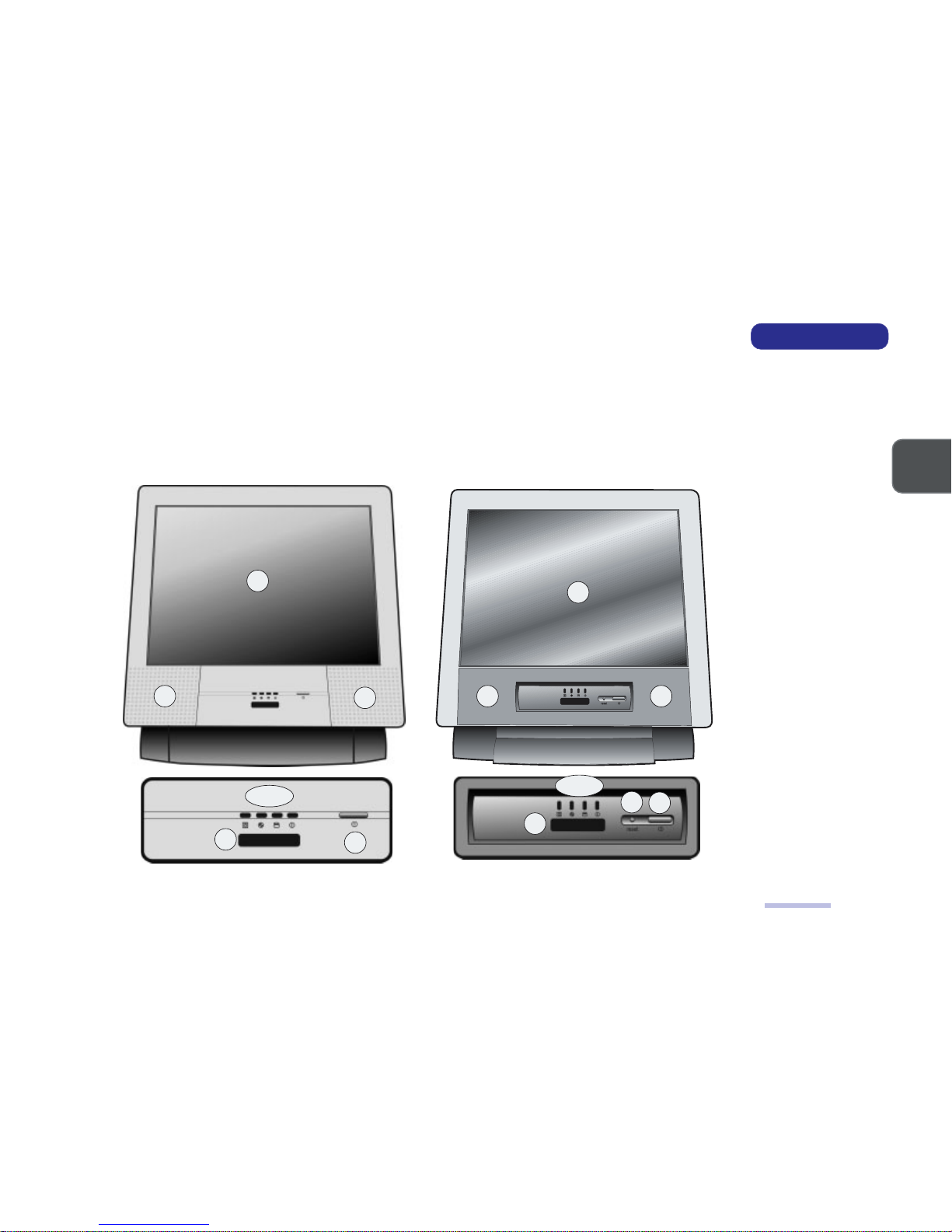
The following figures show the external locations of the main features of the LCD PC’s system unit.
FRONT VIEW
LP2600C
Front View
1
8
7
2
3 ~ 6
2
LP2600T
FRONT VIEW
FIG. 1 – 1
1. LCD
2. Speakers
3. FDD activity LED
4. CD-device
activity LED
5. HDD activity LED
6. Power LED
7. Infrared port
8. Power button
9. Reset button*
(*LP2600T only)
9
8
7
1
2
3 ~ 6
2
Page 15
1 – 8
SERVICE MANUAL
1
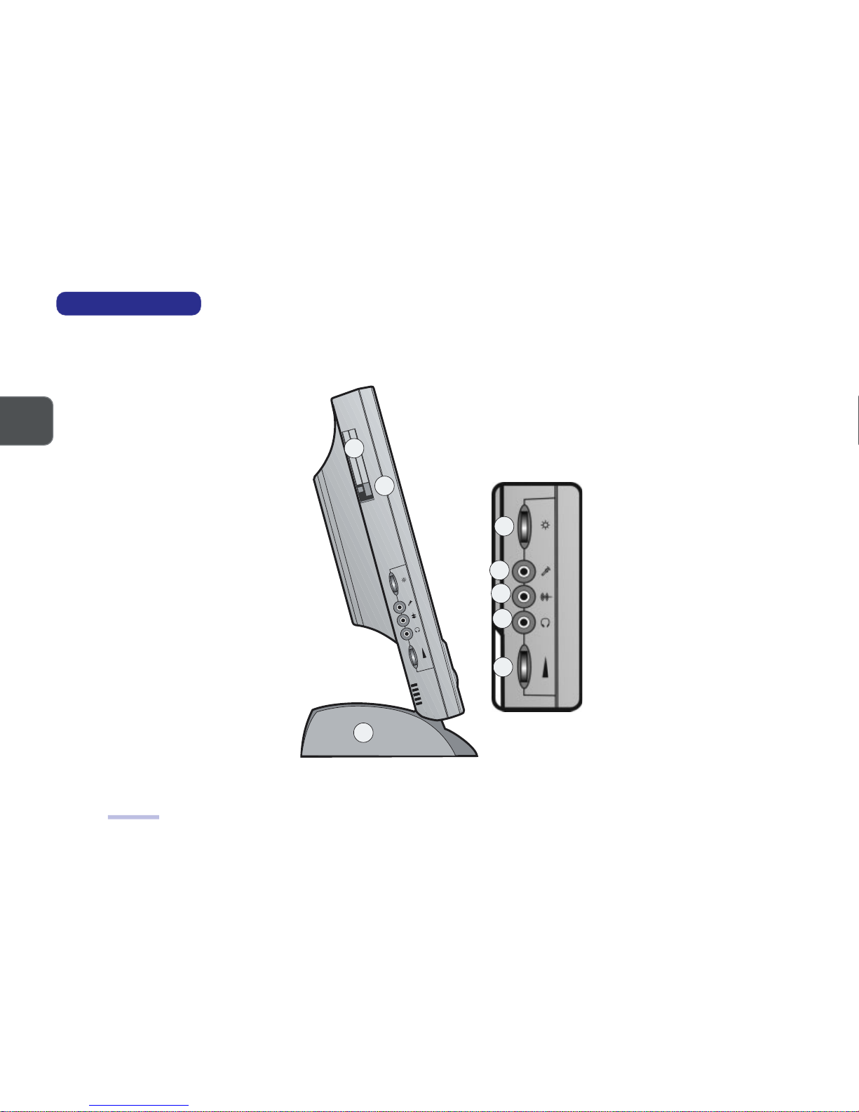
LEFT VIEW
FIG. 1 - 2
1. PC Card
(PCMCIA)
socket
2. PC Card eject
button
3. LCD brightness
control
4. Microphone
input jack
5. Line-in jack
6. Phones out
jack
7. Volume
control knob
8. HDD bay
Left View
1
8
6
7
2
3
4
5
LEFT VIEW
Page 16
1 – 9
INTRODUCTION
1
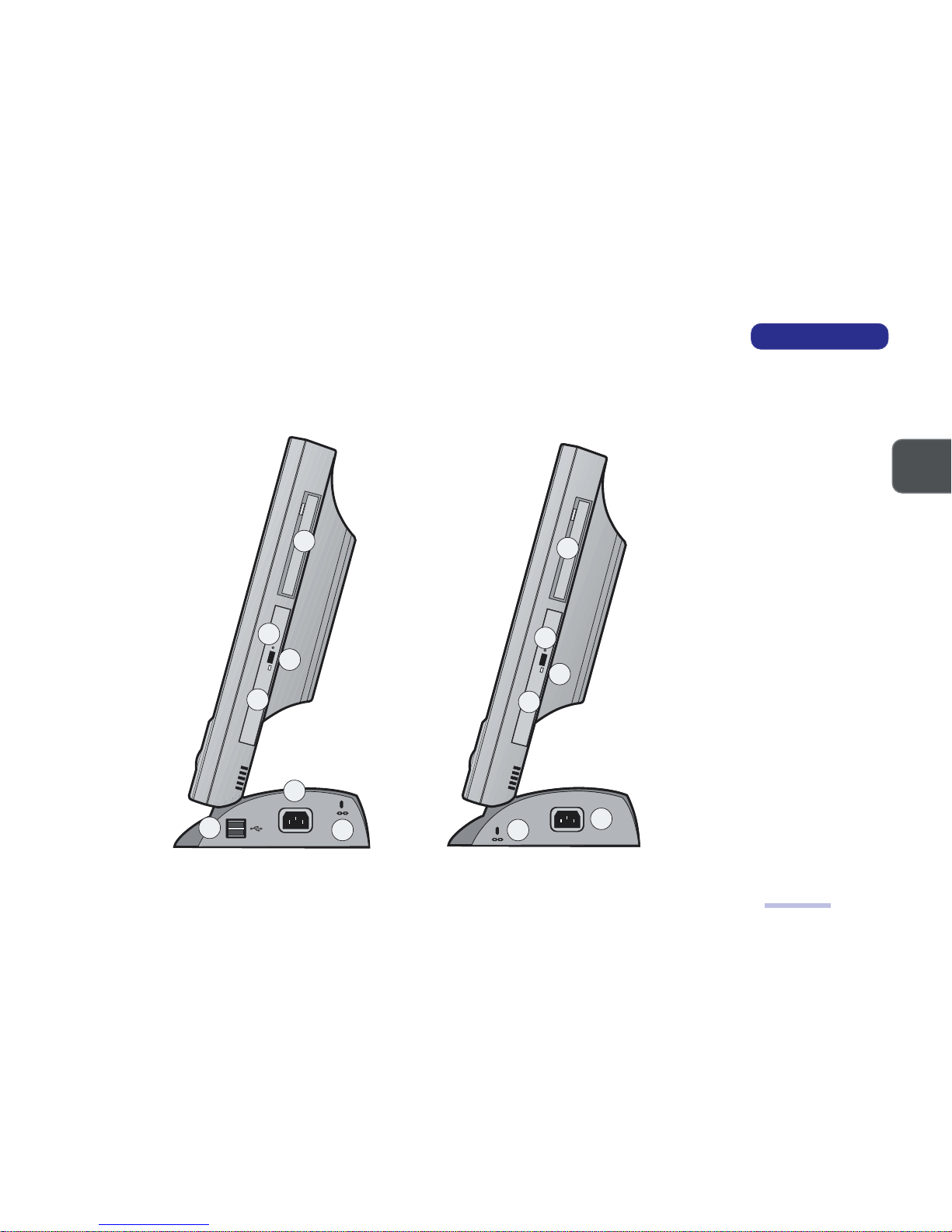
RIGHT VIEW
FIG. 1 - 3
1. FDD bay
2. CD-Device bay
3. Emergency
eject button
- Use a probe
(e.g. a
straightened
paper clip).
4. Eject button
5. Kensington
Lock slot
6. AC-in port
7. two USB ports*
(*LP2600C only)
Right View
1
6
7
2
3
4
5
RIGHT VIEW
LP2600C LP2600T
1
2
3
4
6
5
Page 17
1 – 10
SERVICE MANUAL
1
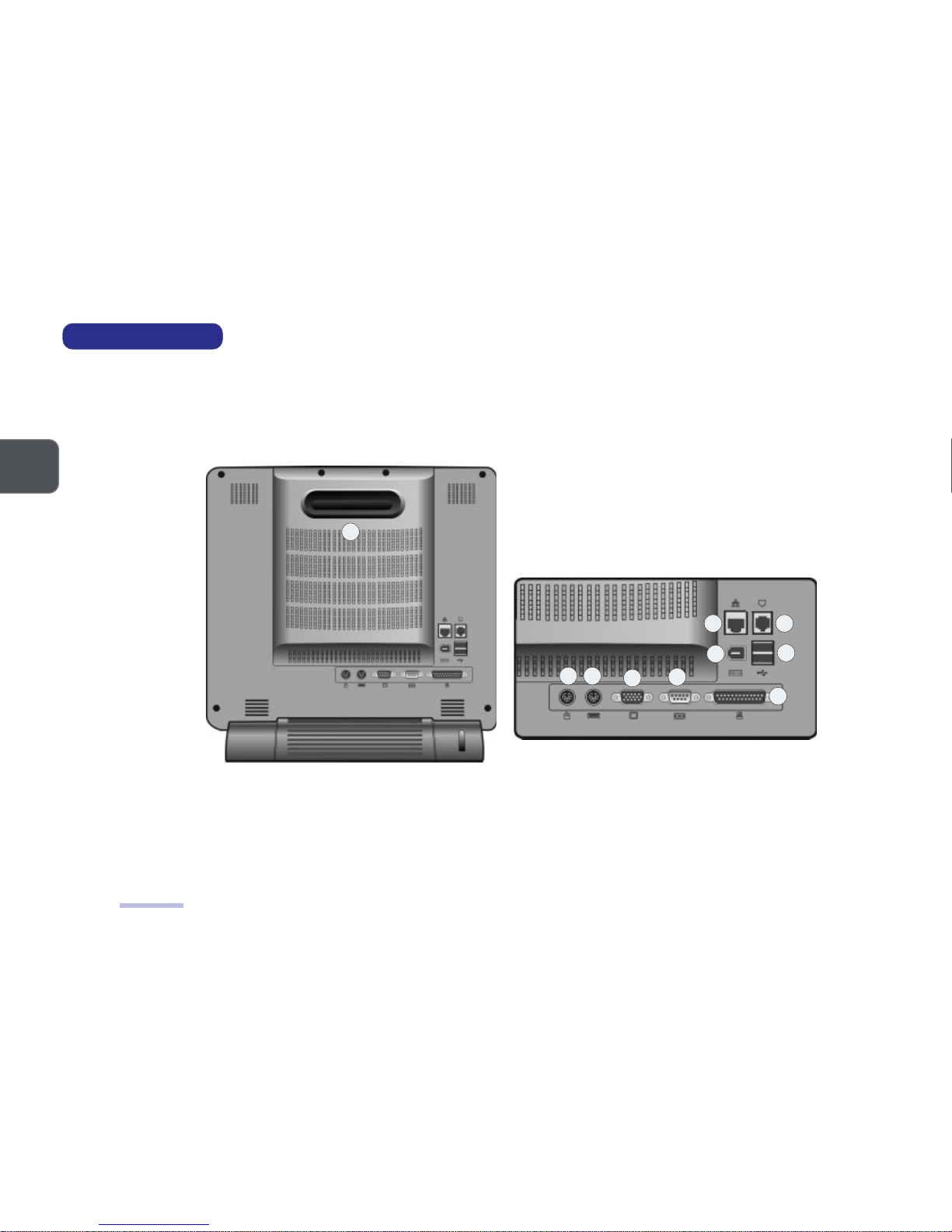
REAR VIEW
FIG. 1 - 4
1. Carrying handle
2. Serial port
(COM A)
3. Printer/Parallel
port
4. VGA port
5. PS/2 mouse port
6. PS/2 keyboard
port
7. IEEE 1394 port
8. USB ports (x2)
9. RJ-45 LAN port
10. RJ-11 Modem port
Rear View
2
3
4
5
8
9 10
6
7
1
REAR VIEW
Page 18
1 – 11
INTRODUCTION
1
System Board Overview - Key Parts
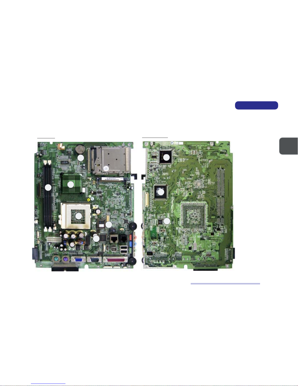
SYSTEM BOARD OVERVIEW
KEY PARTS
KEY PARTS
FIG. 1 - 5
1. CPU socket
(no CPU installed)
2. SiS630ST Single
Chipset (Core
Logic, Audio,
Video & LAN)
3. NSC99A3 Super
I/O Controller
4. Flash ROM
5. two DIMM
Sockets
6. CMOS Battery
7. PCI1420PDV
Cardbus
Controller
8. ZURAC2 (Zoom
Up/Down Rate
Converter)
9. ICS1893 PHY (LAN)
Top View
Bottom View
6
2
5
4
1
3
7
8
9
Page 19
1 – 12
SERVICE MANUAL
1
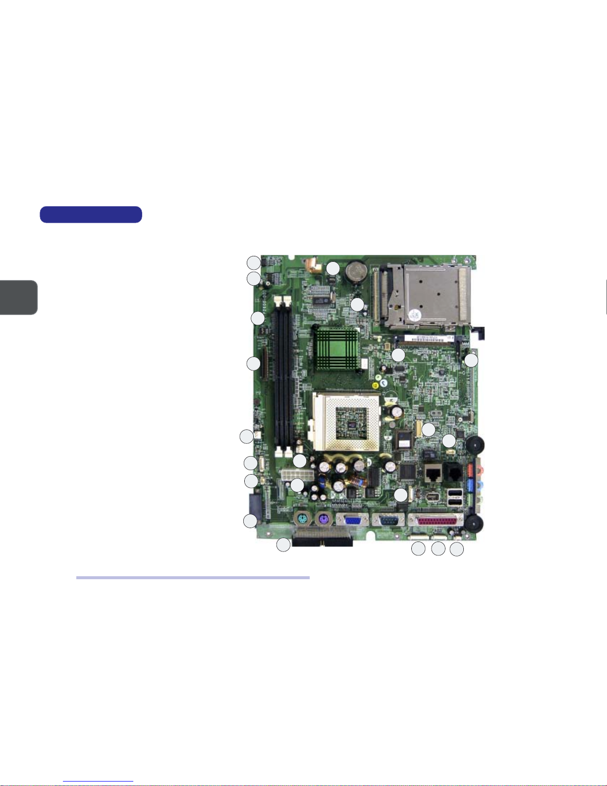
CABLE CONNECTORS, SWITCHES & JUMPERS
CONNECTORS, SWITCHES & JUMPERS
FIG. 1 - 6
1. CN1 (Inverter Cable)
2. CN2 (Bluetooth Module)
3. CN5 (FDD Cable)
4. CN7 (System Fan Cable)
5. CN12 (USB Cable)
6. CN17 (Right Speaker Cable)
7. CN23 (CD Device Cable)
8. CN10 (CPU Fan Cable)
9. CN16 (Power Cable)
10. CN29 (HDD Cable)
11. CN4 (IEEE 1394 Module)
12. CN6 (Modem Module)
13. CN11 (Modem Cable)
14. CN19 (IEEE 1394 Cable)
15. CN30 (LED Cable)
16. CN31 (Inverter Cable)
17. CN32 (Left Speaker Cable)
18. SW1 (CPU Frequency
Switch)
19. SW2 (LCD Type
Switch)
20.J1 (CMOS Clear Jumper)
21. J2 (Panel VCC Jumper)
System Board Overview - Connectors, Switches & Jumpers
10
6
7
4
5
9
8
18
1
2
20
19
16
17
15
14
11
12
13
21
3
Page 20

2 – 12 – 1
2 – 12 – 1
2 – 1
2
DISASSEMBLY
2 DISASSEMBLY
This chapter provides step-by-step instructions for disassembling parts and subsystems. When it comes to reassembly, reverse the
procedures (unless otherwise indicated).
We suggest you completely review any procedure before you take the computer apart.
CPU and Memory Upgrades:
The upgrade procedures for CPU and system memory involve more than the component-specific removal and replacement procedure. Please pay attention to the component-specific upgrade notes.
Illustrations:
To enhance procedural clarity, the illustrations in this chapter do not include all components. Mylar insulation and
adhesive attachments are not shown unless they are critical to the disassembly process.
Page 21

2 – 2
2
SERVICE MANUAL
MAINTENANCE TOOLS
The following tools are recommended when working on the LCD PC:
• M3 Philips-head screwdriver
• M2.5 Philips-head screwdriver (magnetized)*
• M2 Philips-head screwdriver
• Small flat-head screwdriver
• Pair of needle-nose pliers
• Anti-static wrist-strap
* note Maintenance Precaution #3.
CONNECTIONS
Connections within the computer are one of four types:
Locking collar sockets for ribbon connectors To release these connectors, use a small flat-head screwdriver to gently pry the locking
collar away from its base. When replacing the connection, make sure the connector is
oriented in the same way. The pin1 side is usually
not
indicated.
Pressure sockets for multi-wire connectors To release this connector type, grasp it at its head and gently rock it from side to side as you
pull it out.
Do not pull on the wires themselves.
When replacing the connection, do not try to
force it. The socket only fits one way.
Pressure sockets for ribbon connectors To release these connectors, use a small pair of needle-nose pliers to gently lift the connec-
tor away from its socket. When replacing the connection, make sure the connector is oriented in the same way. The pin1 side is usually
not
indicated.
Board-to-board or multi-pin sockets To separate the boards, gently rock them from side to side as you pull them apart. If the
connection is very tight, use a small flat-head screwdriver
- use just enough force to start
the separation.
Maintenance Tools, Connections
Page 22

2 – 32 – 3
2 – 32 – 3
2 – 3
2
DISASSEMBLY
MAINTENANCE PRECAUTIONS
The following precautions are a reminder.
To avoid personal injury or damage to the computer while performing a removal and/or replacement job, take the following precautions:
1. Don't drop it. Perform your repairs and/or upgrades on a stable surface. If the computer falls, the case and other components could be
damaged.
2. Don't overheat it. Note the proximity of any heating elements. Keep the computer out of direct sunlight.
3. Avoid interference. Note the proximity of any high capacity transformers, electric motors, and other strong magnetic fields. These can hinder
proper performance and damage components and/or data. You should also monitor the position of magnetized tools (i.e. screwdrivers).
4. Keep it dry. This is an electrical appliance. If water or any other liquid gets into it, the computer could be badly damaged.
5. Be careful with power. Avoid accidental shocks, discharges or explosions.
•Before removing or servicing any part from the computer, turn the computer off and detach any power supplies.
•When you want to unplug the power cord or any cable/wire, be sure to disconnect it by the plug head. Do not pull on the wire.
6. Peripherals – Turn off and detach any peripherals.
7. Beware of static discharge. ICs, such as the CPU and main support chips, are vulnerable to static electricity. Before handling any part in the
computer, discharge any static electricity inside the computer. When handling a printed circuit board, do not use gloves or other materials which
allow static electricity buildup. We suggest that you use an anti-static wrist strap instead.
8. Beware of corrosion. As you perform your job, avoid touching any connector leads. Even the cleanest hands produce oils which can attract
corrosive elements.
9. Keep your work environment clean. Tobacco smoke, dust or other air-born particulate matter is often attracted to charged surfaces, reducing
performance.
10. Keep track of the components. When removing or replacing any part, be careful not to leave small parts, such as screws, loose inside the
computer.
CLEANING
Do not apply cleaner directly to the computer, use a soft clean cloth.
Do not use volatile (petroleum distillates) or abrasive cleaners on any part of the computer.
Maintenance Precautions
Page 23

2 – 4
2
SERVICE MANUAL
BACK COVER REMOVAL
1. Place the system with its LCD display facing down.
2. Remove the 8 screws (A, B, C, D, E, F, G & H) which secure the Back Cover to the rest of the system.
3. Gently remove the cover from the rest of the system.
REMOVING 6 SCREWS FROM
THE
BACK OF THE SYSTEM
FIG. 2-1
BACK COVER AND THE REST
OF
THE SYSTEM
FIG. 2-2
Back Cover Removal
A
B
C
D
E
F
Back Cover
G H
Page 24
2 – 52 – 5
2 – 52 – 5
2 – 5
2
DISASSEMBLY
CPU Removal
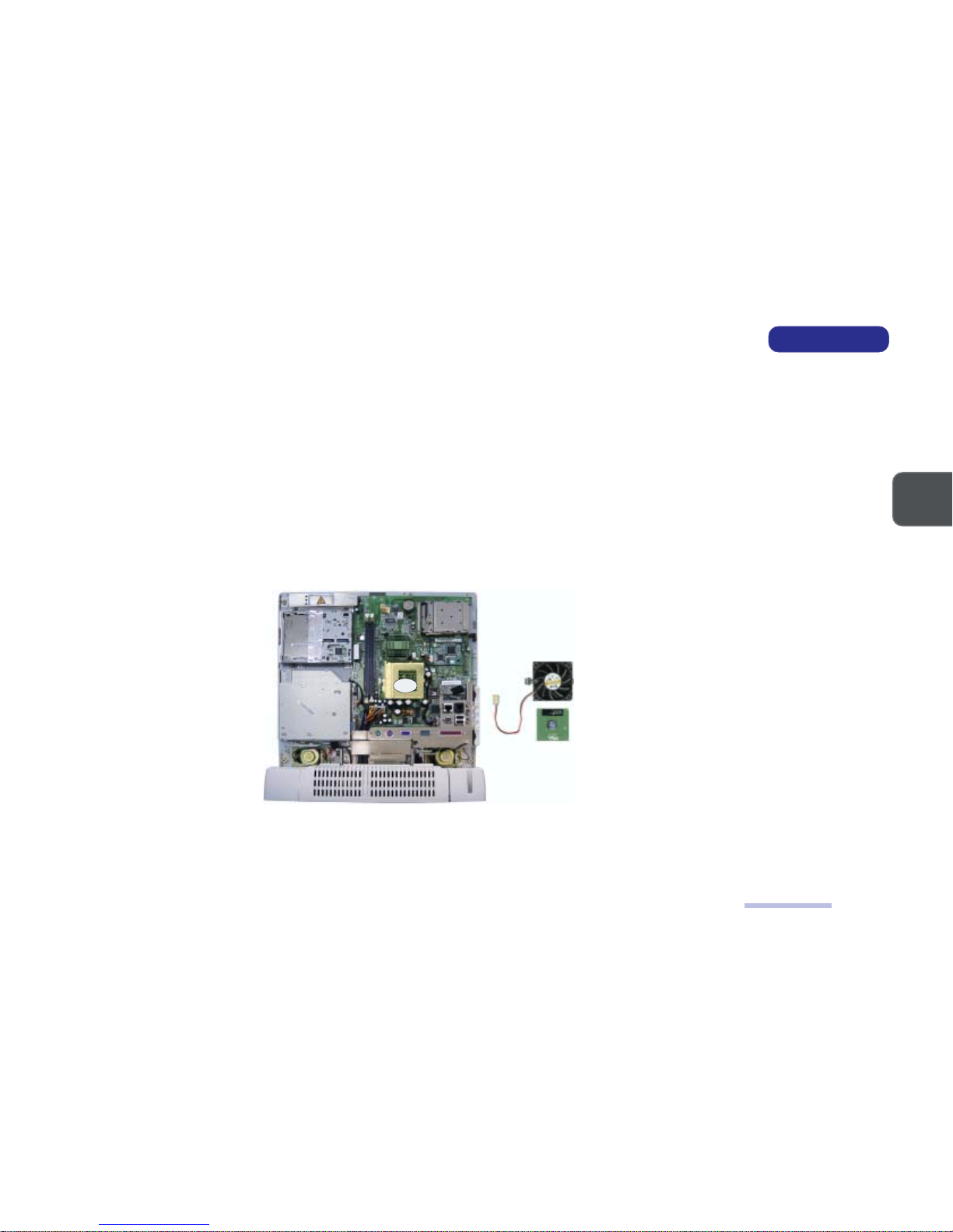
CPU REMOVAL
Part A
Remove the Back Cover (page 2-4).
Part B
!Note: If you want to upgrade the CPU, replace the old CPU with the upgraded one and also see the CPU Upgrade
Notes on the next page.
1. Unplug the Fan Cable from Connector CN10.
2. Disengage both caches at the sides of the Fan from the CPU socket.
3. A thermal pad is attached to the Fan. Remove the Fan with the Thermal Pad from the CPU.
4. Disengage the CPU lever and remove the CPU.
REMOVING THE FAN
AND
THE CPU
FIG. 2-3
!Note for Replacing the CPU: : Reverse the removal procedure. Please also note the following:
When inserting the CPU, put the CPU in the CPU socket with the notched corner of the CPU aligning with the notched corner
of the CPU socket and then engage the lever.
Fan
CPU
CN10
Page 25
2 – 6
2
SERVICE MANUAL
CPU UPGRADE NOTES
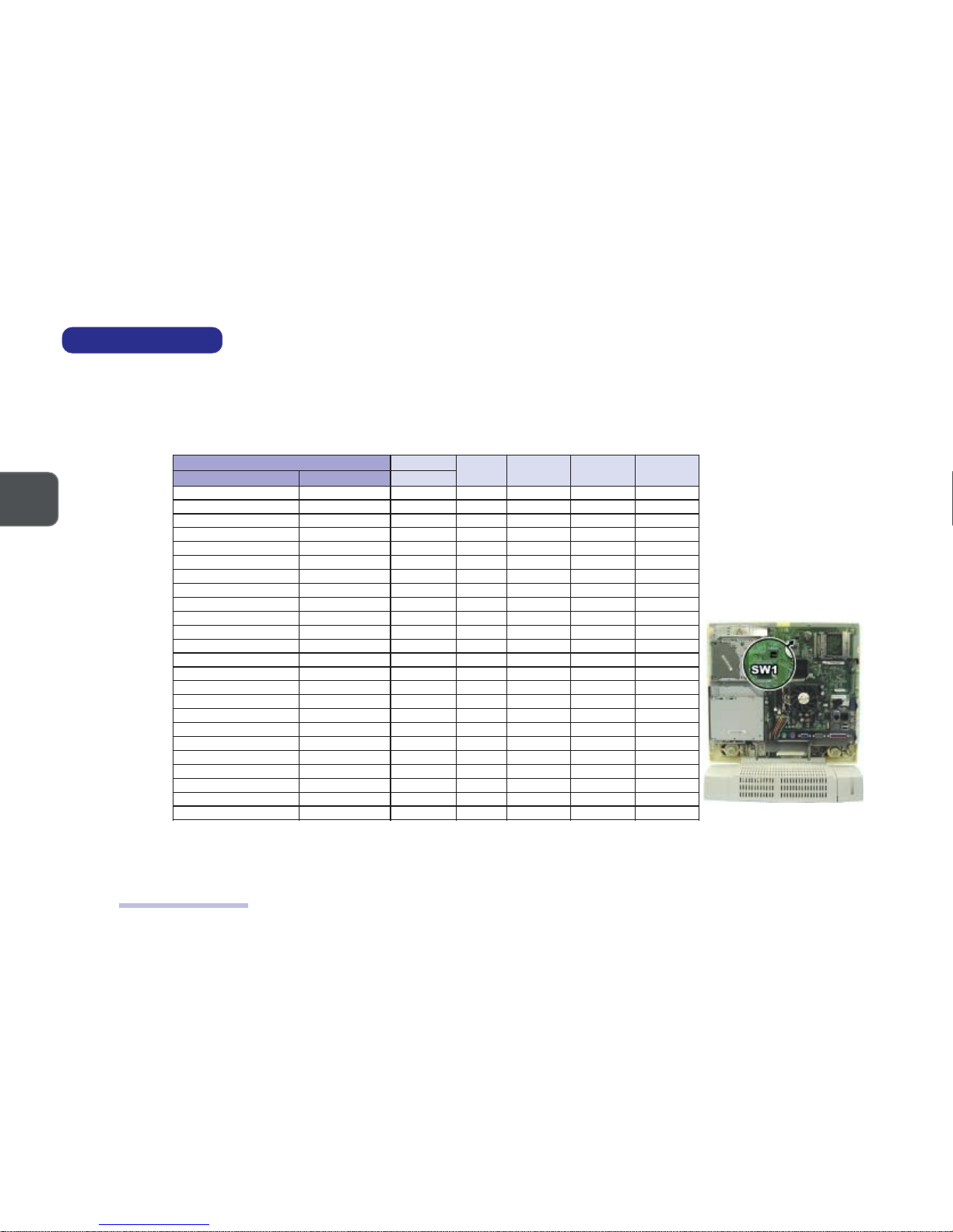
After you install the upgraded CPU, check against the following table to see if you need to adjust switch settings. (Refer to Fig. 24 for the location of the SW1 CPU Frequency Switch.)
SW1 CPU FREQUENCY
SWITCH SETTINGS
TABLE 2-1
SWITCH SW1 LOCATION
FIG. 2-4
CPU Upgrade Notes
UPC MARDS
1-1WS 2-1WS 3-1WS 4-1WS
epyT )zHM(deepSBSF zHM
A335noreleC66001FFOFFOFFOFFO
006noreleC66001FFOFFOFFOFFO
336noreleC66001FFOFFOFFOFFO
766noreleC66001FFOFFOFFOFFO
007noreleC66001FFOFFOFFOFFO
337noreleC66001FFOFFOFFOFFO
667noreleC66001FFOFFOFFOFFO
008noreleC001001NOFFOFFOFFO
058noreleC001001NOFFOFFOFFO
009noreleC001001NOFFOFFOFFO
059noreleC001001NOFFOFFOFFO
006IIIP001001NOFFOFFOFFO
056IIIP001001NOFFOFFOFFO
007IIIP001001NOFFOFFOFFO
057IIIP001001NOFFOFFOFFO
008IIIP001001NOFFOFFOFFO
058IIIP001001NOFFOFFOFFO
0011IIIP001001NOFFOFFOFFO
BE006IIIP331331NONONOFFO
337IIIP331331NONONOFFO
BE008IIIP331331NONONOFFO
668IIIP331331NONONOFFO
339IIIP331331NONONOFFO
0001IIIP331331NONONOFFO
Page 26
2 – 72 – 7
2 – 72 – 7
2 – 7
2
DISASSEMBLY
DIMM Removal & Installation
MEMORY MODULE REMOVAL
REMOVING DIMMS
Part A
Remove the Back Cover (page 2-4).
Part B
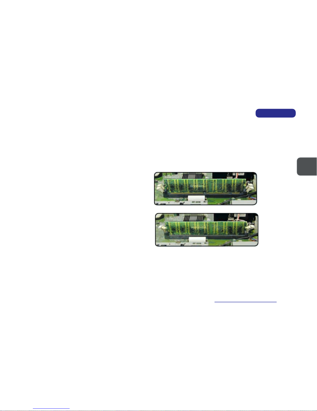
Release the levers on the two ends of the DIMM slot. As you do so,
the module will rise slightly and remove the seated DIMM, one at
a time.
REMOVING THE DIMMS
FIG. 2-5
INSTALLING DIMMS
1. Insert a DIMM in either slot at about a 20o angle. Grooves on the
sides of the module allow you to insert it only one way. Make sure
it is seated as far into the slot as it will go. DO NOT FORCE IT. The
module should fit in without much pressure. If there is a lot of resistance, check to make sure the DIMM is properly seated.
2. Click in the slot levers to secure the module.
3. Reinstall the Back Cover.
!Memory Upgrade Note:
• If you have changed the memory configuration, run SCU so the new total can be registered in the CMOS.
• If you have increased memory, check to see if you need to recreate the Hibernate-specific file if the system runs Windows
98 SE with Hibernate support enabled. (Refer to
Chapter 3, Advanced Controls
&
Chapter 5, Drivers & Utilities
of the
User’s
Manual
for details.)
INSTALLING THE DIMMS
FIG. 2-6
Page 27

2 – 8
2
SERVICE MANUAL
MODEM MODULE REMOVAL
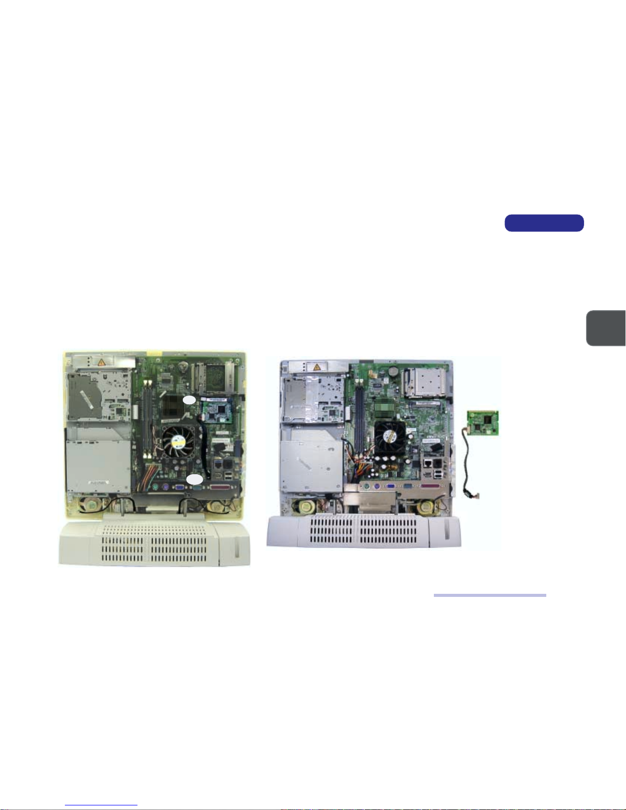
Part A
Remove the Back Cover (page 2-4).
Part B
1. Remove 2 screws (A & B) securing the Modem Module to the System Board.
2. Disconnect the Modem Cable from Connector CN11 on the System Board.
3. Remove the Modem Module from Connector CN6 on the System Board.
A
B
Modem
Module
REMOVING THE MODEM
MODULE
FIG. 2-7
Modem Module Removal
CN11
CN6
Page 28
2 – 92 – 9
2 – 92 – 9
2 – 9
2
DISASSEMBLY
IEEE 1394 Module Removal
IEEE 1394 MODULE REMOVAL
Part A
Remove the Back Cover (page 2-4).
Part B
1. Disconnect the IEEE 1394 Cable from Connector CN19 on the System Board.
2. Remove the IEEE 1394 Module from Connector CN4 on the System Board.
REMOVING THE IEEE
1394 MODULE
FIG. 2-8
CN19
IEEE 1394
Module
CN4
Page 29
2 – 10
2
SERVICE MANUAL
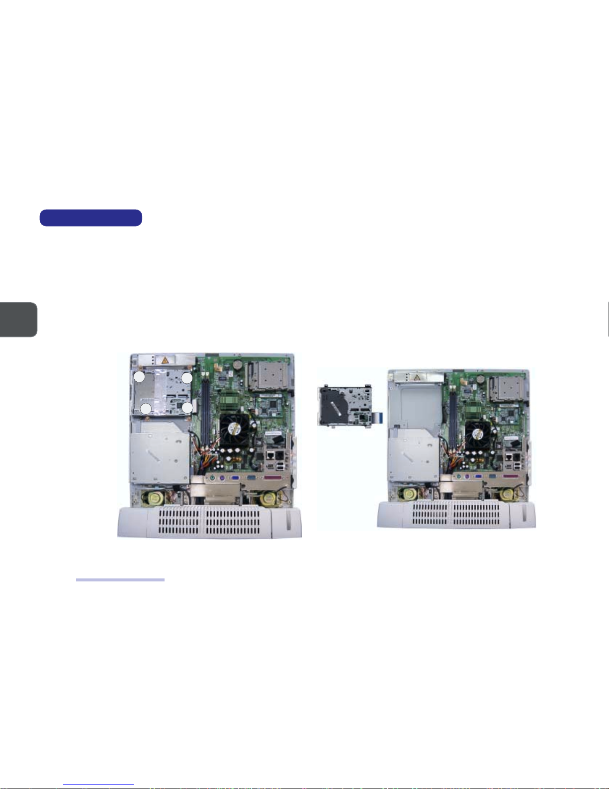
FDD MODULE REMOVAL
Part A
Remove the Back Cover (page 2-4).
Part B
1. Remove 4 screws (A, B, C & D).
2. Separate the FDD Module from the rest of the system by disconnecting the FDD Cable from the System Board at Connector CN5.
REMOVING THE FDD
MODULE (1)
FIG. 2-9
REMOVING THE FDD
MODULE (2)
FIG. 2-10
FDD Module Removal
A
B
C
D
FDD Module
Page 30
2 – 112 – 11
2 – 112 – 11
2 – 11
2
DISASSEMBLY
CD Device Module Removal
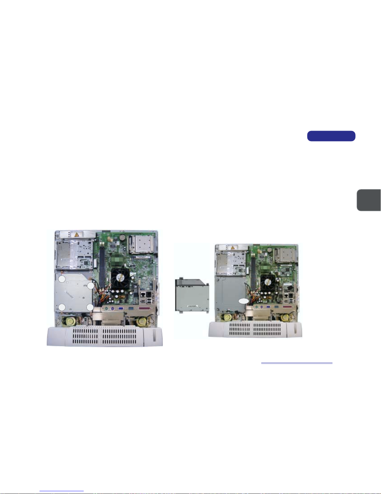
CD DEVICE MODULE REMOVAL
The CD device module can be the CD-ROM Module, DVD Module or CD-RW Module.
Part A
Remove the Back Cover (Page 2-4).
Part B
1. Remove 4 screws (A, B, C & D).
2. Separate the CD device module from the rest of the system by disconnecting the device cable from Connector CN23 on the System Board.
REMOVING THE CD
DEVICE MODULE (1)
FIG. 2-11
REMOVING THE CD
DEVICE MODULE (2)
FIG. 2-12
CD Device
Module
A
B
C D
CN23
Page 31

2 – 12
2
SERVICE MANUAL
INVERTER BOARD REMOVAL
Part A
Remove the Back Cover (Page 2-4).
Part B
1. Remove the Inverter Shielding Plate by removing 3 screws (A, B & C) which secure it to the rest of the system.
(If you have already removed the FDD module, Screws A & B have already been removed during the process.)
2. Remove 2 screws (D & E) which secure the Inverter Board and the Inverter Mylar to the rest of the system.
3. Disconnect the following 3 cables:
(C1 & C2) The LCD to Inverter Board (two cables from Connector CN2).
(C3) The Inverter Board to System Board (from Connector CN1).
4. Separate the Inverter Board and the Inverter Mylar.
REMOVING THE INVERTER
BOARD
FIG. 2-13
A
B
C
Inverter Mylar
Inverter
Shielding
Plate
Inverter Board
Inverter Shielding
Plate
D
E
CN1
CN2
FDD Module
Inverter Board Removal
Page 32

2 – 132 – 13
2 – 132 – 13
2 – 13
2
DISASSEMBLY
I/O BRACKET REMOVAL
Part A
1. Remove the Back Cover (page 2-4).
2. Remove the Modem Module (page 2-8).
Part B
Remove the I/O Bracket by removing 9 screws (A, B, C, D, E, F, G, H & I) which secure it to the rest of the system.
(If you have already removed the CD device module, Screw A has already been removed during the process.)
REMOVING THE I/O
BRACKET
FIG. 2-14
I/O Bracket Removal
A
B
C & D
G
H
I
CD Device
Module
E & F
I/O Bracket
Page 33

2 – 14
2
SERVICE MANUAL
SYSTEM BOARD REMOVAL
Part A
Remove the Back Cover (page 2-4).
Remove the Modem Module (page 2-8).
Remove the I/O Bracket (page 2-13).
Part B
1. Disconnect the following 10 cables from the System Board:
10 Cables
(C1) The Inverter Board to System Board (from Connector CN1).
(If you have already removed the Inverter Board, the Inverter Cable has already been removed during the process.)
(C2) The FDD Module to System Board (from Connector CN5).
(If you have already removed the FDD Module, the FDD Cable has already been removed during the process.)
(C3) The USB Board to System Board (from Connector CN12).
(C4) The Right Speaker to System Board (from Connector CN17).
(C5) The CD device module to System Board (from Connector CN23).
(If you have already removed the CD device module, the device cable has already been removed during the process.)
(C6) The Power Supply to System Board (from Connector CN16).
(C7) The HDD to System Board (from Connector CN29).
(C8) The LED + Inverter Board to System Board (LED Cable from Connector CN30).
(C9) The LED + Inverter Board to System Board (Inverter Cable from Connector CN31).
(C10) The Left Speaker to System Board (from Connector CN32).
2. Disconnect the following 2 ground wires from the System Board:
2 Ground Wires
(W1) A ground wire with the USB Cable fixed to the System Board with a screw.
(W2) A ground wire with the Power Cable fixed to the System Board with a screw.
3. Remove 5 screws (A, B, C, D & E)
System Board Removal
Page 34

2 – 152 – 15
2 – 152 – 15
2 – 15
2
DISASSEMBLY
REMOVING THE SYSTEM
BOARD
FIG. 2-15
System Board Removal
A
B
C
D
4. The System Board is connected to the rest of the system (i.e. LCD Module) via a board-to-board connector.
Remove the System Board from the LCD Connector.
W1
W2
CN32
CN31
CN30
CN23
CN16
CN12
CN17
CN5
CN1
CN29
CD Device
Module
FDD
Module
System Board (Bottom View)
LCD
Connector
LCD
Connector
System Board (Top View)
CN33
E
Page 35

2 – 16
2
SERVICE MANUAL
LCD MODULE REMOVAL
Part A
Remove the Back Cover (page 2-4).
Remove the Modem Module (page 2-8).
Remove the I/O Bracket (page 2-13).
Part B
1. Remove 7 screws (A, B, C, D, E, F & G).
2. Disconnect the following 7 cables.
7 Cables
(C1 & C2) The LCD to Inverter Board ( 2 cables from Connector CN2).
(C3) The Right Speaker to System Board (from Connector CN17)
(C4) The Converter Board to LED + Inverter Board (from Connector CN1).
(C5) The LED + Inverter Board to System Board (LED Cable from Connector CN30).
(C6) The LED + Inverter Board to System Board (Inverter Cable from Connector CN31).
(C7) The Left Speaker to System Board (from Connector CN32)
3. Disconnect the following 3 ground wires.
(W1) A ground wire with the LED Cable fixed to the System Board with a screw.
(W2) A ground wire fixed to the Right Speaker with a screw.
(W3) A ground wire fixed to the Left Speaker with a screw.
LCD Module Removal
Page 36

2 – 172 – 17
2 – 172 – 17
2 – 17
2
DISASSEMBLY
REMOVING 7 SCREWS, 6
CABLES & 3 GROUND
WIRES
FIG. 2-16
CN17
CN32
CN31
CN30
A
B
C
D
E
CN2
LCD Module Removal
CN1
W1
F
G
W2
W3
Page 37

2 – 18
2
SERVICE MANUAL
4. Remove the LCD Module.
A. Remove 4 screws (A, B, C & D) to separate the Front Panel from the rest of the system.
At this point the LCD Module is still connected to the System Board at a board-to-board connector and to the Converter Board.
B. Remove the LCD Module by disconnecting it from Connector CN33 on the reverse side of the System Board and disconnecting the Converter
Cable.
LCD Module Removal
A
B
C
D
Front Panel
LCD Module
Connector
CN33
LCD
Connector
REMOVING THE LCD
MODULE
FIG. 2-17
Converter
Cable
Page 38

2 – 192 – 19
2 – 192 – 19
2 – 19
2
DISASSEMBLY
LED + INVERTER BOARD REMOVAL
Part A
Remove the Back Cover (page 2-4).
Remove the Modem Module (page 2-8).
Remove the I/O Bracket (page 2-13).
Perform Steps 1, 2 & 3 of Part B of the LCD Module Removal Procedure (page 2-16).
Part B
1. Separate the Front Panel from the rest of the system by removing 4 screws (A, B, C & D).
2. Separate the LED + Inverter Board from the Front Panel by removing 3 screws (E, F & G).
REMOVING THE LED +
INVERTER BOARD
FIG. 2-18
LED + Inverter Board Removal
Front Panel
LED + Inverter Board
A
B
C
D
E
F
G
Page 39

2 – 20
2
SERVICE MANUAL
CONVERTER BOARD REMOVAL
Part A
Remove the LCD Module (pages 2-16 ~ 2-18).
Part B
Separate the Converter Board from the rest of the system by removing Screw A.
Converter Board Removal
REMOVING THE CONVERTER
BOARD
FIG. 2-19
Converter Board
A
Page 40

2 – 212 – 21
2 – 212 – 21
2 – 21
2
DISASSEMBLY
Speaker Removal
SPEAKER REMOVAL
Part A
Remove the Back Cover (page 2-4).
Remove the Modem Module (page 2-8).
Remove the I/O Bracket (page 2-13).
Perform Steps 1, 2 & 3 of Part B of the LCD Module Removal Procedure (page 2-16).
Part B
1. Separate the Front Panel from the rest of the system by removing 4 screws (A, B, C & D).
2. Separate the Speakers from the Front Panel by removing 8 screws (E, F, G, H, I, J, K & L).
SEPARATING THE
SPEAKERS FROM THE
FRONT PANEL
FIG. 2-20
A
B
C
D
E F
G H
I
J
K
L
Page 41

2 – 22
2
SERVICE MANUAL
Base Assembly Removal
BASE ASSEMBLY REMOVAL
Part A
Remove the Back Cover (page 2-4).
Remove the Modem Module (page 2-8).
Remove the I/O Bracket (page 2-13).
Part B
Separate the Base Assembly from the rest of the system.
A. Disconnect the following 3 cables and 3 ground wires from the System Board.
3 Cables
(C1) The Power Supply to System Board (Connector CN16).
(C2) The HDD to System Board (from Connector CN29)
(C3) The USB Board to System Board (from Connector CN12)
3 Ground Wires
(W1) A ground wire with the USB Cable fixed to the System Board with a screw.
(W2) A ground wire fixed to the Right Speaker with a screw.
(W3) A ground wire fixed to the Left Speaker with a screw.
B. Remove 4 screws (A, B, C & D).
Page 42

2 – 232 – 23
2 – 232 – 23
2 – 23
2
DISASSEMBLY
Base Assembly Removal
SEPARATING THE BASE
ASSEMBLY FROM THE
SYSTEM
FIG. 2-21
CN16
CN12
CN29
W1
W2
W3
A
B
C
D
Base assembly
Page 43

2 – 24
2
SERVICE MANUAL
Power Supply Removal
POWER SUPPLY REMOVAL
The Power Supply is in the Base Assembly.
Part A
Remove the Base Assembly. (pages 2-22 & 2-23)
Part B
1. Remove the HDD Cartridge.
A. Turn the Base Assembly upside down and remove Screw A. (Only the LP2600T has this screw.)
B. Remove Screw B and pull the HDD Cartridge out from its bay until the HDD’s connectors are exposed.
C. Disconnect the following cables.
(C1) The Power Supply to HDD (Power Cable).
(C2) The System Board to HDD (HDD Signal Cable).
REMOVING THE HDD
CARTRIDGE
FIG. 2-22
HDD Cartridge
C1
C2
B
A
Page 44

2 – 252 – 25
2 – 252 – 25
2 – 25
2
DISASSEMBLY
Power Supply Removal
2. Remove the Swivel Stand.
A. Turn the Base Assembly upside down.
B. Remove 4 screws (A, B, C & D).
REMOVING THE SWIVEL
STAND
FIG. 2-23
3. Separate the Top Cover of the Base Assembly from the rest of the Base Assembly by removing 6 screws (A, B, C, D, E & F).
REMOVING THE TOP
COVER OF THE BASE
ASSEMBLY
FIG. 2-24
A
B
C D
A
B
C
D
E
F
Power Supply
Top Cover (Base Assembly)
Page 45

2 – 26
2
SERVICE MANUAL
4. Separate the Power Supply from the rest of the Base Assembly by removing 4 screws (A, B, C & D).
REMOVING THE POWER
SUPPLY
FIG. 2-25
Power Supply Removal
A B
C
D
Power
Supply
Page 46

2 – 272 – 27
2 – 272 – 27
2 – 27
2
DISASSEMBLY
USB Board Removal
USB BOARD REMOVAL
The USB Board is in the Base Assembly. (LP2600C only)
Part A
Remove the Base Assembly. (pages 2-22 & 2-23)
Remove the HDD Cartridge. (Step 1 of Part B of the Power Supply Removal Procedure, page 2-24)
Remove the Swivel Stand. (Step 2 of Part B of the Power Supply Removal Procedure, page 2-25)
Remove the Top Cover of the Base Assembly (Step 3 of Part B of the Power Supply Removal Procedure, page 2-25)
Part B
Separate the USB Board from the rest of the Base Assembly.
A. Disconnect the USB Cable from Connector CN1 on the USB Board.
B. Remove Screw A which secures the board to the Bottom Cover of the Base Assembly.
REMOVING THE USB
BOARD
FIG. 2-26
USB Board
CN1
A
Page 47

2 – 28
2
SERVICE MANUAL
HDD Removal
HARD DISK DRIVE REMOVAL
The HDD is housed in the Base Assembly.
1. Place the LCD PC with its LCD panel facing up and remove Screw A. (Only the LP2600T has this screw.)
2. Remove Screw B.
REMOVING SCREWS A & B
FIG. 2-27
3. Pull the HDD Cartridge out from its bay until the HDD’s connectors are exposed.
4. Separate the HDD Cartridge from the rest of the system by disconnecting the HDD’s Signal Cable (A) and Power Cable (B).
(Both of these cables are a tight fit.)
PULLING THE HDD
CARTRIDGE OUT AND
DISCONNECTING THE HDD
SIGNAL & POWER CABLES
FIG. 2-28
B
A
B
A
B
A
Page 48

2 – 292 – 29
2 – 292 – 29
2 – 29
2
DISASSEMBLY
HDD Removal
4. Turn the cartridge upside down.
5. Remove 4 screws (A, B, C & D) to separate the HDD Frame from the Cartridge Casing.
SEPARATING THE HDD
FRAME FROM THE
CARTRIDGE CASING
FIG. 2-29
6. Remove 6 screws (A, B, C, D, E & F) to separate the HDD from its frame.
SEPARATING THE HDD
FROM ITS FRAME
FIG. 2-30
A
B
C
D
A
B
C
D
E
F
Page 49

2 – 30
2
SERVICE MANUAL
Notes
NOTES:
Page 50

A – 1
PART LISTS
A
A PART LISTS
This appendix breaks down the LCD PC’s construction into a series of illustrations. The component part numbers are indicated in
the tables opposite the drawings. It includes two sets of part lists for the LP2600C and LP2600T respectively.
Note: This section indicates the manufacturer’s part numbers. Your organization may use a different
system, so be sure to cross-check any relevant documentation.
Note: Be sure to check any update notices. The parts shown in these illustrations are appropriate for
the system at the time of publication. Over the product life, some parts may be improved or reconfigured, resulting in new part numbers.
Page 51

A – 2
SERVICE MANUAL
A
Front Assembly
LP2600C
LP2600C FRONT
ASSEMBLY (PART I)
FIG. A–1
Page 52

A – 3
PART LISTS
A
Front Assembly
LP2600C FRONT
ASSEMBLY (PART II)
FIG. A–2
Page 53

A – 4
SERVICE MANUAL
A
LP2600C FRONT
ASSEMBLY (PART III)
FIG. A–3
Front Assembly
Page 54

A – 5
PART LISTS
A
LP2600C FRONT
ASSEMBLY (PART IV)
FIG. A–4
Front Assembly
Page 55

A – 6
SERVICE MANUAL
A
LP2600C BACK
ASSEMBLY (PART I)
FIG. A–5
Back Assembly
Page 56

A – 7
PART LISTS
A
LP2600C BACK
ASSEMBLY (PART II)
FIG. A–6
Back Assembly
Page 57

A – 8
SERVICE MANUAL
A
LP2600C BACK
ASSEMBLY (PART III)
FIG. A–7
Back Assembly
Page 58

A – 9
PART LISTS
A
LP2600C FDD
MODULE
FIG. A–8
FDD Module
Page 59

A – 10
SERVICE MANUAL
A
LP2600C CD DEVICE
MODULE
FIG. A–9
CD Device Module
Page 60

A – 11
PART LISTS
A
LP2600C BASE
ASSEMBLY (PART I)
FIG. A–10
Base Assembly
Page 61

A – 12
SERVICE MANUAL
A
LP2600C BASE
ASSEMBLY (PART II)
FIG. A–11
Base Assembly
Page 62

A – 13
PART LISTS
A
LP2600C HDD
MODULE
FIG. A–12
HDD Module
Page 63

A – 14
SERVICE MANUAL
A
LP2600T
LP2600T FRONT
ASSEMBLY (PART I)
FIG. A–13
Front Assembly
Page 64

A – 15
PART LISTS
A
LP2600T FRONT
ASSEMBLY (PART II)
FIG. A–14
Front Assembly
Page 65

A – 16
SERVICE MANUAL
A
LP2600T FRONT
ASSEMBLY (PART III)
FIG. A–15
Front Assembly
Page 66

A – 17
PART LISTS
A
LP2600T FRONT
ASSEMBLY (PART IV)
FIG. A–16
Front Assembly
Page 67

A – 18
SERVICE MANUAL
A
LP2600T BACK
ASSEMBLY (PART I)
FIG. A–17
Back Assembly
Page 68

A – 19
PART LISTS
A
LP2600T BACK
ASSEMBLY (PART II)
FIG. A–18
Back Assembly
Page 69

A – 20
SERVICE MANUAL
A
LP2600T BACK
ASSEMBLY (PART III)
FIG. A–19
Back Assembly
Page 70

A – 21
PART LISTS
A
LP2600T FDD
MODULE
FIG. A–20
FDD Module
Page 71

A – 22
SERVICE MANUAL
A
LP2600T CD DEVICE
MODULE
FIG. A–21
CD Device Module
Page 72

A – 23
PART LISTS
A
LP2600T BASE
ASSEMBLY (PART I)
FIG. A–22
Base Assembly
Page 73

A – 24
SERVICE MANUAL
A
LP2600T BASE
ASSEMBLY (PART II)
FIG. A–23
Base Assembly
Page 74

A – 25
PART LISTS
A
LP2600T HDD
MODULE
FIG. A–24
HDD Module
Page 75

A – 26
SERVICE MANUAL
A
NOTES:
Notes
Page 76

B – 1
SWITCHES & JUMPERS
B
B SWITCHES AND JUMPERS
This appendix is about the system’s switches and jumpers.
Page 77

B – 2
SERVICE MANUAL
B
Locations of Switches and Jumpers
LOCATIONS
The following figure shows the locations of the DIP Switches and Jumpers the system uses. You can access them after you remove
the Back Cover (page 2-4). Be sure to turn OFF the system before you perform any part removal procedure.
LOCATIONS OF THE SYSTEM’S
SWITCHES AND JUMPERS
FIG. B-1
Page 78

B – 3
SWITCHES & JUMPERS
B
Switch and Jumper Settings
SETTINGS
CPU FREQUENCY SWITCH SETTINGS (SWITCH SW1)
UPC MARDS
1-1WS 2-1WS 3-1WS 4-1WS
epyT )zHM(deepSBSF zHM
A335noreleC66001FFOFFOFFOFFO
006noreleC66001FFOFFOFFOFFO
336noreleC66001FFOFFOFFOFFO
766noreleC66001FFOFFOFFOFFO
007noreleC66001FFOFFOFFOFFO
337noreleC66001FFOFFOFFOFFO
667noreleC66001FFOFFOFFOFFO
008noreleC001001NOFFOFFOFFO
058noreleC001001NOFFOFFOFFO
009noreleC001001NOFFOFFOFFO
059noreleC001001NOFFOFFOFFO
006IIIP001001NOFFOFFOFFO
056IIIP001001NOFFOFFOFFO
007IIIP001001NOFFOFFOFFO
057IIIP001001NOFFOFFOFFO
008IIIP001001NOFFOFFOFFO
058IIIP001001NOFFOFFOFFO
0011IIIP001001NOFFOFFOFFO
BE006IIIP331331NONONOFFO
337IIIP331331NONONOFFO
BE008IIIP331331NONONOFFO
668IIIP331331NONONOFFO
339IIIP331331NONONOFFO
0001IIIP331331NONONOFFO
Page 79

B – 4
SERVICE MANUAL
B
Switch and Jumper Settings
PANEL TYPE SWTCH AND JUMPER SETTINGS (SWTICH SW2 & JUMPER J2)
CMOS CLEAR JUMPER SETTINGS (JUMPER J1)
.CCVDCLehtstes2JrepmuJ
.NOera2JrepmuJfo2&1snipnehwV5ottessiCCVDCLehT
.NOera2JrepmuJfo3&2snipnehwV3ottessiCCVDCLehT
lenaPDCL
1-2WS 2-2WS 3-2WS 4-2WS 2J
.oNledoM dnarB
IT-002-11XT51THiadnuyHFFOFFONOFFO
V5
)NO2-1snip(
HTA-4X151MLGLFFOFFOFFONO
V3
)NO3-2snip(
epyT
1Jfo2&1sniP 1Jfo3&2sniP
)tluafed(lamroNNO
raelCSOMCNO
Page 80

C – 1
CIRCUIT DIAGRAMS
C
C CIRCUIT DIAGRAMS
This appendix has circuit diagrams of the system’s PCBs.
Printed Circuit Board Part No. of the Latest Version
System Board 71-P2600-002
Inverter Board 71-P261R-001
LED + Inverter Board 71-P2614-001
Converter Board 71-P2T03-003 (for Hyundai panels)
71-P2T05-003 (for Chi Mei panels)
IEEE1394 Extension Card 71-P2205-001A (This is an optional feature)
External USB Board 71-P2206-001 (Only the LP2600C has this feature.)
We have included the latest versions at the press time. If any board you want to service is newer than listed, please consult the
nearest service center.
Page 81

C – 2
SERVICE MANUAL
C
System Board (71-P2600-002) - Sheet 1 of 20
SYSTEM BOARD
71-P2600-002 LP-260C
2
BLOCK DIAGRAM
ÂÅ ¤Ñ ¹q ¸£ CLEVO CO.
120
Thursday, Augus t 09, 2001
1240
Title
Size Document Number Rev
Date: Sheet
of
SOCKET-370
SiS630ST
Audio Codec
KEYBOARD
CRT
EXT ERN A L
POWER
System Block Diag ra m
POWER
REGULATOR
DIMM 1 DIMM 2
IDE 2
AC'97
USB 1
USB 2USB 4
BIOS
CARDBUS
USB 3
CLOCK
IDE 1
RTC
GENERATOR.
LCD
MIC
LINE IN
(ATA-100) (ATA-100)
/ MOUSE
P.8
P.11
P.14
P.12
P.16
P.19
P.9
P.4,5,6 P.16
P.2,3
P.7
P.5,19
P.19
P.17
A3
RTCVDD
+2.5V
VTT
V_CORE
+1.8V
SB3V
SB1.8V
630SVTT
+12V
+5V
+3V
SB5V
PWM
3*CPUs
13*SDRAMs
6*PCIs
1*48MHz
24/48MHz
2*REF
R.G.B.
ZURAC3
PANEL
P.10P.11
P.9P.9 EXT. INT.
LAN PHY
P.13
P.13
RJ-45
ICS1893
LPC SUPER I/O
X'Bus
P.14
LPC
P.8
P.11
HEAD PHONE
P.18
P.18
P.18
MINI-PCI
P.20
DRAM Bus
IDE Bus
PCI Bus
HOST Bus
T0911SXH
NS PC87393
PS/2
PCI1420
(1394 OPTION)
MC'97 MDC
P.15
P.15
RJ-11
MODULE
MII
BLUETOOTH
P.13
GPIOsFIR
P.14
FLOPPY
P.14P.15
PARALLEL
P.14P.15
SERIAL
V_CMOS1.5V
Page 82

C – 3
CIRCUIT DIAGRAMS
C
System Board (71-P2600-002) - Sheet 2 of 20
71-P2600-002 LP-260C
2
Socket-370 PIII CPU
ÂÅ ¤Ñ ¹q ¸£ CLEVO CO.
220
Thursday, Augus t 09 , 2001
1240
Title
Size Document Number Rev
Date: Sheet
of
VTT
CPUVREF
VTT
+2.5V
VTT
VTT
CPUVREF
+2.5V
VTT
+2.5V
V_CMOS1.5V
VTT
V_CORE
V_CMOS1.5V V_C MOS1.5V
V_CMOS1.5V
VTT
SB3V
VTT
VTT
V_CMOS1.5V
V_CMOS1.5V
VTT
VTT
HTDI
PREQ#
CPUSLP#
FERR#
HTDO
PICD0
PICD1
Z0257
CPUCLK Z0255
FLUSH#
PREQ#
HD#22
HD#50
HA#9
HA#16
Z0260
Z0221
IGNNE#
PICCLK
Z0243
Z0242
HD#7
HD#12
HD#16
HD#27
HD#35
HD#38
HA#15
HA#24
HA#31
BSEL1#
Z0220
HTDI
HTRST#
Z0241
Z0236
Z0222
Z0213
Z0216
HD#5
HD#31
HD#39
HD#54
HA#4
HA#17
HREQ#2
Z0217
Z0223
HD#19
HD#43
HD#44
HD#59
HA#6
HD#14
HD#28
HD#37
HD#51
HA#23
HA#26
HREQ#0
HREQ#[0.. 4]
HTDO
SMI#
PWRGOOD
Z0214
HD#4
HD#10
HD#46
HD#60
HA#7
HTCK
HD#0
HD#9
HD#61
HA#20
HA#25
HREQ#4
HD#[0..63]
Z0215
HD#3
HD#11
HD#23
HD#49
HA#18
HA#29
HREQ#3
STPCLK#
FERR#
HD#32
HD#40
HD#58
HD#63
HA#5
HA#10
HA#11
HA#27
Z0238
Z0234
Z0224
HD#24
HD#29
HD#30
HD#52
HA#3
HA#19
Z0210
INTR
PICD1
PICD0
Z0233
Z0212
HD#15
HD#26
HA#12
HA#14
HA#28
HREQ#1
A20M#
Z0246
Z0240
Z0219
HD#17
HD#21
HD#25
HD#33
HD#45
HD#53
RTTCTR L
HTMS
NMI
Z0244
HD#1
HD#13
HD#41
HD#42
HA#13
HA#21
Z0218
HD#2
HD#34
HD#62
BSEL0#
Z0251
HD#18
HD#20
HD#48
HD#55
HD#57
HA#30
INIT#
CPUSLP#
Z0211
HD#8
HD#56
HA#22
HA#[3..31]
Z0237
Z0209
HD#6
HD#36
HD#47
HA#8
Z0248
Z0250
Z0249
Z0247
Z0205
Z0204
Z0203
Z0202
Z0208
SLEWCTRL
Z0245
PIN_AG1
A20M#
IGNNE#
INIT#
INTR
SMI#
STPCLK#
NMI
CLKREF
Z0258
Z0259
Z0253
HTMS
HTRST#
FLUSH#
PIN_AG1
Z0261
TZ058
VID4
VID3
VID1
VID2
VID0
PIN_AK22
PIN_AK22
PICCLK Z 0256
TZ057
CPURST# Z0262
L82
0
1 2
R357
15_R
R342 150
R335
150
R318
75_1%
T2T3T4T5T6T7T12
T13
T14
T15
T16
T17
T9
T8T1 T11
T10
T41
T42
T43
T44
T45
T46
T47
T48
T26
T27 T29
T30
T31 T33
T34
T35 T37
T36 T38
T39
CX4
1000p
CA193
0.1u
CA205
0.1u
CA228
0.1u_R
CX23
1000p
CA208
0.1u
CA46
0.1u
C221
0.01u
CA202
0.1u
C223
0.01u
CA197
0.1u
CA213
0.1u
CX5
1000p
CT43
10u/10V_R
CX24
1000p
CX21
1000p
CA196
0.1u
CA190
0.1u
CA220
0.1u
CA200
0.1u
CX6
1000p
CA195
0.1u
CA192
0.1u
CF28
4.7u/16V
R316
150_1%
CA45
0.1u
C234
10p_R
CA207
0.1u
CA215
0.1u
R327
110_1%
CX3
1000p
CA226
0.1u_R
CA230
0.1u_R
CA229
0.1u
CA194
0.1u
CA199
0.1u
CA212
0.1u
CT18
10u/10V
CA204
0.1u
CT42
10u/10V
CX22
1000p
R334
56.2_1%
CA191
0.1u
R336
150
L84
4.7uH_0805 30%
1 2
R345 330
R344 330
R353 330
R358 150
R346 150
R354 150
R352 150
R359 470
R356 470
R361 470
R362 470
R364 470
R363 470
R355 470
R461 1K
R459
14
R460
0_0805_R
+
CT41
10u/10V
R462 1K
R463 1K
CA261
0.1u
CA266
0.1u
CA260
0.1u
CA258
0.1u
CA264
0.1u
CA265
0.1u
CA259
0.1u
CA263
0.1u
CA262
0.1u
R360 510
R343 680
R365 150
R464
75_1%
R465
150_1%
C291
0.1u
R466
1K
+
CT44
10u/10V
CA268
0.1u
CA267
0.1u
R333
15_R
C229
10p_R
U9A
INTEL_PIII
W37
AN19
AN25
X4
AN17
AK28
AH22
AH26
AD6
R6
AN31
AL23
AL25
AN27
AL27
AK20
AH14
AN29
AL17
AL19
AH18
AH16
AK18
AD4
AA3
Z4
AK6
AA1
Y3
AF6
AB4
AB6
AE3
AJ1
AC3
AG3
Z6
AE1
AN7
AL5
AK14
AL7
AN5
AK10
AH6
AL9
AH10
AL15
AN9
AH8
AH12
AK8
E25
F16
A27
A25
C17
C23
A19
C27
C19
C21
A23
D16
A13
C25
C13
A17
A15
A21
C11
A11A7D12
D14
C15
D10D8A9C9B2C7C1F6C5J3A3A5F12E1E3K6G3F8G1L3H6P4R4H4U3N3L1Q1M4Q3P6S1J1T6S3U1M6N1T4
W1
AC1
AC37
AF4
AK16
AK24
AK30
AL11
AL13
AL21
AN11
AN13
AN15
AN21
AN23
B36
C29
C31
C33
E23
E29
E31
F10
G35
G37
L33
N33
N35
N37
Q33
Q35
Q37
S33
S37
U35
U37
V4W3W35
X6
Y1
E21
E27R2S35
X2
J33
J35
L35
A35
J37
AK26
AH30
AJ35
AL33
E35
AJ33
AE37
AE35
AG37
AN33
V6
F18
E33
AK22
K4
AK12
L37
AG33
C35
E37
G33
AC35
AE33
C37
AG1
W33
U33
AL31
AL29
M36
AN35
AN37
AK32
AL35
AM36
AL37
AJ37
AG35
AH28
AH20
AH4
A29
A31
A33
AA33
AA35
AD36
Z36
AB36
AM2
AJ31
Y33
AK36
BCLK
DEFER#
TRDY #
RESET2#
BPRI#
RS#[2]
RS#[1]
RS#[0]
VREF5
VREF3
ADS#
HITM#
HIT#
DRDY#
DBSY#
LOCK#
BNR#
BR0#
REQ#[4]
REQ#[3]
REQ#[2]
REQ#[1]
REQ#[0]
A#[31]
A#[30]
A#[29]
A#[28]
A#[27]
A#[26]
A#[25]
A#[24]
A#[23]
A#[22]
A#[21]
A#[20]
A#[19]
A#[18]
A#[17]
A#[16]
A#[15]
A#[14]
A#[13]
A#[12]
A#[11]
A#[10]
A#[9]
A#[8]
A#[7]
A#[6]
A#[5]
A#[4]
A#[3]
D#62
D#63
D#61
D#60
D#59
D#58
D#57
D#56
D#55
D#54
D#53
D#52
D#51
D#50
D#49
D#48
D#47
D#46
D#45
D#44
D#43
D#42
D#41
D#40
D#39
D#38
D#37
D#36
D#35
D#34
D#33
D#32
D#31
D#30
D#29
D#28
D#27
D#26
D#25
D#24
D#23
D#22
D#21
D#20
D#19
D#18
D#17
D#16
D#15
D#14
D#13
D#12
D#11
D#10
D#9
D#8
D#7
D#6
D#5
D#4
D#3
D#2
D#1
D#0
A#[33]
RSP#
A#[35]
VTT
AERR#
RESERVED
AP0#
VTT
VTT
VTT
AP1#
VTT
VTT
RP#
BINIT#
DEP5#
DEP1#
DEP0#
VTT
DEP6#
DEP4#
RESERVED
VTT
RESERVED
RESERVED
RESERVED
RESERVED
RESERVED
RESERVED
RESERVED
RESERVED
VTT
VTT
VTT
VTT
BERR#
A#[34]
TESTHI
A#[32]
RESERVED
RESERVED
RESERVED
RESERVED
RESERVED
RESERVED
PICCLK
PICD[0]
PICD[1]
PRDY#
PREQ#
PWRGOOD
SLP#
SMI#
TCK
BPM#[1]
BSEL0
FLUSH#
IERR#
IGNNE#
TRST#
VREF4
VREF1
VREF0
VREF7
VREF2
VREF6
LINT[1]/NMI
INIT#
BPM#[0]
BP#[3]
BP#[2]
FERR#
A20M#
CPUPRES#
EDGCTRL/VRSEL
PLL1
PLL2
THER MDP
THER MDN
LINT[0]/INTR
TDI
TDO
TMS
VID[0]
VID[1]
VID[2]
VID[3]
STPCLK#
THERMTRIP#
VTT
RESET#
DEP7#
DEP3#
DEP2#
VTT
VTT
VCC_1.5V
VCC_2.5V
VCC_CMOS
GND
BSEL1
GND/CLKREF
VID[4]/GND
D
G
S
Q20
SI2302DS
R514
22_R
C322
10p_R
+2.5V [7,10,16,19]
DXP[3]
CPURST#[3,4]
CPUCLK
RS#2[4]
RS#1[4]
RS#0[4]
BPRI#[3,4]
HTRDY#[3,4]
BREQ0#[3,4]
HLOCK#[3]
DEFER#[3,4]
HITM#[3,4]
HIT#[3,4]
DBSY#[3,4]
DRDY#[3,4]
BNR#[3,4]
ADS#[4]
HA#[3..31] [3,4]
HD#[0..63] [3,4]
HREQ#[0..4] [3,4]
SMI#
INIT#
CPUSLP#
IGNNE#
STPCLK#
NMI
PWRGOOD
INTR
A20M#
FERR#
VID[0..4]
VTT [3,19]
V_CORE [3,19]
DXN
Cu-/Tu+
BSEL0# [7]
BSEL1# [7]
PICCLK[10]
PICCLK [10]
HTCK
For Future Compat ibilit y Upgrate
A3
Place near to
CPU pin
(FOR VREF0 TO VREF7)
Place near the S ocket -370
SOCKET-370
(19-31001-044-A)
AGTL+ Termination Resistors
open R334 stuff 56 1%
Page 83

C – 4
SERVICE MANUAL
C
System Board (71-P2600-002) - Sheet 3 of 20
71-P2600-002 LP-260C
2
CPU & GTL+ Termina tion Resistors
ÂÅ ¤Ñ ¹q ¸£ CLEVO CO.
3
20
Thursday, August 09, 2001
1240
Title
Size Document Number Rev
Date: Sheet
of
V_CORE
V_CORE
V_CORE
V_CORE
+5V
V_CORE
+3V
+5V
V_CORE
V_CORE
V_CORE
VTT
VTT
VTT
VTT
+5V
+5V
VTT
VTT
Z0308
Z0303
Z0304
Z0305
Z0306
Z0307
HD#56
HD#61
HD#50
HD#58
HD#53
HD#54
HD#46
HD#55
HD#57
HD#52
HD#59
HD#48
HD#63
HD#40
HD#47
HD#41
HD#49
HD#51
HD#42
HD#45
HD#44
HD#27
HD#39
HD#37
HD#36
HD#38
HD#43
HD#34
HD#22
HD#28
HD#31
HD#29
HD#32
HD#35
HA#20
HA#30
HA#31
HA#27
HA#22
HA#17
HA#29
HA#18
HA#23
HA#24
HA#19
HA#6
HA#3
HA#16
HA#28
CPURST#
HA#21
HA#15
HA#5
HA#7
HA#25
HA#14
HA#9
HA#4
HA#13
HA#8
HA#12
HA#11
HD#14
HD#13
HD#25
HD#33
HD#5
HD#12
HD#4
HD#8
HD#3
HD#2
HD#20
HD#30
HD#11
HD#21
HD#23
HD#62
HD#60
HD#0
HD#7
HD#24
HD#17
HD#6
HD#1
HD#16
HD#26
HD#15
HD#9
HD#19
HD#10
HD#18
HA#26
Z0309
Z0311
Z0312
Z0313
Z0314
PIN_AF36
Cu-/Tu+
Cu+/Tu-
PIN_AF36 Z0310
HA#10
CA70
0.1u
CA57
0.1u
CA79
0.1u
CA58
0.1u
CA76
0.1u
CA77
0.1u
CA50
0.1u
CA54
0.1u
R120 30K_1%
C79
3300p
R122
49.9K_1%
T53
C80
3300p
CF4
4.7u/16V
CA52
0.1u
CA62
0.1u
CB531uCB551uCB541uCB561uCB631uCB501uCB581uCB511uCB52
1u
CB151uCB161uCB91uCB8
1u
CB191uCB571uCB10
1u
CB211uCB22
1u
CA71
0.1u
CA206
0.1u
CA78
0.1u
CA60
0.1u
CA51
0.1u
CA53
0.1u
R142 10K
U10
W83L784R
20
19
18
17
16
15
14
13
11
12
1
2
3
4
5
6
7
8
9
10
VCC
CPUT1/PII1
CPUT2/PII2
VREF
VIN1
RESET#
(+3.3VIN)VIN2
(VBAT)VIN3
BATFAULT#/GPO4
GND
FANIN1/GPO1
FANIN1/GPO2
PWMOUT1
PWMOUT2
FANFAULT#/GPO3
PWR_DN#
SMI#
OVT#
SCL
SDA
T54
T55
CF7
4.7u/16V
CF8
4.7u/16V
CF5
4.7u/16V
CF3
4.7u/16V
CF6
4.7u/16V
CF9
4.7u/16V
CF12
4.7u/16V
CF10
4.7u/16V
CF11
4.7u/16V
RN59 8P4Rx56_R
1
2
3
4
7
6
5
8
RN57 8P4Rx56_R
1
2
3
4
7
6
5
8
RN55 8P4Rx56_R
1
2
3
4
7
6
5
8
RN51 8P4Rx56_R
1
2
3
4
7
6
5
8
RN49 8P4Rx56_R
1
2
3
4
7
6
5
8
RN47 8P4Rx56_R
1
2
3
4
7
6
5
8
RN41 8P4Rx56_R
1
2
3
4
7
6
5
8
RN44 8P4Rx56_R
1
2
3
4
7
6
5
8
RN38 8P4Rx56_R
1
2
3
4
7
6
5
8
RN26 8P4Rx56_R
1
2
3
4
7
6
5
8
RN27 8P4Rx56_R
1
2
3
4
7
6
5
8
RN28 8P4Rx56_R
1
2
3
4
7
6
5
8
RN29 8P4Rx56_R
1
2
3
4
7
6
5
8
RN33 8P4Rx56_R
1
2
3
4
7
6
5
8
RN32 8P4Rx56_R
1
2
3
4
7
6
5
8RN 31 8P4Rx56_R
1
2
3
4
7
6
5
8RN 30 8P4Rx56_R
1
2
3
4
7
6
5
8
RN34 8P4Rx56_R
1
2
3
4
7
6
5
8
RN35 8P4Rx56_R
1
2
3
4
7
6
5
8
RN48 8P4Rx56_R
1
2
3
4
7
6
5
8
RN43 8P4Rx56_R
1
2
3
4
7
6
5
8
RN36 8P4Rx56_R
1
2
3
4
7
6
5
8
RN40 8P4Rx56_R
1
2
3
4
7
6
5
8
RN50 8P4Rx56_R
1
2
3
4
7
6
5
8
RN46 8P4Rx56_R
1
2
3
4
7
6
5
8
RN58 8P4Rx56_R
1
2
3
4
7
6
5
8RN 56 8P4Rx56_R
1
2
3
4
7
6
5
8RN 54 8P4Rx56_R
1
2
3
4
7
6
5
8
R317 30K_1%
JP2
CLOSE
12
Q19
2N3904
B
E
C
CA61
0.1u
CF29
4.7u/16V
CF30
4.7u/16V
CA256
0.1u
R471 1K
R469 1K
R468 0_R
R470 0
R473
2.7K
Q22
2N3904
B
E
C
Q21
2N7002
G
DS
R474
1K
R475 10K
R472
2.7K
R467 56
U9B
INTEL_PIII
A37
AB32
AC33
AC5
AD2
AD34
AF32
AF36
AG5
AH2
AH34
AJ11
AJ15
AJ19
AJ23
AJ27
AJ3
AJ7
AK4
AL1
AL3
AM10
AM14
AM18
AM22
AM26
AM30
AM34
AM6
AN3
B12
B16
B20
B24
B28
B32
B4
B8
D18
D2
D22
D26
D30
D34
D4
E11
E15
E19
E7
F20
F24
F28
F32
F36
G5
H2
H34
K36
L5
M2
M34
P32
P36
Q5
R34
T32
T36
U5
V2
Z34
Z2
Y5
Y37
X36
X32
V34
AA37
AA5
AB2
AB34
AD32
AE5
AF2
AF34
AH24
AH32
AH36
AJ13
AJ17
AJ21
AJ25
AJ29
AJ5
AJ9
AK2
AK34
AM12
AM16
AM20
AM24
AM28
AM32
AM4
AM8
B10
B14
B18
B22
B26
B30
B34
B6
C3
D20
D24
D28
D32
D36
D6
E13
E17
E5
E9
F14
F2
F22
F26
F30
F34
F4
H32
H36
J5
K2
K32
K34
M32
N5
P2
P34
R32
R36
S5
T2
T34
V32
V36
W5
X34
Y35
Z32
GND
GND
GND
GND
GND
GND
GND
GND
GND
GND
GND
GND
GND
GND
GND
GND
GND
GND
GND/VTT_PWRGD
GND/RSV
GND
GND
GND
GND
GND
GND
GND
GND
GND
GND/DYN_OE
GND
GND
GND
GND
GND
GND
GND
GND
GND
GND
GND
GND
GND
GND
GND
GND
GND
GND
GND
GND
GND
GND
GND
GND
GND
GND
GND
GND
GND
GND
GND
GND
GND
GND
GND
GND
GND
GND
GND
GND
GND
GND
GND
GND
GND
GND
VCC_CORE
VCC_CORE
VCC_CORE
VCC_CORE
VCC_CORE
VCC_CORE
VCC_CORE
VCC_CORE
VCC_CORE
VCC_CORE
VCC_CORE
VCC_CORE
VCC_CORE
VCC_CORE
VCC_CORE
VCC_CORE
VCC_CORE
VCC_CORE
VCC_CORE
VCC_CORE
VCC_CORE
VCC_CORE
VCC_CORE
VCC_CORE
VCC_CORE
VCC_CORE
VCC_CORE
VCC_CORE
VCC_CORE
VCC_CORE
VCC_CORE
VCC_CORE
VCC_CORE
VCC_CORE
VCC_CORE
VCC_CORE
VCC_CORE
VCC_CORE
VCC_CORE
VCC_CORE
VCC_CORE
VCC_CORE
VCC_CORE
VCC_CORE
VCC_CORE
VCC_CORE
VCC_CORE
VCC_CORE
VCC_CORE
VCC_CORE
VCC_CORE
VCC_CORE
VCC_CORE
VCC_CORE
VCC_CORE
VCC_CORE
VCC_CORE
VCC_CORE
VCC_CORE
VCC_CORE
VCC_CORE
VCC_CORE
VCC_CORE
VCC_CORE
VCC_CORE
VCC_CORE
VCC_CORE
VCC_CORE
VCC_CORE
VCC_CORE
VCC_CORE
VCC_CORE
VCC_CORE/VTT
VCC_CORE
VCC_CORE
R121
34K_1%
HD#[0.. 63][2,4] VTT [ 2,4,5,19]
+3V [5,6,7,8, 9,10,12,13, 14,15,16,17,18, 19,20]
V_CORE [2,19]
THER M#[6]
DXP [2]
POWEROK
+5V [9,11,12,13, 14,15,16,17, 18,19,20]
630SMCLK[6,7,8]
630SMBDAT[6,7,8]
DXN
BREQ0# [2, 4]
HLOCK# [2,4]
HREQ#1 [2,4]
RS#2 [4]
RS#0 [4]
HREQ#3 [2,4]
HA#[3..31][2,4]
FAN-IN1
FAN-IN2
FAN-PWM1[16]
FAN-PWM2[16]
DRDY# [2,4]
DBSY# [2,4]
RS#1 [4]
HTRDY# [2,4]
HIT# [2,4]
HITM# [ 2,4]
HREQ#2 [2,4]
BPRI# [2]
HREQ#4 [2,4]
HREQ#0 [2,4]
DEFER# [2]
BNR# [2,4]
CPURST# [2]
Cu+/Tu-
Cu-/Tu+
VTT_PWRGD
CPURST# [2]
SOCKET
370
A3
Page 84

C – 5
CIRCUIT DIAGRAMS
C
System Board (71-P2600-002) - Sheet 4 of 20
71-P2600-002 LP-260C
2
630S_1 (HOST/ MEMORY)
ÂÅ ¤Ñ ¹q ¸£ CLEVO CO.
420
Thursday, August 09, 2001
1240
Title
Size Document Number Rev
Date: Sheet
of
+3V
+3V
VTT VTT
+3V
+3V
+3V
+3V
VTT
SCAS#
Z0402630CCLK Z0403630SDCLK
CSB#[0..3]
HD#59
HD#54
HD#51
HD#46
HD#21
HD#10
HD#9
HD#5
HD#0
MD58
MD57
MD56
HD#45
HD#24
HD#8
HD#7
HD#4
MD49
MD19
MD17
MD16
MD15
MD7
HD#49
HD#48
HD#44
HD#41
HD#14
HD#11
MD41
MD38
MD37
MD28
MD23
MD[0 ..6 3]
MD48
MD47
MD31
MD29
MD21
MD20
MD11
Z0437
HD#26
MD30
HD#31
HD#63
HD#50
HD#43
HD#20
HD#19
MD55
MD46
MD42
MD40
MD27
MD26
MD24
HD#32
HD#29
MD54
MD52
MD43
MD33
MD32
MD22
MD0
HD#[0..63]
HD#55
HD#47
HD#6
MD63
MD51
MD44
MD9
HD#57
HD#56
HD#40
HD#39
HD#38
HD#33
HD#25
MD62
MD60
MD50
MD25
MD14
MD4
MD3
MD2
MD1
HD#37
HD#36
HD#30
MD6
630SDCLK
HD#42
HD#23
HD#18
HD#17
HD#16
MD45
HD#61
MD61
HD#35
HD#34
HD#28
HD#27
HD#22
HD#2
HD#1
MD53
MD8
HD#62
HD#60
MD34
MD18
MD13
MD12
MD10
HD#58
HD#53
HD#52
HD#15
HD#13
HD#12
HD#3
MD59
MD39
MD36
MD35
MD5
Z0438
BNR#
STPCLK#
CPUSLP#
HREQ#2
HTRDY#
HIT#
IGNNE#
HREQ#[0.. 4]
INTR
HREQ#1
RS#2
DEFER#
HLOCK#
BREQ0#
HREQ#4
HREQ#3
HREQ#0
CPURST#
BPRI#
DRDY#
RS#0
DBSY#
SMI#
INIT#
FERR#
NMI
RS#1
A20M#
630CCLK
Z0401
GTLVREFBGTLVREFA
GTLVREFB
GTLVREFA
HITM#
ADS#
HA#18
HA#4
HA#23
HA#9
HA#25
HA#8
HA#14
HA#16
HA#6
HA#11
HA#7
HA#29
HA#13
HA#30
HA#10
HA#22
HA#15
HA#19
HA#20
HA#24
HA#5
HA#12
HA#21
HA#31
HA#28
HA#27
HA#17
HA#[3..31]
HA#26
HA#3
CSB#3A
CSB#2A
CSB#1A
CSB#0A
Z0420
Z0421
Z0422
Z0423
Z0424
Z0425
Z0426
DQM1
DQM2
DQM0
DQM7
DQM4
DQM3
DQM[0..7]
DQM5
DQM6Z0428
Z0427
Z0429
Z0430
Z0431
Z0432
Z0433
Z0434
CSB#0
Z0435
SRAS#Z0436
RAMW#
CSA#2Z0405
CSA#0
CSA#1Z0406
Z0407
Z0404
CSA#[0..3]
CSA#3
CSB#3
CSB#1
CSB#2
Z0417
Z0416
Z0418
Z0419
MA4
MA1
Z0415
MA12
MA6
MA9
Z0413
MA14
MA3
MA10
MA[0..14]
MA8
MA5
MA7
Z0412
MA0
MA13
MA2
MA11
Z0414
MD31
MD38
MD39
CSB#2A
CSB#0A
CSB#1A
CSB#3A
MD40
ADS#
TZ001
TZ002
TZ003
TZ004
TZ005 TZ006
TZ007
R106 10
CA181
0.1u
C193
0.01u
+
CT17
10u/10V
C195
10p_R
C43
10p_R
R310
15_R
R67
15_R
CB49
1u
R305
0_0805
R312 0_0805
+
CT40
10u/10V
R309
64.9_1%
CX20
1000p
R313
64.9_1%
R308
150_1%
R311
150_1%
C201
0.01u
R103 10
R100 10
RN8 8P4Rx10
18
27
36
45
CX19
1000p
CX18
1000p
CX17
1000p
RN3 8P4Rx10
18
27
36
45
RN7 8P4Rx10
18
27
36
45
R152 4.7K_R
R56 4.7K_R
R57 4.7K_R
U2-1
SiS-630ST
V29
C18
D16
A17
D18
B17
A18
B18
C17
D17
T29
R26
P25
G27
R29
G28
V26
R25
U29
U26
R24
U28
T27
U27
P28
R27
T26
T28
R28
P27
M24
H26
G29
J26
H29
H27
K27
H28
J29
J27
K26
J28
K28
L26
L27
L28
K29
M25
M26
M27
L29
N25
N28
M28
M29
N29
N26
P24
N27
A24
P29
T25
W28
W27
Y29
Y27
Y26
AA28
AA26
AB28
AB26
AC29
AC27
AC25
AD28
AD27
Y25
AG22
AJ22
AF21
AH21
AF20
AH20
AJ20
AG19
AJ19
AF18
AH18
AF17
AG17
AJ17
AF16
AH16
T24
W29
U25
W26
Y28
V25
AA29
AA27
AB29
AB27
V24
AC28
AC26
AD29
W25
AD26
AF22
AH22
AE23
AG21
AJ21
AG20
AE22
AF19
AH19
AE18
AG18
AJ18
AD20
AH17
AE21
AG16
AE24
AG24
AF24
AJ25
AH25
AG25
AF28
AF29
AA25
AE25
AE26
AE27
AB25
AF27
AF26
AG29
AG28
AG27
AH28
AB24
AH27
AD24
AJ27
AG26
AH26
AJ26
AF25
Y24
AE28
AF23
AG23
AD25
AE29
AJ24
AD22
E9
AJ16
AH23
AH24
AJ23
AE19
AE20
V27
V28
E21
A19
C19
B20
B21
B19
A21
A20
D19
E20
D20
B22
C22
C20
A22
D21
A23
C21
B23
C23
A25
E22
D22
D24
D23
C25
B25
C24
E25
F22
D25
E23
B26
E24
C26
A26
A27
D26
B27
C27
B28
F24
C28
D28
H24
C29
E26
D27
J25
E28
D29
E27
H25
K24
F25
F27
E29
F26
L25
K25
F29
F28
G26
G25
B24
P26
CPUCLK
NMI
SMI#
INIT#
INTR
A20M#
FERR#
IGNNE#
STPCLK#
CPUSLP#/CPUSTOP#
HLOCK#
DEFER#
HTRDY#
CPURST#
BPRI#
BREQ0#
RS#[2]
RS#[1]
RS#[0]
ADS#
HITM#
HIT#
DRDY#
DBSY#
BNR#
HREQ#[4]
HREQ#[3]
HREQ#[2]
HREQ#[1]
HREQ#[0]
HA#[31]
HA#[30]
HA#[29]
HA#[28]
HA#[27]
HA#[26]
HA#[25]
HA#[24]
HA#[23]
HA#[22]
HA#[21]
HA#[20]
HA#[19]
HA#[18]
HA#[17]
HA#[16]
HA#[15]
HA#[14]
HA#[13]
HA#[12]
HA#[11]
HA#[10]
HA#[9]
HA#[8]
HA#[7]
HA#[6]
HA#[5]
HA#[4]
HA#[3]
GTLVREFB
GTLVREFA
MD63
MD62
MD61
MD60
MD59
MD58
MD57
MD56
MD55
MD54
MD53
MD52
MD51
MD50
MD49
MD48
MD47
MD46
MD45
MD44
MD43
MD42
MD41
MD40
MD39
MD38
MD37
MD36
MD35
MD34
MD33
MD32
MD31
MD30
MD29
MD28
MD27
MD26
MD25
MD24
MD23
MD22
MD21
MD20
MD19
MD18
MD17
MD16
MD15
MD14
MD13
MD12
MD11
MD10
MD9
MD8
MD7
MD6
MD5
MD4
MD3
MD2
MD1
MD0
CSA#[5]
CSA#[4]
CSA#[3]
CSA#[2]
CSA#[1]
CSA#[0]
CSB#[5]
CSB#[4]
CSB#[3]
CSB#[2]
CSB#[1]
CSB#[0]
MA[14]
MA[13]
MA[12]
MA[11]
MA[10]
MA[9]
MA[8]
MA[7]
MA[6]
MA[5]
MA[4]
MA[3]
MA[2]
MA[1]
MA[0]
DQM[7]
DQM[6]
DQM[5]
DQM[4]
DQM[3]
DQM[2]
DQM[1]
DQM[0]
CKE
SDCLK
WE#
SRAS#
SCAS#
SDAVDD
SDAVSS
CPUAVDD
CPUAVSS
HD#63
HD#62
HD#61
HD#60
HD#59
HD#58
HD#57
HD#56
HD#55
HD#54
HD#53
HD#52
HD#51
HD#50
HD#49
HD#48
HD#47
HD#46
HD#45
HD#44
HD#43
HD#42
HD#41
HD#40
HD#39
HD#38
HD#37
HD#36
HD#35
HD#34
HD#33
HD#32
HD#31
HD#30
HD#29
HD#28
HD#27
HD#26
HD#25
HD#24
HD#23
HD#22
HD#21
HD#20
HD#19
HD#18
HD#17
HD#16
HD#15
HD#14
HD#13
HD#12
HD#11
HD#10
HD#9
HD#8
HD#7
HD#6
HD#5
HD#4
HD#3
HD#2
HD#1
HD#0
VSSQA
VSSQB
R102 10
R81 10
R101 10
R72 10
R75 10
R104 10
R80 10
R105 10
RN4 8P4Rx10
18
27
36
45
RN5 8P4Rx10
18
27
36
45
RN6 8P4Rx10
18
27
36
45
R433 4.7K
R341 56_R
CA219
0.1u
VTT [3,19]
ADS#[2]
HITM#[2,3]
HIT#[2,3]
DRDY#[2,3]
DBSY#[2,3]
HTRDY#[2,3]
630CCLK
HLOCK#[3]
DEFER#[2]
CPURST#[2]
BPRI#[2]
BREQ0#[2,3]
RS#2[2,3]
RS#1[2,3]
RS#0[2,3]
HD#[0..63] [2,3]
HA#[0..31] [2,3]
HREQ#[0..4] [2,3]
BNR#[2,3]
NMI
SMI#
INIT#
INTR
A20M#
IGNNE#
STPCLK#
CPUSLP#
FERR#
+3V [5,6, 7,8,9,10,12, 13,14,15,16, 17,18,19,20]
MD[0..63] [8,11]
CSB#[0..3]
MA[0..14]
DQM[0..7]
630SDCLK [7 ]
SCAS#
CSA#[0..3]
SRAS#
RAMW#
ADS#[2]
A3
Memory Interface
Host Interface
MD31: Quick sta rt functio n
0 : Disable
1 : Enable
MD38: Enable VGA interrupt func ti on
0 : Disable
1 : Enable
MD39: VGA ECLK and MCLK mode
0 : Sync hronous mod e
1 : Asynchr onous m od e ( Default )
Clos e t o 630S
Clos e t o 630S
Page 85

C – 6
SERVICE MANUAL
C
System Board (71-P2600-002) - Sheet 5 of 20
71-P2600-002 LP-260C
2
630S_2, 630S_5 (PCI/IDE/PWR)
ÂÅ ¤Ñ ¹q ¸£ CLEVO CO.
520
Thursday, August 09, 2001
1240
Title
Size Document Number Rev
Date: Sheet
of
+1.8V
+3V
630SVTT
SB3V
SB1.8V
+3V
+1.8V
VTT
+3V
+3V
+3V
+3V
+3V
+3V
+3V
PREQ#2
PREQ#1
PREQ#0
PGNT#0
C/BE#3
C/BE#2
C/BE#1
C/BE#0
INT#A
INT#D
C/BE#[0.. 3]
630PCLK
DEVSEL#
SERR#
IRDY#
TRDY #
FRAME#
PLOCK#
PAR
STOP#
INT#B
INT#C
PGNT#1
PGNT#2
INT#A
INT#B
INT#C
IDEDA13
AD13
AD31
IDEDA10
IDEDA8
IDEDA3
IDEDA1
IDEDA12
IDEDA0
AD0
AD27
IDEDB[0.. 15]
IDEDB4
IDEDB0
IDEDB8
AD18
AD28
AD29
IDEDA14
IDEDB13
IDEDB12
IDEDB11
IDEDA6
IDEDA2
IDEDB3
Z0508
AD22
AD23
IDEDA5
IDEDA4
IDEDB2
AD11
AD12
AD15
AD16
AD17
IDEDA11
IDEDB5
AD1
AD2
AD3
AD4
AD5
AD19
AD20
AD[0..31]
IDEDB1
AD14
AD9
AD21
IDEDA[0.. 15]
IDEDA15
IDEDA9
IDEDB15
IDEDB14
IDEDB10
AD6
AD7
AD8
AD24
AD25
AD26
IDEDB9
IDEDB7
IDEDB6
IDEDA7
AD10
AD30
INT#D
Z0507
Z0503
Z0502
Z0504
Z0506
Z0505
FRAME#
IRDY#
TRDY #
DEVSEL#
Z0511
PERR#
SERR#
Z0509630PCLK
Z0512
Z0513
Z0514
Z0515
Z0516
Z0517
Z0518
Z0519
Z0520
Z0521
Z0522
Z0523
Z0524
Z0525
Z0526
Z0527
Z0501
Z0510
PGNT#0
PGNT#1
PGNT#2
PLOCK#
PREQ#0
PREQ#2
PREQ#1
STOP#
R63
0_0805
R69
220_1%_R
L9 0_1206
L13
BEAD BK2125HS601 600ohm_0805
L7
BEAD BK2125HS601 600ohm_0805
L81
0_1206
L10
0_1206
R78 0_1206
U2-2
SiS-630ST
C1
C2
C3
D2
D3
D4
F3
H4
J1
L1
N1
P4
P5
P3
H3
H2
H1
J2
B11
M6
J3
L4
AJ15
C11
AE17
AG12
AF12
AH11
AE16
AJ10
AD15
AE15
AG10
AH10
AF11
AG11
AJ11
AD16
AH12
AJ12
AE8
AE12
AG7
AJ6
AD12
AF6
AE11
AH5
AJ5
AE6
AG6
AH6
AF7
AH7
AJ7
AD13
AE13
AG8
AF9
AH9
AH8
AF8
AJ8
AD14
AE14
AG9
AF10
AJ9
AH13
AD17
AF15
AG15
AG13
AF13
AJ13
AG14
AF14
AD18
AJ14
AH14
D1E4J4E3K6E2E1F4F2K5F1G4G3G2G1L5K4K3M5K2K1L3N6L2M4N5M3M2M1N4P6N3AH15
PREQ#[2]
PREQ#[1]
PREQ#[0]
PGNT#[2]
PGNT#[1]
PGNT#[0]
C/BE#[3]
C/BE#[2]
C/BE#[1]
C/BE#[0]
INTA#
INTB#
INTC#
INTD#
FRAME#
IRDY#
TRDY #
STOP#
SERR#
PAR
DEVSEL#
PLOCK#
PCICLK
PCIRST#
IDB0
IDB1
IDB2
IDB3
IDB4
IDB5
IDB6
IDB7
IDB8
IDB9
IDB10
IDB11
IDB12
IDB13
IDB14
IDB15
IDA0
IDA1
IDA2
IDA3
IDA4
IDA5
IDA6
IDA7
IDA8
IDA9
IDA10
IDA11
IDA12
IDA13
IDA14
IDA15
ICHRDYA
IDREQ[A]
IIRQA
CBLIDA
IIOR#[A]
IIOW#[A]
IDACK#[A]
IDSAA[2]
IDSAA[1]
IDSAA[0]
IDECSA#[1]
IDECSA#[0]
ICHRDYB
IDREQ[B]
IIRQB
CBLIDB
IIOR#[B]
IIOW#[B]
IDACK#[B]
IDSAB[2]
IDSAB[1]
IDSAB[0]
IDECSB#[1]
IDECSB#[0]
AD31
AD30
AD29
AD28
AD27
AD26
AD25
AD24
AD23
AD22
AD21
AD20
AD19
AD18
AD17
AD16
AD15
AD14
AD13
AD12
AD11
AD10
AD9
AD8
AD7
AD6
AD5
AD4
AD3
AD2
AD1
AD0
IDEAVDD
R94
33
CA171
0.1u
CA184
0.1u
CA174
0.1u
+
CT4
10u/10V
CB47
1u
CB5
1u
R70
44.2_1%_R
CA186
0.1u
CA165
0.1u
CA176
0.1u
+
CT13
10u/10V_R
+
CT12
10u/10V
CB3
1u
CB46
1u
CB38
1u
CX2
1000p
+
CF2
4.7u/16V
CB48
1u
CA163
0.1u
CB1
1u
CA185
0.1u
CB7
1u
CA170
0.1u
+
CT5
10u/10V
C185
0.01u
CA182
0.1u
+
CT36
10u/10V
CB4
1u
+
CF1
4.7u/16V
CA180
0.1u
CB6
1u
CB41
1u
U2-4
SiS-630ST
Y9
Y8
W9
W8
V9
V8
U8
P9
P8
N8
AB9
AB8
AA9
AA8
M22
L22
K22
J22
J21
H22
H21
H20
H19
W15
W14
W13
V15
V14
U15
U14
T15
T14
R15
R14
P19
P18
P15
P14
N19
N18
N17
N16
N15
N14
N13
N12
N11
M18
M17
M16
M15
M14
M13
M12
L17
L16
L15
L14
L13
V13
V12
U13
U12
U11
T13
T12
T11
R13
R12
R11
P13
P12
P11
H9
J8
P16
P17
R16
R17
R18
R19
T16
T17
T18
T19
U16
U17
U18
U19
V16
V17
V18
W16
W17
U9
T21N9N21
M21L9L21
K21
J20
J19
J17
J16
J13
J10
H16
H13
AB17
AB14
AA21
AA17
AA14
AA10
Y22
T22
N22M8L8
J18
H18
H12
H11
AB20
AB18
AB13
AB11
AB10
Y21
W22
W21
V22
V21
U22
U21M9K9K8J9
J12
J11
H17
H10
AB22
AB21
AB19
AB12
AA22
AA20
AA19
AA18
AA13
AA12
AA11
VDDQ
VDDQ
VDDQ
VDDQ
VDDQ
VDDQ
VDDQ
VDDQ
VDDQ
VDDQ
VDDQ
VDDQ
VDDQ
VDDQ
GTLVTT
GTLVTT
GTLVTT
GTLVTT
GTLVTT
GTLVTT
GTLVTT
GTLVTT
GTLVTT
VSS
VSS
VSS
VSS
VSS
VSS
VSS
VSS
VSS
VSS
VSS
VSS
VSS
VSS
VSS
VSS
VSS
VSS
VSS
VSS
VSS
VSS
VSS
VSS
VSS
VSS
VSS
VSS
VSS
VSS
VSS
VSS
VSS
VSS
VSS
VSS
VSSQ
VSSQ
VSSQ
VSSQ
VSSQ
VSSQ
VSSQ
VSSQ
VSSQ
VSSQ
VSSQ
VSSQ
VSSQ
VSSQ
AUX3.3V
AUX1.8V
VSSD
VSSD
VSSD
VSSD
VSSD
VSSD
VSSD
VSSD
VSSD
VSSD
VSSD
VSSD
VSSD
VSSD
VSSD
VSSD
VSSD
VSSD
VSSD
IVDD
IVDD
IVDD
IVDD
IVDD
IVDD
IVDD
IVDD
IVDD
IVDD
IVDD
IVDD
IVDD
IVDD
IVDD
IVDD
IVDD
IVDD
IVDD
IVDD
IVDD
IVDD
PVDD
PVDD
PVDD
PVDD
PVDD
PVDD
PVDD
PVDD
PVDD
PVDD
PVDD
PVDD
PVDD
PVDD
OVDD
OVDD
OVDD
OVDD
OVDD
OVDD
OVDD
OVDD
OVDD
OVDD
OVDD
OVDD
OVDD
OVDD
OVDD
OVDD
OVDD
OVDD
OVDD
OVDD
OVDD
OVDD
OVDD
OVDD
OVDD
OVDD
CA166
0.1u
+
CT33
10u/10V
RN2
8P4Rx2.7K
1
2
3
4
7
6
5
8
CA177
0.1u
CA164
0.1u
C186
0.01u
CA183
0.1u
CB37
1u
CB42
1u
CA172
0.1u
CB40
1u
CB35
1u
CA187
0.1u
U3
L1087-ADJ_R
3 2
1
VIN VOU T
ADJ
R281 4.7K
R60
15_R
R280 4.7K
C41
10p_R
R249 22
R248 10
R242 33
R238 33
R240 33
R239 33
R237 33
R245 33
R429 22
R210 33
R204 33
R226 10
R221 33
R399 33
R398 33
R397 33
CA33
0.1u
U6B
74HC32
4
5
6
147
R99
33
U6A
74HC32
1
2
3
147
R267 8.2K
R268 8.2K
R300 8.2K
R68 8.2K
R283 4.7K
R51 4.7K
R301 4.7K
R282 4.7K
R276 4.7K
R52 4.7K
R295 4.7K
R279 4.7K
VTT [3,19]
ICHRDYA
IDEREQA
IDE-IRQ14
CBLIDA
IDEIOR#A
IDEIOW#A
IDACK#A
IDECSA#1 [ 11]
IDECSA#0
IDESAA0
IDESAA1
IDESAA2 [ 11]
IDEIOR#B [11]
IDEIOW#B [11]
IDACK#B [11]
IDESAB2 [ 11]
IDESAB1 [ 11]
IDESAB0
IDECSB#1 [ 11]
IDECSB#0 [ 11]
ICHRDYB [11]
IDEREQB [ 11]
IDE-IRQ15 [11]
CBLIDB [11]
IDEDA[0..15] [11]
IDEDB[0..15] [11]
AD[0..31][12,20]
C/BE#[0..3][12,20]
INT#A[12]
INT#B[12]
INT#C
INT#D[10]
630PCLK
PLOCK#[12]
IRDY#[12,20]
SERR#[20]
DEVSEL#[12,20]
STOP#[ 12,20]
FRAME#[12,20]
TRDY #[1 2,20]
PAR[ 12,20]
SB1.8V [19]
PGNT#2
PGNT#1
PGNT#0
PREQ#0
PREQ#1
PREQ#2[20]
PCIRST#2[10,12]
SB3V [2, 15,19,20]
+1.8V [16,19]
+3V [ 3,4,11,12,18, 19,20]
PERR#[12,20]
PCIRST#1[11,14]
(FOR INTERN AL PLL)
IDE Interface
PCI Interface
SiS-630ST
A3
SiS-630ST POWER
1A
1A
PIN4=630SVTT
Close to 630S
Page 86

C – 7
CIRCUIT DIAGRAMS
C
System Board (71-P2600-002) - Sheet 6 of 20
71-P2600-002 LP-260C
2
630S_3 ( VGA / SOUTH BRIDGE )
ÂÅ ¤Ñ ¹q ¸£ CLEVO CO.
6
20
Thursday, August 09, 2001
1240
Title
Size Document Number Rev
Date: Sheet
of
+3V
+3V
+3V
RTCVDD
SB3V
+3V
+3V
SB3V
+3V
SB3V
SB3V
SB3V
+3V
SB3V
+3V
SB5V
SB3V
+3V
+3V
630-14M
REST
COMP
Z0634
Z0633
Z0632
Z0631
Z0630
Z0629
Z0628
Z0627
Z0626
Z0625
Z0624
Z0623
Z0622
Z0621
Z0620
Z0619
Z0618
630SVREF
Z0642
Z0643
Z0641
Z0640
Z0639
Z0638
Z0637
Z0636
Z0635
AC_RESET#
SDATIN0
USB-48M
SYNC
BIT_CLK
SDATIN1
SDATO
SIRQ
LFRAME#
LDRQ#
PME#
THER M#
PSON#
PWRBTN#
Z0603
Z0604
Z0605
Z0606
BIT_CLK Z06 11
USB-48M Z0612
630SMCLK
630SMBDAT
COMP
DACAVDDB
DACAVDDC
DCLKAVDD
ECLKAVDD
LANCLK25M
TXD0
TXD1
TXD2
TXD3
RXD0
RXD1
RXD2
RXD3
630SMCLK
THERM#
630SMBDAT
PME#
Z0614
R7B1G5
G0
630SVREF
B4
G4
G7
R2
PWRGD
LANCLK25M
Z0617
LAD[0..3]
DCLKAVDD
B5B6B0
B2
G1
BATOK
G3G2R6
Z0615
ECLKAVDD
SYSTEM-ON#
B7
LAD3
G6
R1R0R3B3R5
LAD1
LAD2
LAD0
REST
R4
AGPAVDD1
AGPAVDD2
Z0610
Z0646
Z0645
Z0644
Z0602
Z0601
Z0613
TXD3
Z0616
PSON#
DACAVDDC
EXTSMI#
PWRBTN#
RXER
Z0647
Z0648
RXDV
Z0609
Z0608
DACAVDDB
Z0649
TZ008
TZ009
TZ010
TZ022
Z0607
L80
BEAD BK2125HS601 600ohm_0805
1 2
CB44
1u
+
CT37
10u/10V
C192
0.01u
T56
T57
T60
T59
T58 T62
T61 T65
T64
T63
T68T66
T67
T70
T69 T71
T72
T73 T75
T74 T7 8
T77
T76 T81
T79 T80
CB34
1u
T85
T86
T87
T88
R303
15_R
CA167
0.1u
C42
10p_R
CA162
0.1u
C189
10p_R
R62
15_R
R306 22K
L76
BEAD BK2125HS601 600ohm_0805
R55
10M
Y2
32.768K
1 2
3 4
C40
10p
C39
10p
R47 2.2K
CA16
0.1u
CB45
1u
C188
0.01u
L79
BEAD BK2125HS601 600ohm_0805
1 2
+
CT39
10u/10V
C191
0.01u
CB43
1u
L78
BEAD BK2125HS601 600ohm_0805
1 2
+
CT34
10u/10V
C190
0.01u
CB39
1u
CA173
0.1u
R302
10
RN9
8P4Rx4.7K
1 8
2
3 6
4 5
7
R304 4. 7K
R291 4.7K
L11
BEAD BK2125HS601 600ohm_0805
+
CT6
10u/10V
CA158
0.1u
Y3
25M OSC
1
23
4
NC
GNDOSC
VCC
T83
T82 T84
U2-3
SiS-630ST
AJ3
AA5
AB3
AB4
AB5
AB6
R6
AB1
P2
P1
U6
AG4
AF4
AJ4
AE5
AG5
AF5
AH4
B12
E10
B6
A6
D13
E11
C7
E18
A10
B10
A13
B13
D11
C13
A12
H5
J5
G5
H6
E5
F5
F6
E6
F8
E7
E8
D7
AE10
AD10
AE9
AD8
AA1
AA2
B2
B3
B4
B5A3A4A5C5C4E12C8D8A7B7
F13
F17
N24
U24
AE7
AH2
N2
E14
D14
F18
F20
F16
E16
F15
E15
D15
A16
C16
T6
B15
C14
E19
B16
C15
R1
R2
A11
D5
C12
D12
E17
B8
C9
B9
E13
A9
F10
D6
A8
F14
C6
D9
D10
C10
F12
AH3
AG3
AD6
AG1
AF3
AF2
AF1
AE4
AE3
AE2
AE1
AD5
AD4
AD1
AC4
AC3
AC2
AC5
AG2
AC1
T2T3AD2W1AD3
W2
R3
U2
V6
R5
R4
AA4Y5Y4Y3Y2
AA3Y6AB2U3Y1W4W3V5V4V3V2V1U5U4W5U1T5T4T1
B14
A14
A15
AGPCLK
APAR
ATRDY#
ADEVSEL
ASTOP#
ASERR#
AREQ#/VBCAD
AGPRCOMP
RBF#/VBHCLK
WBF#/VBCTL0
PIPE#/VBCTL1
LAD0
LAD1
LAD2
LAD3
SIRQ
LDRQ#
LFRAME#
EXTSMI#
PWRBTN#
RING
PME#
THER M#
PSON#
ACPILED
SPK
AC_SDIN[0]
AC_SDIN[1]
AC_SDOUT
AC_SYNC
AC_RESET#
AC_BIT_CLK
USBCLK48M
UV0-
UV0+
UV1UV1+
UV2UV2+
UV3+
UV3-
UV4UV4+
UV5UV5+
AGPAVDD1
AGPAVSS1
AGPAVDD2
AGPAVSS2
AGPVREF
AGPVSSREF
USBVDD0
USBVDD1
OSC32KHI
OSC32KHO
RTCVSS
RTCVDD
AUXOK
BATOK
PWROK
GP7/SPDIF
PMCLK/GP13
PMDAT/GP12
KBCLK/GP11
KBDAT/GP10
VSSA
VSSB
VSSC
VSSD
RESERVE2
RESERVE1
ENTEST
DACAVDDB
DACAVSSB
DACAVDDC
DACAVSSC
DCLKAVDD
DCLKAVSS
ECLKAVDD
ECLKAVSS
HSYNC
VSYNC
SSYNC
AGNT#/VGCLK
COMP
VREF
RSET
DDC1CLK
DDC1DATA
SBA2/DDC2CLK
SBA1/DDC2DAT
VOSCI
LANCLK25M
GP0/PREQ#3/TXD[0]
GP1/PGNT#3/TXD[1]
GP2/LDRQ1#/TXD[2]
KLOCK#/GP14/TXD[3]
RXD[0]
RXD[1]
RXD[2]
RXD[3]
OC0#/RXDV
OC1#/MDIO
GP15/SMBAL/TXEN
GP5/COL
GP6/CRS
GP8/MDC
GP9/RXCLK
GP4/TXCLK
GP3/RXER
SMCLK
SMBDAT
AAD0
AAD1
AAD2
AAD3
AAD4
AAD5
AAD6
AAD7
AAD8
AAD9
AAD10
AAD11
AAD12
AAD13
AAD14
AAD15
ACBE0#
ACBE1#
SB_STB
SB_STB#
AD_STB0
AD_STB1
AD_STB0#
AD_STB1#
SBA0/VBBLANK#
SBA7
ST0/VBHSYNC
ST1/VBVSYNC
ST2/VBCLK
AAD16/B5
AAD17/B2
AAD18/B3
AAD19/B0
AAD20/B1
ACBE2#/B4
AIRDY#/B6
AFRAME#/B7
ACBE3#/R0
AAD21/R1
AAD22/R2
AAD23/R3
AAD24/R4
AAD25/R5
AAD26/R6
AAD27/R7
AAD28/G2
AAD29/G0
AAD30/G1
AAD31/G3
SBA6/G4
SBA5/G5
SBA4/G6
SBA3/G7
ROUT
GOUT
BOUT
R293 56
R299 8. 2K
R292
8.2K
+
CT7
10u/10V
+
CT8
10u/10V
R320 4. 7K
CA11
0.1u
1KR284
U23A
74HCT14
1 2
147
CA151 0.1u
L75
BEAD BK2125HS601 600ohm_0805
R48
100K
R298 15K
R297 15K
CA178
0.1u
R126 4. 7K
R307
140_1%
C187
10p
R435 4. 7K
CF31
4.7u/16V_R
R515 22
C323
10p_R
CB36
1u
+
CT38
10u/10V
L77
BEAD BK2125HS601 600ohm_0805
1 2
R476 0
U38
TC7SZ125FU
3
2
1
4
5
GND
INA
INB
OUT
VCC
R434 33
C239
10p_R
R516
0_R
C328
0.1u
R[0..7]
HSYNC
BOUT
GOUT
630-14M [7]
DDCCLK [9,10]
DDCDATA [9,10]
ROUT
RTCVDD
+1.8V [16,19]
+3V [3,4,11,12, 18,19,20]
SB5V [10,11,13]
SB3V [2,15,19, 20]
LAD[0..3][14]
BIT_CLK[17]
SDATIN0[15,17,20]
SDATIN1[15]
SDATO[15,17,20]
SYNC[15,17,20]
AC_RESET#[15,17]
UV0-[9]
UV0+[9]
UV1-[9]
UV1+[9]
USB-48M
LDRQ#
LFRAME#[14]
SIRQ[12,14]
630SPK[17]
PME#[12,14,20]
UV2-[9]
UV3+[9]
THER M#[3]
ACPILED
RING
PWRGD
BATOK [16]
KBDAT [16]
KBCLK [16]
PMDAT [16]
PMCLK [16]
SYSTEM-ON# [16]
TXEN [ 13]
TXD0 [13]
TXD1 [13]
TXD2 [13]
TXD3 [13]
RXD0
RXD1
RXD2
RXD3
COL
CRS
RXCLK
TXCLK
RXER
MDC [1 3]
630SMCLK [3,7,8]
630SMBDAT [3,7,8]
MDIO [ 13]
RXDV
VSYNC
LANCLK25M [13]
DDC2CLK [11]
DDC2DAT [18]
IAHSYNC[10]
630DE[10]
IAVSYNC[10]
AGPCLK
POWER-ON
G[0..7]
B[0..7]
UV4-[13]
UV4+[13]
EXTSMI#[13]
POWERSW# [16]
PSON#[13]
UV3-[9]
UV2+[9]
PLPWDN#[11]
VGCLK
VGACLK
VGACLK
PLACE THESE CIRCU I TS CLOSE TO SiS 630
A3
VGA Interface
Power
Management
Interface
LPC
Interface
AC'97
Interface
USB
Interface
LAN
Interface
SMBus
PS/2 GNDRTC InterfaceAG P Pow e r Other
ECL KA VS S
DCLKAVS S
DACAVS SB
DACAVS SC
AGPAVSS2
AGPAVSS1
Page 87

C – 8
SERVICE MANUAL
C
System Board (71-P2600-002) - Sheet 7 of 20
71-P2600-002 LP-260C
2
CLOCK GENERATOR
ÂÅ ¤Ñ ¹q ¸£ CLEVO CO.
720
Thursday, August 16, 2001
1240
Title
Size Document Number Rev
Date: Sheet
of
+2.5V
+3V
+2.5VVCC3_CLK
+3V
+3V
VCC3_CLK
VCC3_CLK
+3V
+3V
Z0705
Z0706
Z0707
Z0708
Z0710
FS1
FS2
FS0
FS0
Z0703
FS1
FS2
FS3
Z0712
Z0713
Z0701
Z0718
Z0719
Z0720
Z0721
Z0722
Z0723
Z0724
Z0725
Z0726
FS3
Z0716
Z0730
Z0729
Z0731
Z0727
Z0728
Z0711
Z0709
Z0717
Z0714
Z0702
Z0715
Z0704
Z0732
Z0733
Z0738
Z0736
Z0739
Z0741
Z0737
Z0734
Z0742
Z0740
Z0735
CPUV
DIMCLK2
DIMCLK5
DIMCLK6
DIMCLK3
DIMCLK0
DIMCLK4
DIMCLK7
DIMCLK1
Z0743
Z0744
Y1
14.318MHz
CA144
0.1u
R22
22
R21
22
R23
22
R32
BEAD SJ-160808-0120B-N3
R39
10
R35 10
R34 10
R19
22
L70
BEAD BK1608LL121 120ohm
CX13
1000p
R20
22
R262 2. 7K
R261 2. 7K
R260 2. 7K
R259 2. 7K
R2
10KR310KR510KR610K
CA8
0.1u
SW1
4X2 DIPSWITCH
1
2
3
4
8
7
6
5
R33 10
R16 10
R14 10
R13 10
R15 10
CA139
0.1u
CA145
0.1u
CA140
0.1u
R37 10
C182
10p
CA129
0.1u
L8
BEAD BK2125HM121 120ohm_0805
CX12
1000p
C22
10p
C8
10p
C11
10p
C10
10p
C15
10p
C9
10p
R31 10K
T91
T92
T95
T94
T93
R38
10
T90
C13
33p
R24
BEAD SJ-160808-0120B-N3
CX16
1000p
CX14
1000p
CX15
1000p
CX1
1000p
R18
22
R17
22
C7
10p
+
CT30
10u/10V
+
CT3
10u/10V
+
CT2
10u/10V
CA7
0.1u
CX7
1000p
+
CT1
10u/10V
R25
BEAD SJ-160808-0120B-N3
C16
10p
U1
W83194R-630A
47
43
10
11
12
13
7
8
20
21
28
29
31
32
34
35
23
37
16
40
2
46
42
25
1
6
14
38
22
33
19
48
4
5
26
3
9
41
24
27
30
45
18
17
44
15
39
36
VDDLCPU
CPUCLK2
GNDPCI
PCICLK3
PCICLK4
PCICLK5
FS1/PCICLK0
FS2/PCICLK1
SDRAM2
SDRAM3
SDRAM4
SDRAM5
SDRAM6
SDRAM7
SDRAM8
SDRAM9
SDATA
SDRAM10
GNDSDR
SDRAM12
FS3/REF0
CPUCLK0
VDDSDR
24_48/CPU2V_3V#
VDDREF
VDDPCI
PCICLK6
SDRAM11
GNDSDR
GNDSDR
VDDSDR
REF1
X1
X2
FS0/48MHZ
GNDREF
PCICLK2
SDRAM13
SCLK
VDDSDR
VDDSDR
CPUCLK1
SDRAM1
SDRAM0
GNDL
VDDSDR
GNDSDR
VDDSDR
T283
R437
10K_R
R436
10K_R
C241
0.1u_R
C181
10p
U28
S-24C08_R
1
2
3
45
6
7
8
A0
A1
A2
GNDSDA
SCL
T/W
VCC
+
CT32
10u/10V
R36 10
L93 5N6K
L89 5N6K
L90 5N6K
L92 5N6K
L95 5N6K
L91 5N6K
L94 5N6K
L97 5N6K
C6
47p
C23
47p
C4
47pC547pC347p
C25
47p
L96 5N6K
C26
47p
C27
10p_R
C12
10p
C24
47p
C240
10p_R
C28
10p
L101 5N6K
L102 5N6K
R1 10K_R
R4
10K_R
C320
0.1u
C321
0.1u_R
S
G
D
Q26
SI2302DS
R165
100K_R
R170 10K_R
R166
100K_R
R169 10K_R
R167
100K_R
R171 10K_R
630SMCLK[3,6,8]
+3V [3,4, 11,12,18,19,20 ]
630SMBDAT[3,6,8]
MINI -PC LK
1420PCLK
630-14M [6]
USB-48M
DIMCLK[0.. 7]
630PCLK
CPUCLK
630CCLK
ZURACPCLK
393PCLK
XI [ 10 ]
AGPCLK
393-48M
630SMCLK[3,6,8]
630SMBDAT[3,6,8]
+2.5V [2,16,19]
630SDCLK [ 4]
VTTPG_CLK
BSEL0# [2]
BSEL1# [2]
ID1
ID0
ID2
NEAR CLOCK GENERATOR
PLACE THESE RESISTORS
Frequency Sel ec tion
95
14.318
100
100
133
112
0
0
0
CPU
33.33
14.318
133
150
166
0
0
0
0
14.318
14.318
95
111
1
1
0
0
1
(MHz)
14.318
33.33
33.33
14.318
PCICLK<37.5MHz
133
100
90
1
0
0
(FS1)
33.33
33.33
33.33 14.318
83.30
PCI
(MHz)
33.33
100
0
0
1
0
0
1
0
1
33.33
14.318
66.7
126
1
1
14.318
66
90
95
166
0
0
1
14.318
33.33
100
150
66.7
1
011
1
1
1
33.33
14.318
1
0
(FS0) REF
14.318
33.33
NOTE:
0
1
0
1
0
0
33.33
133
83.3
112
0
1
0
1
14.318
33.33
33.33
133
1
0
0
1
(MHz)
33.33166
1
1
(MHz)
SDRAM
14.318
33.33
66.70
1
0
1
14.318
14.318
100
1
0
1
1
1
(FS3) (F S2)
100
1
CLOCK GENERATOR DECOUPLING
PLACE THESE CAPACITORS NEAR C LOC K GEN ER ATOR (By -Pass)
A3
addr=11010100
PLACE THESE CAPACITORS N EAR C LOC K GEN ER ATOR (By -Pass)
SIS- 6 30 S CLOCK SETUP TABLE
Board ID.
Page 88

C – 9
CIRCUIT DIAGRAMS
C
System Board (71-P2600-002) - Sheet 8 of 20
71-P2600-002 LP-206C
2
SDRAM DIMM1 & D I MM2
ÂÅ ¤Ñ ¹q ¸£ CLEVO CO.
820Thursday, August 09, 2001
1240
Title
Size Document Number Rev
Date: Sheet of
DIM3V DIM3V
DIM3V
DIM3V
DIM3V
DIM3V
+3V
DIM3V
DIM3V
Z0855
RAMW#
630SMCLK
630SMBDAT
SRAS#
SCAS#
DIMCLK0 Z0801
DIMCLK1 Z0803 DIMCLK2 Z0804
DIMCLK3 Z0802
DIMCLK4 Z0831 DIMCLK5
DIMCLK6 Z0833 DIMCLK7 Z0834
Z0844
Z0832
CKE3
CSB#0
SCAS#
DIMCLK3
CSA#3
630SMCLK
RAMW#
Z0823
DIMCLK5
SRAS#
DIMCLK[0..7]
CSB#1
DIMCLK7
DIMCLK4
DIMCLK6
CSB#2
CSA#1
CKE1
CKE0 CKE2
CSB#[0..3]
DIMCLK2
DIMCLK0
CSA#2CSA#0
DIMCLK1
630SMBDAT
CSA#[0..3]
Z0845
Z0846
Z0847
Z0815
Z0816
Z0814
Z0813 Z0843
Z0825
Z0826
Z0827
Z0828
Z0829
Z0830
Z0856
Z0857
Z0858
Z0859
Z0860
Z0861
Z0819
Z0820
Z0821
Z0822
Z0824
MA12
MA14
MA8
MA3
MA0
MA9
MA0
MA6
DQM4
MA4
DQM6
DQM5
MA1MA1
DQM0
MA10
MA8
DQM6
MA6
DQM4
DQM0
DQM3
MA11
MA7
DQM3
MA10
MA13
MA12
MA14
MA7
MA2
DQM1
DQM5
MA3
MA9
MA11
MA5 MA5
DQM7DQM7
MA13
DQM2
DQM1
DQM2
MA2
MA4
MD53
MD35
MD20 MD 20
MD27 MD 27
MD61
MD11
MD0
MD23
MD53
MD40
MD59
MD30
MD58
MD34
MD18
MD16
MD38
MD2
MD12
MD60
MD51
MD23
MD17
MD22
MD25
MD9
MD21
MD40
MD44
MD39
MD33
MD7
MD62
MD15
MD35
MD34
MD50
MD13
MD29
MD32 MD 32
MD9
MD59
MD2
MD56
MD26
MD63
MD5
MD48
MD43
MD58
MD46
MD41
MD36
MD42
MD3
MD18
MD51
MD62
MD3
MD21
MD14
MD46
MD19
MD47 MD 47
MD6
MD8
MD30
MD60
MD4
MD56
MD[0..63]
MD16
MD50
MD49
MD14
MD39
MD55
MD10
MD45
MD41
MD13
MD48
MD44
MD55
MD0
MD57
MD45
MD17
MD52 MD 52
MD33
MD54
MD19
MD43
MD31
MD8
MD4
MD57
Z0854
MD54
MD22
MD24
MD15
MD49
MD6
MD37
MD1
MD11
MD63
MD5
MD7
MD25
MD24
MD29
MD28
MD37
MD12
MD61
MD38
MD36
MD42
MD31
MD28
MD1
MD26
MD10
Z0848
Z0849
Z0817
Z0818
MA[0. .14 ]
DQM[0..7]
CSB#3
Z0850
Z0852
Z0853
Z0851
CKE1
CKE2
CKE0
CKE3
Z0806
Z0807
Z0805
Z0809
Z0808
Z0836
Z0837
Z0835
Z0839
Z0838
Z0812
Z0811
Z0810
Z0842
Z0841
Z0840
R45
2.2K
R46
2.2K
C53
10p_R
CA49
0.1u
CA75
0.1u
CA24
0.1u
CA20
0.1u
CA10
0.1u
CA9
0.1u
R86
15_R
R40 8.2K
+
CT21
10u/10V
+
CT10
10u/10V
T100
T98
T124
T120
T115
T126
T97
T99
T101
T121
T117
T125
T127
T138
T140
T144
T142
T131
T133
T129
T132
T130
T128
T122 T123
T96
CN9
DIMM 168
2
3
4
5
7
8
9
10
11
13
14
15
16
17
19
20
55
56
57
58
60
65
66
67
69
70
71
72
74
75
76
77
86
87
88
89
91
92
93
94
95
97
98
99
100
101
103
104
139
140
141
142
144
149
150
151
153
154
155
156
158
159
160
161
143647896
116
138
152
33
117
34
118
35
119
36
120
37
121
38
122
28
29
46
47
112
113
130
131
162
148
127
107856854322312
168
157
143
133
124
110
1029084735949414026186
125
79
30
114
45
129
39
123
126
24
83
132
82
25
165
166
167
63
27
115
111
42
163
48
21
22
52
53
105
106
136
137
31
44
128
50
51
616280
108
109
134
135
145
146
81
164
147
DQ[0]
DQ[1]
DQ[2]
DQ[3]
DQ[4]
DQ[5]
DQ[6]
DQ[7]
DQ[8]
DQ[9]
DQ[10]
DQ[11]
DQ[12]
DQ[13]
DQ[14]
DQ[15]
DQ[16]
DQ[17]
DQ[18]
DQ[19]
DQ[20]
DQ[21]
DQ[22]
DQ[23]
DQ[24]
DQ[25]
DQ[26]
DQ[27]
DQ[28]
DQ[29]
DQ[30]
DQ[31]
DQ[32]
DQ[33]
DQ[34]
DQ[35]
DQ[36]
DQ[37]
DQ[38]
DQ[39]
DQ[40]
DQ[41]
DQ[42]
DQ[43]
DQ[44]
DQ[45]
DQ[46]
DQ[47]
DQ[48]
DQ[49]
DQ[50]
DQ[51]
DQ[52]
DQ[53]
DQ[54]
DQ[55]
DQ[56]
DQ[57]
DQ[58]
DQ[59]
DQ[60]
DQ[61]
DQ[62]
DQ[63]
VSS
VSS
VSS
VSS
VSS
VSS
VSS
VSS
A[0]
A[1]
A[2]
A[3]
A[4]
A[5]
A[6]
A[7]
A[8]
A[9]
A[10]/AP
BA[0]
DQM[0]
DQM[1]
DQM[2]
DQM[3]
DQM[4]
DQM[5]
DQM[6]
DQM[7]
VSS
VSS
VSS
VSS
VSS
VSS
VSS
VSS
VSS
VSS
VCC3
VCC3
VCC3
VCC3
VCC3
VCC3
VCC3
VCC3
VCC3
VCC3
VCC3
VCC3
VCC3
VCC3
VCC3
VCC3
VCC3
CK[1]
CK[2]
S#[0]
S#[1]
S#[2]
S#[3]
BA[1]
A[11]
A[12]
NC
SCL
A[13]
SDA
NC
SA[0]
SA[1]
SA[2]
CKE[1]
WE0#
SRAS#
SCAS#
CK[0]
CK[3]
WE2#
CB[0]
CB[1]
CB[2]
CB[3]
CB[4]
CB[5]
CB[6]
CB[7]
NC/OE#0
NC/OE#2
CKE[0]
NC
NC
NCNCNC
NC
NC
NC
NC
NC
NC
WP/NC
NC
REOE/NC
T135
T137
T134
T136
CA68
0.1u
CA19
0.1u
CA13
0.1u
CA59
0.1u
CA47
0.1u
CA56
0.1u
+
CT19
10u/10V
+
CT9
10u/10V
CN8
DIMM 168
2
3
4
5
7
8
9
10
11
13
14
15
16
17
19
20
55
56
57
58
60
65
66
67
69
70
71
72
74
75
76
77
86
87
88
89
91
92
93
94
95
97
98
99
100
101
103
104
139
140
141
142
144
149
150
151
153
154
155
156
158
159
160
161
143647896
116
138
152
33
117
34
118
35
119
36
120
37
121
38
122
28
29
46
47
112
113
130
131
162
148
127
107856854322312
168
157
143
133
124
110
1029084735949414026186
125
79
30
114
45
129
39
123
126
24
83
132
82
25
165
166
167
63
27
115
111
42
163
48
21
22
52
53
105
106
136
137
31
44
128
50
51
616280
108
109
134
135
145
146
81
164
147
DQ[0]
DQ[1]
DQ[2]
DQ[3]
DQ[4]
DQ[5]
DQ[6]
DQ[7]
DQ[8]
DQ[9]
DQ[10]
DQ[11]
DQ[12]
DQ[13]
DQ[14]
DQ[15]
DQ[16]
DQ[17]
DQ[18]
DQ[19]
DQ[20]
DQ[21]
DQ[22]
DQ[23]
DQ[24]
DQ[25]
DQ[26]
DQ[27]
DQ[28]
DQ[29]
DQ[30]
DQ[31]
DQ[32]
DQ[33]
DQ[34]
DQ[35]
DQ[36]
DQ[37]
DQ[38]
DQ[39]
DQ[40]
DQ[41]
DQ[42]
DQ[43]
DQ[44]
DQ[45]
DQ[46]
DQ[47]
DQ[48]
DQ[49]
DQ[50]
DQ[51]
DQ[52]
DQ[53]
DQ[54]
DQ[55]
DQ[56]
DQ[57]
DQ[58]
DQ[59]
DQ[60]
DQ[61]
DQ[62]
DQ[63]
VSS
VSS
VSS
VSS
VSS
VSS
VSS
VSS
A[0]
A[1]
A[2]
A[3]
A[4]
A[5]
A[6]
A[7]
A[8]
A[9]
A[10]/AP
BA[0]
DQM[0]
DQM[1]
DQM[2]
DQM[3]
DQM[4]
DQM[5]
DQM[6]
DQM[7]
VSS
VSS
VSS
VSS
VSS
VSS
VSS
VSS
VSS
VSS
VCC3
VCC3
VCC3
VCC3
VCC3
VCC3
VCC3
VCC3
VCC3
VCC3
VCC3
VCC3
VCC3
VCC3
VCC3
VCC3
VCC3
CK[1]
CK[2]
S#[0]
S#[1]
S#[2]
S#[3]
BA[1]
A[11]
A[12]
NC
SCL
A[13]
SDA
NC
SA[0]
SA[1]
SA[2]
CKE[1]
WE0#
SRAS#
SCAS#
CK[0]
CK[3]
WE2#
CB[0]
CB[1]
CB[2]
CB[3]
CB[4]
CB[5]
CB[6]
CB[7]
NC/OE#0
NC/OE#2
CKE[0]
NC
NC
NCNCNC
NC
NC
NC
NC
NC
NC
WP/NC
NC
REOE/NC
T143
T139
T145
T141
T106
T104
T102
T110
T108
T107
T105
T103
T111
T109
T114
T118
T112
T116
T119
T113
R54
15_R
R91
15_R
R50
15_R
C37
10p_R
C55
10p_R
C36
10p_R
C57
10p_R
C46
10p_R
C38
10p_R
C31
10p_R
R88
15_R
R84
15_R
R53
15_R
R49
15_R
R85 220
R61 220
R79 220
R59 220
R446
0_1206
R447
0_1206
CC22
0.1u
CC23
0.1u
CC24
0.1u
CC20
0.1u
CC19
0.1u
CC21
0.1u
SRAS#
SCAS#
RAMW#
630SMCLK[3,6,7]
CSA#[0..3]
CSB#[0..3]
DIMCLK[0..7]
SRAS#
SCAS#
RAMW#
630SMBDAT[3,6,7]
+3V [3, 4,11,12,18,19,20]
630SMCLK[3,6,7]
630SMBDAT[3,6,7]
MD[0..63][4,11]
DQM[0..7]
MA[0..14]
addr =
1010000b
addr =
1010001b
A3
Page 89

C – 10
SERVICE MANUAL
C
System Board (71-P2600-002) - Sheet 9 of 20
71-P2600-002 LP-260C
2
CRT,USB,EXT.USB Connector
ÂÅ ¤Ñ ¹q ¸£ CLEVO CO.
920
Thursday, August 16, 2001
1240
Title
Size Document Number Rev
Date: Sheet
of
+5V
+5V
+5V
+5V
+5V
+3V
+5V
+5V
+5V
+5V
Z0913
Z0905
Z0931
Z0930
Z0929
Z0928
Z0933
Z0934
Z0935
Z0901 Z0903
Z0902 Z0904
Z0937
Z0940
Z0941
Z0943
Z0922
Z0924
Z0921
Z0925
Z0919
Z0926
Z0923
Z0920
Z0914
Z0907
Z0911
Z0910
Z0915
Z0916Z0909
Z0917
Z0918
Z0906
TZ027
L34
BEAD SJ-201209-1000A-N4_0805
R26
27
F4 POLY SW 1. 1A
R189
15K
C18
100p
R190
15K
+
CT26
10u/10V
C19
20p
R27
27
L44
BEAD SJ-201209-1000A-N4_0805
F8 POLY SW 1.1A
CA104
0.1u
R29
27
R199
15K
R28
27
C20
20p
C21
100p
L25
0_0805
R41
27
F1 POLY SW 1.1A
R176
15K
C32
100p
R178
15K
+
CT24
10u/10V
C33
20p
CA86
0.1u
R42
27
L29
0_0805
F3 POLY SW 1.1A
CA91
0.1u
R43
27
R185
15K
R44
27
C35
20p
R183
15K
C34
100p
C136
22p
R220
75
Q10
2N7002
DGS
D5
DA204U
C
A
AC
D7
DA204U
C
A
AC
D6
DA204U
C
A
AC
L55 BEAD SJ-160808-0120B-N3 1 2
L57 BEAD SJ-160808-0120B-N3 1 2
L56 BEAD SJ-160 808-0120B-N 3
C135
22p
R228 47
C146
220p_R
R230
560
R229 47
C134
22p
L53 BEAD SJ-160 808-0120B-N 3
L59 BEAD SJ-160808-0120B-N3 1 2
R21875R219
75
L58 BEAD SJ-160808-0120B-N3 1 2
C145
220p_R
Q9
2N7002
DGS
CN12
EXT -U SB
1
2
3
4
5
6
7
8
+
CT25
10u/10V
Q8
2N7002
DGS
Q11
2N7002
DGS
R227
560
C149
22p
T146
T147
C148
22p
CN26
CRT CON.
8
15
7
14
6
13
5
12
4
11
3
10
2
9
1
C115
33p
C122
33p
C121
33p
L54
BEAD SJ-160808-0120B-N3
1 2
C147
22p
C114
33p
CA93
0.1u
+
CT28
10u/10V
R203
15K
CN21
USB-CON
1
2
3
4
5
6
7
8
GND3
GND4
GND1
GND2
VCC
1DATA1DATA+
GND
VCC
2DATA2DATA+
GND
GND3
GND4
GND1
GND2
L114
BEAD SJ-201209-1000A-N4_0805
R507 0_R_0805
R506 0_R_0805
R504 0_R_0805
R505 0_R_0805
U34
FILTER SJ2012H-241
1
2
3
4
8
7
6
5
UV0- [6]
UV0+ [6]
UV1+ [6]
UV1- [6]
UV2- [6]
UV2+ [6]
UV3- [6]
+3V [3,4,11,12, 18,19,20]
DDCDATA [6,10]
BOUT
ROUT
VSYNC
HSYNC
GOUT
+5V [3,12,13,19, 20]
DDCCLK [6,10]
UV3+ [6]
PLACE THESE COMPONENT NEAR SiS630S
PLACE THESE COMPONENT NEAR SiS630S
A3
PLACE THESE COMPONENT NEAR SiS630S
PLACE THESE COMPONENT NEAR SiS630S
Page 90

C – 11
CIRCUIT DIAGRAMS
C
System Board (71-P2600-002) - Sheet 10 of 20
71-P2600-002 LP-260C
2
LCD SCALING CONTROLLER
ÂÅ ¤Ñ ¹q ¸£ CLEVO CO.
10 20
Monday, August 13, 2001
1240
Title
Size Document Number Rev
Date: Sheet
of
+3V
+2.5V
+3V
+3V+3V
+3V
+3V
+3V
SB5V
BA5
BA7
BA6
BA3
BA2
BA1
BA0
BA4
RB5
RB7
RB6
RB3
RB2
RB1
RB0
RB4
GB5
GB7
GB6
GB3
GB2
GB1
GB0
GB4
BB1
BB5
BB0
BB7
BB3
BB2
BB6
BB4
GA5
GA3
GA6
GA7
GA2
GA1
GA0
GA4
RA7
RA4
RA6
RA5
RA3
RA1
RA2
RA0
Z1051Z1049
Z105214M_IN
Z1050
14M_IN
TZ023
Z0755
B2
R0
GA2
RB5
RB4
RA0
Z1003
BB4
Z1009
Z1023
GA0G1
Z1037
RB0
GB2
Z1010
Z1014
B1
R6
BA7
RB7
BA0
Z1017
G[0..7]
GA1
GA7
G0
BA6
Z1036
Z1012
Z1018
Z1019
B0
R5
Z1033
RB1
Z1004
G6
RA4
Z1038
Z1053
Z1034
Z1007
R4
RB3
GA3
GB1
BB0
Z1056
Z1005
Z1016
Z1032
G4
B7
BA4
BA5
Z1041
GB4
Z1031
BA2
BB5
R[0..7]
G3
B5
R7
Z1001
Z1040
BB1Z1024
VDDAP
BA1
RA3
GB5
GB3
Z1045
Z1006
Z1008
Z1011
Z1027
B[0..7]
G2
B4
R3
RB2
GA6
Z1042
BB3
RB6
RA2
GB0
BB7
BB6
Z1044
Z1025
ZURAC14M
B6
R2
RA7
Z1039
BB2
G7
RA1
BA3
Z1002
GB7
GB6
ZURAC14M
Z1047
Z1015
Z1048
B3
R1
GA4
RA5
Z1043
Z1013
Z1026
G5
GA5
RA6
Z1035
Z1020
Z1021
Z1022
Z1054
Z1055
R74 0
T148
L19 0_0805
C219
10p
RN45
8P4Rx22
18
27
36
45
T149
T150
CA42
0.1u
R97 22
R98 R
CA44
0.1u
RN25
8P4Rx22
18
27
36
45
RN19
8P4Rx22
18
27
36
45
C218
10p
C217
10p
C216
10p
C75
10p
C73
10p
C72
10p
C71
10p
C215
10p
C214
10p
C213
10p
C212
10p
C70
10p
C68
10p
C67
10p
C66
10p
C211
10p
C210
10p
C209
10p
C208
10p
C65
10p
C64
10p
C63
10p
C62
10p
C206
10p
C205
10p
C204
10p
C61
10p
C60
10p
C59
10p
C58
10p
C203
10p
C202
10p
C200
10p
C199
10p
C56
10p
C54
10p
C52
10p
C51
10p
C198
10p
C197
10p
C196
10p
C194
10p
C50
10p
C49
10p
C47
10p
C45
10p
L18
0_0805
T254
T255
T256
T257
T258
T259
T260
T261
T262
T263
T264
T265
T268
T266
T269
T267
T270
T271
T272
T273
T276
T274
T277
T275
R95 0_R
R96 22
RN18
8P4Rx22
18
27
36
45
RN20
8P4Rx22
18
27
36
45
RN21
8P4Rx22
18
27
36
45
RN22
8P4Rx22
18
27
36
45
RN24
8P4Rx22
18
27
36
45
RN37
8P4Rx22
18
27
36
45
RN39
8P4Rx22
18
27
36
45
RN42
8P4Rx22
18
27
36
45
CX29
1000p
CA32
0.1u
CA38
0.1u
L17 0_1206
L16 0_1206
CT15
10u/10V
CA34
0.1u
CA23
0.1u
CA22
0.1u
CA31
0.1u
CA35
0.1u
CT11
10u/10V
CA17
0.1u
CA40
0.1u
CA28
0.1u
CT16
10u/10V
CT14
10u/10V
CA18
0.1u
CA15
0.1u
CA41
0.1u
CA39
0.1u
CA36
0.1u
CA257
0.1u
C245
18p
R441 0
R442 0
C246
18p_R
R444
0_R
R445
0_R
R87
0_R
L14
0
U5
P2010
1
2
3 4
5
6 7
8
XIN/CLK
XOU T
FS0 VSS
SSON
MODou t SR0
VDD
R92 0
CA30
0.1u
R93 0_R
C247
10p
C244
18p_R
RN23
8P4Rx22
18
27
36
45
C207
10p
Q27
2N7002
R451 0_R
R71 0
R438 22
R483
56.2_1%
CC13
0.1u
T159
T152
L15 0_0805
CA37
0.1u
R508 0_R
T158
T155
T154
T157T15 3
T156
R443 0
T151
Graphic s
Input
Port A
Host
Interface
Overla y
Port
Panel
Interface
Port A
Panel
Interface
Port B
Graphic s
Input
Port B
ZURAC3
Power and Ground
Mode detector
U25
T0911SXH
109
110
104
105
107
123
122
119
118
117
114
113
116
115
108
87
106
95
96
97
55
32
98
120
99
101
102
103
1557547
65
124
77
76
58
57
160
46
45
56
73
1
78
79
204160
86
88
81
84
85
74
82
2
3
67
59
66
130
126
70
69
68
100
4
93
92
91
90
128
141897
14
129
150
40
23
63
112
111
94
71
72
131
125
12780132
121
83
13151617181921
22
6859101112
44
43
42
39
38
37
36
35
34
33
31
30
29
28
27
26
25
24
61
64
62
54
48
49
52
53
51
50
133
134
135
136
137
138
139
140
142
143
144
145
146
147
148
149
151
152
153
154
156
157
158
159
IAGRN3
IAGRN2
IAGRN7
IAGRN6
IAGRN4
IABLU0
IABLU1
IABLU2
IABLU3
IABLU4
IABLU7
VDD3
IABLU5
IABLU6
VSS3
VDD3
IAGRN5
IARED7
IARED6
IARED5
VSS3
VDD3
IARED4
VSS3
IARED3
IARED2
IARED1
IARED0
VDD3
PAGRN0
VDD3
VSS3
IACLK
PAGRN2
PAGRN1
PBRED6
PBRED5
VSS3
PBRED3
PBRED2
PBRED4
PABLU7
VSS2
PAGRN3
PAGRN4
VDD2
VSS2
VDD2
PARED1
PARED2
VSS2
PAGRN7
PARED0
VDD2
PAGRN5
AP
SP
PABLU1
PBRED7
PABLU0
PCLKIN
VSS3
PABLU4
PABLU3
PABLU2
VDD2
VGAHS
PARED7
PARED6
PARED5
PARED4
VDD2
VDD2
PARED3
VDD3
VSS3
RGHS
CLAMP
VSS3
PWM
VDD3
IAGRN0
IAGRN1
VSS3
PABLU5
PABLU6
IAVSYNC
YUVLLC/IBC LK
COSAT
VSS3
IAHSYNC
VSS2
PAGRN6
OVCLK
OVR
OVG
OVB
OVI
OVFB
OVS
OHS
RSTN
DE
INTN
CSYNC
SDA
SCL
POWERDN
PBRED1
PBRED0
PBGRN7
PBGRN6
PBGRN5
PBGRN4
PBGRN3
PBGRN2
PBGRN1
PBGRN0
PBBLU7
PBBLU6
PBBLU5
PBBLU4
PBBLU3
PBBLU2
PBBLU1
PBBLU0
PVSYNC
PHSYNC
PDE
PACLK
XI
XO
VDDAP
PBCLK
VSSAP
VSSPP
IBRED7/Y7
IBRED6/Y6
IBRED5/Y5
IBRED4/Y4
IBRED3/Y3
IBRED2/Y2
IBRED1/Y1
IBRED0/Y0
IBGRN7/YUVPLLC2
IBGRN6/YUVVS
IBGRN5/YUVHS
IBGRN4
IBGRN3/YUVODD
IBGRN2/VREF
IBGRN1/HREF
IBGRN0/CREF
IBBLU7/UV7
IBBLU6/UV6
IBBLU5/UV5
IBBLU4/UV4
IBBLU3/UV3
IBBLU2/UV2
IBBLU1/UV1
IBBLU0/UV0
CC5
0.1u
CC6
0.1u
CC7
0.1u
CC8
0.1u
CC1
0.1u
CC2
0.1u
CC3
0.1u
CC4
0.1u
CC9
0.1u
CC10
0.1u
CC11
0.1u
CC12
0.1u
CC14
0.1u
CC15
0.1u
CC16
0.1u
CC17
0.1u
DDCCLK [6,9]
DDCDATA [6,9]
R[0..7]
G[0..7]
B[0..7]
PGA0
PGA1
PGA2
PGA3
PGA6
PGA4
PGA5
PGA7
PBA6
PBA2
PBA1
PBA5
PBA7
PBA3
PBA4
PBA0
PRB3 [11]
PRB5 [11]
PRB4 [11]
PRB1 [11]
PRB0 [11]
PRB6 [11]
PRB2 [11]
PBB4 [11]
PBB2 [11]
PBB5 [11]
PBB7 [11]
PBB6 [11]
PBB1 [11]
PBB0 [11]
PBB3 [11]
PGB5 [ 11]
PGB3 [ 11]
PGB0 [ 11]
PGB6 [ 11]
PGB1 [ 11]
PGB2 [ 11]
PGB7 [ 11]
PGB4 [ 11]
LCD-VS[11]
LCD-HS[11]
LCD-ON[11]
LCD-CLK [11]
PRA5
PRA3
PRA1
PRA7
PRA2
PRA4
PRA6
PRA0
IAVSYNC[6]
PCIRST#2[5,12,20]
ZURACPCLK
VGCLK
630DE[6]
IAHSYNC[6]
INT#D[5]
+5V [3,12,13,19, 20]
+2.5V [2,16,19]
+3V [3,4,11,12, 18,19,20]
XI
XI [ 7]
PRB7 [11]
Cu-/Tu+
XI [7]
PICCLK [ 2]
POWERDN
A3
Page 91

C – 12
SERVICE MANUAL
C
System Board (71-P2600-002) - Sheet 11 of 20
71-P2600-002 LP-260C
2
IDE & LCD CONNECTORS
ÂÅ ¤Ñ ¹q ¸£ CLEVO CO.
11 20
Thursday, Augus t 16, 2001
1240
Title
Size Document Number Rev
Date: Sheet
of
+3V
+5V
+12V
+5V
+3V
+3V
+3V +3V
+5V
+3V
+5V
+3V
+5V
LCDVCC
+3V+5V
+12V
+5V
+12V
SB5V SB5V
SB5V
+5V
+5V
Z1130
Z1135
Z1140
Z1132
Z1137
Z1131
Z1134
Z1136
Z1133
Z1148
Z1149
Z1150
Z1151
Z1152
Z1153
Z1154
Z1155
Z1156
Z1175LCD-CLK
IDEDB1
IDEDB10
IDEDB7
IDEDB14
IDEDB6
IDEDB11
IDEDB4
IDEDB15
IDEDB5
IDEDB2
IDEDB12
IDEDB13
IDEDB9
IDEDB3
IDEDB0
IDEDB8
Z1145
Z1146
Z1139
Z1159
Z1167
Z1168
Z1169
Z1170
Z1147
LCD-CLK
CBLIDB
Z1174
Z1108
LCD-VS Z1173
Z1164
Z1144
Z1109
IDEDA6A
IDEDA5
IDEDA3A
IDEDA13A
IDEDA11
IDEDA12A
IDEDA7A
IDEDA15
IDEDA4A
Z1114
IDEDA8
Z1127
PCIRST#1
IDEDA2A
Z1112
IDEDA2A
IDEDA12AIDEDA12
IDEDA3A
IDEDA7
IDEDA15A
IDEDA5A
Z1126
IDEDA14AIDEDA1A
IDEDA8A
IDEDA9A
IDEDA10AIDEDA4A
IDEDA13
IDEDA14A
IDEDA5A
IDEDA6A
IDEDA10
IDEDA7A
IDEDA10A
IDEDA13A
IDEDA0A
IDEDA0
IDEDA11A
IDEDA14
IDEDA0A
IDEDA1A
IDEDA2
IDEDA6
IDEDA9
IDEDA15A
IDEDA1IDEDA3
IDEDA8A
IDEDA11A
IDEDA4
IDEDA9A
Z1177
Z1166
ENVDD
ENVDD
Z1178
Z1101
TZ043 TZ044 TZ045 TZ046
TZ047 TZ048
TZ049 TZ050
Z1162
Z1176
Z1165
R428
4.7K
R432 10K
R394 10K
R232 82
R233
5.6K
R73
47K
C77
10p_R
RN61 8P4Rx33
1 8
2 7
3 6
4 5
RN60 8P4Rx33
1 8
2 7
3 6
4 5
RN13
8P4Rx33
1 8
2 7
3 6
4 5
RN12 8P4Rx33
1 8
2 7
3 6
4 5
R108
15_R
T167
R393
470
CA98
0.1u
CA103
0.1u
CT27
10u/10V
L39 0_1206
R402 10
T165
R112
0_R
SW2
4X2 DIPSWITCH
1
2
3
4
8
7
6
5
RN1
8P4Rx4.7K
18
2
36
45
7
CA100
0.1u
CA99
0.1u
T162
R401 82
R314 15
C220
10p_R
C76
10p_R
CN23
CD-ROM CON.
12
34
56
78
910
11 12
13 14
15 16
17 18
19 20
21 22
23 24
25 26
27 28
29 30
31 32
33 34
35 36
37 38
39 40
41
43
45
47
49
42
44
46
48
50
R113 15
CN33
LCD CON.
12
34
56
78
910
11 12
13 14
15 16
17 18
19 20
21 22
23 24
25 26
27 28
29 30
31 32
33 34
35 36
37 38
39 40
41
43
45
47
49
42
44
46
48
50
51 52
53 54
55 56
57 58
59 60
61 62
63 64
65 66
67 68
69 70
71
73
75
77
79
72
74
76
78
80
R107 15
C74
10p_R
Q1
2N7002
D
G
S
R58
47K
Q14
2N3904
B
E C
N
P
TR2
SI4500DY
3
2
1
4 5
6
7
8
S2
G1
S1
G2 D2
D2
D1
D1
R286
2.2K
R289 47K
Q13
2N7002
D
G
S
R244
10K
RN17
8P4Rx33
18
27
36
45
R246 10
R243 82
R251
5.6K
CN29
HDD CON.
12
34
56
78
910
11 12
13 14
15 16
17 18
19 20
21 22
23 24
25 26
27 28
29 30
31 32
33 34
35 36
37 38
39 40
R247
4.7K
RN14
8P4Rx33
1 8
2 7
3 6
4 5
R250 82
T161
T160
R252
10K
RN15 8P4Rx33
18
27
36
45
RN16
8P4Rx33
1 8
2 7
3 6
4 5
R241 10K
R236 10K
TR1
SI3456DV
3
2
1
4
5
6
G
D
D
S
D
D
J2
LCDVCC JUMPER
123
CA188
0.1u
CT35
10u/10V
CA21
0.1u
+
C44
100u/35V_5*7
CA25
0.1u_R
R484
47K
R400
10K
R485 10K
R502
10K
+
C319
47u/25V_5*11
R503 0
U23B
74HCT14
3 4
147
U23F
74HCT14
13 12
147
U23D
74HCT14
9 8
147
T166
Q28
2N7002
DGS
Q32
2N7002
DGS
CA269
0.1u
R518 10K_R
R519 10K_R
R217 10K
IDEDB[0. .15][5]
PCIRST#1[5]
IDECSB#1 [ 5]
IDEREQB [ 5]
IDESAB2 [5]
CD-LED#[16]
AUDIO-L
AUDIO-R [17]CD-GND
IDEIOR#B [5]
IDACK#B [ 5]
IDECSB#0[5]
IDE-IRQ15[5]
ICHRDYB[5]
IDEIOW#B[5]
IDESAB1[5]
IDESAB0
CBLIDB [5]
MD36[4,8]
MD39[4,8]
MD32[4,8]
MD33[4,8]
LCD-VS[10]
LCD-CLK[10]
PRB4[10] PRB0 [ 10]
PRB5[10] PRB1 [ 10]
PRB6[10] PRB2 [ 10]
PRB3 [10]PRB7[10]
PGB3 [ 10]PGB7[10]
PGB2 [ 10]PGB6[10]
PBB7[10] PBB3 [10]
PGB4[10] PGB0 [ 10]
PGB1 [ 10]PGB5[10]
PBB0 [10]PBB4[10]
PBB2 [10]
PBB1 [10]
PBB6[10]
PBB5[10]
PRA4 PRA0
PRA5 PRA1
PRA6 PRA2
PRA7 PRA3
PGA3PGA7
PGA2PGA6
PGA0PGA4
PGA1PGA5
PBA7 PBA3
PBA1PBA5
PBA6 PBA2
PBA0PBA4
LCD-ON [ 10]
LCD-HS [10]
BLONPLPWDN#[6]
+12V_NC
DDC2CLK[6]
+3V [5,6,7,8, 9,10,12,13,14,15, 16,17,18,19,20]
+5V [3,12,13,19, 20]
+12V [12,13,19]
IDESAA2 [5]
IDECSA#1 [ 5]
IDACK#A
IDEIOR#A
ICHRDYA
IDEDA[0.. 15][5]
CBLIDA
IDE-IRQ14
IDEREQA
IDEIOW#A
PCIRST#1[5]
IDECSA#0
IDESAA0
IDESAA1
HDD-LED#[16]
+12V_NC
A3
ID1
ID2
ID3
ID4
OFFONOFF
OFF
OFF
OFF
OFF
ON
OFF
OFF
OFF
ON
OFF
OFF
SW2-1 SW2-2 SW2-3 SW2-4ON=1=H OFF=0=L
SHARP LQ150X1DG51
ID5
J2
12V(Don't care)
5V
CHI MEI M150X3-T03
HYUNDAI HT15TX11-200-HYU. 5V
PINGGND1.2=GND
1-2 Pin : LCDVCC = +5V
2-3 Pin : LCDVCC = +3V
3V
OFF
ONSHARP LQ160E1LG01
Page 92

C – 13
CIRCUIT DIAGRAMS
C
System Board (71-P2600-002) - Sheet 12 of 20
Page 93

C – 14
SERVICE MANUAL
C
System Board (71-P2600-002) - Sheet 13 of 20
71-P2600-002 LP-260C
2
LAN & MODEM CONNECT OR S
ÂÅ ¤Ñ ¹q ¸£ CLEVO CO.
13 20
Thursday, August 16, 2001
1240
Title
Size Document Number Rev
Date: Sheet
of
LANVCC_3V
SB3V
LANVCC_3V
SB3V
LPVCC_3V
LANVCC_3V
LANVCC_3V LPVCC_3V
LANVCC_3V
+5V
+3V
SB5V
+12V
SB3V
P0AC
10TCSR
Z1337
P1CL
Z1338
P2LI
P3TD
100TCSR
P4RD
Z1317
Z1316
Z1315
Z1314
Z1318
Z1324
Z1322
Z1323
Z1321
Z1325
Z1326
Z1327
Z1319
Z1320
Z1328
Z1329
Z1330
Z1331
Z1311
TPI+
TPI-
TPO+
TPO-
10TCSR
100TCSR
TP_CP
P0AC
P1CL
P2LI
P3TD
P4RD
Z1368
Z1313
Z1312
Z1301
Z1336
Z1302
Z1360
Z1355
Z1356
Z1352
Z1351
Z1353
Z1354
WAKE_UP
Z1361
WAKE_UP
Z1357
Z1358
Z1359
TPI-
Z1303
Z1304
TPO-
Z1305
Z1335
TPI+
Z1307
Z1308
Z1306
TP_CP
TPO+
RX+
RX-
TX-
Z1350
Z1363
Z1362
Z1365
Z1364
TX+
Z1348
Z1341
Z1343
Z1344
Z1342
Z1340
Z1345
Z1370
Z1346
Z1347
TZ051
TZ052
TZ053
TZ054
TZ055
TZ056
Z1367 Z1309
Z1366
Z1310
Z1339 Z1369
R154
1K
R339 1K
R153
1K
R148 2K_1%
C90 C_R
R155 1K
R156 1K
R151 1K
R150 1K
75_0805
R348
75_0805
R349
C96
0.1u
R160
49.9_1%
T175
T173
CA221
0.1u
T174
75_0805
R350
+
CT23
10u/10V
CA222
0.1u
CA214
0.1u
CA209
0.1u
CA73
0.1u
CA80
0.1u
CA83
0.1u
CA81
0.1u
CA82
0.1u
RN52
8P4Rx22
18
27
36
45
R138 22
RN53
8P4Rx22
18
27
36
45
R133 22
R135 22
R134 22
R137 22
R136 1K
R127 22
R139 22
R328 22
R331 1. 5K_1%
R329 22
U26
ICS1893
1
64
2
3
4
5
6
7
8
9
10
11
12
13
14
15
16
17
18
19
20
21
22
232425
26
27
28
29
30
31
32
33
34
35
36
37
38
39
40
41
42
43
44
45
46
47
48
49
50
51
52
53
54
55
565758
59
60
61
62
63
NOD/REP
P4RD
10/100SEL
TP_CP
VSS_T
TP_TX+
TP_TX-
VDD_T
VDD_R
10TCSR
100TCSR
VSS_R
VSS_R
TP_RX+
TP_RX-
VDD_R
VDD_R
VSS_R
RESETN
MII/ SI
NC
LSTA
VSS_R
HW/SW
DPXSEL
VDD_D
ANSEL
LOCK
VSS_D
VSS_IO
MDIO
MDC
RXD3
RXD2
RXD1
RXD0
RXDV
VDD_IO
RXCLK
RXER
VSS_IO
RXTRI
TXER
TXCLK
TXEN
TXD0
TXD1
TXD2
TXD3
COL
CRS
VDD_IO
REF_OUT
REF_IN
VDD_IO
P0AC
VSS_IO
VSS_D
VSS_R
P1CL
P2LI
VSS_T
P3TD
VDD_T
R147 2K_1%
C89 C_R
C97
0.1u
R149 1K
C119 0.01u
1MR198
CA97 0.1u
R146 0_R
C81 22p_R
C82 22p_R
Y4
25MHz_R
R161
49.9_1%
R163
49.9_1%
R162
49.9_1%
R340
10K
R143 0
L23 0_0805
L24 0_0805
R10 100K
15K
R7
L5
0
15K
R8
T280
T281
L6
0
+
CT22
10u/10V
+
C2
100u/35V_5*7
CA6
0.1u
CN2
Bluetooth CONN.
1
2
3
4
5
6
7
8
9
10
11
12
GND
DD+
GND
RESET#
NC
GND
Vcc
Vcc
WAKE_UP
DETACH
GND
R11 0
R9 0_R
R12 0_R
R270
10K
F11
POLY SW 0.3A_R
D15
F1AJ3_C Size_R
A C
U23E
74HCT14
11 10
147
L68 0
L69 0 R258 27
R257
27
C180
100p
C179
20p
C252
10p_R
C233
1000p/2KV_1210
C243
0.1u
75_0805
R347
C255
10p_R
C98
0.1u
T172
CN14
RJ-45
8
7
6
5
4
3
2
1
GND1
GND2
GND3
GND4
NC
NC
RO-
NC
NC
RO+
TD-
TD+
GND1
GND2
GND3
GND4
C258
10p_R
C254
10p_R
C253
10p_R
C256
10p_R
C257
10p_R
C259
10p_R
R448A 0_R_0805
R448B 0_R_0805
R449A 0_R_0805
R449B 0_R_0805
U13
LF-H41S
6
8
11
9
7 10
4 12
5
2
1
13
143
15
16
RD+
RD-
RX+
RX-
RD_CT RX_CT
NC NC
NC
TD_C T
TD+
NC
TX-TD-
TX_CT
TX+
0_R_0805R457
0_R_0805R458
CN20
IEEE-1394 CON.
1
2
3
4
5
6
1
2
3
4
5
6
0_R_0805R455
CN19
SMD-1394 CON.
1
2
3
4
5
6
7
8
0_R_0805R456
U36 FILTER SJ2012H-241
1
2
3
4
8
7
6
5
U35
FILTER SJ2012H-241
1
2
3
4
8
7
6
5
R450B BEAD SJ-160808-1000A-N2
R450A BEAD SJ-160808-1000A-N2
BEAD SJ-160808-1000A-N2
R453
BEAD SJ-160808-1000A-N2 R454
+3V [3, 4,11,12,18,19,20]
TXD0[6]
TXD1[6]
TXD2[6]
TXD3[6]
TXEN[6]
MDC[6]
RXD0
RXD1
RXD2
RXD3
COL
CRS
RXDV
RXER
RXCLK
MDIO[6]
TXCLK
LANCLK25M [6]
SB3V [2,15, 19,20]
UV4- [6]
UV4+ [6]
PSON#[6]
EXTSMI# [6]
DETACH[14]
A3
(ADD0)
(ADD1)
(ADD2)
(ADD3)
(ADD4)
Set PHY address=00001
Set transmitting dr iving current
LAN
o
x
H3
o
xL3o
L8oL2
x
L7
o
o
o
L6
o
x
L5
o
RJ-4 5 CONNECTOR TO P VIEW
o
L1
H2
o
H1
o
L4
H4
NODE Ope rati on
Low(0) is Half-Duplex, High(1) is Full-Duplex
Pin2 (10/100SEL) is out put, show now is 10MHz o r 100MHz
1.HW/SW=1
Set as MII mode
Pin24 (DPXSEL) is out put, show now is Hal f or Full
Low(0) is Disable, High(1) is Enable
3.NOD/REP=0
In SW mo de
Set as SW mode
Low(0) is 10 Base -T, High (1) is 100Base-T
Pin26 (ANSEL) is output, show Auto-Negotitation is Enable or Disable
2.MII/SI=0
IEEE-1394
GND1~21=Z1368
CONNECT TO CONNECTOR GROUND
¦¹+12V¹q·½½Ð¾¨¶q¾aªñ 1394 CONN .
(CN11)
Close U18
PLACE THESE COMPONENT NEAR SiS630S
Page 94

C – 15
CIRCUIT DIAGRAMS
C
System Board (71-P2600-002) - Sheet 14 of 20
2
LPC Bridge & Super I/O
ÂÅ ¤Ñ ¹q ¸£ CLEVO CO.
14 20
Thursday, August 09, 2001
71-P2600-002 LP260C
1240
Title
Size Document Number Rev
Date: Sheet
of
+3V
+3V
+5V
+5V
+3V
+3V
+3V
+5V
+3V
+5V
STEP#
TRK0#
FDD-LED#
MTR0#
DIR#
RDATA#
WRPRT#
DRVDEN0
HDSEL#
WDATA#
WGATE#
INDEX#
DSKCHG#
Z1428
Z1425
Z1426
Z1427
LAD[0..3]
PWRDN#
LAD1
LAD0
LAD3
393PCLK
LAD2
LDRQ#
SIRQ
SD1
SD5
SD6
SD7
SD4
SD3
SD0
SD2
393-48M
WDATA#
DSKCHG#
WGATE#
DIR#
WRPRT#
DRVDEN0
FDD-LED#
TRK0#
RDATA#
INDEX#
STEP#
HDSEL#
MTR0#
DTR1#
SOUT1
PD0
PD3
PD7
PD1
PD4
PD6
PD5
PD2
Z1432
Z1433
Z1434
MEMW#
SA16
SA17
SA18
BIOSCS#
MEMR#
SCNF2
GPIO36
FLASHON#
SOUT1
MEMW#
WRPRT#
RDATA#
TRK0#
DSKCHG#
INDEX#
MEMR#
BIOSCS#
PWRDN#
BIOSCS#
MEMR#
SA18
Z1437
MEMW#
FLASHON#
Z1438
SD2
SD0
SD3
SD7
SD4
SD6
SD1
SD5
SA13
SA14
SA15
SA16
SA17
GPIO36
SA15
SA12
SA14
SA13
Z1435
Z1436
XTB0 #
SA0
SA2
SA3
SA1
SA12
SA0
SA2
SA3
SA1
SCNF2
DTR1#
LAD3
SIRQ
LAD2
LDRQ#
SD0
SA8
SD6
SA4
SD1 SA5
SD4
XTB0 #
SA7
SD2
SA9
SA10
SD7
SA6
SD3
SA11
SD5
LAD0
LAD1
Z1439
Z1424
TZ012
TZ011
TZ013
TZ014
T193
T194
T195
T196
T287
T288
R192 10K
RN10
8P4Rx10K
1
2
3
4
7
6
5
8
R191 1K
R389 10K
R180 10K
R181 10K
R173 10K
R184 10K
CA65
0.1u
R172 0_R
U6C
74HC32
9
10
8
147
D2 1N4148
AC
R182
10K
T285
T286
R174 10K_R
R231 10K
RP1
10P8Rx4.7K
1
2
3
4
5
10
6
7
8
9
U12
M29F002BT
2
3
29
28
4
25
23
26
27
5
6
7
8
9
10
11
12
32
1
1630
22
24
31
21
20
19
18
17
15
14
13
A16
A15
A14
A13
A12
A11
A10
A9
A8
A7
A6
A5
A4
A3
A2
A1
A0
VCC
VPP
GNDA17
/CE
/OE
/WE
QD7
QD6
QD5
QD4
QD3
QD2
QD1
QD0
CA85
0.1u
CF15
4.7u/16V
CA92
0.1u
CA235
0.1u
CA87
0.1u
CA236
0.1u
CF17
4.7u/16V
U14
74AC373
3
4
7
8
13
14
17
18
1
11
2
5
6
9
12
15
16
19
10
20
D0
D1
D2
D3
D4
D5
D6
D7
OC
G
Q0
Q1
Q2
Q3
Q4
Q5
Q6
Q7
GND
VCC
CN5
FDD CON.
1
2
3
4
5
6
7
8
9
10
11
12
13
14
15
16
17
18
19
20
21
22
23
24
25
26
R380
0
L12 0_1206CF324.7u/16V_R
CA120.1u
U15
PC87393
15
16
17
18
8
9
12
6
7
11
10
19
20
143963
88
133864
89
21
22
23
24
25
26
27
28
29
30
31
32
33
34
52
50
48
46
45
44
43
42
35
36
37
40
41
47
49
51
53
54
55
56
57
58
59
60
61
62
70
69
68
67
66
3
2
1
100
99
98
97
96
4
5
73
71
72
74
75
76
77
78
79
80
81
82
83
84
85
86
87
90
91
92
93
94
95
65
LAD0
LAD1
LAD2
LAD3
LCLK
LRESET#
LFRAME#
CLKRUN#/GPIO36
LPCPD#
LDRQ#
SERIRQ
SMI#/GPIO35
CLKIN
VDD
VDD
VDD
VDD
VSS
VSS
VSS
VSS
DSKCHG#
HDSEL#
RDATA#
WP#
TRK0#
WGATE#
WDATA#
SETP#
DIR#
DR0#
MTR0#
INDEX#
DENSEL
DRATE0/IRSL2
INDEX#/PD0
TRK0#/PD1
WP#/PD2
RDATA#/PD3
DSKCHG#/PD4
MSEN0/PD5
DRATE0/PD6
MSEN1/PD7
XRD Y /P NF
WGATE#/SLCT
WDATA#/PE
MTR1#/BUSY_WAIT#
DR1#/ACK#
STEP#/SLIN#_ASTRB#
DIR#/INIT#
HDSEL#/ERR #
DENSEL/AFD #_DSTRB#
STB#_WRITE#
DCD1#
DSR1#
SIN1
TEST/RTS1#
XCN F0 /S OU T1
CTS1#
BADDR/DTR1#_BOU T1
RI1#
IRTX
IRRX1
IRRX2_IRSL0
IRSL1
PWUREQ#/IR SL3
XD0/GPIO00/JOYABTN1
XD1/GPIO01/JOYBBTN1
XD2/GPIO02/JOYAY
XD3/GPIO03/JOYBY
XD4/GPIO04/JOYBX
XD5/GPIO05/JOYAX
XD6/GPIO06/JOYBBTN0
XD7/GPIO07/JOYABTN0
XWR#/XCNF1
XRD#/GPIO34/WDO#
XIOWR#/XCS1#/MTR1#/DRATE0
XIORD#/GPIO37/IRSL2/DR1#
XCS0#/DR1#/XDRY/ GPIO25
XA19/DCD2#/JOY ABTN0/GPIO17
XA18/GPIO16/JOYBBTN0/ DSR2#
XA17 /G PI O1 5/ JO YA X/S I N2
XA16 /G PI O1 4/ JO YB X/R TS 2#
XA15/GPIO13/JOYBY /SOUT2
XA14/GPIO12/JOYAY /CTS2#
XA13/GPIO11/JOYBBTN1/D TR2#_BOUT2
XA12/GPIO10/JOYABTN1/RI2#
XA11 /G PI O3 3/ XIO WR #/ MD TX
XA10 /G PI O3 2/ XIO RD #/ MD RX
XA9/GPIO31/MTR1#/PIRQD
XA8/GPIO30/PIRQC
XA7/GPIO27/PIRQB
XA6/GPIO26/PRIQA/XSTB2#
XA5/XSTB1#/XCNF2
XA4/GPIO24/XSTB0#
XA3/ GP IO 23
XA2/ GP IO 22
XA1/ GP IO 21
XA0/ GP IO 20
NC
R509 0
LAD[0..3][6]
LFRAME#[6]
393PCLK
SIRQ[6,12]
LDRQ#
PCIRST#1[5]
393-48M
FDD-LED#
DSR1# [15]
SOUT1 [15]
DCD1# [15]
CTS1# [15]
DTR1# [15]
SIN1 [15]
RING1# [15]
RTS1# [15]
PD[0..7] [15]
LPTACK#
LPTBUSY
LPTERR#
LPTPE
LPTSLIN# [15]
LPTSLCT
LPTIN IT# [15]
LPTAFD# [15]
LPTSTB# [15]
IRRX
IRTX [16]
IRMODE [16]
ID0
ID1
ID2
DETACH[13]
+5V [3,12, 13,19,20]
+3V [3,4, 11,12,18,19,20 ]
PME# [ 6,12,20]
MUTE[18]
LIGHTSW[18]
POWERDN
A3
ISA INTERFACE ROM
XBUS RESE T CO NFIG URA TIO N
For 4Mb flash R OM
SCNF0
SCNF1
BASE ADDRE S S CO NFIG URA TIO N
DTR1# PULL-UP : 4E
DTR1# PULL-DOWN : 2E (D EF AU LT)
Close to PC87393
PINA1=Z1424
PINA2=INDEX#
PINA3=Z1424
PINA4=FDD-LE D#
PINA5=Z1424
PINA6=DSKCHG#
PINA7=Z1425
PINA8=Z1426
PINA9=Z1427
PINA10=MTR0#
PINA11=Z1428
PINA12=DIR#
PINA13=DRVDEN0
PINA14=STEP#
PINA15.17.19.21.23.25=GND
PINA16=WDATA#
PINA18=WGATE#
PINA20=TRK0#
PINA22=WRPRT#
PINA24=RDATA#
PINA26=HDSEL#
Page 95

C – 16
SERVICE MANUAL
C
System Board (71-P2600-002) - Sheet 15 of 20
71-P2600-002 LP-260C
2
PARALLEL & SERIAL PORTS
ÂÅ ¤Ñ ¹q ¸£ CLEVO CO.
15 20
Wednesday , Augus t 15, 20 01
1240
Title
Size Document Number Rev
Date: Sheet
of
+5V
+3V
+3V
SB3V
+3V
+3V
+5V
DTR#
SOUT
RTS#
DSR#
RING#
SIN
CTS#
DCD#
Z1515
Z1517
Z1516
Z1523
Z1521
Z1522
Z1514
Z1520
Z1519
Z1511
Z1512
Z1504
Z1503
Z1501
Z1502
Z1506
Z1507
Z1509
Z1508
TXDA
CTS#CTSA#
Z1513
DTR#
RING#
DCD#
DSRA#
DCDA#
RTSA#
SOUT
DSR#
DTRA#
RXDA
RINGA#
RING#
Z1505
Z1510
SIN
RTS#
LPD3
LPD1
LPD0
LPD2
LPD6
LPD5
LPD7
LPD4
Z1524
LPAFD#
LPSTB#
LPINIT#
LPSLIN#
Z1518
Z1526
Z1528
Z1527 Z1525
LPBUSY
LPACK#
LPPE
LPAFD#
LPINIT#
LPSLCT
LPD7
LPERR#
LPBUSY
LPPE
LPSLIN#
LPD1
LPSTB#
LPD4
LPACK#
LPD0
LPD3
LPD2
LPD5
LPD6
PD7
PD3
PD5
PD4
PD6
PD2
PD[0..7]
PD1
PD0
TZ021
TZ026
U17
MAX3243
13
12
19
14
18
17
16
15
23
22
20
21
28
27
10
4
9
11
5
6
7
8
26
1
3
242
25
TI2
TI3
RO1
TI1
RO2
RO3
RO4
RO5
FON
FOFF#
RO2B
INV#
C1+
V+
TO2
RI1
TO1
TO3
RI2
RI3
RI4
RI5
VCC
C2+
V-
C1-C2-
GND
CA105
0.1u_K TYPE
CA101
0.1u_K TYPE
CA252
0.1u_K TYPE
CA253
0.1u_K TYPE
CA102
0.1u
C133
100p
R215
220K
R216
560K
T197
T198
L41
0_0805
L43 0_0805
R119 0
R325 0
R324 10K_R
R140 0
R319 0_R
CN6
MDC CON.
1
3
5
7
9
11
13
15
17
19
21
23
25
27
29 30
28
26
24
22
20
18
16
14
12
10
8
6
4
2
MONO_OUT
GND
AUXR
AUXL
CDGND
CD_R
CD_L
GND
3.3V
GND
3.3V
SDATA_O
RESET#
GND
MCLK BC LK
GND
SDATA_INA
SDATA_INB
SYNC
GND
VCC
P_DN
R_D
R_D
VCC
GND
R_D
MONO_PHONE
AUDIO_PD
T200 T201
T199
T206
T204
C155
220p
C150
220p
C152
220p
C154
220p
D8
1N4148
A C
C157
220p
C156
220p
CN27
COM1
5
9
4
8
3
7
2
6
1 R410 BEAD BK1608LL121 120ohm
C151
220p
C153
220p
C158
47p
RN63 8P4Rx1K
1
2
3
4
7
6
5
8
RN64 8P4Rx1K
1
2
3
4
7
6
5
8
D17
1N4148
A C
RN62 8P4Rx4.7K
1
2
3
4
7
6
5
8
CA66
0.1u
T202
T203
T205
R409
BEAD BK1608LL121 120ohm
R408
BEAD BK1608LL121 120ohm
R407
BEAD BK1608LL121 120ohm
R406
BEAD BK1608LL121 120ohm
R405
BEAD BK1608LL121 120ohm
R404
BEAD BK1608LL121 120ohm
R403
BEAD BK1608LL121 120ohm
C159
47p
C160
47p
C161
47p
C162
47p
C163
47p
C164
47p
C165
47p
C166
47p
C167
47p
C168
47p
C169
47p
C170
47p
C171
47p
C172
47p
C173
47p
C174
47p
CN15
RJ-11
1
2
XP
XN
CN11
MODEM CON.
1
2
3
L26 0_1206
L27 0_1206
RT1
R2010_R
RN65 8P4Rx4.7K
1
2
3
4
7
6
5
8
CN28
PRINT PORT
13
25
12
24
11
23
10
22
9
21
8
20
7
19
6
18
5
17
4
16
3
15
2
14
1
R426
BEAD BK1608LL121 120ohm
R425
BEAD BK1608LL121 120ohm
R414
BEAD BK1608LL121 120ohm
R423
BEAD BK1608LL121 120ohm
R427
BEAD BK1608LL121 120ohm
R411
BEAD BK1608LL121 120ohm
R418
BEAD BK1608LL121 120ohm
R412
BEAD BK1608LL121 120ohm
R422
BEAD BK1608LL121 120ohm
R415
BEAD BK1608LL121 120ohm
R413
BEAD BK1608LL121 120ohm
R417
BEAD BK1608LL121 120ohm
R420
BEAD BK1608LL121 120ohm
R419
BEAD BK1608LL121 120ohm
R416
BEAD BK1608LL121 120ohm
R421
BEAD BK1608LL121 120ohm
R424
BEAD BK1608LL121 120ohm
DTR1# [14]
SOUT1 [14]
RTS1# [14]
DSR1# [14]
RING1# [14]
SIN1 [14]
CTS1# [14]
DCD1# [14]
RIA# [20]
SDATO[6]
AC_RESET#[6,20]
SYNC [6]
BIT_CLK [17]
PHONE
MONO-OUT
SDATIN1 [ 6,17,20]
SDATIN0 [ 6,17,20]
+3V [3,4,11,12, 18,19,20]
+5V [3,12,13,19, 20]
LPTSLIN# [14]
LPTPE
LPTACK#
LPTAFD# [14]
LPTSLCT
LPTIN IT# [14]
LPTSTB# [14]
LPTBUSY
LPTERR#
PD[0..7] [14]
A3
MDC ( SOFEWARE MODEM )
GND10~11=GND
PIN27=GND
GND26=GND
MODEM
¨Ï¥Î K Type
¤§ºë±K¹q®e
Parts No : 08-106
Page 96

C – 17
CIRCUIT DIAGRAMS
C
System Board (71-P2600-002) - Sheet 16 of 20
71-P2600-002 LP-260C
2
BIOS, RTC,PS/2 CON. & L ED CON.
ÂÅ ¤Ñ ¹q ¸£ CLEVO CO.
16 20
Wednesday, Augus t 15, 2001
1240
Title
Size Document Number Rev
Date: Sheet
of
+3V
SB3V
SB5V
+5V
+5V
BAT
+2.5V+1.8V
+5V
+5V
+3V
RTCVDD
+12V +5V
+5V
+5V
+5V+12V
+12V
RESET-SW#
Z1611
Z1626
Z1603 Z1605
SUSPEND-LED#
SUSPEND-LED#
Z1620
Z1613
Z1622
Z1625
FIRVCC3
Z1623
Z1612
Z1602
Z1604
Z1601
Z1606
RESET-SW#
SYSTEM-ON#
Z1618
Z1621
Z1624
Z1608
Z1631
Z1617
Z1630
Z1628
Z1629
Z1627
Z1607
Z1610
Z1609
Z1619
CN30
INDICATOR CON.
1
2
3
4
5
6
7
8
9
10
11
12
C131
33p
C132
33p
R213
10K
R214
10K
F10
POLY SW 1.1A
L50
BEAD SJ-201209-0600B-N3_0805
CB301uC141
220p
C129
33p
C130
33p
R211
10K
R212
10K
F9
POLY SW 1.1A
C138
220p
C14
0.01u
CB2
1u
R255
1K
BAT1
3V/210mah
12
U23C
74HCT14
5 6
147
R290
10K
T208
T207
T209
CB29
1u
T210
L66
0_0805
C143
47p
C140
47p
C139
47p
CN25
PS2-KEYBOARD CON.
1
2
3
4
5
6
CN24
PS2-MOUSE CON.
1
2
3
4
5
6
L47
BEAD SJ-201209-0600B-N3_0805
J1
CMOS CON.
1
2
3
D9
1N4148
A C
D11
1N4148
A C
D13
1N4148
A C
D14
1N4148
A C
D10
1N4148
A C
D12
1N4148
A C
C142
47p
R89
10K
R77
51K
R76
1K
U4
7407
1110
1312
714
8 9
6 5
4 3
2 1
A5Y5
A6Y6
GNDVCC
Y4 A4
Y3 A3
Y2 A2
Y1 A1
R82
10K
R90
330
R440 4. 7K
+
C17
100u/35V_5*7
C29
100p
+
C30
47u/16V_5*7
R30
51K
D1
1N4148
AC
C286
0.1u
C287
0.1u
CA26
0.1u
Q3
2N7002
G
DS
R351 4.7K_0805
CN7
FAN2 CON.
1
2
3
C100
100u/35V_5*7
R164
4.7K
R114
4.7K
R368
510
Q18
2N7002
G
DS
CN10
FAN CON.
1
2
3
Q4
2N3906
B
E
C
L21 0_0805
R123
2.2K_1206
R369
4.7K
R111 4.7K_0805
C87
100u/35V_5*7
R157
4.7K
R367
2.2K_1206
Q17
2N3906
B
E
C
L83 0_0805
R115
510
R486
1.3K
CA271
0.1u
CA272
0.1u
CA273
0.1u
CA274
0.1u
CA275
0.1u
CA276
0.1u
CA277
0.1u
CA278
0.1u
U37
FILTER SJ2012H-241
1
2
3
4
8
7
6
5
0_R_0805
R510
0_R_0805
R511
0_R_0805
R512
0_R_0805
R513
R517
510
C324
0.1u
+3V [3,4,11,12, 18,19,20]
SB5V [ 10,11,13]
SYSTEM-ON#[6]
HDD-LED#[11]
CD-LED#[11]
FDD-LED#
IRRX
IRTX[14]
POWERSW#[6]
KBDAT[6]
KBCLK[6]
PMDAT[6]
PMCLK[6]
IRMODE[14]
ACPILED
+5V [3,12,13,19, 20]
RTCVDD
SB3V [ 2,15,19,20]
+12V [12, 13,19]
PWRGD
VRMPWRGD [ 19]
PWRGOOD
BATOK [6]
FAN-IN2
FAN-PWM2[3]
FAN-IN1
FAN-PWM1[3]
POWEROK
HTCK
MUST CLOSE TO CHIP RTCVDD PIN
2-3 : CLEAR CMOS
PLACE NEAR TO
SiS 630S
The RTCVDD is 1.8V
A3
PS/2 CONNECTOR TOP VIEW
1
2
34
65
PINGND1.2=GND
PINGND1.2=GND
Page 97

C – 18
SERVICE MANUAL
C
System Board (71-P2600-002) - Sheet 17 of 20
71-P2600-002 LP-260C
2
AC'97 CODEC (AKM4543)
ÂÅ ¤Ñ ¹q ¸£ CLEVO CO.
17 20
Wednesday, Augus t 15, 2001
1240
Title
Size Document Number Rev
Date: Sheet
of
+5V
+A5V
+5V
+A5V
+A5V
+A5V
+A5V
+3V
+2.25VR EF
Z1724
Z1725
Z1726
Z1727
Z1737
Z1729
Z1730
Z1742
Z1743
Z1744
Z1707
Z1731Z1732
Z1722
Z1740
LINE_IN-R
LINE_IN-L
Z1708
Z1709
Z1710
Z1711
Z1712
Z1706
Z1703
PC_BEEP
SDATIN0
Z1736
Z1735
Z1734
Z1733
Z1705
Z1704
Z1713
Z1715
Z1716
Z1719
Z1720
SDATIN1
PC_BEEP
Z1723
Z1702
Z1738
Z1741
Z1721
Z1718
Z1714
Z1717
Z1701
TZ024
TZ025
Z1728
Z1745
Z1746
CA84
0.1u
CF13
4.7u/16V
CA217
0.1u
C224 22p
C222 22p
Y5
24.576MHz
C95
680p
CA218 0.1u
CB14
1u
CT20
10u/10V
R224
100K
R234 3.9K
R225
100K
CB73
1u
+
-
U18A
TDA13 08
3
2
1
84
R430 3. 9K
R431
3.9K
+
-
U18B
TDA13 08
5
6
7
84
CB24
1u
C232
680p
C227
680p
CB62 1u
CB64 1u
CX26 1000p
CX25 1000p
CA69
0.1u
CA72
0.1u
R128 0_0805
R144 10K
U8
AMC7630_R
1
2
3
8
5
6
7
4
V_in
GND
GND
V_out
GND
GND
GND
ENABLE
R330
4.7K
R337
4.7K
R332
0
CA67
0.1u
C91
0.047u
C230
0.047u
C92
0.047u
C226
0.047u
C228
0.047u
C231
0.047u
T216
T211
T212
T213
T214
T215
R141 0_0805
CB75 1u
CF14
4.7u/16V
L22
0_0805
CA74
0.1u
R129 BEAD F C M1608K-800T07 80ohm
R321 BEAD F C M1608K-800T07 80ohm
CA211
0.1u
R326
10K
R323
1.37K_1%
CA210
0.1u
R322
4.99K_1%
R131
BEAD FCM1608K-800T07 80ohm
R130 BEAD F CM1608K-800T07 80ohm
R338 10K
CB65
1u
CB23
1u
CB20
1u
CB18
1u
CB61
1u
CB60
1u
CB17
1u
CB59
1u
R125 BEAD F C M1608K-800T07 80ohm
C86
56p
C85
56p
C225
56p
C83
56p
C84
56p
R124 100K
R132 100K
U6D
74HC32
12
13
11
147
R83
10K
CA27 0.1u
CA64
0.1u
CA63
0.1u
CA109
0.1u
R235
3.9K
CB31 1u
C94
4700p
U11
AKM4543
9714252638
42
12
24
23
21
22
20
18
19
17
16
15
14
13
37
36
35
293031
32
28
27
2
3
11
5
8
10
6
46
45
47
39
41
33
34
48
404344
DVDD2
DVSS2
DVDD1
DVSS1
AVDD1
AVSS1
AVDD2
AVSS2
PC_BEEP
LINE_IN_R
LINE_IN_L
MIC1
MIC2
CD_R
CD_L
CD_GND
VIDEO_R
VIDEO_L
AUX_R
AUX_L
PHONE
MONO_O UT
LINE_OUT_R
LINE_OUT_L
AFILT1
AFILT2
FILT_L
FILT_R
VREFOUT
VREF
XTAL_IN
XTAL_OUT
RESET
SDATA_OUT
SDATA_IN
SYNC
BIT_CLK
CS1
CS0
CHAIN_IN
NC
NC
RX3D
CX3D
CLOCK_OUT
NCNCNC
CB76 2. 2U_0805
CB77 2.2U_0805
SOUND-L
SOUND-R
MONO-OUT
MIC- IN
AUDIO-L
LINE_IN-R [18]
LINE_IN-L [18]
+12V [12,13,19]
+5V [3,12,13,19, 20]
AUDIO-R [ 11]
CD-GND
LINEOUT-R
LINEOUT-L
HEADOUT-L[18]
HEADOUT-R[18]
SDATO[6]
SDATIN0[6,15]
SYNC[6]
PHONE
BIT_CLK[6,15,20]
+3V [3,4,11,12, 18,19,20]
SB3V [2,15,19, 20]
630SPK[6]
SPKROUT#
AC_RESET#[6,20]
+2.25VR EF
SDATIN1 [ 15]
AGND
AGND
AGND
AGND
AGND
AGND
A3
AGND
AGND
AGND
AGND
AGND
NEAR CODEC
NEAR SiS-630s
AGND
AGND
Place near to AC'97 CODEC
AGND
AGND
Page 98

C – 19
CIRCUIT DIAGRAMS
C
System Board (71-P2600-002) - Sheet 18 of 20
71-P2600-002 LP-260C
2
AMPLIFIERS & INVERTER CON.
ÂÅ ¤Ñ ¹q ¸£ CLEVO CO.
18 20Wednesday, Augus t 15, 2001
1240
Title
Size Document Number Rev
Date: Sheet
of
+5V +12V
+5V
+5V
+12V
+A12V
+A12V
+12V
+3V
+3V
+3V
+A5V
+2.25VR EF
+5V
Z1826
Z1816
Z1815
Z1814
Z1817
PANEL-ON
Z1803
Z1828
Z1801AMP_L Z1802
Z1805 Z1804
Z1807
Z1822
Z1821
Z1820
Z1819
AMP_R
R_SPEAKER
L_SPEAKER
Z1827 Z 1829
L_SPEAKER R_SPEAKER
BRIGHTNESS
Z1824 Z1825
R_OUT
BRIGHTNESS
L_OUT
PANEL-ON
Z1818
Z1823
Z1846
Z1842
Z1844
Z1840
Z1843
Z1847
Z1838 Z1836
Z1837
Z1834
Z1839 Z1835
AMP_L
AMP_R
Z1833
Z1832
Z1831
Z1806
Z1841
Z1812
Z1811
Z1810
Z1809
Z1830
BRIGHTNESS
PANEL-ON
Z1848
CN17
R-SPEAKER
1
2
CN32
L-SPEAKER
1
2
CN31
INVERTER-B CON.
1
2
3
4
5
6
7
8
L4 BEAD SJ-160808-1000A-N2
L2 BEAD SJ -160808-1000A-N2
CA1
0.1u
CA4
0.1u
L67 0_0805
R145
51_0805
CA106
0.1u
CE2
10u/16V
C144
2.2u/16V_1206
R207 47K
R209
4.7K
R208
3K
CB28 1u
R395
4.7K
Q7
2N3904
B
E
C
R200
10K
C1
4.7u/16V
T218
C176
100u/16V_6.3*5
C175
100u/16V_6.3*5
R222
1K
R223
1K
CA107
0.1u
CA108
0.1u
R396
3K
D3
1N4148
A C
CE1
10u/16V
L45 0_0805
L62
BEAD SJ-201209-1000A-N4_0805
L37
BEAD SJ-201209-1000A-N4_0805
L61
BEAD SJ-201209-1000A-N4_0805
L32
BEAD SJ-201209-1000A-N4_0805
L20 0_0805
T219
T220
T221
U27
TPA1517
2
4
5
7
9
13
16
17
19
10
111412
20
18
15
6
1
3
8
-INV1
SGND
SVRR
OUT1
PGND
OUT2
VP
M/SS
-INV2
GND
GND
OUT2
PGND
GND
NC
NC
NC
GND
NC
OUT1
CB72 1u
VR2
10K_VR-5P
6
3
2
5
1
CA2
0.1u
CA3
0.1u
CA113
0.1u
CA111
0.1u
CA112
0.1u
CA110
0.1u
L60 0_1206
L64 BEAD SJ-160808-1000A-N 2
L63 BEAD SJ-160808-1000A-N 2
L65 BEAD SJ-160808-1000A-N 2
CF18
4.7u/16V
U22
TC7S08FU
3
2
145
GND
INA
INB
OUT
VCC
R285
2.2K
R273 47K
Q12
2N7002
DGS
C102
0.01u
R179
1K
C105
680p
CA88 0.1u
CF16
4.7u/16V
T217
C110
680p
R177
7.5K
L28 BEAD SJ-160808-1000A-N2
R175 7.5K
R168 0_R
CB26 1u
CB25 1u
L38 BEAD SJ-160808-1000A-N2
C113
680p
C120
680p
R188
22K
R186
22K
R196
0
R187
0
C116
680p
C111
680p
L30 BEAD SJ-160808-1000A-N2
C238
680p_R
L85 BEAD SJ-20120 9-1000A-N 4_0805
CB74 1u
CB71 1u
C137
680p_R
L46 BEAD SJ-201209-1000A-N 4_0805
CN13
MIC_IN
2
10
11
3
1
CN18
LINE_IN
2
10
11
3
1
CN22
SPEAKER_OUT
2
10
11
3
1
VR1
2K_VR
3
2
1
R274 10K_R
L1 0_1206
CN1
INVERTER-A CON.
1
2
4
5
6
7
8
9
10
L3 BEAD SJ-160808-1000A-N2
U31
TC7S08FU
3
2
1
4
5
GND
INA
INB
OUT
VCC
R493 10K
+5V [3,12, 13,19,20]
MUTE[14]
+12V [12,13,19]
LINEOUT-L
HEADOUT-R[17]
HEADOUT-L[17]
LINEOUT-R
+2.25VRE F
DDC2DAT[6]
LIGHTSW[12,14]
MIC-I N
LINE_IN-R[17]
LINE_IN-L[17]
SOUND-L
SOUND-R
BLON
BRIGHTNESS CONTROL
AGND
AGND
ooooo
o
35126
o
VR PIERCE PLAN
AGND
AGND
47
AGND
AGND
AGND
AGND
AGND
AGND
VOLUME CONTROL
AGND
Clos e t o TDA 151 7 a nd COD EC
PINGND1.2=AGND
AGNDAGND
PIN1A..1F=AGND
PIN10A..10F=AGND
PIN2A..2F=Z1840
PIN3A..3F=Z1847
PIN11A..11F=Z1844
AGNDAGND AGND AGND
PIN11A..11F=AGND
PIN10A..10F=AGND
PIN1A..1F=AGND
PIN2A..2F=Z1835
PIN3A..3F=Z1834
PIN1A..1F=AGND
PIN2A..2F=Z1831
PIN3A..3F=Z1830
PIN11A..11F=AMP_R
PIN10A..10F=AMP_L
PIN4=AGND
PIN7=AGND
AGND
AGND
AGND AGND AGND
AGNDAGNDAGND
AGNDAGND
A3
Page 99

C – 20
SERVICE MANUAL
C
System Board (71-P2600-002) - Sheet 19 of 20
71-P2600-002 LP-260C
2
POWER
ÂÅ ¤Ñ ¹q ¸£ CLEVO CO.
19
20Monday, Augus t 13, 2001
1240
Title
Size Document Number Rev
Date: Sheet
of
SB3V
V_CMOS1.5V
+2.5V
+3V
+1.8V
VTT
V_CORE
SB3V
V_CORE
+5V
VTT
+3V
+5V
+3V
+12V
+12V
+5V
+2.5V
SB5V
+12V
V_CORE
+1.8V
+3V
SB5V
+5V
+12V
+A5V
+3V +3V
+3V
+3V
+3V
SB5V
SB1.8V
+5V
Z1913
Z1926
Z1924
Z1917
Z1922
Z1921
Z1903
Z1927
TZ031TZ028
TZ029
TZ030
TZ035
TZ036
TZ037
TZ038
VID1
Z1919
VID4
Z1906
VID0
Z1910
Z1920
VID2
Z1916
Z1912
VID3
Z1909
Z1914
Z1915
Z1907
Z1911
Z1925
Z1905
Z1904
Z1901
Z1902
Z1908
Z1918
TZ042TZ039
TZ040
TZ041
Z1923
C279
0.1u
CB68
1u
CA157
0.1u
R499
R
C276
0.1u
C290
0.1u
R487
15K
C107
4700u/6.3V 12.5*31 . 5
C124
1000u/6.3V 8*20
C260
1u_0805_R
CB27
1u
CB69
1u
+
C128
47u/35V_5*7
C309
4.7u/16V
Q31
2N7002
C106
4700u/6.3V 12.5*31.5
C317
1u_0805
CA232
0.1u
C298
4700u/6.3V 12.5*31.5
C264
0.1u
C261
1u_0805_R
CA116
0.1u
CA123
0.1u
C274
0.1u_0805
CA255
0.1u
CA242
0.1u
R489
1.69K_1%
C263
0.1u_0805
C307
1u
CA245
0.1u
R494
1K
C126
1000u/6.3V 8*20_R
C270
0.1u
R382 100K_1%
R496 3.32K_1%
C284
0.1u
C88
1000u/6.3V 8*20_R
C103
1000u/6.3V 8*20_R
C69
4700u/6.3V 12.5*31 . 5_R
R375 100
C308
0.1u
C236 15p
C272
0.1u_0805
C125
1000u/6.3V 8*20_R
CA90
0.1u
C292
0.01u
C275
0.1u
CA148
0.1u
+
C109
47u/35V_5*7
C104
4700u/6.3V 12.5*31.5
C268
0.1u
C269
0.1u
C277
0.1u
R501
1K_1%
CB66
1u
CA94
0.1u
C251
1u_0805
C288
0.1u
U24
AS2954
SO8
1
2 3
4
8
76
5
OUTPUT
SENSE SHOUTDOWN
GND
INPUT
FEEDBACKVCC
ERROR
C313
4.7u/16V
L31 1.6U
CA227
0.1u
R376
10K
CA55
0.1u
CA175
0.1u
C306
0.1u
C273
0.1u_0805
R500
30K_1%
CA223
0.1u
C294
0.1u
CA225
0.1u
CA243
0.1u
CA14
0.1u
C235 0.22u
C108
4700u/6.3V 12.5*31.5
C117
1000u/6.3V 8*20
C267
0.1u
C310
0.1u
C250
1u_0805
CN16
POWER CONN.
1
2
3
4
5
6
7
8
9
10
11
12
13
14
R452 R
CA126
0.1u
C305
0.22u
R488
205_1%
R371
360K
Q29
2N7002
CX27 C
C299
0.1u
CA254
0.1u
+
C127
47u/35V_5*7
U32
AS2954
SO8
1
2 3
4
8
76
5
OUTPUT
SENSE SHOUTDOWN
GND
INPUT
FEEDBACKVCC
ERROR
C297
0.1u
C78
0.1u
C311
1u
CB67
1u_0805
L113 1U_L2P
CA233
0.1u
C289
0.1u
C266
0.1u
C271
0.1u_0805
CA5
0.1u
C280
0.1u
C237 0.015u
CA95
0.1u
C123
1000u/6.3V 8*20
C112
4700u/6.3V 12.5*3 1. 5
C293
0.1u
CA43
0.1u
CA29
0.1u
CA118
0.1u
CA216
0.1u
CA114
0.1u
C296
1u_0805
C265
0.1u
C303
0.1u
C281
0.1u
CA117
0.1u
CA115
0.1u
R372 1.3K_1%
Q15
GFD30N03
JP3
CLOSE
1 2
D18
SS52
A C
+
C48
330u/10V_6.3*11
R388
10K_1%
C278
0.1u
Q2
GFD30N03
CX28 1000p
Q6
GFB75N03
RA1
0
Q5
GFB75N03
R495 1K_1%
R390 270_1%
R379 3K_1%
CA241
0.22u
R386
1K_1%
+
C93
330u/10V_6.3*11
R385 680_1%
Q30
GFD30N03
+
C295
4.7u/16V
U33
ISL6524
9
1
23
25
7
6
5
4
3
12
17
28
27
26
24
22
21
20
8
2
14
15
10
11
19
18
16
13
VTTPG
DRIVE2
OCSET
LGATE
VID25
VID0
VID1
VID2
VID3
SS24
GND
VCC
UGATE
PHASE
PGND
VSEN1
FB
COMP
PGOOD
FIX
VSEN4
DRIVE4
FAULT/RT
VSEN2
VSEN3
DRIVE3
VAUX
SS13
+
C304
4.7u/16V
+
C300
330u/10V_6.3*11
R381 0
R377
10K
R378
10K_1%
R498 10K_1%
R490
1K_1%
C312
0.1u
C314
1u
R492
1K_1%
C318
0.1u
C315
0.1u
U21
AS2954
SO8
1
2 3
4
8
76
5
OUTPUT
SENSE SHOUTDOWN
GND
INPUT
FEEDBACKVCC
ERROR
+
C302
4.7u/16V
RB1
NC
R491
464_1%
C316
4.7u/16V
+
C325
47u/16V_5*7
C326
10U/10V
C327
10U/10V
C330
10U/10V_R
CA96
0.1u
R497
24K_1%
C301
1u_0805
CB70
1u
C329
10U/10V
CC18
1000P_R
VTTPG_CLK
VTT_PWRGD
POWER-ON
Cu+/Tu-
VID[0..4]
VRMPWRGD [ 16]
SB5V [10,11,13]
Cu+/Tu-
VRM8.5
OVP MARGIN
INCREASE
FM3570 ON:RA1-0,RB1-NC
2A
25A
LOW TUALATIN VTT=1.25V
1.05V~1.825V/28A
HIGH COPPERMINE VTT=1.5V
FM3570 ON:RA1-200,RB1-1K
2A
2A
A3
PGND PGND PGND PGND
PGND
Page 100

C – 21
CIRCUIT DIAGRAMS
C
System Board (71-P2600-002) - Sheet 20 of 20
 Loading...