

Page 1

I
P
REFACE
PREFACE
Service Manual
LCD PC
LP200C/LP200T
Page 2

II
P REFACE
PREFACE
NOTICE
The company reserves the right to revise this publication or to change its contents without notice. Information contained herein is for reference only and does not constitute a commitment on the part of the manufacturer or any
subsequent vendor. They assume no responsibility or liability for any errors or inaccuracies that may appear in this
publication nor are they in anyway responsible for any loss or damage resulting from the use (or misuse) of this
publication.
This publication and any accompanying software may not, in whole or in part, be reproduced, translated, transmitted or
reduced to any machine readable form without prior consent from the vendor, manufacturer or creators of this publication,
except for copies kept by the user for backup purposes.
Brand and product names mentioned in this publication may or may not be copyrights and/or registered trademarks of their
respective companies. They are mentioned for identification purposes only and are not intended as an endorsement of that
product or its manufacturer.
First Edition ©November, 2000
Notice
TRADEMARKS
Intel® and Pentium® are registered trademarks of Intel Corporation.
Windows®, Windows® 95 and Windows NT™ are registered trademarks of Microsoft Corporation.
Other brand and product names are trademarks and/or registered trademarks of their respective companies.
Page 3

III
P
REFACE
PREFACE
ABOUT THIS MANUAL
This manual is intended for service personnel who have completed sufficient training to undertake the maintenance
and inspection of personal computers.
It is organized to allow you to look up basic information for servicing and/or upgrading components of the LCD PC.
The following information is included:
Chapter 1, Introduction, provides general information about the location of system elements and their specifications.
Chapter 2, Disassembly, provides step-by-step instructions for disassembling parts and subsystems and how to up-
grade elements of the system.
Appendix A, Part Lists
Appendix B, Switches & Jumpers
Appendix C, Circuit Diagrams
RELATED DOCUMENTS
You may also need to consult the following manuals for additional information:
User’s Manual on CD
This describes the LCD PC’s features and the procedures for operating the computer and its ROM-based setup program. It also describes the installation and operation of the utility programs provided with the LCD PC.
Concise User’s Manual
This gives a quick guide to the LCD PC and a brief introduction to its features.
This Manual
Page 4

IV
P REFACE
PREFACE
Table of Contents
Table of Contents
PREFACE
Notice ............................................................................................................................................................................................. II
Trademarks ............................................................................................................................................................................... II
About This Manual ...................................................................................................................................................................... III
Related Documents ................................................................................................................................................................. III
Table of Contents ........................................................................................................................................................................ IV
1. INTRODUCTION
Overview ..................................................................................................................................................................................... 1-1
Systm Specifications .................................................................................................................................................................. 1-2
CPU ........................................................................................................................................................................................1-2
Intel Celeron ..................................................................................................................................................................... 1-2
Intel Pentium III ................................................................................................................................................................. 1-2
System Memory .................................................................................................................................................................... 1-2
Core Logic ............................................................................................................................................................................. 1-2
BIOS........................................................................................................................................................................................ 1-3
Video ..................................................................................................................................................................................... 1-3
Storage Devices .................................................................................................................................................................... 1-3
Audio ..................................................................................................................................................................................... 1-4
PCMCIA .................................................................................................................................................................................. 1-4
I/O ..........................................................................................................................................................................................1-4
Input ...................................................................................................................................................................................... 1-5
Communications .................................................................................................................................................................. 1-5
Security .................................................................................................................................................................................. 1-5
Power System ....................................................................................................................................................................... 1-5
Physical Specifications .............................................................................................................................................................. 1-6
Page 5

V
P
REFACE
PREFACE
Table of Contents
Environmental Specifications.................................................................................................................................................... 1-6
Temperature.......................................................................................................................................................................... 1-6
Humidity (non-condensing) ................................................................................................................................................ 1-6
External Locator ......................................................................................................................................................................... 1-7
System Board Overview ........................................................................................................................................................... 1-11
Key Parts .............................................................................................................................................................................. 1-11
Cable Connectors, Switches & Jumpers .......................................................................................................................... 1-12
2. DISASSEMBLY
Overview .................................................................................................................................................................................... 2-1
Maintenance Tools.............................................................................................................................................................. 2-2
Connections ......................................................................................................................................................................... 2-2
Maintenance Precautions .................................................................................................................................................. 2-3
Cleaning .......................................................................................................................................................................... 2-3
Back Cover Removal ................................................................................................................................................................ 2-4
CPU Removal ............................................................................................................................................................................ 2-5
CPU Upgrade Notes ........................................................................................................................................................... 2-6
Switch Settings for All Supported CPUs ........................................................................................................................ 2-6
Locating Switch SW1 ....................................................................................................................................................... 2-6
Memory Module Removal ........................................................................................................................................................2-7
Removing DIMMs .................................................................................................................................................................2-7
Installing DIMMs ...................................................................................................................................................................2-7
FDD Module Removal .............................................................................................................................................................. 2-8
CD Device Module Removal .................................................................................................................................................... 2-9
Inverter Board Removal ..........................................................................................................................................................2-10
I/O Bracket Removal ............................................................................................................................................................... 2-11
System Board Removal ........................................................................................................................................................... 2-12
LCD Module Removal.............................................................................................................................................................. 2-14
Inverter + LED Board Removal ............................................................................................................................................... 2-17
Converter Board Removal ......................................................................................................................................................2-18
Page 6

VI
P REFACE
PREFACE
Table of Contents
Speaker Removal .....................................................................................................................................................................2-19
Base Assembly Removal ........................................................................................................................................................ 2-21
Power Supply Removal .......................................................................................................................................................... 2-23
USB Board Removal............................................................................................................................................................... 2-26
Hard Disk Drive Removal ....................................................................................................................................................... 2-27
Fax/Modem Module & IEEE 1394 Module (Optional) ......................................................................................................... 2-29
APPENDIX A. PART LISTS
APPENDIX B. SWITCHES & JUMPERS
APPENDIX C. CIRCUIT DIAGRAMS
Page 7

1 – 1
I
NTRODUCTION
1. INTRODUCTION
1 INTRODUCTION
OVERVIEW
This manual covers the information you need to service or upgrade both the LP200C and LP200T LCD PCs. The two
models mainly differ in appearance. All the description in this manual applies to both models unless otherwise specified.
Information about operating the computer (e.g. getting started, and the System Configuration Utility) is in the User’s
Manual. Information about drivers (e.g. VGA & audio) is also found in the User’s Manual. That manual is shipped
with the computer.
Operating systems (e.g. Windows 98 Second Edition, Windows 2000 Professional, etc.) have their own manuals as do
application software (e.g. word processing and database programs). If you have questions about those programs, you
should consult those manuals.
The LCD PC comes with a built-in 15” LCD display and is upgradeable in the areas of CPU, system memory and hard
disk. See Chapter 3, “Disassembly,” for a detailed description of the upgrade procedure for each specific component.
This chapter briefly introduces the computer’s technical specifications, external features and system board features.
Page 8

1 – 2
INTRODUCTION
1. INTRODUCTION
SYSTM SPECIFICATIONS
CPU
INTEL CELERON
Socket Type Socket 370 (PPGA)
Speed 500/533/600/633MHz
L1 cache (in CPU) 16KB code + 16KB data
L2 cache (on die) 128KB
INTEL PENTIUM III
Socket Type Socket 370 (FCPGA)
Speed 600/650/700/750/800MHz
L1 cache (in CPU) 16KB code + 16KB data
L2 cache (on die) 256KB
SYSTEM MEMORY
Type SDRAM, 3.3V, 100/133MHz (PC100/133)
Base 0MB (onboard)
Expansion up to 512MB using one or both 168-pin DIMM sockets
(DIMM sizes: 64MB, 128MB, 256MB)
CORE LOGIC
SiS630 digital I/F
System Specifications
Page 9

1 – 3
I
NTRODUCTION
1. INTRODUCTION
BIOS
Insyde 2Mb Flash ROM, APM 1.2, ACPI
VIDEO
Controller built-in SiS630
Memory* SSMA
Interface digital I/F
Display built-in 15” LCD
color TFT
XGA (1024 x 768), 256K colors
Port analog 15-pin VGA port for CRT
*The system allocates or “shares” a portion of system memory for video use. “Shared memory size
is user-configurable via the SCU.
STORAGE DEVICES
HDD fixed, 3.5”, 25.4mm, PCI local bus IDE interface
FDD 3.5”, 1.44MB (3-mode)
CD Device (factory option)
CD-ROM 24X, full size (5.25”) ATAPI interface tray-loading mechanism,
access time below 100ms
DVD 8X, full size (5.25”) ATAPI interface tray-loading mechanism,
access time below 100ms (with software MPEG support)
CD-RW 4X, full size (5.25”) ATAPI interface tray-loading mechanism,
access time below 100ms
System Specifications
Page 10

1 – 4
INTRODUCTION
1. INTRODUCTION
AUDIO
Controller built-in SiS630
Compatibility Sound Blaster, MS Windows Sound System
Compliance AC’97 specs
Output 2 built-in speakers
Ports line-in
phones-out
microphone-in
PCMCIA
Controller TI 1420
Socket (x 2) Type II or (x 1) Type III
I/O
Controller SMSC37N869
Ports
USB (x 4) LP200C
(x 2) LP200T
Serial (x 1) 9-pin, 16550A compatible
(x 1) infrared (modes: IrDA, ASK, FIR)
Parallel (x 1) 25-pin (modes: Standard AT, Bidirectional, ECP, EPP)
PS/2 (x 2) 6-pin, for mouse and keyboard
IEEE1394* (x1) 6-pin, unpowered
(*The IEEE1394 module is a dealer option.)
System Specifications
Page 11

1 – 5
I
NTRODUCTION
1. INTRODUCTION
INPUT
Keyboard (dealer option) 104-key, AT-compatible, with special function keys
COMMUNICATIONS
MODEM*
Type MDC, V.90, 56K (software-based)
Output RJ-11 jack (on-board)
(* The modem module is a dealer option.)
LAN
Type built-in SiS630
Output RJ-45 jack (on-board)
SECURITY
BIOS Password
Kensington Lock Port
POWER SYSTEM
Adapter internal AC, 90W, 90-264V (full range, auto-sensing)
Power Management ACPI-compliant (S1, S4 & S5)
System Specifications
Page 12

1 – 6
INTRODUCTION
1. INTRODUCTION
PHYSICAL SPECIFICATIONS
Dimensions W: 369mm (14.5”)
L: 384mm (15.1”)
D: 175mm (6.9”)
Weight 7.9Kg/17.4lbs
Panel Tilt 0
o
to 15
o
Stand Swivel 270
o
ENVIRONMENTAL SPECIFICATIONS
TEMPERATURE
Operating 5oC to 35oC (41oF to 95oF)
Storage -10
o
C to 65oC (14oF to 149oF)
HUMIDITY (NON-CONDENSING)
Operating 20% to 80%
Storage 10% to 90%
Physical & Environmental Specifications
Page 13
1 – 7
I
NTRODUCTION
1. INTRODUCTION
EXTERNAL LOCATOR
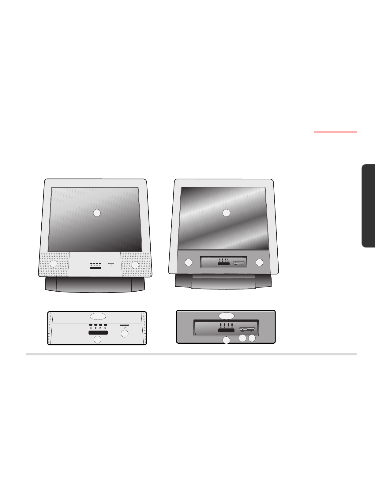
The following figures show the external locations of the main features of the LCD PC.
FRONT VIEW
FIG. 1 – 1
1. LCD
2. Speakers
3. FDD activity LED
4. CD-device activity
LED
5. HDD activity LED
6. Power LED
7. IrDA port
8. ON/OFF & Standby/
Resume button
9. Reset button*
(*LP200T only)
1
2
3 ~ 6
8
7
2
Front View
LP200C LP200T
3 ~ 6
7
89
1
2 2
Page 14
1 – 8
INTRODUCTION
1. INTRODUCTION
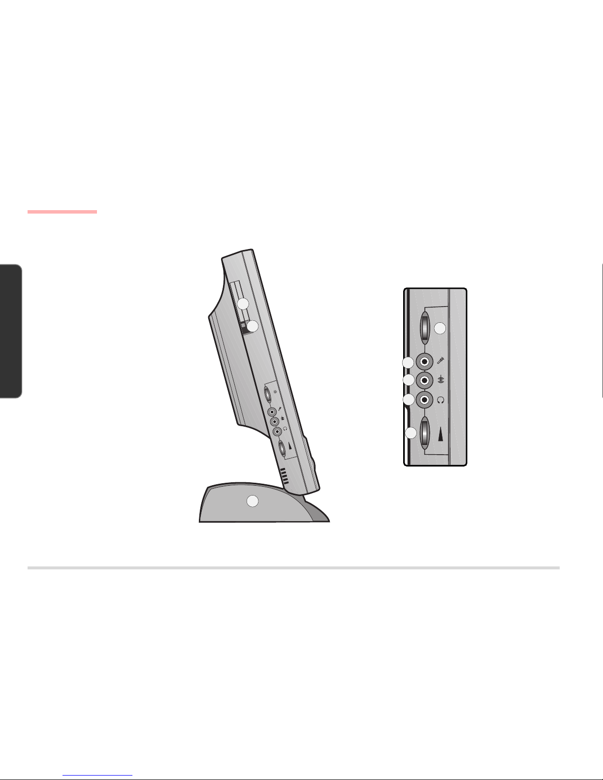
LEFT VIEW
FIG. 1 - 2
1. PC Card
(PCMCIA) socket
2. PC Card eject
button
3. LCD brightness
control
4. Microphone input
jack
5. Line-in jack
6. Phones out jack
7. Volume control
knob
8. HDD bay
1
2
3
4
5
8
6
7
Left View
Page 15
1 – 9
I
NTRODUCTION
1. INTRODUCTION
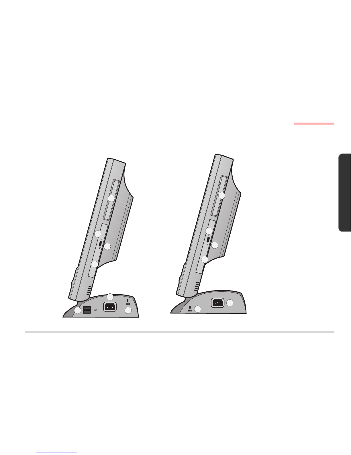
RIGHT VIEW
FIG. 1 - 3
1. FDD bay
2. CD-Device bay
3. Emergency eject
button
- Use a probe (e.g.
a straightened
paper clip).
4. Eject button
5. Kensington lock
port
6. AC-in port
7. two USB ports
(* LP200C only)
1
2
3
4
5
6
7
Right View
LP200C LP200T
5
6
4
2
3
1
Page 16
1 – 10
INTRODUCTION
1. INTRODUCTION
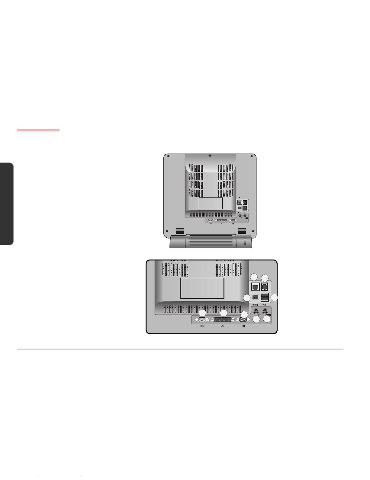
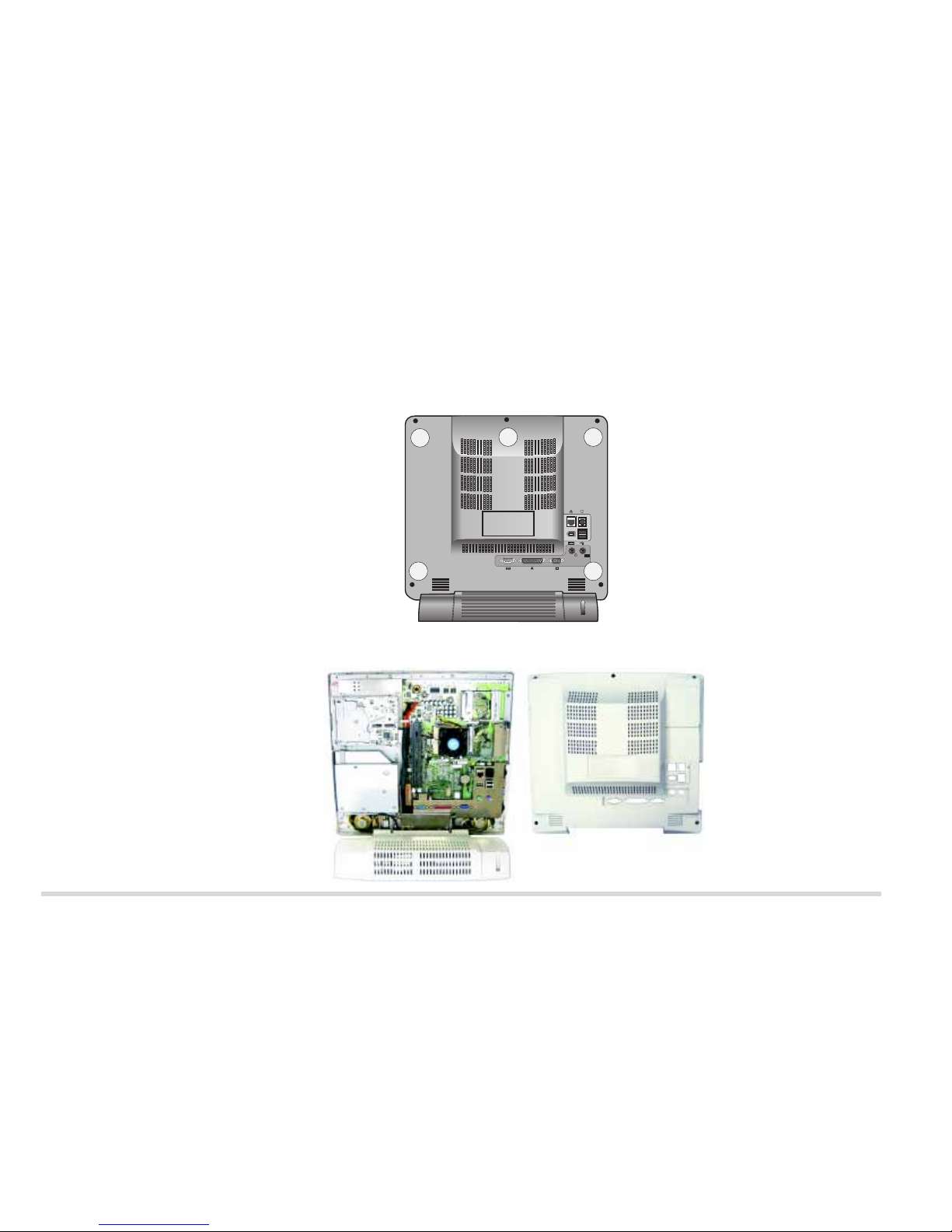
REAR VIEW
FIG. 1 - 4
1. Serial port (COM A)
2. Printer/Parallel
port
3. VGA port
4. PS/2 mouse port
5. PS/2 keyboard port
6. USB ports (x2))
7. IEEE1394 port
8. RJ-45 LAN port
9. RJ-11 Modem port
Rear View
1 2
3
4
5
9
6
8
7
Page 17
1 – 11
I
NTRODUCTION
1. INTRODUCTION
System Board Overview - Key Parts
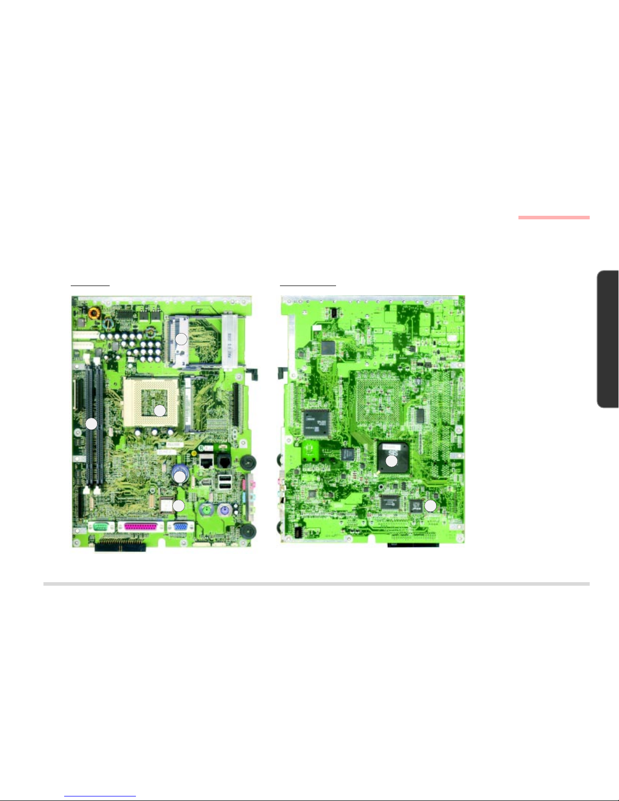
SYSTEM BOARD OVERVIEW
KEY PARTS
KEY PARTS
FIG. 1 - 5
1. CPU
(Intel Pentium III or
Celeron) with Fan
2. SMSC37N869
Super I/O
Controller
3. Flash ROM
4. two DIMM Sockets
5. CMOS Battery
6. PCMCIA Socket
7. SiS630 Integrated
Chip (Core Logic,
Video, Audio &
LAN)
1
23
4
5
6
7
Top View Bottom View
Page 18
1 – 12
INTRODUCTION
1. INTRODUCTION
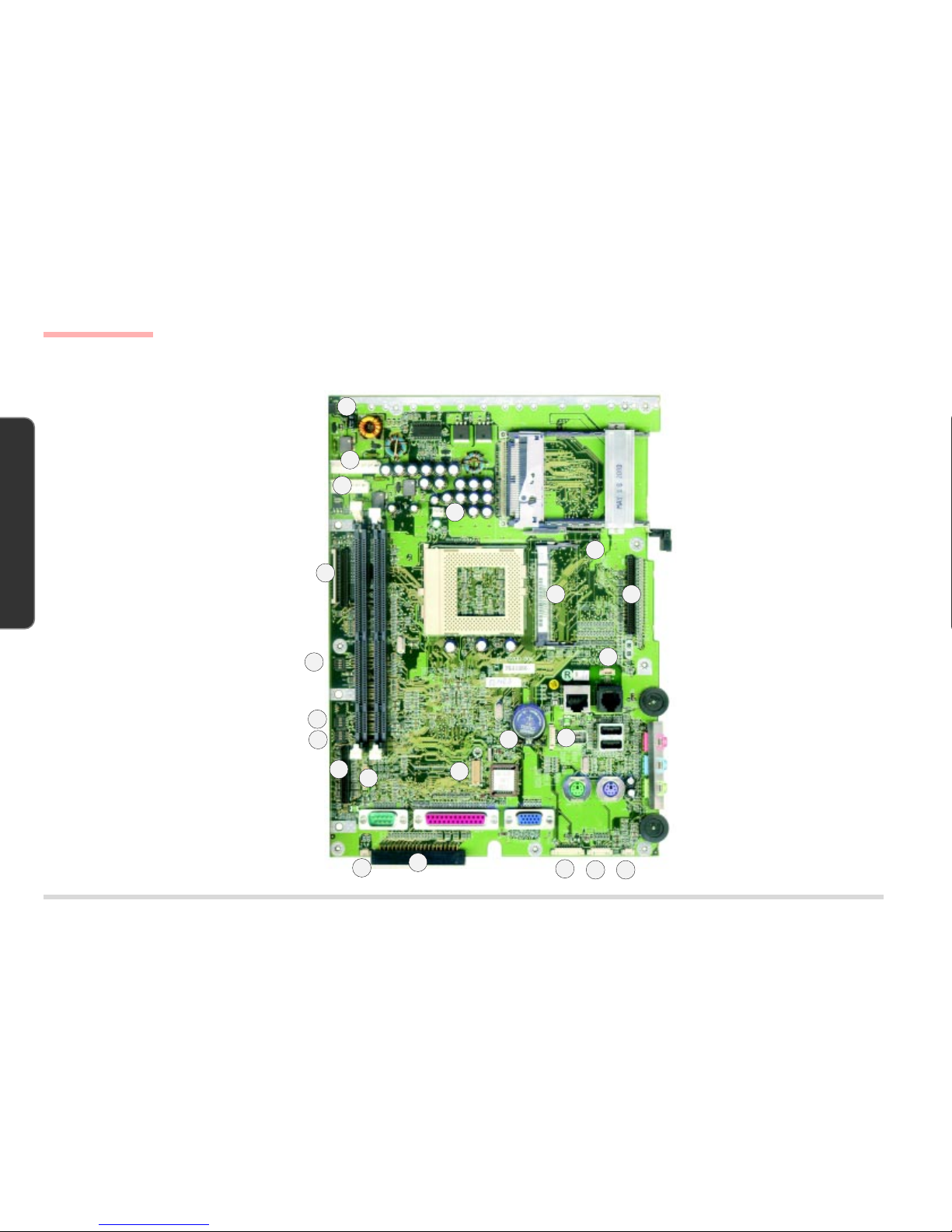
CABLE CONNECTORS, SWITCHES & JUMPERS
CONNECTORS, SWITCHES &
J
UMPERS
FIG. 1 - 6
1. CN1 (Inverter Cable)
2. CN2 (Power Cable)
3. CN4 (Power Cable)
4. CN6 (FDD Cable)
5. CN22 (CD Device
Cable)
6. CN35 (USB Cable)
7. CN33 (Left Speaker
Cable)
8 CN30 (HDD Cable)
9. CN21 (Modem
Module)
10. CN16 (IEEE1394
Cable)
11. CN11 (Modem Cable)
12. CN31 (LED Cable)
13. CN32 (Inverter
Cable)
14. CN34 (Right Speaker
Cable)
15. CN8 (LCD Cable)
16. CN9 (IEEE1394
Module)
17. CN5 (Fan Cable)
18. SW1 (CPU Frequency
Switch)
19. SW3 (LCD Type
Switch)
20. SW4 (System Board
ID Switch)
21. J1 (CMOS Clear
Jumper)
22. J2 (Panel VCC
Jumper)
1
2
3
4
5
8
9
11
12
13 14
15
17
18
19
20
21
22
6
7
System Board Overview - Connectors, Switches & Jumpers
10
16
Page 19

2 – 1
D
ISASSEMBLY
2. DISASSEMBLY
2 DISASSEMBLY
OVERVIEW
This chapter provides step-by-step instructions for disassembling parts and subsystems. When it comes to reassembly, reverse the procedures (unless otherwise indicated). All the procedures apply to both the LP200C and LP200T
unless otherwise specified.
We suggest you completely review any procedure before you take the computer apart.
CPU and Memory Upgrades:
The upgrade procedures for CPU and system memory involve more than the component-specific removal and replacement procedure. Please pay attention to the component-specific upgrade notes.
Page 20

2 – 2
D ISASSEMBLY
2. DISASSEMBLY
MAINTENANCE TOOLS
The following tools are recommended when working on the LCD PC:
• M3 Philips-head screwdriver
• M2.5 Philips-head screwdriver (magnetized)*
• M2 Philips-head screwdriver
• Small flat-head screwdriver
• Pair of needle-nose pliers
• Anti-static wrist-strap
* note Maintenance Precaution #3.
CONNECTIONS
Connections within the computer are one of four types:
Locking collar sockets for ribbon connectors To release these connectors, use a small flat-head screwdriver to gently pry the
locking collar away from its base. When replacing the connection, make sure the
connector is oriented in the same way. The pin1 side is usually
not
indicated.
Pressure sockets for multi-wire connectors To release this connector type, grasp it at its head and gently rock it from side to
side as you pull it out.
Do not pull on the wires themselves.
When replacing the
connection, do not try to force it. The socket only fits one way.
Pressure sockets for ribbon connectors To release these connectors, use a small pair of needle-nose pliers to gently lift the
connector away from its socket. When replacing the connection, make sure the
connector is oriented in the same way. The pin1 side is usually
not
indicated.
Board-to-board or multi-pin sockets To separate the boards, gently rock them from side to side as you pull them apart.
If the connection is very tight, use a small flat-head screwdriver
- use just enough
force to start the separation.
Maintenance Tools, Connections
Page 21

2 – 3
D
ISASSEMBLY
2. DISASSEMBLY
MAINTENANCE PRECAUTIONS
The following precautions are a reminder.
To avoid personal injury or damage to the computer while performing a removal and/or replacement job, take the following precautions:
1. Don't drop it. Perform your repairs and/or upgrades on a stable surface. If the computer falls, the case and other components could
be damaged.
2. Don't overheat it. Note the proximity of any heating elements. Keep the computer out of direct sunlight.
3. Avoid interference. Note the proximity of any high capacity transformers, electric motors, and other strong magnetic fields. These can
hinder proper performance and damage components and/or data. You should also monitor the position of magnetized tools (i.e.
screwdrivers).
4. Keep it dry. This is an electrical appliance. If water or any other liquid gets into it, the computer could be badly damaged.
5. Be careful with power. Avoid accidental shocks, discharges or explosions.
•Before removing or servicing any part from the computer, turn the computer off and detach any power supplies.
•When you want to unplug the power cord or any cable/wire, be sure to disconnect it by the plug head. Do not pull on the wire.
6. Peripherals – Turn off and detach any peripherals.
7. Beware of static discharge. ICs, such as the CPU and main support chips, are vulnerable to static electricity. Before handling any part
in the computer, discharge any static electricity inside the computer. When handling a printed circuit board, do not use gloves or other
materials which allow static electricity buildup. We suggest that you use an anti-static wrist strap instead.
8. Beware of corrosion. As you perform your job, avoid touching any connector leads. Even the cleanest hands produce oils which can
attract corrosive elements.
9. Keep your work environment clean. Tobacco smoke, dust or other air-born particulate matter is often attracted to charged surfaces,
reducing performance.
10. Keep track of the components. When removing or replacing any part, be careful not to leave small parts, such as screws, loose inside
the computer.
C
LEANING
Do not apply cleaner directly to the computer, use a soft clean cloth.
Do not use volatile (petroleum distillates) or abrasive cleaners on any part of the computer.
Maintenance Precautions
Page 22
BACK COVER REMOVAL
1. Place the system with its LCD display facing down.
2. Remove 5 screws (A, , B, C, D & E) which secure the Back Cover to the rest of the system.
3. Gently remove the cover from the rest of the system.
R
EMOVING 5 SCREWS FROM
THE
BACK OF THE SYSTEM
FIG. 2-1
B
ACK COVER AND THE REST OF
THE
SYSTEM
FIG. 2-2
A
B C
D E
Back Cover
Back Cover Removal
2 - 4
Page 23
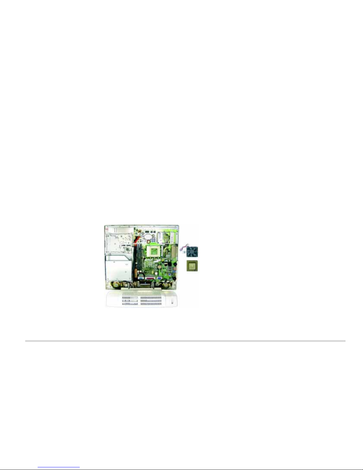
CPU REMOVAL
Part A
Remove the Back Cover. (page 2-4)
Part B
FNote:
If you want to upgrade the CPU, replace the old CPU with the upgraded one and also see the CPU
Upgrade Notes on the next page.
1. Unplug the Fan Cable from Connector CN5.
2. Disengage both caches at the sides of the Fan from the CPU socket.
3. A thermal pad is attached to the Fan. Remove the Fan with the Thermal Pad from the CPU.
4. Disengage the CPU lever and remove the CPU.
FNote for Replacing the CPU: : Reverse the removal procedure. Please also note the following:
When inserting the CPU, put the CPU in the CPU socket with the notched corner of the CPU aligning with the notched
corner of the CPU socket and then engage the lever.
REMOVING THE FAN AND THE
CPU
F
IG. 2-3
CPU Removal
Fan
CPU
CN5
2 - 5
Page 24
2 – 6
D ISASSEMBLY
2. DISASSEMBLY
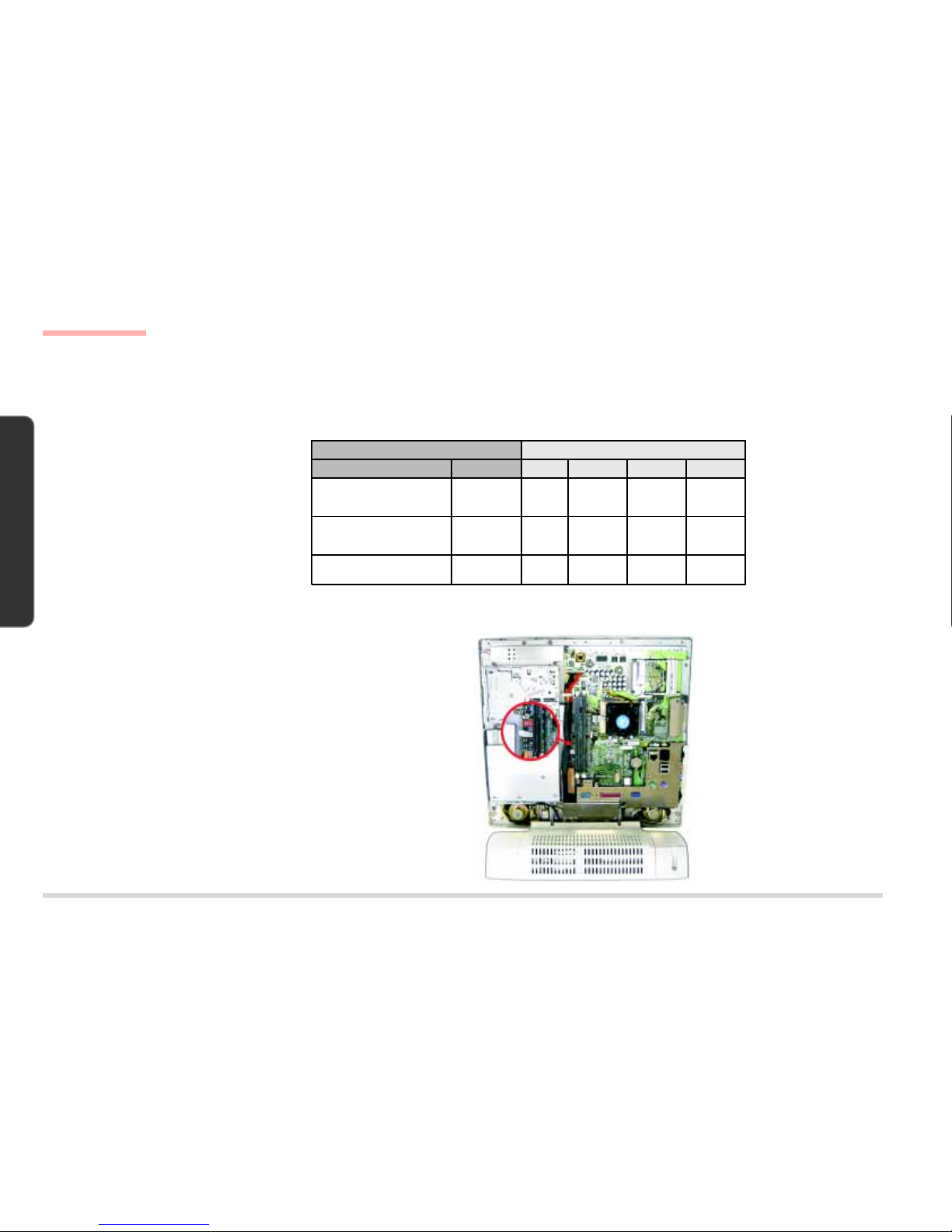
CPU UPGRADE NOTES
After you install the upgraded CPU, check against the following table to see if you need to adjust switch settings.
SWITCH SETTINGS FOR ALL SUPPORTED CPUS
CPU SWITCH SETTINGS
TABLE 2-1
LOCATING SWITCH SW1
Fig. 2-4 shows the location of Switch SW1.
SWITCH SW1 LOCATION
FIG. 2-4
CPU Switch SW1 (CPU Frequency Switch)
Typ e FSB Speed SW1-1 SW1-2 SW1-3 SW1-4
Celeron 466/Celeron 500
Celeron 533/Celeron 566
Celeron 600
66.7MHz OFF OFF OFF OFF
Pentium III 600/Pentium III 650
Pentium III 700/Pentium III 750
Pentium III 800
100MHz ON OFF OFF OFF
Pentium III 667/Pentium III 733
Pentium III 866
133MHz ON ON ON OFF
CPU Upgrade Notes
Page 25
2 – 7
D
ISASSEMBLY
2. DISASSEMBLY
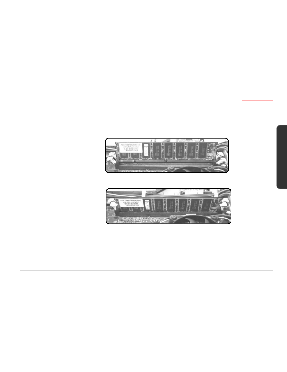
MEMORY MODULE REMOVAL
REMOVING DIMMS
Part A
Remove the Back Cover. (page 2-4)
Part B
Release the levers on the two ends of
the DIMM slot. As you do so, the module will rise slightly and remove the
seated DIMM, one at a time.
R
EMOVING THE DIMMS
FIG. 2-5
INSTALLING DIMMS
1. Insert a DIMM in either slot at about a 20
o
angle. Grooves on the sides of the module
allow you to insert it only one way. Make sure
it is seated as far into the slot as it will go.
DO NOT FORCE IT. The module should fit in
without much pressure. If there is a lot of
resistance, check to make sure the DIMM is
properly seated.
2. Click in the slot levers to secure the module.
3. Reinstall the back cover.
I
NSTALLING THE DIMMS
FIG. 2-6
FMemory Upgrade Note:
• If you have changed the memory configuration, run SCU so the new total can be registered in the CMOS.
• If you have increased memory, check to see if you need to recreate the Hibernate-specific file if the system
runs Windows 98 SE with Hibernate support enabled. (Refer to
Chapter 3, Advanced Controls
&
Chapter 5,
Drivers & Utilities
of the CD-based complete
User’s Manual
for details.)
DIMM Removal & Installation
Page 26
2 – 8
D ISASSEMBLY
2. DISASSEMBLY
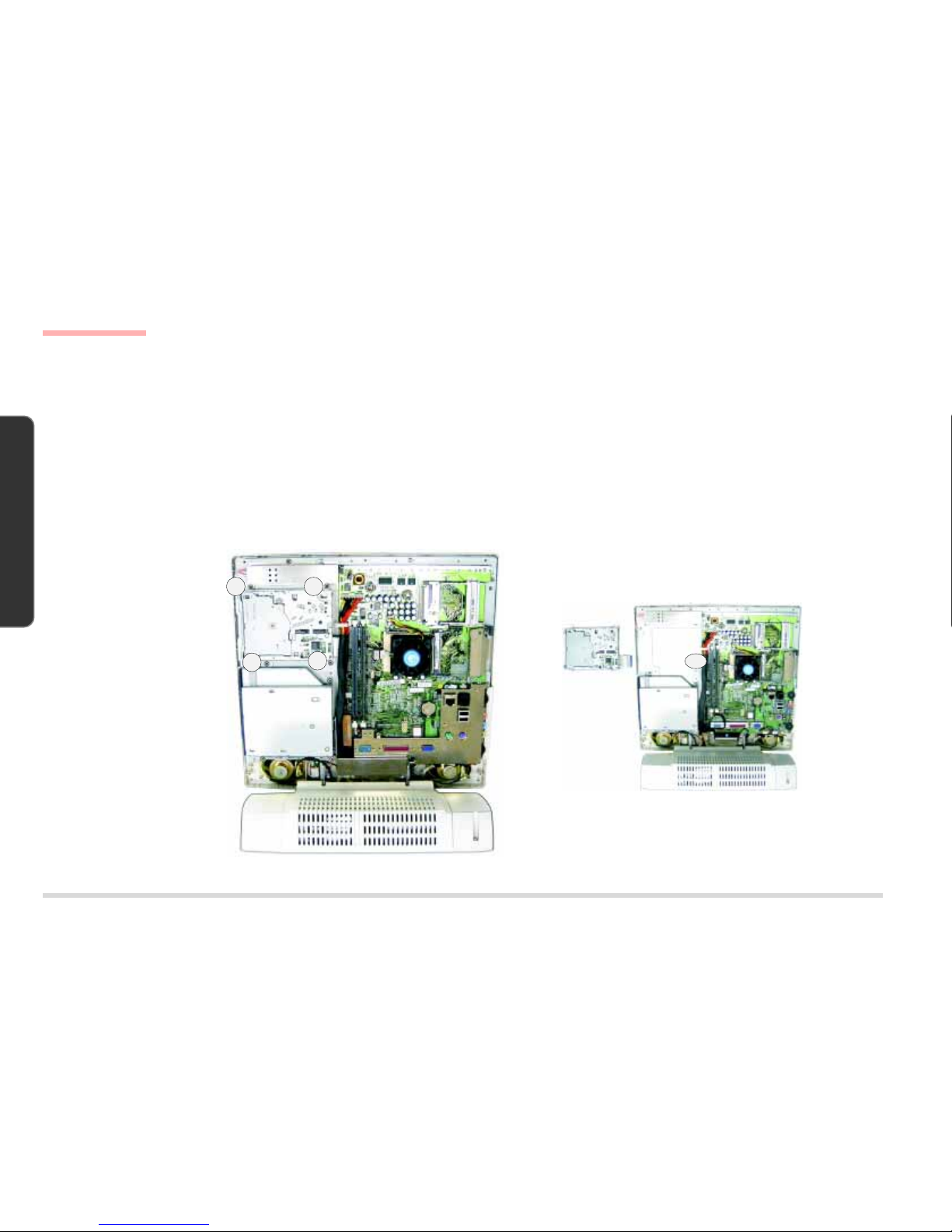
FDD MODULE REMOVAL
Part A
Remove the Back Cover. (page 2-4)
Part B
1. Remove 4 screws (A, B, C & D).
2. Separate the FDD module from the rest of the system by disconnecting the FDD Cable from the System Board at Connector
CN6.
R
EMOVING THE FDD MODULE
(1)
F
IG. 2-7
R
EMOVING THE FDD MODULE
(2)
F
IG. 2-8
FDD Module Removal
A B
C
D
FDD Module
CN6
Page 27
2 – 9
D
ISASSEMBLY
2. DISASSEMBLY
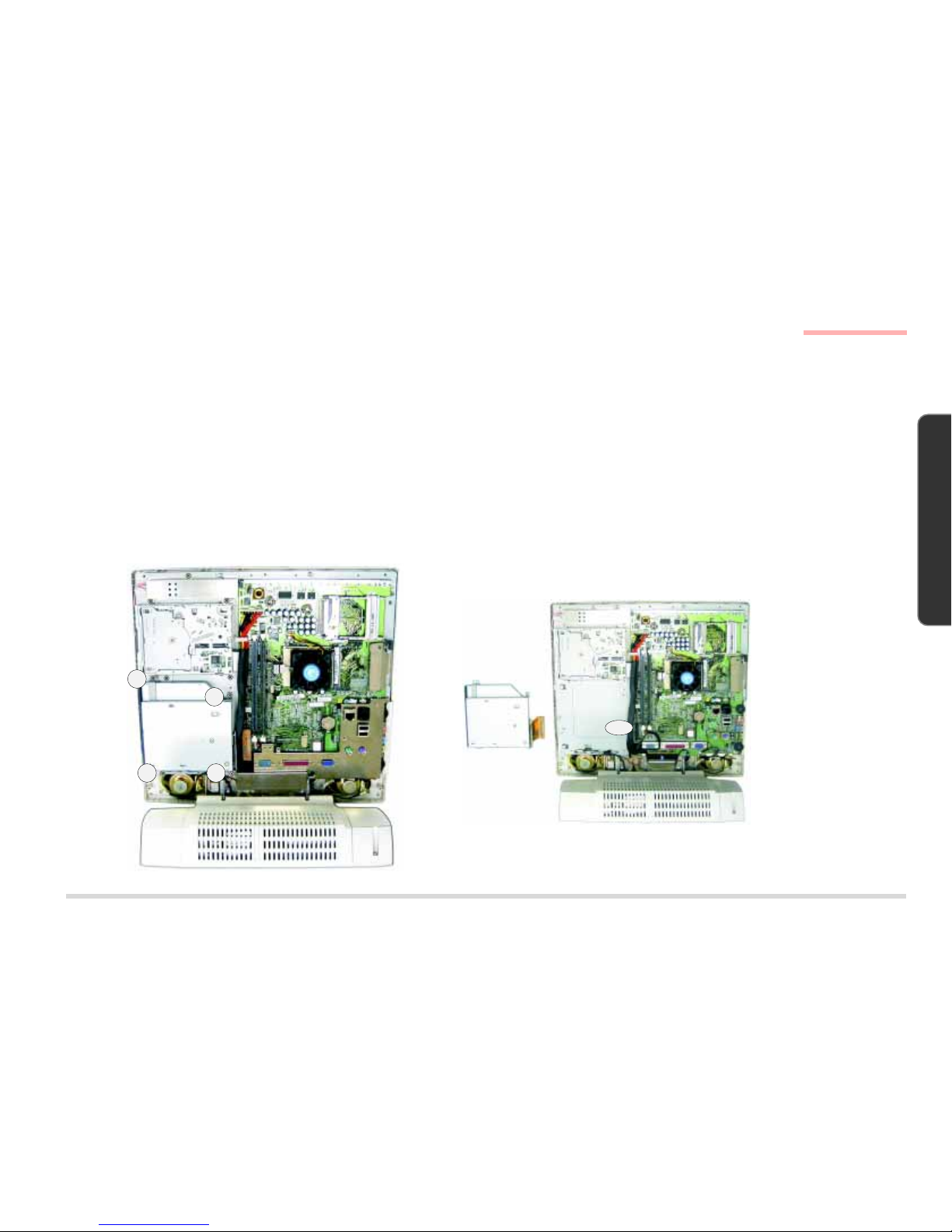
CD DEVICE MODULE REMOVAL
The CD device module can be the CD-ROM module, DVD module or CD-RW module.
Part A
Remove the Back Cover. (Page 2-4)
Part B
1. Remove 4 screws (A, B, C & D).
2. Separate the CD Device Module from the rest of the system by disconnecting the device cable from Connector CN22 on the
System Board.
R
EMOVING THE CD DEVICE
MODULE (1)
F
IG. 2-9
R
EMOVING THE CD DEVICE
MODULE (2)
F
IG. 2-10
CD Device Module Removal
A
B
C D
CD Device
Module
CN22
Page 28
2 – 10
D ISASSEMBLY
2. DISASSEMBLY
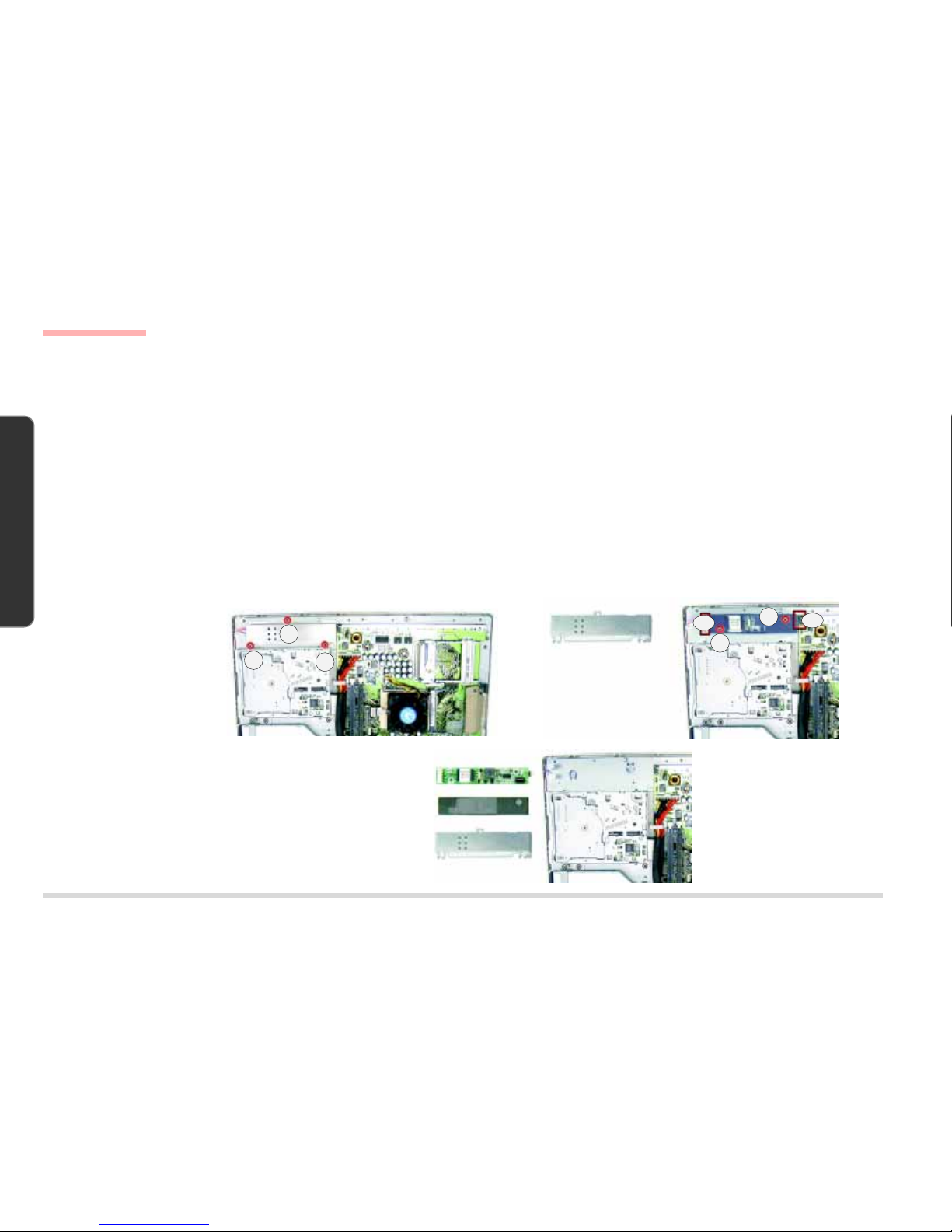
INVERTER BOARD REMOVAL
Part A
Remove the Back Cover. (Page 2-4)
Part B
1. Remove the Inverter Shielding Plate by removing 3 screws (A, B & C) which secure it to the rest of the system.
(If you have already removed the FDD module, Screws A & B have already been removed during the process.)
2. Remove 2 screws (D & E) which secure the Inverter Board and the Inverter Mylar to the rest of the system.
3. Disconnect the following 3 cables:
(C1 & C2) The LCD to Inverter Board (2 cables from Connectors CN2).
(C3) The Inverter Board to System Board (from Connector CN1).
4. Separate the Inverter Board and the Inverter Mylar.
R
EMOVING THE INVERTER
BOARD
FIG. 2-11
Inverter Board Removal
A
B
C
Inverter Mylar
Inverter Shielding
Plate
Inverter Board
Inverter Shielding Plate
D
E
CN1
CN2
FDD Module
Page 29
2 – 11
D
ISASSEMBLY
2. DISASSEMBLY
I/O BRACKET REMOVAL
Part A
Remove the Back Cover. (page 2-4)
Part B
Remove the I/O Bracket by removing 10 screws (A ~ J) which secure it to the rest of the system.
(If you have already removed the CD Device Module, Screw A has already been removed during the process.)
R
EMOVING THE I/O BRACKET
FIG. 2-12
A
B
C & D
GHI
J
E & F
I/O Bracket
I/O Bracket Removal
CD Device
Module
Page 30

2 – 12
D ISASSEMBLY
2. DISASSEMBLY
SYSTEM BOARD REMOVAL
Part A
Remove the Back Cover. (page 2-4)
Remove the I/O Bracket. (page 2-11)
Part B
1. Remove Screw A.
2. Disconnect the following 12 cables and 2 ground wires from the System Board:
12 Cables
(C1) The Inverter Board to System Board (from Connector CN1).
(C2) The FDD Module to System Board (from Connector CN6).
(If you have already removed the FDD Module, the FDD Cable has already been removed during the process.)
(C3) The CD Device Module to System Board (from Connector CN22).
(If you have already removed the CD Device Module, the device cable has already been removed during the process.)
(C4 & C5) The Power Supply to System Board (2 cables from Connector CN2, upper, and Connector CN4, lower).
(Remove the clip which holds the above two cables together and put it aside.)
(C6) The Right Speaker to System Board (from Connector CN34).
(C7) The Left Speaker to System Board (from Connector CN33).
(C8) The LED + Inverter Board to System Board (LED cable from Connector CN31).
(C9) The LED + Inverter Board to System Board (Inverter cable from Connector CN32).
(C10) The HDD to System Board (from Connector CN30).
(C11) The LCD to System Board (from Connector CN8).
(C12) The USB Board to System Board (from Connector CN35).
2 Ground Wires
(W1) A ground wire with the USB Cable fixed to the System Board with a screw.
(W2) A ground wire fixed to the System Board with a screw.
3. Remove the System Board by removing 7 screws (B ~ H).
System Board Removal
Page 31

2 – 13
D
ISASSEMBLY
2. DISASSEMBLY
REMOVING THE SYSTEM BOARD
FIG. 2-13
System Board
System Board Removal
A
B
C
D
E
F
G
H
W1
W2
CN32
CN31
CN33
CN34
CN30
CN22
CN35
CN4
CN6
CN1
CN2
CN8
CD Device
Module
FDD Module
Page 32

2 – 14
D ISASSEMBLY
2. DISASSEMBLY
LCD MODULE REMOVAL
Part A
Remove the Back Cover. (page 2-4)
Remove the I/O Bracket. (page 2-11)
Part B
1. Remove 6 screws (A, B, C, D, E & F).
2. Disconnect the following 8 cables and 3 ground wires.
8 Cables
(C1 & C2) The LCD to Inverter Board (two cables from Connectors CN2).
(C3) The LED + Inverter Board to System Board (LED cable from Connector CN31).
(C4) The LED + Inverter Board to System Board (Inverter cable from Connector CN32).
(C5) The LCD to LED + Inverter Board (from Connector CN1).
(C6) The Left Speaker to System Board (from Connector CN33)
(C7) The Right Speaker to System Board (from Connector CN34)
(C8) The LCD to System Board (from Connector CN8)
3 Ground Wires
(W1) A ground wire fixed to the Left Speaker with a screw.
(W2) A ground wire fixed to the Right Speaker with a screw.
(W3) A ground wire fixed to the System Board with a screw.
LCD Module Removal
Page 33

2 – 15
D
ISASSEMBLY
2. DISASSEMBLY
REMOVING 6 SCREWS, 8
C
ABLES & 3 GROUND WIRES
FIG. 2-14
LCD Module Removal
CN32
CN1
CN2
CN34
CN31
CN33
CN8
W1
W2
W3
C
B
A
D
F
E
Page 34

2 – 16
D ISASSEMBLY
2. DISASSEMBLY
3. Remove the LCD Module.
A. Remove 4 screws (A, B, C & D) to separate the Front Panel from the rest of the system.
B. Disconnect the Converter Cable from the LCD Module.
LCD Module Removal
REMOVING THE LCD MODULE
FIG. 2-15
A
B
CD
Converter Cable
Front Panel
Page 35

2 – 17
D
ISASSEMBLY
2. DISASSEMBLY
Inverter + LED Board Removal
INVERTER + LED BOARD REMOVAL
Part A
Remove the Back Cover. (page 2-4)
Remove the I/O Bracket. (page 2-11)
Remove the Front Panel with the LCD Module. (Steps 1 & 2 of Part B of the LCD Module Removal Procedure, pages 2-14 & 2-15)
Part B
1. Separate the Front Panel from the rest of the system by removing 4 screws (A, B, C & D).
2. Separate the Inverter + LED Board from the Front Panel by removing 3 screws (E, F & G).
R
EMOVING THE INVERTER +
LED B
OARD
FIG. 2-16
E
F
G
Inverter + LED Board
A
B
CD
Front Panel
Page 36

2 – 18
D ISASSEMBLY
2. DISASSEMBLY
CONVERTER BOARD REMOVAL
Part A
Remove the LCD Module. (pages 2-14 ~ 2-16 )
Part B
Separate the Converter Board from the rest of the system by removing Screw A.
R
EMOVING THE CONVERTER
BOARD
FIG. 2-17
A
Converter Board
Converter Board Removal
Page 37

2 – 19
D
ISASSEMBLY
2. DISASSEMBLY
SPEAKER REMOVAL
Part A
Remove the Back Cover. (page 2-4)
Remove the I/O Bracket. (page 2-11)
Part B
1. Disconnect the following 4 cables.
(C1) The Right Speaker to System Board (from Connector CN34).
(C2) The Left Speaker to System Board (from Connector CN33).
(C3) The LED + Inverter Board to System Board (LED cable from Connector CN31).
(C4) The LED + Inverter Board to System Board (Inverter cable from Connector CN32).
2. Remove 4 screws (A, , B, C & D).
D
ISCONNECTING 4 CABLES &
R
EMOVING 4 SCREWS (FOR
SPEAKER
REMOVAL)
F
IG. 2-18
Speaker Removal
A
B
C
D
CN32
CN31
CN33
CN34
Page 38

2 – 20
D ISASSEMBLY
2. DISASSEMBLY
3. Separate the Front Panel from the rest of the system by removing 4 screws (A, B, C & D).
4. Separate the Speakers from the Front Panel by removing 8 screws (E ~ L).
S
EPARATING THE SPEAKERS
FROM
THE FRONT PANEL
FIG. 2-19
A
B
CD
Front Panel
E
F
G
H
I
L
K
J
Speaker Removal
Page 39

2 – 21
D
ISASSEMBLY
2. DISASSEMBLY
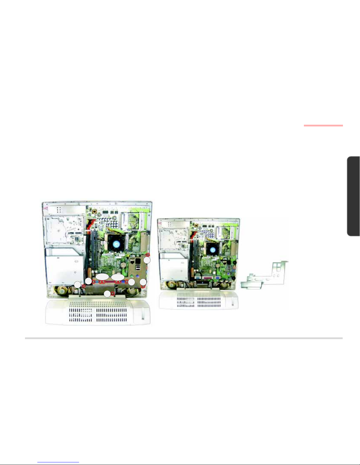
Base Assembly Removal
BASE ASSEMBLY REMOVAL
Part A
Remove the Back Cover. (page 2-4)
Remove the I/O Bracket. (page 2-11)
Part B
Separate the Base Assembly from the rest of the system.
A. Disconnect the following 4 cables and 3 ground wires from the System Board.
4 Cables
(C1 & C2) The Power Supply to System Board (two cables from Connector CN2,upper, and Connector CN4, lower).
(Remove the clip which holds the above two cables together and put it aside.)
(C3) The HDD to System Board (from Connector CN30)
(C4) The USB Board to System Board (from Connector CN35)
3 Ground Wires
(W1) A ground wire with the USB Cable fixed to the System Board with a screw.
(W2) A ground wire fixed to the Right Speaker with a screw.
(W3) A ground wire fixed to the Left Speaker with a screw.
B. Remove 4 screws (A, B, C & D).
Page 40

2 – 22
D ISASSEMBLY
2. DISASSEMBLY
Base Assembly Removal
SEPARATING THE BASE
ASSEMBLY FROM THE SYSTEM
FIG. 2-20
A
B
C
D
CN4
CN35
CN2
CN30
W2
W3
W1
Page 41

2 – 23
D
ISASSEMBLY
2. DISASSEMBLY
POWER SUPPLY REMOVAL
The Power Supply is in the Base Assembly.
Part A
Remove the Base Assembly. (pages 2-21 & 2-22)
Part B
1. Remove the HDD Cartridge.
A. Turn the Base Assembly upside down and remove Screw A. (Only the LP200T has this screw.)
B. Remove Screw B and pull the HDD Cartridge out from its bay until the HDD’s connectors are exposed.
C. Disconnect the following cables.
(C1) The Power Supply to HDD (power cable).
(C2) The System Board to HDD (HDD signal cable).
Power Supply Removal
REMOVING THE HDD
C
ARTRIDGE
FIG. 2-21
HDD Cartridge
C1
C2
B
A
Page 42

2 – 24
D ISASSEMBLY
2. DISASSEMBLY
2. Remove the Swivel Stand.
A. Turn the Base Assembly upside down.
B. Remove 4 screws (A, B, C & D).
R
EMOVING THE SWIVEL STAND
FIG. 2-22
Power Supply Removal
3. Separate the Top Cover of the Base Assembly from the rest of the Base Assembly by removing 6 screws (A, B, C, D, E & F).
R
EMOVING THE TOP COVER OF
THE
BASE ASSEMBLY
FIG. 2-23
Swivel Stand
AB
C
D
E
F
A
B
C
D
Power
Supply
Top Cover (Base Assembly)
Page 43

2 – 25
D
ISASSEMBLY
2. DISASSEMBLY
4. Separate the Power Supply from the rest of the Base Assembly by removing 4 screws (A, B, C & D).
Power Supply Removal
REMOVING THE POWER SUPPLY
FIG. 2-24
A
B
C
D
Power
Supply
Page 44

2 – 26
D ISASSEMBLY
2. DISASSEMBLY
USB BOARD REMOVAL
The USB Board is in the Base Assembly. Only the LP200C has this feature.
Part A
Remove the Base Assembly. (pages 2-21 & 2-22)
Remove the HDD Cartridge. (Step 1 of Part B of the Power Supply Removal Procedure, page 2-23)
Remove the Swivel Stand. (Step 2 of Part B of the Power Supply Removal Procedure, page 2-24)
Remove the Top Cover of the Base Assembly (Step 3 of Part B of the Power Supply Removal Procedure, page 2-24)
Part B
Separate the USB Board from the rest of the Base Assembly.
A. Disconnect the USB Cable from Connector CN1 on the USB Board.
B. Remove Screw A which secures the board to the Bottom Cover of the Base Assembly.
USB Board Removal
REMOVING THE USB BOARD
FIG. 2-25
A
USB Board
CN1
Page 45

2 – 27
D
ISASSEMBLY
2. DISASSEMBLY
HDD Removal
ð
HARD DISK DRIVE REMOVAL
The HDD is housed in the Base Assembly.
1. Place the LCD PC with its LCD panel facing up and remove Screw A. (Only the LP200T has this screw.)
2. Remove Screw B.
R
EMOVING SCREWS A & B
F
IG. 2-26
3. Pull the HDD Cartridge out from its bay until the HDD’s connectors are exposed.
4. Separate the HDD cartridge from the rest of the system by disconnecting the HDD’s IDE Cable (A) and Power Cable (B).
(Both of these cables are a tight fit.)
P
ULLING THE HDD CAR-
TRIDGE OUT AND DISCONNECT-
ING THE IDE & POWER
CABLES
FIG. 2-27
B
A
B
A
Page 46

2 – 28
D ISASSEMBLY
2. DISASSEMBLY
HDD Removal
C
D
A
B
A
B
5. Turn the cartridge upside down.
6. Remove Screws A & B to separate the HDD Frame from the Cartridge Casing.
S
EPARATING THE HDD FRAME
FROM
THE CARTRIDGE CASING
FIG. 2-28
7. Remove Screws A, B, C & D to separate the HDD from its frame.
S
EPARATING THE HDD FROM
ITS
FRAME
FIG. 2-29
Page 47

2 – 29
D
ISASSEMBLY
2. DISASSEMBLY
Fax/Modem & IEEE1394 Module Removal
FAX/MODEM MODULE & IEEE1394 MODULE (OPTIONAL)
The Fax/Modem and IEEE1394 Modules are optional.
Part A
Remove the Back Cover. (page 2-4)
Remove the I/O Bracket. (page 2-11)
Part B
IEEE1394 Module Removal
1. Disconnect the IEEE1394 cable from Connector CN16.
2. Disconnect the module with the cable from Connector CN9 on the System Board.
Fax/Modem Module Removal
1. Disconnect the Fax/Modem cable from Connector CN11.
2. Remove 2 screws (A & B).
2. Disconnect the module with the cable from Connector CN21 on the System Board.
R
EMOVING THE FAX/MODEM &
IEEE1394 M
ODULES
FIG. 2-30
CN11
CN16
CN9
A
B
Page 48

2 – 30
D ISASSEMBLY
2. DISASSEMBLY
NOTES:
Notes
Page 49

A – 1
P
ART
L
ISTS
A. PART LISTS
A PART LISTS
This appendix breaks down the LCD PC’s construction into a series of illustrations. The component part numbers
are indicated in the tables opposite the drawings. It includes two sets of part lists for the LP200C and the LP200T
respectively.
Note: This section indicates the manufacturer’s part numbers. Your organization may use a different
system, so be sure to cross-check any relevant documentation.
Note: Be sure to check any update notices. The parts shown in these illustrations are appropriate for the
system at the time of publication. Over the product life, some parts may be improved or re-configured, resulting in
new part numbers.
Page 50

A – 2
P ART LISTS
A. PART LISTS
Front Assembly (LP200C)
LP200C
LP200C FRONT ASSEMBLY
(PART I)
F
IG. A–1
Page 51

A – 3
P
ART
L
ISTS
A. PART LISTS
Front Assembly (LP200C)
LP200C FRONT ASSEMBLY
(PART II)
F
IG. A–2
Page 52

A – 4
P ART LISTS
A. PART LISTS
Front Assembly (LP200C)
LP200C FRONT ASSEMBLY
(PART III)
F
IG. A–3
Page 53

A – 5
P
ART
L
ISTS
A. PART LISTS
LP200C FRONT ASSEMBLY
(PART IV)
F
IG. A–4
Front Assembly (LP200C)
Page 54

A – 6
P ART LISTS
A. PART LISTS
LP200C BACK ASSEMBLY
(PART I)
F
IG. A–5
Back Assembly (LP200C)
Page 55

A – 7
P
ART
L
ISTS
A. PART LISTS
LP200C BACK ASSEMBLY
(PART II)
F
IG. A–6
Back Assembly (LP200C)
Page 56

A – 8
P ART LISTS
A. PART LISTS
LP200C BACK ASSEMBLY
(PART III)
F
IG. A–7
Back Assem-
Page 57

A – 9
P
ART
L
ISTS
A. PART LISTS
LP200C FDD MODULE
FIG. A–8
FDD Module (LP200C)
Page 58

A – 10
P ART LISTS
A. PART LISTS
LP200C CD DEVICE
MODULE
FIG. A–9
CD Device Module (LP200C)
Page 59

A – 11
P
ART
L
ISTS
A. PART LISTS
LP200C BASE ASSEMBLY
(PART I)
F
IG. A–10
Base Assembly (LP200C)
Page 60

A – 12
P ART LISTS
A. PART LISTS
LP200C BASE ASSEMBLY
(PART II)
F
IG. A–11
Base Assembly (LP200C)
Page 61

A – 13
P
ART
L
ISTS
A. PART LISTS
LP200C HDD MODULE
FIG. A–12
HDD Module (LP200C)
Page 62

A – 14
P ART LISTS
A. PART LISTS
LP200T FRONT ASSEMBLY
(PART I)
F
IG. A–13
Front Assembly (LP200T)
LP200T
Page 63

A – 15
P
ART
L
ISTS
A. PART LISTS
LP200T FRONT ASSEMBLY
(PART II)
F
IG. A–14
Front Assembly (LP200T)
Page 64

A – 16
P ART LISTS
A. PART LISTS
LP200T FRONT ASSEMBLY
(PART III)
F
IG. A–15
Front Assembly (LP200T)
Page 65

A – 17
P
ART
L
ISTS
A. PART LISTS
LP200T FRONT ASSEMBLY
(PART IV)
F
IG. A–16
Front Assembly (LP200T)
Page 66

A – 18
P ART LISTS
A. PART LISTS
LP200T BACK ASSEMBLY
(PART I)
F
IG. A–17
Back Assembly (LP200T)
Page 67

A – 19
P
ART
L
ISTS
A. PART LISTS
LP200T BACK ASSEMBLY
(PART II)
F
IG. A–18
Back Assembly (LP200T)
Page 68

A – 20
P ART LISTS
A. PART LISTS
LP200T BACK ASSEMBLY
(PART III)
F
IG. A–19
Back Assembly (LP200T)
Page 69

A – 21
P
ART
L
ISTS
A. PART LISTS
LP200T FDD MODULE
FIG. A–20
FDD Module (LP200T)
Page 70

A – 22
P ART LISTS
A. PART LISTS
LP200T CD DEVICE
MODULE
FIG. A–21
CD Device Module (LP200T)
Page 71

A – 23
P
ART
L
ISTS
A. PART LISTS
LP200T BASE ASSEMBLY
(PART I)
F
IG. A–22
Base Assembly (LP200T)
Page 72

A – 24
P ART LISTS
A. PART LISTS
Base Assembly (LP200T)
LP200T BASE ASSEMBLY
(PART II)
F
IG. A–23
Page 73

A – 25
P
ART
L
ISTS
A. PART LISTS
LP200T HDD MODULE
FIG. A–24
HDD Module (LP200T)
Page 74

A – 26
P ART LISTS
A. PART LISTS
NOTES:
Notes
Page 75

B – 1
S
WITCHES
& J
UMPERS
B. SWITCHES & JUMPERS
B SWITCHES & JUMPERS
This appendix is about the system’s switches and jumpers.
Page 76

B – 2
SWITCHES & JUMPERS
B. SWITCHES & JUMPERS
Switch & Jumper Locations
SWITCHES AND JUMPERS
LOCATIONS
Page 77

B – 3
S
WITCHES
& J
UMPERS
B. SWITCHES & JUMPERS
Switch & Jumper Settings
hctiwSycneuqerFUPC1WShctiwS
UPC
1-1WS 2-1WS 3-1WS 4-1WS
epyT deepSBSF
335noreleC/005noreleC/664noreleC
056noreleC/006noreleC/665noreleC
008noreleC/007noreleC/766noreleC
zHM7.66FFOFFOFFOFFO
056IIImuitneP/006IIImuitneP
057IIImuitneP/007IIImuitneP
008IIImuitneP
zHM001NOFFOFFOFFO
337IIImuitneP/766IIImuitneP
668IIImuitneP/008IIImuitneP
G1IIImuitneP/339IIImuitneP
zHM331NONONOFFO
hctiwSepyTDCL3WShctiwS
)dnarB(ledoMDCL 1-3WS 2-3WS 3-3WS 4-3WS krameR
)iadnuyH(001-11X51TH
1
FFOFFOFFOFFOXXXXXXXXX:edocraB 230 XXXX
)iadnuyH(001-11X51TH
2
NOFFONOFFOXXXXXXXXX:edocraB 240 XXXX
)iadnuyH(002-11X51THFFOFFONOFFO
)GL(HT2C-2X151MLFFOFFOFFONO
SETTINGS
Page 78

B – 4
SWITCHES & JUMPERS
B. SWITCHES & JUMPERS
Switch & Jumper Settings
hctiwSDIdraoBmetsyS4WShctiwS
epyT 1-4WS 2-4WS 3-4WS 4-4WS
tluafeDFFOFFOFFOFFO
repmuJCCVlenaP2JrepmuJ
epyT 2&12J 3&21J
prahS,iadnuyHNO
devreseRNO
repmuJraelCSOMC1JrepmuJ
epyT 2&11J 3&21J
lamroNNO
raelCSOMCNO
Page 79

C – 1
C
IRCUIT
D
IAGRAMS
C. CIRCUIT DIAGRAMS
C CIRCUIT DIAGRAMS
This appendix has circuit diagrams of the system’s PCBs.
Printed Circuit Board Part No. of the Latest Version
System Board 71-P2200-006
Inverter Board 71-P2202-006
Inverter + LED Board 71-P2203-007A
Converter Board 71-P2204-004
IEEE1394 Extension Card 71-P2205-001 (This is an optional feature.)
External USB Board 71-P2206-001 (Only the LP200C has this feature.)
We have included the latest versions at the press time. If any board you want to service is newer than listed, please
consult the nearest service cneter.
Page 80

C – 2
CIRCUIT DIAGRAMS
C. CIRCUIT DIAGRAMS
System Board (71-P2200-006) - Sheet 1 of 19
LP-200
6
Socket-370 PIII CPU
ÂÅ ¤ Ñ ¹q ¸£ CLEVO C O.
119Tuesday, June 20, 2000
Title
Size Doc ument Number Rev
Date: Sheet
of
V_CMOS
CPUVRE F
VTT +2. 5V
V_CMOS
V_CMOS
V_CORE
V_CMO S
VTT
V_CMOS
VTT
CPUV REF
+2.5V
VTT
VTT
+2.5V
VTT
V_CMOS
HT DI
FLUSH#
PREQ# HTMS
CPUSLP #
HT RST#
FERR#
HTDO
PICD0
HTC KPICD1
Z0104
CPUCLK
PICCLK Z0106
Z0105
A20M#
SMI#
INIT# STPCLK#
IGNNE# NMI
INTR
FLUS H#
PREQ#
HD#22
HD#50
HA#9
HA#16
T Z0113
IGNNE#
PICCLK
T Z0136
T Z0122
T Z0135
HD#7
HD#12
HD#16
HD#27
HD#35
HD#38
HA#15
HA#24
HA#31
BSEL1#
T Z0119
T Z0112
VID2
HT DI
HT RST #
T Z0134
T Z0129
T Z0114
T Z0121
T Z0105
T Z0108
HD#5
HD#31
HD#39
HD#54
HA#4
HA#17
HREQ#2
SLEWCTRL
T Z0117
T Z0115
HD#19
HD#43
HD#44
HD#59
HA#6
HD#14
HD#28
HD#37
HD#51
HA#23
HA#26
HREQ#0
HREQ#[ 0..4]
HTDO
SMI#
PWRGOOD
T Z0106
HD#4
HD#10
HD#46
HD#60
HA#7
HTC K
HD#0
HD#9
HD#61
HA#20
HA#25
HREQ#4
HD#[0..63]
T Z0128
T Z0109
HD#3
HD#11
HD#23
HD#49
HA#18
HA#29
HREQ#3
STPCLK#
FERR#
HD#32
HD#40
HD#58
HD#63
HA#5
HA#10
HA#11
HA#27
T Z0118
Z0102
T Z0125
T Z0132
T Z0131
T Z0127
T Z0116
HD#24
HD#29
HD#30
HD#52
HA#3
HA#19
CLKREF
T Z0102
INTR
PICD1
PICD0
T Z0123
T Z0120
T Z0126
T Z0104
HD#15
HD#26
HA#12
HA#14
HA#28
HREQ#1
A20M#
T Z0138
T Z0133
T Z0111
HD#17
HD#21
HD#25
HD#33
HD#45
HD#53
RTTCT RL
VID3
HTMS
NMI
T Z0137
HD#1
HD#13
HD#41
HD#42
HA#13
HA#21
Z0103
Z0101
T Z0110
HD#2
HD#34
HD#62
BSEL0#
Z0107
HD#18
HD#20
HD#48
HD#55
HD#57
HA#30
VID1
VID0
INIT#
CPUSLP #
T Z0103
HD#8
HD#56
HA#22
HA#[3..31]
T Z0107
T Z0124
T Z0130
T Z0101
HD#6
HD#36
HD#47
HA#8
T Z0139
T Z0141
T Z0143
T Z0142
T Z0140
T Z0145
T Z0146 T Z0144
T Z0151
T Z0150
T Z0149
T Z0148
T Z0147
T Z0152
R259 510
R240 1K
R256 680
C86
4.7u/ 16V
R244 1K
R205 51
L33
33uH
1 2
+
C195
22u/10V_1206
RN8
8P4R x 330
1 8
2
3 6
4 5
7
RN49
8P4R x 150
1 8
2
3 6
4 5
7
CB3
1000p
CB19
1000p
CB4
1000p
CB6
1000p
CB7
1000p
CA18
0.1u
CB20
1000p
R44
150 1%
L31
0
1 2
CB5
1000p
CB8
1000p
CT 45
10u/1 6V
R239
110 1%
CA23
0.1u
CA15 4
0.1u
CA172
0.1u
CA17
0.1u
CA15
0.1u
CA145
0.1u
CA138
0.1u
CA150
0.1u
C198
10p
C194
10p
CA130
0.1u
CA182
0.1u
CA176
0.1u
CA174
0.1u
CA18 0
0.1u
CT 35
10u/16V
CB28
1000p
CB10
1000p
CB9
1000p
CT 6
10u/1 6V
CA26
0.1u
CA173
0.1u
CA48
0.1u
CA171
0.1u
CA22
0.1u
CA175
0.1u
CA44
0.1u
CA16
0.1u
CA132
0.1u
CA131
0.1u
CA14
0.1u
CA133
0.1u
CA134
0.1u
CA135
0.1u
CA136
0.1u
R255
15
R242
15
R232 56
RP17
10P8R x 470
1
2
3
4
5106
7
8
9
R243
110 1%
R49
150
R218
75 1%
R47
150
U3A
INTEL_PIII
W37
AN19
AN25
X4
AN17
AK28
AH22
AH26
AD6
R6
AN31
AL23
AL25
AN27
AL27
AK20
AH14
AN29
AL17
AL19
AH18
AH16
AK18
AD4
AA3
Z4
AK6
AA1
Y3
AF6
AB4
AB6
AE3
AJ1
AC3
AG3
Z6
AE1
AN7
AL5
AK14
AL7
AN5
AK10
AH6
AL9
AH10
AL15
AN9
AH8
AH12
AK8
E25
F16
A27
A25
C17
C23
A19
C27
C19
C21
A23
D16
A13
C25
C13
A17
A15
A21
C11
A11A7D12
D14
C15
D10D8A9C9B2C7C1F6C5J3A3A5F12E1E3K6G3F8G1L3H6P4R4H4U3N3L1Q1M4Q3P6S1J1T6S3U1M6N1T4
W1
AC1
AC37
AF4
AK16
AK24
AK30
AL11
AL13
AL21
AN11
AN13
AN15
AN21
AN23
B36
C29
C31
C33
E23
E29
E31
F10
G35
G37
L33
N33
N35
N37
Q33
Q35
Q37
S33
S37
U35
U37
V4W3W35
X6
Y1
E21
E27R2S35
X2
J33
J35
L35
A35
J37
AK26
AH30
AJ35
AL33
E35
AJ33
AE37
AE35
AG37
AN33
V6
F18
E33
AK22
K4
AK12
L37
AG33
C35
E37
G33
AC35
AE33
C37
AG1
W33
U33
AL31
AL29
M36
AN35
AN37
AK32
AL35
AM36
AL37
AJ37
AG35
AH28
AH20
AH4
A29
A31
A33
AA33
AA35
AD36
Z36
AB36
AM2
AJ31
Y33
BCLK
DEFE R#
TRDY#
RESET 2#
BPRI#
RS#[2]
RS#[1]
RS#[0]
VREF5
VREF3
ADS#
HIT M#
HIT #
DRDY#
DBSY #
LOCK#
BNR#
BR0#
REQ#[ 4]
REQ#[ 3]
REQ#[ 2]
REQ#[ 1]
REQ#[ 0]
A#[31]
A#[30]
A#[29]
A#[28]
A#[27]
A#[26]
A#[25]
A#[24]
A#[23]
A#[22]
A#[21]
A#[20]
A#[19]
A#[18]
A#[17]
A#[16]
A#[15]
A#[14]
A#[13]
A#[12]
A#[11]
A#[10]
A#[9]
A#[8]
A#[7]
A#[6]
A#[5]
A#[4]
A#[3]
D#62
D#63
D#61
D#60
D#59
D#58
D#57
D#56
D#55
D#54
D#53
D#52
D#51
D#50
D#49
D#48
D#47
D#46
D#45
D#44
D#43
D#42
D#41
D#40
D#39
D#38
D#37
D#36
D#35
D#34
D#33
D#32
D#31
D#30
D#29
D#28
D#27
D#26
D#25
D#24
D#23
D#22
D#21
D#20
D#19
D#18
D#17
D#16
D#15
D#14
D#13
D#12
D#11
D#10
D#9
D#8
D#7
D#6
D#5
D#4
D#3
D#2
D#1
D#0
A#[33]
RSP#
A#[35]
VTT
AERR#
RESERV ED
AP0#
VTT
VTT
VTT
AP1#
VTT
VTT
RP#
BINIT#
DEP5#
DEP1#
DEP0#
VTT
DEP6#
DEP4#
RESERV ED
VTT
RESERV ED
RESERV ED
RESERV ED
RESERV ED
RESERV ED
RESERV ED
RESERV ED
RESERV ED
VTT
VTT
VTT
VTT
BERR#
A#[34]
TESTHI
A#[32]
RESERV ED
RESERV ED
RESERV ED
RESERV ED
RESERV ED
RESERV ED
PICCLK
PICD[0]
PICD[1]
PRDY #
PREQ#
PWRGOOD
SLP#
SMI#
TCK
BPM#[1]
BSEL0
FLUS H#
IERR#
IGNNE#
TRST#
VREF4
VREF1
VREF0
VREF7
VREF2
VREF6
LINT [1]/NMI
INIT#
BPM#[0]
BP#[3]
BP#[2]
FERR#
A20M#
CPUPRE S#
EDGCTRL/ VRSEL
PLL1
PLL2
THERMDP
THERMDN
LINT[0]/INTR
TDI
TDO
TMS
VID[0]
VID[1]
VID[2]
VID[3]
STPCLK#
THERMTRIP#
VTT
RESET #
DEP7#
DEP3#
DEP2#
VTT
VTT
VCC_1.5V
VCC_2.5V
VCC_CMOS
GND
BSEL1
GND/ CL KREF
T30
T31
T32
T33
T34
T35
T39
T41
T37
T36
T38
T40
T43
T42
T44
T46
T45
T47
T48
T50
T49
T51T52
T53
T80
T54
T55
T56
T57
T59
T58
T60
T61
T62
T63
T65
T64
T66
T68T69
T67 T71
T73 T72
T70T76
T74 T75
T77
T78
T79
C346
0.1u
C347
0.1u
C348
0.1u
C349
4.7u_1206
+2.5V 6,9,12,18
DXN2
DXP2
CPURST #2,3
CPUCLK6
RS#22,3
RS#12,3
RS#02,3
BPRI#2,3
HT RDY#2,3
BREQ0#2,3
HLOCK#2, 3
DEFE R#2,3
HIT M#2,3
HIT #2,3
DBSY #2,3
DRDY #2,3
BNR#2, 3
ADS#3
HA#[3..31] 2, 3
HD#[0..63] 2, 3
HREQ #[0. .4] 2,3
PICCLK 13
SMI# 3
INIT# 3
CPUSL P# 3
IGNNE# 3
STPCLK# 3
NMI 3
PWRGOOD 12
INTR 3
A20M# 3
FERR# 3
BSEL0# 6
BSEL1# 6
VID[0..3 ] 18
VTT 2,3, 18
V_CORE 2,18
V_CMOS
SOCKET 370
1.30
1.35
1.40
1.45
1.50
1.55
1.60
1.65
1.70
1.75
1.80
1.85
1.90
1.95
2.00
2.05
VCC_CO REVID3 VI D2 VID1 VID0
0
0
1
1
1
0
1
0
1
0
1
0
1
0
1
0
0
0
1
0
0
1
1
1
0
0
1
0
0
1
1
1
0
0
0
0
0
0
0
0
1
1
1
1
1
1
1
1
0
0
1
1
0
0
1
1
0
0
1
1
0
0
1
1
For Fut ure Compat ibilit y Upg rat e
PLACE NEAR T HE MENDOCINO
(FOR VREF0 T O VREF7)
71-P2200-006
A3
SYSTEM BOARD
Page 81

C – 3
C
IRCUIT
D
IAGRAMS
C. CIRCUIT DIAGRAMS
System Board (71-P2200-006) - Sheet 2 of 19
LP-200
6
CPU & GTL+ Termination Resistors
ÂÅ ¤Ñ ¹q ¸£ CLEVO CO.
219Tues day, June 20, 2000
Title
Size Document Number Rev
Date: Sheet of
V_CORE
VTT
VTT
VTT
VTT
VTT
VTT
VTT
VTT
VTT
VTT
VTT
VTT
VTT
VTT
+3V
V_CORE
V_CORE V_CORE
V_CORE V_CORE
V_CORE
V_CORE
+5V
V_CORE
+3V
+5V
+5V
+5V
HD#41
HD#9
HD#50
HD#42
HD#20
HD#0
HD#62
HD#54
HD#1
HD#49
HD#36
HD#60
HD#6
HD#38
HD#26
HD#43
HD#53
HD#27
HD#40
HD#18
HD#25
HD#16
HD#24
HD#17
HD#4
HD#12
HD#39
HD#10
HD#32
HD#61
HD#56
HD#47
HD#19
HD#63
HD#21
HD#59
HD#58
HD#52
HD#45
HD#23
HD#55
HD#30
HD#11
HD#31
HD#7
HD#46
HD#33
HD#29
HD#3
HD#35
HD#57
HD#8
HD#48
HD#34
HD#28
HD#22
HD#2
HD#51
HD#37
HD#13
HD#15
HD#44
HD#5
HD#14
HA#30
HA#17
HA#18
HA#16
HA#23
HA#14
HA#25
HA#26
HA#20HA#22
HA#28
HA#21
HA#5
HA#27
HA#31
HA#15
HA#8
HA#11
HA#13
HA#12
HA#7
HA#29
HA#24
HA#6
HA#10
HA#4
HA#9
HA#3
HA#19
CKE[0..3]
CKE0
CKE1
CKE2
CKE3
Z0201
Z0204
Z0203
Z0202
Z0206
Z0207
Z0208
Z0209
T Z0201
T Z0202
T Z0213
T Z0214
T Z0203
T Z0204
T Z0205
T Z0206
T Z0207
T Z0208
T Z0209
T Z0210
T Z0211
T Z0212
T Z0222
T Z0223
T Z0220
T Z0219
T Z0221
Z0205
RP9
10P8R x 56
1
2
3
4
5106
7
8
9
RP10
10P8R x 56
1
2
3
4
5106
7
8
9
RP12
10P8R x 56
1
2
3
4
5106
7
8
9
RP2
10P8R x 56
1
2
3
4
5106
7
8
9
RP6
10P8R x 56
1
2
3
4
5106
7
8
9
RP1
10P8R x 56
1
2
3
4
5106
7
8
9
RP11
10P8R x 56
1
2
3
4
5106
7
8
9
RP4
10P8R x 56
1
2
3
4
5106
7
8
9
U3B
INT EL_PIII
A37
AB32
AC33
AC5
AD2
AD34
AF32
AF36
AG5
AH2
AH34
AJ11
AJ15
AJ19
AJ23
AJ27
AJ3
AJ7
AK36
AK4
AL1
AL3
AM10
AM14
AM18
AM22
AM26
AM30
AM34
AM6
AN3
B12
B16
B20
B24
B28
B32
B4
B8
D18
D2
D22
D26
D30
D34
D4
E11
E15
E19
E7
F20
F24
F28
F32
F36
G5
H2
H34
K36
L5
M2
M34
P32
P36
Q5
R34
T32
T36
U5
V2
Z34
Z2
Y5
Y37
X36
X32
V34
AA37
AA5
AB2
AB34
AD32
AE5
AF2
AF34
AH24
AH32
AH36
AJ13
AJ17
AJ21
AJ25
AJ29
AJ5
AJ9
AK2
AK34
AM12
AM16
AM20
AM24
AM28
AM32
AM4
AM8
B10
B14
B18
B22
B26
B30
B34
B6
C3
D20
D24
D28
D32
D36
D6
E13
E17
E5
E9
F14
F2
F22
F26
F30
F34
F4
H32
H36
J5
K2
K32
K34
M32
N5
P2
P34
R32
R36
S5
T2
T34
V32
V36
W5
X34
Y35
Z32
GND
GND
GND
GND
GND
GND
GND
GND
GND
GND
GND
GND
GND
GND
GND
GND
GND
GND
GND
GND
GND
GND
GND
GND
GND
GND
GND
GND
GND
GND
GND
GND
GND
GND
GND
GND
GND
GND
GND
GND
GND
GND
GND
GND
GND
GND
GND
GND
GND
GND
GND
GND
GND
GND
GND
GND
GND
GND
GND
GND
GND
GND
GND
GND
GND
GND
GND
GND
GND
GND
GND
GND
GND
GND
GND
GND
GND
VCC_ CO RE
VCC_ CO RE
VCC_ CO RE
VCC_ CO RE
VCC_ CO RE
VCC_ CO RE
VCC_ CO RE
VCC_ CO RE
VCC_ CO RE
VCC_ CO RE
VCC_ CO RE
VCC_ CO RE
VCC_ CO RE
VCC_ CO RE
VCC_ CO RE
VCC_ CO RE
VCC_ CO RE
VCC_ CO RE
VCC_ CO RE
VCC_ CO RE
VCC_ CO RE
VCC_ CO RE
VCC_ CO RE
VCC_ CO RE
VCC_ CO RE
VCC_ CO RE
VCC_ CO RE
VCC_ CO RE
VCC_ CO RE
VCC_ CO RE
VCC_ CO RE
VCC_ CO RE
VCC_ CO RE
VCC_ CO RE
VCC_ CO RE
VCC_ CO RE
VCC_ CO RE
VCC_ CO RE
VCC_ CO RE
VCC_ CO RE
VCC_ CO RE
VCC_ CO RE
VCC_ CO RE
VCC_ CO RE
VCC_ CO RE
VCC_ CO RE
VCC_ CO RE
VCC_ CO RE
VCC_ CO RE
VCC_ CO RE
VCC_ CO RE
VCC_ CO RE
VCC_ CO RE
VCC_ CO RE
VCC_ CO RE
VCC_ CO RE
VCC_ CO RE
VCC_ CO RE
VCC_ CO RE
VCC_ CO RE
VCC_ CO RE
VCC_ CO RE
VCC_ CO RE
VCC_ CO RE
VCC_ CO RE
VCC_ CO RE
VCC_ CO RE
VCC_ CO RE
VCC_ CO RE
VCC_ CO RE
VCC_ CO RE
VCC_ CO RE
VCC_ CO RE
VCC_ CO RE
VCC_ CO RE
RP16
10P8R x 56
1
2
3
4
5106
7
8
9
RP15
10P8R x 56
1
2
3
4
5106
7
8
9
RP14
10P8R x 56
1
2
3
4
5106
7
8
9
RP13
10P8R x 56
1
2
3
4
5106
7
8
9
RP3
10P8R x 56
1
2
3
4
5106
7
8
9
RP5
10P8R x 56
1
2
3
4
5106
7
8
9
RN51
8P4R x 22
1 8
2
3 6
4 5
7
RN53
8P4R x 220
1 8
2
3 6
4 5
7
CA144
0.1u
CA141
0.1u
CA142
0.1 u
CA25
0.1u
CA29
0.1u
CA21
0.1 u
CA28
0.1u
CA153
0.1u
CA151
0.1 u
CB18
1000p
CB16
1000p
CB17
1000p
CB21
1000p
CT 40
10u/16V
CT 44
10u/16V
CT 39
10u/16V
CT 4
10u/16V
CT 42
10u/16V
CT 43
10u/16V
CT 47
10u/16V
CT 7
10u/16V
CT 5
10u/16V
CT 41
10u/16V
CA143
0.1u
CA34
0.1 u
CA152
0.1u
CA19
0.1 u
CA147
0.1u
CA24
0.1u
CA148
0.1u
CA12
0.1u
CA162
0.1u
CA13
0.1u
CA156
0.1 u
CA177
0.1 u
CA128
0.1u
CA127
0.1u
CA126
0.1u
R351
34K_0603(1%)
R348 30K( 1%)
R352 8.2K
C265
3300p
C266
3300p
R353
50K_0603(1%)
U29
W83L784R
20
19
18
17
16
15
14
13
11
12
1
2
3
4
5
6
7
8
9
10
VCC
CPUT 1/ PI I1
CPUT 2/ PI I2
VREF
VIN1
RESE T #
(+3.3VIN)VIN2
(VBAT )VIN3
BATFAULT #/GPO4
GND
FANIN1/GPO1
FANIN1/GPO2
PWMOUT 1
PWMOUT 2
FANFAULT #/GPO 3
PWR_DN#
SMI#
OVT#
SCL
SDA
D19
IN4148
AC
T97
T81
T82
T84
T83
T85
T87
T86
T88
T89
T91
T94
T92
T93
T96
T90
T98
T99
JP4
TO POPEN
1 2
T95
R350 10K
HD#[0.. 63]1, 3 HA#[3.. 31]1, 3
RS#0 1,3
RS#1 1,3
RS#2 1,3
VTT 1,3,18
HI TM#1,3
HREQ#01,3
HREQ #1 1,3HIT #1,3
+3V 3,4,5, 6,7,8, 9,10,11, 12,13,14, 15,16,18, 19
CPURS T# 1, 3
HREQ #2 1,3
DEFER# 1,3
BPRI# 1,3
HREQ#31,3
V_CORE 1,18
DBSY#1,3
BNR#1, 3
HREQ #4 1,3
HT RDY # 1, 3
DRDY#1, 3
HLOCK# 1,3
BREQ0#1,3
CKE[ 0..3] 7
FAN-IN15
THERM#5
DXP 1
DXN 1
POWEROK 12
SB3V 5,12, 15,16,18, 19
+5V 5,6,8, 10,11,12, 13,14,15, 16,17,18, 19
FAN-PWM15
630SMCLK5,6,7
630SMBDAT5,6,7
SOC KET 370
A3 71-P2200-006
Page 82

C – 4
CIRCUIT DIAGRAMS
C. CIRCUIT DIAGRAMS
LP-200
6
630-1 (HOST/MEMORY)
ÂÅ ¤Ñ ¹q ¸£ CLEVO CO.
319Tues day, June 20, 2000
Title
Size Document Number Rev
Date: Shee t
of
VTT
VTT
VTT
+3V
+3V
RAMW #
SRAS#
SCAS#
ADS#
CSA#1
CSA#0
CSA #[0. .3 ]
CSA#3
CSA#2
Z0301630CCLK
Z03396 30SDCLK
DQM2
DQM1
DQM5
DQM [0. .7 ]
DQM4
DQM3
DQM7
DQM6
DQM0
Z0303
Z0304
Z0322
CSB#3
CSB#0
CSB #[0. .3 ]
CSB#2
CSB#1
MA13
MA11
MA[0. .14]
MA14
MA1
MA2
MA10
MA9
MA3
MA4
MA8
MA0
MA6
MA7
MA5
MA12
CSA#3
CSA#2
CSA#1
CSB#1
MA11
MA4
MA12
MA14
MA13
CSB#2
CSB#0
MA8
MA9
MA7
MA10
MA3
MA5
MA6
CSA#0
MA1
MA2
CSB#3
MA0
HREQ #1
HD#59
HD#54
HD#51
HD#46
HD#21
HD#10
HD#9
HD#5
HD#0
MD58
MD57
MD56
Z0311
Z0315
Z0316
Z0328
HREQ#[0. .4]
630CCLK
RS#2
HA#26
HD#45
HD#24
HD#8
HD#7
HD#4
MD49
MD19
MD17
MD16
MD15
MD7
Z0327
Z0337
INTR
A20M#
HREQ #3
HREQ #0
HA#8
HD#49
HD#48
HD#44
HD#41
HD#14
HD#11
MD41
MD38
MD37
MD28
MD23
MD[0.. 63]
BNR#
HA#27
HA#25
HA#18
HA#12
MD48
MD47
MD31
MD29
MD21
MD20
MD11
Z0335
NMI
HD#26
MD30
Z0323
Z0334
IGNNE#
CPURST #
BPRI#
DRDY#
HA#22
HA#16
HA#15
HA#14
HA#11
HA#4
HD#31
Z0305
RS#1
RS#0
HA#28
HD#63
HD#50
HD#43
HD#20
HD#19
MD55
MD46
MD42
MD40
MD27
MD26
MD24
HA#[3. .31]
HA#31
HA#30
HD#32
HD#29
Z0312
Z0309
FERR#
MD54
MD52
MD43
MD33
MD32
MD22
MD0
HD#[0. .63]
HA#3
HD#55
HD#47
HD#6
MD63
MD51
MD44
MD9
Z0308
HA#13
HD#57
HD#56
HD#40
HD#39
HD#38
HD#33
HD#25
MD62
MD60
MD50
MD25
MD14
MD4
MD3
MD2
MD1
Z0325
HREQ #2
HA#24
HA#5
HD#37
HD#36
HD#30
MD6
Z0307
Z0329
Z0332
630SDCLK
DEFE R#
HA#10
HA#9
HD#42
HD#23
HD#18
HD#17
HD#16
MD45
Z0310
Z0336
HT RDY #
HIT #
HA#21
HA#6
HD#61
MD61
Z0313
Z0326
ADS#
DBSY#
HLOC K#
BREQ0#
HREQ #4
HA#17
HD#35
HD#34
HD#28
HD#27
HD#22
HD#2
HD#1
MD53
MD8
Z0306
HA#29
HA#23
HA#19
HD#62
HD#60
MD34
MD18
MD13
MD12
MD10
Z0330
Z0331
Z0333
SMI#
INIT#
STPCLK#
CPUS LP#
HI TM #
HA#20
HA#7
HD#58
HD#53
HD#52
HD#15
HD#13
HD#12
HD#3
MD59
MD39
MD36
MD35
MD5
Z0324
Z0302
GT LREFA
Z0338
Z0320
Z0314
Z0317
Z0319
Z0318
Z0321
R69
150 1%
R66
150 1%
CB12
1000p
CB11
1000p
CA58
0.1u
CB14
1000p
R64 10
R63 10
R68 10
R74
0_0805
R67 56
CA53
0.1u
CB13
1000p
R71
0_0805
+
CT 12
10u/16V
R70
75 1%
RN12 8P 4R X 101 8
2 7
3 6
4 5
RN15 8P 4R X 101 8
2 7
3 6
4 5
C114
10p
C116
10p
RN60 8 P4R X 10
18
27
36
45
RN59 8P4R X 1018
27
36
45
RN57 8P4R X 1018
27
36
45
RN56 8P 4R X 10
18
27
36
45
RN55 8P4R X 10
18
27
36
45
RN58 8P4R X 1018
27
36
45
CE2
1u
R65
75 1%
U14A
SIS-630
A18
T27
T24
M24
R26
V27
V26
U27
N29
A24
V28
U26
V25
U28
V29
T26
R28
J26
T28
U25
U29
T29
R27
K25
J28
J27
K27
K26
J29
L26
M25
K29
N25
P24
K28
L27
L29
M26
P25
L28
R25
M28
M29
M27
R24
P26
N26
N27
P27
N28
P28
T25
D20
E19
A21
F20
C22
E20
B22
C21
B21
E21
A22
F22
C23
D21
B23
E22
C24
D22
D24
E24
C25
E23
D23
B25
F24
A26
E25
A25
D26
D25
B26
C26
B27
B28
C27
A27
C29
C28
D27
D28
E26
D29
E28
H24
E27
E29
F27
F25
F29
G26
F26
J25
F28
G25
G28
H25
G27
G29
H26
K24
L25
H27
H29
H28
W28
V24
Y29
Y27
Y25
W25
AA27
Y24
AB28
AA25
AB25
AC28
AC26
AD28
AD26
AB24
AH22
AD20
AG21
AJ21
AF20
AE19
AJ20
AD18
AH19
AE18
AG18
AJ18
AG17
AE17
AF16
AH16
W29
W27
W26
Y28
Y26
AA29
AA28
AA26
AB29
AB27
AB26
AC29
AC27
AD29
AD27
AD25
AG22
AJ22
AF21
AH21
AE20
AG20
AH20
AF19
AG19
AJ19
AF18
AH18
AF17
AH17
AJ17
AG16
AG29
AG28
AG27
AH28
AH27
AJ27
AG26
AH26
AJ26
AF25
AG25
AH25
AJ25
AE24
AH24
AG24
AF24
AC25
AF29
AE25
AE29
AE27
AH23
AE22
AD24
AE28
AG23
AJ23
AF22
AF23
AE21
F6
AJ15
A23
R29
B24
P29
A19
AF26
AE26
AJ24
AJ16
AD22
AE23
AF28
AF27
F18
D18
B19
C20
E18
A20
B20
C19
D19
CPUCLK
DEFE R#
HT RDY#
CPURST #
BPRI#
RS#[2]
RS#[1]
RS#[0]
VTT A
GT LREFB
ADS#
HIT M#
HIT #
DRDY#
DBSY #
HLOCK#
BNR#
BREQ0#
HREQ#[4]
HREQ#[3]
HREQ#[2]
HREQ#[1]
HREQ#[0]
HA#[31]
HA#[30]
HA#[29]
HA#[28]
HA#[27]
HA#[26]
HA#[25]
HA#[24]
HA#[23]
HA#[22]
HA#[21]
HA#[20]
HA#[19]
HA#[18]
HA#[17]
HA#[16]
HA#[15]
HA#[14]
HA#[13]
HA#[12]
HA#[11]
HA#[10]
HA#[9]
HA#[8]
HA#[7]
HA#[6]
HA#[5]
HA#[4]
HA#[3]
HD#62
HD#63
HD#61
HD#60
HD#59
HD#58
HD#57
HD#56
HD#55
HD#54
HD#53
HD#52
HD#51
HD#50
HD#49
HD#48
HD#47
HD#46
HD#45
HD#44
HD#43
HD#42
HD#41
HD#40
HD#39
HD#38
HD#37
HD#36
HD#35
HD#34
HD#33
HD#32
HD#31
HD#30
HD#29
HD#28
HD#27
HD#26
HD#25
HD#24
HD#23
HD#22
HD#21
HD#20
HD#19
HD#18
HD#17
HD#16
HD#15
HD#14
HD#13
HD#12
HD#11
HD#10
HD#9
HD#8
HD#7
HD#6
HD#5
HD#4
HD#3
HD#2
HD#1
HD#0
MD63
MD62
MD61
MD60
MD59
MD58
MD57
MD56
MD55
MD54
MD53
MD52
MD51
MD50
MD49
MD48
MD47
MD46
MD45
MD44
MD43
MD42
MD41
MD40
MD39
MD38
MD37
MD36
MD35
MD34
MD33
MD32
MD31
MD30
MD29
MD28
MD27
MD26
MD25
MD24
MD23
MD22
MD21
MD20
MD19
MD18
MD17
MD16
MD15
MD14
MD13
MD12
MD11
MD10
MD9
MD8
MD7
MD6
MD5
MD4
MD3
MD2
MD1
MD0
MA[13]
MA[12]
MA[11]
MA[10]
MA[ 9]
MA[ 8]
MA[ 7]
MA[ 6]
MA[ 5]
MA[ 4]
MA[ 3]
MA[ 2]
MA[ 1]
MA[ 0]
CSA #[2]
CSA #[1]
CSA #[0]
CSB #[3]
CSB #[2]
CSB #[1]
DQM[7 ]
DQM[6 ]
DQM[5 ]
DQM[4 ]
DQM[3 ]
DQM[2 ]
DQM[1 ]
DQM[0 ]
WE#
SRAS#
SCAS#
CKE
SDCLK
VTTB
VSSQ
VSSQ
GT LREFA
CPUAVD D
MA[14]
CSB #[0]
CSA #[3]
SDVADD
CSA #[4]
CSA #[5]
CSB #[4]
CSB #[5]
NMI
SMI#
INIT#
INTR
A20M#
FERR#
IGNNE#
STPCLK#
CPUSLP#
R72
15_R
R75
15_R
C350
4.7u_1206_R
C351
4.7u_1206_R
CA237
0.1u
VTT 1,2,18
ADS#1
HI TM #1,2
HIT #1,2
DRDY #1,2
DBSY #1, 2
HT RDY#1,2
630CCLK6
HLOCK#1,2
DEFE R#1,2
CPURST #1, 2
BPRI#1, 2
BREQ0#1,2
RS#21, 2
RS#11, 2
RS#01, 2
ADS#1HD#[0..63] 1,2
HA#[0. .31] 1, 2
HREQ#[0. .4] 1,2
BNR#1, 2
NMI1
SMI#1
INIT#1
INTR1
A20M#1
IGNNE#1
STPCLK#1
CPUSLP#1
FERR#1
+3V 2,4,5,6,7,8,9,10,11, 12,13,14,15, 16,18, 19
MD[0. .63] 4,7, 10
CSB#[ 0.. 3] 7
MA[0. .14] 7
DQM [0.. 7] 7
630SDCLK 6
RAMW # 7
SRAS# 7
SCAS# 7
CSA#[ 0.. 3] 7
CLOSE TO SiS-630
Host Bus Interface
DRAM Co ntroller Interface
SiS-630
71-P2200-006A3
System Board (71-P2200-006) - Sheet 3 of 19
Page 83

C – 5
C
IRCUIT
D
IAGRAMS
C. CIRCUIT DIAGRAMS
System Board (71-P2200-006) - Sheet 4 of 19
LP-200
6
630-2, 630-3 (PCI/ID E / PW R )
ÂÅ ¤Ñ ¹q ¸£ CLEVO CO.
419T ues day , J une 20, 2000
Title
Size Doc um ent Num ber Rev
Date: Sheet of
+1.8V
+3V
+3V
+3V
+1.8V
+3V
+3V
+3V
+3V
PREQ#2 ICHRDYA
PREQ#1 IDEREQA
PREQ#0 IDE-IRQ14
CBLI DA
IDEIOR#A
PGNT #0
C/BE#3
C/BE#2
C/BE#1
C/BE#0
INT#A
ICHRDYB
IDEREQB
INT#D IDE-IRQ15
CBLI DB
IDEIOR#B
IDEIOW#B
IDACK#B
IDESAB2
IDESAB1
IDESAB0
IDECSB#1
IDECSB#0
AD[0. .31]
C/BE#[ 0..3]
AD31
AD30
AD29
AD28
AD27
AD26
AD25
AD24
AD23
AD22
AD21
AD20
AD19
AD18
AD17
AD16
AD15
AD14
AD13
AD12
AD11
AD10
AD9
AD8
AD7
AD6
AD5
AD4
AD3
AD2
AD1
AD0
Z0403
IDACK#A
IDEIOW#A
IDECSA#1
IDESAA1
IDESAA0
IDESAA2
IDECSA#0
MD44
MD43
MD42
MD41
IDEDA0
IDEDB2
IDEDB3
IDEDA[ 0..15]
IDEDA9
IDEDA10
IDEDA8
IDEDA7
IDEDA6
IDEDA3
IDEDB1
IDEDB[ 0..15]
IDEDA11
IDEDB11
IDEDB12
IDEDB13
IDEDA14
IDEDA5
IDEDA4
IDEDB10
IDEDB5
IDEDA2
IDEDA13
IDEDB4
IDEDA15
IDEDB0
IDEDB6
IDEDB7
IDEDB9
IDEDB15
IDEDB8
IDEDB14
IDEDA1
IDEDA12
630PCLK
DEVSEL#
SERR#
IRDY#
TRDY#
FRAME#
PLOCK#
PAR
ST OP#
INT#B
INT#C
Z0405
Z0407
Z0406
Z0404
MD38
MD56
MD55
MD59
MD61
MD62
MD57
MD58
MD60
MD54
MD[0..63]
PGNT #1
PGNT #2
SERR#
ST OP#
DEVS EL# PERR#
PLOCK#
I RDY#
INT#C
INT#B
INT#A
INT#D
PREQ#2
PREQ#0
PREQ#1
FRAM E#
630PCLK
TRDY#
Z0401Z0412
Z0402
PGNT #2
PGNT #1
PGNT #0
T Z0404
T Z0403
T Z0402
T Z0401
+
CT 15
10u/16V
CA63
0.1u
CB15
1000p
R81
BEAD_0805
R30 4.7K_R
R32 4.7K_R
R33 4.7K_R
R34 4.7K_R
R36 4.7K_R
R38 4.7K_R
R78 4.7K_R
R39 4.7K_R
R41 4.7K_R
SW2
4X2 DIPSWIT CH_R
1
2
3
4
8
7
6
5
RN61
8P4R x 4.7K_R
1 8
2
3 6
4 5
7
R35 4.7K_R
RP19
10P8R x 2. 7K
1
2
3
4
5106
7
8
9
RP18
10P8R x 2. 7K
1
2
3
4
5106
7
8
9
C118
10p
U14B
SIS-630
B18
E17
C18
E6
D15
D14
E13
A10
B12
A13
F14
B13
A12
C13
D13
AF8
AG13
AE11
AE15
AD1 2
AF15
F16
C17
D17
AJ9
AH9
AG8
AF13
AE8
AJ12
AH8
AH1 3
AG9
AJ8
AF9
AD10
AE9
AD8
AF6
AF7
AG5
AE7
AE5
AF5
AD6
AE6
AG6
AJ6
AG7
AH7
AH12
B10
D10
E11
C10
C11
B11
E12
A11
D12
C12
C14
E14
B14
A14
A15
E15
B15
C15
F15
A16
B16
C16
E16
D16
A17
B17
D11
F12
AG12
AF12
AH11
AG11
AJ10
AH10
AF10
AE10
AE13
AG10
AD14
AF11
AE14
AJ11
AD15
AJ7
AE16
AJ13
AF14
AH1 4
AG14
AE12
AD1 6
E10A9B9
C9
AJ14
L5
AH15
K5
J5
J4
J3
PREQ#[2]
PREQ#[1]
PREQ#[0]
PCIRST #
C/BE#[ 3]
C/BE#[ 2]
C/BE#[ 1]
C/BE#[ 0]
PAR
FRAM E#
IRDY#
TRDY#
STO P#
DEVSEL#
PLOCK#
ICHRDYA
ICHRDYB
IDREQ[A]
IDREQ[B]
IIRQA
IIRQB
PGNT #[2]
PGNT #[1]
PGNT #[0]
IDECSA #[1]
IDECSA #[0]
IIOR#[A]
IIOR#[B]
IIOW#[A]
IIOW#[B]
IDACK#[A]
IDACK#[B]
IDSAA[2]
IDSAA[1]
IDSAA[0]
IDA14
IDA13
IDA12
IDA11
IDA10
IDA9
IDA8
IDA7
IDA6
IDA5
IDA4
IDA3
IDA2
IDA1
IDA0
IDB15
AD7
AD4
AD5
AD6
AD10
AD11
AD12
AD13
AD14
AD15
AD16
AD17
AD18
AD19
AD20
AD21
AD22
AD23
AD24
AD25
AD26
AD27
AD28
AD29
AD30
AD31
AD9
AD8
IDB0
IDB1
IDB2
IDB3
IDB4
IDB5
IDB6
IDB7
IDB8
IDB9
IDB10
IDB11
IDB12
IDB13
IDB14
IDA15
IDSAB[2]
IDSAB[1]
IDSAB[0]
IDECSB #[1]
IDECSB #[0]
CBL IDA
CBL IDB
AD3
AD2
AD1
AD0
PCICLK
SERR#
IDEAVDD
INTA#
INTB#
INTC#
INTD#
U14C
SIS-630
M12
M13
M14
M15
M16
M17
M18
N12
N13
N14
N15
N16
N17
N18
P12
P13
P14
P15
P16
P17
P18
R12
R13
R14
R15
R16
R17
R18
T12
T13
T14
T15
T16
T17
T18
U12
U13
U14
U15
U16
U17
U18
V12
V13
V14
V15
V16
V17
V18
AA9Y9W9
L21
K21
J21
J20
J19
AA19
AA10
AA11
AA20
AA21
W21
Y21
J13
J14
J15
J16
J17
J18
M9
M21
N9
N21
P9
P21
R9
R21
T9
T21
U9
U21
V9
V21
AA12
AA13
AA14
AA15
AA16
AA17
AA18
H14
H15
H16N8P8
P22R8R22T8T22
AB14
AB15
AB16
VSS
VSS
VSS
VSS
VSS
VSS
VSS
VSS
VSS
VSS
VSS
VSS
VSS
VSS
VSS
VSS
VSS
VSS
VSS
VSS
VSS
VSS
VSS
VSS
VSS
VSS
VSS
VSS
VSS
VSS
VSS
VSS
VSS
VSS
VSS
VSS
VSS
VSS
VSS
VSS
VSS
VSS
VSS
VSS
VSS
VSS
VSS
VSS
VSS
IVDD
IVDD
IVDD
IVDD
IVDD
IVDD
IVDD
IVDD
IVDD
IVDD
IVDD
IVDD
IVDD
IVDD
IVDD
OVDD
OVDD
OVDD
OVDD
OVDD
OVDD
OVDD
OVDD
OVDD
OVDD
OVDD
OVDD
OVDD
OVDD
OVDD
OVDD
OVDD
OVDD
OVDD
OVDD
OVDD
OVDD
OVDD
OVDD
OVDD
OVDD
OVDD
PVDD
PVDD
PVDD
PVDD
PVDD
PVDD
PVDD
PVDD
PVDD
PVDD
PVDD
PVDD
PVDD
R225 300
R76
15
U17D
74HC32
12
13
11
147
U17C
74HC32
9
10
8
147
R313
0
CA51
0.1u
CA70
0.1u
CA52
4.7u/ 10V_1206
CA65
0.1u
CA46
0.1u
CA47
0.1u
CA56
0.1u
CA66
0.1u
CA78
0.1u
CA60
0.1u
CA75
0.1 u
CA55
0.1u
CA62
0.1u
CA54
0.1u
CA64
0.1u
CA61
0.1u
CA73
0.1u
CA74
0.1u
CA59
0.1u
+
CT 11
10u/16V
RN77
8P4R x 2. 7K
1
2
3
4
7
6
5
8
T 104
T 105
T 107
T 106
CA221
0.1u
CA223
0.1u
CA224
0.1u
CA222
0.1u
CA225
0.1u
+
CT 61
10u/16V
+
CT 10
10u/16V
+1.8V 12,18
ICHRDYA 10
IDEREQA 10
IDE-IRQ14 10
CBLIDA 10
IDEI OR#A 10
IDEIOW#A 10
IDACK#A 10
IDECSA#1 10
IDECSA#0 10
IDESAA0 10
IDESAA1 10
IDESAA2 10
IDEI OR#B 10
IDEIOW#B 10
IDACK#B 10
IDESAB2 10
IDESAB1 10
IDESAB0 10
IDECSB#1 10
IDECSB#0 10
ICHRDYB 10
IDEREQB 10
IDE-IRQ15 10
CBLIDB 10
IDEDA[ 0..15] 10
IDEDB[ 0..15] 10
AD[0. .31]11,19
C/BE#[ 0..3]11,19
INT#A11
INT#B11
INT#C19
INT#D9
630PCLK6
PLOCK#11
PCIRST #19,10,19
I RDY#11, 19
SERR#11,19
DEVSEL#11,19
ST OP#11,19
FRAME#11, 19
TRDY#11,19
PAR11,19
MD[0..63]3,7,10
+3V 2,3, 5,6,7, 8,9,10, 11,12,13, 14,15,16, 18,19
PGNT#219
PGNT#1
PGNT#011
PREQ#011
PREQ#1
PREQ#219
PERR# 11, 19
PCIRST #211,12,13
(FOR I NT ERNAL PLL)
MD61: S DRAM DLL Enable
MD60: CPU D LL Enable
MD62: PCI PLL Enable
(Default 00)
(Default 00)
1:Dis able0:E nable
1:Dis able0:E nable
1:Dis able0:E nable
MD[59. .58]: SDRAM DLL DRC[ 1..0]
MD[57. .56]: CPU DLL DRC[1. .0]
MD38: V GA Int errupt Function
1:Enable0:Dis able
(Default 00)
MD[55.. 54]: PC I PLL DRC[1. . 0]
These H/W traps have inte rnal pull -down resi stor s.
SiS-630 POW ER
IDE Interface
PCI Interface
SiS-630
A3
71-P2200-006
CPU Freq uency Rat io Select
1/2 (200 MHz)
1/3 (300 MHz)
1/4 (400 MHz)
1/5 (500 MHz)
2/5 (250 MHz)
2/7 (350 MHz)
2/9 (450 MHz)
2/11 (550MHz)
1/6 (600 MHz)
1/7 (700 MHz)
1/8 (800 MHz)
Rese rve d
2/13 ( 650 MHz)
2/15 ( 750 MHz)
2/3 (150 MHz)
1/2 (200 MHz)
MD44 MD43 MD42 MD41
(IGNNE#)(A20M#)(I NT R)(NMI)
0
1
0
1
0
1
0
1
0
1
0
1
0
1
0
1
0
1
0
1
0
1
0
1
0
1
0
1
0
1
0
1
0
1
0
1
0
0
1
1
1
0
1
0
1
0
0
1
1
1
0
1
0
1
0
0
1
1
0
0
0
0
1
1
1
1
Page 84

C – 6
CIRCUIT DIAGRAMS
C. CIRCUIT DIAGRAMS
System Board (71-P2200-006) - Sheet 5 of 19
LP-200
6
630-4 ( VGA / SOUTH BRIDGE )
ÂÅ ¤Ñ ¹q ¸£ CLEVO C O.
5
19
T u es day, J u ne 2 0, 2000
Title
Size Document Number Rev
Date: Sheet of
+3V
+3V
+3V
RTCVDD
SB3V
+3V
SB3V
SB3V
SB1.8 V
+3V
+5V
3.3V_ TX
SB3V 3.3V_RX
SB3V
SB3V SB3 V SB3V
+5V
+3V
+5V
SB3V
SB3V
SB1.8V
Z0521
COMP
Z0523
SDAT IN 0
SDAT IN 1
SYSTEM-ON#
630SMBDAT
630SMCLK
Z0516
630-14M
AC_RESET #
ECLKAVDD
Z0515
SDAT IN0
Z0531
DCLKA VDD
REST
SYN C
SDAT IN1
DACA VDD
Z0514
Z0513
SDAT O
SIRQ
LFRAME#
LDRQ#
DCLKA VDD
DACA VDD
R5
B4
G4R7G5B1G0B7R4R0R3
B3G7R2G6R1
Z0547
Z052 7
Z0512
G1
B2B5B0B6R6
PWRGD
BAT OK
G3
G2
Z052 6
REST
OC1#
OC0#
THERM#
Z0525630-14 M
BIT _CLK Z0507
USB- 48M Z05 08
Z0510Z0509
Z0511
Z0522
ECLKAVDD
Z0524
PME#
PME#
THERM#
Z0546
PWRBTN#
Z0536
Z0545
Z0520
Z0538
Z0506
Z0505
PWRBTN#
Z0517
Z0537
DDC2CL K
DDC2CL K
Z054 2
Z054 3
COMP
Z0519
630VREF
630VREF
Z0544
Z0540
Z0539
Z0541
LAD2
LAD1 LIG HT- ON
LAD0 LDRQ #
LAD3
SIRQ
T Z 0519
T Z 0520
T Z 0521
T Z 0538
T Z 0541
T Z 0539
T Z 0536
T Z 0537
T Z 0540
T Z 0535
T Z 0542
T Z 0529
T Z 0527
T Z 0534
T Z 0530
T Z 0531
T Z 0532
T Z 0528
T Z 0533
T Z 0524
T Z 0526
T Z 0523
T Z 0525
T Z 0522
T Z 0543
T Z 0544
T Z 0545
T Z 0546
DDC2DATA
DDC2DATA
T Z0505
LAD3
LAD1
T Z0506
T Z0507
T Z0502
LAD0
T Z0504
T Z0508
T Z0503
LAD2
T Z0501
T Z0516
T Z0517
T Z0518
T Z0513
T Z0514
T Z0509
T Z0510
T Z0511
T Z0512
T Z0515
L10
0_0805
1 2
L11
BEAD_0805
1 2
R90
10
C119 1u
CA72
0.1u
+
CT 18
10u/16V
L12
BEAD_0805
1 2
R112
10M
RN62
8P4R x 4.7K
1 8
2
3 6
4 5
7
R107
10
CA83
0.1u
+
CT 21
10u/16V
R214 4.7K
R79 10K
T2T1
T8
T10
T7
T11
L42
BEAD
L13
BEAD
R103
15
R89
15
R104
15
R295 1K
R109 10K
R91 100_R
R80 4.7K
R292
51K
R357 4.7K
RN73
8P4R x 15K
1
2
3
4
7
6
5
8
R355
2.2K
R354
2.2K
T26T25
CA67
0.1u
R356
0
CA6 8
0.1u
+
CT 16
10u/16V
CA81
0.1u
R297
100K
+
CT 17
10u/16V
+
CT 19
22u/ 10V_1206
R77 4.7K
+
C214
22u/ 10V_1206
CA18 6
0.1u
R86
140 1%
+
CT 22
10u/16V
C123
10p
Y3 25M
U15
NM93C46TCM8
1
2
3
4 5
6
7
8
CS
SK
DI
DO G ND
NC
NC
VCC
R100 10K 1%
RN11
8P4R x 100K
1 8
2
3 6
4 5
7
Y4
32.7 68K
1 2
3 4
CA185
0.1u
+
CT 14
10u/ 16V
CA79
0.1u
C120
10p
C132
10P
CA84
0.1u
C124
10p
C216
10P
+
CT 50
22u/ 10V_1206
R98 0
R102 0
CA69
0.1u
R358 0
R359 0_R
R360 0_ R
R363 0
R362
0_R
R361 0
U19A
74HC14
1 2
147
U19B
74HC14
3 4
147
U30A
74HCT14
12
147
RP20
10P8R x 4.7K
1
2
3
4
5106
7
8
9
T109
T110
T112
T111
T116
T113T115
T114T117
T118T121
T120
T119
T122
T124
T123 T132
T125 T131
T126
T130
T128T129
T127
T137
T135T136
T134
T133
U30B
74HCT14
34
147
T141
T145
T140
T138
T144
T139
T143
T142
T146
T147
U14D
SIS-630_6
AG3
AH2
AG4
AH4
AF4
AG1
M1N4N3P2P5P1R4R3R2R1R6T1T2T3R5T4U1U2T5U3U4V1V2V3V4W1T6
P3
V6
AA2
AA3
AA4
P6
AG2
AF3
L1M4M3M2N5
N2
N1
P4
AJ4
AJ5
AH5
AJ3
AH3
AH6
W2
W3
W4
U5Y1Y2Y3V5Y4Y5
AA1W5AB1
AB2
AB3
AB4
AB5
AC1
AC2Y6AC3
AC4
AC5
AD1
AD2
AD3
AD4
AA5
AD5
AE1
AE2
AE3
AE4
AF1
AF2
AB6
K1
L4
K2
M5
L3
L2
G3
H6
G4
G5
F3
M6
E2
F1
F4
F5
J1
D1
D2
F10
E3
E4
E5
C8
D3
D4
C1
C2
C3
H5
A3
B3
A8
C4
D9
E9
B8
K3 E7
D6
C6
D5
C5
J9
J10
J11
J12
A5
F8
A6
B6
B5
J2
K4
B2
AG15B7C7D7A7E8D8
G1
H4H2H1G2K6
H3
E1F2B4A4L9
K9
DDCDATA
DDCCLK
RSET
VREF
COMP
OSCI
B6/V MD 58
B5/V MD 57
B4/V MD 56
B3/V MD 55
B2/V MD 54
B1/V MD 53
B0/V MD 52
R2/V MD 5 1
R1/V MD 5 0
R0/V MD 4 9
R3/V MD 4 8
R4/V MD 4 7
R5/V MD 4 6
R6/V MD 4 5
R7/V MD 4 4
G2/VMD43
G3/VMD42
G1/VMD41
G0/VMD40
G5/VMD39
G4/VMD38
G6/VMD37
G7/VMD36
VBBLANKN/VMD35
VBCT L0/VMD34
VBCT L1/VMD33
VBCAD/VMD32
VDQM4
VDQM3
VDQM2
VDQM1
VDQM0
VCS#
HSYNC
VSYNC
VMD63
VMD62
VMD61
VMD60
B7/V MD 59
VDQM7
VDQM6
VDQM5
BOUT
GOUT
ROUT
ECLKAVDD
DCLKA VDD
DACA VDD
VMA10/ VBHCLK
VMA11/VGCLK
VBA1/ VBCLK
VB HSY NC/ VMD 31
VBVSYNC/VMD30
DDC2CLK/VMD29
DDC2D AT A/ VMD 28
VMD27
VMD26
VMD25
VMD24
VMD23
VMD22
VMD21
VMD20
VMD19
VMD18
VMD17
VMD16
VMD15
VMD14
VMD13
VMD12
VMD11
VMD10
VMD9
VMD8
VMD7
VMD6
VMD5
VMD4
VMD3
VMD2
VMD1
VMD0
SSYNC
LAD1
LAD2
LAD3
LDRQ#
LFRA ME#
SIRQ
UV0+
UV1UV1+
UV2UV2+
LAD0
UV3UV3+
UV4UV4+
CLK48 M
PSON#
ACPILE D
EXTSMI#
PWRB TN#
RING
PME#
THERM#
KBDAT/GP10
KBCLK/ GP11
PMDAT /GP12
PMCLK/GP 13
KLOCK#/GP14
UV0-
AC_S DIN[ 0]
AC_S DIN[ 1]
AC_SYN C
AC_RESET #
AC_SDOUT
GP7/SPDIF
AC_BIT _CLK
SPK GP3/EEDO
EECS
EESK
OC2#/ PLED0/ GP8
OC4#/ PLED1/ GP9
TPI-
TPI+
TPOTPO+
REXT
EEDI
HRTXRXN
HRTXRXP
OSC25MHI/ CLK25M
SMCLK
SMBDAT
GP15/SMBALT#
ENT E ST
GP6
GP5
GP4
GP 2/ LDRQ 1# / OC3#
GP 1/ PGN T #3/OC 1#
GP 0/PRE Q#3/ OC0#
RT CV DD
RT CV SS
OS C32KHI
OS C32KHO
AUXOK
BAT O K
PWRO K
USBVDD
USBVDD
RXAVD D
TXAVDD
IVDDAUX
OVDDAUX
T148
T150
T151
T153
T154T406
T152
C215
1U
L62 BEAD_0805
L63 BEAD_0805
L64 BEAD_0805
B[0..7] 19
R[0..7] 19
G[0..7] 19
LAD[0.. 3]13
KBDAT15
KBCLK15
PMDAT15
PMCLK15
BIT _CLK12,16,19
SDAT IN012 ,16,19
SDAT IN112, 19
SDAT O12,16,19
SYN C12, 16,19
AC_RESET#12,16, 19
UV0-8
UV0+8
UV1-8
UV1+8
USB- 48M6
HSYNC 8
VSYNC 8
SSYNC
BOUT 8
GOUT 8
630-14M 6
VCS#
VBHCL K
VGCLK 9
VBCLK
DDCCLK 8, 9
DDCDATA 8,9
ROUT 8
TPO- 12
TPI- 12
TPI+ 12
OC0# 8
OC1# 8
PWRGD 1 2
BAT OK 15
RTCVDD 15
LDRQ#13
LFRA ME#13
SIRQ11,13
PCMUSE 11
SYSTEM-ON# 15
DRAMEN B
DRAMEN A
OC3# 8
630SPK16
+1.8V 4,12,18
+3V 2,3,4,6,7,8,9,10,11,12,13,14,15,16,18,19
PME#11,19
630SMCLK2,6, 7
630SMB DAT2,6,7
IAHSYNC9
IAVSYNC9
ENVDD10
PSON #12
TPO+ 12
SB1.8V 18
SB3V 12,15, 16,18,19
630SMB DAT 2, 6,7
630SMCLK 2,6,7
UV2-8
UV2+8
UV3-8
UV3+8
POWERSW#15
THERM#2
OC2# 8
PLED
ACPILE D15
RING16
SPDIF
LIGHT -ON 17
LIGHT17
PLACE T HESE CIRCUI T S CLO SE TO Si S 630
Pl ace near to AC' 97 C ODEC
LPC
Interface
Power
Management
Interface
Keyboard
Controller
Interface
AC'97
Interface
USB
Interface
VGA Interface
LAN Interface
SMBus
RTC InterfaceOther GPIO
SiS-630
71-P2200-006A3
Page 85

C – 7
C
IRCUIT
D
IAGRAMS
C. CIRCUIT DIAGRAMS
System Board (71-P2200-006) - Sheet 6 of 19
LP-200
6
CLOCK GENERATOR
ÂÅ ¤Ñ ¹q ¸£ CLEVO CO.
619Tuesday, June 20, 2000
Title
Size Docum ent Num ber Rev
Date: Sheet
of
+2.5V
+3V
+3V
+3V
+2.5V
+3V
+3V
+3V
+5V
+3V
Z0603
Z0604
Z0605
Z0606
Z0608
FS1
FS2
CPUV
FS0
FS0
Z0621 Z0 622
FS1
FS2
FS3
Z0609
Z0610
Z0611
Z0601
Z0602
Z0612
Z0613
Z0614
Z0615
Z0616
Z0617
Z0618
Z0619
Z0620
FS3
DIMC LK6
DIMC LK5
DIMC LK4
DIMC LK0
DIMC LK7
DIMC LK2
DIMC LK3
DIMC LK1
Z0624
Z0629
Z0625
Z0626
Z0627
Z0628
TZ 0602
TZ 0606
TZ 0605
TZ 0607
TZ 0603
TZ 0604
Z0607
TZ 0601
C204
10p
Y1
14.318M Hz
+
C185
22u/10V_1206
CA169
0.1u
R261
22
R258
22
R253
22
R236
22
R252
10
R46
10
R234
10
R262
22
R257
22
L34
BK1608LL121- 120
CB25
1000p
R249
22
R268 2.7K
R270 2.7K
R272 2.7K
R274 2.7K
R267
10K
R269
10K
R271
10K
R273
10K
+
CT 48
10u/16V
CB26
1000p
CB27
1000p
CA178
0.1u
CA17 9
0.1u
R266 10K
R264 10K
SW1
4X2 DIPSWIT C H
1
2
3
4
8
7
6
5
R230
10
R247
10
R231
10
R237
10
R235
10
R245
10
CA17 0
0.1u
CA166
0.1u
CA168
0.1u
CB24
1000p
CB22
1000p
CB23
1000p
U11
ICS9248-126
47
43
10
11
12
13
7
8
20
21
28
29
31
32
34
35
23
37
16
40
2
46
42
25
1
6
14
38
22
33
19
48
4
5
26
3
9
41
24
27
30
45
18
17
44
15
39
36
VDDLCPU
CPUCLK2
GNDPCI
PCICLK3
PCICLK4
PCICLK5
FS1/P CICLK0
FS2/P CICLK1
SDRAM2
SDRAM3
SDRAM4
SDRAM5
SDRAM6
SDRAM7
SDRAM8
SDRAM9
SDAT A
SDRAM10
GNDSDR
SDRAM12
FS3/REF0
CPUCLK0
VDDSDR
24_48/CPU2V_3V #
VDDREF
VDDPCI
PCICLK6
SDRAM11
GNDSDR
GNDSDR
VDDSDR
REF 1
X1
X2
FS0/ 48MHZ
GNDRE F
PCICLK2
SDRAM13
SCLK
VDDSDR
VDDSDR
CPUCLK1
SDRAM1
SDRAM0
GNDL
VDDSDR
GNDSDR
VDDSDR
R246
10
C201
10p
C180
0.1u
L32
HB-1H2012-90
C65
0.1u
+
C206
22u/10V_ 1206
C179
470p
C92
10p
C80
10p
C199
10p
C203
10p
C89
10p
C192
10p
C75
10p
C202
10p_R
C103
10p
C200
10p
C191
10p
C98
10p
C188
10p
C83
10p
C205
10p
C193
10p
C196
10p
C190
10p
R56
22
R52
22
C93
10p
R372
22
R364 1 0K
R365 1 0K
R366 1 0K
R367 1 0K
R368
47K
R369
47K
R370
47K
R371
47K
SW4
4X2 DIPSWITCH
1
2
3
4
8
7
6
5
R48 10K
T 156
T 158
T 157
T 159
T 161
T 160
R260
10
T 155
C341
33p_R
C342
33p
C343
33p
C344
33p_R
C362
10UF/ 10V
BSEL0 # 1
BSEL1 # 1
630SMCLK2,5,7
+2.5V 1,9,12,18
+3V 2,3,4,5, 7, 8,9,10, 11,12,13, 14,15, 16,18,19
630SMBDAT2, 5,7
630SDCLK 3
MINI-PCLK 19
626PCLK 13
1420PCLK 11
630-14M 5
USB-48M 5
DIMCLK[ 0..7] 7
630PCLK 4
626F14M 13
CPUCLK 1
XI 9
869PCLK 13
ZV-PCLK 9
ID0 13
ID1 13
ID2 13
ID3 13
630CCLK 3
NEAR CLOCK GE NERATOR
PLACE THES E RESISTORS
Frequency Selection
95
14.318
100
100
133
112
0
0
0
CPU
33.33
14.318
133
150
166
0
0
0
0
14.318
14.318
95
111
1
1
0
0
1
(MHz)
14.318
33.33
33.33
14.318
PCICLK< 37.5MHz
133
100
90
1
0
0
(FS1)
33.33
33.33
33.33 14.318
83.30
PCI
(MHz)
33.33
100
0
0
1
0
0
1
0
1
33.33
14.318
66.7
126
1
1
14.318
66
90
95
166
0
0
1
14.318
33.33
100
150
66.7
1
011
1
1
1
SIS-630 CLOCK SETUP TABLE
33.33
14.318
1
0
(FS0) REF
14.318
33.33
NOTE:
0
1
0
1
0
0
33.33
133
83.3
112
0
1
0
1
14.318
33.33
33.33
133
1
0
0
1
(MHz)
33.33166
1
1
(MHz)
SDRAM
14.318
33.33
66.70
1
0
1
14.318
14.318
100
1
0
1
1
1
(FS3) (FS2)
100
1
CLOCK GENERATOR DECOUPLING
PLACE THESE CAPAC I T ORS NEAR CLOCK GENERAT OR (By-Pass)
PLAC E T HESE CAP A C IT O RS NEA R CL O CK G ENE R A T O R (By - Pas s)
A3
71-P2200-006
Board ID.
Page 86

C – 8
CIRCUIT DIAGRAMS
C. CIRCUIT DIAGRAMS
System Board (71-P2200-006) - Sheet 7 of 19
LP-200
6
SDRAM DIMM1 & DIMM2
ÂÅ ¤Ñ ¹q ¸£ CLEVO CO.
719Tues day , J une 20, 2000
Title
Size Docum ent Num ber Rev
Date: S heet of
+3V
+3V
+3V
+3V
+3V
Z0721
Z0722
Z0723
Z0724
Z0725
Z0726
Z0727
Z0728
Z0729
Z0730
RAMW#
630SMCLK
630SMBDAT
Z0731
Z0732
SRAS#
SCAS#
DIMCLK0 Z0701
DIMCLK1 Z0702
DIMCLK2 Z0703
DIMCLK3 Z0704
DIMCLK4 Z0717
DIMCL K5
DIMCLK6 Z0718
DIMCLK7 Z0720
Z0734
Z0719
MD56
MD20
MD61
MA3
DQM0
MD32
MD34
MD36 MD36
MD17
MD22
MD35
MD10
MD2
DQM4
MD1
MD38
MA6
MD31
MD37
MD28
MD12
MD21
MD4
CKE 3
MD31
MD59
MD60
MD61
CSB #0
SCAS#
Z0711
Z0712
Z0714
DI MCLK3
DQM[ 0. .7 ]
DQM5
MD39
CSA #3
CSB #3
MD23
MD47
MD40
MD62
MD50
MA4
630SMCLK
MD46
MD41
MA8
MD16
MD2
MD19
MD20
MD39
MD40
MD45
MA0
DQM1
DQM2
DQM3
DQM4
RAMW#
Z0716
MD7
MD45DI MCLK5
MD6
MD32
SRAS#
CKE[0..3]
DIMCLK[ 0..7]
DQM6
MD50
MA5
MA9
MD9
MD30
MA6
MD0
MD37
MD46
MD47
MD63
CSB #1
MA11
Z0713
Z0715
MA[0. .14]
MD19
MA14
MA12
DI MCLK7
DQM1
DI MCLK4
MD23
MA0
MD52
MA10
MD29
MD30
MD48
MD25
DI MCLK6
MD8
MD57
DQM7
MA7
MD26
MD13
MD12
MD26
MD27
MD28
MD44
MD57
MA7
Z0709
CSB #2
MA13
MD44
MD15
MD14
MD24
MD5
MD8
MD10
MD18
MD33
MD34
MD48
MD49
CSA #1
MA13
CKE 1
MD[0. .63]
MD29
MD5
MD49
MD43
MD27
MD18
MD11
MD13
MD14
MD15
MD16
MD17
MD41
DQM0
MA12
Z0705
CKE 0 CKE 2
MD42
MD4
MD24
MD25
DQM7
CSB#[0..3]
MA1
MD11
MD63
MD62
DI MCLK2
MD55
MD58
MD0
MA11
MD51
DI MCLK0
Z0707
Z0708
MD59
MD54
CSA #2
MA4
MD51
MD38
MA2
DQM2
MD3
MD9
MD42
MD43
MD52
MD53
MD54
MD55
MD56
MA1
MA2
CSA #0
MA14
Z0710
DQM3
MD6
MD3
MD60
MD53
MD1
MD33
MD7
MD21
MD22
MD35
MD58
MA3
MA5
MA8
MA9
DQM5
DQM6
DI MCLK1
MA10
Z0706
630SMBDAT
Z0733 Z 0735
CSA#[0..3]
T Z0731
T Z0730
T Z0732
T Z0729
T Z0725
T Z0727
T Z0724
T Z0726
T Z0728 T Z0708
T Z0701
T Z0702
T Z0703
T Z0704
T Z0705
T Z0706
T Z0707
T Z0709
T Z0710
T Z0711
T Z0712
T Z0713
T Z0714
T Z0715
T Z0719
T Z0718
T Z0717
T Z0716
T Z0720
T Z0723
T Z0722
T Z0721
R43
8.2K
R510R62
0
R50 0
RN14 47K x 4
1 8
2 7
3 6
4 5
R42
8.2K
R2510R60
0
R250 0
CN14
DIM M 1 68
2
3
4
5
7
8
9
10
11
13
14
15
16
17
19
20
55
56
57
58
60
65
66
67
69
70
71
72
74
75
76
77
86
87
88
89
91
92
93
94
95
97
98
99
100
101
103
104
139
140
141
142
144
149
150
151
153
154
155
156
158
159
160
161
143647896
116
138
152
33
117
34
118
35
119
36
120
37
121
38
122
28
29
46
47
112
113
130
131
162
148
127
107856854322312
168
157
143
133
124
110
1029084735949414026186
125
79
30
114
45
129
39
123
126
24
83
132
82
25
165
166
167
63
27
115
111
42
163
48
21
22
52
53
105
106
136
137
31
44
128
50
51
616280
108
109
134
135
145
146
147
164
81
DQ[0]
DQ[1]
DQ[2]
DQ[3]
DQ[4]
DQ[5]
DQ[6]
DQ[7]
DQ[8]
DQ[9]
DQ[10]
DQ[11]
DQ[12]
DQ[13]
DQ[14]
DQ[15]
DQ[16]
DQ[17]
DQ[18]
DQ[19]
DQ[20]
DQ[21]
DQ[22]
DQ[23]
DQ[24]
DQ[25]
DQ[26]
DQ[27]
DQ[28]
DQ[29]
DQ[30]
DQ[31]
DQ[32]
DQ[33]
DQ[34]
DQ[35]
DQ[36]
DQ[37]
DQ[38]
DQ[39]
DQ[40]
DQ[41]
DQ[42]
DQ[43]
DQ[44]
DQ[45]
DQ[46]
DQ[47]
DQ[48]
DQ[49]
DQ[50]
DQ[51]
DQ[52]
DQ[53]
DQ[54]
DQ[55]
DQ[56]
DQ[57]
DQ[58]
DQ[59]
DQ[60]
DQ[61]
DQ[62]
DQ[63]
VSS
VSS
VSS
VSS
VSS
VSS
VSS
VSS
A[0]
A[1]
A[2]
A[3]
A[4]
A[5]
A[6]
A[7]
A[8]
A[9]
A[10] /AP
BA[0]
DQM[ 0]
DQM[ 1]
DQM[ 2]
DQM[ 3]
DQM[ 4]
DQM[ 5]
DQM[ 6]
DQM[ 7]
VSS
VSS
VSS
VSS
VSS
VSS
VSS
VSS
VSS
VSS
VCC3
VCC3
VCC3
VCC3
VCC3
VCC3
VCC3
VCC3
VCC3
VCC3
VCC3
VCC3
VCC3
VCC3
VCC3
VCC3
VCC3
CK[1 ]
CK[2 ]
S#[0]
S#[1]
S#[2]
S#[3]
BA[1]
A[11]
A[12]
NC
SCL
A[13]
SDA
NC
SA[0]
SA[1]
SA[2]
CKE[1 ]
WE0#
SRAS#
SCAS#
CK[0 ]
CK[3 ]
WE2#
CB[0 ]
CB[1 ]
CB[2 ]
CB[3 ]
CB[4 ]
CB[5 ]
CB[6 ]
CB[7 ]
NC/O E#0
NC/O E#2
CKE[0 ]
NC
NC
NCNCNC
NC
NC
NC
NC
NC
NC
REOE /NC
NC
WP/NC
C101
10p
C104
10p
C43
10p
C45
10p
C94
10p
C40
10p
C42
10p
CA45
0.1u
CA57
0.1u
CA76
0.1u
CA33
0.1u
CA27
0.1u
CA11
0.1u
CA10
0.1u
CA20
0.1u
CA35
0.1u
CA8
0.1u
CA50
0.1u
CA165
0.1u
RN9 47K x 4
1 8
2 7
3 6
4 5
RN13 47K x 4
1 8
2 7
3 6
4 5
RN10 47K x 4
1 8
2 7
3 6
4 5
C197
10p
CN15
DIM M 1 68
2
3
4
5
7
8
9
10
11
13
14
15
16
17
19
20
55
56
57
58
60
65
66
67
69
70
71
72
74
75
76
77
86
87
88
89
91
92
93
94
95
97
98
99
100
101
103
104
139
140
141
142
144
149
150
151
153
154
155
156
158
159
160
161
143647896
116
138
152
33
117
34
118
35
119
36
120
37
121
38
122
28
29
46
47
112
113
130
131
162
148
127
107856854322312
168
157
143
133
124
110
1029084735949414026186
125
79
30
114
45
129
39
123
126
24
83
132
82
25
165
166
167
63
27
115
111
42
163
48
21
22
52
53
105
106
136
137
31
44
128
50
51
616280
108
109
134
135
145
146
147
164
81
DQ[0]
DQ[1]
DQ[2]
DQ[3]
DQ[4]
DQ[5]
DQ[6]
DQ[7]
DQ[8]
DQ[9]
DQ[10]
DQ[11]
DQ[12]
DQ[13]
DQ[14]
DQ[15]
DQ[16]
DQ[17]
DQ[18]
DQ[19]
DQ[20]
DQ[21]
DQ[22]
DQ[23]
DQ[24]
DQ[25]
DQ[26]
DQ[27]
DQ[28]
DQ[29]
DQ[30]
DQ[31]
DQ[32]
DQ[33]
DQ[34]
DQ[35]
DQ[36]
DQ[37]
DQ[38]
DQ[39]
DQ[40]
DQ[41]
DQ[42]
DQ[43]
DQ[44]
DQ[45]
DQ[46]
DQ[47]
DQ[48]
DQ[49]
DQ[50]
DQ[51]
DQ[52]
DQ[53]
DQ[54]
DQ[55]
DQ[56]
DQ[57]
DQ[58]
DQ[59]
DQ[60]
DQ[61]
DQ[62]
DQ[63]
VSS
VSS
VSS
VSS
VSS
VSS
VSS
VSS
A[0]
A[1]
A[2]
A[3]
A[4]
A[5]
A[6]
A[7]
A[8]
A[9]
A[10] /AP
BA[0]
DQM [0]
DQM [1]
DQM [2]
DQM [3]
DQM [4]
DQM [5]
DQM [6]
DQM [7]
VSS
VSS
VSS
VSS
VSS
VSS
VSS
VSS
VSS
VSS
VCC3
VCC3
VCC3
VCC3
VCC3
VCC3
VCC3
VCC3
VCC3
VCC3
VCC3
VCC3
VCC3
VCC3
VCC3
VCC3
VCC3
CK[ 1]
CK[ 2]
S#[0]
S#[1]
S#[2]
S#[3]
BA[1]
A[11]
A[12]
NC
SCL
A[13]
SDA
NC
SA[0]
SA[1]
SA[2]
CKE [1]
WE0#
SRAS#
SCAS#
CK[ 0]
CK[ 3]
WE2#
CB[ 0]
CB[ 1]
CB[ 2]
CB[ 3]
CB[ 4]
CB[ 5]
CB[ 6]
CB[ 7]
NC/ OE#0
NC/ OE#2
CKE [0]
NC
NC
NCNCNC
NC
NC
NC
NC
NC
NC
REOE /NC
NC
WP/NC
R54
15
R55
15
R29
15
R31
15
R53
15
R28
15
R27
15
R26 8. 2K
R254
15
R198 0_1206
R200
0_1206
+
CT 20
10u/16V
+
CT 24
10u/16V
+
CT 3
10u/16V
C186
470p
+
CT 13
10u/16V
+
CT 9
10u/16V
T 165
T 166
T 164
T 169
T 167
T 168
T 170
T 171
T 172
T 175
T 174
T 173
T 176
T 177
T 178
T 179
T 181
T 180
T 182
T 185
T 184
T 183
T 187
T 188
T 186
T 190
T 192
T 193
T 194
T 191
T 196 T 195
MD[0. .63]3,4,10
MA[0. .14]3
DQM[ 0..7 ]3
SRAS#3
SCAS#3
RAMW#3
630SMCLK2,5, 6
CSA#[0..3]3
CSB#[0..3]3
DIMCLK[ 0..7]6
CKE[0..3]2
SRAS#3
SCAS#3
RAMW#3
SB3V 5,12, 15,16,18, 19
630SMBDAT2, 5,6
+3V 2,3,4, 5,6,8, 9,10,11, 12,13,14, 15,16, 18,19
630SMCLK2,5, 6
630SMBDAT2, 5,6
addr =
1010000b
addr =
1010001b
71-P2200-006A3
Page 87

C – 9
C
IRCUIT
D
IAGRAMS
C. CIRCUIT DIAGRAMS
System Board (71-P2200-006) - Sheet 8 of 19
LP-200
6
CRT,USB,Mini-PCI CONNECTORS
ÂÅ ¤Ñ ¹q ¸£ CLEVO CO.
8
19
Tues day, J une 20, 2000
Title
Size Docu ment Number Rev
Date: Sheet of
+5V
+5V
+5V
+5V
+5V
+3V
+5V
+5V
Z0802
Z0825
Z0804
Z0803
Z0839
Z0801
Z0805
Z0837
Z0834
Z0833
Z0826
Z0831
Z0830
Z0832
Z0827
Z0828
Z0813 Z0814
Z0819
Z0815 Z0816
Z0824
Z0806Z0806
Z0829
Z0811
Z0810
Z0809
Z0822
Z0820
Z0835
Z0821
T Z0802
T Z0801
Z0836
Z0838
Z0808
Z0807
R284 470K
L40
HB-1H321 6-70_1206
R96
22
F6 PO LY SW 1.1A
R94
15K
R285
560K
C211
47p
CB29
1000p
R97
15K
+
C126
10u/16 V
C212
47p
CA183
0.1u
R95
22
R286 470K
L41
HB-1H321 6-70_1206
F5 PO LY SW 1.1A
CB30
1000p
R287
560K
+
C125
10u/16 V
CA184
0.1u
R111
22
R114
15K
R110
22
C129
47p
R113
15K
C130
47p
R374 470K
L55
HB-1H321 6-70_1206
R378
BK1608LL1 21-120
F10 POLY SW 1.1A
R380
15K
R376
560K
C270
47p
CB35
1000p
R379
15K
+
C269
10u/16 V
C271
47p
CA210
0.1u
R377
BK1608LL1 21-120
L56
HB-1H321 6-70_1206
F11 POLY SW 1.1A
CB36
1000p
R387
560K
CA211
0.1u
R389
BK1608LL1 21-120
R390
15K
R388
BK1608LL1 21-120
C274
47p
R391
15K
C273
47p
C151
22p
R330
75
Q14
2N7002
DGS
D17
DA204U
C
A
AC
D6
DA204U
C
A
AC
D16
DA204U
C
A
AC
C147
22p
L21 BK1608HS 601-6001 2
L50 BK1608LL121 -1201 2
L20 BK1608L L121-120
C149
22p
R157 47
C156
220p_R
R155
1K
R156 47
C150
22p
C146
22p
L23 BK1608L L121-120
L48 BK1608LL121 -1201 2
R332
75
R158
1K
C148
22p
L22 BK1608HS 601-6001 2
R331
75
L49 BK1608LL121 -1201 2
C157
220p_R
Q13
2N7002
DGS
D20
1N4148
A C
CN35
EXT -US B
1
2
3
4
5
6
7
8
+
C272
10u/1 6V
R383
0_R
R385 470K
R386
0_R
R382
0
R384
0_R
R373
0
R375
0_R
R381
0
T198
T197
L123 BEAD_0603
L124 BEAD_0603
L125 BEAD_0603
L126 BEAD_0603
C358
33P
C359
33P
C360
33P
C361
33P
CN26
CRT CON.
8
15
7
14
6
13
5
12
4
11
3
10
2
9
1
CN19
USB -CO N
1
2
3
4
5
6
7
8
VCC
1DATA1DAT A+
GND
VCC
2DATA2DAT A+
GND
OC0# 5
UV0- 5
UV0+ 5
OC1# 5
UV1+ 5
UV1- 5
OC2# 5
UV2- 5
UV2+ 5
OC3# 5
UV3+ 5
UV3- 5
+3V 2, 3,4,5, 6,7, 9,10, 11,12,13, 14,15, 16,18, 19
DDCDAT A 5, 9
BOUT5
ROUT5
DDCCLK 5,9
SB3V 5, 12,15, 16,18, 19
VSYNC5
HSYNC5
GOUT5
+5V 2,5,6,10,11,1 2,13,14, 15,16, 17,18, 19
OC2# 5OC0# 5
OC1# 5
OC1# 5
PLACE TH ESE CO MPO NENT NEAR SiS630
PLACE TH ESE CO MPO NENT NEAR SiS630
71-P2200-006
A3
PLACE TH ESE CO MPO N ENT NEAR SiS630
PLACE TH ESE CO MPO N ENT NEAR SiS630
GND1~4=GN D
PIN16.17=GN D
Page 88

C – 10
CIRCUIT DIAGRAMS
C. CIRCUIT DIAGRAMS
System Board (71-P2200-006) - Sheet 9 of 19
LP-200
6
LCD SCALI NG CONTROLLER
ÂÅ ¤Ñ ¹q ¸£ C LEVO CO.
9
19
T ues day , June 20, 2000
Title
Size Document Num ber Rev
Date: S heet of
+3V
+2.5V
Z0904
LCD-VS
LCD-HS
LCD-ON
LCDPCLK
BB0
GB0
RB0
BA0
GA0
GA1
GA2
GA3
GA4
GA5
GA6
GA7
RA4
RA5
RA6
RA7
BA1
BA2
BA3
BA4
BA5
BA6
BA7
BB1
BB2
BB3
BB4
BB5
BB6
BB7
GB1
GB2
GB3
GB4
GB5
GB6
GB7
RB1
RB2
RB3
RB4
RB5
RB6
RB7
SCL
SDAI
SDAO
ZB0
ZB1
ZB2
ZB3
ZB4
ZB5
ZB6
ZB7
ZG0
ZG1
ZG2
ZG3
ZG4
ZG5
ZG6
ZG7
ZR5
ZR1
ZR4
ZR0
ZR6
ZR2
ZR3
ZR7
ZR[0..7]
ZG[0..7]
ZB[0..7]
BA5
BA7
BA6
BA3
BA2
BA1
BA0
BA4
RB5
RB7
RB6
RB3
RB2
RB1
RB0
RB4
GB5
GB7
GB6
GB3
GB2
GB1
GB0
GB4
BB1
BB5
BB0
BB7
BB3
BB2
BB6
BB4
RA5
RA7
RA6
RA4
GA5
GA3
GA6
GA7
GA2
GA1
GA0
GA4
Z0902 SCSN
IAVSYNC
IAHSYNC
SCL
SDAO
SCSN
SDAI
ZV-PCLK
T Z0905
T Z0906
T Z0904
T Z0908
T Z0909
T Z0907
T Z0910
T Z0911
T Z0903
T Z0902
T Z0901
T Z0933
T Z0913
T Z0917
T Z0916
T Z0926
T Z0935
T Z0934
T Z0914
T Z0922
T Z0923
T Z0927
T Z0929
T Z0931
T Z0918
T Z0928
T Z0919
T Z0924
T Z0925
T Z0930
T Z0915
T Z0921
T Z0932
T Z0912
T Z0920
VDDAP
VDDPP
Z0901
Z0912
Z0913
RA1
RA2
RA0
RA1
RA3
RA0
RA2
RA3
LCD-CL K
CT 8
10u/16V
L9
0_1206
R58 1M_R
C107
22P_R
Y2
14.318MHz_R
CA159
0.1u
CA39
0.1u
CA30
0.1u
CA31
0.1u
R220 0
R223 0
R226 0
C82
10p
C79
10p
C77
10p
C74
10p
C72
10p
C69
10p
C64
10p
C67
10p
RN54 8P4R x BEA D
18
27
36
45
C102
10p
C100
10p
C99
10p
C97
10p
C96
10p
C91
10p
C85
10p
C88
10p
C59
10p
C57
10p
C55
10p
C53
10p
C182
10p
C51
10p
C46
10p
C48
10p
C73
10p
C71
10p
C68
10p
C184
10p
C66
10p
C63
10p
C183
10p
C61
10p
C87
10p
C95
10p
C189
10p
C90
10p
C84
10p
C76
10p
C81
10p
C78
10p
R227 0
CA40
0.1u
CA158
0.1u
CA42
0.1u
CA32
0.1u
CA161
0.1u
RN40 8P4R x BEA D
1 8
2 7
3 6
4 5
RN37 8P4R x BEA D
1 8
2 7
3 6
4 5
RN48 8P4R x BEA D
1 8
2 7
3 6
4 5
RN42 8P4R x BEA D
1 8
2 7
3 6
4 5
RN45 8P 4R x BEAD
1 8
2 7
3 6
4 5
RN46 8P 4R x BEAD
1 8
2 7
3 6
4 5
CA41
0.1u
L35 0_1206
CT 49
10u/16V
C105
22P_R
RN52 8P4R x BEA D
18
27
36
45
T 199 T 201T 200 T 202T 204 T 203T 206T205T 208T207T 209
T 210
T 230
T 211
T 218
T 231
T 213
T 214
T 219
T 222
T 223
T 232
T 215
T 226
T 227
T 220
T 221
T 234
T 212
T 216
T 228
T 217
T 224
T 225
T 229
L100 0_0805
L101 0_0805
CA36
0.1u
C56
10p
C62
10p
C60
10p
C58
10p
CA37
0.1u
CA181
0.1u
CA38
0.1u
CA160
0.1u
CA226
0.1u
CA227
0.1u
L105 0_0805
L106 0_0805
CA228
0.1u
CA229
0.1u
RN41 8P 4R x BEAD1 8
2 7
3 6
4 5
RN38 8P4R x BEA D
1 8
2 7
3 6
4 5
C49
10p
C54
10p
C47
10p
C52
10p
Gra phic s
Input
Port A
Host
Interface
Over la y
Port
Panel
Interface
Port A
Panel
Interface
Port B
Gra phic s
Input
Port B
ZURAC
Testing Power and Ground
U12
T_0901
109
110
104
105
107
123
122
119
118
117
114
113
116
115
108
87
106
95
96
97
55
32
98
120
99
101
102
103
1557547
65
124
77
76
58
57
160
46
45
56
73
1
78
79
204160
86
88
81
84
85
74
82
2
3
67
59
66
130
126
70
69
68
100
4
93
92
91
90
128
141897
14
129
150
40
23
63
112
111
94
71
72
131
125
12780132
121
83
13151617181921
22
6859101112
44
43
42
39
38
37
36
35
34
33
31
30
29
28
27
26
25
24
61
64
62
54
48
49
52
53
51
50
133
134
135
136
137
138
139
140
142
143
144
145
146
147
148
149
151
152
153
154
156
157
158
159
IAGRN3
IAGRN2
IAGRN7
IAGRN6
IAGRN4
IABLU0
IABLU1
IABLU2
IABLU3
IABLU4
IABLU7
VDD3
IABLU5
IABLU6
VSS3
VDD3
IAGRN5
IARED7
IARED6
IARED5
VSS3
VDD3
IARED4
VSS3
IARED3
IARED2
IARED1
IARED0
VDD3
PAGRN0
VDD3
VSS3
IACLK
PAGRN2
PAGRN1
PBRE D6
PBRE D5
VSS3
PBRE D3
PBRE D2
PBRE D4
PABLU7
VSS2
PAGRN3
PAGRN4
VDD2
VSS2
VDD2
PARE D1
PARE D2
VSS2
PAGRN7
PARE D0
VDD2
PAGRN5
AP
SP
PABLU1
PBRE D7
PABLU0
VSS3
VSS3
PABLU4
PABLU3
PABLU2
VDD2
VSS3
PARE D7
PARE D6
PARE D5
PARE D4
VDD2
VDD2
PARE D3
VDD3
VSS3
ADCCLKN
CLAMP
VSS3
VDD3
VDD3
IAGRN0
IAGRN1
VSS3
PABLU5
PABLU6
IAVSYNC
YUVLLC/IBCLK
ADCCLK P
VSS3
IAHSYNC
VSS2
PAGRN6
OVCLK
OVR
OVG
OVB
OVI
OVFB
OVS
OHS
RSTN
SCSN
INTN
SDAI
SDAO
SCL
POWERDN
PBRE D1
PBRE D0
PBGRN7
PBGRN6
PBGRN5
PBGRN4
PBGRN3
PBGRN2
PBGRN1
PBGRN0
PBBLU7
PBBLU6
PBBLU5
PBBLU4
PBBLU3
PBBLU2
PBBLU1
PBBLU0
PVSYNC
PHSYNC
PDE
PCLK
XI
XO
VDDAP
VDDPP
VSSA P
VSSP P
IBRED7/Y7
IBRED6/Y6
IBRED5/Y5
IBRED4/Y4
IBRED3/Y3
IBRED2/Y2
IBRED1/Y1
IBRED0/Y0
IBGRN7/YUVPLLC2
IBGRN6/YUVVS
IBGRN5/YUVHS
IBGRN4
IBGRN3
IBGRN2/VREF
IBGRN1/HREF
IBGRN0/CREF
IBBLU7/UV7
IBBLU6/UV6
IBBLU5/UV5
IBBLU4/UV4
IBBLU3/UV3
IBBLU2/UV2
IBBLU1/UV1
IBBLU0/UV0
RN44 8P4R x BEA D
1 8
2 7
3 6
4 5
RN50 8P4R x BEA D1 8
2 7
3 6
4 5
R474 22
DDCC LK5, 8
DDCD AT A5,8
VGCLK5
PCIRST #14,10,19
INT#D4
ZR[0..7]19
ZG[0..7]19
ZB[0..7]19
PRA6 10
PRA4 10
PRA5 10
PRA7 10
PGA0 10
PGA1 10
PGA2 10
PGA3 10
PGA6 10
PGA4 10
PGA5 10
PGA7 10
PBA6 10
PBA2 10
PBA1 10
PBA5 10
PBA7 10
PBA3 10
PBA4 10
PBA0 10
PRB3 10
PRB5 10
PRB4 10
PRB1 10
PRB0 10
PRB6 10
PRB2 10
PRB7 10
PBB4 10
PBB2 10
PBB5 10
PBB7 10
PBB6 10
PBB1 10
PBB0 10
PBB3 10
PGB5 10
PGB3 10
PGB0 10
PGB6 10
PGB1 10
PGB2 10
PGB7 10
PGB4 10
LCD-VS 10
LCD-HS 10
LCD-ON 10
LCD-CLK 10
IAVSYNC5
IAHSYNC5
XI 6
+3V 2, 3,4,5, 6,7,8, 10,11,1 2,13,14, 15,16,18, 19
+2.5V 1,6,12, 18
+5V 2, 5,6, 8,10,11, 12,13,14, 15,16,17, 18,19
ZV-PCLK6
PRA3 10
PRA1 10
PRA2 10
PRA0 10
A3 71-P2200- 006
Page 89

C – 11
C
IRCUIT
D
IAGRAMS
C. CIRCUIT DIAGRAMS
System Board (71-P2200-006) - Sheet 10 of 19
LP-200
6
IDE & LCD CONNECTORS
ÂÅ ¤Ñ ¹q ¸£ CLEVO CO.
10 19Tuesday, June 20, 2000
Title
Size Document Number Rev
Date: S heet
of
+3V
+3V
+5V
+5V
LCDVCC
+5V +12V
+5V
+5V
+3V
+3V
+5V
+5V
+5V +3V
+5V
+5V
Z1042
Z1008
Z1009
Z1006
Z1002
Z1041Z1007
Z1005
Z1003
Z1004
Z1010
Z1015
Z1020
Z1012
Z1017
Z1011
Z1014
Z1023
Z1016
Z1022
Z1013
PCIRST#1
Z1043
Z1044
Z1045
Z1046
Z1047
Z1048
Z1049
Z1050
Z1018
Z1021
Z1001
Z1019
Z1051
Z1052
Z1054
Z1055
LCD-CLK
LCD-VS
Z1056
Z1057
Z1058LCD-CLK
CBLIDB
CBLIDB
Z1059
Z1060
Z1061
Z1062
Z1076
Z1086
Z1078
Z1077
Z1089
Z1088
Z1063
Z1064
Z1065
Z1066
Z1091
Z1084
Z1087
Z1085
Z1071
Z1072
Z1074
Z1075
Z1073
CBLIDB
Z1069
Z1070
Z1067
Z1068
IDEDB1
IDEDB5
Z1083
IDEDB10
IDEDB7
IDEDB1
IDEDB2
Z1080
IDEDB14
IDEDB6
IDEDB14
IDEDB10
IDEDB3
IDEDB11
IDEDB4
IDEDB15
IDEDB11
IDEDB15
IDEDB5
IDEDB8
IDEDB13
Z1081
IDEDB9
IDEDB2
IDEDB12
IDEDB6
IDEDB0
IDEDB13
IDEDB12
IDEDB9
IDEDB3
Z1079
IDEDB0
IDEDB7
IDEDB8
Z1082
IDEDB4
Z1037
IDEDA11
IDEDA10
IDEDA9
IDEDA7
IDEDA1
IDEDA13
IDEDA0
IDEDA3
Z1030
IDEDA5
IDEDA8
IDEDA15
IDEDA6
IDEDA2
IDEDA4
IDEDA12 IDEDA14
Z1026
Z1025
Z1029
Z1034
Z1033
Z1028
Z1038
Z1031
Z1040
Z1032
Z1039
Z1035
Z1036
Z1027
Z1090
T Z1003
Z1053
T Z1004
TZ 1002
TZ 1001
T Z1011
T Z1015
Z1024
T Z1006T Z1012
TZ 1007
TZ 1008
T Z1010
T Z1009
T Z1013
T Z1005
T Z1014
Z1092
Z1093
Z1094LCD-VS
Z1095LCD-HS
R170
1K
R173 82
R169 82
R172 33
R171 33
R168 33
R166
4.7K
R167 82
R165 33
R164 33
R162 33
R163 33
R161 33
CN30
HDD CO N.
12
34
56
78
910
11 12
13 14
15 16
17 18
19 20
21 22
23 24
25 26
27 28
29 30
31 32
33 34
35 36
37 38
39 40
R130
1K
R142 10K
R133 33
R127 82
R175
10K
R160 10K
R121 10K
RN31 8P4 R x 33
1 8
2 7
3 6
4 5
RN29 8P4R x 3 3
1 8
2 7
3 6
4 5
R131 33
R134 82
R125 33
R136
5.6K
R122
10K
R124 33
Q10
DTD114EK
B
C
E
R204
47K
CA137
0.1 u
TR1
SI3456DV
3
2
1
4
5
6
G
D
D
S
D
D
C44
3.3u/16V
C181
3.3u/16V
Q11
2N7002
D
G
S
R202
47K
C106
10p
CN8
LCD CON.
12
34
56
78
910
11 12
13 14
15 16
17 18
19 20
21 22
23 24
25 26
27 28
29 30
31 32
33 34
35 36
37 38
39 40
41
43
45
47
49
42
44
46
48
50
51 52
53 54
55 56
57 58
59 60
61 62
63 64
65 66
67 68
69 70
R159 10K
R128 10K
SW3
4X2 DIPSWITCH
1
2
3
4
8
7
6
5
RN16 8P 4R x 33
1 8
2 7
3 6
4 5
RN19 8P4R x 33
1 8
2 7
3 6
4 5
RN17 8P4R x 33
1 8
2 7
3 6
4 5
RN20 8P4R x 33
1 8
2 7
3 6
4 5
RN18 8P4R x 33
1 8
2 7
3 6
4 5
R57
15
R238
1K
R229 10K
R213 33
R241 82
R208 10K
R222 33
R228 82
R211 33
R45
5.6K
R215 33
R209 33
RN39 8P4R x 33
18
27
36
45
RN7 8P4R x 33
1 8
2 7
3 6
4 5
RN6 8P 4 R x 33
1 8
2 7
3 6
4 5
CN7
LS- 120 CON.
12
34
56
78
910
11 12
13 14
15 16
17 18
19 20
21 22
23 24
25 26
27 28
29 30
31 32
33 34
35 36
37 38
39 40
41
43
45
47
49
42
44
46
48
50
RN47 8P4R x 33
18
27
36
45
RN43 8P4R x 33
18
27
36
45
RN32 8P4R x 33
18
27
36
45
RN30 8P4R x 33
18
27
36
45
J2
LCD VCC CON.
123
RN63
8P4R x 10K
18
2
36
45
7
T254
T252
T253
T251
T255
T258
T256
T257
R126 33
T262
T260
T259
R212
10K
R206
470_R
R174
5.6K
R116
470
T261
Z263
Z264
T265
CA88
0.1u
CA87
0.1u
CT52
10u/10V
FB18 0_120 6
CN22
CD-ROM CO N.
12
34
56
78
910
11 12
13 14
15 16
17 18
19 20
21 22
23 24
25 26
27 28
29 30
31 32
33 34
35 36
37 38
39 40
41
43
45
47
49
42
44
46
48
50
CA238
0.1 u
CA239
0. 1u
FB19 0_1206
CT63
10u/10V
C363
10p
R472
15
C364
10p
R473
15
+3V 2,3,4,5,6,7,8,9,11,12,13, 14,15,16, 18,19
CBLIDA 4
IDEREQA4
IDEIOW#A4
IDEIOR#A4
IDACK#A4
ICHRDY A4
IDE-IRQ144
PCIRST #14,9,19
IDESAA2 4
IDECSA#1 4
IDESAA14
IDESAA04
IDECSA#04
IDEIOW#B4
ICHRDY B4
IDE-IRQ154
IDESAB04
IDESAB14
IDEDB[ 0..15]4
PCIRST#14,9,19
+5V 2,5, 6,8, 11 ,12,13,14,15,16,17 ,18,19
IDECSB#04 IDECSB#1 4
IDEREQB 4
IDESAB2 4
ENVDD5
LCD-HS 9
LCD-ON 9
LCD-VS9
LCD-CLK9
HDD-LE D#15
CD-LED#15
CBLIDB 4
PRB0 9
PRB1 9
PRB2 9
PRB3 9
PRB4 9
PRB5 9
PRB7 9
PRB6 9
PGB7 9
PGB6 9
PGB5 9
PGB4 9
PBB6 9
PBB7 9
PGB0 9
PGB1 9
PGB3 9
PGB2 9
PBB1 9
PBB0 9
PBB5 9
PBB3 9
PBB4 9
PBB2 9
PRA09
PRA19
PRA29
PRA39
PRA49
PRA59
PRA69
PRA79
PGA79
PGA69
PGA59
PGA49
PGA19
PGA09
PGA39
PGA29
PBA69
PBA79
PBA39
PBA29
PBA49
PBA59
PBA19
PBA09
MD363,7
MD393,7
IDEDA[ 0..15]4
IDEIOW#B4
ICHRDY B4
IDE-IRQ154
IDESAB04
IDESAB14
IDEDB[ 0..15]4
PCIRST#14,9,19
IDECSB#04
IDACK#B 4
IDECSB#1 4
IDEREQB 4
IDESAB2 4
IDEIOR#B 4
CD-LED#15
CBLIDB 4
AUDIO-L16 AUDIO-R 16
MD323,7
MD333,7
CD-GN D16
IDEIOR#B 4
IDACK#B 4
ID1
ID2
ID3
ID4
15" X-TFT HYUNDAI HT 15X11-100
OFF
ON
OFF
OFF
OFF
OFF
ON
OFF
OFF
ON
OFF
OFF
OFF
OFF
OFF
OFF
SW-1 SW -2 SW -3 SW -4ON=1 =H O FF=0 =L
A3
71-P2200-006
1-2 Pin : LCD VCC = +5V
2-3 Pin : LCD VCC = +3V
15.1" X-TFT LG LM151X2-C2TH
15.1" X-TFT SHARP LQ 150X1DG51
Page 90

C – 12
CIRCUIT DIAGRAMS
C. CIRCUIT DIAGRAMS
System Board (71-P2200-006) - Sheet 11 of 19
{Do c} 0 .0
320
Custom
11 19Tuesday, June 20, 2000
Titl e
Si ze D ocument Number R ev
Date: Sheet
of
{Do c} 0 .0
320
Custom
11 19Tuesday, June 20, 2000
Titl e
Si ze D ocument Number R ev
Date: Sheet
of
{Do c} 0 .0
320
Custom
11 19Tuesday, June 20, 2000
Titl e
Si ze D ocument Number R ev
Date: Sheet
of
{Do c} 0 .0
320
Custom
11 19Tuesday, June 20, 2000
Titl e
Si ze D ocument Number R ev
Date: Sheet
of
{Do c} 0 .0
320
Custom
11 19Tuesday, June 20, 2000
Titl e
Si ze D ocument Number R ev
Date: Sheet
of
{Do c} 0 .0
320
Custom
11 19Tuesday, June 20, 2000
Titl e
Si ze D ocument Number R ev
Date: Sheet
of
{Do c} 0 .0
320
Custom
11 19Tuesday, June 20, 2000
Titl e
Si ze D ocument Number R ev
Date: Sheet
of
LP-200
6
CARDBUS BRIDGE [T I PCI1420]
ÂÅ ¤Ñ ¹q ¸£ CLEVO CO.
11 19Tuesday, June 20, 2000
Titl e
Size Document Number Rev
Date: Sheet
of
+3V
+3V +5V +12V
+VC C_B+VC C_A
+3V
+5V
+VP P_ A
+VC C_A
+VP P_ B
+VC C_B
+VP P_B+VC C_A
+VC C_A
+VCC _B+V PP _A
+VC C_B
+3V
+3V
+5V
+3V
+3V
+VC C_A
+3V
+VC C_B
GRST#
+5V
+12V
AD23Z1 103
A-CA D30
A-CA D18
A-CAD5
A-CA D14
A-CAD7
A-CAD4
A-CAD6
A-CA D28
A-CA D10
A-CA D17
A-CA D16
A-CA D21
A-CA D12
A-CAD2
A-CA D29
A-CA D24
A-CA D23
A-CA D31
A-CA D11
A-CA D20
A-CAD9
A-CAD8
A-CA D25
A-CAD3
A-CA D13
A-CA D22
A-CA D26
A-CA D27
A-CA D15
A-CA D19
A-CAD1
A-CAD0
B-CAD0
B-CA D29
B-CAD2
B-CA D15
B-CAD1
B-CA D26
B-CAD5
B-CAD9
B-CA D21
B-CA D19
B-CA D23
B-CA D22
B-CA D27
B-CA D18
B-CA D28
B-CA D16
B-CA D25
B-CA D10
B-CA D20
B-CAD4
B-CA D13
B-CA D17
B-CA D11
B-CAD7
B-CA D31
B-CA D30
B-CAD3
B-CA D14
B-CA D12
B-CA D24
B-CAD8
B-CAD6
Z110 4 Z110 6
A-CCLKRUN# B-CCLKRUN#
C/B E#3
C/B E#1
C/B E#0
C/B E#2
AD31
AD25
AD15
AD30
AD0
AD11
AD28
AD29
AD4
AD2
AD3
AD24
AD20
AD5
AD12
AD6
AD21
AD26
AD27
AD7
AD18
AD8
AD23
AD13
AD17
AD14
AD16
AD1
AD10
AD9
AD19
AD22
AD[0..31]
C/B E#[0. .3]
CLOCK
DATA
LATCH
DATA
CLOCK
LATCH
A-CCLKRUN#
B-CCLKRUN#
Z1105
Z110 7
Z110 8
TZ1104
TZ1103
TZ1102
TZ1101
GRST#
A-CDEVSEL#
A-CSTOP#
A-CPERR#
A-CBLOCK#
A-CTRDY #
A-CINT#
A-CIRDY#
A-CSTSCHG
B-CCD2#
A-CCD2#
B-CVS2
A-CVS2
A-CRST#
A-CSERR#
A-CAUDIO
A-CREQ#
B-CBLOCK#
B-CPERR#
B-CSTOP#
B-CDEVSEL#
B-CTRDY #
B-CIRDY#
B-CRST#
B-CSTSCHG
A-CCD1#
B-CCD1#
B-CVS1
A-CVS1
B-CINT#
B-CSERR#
B-CAUDIO
B-CREQ#
Z110 9
CA 121
0.1u
CA112
0.1u
CT26
10u/25V_1206
CT34
10u/16V
CA 124
0.1u
CA 123
0.1u
CA 115
0.1u
CA116
0.1u
CA122
0.1u
CA125
0.1u
CT33
10u/16V
CT32
10u/16V
CT29
10u/16V
CA114
0.1u
C165
10u/25V _1206
CA113
0.1u
C166
10u/25V _1206
R192
15
C175
10p
R393
47
R394
47
C278
33P
C277
33P
SLOT A INTERFACE SLOT B INTERFACE
CAR D A CARD B
CONTROL CONTROL
TERM INALS TERM INALS
PCI BUS INTERFA CE
POW ER
POWE R S WIT CH
U31
PCI 1420
U11
R11
P11
U12
V12
R12
P12
V13
U13
W14
R13
U14
P14
W15
R14
V15
U15
N19
M15
M18
L19
L17
L15
K19
K15
K14
J19
H14
H15
G18
G17
F19
K17
N18
W16
P13
P18
H5G1G3H6F1G5F2E1G6F5E3A4E6B5F6A5A8E9F9B9A9
F10
E10
C10
B11
A12
C12
B8
F11
E13
C11
B12
E12
A13E2C8
A15
A10
G15
C7
F8
C13
A7
C14
C6
A6
B13
A14
B6
F7
B7
K3
E19
F14
F17
L6
M1
G2
J5
P2
M6
B10
F12
E18
K18
V14
P9
B14
G19
N15
W12U7L3
F3
H2J1H1J3J2K1J6K5L1L2L5M3M2W4U5R6V5U6V6W6V7W7R8
W10
V10
U10
R10
W11
P8
T1
N1
K6
P6
W9
N6
R1
R3
P3
V8
P5
U9
N3
P1
R7
W5
W8
N5
V9
R2
H3
R9
U8
P7
P10
N2
K2
M5
D19
D1
E8
C5
A11
A16
E14
F13
B15
M17
W13
T19
G14
M19
J18
H17
V11
J15
P15
P19
H19
R18
J14
L18
L14
N14
R17
H18
M14
J17
R19
N17
P17
C9E7F18
E11
F15
E17
C15
A_CAD0
A_CAD1
A_CAD2
A_CAD3
A_CAD4
A_CAD5
A_CAD6
A_CAD7
A_CAD8
A_CAD9
A_CAD10
A_CAD11
A_CAD12
A_CAD13
A_CAD14
A_CAD15
A_CAD16
A_CAD17
A_CAD18
A_CAD19
A_CAD20
A_CAD21
A_CAD22
A_CAD23
A_CAD24
A_CAD25
A_CAD26
A_CAD27
A_CAD28
A_CAD29
A_CAD30
A_CAD31
A_CC/BE3#
A_CC/BE2#
A_CC/BE1#
A_CC/BE0#
A_CCLK
AD0
AD1
AD2
AD3
AD4
AD5
AD6
AD7
AD8
AD9
AD10
AD12
AD13
AD14
AD15
C/BE1#
AD17
AD18
AD19
AD20
AD21
AD22
AD23
IDS E L
AD27
AD28
AD11
AD16
AD24
AD25
AD26
AD29
AD30
AD31
C/BE0#
C/BE2#
C/BE3#
PCLK
SPKROUT#
DEVSEL#
FRA ME #
GNT#
IRDY #
RI_OUT#/PME#
PAR
PERR#
REQ#
PRST#
SERR#
STOP#
TRDY#
B_CAD7
CLOCK
DATA
LATCH
B_CAD11
B_CAD12
GND
GND
GND
B_CAD16
GND
GND
GND
GND
GND
GND
VCC
VCC
VCC
VCC
VCC
VCC
VCC
B_CAD0
B_CAD1
B_CAD2
B_CAD3
B_CAD4
B_CAD5
B_CAD6
B_CAD8
B_CAD9
B_CAD10
B_CAD13
B_CAD14
B_CAD15
B_CAD17
B_CAD18
B_CAD19
B_CAD20
B_CAD21
B_CAD22
B_CAD23
B_CAD24
B_CAD25
B_CAD26
B_CAD27
B_CAD28
B_CAD29
B_CAD30
B_CAD31
B_CC/BE3#
B_CC/BE2#
B_CC/BE1#
B_CC/BE0#
B_CCLK
B_CAUDIO
B_CBLOCK#
B_CDEVSEL#
B_CFRAME#
B_CGNT#
B_CINT#
B_CIRDY#
B_CLKRUN#
B_CPAR
B_CPERR#
B_CREQ#
B_CRST#
B_CSERR#
B_CSTOP#
B_CSTSCHG
B_CTRDY#
B_CCD1#
B_CCD2#
B_CVS1
B_CVS2
B_RSVD/D2
B_RSVD/A18
B_RSVD/D14
VCCB
SUSPE N D#
VCCP
GND
GND
GRST#
PCREQ/GPIO2/IRQ2/MFUNC2
LOCK#/GPIO3/IRQ4/MFUNC4
PC GNT/G PIO4/IR Q5//MFUN C5
CLKRUN#/IRQ6/MFUNC6
VCCA
A_RSVD/D14
A_RSVD/A18
A_RSVD/D2
A_CVS2
A_CVS1
A_CCD2#
A_CCD1#
A_CAUDIO
A_CBLOCK#
A_CTRDY#
A_CSTSCHG
A_CSTOP#
A_CSERR#
A_CRST#
A_CREQ#
A_CPERR#
A_CPAR
A_CLKRUN#
A_CIRDY#
A_CINT#
A_CGNT#
A_CFRAME#
A_CDEVSEL#
VCC
VCC
VCCI
VCCP
INTA #/GPIO 0/IRQ0/ MFUNC 0
INTB #/GPIO 1/IRQ1/ MFUNC 1
SE RIRQ/IRQ3/MFUNC 3
R395
0_0805
CT28
10u/25V _1206
CA214
0.1u
CT30
10u/16V
CA 117
0.1u
CA 118
0.1u
CT31
10u/16V
CA212
0.1u
CA213
0.1u
CT27
10u/25V_1206
CA120
0.1u
CA119
0.1u
CA215
0.1u
R196
100
R181 47K
R178 47K
R419 10K
R420
10K
T407
T267
T268
T269
R461 0_R
R462 0
RN87
8P4R x 43K_R
1 8
2
3 6
4 5
7
RN86
8P4R x 43K_R
1 8
2
3 6
4 5
7
RN91
8P4R x 43K_R
1 8
2
3 6
4 5
7
RN90
8P4R x 43K_R
1 8
2
3 6
4 5
7
RN84
8P4R x 43K_R
1 8
2
3 6
4 5
7
RN85
8P4R x 43K_R
1 8
2
3 6
4 5
7
RN88
8P4R x 43K_R
1 8
2
3 6
4 5
7
RN89
8P4R x 43K_R
1 8
2
3 6
4 5
7
CT62
10u/16V _R
CA230
0.1u_R
U28
TPS _2 206
7
24
12
1
2
30
15
16
17
3
4
5
14
6
13
19
18
25
8
9
10
11
23
20
21
22
29
12V
12V
GND
5V
5V
5V
3V
3V
3V
DATA
CLOCK
LATCH
/RES ET
RESET
/APWR_GOOD
/BPWR_GOOD
/OC
VDD
AVPP
AVCC
AVCC
AVCC
BVPP
BVCC
BVCC
BVCC
MODE
R471 10K _R
CA240
0.1u
1420PCLK 6
A-CCLK19
A-CAD[0..31]19
B-C CLK 19
B-CAD[0..31]19
A-CC/BE0#19
A-CC/BE1#19
A-CC/BE2#19
A-CC/BE3#19
B-CC/BE0#19
B-CC/BE1#19
B-CC/BE2#19
B-CC/BE3#19
A-CRST#19
A-CCD1#19
A-CCD2#19
A-CBLOCK#19
A-CDEVSEL#19
A-CSTSCHG19
A-CAUDIO19
A-CIRDY#19
A-CFRAME#19
A-CREQ#19
A-CGNT#19
A-CSERR#19
A-CINT#19
A-CPERR#19
A-CSTOP#19
A-CTRDY #19
A-RSVD/D219
A-RSVD/A1819
A-RSVD/D1419
A-CVS119
A-CVS219
A-CPAR19
A-CCLKRUN#19
B-CRST# 19
B-CCD1# 19
B-CDEVSEL#19
B-CSTSCHG19
B-CAUDIO19
B-CIRDY#19
B-CFRAME#19
B-CREQ#19
B-CGNT#19
B-CSERR#19
B-CINT# 19
B-CPERR#19
B-CSTOP#19
B-CTRDY#19
B-RSVD/D219
B-RSVD/A1819
B-RSVD/D1419
B-CVS1 19
B-CVS2 19
B-CPAR 19
B-CCLKRUN#19
B-CBLOCK#19
AD[0..31]4,19
C/B E#[0. .3]4,19
PLOCK#4
STOP# 4,19
IRDY# 4,19
PE RR# 4,19
SE RR# 4,19
DEVSEL#4,19
PAR 4,19
TRDY# 4,19
PCIR ST#24,12,13
PGNT#0 4
PREQ#0 4
AD 23 4,19
SPKROUT#16
PME # 5,19
SUSPEND#
INT#A4
INT#B4
SIRQ5,13
PCIRST#24,12,13
FRAM E# 4,19
PCMUSE5
PCMCIA-RI#16
B-CCD2# 19
PC IRS T#24,12,13
AS CLOSE TO PC I14 20 AS POSS IBLE
71- P2200- 006A3
CLO SE TO TPS_ 2206
Page 91

C – 13
C
IRCUIT
D
IAGRAMS
C. CIRCUIT DIAGRAMS
System Board (71-P2200-006) - Sheet 12 of 19
LP-200
6
LAN & MODEM CONNECTORS
ÂÅ ¤Ñ ¹q ¸£ CLEVO CO.
12 19Tues day , June 20, 2000
Title
Size Docum ent Number Rev
Date: Sheet
of
+3V
+5V
+5V
+5V
+2.5V+1.8V
3.3V_RX
3.3V_T X
+3V
SB5V
SB3V
SB5V
SB5V
SB5V
SB5V
Z1209
Z1208
RX+
Z1226
Z1205
T Z1210
Z1203
Z1204
Z1247
Z1228
Z1229
Z1231
Z1230
RX-
TX-
TX+
Z1225
Z1223
Z1237
Z1238
Z1235
Z1236
Z1234
Z1240
Z1243
Z1239
Z1241
Z1233
Z1242
Z1245
Z1244
T Z1201
T Z1202
T Z1204
T Z1203
T Z1208
T Z1207
T Z1205
T Z1206
T Z1209
T Z1213
T Z1212
T Z1211
Z1232
T Z1219
T Z1220TZ1217
T Z1218T Z1216T Z1214
T Z1221 T Z1215
Z1246
CN13
RJ-11
1
2
XP
XN
75_0805
R88
75_0805
R84
75_0805
R87
75_0805
R83
R317 0
R314 0_R
C115
47p
C121
1000p/2KV_1210
C113
47p
C112
47p
C117
47p
CN11
MODEM CON.
1
2
3
C210
0.01u
C207
10p
U13
Pul se-H0009
1
2
16
15
3 14
4 13
5
6
7
12
98
11
10
RD+
RD-
RX+
RX-
RD_C T RX_CT
NC NC
NC
TD_CT
TD+
NC
TX-TD-
TX_CT
TX+
C208
10p
C209
0.01u
C111
0.01u
R309
10K
R299
10K
R300
330
R301
1K
R303
51K
R279 27_0805
R277 27_0805
R280
27_0805
R278
27_0805
R275
56_0805
R276
56_0805
R310 0
R316 10K _R
U18
7407
1110
1312
714
8 9
6 5
4 3
2 1
A5Y5
A6Y6
GNDVCC
Y4 A4
Y3 A3
Y2 A2
Y1 A1
CA192
0.1u
1KR342
C279 0.01u
1MR397
CA216 0. 1u
CN16
SMD-1394 CON.
1
2
3
4
5
6
7
8
RN74
R-PACK8_1
1 8
2
3 6
4 5
7
U35A
74HCT14
1 2
147
R399 0_R
R398 0
CN21
MDC CON.
1
3
5
7
9
11
13
15
17
19
21
23
25
27
29 30
28
26
24
22
20
18
16
14
12
10
8
6
4
2
MONO_OUT
GND
AUXR
AUXL
CDGN D
CD_R
CD_L
GND
3.3V
GND
3.3V
SDATA_O
RES ET #
GND
MCLK BCLK
GND
SDATA_INA
SDATA_INB
SYNC
GND
VCC
P_DN
R_D
R_D
VCC
GND
R_D
MONO_PHO NE
AUDIO_PD
T 270
T 271
T 273
T 272
T 275
T 274
T 276
T 277
T 279
T 278
T 281
T 280
U35C
74HCT14
5 6
147
U35D
74HCT14
9 8
147
U35E
74HCT14
11 10
147
U35F
74HCT14
13 12
147
T 398
T 399
T 400
T 401
T 402
T 403 T404
T 405
L65
0
L66
0
CN12
RJ-45
8
7
6
5
4
3
2
1
GND1
GND2
NC
NC
RO-
NC
NC
RO+
TD-
TD+
GND1
GND2
RT 1
R2010
CN17
IEEE-1394 CON.
1
2
3
4
5
6
1
2
3
4
5
6
TPI+5
TPI-5
TPO+5
TPO-5
SDATO5,16, 19
AC_RESET#5,16,19
PCIRST#24,11,13
SYN C 5,16,19
BIT _CLK 5,16, 19
PHONE 16
MONO-OUT16
+5V 2,5, 6,8,10, 11,13, 14,15,16, 17,18,19
+3V 2,3,4, 5,6,7, 8,9,10, 11,13,14, 15,16, 18,19
VRMPWRGD 18
RESE T-SW# 15
PWRGOOD1
PWRGD5
V_CMOS 1
POWER-O N 18PSON #5
POWEROK 2
SDATIN1 5,19
SDAT IN0 5,16,19
IEEE- 1394 CONNECTOR TOP VIEW
LAN
IEEE-1394
MDC ( S OFEWARE M OD EM )
MODEM
GND1~21=GND
71-P2200-006
A3
o
x
H3
o
xL3o
L8oL2
x
L7
o
o
o
L6
o
x
L5
o
RJ-45 CONNECTO R TOP V IEW
o
L1
H2
o
H1
o
L4
H4
CONNEC T TO CONNEC TOR GROUN D
Page 92

C – 14
CIRCUIT DIAGRAMS
C. CIRCUIT DIAGRAMS
System Board (71-P2200-006) - Sheet 13 of 19
6
LPC Bridge & Super I/O
ÂÅ ¤Ñ ¹q ¸£ CLEVO CO.
13 19Tuesday, J une 20, 2000
Title
Size Doc ument Number Rev
Date: Sheet of
+5V
+5V
+3V
+5V
+5V
+5V+5V +5V +5V
+3V
+5V
+5V
+5V
+5V
+5V
+3V
+3V
+5V
PWRDN#
LAD1
LAD0
LAD3
626PCLK
LAD2
LA21
LA17
LA23
LA20
LA19
LA22
LA18
IOCHRDY
RST DRV
REFR ESH#
IOR#
IOW#
SBHE#
Z1331
MEMCS16#
IO CS16#
TC
AEN
SMEMR#
MEMR#
SMEMW#
MEMW#
OWS#
IOCHCK#
DACK1#
DACK2#
DACK3#
DREQ 1
DREQ 3
DREQ 2
IRQ3
IRQ4
IRQ5
IRQ6
IRQ7
IRQ9
IRQ11
IRQ10
IRQ14
IRQ12
IRQ15
IRQ1
TC
AEN
IOCHRDY
DREQ 0
DREQ 1
DREQ 2
DACK1#
DACK2#
869-14M
IOR#
Z1330
Z1327
Z1328
WRPRT #
RDATA#
TRK0#
DSKC HG#
Z1335
MEMR#
MEMW#
LPD3
LPD1
LPD0
LPD2
LPD6
LPD5
LPD7
LPD4
INDEX#
RING2#
DCD2#
RXD2
DSR2 #
CTS2#
IOR#
IOW#
Z1332
IRQ9
IRQ10
IRQ7
IRQ6
Z1334
SD[0..7]
MAST ER#
MAST ER #
869-14M
DREQ 1
DREQ 0
IO CS16#
SBHE#
DREQ 2
LA20
DREQ 6
PWRDN#
MEMCS16#
DREQ 3
LA23
DREQ 5
LA19
LA18
LA22
REFR ESH#
LA21
LA17
DREQ 7
OWS#
IOCHCK#
SMEMR#
SMEMW#
626AGND
LAD[0.. 3]
SA0
SA2
SA12
SA3
SA13
SA1
SA7
SA18
SA16
SA8
SA15
SA17
SA9
SA11
SA8
SA14
SA10
SA4
SA6SA6
SA7
SA5
SA[ 0..18]
SA9
SA4
SA1
SA3
SA10
SA2
SA5
SA0
626PCLK
SA[0. .18]
IOW#
RST DR V
Z1347
SD1
SD5
SD[0..7]
SD6
SD2
SD1
SD3
SD3
SD7
IRQ5
IRQ4
SD7
SD6
SD4
SD4
DRVDEN 0
SD1
IRQ1
SD3
SD5
SD0
SD2
IRQ3
SD5
SD6
SD4
SD7
SD0
SD0
SD2
Z1329
WDATA#
DSKC HG#
WGATE#
DIR#
WRPRT #
RTS2#
DRVDE N0
PD0
FDD-LED#
RING2#
DCD2#
DSR2#
RXD2
CTS2#
TRK0#
RDATA#
INDEX#
PD3
PD7
PD1
PD4
PD6
PD5
PD2
ST EP#
HDSEL#
RTS2#
MTR0#
SD[0. .15]
DREQ 0
DREQ 5
DREQ 6
DREQ 7
DACK0#
DACK5#
DACK7# DREQ 3
DACK0#
DACK3#
SIRQ
869PCLK
SA11
SA12
SA13
SA14
SA15
Z1326
Z1345
ST EP#
TRK0#
FDD-LED#
MTR0#
DIR#
RDATA#
WRPRT #
DRVDEN 0
HDSEL#
WDAT A#
WGATE#
INDEX#
DSKC HG#
Z1342
IRQ14
IRQ15
IRQ12
IRQ11
Z1343
T Z1301
T Z1315
T Z1308
T Z1309
T Z1306
T Z1307
T Z1305
T Z1304
T Z1302
T Z1303
T Z1310
T Z1314
T Z1311
T Z1312
T Z1313
T Z1316 TZ 1318
T Z1317 TZ 1319
T Z1320 TZ 1322
T Z1323T Z1321
DACK6#
Z1346
Z1348
GAMECS#
C257
0.01u
C222
0.01u
CT 59
10u/16V
R139
47K_R
R140
820
R304 0_0805
RN21 8P4R x 4.7K
1
2
3
4
7
6
5
8
RN71
8P4R x 1 K
1
2
3
4
7
6
5
8
RN72
8P4R x 1K
1
2
3
4
7
6
5
8
RN64
8P4R x 10K
1
2
3
4
7
6
5
8
RN68
8P4R x 47K
1
2
3
4
7
6
5
8
R138 47 K
T23
T22
RN24 8P4R x 10K
1
2
3
4
7
6
5
8
R306
15
RN25 8P4R x 10K
1
2
3
4
7
6
5
8
RN69 8P4R x 10K
1
2
3
4
7
6
5
8
R307 18
RN67 8P4R x 10K
1
2
3
4
7
6
5
8
RN65 8P4R x 10K
1
2
3
4
7
6
5
8
RN22 8P4R x 10K
1
2
3
4
7
6
5
8
RN26 8P4R x 10K
1
2
3
4
7
6
5
8
R315
0_0805
RN66
8P4R x 10K
1
2
3
4
7
6
5
8
RN23 8P4R x 10K
1
2
3
4
7
6
5
8
RN28 8P4R x 4.7K
1
2
3
4
7
6
5
8
RN27 8P4R x 4.7K
1
2
3
4
7
6
5
8
D5
1N4148
A C
LPT
IR
POWER
ISA
SERIAL
PORT
FDC
U24
37N869
55
44
26
27
28
29
30
31
32
39
40
41
46
47
48
49
51
52
53
54
33
34
35
36
37
38
13
70
69
68
79
80
78
82
86
87
89
91
90
88
14
7
8
5
6
11
10
15
12
100
3
1
57
58
59
60
71
72
73
74
75
67
65
64
63
24
23
98
4
45
83
95
93
61
62
66
56
92
43
42
50
2
9
16
17
18
81
84
85
99
22
96
97
94
77
76
19
20
21
25
RESET
AEN
A0
A1
A2
A3
A4
A5
A6
A7
A8
A9
D0
D1
D2
D3
D4
D5
D6
D7
TC
DACK_B #
A11
A12
SIRQ
CLK33
VCC
VCC
PD0
PD1
RTS1#
CTS1#
DSR1#
RI 1#
RXD2/ IRR X
TXD2/IRT X
RTS2#
DTR2#
CTS2#
DSR2#
RDATA #
WDAT A#
WGATE#
DIR#
STEP #
TRK0#
INDEX#
DSKCHG #
WRT PRT #
MTR0#
A14
A13
SLCT
PE
BUSY
ACK#
SLCT IN#
INIT#
ERROR#
AUTOF D#
ST ROBE#
PD2
VSS
PD4
PD5
IRTX2
IRRX2
IOCHRDY
VSS
VSS
DCD1#
A10
VSS
PD7
PD6
PD3
PWRG D/GAMECS#
ADRX# /CL KRUN#
IOW#
IOR#
DRQ_B
DS0#
HDSEL#
DRVDEN1
DRQ_D
CLK14
DTR1#
RI 2#
DCD2#
DRVDEN0
DACK_D#
IRQIN
DRQ_C
DACK_C#
TXD1
RXD1
DRQ_A
DACK_A #
IRMODE/IRR3
A15
C218
10p
CN6
FDD C ON.
1
2
3
4
5
6
7
8
9
10
11
12
13
14
15
16
17
18
19
20
21
22
23
24
25
26
R343 10K
R344 10K
RN75 8P4R x 10K
1
2
3
4
7
6
5
8
R400 10 K
LPC
POWER
CLOCK
ISA
U22
W83626F
31
32
33
34
35
41
42
43
44
46
47
48
49
51
52
53
54
56
57
58
67
68
69
71
72
73
74
75
76
77
84
86
91
92
100
101
102
105
110
112
113
114
115
116
117
118
119
120
121
122
123
124
125
126
127
128
36
37
1
2
3
4
5
6
7
8
9
10
11
12
13
14
15
16
17
18
19
20
21
22
23
24
25
30
50
55
45
61
60
59
95
85
83
82
81
80
79
78
94
93
70
26
27
28
29
99
98
97
96
90
89
88
87
39
40
62
63
64
65
66
111
109
108
107
106
104
103
38
SA0
SA1
SA2
SA3
SA4
SA5
SA6
SA7
SA8
SA9
SA10
SA11
SA12
SA13
SA14
SA15
SA16
SA17
SA18
SA19
SD0
SD1
SD2
SD3
SD4
SD5
SD6
SD7
IO CHCK#
RST DR V
IOW#
IOR#
REF RESH #
SYSCLK
TC
BALE
SBHE#
VCC5
GND
MEMR#
MEMW#
SD8
SD9
SD10
SD11
SD12
SD13
VCC5
SD14
SD15
MASTER#/RTCEN #
DRQ7
GND
DACK7#
DRQ6
DACK6#
80PCS#/K BEN#
ROMCS #
DRQ5
DACK5#
DRQ0
DACK0#
VCC5
IRQ14
IRQ15
IRQ12
IRQ11
IRQ10
IOCS 16#
MEMCS16#
LFRAM#
PCIRST #
GND
LAD3
LAD2
LAD1
LAD0
VCC3
PCICLK
LDRQ#
SERIRQ
PWRDN#
AVCC3
AGND
GND
VCC5
VCC5
IOCHRDY
GND
AEN
GND
VCC5
SMEMR#
SMEMW#
OW S#
GND
DRQ2
IRQ9
IRQ6
IRQ7
VCC5
14.318M
14MOUT 1
14MOUT 2
25M/24. 576M
DACK2#
IRQ3
IRQ4
IRQ5
DRQ1
DACK1#
DRQ3
DACK3#
GPI O1/KBCS#
GP IO 2/M CCS#
GPIO3/IRQIN1
GPIO4/ PLED
GPIO5/KBEN
GPIO6/RTCCS#
GPIO7/ IOHCS#
LA17
LA18
LA19
LA20
LA21
LA22
LA23
IRQ1/GPIO0
C217
10p
T 282
T 293
T285
T284
T286
T287
T289
T288
T291
T290
T283
T 292
T 294
T 295
T 296
U30 C
74HCT14
56
147
U30D
74HCT 14
98
147
U30E
74HCT14
1110
147
U30F
74HCT14
1312
147
T 384
T385
T 387
T386T 388
T 389T391
T390
T13
T14
T15
T24
R30815R434
10K
R439
10K
R438
10K
L90
0_0805
L91
0_0805
L130 0_1206
C365 0. 1u
R401 10 K
SA[0.. 18] 15
SD[0.. 7] 15
LAD[ 0.. 3]5
LFRAME#5
626PCL K6
SIRQ5,11
LDRQ#5
PCIRST #24,11, 12
MEMR# 15
MEMW# 15
IRQ3
IRQ4
IRQ5
IRQ6
IRQ7
IRQ10
IRQ11
IRQ12
IRQ14
IRQ15
IRQ9
IRQ1
626F14M 6
SA[ 0..18]15
IRMODE15
BIO SCS#15
PI CCLK 1
SD[0..7]15
GAMECS#
+5V 2,5, 6,8, 10,11,12, 14,15,16, 17,18,19
SD[0.. 15]15
DSR1 # 14
TXD1 14
LPT ACK# 14
LPTBU SY 14
LPT ERR# 14
FDD-LED# 15
LPTP E 14
DCD1# 14
CTS1# 14
LPTS LIN# 14
LPTS LCT 14
DTR1# 14
LPTINIT# 14
RXD1 14
RING1# 14
LPT AFD# 14
PD[0..7] 14
RTS1# 14
LPTS TB# 14
IRTX15
IRRX15
+3V 2,3,4,5,6,7,8,9,10,11,12,14,15,16,18,19
869PCLK6
IOR#
IOW#
IOR#
IOW#
LPD014
LPD114
LPD214
LPD314
LPD414
LPD514
LPD614
LPD714
IOCHRDY
BIO SCS#15
MUT E17
FLASH-ON#15
IOR#
IOW#
ID16
ID26
ID36
LIG HTSW17
ID06
NOT E:
Use 47K pull-up
select i ng 370 HEX
Us e 820 pull-up
selecting 3F0 HEX
CLOSE TO 37N869
A3
LP-200
71-P2200-006
Page 93

C – 15
C
IRCUIT
D
IAGRAMS
C. CIRCUIT DIAGRAMS
System Board (71-P2200-006) - Sheet 14 of 19
LP-200
6
PARA LLEL & SERIAL PORTS
ÂÅ ¤Ñ ¹q ¸£ CL E VO C O.
14 19T ues day, June 20, 2000
Title
Size Docum ent Num ber Rev
Date: Sheet
of
+5V
+5V +3V
DCDA# DCD#
DT R#
DSRA# DSR#
SOUT
RXDA SI N
RT S#
RTSA# RT S#
DSR#
TXDA SOUT
RING #
CTSA# CT S#
SIN
DTRA# DT R#
CT S#
RING A# RING #
DCD#
Z1409
Z1413
Z1410
Z1415
Z1411
Z1412
Z1422 Z1423
Z1421RING# TZ1412
T Z1411
LPST B#
LPAFD#
LPACK#
PD1
LPERR#
LPPE
PD3
PD6
PD7
LPD0
PD5
LPD2
LPSLI N#
LPD7
LPD4
LPD3
LPD1
LPSLCT
PD4
PD0
LPINIT#
LPD6
LPD5
Z1414
LPBUSY
PD2
C249
220p
R143
BEAD
R144
BEAD
R145
BEAD
R146
BEAD
R147
BEAD
R148
BEAD
R149
BEAD
R150
BEAD
C250
220p
C251
220p
C252
220p
C253
220p
C254
220p
C255
220p
C256
220p
U25
MAX3243
13
12
19
14
18
17
16
15
23
22
20
21
28
27
10
4
9
11
5
6
7
8
26
1
3
242
25
TI2
TI3
RO1
TI1
RO2
RO3
RO4
RO5
FON
FOFF#
RO2 B
INV#
C1+
V+
TO2
RI1
TO1
TO3
RI2
RI3
RI4
RI5
VCC
C2+
V-
C1-C2-
GND
CA98
0.1u
CA100
0.1u
CA10 1
0.1u
CA99
0.1u
CA10 2
0.1u
C302
100p
R422
220K
R421
560K
D25
1N4148
A C
T299
T300
L92
0_0805
L93 0_0805
CN27
COM 1
5
9
4
8
3
7
2
6
1
C244
47p
D15 1N4148
AC
FB4
C235
47p
FB10
CN28
PRINT PORT
13
25
12
24
11
23
10
22
9
21
8
20
7
19
6
18
5
17
4
16
3
15
2
14
1
FB6
R152 4.7K
FB15
C242
47p
FB7
C238
47p
FB12
C243
47p
C237
47p R333 4.7K
FB9
C236
47p
R153 4.7KC246
47p
C240
47p
FB8
C241
47p
FB5
FB1
FB13
C239
47p
FB16
FB17
C247
47p
C245
47p
C152
47p
R151 4.7K
C234
47p
FB3
C153
47p
C248
47p
FB11
FB2
FB14
DT R1# 1 3
TXD1 13
RT S1# 13
DSR1# 1 3
RING 1# 13
RXD1 13
CT S1# 13
DCD1# 13
DT R#
SOUT
RT S#
DSR#
RING #
SIN
CT S#
DCD#
LPD0 13
LPD1 13
LPD3 13
LPD2 13
LPD4 13
LPD5 13
LPD6 13
LPD7 13
RI A# 1 6
LPT BUSY 13
+5V 2, 5,6, 8,10,11, 12,13,15, 16,17,18, 19
+3V 2, 3,4, 5,6,7, 8,9,10, 11,12,13, 15,16,18, 19
PD[0..7] 13
LPT AFD# 13
LPTSTB# 13
LPT ERR# 13
LPT SLIN# 13
LPT SLCT 13
LPT ACK# 13
LPTINIT# 13
LPT PE 13
GND10~11=GND
71-P2200-006
A3
BK1608LL121-120 * 17
PIN27=GND
GND26=GND
Page 94

C – 16
CIRCUIT DIAGRAMS
C. CIRCUIT DIAGRAMS
System Board (71-P2200-006) - Sheet 15 of 19
LP-200
6
BIOS,RTC,PS/2 CON. & LED CON.
ÂÅ ¤Ñ ¹q ¸£ CLE VO CO .
15 19T uesday , June 20, 20 00
Title
Size Document Number Rev
Date: Sheet
of
+5V
+5V
+3V
+3V
RTCVDD
BAT
SB3V
+5V +12V +5V
SB5V
SB3V
SB3V
SB3V
SB3V
+5V
+5V
SA[0..17] SD[0..7]
Z1505
SA0
SA1
SA2
SA3
SA4
SA5
SA6
SA7
SA8
SA9
SA10
SA11
SA12
SA13
SA14
SA15
SA16
SA17
Z1501
SD2
SD0
SD3
SD7
SD4
SD6
SD1
SD5
SYST EM-O N#
HDD-L ED#
CD-LE D#
FDD- LED#
IRTX
IRRX
RESET -SW#
PO WERSW#
KBDAT
KBCL K
Z1503
Z1514
Z1516
Z1515
PMDAT
PMCLK
Z1504
Z1517
Z1519
Z1531
Z1522 Z1532 Z 1521
Z1524
Z1525
Z152 3
Z1526
Z1530
SUSPEND-LED#
SUSPE ND-LE D#
Z1529
TZ1502
TZ1501
TZ1504
Z1518
TZ1503
TZ1506TZ1505
TZ1507
TZ1510
TZ1511 TZ1512
TZ1509
TZ1508
Z1528
FIRVCC3
CA106
0.1u
R324 0 _R
U6
M29F002BT
2
3
29
28
4
25
23
26
27
5
6
7
8
9
10
11
12
32
1
1630
22
24
31
21
20
19
18
17
15
14
13
A16
A15
A14
A13
A12
A11
A10
A9
A8
A7
A6
A5
A4
A3
A2
A1
A0
VCC
VPP
GNDA17
/CE
/OE
/WE
QD7
QD6
QD5
QD4
QD3
QD2
QD1
QD0
U17A
74HC32
1
2
3
147
CN31
INDICATOR CON.
1
2
3
4
5
6
7
8
9
10
11
12
L43 BK16 08LL121-120
L44 BK16 08LL121-120
C230
47p
C229
47p
R327
10K
R326
10K
F7
POLY SW 1.1A
L51 HB- 1H3216-70_1206
CE241uC228
220p
L45 BK16 08LL121-120
L46 BK16 08LL121-120
C232
47p
C231
47p
R329
10K
R328
10K
F9
POLY SW 1.1A
L47 HB- 1H3216-70_1206
C233
220p
1
H22
MT H354D 111
2
3
4
5 6
7
8
9
1
H28
MTH354 D111
2
3
4
5 6
7
8
9
1
H24
MT H237D1 10
2
3
4
5 6
7
8
9
1
H30
MT H354D111
2
3
4
5 6
7
8
9
1
H16
MT H276D118
2
3
4
5 6
7
8
9
1
H19
R665X276D189A
2
3
4
5 6
7
8
9
1
H23
R665X276D189A
2
3
4
5 6
7
8
9
1
H25
R665X276D189A
2
3
4
5 6
7
8
9
D14 1N414 8
AC
M12
M-MA RK1
M11
M-M ARK1
M15
M-MA RK1
M13
M-MARK 1
M10
M-MA RK1
M18
M-M ARK1
M16
M-MA RK1
M9
M-MARK 1
M1
M-MARK 1
M8
M-MA RK1
M19
M-MARK 1M5M-MA RK1M7M-M ARK1
M3
M-MA RK1M4M-M ARK1
M20
M-MA RK1
1
H29
MTH354 D111
2
3
4
5 6
7
8
9
R118
120K
C136
0.01u
+
C135
22u/10V _1206
CE5
1u
R298
1K
J1
CMOS CON.
123
D10
1N4148
A C
D12
1N4148
A C
D11
1N4148
A C
R25
2K_1206
C177
100u/25V _5X7
CN5
FAN CON.
1
2
3
R24 4.7K
R23
510
R22
4.7K
R21
4.7K
Q7
2N3906
B
E
C
Q8
2N7002
G
DS
M6
M-MA RK1M2M-M ARK1
M14
M-MA RK1
M17
M-MARK 1
H1
C158D158
H27
C158D158
H2
C178D100H3C178D10 0H5C178 D100H4C178D1 00H7C178D100H6C178D100
H8
C178D100
H10
C178D100
H15
C178D10 0
H14
C178D1 00
H11
C178 D100
H9
C178D100
H13
C178D100
H12
C178D10 0
1
H20
MT H354D111
2
3
4
5 6
7
8
9
1
H21
MTH354 D111
2
3
4
5 6
7
8
9
BAT1
3V/210mah
12
D18
1N4148
A C
D21
1N4148
A C
U35B
74HCT 14
3 4
147
R423
10K
D26
1N4148
A C
D27
1N4148
AC
T310
T309
T311
CE23
1u
T312
U19D
74HC14
9 8
147
U19E
74HC14
11 10
147
U19F
74HC14
13 12
147
U19C
74HC14
5 6
147
T364T360
T 361
T363
T362
T365
T366
T 377
L80 600_0805
L94 0_0805
1
H18
MT H354D1 11
2
3
4
5 6
7
8
9
1
H17
MTH354 D111
2
3
4
5 6
7
8
9
C366
33P
C367
33P
C368
33P
C369
33P
CN25
PS2-KEYBOARD CON.
1
2
3
4
5
6
CN24
PS2-MOUS E CON .
1
2
3
4
5
6
+5V 2,5, 6,8, 10,11, 12,13, 14,16, 17,18, 19
+3V 2,3,4,5,6,7,8,9,10,11,12,13,14,16,18,19
SYS 5V
RTCVDD 5
SA[0..17]13
BIO SCS# 13
SA18 13
MEMR # 13
MEMW# 13
FLASH-ON# 13
SYST EM-O N#5
HDD-LED#10
CD-LE D#10
FDD- LED#13
RESET -SW#12
IRRX13
IRTX13
PO WERSW#5
KBDAT5
KBCL K5
PMDAT5
PMCLK5
SD[ 0..7] 13
BATOK 5
FAN-PWM2
IRMODE13
FAN-IN 2
ACPILED5
ISA INTERF ACE ROM
For 4M b f lash ROM
PINGND1~2= GND
PINGND1~2= GND
MUST CLOSE TO CHIP RTCVDD PIN
2-3 : CLEAR CMOS
PLACE C234 & C232 NEAR TO SiS 630
The RTCVDD is 1.8V
71-P2200-006
A3
PS/2 C ONNECTOR TOP V IEW
1
2
34
65
Page 95

C – 17
C
IRCUIT
D
IAGRAMS
C. CIRCUIT DIAGRAMS
System Board (71-P2200-006) - Sheet 16 of 19
LP-200
6
AC'97 COD EC (AKM4543)
ÂÅ ¤Ñ ¹q ¸£ CLE VO CO.
16 19T uesday, June 20, 2000
Title
Size Document Number Rev
Dat e: She et
of
+A3V
+5V
+A5V
+3V
+A3V
+3V
SB3V
SB3V
SB3V
SB3V
SB3V
SB3V
+5V
+5V +5V
+A5V
+A5V
+A5V
+2. 25VREF
+A5V
Z1623
Z1624
Z1625
Z1626
Z1643
Z1608
Z1606 Z1627
Z1611
Z1612
Z1613
Z1614
Z1619
Z1620
Z1622
Z1621
Z1605
Z1638
Z1645
Z1650
Z165 1
Z1644
PC_ BEEP
PCMSPK
Z163 1
Z1630
Z1636
PCMSPK
Z1634
Z1633
Z1635
Z1637
Z1615
Z1617
Z1618
Z1616
LINE_IN-R
LINE_IN-L
TZ 1606
T Z1601
T Z1602
T Z1603
T Z1604
T Z1605
Z1609
T Z1610
T Z1611
T Z1612
TZ1609
T Z1607
T Z1608
Z1640
Z1639
Z1642
Z1601
PHONE
PC_BEE P Z 1602
Z1648
Z1649
Z1647
Z1646
CA8 9
0.1u
CT 54
10u/16V
CA94
0.1u
C141
4700p
C140 22p
C138 22p
Y6
24.576 MHz
C223
680p
CE13 0. 1u
CE10
1u
CT 55
10u/ 16V
R283
100K
R105 3.9 K
R99 3.9K
R92
100K
CE3
1u_0805
+
-
U16A
TDA1308
3
2
1
84
CT 57
10u/ 16V
R323 BK160 8LL121-120
CA96
0.1u
CA91
0.1u
CA93
0.1u
R106 3.9 K
R108
3.9K
+
-
U16 B
T DA1308
5
6
7
84
CE1 5
1u
CE6
1u
CE1 9
1u
CE1 7
1u
CE2 0
1u
CE1 6
1u
CE8
1u
CE7
1u
C224
680p
C143
680p
CE14 1u
CE1 8
1u
CE22 1u
CE21 10 00p
CE11 10 00p
U17 B
74HC32
4
5
6
147
CA195
0.1u
CA90
0.1u
R347 0_0805_R
R345 10 K
R346 10 K
U21
AMC763 0
1
2
3
8
5
6
7
4
V_in
GND
GND
V_out
GND
GND
GND
ENABLE
R402
4.7K
R405
4.7K
R404
0
R408
330K
U33B
74HC08
4
5
6
147
R410
100K
R409
330K
R411
1M
R407
330K
U33A
74HC08
1
2
3
147
C283 1u/ 10V_0805
C282 1u/ 10V_0805
C281 1u/ 10V_0805
CA85 0. 1u
C308
0.04 7u
C305
0.04 7u
C307
0.047 u
C303
0.04 7u
C304
0.047u
C306
0.047u
T313
T314T315T316T317T318
U33C
74HC08
9
10
8
147
U33 D
74HC08
12
13
11
147
T 392
T 393
T 395
T 394
T396
T397
R433
0_0805_R
R428
0_0805
R429
1K_R
R430
1K_R
R431
1K_R
R432
1K_R
R459 0
CE25 1 u_0805 CE26 1u_0805
CA236
0.1u
C352
4.7u _1206_R
L127
BEAD_08 05
CA235
0.1u
R465 0
C355
C
R468 0
R469 0
CA188 0.1u
R463
10K
R117
1.37K
CA187
0.1u
R302
4.99K
C357
C
C356
C
R466 0
C354
C
R454
10K
C353
C
R467 0
U20
AKM4543
9714252638
42
12
24
23
21
22
20
18
19
17
16
15
14
13
37
36
35
293031
32
28
27
2
3
11
5
8
10
6
46
45
47
39
41
33
34
48
404344
DVDD2
DVSS2
DVDD1
DVSS1
AVDD1
AVSS 1
AVDD2
AVSS 2
PC_ BEEP
LINE_IN_R
LINE _IN_L
MIC1
MIC2
CD_R
CD_L
CD_GND
VIDE O_R
VIDEO _L
AUX_R
AUX_L
PHONE
MONO _OUT
LINE_O UT_ R
LINE _OUT _L
AFILT1
AFILT2
FILT _L
FILT_R
VREFOUT
VREF
XT A L_IN
XTA L_OUT
RESET
SDATA_OUT
SDATA_IN
SY NC
BIT _CL K
CS1
CS0
CHAIN_IN
NC
NC
RX3D
CX3D
CLO CK_ OUT
NCNCNC
SOUN D-L 17 SOUND-R 17
MONO -O UT 12
MIC-IN 17
AUDIO-L 10
LINE_IN-R 17
LINE_IN-L 17
630SPK5
+5V 2,5,6,8,10,11,12,13,14,15,17,18,19
+3V 2,3,4,5,6,7,8,9,10,11,12,13,14,15,18,19
AUDI O-R 10
CD-G ND 10
RING 5
SPKROUT#11
MINIPCI-RI#19
PCMCIA-RI#11
RIA#14
LINEOUT -R 17
LINEOUT -L 17
HEADOUT-L17 HEAD OUT-R17
SDAT O5,12, 19
SDAT IN05, 12,19
SYNC5, 12,19
AC_RESET#5, 12,19
PHONE12
BIT _CLK5, 12, 19
AGND
AGND
AGND
AGND
AGND
AGND
71-P2200-006A3
AGND
AGND
AGND
AGND
AGND
AGND
NEAR U20
NEAR U14
AGND
AGND
Page 96

C – 18
CIRCUIT DIAGRAMS
C. CIRCUIT DIAGRAMS
System Board - Sheet 17 of 19
LP-200
6
AMPLIFIE RS & INVERTE R C O N.
ÂÅ ¤Ñ ¹q ¸£ CL E VO C O.
A3
17 19T uesday, June 20, 2000
Title
Size Document Number Rev
Date: Sheet
of
+5V +12V
+5V +12V
+5V
+12V
+A12V
+A12V
+5V
+A5V
+2.25V REF
Z1762
Z1720
Z1719
Z1718
Z1721BRIG HTNES S
Z1715
Z1713
Z1714
Z1716BRIG HTNES S
Z1728
BRIG HTNES S
Z1739
L_OUT
R_OUT
HEAD_L
AMP_R
AMP_L
Z1764
HEADO UT -L
HEADOUT- R
Z1747Z1746
Z1754
Z1751AMP_L Z 1748
Z1749 Z1750
Z1758
HEAD _R
Z1732
Z1755
Z1756
Z1723
LIG HT LIGHT -O N
TZ1704
TZ1703
TZ1702
TZ1701
TZ 1706
SO UND-L HEAD _L
SO UND- R
AMP_R
HEAD _R
Z1745Z1744
R_OUT
L_OUT
R_SPEA KER
L_SPEA KER
Z1763
TZ 1708
Z1765
Z1731
L_SPE AKER
R_SPEAKE R
Z1737
LIGHT-ON
Z1730
Z1724
Z1733
Z1734
Z1759
Z1760
Z1735
CN33
R-SPEAKER
1
2
C227
680p_R
L18 BEAD_0805
R141
1K_R
C225
680p_R
CN34
L-SPEAKER
1
2
L25 HB- 1H2012-151T03
L27 HB-1H160-600
L26 HB-1H160-600
CA209
0.1u/50V _0805
CA110
0.1u
CA111
0.1u
CA2 07
0.1u
L28 HB-1H160-600
CN32
INVERT ER-B CON.
1
2
3
4
5
6
7
8
L1 HB- 1H2012-151T03
L5 HB-1H160-600
L2 HB-1H160-600
CA1
0.1u/50V _0805
CA2
0.1u
CA5
0.1u
CA3
0.1u
L3 HB-1H160-600
VR1
2K_VR
123
L30
HB-1H2012-151T 03_1206
R85
51_0805
CA109
0.1u
C160
10u/25V_1206
C161
2.2u/25V _1206
R154 47K
U26
T PA1517(SOP20)
2
4
5
7
9
13
16
17
19
10
111412
20
18
15
6
1
3
8
-INV1
SGND
SVRR
OUT1
PGND
OUT2
VP
M/S S
-INV2
GND
GND
OUT2
PGND
GND
NC
NC
NC
GND
NC
OUT1
L17 BEAD _0805
R137
1K_R
CA200
0.1u_R
CA197
0.1u_R
C159
4.7u_1206
R412
4.7K
R413
3K
C285 1u_0805
R414
4.7K
C286
1u_0805
C134
0.01u
R115
1K
C133
680p
CA8 6
0.1u
C264
10U/16V
R416
0
Q15
2N3904
B
E
C
R176 10K
CE12 1u
C142
680p
C139
680p
CE9 1u
L16
HB-1H160-600_0603
L15
HB-1H160-600_0603
C137
680p
C144
680p
R427 0_R
C314
47U/16V_5X7
T 319
T 320
T 322
T 321
T 324
T 326
C154
1u_0805
C155
1u_0805
C226
100U/16V_6. 3X5
C145
100U/16V_6. 3X5
R1351KR325
1K
CA9 7
0.1u
CA20 3
0.1u
C131
680p
R293
7.5 K
L14
BK2125HS601-600_0805
R415
3K
R435 10K
D28
1N4148
A C
C284
10u/25V_1206
L19 0_0805
L107 0_0805
L109 0_0805
L108
0_0805
L110
0_0805
U36
TC7S08F
3
2
145
GND
INA
INB
OUT
VCC
CN1
INVERTER-A CON.
1
2
4
5
6
7
8
9
10
R296
7.5K
R464
0_R
VR2
10K_VR -5P
6
3
2
5
1
L129
HB-1H2012-90_0805
CN18
MIC_IN
2
10
11
3
1
R129
22K
R123
22K
R424 22K
R425
22K
CN20
LINE _IN
2
10
11
3
1
CN23
SPEAKER_OUT
2
10
11
3
1
LIGHT-ON5
LIGHT-ON5
+5V 2, 5,6,8,10, 11,12, 13,14,15,16, 18,19
LINEO UT-R16
LINEOUT -L16
+12V 10, 11,15,18
MODEM-MIC
MIC-IN16
MUT E13
LIGHT5
LIGHT SW13
LINE_IN -R16
LINE_ IN-L16
HEADOUT - L16
HEADOUT-R16
SOUND-L16
SO UND- R16
VOLUME CONTROL
07-10494-7C0
07-10494-7C0
BRIGHTNESS CONTROL
AGNDAGND
AGND
PIN1 A~1F=GN D
PIN2 A~2F=Z1 731
PIN3 A~3F=Z 1735
PIN2 A~2F=Z 1737
PIN11A~11F=AMP_ R
PIN1A~1F=GND
AGND
ooooo
o
35126
o
VR PIERCE PLAN
71-P2200-006
AGND
AGND
AGND
PIN4.7=AGND
47
PIN 10A~10F =AMP_L
AGND AGNDAGND
AGND
AGND
AGND
PIN2 A~2F=Z1 760
PIN1 A~1F=GN D
PIN1 0A~10F= GND
PIN1 1A~11F= GND
PIN3 A~3F=Z1 759
AGNDAGND
PIN1 0A~10F= GND
PIN11A~11F=TZ1708
AGND
AGND AGND AGND
Page 97

C – 19
C
IRCUIT
D
IAGRAMS
C. CIRCUIT DIAGRAMS
System Board (71-P2200-006) - Sheet 18 of 19
LP200
6
POWER
A3
18 19T uesday, June 20, 20 00
71-P2200-006
Title
Size Doc um ent Num ber Rev
Date: S heet
of
+3V
V_CORE
+2.5V
+5V
+1.8V
+5V
+3V
SB5V
+12V
SB5V
+5V
+3V
+5V
SB3V
SB1. 8V
VTT
+5V
+3V
+12V
+5V SB5V
V_CORE
+12V
Z1801
Z1804
VID 0
VID 1
VID 2
VID3
Z1813
VRMPWRGD
Z1841
Z1833
Z1819
SHUTDOWN
Z1805
Z1834
VID[0..3]
Z1818
Z1820
Z1817
Z1831
Z1832
Z1840
Z1843
Z1842
Z1822
Z1821
Z1856
Z1836
Z1835
Z1839
Z1837
Z1846
Z1844
Z1845
Z1848
Z1849
Z1826
Z1814
Z1815
Z1812
Z1816
Z1823
T Z1801
CA4
0.1u
R17
1.5K
L8 2uH
R12 3K
C187 0.22u
R14
10K
R18
510K
+
C33
330u/ 10V(6. 3*11)
CA129
0.1u_12 06
CE1
1u_0805
+
C20
1000uF/ 6.3V( 8*14)
L7 1uH
CA6
0.1u_12 06
+
C14+C13+C12
R5
1K
CB1 1000p
C8 10p
+
C10+C11
+
C32
330U/10V (6.3* 11)
Q9
HUF76121D3S
G
DS
Q1
HUF76129 S3S
G
DS
Q5
HUF76121 D3S
G
DS
C9 270 0p_0805
R16
150K
Q2
HUF76129 S3S
G
DS
R8 22_0805
R13 22_0805
CB2
1000p
R15 8 06 1%
R2 6 80 1%
R6
0_0805
Q6
NZT651
B
E
C
R19
100
R20
164
C163
10uF/ 16V_1206
VIN VOUT
ADJ
U2
L1087- ADJ(SO T- 223)
1
23
R7
10(BE AD_0805)
R19 4
100
R19 5
44
C17 3
10uF/ 16V_1206
C35
10UF /16V_1206
CA194
0.1u
CA199
0.1u
CA104
0.1u
CA198
0.1u
CA196
0.1u
CA191
0.1u
CA201
0.1u
CA107
0.1u
CA204
0.1u
CA92
0.1u
CT56
10u/16V
CT51
10u/16V
CT58
10u/16V
CT2
10u/16V
CA103
0.1u
CA193
0.1u
CA189
0.1u
CA43
0.1u
CA139
0.1u
CA7
0.1u
CA163
0.1u
CA164
0.1u
CA157
0.1u
CA155
0.1u
CA146
0.1u
+
CT53
10u/16V
+
CT46
10u/16V
+
CT38
10u/16V
CA149
0.1u
CA108
0.1u
CA202
0.1u
CA95
0.1u
CA190
0.1u
CA208
0.1u
CA167
0.1u
CA140
0.1u
CA105
0.1u
CA80
0.1u
CA82
0.1u
CA9
0.1u
CT37
22u/10V
CT36
10u/16V
CT60
10u/16V
+
CT1
10u/16V
R11
10K 1%
JP1
JUMPER OPEN
1 2
JP2
JUMPER OPEN
12
JP3
JUMPER OPEN
12
+
C312+C313
T328
T327
C315
10UF /16V_1206
C316
10UF/ 16V_1206
VIN VOUT
ADJ
U9
L1087-A DJ(SO T- 223)
1
23
C176
10UF/ 16V_1206
R44 0
0_0805
F1
3A
F3
10A
C289
10U/16V
R10
470_1206
C290
1uF/ 50V_1206
R9
2K_1206
C1
1uF/ 50V_1206
C297
10U/16V
R18 2 10 0
F2
1A
R191
1K
F4
7A
D7
5.6V /1W
A C
D1
15V/1W
A C
D2
7.5V/ 1W
A C
R177
150_1206
C298
1uF/ 50V_1206
C294
10U/25V_1206
D8
5.6V/ 1W
A C
CN4
POEWR2 CON
1
2
3
4
5
6
C287
10U/16V
C292
10U/25V_1206
C29 5
10U/16V
C288
1uF/ 50V_1206
C293
1uF/ 50V_1206
C29 6
1uF/ 50V_1206
CN2
POWER1 CON
1
2
3
4
5
6
7
8
R179
10K
C301
10U/16V
L58
JBT 0385-1008 05-4
34
2 1
L59
JBT 0385-1008 05-4
34
2 1
L60
JBT 0385- 100805-4
34
2 1
D24
EC2QS 04
A C
L57
EMI CHOCK SMD
21
4 3
C168
10uF/ 25V_1206
+
C23+C29+C31+C16
+
C15+C28+C22 C178
1u_1206
+
C24+C30+C21
+
C309+C310+C31 1
D9
ZD2.2V/1W
A C
R1
10K 1%
+
C34
330U/10V (6.3* 11)
R45 0
0_0805
C167
1uF/ 50V_0805
D3
EC2QS 04
A C
D4
EC2QS 04
A C
CA231
0.1u_06 03
CA232
0.1u_06 03
CA233
0.1u_06 03
CA234
0.1u_06 03
U1
HIP6021
9
1 23
25
7
6
5
4
3
12
17
28
27
26
24
22
21
20
8
2
14
15
13
11
10
19
18
16
SD
DRI VE2 OCSE T
LGAT E
VID 0
VID 1
VID 2
VID 3
VID 4
SS
GND
VCC
UGATE
PHASE
PGND
VSEN1
FB
COMP
PGOOD
FIX
VSEN4
DRI VE4
FAULT /RT
SELECT
VSEN2
VSEN3
DRI VE3
VAUX
R3
680
R4
1K
R470 R
CT64
10u/25V_12 06
CT65
10u/25V _1206
VRMPWRGD 12
VID[0..3] 1 +5V 2,5, 6,8, 10,11,12 ,13, 14,15,16 ,17, 19
+2.5V 1,6,9,12
+1.8V 4,12
V_CORE 1,2
+3V2, 3,4, 5,6,7, 8,9, 10,11 ,12,13, 14,15 ,16,19
+3V 2,3,4,5,6,7,8,9,10,11,12,13,14,15,16,19
+1.5V
+12V 10,11 ,15, 17
POWER-ON 12
SB5V 12,15
2A
2A
1A
1000uF/6.3V(8*14)
1000uF/6.3V(8*14)
SOT-223PINC1=+3V
CLEV O.CO
PIN4 =SB3V
PIN4=SB1.8V
SOD- 1206
SOD-1206
Page 98

C – 20
CIRCUIT DIAGRAMS
C. CIRCUIT DIAGRAMS
System Board (71-P2200-006) - Sheet 19 of 19
{Doc} 0.0
320
Cus tom
19 19Tues day, June 20, 2000
itle
ize Document Number Rev
ate: Sheet
of
{Doc} 0.0
320
Cus tom
19 19Tues day, June 20, 2000
itle
ize Document Number Rev
ate: Sheet
of
{Doc} 0.0
320
Cus tom
19 19Tues day, June 20, 2000
itle
ize Document Number Rev
ate: Sheet
of
{Doc} 0.0
320
Cus tom
19 19Tues day, June 20, 2000
itle
ize Document Number Rev
ate: Sheet
of
{Doc} 0.0
320
Cus tom
19 19Tues day, June 20, 2000
itle
ize Document Number Rev
ate: Sheet
of
{Doc} 0.0
320
Cus tom
19 19Tues day, June 20, 2000
itle
ize Document Number Rev
ate: Sheet
of
{Doc} 0.0
320
Cus tom
19 19Tues day, June 20, 2000
itle
ize Document Number Rev
ate: Sheet
of
LP-200
6
CARD BUS SLO T
ÂÅ ¤Ñ ¹q ¸£ CLEVO CO.
19 19
Tuesday, J u ne 20, 2000
Title
Size Document Number Rev
Date: Sheet of
SB3V
+3V+5V
SB3V
+5V
+3V
+5V
+VCC_A
+VPP_A +VPP_B
+VCC_B
PME#
AD3
STOP#
AD20
PREQ#2
SDATIN1
AD14
AD25
SYNC
C/BE#1
AD29
AC_RESET#
PAR
AD12
AD26
AD17
AD16
AD4
PERR#
AD28
AD27
AD8
IRDY#
AD0
AD24
PGNT#2
SDATIN0
AD11
PCIRST# 1
AD9
AD7
DEVSE L#
AD21
MODEMSPKMDM-PHONE
AD6
IDSEL
SERR#
AD13
AD30
INT#C
C/BE#0
MINI-PCLK
Z1902
AD1
AD5
AD10
C/BE#2
AD18
BIT_CLK
C/BE#3
SDATO
Z1903
AD2
AD22
FRAME#
AD19
AD15
TRDY#
AD23
AD31
Z1901
A-CAD13
A-CAD6
A-CAD28
A-CAD23
A-CAD24
A-CAD14
A-CAD26
A-CAD18
A-CAD8
A-CAD17
A-CAD22
A-CAD5
A-CAD7
A-CAD12
A-CAD25
A-CAD30
A-CAD0
A-CAD11
A-CAD4
A-CAD15
A-CAD1
A-CAD9
A-CCD2#
A-CAD3
A-CAD29
A-CAD16
A-CCD1#
A-CAD2
A-CAD27
A-CAD19
A-CAD20
A-CAD21
A-CAD10
A-CAD31
B-CAD1
B-CAD26
B-CAD11
B-CAD23
B-CAD2
B-CAD12
B-CAD22
B-CAD29
B-CAD8
B-CAD28
B-CCD1#
B-CAD3
B-CAD9
B-CAD10
B-CAD17
B-CAD19
B-CAD30
B-CAD16
B-CAD0
B-CAD27
B-CAD15
B-CCD2#
B-CAD5
B-CAD13
B-CAD7
B-CAD25
B-CAD4
B-CAD6
B-CAD21
B-CAD24
B-CAD14
B-CAD18
B-CAD31
B-CAD20
TZ1920
TZ1921
TZ1923
TZ1922
TZ1924
TZ1925
TZ1926
TZ1906
TZ1905
TZ1903
TZ1904
TZ1902
TZ1901
TZ1907
TZ1908
TZ1909
TZ1910
TZ1915
TZ1914
TZ1913
TZ1912
TZ1911
TZ1918
TZ1929
TZ1916
TZ1917
TZ1919
TZ1928
TZ1927
Z1904MINI-PCLK
G[0..7]
G3
G7
G1
G4
G5
G6
G2
G0
B[0..7]
B1
B6
B3
B7
B4
B5
B2
B0
R[0..7]
R0
R6
R3
R5
R1
R2
R7
R4
Z1905
Z1906 Z1908
Z1907
R217 10 0
R210 0
R61 0
R426
10K
CA218
0.1u
CA219
0.1u
CA220
0.1u
CA217
0.1u
T345
T343
CN9
Mini-PCI CON.
12
34
56
78
910
11 12
13 14
15 16
17 18
19 20
21 22
23 24
25 26
27 28
29 30
31 32
33 34
35 36
37 38
39 40
41
43
45
47
49
42
44
46
48
50
51 52
53 54
55 56
57 58
59 60
61 62
63 64
65 66
67 68
69 70
71 72
73 74
75 76
77 78
79 80
81 82
83 84
85 86
87 88
89 90
91 92
93 94
95 96
97 98
99 100
101 102
103 104
105 106
107 108
109 110
111 112
113 114
115 116
117 118
119 120
121 122
123 124
T347
T346
T349
T348
T350
T334
T339
T337
T336
T335
T333
T338
T340
T341
T342
T329
T330
T331
T332
T351
T352
T353
T355
T354
T356
T357
T358
CN3A
BERG TA-11 16
A1
A4
A6
A8
A10
A13
A15
A17
A19
A21
A23
A26
A28
A30
A32
A34
A35
A38
A39
A41
A44
A46
A50
A52
A54
A57
A59
A61
A63
A65
A67
A69
A2
A12
A3
A5
A7
A9
A11
A14
A16
A18
A22
A24
A27
A29
A31
A33
A36
A37
A40
A43
A45
A47
A49
A51
A53
A56
A58
A60
A62
A66
A68
A70
A25
A48
A20
A64
A42
A71
A55
A72
GND
CAD0 -D3
CAD1 -D4
CAD3 -D5
CAD5 -D6
CAD7 -D7
CC/BE# 0-CE 1#
CAD9 -A10
CAD1 1-OE#
CAD1 2-A1 1
CAD1 4-A9
CC/BE #1-A 8
CPAR- A10
CPERR# -A14
CGNT# -WE#
CINT# -REQ#
VCC
VPP1
CCLK -A16
CIRDY #-A15
CC/BE#2 -A12
CAD1 8-A7
CAD2 1-A5
CAD2 2-A4
CAD2 3-A3
CAD2 4-A2
CAD2 5-A1
CAD2 6-A0
CAD2 7-D0
CAD2 9-D1
RSVD- D2
CLKRUN #-WP
GND
GND
CCD1# -CD1#
CAD2 -D11
CAD4 -D12
CAD6 -D13
RSVD- D14
CAD8 -D15
CAD10 -CE2 #
CVS1 -VS1
CAD15 -IOWR #
CAD1 6-A1 7
RSVD- A18
CBLOCK #-A1 9
CSTOP #-A20
CDEVSEL# -A21
VCC
VPP2
CTRDY #-A22
CFRAM E#- A23
CAD1 7-A2 4
CAD1 9-25
CVS2 -VS2
CRST#-RESE T
CSERR# -WAI T#
CREQ#- INPACK#
CC/BE# 3-RE G#
CAUDIO# -BVD2
CSTSCHG-STS CHG#
CAD3 0-D9
CAD3 1-D10
CCD2# -CD2#
GND
CAD2 0-A6
CAD13 -IORD#
CAD2 8-D8
GND
GND
GND
GND
CN3B
BERG TA-1116
B1
B4
B6
B8
B10
B12
B14
B16
B19
B21
B23
B25
B27
B29
B32
B34
B35
B38
B39
B41
B43
B45
B50
B52
B54
B56
B58
B60
B63
B65
B67
B69
B2
B18
B3
B5
B7
B9
B11
B13
B15
B17
B22
B24
B26
B28
B30
B33
B36
B37
B40
B42
B44
B46
B49
B51
B53
B55
B57
B59
B62
B66
B68
B70
B31
B47
B20
B64
B48
B71
B61
B72
GND
CAD0 -D3
CAD1 -D4
CAD3 -D5
CAD5 -D6
CAD7 -D7
CC/BE# 0-CE 1#
CAD9 -A10
CAD1 1-OE#
CAD1 2-A1 1
CAD1 4-A9
CC/BE #1-A 8
CPAR- A10
CPERR# -A14
CGNT# -WE#
CINT#-REQ#
VCC
VPP1
CCLK -A16
CIRDY #-A15
CC/BE#2-A12
CAD1 8-A7
CAD2 1-A5
CAD2 2-A4
CAD2 3-A3
CAD2 4-A2
CAD2 5-A1
CAD2 6-A0
CAD2 7-D0
CAD2 9-D1
RSVD- D2
CLKRUN #-WP
GND
GND
CCD1# -CD1#
CAD2 -D11
CAD4 -D12
CAD6 -D13
RSVD- D14
CAD8 -D15
CAD10 -CE2 #
CVS1 -VS1
CAD15 -IOWR #
CAD1 6-A1 7
RSVD- A18
CBLOCK #-A1 9
CSTOP# -A20
CDEVSEL# -A21
VCC
VPP2
CTRDY# -A22
CFRAM E#- A23
CAD1 7-A2 4
CAD19-25
CVS2 -VS2
CRST#-RESE T
CSERR# -WAI T#
CREQ#- INPACK#
CC/BE# 3-RE G#
CAUDIO# -BVD2
CSTS CHG-STSC HG#
CAD3 0-D9
CAD3 1-D10
CCD2# -CD2#
GND
CAD2 0-A6
CAD13 -IORD#
CAD2 8-D8
GND
GND
GND
GND
C50
10p
R37
15
RN81 8P4R x 22
1 8
2 7
3 6
4 5
C319
10p
C317
10p
C318
10p
C320
10p
C328
10p
C326
10p
C327
10p
C325
10p
RN83 8P4R x 22
1 8
2 7
3 6
4 5
RN82 8P4R x 22
1 8
2 7
3 6
4 5
C336
10p
C333
10p
C334
10p
C335
10p
C340
10p
C337
10p
C339
10p
C338
10p
C324
10p
RN79 8P4R x 22
1 8
2 7
3 6
4 5
C322
10p
C330
10p
C331
10p
C329
10p
C323
10p
C332
10p
C321
10p
RN78 8P4R x 22
1 8
2 7
3 6
4 5
RN80 8P4R x 22
1 8
2 7
3 6
4 5
L95
0_0805
L96
0_0805
L98
0_0805
L97
0_0805
B-CVS211
B-CRST#11
B-CSERR#11
B-CREQ#11
B-CSTSCHG11
B-CCD2#11
B-CGNT#11
B-CAD[ 0.. 31]11
B-CPAR11
B-CPERR#11
B-CINT#11
B-CTRDY#11
B-CIRDY#11
B-CVS111
B-RSVD/A1 811
B-CBL OCK#11
B-CSTOP#11
B-CDEVSEL#11
B-CFRAME #11
B-RSVD/D1411
B-CCD1#11
B-RSVD/D211
B-CCLKRUN#11
BIT_CLK5,12,16
AD314,11
STOP# 4,11
AD24 4,11
AD54,11
SDATO 5,12,16
AD254,11
AD2 4,11
AD11 4,11
AD13 4,11
AD16 4,11
AD0 4,11
IRDY#4,11
SYNC5,12,16
AD14,11
AD74,11
MODEMSPK
AD194,11
MDM-PHONE
AD6 4,11
AD144,11
AD20 4,11
SDATIN05,12,16
AD294,11
INT#C 4
AD9 4,11
AD15 4,11
PME# 5 ,11
AD234,11
AD84,11
PCIRST# 1 4,9, 10
AD28 4,11
FRAME# 4,11
AD26 4,11
PREQ#24
AD104,11
AD4 4,11
C/BE#0 4,11
PAR 4 ,11
MINI -PCLK6
C/BE#14,11
SDATIN1 5,1 2
PERR#4,11
AD274,11
C/BE#34,11
DEVSE L# 4 ,11
AD18 4,11
C/BE#24,11
AC_RESET# 5,1 2,16
TRDY# 4,11
AD30 4,11
AD34,11
AD214,11 AD22 4,11
AD124,11
AD174,11
SERR#4,11
MINIP CI-RI# 16
B-CC/BE1#11
B-CC/BE0#11
B-CC/BE2#11
B-CC/BE3#11
PGNT#2 4
A-CVS111
A-CIRDY#11
A-CRST#11
A-RSVD/D211
A-RSVD/A1 811
A-CSTOP#11
A-CFRAM E#11
A-CC/BE1#11
A-CCLK11
A-CCD2#11
A-CREQ#11
A-CGNT#11
A-CBLOCK#11
A-CAUDIO11
A-CINT#11
A-RSVD/D1411
A-CSERR#11
A-CDEVSEL#11
A-CPERR#11
A-CC/BE0#11
A-CVS211
A-CTRDY#11
A-CAD[ 0.. 31]11
A-CPAR11
A-CC/BE2#11
A-CST SCHG11
A-CCD1#11
A-CCLKRUN#11
A-CC/BE3#11
B-CCLK11
B-CAUDIO11
ZG0 9
ZG3 9
G[0.. 7]5
ZG1 9
ZG7 9
ZG5 9
ZG4 9
ZG2 9
ZG6 9
ZB2 9
ZB3 9
ZB0 9
ZB1 9
B[0..7]5
ZB6 9
ZB7 9
ZB5 9
ZB4 9
ZR2 9
ZR1 9
ZR7 9
ZR3 9
ZR5 9
ZR4 9
ZR6 9
ZR0 9
R[0..7]5
A3
71-P 2200- 006A3
PIN5~8=GND PIN5~8=GND
FOR LG PANE L ONLY
Page 99

C – 21
C
IRCUIT
D
IAGRAMS
C. CIRCUIT DIAGRAMS
INVERTER BOARD
Inverter Board (71-P2202-006)
ÂÅ ¤Ñ ¹q ¸£ CLEVO CO.
A3
11Monday, November 06, 2000
0921
Title
Size Doc u m ent Number Rev
Date : S heet of
V2
V1
V1V2
Z0104
Z0112
Z0110
Z0111
Z0105
Z0114
Z0121
Z0106
Z0115
Z0119
Z0113
Z0123
Z0124
Z0109
Z0120
Z0117
Z0118
Z0116
Z0127
Z0103
Z0107
Z0122
Z0126
Z0138
Z0136 Z0137
Z0125
Z0108
C12
4.7u/25V_1206
R5
33K
C11
0.1u
C8
0.1u
R17
1K 1%
C10
10u/10V_1206
R9
6.8K
C5
0.1u_0805
U1
TL494_0
9
10
11
12
13
14
15
16
8
7
6
5
4
3
2
1
E1
E2
C2
VCC
OUT
VREF
-IN 2
+IN2
C1
GND
RT
CT
DEAD
COMP EN
-IN 1
+IN1
R19
0
R10
4.7K 1%
C3 18p/ 3KV
Q6
DT D114EK
B
CE
R3
1K_0805
R4
1K 1%_0805
R7
2.2K
Q3
DTB114
B
C E
C9
1000p
C7
10u/16V_1206
R11
2.2K
C13
0.01u
C14
0.1u
R6
1K
+
C1
1000u/16V(6.3*11)
R1
2.2K_1206
T1
CDT1524-165
6
1
257
10
4
3
R8
2.2K
Q1
4431
4
62
73
51
8
R14
649 1%
R18
2K 1%
R15
NC 1%
C6 18p/ 3KV
R2
1K_0805
C4
0.15 u/100V
R24
1M
R25
1M
L6
600_0805
C18
4.7u/10V_1206
C2
0.1u
C20
0.1u
F1 1.5A
Q2
SD1782
B
E
C
Q7
2SD1782
B
E
C
D2
1N4148
AC
CN2
S-4P
1
2
3
4
*
*
*
*
D7
DAN217
A AC
C
Q4
4672
B
E
C
Q5
4672
B
E
C
L1
100uH_SDS1 208
1 2
JP?
HEADER 5X2
12
34
56
78
910
L7
600_0805
D4
EC2QS04
A C
LIGHT -ON
HV
LV
HV
PINC1=Z012 0
PINC1=Z01 21
PIN1A=Z01 08
PIN2A=Z01 16
PIN 1,2,3: 12V
PIN 4: PANEL ON
PIN 6: BRIGHT
PIN 7,8,9 : GND
71- P2202-0 06 LP 200
INVERTER
6.0
Page 100

C – 22
CIRCUIT DIAGRAMS
C. CIRCUIT DIAGRAMS
INVERTER + LED BOARD
Inverter + LED Board (71-P2203-007A)
71-P2 203-007A LP-200
7.0
INDI C ATO R & INVERTER BOARD
ÂÅ ¤Ñ ¹q ¸£ CLEVO CO.
A3
11Friday, Oct ober 06, 2000
0921
Title
Size Document Num ber Rev
Date: Sheet of
+5V
+3V
+5V
V2
V1
V1
+3V
V2
Z0104
Z0112
Z0110
Z0111
LIGHT -ON
Z0105
Z0114
Z0121
Z0102
Z0106
Z0115
Z0119
Z0113
Z0123
Z0124
Z0109
IRTX
SUSPEND-LED#
SYSTEM-O N#
HDD-LED#
CD-LED#
FDD -L ED#
IRTX
IRRX
RESET -SW#
PWRBT N#
Z0132 Z 0133 Z0134
SYSTEM-O N#
HDD-LED#
CD-LED#
FDD-LE D#
PWRBT N#
RESET -SW#
IRRX
Z0120
Z0117
IRMODE
IRMODE
Z0130 Z0131
SUSPEND-LED#
Z0118
Z0108 Z0116
Z0127
Z0101 Z0103
Z0107
Z0122
Z0126
Z0138
Z0136 Z0137
Z0128
Z0125
Z0135
TZ0102
TZ0101
C12
4.7u/25V_1206
R5
33K
C11
0.1u
C8
0.1u
R17
1K 1%
C10
10u/10V_1206
R9
6.8K
C5
0.1u_0805
U1
T L494_0
9
10
11
12
13
14
15
16
8
7
6
5
4
3
2
1
E1
E2
C2
VCC
OUT
VREF
-IN2
+IN2
C1
GND
RT
CT
DEA D
COM PEN
-IN1
+IN1
R19
0
R10
4.7K 1%
C3 18p/3KV
Q6
DTD114EK
B
CE
R3
1K_0805
R4
1K 1%_0805
R7
2.2K
Q3
DTB114
B
C E
C9
1000p
C7
10u/16V_1206
R11
2.2K
C13
0.01u
C14
0.1u
R6
1K
+
C1
1000u/16V(6.3 *11)
R1
2.2K_1206
T1
CDT1524-165
6
1
257
10
4
3
R8
2.2K
Q1
4431
4
62
73
51
8
R14
649 1%
R18
2K 1%
R15
NC 1%
C6 18p/3KV
R20
220
R21
470
R22
470
R23
470
C17
0.1u
SW1
POWER-O N
1 2
5
43
SW2
RESET
1 2
5
43
R2
1K_0805
C4
0.15u/100V
R24
1M
R25
1M
R26
220
U2
TFDU6101E
8
1
7
3
6
2
4
5
GND
IRED ANODE
MODE
TXD
VCC
IRED CAT HODE
RXD
SD/MO DE
SW3
POWER-ON
1 2
5
43
SW4
RESET
1 2
5
43
L7
600_0805
L6
600_0805
C18
4.7u/10V _1206
C2
0.1u
C20
0.1u
L3
600_0805
F1 1.5A
R13 3.6_0805
R12 3. 6_0805
Q2
SD1782
B
E
C
Q7
2SD1782
B
E
C
D9
GREEN
AC
D10
GREEN
AC
D11
GREEN
AC
D2
1N4148
AC
D4
EC2QS04
A C
CN2
S-4P
1
2
3
4
*
*
*
*
D7
DAN217
A AC
C
H1
C111D111
1
H3
MTH315D111
2
3
4
5 6
7
8
9
H4
C60D60H5C60D60
D8
GREEN/ORANGE
43
1 2
Q4
4672
B
E
C
Q5
4672
B
E
C
1
H2
MTH315D111
2
3
4
5 6
7
8
9
C19
10u/10V_1206
C15
0.1u_0805
C16
10u/10V_1206
R16
47_0805
C21
0.1U
CN3
INDICAT OR
1
2
3
4
5
6
7
8
9
10
11
12
13
L1
100uH_SDS1208
1 2
L10
BEAD
CN1
INVERTER
1
2
3
4
5
6
7
8
1
2
3
4
5
6
7
8
LIGHT -ON
HV
LV
HV
PINC1=Z0120
PINC1=Z0121
FGND
FGND FGND
PIN1A=Z0108
PIN2A=Z0116
PIN9=GND_EARTH
 Loading...