

Page 1

Page 2

Page 3

Preface
Notice
The company reserves the right to revise this publication or to change its contents without notice. Information contained herein is for reference only and does not constitute a commitment on the part of the manufacturer or any subsequent vendor. They assume no responsibility or liability for any errors or
inaccuracies that may appear in this publication nor are they in anyway responsible for any loss or damage
resulting from the use (or misuse) of this publication.
This publication and any accompanying software may not, in whole or in part, be reproduced, translated,
transmitted or reduced to any machine readable form without prior consent from the vendor, manufacturer
or creators of this publication, except for copies kept by the user for backup purposes.
Brand and product names mentioned in this publication may or may not be copyrights and/or registered
trademarks of their respective companies. They are mentioned for identification purposes only and are not
intended as an endorsement of that product or its manufacturer.
©July 2004
Trademarks
This product incorporates copyright protection technology that is protected by method claims of certain
U.S. patents and other intellectual property rights owned by Macrovision Corporation and other rights
owners. Use of this copyright protection technology must be authorized by Macrovision Corporation, and
is intended for home or other limited viewing uses only unless otherwise authorized by Macrovision Corporation. Reverse engineering or disassembly is prohibited.
Intel and Pentium are registered trademarks of Intel Corporation.
I
Page 4

Preface
FCC Statement
(Federal Communications Commission)
This equipment has been tested and found to comply with the limits for a Class B digital device, pursuant
to Part 15 of the FCC Rules. These limits are designed to provide reasonable protection against harmful
interference in a residential installation. This equipment generates, uses and can radiate radio frequency
energy and, if not installed and used in accordance with the instructions, may cause harmful interference
to radio communications. However, there is no guarantee that interference will not occur in a particular
installation. If this equipment does cause harmful interference to radio or television reception, which can
be determined by turning the equipment off and on, the user is encouraged to try to correct the interference
by one or more of the following measures:
• Re orient or relocate the receiving antenna.
• Increase the separation between the equipment and receiver.
• Connect the equipment into an outlet on a circuit different from that to which the receiver is connected.
• Consult the service representative or an experienced radio/TV technician for help.
Warning
Use only shielded cables to connect I/O devices to this equipment. You are cautioned that changes or modifications not expressly approved by the manufacturer for compliance with the above standards could void your authority to operate the equipment.
II
Page 5

Preface
IMPORTANT SAFETY INSTRUCTIONS
When using your any electrical equipment, basic safety precautions should always be followed to reduce
the risk of fire, electric shock and injury to persons, including the following:
1. Do not use this product near water, for example near a bath tub, wash bowl, kitchen sink or laundry
tub, in a wet basement or near a swimming pool.
2. Avoid using this equipment with a telephone line (other than a cordless type) during an electrical
storm. There may be a remote risk of electrical shock from lightning.
3. Do not use the telephone to report a gas leak in the vicinity of the leak.
4. Use only the power cord and batteries indicated in this manual. Do not dispose of batteries in a fire.
They may explode. Check with local codes for possible special disposal instructions.
CAUTION
Always disconnect all telephone lines from the wall outlet before servicing or disassembling this equipment.
TO REDUCE THE RISK OF FIRE, USE ONLY NO. 26 AWG OR LARGER,
TELECOMMUNICATION LINE CORD
III
Page 6

Preface
Instructions for Care and Operation
The computer is quite rugged, but it can be damaged. To prevent this, follow these suggestions:
1. Don’t drop it, or expose it to shock. If the computer falls, the case and the components could be damaged.
2. Keep it dry, and don’t overheat it. Keep the computer and power supply away from any kind of heating
element. This is an electrical appliance. If water or any other liquid gets into it, the computer could be badly
damaged.
3. Avoid interference. Keep the computer away from high capacity transformers, electric motors, and other
strong magnetic fields. These can hinder proper performance and damage your data.
4. Follow the proper working procedures for the computer. Shut the computer down properly and don’t forget
to save your work. Remember to periodically save your data as data may be lost if the battery is depleted.
5. Take care when using peripheral devices.
IV
Page 7
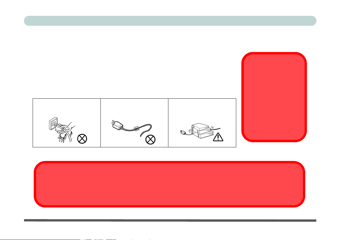
Power Safety
The computer has specific power requirements:
• When you want to unplug the power cord, be sure to disconnect it by the plug
head, not by its wire.
• Make sure the socket and any extension cord(s) you use can support the total
current load of all the connected devices.
• Before cleaning the computer, make sure it is disconnected from any external
power supplies.
Do not plug in the power
cord if you are wet.
Do not use the power cord if
it is broken.
Do not place heavy objects
on the power cord.
Before you undertake
any upgrade procedures, make sure that
you have turned off the
power, and disconnected all peripherals
and cables (including
telephone lines).
Power Safety
Warning
Mainboard Battery Note
CAUTION: Danger of explosion if battery is incorrectly replaced. Replace only with the same or equivalent type
recommended by the manufacturer. Discard a used battery according to the manufacturer’s instructions.
Preface
V
Page 8

Preface
Cleaning
Do not apply cleaner directly to the computer, use a soft clean cloth.
Do not use volatile (petroleum distillates) or abrasive cleaners on any part of the computer.
Servicing
Do not attempt to service the computer yourself. Doing so may violate your warranty and expose you and
the computer to electric shock. Refer all servicing to authorized service personnel. Unplug the computer
from the power supply. Then refer servicing to qualified service personnel under any of the following conditions:
• When the power cord is damaged or frayed.
• If the computer has been exposed to any liquids.
• If the computer does not work normally when you follow the operating instructions.
• If the computer has been dropped or damaged (do not touch the poisonous liquid if the LCD panel breaks).
• If there is an unusual odor, heat or smoke coming from your computer.
VI
Page 9

Preface
Ergonomics
We designed your LCD PC system to be functional as well as attractive. To get most out of it, here are
some suggestions on how to position and use the computer:
• The top third of the LCD (screen) should be at eye-level or slightly below.
• The LCD should be at least 18"/45cm. directly in front of you.
• If the screen resolution (e.g. 1024x768) makes you strain to read, change it: In Windows Control
Panel, double-click Display (icon) and click Settings (tab). Then adjust the “Screen area” to something more comfortable (e.g. 800x600).
• Angle the LCD so that it doesn’t reflect any light into your eyes.
• Use a chair which offers good back support (especially lower-back). The seat should allow your feet
to rest flat on the floor or on a footrest directly in front of you.
• If possible, illuminate your work area with natural daylight or use a steady-glowing (non-flickering)
light source.
• Place the keyboard and mouse so that your arms are at your sides and your forearms are roughly par-
allel to the floor. Your wrists should flex slightly downward as you work. Your neck and shoulders
should also be relaxed.
• Take a break from the computer. Get up, stretch, flex your wrists, walk about, and look at something
else for about 10 minutes every hour.
VII
Page 10

Preface
VIII
Page 11

Contents
Notice ...........................................................................I
Trademarks ..........................................................I
FCC Statement ...................................................II
Instructions for Care and Operation ....................... I-IV
Power Safety ...................................................... V
Cleaning ........................................................... VI
Servicing ........................................................... VI
Ergonomics ............................................................I-VII
Introduction
Overview ..................................................................1-1
In the Box .......................................................1-1
The Manual ..............................................................1-2
Advanced Users ..................................................1-2
Beginners and Not-So-Advanced Users .............1-2
Warning Boxes ...................................................1-2
Not Included .......................................................1-3
System Software .................................................1-3
Quick Start Guide .....................................................1-4
System Map ..............................................................1-5
Getting to Know Your Computer .......................1-5
Model Types and Design Differences ......................1-6
Front View ................................................................1-7
Preface
Front View ............................................................... 1-8
LCD Panel ...................................................... 1-9
Stereo Speakers .............................................. 1-9
Disk Activity LED Indicators ........................ 1-9
Power LED Indicator ..................................... 1-9
Reset Button (Model A - Design II only) ...... 1-9
Power Button ............................................... 1-10
Optical (CD/DVD) Device Bay ................... 1-10
Left View ............................................................... 1-11
3.5" FDD (Floppy Disk Drive) .................... 1-12
6-in-1 Flash Card Reader (Optional) ........... 1-12
Hard Disk Drive ........................................... 1-12
Optical (CD/DVD) Device Bay ................... 1-13
Right View ............................................................. 1-14
LCD Brightness Control Knob .................... 1-15
Volume Control Knob ................................. 1-15
Dual PC Card Slots ...................................... 1-15
Dual USB Ports ............................................ 1-16
AC Power-In Port ........................................ 1-16
Security Lock Slot ....................................... 1-16
Rear View .............................................................. 1-17
Carrying Handle ........................................... 1-18
Headphone-Out Jack .................................... 1-18
IX
Page 12

Preface
Line-In Jack ..................................................1-18
Microphone-In Jack ......................................1-18
RJ-45 LAN Jack ...........................................1-19
RJ-11 Phone Jack .........................................1-19
Dual USB Ports ............................................1-19
Unpowered - IEEE 1394 Port (Optional) ..... 1-20
PS/2 Type Mouse & Keyboard Ports ...........1-20
Printer/Parallel Port ......................................1-21
Serial Port .....................................................1-21
External Monitor (VGA) Port ......................1-21
Vent ..............................................................1-21
Using The Computer
Overview ..................................................................2-1
Turning On The Computer .......................................2-2
The Disk Drives .......................................................2-3
The Hard Disk Drive (HDD) ..............................2-3
The Floppy Disk Drive (FDD) ...........................2-3
Inserting/Removing Floppy Disks .................2-3
The Optical (CD/DVD) Device ................................2-4
Loading Compact Discs ......................................2-5
Handling CDs or DVDs ......................................2-5
DVD Regional Codes .........................................2-6
Changing the Regional Codes ........................2-7
The PC Card Slot ......................................................2-8
Inserting and Removing PC Cards ..................... 2-8
Keyboard .................................................................. 2-9
Mouse ..................................................................... 2-10
Adding a Printer ..................................................... 2-11
USB Printer ...................................................... 2-11
Install Instructions: ...................................... 2-11
Parallel Printer .................................................. 2-12
Install Instructions: ...................................... 2-12
Advanced Controls
Overview .................................................................. 3-1
Advanced Video Controls ........................................ 3-2
Dynamic Video Memory Technology ............... 3-2
Video Driver Controls ............................................. 3-3
Making Adjustments for the Display ................. 3-3
Display Properties .............................................. 3-4
Intel Video Driver Controls .............................. 3-5
Schemes ............................................................. 3-7
Switching/Enabling Displays ................................... 3-8
Intel(R) Dual Display Clone .............................. 3-9
Power Management Features ................................. 3-10
Enabling Power Options ........................................ 3-11
Conserving Power (Individual Components) ... 3-12
Monitor Standby .......................................... 3-12
Hard Disk Standby ....................................... 3-12
X
Page 13

Preface
Conserving Power (System) .............................3-13
Hibernate Mode vs. Shutdown .........................3-14
Standby Mode vs. Hibernate Mode ..................3-14
Resuming From Power Saving Modes .............3-14
Configuring the Power Button ..........................3-15
Wireless Network Setup .........................................3-16
6-in-1 Flash Card Reader .......................................3-17
Video Capture Card ................................................3-18
Drivers & Utilities
Overview ..................................................................4-1
What To Install .........................................................4-2
Authorized Driver Message ................................4-2
Version Conflict Message ..................................4-3
Updating/Reinstalling Individual Drivers ..........4-3
Installation Procedure ...............................................4-4
Windows 2000 Professional .....................................4-5
Chipset (Win2000) .........................................4-5
Audio (Win2000) ...........................................4-6
Video (Win2000) ............................................4-6
LAN (Win2000) .............................................4-6
Modem (Win2000) .........................................4-7
PC Card/PCMCIA (Win2000) .......................4-7
Wireless LAN (Win2000) ..............................4-8
Windows XP ............................................................4-9
Chipset (WinXP) .......................................... 4-10
Audio (WinXP) ............................................ 4-10
Video (WinXP) ............................................ 4-11
LAN (WinXP) .............................................. 4-11
Modem (WinXP) ......................................... 4-11
Wireless LAN (WinXP) ............................... 4-12
BIOS Utilities
Overview .................................................................. 5-1
Important BIOS Settings .......................................... 5-2
The Power-On Self Test (POST) ............................. 5-3
POST Screen ............................................................ 5-4
Failing the POST ................................................ 5-5
Fatal Errors .................................................... 5-5
Non-Fatal Errors ............................................ 5-5
The Setup Program .................................................. 5-6
Entering Setup .................................................... 5-6
Setup Screens ..................................................... 5-6
Main Menu ............................................................... 5-7
Advanced Menu ....................................................... 5-9
Security Menu ........................................................ 5-12
Power Menu ........................................................... 5-14
Boot Menu ............................................................. 5-15
Configuring the Network Boot Protocol .......... 5-17
Exit Menu .............................................................. 5-18
XI
Page 14

Preface
Upgrading The Computer
Overview ..................................................................6-1
When Not to Upgrade .........................................6-2
Hard Disk Drive Upgrade ........................................6-3
Hard Disk Upgrade Process ................................6-3
Setting Up a New HDD ..................................6-6
System Memory Upgrade .........................................6-7
Memory Upgrade Process ..................................6-7
Troubleshooting
Overview ..................................................................7-1
Basic Hints and Tips ................................................7-2
Backup and General Maintenance ............................7-3
Viruses ......................................................................7-4
Upgrading and Adding New Hardware/Software ....7-5
Display .....................................................................7-7
Hard Disk & Boot Password ....................................7-9
Floppy Disk Drive ..................................................7-10
Audio ......................................................................7-11
CD Device ..............................................................7-12
PC Card ..................................................................7-13
Keyboard and Mouse .............................................7-14
Printer .....................................................................7-15
Hyper-Threading Notes ..........................................7-16
Appendix A. Model A Specifications
Processor Types ...................................................... A-2
Core Logic .............................................................. A-2
Memory ................................................................... A-3
BIOS ....................................................................... A-3
LCD ........................................................................ A-3
Video ....................................................................... A-3
Audio ...................................................................... A-4
Interface .................................................................. A-4
I/O Chip .................................................................. A-4
PC Card Sockets ..................................................... A-4
Storage .................................................................... A-4
Modem .................................................................... A-5
LAN ........................................................................ A-5
Power ...................................................................... A-5
Power Management ................................................ A-5
Indicators ................................................................ A-5
Physical Dimensions ............................................... A-5
Weight ..................................................................... A-5
Fan Bearing Type .................................................... A-5
Security ................................................................... A-5
Other Features ......................................................... A-5
Optional .................................................................. A-6
XII
Page 15
Chapter 1: Introduction
Overview
What this chapter covers:
• In the Box — the parts and pieces provided
• The Manual — how to use it
• Quick Start Guide — the minimum you need to know
• System Map — navigate around your computer
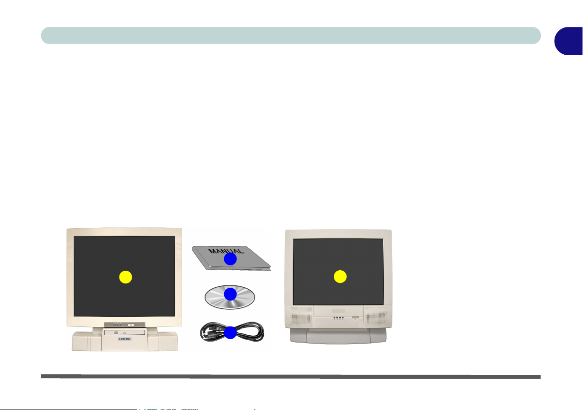
In the Box
The following should be in the box.
4
1
3
2
Introduction
1
Figure 1 - 1
Box Contents
1. The LCD PC
(there are two different model types
in this series - see
page 1 - 6)
2. Power Cord
3. Device Driver’s &
Utilities + User’s
1
Manual CD-ROM
(including this
English Language
Manual in Adobe
Acrobat “PDF”
format)
4. User’s Manual
Overview 1 - 1
Page 16

1
Introduction
The Manual
Notes
Check the light colored
boxes with the mark
above to find detailed
information about the
computer’s features.
This manual refers to the hardware and essential software required to run your
computer. Depending on how your system is configured, some or all of the
features described may already be set up.
Advanced Users
If you are an advanced user you may skip over most of this manual. However
you may find it useful to refer to
Utilities” on page 5 - 1 and
may find the notes marked with a
“Drivers & Utilities” on page 4 - 1, “BIOS
“Upgrading The Computer” on page 6 - 1. You
of interest to you.
Beginners and Not-So-Advanced Users
If you are new to computers, or do not have an advanced knowledge of them,
then you should try to look through all the documentation. Do not worry if you
do not understand everything the first time. Keep this manual nearby and refer
to it to learn as you go. You may find it useful to refer to the notes marked with
a
as indicated in the margin.
Warning Boxes
No matter what your level please pay careful attention to the warning and safety information indicated by the symbol. Also please note the safety and
handling instructions as indicated in the
Preface.
1 - 2 The Manual
Page 17

Not Included
Operating systems (e.g. Windows 2000 Professional, Windows XP etc.) have
their own manuals as do applications (e.g. word processing, spreadsheet and
database programs). If you have questions about the operating systems or programs then please consult the appropriate manuals.
System Software
Your computer may already come with system software pre-installed. Where
this is not the case, or where you are re-configuring your computer for a different system, you will find this manual refers to the following operating systems:
• Microsoft Windows 2000 Professional
• Microsoft Windows XP
Introduction
1
The Manual 1 - 3
Page 18

1
Introduction
Quick Start Guide
Peripheral Devices
Please note that peripherals (printers, digital cameras, etc.)
which attach to your
computer by either
USB or IEEE1394
ports may be connected after Windows is
up and running. All other peripherals must be
connected before you
turn on the system.
This guide assumes that you are already familiar with computers and can tell
at a glance what and where all the key components are. If you are not that comfortable with this type of device, then please refer to the following pages,
which give an overview of the system.
It is still best to review these steps, before taking any action. If there is anything you are not sure about, then please refer to the appropriate chapter before
continuing.
Unless you need to install an operating system your computer should be ready
to work right out of the box. Before you begin please follow the safety instructions in the Preface.
1. Remove all packing materials, CDs/DVDs, floppy disks, and any Pc Cards.
2. Securely attach any peripherals you want to use with the computer (e.g.
keyboard and mouse) to their ports.
3. Attach the AC power cord to the AC power-In port on the right of the
computer.
4. Push the power button to turn the computer “on”.
Then plug the AC power cord into an outlet.
1 - 4 Quick Start Guide
Page 19

System Map
Your LCD PC has a lot of built-in features. Most of these are enabled by your
operating system (OS). Further explanations of the various subsystems are
covered in the chapter or pages indicated.
Getting to Know Your Computer
The following graphics will help you to become familiar with the basic functions, and to learn the location of the various ports and components of your
computer.
Introduction
1
System Map 1 - 5
Page 20
1
Introduction
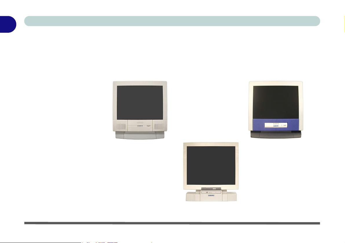
Model Types and Design Differences
There two model types (pictured below) in this LCD PC series. The model
types differ in physical appearance (Model A’s optical CD/DVD device bay
is located on the left side of the computer, Model B’s is at the front) and their
specifications. In addition, Model A has two different designs.
Figure 1 - 2
Model Types &
Design Differences
Model A (Design I) Model A (Design II)
1 - 6 Model Types and Design Differences
Model B
Page 21
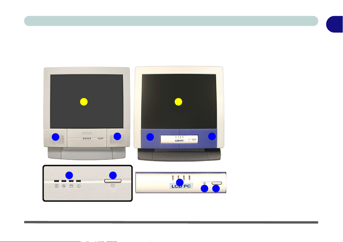
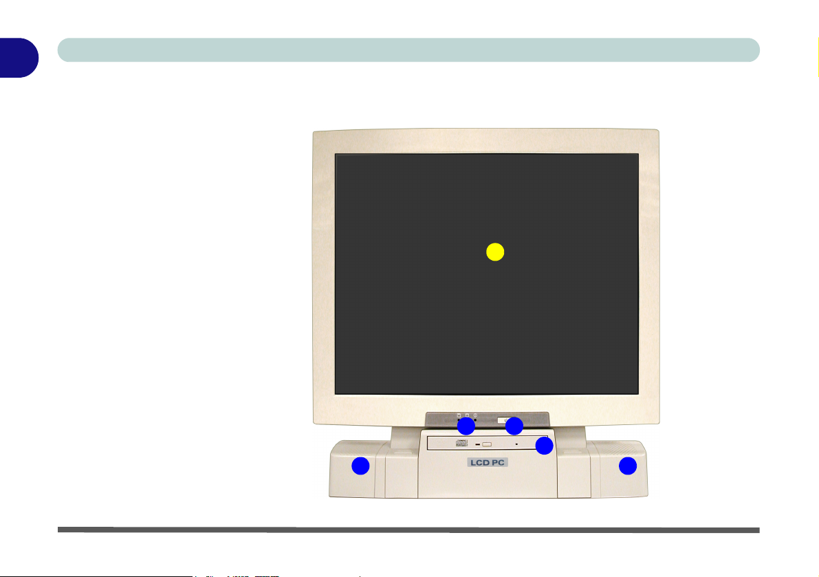
Front View
(Model A)
Design I Design II
Introduction
1
Figure 1 - 3
Front View (Model A)
1. LCD Panel
2. Speakers
3. LED Activity
1
1
indicators
4. Power Button
5. Reset Button
(Design II Only)
2
2
43
2
3
2
4
5
Front View 1 - 7
Page 22
1
Introduction
Front View
(Model B)
Figure 1 - 4
Front View (Model B)
1. LCD Panel
2. Speakers
3. LED Activity
indicators
4. Power Button
5. Optical (CD/DVD)
Device Bay
(Model B Only)
1
3 4
5
22
1 - 8 Front View
Page 23

LCD Panel
The LCD PC comes with a 15" XGA or 17" SXGA LCD (Liquid Crystal Display) TFT color screen (see LCD on pages A-3 for details).
Stereo Speakers
The built-in speakers provide rich, stereo sound.
Disk Activity LED Indicators
These display the system’s operational status including the power status, and
read/write activity on the floppy disk drive, hard disk drive and CD/DVD device (Model A has a separate indicator for CD/DVD activity , Model B
uses a single indicator for CD/DVD and HDD activity.)
Power LED Indicator
When the system is powered on and the operating system running the light
will be solid green. When the system is in the Standby power saving mode,
the light will flash orange. When the system is in Hibernate power saving
mode the light will be off (see “Configuring the Power Button” on page 3 -
15).
Introduction
1
Reset Button (Model A - Design II only)
Press this button to restart your computer. This button is equivalent to pressing
Ctrl + Alt + Del and only available on Model A - Design II (Figure 1 - 3).
Front View 1 - 9
Page 24

1
Introduction
Power Button
Press this button to turn your computer on or off (see “Turning On The Com-
Shutdown
Please note that you
should always shut
your computer down
by choosing the Shut
Down/Turn Off Computer command from
the Start menu in Windows. This will help
prevent hard disk or
system problems.
Forced Off
If the system “hangs”,
and the Ctrl + Alt + Del
key combination
doesn’t work, press the
power button for 4 sec-
onds to force the system to turn itself off.
puter” on page 2 - 2).
once configured as such, in the power management control panel of your operating system (see “Configuring the Power Button” on page 3 - 15). The
power LED will display the current power status of the computer.
Optical (CD/DVD) Device Bay
The optical device bay will contain a (12.7mm height) CD/DVD type device.
The actual device will depend on your purchase option (see “Storage” on
page A - 4 for options). For more information on using the drive please refer
to “The Optical (CD/DVD) Device” on page 2 - 4.
If you need to manually eject a CD/DVD (e.g. due to an unexpected power interruption) you may push the end of a straightened paper clip into the emergency eject
hole. Do not use a sharpened pencil or similar object that may break and become
lodged in the hole.
This button may also be used as a suspend/resume key,
CD Emergency Eject
1 - 10 Front View
Page 25
Introduction
1
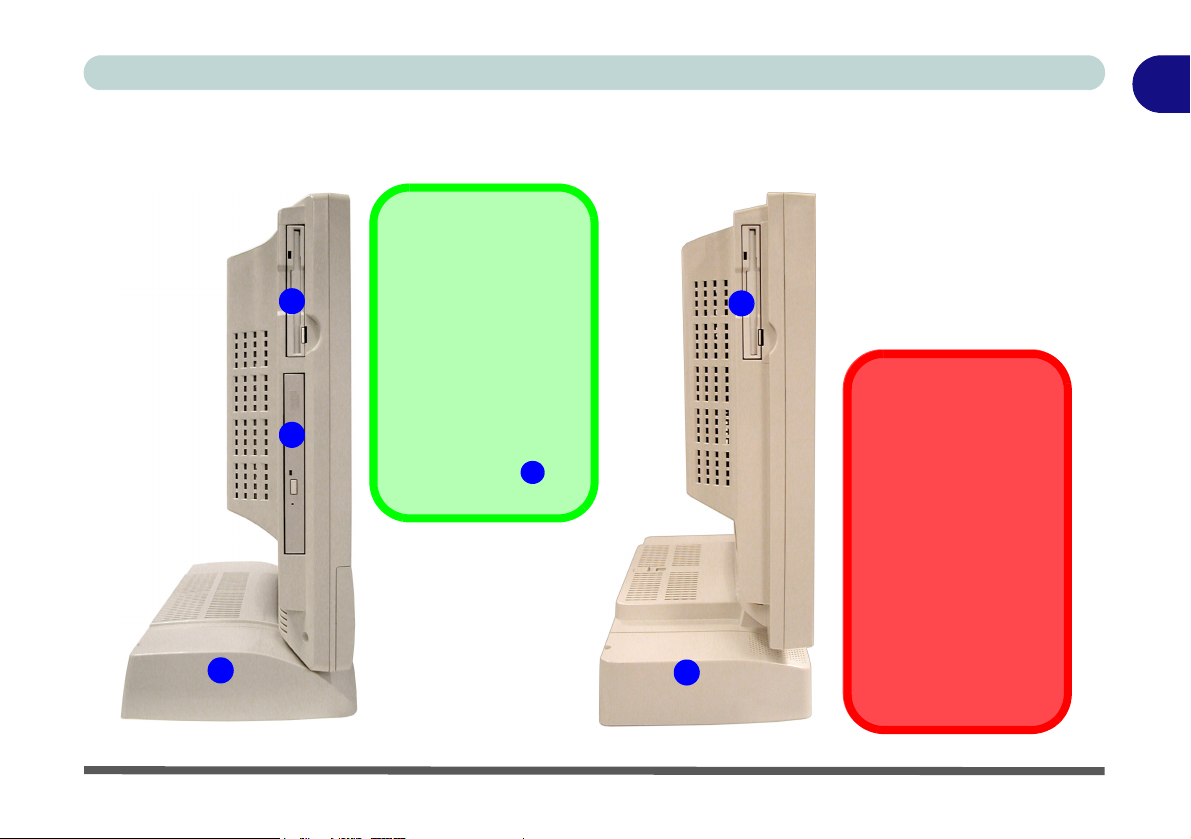
Left View
Model A
2
Figure 1 - 5
Model B
*Floppy Disk Drive &
Optional Modules
1
3
If you have either the
6-in-1 Card Reader,
or Video Capture
Card options, then
the optional module
will replace the floppy
disk drive module in
the slot at point .
1
1
2
Left View
1. Floppy Disk Drive*
2. Hard Disk Drive
(HDD) Bay
3. Optical (CD/DVD)
Device Bay
(Model A only)
Drive Warning
Don’t try to remove the
hard disk (HDD) while
the system is on. This
could cause data loss
or damage.
Unauthorized removal
or tampering with the
HDD may violate your
warranty. If you are in
doubt, consult your
service representative.
Left View 1 - 11
Page 26

1
Introduction
3.5" FDD (Floppy Disk Drive)
*Floppy Disk Drive &
Optional Modules
If you have either the
6-in-1 Card Reader,
or Video Capture
Card options, then
the optional module
will replace the floppy
disk drive module in
the slot at point .
1
This is a 3.5", 3-mode, 1.44 MB fixed floppy disk drive. For more information
please refer to “The Floppy Disk Drive (FDD)” on page 2 - 3.
6-in-1 Flash Card Reader (Optional)
The card reader allows you to use the most popular digital storage cards. The
formats which can be read include:
• MMC (MultiMedia Card)
• SD (Secure Digital)
• MS (Memory Stick)
• SM (SmartMedia Card)
• CF (Compact Flash Types I & II)
• MD (IBM Microdrive)
Media Warning
Don’t try to remove a
floppy disk while the
system is accessing it.
This may cause the
system to “crash”.
1 - 12 Left View
Video Capture Card (Optional)
The video capture card allows you to watch TV, video conference and capture
still images and video on your PC. The card has an S-Video-In port and Audio/
Video ports.
Hard Disk Drive
See “Hard Disk Drive Upgrade” on page 6 - 3 for information on upgrading/
replacing your hard disk drive (see “Storage” on page A - 4).
Page 27

Optical (CD/DVD) Device Bay
The optical device bay will contain a (12.7mm height) CD/DVD type device.
The actual device will depend on your purchase option (see “Storage” on
page A - 4 for options). For more information on using the drive please refer
to “The Optical (CD/DVD) Device” on page 2 - 4.
CD Emergency Eject
If you need to manually eject a CD/DVD (e.g. due to an unexpected power interruption) you may push the end of a straightened paper clip into the emergency eject
hole. Do not use a sharpened pencil or similar object that may break and become
lodged in the hole.
Introduction
1
Left View 1 - 13
Page 28
1
Introduction
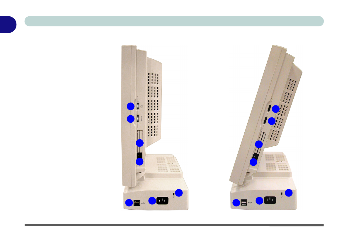
Figure 1 - 6
Right View (All
Models)
1. LCD Brightness
Control Knob
2. Volume Control
Knob
3. Dual PC Card
Slots
4. PC Card Eject
Buttons
5. Dual USB Ports
6. AC Power-In Port
7. Security Lock Slot
Right View
1
2
3
4
5
6
1
2
3
4
7
5
6
7
1 - 14 Right View
Page 29

LCD Brightness Control Knob
Adjust the brightness of the computer’s LCD panel with this control.
Volume Control Knob
Adjust the sound from your audio source (CD or DVD) with this control.
Sound Volume Adjustment
How high the sound volume can be set using the volume control knob depends on
the setting of the volume control within Windows. Click the Volume icon on the
taskbar (or go to Start > Programs > Accessories > Entertainment > Volume
Control) to check the setting.
Dual PC Card Slots
There are two Type-II PC Card slots, or the slot may be used for one Type III
PC Card (PC Cards were also previously referred to as PCMCIA). Refer to
“The PC Card Slot” on page 2 - 8 for more information on the PC Card slots.
Introduction
1
Right View 1 - 15
Page 30

1
Introduction
Dual USB Ports
These USB 2.0 ports are hardware interfaces for high-speed peripherals, such
as an external HDD, digital video camera or high-speed scanner. They also
support USB 1.1 compliant devices, such as a keyboard, mouse, joystick,
scanner, printer or telephony device. Devices may be plugged into the computer, and unplugged from the computer, without the need to turn the system
off (two more USB ports are located on the rear of the computer). Make sure
you install the Service Packs to enable USB 2.0 (see “Windows 2000 Service
Pack 4” on page 4 - 5 & “Windows XP Service Pack 1/1a” on page 4 - 9).
AC Power-In Port
To power your computer plug the supplied cable in here, then connect the other end to an AC power source.
Security Lock Slot
To prevent possible theft a Kensington-type lock can be attached to this slot.
Locks can be purchased at most computer stores.
1 - 16 Right View
Page 31

Introduction
1
Rear View
2 8
3 4
Figure 1 - 7
Rear View (All
10
13
11
12
Models)
1. Carrying Handle
2. Headphone-Out
Jack
3. Line-In Jack
4. Microphone-In
Jack
5. RJ-45 LAN Jack
6. RJ-11 Phone Jack
7. Dual USB Ports
8. Unpowered IEEE 1394 Port
(optional with
Mini PCI IEEE
1394 Module)
9. PS/2 Mouse &
Keyboard Ports
10. Printer/Parallel
Port
11. Serial Port
12. External Monitor
(VGA) Port
13. Vents
13
1
13
13
6
5
7
13
9
Rear View 1 - 17
Page 32

1
Introduction
Carrying Handle
The handle design allows for single-hand use provided that you have enough
strength to move the machine with one hand. However, considering its weight,
we strongly recommend you use both hands to move the machine (with one
hand gripping the handle and the other gripping the base of the machine) to
avoid accidentally dropping it, which might cause damage to the machine or
yourself.
Headphone-Out Jack
Headphones or speakers may be connected through this jack.
Note: Set your system’s volume to a reduced level before connecting to this
jack.
Line-In Jack
Use this to connect external audio sources to play through your computer’s
speakers.
Microphone-In Jack
Record on your computer from audio sources plugged in to this jack.
1 - 18 Rear View
Page 33

RJ-45 LAN Jack
This port supports LAN (Network) functions. Note: Broadband (e.g. ADSL)
modems usually connect to the LAN port.
RJ-11 Phone Jack
This port connects to the built-in modem. You may plug the telephone line directly into this RJ-11 telephone connection.
Note: Broadband (e.g. ADSL) modems usually connect to the LAN port.
Dual USB Ports
These USB 2.0 ports are hardware interfaces for high-speed peripherals, such
as an external HDD, digital video camera or high-speed scanner. They also
support USB 1.1 compliant devices, such as a keyboard, mouse, joystick,
scanner, printer or telephony device. Devices may be plugged into the computer, and unplugged from the computer, without the need to turn the system
off. Make sure you install the Service Packs to enable USB 2.0 (see “Windows
2000 Service Pack 4” on page 4 - 5 & “Windows XP Service Pack 1/1a” on
page 4 - 9).
Introduction
1
Rear View 1 - 19
Page 34

1
Introduction
Unpowered - IEEE 1394 Port (Optional)
If your purchase includes the optional Mini PCI IEEE 1394 module, then this
port will allow high speed connection to various peripheral devices, e.g. external disk drives and digital cameras (see note below).
IEEE 1394
The optional IEEE 1394 port only supports SELF POWERED IEEE 1394 devices.
PS/2 Type Mouse & Keyboard Ports
Connect an external PS/2 type mouse or keyboard to these ports.
Port Warning
The computer can only accept one keyboard at a time. Don’t try to install a USB and
a PS/2 keyboard at the same time. Doing so may cause resource conflicts and
make the system unstable.
1 - 20 Rear View
Page 35

Printer/Parallel Port
This port supports ECP (Extended Capabilities Port) and EPP (Enhanced Parallel Port) modes (see “Interface” on page A - 4).
Serial Port
Connect a serial type mouse to this port.
External Monitor (VGA) Port
Connect an external VGA monitor to this port to allow dual video or simultaneous display on the LCD and external VGA monitor (see “Switching/En-
abling Displays” on page 3 - 8).
Vent
This enables airflow to prevent the system from overheating.
Introduction
Overheating
To prevent your computer from overheating
make sure nothing
blocks the vent while
the computer is in use.
1
Rear View 1 - 21
Page 36

1
Introduction
1-22
Page 37

Using The Computer
Chapter 2: Using The Computer
Overview
To learn more about your computer, please read this chapter.
This chapter includes:
• Turning on the Computer
• The Disk Drives
• The Optical (CD/DVD) Device
• The PC Card Slot
• Keyboard
• Mouse
• Printer (general guidelines)
2
Overview 2 - 1
Page 38

Using The Computer
2
Power Button as
Standby or Hibernate
Button
If you are using an
ACPI-compliant OS,
such as Windows 2000
Professional or Windows XP, the power
button can be designated as Standby or
Hibernate button within the OS’s “Power Options” subsystem (see
your OS’s documenta-
“Configuring
tion, or
the Power Button” on
page 3 - 15 for de-
tails).
Turning On The Computer
Now you are ready to begin using your new computer. To turn it on simply
press the power button on the front panel.
When the computer is on, you can use the power button as a hot-key button
when it is pressed for less than 4 seconds. Use Power Options in the “Win-
dows” Control Panel to configure this feature.
Forced Off
If the system “hangs”, and the Ctrl + Alt + Del key combination doesn’t work, press
the power button for 4 seconds, or longer, to force the system to turn itself off.
2 - 2 Turning On The Computer
Page 39

Using The Computer
The Disk Drives
The Hard Disk Drive (HDD)
The hard disk drive is used to store your data in the computer and is accessible
from the bay on the left of your computer (see “Left View” on page 1 - 11).
For further details on removing and inserting the hard disk see “Hard Disk
Drive Upgrade” on page 6 - 3.
The Floppy Disk Drive (FDD)
The computer is equipped with a fixed 1.44 MB, 3.5" floppy disk drive module. (If you have either the 6-in-1 Card Reader, or Video Capture Card options, then the optional module will replace the floppy disk drive module in
the slot.) By default it is drive “A:” and can be used as a boot device if properly set in the BIOS (refer to “Boot Menu” on page 5 - 15).
Inserting/Removing Floppy Disks
When using the floppy drive, always insert your floppy diskette with the labelside facing the front of the machine. To remove the inserted diskette, press the
eject button at the bottom-left corner of the floppy drive.
2
Power Safety
Before attempting to
access any of the internal components of
your computer please
insure that the machine is turned off and
not connected to the
AC power.
Media Warning
Don’t try to remove a
floppy disk while the
system is accessing it.
This may cause the
system to “crash”.
The Disk Drives 2 - 3
Page 40

Using The Computer
2
How high the sound
volume can be set using the volume control
knob depends on the
setting of the volume
control within Win-
dows. Click the Volume icon on the
taskbar to check the
setting.
Sound Volume
Adjustment
The Optical (CD/DVD) Device
The computer’s optical device bay contains a CD/DVD type device. The actual device will depend on your purchase option (see “Storage” on page A -
4 for options). The device is usually labeled drive D: and may be used as a
boot device if properly set in the BIOS (see “Boot Menu” on page 5 - 15).
Model B
2
Figure 2 - 1
CD/DVD Device
4
1
3
1. Open Button
2. Busy Indicator
3. Emergency
Eject Hole
4. Disk Tray
Model A
2 - 4 The Optical (CD/DVD) Device
Page 41

Using The Computer
Loading Compact Discs
To insert a CD/DVD, press the open button and carefully place a CD/DVD
onto the disc tray with label-side facing forward (use just enough force to click
onto the tray’s spindle). Gently push the CD/DVD tray in until its lock
“clicks” and you are ready to start. The busy indicator will light up while data
is being accessed, or while an audio/video CD, or DVD, is playing. If power
is unexpectedly interrupted, insert an object such as a straightened paper clip
into the emergency eject hole to open the tray.
Handling CDs or DVDs
Proper handling of your CDs/DVDs will prevent them from being damaged.
Please follow the advice below to make sure that the data stored on your CDROM/ DVD-ROM discs can be accessed.
Remember to:
• Hold the CD or DVD by the edges; do not touch the surface of the disc.
• Use a clean, soft, dry cloth to remove dust or fingerprints.
• Do not write on the surface with a pen.
• Do not attach paper or other materials to the surface of the disc.
• Do not store or place the CD or DVD in high-temperature areas.
• Do not use benzene, thinner, or other cleaners to clean the CD or DVD.
• Do not bend the CD or DVD.
• Do not drop or subject the CD or DVD to shock.
CD/DVD Emergency
Eject
If you need to manually
eject a CD/DVD (e.g.
due to an unexpected
power interruption) you
may push the end of a
straightened paper clip
into the emergency
eject hole.
Media Warning
When manually ejecting a CD/DVD disc, DO
NOT use a sharpened
pencil or similar object
which may break, and
become lodged in the
hole.
2
The Optical (CD/DVD) Device 2 - 5
Page 42

Using The Computer
2
Figure 2 - 2
DVD Regional
Codes
DVD region detection is device dependent, not OS-dependent. You can select
your module’s region code 5 times. The fifth selection is permanent. This cannot be altered even if you change your operating system or you use the module
in another computer.
DVD Regional Codes
2 - 6 The Optical (CD/DVD) Device
Page 43

Using The Computer
Changing the Regional Codes
Go to Control Panel in WindowsXP/2000, double-click System, click Device
Manager, and then click the + next to DVD/CD-ROM drives. Double-click
on the DVD-ROM device to bring up the Properties menu, and select the
DVD Region (tab) to bring up the control panel as seen in “DVD Regional
Codes” on page 2 - 6.
DVD Regional Coding
Region Geographical Location
1 USA, Canada
2 Western Europe, Japan, South Africa, Middle East & Egypt
3
4 South & Central America, Mexico, Australia, New Zealand
5 Russia, Eastern Europe, India & Most of Africa
6 China
South-East Asia, Taiwan, South Korea, The Philippines, Indonesia, Hong
Kong
2
Table 2 - 1
DVD Regional
Coding
The Optical (CD/DVD) Device 2 - 7
Page 44

Using The Computer
2
The PC Card Slot
The computer is equipped with two PC Card slots for type II PC Cards. You
can also insert one type III PC Card. Type III PC Cards only fit into the rear
socket.
Inserting and Removing PC Cards
• Align the PC Card with the slot and push the card in until it locks into
place.
• To remove a PC Card, simply press the eject button next to the slot.
2 - 8 The PC Card Slot
Page 45

Using The Computer
Keyboard
You can connect a keyboard through either of the following types of ports:
• PS/2 keyboard port (at the rear of the computer)
• USB ports (two at the rear and two on the right of the computer)
Note: Only connect one keyboard to the computer at any time to avoid resource conflicts and system instability.
2
1
2
2
Special Characters
Some software applications allow the
number-keys to be
used with Alt to produce special characters. These special
characters can only be
produced by using the
numeric keypad (usually on the right of the
keyboard). The regular
number keys will not
work. Make sure that
NumLock is on.
Figure 2 - 3
Keyboard Ports
1. PS/2 Keyboard
Port
2. USB Ports
Keyboard 2 - 9
Page 46

Using The Computer
2
Mouse Driver
If you are using an external mouse your operating system may be
able to auto-configure
your mouse during its
installation or only enable its basic functions.
Be sure to check the
device’s user documentation for details.
Mouse
You can also add a mouse to your computer through any of the following
ports:
• The PS/2 port at the rear of the computer
• Four USB ports, two on the right, and two at the rear of the computer
• The serial port at the rear of the computer
Note: Only connect one mouse to the computer at any time to avoid resource
conflicts and system instability.
Figure 2 - 4
Mouse Ports
1. PS/2 Mouse
Port
2. USB Ports
3. Serial Mouse
Port
1
32
2
2 - 10 Mouse
Page 47

Using The Computer
Adding a Printer
The most commonly used peripheral is a printer. The following conventions
will help you to add a printer, however it is always best to refer to the printer
manual for specific instructions and configuration options.
USB Printer
Most new printers have a USB interface connection. There are four USB ports
on your computer and you may use any one of the ports to connect the printer.
Install Instructions:
1. Set up the printer according to its instructions (unpacking, paper tray, toner/
ink cartridge etc.).
2. Turn ON the printer.
3. Turn ON the computer.
4. Connect the printer’s USB cable to one of the USB ports on the computer.
5. Windows will identify the printer and either load one of its own drivers or ask
you to supply one. Follow the on-screen instructions.
2
Adding a Printer 2 - 11
Page 48

Using The Computer
2
This is still the most common type of printer.
Install Instructions:
1. Set up the printer according to its instructions (unpacking, paper tray, toner/
ink cartridge etc.).
2. Attach the parallel cable to the printer.
3. Connect the printer’s parallel cable to the printer/parallel port at the rear of
the computer.
4. Turn ON the printer.
5. Turn ON the computer.
6. Windows will identify the printer and either load one of its own drivers or ask
you to supply one. Follow the on-screen instructions.
Parallel Printer
2 - 12 Adding a Printer
Page 49

Chapter 3: Advanced Controls
Advanced Controls
Overview
This chapter covers:
• Advanced Video Controls
• Power Management Features
• Wireless Network Setup
• 6-in-1 Flash Card Reader
3
Drivers
You are unable to use
most advanced controls until the necessary drivers and
utilities are properly installed. If your system
hasn’t been properly
configured (your service representative
may have already
done that for you), refer to “What To In-
stall” on page 4 - 2,
for installation instructions.
Overview 3 - 1
Page 50

Advanced Controls
Advanced Video Controls
3
DVMT Notes
DVMT is not user configurable (see “Share
Memory (Main
Menu)” on page 5 - 8
for user configurable
options.
DVMT is not local video memory.
DVMT will not function
in MS-DOS. DOS uses
the legacy memory indicated.
This section is about making adjustments for the LCD, and switching display
devices.
Make sure you have installed the video driver or all the options listed on the
following pages will not be available to you (see “Installation Procedure” on
page 4 - 4).
Dynamic Video Memory Technology
Intel® DVMT automatically and dynamically allocates as much (up to 64MB)
system memory (RAM) as needed to the video system. DVMT returns whatever memory is no longer needed to the operating system which ensures optimal graphics and system memory performance.
System Memory Maximum Memory Allocated for Graphics by DVMT
Table 3 - 1
DVMT Memory
Requirements
128 MB - 255MB 32MB
256MB - Maximum Memory 64MB
3 - 2 Advanced Video Controls
0MB - 127MB Not Supported
Page 51

Video Driver Controls
The video interface lets you change the screen resolution and color output to
whatever is most comfortable/efficient for you. This is a matter of hardware,
video memory and the driver for your operating system. The driver interface
shows the available options (see “LCD” on page A - 3 for the LCD options).
You can switch display devices from the Display Properties control panel in
Windows as long as the video driver is installed (see “What To Install” on
page 4 - 2).
Making Adjustments for the Display
The higher the resolution you set the LCD for, the more information the LCD
can display on screen. To change the LCD’s resolution and color depth go to
the Display Properties control panel:
1. Click Start, point to Settings (or just click Control Panel) and click Control
Panel (if you are in Category View choose Appearance and Themes).
2. Double-click Display (icon).
3. In the Display Properties dialog box, click Settings (tab).
4. In Screen area/Screen resolution, move the slider to the preferred setting
for resolution (see in Figure 3 - 1 on page 3 - 4).
5. In Colors/Color quality, click the arrow and scroll to the preferred setting
for color depth (see in Figure 3 - 1 on page 3 - 4).
1
2
Advanced Controls
Screen Resolution/
Area Note
You may set the resolution to a higher setting than the panel
supports, however this
will require you to pan
(scroll) around the
screen as the display
area will be larger than
what you can see on
the LCD.
3
Video Driver Controls 3 - 3
Page 52

Advanced Controls
Display Properties
Figure 3 - 1
3
Display Properties
Intel(R) Extreme
Graphics Controller
Properties
You can click Graphics Properties (but-
ton) in the Intel(R)
Extreme Graphics
tab (in the Advanced
options) to access the
screens in Figure 3 - 3
on page 3 - 6.
When the Display Properties control panel is open, click the Advanced
(button) to bring up the options tabs. Clicking through these tabs allows you
to make any video adjustments you require.
3 - 4 Video Driver Controls
1
2
3
3
Page 53

Intel Video Driver Controls
After installing the video driver there will be an additional control panel entitled Intel(R) Extreme Graphics. To get to the control panel to make changes to the Graphics Properties, do the following:
1. Click Start, point to Settings (or just click Control Panel) and click Control
Panel.
2. Double-click Intel(R) Extreme Graphics (icon) to bring up the Intel(R)
82865G Graphics Controller Properties.
Make changes to the Devices, Color, Schemes, Hot Keys by clicking the appropriate tab and adjusting the setting, then clicking OK. The Information and
Open GL tabs display information about the graphics properties of your computer, and the Support item in the Information tab has weblinks to the latest
information (drivers, troubleshooting issues etc.) on the Intel Website. Some
screen examples are shown on the following page.
Advanced Controls
Taskbar
You may also access
the control panel from
the taskbar at the bottom right of the screen.
Click on the icon to
bring up the menu and
scroll to Graphics Op-
tions > Graphics
Properties.
Figure 3 - 2
Intel Extreme
Graphics Control
Panel
3
Video Driver Controls 3 - 5
Page 54

Advanced Controls
Figure 3 - 3
3
Intel Graphics
Controller Properties
3 - 6 Video Driver Controls
Page 55

Schemes
Use Schemes to configure quick settings for applications which require specific resolution and color settings in order to run properly e.g. games, multimedia programs. To set the schemes:
1. Go to the Intel(R) Extreme Graphics control panel (see “Intel Video
Driver Controls” on page 3 - 5).
2. Click on Schemes (tab).
3. Select New to setup the scheme, and type a name in the dialog box that
pops up, then click OK.
4. Click on the scheme name you had typed in the Schemes box, and choose
the option you wish to use from the in the Video Modes box.
5. Browse to the executable file for the application you want to set a scheme
for (see sidebar).
6. You can click in the "Reset On Exit" box to return to your original settings
when you exit the program, then click Save to save the settings.
7. When you want to run the program, select it from the Schemes box and
click "Invoke" to run the highlighted program in the chosen video setting
(alternatively you can select it from Display Modes by clicking on the icon
option in the taskbar at the bottom right of the screen).
Advanced Controls
Application.exe
You will need to locate
the actual application
executable (.exe) file,
not just the shortcut.
To find the application
right-click its shortcut
on the desktop click
Properties. Click the
Shortcut (tab) and see
where the executable
file is located by clicking the Find Target
(button). Note the location and you will then
be able to browse to
this file.
3
Video Driver Controls 3 - 7
Page 56

Advanced Controls
Switching/Enabling Displays
3
Vertical Refresh Rate
The vertical refresh rate
of your external VGA
monitor is important. If it
is too low and/or you’re
using fluorescent lighting, the screen will appear to flicker. To
reduce flickering on a
monitor, use faster refresh rates (we recommend a refresh rate of
72Hz or more). But first
check your monitor’s
documentation to make
sure it can support the
rates listed by the video
driver. The default refresh rate for VGA monitors (without drivers) is
60Hz.
With the video driver installed (see “What To Install” on page 4 - 2), you
can use its built-in controls to switch between the displays as follows:
1. Plug the VGA monitor into the appropriate port at the rear of the computer.
2. Go to the Intel(R) 82865G Graphics Controller Properties control panel
(see “Intel Video Driver Controls” on page 3 - 5) and select Devices
(tab).
3. Choose the display option from the list on the left.
4. If you are using and click Apply > OK to confirm the settings change (you
may need to give the monitor a few seconds to display the picture).
Figure 3 - 4
Switching Displays
3 - 8 Switching/Enabling Displays
Page 57

Intel(R) Dual Display Clone
In addition to using a single display device (LCD or VGA monitor), you can
use Intel(R) Dual Display Clone Mode to drive two displays with the same
content. To Enable Dual Display Clone Mode:
1. Plug the VGA monitor into the appropriate port.
2. Go to the Intel(R) 82865G Graphics Controller Properties control panel
(see “Intel Video Driver Controls” on page 3 - 5) and select Devices
(tab).
3. Click the Intel(R) Dual Display Clone icon in the devices Devices (tab).
(Note: this option is only available when you have attached the monitor.)
4. Choose one device to be the Primary/Secondary display.
5. Adjust the settings by clicking the Device Settings (button) if necessary.
6. Click Apply > OK and close the control panels.
Advanced Controls
3
Figure 3 - 5
Device Settings
(Dual Display Clone
Mode)
Switching/Enabling Displays 3 - 9
Page 58

Advanced Controls
Power Management Features
3
Operating System
Power Management
Power management
functions will vary
slightly depending on
your operating system.
For more information it
is best to refer to the
user’s manual of your
operating system.
(Note: All pictures used
on the following pages
are from the Windows
XP OS).
The system supports various ACPI-compliant (Advanced Configuration and
Power Interface) power management features. You can use them to reduce the
power consumption.
Windows 2000 Professional and Windows XP are ACPI-compliant operating
systems.
In this section, we will give you an overview of the power management options the system can offer.
Using some form of power management greatly increases the life span of
the LCD.
3 - 10 Power Management Features
Page 59

Enabling Power Options
The Power Options are enabled through the Control Panel in your Windows
system. With other operating systems you may also have some form of power
management available, so check your documentation. Click Start (menu),
point to Settings and click Control Panel.
Advanced Controls
3
Figure 3 - 6
Power Options
You may conserve power through individual components or throughout the
whole system.
Enabling Power Options 3 - 11
Page 60

Advanced Controls
Conserving Power (Individual Components)
3
Monitor Standby
To conserve power, you can set the monitor to turn off after a specified time.
Hard Disk Standby
The computer's hard disk motor will be turned off if the hard disk drive has
not been accessed for a specified period of time. If the system reads or writes
data, the hard disk motor will be turned back on.
Figure 3 - 7
Power Schemes
3 - 12 Enabling Power Options
Page 61

Conserving Power (System)
With this function you can stop the computer’s operation and restart where
you left off. This system features Standby and Hibernate suspend mode levels (Hibernate mode will need to be enabled by clicking the option in the Hi-
bernate tab in the control panel).
Advanced Controls
3
Figure 3 - 8
Enable Hibernate
Enabling Power Options 3 - 13
Page 62

Advanced Controls
Hibernate Mode vs. Shutdown
“Hibernate Mode” and “Shutdown” are the same in that the system is off and
3
you need to press the power button to turn it on. Their main difference is:
When you come back from hibernation, you can return to where you last left
off (what was on your desktop) without reopening the application(s) and
file(s) you last used.
You can use either method depending on your needs.
Standby Mode vs. Hibernate Mode
If you want to stay away from your work for just a while, you can put the system on standby instead of in hibernation. It takes a longer time to wake up the
system from Hibernate mode than from Standby mode.
Resuming From Power Saving Modes
The system can resume from power saving through individual components
such as the hard disk or monitor by either pressing a key on the keyboard, or
by moving the mouse. While in these modes the power LED will remain
green.
To get the system to resume from Standby or Hibernate mode you will need
to press the power button.
3 - 14 Enabling Power Options
Page 63

Configuring the Power Button
The power button may be set to send the computer in to either Standby or Hibernate mode (Figure 3 - 9). In Standby mode the power LED will flash or-
ange, in Hibernate mode the LED will be off. If you are in a power saving
mode set to save power through individual components (e.g. hard disk, monitor), the LED will remain green.
Advanced Controls
3
Figure 3 - 9
Advanced Power
Options
Enabling Power Options 3 - 15
Page 64

Advanced Controls
Figure 3 - 10
WLAN Config
3
Utility & Network
Connection
Properties
Wireless Network Setup
If your configuration includes the optional Wireless LAN module you will
need to install the driver for it (see “What To Install” on page 4 - 2). You can
then configure the options from the Wireless Configuration Utility by clicking
the icon in the Windows control panel, or in the taskbar.
3 - 16 Wireless Network Setup
Page 65

6-in-1 Flash Card Reader
The optional card reader allows you to use the most popular digital storage
cards. If your purchase includes the card reader it will replace the floppy disk
drive assembly on the left side of the computer (see “Left View” on page 1 -
11). The formats which can be read include:
• MMC (MultiMedia Card)
• SD (Secure Digital)
• MS (Memory Stick)
• SM (SmartMedia Card)
• CF (Compact Flash Types I & II)
• MD (IBM Microdrive)
Advanced Controls
3
6-in-1 Flash Card Reader 3 - 17
Page 66

Advanced Controls
Video Capture Card
The optional video capture card allows you to watch TV, video conference
3
and capture still images and video on your PC. If your purchase includes the
video capture card it will replace the floppy disk drive assembly on the left
side of the computer (see “Left View” on page 1 - 11). The card has an S-Video-In port and Audio/Video ports.
The video capture card is ideal for capturing video from analog devices to
your PC. You can also perform basic editing functions such as adding titles
and audio overlay on your video clips.
The package supplied includes an installation guide and software.
3 - 18 Video Capture Card
Page 67

Chapter 4: Drivers & Utilities
Overview
Drivers & Utilities
This chapter deals with installing the drivers and
utilities essential to the operation or improvement
of some of the LCD PC’s subsystems. The system
takes advantage of some newer hardware components for which the latest versions of most available
operating systems haven’t built in drivers and utilities. Thus, some of the system components won’t
be auto-configured with an appropriate driver or
utility during operating system installation. Instead,
you need to manually install some system-required
drivers and utilities. In this chapter, we group driver
and utility installation instructions by operating
system. The following operating systems are covered.
• Windows 2000 Professional
• Windows XP
Assumption
We assume that you will install all drivers and utilities
from the built-in CD device and it is assigned to “Drive
D:”. In addition, all file extensions can be seen [see
“Navigate (Browse...) to D:” on page 4 - 2].
Overview 4 - 1
4
Page 68

Drivers & Utilities
What To Install
The Device Drivers & Utilities + User’s Manual
CD-ROM contains the drivers and utilities neces-
sary for the proper operation of the LCD PC.
4
Table 4 - 1 on page 4 - 4 lists what you need to in-
stall manually according to your choice of the operating system. It is very important that the drivers
You will notice that many of the instructions for driver
installation require you to “Navigate (Browse...) to
D:”.
Navigate (Browse...) to D:
are installed in the order indicated in the table.
In this case “D:” is the drive specified for your CD de-
Authorized Driver Message
If you receive a message telling you that the driver
you are installing is not authorized (Digital Signa-
ture Not Found), just click Yes or Continue Anyway to ignore the message and continue the
installation procedure.
You will receive this message in cases where the
driver has been released after the version of Win-
dows you are currently using. All the drivers provided will have already received certification for
vice. Not all computers are setup the same way, and
some computers have the CD listed under a different
drive letter - e.g. if you have two hard drives (or hard
disk partitions) one may be designated as “Drive C:”
and the other as “Drive D:”. In this case the CD device
may be designated as “Drive E:” - Please make sure
you are actually navigating to the correct drive letter
for the CD device.
When you click the Browse (button) after clicking
Run in the Start menu you will see the “Look in:” dialog box at the top of the Browse window. Click the
scroll button to navigate to My Computer to display
the devices and drive letters.
Windows.
4 - 2 What To Install
Page 69

Drivers & Utilities
Version Conflict Message
During driver installation if you encounter any “file
version conflict” message, click “Yes” to choose to
keep the existing (newer) version.
Updating/Reinstalling Individual Drivers
If you wish to update/reinstall individual drivers it
may be necessary to uninstall the original driver.
To do this go to the Control Panel in the Windows
OS and double-click the Add/Remove Programs
item. If you see the individual driver listed (if not
see below), uninstall it, following the on screen
prompts (it may be necessary to restart the computer). Go to the appropriate section of the manual to
complete the update/reinstall procedure for the
driver in question.
If the driver is not listed in the Add/Remove Pro-
grams item:
1. Click Start (menu), point to Settings and click
Control Panel. Double-click System (icon)
and then click Hardware (tab) > Device Man-
ager (button).
2. Double-click the device you wish to update/
reinstall the driver for (you may need to click
“+”).
3. Look for the Update Driver button (check the
Driver tab) and follow the on screen prompts.
4
What To Install 4 - 3
Page 70

Drivers & Utilities
Installation Procedure
Feature Win 2000 Win XP
Service Packs if
4
Required
Chipset page 4 - 5 page 4 - 10
Audio page 4 - 6 page 4 - 10
Video page 4 - 6 page 4 - 11
LAN page 4 - 6 page 4 - 11
Modem page 4 - 7 page 4 - 11
PC Card/PCMCIA page 4 - 7 Not Required
Wireless LAN page 4 - 8 page 4 - 12
4 - 4 Installation Procedure
page 4 - 5 page 4 - 9
Table 4 - 1 - Installation Procedure
Page 71

Windows 2000 Professional
Drivers & Utilities
This section covers driver and utility installation instructions for Windows 2000 Professional.
Windows 2000 Service Pack 4
Make sure that you install Windows 2000 Service
Pack 4 (or a version which includes Service Pack
4) before installing all the drivers. Service Pack 4
includes support for USB 2.0.
Chipset (Win2000)
Chipset Driver Installation and Serial Mouse
Make sure that you do not have a serial mouse
plugged in to the serial port at the rear of the computer when installing the Chipset driver.
1. Click Start (menu) > Run...
2. Navigate (Browse..) to
D:\Drivers\Chipset\Setup.exe and click OK.
3. Click Next > Yes > Next.
4. Click Finish to restart the computer.
Windows 2000 Internet Explorer 5.5
Make sure that you install Internet Explorer 5.5 (or
higher version) if you are using the Windows 2000
OS.
4
Windows 2000 Professional 4 - 5
Page 72

Drivers & Utilities
Audio (Win2000)
1. Click Start (menu) > Run...
2. Navigate (Browse..) to
D:\Drivers\Audio\Setup.exe and click OK >
Next.
4
3. Click Finish to restart the computer.
4. You can click the AC97 Audio Configuration
icon in the taskbar for configuration options.
5. You can also go to the Sounds and
Multimedia control panel (Start Menu and
point to Settings and click Control Panel then
double-click the Sounds and Multimedia
icon) for further audio configuration options.
Video (Win2000)
1. Click Start (menu) > Run...
2. Navigate (Browse..) to
D:\Drivers\Video\Graphics\Setup.exe and
click OK.
3. Click Next > Yes.
4. Click Finish to restart the computer.
5. See “Advanced Video Controls” on page 3 - 2
for details on adjusting the video settings.
LAN (Win2000)
1. Click Start (menu) > Run...
2. Navigate (Browse..) to
D:\Drivers\LAN\Setup.exe and click OK.
3. To continue click Next.
4. Click Finish and restart the computer.
5. The network settings can now be configured.
4 - 6 Windows 2000 Professional
Page 73

Drivers & Utilities
Modem (Win2000)
1. Click Start (menu) > Run...
2. Navigate (Browse..) to
D:\Drivers\Modem\WIN2K\Setup.exe and
click OK.
3. Click
4. Click .
5. The modem is ready for dial-up configuration.
(button).
Modem Country Selection
Be sure to check if the modem country selection is appropriate for you (Control Panel > Phone and Mo-
dem Options).
PC Card/PCMCIA (Win2000)
1. Click Start (menu), point to Settings and click
Control Panel. Double-click System (icon)
and then click Hardware (tab).
2. Click Device Manager (button), then click “+”
next to PCMCIA (if its sub-items are not
shown).
3. Double-click either Generic CardBus
Controller item, and click the Driver (tab).
4. Click Update Driver (button).
5. When the Upgrade Device Driver Wizard
appears, click Next.
6. Select “Search for a suitable driver for my
device (recommended)” and click Next.
7. When Locate Driver Files appears, select
ONLY “Specify a location” and click Next.
8. Navigate (Browse...) to D:\Drivers\Pcmcia.
9. Click Open > OK > Next.
10.Click Finish and then repeat the procedure to
update the other Generic CardBus Controller
item.
4
Windows 2000 Professional 4 - 7
Page 74

Drivers & Utilities
Wireless LAN (Win2000)
1. Click Start (menu) > Run...
2. Navigate (Browse..) to
D:\Drivers\WLAN\Setup.exe and click OK.
3. Click Yes (you can ignore the hardware present
4
Question).
4. Click Next.
5. Click Finish and restart the computer.
6. The settings can now be configured.
4 - 8 Windows 2000 Professional
Page 75

Drivers & Utilities
Windows XP
This section covers driver and utility installation instructions for Windows XP.
Windows XP Service Pack 1/1a
Make sure you install Windows XP Service Pack 1/1a or above (or a Windows XP version which includes Service Pack 1/1a or above) before installing any drivers. Service Pack 1/1a and above includes support for USB
2.0.
If you have upgraded the system by installing Service Pack 1/1a (i.e. your Windows XP version does not include
Service Pack 1/1a) then follow these instructions:
1.If you can see the My Computer icon on your desktop (if you cannot see the My Computer icon go to step 2)
click on it once to select it, then right-click it to make the sub-menu appear and scroll down to Properties and
click on it (go to step 3).
2.If you cannot see the My Computer icon click Start (menu), then point to (but don’t click just highlight it) My
Computer. Right-click it to make the sub-menu appear and scroll down to Properties and click on it (go to step
3).
3.Click the Hardware (tab), then click Device Manager (button).
4.Click “+” next to Other Devices (if its sub-items are not shown).
5.Right-click Universal Serial Bus (USB) Controller and select Uninstall > OK.
6.Restart the computer and it will find the USB 2.0 controller.
4
Windows XP 4 - 9
Page 76

Drivers & Utilities
Chipset (WinXP)
Chipset Driver Installation and Serial Mouse
4
Make sure that you do not have a serial mouse
plugged in to the serial port at the rear of the computer when installing the Chipset driver.
1. Click Start (menu) > Run...
2. Navigate (Browse..) to
D:\Drivers\Chipset\Setup.exe and click OK.
3. Click Next > Yes > Next.
4. Click Finish to restart the computer.
Audio (WinXP)
1. Click Start (menu) > Run...
2. Navigate (Browse..) to
D:\Drivers\Audio\Setup.exe and click OK >
Next.
3. Click Finish to restart the computer.
4. You can click the AC97 Audio Configuration
icon in the taskbar for configuration options.
5. You can also go to the Sounds and Audio
Devices control panel (Start Menu and point to
Settings and click Control Panel then double-
click the Sounds and Audio Devices icon) for
further configuration options.
Note: If you are in the Category View, choose
Sounds, Speech and Audio Devices >
Sounds and Audio Devices.
4 - 10 Windows XP
Page 77

Drivers & Utilities
Video (WinXP)
1. Click Start (menu) > Run...
2. Navigate (Browse..) to
D:\Drivers\Video\Graphics\Setup.exe and
click OK.
3. Click Next > Yes.
4. Click Finish to restart the computer.
LAN (WinXP)
1. Click Start (menu) > Run...
2. Navigate (Browse..) to
D:\Drivers\LAN\Setup.exe and click OK.
3. To continue click Next.
4. Click Finish and restart the computer.
5. The network settings can now be configured.
Modem (WinXP)
1. Click Start (menu) > Run...
2. Navigate (Browse..) to
D:\Drivers\Modem\WINXP\Setup.exe and
click OK.
3. Click
4. Click .
5. The modem is ready for dial-up configuration.
(button).
Modem Country Selection
Be sure to check if the modem country selection is appropriate for you (Control Panel > Phone and Mo-
dem Options).
4
Windows XP 4 - 11
Page 78

Drivers & Utilities
Wireless LAN (WinXP)
1. Click Start (menu) > Run...
2. Navigate (Browse..) to
D:\Drivers\WLAN\Setup.exe and click OK.
3. Click Yes (you can ignore the hardware present
4
Question).
4. Click Next.
5. Click Finish and restart the computer.
6. The settings can now be configured.
4 - 12 Windows XP
Page 79

Chapter 5: BIOS Utilities
BIOS Utilities
Overview
This chapter gives a brief introduction to the computer’s built-in software:
Diagnostics: the POST (Power-On Self Test)
Configuration:the Setup utility
If your computer has never been set up, or you are making important changes
to the system (e.g. hard disk setup), then you should review this chapter first
and note the original settings found in Setup. Even if you are a beginner, keep
a record of the settings you find and any changes you make. This information
could be useful if your system ever needs servicing.
There is one general rule: Don’t make any changes unless you are sure of
what you are doing. Many of the settings are required by the system, and
changing them could cause it to become unstable or worse. If you have any
doubts, consult your service representative.
BIOS Settings
Warning
Incorrect settings can
cause your system to
malfunction. To correct
mistakes, return to Setup and restore the Setup Defaults with <F9>.
5
Overview 5 - 1
Page 80

BIOS Utilities
Important BIOS Settings
Generally speaking you should not have to adjust any of the BIOS settings as
they will already be set for your computer. However the following is a quick
reference to the most important settings you may need to change at some
point.
5
Table 5 - 1
Important BIOS
Settings
Option Page # Purpose
Specifies the order of the devices on which the com-
Boot Menu 5 - 15
Share
Memory
(Main
Menu)
5 - 8
puter searches for an Operating System as it starts
up.
Allows you to set the amount of memory (RAM) to
be allocated as video memory by the system.
5 - 2 Important BIOS Settings
Page 81

The Power-On Self Test (POST)
Each time you turn on the computer, the system takes a few seconds to conduct a POST (see sidebar), including a quick test of the RAM.
BIOS Utilities
Logo Screen
As the POST proceeds, the computer will tell you if there is anything wrong.
If there is a problem which prevents the system from booting, it will display a
system summary and prompt you to run Setup.
If there are no problems, the Setup prompt will disappear and the system will
load the operating system. Once that starts, you can’t get into Setup without
rebooting.
The Power-On Self Test (POST) 5 - 3
Note that you may not
see the POST screen as
illustrated in “POST
(Sample) Screen” on
page 5 - 4, if the OSB
Logo is displayed at
startup. You can disable
the logo display from the
Advanced Menu option
(see “OSB Logo Con-
trol (Advanced Menu)”
on page 5 - 10).
5
Page 82

BIOS Utilities
Phoenix cME FirstBIOS Desktop Pro
Copyright 1985-2002 Phoenix Technologies Ltd.
All Rights Reserved
L297P/U-3.01
CPU = Intel(R) Pentiumn(R) CPU 3.06GHz
503M System RAM Passed
512K Cache SRAM Passed
System BIOS shadowed
Video BIOS shadowed
Fixed Disk 0: ST340824A
ATAPI CD-ROM: CD-224E
Mouse initialized
Press <F2> to enter SETUP
POST Screen
Post Screen
1. BIOS information
2. CPU type
3. Memory status
5
4. HDD identification
notice
5. Enter Setup prompt
appears only during
POST
Figure 5 - 1
POST (Sample)
Screen
1
2
3
4
5
5-4POST Screen
Page 83

Failing the POST
Errors can be detected during the POST. There are two categories, “fatal” and
“non-fatal”.
Fatal Errors
These stop the boot process and usually indicate there is something seriously
wrong with your system. Take the computer to your service representative or
authorized service center as soon as possible.
Non-Fatal Errors
This kind of error still allows you to boot. You will get a message identifying
the problem (make a note of this message!) followed by the prompt:
• Press <F1> to resume,
• <F2> to enter Setup
Press F1 to see if the boot process can continue. It may work, without the correct configuration.
Press F2 to run the Setup program and try to correct the problem. If you still
get an error message after you change the setting, or if the “cure” seems even
worse, call for help.
BIOS Utilities
5
POST Screen 5 - 5
Page 84

BIOS Utilities
The Setup Program
Setup Screens
Instructions on how to
navigate each screen
are in the box at the
bottom of the screen.
5
For help, press F1 to
call up a General Help
screen, and use the arrow keys to scroll up or
down the page.
The “Item Specific
Help” on the right side
of each screen explains the highlighted
item and its options. If
you see an arrow (
next to an item, press
Enter to go to a submenu on that subject.
The sub-menu screen
which appears has a
similar layout but the
Enter key may execute
a command.
X)
The Setup program tells the system how to configure itself and manage basic
features and subsystems (e.g. port configuration).
Entering Setup
To enter Setup, turn on the computer and press F2 during the POST. The
prompt (“Press F2 to Enter Setup”) seen in Figure 5 - 1 is usually present
for a few seconds after you turn on the system. If you get a “Keyboard Error”
(usually because you pressed F2 too quickly) just press F2 again.
If the computer is already on, reboot using the Ctrl + Alt + Delete combina-
tion and then hold down F2 when prompted. Setup’s main menu will appear.
Setup Screens
The following pages contain additional advice on portions of the Setup.
Along the top of the screen is a menu bar with menu headings. When you select a heading, a new screen appears. Scroll through the features listed on each
screen to make changes to Setup.
5 - 6 The Setup Program
Page 85

Main Menu
BIOS Utilities
PhoenixBIOS Setup Utility
Main
Main Advanced Security Power Boot Exit
Item Specific Help
System Time [22:01:05]
System Date [07/25/2003]
Legacy Diskette A: [1.44/1.25 MB 3
Primary Master 40021MB
Secondary Master CD-ROM
System Memory: 640 KB
Extended Memory 246 MB
Share Memory [16 MB]
F1 Help Select Item -/+ Change Values F9 Setup Defaults
Esc Exit Select Menu Enter Select Sub-Menu F10 Save and Exit
22
1
"]
/
2
<Tab>, <Shift Tab>, or
<Enter> selects field.
System Time & Date (Main Menu)
The hour setting uses the 24-hour system (i.e., ØØ = midnight; 13 = 1 pm). If
you can change the date and time settings in your operating system, you will
also change these settings. Some applications may also alter data files to reflect these changes.
Figure 5 - 2
Main Menu
5
Main Menu 5 - 7
Page 86

BIOS Utilities
Legacy Diskette A: (Main Menu)
This control allows you to enable/reconfigure the floppy disk drive.
Primary Master (Main Menu)
This item gives information on the main IDE HDD which fits into the computer’s HDD bay.
5
5-8Main Menu
Secondary Master (Main Menu)
This item gives information on the secondary IDE device, usually your CD device.
System Memory, Extended Memory (Main Menu)
These items contain information on the system memory. These two items are
not user configurable.
Share Memory (Main Menu)
This item tells the computer how much system memory can be shared to
become available as video memory. By default, the video memory is set to
16MB. You may also set it to 8MB or 32MB (maximum). Bear in mind
that the more overall memory is used as video memory, the less is available
as system memory. This memory is allocated from your system memory
e.g. if you computer has 128MB of memory (RAM), then 16MB (default)
will be allocated to video leaving the system with 112MB of RAM.
Page 87

Advanced Menu
BIOS Utilities
PhoenixBIOS Setup Utility
Main Advanced Security Power Boot Exit
Setting items on this menu to incorrect
values may cause your system to malfunction.
Installed O/S: []
Reset Configuration Data: [No]
Large Disk Access Mode: [DOS]
Legacy USB Support: [Enabled]
OSB Logo Control [Enabled]
USB 2.0 Controller [Enabled]
Hyper Threading Technology
I/O Device Configuration
F1 Help Select Item -/+ Change Values F9 Setup Defaults
Esc Exit Select Menu Enter Select Sub-Menu F10 Save and Exit
Advanced
Setup Warning
PNP O/S
Will only appear if the CPU
supports Hyper Threading.
Item Specific Help
Select the operating
system installed
on your system which
you will use most
commonly.
Note: An incorrect
setting can cause
some operating
systems to display
unexpected behavior.
Note: WinME can not
support USB 2.0.
Installed O/S: (Advanced Menu)
This setting tells the computer what kind of operating system you’re using.
Windows 2000 and Windows XP are Plug’n’Play (PNP) OS’s.
Figure 5 - 3
Advanced Menu
5
Logo Screen
Note that you may not
see the POST screen as
illustrated in “POST
(Sample) Screen” on
page 5 - 4, if the OSB
Logo is displayed at
startup. You can disable
the logo display to see
the POST screen.
Advanced Menu 5 - 9
Page 88

BIOS Utilities
Reset Configuration Data: (Advanced Menu)
This item is set to “No” as default. You can change the setting to “Yes” if you
have installed a new add-on which has reconfigured the system, resulting in
such a serious system conflict that the operating system is unable to boot.
Large Disk Access Mode: (Advanced Menu)
Select “Other” if you are using systems such as Novell, UNIX etc. Select
5
“DOS” (default) if you are using Windows.
Legacy USB Support: (Advanced Menu)
Choose “Enabled” if you intend to use USB devices in systems which do not
normally support USB functionality (e.g. DOS). The default setting is “En-
abled” and does not need to be changed if you intend to use your USB devices
in Windows.
OSB Logo Control (Advanced Menu)
You can choose to Enable/Disable the OSB Logo displayed at startup. The default setting is “Enabled”.
USB 2.0 Controller (Advanced Menu)
You can Enable/Disable (the default setting is “Enabled”) USB 2.0 support
for operating systems other than Windows. For support for devices in Win-
dows see “Windows 2000 Service Pack 4” on page 4 - 5 and “Windows XP
Service Pack 1/1a” on page 4 - 9.
5 - 10 Advanced Menu
Page 89

Hyper-Threading (Advanced Menu)
You can enable (the default setting is disabled) Hyper-Threading if your computer has an Intel Pentium® 4 Processor with Hyper-Threading Technology
(see “Processor Types” on page A - 2), running the Windows XP OS, or Windows 2000 (with Service Pack 4 installed). Hyper-Threading will increase
performance of your computer depending on the hardware and software you
use.
• If you do not have a Processor with Hyper-Threading Technology,
this menu option will not appear.
• DO NOT enable this option in Windows 2000 unless you have Service
Pack 4 installed.
• Once you have enabled Hyper-Threading, DO NOT disable the
option.
I/O Device Configuration (Advanced Menu)
The sub-menu under this line includes options to configure the Parallel
(Printer) port and Serial (Mouse) port A. These can be left to the default set-
tings, unless you wish to use certain devices (e.g. a printer) which require settings to be adjusted accordingly. Check the documentation for any such
devices to see what settings are required.
BIOS Utilities
Hyper-Threading
To use Hyper-Threading you
must have a computer with a
Pentium 4 Processor which
supports Hyper-Threading
Technology, running the
Windows XP OS, or Windows 2000 with Service
Pack 4 installed. The menu
option will not appear if your
CPU does not support HyperThreading.
If you are updating your
BIOS from a previous version
which did not have the HyperThreading option, you must
reinstall Windows XP/Windows 2000 with SP4 installed after you have
updated your BIOS.
If you are changing your processor from a cpu which supports Hyper-Threading, to
one which does not, you will
need to reinstall your OS.
5
Advanced Menu 5 - 11
Page 90

BIOS Utilities
E
Security Menu
Figure 5 - 4
Security Menu
5
Main Advanced Security Power Boot Exit
Supervisor Password Is: Clear
User Password Is: Clear
Set Supervisor Password [E
Fixed disk boot sector: [Enter]
Password on boot: [Disabled]
F1 Help Select Item -/+ Change Values F9 Setup Defaults
Esc Exit Select Menu Enter Select Sub-Menu F10 Save and Exit
Security Menu
The changes you make here affect the access to the Setup utility itself, and also
access to your machine as it boots up after you turn it on. These settings do not
affect your machine or network passwords which will be set in your software
OS.
PhoenixBIOS Setup Utility
Security
nter]
Item Specific Help
Supervisor Password
controls access to the
setup utility.
5 - 12 Security Menu
Page 91

Set Supervisor Password (Security Menu)
You can set a password for access to the Setup utility. This will not affect access to the computer OS, (only the Setup utility) unless you choose to set a
Password on Boot (see below). You can set the user password from the submenu (Set User Password) after you have set the supervisor password.
Set User Password (Security Menu)
You can set a password for user mode access to the Setup utility. This will not
affect access to the computer OS, (only the Setup utility) unless you choose to
set a Password on Boot (see below). Many menu items in the Setup utility cannot be modified in user mode. You can only set the user password after you
have set the supervisor password.
Password on boot: (Security Menu)
Specify whether a password (supervisor or user password) should be entered
to boot the computer. If “Enabled” is selected, only users who enter a correct
password can boot the system (see the warning in the sidebar). The default
setting is “Disabled”.
Note: To clear existing passwords press Enter and type the existing password.
Then press Enter for the new password (without typing any password entry)
and Enter again to confirm the password clearance.
BIOS Utilities
Password Warning
If you set a boot password (Password on boot
is “Enabled“), NEVER
forget your password.
The consequences of
this could be serious. If
you cannot remember
your boot password you
must contact your vendor and you may lose all
of the information on
your hard disk.
5
Security Menu 5 - 13
Page 92

BIOS Utilities
Power Menu
Figure 5 - 5
Power Menu
Main Advanced Security Boot Exit
Power Loss Control: []
5
F1 Help Select Item -/+ Change Values F9 Setup Defaults
Esc Exit Select Menu Enter Select Sub-Menu F10 Save and Exit
PhoenixBIOS Setup Utility
Power
Stay Off
Item Specific Help
This is Power Loss
Control
Power Loss Control (Power Menu)
Here you may set what happens to your machine after a loss of power (e.g. due
to a power cut). When power resumes the computer can either stay off, power
on, or return to the same power state it was in when the power loss occurred
(e.g. if the machine was off it will remain so, if it was on it will turn on again).
In any case data which was not saved prior to the power loss cannot be recovered. The default setting is “Stay Off”.
5-14Power Menu
Page 93

Boot Menu
BIOS Utilities
PhoenixBIOS Setup Utility
Main Advanced Security Power Exit
+Removable Devices
CD-ROM Drive
+Hard Drive
Network Boot
F1 Help Select Item -/+ Change Values F9 Setup Defaults
Esc Exit Select Menu Enter Select Sub-Menu F10 Save and Exit
Boot
Item Specific Help
Keys used to view or
configure devices:
<Enter> expands or
collapses devices with
a+or<Ctrl+Enter> expands
all
<Shift+1> enables or
disables a device.
<+> and <-> moves the
device up or down.
<n> May move removable
device between the Hard
Disk or Removable Disk
<d> Remove a device
that is not installed.
Boot Menu
When you turn the computer on it will look for an operating system (e.g Windows XP) from the devices listed in this menu, and in this order. If it cannot
find the operating system on that device, it will try to load it from the next device in the order specified in the Boot Menu.
Figure 5 - 6
Boot Menu
5
Boot Menu 5 - 15
Page 94

BIOS Utilities
Boot devices are usually hard drives, floppy drives (removable devices), and
CD-ROMs.
When you specify a device as a boot device on the Boot Menu, it requires the
availability of an operating system on that device. Most PCs come with an operating system already installed on hard drive “C:”.
5
5 - 16 Boot Menu
If you wish to boot from a CD-ROM you will need to add it to the boot order.
As a general rule the order below is recommended:
1. Removable Devices (usually floppy disks)
2. CD-ROM Drive
3. Hard Drive
4. Network Boot
In everyday use you will usually boot from the hard drive, however there may
be occasions when it is advantageous to boot from a floppy disk or CD-ROM.
To get the option to run the Realtek Boot Agent Menu, which allows the option to boot from a network, see “Configuring the Network Boot Protocol”
on page 5 - 17.
Page 95

BIOS Utilities
Realtek RTK8139(A/B/C)/RTL8130 Boot Agent
Press Shift-F10 to configure .........
Configuring the Network Boot Protocol
1
2
Realtek RTL8139(X)/8130/810X Boot Agent
Configuration Menu v2.13
Network Boot Protocol PXE
Boot Order ROM Disable
Show Config Message Enable
Show Message Time 3 Seconds
Network boot disabled, boot local devices
<Esc> <Space> <Enter> <F4>
Quit Change Value Next Option Save/Quit
After enabling the network boot option from the Boot menu (see “Boot
Menu” on page 5 - 15) you may configure the settings at startup. When you
see the message pictured , press and hold the Shift and F10 keys to get to
1
the Boot Agent Configuration Menu . Save the settings to automatically
boot from the network at startup.
PXE
Figure 5 - 7
Boot Agent Menu
Enabling Network
Boot
Go to the Boot Menu
(see page 5 - 15).
Set Network Boot to
first in the boot order.
Save the changes and
exit.
At startup, press and
hold the Shift and F10
keys.
Configure the network
protocol.
Save the settings to
2
automatically boot
from the network.
5
Boot Menu 5 - 17
Page 96

BIOS Utilities
Exit Menu
Figure 5 - 8
Exit Menu
5
Main Advanced Security Boot Exit
Exit Saving Changes
Exit Discarding Changes
Load Setup Defaults
Discard Changes
Save Changes
F1 Help Select Item -/+ Change Values F9 Setup Defaults
Esc Exit Select Menu Enter Select Sub-Menu F10 Save and Exit
PhoenixBIOS Setup Utility
Exit
Item Specific Help
Exit System Setup and
save your changes to
CMOS.
Choosing to “Discard Changes” or “Exit Discarding Changes” will wipe out
any changes you have made to the Setup. You can choose “Load Setup De-
faults” to return the Setup to its original state and erase any changes you have
made in a previous session.
5 - 18 Exit Menu
Page 97

Upgrading The Computer
Chapter 6: Upgrading The Computer
Overview
This chapter contains the information on upgrading the computer. Follow the
steps outlined to make the desired upgrades. If you have any trouble or problems you can contact your service representative for further help. Before you
begin you will need:
• A small crosshead or Phillips screwdriver
• A small regular screw driver
• An antistatic wrist strap
Before working with or repairing the internal components you will need to
wear an antistatic wrist strap to ground yourself because static electricity may
damage the components.
The chapter includes:
• Upgrading the HDD
• Upgrading the System Memory
Please make sure that you review each procedure before you perform it.
Replacing components involves the same procedure as upgrading them.
6
Warranty Warning
Please check with your
service representative
before undertaking any
upgrade procedures to
find out if this will VOID
your warranty.
Overview 6 - 1
Page 98

Upgrading The Computer
When Not to Upgrade
Power Safety
Warning
Before you undertake
any upgrade procedures, make sure that
you have turned off the
power, and discon-
6
nected all peripherals
and cables (including
telephone lines).
These procedures involve opening the system’s case, adding and sometimes
replacing parts.
You should not perform any of these upgrades if:
• your system is still under warranty or a service contract
• you don’t have all the necessary equipment
• you’re not in the correct environment
• you doubt your abilities
Under any of these conditions, contact your service representative to purchase
or replace the component(s).
6 - 2 Overview
Page 99

Upgrading The Computer
Hard Disk Drive Upgrade
The hard disk drive is used to store your data internally in the computer. It is
mounted at the left side and can be taken out to accommodate other 3.5" IDE
hard disk drives of the same or higher capacity.
Hard Disk Upgrade Process
1. Unplug the power cord and disconnect all peripheral cables (including the
phone line) from the computer.
2. Turn off the computer and turn it around so that you may comfortably
access the left side.
3. Remove screw from the HDD Bay .
1 2
2
6
Figure 6 - 1
Hard Disk Drive
Bay
1
Hard Disk Drive Upgrade 6 - 3
Page 100

Upgrading The Computer
4. Pull the HDD assembly out from the bay and disconnect the IDE cable ,
and power cable .
2
1
Figure 6 - 2
Hard Disk Drive
Assembly
Removal
1
2
1
2
6
3 6
Figure 6 - 3
4 Hard Disk Drive
Assembly Screws
5. Turn the assembly over and remove screws ( - ) holding the assembly
to the bay cover.
4
3
5
6
6 - 4 Hard Disk Drive Upgrade
 Loading...