

Page 1

Page 2

Page 3

LCD Computer
L295N/L297N Series
Service Manual
Preface
Preface
I
Page 4

Preface
Preface
Notice
The company reserves the right to revise this publication or to change its contents without notice. Information contained
herein is for reference only and does not constitute a commitment on the part of the manufacturer or any subsequent vendor. They assume no responsibility or liability for any errors or inaccuracies that may appear in this publication nor are
they in anyway responsible for any loss or damage resulting from the use (or misuse) of this publication.
This publication and any accompanying software may not, in whole or in part, be reproduced, translated, transmitted or
reduced to any machine readable form without prior consent from the vendor, manufacturer or creators of this publication, except for copies kept by the user for backup purposes.
Brand and product names mentioned in this publication may or may not be copyrights and/or registered trademarks of
their respective companies. They are mentioned for identification purposes only and are not intended as an endorsement
of that product or its manufacturer.
Version 1.0
October 2006
Trademarks
Intel®, Celeron and Intel® Core are registered trademarks of Intel Corporation.
Windows® is a registered trademark of Microsoft Corporation.
Other brand and product names are trademarks and/or registered trademarks of their respective companies.
II
Page 5

About this Manual
This manual is intended for service personnel who have completed sufficient training to undertake the maintenance and
inspection of personal computers.
It is organized to allow you to look up basic information for servicing and/or upgrading components of the L295N/
L297N computer.
The following information is included:
Chapter 1, Introduction, provides general information about the location of system elements and their specifications.
Chapter 2, Disassembly, provides step-by-step instructions for disassembling parts and subsystems and how to upgrade
elements of the system.
Appendix A, Part Lists
Appendix B, Schematic Diagrams
Preface
Preface
III
Page 6

Preface
Related Documents
You may also need to consult the following manual for additional information:
User’s Manual on CD
This describes the computer’s features and the procedures for operating the computer and its ROM-based setup program.
It also describes the installation and operation of the utility programs provided with the computer.
Preface
IV
Page 7

Contents
Preface
Introduction ..............................................1-1
Overview .........................................................................................1-1
System Specifications .....................................................................1-2
External Locator - Front View ........................................................1-5
External Location - Left & Right Side Views .................................1-6
External Locator - Rear View .........................................................1-7
Mainboard Overview - Top (Key Parts) .........................................1-8
Mainboard Overview - Bottom (Key Parts) ....................................1-9
Mainboard Overview - Top (Cable Connectors & Switches) ....... 1-10
Mainboard Overview - Bottom (Cable Connectors & Switches) .1-11
Disassembly ...............................................2-1
Overview .........................................................................................2-1
Maintenance Tools ..........................................................................2-2
Connections .....................................................................................2-2
Maintenance Precautions .................................................................2-3
Disassembly Steps ...........................................................................2-4
Removing the Hard Disk Drive Assembly ...................................... 2-5
Removing the LCD Back Cover .....................................................2-6
Removing the System Memory .......................................................2-7
Removing and Installing the Processor ...........................................2-8
Removing the Modem ...................................................................2-11
Removing the Wireless LAN Module ........................................... 2-12
Removing the Bluetooth Module ..................................................2-13
Removing the Floppy Disk Drive Assembly ................................2-14
Removing the Optical Device Assembly ......................................2-15
Part Lists ..................................................A-1
Part List Illustration Location ........................................................A-2
L295N - Base .................................................................................A-3
L295N - Bracket (AU) ...................................................................A-4
L295N - Front ................................................................................ A-5
L295N - Front - Touch Screen ....................................................... A-6
L295N - Combo Drive ................................................................... A-7
L295N - DVD-RW Drive .............................................................. A-8
L295N - FDD ................................................................................. A-9
L295N - HDD .............................................................................. A-10
L297N - Base ............................................................................... A-11
L297N - Bracket (Chi-Mei) ......................................................... A-12
L297N - Bracket - TouchScreen (AU) ........................................ A-13
L297N - Bracket - TouchScreen (Chi-Mei) ................................. A-14
L297N - Front .............................................................................. A-15
L297N - Combo Drive ................................................................. A-16
L297N - DVD-RW Drive ............................................................ A-17
L297N - FDD ............................................................................... A-18
L297N - HDD .............................................................................. A-19
Schematic Diagrams................................. B-1
System Block Diagram ...................................................................B-2
Clock Generator ..............................................................................B-3
Yonah CPU - 1 of 2 ........................................................................B-4
Yonah CPU - 2 of 2 ........................................................................B-5
Calistoga 1/5 Host ...........................................................................B-6
Calistoga 2/5 ...................................................................................B-7
Calistoga 3/5 DDR ..........................................................................B-8
Calistoga 4/5 ...................................................................................B-9
Calistoga 5/5 POWER ..................................................................B-10
DDRII RIMM ...............................................................................B-11
Chrontel CH7308 ..........................................................................B-12
LCD Connector .............................................................................B-13
VGA Interface ...............................................................................B-14
ICH7-M 1/4 (SATA) ....................................................................B-15
Preface
V
Page 8

Preface
ICH7-M 2/4 (PCI, USB) .............................................................. B-16
ICH7-M 3/4 (FWH) ..................................................................... B-17
ICH7-M 4/4 .................................................................................. B-18
CD-ROM, Ext USB, Mini PCI ..................................................... B-19
MDC, Mini Card, USB2.0, BT .................................................... B-20
LAN RTL8110SBL ...................................................................... B-21
TI PCI7412 ................................................................................... B-22
PCM Socket, 3-in-1 Socket .......................................................... B-23
Azalia CODEC ALC883 & MDC ................................................ B-24
H8 ................................................................................................. B-25
COM Port, Fan, Parallel Port ....................................................... B-26
Super I/O PC87392, FDD ............................................................ B-27
VDD3, VDD5, 3.3V, 5V .............................................................. B-28
1.5VS, 1.05VS, 2.5VS .................................................................. B-29
AC-IN, 1.8V, 0.9VS ..................................................................... B-30
VCORE ........................................................................................ B-31
Preface
12VS ............................................................................................. B-32
Button Board for L295N .............................................................. B-33
Button Board for L297N .............................................................. B-34
CD-ROM Board for L295N ......................................................... B-35
CD-ROM Board for L297N ......................................................... B-36
USB Board ................................................................................... B-37
CardReader Board ........................................................................ B-38
Screw Hole ................................................................................... B-39
VI
Page 9

1: Introduction
Overview
This manual covers the information you need to service or upgrade the L295N/L297N LCD computer. Information about
operating the computer (e.g. getting started, and the Setup utility) is in the User’s Manual. Information about drivers (e.g.
VGA & audio) is also found in User’s Manual. That manual is shipped with the computer.
Operating systems (e.g. DOS, Windows 9x, Windows NT 4.0, Windows 2000, Windows XP, OS/2 Warp, UNIX, etc.) have
their own manuals as do application software (e.g. word processing and database programs). If you have questions about
those programs, you should consult those manuals.
The L295N/L297N LCD computer is designed to be upgradeable. See “Disassembly” on page 2 - 1 for a detailed description of the upgrade procedures for each specific component. Please note the warning and safety information indicated by the “” symbol.
The balance of this chapter reviews the computer’s technical specifications and features.
Introduction
1.Introduction
Overview 1 - 1
Page 10
Introduction
Latest Specification Information
The specifications listed in this Appendix are correct at the time of going to press. Certain items (particularly processor types/speeds
and CD/DVD device types) may be changed or updated due to the manufacturer's release schedule. Check with your service center for
details.
Table 1 - 1
System
Specifications
System Specifications
Feature Specification
1.Introduction
Processor Types Intel® Core™ 2 Duo Processor
(478-pin) Micro-FC-PGA Package
T7200/ T7400/ T7600
Intel® Core™ 2 Duo Processor
(478-pin) Micro-FC-PGA Package
T5500/ T5600
Intel® Core™ Duo Processor
(478-pin) Micro-FC-PGA Package
T2300/ T2400/ T2500/ T2600/ T2700
65nm (65 Nanometer) Process Technology
4MB On-die L2 Cache & 667MHz FSB
2.0/ 2.16/ 2.33 GHz
65nm (65 Nanometer) Process Technology
2MB On-die L2 Cache & 667MHz FSB
1.66/ 1.83 GHz
65nm (65 Nanometer) Process Technology
2MB On-die L2 Cache & 667MHz FSB
1.66/ 1.83/ 2.0/ 2.16/ 2.33 GHz
Intel® Core™ Solo Processor
(478-pin) Micro-FC-PGA Package
T1300/ T1400
Intel® Celeron® M Processor
(478-pin) Micro-FCPGA Package
410/ 420/ 430/ 440/ 450
Core Logic Intel 945GM + ICH7-M
65nm (65 Nanometer) Process Technology
2MB On-die L2 Cache & 667MHz FSB
1.66/ 1.83 GHz
65nm (65 Nanometer) Process Technology
1MB On-die L2 Cache & 533MHz FSB
1.46/ 1.60/ 1.73/ 1.86/ 2.0 GHz
1 - 2 System Specifications
Page 11
Feature Specification
Introduction
LCD L295N
15.0" XGA Anti-Glare Type Flat Panel TFT (1024*768)
Touch Panel (Factory Option)
Hard Glass (Factory Option)
Security Security (Kensington® Type) Lock Slot BIOS Password
Memory Two 200 Pin SO-DIMM Sockets Supporting DDRII (DDR2) 533/667 MHz
64-bit Wide DDRII (DDR2) Data Channels
Memory Expandable up to 2GB (256/ 512/ 1024 MB DDRII Modules)
(Note: Do Not Use Other Module Types)
Video Controller Intel 945GM Integration
Intel® Graphics Media Accelerator 950 (Intel® GMA 950)
Dynamic Video Memory Technology DVMT - Supports up to 224MB of Video Memory (dynamically allocated from
system memory where needed)
BIOS 4MB Flash ROM Phoenix BIOS
Storage One 3.5”, 25.4mm (h) Hard Disk (HDD) with SATA (Serial) Interface
One 3.5", 1.44MB 3-Mode Floppy Disk Drive
One changeable 12.7mm(h) Optical Device (CD/DVD) Type Drive (see “Optional” on page 1 - 4 for drive options)
Audio Intel AZALIA High Definition Audio Interface
3D Stereo Enhanced Sound System
Sound-Blaster PRO™ Compatible
Keyboard Multi-language External Keyboard (Option)
L297N
17.0" SXGA Anti-Glare Type Flat Panel TFT (1280*1024)
Touch Panel (Factory Option)
Hard Glass (Factory Option)
2 * Built-In Speakers
Built-In Microphone, Line-In & Headphone Jacks
1.Introduction
PC Card Sockets Supports One Type II PCMCIA Slot (Cardbus Support)
Card Reader Embedded 7-in-1 Card Reader (SD/ MMC/ MS/ MS PRO/ MS Duo/ Mini SD/ RSMMC)
Interface One Serial Port
One Parallel Port
One External Monitor Port
One Headphone-Out Jack
One Microphone-In Jack
One Line-In Jack
Four USB 2.0 Ports
One RJ-45 Jack for LAN
One RJ-11 Jack for Modem
One AC-In Jack
One IEEE 1394a Port (Un-Powered)
System Specifications 1 - 3
Page 12
Introduction
Feature Specification
Communication 1GB PCIe Ethernet LAN
MDC 56K Fax Modem - V.90 & V.92 Compliant
Intel PRO/Wireless 3945ABG PCIe Interface Wireless LAN Module (Optional)
802.11 b/g Wireless LAN Module (Optional)
USB (2.0) Bluetooth Module (Factory Option)
1.Introduction
Power
Management
Power Full Range - 90W Built-in AC adapter
Environmental
Spec
Dimensions &
Weight
Optional Optical Drive Module Options:
Supports ACPI 2.0 Supports Wake On Modem Ring
Temperature
Operating: 5°C ~ 35°C
Non-Operating: -20°C ~ 60°C
L295N
369mm (W) * 188mm (D) * 384mm (H)
8.2Kg+/- 5% With Touch Screen
7.9Kg+/- 5% Without Touch Screen
Tilt (0-15 deg), Swivel (270 deg)
Combo Drive Module
DVD-Dual Drive Module
DVD Super Multi Drive Module
Touch Panel (Factory Option)
Hard Glass (Factory Option)
Supports Wake On LAN
Relative Humidity
Operating: 20% ~ 80%
Non-Operating: 10% ~ 90%
L297N
395mm (W) * 179mm (D) * 418mm (H)
10.1Kg+/- 5% With Touch Screen
9.8Kg+/- 5% Without Touch Screen
Tilt (0-15 deg), Swivel (270 deg)
Intel PRO/Wireless 3945ABG PCIe Interface Wireless
LAN Module
802.11 b/g Wireless LAN Module
USB (2.0) Bluetooth Module (Factory Option)
1 - 4 System Specifications
Page 13
External Locator - Front View
1
2
4
2
3
43
1
2
4
2
3
43
5
66
L295N L297N
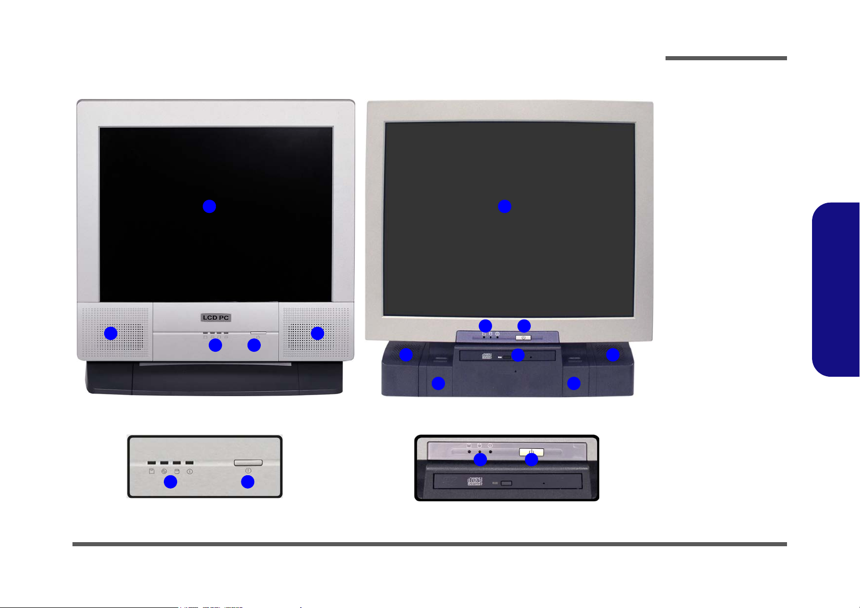
Figure 1 - 1
Front View
1. LCD Panel
2. Speakers
3. LED Activity
indicators
4. Power Button
5. Optical (CD/
DVD) Device
Bay (L297N
only)
6. Keyboard Holder
(L297N only)
Introduction
1.Introduction
External Locator - Front View 1 - 5
Page 14
Introduction
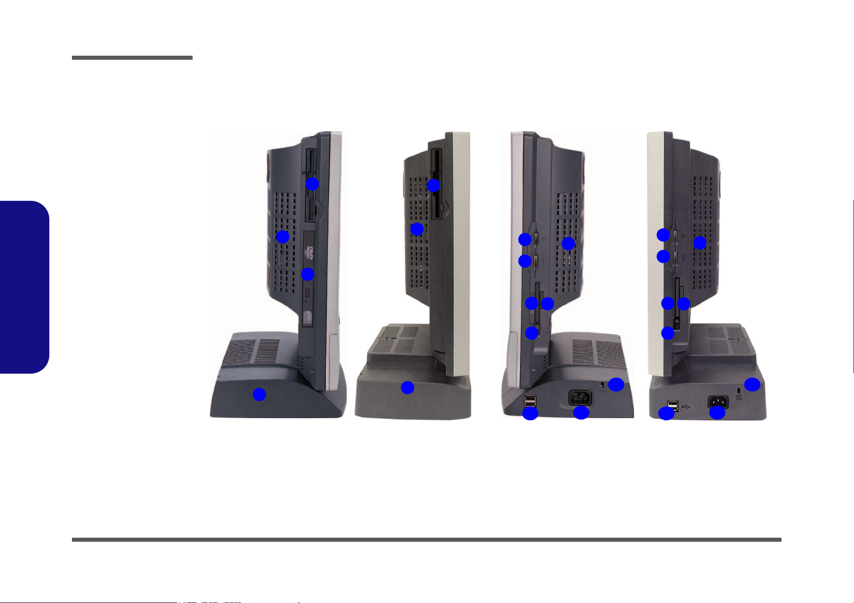
Figure 1 - 2
Left & Right Views
1. Floppy Disk
Drive*
2. Vent
3. Hard Disk Drive
(HDD) Bay
4. CD Device
(L295N only)
5. LCD Brightness
Control Knob
6. Volume Control
Knob
7. Dual PC Card
Slots
8. PC Card Eject
Buttons
9. 7-in-1 Card
Reader
10. 2* USB Ports
11. AC Power-In Port
12. Security Lock
Slot
2
8
7
3
1
1
2
5
6
9
2
11
10
L295N L297N L295N L297N
2
3
4
5
6
12
8
7
9
11
10
12
Left Right
External Location - Left & Right Side Views
1.Introduction
1 - 6 External Location - Left & Right Side Views
Page 15
External Locator - Rear View
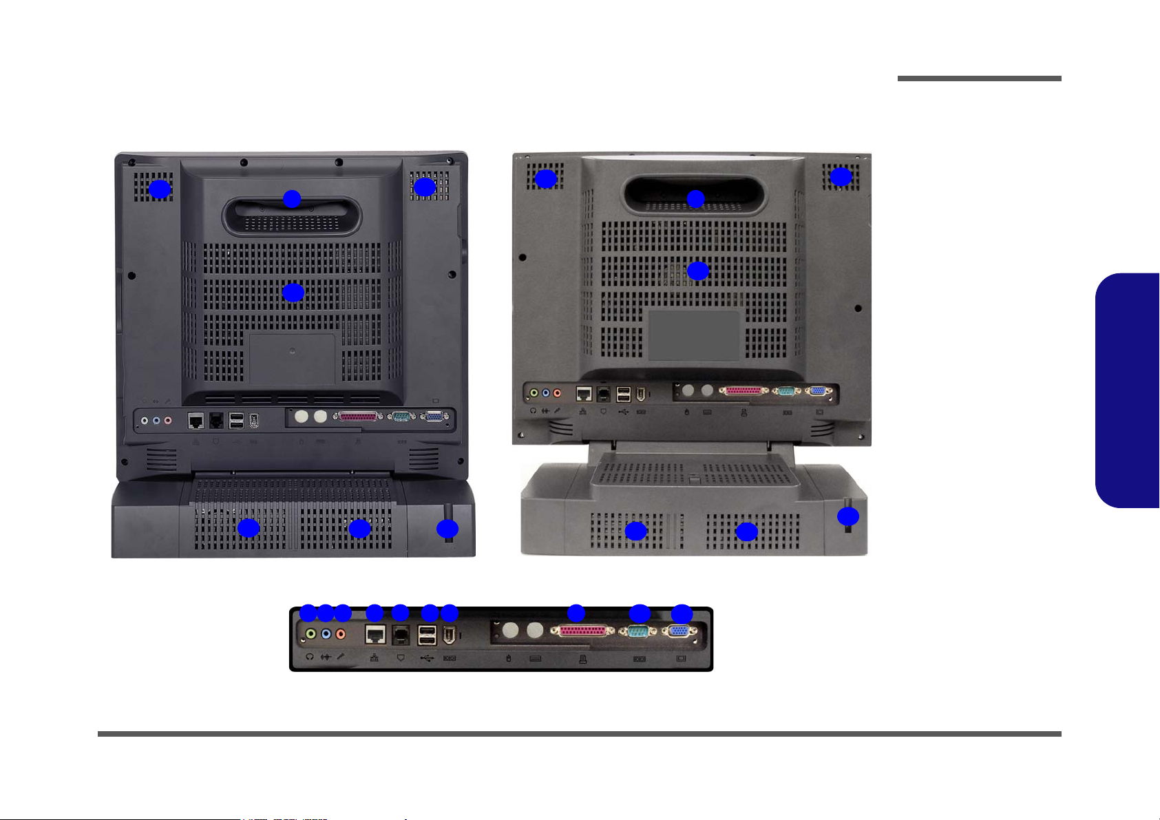
Figure 1 - 3
Rear View
1. Carrying Handle
2. Headphone-Out
Jack
3. Line-In Jack
4. Microphone-In
Jack
5. RJ-45 LAN Jack
6. RJ-11 Phone
Jack
7. 2* USB Ports
8. Unpowered IEEE 1394 Port
9. Printer/Parallel
Port
10. Serial Port
11. External Monitor
Port
12. Vents
13. Hard Disk Bay
Screw
1
4 5
6
12
2 3 87
12
10
11
13
12
12
9
1
12
12
12
12
12
L295N L297N
13
13
Introduction
1.Introduction
External Locator - Rear View 1 - 7
Page 16
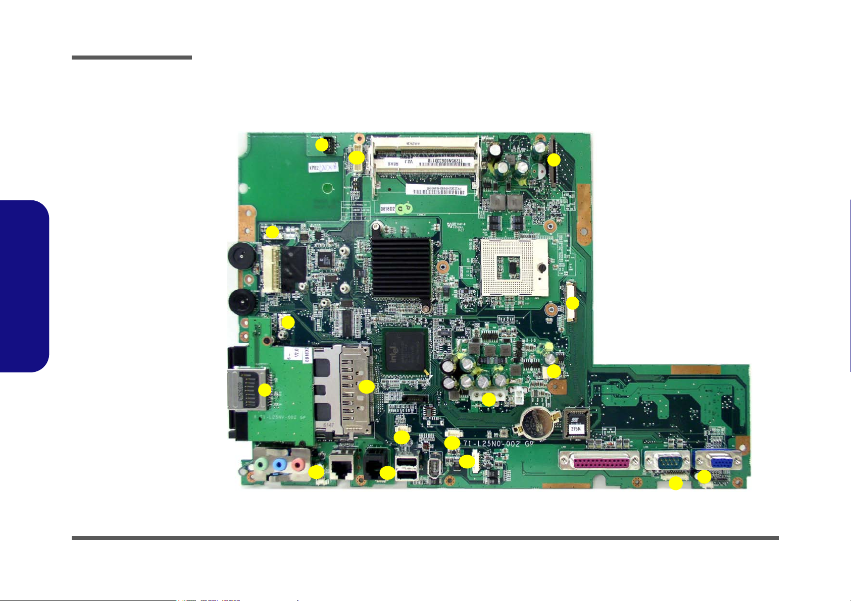
Introduction
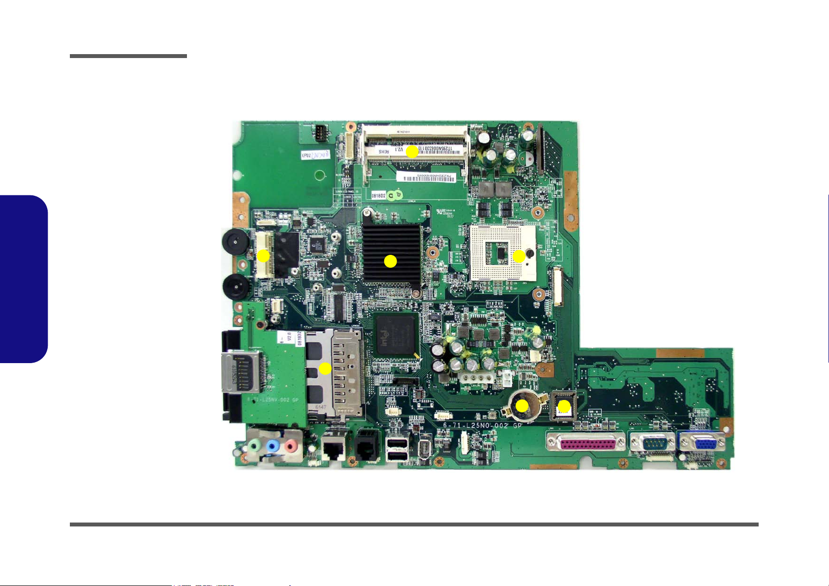
Figure 1 - 4
Mainboard Over-
view - Top
Key Parts
1. CPU Socket (no
CPU Installed)
2. Intel 945GM
(North Bridge)
3. RAM Sockets
4. Mini Card
Socket for
WLAN
5. FLASH BIOS
6. CMOS Battery
7. Cardbus
PCI7412
5
6
7
4
1
3
2
Mainboard Overview - Top (Key Parts)
1.Introduction
1 - 8 Mainboard Overview - Top (Key Parts)
Page 17
Mainboard Overview - Bottom (Key Parts)
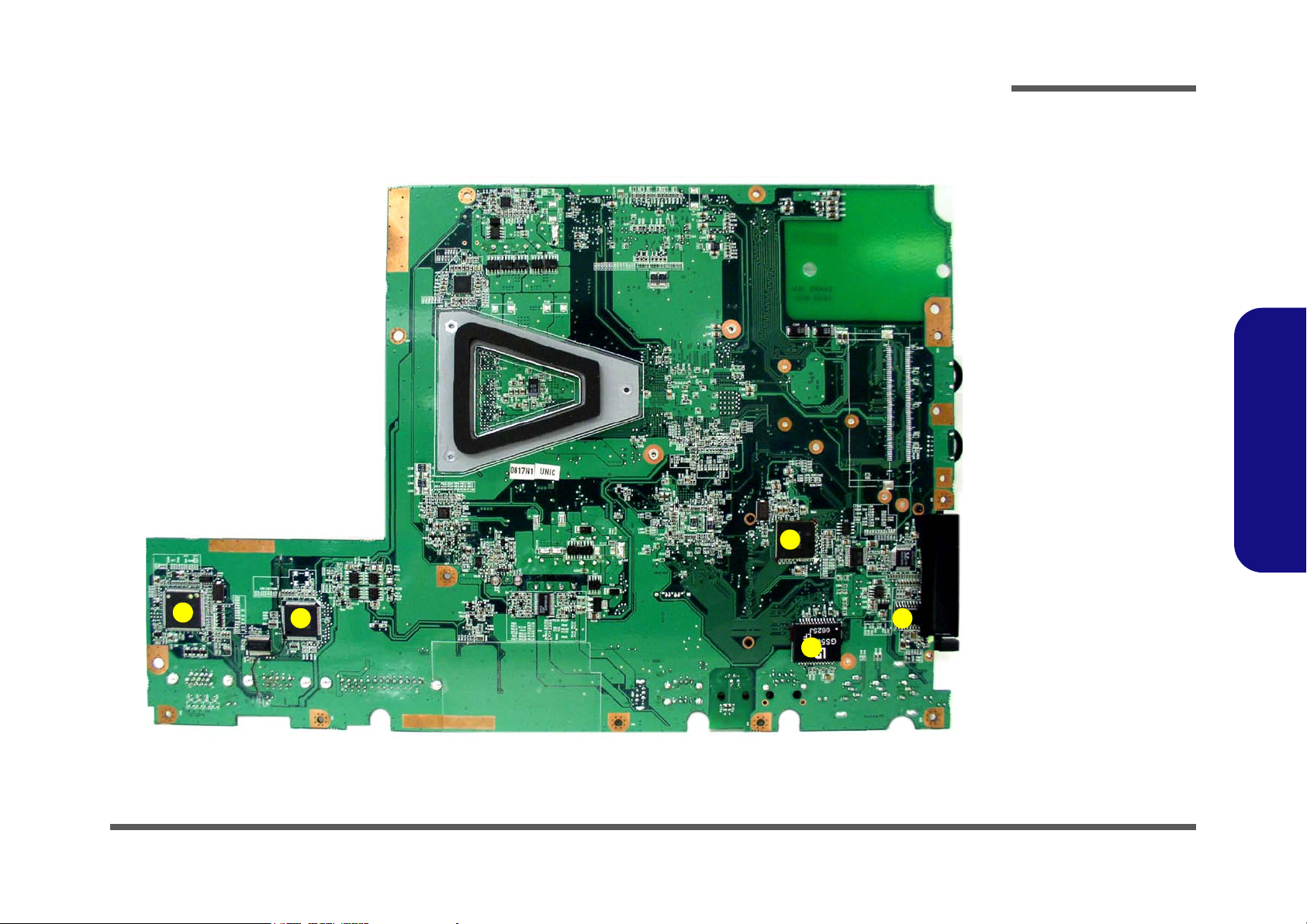
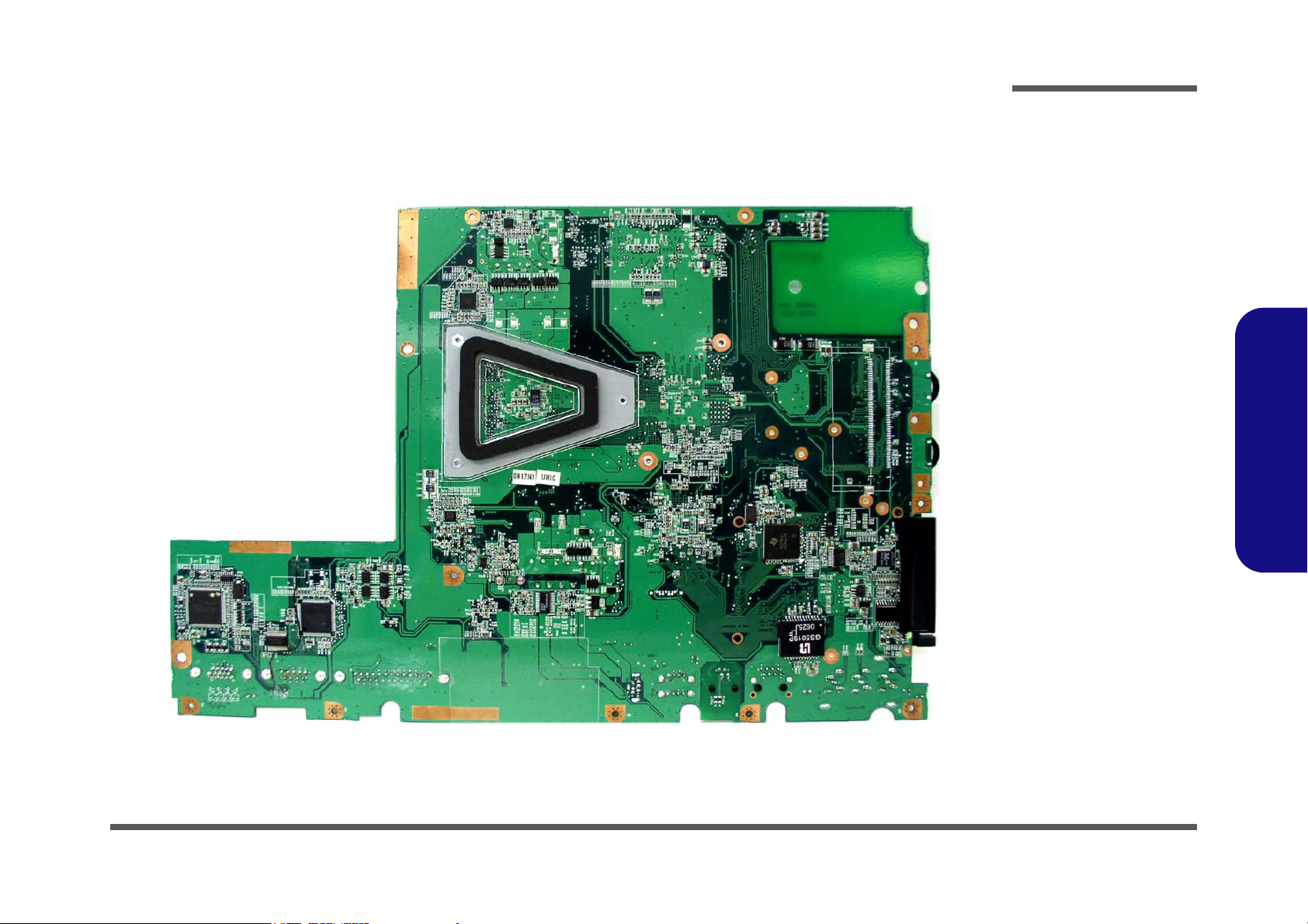
Figure 1 - 5
Mainboard Over-
view - Bottom
Key Parts
1. Chrontel CH7308
2. Clock Generator
3. Intel ICH7-M 652
mBGA (South
Bridge)
4. SUPER I/O
Winbond
PC87392
5. AZALIA MDC
Module
4
5
3
1
2
Introduction
1.Introduction
Mainboard Overview - Bottom (Key Parts) 1 - 9
Page 18
Introduction
1
2
3
4
5
6
7
8
9
10
11
12
13
14
15
17
16
Figure 1 - 6
Mainboard Top
Cable Connectors &
Switches
1. CD/DVD Device
(CN7)
2. Floppy Disk Drive
(CN5)
3. CN35 (LCD
Connector)
4. Inverter (CN1)
5. BT Module
6. Modem Module
7. Card Reader
8. Speaker (CN31)
9. Modem Cable
(CN33)
10. PC CARD (CN13)
11. Touch Screen
(CN16)
12. IEEE1394 (CN36)
13. USB 2.0 (CN17)
14. LED Board
(CN30)
15. Speaker (CN32)
16. Power (CN12)
17. Fan Power (CN9)
1.Introduction
Mainboard Overview - Top (Cable Connectors & Switches)
1 - 10 Mainboard Overview - Top (Cable Connectors & Switches)
Page 19
Mainboard Overview - Bottom (Cable Connectors & Switches)
1
Figure 1 - 7
Mainboard Bottom
Cable Connectors &
Switches
Introduction
1.Introduction
Mainboard Overview - Bottom (Cable Connectors & Switches) 1 - 11
Page 20

Introduction
1.Introduction
1-12
Page 21
2: Disassembly
Information and
Component Parts
Warning
Overview
This chapter provides step-by-step instructions for disassembling parts and subsystems. When it comes to reassembly,
reverse the procedures (unless otherwise indicated).
We suggest you completely review any procedure before you take the computer apart.
Disassembly
Procedures such as upgrading/replacing the RAM, CD device and hard disk are included in the User’s Manual but are
repeated here for your convenience.
To make the disassembly process easier each section may have a box in the page margin. Information contained under
the figure # will give a synopsis of the sequence of procedures involved in the disassembly procedure. A box with a
lists the relevant parts you will have after the disassembly process is complete. Note: The parts listed will be for the dis-
assembly procedure listed ONLY, and not any previous disassembly step(s) required. Refer to the part list for the previous disassembly procedure. The amount of screws you should be left with will be listed here also.
A box with a will provide any possible helpful information. A box with a contains warnings.
An example of these types of boxes are shown in the sidebar.
2.Disassembly
Overview 2 - 1
Page 22

Disassembly
2.Disassembly
NOTE: All disassembly procedures assume that the system is turned OFF, and disconnected from any power supply,
and that all peripheral cables are disconnected (including telephone lines and network cables).
Maintenance Tools
The following tools are recommended when working on the computer:
• M3 Philips-head screwdriver
• M2.5 Philips-head screwdriver (magnetized)
• M2 Philips-head screwdriver
• Small flat-head screwdriver
• Pair of needle-nose pliers
• Anti-static wrist-strap
Connections
Connections within the computer are one of four types:
Locking collar sockets for ribbon connectors To release these connectors, use a small flat-head screwdriver to gently pry the
locking collar away from its base. When replacing the connection, make sure
the connector is oriented in the same way. The pin1 side is usually not indicated.
2-2Overview
Pressure sockets for multi-wire connectors To release this connector type, grasp it at its head and gently rock it from side
to side as you pull it out. Do not pull on the wires themselves. When replacing
the connection, do not try to force it. The socket only fits one way.
Pressure sockets for ribbon connectors To release these connectors, use a small pair of needle-nose pliers to gently lift
the connector away from its socket. When replacing the connection, make sure
the connector is oriented in the same way. The pin1 side is usually not indicated.
Board-to-board or multi-pin sockets To separate the boards, gently rock them from side to side as you pull them
apart. If the connection is very tight, use a small flat-head screwdriver - use
just enough force to start.
Page 23

Maintenance Precautions
Power Safety
Warning
Before you undertake
any upgrade procedures, make sure that
you have turned off
the power, and disconnected all peripherals and cables
(including telephone
lines). It is advisable
to also remove your
battery in order to prevent accidentally turning the machine on.
The following precautions are a reminder. To avoid personal injury or damage to the computer while performing a removal and/or replacement job, take the following precautions:
1. Don't drop it. Perform your repairs and/or upgrades on a stable surface. If the computer falls, the case and other
2. Don't overheat it. Note the proximity of any heating elements. Keep the computer out of direct sunlight.
3. Avoid interference. Note the proximity of any high capacity transformers, electric motors, and other strong mag-
4. Keep it dry. This is an electrical appliance. If water or any other liquid gets into it, the computer could be badly
5. Be careful with power. Avoid accidental shocks, discharges or explosions.
6. Peripherals – Turn off and detach any peripherals.
7. Beware of static discharge. ICs, such as the CPU and main support chips, are vulnerable to static electricity.
8. Beware of corrosion. As you perform your job, avoid touching any connector leads. Even the cleanest hands pro-
9. Keep your work environment clean. Tobacco smoke, dust or other air-born particulate matter is often attracted
10. Keep track of the components. When removing or replacing any part, be careful not to leave small parts, such as
Disassembly
components could be damaged.
netic fields. These can hinder proper performance and damage components and/or data. You should also monitor
the position of magnetized tools (i.e. screwdrivers).
damaged.
2.Disassembly
•Before removing or servicing any part from the computer, turn the computer off and detach any power supplies.
•When you want to unplug the power cord or any cable/wire, be sure to disconnect it by the plug head. Do not pull on the wire.
Before handling any part in the computer, discharge any static electricity inside the computer. When handling a
printed circuit board, do not use gloves or other materials which allow static electricity buildup. We suggest that
you use an anti-static wrist strap instead.
duce oils which can attract corrosive elements.
to charged surfaces, reducing performance.
screws, loose inside the computer.
Cleaning
Do not apply cleaner directly to the computer, use a soft clean cloth.
Do not use volatile (petroleum distillates) or abrasive cleaners on any part of the computer.
Overview 2 - 3
Page 24

Disassembly
Disassembly Steps
The following lists the disassembly steps, and on which page to find the related information. PLEASE PERFORM THE
DISASSEMBLY STEPS IN THE ORDER INDICATED.
2.Disassembly
To remove the hard disk drive assembly:
1. Remove the hard disk drive assembly page 2 - 5
To remove the LCD back cover:
1. Remove the LCD back cover page 2 - 6
To remove the system memory:
1. Remove the LCD back cover page 2 - 6
2. Remove the system memory page 2 - 7
To remove and install the Processor:
1. Remove the LCD back cover page 2 - 6
2. Remove the processor page 2 - 8
3. Install the processor page 2 - 10
To remove the modem:
1. Remove the LCD back cover page 2 - 6
2. Remove the modem page 2 - 11
To remove the WLAN module:
To remove the Bluetooth module:
1. Remove the LCD back cover page 2 - 6
2. Remove the bluetooth module page 2 - 13
To remove the floppy disk drive assembly:
1. Remove the LCD back cover page 2 - 6
2. Remove the floppy disk drive assembly page 2 - 14
To remove the Optical Device:
1. Remove the LCD back cover page 2 - 6
2. Remove the optical device page 2 - 15
1. Remove the LCD back cover page 2 - 6
2. Remove the WLAN module page 2 - 12
2 - 4 Disassembly Steps
Page 25
Removing the Hard Disk Drive Assembly
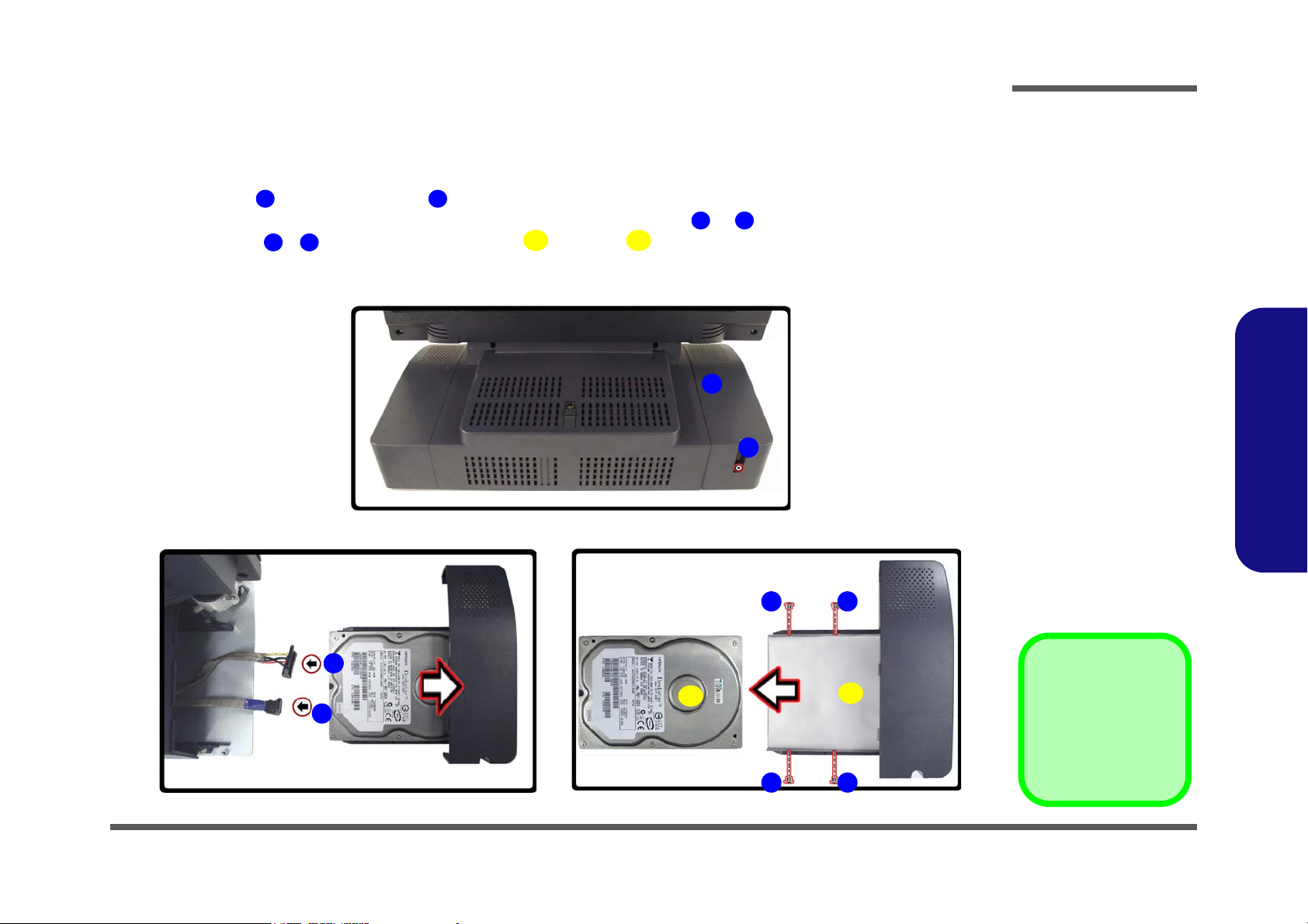
Figure 2 - 1
Hard Disk Removal
Sequence
a. Remove the screw
from the HDD Bay.
b. Slide the HDD assem-
bly in the direction of
the arrow and disconnect the cables.
c. Remove the screws
and separate the HDD
from the case.
2. HDD Bay Cover
9. HDD
10. HDD case
•5 Screws
123
4
5
8
9
10
1
2
3
4
a.
b. c.
5 6
7
9
10
8
1. Unplug the power cord and disconnect all peripheral cables (including the phone line) from the computer.
2. Turn OFF the computer and turn it around so that you may comfortably access the left side.
3. Remove screw from the HDD Bay .
4. Carefully pull the HDD assembly out from the bay and disconnect cables & .
5. Remove screws - and separate the hard disk and case .
6. Insert the new hard disk, and reverse the removal procedure to install the new hard disk.
Disassembly
2.Disassembly
Removing the Hard Disk Drive Assembly 2 - 5
Page 26
Disassembly
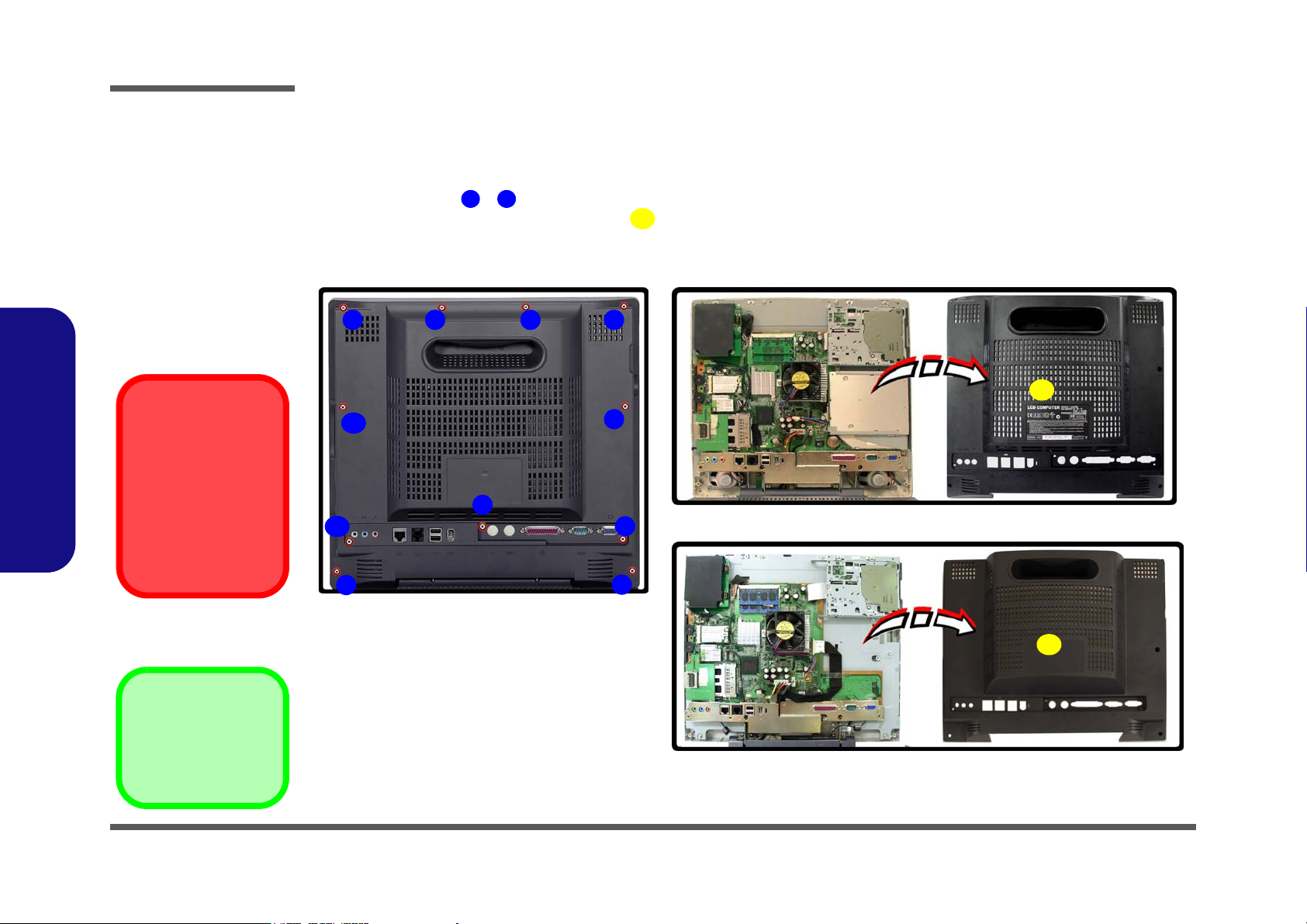
Figure 2 - 2
LCD Back Cover
Removal
Sequence
a. Remove the screws
from the LCD back
cover.
b. Lift the cover out and
set it aside.
1
11
12
12. LCD back cover
•11 Screws
a.
1 2 3 4
6
5
7
9
8
10
11
b.
12
12
L295N
L297N
Card Reader/PC Card
Slots
Make sure you remove
any cards or covers in
the 7-in-1 Card Reader
and PC Card slot before removing the rear
case cover.
Removing the LCD Back Cover
1. Unplug the power cord and disconnect all peripheral cables (including the phone line) from the computer.
2. Turn OFF the computer and place it with its LCD display facing down on a clean, dry, level surface.
3. Remove screws - from the LCD back cover and slide it up towards the top of the computer.
4. Carefully remove the LCD back cover from the main unit and set it aside.
2.Disassembly
2 - 6 Removing the LCD Back Cover
Page 27
Removing the System Memory
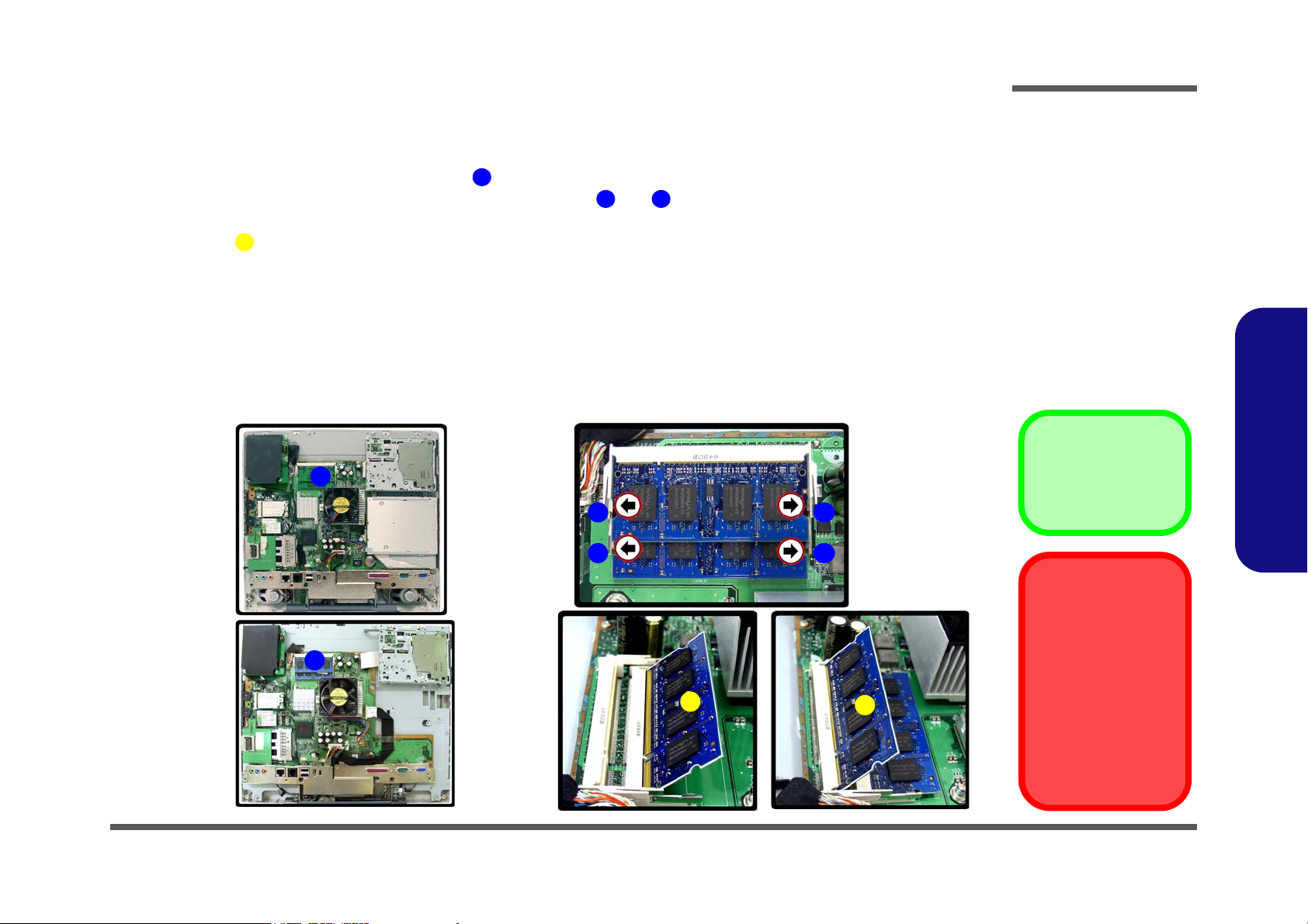
Figure 2 - 3
Memory Removal
Sequence
a. Locate the memory
sockets.
b. Pull the latch(es) on
the memory sockets to
release the module(s)
and lift it (them) out.
c. Insert a new module.
4. Memory module(s)
123
4
Contact Warning
Be careful not to touch
the metal pins on the
module’s connecting
edge. Even the cleanest hands have oils
which can attract particles, and degrade the
module’s performance.
c.
a.
2
b.
3
4
1
2 3
4
1
L295N
L297N
1. Remove the LCD back cover (page 2 - 6).
2. The memory sockets will be visible at point on the mainboard.
3. For each module you want to replace, gently push the latches and toward the sides of the socket to release the
module. Push the latches to release the second module if necessary.
4. The module will pop-up, and you can remove it.
5. Insert the new module. The module will only fit one way as defined by the pin alignment.
6. Make sure the module is seated as far into the slot as it will go (DO NOT FORCE IT). The latches will click into
place on the sides of the module. Make sure they are secure.
7. Reverse the procedures to put the computer back together, and do not forget all the screws. When you restart the
computer the new memory configuration should be registered.
8. If the system doesn’t properly detect the new memory, and you are sure they are properly “seated”, you may
need to run the Setup utility.
Disassembly
2.Disassembly
Removing the System Memory 2 - 7
Page 28
Disassembly
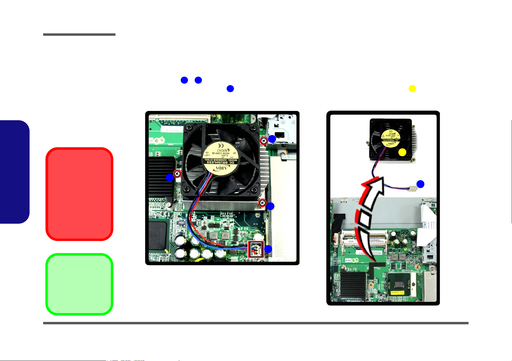
Figure 2 - 4
Processor
Removal
Sequence
a. Remove the screws
from the CPU heat
sink and fan unit.
b. Release the power ca-
ble and lift the heat
sink & fan unit out.
134
5
2
1
a.
4
3
b.
5
4
5. Heat Sink & Fan
•3 Screws
Caution
The heat sink, and
CPU area in general,
contains parts which
are subject to high
temperatures - Please
allow the area time to
cool before removing
these parts.
Removing and Installing the Processor
Processor Removal Procedure
1. Remove the LCD back cover (page 2 - 6).
2. Remove screws - from the CPU heat sink fan unit (in the order indicated in Figure 2 - 5a).
3. Disconnect the fan power cable from the mainboard and lift out the CPU heat sink fan unit .
2.Disassembly
2 - 8 Removing and Installing the Processor
Page 29
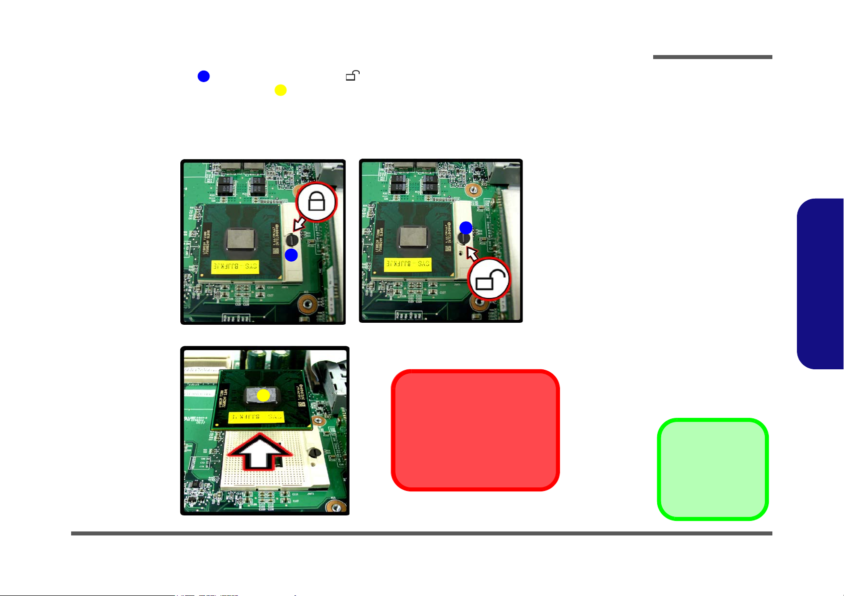
4. Turn the release latch towards the unlock symbol , to release the CPU (Figure 2 - 5c).
6
7
c.
7
d.
Caution
The heat sink, and CPU area in
general, contains parts which are
subject to high temperatures. Allow
the area time to cool before removing these parts.
Lock
Unlock
6
6
Figure 2 - 5
Processor
Removal
Sequence (cont’d)
c. Turn the release latch
to unlock the CPU.
d. Lift the CPU out of the
socket.
7. CPU
5. Carefully (it may be hot) lift the CPU up out of the socket (Figure 2 - 5d).
6. See page 2 - 10 for information on inserting a new CPU.
7. When re-inserting the CPU, pay careful attention to the pin alignment, it will fit only one way (DO NOT FORCE
IT!).
Disassembly
2.Disassembly
Removing and Installing the Processor 2 - 9
Page 30

Disassembly
8981011121314131215
8. CPU
10. Heat Sink & Fan
•3 Screws
Figure 2 - 6
Processor
Installation
Sequence
e. Insert the CPU.
f. Turn the release latch to-
wards the lock symbol.
g. Apply thermal grease to
the top of the CPU.
h. Replace the heat sink.
i. Tighten the 3 screws as
instructed and connect
the fan cable.
e. h.
8
g.
9
10
8
f.
i.
13
14
12
15
Note
The screws should not be
tightened in excess of
3Kg.
11
Caution
Take extra care not to
damage the mainboard
components when replacing the CPU heat
sink fan unit and tightening the screws.
Processor Installation Procedure
1. Insert the CPU , and pay careful attention to the pin alignment; it will fit only one way (DO NOT FORCE IT!).
2. Turn the release latch towards the lock symbol (Figure 2 - 6f).
3. Apply the thermal grease to the top of the CPU .
4. Replace the heat sink fan unit using the rubber as alignment guide as indicated in Figure 2 - 6h.
5. Tighten screws & on the CPU heat sink fan unit to approximately 1/3 of the way.
6. Tighten screw fully.
7. Tighten screw fully, and then tighten the screw fully.
8. Connect the fan power cable to the mainboard.
9. Replace the LCD back cover and screws (page 2 - 6).
2.Disassembly
2 - 10 Removing and Installing the Processor
Page 31

Removing the Modem
Figure 2 - 7
Modem Removal
Sequence
a. Remove the screws
from the modem unit.
b. Remove the modem
from the connector
and disconnect the
cable.
c. Lift the modem off the
board.
4. Modem module
•2 Screws
1
243
5
1
3
5
a. c.
2
4
b.
4
1. Remove the LCD back cover (page 2 - 6).
2. Remove screws and from the modem module.
3. Remove the modem module from the connector socket , and disconnect the modem cable at point .
4. Lift the modem off the mainboard.
Disassembly
2.Disassembly
Removing the Modem 2 - 11
Page 32

Disassembly
Figure 2 - 8
Wireless LAN
Module Removal
Sequence
a. Disconnect the cable
and remove the 2
screws.
b. The WLAN module will
pop-up.
c. Remove the WLAN
module.
123
4
4
2
3
1
a.
c.
4
b.
4
4. WLAN Module
•2 Screws
Removing the Wireless LAN Module
1. Remove the LCD back cover (page 2 - 6).
2. Carefully disconnect cable , then remove screws & from the module socket.
3. The wireless LAN module will pop-up.
4. Lift the wireless LAN module up and off the computer.
2.Disassembly
2 - 12 Removing the Wireless LAN Module
Page 33

Figure 2 - 9
Bluetooth Module
Removal
Sequence
a. Disconnect the cable
and remove the 2
screws.
b. Remove the bluetooth
module.
123
4
2
3
1
a.
4
b.
4. Bluetooth Module
•1 Screw
Disassembly
Removing the Bluetooth Module
1. Remove the LCD back cover (page 2 - 6) and WLAN module (page 2 - 12).
2. Carefully disconnect cable & , then remove screw from the module socket.
3. Lift the bluetooth module up and off the computer.
2.Disassembly
Removing the Bluetooth Module 2 - 13
Page 34

Figure 2 - 10
Floppy Disk Drive
Assembly
Removal
Sequence
a. Remove the screws
from the FDD assem-
bly and disconnect the
FDD ribbon cable.
b. Lift the FDD assembly
off the board.
145
6
6. FDD Assembly
•4 Screws
1
3
a.
b.
4
6
2
5
Disassembly
Removing the Floppy Disk Drive Assembly
1. Remove the LCD back cover (page 2 - 6).
2. Remove screws - from the floppy disk drive assembly.
3. Carefully disconnect the floppy disk drive ribbon cable at point .
4. Lift the floppy disk drive assembly off the mainboard.
2.Disassembly
2 - 14 Removing the Floppy Disk Drive Assembly
Page 35

Removing the Optical Device Assembly
Figure 2 - 11
Optical Device
Assembly
Removal
Sequence
(L295N)
a. Remove the screws
and disconnect the
cable.
b. Remove the Optical
Device.
134
5
a. b.
1
2
3
5
4
5. Optical Device
•3 Screws
For L295N
1. Remove the LCD back cover (page 2 - 6).
2. Remove screws - , and disconnect cable , from the optical device.
3. Remove the optical device , and remove the screws in order to separate the optical device from the bracket.
4. Reverse the removal procedures to intall the new optical device.
Disassembly
2.Disassembly
Removing the Optical Device Assembly 2 - 15
Page 36

Disassembly
Figure 2 - 12
Optical Device
Assembly
Removal
Sequence
(L297N)
a. Remove the screw,
and push the switch
to slide the optical
device assembly out
of the computer.
b. Remove the Optical
Device.
1
2
a.
b.
2
1
2. Optical Device
•1 Screw
2.Disassembly
For L297N
1. Remove the LCD back cover (page 2 - 6).
2. Locate the optical device eject switch and remove screw .
3. Push the optical device eject switch to slide the optical device assembly out of the bay.
4. Remove the optical device, and reverse the removal procedures to install the new optical device.
2 - 16 Removing the Optical Device Assembly
Page 37

Appendix A: Part Lists
This appendix breaks down the L295N/L297N computer’s construction into a series of illustrations. The component part
numbers are indicated in the tables opposite the drawings.
Note: This section indicates the manufacturer’s part numbers. Your organization may use a different system, so be sure
to cross-check any relevant documentation.
Note: Some assemblies may have parts in common (especially screws). However, the part lists DO NOT indicate the
total number of duplicated parts used.
Part Lists
Note: Be sure to check any update notices. The parts shown in these illustrations are appropriate for the system at the
time of publication. Over the product life, some parts may be improved or re-configured, resulting in new part numbers.
A.Part Lists
A-1
Page 38

Part Lists
Table A - 1
Part List Illustration
Location
Part List Illustration Location
The following table indicates where to find the appropriate part list illustration.
Part L295N L297N
Base page A - 3 page A - 11
Bracket (AU) page A - 4
Bracket (Chi-Mei) page A - 12
Bracket - Touch Screen (AU) page A - 13
Bracket - Touch Screen (Chi-Mei) page A - 14
Front page A - 5 page A - 15
Front - Touch Screen page A - 6
Combo page A - 7 page A - 16
A.Part Lists
A - 2 Part List Illustration Location
DVD-RW page A - 8 page A - 17
FDD page A - 9 page A - 18
HDD page A - 10 page A - 19
Page 39

L295N - Base
Figure A - 1
L295N - Base
無鉛
無鉛
無鉛
無鉛
無鉛
無鉛
無鉛
無鉛
無鉛
無鉛
無鉛
無鉛
無鉛
無鉛
無鉛
無鉛
無鉛
無鉛(黑橡膠)
無鉛
無鉛
(加拉帶跟導電布 480MM) L297T 無鉛
Part Lists
A.Part Lists
L295N - Base A - 3
Page 40

Part Lists
Figure A - 2
L295N Bracket (AU)
無鉛
無鉛
昆山(無鉛)
無鉛
無鉛
無鉛
無鉛
三價絡 無鉛
無鉛
無鉛
無鉛
無鉛
無鉛
無鉛
無鉛
無鉛
無鉛
無鉛
顏色:黑色 不噴漆)無鉛
無鉛
無鉛
無鉛
無鉛
無鉛
無鉛
無鉛
無鉛
強茂
無鉛
無鉛
無鉛
無鉛
無鉛
無鉛
無鉛
無鉛
無鉛
無鉛
無鉛
無鉛
無鉛
無鉛
無鉛
無鉛
無鉛
無鉛
無鉛
A.Part Lists
A - 4 L295N - Bracket (AU)
L295N - Bracket (AU)
Page 41

L295N - Front
Figure A - 3
L295N - Front
無鉛
銀色 無鉛
無鉛
無鉛
三價絡 無鉛
無鉛
無鉛
無鉛
無鉛
無鉛
無鉛
無鉛
無鉛 (億全)
Part Lists
A.Part Lists
L295N - Front A - 5
Page 42

Part Lists
Figure A - 4
L295N - Front -
Touch Screen
無鉛
銀色 無鉛
無鉛
無鉛
三價絡 無鉛
無鉛
無鉛
無鉛
無鉛
無鉛
無鉛
無鉛
無鉛(億全)
無鉛
A.Part Lists
L295N - Front - Touch Screen
A - 6 L295N - Front - Touch Screen
Page 43

L295N - Combo Drive
無鉛
無鉛
無鉛
無鉛
無鉛
無鉛
無鉛
無鉛
無鉛
無鉛
無鉛
Figure A - 5
L295N -
Combo Drive
Part Lists
A.Part Lists
L295N - Combo Drive A - 7
Page 44

Part Lists
無鉛
無鉛
無鉛
無鉛
無鉛
無鉛
無鉛
無鉛
無鉛
無鉛
無鉛
凱明 L295N 無鉛
Figure A - 6
L295N -
DVD-RW Drive
A.Part Lists
L295N - DVD-RW Drive
A - 8 L295N - DVD-RW Drive
Page 45

L295N - FDD
Figure A - 7
L295N - FDD
無鉛
無鉛
無鉛
無鉛
無鉛
Part Lists
A.Part Lists
L295N - FDD A - 9
Page 46

Part Lists
Figure A - 8
L295N - HDD
無鉛
無鉛
無鉛
無鉛
無鉛
無鉛
A.Part Lists
L295N - HDD
A - 10 L295N - HDD
Page 47

L297N - Base
Figure A - 1
L297N - Base
導電布
無鉛
無鉛
無鉛(億全)
(加拉帶跟導電布 480MM) L297T 無鉛
無鉛
無鉛
無鉛
無鉛
無鉛
無鉛
無鉛
無鉛
無鉛
無鉛
無鉛
無鉛
無鉛
無鉛
無鉛
無鉛
無鉛
無鉛
無鉛
無鉛
無鉛
無鉛
無鉛
無鉛
無鉛
無鉛
無鉛
(黑橡膠)
無鉛
Part Lists
A.Part Lists
L297N - Base A - 11
Page 48

Part Lists
Figure A - 2
L297N - Bracket
A.Part Lists
(Chi-Mei)
L297N - Bracket (Chi-Mei)
昆山 無鉛
無鉛
三價絡 無鉛
無鉛
無鉛
無鉛
無鉛
無鉛
無鉛
無鉛
無鉛
無鉛
無鉛
無鉛
無鉛
無鉛
無鉛
無鉛
無鉛
無鉛
無鉛
A - 12 L297N - Bracket (Chi-Mei)
無鉛
無鉛
無鉛
無鉛
頭徑4.5 頭厚0.8MM 無鉛
無鉛
無鉛
無鉛
無鉛
銀色) L287PB 無鉛
(黑色) 無鉛
顏色:黑色 不噴漆)無鉛
無鉛
無鉛
無鉛
Page 49

L297N - Bracket - TouchScreen (AU)
昆山 無鉛
無鉛
無鉛
三價絡 無鉛
無鉛
無鉛
無鉛
(強茂) 外包 L297N
Part Lists
無鉛
無鉛
無鉛
無鉛
無鉛
無鉛
無鉛
無鉛
無鉛
無鉛
無鉛
無鉛
無鉛
無鉛
無鉛
無鉛
無鉛
無鉛
無鉛
無鉛
無鉛
無鉛
Figure A - 3
L297N - Bracket -
Touch Screen (AU)
A.Part Lists
無鉛
顏色:黑色 不噴漆)無鉛
(黑色) 無鉛
無鉛
無鉛
無鉛
無鉛
無鉛
無鉛
無鉛
L297N - Bracket - TouchScreen (AU) A - 13
Page 50

Part Lists
Figure A - 4
L297N - Bracket -
Touch Screen
A.Part Lists
(Chi-Mei)
L297N - Bracket - TouchScreen (Chi-Mei)
昆山 無鉛
無鉛
無鉛
三價絡 無鉛
(黑色) 無鉛
無鉛
無鉛
(強茂) 外包 L297N
無鉛
無鉛
無鉛
無鉛
無鉛
無鉛
無鉛
無鉛
無鉛
無鉛
無鉛
無鉛
無鉛
無鉛
無鉛
無鉛
無鉛
無鉛
無鉛
無鉛
無鉛
無鉛
無鉛
無鉛
A - 14 L297N - Bracket - TouchScreen (Chi-Mei)
無鉛
無鉛
顏色:黑色 不噴漆)無鉛
無鉛
無鉛
無鉛
無鉛
Page 51

L297N - Front
Figure A - 5
L297N - Front
無鉛
銀色 無鉛
無鉛
無鉛
無鉛
Part Lists
A.Part Lists
L297N - Front A - 15
Page 52

Part Lists
Figure A - 6
L297N -
Combo Drive
A.Part Lists
L297N - Combo Drive
A - 16 L297N - Combo Drive
Page 53

L297N - DVD-RW Drive
Figure A - 7
L297N -
DVD-RW Drive
Part Lists
A.Part Lists
L297N - DVD-RW Drive A - 17
Page 54

Part Lists
Figure A - 8
L297N - FDD
漢保(無鉛)
無鉛
無鉛
無鉛
A.Part Lists
L297N - FDD
A - 18 L297N - FDD
Page 55

L297N - HDD
Figure A - 9
L297N - HDD
無鉛
鋁箔遮罩, 無鉛
無鉛
無鉛
無鉛
Part Lists
A.Part Lists
L297N - HDD A - 19
Page 56

Part Lists
Part Lists
A - 20
Page 57

Appendix B: Schematic Diagrams
Table B - 1
Schematic Diagram
Version Note
The schematic diagrams in this chapter
are based upon version 6-71-L25N0-002.
If your mainboard (or
other boards) are a later version, please
check with the Service
Center for updated diagrams (if required).
This appendix has circuit diagrams of the L295N/L297N computer’s PCB’s. The following table indicates where to find
the appropriate schematic diagram.
Diagram - Page Diagram - Page Diagram - Page
System Block Diagram - Page B - 2 ICH7-M 1/4 (SATA) - Page B - 15 VDD3, VDD5, 3.3V, 5V - Page B - 28
Schematic Diagrams
Clock Generator - Page B - 3 ICH7-M 2/4 (PCI, USB) - Page B - 16 1.5VS, 1.05VS, 2.5VS - Page B - 29
Yonah CPU - 1 of 2 - Page B - 4 ICH7-M 3/4 (FWH) - Page B - 17 AC-IN, 1.8V, 0.9VS - Page B - 30
Yonah CPU - 2 of 2 - Page B - 5 ICH7-M 4/4 - Page B - 18 VCORE - Page B - 31
Calistoga 1/5 Host - Page B - 6 CD-ROM, Ext USB, Mini PCI - Page B - 19 12VS - Page B - 32
Calistoga 2/5 - Page B - 7 MDC, Mini Card, USB2.0, BT - Page B - 20 Button Board for L295N - Page B - 33
Calistoga 3/5 DDR - Page B - 8 LAN RTL8110SBL - Page B - 21 Button Board for L297N - Page B - 34
Calistoga 4/5 - Page B - 9 TI PCI7412 - Page B - 22 CD-ROM Board for L295N - Page B - 35
Calistoga 5/5 POWER - Page B - 10 PCM Socket, 3-in-1 Socket - Page B - 23 CD-ROM Board for L297N - Page B - 36
DDRII RIMM - Page B - 11 Azalia CODEC ALC883 & MDC - Page B - 24 USB Board - Page B - 37
Chrontel CH7308 - Page B - 12 H8 - Page B - 25 CardReader Board - Page B - 38
LCD Connector - Page B - 13 COM Port, Fan, Parallel Port - Page B - 26 Screw Hole - Page B - 39
VGA Interface - Page B - 14 Super I/O PC87392, FDD - Page B - 27
B.Schematic Diagrams
B-1
Page 58

Schematic Diagrams
33 MHz
PCI-E
DDRII
SATA HDD
33 MHz
Parallel POR T
IMVP-6 VR
INT
SPK
SDVO
AZALIA L INK
PCI BUS
ALC883
HUB
1466 FCBGA
AZALIA C ODEC
NORTH BRIDGE
LPC
R.G.B
TI PCI7412
AUDIO AMP
SOUTH BRIDGE
667 MHz
USB0
Page ?
TOUCH
PANEL
24MHz
LVDS
CK-41 0M
ICS9LPR310BGLF
SPI
USB2
USB2.0
USB1
478 uFCPGA
COM PORT
4.VCORE
2.1.5VS,1.05VS,2.5VS
SPI
Mini PCIE
480 Mbps
CRT
Firmware
LINE
IN
533/667 MHz
BULE TOOTH
GOLANUSB3
USB6
652 BGA
FDD
FLASH
USB4
3.ACIN,1.8V,0.9VS
1.VDD3,VDD5,3.3V,5V
CHRONTEL
CH7308
FSB
H8 2111
PCMCIA/1394
LCD CONN
PROCESSOR
945GM
ICH7-M
ON BOARD JACK
CD-ROM
RTL8110SCL
AZALIA MDC
USB5
REALTEK
FAN
DDR 2 DIMM X2
IDE BUS
PC87392
DMI
SATA-150
MIC
IN
USB BOARD
Yonah/Merom
Giga-LAN
TPA1517
SPK
OUT
THER MAL
SENSOR
CLEVO L295N/L297N System Block Diagram
Card Re ader
5.12VS
Sheet 1 of 38
Schematic Diagram
System Block Diagram
B.Schematic Diagrams
B - 2
Page 59

Clock Generator
Sheet 2 of 38
Clock Generator
BSEL0
ICH_SMBDAT10,16,19, 20
CLK_D REFSS
Layout note:
L56
HCB1608KF-121T25
3.3VS
C149
0.1U_16V_0 4
C452
10U_10V_08
1
100 MHz
PM_STPPCI#16
0
R84 2.2K_04
CLK48_CARDBUS
SIO_48M
RN3
22_04_4P2R
1 4
2 3
CLK_BSEL05
CLK_MCH_BCLK 5
CLK_DREFSS 6
CLK_CPU_BCLK#
PCLK_CAR DBUS
FSLB
CLK_BSEL15
1
CLK_BSEL25
CLK_MCH_BCLK# 5
XTAL _ I N
R92 22_04
C432 *10P_50V_04
CLK_MCH_BCLK
PCLK_LPC
PEREQ1#: PCIECLK 0, 6
PEREQ2#: PCIECLK 1, 8
PEREQ3#: PCIECLK 2, 4
PEREQ4#: PCIECLK 3, 5, 7
PEREQ[1..4]# have internal pull up
CLK_I CH4816
200 MHz
3.3VS
C442 *10P_50V_04
PCLK_LAN20
Host Clock
C434 *10P_50V_04
R286 12.1_1%_04 CLK_PCIE_MINI
CLK_D REFSS# 6
CLK48_CARDBUS
SIOPCLK
PCLK_LAN
C150
0.1U_16V_04
C144
27P_50V_04
C173
0.1U_16V_04
CLK_SATA 14
RN5
22_04_4P2R
1 4
2 3
PCLK_MINI18
R289 2.2K_04
???!
CLK_PCIE_3GPLL#
C438 *10P_50V_04
CLK_PCIE_MINI# 19
CLK_ICH1416
PCLK_H8
PCLK_MINI
133 MHz
R288 10K_04
Place terminationclose to
CK410M
SIO_48M
R123 4.3K_1%_04
PCLK_H824
C175
0.1U_16V_0 4
FSLA
CLK_PCIE _ICH 15
C441 *10P_50V_04
C433 *10P_50V_04
R100 33_04
CLOCK GENERATOR
R102 33_04
C445 *10P_50V_04
SIO_48M26
CLK_SATA# 14
R89 33_04
Layout note:
3.3VS
R287 12.1_1%_04
PCLK_ICH15
0
CLK_PCIE_MINI 19
R101 33_04
BSEL2
CLK_PCIE_3GPLL# 6
Frequency
CLK_PCIE_MINI#
CLK_PCIE_3GPLL
CLK_DREF 6
PCLK_ICH
FSLC
SIOPC LK26
RN4
22_04_4P2R
1 4
2 3
CLK_I CH48
C145
1U_10V_06
3.3VS
PLACE CRYSTAL
WITHIN 500 MILS
OF CK410M
RN1
22_04_4P2R
1 4
2 3
X1
14.318MHz
12
R128 10K_04
ICH_SMBCLK10,16, 19,20
PCLK_H8
CLK_DREF
CLK_CPU_BCLK
C151
0.1U_16V_04
PCLK_CARD BUS
FSLA
0
CLK_PCIE_ICH#
1
CLK_ICH48
C451
1U_10V_06
C435 *10P_50V_04
R99 22_04
MCH_CLKREQ# 6
CLK_CPU_BCLK# 3
CLK_DREF#
RN6
22_04_4P2R
1 4
2 3
R93 33_04
CLK_SATA
FSLB
RN8
22_04_4P2R
1 4
2 3
CLK_D REFSS#
C146 *10P_50V_04
R290 12.1_1%_04
PCLK_LAN
1
CLK_PCIE_ICH# 15
R96 *33_04
CLK_CPU_BCLK 3
C437 *10P_50V_04
PCLK_LPC16
XTAL _ OU T
RN7
22_04_4P2R
1 4
2 3
1
CLK_CH730811
R129 10K_04
3.3VS
166 MHz
0
R103 0_04
3.3VS
C161
0.1U_16V _04
R97 2.2K_04
C439
10U_10V_08
WLAN_CL KREQ# 19
PCLK_LPC
PM_STPCPU#16
PCLK_CARD BUS21
1
C148
1U_10V_06
R88 33_04
BSEL1
Layout note:
CLK_PCIE_3GPLL 6
FSLC
C138
10U_10V_08
CLK_PCIE_ICH
SIOPC LK
C143
27P_50V_04
C158
0.1U_16V_04
Insatlled:
Differential clock
level is higher
CLK48_CARD BUS21
CLK_MCH_BCLK#
CLK_DREF# 6
C171
0.1U_16V_0 4
1
1
U6
ICS9LPR 310BGLF
5
11
56
62
49
51
35
48
52
2
6
8
55 16
61
12
42
34
58
57
45
36
33
60
3
4
28
50
54
9
64
132137
53
32
30
31
27
26
24
25
23
22
19
20
18
17
14
15
10
47
7
1
29
46
39
38
41
40
44
43
59
63
PCIC LK3
VDD_48
VDDR EF
CPU_STOP#
CPUCLK1
CPUCLK0#
PCIEX5#
CPUCLK1#
CPUCLK0
GND
GND
PCIC LK_F0
SDATA PEREQ 1#
REF1/FSLC
FSLA/USB _48MHz_2X
VDDPCIEX
PEREQ2#
X1
X2
VDDA
PCIEX5
PEREQ4#
REF0/FSLB
PCICLK1_2X
PCICLK2_2X
VDDPCIEX
VDDCPU
SCLK
*SELDOT/PC ICLK_F 1
PCICLK0_2X
GND
GND
GND
GND
PEREQ3#
PCIEX4
PCIEX4#
SATACLK#
SATACLK
PCIEX3
PCIEX3#
PCIEX2#
PCIEX2
PCIEX1
PCIEX1#
LCDCL K#/PCIEX0#
LCDCL K/PCIEX0
27FIX/DOT96
27SS/DOT96#
VTT_PWRGD #/PD
VREF
VDD_PCI1
VDD_PC I0
GND
GNDA
PCIEX6
PCIEX6#
PCIEX7
PCIEX7#
PCIEX8
PCIEX8#
GND
PCI/ PCIEX_STOP#
PCLK_IC H
CLKEN#30
PCLK_MINI
L57
HCB1608KF-121T25
RN9
22_04_4P2R
1 4
2 3
CLK_SATA#
L12
HCB1608KF-121T25
Schematic Diagrams
B.Schematic Diagrams
Clock Generator B - 3
Page 60

Schematic Diagrams
Sheet 3 of 38
Yonah CPU 1 of 2
H_D#[63:0] 5
H_THERMDC
Layout Note:
H_DINV#2 5
COMP1
H_A#11
H_PRDY#
VDD3
H_D#[63:0] 5
H_D#8
C31
0.1U_X7R_04
H_D#55
0.5" max, Zo= 55 Ohms
H_ADSTB#15
H_D#37
H_D#9
H_A#21
H_D#41
H_D#42
R16 39_06
H_A#16
H_D#62
ITP_DBRST#
H_D#20
H_DINV#05
H_FERR#14
H_D#60
COMP2
R52
4.7K_04
PM_THRMTRIP# sh ould connect to
945GM and ICH7- M without T-ing
Near to
F75383M
PSI#
THER M_R ST#
10 MILE
H_TDI
H_A#25
R40 51. 1_1%_04
H_A#27
H_PROCHOT#
H_A#5
R62
100K_04
H_D#3
H_BPM1#
H_D#24
ITP_DBRST#
Layout note:
10 MILE
VDD3
H_D#53H_D#21
R14 680_06
R43 *1K_04
H_D#50
H_D#48
U4
ADT1032ARM
8
7
6
54
3
2
1
SCLK
SDATA
ALERT#
GNDTHERM#
D-
D+
VDD
H_HIT# 5
H_D#17
If PROCHOT# is routed between CPU, IMVP and MCH,
pull-up resistor has to be 75 ohm ? 5%. If not
use, pull-up r esistor has to be 58 ohm ? 5%
CPUPWRGD 14
H_BPRI# 5
H_ADS# 5
R15 27_06
H_THERMDC
H_BR0# 5
THER M_RST#24
H_A#22
Thermal IC
H_A#29
H_A#9
3.3VS
H_D#13
H_D#27
H_D#39
H_A#20
H_D#38
H_D#57
C37
0.01U_16V_04
H_TRST#
R59
4.7K_04
C47
1U_X5R_06
Layout note:
R55 is Reserved for ADT1032ARM
H_DPWR# 5
H_TRDY# 5
H_A#8
H_D#40
R23
54.9_1%_06
H_A#24
H_D#14
H_A#15
H_A#12
H_IERR#
R25
27.4_1%_06
H_A#14
COMP3
COMP2
H_D#56
R18 54. 9_1%_06
H_DSTBP#15
H_IERR#
13-51R11-28C
PSI# 30
Q9
AO3409
G
DS
CLK_CPU_BCLK 2
H_SMI#14
H_TDO
H_REQ#3
H_DSTBN#3 5
H_D#45
H_D#12
THM_VD D
PM_THR MTRI P# 6, 14,27
H_RS#0 5
H_D#46
H_BPM3#
FROM IMVP6
to H8 & S.B.
package: 0402
H_D#44
R20
2K_1%_06
CPU_BSEL05
H_DSTBN#05
H_DRDY# 5
H_D#11
H_IGNNE#14
H_A20M#14
H_THERMDA
H_D#54
H_DPSLP# 14
H_DSTBP#3 5
COMP3
H_A#17
H_A#30
C111
1U_10V_06
SMC_THERM 24
H_REQ#1
H_D#61
H_A#19
H_D#58
H_D#36
H_D#32
Do'nt cross to high speed signal
H_CPURST# 5
Layout Note:
H_DINV#15
H_D#43
H_A#7
H_D#30
RESERVED
ADDR GROUP 0
CONTROLXDP/ITP SIGNALSTHERMHOST
CLK
JSKT1A
1-1674770-2
J4
L4
M3
K5
M1
N2
J1
N3
P5
P2
L1
P4
P1
R1
L2
K3
H2
K2
J3
L5
Y2
U5
R3
W6
U4
Y5
U2
R4
T5
T3
W3
W5
Y4
W2
Y1
V4
A6
A5
C4
D5
C6
B4
A3
AA1
AA4
AB2
AA3
M4
N5
T2
V3
B2
C3
B25
T22
D2
F6
D3
C1
AF1
D22
C23
C24
A22
A21
D21
A24
A25
C7
AD4
AD3
AD1
AC4
AC2
AC1
AC5
AA6
AB3
AB5
AB6
C20
G6
E4
B1
F3
F4
G3
G2
D20
B3
H4
F1
H5
F21
E1
H1
E2
G5
A[3]#
A[4]#
A[5]#
A[6]#
A[7]#
A[8]#
A[9]#
A[10]#
A[11]#
A[12]#
A[13]#
A[14]#
A[15]#
A[16]#
ADSTB[0] #
REQ[0]#
REQ[1]#
REQ[2]#
REQ[3]#
REQ[4]#
A[17]#
A[18]#
A[19]#
A[20]#
A[21]#
A[22]#
A[23]#
A[24]#
A[25]#
A[26]#
A[27]#
A[28]#
A[29]#
A[30]#
A[31]#
ADSTB[1] #
A20M#
FERR#
IGNNE#
STPCLK#
LINT0
LINT1
SMI#
RSVD[01]#
RSVD[02]#
RSVD[03]#
RSVD[04]#
RSVD[05]#
RSVD[06]#
RSVD[07]#
RSVD[08]#
RSVD[09]#
RSVD[10]#
RSVD[11]#
RSVD[12]#
RSVD[13]#
RSVD[14]#
RSVD[15]#
RSVD[16]#
RSVD[17]#
RSVD[18]#
RSVD[19]#
RSVD[20]#
BCLK[0]
BCLK[1]
PROCHOT
THER MDA
THER MDC
THERMTRIP#
BPM[0]#
BPM[1]#
BPM[2]#
BPM[3]#
PRDY#
PREQ#
TCK
TDI
TDO
TMS
TRST#
DBR#
HIT#
HITM#
RESET#
RS[0]#
RS[1]#
RS[2]#
TRDY#
IERR#
INIT#
LOCK#
BR0#
DEFER#
DRDY#
DBSY#
ADS#
BNR#
BPRI#
H_D#7
H_D#[63:0]5
H_STPCLK#14
R66 56_04
DATA GRP 3
DATA GRP 0 DATA GRP 1
MISC
DATA GRP 2
JSKT1B
1-1674770-2
E22
F24
E26
H22
F23
G25
E25
E23
K24
G24
J24
J23
H26
F26
K22
H25
H23
G22
J26
N22
K25
P26
R23
L25
L22
L23
M23
P25
P22
P23
T24
R24
L26
T25
N24
M24
N25
M26
AD26
C26
D25
B22
B23
C21
R26
U26
U1
V1
E5
B5
D24
D6
D7
AE6
AC22
AC23
AB22
AA21
AB21
AC25
AD20
AE22
AF23
AD24
AE21
AD21
AE25
AF25
AF22
AF26
AD23
AE24
AC20
AA23
AB24
V24
V26
W25
U23
U25
U22
AB25
W22
Y23
AA26
Y26
Y22
AC26
AA24
W24
Y25
V23
D[0]#
D[1]#
D[2]#
D[3]#
D[4]#
D[5]#
D[6]#
D[7]#
D[8]#
D[9]#
D[10
D[11]#
D[12]#
D[13]#
D[14]#
D[15]#
DSTBN[0]#
DSTBP[0]#
DINV[0]#
D[16]#
D[17]#
D[18]#
D[19]#
D[20]#
D[21]#
D[22]#
D[23]#
D[24]#
D[25]#
D[26]#
D[27]#
D[28]#
D[29]#
D[30]#
D[31]#
DSTBN[1]#
DSTBP[1]#
DINV[1]#
GTLREF
TEST1
TEST2
BSEL[0]
BSEL[1]
BSEL[2]
COMP[0]
COMP[1]
COMP[2]
COMP[3]
DPRSTP#
DPSLP#
DPWR#
PWRGOOD
SLP#
PSI#
D[48]#
D[49]#
D[50]#
D[51]#
D[52]#
D[53]#
D[54]#
D[55]#
D[56]#
D[57]#
D[58]#
D[59]#
D[60]#
D[61]#
D[62]#
D[63]#
DSTBN[3]#
DSTBP[3]#
DINV[3]#
D[32]#
D[33]#
D[34]#
D[35]#
D[36]#
D[37]#
D[38]#
D[39]#
D[40]#
D[41]#
D[42]#
D[43]#
D[44]#
D[45]#
D[46]#
D[47]#
DSTBN[2]#
DSTBP[2]#
DINV[2]#
R26
27.4_1%_06
R67 150_1%_06
COMP0, COMP2: 0.5" Max, Zo=27.4 Ohms
COMP1, COMP3: 0.5" Max, Zo=55 Ohms
Best estimate is 18 mils wide trace for outer
layers and 14 mils wide trace if on internal
layers.
10mil
CPU_GTLREF
H_RS#2 5
H_D#5
H_D#19
Q8
2N7002W
G
DS
THM_VD D
R68
100K_04
H_D#52
H_A#31
H_ADSTB#05
Layout Note:
Route H_THERMDA and
H_THERMDC on same layer.
10 mil trace on 10 mi l
spacing.
1.05VS
H_PROCHOT#
H_D#63
H_DSTBN#15
H_A#10
H_TCK
H_REQ#0
H_D#51
H_D#25
R61 22_1%_04
C108 2200P_50V_04
H_A#23
H_TDI
H_A#4
H_D#26
THERM_ALERT# 16,24
H_REQ#2
H_D#15
COMP0
H_D#10
H_LOCK# 5
H_D#47
H_D#35
H_TMS
H_REQ#4
R46 0_04
H_D#[63:0]5
H_BNR# 5
COMP0
H_TCK
H_D#49
H_A#6
H_DSTBN#2 5
H_D#29
H_PREQ#
SMD_THERM
Voltage
H_D#28
H_D#23
H_HITM# 5
H_A#26
H_A#13
H_INTR14
H_DEFER# 5
H_D#33
H_D#18
H_DSTBP#05
H_REQ#[4:0]5
R54 * 0_04
H_A#18
PM_THR MTRI P# 6, 14,27
H_CPUSLP# 5
R50
10K_04
H_TRST#
H_A#3
H_D#1
H_BPM0#
H_D#2
R19 1K_1%_06
H_NMI14
CLK_CPU_BCLK# 2
H_TMS
H_D#4
R17 150_1%_06
H_D#34
COMP1
CPU_BSEL25
CPU_BSEL15
H_A#[31:3]5
H_DPRSTP# 14,30
H_D#6
H_A#[31:3]5
H_INIT# 14
H_THERMDA
translation
H_D#31
H_D#22
H_RS#1 5
H_D#0
1.05VS
SMD_THERM 24
H_D#16
H_D#59
H_DBSY# 5
H_PREQ#
H_A#28
R63 68_06
R24
54.9_1%_06
20 mil
H_DSTBP#2 5
H_DINV#3 5
Within 2.0"
of the CPU
H_BPM2#
THERM_ALERT#
R55 *10K_04
Yonah CPU - 1 of 2
B.Schematic Diagrams
B - 4 Yonah CPU - 1 of 2
Page 61

Yonah CPU - 2 of 2
Sheet 4 of 38
Yonah CPU 2 of 2
C78
22U_X5R_08
C385
22U_X5R_08
C121
1U_X5R_06
C127
22U_X5R_08
C125
1U_X5R_06
C63
22U_X5R_08
C123
0.01U_16V_04
Layout note:
VCORE
1.5VS
C394
22U_X5R_08
C387
22U_X5R_08
C116
22U_X5R_08
H_VID1
C369
22U_X5R_08
C400
0.1U_X7R_04
Layout Note:
C122
1U_X5R_06
C388
0.1U_X7R_04
R13
100_1%_06
H_VID0
+
C73
150U_4V_D
VCORE
Route VCCSENSE and
VSSSENSE trac e s at 27 .4Ohm
with 50 mil spacing .
Place PU and PD within 1
inch of CPU.
H_VID5
H_VID2
C407
0.1U_X7R_04
C128
22U_X5R_08
VCCSEN SE
C115
1U_X5R_06
130mA
C114
1U_X5R_06
C353
0.1U_X7R_04
C365
0.1U_X7R_04
VCORE
VCORE
C386
22U_X5R_08
C399
0.1U_X7R_04
H_VID3
C384
0.1U_X7R_04
C361
0.1U_X7R_04
C120
22U_X5R_08
H_VID6
2A
C79
22U_X5R_08
C24
1U_X5R_06
VCORE
H_VID[ 6:0] 30
C64
22U_X5R_08
1.05VS
Co-layout
C402
22U_X5R_08
C18
1U_X5R_06
VSSSENSE 30
R12
100_1%_06
VCCP = 1.05V (0.997V~1.102V)
1.05VS
C126
1U_X5R_06
C377
0.1U_X7R_04
C364
0.1U_X7R_04
H_VID[6:0]
VCORE
C17
1U_X5R_06
1.05VS
VCCSEN SE 30
C117
22U_X5R_08
VCORE
C21
1U_X5R_06
PLACE NEAR CPU
C350
0.1U_X7R_04
JSKT1D
1-1674770-2
A4
A8
A11
A14
A16
A19
A23
A26
B6
B8
B11
B13
B16
B19
B21
B24
C5
C8
C11
C14
C16
C19
C2
C22
C25
D1
D4
D8
D11
D13
D16
D19
D23
D26
E3
E6
E8
E11
E14
E16
E19
E21
E24
F5
F8
F11
F13
F16
F19
F2
F22
F25
G4
G1
G23
G26
H3
H6
H21
H24
J2
J5
J22
J25
K1
K4
K23
K26
L3
L6
L21
L24
M2
M5
M22
M25
N1
N4
N23
N26
P3
P6
P21
P24
R2
R5
R22
R25
T1
T4
T23
T26
U3
U6
U21
U24
V2
V5
V22
V25
W1
W4
W23
W26
Y3
Y6
Y21
Y24
AA2
AA5
AA8
AA11
AA14
AA16
AA19
AA22
AA25
AB1
AB4
AB8
AB11
AB13
AB16
AB19
AB23
AB26
AC3
AC6
AC8
AC11
AC14
AC16
AC19
AC21
AC24
AD2
AD5
AD8
AD11
AD13
AD16
AD19
AD22
AD25
AE1
AE4
AE8
AE11
AE14
AE16
AE19
AE23
AE26
AF3
AF6
AF8
AF11
AF13
AF16
AF19
AF21
AF24
VSS[001]
VSS[002]
VSS[003]
VSS[004]
VSS[005]
VSS[006]
VSS[007]
VSS[008]
VSS[009]
VSS[010]
VSS[011]
VSS[012]
VSS[013]
VSS[014]
VSS[015]
VSS[016]
VSS[017]
VSS[018]
VSS[019]
VSS[020]
VSS[021]
VSS[022]
VSS[023]
VSS[024]
VSS[025]
VSS[026]
VSS[027]
VSS[028]
VSS[029]
VSS[030]
VSS[031]
VSS[032]
VSS[033]
VSS[034]
VSS[035]
VSS[036]
VSS[037]
VSS[038]
VSS[039]
VSS[040]
VSS[041]
VSS[042]
VSS[043]
VSS[044]
VSS[045]
VSS[046]
VSS[047]
VSS[048]
VSS[049]
VSS[050]
VSS[051]
VSS[052]
VSS[053]
VSS[054]
VSS[055]
VSS[056]
VSS[057]
VSS[058]
VSS[059]
VSS[060]
VSS[061]
VSS[062]
VSS[063]
VSS[064]
VSS[065]
VSS[066]
VSS[067]
VSS[068]
VSS[069]
VSS[070]
VSS[071]
VSS[072]
VSS[073]
VSS[074]
VSS[075]
VSS[076]
VSS[077]
VSS[078]
VSS[079]
VSS[080]
VSS[081]
VSS[082]
VSS[083]
VSS[084]
VSS[085]
VSS[086]
VSS[087]
VSS[088]
VSS[089]
VSS[090]
VSS[091]
VSS[092]
VSS[093]
VSS[094]
VSS[095]
VSS[096]
VSS[097]
VSS[098]
VSS[099]
VSS[100]
VSS[101]
VSS[102]
VSS[103]
VSS[104]
VSS[105]
VSS[106]
VSS[107]
VSS[108]
VSS[109]
VSS[110]
VSS[111]
VSS[112]
VSS[113]
VSS[114]
VSS[115]
VSS[116]
VSS[117]
VSS[118]
VSS[119]
VSS[120]
VSS[121]
VSS[122]
VSS[123]
VSS[124]
VSS[125]
VSS[126]
VSS[127]
VSS[128]
VSS[129]
VSS[130]
VSS[131]
VSS[132]
VSS[133]
VSS[134]
VSS[135]
VSS[136]
VSS[137]
VSS[138]
VSS[139]
VSS[140]
VSS[141]
VSS[142]
VSS[143]
VSS[144]
VSS[145]
VSS[146]
VSS[147]
VSS[148]
VSS[149]
VSS[150]
VSS[151]
VSS[152]
VSS[153]
VSS[154]
VSS[155]
VSS[156]
VSS[157]
VSS[158]
VSS[159]
VSS[160]
VSS[161]
VSS[162]
C88
22U_X5R_08
C348
0.1U_X7R_04
C69
22U_X5R_08
C379
0.1U_X7R_04
C395
0.1U_X7R_04
H_VID4
VSSSENSE
C87
22U_X5R_08
C20
1U_X5R_06
C23
1U_X5R_06
JSKT1C
1-1674770-2
A7
A9
A10
A12
A13
A15
A17
A18
A20
B7
B9
B10
B12
B14
B15
B17
B18
B20
C9
C10
C12
C13
C15
C17
C18
D9
D10
D12
D14
D15
D17
D18
E7
E9
E10
E12
E13
E15
E17
E18
E20
F7
F9
F10
F12
F14
F15
F17
F18
F20
AA7
AA9
AA10
AA12
AA13
AA15
AA17
AA18
AA20
AB9
AC10
AB10
AB12
AB14
AB15
AB17
AB18
AB20
AB7
AC7
AC9
AC12
AC13
AC15
AC17
AC18
AD7
AD9
AD10
AD12
AD14
AD15
AD17
AD18
AE9
AE10
AE12
AE13
AE15
AE17
AE18
AE20
AF9
AF10
AF12
AF14
AF15
AF17
AF18
AF20
V6
G21
J6
K6
M6
J21
K21
M21
N21
N6
R21
R6
T21
T6
V21
W21
B26
AD6
AF5
AE5
AF4
AE3
AF2
AE2
AF7
AE7
VCC[001]
VCC[002]
VCC[003]
VCC[004]
VCC[005]
VCC[006]
VCC[007]
VCC[008]
VCC[009]
VCC[010]
VCC[011]
VCC[012]
VCC[013]
VCC[014]
VCC[015]
VCC[016]
VCC[017]
VCC[018]
VCC[019]
VCC[020]
VCC[021]
VCC[022]
VCC[023]
VCC[024]
VCC[025]
VCC[026]
VCC[027]
VCC[028]
VCC[029]
VCC[030]
VCC[031]
VCC[032]
VCC[033]
VCC[034]
VCC[035]
VCC[036]
VCC[037]
VCC[038]
VCC[039]
VCC[040]
VCC[041]
VCC[042]
VCC[043]
VCC[044]
VCC[045]
VCC[046]
VCC[047]
VCC[048]
VCC[049]
VCC[050]
VCC[051]
VCC[052]
VCC[053]
VCC[054]
VCC[055]
VCC[056]
VCC[057]
VCC[058]
VCC[059]
VCC[060]
VCC[061]
VCC[062]
VCC[063]
VCC[064]
VCC[065]
VCC[066]
VCC[067]
VCC[ 68]
VCC[ 69]
VCC[ 70]
VCC[ 71]
VCC[ 72]
VCC[ 73]
VCC[ 74]
VCC[ 75]
VCC[ 76]
VCC[ 77]
VCC[ 78]
VCC[ 79]
VCC[ 80]
VCC[ 81]
VCC[ 82]
VCC[ 83]
VCC[ 84]
VCC[ 85]
VCC[ 86]
VCC[ 87]
VCC[ 88]
VCC[ 89]
VCC[ 90]
VCC[ 91]
VCC[ 92]
VCC[ 93]
VCC[ 94]
VCC[ 95]
VCC[ 96]
VCC[ 97]
VCC[ 98]
VCC[ 99]
VCC[100]
VCCP[01]
VCCP[02]
VCCP[03]
VCCP[04]
VCCP[05]
VCCP[06]
VCCP[07]
VCCP[08]
VCCP[09]
VCCP[10]
VCCP[11]
VCCP[12]
VCCP[13]
VCCP[14]
VCCP[15]
VCCP[16]
VCCA
VID[ 0]
VID[ 1]
VID[ 2]
VID[ 3]
VID[ 4]
VID[ 5]
VID[ 6]
VCCSENSE
VSSSENSE
Near pin B26
VCORE
+
C98
*220U_2. 5V_B
Layout note:
C383
0.1U_X7R_04
C373
0.1U_X7R_04
C401
22U_X5R_08
C370
22U_X5R_08
C398
22U_X5R_08
Schematic Diagrams
B.Schematic Diagrams
Yonah CPU - 2 of 2 B - 5
Page 62

Schematic Diagrams
Sheet 5 of 38
Calistoga 1/5 Host
1.05VS
H_DINV#3 3
H_D#24
0
R78 *0_04
H_D#17
C93
0.1U_X7R_04
BSEL1
H_A#15
H_D#40
H_D#41
H_A#4
MCH _H XR C OM P
H_DSTBN#0 3
H_A#22
H_A#21
H_A#8
200 MHz
H_D#20
H_A#3
H_ADSTB#0 3
H_A#13
10 mils wide, 20 mils spacing
CLK_MCH_BC LK#2
H_A#9
1.05VS
H_D#52
R261
221_1%_06
1
H_A#29
H_D#53
Layout Notice:
H_DINV#2 3
H_D#3
H_D#2
MCH _ HY SW I N G
CLK_MCH_BCLK2
H_TRDY# 3
H_D#[63:0]3
CLK_BSEL1 2
H_D#54
H_D#22
H_D#18
H_CPUSLP# 3
H_A#30
MCH_HXSWING and MCH_HY SW IN G
should be 10 mils traces
and 20 mils spacing
MCH _H Y S C OMP
R264
100_1%_06
R36
100_1%_06
H_A#[31: 3] 3
HOST
U3A
CALISTOGA
H9
C9
E11
G11
F11
G12
F9
H11
J12
G14
D9
J14
H13
J15
F14
D12
A11
C11
A12
A13
E13
G13
F12
B12
B14
C12
A14
C14
D14
E8
B9
C13
J13
C6
F6
C7
AG1
AG2
B7
E1
E2
E4
Y1
U1
W1
F1
J1
H1
J6
H3
K2
G1
G2
K9
K1
K7
J8
H4
J3
K11
G4
T10
W11
T3
U7
U9
U11
T11
W9
T1
T8
T4
W7
U5
T9
W6
T5
AB7
AA9
W4
W3
Y3
Y7
W5
Y10
AB8
W2
AA4
AA7
AA2
AA6
AA10
Y8
AA1
AB4
AC9
AB11
AC11
AB3
AC2
AD1
AD9
AC1
AD7
AC6
AB5
AD10
AD4
AC8
A7
C3
J7
W8
U3
AB10
J9
H8
K4
T7
Y5
AC4
K3
T6
AA5
AC5
D3
D4
B3
D8
G8
B8
F8
A8
B4
E6
D6
E3
E7
K13
H_A#_3
H_A#_4
H_A#_5
H_A#_6
H_A#_7
H_A#_8
H_A#_9
H_A#_10
H_A#_11
H_A#_12
H_A#_13
H_A#_14
H_A#_15
H_A#_16
H_A#_17
H_A#_18
H_A#_19
H_A#_20
H_A#_21
H_A#_22
H_A#_23
H_A#_24
H_A#_25
H_A#_26
H_A#_27
H_A#_28
H_A#_29
H_A#_30
H_A#_31
H_ADS#
H_ADSTB#_0
H_ADSTB#_1
H_VREF_0
H_BNR#
H_BPRI#
H_BREQ#0
H_CLKIN#
H_CLKIN
H_CPURST#
H_XRCOMP
H_XSCOMP
H_XSWING
H_YRCOMP
H_YSCOMP
H_YSWING
H_D#_0
H_D#_1
H_D#_2
H_D#_3
H_D#_4
H_D#_5
H_D#_6
H_D#_7
H_D#_8
H_D#_9
H_D#_10
H_D#_11
H_D#_12
H_D#_13
H_D#_14
H_D#_15
H_D#_16
H_D#_17
H_D#_18
H_D#_19
H_D#_20
H_D#_21
H_D#_22
H_D#_23
H_D#_24
H_D#_25
H_D#_26
H_D#_27
H_D#_28
H_D#_29
H_D#_30
H_D#_31
H_D#_32
H_D#_33
H_D#_34
H_D#_35
H_D#_36
H_D#_37
H_D#_38
H_D#_39
H_D#_40
H_D#_41
H_D#_42
H_D#_43
H_D#_44
H_D#_45
H_D#_46
H_D#_47
H_D#_48
H_D#_49
H_D#_50
H_D#_51
H_D#_52
H_D#_53
H_D#_54
H_D#_55
H_D#_56
H_D#_57
H_D#_58
H_D#_59
H_D#_60
H_D#_61
H_D#_62
H_D#_63
H_DBSY #
H_DEFER#
H_DINV#_0
H_DINV#_1
H_DINV#_2
H_DINV#_3
H_DPWR#
H_DRDY#
H_DSTBN#_0
H_DSTBN#_1
H_DSTBN#_2
H_DSTBN#_3
H_DSTBP#_0
H_DSTBP#_1
H_DSTBP#_2
H_DSTBP#_3
H_HIT#
H_HITM#
H_LOCK#
H_REQ#_0
H_REQ#_1
H_REQ#_2
H_REQ#_3
H_REQ#_4
H_RS#_0
H_RS#_1
H_RS#_2
H_SLPCP U#
H_TRDY#
H_VREF_1
H_ADS# 3
H_D#26
MCH _ HXS WI N G
H_D#14
H_D#47
MCH _H XS C OMP
C412
0.1U_X7R_04
H_DSTBP#1 3
H_A#18
H_D#63
1
Layout Notice:
MCH _B SE L1 6
R91 *0_04
H_D#60
H_D#44
1.05VS
H_BNR# 3
R86 0_04
R75 0_04
R262
100_1%_06
H_RS#2 3
H_ADSTB#1 3
H_D#39
R74
1K_04
Frequency
0
CLK_BSEL0 2
H_D#55
H_D#16
R95 0_04
R32 24.9_1%_06
H_A#23
R90
1K_04
H_D#58
1.05VS
H_HITM# 3
H_REQ#2
133 MHz
H_BR0# 3
BSEL0
H_DSTBP#0 3
H_D#59
H_A#25
H_D#29
H_D#30
H_DSTBN#2 3
H_REQ#1
H_D#21
H_A#28
1.05VS
H_A#20
1
H_A#6
H_BPRI# 3
R77
1K_04
H_DSTBN#1 3
H_D#45
H_A#11
H_DBSY # 3
H_D#46
H_D#43
C428
0.1U_X7R_04
H_D#27
H_DSTBP#3 3
H_A#24
H_D#5
R94
1K_04
0
H_A#14
H_D#12
H_REQ#0
H_D#57
MCH _ HXS C OMP
H_D#36
R51 54.9_1%_06
H_RS#0 3
H_D#42
H_D#10
R85
1K_04
H_D#33
H_D#61
1
H_A#12
R72 *1K_04
H_A#5
H_REQ#4
H_D#62
H_DSTBN#3 3
H_D#34
MCH _B SE L2 6
MCH_HYRCOMP
H_D#8
H_DEFER# 3
H_D#9
H_D#0
100 MHz
0.1uF should be placed
100mils or less from GMCH
pin.
H_LOCK# 3
H_D#13 H_A#16
Host Clock
H_D#31
H_D#7
H_RS#1 3
H_A#27
CLK_BSEL2 2
H_CPURST# 3
H_D#25
H_DRDY# 3
H_D#35
H_DPWR# 3
MCH _ HXR C OM P
H_D#51
1
CPU_BSEL23
1.05VS
MCH _ HY SC O MP
R71
1K_04
H_DSTBP#2 3
H_D#4
MCH _B SE L0 6
H_A#19
H_D#6
1
1
H_D#1
H_D#48
Layout Notice:
H_REQ#3
H_A#7
R38 54.9_1%_06
H_REQ#[4:0] 3
H_A#31
H_D#49
H_A#17
0
1.05VS
H_D#28
H_D#23
H_D#50
H_D#56
R57 24.9_1%_06
CPU_BSEL03
166 MHz
H_D#15
CPU_BSEL13
MCH_HYRCOMP
H_DINV#0 3
H_D#37
H_A#10
R39
221_1%_06
H_D#32
H_D#11
H_A#26
BSEL2
H_D#38
R263
200_1%_06
H_DINV#1 3
H_HIT# 3
H_D#19
1
Calistoga 1/5 Host
B.Schematic Diagrams
B - 6 Calistoga 1/5 Host
Page 63

Sheet 6 of 38 Calistoga 2/5
CLK_DREFSS 2
SDVOB_RED# 11
C62
1U_X5R_ 06
R270 10K_04
DMI_RXP[3:0] 15
R249 5.6K_04
R250 *2.2K_04
MCH _C FG1 3
MCH _CFG1 2
PM_EXTTS1#
6
MCH _CFG9
R268 39.2_1%_06
MCH_CFG9 (PCIE Graphics Lane)
1.8V
DMI_RXN1
MCH _CFG1 1
CLK_DREF 2
MCH _CFG1 1
R282 10K_04
DMI_TXP[ 3:0] 15
M_VREF_MCH
Enable
R269 *1K_04
M_ODT0 10
PEG_COMP
MCH _CFG9
Reverse Lane
PM_EXTTS0#10
MCH _CFG7
MCH _CFG1 3
R81 150_1%_06
CLK_DREFSS# 2
M_CLK_DDR1 10
M_R CO MP P
C135 *22P_50V_04
MCH _CFG2 0
DMIx4
DELAY_PWRGD16,30
0.1uF should be placed
100mils or less from GMCH
pin.
DMI_TXP1
MCH _CFG1 9
Calistoga Strapping
2.5VS
M_CS3# 1 0
DAC_DDCADATA13
MCH _CFG7
MCH _CFG5
Lanes reversed
DMI_TXP3
MCH _C FG5
R278 10K_04
Layout Notice:
CLK_PCIE_3GPLL# 2
R271 10K_04
SDVO an d PCIe x1 are operating
simultaneously via the PEG port
M_CS1# 1 0
M_CLK_DDR0 10
PM_EXTTS1#_R
DMI_TXN 3
PM_EXTTS0#
C416 0.1U_16V_04
R244 80.6_1%_0 6
R246 100_04
RSVD
M_CLK_DDR0#
DMI_RXN[3:0] 15
R27 1K_1%_06
3.3VS
DMI_RXP1
M_CLK_DDR0# 10
MCH _ BSE L05
SDVO_STALL 11
MCH _CFG1 3
M_CLK_DDR2 10
M_ODT2 10
MCH_CFG11 (PSB 4X CLK ENABL)
MCH_CFG18 (VCC select)
DAC_BLUE13
DAC_GREEN13
DMI_TXN 0
DMI_TXN 2
C101 0.1U_16V_04
R283 *0_04
M_CKE0 10
M_R CO MP N
M_CLK_DDR2#
LVDS
PCI-EXPRESS GRAPHICS
TV
VGA
U3C
CALISTOGA
D40
D38
F34
G38
H34
J38
L34
M38
N34
P38
R34
T38
V34
W38
Y34
AA38
AB34
AC38
D34
F38
G34
H38
J34
L38
M34
N38
P34
R38
T34
V38
W34
Y38
AA34
AB38
F36
G40
H36
J40
L36
M40
N36
P40
R36
T40
V36
W40
Y36
AA40
AB36
AC40
D36
F40
G36
H40
J36
L40
M36
N40
P36
R40
T36
V40
W36
Y40
AA36
AB40
J30
H30
H29
G26
G25
B38
C35
F32
C33
C32
A33
A32
C37
B35
A37
B37
B34
A36
E27
E26
G30
D30
F29
F30
D29
F28
D32
A16
C18
A19
J20
B16
B18
B19
E23
D23
C26
C25
C22
B22
G23
J22
A21
B21
H23
EXP_A_COMPI
EXP_A_COMPO
EXP_A_RXN_0
EXP_A_RXN_1
EXP_A_RXN_2
EXP_A_RXN_3
EXP_A_RXN_4
EXP_A_RXN_5
EXP_A_RXN_6
EXP_A_RXN_7
EXP_A_RXN_8
EXP_A_RXN_9
EXP_A_RXN _10
EXP_A_RXN _11
EXP_A_RXN _12
EXP_A_RXN _13
EXP_A_RXN _14
EXP_A_RXN _15
EXP_A_RXP_0
EXP_A_RXP_1
EXP_A_RXP_2
EXP_A_RXP_3
EXP_A_RXP_4
EXP_A_RXP_5
EXP_A_RXP_6
EXP_A_RXP_7
EXP_A_RXP_8
EXP_A_RXP_9
EXP_A_RXP_1 0
EXP_A_RXP_1 1
EXP_A_RXP_1 2
EXP_A_RXP_1 3
EXP_A_RXP_1 4
EXP_A_RXP_1 5
EXP_A_TXN_0
EXP_A_TXN_1
EXP_A_TXN_2
EXP_A_TXN_3
EXP_A_TXN_4
EXP_A_TXN_5
EXP_A_TXN_6
EXP_A_TXN_7
EXP_A_TXN_8
EXP_A_TXN_9
EXP_A_TXN _10
EXP_A_TXN _11
EXP_A_TXN _12
EXP_A_TXN _13
EXP_A_TXN _14
EXP_A_TXN _15
EXP_A_TXP_0
EXP_A_TXP_1
EXP_A_TXP_2
EXP_A_TXP_3
EXP_A_TXP_4
EXP_A_TXP_5
EXP_A_TXP_6
EXP_A_TXP_7
EXP_A_TXP_8
EXP_A_TXP_9
EXP_A_TXP_10
EXP_A_TXP_11
EXP_A_TXP_12
EXP_A_TXP_13
EXP_A_TXP_14
EXP_A_TXP_15
L_BKLTEN
L_CLKCTLA
L_CLKCTLB
L_DDC_CLK
L_DDC_DATA
L_IBG
L_VBG
L_VDDEN
L_VREFH
L_VREFL
LA_CLK#
LA_CLK
LA_DATA#_0
LA_DATA#_1
LA_DATA#_2
LA_DATA_0
LA_DATA_1
LA_DATA_2
LB_CLK#
LB_CLK
LB_DATA#_0
LB_DATA#_1
LB_DATA#_2
LB_DATA_0
LB_DATA_1
LB_DATA_2
L_BKLTCTL
TV_DAC A_OU T
TV_DAC B_OU T
TV_DACC_OUT
TV_IR EF
TV_IR TNA
TV_IR TNB
TV_IR TNC
CRT_BLUE
CRT_BLUE#
CRT_DDC_CLK
CRT_DDC _DATA
CRT_GREEN
CRT_GREEN#
CRT_HSY NC
CRT_IR EF
CRT_RED
CRT_RED#
CRT_VSYNC
1.5VS
DAC_HSYNC13
SDVO_STALL# 11
MAX=0.5"
DMI_RXN0
M_CLK_DDR3
C411 0.1U_16V_04
DAC_VSYNC13
M_CLK_DDR3 10
M_CLK_DDR3# 10
DMI_RXN3
R284 255_1%_06
3.3VS
MCH _C FG1 2
CLK_PCIE_3GPLL 2
M_CLK_DDR2# 10
SDVOB_BLUE 11
LOW
MCH_ ICH _SY NC#15
M_CKE1 10
R251 5.6K_04
8X ENABLE
MCH _CFG1 6
DMIx2
DMI_TXN[3:0] 15
MCH_CLKREQ#2
C106 0.1U_16V_04
R275 10K_04
C414 0.1U_16V_04
M_CLK_DDR1# 10
MCH _CFG1 2
R276 *0_04
MCH_CFG16 (FSB Dynamic ODT)
SDVOB_CLKN 11
C136 *22P_50V_04
DAC_RED13
R281 39.2_1%_06
Mobile CPU
MCH_BSEL[2..0]
001 = PSB533
011 = PSB667
Others =
Rese rved
M_RCO MPP
R277 0_04
DAC_DDCACLK13
PM_THRMTRIP#3,14, 27
DMI_RXP2
R252 *2.2K_04
DEL 8/1
R274 10K_04
R248 *2.2K_04
C134 * 22P_50V_04
M_CLK_DDR3#
MCH_CFG20 (PCIe backward
inerpoer ability mode )
M_CKE2 10
DMI_TXN 1
PM_EXTTS1#_R
SDVO_CTRLCLK
MCH _CFG1 6
DMI_TXP2
R254 *2.2K_04
PM_DPRSLPVR16,30
NB_RSTIN#
R83 150_1%_06
R259 *2.2K_04
SDVOB_RED 11
MCH_CFG19 (DMI Lane reversal)
3.3VS
M_CS0# 1 0
MCH _CFG5
R272 *1K_04
DMI_TXN 1
M_CS2# 1 0
1.8V
CLK_DREF# 2
R245 80.6_1%_0 6
1.05V
SDVO_CTRLDATA11
R253 *0_04
Normal operation
1.5V
MCH _ BSE L25
SDVOB_CLKP 11
M_CLK_DDR0
MCH_CFG7 (CPU Strap)
NB_RSTIN#
R273 *1K_04
M_ODT3 10
M_ODT1 10
1.5VS
R266 *2.2K_04
RSVD
DMI_TXP0
MCH _CFG1 9
R82 150_1%_06
1.5VS
DMI_RXN2
C70
0.01U _16V_04
SDVO_C TRLC LK11
C419 0.1U_16V_04
HIGH
M_RCO MPN
C103 0.1U_16V_04
MCH _CFG1 8
PM_EXTTS0#
PM
MISC
NC
DDR MUXINGCLKDMI
CFGRSVD
U3B
CALISTOGA
D1
C41
C1
BA41
BA40
BA39
BA3
BA2
BA1
B41
B2
AY41
AY1
AW41
AW1
A40
A4
A39
A3
H28
H27
AY35
AR1
AW7
AW40
AW35
AT1
AY7
AY40
AU20
AT20
BA29
AY29
AW13
AW12
AY21
AW21
AL20
AF10
BA13
BA12
AY20
AU21
AV9
AT9
AK1
AK41
J25
K27
J26
K16
K18
J18
F18
E15
F15
E18
D19
D16
G16
E16
D15
G15
K15
C15
H16
G18
H15
G28
F25
H26
G6
AH33
AH34
A27
A26
C40
D41
AE35
AF39
AG35
AH39
AC35
AE39
AF35
AG39
AE37
AF41
AG37
AH41
AC37
AE41
AF37
AG41
AF33
AG33
T32
R32
AG11
AF11
K28
J19
H32
F3
F7
H7
K30
J29
A41
A35
A34
D28
D27
NC0
NC1
NC2
NC3
NC4
NC5
NC6
NC7
NC8
NC9
NC10
NC11
NC12
NC13
NC14
NC15
NC16
NC17
NC18
SDVO_CTRLCLK
SDVO_CTRLDATA
SM_CK_0
SM_CK_1
SM_CK_2
SM_CK_3
SM_CK#_0
SM_CK#_1
SM_CK#_2
SM_CK#_3
SM_CKE_0
SM_CKE_1
SM_CKE_2
SM_CKE_3
SM_CS#_0
SM_CS#_1
SM_CS#_2
SM_CS#_3
SM_OCDCOMP_0
SM_OCDCOMP_1
SM_ODT_0
SM_ODT_1
SM_ODT_2
SM_ODT_3
SM_RCOMP#
SM_RCO MP
SM_VREF _0
SM_VREF _1
CFG_18
CFG_19
CFG_20
CFG_0
CFG_1
CFG_2
CFG_3
CFG_4
CFG_5
CFG_6
CFG_7
CFG_8
CFG_9
CFG_10
CFG_11
CFG_12
CFG_13
CFG_14
CFG_15
CFG_16
CFG_17
PM_BMBUSY#
PM_EXTTS#_0
PM_EXTTS#_1
PM_THRMTRIP#
PWROK
RSTIN#
D_REFCLKIN#
D_REFCLKIN
D_REFSSCLKIN#
D_REFSSCLKIN
DMI_R XN_0
DMI_R XN_1
DMI_R XN_2
DMI_R XN_3
DMI_RXP_0
DMI_RXP_1
DMI_RXP_2
DMI_RXP_3
DMI_TXN_0
DMI_TXN_1
DMI_TXN_2
DMI_TXN_3
DMI_TXP_0
DMI_TXP_1
DMI_TXP_2
DMI_TXP_3
G_CLKIN#
G_CLKIN
RSVD_1
RSVD_2
RSVD_5
RSVD_6
ICH_SYNC#
RSVD_8
CLK_R EQ0#
RSVD_3
RSVD_4
RSVD_7
TV_D C ON SE L0
TV_D C ON SE L1
RSVD_11
RSVD_12
RSVD_13
RSVD_14
RSVD_15
R255 1.5K_04
Normal
MCH _CFG1 8
R256 *2.2K_04
Disable
CFG[17..3] has
internal pull up
CFG[20..18] has
internal pull down
SDVOB_GREEN 11
M_CLK_DDR1
R265 24.9_1%_ 06
DMI_RXP0
SDVOB_GREEN# 11
M_CLK_DDR1#
SDVO_CTRLDATA
PLT_RST#11,15,16,18,19
MCH _ BSE L15
PM_EXTTS1#_R
DMI_RXP3
Minimize REFSET
routing length and
shield with VSS
PM_BMBU SY#16
MCH _CFG2 0
C102 0.1U_16V_04
R247 0_04
M_CKE3 10
Only SDVO or PCIe
x1 is operational
3.3VS
SDVOB_BLUE# 11
PM_EXTTS0#
M_CLK_DDR2
PM_EXTTS1#
R29
1K_1%_ 06
Calistoga 2/5
Schematic Diagrams
B.Schematic Diagrams
Calistoga 2/5 B - 7
Page 64

Schematic Diagrams
Sheet 7 of 38
Calistoga 3/5 DDR
M_B_ CA S# 1 0
M_A_A[13:0] 10
M_B_ DQ 59
M_B_ DQ 27
M_A_BS0# 10
M_A_DQ2 4
M_A_DQ2 9
M_A_ DM7 10
M_B_ DQ 24
M_A_DQ5 5
M_A_DQ6 3
M_A_DQ3 8
M_A_ DQ[ 63 :0]10
M_B_ DQ 8
M_B_ DQS 5# 10
M_B_ DQ 0
M_A_DQ4 5
M_B_ DM0 10
M_A_DQ9
M_B_ DQ 63
M_A_ DQ S6 # 10
M_B_A2
M_A_DQ4
M_B_ DQ 12
M_A_A9
M_A_DQ3 0
DDR SYSTEM MEMORY B
U3E
CALISTOGA
AK39
AJ37
AP39
AR41
AJ38
AK38
AN41
AP41
AT40
AV41
AU38
AV38
AP38
AR40
AW38
AY38
BA38
AV36
AR36
AP36
BA36
AU36
AP35
AP34
AY33
BA33
AT31
AU29
AU31
AW31
AV29
AW29
AM19
AL19
AP14
AN14
AN17
AM16
AP15
AL15
AJ11
AH10
AJ9
AN10
AK13
AH11
AK10
AJ8
BA10
AW10
BA4
AW4
AY10
AY9
AW5
AY5
AV4
AR5
AK4
AK3
AT4
AK5
AJ5
AJ3
AT24
AV23
AY28
AR24
AK36
AR38
AT36
BA31
AL17
AH8
BA5
AN4
AM39
AT39
AU35
AR29
AR16
AR10
AR7
AN5
AM40
AU39
AT35
AP29
AP16
AT10
AT7
AP5
AY23
AW24
AY24
AR28
AT27
AT28
AU27
AV28
AV27
AW27
AV24
BA27
AY27
AR23
AU23
AK16
AK18
AR27
SB_DQ0
SB_DQ1
SB_DQ2
SB_DQ3
SB_DQ4
SB_DQ5
SB_DQ6
SB_DQ7
SB_DQ8
SB_DQ9
SB_DQ10
SB_DQ11
SB_DQ12
SB_DQ13
SB_DQ14
SB_DQ15
SB_DQ16
SB_DQ17
SB_DQ18
SB_DQ19
SB_DQ20
SB_DQ21
SB_DQ22
SB_DQ23
SB_DQ24
SB_DQ25
SB_DQ26
SB_DQ27
SB_DQ28
SB_DQ29
SB_DQ30
SB_DQ31
SB_DQ32
SB_DQ33
SB_DQ34
SB_DQ35
SB_DQ36
SB_DQ37
SB_DQ38
SB_DQ39
SB_DQ40
SB_DQ41
SB_DQ42
SB_DQ43
SB_DQ44
SB_DQ45
SB_DQ46
SB_DQ47
SB_DQ48
SB_DQ49
SB_DQ50
SB_DQ51
SB_DQ52
SB_DQ53
SB_DQ54
SB_DQ55
SB_DQ56
SB_DQ57
SB_DQ58
SB_DQ59
SB_DQ60
SB_DQ61
SB_DQ62
SB_DQ63
SB_BS_0
SB_BS_1
SB_BS_2
SB_CAS#
SB_DM_0
SB_DM_1
SB_DM_2
SB_DM_3
SB_DM_4
SB_DM_5
SB_DM_6
SB_DM_7
SB_DQS_0
SB_DQS_1
SB_DQS_2
SB_DQS_3
SB_DQS_4
SB_DQS_5
SB_DQS_6
SB_DQS_7
SB_DQS#_0
SB_DQS#_1
SB_DQS#_2
SB_DQS#_3
SB_DQS#_4
SB_DQS#_5
SB_DQS#_6
SB_DQS#_7
SB_MA_0
SB_MA_1
SB_MA_2
SB_MA_3
SB_MA_4
SB_MA_5
SB_MA_6
SB_MA_7
SB_MA_8
SB_MA_9
SB_MA_10
SB_MA_11
SB_MA_12
SB_MA_13
SB_RAS#
SB_RCVEN IN#
SB_RCVEN OUT#
SB_WE#
M_B_ DQS 7 1 0
M_B_ DQS 2 1 0
M_A_DQ1 1
M_B_ DQS 1 1 0
M_A_ DQ S1 # 10
M_B_ DQ 55
M_B_BS0# 10
M_A_ DQ S4 10
M_B_ DQ 53
M_A_DQ4 4
M_A_A0
M_A_A13
M_A_A4
M_B_ DQ 36
M_B_A9
M_A_DQ2 8
M_A_ DQ S1 10
M_B_ DQ 22
M_B_ DQ 62
M_A_DQ4 8
M_B_ DQ 46
M_A_DQ3 6
M_A_ DM5 10
M_B_ DQ 25
M_A_ DQ S7 10
M_B_A6
M_A_DQ3 9
M_A_DQ5 2
M_A_DQ1 0
M_A_DQ7
M_B_ DQ 32
M_A_ DQ S4 # 10
M_B_ DQ 23
M_A_DQ1 6
M_A_ DQ S5 10
M_A_DQ4 0
M_B_ DQ 2
M_A_DQ6 1
M_A_A5
M_A_ DM4 10
M_B_A7
M_B_ DM5 10
M_B_ DQS 4# 10
M_B_ DQ 5
M_B_ DQ 48
M_A_A2
M_A_DQ4 9
M_A_A7
M_B_A4
M_B_ DQ 52
M_A_DQ4 3
M_A_DQ2 5
M_B_BS2# 10
M_A_ DQ S3 10
M_B_ DQ 7
M_B_ DM7 10
M_A_ DQ S7 # 10
M_B_ DQS 3# 10
M_B_ DQ 1
M_B_ DQ 21
M_B_ DQ 49
M_A_DQ5 3
M_B_ DQS 7# 10
M_B_ DQ 38
M_A_DQ6 2
M_B_ DQS 6# 10
M_B_ DQ 4
M_A_DQ1 5
M_B_ DQ 50
M_B_ DQ 30
M_A_DQ4 7
M_A_DQ1
M_B_ DQ 51
M_A_DQ1 2
M_A_DQ5 7
M_B_ DQ 43
M_A_DQ5 9
M_A_DQ3 1
M_A_ DQ S2 10
M_B_ DQ 34
M_A_DQ4 2
M_A_ DM3 10
M_A_ DM2 10
M_B_ DQS 0 1 0
M_B_ DQ 45
M_A_DQ5
M_A_DQ1 7
M_B_ DQS 1# 10
M_B_ DQ 6
M_A_A3
M_A_DQ6 0
M_B_A1
M_A_A11
M_A_CAS# 10
M_B_ DQ 47
M_A_DQ4 6
M_B_ DQ 40
M_B_ DQ 9
M_B_A11
M_B_ DQ 35
M_A_BS2# 10
M_A_ DQ S0 # 10
M_A_A6
M_B_ DQ 10
M_B_ DQ 11
M_B_ DQS 0# 10
M_B_A5
M_B_ DQ 26
M_A_DQ2 1
M_B_ DM4 10
M_A_ DM1 10
M_B_ DQS 3 1 0
M_B_ DQ 29
M_A_DQ5 4
M_A_DQ2
M_A_ DM6 10
M_A_DQ1 4
M_A_RAS# 10
M_B_ DQS 5 1 0
M_B_ DQ 14
M_B_ DQ 3
M_B_ DQ 37
M_B_ DQ 20
M_A_DQ6
M_A_DQ5 8
M_A_ DQ S5 # 10
M_B_ DQ 61
M_B_ DQ 33
M_B_ DQ 39
M_A_DQ3 2
M_B_ DM3 10
M_B_ DQ 19
M_A_DQ2 6
M_A_A10
M_B_ DM6 10
M_B_A[13:0] 10
M_A_DQ3 5
M_B_ WE # 10
M_B_ DQ 16
M_A_DQ1 3
M_A_ DQ S6 10
M_B_ DQ 44
M_A_DQ2 3
M_B_ DM1 10
M_B_ DQ 58
M_B_ DQ 13
DDR SYSTEM MEMORY A
U3D
CALISTOGA
AJ35
AJ34
AM31
AM33
AJ36
AK35
AJ32
AH31
AN35
AP33
AR31
AP31
AN38
AM36
AM34
AN33
AK26
AL27
AM26
AN24
AK28
AL28
AM24
AP26
AP23
AL22
AP21
AN20
AL23
AP24
AP20
AT21
AR12
AR14
AP13
AP12
AT13
AT12
AL14
AL12
AK9
AN7
AK8
AK7
AP9
AN9
AT5
AL5
AY2
AW2
AP1
AN2
AV2
AT3
AN1
AL2
AG7
AF9
AG4
AF6
AG9
AH6
AF4
AF8
AU12
AV14
BA20
AY13
AJ33
AM35
AL26
AN22
AM14
AL9
AR3
AK33
AT33
AN28
AM22
AN12
AN8
AP3
AG5
AH4
AK32
AU33
AN27
AM21
AM12
AL8
AN3
AH5
AY16
AU14
AW16
BA16
BA17
AU16
AV17
AU17
AW17
AT16
AU13
AT17
AV20
AV12
AW14
AK23
AK24
AY14
SA_DQ0
SA_DQ1
SA_DQ2
SA_DQ3
SA_DQ4
SA_DQ5
SA_DQ6
SA_DQ7
SA_DQ8
SA_DQ9
SA_DQ10
SA_DQ11
SA_DQ12
SA_DQ13
SA_DQ14
SA_DQ15
SA_DQ16
SA_DQ17
SA_DQ18
SA_DQ19
SA_DQ20
SA_DQ21
SA_DQ22
SA_DQ23
SA_DQ24
SA_DQ25
SA_DQ26
SA_DQ27
SA_DQ28
SA_DQ29
SA_DQ30
SA_DQ31
SA_DQ32
SA_DQ33
SA_DQ34
SA_DQ35
SA_DQ36
SA_DQ37
SA_DQ38
SA_DQ39
SA_DQ40
SA_DQ41
SA_DQ42
SA_DQ43
SA_DQ44
SA_DQ45
SA_DQ46
SA_DQ47
SA_DQ48
SA_DQ49
SA_DQ50
SA_DQ51
SA_DQ52
SA_DQ53
SA_DQ54
SA_DQ55
SA_DQ56
SA_DQ57
SA_DQ58
SA_DQ59
SA_DQ60
SA_DQ61
SA_DQ62
SA_DQ63
SA_BS_0
SA_BS_1
SA_BS_2
SA_CAS#
SA_DM_0
SA_DM_1
SA_DM_2
SA_DM_3
SA_DM_4
SA_DM_5
SA_DM_6
SA_DQS_0
SA_DQS_1
SA_DQS_2
SA_DQS_3
SA_DQS_4
SA_DQS_5
SA_DQS_6
SA_DQS_7
SA_DM_7
SA_DQS#_0
SA_DQS#_1
SA_DQS#_2
SA_DQS#_3
SA_DQS#_4
SA_DQS#_5
SA_DQS#_6
SA_DQS#_7
SA_MA_0
SA_MA_1
SA_MA_2
SA_MA_3
SA_MA_4
SA_MA_5
SA_MA_6
SA_MA_7
SA_MA_8
SA_MA_9
SA_MA_10
SA_MA_11
SA_MA_12
SA_MA_13
SA_RAS#
SA_RCVEN IN#
SA_RCVEN OUT#
SA_WE#
M_A_ DM0 10
M_B_DQ[63:0]10
M_A_DQ5 1
M_B_ DQS 4 1 0
M_B_ DQ 15
M_A_DQ8
M_B_ RA S# 1 0
M_B_BS1# 10
M_A_A12
M_B_A12
M_A_DQ2 2
M_A_DQ1 8
M_B_ DM2 10
M_B_ DQ 28
M_A_DQ5 0
M_A_DQ5 6
M_B_A0
M_B_A8
M_A_ W E# 1 0
M_B_ DQ 31
M_B_ DQ 54
M_A_DQ4 1
M_A_BS1# 10
M_B_ DQS 2# 10
M_A_A8
M_A_ DQ S2 # 10
M_B_ DQ 17
M_A_DQ3 3
M_B_ DQ 42
M_A_DQ3
M_A_DQ3 7
M_A_DQ0
M_B_ DQ 60
M_A_DQ2 7
M_B_ DQ 41
M_B_A10
M_A_DQ1 9
M_A_ DQ S0 10
M_A_DQ3 4
M_B_ DQS 6 1 0
M_B_ DQ 57
M_B_ DQ 18
M_B_A13
M_A_DQ2 0
M_B_ DQ 56
M_A_ DQ S3 # 10
M_A_A1
M_B_A3
Calistoga 3/5 DDR
B.Schematic Diagrams
B - 8 Calistoga 3/5 DDR
Page 65

Calistoga 4/5
Sheet 8 of 38 Calistoga 4/5
C355
0.1UF _X7R_04
Layout Note:
C374
0.1UF_X7R_04
1.5VS
C33
0.47U _10V_06
C406
0.22U_16V_06
C360
0.1UF_X7R_04
+
C107
470U_2.5V_D
C89
0.22U_16V_06
C48
0.47U _10V_06
1.05VS
C105
10U_1 0V_08
C341
0.1UF _X7R_04
C366
0.1UF_X7R_04
Co-layout
C344
0.47U _10V_06
C81
1U_X5R_06
+
C279
*330U _2.5V_ D
C56
0.47U_10V_06
C283
10U_10V _08
1.5VS
C371
0.1UF _X7R_04
C9
0.1U_ X7R_04
VCC
U3G
CALISTOGA
AA33
W33
P33
N33
L33
J33
AA32
Y32
W32
V32
P32
N32
M32
L32
J32
AA31
W31
V31
T31
R31
P31
N31
M31
AA30
Y30
W30
V30
U30
T30
R30
P30
N30
M30
L30
AA29
Y29
W29
V29
U29
R29
P29
M29
L29
AB28
AA28
Y28
V28
U28
T28
R28
P28
N28
M28
L28
P27
N27
M27
L27
P26
N26
L26
N25
M25
L25
P24
N24
M24
AB23
AA23
Y23
P23
N23
M23
L23
AC22
AB22
Y22
W22
P22
N22
M22
L22
AC21
AA21
W21
N21
M21
L21
AC20
AB20
Y20
W20
P20
N20
M20
L20
AB19
AA19
Y19
N19
M19
L19
N18
M18
AU41
AT41
AM41
AU40
BA34
AY3 4
AW34
AV34
AU34
AT34
AR34
BA30
AY3 0
AW30
AV30
AU30
AT30
AR30
AP30
AN30
AM30
AM29
AL29
AK29
AJ29
AH29
AJ28
AH28
AJ27
AH27
BA26
AY2 6
AW26
AV26
AU26
AT26
AR26
AJ26
AH26
AJ25
AH25
AJ24
AH24
BA23
AJ23
BA22
AY2 2
AW22
AV22
AU22
AT22
AR22
AP22
AK22
AJ22
AK21
AK20
BA19
AY1 9
AW19
AV19
AU19
AT19
AR19
AP19
AK19
AJ19
AJ18
AJ17
AH17
AJ16
AH16
BA15
AY1 5
AW15
AV15
AU15
AT15
AR15
AJ15
AJ14
AJ13
AH13
AK12
AJ12
AH12
AG12
AK11
BA8
AY8
AW8
AV8
AT8
AR8
AP8
BA6
AY6
AW6
AV6
AT6
AR6
AP6
AN6
AL6
AK6
AJ6
AV1
AJ1
L18
P17
N17
M17
N16
M16
L16
VCC_0
VCC_1
VCC_2
VCC_3
VCC_4
VCC_5
VCC_6
VCC_7
VCC_8
VCC_9
VCC_10
VCC_11
VCC_12
VCC_13
VCC_14
VCC_15
VCC_16
VCC_17
VCC_18
VCC_19
VCC_20
VCC_21
VCC_22
VCC_23
VCC_24
VCC_25
VCC_26
VCC_27
VCC_28
VCC_29
VCC_30
VCC_31
VCC_32
VCC_33
VCC_34
VCC_35
VCC_36
VCC_37
VCC_38
VCC_39
VCC_40
VCC_41
VCC_42
VCC_43
VCC_44
VCC_45
VCC_46
VCC_47
VCC_48
VCC_49
VCC_50
VCC_51
VCC_52
VCC_53
VCC_54
VCC_55
VCC_56
VCC_57
VCC_58
VCC_59
VCC_60
VCC_61
VCC_62
VCC_63
VCC_64
VCC_65
VCC_66
VCC_67
VCC_68
VCC_69
VCC_70
VCC_71
VCC_72
VCC_73
VCC_74
VCC_75
VCC_76
VCC_77
VCC_78
VCC_79
VCC_80
VCC_81
VCC_82
VCC_83
VCC_84
VCC_85
VCC_86
VCC_87
VCC_88
VCC_89
VCC_90
VCC_91
VCC_92
VCC_93
VCC_94
VCC_95
VCC_96
VCC_97
VCC_98
VCC_99
VCC_100
VCC_101
VCC_102
VCC_103
VCC _SM_0
VCC _SM_1
VCC _SM_2
VCC _SM_3
VCC _SM_4
VCC _SM_5
VCC _SM_6
VCC _SM_7
VCC _SM_8
VCC _SM_9
VCC_SM_10
VCC_SM_11
VCC_SM_12
VCC_SM_13
VCC_SM_14
VCC_SM_15
VCC_SM_16
VCC_SM_17
VCC_SM_18
VCC_SM_19
VCC_SM_20
VCC_SM_21
VCC_SM_22
VCC_SM_23
VCC_SM_24
VCC_SM_25
VCC_SM_26
VCC_SM_27
VCC_SM_28
VCC_SM_29
VCC_SM_30
VCC_SM_31
VCC_SM_32
VCC_SM_33
VCC_SM_34
VCC_SM_35
VCC_SM_36
VCC_SM_37
VCC_SM_38
VCC_SM_39
VCC_SM_40
VCC_SM_41
VCC_SM_42
VCC_SM_43
VCC_SM_44
VCC_SM_45
VCC_SM_46
VCC_SM_47
VCC_SM_48
VCC_SM_49
VCC_SM_50
VCC_SM_51
VCC_SM_52
VCC_SM_53
VCC_SM_54
VCC_SM_55
VCC_SM_56
VCC_SM_57
VCC_SM_58
VCC_SM_59
VCC_SM_60
VCC_SM_61
VCC_SM_62
VCC_SM_63
VCC_SM_64
VCC_SM_65
VCC_SM_66
VCC_SM_67
VCC_SM_68
VCC_SM_69
VCC_SM_70
VCC_SM_71
VCC_SM_72
VCC_SM_73
VCC_SM_74
VCC_SM_75
VCC_SM_76
VCC_SM_77
VCC_SM_78
VCC_SM_79
VCC_SM_80
VCC_SM_81
VCC_SM_82
VCC_SM_83
VCC_SM_84
VCC_SM_85
VCC_SM_86
VCC_SM_87
VCC_SM_88
VCC_SM_89
VCC_SM_90
VCC_SM_91
VCC_SM_92
VCC_SM_93
VCC_SM_94
VCC_SM_95
VCC_SM_96
VCC_SM_97
VCC_SM_98
VCC_SM_99
VCC _SM_100
VCC _SM_101
VCC _SM_102
VCC _SM_103
VCC _SM_104
VCC _SM_105
VCC _SM_106
VCC _SM_107
VCC_104
VCC_105
VCC_106
VCC_107
VCC_108
VCC_109
VCC_110
VSS
U3J
CALISTOGA
AT23
AN23
AM23
AH23
AC23
W23
K23
J23
F23
C23
AA22
K22
G22
F22
E22
D22
A22
BA21
AV21
AR21
AN21
AL21
AB21
Y21
P21
K21
J21
H21
C21
AW20
AR20
AM20
AA20
K20
B20
A20
AN19
AC19
W19
K19
G19
C19
AH18
P18
H18
D18
A18
AY17
AR17
AP17
AM17
AK17
AV16
AN16
AL16
J16
F16
C16
AN15
AM15
AK15
N15
M15
L15
B15
A15
BA14
AT14
AK14
AD14
AA14
U14
K14
H14
E14
AV13
AR13
AN13
AM13
AL13
AG13
P13
F13
D13
B13
AY12
AC12
K12
H12
E12
AD11
AA11
Y11
J11
D11
B11
AV10
AW9
AR9
AH9
AB9
Y9
R9
G9
E9
A9
AG8
AD8
AA8
U8
K8
C8
BA7
AV7
AP7
AL7
AJ7
AH7
AF7
AC7
R7
G7
D7
AG6
AD6
AB6
Y6
U6
N6
K6
H6
B6
AV5
AF5
AD5
AY4
AR4
AP4
AL4
AJ4
Y4
U4
R4
J4
F4
C4
AY3
AW3
AV3
AL3
AH3
AG3
AF3
AD3
AC3
AA3
G3
AT2
AR2
AP2
AK2
AJ2
AD2
AB2
Y2
U2
T2
N2
J2
AG10
AC10
W10
U10
BA9
AL10
AJ10
AP10
H2
F2
C2
AL1
VSS_180
VSS_181
VSS_182
VSS_183
VSS_184
VSS_185
VSS_186
VSS_187
VSS_188
VSS_189
VSS_190
VSS_191
VSS_192
VSS_193
VSS_194
VSS_195
VSS_196
VSS_197
VSS_198
VSS_199
VSS_200
VSS_201
VSS_202
VSS_203
VSS_204
VSS_205
VSS_206
VSS_207
VSS_208
VSS_209
VSS_210
VSS_211
VSS_212
VSS_213
VSS_214
VSS_215
VSS_216
VSS_217
VSS_218
VSS_219
VSS_220
VSS_221
VSS_222
VSS_223
VSS_224
VSS_225
VSS_226
VSS_227
VSS_228
VSS_229
VSS_230
VSS_231
VSS_232
VSS_233
VSS_234
VSS_235
VSS_236
VSS_237
VSS_238
VSS_239
VSS_240
VSS_241
VSS_242
VSS_243
VSS_244
VSS_245
VSS_246
VSS_247
VSS_248
VSS_249
VSS_250
VSS_251
VSS_252
VSS_253
VSS_254
VSS_255
VSS_256
VSS_257
VSS_258
VSS_259
VSS_260
VSS_261
VSS_262
VSS_263
VSS_264
VSS_265
VSS_266
VSS_267
VSS_268
VSS_269
VSS_270
VSS_271
VSS_272
VSS_273
VSS_274
VSS_275
VSS_276
VSS_285
VSS_286
VSS_287
VSS_288
VSS_289
VSS_290
VSS_291
VSS_292
VSS_293
VSS_294
VSS_295
VSS_296
VSS_297
VSS_298
VSS_299
VSS_300
VSS_301
VSS_302
VSS_303
VSS_304
VSS_305
VSS_306
VSS_307
VSS_308
VSS_309
VSS_310
VSS_311
VSS_312
VSS_313
VSS_314
VSS_315
VSS_316
VSS_317
VSS_318
VSS_319
VSS_320
VSS_321
VSS_322
VSS_323
VSS_324
VSS_325
VSS_326
VSS_327
VSS_328
VSS_329
VSS_330
VSS_331
VSS_332
VSS_333
VSS_334
VSS_335
VSS_336
VSS_337
VSS_338
VSS_339
VSS_340
VSS_341
VSS_342
VSS_343
VSS_344
VSS_345
VSS_346
VSS_347
VSS_348
VSS_349
VSS_350
VSS_351
VSS_352
VSS_353
VSS_354
VSS_355
VSS_356
VSS_280
VSS_281
VSS_282
VSS_283
VSS_284
VSS_278
VSS_279
VSS_277
VSS_357
VSS_358
VSS_359
VSS_360
C4
10U_10V _08
1.8V
C349
0.1UF_X7R_04
1.8V
C46
0.47U _10V_06
1.05VS
C336
10U_10V_08
C356
0.1UF_X7R_04
C367
0.1UF_X7R_04
C378
0.1UF_X7R_04
C287
0.47U_10V_06
C100
10U_1 0V_08
C375
0.1UF _X7R_04
+
C315
220U_2.5V_B
near pin BA15
VSS
U3I
CALISTOGA
AC41
AA41
W41
T41
P41
M41
J41
F41
AV40
AP40
AN40
AK40
AJ40
AH40
AG40
AF40
AE40
B40
AY39
AW39
AV39
AR39
AN39
AJ39
AC39
AB39
AA39
Y39
W39
V39
T39
R39
P39
N39
M39
L39
J39
H39
G39
F39
D39
AT38
AM38
AH38
AG38
AF38
AE38
C38
AK37
AH37
AB37
AA37
Y37
W37
V37
T37
R37
P37
N37
M37
L37
J37
H37
G37
F37
D37
AY36
AW36
AN36
AH36
AG36
AF36
AE36
AC36
C36
B36
BA35
AV35
AR35
AH35
AB35
AA35
Y35
W35
V35
T35
R35
P35
AF34
AE34
AC34
C34
AW33
AV33
AR33
AE33
AB33
Y33
V33
T33
R33
M33
H33
G33
F33
D33
B33
AH32
AG32
AF32
AE32
AC32
AB32
G32
B32
AY31
AV31
AN31
AJ31
AG31
AB31
Y31
AB30
E30
AT29
AN29
AB29
T29
N29
K29
G29
E29
C29
B29
A29
BA28
AW28
AU28
AP28
AM28
AD28
AC28
W28
J28
E28
AP27
AM27
AK27
J27
G27
F27
C27
B27
AN26
M26
K26
F26
D26
AK25
P25
K25
H25
E25
D25
A25
BA24
AU24
AL24
AW23
N35
M35
L35
J35
H35
G35
F35
D35
AN34
AK34
AG34
VSS_0
VSS_1
VSS_2
VSS_3
VSS_4
VSS_5
VSS_6
VSS_7
VSS_8
VSS_9
VSS_10
VSS_11
VSS_12
VSS_13
VSS_14
VSS_15
VSS_16
VSS_17
VSS_18
VSS_19
VSS_20
VSS_21
VSS_22
VSS_23
VSS_24
VSS_25
VSS_26
VSS_27
VSS_28
VSS_29
VSS_30
VSS_31
VSS_32
VSS_33
VSS_34
VSS_35
VSS_36
VSS_37
VSS_38
VSS_39
VSS_40
VSS_41
VSS_42
VSS_43
VSS_44
VSS_45
VSS_46
VSS_47
VSS_48
VSS_49
VSS_50
VSS_51
VSS_52
VSS_53
VSS_54
VSS_55
VSS_56
VSS_57
VSS_58
VSS_59
VSS_60
VSS_61
VSS_62
VSS_63
VSS_64
VSS_65
VSS_66
VSS_67
VSS_68
VSS_69
VSS_70
VSS_71
VSS_72
VSS_73
VSS_74
VSS_75
VSS_76
VSS_77
VSS_78
VSS_79
VSS_80
VSS_81
VSS_82
VSS_83
VSS_84
VSS_85
VSS_86
VSS_87
VSS_99
VSS_100
VSS_101
VSS_102
VSS_103
VSS_104
VSS_105
VSS_106
VSS_107
VSS_108
VSS_109
VSS_110
VSS_111
VSS_112
VSS_113
VSS_114
VSS_115
VSS_116
VSS_117
VSS_118
VSS_119
VSS_120
VSS_121
VSS_122
VSS_123
VSS_124
VSS_125
VSS_126
VSS_127
VSS_128
VSS_129
VSS_130
VSS_131
VSS_132
VSS_133
VSS_134
VSS_135
VSS_136
VSS_137
VSS_138
VSS_139
VSS_140
VSS_141
VSS_142
VSS_143
VSS_144
VSS_145
VSS_146
VSS_147
VSS_148
VSS_149
VSS_150
VSS_151
VSS_152
VSS_153
VSS_154
VSS_155
VSS_156
VSS_157
VSS_158
VSS_159
VSS_160
VSS_161
VSS_162
VSS_163
VSS_164
VSS_165
VSS_166
VSS_167
VSS_168
VSS_169
VSS_170
VSS_171
VSS_172
VSS_173
VSS_174
VSS_175
VSS_176
VSS_177
VSS_178
VSS_179
VSS_88
VSS_89
VSS_90
VSS_91
VSS_92
VSS_93
VSS_94
VSS_95
VSS_96
VSS_97
VSS_98
NCTF
U3F
CALI STOGA
AD27
AC27
AB27
AA27
Y27
W27
V27
U27
T27
R27
AD26
AC26
AB26
AA26
Y26
W26
V26
U26
T26
R26
AD25
AC25
AB25
AA25
Y25
W25
V25
U25
T25
R25
AD24
AC24
AB24
AA24
Y24
W24
V24
U24
T24
R24
AD23
V23
U23
T23
R23
AD22
V22
U22
T22
R22
AD21
V21
U21
T21
R21
AD20
V20
U20
T20
R20
AD19
V19
U19
T19
AD18
AC18
AB18
AA18
Y18
W18
V18
U18
T18
AE27
AE26
AE25
AE24
AE23
AE22
AE21
AE20
AE19
AE18
AC17
Y17
U17
R19
AG18
AF18
R18
AG17
AF17
AE17
AD17
AB17
AA17
W17
V17
T17
R17
AG16
AF16
AE16
AD16
AC16
AB16
AA16
Y16
W16
V16
U16
T16
R16
AG15
AF15
AE15
AD15
AC15
AB15
AG27
AF27
AG26
AF26
AG25
AF25
AG24
AF24
AG23
AF23
AG22
AF22
AG21
AF21
AG20
AF20
AG19
AF19
AA15
Y15
W15
V15
U15
T15
R15
VCC_NCTF0
VCC_NCTF1
VCC_NCTF2
VCC_NCTF3
VCC_NCTF4
VCC_NCTF5
VCC_NCTF6
VCC_NCTF7
VCC_NCTF8
VCC_NCTF9
VCC_NCTF10
VCC_NCTF11
VCC_NCTF12
VCC_NCTF13
VCC_NCTF14
VCC_NCTF15
VCC_NCTF16
VCC_NCTF17
VCC_NCTF18
VCC_NCTF19
VCC_NCTF20
VCC_NCTF21
VCC_NCTF22
VCC_NCTF23
VCC_NCTF24
VCC_NCTF25
VCC_NCTF26
VCC_NCTF27
VCC_NCTF28
VCC_NCTF29
VCC_NCTF30
VCC_NCTF31
VCC_NCTF32
VCC_NCTF33
VCC_NCTF34
VCC_NCTF35
VCC_NCTF36
VCC_NCTF37
VCC_NCTF38
VCC_NCTF39
VCC_NCTF40
VCC_NCTF41
VCC_NCTF42
VCC_NCTF43
VCC_NCTF44
VCC_NCTF45
VCC_NCTF46
VCC_NCTF47
VCC_NCTF48
VCC_NCTF49
VCC_NCTF50
VCC_NCTF51
VCC_NCTF52
VCC_NCTF53
VCC_NCTF54
VCC_NCTF55
VCC_NCTF56
VCC_NCTF57
VCC_NCTF58
VCC_NCTF59
VCC_NCTF60
VCC_NCTF61
VCC_NCTF62
VCC_NCTF63
VCC_NCTF64
VCC_NCTF65
VCC_NCTF66
VCC_NCTF67
VCC_NCTF68
VCC_NCTF69
VCC_NCTF70
VCC_NCTF71
VCC_NCTF72
VSS_N CTF0
VSS_N CTF1
VSS_N CTF2
VSS_N CTF3
VSS_N CTF4
VSS_N CTF5
VSS_N CTF6
VSS_N CTF7
VSS_N CTF8
VSS_N CTF9
VSS_NCTF10
VSS_NCTF11
VSS_NCTF12
VCC AUX_NC TF18
VCC AUX_NC TF19
VCC AUX_NC TF20
VCC AUX_NC TF21
VCC AUX_NC TF22
VCC AUX_NC TF23
VCC AUX_NC TF24
VCC AUX_NC TF25
VCC AUX_NC TF26
VCC AUX_NC TF27
VCC AUX_NC TF28
VCC AUX_NC TF29
VCC AUX_NC TF30
VCC AUX_NC TF31
VCC AUX_NC TF32
VCC AUX_NC TF33
VCC AUX_NC TF34
VCC AUX_NC TF35
VCC AUX_NC TF36
VCC AUX_NC TF37
VCC AUX_NC TF38
VCC AUX_NC TF39
VCC AUX_NC TF40
VCC AUX_NC TF41
VCC AUX_NC TF42
VCC AUX_NC TF43
VCC AUX_NC TF44
VCC AUX_NC TF45
VCC AUX_NC TF46
VCC AUX_NC TF47
VCC AUX_NC TF48
VCC AUX_NC TF49
VCC AUX_NC TF50
VCCAUX_NCTF0
VCCAUX_NCTF1
VCCAUX_NCTF2
VCCAUX_NCTF3
VCCAUX_NCTF4
VCCAUX_NCTF5
VCCAUX_NCTF6
VCCAUX_NCTF7
VCCAUX_NCTF8
VCCAUX_NCTF9
VCC AUX_NC TF10
VCC AUX_NC TF11
VCC AUX_NC TF12
VCC AUX_NC TF13
VCC AUX_NC TF14
VCC AUX_NC TF15
VCC AUX_NC TF16
VCC AUX_NC TF17
VCC AUX_NC TF51
VCC AUX_NC TF52
VCC AUX_NC TF53
VCC AUX_NC TF54
VCC AUX_NC TF55
VCC AUX_NC TF56
VCC AUX_NC TF57
1.05VS
C16
10U_10V _08
C372
0.1UF _X7R_04
C389
0.22U _16V_06
C19
0.1U_ X7R_04
C396
0.1UF_X7R_04
C12
0.1U_X7R_04
Schematic Diagrams
B.Schematic Diagrams
Calistoga 4/5 B - 9
Page 66

Schematic Diagrams
Sheet 9 of 38
Calistoga 5/5
POWER
C96
10U_10V_08
C429
1U_X5R_06
C83
0.47U_ 16V_06
C413
0.1U_X7R_04
C131
1U_X5R_06
POWER
U3H
CALISTOGA
C30
B30
A30
R13
N13
M13
L13
AB12
AA12
Y12
W12
V12
U12
T12
R12
P12
N12
M12
L12
R11
P11
N11
M11
R10
P10
N10
M10
P9
N9
M9
R8
P8
N8
M8
P7
N7
M7
R6
P6
M6
A6
R5
P5
N5
M5
P4
N4
M4
R3
P3
N3
M3
R2
P2
M2
D2
AB1
AJ41
AB41
Y41
V41
R41
N41
G41
AC33
F21
E21
B26
C39
AF1
A38
AF2
H20
E19
F19
C20
D20
E20
F20
AH1
AH2
A28
B28
C28
D21
A23
B23
B25
H19
AK31
AF31
AE31
AC31
AL30
AK30
AJ30
AH30
AG30
AF30
AE30
AD30
W13
V13
U13
T13
AB13
AA13
Y13
H22
L41
AC14
AB14
W14
T14
R14
P14
N14
M14
L14
AD13
AC13
AC30
AG29
AF29
AE29
AD29
AC29
AG28
AF28
AE28
AH22
AJ21
AH21
AJ20
AH20
AH19
P19
P16
AH15
P15
AH14
AG14
AF14
AE14
R1
P1
N1
M1
V14
Y14
AF13
G21
B39
G20
H41
AE13
AF12
AE12
AD12
VCC_TXLVD S0
VCC_TXLVD S1
VCC_TXLVD S2
VTT_1 9
VTT_2 0
VTT_2 1
VTT_2 2
VTT_2 3
VTT_2 4
VTT_2 5
VTT_2 6
VTT_2 7
VTT_2 8
VTT_2 9
VTT_3 0
VTT_3 1
VTT_3 2
VTT_3 3
VTT_3 4
VTT_3 5
VTT_3 6
VTT_3 7
VTT_3 8
VTT_3 9
VTT_4 0
VTT_4 1
VTT_4 2
VTT_4 3
VTT_4 4
VTT_4 5
VTT_4 6
VTT_4 7
VTT_4 8
VTT_4 9
VTT_5 0
VTT_5 1
VTT_5 2
VTT_5 3
VTT_5 4
VTT_5 5
VTT_5 6
VTT_5 7
VTT_5 8
VTT_5 9
VTT_6 0
VTT_6 1
VTT_6 2
VTT_6 3
VTT_6 4
VTT_6 5
VTT_6 6
VTT_6 7
VTT_6 8
VTT_6 9
VTT_7 0
VTT_7 1
VTT_7 2
VCC3G0
VCC3G1
VCC3G2
VCC3G3
VCC3G4
VCC3G5
VCCA_3GBG
VCCA_3GPLL
VCCA_CRTDAC0
VCCA_CRTDAC1
VCCA_D PLLA
VCCA_D PLLB
VCCA_HPLL
VCCA_LV DS
VCCA_MPLL
VCCA_TVBG
VCCA_TVDACA0
VCCA_TVDACA1
VCCA_TVDACB0
VCCA_TVDACB1
VCCA_TVDACC0
VCCA_TVDACC1
VCCD_HMPLL0
VCCD_HMPLL1
VCCD _LVD S0
VCCD _LVD S1
VCCD _LVD S2
VCCD _TVDAC
VCC_HV0
VCC_HV1
VCC_HV2
VCCDQ_TVDAC
VCCAUX0
VCCAUX1
VCCAUX2
VCCAUX3
VCCAUX4
VCCAUX5
VCCAUX6
VCCAUX7
VCCAUX8
VCCAUX9
VCCAUX10
VCCAUX11
VTT_1 5
VTT_1 6
VTT_1 7
VTT_1 8
VTT_1 2
VTT_1 3
VTT_1 4
VCCSYNC
VCC3G6
VTT_0
VTT_1
VTT_2
VTT_4
VTT_5
VTT_6
VTT_7
VTT_8
VTT_9
VTT_1 0
VTT_1 1
VCCAUX12
VCCAUX13
VCCAUX14
VCCAUX15
VCCAUX16
VCCAUX17
VCCAUX18
VCCAUX19
VCCAUX20
VCCAUX21
VCCAUX22
VCCAUX23
VCCAUX24
VCCAUX25
VCCAUX26
VCCAUX27
VCCAUX28
VCCAUX29
VCCAUX30
VCCAUX31
VCCAUX32
VCCAUX33
VCCAUX34
VTT_7 3
VTT_7 4
VTT_7 5
VTT_7 6
VTT_3
VCCAUX35
VCCAUX36
VSSA_CRTDAC
VSSA_LVDS
VSSA_TVBG
VSSA_3GBG
VCCAUX37
VCCAUX38
VCCAUX39
VCCAUX40
3VS_ATVBG
L5 HCB1608K F-121T25
C424
0.1U_X7R_04
C376
0.1U_X7R_04
C405
0.1U_X7R_04
C55
22U_6.3V_08
C415
0.1U_X7R_04
L50 HCB1608K F-121T25
C28
0.1U_X7R_04
CLOSE TO L14
C425
0.1U_X7R_04
3VS_TVDACA
C408
0.1U_X7R_04
2.5VS_TXLVDS
C92
1U_X5R_06
C71
10U_10V_08
L53 HCB1608 KF-121T25
R267
0_06
C417
0.1U_X7R_04
C421
0.1U_X7R_04
1.5VS_QTVDAC
2.5VS
1.5VS
+
C82
330U_2. 5V_D
+
C80
470U_2.5V_D
C58
22U_6. 3V_08
3VS_TVDACB
L15
HCB1608KF -121T25
C409
0.1U_X7R_04
C119
0.22U_ 16V_06
1.5VS
C45
22U_6.3V_08
2.5VS
C52
0.1U_X7R_04
C141
0.1U_X7R_04
3VS_ATVBG
2.5VS
C147
10U_10V_08
VTTLF _C AP1
C381
0.1U_X7R_04
L51 HCB1608K F-121T25
C137
0.47U_ 16V_06
L14
HCB1608KF -121T25
3VS_TVDACC
1.05VS
C99
10U_10V_08
C410
0.1U_X7R_04
1.5VS_DPL LA
L54
*HCB 1608KF-121T25
C65
22U_6.3V_08
L8 HCB1608 KF-121T25
1.5VS
3.3VS
3VS_TVDACC
R87
*0_06
1.5VS_PC IE
1.5VS
C391
0.1U_X7R_04
1.5VS_DPL LB
C420
1U_X5R_06
R260 10 _06
C51
0.1U_X7R_04
C139
0.1U_X7R_04
C97
10U_10V_08
C393
0.1U_X7R_04
2.5VS
L13
HCB1608KF -121T25
C104
10U_10V_08
C422
0.1U_X7R_04
1.5VS_3GPLL
Within
250mils
C352
0.1U_X7R_04
C49
0.1U_X7R_04
C57
22U_6.3V_08
1.05VS
C426
*0.1U_X7R_04
C392
0.1U_X7R_04
D8 SCS551V-30
AC
L4 HCB1608K F-121T25
1.5VS
R257
0_06
C351
0.1U_X7R_04
2.5VS_CR TDAC
1.5VS_MPLL
C363
0.1U_X7R_04
VTTLF _C AP3
1.5VS
R258
*0_06
C60
1U_X5R_06
D2
SCS551V-30
AC
Within
200mils
1.5VS
C142
0.1U_X7R_04
C430
*1U_X7R_06
C72
0.1U_X7R_04
C140
0.1U_X7R_04
Within
200mils
1.5VS_HPLL
2.5VS
3VS_TVDACA
C130
1U_X5R_06
R80
10_06
VTTLF _C AP2
3VS_TVDACB
C380
0.1U_X7R_04
C362
0.1U_X7R_04
C54
0.1U_X7R_04
C427
*0.1U_X7R_04
C129
1U_X5R_06
Within
200mils
Within
250mils
C418
0.1U_X7R_04
L52 HCB1608K F-121T25
C382
10U_10V_08
L16
HCB1608KF -121T25
C397
0.1U_X7R_04
Within
200mils
3.3VS
C36
22U_6. 3V_08
C390
10U_10V_08
1.5VS
C132
1U_X5R_06
Within
250mils
L55 HCB1608K F-121T25
C403
0.1U_X7R_04
Calistoga 5/5 POWER
B.Schematic Diagrams
B - 10 Calistoga 5/5 POWER
Page 67

DDRII RIMM
Sheet 10 of 38
DDRII RIMM
M_A_D Q6
M_A_D Q2 5
M_B_ A9
M_B_DQ5
M_CLK_DDR3#6
M_B_DQ1
M_A_D Q4 4
M_CS 2#
RN21
4P2RX56_04
14
23
M_B_DQ6
M_A_D Q4 5
M_CLK_DDR2
RN23
4P2RX56_04
1 4
2 3
M_CS2#6
M_A_ WE#
M_A_D Q5
M_B_DQ21
M_A_A 13
M_A_D Q S5#7
M_OD T0
M_A_D Q2 9
M_A_D Q5 9
C5
10U_6.3V_08
M_A_D Q2 2
M_B_DQ24
M_A_D Q9
M_B_DQ50
R235
10K_06
C316
2.2UF_6.3V_06
M_B_DQ43
M_A_A7
M_B_B S# 2
RN37
4P2RX56_04
1 4
2 3
C358
0.1U F_X7R _04
C295
2.2UF_6.3V_06
1.8V
M_CLK_DDR0 M_CLK_DDR1
C289
0.1UF_X7R_04
ICH_SMBCLK2,16,19,20
M_A_D Q4 3
M_B_DQ S6#7
M_B_DQ11
M_CK E1
SA1_DI M0
C330 0. 1UF_X7R_04
M_B_B S2#7
M_A_ CAS #
M_OD T3
C301
*10PF_50V_04
M_A_D Q4 0
M_B_DQ45
RN29
4P2RX56_04
14
23
M_A_D Q S2#7
M_B_D M17
M_A_D Q4
M_A_D Q1 1
M_A_D Q1
M_A_A 0
M_B_DQ26
M_B_A 11
M_B_DQ29
M_A_D Q3 6
C327 0. 1UF_X7R_04
M_B_D M67
M_A_D Q6 2
M_A_D Q1 8
C307
0.1UF_X7R_04
C3
10U_6.3V_08
R236
75_1%_06
C293
0.1UF_X7R_04
J_DIMM_A1A
CA0145-200N02
102
101
100
99
98
97
94
92
93
91
105
90
89
116
86
84
85
5
7
17
19
4
6
14
16
23
25
35
37
20
22
36
38
43
45
55
57
44
46
56
58
61
63
73
75
62
64
74
76
123
125
135
137
124
126
134
136
141
143
151
153
140
142
152
154
157
159
173
175
158
160
174
176
179
181
189
191
180
182
192
194
107
106
108
109
113
110
115
79
80
30
32
164
166
195
197
200
198
10
26
52
67
130
147
170
185
13
31
51
70
131
148
169
188
11
29
49
68
129
146
167
186
114
119
A0
A1
A2
A3
A4
A5
A6
A7
A8
A9
A10/AP
A11
A12
A13
A14
A15
A16_BA2
DQ0
DQ1
DQ2
DQ3
DQ4
DQ5
DQ6
DQ7
DQ8
DQ9
DQ10
DQ11
DQ12
DQ13
DQ14
DQ15
DQ16
DQ17
DQ18
DQ19
DQ20
DQ21
DQ22
DQ23
DQ24
DQ25
DQ26
DQ27
DQ28
DQ29
DQ30
DQ31
DQ32
DQ33
DQ34
DQ35
DQ36
DQ37
DQ38
DQ39
DQ40
DQ41
DQ42
DQ43
DQ44
DQ45
DQ46
DQ47
DQ48
DQ49
DQ50
DQ51
DQ52
DQ53
DQ54
DQ55
DQ56
DQ57
DQ58
DQ59
DQ60
DQ61
DQ62
DQ63
BA0
BA1
RAS#
WE#
CAS#
S0#
S1#
CKE0
CKE1
CK0
CK0#
CK1
CK1#
SDA
SCL
SA1
SA0
DM0
DM1
DM2
DM3
DM4
DM5
DM6
DM7
DQS0
DQS1
DQS2
DQS3
DQS4
DQS5
DQS6
DQS7
DQS0#
DQS1#
DQS2#
DQS3#
DQS4#
DQS5#
DQS6#
DQS7#
ODT0
ODT1
M_A_BS0#7
ICH _SMBD AT2,1 6,1 9,20
M_B_DQ13
M_A_D M77
M_A_D Q S6#7
M_B_D M07
M_B_ A6
M_A_A9
M_B_A 4
M_CLK_DDR2#
C270 0. 1UF_X7R_04
M_OD T1
M_B_ A13
M_A_A1
M_B_DQ56
M_A_D Q1 2
M_A_D Q S0#7
M_A_D Q4 1
M_CS 3#
M_A_A 11
C323 0. 1UF_X7R_04
C15
10U_6.3V_08
R241
75_1%_06
M_B_DQS67
M_B_A 3
M_A_D Q1 0
M_A_D Q3 5
C314
0.1UF_X7R_04
M_B_B S1#7
M_B_DQ61
C302
*10PF _50 V_04
RN22
4P2RX56_04
1 4
2 3
M_B_DQS07
M_B_DQ S0#7
M_ODT26
M_B_ A1
M_B_DQ59
M_B_A 7
M_A_A [ 13 :0 ]7
M_B_DQ0
M_A_D Q5 7
M_A_D Q3 3
M_B_DQ39
C306
0.1UF_X7R_04
C30
0.1UF_X7R_04
16-56034-45A
M_B_DQ41
M_A_D Q5 2
RN25
4P2RX56_04
14
23
CLOSE TO J_DIMM_B1A
M_B_DQ S3#7
M_A_DQS67
M_B_DQ S1#7
M_B_C A S#
PM_EXTTS0#6
M_A_WE#7
M_B_ A7
M_OD T0
C296
0.1UF_X7R_04
C305 0. 1UF_X7R_04
M_CLK_DDR2#6
M_B_ A12
M_B_DQ17
M_B_DQ31
M_CLK_DDR 36
M_B_DQ62
M_CLK_DDR1
M_A_A5
M_A_A 8
M_A_A 6
C328 0. 1UF_X7R_04
C331 0. 1UF_X7R_04
C311
0.1UF_X7R_04
C281
*10PF_50V_04
ICH _SMBD AT2,16,19,20
M_A_D Q2 6
M_B_DQ54
M_A_D Q4 2
M_B_DQ16
RN41
4P2RX56_04
1 4
2 3
M_A_RAS#7
M_A_D Q1 6
CLOSE TO J_DIMM_B1A
M_CK E2
M_A_A4
RN42
4P2RX56_04
1 4
2 3
R237
0_04
M_B_DQ25
M_B_A 6
M_B_DQ47
PM_EXTTS1#6
M_B_D M37
M_B_R A S#
M_B_A[13:0]7
M_B_A 12
M_A_D Q8
C312 0. 1UF_X7R_04
RN38
4P2RX56_04
1 4
2 3M_B_DQ27
SA0_DIM1
M_A_D Q6 3
M_A_A 7
C269 0. 1UF_X7R_04
M_B_W E #
M_A_D Q2 8
C10
10U_6.3V_08
M_A_CAS#7
M_CK E1
MVREF_DIM0
M_A_R A S#
M_A_D Q1 5
C310 0. 1UF_X7R_04
M_ODT16
M_B_DQ32
M_B_DQ8
C333 0. 1UF_X7R_04
M_B_DQ38
M_B_DQ42
M_B_DQ37
1.8V
M_OD T3
M_A_D Q3 8
M_A_D Q1 4
M_B_ A4
C322 0. 1UF_X7R_04
1.8V
M_CLK_DDR 26
M_B_DQ57
M_B_DQ23
M_A_A11
C303
0.1UF_X7R_04
RN40
4P2RX56_04
1 4
2 3
C313
0.1UF_X7R_04
M_A_A 4
M_CLK_DDR3#
M_OD T1
M_A_D Q2 1
M_CLK_DDR2#
RN32
4P2RX56_04
1 4
2 3
M_A_D Q1 9
M_B_A 2
M_B_DQ9M_A_A8
M_B_ A3
J_DIMM_B1B
CA0115-200N02
112
111
117
96
95
118
81
82
87
103
88
104
199
83
120
50
69
163
1
201
202
47
133
183
77
12
48
184
78
71
72
121
122
196
193
8
18
24
41
53
42
54
59
65
60
66
127
139
128
145
165
171
172
177
187
178
190
9
21
33
155
34
132
144
156
168
2
3
15
27
39
149
161
28
40
138
150
162
VDD1
VDD2
VDD3
VDD4
VDD5
VDD6
VDD7
VDD8
VDD9
VDD10
VDD11
VDD12
VDDS PD
NC1
NC2
NC3
NC4
NCTEST
VREF
GND0
GND1
VSS1
VSS2
VSS3
VSS4
VSS5
VSS6
VSS7
VSS8
VSS9
VSS10
VSS11
VSS12
VSS13
VSS14
VSS15
VSS16
VSS17
VSS18
VSS19
VSS20
VSS21
VSS22
VSS23
VSS24
VSS25
VSS26
VSS27
VSS28
VSS29
VSS30
VSS31
VSS32
VSS33
VSS34
VSS35
VSS36
VSS37
VSS38
VSS39
VSS40
VSS41
VSS42
VSS43
VSS44
VSS45
VSS46
VSS47
VSS48
VSS49
VSS50
VSS51
VSS52
VSS53
VSS54
VSS55
VSS56
VSS57
M_A_D Q S4#7
M_B_DQ63
C292
0.1UF_X7R_04
M_CLK_DDR#0
M_B_B S1 #
M_CK E0
M_A_D Q4 6
C326 0. 1UF_X7R_04
1.8V
M_B_DQ35
M_A_DQS57
M_A_D Q S3#7
M_B_DQ20
M_B_ A8
M_A_ BS2#
M_A_D Q2 0
1.8V
M_B_DQ S2#7
M_A_DQS27
M_A_ RAS #
R238 75_1%_06
M_CS1#6
M_B_DQS77
M_B_DQ18
M_OD T2
MVREF_DIM1
RN34
4P2RX56_04
1 4
2 3
3.3VS
M_B_ A2
M_A_D Q5 3
C324 0. 1UF_X7R_04
M_CLK_DDR16
M_B_B S0#7
M_CLK_DDR0#
C339
10U_6.3V_08
M_B_D M57
M_B_DQ[63:0] 7
+
C334
220U_2.5V_B
M_A_D M27
M_CLK _D DR 1#6
M_B_C A S#
M_A_A 2
M_A_D Q5 6
M_CS 1#
C266 0. 1UF_X7R_04
RN27
4P2RX56_04
1 4
2 3
M_A_DQS77
M_A_D Q5 1
M_CLK_DDR06
M_CK E0
M_OD T2
M_A_A0
M_B_DQ60
J_DIMM_B1A
CA0115-200N02
102
101
100
99
98
97
94
92
93
91
105
90
89
116
86
84
85
5
7
17
19
4
6
14
16
23
25
35
37
20
22
36
38
43
45
55
57
44
46
56
58
61
63
73
75
62
64
74
76
123
125
135
137
124
126
134
136
141
143
151
153
140
142
152
154
157
159
173
175
158
160
174
176
179
181
189
191
180
182
192
194
107
106
108
109
113
110
115
79
80
30
32
164
166
195
197
200
198
10
26
52
67
130
147
170
185
13
31
51
70
131
148
169
188
11
29
49
68
129
146
167
186
114
119
A0
A1
A2
A3
A4
A5
A6
A7
A8
A9
A10/AP
A11
A12
A13
A14
A15
A16_BA2
DQ0
DQ1
DQ2
DQ3
DQ4
DQ5
DQ6
DQ7
DQ8
DQ9
DQ10
DQ11
DQ12
DQ13
DQ14
DQ15
DQ16
DQ17
DQ18
DQ19
DQ20
DQ21
DQ22
DQ23
DQ24
DQ25
DQ26
DQ27
DQ28
DQ29
DQ30
DQ31
DQ32
DQ33
DQ34
DQ35
DQ36
DQ37
DQ38
DQ39
DQ40
DQ41
DQ42
DQ43
DQ44
DQ45
DQ46
DQ47
DQ48
DQ49
DQ50
DQ51
DQ52
DQ53
DQ54
DQ55
DQ56
DQ57
DQ58
DQ59
DQ60
DQ61
DQ62
DQ63
BA0
BA1
RAS#
WE#
CAS#
S0#
S1#
CKE0
CKE1
CK0
CK0#
CK1
CK1#
SDA
SCL
SA1
SA0
DM0
DM1
DM2
DM3
DM4
DM5
DM6
DM7
DQS0
DQS1
DQS2
DQS3
DQS4
DQS5
DQS6
DQS7
DQS0#
DQS1#
DQS2#
DQS3#
DQS4#
DQS5#
DQS6#
DQS7#
ODT0
ODT1
M_B_DQ55
M_A_A10
M_B_DQ58
M_CLK_DDR2
C354
0.1UF_X7R_04
M_CKE36
M_B_DQ33
C308
0.1UF_X7R_04
M_B_DQ S7#7
M_B_DQ53
SA1_DIM1
CLOSE TO J_DIMM_A1A
M_A_D M67
M_A_D M37
M_A_B S2 #
M_B_DQ51
M_CLK_DDR3
R234
10K_06
0.9VS
M_A_A13
M_CS 2#
M_A_DQS47
M_A_W E #
M_B_DQ52
M_A_D Q6 0
M_B_A 8
M_B_ A11
M_B_A 5
C288
2.2UF_6.3V_06
C357
0.1UF_X7R_04
J_DIMM_A1B
CA0145-200N02
112
111
117
96
95
118
81
82
87
103
88
104
199
83
120
50
69
163
1
201
202
47
133
183
77
12
48
184
78
71
72
121
122
196
193
8
18
24
41
53
42
54
59
65
60
66
127
139
128
145
165
171
172
177
187
178
190
9
21
33
155
34
132
144
156
168
2
3
15
27
39
149
161
28
40
138
150
162
VDD1
VDD2
VDD3
VDD4
VDD5
VDD6
VDD7
VDD8
VDD9
VDD10
VDD11
VDD12
VDDSPD
NC1
NC2
NC3
NC4
NCTEST
VREF
GND0
GND1
VSS1
VSS2
VSS3
VSS4
VSS5
VSS6
VSS7
VSS8
VSS9
VSS10
VSS11
VSS12
VSS13
VSS14
VSS15
VSS16
VSS17
VSS18
VSS19
VSS20
VSS21
VSS22
VSS23
VSS24
VSS25
VSS26
VSS27
VSS28
VSS29
VSS30
VSS31
VSS32
VSS33
VSS34
VSS35
VSS36
VSS37
VSS38
VSS39
VSS40
VSS41
VSS42
VSS43
VSS44
VSS45
VSS46
VSS47
VSS48
VSS49
VSS50
VSS51
VSS52
VSS53
VSS54
VSS55
VSS56
VSS57
MVREF _ DI M1
C35
0.1UF_X7R_04
M_B_DQ S5#7
ICH_SMBCLK2,16, 19, 20
M_ODT36
M_CS 0#
C278
*10PF_50V_04
M_B_DQ34
C317
2.2UF_6.3V_06
RN36
4P2RX56_04
1 4
2 3
RN30
4P2RX56_04
1 4
2 3
C275
0.1UF_X7R_04
CLOSE TO J_DIMM_A1A
M_A_D Q S7#7
M_A_A 10
RN35
4P2RX56_04
1 4
2 3
M_A_A 5
M_CLK_DDR1#
M_B_W E#7
M_B_R A S#
M_A_A12
C271 0. 1UF_X7R_04
SA0_DI M0M_A_D Q3 0
MVREF_DI M0
M_B_DQ15
M_A_D Q2 4
M_B_B S1 #
M_CK E2
+
C335
220U_2.5V_B
M_B_DQS47
M_A_C A S#
M_B_B S0 #
M_B_DQ49
R240
10K_06
C300
10U_6.3V_08
0.9VS
M_A_D M17
M_B_D M77
R239
10K_06
C291
10U_6.3V_08
M_A_DQS17
M_B_DQ3
M_CLK_DDR0
M_A_ BS1#
M_B_ A5
M_A_D Q2 7
M_CS 3#
M_A_DQS37
M_B_DQ7
M_B_A 9
M_A_D Q4 8
M_B_DQ19
M_A_D Q4 7
M_B_D M47
M_CS3#6
M_B_D M27
M_B_DQ48
M_B_ A10
M_B_A 0
M_CLK_DDR3#
RN43
4P2RX56_04
1 4
2 3
C298 0. 1UF_X7R_04
M_B_ A0
M_A_D Q4 9
M_B_DQ2
M_CS 1# M_CLK_DDR3
M_B_DQ40
M_A_D Q2
M_A_D Q5 8
C273
10U_6.3V_08
M_A_ BS0#
M_B_DQ4
C318
10U_6.3V_08
R242 75_1%_06
C268 0. 1UF_X7R_04
16-56034-45A
M_A_D Q7
M_A_D Q1 3
C320 0. 1UF_X7R_04
M_A_D Q3 2
M_A_A6
M_B_DQS17
M_A_D Q3 7
M_A_D Q3 1
M_A_D Q5 0
C299
0.1U F_X7R _04
RN28
4P2RX56_04
1 4
2 3
3.3VS
3.3VS
M_CS0#6
M_B_B S0 #
M_A_A2
RN19
4P2RX56_04
1 4
2 3
C304
10U_6.3V_08
RN18
4P2RX56_04
14
23
R233
0_04
M_CLK _D DR 0#6
M_A_D Q3
M_A_A 9
M_B_DQ22
C44
0.1UF_X7R_04
C309
0.1UF_X7R_04
M_B_ CA S#7
M_A_A 12
M_B_DQ10
RN24
4P2RX56_04
14
23
NOTE: Place one cap close
to every 2 pull-up resistors
terminated to +VTT_MEM
M_CKE16
M_B_DQS27
M_A_D M07
M_B_DQ30
M_B_DQ46
RN26
4P2RX56_04
1 4
2 3
C274
0.1UF_X7R_04
NOTE: Place one cap close
to every 2 pull-up resistors
terminated to +VTT_MEM
M_CL K_D D R1#
M_B_DQ28
M_B_DQS37
M_B_ RA S#7
M_A_D Q0
M_A_D Q2 3
RN31
4P2RX56_04
1 4
2 3
C319 0. 1UF_X7R_04
M_A_D Q[ 63 :0 ] 7
M_A_D Q5 5
M_B_A 13
M_A_D Q S1#7
M_B_DQ12
M_CK E3
C321 0. 1UF_X7R_04
C332 0. 1UF_X7R_04
1.8V
M_B_W E #
M_A_A3
M_B_DQ S4#7
M_CKE26
M_A_D Q5 4
RN33
4P2RX56_04
1 4
2 3
M_A_BS2#7
M_A_D Q3 9
C294
0.1UF_X7R_04
M_B_DQS57
M_CKE06
M_A_D M47
M_ODT06
C267 0. 1UF_X7R_04
M_B_B S2 #
M_B_DQ14
M_A_A 1
M_CK E3
C325 0. 1UF_X7R_04
M_A_D M57
M_A_B S0 #
M_A_A 3
M_B_DQ44
M_A_D Q6 1
C329 0. 1UF_X7R_04
M_A_BS1#7
M_B_A 1
M_CS 0#
M_A_B S1 #
M_B_A 10
RN39
4P2RX56_04
1 4
2 3
C297 0. 1UF_X7R_04
RN20
4P2RX56_04
14
23
M_A_DQS07
M_A_D Q1 7
M_A_D Q3 4
M_B_DQ36
Schematic Diagrams
B.Schematic Diagrams
DDRII RIMM B - 11
Page 68

Sheet 11 of 38
Chrontel CH7308
SDVOB_GREEN#6
LVDS_UC LKP12
SDVOB_BLUE6
Y1
14.31818MHz
C84
22P_50V_04
LVDS_LN2 12
C77
10U_10V_08
LVDS_LP0 12
STALLSTALL+
L2
HCB1608KF -121T25
LVDS_UN 312
L10
HCB1608KF -121T25
SDVO_STA LL# 6
LVDS_UC LKN12
SDVOB_BLUE#6
LVDS_UN 212
LVDS_LN1 12
L7
HCB1608KF-121T25
C59
0.1U_10V_04
LVDS_LCLKN 12
LVDS_UP012
C66
0.1U_10V_04
R33
10K_04
C50
0.1U_10V_04
SDVOB_RED#6
SDVOB_GREEN6
3.3VS
LVDS_LN3 12
SDVO_CTRLCLK6
R37
*10K_04
SDVO_CTRLDATA6
EDID_CLK
(20PPM)
LIGHTPWR12
LVDS_UP112
C74
0.1U_10V_04
SDVOB_RED6
C75
10U_10V_08
LVDS_LCLKP 12
LVDS_UP212
C90
0.1U_10V_04
LVDS_LP1 12
C42
0.1U_10V_04
LVDS_LN0 12
PLT_R ST#6,15,16,18,19
CH7308
Chrontel
64 pin - LQFP
U2
9
10
48
4
5
47
7
282726
6
11
8
12
32
1
2
42
18
194521
223124
25
33
37
38
36
23
40
41
39
34
35
17
43
44
46
52
15
14
20
16
51
50
13
3
49
30
29
5554585753595661606263
64
SD_PROM
SC_PROM
SDVOB_ STALL-
RESET*
AS
SDVOB_STALL+
SPD
LGND
LDC5*
LDC5
SPC
SD_DDC
AGND_PLL
SC_DDC
VSWI NG
ENABKL
ENAVDD
LDC1
LL2C*
LVDD
LDC0
LDC7*
LGND
DGND
LDC6*
LVDD
LDC3
LL1C*
LVDD
LL1C
LDC6
LDC2*
LGND
LDC2
LDC3*
LGND
LL2C
LDC1*
LVDD
LDC0*
SDVOB_R -
XO
XI
LDC7
DVDD
SDVOB_R +
TST3
DGND
AVDD_PLL
DVDD
LDC4*
LDC4
SDVOB_G -
SDVOB_G +
SDVOB _B-
SDVOB _B+
AGND
AGND
AVDD
SDVOB_CLK--
SDVOB_CLK+
AVDD
TST2
TST1
3.3VS
SDVOB_CLKP6
R34
5.6K_04
EDID _CLK12
EDID_DATA
2.5VS
CLK_CH73082
L6
HCB1608KF -121T25
8/2? SIZE
L9
HCB1608KF -121T25
R35
5.6K_04
3.3VS
C67
0.1U_10V_04
C41 0. 1U_10V_04
VSWING
C53
0.1U_10V_04 C40 0. 1U_10V_04
R21
2.4K_1%_04
C91
10U_10V_08
?????
SDVO_STA LL 6
LVDS_LP3 12
C85
22P_50V_04
C32
10U_10V_08
STALL-
C76
0.1U_10V_04
EDID _DATA12
SDVOB_CLKN6
2.5VS
LVDS_UN 112
C86
10U_10V_08
LVDS_UP312
5VS
C43
0.1U_10V_04
L3
HCB1608KF -121T25
LCDPW R12
LVDS_UN 012
STALL+
LVDS_LP2 12
B.Schematic Diagrams
Schematic Diagrams
Chrontel CH7308
B - 12 Chrontel CH7308
Page 69

LCD Connector
Sheet 12 of 38
LCD Connector
R44
47K_06
C1
0.1U_10V_04
o
LVDS_LP111
PANEL-ON
VR_BRIGHTNESS1
2K_VR
3
2
1
CN3
8P4CX10PF
123
4 5
678
LVDS _LN0
U1C
SN74AHC08
9
10
8
147
3.3V
LVDS _LP1
R41 10K_06
J_INV1
SPTS-08-VB-1
1
2
4
5
6
7
8
3
15"
PWRSEL
+
C338
100U_10V_D
C29
0.1U_10V_04
LCD PWR
LCD_BRIGHTNESS
U1A
SN74AHC08
1
2
3
147
VIN
3.3VS
LCDVCC
6
17"
LVDS_UN1
C282
10U_ 10V_12
12VS
LVDS _UP0
C276
0.1U_10V_04
R2 *0_06
LVDS_LN311
VR PIERCE PLAN
L47 SJ-201209-0600B-N3 600_0805
LIGHTPWR11
U1D
SN74AHC08
12
13
11
147
D1
1N4148
A C
R31
0_06
12
ON
SW_LCDID1
NHDS-02-T
341
2
LVDS _LN1
LVDS_UN3
2
3.3V
L49 SJ-201209-0600B-N3 600_0805
TO INVERTER BOARD
2A 100mil
R439
*10K_06
C285
10U_10V_12
R49 47K_06
D03? ?
Q4
2N7002W
D
G
S
o
R8
10K_06
TO LCD PANEL
L29XN LCD PANEL ID
R243
470_12
C340
10U_10V_12
LCDV CC
LVDS _LP3
LVDS_LN211
L46 0_06
LCDID2 16
12VS
0
2.5VS
LCDVCC TRACE WIDTH 100MIL ? ?
LAYOUT ? ? ? ?
BRIGHTN ESS C ONTROL
LCDID0 16
PANEL-ON
LVDS _LP2
C284
10U_10V_12
LVDS_UP1 11
R45 47K_06
C290
10U_10 V_12
LVDS _LN3
C7
0.1U _10V_04
3
LCDID1
LVDS_LN111
RXO[0..] AND RXE[0..]
? ? ? ,? GROUND
??,??
GND(6)/SPAC(6)/SIGNAL(8)/SPAC(10)/SGINAL(8)/SPAC(6)/GND(6)
PINGND1.2=GND
Q1
SI3456DV-T1-E3
3
2
1
4
5
6
G
D
D
S
D
D
LVDS_UN1 11
C2
*10U _25V_12
R5
10K_06
LVDS_UN3 11
D02BOM? ?
LVDS_LP211
LVDS_UN011
4
RXO[0..] AND RXE[0..]
WIDTH/SPACING
8mil/10mil
EDID_DATA 11
LVDS_UN2
LVDS_UCLKP 11
LVDS_UP011
5VS
BKL_EN24
3.3V
LVDS_LN011
LVDS_UP2
R440
*0_06
8/3
LVDS_UP3 11
LVDS_LCLKN11
SWBKON16
C14
0.1U_10V_04
o
5V
Q5
2N7002W
DGS
LCDPWR11
+
C337
100U _10V_D
12VS
C286
0.1U _10V_04
1
5
LVDS_LP011
LVDS_UCLKP
U1B
SN74 AHC0 8
4
5
6
147
LVDS _LP0
C277
0.1U_50V_06
C22
0.1U_10V_04
CN4
8P4CX10PF
123
4 5
678
Q6
2N7002W
D
G
S
N
N
Q3
TRA SWITCH SP8K3
3
2 1
4 5
6
7 8
S2
G1 S1
G2 D2
D2
D1 D1
LVDS_UP2 11
C25
0.1U_10V_04
LVDS_UCLKN 11
C280
0.1U_10V_04
5VS
C8
0.1U_10V_04
CN5
8P4CX10P F
123
4 5
678
LVDS_UCLKN
LVDS _LN2
R47
47K_06
PWRSEL
LVDS_UN2 11
C6
0.1U _10V_04
LCDID0
LVDS _LCLKP
8/3
R7
*10K_06
EDID_CLK 11
3.3V
L48 SJ-201209-0600B-N3 600_0805
2.5VS
o
R48
47K_06
o
3.3V
LVDS_LCLKP11
LVDS_UP1
LCD_BRIGHTNESS
R4
10K_06
C272
10U_25V_12
7
PM_PWROK16,30
1
12VS
J_LCD1
87216-300
1
2
3
4
5
6
7
8
9
11
12
13
14
10
16
17
20
18
19
21
22
24
25
23
15
26
27
28
29
30
RXO0RXO0+
RXO1RXO1+
RXO2RXO2+
GND
RXOCRXOC+
RXO3RXO3+
RXE0RXE0+
GND
RXE1RXE1+
GND
RXE2RXE2+
RXEC-
RXEC+
RXE3-
RXE3+
GND
NC/TEST
NC/DE OUT
NC/SELLVDS
VCC
VCC
VCC
1
CN2
8P4CX10PF
123
4 5
678
R441
0_06
LVDS _UN0
LVDS_LP311
o
3.3VS
LCDID1 16
LVDS _LCLKN
o
12VS
LVDS_UP3
1
R3 *0_06
Q7
2N70 02W
D
G
S
CN1
8P4CX10PF
123
4 5
678
Schematic Diagrams
LCD Connector B - 13
B.Schematic Diagrams
Page 70

Schematic Diagrams
Sheet 13 of 38 VGA Interface
24 mil
PLEASE CLOSE TO CONNE CTO R
L23 FCM1608K-121T06_06
5VS
DAC_VSYNC
L24 FCM1608K-121T06_06
DDCLK
DDCLK
Ra, Rb, Rc(75O
Intel S o lution NB
Connector150O
5VS
CRT
R227 4.7K_04
Q17
2N7002W
G
DS
DAC_RED
FBLU
Ra
FRED
R202
150_1%_04
C249
.001U _50V_04
5VS
D23
*BAV99
A
C
AC
close to con.
DAC_DDCADATA
C232
10P_50V_04
L43
FC M1608K-121T06_06
5VS
2.5VS
L42
FC M1608K-121T06_06
R225 4.7K_04
C226
22P_50V_04
DAC_GREEN6
DAC_HSYNC
DAC_DDCACLK
C233
10P_50V_04
VSYN C
DAC_RED6
USB_PP7 15
HSYNC
R201
150_1%_04
C248
.001U_50V_04
D22
BAV99
A
C
AC
HSYNC
L22 FCM1608K-121T06_06
DAC_VSYNC6
Q19
2N7002W
G
DS
C227
22P_50V_04
DAC_GREEN
R208 *0_06
C234
10P_50V_04
L41
FC M1608K-121T06_06
DDCDATA
R199
*1K_06
R200
150_1%_04
R209 *0_06
5VS
C225
22P_50V_04
5VS
R226 4.7K_04
Q18
2N7002W
G
DS
USB_PN715
D26
*BAV99
A
C
AC
D20
BAV99
A
C
AC
Rb
C250
.001U _50V_04
DAC_DDCADATA6
D21
BAV99
A
C
AC
D7
*SCS 751
AC
C247
.001U_50V_04
J_CRT1
ZD ADA1-1550-AF
8
7
6
5
4
3
2
1
9
10
11
12
13
14
15
GND2
GND 1
D24
*BAV99
A
C
AC
Rc
DAC_BLUE
L44
FC M1608K-121T06_06
D25
*BAV99
A
C
AC
Q16 2N 7002W
G
DS
5VS
VSYNC
DAC_DDCACLK6
DAC_HSYNC6
R228 4.7K_04
FGRN
2.5VS
DDCDATA
DAC_BLUE6
VGA Interface
B.Schematic Diagrams
B - 14 VGA Interface
Page 71

ICH7-M 1/4 (SATA)
Sheet 14 of 38
ICH7-M 1/4 (SATA)
INTRUDER#
ICH_INTVRMEN
R105
8.2K_06
C163 3900P_50V_06
R119 0_04
7/21
KBC_RST# 24
SATATXP0
IDE_ PDIOR #
R137 39_06
IDE_PDCS1# 18
R444 * 0_06
AZ_SD IN119
IDE_PDD15
R306 39_06
R136 * 10K_04
LPC_DRQ0 # 26
R130
*0_04
12VS
LPC_AD 2
H_DPRSTP# 3,30
LPC_AD[3:0] 16,24,26
RTCVCC
C177
1U_10V_06
LPC_AD 1
8/2? ? ?
IDE_PD A1 18
SATARXP0
CPUPWRGD 3
H_CPUSLP_SB#
SATATXP0
R116 24. 9_1%_06
R115
10K_06
H_INIT# 3
H_NMI 3
3.3VS
H_STPCLK# 3
IDE_PDD4
SATATXN0
AZ_SYNC19,23
RTCRST#
R445 * 0_06
R112 0_04
IDE_PDDACK#18
J_SATA_PWR1
SATA POWER CONN
1
2
3
4
+12V
GND
GND
+5V
H_IGNNE# 3
IDE_PD IOR #18
C653
0.1UF _50V_08
R442 * 0_06
SATATXN0
R113 10 K_04
R131
330K_06
? ? ? 332K_1%
PJ3
OPEN_6mil
1 2
FWH_INIT# 16
H_SMI# 3
L74
FRC- 1394-201_R
1
2
3
4
8
7
6
5
R132 20K_1%_06
R110 56_04
PM_THRMTRIP# 3,6,27
IDE_PDD[15:0] 18
IDE_PDD7
IDE_PDD3
HDDLED#
IDE_PD A2 18
R114 10K_ 04
D3 SC S751V-40
A C
R108
1K_06
R405
1K_04
CPUPWRGD
SATARXP0
RTC_X1
CLK_SATA2
IDE_PDIRQ#
H_DPSLP# 3
SB_THRMTRIP#
R104 56_04
C179
1U_X5R_06
RTCVCC
H_INTR 3
C176
15P_50V_04
C165 3900P_50V_06
Y2
32.768K
12
Within 500mil
VDD3
H_A20M# 3
IDE_PDD0
1.05VS
3.3VS
IDE_PDIOW#18
IDE_PDD14
RTCLAN
AC-97/AZALIA
SATA
IDE
LPCCPU
U8A
ICH7-M
AB1
AB2
W4
Y5
W1
Y1
Y2
W3
V3
U3
U5
V4
T5
U7
V6
V7
U1
R6
R5
T2
T3
T1
T4
AF18
AF3
AE3
AG2
AH2
AF7
AE7
AG6
AH6
AF1
AE1
AH10
AG10
AH17
AE17
AF17
AE16
AD16
AB15
AE14
AG13
AF13
AD14
AC13
AD12
AC12
AE12
AF12
AB13
AC14
AF14
AH13
AH14
AC15
AE15
AG16
AH16
AF16
AH15
AF15
AA6
AB5
AC4
Y6
AC3
AA5
AB3
AE22
AH28
AG27
AF24
AH25
AG26
AG24
AG22
AG21
AF22
AF25
AG23
AF23
AH24
AH22
AF26
AA3
RTXC1
RTCX2
INTVRMEN
INTRUDER#
EE_CS
EE_SHCLK
EE_DOUT
EE_DIN
LAN_CL K
LAN_RS TSYNC
LAN_RXD0
LAN_RXD1
LAN_RXD2
LAN_TXD0
LAN_TXD1
LAN_TXD2
ACZ_BIT_CLK
ACZ_SYNC
ACZ_RST#
ACZ_SDIN0
ACZ_SDIN1
ACZ_SDIN2
ACZ_SDOUT
SATALED#
SATA0RXN
SATA0RXP
SATA0TXN
SATA0TXP
SATA2RXN
SATA2RXP
SATA2TXN
SATA2TXP
SATA_CLKN
SATA_CLKP
SATARBIASN
SATARBIASP
DA0
DA1
DA2
DCS1#
DCS3#
DD0
DD1
DD2
DD3
DD4
DD5
DD6
DD7
DD8
DD9
DD10
DD11
DD12
DD13
DD14
DD15
DDREQ
IORDY
IDEIRQ
DDAC K#
DIOW#
DIOR#
LAD0
LAD1
LAD2
LAD3
LDRQ0#
LDRQ1#/GPIO23
LFRAME#
A20GATE
A20M#
CPUSLP#
TP1/DPRSTP#
TP2/DPSLP#
FERR#
GPIO49/ CPU PWRGD
IGNNE#
INIT3_3V#
INIT#
INTR
RCIN#
SMI#
NMI
STPCLK#
THER MTRI P#
RTCRST#
LPC_FRAME# 16, 24,26
LPC_AD 0
J_SATA1
5050-04W
2
3
5
6
1
4
7
TXP
TXN
RXN
RXP
GND
GND
GND
IDE_PDD13R291 1 0K_04
24.9_1% needs to placed wit hi n 2" of ICH7 ,
56 Ohm must be placed within 2" of 24.9_1%
w/o stub.
IDE_PDD11
IDE_PDIORDY
C174
15P_50V_04
8/4 EMI
ICH_DPRSTP#
IDE_PDIRQ#
SATARXN0
5VS
IDE_PD A0 18
IDE_PDD8
LPC_FRAME#
IDE_PDD10
R107 * 56_04
BAT_CMOS1
CR2032
12
C156
*0.1UF_10V_04
CLK_SATA#2
IDE_PDD5
Layout note:
AZ_SD IN023
AZ_RST#19, 23
H_A20GATE 24
HDDLED#
IDE_PDD6
R292 4 .7K_04
8/3 EMI
AZ_BI TCLK19,23
R111 * 56_04
R307 39_06
H_FERR# 3
AZ_SDOUT19,23
ICH_DPSLP#
R127
10M_06
Within 2.5inch
LPC_AD 3
3.3VS
IDE_PDD12
Within 150mil
IDE_PDI ORDY18
R443 * 0_06
IDE_PDCS3# 18IDE_PDDREQ18
SATARXN0
RTC_X2
Q11
2N3904
B
E C
D17 SCS751V-40
A C
C652
0.1UF _50V_08
Q10
2N3904
B
E C
TO SATA HDD
3.3VS
IDE_PDD2
PM_THRMTRIP#
C169 3900P_50V_06
IDE_PDIRQ#18
ICH_INTVRMEN
R303 39_06
C155 3900P_50V_06
1.05VS
IDE_PDD9
IDE_ PDIOR DY
(+3VS)
IDE_PDD1
R135
1M_06
R109 2 4.9_1%_06
SATA_LED#18
7/21
Schematic Diagrams
ICH7-M 1/4 (SATA) B - 15
B.Schematic Diagrams
Page 72

Schematic Diagrams
Sheet 15 of 38
ICH7-M 2/4
(PCI, USB)
PCI_PERR#
PCI_REQ2#:
USB_PN4 19
RN14
8P4RX10K_04
1
2
3456
7
8
LPC(default)
01
USB_PP1 19
PCI_INT#G
C183
33P_50V_04
(+3VS)
Mini PCI
PCI_IRDY# 18,20,21
PCI_STOP#
SPI_SCLK
USB_OC0#19
PCI_AD30
PCI_AD15
PCI_INT#H
PCI_AD27:
MCH_ICH_SY NC# 6
PCI_AD9
PCI_INT#H
R139 47_04
Place within 500
mils of ICH
PCI_AD16
USB_OC4#
Mini PCI
USB_PP0 19
PCLK_ICH
PCI_INT#F
(+5VS)
PCI_PME# 18,20,21, 24,26
PCI E_TXN1_ C
PCI_REQ0#
PCI_GNT5#
(+5VS)
DMI_TXN3 6
USB_OC2#
PCI_INT#B
PCI_INT#D
PCI_AD5
GNT4#
PCI_INT#B
PCI_REQ4#
USB_PN1 19
USB_PN5 18
PCI_AD4
U7
*SPI
1
2
3
4
5
6
7
8
CE#
SO
WP#
VSS
SI
SCK
HOLD#
VDD
R138 47_04
USB_PP5 18
CardBus,LAN
PCI_AD23:
DMI_RXN1 6
PCI_PERR#
PCI_INT#A
PCI_REQ5#
PCI_REQ1#
USB_PP6 19
PCI_IRDY#
N/B,IDE,KBC
DMI_RXN0 6
DMI_RXP3 6
DMI_RXP1 6
R166 *10_06
USB_PP3 18
PCI_AD31
PCI_INTA#:
ICH7 Boot BIOS select
1.5VS
SPI_SO
PCLK_ICH 2
DMI_TXP3 6
PCI_ C/ BE#3 18, 20, 21
PCI_AD23
PCIRST#:
R165 10K_ 04
PCI_REQ1# 20
PCIRST# 16,18, 21,22,24,26
PCI_TRDY#
USB_OC6#
PCI_FRAME# 18, 20,21
PCI_PERR# 18,20,21
PCI_AD3
RN46
8P4RX10K_04
1
2
3
4 5
6
7
8
PCI_DEVSEL#
R309 *10K_04
PRST#:
USB_OC3#18
USB_OC7#
PCI_REQ2#
PCI_TRDY# 18,20,21
DMI_RXN3 6
DMI_TXP1 6
USB_PN3 18
Cardbus
3.3VS
PCI_ C/ BE#1 18, 20, 21
PCI_FRAME#
SPI_SI
PCI_LOCK#
CardBus
PCI_INT#D20,21
PCI_AD21
PCI_AD1
R346 * 10K_06
R140 3.3K_06
(+5VS)
CardBus
PCI_REQ1#
R330 22.6_1%_06
(+5VS)
PCI_DEVSEL# 18,20,21
(+3V)
PCI_INT#F
PCIE_RXP1_WLAN19
PCI_GNT2# 21
DMI_TXP2 6
PCI_GNT1# 20
PCI_SERR# 18,20,21
R333 * 10K_06
PCI_INTF#:
PCI_GNT3#
PCIE_TXN1_WLAN19
PLT_ R S T# 6, 11 ,1 6 , 1 8, 1 9
Mini PCI
PCI_INT#D
PCI_AD29
(+3VS)
PCIE_RXN1_WLAN19
USB_PN2 19
USB_PN7 13
PCI_REQ2#
PLT_RST#:
PCI_INTC#:
PCI_INT#A
RA
PCI_AD20
PCI_GNT0#
PCI_GNT2#
3.3VS
R308 *10K_04
PCI_AD[31:0]18,20,21
DMI_RXP0 6
PCI_INT#G
CLK_PCIE_ICH 2
USB_OC7#
RB
PCI_REQ3#
USB_OC6#
R142 *10K_04
CardBus,Mini PCI
PCIRST#
Cardbus,SIO,KBC
PCI_ C/ BE#2 18, 20, 21
PCI_DEVSEL#
PCI
Interrupt I/F
MISC
U8B
ICH7-M
E18
C18
A16
F18
E16
A18
E17
A17
A15
C14
E14
D14
B12
C13
G15
G13
E12
C11
D11
A11
A10
F11
F10
E9
D9
B9
A8
A6
C7
B6
E6
D6
D7
E7
C16
D16
C17
D17
E13
F13
A13
A14
C8
D8
B15
C12
D12
C15
A7
E10
B18
A12
C9
E11
B10
F15
F14
F16
C26
A9
B19
A3
B4
C5
B5 G7
F8
F7
G8
AE5
AD5
AG4
AH4
AD9 AH20
F21
AH8
AG8
AE9
AD0
AD1
AD2
AD3
AD4
AD5
AD6
AD7
AD8
AD9
AD10
AD11
AD12
AD13
AD14
AD15
AD16
AD17
AD18
AD19
AD20
AD21
AD22
AD23
AD24
AD25
AD26
AD27
AD28
AD29
AD30
AD31
REQ0#
GNT0#
REQ1#
GNT1#
REQ2#
GNT2#
REQ3#
GNT3#
REQ4#/GPIO22
GNT4#/GPIO48
GPIO1/REQ5 #
GPIO17/GNT5#
C/BE0#
C/BE1#
C/BE2#
C/BE3#
IRDY#
PAR
PCIRST#
DEVSEL#
PERR#
PLOCK#
SERR#
STOP#
TRDY#
FRAME#
PLTRST#
PCICLK
PME#
PIRQA#
PIRQB#
PIRQC#
PIRQD# GPIO5/PIRQH#
GPIO4/PIR QG#
GPIO3/PIR QF#
GPIO2/PIRQE#
RSVD[1]
RSVD[2]
RSVD[3]
RSVD[4]
RSVD[5] MCH_SYNC#
RSVD[9]
RSVD[8]
RSVD[7]
RSVD[6]
R313 10K_ 04
10
GNT5#
PCI_AD25
PCI_REQ3#
USB_OC4#
Unst aff
PCI_AD22
USB_OC2#
C94 0.1U_04_X7R
PCI_INTB#:
PCI_REQ3# 18
USB_PP7 13
PCI_REQ1#:
PCI_REQ0#
USB_OC5#18
DMI_TXN1 6
PCI_INT#A21
LAN
PCI_ C/ BE#0 20, 21
DMI_TXN0 6
(+3VS)
PCI_REQ3#:
PCI_STOP#
C181
33P_50V_04
RN13
8P4RX10K_04
1
2
3456
7
8
C95 0.1U_04_X7R
USB0: Port0
USB1: Port1
USB2: Mini Card
USB3: Port3
USB4: Bluetooth
USB5: Port5
USB6:Touch Panel
USB7:N.C
USB_PN6 19
PCI_INT#F 18
C200 *10P_50V_04
R143 47_04
(+3V)
RN12
8P4RX10K_04
1
2
3456
7
8
Strap
11
PCI_AD28
PCI_TRDY#
SPI_SO
PCI_INT#B20,21
PCI_AD27
PCI_AD18
PCI_INT#C
C180
33P_50V_04
PCI_AD20:
PCI_GNT1#
PCI_AD17
PCI_AD14
DMI_RXP2 6
PCI_IRDY #
Unst aff
Stuff
PCI_GNT3# 18
PCI_INT#E
PCI_INT#E
R304 3.3K_06
SPI_SCLK
PLT_RST#
USB_PP2 19
PCI_AD0
PCI_REQ5#
CHRONTEL,MINI CARD
PCI_INT#C18,21
PCIE_TXP1_WLAN19
PCI_AD11
PCI_AD10
PCI_AD19
PCI_AD6
PCI_FRAME#
USB_OC1#19
PCI_LOCK#
SPI_SI
Unst aff
SPI_CE#
PCI_GNT4#
PCI-Express
Direct Media Interface
USB
SPI
U8D
ICH7-M
F26
F25
E28
E27
H26
H25
G28
G27
K26
K25
J28
J27
M26
M25
L28
L27
P26
P25
N28
N27
T25
T24
R28
R27
V26
V25
U28
U27
Y26
Y25
W28
W27
AB26
AB25
AA28
AA27
AD25
AD24
AC28
AC27
AE28
AE27
C25
D25
D3
C4
D5
D4
E5
C3
A2
B3
F1
F2
G4
G3
H1
H2
J4
J3
K1
K2
L4
L5
M1
M2
N4
N3
D2
D1
R2
P6
P1
P5
P2
PERn1
PERp1
PETn1
PETp1
PERn2
PERp2
PETn2
PETp2
PERn3
PERp3
PETn3
PETp3
PERn4
PERp4
PETn4
PETp4
PERn5
PERp5
PETn5
PETp5
PERn6
PERp6
PETn6
PETp6
DMI0RXN
DMI0RXP
DMI0TXN
DMI0TXP
DMI1RXN
DMI1RXP
DMI1TXN
DMI1TXP
DMI2RXN
DMI2RXP
DMI2TXN
DMI2TXP
DMI3RXN
DMI3RXP
DMI3TXN
DMI3TXP
DMI_CLKN
DMI_CLKP
DMI_ZCOMP
DMI_IRCOMP
OC0#
OC1#
OC2#
OC3#
OC4#
OC5#/GPIO29
OC6#/GPIO30
OC7#/GPIO31
USBP0N
USBP0P
USBP1N
USBP1P
USBP2N
USBP2P
USBP3N
USBP3P
USBP4N
USBP4P
USBP5N
USBP5P
USBP6N
USBP6P
USBP7N
USBP7P
USBRBIAS#
USBRBIAS
SPI_CLK
SPI_CS#
SPI_ARB
SPI_MOSI
SPI_MISO
LAN
Unst aff
3.3VS
DMI_TXP0 6
(+5VS)
CLK_PCIE_ICH # 2
PCI E_TXP1_C
C182
33P_50V_04
(+3V)
USB_PN0 19
PCI_SERR#
PCI_AD8
PCI_AD7
PCI_AD12
RN15
8P4RX10K_04
1
2
3456
7
8
PCI_REQ4#
R327 24.9_1%_06
SPI
PCI_AD24
PCI_INT#C
CardBus,LANPCI_INTD#:
PCI_PAR 18, 20,21
PCI_GNT4# 16
PCI_SERR#
DMI_RXN2 6
PCI_AD13
PCI_STOP# 1 8,20,21
LAN
DMI_TXN2 6
PCI_AD2
PCI St uff
PCI_AD26
RN45
8P4RX10K_04
1
2
3456
7
8
USB_PP4 19
PCLK_ICH
PCI_REQ2# 21
Place within 500
mils of ICH
SPI_CE#
ICH7-M 2/4 (PCI, USB)
B.Schematic Diagrams
B - 16 ICH7-M 2/4 (PCI, USB)
Page 73

ICH7-M 3/4 (FWH)
Sheet 16 of 38
ICH7-M 3/4 (FWH)
CLK_ICH48
SMB_LINK 1
Turn on VCORE
Enable
3.3VS
LINK_ALE RT#
INT_SERIRQ21,24,26
INT_SERIRQ
R164 10K_04
SUSC# 24
P_RST#
THERM_ALER T#3,24
R406
1K_04
XVS _ P W R G D
From S.B.
SATA
SMB
SYS
GPIO
GPIO
GPIO
Clocks
Power MGT
U8C
ICH7-M
AF19
AH18
AH19
AE19
C22
B22
A26
B25
A25
A19
A27
A22
AB18
AC21
AC18
E21
E20
A20
B23
F19
E19
R4
E22
AC20
AF21
R3
D20
AG18
AC19
U2
AD21
AD20
AE20
F20
AH21
AF20
AD22
AC1
B2
C20
B24
D23
F22
AA4
AC22
C21
C23
C19
Y4
A28
A21
B21
E23
GPIO21/SATA0GP
GPIO19/SATA1GP
GPIO36/SATA2GP
GPIO37/SATA3GP
SMBCLK
SMBDATA
LINKALERT#
SMLINK0
SMLINK1
SPKR
SUS_STAT#
SYS_RST#
GPIO0/BM_BUSY#
GPIO6
GPIO7
GPIO8
GPIO9
GPIO10
GPIO11 /SMBALERT#
GPIO12
GPIO13
GPIO14
GPIO15
GPIO18/STPPCI#
GPIO20/STPCPU#
GPIO24
GPIO25
GPIO32/CLKRUN#
GPIO33/AZ_DOCK_EN#
GPIO34/AZ_DOCK_RST#
GPIO35
GPIO38
GPIO39
WAKE#
SERIRQ
THRM#
VRMPWRGD
CLK14
CLK48
SUSCLK
SLP_S3#
SLP_S4#
SLP_S5#
PWROK
GPIO16/DPRSLPVR
TP0/ BA TLO W#
PWRB TN#
LAN_RST#
RSMRST#
RI#
GPIO26
GPIO27
GPIO28
C197 *10P_50V_0 6
R299 100_04
ICH _SMBDAT
R172 *10K_04
(+3V)
SMI#24
SMB_LINK1
PWRB TN#
SB_PWR OK
R117
10K_04
3.3V
(+3VS)
???? 8/1
SMI#
SWI#
MBID 0
RN44
8P4RX10K_04
1
2
3456
7
8
RN2
8P4RX10K_04
1
2
3
4 5
6
7
8
PLT_RST#15,18,21,22,24,26
SLP_S5#
PM_STPPCI#
XVS _P W R GD24,28
SCI#24
MBID 1
SWBKON
RN11
8P4RX10K_04
1
2
3456
7
8
(+3V)
INT_SERIRQ
R414 *0_04
PCLK_LPC 2
C157
*0.1U_50V_04
SWBKON12
RI#
RN10
8P4RX10K_04
1
2
3456
7
8
R167 *10_06
C170 *10P_50V_0 6
LPC_AD3
(+3VS)
SB_SUSSTAT#
(+3V)
3.3VS
MBID 1
(+3VS)
LCDID1 12
DELAY_PWRGD6,30
R162 10K_04
(+3V)
LPC_FLASH
PM_PWRO K 12,30
R134 100_04
VCORE_ON
R161 2.2 K_04
CLK_ICH14 2
LPC_AD 1
R294 0_04
(+3VS)
PRST#
R318 1K _04
(+3VS)
(+3VS)
(+3V)
High
GATE_PCIR ST#
R121
100K_04
PM_STPPCI#2
ICH_SMBCLK
R298 *1 00K_04
3.3VS
RI#
3.3VS
RSMRST# 24
P_RST#
R133 10K_04
C613
0.1U_50V_04
(+3V)
RN48
8P4RX10K_04
1
2
3
4 5
6
7
8
R124
*0_04
(+3V)
PM_STPPCI#
Layout note:
PLT_RST#
LPC_FRAME# 14,24,26
FWH_TBL#
SB_PWR OK
R120 *0_04
(+3VS)
SB_BATLOW #
SCI#
SCI# 24
LPC_FR AME#
ICH_SMBCLK2,10,19,20
PM_DPR SLPVR 6,30
PM_STPCPU#
SUSB#
Protected
VCORE_ON24
PCI_GNT4#15
(+3V)
(+3VS)
PM_BMBUSY #6
SUSC #
R408 8. 2K_04
FWH_TBL# R415 100_04
SCI#
R416 100_04
(+3VS)
3.3V
SB_SUSS TAT#
SWI#
MBID 0
Flash Mode
3.3VS
CLK_ICH14
R171 *0_06
PCIE_ WAKE#
3.3V
PWRBTN# 24
R163 10K_04
LCDID0 12
RESET_SW #
Q15 2N700 2W
G
SD
LPC BIOS ROM
NOTE:
IF USE VCORE _ON ADD R216,R211
IF USE MAX809 ADD R464
(+3VS)
PCBEEP
R293
10K_1%
R160 2.2 K_04
SMB_LINK0
ICH _SMBCLK
R118 0_0 4
C612
0.1U_50V_04
R126 *10_06
PCBEEP25
PM_THRM#
SCI#
R314 *0_04
(+3VS)
FWH_INIT# 14
LPC_AD 0
Normal Low
PCIE_ WAKE#19
R319 *10K_04
R168 *10K _04
3.3VS
PCIE_WAKE#
INSTANT_ON
ICH _SMBDAT
FWH_WP#
(+3V)
R315 10K_04
C162
*0.1U_5 0V_04
R125
0_04
CLK_ICH14
R170 10K _04
PRST#18,20,21
LINK_ALERT#
(+3VS)
Low
LPC_AD3 14,24,26
JBIOS1
SST49LF004B-33-4 C-NHE
1
2
3
4
5
6
7
8
9
10
11
12
13
14
15
16 17
18
19
20
21
22
23
24
25
26
27
28
29
30
31
32
NC(VPP)
RST#
A9(FGPI 3)
A8(FGPI 2)
A7(FGPI 1)
A6(FGPI 0)
A5(WP#)
A4(TBL#)
A3(ID3)
A2(ID2)
A1(ID1)
A0(ID0)
LAD0(FW H0)
LAD1(FW H1)
LAD2(FW H2)
GND LAD3(FWH 3)
DQ4(RFU)
DQ5(RFU)
DQ6(RFU)
DQ7(RFU)
NC(RFU)
WE#(FWH4)
OE#(INIT#)
VCC
NC(GND)
NC(VCCA)
GNDA
MODE (I C)
A10(FGPI 4)
CLK
VCC
(+3V)
CLK_ICH48 2
SUSB#
POWER OK
LPC_AD 2
INSTANT_ON
R122
1K_04
L295N: 00
L297N: 01
3.3V
LCDID2 12
R295 0_04
R404 8. 2K_04
U12
74AHC1G0 8GW
1
2
4
5
3
(+3V)
MAX809_SOT23
PLT_ RS T# 6 ,1 1, 15, 18 ,1 9
(+3VS)
VRM_PWRGD30
RESET_SW#
R173 10K_04
R169 10K_04
R409
0_04
LPC_AD 014,24,26
FWH_WP#
3.3V
GATE_PCIR ST#
SWI#24
LPC_AD 214,24,26
R411 100_04
(+3VS)
CLK_ICH48
R305 0_ 04
It"s for internal testing
purposes only
(+3VS)
PM_THRM#
PM_STPCPU#
LPC_AD 114,24,26
SMI#
(+3V)
3.3V
PM_STPCPU #2
RESET_SW#18
ICH_SMBDAT2,10,19,20
(+3VS)
SMB_LINK 0
SUSC#
U5
G690L293T7 3
3
1
2
VCC
GND
RESET#
SUSB# 24,27
(+3V)
Schematic Diagrams
B.Schematic Diagrams
ICH7-M 3/4 (FWH) B - 17
Page 74

Schematic Diagrams
Sheet 17 of 38
ICH7-M 4/4
1.5VS_PCIE_ICH
L61 0_12
1.5VS_PCIE_ICH
Place within 100mils
of ICH on the bottom
side or 140 mils on
the top
3.3V
R317
10_06
C514
0.1U__16V_04
C522
0.1U__16V_04
C449
0.1U__16V_04
3.3VS
C506
0.1U__16V_04
C466
0.1U__16V_04
C532
0.1U__16V_04
Place on secondary
side under MCH
1.5VS
C444
1U_X5R_06
C507
0.1U__16V_04
1.5VS
C487
0.1U__16V_04
Layout note:
Layout note:
3.3VS
C525
0.1U__16V_04
5VS
C467
0.1U__16V_04
C505
1U_X5R_06
Layout note:
5VS
1.5VS_PCIE_ICH
Place within 100mils of ICH
on the bottom side or 140
mils on the top near pin
AG9
1.5VS
C229
0.1U__16V_04
D9
SCS751V-40
AC
Place within 100 mils
of ICH7 on the bottom
side of 140mils on
the top
1.5VS
3.3V
C443
10U_10V_08
C484
0.1U__16V_04
C464
0.1U__16V_04
1.5VS_PCIE_ICH
C519
0.1U__16V_04
C523
0.1U__16V_04
VCC5REF
3.3V
CLOSE TO pin W5
3.3V
C531
0.1U_ _16V_04
3.3V
C472
1U_X5R_06
C166
0.01U _16V_04
C159
10U_10V_08
1.5VS
Layout note:
C548
0.1U__16V_04
V5REF_SUS
1.05VS
U8E
ICH7-M
A4
A23
B1
B8
B11
B14
B17
B20
B26
B28
C2
C6
C27
D10
D13
D18
D21
D24
E1
E2
E4
E8
E15
F3
F4
F5
F12
F27
F28
G1
G2
G5
G6
G9
G14
G18
G21
G24
G25
G26
H3
H4
H5
H24
H27
H28
J1
J2
J5
J24
J25
J26
K24
K27
K28
L13
L15
L24
L25
L26
M3
M4
M5
M12
M13
M14
M15
M16
M17
M24
M27
M28
N1
N2
N5
N6
N11
N12
N13
N14
N15
N16
N17
N18
N24
N25
N26
P3
P4
P12
P13
P14
P15
P16
P17
P24
P27
P28
R1
R11
R12
R13
R14
R15
R16
R17
R18
T6
T12
T13
T14
T15
T16
T17
U4
U12
U13
U14
U15
U16
U17
U24
U25
U26
V2
V13
V15
V24
V27
V28
W6
W24
W25
W26
Y3
Y24
Y27
Y28
AA1
AA24
AA25
AA26
AB4
AB6
AB11
AB14
AB16
AB19
AB21
AB24
AB27
AB28
AC2
AC5
AC9
AC11
AD1
AD3
AD4
AD7
AD8
AD11
AD15
AD19
AD23
AE2
AE4
AE8
AE11
AE13
AE18
AE21
AE24
AE25
AF2
AF4
AF8
AF11
AF27
AF28
AG1
AG3
AG7
AG11
AG14
AG17
AG20
AG25
AH1
AH3
AH7
AH12
AH23
AH27
VSS[1 ]
VSS[2 ]
VSS[3 ]
VSS[4 ]
VSS[5 ]
VSS[6 ]
VSS[7 ]
VSS[8 ]
VSS[9 ]
VSS[1 0]
VSS[1 1]
VSS[1 2]
VSS[1 3]
VSS[1 4]
VSS[1 5]
VSS[1 6]
VSS[1 7]
VSS[1 8]
VSS[1 9]
VSS[2 0]
VSS[2 1]
VSS[2 2]
VSS[2 3]
VSS[2 4]
VSS[2 5]
VSS[2 6]
VSS[2 7]
VSS[2 8]
VSS[2 9]
VSS[3 0]
VSS[3 1]
VSS[3 2]
VSS[3 3]
VSS[3 4]
VSS[3 5]
VSS[3 6]
VSS[3 7]
VSS[3 8]
VSS[3 9]
VSS[4 0]
VSS[4 1]
VSS[4 2]
VSS[4 3]
VSS[4 4]
VSS[4 5]
VSS[4 6]
VSS[4 7]
VSS[4 8]
VSS[4 9]
VSS[5 0]
VSS[5 1]
VSS[5 2]
VSS[5 3]
VSS[5 4]
VSS[5 5]
VSS[5 6]
VSS[5 7]
VSS[5 8]
VSS[5 9]
VSS[6 0]
VSS[6 1]
VSS[6 2]
VSS[6 3]
VSS[6 4]
VSS[6 5]
VSS[6 6]
VSS[6 7]
VSS[6 8]
VSS[6 9]
VSS[7 0]
VSS[7 1]
VSS[7 2]
VSS[7 3]
VSS[7 4]
VSS[7 5]
VSS[7 6]
VSS[7 7]
VSS[7 8]
VSS[7 9]
VSS[8 0]
VSS[8 1]
VSS[8 2]
VSS[8 3]
VSS[8 4]
VSS[8 5]
VSS[8 6]
VSS[8 7]
VSS[8 8]
VSS[8 9]
VSS[9 0]
VSS[9 1]
VSS[9 2]
VSS[9 3]
VSS[9 4]
VSS[9 5]
VSS[9 6]
VSS[9 7]
VSS[98]
VSS[99]
VSS[100]
VSS[101]
VSS[102]
VSS[103]
VSS[104]
VSS[105]
VSS[106]
VSS[107]
VSS[108]
VSS[109]
VSS[110]
VSS[111]
VSS[112]
VSS[113]
VSS[114]
VSS[115]
VSS[116]
VSS[117]
VSS[118]
VSS[119]
VSS[120]
VSS[121]
VSS[122]
VSS[123]
VSS[124]
VSS[125]
VSS[126]
VSS[127]
VSS[128]
VSS[129]
VSS[130]
VSS[131]
VSS[132]
VSS[133]
VSS[134]
VSS[135]
VSS[136]
VSS[137]
VSS[138]
VSS[139]
VSS[140]
VSS[141]
VSS[142]
VSS[143]
VSS[144]
VSS[145]
VSS[146]
VSS[147]
VSS[148]
VSS[149]
VSS[150]
VSS[151]
VSS[152]
VSS[153]
VSS[154]
VSS[155]
VSS[156]
VSS[157]
VSS[158]
VSS[159]
VSS[160]
VSS[161]
VSS[162]
VSS[163]
VSS[164]
VSS[165]
VSS[166]
VSS[167]
VSS[168]
VSS[169]
VSS[170]
VSS[171]
VSS[172]
VSS[173]
VSS[174]
VSS[175]
VSS[176]
VSS[177]
VSS[178]
VSS[179]
VSS[180]
VSS[181]
VSS[182]
VSS[183]
VSS[184]
VSS[185]
VSS[186]
VSS[187]
VSS[188]
VSS[189]
VSS[190]
VSS[191]
VSS[192]
VSS[193]
VSS[194]
+
C492
100U_6 .3V _B
C481
0.1U__16V_04
Layout note:
1.5VS_ PCIE_ ICH
C454
0.1U__16V_04
C462
0.1U__16V_04
3.3VS
Distribute in PCI section
Place within 100 mils
of pin F6 of ICH7 on
the bottom side of
140mils on the top
D10
SCS751V-40
AC
D11
SCS751V-40
AC
3.3VS
C544
0.1U__16V_04
1.5VS
C540
0.1U__16V_04
Layout note:
Layout note:
3.3V
C493
1U_X5R_06
C497
0.1U__16V_04
3.3V
VCC5REF
1.5VS
C486
0.1U__16V_04
C524
0.1U__16V_04
1.5VS
Layout note:
Layout note:
C459
0.1U_ _16V_04
3.3V
3.3V
1.5VS_PCIE_ICH
C447
0.1U__16V_04
3.3V
+
C489
100U_6.3V_B
Place above Caps within 100 mils of ICH on the bottom
side or 140 mils on the top near D28, T28, AD28
C504
0.1U__16V_04
1.5VS
Place within 100mils of
ICH on the bottom side or
140 mils on the top
3.3VS
C495
0.1U_ _16V_04
Place within 100 mils
of ICH7 on the bottom
side of 140mils on
the top
1.05VS
1.05VS
C490
0.1U__16V_04
Layout note:
5V
5VS
C527
0.1U__16V_04
C455
1U_X5R_06
C482
0.1U__16V_04
C468
*10U_10V_08
C457
10U_10V _08
Place within 100 mils
of pin AD17 of ICH7
on the bottom side or
140 mils on the top
side
1.5VS _PCI E_I CH
L17 HC B1608K F-1 21T25
1.5VS_PCIE_ICH
C488
0.1U__16V_04
3.3V
C456
0.1U__16V_04
RTCVCC
1.5VS_PCIE_ICH
3.3VS
C500
0.1U__16V_04
Layout note:
3.3VS
1.5VS
1.05VS
C510
0.1U_ _16V_04
1.5VS_ PCIE _ICH
L58
HCB2012KF-500T40
Layout note:
1.5VS_PCIE_ICH
C515
0.1U__16V_04
C450
0.1U__16V_04
C485
1U_X5R_06
Place within 100mils of ICH on the
bottom side or 140 mils on the top
1.5VS
C496
0.1U__16V_04
3.3V
V5RE F_SU S
C529
0.1U__16V_04
C491
0.1U__16V_04
Layout note:
C478
0.1U__16V_04
C494
0.1U__16V_04
CLOSE TO C363
C480
0.1U__16V_04
Place within 100 mils
of ICH7 on the bottom
side of 140mils on
the top
CORE
VCCA3GP
VCC PAUX
USB
ATXARX
IDE
USB CORE
PCI
U8F
ICH7-M
G10
AD17
F6
AA22
AA23
AB22
AB23
AC23
AC24
AC25
AC26
AD26
AD27
AD28
D26
D27
D28
E24
E25
E26
F23
F24
G22
G23
H22
H23
J22
J23
K22
K23
L22
L23
M22
M23
N22
N23
P22
P23
R22
R23
R24
R25
R26
T22
T23
T26
T27
T28
U22
U23
V22
V23
W22
W23
Y22
Y23
B27
AG28
AB7
AC6
AC7
AD6
AE6
AF5
AF6
AG5
AH5
AD2
AH11
AB10
AB9
AC10
AD10
AE10
AF10
AF9
AG9
AH9
C1
AA2
Y7
L11
L12
L14
L16
L17
L18
M11
M18
P11
P18
T11
T18
U11
U18
V11
V12
V14
V16
V17
V18
V5
V1
W2
W7
U6
R7
AE23
AE26
AH26
AA7
AB12
AB20
AC16
AD13
AD18
AG12
AG15
AG19
A5
B13
B16
B7
C10
D15
F9
G11
G12
G16
W5
P7
A24
C24
D19
D22
G19
K3
K4
K5
K6
L1
L2
L3
L6
L7
M6
M7
N7
AB17
AC17
T7
F17
G17
AB8
AC8
K7
C28
G20
A1
H6
H7
J6
J7
E3
V5REF[1]
V5REF[2]
V5REF_Sus
Vcc1_5_B[1]
Vcc1_5_B[2]
Vcc1_5_B[3]
Vcc1_5_B[4]
Vcc1_5_B[5]
Vcc1_5_B[6]
Vcc1_5_B[7]
Vcc1_5_B[8]
Vcc1_5_B[9]
Vcc1_5_B[10]
Vcc1_5_B[11]
Vcc1_5_B[12]
Vcc1_5_B[13]
Vcc1_5_B[14]
Vcc1_5_B[15]
Vcc1_5_B[16]
Vcc1_5_B[17]
Vcc1_5_B[18]
Vcc1_5_B[19]
Vcc1_5_B[20]
Vcc1_5_B[21]
Vcc1_5_B[22]
Vcc1_5_B[23]
Vcc1_5_B[24]
Vcc1_5_B[25]
Vcc1_5_B[26]
Vcc1_5_B[27]
Vcc1_5_B[28]
Vcc1_5_B[29]
Vcc1_5_B[30]
Vcc1_5_B[31]
Vcc1_5_B[32]
Vcc1_5_B[33]
Vcc1_5_B[34]
Vcc1_5_B[35]
Vcc1_5_B[36]
Vcc1_5_B[37]
Vcc1_5_B[38]
Vcc1_5_B[39]
Vcc1_5_B[40]
Vcc1_5_B[41]
Vcc1_5_B[42]
Vcc1_5_B[43]
Vcc1_5_B[44]
Vcc1_5_B[45]
Vcc1_5_B[46]
Vcc1_5_B[47]
Vcc1_5_B[48]
Vcc1_5_B[49]
Vcc1_5_B[50]
Vcc1_5_B[51]
Vcc1_5_B[52]
Vcc1_5_B[53]
Vcc3_3[1]
VccDMIPLL
Vcc1_5_A[1]
Vcc1_5_A[2]
Vcc1_5_A[3]
Vcc1_5_A[4]
Vcc1_5_A[5]
Vcc1_5_A[6]
Vcc1_5_A[7]
Vcc1_5_A[8]
Vcc1_5_A[9]
VccSATAPLL
Vcc3_3[2]
Vcc1_5_A[10]
Vcc1_5_A[11]
Vcc1_5_A[12]
Vcc1_5_A[13]
Vcc1_5_A[14]
Vcc1_5_A[15]
Vcc1_5_A[16]
Vcc1_5_A[17]
Vcc1_5_A[18]
VccUSBPLL
VccSus1_05/VccLAN1_05[1]
VccSus1_05/VccLAN1_05[2]
Vcc 1_05[ 1]
Vcc 1_05[ 2]
Vcc 1_05[ 3]
Vcc 1_05[ 4]
Vcc 1_05[ 5]
Vcc 1_05[ 6]
Vcc 1_05[ 7]
Vcc 1_05[ 8]
Vcc 1_05[ 9]
Vcc1_05[10]
Vcc1_05[11]
Vcc1_05[12]
Vcc1_05[13]
Vcc1_05[14]
Vcc1_05[15]
Vcc1_05[16]
Vcc1_05[17]
Vcc1_05[18]
Vcc1_05[19]
Vcc1_05[20]
VccSus3_3/VccLAN3_3[1]
VccSus3_3/VccLAN3_3[2]
VccSus3_3/VccLAN3_3[3]
VccSus3_3/VccLAN3_3[4]
Vcc3_3/VccHDA
VccSus3_3/VccSusHDA
V_CPU_IO[1]
V_CPU_IO[2]
V_CPU_IO[3]
Vcc3_3[3]
Vcc3_3[4]
Vcc3_3[5]
Vcc3_3[6]
Vcc3_3[7]
Vcc3_3[8]
Vcc3_3[9]
Vcc 3_3[ 10]
Vcc 3_3[ 11]
Vcc 3_3[ 12]
Vcc 3_3[ 13]
Vcc 3_3[ 14]
Vcc 3_3[ 15]
Vcc 3_3[ 16]
Vcc 3_3[ 17]
Vcc 3_3[ 18]
Vcc 3_3[ 19]
Vcc 3_3[ 20]
Vcc 3_3[ 21]
VccRTC
VccSus3_3[1]
VccSus3_3[2]
VccSus3_3[3]
VccSus3_3[4]
VccSus3_3[5]
VccSus3_3[6]
VccSus3_3[7]
VccSus3_3[8]
VccSus3_3[9]
VccSus3_3[10]
VccSus3_3[11]
VccSus3_3[12]
VccSus3_3[13]
VccSus3_3[14]
VccSus3_3[15]
VccSus3_3[16]
VccSus3_3[17]
VccSus3_3[18]
Vcc1_5_A[19]
Vcc1_5_A[20]
Vcc1_5_A[21]
Vcc1_5_A[22]
Vcc1_5_A[23]
Vcc1_5_A[24]
Vcc1_5_A[25]
VccSus1_05[1]
VccSus1_05[2]
VccSus1_05[3]
Vcc1_5_A[26]
Vcc1_5_A[27]
Vcc1_5_A[28]
Vcc1_5_A[29]
Vcc1_5_A[30]
VccSus3_3[19]
Layout note:
C458
0.1U__16V_04
C470
0.1U__16V_04
Place at MCH edge
1.05VS
R300
100_04
C463
0.1U_ _16V_04
C448
0.1U__16V_04
C513
0.1U_ _16V_04
Place within 100mils of ICH
on the bottom side or 140
mils on the top near pin
AG5
ICH7-M 4/4
B.Schematic Diagrams
B - 18 ICH7-M 4/4
Page 75

CD-ROM, Ext USB, Mini PCI
Sheet 18 of 38
CDROM, Ext USB,
Mini PCI
PCI_AD29
R64 *10_06
60 mil
PIN(11,12)=GND
IDE_PDD9
PCI_REQ3#15
PCI_STOP# 15,20,21
USB_PP315
IDE_PDD13 PCI_REQ3#
L38
PLW3 216S161SQ 2
1
4
2
3
5VS
PCI_AD3
PRST#
3.3VS
IDE_PDA1
L39 0_12
DRV0#
C640
10U_10 V_08
NEAR EXT-USB CONNECTOR
IDE_PDD5
USB_PP3
+
C436
100U_ 6.3V_B
USBVCC2
PCI_C/BE#1
J_EXT_ USB1
85204-08001
1
2
3
4
5
6
7
8
L72
HCB 3216KF- 800T30
R76 10K_04
From
CD-ROM
PCI_FRAME# 15,20,21
3.3VS
PCI_PERR#15,20,21
PCI_AD1
PCI_AD30
C254
0.1U_16V_04
IDE_PDD8
R58
100_06
TO LED BOARD
PCI_DEVSEL# 15,20,21
PCI_AD23
PCI_AD27
SUSPEND#
+
C647
100U_1 0V_D
C639
10U_10 V_08
R42
33_04
PCI_INT#C15,21
Signal:Space = 1:1
PCI_AD24
PCI_STOP#
POWERSW#29
PCI_AD16
PCI_AD20
+
C440
*100U _6.3V_ B
R221 *0_06
IDE_PDD6
PCLK_ MINI2
ID E_PDD IAG#
PCI_AD7
M1_IRQ
Layout note:
PCI_AD14
TO USB TRANSFER
BOARD(USB 3,5)
C245
0.1U _16V_04
PCI_C/BE#[0..3]15,20,21
SUSPEND#24
IDE_PDD0
USB_PN315
PCI_AD[0..31]
IDE_PDD1
CD_RESET#
PCI_INT#C
LED_PWR24
SATA_LED #14
PCI_AD5
+
C648
100U_1 0V_D
5VS
IDE_PDDREQ
C368
0.1U _16V_04
CD_R
PCI_AD2
PCI_AD6
C431
0.1U _16V_04
Signal:Space = 1:2
IDE_PDD11
R222 *0_06
C153
0.1U_16V_04
C253
0.1U_16V_04
EMI solution,when placement
near to USB Port?
PCI_IRDY#
C38
0.1U _16V_04
CD_G
PIN(9,10)=GND
IDE_PDDACK#
M1_I R Q
C124
0.1U_16V_04
R73 10K_04
C172
10U_1 0V_08
L36
PLW32 16S161SQ 2
1
4
2
3
To
AUDIO
CODEC
IDE_ PDDA CK#14
PLT_RST#6,11,15, 16,19
PCI_AD9
IDE_PDIOW#
PCI_AD25
R434 470K_04
C68
0.1U _16V_04
IDE_ PDIOR #14
PCI_PME#
PCI_SERR#
C251
0.1U_16V_04
C359
0.1U _16V_04
C342
0.1U _16V_04
CD_R
PCIRST#15,16,21,22,24,26
IDE_PDCS3#
60 mil
PCI_INT#F
C404
0.1U _16V_04
IDE_ PDIOW #14
R280 * 0_04
TO CD-ROM TRANSFER BOARD
8/2
5VS
R279 * 0_04
C133
0.1U_16V_04
PCI_IRDY#15,20,21
IDE_PDD14
R65
10_06
C246
0.1U_16V_04
IDE_PDA2
PCI_DEVSEL#
PCI_GNT3#
R70
33_04
3.3V
IDE_PDD3
CD_DASP#
USB_PN5
J_CDROM1
87151-4007G
1
2
3
4
5
6
7
8
9
10
11
12
13
14
15
16
17
18
19
20
21
22
23
24
25
26
27
28
29
30
31
32
33
34
35
36
37
38
39
40
R98 10K_04
3.3VS
PCI_INT#F15
R435 560K_04
INT_CD_R & CD_GND & INT_CD_L must
parallel routing to Audio Codec. The
space must be equal.
RESET_SW#16
C160
0.1U _16V_04
PCI_ AD20
PCIRST#
IDE_PD CS3#14
IDE_PDD2
C643
0.1U_16V_04
Co-lay Common Choke? 0O
??,??Cost
_Down? ?
PCI_SERR#15,20,21
MINI PCI FOR DEBUG
5V
5VS
USB_PN515
IDE_PDCS1#
5VS
IDE_PDD10
C423
0.1U_16V_04
CD_G23
PCI_AD26
PCI_INT#C
PCI_AD0
IDE_PDIORDY
IDE_ PDA114
PCI_C/BE#2
8/2
CD_G
PCI_FRAME#
PCI_AD31
USBVCC2
PCI_GNT3# 15
R219 *0_06
Signal:Space = 1:2
USB_OC3#15
PCI_AD21
Other Signal
60 mil
IDE_PDIOR#
PCI_PAR
PCI_AD10
60 mil
CD_DASP#
C242
0.1U_1 6V_04
PCI_C/BE#0
PRST#
IDE_PDD7
U26
RT9701-CPL
1
2
3
4
5
VOUT
GND
VIN
VIN
VOUT
5VS
CD_RESET#
J_LED1
85204-10001
1
2
4
5
6
7
8
9
10
3
Other Signal
IDE_PDIRQ#14
IDE_PDA0
PCI_PERR#
USB_PN3
+
C453
*100U _6.3V _B
USBVCC2
PCI_AD8
R437 560K_04
3.3VS
IDE_ PDDR EQ14
PCI_AD22
PCI_AD19
PCI_ PME# 15,20 ,21,2 4,26
PCI_TRDY#
PCI_AD28
L71
HCB3216KF-800T30
J_MINIPCI1
*Mini-PCI_CON
12
34
56
78
910
11 12
13 14
15 16
17 18
19 20
21 22
23 24
25 26
27 28
29 30
31 32
33 34
35 36
37 38
39 40
41
43
45
47
49
42
44
46
48
50
51 52
53 54
55 56
57 58
59 60
61 62
63 64
65 66
67 68
69 70
71 72
73 74
75 76
77 78
79 80
82
83 84
85 86
87 88
89 90
91 92
93 94
95 96
97 98
99 100
101 102
103 104
105 106
107 108
109 110
111 112
113 114
115 116
117 118
119 120
121 122
123 124
NC3NC4
81
IDE_PDD15
PCLK_MINI
Signal:Space = 1:1
USB_PP515
PCI_AD15
USB_PP5
R436 470K_04
C113
0.1U _16V_04
PRST
CD_R23
IDE_PDD4
C241
0.1U_1 6V_04
PCI_AD11
IDE_ PDA214
IDE_PDIORDY
PCI_AD12
C645
0.1U_16V_04
PCI_ AD[0. .31]15,20,21
R69
*33_04
R220 *0_06
IDE_ PDCS 1#14
PCI _TRDY # 15, 20,21
PRST#16,2 0,21
ID E_PDIR Q#
C118
0.1U_16V_04
PCI _PAR 15, 20,21
C164
0.1U _16V_04
ID E_PDD [15:0]14
PCI_AD4
PCI_AD18
5VS
CD_L23
IDE_PDD12
3.3V
IDE_ PDIOR DY14
CD_L
PCI_INT#F
+
C446
100U_6.3V_B
3.3VS
IDE_PDD[15:0]
PCI_AD13
PCI_AD17
C167
0.1U _16V_04
IDE_PDIRQ#
PCI_C/BE#[0..3]
R79 10K_04
5V
IDE_ PDA014
USB_OC5#15
PCI_C/BE#3
C152
0.1U_16V_04
CD_L
IDE_PDDIAG#
PCI RST#
R53
0_04
Schematic Diagrams
B.Schematic Diagrams
CD-ROM, Ext USB, Mini PCI B - 19
Page 76

Schematic Diagrams
Sheet 19 of 38
MDC. Mini Card,
USB2.0, BT
3VS_BT
USB_PN2
BT_DET#24
J_USB1
UB0112C-T1-4F
1
2
3
4
5
6
7
8
11
12
9
10
VCC
1DATA-
1DATA+
GND
VCC
2DATA-
2DATA+
GND
GND3
GND4
GND1
GND2
ICH _SMBCLK
KEY
J_MINICARD1
88911-5204
3
5
7
9
11
13
1
15
23
25
21
27
31
33
29
17
19
20
37
39
41
43
45
47
49
51
44
42
18
16
14
2
12
10
8
6
4
22
24
26
28
30
32
34
36
38
40
46
48
50
52
35
BT_DATA
BT_CHCLK
CLKREQ#
GND0
REFCLKREFCLK+
WAKE#
GND1
PETn0
PETp0
GND2
GND3
PERn0
PERp0
GND4
NC3
NC4
W_DISABLE#
NC6
NC7
NC8
NC9
NC10
NC11
NC12
NC13
LED_WLAN#
NC(LED_WWAN#)
GND6
UIM_VPP
UIM_RESET
3.3V_0
UIM_CLK
UIM_DATA
UIM_PWR
1.5V_0
GND5
PERSET#
3.3VAU X
GND7
1.5V_1
NC(SMB_C LK)
NC(SMB_DATA)
GND8
NC(USB_D-)
NC(USB_D+)
GND9
NC(LED_WPAN#)
1.5V_2
GND10
3.3V_1
GND11
L70
HCB32 16KF-800T30
R210 *0_06
PIN GND1~4=PJGND
11
BT_EN#
10mil
WLAN_DET#
+
C26
*220U_2.5V_B
12
C405, C406:
USB_PP0
BT_EN 24
C11
10U_10V _08
PCIE_WAKE#
J_TOUCH_PANEL1
85205-04001
1
2
3
4
U11
RT9701-C PL
1
2
3
4
5
VOUT
GND
VIN
VIN
VOUT
1.5VS
AZ_BITCLK
C109
0.1U_X7R _04
R30 *0_04
USB_PN015
L21 0_06
2
3G card used: Place the C908, C909
PCIE_R XP1_WLAN
50mil
R10 0_06
C61
0.1U_1 6V_04
TOUCH PANEL(USB 6)
AZ_RST#14,23
USB_PP415
3.3VS
AZ_SDOUT
J_RJ1
C10146-10 2A4-L
1
2
TIP
RING
C263
0.1U_1 6V_04
5V
R9 0_06
BT_DET#
R106 0_ 04
USB_OC0#15
R230 470K_04
PIN(5,6)=GND
L73
HCB3 216KF-80 0T30
C641
0.1U_16V _04
AZ_BITC LK 14,23
R60 0_04
12
60 mil
AZ_SDOUT14,23
PCIE_ WAKE#16
R56 0_04
C646
0.1U_16V _04
PJL2
BK2125HS121_0805
L18
FCM1608K-121T06_06
48 mil
AZ_SD IN114
USB_PP4
EMI solution,when placement
near to USB Port?
CLK_PCIE_MINI#
USBVCC1
USB_PP6 15
PCIE _RXN1_W LAN15
PCIE_TXN1_WLAN
J_MDC1
ICH_S MBCLK 2,10, 16,20
USB_OC1#
C219
0.1U_16 V_04
USB_PN115
R197 0_06
ICH_S MBDAT 2,10, 16,20
USB_OC1#15
MINI CARD(USB 2)
USB_PN4
1.5VS
CLK_PCIE_MINI2
C154
*10P_50V_04
+
C642
100U_10V _D
R285
22_04
C34
10U_10V_08
>>>Near to S.B. for Intel plat fo rm
WLAN_DET#24
L27
PLW3216S1 61SQ2
1
4
2
3
R22 10K_04
1
60 mil
39.2 Max:
0.5inch
USBVCC1
USB_OC0#
L11
*PLW3 216S161SQ2
1
4
2
3
WLAN_EN
C39
0.1U_16V_04
AZ_R ST#
CLK_PCIE_MINI
MODEM
+
C27
*220U_2.5V_B
12
J_MDC1
88020-12001
1
3
5
7
9
11 12
10
8
6
4
2
GND
Azalia_SDO
GND
Azalia_SYNC
Azalia_SDI
Azalia_RST# Azalia_BCLK
GND
GND
3.3V Main/aux
RESERVED
RESERVED
ALAZIA MDC
USB_PN6 15
R231 560K_04
3.3VS
3.3V
USB_PN415
USB_PN1
USB_PP1
PCIE_RXN1_WLAN
PLT_R S T#
60 mil
NEAR EXT-USB CONNECTOR
RJ-11
3.3V
PLT_RST# 6, 11,15, 16,18
USB_PP2 15
8PIN--->9PIN
USB_PP015
AZ_SY NC14,23
60 mil
L1
HCB2012 KF-500T40
ICH _SMBDAT
PJL1
BK2125HS121_0805
PCI E_TXP1_WLAN15
C264
0.1U_1 6V_04
USB_PN2 15
USBVC C1
R11
10K_04
R212 *0_06
C110
0.1U_X7R _04
PCIE_TXP1_WLAN
RJ-11 PLANE
C13
0.1U_1 6V_04
J_BT1
87212-09G0
1
2
3
4
5
6
7
8
9
+3.3v
GND
USBUSB+
DETECT#
CH_DATA
CH_CLK
BT_ON#
N.C
CLK_PCIE_MINI#2
USB_PN0
>>>Near to JMINI1 for Nvid ia platform
R229 560K_04
Q2
2N7002W
G
DS
C112
10U_10V_ 08
AZ_SY NC
USB BLUETOOTH(USB 4)
Co-lay Common Choke? 0O
??,??Cost
_Down? ?
USB_PP2
Co-lay Common Choke? 0O
??,??Cost
_Down? ?
USB_PP115
C168
0.1U_16V_04
WLAN_EN 24
AZ_SDIN1
USB CONN(USB 0,1)
PCIE_RXP1_WLAN15
R232 470K_04
3.3VS
5V
C262
10U_10V _08
2.5mm
C261
10U_10V_08
J_MODEM1
MODEM CON.
1
2
3
USBVCC?????5V
~5.25V??,????
4.9V,???????
Device? Eye Pattern Test
fail? ? ? ? ? ?
3.3VS
R211 *0_06
WLAN_CLKREQ#
L28
PLW3216S1 61SQ2
1
4
2
3
PCIE_TXN 1_WLAN15
+
C649
100U_10V _D
R28 *0_04
WLAN_C LKREQ#2
R196 0_06
R213 *0_06
MDC, Mini Card, USB2.0, BT
B.Schematic Diagrams
B - 20 MDC, Mini Card, USB2.0, BT
Page 77

LAN RTL8110SBL
Sheet 20 of 38
LAN RTL8110SBL
C194
0.1U_16V_04
PCI_S TOP#15,1 8,21
R179
*49.9_ 1%_06
C199
10U_10V_08
PCI _AD4
LAN_MD I0+
R191 1K_04
7/21
PCI_PAR15,18 ,21
LAN_MD I2-
R195 0_04
LAN_VD D25
LAN-EEDI
LAN_MD I3-
C607
0.01U_16V_04
U18
AT93C465666
1
2
3
4
6
7
8
5
CS
SK
DIDONC
NC
VCC
GND
C218
0.1U _16V_04
LAN_VDD25
PCI _AD31
C192
18P_50V_06
40mil
LAN-RI#
R429
75_1%_06
7/21
R184
*49.9_1%_06
C584
0.1U_16V_04
3.3V
C589
0.1U_16V_04
PCI _AD8
C590
0.1U_16V_04
PCLK _LAN
VCTR L25
PCI _AD11 MLMX2-
C223
0.1U_16V_04
LAN-EECS
C224
0.1U_16V_04
100mil
MLMX3+
PCI _AD22
LAN_VDD33
MLMX3-
C204
*0.01U _16V_0 4
M66EN
PCI _AD27
PCI _AD9
C606
0.01U_16V_04
40mil
C599
0.1U_16V_04
PCI_INT#B15 ,21
LAN_MD I0-
LAN-EEDO
LAN_I DSEL
LAN_MD I1+
C212
0.1U_16V_04
MLMX4+
LAN-EESK
PCI _AD25
C605
0.01U_16V_04
PCI_C/BE#015,21
R194 *10_06
R177 0_06
PCI _AD10
C191
18P_50V_06
R193 *0_04
PCI_PERR#15,18,21
L65
HCB3216KF-800T30
PCI_DEVSEL#15,18,21
PCI _AD6
L26
CM-4M3216-181JT
1
2
3
4 5
6
7
8
40mil
R198
100_04
C608
10U_10V_08
CLOSE TO LAN CHIP
LAN-EEDO
PCI _AD23
L66 *0_08
LAN_V_DAC
PCI _AD19
PRST#16,18,21
R190 *15K_05
ICH_SMBDAT 2,10,16,19
LAN_MD I1-
C210
*0.01U_16V_04
LAN_VDD12
PCI_REQ1#15
LAN_X1
PCI_INT#D15, 21
Q14
2SB1188
B
EC
PCI _AD21
C571
0.1U_16V_04
C209
0.1U_ 16V_04
PCI _AD18
LAN_V DD3 3
40mil
C603
0.1U_16V_04
C211
*0.01U _16V_0 4
LAN_VDD33
C207
*0.01U_16V_04
C222
0.1U_16V_04
8/3
PCI_TRDY#15,18,21
PCI _AD13
3.3VS
C604
0.1U_16V_04
PCI _AD7
R175
2.49K_1 %_06
PCI_SERR#15,18,21
C208
0.1U_16V_04
C601
0.1U_16V_04
PCI _AD15
C206
0.1U_16V_04
R174
*49.9_ 1%_06
C217
0.1U_16V_04
C215
0.1U_16V_04
PCI_PME#
VCTRL12
LAN-EESK
MLMX4-
J-RJ45
5J1.0037.808GP
8
7
6
5
4
3
2
1
GND1
GND2
GND3
GND4
DD-
DD+
DB-
DC-
DC+
DB+
DA-
DA+
GND 1
GND 2
GND 3
GND 4
R428
75_1%_0 6
PCI_G NT1#15
PCI _AD12
PCI_C/BE#115,18,21
LAN-EECS
R431
75_1%_06
C216 *10P_50V_04
LAN-EEDI
PCI _AD28
R399 0_04
C213
0.1U_16V_04
R189
*49.9_1%_06
C220
0.1U_16V_04
CLOSE TO TRANSFORMAL
LAN_VDD33
PCI INTERFACE
GND
POWER
EEPROM LEDATTACHMENT UNIT
RTL8100CL/RTL8110SBL
LAN
U10
RTL8110SCL
104
103
102
98
97
96
95
93
90
89
87
86
85
83
82
79
59
58
57
55
53
50
49
47
43
42
40
39
37
36
34
33
92
77
60
44
68
61
29
30
63
67
70
75
69
76
25
27
46
28
4156718494
645424
1072016
38
21
117
115
114
1
6
18
19
121
122
8
111
109
108
106
3
127
31
23
105
7899110
88
74
72
45
32
65
113
26
116
518191
101
119
7
10
125
126
124
120
1231211
2
5
14
15
66
4
91317
128
2235485262
73
80
100
112
118
AD0
AD1
AD2
AD3
AD4
AD5
AD6
AD7
AD8
AD9
AD10
AD11
AD12
AD13
AD14
AD15
AD16
AD17
AD18
AD19
AD20
AD21
AD22
AD23
AD24
AD25
AD26
AD27
AD28
AD29
AD30
AD31
C/BE0#
C/BE1#
C/BE2#
C/BE3#
DEVSEL#
FRAME#
GNT#
REQ#
IRDY #
TRD Y #
PERR#
SERR#
STOP#
PAR
INTA#
RST#
IDSEL
CLK
VDD33
VDD 33
VDD33
VDD33
VDD33
NC/VDD12
VDD25/VDD12
NC/VDD12
VDD33
AVDD33/AVDDL
NC/AVDDL
GND/DVSS
GND/DVSS
LED0
LED1
LED2
MDI0+
MDI1 -
NC/MDI3+
NC/MDI3-
X1
X2
CTRL25
EESK
EEDI
EEDO
EECS
AVDD33/AVDDL
RTSET
PME#
ISOLATE#
LWAKE
VDD/25VDD12
VDD25/VDD12
NC/VDD12
NC/M66EN
NC/SMBDATA
NC/SMBCLK
NC/VDD12
VDD25/VDD12
CLKRUN#
LED3
VDD33
NC/VDD12
GND/DVSS
GND/DVSS
GND/DVSS
GND/DVSS
GND /DV SS
AVDD33/AVDDL
NC/AVDDH
NC/CTRL12
NC/VDD12
GND/AVSS
NC/AVDDH
GND /AVS S
AVDD25/AVDDH
NC/AVSS
MDI0 -
MDI1+
NC/MDI2+
NC/MDI2-
GND/DVSS
GND/AVSS
NC/AVSS
NC/AVSS
GND/AVSS
GND/AVSS
NC/DVSS
GND/DVSS
NC/DVSS
GND/DVSS
NC/DVSS
NC/DVSS
GND/DVSS
GND/DVSS
NC/DVSS
NC/DVSS
C572
0.1U_16V_04
VCTR L12
PCI _AD17
L25
CM-4M3216-181JT
1
2
3
4 5
6
7
8
8/2? ? ?
PCI _AD5
R183
*49.9_ 1%_06
PCLK_LAN2
PCI_AD[31:0]15,18,21
PCI _AD14
PCI _AD0
X2 2 5 MH z
12
C600
10U_10V_08
PCI _AD30
LAN_V_DAC
LAN_MD I3+
C602
10U_10V_08
C195
0.1U_16V_04
C221
0.1U_16V_04
PCI _FRAME #15,18,21
PCI_AD27
PCI _AD26
7/21
MLMX1-
C637
1000_2KV_12
LAN_VDD33
R182 1K_04
C193
0.1U_16V_04
PCI _AD24
PCI_C/BE#315,18,21
R385
5.1K_1% _06
R180
*49.9_1%_06
PCI_PME# 15,18,21,24,26
PCI_C/BE#215,18,21
R192 *0_04
C214 0.1U_16V_04
R181
*49.9_1%_06
R430
75_1%_06
LAN_VDD33
R176 *0_06
Q21
2SB1188
B
EC
ICH_SMBCLK 2,10,16,19
LAN_X2
7/21(? ? 6-19-91001-001)
LAN_VDD33
PCI _AD29
R369
*10K_04
C198
0.1U_16V_04
PCI _AD2
PCI _AD1
C609
0.01U_16V_04
PCI_AD[31:0]
PCI_I RDY #15, 18,21
R178
*49.9_1%_06
VCTR L25
C596
0.1U_16V_04
LAN_MD I2+
PCI _AD16
MLMX1+
MLMX2+
PCLK_LAN
L67
GS5019PLF
1
2
3
4
5
6
7
8
9
10
11
12 13
14
15
16
17
18
19
20
21
22
23
24
TCT1
TD1+
TD1-
TCT2
TD2+
TD2-
TCT3
TD3+
TD3-
TCT4
TD4+
TD4- MX4-
MX4+
MCT4
MX3-
MX3+
MCT3
MX2-
MX2+
MCT2
MX1-
MX1+
MCT1
PCI _AD20
PCI _AD3
PRST#
Schematic Diagrams
B.Schematic Diagrams
LAN RTL8110SBL B - 21
Page 78

Schematic Diagrams
Sheet 21 of 38
TI PCI7412
PCI_AD2315,18,20
TPB0-
A_CCD1# 22
PCM_PRST#
A_CAD30
PCI_AD24
3.3VS
PCI_INT#B15, 20
A_CAD10
C471
20P_50V_04
R343 44.2_04
8/3
R151
100K_04
PCI_AD23
PRST#
C465
.001U_50V_04
3.3VS
VCC_CARD
A_CIRDY # 22
A_CD2 22
A_CAD28
A_CRST#
PCI_AD[0:31]15, 18,20
A_CDEVSEL# 22
MS_C D#
L59
FCM1608K-121T06_06
PCI_STOP#15,18,20
A_CPERR# 22
A_CFRAME#
PCIRST#
PCI_REQ2#15
PCI_SERR#15,18, 20
PCI_AD26
PCI_C/ BE#3
C178 *0. 1UF_10V_04
R144 *1 0_06
A_CCLKRUN#
A_CAD 7
PCI_AD12
UF0161C-HPV1-4F
J_1394
3
4
5
6
1
2
TPB#
TPB
TPA#
TPA
SH1
SH2
PCI_PME#15,18,20,24,26
A_CCBE3#
C476
10U_10V_08
A_A18 22
TPS_ D AT A22
PCM_PR ST#
PCI_TRDY #15,18,20
PCI_INT#D15,20
SD_WP
A_CPERR#
PCI_SERR#
A_CINT#
A_CAUDIO
PCI_INT#B
A_CAD24
R217 *0_04
A_CAD19
A_CAD17
A_A18
PCI_AD10
R205 56.2_04
PCI_INT#A
C536
.1U_50V_04
R296 *0_04
A_CRST# 22
PCI_AD15
A_CAD1
A_CVS1
R148
*10_06
R204 56.2_04
MS/SD_D3
MS/SD_D1
A_CAD25
C477
10U_1 0V_08
C460
.1U_50V_04
PCI_AD6
R146
10_06
A_CD14
A_CCBE2#22
A_CBLOCK# 22
PCI_AD23
R149 *0_04
AVDD 33
PCI_AD4
PCI_AD18
PCI_INT#A15
A_CPAR 22
MS/SD_D0
SD_CD#
R152 47K_04
R150 47K_04
CLK_SD
C479
.001U_50V_04
3.3VS
CLK48_CARDBU S
PCI_AD16
C518 1U_10V_06
C231 1U _10V_06
A_CAD0
CARD_PWREN#
A_CAD9
R158 47K_04
3.3VS
PCI_DEVSEL#15,18, 20
A_CGNT# 22
A_CAD13
A_CCBE3#22
PCI_PAR
SPKROUT25
A_CSTSCHG 22
PCLK_CARDBUS
A_CVS2
C461
.1U_50V_04
PCI_AD25
A_CSTSCHG
PCI_PERR#
MS/SD_D2
R297 1K_04
R328 0_04
A_CCLK 22
R301 6.34K_1%_04
7/21
PCI_AD8
R203 56.2_04
R145 10_06
PHYSCL K
R325 0_04
A_CVS1 22
PCI_PME#
PCI_AD14
MS_CD #
3.3VS
A_CSERR#
A_CAD27
CARD_PWREN#
A_CAUDIO 22
A_CAD12
A_CAD26
A_CINT# 22
A_CAD11
PCI_AD28
SD_CD#
U13
AT24C02BN-10SU-1.8
1
2
3
45
6
7
8
AD0
AD1
AD2
GNDSD A
SCL
WE#
VCC
R154 *47K_04
D02BOM? ?
TPB0+
A_CCBE2#
CLK48_CARDBUS2
PCI_AD9
L60
FCM1608K-121T06_06
PCI_STOP#
CLK_SD
PCI_C/BE#[0..3]
MS/S D_ D2
PCI_INT#C
C469
.1U_50V_04
A_CAD4
MS/S D_ D3
J_CARDREADER1
CON16
1
2
3
4
5
6
7
8
9
10
11
12
13
14
15
16
3.3VS
A_CBLOCK#
PCI_C/ BE#2
C552
10U_10V_08
C555
10P_50V_04
C474 .1U_50V_04
A_CD2
X3
24.57 6MHz
C473
.1U_50V_04
3.3VS
PCLK_CARDBUS2
A_CCBE0#22
A_CDEVSEL#
PCI_AD[0..31]
R141 1K_04
A_CTRDY#
PCM_GRST#
R331
2.7K_04
A_CAD6
PCI_AD11
PCI_AD7
A_CFRAME# 22
A_CAD21
MS_BS/SD_CMD
A_CAD3
PCI_FR AME#
MS/S D_ D1
R332 *0_04
C511 0. 1U_50V_04
A_CAD20
PCI7412
PCI BUS I/F
CardBus
Ground
VCC/VPP
FlashMedia
IEEE1394
Texas Instruments
Miscellaneous
BGA1
PCI7402ZHK
C5
A4
B4D1E3
E2F5E1
F3
G3
G2
F1
E9
A8
B8
A3
C8
F8
E8
A7
B7
C7
A6
B6
E7
C6A5B5
E6
G1
H5
H2
H1
J1
J2
J3
H3
A9
C9
B9
L2
L3
N5
R6
V5
U6
W5
W6
V6
R7
U7
P2
U5
V7
W10
L5
L1
K3
K5
R11
P11
U11
V11
W11
R10
U10
V10
R9
U9
V9
W9
V8
U8
R8
W7
W4
T2
T1
R3
P5
R2
R1
P3
N3
N2
N1
M5
M6
M3
M2
M1
P13
P14
U15
U19
R19
R18
W8
P1
T18
T19
R12
P12
R17
U13
U14
R14
V14
W14
R13
V13
W13
V16
W16
W17
V15
W15
K2
K1
K19
G6
P15
B10
C15
C14
J19
A15
B16
C12
M19
H17
G15
A12
G18
G19
H14
F17
E12
G17
E19
F19
A11
F18
E13
E18
H18
L17
H15
B12
A13
B11
N15
P19
N18
N17
M15
N19
M18
M17
L19
L18
L15
K18
K17
K15
J18
J15
J17
H19
F15
E17
D19
A16
E14
B15
B14
A14
C13
B13
C11
E11
F11
A10
C10
F7
F10
F13
G14
K14
M14P9P7N6K6
H6
J6
L6
P6
P8
P10
L14
J14
F14
F12
F9
F6
P17
G5
E10
C4
F2
U12
V12
W12
J5
SD_CMD// SM_ALE//SC _GPIO2
SD_CLK// SM_RE#//SC _GPIO1
SM_CLE//SC _GPIO0
SM_R/B#//SC_RFU
SM_PHYS_WP#// SC_FCB
SC_CLK
SC_RST
SC_DATA
SC_CD#
SDA
SCL
CLK_48
SD_CD#
MS_C D#
SM_CD#
XD_CD#// SM_PHYS_WP#
MC_P WR _C TR L_ 0
MC_PWR_CTRL_1//SM_R/B#
MS_BS//SD_CMD//SM_WE#
MS_CLK//SD_CLK// SM_EL_WP#
MS_DATA0//SD_DAT0/ /SM_D0
MS_DATA1//SD_DAT1/ /SM_D1
MS_DATA2//SD_DAT2/ /SM_D2
MS_DATA3//SD_DAT3/ /SM_D3
SD_WP//SM_CE#
SD_DAT0//SM_D4//SC_GPIO6
SD_DAT1// SM_D5// SC_GPIO5
SD_DAT2// SM_D6// SC_GPIO4
SD_DAT3// SM_D7// SC_GPIO3
MFUNC0
MFUNC1
MFUNC2
MFUNC3
MFUNC4
MFUNC5
MFUNC6
SPKROUT
CLOCK//VD1//VCCD0#
LATCH//VD3//VPPD0
DATA//VD2//VPPD1
GNT#
REQ#
IDSEL
FRAME#
IRDY#
DEVSEL#
TRDY #
SERR#
STOP#
PERR#
PAR
CBE3
CBE2
CBE1
CBE0
RI_OUT#
PCLK
PRST#
GRST#
AD00
AD01
AD02
AD03
AD04
AD05
AD06
AD07
AD08
AD09
AD10
AD11
AD12
AD13
AD14
AD15
AD16
AD17
AD18
AD19
AD20
AD21
AD22
AD23
AD24
AD25
AD26
AD27
AD28
AD29
AD30
AD31
AVDD33_00
AVDD33_01
AVDD33_02
VDDPLL33
XI
XO
VCCP_01
VCCP_00
R0
R1
CPS
TEST0
VSSPLL
AGND_00
AGND_01
AGND_02
TPA0P
TPA0N
TPBIAS 0
TPB0P
TPB0N
TPA1P
TPA1N
TPBIAS 1
TPB1P
TPB1N
VR_EN#
1.5V_00
1.5V_01
SC_VCC5
VDDPLL15
RSVD_04//D2
CRST#
CREQ#//INPACK#
VCCCB_00
VCCCB_01
CVS2//VS2#
CSERR#//WAIT#
RSVD_01//D14
RSVD_02//A18
CTRDY#
CSTSCH G
CSTOP#
CPERR#
CPAR
CIRDY
CINT#
CGRANT#
CFRAME#
CDEVSEL#
CCLKRUN#
CCLK
CCBE3
CCBE2
CCBE1
CCBE0
CBLOCK#
CAUDIO
CVS1//VS1#
CCD2#//CD2#
CCD1#//CD1#
CAD00
CAD01
CAD02
CAD03
CAD04
CAD05
CAD06
CAD07
CAD08
CAD09
CAD10
CAD11
CAD12
CAD13
CAD14
CAD15
CAD16
CAD17
CAD18
CAD19
CAD20
CAD21
CAD22
CAD23
CAD24
CAD25
CAD26
CAD27
CAD28
CAD29
CAD30
CAD31
GND_10
GND_09
GND_08
GND_07
GND_06
GND_05
GND_04
GND_03
GND_02
GND_01
GND_00
VCC33_00
VCC33_01
VCC33_02
VCC33_03
VCC33_04
VCC33_05
VCC33_06
VCC33_07
VCC33_08
VCC33_09
VCC33_10
PHY_TEST_MA
SC_PWR_CT RL
USB_EN
RSVD_03//VD0//VCCD 1#//PS_MODE
SC_OC#
PC0_RSVD
PC1_RSVD
PC2_RSVD
SUSPEND#
PCI_GNT2#15
PCI_C/ BE#0
CLOSE TO 1394 CONNECTOR
A_CAD 29
PCI_TRDY#
A_CAD31
A_CREQ# 22
A_CAD23
A_CAD16
A_CSTOP#
PCI_AD5
C475
10U_10V_08
A_CVS2 22
A_CAD5
PCI_AD2
R206 56.2_04
A_CGNT# C184
.01U_50V_04
PCI_INT#C15,18
SD_WP
MS_BS/SD_CMD
C512 1U _10V_06
VCC_CARD
3.3VS
A_CAD[31: 0]22
PCI_INT#D
A_CIRDY#
R322 0_04
SPKROUT
AVDD33
PCI_AD27
?????
PCM_GRST#
MS/S D_ CL K
PCI_AD29
INT_SERIRQ
R323 47K_04
INT_SERIR Q16,24, 26
PCI_C/BE#[0. .3]15,18,20
TPA0-
PCIRST#
R326 0_04
Q13
AO3409
G
DS
A_CSTOP# 22
A_CAD 18
A_CCBE1#
PCI_AD19
PCI_AD3
PRST#
R310 330_04
PCIRST# 15,16,18,22,24,26
A_CCBE0#
... .
L34 COMMON CHOKE 160 OHM #944CM-0051 =P3
1 8
2 7
3 6
54
C503
10U_10V_08
R320 220_04
PCI_C/ BE#1
PCI_AD30
CLK_SD
R155 0_04
Card Reader Powe r
PCI_DEVSEL#
A_CAD2
A_CAD22
A_CCD2#
R218 *0_04
A_CTRDY# 22
PCI_AD22
A_CCLKRUN# 22
PRST# 16,18, 20
PCI_AD21
C509 1U_10V_06
Co-lay Common Choke? 0O
? ? , ? ? Cost_Down? ?
A_CSERR# 22
A_CAD8
A_CAD14
PHYSDATA
MS/S D_ D0
R216 *0_04
60 mil
3.3VS
PCI_GNT2#
PCI_AD13
3.3VS
TPS_LATC H22
PCI_REQ2#
TPS_CL OCK22
R312 4.7K_04
C483
20P_50V_04
CLOSE TO TI7412
A_CD14 22
PCI_IRDY#
A_CAD15
PCI_AD0
VDDPLL33
A_CPAR
R157
100K_04
24 mil
14PIN---->16PIN
PCI_AD1
C230 220P_50V_04
PCI_PAR15,18,20
PCI_IRDY#15,18, 20
CLK48_CAR DBUS
PCI_AD17
R215 *0_04
A_CCD2# 22
C188
.1U_50V_04
R207 5.1K_04
C185
.1U_50V_04
3.3VS
A_CCD1#
PCI_AD31
C498 .1U_50V_04
R147 100_04
PCI_PERR#15,18, 20
PCI_FRAME#15,18,20
60 mil
TPA0+
A_CCLK
R329
2.7K_04
VDDPLL33
A_CCBE1#22
A_CREQ#
PCI_AD20
C502
.1U_50V_04
R302 1K_04
TI PCI7412
B.Schematic Diagrams
B - 22 TI PCI7412
Page 79

PCM Socket, 3-in-1 Socket
Sheet 22 of 38
PCM Socket,
3-in-1 Socket
C546
0.1U_16V_04
C537
*0.1U _50V_06
A_CAD17
C201
*0.1U_16 V_04
C517
10U_10V_08
A_CAD11
A_CDEV SEL# 21
A_CAD15
A_CCL K
3.3VS
TPS_L ATCH 21
A_CAD27
A_CD1421
A_CPERR# 21
A_CAD1
AVPP
A_CAD26
AVPP
A_CAD4
A_CRST# 21
A_CPAR 21
A_CAD3
C528
*0.1U _16V_04
A_CCD1# 21
PCIRST# 15,16,18 ,21,24, 26
A_CAD13
C196
*0.1U_16V_04
R334 *10K_04
A_CIRDY# 21
TPS_C LOC K 21
A_CCBE 0#
A_CAD2
A_CAD12
A_CGNT# 2 1
C202
*0.1U_16V_04
A_CVS1 21
A_CAD23
A_CAD24
A_CAD28
A_CCBE1# 21
J_PCMCIA1
130602
PCB Footprint = 20216-0021A
29
28
27
26
25
24
23
22
12
11
8
10
13
14
20
19
46
47
48
49
50
53
54
55
56
51
17
68
35
34
1
30
31
32
2
3
4
5
6
64
65
66
37
38
39
40
41
7
42
45
44
9
61
58
33
15
43
57
36
67
62
63
59
16
60
21
52
18
6970717273
74
CAD26/A0
CAD25/A1
CAD24/A2
CAD23/A3
CAD22/A4
CAD21/A5
CAD20/A6
CAD18/A7
CCBE1#/A8
CAD14/A9
CAD9/A10
CAD12/A11
CPAR/A13
CPERR#/A14
CIRDY#/A15
CCLK/A16
CAD16/A17
RFU/A18
CBLOCK#/ A19
CSTOP#/A20
CDEVSEL#/A21
CTRDY#/A22
CFRAME#/A23
CAD17/A24
CAD19/A25
VCC
VCC
GND
GND
GND
GND
CAD27/D0
CAD29/D1
RFU/D2
CAD0/D3
CAD1/D4
CAD3/D5
CAD5/D6
CAD7/D7
CAD28/D8
CAD30/D9
CAD31/D10
CAD2/D11
CAD4/D12
CAD6/D13
RFU/D14
CAD8/D15
CCBE0#/CE1#
CAD10/CE2#
CAD15/IOWR#
CAD13/IORD#
CAD11/OE#
CCBE3#/REG#
CRST#/RESET
CCLKR UN#/I OIS16#
CGNT#/WE#
CVS1/VS1#
CVS2/VS2#
CCD1#/ CD1#
CCD2#/ CD2#
CAUDIO/SPKR#
CSTSCHG/STSCHG#
CSERR#/WAIT#
CINT#/IREQ#
CREQ#/INPACK#
CCBE2 #/A12
VPP
VPP
GND1
GND2
GND3
GND4
GND5
GND6
3.3V
C526
0.1U_16V_04
?SIZE
TPS_D ATA 2 1
A_CAD25
C203
*0.1U_16V_04
A_CAD19
AVCC
A_CAD31
A_CAD5
U15
TPS2220BDB
17
18
13
14
2
24
11
15
7
8
10
9
3
19
21
20
1
4
5
12
6
16
22
23
NC
NC
3.3V
NC
5V
NC
GND
OC
12V
AVPP
AVCC
AVCC
DATA
NC
SHDN
12V
5V
CLOCK
LATCH
RESET#
NC
NC
NC
NC
A_CAD20
R341 *10K_04
12VS
C542
10U_25V_12
AVCC
A_CAD8
A_CAD10
A_CAD18
A_CSTOP# 21
A_CTRDY# 21
A_CCBE 1#
A_CCBE3# 21
A_CCBE 3#
A_CAD0
C551
10U_10V_08
A_CAD30
A_CCBE2# 21
A_CRST#
C541
*0.1U_16V_04
A_CFRAME# 21
A_CAD14
A_CD221
5V
C205
*0.1U_16V_04
A_CAD21
A_CAD29
A_CAD9
A_CAD7
CARDBUS SOCK ET
A_CINT# 21
A_CREQ# 21
A_CAD16
C533
*0.1U _16V_04
A_CAUDIO 21
A_CAD[31:0]21
A_CAD22
A_CSERR# 21
A_CBLOCK# 21
A_CCD2# 21
A_A1821
A_CAD6
A_CSTSCHG 21
C535
0.1U_50V_06
A_CCBE0# 21
A_CCLKRU N# 21
A_CVS2 21
A_CCLK 21
A_CCBE 2#
Schematic Diagrams
B.Schematic Diagrams
PCM Socket, 3-in-1 Socket B - 23
Page 80

Schematic Diagrams
Sheet 23 of 38
Azalia CODEC
ALC883 & MDC
MIC 1_R / LFE
R372
1.5K_04
AZ_BITCLK
C534
10U_10 V_08
R423
100_06
R433 0_06
FRONT-L
C620
1U_16V_12
C569
0.1U_16V_04
o
C244
100U_16V_6.3*5
LINE-R
J_HEADPHONE1
2SJ-S0 540-004
2
4
5
3
1
C499 0.1U_10V_04
AGND
AZ_SDOUT
HEADPHONE-R
L45
HCB2012KF-500T40
C554
10U_10V_08
7
AGND
6
C501
0.1U_50V_04
C240
680P_50V_06
R311
1K_04
RV_VOLUME1
10K_VR-5P
6
3
2
5
1
C543
680P_50V_06
FRONT-R
C568
0.1U _16V_04
R389 1. 5K_04
AGND
C236
680P_50V_06
AZ_SYNC14 ,19
VROUT-L
U20
TPA1517DWPR
2
4
5
7
9
13
16
17
19
10
111412
20
18
15
6
1
3
8
-INV1
SGND
SVRR
OUT1
PGND
OUT2
VP
M/SS
-INV2
GND
GND
OUT2
PGND
GND
NC
NC
NC
GND
NC
OUT1
C575 1U_10V_06
3VS_CODEC
MIC 1_R / LF E
VROUT-R
SPEAKER_R
C578 1U_10V_06
C634
4.7U_ 16V_12
VDDAC
5
L35 FCM1608K-121T06_06
R422 22K_06
J_LI NE_I N1
2SJ-S05 40-003
2
4
5
3
1
AGND
CD_R
MUTE#
R370
1.5K_04
C553 *100P_50V_04
8/4
HEADPHONE OUT
AGN D
AZ_SDOUT14,19
R321
3K_04
R418 4.7K_06
C259
470P__50V_06
AGND
R2
L32 FCM1608K-121T06_06
HEADPHONE-L
LINE-L
C547
10U_10V_08
3.3VS
AZ_SYNC
C579 1U_10V_06
AGND
VROUT- L
C538
680P_50V_06
C539 10P_50V_04
C549 1U_1 0V_06
C530
0.1U_16V_04
C545
0.1U_ 50V_04
CD_L18
C516
0.1U_50V_04
Q24
AO3400
G
DS
R390 1.5K_04
R374
100K_04
VREF=1.215V
PIN7=AGND
C255
0.1U_10V_06
R417
22K_06
L_OUT
C260
470P__50V_06
o
LINE- R
C237
680P_50V_06
R324
20K_04
C559
0.1U_ 16V_04
24 mil
3
AZ_RST#14,1 9
MIC 1_L
C581 1U_10V_06
Q22
AO3400
G
DS
C576 1U_10V_06
R339 22_04
C238
680P_50V_06
L63 *FCM2012V-121_08
C594
2.2U_ 16V_12
VO=VREF(R2+R1)/R2
MIC1-VREFO-R
FRONT-R
PQ47
2N7002W
G
DS
C651 100U_16V_D
R419
4.7K_06
C638 *0.1U_10V_04
R335
0_04
C567
0.1U_ 16V_04
o
VOL_MUTE24
MIC 1_R / LFE
R342 10K_04
C644 *0.1U_10V_04
40Mil
AZ_SDIN0
PIN4=AGND
MIC1-VREFO-L
C563
0.1U_16V_04
VR PIERCE PLAN
BEEP
R336 2.2K_04
C560
0.1U_16V_04
Power Plane
AZ_RST#
R316
10K_04
PIN(3,4)=GND
R_OUT
4
AZ_SDIN014
FRONT-L
C595 2.2U_10V_ 08
8/4
A12V
R337 0_04
FRONT-L
DIGITAL
ANALOG
U16
ALC883
1
2
3
4
5
6
789
10
11
12
13
141516
17
18
19
20
21
22
23
24
26
27
28
29
30
31
32
33
34
35
36
37
39
40
41
42
43
44
45
46
47
48
38
25
DVDD1
GPIO0
GPIO1
DVSS1
SDATA-OUT
BIT-C LK
DVSS2
SDATA-IN
DVDD2
SYN C
RESET#
PCBEEP
Sense A(JD 1)
LINE 2-L/ AUX- L
LINE2-R/AUX-R
MIC2-L
MIC2-R
CD-L
CD-GND
CD-R
MIC 1-L
MIC 1-R
LINE1 -L
LINE1 -R
AVSS1
VREF
MIC 1- V RE F O - L
LINE1-VREFO-L
MIC 2- V RE F O
LINE2-VREFO
MIC1-VREF O-R
DCVOL
Sense B(JD2)
FRONT-OUT-L
FRONT-OUT-R
LINE1-VREFO-R
SURR-OUT-L
JDREF
SURR-OUT-R
AVSS2
CEN-OUT
LFE-OUT
SurrBack-L/GPIO0
SurrBack-R/ XTLSEL
SPDIFI/ EAPD
SPDI FO
AVDD2
AVDD 1
C562
0.1U_16V_04
1
CD_G18
R371
1.5K_04
R338 2.2K_04
12VS
BEEP25
C550
0.1U_50V_04
2
L33 FCM1608K-121T06_06
R1
LINE-L
CD_G
C258
0.1U_10V_06
C617
0.1U_ 50V_06
R223
1K_06
AGND
SPEAKER_L
L37 FCM1608K-121T06_06
LINE IN
AGN D
L62
HCB2012KF-500T40
R391 1. 5K_04
AGND
AGN D
AGND
VOL_MUTE24
C597 0.1U_10V_04
C228 0.1U_10V_04
R432 0_06
C570
0.1U_ 16V_04
R388
4.7K_ 06
PIN(3,4)=GND
A12V
AGN D
AGND
HEADPHONE-L
R367
4.7K_06
C650
100U_1 6V_D
J_INTSPK_R1
85204-02001
1
2
o
C565
0.1U_ 16V_04
AZ_BITCLK14,19
HEADPHONE-R
o
CD_R18
C508
10U_10V_08
AGND
C239
680P_50V_06
o
U14
AME8804
1
2
34
5
6
VIN
GND
ENPG
ADJ
VOUT
AGND
SPEAKER_L
R345 1K_04
AGND
L69 0_08
C556 0.1U_10V_04
C265 0.1U_10V_04
MIC I N
D02BOM? ?
MIC 1_L
R373
100K_04
SPEAKER_R
Q23
AO3400
G
DS
C577 1U_10V_06
AGN D
C243
680P_50V_06
o
AGND
VOL_MUT E24
VROUT- R
C618 2.2_10V__08
L64
FCM2012VF-121T08
Q25
AO3400
G
DS
C566
0.1U_16V_04
C257
100U_16V_6.3*5
CD_L
FRONT-R
J_MIC1
2SJ-S05 40-002
2
4
5
3
1
C564
0.1U_16V_04
J_INTSPK_L1
85204-02001
1
2
L31 FCM1608K-121T06_06
C580 1U_10V_06
R224
1K_06
L30 FCM1608K-121T06_06
AGND
AGND
AGND
5VS
MIC 1_L
C561
0.1U_ 16V_04
Azalia CODEC ALC883 & MDC
B.Schematic Diagrams
B - 24 Azalia CODEC ALC883 & MDC
Page 81

H8
Sheet 24 of 38
H8
1
VDD5
KBC_BEEP 25
H8_GA20
KBD_D ATA
THERM_ALERT#3,16
CPU_FAN 25
C582
0.1U_50V_04
C591
0.1U _50V_0 4
SUSC#
LPC_AD214,16,26
R349
100K_04
VDD5
BT_DET#
VDD5
80CLK
VDD3
8/1
LPC_AD014,16,26
KBC_ TXD1
H8_51
80PORT_DET#
KBC_MD1
DD_ON
SCI#16
R362 10K_04
WLAN_EN 19
LPC_AD114,16,26
LPC_AD314,16,26
LPC_FRAME#
Q20
2N700 2W
G
DS
D15 SCS751V-40
A C
KBD_CLK
WLAN_DET#
PWR_SW#
R386
10M_06
MD0_BOOT_FLASH
SMD_THERM
KBC_TXD1
R348
10K_04
R412 1 20K_06
C583
0.1U_50V_04
H8_43
R446
10K_04
U23
CM2838GSIM25
1
2
3
4
5
VIN
GNDSDBP
VO
RSMRST#16
PWRBTN#
R350 10K_04
R353
10K_04
R368 0_04
H8_PB#
H8_SMI#
80CLK
VDD 3
R392 10K_04
J_H8DBG
KBD_ CLK
SMC_THERM3
X4
10MHz
PWRBTN#16
XVS_PWR GD 16, 28
3IN1
BKL_EN 12
KBC_ VDD
KBC_RXD1
C557
1U_1 0V_06
9
PWR_SW#29
R387 10K_04
H8_44
R384 10K_04
SUSPEND# 18
R355 10K_04
R400 10K_04
8/4
H8_57
INT. K/B
Debug Port
South
Bridge
Theraml
Battery
PS2
Power
Management
Consumer IR
LED
Indicator
PWM
output
Clock
GPIO
U19
HD 64F211 1BVTE10B V
9
10
16
15
66
68
69
70
71
72
73
74
75
2
3
4
129
130
131
133
134
135
121
122
123
124
125
126
127
128
8
142
11
12
120
119
118
117
116
115
114
113
67
1119542
7
767736
1
13
58
57
56
55
54
53
52
51
78
79
80
81
82
83
84
85
43
44
45
46
47
48
49
50
24
23
22
21
20
19
18
17
136
137
138
5
6
143
41
40
39
38
37
35
34
33
14
25
26
27
28
29
30
31
32
139 86
65
64
63
62
61
60
59
87
88
89
90
91
92
93
94
96
97
98
99
100
101
102
103
144
104
105
106
107
108
109
110
112
140
141
132
MD1
MD0
P50/ExTxD1*
P51/ExRxD1*
PD0
P70/AN0
P71/AN1
P72/AN2
P73/AN3
P74/AN4
P75/AN5
P76
P77
P43/TMC11
P44/TMO1
P45/TMR11
P80/PME#
P81//CS2#/GA20
P82/CLKRUN#/HIFSD
P84/IRQ3#/TxD1
P85/IRQ4#/RxD1
P86/IRQ5#/SCK1/SCL1
P30/D 8/H DB0/ LAD0
P31/D 9/H DB1/ LAD1
P32/D10/HDB2/LAD2
P33/D11/HDB3/LAD3
P34/D12/HDB4/LFRAME#
P35/D13/HDB5/LRESET#
P36/D14/HDB6/LCLK
P37/D15/HDB7/SERIRQ
RESET#
RESE T_OUT#
NMI
STBY#
PB0/D0/WUE0#/LSMI#
PB1/D1/WUE1#/LSCI
PB2/WUE2#
PB3/WUE3#
PB4/WUE4#
PB5/WUE5#
PB6/WUE6#
PB7/WUE7#
AVSS
VSS
VSS
VSS
VSS
AVCC
AVref
VCCB
VCC
VCL
PG0
PG1
PG2
PG3
PG4/ExSDAA*
PG5/ExSCLA*
PG6/ExSDAB*
PG7/ExSCLB*
P60/FTCI/KIN0#/TMIX
P61/FTOA/KIN1#
P62/FTIA/KIN2#/TMIY
P63/FTIB/KIN3#
P64/FTIC/KIN4#
P65/FTID/KIN5#
P66/FTOB/KIN6#/IRQ6#
P67/TMOX/KIN7#/IRQ7#
PF7/TMOY*
PF6/ExTMOX*
PF5/ExTMIY*
PF4/ ExTMIX*
PF3/ TMOB
PF2/ TMOA
PF1/TMIB
PF0/TMIA
P90/IRQ2#/ADTRG#
P91/IRQ1#
P92/IRQ0#
P93
P94
P95
P96/EXCL
P97SDA0
P40/TMCI0
P41/TMO0
P42/TMRI0/SDA1
P46
P47
XTA L
PA0/KIN8#
PA1/KIN9#
PA2/KIN10#/PS2AC
PA3/KIN11#/PS2AD
PA4/KIN12#/PS2BC
PA5/KIN13#/PS2BD
PA6/KIN14#/PS2CC
PA7/KIN15#/PS2CD
P52/ExSCK1*/SCL0
PE7
PE6
PE5
PE4
PE3
PE2
PE1
PE0
VSS VCC
PD1
PD2
PD3
PD4
PD5
PD6
PD7
PC7
PC6
PC5
PC4
PC3
PC2
PC1
PC0
P27
P26
P25
P24
P23
P22
P21
P20
EXTAL
P17/PW7
P16/PW6
P15/PW5
P14/PW4
P13/PW3
P12/PW2
P11/PW1
P10/PW0
X1
X2
P83/LPCPD#
KBC_VDD
KBC_RST#14
LPC_AD0
MD0_BOOT_FLASH
R351 10K_04
VCORE_ON16
R438 10K_04
C558
10U_10V_08
PCIRST#
WLAN_DET#
R360 *10K_04
H8_SCI#
AUX_DATA
R410 10K_04
SMD_THERM3
MD0_BOOT_FLASH
C624
0.1U_50V_04
R402 10K_04
THERM_R ST#3
H_A20GATE
VDD3
KBC_TXD1
VDD3
CPU_FANSEN
H8_VCCB(5VS) require
5ms rise time
SUSB#16,27
VOL_MUTE 23
MD0_BOO T_FLASH
KBC_RXD1
C632
0.01U_50V_04
JA1
SHORT-A
1 2
SMI#
DD_ON
H8_SW I#
80CLK
VDD5
H8_RCIN#
H8_45
C627
10U_10V_08
WLAN_DET# 19
L68
*FCM2012V-121_08
SUSC#16
H8_47
KBD_DATA
AUX_CLK
H8_55
R393 10K_04
C615
0.1U_50V_04
R394 10K_04
BT_DET# 19
LPC_AD1
J_80DEBUG1
85205-05001
1
2
3
4
5
R352
10K_04
R407 10K_04
C614
1U_10V _06
H8_52
KBC_RESET#
VDD3
KBD_DATA
R363 10K_04
H8_SMI#
BKL_EN
H8_RCIN#
PSW1
HCH_STS-02
3
1 4
2
KBC_RXD1
R347 10K_04
R357 10K_04
SWI#
KBC_TXD1
SUSB#
KBC_ MD1
R403 10K_04
DD_ON27
INT_SERIRQ16,21,26
VDD 3
VDD3
INT_SERIRQ
KBC_AGND
C626
0.1U_50V_04
VDD5
H8_GA20
WLAN_EN
R397 10K_04
D14 SCS751V-40
A C
PCIRST#15,16,18,21,22,26
SYS_FANSEN
80CLK
R396 0_04
RSMRST#
KBC_STBY#
H8_48
PCLK_H82
R395
100K_04
VDD3
MODE L_ID
H8_46
KBC_LPCPD#
AUX_DATA
C592
22P_50V_ 04
D16 SCS751V-40
A C
NMI
10
VDD3
WLAN_EN
H8_56
R361 100K_04
AUX_CLK
KBC_AGND
CPU_FANSEN 25
SWI#16
LPC_FRAME#14,16,26
KBC_RESET#
LED_PWR 18
THERM_ ALERT#
VDD3
KBC_RST#
KBC_MD1
R365 10K_04
R366 *0_04
XVS _ P W R G D
80PORT_DET#
THERM_ RST#
5VS
SCI#
R358 10K_04
CPUFAN
H8_PB#
C574
10U_10V_08
LPC_AD3
KBC_B EEP
80PORT_DET#
BT_DET#
24 mil
PCLK_H8
D13 SCS751V-40
A C
H8_SWI#
C625
0.1U _50V_04
MD0_BOOT_FLASH
MODEL _ID
PCI_ PME#
D18 SCS751V-40
A C
R359 10K_04
JEXTKB1
*85205-04001
1
2
3
4
1
2
3
4
SMI#16
PWR_SW#
3IN1
PCI_PME# 15,18,20,21,26
2
???
SMC_THERM
C598
22P_50V_ 04
H_A20GATE14
KBD_CLK
H8_54
KBC_VDD
R364
100K_04
U17
AAT3510IGV
3
5
2
1
4
MR#
VCC
GND
RESET#
WDI
R356 10K_04
LPC_AD2
WEB0#
D19 SCS751V-40
A C
H8_SCI#
BT_EN 19
J_H8DBUG1
SPUFZ-10S3-B-0-B
12
34
56
78
910
H8_53
80PORT_ DET#
3IN1
BT_EN
D12 SCS751V-40
A C
Schematic Diagrams
B.Schematic Diagrams
H8 B - 25
Page 82

Schematic Diagrams
Sheet 25 of 38
COM Port, Fan,
Parallel Port
DCD#26
LPTACK #
RXD
C622
1U_10V_ 06
LPD0
LPD3
LN1
FC A3216KF4-12 1 T03
1
2
3
4 5
6
7
8
R153 10K_04
LPPE#
CPU_FANSEN24
LPSTROBE#
SPKROUT
/WGATE#
TXD26
CN9
8P4CX180PF
123
45
678
LPD1
LPTERR OR#26
R156
4.99K_1%_06
PCBEEP
LPPE#
LPERROR#
3.3VS
LPTD[0..7] 26
LPTD0
+
-
U9A
LM358-01
3
2
1
84
/HDSEL#
LPTBUSY#26
/DENSEL#
LPD4
L19
HCB2012K-500T40_08
LPD5
TXD
RTS#26
R159 4.7K _04
Q12
NDS352AP_NL
G
D S
LPTACK#26
RXD26
LPAFD#
J_COM1
COM1
5
9
4
8
3
7
2
6
1
/RDATA#
LPAFD#
DSR#
/DSKCHG#
RING#26
RN17
8P4RX220
81
72
653
4
CTS#26
LPTD3
LPSLCTIN#
CN7
8P4CX180P F
123
45
678
RN49
8P4RX4. 7K
81726
5
3
4
D4
SCS551V-30
A C
/WP#
FAN_DC_VOL
LPD7
RN47
8P4RX4.7K
81726
5
3
4
PCBEEP16
LPTIN IT#
LPTD4
10mil
5VS
LPSLCTIN#
C631
0.1U_16V_04
/DRV1#/5V
BEEP
LPTBUS Y#
C623
1U_10V_ 06
LPTSLC TIN#
LPTAFD #
DCD#
VDD5
LN2
FC A3216KF4-12 1 T03
1
2
3
4 5
6
7
8
FAN_DC_VOL
R426 0_06
L29
FCM1608K-121T06_06
1 2
J_FAN1
8812-3
1
2
3
LPTSLCTI N#26
LPBUSY#
/DRV0#
CPU_FAN24
LPINIT#
U25
MAX3243CD BR
28
24
1
2
14
13
12
20
19
18
17
16
15
23
22
21
27
3
9
10
11
4
5
6
7
8
25
26
C1+
C1-
C2+
C2-
T1I N
T2I N
T3I N
R2OUTB
R1OUT
R2OUT
R3OUT
R4OUT
R5OUT
FORCEON
/FORCEOFF
/INVALID
V+
V-
T1O UT
T2O UT
T3O UT
R1IN
R2IN
R3IN
R4IN
R5IN
GND
VCC
/TRK0#
LPTINI T#26
DSR#26
LPTD1
3
LPD6
LPACK#
LPBUSY#
C629 0.1U_16V_04
/MTR0#
LPD1
RTS#
R214
4.7K_06
? LOGO? ? R493DEL
D5 SCS551V-30
AC
C630
0.1U_16V_04
LPD3
DTR#
LPTD7
LPTPE#
C628
2200P_50 V_04
R421 1M_ 04
/DIR#
PIN
12~23=GGND
3.3VS
BEEP 23
KBC_BEEP
LPTD2
LPTSTB#
3.3VS
LPD7
/WDATA#
LPTERR OR#
KBC_B EEP24
C636
0.1U _16V_04
C621
1U_10V_ 06
C190
10U_10V _08
J_PRN1
DSM-B- 25-S1-P
13
25
12
24
11
23
10
22
9
21
8
20
7
19
6
18
5
17
4
16
3
15
2
14
1
GND1
GND2
SPKROUT21
LPSLCT#
LPTSTB#26
/STEP#
/MTR1#
LPTPE#26
LPTD5
R413 100K_06
40MIL
LPTSLCT#26
LPD2
CN10
8P4CX180PF
123
45
678
CN8
8P4CX180PF
123
45
678
VDD5
RN16
8P4RX220
81
72
653
4
LPIN IT#
C187
*1U_16V_04
LPSLCT#
PC BEEP
LN4
FC A3216KF4-12 1 T03
1
2
3
4 5
6
7
8
C635
0.1U_16V_04
LN3
FC A3216KF4-12 1 T03
1
2
3
4 5
6
7
8
CN6
8P4CX180P F
123
45
678
LPTD6
C189
10U_10V _08
LPD6
LPD4
Parallel
PORT
3.3VS
1
LPTSLC T#
LPSTROBE#
LPACK#
C235
180P_50 V_04
+
-
U9B
LM358-01
5
6
7
D6
1N4148
A C
FAN CONTROL
LPD2
CN11
8P4CX180P F
123
45
678
R420
10K_04
3.3VS
LPD0
VDD5
LPERROR#
CTS#
U24
74AHC1G4GW
1
2
53
4
LPTAFD #26
KBCBEEP
DTR#26
LPTD[0..7]
C616
0.1U_16V_04
C186
0.1U _16V_04
U22
74AHC 1G08GW
1
2
5
4
3
JFAN
LPD5
COM PORT
/INDEX#
C619
0.1U _16V_04
COM Port, Fan, Parallel Port
B.Schematic Diagrams
B - 26 COM Port, Fan, Parallel Port
Page 83

Super I/O PC87392, FDD
Sheet 26 of 38
Super I/O PC87392,
FDD
WGATE#
RDATA#
STEP#
MTR0#
PC87392
U21
PC87392-VJG
15
16
17
18
8
9
12
6
7
11
10
19
20
143963
88
133864
89
21
22
23
24
25
26
27
28
29
30
31
32
33
34
52
50
48
46
45
44
43
42
35
36
37
40
41
47
49
51
53
54
55
56
57
58
59
60
61
62
70
69
68
67
66
3
2
1
100
99
98
97
96
4
5
73
71
72
74
75
76
77
78
79
80
81
82
83
84
85
86
87
90
91
92
93
94
95
65
LAD0
LAD1
LAD2
LAD3
LCLK
LRESET#
LFRAME#
CLKRUN#/GPIO36
LPCPD#
LDRQ#
SERIRQ
SMI#/GPIO35
CLKIN
VDD
VDD
VDD
VDD
VSS
VSS
VSS
VSS
DSKCHG#
HDSEL#
RDATA#
WP#
TRK0#
WGATE#
WDATA#
SETP#
DIR#
DR0#
MTR0 #
INDEX#
DENSEL
DRATE0/IRSL2
PD0/IN DEX#
PD1/TRK0#
PD2/WP#
PD3/RDATA#
PD4/DSKCH G#
PD5/MSEN0
PD6/DRATE0
PD7/MSEN1
PNF/XRDY
SLCT/WGATE#
PE/WDATA#
BUSY_WAI T#/MTR1#
ACK#/D R1#
SLIN#_ASTRB#/STEP#
INIT#/DIR#
ERR#/H DSEL#
AFD#_DSTRB#/DENSEL
STB#_WRITE#
DCD1#
DSR1#
SIN1
RTS1#/TEST
SOUT1/XCNF0
CTS1#
DTR1#_BOUT1/BADDR
RI1#
IRTX
IRRX1
IRRX2_IRSL0
IRSL1
IRSL3/PW UREQ#
XD0/GPIO 00/J OYABTN1
XD1/GPIO 01/J OYBBTN1
XD2/GPIO02/JOYAY
XD3/GPIO03/JOYBY
XD4/GPIO 04/J OYBX
XD5/GPIO 05/J OYAX
XD6/GPIO 06/J OYBBTN0
XD7/GPIO 07/J OYABTN0
XWR#/XCNF1
XRD#/GPIO34/WDO#
XIOWR#/XCS1#/MTR1#/DRATE0
XIORD#/GPIO37/ IRSL2/DR 1#
XCS0#/DR1#/XDRY/GPIO25
XA19/DCD2#/JOYABTN0/GPIO17
XA18/GPIO16/JOYBBTN0/DSR2#
XA17/GPIO15/JOYAX/SIN2
XA16/GPIO14/JOYBX/RTS2#
XA15/GPIO1 3/JOY BY /SOUT2
XA14/GPIO12/JOYAY/ CTS2#
XA13/GPIO11/JOYBBTN1/DTR2#_BOUT2
XA12/GPIO10/JOYABTN1/RI2#
XA11/GPIO33/XIOWR#/MDTX
XA10/GPIO32/XIORD#/MDRX
XA9/GPIO31/MTR1#/PIRQD
XA8/GPIO30/PIRQC
XA7/GPIO27/PIRQB
XA6/GPIO26/PRIQA/XSTB2#
XA5/ XS TB 1 # /XC N F 2
XA4/GPIO24/XSTB0#
XA3/GPIO23
XA2/GPIO22
XA1/GPIO21
XA0/GPIO20
NC
RING#
LPTERROR# 25
INDEX#
DCD# 25
LPTSLCT# 25
HDSEL#
PNF
WRPRT#
RXD 25
WDATA#
DIR#
PNF
3.3VS
HDSEL#
SIO_48M2
DISKCHG#
R378
10K_06
T575
T545
TXD 25
T576
1.6M_EN#
LPC_AD1
SIO_48M
TRK0#
T555
LPC_FRAME#14,16,24
RDATA#
8/3
R382
4.7K_06
T567
T538
R401
4.7K_06
Set Printer Port F unction
8/3
DSR# 25
TXD
WDATA#
LPTPE#
T536
C573 *0.1U_16V_04
5VS
R398
10K_06
DRV0#2
T564
L40
FCM2012VF-121T08
3.3VS
LPC_FRAME#
CTS# 25
1.6M_EN#
T573
DRV0#
T541
T577
LPTSLCT#
DSR#
DRV0#
LPTBUSY# 25
LPC_AD3
XCNF0(59)=HI
XCNF1(4)=LOW
XCNF2(90)=X
R379 *0_06
R424
*10K_06
R377
10K_06
LPTD4
LPTD2
LPTSLCTIN#
T572
MTR0#
DISKCHG#
TRK0#
WGATE#
INDEX#
T540
T549
RDATA#
3.3VS
3.3VS
STEP#
PCI_PME# 15,18,20,21,24
1.6M_EN#
T562
R380 0_06
8/3
T569
INT_SERIRQ
LPC_AD2
INT_SERIRQ16,21,24
LPTIN IT#
T561
TXD
T551
C593
0.1U_10V_04
INDEX#
DTR# 25
R381
*10_06
8/3
RXD
LPTD[0..7]
61
SIOPCLK
DISKCHG#
R376
10K_06
DISKCHG#
C256
10U_10V_12
LPTACK#
DIR#
WGATE#
T565
BASE ADDRESS:(61)
NC: 2E
PULL HIGH:4E
LPTERROR#
DTR#
C585 *0.1U_16V_04
LPTSTB# 2 5
T560
J_FDD1
85203-26021
1
2
3
4
5
6
7
8
9
10
11
12
13
14
15
16
17
18
19
20
21
22
23
24
25
26
27
28
29
30
31
32
33
34
35
36
37
38
39
40
41
42
43
44
45
46
47
48
49
50
51
52
1
2
3
4
5
6
7
8
9
10
11
12
13
14
15
16
17
18
19
20
21
22
23
24
25
26
27
28
29
30
31
32
33
34
35
36
37
38
39
40
41
42
43
44
45
46
47
48
49
50
51
52
T571
T563
LPTD6
LPTAFD#
T552
LPTD[0..7] 25
SIOPCLK2
3.3VS
MTR0#
DCD#
SIO_48M
LPTD5
C610
0.1U_10V_04
LPC_AD[0:3]14,16,24
WRPRT#
LPTSLCTIN# 25
DTR#
INDEX#
C587 *0.1U_16V_04
T570
WRPRT#
RDATA#
T554
T558
C611
0.1U_10V_04
CTS#
T581
LPC_DRQ0#14
T566
59
D03? ?
LPTBUSY#
R375
10K_06
R427
*0_06
LPTIN IT# 2 5
RTS# 25
LPTACK# 25
DIR#
RING# 25
LPC_DRQ0#
T539
DRV0#
TRK0#
T550
PCIRST#15,16,18,21,22,24
LPTD3
T553
TO FDD
LPTD1
C633
0.1U_10V_04
LPTPE# 25
LPTD0
HDSEL#
C252
0.1U_16V_06
3.3VS
T574
T568
C586
33PF_50V_04
Y3
*48MHZ-OSC
1
2
4
3
CNT
GND
VCC
OUT
T547
LPTD7
STEP#
T556
R425
*10K_06
T559
LPTAFD# 25
D03? ?
WRPRT#
LPTSTB#
TRK0#
R383
*4.7K_06
3.3VS
RTS#
WDATA#
T557
LPC_AD0
C588
*10P_50V_04
Schematic Diagrams
B.Schematic Diagrams
Super I/O PC87392, FDD B - 27
Page 84

Schematic Diagrams
Sheet 27 of 38
VDD3, VDD5, 3.3V,
5V
VDD5
PD5 SCS355V
AC
PR68 15K_04
PJ7
JUMP
21
VDD 3
PD8
SM340A
AC
PR100
100K_04
SYS5V
PJ14
40mil
12
Ra
VIN
PR72
20K_1%_04
PC31
.1U_50V_06
3A
SGND4
PR82
1M_04
PD7 SCS355V
A C
PL5
4.7UH_5.5A_6.8*7.3*3.5
1 2
SYS3V
SYS5V
5V
RUN/SS1
SYS15V
PR85
10_04
3A
PC122
10U_10V_08
PC101
.001U_50V_04
SYS3V
PC93 220P_50 V_04
PR71 *0_04
4A
DD_ON#
DD_ON24
PQ36
2N7002W
G
S D
PQ7
SI4800BDY
4
6257318
PR83 1M_04
5VS
SYS15V
3A
3A
VDD5
Rb
SYS15V
PC27
.01U_50V
SUSBL 28,29,31
PR101
10K_04
PC23
2200PF_ 50V_X7R
PC129
2200P_50V_04
PC123
.1U_50V_06
EN_15VS
PQ25
2N7002W
G
DS
Power Plane
SGND 4
PC94 220P_50 V_04
PR110
1M_04
PR70
0_04
PC34
10U_25 V_12
PJ12
40mil
12
0V:220KHz
5V:640KHz
PJ9 4A
1 2
PC125
.1U_50V_04
PR77
63.4K_1%_04
PR89
680_04
PR80 10_04
PR75 0_04
DD_ON
PR26
10m_12
PR27
10m_12
RUN/SS2
PR76 105K_1% _04
PQ23
2N3904
B
E C
PR88
680_04
Ra
8/4-06
PC136
.1U_50V_04
SYS10V
INTVCC2
PC108
2.2UU_6.3V_06
SGND4
EN_15V
PL6
4.7UH_5.5A_6.8*7.3*3.5
1 2
PR87
10K_04
PR106
1M_04
PC95
*.001U_50V_04
PC29 .1U_50V_06
PR135 *0_06
VIN
PC124
*.01U_50V_04
PQ26
2N700 2W
G
DS
PR73 20K_1%_04
PC127
*.01U_50V_04
PQ10
SI4800BDY
4
6 257 318
8/2-06
PR84 0_04
SUSB #16,24
PC26
10U_25V_12
PC24
2200PF_ 50V_X7R
EN_15V
PQ9
SI4800BDY
4
6257318
8/2-06
PR86
10K_04
PC128
0.022U _16V_0 4
PC111
.1U_50V_04
PQ35
SI4800BDY
4
6 2
5
7 3
1
8
SGND4
PC104
.01U_50V
PQ40
SI480 0BDY
4
6 2
5
7 3
1
8
PJ8 4A
1 2
PD15
SCS551V-30
AC
? VDD3 VDD5 High Side ? ? ? ? 2pcs 10u_25V
PC28
.01U _50V
5V
PR74
*0_04
+
PC41
220U/6.3V_D
INTVCC2
SGND4
8/4-06
PQ38
2N7002W
G
S D
PR121
100K_04
RUN/SS2
PR103
1M_04
SYS5V
INTVCC2
PC110
.1U_50V_04
3A
PC96 *30P_50V_04
DD_ON#
PD6 SCS355V
A C
PR69 15K_04
5V
PQ39
SI4800BDY
4
6 2
5
7 3
1
8
3.3VS
8/4
PC126
2200P_50V_04
PC103
.01U _50V_06
+
PC40
220U/6.3V_D
PC25
10U_25V_12
PQ34
SI480 0BDY
4
6 2
5
7 3
1
8
VDD3
PR105
0_04
PC107
4.7U_10V_08
Power Plane
DD_ON#
PC99 .01 U_50V_04
PQ33
2N7002W
G
DS
PM_THRMTRIP#3,6,14
RUN/SS1
PR79 10_04
3A
PC98
.01U_50V_04
PD9
SM340A
A C
PC106
1U_1 0V_06
3.3V
PC139
10U_10V_08
PC102
.001U_50V_04
PR78 10_04
INTVCC2
3A
VDD3
VIN
PR98
1M_04
PU4
LTC3728LXCUH
28
30
31
1
2
3
4
5
6
15
17
14
19
20
21
22
23
24
27
187
8
9
11
12 13
25
26
32
29
10
16
RUN/SS1
SENSE1+
SENSE1-
VOSEN SE1
PLLF LTR
PLLIN
FCB
ITH1
SGND
SW2
BOOST2
TG2
PGND
INTVCC
EXTVCC
BG1
VIN
BOOST1
PGOOD
BG23.3VOUT
ITH2
VOSEN SE2
SENSE2-
SENSE2+ RUN/SS2
SW1
TG1
NC
NC
NC
NC
PQ44
2N7002W
G
DS
PR81 10_04
Power Plane
VIN
5V
PC35
.1U_50V_06
PR104
0_04
PC134
.1U_50V_04
PD4 SCS355V
AC
SGND4
4A
PQ27
2N70 02W
G
DS
PC100*180P_50V_04
VCORE
PQ30
2N7002W
G
S D
PC33
10U_25V_12
Power Plane
VDD 5
PD14
SCS551V-30
AC
PC133
0.01U_25V_04
PQ8
SI4800BDY
4
6 257 318
PC105
.1U_50V_06
PC97 * 30P_50V_04
8/3
PQ24
2N3904
B
E C
SUSBL28, 29,31
PR122
10K_04
PJ11
40mil
1 2
3A
VDD5
DD_ON# 29
PQ41
2N7002W
G
DS
Rb
VDD3, VDD5, 3.3V, 5V
B.Schematic Diagrams
B - 28 VDD3, VDD5, 3.3V, 5V
Page 85

1.5VS, 1.05VS, 2.5VS
Sheet 28 of 38
1.5VS, 1.05VS, 2.5VS
PR114
200_1%
8/2-06
SUSBL
PC30
20P_50V_04
PC135
.001U_50V_04
PQ29
SI4800BDY
4
6257318
5V
PC50
.1U_50V_06
8/2-06
PR112 10K_1%_04
SUSBL27, 29,31
PL8
2.5U_7*7* 3.5
SGND2
SGND1
2A
8/2-06
SGND1
SC413
PU6
SC413
1
2
3
4
5
6
7
8
9
10
11
12
13
14
15
16
17
18
19
20
21
22
23
24
25
26
27
28
PGND1
DL1
VDDP1
ILIM1
LX1
DH1
BST1
EN/PSV2
TON2
VOUT2
VCCA2
FBK2
PGOOD2
AGND2
PGND2
DL2
VDDP2
ILIM2
LX2
DH2
BST2
EN/PSV1
TON1
VOUT1
VCCA1
FBK1
PGOOD1
AGND1
2A
PC143
4.7U/10V_08
PR124
0
VIN
5V
SUSBL27,29,31
PR120
10K_04
Power Plan e
8/2-06
1.05VS
SGND2
PQ37
SI4800BDY
4
6257318
V1.5
5V
PR128 10K_04
+
PC32
*330UF/ 2.5V
Rb
PR111 0_06
PR107
0_06
Ra
8/2-06
SGND2
V1.05
PC109
100P_50V_04
3.3VS
PC131 . 1U_50V_06
PQ46
2N7002W
G
DS
+
PC39
820UF/25V10*20
+
PC42
3300UF/6. 3V10*23
PR123 1M_04
+
PC38
3300UF/6.3V10*23
Rb
PD18
SM240A
A C
PR115 750K_04
1.5VS
8/1
PR125 10K_1%_04
PC137
.1U_50V_04
6A
PC132 1U_10V_06
+
PC112
*330UF/2.5V
2.5VS
PC140
*1U_10V
6A
SGND1
SUSBL
PR118
100K_04
6/15
PR25
20K_1%_04
SGND1
Power Plan e
PU7
CM1117
3
1
2
4
Vin
Adj
Out
Fb
PQ43
2N7002W
G
DS
PQ45
2N7002W
G
DS
XVS_PWRGD16,24
SGND2
PD19
SCS551V-30
AC
5VS
5V
PC141
*1U_10V
PR116 47K_04
PR109 10_04
PR24
10K_1%_04
PJ4
8mm
1 2
PC146
10U/25V_12
Ra
PD20
SCS551V-30
AC
PC144 .1U_50V_06
+
PC43
820UF/25V10*20
PR119
10K_04
PR91
11K_1%_04
PC115
.1U_50V_06
PD16
SM240A
A C
PR90
10K_1%_04
PR129
0_04
8/2
PR127
0_06
PC145 1U_10V_06
PR126 10_04
PL4
2.2UH 8A 6.8* 7.3*3.5
1 2
8/2
SGND2
PR113
200_1%
1A
PQ28
SI4800BDY
4
6257318
PQ42
2N7002W
G
DS
SGND1 SGND2
PC130 1U_10V_06
PJ10
6mm
1 2
SGND1PQ13
SI4800BDY
4
6257318
PR117 0_04
PC142 . 001U_50V_04
PC138
.1U_50V_04
PC147 1U_10V_06
PR108 0_04
Schematic Diagrams
B.Schematic Diagrams
1.5VS, 1.05VS, 2.5VS B - 29
Page 86

Schematic Diagrams
Sheet 29 of 38
AC-IN, 1.8V, 0.9VS
PD21 SCS551V-30
AC
PL9
HCB4532KF-800T60
?
PC70
1U/50V_06
PC62
.068U_50V_06
PR39
100K_04
PL1
4.7UH 8A 6.8* 7.3*3.5
PR41 47K_04
8/2-06
PC154
0.1UF/50V_08
SUSBL
PC64
*.1U_50V_04
PR130
200K
PR132 10K
3.3V
PWR_SW #24
PR43
0_06
PC68
1U_10V_06
DD_ON#27
VDD3
PC55
.1U_50V_06
5V
SUSBL27,28,31
PD12
SM340A
A C
PQ17
SI4800BDY
4
6257318
PC69
1U_1 0V_06
PR38
0_06
+
PC66
*330UF/2.5V
PC54
.1U_50V_06
8/3 EMI
PR133
100K_06
5V
PQ16
2N7002W
G
DS
PC59
.1U_50V_04
PC52
.1U_50V_06
PC58
1U_10V_06
PR36
7.15K_1%_06
8/2
PC72
.01U_50V_04
PQ14
2N7002W
G
DS
VIN
PC1
10U_25V_12
PC60
1U_10V_06
PC67
1000P_50V_06
PC149
.1U_25V_06
PC148
.1U_25V_06
PR33
2.2K_1%_06
PJ1
OPEN_3A
12
1.5A
PR131
10K_06
PQ15
2N7002W
G
DS
PR31
*10K_08
PC156
0.1UF/50V_08
PJ6
OPEN_8A
1 2
5V
PJ15
OPEN_3A
12
5V
PD11
SCS551V-30
AC
8/2-06
PR35
20K_1%_06
PR42 100K_04
6A
0.9VS
1.8VEN
PR47 0_06
PC48
10UF/25V_12
VSSA
1.8V_PWRGD
PC53
10UF/25V_12
PQ48
2N7002W
G
DS
V1.8
PC51
0.1UF/50V_08
Ra
8/4
VIN
V1.8
PC61
.1U_50V_04
PC49
10UF/25V_12
PR30
10K_08
PC150
10U_ 25V_12
PC47
10UF/25V_12
PU2
SC486
11
2
3
4
5
6
7
8
9
10
1
12
13
14
15
16
17
18
19
20
21
22
23
24
VTTEN
TON
VDDQS
VSSA
VCCA
FB
PGD
REF
COMP
VTTS
EN/PSV
VDDP2
VDDP2
VTT
VTT
PGND1
PGND2
PGND1
DL
VDDP1
ILIM
LX
DH
BST
PR45
10_06
PC65
.1U_50V_06
4A 160mil
PR46
10K_1%_06
PR44
1.5M_06
PC71
.1U_50V_04
PQ1
SI4800BDY4
6257318
Rb
+
PC4
3300UF/6.3V10* 23
DD_ON#
V1.8
PR32
10_06
J_DCIN1
9359-02P
2
1
1.8V
+
PC3
820UF/25V10*20
PC153
0.1UF/50V_08
PC152
0.1UF/5 0V_08
+
PC5
*820UF/25V10*20
8/2-06
VTTEN
PC56
100P_50V_04
PC2
1U_10V_06
POWERSW#18
PR40
10_06
VSSA
PC57
*10U_10V_08
8/2-06
8/4 EMI
VIN
PR1 10 _06
PQ49
DTA114EUA
C E
B
PC155
0.1UF/5 0V_08
PC63
.1U_50V_04
PR34 280K_04
PR37 10_06
VIN
POWERSW#
AC-IN, 1.8V, 0.9VS
B.Schematic Diagrams
B - 30 AC-IN, 1.8V, 0.9VS
Page 87

VCORE
Sheet 30 of 38
VCORE
CLKEN#2
DELAY _PWRGD6,16
D02BOM? ?
PR12
28K_1%
1 2
CS1N
PR22
10K_04
DRP+
V-RC2
CLSET
PQ6
*2N7002W
G
DS
PC90 0.022U_06
1 2
3.3VS
1.05VS
PC85 1000P_50V_0612
PM_DPRSLPVR6,16
CLKEN#
8/2-06
D02BOM? ?
H_VID34
+
PC21
470U/2.5V_D
PR5 47K_04
1 2
PQ22
IRF7821TRPBF
4
62738
5
1
VIN
PSI#3
VREF
PC87 100p_041 2
PR61
1K_04
1
2
+
PC91
*470U/ 2.5V_D
PM_PWR OK12, 16
PC89
1u
1
2
PR8
*10K/0402
PR57 130K_1%
PR59
10
1
2
2006/03/10
VIN
PR15
17.4K_1%
1 2
PC76
1u
1
2
PC10
1000P_50V_06
1
2
D02BOM? ?
PR18
100_1%
1
2
VDD5
VSSSENSE4
EN_VCORE
SS
PR9 47K_04
1 2
VPN1
HYS
DCR_DR2
PC14
1u
1
2
DCR_DR1
PR11
6.49K_1%
1
2
FB-
DRN2
PQ4
2N7002W
G
DS
PD1
SM340A
A C
VCCS ENSE4
E-RC
BG1
DRN1
PR2
7.5K_1%
1 2
EN_VCORE
VREF
PR13
10K/0402
PC11
*1UF
PU3
SC452
1
2
3
4
5
6
7
8
9
10
11
15161718192021
22
23
24
25
26
27
28
29
30
31
32
33
3435363738394041424344
141312
45
CLKEN#
VREF
HYS
CLSET
VID6
VID5
VID4
VID3
VID2
VID1
VID0
BST2
TG2
DRN2
BG2
V5_2
PSI#
FB+
FB-
DRP-
DRP+
SS
DAC
AGND
VCCA
ERRO UT
CS2+
CS2-
CS1-
CS1+
ISH
NC
EN
V5_1
BG1
DRN1
TG1
BST1
VIN1
VPN1
DPRSL
VIN2
VPN2
PWRGD
GND
5V
E-RC
BG1
D02BOM? ?
H_VID54
BG2
H_VID64
PTH1
100K_TH
12
JOPEN1
*OPEN_30mil
1 2
+
PC6
820UF/25V10*20
PU1
*74AHCT1G02
4
53
1
2
H_VID14
TG1
DRN2
PR66 101 2
PR55 30.1K_1%
PC13
68p
1
2
+
PC19
470U/2.5V_D
BG1
PD13
SCS551V-30
AC
PC84
0.01UF _04
1
2
+
PC92
*470U/ 2.5V_D
8/2-06
PR17 47K_04
1 2
PR51 *0_0 4
PR49
0_04
1
2
8/2-06
PR50 * 0_04
PC9
0.01U_ 50V_06
1
2
SS
PR54
0
1 2
PQ20
IRF7832ZTRPBF
4
62738
5
1
TH1, TH2
? ? =0603
PC86
68p
1
2
3.3VS
+
PC22
470U/2.5V_D
PC82
1u
1
2
PR20 *0_04
PD3
SCS551V-30
A C
Modified in
checklist
Rev 1.501
H_VID04
H_VID44
PC8
0.1U_5 0V_06
1
2
PC73
0.1U _50V_06
1
2
CS1N
A
VIN
close to IMVP6
VCOR E
DRN1
PC83
1000P_50V_06
1
2
H_DPRSTP#3,14
PC15
1000P_50V_06
1
2
IRF7831TRPBF
4
62738
5
1
PC80
100p_04
1
2
3.3VS
PC12 0. 033U_ 06
1 2
36A
CS1N
CS2N
PD2
SM340A
A C
TG2
PQ3
2N3904
G
DS
PR62
7.5K_1%
1 2
PR4
0_06
1 2
8/4-06
VPN2
PR14 01 2
CS2N
PR21
10K_04
18A
PQ21
IRF7821TRPBF
4
62738
5
1
PC16 0. 033U_ 06
1 2
PR23 * 0_04
8/2-06
B
PR56
1K_1%
1
2
BST2
TG2
PR52
680
1
2
CS2N
DAC
PR16 47K_04
1 2
PR6
28K_1%
1 2
CLKEN#
PR63 0
1 2
18A
PC81 100p_0412
DRP-
PR3
100_1%
1
2
VIN
PR10
17.4K_1%
1 2
PR67 0_041 2
PQ5
2N7002W
G
DS
PC74
0.1U_5 0V_06
1
2
8/4-06
PC79
1500p
1
2
PC75
1u
1
2
PR60 300K_1%
ISH
PR65 101 2
A
PC18 *0.1 u_04
PQ2
IRF7832ZTRPBF
4
62738
5
1
PL3
0.5uH
VDD5
VCCA
B
PR64
*680
1
2
V-RC1
PR7
1K/0402
5V
BST1
PJ2
*OPEN_20mil
1 2
PL2 0.5uH
8/2-06
DRP-
DRN1
CLKEN#
PC77
0.1U_50V_06
1
2
VDD5
BG1
PR53 499_1 %
DRP_L2
+
PC20
470U/2.5V_D
PQ18
IRF7832ZTRPBF
4
62738
5
1
5V
5V
H_VID24
PC17
*0.022U_04_X7R
DRP+
PR48 *0_0 4
PR58 130K_1%
BG1
PTH2
100K_TH
12
VRM_PWRGD 16
CS2P
+
PC7
820UF/25V10*20
D02BOM? ?
PR19 01 2
PC78 0.022U _06
1 2
8/2-06
DRN2
FB+
DRP_L1
1.05VS
PC88
68p
1
2
Schematic Diagrams
B.Schematic Diagrams
VCORE B - 31
Page 88

Schematic Diagrams
Sheet 31 of 38
12VS
PR92 0
PR134
14.3K
VDD5
PR138 56K
PC36
0.1UF/50V(0805)
PQ50
2SB1198K
B
EC
+
PC37
820UF/ 25V10*20
PC118
0.1UF_ 06
VIN
PR97 23.7K
VIN
PR95
34.8K
PQ51
2N7002W
G
DS
5A
SUSBL27,28,29
PQ12
SI4 8 0 0
4
6257318
PR136 10
8/2-06
PJ13
*OPEN_20mil
1 2
PC151
0.22UF_16V_06
PC120 56 00P_04
PC114
0.1uF_04
PR99
*47K
8/2-06
PR29
0
+
PC45
1500UF /16V10* 20
R344
10K_04
PR94
1.2K
PC46
0.1UF/50V(0805)
PJ5
6mm
1 2
PC117
*1000PF(0603)
PU5
SC4612
1
2
3
4
5
6 7
8
9
10
11
12
ILIM
OSC
SSEN
EAO
FB
VDD GND
DL
DRV
BST
DH
PHASE
PD10
SM240A
A C
R340
10K_04
12VS
PR102
*10K
SSEN
SUSBL27, 28,29
8/2-06
PQ31
2N7002W
G
DS
PR137 10K
PC116
2200P_06
PL7
4.7UH
1 2
8/2-06
PQ11
SI4 8 0 0
4
6257318
8/2-06
PC113
2.2UF/10V(0805)
PR93 *10
VDD5
PR96 1.5K
PD17 RB751V
A C
+
PC44
1500UF /16V10* 20
8/2-06
8/4
PC121 1000P F_04
PR28 0
8/4-06
SSEN
PC119 68 0PF_04
PQ32
2N7002W
G
DS
12VS
B.Schematic Diagrams
B - 32 12VS
Page 89

Button Board for L295N
Sheet 32 of 38
Button Board for
L295N
CR2
220_06
CR3
470_06
8/2
CRESET-SW#
8/2
C5VS
SUSPEN D-LED
CC2
*0.1U _16V_06
CCN1
INDICATOR
1
2
3
4
5
6
7
8
9
10
CD1
GREEN/ORAGNE
21
4 3
C5V
C5V
CSUSPEND
CSYSTEM-ON
CPOWERSW#
CD5
SCS355V
AC
CD2
GREEN
CSW1
POWER-ON_R
1 2
5
43
FDD-LED
EPSON SW2 AND SW4
CD-LED#
CC3
*4.7U_ 10V_06
CFDD-LED#
CHDD-LED#
HDD-LED
47K
47K
CQ3
DTA114EUA
C
B
E
CC1
0.1U_16V_0 6
C5V
CD4
GREEN
CD-LED
CD3
GREEN
SYSTEM ON-LED
CR4
80.6_06
SW1 AND SW3 FOR Distrib ut io n
10K
10K
CQ1
DTC114EU A
C
B
E
CR1
220_06
10K
10K
CQ2
DTC114EUA
C
B
E
NEAR CN1 CONNECTOR
8/4
C5VS
CR5
470_06
Schematic Diagrams
B.Schematic Diagrams
Button Board for L295N B - 33
Page 90

Schematic Diagrams
Sheet 33 of 38
Button Board for
L297N
DRESET-SW#
D5V
DFDD-LED#
FDD-LED
10K
10K
DQ2
DTC114EUA
C
B
E
HDD-LED
DR1
220_06
EPSON SW2 AND SW4
SYSTEM ON-LED
DSYSTEM-ON
D5VS
DD1
GREEN
D5V
D5VS
SW1 AND SW3 FOR Distrib ut io n
DC1
*4.7U_ 10V_06
DC2
*0.1U _16V_06
DD3
GREEN/ORAGNE
21
4 3
NEAR CN1 CONNECTOR
DCD-LED#
DC3
0.1U_16V_0 6
DSW1
POWER-ON_R
1 2
5
43
DPOWERSW#
DR4
470_06
DCN1
INDICATOR
1
2
3
4
5
6
7
8
9
10
DR3
470_06
8/2
DSUSPEND
DHDD-LED#
10K
10K
DQ1
DTC114EU A
C
B
E
DD2
GREEN
D5V
DR2
220_06
8/2
Button Board for L297N
B.Schematic Diagrams
B - 34 Button Board for L297N
Page 91

CD-ROM Board for L295N
Sheet 34 of 38
CD-ROM Board for
L295N
8/2
FIDE_PDDACK#
FIDE_PDDIAG#
FIDE_PDD5
+
FC5
*100U_6.3V_B
FIDE_PDD11
FCD_DASP#
FIDE_PDCS3#
FCD_G
FCD_L
FIDE_PDIORDY
+
FC4
10_10V_12
FIDE_PDD0
FIDE_PDD12
FIDE_PDA0
FIDE_PDIRQ#
FIDE_PDD5
FIDE_PDCS3#
FIDE_PDD15
FC3
0.1U_16V_06
FIDE_PDA1
FIDE_PDD2
FIDE_PDDACK#
ADD:MASTER
DEL:SLAVE
FCD_L
FIDE_PDIOW#
FCD_RESET#
FIDE_PDD9
FCD_G
FIDE_PDD7
FIDE_PDIRQ#
FCD_RESET#
FIDE_PDD10
FIDE_PDDIAG#
PIN GND1~GND2=GND
FCD_DASP#
FC1
0.1U_16V_06
F5VS
FIDE_PDD2
FC2
1U_10V_06
FR1
0_04
FIDE_PDD12
FIDE_PDD7
FIDE_PDD1 FIDE_PDA1
FCD_R
FIDE_PDD6
FIDE_PDD8
FIDE_PDD14
FIDE_PDIORDY
FIDE_PDIOR#
FIDE_PDD3
TO CD-ROM CONN
FIDE_PDD15
FIDE_PDD4
FIDE_PDD1
FIDE_PDA0
FIDE_PDDREQ
FIDE_PDD9
FIDE_PDCS1#
FIDE_PDD3 FIDE_PDD13
FIDE_PDD6
FIDE_PDA2
FIDE_PDD8
FIDE_PDIOW#
FIDE_PDD11
FIDE_PDA2
FIDE_PDIOR#
FCD_R
FIDE_PDD4
FIDE_PDD0
F5VS
FIDE_PDD10
FIDE_PDD13
FCN1
CABLE CON.
1
2
3
4
5
6
7
8
9
10
11
12
13
14
15
16
17
18
19
20
21
22
23
24
25
26
27
28
29
30
31
32
33
34
35
36
37
38
39
40
FIDE_PDCS1#
FJCD1
CDR-50SSX0000A
12
34
56
78
910
11 12
13 14
15 16
17 18
19 20
21 22
23 24
25 26
27 28
29 30
31 32
33 34
35 36
37 38
39 40
41 42
43 44
45 46
47 48
49 50
FIDE_PDDREQ
FIDE_PDD14
Schematic Diagrams
B.Schematic Diagrams
CD-ROM Board for L295N B - 35
Page 92

Schematic Diagrams
Sheet 35 of 38
CD-ROM Board for
L297N
AIDE_PDIOR#
AID E_PDD2
AID E_PDD0
AIDE_PDD 11
AIDE_PDD 13
AC5
0.1U_16V_06
TO CD-ROM CONN
AID E_PDDAC K#
A5VS
+
AC2
10_10V_12
AID E_PDD6AID E_PDD9
AIDE_PDD 15
AID E_PDD4
ACD_R
AID E_PDD7
AID E_PDDI AG#
AIDE _PDCS3#
AIDE_PD D15
PIN GND1~GND2=GND
AIDE_PDDACK#
ACD_G
AID E_PDA1
AJCD1
CDR-50S SX0000A
12
34
56
78
910
11 12
13 14
15 16
17 18
19 20
21 22
23 24
25 26
27 28
29 30
31 32
33 34
35 36
37 38
39 40
41 42
43 44
45 46
47 48
49 50
AID E_PDD1
ACN1
CABLE CON.
1
2
3
4
5
6
7
8
9
10
11
12
13
14
15
16
17
18
19
20
21
22
23
24
25
26
27
28
29
30
31
32
33
34
35
36
37
38
39
40
AIDE_PDIRQ#
+
AC1
100U_6.3V_B
AID E_PDIOW #
ACD_DASP#
AID E_PDD6
AIDE _PDA0
AIDE_PDDREQ
AIDE _PDCS1#
AIDE_PD D10
AIDE_PD D14
ACD_RESET#
AIDE_PD D11
ACD_R ESET#
AID E_PDD7
AIDE_PDD 12
AIDE_PDIORDY
AID E_PDD5
AID E_PDD0
AIDE_PDD 14
AIDE_PDD8
AC4
1U_10V_06
AR1
0_04
ACD_L
AIDE_PD D13
AIDE_PDIRQ#
AID E_PDA2
AIDE_PDD9
AC3
0.1U_16V_06
ADD:MASTER
DEL:SLAVE
AIDE_PDDIAG#
AIDE _PDA2
AID E_PDD3
ACD_G
A5VS
AIDE _PDIOW #
AIDE_PDIORDY
AID E_PDA0
AIDE _PDA1
AIDE_PDDREQ
AIDE_PD D12
ACD_R
AID E_PDD2
AID E_PDD3
AIDE_PDD 10
AID E_PDD4
AID E_PDIOR #
AID E_PDD8
AID E_PDD5
ACD_DASP#
AID E_PDCS1#
AID E_PDD1
AID E_PDCS3#
ACD_L
CD-ROM Board for L297N
B.Schematic Diagrams
B - 36 CD-ROM Board for L297N
Page 93

USB Board
Sheet 36 of 38
USB Board
DATA_H1
1:UV2+/- trace width 8 mil ,? width :space? 1:1? ? GND
?
???
LAYOUT
???????
4:GND ??????,?????
BR2 *0_06
3:? ? Power Line trace width 50 mil ? ? (v+_ out 1,v +_o u t2 )
V+_OUT2
BCN1
EXT -U SB
1
2
3
4
5
6
7
8
DATA_L1
BL1
FRC-1394- 201
1
2
3
4
8
6
5
7
2:UV3+/- trace width 8 mil ,? width :space ? 1:1? ? GND
???
BC3
0.1U_10V_04
UV2-
BJ_USB1
USB_CONN
1
2
3
4
5
6
7
8
91011
12
V+_OUT1
DATA_L1
DATA_H1
GND
V+_OUT2
DATA_L2
DATA_H2
GND
GND
GND
GND
GND
BR4 *0_06
DATA_L2
V+_OUT1
+
BC2
47U_16V_08
BC1
0.1U_10V_04
BR3 *0_06
BR1 *0_06
UV2+
DATA_H2
UV3+
+
BC4
47U_16V_08
UV3-
Schematic Diagrams
B.Schematic Diagrams
USB Board B - 37
Page 94

Schematic Diagrams
Sheet 37 of 38
CardReader Board
ESD_WP
EGND
ESD_CD#
EMS/SD_D2
ECLK_SD
EVCC_CARD
ECLK_SD
EJ_CARDR EADER1
88065-01401
1
2
3
4
5
6
7
8
9
10
11
12
13
14
15
16
17
18
19
20
21
22
23
SD-WP-SW
SD-DATA1
SD-DATA0
SD-G ND1
MS-GN D1
MS-B S
SD-C LK
MS-D ATA1
MS-D ATA0
SD-VCC
MS-D ATA2
SD-G ND2
MS-IN S
MS-D ATA3
SD-CMD
MS-SC LK
MS-VC C
SD-DATA3
MS-GN D2
SD-DATA2
SD-CD-SW
GND1
GND2
EMS/SD_D0
EVCC_CARD
EMS_CD#
EMS/SD_D1
ECLK_SD
ER2
*0_06
ESD_CD#
ECLK_SD
EMS/SD_D1
EGND
EJ_CARDR EADER2
CON16
1
2
3
4
5
6
7
8
9
10
11
12
13
14
15
16
ESD_WP
EMS/SD_D3
4 IN 1 SOCKET SD/MMC/MS/MS Pro
EMS/SD_D3
EMS/SD_D0
8/2
ER1
*10_06
Close to socket
EC1 * 0.1U_16V_04
EMS/SD_D1
EVCC_CARD
EMS_BS/SD_CMD
EVCC_CARD
7/21
EMS_BS/SD_CMD
7/21
EMS/SD_D2
EC2
*10P_50V_04
EMS_CD#
EMS/SD_D2
EMS/SD_D0
EMS_BS/SD_CMD
EMS/SD_D3
CardReader Board
B.Schematic Diagrams
B - 38 CardReader Board
Page 95

Screw Hole
Sheet 38 of 38
Screw Hole
BGND
DGND
USB Board
AH1
H6_0D3_2
EH1
H6_0D2_7
CardReader Board
1
H24
MTH276D169A
2
3
4
5 6
7
8
9
H3
H6_0
M1
M-MARK1
FGNDC
H19
H7_0D2_3
1
H30
MTH2 7 6 D 1 10
2
3
4
5 6
7
8
9
CGND
FH2
H5_0D2_3
DH3
C55D55
1
H31
MTH276D110
2
3
4
5 6
7
8
9
GND
H9
H8_0D4_2
1
H21
MTH276D169B
2
3
4
5 6
7
8
9
H2
H7_0D2_8
H12
H6_0D2_3
H18
C237D83
1
H26
MTH 2 76 D 11 0
2
3
4
5 6
7
8
9
FH1
H5_0D2_3
CDRom Board
H7
H8_0D4_2
H6
H8_0D4_2
CH4
C60D60
H4
H6_0
M7
M-MA R K 1
FH3
H5_0D2_3
M4
M-MAR K1
FGNDC
H17
H6_0D2_7
M3
M-MA R K 1
H5
H10_0D4_2
L297N
CGND
H20
D138X40
CH2
C60D60
FGNDC
H14
H8_0D4_2
1
H25
MTH400D130
2
3
4
5 6
7
8
9
Button Board
AGNDC
H16
H6_0D2_8
AH2
H6_0D3_2
1
H29
MTH276D110
2
3
4
5 6
7
8
9
1
H32
MTH276D110
2
3
4
5 6
7
8
9
CDRom Board
M5
M-MARK1
AGNDC
1
H27
MTH27 6D 11 0B
2
3
4
5 6
7
8
9
H13
H6_0D2_7
H22
D138X40
1
H28
MTH276D110
2
3
4
5 6
7
8
9
H1
H7_0D2_8
L297N
CGND
DH1
H8_0D2_7
Main Board
CH5
H8_0D2_8
BH1
H7_0D3_5
M6
M-MAR K1
DH2
H8_0D2_7
H8
H6_0D2_3
EGND
CH3
H8_0D2_8
L295N
H10
H6_0D3_3
Button Board
H15
H8_0D4_2
CH1
H8_0D2_8
H23
D138X40
L295N
DGND
M2
M-MAR K1
H11
H6_0D2_7
M8
M-MAR K1
Schematic Diagrams
B.Schematic Diagrams
Screw Hole B - 39
Page 96

Schematic Diagrams
B.Schematic Diagrams
B - 40
 Loading...