

Page 1

Page 2

Page 3

LCD Computer
L295T Series
Service Manual
Preface
Preface
I
Page 4

Preface
Preface
Notice
The company reserves the right to revise this publication or to change its contents without notice. Information contained
herein is for reference only and does not constitute a commitment on the part of the manufacturer or any subsequent vendor. They assume no responsibility or liability for any errors or inaccuracies that may appear in this publication nor are
they in anyway responsible for any loss or damage resulting from the use (or misuse) of this publication.
This publication and any accompanying software may not, in whole or in part, be reproduced, translated, transmitted or
reduced to any machine readable form without prior consent from the vendor, manufacturer or creators of this publication, except for copies kept by the user for backup purposes.
Brand and product names mentioned in this publication may or may not be copyrights and/or registered trademarks of
their respective companies. They are mentioned for identification purposes only and are not intended as an endorsement
of that product or its manufacturer.
Version 1.0
November 2005
Trademarks
Intel® and Pentium® are registered trademarks of Intel Corporation.
Windows® is a registered trademark of Microsoft Corporation.
Other brand and product names are trademarks and/or registered trademarks of their respective companies.
II
Page 5

About this Manual
This manual is intended for service personnel who have completed sufficient training to undertake the maintenance and
inspection of personal computers.
It is organized to allow you to look up basic information for servicing and/or upgrading components of the computer.
The following information is included:
Chapter 1, Introduction, provides general information about the location of system elements and their specifications.
Chapter 2, Disassembly, provides step-by-step instructions for disassembling parts and subsystems and how to upgrade
elements of the system.
Appendix A, Part Lists
Appendix B, Schematic Diagrams
Preface
Preface
III
Page 6

Preface
Related Documents
You may also need to consult the following manual for additional information:
User’s Manual on CD
This describes the computer’s features and the procedures for operating the computer and its ROM-based setup program.
It also describes the installation and operation of the utility programs provided with the computer.
Preface
IV
Page 7

Contents
Preface
Introduction ..............................................1-1
Overview .........................................................................................1-1
System Specifications .....................................................................1-2
External Locator - Front View ........................................................1-5
External Location - Left & Right Side Views .................................1-6
External Locator - Rear View .........................................................1-7
Mainboard Overview - Top .............................................................1-8
Key Parts ........................................................................................1-8
Mainboard Overview - Bottom .......................................................1-9
Key Parts .........................................................................................1-9
Mainboard Overview - Top ...........................................................1-10
Cable Connectors and Switches ....................................................1-10
Mainboard Overview - Bottom .....................................................1-11
Cable Connectors and Switches ....................................................1-11
Disassembly ...............................................2-1
Overview .........................................................................................2-1
Maintenance Tools ..........................................................................2-2
Connections .....................................................................................2-2
Maintenance Precautions .................................................................2-3
Disassembly Steps ...........................................................................2-4
Removing the Hard Disk Drive Assembly ......................................2-5
Removing the LCD Back Cover .....................................................2-6
Removing the System Memory .......................................................2-7
Removing the CPU ..........................................................................2-8
Removing the I/O Bracket .............................................................2-10
Removing the Modem ...................................................................2-11
Removing the Floppy Disk Drive Assembly ................................2-12
Removing the Mini PCI I/F Module .............................................2-13
Removing the Optical Device Assembly ......................................2-14
Part Lists ..................................................A-1
Part List Illustration Location ........................................................ A-2
L295T - Base ................................................................................. A-3
L295T - Bracket ............................................................................. A-4
L295T - Front ................................................................................ A-5
L295T - Toshiba DVD-RW ........................................................... A-6
L295T - FDD ................................................................................. A-7
L295T - HDD ................................................................................ A-8
Schematic Diagrams.................................B-1
System Block Diagram ...................................................................B-2
CPU Prescott - 1 of 2 ......................................................................B-3
CPU Prescott - 2 of 2 ......................................................................B-4
Clock Generator ..............................................................................B-5
MCH Power ....................................................................................B-6
MCH Host .......................................................................................B-7
MCH AGP ......................................................................................B-8
MCH Memory ................................................................................B-9
MCH Memory Termination ..........................................................B-10
DDR RIMM ..................................................................................B-11
DVO Chrontel CH7107A .............................................................B-12
LCD Connector .............................................................................B-13
CRT & USB ..................................................................................B-14
ICH5 (Power, LPC, Clock, SMbus) .............................................B-15
ICH5 (PCI, IDE, UHB, USB, LAN) ............................................B-16
Thermal & Fan Controller ............................................................B-17
Cardbus PCI1520 ..........................................................................B-18
IEEE 1394 .....................................................................................B-19
Cardbus Slot & Mini PCI .............................................................B-20
LAN RTL8100CL/8110SL ...........................................................B-21
Preface
V
Page 8

Preface
IDE Connector & Firmware Hub ................................................. B-22
SIO W83627HF ............................................................................B-23
Serial & Parallel Port ....................................................................B-24
CODEC ........................................................................................ B-25
Amplifiers & Inverter Connector .................................................B-26
Power 1 ......................................................................................... B-27
Power 2 ......................................................................................... B-28
Power 3 ......................................................................................... B-29
Power 4 ......................................................................................... B-30
Preface
VI
Page 9

1: Introduction
Overview
This manual covers the information you need to service or upgrade the L295T LCD computer. Information about operating the computer (e.g. getting started, and the Setup utility) is in the User’s Manual. Information about drivers (e.g.
VGA & audio) is also found in User’s Manual. That manual is shipped with the computer.
Operating systems (e.g. DOS, Windows 9x, Windows NT 4.0, Windows 2000, Windows XP, OS/2 Warp, UNIX, etc.) have
their own manuals as do application software (e.g. word processing and database programs). If you have questions about
those programs, you should consult those manuals.
The L295T LCD computer is designed to be upgradeable. See “Disassembly” on page 2 - 1 for a detailed description of
the upgrade procedures for each specific component. Please note the warning and safety information indicated by the
“” symbol.
The balance of this chapter reviews the computer’s technical specifications and features.
Introduction
1.Introduction
Overview 1 - 1
Page 10
Introduction
Table 1 - 1
System
Specifications
1.Introduction
System Specifications
Latest Specification Information
The specifications listed in this Appendix are correct at the time of going to pre ss. Certain items (particularly p rocessor types/speeds
and CD/DVD device types) may be changed or updated due to the manufacturer's release schedule. Check with your service center for
details.
Feature Specification
Processor Types Intel® Pentium® 4 630/ 640/ 650 Processor with HT
Technology
LGA775 Package (775-pin)
Intel® Pentium® 4 520/ 530/ 540/ 550 Processor with HT
Technology
LGA775 Package (775-pin)
(90nm) 90 Nanometer Process Technology, 2MB On-Die
L2 Cache & 800MHz Front Side Bus - 3.0/ 3.2/ 3.4 GHz
(90nm) 90 Nanometer Process Technology, 1MB On-Die
L2 Cache & 800MHz Front Side Bus - 2.8/ 3.0/ 3.2/ 3.4
GHz
Core Logic Intel 865GV + ICH5
LCD Options 15.0" XGA Flat Panel TFT (1024*768)
Security Security (Kensington® Type) Lock Slot BIOS Password
1 - 2 System Specifications
Intel® Pentium® 4 520J/ 530J/ 540J/ 550J Processor with
HT Technology
LGA775 Package (775-pin)
Intel® Celeron® D 325J/ 330J/ 335J/ 340J/ 345J/
Processor
LGA775 Package (775-pin)
(90nm) 90 Nanometer Process Technology, 1MB On-Die
L2 Cache & 800MHz Front Side Bus - 2.8/ 3.0/ 3.2/ 3.4
GHz
(90nm) 90 Nanometer Process Technology, 256K On-Die
L2 Cache & 533MHz Front Side Bus - 2.53/ 2.66/ 2.8/
2.93/ 3.06 GHz
Page 11
Feature Specification
Introduction
Memory Dual Channel
Two 200-Pin SODIMM Sockets, Supporting DDR 333 /
DDR 400 MHz Modules Only
(Note: Do Not Use Other Module Types)
Video Controller 865GV Integrated Chipset
Supports 3D Hardware Motion Compensation
BIOS 4MB Flash ROM Phoenix BIOS
Storage One Fixed 3.5", 25.4mm Height Hard Disk Drive Supporting Both IDE and SATA Interfaces
One 3.5", 1.44MB 3-Mode Floppy Disk Drive (Exchangeable With 6-in-1 Card Reader Module or Video-Capture
Module)
One changeable 12.7mm(h) Optical Device (CD/DVD) Type Drive (see “Optional” on page C - 4 for drive options)
Audio AC’97 2.2 Compliant
Sound Blaster™ Compatible
Windows Sound System™ Compatible
Interface One Serial Port
One Parallel Port
One External Monitor Port
Two PS/2 Ports (Keyboard & Mouse)
One Headphone-Out Jack
One Microphone-In Jack
One Line-In Jack
Four USB 2.0 Ports
One RJ-45 Jack for LAN
One RJ-11 Jack for Modem
Memory Expandable up to 2GB (256/ 512/ 1024 MB DDR
Modules)
Shared Memory Architecture (Supports up to 64MB of
Dynamically Allocated Shared Memory as Video Memory)
2 * Built-In 2W Main Stereo Speakers
One Headphone-Out Jack
One Microphone-In Jack
One Line-In Jack
1.Introduction
One IEEE 1394 Port (Un-Powered) Enabled by Mini-PCI /IF IEEE 1394 Module (optional)
PC Card Sockets Supports Two Type II Slots or One Type III PCMCIA Slot (Cardbus Support)
System Specifications 1 - 3
Page 12
Introduction
Feature Specification
1.Introduction
Communication 1000Mb Base-T Gigabit LAN Built-In (10/100Mb Base-T
Compliant)
Interchangeable V.90 (V.92 Compliant) / 56K MDC
Modem
OR
56K MDC Modem (V.92 Compliant) & Bluetooth Combo
Module (Factory Option)
Power
Management
Power Internal Switching Power Supply
Environmental
Spec
Physical
Characteristics
Optional Optical Drive Module Options:
Supports ACPI v1.0b
Supports Hibernate Mode
Full Range -160W
Temperature
Operating: 5°C ~ 35°C
Non-Operating: -20°C ~ 60°C
369mm (H) * 384mm (W) * 188mm (D)
Fan Bearing: Two Ball Bearings
CD-ROM Drive Module
Combo Drive Module
DVD-ROM Drive Module
DVD-Dual Drive Module
Options Below Exchangeable with Floppy Disk Drive
Module:
6-in-1 Card Reader Module - For MD/ CF/ SM/ MS/ SD/
MMC Formats (Factory Option)
802.11 b/ g Wireless LAN Module with Mini-PCI Interface
(Optional)
OR
IEEE 1394 Module with Mini-PCI Interface (Optional)
Power Button as Sleep/Resume Key
Supports Standby Mode
Relative Humidity
Operating: 20% ~ 80%
Non-Operating: 10% ~ 90%
8.9Kg
Tilt (0-15 deg), Swivel (270 deg)
MDC Modem
OR
MDC & Bluetooth Modem Combo Module (Factory
Option)
802.11 b/ g Wireless LAN Module with Mini-PCI Interface
(Optional)
OR
IEEE 1394 Module with Mini-PCI Interface (Optional)
1 - 4 System Specifications
Video Capture Card Module Supporting S-Video-In and
AV Terminal (Factory Option)
Page 13
Introduction
External Locator - Front View
1
2
3
4
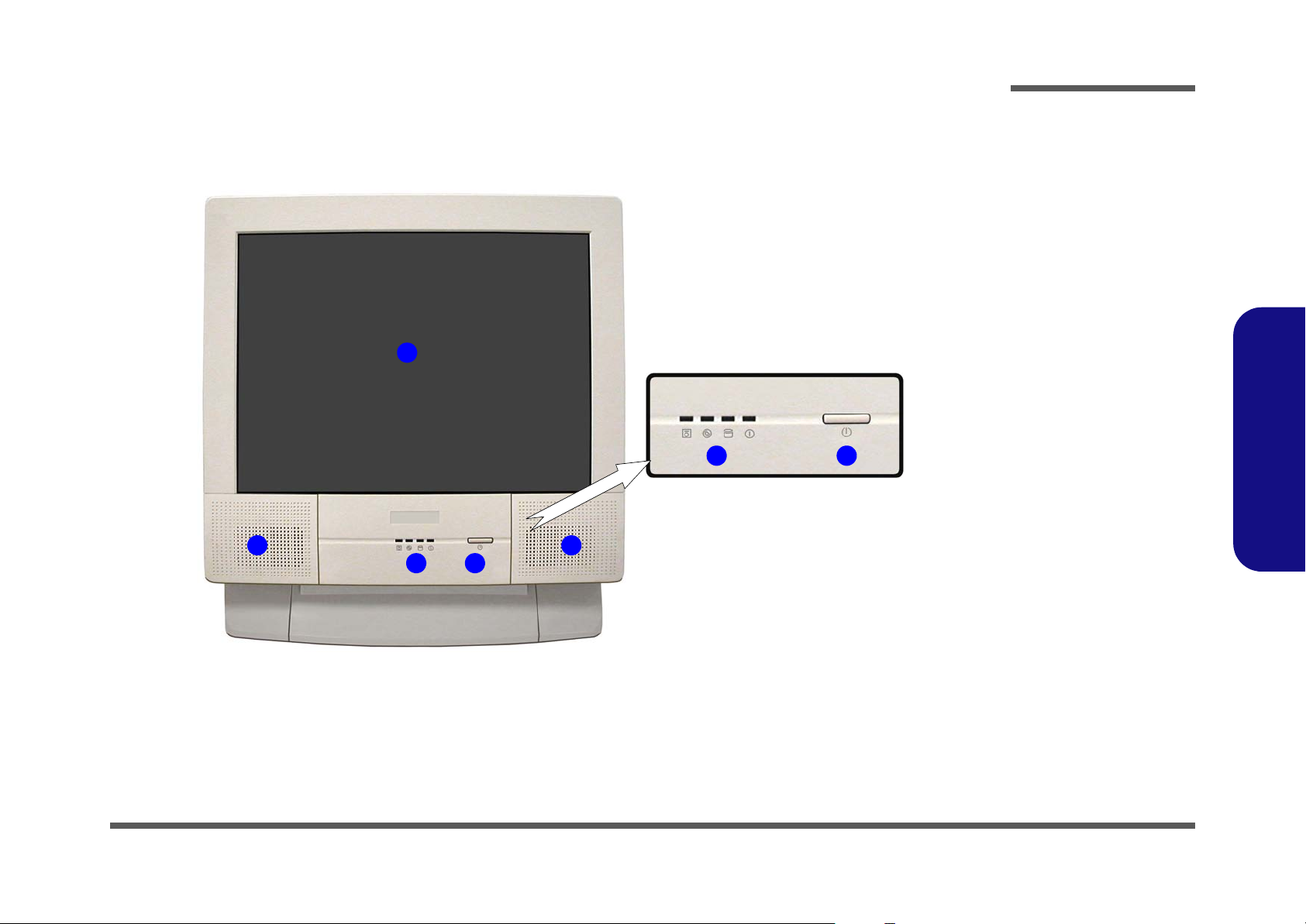
Figure 1 - 1
Front View
1. LCD Panel
2. Speakers
3. LED Activity
indicators
4. Power Button
1.Introduction
43
2
External Locator - Front View 1 - 5
Page 14
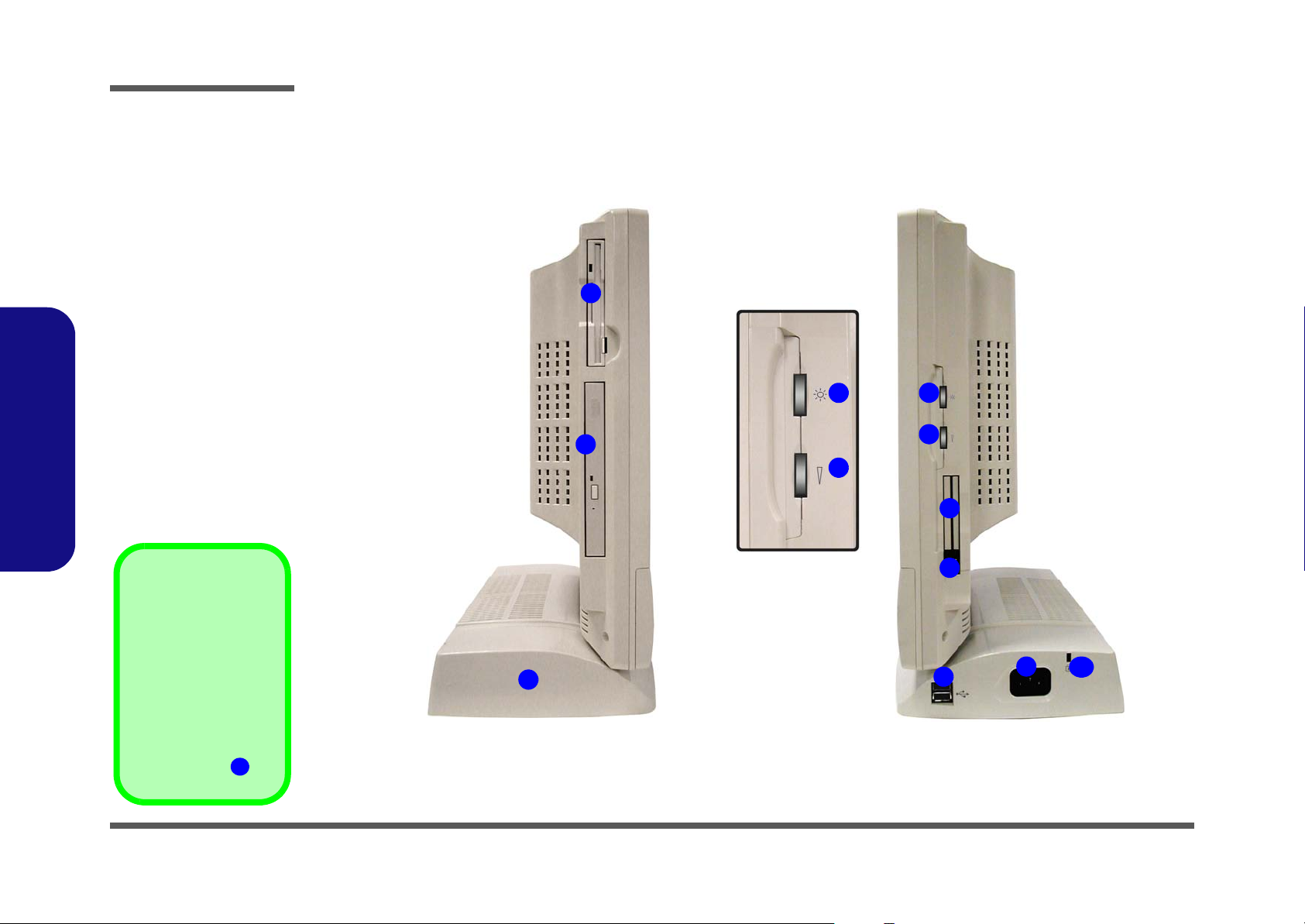
Introduction
Figure 1 - 2
Left & Right Views
1. Floppy Disk
Drive*
2. Hard Disk Drive
(HDD) Bay
3. CD Device
4. LCD Brightness
Control Knob
5. Volume Control
Knob
6. Dual PC Card
Slots
7. PC Card Eject
Buttons
8. Dual USB Ports
9. AC Power-In Port
10. Security Lock
1.Introduction
Slot
External Location - Left & Right Side Views
Left
1
4
3
5
Right
4
5
6
7
*Floppy Disk Drive &
Optional Modules
If you have either the
6-in-1 Card Reader,
or Video Capture
Card options, then
the optional module
will replace the floppy
disk drive module in
the slot at point .
1
2
1 - 6 External Location - Left & Right Side Views
8
9
10
Page 15
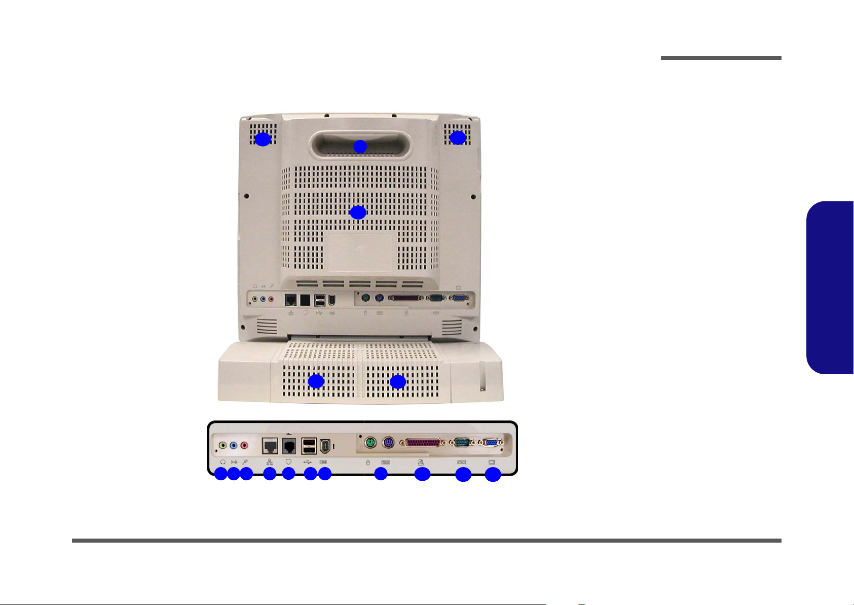
Introduction
External Locator - Rear View
13
13
13
Figure 1 - 3
Rear View
1. Carrying Handle
1
13
13
2. Headphone-Out
Jack
3. Line-In Jack
4. Microphone-In
Jack
5. RJ-45 LAN Jack
6. RJ-11 Phone
Jack
7. Dual USB Ports
8. Unpowered IEEE 1394 Port
9. PS/2 Mouse &
Keyboard Ports
10. Printer/Parallel
Port
11. Serial Port
12. External Monitor
(CRT) Port
13. Vents
1.Introduction
4 5
2 3 87
6
9
10
11 12
External Locator - Rear View 1 - 7
Page 16
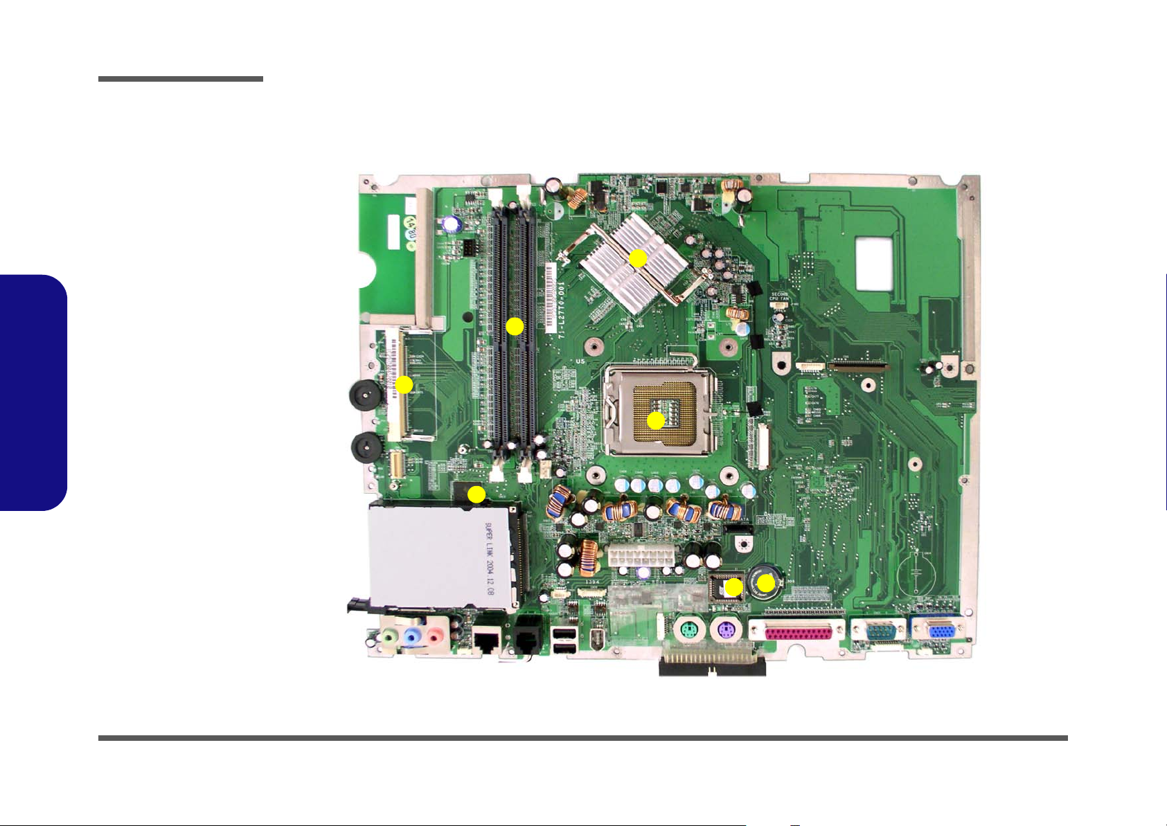
Introduction
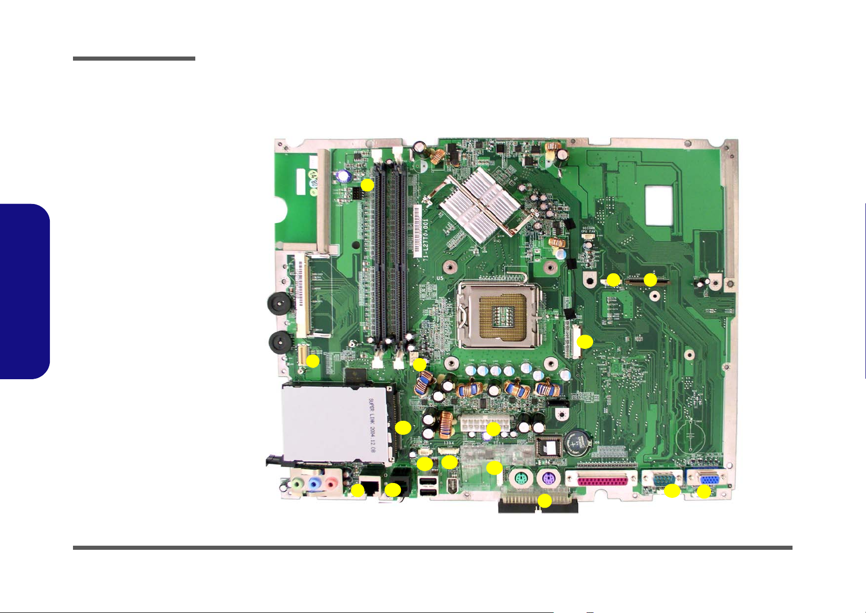
Figure 1 - 4
Mainboard Over-
view - Top
Key Parts
1. CPU Socket (no
CPU Installed)
2. Intel SpringdaleG (North Bridge)
3. RAM Sockets
4. Mini PCI Socket
for WLAN or
IEEE1394
5. FLASH BIOS
6. CMOS Battery
7. Cardbus
PCI1520
1.Introduction
Mainboard Overview - Top
Key Parts
2
3
4
1
7
1 - 8 Mainboard Overview - Top
6
5
Page 17
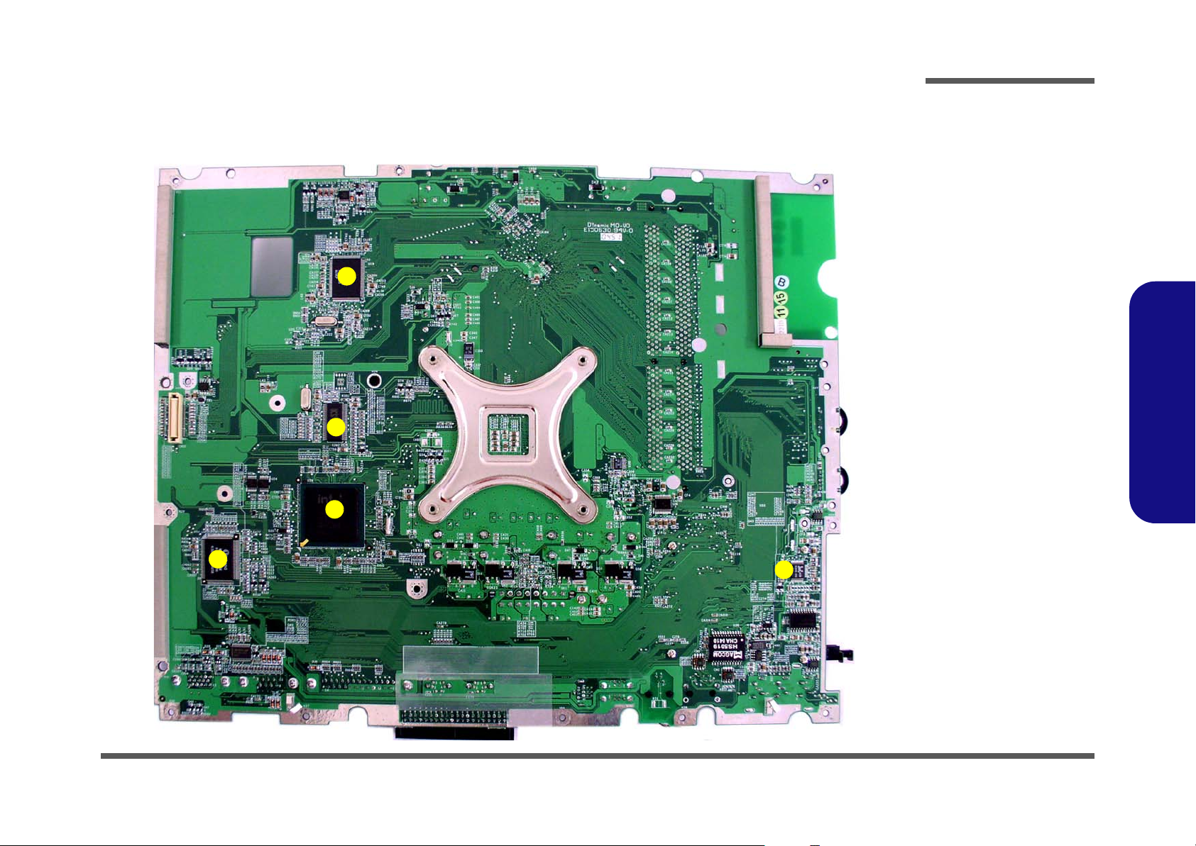
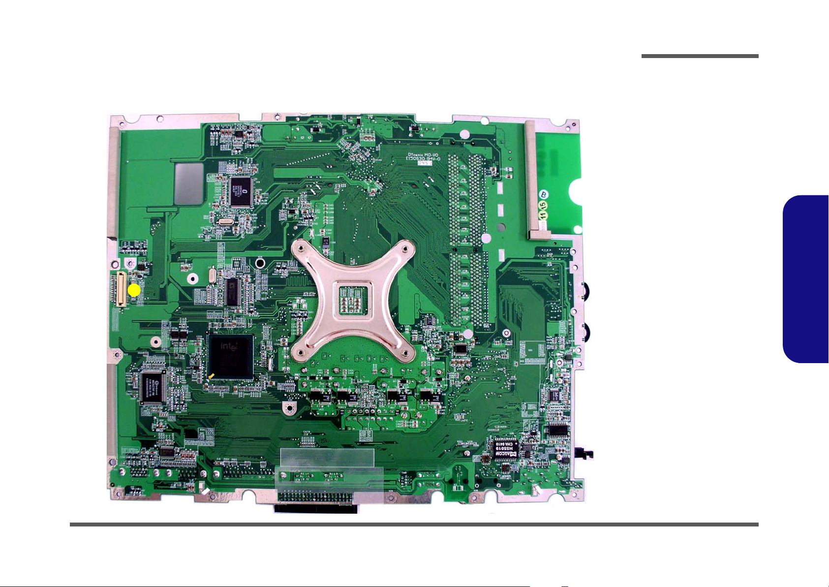
Introduction
Mainboard Overview - Bottom
Key Parts
1
2
3
Figure 1 - 5
Mainboard Over-
view - Bottom
Key Parts
1. Chrontel
CH7017A
2. Clock Generator
3. Intel ICH-5 460
mBGA (South
Bridge)
4. SUPER I/O
Winbond
W83627HF
5. AC’97 MDC
Module
1.Introduction
4
5
Mainboard Overview - Bottom 1 - 9
Page 18
Introduction
Figure 1 - 6
Mainboard Top
Cable Connectors &
Switches
1. Floppy Disk Drive
(CN5)
2. TV Port or Touch
Screen (Bluetooth
use)
3. CD/DVD Device
(CN7)
4. Fan Power (CN9)
5. Inverter (CN1)
6. Modem Module
7. Speaker (CN31)
8. Modem Cable
(CN33)
9. PC CARD (CN13)
1.Introduction
10. Touch Screen
(CN16)
11. IEEE1394 (CN36)
12. USB 2.0 (CN17)
13. LED Board
(CN30)
14. Speaker (CN32)
15. Power (CN12)
16. Hard Disk (CN34)
Mainboard Overview - Top
Cable Connectors and Switches
5
6
4
9
15
2
3
1
1 - 10 Mainboard Overview - Top
11
10
7
8
12
16
13
14
Page 19
Introduction
Mainboard Overview - Bottom
Cable Connectors and Switches
1
Figure 1 - 7
Mainboard Bottom
Cable Connectors &
Switches
1. CN35 (LCD
Connector)
1.Introduction
Mainboard Overview - Bottom 1 - 11
Page 20

Introduction
1.Introduction
1-12
Page 21
2: Disassembly
Overview
This chapter provides step-by-step instructions for disassembling parts and subsystems. When it comes to reassembly,
reverse the procedures (unless otherwise indicated).
We suggest you completely review any procedure before you take the computer apart.
Disassembly
Procedures such as upgrading/replacing the RAM, CD device and hard disk are included in the User’s Manual but are
repeated here for your convenience.
To make the disassembly process easier each section may have a box in the page margin. Information contained under
the figure # will give a synopsis of the sequence of procedures involved in the disassembly procedure. A box with a
lists the relevant parts you will have after the disassembly process is complete. Note: The parts listed will be for the disassembly procedure listed ONLY, and not any previous disassembly step(s) required. Refer to the part list for the previous disassembly procedure. The amount of screws you should be left with will be listed here also.
A box with a will provide any possible helpful information. A box with a contains warnings.
An example of these types of boxes are shown in the sidebar.
2.Disassembly
Information and
Component Parts
Warning
Overview 2 - 1
Page 22

Disassembly
2.Disassembly
NOTE: All disassembly procedures assume that the system is turned OFF, and disconnected from any power supply,
and that all peripheral cables are disconnected (including telephone lines and network cables).
Maintenance Tools
The following tools are recommended when working on the computer:
• M3 Philips-head screwdriver
• M2.5 Philips-head screwdriver (magnetized)
• M2 Philips-head screwdriver
• Small flat-head screwdriver
• Pair of needle-nose pliers
• Anti-static wrist-strap
Connections
Connections within the computer are one of four types:
Locking collar sockets for ribbon connectors To release these connectors, use a small flat-head screwdriver to gently pry the
locking collar away from its base. When replacing the connection, make sure
the connector is oriented in the same way. The pin1 side is usually not indicated.
2 - 2 Overview
Pressure sockets for multi-wire connectors To release this connector type, grasp it at its head and gently rock it from side
to side as you pull it out. Do not pull on the wires themselves. When replacing
the connection, do not try to force it. The socket only fits one way.
Pressure sockets for ribbon connectors To release these connectors, use a small pair of needle-nose pliers to gently lift
the connector away from its socket. When replacing the connection, make sure
the connector is oriented in the same way. The pin1 side is usually not indicated.
Board-to-board or multi-pin sockets To separate the boards, gently rock them from side to side as you pull them
apart. If the connection is very tight, use a small flat-head screwdriver - use
just enough force to start.
Page 23

Maintenance Precautions
The following precautions are a reminder. To avoid personal injury or damage to the computer while performing a removal and/or replacement job, take the following precautions:
1. Don't drop it. Perform your repairs and/or upgrades on a stable surface. If the computer falls, the case and other
components could be damaged.
2. Don't overheat it. Note the proximity of any heating elements. Keep the computer out of direct sunlight.
3. Avoid interference. Note the proximity of any high capacity transformers, electric motors, and other strong mag-
netic fields. These can hinder proper performance and damage components and/or data. You should also monitor
the position of magnetized tools (i.e. screwdrivers).
4. Keep it dry. This is an electrical appliance. If water or any other liquid gets into it, the computer could be badly
damaged.
5. Be careful with power. Avoid accidental shocks, discharges or explosions.
•Before removing or servicing any part from the computer, turn the computer off and detach any power supplies.
•When you want to unplug the power cord or any cable/wire, be sure to disconnect it by the plug head. Do not pu ll on the wir e.
6. Peripherals – Turn off and detach any peripherals.
7. Beware of static discharge. ICs, such as the CPU and main support chips, are vulnerable to static electricity.
Before handling any part in the computer, discharge any static electricity inside the computer. When handling a
printed circuit board, do not use gloves or other materials which allow static electricity buildup. We suggest that
you use an anti-static wrist strap instead.
8. Beware of corrosion. As you perform your job, avoid touching any connector leads. Even the cleanest hands produce oils which can attract corrosive elements.
9. Keep your work environment clean. Tobacco smoke, dust or other air-born particulate matter is often attracted
to charged surfaces, reducing performance.
10. Keep track of the components. When removing or re placing any part, be careful not to leave small p arts, such as
screws, loose inside the computer.
Disassembly
Power Safety
Warning
Before you undertake
any upgrade procedures, make sure that
you have turned off
the power, and disconnected all peripherals and cables
(including telephone
lines). It is advisable
to also remove your
battery in order to prevent accidentally turning the machine on.
2.Disassembly
Cleaning
Do not apply cleaner directly to the computer, use a soft clean cloth.
Do not use volatile (petroleum distillates) or abrasive cleaners on any part of the computer.
Overview 2 - 3
Page 24

Disassembly
Disassembly Steps
The following lists the disassembly steps, and on which page to find the related information. PLEASE PERFORM THE
DISASSEMBLY STEPS IN THE ORDER INDICATED.
2.Disassembly
To remove the hard disk drive assembly:
1. Remove the hard disk drive assembly page 2 - 5
To remove the LCD back cover:
1. Remove the LCD back cover page 2 - 6
To remove the system memory:
1. Remove the LCD back cover page 2 - 6
2. Remove the system memory page 2 - 7
To remove the CPU:
1. Remove the LCD back cover page 2 - 6
2. Remove the CPU page 2 - 8
To remove the I/O Bracket:
1. Remove the LCD back cover page 2 - 6
2. Remove the I/O bracket page 2 - 10
To remove the modem:
1. Remove the LCD back cover page 2 - 6
2. Remove the I/O bracket page 2 - 10
3. Remove the modem page 2 - 11
To remove the floppy disk drive assembly:
1. Remove the LCD back cover page 2 - 6
2. Remove the floppy disk drive assembly page 2 - 12
To remove the Mini PCI I/F module:
1. Remove the LCD back cover page 2 - 6
2. Remove the Mini PCI I/F module page 2 - 13
To remove the Optical Device:
1. Remove the LCD back cover page 2 - 6
2. Remove the optical device page 2 - 14
2 - 4 Disassembly Steps
Page 25

Disassembly
Removing the Hard Disk Drive Assembly
1. Turn OFF the computer and turn it around so that you may comfortably access the left side.
2. Remove screw from the HDD Bay .
3. Carefully pull the HDD assembly out from the bay and disconnect the IDE cable , and power cable .
4. Turn the assembly over and remove screws ( - ) holding the assembly to the bay cover .
5. Remove screws - and separate the hard disk and case .
6. Insert the new hard disk, and reverse the removal procedure to install the new hard disk.
a. b.
1 2
10 15
2
1
d.
9
5 8
16 17
e.
17
10
3 4
9
c.
3
4
11
12
Figure 2 - 1
Hard Disk Removal
Sequence
a. Remove the screw
from the HDD Bay.
b. Slide the HDD assem-
bly in the direction of
the arrow.
c. Disconnect the IDE
and power cables.
d. Remove the screws
from the assembly.
e. Remove the screws
and separate the HDD
from the case.
2.Disassembly
5
6
9. HDD Bay Cover
16
7
8
13
14
15
Removing the Hard Disk Drive Assembly 2 - 5
16.HDD
17.HDD case
•11 Screws
Page 26

Disassembly
Figure 2 - 2
LCD Back Cover
Removal
Sequence
a. Remove the screws
from the LCD back
cover.
b. Lift the cover out and
set it aside.
2.Disassembly
Removing the LCD Back Cover
1. Turn OFF the computer and place it with its LCD display facing down on a clean, dry, level surface.
2. Remove screws - from the LCD back cover and slide it up towards the top of the computer.
3. Carefully remove the LCD back cover from the main unit and set it aside.
a.
1 2 3 4
11
10
9
1 11
12
b.
5
12
8
6
7
12.LCD back cover
•11 Screws
2 - 6 Removing the LCD Back Cover
Page 27

Disassembly
Removing the System Memory
1. Remove the LCD back cover (page 2 - 6).
2. The memory sockets will be visible at point on the mainboard.
3. For each module you want to replace, gently pull the latches and toward the sides of the socket to release the
module.
4. Pull the latches to release the second module if necessary.
5. The module will pop-up, and you can remove it.
4
6. Insert a new module and fit the connectors firmly into the memory slot.
7. Reverse the procedures to put the computer back together, and do not forget all the screws. When you restart the
computer the new memory configuration should be registered.
8. If the system doesn’t properly detect the new memory, and you are sure they are properly “seated”, you may
need to run the Setup utility.
a.
1
1
2 3
b.
2
3
Figure 2 - 3
Memory Removal
Sequence
a. Locate the memory
sockets.
b. Pull the latch(es) on
the memory sockets to
release the module(s)
and lift it (them) out.
c. Insert a new module.
2.Disassembly
4. Memory module(s)
c.
Contact Warning
Be careful not to touch
the metal pins on the
module’s connecting
edge. Even the clean-
4
Removing the System Memory 2 - 7
est hands have oils
which can attract particles, and degrade the
module’s performance.
Page 28

Disassembly
Figure 2 - 4
CPU Removal
Sequence
a. Remove the screws
from the CPU heat
sink and fan unit.
b. Release the power ca-
ble and lift the heat
sink & fan unit out.
Caution
The heat sink, and
CPU area in general,
contains parts which
are subject to high
2.Disassembly
temperatures - Please
allow the area time to
cool before removing
these parts.
Removing the CPU
1. Remove the LCD back cover (page 2 - 6).
2. Remove screw - from the CPU heat sink fan unit.
3. Release the power cable from the board and lift out the CPU heat sink fan unit .
a.
5
1 4
1
4
5
6
b.
2
5
3
6
6. Heat Sink & Fan
•4 Screws
2 - 8 Removing the CPU
Page 29

Disassembly
4. Press down and hold the latch (on the top of the CPU unit).
5. You will be able to release the latch while it is held down, and then ease the bracket off the CPU unit
6. Carefully (it may be hot) lift the CPU up out of the socket using the CPU removal tool.
1
2
3
7. When re-inserting the CPU pay careful attention to the pin alignment, it will fit only one way (don’t force it!).
a.
1
c.
b.
2
Figure 2 - 5
CPU Removal
Sequence (cont’d)
a. Release the latch.
b. Ease the bracket off
the CPU unit.
b. Use the tool to lift out
the CPU.
2.Disassembly
3
3. CPU
Removing the CPU 2 - 9
Page 30

Disassembly
Figure 2 - 6
I/O Bracket
Removal
Sequence
a. Remove the screws
from the I/O bracket.
b. Lift the I/O bracket up
off the mainboard.
2.Disassembly
Removing the I/O Bracket
1. Remove the LCD back cover (page 2 - 6).
2. Remove the standard screws - , and use long-nosed pliers or a nutdriver to remove the hex socket connector
type screws - .
4 9
3. Carefully ease the I/O bracket off the mainboard.
a.
b.
1 3
10
4 5
2
6 7
819
3
10.I/O bracket
9 Screws
2 - 10 Removing the I/O Bracket
10
Page 31

Disassembly
Removing the Modem
1. Remove the LCD back cover (page 2 - 6) and I/O bracket (page 2 - 10).
2. Remove screws and from the modem module and disconnect the modem cable at point .
3. Disconnect the modem module from the connector socket , and lift it and the modem and cable off the
mainboard.
a. b.
1 2 3
4
1
2
5
4
5
6
6
Figure 2 - 7
Modem Removal
Sequence
a. Remove the screws
from the modem unit,
and disconnect the
cable.
b. Lift the modem and
cable off the board.
2.Disassembly
3
4. Modem module
6. Modem cable
•2 Screws
Removing the Modem 2 - 11
Page 32

Disassembly
Figure 2 - 8
Floppy Disk Drive
Assembly
Removal
Sequence
a. Remove the screws
from the FDD assembly and disconnect the
FDD ribbon cable.
b. Lift the FDD assembly
off the board.
2.Disassembly
Removing the Floppy Disk Drive Assembly
1. Remove the LCD back cover (page 2 - 6).
2. Remove screws - from the floppy disk drive assembly.
3. Carefully disconnect the floppy disk drive ribbon cable at point .
4. Lift the floppy disk drive assembly off the mainboard.
a.
1 4
5
6
2
1
3
45
b.
6. FDD Assembly
•4 Screws
2 - 12 Removing the Floppy Disk Drive Assembly
6
Page 33

Disassembly
Removing the Mini PCI I/F Module
1. Remove the LCD back cover (page 2 - 6,).
2. Release the pins at points & and carefully lift up the Mini PCI I/F module.
3. Disconnect the antenna cable at point on the module, then lift Mini PCI I/F module off the mainboard.
a.
1
3
1 2
3
b.
2
4
4
Figure 2 - 9
Mini PCI I/F Module
Removal
Sequence
a. Release the pins and
carefully lift the Mini
PCI I/F module up and
disconnect the cable.
b. Lift the Mini PCI I/F
module up and out
from the mainboard.
2.Disassembly
4. Mini PCI I/F module
Removing the Mini PCI I/F Module 2 - 13
Page 34

Disassembly
Figure 2 - 10
Optical Device
Assembly
Removal
Sequence
a. Remove the screws
and disconnect the
cable.
b. Remove the Optical
Device.
2.Disassembly
Removing the Optical Device Assembly
1. Remove the LCD back cover (page 2 - 6).
2. Remove screws - , and disconnect cable , from the optical device.
3. Remove the optical device .
a. b.
1
4
2
1 3 4
5
5
5. Optical Device
•3 Screws
2 - 14 Removing the Optical Device Assembly
3
Page 35

Appendix A: Part Lists
This appendix breaks down the computer’s construction into a series of illustrations. The component part numbers are
indicated in the tables opposite the drawings.
Note: This section indicates the manufacturer’s part numbers. Your organization may use a different system, so be sure
to cross-check any relevant documentation.
Note: Some assemblies may have parts in common (especially screws). However, the part lists DO NOT indicate the
total number of duplicated parts used.
Part Lists
Note: Be sure to check any update notices. The parts shown in these illustrations are appropriate for the system at the
time of publication. Over the product life, some parts may be improved or re-configured, resulting in new part numbers.
A.Part Lists
A-1
Page 36

Part Lists
Table A - 1
Part List Illustration
A.Part Lists
Part List Illustration Location
The following table indicates where to find the appropriate part list illustration.
Part L295T - Page #
Base page A - 3
Bracket page A - 4
Front page A - 5
DVD-RW page A - 6
FDD page A - 7
HDD page A - 8
Location
A - 2 Part List Illustration Location
Page 37

L295T - Base
Part Lists
(BL2164/深藍色)
SATA HDD CABLE (加拉帶跟導電布 480MM) L297T 無鉛
Figure A - 1
L295T - Base
A.Part Lists
L295T - Base A - 3
Page 38

Part Lists
Figure A - 2
L295T Bracket
A.Part Lists
L295T - Bracket
A - 4 L295T - Bracket
Page 39

L295T - Front
Part Lists
Figure A - 3
L295T - Front
A.Part Lists
L295T - Front A - 5
Page 40

Part Lists
Figure A - 4
L295T - Toshiba
A.Part Lists
L295T - Toshiba DVD-RW
DVD-RW
A - 6 L295T - Toshiba DVD-RW
Page 41

L295T - FDD
Part Lists
Figure A - 5
L295T - FDD
A.Part Lists
L295T - FDD A - 7
Page 42

Part Lists
Figure A - 6
L295T - HDD
A.Part Lists
L295T - HDD
A - 8 L295T - HDD
Page 43

Appendix B: Schematic Diagrams
This appendix has circuit diagrams of the systems PCB’s:
Schematic Diagrams
Diagram - Page Diagram - Page
System Block Diagram - Page B - 2 Thermal & Fan Controller - Page B - 17
CPU Prescott - 1 of 2 - Page B - 3 Cardbus PCI1520 - Page B - 18
CPU Prescott - 2 of 2 - Page B - 4 IEEE 1394 - Page B - 19
Clock Generator - Page B - 5 Cardbus Slot & Mini PCI - Page B - 20
MCH Power - Page B - 6 LAN RTL8100CL/8110SL - Page B - 21
MCH Host - Page B - 7 IDE Connector & Firmware Hub - Page B - 22
MCH AGP - Page B - 8 SIO W83627HF - Page B - 23
MCH Memory - Page B - 9 Serial & Parallel Port - Page B - 24
MCH Memory Termination - Page B - 10 CODEC - Page B - 25
DDR RIMM - Page B - 11 Amplifiers & Inverter Connector - Page B - 26
DVO Chrontel CH7107A - Page B - 12 Power 1 - Page B - 27
LCD Connector - Page B - 13 Power 2 - Page B - 28
CRT & USB - Page B - 14 Power 3 - Page B - 29
ICH5 (Power, LPC, Clock, SMbus) - Page B - 15 Power 4 - Page B - 30
Table B - 1
Schematic Diagram
B.Schematic Diagrams
ICH5 (PCI, IDE, UHB, USB, LAN) - Page B - 16
B-1
Page 44

Schematic Diagrams
Sheet 1 of 29
Schematic Diagram
B.Schematic Diagrams
System Block Diagram
CRT
RTL8110SBL
AC'97 MDC
FLOPPY
CHRONTEL
CH7017A
RealTek
MODULE
USB 1
USB 2
INT.
SATA
KEYBOARD
/ MOUSE
PCI Bus
AC'97 Bus
LCD
LVDS
PANEL
RJ-45
RJ-11
TOUCH
PANEL
TV-TUNER
SERIAL GPIOs
USB 3
USB 4
EXT.
PARALLEL
L297T System Block Diagram
3 * CPUCLKC
3 * CPUCLKT
6 * PCI-33MHz
2 * 48MHz
3 * 66MHz
2 * 14MHz
Dual-Channel DDR Memory - Bus
IDE Bus
R.G.B.
DVO
LGA-775
Intel Pentium 4 processor
Prescott or Northwood
400/533/800MHz
Host Bus
Intel
SPRINGDALE-G
( North Bridge )
266MB/s
Hub interface 1.5
Intel
ICH-5
460 mBGA
( South Bridge )
LPC Bus
SUPER I/O
Winbond
W83627HF
PCI Bus
AC'97 Bus
Firmware
HUB
( BIOS )
CLOCK
GENERATOR.
Channel A
DIMM 1
IDE 1
(ATA-100)
CARDBUS
PCI1520
AC'97
Audio Codec
RTCVCC
V_CORE
VTT1.2V
DUAL2.5V
+1.5V
+1.275V
SB3V
+1.7V
+12V
+5V
+3V
SB5V
Channel B
DIMM 2
IDE 2
(ATA-100)
MINI-PCI
WLAN or
IEEE1394
OPTION
MIC
LINE IN
HEAD PHONE
POWER
RTC
PWM
REGULATOR
EXTERNAL
POWER
B - 2
Page 45

CPU Prescott - 1 of 2
Z0201
Z0202
HREQ#0
HREQ#1
HREQ#2
HREQ#3
HREQ#4
HADSTB#0
HPCREQ#
Z0203
Z0204
Z0205
Z0206
Z0207
Z0208
HADSTB#1
ADS#
BNR#
HIT#
Z0209
BPRI#
DBSY#
DRDY#
HITM#
IERR#
HINIT#
HLOCK#
HTRDY#
Z0210
DEFER#
EDRDY#
Z0211
Z0212
Z0213
Z0214
Z0215
Z0216
Z0217
HGTLREF
RS#0
RS#1
RS#2
L5
P6
M5
L4
M4
R4
T5
U6
T4
U5
U4
V5
V4
W5
N4
P5
K4
J5
M6
K6
J6
R6
G5
AB6
W6
Y6
Y4
AA4
AD6
AA5
AB5
AC5
AB4
AF5
AF4
AG6
AG4
AG5
AH4
AH5
AJ5
AJ6
AC4
AE4
AD5
D2
C2
D4
H4
G8
B2
C1
E4
AB2
P3
C3
E3
AD3
G7
F2
AB3
U2
U3
F3
G3
G4
H5
J16
H15
H16
J17
H1
G23
B3
F5
A3
U5A
A03#
A04#
A05#
A06#
A07#
A08#
A09#
A10#
A11#
A12#
A13#
A14#
A15#
A16#
RSVD
RSVD
REQ0#
REQ1#
REQ2#
REQ3#
REQ4#
ADSTB0#
PC_REQ#
A17#
A18#
A19#
A20#
A21#
A22#
A23#
A24#
A25#
A26#
A27#
A28#
A29#
A30#
A31#
A32#
A33#
A34#
A35#
RSVD
RSVD
ADSTB1#
ADS#
BNR#
HIT#
RSP#
BPRI#
DBSY#
DRDY#
HITM#
IERR#
INIT#
LOCK#
TRDY#
BINIT#
DEFER#
EDRDY#
MCERR#
AP0#
AP1#
BR0#
TESTHI08
TESTHI09
TESTHI10
DP0#
DP1#
DP2#
DP3#
GTLREF0
RESET#
RS0#
RS1#
RS2#
CPU_LGA775-P4
V_CORE
VTT1.2V
VTT_OL
VTT1.2V
INIT#14,21
33PF
VTT_OL
BR0#6
VTT_OL
VTT_OL
CPURST#6
PLEASE COLSE TO Pin-H1
VTT_OR
R684 49.9_1%
C388
0.01UF_X7R
R678 62
C349
R683 62
HA#[3..16]6
HA#[17..31]6
EDRDY#
R677
20
R679 62
R680 62
R681 62
R682 62
R685
100_1%
HREQ#06
HREQ#26
HREQ#36
HREQ#46
HADSTB#06
HADSTB#16
HLOCK#6
HTRDY#6
DEFER#6
C371
22PF
HGTLREF
C389
1UF_X7R(0603)
DBSY#6
DRDY#6
ADS#6
BNR#6
BPRI#6
HITM#6
HIT#6
CPURST#
RS#06
RS#16
RS#26
BR#0
TESTHI8
TESTHI9
TESTHI10
C366 220PF
HA#3
HA#4
HA#5
HA#6
HA#7
HA#8
HA#9
HA#10
HA#11
HA#12
HA#13
HA#14
HA#15
HA#16
HA#17
HA#18
HA#19
HA#20
HA#21
HA#22
HA#23
HA#24
HA#25
HA#26
HA#27
HA#28
HA#29
HA#30
HA#31
D00#
D01#
D02#
D03#
D04#
D05#
D06#
D07#
D08#
D09#
D10#
D11#
D12#
D13#
D14#
D15#
DBI0#
HOST ADDRESS
DSTBN0#
DSTBP0#
D16#
D17#
D18#
D19#
D20#
D21#
HOST DATAHOST DATA
D22#
D23#
D24#
D25#
D26#
D27#
D28#
D29#
D30#
D31#
DBI1#
DSTBN1#
DSTBP1#
D32#
D33#
D34#
D35#
D36#
D37#
D38#
D39#
D40#
D41#
D42#
D43#
D44#
D45#
D46#
D47#
DBI2#
DSTBN2#
DSTBP2#
D48#
D49#
D50#
D51#
D52#
D53#
D54#
D55#
D56#
D57#
D58#
D59#
D60#
D61#
D62#
D63#
DBI3#
DSTBN3#
DSTBP3#
V_CORE 4,6,14,22,27
VTT1.2V 3,5,6,14,29
VTT_OL 3
B4
C5
A4
C6
A5
B6
B7
A7
A10
A11
B10
C11
D8
B12
C12
D11
A8
C8
B9
G9
F8
F9
E9
D7
E10
D10
F11
F12
D13
E13
G13
F14
G14
F15
G15
G11
G12
E12
G16
E15
E16
G18
G17
F17
F18
E18
E19
F20
E21
F21
G21
E22
D22
G22
D19
G20
G19
D20
D17
A14
C15
C14
B15
C18
B16
A17
B18
C21
B21
B19
A19
A22
B22
C20
A16
C17
HD#0
HD#1
HD#2
HD#3
HD#4
HD#5
HD#6
HD#7
HD#8
HD#9
HD#10
HD#11
HD#12
HD#13
HD#14
HD#15
HDB#0
HDSTBN#0
HDSTBP#0
HD#16
HD#17
HD#18
HD#19
HD#20
HD#21
HD#22
HD#23
HD#24
HD#25
HD#26
HD#27
HD#28
HD#29
HD#30
HD#31
HDB#1
HDSTBN#1
HDSTBP#1
HD#32
HD#33
HD#34
HD#35
HD#36
HD#37
HD#38
HD#39
HD#40
HD#41
HD#42
HD#43
HD#44
HD#45
HD#46
HD#47
HDB#2
HDSTBN#2
HDSTBP#2
HD#48
HD#49
HD#50
HD#51
HD#52
HD#53
HD#54
HD#55
HD#56
HD#57
HD#58
HD#59
HD#60
HD#61
HD#62
HD#63
HDB#3
HDSTBN#3
HDSTBP#3
HD#[0..15] 6
HDB#0 6
HDSTBN#0 6HREQ#16
HDSTBP#0 6
HD#[16..31] 6
HDB#1 6
HDSTBN#1 6
HDSTBP#1 6
HD#[32..47] 6
HDB#2 6
HDSTBN#2 6
HDSTBP#2 6
HD#[48..63] 6
HDB#3 6
HDSTBN#3 6
HDSTBP#3 6
V_CORE
V_CORE
C358
10UF(0805)_R
C374
10UF(0805)_R
V_CORE
AA8
AB8
AC23
AC24
AC25
AC26
AC27
AC28
AC29
AC30
AC8
AD23
AD24
AD25
AD26
AD27
AD28
AD29
AD30
AD8
AE11
AE12
AE14
AE15
AE18
AE19
AE21
AE22
AE23
AE9
AF11
AF12
AF14
AF15
AF18
AF19
AF21
AF22
AF8
AF9
AG11
AG12
AG14
AG15
AG18
AG19
AG21
AG22
AG25
AG26
AG27
AG28
AG29
AG30
AG8
AG9
AH11
AH12
AH14
AH15
C359
10UF(0805)_R
C375
10UF(0805)
U5C
VCC
VCC
VCC
VCC
VCC
VCC
VCC
VCC
VCC
VCC
VCC
VCC
VCC
VCC
VCC
VCC
VCC
VCC
VCC
VCC
VCC
VCC
VCC
VCC
VCC
VCC
VCC
VCC
VCC
VCC
VCC
VCC
VCC
VCC
VCC
VCC
VCC
VCC
VCC
VCC
VCC
VCC
VCC
VCC
VCC
VCC
VCC
VCC
VCC
VCC
VCC
VCC
VCC
VCC
VCC
VCC
VCC
VCC
VCC
VCC
CPU_LGA775-P4
C360
10UF(0805)
C376
10UF(0805)
C386 0.1UF
C390 0.1UF
C392 0.1UF
C394 0.1UF
C396 0.1UF
VCC
VCC
VCC
VCC
VCC
VCC
VCC
VCC
VCC
VCC
VCC
VCC
VCC
VCC
VCC
VCC
VCC
VCC
VCC
VCC
VCC
VCC
VCC
VCC
VCC
VCC
VCC
VCC
VCC
VCC
VCC
VCC
VCC
VCC
VCC
VCC
VCC
VCC
VCC
VCC
VCC
VCC
VCC
VCC
VCC
VCC
VCC
VCC
VCC
VCC
VCC
VCC
VCC
VCC
VCC
VCC
VCC
VCC
VCC
VCC
C361
10UF(0805)
C377
10UF(0805)
V_CORE
V_CORE
AH18
AH19
AH21
AH22
AH25
AH26
AH27
AH28
AH29
AH30
AH8
AH9
AJ11
AJ12
AJ14
AJ15
AJ18
AJ19
AJ21
AJ22
AJ25
AJ26
AJ8
AJ9
AK11
AK12
AK14
AK15
AK18
AK19
AK21
AK22
AK25
AK26
AK8
AK9
AL11
AL12
AL14
AL15
AL18
AL19
AL21
AL22
AL25
AL26
AL29
AL30
AL8
AL9
AM11
AM12
AM14
AM15
AM18
AM19
AM21
AM22
AM25
AM26
C378
10UF(0805)_R
C387 0.1UF
C391 0.1UF
C393 0.1UF
C395 0.1UF
C397 0.1UF
C362
10UF(0805)
V_CORE
C363
10UF(0805)
C379
10UF(0805)_R
AM29
AM30
AM8
AM9
AN11
AN12
AN14
AN15
AN18
AN19
AN21
AN22
AN25
AN26
AN29
AN30
AN8
AN9
J10
J11
J12
J13
J14
J15
J18
J19
J20
J21
J22
J23
J24
J25
J26
J27
J28
J29
J30
K23
K24
K25
K26
K27
K28
K29
K30
M23
M24
M25
M26
VCC
VCC
VCC
VCC
VCC
VCC
VCC
VCC
VCC
VCC
VCC
VCC
VCC
VCC
VCC
VCC
VCC
VCC
VCC
VCC
VCC
VCC
VCC
VCC
VCC
VCC
VCC
VCC
VCC
VCC
VCC
VCC
VCC
VCC
VCC
VCC
VCC
J8
VCC
J9
VCC
VCC
VCC
VCC
VCC
VCC
VCC
VCC
VCC
K8
VCC
L8
VCC
VCC
VCC
VCC
VCC
U5D
CPU_LGA775-P4
C350 22UF/6.3V
C352 22UF/6.3V_R
C354 22UF/6.3V
C356 22UF/6.3V_R
C364 22UF/6.3V
C367 22UF/6.3V
C369 22UF/6.3V
C372 22UF/6.3V
C380 22UF/6.3V
C382 22UF/6.3V
C384 22UF/6.3V
Schematic Diagrams
Sheet 2 of 29
CPU Prescott 1 of 2
V_CORE
M27
VCC
M28
VCC
M29
VCC
M30
VCC
M8
VCC
N23
VCC
N24
VCC
N25
VCC
N26
VCC
N27
VCC
N28
VCC
N29
VCC
N30
VCC
N8
VCC
P8
VCC
R8
VCC
T23
VCC
T24
VCC
T25
VCC
T26
VCC
T27
VCC
T28
VCC
T29
VCC
T30
VCC
T8
VCC
U23
VCC
U24
VCC
U25
VCC
U26
VCC
U27
VCC
U28
VCC
U29
VCC
U30
VCC
U8
VCC
V8
VCC
W23
VCC
W24
VCC
W25
VCC
W26
VCC
W27
VCC
W28
VCC
W29
VCC
W30
VCC
W8
VCC
Y23
VCC
Y24
VCC
Y25
VCC
Y26
VCC
Y27
VCC
Y28
VCC
Y29
VCC
Y30
VCC
Y8
VCC
V_CORE
V_CORE
1.55V
78~119A
Inside CPU socket
Button Side
C351 22UF/6.3V
C353 22UF/6.3V_R
C355 22UF/6.3V
C357 22UF/6.3V
C365 22UF/6.3V
C368 22UF/6.3V
C370 22UF/6.3V
C373 22UF/6.3V
C381 22UF/6.3V
C383 22UF/6.3V
C385 22UF/6.3V
B.Schematic Diagrams
CPU Prescott - 1 of 2 (71-L27T0-002) B - 3
Page 46

Schematic Diagrams
CPU Prescott - 2 of 2
Sheet 3 of 29
CPU Prescott 2 of 2
B.Schematic Diagrams
VCCA_VSSA_VCOREPLL Trace width donesn't less than 12 Mil
As close as possible to CPU socket
VTT1.2V
L64
10U2012K-500T40
VTT_OR
C336
0.1UF
THERMDA16
THERMDC16
L65
10U2012K-500T40
C331
C332
1UF(0603)
10UF/X7R(0805)
C334
1UF(0603)
RP1 8P4RX680_0402
4
R642 680
R643 680
Trace Width : 10 mil
C338
1000PF
FSBSEL04
FSBSEL14
VTT_OR
C340
C341
0.1UF
10UF(0805)
81
72
653
0.01UF
C342
12
C333
+
220UF/4V_1.7mm
VSSA
VID3
VID1
VID0
VID2
VID4
VID5
C339
1000PF
VTT1.2V
R896
470
100mA
VTT_OL
10UF(0805)
120mA
VCCA
R634
*0/SHT/X
VCOREPLL
THERMDA
THERMDC
R897
470
C343
VTT_OR
VTT_OR
C344
0.1UF
SMI#14
A20M#14
FERR#14
INTR14
IGNNE#14
STPCLK#14
VID[0..5]22,27
CPUCLK4
CPUCLK#4
VCCSENSE27
VSSSENSE27
R653 51_1%
R654 51_1%
R655 51_1%
R656 51_1%
R657 51_1%
R658 62
R659 62
R660 62
R661 62
R662 62
R663 62
ITPCLK4
ITPCLK#4
C345
0.01UF
Z0341
Z0340
VTT_OL
VTT1.2V
AN20
AN23
AN24
AN27
AN28
AN7
B11
B14
B17
B20
B24
C10
C13
C16
C19
C22
C24
D12
D15
D18
D21
D24
E11
E14
E17
E20
E25
E26
E27
E28
E29
F10
F13
F16
F19
F22
H10
H11
H12
H13
H14
H17
H18
H19
H20
H21
H22
H23
H24
H25
H26
H27
H28
H29
B1
B5
B8
C4
C7
D3
D5
D6
D9
E2
E8
F4
F7
G1
U5F
VSS
VSS
VSS
VSS
VSS
VIDSELECT
VSS
VSS
VSS
VSS
VSS
VSS
VSS
VSS
VSS
VSS
VSS
VSS
VSS
VSS
VSS
VSS
VSS
VSS
VSS
VSS
VSS
VSS
VSS
VSS
VSS
VSS
VSS
VSS
VSS
VSS
VSS
VSS
VSS
VSS
VSS
VSS
VSS
VSS
VSS
VSS
VSS
VSS
VSS
VSS
VSS
VSS
VSS
VSS
VSS
VSS
VSS
VSS
VSS
VSS
VSS
VSS
VSS
VSS
VSS
VSS
VSS
GTLREF_SEL
CPU_LGA775-P4
VTT_OL 2
VTT1.2V 2,5,6,14,29
H3
VSS
H6
VSS
H7
VSS
H8
VSS
H9
VSS
J4
VSS
J7
VSS
K2
VSS
K5
VSS
K7
VSS
L23
VSS
L24
VSS
L25
VSS
L26
VSS
L27
VSS
L28
VSS
L29
VSS
L30
VSS
L3
VSS
L6
VSS
L7
VSS
M1
VSS
M7
VSS
N3
VSS
N6
VSS
N7
VSS
P23
VSS
P24
VSS
P25
VSS
P26
VSS
P27
VSS
P28
VSS
P29
VSS
P30
VSS
P4
VSS
P7
VSS
R2
VSS
R23
VSS
R24
VSS
R25
VSS
R26
VSS
R27
VSS
R28
VSS
R29
VSS
R30
VSS
R5
VSS
R7
VSS
T3
VSS
T6
VSS
T7
VSS
U1
VSS
U7
VSS
V23
VSS
V24
VSS
V25
VSS
V26
VSS
V27
VSS
V28
VSS
V29
VSS
V30
VSS
V3
VSS
V6
VSS
V7
VSS
W4
VSS
W7
VSS
Y2
VSS
Y5
VSS
Y7
VSS
CPUPWRGD
U5B
P2
SMI#
SMI#
K3
A20M#
A20M#
R3
FERR#
FERR#/PBE#
K1
INTR
LINT0
L1
NMI
NMI14
CPUCLK
CPUCLK#
FSBSEL0
FSBSEL1
FSBSEL2
IGNNE#
STPCLK#
VCCA
VSSA
Z0301
VCOREPLL
VID0
VID1
VID2
VID3
VID4
VID5
Z0302
Z0303
Z0308
TCK
TDI
TDO
TMS
TRST#
BPM#0
BPM#1
BPM#2
BPM#3
BPM#4
BPM#5
Z0322
ITPCLK
ITPCLK#
Z0309
Z0310
Z0311
Z0312
Z0313
Z0314
Z0315
Z0316
Z0317
Z0318
Z0319
Z0320
Z0306
Z0307
LINT1
N2
IGNNE#
M3
STPCLK#
A23
VCCA
B23
VSSA
D23
RSVD
C23
VCCIOPLL
AM2
VID0
AL5
VID1
AM3
VID2
AL6
VID3
AK4
VID4
AL4
VID5
AM5
RSVD/VID6
F28
BCLK0
G28
BCLK1
AE8
SKTOCC#
AL1
THERMDA
AK1
THERMDC
AN3
VCC_SENSE
AN4
VSS_SENSE
AN5
RSVD
AN6
RSVD
F29
VTT_PKGSENSE/RSVD
AE1
TCK
AD1
TDI
AF1
TDO
AC1
TMS
AG1
TRST#
AJ2
BPM0#
AJ1
BPM1#
AD2
BPM2#
AG2
BPM3#
AF2
BPM4#
AG3
BPM5#
AC2
DBR#
AK3
ITP_CLK0
AJ3
ITP_CLK1
G29
BSEL0
H30
BSEL1
G30
BSEL2
AE3
RSVD
D1
RSVD
D14
RSVD
E5
RSVD
E6
RSVD
E7
RSVD
F6
RSVD
B13
RSVD
T2
RSVD/COMP5
V1
RSVD
W1
RSVD
Y3
RSVD
CPU_LGA775-P4
THERMTRIP#
BOOTSELECT
VTT_OUT_RIGHT
VTT_OUT_LEFT
GTLREF1/NC
TESTHI00
TESTHI01
TESTHI11
TESTHI12
TESTHI02
TESTHI03
TESTHI04
TESTHI05
TESTHI06
TESTHI07
RSVD
RSVD
RSVD
PWRGOOD
PROCHOT#
COMP0
COMP1
COMP2
COMP3
LL_ID0
LL_ID1
VTTPWRGD
VTT_SEL
RSVD
RSVD
RSVD
RSVD
RSVD
RSVD
COMP4/NC
TESTHI0
F26
TESTHI1
W3
TESTHI11
P1
TESTHI12
W2
F25
G25
G27
G26
G24
F24
TESTHI2_7
AK6
RSVD AK6
RSVD G6
G6
CPUSLP#
L2
SLP#
Z0321
AH2
CPUPWRGD
N1
PROCHOT#
AL2
THERMTRIP#
M2
COMP0
A13
T1
COMP1
COMP2
G2
R1
COMP3
Y1
BOOTSEL
LL_ID0
V2
LL_ID1
AA2
A25
VTT
A26
VTT
A27
VTT
A28
VTT
A29
VTT
A30
VTT
B25
VTT
B26
VTT
B27
VTT
B28
VTT
B29
VTT
B30
VTT
C25
VTT
C26
VTT
C27
VTT
C28
VTT
C29
VTT
C30
VTT
D25
VTT
D26
VTT
D27
VTT
D28
VTT
D29
VTT
D30
VTT
AM6
AA1
J1
Z0326
F27
Z0327
N5
Z0328
AE6
Z0329
C9
Z0330
G10
Z0331
D16
Z0332
A20
Z0333
E23
NC
Z0334
E24
NC
Z0335
F23
NC
Z0336
H2
Z0337
J2
Z0338
J3
NC
FERR#
R632 62
R633 62
R635 62
R636 62
R637 62
R638 *62
R639 *62
C335 33PF
R644 60.4_1%
R645 60.4_1%
R646 100_1%
R647 100_1%
R648 *62
VTT1.2V_PWRGD
R671 *1K
C330 1000PF
R628 100
R630 62
VTT1.2V
VTT_OL
VTT1.2V
VTT_OR
VTT_OL
CPUSLP# 14
CPUPWRGD 14
PROCHOT# 6
THERMTRIP# 14,16
Place outside of CPU socket
VTT_OL
C337 0.1UF_X7R
VTT_OR
VTT1.2V
4A
VTT1.2V_PWRGD 29
Wider than
VTT_OR
12 mil
VTT_OL
+3V
VTT1.2V
C346
10UF(0805)
C347
0.1UF
C348
0.01UF
VTT_OL
VTT1.2V
VSSSENSE
S2
SHORT
C486
0.1u
U5E
A12
VSS
A15
VSS
A18
VSS
A2
VSS
A21
VSS
A24
VSS
A6
VSS
A9
VSS
AA23
VSS
AA24
VSS
AA25
VSS
AA26
VSS
AA27
VSS
AA28
VSS
AA29
VSS
AA3
VSS
AA30
VSS
AA6
VSS
AA7
VSS
AB1
VSS
AB23
VSS
AB24
VSS
AB25
VSS
AB26
VSS
AB27
VSS
AB28
VSS
AB29
VSS
AB30
VSS
AB7
VSS
AC3
VSS
AC6
VSS
AC7
VSS
AD4
VSS
AD7
VSS
AE10
VSS
AE13
VSS
AE16
VSS
AE17
VSS
AE2
VSS
AE20
VSS
AE24
VSS
AE25
VSS
AE26
VSS
AE27
VSS
AE28
VSS
AE29
VSS
AE30
VSS
AE5
VSS
AE7
VSS
AF10
VSS
AF13
VSS
AF16
VSS
AF17
VSS
AF20
VSS
AF23
VSS
AF24
VSS
21
AF25
VSS
AF26
VSS
AF27
VSS
AF28
VSS
AF29
VSS
AF30
VSS
AF3
VSS
AF6
VSS
AF7
VSS
AG10
VSS
AG13
VSS
AG16
VSS
AG17
VSS
AG20
VSS
CPU_LGA775-P4
C488
C487
0.1u
0.1u
AG23
VSS
AG24
VSS
AG7
VSS
AH1
VSS
AH10
VSS
AH13
VSS
AH16
VSS
AH17
VSS
AH20
VSS
AH23
VSS
AH24
VSS
AH3
VSS
AH6
VSS
AH7
VSS
AJ10
VSS
AJ13
VSS
AJ16
VSS
AJ17
VSS
AJ20
VSS
AJ23
VSS
AJ24
VSS
AJ27
VSS
AJ28
VSS
AJ29
VSS
AJ30
VSS
AJ4
VSS
AJ7
VSS
AK10
VSS
AK13
VSS
AK16
VSS
AK17
VSS
AK2
VSS
AK20
VSS
AK23
VSS
AK24
VSS
AK27
VSS
AK28
VSS
AK29
VSS
AK30
VSS
AK5
VSS
AK7
VSS
AL10
VSS
AL13
VSS
AL16
VSS
AL17
VSS
AL20
VSS
AL23
VSS
AL24
VSS
AL27
VSS
AL28
VSS
AL3
VSS
AL7
VSS
AM1
VSS
AM10
VSS
AM13
VSS
AM16
VSS
AM17
VSS
AM20
VSS
AM23
VSS
AM24
VSS
AM27
VSS
AM28
VSS
AM4
VSS
Z0339
AM7
VID7/VSS
AN1
VSS
AN10
VSS
AN13
VSS
AN16
VSS
AN17
VSS
AN2
VSS
C489
0.1u
C491
C490
0.1u
0.1u
+3V
+3V 4..6,11..17,19..24,26..29
B - 4 CPU Prescott - 2 of 2 (71-L27T0-002)
Page 47

Clock Generator
Schematic Diagrams
R105
10_1%_R
+3V
VTT_PWRGD#
Iref=2.32mA
R99
475_1%
R894 1.5K
1 = HI , 0 = LOW
ID1
ID2
ID3
ID4
55
Z0401
VDDA
Z0402
34
VDD48
3
Z0403
VDDREF
10
VDDPCI
16
VDDPCI
24
VDD3V66
36
VDDSRC
42
VDDCPU
48
VDDCPU
28
SCLK
30
SDATA
21
Z0404
PD#
49
PCI_STOP#
50
CPU_STOP#
35
VTT_PWRGD#
51
FS_A
56
FS_B
Z0405
52
IREF
6
GND
11
GND
17
GND
25
GND
33
GND
39
GND
45
GND
53
GND
54
GND
Z0431
G
S
G
S
R895 4.7K
24_48MHz/SEL24_48#
Q73
D
2N7002
Q74
D
2N7002
MBID1
1
1
0
0
U22
CPUCLKC0
CPUCLKC1
CPUCLKC2
CPUCLKT0
CPUCLKT1
CPUCLKT2
PCICLK0/Reset_EN
PCICLK1
PCICLK2
PCICLK3
PCICLK4
PCICLK5
PCICLK6
PCICLK_FS2
PCICLK_FS4
PCICLK_F2
48MHz_0/FS3
SRCCLKC
SRCCLKT
3V66_0/Reset#
3V66_1
3V66_2
3V66_3
3V66_4/VCH_CLK
ICS952618
CLKBSEL0
CLKBSEL1
MBID2
1
V1.0
0
V3.0
1
V4.0
0
Z0407
40
Z0408
43
Z0409
46
Z0410
41
44
Z0411
Z0412
47
Z0413
12
Z0414
13
14
Z0415 R369 33_1%
Z0416
15
18
Z0417
Z0418
19
TZ0401
20
7
Z0432
Z0433
8
9
TZ0402
Z0419
1
REF0
Z0420
2
REF1
Z0421
31
32
Z0422
Z0423
37
Z0424
38
TZ0403
22
23
Z0425
Z0426
26
TZ0404
27
Z0427
29
Z0429
4
X1
Z0430
5
X2
C224
18p
V2.0
R356 10K
R359 10K
R352
0_R
Y2
12
14.318MHz
FOR L297P
FOR L297P
FOR L297T
R371 33_1%
R363 33_1%
R357 33_1%
R367 33_1%
R360 33_1%
R354 33_1%
R362 33_1%
R365 33_1%
R373 33_1%
R378 33_1%
R381 33_1%
R349 33_1%_R
R350 33_1%_R
R347 33_1%
R393 10K
R391 33_1%
R382 33_1%
R390 10K
R379 33_1%
R376 33_1%
R383 33_1%
R384 33_1%
R392 33_1%_R
R603 33_1%
C223
18p
CLK100#
CLK100
R355
49.9_1%
R361
49.9_1%
CP25
CP22
33p
10p
CLK100# 14
CLK100 14
FREQUENCY SETUP TABLE
(FS3)
(FS2)
(FS4)
+3V
+3V
V_CORE
V_CORE 2,6,14,22,27
+3V 3,5,6,11..17,19..24,26..29
+5V 11..14,16,17,19,21..29
(FSA)
0
0
0
0
0
0
0
0
0
L45 FCM2012K-121T 0805
+3V
L44
FCM2012K-121T 0805
CT56
+
10u/10V_1206
BSEL06
BSEL16
R395 10K CLK100
R403
220
(FSB)
0
0
1
CT57
10u/10V_1206
CA83
0.1u_X7R
R313
2.49K_1%
Z0406
2N3904
0
1
0
CA224
0.1u_X7R
R321 2K_1%
R320 2K_1%
R312
2.49K_1%
B
Q33
E C
CPU
(MHz)
100.00
200.00
133.33
C78
0.01u
VTT_PWRGD#
CA79
0.1u_X7R
+3V
SRC
(MHz)
100/200
100/200
100/200
PCI
AGP
(MHz)
(MHz)
66.67 33.33
33.33
66.67
66.67
33.33
R402 1_1%
CA221
CA77
0.1u_X7R
0.1u_X7R
+3V
CT58
10u/10V_1206
CA225
0.1u_X7R
R351
1K_1%
FSBSEL03
FSBSEL13
SMBDATA10,14,16,20,22
+3V
R353
1K_1%
SMBCLK10,14,16,20,22
CA86
0.1u_X7R
CA227
0.1u_X7R
R375 1K
CLKBSEL0
CLKBSEL1
+5V
R368
49.9_1%
CP27
10p
R458 10K_R
R459 10K
R358
49.9_1%
CP29
10p
CP11
CP10
10p
10p_R
CP38
CP37
10p
10p
CP32
10p
CP9
10p
CLK100#
CP3
10p
R456
0
R364
49.9_1%
CP35
10p
CP39
10p
R377
49.9_1%
R457
0_R
CP36
10p
R372
49.9_1%
R380
49.9_1%
MBID1 22
MBID2 22
ITPCLK# 3
CPUCLK# 3
MCHCLK# 6
ITPCLK 3
CPUCLK 3
MCHCLK 6
FWHPCLK 21
LANPCLK 20
ICHPCLK 15
PCLK 17
MINI-PCLK 19
SIOPCLK 22
CH7017A-CLK 11
ALC650 24
ICH-14M 14
ICH-48M 14
DREFCLK 7
MCH66CLK 7
ICH66CLK 14
SIO-48M 22
Sheet 4 of 29
Clock Generator
B.Schematic Diagrams
Clock Generator (71-L27T0-002) B - 5
Page 48

Schematic Diagrams
Sheet 5 of 29
MCH Power
B.Schematic Diagrams
MCH Power
VTT1.2V 2,3,6,14,29
+1.5V 7,11,13..15,22,28
DUAL2.5V 8,10,22,26
VSMYRC 8
VSMYRCO 8
+1.7V 26
M26
M27
M28
M30
M33
N32
N35
R32
U18
U19
U32
W17
W18
W32
Y10
Y26
Y27
Y28
Y30
Y33
Y35
L35
M3
M6
N1
N4
P3
P6
P8
P9
P26
P27
P28
P30
P33
R1
R4
T1
T3
T6
T8
T9
T10
T26
T27
T28
T30
T33
T35
U4
V3
V6
V8
V9
V10
V17
V19
V26
V27
V28
V30
V33
W4
Y3
Y6
Y8
Y9
VSS
VSS
VSS
VSS
VSS
VSS
VSS
VSS
VSS
VSS
VSS
VSS
VSS
VSS
VSS
VSS
VSS
VSS
VSS
VSS
VSS
VSS
VSS
VSS
VSS
VSS
VSS
VSS
VSS
VSS
VSS
VSS
VSS
VSS
VSS
VSS
VSS
VSS
VSS
VSS
VSS
VSS
VSS
VSS
VSS
VSS
VSS
VSS
VSS
VSS
VSS
VSS
VSS
VSS
VSS
VSS
VSS
VSS
VSS
VSS
VSS
VSS
VSS
VSS
VSS
VSS
VSS
J6J7J8J9K6K7K8K9L6L7L9
VCC
VCC
VSS
VSS
VSS
VSS
AA1
AA4
AA32
AB3
AB6
L10
VCC
VCC
VCC
VCC
VCC
VCC
VCC
VCC
VCC
VSS
VSS
VSS
VSS
VSS
VSS
VSS
VSS
VSS
AB8
AB9
AB10
AB26
AB27
AB28
AB30
AB33
AC1
L11M8M9
VCC
VSS
AC4
VCCA_FSB
+1.5V
CA24
0.1u_X7R
+
C55
330u/6.3V_6.3*11
VCCA_DPLL
CA177
0.1u_X7R
VSMYRCO
+3V
VCCA_DAC
C45
0.01u
VTT1.2V
CA26
0.1u_X7R
CA178
0.1u_X7R
CA27
0.1u_X7R
VCCA_DDR
L9 0.1uH_0805
C48
+
100u/16V_6.3*7
C44
+
100u/16V_6.3*7
+
CT42
4.7u/16V_1206
VSMYRCO
C68
0.22u
L7 0.1uH_0805
兆旭
845 HEAT SINK HOOK
兆旭
845 HEAT SINK HOOK
+1.5V
C42
+
330u/6.3V_6.3*11
Close Power Output
M10
M11N9N10
N11
P10
P11
R11
T16
T17
T18
T19
VCC
VCC
VCC
VCC
VCC
VCC
VCC
VCC
VCC
VCC
VCC
VCC
VCC
VCC
+
10u/10V_1206
T20
U16
VCC
VCC
CT1
CT46
+
4.7u/16V_1206
U17
U20
V16
V18
V20
W16
W19
W20
Y16
Y17
VCC
VCC
VCC
VCC
VCC
VCC
VCC
VCC
VCC
VCC
CA193
CA192
0.1u_X7R
0.1u_X7R
Y18
Y19
Y20J1J2J3J4J5K2K3K4K5L1L2L3L4L5
VCC
VCC
VCC
VCC
VCC_AGP
VCC_AGP
VCC_AGP
VCC_AGP
VCC_AGP
VCC_AGP
CA7 0.1u_X7R
CA12 0.1u_X7R
C56 0.47u
C58 0.47u
CA50 0.1u_X7R
Z0503
Z0504
Z0501
Z0502
Z0505
A15
A21
A31A4A5A6B5B6C5C6D5D6D7E6E7
AG1
Y1
VTT
VTT
VTT
VTT
VTT
VTT
VTT
VCC_AGP
VCC_AGP
VCC_AGP
VCC_AGP
VCC_AGP
VCC_AGP
VCC_AGP
VCC_AGP
VCC_AGP
VCC_AGP
VTT
CA32
CA33
0.1u_X7R
0.1u_X7R
1 inch
VCCA_FSB
VCCA_DPLL
VCCA_DAC
F7
B4B3C2
AB25
VTT
Y11
VTT
VTT
VTT
VTT
VTT
VTT
VTT
VCCA_FSB
VCCA_AGP
VCCA_DAC
VCCA_DPLL
SPRINGDALE-GMCH POWER & GROUND
VSS
VSS
VSS
VSS
VSS
VSS
VSS
VSS
VSS
VSS
VSS
VSS
VSS
VSS
VSS
VSS
VSS
VSS
VSS
VSS
VSS
VSS
VSS
VSS
VSS
VSS
VSS
VSS
VSS
VSS
VSS
VSS
VSS
VSS
VSS
VSS
VSS
VSS
VSS
VSS
VSS
VSS
VSS
VSS
VSS
VSS
VSS
VSS
VSS
VSS
VSS
VSS
VSS
VSS
VSS
VSS
VSS
VSS
VSS
VSS
VSS
VSS
VSS
VSS
VSS
VSS
VSS
VSS
VSS
VSS
VSS
VSS
VSS
VSS
VSS
VSS
VSS
AC32
AC35
AD3
AD6
AD8
AD9
AD10
AD28
AD30
AD33
AE1
AE4
AE10
AE11
AE12
AE13
AE25
AE26
AE32
AE35
AF3
AF6
AF9
AF11
AF14
AF16
AF18
AF20
AF22
AF24
AF25
AF30
AF33
AG4
AG8
AG14
AG16
AG18
AG20
AG22
AG24
AG26
AG28
AG32
AG35
AH3
AH12
AH6
AH10
AH14
AH16
AH18
AH20
AH22
AH24
AH30
AH33
AJ1
AJ4
AJ9
AJ32
AJ35
AK3
AK8
AK10
AK12
AK14
AK16
VSS
AK18
AK20
AK22
AK24
AK26
AK28
AL1
AL32
AM9
AM11
VCCA_DDR1
VSS
C52
0.47u
1 inch
U2A
AC25
AC26
VCCA_DDR2
VCCA_DDR3
VSSA_DAC
VSS
VSS
VSS
VSS
AM13
AM15
AM17
AM19
CT3
+
C51
4.7u/16V_1206
1u
Close Power Ouput
14 mil
VCCA_DDR
AL6
VCC_DDR
AL7
VCC_DDR
AM1
VCC_DDR
AM2
VCC_DDR
AM3
VCC_DDR
AM5
VCC_DDR
AM6
VCC_DDR
AM7
VCC_DDR
AM8
VCC_DDR
AN2
VCC_DDR
AN4
VCC_DDR
AN5
VCC_DDR
AN6
VCC_DDR
AN7
VCC_DDR
AN8
VCC_DDR
AP3
VCC_DDR
AP4
VCC_DDR
AP5
VCC_DDR
AP6
VCC_DDR
AP7
VCC_DDR
AR4
VCC_DDR
AR5
VCC_DDR
AR7
VCC_DDR
AR31
VCC_DDR
AA35
VCC_DDR
AL35
VCC_DDR
AR15
VCC_DDR
AR21
VCC_DDR
E35
VCC_DDR
R35
VCC_DDR
G1
VCC_DAC
G2
VCC_DAC
D3
AR32
VSS
AR29
VSS
AR27
VSS
AR25
VSS
AR23
VSS
AR20
VSS
AR16
VSS
AR13
VSS
AR11
VSS
AR9
VSS
AN32
VSS
AN30
VSS
AN28
VSS
AN26
VSS
AN24
VSS
AN22
VSS
AN20
VSS
AN18
VSS
AN16
VSS
AN14
VSS
AN12
VSS
AN10
VSS
AM35
VSS
AM29
VSS
AM27
VSS
AM25
VSS
AM23
VSS
AM21
VSS
SPRINGDALE-G
+
CT4
4.7u/16V_1206
TZ0501
Z0508
Z0509
Z0510
Z0511
CA31
0.1u_X7R
CA196
0.1u_X7R
DUAL2.5V
+
CT41
22u/10V_1206
C70
0.47u
HOLDER1
/ A019-194-02-240
HOLDER2
/ A019-194-02-240
L8 0.82uH
C53
+
100u/16V_6.3*7
L6
BEAD BK2125HS 470_1A_0805
C43
+
100u/16V_6.3*7
R48 1_1%
Z0506
Z0507
R44 1_1%
CA181
0.1u_X7R
VSMYRC
C41
CA9
0.22u
0.1u_X7R
CA184
0.1u_X7R
CA30
0.1u_X7R
VSMYRC
+1.5V
+1.5V
+1.7V
CA183
0.1u_X7R
CA39
0.1u_X7R
+1.5V
B - 6 MCH Power (71-L27T0-002)
Page 49

MCH Host
Schematic Diagrams
VTT1.2V
C481
1u
VTT1.2V 2,3,5,14,29
V_CORE 2,4,14,22,27
R69 200_1%
V_CORE
R902
200_1%
GMCHDVREF
R893
169_1%
CPURST#2
HD#[0..63]2
ADS#2
HTRDY#2
DRDY#2
DEFER#2
HITM#2
HIT#2
HLOCK#2
BR0#2
BNR#2
BPRI#2
DBSY#2
RS#02
RS#12
RS#22
R63 20_1%
TRACE WIDE 10 MILS
C482
0.01u
GMCH-PWROK
Z0601
HDSWING
GMCHDVREF
3.5 inches max
CLOSE MCH
HD#[0..63]
CA202
0.1u
HA#[3..31]2
AE14
Sheet 6 of 29
MCH Host
HD#6
HD#1
HD#7
HD#5
HD#3
HD#9
HD#8
HD#2
HD#4
HD#0
B23
E22
B21
D20
B22
D22
B20
C21
E18
HD0#
HD1#
HD2#
HD3#
HD4#
HD5#
HD6#
HD7#
F27
ADS#
D24
HTRDY#
G24
DRDY#
L21
DEFER#
E23
HITM#
K21
HIT#
E25
HLOCK#
B24
BREQ0#
B28
BNR#
B26
BPRI#
E27
DBSY#
G22
RS0#
C27
RS1#
B27
RS2#
E8
CPURST#
PWROK
E24
HDRCOMP
C25
HDSWING
F23
HDVREF
HA#[3..31]
+3V
HD#16HA#10
HD#11
HD#15
HD#14
HD#10
HD#13
HD#12
E20
B16
D16
B18
B17
E16
D18
G20
HD8#
HD9#
HD10#
HD11#
HD12#
HD13#
HD14#
HD15#
SPRINGDALE-GMCH HOST INTERFACE
HA3#
HA4#
HA5#
HA6#
HA7#
HA8#
HA9#
D26
D30
L23
E29
B32
K23
C30
C31
HA#6
HA#3
HA#8
HA#9
HA#7
HA#5
HA#4
HD#17
F17
HD16#
HA10#
J25
HA#11
HD#18
E19
HD17#
HA11#
B31
HA#12
HD#19
F19
HD18#
HA12#
E30
HA#13
HD#20
J17
HD19#
HA13#
B33
HA#14
HD#21
L18
HD20#
HA14#
J24
HA#15
HD#22
G16
HD21#
HA15#
F25
HA#16
HD#23
G18
HD22#
HA16#
D34
HA#17
HD#24
F21
HD23#
HA17#
C32
HA#18
HD#25
F15
HD24#
HA18#
F28
HA#19
VTT1.2V
HD#26
E15
HD25#
HA19#
C34
HA#20
HD#27
E21
HD26#
HA20#
J27
HA#21
HD#28
J19
HD27#
HA21#
G27
HA#22
HD#29
G14
HD28#
HA22#
F29
HA#23
HD#30
E17
HD29#
HA23#
E28
HA#24
HD#31
K17
HD30#
HA24#
H27
HA#25
HD#32
J15
HD31#
HA25#
K24
HA#26
HD#33
L16
HD32#
HA26#
E32
HA#27
HD#34
J13
HD33#
HA27#
F31
HA#28
HD#35
F13
HD34#
HA28#
G30
HA#29
HD#36
F11
HD35#
HA29#
J26
HA#30
HD#37
E13
HD36#
HA30#
G26
HA#31
HD#38
K15
HD37#
HA31#
HD#39
G12
HD38#
HD#40
G10
HD39#
HD#41
L15
HD40#
HD#42
E11
HD41#
B29
HD#43
K13
HD42#
HREQ0#
J23
HD#44
J11
HD43#
HREQ1#
L22
HD#45
H10G8E9
HD44#
HREQ2#
C29
HD#46
HD45#
HREQ3#
J21
HD#47
HD46#
HREQ4#
HD#48
B13
HD47#
D28
HD#49
E14
HD48#
HADSTB1#
B30
HD#50
B14
HD49#
HADSTB0#
HD#51
B12
HD50#
B7
HD#52
B15
HD51#
HCLKP
C7
HD#53
D14
HD52#
HCLKN
HD#54
C13
HD53#
HD#55
B11
HD54#
HD#56
D10
HD55#
HD#57
HD#60
HD#63
HD#62
HD#61
HD#59
HD#58
U2B
C11
E10
B10C9B9D8B8
HD56#
HD57#
HD58#
HD59#
HD60#
HD61#
HD62#
HD63#
PROCHOT#
BESL0
BSEL1
HDSTBP0#
HDSTBN0#
DINV0#
HDSTBP1#
HDSTBN1#
DINV1#
HDSTBP2#
HDSTBN2#
DINV2#
HDSTBP3#
HDSTBN3#
DINV3#
SPRINGDALE-G
MCHCLK# 4
MCHCLK 4
HADSTB#0 2
HADSTB#1 2
HREQ#4 2
HREQ#3 2
HREQ#2 2
HREQ#1 2
HREQ#0 2
L20
L13
L12
B19
C19
C17
L19
K19
L17
G9
F9
L14
D12
E12
C15
PROCHOT# 3
BSEL0 4
BSEL1 4
HDSTBP#0 2
HDSTBN#0 2
HDB#0 2
HDSTBP#1 2
HDSTBN#1 2
HDB#1 2
HDSTBP#2 2
HDSTBN#2 2
HDB#2 2
HDSTBP#3 2
HDSTBN#3 2
HDB#3 2
B.Schematic Diagrams
C235
0.1u
5
U27
SUSB#14,20,22
PWROK12,14,28
2
1
3
74AHC1G08(SC-88A)
4
GMCH-PWROK
R70
301_1%
R66
102_1%
C66
0.01u_R
C54
0.01u
HDSWING
MCH Host (71-L27T0-002) B - 7
Page 50

Schematic Diagrams
MCH AGP
Sheet 7 of 29
MCH AGP
B.Schematic Diagrams
+1.5V 5,11,13..15,22,28
HI_[0..10]15
+1.5V
R292
226_1%
R294
147_1%
R293
113_1%
CA182
0.1u
CA179
0.1u
+1.5V
+1.5V
HI_[0..10]
HI_STRF15
HI_STRS15
DREFCLK4
ICHSYNC#14
PCIRST#15,21
CI_SWING
C215
0.01u
C217
0.01u
R36 52.3_1%
R31 52.3_1%
CLOSE NB
CI_VREF
HI_0
AF5
HI_1
AG3
HI_2
AK2
HI_3
AG5
HI_4
AK5
HI_5
AL3
AL2
HI_6
HI_7
AL4
AJ2
HI_8
HI_9
AH2
HI_10
AJ3
AH5
AH4
Z0701
AD4
HI_SWING
AE3
HI_VREF
AE2
AK7
TZ0744
TZ0745
AH7
AD11
TZ0746
AF7
TZ0747
TZ0748
AD7
TZ0749
AC10
AF8
TZ0750
TZ0751
AG7
TZ0752
AE9
TZ0753
AH9
AG6
TZ0754
TZ0772
AJ6
AJ5
TZ0773
Z0702
AG2
CI_SWING
AF2
CI_VREF
AF4
G4
TZ0755
AP8
AJ8
AK4
CP7
10p_R
CLOSE TO GMCH
HI_0
HI_1
HI_2
HI_3
HI_4
HI_5
HI_6
HI_7
HI_8
HI_9
HI_10
HISTRF
HISTRS
HI_RCOMP
HI_SWING
HI_VREF
CI0
CI1
CI2
CI3
CI4
CI5
CI6
CI7
CI8
CI9
CI10
CISTRF
CISTRS
CI_RCOMP
CI_SWING
CI_VREF
DREFCLK
EXTTS#
ICH_SYNC#
RSTIN#
VSS
A7A9A11
TZ0701
A3
VSS
TZ0702
A33
NC_1
VSS
A13
TZ0704
TZ0703
A35
AF13
NC_2
NC_3
HUB CSA
VSS
VSS
A16
A20
TZ0705
AF23
NC_4
VSS
A23
TZ0706
AJ12
NC_5
VSS
A25
TZ0707
AN1
NC_6
VSS
A27
TZ0708
AP2
NC_7
VSS
A29
TZ0709
TZ0712
TZ0710
TZ0711
AR3
AR33
AR35B2B25
NC_8
NC_9
NC_10
NC_11
NC_12
VSS
VSS
VSS
VSS
VSS
A32C4C8
C10
CLOSE TO GMCH
C218
0.01u
C216
0.01u
TZ0713
NC_13
TZ0714
B34C1C23
NC_14
TZ0716
NC_15
NC_16
TZ0717
C35
NC_17
TZ0718
E26
NC_18
TZ0719
M31
TZ0726
TZ0728
TZ0735
TZ0723
TZ0721
TZ0724
TZ0722
AE6
AC11
W9
AC6V4AC5
W5
R25
NC_19
NC_20
DVOB_VSYNC / GAD1
DVOB_HSYNC / GAD0
DVOB_BLANK# / GCBE1
DVOB_CLK / GADSTBF0
DVOB_CLK# / GADSTBS0
TZ0734
TZ0737
TZ0738
TZ0733
TZ0731
TZ0732
TZ0727
AE5
DVOB_FLDSTL / GAD14
TZ0736
TZ0729
TZ0730
AD5
AA10
AC9
AB11
AB7
AA9
AA6
AA5
W10
AA11
V5
Y7
DVOB_D1 / GAD2
DVOB_D0 / GAD3
DVOB_D3 / GAD4
DVOB_D2 / GAD5
DVOB_D5 / GAD6
DVOB_D4 / GAD7
DVOB_D6 / GAD8
DVOB_D9 / GAD9
DVOB_D8 / GAD10
DVOB_D7 / GCBE0
DVOB_D11 / GAD11
DVOB_D10 / GAD12
DVOC_CLK / GADSTBF1
DVOC_CLK# / GADSTBS1
TZ0725
TZ0720
TZ0715
AGP
SPRINGDALE-GMCH AGP HUB INTERFACE
VSS
VSS
VSS
VSS
VSS
VSS
VSS
VSS
VSS
VSS
VSS
VSS
VSS
C12
C14
C16
C18
C20
C22
C24
C26D1C28D9D11
+1.5V
CA180
0.1u
CA4
0.1u
near divider
R30
147_1%
R295
113_1%
R27
226_1%
D13
D15
HI_SWING
HI_VREF
VSS
VSS
VSS
VSS
VSS
VSS
D25
D23
D21
D19
D17
VSS
VSS
VSS
VSS
VSS
VSS
VSS
VSS
VSS
D29
D27
VSS
VSS
VSS
VSS
VSS
F3F1E3E1D35
D33
D31
F5F8F10
F12
F14
F16
DVOC_D7
DVOC_D4
DVOC_D5
DVOC_D8
DVOC_D0
DVOC_D3
DVOC_D1
DVOC_D2
DVOC_D6
AA2Y4Y2W2Y5V2W3U3T2T4T5R2P2
M2
U2
DVOC_D0 / GAD19
DVOC_D1 / GAD20
DVOC_D2 / GAD21
DVOC_D3 / GAD22
DVOC_D4 / GAD23
DVOC_D7 / GAD24
DVOC_D6 / GAD25
DVOC_D8 / GAD27
DVOC_VSYNC / GAD16
DVOC_HSYNC / GAD17
VSS
VSS
F18
F20
DVOC_D5 / GCBE3
DVOC_BLANK# / GAD18
DVOC_FLDSTL / GAD31
VSS
VSS
VSS
VSS
VSS
VSS
VSS
VSS
VSS
VSS
VSS
F26
G28
G31
G35H2H5H8H9
VSS
H12
F22
F24
DVOC_D9
DVOC_D11
DVOC_D10
P5
DVOC_D9 / GAD26
DVOC_D11 / GAD28
DVOC_D10 / GAD29
VSS
VSS
VSS
H14
H16
H18
ADDID1
ADDID0
ADDID3
ADDID4
ADDID2
R6P7R3R5U9
ADDID0 / GSBA0#
ADDID1 / GSBA1#
ADDID2 / GSBA2#
ADDID3 / GSBA3#
VSS
VSS
VSS
VSS
VSS
VSS
H20
H22
H24
H26
H30
H33
J10
R51 330
ADDID5
U10U5T7
ADDID4 / GSBA4#
VSS
J12
ADDID6
ADDID5 / GSBA5#
VSS
J14
ADDID7
ADDID6 / GSBA6#
VSS
J16
ADDID7 / GSBA7#
VSS
J18
ADDID7
W6
DVOBC_CLKINT / GAD13
VSS
VSS
J20
DVOC_D[0..11]
TZ0741
TZ0742
TZ0743
TZ0740
P4
U11
T11
AA3
GCBE2
MI2C_CLK / GIRDY
GSBSTBF
GSBSTBS
MI2C_DATA / GDEVSEL
MDVI_CLK / GTRDY
MDVI_DATA / GFRAME
MDDC_CLK / GSTOP
MDDC_DATA / GAD15
GPAR/ADD_DETECT
DVOBC_INTR# / GAD30
DVOBC_RCOMP/GRCOMP
VSS
VSS
VSS
VSS
VSS
VSS
VSS
J22
J28
J32
J35
K11
K12
K14
K16
U2D
GCLKIN
GREQ
GGNT
GSWING
GVREF
GRBF
GWBF
DBI_HI
DBI_LO
GST0
GST1
GST2
DDCA_DATA
DDCA_CLK
RED
RED#
GREEN
GREEN#
BLUE
BLUE#
HSYNC
VSYNC
REFSET
RESERVED_1
RESERVED_2
RESERVED_3
RESERVED_4
RESERVED_5
VSS
VSS
VSS
VSS
VSS
VSS
VSS
VSS
VSS
VSS
VSS
VSS
K18
K20
K22
SPRINGDALE-G
DVOC_CLK 11
DVOC_CLK# 11
DVOC_HSYNC 11
DVOC_VSYNC 11
DVOC_BLANK# 11
DVOC_FLDSTL 11
DVOC_D[0..11] 11
DVOBC_CLKIN 11
H4
V11
AB4
Z0704
AB5
Z0705
U6
Z0706
W11
Z0707
V7
Z0708
R33 330
AB2
TZ0757
N6
TZ0758
M7
Z0703
AC2
TZ0771
AC3
GVREF
AD2
TZ0759
R10
TZ0760
R9
TZ0761
M4
TZ0762
M5
TZ0763
N3
TZ0764
N5
TZ0765
N2
H3
F2
F4
E4
H6
G5
H7
G6
G3
E2
Z0712
D2
R40 127_1%
TZ0766
AG10
TZ0767
AG9
TZ0768
AN35
TZ0769
AP34
TZ0770
AR1
L31
L26
L25
L24
K33
K29
K27
K25
MCH66CLK
RN3
4 5
3
2
Z0704
1
R38 43.2_1%
R37 1K_1%
CA299
R35
1K_1%
0.1u
DDCDATA 13
DDCCLK 13
ROUT 13
GOUT 13
BOUT 13
HSYNC 13
VSYNC 13
MCH66CLK 4
MI2C_CLK 11
MI2C_DATA 11
6
7
8
8P4R*4.7K
+1.5V
+1.5V
+1.5V
B - 8 MCH AGP (71-L27T0-002)
Page 51

MCH Memory
VSMYRCO 5
VSMYRC 5
DUAL2.5V 5,10,22,26
SMYRCOMPVOH
R71
10K_1%
R64
30.1K_1%
Schematic Diagrams
Sheet 8 of 29
VSMYRCO
C65
C67
0.1u
0.22u
C64
1u
SMYRCOMPVOL
C63
0.01u
R76
10K_1%
R75 30.1K_1%
C71
1u
VSMYRCO
C69
0.22u
SMVREF_B
CA1
0.1u
R20 150_1%
C33
R22
150_1%
2.2u_0805
C29
2.2u_0805
DUAL2.5V
close to pin AP9
MCH Memory
C214
2.2u_0805
SMAA_A[0..12]9,10
C30
2.2u_0805
DUAL2.5V
C21
0.1u
C11
1u
SCMDCLK_A010
SCMDCLK_A0#10
SCMDCLK_A110
SCMDCLK_A1#10
SCMDCLK_A210
SCMDCLK_A2#10
R26
42.2_1%
R23
42.2_1%
DUAL2.5V
SDQ_B[0..63]9,10
SWE_A#9,10
SCAS_A#9,10
SRAS_A#9,10
SBA_A09,10
SBA_A19,10
SCS_A0#9,10
SCS_A1#9,10
R18
10K_1%
SMXRCOMPVOH
R14
30.1K_1%
SMAA_A[0..12]
SMXRCOMPVOH
SMXRCOMPVOL
SMVREF_A
SMXRCOMP
SMAA_A0
SMAA_A1
SMAA_A2
SMAA_A3
SMAA_A4
SMAA_A5
SMAA_A6
SMAA_A7
SMAA_A8
SMAA_A9
SMAA_A10
SMAA_A11
SMAA_A12
SWE_A#
SCAS_A#
SRAS_A#
SBA_A0
SBA_A1
SCS_A0#
SCS_A1#
SDQ_A[0..63]9,10
SDQ_B[0..63]
TZ0801
TZ0802
TZ0803
TZ0804
TZ0805
TZ0806
TZ0807
TZ0808
TZ0809
TZ0810
TZ0811
TZ0812
TZ0813
AJ34
AL33
AK29
AN31
AL30
AL26
AL28
AN25
AP26
AP24
AJ33
AN23
AN21
AB34
Y34
AC33
AE33
AH34
AA34
Y31
Y32
W34
AK32
AK31
AP17
AN17
N33
N34
AK33
AK34
AM16
AL16
P31
P32
AL34
AM34
AP32
AP31
AM26
AN9
AL9
E34
AK9
SMAA_A0
SMAA_A1
SMAA_A2
SMAA_A3
SMAA_A4
SMAA_A5
SMAA_A6
SMAA_A7
SMAA_A8
SMAA_A9
SMAA_A10
SMAA_A11
SMAA_A12
SWE_A#
SCAS_A#
SRAS_A#
SBA_A0
SBA_A1
SCS_A0#
SCS_A1#
SCS_A2#
SCS_A3#
SCMDCLK_A0
SCMDCLK_A0#
SCMDCLK_A1
SCMDCLK_A1#
SCMDCLK_A2
SCMDCLK_A2#
SCMDCLK_A3
SCMDCLK_A3#
SCMDCLK_A4
SCMDCLK_A4#
SCMDCLK_A5
SCMDCLK_A5#
SMAB_A1
SMAB_A2
SMAB_A3
SMAB_A4
SMAB_A5
SMXRCOMPVOH
SMXRCOMPVOL
SMVREF_A
SMXRCOMP
SDQ_A[0..63]
AP10
SDQ_A0
SDQ_B0
AJ10
SDQ_A0
AP11
SDQ_A1
SDQ_B0
SDQ_A1
DUAL2.5V
SDQ_B1
SDQ_B3
SDQ_B2
AE15
AL11
AE16
SDQ_B1
SDQ_B2
SDQ_A2
SDQ_A3
AM12
AN13
AM10
SDQ_A3
SDQ_A4
SDQ_A2
SDQ_B6
SDQ_B8
SDQ_B4
SDQ_B5
SDQ_B7
AL8
AF12
AK11
AG12
AE17
SDQ_B3
SDQ_B4
SDQ_B5
SDQ_B6
SDQ_B7
SDQ_A4
SDQ_A5
SDQ_A6
SDQ_A7
SDQ_A8
AL10
AL12
AP13
AP14
AM14
SDQ_A9
SDQ_A6
SDQ_A7
SDQ_A8
SDQ_A5
R16 30.1K_1%
SDQ_B9
SDQ_B10
AL13
AK17
SDQ_B8
SDQ_B9
SDQ_A9
SDQ_A10
AL18
AP19
SDQ_A11
SDQ_A10
C31
2.2u_0805
SDQS_B[0..7]
SDM_B[0..7]
SDQS_B6
SDQS_B1
SDQS_B2
SDQS_B3
SDQS_B0
SDQS_B5
SDQS_B4
SDQ_B25
SDQ_B12
SDQ_B14
SDQ_B13
SDQ_B17
SDQ_B18
SDQ_B11
SDQ_B16
SDQ_B19
SDQ_B20
SDQ_B15
AL17
AK13
AJ14
AJ16
AJ18
AE19
AE20
AG23
AK23
AL19
SDQ_B10
SDQ_B11
SDQ_B12
SDQ_B13
SDQ_B14
SDQ_B15
SDQ_B16
SDQ_B17
SDQ_B18
SDQ_B19
SDQ_B20
SDQ_B30
SDQ_B35
SDQ_B29
SDQ_B22
SDQ_B21
SDQ_B24
SDQ_B23
AK21
AJ24
AE22
AK25
SDQ_B21
SDQ_B22
SDQ_B23
SDQ_B24
SDQ_B34
SDQ_B27
SDQ_B32
SDQ_B36
SDQ_B33
SDQ_B31
SDQ_B26
SDQ_B28
AH26
AG27
AF27
AJ26
SDQ_B25
SDQ_B26
SDQ_B27
SDQ_B37
AJ27
AD25
AF28
AE30
AC27
AC30
Y29
AE31
AB29
SDQ_B28
SDQ_B29
SDQ_B30
SDQ_B31
SDQ_B32
SDQ_B33
SDQ_B34
SDQ_B35
SDQ_B36
SDQ_B47
SDQ_B51
SDQ_B39
SDQ_B38
SDQ_B40
SDQ_B43
SDQ_B42
SDQ_B41
AA26
AA27
AA30
W30
U27
T25
SDQ_B37
SDQ_B38
SDQ_B39
SDQ_B40
SDQ_B41
SDQ_B42
SDQ_B43
SDQ_B53
SDQ_B44
SDQ_B49
SDQ_B45
SDQ_B52
SDQ_B46
SDQ_B50
SDQ_B48
AA31
V29
U25
R27
P29
R30
K28
L30
R31
R26
SDQ_B44
SDQ_B45
SDQ_B46
SDQ_B47
SDQ_B48
SDQ_B49
SDQ_B50
SDQ_B51
SDQ_B52
SDQ_B53
SDQ_B63
SDQ_B57
SDQ_B61
SDQ_B59
SDQ_B62
SDQ_B56
SDQ_B60
SDQ_B58
SDQ_B54
SDQ_B55
P25
L32
K30
H29
F32
G33
N25
M25
J29
G32
SDQ_B54
SDQ_B55
SDQ_B56
SDQ_B57
SDQ_B58
SDQ_B59
SDQ_B60
SDQ_B61
SDQ_B62
SDQ_B63
SDQS_B7
SDM_B3
SDM_B5
SDM_B2
SDM_B4
SDM_B7
SDM_B1SDM_A2
SDM_B6
SDM_B0
AF15
AG13
AG21
AH27
AD29
U30
L27
J30
AG11
AG15
AE21
SDM_B0
SDM_B1
SDQS_B0
SDQS_B1
SDQS_B2
SDM_B2
SDQS_B3
SDQS_B4
SDQS_B5
SDQS_B6
SDQS_B7
TZ0829
TZ0830
AJ28
AC31
U31
M29
J31
AK19
AF19
AG19
AE18
SDM_B3
SDM_B4
SDM_B5
SDM_B6
SDM_B7
SCKE_B0
SCKE_B1
SCKE_B2
DDR Channel B
SPRINGDALE-GMCH MEMORY INTERFACE
DDR Channel A
SCKE_A0
SCKE_A1
SCKE_A2
SDQ_A11
SDQ_A12
SDQ_A13
SDQ_A14
SDQ_A15
SDQ_A16
SDQ_A17
SDQ_A18
SDQ_A19
SDQ_A20
SDQ_A21
SDQ_A22
SDQ_A23
SDQ_A24
SDQ_A25
SDQ_A26
SDQ_A27
SDQ_A28
SDQ_A29
SDQ_A30
SDQ_A31
SDQ_A32
SDQ_A33
SDQ_A34
SDQ_A35
SDQ_A36
SDQ_A37
SDQ_A38
SDQ_A39
SDQ_A40
SDQ_A41
SDQ_A42
SDQ_A43
SDQ_A44
SDQ_A45
SDQ_A46
SDQ_A47
SDQ_A48
SDQ_A49
SDQ_A50
SDQ_A51
SDQ_A52
SDQ_A53
SDQ_A54
SDQ_A55
SDQ_A56
SDQ_A57
SDQ_A58
SDQ_A59
SDQ_A60
SDQ_A61
SDQ_A62
SDQ_A63
SDQS_A0
SDQS_A1
SDQS_A2
SDQS_A3
SDQS_A4
SDQS_A5
SDQS_A6
SDQS_A7
SDM_A0
SDM_A1
SDM_A2
AL14
AN15
AP18
AM18
AP22
AM22
AL24
AN27
AP21
AL22
AP25
AP27
AP28
AP29
AP33
AM33
AM28
AN29
AM31
AN34
AH32
AG34
AF32
AD32
AH31
AG33
AE34
AD34
AC34
AB31
V32
V31
AD31
AB32
U34
U33
T34
T32
K34
K32
T31
P34
L34
L33
J33
H34
E33
F33
K31
J34
G34
F34
AN11
AP15
AP23
AM30
AF34
SDQS_A0
SDQS_A3
SDQS_A4
SDQS_A1
SDQ_A27
SDQ_A25
SDQ_A18
SDQ_A22
SDQ_A28
SDQ_A19
SDQ_A17
SDQ_A20
SDQ_A12
SDQ_A15
SDQ_A13
SDQ_A16
SDQ_A21
SDQ_A14
C25
1u
SDQ_A31
SDQ_A34
SDQ_A30
SDQ_A32
SDQ_A24
SDQ_A33
SDQ_A26
SDQ_A29
SDQ_A23
SMXRCOMPVOL
C24
R21
10K_1%
0.01u
SDQ_A44
SDQ_A46
SDQ_A39
SDQ_A38
SDQ_A40
SDQ_A36
SDQ_A35
SDQ_A42
SDQ_A43
SDQ_A45
SDQ_A37
SDQ_A41
SDQ_A55
SDQ_A57
SDQ_A48
SDQ_A54
SDQ_A47
SDQ_A51
SDQ_A58
SDQ_A52
SDQ_A56
SDQ_A53
SDQ_A50
SDQ_A49
SDQ_A62
SDQ_A60
SDQ_A61
SDQ_A59
close to pin
E34
SDQS_A2
SDQ_A63
SDM_A3
V34
M32
H31
AP12
AP16
AM24
AP30
AF31
SDM_A0
SDM_A4
SDM_A1
SDM_A3
SDQS_A6
SDQS_A7
SDQS_A5
SMVREF_A
C72
CA52
0.1u
2.2u_0805
SCKE_A3
SDM_A4
SDM_A5
SDM_A6
SDM_A7
AL20
AN19
AM20
AP20
W33
M34
H32
TZ0814
TZ0815
SCKE_A1
SCKE_A0
SDM_A5
SDM_A6
SDM_A7
SDM_A[0..7]
SDQS_A[0..7]
SCKE_B0
SCKE_B1
SMAA_B0
SMAA_B1
SMAA_B2
SCKE_B3
SMAA_B3
SMAA_B4
SMAA_B5
SMAA_B6
SMAA_B7
SMAA_B8
SMAA_B9
SMAA_B10
SMAA_B11
SMAA_B12
SWE_B#
SCAS_B#
SRAS_B#
SBA_B0
SBA_B1
SCS_B0#
SCS_B1#
SCS_B2#
SCS_B3#
SCMDCLK_B0
SCMDCLK_B0#
SCMDCLK_B1
SCMDCLK_B1#
SCMDCLK_B2
SCMDCLK_B2#
SCMDCLK_B3
SCMDCLK_B3#
SCMDCLK_B4
SCMDCLK_B4#
SCMDCLK_B5
SCMDCLK_B5#
SMAB_B1
SMAB_B2
SMAB_B3
SMAB_B4
SMAB_B5
SMYRCOMPVOH
SMYRCOMPVOL
SMVREF_B
SMYRCOMP
SPRINGDALE-G
SDQS_B[0..7] 9,10
SDM_B[0..7] 9,10
SCKE_B0 9,10
SCKE_B1 9,10
U2C
AG31
SMAA_B0
AJ31
SMAA_B1
AD27
SMAA_B2
SMAA_B3
AE24
AK27
SMAA_B4
AG25
SMAA_B5
SMAA_B6
AL25
AF21
SMAA_B7
AL23
SMAA_B8
AJ22
SMAA_B9
SMAA_B10
AF29
SMAA_B11
AL21
SMAA_B12
AJ20
SWE_B#
W27
W31
SCAS_B#
W26
SRAS_B#
SBA_B0
Y25
SBA_B1
AA25
U26
SCS_B0#
T29
SCS_B1#
V25
TZ0816
TZ0817
W25
AG29
AG30
AF17
AG17
N27
N26
TZ0818
AJ30
AH29
TZ0819
TZ0820
AK15
TZ0821
AL15
TZ0822
N31
TZ0823
N30
AE27
TZ0824
TZ0825
AD26
AL29
TZ0826
TZ0827
AL27
TZ0828
AE23
R34
SMYRCOMPVOH
R33
SMYRCOMPVOL
SMVREF_B
AP9
AA33
SMYRCOMP
SCKE_A1 9,10
SCKE_A0 9,10
SDM_A[0..7] 9,10
SDQS_A[0..7] 9,10
SMAA_B[0..12]
SMAA_B[0..12] 9,10
SWE_B# 9,10
SCAS_B# 9,10
SRAS_B# 9,10
SBA_B0 9,10
SBA_B1 9,10
SCS_B0# 9,10
SCS_B1# 9,10
SCMDCLK_B0 10
SCMDCLK_B0# 10
SCMDCLK_B1 10
SCMDCLK_B1# 10
SCMDCLK_B2 10
SCMDCLK_B2# 10
VSMYRC
R56
42.2_1%
R61
42.2_1%
C57
2.2u_0805
B.Schematic Diagrams
MCH Memory (71-L27T0-002) B - 9
Page 52

Schematic Diagrams
MCH Memory Termination
Sheet 9 of 29
MCH Memory
Termination
B.Schematic Diagrams
+1.275V 26
SDQS_A[0..7]8,10
SDQ_A[0..63]8,10
SDM_A[0..7]8,10
SDQS_A2
R47 56
SDQS_A0
SDM_A0
SDQ_A2
SDQ_A6
RN5 8P4R*56
SDQ_A0
SDQ_A4
SDQ_A5
SDQ_A1
RN2 8P4R*56
SDQ_A12
SDQS_A1
SDQ_A13
SDM_A1
RN9 8P4R*56
SDQ_A14
SDQ_A15
SDQ_A10
SDQ_A11
RN11 8P4R*56
SDM_A2
SDQ_A18
SDQ_A22
RN16 8P4R*56
SDQ_A23
SDQ_A19
SDQ_A24
SDQ_A28
RN19 8P4R*56
SDQ_A25
SDQ_A29
SDQS_A3
SDM_A3
RN21 8P4R*56
SDQ_A30
SDQ_A26
SDQ_A27
SDQ_A31
RN23 8P4R*56
SDQ_A32
SDQ_A36
SDQ_A33
SDQ_A37
RN27 8P4R*56
SDQS_A4
SDQ_A34
SDM_A4
SDQ_A38
RN29 8P4R*56
SDQ_A45
SDQ_A41
SDM_A5
SDQS_A5
RN32 8P4R*56
SDQ_A39
SDQ_A35
SDQ_A44
SDQ_A40
RN30 8P4R*56
SDQ_A42
SDQ_A43
SDQ_A46
SDQ_A47
RN34 8P4R*56
SDQ_A50
SDQ_A51
SDQ_A60
SDQ_A61
RN40 8P4R*56
SDQ_A62
SDQ_A63
SDQ_A58
SDQ_A59
RN45 8P4R*56
SDQ_A56
SDQ_A57
SDM_A7
SDQS_A7
RN43 8P4R*56
SDM_B0
SDQS_B0
SDQ_B2
SDQ_B6
SDQ_B0
SDQ_B4
SDQ_B5
SDQ_B1
SDQ_B14
SDQ_B15
SDQ_B10
SDQ_B11
SDQ_B12
SDQ_B13
SDQS_B1
SDM_B1
SDQS_B2
SDM_B2
SDQ_B18
SDQ_B22
SDQ_B19
SDQ_B23
SDQ_B24
SDQ_B28
SDQ_B25
SDQ_B29
SDQS_B3
SDM_B3
SDQ_B26
SDQ_B30
SDQ_B27
SDQ_B31
SDQ_B32
SDQ_B36
SDQ_B33
SDQ_B37
SDQS_B4
SDQ_B34
SDQ_B38
SDQ_B39
SDQ_B35
SDQ_B44
SDQ_B40
SDQ_B45
SDQ_B41
SDQS_B5
SDM_B5
SDM_B6
SDQ_B54
SDQS_B6
SDQ_B50
SDQ_B55
SDQ_B51
SDQ_B60
SDQ_B61
SDQ_B62
SDQ_B58
SDQ_B63
SDQ_B59
SDQ_B56
SDQ_B57
SDM_B7
SDQS_B7
SDQ_B[0..63]
SDQS_B[0..7]
SDM_B[0..7]
1
8
2
7
3456
RN4 8P4R*56
1
8
2
7
3456
RN1 8P4R*56
1
8
2
7
3456
RN10 8P4R*56
1
8
2
7
3456
RN8 8P4R*56
1
8
2
7
3456
RN14 8P4R*56
1
8
2
7
3456
RN18 8P4R*56
1
8
2
7
3456
RN20 8P4R*56
1
8
2
7
3456
RN22 8P4R*56
1
8
2
7
3456
RN26 8P4R*56
1
8
2
7
3456
RN28 8P4R*56
1
8
2
7
3456
RN31 8P4R*56
1
8
2
7
3456
RN33 8P4R*56
1
8
2
7
3456
RN39 8P4R*56
1
8
2
7
3456
RN41 8P4R*56
1
8
2
7
3456
RN47 8P4R*56
1
8
2
7
3456
RN46 8P4R*56
+1.275V
+1.275V
C74
4.7u/16V_1206
CA17
0.1u
CA13
0.1u
CA49
0.1u
CA42
0.1u
CA80
0.1u
CA69
0.1u
CA54
0.1u
CA93
0.1u
CA74
0.1u
CA95
0.1u
SDQ_B20
SDQ_B16
SDQ_B17
SDQ_B21
SDQ_B42
SMAA_B[0..12]
SBA_B08,10
SBA_B18,10
SCS_B0#8,10
SCS_B1#8,10
SWE_B#8,10
SCAS_B#8,10
SRAS_B#8,10
SCKE_B08,10
SCKE_B18,10
+1.275V
C39
+
100u/16V_5*11
SDQ_B46
SDQ_B43
SDQ_B47
SDQ_B7
SDQ_B3
SDQ_B8
SDQ_B9
SDQ_B48
SDQ_B52
SDQ_B49
SDQ_B53
SMAA_B2
SMAA_B1
SMAA_B0
SMAA_B10
SMAA_B4
SMAA_B5
SMAA_B6
SMAA_B3
SMAA_B9
SMAA_B11
SMAA_B7
SMAA_B8
SMAA_B12
SBA_B0
SBA_B1
SCS_B0#
SCS_B1#
SWE_B#
SCAS_B#
SRAS_B#SDM_B4
SCKE_B0
SCKE_B1
C87
+
100u/16V_5*11
close channel B DIMM
CA68
0.1u
CA61
0.1u
CA47
0.1u
CA28
0.1u
CA29
0.1u
CA40
0.1u
CA84
0.1u
CA18
0.1u
CA8
0.1u
CA88
0.1u
CA92
0.1u
CA45
0.1u
CA67
0.1u
CA35
0.1u
CA57
0.1u
CA41
0.1u
SMAA_B[0..12]8,10
1
8
2
7
3456
RN12 8P4R*56
1
8
2
7
3456
RN35 8P4R*56
1
8
2
7
3456
RN6 8P4R*56
1
8
2
7
3456
RN37 8P4R*56
1
8
2
7
3456
RN24 8P4R*47
R72 47
R54 47
R58 47
R73 47
1
8
2
7
3456
RN15 8P4R*47
R45 47
R84 47
R78 47
R100 47
R94 47
R90 47
R101 47
R87 47
R42 47
R39 47
C81
4.7u/16V_1206
SDQS_A[0..7]
SDQ_A[0..63]
SDM_A[0..7]
+1.275V
CA10
1
8
2
7
8
7
8
7
8
7
8
7
8
7
8
7
8
7
8
7
8
7
8
7
8
7
8
7
8
7
8
7
8
7
0.1u
3456
CA64
1
2
3456
0.1u
CA56
1
2
0.1u
3456
CA19
1
2
3456
0.1u
CA76
1
2
0.1u
3456
CA34
1
2
0.1u
3456
CA25
1
2
0.1u
3456
CA87
1
2
3456
0.1u
CA15
1
2
0.1u
3456
CA85
1
2
3456
0.1u
CA71
1
2
0.1u
3456
CA72
1
2
0.1u
3456
CA51
1
2
0.1u
3456
CA78
1
2
3456
0.1u
CA37
1
2
0.1u
3456
CA43
1
2
3456
0.1u
SMAA_A[0..12]8,10
SBA_A08,10
SBA_A18,10
SCS_A0#8,10
SCS_A1#8,10
SWE_A#8,10
SCAS_A#8,10
SRAS_A#8,10
SCKE_A08,10
SCKE_A18,10
+1.275V
C88
+
100u/16V_5*11
SMAA_A[0..12]
SDQ_A20
SDQ_A16
SDQ_A17
SDQ_A21
SDQ_A48
SDQ_A49
SDQ_A52
SDQ_A53
SDQ_A7
SDQ_A3
SDQ_A8
SDQ_A9
SDM_A6
SDQS_A6
SDQ_A54
SDQ_A55
SMAA_A2
SMAA_A1
SMAA_A0
SMAA_A10
SMAA_A4
SMAA_A5
SMAA_A6
SMAA_A3
SMAA_A7
SMAA_A8
SMAA_A12
SMAA_A11
SMAA_A9
SBA_A0
SBA_A1
SCS_A0#
SCS_A1#
SWE_A#
SCAS_A#
SRAS_A#
SCKE_A0
SCKE_A1
C73
+
10u/10V_1206
RN13 8P4R*56
RN36 8P4R*56
RN7 8P4R*56
RN38 8P4R*56
RN25 8P4R*47
R74 47
R57 47
R65 47
R77 47
RN17 8P4R*47
R46 47
R52 47
R53 47
R85 47
R79 47
R92 47
R96 47
R88 47
R95 47
R86 47
C79
4.7u/16V_1206
8
7
8
7
8
7
8
7
8
7
8
7
R43 47
R41 47
1
2
3456
1
2
3456
1
2
3456
1
2
3456
1
2
3456
1
2
3456
+1.275V
CA44
0.1u
CA23
0.1u
CA36
0.1u
CA22
0.1u
CA11
0.1u
CA81
0.1u
CA96
0.1u
CA48
0.1u
CA90
0.1u
CA62
0.1u
C40
4.7u/16V_1206
SDQ_B[0..63]8,10
SDQS_B[0..7]8,10
SDM_B[0..7]8,10
B - 10 MCH Memory Termination (71-L27T0-002)
close channel A DIMM
Page 53

DDR RIMM
Schematic Diagrams
DUAL2.5V
CA226
0.1u_X7R
CA214
0.1u_X7R
CA2
0.1u_X7R
CA223
0.1u_X7R
CA53
0.1u_X7R
CA3
0.1u_X7R
SDQ_A[0..63]8,9
SMAA_A[0..12]8,9
SDM_A[0..7]8,9
SDQS_A[0..7]8,9
Place close to RIMM 1
CA97
0.1u_X7R
CA228
0.1u_X7R
CA66
0.1u_X7R
CA212
0.1u_X7R
CA215
0.1u_X7R
CA207
0.1u_X7R
C84
+
330u/6.3V_6.3*11
CA185
0.1u_X7R
CA91
0.1u_X7R
C89
+
330u/6.3V_6.3*11
CA55
0.1u_X7R
CA217
0.1u_X7R
Place close to RIMM 2
DUAL2.5V
R32
75_1%
BRIMM_VREF
R28
75_1%
DUAL2.5V
R29
75_1%
R34
75_1%
DUAL2.5V 5,8,22,26
CA213
0.1u_X7R
CA46
0.1u_X7R
CA20
0.1u_X7R
CA232
0.1u_X7R
ARIMM_VREF
SDQ_A[0..63]
SMAA_A[0..12]
SDM_A[0..7]
SDQS_A[0..7]
CA73
0.1u_X7R
CA189
0.1u_X7R
CA199
0.1u_X7R
CA38
0.1u_X7R
SCMDCLK_A1#8
SCMDCLK_A0#8
SCMDCLK_A2#8
Sheet 10 of 29
CA5
0.1u_X7R
ARIMM_VREF
SDQ_B[0..63]
SMAA_B[0..12]
SDM_B[0..7]
SDQS_B[0..7]
SCMDCLK_B18
SCMDCLK_B1#8
SCMDCLK_B08
SCMDCLK_B0#8
SCMDCLK_B28
SCMDCLK_B2#8
DUAL2.5V
SCKE_B08,9
SCKE_B18,9
SCS_B0#8,9
SCS_B1#8,9
SWE_B#8,9
SCAS_B#8,9
SRAS_B#8,9
SBA_B08,9
SBA_B18,9
R409 4.7K
SDM_B0
SDM_B1
SDM_B2
SDM_B3
SDM_B4
SDM_B5
SDM_B6
SDM_B7
SDQS_B0
SDQS_B1
SDQS_B2
SDQS_B3
SDQS_B4
SDQS_B5
SDQS_B6
SDQS_B7
SMAA_B0
SMAA_B1
SMAA_B2
SMAA_B3
SMAA_B4
SMAA_B5
SMAA_B6
SMAA_B7
SMAA_B8
SMAA_B9
SMAA_B10
SMAA_B11
SMAA_B12
TZ1023
TZ1024
TZ1025
TZ1026
TZ1027
TZ1028
TZ1029
TZ1030
TZ1031
TZ1032
TZ1033
TZ1034
TZ1035
TZ1036
SMBDATA
SMBCLK
TZ1037
Z1001
48
43
41
130
37
32
125
29
122
27
141
118
115
103
97
107
119
129
149
159
169
177
140
14
25
36
56
67
78
86
47
44
45
49
51
134
135
142
144
21
111
16
17
137
138
76
75
157
158
71
163
90
63
65
154
91
92
59
52
113
181
182
183
5
DUAL2.5V
A0
A1
A2
A3
A4
A5
A6
A7
A8
A9
A10
A11
A12
A13
DM0
DM1
DM2
DM3
DM4
DM5
DM6
DM7
DM8
DQS0
DQS1
DQS2
DQS3
DQS4
DQS5
DQS6
DQS7
DQS8
CB0
CB1
CB2
CB3
CB4
CB5
CB6
CB7
CKE0
CKE1
CK0
CK0#
CK1
CK1#
CK2
CK2#
CS0#
CS1#
CS2#/NC
CS3#/NC
WP
WE#
CAS#
RAS#
SDA
SCL
BA0
BA1
BA2
SA0
SA1
SA2
15223054627796
104
112
128
VDDQ
VDDQ
VDDQ
VDDQ
VDDQ
VDDQ
VDDQ
VDDQ
VDDQ
VSS
VSS
VSS
VSS
VSS
VSS
VSS
3111826344250586674818993
136
VDDQ
VSS
VDDQ
VSS
143
156
VDDQ
VSS
VDDQ
VSS
164
172
VDDQ
VDDQ
VSS
VSS
1807384685
VDD
VDD
VDD
VDDQ
VSS
VSS
VSS
VSS
VSS
100
116
124
132
139
CN2
108
120
148
168
70
VDD
VDD
VDD
VDD
VDD
VDD
VDDSPD
DQ0
DQ1
DQ2
DQ3
DQ4
DQ5
DQ6
DQ7
DQ8
DQ9
DQ10
DQ11
DQ12
DQ13
DQ14
DQ15
DQ16
DQ17
DQ18
DQ19
DQ20
DQ21
DQ22
DQ23
DQ24
DQ25
DQ26
DQ27
DQ28
DQ29
DQ30
DQ31
DQ32
DQ33
DQ34
DQ35
DQ36
DQ37
DQ38
DQ39
DQ40
DQ41
DQ42
DQ43
DQ44
DQ45
DQ46
DQ47
DQ48
DQ49
DQ50
DQ51
DQ52
DQ53
DQ54
DQ55
DQ56
DQ57
DQ58
DQ59
DQ60
DQ61
DQ62
DQ63
VREF
VDDID
NC/RESET#
NC/FETEN
NC
NC
NC
NC
VSS
VSS
VSS
VSS
CHAN B DDR_RIMM
145
152
160
176
DDR RIMM
184
SDQ_B0
2
4
SDQ_B1
SDQ_B2
6
SDQ_B3
8
SDQ_B4
94
SDQ_B5
95
98
SDQ_B6
SDQ_B7
99
12
SDQ_B8
13
SDQ_B9
19
SDQ_B10
20
SDQ_B11
105
SDQ_B12
106
SDQ_B13
109
SDQ_B14
SDQ_B15
110
23
SDQ_B16
24
SDQ_B17
SDQ_B18
28
SDQ_B19
31
114
SDQ_B20
SDQ_B21
117
SDQ_B22
121
123
SDQ_B23
SDQ_B24
33
SDQ_B25
35
39
SDQ_B26
40
SDQ_B27
126
SDQ_B28
127
SDQ_B29
131
SDQ_B30
133
SDQ_B31
SDQ_B32
53
55
SDQ_B33
57
SDQ_B34
60
SDQ_B35
146
SDQ_B36
SDQ_B37
147
150
SDQ_B38
151
SDQ_B39
SDQ_B40
61
SDQ_B41
64
68
SDQ_B42
69
SDQ_B43
153
SDQ_B44
SDQ_B45
155
161
SDQ_B46
162
SDQ_B47
72
SDQ_B48
73
SDQ_B49
79
SDQ_B50
SDQ_B51
80
165
SDQ_B52
166
SDQ_B53
170
SDQ_B54
171
SDQ_B55
83
SDQ_B56
SDQ_B57
84
87
SDQ_B58
88
SDQ_B59
174
SDQ_B60
175
SDQ_B61
178
SDQ_B62
179
SDQ_B63
1
82
10
167
9
101
102
173
TZ1038
TZ1039
TZ1040
TZ1041
TZ1042
TZ1043
TZ1044
BRIMM_VREF
CA6
0.1u_X7R
B.Schematic Diagrams
SDQ_B[0..63]8,9
SMAA_B[0..12]8,9
SDM_B[0..7]8,9
SDQS_B[0..7]8,9
DUAL2.5V
15223054627796
104
112
128
136
143
156
164
172
1807384685
VDDQ
VDDQ
VDDQ
VDDQ
VDDQ
VDDQ
VDDQ
VDDQ
VDDQ
VDDQ
VDDQ
VDDQ
VDDQ
VDDQ
VDDQ
SMAA_A0
48
TZ1001
TZ1002
TZ1003
TZ1004
TZ1005
TZ1006
TZ1007
TZ1008
TZ1009
TZ1010
TZ1011
TZ1012
TZ1013
TZ1014
TZ1015
A0
43
A1
41
A2
130
A3
37
A4
32
A5
125
A6
29
A7
122
A8
27
A9
141
A10
118
A11
115
A12
103
A13
97
DM0
107
DM1
119
DM2
129
DM3
149
DM4
159
DM5
169
DM6
177
DM7
140
DM8
5
DQS0
14
DQS1
25
DQS2
36
DQS3
56
DQS4
67
DQS5
78
DQS6
86
DQS7
47
DQS8
44
CB0
45
CB1
49
CB2
51
CB3
134
CB4
135
CB5
142
CB6
144
CB7
21
CKE0
111
CKE1
16
CK0
17
CK0#
137
CK1
138
CK1#
76
CK2
75
CK2#
157
CS0#
158
CS1#
71
CS2#/NC
163
CS3#/NC
90
WP
63
WE#
65
CAS#
154
RAS#
91
SDA
92
SCL
59
BA0
52
BA1
113
BA2
181
SA0
182
SA1
183
SA2
VSS
VSS
VSS
VSS
VSS
3111826344250586674818993
SMAA_A1
SMAA_A2
SMAA_A3
SMAA_A4
SMAA_A5
SMAA_A6
SMAA_A7
SMAA_A8
SMAA_A9
SMAA_A10
SMAA_A11
SMAA_A12
SDM_A0
SDM_A1 SDQ_A15
SDM_A2
SDM_A3
SDM_A4
SDM_A5
SDM_A6
SDM_A7
SDQS_A0
SDQS_A1
SDQS_A2
SDQS_A3
SDQS_A4
SDQS_A5
SDQS_A6
SDQS_A7
SCKE_A08,9
SCKE_A18,9
SCMDCLK_A18
SCMDCLK_A08
SCMDCLK_A28
SCS_A0#8,9
SCS_A1#8,9
SWE_A#8,9
SCAS_A#8,9
SRAS_A#8,9
SMBDATA4,14,16,20,22
SMBCLK4,14,16,20,22
SBA_A08,9
SBA_A18,9
VDDQ
VSS
VSS
VSS
VSS
VSS
VSS
VSS
VSS
VSS
VSS
100
116
124
70
VDD
VDD
VDD
VDD
VDD
NC/RESET#
VSS
VSS
VSS
VSS
VSS
132
139
145
152
CN3
108
120
148
168
VDD
VDD
VDD
VDD
184
VDDSPD
2
DQ0
4
DQ1
6
DQ2
8
DQ3
94
DQ4
95
DQ5
98
DQ6
99
DQ7
12
DQ8
13
DQ9
19
DQ10
20
DQ11
105
DQ12
106
DQ13
109
DQ14
110
DQ15
23
DQ16
24
DQ17
28
DQ18
31
DQ19
114
DQ20
117
DQ21
121
DQ22
123
DQ23
33
DQ24
35
DQ25
39
DQ26
40
DQ27
126
DQ28
127
DQ29
131
DQ30
133
DQ31
53
DQ32
55
DQ33
57
DQ34
60
DQ35
146
DQ36
147
DQ37
150
DQ38
151
DQ39
61
DQ40
64
DQ41
68
DQ42
69
DQ43
153
DQ44
155
DQ45
161
DQ46
162
DQ47
72
DQ48
73
DQ49
79
DQ50
80
DQ51
165
DQ52
166
DQ53
170
DQ54
171
DQ55
83
DQ56
84
DQ57
87
DQ58
88
DQ59
174
DQ60
175
DQ61
178
DQ62
179
DQ63
1
VREF
82
VDDID
10
167
NC/FETEN
9
NC
101
NC
102
NC
173
NC
VSS
VSS
CHAN A DDR_RIMM
160
176
TZ1016
TZ1017
TZ1018
TZ1019
TZ1020
TZ1021
TZ1022
SDQ_A0
SDQ_A1
SDQ_A2
SDQ_A3
SDQ_A4
SDQ_A5
SDQ_A6
SDQ_A7
SDQ_A8
SDQ_A9
SDQ_A10
SDQ_A11
SDQ_A12
SDQ_A13
SDQ_A14
SDQ_A16
SDQ_A17
SDQ_A18
SDQ_A19
SDQ_A20
SDQ_A21
SDQ_A22
SDQ_A23
SDQ_A24
SDQ_A25
SDQ_A26
SDQ_A27
SDQ_A28
SDQ_A29
SDQ_A30
SDQ_A31
SDQ_A32
SDQ_A33
SDQ_A34
SDQ_A35
SDQ_A36
SDQ_A37
SDQ_A38
SDQ_A39
SDQ_A40
SDQ_A41
SDQ_A42
SDQ_A43
SDQ_A44
SDQ_A45
SDQ_A46
SDQ_A47
SDQ_A48
SDQ_A49
SDQ_A50
SDQ_A51
SDQ_A52
SDQ_A53
SDQ_A54
SDQ_A55
SDQ_A56
SDQ_A57
SDQ_A58
SDQ_A59
SDQ_A60
SDQ_A61
SDQ_A62
SDQ_A63
DDR RIMM (71-L27T0-002) B - 11
Page 54

Schematic Diagrams
Sheet 11 of 29
DVO Chrontel
CH7107A
B.Schematic Diagrams
DVO Chrontel CH7107A
+1.5V 5,7,13..15,22,28
+3V 3..6,12..17,19..24,26..29
+5V 4,12..14,16,17,19,21..29
L41 FCM2012K-121T 0805
+1.5V
L38 FCM2012K-121T 0805
+3V
DVOC_D[0..11]7
+3V
C311
0.1u_R
R330 0_R
R318 0_R
XI/FIN
R325 10K
CT48
+
10u/10V_1206
CH7017A-CLK4
8
7
Z1131
Z1132
6
+
CT50
10u/10V_1206
U20
VDD
FS0
MODout
P2781_R
R331 0_R
Z1130
C221
10p_R
DVOBC_CLKIN7
CT44
+
10u/10V_1206
XIN/CLK
+3V
PCIRST#115,21,22
CA209
0.1u_X7R
DVOC_D[0..11]
R593 0_R
1
2
XOUT
3
FS0
45
LFVSS
DVOC_HSYNC7
DVOC_VSYNC7
DVOC_BLANK#7
DVOC_FLDSTL7
Z1133
Z1134
Z1129
L42 FCM2012K-121T 0805
CA210 0.1u_X7R
R319 10K
Z1107
CA206
0.1u_X7R
DVOC_D0
DVOC_D1
DVOC_D2
DVOC_D3
DVOC_D4
DVOC_D5
DVOC_D6
DVOC_D7
DVOC_D8
DVOC_D9
DVOC_D10
DVOC_D11
Z1135
R328 0_R
R329 0_R
CA187
0.1u_X7R
R316 0
R324 0_R
C219
18p
CA200
0.1u_X7R
DVOC_CLK#7
DVOC_CLK7
C220
10p_R
Y1
14.318MHz
CT51
+
10u/10V_1206
Z1101
Z1102
CA203
0.1u_X7R
12
CA211
0.1u_X7R
TZ1101
TZ1102
TZ1103
TZ1104
TZ1105
TZ1106
TZ1107
TZ1108
TZ1109
TZ1110
TZ1111
TZ1112
TZ1113
TZ1114
TZ1115
TZ1116
TZ1117
TZ1118
XI/FIN
R317 0
Z1106
C222
18p
RN55 8P4R*75
Z1110
Z1111
TZ1131
474849
C/HSYNC
DC2
117
119
TZ1126
TZ1127
DACA3
HOUT
120
TZ1128
DACB3
VOUT
121
TZ1129
DACA2
HPD
122
TZ1130
DACA1
DACB2
HPINT#
GPIO0
123
124
DACB1
GPIO1
125
Z1112
Z1113
Z1114
Z1115
Z1116
Z1117
40414243444546
DACA0
GPIO2
126
DACB0
GPIO3
56
373839
DAC_VDD
VSWING
LPLL_VDD
LPLL_GND
LPLLCAP
ENABKL
ENAVDD
GPIO4
GPIO5
57
118
Z1121
Z1123
Z1122
Z1124
Z1125
Z1126
Z1105
TZ1132
50
51
54
55
585960
61
64
83
84
103
67
75
92
100
62
63
65
66
74
76
68
69
70
71
72
73
77
78
79
80
81
82
85
86
87
88
89
90
94
95
96
97
98
99
91
93
101
102
104
105
DVDD
DVDD
DVDD
DVDD
DGND
DGND
DGND
DGND
FLD/STL1
DE1
V1
H1
XCLK1#
XCLK1
D1[0]
D1[1]
D1[2]
D1[3]
D1[4]
D1[5]
D1[6]
D1[7]
D1[8]
D1[9]
D1[10]
D1[11]
D2[0]
D2[1]
D2[2]
D2[3]
D2[4]
D2[5]
D2[6]
D2[7]
D2[8]
D2[9]
D2[10]
D2[11]
XCLK2#
XCLK2
H2
V2
DE2
FLD/STL2
Z1128
+3V
52
XI/FIN
R308
10K
Z1127
R297
330_R
VDDV
P-OUT
VREF1
RESET#
TVPLL_VCC
TVPLL_VDD
TVPLL_GND
BCO/VSYNC
AS
SPD
SPC
HIN
VIN
VREF2
SDD
SDC
DD1
DC1
108
109
110
TZ1120
TZ1119
MI2C_CLK
DD2
111
112
113
114
115
116
TZ1122
TZ1124
TZ1123
TZ1125
TZ1121
+1.5V
XO
53
106
107
MI2C_DATA
7
8
7
8
RN54 8P4R*75
Z1118
U19
DAC_GND
DAC_GND
ISET
36
32
LVDD
26
LVDD
20
LVDD
19
LVDD
13
LVDD
7
LVDD
35
LGND
29
LGND
23
LGND
16
LGND
10
LGND
4
LGND
34
LDC0#
33
LDC0
31
LDC1#
30
LDC1
28
LDC2#
27
LDC2
22
LDC3#
21
LDC3
25
LL1C#
24
LL1C
18
LDC4#
17
LDC4
15
LDC5#
14
LDC5
12
LDC6#
11
LDC6
9
LDC7#
8
LDC7
6
LL2C#
5
LL2C
1
3
2
128
127
V5V
CH7017A
+3V
R323
10K_R
R327
330
Z1108
Z1109
CA186
0.1u_X7R
R322
10K_R
R326
330
Z1119
Z1120
3456
2
1
3456
2
1
R304
10K_R
R298
330_R
CT49
CA208
+
0.1u_X7R
10u/10V_1206
R314 140_1%
R315 2.4K_1%
CA204
0.1u_X7R
Z1104
CA194
100p
CT43
+
10u/10V_1206
R305
R307
R306
10K_R
10K_R
10K_R
R299
R300
R301
330_R
330_R
330_R
L0- 12
L0+ 12
L1- 12
L1+ 12
L2- 12
L2+ 12
L3- 12
L3+ 12
LCLK- 12
LCLK+ 12
U0- 12
U0+ 12
U1- 12
U1+ 12
U2- 12
U2+ 12
U3- 12
U3+ 12
UCLK- 12
UCLK+ 12
CA190
0.1u_X7R
CA205
0.1u_X7R
L40FCM2012K-121T 0805
CA201
0.1u_X7R
CA191
0.1u_X7R
Z1103
CA198
0.1u_X7R
CT45
+
10u/10V_1206
LIGHTPWR 12
LCDPWR 12
+3V
L39FCM2012K-121T 0805
+3V
R302
R303
1K
1K
MI2C_CLK
MI2C_DATA
L37FCM2012K-121T 0805
CA195
0.1u_X7R
+5V
CT47
+
10u/10V_1206
+3V
MI2C_CLK7
MI2C_DATA7
+1.5V
CA197
0.1u_X7R
L36FCM2012K-121T 0805
B - 12 DVO Chrontel CH7107A (71-L27T0-002)
Page 55

LCD Connector
Schematic Diagrams
LIGHTPWR11
PWRSEL
+12V
+3V
+3V
GPO2314
+12V
R337
47K
G
R338 47K
R336 10K_R
LCDPWR
LCLK-11
LCLK+11
R434
10K
+12V
LCDSEL122
LCDSEL222
R333
47K
D
2N7002
S
DGS
L0-11
L0+11
L1-11
L1+11
L2-11
L2+11
L3-11
L3+11
R436
10K
Q31
Q29
2N7002
R102 0
R103 0
Sheet 12 of 29
LCD Connector
B.Schematic Diagrams
CA218
0.1u
CA220
0.1u
U0- 11
U0+ 11
U1- 11
U1+ 11
U2- 11
U2+ 11
U3- 11
U3+ 11
LCDPWR 11
LCDSEL3 22
LCDSEL4 22
+
C77
100u/16V_5*7
CA222
0.1u
UCLK- 11
UCLK+ 11
SB5V
R277
R276
10K
330_0805
Q22
+5V
CA219
0.1u
2N3906
B
LCDVCC
SUSPEND#
EC
PANEL-ON
BRIGHTNESS
R348
470_1206
HDD-LED#21
SATALED#14
+3V
CT2
CT73
10u/10V_1206
10u/10V_1206
L0L0+
L2L2+
P_LCLKP_LCLK+
U0U0+
U2U2+
L1L1+
L3L3+
P_UCLKP_UCLK+
U1U1+
U3U3+
BRIGHTNESS CONTROL
A C
+5V
R590 10K
CA21
0.1u
CP24
10p
CP34
10p
D4
1N4148
D38 1N4148
C A
D37 1N4148
C A
+5V
CA188
CA16
0.1u
0.1u
CP21
CP15
10p
10p
CP31
CP19
10p
10p
3
Z1216
VR1
PINGND1.2=GND
2K_VR
Close to connector
CT74
CP13
10p
CP17
10p
10u/10V_1206
2
RESET-SW#14
R625 10K
+3V
CT75
10u/10V_1206
CP28
10p
CP2
10p
BRIGHTNESS
1
Z1217
SYSTEM-ON#22
CD-LED#21
FDD-LED#22
POWERSW#22
+12V
CT76
10u/16V_1206_R
CP26
10p
CP1
10p
+5V
PWROK6,14,28
+5V
147
4
6
Z1204
Z1201
U23B
74HCT08
+12V
R332
47K
D
+3V
CA60
Q30
2N7002
S
T2
T4
T5
0.1u
R91 47K
Q28
G
2N7002
D
S
CA70
0.1u
Z1212
P_LCLKP_LCLK+
Z1213
TZ1201
TZ1202
TZ1203
Z1214
5
G
1
2
+
C76
100u/16V_5*7
CN35
12
34
56
78
910
11 12
13 14
15 16
17 18
19 20
21 22
23 24
25 26
27 28
29 30
31 32
33 34
35 36
37 38
39 40
41
43
45
47
49
51 52
53 54
55 56
57 58
59 60
LCD CON.
CA296
0.1u
147
PANEL-ON
3
U23A
74HCT08
7 8
D1 D1
Z1202
2 1
G1 S1
3
S2
4 5
G2 D2
SI9936DY
Z1203
+12V
Z1205
TR1
1
D
2
D
Z1206
3
G
SI3456DV
Z1215
P_UCLKP_UCLK+
42
TZ1204
44
46
48
50
TZ1205
PWRSEL
Q32
N
N
T3
6
D2
6
D
5
D
4
S
R366 0
R370 0
SUSPEND22
+
CT55
10u/25V
+3V
SB5V 13,14,22,26,28,29
+3V 3..6,11,13..17,19..24,26..29
+5V 4,11,13,14,16,17,19,21..29
+12V 13,16,17,22,24..28
+5V
L32 0_1206
CA170
CA172
CA298
CA173
0.1u
0.1u
0.1u
0.1u
L4 SJ-201209-0600B-N3 600_0805
L35 SJ-201209-0600B-N3 600_0805
L5 SJ-201209-0600B-N3 600_0805
CA14
0.1u
CP23
10p
CP33
10p
R104
0
L3 0_1206
CP20
CP14
CP12
10p
10p
10p
CP18
CP30
CP16
10p
10p
10p
CA171
0.1u
Z1207
SUSPEND#
Z1218
Z1208
Z1209
Z1210
Z1211
CN30
1
2
3
4
5
6
7
8
9
10
INDICATOR CON.
PIN(11,12)=GND
CN1
1
2
3
4
5
6
7
8
INVERTER CON.
VR PIERCE PLAN
4
o
5
6
1
o
o
o
7
o
3
2
o
o
LCD Connector (71-L27T0-002) B - 13
Page 56

Schematic Diagrams
CRT & USB
Sheet 13 of 29
CRT & USB
B.Schematic Diagrams
+1.5V
GND1
GND2
GND3
GND4
+1.5V 5,7,11,14,15,22,28
+5V 4,11,12,14,16,17,19,21..29
+12V 12,16,17,22,24..28
SB5V 12,14,22,26,28,29
VSYNC7
HSYNC7
BOUT7
GOUT7
ROUT7
CA162
CA164
CA163
0.1u
0.1u
0.1u
CN28
VCC
VCC
1DATA-
1DATA+
2DATA-
2DATA+
GND1
GND2
GND
GND3
GND
GND4
USB-CON
EN26
R592 47
R591 47
AC
D10
DA204U
C
A
1
5
2
3
6
7
4
8
G
BOM CHANGE FOR PE MCN.
L59 100
L58 100
CN17
1
5
2
3
6
7
4
8
EXT-USB
PIN(9,10)=GND
USBVCC
D7
SK54
A C
CN22
8
15
Z1305
7
14
Z1306
6
13
Z1307
5
12
Z1308
4
Z1309
Z1310
11
3
Z1311
10
2
Z1312
9
Z1313
1
CRT CON.
PINGND1~2=GND
Z1319
C207
C204
0.1u
0.1u
NEAR EXT-USB CONNECTOR
+5V
Z1320
Z1321
C290
C291
33p
33p
AC
DA204U
C
A
+
CT38
10u/10V_1206
CN16
1
2
3
4
USB-TOUCH PANEL
PIN(5,6)=GND
+5V
CA336
CA335
0.1u
0.1u
+5V
Q47
G
2N7002
Z1301
S
Z1302
AC
AC
A
SB5V
C
D
S
DA204U
R606
4.7K
D8
D9
DA204U
C
A
C166
C167
470p
470p
G
Z1332
Q54
2N7002
+5V
G
Z1314
+
100u/16V_6.3*7
Z1315
Z1316
Z1324
Z1325
S
Q46
2N7002
SB5V
C165
S
D
D
D
R310
R309
75_1%
75_1%
close to GMCH
Q53
A03401
R235 0_r(0603)
R236 0_r(0603)
R237 0_r(0603)
R238 0_r(0603)
Z1333
CA337
0.1u
Z1303
Z1304
R311
75_1%
CA338
0.1u
U16
1
2
3
4
FRC-1394-201
+5V
CA339
0.1u
8
7
6
5
R604
6.19K_1%
Z1326
R607
1K
C
A
AC
C286
22p
B
close to con.
C
A
D11
DA204U
AC
C288
C287
22p
22p
F3 POLY SW 1.5A
R214 2.4K_1%
CA158
0.1u
SB5V
R605
4.7K
Z1327
Q51
B
2N3904
E C
D12
DA204U
L28 SJ-201209-0600B-N3 600_08051 2
L29 SJ-201209-0600B-N3 600_08051 2
L56 BEAD FCM1608K121 120ohm1 2
L55 BEAD FCM1608K121 120ohm1 2
L54 BEAD FCM1608K121 120ohm1 2
R215
4.7K
+12V
R225
10K
Z1328
Q52
2N3904
E C
USBVCC
CP44
22p
OC4# 15
OC3# 15
USB4- 15
USB4+ 15
USB3- 15
USB3+ 15
Q18
7 8
D1 D1
N
2 1
G1 S1
3
S2
D2
P
4 5
G2 D2
CEM9939A
C492
470p
C493
470p
T6
T7
CP46
CP45
22p
22p
6
Q20
2N7002(A)
C A
D29 1N4148_R
Q21
2N7002(A)
C A
D28 1N4148_R
AC
D35
D34
DA204U
C
A
+5V
F2 POLY SW 1.5A
CA159
0.1u
Z1329
Z1317
Z1318
C159
0.1u
R571 4.7K
Z1330
B
R233 1K
R263 4.7K
E C
R570 4.7K
Z1331
B
R234 1K
R264 4.7K
E C
R223 2.4K_1%
USB5- 15
USB5+ 15
USB1- 15
USB1+ 15
L17 0
R205 0
R206 0
R224
4.7K
USBVCC
+5V
+3V
+5V
+3V
DDCDATA 7
DDCCLK 7
OC1# 15
OC5# 15
+5V
USB7- 15,24
USB7+ 15,24
B - 14 CRT & USB (71-L27T0-002)
Page 57

ICH5 (Power, LPC, Clock, SMbus)
Schematic Diagrams
+1.5V
C86
C85
CA98
0.01u
0.01u
0.1u_X7R
H24
R6
J19
K19
M15
N15
N23
E15
F15
R10
VCC1_5
VCC1_5
VCC1_5
VCC1_5
VCC1_5
VCC1_5
VCC1_5
VCC1_5
VCC1_5
VCC1_5
Power
VSS
VSS
VSS
VSS
VSS
VSS
VSS
VSS
VSS
VSS
C18
C20
C22D1D6
D11
D16
D18
D20
C16
SB3V
F16
F18
F17
K15
VCCSUS3_3
VCCSUS3_3
VCCSUS3_3
VCCSUS3_3
VCCSUS3_3
VSS
VSS
VSS
VSS
VSS
AD8
AD12
AD17
AD21
B13
R495 10K
R501 10K
R498 8.2K
R491 8.2K
R492 8.2K
R500 10K_R
K13
K12
K10
VCC1_5
VCC1_5
Ground
VSS
VSS
VSS
VSS
B17
B19
B21
B23C3C8
C93
0.01u
L19
P19
VCC1_5
VCC1_5
VSS
VSS
SB3V
+3V
+
CT68
10u/10V_1206
LAD[0..3]21,22
LFRAME#21,22
THERM#22
THERMTRIP#3,16
PWRBTN#22
RESET-SW#12
RSMRST#22
VRMPGD27
PD66DET21
SD66DET21
RN63
8P4R*10K
SB3V
GPO2716
SB3V
LPCPME#22
GPO2312
SATALED#12
ICHSYNC#7
PWROK6,12,28
CT65
+
10u/10V_1206
+
CT69
10u/10V_1206
LAD[0..3]
LDRQ#22
SUSB#6,20,22
SUSC#22,26
RI#23
CA301 0.1u_R
4 5
3
2
1
R496 10K
R497 0
C107
1u
CA117
0.1u_X7R
THERMTRIP#
ICH5-PWROK
R493 0
SUSCLK
BATLOW#
6
7
8
CA121
0.1u_X7R
CA104
0.1u_X7R
LAD0
LAD1
LAD2
LAD3
TZ1401
TZ1402
TZ1403
Z1401
LPCPD#
TZ1404
Z1402
Z1403
Z1404
Z1406
TZ1405
TZ1406
TZ1407
TZ1408
TZ1410
TZ1412
SB3V
C230
0.1u
5
U25
2
1
3
74AHC1G08(SC-88A)_R
CA111
0.1u_X7R
CA120
0.1u_X7R
T5
LAD0 /FB0
R4
LAD1 /FB1
R3
LAD2 /FB2
U4
LAD3 /FB3
T4
LFRAME# /FB4
U5
LDRQ0#
R2
LDRQ1#/GPIO41
T2
THRM#
T21
THRMTRIP#
T20
SLP_S1#/GPIO19
W1
SLP_S3#
U2
SLP_S4#
AA3
SLP_S5#
AC12
PWROK
Y4
PWRBTN#
AB3
RI#
U1
SYS_RESET#
AB13
RSMRST#
AA1
LAN_RST#
AB1
SUS_STAT#/LPCPD#
Y1
SUSCLK
R20
VRMPWRGD(VGATE)
AB2
BATLOW#/TP[0]
P20
DPRSLPVR
R5
GPIO6/AGPBUSY#
U3
GPIO7
Y2
GPIO8
W4
GPIO12
W3
GPIO25
V3
GPIO27
W5
GPIO13
U21
GPIO18(STP_PCI#)
U22
GPIO20(STP_CPU#)
R1
GPIO21(C3_STAT#)
U20
GPIO22(CPUPERF#)
F22
GPIO23(SSMUXSEL)
W2
GPIO28
T1
GPIO32
G23
GPIO33
F21
GPIO34
R11
VSS
R14
VSS
T23
VSS
T3
VSS
T6
VSS
U19
VSS
V1
VSS
V21
VSS
W16
VSS
W18
VSS
Y3
VSS
Y6
VSS
Y7
VSS
Y8
VSS
Y10
VSS
Z1422
4
R441 0_R
R440 0
CA236
0.1u_X7R
CA109
0.1u_X7R
B5F6H6L6M10
G1
VCC3_3
VCC3_3
VCC3_3
VCC3_3
VSS
VSS
VSS
VSS
VSS_RSVD
A7
A10
A15
A17
A1
C102
0.01u
CA234
CA116
0.1u_X7R
0.1u_X7R
N10P6R13
V19
W15
W17
K6
VCC3_3
VCC3_3
VCC3_3
VCC3_3
VCC3_3
VCC3_3
VCC3_3
VCC3_3
LPC
Power
Management
GPIO
VSS
VSS
VSS
VSS
VSS
VSS
VSS
VSS
A19
A21
A23
AA5
AA7
AA9
AA11
AA13
AA21
ICH5-PWROK
CA261
0.1u
W24
AD13
AD20
G19
G21
VCC3_3
VCC3_3
VCC3_3
VCC3_3
VCC3_3
VSS
VSS
VSS
VSS
VSS
AA24
AB5
AB7
AB9
AB11
E14U6V6
E18
E13
F11
F10
E11
B15
VCC3_3
VCCSUS3_3
VCCSUS3_3
VCCSUS3_3
VCCSUS3_3
VCCSUS3_3
VCCSUS3_3
VCCSUS3_3
VCCSUS3_3
VSS
VSS
VSS
VSS
VSS
VSS
VSS
VSS
VSS
VSS
AB15
VSS
AB18
AC2
AC4
AC6
AC8
AC10
AC13
AC23
AD4
AD6
RESET-SW#
BATLOW#
SUSCLK
SMBCLK
SMBDATA
LPCPD#
CA233
CA113
0.1u_X7R
0.1u_X7R
C104
C243
0.01u
0.01u
W11
W10W7W8
E22
W6
F14
W19
R12
W9
VCC1_5
VCC1_5
VCC1_5
VCC1_5
VCC1_5
VCC1_5
VCC1_5
VCC1_5
VCC1_5
VCC1_5
VSS
VSS
VSS
VSS
VSS
VSS
VSS
VSS
VSS
VSS
D22
D24
E17
E19
E20
E21
E23F3F9G6G20
CA115
0.1u_X7R
C228
0.01u
Z1407
Z1408
AA6
C24
AB6
F19Y5AA4
VCC1_5
VCCSUS1_5
VCCUSBPLL
VCCSATAPLL
VCCSATAPLL
CPU
SMbus
Other
Clock
VSS
VSS
VSS
VSS
VSS
VSS
VSS
VSS
G24H1H19
H22J6J21
J23K3K11
V_CORE 2,4,6,22,27
+1.5V 5,7,11,13,15,22,28
+3V 3..6,11..13,15..17,19..24,26..29
+5V 4,11..13,16,17,19,21..29
SB3V 15,16,19,20,22..24,26
SB5V 12,13,22,26,28,29
VCCSUS1_5
VSS
CA107
0.1u_X7R
AB4F7F8
VCCSUS1_5
VSS
CT61
CA112
+
10u/10V_1206
0.1u_X7R
Z1423
R900 0_R
CA105
R901 0
0.1u_X7R
K24
R15
R19
V_CPU_IO
VSS
VSS
L10
L11
T19A8W14
V_CPU_IO
V_CPU_IO
CPUPWRGD/GPIO49
SMBALERT#/GPIO11
VSS
VSS
VSS
VSS
L12
L13
L14
VREF5V
U28A
E16
V5REF_SUS
V5REF
V5REF
AD11
VCCRTC
V23
A20M#
P22
CPUSLP#
U24
FERR#
R21
IGNNE#
R23
INIT#
U23
INTR
R22
NMI
V24
SMI#
T24
STPCLK#
P23
RCIN#
T22
A20GATE
P24
R24
DPSLP#
AD2
SMBCLK
AD1
SMBDATA
AC3
AD3
SMLINK0
AA2
SMLINK1
E24
SPKR
Y12
INTRUDER#
AD10
INTVRMEN
V5
LINKALERT#
AA12
RTCRST#
F20
CLK14
F24
CLK48
N22
CLK66
AC5
CLK100P
AD5
CLK100N
AC11
RTCX1
AB12
RTCX2
P21
VSS
P15
VSS
P14
VSS
P13
VSS
P12
VSS
P11
VSS
P10
VSS
P1
VSS
N20
VSS
N14
VSS
N13
VSS
N12
VSS
N11
VSS
M24
VSS
M22
VSS
M14
VSS
M13
VSS
VSS
VSS
VSS
VSS
VSS
VSS
VSS
L15
L21
L23M1M5
M11
M12
ICH5
Z1409
VCCSUS1_5
VCCSUS1_5
VCCSUS1_5
VSS
VSS
VSS
VSS
K14
K20
K22
TZ1413
Z1412
Z1413
Z1414
Z1415
Z1416
Z1417
Z1420
Z1421
VREF5V
V_CORE
VTT1.2V
CA108
0.1u_X7R
R489 10K
R485 10K
R499 10K
R442 1M
R451 330K
R158 10K
R448 10M
C234
10p
THERMTRIP#
CA253
0.1u
SB5V
A20M# 3
CPUSLP# 3
FERR# 3
IGNNE# 3
INIT# 2,21
INTR 3
NMI 3
SMI# 3
STPCLK# 3
KBRST# 22
A20GATE 22
CPUPWRGD 3
SMBCLK 4,10,16,20,22
SMBDATA 4,10,16,20,22
ICHSPK 24
ICH-14M 4
ICH-48M 4
ICH66CLK 4
CLK100 4
CLK100# 4
1 2
32.768KHz
PIN3,4=GND
KBRST#
A20GATE
THERM#
VRMPGD
Y3
D20
R240S
R453 1K
C240
0.01u
SB3V
AC
D26
RTCVCC
1N4148
CA251
0.1u_X7R
SMBALERT# 16
C236
10p
R421 62_1%
R418 8.2K
R419 10K
R159 8.2K
R420 10K
AC
RTC CIRCUIT
CB17
1u
CN15
SB3V
SB3V
RTCVCC
SB3V
Z1419
R199
4.7K
2-3:CLEAR CMOS
D27
SD103AWS
KORYO CR2032_R
J5
CMOS CON.
12
+3V
+5V
123
AC
Z1418
V_CORE
CN14
Z1410
KORYO CR2032
RTCVCC
+3V
Z1411
12
ICH5 (Power, LPC,
Clock, SMbus)
B.Schematic Diagrams
R548
1K
R200
180K
CB6
0.1u
Sheet 14 of 29
ICH5 (Power, LPC, Clock, SMbus) (71-L27T0-002) B - 15
Page 58

Schematic Diagrams
Sheet 15 of 29
ICH5 (PCI, IDE, UHB,
USB, LAN)
B.Schematic Diagrams
ICH5 (PCI, IDE, UHB, USB, LAN)
C/BE#0
C/BE#1
C/BE#2
C/BE#3
REQ0#
REQ1#
REQ2#
REQ3#
REQ4#
GNT0#
GNT1#
GNT2#
REQA#
REQB#
TZ1526
TZ1501
TZ1502
TZ1503
TZ1504
Z1501
AD[0..31]
AD5
AD4
AD9
AD2
AD6
AD0
AD7
AD8
AD3
AD1
J4J5G3K4H5H2J3J2K5F2M4H4L5G2K1G5G4L1B2P5H3N5C4N4E6P3D3N2F5P4F4
AD0
E3
C/BE0#
J1
C/BE1#
N3
C/BE2#
M2
C/BE3#
D5
REQ0#
C1
REQ1#
C5
REQ2#
B6
REQ3#
C6
REQ4#/GPIO40
D4
GNT0#
A3
GNT1#
B7
GNT2#
C7
GNT3#
A4
GNT4#
A5
REQA#/GPIO0
E7
REQB#/REQ5#/GPIO1
E8
GNTA#/GPIO16
B4
GNTB#/GNT5#/GPIO17
N1
PCICLK
F1
PAR
V2
PME#
M3
IRDY#
E4
TRDY#
E5
STOP#
L4
SERR#
K2
PERR#
L2
PLOCK#
V4
PCIRST#
D2
FRAME#
L3
DEVSEL#
AC1
CLKRUN#/GPIO24
D8
AC_BIT_CLK
E12
AC_SDIN0
D12
AC_SDIN1
A13
AC_SDIN2
C12
AC_RST#
B8
AC_SYNC
A9
AC_SDOUT
PDA021
PDA121
PDA221
SDA021
SDA121
SDA221
PDD[0..15]21
SDD[0..15]21
SERR#
8
7
DEVSEL#
PLOCK#
IRDY#
RN62 8P4R*8.2K
8
STOP#
7
TRDY#
INTB#
PERR#
RN61 8P4R*8.2K
AD1
AD2
AD3
AD4
AD5
AC'97
1
2
3456
1
2
3456
AD10
AD11
AD6
AD7
AD8
AD9
AD10
PCI Interface
PDA0
AA19
AD19
AD12
AD13
AD11
AD12
PDA1
PDA2
AC19
+3V
+3V
AD21
AD29
AD27
AD17
AD14
AD20
AD18
AD19
AD16
AD15
AD13
AD14
AD15
AD16
AD17
AD18
AD19
AD20
AD30
AD24
AD26
AD22
AD21
AD31
AD23
AD28
AD25
P2
AD22
AD23
AD24
AD25
AD26
AD27
AD28
AD29
AD30
AD31
IDE Interface
SDA0
SDA1
SDA2
PDD0
PDD1
PDD2
PDD3
PDD4
PDD5
PDD6
PDD7
PDD8
PDD9
PDD10
PDD11
PDD12
PDD13
W22
W23
W21
AB16
Y13
Y14
AC14
AA14
AC15
AD14
PDD6
PDD3
PDD0
PDD4
PDD2
PDD1
PDD5
SB3V
CA244
0.1u
PCIRST#
AB14
PDD7
AD15
PDD8
Y15
PDD9
PDD14
AD16
AA15
AC16
Y16
AA16
PDD13
PDD12
PDD14
PDD11
PDD10
1
2
4
5
C/BE#[0..3]17,19,20
BIT_CLK24
AC_SDIN024
AC_SDIN124
AC_SDIN224
AC_RESET#24
AC_SYNC24
AC_SDOUT24
PAR
R494 2.7K
R473 8.2KREQA#
REQB#
R471 8.2K
R413 8.2K
SERIRQ
REQ4#
R472 8.2K
8
INTC#
7
INTD#
REQ1#
FRAME#
RN59 8P4R*8.2K
8
REQ3#
7
REQ2#
REQ0#
INTA#
RN58 8P4R*8.2K
+1.5V 5,7,11,13,14,22,28
+3V 3..6,11..14,16,17,19..24,26..29
SB3V 14,16,19,20,22..24,26
AD[0..31]17,19,20
C/BE#[0..3]
REQ0#17
REQ1#19
REQ2#20
GNT0#17
GNT1#19
GNT2#20
ICHPCLK4
PAR17,19,20
PME#17,19,20,22
IRDY#17,19,20
TRDY#17,19,20
STOP#17,19,20
SERR#17,19,20
PERR#17,19,20
PLOCK#17
PCIRST#7,21
FRAME#17,19,20
DEVSEL#17,19,20
CP51 10p_R
AC_SDIN0
AC_SDIN1
AC_SDIN2
R447 0
CP41
10p_R
+3V
1
+3V
2
3456
1
+3V
2
3456
USB0+ 16
USB0- 16
USB1+ 13
USB1- 13
USB3+ 13
USB3- 13
USB4+ 13
USB4- 13
USB5+ 13
USB5- 13
USB7+ 13,24
USB7- 13,24
R412 18.2_1%
TZ1510
E10
LAN_CLK
TZ1511
TZ1512
TZ1513
C10C9C11D9E9
LAN_RXD0
LAN_RXD1
LAN_RXD2
LAN
TZ1514
LAN_TXD0
TZ1515
LAN_TXD1
TZ1516
B12
LAN_TXD2
TZ1517
D10
LAN_RSTSYNC
TZ1518
TZ1519
B10
B11
EE_CS
EE_DIN
EEPROM
TZ1520
B9
EE_DOUT
TZ1521
A12
TZ1524
C23
D23
A22
B22
C21
USBP0P
USBP1P
USBP0N
USBP1N
EE_SHCLK
TZ1525
D21
A20
B20
USBP2P
USBP3P
USBP2N
USBP3N
Interrupt
Interface
C19
D19
USBP4P
USB
TZ1527
TZ1528
A18
B18
C17
D17
USBP5P
USBP6P
USBP5N
USBP4N
SATA
HUB
Interface
PDIOR#
PDIOW#
PIORDY
PDDREQ
SDDREQ
PDDACK#
SDD0
SDD1
SDD2
SDD3
SDD4
SDD5
SDD6
SDD7
SDD8
SDD9
SDD10
SDD11
SDD12
SDD13
SDD14
SDD15
PDCS3#
SDCS1#
PDD15
AB17
AA22
AB23
AD23
AD24
AB21
AC21
AB20
AC20
Y19
AD22
AC22
SDD10
SDD6
SDD8
SDD7
SDD3
SDD5
SDD9
SDD1
SDD2
SDD4
SDD0
PDD15
147
147
U24A
74HC32
U24B
74HC32
R424
Z1512
3
R423
6
Z1513
SDCS3#
AA20
AB22
AC24
AB24
AA23
Y18
V22
V20
SDD12
SDD14
SDD11
SDD13
SDD15
33
C227
0.01u_R
33
PDCS1#
SDIOW#
SDIOR#
AD18
AA17
Y22
Y23
AB19
PCIRST#1 11,21,22
PCIRST#2 17,19,20
SDDACK#
AC18
W20
SIORDY
AA18
Y21
AC17
Y20
Z1504
U28B
A24
B24
A16
B16
USBP7P
USBP6N
USBP7N
USBRBIAS
NC
A11
TZ1505
OC4#/GPIO9
USBRBIAS#
OC5#/GPIO10
OC6#/GPIO14
OC7#/GPIO15
PIRQA#
PIRQB#
PIRQC#
PIRQD#
PIRQE#/GPIO2
GPIO3/PIRQF#
GPIO4/PIRQG#
PIRQH#/GPIO5
SERIRQ
SATA0TXP
SATA0TXN
SATA0RXP
SATA0RXN
SATA1TXP
SATA1TXN
SATA1RXP
SATA1RXN
SATARBIASP
SATARBIASN
HL_STBF
HL_STBS
HIRCOMP
HI_VSWING
HIREF
ICH5
PIORDY 21
SIORDY 21
PDDREQ 21
SDDREQ 21
PDDACK# 21
SDDACK# 21
PDIOR# 21
PDIOW# 21
SDIOR# 21
SDIOW# 21
PDCS1# 21
PDCS3# 21
SDCS1# 21
SDCS3# 21
OC0#
OC1#
OC2#
OC3#
IRQ14
IRQ15
HL0
HL1
HL2
HL3
HL4
HL5
HL6
HL7
HL8
HL9
HL10
HL11
C15
Z1514
D15
Z1515
D14
C14
B14
A14
D13
Z1516
Z1517
C13
B3
E1
A2
C2
Z1505
D7
Z1506
A6
Z1507
E2
B1
Z1508
RN68 8P4R*10K
F23
Y17
Y24
AA8
AB8
AC7
AD7
TZ1506
AA10
TZ1507
AB10
TZ1508
AC9
AD9
TZ1509
Y11
Z1509
Y9
HI_0
H20
HI_1
H21
HI_2
J20
HI_3
H23
HI_4
M23
HI_5
M21
HI_6
N21
HI_7
M20
HI_8
L22
J22
HI_9
HI_10
K21
Z1510
G22
K23
J24
N24
Z1511
Z1518
L20
Z1519
L24
RN57 8P4R*10K
INTA#
INTB#
INTC#
INTD#
1
8
2
7
3456
R452 24.9_1%
HI_[0..10]
R414 62_1%
R417 52.3_1%
4 5
3
2
1
C91
0.01u
C226
0.01u
6
7
8
INTA# 17,19
INTB# 17,19
INTC# 19,20
SERIRQ 17,22
IRQ14 21
IRQ15 21
SATA0TXP 21
SATA0TXN 21
SATA0RXP 21
SATA0RXN 21
HI_[0..10] 7
HI_STRF 7
HI_STRS 7
+1.5V
226_1%
R407
147_1%
R415
113_1%
NEAR ICH5
SB3V
OC1# 13
OC3# 13
OC4# 13
OC5# 13
+3V
+1.5V
R416
CA231
0.1u
CA230
0.1u
B - 16 ICH5 (PCI, IDE, UHB, USB, LAN) (71-L27T0-002)
Page 59

Thermal & Fan Controller
+3V 3..6,11..15,17,19..24,26..29
+5V 4,11..14,17,19,21..29
+12V 12,13,17,22,24..28
SB3V
Schematic Diagrams
Sheet 16 of 29
Thermal & Fan
Controller
+3V
CA353
0.1u
SMBALERT# 14
FANIN1
CA354
0.1u
CA355
0.1u
PWMOUT1
+3V
R141
4.7K
PWMOUT1
R601 10K
GPO2714
G
B
Z1617
R136 4.7K
Z1612
D
Q10
2N7002
S
PWMOUT2
Q49
2N3904_R
E C
B
1K_1206
E C
R139
PWMOUT1
2N3904
+12V
Q8
Q40
G
G
Z1610
D S
D S
AO3409_R
AO3409
+
C101
100u/16V_6.3*7
Q50
+12V
CA
D19
1N4148
FANIN1
R899
R137
0_R
10K
Z1620
Z1614
CN9
1
2
3
4
MOLEX 5045-04A
CPU FAN
B.Schematic Diagrams
SB3V
+3V
THERMTRIP#3,14
B
Q48
2N3904
E C
R133
10K
EC
Q9
B
2N3906
SMBDATA4,10,14,20,22
SMBCLK4,10,14,20,22
THERMDA3
THERMDC3
R140 10K
SB3V
R142 10K
CN4
1
2
3
4
5
6
7
8
R134 0
R143 0
+5V
CT72
+
10u/10V_1206
Z1601
9
Z1602
16
Z1603
1
13
C103
3300p
12
11
Z1618
C309
3300p
10
Z1619
Z1604
8
Z1605
4 5
CA65
0.1u
Z1615
Z1616
VIDEO-R 24
VIDEO-L 24
CA119
0.1u
2
GND
E1
SMBDATA
SMBCLK
D1+
D1-
D2+
D2-
PWM3
TACH3 PWM2
ADT7460
R345 0
R346 0
U21
4
3
2
1
FRC-1394-201_R
CA350
0.1u
U30
3
Z1606
14
2.5VIN
VCC
6
Z1607
TACH1
15
PWM1
7
TACH2
5
6
7
8
CA352
CA351
0.1u
0.1u
R135 0
R454 10K
R455
4.7K
PWMOUT1
R468 10K
R466 10K_R FANIN2
Z1608
R467
4.7K_R
PWMOUT2
USB0- 15
USB0+ 15
TV-TUNER
Thermal & Fan Controller (71-L27T0-002) B - 17
Page 60

Schematic Diagrams
Cardbus PCI1520
Sheet 17 of 29
Cardbus PCI1520
B.Schematic Diagrams
CA240
0.1u
+12V
+5V
+3V
+5V
+5V
CF4
4.7u/16V_1206
PCIRST#2
DATA
CLOCK
LATCH
Z1702
CA340
0.1u
CA345
0.1u
CLOSE TO TPS_2224
+5V
CF5
CA243
4.7u/16V_1206
0.1u
7
12V
20
12V
1
5V
2
5V
24
5V
13
3V
14
3V
12
RESET#
3
DATA
4
CLOCK
5
LATCH
15
OC#
TPS_2224
R450
43K
CA341
CA342
0.1u
0.1u
CA346
CA347
0.1u
0.1u
PCMCIA-RI#
MFUNC5
SPKROUT#
+12V
CA242
0.1u
U26
8
AVPP
9
AVCC
10
AVCC
19
BVPP
18
BVCC
17
BVCC
21
SHDN#
6
NC
16
NC
22
NC
23
NC
11
GND
CA344
CA343
0.1u
0.1u
CA349
CA348
0.1u
0.1u
R599 10K
R600 10K
R131 43K
Z1703
Z1704
Z1705
Z1706
TZ1701
CF6
4.7u/16V_1206
+VPP_A
+VCC_A
+VPP_B
+VCC_B
T8
T9
T10
T11
+3V
+3V 3..6,11..16,19..24,26..29
+5V 4,11..14,16,19,21..29
+12V 12,13,16,22,24..28
+VCC_A 19
+VCC_B 19
+VPP_A 19
+3V
CT32
+
10u/10V_1206
INTA#15,19
INTB#15,19
PCMCIA-RI#23
SERIRQ15,22
PLOCK#15
+VPP_B 19
CT31
+
10u/10V_1206
A-CCLK19
A-CC/BE0#19
A-CC/BE1#19
A-CC/BE2#19
A-CC/BE3#19
A-CAUDIO19
A-CBLOCK#19
A-CDEVSEL#19
A-CFRAME#19
A-CGNT#19
A-CINT#19
A-CIRDY#19
A-CCLKRUN#19
A-CPAR19
A-CPERR#19
A-CREQ#19
A-CRST#19
A-CSERR#19
A-CSTOP#19
A-CSTSCHG19
A-CTRDY#19
A-RSVD/D219
A-RSVD/A1819
A-RSVD/D1419
A-CCD1#19
A-CCD2#19
A-CVS119
A-CVS219
R130
10K
CA106
0.1u
A-CAD[0..31]19
R449 47
+VCC_A
R431 0
R432 0
PCMCIA-RI#
R613 0
MFUNC5
Z1712
Z1713
Z1714
C308
R430
1u
0
CA247
0.1u
Z1715
Z1710
Z1711
Z1716
CA128
0.1u
M14
V14
T19
M17
K14
H17
N14
N15
M15
P18
H19
N18
H15
P15
R18
K17
L15
H18
P17
H14
N17
F17
R17
V13
U11
G18
J15
L18
P19
E5
D19
A16
E14
F13
B15
A15
C14
K19
L1
A6
A9
A14
E1
K1
P1
R19
W6
F19
W14
+3V
CA136
CA129
CA118
CA246
0.1u
0.1u
A-CAD0
A-CAD4
A-CAD2
A-CAD1
A-CAD3
P11
W12
R11
U12
V12
A_CAD0
A_CAD1
A_CAD2
A_CAD3
A_CCLK
A_CC/BE0#
A_CC/BE1#
A_CC/BE2#
A_CC/BE3#
A_CAUDIO
A_CBLOCK#
A_CDEVSEL#
A_CFRAME#
A_CGNT#
A_CINT#
A_CIRDY#
A_CLKRUN#
A_CPAR
A_CPERR#
A_CREQ#
A_CRST#
A_CSERR#
A_CSTOP#
A_CSTSCHG
A_CTRDY#
A_RSVD/D2
A_RSVD/A18
A_RSVD/D14
A_CCD1#
A_CCD2#
A_CVS1
A_CVS2
VCCA
NC
INTA#/GPIO0/MFUNC0
INTB#/GPIO1/MFUNC1
PCREQ/GPIO2/MFUNC2
SERRIR/IRQ3/MFUNC3
LOCK#/GPIO3/MFUNC4
PCGNT/GPIO4/MFUNC5
CLKRUN#/IRQ6/MFUNC6
VR_OUT
VR_EN#
GND
GND
GND
GND
GND
GND
GND
GND
GND
GND
VCCP
A10
AD[0..31]15,19,20
C/BE#[0..3]15,19,20
CA237
C116
C90
0.1u
0.1u
0.1u
0.1u
0.1u
A-CAD10
A_CAD8
A-CAD9
R13
U14
A_CAD9
A-CAD17
A-CAD22
A-CAD15
A-CAD11
W15
A_CAD10
A_CAD11
A-CAD21
A-CAD14
A-CAD19
A-CAD24
A-CAD18
A-CAD20
A-CAD16
A-CAD12
A-CAD13
P14
V15
U15
A_CAD12
A_CAD13
A-CAD23
R14
W16
M18
M19
L19
L17
L14
K18
K15
J18
A_CAD14
A_CAD15
A_CAD16
A_CAD17
A_CAD18
A_CAD19
A_CAD20
A_CAD21
A_CAD22
A_CAD23
A-CAD5
R12
A_CAD4
A-CAD6
P12
A_CAD5
A-CAD7
U13
A_CAD6
A-CAD8
P13
A_CAD7
SLOT A INTERFACE SLOT B INTERFACE
CARD A CARD B
CONTROL CONTROL
TERMINALS TERMINALS
POWER
AD0
AD1
AD2
AD3
AD4
VCC
VCC
VCC
VCC
VCC
VCC
VCC
VCC
VCC
N19N1J19
G19G1A12
A7
W8
W13
AD[0..31]
C/BE#[0..3]
AD5
G2G3H6F1G5F2F3E2F5E3D1A4C5E6B5F6B8A8E9F9C9B9F10
AD2
AD6
AD4
AD5
AD1
AD3
AD0
CA110
0.1u
C321
0.1u
A-CAD28
A-CAD26
A-CAD30
A-CAD29
A-CAD27
A-CAD25
J17
J14
G17
G14
F18
G15
A_CAD24
A_CAD25
A_CAD26
A_CAD27
A_CAD28
A_CAD29
A_CAD30
PCI-1520
AD6
AD7
AD8
AD9
AD10
AD12
AD11
B12
AD12
AD10
AD11
AD8
AD9
AD7
+VCC_A
CF8
CA256
4.7u/16V_1206
0.1u
B-CAD26
A-CAD31
E19
B-CAD25
B-CAD28
B-CAD27
B-CAD29
B-CAD31
B-CAD23
B-CAD30
B-CAD24
W10
V10
U10
R10
V11
A_CAD31
B_CAD24
B_CAD25
B_CAD26
B_CAD27
B_CAD28
B_CAD29
B_CAD30
B_CAD31
PCI BUS INTERFACE
AD13
AD14
AD15
AD17
AD18
AD19
AD20
AD21
AD22
AD23
AD16
C8
B10
AD19
AD24
AD20
AD18
AD21
AD14
AD13
AD22
AD17
AD23
AD15
AD16
B_CAD23
AD24
B-CAD22
F12
AD25
B-CAD21
B-CAD20
B_CAD21
B_CAD22
AD25
AD26
E11
F11
AD26
AD27
CA250
0.1u
B-CAD19
B-CAD18
B-CAD17
B_CAD18
B_CAD19
B_CAD20
AD27
AD28
AD29
B11
A11
C12
AD30
AD28
AD29
+VPP_A
CA272
0.1u
B-CAD11
B-CAD16
B-CAD12
B-CAD14
B-CAD15
B-CAD13
L3
L6
M3
B_CAD11
B_CAD12
B_CAD16
B_CAD13
B_CAD14
B_CAD15
B_CAD17
POWER SWITCH
C/BE1#
AD30
AD31
C/BE0#
C/BE2#
E12G6F8
C/BE#1
C/BE#2
C/BE#0
AD31
B-CAD10
B-CAD9
B_CAD10
C/BE3#
B14
C/BE#3
CF7
4.7u/16V_1206
B-CAD7
B-CAD6
B-CAD8
K2
B_CAD7
B_CAD6
B_CAD8
B_CAD9
PAR
PRST#
GRST#
A5
C13
C11
B-CAD5
B-CAD1
B-CAD3
B-CAD4
B-CAD2
B_CAD2
B_CAD3
B_CAD4
B_CAD5
B_CCLK
B_CC/BE0#
B_CC/BE1#
B_CC/BE2#
B_CC/BE3#
B_CAUDIO
B_CBLOCK#
B_CDEVSEL#
B_CFRAME#
B_CGNT#
B_CINT#
B_CIRDY#
B_CLKRUN#
B_CPAR
B_CPERR#
B_CREQ#
B_CRST#
B_CSERR#
B_CSTOP#
B_CSTSCHG
B_CTRDY#
B_RSVD/D2
B_RSVD/A18
B_RSVD/D14
B_CCD1#
B_CCD2#
B_CVS1
B_CVS2
SUSPEND#
SPKROUT#
RI_OUT#/PME#
FRAME#
DEVSEL#
IDSEL
CLK48
PCI 1520PBGA
E10
W11
Z1707
PCIRST#2
CA137
0.1u
B-CAD0
H3H1H2J2J1J5J3K3K6L2L5M2M1W4U5R6V5U6V6P8V7W7R8
B_CAD1
CLOCK
LATCH
STOP#
IRDY#
TRDY#
SERR#
PERR#
VCCB
DATA
REQ#
GNT#
PCLK
U41
B_CAD0
+VCC_B
CA259
0.1u
P6
K5
M6
T1
U7
V9
N3
P3
R3
N5
V8
P5
R9
N2
N6
R7
W5
W9
P2
U9
R2
P10
M5
J6
H5
P9
U8
P7
R1
F15
E17
E18
C15
F14
E13
A13
B13
B6
B7
C7
C6
E7
E8
F7
C10
R126
100
PAR 15,19,20
PCIRST#2 15,19,20
CF3
4.7u/16V_1206
B-CAD[0..31] 19
Z1708
R162 47
CLOCK
DATA
LATCH
Z1709
SPKROUT#
PCLK
+VCC_B
AD23 15,19,20
+VPP_B
CA271
CA235
0.1u
0.1u
B-CCLK 19
B-CC/BE0# 19
B-CC/BE1# 19
B-CC/BE2# 19
B-CC/BE3# 19
B-CAUDIO 19
B-CBLOCK# 19
B-CDEVSEL# 19
B-CFRAME# 19
B-CGNT# 19
B-CINT# 19
B-CIRDY# 19
B-CCLKRUN# 19
B-CPAR 19
B-CPERR# 19
B-CREQ# 19
B-CRST# 19
B-CSERR# 19
B-CSTOP# 19
B-CSTSCHG 19
B-CTRDY# 19
B-RSVD/D2 19
B-RSVD/A18 19
B-RSVD/D14 19
B-CCD1# 19
B-CCD2# 19
B-CVS1 19
B-CVS2 19
R129 10K
SPKROUT# 24
PME# 15,19,20,22
REQ0# 15
GNT0# 15
STOP# 15,19,20
IRDY# 15,19,20
TRDY# 15,19,20
SERR# 15,19,20
PERR# 15,19,20
FRAME# 15,19,20
DEVSEL# 15,19,20
Z1701
CP4
10p_R
R127
75_R
CF2
4.7u/16V_1206
+3V
T12
+3V
PCLK 4
B - 18 Cardbus PCI1520 (71-L27T0-002)
Page 61

IEEE 1394
Schematic Diagrams
Sheet 18 of 29
IEEE 1394
H20
O165X67D138X40
M1
M-MARK1
H3
C237D237
M10
M-MARK1
H26
2
3
1
4
5 6
MTH276D169BU
H10
C237D237
H19
O165X67D138X40
M2
M-MARK1
2
9
3
8
4
7
5 6
MTH276D169BUA
H9
C237D237
H18
O165X67D138X40
M11
M-MARK1
H31
1
H11
C413B354D158
9
8
7
H22
SMD118X315R
M9
M-MARK1
H25
2
3
1
4
5 6
MTH276D110TBA
H12
C413B354D158
CONNECT TO CONNECTOR GROUND
H23
SMD118X315R
M15
M16
M-MARK1
M-MARK1
9
2
8
3
7
4
5 6
MTH276D110TBB
H16
C413B354D158
IEEE-1394 CON.
PIN GND1~3 =GND
H24
SMD118X315R
M13
M-MARK1
H30
9
8
1
7
H15
H7
C413B354D158
C71D38
CN29
1
2
3
4
5
6
H32
SMD118X315R
M12
M-MARK1
H13
2
3
4
5 6
MTH315D201TUA
1
2
Z1802
3
Z1803
4
Z1804
5
Z1805
6
Z1806
H33
SMD118X315R
M14
M-MARK1
9
8
1
7
H5
H8
C71D38
C71D38
H6
C71D38
BEAD BK1608LL121 120 ohmR598
0_r(0603)R242
0_r(0603)R241
0_r(0603)R240
1
8
2
7
3
6
4
5
U17 FRC-1394-201
H4
2
3
4
5 6
MTH276D111
H38
2
3
4
5 6
MTH276D110TA
H14
MTH237D110_TMKA
2
3
4
5 6
H43
H42
C276
C276
9
8
1
7
9
8
1
7
1
H44
H45
C276
C315D111
Z1808
Z1809
Z1810
Z18110_r(0603)R239
Z1812
SMD-1394 CON.
H36
2
3
1
4
5 6
MTH276D110TA
H1
2
3
1
4
5 6
MTH276D111R
H17
MTH237D110_TMKA
2
3
1
4
5 6
H46
C315D111
CN36
1
2
3
4
5
6
7
8
9
8
7
9
8
7
H47
C118D118
H37
2
3
1
4
5 6
MTH276D110TA
H2
2
3
1
4
5 6
MTH276D169R
H21
2
3
1
4
5 6
MTH276D110TA
H48
C118D118
B.Schematic Diagrams
H34
2
3
1
4
5 6
MTH276D110TA
H28
2
3
1
4
5 6
MTH276D110TA
H27
2
3
1
4
5 6
MTH400D130TU
9
8
7
9
8
7
9
8
7
9
8
7
9
8
7
9
8
7
H35
2
3
1
4
5 6
MTH276D110TA
H29
2
3
1
4
5 6
MTH276D110TA
9
8
7
9
8
7
H49
2
3
1
4
5 6
HOLEC335D165-7BMP
H50
2
3
1
4
5 6
HOLEC335D165-7BMP
H51
2
3
1
4
5 6
HOLEC335D165-7BMP
7
7
7
IEEE 1394 (71-L27T0-002) B - 19
Page 62

Schematic Diagrams
Cardbus Slot & Mini PCI
Sheet 19 of 29
Cardbus Slot &
Mini PCI
B.Schematic Diagrams
A-CAD[0..31]17
A-CC/BE0#17
A-CC/BE1#17
A-CPAR17
A-CPERR#17
A-CGNT#17
A-CINT#17
A-CCLK17
A-CIRDY#17
A-CC/BE2#17
A-RSVD/D217
A-CCLKRUN#17
A-RSVD/D1417
A-CVS117
A-RSVD/A1817
A-CBLOCK#17
A-CSTOP#17
A-CDEVSEL#17
A-CTRDY#17
A-CFRAME#17
A-CVS217
A-CRST#17
A-CSERR#17
A-CREQ#17
A-CC/BE3#17
A-CAUDIO17
A-CSTSCHG17
SB3V 14..16,20,22..24,26
+3V 3..6,11..17,20..24,26..29
+5V 4,11..14,16,17,21..29
+VCC_A 17
+VCC_B 17
+VPP_A 17
+VPP_B 17
A-CAD0
A-CAD1
A-CAD3
A-CAD5
A-CAD7
A-CAD9
A-CAD11
A-CAD12
A-CAD14
A-CAD18
A-CAD20
A-CAD21
A-CAD22
A-CAD23
A-CAD24
A-CAD25
A-CAD26
A-CAD27
A-CAD29
A-CCD1#-C
A-CAD2
A-CAD4
A-CAD6
A-CAD8
A-CAD10
A-CAD13
A-CAD15
A-CAD16
A-CAD17
A-CAD19
A-CAD28
A-CAD30
A-CAD31
A-CCD2#-C
A2
CAD0-D3
A3
CAD1-D4
A4
CAD3-D5
A5
CAD5-D6
A6
CAD7-D7
A7
CC/BE#0-CE1#
A8
CAD9-A10
A9
CAD11-OE#
A10
CAD12-A11
A11
CAD14-A9
A12
CC/BE#1-A8
A13
CPAR-A13
A14
CPERR#-A14
A15
CGNT#-WE#
A16
CINT#-REQ#
A19
CCLK-A16
A20
CIRDY#-A15
A21
CC/BE#2-A12
A22
CAD18-A7
A23
CAD20-A6
A24
CAD21-A5
A25
CAD22-A4
A26
CAD23-A3
A27
CAD24-A2
A28
CAD25-A1
A29
CAD26-A0
A30
CAD27-D0
A31
CAD29-D1
A32
RSVD-D2
A33
CLKRUN#-WP
A36
CCD1#-CD1#
A37
CAD2-D11
A38
CAD4-D12
A39
CAD6-D13
A40
RSVD-D14
A41
CAD8-D15
A42
CAD10-CE2#
A43
CVS1-VS1
A44
CAD13-IORD#
A45
CAD15-IOWR#
A46
CAD16-A17
A47
RSVD-A18
A48
CBLOCK#-A19
A49
CSTOP#-A20
A50
CDEVSEL#-A21
A53
CTRDY#-A22
A54
CFRAME#-A23
A55
CAD17-A24
A56
CAD19-25
A57
CVS2-VS2
A58
CRST#-RESET
A59
CSERR#-WAIT#
A60
CREQ#-INPACK#
A61
CC/BE#3-REG#
A62
CAUDIO#-BVD2
A63
CSTSCHG-STSCHG#
A64
CAD28-D8
A65
CAD30-D9
A66
CAD31-D10
A67
CCD2#-CD2#
BERG TA-1116
PIN GND1~4=GND
CN13A
CN6
12
34
56
78
910
11 12
13 14
15 16
17 18
19 20
21 22
23 24
25 26
27 28
29 30
31 32
33 34
35 36
37 38
39 40
42
41
44
43
46
45
48
47
50
49
51 52
53 54
55 56
57 58
59 60
61 62
63 64
65 66
67 68
69 70
71 72
73 74
75 76
77 78
79 80
81 82
83 84
85 86
87 88
89 90
91 92
93 94
95 96
97 98
99 100
101 102
103 104
105 106
107 108
109 110
111 112
113 114
115 116
117 118
119 120
121 122
123 124
+5V
Z1927
TZ1907
TZ1908
TZ1909
Z1930
Z1931
Z1932
+3V
MINIPCI-RI#
Z1909
T16
Z1910
T18
Z1911
T20
Z1912
T22
Z1913
T24
Z1914
T26
Z1915
R339 0
INTB#
TZ1903
Z1916
PCIRST#2
GNT1#
PME#
Z1924
AD30
AD28
AD26
AD24
IDSEL
R89 100
AD22
AD20
PAR
AD18
AD16
FRAME#
TRDY#
STOP#
DEVSEL#
AD15
AD13
AD11
AD9
C/BE#0
AD6
AD4
AD2
AD0
Z1925
T30
Z1926
T31
T32
T35
T37
R112 0
R83 0
T28
MINIPCI-RI# 23
INTC# 15,20
INTB# 15,17
PCIRST#2 15,17,20
GNT1# 15
PME# 15,17,20,22
AD30 15,17,20
AD28 15,17,20
AD26 15,17,20
AD24 15,17,20
AD22 15,17,20
AD20 15,17,20
PAR 15,17,20
AD18 15,17,20
AD16 15,17,20
FRAME# 15,17,20
TRDY# 15,17,20
STOP# 15,17,20
DEVSEL# 15,17,20
AD15 15,17,20
AD13 15,17,20
AD11 15,17,20
AD9 15,17,20
C/BE#0 15,17,20
AD6 15,17,20
AD4 15,17,20
AD2 15,17,20
AD0 15,17,20
PHONE 24
SB3V
SB3V
+3V
Z1901
T14
Z1902
T15
Z1903
T17
Z1904
T19
Z1905
T21
Z1906
T23
Z1907
T25
Z1908
T27
TZ1901
MINI-PCLK
REQ1#
AD31
AD29
AD27
AD25
TZ1902
C/BE#3
AD23
AD21
AD19
AD17
C/BE#2
IRDY#
CLKRUN#
SERR#
PERR#
C/BE#1
AD14
AD12
AD10
AD8
AD7
AD5
Z1917
T29
AD3
+5V
AD1
TZ1904
TZ1905
TZ1906
Z1921
T33
Z1922
T34
Z1923
T36
+5V
Mini-PCI CON.
PIN(125,126)=GND
CAD0-D3
CAD1-D4
CAD3-D5
CAD5-D6
CAD7-D7
CC/BE#0-CE1#
CAD9-A10
CAD11-OE#
CAD12-A11
CAD14-A9
CC/BE#1-A8
CPAR-A10
CPERR#-A14
CGNT#-WE#
CINT#-REQ#
CCLK-A16
CIRDY#-A15
CC/BE#2-A12
CAD18-A7
CAD20-A6
CAD21-A5
CAD22-A4
CAD23-A3
CAD24-A2
CAD25-A1
CAD26-A0
CAD27-D0
CAD29-D1
RSVD-D2
CLKRUN#-WP
CCD1#-CD1#
CAD2-D11
CAD4-D12
CAD6-D13
RSVD-D14
CAD8-D15
CAD10-CE2#
CVS1-VS1
CAD13-IORD#
CAD15-IOWR#
CAD16-A17
RSVD-A18
CBLOCK#-A19
CSTOP#-A20
CDEVSEL#-A21
CTRDY#-A22
CFRAME#-A23
CAD17-A24
CAD19-25
CVS2-VS2
CRST#-RESET
CSERR#-WAIT#
CREQ#-INPACK#
CC/BE#3-REG#
CAUDIO#-BVD2
CSTSCHG-STSCHG#
CAD28-D8
CAD30-D9
CAD31-D10
CCD2#-CD2#
CN13B
VPP1
VPP2
+VCC_B
INTA#15,17
B17
VCC
B51
VCC
+VPP_B
B18
B52
R522
100K
B1
GND
B34
GND
B35
GND
B68
GND
MINI-PCLK4
REQ1#15
AD3115,17,20
AD2915,17,20
AD2715,17,20
AD2515,17,20
C/BE#315,17,20
AD2315,17,20
AD2115,17,20
AD1915,17,20
AD1715,17,20
C/BE#215,17,20
IRDY#15,17,20
SERR#15,17,20
PERR#15,17,20
C/BE#115,17,20
AD1415,17,20
AD1215,17,20
AD1015,17,20
AD815,17,20
AD715,17,20
AD515,17,20
AD315,17,20
AD115,17,20
MONO_OUT24
B-CAD[0..31]17
+VCC_A
A17
VCC
A51
VCC
+VPP_A
A18
VPP1
A52
VPP2
A1
GND
A34
GND
A35
GND
A68
GND
B-CC/BE0#17
B-CC/BE1#17
B-CPAR17
B-CPERR#17
B-CGNT#17
B-CINT#17
B-CCLK17
B-CIRDY#17
B-CC/BE2#17
B-RSVD/D217
B-CCLKRUN#17
R521
100K
B-RSVD/D1417
B-CVS117
B-RSVD/A1817
B-CBLOCK#17
B-CSTOP#17
B-CDEVSEL#17
B-CTRDY#17
B-CFRAME#17
B-CVS217
B-CRST#17
B-CSERR#17
B-CREQ#17
B-CC/BE3#17
B-CAUDIO17
B-CSTSCHG17
B-CAD0
B-CAD1
B-CAD3
B-CAD5
B-CAD7
B-CAD9
B-CAD11
B-CAD12
B-CAD14
B-CAD18
B-CAD20
B-CAD21
B-CAD22
B-CAD23
B-CAD24
B-CAD25
B-CAD26
B-CAD27
B-CAD29
B-CCD1#-C
B-CAD2
B-CAD4
B-CAD6
B-CAD8
B-CAD10
B-CAD13
B-CAD15
B-CAD16
B-CAD17
B-CAD19
B-CAD28
B-CAD30
B-CAD31
B-CCD2#-C
B2
B3
B4
B5
B6
B7
B8
B9
B10
B11
B12
B13
B14
B15
B16
B19
B20
B21
B22
B23
B24
B25
B26
B27
B28
B29
B30
B31
B32
B33
B36
B37
B38
B39
B40
B41
B42
B43
B44
B45
B46
B47
B48
B49
B50
B53
B54
B55
B56
B57
B58
B59
B60
B61
B62
B63
B64
B65
B66
B67
BERG TA-1116
PCIRST#2
CP8
10p_R
+5V
+3V
CA82
CA63
0.1u
CA59
0.1u
0.1u
CLKRUN#
R97
10K
B-CCD1#-C
B-CCD2#-C
R551
22
R484
22
C277
270p
C246
270p
B-CCD1# 17
B-CCD2# 17
Close to solt
A-CCD1#-C
A-CCD2#-C
CA58
R550
22
R482
22
A-CCD1# 17
C278
270p
A-CCD2# 17
C245
270p
CA75
0.1u
0.1u
B - 20 Cardbus Slot & Mini PCI (71-L27T0-002)
Page 63

LAN RTL8100CL/8110SL
Schematic Diagrams
L72 0(0603R)
LANVCC25
L76
LANVCC33
CT83
+
C477
22u(1206)
1000p
AD[0..31]15,17,19
C/BE#[0..3]15,17,19
LANPCLK4
AD22
R886 100
PAR15,17,19
REQ2#15
GNT2#15
IRDY#15,17,19
TRDY#15,17,19
STOP#15,17,19
PERR#15,17,19
SERR#15,17,19
FRAME#15,17,19
DEVSEL#15,17,19
SB3V 14..16,19,22..24,26
+3V 3..6,11..17,19,21..24,26..29
0(0603)_R
40 mil
330 mA
CA318
0.1u
G
CA324
0.1u
CT81
+
10u(0805)
CA319
CA320
0.1u
0.1u
L81 0(0603R)
Z2026
AD0
AD1
AD2
AD3
AD4
AD5
AD6
AD7
AD8
AD9
AD10
AD11
AD12
AD13
AD14
AD15
AD16
AD17
AD18
AD19
AD20
AD21
AD22
AD23
AD24
AD25
AD26
AD27
AD28
AD29
AD30
AD31
C/BE#0
C/BE#1
C/BE#2
C/BE#3
LANPCLK
Z2001
LANRST#
LAN-INT#
PAR
REQ2#
GNT2#
IRDY#
TRDY#
STOP#
PERR#
SERR#
FRAME#
DEVSEL#
LAN_AVDDL
G
10
120
104
103
102
98
97
96
95
93
90
89
87
86
85
83
82
79
59
58
57
55
53
50
49
47
43
42
40
39
37
36
34
33
92
77
60
44
28
46
27
25
76
30
29
63
67
69
70
75
61
68
CA308
0.1u
CA321
0.1u
AVDDH
AVDDH
AD0
AD1
AD2
AD3
AD4
AD5
AD6
AD7
AD8
AD9
AD10
AD11
AD12
AD13
AD14
AD15
AD16
AD17
AD18
AD19
AD20
AD21
AD22
AD23
AD24
AD25
AD26
AD27
AD28
AD29
AD30
AD31
C/BE0#
C/BE1#
C/BE2#
C/BE3#
CLK
IDSEL
RST#
INTA#
PAR
REQ#
GNT#
IRDY#
TRDY#
STOP#
PERR#
SERR#
FRAME#
DEVSEL#
CA309
0.1u
CA322
0.1u
4156718494
26
VDD33
VDD33
PCI
Interface
CA310
0.1u
CA323
0.1u
VDD33
VDD33
GND
GND
49131722
L73 0(0603)_R
L77 0(0805R)
CA311
0.1u
1072016
3
7
VDD33
VDD33
VDD33
AVDDL
AVDDL
AVDDL
AVDDL
G
LAN_DVDD
CT82
+
10u(0805)
645424
7899110
45
32
116
VDD18
VDD18
VDD18
VDD18
VDD18
VDD18
VDD18
VDD18
VDD18
POWER
ATTACHMENT
UNIT
LAN RTL8100CL/8110SL
EEPROM
GND
GND
GND
GND
GND
GND
GND
GND
35
48
5251627380
128
GND
GND
GND
GND
GND
GND
GND
GND
38
21
100
112
118
126
LV2/VDD18
GND
GND
66
C476
1000p
Z2002
U13
12
HSDAC+
LED0
HSDAC-
LED1
LED2
LED
LED3
MDI0+
MDI0-
MDI1+
MDI1-
MDI2+
MDI2-
MDI3+
MDI3-
SMBDATA
SMBCLK
EECS
EESK
EEDI
EEDO
M66EN
CLKRUN#
CTRL25
CTRL18
PME#
LWAKE
ISOLATE#
RTSET
GND
GND
GND
GND
81
91
101
119
RTL8110SL
LANVCC18
X1
X2
GND
PIN 129=GND
124
123
CA312
0.1u
GND
11
117
115
114
113
1
2
5
6
14
15
18
19
49.9_1%
74
72
106
111
109
108
88
65
8
125
31
105
23
121
122
127
Z2004
Z2005
Z2006
Z2007
Z2008
MDI0+
MDI0MDI1+
MDI1-
MDI2+
MDI2MDI3+
MDI3-
R863
Z2011
Z2012
LAN-EECS
LAN-EESK
LAN-EEDI
LAN-EEDO
Z2013
Z2014
VCTRL25
VCTRL18
PME#
LAN-RI#
Z2003
Z2015
Z2016
Z2017
LANVCC25
CA305
0.1u
CA314
CA313
0.1u
0.1u
L82 0(0603R)
L79 0(0603)_R
L80 0(0603)_R
CA334
0.1u
R856
T161
T162
T163
T164
Z2018
R874 0_R
R879 0_R
R881 1K
R883 10K
R890
2.49K_1%
G
EC
Q70
CT77
+
2SB1188
B
10u(0805)
CA315
CA317
CA316
0.1u
0.1u
G
Z2009
0(0603R)
R858
G
49.9_1%
R864
49.9_1%
0.01u
CA333
R865
49.9_1%
Z2019
G
PME# 15,17,19,22
LAN-RI# 23
Y7
12
C479
25MHz
27p
5.9K------RTL8100CL
2.49K------RTL8110SL
VCTRL25
0.1u
49.9_1%
LANVCC33
LANVCC25
LANVCC18
R859
R866
49.9_1%
LANVCC25
1
2
3
4 5
C480
27p
LANVCC33
CA325
0.01u
49.9_1%
R852 0
R868 0
CA327
CA331
0.01u
0.01u
SMBDATA 4,10,14,16,22
SMBCLK 4,10,14,16,22
U35
CS
VCC
SK
NC
DI
NC
DO GND
93C46
R882 5.6K
R884 10K_R
R885 10K
R889
15K_R
PCIRST#215,17,19
Z2010
R860
INTC#15,19
8
7
6
CT78
+
10u(0805)
CA328
0.1u
TZ2001
TZ2002
DS
R861
49.9_1%
2N7002_R
LANVCC18
CA306
0.1u
CA326
0.01u
Z2027
V_DAC
V_DAC
V_DAC
CA330
CA329
0.01u
0.01u
LANVCC33
R887 1K
R888 1K_R
Q72
G
R891 10
R892 0
Z2028
EC
Q71
2SB1188
CT79
+
B
10u(0805)
CA332
0.1u
VCTRL18
24ST0023-3------RTL8100CL
24HST1041A-3------RTL8110SL
U36
12 13
TD4- MX4-
11
TD4+
MX4+
9
TD3-
MX3-
8
TD3+
MX2-
6
TD2-
MX2+
5
TD2+
MX3+
3
TD1-
MX1-
2
TD1+
MX1+
10
TCT4
MCT4
7
TCT3
MCT3
4
TCT2
MCT2
1
TCT1
MCT1
24HST1041A-3
+3V
LANVCC33
SUSB# 6,14,22
LANRST#
LAN-INT#
L74
HCB2012K-500T40(0805)
G
L78 0(0805)_R
LMX4LMX4+
14
LMX3-
16
19
LMX2-
20
LMX2+
LMX3+
17
LMX1-
22
23
LMX1+
15
18
21
24
Z2023
Z2021
Z2022
R875 75
R876 75
R877 75
Z2024
C478
1000p/2KV(1206)
Z2020
R878 75
LANVCC33
LANVCC25
R854 0_R
R855 0_R
R857 0_R
R862 0_R
1
2
3
4
FRC-1394-201
4
3
2
1
R867 0_R
R869 0_R
R870 0_R
R873 0_R
LANVCC33
CMX4-
8
CMX4+
7
6
CMX3-
CMX3+
5
CM1
CM2
FRC-1394-201
5
6
7
8
CMX2CMX2+
CMX1CMX1+
CA307
LANPCLK
0.1u
L75 0(1206)
CT80
+
10u(0805)
R853 0_R
1
DA+
2
DA-
3
DB+
4
DC+
5
DC-
6
DB-
7
DD+
8
DD-
R871
0_R
R880 10
GND1
GND2
GND3
GND4
R341
75_R
CN27
RJ-45
R872
Z2025
CP52
10p
SB3V
LAN RTL8100CL/
8110SL
B.Schematic Diagrams
GND1
GND2
GND3
GND4
75_R
Sheet 20 of 29
LAN RTL8100CL/8110SL (71-L27T0-002) B - 21
Page 64

Schematic Diagrams
IDE Connector & Firmware Hub
Sheet 21 of 29
IDE Connector &
Firmware Hub
B.Schematic Diagrams
+3V 3..6,11..17,19,20,22..24,26..29
+5V 4,11..14,16,17,19,22..29
PDD[0..15]15
PCIRST#
+5V
9
10
PDDREQ15
PDIOW#15
PDIOR#15
PIORDY15
PDDACK#15
IRQ1415
PDA115
PDA015
PDCS1#15
HDD-LED#12
PCIRST#7,15
PDD[0..15]
147
SDDACK#15
+3V
U23C
74HCT08
SDD[0..15]15
SDDREQ15
SDIOR#15
SD66DET14
SDCS3#15
CD-LED#12
SDCS1#15
IRQ1515
SIORDY15
SDIOW#15
8
SDA215
SDA015
SDA115
12
13
Z2101
+3V
+3V
R271
10K
+5V
R273
10K
+5V
R119 10K
R120 4.7K
+5V
U23D
147
74HCT08
11
+5V
R275 33
RN53 8P4R*0
PDD7
PDD8
PDD6
PDD9
PDD3 Z2142
PDD12
R272
PDD2
4.7K
PDD13
RN51 8P4R*0
1
2
3
4 5
1
2
3
4 5
Z2102
Z2130
8
Z2130
Z2131
Z2138
7
Z2131
6
Z2132
Z2133
Z2139
Z2134
Z2134
8
Z2135
Z2136
Z2137
13 14
17 18
19 20
21
23
25
27
29
31
33
35
37
7
Z2142
Z2135
6
Z2143
HDD CON.
SDD[0..15]
SDD8
SDD9
RN42
8P4R*0
SDD10
SDD11
CT64
+
10u/10V_1206
SDD12
RN44
SDD13
8P4R*0
SDD14
SDD15
SDD0
RN48
SDD1
SDD2
8P4R*0
SDD3
SDD4
RN49
SDD5
SDD6
8P4R*0
SDD7
R121 33
CA99
0.1u
CA103
0.1u
R113
R118
10K
10K_R
Z2128
L46 0_1206
C80
0.047u_R
AUDIO-R24
CD-GND24
AUDIO-L24
CN34
1
3 4
5 6
7 8
91110
1
2
3
4 5
1
2
3
4 5
1
2
3
4 5
1
2
3
4 5
CA101
0.1u
2
12
1615
22
24
26
28
30
32
34
36
38
4039
8
7
6
8
7
6
8
7
6
8
7
6
Z2124
Z2154
Z2155
Z2156
Z2157
Z2158
Z2159
Z2160
Z2161
SDDREQ
SDIOR#
SDDACK#
SD66DET
SDA2
SDCS3#
CD-LED#
SDCS1#
SDA0
SDA1
IRQ15
SIORDY
SDIOW#
Z2153
Z2152
Z2151
Z2150
Z2149
Z2148
Z2147
Z2146
PPCIRST#
AUDIO-R
CD-GND
AUDIO-L
Z2138
Z2139
Z2140
Z2141
Z2143
Z2144
Z2145
Z2104
Z2103
T46
T55
C211
0.047u_R
CABLE CON.
RN52 8P4R*0
8
Z2132
Z2140
7
Z2133
Z2141
Z2136
8
7
Z2144
Z2137
Z2145
R270
10K
CN7
1
2
3
4
5
6
7
8
9
10
11
12
13
14
15
16
17
18
19
20
21
22
23
24
25
26
27
28
29
30
31
32
33
34
35
36
37
38
39
40
1
PDD5
2
PDD10
3456
PDD4
PDD11
1
PDD1
PDD14
2
PDD0
3456
PDD15
RN50
8P4R*0
PD66DET 14
PDA2 15
PDCS3# 15
+3V
R559
10K
CA278
CA151
0.1u
0.1u
PCIRST#111,15,22
R203
R558
10K
10K
INIT#2,14
CN10
1
GND
4
GND
7
GND
SATA
TZ2101
27
25
32
1
TZ2102
Z2105
T48
T50
T52
T54
R557
10K
TXN
RXN
RXP
12
11
Z2106
10
Z2107
Z2108
9
2
3
Z2109
30
Z2110
Z2111
4
5
Z2112
Z2113
6
16
26
R556
28
10K
+3V
Q34
2N3904
R406
B
Z2122
4.7K
2
TXP
Z2162
3
Z2163
Z2164
5
Z2165
6
VCCA/NC
VCC1
VCC2
VPP/NC
A0/ID0
A1/ID1
A2/ID2
A3/ID3
RESET#
A9/FGPI3
A10/FGPI4
A8/FGPI2
A7/FGPI1
A6/FGPI0
GND1
GND2
GND3
R400
4.7K
Z2123
E C
U14
FWH0/DQ0
FWH1/DQ1
FWH2/DQ2
FWH3/DQ3
RSVD/DQ4
RSVD/DQ5
RSVD/DQ6
RSVD/DQ7
RY/BY#
FWH4/WE#
OE#/INIT#
R/C#/CLK
Firmware HUB
Q35
2N3904
B
U31
FRC-1394-201_R
1
2
3
4
R475 0
R479 0
R481 0
R486 0
13
14
15
17
18
19
20
21
22
7
WP
8
TBL
23
24
31
29
IC
R401
1K
E C
8
7
6
5
Z2121
FWHINIT#
LAD0
LAD1
LAD2
LAD3
Z2114
Z2115
Z2116
Z2117
Z2118
Z2119
Z2120
FWHINIT#
R202
10K
LAD[0..3]
T47
T49
T51
T53
T56
R555 10K
R554 10K
SATA0TXP
SATA0TXN
SATA0RXN
SATA0RXP
LAD[0..3] 14,22
LFRAME# 14,22
FWHPCLK 4
SATA0TXP 15
SATA0TXN 15
SATA0RXN 15
SATA0RXP 15
+3V
B - 22 IDE Connector & Firmware Hub (71-L27T0-002)
Page 65

SIO W83627HF
Schematic Diagrams
R488 4.7K
+5V
CA267
0.1u_R
RTCVCC 14
V_CORE 2,4,6,14,27
SB3V 14..16,19,20,23,24,26
SB5V 12..14,26,28,29
+3V 3..6,11..17,19..21,23,24,26..29
+5V 4,11..14,16,17,19,21,23..29
+12V 12,13,16,17,24..28
CA255
CA257
0.1u
0.1u
CA254
CA260
0.1u
0.1u
LAD0
LAD1
LAD2
LAD3
PME#
CLKIN
PCICLK
LDRQ#
SERIRQ
LFRAME#
LRESET#
SUSCLKIN
BEEP
CASEOPEN#
VCOREA
VCOREB
VREF
VTIN1
VTIN2
VTIN3
+3.3VIN
-5VIN
-12VIN
+12VIN
OVT#
VID0
VID1
VID2
VID3
VID4
FANPWM1
FANPWM2
FANIO1
FANIO2
FANIO3
IRQIN0/MSO
GP10/GPSA1/P12
GP11/GPSB1/P13
GP12/GPX1/P14
GP13/GPX2/P15
GP14/GPY2/P16
GP15/GPY1
GP16/GPSB2
GP17/GPSA2
GP20/MSI
GP21/SCL
GP22/SDA
GP23/PLED
GP24/WDTO
GP25/IRRX
GP26/IRTX
GP30/SUSCIN
GP31/PWRCTL#
GP32/PWROK
GP33/RSMRST#
GP34/CIRRX
GP35/SUSLED
Z2216
124877
114
VCC
VCC
VCC
VCC
VCC
LPC
Hardware
Monitor
Game Port
Midi Port
GPIO
GND
AGND
93
97
VSS
20
556186
28
VSB
AVCC
VCC3V
Serial
Port
FDD
Parallel
Port
KBC
ACPI
VSS
VSS
VSS
117
CA263
0.1u
CA275
0.1u
U32
CTSA#
DSRA#
RTSA#
DTRA#
SINA
SOUTA
DCDA#
RIA#
CTSB#
DSRB#
RTSB#
DTRB#
SINB
SOUTB
DCDB#
RIB#
DRVDEN0
DRVDEN1
INDEX#
MOA#
DSB#
DSA#
MOB#
DIR#
STEP#
WD#
WE#
TRAK0#
WP#
RDATA#
HEAD#
DSKCHG#
SLCT
BUSY
ACK#
SLIN#
INIT#
ERR#
AFD#
STB#
KBLOCK#
GA20M
KBRST#
KCLK
KDAT
MCLK
MDAT
PSOUT#
PSIN
VBAT
W83627HF
+12V
T59
T60
T61
T62
T63
T64
T65
T72
R483
28K_1%
CTSA# 23
DSRA# 23
RTSA# 23
DTRA# 23
SINA 23
SOUTA 23
DCDA# 23
RIA# 23
R502
4.7K_R
FDD-LED# 12
PD[0..7]
LPTSLCT 23
LPTPE 23
LPTBUSY 23
LPTACK# 23
LPTSLIN# 23
LPTINIT# 23
LPTERR# 23
LPTAFD# 23
LPTSTB# 23
A20GATE 14
KBRST# 14
KBCLK 25
KBDAT 25
PMCLK 25
PMDAT 25
PWRBTN# 14
R525 10K
B
Z2227
Q41
E C
2N3904
R480
10K_1%
+5V
PD[0..7] 23
R529
22K
R532 33
CB14
1u
+12VIN
SB5V
PMDAT
PMCLK
KBDAT
KBCLK
CP47
10p
+3V
CA265
0.1u
SB5V
CA274
0.1u
49
50
RTSA#
51
52
53
SOUTA
54
56
57
78
Z2217
Z2218
79
Z2219
80
81
Z2220
Z2221
82
83
Z2222
84
Z2223
Z2224
85
1
DRVDEN0
2
TZ2217
INDEX#
3
4
MTR0#
TZ2218
5
FDD-LED#
6
7
TZ2219
8
DIR#
9
STEP#
10
WDATA#
11
WGATE#
TRK0#
13
WRPRT#
14
15
RDATA#
16
HDSEL#
DSKCHG#
17
PD0
42
PD0
41
PD1Z2213
PD1
40
PD2
PD2
39
PD3
PD3
38
PD4
PD4
PD5
37
PD5
36
PD6
PD6
PD7
35
PD7
31
32
PE
33
34
43
44
45
46
47
58
Z2225
59
60
62
63
65
66
67
PWRBTN#
68
Z2226
74
RTCVCC
CA264
0.1u
SB5V
PWRON#
CP48
10p
R517
1K
R533
10K
G
CP50
CP49
10p
10p
POWERSW# 12
POWER-ON 28
D
CA269
Q42
0.1u
2N7002
S
COMPARY LOGO
L43 0_1206
+5V
INDEX#
FDD-LED#
DSKCHG#
Z2229
T69
Z2230
T70
Z2231
T71
MTR0#
Z2232
T73
DIR#
DRVDEN0
STEP#
WDATA#
WGATE#
TRK0#
WRPRT#
RDATA#
HDSEL#
+5V
LAD[0..3]
R505 0_R
SIO-48M
SIOPCLK
LDRQ#
R507 0
R508 2M
R465 4.7K
R470 4.7K
R469 4.7K
+3V
R487 4.7K
R460 0
R461 0
R462 0
R463 0
R464 0
LCDSEL1
LCDSEL2
LCDSEL3
LCDSEL4
COMPARY LOGO
L49 0_0805
CT66
+
10u/10V_1206
T66
T67
T68
Z2215
PWRON#
RSMRST#
SUSPEND
CA262
0.1u
LAD0
LAD1
LAD2
LAD3
Z2201
TZ2201
Z2202
Z2203
Z2204
TZ2202
Z2205
TZ2203
Z2206
Z2207
Z2208
Z2209
Z2211
Z2210
Z2212
TZ2204
TZ2205
TZ2206
TZ2207
Z2214
TZ2208
TZ2221
TZ2214
TZ2215
TZ2216
TZ2220
+5VIN
CA273
0.1u
118
100
101
104
103
102
105
110
109
108
107
106
116
115
113
112
111
120
128
127
126
125
124
123
122
121
119
27
26
25
24
19
18
21
22
23
29
30
75
76
99
98
94
95
96
92
91
90
89
88
87
73
72
71
70
69
64
+5VIN
R490
10K
LAD[0..3]14,21
PME#15,17,19,20
LPCPME#14
SIO-48M4
SIOPCLK4
LDRQ#14
SERIRQ15,17
LFRAME#14,21
PCIRST#111,15,21
RTCVCC
V_CORE
+1.5V
DUAL2.5V
+12VIN
THERM#14
VID03,27
VID13,27
VID23,27
VID33,27
VID43,27
MUTE24
LCDSEL112
LCDSEL212
LCDSEL312
LCDSEL412
MBID14
MBID24
SMBCLK4,10,14,16,20
SMBDATA4,10,14,16,20
SYSTEM-ON#12
R512 0
SUSB#6,14,20
R509 0_R
SUSC#14,26
PWRON#26
SIOPWROK28
RSMRST#14
SUSPEND12
FDD-LED#
INDEX#
RTSA#
SOUTA
TRK0#
WRPRT#
RDATA#
DSKCHG#
PWRBTN#
SUSB#
SUSC#
RSMRST#
LCDSEL1
LCDSEL2
LCDSEL3
LCDSEL4
R619 10K_R
Z2228
CN5
1
2
3
4
5
6
7
8
9
10
11
12
13
14
15
16
17
18
19
20
21
22
23
24
25
26
FDD CON.
1~26=A1~A26
R478 10K
R474 1K_R
R535 10K_R
R536 10K_R
4 5
3
6
2
7
1
8
RN60 8P4R*1K_R
R520 8.2K
R513 10K
R510 10K_R
R518 4.7K
R519 47K_R
1
8
2
7
3456
RN69 8P4R*15K
+5V
Z2233
CMOS CON._R
CT54
10u/10V_1206
J8
1
2
3
CA216
0.1u
+5V
Sheet 22 of 29
SIO W83627HF
SB3V
B.Schematic Diagrams
+5V
SIO W83627HF (71-L27T0-002) B - 23
Page 66

Schematic Diagrams
Serial & Parallel Port
Sheet 23 of 29
Serial & Parallel Port
B.Schematic Diagrams
CN21
1
6
2
7
3
8
4
9
5
COM1
GND1~2=GND
CN20
1
14
2
15
3
16
4
17
5
18
6
19
7
20
8
21
9
22
10
23
11
24
12
25
13
PRINT PORT
GND1=GND
GND2=GND
SB3V 14..16,19,20,22,24,26
+3V 3..6,11..17,19..22,24,26..29
+5V 4,11..14,16,17,19,21,22,24..29
+12V 12,13,16,17,22,24..28
DCD1#
DSR1#
RXD1
RTS1#
TXD1
CTS1#
DTR1#
RING1#
LPSTB#
LPAFD#
LPD0
LPERR#
LPD1
LPINIT#
LPD2
LPSLIN#
LPD3
LPD4
LPD5
LPD6
LPD7
LPACK#
LPBUSY
LPPE
LPSLCT
DTR#
9
SOUT
10
RN65 8P4R*2.7K1
RN66 8P4R*2.7K1
RN64 8P4R*2.7K1
RN67 8P4R*2.7K1
CA287
0.1u
D36
A C
1N4148
2
3
4
2
3
4
2
3
4
2
3
4
R261
RTS#
DSR#
RING#
SIN
CTS#
DCD#
CA166
0.1u
CA165
0.1u
8
7
6
5
8
7
6
5
8
7
6
5
8
7
6
5
2.7K
Z2301
Z2302
Z2303
Z2304
Z2315
11
4
5
6
7
8
26
25
1
3
LPTSTB# 22
LPTAFD# 22
LPTERR# 22
LPTINIT# 22
LPTSLIN# 22
LPTACK# 22
LPTBUSY 22
LPTPE 22
LPTSLCT 22
R585
BEAD BK1608HS-241
R584 BEAD BK1608HS-241
R583
BEAD BK1608HS-241
R582
BEAD BK1608HS-241
R581
BEAD BK1608HS-241
R580
BEAD BK1608HS-241
R579
BEAD BK1608HS-241
R578
BEAD BK1608HS-241
C295
C297
C298
220p
220p
C180
180p
CA294 0.1u
CA292 0.1u
CA291 0.1u
CA293 0.1u
C299
220p
C182
C181
180p
180p
D33 1N4148
Z2310
D31 1N4148
Z2311
D30 1N4148
Z2312
D32 1N4148
Z2313
C296
220p
220p
C179
C178
180p
180p
MINIPCI-RI#19
PCMCIA-RI#17
RINGIN#
LAN-RI#20
C302
C300
C301
220p
220p
220p
C187
C183
C185
C186
C184
180p
180p
180p
180p
CA
CA
R568
Z2314
CA
1K
CA
C189
C188
180p
180p
180p
SB3V
R561
4.7K
Q45
2N3904
Z2316
B
E C
C284
R567
1K
1u
DCD#
DSR#
SIN
RTS#
SOUT
CTS#
DTR#
RING#
C192
C190
C191
180p
180p
RI# 14
C194
C193
180p
180p
180p
L52
+5V
0_0805
R262
BEAD BK1608HS-241
R260
BEAD BK1608HS-241
R259
BEAD BK1608HS-241
R258
BEAD BK1608HS-241
R257
BEAD BK1608HS-241
R256
BEAD BK1608HS-241
R255
BEAD BK1608HS-241
R254
BEAD BK1608HS-241
R253
BEAD BK1608HS-241
R252
BEAD BK1608HS-241
R251
BEAD BK1608HS-241
R250
BEAD BK1608HS-241
R249
BEAD BK1608HS-241
R248
BEAD BK1608HS-241
R247
BEAD BK1608HS-241
R246
BEAD BK1608HS-241
R245
BEAD BK1608HS-241
+5V
LPINIT#
LPD2
LPSLIN#
LPD3
LPD4
LPD5
LPD6
LPD7
LPSTB#
LPD0
LPERR#
LPD1
LPACK#
LPBUSY
LPPE
LPSLCT
LPAFD#
U37
TO1
TO2
TO3
RI1
RI2
RI3
RI4
RI5
VCC
FOFF#
GND
C2+
V-
MAX3243
K Type
使用 之精密電容
Parts No : 08-106
RO2B
14
TI1
13
TI2
12
TI3
19
RO1
18
RO2
17
RO3
16
RO4
15
RO5
Z2305
23
FON
22
Z2306
21
INV#
20
Z2307
28
C1+
242
Z2308
C1-C2-
Z2309
27
V+
PD0
PD1
PD2
PD3
PD4
PD5
PD6
PD7
RINGIN#
PD[0..7]
CA285
0.1u
CA286
0.1u
DTRA# 22
SOUTA 22
RTSA# 22
DSRA# 22
RIA# 22
SINA 22
CTSA# 22
DCDA# 22
L53 0_0805
T74
CA288
0.1u
PD[0..7] 22
+3V
B - 24 Serial & Parallel Port (71-L27T0-002)
Page 67

CODEC
Schematic Diagrams
+12V
+12V
3
BIT_CLK15
AC_SDIN215
AC_SDOUT15
AC_SYNC15
AC_RESET#15
PC_BEEP
R182 10K
CN33
1
2
3
MODEM CON.
MONO_OUT19
AC_SDOUT
AC_RESET#
L48 BEAD BK2125HS601 600ohm_0805_R
+5V
8
OUTPUT
GND
UTC78L05_R
2
R167 33
R174 33
PHONE
C257
2200p
7
6
5
+A5V
1
CP43
10p
U42
PHONE19
INPUT
1u_0805
CB10
MODEM
Z2409
L33 LF BK2125HM121
Z2410
L34 LF BK2125HM121
MDC ( SOFEWARE MODEM )
MONO_OUT
Z2432
T76
Z2433
T78
Z2434
T79
Z2435
T81
SB3V
R426 33
CA146
0.1u
U29
V_out
V_in
GND
GND
GND
GND
NC
NC
LM78L05
+3V
CP42
10p
CA276
R180
1K
0.1u_R
RT1
R2010_R
+3V
Z2436
CA100
0.1u
1
2
CT67
10u/10V_1206
Near CODEC
R511 33
R516 33
R176
10K
Z2405
Z2406
CA123
0.1u
CF9
4.7u/16V_1206
C266 0.22u
CA270 0.1u
+2.25VREF
3
4
AGND
R476 0_0805
CP5
C120
10p
27p
R540 1K
R544
1K
AGND
CN23
1
Z2411
XP
2
Z2412
XN
RJ-11
CN8
1
MONO_OUT
3
5
7
9
11
13
15
17
19
21
23
25
27
29 30
MDC CON.
PIN(NC3,NC4,NC5,NC6,NC7,NC8)=GND
AUDIO_PD
GND
MONO_PHONE
AUXR
AUXL
CDGND
CD_R
CD_L
GND
3.3V
GND
3.3V
SDATA_O
RESET#
GND
MCLK BCLK
P_DN
SYNC
SDATA_INB
SDATA_INA
R_D
GND
VCC
R_D
R_D
VCC
GND
GND
+A5V
CA125
0.1u
R477 0_0805_R
CA134
0.1u
CBIT_CLK
Z2404
Z2447
Z2448
TZ2401
Z2407
Z2408
AGND
R179 0
CF11
4.7u/16V_0805
AGND
Z2437
2
4
Z2438
6
8
10
Z2439
12
Z2440
14
Z2441
16
18
20
22
24
Z2444
26
28
Z2445
CA126
CA140
0.1u
0.1u
CA138
0.1u
6
8
5
10
11
48
13
12
42
AGND
T75
T77
Z2442
Z2443
T83
R425 33
CA127
0.1u
Z2401
9714252638
DVDD2
DVDD1
BIT_CLK
SDATA_IN
SDATA_OUT
SYNC
RESET#
SPDIFO
PHONE
PC_BEEP
DVSS1
DVSS2
AVSS1
AVSS2
CF10
CA268
0.1u
4.7u/16V_1206
+5V
CA245
0.1u
PHONE
R429 33
R428 33
R427 0_R
AVDD1
AVDD2
VREFOUT
VREF
28
27
Z2414
Z2413
C117
0.01u_R
CA239
0.1u
R626 0
R627 0
R438 10K_R
R439 0
CBIT_CLK
TZ2403
43
JD/SDIN1/GPIO0
CAP4/NC
34
Z2415
AC_SYNC
CP40
10p
TZ2404
44
33
Z2416
C118
1u_R
TEST1/GPIO1
CAP3/CAP1
32
Z2417
TZ2406
TZ2405
473940
HP_OUT_C/NC
CAP1/VRAD
CAP2/VRDA
Z2418
Z2419
Z2422
USB7+ 13,15
+3V
R166
0_R
Z2402
TZ2407
TZ2408
2
41
EAPD
XTAL_IN
HP_OUT_L
HP_OUT_R
AFILT1
AFILT2
293031
C256
Z2420
C252
CB2
CB13
R172 0_R
AC_SDIN1 15
AC_SDIN0 15
Z2446
R503
1M
Z2403
3
XTAL_OUT
ID1#
ID0#
46
45
TZ2402
1000p_R
1000p_R
1u
1u
R154 0_R
C112 0(0603)
R156 0_R
Y4
24.576MHz
U33
18
CD_L
20
CD_R
19
CD_GND_REF
23
LINE_IN_L
24
LINE_IN_R
35
LINE_OUT_L
36
LINE_OUT_R
21
MIC1
22
MIC2
14
AUX_L
15
AUX_R
16
VIDEO_L
17
VIDEO_R
37
MONO_OUT
ALC202
Z2421
R160
0_R
If 14.318M External CLK is used
AGND
ICHSPK14USB7- 13,15
SPKROUT#17
MUTE22
C247 18p
C248 18p
Z2423
Z2424
Z2425
Z2428
C108
C109
680p_R
AGND
C229
0.022u
Sheet 24 of 29
CODEC
B.Schematic Diagrams
R538
56K
1u_R
Z2449
1u
Z2450
1u
1u_R
1u_R
SB3V 14..16,19,20,22,23,26
+3V 3..6,11..17,19..23,26..29
+5V 4,11..14,16,17,19,21..23,25..29ALC650 4
+12V 12,13,16,17,22,25..28
+A5V 25
+2.25VREF 25
Z2426
R195 1K
R194 1K
Z2427
R193
R539
56K
0
AGND
LINE_IN-L 25
LINE_IN-R 25
HPHONE-L 25
HPHONE-R 25
MIC-IN 25
MIC2 25
R595 100
R596 100
CAUX-L
CAUX-R
CLINE-IN-L
CLINE-IN-R
CMIC-IN
CLINE-OUT-L
CLINE-OUT-R
CMIC2
CVIDEO-L
CVIDEO-R
VIDEO-L 16
VIDEO-R 16
C258 0.01u
C139 0.01u
C264 0.01u
C265 0.01u
C262 0.047u_R
C113 680p_R
C111 680p_R
C263 0.22u_R
C131 0.22u_R
C132 0.22u_R
AUDIO-L 21
AUDIO-R 21
CD-GND 21
S1
21
SHORT_1A
AGND
AGND
+3V
CB5 1u
CB3 1u
CB4 1u
C261
C259
0.01u
CLINE-IN-L
CLINE-IN-R
CLINE-OUT-L
CLINE-OUT-R
CMIC-IN
CMIC2
CAUX-L
CAUX-R
CVIDEO-L
CVIDEO-R
R153 1K
Z2429
0.22u
R152
220K
AGND
9
Z2430
10
R435
R437
10K_R
1K
R190
B
Z2431
10K
Q43
2N3904
C260
0.01u
0.01u
C268 0.47u
C269 0.47u
CB12 2.2u_0805
CB11 2.2u_0805
CB15 2.2u_0805
C267
C304
C305
C306
C307
MONO_OUT
SB3V
147
PC_BEEP
8
U24C
74HC32
E C
CODEC (71-L27T0-002) B - 25
Page 68

Schematic Diagrams
Amplifiers & Inverter Connector
Sheet 25 of 29
Amplifiers & Inverter
Connector
B.Schematic Diagrams
AMP_L
R553
AMP_R
4.7K
+A12V
+5V
R216
10K
KBDAT22
KBCLK22
+5V
R221
10K
PMDAT22
PMCLK22
+2.25VREF 24
+A5V 24
+5V 4,11..14,16,17,19,21..24,26..29
+12V 12,13,16,17,22,24,26..28
+12V
R547
Z2501
4.7K
Z2504
R552 3K
R560 22K
POLY SW 1.1A
R217
10K
C162
33p
POLY SW 1.1A
R222
10K
C164
33p
L51 0_0805
CB16 2.2u_0805
R546
3K
AGND
CB18 2.2u_0805
AGND
F4
C163
33p
F1
C161
33p
C274
2.2u/16V_1206
AGND
MUTE#
1
2
3
4
FRC-1394-201
CF12
4.7u/16V_1206
AGND
Z2502
2
Z2503
5
4
Z2505
19
17
CF13
4.7u/16V_1206
AGND
Z2512
0_r(0603)R228
0_r(0603)R229
U15
8
7
6
5
R226
0_r(0603)
0_r(0603)R227
VR PIERCE PLAN
4
o
1
o
+A12V
CA284
0.1u
-INV1
SVRR
SGND
-INV2
M/SS
PGND
GND
9
10
1
AGND
BEAD HF50ACB321611T_1206
Z2516
BEAD HF50ACB321611T_1206
Z2517
Z2518
7
o
2
6
5
3
o
o
o
o
U34
16
VP
OUT1
OUT1
NC
NC
NC
NC
OUT2
OUT2
GND
GND
PGND
GND
TPA1517
111412
20
L20
Z2514
Z2515
C203
C205
220p
220p
L19
C170
C171
220p
220p
7
L_OUT
8
3
6
15
18
13
Z2513
Z2519
Close to TDA1517 and CODEC
L47 0_0805
L57 0_0805
Z2506
Z2507
Z2508
Z2509
R545
1K
Z2510
T85
T86
CA277
T87
T88
0.1u
AGND
R_OUT
R204
1K
Z2511
CA152
0.1u
AGND
C168
CB8
220p
1u
C169
CB9
0.1u
1u
C206
L_SPEAKER
100u/16V_6.3*7
C208
R_SPEAKER
100u/16V_6.3*7
CN19
1
2
3
4
5
6
PS2-KEYBOARD CON.
CA160
PINGND1.2=GND
0.1u
CN18
1
2
3
4
5
6
PS2-MOUSE CON.
CA161
PINGND1.2=GND
0.1u
AGND
AGND
VROUT-L
VROUT-R
MUTE#
LINE_IN-R24
LINE_IN-L24
SOUND-R
SOUND-L
+A5V
AGND
CB20 2.2u_0805
CB19 2.2u_0805
68KR562
MIC-IN24
CB21 1u
CB22 1u
C210 100u/16V_6.3*7
C209 100u/16V_6.3*7
L_SPEAKER
CA295
0.1u
8
Z2540
3
Z2541
5 6
2
Z2542
68KR563
+2.25VREF
+A5V
CA167 0.1u
R268
10K
AGND
AGND
R569
47K
AGND
AGND
L27
0_0805
C326
470p
C318 0(0805)
C319 0(0603)
C320 0(0805)
U38
VDD
OUTA
INA
OUTB
INB BIAS
MUTE
RT9131
Z2526
Z2527
R574
22K
Z2532
Z2533
R269
47K
GND
R576 0
R577 7.5K_R
R267
Z2521
1K
C197
0.01u
AGND
R266 4.7K
R265 4.7K
R575
22K
AGND
AMP_R
AMP_L
C285
470p_R
AGND
AGND
Z2536
Z2537
L-SPEAKER
L26
PIN(3,4)=GND
Bead BK2125HS121_0805
L60 0_0805
L61 0_0805
L62 0_0805
L63 0_0805
AGND
1
SOUND-L
SOUND-R
7
Z2543
4
AGND
Z2520
CT71
+
10u/10V_1206
R573
AGND
2.2K
L25
Z2522
BEAD BK2125HS241
C200
470p_R
AGND
Z2528
BEAD BK2125HS241
Z2529
BEAD BK2125HS241
C198
C199
470p_R
470p_R
AGND
AGND
L24 BEAD BK2125HS241
L23 BEAD BK2125HS241
C201
470p_R
CN32
AGND
1
2
CF14
4.7u/16V_1206
R_SPEAKER
AGND
MIC224
T84
L22
L21
470p
HPHONE-L24
HPHONE-R24
C195
L31
0_0805
C196
680p_R
Z2530
Z2531
C327
470p
VROUT-L
VROUT-R
C293
470p
R274
1K_R
Z2523
3
Z2524
5
4
2
Z2525
1
C212
680p
Z2534
Z2535
C294
470p
VOLUME CONTROL
MIC_IN
C292
470p
3
5
4
2
1
HEADPHONE
Z2538
Z2539
R-SPEAKER
L30
PIN(3,4)=GND
Bead BK2125HS121_0805
VR2
6
3
2
5
10K_VR-5P
PIN4=AGND
PIN7=AGND
CN26
CN24
CN31
1
2
3
5
4
2
1
LINE_IN
CN25
1
AGND
B - 26 Amplifiers & Inverter Connector (71-L27T0-002)
Page 69

Power 1
Schematic Diagrams
+12V
A C
PWRON#22
SB3V 14..16,19,20,22..24
SB5V 12..14,22,28,29
+1.275V 9
+1.7V 5
DUAL2.5V 5,8,10,22
+5V 4,11..14,16,17,19,21..25,27..29
+12V 12,13,16,17,22,24,25,27,28
J2
JOPEN_10A
C18
220U/4V_D
+5V
SB5V
CT40
+
1u_0805
10A
DUAL2.5V
SB5V
5
U40
2
1
3
74AHC1G08(SC-88A)
C47
0.1u
R620
15_1206
CA297
0.1u
3A
CA168
0.1u
4
1
3 4
2
R614
+
15_1206
Q19 AP1117(SOT223)
3 2
VIN VOUT
EN
U3
VIN
VOUT
EN PG
GND
ADJ
CM2854
J1
JOPEN_3A
12
C325
220U/6.3V_10*5
ADJ
1
6
5
+1.275V
PIN4=Z2615
Z2616
P_GND1
Z2617
TZ2601
45.3K_1%
26.7K_1%
C494 0.1u
C495 0.1u
C496 0.1u
Z2618
Z2615
R232
R230
C202
0.01u
R49
18K_1%
R50
43.2K_1%
C49
0.1u
CA169
0.1u
R231
+
200_1%
C46
4.7u/10V_0805
J6
21
JOPEN
CT39
4.7u/10V_0805
J3
JOPEN_150mA
1A
SB3V
+1.7V
SB5V
D3
EN13
PGOOD128
SK54
P_GND4
R5
1K
C508
R296
0
C497 0.1u
C498 0.1u
C499 0.1u
AC
10u/25V_1206
EN
Z2626
Z2601
C509
D13
SR140
10u/25V_1206
C23
P_GND1
SUSC#14,22
G
L2 1uH
10u/25V_1206
1
C1
0.01u_R
2
C10
0.1u
P_GND1
SB5V
R289
4.7K
SB5V
D
Q27
2N7002
S
Z2603
R9
1M
Z2605
C4
0.1u_R
P_GND1
R291 1K
SB5V
R288 10K
R290 10K
R287 10K
+2.55V
Z2602
R12 10
PU1
1
EN/PSV
BST
2
TON
3
VOUT
4
VCCA
ILIM
5
Z2607
FBK
VDDP
6
PGOOD
7 8
GND PGND
SC1470
R1 0
P_GND1
R282 1K
Z2620
Z2621
Q26
B
2N3904
E C
Z2622
2
Z2623
4
Z2625
3
Z2624 Z2627
1
12
TZ2602
CA175
TZ2603
10
11
TZ2604
TZ2605
P_GND4
C13
10u/6.3V_0805
P_GND4
13
P_GND4
1u
R24 0
14
13
DH
12
LX
11
10
9
DL
D1
PR1
CLK1
CLR1
D2
PR2
CLK2
CLR2
74AHC74
C16
0.1u
P_GND4
U18
2
C38
A
D41
SCS335T
C
Z2608
C2
0.1u
Z2609
Z2610
Z2611
R6 47K
Z2612
AP85L02HA
1
C8
4.7u/10V_0805
2
P_GND1
Z2619
CA176
1u
SB5V
CA174
0.1u
14
VCC
TZ2606
5
Q1
6
Q1
TZ2607
9
Q2
TZ2608
8
Q2
7
GND
C15
R19
0.1u
10K_1%
R25
C34
10K_1%
0.1u
P_GND4
P_GND4
0.1u
1
DS
Q3
AP85L02HA
G
1 2
DS
D42
Q1
G
SB5V
P_GND4
SM340A
A C
SB5V
R283
20K
G
D18
1N4148
A C
U1
1
VIN
5
Z2613
REFEN
7
AGND
8
PGND
CM8562
PIN9 =GND
2
C32
10u/25V_1206
1
L1
6.8uH
R278
10K
D
S
C14
Z2629
Q25
2N7002
VCCA
VOUT
VOUT
VFB
2
1
12
+
3300u/6.3V_10*25
SD103AWS_R
R594 200K_1%
6
2
3
4
C510
10u/25V_1206
C37
3300u/6.3V_10*25
D39
C20
0.1u
12
AC
Z2614
+
C36
0.1u
+2.55V
1
C7
100p
2
P_GND1
C303
2.2u_0805
+3V
4.7u/10V_0805
C35
10u/6.3V_0805
C19
0.1u
Z2628
C50
+
12
R8
20K_1%
R4
4.87K_1%
Sheet 26 of 29
Power 1
B.Schematic Diagrams
Power 1 (71-L27T0-002) B - 27
Page 70

Schematic Diagrams
Sheet 27 of 29
Power 2
B.Schematic Diagrams
Power 2
V_CORE 2,4,6,14,22
+5V 4,11..14,16,17,19,21..26,28,29
+12V 12,13,16,17,22,24..26,28
R701
24.9K_1%
VCC
R706
3.6K_1%_R
VRD_EN29
+12V
VRMPGD14
R708
C417
6.8nF
10K_1%
R712
0
R716
300_1%
R717
20K_1%
C432
Z2707
470pF
C434
470pF
P_GND2
+3V
P_GND2
C500 0.1u
C501 0.1u
P_GND2
VIN
C399
L67
0.9uH
C423
L68
0.9uH
L69
0.9uH
L70
0.9uH
R731 0
L66
1 2
1.6uH
C401
C400
0.1u
0.01u
C408
C409
C410
+
+
+
3300u/6.3V_8*9
3300u/6.3V_10*25
VIN
C424
C425
0.01u
0.1u
C428
C429
+
+
3300u/6.3V_8*9
VIN
C440
C441
0.01u
0.1u
C446
C445
C447
+
+
+
3300u/6.3V_8*9
3300u/6.3V_10*25
VIN
C456
C455
0.1u
0.01u
C459
C460
+
+
3300u/6.3V_8*9
3300u/6.3V_8*9
3300u/6.3V_8*9
3300u/6.3V_10*25
V_CORE
3300u/6.3V_8*9
+12V
C402
C403
1u
0.01u
V_CORE
C412
C411
0.1u
0.01u
V_CORE
C430
C431
0.01u
0.1u
V_CORE
C448
C449
0.01u
0.1u
+
+
C484
C485
330U_R
330U_R
V_CORE
C462
C461
0.1u
0.01u
10
CDLY
6
10
CDLY
6
10
CDLY
6
PGND
VIN
VPN
AUX1
PGND
BG
VIN
VPN
AUX4
PGND
BG
VIN
VPN
AUX3
PGND
BG
VIN
VPN
AUX2
BG
SC420
R687 0
U43
9
8
7
SC420
R898 0
U44
9
8
7
SC420
U45
9
8
7
SC420
U46
9
8
7
Z2737
R707
Z2724
100
Z2736
R722
Z2725
100
R724 0
Z2735
R728
Z2729
100
R729 0
Z2734
R732
100
Z2740
+
C398
1000u/16V/10*20
C422
1000u/16V/10*20
C438
1000u/16V/10*20
C453
1000u/16V/10*20
+
10u/25V_1206
PN4
1 2
D44
SM340A
A C
+
10u/25V_1206
PN3
1 2
D47
SM340A
A C
C439
+
10u/25V_1206
PN2
1 2
D50
SM340A
A C
C454
+
10u/25V_1206
PN1
1 2
D53
SM340A
A C
P_GND2
DS
Z2741
Z2742
C413
10P
C415
1000P
Z2743
Z2744
C483
10P
C436
1000P
Z2745
Z2746
C450
10P
C452
1000P
Z2747
Z2701
C463
10P
C465
Z2733
1000P
Q58
G
AOD436
DS
Q59
G
AOD438
D45
RB751V
A C
+
DS
Q60
G
AOD436
DS
Q61
G
AOD438
D48
RB751V
A C
+
DS
Q62
G
AOD436
DS
Q63
G
AOD438
D51
RB751V
A C
+
DS
Q64
G
AOD436
DS
Q65
G
AOD438
D54
RB751V
A C
R686 0(0805R)
+5V
PN4
R698
1
OUTSEN
OSCREF
PGOOD
Z2739
C406
220nF
R694
R699
100K/NTC
1
Z2712
R713
10K_R
24
OS4
23
Z2713
22
OUT4
Z2714
21
OUT3
Z2715
20
OUT2
Z2716
19
OUT1
18
AGND
Z2717
R720
17
234K_1%
16
15
VID5
14
VID0
VSSSENSE 3
VCCSENSE 3
S3
21
V_CORE
SHORT
V_CORE
R697
R704
24.9K_1%
C420
R711
6.8nF
10K_1%
Z2738
Z2702
Z2703
Z2704
Z2705
Z2706
VCC
R696
AUX4
1
1
U47
1
OS3
2
OS2
3
OS1
4
BGOUT
5
ERROUT
6
GNDSEN
7
FB
8
OFFSET/MSENSE
9
VCC
10
VID4
11
VID3
12 13
VID2 VID1
SC2646
R726 0
Z2708
R727 0
Z2709
AUX1
C418
6.8nF
C433
1uF
P_GND2
R723
10K_R
C444
0.1uF
24.9K_1%
VID03,22
VID13,22
VID23,22
VID33,22
VID43,22
VID53
R702
10K_1%
R703
24.9K_1%
R710
R709
C419
6.8nF
10K_1%
MSENSE
R718
R719
1M_R
1M_R
R721
10
C437
1uF/25V(0805)
P_GND2
21
J9
JOPEN
AUX3
AUX2
PN1
PN3
PN2
R691
R690
R689
10K
Z2710
R692
10K
10K
10K
R693
C407
20K_1%
R695
150pF
Z2711
2.2K_1%
R705
20K_1%
C416
1.5nF
P_GND2
OUTSEN
MSENSE
R700
0
+12V
R714
10K_R
A
C458
1U(0805)
A
A
A
C405
1U(0805)
C427
1U(0805)
C443
1U(0805)
D52
SCS335T
D43
SCS335T
D46
SCS335T
D49
SCS335T
VIN
VIN
VIN
VIN
C404
Z2718
C
R688
0
Z2719
0.1U/25V(0805)
C421
Z2721
C
R715
0
Z2723
0.1U/25V(0805)
Z2726
C
R725
0
Z2728
0.1U/25V(0805)
1u/10V(0603)
Z2730
C
R730
0
Z2732
0.1U/25V(0805)
Z2720
1
3
2
C414
1
3
2
C435
C442
1u/10V(0603)
Z2727
1
3
2
C451
C457
Z2731
1
TG
3
CO
2
BST
C464
13
TG
CO
BST
Z2722
13
TG
CO
BST
13
TG
CO
BST
13
PAD
1u/10V(0603)
12
PAD
DRN
VIN2
4
1u/10V(0603)
12
PAD
DRN
VIN2
4
12
PAD
DRN
VIN2
4
12
DRN
VIN2
4
11
N/C
EN
5
11
N/C
EN
5
11
N/C
EN
5
11
10
N/C
CDLY
EN
6
5
B - 28 Power 2 (71-L27T0-002)
Page 71

Power 3
+5V
+5V
Z2808
1
C3
0.01u
2
P_GND3
PGOOD2
C17
0.1u
P_GND3
P_GND3
R7
1M
C5
0.1u
R2 0
R17 10
R3
10K
Z2809
1
2
Z2810
3
4
5
6
7 8
R15 0
P_GND3
PU2
EN/PSV
TON
VOUT
VCCA
FBK
VDDP
PGOOD
GND PGND
SC1470
Schematic Diagrams
Sheet 28 of 29
+1.5V 5,7,11,13..15,22
+3V 3..6,11..17,19..24,26,27,29
+5V 4,11..14,16,17,19,21..27,29
+12V 12,13,16,17,22,24..27
SB5V 12..14,22,26,29
2
2
C26
Z2807
A
D55
SCS335T
C
14
Z2802
BST
Z2803
13
DH
12
Z2804
LX
Z2805
11
ILIM
10
9
DL
1
2
P_GND3
R10 15K
Z2806
C12
4.7u/10V_0805
C6
0.1u
AP85L02HA
DS
G
DS
G
1
Q4
AP85L02HA
Q2
0.1u
1 2
D14
SR340
A C
C22
10u/25V_1206
1
PL1
6.8uH
6A
+1.5V
6A
PJ1
Z2812
1 2
6mm
1
C9
R11
100p
20K_1%
2
R13
10K_1%
P_GND3
P_GND3
C502 0.1u
C503 0.1u
C504 0.1u
C505 0.1u
Z2811
12
12
C27
C28
3300u/6.3V_10*25
+
+
3300u/6.3V_10*25_R
Power 3
B.Schematic Diagrams
+3V
SB5V
R279
4.7K
Z2819
D
G
S
PGOOD2
+5V
R284
R285
R286
10K
10K
10K
D17 1N4148
D16 1N4148
D15 1N4148
C155
+
CA147
100u/16V_6.3*7
C156
+
390u/6.3V_8*10.5
0.1u
CA149
0.1u
78910
6
5
4
3
2
1
C157
+
100u/16V_6.3*7
R183
10K_R
CN12
11
12
13
14
15
16
POWER CONN.
SB5V
C158
100u/16V_6.3*7
R184 0
POWER-ON22
CA142
+
CF1
4.7u/16V_1206
CB7
0.1u
1u
Z2801
C134
0.01u
+
+12V
C142
C150
0.01u
1000p
+5V
C152
C151
0.01u
1000p
+3V
C154
1000p
PGOOD126
SIOPWROK22
Delay 250ms
+5V
R281
4.7K
Z2821
AC
AC
AC
Q24
2N7002
R280
1K
Q23
2N7002
PWROK 6,12,14
D
G
S
Power 3 (71-L27T0-002) B - 29
Page 72

Schematic Diagrams
Sheet 29 of 29
Power 4
Power 4
B.Schematic Diagrams
R736
1M
C474
0.1u
R743
10K
Q68
2N7002
R737
10K
Z2909
Z2910
Z2913
P_GND5
Z2901
R733 0
R734 10
PU3
1
EN/PSV
2
TON
3
VOUT
4
VCCA
5
FBK
6
PGOOD
7 8
GND PGND
SC1470
R740 0
VTT1.2V
R742
681_1%
D
G
R746 4.7K
S
Q67
2N7002
Z2914
CA304
0.1u
VDDP
BST
ILIM
G
DH
LX
DL
Z2907
2
2
C467
A
D56
SCS335T
C
Z2902
Z2903
Z2904
R738 15K
Z2905
Z2906
1
C475
4.7u/10V_0805
2
VTT1.2V_PWRGD 3
CA303
0.1u_R
C468
0.1u
VRD_EN 27
4
2
14
13
12
11
10
9
P_GND5
+3V
R744
1K_R
D
Q69
2N7002
S
C466
10u/25V_1206
0.1u
1
1
PJ2
1 2
5mm
5A
VTT1.2V
C506 0.1u
C507 0.1u
P_GND5
5
6
Q66A
AO4914
3
Q66B
7
8
AO4914
1
1 2
6.8uH
D57
SM340A
A C
L71
C470
560U/2.5V 8*9
Z2911
+
+
C471
330U_R
1
2
Z2912
C472
100p
5A
R739
14.3K_1%
R741
10K_1%
P_GND5
+5V
+5V
Z2908
R735
10K
1
C469
0.01u
2
P_GND5
C473
0.1u
P_GND5
P_GND5
SB5V
D
G
CA302
0.1u
S
R745
10K
B - 30 Power 4 (71-L27T0-002)
 Loading...