

Clevo L295N, L297N Service Manual


Preface
I
Preface
LCD Computer
L295N/L297N Series
Service Manual

Preface
II
Preface
Notice
The company reserves the right to revise this publication or to change its contents without notice. Information contained
herein is for reference only and does not constitute a commitment on the part of the manufacturer or any subsequent vendor. They assume no responsibility or liability for any errors or inaccuracies that may appear in this publication nor are
they in anyway responsible for any loss or damage resulting from the use (or misuse) of this publication.
This publication and any accompanying software may not, in whole or in part, be reproduced, translated, transmitted or
reduced to any machine readable form without prior consent from the vendor, manufacturer or creators of this publication, except for copies kept by the user for backup purposes.
Brand and product names mentioned in this publication may or may not be copyrights and/or registered trademarks of
their respective companies. They are mentioned for identification purposes only and are not intended as an endorsement
of that product or its manufacturer.
Version 1.0
October 2006
Trademarks
Intel®, Celeron and Intel® Core are registered trademarks of Intel Corporation.
Windows® is a registered trademark of Microsoft Corporation.
Other brand and product names are trademarks and/or registered trademarks of their respective companies.

Preface
III
Preface
About this Manual
This manual is intended for service personnel who have completed sufficient training to undertake the maintenance and
inspection of personal computers.
It is organized to allow you to look up basic information for servicing and/or upgrading components of the L295N/
L297N computer.
The following information is included:
Chapter 1, Introduction, provides general information about the location of system elements and their specifications.
Chapter 2, Disassembly, provides step-by-step instructions for disassembling parts and subsystems and how to upgrade
elements of the system.
Appendix A, Part Lists
Appendix B, Schematic Diagrams

Preface
IV
Preface
Related Documents
You may also need to consult the following manual for additional information:
User’s Manual on CD
This describes the computer’s features and the procedures for operating the computer and its ROM-based setup program.
It also describes the installation and operation of the utility programs provided with the computer.

Preface
V
Preface
Contents
Introduction ..............................................1-1
Overview .........................................................................................1-1
System Specifications .....................................................................1-2
External Locator - Front View ........................................................1-5
External Location - Left & Right Side Views ................................. 1-6
External Locator - Rear View .........................................................1-7
Mainboard Overview - Top (Key Parts) .........................................1-8
Mainboard Overview - Bottom (Key Parts) ....................................1-9
Mainboard Overview - Top (Cable Connectors & Switches) ....... 1-10
Mainboard Overview - Bottom (Cable Connectors & Switches) .1-11
Disassembly ...............................................2-1
Overview .........................................................................................2-1
Maintenance Tools .......................................................................... 2-2
Connections .....................................................................................2-2
Maintenance Precautions .................................................................2-3
Disassembly Steps ........................................................................... 2-4
Removing the Hard Disk Drive Assembly ...................................... 2-5
Removing the LCD Back Cover .....................................................2-6
Removing the System Memory ....................................................... 2-7
Removing and Installing the Processor ...........................................2-8
Removing the Modem ...................................................................2-11
Removing the Wireless LAN Module ........................................... 2-12
Removing the Bluetooth Module .................................................. 2-13
Removing the Floppy Disk Drive Assembly ................................2-14
Removing the Optical Device Assembly ......................................2-15
Part Lists ..................................................A-1
Part List Illustration Location ........................................................A-2
L295N - Base .................................................................................A-3
L295N - Bracket (AU) ...................................................................A-4
L295N - Front ................................................................................ A-5
L295N - Front - Touch Screen ....................................................... A-6
L295N - Combo Drive ................................................................... A-7
L295N - DVD-RW Drive .............................................................. A-8
L295N - FDD ................................................................................. A-9
L295N - HDD .............................................................................. A-10
L297N - Base ............................................................................... A-11
L297N - Bracket (Chi-Mei) ......................................................... A-12
L297N - Bracket - TouchScreen (AU) ........................................ A-13
L297N - Bracket - TouchScreen (Chi-Mei) ................................. A-14
L297N - Front .............................................................................. A-15
L297N - Combo Drive ................................................................. A-16
L297N - DVD-RW Drive ............................................................ A-17
L297N - FDD ............................................................................... A-18
L297N - HDD .............................................................................. A-19
Schematic Diagrams................................. B-1
System Block Diagram ...................................................................B-2
Clock Generator ..............................................................................B-3
Yonah CPU - 1 of 2 ........................................................................B-4
Yonah CPU - 2 of 2 ........................................................................B-5
Calistoga 1/5 Host ...........................................................................B-6
Calistoga 2/5 ...................................................................................B-7
Calistoga 3/5 DDR ..........................................................................B-8
Calistoga 4/5 ...................................................................................B-9
Calistoga 5/5 POWER ..................................................................B-10
DDRII RIMM ...............................................................................B-11
Chrontel CH7308 ..........................................................................B-12
LCD Connector .............................................................................B-13
VGA Interface ...............................................................................B-14
ICH7-M 1/4 (SATA) ....................................................................B-15

Preface
VI
Preface
ICH7-M 2/4 (PCI, USB) .............................................................. B-16
ICH7-M 3/4 (FWH) ..................................................................... B-17
ICH7-M 4/4 .................................................................................. B-18
CD-ROM, Ext USB, Mini PCI ..................................................... B-19
MDC, Mini Card, USB2.0, BT .................................................... B-20
LAN RTL8110SBL ...................................................................... B-21
TI PCI7412 ................................................................................... B-22
PCM Socket, 3-in-1 Socket .......................................................... B-23
Azalia CODEC ALC883 & MDC ................................................ B-24
H8 ................................................................................................. B-25
COM Port, Fan, Parallel Port ....................................................... B-26
Super I/O PC87392, FDD ............................................................ B-27
VDD3, VDD5, 3.3V, 5V .............................................................. B-28
1.5VS, 1.05VS, 2.5VS .................................................................. B-29
AC-IN, 1.8V, 0.9VS ..................................................................... B-30
VCORE ........................................................................................ B-31
12VS ............................................................................................. B-32
Button Board for L295N ..............................................................B-33
Button Board for L297N ..............................................................B-34
CD-ROM Board for L295N ......................................................... B-35
CD-ROM Board for L297N ......................................................... B-36
USB Board ................................................................................... B-37
CardReader Board ........................................................................ B-38
Screw Hole ................................................................................... B-39

Introduction
Overview 1 - 1
1.Introduction
1: Introduction
Overview
This manual covers the information you need to service or upgrade the L295N/L297N LCD computer. Information about
operating the computer (e.g. getting started, and the Setup utility) is in the User’s Manual. Information about drivers (e.g.
VGA & audio) is also found in User’s Manual. That manual is shipped with the computer.
Operating systems (e.g. DOS, Windows 9x, Windows NT 4.0, Windows 2000, Windows XP, OS/2 Warp, UNIX, etc.) have
their own manuals as do application software (e.g. word processing and database programs). If you have questions about
those programs, you should consult those manuals.
The L295N/L297N LCD computer is designed to be upgradeable. See “Disassembly” on page 2 - 1 for a detailed description of the upgrade procedures for each specific component. Please note the warning and safety information indicated by the “” symbol.
The balance of this chapter reviews the computer’s technical specifications and features.
Introduction
1 - 2 System Specifications
1.Introduction
System Specifications
Feature Specification
Processor Types Intel® Core™ 2 Duo Processor
(478-pin) Micro-FC-PGA Package
T7200/ T7400/ T7600
65nm (65 Nanometer) Process Technology
4MB On-die L2 Cache & 667MHz FSB
2.0/ 2.16/ 2.33 GHz
Intel® Core™ 2 Duo Processor
(478-pin) Micro-FC-PGA Package
T5500/ T5600
65nm (65 Nanometer) Process Technology
2MB On-die L2 Cache & 667MHz FSB
1.66/ 1.83 GHz
Intel® Core™ Duo Processor
(478-pin) Micro-FC-PGA Package
T2300/ T2400/ T2500/ T2600/ T2700
65nm (65 Nanometer) Process Technology
2MB On-die L2 Cache & 667MHz FSB
1.66/ 1.83/ 2.0/ 2.16/ 2.33 GHz
Intel® Core™ Solo Processor
(478-pin) Micro-FC-PGA Package
T1300/ T1400
65nm (65 Nanometer) Process Technology
2MB On-die L2 Cache & 667MHz FSB
1.66/ 1.83 GHz
Intel® Celeron® M Processor
(478-pin) Micro-FCPGA Package
410/ 420/ 430/ 440/ 450
65nm (65 Nanometer) Process Technology
1MB On-die L2 Cache & 533MHz FSB
1.46/ 1.60/ 1.73/ 1.86/ 2.0 GHz
Core Logic Intel 945GM + ICH7-M
Latest Specification Information
The specifications listed in this Appendix are correct at the time of going to press. Certain items (particularly processor types/speeds
and CD/DVD device types) may be changed or updated due to the manufacturer's release schedule. Check with your service center for
details.
Table 1 - 1
System
Specifications
Introduction
System Specifications 1 - 3
1.Introduction
LCD L295N
15.0" XGA Anti-Glare Type Flat Panel TFT (1024*768)
Touch Panel (Factory Option)
Hard Glass (Factory Option)
L297N
17.0" SXGA Anti-Glare Type Flat Panel TFT (1280*1024)
Touch Panel (Factory Option)
Hard Glass (Factory Option)
Security Security (Kensington® Type) Lock Slot BIOS Password
Memory Two 200 Pin SO-DIMM Sockets Supporting DDRII (DDR2) 533/667 MHz
64-bit Wide DDRII (DDR2) Data Channels
Memory Expandable up to 2GB (256/ 512/ 1024 MB DDRII Modules)
(Note: Do Not Use Other Module Types)
Video Controller Intel 945GM Integration
Intel® Graphics Media Accelerator 950 (Intel® GMA 950)
Dynamic Video Memory Technology DVMT - Supports up to 224MB of Video Memory (dynamically allocated from
system memory where needed)
BIOS 4MB Flash ROM Phoenix BIOS
Storage One 3.5”, 25.4mm (h) Hard Disk (HDD) with SATA (Serial) Interface
One 3.5", 1.44MB 3-Mode Floppy Disk Drive
One changeable 12.7mm(h) Optical Device (CD/DVD) Type Drive (see “Optional” on page 1 - 4 for drive options)
Audio Intel AZALIA High Definition Audio Interface
3D Stereo Enhanced Sound System
Sound-Blaster PRO™ Compatible
2 * Built-In Speakers
Built-In Microphone, Line-In & Headphone Jacks
Keyboard Multi-language External Keyboard (Option)
PC Card Sockets Supports One Type II PCMCIA Slot (Cardbus Support)
Card Reader Embedded 7-in-1 Card Reader (SD/ MMC/ MS/ MS PRO/ MS Duo/ Mini SD/ RSMMC)
Interface One Serial Port
One Parallel Port
One External Monitor Port
One Headphone-Out Jack
One Microphone-In Jack
One Line-In Jack
Four USB 2.0 Ports
One RJ-45 Jack for LAN
One RJ-11 Jack for Modem
One AC-In Jack
One IEEE 1394a Port (Un-Powered)
Feature Specification
Introduction
1 - 4 System Specifications
1.Introduction
Communication 1GB PCIe Ethernet LAN
MDC 56K Fax Modem - V.90 & V.92 Compliant
Intel PRO/Wireless 3945ABG PCIe Interface Wireless LAN Module (Optional)
802.11 b/g Wireless LAN Module (Optional)
USB (2.0) Bluetooth Module (Factory Option)
Power
Management
Supports ACPI 2.0 Supports Wake On Modem Ring
Supports Wake On LAN
Power Full Range - 90W Built-in AC adapter
Environmental
Spec
Temperature
Operating: 5°C ~ 35°C
Non-Operating: -20°C ~ 60°C
Relative Humidity
Operating: 20% ~ 80%
Non-Operating: 10% ~ 90%
Dimensions &
Weight
L295N
369mm (W) * 188mm (D) * 384mm (H)
8.2Kg+/- 5% With Touch Screen
7.9Kg+/- 5% Without Touch Screen
Tilt (0-15 deg), Swivel (270 deg)
L297N
395mm (W) * 179mm (D) * 418mm (H)
10.1Kg+/- 5% With Touch Screen
9.8Kg+/- 5% Without Touch Screen
Tilt (0-15 deg), Swivel (270 deg)
Optional Optical Drive Module Options:
Combo Drive Module
DVD-Dual Drive Module
DVD Super Multi Drive Module
Touch Panel (Factory Option)
Hard Glass (Factory Option)
Intel PRO/Wireless 3945ABG PCIe Interface Wireless
LAN Module
802.11 b/g Wireless LAN Module
USB (2.0) Bluetooth Module (Factory Option)
Feature Specification
Introduction
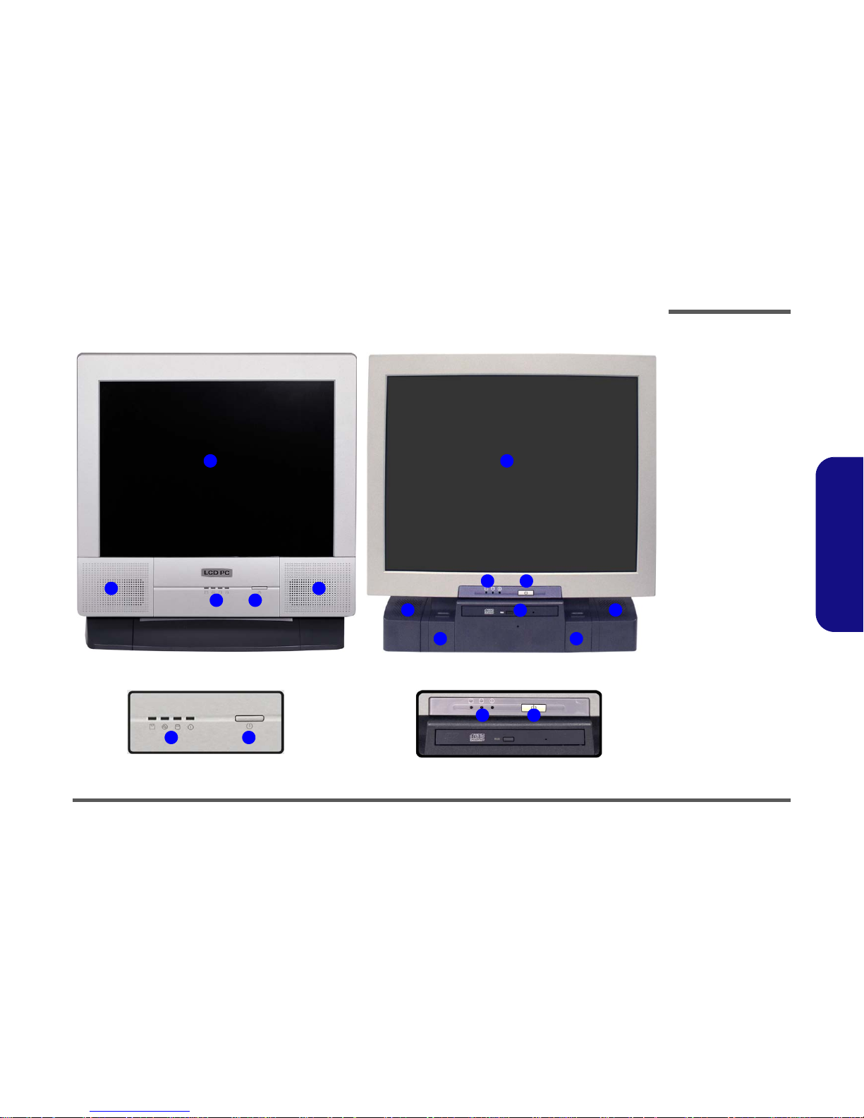
External Locator - Front View 1 - 5
1.Introduction
External Locator - Front View
1
2
4
2
3
43
1
2
4
2
3
43
5
66
L295N L297N
Figure 1 - 1
Front View
1. LCD Panel
2. Speakers
3. LED Activity
indicators
4. Power Button
5. Optical (CD/
DVD) Device
Bay (L297N
only)
6. Keyboard Holder
(L297N only)
Introduction
1 - 6 External Location - Left & Right Side Views
1.Introduction
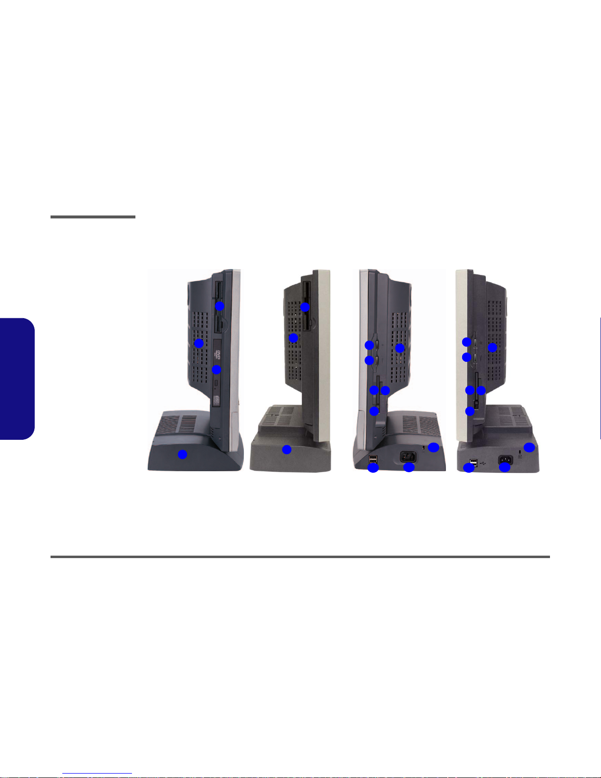
External Location - Left & Right Side Views
Figure 1 - 2
Left & Right Views
1. Floppy Disk
Drive*
2. Vent
3. Hard Disk Drive
(HDD) Bay
4. CD Device
(L295N only)
5. LCD Brightness
Control Knob
6. Volume Control
Knob
7. Dual PC Card
Slots
8. PC Card Eject
Buttons
9. 7-in-1 Card
Reader
10. 2* USB Ports
11. AC Power-In Port
12. Security Lock
Slot
2
8
7
3
1
1
2
5
6
9
2
11
10
L295N L297N L295N L297N
2
3
4
5
6
12
8
7
9
11
10
12
Left Right
Introduction
External Locator - Rear View 1 - 7
1.Introduction
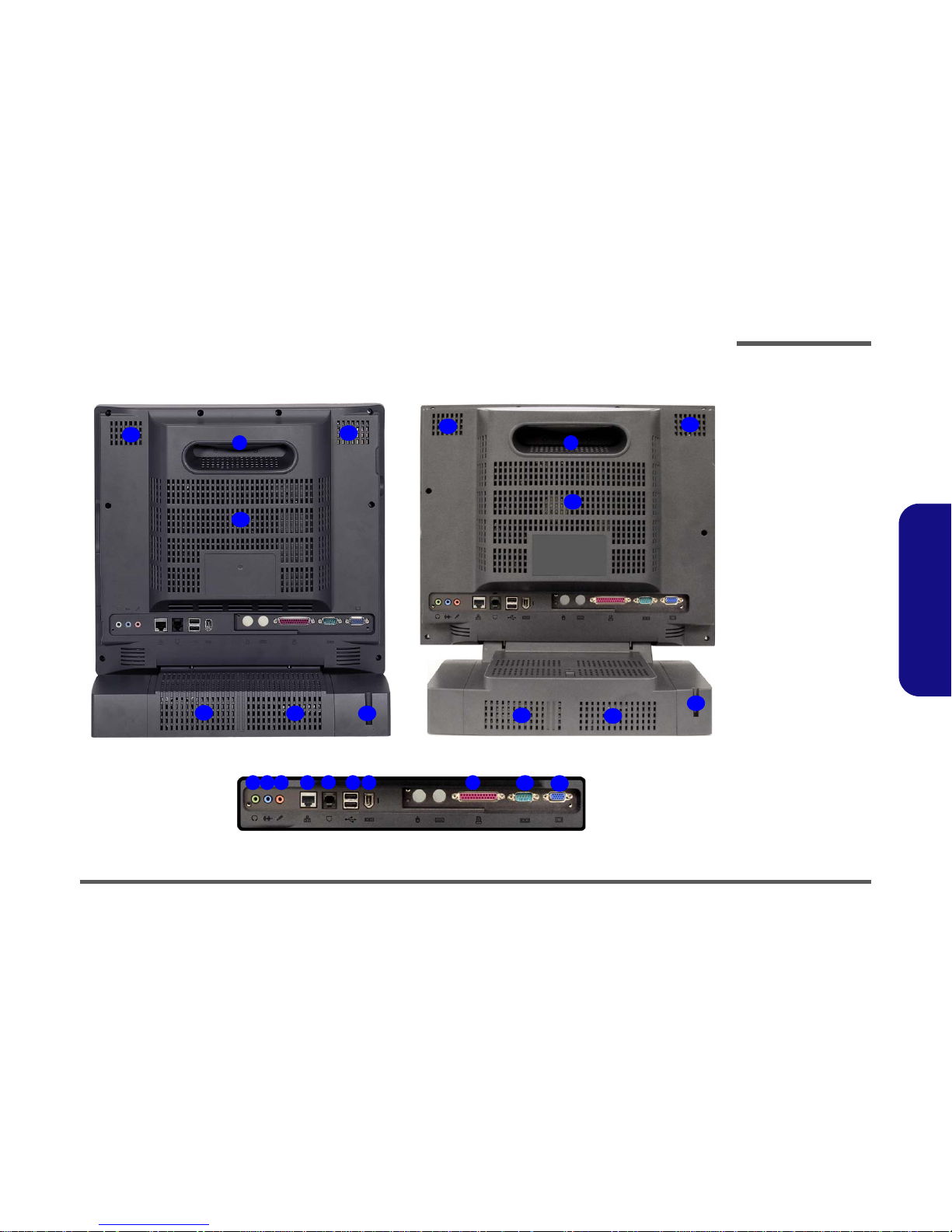
External Locator - Rear View
Figure 1 - 3
Rear View
1. Carrying Handle
2. Headphone-Out
Jack
3. Line-In Jack
4. Microphone-In
Jack
5. RJ-45 LAN Jack
6. RJ-11 Phone
Jack
7. 2* USB Ports
8. Unpowered IEEE 1394 Port
9. Printer/Parallel
Port
10. Serial Port
11. External Monitor
Port
12. Vents
13. Hard Disk Bay
Screw
1
4 5
6
12
2 3 87
12
10
11
13
12
12
9
1
12
12
12
12
12
L295N L297N
13
13
Introduction
1 - 8 Mainboard Overview - Top (Key Parts)
1.Introduction
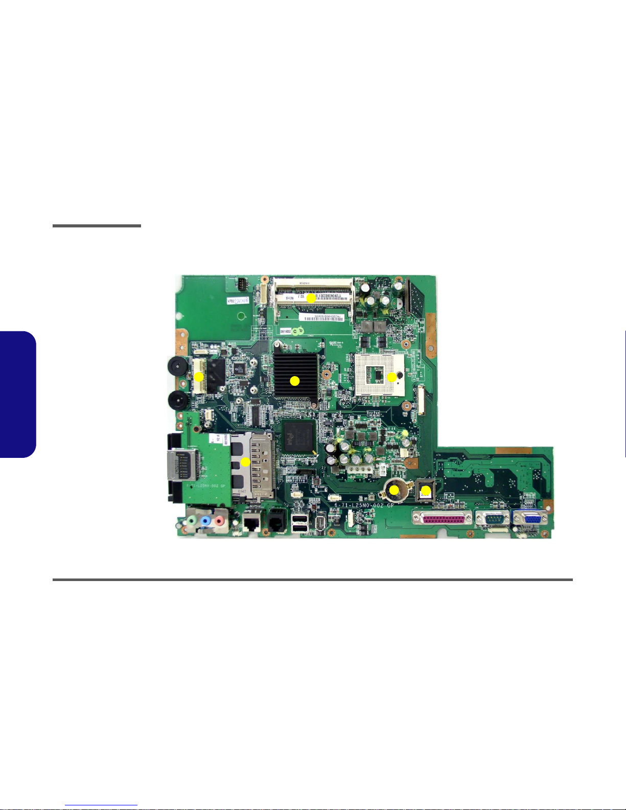
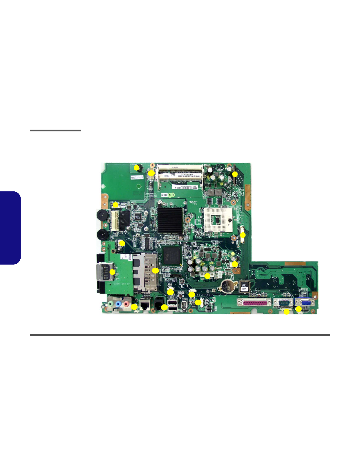
Mainboard Overview - Top (Key Parts)
Figure 1 - 4
Mainboard Over-
view - Top
Key Parts
1. CPU Socket (no
CPU Installed)
2. Intel 945GM
(North Bridge)
3. RAM Sockets
4. Mini Card
Socket for
WLAN
5. FLASH BIOS
6. CMOS Battery
7. Cardbus
PCI7412
5
6
7
4
1
3
2
Introduction
Mainboard Overview - Bottom (Key Parts) 1 - 9
1.Introduction
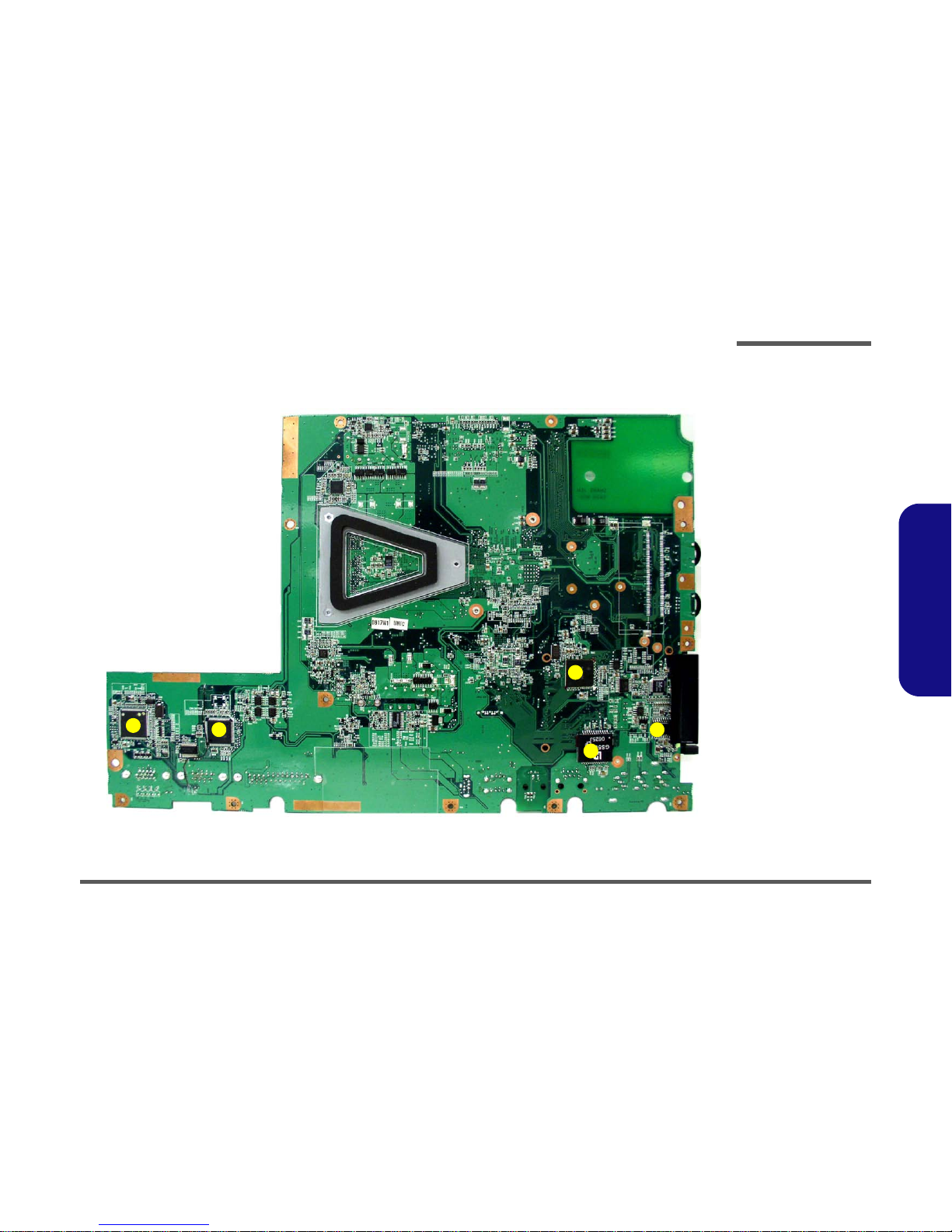
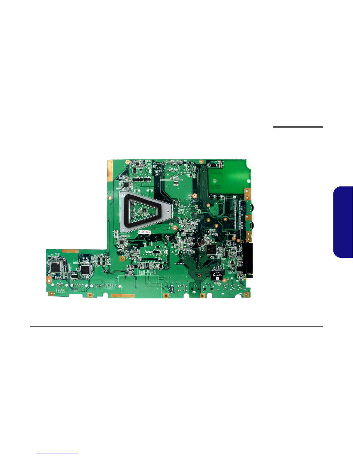
Mainboard Overview - Bottom (Key Parts)
Figure 1 - 5
Mainboard Over-
view - Bottom
Key Parts
1. Chrontel CH7308
2. Clock Generator
3. Intel ICH7-M 652
mBGA (South
Bridge)
4. SUPER I/O
Winbond
PC87392
5. AZALIA MDC
Module
4
5
3
1
2
Introduction
1 - 10 Mainboard Overview - Top (Cable Connectors & Switches)
1.Introduction
Mainboard Overview - Top (Cable Connectors & Switches)
1
2
3
4
5
6
7
8
9
10
11
12
13
14
15
17
16
Figure 1 - 6
Mainboard Top
Cable Connectors &
Switches
1. CD/DVD Device
(CN7)
2. Floppy Disk Drive
(CN5)
3. CN35 (LCD
Connector)
4. Inverter (CN1)
5. BT Module
6. Modem Module
7. Card Reader
8. Speaker (CN31)
9. Modem Cable
(CN33)
10. PC CARD (CN13)
11. Touch Screen
(CN16)
12. IEEE1394 (CN36)
13. USB 2.0 (CN17)
14. LED Board
(CN30)
15. Speaker (CN32)
16. Power (CN12)
17. Fan Power (CN9)
Introduction
Mainboard Overview - Bottom (Cable Connectors & Switches) 1 - 11
1.Introduction
Mainboard Overview - Bottom (Cable Connectors & Switches)
1
Figure 1 - 7
Mainboard Bottom
Cable Connectors &
Switches

Introduction
1-12
1.Introduction

Disassembly
Overview 2 - 1
2.Disassembly
2: Disassembly
Overview
This chapter provides step-by-step instructions for disassembling parts and subsystems. When it comes to reassembly,
reverse the procedures (unless otherwise indicated).
We suggest you completely review any procedure before you take the computer apart.
Procedures such as upgrading/replacing the RAM, CD device and hard disk are included in the User’s Manual but are
repeated here for your convenience.
To make the disassembly process easier each section may have a box in the page margin. Information contained under
the figure # will give a synopsis of the sequence of procedures involved in the disassembly procedure. A box with a
lists the relevant parts you will have after the disassembly process is complete. Note: The parts listed will be for the dis-
assembly procedure listed ONLY, and not any previous disassembly step(s) required. Refer to the part list for the previous disassembly procedure. The amount of screws you should be left with will be listed here also.
A box with a will provide any possible helpful information. A box with a contains warnings.
An example of these types of boxes are shown in the sidebar.
Information and
Component Parts
Warning

Disassembly
2-2Overview
2.Disassembly
NOTE: All disassembly procedures assume that the system is turned OFF, and disconnected from any power supply,
and that all peripheral cables are disconnected (including telephone lines and network cables).
Maintenance Tools
The following tools are recommended when working on the computer:
• M3 Philips-head screwdriver
• M2.5 Philips-head screwdriver (magnetized)
• M2 Philips-head screwdriver
• Small flat-head screwdriver
• Pair of needle-nose pliers
• Anti-static wrist-strap
Connections
Connections within the computer are one of four types:
Locking collar sockets for ribbon connectors To release these connectors, use a small flat-head screwdriver to gently pry the
locking collar away from its base. When replacing the connection, make sure
the connector is oriented in the same way. The pin1 side is usually not indicated.
Pressure sockets for multi-wire connectors To release this connector type, grasp it at its head and gently rock it from side
to side as you pull it out. Do not pull on the wires themselves. When replacing
the connection, do not try to force it. The socket only fits one way.
Pressure sockets for ribbon connectors To release these connectors, use a small pair of needle-nose pliers to gently lift
the connector away from its socket. When replacing the connection, make sure
the connector is oriented in the same way. The pin1 side is usually not indicated.
Board-to-board or multi-pin sockets To separate the boards, gently rock them from side to side as you pull them
apart. If the connection is very tight, use a small flat-head screwdriver - use
just enough force to start.

Disassembly
Overview 2 - 3
2.Disassembly
Maintenance Precautions
The following precautions are a reminder. To avoid personal injury or damage to the computer while performing a removal and/or replacement job, take the following precautions:
1. Don't drop it. Perform your repairs and/or upgrades on a stable surface. If the computer falls, the case and other
components could be damaged.
2. Don't overheat it. Note the proximity of any heating elements. Keep the computer out of direct sunlight.
3. Avoid interference. Note the proximity of any high capacity transformers, electric motors, and other strong mag-
netic fields. These can hinder proper performance and damage components and/or data. You should also monitor
the position of magnetized tools (i.e. screwdrivers).
4. Keep it dry. This is an electrical appliance. If water or any other liquid gets into it, the computer could be badly
damaged.
5. Be careful with power. Avoid accidental shocks, discharges or explosions.
•Before removing or servicing any part from the computer, turn the computer off and detach any power supplies.
•When you want to unplug the power cord or any cable/wire, be sure to disconnect it by the plug head. Do not pull on the wire.
6. Peripherals – Turn off and detach any peripherals.
7. Beware of static discharge. ICs, such as the CPU and main support chips, are vulnerable to static electricity.
Before handling any part in the computer, discharge any static electricity inside the computer. When handling a
printed circuit board, do not use gloves or other materials which allow static electricity buildup. We suggest that
you use an anti-static wrist strap instead.
8. Beware of corrosion. As you perform your job, avoid touching any connector leads. Even the cleanest hands pro-
duce oils which can attract corrosive elements.
9. Keep your work environment clean. Tobacco smoke, dust or other air-born particulate matter is often attracted
to charged surfaces, reducing performance.
10. Keep track of the components. When removing or replacing any part, be careful not to leave small parts, such as
screws, loose inside the computer.
Cleaning
Do not apply cleaner directly to the computer, use a soft clean cloth.
Do not use volatile (petroleum distillates) or abrasive cleaners on any part of the computer.
Power Safety
Warning
Before you undertake
any upgrade procedures, make sure that
you have turned off
the power, and disconnected all peripherals and cables
(including telephone
lines). It is advisable
to also remove your
battery in order to prevent accidentally turning the machine on.

Disassembly
2 - 4 Disassembly Steps
2.Disassembly
Disassembly Steps
The following lists the disassembly steps, and on which page to find the related information. PLEASE PERFORM THE
DISASSEMBLY STEPS IN THE ORDER INDICATED.
To remove the hard disk drive assembly:
1. Remove the hard disk drive assembly page 2 - 5
To remove the LCD back cover:
1. Remove the LCD back cover page 2 - 6
To remove the system memory:
1. Remove the LCD back cover page 2 - 6
2. Remove the system memory page 2 - 7
To remove and install the Processor:
1. Remove the LCD back cover page 2 - 6
2. Remove the processor page 2 - 8
3. Install the processor page 2 - 10
To remove the modem:
1. Remove the LCD back cover page 2 - 6
2. Remove the modem page 2 - 11
To remove the WLAN module:
1. Remove the LCD back cover page 2 - 6
2. Remove the WLAN module page 2 - 12
To remove the Bluetooth module:
1. Remove the LCD back cover page 2 - 6
2. Remove the bluetooth module page 2 - 13
To remove the floppy disk drive assembly:
1. Remove the LCD back cover page 2 - 6
2. Remove the floppy disk drive assembly page 2 - 14
To remove the Optical Device:
1. Remove the LCD back cover page 2 - 6
2. Remove the optical device page 2 - 15

Disassembly
Removing the Hard Disk Drive Assembly 2 - 5
2.Disassembly
Removing the Hard Disk Drive Assembly
1. Unplug the power cord and disconnect all peripheral cables (including the phone line) from the computer.
2. Turn OFF the computer and turn it around so that you may comfortably access the left side.
3. Remove screw from the HDD Bay .
4. Carefully pull the HDD assembly out from the bay and disconnect cables & .
5. Remove screws - and separate the hard disk and case .
6. Insert the new hard disk, and reverse the removal procedure to install the new hard disk.
Figure 2 - 1
Hard Disk Removal
Sequence
a. Remove the screw
from the HDD Bay.
b. Slide the HDD assem-
bly in the direction of
the arrow and disconnect the cables.
c. Remove the screws
and separate the HDD
from the case.
2. HDD Bay Cover
9. HDD
10. HDD case
•5 Screws
123
4
5
8
9
10
1
2
3
4
a.
b. c.
5 6
7
9
10
8
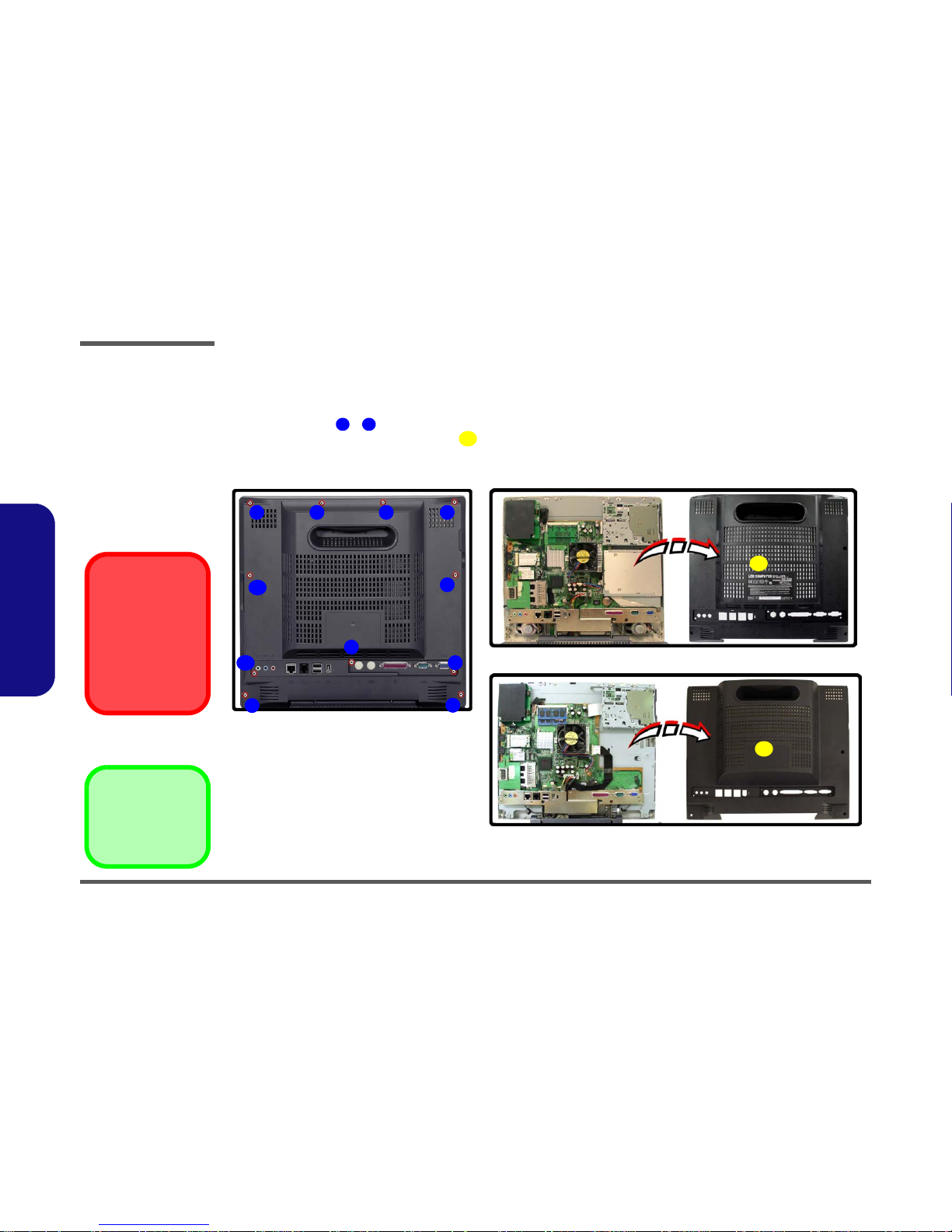
Disassembly
2 - 6 Removing the LCD Back Cover
2.Disassembly
Removing the LCD Back Cover
1. Unplug the power cord and disconnect all peripheral cables (including the phone line) from the computer.
2. Turn OFF the computer and place it with its LCD display facing down on a clean, dry, level surface.
3. Remove screws - from the LCD back cover and slide it up towards the top of the computer.
4. Carefully remove the LCD back cover from the main unit and set it aside.
Figure 2 - 2
LCD Back Cover
Removal
Sequence
a. Remove the screws
from the LCD back
cover.
b. Lift the cover out and
set it aside.
1
11
12
12. LCD back cover
•11 Screws
a.
1 2 3 4
6
5
7
9
8
10
11
b.
12
12
L295N
L297N
Card Reader/PC Card
Slots
Make sure you remove
any cards or covers in
the 7-in-1 Card Reader
and PC Card slot before removing the rear
case cover.
Disassembly
Removing the System Memory 2 - 7
2.Disassembly
Removing the System Memory
1. Remove the LCD back cover (page 2 - 6).
2. The memory sockets will be visible at point on the mainboard.
3. For each module you want to replace, gently push the latches and toward the sides of the socket to release the
module. Push the latches to release the second module if necessary.
4. The module will pop-up, and you can remove it.
5. Insert the new module. The module will only fit one way as defined by the pin alignment.
6. Make sure the module is seated as far into the slot as it will go (DO NOT FORCE IT). The latches will click into
place on the sides of the module. Make sure they are secure.
7. Reverse the procedures to put the computer back together, and do not forget all the screws. When you restart the
computer the new memory configuration should be registered.
8. If the system doesn’t properly detect the new memory, and you are sure they are properly “seated”, you may
need to run the Setup utility.
Figure 2 - 3
Memory Removal
Sequence
a. Locate the memory
sockets.
b. Pull the latch(es) on
the memory sockets to
release the module(s)
and lift it (them) out.
c. Insert a new module.
4. Memory module(s)
123
4
Contact Warning
Be careful not to touch
the metal pins on the
module’s connecting
edge. Even the cleanest hands have oils
which can attract particles, and degrade the
module’s performance.
c.
a.
2
b.
3
4
1
2 3
4
1
L295N
L297N
Disassembly
2 - 8 Removing and Installing the Processor
2.Disassembly
Removing and Installing the Processor
Processor Removal Procedure
1. Remove the LCD back cover (page 2 - 6).
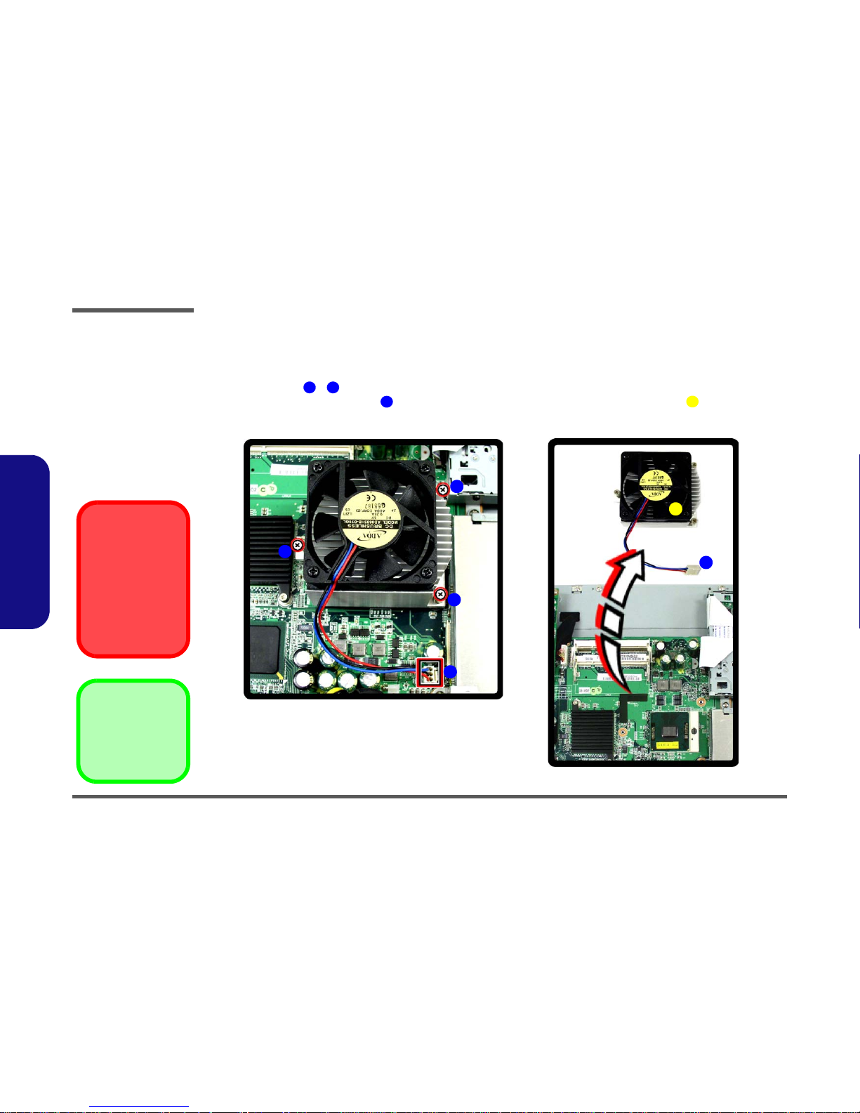
2. Remove screws - from the CPU heat sink fan unit (in the order indicated in Figure 2 - 5a).
3. Disconnect the fan power cable from the mainboard and lift out the CPU heat sink fan unit .
Figure 2 - 4
Processor
Removal
Sequence
a. Remove the screws
from the CPU heat
sink and fan unit.
b. Release the power ca-
ble and lift the heat
sink & fan unit out.
134
5
2
1
a.
4
3
b.
5
4
5. Heat Sink & Fan
•3 Screws
Caution
The heat sink, and
CPU area in general,
contains parts which
are subject to high
temperatures - Please
allow the area time to
cool before removing
these parts.
Disassembly
Removing and Installing the Processor 2 - 9
2.Disassembly
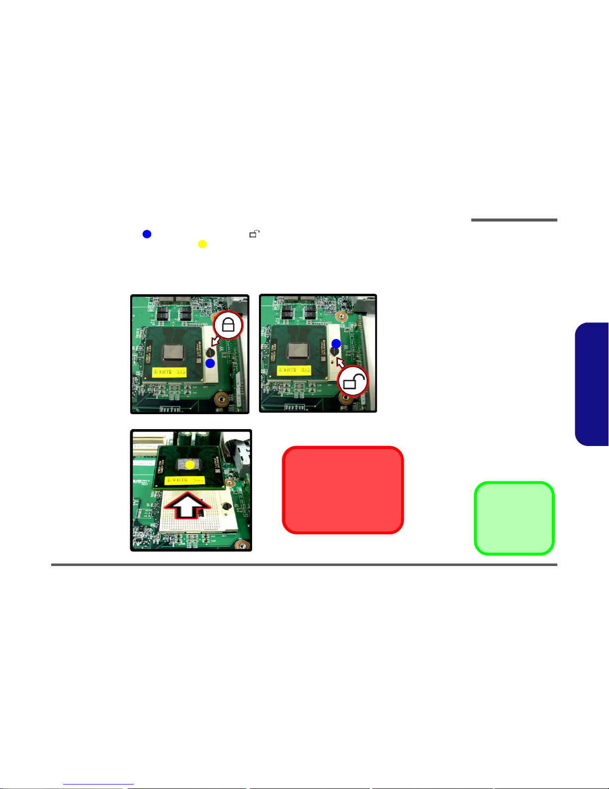
4. Turn the release latch towards the unlock symbol , to release the CPU (Figure 2 - 5c).
5. Carefully (it may be hot) lift the CPU up out of the socket (Figure 2 - 5d).
6. See page 2 - 10 for information on inserting a new CPU.
7. When re-inserting the CPU, pay careful attention to the pin alignment, it will fit only one way (DO NOT FORCE
IT!).
6
7
c.
7
d.
Caution
The heat sink, and CPU area in
general, contains parts which are
subject to high temperatures. Allow
the area time to cool before removing these parts.
Lock
Unlock
6
6
Figure 2 - 5
Processor
Removal
Sequence (cont’d)
c. Turn the release latch
to unlock the CPU.
d. Lift the CPU out of the
socket.
7. CPU
 Loading...