

Page 1

L140MU / L141MU
Page 2

Page 3

Notebook Computer
L140MU / L141MU
Service Manual
Preface
Preface
I
Page 4

Preface
Preface
Notice
The company reserves the right to revise this publication or to change its contents without notice. Information contained
herein is for reference only and does not constitute a commitment on the part of the manufacturer or any subsequent vendor. They assume no responsibility or liability for any errors or inaccuracies that may appear in this publication nor are
they in anyway responsible for any loss or damage resulting from the use (or misuse) of this publication.
This publication and any accompanying software may not, in whole or in part, be reproduced, translated, transmitted or
reduced to any machine readable form without prior consent from the vendor, manufacturer or creators of this publication, except for copies kept by the user for backup purposes.
Brand and product names mentioned in this publication may or may not be copyrights and/or registered trademarks of
their respective companies. They are mentioned for identification purposes only and are not intended as an endorsement
of that product or its manufacturer.
Version 1.0
September 2020
Trademarks
Pentium and Celeron are trademarks of Intel Corporation.
Windows® is a registered trademark of Microsoft Corporation.
Other brand and product names are trademarks and /or registered trademarks of their respective companies.
II
Page 5

About this Manual
This manual is intended for service personnel who have completed sufficient training to undertake the maintenance and
inspection of personal computers.
It is organized to allow you to look up basic information for servicing and/or upgrading components of the L140MU /
L141MU series notebook PC.
The following information is included:
Chapter 1, Introduction, provides general information about the location of system elements and their specifications.
Chapter 2, Disassembly, provides step-by-step instructions for disassembling parts and subsystems and how to upgrade
elements of the system.
Preface
Appendix A, Part Lists
Appendix B, Schematic Diagrams
Preface
III
Page 6

Preface
IMPORTANT SAFETY INSTRUCTIONS
Follow basic safety precautions, including those listed below, to reduce the risk of fire, electric shock and injury to persons when using any electrical equipment:
1. Do not use this product near water, for example near a bath tub, wash bowl, kitchen sink or laundry tub, in a wet
basement or near a swimming pool.
2. Avoid using a telephone (other than a cordless type) during an electrical storm. There may be a remote risk of electrical shock
from lightning.
3. Do not use the telephone to report a gas leak in the vicinity of the leak.
4. Use only the power cord and batteries indicated in this manual. Do not dispose of batteries in a fire. They may explode. Check
with local codes for possible special disposal instructions.
5. This product is intended to be supplied by a Listed Power Unit with an AC Input of 100 - 240V, 50 - 60Hz, DC Output of 19V,
3.42A (65 Watts) minimum AC/DC Adapter.
Preface
IV
FCC Statement
This device complies with Part 15 of the FCC Rules. Operation is subject to the following two conditions:
This device may not cause harmful interference.
This device must accept any interference received, including interference that may cause undesired operation.
Page 7
Instructions for Care and Operation
The notebook computer is quite rugged, but it can be damaged. To prevent this, follow these suggestions:
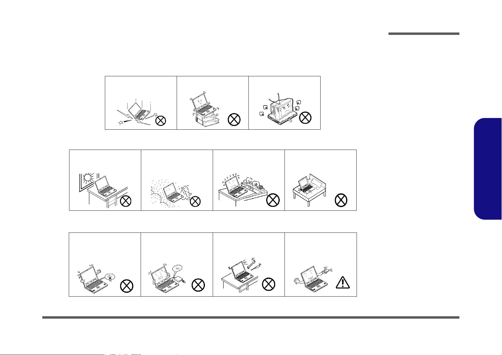
1. Don’t drop it, or expose it to shock. If the computer falls, the case and the components could be damaged.
Preface
Do not expose the computer
to any shock or vibration.
Do not place it on an unstable
surface.
Do not place anything heavy
on the computer.
2. Keep it dry, and don’t overheat it. Keep the computer and power supply away from any kind of heating element. This is an
electrical appliance. If water or any other liquid gets into it, the computer could be badly damaged.
Do not expose it to excessive
heat or direct sunlight.
Do not leave it in a place
where foreign matter or moisture may affect the system.
Don’t use or store the computer in a humid environment.
Do not place the computer on
any surface which will block
the vents.
3. Follow the proper working procedures for the computer. Shut the computer down properly and don’t forget to save your
work. Remember to periodically save your data as data may be lost if the battery is depleted.
Do not turn off the power
until you properly shut down
all programs.
Do not turn off any peripheral
devices when the computer is
on.
Do not disassemble the computer by yourself.
Perform routine maintenance
on your computer.
Preface
V
Page 8
Preface
Power Safety
Warning
Before you undertake
any upgrade procedures, make sure that
you have turned off the
power, and disconnected all peripherals
and cables (including
telephone lines and
power cord). It is advisable to also remove
your battery in order to
prevent accidentally
turning the machine
on.
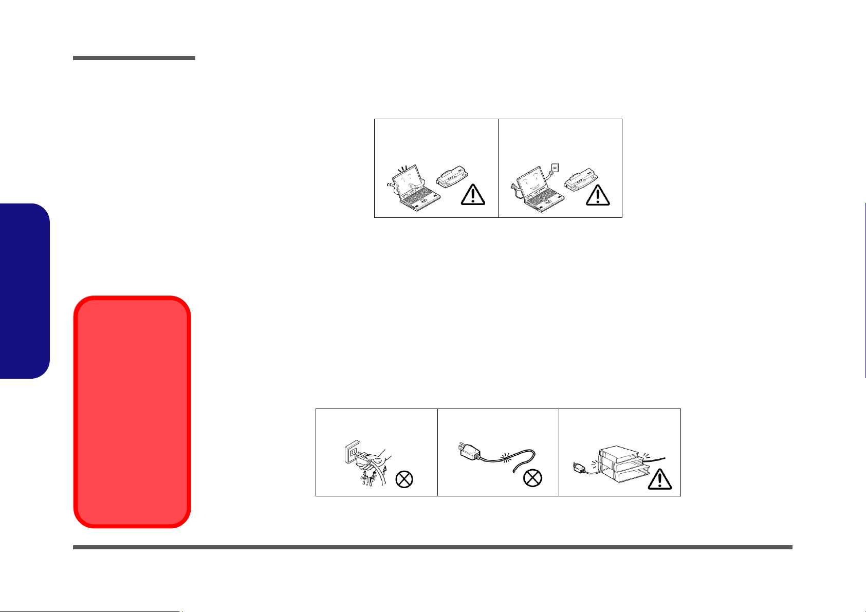
4. Avoid interference. Keep the computer away from high capacity transformers, electric motors, and other strong magnetic
fields. These can hinder proper performance and damage your data.
5. Take care when using peripheral devices.
Preface
VI
Use only approved brands of
peripherals.
Unplug the power cord before
attaching peripheral devices.
Power Safety
The computer has specific power requirements:
• Only use a power adapter approved for use with this computer.
• Your AC adapter may be designed for international travel but it still requires a steady, uninterrupted power supply. If you are
unsure of your local power specifications, consult your service representative or local power company.
• The power adapter may have either a 2-prong or a 3-prong grounded plug. The third prong is an important safety feature; do
not defeat its purpose. If you do not have access to a compatible outlet, have a qualified electrician install one.
• When you want to unplug the power cord, be sure to disconnect it by the plug head, not by its wire.
• Make sure the socket and any extension cord(s) you use can support the total current load of all the connected devices.
• Before cleaning the computer, make sure it is disconnected from any external power supplies.
Do not plug in the power
cord if you are wet.
Do not use the power cord if
it is broken.
Do not place heavy objects
on the power cord.
Page 9

Battery Precautions
Battery Disposal
The product that you have purchased contains a rechargeable battery. The battery is recyclable. At the end of its useful life, under various state and local laws, it may be illegal to dispose of this battery into the municipal waste stream. Check with your local solid waste
officials for details in your area for recycling options or proper disposal.
Caution
Danger of explosion if battery is incorrectly replaced. Replace only with the same or equivalent type recommended by the manufacturer.
Discard used battery according to the manufacturer’s instructions.
Battery Level
Click the battery icon in the taskbar to see the current battery level and charge status. A battery that drops below a level of 10%
will not allow the computer to boot up. Make sure that any battery that drops below 10% is recharged within one week.
• Only use batteries designed for this computer. The wrong battery type may explode, leak or damage the computer.
• Do not continue to use a battery that has been dropped, or that appears damaged (e.g. bent or twisted) in any way. Even if the
computer continues to work with a damaged battery in place, it may cause circuit damage, which may possibly result in fire.
• Recharge the batteries using the notebook’s system. Incorrect recharging may make the battery explode.
• Do not try to repair a battery pack. Refer any battery pack repair or replacement to your service representative or qualified service
personnel.
• Keep children away from, and promptly dispose of a damaged battery. Always dispose of batteries carefully. Batteries may explode
or leak if exposed to fire, or improperly handled or discarded.
• Keep the battery away from metal appliances.
• Affix tape to the battery contacts before disposing of the battery.
• Do not touch the battery contacts with your hands or metal objects.
Battery Guidelines
The following can also apply to any backup batteries you may have.
• If you do not use the battery for an extended period, then remove the battery from the computer for storage.
• Before removing the battery for storage charge it to 60% - 70%.
• Check stored batteries at least every 3 months and charge them to 60% - 70%.
Preface
Preface
VII
Page 10
Preface
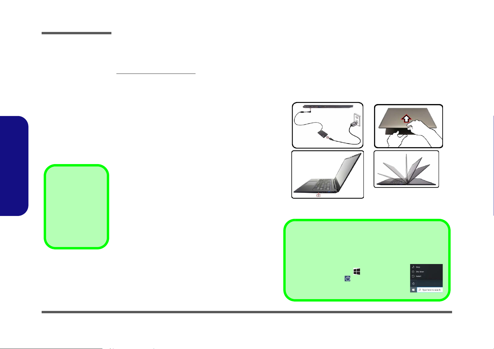
Figure 1
Opening the Lid/LCD/Computer
with AC/DC Adapter Plugged-In
Shut Down
Note that you should always shut your computer down by choosing the
Shut down command in Windows (see below). This will help prevent
hard disk or system problems.
1. Click the Start Menu icon .
2. Click the Power item .
3. Choose Shut down from the menu.
180°
Powering the
Computer On
After every disassembly, make sure that the
bottom case’s screws
are all inserted and
tightened before turning the computer on.
Related Documents
You may also need to consult the following manual for additional information:
User’s Manual on CD/DVD
This describes the notebook PC’s features and the procedures for operating the computer and its ROM-based setup program. It also describes the installation and operation of the utility programs provided with the notebook PC.
System Startup
1. Remove all packing materials.
2. Place the computer on a stable surface.
3. Securely attach any peripherals you want to use with the
computer (e.g. keyboard and mouse) to their ports.
4. When first setting up the computer use the following
procedure (as to safeguard the computer during shipping,
the battery will be locked to not power the system until first
connected to the AC/DC adapter and initially set up as
Preface
below):
• Attach the AC/DC adapter cord to the DC-In jack on the
left of the computer, then plug the AC power cord into an
outlet, and connect the AC power cord to the AC/DC
adapter. The battery will now be unlocked.
5. Use one hand to raise the
angle
(do not exceed 180 degrees); use the other hand (as
illustrated in Figure 1) to support the base of the computer
(Note: Never lift the computer by the lid/LCD).
6. Press the power button on the left side of the computer to
turn it on (note that the lid/LCD must be open for the power
button to function).
VIII
lid/LCD to a comfortable viewing
Page 11

Contents
Preface
Introduction ..............................................1-1
Overview .........................................................................................1-1
Specifications .................................................................................. 1-2
External Locator - Top View with LCD Panel Open ......................1-4
External Locator - Front & Right Side Views .................................1-5
External Locator - Left Side & Rear View .....................................1-6
External Locator - Bottom View ..................................................... 1-7
Mainboard Overview - Top (Key Parts) .........................................1-8
Mainboard Overview - Bottom (Key Parts) .................................... 1-9
Mainboard Overview - Top (Connectors) ..................................... 1-10
Mainboard Overview - Bottom (Connectors) ...............................1-11
Disassembly ...............................................2-1
Overview .........................................................................................2-1
Maintenance Tools ..........................................................................2-2
Connections ..................................................................................... 2-2
Maintenance Precautions .................................................................2-3
Disassembly Steps ...........................................................................2-4
Removing the Battery ......................................................................2-5
Removing the System Memory (RAM) ..........................................2-7
Removing the Wireless LAN Module ............................................. 2-9
Wireless LAN, and Combo Module Cables ..................................2-10
Removing the 4G Module .............................................................2-11
Removing the M.2 SSD Module ...................................................2-12
Removing the CCD .......................................................................2-14
Removing the LCD .......................................................................2-16
Part Lists ..................................................A-1
Part List Illustration Location ........................................................A-2
Top .................................................................................................A-3
Bottom ............................................................................................ A-4
LCD ............................................................................................... A-5
MB ................................................................................................. A-6
Schematic Diagrams................................. B-1
System Block Diagram ...................................................................B-2
Processor 1/12 .................................................................................B-3
Processor 2/12 .................................................................................B-4
Processor 3/12 .................................................................................B-5
Processor 4/12 .................................................................................B-6
Processor 5/12 .................................................................................B-7
Processor 6/12 .................................................................................B-8
Processor 7/12 .................................................................................B-9
Processor 8/12 ...............................................................................B-10
Processor 9/12 ...............................................................................B-11
Processor 10/12 .............................................................................B-12
Processor 11/12 .............................................................................B-13
Processor 12/12 .............................................................................B-14
DDR4 CH0-1 ................................................................................B-15
DDR4 CH0-2 ................................................................................B-16
DDR4 Terminations ......................................................................B-17
DDR4 Decaps ...............................................................................B-18
DDR4 SO-DIMM_1 .....................................................................B-19
HDMI ............................................................................................B-20
Panel / 3.3VA ................................................................................B-21
Retimer .........................................................................................B-22
Retimer .........................................................................................B-23
PD65993, Type-C .........................................................................B-24
Audio Codec .................................................................................B-25
RTS5227S .....................................................................................B-26
WLAN/BT ....................................................................................B-27
KBC ITE IT5570 ..........................................................................B-28
Preface
IX
Page 12

Preface
M Key PCIE SSD-1 .....................................................................B-29
M Key PCIE SSD-2 .....................................................................B-30
USB Charger ................................................................................ B-31
USB Gen1 .................................................................................... B-32
Conn Fan, CCD, TP, LED KB ..................................................... B-33
TPM, PW Button, LID SW, LED ................................................B-34
3.3V, 5V, 3VS, 5VS, CTL ...........................................................B-35
VDD3, VDD5 ............................................................................... B-36
2.5V, VCCST, VCCSTG .............................................................B-37
VDDQ, VDDQ_VTT, 1.5VS, 1.8VA .......................................... B-38
V1.05A / VNN .............................................................................B-39
AC_In ........................................................................................... B-40
VCCIN ......................................................................................... B-41
NCP81269 .................................................................................... B-42
Charger ......................................................................................... B-43
M.2 B Key, 3G, USB ...................................................................B-44
Preface
SIM Board .................................................................................... B-45
Power Sequence ...........................................................................B-46
X
Page 13

Chapter 1: Introduction
Overview
This manual covers the information you need to service or upgrade the L140MU / L141MU series notebook computer.
Information about operating the computer (e.g. getting started, and the Setup utility) is in the User’s Manual. Information
about dri-vers (e.g. VGA & audio) is also found in the User’s Manual. The manual is shipped with the computer.
Operating systems (e.g. Window 10, etc.) have their own manuals as do application softwares (e.g. word processing and
database programs). If you have questions about those programs, you should consult those manuals.
Introduction
The L140MU / L141MU series notebook is designed to be upgradeable. See Disassembly on page 2 - 1 for a detailed
description of the upgrade procedures for each specific component. Please take note of the warning and safety information indicated by the “” symbol.
The balance of this chapter reviews the computer’s technical specifications and features.
1.Introduction
Overview 1 - 1
Page 14
Introduction
Latest Specification Information
The specifications listed here are correct at the
time of sending them to the press. Certain items
(particularly processor types/speeds) may be
changed, delayed or updated due to the manufacturer's release schedule. Check with your
service center for more details.
CPU
The CPU is not a user serviceable part. Accessing the CPU in any way may violate your
warranty.
Specifications
1.Introduction
Processor Options
Intel® Core™ i7 Processor
i7-1165G7 (2.70GHz)
12MB Smart Cache, 14nm, DDR4-3200MHz, TDP 28W
Intel® Core™ i5 Processor
i5-1135G7 (2.30GHz)
8MB Smart Cache, 14nm, DDR4-3200MHz, TDP 28W
Intel® Core™ i3 Processor
i3-1115G4 (2.70GHz)
6MB Smart Cache, 14nm, DDR4-3200MHz, TDP 28W
BIOS
128Mb SPI Flash ROM
Insyde BIOS
Memory
Dual Channel DDR4
On Board DDR4 8GB
One 260 Pin SO-DIMM Socket Supporting DDR4 3200MHz
Memory
Memory Expandable up to 32GB
Compatible with 8GB, 16GB or 32GB Modules
(The real memory operating frequency depends on the FSB
of the processor.)
LCD Options
14" (35.56cm), 16:9, FHD (1920x1080)
Storage
One M.2 SATA/PCIe Gen3 x4 Solid State Drive (SSD)
(Factory Option) One M.2 SATA Solid State Drive (SSD)
Video Adapter
Intel UHD Graphics 630
HDR Support
Rec. 2020
Microsoft DirectX® 12 Compatible
Pointing Device
Built-in Touchpad (with Microsoft PTP Multi Gesture & Scrolling Functionality)
Keyboard
White-LED Keyboard
Or
(Factory Option) Keyboard
Audio
High Definition Audio Compliant Interface
2 * Built-In Speakers
Built-In Array Microphone
Security
Security (Kensington® Type) Lock Slot
BIOS Password
Intel PTT for Systems Without TPM Hardware
(Factory Option) TPM 2.0
M.2 Slots
Slot 1 for Combo WLAN and Bluetooth Module
Slot 2 for PCIe Gen4 x4 SSD
(Factory Option) Slot 3 for SATA or PCIe Gen3 x4 SSD or
4G-Module
Card Reader
1 - 2 Specifications
MicroSD Card Reader
Page 15

Introduction
Interface
One Thunderbolt 4 Port with Power Delivery (DC-In)
One USB 3.2 Gen 1 Type-A Port
One USB 3.2 Gen 2 Type-A Port
One HDMI-Out Port
One 2-In-1 Audio Jack (Headphone / Microphone)
One DC-in Jack
Communication
1.0M HD Camera Module
Or
(Factory Option) Windows Hello Camera Module
(Factory Option) M.2 3042 4G Module
WLAN/ Bluetooth M.2 Modules:
(Factory Option) Intel® Dual Band Wi-Fi 6 AX200 Wireless
LAN (802.11ax) + Bluetooth
(Factory Option) Intel® Dual Band Wi-Fi 6 AX201 Wireless
LAN (802.11ax) + Bluetooth
Power
Full Range AC/DC Adapter
AC Input: 100 - 240V, 50 - 60Hz
DC Output: 19V, 3.42A (65W)
Dimensions & Weight
322mm (w) * 216.8mm (d) * 16.5mm (h)
(Height Excluding Battery Area)
990g
1.Introduction
Embedded Lithium-Ion Polymer Battery Pack, 36WH
(Factory Option) Embedded Lithium-Ion Polymer Battery
Pack, 73WH
Environmental Spec
Temperature
Operating: 5°C - 35°C
Non-Operating: -20°C - 60°C
Relative Humidity
Operating: 20% - 80%
Non-Operating: 10% - 90%
Specifications 1 - 3
Page 16
Introduction
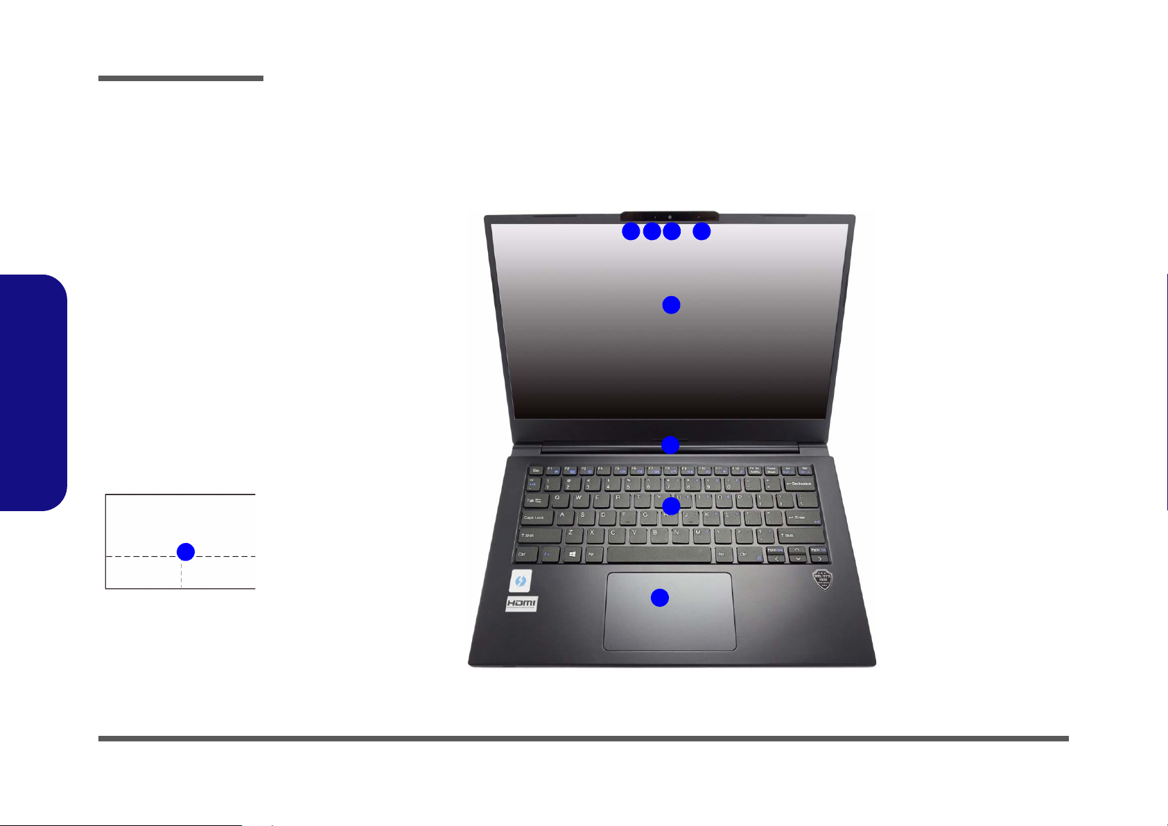
Figure 1
Top View
1. PC Camera
Or
(Factory Option)
Windows Hello
Camera
2. *Camera LED
*When the camera
is in use, the LED
will be illuminated.
3. Built-In Array
Microphone
4. Display
5. Vent
6. Keyboard
7. Touchpad &
Buttons
7
5
7
2 1 3
4
3
6
1.Introduction
External Locator - Top View with LCD Panel Open
Note that the Touchpad and
Buttons has a valid operational area indicated within
the dotted lines.
1 - 4 External Locator - Top View with LCD Panel Open
Page 17
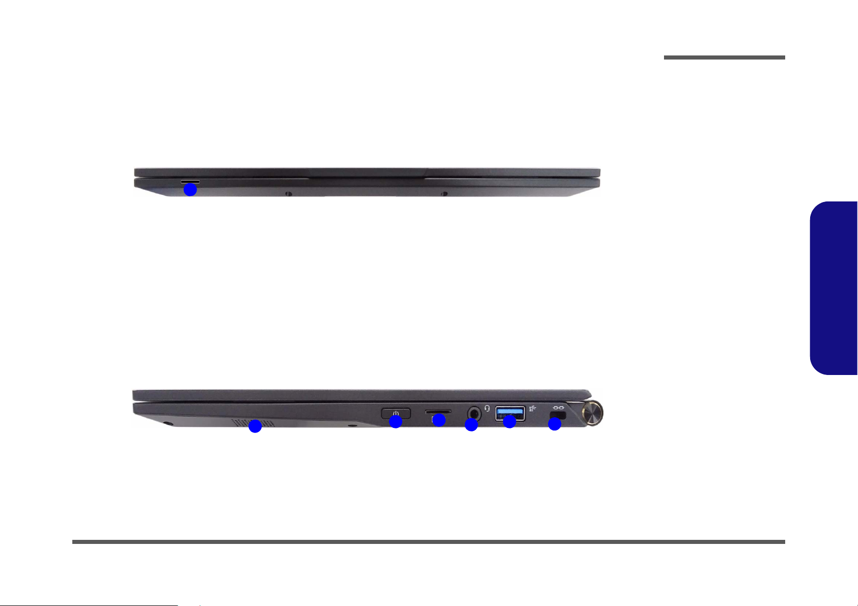
External Locator - Front & Right Side Views
Figure 2
Front View
1. (Factory Option)
USIM Card
Reader (for 4G
USIM Cards)
Figure 3
Right Side View
1. Speaker
2. Power Button
3. MicroSD Card
Reader
4. 2-In-1 Audio Jack
(Headphone and
Microphone)
5. USB 3.2 Gen 1
Type-A Port
6. Security Lock Slot
FRONT VIEW
1
RIGHT SIDE VIEW
1
2
3
4
5
6
Introduction
1.Introduction
External Locator - Front & Right Side Views 1 - 5
Page 18
1.Introduction
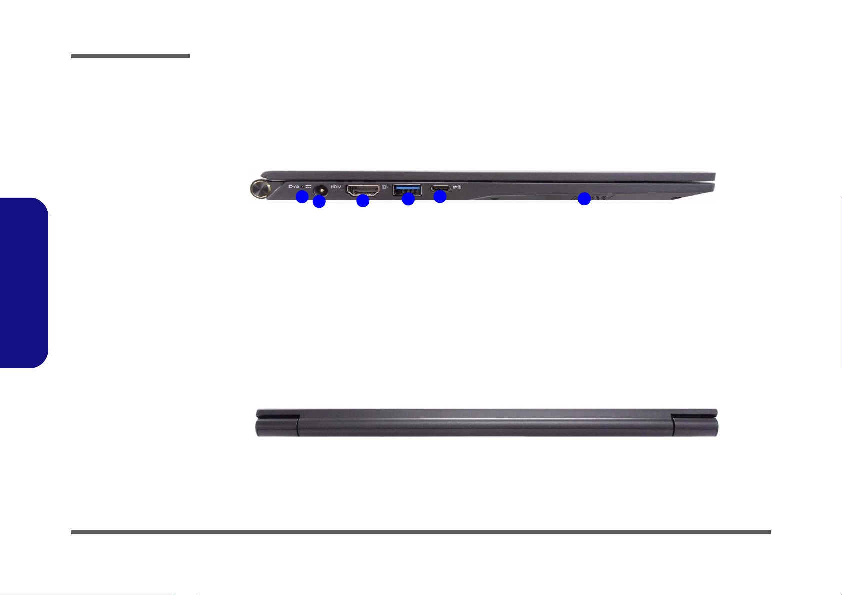
Figure 4
Left Side View
1. LED Indicator
2. DC-In Jack
3. HDMI-Out Port
4. USB 3.1 Gen 2
Type-A Port
5. DisplayPort 1.2
over USB 3.1 Gen
2 Type-C Port with
Power Delivery
(DC-In)
6. Speaker
LEFT SIDE VIEW
1
2
3
4
5
6
Figure 5
Rear View
REAR VIEW
Introduction
External Locator - Left Side & Rear View
/
1 - 6 External Locator - Left Side & Rear View
Page 19
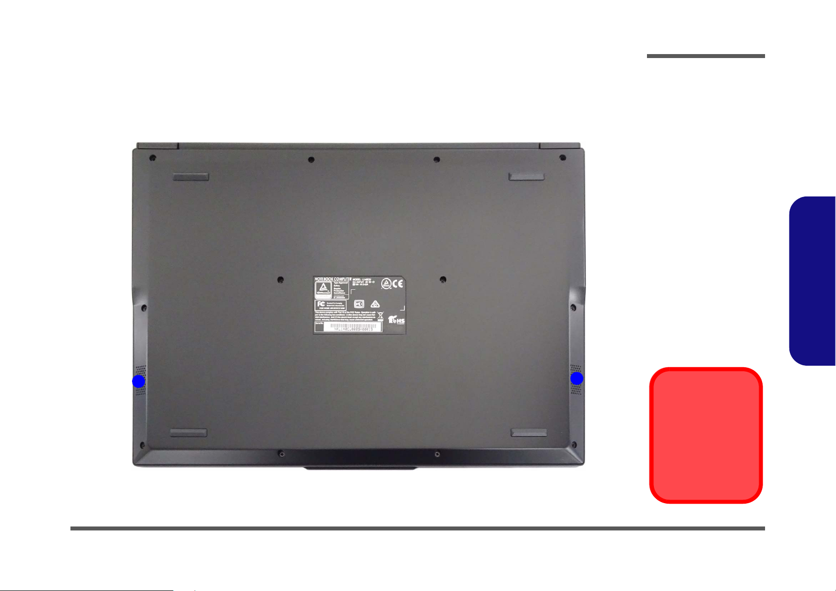
External Locator - Bottom View
Figure 6
Bottom View
1. Speakers
Overheating
To prevent your computer from overheating, make sure nothing blocks any vent
while the computer is
in use.
1
1
Introduction
1.Introduction
External Locator - Bottom View 1 - 7
Page 20
Introduction
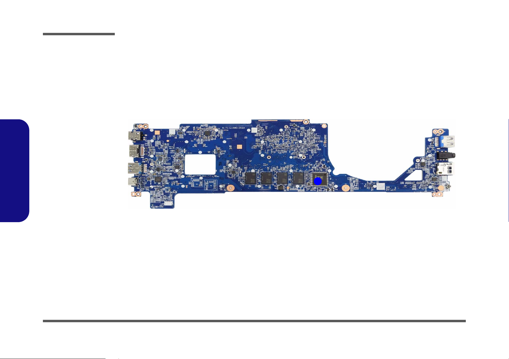
Figure 7
Mainboard Top
Key Parts
1. KBC-ITE IT5570
1
1.Introduction
Mainboard Overview - Top (Key Parts)
1 - 8 Mainboard Overview - Top (Key Parts)
Page 21
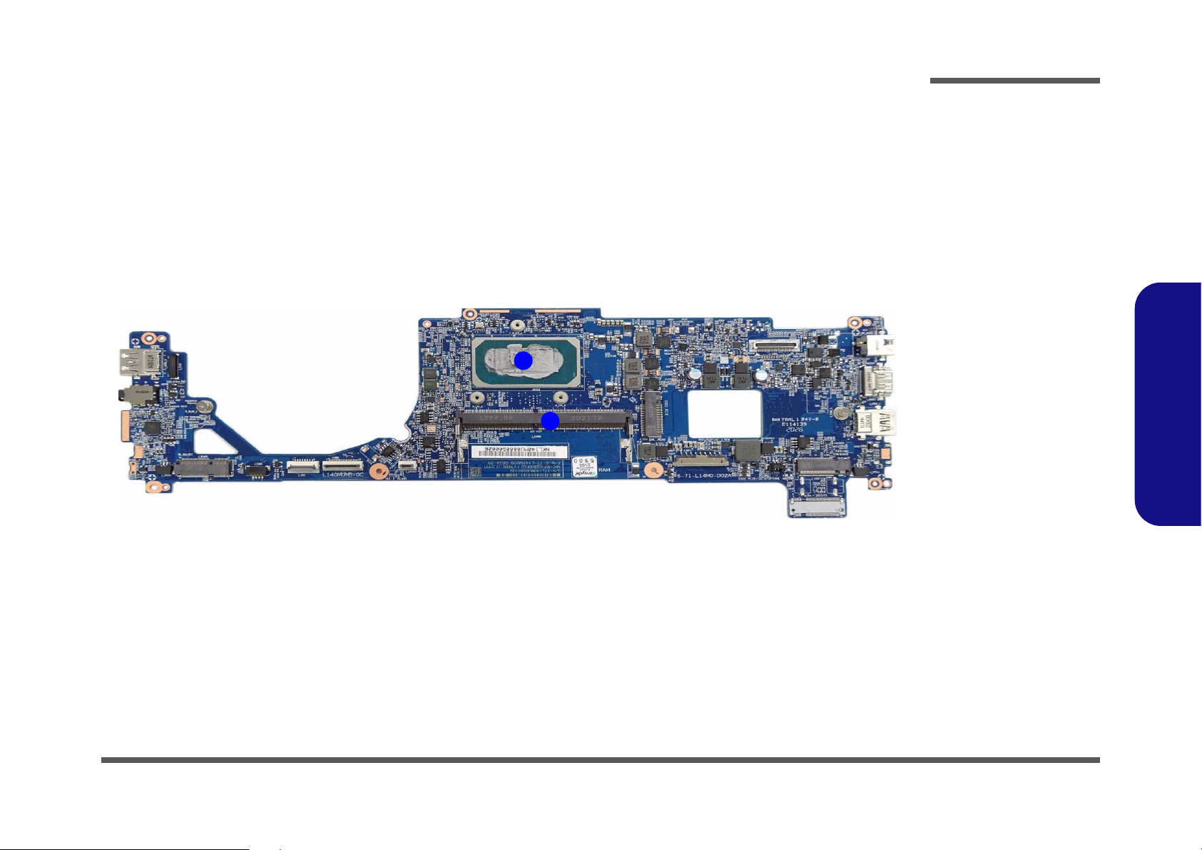
1
2
Figure 8
Mainboard Bottom
Key Parts
1. CPU
2. Memory Slots
DDR4 SO-DIMM
Mainboard Overview - Bottom (Key Parts)
Introduction
1.Introduction
Mainboard Overview - Bottom (Key Parts) 1 - 9
Page 22
Introduction
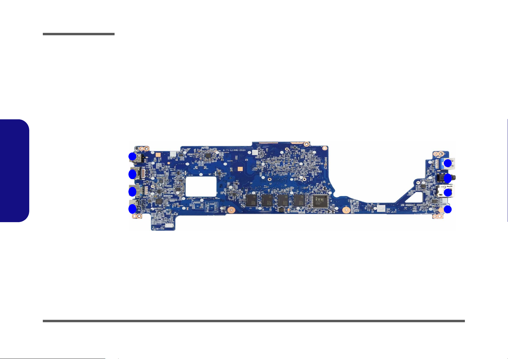
Figure 9
Mainboard Top
Connectors
1. DC-In Jack
2. HDMI-Out Port
3. USB 3.1 Gen 2
Type-A Port
4. DisplayPort 1.2
over USB 3.1
Gen 2 Type-C
Port with Power
Delivery (DC-In)
5. Power Button
6. MicroSD Card
Reader
7. 2-In-1 Audio Jack
(Headphone and
Microphone)
8. USB 3.0 (USB 3.1
Gen 1) Type-A
Port
8
1
2
5
3
6
4
7
1.Introduction
Mainboard Overview - Top (Connectors)
1 - 10 Mainboard Overview - Top (Connectors)
Page 23
Mainboard Overview - Bottom (Connectors)
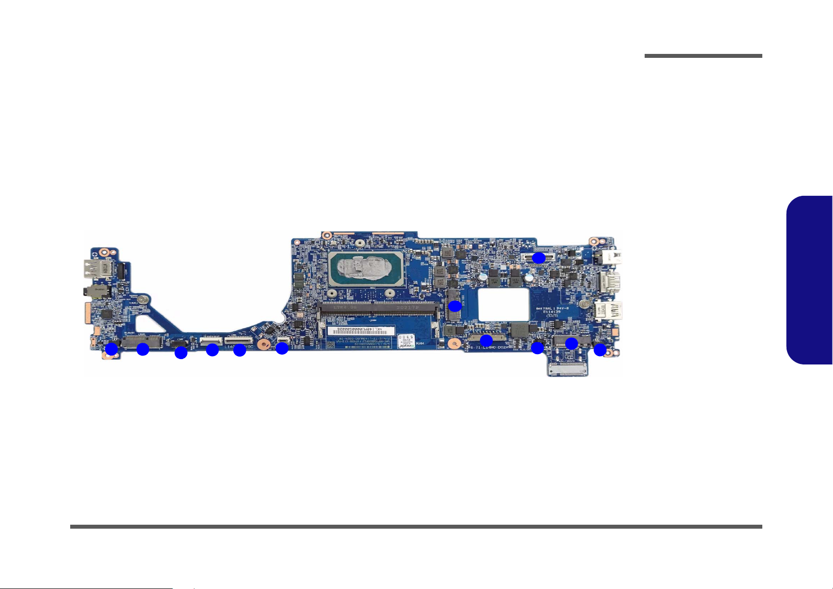
Figure 10
Mainboard Bottom
Connectors
1. Speaker Connector
2. WLAN Connector
3. Fan Connector
4. Touchpad Cable
Connector
5. Keyboard Cable
Connector
6. LED Keyboard
Connector
7. Battery Connector
8. BIOS Battery
Connector
9. M.2 Card
Connector (SATA /
PCIE)
10. M.2 Card
Connector (PCIE
only)
11. LCD Cable
Connector
10
9
1
2
4
6
7
3
5
8
11
1
Introduction
1.Introduction
Mainboard Overview - Bottom (Connectors) 1 - 11
Page 24

1.Introduction
Introduction
1 - 12
Page 25
Chapter 2: Disassembly
Information
Warning
Overview
This chapter provides step-by-step instructions for disassembling the L140MU / L141MU series notebook’s parts and
subsystems. When it comes to reassembly, reverse the procedures (unless otherwise indicated).
We suggest you completely review any procedure before you take the computer apart.
Disassembly
Procedures such as upgrading/replacing the RAM, optical device and hard disk are included in the User’s Manual but are
repeated here for your convenience.
To make the disassembly process easier each section may have a box in the page margin. Information contained under
the figure # will give a synopsis of the sequence of procedures involved in the disassembly procedure. A box with a
lists the relevant parts you will have after the disassembly process is complete. Note: The parts listed will be for the dis-
assembly procedure listed ONLY, and not any previous disassembly step(s) required. Refer to the part list for the previous disassembly procedure. The amount of screws you should be left with will be listed here also.
A box with a will also provide any possible helpful information. A box with a contains warnings.
An example of these types of boxes are shown in the sidebar.
2.Disassembly
Overview 2 - 1
Page 26
Disassembly
2.Disassembly
NOTE: All disassembly procedures assume that the system is turned OFF, and disconnected from any power supply (the
battery is removed too).
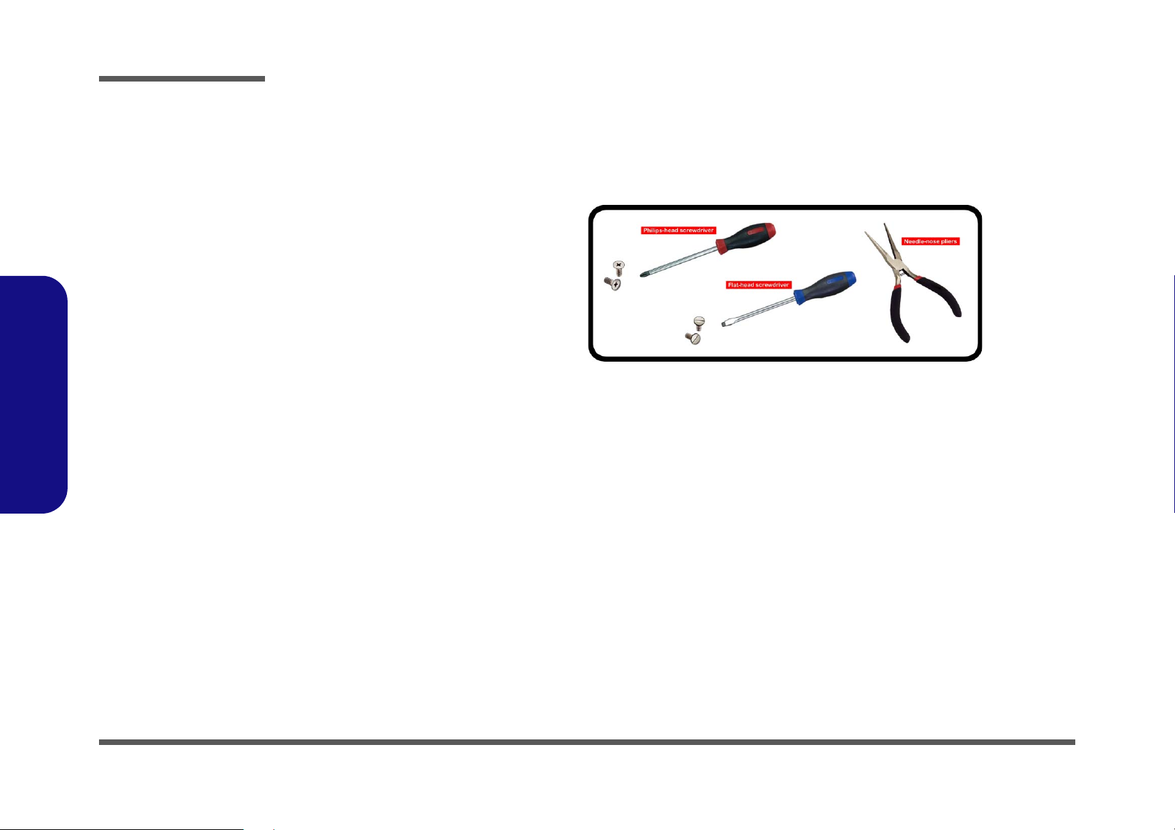
Maintenance Tools
The following tools are recommended when working on the notebook PC:
• M3 Philips-head screwdriver
• M2.5 Philips-head screwdriver (magnetized)
• M2 Philips-head screwdriver
• Small flat-head screwdriver
• Pair of needle-nose pliers
• Anti-static wrist-strap
Connections
Connections within the computer are one of four types:
Locking collar sockets for ribbon connectors To release these connectors, use a small flat-head screwdriver to
gently pry the locking collar away from its base. When replacing the connection, make sure the connector is oriented in the
same way. The pin1 side is usually not indicated.
2 - 2 Overview
Pressure sockets for multi-wire connectors To release this connector type, grasp it at its head and gently
rock it from side to side as you pull it out. Do not pull on the
wires themselves. When replacing the connection, do not try to
force it. The socket only fits one way.
Pressure sockets for ribbon connectors To release these connectors, use a small pair of needle-nose pli-
ers to gently lift the connector away from its socket. When replacing the connection, make sure the connector is oriented in
the same way. The pin1 side is usually not indicated.
Board-to-board or multi-pin sockets To separate the boards, gently rock them from side to side as
you pull them apart. If the connection is very tight, use a small
flat-head screwdriver - use just enough force to start.
Page 27

Maintenance Precautions
Power Safety
Warning
Before you undertake
any upgrade procedures, make sure that
you have turned off the
power, and disconnected all peripherals
and cables (including
telephone lines and
power cord). It is advisable to also remove
your battery in order to
prevent accidentally
turning the machine
on.
The following precautions are a reminder. To avoid personal injury or damage to the computer while performing a removal and/or
replacement job, take the following precautions:
1. Don't drop it. Perform your repairs and/or upgrades on a stable surface. If the computer falls, the case and other components
could be damaged.
2. Don't overheat it. Note the proximity of any heating elements. Keep the computer out of direct sunlight.
3. Avoid interference. Note the proximity of any high capacity transformers, electric motors, and other strong magnetic fields.
These can hinder proper performance and damage components and/or data. You should also monitor the position of magnetized tools (i.e. screwdrivers).
4. Keep it dry. This is an electrical appliance. If water or any other liquid gets into it, the computer could be badly damaged.
5. Be careful with power. Avoid accidental shocks, discharges or explosions.
• Before removing or servicing any part from the computer, turn the computer off and detach any power supplies.
• When you want to unplug the power cord or any cable/wire, be sure to disconnect it by the plug head. Do not pull on the wire.
6. Peripherals – Turn off and detach any peripherals.
7. Beware of static discharge. ICs, such as the CPU and main support chips, are vulnerable to static electricity. Before han-
dling any part in the computer, discharge any static electricity inside the computer. When handling a printed circuit board, do
not use gloves or other materials which allow static electricity buildup. We suggest that you use an anti-static wrist strap
instead.
8. Beware of corrosion. As you perform your job, avoid touching any connector leads. Even the cleanest hands produce oils
which can attract corrosive elements.
9. Keep your work environment clean. Tobacco smoke, dust or other air-born particulate matter is often attracted to charged
surfaces, reducing performance.
10. Keep track of the components. When removing or replacing any part, be careful not to leave small parts, such as screws,
loose inside the computer.
Cleaning
Do not apply cleaner directly to the computer, use a soft clean cloth.
Do not use volatile (petroleum distillates) or abrasive cleaners on any part of the computer.
(For Computer Models Supplied with Light Blue Cleaning Cloth) Some computer models in this series come supplied with a
light blue cleaning cloth. To clean the computer case with this cloth follow the instructions below.
• Power off the computer and peripherals.
• Disconnect the AC/DC adapter from the computer.
• Use a little water to dampen the cloth slightly.
• Clean the computer case with the cloth.
• Dry the computer with a dry cloth, or allow it time to dry before turning on.
• Reconnect the AC/DC adapter and turn the computer on.
Disassembly
2.Disassembly
Overview 2 - 3
Page 28

Disassembly
2.Disassembly
Disassembly Steps
The following table lists the disassembly steps, and on which page to find the related information. PLEASE PERFORM
THE DISASSEMBLY STEPS IN THE ORDER INDICATED.
To remove the Battery:
1. Remove the battery page 2 - 5
To remove the System Memory:
1. Remove the battery page 2 - 5
2. Remove the system memory page 2 - 7
To remove the Wireless LAN Module:
1. Remove the battery page 2 - 5
2. Remove the WLAN page 2 - 9
To remove the 4G Module:
1. Remove the battery page 2 - 5
2. Remove the 4G page 2 - 11
To remove the M.2 SSD Module:
1. Remove the battery page 2 - 5
2. Remove the SSD-1 module page 2 - 12
3. Remove the SSD-2 module page 2 - 13
To remove the CCD Module:
1. Remove the battery page 2 - 5
2. Remove the CCD module page 2 - 14
To remove the LCD Module:
1. Remove the battery page 2 - 5
2. Remove the CCD module page 2 - 14
3. Remove the LCD module page 2 - 16
2 - 4 Disassembly Steps
Page 29

Removing the Battery
1
1213141516
19
20
13. Bottom Cover
20. Battery
•12 Screws
Figure 1
Battery-1 Removal
a. Remove the screws.
b. Remove the bottom case
and locate the battery.
c. Disconnect the cable and
remove the adhesive.
mylar
d. Lift the battery off the
computer.
Powering the
Computer On
After every disassembly, make sure that the
bottom case’s screws
are all inserted and
tightened before turning the computer on.
a.
c.
1
2
4
b.
8
5
6
7
3
9
10
11
12
13
20
17
19
16
18
14
15
d.
Battery-1 Removal Procedure
1. Turn off the computer, turn it over.
2. Remove screws - from the bottom case (Figure 1a).
3. Remove the bottom case up. The battery will be visible at point on the computer (Figure 1b).
4. Carefully disconnect the cable , then remove the adhesive mylar
5. Lift the battery off the computer (Figure 1d
6. Reverse the process to install a new battery (do not forget to replace all the screws and bottom cover).
Disassembly
- as shown (Figure 1c).
).
2.Disassembly
Removing the Battery 2 - 5
Page 30

Disassembly
1
1213141516
17
18
13. Bottom Cover
18. Battery
•12 Screws
Figure 2
Battery-2 Removal
a. Remove the screws.
b. Remove the bottom case
and locate the battery.
c. Disconnect the cable and
remove the screws.
d. Lift the battery off the
computer.
Powering the
Computer On
After every disassembly, make sure that the
bottom case’s screws
are all inserted and
tightened before turning the computer on.
a.
c.
1
2
4
b.
8
5
6
7
3
9
10
11
12
13
18
17
16
14
15
d.
2.Disassembly
Battery-2 Removal Procedure
1. Turn off the computer, turn it over.
2. Remove screws - from the bottom case (Figure 1a).
3. Remove the bottom case up. The battery will be visible at point on the computer (Figure 1b).
4. Carefully disconnect the cable , then remove the adhesive mylar
5. Lift the battery off the computer (Figure 1d
).
6. Reverse the process to install a new battery (do not forget to replace all the screws and bottom cover).
- (Figure 1c).
2 - 6 Removing the Battery
Page 31

Removing the System Memory (RAM)
Figure 3
RAM Module
Removal
a. The RAM modules will
be visible at point
on the mainboard.
b. Pull the release lat-
ches.
c. Remove the module.
Contact Warning
Be careful not to touch
the metal pins on the
module’s connecting
edge. Even the cleanest
hands have oils which
can attract particles, and
degrade the module’s
performance.
1
4. RAM Module
123
4
a.
1
b.
c.
2 3
4
The computer has one memory sockets for 260 pin Small Outline Dual In-line Memory Modules (SO-DIMM) supporting
DDR4 3200MHz. The main memory can be expanded up to 32GB. The total memory size is automatically detected by
the POST routine once you turn on your computer.
Memory Upgrade Process
1. Turn off the computer, turn it over to remove the battery (page 2 - 5).
2. The RAM modules will be visible at point on the mainboard (Figure 3b
3. Gently pull the two release latches ( & ) on the sides of the memory socket in the direction indicated by the
arrows (Figure 3b).
4. The RAM module will pop-up (Figure 3c), and you can then remove it.
Disassembly
).
2.Disassembly
Removing the System Memory (RAM) 2 - 7
Page 32

Disassembly
2.Disassembly
5. Pull the latches to release the second module if necessary.
6. Insert a new module holding it at about a 30° angle and fit the connectors firmly into the memory slot.
7. The module will only fit one way as defined by its pin alignment. Make sure the module is seated as far into the slot
as it will go. DO NOT FORCE IT; it should fit without much pressure.
8. Press the module in and down towards the mainboard until the slot levers click into place to secure the module.
9. Replace the bottom case and the screws
10. Restart the computer to allow the BIOS to register the new memory configuration as it starts up.
(see page 2 - 5).
2 - 8 Removing the System Memory (RAM)
Page 33

Removing the Wireless LAN Module
123
4
5
b.
c.
a.
2
3
5
1
5
4
5.Wireless LAN Module
•1 Screw
Figure 4
Wireless LAN
Module Removal
a. Locate the WLAN.
b. Disconnect the cable
and remove the screw.
c. The WLAN module will
pop up and lift it out of
the computer.
Note: Make sure you
reconnect the antenna
cable to the “1 + 2”
socket (Figure 4b).
1. Turn off the computer, turn it over to remove the battery (page 2 - 5).
2. The Wireless LAN module will be visible at point on the mainboard (Figure 4a).
3. Carefully disconnect the cables & , and then remove the screw (Figure 4b)
4. The Wireless LAN module (Figure 4c) will pop-up, and you can remove it from the computer.
5. Reverse the process to install a new module (do not forget to replace all the screws and bottom cover).
Disassembly
2.Disassembly
Removing the Wireless LAN Module 2 - 9
Page 34

Disassembly
Wireless LAN, and Combo Module Cables
Note that the cables for connecting to the antennae on WLAN, WLAN & Bluetooth Combo, 3G and LTE modules are
not labelled. The cables/covers (each cable will have either a black or transparent cable cover) are color coded for identification as outlined in the table below.
2.Disassembly
Module Type
WLAN/WLAN & Bluetooth
Combo
LTE Broadband
Antenna
Type
WL 1 Black Transparent
WL 2 Black White
LTE 1 Black Black
LTE 2 Black Blue
Cable Color
Cable Cover
Type
Cable 1 is usually connected to antenna 1 (Main) on the module, and cable 2 to antenna 2 (Aux).
2 - 10 Wireless LAN, and Combo Module Cables
Page 35

Removing the 4G Module
123
4
5
b.
c.
a.
2
3
5
1
5
4
5.4G Module
•1 Screw
Figure 5
4G Module Removal
a. Locate the WLAN.
b. Disconnect the cable
and remove the screw.
c. The WLAN module will
pop up and lift it out of
the computer.
1. Turn off the computer, turn it over to remove the battery (page 2 - 5).
2. The module will be visible at point on the mainboard (Figure 5a).
3. Carefully disconnect the cables & , and then remove the screw (Figure 5b)
4. The module (Figure 4c) will pop-up, and you can remove it from the computer.
5. Reverse the process to install a new module (do not forget to replace all the screws and bottom cover).
Disassembly
2.Disassembly
Removing the 4G Module 2 - 11
Page 36

Disassembly
1
2
3
3.M.2 SATA/PCIE
Module
•1 Screw
Figure 6
M.2 SSD1 Module
Removal
a. Locate the M.2 SSD.
b. Remove the screw.
c. The M.2 SSD module
will pop up.
b.
c.
a.
2
3
1
3
Removing the M.2 SSD Module
M.2 SSD1 Removal Procedure
1. Turn off the computer, turn it over to remove the battery (page 2 - 5).
2. The M.2 SSD module will be visible at point on the mainboard (Figure 6a).
3. Remove the screw
4. The M.2 SSD module (Figure 6c) will pop-up, and you can remove it from the computer.
(Figure 6b)
2.Disassembly
2 - 12 Removing the M.2 SSD Module
Page 37

M.2 SSD2 Removal Procedure
1
2
3
3.M2 PCIE Module only
•1 Screw
Figure 7
M.2 SSD2 Module
Removal
a. Locate the M.2 SSD.
b. Remove the screw.
c. The M.2 SSD module
will pop up.
b.
c.
a.
2
3
1
3
1. Turn off the computer, turn it over to remove the battery (page 2 - 5).
2. The M.2 SSD module will be visible at point on the mainboard (Figure 7a).
3. Remove the screw
4. The M.2 SSD module (Figure 7c) will pop-up, and you can remove it from the computer.
(Figure 7b)
Disassembly
2.Disassembly
Removing the M.2 SSD Module 2 - 13
Page 38

Disassembly
1
4
5
b.
a.
1
5
4
2
3
5
5. LCD Front Cover
Figure 8
CCD Removal
a. Run your fingers around
the inner frame of the
LCD panel at the points
indicated by the arrows.
b. Lay the computer down
on a flat surface. Lift the
LCD front panel upwards.
Removing the CCD
1. Turn off the computer, turn it over to remove the battery (page 2 - 5).
2. Lift up the inner frame and run your fingers around the inner frame of the LCD panel at the points as indicated by
the arrows - (Figure 8a).
3. Lay the computer down on a flat surface with the top case up forming a 180 degree angle. Carefully lift and
remove the LCD front cover upwards (Figure 8b).
2.Disassembly
2 - 14 Removing the CCD
Page 39

4. Disconnect the cable (Figure 9c).
6
7
d.
c.
7
6
7. CCD Module
Figure 9
CCD Removal
(cont’d.)
c. Disconnect the cable.
d. Remove the CCD mod-
ule.
5. Remove the CCD module (Figure 9d).
6. Reverse the process to install a new CCD module.
Disassembly
2.Disassembly
Removing the CCD 2 - 15
Page 40

Disassembly
1
456
5
b.
a.
1
5
4
2
3
d.
c.
5
6
5. LCD Panel
Figure 10
LCD Removal
a. Remove the mylar at the
points indicated.
b. Lift the LCD front panel.
c. Disconnect the cable.
d. Remove the LCD panel.
Removing the LCD
1. Turn off the computer, turn it over to remove the battery (page 2 - 5) and CCD (page 2 - 14).
2. Remove the adhesive mylar at the points - as indicated (Figure 10a).
3. Carefully lift the LCD panel as shown (Figure 10b).
4. Disconnect the cable (Figure 10c).
5. Remove the LCD panel (Figure 10d).
6. Reverse the process to install a new LCD panel.
2.Disassembly
2 - 16 Removing the LCD
Page 41

Appendix A: Part Lists
This appendix breaks down the L140MU / L141MU series notebook’s construction into a series of illustrations. The
component part numbers are indicated in the tables opposite the drawings.
Note: This section indicates the manufacturer’s part numbers. Your organization may use a different system, so be sure
to cross-check any relevant documentation.
Note: Some assemblies may have parts in common (especially screws). However, the part lists DO NOT indicate the
total number of duplicated parts used.
Note: Be sure to check any update notices. The parts shown in these illustrations are appropriate for the system at the
time of publication. Over the product life, some parts may be improved or re-configured, resulting in new part numbers.
A.Part Lists
A - 1
Page 42

Table A - 1
Part List Illustration
Location
Part List Illustration Location
The following table indicates where to find the appropriate part list illustration.
Part
Top
page A - 3
A.Part Lists
Bottom
LCD
MB
page A - 4
page A - 5
page A - 6
A - 2
Page 43

Top
Figure A - 1
Top
A.Part Lists
Top A - 3
Page 44

A.Part Lists
Figure A - 2
Bottom
Bottom
A - 4 Bottom
Page 45

LCD
Figure A - 3
LCD
A.Part Lists
LCD A - 5
Page 46

A.Part Lists
Figure A - 4
MB
MB
A - 6 MB
Page 47

Appendix B: Schematic Diagrams
Table B - 1
SCHEMATIC
DIAGRAMS
Version Note
The schematic dia-
grams in this chapter
are based upon ver-
sion 6-7P-L14M2-003.
If your mainboard (or
other boards) are a lat-
er version, please
check with the Service
Center for updated di-
agrams (if required).
This appendix has circuit diagrams of the L140MU / L141MU notebook’s PCB’s. The following table indicates where
to find the appropriate schematic diagram.
System Block Diagram - Page B - 2 DDR4 Decaps - Page B - 18 TPM, PW Button, LID SW, LED - Page B - 34
Processor 1/12 - Page B - 3 DDR4 SO-DIMM_1 - Page B - 19 3.3V, 5V, 3VS, 5VS, CTL - Page B - 35
Processor 2/12 - Page B - 4 HDMI - Page B - 20 VDD3, VDD5 - Page B - 36
Processor 3/12 - Page B - 5 Panel / 3.3VA - Page B - 21 2.5V, VCCST, VCCSTG - Page B - 37
Processor 4/12 - Page B - 6 Retimer - Page B - 22 VDDQ, VDDQ_VTT, 1.5VS, 1.8VA - Page B - 38
Processor 5/12 - Page B - 7 Retimer - Page B - 23 V1.05A / VNN - Page B - 39
Processor 6/12 - Page B - 8 PD65993, Type-C - Page B - 24 AC_In - Page B - 40
Processor 7/12 - Page B - 9 Audio Codec - Page B - 25 VCCIN - Page B - 41
Processor 8/12 - Page B - 10 RTS5227S - Page B - 26 NCP81269 - Page B - 42
Processor 9/12 - Page B - 11 WLAN/BT - Page B - 27 Charger - Page B - 43
Processor 10/12 - Page B - 12 KBC ITE IT5570 - Page B - 28 M.2 B Key, 3G, USB - Page B - 44
Processor 11/12 - Page B - 13 M Key PCIE SSD-1 - Page B - 29 SIM Board - Page B - 45
Processor 12/12 - Page B - 14 M Key PCIE SSD-2 - Page B - 30 Power Sequence - Page B - 46
DDR4 CH0-1 - Page B - 15 USB Charger - Page B - 31
DDR4 CH0-2 - Page B - 16 USB Gen1 - Page B - 32
DDR4 Terminations - Page B - 17 Conn Fan, CCD, TP, LED KB - Page B - 33
Schematic Diagrams
Diagram - Page Diagram - Page Diagram - Page
B.Schematic Diagrams
B - 1
Page 48

Schematic Diagrams
Sheet 1 of 45
System Block
Diagram
5
5
4
4
3
3
2
2
1
1
D D
C C
B B
A A
SHEET 37
L140MU Tiger Lake U System Block Diagram
SHEET 36
TOUCH PAD
ESPI
USB3.1
SHEET 37
SHEET 24
PCIE
SENTELIC
USB2.0
24 MHz
SHEET 27
128pins LQFP
32.768KHz
EC SMBUS
AZALIA LINK
SYSTEM SMBUS
3200 MHz
DDR4
ITE 5570
Tiger Lake UP3
LED K/B
EC
Azalia Codec
SHEET 32
SHEET 34
3V,5V,3VS,5VS
HP
MIC
SHEET 24
VDDQ,VDDQ_VTT,1.8VA,
1.5VS
2.5V,VCCST,VCCSTG
SHEET 2~13
SHEET 2
3200 MHz
DDR4
SHEET 19
HDMI
ALC293D
14*14*1.6mm
100 MHz
THERMAL
SENSOR
25MHz
SHEET 27
SMART
FAN
SHEET 32
SHEET 35
VDD3,VDD5
DDR4
SHEET 14-17
ON-BOARD RAM A
6-71-L14M0-D02A
6-7P-L14M2-004
MAIN BOARD
SHEET 2~44
2 IN 1
SYSTEM SMBUS
DDR4
SHEET 18
SO-DIMM B
SHEET 28
2nd M.2
SSD
BGA1499 45.5x25mm
15W
PROCESSOR
38.4 MHz
50ohm
50ohm
SHEET 23
INT SPKER-R
INT SPKER-L
AC-IN
VCCIN_AUX NCP81269
SHEET 41
AC_IN
SHEET 39
CHARGER
SHEET 42
RTD3
SPI
SHEET 27
SPI ROM
Realtek
RTS5227S
SHEET 25
CARD READER
BOARD
<12"
Micro SD
SOCKET
SHEET 25
SHEET 30
TPM
(Option)
DIGITAL MIC
SHEET 24
DDIB
X16 X16 X16 X16
SHEET 27
EC ROM
PCIE6
PCIE4
TCP
Re-timer
SHEET 21,22
Burnside
(TCP0)
TBT4
25 MHz
SHEET 23
TPS65993
Type C CC
USB2.0 port3
SHEET 23
TYPE C CONN
USB2.0
port 3
SHEET 20
eDP
DDIA
SATA
PCIE4
CCD+INT MIC
SHEET 30
USB2.0 port 7
RGBIR CMR
USB2.0
port 3
RTD3
M.2
SHEET 26
WLAN+BT
PCIE3
RTD3
PCIE9~12
SHEET 29
1st M.2SSD
(SATA1)
V1.05A BYPASS RAIL
VNN BYPASS RAIL
SHEET 38
VCCIN_NCP81303
SHEET 40
SIM BOARD
SHEET 45
USB2.0 port1
SHEET 44
USB3.1 port4
GEN 1
USB2.0 port2
SHEET 31
USB3.1 port2
USB2.0 port1
SHEET 30
USB3.1 port1
GEN 1
GEN 2
SHEET 45
SIM CARD BOARD
6-71-L14MG-D02
M.2 B KEY 3G
Title
Size Document Number Rev
Date: Sheet
of
6-7P-L14M2-004
D02A
[01] BLOCK DIAGRAM
A3
145Friday, July 10, 2020
ᙔ!Ϻ!ႝ!တ!!DMFWP!DP/
L140MU
Title
Size Document Number Rev
Date: Sheet
of
6-7P-L14M2-004
D02A
[01] BLOCK DIAGRAM
A3
145Friday, July 10, 2020
ᙔ!Ϻ!ႝ!တ!!DMFWP!DP/
L140MU
Title
Size Document Number Rev
Date: Sheet
of
6-7P-L14M2-004
D02A
[01] BLOCK DIAGRAM
A3
145Friday, July 10, 2020
ᙔ!Ϻ!ႝ!တ!!DMFWP!DP/
L140MU
System Block Diagram
B.Schematic Diagrams
B - 2 System Block Diagram
Page 49
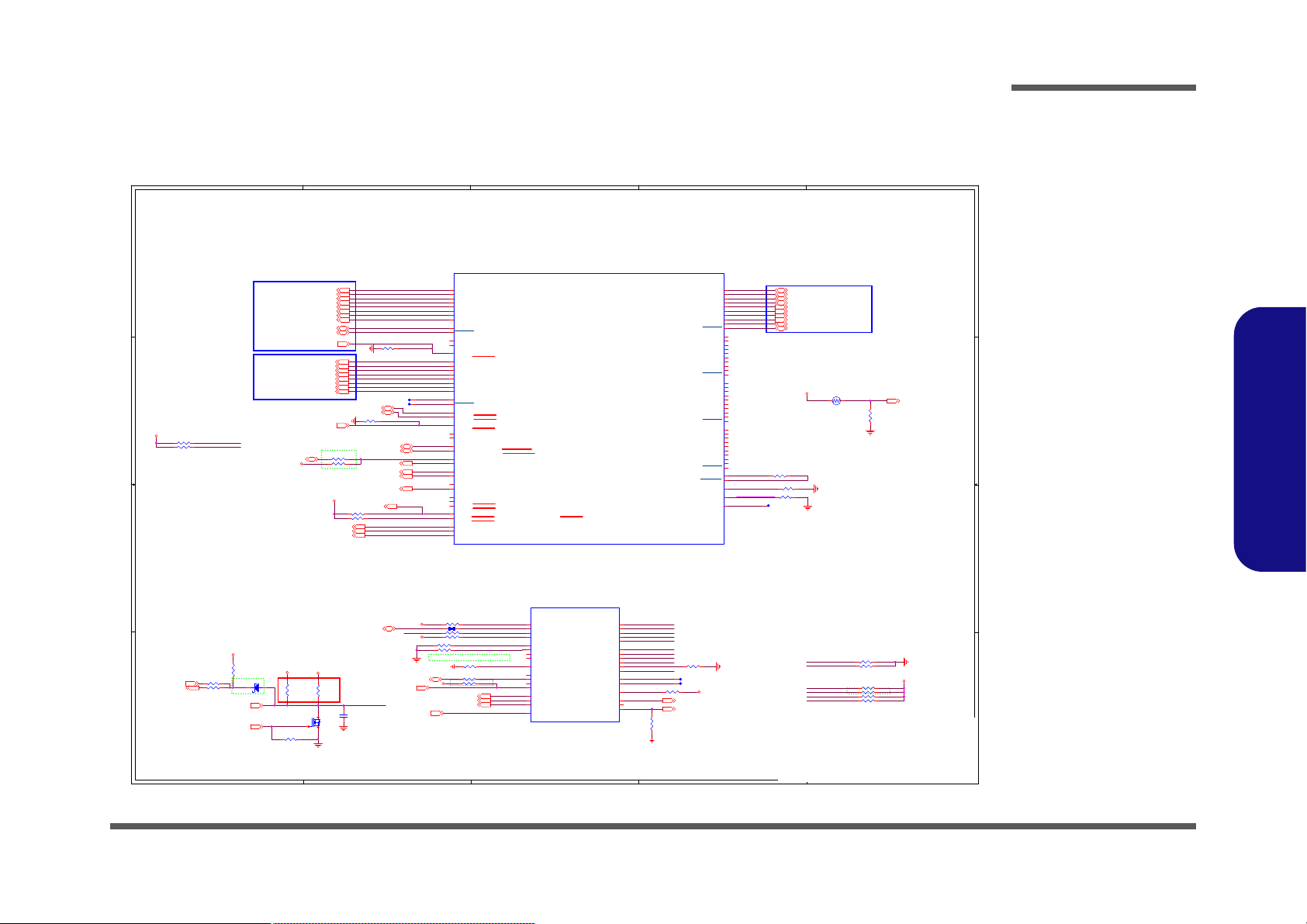
Processor 1/12
Sheet 2 of 45
Processor 1/12
5
5
4
4
3
3
2
2
1
1
D D
C C
B B
A A
1:2 (4mils:8mils)
Analog Thermal Sensor
EVT ⼴䴻Thermal
⼙⁷䅙䚠₨ 䡢⭂
PCB
㚨檀㹓⹎
, NTC
ㅱ娚㓦伖
PCB
㚨檀㹓⹎嗽
.
6-17-10400-730 EWTF02-104F4F-N
100k_1%_0402_NTC
Tiger Lake U A,U/20 DDI,MISC,TCP,JTAG
HDMI PORT
DIFF=85ohm
eDP PANEL
DIFF=85ohm
Form power
Form EC
CAD Note: Capacitor need to be placed
close to buffer output pin
LENGTH <500MILS
PU/PD for JTAG signals
TBT
DIFF=85ohm
\\
Ḵ怠ᶨ℔㜧㗗
VCCSTG_OUT_LGC,Ivy
Efm䶂嶗-!509!Nby
Efm!gvodujpo-!402:!Ujn
Npejgz-!509!Nby
Npejgz!Wbmvf-!608!Nby
Npejgz-!7028!Nby
3.3V
3.3VS
VCCST
VCCST
VCCSTG
VCCSTG
VCCSTG_OUT_LGC
VCCSTG
3.3VA
3.3VA
3.3VS
3.3VA
THERM_VOLT 27
HDMI_DATA2P19
HDMI_DATA2N19
HDMI_DATA1P19
HDMI_DATA1N19
HDMI_DATA0P19
HDMI_DATA0N19
HDMI_CLOCKP19
HDMI_CLOCKN19
EDP_TXN_020
EDP_TXN_120
EDP_TXP_120
EDP_TXP_020
EDP_TXP_220
EDP_TXN_220
EDP_TXP_320
EDP_TXN_320
EDP_AUXN20
EDP_AUXP20
BLON20
NB_ENAVDD20
EDP_BRIGHTNESS20
EDP_HPD20
HDMI_HPD19
H_PECI27
GPP_B332
H_PROCHOT_EC27
H_PROCHOT#40
TCP0_TXRX1_DP 21
TCP0_TXRX1_DN 21
TCP0_TXRX0_DP 21
TCP0_TXRX0_DN 21
TCP0_TX1_DP 21
TCP0_TX1_DN 21
TCP0_TX0_DP 21
TCP0_TX0_DN 21
TCP0_AUX_DP 21
TCP0_AUX_DN 21
HDMI_CTRLCLK19
HDMI_CTRLDATA19
TBT_LSX0_TXD21
TBT_LSX0_RXD9,21
CNVI_WAKE#26
GPP_D109
GPP_D129
GPP_E219
GPP_H29
GPP_H09
GPP_H19
GPP_F10 9
GPP_F7 9
SWI#27
SB_KBCRST#27
GPP_D13_RTD329
GPPC_DMIC_CLK32
VRALERT#_PD23
VRALERT#12
Title
Size Document Number Rev
Date: Sheet
of
6-71-L14M0-D02A
D02A
[02] CML A,D/20 DDI,MISC,JAG
Custom
245Friday, July 10, 2020
ᙔ!Ϻ!ႝ!တ!!DMFWP!DP/
L140MU
Title
Size Document Number Rev
Date: Sheet
of
6-71-L14M0-D02A
D02A
[02] CML A,D/20 DDI,MISC,JAG
Custom
245Friday, July 10, 2020
ᙔ!Ϻ!ႝ!တ!!DMFWP!DP/
L140MU
Title
Size Document Number Rev
Date: Sheet
of
6-71-L14M0-D02A
D02A
[02] CML A,D/20 DDI,MISC,JAG
Custom
245Friday, July 10, 2020
ᙔ!Ϻ!ႝ!တ!!DMFWP!DP/
L140MU
R504 0_04
R59
*20K_04
R51 51_04
R243
20K_1%_04
R155 *100K_04
R47 *51_04
T32 PCB Footprint = TC32-75
R498 10K_04
T7 PCB Footprint = TC32-75
R25 0_04
R160 0_04
R526 51_04
R151 *100K_04
R49
100K_04
R52 *1K_04
D26
RB751S-40H
AC
R24 *1K_04
R58 49.9_1%_04
R112 49.9_1%_04
U8513A
TGL_U_IP_EXT
AC2
DDIA_TXP_3
AC1
DDIA_TXN_3
AD2
DDIA_TXP_2
AD1
DDIA_TXN_2
AF1
DDIA_TXP_1
AF2
DDIA_TXN_1
AG2
DDIA_TXP_0
AG1
DDIA_TXN_0
T12
DDIB_TXP_3
T11
DDIB_TXN_3
Y11
DDIB_TXP_2
Y9
DDIB_TXN_2
T9
DDIB_TXP_1
P9
DDIB_TXN_1
V11
DDIB_TXP_0
V9
DDIB_TXN_0
AY2
TCP0_TXRX_P1
AY1
TCP0_TXRX_N1
BB1
TCP0_TXRX_P0
BB2
TCP0_TXRX_N0
AM5
TCP0_TX_P1
AM7
TCP0_TX_N1
AT7
TCP0_TX_P0
AT5
TCP0_TX_N0
AT2
TCP1_TXRX_P1
AT1
TCP1_TXRX_N1
AU1
TCP1_TXRX_P0
AU2
TCP1_TXRX_N0
AD5
TCP1_TX_P1
AD7
TCP1_TX_N1
AH7
TCP1_TX_P0
AH5
TCP1_TX_N0
BF1
TCP2_TXRX_P1
BF2
TCP2_TXRX_N1
BE2
TCP2_TXRX_P0
BE1
TCP2_TXRX_N0
BD7
TCP2_TX_P1
BD5
TCP2_TX_N1
AY5
TCP2_TX_P0
AY7
TCP2_TX_N0
BK1
TCP3_TXRX_P1
BK2
TCP3_TXRX_N1
BJ2
TCP3_TXRX_P0
BJ1
TCP3_TXRX_N0
BM7
TCP3_TX_P1
BM5
TCP3_TX_N1
BH5
TCP3_TX_P0
BH7
TCP3_TX_N0
M8
DSI_DE_TE_2
AF5
TCP1_AUX
DF43
GPP_A17/DISP_MISCC/I2S4_TXD
BK5
TCP3_AUX_P
BB5
TCP2_AUX_P
AF7
TCP1_AUX_P
AP7
TCP0_AUX_P
DK45
GPP_A15/USB_OC2#/DDSP_HPD4/DISP_MISC4/I2S4_SCLK
DF47
GPP_A20/DDSP_HPD2/DISP_MISC2/I2S5_SFRM
DK23
GPP_D11/ISH_SPI_MISO/DDP4_CTRLCLK/T BT_LSX3_TXD/GSPI2_MISO
AD9
DDIB_AUX
DG10
EDP_BKLTCTL
DU8
GPP_E18/DDP1_CTRLCLK/TBT_LSX0_TXD
DJ47
GPP_A22/DDPC_CTRLDATA/I2S5_RXD
AB9
DDIB_AUX_P
DN4
GPP_E22/DDPA_CTRLCLK/DNX_FORCE_RE LOAD
AJ2
DDIA_AUX_P
DM8
EDP_VDDEN
DG47
GPP_A21/DDPC_CTRLCLK/I2S5_TXD
DK27
GPP_H17/DDPB_CTRLDATA
AB1
DDI_RCOMP
AJ1
DDIA_AUX
DM23
GPP_D10/ISH_SPI_CLK/DDP3_CTRLDATA /TBT_LSX2_RXD/GSPI2_CLK
DN8
EDP_BKLTEN
DM29
GPP_H16/DDPB_CTRLCLK/PCIE_LNK_DOWN
DN23
GPP_D9/ISH_SPI_CS#/DDP3_CTRLCLK/ TBT_LSX2_TXD/GSPI2_CS0#
DT6
GPP_E23/DDPA_CTRLDATA
DH52
GPP_A14/USB_OC1#/DDSP_HPD3/I2S3_RXD/DISP_MISC3/DMIC_CLK_B1
BB7
TCP2_AUX
AN1
TC_RCOMP
DG43
GPP_A18/DDSP_HPDB/DISP_MISCB/I2S4_RXD
AP5
TCP0_AUX
DF45
GPP_A19/DDSP_HPD1/DISP_MISC1/I2S5_SCLK
DR5
GPP_E14/DDSP_HPDA/DISP_MISCA
CE4
DISP_UTILS/DSI_DE_TE_1
DN21
GPP_D12/ISH_SPI_MOSI/DDP4_CTRLDATA /TBT_LSX3_RXD/GSPI2_MOSI
AN2
TC_RCOMP_P
DD6
GPP_E21/DDP2_CTRLDATA/TBT_LSX1_RX D
DF6
GPP_E20/DDP2_CTRLCLK/TBT_LSX1_TXD
DV8
GPP_E19/DDP1_CTRLDATA/TBT_LSX0_RX D
BK7
TCP3_AUX
R55 *14mil_02
R73 100K _04
R502 499_1%_04
R26 *10K_04
R100 2.2K_04
C391
*47p_25V_NPO_02
R508 150_1%_04
TH1
EWTF02-104F4F-N
1 2
R13 1K_04
T1
R97 2.2K_04
T2
R496
100K_04
R503
*1K_04
R509 0_04
R505 150_1%_04
R12 49.9_1%_04
R38 1K_04
U8513U
TGL_U_IP_EXT
BK9
PECI
CB9
PCH_OPIRCOMP
DF4
DBG_PMODE
D8
PCH_JTAGX
K4
PROC_TRST#
DF31
GPP_H2
CT39
PROC_POPIRCOMP
DV32
GPP_H1
DU5
GPP_E3/CPU_GP0
DF8
GPP_E7/CPU_GP1
DW32
GPP_H0
D11
PROC_PRDY#
DT14
GPP_F10
A9
PCH_TMS
B6
PROC_TCK
D12
PROC_TDO
M7
CATERR#
A7
PCH_TCK
B12
PCH_TDI
M5
THRMTRIP#
G1
EAR_N_TEST_NCTF
DB41
GPP_B3/CPU_GP2
DB42
GPP_B4/CPU_GP3
E2
PROCHOT#
H4
PCH_TRST#
E12
PCH_TDO
C11
PROC_PREQ#
CW12
TP_1
DT15
GPP_F7
DJ27
GPP_H19/TIME_SYNC0
CM39
TP_2
B9
PROC_TMS
DR15
GPP_F9
A12
PROC_TDI
Q9
2SK3018S3
G
DS
R158 *100K_04
R62 51_04
R37
1K_04
R497 100K_04
R525 51_04
T3
R522 *51_04
DDI2_AUXN
DDI2_AUXP
HDMI_CTRLDATA
HDMI_CTRLCLK
DDI_RCOMP
EDP_DISP_UTIL
TCRCOMP_DP
TCRCOMP_DN
HDMI_DSI_DE_TE_2
H_CATERR#
H_PECI_ISO
H_PROCHOT#_D
THRMTRIP_R_N
H_PROCHOT#
GPP_B3_R
PCH_OPI_RCOMP
CPU_POPIRCOMP
XDP_TRST#
XDP_TCLK
XDP_TDI
XDP_TDO
XDP_TMS
PCH_JTAG_TCK
XDP_TDI
XDP_TDO
XDP_TMS
XDP_TRST#
XDP_TCLK
XDP_PREQ#
XDP_PRDY#
H_PROCHOT#
XDP_TDI
XDP_TDO
XDP_TMS
XDP_TCLK
XDP_TCLK
XDP_TRST#
HDMI_CTRLCLK
HDMI_CTRLDATA
GPP_F10
GPP_D10
GPP_D12
GPP_E21
GPP_F7
GPP_H0
GPP_H1
GPP_H2
USB_OC2#
Schematic Diagrams
B.Schematic Diagrams
Processor 1/12 B - 3
Page 50

Schematic Diagrams
Sheet 3 of 45
Processor 2/12
5
5
4
4
3
3
2
2
1
1
D D
C C
B B
A A
Tiger Lake U B,C/20 DDR4 Non-Interleave
M_A_DQ_0_014
M_A_DQ_0_114
M_A_DQ_0_214
M_A_DQ_0_314
M_A_DQ_0_414
M_A_DQ_0_514
M_A_DQ_0_614
M_A_DQ_0_714
M_A_DQ_1_014
M_A_DQ_1_114
M_A_DQ_1_214
M_A_DQ_1_314
M_A_DQ_1_414
M_A_DQ_1_514
M_A_DQ_1_614
M_A_DQ_1_714
M_A_DQ_2_015
M_A_DQ_2_115
M_A_DQ_2_215
M_A_DQ_2_315
M_A_DQ_2_415
M_A_DQ_2_515
M_A_DQ_2_615
M_A_DQ_2_715
M_A_DQ_3_015
M_A_DQ_3_115
M_A_DQ_3_215
M_A_DQ_3_315
M_A_DQ_3_415
M_A_DQ_3_515
M_A_DQ_3_615
M_A_DQ_3_715
M_A_DQ_4_014
M_A_DQ_4_114
M_A_DQ_4_214
M_A_DQ_4_314
M_A_DQ_4_414
M_A_DQ_4_514
M_A_DQ_4_614
M_A_DQ_4_714
M_A_DQ_5_014
M_A_DQ_5_114
M_A_DQ_5_214
M_A_DQ_5_314
M_A_DQ_5_414
M_A_DQ_5_514
M_A_DQ_5_614
M_A_DQ_5_714
M_A_DQ_6_015
M_A_DQ_6_115
M_A_DQ_6_215
M_A_DQ_6_315
M_A_DQ_6_415
M_A_DQ_6_515
M_A_DQ_6_615
M_A_DQ_6_715
M_A_DQ_7_015
M_A_DQ_7_115
M_A_DQ_7_215
M_A_DQ_7_315
M_A_DQ_7_415
M_A_DQ_7_515
M_A_DQ_7_615
M_A_DQ_7_715
CPUDRAMRST# 14,15,18
M_A_CLK_DDR0 14,15,16
M_A_CLK_DDR#0 14,15,16
M_A_ODT0 14,15
M_A_CS#0 14,15,16
M_A_CKE0 14,15,16
DDR_VREF_CA 16
M_A_ACT# 14,15,16
DDR_VTT_CTRL 37
M_A_BG0 14,15,16
M_A_BA1 14,15,16
DDR0_A_ALERT# 14,15
DDR0_A_PARITY 14, 15
M_A_BG1 14
M_A_BA0 14,15,16
M_B_CKE0 18
M_B_CKE1 18
M_B_CLK_DDR0 18
M_B_CS#1 18
M_B_ODT1 18
M_B_ODT0 18
M_B_CS#0 18
M_B_BG1 18
M_B_BG0 18
M_B_BA0 18
M_B_ACT# 18
M_B_BA1 18
DDR1_B_PARITY 18
DDR1_B_ALERT# 18
M_B_CLK_DDR1 18
M_B_CLK_DDR#1 18
M_B_CLK_DDR#0 18
DDR1_VREF_DQ 18
M_B_DQ_0_018
M_B_DQ_1_018
M_B_DQ_1_118
M_B_DQ_1_218
M_B_DQ_1_318
M_B_DQ_1_418
M_B_DQ_1_518
M_B_DQ_1_618
M_B_DQ_1_718
M_B_DQ_0_118
M_B_DQ_0_218
M_B_DQ_0_318
M_B_DQ_0_418
M_B_DQ_0_518
M_B_DQ_0_618
M_B_DQ_0_718
M_B_DQ_2_018
M_B_DQ_2_118
M_B_DQ_2_218
M_B_DQ_2_318
M_B_DQ_2_418
M_B_DQ_2_518
M_B_DQ_2_618
M_B_DQ_2_718
M_B_DQ_3_018
M_B_DQ_4_018
M_B_DQ_5_018
M_B_DQ_3_118
M_B_DQ_3_218
M_B_DQ_3_318
M_B_DQ_3_418
M_B_DQ_3_518
M_B_DQ_3_618
M_B_DQ_3_718
M_B_DQ_4_118
M_B_DQ_4_218
M_B_DQ_4_318
M_B_DQ_4_418
M_B_DQ_4_518
M_B_DQ_4_618
M_B_DQ_4_718
M_B_DQ_6_018
M_B_DQ_7_018
M_B_DQ_5_118
M_B_DQ_5_218
M_B_DQ_5_318
M_B_DQ_5_418
M_B_DQ_5_518
M_B_DQ_5_618
M_B_DQ_5_718
M_B_DQ_6_118
M_B_DQ_6_218
M_B_DQ_6_318
M_B_DQ_6_418
M_B_DQ_6_518
M_B_DQ_6_618
M_B_DQ_6_718
M_B_DQ_7_118
M_B_DQ_7_218
M_B_DQ_7_318
M_B_DQ_7_418
M_B_DQ_7_518
M_B_DQ_7_618
M_B_DQ_7_718
M_A_A0 14,15,16
M_A_A1 14,15,16
M_A_A2 14,15,16
M_A_A3 14,15,16
M_A_A4 14,15,16
M_A_A5 14,15,16
M_A_A6 14,15,16
M_A_A7 14,15,16
M_A_A8 14,15,16
M_A_A9 14,15,16
M_A_A10 14,15,16
M_A_A11 14,15,16
M_A_A12 14,15,16
M_A_A13 14,15,16
M_A_A14 14,15,16
M_A_A15 14,15,16
M_A_A16 14,15,16
M_B_A0 18
M_B_A1 18
M_B_A2 18
M_B_A3 18
M_B_A4 18
M_B_A5 18
M_B_A6 18
M_B_A7 18
M_B_A8 18
M_B_A9 18
M_B_A10 18
M_B_A11 18
M_B_A12 18
M_B_A13 18
M_B_A14 18
M_B_A15 18
M_B_A16 18
M_A_DQS#0 14
M_A_DQS#1 14
M_A_DQS#2 15
M_A_DQS#3 15
M_A_DQS#4 14
M_A_DQS#5 14
M_A_DQS#6 15
M_A_DQS#7 15
M_A_DQS0 14
M_A_DQS1 14
M_A_DQS2 15
M_A_DQS3 15
M_A_DQS4 14
M_A_DQS5 14
M_A_DQS6 15
M_A_DQS7 15
M_B_DQS0 18
M_B_DQS1 18
M_B_DQS2 18
M_B_DQS3 18
M_B_DQS4 18
M_B_DQS5 18
M_B_DQS6 18
M_B_DQS7 18
M_B_DQS#1 18
M_B_DQS#0 18
M_B_DQS#4 18
M_B_DQS#3 18
M_B_DQS#2 18
M_B_DQS#7 18
M_B_DQS#6 18
M_B_DQS#5 18
Title
Size Document Num ber Rev
Date: Sheet
of
6-71-L14M0-D02A
D02A
[03] CML U B,C/20 DDR4 Non-interleave
Custom
345Friday, July 10, 2020
ᙔ!Ϻ!ႝ!တ!!DMFWP!DP/
L140MU
Title
Size Document Num ber Rev
Date: Sheet
of
6-71-L14M0-D02A
D02A
[03] CML U B,C/20 DDR4 Non-interleave
Custom
345Friday, July 10, 2020
ᙔ!Ϻ!ႝ!တ!!DMFWP!DP/
L140MU
Title
Size Document Num ber Rev
Date: Sheet
of
6-71-L14M0-D02A
D02A
[03] CML U B,C/20 DDR4 Non-interleave
Custom
345Friday, July 10, 2020
ᙔ!Ϻ!ႝ!တ!!DMFWP!DP/
L140MU
LP4-LP5(NIL)/DDR4 (NIL)/DDR4 (IL)
DDR4/LP4/LP5/LP5 CMD Flip
DDR4/LP4/LP5/LP5 CMD Flip
DDR4/LP4/LP5/LP5 CMD Flip
DDR4/LP4/LP5/LP5 CMD Flip
DDR4/LP4/LP5/LP5 CMD Flip
DDR4/LP4/LP5/LP5 CMD Flip
LP4-LP5(NIL)/DDR4 (NIL)/DDR4 (IL)
DDR4/LP4/LP5/LP5 CMD Flip
DDR4/LP4/LP5/LP5 CMD Flip
DDR4/LP4/LP5/LP5 CMD Flip
DDR4/LP4/LP5/LP5 CMD Flip
DDR4/LP4/LP5/LP5 CMD Flip
U8513B
TGL_U_IP_EXT
?
AU50
DDR0_ALERT#
AU49
DDR0_VREF_CA
E52
DDR_VTT_CTL
C49
DDR_RCOMP
BL52
DDR0_BG0/DDR2_CA3/DDR2_CA4/DDR2_CS1
BY50
DDR0_MA5/DDR0_CA5/DDR0_CA6/DDR0_CA0
CF44
DDR0_ODT1/DDR1_CA0/DDR1_CA0/DDR1_CA6
BU52
DDR0_CKE1/DDR2_CA4/DDR2_CA5/DDR2_CA1
CD45
NC/DDR1_CKE0/DDR1_WCK_P/DDR1_W CK_P
BD41
DDR3_DQ1_0/DDR0_DQ7_0/DDR1_DQ3_0
BD45
DDR3_DQ1_5/DDR0_DQ7_5/DDR1_DQ3_5
BH41
DDR3_DQ0_0/DDR0_DQ6_0/DDR1_DQ2_0
BH47
DDR3_DQ0_5/DDR0_DQ6_5/DDR1_DQ2_5
BC49
DDR2_DQ1_0/DDR0_DQ5_0/DDR0_DQ3_0
AY50
DDR2_DQ1_5/DDR0_DQ5_5/DDR0_DQ3_5
BH49
DDR2_DQ0_0/DDR0_DQ4_0/DDR0_DQ2_0
BF50
DDR2_DQ0_5/DDR0_DQ4_5/DDR0_DQ2_5
CK41
DDR1_DQ1_0/DDR0_DQ3_0/DDR1_DQ1_0
CK45
DDR1_DQ1_5/DDR0_DQ3_5/DDR1_DQ1_5
CV41
DDR1_DQ0_0/DDR0_DQ2_0/DDR1_DQ0_0
CT45
DDR1_DQ0_5/DDR0_DQ2_5/DDR1_DQ0_5
CL49
DDR0_DQ1_0/DDR0_DQ1_0/DDR0_DQ1_0
CH50
DDR0_DQ1_5/DDR0_DQ1_5/DDR0_DQ1_5
CU49
DDR0_DQ0_0/DDR0_DQ0_0/DDR0_DQ0_0
CP50
DDR0_DQ0_5/DDR0_DQ0_5/DDR0_DQ0_5
BB42
DDR3_DQ1_3/DDR0_DQ7_3/DDR1_DQ3_3
BH42
DDR3_DQ0_3/DDR0_DQ6_3/DDR1_DQ2_3
BC53
DDR2_DQ1_3/DDR0_DQ5_3/DDR0_DQ3_3
BH53
DDR2_DQ0_3/DDR0_DQ4_3/DDR0_DQ2_3
CK42
DDR1_DQ1_3/DDR0_DQ3_3/DDR1_DQ1_3
CT42
DDR1_DQ0_3/DDR0_DQ2_3/DDR1_DQ0_3
CL53
DDR0_DQ1_3/DDR0_DQ1_3/DDR0_DQ1_3
CU53
DDR0_DQ0_3/DDR0_DQ0_3/DDR0_DQ0_3
BV44
DDR0_BA0/DDR3_CA0/DDR3_CA0/DDR3_CA6
BV47
DDR0_MA2/DDR3_CS0/DDR3_CA2/DDR3_CA2
BT51
DDR0_MA11/NC/DDR2_CS1/DDR2_CA4
CD53
DDR0_MA3/DDR0_CS1/DDR0_CS0/DDR0_CA3
CF42
DDR0_CS1/DDR1_CA1/DDR1_CA1/DDR1_CA5
BD42
DDR3_DQ1_1/DDR0_DQ7_1/DDR1_DQ3_1
BB41
DDR3_DQ1_2/DDR0_DQ7_2/DDR1_DQ3_2
BB47
DDR3_DQ1_6/DDR0_DQ7_6/DDR1_DQ3_6
BD47
DDR3_DQ1_7/DDR0_DQ7_7/DDR1_DQ3_7
BK41
DDR3_DQ0_1/DDR0_DQ6_1/DDR1_DQ2_1
BK42
DDR3_DQ0_2/DDR0_DQ6_2/DDR1_DQ2_2
BK45
DDR3_DQ0_6/DDR0_DQ6_6/DDR1_DQ2_6
BK47
DDR3_DQ0_7/DDR0_DQ6_7/DDR1_DQ2_7
BC50
DDR2_DQ1_1/DDR0_DQ5_1/DDR0_DQ3_1
BC52
DDR2_DQ1_2/DDR0_DQ5_2/DDR0_DQ3_2
AY52
DDR2_DQ1_6/DDR0_DQ5_6/DDR0_DQ3_6
AY53
DDR2_DQ1_7/DDR0_DQ5_7/DDR0_DQ3_7
BH50
DDR2_DQ0_1/DDR0_DQ4_1/DDR0_DQ2_1
BH52
DDR2_DQ0_2/DDR0_DQ4_2/DDR0_DQ2_2
BF52
DDR2_DQ0_6/DDR0_DQ4_6/DDR0_DQ2_6
BF53
DDR2_DQ0_7/DDR0_DQ4_7/DDR0_DQ2_7
CM41
DDR1_DQ1_1/DDR0_DQ3_1/DDR1_DQ1_1
CM42
DDR1_DQ1_2/DDR0_DQ3_2/DDR1_DQ1_2
CM47
DDR1_DQ1_6/DDR0_DQ3_6/DDR1_DQ1_6
CK47
DDR1_DQ1_7/DDR0_DQ3_7/DDR1_DQ1_7
CT41
DDR1_DQ0_1/DDR0_DQ2_1/DDR1_DQ0_1
CV42
DDR1_DQ0_2/DDR0_DQ2_2/DDR1_DQ0_2
CV47
DDR1_DQ0_6/DDR0_DQ2_6/DDR1_DQ0_6
CT47
DDR1_DQ0_7/DDR0_DQ2_7/DDR1_DQ0_7
CL50
DDR0_DQ1_1/DDR0_DQ1_1/DDR0_DQ1_1
CL52
DDR0_DQ1_2/DDR0_DQ1_2/DDR0_DQ1_2
CH52
DDR0_DQ1_6/DDR0_DQ1_6/DDR0_DQ1_6
CH53
DDR0_DQ1_7/DDR0_DQ1_7/DDR0_DQ1_7
CU50
DDR0_DQ0_1/DDR0_DQ0_1/DDR0_DQ0_1
CU52
DDR0_DQ0_2/DDR0_DQ0_2/DDR0_DQ0_2
CP52
DDR0_DQ0_6/DDR0_DQ0_6/DDR0_DQ0_6
CP53
DDR0_DQ0_7/DDR0_DQ0_7/DDR0_DQ0_7
CB42
DDR0_BA1/DDR1_CA5/DDR1_CA6/DDR1_CA0
BV41
DDR0_MA0/NC/DDR3_CS1/DDR3_CA4
BY53
DDR0_MA8/DDR0_CA2/DDR0_CA3/DDR0_CS0
BT45
NC/DDR3_CKE0/DDR3_WCK_P/DDR3_W CK_P
BV45
DDR0_PAR/DDR3_CS1/DDR3_CS0/DDR3_CA3
BP44
NC/DDR3_CA2/DDR3_CA3/DDR3_CS0
BP45
NC/DDR3_CA3/DDR3_CA4/DDR3_CS1
BU50
DDR0_MA9/DDR2_CA0/DDR2_CA0/DDR2_CA6
CF41
DDR0_MA13/DDR1_CS1/DDR1_CS0/DDR1_CA3
BP42
NC/DDR3_CA4/DDR3_CA5/DDR3_CA1
BP47
NC/DDR3_CA5/DDR3_CA6/DDR3_CA0
BN51
NC/DDR2_CKE0/DDR2_WCK_P/DDR2_W CK_P
BV42
DDR0_MA10/DDR3_CA1/DDR3_CA1/DDR3_CA5
CB44
DDR0_MA15/DDR1_CA3/DDR1_CA4/DDR1_CS1
CR51
DDR0_DQSP_0/DDR0_DQSP_0/DDR0_DQSP_0
CK51
DDR0_DQSP_1/DDR0_DQSP_1/DDR0_DQSP_1
CT44
DDR1_DQSP_0/DDR0_DQSP_2/DDR1_DQSP_0
CK44
DDR1_DQSP_1/DDR0_DQSP_3/DDR1_DQSP_1
BG51
DDR2_DQSP_0/DDR0_DQSP_4/DDR0_DQSP_2
BA51
DDR2_DQSP_1/DDR0_DQSP_5/DDR0_DQSP_3
BK44
DDR3_DQSP_0/DDR0_DQSP_6/DDR1_DQSP_2
BB44
DDR3_DQSP_1/DDR0_DQSP_7/DDR1_DQSP_3
CE50
NC/DDR0_CA1/DDR0_CA1/DDR0_CA5
CE53
NC/DDR0_CA0/DDR0_CA0/DDR0_CA6
BL50
DDR0_CKE0/DDR2_CA5/DDR2_CA6/DDR2_CA0
CA53
NC/DDR0_CKE1/DDR0_WCK_N/DDR0_W CK
CD47
NC/DDR1_CKE1/DDR1_WCK_N/DDR1_W CK
BN53
NC/DDR2_CKE1/DDR2_WCK_N/DDR2_W CK
BT47
NC/DDR3_CKE1/DDR3_WCK_N/DDR3_W CK
BP52
NC/DDR2_CLK_P/DDR2_CLK_P/DDR2_CLK_P
BN50
DDR0_BG1/DDR2_CA2/DDR2_CA3/DDR2_CS0
CE52
DDR0_MA1/NC/DDR0_CS1/DDR0_CA4
CD51
DDR0_MA4/DDR0_CS0/DDR0_CA2/DDR0_CA2
CR50
DDR0_DQSN_0/DDR0_DQSN_0/DDR0_DQSN_0
CK50
DDR0_DQSN_1/DDR0_DQSN_1/DDR0_DQSN_1
CV44
DDR1_DQSN_0/DDR0_DQSN_2/DDR1_DQSN_0
CM44
DDR1_DQSN_1/DDR0_DQSN_3/DDR1_DQSN_1
BG50
DDR2_DQSN_0/DDR0_DQSN_4/DDR0_DQSN_2
BA50
DDR2_DQSN_1/DDR0_DQSN_5/DDR0_DQSN_3
BH44
DDR3_DQSN_0/DDR0_DQSN_6/DDR1_DQSN_2
BD44
DDR3_DQSN_1/DDR0_DQSN_7/DDR1_DQSN_3
BP53
NC/DDR2_CLK_N/DDR2_CLK_N/DDR2_CLK
BT53
DDR0_ACT#/DDR2_CS1/DDR2_CS0/DDR2_CA3
CB47
DDR0_MA16/DDR1_CA4/DDR1_CA5/DDR1_CA1
CA50
DDR0_MA7/DDR0_CA4/DDR0_CA5/DDR0_CA1
BL53
NC/DDR2_CS0/DDR2_CA2/DDR2_CA2
CD42
NC/DDR1_CLK_P/DDR1_CLK_P/DDR1_CLK_P
CF45
DDR0_ODT0/DDR1_CS0/DDR1_CA2/DDR1_CA2
CC53
DDR0_CLK_N0/DDR0_CLK_N/DDR0_CLK_N/DDR0_CLK
BT41
DDR0_CLK_N1/DDR3_CLK_N/DDR3_CLK_N/DDR3_CLK
CA51
NC/DDR0_CKE0/DDR0_WCK_P/DDR0_W CK_P
CC52
DDR0_CLK_P0/DDR0_CLK_P/DDR0_CLK_P/DDR0_CLK_P
BU53
DDR0_MA12/DDR2_CA1/DDR2_CA1/DDR2_CA5
CB45
DDR0_MA14/DDR1_CA2/DDR1_CA3/DDR1_CS0
CF47
DDR0_CS0/NC/DDR1_CS1/DDR1_CA4
CD41
NC/DDR1_CLK_N/DDR1_CLK_N/DDR1_CLK
BT42
DDR0_CLK_P1/DDR3_CLK_P/DDR3_CLK_P/DDR3_CLK_P
BB45
DDR3_DQ1_4/DDR0_DQ7_4/DDR1_DQ3_4
BH45
DDR3_DQ0_4/DDR0_DQ6_4/DDR1_DQ2_4
AY49
DDR2_DQ1_4/DDR0_DQ5_4/DDR0_DQ3_4
BF49
DDR2_DQ0_4/DDR0_DQ4_4/DDR0_DQ2_4
CM45
DDR1_DQ1_4/DDR0_DQ3_4/DDR1_DQ1_4
CV45
DDR1_DQ0_4/DDR0_DQ2_4/DDR1_DQ0_4
CH49
DDR0_DQ1_4/DDR0_DQ1_4/DDR0_DQ1_4
CP49
DDR0_DQ0_4/DDR0_DQ0_4/DDR0_DQ0_4
DV47
DRAM_RESET#
BY52
DDR0_MA6/DDR0_CA3/DDR0_CA4/DDR0_CS1
LP4-LP5(NIL)/DDR4 (NIL)/DDR4 (IL)
LP4-LP5(NIL)/DDR4 (NIL)/DDR4 (IL)
DDR4/LP4/LP5/LP5 CMD Flip
DDR4/LP4/LP5/LP5 CMD Flip
DDR4/LP4/LP5/LP5 CMD Flip
DDR4/LP4/LP5/LP5 CMD Flip
DDR4/LP4/LP5/LP5 CMD Flip
DDR4/LP4/LP5/LP5 CMD Flip
DDR4/LP4/LP5/LP5 CMD Flip
DDR4/LP4/LP5/LP5 CMD Flip
DDR4/LP4/LP5/LP5 CMD Flip
U8513C
TGL_U_IP_EXT
AU52
DDR1_VREF_CA
AA53
DDR1_MA3/DDR4_CS1/DDR4_CS0/DDR4_CA3
AE44
DDR1_ODT1/DDR5_CA0/DDR5_CA0/DDR5_CA6
P52
DDR1_CKE1/DDR6_CA4/DDR6_CA5/DDR6_CA1
AC41
NC/DDR5_CLK_N/DDR5_CLK_N/DDR5_CLK
N38
DDR7_DQ1_0/DDR1_DQ7_0/DDR1_DQ7_0
H36
DDR7_DQ1_5/DDR1_DQ7_5/DDR1_DQ7_5
J47
DDR7_DQ0_0/DDR1_DQ6_0/DDR1_DQ6_0
J41
DDR7_DQ0_5/DDR1_DQ6_5/DDR1_DQ6_5
A40
DDR6_DQ1_0/DDR1_DQ5_0/DDR0_DQ7_0
B38
DDR6_DQ1_5/DDR1_DQ5_5/DDR0_DQ7_5
E47
DDR6_DQ0_0/DDR1_DQ4_0/DDR0_DQ6_0
D43
DDR6_DQ0_5/DDR1_DQ4_5/DDR0_DQ6_5
AL47
DDR5_DQ1_0/DDR1_DQ3_0/DDR1_DQ5_0
AL41
DDR5_DQ1_5/DDR1_DQ3_5/DDR1_DQ5_5
AV47
DDR5_DQ0_0/DDR1_DQ2_0/DDR1_DQ4_0
AR42
DDR5_DQ0_5/DDR1_DQ2_5/DDR1_DQ4_5
AH49
DDR4_DQ1_0/DDR1_DQ1_0/DDR0_DQ5_0
AF50
DDR4_DQ1_5/DDR1_DQ1_5/DDR0_DQ5_5
AP49
DDR4_DQ0_0/DDR1_DQ0_0/DDR0_DQ4_0
AL50
DDR4_DQ0_5/DDR1_DQ0_5/DDR0_DQ4_5
AC52
DDR1_MA1/NC/DDR4_CS1/DDR4_CA4
W51
NC/DDR4_CKE0/DDR4_WCK_P/DDR4_W CK_P
AC47
NC/DDR5_CKE0/DDR5_WCK_P/DDR5_W CK_P
N36
DDR7_DQ1_3/DDR1_DQ7_3/DDR1_DQ7_3
G45
DDR7_DQ0_3/DDR1_DQ6_3/DDR1_DQ6_3
E41
DDR6_DQ1_3/DDR1_DQ5_3/DDR0_DQ7_3
A46
DDR6_DQ0_3/DDR1_DQ4_3/DDR0_DQ6_3
AJ45
DDR5_DQ1_3/DDR1_DQ3_3/DDR1_DQ5_3
AR45
DDR5_DQ0_3/DDR1_DQ2_3/DDR1_DQ4_3
AH53
DDR4_DQ1_3/DDR1_DQ1_3/DDR0_DQ5_3
AP53
DDR4_DQ0_3/DDR1_DQ0_3/DDR0_DQ4_3
R41
DDR1_CLK_P1/DDR7_CLK_P/DDR7_CLK_P/DDR7_CLK_P
N51
DDR1_MA11/NC/DDR6_CS1/DDR6_CA4
J53
NC/DDR6_CS0/DDR6_CA2/DDR6_CA2
K51
NC/DDR6_CKE0/DDR6_WCK_P/DDR6_W CK_P
AC42
NC/DDR5_CLK_P/DDR5_CLK_P/DDR5_CLK_P
L38
DDR7_DQ1_1/DDR1_DQ7_1/DDR1_DQ7_1
L36
DDR7_DQ1_2/DDR1_DQ7_2/DDR1_DQ7_2
G36
DDR7_DQ1_6/DDR1_DQ7_6/DDR1_DQ7_6
G38
DDR7_DQ1_7/DDR1_DQ7_7/DDR1_DQ7_7
G47
DDR7_DQ0_1/DDR1_DQ6_1/DDR1_DQ6_1
J45
DDR7_DQ0_2/DDR1_DQ6_2/DDR1_DQ6_2
G41
DDR7_DQ0_6/DDR1_DQ6_6/DDR1_DQ6_6
G42
DDR7_DQ0_7/DDR1_DQ6_7/DDR1_DQ6_7
B40
DDR6_DQ1_1/DDR1_DQ5_1/DDR0_DQ7_1
D40
DDR6_DQ1_2/DDR1_DQ5_2/DDR0_DQ7_2
D38
DDR6_DQ1_6/DDR1_DQ5_6/DDR0_DQ7_6
E38
DDR6_DQ1_7/DDR1_DQ5_7/DDR0_DQ7_7
D46
DDR6_DQ0_1/DDR1_DQ4_1/DDR0_DQ6_1
B46
DDR6_DQ0_2/DDR1_DQ4_2/DDR0_DQ6_2
B43
DDR6_DQ0_6/DDR1_DQ4_6/DDR0_DQ6_6
A43
DDR6_DQ0_7/DDR1_DQ4_7/DDR0_DQ6_7
AL45
DDR5_DQ1_1/DDR1_DQ3_1/DDR1_DQ5_1
AJ47
DDR5_DQ1_2/DDR1_DQ3_2/DDR1_DQ5_2
AJ42
DDR5_DQ1_6/DDR1_DQ3_6/DDR1_DQ5_6
AJ41
DDR5_DQ1_7/DDR1_DQ3_7/DDR1_DQ5_7
AR47
DDR5_DQ0_1/DDR1_DQ2_1/DDR1_DQ4_1
AV45
DDR5_DQ0_2/DDR1_DQ2_2/DDR1_DQ4_2
AV42
DDR5_DQ0_6/DDR1_DQ2_6/DDR1_DQ4_6
AR41
DDR5_DQ0_7/DDR1_DQ2_7/DDR1_DQ4_7
AH50
DDR4_DQ1_1/DDR1_DQ1_1/DDR0_DQ5_1
AH52
DDR4_DQ1_2/DDR1_DQ1_2/DDR0_DQ5_2
AF52
DDR4_DQ1_6/DDR1_DQ1_6/DDR0_DQ5_6
AF53
DDR4_DQ1_7/DDR1_DQ1_7/DDR0_DQ5_7
AP50
DDR4_DQ0_1/DDR1_DQ0_1/DDR0_DQ4_1
AP52
DDR4_DQ0_2/DDR1_DQ0_2/DDR0_DQ4_2
AL52
DDR4_DQ0_6/DDR1_DQ0_6/DDR0_DQ4_6
AL53
DDR4_DQ0_7/DDR1_DQ0_7/DDR0_DQ4_7
U50
DDR1_MA5/DDR4_CA5/DDR4_CA6/DDR4_CA0
AU53
DDR1_ALERT#
J52
DDR1_BG0/DDR6_CA3/DDR6_CA4/DDR6_CS1
AA51
DDR1_MA4/DDR4_CS0/DDR4_CA2/DDR4_CA2
AE42
DDR1_CS1/DDR5_CA1/DDR4_CA1/DDR4_CA5
Y52
DDR1_CLK_P0/DDR4_CLK_P/DDR4_CLKP/DDR4_CLK_P
AA42
DDR1_BA1/DDR5_CA5/DDR5_CA6/DDR5_CA0
U52
DDR1_MA6/DDR4_CA3/DDR4_CA4/DDR4_CS1
U53
DDR1_MA8/DDR4_CA2/DDR4_CA3/DDR4_CS0
AE41
DDR1_MA13/DDR5_CS1/DDR5_CS0/DDR5_CA3
U42
DDR1_MA10/DDR7_CA1/DDR7_CA1/DDR7_CA5
AA44
DDR1_MA15/DDR5_CA3/DDR5_CA4/DDR5_CS1
AN51
DDR4_DQSP_0/DDR1_DQSP_0/DDR0_DQSP_4
AG51
DDR4_DQSP_1/DDR1_DQSP_1/DDR0_DQSP_5
AV44
DDR5_DQSP_0/DDR1_DQSP_2/DDR1_DQSP_4
AJ44
DDR5_DQSP_1/DDR1_DQSP_3/DDR1_DQSP_5
C45
DDR6_DQSP_0/DDR1_DQSP_4/DDR0_DQSP_6
D39
DDR6_DQSP_1/DDR1_DQSP_5/DDR0_DQSP_7
G44
DDR7_DQSP_0/DDR1_DQSP_6/DDR1_DQSP_6
K36
DDR7_DQSP_1/DDR1_DQSP_7/DDR1_DQSP_7
J50
DDR1_CKE0/DDR6_CA5/DDR6_CA6/DDR6_CA0
W53
NC/DDR4_CKE1/DDR4_WCK_N/DDR4_W CK
AC45
NC/DDR5_CKE1/DDR5_WCK_N/DDR5_W CK
K53
NC/DDR6_CKE1/DDR6_WCK_N/DDR6_W CK
R45
NC/DDR7_CKE1/DDR7_WCK_N/DDR7_W CK
W50
DDR1_MA7/DDR4_CA4/DDR4_CA5/DDR4_CA1
P50
DDR1_MA9/DDR6_CA0/DDR6_CA0/DDR6_CA6
K50
DDR1_BG1/DDR6_CA2/DDR6_CA3/DDR6_CS0
AN50
DDR4_DQSN_0/DDR1_DQSN_0/DDR0_DQSN_4
AG50
DDR4_DQSN_1/DDR1_DQSN_1/DDR0_DQSN_5
AR44
DDR5_DQSN_0/DDR1_DQSN_2/DDR1_DQSN_4
AL44
DDR5_DQSN_1/DDR1_DQSN_3/DDR1_DQSN_5
D45
DDR6_DQSN_0/DDR1_DQSN_4/DDR0_DQSN_6
C39
DDR6_DQSN_1/DDR1_DQSN_5/DDR0_DQSN_7
J44
DDR7_DQSN_0/DDR1_DQSN_6/DDR1_DQSN_6
K38
DDR7_DQSN_1/DDR1_DQSN_7/DDR1_DQSN_7
N53
DDR1_ACT#/DDR6_CS1/DDR6_CS0/DDR6_CA3
AA47
DDR1_MA16/DDR5_CA4/DDR5_CA5/DDR5_CA1
U45
DDR1_PAR/DDR7_CS1/DDR7_CS0/DDR7_CA3
AE45
DDR1_ODT0/DDR5_CS0/DDR5_CA2/DDR5_CA2
AC53
NC/DDR4_CA0/DDR4_CA0/DDR4_CA6
AC50
NC/DDR4_CA1/DDR4_CA1/DDR4_CA5
N47
NC/DDR7_CA2/DDR7_CA3/DDR7_CS0
N44
NC/DDR7_CA3/DDR7_CA4/DDR7_CS1
R47
NC/DDR7_CKE0/DDR7_WCK_P/DDR7_W CK_P
Y53
DDR1_CLK_N0/DDR4_CLK_N/DDR4_CLK_N/DDR4_CLK
M53
NC/DDR6_CLK_N/DDR6_CLK_N/DDR6_CLK
R42
DDR1_CLK_N1/DDR7_CLK_N/DDR7_CLK_N/DDR7_CLK
AE47
DDR1_CS0/NC/DDR4_CS1/DDR4_CA4
M52
NC/DDR6_CLK_P/DDR6_CLK_P/DDR6_CLK_P
U44
DDR1_BA0/DDR7_CA0/DDR7_CA0/DDR7_CA6
U47
DDR1_MA2/DDR7_CS0/DDR7_CA2/DDR7_CA2
P53
DDR1_MA12/DDR6_CA1/DDR6_CA1/DDR6_CA5
AA45
DDR1_MA14/DDR5_CA2/DDR5_CA3/DDR5_CS0
H38
DDR7_DQ1_4/DDR1_DQ7_4/DDR1_DQ7_4
J42
DDR7_DQ0_4/DDR1_DQ6_4/DDR1_DQ6_4
A38
DDR6_DQ1_4/DDR1_DQ5_4/DDR0_DQ7_4
E44
DDR6_DQ0_4/DDR1_DQ4_4/DDR0_DQ6_4
AL42
DDR5_DQ1_4/DDR1_DQ3_4/DDR1_DQ5_4
AV41
DDR5_DQ0_4/DDR1_DQ2_4/DDR1_DQ4_4
AF49
DDR4_DQ1_4/DDR1_DQ1_4/DDR0_DQ5_4
AL49
DDR4_DQ0_4/DDR1_DQ0_4/DDR0_DQ4_4
U41
DDR1_MA0/NC/DDR7_CS1/DDR7_CA4
N45
NC/DDR7_CA4/DDR7_CA5/DDR7_CA1
N42
NC/DDR7_CA5/DDR7_CA6/DDR7_CA0
R585
100_1%_04
M_A_A14
M_A_A12
M_A_A6
M_A_A15
M_A_A16
M_A_A13
M_A_A9
M_A_A7
M_A_A8
M_A_A11
M_A_A10
M_A_A4
M_A_A5
M_A_A3
M_A_DQS#6
M_A_DQS#7
M_A_DQS7
M_A_DQS1
M_A_DQS3
M_A_DQS#1
M_A_DQS#3
M_A_DQS4
M_A_DQS5
M_A_DQS6
M_A_DQS#4
M_A_DQS#5
M_A_DQS#0
M_A_DQS0
M_A_DQS2
M_A_DQS#2
M_A_A1
M_A_A2
M_A_A0
DDR_RCOMP_0
M_B_A12
M_B_A14
M_B_A9
M_B_A7
M_B_A6
M_B_A15
M_B_A16
M_B_A13
M_B_A5
M_B_A8
M_B_A11
M_B_A10
M_B_A3
M_B_A4
M_B_A0
M_B_A2
M_B_A1
M_B_DQS7
M_B_DQS1
M_B_DQS#6
M_B_DQS6
M_B_DQS5
M_B_DQS4
M_B_DQS3
M_B_DQS#2
M_B_DQS2
M_B_DQS0
M_B_DQS#7
M_B_DQS#5
M_B_DQS#4
M_B_DQS#3
M_B_DQS#1
M_B_DQS#0
Processor 2/12
B.Schematic Diagrams
B - 4 Processor 2/12
Page 51

5
5
4
4
3
3
2
2
1
1
D D
C C
B B
A A
Tiger Lake U D,T,S/20 CFG,RSVD
Configuration Signals: The CFG
signals have a default value of '1' if not
terminated on the board. Refer to the
appropriate platform design guide for
pull-down recommendations when a
logic low is desired.
Intel recommends placing test points
on the board for CFG pins.
CFG[3:0]: Reserved configuration
Ʉ
lane.
CFG[4]: eDP enable:
Ʉ
— 1 = Disabled.
— 0 = Enabled.
CFG[6:5]: Reserved configuration
Ʉ
lanes.
CFG[7]: PEG Training:
Ʉ
— 1 = (default) PEG Train
immediately following
RESET# de assertion.
— 0 = PEG Wait for BIOS for
training.
CFG[13:8]: Reserved
Ʉ
configuration lanes.
CFG[14]: PEG60 Lane Reversal:
Ʉ
— 1 - (Default) Normal
— 0 - Reversed
CFG[17:15]: Reserved
Ʉ
configuration lanes.
3.3VA
Title
Size Document Number Rev
Date: Sheet
of
6-71-L14M0-D02A
D02A
[04] CML U D,Q/20 CFG
A3
445Friday, July 10, 2020
ᙔ!Ϻ!ႝ!တ!!DMFWP!DP/
L140MU
Title
Size Document Number Rev
Date: Sheet
of
6-71-L14M0-D02A
D02A
[04] CML U D,Q/20 CFG
A3
445Friday, July 10, 2020
ᙔ!Ϻ!ႝ!တ!!DMFWP!DP/
L140MU
Title
Size Document Number Rev
Date: Sheet
of
6-71-L14M0-D02A
D02A
[04] CML U D,Q/20 CFG
A3
445Friday, July 10, 2020
ᙔ!Ϻ!ႝ!တ!!DMFWP!DP/
L140MU
R65*1K_04
R501 2.2K_1%_04
R595 10K_04
U8513D
TGL_U_IP_EXT
DW47
RSVD_3
DV24
RSVD_2
A48
RSVD_5
DW49
RSVD_4
R57*1K_04
T5
R520 49.9_1%_04
T6
U8513S
TGL_U_IP_EXT
C53
RSVD_23
DF49
RSVD_22
DF50
RSVD_21
DF52
RSVD_20
U35
RSVD_27
A6
IST_TP_1
AP9
RSVD_30
CF39
RSVD_26
A4
IST_TP_0
A52
RSVD_31
E53
RSVD_25
CB39
RSVD_32
T35
RSVD_24
DU53
PCH_IST_TP_0
DT52
PCH_IST_TP_1
B53
RSVD_29
DF53
RSVD_19
F53
RSVD_28
V21
RSVD_TP_29
BF12
RSVD_TP_28
D4
RSVD_TP_27
CY15
RSVD_TP_26
CY30
RSVD_TP_25
CY28
RSVD_TP_39
U38
RSVD_TP_38
W38
RSVD_TP_37
AY12
RSVD_TP_36
W37
RSVD_TP_35
BB12
RSVD_TP_34
U21
RSVD_TP_33
CD39
RSVD_TP_32
U37
RSVD_TP_31
W20
RSVD_TP_30
U8513T
TGL_U_IP_EXT
DV6
RSVD_15
C1
RSVD_TP_9
Y2
BPM#_0
E6
CFG_4
DV51
VSS_1
AK9
RSVD_12
AB4
BPM#_1
H9
CFG_5
AH9
RSVD_13
K8
CFG_6
DD13
RSVD_10
H7
CFG_7
DF13
RSVD_11
U17
CFG_17
E7
CFG_0
H11
CFG_16
D9
CFG_1
B5
CFG_RCOMP
E9
CFG_2
T15
CFG_15
DV53
TP_4
H5
CFG_3
V17
CFG_14
U15
CFG_13
AR2
TCP0_MBIAS_RCOMP
B3
RSVD_7
K11
CFG_12
D52
SKTOCC#
AL10
RSVD_TP_2
A3
RSVD_6
K12
CFG_11
V35
RSVD_18
AM12
RSVD_TP_3
K9
CFG_10
AH12
RSVD_TP_4
K7
CFG_8
E1
RSVD_TP_19
DV2
RSVD_TP_18
DW2
RSVD_TP_17
DT2
RSVD_TP_16
DU1
RSVD_TP_15
DW3
RSVD_TP_14
DV4
RSVD_TP_13
CU40
RSVD_TP_12
CP39
RSVD_TP_11
D2
RSVD_TP_10
AJ10
RSVD_TP_5
T17
CFG_9
DW52
TP_3
DW5
RSVD_TP_24
DR53
RSVD_TP_23
DR2
RSVD_TP_22
DR1
RSVD_TP_21
AB2
RSVD_16
F1
RSVD_TP_20
AR1
RSVD_TP_6
W34
RSVD_17
A51
RSVD_TP_7
BM12
RSVD_9
M4
BPM#_2
DW6
RSVD_14
B51
RSVD_TP_8
BN10
RSVD_8
Y1
BPM#_3
T4
R33 1K_04
R84 *1K_04
CFG4
CFG0
CFG7
CFG_RCOMP
SKTOCC#
TCP0_MBIAS_RCOMP
CFG14
CFG5
CFG6
CFG3
Sheet 4 of 45
Processor 3/12
Processor 3/12
Schematic Diagrams
B.Schematic Diagrams
Processor 3/12 B - 5
Page 52

Schematic Diagrams
5
5
4
4
3
3
2
2
1
1
D D
C C
B B
A A
Close to SPI TPM
Tiger Lake U E/20 SPI/SMB/LPC
Close to BIOS ROM
Default
HIGH = TPM
TPM Type Detect
PCH_GPP_D21
SPI_* = 1.5"~6.5"
BIOS+ME ROM
128M bit
RETIMER
TP
Close to EC
W/O TPM TPM
49.9_1%_04 56_1%_04
旣ῤ
W/O TPM TPM
15_1%_04
5.1_1%_04
旣ῤ
Npejgz!qv!4/4WB-!3028!Ujn
⎴℔㜧-!3031!Ujn
Npejgz-!3036!Ujn
Npejgz!x0UQN!wbmvf-!509!Nby
Npejgz!x0UQN!wbmvf-!509!Nby
Npejgz!x0UQN!wbmvf-!509!Nby
Efm-!50:!Nby
Efm-!5033!Nby
Npejgz!Gppuqsjou-!702!Nby
SPI_3.3VVDD3
3.3VA
3.3VS
3.3VA
SPI_3.3V
3.3VS
TPM_SPI_MOSI33
TPM_SPI_MISO33
TPM_SPI_CS#33
TPM_SPI_CLK33
SMB_CLK_DDR 18
SMB_DAT_DDR 18
SMB_DATA 32
SMB_CLK 32
CL_RST#126
CL_DATA126
CL_CLK126
ESPI_CLK 27
ESPI_IO_3 27
ESPI_IO_2 27
ESPI_IO_1 27
ESPI_IO_0 27
ESPI_CS_N 27
TBT_I2C_SCL 23
TBT_I2C_SDA 23
SML0_CLK 21
SML0_DATA 21
ESPI_RESET_N 27
PCH_SPI_DQ39
GPP_B239
PCH_GPP_C29,26
PCH_GPP_C59
SPI_SI_R9
PCH_SPI_DQ29
PCH_GPP_E119
PCH_GPP_E109
PCH_GPP_E69
HSPI_SCLK27
HSPI_CE#27
HSPI_MSO27
HSPI_MSI27
ROM_I2C_EN23
Title
Size Document Number Rev
Date: Sheet
of
6-71-L14M0-D02A
D02A
[05] TGL U E/20 SPI/SMB/LPC
Custom
545Friday, July 10, 2020
ᙔ!Ϻ!ႝ!တ!!DMFWP!DP/
L140MU
Title
Size Document Number Rev
Date: Sheet
of
6-71-L14M0-D02A
D02A
[05] TGL U E/20 SPI/SMB/LPC
Custom
545Friday, July 10, 2020
ᙔ!Ϻ!ႝ!တ!!DMFWP!DP/
L140MU
Title
Size Document Number Rev
Date: Sheet
of
6-71-L14M0-D02A
D02A
[05] TGL U E/20 SPI/SMB/LPC
Custom
545Friday, July 10, 2020
ᙔ!Ϻ!ႝ!တ!!DMFWP!DP/
L140MU
R117 *100K_04
R625 15_1%_04
W/O TPM=15_1%_04 ; TPM=5.1_1%_04
R592 75K_04
R125 100K_04
U33
GD25B127DSIGR
PCB Footprint = wson8l-8x6mm
CE#
1
SO
2
WP#
3
VSS
4
SI
5
SCK
6
HOLD#
7
VDD
8
R69
*14mil_02
R598 15_1%_04
R657 49.9_1%_04
R68 1K _04
R61 10K_04
TPM
T16
R71
*14mil_02
R166 15_1%_04
R632 0_04
TPM
R76 *1K _04
R652 49.9_1%_04
W/O TPM=49.9_1%_04 ; TPM=56_1%_04
R629 56_1%_04
TPM
R82 499_1%_04
U8513E
TGL_U_IP_EXT
DJ37
SPI0_CLK
DK52
GPP_A4/ESPI_CS#
DK15
GPP_F16/GSXCLK/THC1_SPI2_CS#
DN13
GPP_F13/GSXSLOAD/THC1_SPI2_IO1
DJ17
GPP_C7/SML1DATA
DH4
CL_DATA
DM6
GPP_E12/SPI1_MISO_IO1/THC0_SPI1_I O1
DK17
GPP_C6/SML1CLK
DN10
GPP_F18/THC1_SPI2_INT#
DN15
GPP_F11/THC1_SPI2_CLK
DG37
SPI0_CS0#
DJ39
SPI0_IO2
DP50
GPP_A1/ESPI_IO1
DF2
CL_RST#
DR9
GPP_E1/SPI1_IO2/THC0_SPI1_IO2
DN5
GPP_E2/SPI1_IO3/THC0_SPI1_IO3
DJ33
SPI0_MISO
DG35
SPI0_IO3
DP52
GPP_A0/ESPI_IO0
CY50
GPP_B23/SML1ALERT#/PCHHOT#/GSP I1_CS1#
DJ53
GPP_A3/ESPI_IO3/SUSACK#
DH3
CL_CLK
DM13
GPP_F14/GSXDIN/THC1_SPI2_IO2
DT8
GPP_E6/THC0_SPI1_RST#
DW9
GPP_E17/THC0_SPI1_INT#
DM19
GPP_C1/SMBDATA
DN17
GPP_C5/SML0ALERT#
DK21
GPP_C0/SMBCLK
DJ35
SPI0_MOSI
DV11
GPP_E8/SPI1_CS1#/SATA_LED#
DF35
SPI0_CS1#
DK8
GPP_E10/SPI1_CS#/THC0_SPI1_CS#
DF39
SPI0_CS2#
DH50
GPP_A2/ESPI_IO2/SUSWARN#_SUSPWRDNACK
DM17
GPP_C4/SML0DATA
DN19
GPP_C2/SMBALERT#
DN53
GPP_A5/ESPI_CLK
DK13
GPP_F15/GSXSRESET#/THC1_SPI2_IO3
DK6
GPP_E13/SPI1_MOSI_IO0/THC0_SPI1_I O0
DL50
GPP_A6/ESPI_RESET#
DK19
GPP_C3/SML0CLK
DV14
GPP_F17/THC1_SPI2_RST#
DJ15
GPP_F12/GSXDOUT/THC1_SPI2_IO0
DJ6
GPP_E11/SPI1_CLK/THC0_SPI1_CLK
R79 *1K _04
R648 49.9_1%_04
W/O TPM=49.9_1%_04 ; TPM=56_1%_04
R60 100K_04
W/O TPM
R86 499_1%_04
C436
*27p_25V_NPO_02
R642 15_1%_04
W/O TPM=15_1%_04 ; TPM=5.1_1%_04
R626 56_1%_04
TPM
R596 49.9_1%_04
R666 *0201_s hort
R170 15_1%_04
R51510K_04
R636 49.9_1%_04
W/O TPM=49.9_1%_04 ; TPM=56_1%_04
R669 *20m il_short_04
R656
20K_1%_04
R650 15_1%_04
W/O TPM=15_1%_04 ; TPM=5.1_1%_04
R108 49.9_1%_04
R661
20K_1%_04
C500
0.1u_6.3V_X5R_02
R167 15_1%_04
R70 1K _04
R640 56_1%_04
TPM
HSPI_MSI
HSPI_SCLK
SPI0_CS2#
HSPI_MSO
SPI0_CS2#
SPI_SI
SPI_SCLK
SPI_SO
HSPI_MSI
HSPI_SCLK
HSPI_MSO
SMB_CLK
SMB_DATA
PCH_GPP_C2
SPI_SCLK_R
SPI_SO_R
PCH_SPI_DQ3
SPI0_CS1#
SPI_SI_R
PCH_SPI_DQ2
SPI0_CS2#
PCLK_KBC_R
SMB_CLK
SMB_DATA
PCH_GPP_E10
SPI_SCLK_R
SML0_CLK
SML0_DATA
TBT_I2C_SDA
TBT_I2C_SCL
PCH_SATAHDD_LED#
SPI_CS_0# PCH_GPP_C5
PCH_GPP_E6
TPM_DET#
PCH_GPP_E11
GPP_B23
SPI_WP#_0
SPI_HOLD#_0
SPI_CS_0#
SPI_SI
SPI_SO
SPI_SCLK
SPI_HOLD#_0
SPI_WP#_0
SPI_CS_0#
SPI_SCLK_R
SPI_SI_R
SPI_SO_R
Sheet 5 of 45
Processor 4/12
Processor 4/12
B.Schematic Diagrams
B - 6 Processor 4/12
Page 53

Processor 5/12
5
5
4
4
3
3
2
2
1
1
D D
C C
B B
A A
Tiger Lake U F,G/20 GPIO/HDA
㓦伖
BOT朊
㉮味⎗㉱䶂⛘㕡
For BIOS Debug
HDA_SDO/HDA_SYNNC/HDA_BCLK/HDA_RST#
CAP should be close PCH
Trace Length <1"
I2C Address: 0x2C
TOUCH PAD
CLOSE TO PCH
3.3V
1.8V
1.8V/3.3V
1.8V/3.3V
1.8V/3.3V:A B C D E F H R T U
1.8V:S
3.3V:GPD
0=>Disable “No Reboot” mode. (Default)
1=>Enable “No Reboot” mode (PCH will
disable the TCO Timer
system reboot feature). This function is
useful when running ITP/XDP.
BOARD ID
GPP_D3
HIGH = L140MU
LO =
GPP_D18 DDR TypeGPP_D17
枭䚖
1
2
3
4
LOW
HIGH
SAMSUNG2666
LOW
LOW
LOWHIGH
HIGH HIGH
LOW = Disable (Default)
HIGH =Enable Top Swap mode
0=>Enable security measures defined
in the Flash Descriptor.(Default)
1=>Disable Flash Descriptor
Security (override).
SAMSUNG3200
(default)
⋩戻
2666
⋩戻
3200
5
6
GPP_D1
LOW
LOW
LOW
LOW
HIGH
HIGH
HIGH
HIGH HIGH
LOW
Npejgz-!3022!Ujn
Npejgz-!3022!Ujn
Npejgz-!3029!Ujn
Efm!S639-!302:!Ujn
EFM!UCUB`J3D`JOU-!302:!Ujn
Npejgz-!509!Nby
Bee-!509!Nby
Npejgz-!5034!Nby
Npejgz!Wbmvf-!608!Nby
VDD3
1.8VA
3.3VS
3.3VS
3.3VS
3.3VS
3.3VA
3.3VS
3.3VS
1.8VA
3.3VS
3.3VA
HDA_SDIN0 24
HDA_SYNC 24
HDA_BITCLK 24
HDA_SDOUT 24
ME_WE 27
AZ_RST#_R 24
T_SDA32
T_SCL32
SSD2_PWR_DN# 29
SSD1_PWR_DN#28
SB_BLON 20
CNVI_MFUART2_TXD26
CNVI_MFUART2_RXD26
TC_RETIMER_FORCE_PWR21,23
PCH_BT_EN 26
PCH_GPP_C2326
CNVI_RST# 26
CNVI_CLKREQ 26
TPM_PIRQ#33
LEDKB_DET# 27,32
PCH_SPKR24
SERIRQ27
SMI# 27
SCI# 27
GPP_C12_RTD328
GPPC_DMIC_DATA 32
PCH_I2C_SCL23
PCH_I2C_SDA23
Title
Size Document Number Rev
Date: Sheet
of
6-71-L14M0-D02A
D02A
[06] CML U F,G/20 GPIO/HDA
Custom
645Friday, July 10, 2020
ᙔ!Ϻ!ႝ!တ!!DMFWP!DP/
L140MU
Title
Size Document Number Rev
Date: Sheet
of
6-71-L14M0-D02A
D02A
[06] CML U F,G/20 GPIO/HDA
Custom
645Friday, July 10, 2020
ᙔ!Ϻ!ႝ!တ!!DMFWP!DP/
L140MU
Title
Size Document Number Rev
Date: Sheet
of
6-71-L14M0-D02A
D02A
[06] CML U F,G/20 GPIO/HDA
Custom
645Friday, July 10, 2020
ᙔ!Ϻ!ႝ!တ!!DMFWP!DP/
L140MU
T14
R12333_04
R5601K_04
C108*2p_25V_NPO_02
R537 *2.2K_04
R16275K_04
R544 100K_04
R703 0_02
R594 200_1%_04
R546 *2.2K_04
R545 *100K_04
R704 0_02
C420*2p_25V_NPO_02
T42
R506 *10K_04
R56533_04
T43
R77 *10K_04
R530 100K_04
DDR_3200
R105 200_1%_04
C419*2p_25V_NPO_02
R532 *100K_04
R606 *14mil_02
R56133_04
U8513F
TGL_U_IP_EXT
DT35
GPP_T2
DR24
GPP_D18/ISH_GP5
DT21
GPP_C8/UART0_RXD
DV21
GPP_C9/UART0_TXD
DG17
GPP_U5
DB47
GPP_B7/ISH_I2C1_SDA
DJ23
GPP_C19/I2C1_SCL
DW18
GPP_C16/I2C0_SDA
DV19
GPP_C13/UART1_TXD/ISH_UART1_TXD
DC49
GPP_B17/GSPI0_MISO
DR7
GPP_E15/ISH_GP6
DD47
GPP_B10/I2C5_SCL/ISH_I2C2_SCL
DF25
GPP_H9/I2C4_SCL/CNV_MFUART2_TXD
DC50
GPP_B14/SPKR/TIME_SYNC1/GSPI0_CS1#
DC53
GPP_B16/GSPI0_CLK
DR21
GPP_C11/UART0_CTS#
CY39
GPP_B8/ISH_I2C1_SCL
DB44
GPP_B5/ISH_I2C0_SDA
DF29
GPP_H7/I2C3_SCL
DC52
GPP_B15/GSPI0_CS0#
DJ19
GPP_C23/UART2_CTS#
CY52
GPP_B21/GSPI1_MISO
DJ8
GPP_E16/ISH_GP7
DT18
GPP_C18/I2C1_SDA
CY49
GPP_B20/GSPI1_CLK
DV27
GPP_D0/ISH_GP0/BK0/SBK0
DT27
GPP_D1/ISH_GP1/BK1/SBK1
DU31
GPP_D2/ISH_GP2/BK2/SBK2
DV31
GPP_D3/ISH_GP3/BK3/SBK3
DV25
GPP_D16/ISH_UART0_CTS#
DG29
GPP_H6/I2C3_SDA
CY53
GPP_B22/GSPI1_MOSI
DB45
GPP_B6/ISH_I2C0_SCL
DJ29
GPP_H5/I2C2_SCL
DG19
GPP_U4
DR51
GPP_RCOMP
DF21
GPP_C22/UART2_RTS#
DT19
GPP_C12/UART1_RXD/ISH_UART1_RXD
DW21
GPP_C10/UART0_RTS#
DV18
GPP_C17/I2C0_SCL
DN33
GPP_T3
DD44
GPP_B9/I2C5_SDA/ISH_I2C2_SDA
DT25
GPP_D15/ISH_UART0_RTS#/GSPI2_CS1#/ IMGCLKOUT5
DW27
GPP_D13/ISH_UART0_RXD
DF27
GPP_H8/I2C4_SDA/CNV_MFUART2_RXD
DJ21
GPP_C21/UART2_TXD
DU19
GPP_C14/UART1_RTS#/ISH_UART1_RTS#
DR18
GPP_C15/UART1_CTS#/ISH_UART1_CTS#
DA51
GPP_B18/GSPI0_MOSI
DU25
GPP_D17/ISH_GP4
DJ31
GPP_H4/I2C2_SDA
DA50
GPP_B19/GSPI1_CS0#
DR27
GPP_D14/ISH_UART0_TXD
DG23
GPP_C20/UART2_RXD
R550 *10K_04
R529 100K_04
DDR_2666
R531 100K_04
R599
*4.7K_04
R608
*4.7K_04
R5242.2K_04
R81 *0_06
R535 100K_04
DDR_⋩戻
R83 *10K_04
R593
*20K_04
D28RB751S-40H
AC
R5232.2K_04
R607
*20K_04
T34
R536 100K_04
DDR_SAMSUNG
R55733_04
R48 *10K_04
U8513G
TGL_U_IP_EXT
DF33
SNDW_RCOMP
DG50
GPP_A10/I2S2_RXD/DMIC_DATA1
DU37
GPP_R1/HDA_SYNC/I2S0_SFRM
DG41
GPP_A23/I2S1_SCLK
DK31
GPP_S5/SNDW2_DATA/DMIC_DATA1
DK33
GPP_S4/SNDW2_CLK/DMIC_CLK_A1
DH49
GPP_A13/PMC_I2C_SCL/I2S3_TXD/DMIC_CLK_B0
DW35
GPP_S2/SNDW1_CLK/DMIC_CLK_B0
DM31
GPP_S7/SNDW3_DATA/DMIC_DATA0
DN31
GPP_S6/SNDW3_CLK/DMIC_CLK_A0
DT32
GPP_S0/SNDW0_CLK
DL52
GPP_A11/PMC_I2C_SDA/I2S3_SCLK
DG51
GPP_A8/I2S2_SFRM/CNV_RF_RESET#/DMIC_DATA_0
DV41
GPP_R4/HDA_RST#
DV37
GPP_R3/HDA_SDI0/I2S0_RXD
DW38
GPP_R5/HDA_SDI1/I2S1_RXD
DL49
GPP_A9/I2S2_TXD/MODEM_CLKREQ/CRF_XTAL_CLK REQ/DMIC_CLK_A1
DW24
GPP_D19/I2S_MCLK1
DT38
GPP_R7/I2S1_SFRM
DW15
GPP_F8/I2S_MCLK2_INOUT
DR38
GPP_R0/HDA_BCLK/I2S0_SCLK
DL53
GPP_A7/I2S2_SCLK/DMIC_CLK_A0
DT37
GPP_R2/HDA_SDO/I2S0_TXD
DV38
GPP_R6/I2S1_TXD
DR35
GPP_S1/SNDW0_DATA
DV35
GPP_S3/SNDW1_DATA/DMIC_CLK_B1
C417*2p_25V_NPO_02
T13
R553
*2.2K_04
UART2_RXD
UART2_TXD
HDA_SYNC#L
HDA_BITCLK#L
HDA_SDOUT#L
HDA_RST#1
SD_RCOMP
PCH_GPP_B18
PCH_GPP_B16
UART2_RXD
UART2_TXD
PCH_HDA_SPKR
PCH_GPP_B18
BOARD_ID
DDR_TYPE_D18
DDR_TYPE_D18
BOARD_ID
DDR_TYPE_D17
DDR_TYPE_D17
PCH_HDA_SPKR
HDA_SDOUT#L
T_SDA
T_SCL
DDR_TYPE_D1
DDR_TYPE_D1
SERIRQ
SMI#
SCI#
PCH_FLASH_I2C_SDA
PCH_FLASH_I2C_SCL
PCH_FLASH_I2C_SCL
PCH_FLASH_I2C_SDA
Sheet 6 of 45
Processor 5/12
Schematic Diagrams
B.Schematic Diagrams
Processor 5/12 B - 7
Page 54

Schematic Diagrams
5
5
4
4
3
3
2
2
1
1
D D
C C
B B
A A
Tiger Lake U H,I/20 PCIE,SATA,USB
USB port1(2.0+3.0)
USB port1(2.0+3.0)
2nd SSD PCIEx4
CCD
BT
1st SSD PCIEx4
CARD READER
USB port2 (2.0)
Type C
USB port2 (2.0)
USB port2 (3.0)
WLAN
3G/LTE
3.3VA
3.3VS
USB3_1RXP30
USB3_1RXN30
USB3_1TXN30
USB3_1TXP30
USB_PN1 30
USB_PP1 30
PCIE_TXP12_SSD29
PCIE_TXN12_SSD29
PCIE_RXP12_SSD29
PCIE_RXN12_SSD29
PCIE_TXP11_SSD29
PCIE_TXN11_SSD29
PCIE_RXP11_SSD29
PCIE_RXN11_SSD29
PCIE_TXP10_SSD29
PCIE_TXN10_SSD29
PCIE_RXP10_SSD29
PCIE_RXN10_SSD29
PCIE_TXP9_SSD29
PCIE_TXN9_SSD29
PCIE_RXP9_SSD29
PCIE_RXN9_SSD29
USB_PP10 26
USB_PN10 26
USB_PP7 32
USB_PN7 32
PCIE4_TXP1_SSD 28
PCIE4_TXN1_SSD 28
PCIE4_RXP1_SSD 28
PCIE4_RXN1_SSD 28
PCIE4_TXP0_SSD 28
PCIE4_TXN0_SSD 28
PCIE4_RXP0_SSD 28
PCIE4_RXN0_SSD 28
PCIE4_TXP3_SSD28
PCIE4_TXN3_SSD28
PCIE4_RXP3_SSD28
PCIE4_RXN3_SSD28
PCIE4_TXP2_SSD28
PCIE4_TXN2_SSD28
PCIE4_RXP2_SSD28
PCIE4_RXN2_SSD28
DEVSLP0 28
DEVSLP1 29
USB_PP3 23
USB_PN3 23
USB_PN2 31
USB_PP2 31
USB3_2RXP31
USB3_2RXN31
USB3_2TXN31
USB3_2TXP31
SATAGP1 29
PCIE_TXP3_WLAN26
PCIE_TXN3_WLAN26
PCIE_RXP3_WLAN26
PCIE_RXN3_WLAN26
PCIE_TXN6_CARD25
PCIE_TXP6_CARD25
PCIE_RXP6_CARD25
PCIE_RXN6_CARD25
USB3_RX4_N44
USB3_RX4_P44
USB3_TX4_N44
USB3_TX4_P44
USB_PP4 44
USB_PN4 44
Title
Size Document Number Rev
Date: Sheet
of
6-71-L14M0-D02A
D02A
[07] CML U H/20 PCIE/SATA
A3
745Friday, July 10, 2020
ᙔ!Ϻ!ႝ!တ!!DMFWP!DP/
L140MU
Title
Size Document Number Rev
Date: Sheet
of
6-71-L14M0-D02A
D02A
[07] CML U H/20 PCIE/SATA
A3
745Friday, July 10, 2020
ᙔ!Ϻ!ႝ!တ!!DMFWP!DP/
L140MU
Title
Size Document Number Rev
Date: Sheet
of
6-71-L14M0-D02A
D02A
[07] CML U H/20 PCIE/SATA
A3
745Friday, July 10, 2020
ᙔ!Ϻ!ႝ!တ!!DMFWP!DP/
L140MU
R39 *4.7K_04
R500 10K_04
R802.2K_1%_04
R98*10K_04
R154 100K_04
U8513H
TGL_U_IP_EXT
V12
V12
PCIE4_RCOMP
P5
PCIE4_TX_P_3
P7
PCIE4_TX_N_3
N1
PCIE4_RX_P_3
N2
PCIE4_RX_N_3
T5
PCIE4_TX_P_2
T7
PCIE4_TX_N_2
R1
PCIE4_RX_P_2
R2
PCIE4_RX_N_2
V5
PCIE4_TX_P_1
V7
PCIE4_TX_N_1
T2
PCIE4_RX_N_1
T1
PCIE4_RX_P_1
Y5
PCIE4_TX_P_0
Y7
PCIE4_TX_N_0
V1
PCIE4_RX_P_0
V2
PCIE4_RX_N_0
Y12
PCIE4_RCOMP_P
U8513I
TGL_U_IP_EXT
CV4
USB2P_10
CY3
USB2N_10
DD5
USB2P_9
DD4
USB2N_9
CW9
USB2P_8
DA9
USB2N_8
DD1
USB2P_7
DD2
USB2N_7
DA1
USB2P_6
DA2
USB2N_6
DA12
USB2P_5
DA11
USB2N_5
DC8
USB2P_4
DC7
USB2N_4
DB4
USB2P_3
DB3
USB2N_3
DA5
USB2P_2
DA4
USB2N_2
DC11
USB2P_1
DC9
USB2N_1
DE1
USB2_COMP
DA7
PCIE1_TXN/USB31_1_TXN
DA8
PCIE1_TXP/USB31_1_TXP
CW7
PCIE2_TXN/USB31_2_TXN
CW8
PCIE2_TXP/USB31_2_TXP
CU7
PCIE3_TXN/USB31_3_TXN
CU8
PCIE3_TXP/USB31_3_TXP
CR7
PCIE4_TXN/USB31_4_TXN
CR8
PCIE4_TXP/USB31_4_TXP
CN1
PCIE5_RXN
BY8
PCIE9_TXN
DP4
GPP_E0/SATAXPCIE0/SATAGP0
CD8
PCIE7_TXN
CF3
PCIE11_RXN/SATA0_RXN
CF4
PCIE11_RXP/SATA0_RXP
BV9
PCIE11_TXN/SATA0_TXN
BT9
PCIE11_TXP/SATA0_TXP
DT31
GPP_H13/M2_SKT2_CFG1
CK2
PCIE7_RXN
DF1
USB_ID
CJ7
PCIE5_TXN
CG7
PCIE6_TXN
CE1
PCIE12_RXN/SATA1_RXN
BT8
PCIE12_TXN/SATA1_TXN
DV9
PCIE_RCOMP_P
CV1
PCIE1_RXN/USB31_1_RXN
CV2
PCIE1_RXP/USB31_1_RXP
CT4
PCIE2_RXN/USB31_2_RXN
CU3
PCIE2_RXP/USB31_2_RXP
CT1
PCIE3_RXN/USB31_3_RXN
CT2
PCIE3_RXP/USB31_3_RXP
CN4
PCIE4_RXN/USB31_4_RXN
CN5
PCIE4_RXP/USB31_4_RXP
CJ8
PCIE5_TXP
DG8
GPP_E4/DEVSLP0
DN6
GPP_E5/DEVSLP1
DF41
GPP_A12/SATAXPCIE1/SATAGP1/I2S3_SFRM
CK1
PCIE7_RXP
CK5
PCIE8_RXP
E3
RSVD_BSCAN
DR32
GPP_H12/M2_SKT2_CFG0
CB8
PCIE8_TXP
DJ45
GPP_A16/USB_OC3#/I2S4_SFRM
DD8
GPP_E9/USB_OC0#
DT9
PCIE_RCOMP
DN29
GPP_H15/M2_SKT2_CFG3
CG4
PCIE9_RXN
BY7
PCIE9_TXP
DC12
USB_VBUSSENSE
DK29
GPP_H14/M2_SKT2_CFG2
CL3
PCIE6_RXN
CG1
PCIE10_RXN
CG2
PCIE10_RXP
BV8
PCIE10_TXN
BV7
PCIE10_TXP
CE2
PCIE12_RXP/SATA1_RXP
BT7
PCIE12_TXP/SATA1_TXP
CD9
PCIE7_TXP
CK4
PCIE8_RXN
CN2
PCIE5_RXP
CB7
PCIE8_TXN
CL4
PCIE6_RXP
CG8
PCIE6_TXP
CG5
PCIE9_RXP
R18 100K_04
R514100_1%_04
R72 10K_04
R493 113_1%_04
T8
T10
USB_OC0#
PCIE_RCOMPN
PCIE_RCOMPP
USB_PN5
USB_PP5
PCIE4_RCOMPN
PCIE4_RCOMPP
USBCOMP
USB_VBSENNSE
USB_ID
G_INT1
USB_OC0#
USB_OC0#
USB_OC3#
USB_OC3#
Sheet 7 of 45
Processor 6/12
Processor 6/12
B.Schematic Diagrams
B - 8 Processor 6/12
Page 55

5
5
4
4
3
3
2
2
1
1
D D
C C
B B
A A
ijıŮŪŭŴ
BOTTOM
ijıŮŪŭŴ
RTC CLEAR
ijıŮŪŭŴ
Tiger Lake U I,K/20 CNVI/CLK
CNVi
WLAN_CLKREQ# PU 10K_04 IN PCH SIDE
Processor Pullups/Pull downs
\\
℔㜧㓡
1uF,Ivy
32.768KHz
Use a shielded crystal GND and
isolation external GND
0 = 38.4 MHz (default)
1 = 24 MHz
M.2 CNVI MODES
LOW-> INTEGRATED CNVI ENABLE
HIGH-> INTEGRATED CNVI DISABLE
NO INTERNAL PU/PD
SAMPLING - RSMRSTB
Npejgz-!3022!Ujn
㓡ᶵᶲẞ-!3038!Ujn
Gpmmpx!QEH!Sfw2/2-!404!Ujn
Npejgz!wbmvf-!509!Nby
Npejgz!wbmvf-!509!Nby
Npejgz!wbmvf-!608!Nby
VDD3
VCC_RTC
3.3VS
1.8VA
3.3VS
SM_INTRUDER_N10
CNVI_WT_D0P 26
CNVI_WT_D0N 26
CNVI_WT_D1P 26
CNVI_WT_D1N 26
CNVI_WT_CLKN 26
CNVI_WR_D0N 26
CNVI_WR_D0P 26
CNVI_WR_D1N 26
CNVI_WR_D1P 26
CNVI_WR_CLKN 26
CNVI_WR_CLKP 26
CNVI_WT_CLKP 26
CNVI_GNSS_PA_BLANKING 26
CLK_PCIE_SSD1#29
CLK_PCIE_SSD129
CLK_PCIE_CARD25
CLK_PCIE_CARD#25
SUS_CLK 26
CARD_CLKREQ# 25
SSD1_CLKREQ# 29
CLK_PCIE_WLAN26
CLK_PCIE_WLAN#26
CLK_PCIE_SSD228
CLK_PCIE_SSD2#28
WLAN_CLKREQ# 26
SSD2_CLKREQ# 28
CNVI_BRI_RSP 26
CNVI_BRI_DT 26
CNVI_RGI_DT 26
CNVI_RGI_RSP 26
PM_CLKRUN#27
Title
Size Document Number Rev
Date: Sheet
of
6-71-L14M0-D02A
D02A
[08] CML U I,J/20 CNVI/CLK
A3
845Friday, July 10, 2020
ᙔ!Ϻ!ႝ!တ!!DMFWP!DP/
L140MU
Title
Size Document Number Rev
Date: Sheet
of
6-71-L14M0-D02A
D02A
[08] CML U I,J/20 CNVI/CLK
A3
845Friday, July 10, 2020
ᙔ!Ϻ!ႝ!တ!!DMFWP!DP/
L140MU
Title
Size Document Number Rev
Date: Sheet
of
6-71-L14M0-D02A
D02A
[08] CML U I,J/20 CNVI/CLK
A3
845Friday, July 10, 2020
ᙔ!Ϻ!ႝ!တ!!DMFWP!DP/
L140MU
U8513K
TGL_U_IP_EXT
DM1
XTAL_OUT
DL1
XTAL_IN
DT47
RTCX2
DR47
RTCX1
DT30
GPP_D7/SRCCLKREQ2#
DT24
GPP_D8/SRCCLKREQ3#
DW30
GPP_D5/SRCCLKREQ0#
DN37
RTCRST#
DV30
GPP_D6/SRCCLKREQ1#
CN7
CLKOUT_PCIE_P0
BY4
CLKOUT_PCIE_P1
CB4
CLKOUT_PCIE_P2
CL7
CLKOUT_PCIE_P3
BW4
CLKOUT_PCIE_P4
CB2
CLKOUT_PCIE_P5
BW1
CLKOUT_PCIE_P6
DK37
SRTCRST#
DU14
GPP_F19/SRCCLKREQ6#
DW41
GPD8/SUSCLK
DJ5
XCLK_BIASREF
DF23
GPP_H11/SRCCLKREQ5#
CN8
CLKOUT_PCIE_N0
BY3
CLKOUT_PCIE_N1
CB5
CLKOUT_PCIE_N2
CL8
CLKOUT_PCIE_N3
BW5
CLKOUT_PCIE_N4
CB1
CLKOUT_PCIE_N5
BW2
CLKOUT_PCIE_N6
DG25
GPP_H10/SRCCLKREQ4#
R43
*4.7K_04
R568 33_04
JOPEN1
*OPEN_10mil-1MM
12
X3
CM315D_32.768KHZ
1 2
R540 10K_04
R67
20K_04
R601150_1%_04
R366 20K_1%_04
R527 10K_04
R507
200K_1%_04
R684
1K_04
R541 10K_04
R908.2K_04
C428 12p_50V_NPO_04
C532
1u_6.3V_X5R_04
J_RTC1
50271-0020N-001
PCB Footprint = 85204-02R
P/N = 6-20-43130-102
2
1
R691
*1M_04
C430 12p_50V_NPO_04
R580
10M_06
C312
1u_6.3V_X5R_04
R49960.4_1%_04
C552
*0.1u_10V_X7R_04
R356 1M_04
C314
1u_6.3V_X5R_04
C390 12p_50V_NPO_04
U8513J
TGL_U_IP_EXT
DW44
CNVI_WR_CLKN
DV44
CNVI_WR_CLKP
DT43
CNVI_WR_D0N
DV43
CNVI_WR_D1N
DR49
CNVI_WT_D0N
DM47
CNVI_WT_D1N
N20
CSI_C_DN_0
L20
CSI_C_DP_0
N18
CSI_C_DN_1
L18
CSI_C_DP_1
B15
CSI_C_DN_3
A15
CSI_C_DP_3
E15
CSI_C_DN_2
D15
CSI_C_DP_2
E18
CSI_E_DN_0/CSI_F_DN_3
DR30
GPP_D4/IMGCLKOUT_0/BK4/SBK4
DM25
GPP_H22/IMGCLKOUT3
A20
CSI_F_CLK_P
DN25
GPP_H21/IMGCLKOUT2
DK25
GPP_H23/IMGCLKOUT4
C16
CSI_E_CLK_P
N16
CSI_B_CLK
D16
CSI_E_CLK
D20
CSI_F_DN_0
E22
CSI_F_DP_0
B22
CSI_F_DN_1
D22
CSI_F_DP_1
L16
CSI_B_CLK_P
H20
CSI_C_CLK
DV15
GPP_F6/CNV_PA_BLANKING
DN51
CNVI_WT_RCOMP
DN49
CNVI_WT_D0P
DK47
CNVI_WT_D1P
N14
CSI_B_DN_3
L14
CSI_B_DP_3
H14
CSI_B_DN_2
G14
CSI_B_DP_2
H18
CSI_B_DN_0
G18
CSI_B_DP_0
G16
CSI_B_DN_1
H16
CSI_B_DP_1
B18
CSI_E_DP_1/CSI_F_DP_2
K14
CSI_RCOMP
A18
CSI_E_DN_1/CSI_F_DN_2
DF17
GPP_F0/CNV_BRI_DT/UART0_RTS#
DJ13
GPP_F3/CNV_RGI_RSP/UART0_CTS#
DK10
GPP_F4/CNV_RF_RESET#
DF15
GPP_F1/CNV_BRI_RSP/UART0_RXD
DG13
GPP_F2/CNV_RGI_DT/UART0_TXD
DR44
CNVI_WR_D0P
DU43
CNVI_WR_D1P
DN47
CNVI_WT_CLKN
DN45
CNVI_WT_CLKP
B20
CSI_F_CLK
DJ10
GPP_F5/MODEM_CLKREQ/CRF_XTAL_CLKREQ
G20
CSI_C_CLK_P
D18
CSI_E_DP_0/CSI_F_DP_3
DJ25
GPP_H20/IMGCLKOUT1
X2
XTAL19001-X-022-3
1 2
34
R102 10K_04
C
A
A
D42
BAT54CS3
1
2
3
R78 150_1%_04
C389 12p_50V_NPO_04
R357 20K_1%_04
R44
*47K_04
RTCRST#
RTC_VBAT_1
SRTCRST#
CNVI_WT_RCOMP
SSD2_CLKREQ#
SSD1_CLKREQ#
WLAN_CLKREQ#
CARD_CLKREQ#
XCLK_BIASREF
RTC_X1
SUSCLK_R
RTC_X2
XTAL38.4_OUT
XTAL38.4_IN
CARD_CLKREQ#
SSD1_CLKREQ#
SRTCRST#
RTCRST#
WLAN_CLKREQ#
SSD2_CLKREQ#
CNVI_BRI_DT
CNVI_RGI_DT
PM_CLKRUN#
Sheet 8 of 45
Processor 7/12
Processor 7/12
Schematic Diagrams
B.Schematic Diagrams
Processor 7/12 B - 9
Page 56

Schematic Diagrams
Sheet 9 of 45
Processor 8/12
5
5
4
4
3
3
2
2
1
1
D D
C C
B B
A A
Tiger Lake U STRAP PINS
TBT LSX #0 PINS VCCIO CONFIGURATION
HIGH: 3.3V
LOW: 1.8V
WEAK INTERNAL PD 20K
SAMPLING - RSMRSTB
0 = DDP3 I2C / TBT_LSX2 pin at 1.8V
1 = DDP3 I2C / TBT_LSX2 pin at 3.3V
(internal PD 20K)
This is bit 3 of a total of
4-bit encoded pin straps for
boot
configuration.
Refer to Boot Strap 0 (on
GPP_C5) for the encoding.
(internal PD 20K)
0 = DDP4 I2C / TBT_LSX3 pins at 1.8V
1 = DDP4 I2C / TBT_LSX3 pins at 3.3
(internal PD 20K)
This is bit 1 of a total of 4-bit
encoded pin
straps for boot configuration.
Refer to Boot Strap 0 (on GPP_C5)
for the encoding.
(internal PD 20K)
This strap should sample LOW.
There should NOT be any onboard
device driving it to opposite direction
during strap sampling.
(internal PD 20K)
This strap should sample LOW.
There should NOT be any onboard
device driving it to opposite direction
during strap sampling.
(internal PD 20K)
0 = DDP2 I2C / TBT_LSX1 pins at 1.8V
1 = DDP2 I2C / TBT_LSX1 pins at 3.3V
(internal PD 20K)
This is bit 2 of a total of
4-bit encoded pin straps for
boot
configuration.
Refer to Boot Strap 0 (on
GPP_C5) for the encoding.
(internal PD 20K)
0=>Disable IntelR ME Crypto Transport
Layer Security (TLS)
cipher suite (no confidentiality).
(Default)
1=>Enable IntelR ME Crypto Transport
Layer Security (TLS)
cipher suite (with confidentiality).
Must be pulled up to support
IntelR AMT with TLS.
(internal PD 20K)
External pull-up is required.
This strap should sample HIGH.
There should NOT be any
onboard
device driving it to opposite
direction during strap
sampling.
External pull-up is required.
Recommend 100K if pulled up to
3.3V or 75K if pulled up to 1.8V.
This strap should sample HIGH.
There should NOT be any onboard
device driving it to opposite
direction during strap
sampling.
External pull-up is required.
Recommend 100K if pulled up to
3.3V or 75K if pulled up to 1.8V.
This strap should sample HIGH. There
should NOT be any onboard
device driving it to opposite
direction during strap
sampling.
0=>Disable “No Reboot” mode.
(Default)
1=>Enable “No Reboot” mode
(PCH will disable the TCO
Timer
system reboot feature). This
function is useful when
running ITP/
XDP.
(internal PD 20K)
This is bit 0 (LSB) of a total of
4-bit encoded pin straps for boot
configuration.
This strap is used in conjunction
with Boot Strap 1,2,3, (on
GPP_H0, GPP_H1, GPP_H2
respectively).
4-bit boot strap configuration
encodings:
0000 = Master Attached Flash
Configuration (BIOS / CSME on
SPI). eSPI is enabled
0010 = Master Attached Flash
Configuration (BIOS / CSME on
SPI). eSPI is disabled
0100 = BIOS on eSPI Peripheral
Channel; CSME on master
attached SPI
1000 = Slave Attached Flash
Configuration (BIOS / CSME on
eSPI attached device).
1100 = BIOS on eSPI peripheral
Channel; CSME on slave
attached SPI.
Others: Reserved
(internal PD 20K)
THC0_SPI1 Chip Select: Used to
select the touch devices if it is
connected to
THC0_SPI1 interface.
THC0_SPI1 Clock: THC SPI1 clock
output from PCH. Supports 20 MHz, 33
MHz and
50 MHz.
0 = 38.4 MHz clock (direct
from crystal) (default)
1 = 19.2 MHz clock (derived
from 38.4 MHz crystal)
Notes: 1. The internal
pull-down is disabled after
RSMRST#
de-asserts.
2. When used as PCHHOT# and
strap low, a 150K
pull-up is needed to ensure it
does not override
the internal pull-down strap
sampling.
3. This signal is in the
primary well.
(internal PD 20K)
Npejgz-!3022!Ujn
Npejgz-!3022!Ujn
Npejgz!qv!4/4WB-!3028!Ujn Npejgz!qv!4/4WB-!3028!Ujn
Npejgz!qv!4/4WB-!3028!Ujn
Efm䶂嶗-!509!Nby
Efm䶂嶗-!509!Nby
Efm䶂嶗-!509!Nby
Efm䶂嶗-!509!Nby
Efm䶂嶗-!509!Nby
Efm䶂嶗-!509!Nby
Efm䶂嶗-!509!Nby
Efm䶂嶗-!509!Nby
Efm䶂嶗-!509!Nby
Efm䶂嶗-!509!Nby
Efm䶂嶗-!509!Nby
Efm䶂嶗-!509!Nby
3.3VA
3.3VA 3.3VA
3.3VA 3.3VA
3.3VA
3.3VA 3.3VA
3.3VA
1.8VA 1.8VA
1.8VA 3.3VA
3.3VA
3.3VA
3.3VA
3.3VA
3.3VA
TBT_LSX0_RXD 2,21 GPP_D12 2GPP_D10 2
GPP_E21 2 GPP_F7 2 GPP_F10 2
GPP_H0 2 GPP_H1 2 GPP_H2 2
PCH_SPI_DQ2 5PCH_SPI_DQ3 5PCH_GPP_C2 5,26 GPP_B23 5SPI_SI_R 5PCH_GPP_C5 5
PCH_GPP_E10 5 PCH_GPP_E6 5PCH_GPP_E11 5
Title
Size Document Number Rev
Date: Sh eet
of
6-71-L14M0-D02A
D02A
[09] STRAP PINS
A3
945Friday, July 10, 2020
ᙔ!Ϻ!ႝ!တ!!DMFWP!DP/
L140MU
Title
Size Document Number Rev
Date: Sh eet
of
6-71-L14M0-D02A
D02A
[09] STRAP PINS
A3
945Friday, July 10, 2020
ᙔ!Ϻ!ႝ!တ!!DMFWP!DP/
L140MU
Title
Size Document Number Rev
Date: Sh eet
of
6-71-L14M0-D02A
D02A
[09] STRAP PINS
A3
945Friday, July 10, 2020
ᙔ!Ϻ!ႝ!တ!!DMFWP!DP/
L140MU
R511
*4.7K_04
R113
4.7K_04
R93
*4.7K_04
R662
100K_1%_04
R602
*4.7K_04
R663
*4.7K_04
R547
*4.7K_04
R91
*4.7K_04
R519
*4.7K_04
R85
*4.7K_04
R106
*100K_1%_04
R53
*20K_04
R107
100K_1%_04
R50
20K_04
R89
*4.7K_04
R104
*4.7K_04
R54
*4.7K_04
R42
*20K_04
R512
*4.7K_04
R510
100K_1%_04
R41
20K_04
R551
*4.7K_04
R27
*4.7K_04
TBT_LSX0_RXD GPP_D10 GPP_D12
GPP_E21 GPP_F7 GPP_F10
GPP_H0 GPP_H1 GPP_H2 PCH_GPP_E11 PCH_GPP_E10
PCH_GPP_C2 PCH_GPP_C5
PCH_GPP_E6
SPI_SI_R PCH_SPI_DQ2PCH_SPI_DQ3 GPP_B23
Processor 8/12
B.Schematic Diagrams
B - 10 Processor 8/12
Page 57

Processor 9/12
Sheet 10 of 45
Processor 9/12
5
5
4
4
3
3
2
2
1
1
D D
C C
B B
A A
LOW-> 3.3 V
HIGH-> 1.8 V
NO TERMINATION
NOT SAMPLED
DEFAULT 3.3V
Tiger Lake U L/20 POWER CONTROL
PU DOWN 4.7K SPI FOR3.3V
PLT_RST# to Buffer
Npejgz-!3022!Ujn
Npejgz-!3029!Ujn
Bee!HQQ`C22-!302:!Ujn
Npejgz-!3032!Ujn
㓡ᶵᶲẞ-!3038!Ujn
Npejgz-!509!Nby
Npejgz-!509!Nby
Npejgz-!503:!Nby
Npejgz!Wbmvf-!608!Nby
VDD3
VDD3
3.3VS
3.3VA
3.3VA
VDD3
VDD3
VDD3
VDD3
VDD3
VDD3
3.3V
VCCST
SUSB#10,20,30,34,36,37
RSMRST#10,27
3.3_VCCST_OVERRIDE 36
BUF_PLT_RST# 21,25,26,27,28,29,33
VDDQ_PWRGD37
ALL_SYS_PWRGD 20,27,40
H_VR_READY40
EC_EN27
SUSC# 42
SUSB# 10,20,30,34,36,37
CPU_C10_GATE# 27,36
RSMRST#10,27
PWR_BTN# 27
SUSC#_PCH27
SLP_S0#27,36
SUSB#_PCH27
SLP_SUS#20,27,37
PCH_PWROK_EC27
PCH_DPWROK_EC27
GPD7_REST 21
PCIE_WAKE# 25,27,28,29
PM_PWROK27
AC_PRESENT 27
SM_INTRUDER_N8
PCH_SLP_WLAN#_R27
GPD9_RTD326
3G_WAKE# 44
TBTA_I2C_INT 23
Title
Size Document Number Rev
Date: Sheet of
6-71-L14M0-D02A
D02A
[10] CML U K POWER CONTROL
A3
10 45Friday, July 10, 2020
ᙔ!Ϻ!ႝ!တ!!DMFWP!DP/
L140MU
Title
Size Document Number Rev
Date: Sheet
of
6-71-L14M0-D02A
D02A
[10] CML U K POWER CONTROL
A3
10 45Friday, July 10, 2020
ᙔ!Ϻ!ႝ!တ!!DMFWP!DP/
L140MU
Title
Size Document Number Rev
Date: Sheet
of
6-71-L14M0-D02A
D02A
[10] CML U K POWER CONTROL
A3
10 45Friday, July 10, 2020
ᙔ!Ϻ!ႝ!တ!!DMFWP!DP/
L140MU
R472
100K_1%_04
U19A
74LVC08APW
1
2
3
147
R152 100K_04
R174 47K_04
R145
*20K_04
R590 *4.7K_04
R118 100K_04
R398
0_04
R150
*4.7K_04
C155
*0.33u_6.3V_X5R_02
C174
*0.33u_6.3V_X5R_02
U30
U74AHC1G08G-AL5-R
1
2
5
4
3
C379
*0.01u_50V_X7R_04
R109 *10K_04
R516
100K_04
R156100K_04
R8 *14mil_02
S
D
G
Q5A
MTDK3S6R
2
61
R110 100K_04
R1358.2K_04
R32
0_04
R119 0_04
R480
1M_04
Q2
2SK3018S3
G
DS
R133 100K_04
T19
R35
0_04
R492
60.4_1%_04
R15 10K_04
U19D
74LVC08APW
12
13
11
147
R141*100K_04
R478
100K_04
C129
*0.33u_6.3V_X5R_02
R709
1K_1%_04
S
D
G
Q5B
MTDK3S6R
5
34
T33
R114 *0_04
U19B
74LVC08APW
4
5
6
147
R124
0_04
R63
*10K_04
U19C
74LVC08APW
9
10
8
147
R140100K_04
R491
1K_04
R146*10K_04
R5914.7K_04
C1 0.1u_6.3V_X5R_02
R479
100K_1%_04
R425
61.9K_1%_04
U35
U74AHC1G08G-AL5-R
1
2
5
4
3
Q31
MMBT3904H
B
E C
R147*0_04
R95 *100K_04
T18
R16 *3.3K_1%_04
R56 *1K_04
U8513L
TGL_U_IP_EXT
DK35
DSW_PWROK
DF10
SYS_PWROK
DN35
PCH_PWROK
DT49
SPIVCCIOSEL
CE5
VCCSTPWRGOOD_TCSS
BP8
VCCST_PWRGD
BP9
VCCST_OVERRIDE
DM37
INTRUDER#
DG31
GPP_H3/SX_EXIT_HOLDOFF#
DM41
GPD2/LAN_WAKE#
DK39
WAKE#
DK41
GPD3/PWRBTN#
DV49
SLP_SUS#
DD42
GPP_B12/SLP_S0#
DT44
GPD9/SPL_WLAN#
DJ43
GPD4/SLP_S3#
DW12
GPP_F21/EXT_PWR_GATE2#
DR41
GPD6/SLP_A#
DJ41
GPD5/SLP_S4#
DN43
GPD7
CW40
GPP_B11/PMCALERT#
DN39
SLP_LAN#
DT41
GPD11/LANPHYPC/DSWLDO_MON
DD41
GPP_B13/PLTRST#
DN27
GPP_H18/CPU_C10_GATE#
BM9
PROCPWRGD
DM35
RSMRST#
DR12
GPP_F20/EXT_PWR_GATE#
DK43
GPD1/ACPRESENT
DD10
SYS_RESET#
DN41
GPD0/BATLOW#
DM43
GPD10/SLP_S5#
R136 0_04
R115 1M_04
R445
*0_04
R14210K_04
R17 *100K_04
R589 0_04
CPU_C10_GATE#
PCIE_WAKE#
GPD7_REST
VCCST_PWRGD
AC_PRESENT
PM_BATLOW#
PWR_BTN#
RSMRST#
SYS_PWROK
PCH_PWROK
PCH_DPWROK
PCH_PWROK_EC
PCH_PWROK
SYS_RESET#
SYS_PWROK
VCCST_OVERRIDE
VCCST_OVERRIDE
PLT_RST#
ALL_SYS_PWRGD
GPD7_REST
EC_EN
SUSC#_PCH
SUSB#_PCH
SPIVCCIOSEL
RSMRST#
SYS_RESET#
CPU_C10_GATE#
PLT_RST#
SUSC#_PCH
PROCPWRGD
SUSB#_PCH
PWR_BTN#
PM_BATLOW#SLP_S5#
SLP_S0#
SLP_A#
SLP_SUS#_R
PCH_DPWROK_EC
PCH_PWROK_EC SYS_PWROK
PCH_PWROK
RSMRST#
PCH_DPWROK
SPIVCCIOSEL
H_VCCST_PWRGD
ALL_SYS_PWRGD
ALL_SYS_PWRGD
AC_PRESENT
EXT_PWR_GATE#
PM_SLP_LAN#
GPD9_RTD3PCH_SLP_WLAN#_R
PCH_PWROK
EXT_PWR_GATE#
EXT_PWR_GATE2#
VCCST_OVERRIDE
Schematic Diagrams
B.Schematic Diagrams
Processor 9/12 B - 11
Page 58

Schematic Diagrams
Sheet 11 of 45
Processor 10/12
5
5
4
4
3
3
2
2
1
1
D D
C C
B B
A A
㓦伖
cpu 側朊(TOP朊)
㓦伖
cpu 側朊(TOP朊)
㓦伖
cpu 側朊(TOP朊)
㓦伖
cpu 側朊(TOP朊)
Tiger Lake U L,M/20 VCC_IN,VDD2_CPU
0.5A
1.5A
0.3A
36A
㓦伖
cpu 側朊(TOP朊)
36A
0.3A
㓦伖
cpu 側朊(TOP朊)
SVID Signals
CAD Note: the PU resistors close to CPU
㓦伖
cpu 側朊(TOP朊)
㓦伖
cpu 側朊(TOP朊)
Efm-!605!S51-S42!Nby
Npejgz-!605!Nby
VCCSTG_OUT
VCCIO_OUT
VCCSTG_OUT_LGC
VCCST
VCCSTG
VCC_INVCC_IN
VCC_IN
VCC_IN
VDDQ
VDDQ
VDDQ
VDDQ
VCC_IN
VCC_IN
VCC_IN
VDDQ
VCC_IN
VCCSTGVCCST
VCCST
VCC_IN
VCC_IN
VCCIO_OUT
H_CPU_SVIDALRT# 40
H_CPU_SVIDCLK 40
H_CPU_SVIDDAT 40
VCC_SENSE 40
VSS_SENSE 40
Title
Size Document Number Rev
Date: Sheet
of
6-71-L14M0-D02A
D02A
[11] CML U L,M/20 VCC,VCCGT
A3
11 45Friday, July 10, 2020
ᙔ!Ϻ!ႝ!တ!!DMFWP!DP/
L140MU
Title
Size Document Number Rev
Date: Sheet
of
6-71-L14M0-D02A
D02A
[11] CML U L,M/20 VCC,VCCGT
A3
11 45Friday, July 10, 2020
ᙔ!Ϻ!ႝ!တ!!DMFWP!DP/
L140MU
Title
Size Document Number Rev
Date: Sheet
of
6-71-L14M0-D02A
D02A
[11] CML U L,M/20 VCC,VCCGT
A3
11 45Friday, July 10, 2020
ᙔ!Ϻ!ႝ!တ!!DMFWP!DP/
L140MU
C111
1u_6.3V_X6S_04
C61
22u_6.3V_X5R_06
R2 56_1%_04
C53
1u_6.3V_X6S_04
C93
*22u_6.3V_X5R_06
R3 *0201_short
C133
10u_6.3V_X5R_04
+
C398
PSLB30E227M
C49
10u_6.3V_X5R_04
C115
1u_6.3V_X6S_04
R10 100_1%_04
C50
1u_6.3V_X6S_04
C173
1u_6.3V_X6S_04
C39
1u_6.3V_X6S_04
U8513M
TGL_U_IP_EXT
A24
VCCIN_1
A26
VCCIN_2
A29
VCCIN_3
A30
VCCIN_4
A33
VCCIN_5
A35
VCCIN_6
AY39
VCCIN_7
B24
VCCIN_8
B26
VCCIN_9
B29
VCCIN_10
B30
VCCIN_11
B33
VCCIN_12
B35
VCCIN_13
BA10
VCCIN_14
BA40
VCCIN_15
BB39
VCCIN_16
BB9
VCCIN_17
BC10
VCCIN_18
BC40
VCCIN_19
BD39
VCCIN_20
BD9
VCCIN_21
BE10
VCCIN_22
BE40
VCCIN_23
BF9
VCCIN_24
BG10
VCCIN_25
BG40
VCCIN_26
BH12
VCCIN_27
BH39
VCCIN_28
BH9
VCCIN_29
BJ10
VCCIN_30
BJ40
VCCIN_31
BK39
VCCIN_32
BL10
VCCIN_33
BL40
VCCIN_34
BM39
VCCIN_35
BN40
VCCIN_36
BP12
VCCIN_37
BP39
VCCIN_38
BR10
VCCIN_39
BR40
VCCIN_40
BT12
VCCIN_41
BT39
VCCIN_42
BU10
VCCIN_43
BU40
VCCIN_44
BV12
VCCIN_45
BY12
VCCIN_46
CA10
VCCIN_47
CB12
VCCIN_48
D24
VCCIN_49
D26
VCCIN_50
D29
VCCIN_51
D30
VCCIN_52
D33
VCCIN_53
D35
VCCIN_54
E24
VCCIN_55
E26
VCCIN_56
E27
VCCIN_57
E29
VCCIN_58
E30
VCCIN_59
E32
VCCIN_60
E33
VCCIN_61
G2
VCCIN_62
G24
VCCIN_63
G26
VCCIN_64
G30
VCCIN_65
G32
VCCIN_66
H24
VCCIN_67
H26
VCCIN_68
H30
VCCIN_69
H32
VCCIN_70
J1
VCCIN_71
J2
VCCIN_72
K1
VCCIN_73
K2
VCCIN_74
K24
VCCIN_75
K26
VCCIN_76
K30
VCCIN_77
K32
VCCIN_78
L24
VCCIN_79
L26
VCCIN_80
L30
VCCIN_81
L32
VCCIN_82
N24
VCCIN_83
N26
VCCIN_84
N30
VCCIN_85
N32
VCCIN_86
P24
VCCIN_87
P26
VCCIN_88
P28
VCCIN_89
P30
VCCIN_90
P32
VCCIN_91
T21
VCCIN_92
T23
VCCIN_93
T25
VCCIN_94
T27
VCCIN_95
T31
VCCIN_96
U23
VCCIN_97
U27
VCCIN_98
U29
VCCIN_99
U31
VCCIN_100
U33
VCCIN_101
V23
VCCIN_102
V25
VCCIN_103
V27
VCCIN_104
V29
VCCIN_105
V31
VCCIN_106
V33
VCCIN_107
W22
VCCIN_108
W24
VCCIN_109
W28
VCCIN_110
W32
VCCIN_111
R38
VCCIN_SENSE
R37
VSSIN_SENSE
M12
VIDSOUT
M11
VIDSCK
P12
VIDALERT#
C87
*22u_6.3V_X5R_06
C64
1u_6.3V_X6S_04
C168
10u_6.3V_X5R_04
T9
C35
*22u_6.3V_X5R_06
C32
*10u_6.3V_X5R_04
C55
22u_6.3V_X5R_06
C33
10u_6.3V_X5R_04
C160
10u_6.3V_X5R_04
C89
22u_6.3V_X5R_06
C10
1u_6.3V_X6S_04
C98
1u_6.3V_X6S_04
C83
10u_6.3V_X5R_04
C396
47u_6.3V_X5R_08
C103
*10u_6.3V_X5R_04
C116
1u_6.3V_X6S_04
C17
1u_6.3V_X6S_04
C113
22u_6.3V_X5R_06
C21
1u_6.3V_X6S_04
C78
*22u_6.3V_X5R_06
C120
10u_6.3V_X5R_04
C15
1u_6.3V_X6S_04
C164
10u_6.3V_X5R_04
C91
22u_6.3V_X5R_06
C5
10u_6.3V_X5R_04
C69
*22u_6.3V_X5R_06
C84
1u_6.3V_X6S_04
C156
10u_6.3V_X5R_04
C81
22u_6.3V_X5R_06
C146
1u_6.3V_X6S_04
C82
1u_6.3V_X6S_04
C75
*10u_6.3V_X5R_04
C105
1u_6.3V_X6S_04
C112
22u_6.3V_X5R_06
C70
1u_6.3V_X6S_04
C66
1u_6.3V_X6S_04
C92
22u_6.3V_X5R_06
C16
1u_6.3V_X6S_04
C41
10u_6.3V_X5R_04
C71
1u_6.3V_X6S_04
C94
1u_6.3V_X6S_04
C74
1u_6.3V_X6S_04
C425
22u_6.3V_X5R_06
R116
100_1%_04
C157
10u_6.3V_X5R_04
C73
1u_6.3V_X6S_04
C142
1u_6.3V_X6S_04
C85
1u_6.3V_X6S_04
C104
1u_6.3V_X6S_04
R689
100_1%_04
C54
22u_6.3V_X5R_06
C114
1u_6.3V_X6S_04
C435
47u_6.3V_X5R_08
C147
1u_6.3V_X6S_04
C137
1u_6.3V_X6S_04
C13
10u_6.3V_X5R_04
C96
1u_6.3V_X6S_04
R11 220_04
R122 *20mil_short_04
C68
22u_6.3V_X5R_06
C117
10u_6.3V_X5R_04
C65
*10u_6.3V_X5R_04
C123
1u_6.3V_X6S_04
C119
10u_6.3V_X5R_04
C138
1u_6.3V_X6S_04
C434
47u_6.3V_X5R_08
R129 *20mil_short_04
C27
1u_6.3V_X6S_04
C40
1u_6.3V_X6S_04
C88
*22u_6.3V_X5R_06
R9 *0201_short
C97
10u_6.3V_X5R_04
C57
22u_6.3V_X5R_06
C161
10u_6.3V_X5R_04
C34
10u_6.3V_X5R_04
C141
10u_6.3V_X5R_04
C60
*22u_6.3V_X5R_06
C100
1u_6.3V_X6S_04
C58
22u_6.3V_X5R_06
C72
22u_6.3V_X5R_06
C135
10u_6.3V_X5R_04
C397
47u_6.3V_X5R_08
U8513O
TGL_U_IP_EXT
V15
VCCION_OUT
M9
VCCSTG_OUT_LGC
BT1
VCCST_2
BT2
VCCST_1
BT4
VCCST_3
AD12
VCCSTG_2
AF12
VCCSTG_1
BP2
VCCSTG_3
BP1
VCCSTG_4
E51
VDD2_44
CG40
VDD2_36
AM40
VDD2_16
BP4
VCCSTG_5
F49
VDD2_45
CA40
VDD2_31
AL39
VDD2_15
T51
VDD2_46
BV52
VDD2_30
AW40
VDD2_22
AK52
VDD2_14
T52
VDD2_47
CC49
VDD2_33
AW51
VDD2_23
AK51
VDD2_13
AF40
VDD2_8
AG10
VCCSTG_OUT_4
AM9
VCCSTG_OUT_3
AN10
VCCSTG_OUT_2
AF9
VCCSTG_OUT_1
CC40
VDD2_32
AT52
VDD2_20
AK40
VDD2_12
AG39
VDD2_9
AU40
VDD2_21
AJ39
VDD2_11
BD52
VDD2_26
AH40
VDD2_10
BK51
VDD2_27
AD40
VDD2_4
AW52
VDD2_24
AD51
VDD2_5
BD51
VDD2_25
AD52
VDD2_6
CL40
VDD2_39
AE39
VDD2_7
CJ40
VDD2_38
AA39
VDD2_1
CN40
VDD2_40
BK52
VDD2_28
AR39
VDD2_19
AB40
VDD2_2
CP47
VDD2_41
CE40
VDD2_35
BV51
VDD2_29
AP40
VDD2_18
AC39
VDD2_3
CR40
VDD2_42
CC50
VDD2_34
D50
VDD2_43
CH39
VDD2_37
AN39
VDD2_17
C148
1u_6.3V_X6S_04
C9
1u_6.3V_X6S_04
C121
*22u_6.3V_X5R_06
C47
0.1u_10V_X5R_04
C90
10u_6.3V_X5R_04
C102
22u_6.3V_X5R_06
C134
1u_6.3V_X6S_04
C95
*10u_6.3V_X5R_04
C136
10u_6.3V_X5R_04
VCC_SENSE_R
VSS_SENSE_R
VCC_SENSE_R
VSS_SENSE_R
H_CPU_SVIDALRT#_R H_CPU_SVIDALRT#
H_CPU_SVIDCLK_R
H_CPU_SVIDDAT_R
H_CPU_SVIDALRT#
H_CPU_SVIDDAT_R
Processor 10/12
B.Schematic Diagrams
B - 12 Processor 10/12
Page 59

Processor 11/12
Sheet 12 of 45
Processor 11/12
5
5
4
4
3
3
2
2
1
1
D D
C C
B B
A A
PLACE CAP CLOSEST POSSIBLE TO THE BGA
14A
\\CHECK LIST 32枩,PU 3.3VA,1.8VA
3mA
5mA
0.2A
1.3A
Tiger Lake U P/20 VCCIN_AUX
CLOSE PIN DV28
㓦伖
cpu 側朊(TOP朊)
㓦伖
cpu 側朊(TOP朊)
0.2A
0.8A
0.2A
0.2A
1.3A
㓦伖
cpu 側朊(TOP朊)
㓦伖
cpu 側朊(TOP朊)
Efm-!509!Nby
Tipsu-!509!Nby
Npejgz-!509!Nby
Npejgz-!509!Nby
Efm-!509!Nby
㓡ᶲẞ-!5033!Nby
Npejgz-!5026!Nby
Bee-!7023!Nby
3.3VA VCCDSW_1P051.8VA VCCLDOSTD_OUT_0P85VCCDPHY_1P24
1.8VA
VCCA_CLKLDO_1P8
1.8VA
1.8VA
VCCA_CLKLDO_1P8
3.3VA
1.8VA
VCCRTCEXT
VCCLDOSTD_OUT_0P85
VCCDPHY_1P24
VCCDSW_1P05
VCC1P05_OUT_FET
VCC1P05_OUT_PCH
VCC_RTC
VDD3
3.3VA
1.8VA
1.8VA
3.3VA
VCCIN_AUX
VCCIN_AUX
VCC_VNNEXT_1P05V
VCC_V1P05EXT_1P05V
VCCIN_AUX
3.3VA
VCCIN_AUXVCCIN_AUX
VCCRTCEXT VCC_RTC
VCC_V1P05EXT_1P05V VCC_VNNEXT_1P05V
VCCIN_AUX_VSSSENSE41
VCCIN_AUX_VCCSENSE41
VNN_CTRL38
V1P05_CTRL38
VCCIN_AUX_VID041
VCCIN_AUX_VID141
VRALERT#2
Title
Size Document Number Rev
Date: Sheet
of
6-71-L14M0-D02A
D02A
[12] CML U P/20 POWER
A3
12 45Friday, July 10, 2020
ᙔ!Ϻ!ႝ!တ!!DMFWP!DP/
L140MU
Title
Size Document Number Rev
Date: Sheet
of
6-71-L14M0-D02A
D02A
[12] CML U P/20 POWER
A3
12 45Friday, July 10, 2020
ᙔ!Ϻ!ႝ!တ!!DMFWP!DP/
L140MU
Title
Size Document Number Rev
Date: Sheet
of
6-71-L14M0-D02A
D02A
[12] CML U P/20 POWER
A3
12 45Friday, July 10, 2020
ᙔ!Ϻ!ႝ!တ!!DMFWP!DP/
L140MU
C118
1u_6.3V_X5R_04
C8
22u_6.3V_X5R_06
C382
47u_6.3V_X5R_08
C31
10u_6.3V_X5R_04
C558
*1u_6.3V_X6S_04
C387
10u_6.3V_X5R_04
C79
22u_6.3V_X5R_06
R713
*100K_04
C42
10u_6.3V_X5R_04
C62
22u_6.3V_X5R_06
R132100K_04
C14
10u_6.3V_X5R_04
R144
0_04
C371
47u_6.3V_X5R_08
C44
10u_6.3V_X5R_04
C7
10u_6.3V_X5R_04
C36
22u_6.3V_X5R_06
C80
22u_6.3V_X5R_06
R138
*0_04
C110
10u_6.3V_X5R_04
C38
10u_6.3V_X5R_04
R36
0_04
R697 0_04
C51
10u_6.3V_X5R_04
C56
22u_6.3V_X5R_06
C63
22u_6.3V_X5R_06
R64 0_04
C557
*1u_6.3V_X6S_04
R698 0_04
C372
47u_6.3V_X5R_08
C59
22u_6.3V_X5R_06
C45
10u_6.3V_X5R_04
C394
47u_6.3V_X5R_08
R517 0_04
C374
47u_6.3V_X5R_08
C52
22u_6.3V_X5R_06
C19
10u_6.3V_X5R_04
C43
10u_6.3V_X5R_04
C101
0.1u_6.3V_X5R_02
C399
47u_6.3V_X5R_08
R46
0_06
C422
2.2u_6.3V_X5R_04
C48
10u_6.3V_X5R_04
C395
47u_6.3V_X5R_08
R101
0_04
C6
10u_6.3V_X5R_04
C76
22u_6.3V_X5R_06
C380
47u_6.3V_X5R_08
C410
4.7u_6.3V_X5R_04
C414
0.1u_6.3V_X5R_02
C86
0.1u_6.3V_X5R_02
C46
10u_6.3V_X5R_04
C28
10u_6.3V_X5R_04
R130100K_04
C381
47u_6.3V_X5R_08
T15
R714
*100K_04
R99
*0_04
U8513N
TGL_U_IP_EXT
AB12
VCCIN_AUX_1
AC10
VCCIN_AUX_2
AE10
VCCIN_AUX_3
AK2
VCCIN_AUX_4
AR10
VCCIN_AUX_5
AT12
VCCIN_AUX_6
AU10
VCCIN_AUX_7
AW10
VCCIN_AUX_8
BV1
VCCIN_AUX_9
BV39
VCCIN_AUX_10
BW40
VCCIN_AUX_11
BY39
VCCIN_AUX_12
CC1
VCCIN_AUX_13
CD12
VCCIN_AUX_14
CF10
VCCIN_AUX_15
CG12
VCCIN_AUX_16
CH10
VCCIN_AUX_17
CJ1
VCCIN_AUX_18
CJ12
VCCIN_AUX_19
CK10
VCCIN_AUX_20
CL12
VCCIN_AUX_21
CM10
VCCIN_AUX_22
CP1
VCCIN_AUX_23
CP10
VCCIN_AUX_24
CR12
VCCIN_AUX_25
CT10
VCCIN_AUX_26
CU12
VCCIN_AUX_27
CY1
VCCIN_AUX_28
AV9
VCCIN_AUX_VSSSENSE
AT9
VCCIN_AUX_VCCSENSE
DD17
VCC_VNNEXT_1P05_1
DD18
VCC_VNNEXT_1P05_2
DA15
VCC_V1P05EXT_1P05_1
DA17
VCC_V1P05EXT_1P05_2
CY18
VCCPRIM_1P8_1
CY20
VCCPRIM_1P8_2
CY24
VCCPRIM_1P8_3
CY26
VCCPRIM_1P8_4
DA18
VCCPRIM_1P8_5
DA20
VCCPRIM_1P8_6
DA22
VCCPRIM_1P8_7
DA24
VCCPRIM_1P8_8
DA26
VCCPRIM_1P8_9
DC18
VCCPRIM_1P8_10
DC20
VCCPRIM_1P8_11
DC22
VCCPRIM_1P8_12
DC24
VCCPRIM_1P8_13
DC26
VCCPRIM_1P8_14
DD20
VCCPRIM_1P8_15
DD22
VCCPRIM_1P8_16
DV22
VCCPRIM_1P8_17
DA35
VCCPRIM_3P3_1
DC28
VCCPRIM_3P3_2
DC30
VCCPRIM_3P3_3
DD30
VCCPRIM_3P3_4
DC15
VCCA_CLKLDO_1P8_2
DV16
VCCA_CLKLDO_1P8_1
DV28
VCCDPHY_1P24
DD38
VCCDSW_1P05
DA28
VCCPGPPR
CV39
VCCPRIM_1P8_18
DD37
VCCDSW_3P3
DV46
VCCLDOSTD_0P85
AK1
VCCIN_AUX_29
DC31
VCCPRIM1P05_OUT_PCH_3
DC33
VCCPRIM1P05_OUT_PCH_2
DA31
VCCPRIM1P05_OUT_PCH_1
BR3
VCC1P05_OUT_FET_1
BR4
VCC1P05_OUT_FET_2
DC35
VCCRTC
BT5
VCC1P05_OUT_FET_3
AP12
RSVD_1
DV34
DCPRTC
DT12
GPP_F23/V1P05_CTRL
DV12
GPP_F22/VNN_CTRL
DB38
GPP_B1/CORE_VID1
DB37
GPP_B0/CORE_VID0
DB39
GPP_B2/VRALERT#
?
CY33
VCCPRIM_3P3_6
?
CY31
VCCPRIM_3P3_5
Schematic Diagrams
B.Schematic Diagrams
Processor 11/12 B - 13
Page 60

Sheet 13 of 45
Processor 12/12
Schematic Diagrams
5
5
4
4
3
3
2
2
1
1
D D
C C
B B
A A
Tiger Lake U P,Q,R/20 VSS
CPU戭
㞙
6-34-W54CS-010 (BOT)
Title
Size Document Number Rev
Date: Sheet
of
6-71-L14M0-D02A
D02A
[13] CML U R,S,T/20 VSS
A3
13 45Friday, July 10, 2020
ᙔ!Ϻ!ႝ!တ!!DMFWP!DP/
L140MU
Title
Size Document Number Rev
Date: Sheet
of
6-71-L14M0-D02A
D02A
[13] CML U R,S,T/20 VSS
A3
13 45Friday, July 10, 2020
ᙔ!Ϻ!ႝ!တ!!DMFWP!DP/
L140MU
Title
Size Document Number Rev
Date: Sheet
of
6-71-L14M0-D02A
D02A
[13] CML U R,S,T/20 VSS
A3
13 45Friday, July 10, 2020
ᙔ!Ϻ!ႝ!တ!!DMFWP!DP/
L140MU
H_CPU_2
H6_0B3_7D3_7
H6_0B3_7D3_7
H_CPU_1
H6_0B3_7D3_7
H6_0B3_7D3_7
U8513P
TGL_U_IP_EXT
BY42
VSS_353
BP50
VSS_343
BM47
VSS_337
BK48
VSS_328
BB4
VSS_302
AT8
VSS_270
AN47
VSS_262
AG47
VSS_243
AC49
VSS_233
AB5
VSS_229
BV5
VSS_350
BP5
VSS_342
BC2
VSS_305
AV4
VSS_273
AN48
VSS_263
AC44
VSS_232
A49
VSS_226
BW10
VSS_351
BM8
VSS_338
BC1
VSS_304
B32
VSS_293
AV39
VSS_272
AN44
VSS_260
AN42
VSS_259
AD48
VSS_235
AA41
VSS_227
BN48
VSS_339
BD4
VSS_307
B27
VSS_292
AN45
VSS_261
AN41
VSS_258
AD4
VSS_234
A32
VSS_224
BD12
VSS_306
B23
VSS_291
AP8
VSS_266
AF4
VSS_237
A45
VSS_225
BH2
VSS_323
BD8
VSS_309
B2
VSS_290
AT4
VSS_267
AM8
VSS_257
AK12
VSS_248
AD8
VSS_236
BH1
VSS_322
BD48
VSS_308
B48
VSS_297
AN53
VSS_264
AM4
VSS_256
AK4
VSS_249
AG41
VSS_239
A27
VSS_223
BV48
VSS_349
BG53
VSS_321
BF7
VSS_318
B42
VSS_296
AY4
VSS_280
AP4
VSS_265
AM2
VSS_255
AF8
VSS_238
BV3
VSS_348
BG48
VSS_320
BF8
VSS_319
B39
VSS_295
AY41
VSS_281
AW48
VSS_279
AM1
VSS_254
BK4
VSS_327
BF47
VSS_316
B36
VSS_294
AY42
VSS_282
AW2
VSS_278
AK8
VSS_253
BL49
VSS_330
BK12
VSS_326
BF5
VSS_317
AY44
VSS_283
AK7
VSS_252
AG48
VSS_244
BT44
VSS_345
BM1
VSS_331
BH8
VSS_325
BF44
VSS_314
AY45
VSS_284
AT48
VSS_268
AK5
VSS_251
AG53
VSS_245
BP7
VSS_344
BM4
VSS_332
BH4
VSS_324
BF45
VSS_315
B8
VSS_299
AY47
VSS_285
AV7
VSS_275
AT51
VSS_269
AK48
VSS_250
AH4
VSS_246
BU49
VSS_347
BM41
VSS_333
BF41
VSS_312
B52
VSS_298
AY8
VSS_286
AV5
VSS_274
AH8
VSS_247
BT48
VSS_346
BM42
VSS_334
BF42
VSS_313
BA53
VSS_301
AY9
VSS_287
AW1
VSS_277
AG42
VSS_240
BP49
VSS_341
BM44
VSS_335
BF39
VSS_310
BA48
VSS_300
B13
VSS_288
AV8
VSS_276
AG44
VSS_241
AB8
VSS_231
BY41
VSS_352
BP41
VSS_340
BM45
VSS_336
BK8
VSS_329
BF4
VSS_311
BB8
VSS_303
B19
VSS_289
AV12
VSS_271
AG45
VSS_242
AB7
VSS_230
AA48
VSS_228
H_CPU_3
H6_0B3_7D3_7
H6_0B3_7D3_7
T11
U8513R
TGL_U_IP_EXT
W48
VSS_104
W16
VSS_95
T19
VSS_81
L42
VSS_54
DW51
VSS_22
W1
VSS_94
P49
VSS_77
P11
VSS_68
L47
VSS_57
E13
VSS_23
W30
VSS_97
P4
VSS_76
P14
VSS_69
L45
VSS_56
G52
VSS_33
E19
VSS_24
DT50
VSS_11
DR28
VSS_6
W26
VSS_96
P35
VSS_75
L34
VSS_51
G51
VSS_32
E35
VSS_25
DT4
VSS_10
DR34
VSS_7
Y8
VSS_108
P33
VSS_74
L28
VSS_50
K18
VSS_42
G48
VSS_31
E48
VSS_26
DU16
VSS_13
DR16
VSS_4
W41
VSS_99
P22
VSS_73
L41
VSS_53
K20
VSS_43
G39
VSS_30
G22
VSS_27
DU11
VSS_12
DR22
VSS_5
W39
VSS_98
P20
VSS_72
N34
VSS_64
L39
VSS_52
J49
VSS_40
H34
VSS_37
DU28
VSS_15
U25
VSS_88
P18
VSS_71
N39
VSS_65
K16
VSS_41
H28
VSS_36
G28
VSS_28
DU22
VSS_14
U39
VSS_89
P16
VSS_70
N41
VSS_66
K34
VSS_46
H22
VSS_35
G34
VSS_29
DU40
VSS_17
N48
VSS_67
K48
VSS_47
H12
VSS_34
DU34
VSS_16
DR40
VSS_8
W47
VSS_103
T8
VSS_86
M2
VSS_60
K22
VSS_44
DV1
VSS_19
DR46
VSS_9
W45
VSS_102
U19
VSS_87
M50
VSS_61
K28
VSS_45
DU46
VSS_18
W44
VSS_101
T4
VSS_84
N22
VSS_62
M1
VSS_59
W42
VSS_100
V19
VSS_91
T48
VSS_85
N28
VSS_63
L49
VSS_58
J39
VSS_39
Y50
VSS_107
U49
VSS_90
T29
VSS_82
H8
VSS_38
Y49
VSS_106
V8
VSS_93
T33
VSS_83
R39
VSS_79
K5
VSS_48
DV40
VSS_20
DP53
VSS_2
Y4
VSS_105
V4
VSS_92
R44
VSS_80
P8
VSS_78
L44
VSS_55
L22
VSS_49
DV52
VSS_21
DR11
VSS_3
R75
*0201_short
U8513Q
TGL_U_IP_EXT
CH44
VSS_132
CH45
VSS_133
CH47
VSS_134
CJ3
VSS_135
CJ5
VSS_136
CJ9
VSS_137
CK39
VSS_138
CK48
VSS_139
CK53
VSS_140
CL9
VSS_141
CN12
VSS_142
CN48
VSS_143
CN51
VSS_144
CN52
VSS_145
CN9
VSS_146
CP3
VSS_147
CP41
VSS_148
CP42
VSS_149
CP44
VSS_150
CP45
VSS_151
CP5
VSS_152
CR48
VSS_153
CR53
VSS_154
CR9
VSS_155
CT5
VSS_156
CU4
VSS_157
CU9
VSS_158
CV10
VSS_159
CV48
VSS_160
CV5
VSS_161
CV51
VSS_162
CV52
VSS_163
CY17
VSS_164
CY22
VSS_165
CY35
VSS_166
CY41
VSS_167
CY42
VSS_168
CY44
VSS_169
CY45
VSS_170
CY47
VSS_171
CY5
VSS_172
D27
VSS_173
D32
VSS_174
D36
VSS_175
D42
VSS_176
D49
VSS_177
D5
VSS_178
DA30
VSS_179
DA33
VSS_180
DA53
VSS_181
DC17
VSS_182
DD15
VSS_183
DD24
VSS_184
DD26
VSS_185
DD28
VSS_186
DD31
VSS_187
DD33
VSS_188
DD35
VSS_189
DD39
VSS_190
DD45
VSS_191
DD51
VSS_192
DD52
VSS_193
DE3
VSS_194
DE5
VSS_195
DF19
VSS_196
DF37
VSS_197
DG15
VSS_198
DG21
VSS_199
DG27
VSS_200
DG33
VSS_201
DG39
VSS_202
DG45
VSS_203
DG5
VSS_204
DG53
VSS_205
DG6
VSS_206
DJ1
VSS_207
DJ2
VSS_208
DJ4
VSS_209
DK51
VSS_210
DL3
VSS_211
DL5
VSS_212
DM10
VSS_213
DM15
VSS_214
DM21
VSS_215
DM27
VSS_216
DM33
VSS_217
DM39
VSS_218
DM4
VSS_219
DM45
VSS_220
DN1
VSS_221
DN2
VSS_222
CG9
VSS_129
BY49
VSS_112
CG52
VSS_128
BY9
VSS_113
C13
VSS_114
C19
VSS_115
BY44
VSS_109
C23
VSS_116
CA48
VSS_117
CB41
VSS_118
CC10
VSS_119
CC5
VSS_121
CC3
VSS_120
CD48
VSS_123
CH41
VSS_130
CD44
VSS_122
CH42
VSS_131
CE49
VSS_125
CD7
VSS_124
CG51
VSS_127
CG48
VSS_126
BY45
VSS_110
BY47
VSS_111
Processor 12/12
B.Schematic Diagrams
B - 14 Processor 12/12
Page 61

Sheet 14 of 45
DDR4 CH0-1
DDR4 CH0-1
5
5
4
4
3
3
2
2
1
1
D D
C C
B B
A A
MEM_DDR4 CH0- 1 OF 2
BG1 SIG FROM CONTROLLER
UZQ
INTERNAL ONLY
240E PDE9 GND
SDP
BG1M9 GND
DDPDDR PINS
㓡
04
㓡
04
TXBQ-!2041!Ujn
TXBQ-!2041!Ujn
TXBQ-!2041!Ujn
VDDQ
VDDQ
VDDQ
VDDQ
VDDQ
VDDQ
2.5V
VDDQ
2.5V
M_A_CLK_DDR#0 3,14,15,16
M_A_CLK_DDR0 3,14,15,16
M_A_CKE0 3,14,15,16
M_A_CS#0 3,14,15,16
M_A_ACT# 3,14,15,16
CPUDRAMRST# 3,14,15,18
DDR0_A_ALERT# 3,14,15
M_A_ODT0 3,14,15
DDR0_A_PARITY 3,14,15
M_A_BG1_R15,16
M_A_BA0 3,14,15,16
M_A_BA1 3,14,15,16
M_A_BG0 3,14,15,16
M_A_BG1 3
M_A_CLK_DDR#0 3,14,15,16
M_A_CLK_DDR0 3,14,15,16
M_A_CKE0 3,14,15,16
M_A_CS#0 3,14,15,16
M_A_ACT# 3,14,15,16
CPUDRAMRST# 3,14,15,18
DDR0_A_ALERT# 3,14,15
M_A_ODT0 3,14,15
DDR0_A_PARITY 3,14,15
DDR_VREF_CA_FILT
DDR_VREF_CA_FILT14,15,16
M_A_BA0 3,14,15,16
M_A_BA1 3,14,15,16
M_A_BG0 3,14,15,16
M_A_DQS#03
M_A_DQS#13
M_A_DQS03
M_A_DQS13
M_A_DQS#43
M_A_DQS#53
M_A_DQS43
M_A_DQS53
M_A_A0 3,14,15,16
M_A_A1 3,14,15,16
M_A_A2 3,14,15,16
M_A_A3 3,14,15,16
M_A_A4 3,14,15,16
M_A_A5 3,14,15,16
M_A_A6 3,14,15,16
M_A_A7 3,14,15,16
M_A_A8 3,14,15,16
M_A_A9 3,14,15,16
M_A_A10 3,14,15,16
M_A_A11 3,14,15,16
M_A_A12 3,14,15,16
M_A_A13 3,14,15,16
M_A_A14 3,14,15,16
M_A_A15 3,14,15,16
M_A_A16 3,14,15,16
M_A_DQ_0_33
M_A_DQ_1_33
M_A_DQ_4_73
M_A_DQ_4_43
M_A_DQ_4_13
M_A_DQ_4_23
M_A_DQ_4_63
M_A_DQ_5_13
M_A_DQ_5_63
M_A_DQ_5_53
M_A_DQ_5_43
M_A_DQ_5_33
M_A_DQ_5_23
M_A_DQ_5_73
M_A_DQ_5_03
M_A_DQ_4_53
M_A_DQ_4_03
M_A_DQ_4_33
M_A_DQ_1_53
M_A_DQ_1_63
M_A_DQ_1_13
M_A_DQ_1_03
M_A_DQ_1_23
M_A_DQ_1_43
M_A_DQ_1_73
M_A_DQ_0_43
M_A_DQ_0_53
M_A_DQ_0_63
M_A_DQ_0_73
M_A_DQ_0_03
M_A_DQ_0_23
M_A_DQ_0_13
Title
Size Document Number Rev
Date: Sheet
of
6-71-L14M0-D02A
D02A
[14] MEM_DDR4 CH0_1
A3
14 45Friday, July 10, 2020
ᙔ!Ϻ!ႝ!တ!!DMFWP!DP/
L140MU
Title
Size Document Number Rev
Date: Sheet
of
6-71-L14M0-D02A
D02A
[14] MEM_DDR4 CH0_1
A3
14 45Friday, July 10, 2020
ᙔ!Ϻ!ႝ!တ!!DMFWP!DP/
L140MU
Title
Size Document Number Rev
Date: Sheet
of
6-71-L14M0-D02A
D02A
[14] MEM_DDR4 CH0_1
A3
14 45Friday, July 10, 2020
ᙔ!Ϻ!ႝ!တ!!DMFWP!DP/
L140MU
C294
*0.1u_16V_X7R_04
R287 0_1%_02
R302
240_1%_04
C292
0.1u_6.3V_X5R_02
K4AAG165WA-BCTD
STUFF
U11
INS110488461
T1
VSS_7
N1
VSS_6
K9
VSS_5
K1
VSS_4
G8
VSS_3
E1
VSS
B2
VSS
F9
ZQ
E9
VSS_10
M1
VREFCA
T7
NC
E7
NF_LDM_N_LDBI_N
E2
NF_UDM_N_UDBI_N
G3
LDQS_T
F3
LDQS_C
B7
UDQS_T
A7
UDQS_C
G2
DQ0
F7
DQ1
H3
DQ2
H7
DQ3
H2
DQ4
H8
DQ5
J3
DQ6
J7
DQ7
A3
DQ8
B8
DQ9
C3
DQ10
C7
DQ11
C2
DQ12
C8
DQ13
D3
DQ14
D7
DQ15
R9
VPP
B1
VPP
T9
VDD
R1
VDD
L9
VDD
L1
VDD
J9
VDD
J1
VDD
G7
VDD
D1
VDD
B9
VDD
B3
VDD
H9
VSSQ
H1
VSSQ
F1
VSSQ
E8
VSSQ
E3
VSSQ
D8
VSSQ
D2
VSSQ
C9
VSSQ
A8
VSSQ
A2
VSSQ
M9
VSS_9
N9
TEN
T3
PAR
K3
ODT
P9
ALERT_N
P1
RESET_N
L3
ACT_N
L7
CS_N
K2
CKE
K7
CK_T
K8
CK_C
P3
A0
P7
A1
R3
A2
N7
A3
N3
A4
P8
A5
P2
A6
R8
A7
R2
A8
R7
A9
M3
AP/A10
T2
A11
M7
A12_BC_N
T8
A13
L2
A14_WE_N
M8
A15_CAS_N
L8
A16_RAS_N
M2
BG0
N2
BA0
N8
BA1
J8
VDDQ
J2
VDDQ
G9
VDDQ
G1
VDDQ
F8
VDDQ
F2
VDDQ
D9
VDDQ
C1
VDDQ
A9
VDDQ
A1
VDDQ
R295
0_1%_02
STUFF
K4AAG165WA-BCTD
U9
INS110488878
T1
VSS_7
N1
VSS_6
K9
VSS_5
K1
VSS_4
G8
VSS_3
E1
VSS
B2
VSS
F9
ZQ
E9
VSS_10
M1
VREFCA
T7
NC
E7
NF_LDM_N_LDBI_N
E2
NF_UDM_N_UDBI_N
G3
LDQS_T
F3
LDQS_C
B7
UDQS_T
A7
UDQS_C
G2
DQ0
F7
DQ1
H3
DQ2
H7
DQ3
H2
DQ4
H8
DQ5
J3
DQ6
J7
DQ7
A3
DQ8
B8
DQ9
C3
DQ10
C7
DQ11
C2
DQ12
C8
DQ13
D3
DQ14
D7
DQ15
R9
VPP
B1
VPP
T9
VDD
R1
VDD
L9
VDD
L1
VDD
J9
VDD
J1
VDD
G7
VDD
D1
VDD
B9
VDD
B3
VDD
H9
VSSQ
H1
VSSQ
F1
VSSQ
E8
VSSQ
E3
VSSQ
D8
VSSQ
D2
VSSQ
C9
VSSQ
A8
VSSQ
A2
VSSQ
M9
VSS_9
N9
TEN
T3
PAR
K3
ODT
P9
ALERT_N
P1
RESET_N
L3
ACT_N
L7
CS_N
K2
CKE
K7
CK_T
K8
CK_C
P3
A0
P7
A1
R3
A2
N7
A3
N3
A4
P8
A5
P2
A6
R8
A7
R2
A8
R7
A9
M3
AP/A10
T2
A11
M7
A12_BC_N
T8
A13
L2
A14_WE_N
M8
A15_CAS_N
L8
A16_RAS_N
M2
BG0
N2
BA0
N8
BA1
J8
VDDQ
J2
VDDQ
G9
VDDQ
G1
VDDQ
F8
VDDQ
F2
VDDQ
D9
VDDQ
C1
VDDQ
A9
VDDQ
A1
VDDQ
C286
0.1u_6.3V_X5R_02
R277
0_1%_02
R288
240_1%_04
R267 0_1%_02
R347
470_04
R353 *0_1%_02
R342
0_1%_02
M_A_ACT#
DDR0_A_ALERT#
M_A_CKE0
M_A_CLK_DDR#0
M_A_CLK_DDR0
M_A_CS#0
M_A_ODT0
DDR0_A_PARITY
CPUDRAMRST#
M_A_DQS#4
M_A_DQS4
M_A_DQS#5
M_A_DQS5M_A_ACT#
DDR0_A_ALERT#
M_A_BA0
M_A_BA1
M_A_BG0
M_A_BG1M_A_BG1_R
M_A_BG1_R M_A_BG1_R
M_A_CKE0
M_A_CLK_DDR#0
M_A_CLK_DDR0
M_A_CS#0M_A_DQS#0
M_A_DQS0
M_A_DQS#1
M_A_DQS1
DDR4_CH0_M1_DM
ŅŅœĵŠńʼnıŠŎIJŠŅŎ
DDR4_CH0_M1_DM
DDR4_CH0_M1_VSS_10
DDR4_CH0_M2_DM
DDR4_CH0_M2_DM
DDR4_CH0_M2_VSS_10
M_A_A0
M_A_A1
M_A_A10
M_A_A11
M_A_A12
M_A_A13
M_A_A14
M_A_A15
M_A_A16
M_A_A2
M_A_A3
M_A_A4
M_A_A5
M_A_A6
M_A_A7
M_A_A8
M_A_A9
M_A_ODT0
DDR0_A_PARITY
DDR4_CH0_UZQ1 DDR4_CH0_UZQ2
CPUDRAMRST#
CPUDRAMRST#
M_A_BA0
M_A_BA1
M_A_BG0
M_A_A0
M_A_A1
M_A_A10
M_A_A11
M_A_A12
M_A_A13
M_A_A14
M_A_A15
M_A_A16
M_A_A2
M_A_A3
M_A_A4
M_A_A5
M_A_A6
M_A_A7
M_A_A8
M_A_A9
Schematic Diagrams
5,16
B.Schematic Diagrams
DDR4 CH0-1 B - 15
Page 62

Schematic Diagrams
5
5
4
4
3
3
2
2
1
1
D D
C C
B B
A A
NOTE: THE ALERT SIGNAL MUST BE ROUTED IN THE OPPOSITE DIRECTION TO THE ADDRESS/COMMAND BUS.
INTERNAL ONLY
FOR E.G. THE ALERT SIGNAL MUST FIRST CONNECT TO THE LAST DEVICE THAT THE ADDRESS/COMMAND BUS IS CONNECTED TO.
BG1 SIG FROM CONTROLLER
UZQ 240E PDE9 GND
SDP
BG1M9 G ND
DDPDDR PINS
MEM_DDR4 CH0- 2 OF 2
TXBQ-!2041!Ujn
TXBQ-!2041!Ujn
VDDQ VDDQ
VDDQ
2.5V
VDDQ
2.5V
VDDQ
VDDQ
VDDQ
M_A_BG1_R 14,15,16
M_A_CLK_DDR#0 3,14,15,16
M_A_CLK_DDR0 3,14,15,16
M_A_CKE0 3,14,15,16
M_A_CS#0 3,14,15,16
M_A_ACT# 3,14,15,16
CPUDRAMRST# 3,14,15,18
DDR0_A_ALERT# 3,14,15
M_A_ODT0 3,14,15
DDR0_A_PARITY 3,14,15
M_A_BA0 3,14,15,16
M_A_BA1 3,14,15,16
DDR0_A_ALERT#3,14,15
DDR0_A_PARITY3,14,15
M_A_BA0 3,14,15,16
M_A_BA1 3,14,15,16
M_A_BG0 3,14,15,16
M_A_CLK_DDR#0 3,14,15,16
M_A_CLK_DDR0 3,14,15,16
M_A_CKE0 3,14,15,16
M_A_CS#0 3,14,15,16
M_A_ACT# 3,14,15,16
CPUDRAMRST# 3,14,15,18
DDR0_A_ALERT# 3,14,15
M_A_ODT0 3,14,15
DDR0_A_PARITY 3,14,15
M_A_BG1_R 14,15,16
DDR_VREF_CA_FILT14,15,16 DDR_VREF_CA_FILT14,15,16
M_A_DQS#23
M_A_DQS#33
M_A_DQS23
M_A_DQS33
M_A_DQS#63
M_A_DQS#73
M_A_DQS63
M_A_DQS73
M_A_A0 3,14,15,16
M_A_A1 3,14,15,16
M_A_A2 3,14,15,16
M_A_A3 3,14,15,16
M_A_A4 3,14,15,16
M_A_A5 3,14,15,16
M_A_A6 3,14,15,16
M_A_A7 3,14,15,16
M_A_A8 3,14,15,16
M_A_A9 3,14,15,16
M_A_A10 3,14,15,16
M_A_A11 3,14,15,16
M_A_A12 3,14,15,16
M_A_A13 3,14,15,16
M_A_A14 3,14,15,16
M_A_A15 3,14,15,16
M_A_A16 3,14,15,16
M_A_DQ_3_23
M_A_DQ_3_63
M_A_DQ_3_53
M_A_DQ_3_33
M_A_DQ_3_13
M_A_DQ_3_43
M_A_DQ_3_03
M_A_DQ_3_73
M_A_DQ_2_03
M_A_DQ_2_33
M_A_DQ_2_53
M_A_DQ_2_43
M_A_DQ_2_13
M_A_DQ_2_63
M_A_DQ_2_73
M_A_DQ_2_23
M_A_DQ_6_73
M_A_DQ_6_63
M_A_DQ_6_53
M_A_DQ_6_43
M_A_DQ_6_33
M_A_DQ_6_23
M_A_DQ_6_13
M_A_DQ_6_03
M_A_DQ_7_73
M_A_DQ_7_63
M_A_DQ_7_53
M_A_DQ_7_43
M_A_DQ_7_33
M_A_DQ_7_23
M_A_DQ_7_13
M_A_DQ_7_03
M_A_BG0 3,14,15,16
Title
Size Document Number Rev
Date: Sheet
of
6-71-L14M0-D02A
D02A
[15] MEM_DDR4 CH0_2
A3
15 45Friday, July 10, 2020
ᙔ!Ϻ!ႝ!တ!!DMFWP!DP/
L140MU
Title
Size Document Number Rev
Date: Sheet
of
6-71-L14M0-D02A
D02A
[15] MEM_DDR4 CH0_2
A3
15 45Friday, July 10, 2020
ᙔ!Ϻ!ႝ!တ!!DMFWP!DP/
L140MU
Title
Size Document Number Rev
Date: Sheet
of
6-71-L14M0-D02A
D02A
[15] MEM_DDR4 CH0_2
A3
15 45Friday, July 10, 2020
ᙔ!Ϻ!ႝ!တ!!DMFWP!DP/
L140MU
R283 0_1%_02
R290 0_1%_02
K4AAG165WA-BCTD
U12
INS110494228
STUFF
T1
VSS_7
N1
VSS_6
K9
VSS_5
K1
VSS_4
G8
VSS_3
E1
VSS
B2
VSS
F9
ZQ
E9
VSS_10
M1
VREFCA
T7
NC
E7
NF_LDM_N_LDBI_N
E2
NF_UDM_N_UDBI_N
G3
LDQS_T
F3
LDQS_C
B7
UDQS_T
A7
UDQS_C
G2
DQ0
F7
DQ1
H3
DQ2
H7
DQ3
H2
DQ4
H8
DQ5
J3
DQ6
J7
DQ7
A3
DQ8
B8
DQ9
C3
DQ10
C7
DQ11
C2
DQ12
C8
DQ13
D3
DQ14
D7
DQ15
R9
VPP
B1
VPP
T9
VDD
R1
VDD
L9
VDD
L1
VDD
J9
VDD
J1
VDD
G7
VDD
D1
VDD
B9
VDD
B3
VDD
H9
VSSQ
H1
VSSQ
F1
VSSQ
E8
VSSQ
E3
VSSQ
D8
VSSQ
D2
VSSQ
C9
VSSQ
A8
VSSQ
A2
VSSQ
M9
VSS_9
N9
TEN
T3
PAR
K3
ODT
P9
ALERT_N
P1
RESET_N
L3
ACT_N
L7
CS_N
K2
CKE
K7
CK_T
K8
CK_C
P3
A0
P7
A1
R3
A2
N7
A3
N3
A4
P8
A5
P2
A6
R8
A7
R2
A8
R7
A9
M3
AP/A10
T2
A11
M7
A12_BC_N
T8
A13
L2
A14_WE_N
M8
A15_CAS_N
L8
A16_RAS_N
M2
BG0
N2
BA0
N8
BA1
J8
VDDQ
J2
VDDQ
G9
VDDQ
G1
VDDQ
F8
VDDQ
F2
VDDQ
D9
VDDQ
C1
VDDQ
A9
VDDQ
A1
VDDQ
R361
49.9_1%_04
R306
240_1%_04
STUFF
K4AAG165WA-BCTD
U10
INS110493767
T1
VSS_7
N1
VSS_6
K9
VSS_5
K1
VSS_4
G8
VSS_3
E1
VSS
B2
VSS
F9
ZQ
E9
VSS_10
M1
VREFCA
T7
NC
E7
NF_LDM_N_LDBI_N
E2
NF_UDM_N_UDBI_N
G3
LDQS_T
F3
LDQS_C
B7
UDQS_T
A7
UDQS_C
G2
DQ0
F7
DQ1
H3
DQ2
H7
DQ3
H2
DQ4
H8
DQ5
J3
DQ6
J7
DQ7
A3
DQ8
B8
DQ9
C3
DQ10
C7
DQ11
C2
DQ12
C8
DQ13
D3
DQ14
D7
DQ15
R9
VPP
B1
VPP
T9
VDD
R1
VDD
L9
VDD
L1
VDD
J9
VDD
J1
VDD
G7
VDD
D1
VDD
B9
VDD
B3
VDD
H9
VSSQ
H1
VSSQ
F1
VSSQ
E8
VSSQ
E3
VSSQ
D8
VSSQ
D2
VSSQ
C9
VSSQ
A8
VSSQ
A2
VSSQ
M9
VSS_9
N9
TEN
T3
PAR
K3
ODT
P9
ALERT_N
P1
RESET_N
L3
ACT_N
L7
CS_N
K2
CKE
K7
CK_T
K8
CK_C
P3
A0
P7
A1
R3
A2
N7
A3
N3
A4
P8
A5
P2
A6
R8
A7
R2
A8
R7
A9
M3
AP/A10
T2
A11
M7
A12_BC_N
T8
A13
L2
A14_WE_N
M8
A15_CAS_N
L8
A16_RAS_N
M2
BG0
N2
BA0
N8
BA1
J8
VDDQ
J2
VDDQ
G9
VDDQ
G1
VDDQ
F8
VDDQ
F2
VDDQ
D9
VDDQ
C1
VDDQ
A9
VDDQ
A1
VDDQ
R303
240_1%_04
C284
0.1u_6.3V_X5R_02
R403
240_1%_04
R292
0_1%_02
C296
0.1u_6.3V_X5R_02
R298
0_1%_02
M_A_BG1_R
M_A_ACT#
DDR0_A_ALERT#
M_A_CKE0
M_A_CLK_DDR#0
M_A_CLK_DDR0
M_A_CS#0
M_A_ODT0
DDR0_A_PARITY
CPUDRAMRST#
M_A_BA0
M_A_BA1
M_A_BG0
M_A_A0
M_A_A1
M_A_A10
M_A_A11
M_A_A12
M_A_A13
M_A_A14
M_A_A15
M_A_A16
M_A_A2
M_A_A3
M_A_A4
M_A_A5
M_A_A6
M_A_A7
M_A_A8
M_A_A9
DDR0_A_ALERT#
M_A_BG1_R
M_A_DQS#2
M_A_DQS2
M_A_DQS#3
M_A_DQS3
M_A_DQS#6
M_A_DQS6
M_A_DQS#7
M_A_DQS7
ŅŅœĵŠńʼnıŠŎĴŠŅŎ
DDR4_CH0_M3_DM
DDR4_CH0_M3_DM
DDR4_CH0_M3_VSS_10
DDR4_CH0_M4_DM
ŅŅœĵŠńʼnıŠŎĵŠŅŎ
DDR4_CH0_M4_DM
DDR4_CH0_M4_VSS_10
DDR0_A_PARITY
DDR4_CH0_UZQ3 DDR4_CH0_UZQ4
M_A_BA0
M_A_BA1
M_A_BG0
M_A_A0
M_A_A1
M_A_A10
M_A_A11
M_A_A12
M_A_A13
M_A_A14
M_A_A15
M_A_A16
M_A_A2
M_A_A3
M_A_A4
M_A_A5
M_A_A6
M_A_A7
M_A_A8
M_A_A9
M_A_ACT#
DDR0_A_ALERT#
M_A_CKE0
M_A_CLK_DDR#0
M_A_CLK_DDR0
M_A_CS#0
M_A_ODT0
DDR0_A_PARITY
CPUDRAMRST#
Sheet 15 of 45
DDR4 CH0-2
DDR4 CH0-2
B.Schematic Diagrams
B - 16 DDR4 CH0-2
Page 63

5
5
4
4
3
3
2
2
1
1
D D
C C
B B
A A
MEM_DDR4 TERMINATIONS
ALL 37.4 CHANGE TO 34.8 OHM
ALL 37.4 CHANGE TO 34.8 OHM
ALL 37.4 CHANGE TO 34.8 OHM
VDDQ
VDDQ
VDDQ_VTT
VDDQ_VTT
VDDQ_VTT
DDR_VREF_CA3 DDR_VREF_CA_FILT 14,15
M_A_A03,14,15
M_A_A13,14,15
M_A_A23,14,15
M_A_A33,14,15
M_A_A43,14,15
M_A_A53,14,15
M_A_A63,14,15
M_A_A73,14,15
M_A_A83,14,15
M_A_A93,14,15
M_A_A113,14,15
M_A_A123,14,15
M_A_A133,14,15
M_A_A143,14,15
M_A_A153,14,15
M_A_A163,14,15
M_A_BA03,14,15
M_A_BA13,14,15
M_A_BG03,14,15
M_A_BG1_R14,15
M_A_A103,14,15
M_A_CLK_DDR03,14,15
M_A_CLK_DDR#03,14,15
M_A_ACT#3,14,15
M_A_CS#03,14,15
M_A_CKE03,14,15
Title
Size Document Number Rev
Date: Sheet
of
6-71-L14M0-D02A
D02A
[16] MEM_DDR4 TERMINATIONS
A3
16 45Friday, July 10, 2020
ᙔ!Ϻ!ႝ!တ!!DMFWP!DP/
L140MU
Title
Size Document Number Rev
Date: Sheet
of
6-71-L14M0-D02A
D02A
[16] MEM_DDR4 TERMINATIONS
A3
16 45Friday, July 10, 2020
ᙔ!Ϻ!ႝ!တ!!DMFWP!DP/
L140MU
Title
Size Document Number Rev
Date: Sheet
of
6-71-L14M0-D02A
D02A
[16] MEM_DDR4 TERMINATIONS
A3
16 45Friday, July 10, 2020
ᙔ!Ϻ!ႝ!တ!!DMFWP!DP/
L140MU
R326
34.8_1%_02
R315
1K_1%_04
R417
34.8_1%_02
R415
34.8_1%_02
R309 2_1%_04
R363
34.8_1%_02
R333
34.8_1%_02
C274
0.022u_16V_X7R_04
R420
34.8_1%_02
R354
34.8_1%_02
R314
24.9_1%_04
R379
34.8_1%_02
R416
34.8_1%_02
R352
34.8_1%_02
R418
34.8_1%_02
R419
34.8_1%_02
R380
34.8_1%_02
R414
34.8_1%_02
R413
34.8_1%_02
R362
34.8_1%_02
R358
34.8_1%_02
R405
34.8_1%_02
R385
34.8_1%_02
R335
34.8_1%_02
R406
34.8_1%_02
C272 0.1u_16V_X7R_04
R346
*34.8_1%_02
R316 39_1%_04
R341
34.8_1%_02
R324
1K_1%_04
R325 39_1%_04
R348
34.8_1%_02
M_A_ACT#
M_A_BA0
M_A_BA1
M_A_BG0
M_A_BG1_R
M_A_CKE0
M_A_CLK_DDR#0
M_A_CLK_DDR0
M_A_CS#0
M_A_A0
M_A_A1
M_A_A10
M_A_A11
M_A_A12
M_A_A13
M_A_A14
M_A_A15
M_A_A16
M_A_A2
M_A_A3
M_A_A4
M_A_A5
M_A_A6
M_A_A7
M_A_A8
M_A_A9
DDR4_CH0_VREFCA_RC
DDR4 Terminations
Sheet 16 of 45
DDR4 Terminations
Schematic Diagrams
B.Schematic Diagrams
DDR4 Terminations B - 17
Page 64

Schematic Diagrams
5
5
4
4
3
3
2
2
1
1
D D
C C
B B
A A
VTT DECAPS
DRAM4DRAM1
DRAM3
DRAM4
VDDQ DECAPS
VPP DECAPS
DRAM3
DRAM2 DRAM1
DRAM2
MEM_DDR4 CH0- DECAPS
DRAM2DRAM1 DRAM4DRAM3
VDDQ VDDQ VDDQ VDDQ
VDDQ
VDDQ_VTT
2.5V 2.5V 2.5V 2.5V 2.5V 2.5V
VDDQ_VTT VDDQ_VTT VDDQ_VTT VDDQ_VTT VDDQ_VTTVDDQ_VTT VDDQ_VTT
Title
Size Document Number Rev
Date: Sheet
of
6-71-L14M0-D02A
D02A
[17] MEM_DDR4 CH0- DECAPS
A3
17 45Friday, July 10, 2020
ᙔ!Ϻ!ႝ!တ!!DMFWP!DP/
L140MU
Title
Size Document Number Rev
Date: Sheet
of
6-71-L14M0-D02A
D02A
[17] MEM_DDR4 CH0- DECAPS
A3
17 45Friday, July 10, 2020
ᙔ!Ϻ!ႝ!တ!!DMFWP!DP/
L140MU
Title
Size Document Number Rev
Date: Sheet
of
6-71-L14M0-D02A
D02A
[17] MEM_DDR4 CH0- DECAPS
A3
17 45Friday, July 10, 2020
ᙔ!Ϻ!ႝ!တ!!DMFWP!DP/
L140MU
C329
1u_6.3V_X5R_02
C235
1u_6.3V_X5R_02
C326
10u_6.3V_X5R_04
C252
1u_6.3V_X5R_02
C247
10u_6.3V_X5R_04
C236
1u_6.3V_X5R_02
C221
1u_6.3V_X5R_02
C242
1u_6.3V_X5R_02
C225
1u_6.3V_X5R_02
C243
1u_6.3V_X5R_02
C338
1u_6.3V_X5R_02
C325
1u_6.3V_X5R_02
C341
*10u_6.3V_X5R_04
C300
1u_6.3V_X5R_02
C342
*10u_6.3V_X5R_04
C333
1u_6.3V_X5R_02
C244
1u_6.3V_X5R_02
C316
1u_6.3V_X5R_02
C258
10u_6.3V_X5R_04
C315
10u_6.3V_X5R_04
C336
1u_6.3V_X5R_02
C322
1u_6.3V_X5R_02
C293
1u_6.3V_X5R_02
C281
10u_6.3V_X5R_04
C337
1u_6.3V_X5R_02
C257
1u_6.3V_X5R_02
C339
1u_6.3V_X5R_02
C327
1u_6.3V_X5R_02
C256
10u_6.3V_X5R_04
C255
1u_6.3V_X5R_02
C324
10u_6.3V_X5R_04
C291
1u_6.3V_X5R_02
C330
1u_6.3V_X5R_02
C237
1u_6.3V_X5R_02
C219
10u_6.3V_X5R_04
C323
1u_6.3V_X5R_02
C335
10u_6.3V_X5R_04
C279
10u_6.3V_X5R_04
C308
1u_6.3V_X5R_02
C285
1u_6.3V_X5R_02
C260
1u_6.3V_X5R_02
C250
1u_6.3V_X5R_02
C331
1u_6.3V_X5R_02
C229
1u_6.3V_X5R_02
Sheet 17 of 45
DDR4 Decaps
DDR4 Decaps
B.Schematic Diagrams
B - 18 DDR4 Decaps
Page 65

5
5
4
4
3
3
2
2
1
1
D D
C C
B B
A A
SO-DIMM_1
6-86-24260-002
SWAP, 1/30 Tim
SWAP, 1/30 Tim
SWAP, 1/30 Tim
VDDQ_VTT
VDDQ
VDDQ
VDDQ
3.3VS
VDDQ
VDDQ
VDDQ_VTT
2.5V
VDDQ
VDDQ
2.5V
3.3VS
VDDQ
SMB_CLK_DDR5
SMB_DAT_DDR5
M_B_ODT13
M_B_ODT03
M_B_CS#13
M_B_CS#03
M_B_CLK_DDR13
M_B_CLK_DDR#13
M_B_CLK_DDR03
M_B_CLK_DDR#03
M_B_CKE03
M_B_CKE13
CPUDRAMRST#3,14,15
M_B_ACT#3
DDR1_B_PARITY3
DDR1_B_ALERT#3
M_B_BG13
M_B_BA13
M_B_BG03
M_B_BA03
DDR1_VREF_DQ3
M_B_DQ_4_0 3
M_B_DQ_5_0 3
M_B_DQ_4_1 3
M_B_DQ_4_2 3
M_B_DQ_4_3 3
M_B_DQ_4_4 3
M_B_DQ_4_5 3
M_B_DQ_4_6 3
M_B_DQ_4_7 3
M_B_DQ_6_0 3
M_B_DQ_7_0 3
M_B_DQ_5_5 3
M_B_DQ_5_7 3
M_B_DQ_5_3 3
M_B_DQ_5_4 3
M_B_DQ_5_2 3
M_B_DQ_5_1 3
M_B_DQ_5_6 3
M_B_DQ_6_1 3
M_B_DQ_6_2 3
M_B_DQ_6_3 3
M_B_DQ_6_4 3
M_B_DQ_6_5 3
M_B_DQ_6_6 3
M_B_DQ_6_7 3
M_B_DQ_7_1 3
M_B_DQ_7_2 3
M_B_DQ_7_3 3
M_B_DQ_7_4 3
M_B_DQ_7_5 3
M_B_DQ_7_6 3
M_B_DQ_7_7 3
M_B_DQ_1_6 3
M_B_DQ_0_1 3
M_B_DQ_3_2 3
M_B_DQ_3_3 3
M_B_DQ_3_0 3
M_B_DQ_3_5 3
M_B_DQ_2_5 3
M_B_A03
M_B_A13
M_B_A23
M_B_A33
M_B_A43
M_B_A53
M_B_A63
M_B_A73
M_B_A83
M_B_A93
M_B_A103
M_B_A113
M_B_A123
M_B_A133
M_B_A143
M_B_A153
M_B_A163
M_B_DQS0 3
M_B_DQS1 3
M_B_DQS2 3
M_B_DQS3 3
M_B_DQS4 3
M_B_DQS5 3
M_B_DQS6 3
M_B_DQS7 3
M_B_DQS#1 3
M_B_DQS#0 3
M_B_DQS#4 3
M_B_DQS#3 3
M_B_DQS#2 3
M_B_DQS#7 3
M_B_DQS#6 3
M_B_DQS#5 3
M_B_DQ_0_2 3
M_B_DQ_0_0 3
M_B_DQ_0_3 3
M_B_DQ_0_5 3
M_B_DQ_0_4 3
M_B_DQ_0_6 3
M_B_DQ_0_7 3
M_B_DQ_3_6 3
M_B_DQ_3_7 3
M_B_DQ_3_1 3
M_B_DQ_3_4 3
M_B_DQ_1_0 3
M_B_DQ_1_1 3
M_B_DQ_1_3 3
M_B_DQ_1_2 3
M_B_DQ_1_4 3
M_B_DQ_1_5 3
M_B_DQ_1_7 3
M_B_DQ_2_6 3
M_B_DQ_2_3 3
M_B_DQ_2_1 3
M_B_DQ_2_2 3
M_B_DQ_2_0 3
M_B_DQ_2_4 3
M_B_DQ_2_7 3
Title
Size Document Number Rev
Date: Sheet
of
6-71-L14M0-D02A
D02A
[18] DDR4 SO-DIMM_1
A3
18 45Friday, July 10, 2020
ᙔ!Ϻ!ႝ!တ!!DMFWP!DP/
L140MU
Title
Size Document Number Rev
Date: Sheet
of
6-71-L14M0-D02A
D02A
[18] DDR4 SO-DIMM_1
A3
18 45Friday, July 10, 2020
ᙔ!Ϻ!ႝ!တ!!DMFWP!DP/
L140MU
Title
Size Document Number Rev
Date: Sheet
of
6-71-L14M0-D02A
D02A
[18] DDR4 SO-DIMM_1
A3
18 45Friday, July 10, 2020
ᙔ!Ϻ!ႝ!တ!!DMFWP!DP/
L140MU
C278
1u_6.3V_X5R_02
C203
0.1u_10V_X5R_04
C232
*0.1u_10V_X7R_04
C202
1u_6.3V_X5R_02
J_DIMMAA
D4AS0-26001-1P40
PCB Footprint = ddr4_260p_std_h40_d4asx
CK0_T
137
CK0_C
139
CK1_T
138
CK1_C
140
CKE0
109
CKE1
110
S0*
149
S1*
157
ODT0
155
ODT1
161
BG0
115
BG1
113
BA0
150
BA1
145
A0
144
A1
133
A2
132
A3
131
A4
128
A5
126
A6
127
A7
122
A8
125
A9
121
A10_AP
146
A11
120
A12
119
A13
158
A14_WE*
151
A15_CAS*
156
A16_RAS*
152
ACT*
114
PARITY
143
ALERT*
116
EVENT*
134
RESET*
108
VREFCA
164
SDA
254
SCL
253
SA2
166
SA1
260
SA0
256
CB0_NC
92
CB1_NC
91
CB2_NC
101
CB3_NC
105
CB4_NC
88
CB5_NC
87
CB6_NC
100
CB7_NC
104
DM0*/DBI0*
12
DM1*/DBI1*
33
DM2*/DBI2*
54
DM3*/DBI3*
75
DM4*/DBI4*
178
DM5*/DBI5*
199
DM6*/DBI6*
220
DM7*/DBI7*
241
DM8*/DBI8*
96
S2*/C0
162
S3*/C1
165
DQ0
8
DQ1
7
DQ2
20
DQ3
21
DQ4
4
DQ5
3
DQ6
16
DQ7
17
DQ8
28
DQ9
29
DQ10
41
DQ11
42
DQ12
24
DQ13
25
DQ14
38
DQ15
37
DQ16
50
DQ17
49
DQ18
62
DQ19
63
DQ20
46
DQ21
45
DQ22
58
DQ23
59
DQ24
70
DQ25
71
DQ26
83
DQ27
84
DQ28
66
DQ29
67
DQ30
79
DQ31
80
DQ32
174
DQ33
173
DQ34
187
DQ35
186
DQ36
170
DQ37
169
DQ38
183
DQ39
182
DQ40
195
DQ41
194
DQ42
207
DQ43
208
DQ44
191
DQ45
190
DQ46
203
DQ47
204
DQ48
216
DQ49
215
DQ50
228
DQ51
229
DQ52
211
DQ53
212
DQ54
224
DQ55
225
DQ56
237
DQ57
236
DQ58
249
DQ59
250
DQ60
232
DQ61
233
DQ62
245
DQ63
246
DQS0_T
13
DQS1_T
34
DQS2_T
55
DQS3_T
76
DQS4_T
179
DQS5_T
200
DQS6_T
221
DQS7_T
242
DQS8_T
97
DQS0_C
11
DQS1_C
32
DQS2_C
53
DQS3_C
74
DQS4_C
177
DQS5_C
198
DQS6_C
219
DQS7_C
240
DQS8_C
95
C223
10u_6.3V_X5R_04
C251
10u_6.3V_X5R_04
C222
2.2u_6.3V_X5R_04
J_DIMMAB
D4AS0-26001-1P40
PCB Footprint = ddr4_260p_std_h40_d4asx
VDD19
163
VDD18
160
VDD17
159
VDD16
154
VDD15
153
VDD14
148
VDD13
147
VDD12
142
VDD11
141
VDD10
136
VDD9
135
VDD8
130
VDD7
129
VDD6
124
VDD5
123
VDD4
118
VDD3
117
VDD2
112
VDD1
111
VSS
251
VSS
247
VSS
243
VSS
239
VSS
235
VSS
231
VSS
227
VSS
223
VSS
217
VSS
213
VSS
209
VSS
205
VSS
201
VSS
197
VSS
193
VSS
189
VSS
185
VSS
181
VSS
175
VSS
171
VSS
167
VSS
107
VSS
103
VSS
99
VSS
93
VSS
89
VSS
85
VSS
81
VSS
77
VSS
73
VSS
69
VSS
65
VSS
61
VSS
57
VSS
51
VSS
47
VSS
43
VSS
39
VSS
35
VSS
31
VSS
27
VSS
23
VSS
19
VSS
15
VSS
9
VSS
5
VSS
1
VTT
258
VPP2
259
VPP1
257
VDDSPD
255
MT1
GND1
MT2
GND2
VSS
252
VSS
248
VSS
244
VSS
238
VSS
234
VSS
230
VSS
226
VSS
222
VSS
218
VSS
214
VSS
210
VSS
206
VSS
202
VSS
196
VSS
192
VSS
188
VSS
184
VSS
180
VSS
176
VSS
172
VSS
168
VSS
106
VSS
102
VSS
98
VSS
94
VSS
90
VSS
86
VSS
82
VSS
78
VSS
72
VSS
68
VSS
64
VSS
60
VSS
56
VSS
52
VSS
48
VSS
44
VSS
40
VSS
36
VSS
30
VSS
26
VSS
22
VSS
18
VSS
14
VSS
10
VSS
6
VSS
2
C228
10u_6.3V_X5R_04
C234
0.1u_6.3V_X5R_02
C230 0.1u_10V_X5R_04
C205
10u_6.3V_X5R_04
R261 2_1%_04
C231
*2.2u_10V_X5R_04
C199
2.2u_6.3V_X5R_04
R257
1K_1%_04
C227
10u_6.3V_X5R_04
C233
0.022u_16V_X7R_04
R262 240_1%_04
C204
10u_6.3V_X5R_04
R256
1K_1%_04
R218 240_1%_04
C194
10u_6.3V_X5R_04
C211
2.2u_6.3V_X5R_04
R214 240_1%_04
R249
24.9_1%_04
C197
10u_6.3V_X5R_04
M_B_DQS#8
M_B_DQS8
M_B_DQS4
M_B_DQS5
M_B_DQS7
M_B_DQS6
M_B_DQS1
M_B_DQS0
M_B_DQS3
M_B_DQS2
M_B_DQS#5
M_B_DQS#4
M_B_DQS#7
M_B_DQS#6
M_B_DQS#1
M_B_DQS#0
M_B_DQS#3
M_B_DQS#2
DIMM1_CHB_EVENT#
VREFCA_CHB_DIMM
VREFCA_CHB_DIMM
M_B_A9
M_B_A8
M_B_A7
M_B_A5
M_B_A6
M_B_A4
M_B_A3
M_B_A2
M_B_A1
M_B_A0
M_B_A15
M_B_A14
M_B_A13
M_B_A11
M_B_A12
M_B_A10
M_B_A16
VREFCA_CHB_DIMM
DIMM1_CHB_EVENT#
Sheet 18 of 45
DDR4 SO-DIMM_1
DDR4 SO-DIMM_1
Schematic Diagrams
B.Schematic Diagrams
DDR4 SO-DIMM_1 B - 19
Page 66

5
5
4
4
3
3
2
2
1
1
D D
C C
B B
A A
( W/O LEVELSHIFT)
PIN GND1~4=GND
⮵⛘旣ῤ
BY PLATFROM
HDMI
HDMI ESD W/O LEVELSHIFT 暨ᶲ, NET ⎗SWAP
6-15-70023-7B0
⮵⛘旣ῤ
BY PLATFROM
廠↢␥⎵ẍ
INTEL IC PIN⭂佑,
㍍䶂䡢娵
IC䪗 CONNECTOR
䪗
DATA2 DATA0
DATA1 DATA1
DATA0 DATA2
CLOCK CLOCK
⤪㚱ᶵ⎴,ℵὅIC天㯪⍣婧㔜
100mA
0328 change value
6-21-14A70-019
C128G1-K1909-L
D18 劍SMBUS
㛒㺷暣炻⇯⎗
Short.
BY platform
婧㔜℞ῤ
follow
ℙ䓐䶂嶗
,Ivy11/22
follow
ℙ䓐䶂嶗
,Ivy11/22
follow
ℙ䓐䶂嶗
,Ivy11/22
follow
ℙ䓐䶂嶗
,Ivy11/22
follow
ℙ䓐䶂嶗
,Ivy11/22
CONNECTOR
TGL天㯪4.7K->2.2K,Ivy1/7
Npejgz-!608!Nby
Npejgz!Wbmvf-!608!Nby
Npejgz!Wbmvf-!608!NbyNpejgz!Wbmvf-!608!Nby
Npejgz!Wbmvf-!608!Nby
Npejgz-!608!Nby
Npejgz-!608!Nby
Npejgz-!608!Nby
Npejgz-!608!Nby
HDMI_5VS
5VS
GND_HDMI
GND_HDMI
3.3VS
5VS
HDMI_5VS
3.3VS
5VS
HDMI_CTRLDATA2
HDMI_CTRLCLK2
HDMI_CLOCKP2
HDMI_DATA1P2
HDMI_CLOCKN2
HDMI_DATA1N2
HDMI_DATA0P2
HDMI_DATA0N2
HDMI_DATA2P2
HDMI_DATA2N2
HDMI_HPD2
Title
Size Document Number Rev
Date: Sheet
of
6-71-L14M0-D02A
D02A
[19] HDMI
A3
19 45Friday, July 10, 2020
ᙔ!Ϻ!ႝ!တ!!DMFWP!DP/
L140MU
Title
Size Document Number Rev
Date: Sheet
of
6-71-L14M0-D02A
D02A
[19] HDMI
A3
19 45Friday, July 10, 2020
ᙔ!Ϻ!ႝ!တ!!DMFWP!DP/
L140MU
Title
Size Document Number Rev
Date: Sheet
of
6-71-L14M0-D02A
D02A
[19] HDMI
A3
19 45Friday, July 10, 2020
ᙔ!Ϻ!ႝ!တ!!DMFWP!DP/
L140MU
C127 0.1u_10V_X5R_04
D6
ESD73034D
5
1
2
3
4
10
9
8
7
6
R175 470_04
R134 470_04
J_HDMI1
16-A2820-1A03-0
SHIELD2
2
TMDS DATA1+
4
TMDS DATA1-
6
SHIELD0
8
TMDS CLOCK+
10
TMDS CLOCK-
12
RESERVED
14
SDA
16
+5V
18
TMDS DATA2+
1
TMDS DATA2-
3
SHIELD1
5
TMDS DATA0+
7
TMDS DATA0-
9
CLK SHIELD
11
CEC
13
SCL
15
DDC/CEC GND
17
HOT PLUG DETECT
19
GND
GND1
GND
GND2
GND
GND3
GND
GND4
R169 470_04
R567
20K_04
R143
*180_1%_04
C109 0.1u_10V_X5R_04
R161 470_04
R120 470_04
C554
1u_6.3V_X5R_04
R569
2.2K_04
U23
APL3517A
VIN
3
VOUT
2
GND
1
C159 0.1u_10V_X5R_04
R127
*180_1%_04
R578
1M_04
D27
RB751S-40H
AC
R564
2.2K_04
R172
*180_1%_04
D5
ESD73034D
5
1
2
3
4
10
9
8
7
6
C122 0.1u_10V_X5R_04
C154 0.1u_10V_X5R_04
Q17
2SK3018S3
G
DS
C412
*10u_6.3V_X5R_06
C553
0.1u_6.3V_X5R_02
C139 0.1u_10V_X5R_04
C169 0.1u_10V_X5R_04
S
D
G
Q24A
MTDK5S6R
2
61
Q20
2SK3018S3
G
DS
R159
*180_1%_04
C415
*22u_6.3V_X5R_06
D3
ESD73034D
5
1
2
3
4
10
9
8
7
6
R148 470_04
R139 470_04
C167 0.1u_10V_X5R_04
R153 470_04
T17
S
D
G
Q24B
MTDK5S6R
5
34
HDMI_CEC
HDMI_SCL-C-R
HDMI_HPD-C-R
TMDS_CLOCK#
TMDS_CLOCK
TMDS_DATA1#
TMDS_DATA1
TMDS_CLOCK#
TMDS_DATA1#
TMDS_DATA1
TMDS_DATA2#
TMDS_DATA2
TMDS_DATA0
TMDS_DATA0#
TMDS_DATA0
TMDS_CLOCK#J
TMDS_CLOCKJ
TMDS_DATA1#J
TMDS_DATA1J
TMDS_DATA0#J
TMDS_DATA0J
TMDS_DATA2#J
TMDS_DATA2J
TMDS_CLOCK
TMDS_CLOCK#
TMDS_DATA1
TMDS_DATA2#
TMDS_DATA2
TMDS_DATA0
TMDS_DATA0#
TMDS_DATA1#
HDMI_CTRLDATA
HDMI_CTRLCLK
HDMI_SCL-C
HDMI_SDA-C
TMDS_DATA0#
TMDS_DATA2#
TMDS_DATA2
HDMI_SDA-C-R
TMDS_CLOCK
TMDS_DATA1# TMDS_DATA1#J
TMDS_DATA1JTMDS_DATA1
TMDS_DATA0#
TMDS_CLOCK
TMDS_CLOCK#
TMDS_CLOCKJ
TMDS_CLOCK#J
TMDS_DATA0 TMDS_DATA0J
TMDS_DATA0#JTMDS_DATA2#J
TMDS_DATA2J
TMDS_DATA2#
TMDS_DATA2
HDMI_HPD-C-R
HDMI_SCL-C-R
HDMI_SDA-C-R
HDMI_HPD-C
HDMI_SDA-C
HDMI_SCL-C
HDMI_HPD-C
Sheet 19 of 45
HDMI
Schematic Diagrams
HDMI
B.Schematic Diagrams
B - 20 HDMI
Page 67

5
5
4
4
3
3
2
2
1
1
D D
C C
B B
A A
PANEL POWER
PANEL BACKLIGHT
2A
2A
EM5290
PCBfootprint:
TDFN14-2X3MM-A
3Aẍᶲ>120mil
3Aẍᶲ>120mil
Entire trace of Panel VCC should be wider than 120-mil
3A
ẍᶲ
ὅ
Panel rise time
婧㔜℞ῤ
PANEL POWER
6-15-35726-7B0
枸䔁 婧㔜
POWER SEQUENCE
eDP panel
30PIN
PANEL CONNECTOR (For coaxial cable)
DEFAULT SHORT
2A
3.3VA
follow
ℙ䓐䶂嶗㰺忁柮
cap,Ivy11/22
>120 mil
PANEL
3.3V
3.3V
3.3V
3.3V
PLVDD
3.3VS
3.3VS
PLVDD
VDD3
PLVDD
3.3VS
3.3V
VIN VLED
VLED
VDD3
3.3VA
ALL_SYS_PWRGD10,27,40
SB_BLON6
LID_SW#27,32,33
BKL_EN27
BLON2
EDP_AUXN2
EDP_AUXP2
EDP_TXN_02
EDP_TXN_12
EDP_TXP_12
EDP_TXP_02
EDP_TXN_22
EDP_TXP_22
EDP_TXN_32
EDP_TXP_32
EDP_HPD2
EDP_BRIGHTNESS2
NB_ENAVDD2
SUSB#10,30,34,36,37
VA_EC_EN 22,27,37
SLP_SUS# 10,27,37
Title
Size Document Number Rev
Date: Sh eet
of
6-71-L14M0-D02A
D02A
[20] PANEL / 3.3VA
A3
20 45Friday, July 10, 2020
ᙔ!Ϻ!ႝ!တ!!DMFWP!DP/
L140MU
Title
Size Document Number Rev
Date: Sh eet
of
6-71-L14M0-D02A
D02A
[20] PANEL / 3.3VA
A3
20 45Friday, July 10, 2020
ᙔ!Ϻ!ႝ!တ!!DMFWP!DP/
L140MU
Title
Size Document Number Rev
Date: Sh eet
of
6-71-L14M0-D02A
D02A
[20] PANEL / 3.3VA
A3
20 45Friday, July 10, 2020
ᙔ!Ϻ!ႝ!တ!!DMFWP!DP/
L140MU
C11
0.1u_6.3V_X5R_02
C18
0.1u_6.3V_X5R_02
C409 0.1u_10V_X5R_04
U24A
74LVC08APW
14
3
2
1
7
R66
100K_04
R483
100K_04
C23
220p_50V_NPO_04
R5
*100K_04
J2
OPEN_2A
12
.
L1
HCB1608KF-121T30
C405 0.1u_10V_X5R_04
S
D
G
Q6A
*MTDK5S6R
2
61
R29 10K_04
R486 *0_04
C383
*220p_50V_X7R_04
R482
*4.7K_06
R7
*150K_1%_04
C20
0.1u_6.3V_X5R_02
C392
*0.1u_50V_X5R_04
C401 0.1u_10V_X5R_04
R534 *100K_04
C408 0.1u_10V_X5R_04
C29
0.1u_50V_X5R_04
R30 *10K_04
C37
1u_6.3V_X5R_02
R74 *10K_04
R28 100K_04
R121 100K_04
D24
BAV99 RECTIFIER
A
C
AC
C402 0.1u_10V_X5R_04
R128 *100K_04
C22
0.1u_16v_X5R_02
C404 0.1u_10V_X5R_04
R6 *19.1K_04
R484 1K_04
C12
0.1u_6.3V_X5R_02
C25
*10u_6.3V_X5R_04
C406 0.1u_10V_X5R_04
C26
*1u_25V_X5R_06
R533 *100K_04
C407 0.1u_10V_X5R_04
S
D
G
Q6B
*MTDK5S6R
5
34
U24B
74LVC08APW
14
6
5
4
7
U24C
74LVC08APW
14
8
10
9
7
R14 0_04
C30
*0.01u_50V_X7R_04
R485 *0_04
R490
*10K_04
C2
*0.22u_25V_X7R_06
J_LCD1
lvdfh-03008-tp00+
1
1
2
2
3
3
4
4
5
5
6
6
7
7
8
8
9
9
10
10
11
11
12
12
13
13
14
14
15
15
16
16
17
17
18
18
19
19
20
20
21
21
22
22
23
23
24
24
25
25
26
26
27
27
28
28
29
29
30
30
GND1
GND1
GND2
GND2
GND3
GND3
GND4
GND4
GND5
GND5
Q8
*2SK3018S3
G
DS
C400 0.1u_10V_X5R_04
C403 0.1u_10V_X5R_04
U24D
74LVC08APW
14
11
13
12
7
C3
*0.1u_6.3V_X5R_02
C24
1000p_50V_X7R_04
C4
1u_6.3V_X5R_02
Q7*AO3415
G
DS
G5016U3
CT2
10
OUT2
8
EN2
5
VBIAS
4
IN2
6
GND
11
EN1
3
CT1
12
OUT1
13
IN1
1
IN1
2
OUT1
14
IN2
7
OUT2
9
GND
15
BLON1
BLON2
INV_BLON
BLON
SB_BLON
BLON3
EDP_AUX
EDP_TXP0
EDP_TXN0
EDP_TXP1
EDP_TXN1
EDP_TXN2
EDP_TXP2
EDP_TXN3
EDP_TXP3
EDP_BRIGHTNESS
EDP_HPD_L
PLVDD
PANEL_VCC_EN
PANEL_VCC_EN
EDP_BRIGHTNESS
INV_BLON
EDP_HPD_L
EDP_AUX#
3.3VA_EN
Sheet 20 of 45
Panel / 3.3VA
Panel / 3.3VA
Schematic Diagrams
B.Schematic Diagrams
Panel / 3.3VA B - 21
Page 68

Schematic Diagrams
5
5
4
4
3
3
2
2
1
1
D D
C C
B B
A A
FLASH SHARING CONFIGURATION
close to AC CAP
put together
& close to TYPE-C
STITCH AS MANY POSSIBLE GND VIAS OVER XTAL
SHIELD
CAD NOTE:
RETIMER
XTAL
Efm℔㜧䶂㭝-!3022!Ujn
Npejgz!gppuqsjou-!5039!Nby
Npejgz-!509!Nby
Bee-!509!Nby
Bee!UQ-!509!Nby
8M BIT
VCC3P3_LC
3.3V
VDD3_SYS
VCC3V3_SX VCC3V3_SX VCC3V3_SX
VCC3V3_SX
VDD3_SYS
VDD3_SYS
VDD3_SYS
TBTA_TX_1_P 23
TBTA_TX_1_N 23
TBTA_TX_2_P 23
TBTA_TX_2_N 23
TBTA_RX_2_P 23
TBTA_RX_1_N 23
TBTA_RX_1_P 23
TBTA_RX_2_N 23
TBT_LSX0_RXD2,9
TBT_LSX0_TXD2
TC_RETIMER_FORCE_PWR 6,23
RETIMER_I2C_INT 23
TBT_RESET_N 23
RETIMER_I2C_SCL 23
RETIMER_I2C_SDA 23
SML0_CLK 5
SML0_DATA 5
TCP0_TX0_DN2
TCP0_TX0_DP2
TCP0_TXRX0_DP2
TCP0_TXRX0_DN2
TCP0_TX1_DN2
TCP0_TX1_DP2
TCP0_TXRX1_DP2
TCP0_TXRX1_DN2
TBTA_SBU2 23
TBTA_SBU1 23
TCP0_AUX_DP2
TCP0_AUX_DN2
EC_FORCE_POWER 27
BUF_PLT_RST# 10,25,26,27,28,29,33
GPD7_REST 10
Title
Size Document Number Rev
Date: S heet
of
6-71-L14M0-D02A
D02A
[21] RETIMER
A3
21 45Friday, July 10, 2020
ᙔ!Ϻ!ႝ!တ!!DMFWP!DP/
L140MU
Title
Size Document Number Rev
Date: S heet
of
6-71-L14M0-D02A
D02A
[21] RETIMER
A3
21 45Friday, July 10, 2020
ᙔ!Ϻ!ႝ!တ!!DMFWP!DP/
L140MU
Title
Size Document Number Rev
Date: S heet
of
6-71-L14M0-D02A
D02A
[21] RETIMER
A3
21 45Friday, July 10, 2020
ᙔ!Ϻ!ႝ!တ!!DMFWP!DP/
L140MU
R388 221K_1%_02
U34
W25Q80DV
CE#
1
SO
2
WP#
3
VSS
4
SI
5
SCK
6
HOLD#
7
VDD
8
R681
0_02
R4302.2_1%_02
R400 221K_1%_02
T44
POC GPIO
DEBUG
FLASHJTAG
Main
U18A
JHL8040R Y
EE_CLK
C7
EE_CS#
B6
EE_DI
C6
EE_DO
B4
I2C_SCL
C9
RESET#
L11
RBIAS
L4
RSENSE
L5
TCK
B5
TDI
A3
TDO
C5
TEST_EN
B11
TEST_PWR_GOOD
B3
THERMDA
M11
TMS
C3
XTAL_25_IN
L9
XTAL_25_OUT
M9
FUSE_VQPS_64
B2
TEST_EDM
M12
I2C_SDA
E7
I2C_INT
A10
FORCE_PWR
B10
FLASH_BUSY#
A9
SMBUS_SCL
A7
MONDC
A11
MONDC_SVR
L12
NC_A12
A12
ATEST_P
A1
ATEST_N
A2
SMBUS_SDA
B7
FLASH_SHARE_EN
A4
FLASH_MASTER_SLAVE
A5
POC_GPIO_12
A6
POC_GPIO_5
B9
POC_GPIO_6
A8
PERST#
B8
NC_L3
L3
D10 15KV/0.2PF CESD0201UC5VB-M
1 2
R382
*0_04
C264 0.22u_10V_X5R_02
R682
0_02
R409
*10K_04
R304
100_04
D12 15KV/0.2PF CESD0201UC5VB-M
1 2
C3170.22u_10V_X5R_02
C263 0.22u_10V_X5R_02
T40
R344 221K_1%_02 D13 15KV/0.2PF CESD0201UC5VB-M
1 2
C2880.22u_10V_X5R_02
R310 221K_1%_02
R3992.2_1%_02
R427
10K_04
C268 0.22u_10V_X5R_02
R383
0_04
R329
10K_1%_04
D19 15KV/0.2PF CESD0201UC5VB-M
1 2
C3210.22u_10V_X5R_02
C290
6.8p_25V_NPO_02
T41
R659
*1M_1%_04
R3222.2_1%_02
D11 15KV/0.2PF CESD0201UC5VB-M
1 2
D18 15KV/0.2PF CESD0201UC5VB-M
1 2
C3340.33u_6.3V_X5R_02
R339
10K_04
C289
6.8p_25V_NPO_02
R439 *0_04
R293
*1M_1%_04
R323 221K_1%_02
R3942.2_1%_02
R359
0_04
D16 15KV/0.2PF CESD0201UC5VB-M
1 2
T27
C2950.22u_10V_X5R_02
R311
10K_1%_04
C262 0.22u_10V_X5R_02
R3132.2_1%_02
R312
10K_1%_04
R668
3.3K_1%_04
R672
3.3K_1%_04
R440 221K_1%_02
C269 0.22u_10V_X5R_02
C498
2.2u_10V_X5R_02
R305
10K_1%_04
R3362.2_1%_02
R320
2.2K_1%_04
C2760.33u_6.3V_X5R_02
C267 0.22u_10V_X5R_02
D15 15KV/0.2PF CESD0201UC5VB-M
1 2
R321
*10K_04
TBT PORTS
Port A - Host Side
Port B - TypeC Side
U18D
JHL8040R Y
ASSTXn1
G2
ASSTXp1
G1
PA_LSRX_SBU2
L7
ASSTXp2
E1
ASSTXn2
E2
ASSRXn2
C2
ASSRXp2
C1
PA_LSTX_SBU1
M7
ASSRXn1
J2
ASSRXp1
J1
BSSRXp1
J12
BSSRXn1
J11
BSSTXp1
G12
BSSTXn1
G11
BSSRXp2
C12
BSSRXn2
C11
BSSTXp2
E12
BSSTXn2
E11
PB_SBU1
M10
PB_SBU2
L10
PA_AUX_P
L8
PA_AUX_N
M8
R424 221K_1%_02
R345
2.2K_1%_04
R391
10K_04
R4382.2_1%_02
R351
*10K_04
R387 10K_04
X1
FSX3L 25MHZ
12
3 4
R328
10K_04
C2800.33u_6.3V_X5R_02
C266 0.22u_10V_X5R_02
R360 0_04
R334 221K_1%_02
R338
*10K_04
R3432.2_1%_02
R350
*10K_04
C265 0.22u_10V_X5R_02
R673 4.75K_0.5%_04
R408 10K_04
C3320.33u_6.3V_X5R_02
R426
0_04
FLASH_BUSY
BB_TCP0_RSENSE
BB_TCP0_RBIAS
TBT_XTAL_25_OUT
TBT_XTAL_25_IN
DG_EE_WP#
DG_EE_DO
DG_EE_CS#
DG_EE_HOLD#
TCP0_RT_TDO
TCP0_RT_TCK
TCP0_RT_TMS
TCP0_RT_TDI
TBTA_TX1_P_R
TBTA_TX2_N_R
TBTA_TX2_P_R
TBTA_RX1_N_R
TBTA_RX1_P_R
TBTA_TX1_N_R
TBTA_RX2_P_R
TBTA_RX2_N_R
TBTA_TX1_P
TBTA_RX1_N
TBTA_RX1_P
TBTA_RX2_N
TBTA_RX2_P
TBTA_TX1_N
TBTA_TX2_N
TBTA_TX2_P
TBTA_TX2_N
TBTA_RX2_P
TBTA_TX2_P
TBTA_RX2_N
TBTA_RX1_N
TBTA_RX1_P
TBTA_TX1_P
TBTA_TX1_N
TBTA_RX_2_N
TBTA_RX_2_P
TBTA_TX_1_N
TBTA_TX_2_P
TBTA_TX_2_N
TBTA_RX_1_P
TBTA_RX_1_N
TBTA_TX_1_P
TCP0_TX1_C_DN
TCP0_TX1_C_DP
TCP0_TXRX1_C_DP
TCP0_TXRX1_C_DN
BB_TCP0_TEST_PWR_GOOD
TP_TCP0_BB_NC
TP_TCP0_THERMDA
TCP0_RT_TCK
TCP0_RT_TDO
TCP0_RT_TDI
TCP0_RT_TMS
FLASH_BUSY
FLASH_MSTR_SLV
BB_TCP0_GPIO_5
BB_TCP0_GPIO_6
FLASH_SHARE_EN
POC_GPIO_12
SMBUS_SCL
SMBUS_SDA
BB_TCP0_GPIO_6
DG_EE_DI
DG_EE_DO
DG_EE_CS#
DG_EE_CLK
FLASH_MSTR_SLV POC_GPIO_12 FLASH_SHARE_EN
BB_TCP0_GPIO_5 BB_TCP0_TEST_PWR_GOOD
TC_RETIMER_FORCE_PWR
DG_EE_DI
DG_EE_WP#
DG_EE_HOLD#
DG_EE_CLK
DG_EE_DO
DG_EE_CS#
TCP0_TX0_C_DN
TCP0_TX0_C_DP
TCP0_TXRX0_C_DN
TCP0_TXRX0_C_DP
TBT_XTAL_25_OUT
TBT_XTAL_25_IN
ATEST_P
ATEST_N
Sheet 21 of 45
Retimer
Retimer
B.Schematic Diagrams
B - 22 Retimer
Page 69

Retimer
5
5
4
4
3
3
2
2
1
1
D D
C C
B B
A A
3.3v @ 370mA
3.3V
1A
EM5290
PCBfootprint:
TDFN14-2X3MM-A
2nd source G5016
3.3V 230mA
Short
DEFAULT
Pin J7
Pin M4
Pin E6
Pin J7
Pin F6
Pin E3
Pin E9
Pin L2
Pin E5
Pin J3
Pin L6
0.5A
2A
0.9V 850mA
40mil
RETIMER
Npejgz-!5025!Nby
Npejgz-!50:!Nby
QK!Qpjou!㓡ᶲẞ-!602:!Nby
Npejgz-!603:!Nby
Npejgz-!702!Nby
Bee-!702!Nby
Npejgz-!702!Nby
VCC0V9_SVR
VCC3P3A_SVR
VCC3V3_SX
VCC3P3_LC
VCC0V9_SVR
VCC3P3_ANA
VCC3P3_ANA
VCC3P3_LC
VCC0P9_LC
VCC0P9_LC
VCC0P9_LVR
VCC0P9_LVR
VCC3P3A_SVR
VCC3V3_SX
VCC3V3_SX
VCC3V3_SX
VDD3
VDD3_SYS
3.3VA
VREG3
VCC3V3_PD
BB_LS_EN23
VA_EC_EN 20,27,37
SINK_CTRL 23,39
Title
Size Document Number Rev
Date: Sheet
of
6-71-L14M0-D02A
D02A
[22] RETIMER
A3
22 45Friday, July 10, 2020
ᙔ!Ϻ!ႝ!တ!!DMFWP!DP/
L140MU
Title
Size Document Number Rev
Date: Sheet
of
6-71-L14M0-D02A
D02A
[22] RETIMER
A3
22 45Friday, July 10, 2020
ᙔ!Ϻ!ႝ!တ!!DMFWP!DP/
L140MU
Title
Size Document Number Rev
Date: Sheet
of
6-71-L14M0-D02A
D02A
[22] RETIMER
A3
22 45Friday, July 10, 2020
ᙔ!Ϻ!ႝ!တ!!DMFWP!DP/
L140MU
C198
0.1u_6.3V_X5R_02
C
A
A
D43
*BAT54CS3
1
2
3
C503
2.2u_10V_X5R_02
Power
U18B
JHL8040R
SVR_IND
M1
SVR_VSS
M2
VCC0P9_SVR
G3
VCC0P9_SVR_PB_ANA
E9
VCC0P9_SVR_PB_ANA
G9
NC_J5
J5
VCC3P3A
J7
VCC3P3_LC
E5
VCC0P9_SVR
E3
VCC0P9_LC
J3
VCC0P9_LVR
L6
VCC0P9_LVR_SENSE
M6
VCC0P9_SVR_ANA
G6
VCC3P3_SVR
M5
VCC0P9_SVR_ANA
F6
VCC3P3_SVR
M4
SVR_IND
L1
SVR_VSS
M3
VCC3P3_ANA
L2
NC_J6
J6
VCC3P3_SX
E6
R187 *0_04
C509
2.2u_10V_X5R_02
C188
0.1u_6.3V_X5R_02
C523
18p_25V_NPO_02
C524
2.2u_10V_X5R_02
R678 0_06
C499
2.2u_10V_X5R_02
R183
*10K_04
J7
2mm
1 2
EM5209U8
CT2
10
OUT2
8
EN25VBIAS
4
IN2
6
GND11EN1
3
CT1
12
OUT1
13
IN1
1
IN1
2
OUT1
14
IN2
7
OUT2
9
GND
15
L4
HCB1005KF-121T20
GND
U18C
JHL8040R
VSS_ANA
B1
VSS_ANA
B12
VSS_ANA
D1
VSS_ANA
D2
VSS_ANA
D11
VSS_ANA
D12
VSS
F3
VSS_ANA
F2
VSS_ANA
F9
VSS_ANA
F11
VSS_ANA
F12
VSS_ANA
H1
VSS_ANA
H2
VSS_ANA
K2
VSS_ANA
K12
VSS_ANA
K11
VSS_ANA
H12
VSS_ANA
H11
VSS_ANA
K1
VSS
F5
VSS_ANA
F7
VSS
G5
VSS_ANA
G7
VSS_ANA
F1
VSS_ANA
J9
C527
2.2u_10V_X5R_02
C515
*47u_6.3V_X5R_06
C189
0.1u_6.3V_X5R_02
C185
1u_6.3V_X5R_02
C489
10u_6.3V_X5R_06
C514
18p_25V_NPO_02
C186
*0.1u_6.3V_X5R_02
C506
2.2u_10V_X5R_02
L19
SDTM25201T-R68MS
PCB Footprint = sdtm25201t
C201
220p_50V_NPO_04
R178
*100K_04
C556
2.2u_10V_X5R_02
C184
*0.1u_6.3V_X5R_02
R188
0_04
C505
2.2u_10V_X5R_02
C501
47u_6.3V_X5R_06
C200
220p_50V_NPO_04
C525
2.2u_10V_X5R_02
R181 0_04
C504
2.2u_10V_X5R_02
C187
0.1u_6.3V_X5R_02
C507
2.2u_10V_X5R_02
C537
47u_6.3V_X5R_06
C511
10u_6.3V_X5R_04
VCC0v9_P1_SVR_IND
VCC0v9_P1_SVR_IND
3.3V_R
3.3V_CT
PD_EC_ENPD_EC_EN
Sheet 22 of 45
Retimer
Schematic Diagrams
B.Schematic Diagrams
Retimer B - 23
Page 70

Schematic Diagrams
5
5
4
4
3
3
2
2
1
1
D D
C C
B B
A A
Short
DEFAULT
80Ohm, 0.01Ohm DCR, 8A Idc
main:6-21-B4K20-024
second: 6-21-B4K60-024
VBUS Source 5V,3A
EC
SOC
RETIMER
3A
ADCIN1=7
ADCIN2=5
Always Enable Sink
I2C Address Index=1
close Type C
0.5A
10mil
10mil
TPS65993
INPUT :5~20V
OUTPUT:5V
Bee-!3028!Ujn
Npejgz-!3032!Ujn
0x20
0x38
0x40
0x50
Npejgz-!509!Nby
Npejgz-!5034!Nby
Npejgz-!5025!Nby
Efm-!606!Nby
Npejgz-!606!Nby
256K bit
Npejgz-!702!Nby
VCC3V3_PD
5VS VCC5V0_SYS
VCC5V0_SYS
LDO_3V3
LDO_1V5
VCC3V3_PD
TBTA_VBUS
EMI_GND
LDO_3V3
LDO_3V3
LDO_3V3LDO_3V3
LDO_3V3
LDO_3V3
VA2
3.3VA
LDO_3V3
SMB_CLK_EC 27
SMB_DATA_EC 27
TBTA_I2C_INT10
TBT_I2C_SCL5
TBT_I2C_SDA5
TBTA_SBU121
TBTA_SBU221
TBTA_TX_2_P21
TBTA_TX_2_N21
TBTA_RX_1_P21
TBTA_RX_1_N21
TBTA_TX_1_P21
TBTA_TX_1_N21
TBTA_RX_2_P21
TBTA_RX_2_N21
BB_LS_EN22
TBT_RESET_N 21
SINK_CTRL22,39
TC_RETIMER_FORCE_PWR6,21
USB_PP37
USB_PN37
VRALERT#_PD2
PA_GATE_VSYS 39
PA_GATE_VBUS 39
RETIMER_I2C_INT21
ROM_I2C_EN5
PCH_I2C_SDA6
PCH_I2C_SCL6
RETIMER_I2C_SCL21
RETIMER_I2C_SDA21
ACE_I2C_IRQ2Z27
Title
Size Document Number Rev
Date: Sheet
of
6-71-L14M0-D02A
D02A
[23] PD 65993,TYPE C
A3
23 45Friday, July 10, 2020
ᙔ!Ϻ!ႝ!တ!!DMFWP!DP/
L140MU
Title
Size Document Number Rev
Date: Sheet
of
6-71-L14M0-D02A
D02A
[23] PD 65993,TYPE C
A3
23 45Friday, July 10, 2020
ᙔ!Ϻ!ႝ!တ!!DMFWP!DP/
L140MU
Title
Size Document Number Rev
Date: Sheet
of
6-71-L14M0-D02A
D02A
[23] PD 65993,TYPE C
A3
23 45Friday, July 10, 2020
ᙔ!Ϻ!ႝ!တ!!DMFWP!DP/
L140MU
R542
*10K_04
R196
10K_04
R538 0_04
C177
22u_6.3V_X5R_06
R149 2.2K_04
C493 1u_25V_X5R_06
C533 *0.1u_25V_X5R_04
C196 220p_50V_NPO_04
R176 10K_04
R572 *0_04
R579
*10K_04
S
D
G
Q14A
*MTDK5S6R
2
61
R584
*10K_04
C517 1u_25V_X5R_06
C170
10u_6.3V_X5R_06
EMR4 0.1u_25V_X5R_04
R586
10K_04
R179 2.2K_04
U26
AT24C256C
PCB Footprint = soic8-3_9mm
A0
1
A1
2
A2
3
GND
4
VCC
8
WP
7
SCL
6
SDA
5
U7
U74AHC1G08G-AL5-R
1
2
5
4
3
R699 2.2K_04
R182 *0_04
R173 2.2K_04
R190 100K_04
C488
1u_25V_X5R_06
R700 2.2K_04
R571
*10K_04
U6
TPS65993ADYBGR
PP5V_1
A7
PP5V_2
B7
PP5V_3
C7
PP5V_4
D7
PP5V_5
E7
PP5V_6
F7
PP5V_7
G7
PP5V_8
H7
VIN_3V3
H4
ADCIN1
G4
ADCIN2
G3
GPIO0
C1
GPIO1
G1
GPIO2
A6
GPIO3
H6
GPIO4
B3
GPIO5
C2
GPIO6
F6
GPIO7
G6
GPIO8
B6
GPIO9
C6
I2C_EC_SCL
E1
I2C_EC_SDA
F1
I2C_EC_IRQ#
D1
I2C2s_IRQ#
F2
I2C2s_SCL
E2
I2C2s_SDA
D2
I2C3m_SCL
A2
I2C3m_IRQ#
B1
I2C3m_SDA
A1
I2C3m_SDA_1
B2
PA_CC1
G5
PA_CC2
H5
PA_VBUS_1
H8
PA_VBUS_2
G8
PA_VBUS_3
F8
PA_GATE_VBUS
E8
PA_GATE_VSYS
A4
VSYS
A3
NC_1
B4
NC_2
D8
GND1
A8
GND2
B8
GND3
C8
NC_3
B5
NC_4
A5
LD0_3V3
H3
LD0_1V5_1
H1
LD0_1V5_2
G2
GND4
H2
C195 220p_50V_NPO_04
C432 0.1u_6.3V_X5R_02
J8
3mm
1 2
R184 10K_04
R570
10K_04
S
D
G
Q12B
MTDK5S6R
5
34
C183
10u_6.3V_X5R_06
J_TYPEC1
DX07S024JJ2
Y
GND
A1
TX0_P
A2
TX0_N
A3
VBUS
A4
CC1
A5
USB2_P_T
A6
USB2_N_T
A7
SBU1
A8
VBUS
A9
RX1_N
A10
RX1_P
A11
GND
A12
GND
B12
RX0_P
B11
RX0_N
B10
VBUS
B9
SBU2
B8
USB2_N_B
B7
USB2_P_B
B6
CC2
B5
VBUS
B4
TX1_N
B3
TX1_P
B2
GND
B1
CGND
GND1
CGND
GND2
CGND
GND3
CGND
GND4
L9
*WCM2012F2S-161T03-short
1
4
2
3
C494
1u_25V_X5R_06
C190
10u_6.3V_X5R_06
R198
10K_04
D14
ESD73034D
5
1
2
3
4
10
9
8
7
6
C271 1u_25V_X5R_06
L20
HCB2012KF-800T80
Q13
*2SK3018S3
G
DS
R577
10K_04
C536 *0.1u_25V_X5R_04
S
D
G
Q22B MTDK5S6R
5
34
S
D
G
Q12A
MTDK5S6R
2
61
R205
*100K_04
R180 2.2K_04
R165
*0_04
D41
ESD73034D
5
1
2
3
4
10
9
8
7
6
R164 *2.2K_04
C192
22u_6.3V_X5R_06
C171
22u_6.3V_X5R_06
R194
*100K_04
EMR3 0.1u_25V_X5R_04
R587 *0_04
R163 *2.2K_04
R185 2.2K_04
R548 0_04
R207
10K_04
R199 0_06
C508 1u_25V_X5R_06
C191
10u_6.3V_X5R_06
C172
22u_6.3V_X5R_06
S
D
G
Q22A MTDK5S6R
2
61
C193
22u_6.3V_X5R_06
R575
10K_04
R690 *10K_04
S
D
G
Q14B
*MTDK5S6R
5
34
D40
SS1040G
A C
R157 2.2K_04
R171 10K_04
ADDIN1
ADDIN2
TBT_PA_VBUS
PA_GATE_VBUS
PA_GATE_VSYS
PPHV
TBTA_CC2
TBTA_CC1
GPIO0_TBT_RESET_N
ACE_I2C_SCL2
ACE_I2C_SDA2
ACE_I2C_SDA2
ACE_I2C_SCL2
GPIO0_TBT_RESET_N
USB_PN3_J
USB_PP3_J
USB_PP3_R
USB_PN3_R
TBTA_RX_1_N
TBTA_RX_1_P
TBTA_TX_1_N
TBTA_TX_1_P
TBTA_TX_2_P
TBTA_TX_2_NTBTA_RX_2_N
TBTA_RX_2_P
TBTA_CC1_J
TBTA_CC2_J
TBTA_SBU2_J
TBTA_SBU1_J
USB_PN3_J
USB_PP3_J
TBT_PA_VBUS
TBTA_RX_1_P
TBTA_RX_1_N
ACE_I2C_SCL2
ACE_I2C_SDA2
ACE_I2C_IRQ2Z
TBT_I2C_SCL
TBT_I2C_SDA
TBTA_I2C_INT
TBTA_TX_2_P
TBTA_TX_2_N
TBTA_CC2
TBTA_CC1
TBTA_SBU2
TBTA_SBU1
TBTA_CC1_J
TBTA_CC2_J
TBTA_SBU2_J
TBTA_SBU1_J
TBTA_TX_1_N
TBTA_TX_1_P
TBTA_RX_2_P
TBTA_RX_2_N
RETIMER_I2C_SCL
RETIMER_I2C_SDA
RETIMER_I2C_INT
ADDIN1
TBTA_SBU1_J
TBTA_SBU2_J
GPIO0_TBT_RESET_N
ADDIN2
USB_PN3_J
USB_PP3_J
ROM_I2C_SDA
ROM_I2C_SCL
WP
PCH_I2C_SCL
PCH_I2C_SDA
RETIMER_I2C_SDA
RETIMER_I2C_SCL
ROM_I2C_SDA
ROM_I2C_SCL
ROM_I2C_SCL
ROM_I2C_SDA
Sheet 23 of 45
PD65993, Type-C
PD65993, Type-C
B.Schematic Diagrams
B - 24 PD65993, Type-C
Page 71

Audio Codec
5
5
4
4
3
3
2
2
1
1
D D
C C
B B
A A
CLOSE TO CODEC
0824 MODIFY
4R: 40mils
8R: 20mils
Closed to ALC269VC2 Pins.
1.5W/4R
EMI Require
Connect VAULE FOR
REFERENCE BY
PROJECT
Pin27 Pin27
QFN 6x6
Thermal Pad place 49
Via hole.
Moat
!!"
#$% !%
PC BEEP
6-06-00543-021
FOR VOLUMN
ADJUST
HEADPHONE COMBO JACK
BLACK
COMBO(HP+MIC)
6-20-B28P0-006
Layout note:
GND
HP-R
Headphone
妲嘇䶂⮔
> 10mils
嶅暊
phone jack
崲怈
䶂⼹⯙⽭枰崲⮔
R/L
⽭枰⊭央
GND
ᶼ攻嶅䁢3*䶂⮔
3*R/L
䶂⮔
HP-L
GND
D02
ᾖ㬋
0.2A
2.5A
follow
ℙ䓐䶂嶗
,Ivy11/22
R480 R482
℔䇰
Spec
悥㗗䓐
2.2k,
⓷旧Ṇ䁢Ṩ湤
4.7K
AUDIO CODEC ALC293D
Npejgz!Wbmvf-!608!Nby
AUDG
5VS
AUDG
AUDG
AUDG
AUDG
AUDG
3.3VS
3.3VS
5VS
AUDG
5VS
5VS_AUD
AUDG
3.3VS
1.5VS
3.3VS
AUDG
AUDG
3.3VS
AUDG
AUDG AUDG AUDG
AUDG
3.3VS
AUDG
AUDG AUDG
KBC_BEEP27
MIC_CLK232
MIC_DATA232
AZ_RST#_R 6
HDA_SYNC 6
HDA_SDOUT 6
HDA_SDIN0 6
HDA_BITCLK 6
PCH_SPKR6
KBC_MUTE#27
Title
Size Document Number Rev
Date: Sheet
of
6-71-L14M0-D02A
D02A
[24] ALC293D (AUDIO CODEC)
A3
24 45Friday, July 10, 2020
ᙔ!Ϻ!ႝ!တ!!DMFWP!DP/
L140MU
Title
Size Document Number Rev
Date: Sheet
of
6-71-L14M0-D02A
D02A
[24] ALC293D (AUDIO CODEC)
A3
24 45Friday, July 10, 2020
ᙔ!Ϻ!ႝ!တ!!DMFWP!DP/
L140MU
Title
Size Document Number Rev
Date: Sheet
of
6-71-L14M0-D02A
D02A
[24] ALC293D (AUDIO CODEC)
A3
24 45Friday, July 10, 2020
ᙔ!Ϻ!ႝ!တ!!DMFWP!DP/
L140MU
C455
0.1u_6.3V_X5R_02
C449
100p_50V_NPO_04
R620 0_04
R651 0_04
C451
2.2u_6.3V_X5R_04
R621
0_04
C470
0.1u_6.3V_X5R_02
L13 FCM1005KF-121T03
C464
0.1u_6.3V_X5R_02
C348
*180p_50V_NPO_04
L11
HCB1608KF-800T30
C483
*2p_25V_NPO_02
R6154.7K_04
C480
100p_25V_NPO_02
R644
0_04
R616 75_04
C176
100p_50V_NPO_04
L10
HCB1608KF-800T30
J_HP_COMBO1
2SJ3080-000111F
2
6
3
5
4
1
MS
J_SPKR1
50281-0020N-001
2
1
R622 1_06
C462 2.2u_6.3V_X5R_04
C461
4.7u_6.3V_X5R_04
J_SPKL1
50281-0020N-001
2
1
R654 33_04
L17 FCM1005KF-121T03
R633
200K_1%_04
C512
*180p_50V_NPO_04
C453
10u_6.3V_X5R_06
C143 0.1u_25V_X5R_04
C478
*100p_25V_NPO_02
C460
2.2u_6.3V_X5R_04
R609 0_04
C481
0.1u_6.3V_X5R_02
C468 4.7u_6.3V_X5R_04
R623 100K_04
C454 1u_6.3V_X5R_02
C447 0.1u_25V_X5R_04
L3 FCM1005MF-300T03
U31
ALC293D-CG
I2S OE1GPIO0/DMIC-CLK2DVDD-IO3GPIO1/DMIC-DATA124SDATA-OUT5BIT-CLK6LDO3-CAP7SDATA-IN8DVDD9SYNC10RESET#11PCBEEP
12
HP/MIC1 JD
13
I2S_IN/I2S_OUT JD
14
I2S_MCLK
15
I2S_SCLK
16
I2S_DOUT
17
I2S_LRCK
18
MIC1-L
19
MIC1-R
20
LDO1-CAP
21
AUX mode/LINE1 JD
22
LINE1-VREFO
23
I2S_DIN
24
VREF
25
AVSS1
26
AVDD1
27
LINE1-L/RING2
28
LINE1-R/SLEEVE
29
MIC1-VREFO
30
MIC-CAP
31
HP-OUT-R
32
HPOUT-L
33
CPVEE
34
CBN
35
CBP
36
AVSS2
37
HVDD(3.3V)
38
LDO2-CAP
39
AVDD2
40
PVDD1
41
SPK-OUT-L+
42
SPK-OUT-L-
43
SPK-OUT-R-
44
SPK-OUT-R+
45
PVDD2
46
SPDIFO
47
EAPD+PD
48
GND
49
D32*AVLC5S02100
12
R618 0_04
C482
0.1u_6.3V_X5R_02
C479
0.1u_6.3V_X5R_02
R619 2.2K_1%_04
C
A
A
D37
BAT54CS3
1
2
3
C457 1u_6.3V_X5R_02
C463 2.2u_6.3V_X5R_04
L14 FCM1005MF-300T03
C486
2.2u_6.3V_X5R_04
D7*AVLC5S02100
12
D31*AVLC5S02100
12
C
A
A
D33
BAT54AS3
1
2
3
L21
HCB1608KF-800T30
C
A
A
D38
BAT54AS3
1
2
3
R637
100K_1%_04
C485
22p_25V_NPO_02
R6174.7K_04
R204 *0_04
C477
*4.7u_6.3V_X5R_04
R635
4.7K_04
R655
100K_04
L16 *HCB1005KF-121T20
1 2
D34
*15KV/0.2PF CESD0201UC5VB-M
12
C465 4.7u_6.3V_X5R_04
R186 0_04
C467
2.2u_6.3V_X5R_04
C448
100p_50V_NPO_04
L15
HCB1005KF-121T20
1 2
R641 4.7K_04
C484
2.2u_6.3V_X5R_04
R660 0_04
C347
*180p_50V_NPO_04
C456 2.2u_6.3V_X5R_04
L22
HCB1608KF-800T30
C535
*180p_50V_NPO_04
R603 75_04
C437
100p_50V_NPO_04
D30*AVLC5S02100
12
C452
2.2u_6.3V_X5R_04
D35AVLC5S02100
12
R647
*0_04
C473
*0.1u_6.3V_X5R_02
R610 *10K_04
R191 2.2K_1%_04
C487
10p_25V_NPO_02
SPKOUTR+
MIC1_VREFO_L
HEADPHONE_R
HEADPHONE_L
SPKOUTR+_R
SPKOUTR-
SPKOUTR+
SPKOUTR-_R
SPKOUTL+_L
SPKOUTL+
SPKOUTL-
SPKOUTL-_L
HEADPHONE_L
HEADPHONE_R
3.3VS
SPKOUTL+
SPKOUTL-
SPKOUTR-
MIC1_R
MIC1_L
BEEP_R
BEEP_CBEEP_A
CODEC_PD#
AVDD2
BEEP_R
SDATA-IN
BIT-CLK
AZ_RST#_R
CODEC_PD#
SLEEVE
RING2
LINE1-VREFO
EARPHONE_R
EARPHONE_LHEADPHONE_L
HEADPHONE_R
SLEEVE
RING2
LINE1-VREFO
LINE1-VREFO
MIC1_VREFO_L
HEADPHONE_L
HEADPHONE_R
HP_SENSE
HP_SENSE
HPOL_CON
HPOR_CON
SLEEVE_CON
RING2_CON
Sheet 24 of 45
Audio Codec
Schematic Diagrams
B.Schematic Diagrams
Audio Codec B - 25
Page 72

5
5
4
4
3
3
2
2
1
1
D D
C C
B B
A A
Near Cardreader CONN
20 mil
12 mil
L<200mils
NEAR PIN11
60 mil
40 mil
SD Card Remove Fall time less than 1 ms
when SD card remove.
20 mil
20 mil
40 mil
100ohm +/- 15%
5/21 update PCB Footprint
60 mil
1.2A
Near Cardreader CONN
0618 VALUE UPDATE
SP7: internal pull-down 200k
劍ἧ䓐
microSD socket,
⇯
SD_WP(#29)
ᶵ⎗䨢㍍,⽭枰㍍
GND
Electric Function Detect Switch
OpenWithout Card
Instered Card Close
Detect -- CommonSwitch Diagram
COMMON DETECT
COMMON : PIN 9 OF SIGNAL CONTACT
DETECT : PIN 10 OF SIGNAL CONTACT
0328 change value
D02A
ᾖ㬋
1.32A
RTS5227S
AV12
3.3V_IN
VCC_CARD
DV12_S
3.3VS
DV12_S
VCC_CARD
3V3AUX
VCC_CARD
3.3VS
VDD3
3V3AUX
CARD_3V3
CLK_PCIE_CARD8
CLK_PCIE_CARD#8
PCIE_RXN6_CARD7
PCIE_RXP6_CARD7
PCIE_WAKE#10,27,28,29
PCIE_TXN6_CARD7
PCIE_TXP6_CARD7
BUF_PLT_RST#10,21,26,27,28,29,33
CARD_CLKREQ#8
Title
Size Document Number Rev
Date: Sheet
of
6-71-L14M0-D02A
D02A
[25] RTS5227S
A3
25 45Friday, July 10, 2020
ᙔ!Ϻ!ႝ!တ!!DMFWP!DP/
L140MU
Title
Size Document Number Rev
Date: Sheet
of
6-71-L14M0-D02A
D02A
[25] RTS5227S
A3
25 45Friday, July 10, 2020
ᙔ!Ϻ!ႝ!တ!!DMFWP!DP/
L140MU
Title
Size Document Number Rev
Date: Sheet
of
6-71-L14M0-D02A
D02A
[25] RTS5227S
A3
25 45Friday, July 10, 2020
ᙔ!Ϻ!ႝ!တ!!DMFWP!DP/
L140MU
C491
0.1u_6.3V_X5R_02
R294 10K_04
R393 6.2K_1%_04
C305
0.1u_6.3V_X5R_02
C270
0.1u_6.3V_X5R_02
RTS5227S
QFN32
U17
RTS5227S
HSIP
3
HSIN
4
REFCLKP
5
REFCLKN
6
HSOP
7
HSON
8
AV1210RREF93V3_IN11CARD_3V312DV12S14SP1
15
NC
22
DV33_18
18
SP4
19
SP5
20
SP6
21
GPIO
28
SP7
29
SD_CD#
30
MS_INS#
31
WAKE#
32
SP3
17
GND
33
PERST#
1
CLKREQ#
2
NC13SP2
16
NC
23
NC
24
NC25NC
26
3V3aux
27
J_SD1
WQ21823-DES1-7F
P/N = 6-21-K4Y10-008
PCB Footprint = wq2182x-des1-7x
CD/DATA3
2
GND
GND1
GND
GND2
DATA2
1
DATA0
7
DATA1
8
VDD
4
CLK
5
VSS
6
CMD
3
COMMON
9
CD#
10
R327 33_04
R386 33_04
C319
10u_6.3V_X5R_06
C502
22u_6.3V_X5R_06
R289 0_04
C303
*0.1u_6.3V_X5R_02
C318
4.7u_6.3V_X5R_04
C273 0.1u_10V_X5R_04
C287 0.1u_10V_X5R_04
C298
1u_6.3V_X5R_04
R284 *10K_04
T25
C277 0.1u_10V_X5R_04 R319 33_04
C513
0.1u_6.3V_X5R_02
R397 0_06
R365 0_04
C495
*10u_6.3V_X5R_06
R337 33_04
C306
0.1u_6.3V_X5R_02
C302
0.1u_6.3V_X5R_02
R395 33_04
C304
*4.7u_6.3V_X5R_04
R675 0.2R_5%_06
R355 33_04
C253
10u_6.3V_X5R_06
C275 *5P_50V_NPO_04
C297 0.1u_10V_X5R_04
C492
0.1u_6.3V_X5R_02
PCIE_TXN6_CARD
PCIE_TXP6_CARD
CLK_PCIE_CARD
CLK_PCIE_CARD#
PCIE_RXP6_CARD
PCIE_RXN6_CARD
RTS5227_HSOP
RTS5227_HSON
BUF_PLT_RST#
CARD_CLKREQ#
CR_RREF
CARD_3V3
SP1
DV33_18
SP4
SP6
SP5
SD_D0
SD_D3
SD_D2
SD_D1
SP2
SD_CD#
CR1_LEDN
PCIE_WAKE#
SD_CLK
SP3
MS_INS#
SD_D0
SD_D1
SD_D2
SD_D3
SD_CLK
SD_CD#
SD_CMD
SD_CMD
RTS5227_HSIP
RTS5227_HSIN
PCIE_WAKE#
CARD_CLKREQ#
PCIE_RXN6_CARD
PCIE_RXP6_CARD
PCIE_TXN6_CARD
PCIE_TXP6_CARD
CLK_PCIE_CARD#
CLK_PCIE_CARD
BUF_PLT_RST#
Sheet 25 of 45
RTS5227S
Schematic Diagrams
RTS5227S
B.Schematic Diagrams
B - 26 RTS5227S
Page 73

1
1
A A
PIN 2, 4
CNVi
CLOSE TO CONN.
PIN 2, 4
These TEST PAD put together in BOT side
NEW PART
Hybrid M.2 KEY-E 2230
WLAN
80 mil
BLUETOOTH
ᶵ⎗䓐
USB3.0 port
妲嘇㚫忈ㆸ
BT Power Management Issue.
USB 暨婳BIOS
姕⭂䁢
XHCI
CNVi M.2 A+E KEY BT㍍USB 2.0 PORT
PCH-LP USB2.0 PORT-10
PCH-H USB2.0 PORT-14
80 mil
PCIE TX AC CAP NEAR PCH
AP2821KTR-G1
P/N = 6-02-02821-9C0
>120 mil>120 mil
LAYOUT NEAR PIN72,74
PIN 72, 74
PIN 72, 74
CNVi
L: CNVi
H: W/O
CNVi
CLOSE TO PCH
2A
2A
PIN 72, 74
CNVI WLAN/BT
Npejgz!wbmvf-!3024!Ujn
Npejgz!gppuqsjou-wbmvf!3028!Ujn
Gpmmpx!DOWJ!difdlmjtu-!403!Ujn
Npejgz-!7021!Nby
WLAN_3.3V
WLAN_3.3V
1.8VA
VDD3 WLAN_3.3V WLAN_3.3V
1.8VA
VDD3
3.3VS
3.3VA
WLAN_3.3V
CNVI_WT_CLKP8
CNVI_WT_D0P8
CNVI_WT_CLKN8
CNVI_WT_D0N8
CNVI_WT_D1N8
CNVI_WT_D1P8
CNVI_BRI_RSP 8
CNVI_RGI_RSP 8
CNVI_MFUART2_RXD 6
CNVI_GNSS_PA_BLANKING 8
CLK_PCIE_WLAN8
PCIE_RXP3_WLAN7
PCIE_RXN3_WLAN7
PCIE_TXN3_WLAN7
PCIE_TXP3_WLAN7
CLK_PCIE_WLAN#8
WLAN_EN 27
WLAN_CLKREQ#8
EC_BT_EN 27
SUS_CLK 8
BUF_PLT_RST# 10,21,25,27,28,29,33
USB_PN107
USB_PP107
CNVI_RST# 6
CNVI_CLKREQ 6
CNVI_BRI_DT 8
CNVI_RGI_DT 8
CNVI_MFUART2_TXD 6
WLAN_PWR_EN27
CNVI_DET#27
CNVI_WR_CLKP8
CNVI_WR_CLKN8
CNVI_WR_D0P8
CNVI_WR_D0N8
CNVI_WR_D1P8
CNVI_WR_D1N8
CNVI_WAKE# 2
CL_CLK1 5
CL_RST#1 5
CL_DATA1 5
GPD9_RTD310
PCH_BT_EN 6
PCH_GPP_C236
PCH_GPP_C2 5,9
Title
Size Document Number Rev
Date: Sheet
of
6-71-L14M0-D02A
D02A
[26] CNVI WLAN/BT
A3
26 45Friday, July 10, 2020
ᙔ!Ϻ!ႝ!တ!!DMFWP!DP/
L140MU
Title
Size Document Number Rev
Date: Sheet
of
6-71-L14M0-D02A
D02A
[26] CNVI WLAN/BT
A3
26 45Friday, July 10, 2020
ᙔ!Ϻ!ႝ!တ!!DMFWP!DP/
L140MU
Title
Size Document Number Rev
Date: Sheet
of
6-71-L14M0-D02A
D02A
[26] CNVI WLAN/BT
A3
26 45Friday, July 10, 2020
ᙔ!Ϻ!ႝ!တ!!DMFWP!DP/
L140MU
R444 *10K_04
R367
*71.5K_1%_04
C544
1u_6.3V_X5R_02
R377 *0_04
C546 0.1u_16V_X5R_02
R376 *33_04
R429 0_04
R374 *33_04
R686 0_04
R372 *0_04
C526
0.1u_6.3V_X5R_02
R373 *0_04
R435 200K_04
R431
100K_04
C545 0.1u_16V_X5R_02
R371 *0_04
R300 100K_04
T26
R434 *20K_04
E KEY
J_WLAN1
NASE0-S6701-TSH4
SUSCLK(32Khz)(O)
50
CLKREQ0_N
53
GND12
69
REFCLKP0
47
REFCLKN0
49
PEWAKE0_N
55
WT_D0N
65
WT_D0P
67
WT_D1N
59
WT_D1P
61
GND11
63
GND6
33
GND13
75
3.3V2
72
UART_CTS/RGI_RSP
34
I2C CLK(O)
60
UART_TX/RGI_DT
32
USB_DN
5
USB_DP
3
I2C DATA(IO)
58
COEX1_TXD(I/O)1.8V
48
PERST0_N(O)
52
COEX3(I/O)1.8V
44
GND10
57
LED2_N(OD)
16
3.3V0
2
CLINK_RESET
38
GND1
1
LED1_N(OD)
6
WGR_D0P
17
W_DISABLE1_N(O)
56
3.3V1
4
GND2
7
GND4
18
CLINK_DATA
40
GND7
39
PETP0
35
PERP0
41
PERN0
43
PETN0
37
GND8
45
GND9
51
IRQ_N(I)
62
COEX2_RXD(I/O)1.8V
46
3.3V3
74
GND5
19
WGR_CLKN
21
WGR_CLKP
23
UART_WAKE_N
20
UART_RX/BRI_RSP
22
UART_RTS/BRI_DT
36
CLINK_CLK
42
W_DISABLE2_N(O)
54
REFCLK0
64
PERST1_N
66
CLKREQ1_N
68
PEWAKE1_N
70
WT_CLKN
71
WT_CLKP
73
PCM_OUT/CLKREQ0
14
PCM_IN
12
PCM_SYNC/LCP_RSTN
10
PCM_CLK
8
WGR_D0N
15
GND3
13
WGR_D1P
11
WGR_D1N
9
R378 0_04
R428
100K_04
C540
22u_6.3V_X5R_06
R375 *33_04
T29
C307
22u_6.3V_X5R_06
R410 0_04
R370 0_04
R396 *10K_04
T28
R404 49.9_1%_04
C539
0.01u_50V_X7R_04
R369 49.9_1%_04
R364 *10K_04
T37
R402 0_04
R433
*20K_04
R368 10K_04
C313
0.1u_6.3V_X5R_02
U39
UP7553PMA5-25
VIN
4
VIN
5
EN
3
VOUT
1
GND
2
R407 *0_04
R432
*20K_04
R687 *0_04
C538
0.01u_50V_X7R_04
H_WLAN_1
H6_5B3_7D3_7
H6_5B3_7D3_7
CNVI_BRI_RSP_R
CNVI_RGI_RSP_R
WLAN_PWR_EN
BT_EN
WLAN_EN
BUF_PLT_RST#
BT_EN
CNVI_RGI_RSP
CNVI_BRI_RSP
BUF_PLT_RST#
CNVI_RGI_DT_R
CNVI_BRI_DT_R
CL_RST#1_R
CL_DATA1_R
CL_CLK1_R
CNVI_GNSS_PA_BLANKING_R
CNVI_MFUART2_TXD_R
CNVI_MFUART2_RXD_R
SUS_CLK
WLAN_EN_R
CNVI_WAKE#
WLAN_WAKEUP#
CNVI_DET#
BT_EN
CNVI_WAKE#
WLAN_EN_R
Sheet 26 of 45
WLAN/BT
WLAN/BT
Schematic Diagrams
B.Schematic Diagrams
WLAN/BT B - 27
Page 74

1
1
2
2
3
3
4
4
5
5
6
6
7
7
8
8
A A
B B
C C
D D
MODEL_ID
L140MU
RB
10K
V1.0 X
RA
RA
RB
OPTION
(
⎗ẍ嬲≽ὅEC㍸ὃ䘬
EXECL堐)
㛒⛐
EXECL
堐䘬≇傥⎗ẍ冒埴␥⎵
䚖⇵䓐䵈刚⫿橼ẋ堐⎗
OPTION
DEFAULT
㓡ᶲẞ
,
(
⤪㰺㚱ᶲẞ
,
RTC
便暣忶⣏
)
PIN11㍍ 3.3VS/1.8VS
㰢⭂
ITE 悐↮PIN 1.8V OR
3.3V level
PROJECT NAME
EEPROM FOR IT8987
㬌䶂嶗暨ᶲ
2M SPI ROM(non share EC ROM)
㓗㎜
1.8V/3/3V by EC code setting
OPTION
OPTION
OPTION
OPTION
OPTION
OPTION
OPTION
OPTION
OPTION
eSPI暨1.8V
OPTION
PCB FOOTPRINT:
change M-SOP8
9V~19V
Zener Diode-->5V or 6V
6-06-005R1-051
BAT_DET
㬌䁢↮⡻暣嶗
婳ᶨ⭂天ἧ䓐1%䘬暣旣
⼭䓐暣㰈婧㔜℞ῤ
3 R1364 90.9K, R1365 20K
㬌
PIN
暨姕⭂䁢
High
OPTION
OPTION
OPTION
OPTION
OPTION
OPTION
OPTION
OPTION
OPTION
OPTION
OPTION
OPTION
OPTION
OPTION
OPTION
OPTION
OPTION
⇌㕟
&'(≇傥
")㗪㚱
㗪㰺㚱
FOR LED KB
W/ TPM
ᶲẞ
0.2A
IT5570
eSPI
ADD PIN
㓡ᶲẞ-!50:!Nby
Gpmmpxℙ䓐䶂嶗-!302:!Ujn
Npejgz!X0P!UQN-!50:!Nby
Bee-!509!Nby
Npejgz-!5034!Nby
1M BIT
Npejgz-!7021!Nby
VDD3
VDD3
KBC_AGND
KBC_AVDD
VDD3
VDD3
1.8VA
1.8VA
KBC_AGND
KBC_AGND
3.3V
VDD3
VDD3
VDD3
VDD3
VDD3
VDD3
VDD3
VDD3
VIN
VDD3
VREG3
VDD3
LED_ACIN33
AC_IN#43
SWI# 2
CNVI_DET# 26
CPU_FANSEN 32
SB_KBCRST# 2
PWR_SW#34
LID_SW#20,32,33
TP_CLK32
TP_DATA32
KBC_BEEP24
H_PECI2
THERM_VOLT2
TOTAL_CUR43
KBLIGHT_ADJ32
H_PROCHOT_EC2
HSPI_CE# 5
HSPI_MSI 5
PM_PWROK 10,27
ALL_SYS_PWRGD 10,20,40
USB_CHARGE_EN35
PWR_BTN#10
SMC_BAT27,43
SMD_BAT27,43
SMC_BAT27,43
SMD_BAT27,43
BAT_DET43
KBC_MUTE#24
RSMRST# 10
BKL_EN 20
SUSB#_PCH 10
SUSC#_PCH 10
CCD_EN32
XLP_OUT 35
PCH_PWROK_EC10
PCH_DPWROK_EC10
CPU_FAN32
VA_EC_EN 20,22,37
WLAN_EN 26
USB_PWR_EN#30
LEDKB_DET#6,32
AC_PRESENT10
PM_PWROK10,27
LED_PWR33
EC_EN 10
WLAN_PWR_EN26
ESPI_IO_05
ESPI_IO_15
HSPI_MSO 5
HSPI_SCLK 5
PM_CLKRUN# 8
ME_WE 6
DD_ON 30,34,35
PCH_SLP_WLAN#_R 10
VR_ON 40
BAT_VOLT43
AC/BATL#43
80CLK28,29
3IN128,29
SMB_CLK_EC23
SMB_DATA_EC23
SINK_CTRL_EC 39
SLP_S0#10,36
CPU_C10_GATE#10,36
PCIE_WAKE# 10,25,28,29
BUF_PLT_RST#
ESPI_RESET_N5
EC_BT_EN26
V1P05EXT_PWRGD 38
EC_FORCE_POWER21
ESPI_CS_N5
ESPI_IO_25
ESPI_IO_35
ESPI_CLK5
SERIRQ6
3G_EN 44
3G_PWR_EN 44
SMI#6
SCI#6
VCCIN_AUX_PG 38,41
SLP_SUS# 10,20,37
ACE_I2C_IRQ2Z23
Title
Size Document Number Rev
Date: Sheet
of
6-71-L14M0-D02A
D02A
[27] IT5570
A3
27 45Friday, July 10, 2020
ᙔ!Ϻ!ႝ!တ!!DMFWP!DP/
L140MU
Title
Size Document Number Rev
Date: Sheet
of
6-71-L14M0-D02A
D02A
[27] IT5570
A3
27 45Friday, July 10, 2020
ᙔ!Ϻ!ႝ!တ!!DMFWP!DP/
L140MU
Title
Size Document Number Rev
Date: Sheet
of
6-71-L14M0-D02A
D02A
[27] IT5570
A3
27 45Friday, July 10, 2020
ᙔ!Ϻ!ႝ!တ!!DMFWP!DP/
L140MU
D22
BAV99 RECTIFIER
A
C
AC
D8
BAV99 RECTIFIER
A
C
AC
R392
100K_04
R658
20K_1%_04
R442 47_04
J_KB1
FP225H-024S10M
24
23
22
14
12
11
21
8
20
19
6
5
18
4
17
10
9
7
3
2
1
16
15
13
R296 33_04
TPM
R238 10K_04
R664
20K_1%_04
R254 *0_04
PQ15
MMBT3904H
B
E C
R275
10K_04
R401 0_04
C282
0.1u_6.3V_X5R_02
R307 33_04
TPM
R251 *0_04
Q27
2SK3018S3
G
DS
C528
0.1u_6.3V_X5R_02
TPM
R611 43_1%_04
R280
0_04
W/O TPM
R441 100K_04
R679 3.3K_1%_04
TPM
R240 0_04
R461 1.5K_04
R423 0_04
C343
0.1u_6.3V_X5R_02
R260 10K_1%_04
C345 0.1u_6.3V_X5R_02
R667
100K_04
R448 10K_04
R705 0_04
C490
*0.1u_25V_X5R_04
IT5570
U16B
IT5570E-128/CX
GPJ1/TACH2B
77
GPD1/RI2#/5VT
21
GPJ2/DAC2/TACH0B
78
GPC1/SMCLK1/5VT
115
GPC2SMDAT1/5VT
116
GPF7/SMDAT2/PECIRQT#
118
GPA0/PWM0/5VT
24
GPA2/PWM2/5VT
28
GPA3/PWM3/5VT
29
GPA4/SMCLK5/PWM4/5VT
30
DAC3/TACH1B/GPJ3
79
5VT/SSCE0#/GPG2
100
DAC4/DCD0#/GPJ4
80
ADC2/GPI2
68
5VT/ID3/GPH3
96
5VT/ID4/GPH4
97
5VT/ID5/GPH5
98
KSO16/SMOSI/GPC3
56
KSO17/SMISO/GPC5
57
GPI6/ADC6/DSR1#
72
GPJ0/TACH2A
76
TACH1A/TMA1/GPD7
48
DAC5/RIG0#/GPJ5
81
GPJ7
2
GPJ6
128
GPA5/SMDAT5/PWM5/5VT
31
GPA6/PWM6/SSCK/5VT
32
GPA7/PWM7/RIG1#/5VT
34
GPI5/ADC5/DCD1#
71
R665
*100K_04
R454 47_04
C299
0.1u_6.3V_X5R_02
R458 0_04
R286 0_04 W/O TPM
R706 *0_04
D23
BAV99 RECTIFIER
A
C
AC
C450
0.1u_6.3V_X5R_02
.
L7 HCB1005KF-121T20
LPC
GPIO
SMBUS
PS/2
K/B MATRIX
IT5570
ADC
U16A
IT5570E-128/CX
GPM0/EIO0/LAD0
10
GPM1/EIO1/LAD1
9
GPM2/EIO2/LAD2
8
GPM3/EIO3/LAD3
7
GPM4/ESCK/LPCCLK
13
GPM5/ECS#/LFRAME#
6
GPM6/ALERT#/SERIRQ
5
GPD2/ERST#/LPCRST#/5VT
22
WRST#
14
GPE1/EGAD/5VT
82
GPB0/AC_IN#
108
GPC7/RXD/SIN0/PWUREQ#/BBO/SMCLK2ALT
16
GPD0/RI1#
18
GPD4/ECSMI#
15
GPD3/ECSCI#/5VT
23
GPI0/ADC0
66
GPI1/ADC1
67
GPI3/ADC3
69
GPI4/ADC4
70
GPI7/ADC7/CTS1#
73
KSI0/STB#
58
KSI1/AFD#
59
KSI2/INIT#
60
KSI3/SLIN#
61
KSI4
62
KSI5
63
KSI6
64
KSI7
65
KSO0/PD0
36
KSO1/PD1
37
KSO2/PD2
38
KSO3/PD3
39
KSO4/PD4
40
KSO5/PD5
41
KSO6/PD6
42
KSO7/PD7
43
KSO8/ACK#
44
KSO9/BUSY
45
KSO10/PE
46
KSO11/ERR#
51
KSO12/SLCT
52
KSO13
53
KSO14
54
KSO15
55
GPE0/SMCLK4/L80HLAT/BAO/5VT
19
GPE7/SMDAT4/L80LLAT/5VT
20
GPF6/PECI/SMCLK2
117
GPA1/PWM1/5VT
25
GPF0/PS2CLK0/CEC/TMB0/5VT
85
GPF2/SMCLK0/5VT
87
GPF1/PS2DAT0/TMB1/5VT
86
GPF3/SMDAT0/5VT
88
GPF4/PS2CLK2/5VT
89
GPF5/PS2DAT2/5VT
90
GPB3/PWRSW
110
GPB1/LID_SW#
109
GPD5/GINT/CTS0#/5VT
33
GPB6/KBRST#
4
GPG6/DSR0#
119
VCORE12VSS1VSS27VSS49VSS91GPC0/CRX0/5VT
113
GPG1/DTR1#/SBUSY/ID7
122
AVSS
75
11
VCC
VSTBY26VSTBY50VSTBY92VSTBY
114
VSTBY
121
VSTBY(PLL)
127
GPH7
3
AVCC
74
VSTBY_FSPI
106
SSCE1#/GPG0
125
5VT/CTX1/SOUT1/SMDAT3/ID2/GPH2
95
5VT/RTS1#/GPE5
35
5VT/TXD/SOUT0/LPCPD#/GPE6
17
TACH0A/GPD6
47
TMRI0/GPC4
120
TMRI1/GPC6
124
CTX0/TMA0/GPB2
123
GA20/GPB5
126
5VT/CLKRUN#/ID0/GPH0
93
5VT/ID6/GPH6
99
5VT/CRX1/SIN1/SMCLK3/ID1/GPH1
94
FSCE#/GPG3
101
FMOSI/GPG4
102
FMISO/GPG5
103
FSCK/GPG7
105
VSS
104
BTN#/GPE4
107
VSTBY0
112
XLP_OUT/GPB4
111
GPE2/EGCS#/5VT
83
GPE3/EGCLK/5VT
84
R677 3.3K_1%_04
TPM
R340 10K_04
R285 33_04
TPM
C241
0.1u_6.3V_X5R_02
R708 0_04
R670 *10K_04
R330 0_04
U37
U74AHC1G08G-AL5-R
1
2
5
4
3
R317 *0_04
C301
10u_6.3V_X5R_06
U38
GD25D10BTIGR
TPM
CE#
1
SO
2
WP#
3
VSS
4
SI
5
SCK
6
HOLD#
7
VDD
8
R299 0_04
W/O TPM
C283
0.1u_6.3V_X5R_02
R177
0_04
R242 100K_04
U.C.-W/O
C340 0.1u_16V_X5R_02
R252 0_04
R349 10K_04
D39
MMSZ5231BS
AC
R279 0_04
TPM
C510
*5p_50V_NPO_04
R443 1.5K_04
C344
0.1u_6.3V_X5R_02
R246 *10K_04
R258 *0_04
R234 100K_04
U.C.
R253 100K_04
C249 1u_6.3V_X5R_02
R318 *0_04
R452 *20mil_short_04
R255
*20mil short-p
R308 0_04 W/O TPM
KBC_WRESET#
KB-SI3
KB-SI2
KB-SI1
KB-SI6
KB-SI4
KB-SO7
KB-SI0
KB-SI5
KB-SI7
MODEL_ID
MODEL_ID
BAT_VOLT
80CLK
BAT_DET
BAT_VOLT
ALSPI_SCLK
3IN1
FDIO2
FDIO3
ALSPI_CE#
ALSPI_MSO
ALSPI_MSI
ALSPI_SCLK
RSMRST#
VSTBY_FSPI
ALSPI_CE#
KB-SO8
KB-SO9
KB-SO10
KB-SO11
KB-SO12
KB-SO13
KB-SO14
KB-SO15
KB-SO0
KB-SO1
KB-SO2
KB-SO3
KB-SO4
KB-SO5
KB-SO6
CCD_EN
SMC_BAT
BAT_DET
SMD_BAT
VBATT_BOOST#
EC_RSMRST#
ALSPI_MSI
ALSPI_MSO
CPU_FAN
CPU_FAN
WEN
EC_CLKRUN#
PCH_SLP_WLAN#_R
VBATT_BOOST#
SMB_CLK_EC
SMB_DATA_EC
SMB_DATA_EC
SMB_CLK_EC
GATE
S0
SLP_SUS#
EC_RSMRST#
Sheet 27 of 45
KBC ITE IT5570
Schematic Diagrams
KBC ITE IT5570
B.Schematic Diagrams
B - 28 KBC ITE IT5570
,28,29,33
Page 75

M Key PCIE SSD-1
5
5
4
4
3
3
2
2
1
1
D D
C C
B B
A A
>120 mil
>120 mil
80 mils
FOR OPTANE SUPPORT
FOR OPTANE SUPPORT
SSD_CLKREQ# PU 10K_04 IN PCH SIDE
RTD3
DEBUG CARD
120 MIL
3A
0317
3A
Efm℔㜧䶂㭝-!3022!Ujn
Npejgz-!5038!Nby
M.2 SSD1 (PCIE_GEN4)
Npejgz-!6022!Nby
Bee-!6022!Nby
SSD1_3.3VS
SSD1_3.3VS
SSD1_3.3VS
GNDGND
GND
GND GNDGND
GND
3.3VS
GND
VDD3
GND
3.3VS
3.3VS
3.3VS
3.3V
SSD1_3.3VS
GND
3.3VS
SSD2_CLKREQ# 8
DEVSLP0 7
80CLK 27,29
3IN1 27,29
BUF_PLT_RST#10,21,25,26,27,29,33
GPP_C12_RTD36
SSD1_PWR_DN#6
CLK_PCIE_SSD28
CLK_PCIE_SSD2#8
PCIE4_RXP3_SSD7
PCIE4_RXN3_SSD7
PCIE4_TXP3_SSD7
PCIE4_TXN3_SSD7
PCIE4_RXP0_SSD7
PCIE4_RXN0_SSD7
PCIE4_TXN0_SSD7
PCIE4_TXP0_SSD7
PCIE4_RXP1_SSD7
PCIE4_RXN1_SSD7
PCIE4_TXP1_SSD7
PCIE4_TXN1_SSD7
PCIE4_RXN2_SSD7
PCIE4_RXP2_SSD7
PCIE4_TXP2_SSD7
PCIE4_TXN2_SSD7
PCIE_WAKE# 10,25,27,29
Title
Size Document Number Rev
Date: Sheet
of
6-71-L14M0-D02A
D02A
[28] 1st M KEY PCIE_GEN4
A3
28 45Friday, July 10, 2020
ᙔ!Ϻ!ႝ!တ!!DMFWP!DP/
L140MU
Title
Size Document Number Rev
Date: Sheet
of
6-71-L14M0-D02A
D02A
[28] 1st M KEY PCIE_GEN4
A3
28 45Friday, July 10, 2020
ᙔ!Ϻ!ႝ!တ!!DMFWP!DP/
L140MU
Title
Size Document Number Rev
Date: Sheet
of
6-71-L14M0-D02A
D02A
[28] 1st M KEY PCIE_GEN4
A3
28 45Friday, July 10, 2020
ᙔ!Ϻ!ႝ!တ!!DMFWP!DP/
L140MU
C442 0.22u_10V_X5R_02
C238
22u_6.3V_X5R_06
C218
0.1u_6.3V_X5R_02
H_SSD2_1
H6_5B3_7D3_7
H6_5B3_7D3_7
C429
22u_6.3V_X5R_06
R248
10K_04
C458 0.22u_10V_X5R_02
R217 0_04
R192
1M_04
M KEY
J_SSD1
NASM0-S6701-TSH4
PCB Footprint = 213maaa32xa
P/N = 6-21-84KW0-075
SUSCLK(32Khz)(O)
68
CLKREQ#(IO)
52
GND11
71
REFCLKP
55
REFCLKN
53
PEWake#(IO)
54
PEDET(NC-PCIe/GND-SATA)
69
GND10
57
DAS/DSS#(I)(OD)
10
GND12
73
3.3V2
12
NC18
67
NC1
8
NC0
6
DEVSLP(O)
38
PERST#(O)
50
GND9
51
3.3V0
2
GND0
1
3.3V1
4
GND1
3
GND2
9
PERp0/SATA-B-
43
PETp0/SATA-A+
49
PETn0/SATA-A-
47
PERn0/SATA-B+
41
GND7
39
GND8
45
GND13
75
3.3V3
14
3.3V4
16
PERn3
5
PERp3
7
3.3V5
18
GND3
15
PETn3
11
PETp3
13
GND5
27
PETn2
23
GND4
21
PERn2
17
PERp2
19
PETp2
25
NC3
22
NC2
20
NC5
26
NC4
24
NC7
30
NC9
34
NC6
28
NC8
32
NC10
36
NC12
42
NC13
44
NC15
48
NC14
46
NC11
40
PETp1
37
PETn1
35
PERp1
31
PERn1
29
GND6
33
NC16
56
NC17
58
3.3V6
70
3.3V7
72
3.3V8
74
C248
0.1u_6.3V_X5R_02
C426
*0.1u_6.3V_X5R_02
C459 0.22u_10V_X5R_02
C245
0.1u_6.3V_X5R_02
R197
*0_04
R556 *10K_04
C471 0.22u_10V_X5R_02
C418
0.1u_6.3V_X5R_02
R555 0_04
R209 0_04
C220
0.1u_6.3V_X5R_02
PJ17
*OPEN_2A
12
C440 0.22u_10V_X5R_02
U25
SY6288E1AAC
OUT
1
GND
2
OCB
3
EN
4
IN
5
R212 0_04
U8515
U74AHC1G08G-AL5-R
1
2
5
4
3
R239 0_04
C438 0.22u_10V_X5R_02
C423
0.1u_6.3V_X5R_02
C444 0.22u_10V_X5R_02
C433
0.1u_6.3V_X5R_02
C431
0.1u_6.3V_X5R_02
R193
10K_04
R588
100K_04
C472 0.22u_10V_X5R_02
R710 *0_04
SSD1_PLT_RST_R_N
M2M_SSD1_LED#
SSD1_PLT_RST_R_N
M2M_SSD1_LED#
Sheet 28 of 45
M Key PCIE SSD-1
Schematic Diagrams
B.Schematic Diagrams
M Key PCIE SSD-1 B - 29
Page 76

Schematic Diagrams
5
5
4
4
3
3
2
2
1
1
D D
C C
B B
A A
FOR OPTANE SUPPORT
SATAGP1
L: SATA
H: PCIe
FOR OPTANE SUPPORT
SSD_CLKREQ# PU 10K_04 IN PCH SIDE
>120 mil
PCB Footprint
婳䡢娵㨇㥳ἧ䓐䘬
Connector
>120 mil
80 mils
RTD3
120 MIL
3A
PCIE12/SATA1
暨㏕惵
SATAGP1冯DEVSLP1
3A
DEBUG CARD
⮯gvodujpo㓡䁢)N3*!TTE`2-!402:!Ujn
Efm℔㜧䶂㭝-!3022!Ujn
Npejgz-!5038!Nby
M.2 SSD2 (PCIE_GEN3)
Npejgz-!6022!Nby
Bee-!6022!Nby
SSD2_3.3VS
SSD2_3.3VS
GND
GND
GND GND
SSD2_3.3VS
3.3VS
GND
GND GND
GND
GND
3.3VS
3.3VS
3.3V
SSD2_3.3VS
3.3VS
GND
VDD3
3.3VS
SSD1_CLKREQ# 8
SATAGP17
CLK_PCIE_SSD18
CLK_PCIE_SSD1#8
DEVSLP1 7
BUF_PLT_RST#10,21,25,26,27,28,33
GPP_D13_RTD32
SSD2_PWR_DN#6
PCIE_RXN11_SSD7
PCIE_RXP11_SSD7
PCIE_RXN9_SSD7
PCIE_RXN10_SSD7
PCIE_RXP10_SSD7
PCIE_RXP12_SSD7
PCIE_RXN12_SSD7
PCIE_RXP9_SSD7
PCIE_TXN11_SSD7
PCIE_TXP11_SSD7
PCIE_TXP9_SSD7
PCIE_TXP10_SSD7
PCIE_TXN10_SSD7
PCIE_TXN12_SSD7
PCIE_TXP12_SSD7
PCIE_TXN9_SSD7
3IN1 27,28
80CLK 27,28
PCIE_WAKE# 10,25,27,28
Title
Size Document Number Rev
Date: Sheet
of
6-71-L14M0-D02A
D02A
[29] 2nd M KEY PCIE_GEN3
A3
29 45Friday, July 10, 2020
ᙔ!Ϻ!ႝ!တ!!DMFWP!DP/
L140MU
Title
Size Document Number Rev
Date: Sheet
of
6-71-L14M0-D02A
D02A
[29] 2nd M KEY PCIE_GEN3
A3
29 45Friday, July 10, 2020
ᙔ!Ϻ!ႝ!တ!!DMFWP!DP/
L140MU
Title
Size Document Number Rev
Date: Sheet
of
6-71-L14M0-D02A
D02A
[29] 2nd M KEY PCIE_GEN3
A3
29 45Friday, July 10, 2020
ᙔ!Ϻ!ႝ!တ!!DMFWP!DP/
L140MU
C516 0.22u_10V_X5R_02
(M2) SSD_2
R436
100K_04
(M2) SSD_2
R685 0_04
(M2) SSD_2
PJ13
*OPEN_2A
(M2) SSD_2
12
C357
0.1u_6.3V_X5R_02
(M2) SSD_2
R712 *0_04
(M2) SSD_2
C519 0.22u_10V_X5R_02
(M2) SSD_2
C359
22u_6.3V_X5R_06
(M2) SSD_2
C542
0.1u_6.3V_X5R_02
(M2) SSD_2
C353
0.1u_6.3V_X5R_02
(M2) SSD_2
U40
SY6288E1AAC
(M2) SSD_2
OUT
1
GND
2
OCB
3
EN
4
IN
5
C358
0.1u_6.3V_X5R_02
(M2) SSD_2
C529 0.22u_10V_X5R_02
(M2) SSD_2
C354
0.1u_6.3V_X5R_02
(M2) SSD_2
R692 0_04(M2) SSD_2
R693 0_04
(M2) SSD_2
M KEY
J_SSD2
NASM0-S6701-TSH4
PCB Footprint = 213maaa32xa
P/N = 6-21-84KW0-075
(M2) SSD_2
SUSCLK(32Khz)(O)
68
CLKREQ#(IO)
52
GND11
71
REFCLKP
55
REFCLKN
53
PEWake#(IO)
54
PEDET(NC-PCIe/GND-SATA)
69
GND10
57
DAS/DSS#(I)(OD)
10
GND12
73
3.3V2
12
NC18
67
NC1
8
NC0
6
DEVSLP(O)
38
PERST#(O)
50
GND9
51
3.3V0
2
GND0
1
3.3V1
4
GND1
3
GND2
9
PERp0/SATA-B-
43
PETp0/SATA-A+
49
PETn0/SATA-A-
47
PERn0/SATA-B+
41
GND7
39
GND8
45
GND13
75
3.3V3
14
3.3V4
16
PERn3
5
PERp3
7
3.3V5
18
GND3
15
PETn3
11
PETp3
13
GND5
27
PETn2
23
GND4
21
PERn2
17
PERp2
19
PETp2
25
NC3
22
NC2
20
NC5
26
NC4
24
NC7
30
NC9
34
NC6
28
NC8
32
NC10
36
NC12
42
NC13
44
NC15
48
NC14
46
NC11
40
PETp1
37
PETn1
35
PERp1
31
PERn1
29
GND6
33
NC16
56
NC17
58
3.3V6
70
3.3V7
72
3.3V8
74
R422 1K_04
(M2) SSD_2
R437
10K_04
(M2) SSD_2
R455 0_04(M2) SSD_2
R694 0_04(M2) SSD_2
R460
1M_04
(M2) SSD_2
C530 0.22u_10V_X5R_02
(M2) SSD_2
C355
0.1u_6.3V_X5R_02
(M2) SSD_2
C356
0.1u_6.3V_X5R_02
(M2) SSD_2
R447
10K_04
(M2) SSD_2
U8514
U74AHC1G08G-AL5-R
(M2) SSD_2
1
2
5
4
3
C541
*0.1u_6.3V_X5R_02
(M2) SSD_2
C351
22u_6.3V_X5R_06
(M2) SSD_2
C521 0.22u_10V_X5R_02
(M2) SSD_2
R449 *0_04
(M2) SSD_2
C520 0.22u_10V_X5R_02
(M2) SSD_2
C531 0.22u_10V_X5R_02
(M2) SSD_2
C522 0.22u_10V_X5R_02
(M2) SSD_2
R683 *10K_04
(M2) SSD_2
C543
0.1u_6.3V_X5R_02
(M2) SSD_2
M2M_SSD2_LED#
SSD2_PLT_RST_R_N
PCIE_SATA1
SSD2_PLT_RST_R_N
M2M_SSD2_LED#
Sheet 29 of 45
M Key PCIE SSD-2
M Key PCIE SSD-2
B.Schematic Diagrams
B - 30
Page 77

USB Charger
5
5
4
4
3
3
2
2
1
1
D D
C C
B B
A A
W/O USB CHARGER
2A/90mohm
CLOSE TO CONNECTOR
USB3.0 Max Trace length
Follow Design Guide
80 MIL
USB PORT Charge
USB 3.0 port (CHARGER)
SLG55593VTR : 6-02-55593-9D0
CB Smart CDP
pin8 pin4 Function
0 X DCP autodetect with
mouse/keyboard wake up
1 0 S0 Charging with SDP
1 1 S0 Charging with CDP
If select CB pin contact to SUSB#, you can Support
DCP mode and Apple-compliant devices charge in
S3 status.
Refer to datasheet for detail
with Redriver
with Redriver
With USB CHARGER
0819 Ryan
0.12A
1.5A
Closed to REDRIVER
Power Pin
Npejgz-!5025!Nby
Npejgz!Wbmvf-!608!Nby
USBVCC_CH
USBVCC_CH
VDD5
VDD5
VDD5
GND
3.3V_P1
GND
3.3V_P1 3.3V_P1
3.3V_P1
GND GND
3.3V_P1
DUMMY_GND DUMMY_GND
3.3V_P1
3.3V
USB_PP17
USB_PN17
USB_PWR_EN#27
DD_ON27,34,35
SUSB#10,20,34,36,37
USB3_1RXP7
USB3_1RXN7
USB3_1TXP7
USB3_1TXN7
Title
Size Document Number Rev
Date: Sheet
of
6-71-L14M0-D02A
D02A
[30] USB 3.1 GEN2 (CHARGER)
A3
30 45Friday, July 10, 2020
ᙔ!Ϻ!ႝ!တ!!DMFWP!DP/
L140MU
Title
Size Document Number Rev
Date: Sheet
of
6-71-L14M0-D02A
D02A
[30] USB 3.1 GEN2 (CHARGER)
A3
30 45Friday, July 10, 2020
ᙔ!Ϻ!ႝ!တ!!DMFWP!DP/
L140MU
Title
Size Document Number Rev
Date: Sheet
of
6-71-L14M0-D02A
D02A
[30] USB 3.1 GEN2 (CHARGER)
A3
30 45Friday, July 10, 2020
ᙔ!Ϻ!ႝ!တ!!DMFWP!DP/
L140MU
M11
*M-MARK
D36
ESD73034D
5
1
2
3
4
10
9
8
7
6
H15
*C111D111N
C111D111N
R223 *1K_04
H16
*C111D111N
C111D111N
R276
100K_04
U.C.
M7
*M-MARK
R237
220K_1%_04
H5
*H5_0B3_5D2_5
H5_0B3_5D2_5
C254
0.1u_6.3V_X5R_02
U.C.
H9
*h8_0d2_5
h8_0d2_5
M12
*M-MARK
H4
*H5_0B3_5D2_5
H5_0B3_5D2_5
R271 1K_04
R281
*0_04 U.C.
M6
*M-MARK
C224 0.22u_10V_X5R_04
H12
*H5_0B3_5D2_8
H5_0B3_5D2_8
1
H8
*MTH6_0D2_3
MTH6_0D2_3
2
3 5
4
Standard-A
J_USB3_1
18-33890-1A63-A
VBUS
1
D-
2
D+
3
GND_D
7
SSRX-
5
SSRX+
6
GND
4
SSTX-
8
SSTX+9SHIELD
GND1
SHIELD
GND2
SHIELD
GND3
SHIELD
GND4
R282 *1K_04
M3
*M-MARK
H7
*H5_0B3_5D2_5
H5_0B3_5D2_5
C210 0.33u_6.3V_X5R_04R272 *1K_04
C240 0.22u_10V_X5R_04
L18
*WCM2012F2S-161T03-short
1
4
2
3
1
H6
*MTH6_0D2_3
MTH6_0D2_3
2
3 5
4
C246
0.1u_6.3V_X5R_02
H10
*h8_0d2_5
h8_0d2_5
R222 1K_04
C443
10u_6.3V_X5R_04
C441 22u_6.3V_X5R_06
M5
*M-MARK
C259
10u_6.3V_X5R_06
R233 *1K_04
C239 0.22u_10V_X5R_04
M2
*M-MARK
C207
0.1u_6.3V_X5R_02
R270 *1K_04
C216 0.22u_10V_X5R_04
R268 0_04 U.C.-W/O
M1
*M-MARK
L8 HCB1005KF-121T20
R224 *1K_04
C217 0.33u_6.3V_X5R_04
H11
*O7_0x6_0d3_3x2_3
O7_0x6_0d3_3x2_3
R269 *1K_04
C209 0.22u_10V_X5R_04
D9
ESD73034D
5
1
2
3
4
10
9
8
7
6
U29
uP7549UMA5-20
OC#
3
VIN
5
EN#
4
VOUT
1
GND
2
U15
SLG55593VTR
TDFN8-2X2MM
U.C.
PRE#
1
DM
2
DP
3
CDP4VCC
5
TDP
6
TDM
7
CB
8
GND
9
R221 *1K_04
R645 0_04 U.C.-W/O
C261
10u_6.3V_X5R_06
R247
220K_1%_04
H1
*C111D111N
C111D111N
R297 0_04 U.C.
C446
0.1u_6.3V_X5R_02
R273 *1K_04
M4
*M-MARK
1
H2
*MTH6_0D2_3
MTH6_0D2_3
2
3 5
4
M9
*M-MARK
R265 1K_04
U14
NB7NPQ1002M
VDD
1
AIP
2
AIN
3
GND
4
GND
5
GND
6
GND
7
BON
8
BOP
9
VDD
10
RXDET_EN11SWB12GND13FGB14EQB
15
VDD
16
BIP
17
BIN
18
GND
19
GND
20
GND
21
GND
22
AOP
24
VDD
25
GND_PAD
31
EN
30
SWA
29
GND
28
FGA
27
EQA
26
AON
23
H14
*H5_0B3_5D2_5
H5_0B3_5D2_5
R278
10K_04
U.C.
R225 *1K_04
R646 0_04 U.C.-W/O
M8
*M-MARK
M10
*M-MARK
H3
*C111D111N
C111D111N
1
H13
*MTH6_0D2_3
MTH6_0D2_3
2
3 5
4
R220 68K_1%_04
C226 0.22u_10V_X5R_04
C445 22u_6.3V_X5R_06
USB_PP1
USB_PN1 USB_PN1_R
USB_DD_ON#
USB_PP1_R
USB_PN1_R
USB_PP1_R
USB_PN1
USB_PP1
USB_DD_ON#
USB_DD_ON#
EQA_P1
SWA_P1
EQB_P1
SWB_P1
FGB_P1
RXDET_EN_P1
EQA_P1
SWA_P1
EQB_P1
SWB_P1
FGA_P1
EN_P1
FGB_P1
FGA_P1
USB3_1RXP_C
USB3_1RXN_C
USB3_1TXP_C
USB3_1TXN_C
SWA_P1
EQA_P1
FGA_P1
RXDET_EN_P1
SWB_P1 FGB_P1
EQB_P1
EN_P1
USB3_1RXN_RJ
USB3_1RXP_RJ
USB3_1TXN_R
USB3_1TXP_R
USB3_1TXN_RJ
USB3_1TXP_RJ
USB3_1RXN_R
USB3_1RXP_R
USB3_1TXPJ
USB3_1TXNJ
USB3_1TXP_RJ
USB3_1TXN_RJ
USB_PP1R
USB3_1TXPJ
USB3_1TXNJ
USB_PN1_RJ
USB_PP1_RJ
USB3_1RXPJ
USB3_1RXNJ
USB_PP1_R
USB_PN1_R
USB_PP1R
USB_PN1R
USB_PN1R
USB_PP1_RJ
USB_PN1_RJ
USB3_1RXPJ
USB3_1RXNJUSB3_1RXN_RJ
USB3_1RXP_RJ
Sheet 30 of 45
USB Charger
Schematic Diagrams
B.Schematic Diagrams
USB Charger B - 31
Page 78

Schematic Diagrams
5
5
4
4
3
3
2
2
1
1
D D
C C
B B
A A
1A
2A/90mohm
0328 change value
USB CONNECTOR SIDE
PCH SIDE
with Redriver
0.11A
USB3.1 GEN1(Redriver)
⚈
6-20-B4Z40-109
⑩岒䔘ⷠ炻㓭㓡
6-20-B4Z20-009,Ivy1/7
Npejgz-!5025!Nby
5V
USBVCC3.0_3
USBVCC3.0_3
3.3V
3.3V
3.3V
3.3V
USB_PP27
USB_PN27
DD_ON#34
USB3_2RXN 7
USB3_2RXP 7
USB3_2TXP 7
USB3_2TXN 7
Title
Size Document Number Rev
Date: Sheet
of
6-71-L14M0-D02A
D02A
[31] USB3.1 GEN1
A3
31 45Friday, July 10, 2020
ᙔ!Ϻ!ႝ!တ!!DMFWP!DP/
L140MU
Title
Size Document Number Rev
Date: Sheet
of
6-71-L14M0-D02A
D02A
[31] USB3.1 GEN1
A3
31 45Friday, July 10, 2020
ᙔ!Ϻ!ႝ!တ!!DMFWP!DP/
L140MU
Title
Size Document Number Rev
Date: Sheet
of
6-71-L14M0-D02A
D02A
[31] USB3.1 GEN1
A3
31 45Friday, July 10, 2020
ᙔ!Ϻ!ႝ!တ!!DMFWP!DP/
L140MU
R232 2K_1%_04
R226 4.7K_04
R244
*4.7K_04
R236 0_04
R266 *0_04
C212 0.1u_10V_X5R_04
R245
*4.7K_04
R210 *4.7K_04
R250 *0_04
C206
0.1u_6.3V_X5R_02
C124 22u_6.3V_X5R_06
C214 0.1u_10V_X5R_04
C208
0.01u_16V_X7R_04
R195 0_04
C421
10u_6.3V_X5R_06
R235 *4.7K_04
R216 *0_04
Standard-A
J_USB3_2
US09N45UCB194
VBUS
1
D-
2
D+
3
GND_D
7
SSRX-
5
SSRX+
6
GND
4
SSTX-
8
SSTX+9SHIELD
GND1
SHIELD
GND2
R206 *0_04
C182
1u_6.3V_X5R_02
L12
*WCM2012F2S-161T03-short
1
4
2
3
R189 *0_04
C213 0.1u_10V_X5R_04
R231 *4.7K_04
C107 22u_6.3V_X5R_06
R208 *4.7K_04
C1780.1u_10V_X5R_04
C128
0.1u_10V_X5R_04
R215 4.7K_04
D2
ESD73034D
5
1
2
3
4
10
9
8
7
6
C1810.1u_10V_X5R_04
U27
uP7549UMA5-20
PCB Footprint = M-SOT23-5
VOUT1VIN
5
GND
2
EN#4OC#
3
R241 *4.7K_04
R259 *0_04
R201 *4.7K_04
C1800.1u_10V_X5R_04
C215 0.1u_10V_X5R_04
R263 4.7K_04
D29
ESD73034D
5
1
2
3
4
10
9
8
7
6
U13
ASM1464
PCB Footprint = QFN24-4X4MM
VCC
1
EQ1
2
DE1
3
OS1
4
EN_RXD
5
GND
6
NC
7
RX1-
8
RX+
9
GND
10
TX2-
11
TX2+
12
VCC13CM14OS215DE216EQ217GND
18
RX2+
19
RX2-
20
GND
21
TX1+
22
TX1-
23
NC
24
GND
25
R604
*4.7K_04
R200 *0402_short
C1790.1u_10V_X5R_04
R227 *0_04
R211 *0_04
R605
*4.7K_04
R264 4.7K_04
DD_ON#
RXN2_J
RXP2_J
TXP2_J
TXN2_J
USB3_RXN2_R
USB3_RXP2_R
USB_PP2_J
USB_PN2_JUSB_PN2_CON
USB_PP2
USB_PN2
USB_PP2_CON
TXP2_J
TXN2_J
USB_PN2_J
USB_PP2_J
RXP2_J
RXN2_J
USB3_TXP2_R
USB3_TXN2_R
I2C_SCK_20I2C_SDA_20
USB3_2RXP
USB3_2RXN
USB3_2TXN
USB3_2TXP
USB3_TXN2_R
USB3_TXP2_R
USB3_RXP2_R
USB3_RXN2_R
I2C_SCK_20
I2C_SDA_20
Sheet 31 of 45
USB Gen1
USB Gen1
B.Schematic Diagrams
B - 32 USB Gen1
Page 79

Conn Fan, CCD, TP, LED KB
5
5
4
4
3
3
2
2
1
1
D D
C C
B B
A A
TP Connect
CPU FAN CONN
WHITE LED KEYBOARD
CCD
1A
1A
From EC default HI
㬌㕁嘇䁢
3A,
⤪䓐
2nd source
㗪
天㲐シㅱ䓐
CCD+ DIGITAL MIC
6-21-64D00-112
1.RGBIR4.0 CCD(6-88-N14WC-5110)
(1)Power--> mount R293
(2)Cable 12 to 12(6-43-N14WT-021)
2.RGBIR2.0 CCD(6-88-N130C-0A01)
(1)Power--> mount R325
(2)Cable 12 to 10(6-43-N13WT-011)
3.Normal CCD(6-88-N14WC-5101)
(1)Power--> X
(2)Cable 12 to 8(6-43-N14WT-021)
MP-13C2J4303_A LED KB
VCC: 5V
LED Vf: 2.9~3.4V
IA: 270mA(Max)
0.5A
0.5A
CPU_FAN
0525 Pin2/3 Ḻ婧pin
FAN_PWM
T/P
婳䡢娵ἧ䓐䘬✳嘇⍲暣⡻
0.02A
To T/P
Npejgz-!5024!Nby
EBUB!Dmptf!QDI)S341*
DML!Dmptf!Efwjdf)S339*
暣旣㓦伖ỵ伖=2#
Bee!D666-!702!Nby
5VS KB_LED_PW R
5VS
KB_LED_PWR
KB_LED_PWR
3.3VS
CCD_PWR
3.3VS
5VS
3.3VS
5VS
3.3VS
3.3VS
TP_VCC
TP_VCC
TP_VCC
TP_VCC TP_VCC
KBLIGHT_ADJ 27
USB_PP77
USB_PN77
CCD_EN27
MIC_DATA224
MIC_CLK224
GPPC_DMIC_CLK2
GPPC_DMIC_DATA6
LEDKB_DET# 6,27
CPU_FANSEN27
CPU_FAN27
TP_DATA 27
TP_CLK 27
SMB_DATA 5
SMB_CLK 5
T_SCL 6
T_SDA 6
LID_SW# 20,27,33
GPP_B3 2
Title
Size Document Number Rev
Date: S heet
of
6-71-L14M0-D02A
D02A
[32] CONN FAN,T/P,CCD&IR,WHITE KB
A3
32 45Friday, July 10, 2020
ᙔ!Ϻ!ႝ!တ!!DMFWP!DP/
L140MU
Title
Size Document Number Rev
Date: S heet
of
6-71-L14M0-D02A
D02A
[32] CONN FAN,T/P,CCD&IR,WHITE KB
A3
32 45Friday, July 10, 2020
ᙔ!Ϻ!ႝ!တ!!DMFWP!DP/
L140MU
Title
Size Document Number Rev
Date: S heet
of
6-71-L14M0-D02A
D02A
[32] CONN FAN,T/P,CCD&IR,WHITE KB
A3
32 45Friday, July 10, 2020
ᙔ!Ϻ!ႝ!တ!!DMFWP!DP/
L140MU
S
D
G
Q26B
MTDK3S6R
5
34
R389 *20mil short-p
D4
*ESD73034D
5
1
2
3
4
10
9
8
7
6
C555 100p_50V_NPO_04
R446
100K_04
C352
10u_6.3V_X5R_04
L6 FCM1005KF-121T03
1 2
J_LEDKB1
FP225H-006S10M
1
2
3
4
5
6
C311
0.1u_6.3V_X5R_02
C158
47p_25V_NPO_02
C551
*10p_25V_NPO_02
R219
1K_04
J_FAN1
50281-00401-001
PCB Footprint = 88266-04_L
6-20-63110-104
1
2
3
4
C149
47p_25V_NPO_02
R624 0_04
U28
UP7553PMA5-25
VIN
4
VIN
5
EN
3
VOUT
1
GND
2
C99
1u_6.3V_X5R_02
R381 100K_04
C349
*4.7u_6.3V_X5R_06
R680 10K_04
R230 *0_04
S
D
G
Q26A
MTDK3S6R
2
61
C518
10u_6.3V_X5R_04
C350
1u_6.3V_X5R_02
R228 *33_04
D20
ESDPSA0402V12
12
R421
1K_04
R462 4.7K_04
C534
0.1u_6.3V_X5R_02
C310
1u_6.3V_X5R_02
R613 0_04
R92
0_06
<FUNCTION>
R612 *0_04
J_CCD2
50208-01201-001
PCB Footprint = 50208-012xx-xxx_r
1
2
3
4
5
6
7
8
9
10
11
12
C320
47p_25V_NPO_02
L2
*WCM2012F2S-161T03-short
1
4
2
3
T36
C309
*10u_6.3V_X5R_04
C328
47p_25V_NPO_02
R213
1K_04
.
L23 *HCB1608KF-121T30
D17
ESD73034D
5
1
2
3
4
10
9
8
7
6
J_TP2
FP226H-008S10M
1
2
3
4
5
6
7
8
L5 FCM1005KF-121T03
1 2
R614 *0_04
U36
NCT3940S-A
VOUT
3
GND
5
VIN
2
FON
1
VSET
4
GND
6
GND
8
GND
7
R390
1K_04
C77
2.2u_6.3V_X5R_04
FON-KB
MIC_DATA2_R
USB_PP7_J
USB_PN7_J
CCD_EN
MIC_CLK2_RMIC_CLK2_L
MIC_DATA2_RMIC_DATA2_L
USB_PP7_C
USB_PN7_C
MIC_DATA2_L
MIC_CLK2_L
MIC_CLK2_R
TP_CLK
TP_DATA
TP_SMB_DATA_J
TP_SMB_CLK_J
TP_CLK
TP_DATA
TP_SMB_CLK_J
TP_SMB_DATA_JTP_SMB_DATA_JJ
TP_SMB_CLK_JJ
TP_CLK_J
TP_DATA_J
TP_CLK_J
TP_DATA_J
TP_SMB_DATA_JJ
TP_SMB_CLK_JJ
USB_PP7_C
USB_PN7_C
USB_PP7_J
USB_PN7_J
Sheet 32 of 45
Conn Fan, CCD, TP,
LED KB
Schematic Diagrams
B.Schematic Diagrams
Conn Fan, CCD, TP, LED KB B - 33
Page 80

Schematic Diagrams
5
5
4
4
3
3
2
2
1
1
D D
C C
B B
A A
2
3
1
LID IC VAULE FOR REFERENCE BY PROJECT
暞ẞ㔠
:2 pcs
ESD枸䔁 4/26/2016
0701
Modify R816
ᶵᶲẞ炻㓡䓙EC姕⭂
pull up
5/25/2017
POWER ON LED/ AC IN
0.28A
VARISTOR
NEW PART
Default
30mA
D02 CHANGE POWER PLAN
PIN8
PIN22
PIN1 PIN8
TPM POWER BUTTON
LID SWITCH IC LED(ACIN/PWR)
gpmmpxℙ䓐䶂嶗-!302:!Ujn
Tipsu-!509!Nby
Gpmmpxℙ䓐䶂嶗-!3031!Ujn
VDD3
3.3VA
TPM_3.3VVDD3
TPM_3.3V
TPM_3.3V
TPM_3.3VTPM_3.3V
TPM_3.3V
LID_SW# 20,27,32
LED_ACIN27
LED_PWR27
M_BTN# 34
TPM_SPI_MISO5
TPM_SPI_MOSI5
TPM_SPI_CLK5
TPM_SPI_CS#5
TPM_PIRQ#6
BUF_PLT_RST#10,21,25,26,27,28,29
Title
Size Document Number Rev
Date: Sheet
of
6-71-L14M0-D02A
D02A
[33] TPM,PW BUTTON,LID SW,LED
A3
33 45F riday, July 1 0, 202 0
ᙔ!Ϻ!ႝ!တ!!DMFWP!DP/
L140MU
Title
Size Document Number Rev
Date: Sheet
of
6-71-L14M0-D02A
D02A
[33] TPM,PW BUTTON,LID SW,LED
A3
33 45F riday, July 1 0, 202 0
ᙔ!Ϻ!ႝ!တ!!DMFWP!DP/
L140MU
Title
Size Document Number Rev
Date: Sheet
of
6-71-L14M0-D02A
D02A
[33] TPM,PW BUTTON,LID SW,LED
A3
33 45F riday, July 1 0, 202 0
ᙔ!Ϻ!ႝ!တ!!DMFWP!DP/
L140MU
C469
0.1u_6.3V_X5R_02
TPM
C466
0.1u_6.3V_X5R_02
TPM
D25
ESD73034D
51234
10
987
6
R628 *0_04TPM
C474
0.1u_6.3V_X5R_02
TPM
SW1
TCD-C2KQR
PCB Footprint = TCD-C2KQR
P/N = 6-53-31500-041
S1
S1S2S2
GND
G1
GND
G3
GND
G2
R494
220_04
R695 20K_04
TPM
C476 0.1u_6.3V_X5R_02
TPM
R630 0_04
TPM
R474 *100K_04
R696 10K_04
TPM
D21
*AVL18S02015
12
TPM
U32
SLB9670VQ F/W 7.85 TPM
RST#
17
NC_C
26
VSS_3
23
SPI_CS#
20
NC_4
10
NC_7
13
SPI_MISO
24
SPI_CLK
19
VDD
22
SPI_MOSI
21
NC_A
16
NC_D
27
NC_9
15
NC_2
4
NC_5
11
PIRQ#
18
NC_B
25
GPIO0
6
VSS_1
2
NC_8
14
VDD
8
VSS_2
9
PP
7
VDD
1
NC_1
3
NC_6
12
NC_E
28
NC_3
5
NC_F
29
NC_G
30
NC_H
31
VSS_4
32
VSS_5
33
ED2
*V15AVLC0402
1 2
C370
0.1u_6.3V_X5R_02
SG
Y
D1
RY-SP195UHYUYG4
1
3
2
4
R631 4.7K_04
TPM
U1
YB8251ST23
VCC1OUT
2
GND
3
C475
1u_6.3V_X5R_02
TPM
C346
*0.1u_25V_X5R_04
R634 4.7K_04
TPM
C376
*100p_25V_NPO_02
R495
220_04
LED_ACIN
LED_PWR
TPM_GPIO
TPM_PP
Sheet 33 of 45
TPM, PW Button,
LID SW, LED
TPM, PW Button, LID SW, LED
B.Schematic Diagrams
B - 34 TPM, PW Button, LID SW, LED
Page 81

3.3V, 5V, 3VS, 5VS, CTL
5
5
4
4
3
3
2
2
1
1
D D
C C
B B
A A
ONON
ONON
DD_ON# SUSB
EMI
ON
6A
5VS
6A
5V
ON
EM5290
PCBfootprint:
TDFN14-2X3MM-A
2nd source G5016
6A 6A
3.3VS
EM5290
PCBfootprint:
TDFN14-2X3MM-A
2nd source G5016
'*$+
3.3V
DEL J9
0901 5V, 5VS
⮵婧
0905 change footprint
0905 change footprint 0905 change
footprint
D02 CHANGE COMOND02 CHANGE COMON
Qpxfs!po
WEE40WEE6!QXN
2/11 月役SWITCH
㒢㓦
'*$+
VDD3
VDD3
VIN
VIN
VDD5
5VS
VDD3
VDD5
5V
VDD5
VDD3
3.3V
VDD3
3.3VS
VDD3
VREG3
VREG3
VREG3
DD_ON# 31
SUSB 37
SUSB#10,20,30,36,37
DD_ON27,30,35
PWR_SW# 27
M_BTN#33
Title
Size Document Number Rev
Date: Sh eet
of
6-71-L14M0-D02A
D02A
[34] 3.3V,5V,3VS,5VS,CTL
A3
34 45Friday, July 10, 2020
ᙔ!Ϻ!ႝ!တ!!DMFWP!DP/
L140MU
Title
Size Document Number Rev
Date: Sh eet
of
6-71-L14M0-D02A
D02A
[34] 3.3V,5V,3VS,5VS,CTL
A3
34 45Friday, July 10, 2020
ᙔ!Ϻ!ႝ!တ!!DMFWP!DP/
L140MU
Title
Size Document Number Rev
Date: Sh eet
of
6-71-L14M0-D02A
D02A
[34] 3.3V,5V,3VS,5VS,CTL
A3
34 45Friday, July 10, 2020
ᙔ!Ϻ!ႝ!တ!!DMFWP!DP/
L140MU
C424
*0.1u_6.3V_X5R_02
C125
0.1u_6.3V_X5R_02
C427
*0.1u_6.3V_X5R_02
R457
47K_04
C126
0.1u_6.3V_X5R_02
C152
*0.1u_6.3V_X5R_02
C151
1u_6.3V_X5R_02
Q18
*2SK3018S3
G
DS
Q15
2SK3018S3
G
DS
C140
220p_50V_NPO_04
R574 10K_04
R412 1K_04
R583
10K_04
ED1
*V15AVLC0402
1 2
C130
0.1u_6.3V_X5R_02
J1
*CV-40mil
JUMP-1MM
12
R576
100K_04
R543
100K_04
J4 *CV-40mil
JUMP-1MM
12
C150
470p_50V_X7R_04
S
D
G
Q1A
MTDK3S6R
2
6
1
R581
10K_04
C413
*30p_25V_NPO_02
C144
220p_50V_NPO_04
R384
200K_04
R573 10K_04
C153
220p_50V_NPO_04
C411 1000p_50V_X7R_04
Q21
*2SK3018S3
G
DS
R566
10K_04
J6
OPEN-1mm
1 2
EM5209U5
CT2
10
OUT2
8
EN25VBIAS
4
IN2
6
GND11EN1
3
CT1
12
OUT1
13
IN1
1
IN1
2
OUT1
14
IN2
7
OUT2
9
GND
15
C163
0.1u_6.3V_X5R_02
C175
*0.1u_6.3V_X5R_02
Q23
2SK3018S3
G
DS
Q16
*2SK3018S3
G
DS
C67 *1000p_50V_X7R_04
Q19
2SK3018S3
G
DS
C145
1u_6.3V_X5R_02
C132
*0.1u_6.3V_X5R_02
R168
100_04
C166
0.1u_6.3V_X5R_02
R563
10K_04
R582
*100_04
S
D
G
Q1B
MTDK3S6R
5
3
4
R554
*100_06
R451
47K_04
J3
OPEN-1mm
12
C162
0.1u_6.3V_X5R_02
C165
0.1u_6.3V_X5R_02
J5 *CV-40mil
JUMP-1MM
1 2
R411
1M_04
C131
0.1u_6.3V_X5R_02
R562
*100_04
EM5209U4
CT2
10
OUT2
8
EN2
5
VBIAS
4
IN2
6
GND
11
EN1
3
CT1
12
OUT1
13
IN1
1
IN1
2
OUT1
14
IN2
7
OUT2
9
GND
15
R137
100K_04
DD_ON#
SUSB
VDD3_R
SUSB#
SUSB#_EN
VDD3_R
SUSB#_ENSUSB#_EN_R
SUSB
DD_ON#
SUSB
DD_ON_EN
EN2
DD_ON#
PWR_SW#
DD_ONDD_ON_EN
Sheet 34 of 45
3.3V, 5V, 3VS, 5VS,
CTL
Schematic Diagrams
B.Schematic Diagrams
3.3V, 5V, 3VS, 5VS, CTL B - 35
Page 82

Schematic Diagrams
5
5
4
4
3
3
2
2
1
1
D D
C C
B B
A A
Qpxfs!po
WEE40WEE6!QXN
CV Test
9.2A
R1
=2*(1+13K/20K)
=3.3
Vout=2*(1+R1/R2)
R2
R1
R2
Vout=2*(1+R1/R2)
=2*(1+30K/19.1K)
=5.1927
VDD5
for EMI
3A
2.5A
16.5A
VDD3
for EMI
OCP design 8.9A OCP design 8.9A
Co-lay
VREG5
VREG5
VDD3
VIN
SYS3V
VIN
VDD5
VREG3
VREG5
VIN
SYS5V
XLP_OUT27
DD_ON27,30,34
USB_CHARGE_EN27
Title
Size Document Number Rev
Date: Sh eet
of
6-71-L14M0-D02A
D02A
[35] VDD3 / VDD5
A3
35 45Friday, July 10, 2020
ᙔ!Ϻ!ႝ!တ!!DMFWP!DP/
L140MU
Title
Size Document Number Rev
Date: Sh eet
of
6-71-L14M0-D02A
D02A
[35] VDD3 / VDD5
A3
35 45Friday, July 10, 2020
ᙔ!Ϻ!ႝ!တ!!DMFWP!DP/
L140MU
Title
Size Document Number Rev
Date: Sh eet
of
6-71-L14M0-D02A
D02A
[35] VDD3 / VDD5
A3
35 45Friday, July 10, 2020
ᙔ!Ϻ!ႝ!တ!!DMFWP!DP/
L140MU
PJ4
*CV-40mil
OPEN
12
PR44
2.2_06
PR125 0_06
PC30
0.1u_10V_X5R_04
PC78
1u_6.3V_X5R_04
PD7CSOD140BSH
A C
R21
1M_04
PJ8
5mm
SHORT
12
PC12 *100p_50V_NPO_04
R518 0_04
PR19
19.1K_1%_06
PC118
0.1u_25V_X5R_04
EMC3
1000p_50V_X7R_04
EMR25.1_06
R19
*20mil_short_04
PC79
0.1u_10V_X7R_04
PC81
0.1u_10V_X7R_04
PR126 0_06
PR20
19.1K_1%_06
PR119 0_06
PJ15
*CV-40mil
OPEN
1 2
+
PC124
APXF6R3ARA151ME40G
PJ7
5mm
SHORT
1 2
PC89
1u_6.3V_X5R_04
PC106
4.7u_25V_X5R_08
PR21
13K_1%_06
PC31
0.1u_10V_X5R_04
+
PC123
APXF6R3ARA151ME40G
EMR1
5.1_06
PC11
*1000p_50V_X7R_04
Q11
2SK3018S3
G
DS
PQ8
AON6996
1
283
4
9
567
PR18
30K_1%_06
S
D
G
Q10B
MTDK3S6R
5
3
4
PC103
4.7u_25V_X5R_08
PC97
4.7u_25V_X5R_08
PQ7
AON6996
1
283
4
9
567
PL4
BCIHP0730-4R7M
12
R20
200K_04
PR102
35.7K_1%_04
PC113
4.7u_25V_X5R_08
PU4
TPS51275B-1RUKR
EN1
20
VFB1
2
VREG5
13
DRVL1
15
SW1
18
VFB2
4
DRVH2
10
VCLK
19
VBST2
9
EN2
6
VREG3
3
SW2
8
DRVL2
11
VIN
12
DRVH1
16
VBST1
17
PGOOD
7
VO1
14
GND PAD
21
CS11CS2
5
PR103
35.7K_1%_04
EMC4
1000p_50V_X7R_04
S
D
G
Q10A
MTDK3S6R
2
6
1
PC90
1000p_50V_X7R_04
+
PC108
*25TQC15MYFB
PL5
BCIHP0730-4R7M
12
PD6
CSOD140BSH
A C
PC100
4.7u_25V_X5R_08
R22
200K_04
PC104
0.1u_25V_X5R_04
PR118 0_06
PR32
200K_04
DD_ON_EN_VDD
EN_5V
EN_3V
EN_5VEN_3V
Sheet 35 of 45
VDD3, VDD5
VDD3, VDD5
B.Schematic Diagrams
B - 36
Page 83

2.5V, VCCST, VCCSTG
5
5
4
4
3
3
2
2
1
1
D D
C C
B B
A A
VCCSTG
500mA
VCCST
300mA
DEFAULT
SHORT
1.05V
㓡ᶵᶲẞ-!50:!Nby
Normal turn on
and fall to LP#
target value after
PG + 1 ms
EN
LOW
Asserted when
output reaches
nominal voltage
and remains high
during LP# = 0
OUTPUTLP# PG
0 V, Off
HIGH
00
010 V, Off
LOW
11 Remains asserted
after SS
01
DEFAULT SHORT
1A
Rb
天䦣月役
PIN6
儛
Ra
1A
Vout = 0.8V ( 1 + Ra / Rb )
2.5V
VDD3
VDD3
VCCSTG
VDD3
VCCST
VDD3
VCC1P05_OUT_FET
VDD3
VDD3
VCC1P05_OUT_FET
VDD3
3.3V
5V
2.5V
CPU_C10_GATE#10,27
SUSB#10,20,30,34,37
SLP_S0#10,27
3.3_VCCST_OVERRIDE10,36
3.3_VCCST_OVERRIDE10,36
2.5V_PG37
SUSC#10
Title
Size Document Number Rev
Date: S heet
of
6-71-L14M0-D02A
D02A
[36] 2.5V / VCCST/ VCCSTG
A3
36 45Friday, July 10, 2020
ᙔ!Ϻ!ႝ!တ!!DMFWP!DP/
L140MU
Title
Size Document Number Rev
Date: S heet
of
6-71-L14M0-D02A
D02A
[36] 2.5V / VCCST/ VCCSTG
A3
36 45Friday, July 10, 2020
ᙔ!Ϻ!ႝ!တ!!DMFWP!DP/
L140MU
Title
Size Document Number Rev
Date: S heet
of
6-71-L14M0-D02A
D02A
[36] 2.5V / VCCST/ VCCSTG
A3
36 45Friday, July 10, 2020
ᙔ!Ϻ!ႝ!တ!!DMFWP!DP/
L140MU
PC173
0.1u_6.3V_X5R_02
R1 0_04
R488
*33_04
PJ22 *CV-40mil
1 2
R477 *0_04
C373
*10u_6.3V_X5R_06
C378
*10u_6.3V_X5R_06
PJ14 OPEN-1mm
1 2
PR91
21.5K_1%_04
S
D
G
Q3A
*MTDK3S6R
2
61
PR173 0_04
S
D
G
Q4A
*MTDK3S6R
2
61
C384
0.1u_6.3V_X5R_02
PC171
0.1u_6.3V_X5R_02
R475
120_04
S
D
G
Q4B
*MTDK3S6R
5
34
PR90
10K_1%_04
C393
0.1u_6.3V_X5R_02
PC170
10u_6.3V_X5R_06
C375
0.1u_6.3V_X5R_02
C388
*0.1u_10V_X5R_04
PC172
22u_6.3V_X5R_06
U21
FA7609A6
NC
3
GND
1
VIN
2
VOUT
4
VBIAS
5
ON
6
PU9
G9661-25ADJF11U
GND
8
VCNTL
4
NC
5
VIN
3
VOUT
6
VFB
7
POK
1
EN
2
GND1
9
PR175
*47K_04
PR176 100K_04
S
D
G
Q3B
*MTDK3S6R
5
34
C386
0.1u_6.3V_X5R_02
U22
FA7609A6
NC
3
GND
1
VIN
2
VOUT
4
VBIAS
5
ON
6
PC60
82p_50V_NPO_04
U2
74LVC1G32
4
53
1
2
R473
*33_04
R481 0_04
C385
1u_6.3V_X5R_02
PC174
1u_6.3V_X5R_02
R489
*100K_04
C377
1u_6.3V_X5R_02
PC166
0.1u_6.3V_X5R_02
R476
*100K_04
R4 *0_04
U20
74LVC1G32
4
53
1
2
PJ23 1mm
1 2
C369
0.1u_6.3V_X5R_02
1.05V_VCCSTG_EN
1.05V_VCCST_EN
1.05V_VCCST_EN
VCCST_EN 1.05V_VCCSTG_ENVCCSTG_EN
VCCSTG_EN
VCCST_EN
SLP_S0#
Sheet 36 of 45
2.5V, VCCST,
VCCSTG
Schematic Diagrams
B.Schematic Diagrams
2.5V, VCCST, VCCSTG B - 37
Page 84

Schematic Diagrams
1
1
2
2
3
3
4
4
5
5
6
6
7
7
8
8
A A
B B
C C
D D
1.5A
Ra
Rb
1.5A
1.8VA
天䦣月役
PIN6
儛
1.5VS
DDR4
1.2V/0.6VS
DEFAULT SHORT
2A
VDDQ(1.2V)
VTT_MEM(0.675V)
2A
45mil
9A
Vout
=0.75*(1+R1/R2)
=0.75*(1+4.99K/8.06K)
=1.214V
5/21
DEFAULT
SHORT
ON
ON
OCP 16A
1A
0.5A
Ra
0.5A
Rb
Vout=1.24V*(1+R1/R2)
Vout=1.24V*(1+0.235)=1.53V
Npejgz!wbmvf-!3038!Ujn
Npejgz!wbmvf-!3038!Ujn
Gpmmpx!ℙ䓐!wbvmf-!6031!Nby
VREG5
VDD3
1.8VA
VIN
5V
VDDQ
VIN
VDDQ_VTT
5V5V
VDDQ
3.3V
5V
5V
VDD3 1.5VS
VA_EC_EN20,22,27
VDDQ_PWRGD 10
DDR_VTT_CTRL3
SUSB34
2.5V_PG42
SUSB#10,20,30,34,36
1.8V_PG41
SLP_SUS#10,20,27
Title
Size Document Number Rev
Date: Sheet
of
6-71-L14M0-D02A
D02A
[37] VDDQ,VDDQ_VTT,1.5VS,1.8VA
A3
37 45Friday, July 10, 2020
ᙔ!Ϻ!ႝ!တ!!DMFWP!DP/
L140MU
Title
Size Document Number Rev
Date: S heet
of
6-71-L14M0-D02A
D02A
[37] VDDQ,VDDQ_VTT,1.5VS,1.8VA
A3
37 45Friday, July 10, 2020
ᙔ!Ϻ!ႝ!တ!!DMFWP!DP/
L140MU
Title
Size Document Number Rev
Date: S heet
of
6-71-L14M0-D02A
D02A
[37] VDDQ,VDDQ_VTT,1.5VS,1.8VA
A3
37 45Friday, July 10, 2020
ᙔ!Ϻ!ႝ!တ!!DMFWP!DP/
L140MU
PJ19
*CV-40mil
12
PC46
1u_6.3V_X5R_02
PR70 2.2_06
PC144
0.1u_10V_X5R_04
PU8
G9661-25ADJF11U
GND
8
VCNTL
4
NC
5
VIN
3
VOUT
6
VFB
7
POK
1
EN
2
GND
9
PR63 0_04
PR170
12.7K_1%_04
Q25
BTN3904
B
E C
PR69
6.49K_1%_04
PC177
0.1u_6.3V_X5R_02
PR172 0_04
PC141
10u_6.3V_X5R_06
PC164
0.1u_25V_X7R_06
PC167
0.1u_16V_X7R_04
PR174
47K_1%_04
PC163
*0.01u_50V_X7R_04
PC139
82p_50V_NPO_04
PD9
*RB0540S2
<Function>
A C
PR171
200K_1%_04
PR71
*15mil_short
PC48
*10u_6.3V_X5R_06
PC51 0.1u_16V_X7R_04
PR62
10K_04
PJ11
2mm
1 2
PC178
1u_6.3V_X5R_04
PD10
SS1040G
A C
PJ12
OPEN-5mm
12
+
PC175
PSLB30E227M
C439
0.01u_16V_X7R_04
PR86
2.2_06
PR65 10K_04
PR64 560K_1%_04
PR155 *0_04
PR68 4.99K_1%_04
PC165
0.1u_10V_X5R_04
PC55
2200p_50V_X7R_04
PC53 10u_6.3V_X5R_06
PR169
10K_1%_04
PC44 0.1u_6.3V_X5R_02
PU10
NCT3705U-A
IN
1
GND
2
SHDN#
3
VOUT
5
SET
4
PL9
BCIHP0730-1R0M
1 2
PC42
1u_6.3V_X5R_02
PQ17
AON6996
1
283
4
9
567
PR168 20K_04
PC146
10u_6.3V_X5R_06
PR56
47K_04
PQ13
2SK3018S3
G
DS
PC143
0.1u_10V_X5R_04
+
PC155
4.7u_25V_X5R_08
PC145
1u_6.3V_X5R_04
R274
10K_04
PR60 47K_04
+
PC154
4.7u_25V_X5R_08
PR94 30K_1%_04
PR87
*15mil_short
PC142
10u_6.3V_X5R_06
PC140
0.1u_10V_X5R_04
PU3
G5616BRZ1U
<Function>
VTTGND
1
VLDOIN
19
VTT
20
VTTSNS
2
GND
3
TON
9
VTTREF4VCC5
11
PGOOD
10
S5
8
S3
7
VDDQSET
6
VDDQSNS
5
CS
13
PGND
14
DRVL
15
LL
16
DRVH
17
VBST
18
PVCC5
12
GND
21
R600
1K_04
PR67 8.06K_1%_04
PC40
*0.1u_6.3V_X5R_02
R203 *10K_04
PC49
22u_6.3V_X5R_06
PC41 *100p_50V_NPO_04
PC168
4.7u_6.3V_X5R_04
PC36
*0.22u_10V_X5R_04
PC176
0.1u_10V_X5R_04
VTT_EN#
VDDQ_DRVH
VTTEN
VTT_TON
VDDQSET
VTT_SNS
VDDQ_VBST
VTT_REF
VDDQ_SNS
PGOOD
VTT_MEM_R
VDDQ_L
VDDQ_DRVL
VDDQ_VCC5
VDDQ_CS
DRVH_R
Sheet 37 of 45
VDDQ, VDDQ_VTT,
1.5VS, 1.8VA
VDDQ, VDDQ_VTT, 1.5VS, 1.8VA
B.Schematic Diagrams
B - 38 VDDQ, VDDQ_VTT, 1.5VS, 1.8VA
Page 85

V1.05A / VNN
5
5
4
4
3
3
2
2
1
1
D D
C C
B B
A A
200mA
V1.05A BYPASS RAIL
1.05V
0
C1PART NUMBER !LPM
X
1
0
C0
X
0
01
1
110
VOUT (V)
0(LPM)
1.05V
1.05V
0.96V
11
1 0.96V
200mA
VNN BYPASS RAIL
VNN_BYP
0
C1PART NUMBER !LPM
X
1
0
C0
X
0
01
1
1 1 0
VOUT (V)
0.7V
1.05V
1.05V
0.78V
1 1
1 0.7V
footprint change to qfn13_2*3mm
footprint change to qfn13_2*3mm
Npejgz-!3022!Ujn
Npejgz!Wbmvf-!509!Nby
Npejgz-!509!Nby
Npejgz-!509!Nby
Npejgz-!509!NbyNpejgz-!509!Nby
Npejgz-!5034!Nby
Npejgz-!5034!Nby
Npejgz-!5034!Nby
Npejgz-!5034!Nby
㓡ᶵᶲẞ-!602:!Nby
㓡ᶵᶲẞ-!602:!Nby
㓡ᶵᶲẞ-!602:!Nby
㓡ᶵᶲẞ-!602:!Nby
VDD3
3.3VS
1.05VGND
3.3VA
VIN
VDD3
GND
VDD3
3.3VS
VNNBYPGND
3.3VA
VIN
3.3VA
VCC_VNNEXT_1P05V
GND
1.05VGND
1.05VGND
VNNBYPGND
VNNBYPGND
VCC_V1P05EXT_1P05VV1.05A_EXT_OUT
V_VNN_EXT_OUT
VCCIN_AUX_PG27,41
V1P05EXT_PWRGD27
VNN_CTRL12
V1P05_CTRL12
Title
Size Document Number Rev
Date: Sheet
of
6-71-L14M0-D02A
D02A
[38] V1.05A / VNN BYPASS RAIL
A3
38 45Friday, July 10, 2020
ᙔ!Ϻ!ႝ!တ!!DMFWP!DP/
L140MU
Title
Size Document Number Rev
Date: Sheet
of
6-71-L14M0-D02A
D02A
[38] V1.05A / VNN BYPASS RAIL
A3
38 45Friday, July 10, 2020
ᙔ!Ϻ!ႝ!တ!!DMFWP!DP/
L140MU
Title
Size Document Number Rev
Date: Sheet
of
6-71-L14M0-D02A
D02A
[38] V1.05A / VNN BYPASS RAIL
A3
38 45Friday, July 10, 2020
ᙔ!Ϻ!ႝ!တ!!DMFWP!DP/
L140MU
PC110
*0.01u_50V_X7R_04
PR145
3.3_06
PC116
0.22u_10V_X5R_04
PR136
10K_04
PC128
0.1u_10V_X5R_04
PR164
*20K_04
PR142
5.1_1%_04
PJ6 *1mm
1 2
PR161
10K_04
PR167
100K_04
PC93
4.7u_25V_X5R_08
PC129
22u_6.3V_X5R_06
PC125
22u_6.3V_X5R_06
PR159
0_04
PC115
22u_6.3V_X5R_06
PJ18 *2mm
1 2
PL3
BCIHP5420HC-1ROM
12
PR46
*0_04
PC138
4.7u_25V_X5R_08
PR156
3.3_06
PR47
20K_04
PC109
1u_6.3V_X5R_04
PR157 0_04
PR162
10K_04
PR160 100K_04
PC85
4.7u_25V_X5R_08
PC135
1u_6.3V_X5R_04
PR158
5.1_1%_04
PJ21
*CV-40mil
1 2
PR48
*0_04
PC126
0.1u_10V_X5R_04
PR50 100K_04
PR144 0_04
PC130
22u_6.3V_X5R_06
PU7
NB695AGD-Z
VIN
1
C0
4
AGND
11
SW
8
VOUT
12
3V3
10
C1
3
EN
5
PG
13
PGND
2
LP#
6
MODE
7
BST
9
PR134
10K_04
PR163
*0_04
PR154
*0_04
PC32
0.1u_25V_X7R_06
PR131
10K_04
PJ5
*CV-40mil
1 2
PR166
0_04
PJ16
*2mm
1 2
PC136
*0.01u_50V_X7R_04
PC137
4.7u_25V_X5R_08
PR139
0_04
PR45
*20K_04
PL7
BCIHP5420HC-1ROM
12
PJ20 *1mm
1 2
PR165
10K_04
PC95
0.1u_25V_X7R_06
PC134
0.22u_10V_X5R_04
PU6
NB695AGD-Z
VIN
1
C0
4
AGND
11
SW
8
VOUT
12
3V3
10
C1
3
EN
5
PG
13
PGND
2
LP#
6
MODE
7
BST
9
PR146
0_04
1.05V_EN
VNN_PWRGD
VNN_PWRGD
1.05V_EN
VNN_EN
VNN_EN
Sheet 38 of 45
V1.05A / VNN
Schematic Diagrams
B.Schematic Diagrams
V1.05A / VNN B - 39
Page 86

Schematic Diagrams
5
5
4
4
3
3
2
2
1
1
D D
C C
B B
A A
AC-IN
3.5A
3.5A
TYPEC-IN
Npejgz-!3032!Ujn
Npejgz-!609!Nby
Npejgz-!3032!Ujn
Npejgz-!609!Nby
DC_IN
VA2
TBTA_VBUS
SINK_CTRL22,23
PA_GATE_VSYS23
SINK_CTRL_EC 27
PA_GATE_VBUS23
Title
Size Document Number Rev
Date: Sheet
of
6-71-L14M0-D02A
D02A
[39] AC_IN
A3
39 45Friday, July 10, 2020
ᙔ!Ϻ!ႝ!တ!!DMFWP!DP/
L140MU
Title
Size Document Number Rev
Date: Sheet
of
6-71-L14M0-D02A
D02A
[39] AC_IN
A3
39 45Friday, July 10, 2020
ᙔ!Ϻ!ႝ!တ!!DMFWP!DP/
L140MU
Title
Size Document Number Rev
Date: Sheet
of
6-71-L14M0-D02A
D02A
[39] AC_IN
A3
39 45Friday, July 10, 2020
ᙔ!Ϻ!ႝ!တ!!DMFWP!DP/
L140MU
PD3 *SK540SB
A C
PR110 10K_1%_04
PR177
100K_1%_06
PQ5
2SK3018S3
G
DS
PR40
200K_04
PR141
100K_04
PR180 *0_04
PC24
*0.1u_25V_X7R_06
PD4 SK540SB
A C
PR181 0_04
J_DC_JACK2
2DC3061-035111F
1
1
3
3
2
2
GND1
GND2
PD1
ZD5245BS2
AC
PR43
100K_1%_06
EMC1
0.1u_25V_X7R_06
PQ3
AONS21321
4
62
5731
8
PR182 10K_1%_04
PR111
100K_1%_04
PQ1
2SK3018S3
G
DS
PR183 *0_04
PD2 SK540SB
A C
PR112
100K_04
PR113 20K_04
Sheet 39 of 45
AC_In
AC_In
B.Schematic Diagrams
B - 40 AC_In
Page 87

VCCIN
5
5
4
4
3
3
2
2
1
1
D D
C C
B B
A A
22uF_0603_X5R_4V
Place close to
phase 1 MOSFET
DEFAULT SHORT
Fsw~ 500KHZ
Place close to
CPU pins
Place close to
phase 1 Inductor
Place close to U8514
ICCMAX 55A// DCLL 2m ohm /OCP:72A
Co-lay
Co-lay
E-CAP
100u_25V
DEFAULT SHORT
CV TEST 1.8V
PSYS MAX 71.2W
Npejgz-!3022!Ujn
Efm!QD222-!3024!Cszbo
Npejgz-!3029!Cszbo
Npejgz-!3029!Cszbo
Npejgz-!405!Cszbou
Npejgz-!405!Cszbou
Npejgz-!405!Cszbou
㓡ᶵᶲẞ-!407!Cszbou
㓡ᶵᶲẞ-!407!Cszbou
Npejgz!up!4/4WT-!402:!Ujn
Npejgz-!509!Nby
Npejgz-!509!Nby
VCCST
3.3V
VIN
VIN
VIN
5V
3.3VS
5V
5V
VCC_IN
VCC_IN
VCC_IN
VCC_IN
VCC_IN
5V
VIN
VIN VIN
PSYS 43
H_CPU_SVIDALRT# 11
H_PROCHOT# 2
H_CPU_SVIDCLK 11
H_CPU_SVIDDAT 11
VCC_SENSE11
VSS_SENSE11
ALL_SYS_PWRGD10,20,27
VR_ON27
H_VR_READY10
Title
Size Document Number Rev
Date: Sheet
of
6-71-L14M0-D02A
D02A
[40] VCCIN
A3
40 45Friday, July 10, 2020
ᙔ!Ϻ!ႝ!တ!!DMFWP!DP/
L140MU
Title
Size Document Number Rev
Date: Sheet
of
6-71-L14M0-D02A
D02A
[40] VCCIN
A3
40 45Friday, July 10, 2020
ᙔ!Ϻ!ႝ!တ!!DMFWP!DP/
L140MU
Title
Size Document Number Rev
Date: Sheet
of
6-71-L14M0-D02A
D02A
[40] VCCIN
A3
40 45Friday, July 10, 2020
ᙔ!Ϻ!ႝ!တ!!DMFWP!DP/
L140MU
PR14 0_04
PR9
4.3K_1%_04
PC22
0.22u_16V_X7R_06
PR147
*20mil short-p
PR150
*20mil short-p
PR151
*20mil short-p
PC131
22u_6.3V_X6S_08
PR12
14.7K_1%_04
PC74
22u_6.3V_X5R_06
PC73
470p_50V_X7R_04
PL2
CMME063T-R24MS1R197
12
G2
SW
G1
S2
D1
S1
PQ11
FDPC5018SG
1
4
2
8
9
6
5
7
3
10
PR34 0_04
EMC2
0.01u_50V_X7R_04
PC10 *0.1u_16V_X7R_04
PC72
22u_6.3V_X6S_08
PC26
*22u_6.3V_X5R_06
PR5 *100_04
PR121
53.6K_1%_04
PR33
*100K_1%_04
EMC5
0.01u_50V_X7R_04
PR96
1K_1%_04
PR35
100_04
+
PC121
25TQC15MYFB
PR15
910_04
PR24 10_04
PR28
10K_1%_04
PR42
2.2_06
PJ1 *CV-40mil
12
PC101
0.01u_50V_X7R_04
PR3 *100_04
PR148
*20mil short-p
PC67
*T55D107M025C0060
PC6
220p_50V_NPO_04
PL6
CMME063T-R24MS1R197
12
PJ26
1mm
1 2
PJ2 *1mm
1 2
PR2 10K_04
PR25
*100K_1%_04
PR6
75K_1%_04
PR16
147K_1%_06
PR120 2_06
PC16
1u_16V_X7R_06
PC92
*22u_6.3V_X5R_06
PR99
29.4K_1%_04
PR8
147K_1%_06
PR114
118K_1%_04
+
PC133
PSLB30E227M
PR39 1K_04
PR13 1K_1%_04
PR31
*100_04
PC27
22u_6.3V_X5R_06
PR1
165K_1%_04
PR11 *1K_1%_04
PC20
0.22u_16V_X7R_06
PR7
220K_1%_04
PNTC1
*EWTF02-103F3I-N
12
PJ3 1mm
1 2
PC23
*22u_6.3V_X5R_06
PC21
4.7u_6.3V_X6S_06
PC17
0.1u_10V_X7R_04
PR30 0_04
PR4 0_04
PC91
22u_6.3V_X5R_06
PC25
1u_25V_X7R_06
PC77
22u_6.3V_X6S_08
PR10
49.9_1%_04
G2
SW
G1
S2
D1
S1
PQ4
FDPC5018SG
1
4
2
8
9
6
5
7
3
10
PC1
2200p_50V_X7R_04
PR38 10K_1%_04
PR37 43.2K_1%_04
PR41
2.2_06
PC86
*10u_25V_X6S_08
PC122
*10u_25V_X6S_08
PC161
*T55D107M025C0060
+
PC87
25TQC15MYFB
PC2
470p_50V_X7R_04
PC127
0.01u_50V_X7R_04
PR22
*100_04
PC3
820p_50V_X7R_04
PC120
*10u_25V_X6S_08
PR179 118K_1%_04
PR17 10_04
PR122
1_06
PC18
0.01u_50V_X7R_04
PC96
*10u_25V_X6S_08
PC5
1000p_50V_X7R_04
PR29
2K_1%_04
PC13
0.022u_25V_X7R_04
PC9
0.01u_50V_X7R_04
PR27
45.3_1%_04
PR26 0_04
PC29
1u_25V_X7R_06
PC4
2200p_50V_X7R_04
PR98
56.2K_1%_04
PJ25
*CV-40mil
1 2
PR117
0_04
PU1
NCP81303MNTXG
VSN
3
VSP
2
IOUT
4
DIFFOUT
5
FB
6
COMP
7
ILIM
8
CSCOMP
9
CSSUM
10
CSREF11CSP312CSP213ADD18ICCMAX19GND
20
BST1
21
HG1
22
SW1
23
VBOOT/SR
17
LG3
27
SW3
28
HG3
29
BST3
30
PWM2
31
VRMP
32
VCC
33
SDIO
35
ALERT#
36
SCLK
37
VR_HOT#
38
VR_RDY
39
EN
40
DRON16CSP114TSENSE
15
LG1
24
PVCC
25
PGND
26
PSYS
1
PAD
41
ROSC
34
PC7 47p_50V_NPO_04
PR36 26.1K_1%_04
PR106
10K_1%_04
PC76
0.022u_25V_X7R_04
PR23
*75_04
+
PC98
PSLB30E227M
PC132
*22u_6.3V_X5R_06
PC15
0.1u_16V_X7R_04
303_CSP3
CSN3
CSN1
CSN3
SWN3
SW3
303_VSN
FB
COMP
CSCOMP
CSSUM
SWN1
SW1
CSN1
SWN1
SWN3
303_CSP1
TSENSE
VR_EN
PWM2
CSREF
CSREF
303_VSP
DIFFOUT
CSREF
TSENSE
DRON
303_CSP3
303_CSP2
SWN3
SWN1
303_CSP1
Sheet 40 of 45
VCCIN
Schematic Diagrams
B.Schematic Diagrams
VCCIN B - 41
Page 88

Schematic Diagrams
5
5
4
4
3
3
2
2
1
1
D D
C C
B B
A A
Die sense or
Remote sense
22uF_0603*10 PCS
GL_R
15K==>600KHZ
6K==>400KHZ
2K==>300KHZ
ICCMAX 27A// DCLL 0 ohm // OCP 32A
Co-lay
Npejgz-!3029!Cszbo
Npejgz-!3031!Cszbo
㓡ᶵᶲẞ-!407!Cszbou
Npejgz-!509!Nby
Npejgz-!509!Nby
Npejgz-!509!Nby
Npejgz-!509!Nby
Npejgz-!509!Nby
Npejgz-!509!Nby
Npejgz-!509!Nby
Npejgz-!509!Nby
VIN
VDD5
VDD5
VCCIN_AUX
VCCIN_AUX
VCCIN_AUX
VDD3
5V
VCCIN_AUX_VSSSENSE 12
1.8V_PG37
VCCIN_AUX_VID012
VCCIN_AUX_VID112
VCCIN_AUX_PG 27,38
VCCIN_AUX_VCCSENSE 12
Title
Size Document Number Rev
Date: Sheet
of
6-71-L14M0-D02A
D02A
[41] NCP81269
A3
41 45Friday, July 10, 2020
ᙔ!Ϻ!ႝ!တ!!DMFWP!DP/
L140MU
Title
Size Document Number Rev
Date: Sheet
of
6-71-L14M0-D02A
D02A
[41] NCP81269
A3
41 45Friday, July 10, 2020
ᙔ!Ϻ!ႝ!တ!!DMFWP!DP/
L140MU
Title
Size Document Number Rev
Date: Sheet
of
6-71-L14M0-D02A
D02A
[41] NCP81269
A3
41 45Friday, July 10, 2020
ᙔ!Ϻ!ႝ!တ!!DMFWP!DP/
L140MU
PC69
*10u_25V_X6S_08
PC8
1u_25V_X7R_06
PR107
*20mil short-p
PR135 *20mil short-p
PR108
*20mil short-p
PR137
100_04
PR127 *20mil short-p
PR115
30.1K_1%_04
PR143
100_04
PC94
0.1u_16V_X7R_04
PC71
0.01u_50V_X7R_04
PR100
160K_1%_04
PC65
22u_6.3V_X6S_08
PU5
NCP81269MNTXG
EN
1
VCC
2
VID0
3
VID1
4
VDRP
5
V26V17VREF8PG9PGND
10
GL/FSET
11
VCCP
12
SWN
13
GH
14
BST
15
CSP
16
CSN
17
FBRTN
18
FB
19
COMP
20
AGND
21
PR124
2.2_06
PR109
51K_1%_04
PC80
330p_50V_NPO_04
PR116
15K_1%_04
+
PC62
PSLB30E227M
PC88
1u_16V_X7R_06
PR129
3.01K_1%_04
PL1
CMME063T-R24MS1R197
12
PR97
10K_1%_04
PC82
22u_6.3V_X6S_08
PR140 *20mil short-p
PC84
22u_6.3V_X6S_08
PR130
6.19K_1%_04
PR104
88.7K_1%_04
PC75
6800p_50V_X7R_04
PR133
200_1%_04
PC66
*10u_25V_X6S_08
PR101
2K_1%_04
PR123 2_06
G2
SW
G1
S2
D1
S1
PQ2
FDPC5018SG
1
4
2
8
9
6
5
7
3
10
PC99
47p_50V_NPO_04
PR138
33.2K_1%_04
PC14
4.7u_6.3V_X6S_06
PC61
2200p_50V_X7R_04
+
PC68
25TQC15MYFB
PC83
*22u_6.3V_X6S_08
PC64
*22u_6.3V_X6S_08
PC63
22u_6.3V_X6S_08
PR105
15K_1%_04
PJ24 *CV-40mil
12
PR132
10K_1%_04
PC107
330p_50V_NPO_04
PR128
14.3K_1%_04
PR95
2.2_06
PC19
0.22u_16V_X7R_06
PC105
330p_50V_NPO_04
PR178 10K_04
269_SWN
269_BST
269_FB
269_CSP
269_V1
269_CSN
269_GL/FSET
269_GH
269_V2
269_FBRTN
269_FBRTN
269_COMP
269_FB
Sheet 41 of 45
NCP81269
NCP81269
B.Schematic Diagrams
B - 42 NCP81269
Page 89

Charger
5
5
4
4
3
3
2
2
1
1
D
C
B
A
SMART CHARGER TI24780S
7/20
7/20
4/25 OCP 7.1A
D02
ᾖ㬋
0201_short
Npejgz-!509!Nby
Npejgz-!509!Nby
VDD3
VA
VREG3
VREG3
VIN
VDD3
VDD3
VDD3
VA
VA2
SMC_BAT 27
SMD_BAT 27
BAT_VOLT 27
AC/BATL# 27
BAT_DET27
PSYS40
AC_IN# 27
TOTAL_CUR 27
Title
Size Document Number Rev
Date: Sheet
of
6-71-L14M0-D02A
D02A
[42] CHARGER
Custom
42 45Friday, July 10, 2020
ᙔ!Ϻ!ႝ!တ!!DMFWP!DP/
L140MU
Title
Size Document Number Rev
Date: Sheet
of
6-71-L14M0-D02A
D02A
[42] CHARGER
Custom
42 45Friday, July 10, 2020
ᙔ!Ϻ!ႝ!တ!!DMFWP!DP/
L140MU
Title
Size Document Number Rev
Date: Sheet
of
6-71-L14M0-D02A
D02A
[42] CHARGER
Custom
42 45Friday, July 10, 2020
ᙔ!Ϻ!ႝ!တ!!DMFWP!DP/
L140MU
PC52
0.01u_25V_X7R_04
PC160 30p_50V_NPO_04
PC117
0.047u_25V_X7R_06
PR74
47K_04
PC38
100p_50V_NPO_04
PC56
0.1u_25V_X7R_06
PC47
0.047u_25V_X7R_06
PD14
MDL914S2
AC
PC39
100p_50V_NPO_04
PC37
0.1u_25V_X7R_06
PC169 30p_50V_NPO_04
PR7810_04
PD11
SS1040WG
A C
PU2
BQ24780SRUYR
ACN
1
ACP
2
CMSRC
3
ACDRV
4
ACOK
5
ACDET
6
IADP
7
IDCHG8PMON9PROCHOT#10SDA11SCL12CMPIN13CMPOUT
14
BATPRES#
15
TB_STAT#
16
BATSRC
17
BATDRV
18
SRN
19
SRP
20
ILIM
21
GND_1
22
LODRV
23
REGN
24
BTST
25
HIDRV
26
PHASE
27
VCC
28
GND_2
29
PRS2
WMCSL0612R005FETA
PQ19
MTE1K0P15KN3
G
DS
PC112
10u_25V_X5R_08
PQ14
PDC3906Z
4
5255315
PC54
0.1u_25V_X7R_06
PQ6
PDC3906Z
4
52
5531
5
PC59
0.1u_16V_X7R_04
PR66
10_1%_06
PR59 0_04
PC102
0.1u_25V_X7R_06
J_BAT1
0
2
3
4
6
5
7
8
1
9
PC45
100p_50V_NPO_04
PC43
1u_25V_X5R_06
R301
*0201_short
PC157
4.7u_25V_X5R_08
PC35
0.1u_25V_X7R_06
PQ10
BTN3904
M-SOT23-CBE
B
E C
PR73 0_04
PR49
4.7_06
PD5
MESMAJ20A-G
A C
PR153
47K_04
PQ18
2SK3018S3
G
DS
PR149
4.02K_1%_04
PC150
4.7u_25V_X5R_08
PR76 0_04
EMC70.01u_50V_X7R_04
PQ12
*2SK3018S3
G
DS
PRS1
WMCSL0612R005FETA
PR93
300K_1%_04
R558
*0201_short
PR84
10K_1%_04
PC158
4.7u_25V_X5R_08
PR52
10K_04
PC15222u_25V_X5R_08
PR81
78.7K_1%_04
PR58
470K_04
PR61 *0_04
PR72
*10K_1%_04
PR83
4.02K_1%_04
PC114
0.1u_25V_X7R_06
PR54
4.7_04
PQ16
AON6996
1
283
4
9
567
PC156
4.7u_25V_X5R_08
PQ9
MDU1512
ULTRASO-8
G
D S
PD12
SS1040WG
A C
PC28
1000p_50V_X7R_04
PL8
BCIHP1030-2R2M
12
PR77 0_04
PC147
1500p_50V_04
EMC6
0.01u_50V_X7R_04
R559
*0201_short
PR57
76.8K_1%_04
PC58
4700p_50V_X7R_04
PC57
0.1u_25V_X7R_06
PR92
100K_04
PC50
2.2u_16V_X5R_06
PC162
*100p_50V_NPO_04
PR85
*10K_1%_04
PL11
HCB1005KF-121T20
PC15110u_25V_X5R_08
PR89
60.4K_1%_04
PD8
ZD5245BS2
AC
PC15310u_25V_X5R_08
PR7910_04
PEML1
HCB2012KF-800T80
PC119
2.2u_25V_X5R_08
PL12HCB1005KF-121T20
PR8010_04
PR152
*100K_04
PD13
MDL914S2
AC
PL10 H CB1005KF-121T20
PC148
0.1u_25V_X7R_06
PR55
4.02K_1%_04
PC34
0.1u_25V_X7R_06
PC33
0.1u_25V_X7R_06
PR51
4.7_06
PR53 10K_04
R291
*0201_short
PR88
2.2_06
PC159 30p_50V_NPO_04
PR82
287K_1%_04
PR75 0_06
PC149
1000p_50V_X7R_04
VA1
BTST
PACN
SMD_BAT
SMC_BAT
ACDRV
REGN
TB_STAT
IDCHG
ACDET
ILIM
Phase
CMSRC
PACP
BATDRV
SRP
SRN
LODRV
HIDRV
BATVLT
BATGS
V_BAT
IOUT
BAT_DET_CBAT_DET_C
SMC_BAT
SMD_BAT
BAT_DET_C
V_BAT
Sheet 42 of 45
Charger
Schematic Diagrams
B.Schematic Diagrams
50458-00901-0
Charger B - 43
Page 90

Schematic Diagrams
5
5
4
4
3
3
2
2
1
1
D D
C C
B B
A A
>120 mil
3G POWER
>120 mil
From H8 default HI
3G NGFF B KEY
6-21-84KY0-075 (H=3mm)
枰≈㷔娎溆)冯㧉䳬 ⎴朊*!
㚱Ujnjoh!天 㯪慷㷔
USB3.0 PORT
Layout
㗪
1. SIM
㚱ᾉ嘇䶂≈䰿
(Width: 10mil & Spacing: 10mil)
2.
㚱ᾉ嘇䶂攻≈
GND
3. SIM hold
㛔橼⚃␐≈
GND
⚵丆
4. SIM CONN 月役 MINI CARD CONN
M.2 3G/4G-LTE module SIM Detect
Pin 66
炻ℏ悐䁢
1.8V with
Pull-up
暣旣
HUAWEI MU736㬌PIN䁢OD PIN
need pull high
⤪㚱
3G WAKE UP天ᶲ0 ohm
3G_3.3V
GND
3G_3.3V
GND GND
GND
3G_3.3V
3.3V
GND
GND
GND
3G_3.3V
GND
GND
3G_EN 27
3G_PWR_EN27
3G_WAKE#10
USB3_TX4_N7
USB3_TX4_P7
USB3_RX4_N7
USB3_RX4_P7
USB_PP47
USB_PN47
Title
Size Document Number Rev
Date: Sh eet
of
6-71-L14M0-D02A
D02A
[43] M.2 B KEY 3G USB3
A3
43 45Fr iday, July 1 0, 2020
ᙔ!Ϻ!ႝ!တ!!DMFWP!DP/
L140MU
Title
Size Document Number Rev
Date: Sh eet
of
6-71-L14M0-D02A
D02A
[43] M.2 B KEY 3G USB3
A3
43 45Fr iday, July 1 0, 2020
ᙔ!Ϻ!ႝ!တ!!DMFWP!DP/
L140MU
Title
Size Document Number Rev
Date: Sh eet
of
6-71-L14M0-D02A
D02A
[43] M.2 B KEY 3G USB3
A3
43 45Fr iday, July 1 0, 2020
ᙔ!Ϻ!ႝ!တ!!DMFWP!DP/
L140MU
Q28
AO3415
3G/LTE
G
DS
+
C550
220u_6.3V_6.3*4.4
3G/LTE
Q29
2SK3018S3
3G/LTE
G
DS
R467
*100_06
3G/LTE
C362
1u_6.3V_X5R_02
3G/LTE
T31
C360
470p_50V_X7R_04
3G/LTE
L24
*WCM2012F2S-161T03-short
3G/LTE
1
4
2
3
C366 0.1u_6.3V_X5R_02
3G/LTE
C363
0.1u_6.3V_X5R_02
3G/LTE
R470 10K_04
3G/LTE
T30
R471 0_06
3G/LTE
C548 0.1u_10V_X7R_04
3G/LTE
R464 100K_04
3G/LTE
R463 *0_04
L26 *WCM2012F2S-161T03-short
3G/LTE
1
4
2
3
S
D
G
Q30B
MTDK5S6R
3G/LTE
5
34
R456
100K_04
3G/LTE
C367
10u_6.3V_X5R_06
3G/LTE
R465
20K_1%_04
3G/LTE
R468
*12K_06
3G/LTE
J_SIM1
FP225H-008S11M
fp225h-008gxxxm
P/N = 6-20-94K30-108
3G/LTE
1
2
3
4
5
6
7
8
C547 0.1u_10V_X7R_04
3G/LTE
C365
0.1u_6.3V_X5R_02
3G/LTE
R469 *0_04
3G/LTE
C361 1u_6.3V_X5R_02
3G/LTE
+
C549 220u_6.3V_6.3*4.4
3G/LTE
C368 0.1u_6.3V_X5R_02
3G/LTE
L25
*WCM2012F2S-161T03-short
3G/LTE
1
4
2
3
B KEY
J_3G1
NASB0-S6701-TSH4
3G/LTE
SUSCLK(32Khz)(O)
68
CLKREQ#(IO)
52
GND9
71
REFCLKP
55
REFCLKN
53
PEWake#(IO)
54
CONFIG_1
69
PETp1/USB3.0-Tx+/SSIC-TxP
37
PETn1/USB3.0-Tx-/SSIC-TxN
35
ANTCTL0(I)1.8V
59
PERp1/USB3.0-Rx+/SSIC-RxP
31
PERn1/USB3.0-Rx-/SSIC-RxN
29
GND8
57
GND3
27
GPIO_9/DAS/DSS#(I)( OD)
10
GND10
73
GPIO_8(IO)1.8V
28
UIM_RESET(I)
30
3.3V2
70
UIM_CLK(I)
32
UIM_DATA(IO)
34
UIM_PWR(I)
36
Reset#(O)1.8V
67
SIM Detect(O)
66
NC1
58
GPIO_0(IO)1.8V
40
NC0
56
USB_D-
9
USB_D+
7
DEVSLP(O)
38
COEX1(I/O)1.8V
64
PERST#(O)
50
COEX3(I/O)1.8V
60
GND7
51
W_DISABLE#1(O)
8
GPIO_5(IO)1.8V
20
3.3V0
2
GPIO_11(IO)1.8V
23
CONFIG_3
1
Full_Card_Power_Off#(O)1.8V
6
GND0
3
CONFIG_0
21
3.3V1
4
GND1
5
GND2
11
GPIO_6(IO)1.8V
22
GPIO_7(IO)1.8V
24
GPIO_10(IO)1.8V
26
GPIO_12(IO)1.8V
25
GND4
33
PERp0/SATA-B-
43
PETp0/SATA-A+
49
PETn0/SATA-A-
47
PERn0/SATA-B+
41
GND5
39
GND6
45
ANTCTL1(I)1.8V
61
ANTCTL2(I)1.8V
63
ANTCTL3(I)1.8V
65
CONFIG_2
75
GPIO_1(IO)1.8V
42
GPIO_2(IO)1.8V
44
GPIO_3(IO)1.8V
46
GPIO_4(IO)1.8V
48
COEX2(I/O)1.8V
62
3.3V3
72
3.3V4
74
R466
10_06
3G/LTE
C364
0.1u_6.3V_X5R_02
3G/LTE
S
D
G
Q30A
MTDK5S6R
3G/LTE
2
61
Z2703
PWR_ON_OFF
Z2704
Z2705
PWR_ON_OFF
3G_PWR_EN
SIM_DET
SIM_DET
DETECT_SW
WAKE_ON_WW AN#
BODYSAR_N
UIM_DATA
UIM_PWR
UIM_RST
UIM_CLK
M2B_3GSSD_LED#R
UIM_PWR
UIM_RST
DETECT_SW
UIM_DATA
UIM_CLK
Sheet 43 of 45
M.2 B Key, 3G, USB
M.2 B Key, 3G, USB
B.Schematic Diagrams
B - 44 M.2 B Key, 3G, USB
Page 91

SIM Board
5
5
4
4
3
3
2
2
1
1
D D
C C
B B
A A
6-86-24008-002
Layout
㗪
1. SIM
㚱ᾉ嘇䶂≈䰿
(10mil)
2.
㚱ᾉ嘇䶂攻≈
GND
3. SIM hold
㛔橼⚃␐≈
GND
⚵丆
4.SIM CONN 月役 MINI CARD CONN
5. SIM
㭷ᶨᾉ嘇䶂䘬
Layout
嵹䶂暨⮷㕤10℔↮
.
娵姤䓐
SIM CARD BOARD
B32
1
㕁嘇㧁嬀䓐
婳伖㕤㕁嘇⼴㕡
C
A
Bee-!605!Nby
3G_GND 3G_GND 3G_GND
3G_GND
3G_GND
3G_GND
3G_GND 3G_GND 3G_GND
Title
Size Document Number Rev
Date: Sheet
of
6-71-L14MG-D02
D02
[44]SIM CARD BOARD
A3
44 45Friday, July 10, 2020
ᙔ!Ϻ!ႝ!တ!!DMFWP!DP/
L140MU
Title
Size Document Number Rev
Date: Sheet
of
6-71-L14MG-D02
D02
[44]SIM CARD BOARD
A3
44 45Friday, July 10, 2020
ᙔ!Ϻ!ႝ!တ!!DMFWP!DP/
L140MU
Title
Size Document Number Rev
Date: Sheet
of
6-71-L14MG-D02
D02
[44]SIM CARD BOARD
A3
44 45Friday, July 10, 2020
ᙔ!Ϻ!ႝ!တ!!DMFWP!DP/
L140MU
(TOP VIEW)
SJ_SIM1_3GLTE1
WL31581-E1B00-7H
PCB Footprint = WL31581-E1B00-7H
SIM BOARD
UIM_VPP
C6
UIM_GND
C5
UIM_VCC
C1
UIM_RST
C2
UIM_CLK
C3
MCMD
C8
UIM_I/O
C7
CD
C9
GND1
C10
GND2
C11
DAT0
C4
SH3
*h6_0d2_5
h6_0d2_5
3SR1 *0_04
SIM BOARD
SC3
0.01u_16V_X7R_04
SIM BOARD
1SR1 *0_04SIM BOARD
SJ_SIM1
FP225H-008S11M
fp225h-008gxxxm
P/N = 6-20-94K30-108
SIM BOARD
1
2
3
4
5
6
7
8
6SR1 *0_04 SIM BOARD
SR1 *4.7K_04 SIM BOARD
SH2
*h6_0d2_5
h6_0d2_5
4SR1 *0_04 SIM BOARD
2SR1 *0_04
SIM BOARD
SC1
*22p_50V_NPO_04
SIM BOARD
5SR1 *0_04 SIM BOARD
SH1
*h6_0d2_5
h6_0d2_5
SC2
*0.1u_6.3V_X5R_02
SIM BOARD
SUIM_DATA
SUIM_CLK
SUIM_RST
SDETECT_SW
SUIM_VPP
SUIM_PWR
SUIM_PWR
SUIM_RST
SDETECT_SW
SUIM_DATA
SUIM_CLK
Sheet 44 of 45
SIM Board
Schematic Diagrams
B.Schematic Diagrams
SIM Board B - 45
Page 92

Schematic Diagrams
5
5
4
4
3
3
2
2
1
1
D D
C C
B B
A A
PWR_SW#
VCCIN_AUX
VA_EC_EN
3.3VA
1.8VA
126us
VDD5
3.3V
RSMRST#
RTCRST#
VCC_RTC
G3 to S0
L140MU Power On Sequence
95ms
SLP_SUS#_R
VDD3
DSW_PWROK
84ms
98us
680us
1.2ms
3.2ms
126us
1.85ms
143ms
146ms
1.2ms
SUSB#_PCH
CPU_C10_GATE#
VCCST
2.5V
VDDQ
VCCSTG
ALL_SYS_PWRGD
SUSC#_PCH
VTT
VCCIN_VR_READY
PCH_PWROK
PLT_RST#
SYS_PWROK
VCCIN
8us
1ms
34us
469ms
258us
1.012ms
5.3ms
8.9us
346.5ms
344ms
122ms
220ms
2.32ms
200us
DD_ON
VCC_VNNEXT
5V
VCC_V1P05EXT
13ms
ESPI_RESET_N
PWR_BTN#
243ms
SUSC#_PCH
SUSC#_PCH
SUSC#_PCH
SUSB#_PCH
SUSB#_PCH
G3 Status
AC IN
Status
Power on
Status
CPU FIVR
Title
Size Document Number Rev
Date: Sheet
of
6-71-L14M0-D02A
D02A
[45] Power Sequence
Custom
45 45Friday, July 10, 2020
ᙔ!Ϻ!ႝ!တ!!DMFWP!DP/
L140MU
Title
Size Document Number Rev
Date: Sheet
of
6-71-L14M0-D02A
D02A
[45] Power Sequence
Custom
45 45Friday, July 10, 2020
ᙔ!Ϻ!ႝ!တ!!DMFWP!DP/
L140MU
Title
Size Document Number Rev
Date: Sheet
of
6-71-L14M0-D02A
D02A
[45] Power Sequence
Custom
45 45Friday, July 10, 2020
ᙔ!Ϻ!ႝ!တ!!DMFWP!DP/
L140MU
Sheet 45 of 45
Power Sequence
Power Sequence
B.Schematic Diagrams
B - 46 Power Sequence
 Loading...