


Notebook Computer
D870P Series
Service Manual
Preface
Preface
I

Preface
Preface
Notice
The company reserves the right to revise this publication or to change its contents without notice. Information contained
herein is for reference only and does not constitute a commitment on the part of the manufacturer or any subsequent vendor. They assume no responsibility or liability for any errors or inaccuracies that may appear in this publication nor are
they in anyway responsible for any loss or damage resulting from the use (or misuse) of this publication.
This publication and any accompanying software may not, in whole or in part, be reproduced, translated, transmitted or
reduced to any machine readable form without prior consent from the vendor, manufacturer or creators of this publication, except for copies kept by the user for backup purposes.
Brand and product names mentioned in this publication may or may not be copyrights and/or registered trademarks of
their respective companies. They are mentioned for identification purposes only and are not intended as an endorsement
of that product or its manufacturer.
Version 1.0
March 2004
Trademarks
Intel® and Pentium® are registered trademarks of Intel Corporation.
Windows® is a registered trademark of Microsoft Corporation.
Other brand and product names are trademarks and/or registered trademarks of their respective companies.
II

About this Manual
This manual is intended for service personnel who have completed sufficient training to undertake the maintenance and
inspection of personal computers.
It is organized to allow you to look up basic information for servicing and/or upgrading components of the notebook PC.
The following information is included:
Chapter 1, Introduction, provides general information about the location of system elements and their specifications.
Chapter 2, Disassembly, provides step-by-step instructions for disassembling parts and subsystems and how to upgrade
elements of the system.
Appendices A, Part Lists
Appendices B, Schematic Diagrams
Preface
Preface
III

Preface
Preface
Related Documents
You may also need to consult the following manual for additional information:
User’s Manual on CD
This describes the notebook PC’s features and the procedures for operating the computer and its ROM-based setup program. It also describes the installation and operation of the utility programs provided with the notebook PC.
IV

Contents
Preface
Introduction ..............................................1-1
Overview .........................................................................................1-1
System Specifications .....................................................................1-2
External Locator - Top View ..........................................................1-5
External Locator - Front & Left Side Views ...................................1-6
External Locator - Right Side & Rear Views .................................. 1-7
External Locator - Bottom View .....................................................1-8
Mainboard Overview - Top (Key Parts) .........................................1-9
Mainboard Overview - Bottom (Key Parts) ..................................1-10
Mainboard Overview - Top (Connectors) .....................................1-11
Mainboard Overview - Bottom (Connectors) ...............................1-12
Disassembly ...............................................2-1
Overview .........................................................................................2-1
Maintenance Tools ..........................................................................2-2
Connections .....................................................................................2-2
Maintenance Precautions .................................................................2-3
Cleaning ..........................................................................................2-3
Disassembly Steps ...........................................................................2-4
Removing the Battery ......................................................................2-5
Removing the System Memory (RAM) .......................................... 2-6
Memory Upgrade Process ...............................................................2-6
Removing the CD/DVD Device (Bay Two) ...................................2-8
Removing the Processor ..................................................................2-9
Removing the Hard Disk Drive ..................................................... 2-11
Hard Disks in a RAID Configuration ............................................2-11
Hard Disk Upgrade Process ..........................................................2-11
Jumper Setting for RAID/ATA Configuration ..............................2-12
Removing the Bluetooth Module ..................................................2-13
Removing the Wireless LAN Module .......................................... 2-14
Removing the Keyboard ............................................................... 2-15
Part Lists for D870P ................................A-1
Part List Illustration Location ........................................................ A-2
Top ................................................................................................. A-3
Bottom ........................................................................................... A-4
LCD 17" ......................................................................................... A-5
CD-ROM Drive - QSI ................................................................... A-6
CD-ROM Drive - TEAC ............................................................... A-7
CD-RW Drive - TEAC .................................................................. A-8
CD-RW Drive - Toshiba ................................................................ A-9
Combo Drive ............................................................................... A-10
DVD-ROM Drive - QSI .............................................................. A-11
DVD-ROM Drive - TEAC .......................................................... A-12
DVD-RW Drive ........................................................................... A-13
DVD+RW Drive - Pioneer .......................................................... A-14
DVD+RW Drive - Toshiba .......................................................... A-15
Hard Disk Device ......................................................................... A-16
Sub Woofer Speaker .................................................................... A-17
Sub Woofer Speaker 8 ................................................................. A-18
TV Tuner ..................................................................................... A-19
Card Reader ................................................................................. A-20
Schematic Diagrams for D870P ..............B-1
System Block Diagram ...................................................................B-2
CPU Northwood & Prescott (1 of 2) ..............................................B-3
CPU Northwood & Prescott (2 of 2) ..............................................B-4
CPU Decoupling .............................................................................B-5
CLK409 ..........................................................................................B-6
Preface
V

Preface
Springdale (HOST, AGP, Hub) ...................................................... B-7
Springdale (DDR Interface) ........................................................... B-8
DDR Termination ........................................................................... B-9
DDR SODIMM ............................................................................ B-10
Springdale (Voltage, PLL, VSS) .................................................. B-11
Mobility M10-P ............................................................................ B-12
Mobility M10-P MEM A/B .......................................................... B-13
VGA DDR DRAM Channel A ..................................................... B-14
VGA DDR DRAM Channel B ..................................................... B-15
VGA DDR DRAM Termination .................................................. B-16
Mobility M10-P_POW ................................................................. B-17
DVI, TV Out & LVDS ................................................................. B-18
ICH5 (1 of 2) ................................................................................ B-19
ICH5 (2 of 2) ................................................................................ B-20
USB Port & RTC .......................................................................... B-21
RAID PDC20265R ....................................................................... B-22
Preface
HDD & CD-R/W .......................................................................... B-23
AMP TPA0202 / ALC650 ............................................................ B-24
Audio Jack & Fan Control ........................................................... B-25
NS87393 LPC Bridge & Super I/O .............................................. B-26
Flash ROM/LPT1 ......................................................................... B-27
I/O, FDD, LED & Debug ............................................................. B-28
KBC H8 ........................................................................................ B-29
PCMCIA ENE1410 ...................................................................... B-30
IEEE 1394 TSB43AB21 .............................................................. B-31
LAN RTL8100C/RTL8110S(B)-32 ............................................. B-32
Power Plane .................................................................................. B-33
Vcore ............................................................................................ B-34
System Power 1 ............................................................................ B-35
System Power 2 ............................................................................ B-36
Charger ......................................................................................... B-37
3VH8, VDD1.8 ............................................................................ B-38
S/W Board & Hot-Key .................................................................B-39
TouchPad Switchboard .................................................................B-40
VI

1: Introduction
Overview
This manual covers the information you need to service or upgrade the D870P series notebook computer. Information
about operating the computer (e.g. getting started, and the Setup utility) is in the User’s Manual. Information about drivers (e.g. VGA & audio) is also found in User’s Manual. That manual is shipped with the computer.
Operating systems (e.g. DOS, Windows 9x, Windows NT 4.0, Windows 2000, Windows XP, OS/2 Warp, UNIX, etc.) have
their own manuals as do application software (e.g. word processing and database programs). If you have questions about
those programs, you should consult those manuals.
The D870P series notebook is designed to be upgradeable. See “Disassembly” on page 2 - 1 for a detailed description
of the upgrade procedures for each specific component. Please note the warning and safety information indicated by the
“” symbol.
The balance of this chapter reviews the computer’s technical specifications and features.
Introduction
1.Introduction
Overview 1 - 1
Introduction
System Specifications
Feature Specification
1.Introduction
Processor Types Intel Pentium® Processor (478-pin) Micro-(µ)FCPGA
Package
Intel Prescott Processor (478-pin) Micro-(
Package
All the above processors support Hyper Threading Technology
Core Logic Intel 865PE + ICH5
Security Security (Kensington® Type) Lock Slot BIOS Password
Memory Two 64-bit wide DDR Data Channels
Two 200 Pin DDR SODIMM Sockets
Supporting DDR 333/400 MHz Modules
BIOS One 512KB Flash ROM Phoenix BIOS
LCD 17.0" WXGA TFT LCD
Display ATI Mobility Radeon 9700 High Perfomance Chip
Integrated 128-bit 2D/3D Graphics Accelerator
Advanced HW Acceleration for DVD Playback
Fully DirectX® 9 Support
Ultra AGP™ 8x
256MB DDR SGRAM On Board
Dual-View Display Monitor
External Display Resolution up to 1600 * 1200
HDTV Support
µ)FCPGA
(µ0.13) 0.13 Micron Process Technology, 512K On-Die
L2 Cache & 800MHz Front Side Bus - 2.4/ 2.6/ 2.8/ 3.0/
3.2 GHz
(µ0.09) 0.09 Micron Process Technology, 102l4K OnDie L2 Cache & 800MHz Front Side Bus - 3.2/ 3.4/ 3.6
GHz
Supporting 256/512/1024 MB DDR RAM Modules
Expandable up to 2GB
1 - 2 System Specifications

Feature Specification
Storage One Changeable Optical Device (DVD-ROM/ Combo/ CD-RW/ DVD+RW/ DVD-RW /DVD-Dual Drive)
One Changeable Primary 2.5” 9.5mm (h) Hard Disk Drive
One External USB 1.44Mb Floppy Disk Drive (Optional)
One Changeable 2nd 2.5” 9.5mm (h) RAID (Optional)
Supports Master Mode IDE, Supporting PIO Mode 5 / ATA-33/66/100/133 (Ultra DMA)
One Fixed 7-In-1 Card Reader Module (Factory Option)
One Changeable TV Tuner (Optional)
Data Backup RAID 0, RAID 1, HDD Fault Tolerance System (Optional)
Introduction
Audio AC’97 2.2 Compliant Device
3D Stereo Enhanced Sound System
Virtual 6-Channel Audio Output
Compatible Sound Blaster PRO™
Keyboard, Pointing
Device & Buttons
Interface &
Communication
PCMCIA One Type II PCMCIA 3.3V/5V Socket Supporting CardBus
Indicators LED Indicators (HDD Activity, Suspend/Power On/AC-In, Battery Charging/Battery Full, Num Lock, Caps Lock,
Full Size Winkey Keyboard with Numeric Keypad
Built-In TouchPad
3 Hot Keys (Default Internet Browser/ Default Email Program & Application)
Three USB 2.0 Ports
One Mini IEEE1394 Ports
One S-Video Jack for TV Output
One Serial Port
One Parallel Port (LPT1) Supporting ECP/EPP
One Infrared Transceiver (IrDA 1.1/FIR/SIR/ASKIR)
Infrared Transfer 1cm ~ 1M Operating
Distance
115.2K bps SIR
4M bps FIR
One DVI-Out Port
One PS/2 Port (Mouse/Keyboard)
One Headphone Jack
One Microphone Jack
Scroll Lock)
S/PDIF Digital Output (5.1 CH)
Built-In Microphone
Built-In 4 Speakers
Built-in Sub Woofer (Factory Option)
One S/PDIF Out Port
One RJ-11 Jack (Modem)
One RJ-45 Jack (Local Area Network)
1000BASE-T (Gigabit) LAN On Board
10/100 BASE-T Compatible
Integrated V.90/l56K MDC Modem (V.92 Compliant)
One DC-In Jack
802.11g Wireless LAN (Optional)
300K Pixel Video Camera Module (Optional)
Bluetooth Module (Optional)
One S-Video Jack for Video Input (Optional with TV
Tuner Module)
One Line-In Jack for Audio Input (Optional with TV
Tuner Module)
1.Introduction
System Specifications 1 - 3
Introduction
Feature Specification
1.Introduction
Power Management Supports ACPI v1.0b
Supports Hibernate/Standby Modes
Power Full Range AC Adapter - AC-In 100~240V, 50~60Hz, DC Output 20V, 7.5A
Easy Changeable Main Battery Smart Li-Ion
Environmental Spec Temperature
Operating: 5
Non-Operating: -20°C ~ 60°C
Physical Dimensions &
Weight
Optional DVD-ROM Drive Module
393mm (w) * 280mm (d) * 42mm (h) 3.90kg without Battery
CD-RW Drive Module
DVD/CD-RW Combo Drive Module
DVD-RW Drive Module
DVD+RW/DVD-Dual Module
Software DVD Player
Wireless LAN Module
°C ~ 35°C
Supports Battery Low Sleep
Supports Resume From Modem Ring
Relative Humidity
Operating: 20% ~ 80%
Non-Operating: 10% ~ 90%
Bluetooth Module
Video Camera Module
7-In-1 Card Reader Module
TV-Tuner Module
Sub Woofer Module
12-Cell Battery Pack
1 - 4 System Specifications
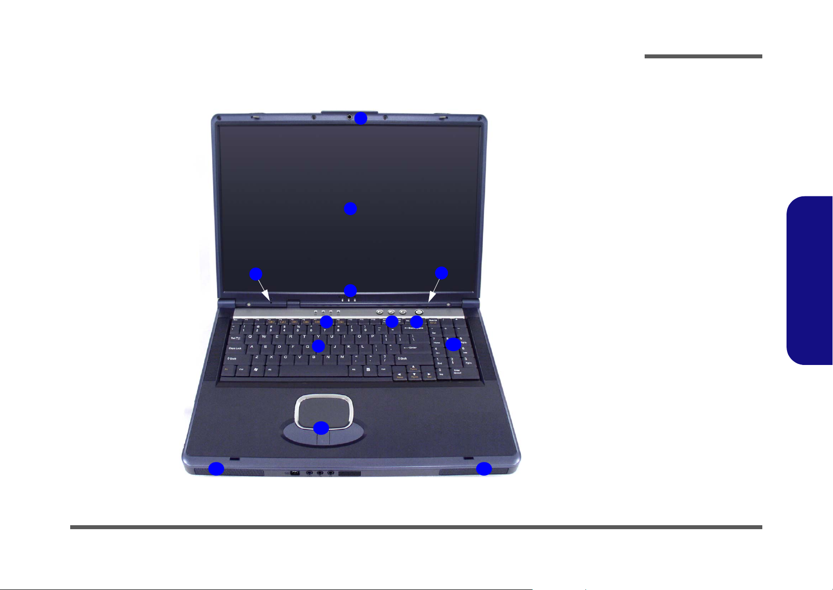
External Locator - Top View
3
Introduction
Figure 1
1
2
5
4
6
7
8
Top View
1. Built-In PC
Camera (Optional)
2. LCD
3. Built-In Microphone
4. LED Power, Battery
& E-Mail Status
Indicators
5. Close Cover Switch
6. LED Status
Indicators
7. Hot-Key Buttons
8. Power Button
9. Keyboard
10. Numeric Keypad
11. Built-In Speakers
12. TouchPad and
Buttons
1.Introduction
11
9
12
10
11
External Locator - Top View 1 - 5
Introduction
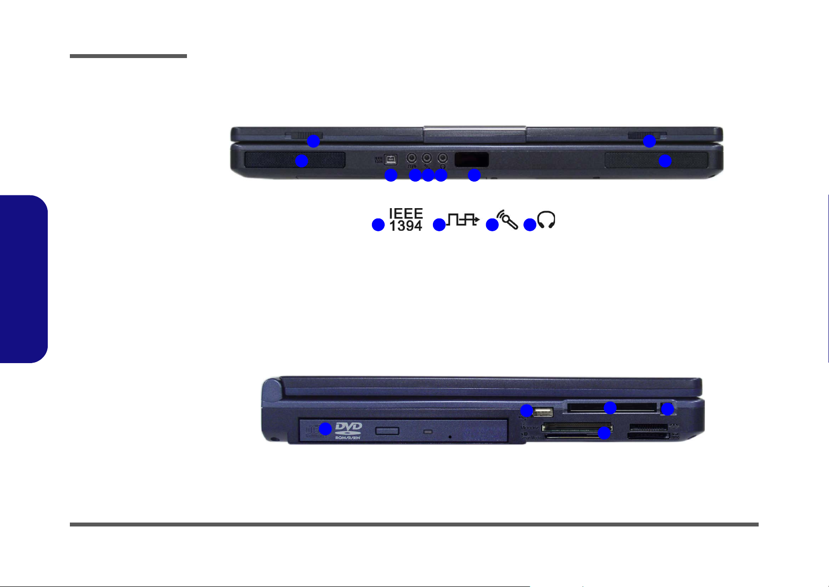
Figure 2
Front View
1. LCD Latches
2. Mini-IEEE 1394 Port
3. S/PDIF Out Port
4. Microphone-In Jack
5. Headphone-Out
Jack
6. Infrared Transceiver
7. Built-In Speakers
Figure 3
1.Introduction
Left Side View
1. Bay Two - CD/DVD
Device Bay
2. PC Card Slot
3. PC Card Slot Eject
Button
4. USB 2.0/1.1 Port
5. Bay One - Optional
for 7-In-1 Card
Reader (pictured)
OR Sub Woofer
External Locator - Front & Left Side Views
1 1
7
3 4 5 6
2
2 3 4 5
4
1
7
2
3
5
1 - 6 External Locator - Front & Left Side Views
External Locator - Right Side & Rear Views
1
3 4 5
Introduction
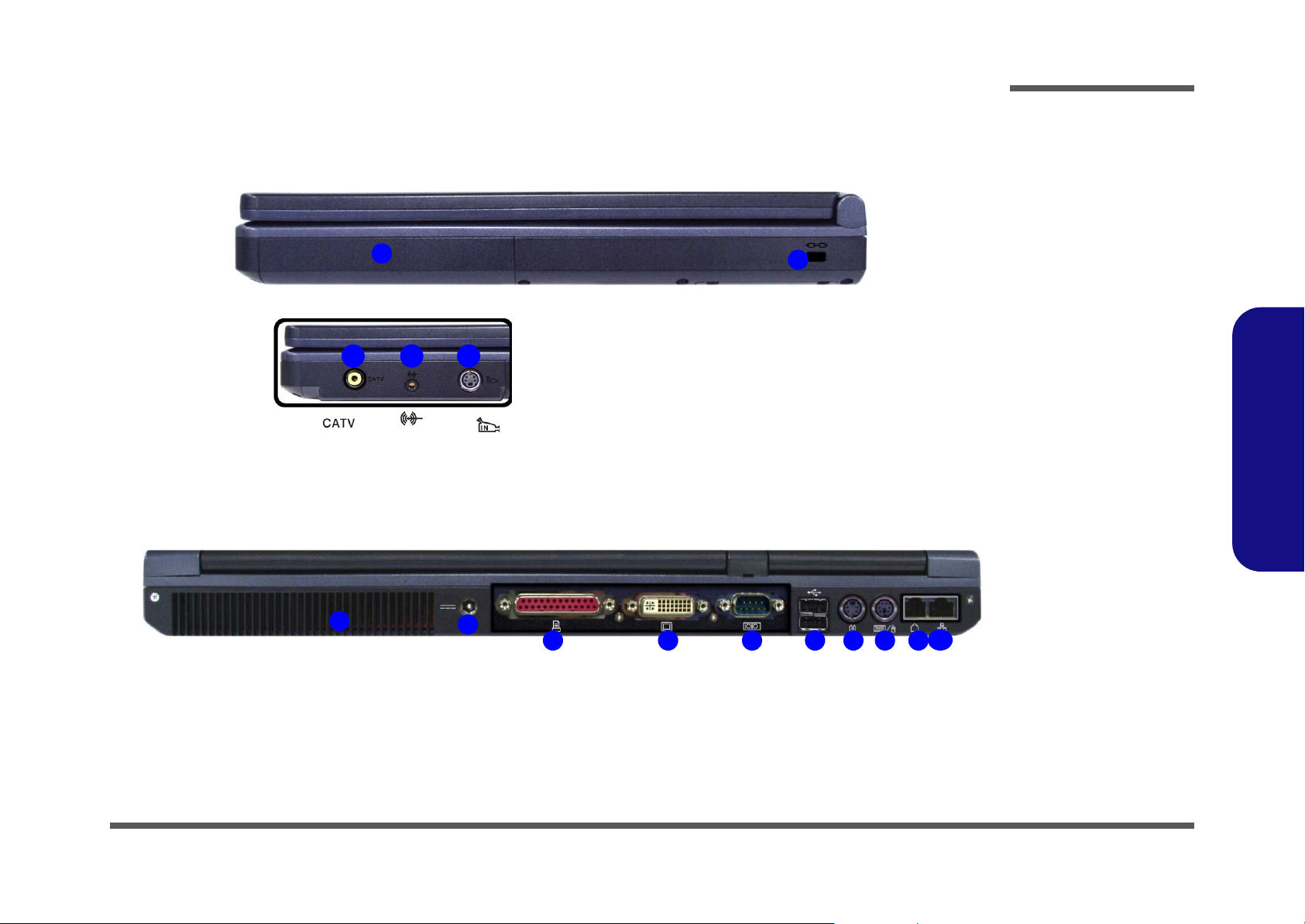
Figure 4
Right Side View
1. Bay Three -
2
Optional for TV-
Tuner OR Sub
Woofer
2. Security Lock Slot
3. CATV Port
4. Line-In Port
5. S-Video-In Port
1.Introduction
Figure 5
Rear View
1. Vent/Fan Intake
2. DC-In Jack
3. Printer/Parallel Port
4. DVI-Out Monitor
1
2
3 4 5 6 7 8 9 10
Port
5. Serial/Com Port
6. 2 * USB Ports
7. S-Video-Out Port
8. PS/2 Type Port
9. RJ-11 Phone Jack
10. RJ-45 LAN Jack
External Locator - Right Side & Rear Views 1 - 7
Introduction
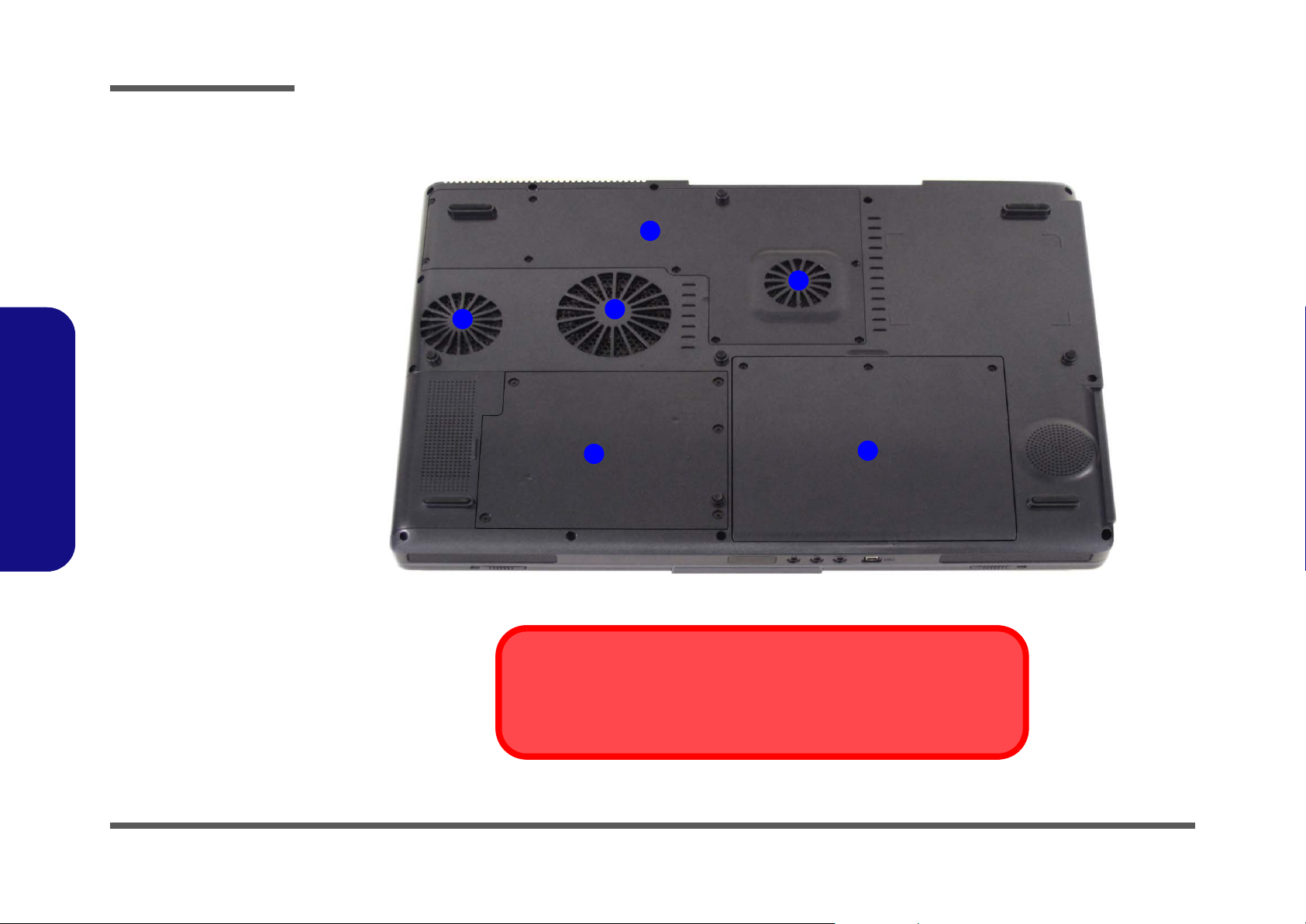
Figure 6
Bottom View
External Locator - Bottom View
1. Vent/Fan Intake
2. CPU/RAM Cover
3. Battery
4. Hard Disk/WLAN
Module/Bluetooth
Module Cover
Note: The RAM and
optional Wireless
LAN module are located under the CPU
Heatsink Cover.
1.Introduction
2
1
1
1
3
4
1 - 8 External Locator - Bottom View
Overheating
To prevent your computer from overheating make sure nothing blocks the vent/fan
intakes while the computer is in use.
Introduction
Mainboard Overview - Top (Key Parts)
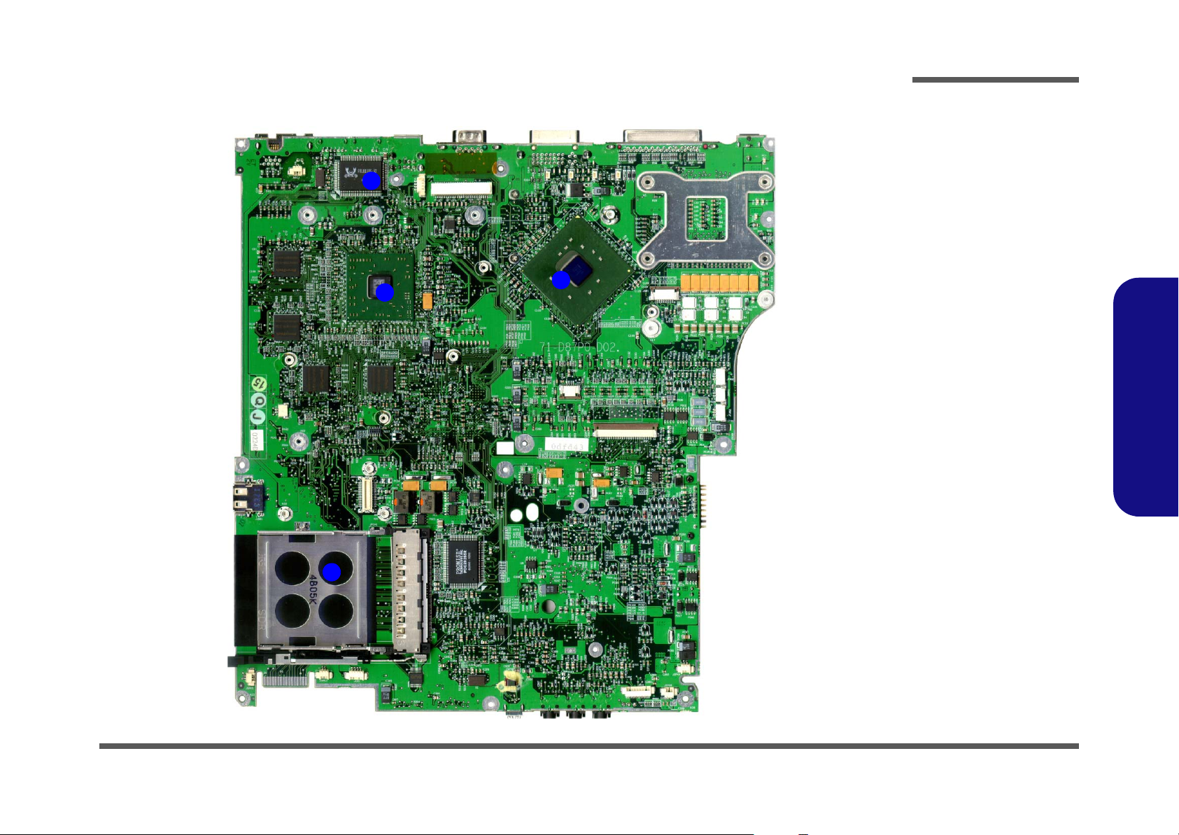
4
3
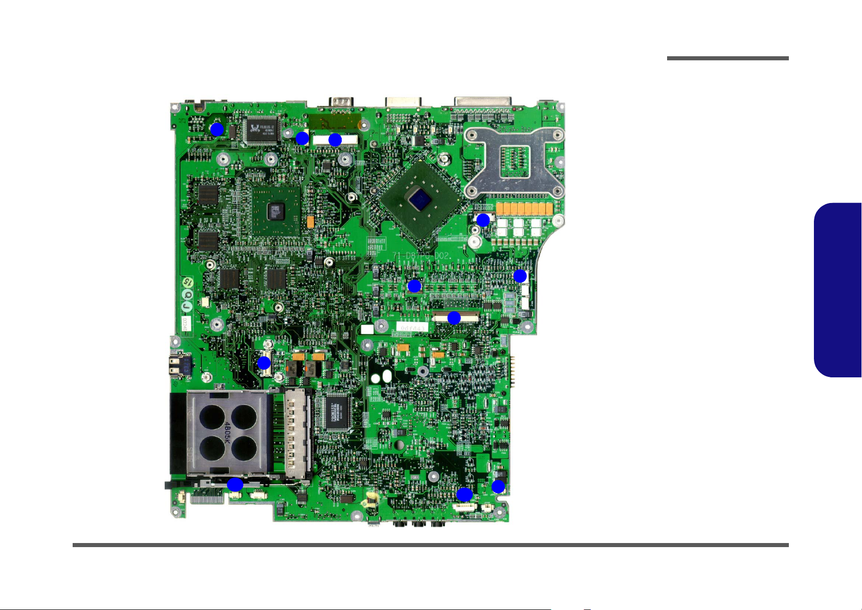
Figure 7
Mainboard Top
Key Parts
1. PC Card
Assembly
2. Northbridge - Intel
865PE
3. ATI Mobility
2
Radeon 9700
4. LAN Controller
RTL8110S-32
1.Introduction
1
Mainboard Overview - Top (Key Parts) 1 - 9
Introduction
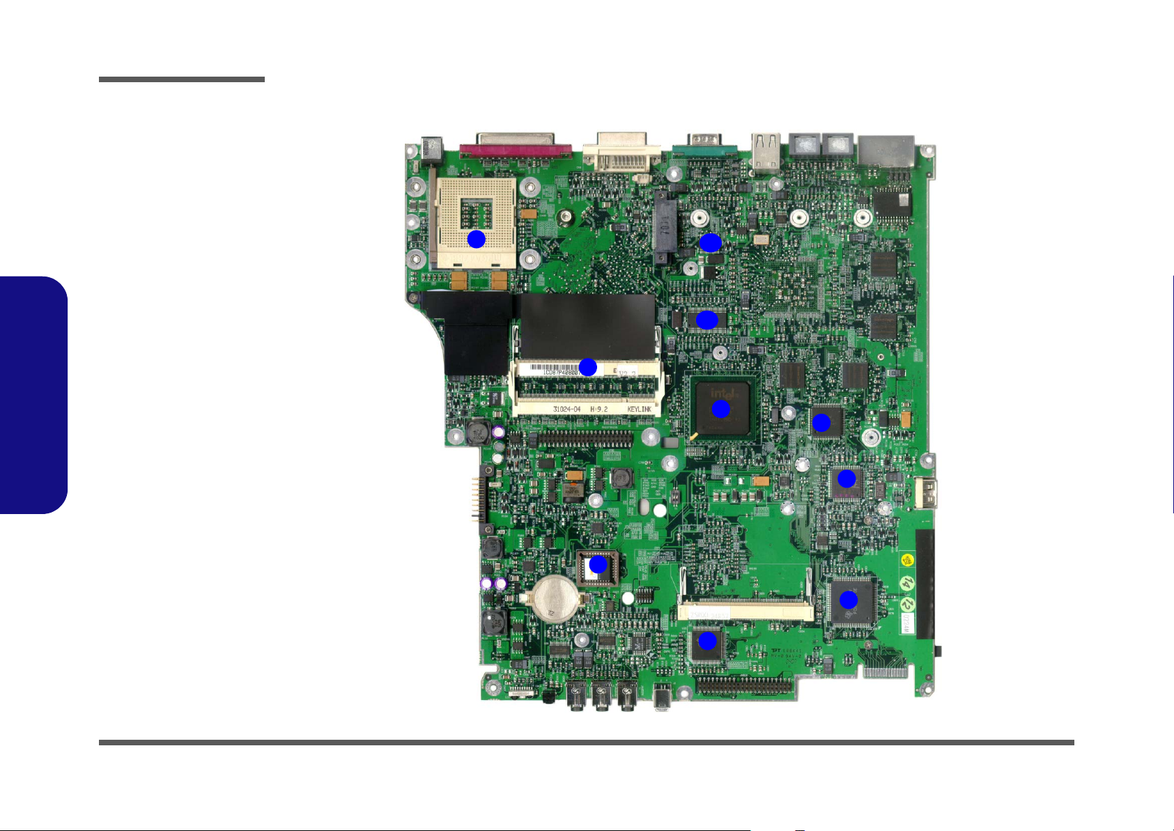
Figure 8
Mainboard Bottom
Key Parts
1. CPU Socket (no
CPU installed)
2. Memory Slots (no
memory installed)
3. ICH-5
4. Flash BIOS ROM
5. 1394 TSB43AB21
6. CardBus
PCI1410
7. Keyboard
Controller - KBC
H8 H8S-2149 HM
8. LPC Super I/O
NS PC87393
1.Introduction
9. Clock Generator
10. ALC650 - Audio
Codec
Mainboard Overview - Bottom (Key Parts)
1
2
10
9
3
8
7
1 - 10 Mainboard Overview - Bottom (Key Parts)
4
6
5
Introduction
Mainboard Overview - Top (Connectors)
1
8
11
3
2
6
Figure 9
Mainboard Top
Connectors
1. Modem Cable
Connector
(JMDC1)
2. LCD (and Inverter)
Connector (CN1)
3. Video Camera
Cable Connector
4
5
7
9
10
(JCCD1)
4. Power Switch
Board Cable
Connector (JSW1)
5. Fan Cable
Connector
(JFAN1)
6. TouchPad Cable
Connector (JTP1)
7. Keyboard Cable
Connector (JKB1)
8. Modem Module
Connector
(JMDC2)
9. Speaker Cable
Connector
(JSPK4)
10. TV Tuner
Connector (JTV1)
11. Speaker Cable
Connector
(JSPK3)
1.Introduction
Mainboard Overview - Top (Connectors) 1 - 11
Introduction
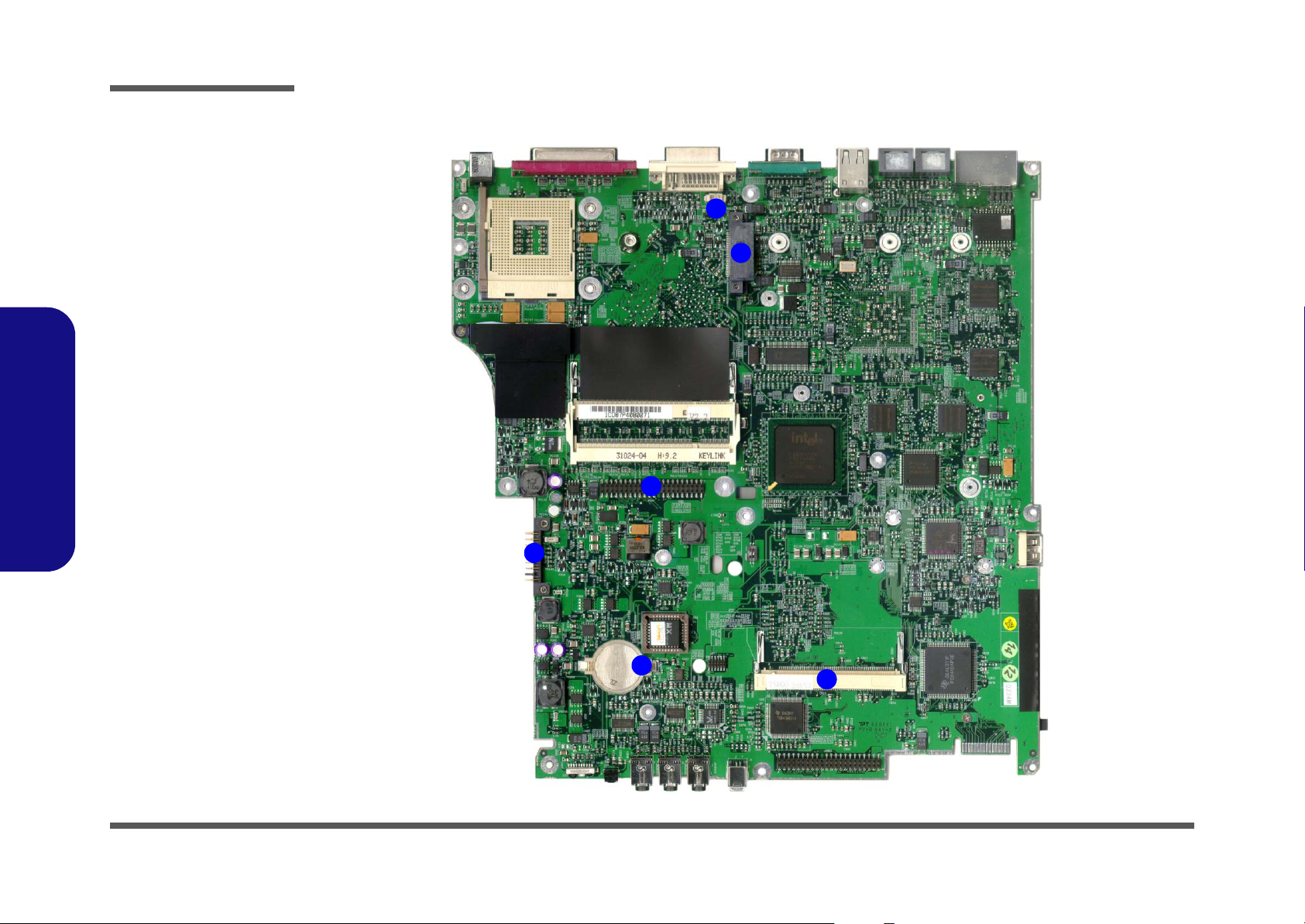
Figure 10
Mainboard Bottom
Connectors
1. DDR RAM Fan
Connector
(JFAN3)
2. CD-ROM Device
Connector
(JCDROM1)
3. Hard Disk Cable
Connector
(JHDD1)
4. Mini-PCI
(Wireless Lan
Module)
Connector
(CN10)
1.Introduction
5. Battery
Connector (CN9)
6. CMOS Battery
Connector (BAT1)
Mainboard Overview - Bottom (Connectors)
1
2
3
5
1 - 12 Mainboard Overview - Bottom (Connectors)
6
4

2: Disassembly
Overview
This chapter provides step-by-step instructions for disassembling the D870P series notebook’s parts and subsystems.
When it comes to reassembly, reverse the procedures (unless otherwise indicated).
We suggest you completely review any procedure before you take the computer apart.
Disassembly
Procedures such as upgrading/replacing the RAM, CD device and hard disk are included in the User’s Manual but are
repeated here for your convenience.
To make the disassembly process easier each section may have a box in the page margin. Information contained under
the figure # will give a synopsis of the sequence of procedures involved in the disassembly procedure. A box with a
lists the relevant parts you will have after the disassembly process is complete. Note: The parts listed will be for the disassembly procedure listed ONLY, and not any previous disassembly step(s) required. Refer to the part list for the previous disassembly procedure. The amount of screws you should be left with will be listed here also.
A box with a will provide any possible helpful information. A box with a contains warnings.
An example of these types of boxes are shown in the sidebar.
2.Disassembly
Information
Warning
Overview 2 - 1

Disassembly
2.Disassembly
NOTE: All disassembly procedures assume that the system is turned OFF, and disconnected from any power supply (the
battery is removed too).
Maintenance Tools
The following tools are recommended when working on the notebook PC:
• M3 Philips-head screwdriver
• M2.5 Philips-head screwdriver (magnetized)
• M2 Philips-head screwdriver
• Small flat-head screwdriver
• Pair of needle-nose pliers
• Anti-static wrist-strap
Connections
Connections within the computer are one of four types:
Locking collar sockets for ribbon connectors To release these connectors, use a small flat-head screwdriver to gently pry
the locking collar away from its base. When replacing the connection, make
sure the connector is oriented in the same way. The pin1 side is usually not
indicated.
2 - 2 Overview
Pressure sockets for multi-wire connectors To release this connector type, grasp it at its head and gently rock it from side
to side as you pull it out. Do not pull on the wires themselves. When replacing
the connection, do not try to force it. The socket only fits one way.
Pressure sockets for ribbon connectors To release these connectors, use a small pair of needle-nose pliers to gently
lift the connector away from its socket. When replacing the connection, make
sure the connector is oriented in the same way. The pin1 side is usually not
indicated.
Board-to-board or multi-pin sockets To separate the boards, gently rock them from side to side as you pull them
apart. If the connection is very tight, use a small flat-head screwdriver - use
just enough force to start.

Maintenance Precautions
The following precautions are a reminder. To avoid personal injury or damage to the computer while performing a removal and/or replacement job, take the following precautions:
1. Don't drop it. Perform your repairs and/or upgrades on a stable surface. If the computer falls, the case and other
components could be damaged.
2. Don't overheat it. Note the proximity of any heating elements. Keep the computer out of direct sunlight.
3. Avoid interference. Note the proximity of any high capacity transformers, electric motors, and other strong mag-
netic fields. These can hinder proper performance and damage components and/or data. You should also monitor
the position of magnetized tools (i.e. screwdrivers).
4. Keep it dry. This is an electrical appliance. If water or any other liquid gets into it, the computer could be badly
damaged.
5. Be careful with power. Avoid accidental shocks, discharges or explosions.
•Before removing or servicing any part from the computer, turn the computer off and detach any power supplies.
•When you want to unplug the power cord or any cable/wire, be sure to disconnect it by the plug head. Do not pull on the wire.
6. Peripherals – Turn off and detach any peripherals.
7. Beware of static discharge. ICs, such as the CPU and main support chips, are vulnerable to static electricity.
Before handling any part in the computer, discharge any static electricity inside the computer. When handling a
printed circuit board, do not use gloves or other materials which allow static electricity buildup. We suggest that
you use an anti-static wrist strap instead.
8. Beware of corrosion. As you perform your job, avoid touching any connector leads. Even the cleanest hands produce oils which can attract corrosive elements.
9. Keep your work environment clean. Tobacco smoke, dust or other air-born particulate matter is often attracted
to charged surfaces, reducing performance.
10. Keep track of the components. When removing or replacing any part, be careful not to leave small parts, such as
screws, loose inside the computer.
Disassembly
Power Safety
Warning
Before you undertake
any upgrade procedures, make sure that
you have turned off the
power, and disconnected all peripherals
and cables (including
telephone lines). It is
advisable to also remove your battery in
order to prevent accidentally turning the
machine on.
2.Disassembly
Cleaning
Do not apply cleaner directly to the computer, use a soft clean cloth.
Do not use volatile (petroleum distillates) or abrasive cleaners on any part of the computer.
Overview 2 - 3

Disassembly
Disassembly Steps
The following table lists the disassembly steps, and on which page to find the related information. PLEASE PERFORM
THE DISASSEMBLY STEPS IN THE ORDER INDICATED.
2.Disassembly
To remove the Battery:
1. Remove the battery page 2 - 5
To remove the System Memory:
1. Remove the battery page 2 - 5
2. Remove the system memory page 2 - 6
To remove the CD Device:
1. Remove the battery page 2 - 5
2. Remove the CD Device page 2 - 8
To remove the Processor:
1. Remove the battery page 2 - 5
2. Remove the processor page 2 - 9
To remove the HDD:
1. Remove the battery page 2 - 5
2. Remove the HDD page 2 - 11
To remove the Bluetooth Module:
To remove the Wireless LAN Module:
1. Remove the battery page 2 - 5
2. Remove the HDD page 2 - 11
3. Remove the Wireless LAN module page 2 - 14
To remove the Keyboard:
1. Remove the battery page 2 - 5
2. Remove the kayboard page 2 - 15
1. Remove the battery page 2 - 5
2. Remove the HDD page 2 - 11
3. Remove the Bluetooth module page 2 - 13
2 - 4 Disassembly Steps
Removing the Battery
1. Turn the computer off, place it on a clean, stable surface and turn it over.
2. Remove screws
3. Remove the battery (and Bay Three device if applicable) by applying gentle pressure to slide it in the direction of the arrow (Figure 1b)
4. Reverse the process to replace the battery.
1 5
- (Figure 1a).
6 7
.
Disassembly
b.a.
a. Remove the screws.
b. Remove the battery (and
1
5
2
3
4
6
7
Figure 1
Battery Removal
Bay Three Device is applicable).
2.Disassembly
6. Battery
7. Bay Three Device
•5 Screws
Removing the Battery 2 - 5
Disassembly
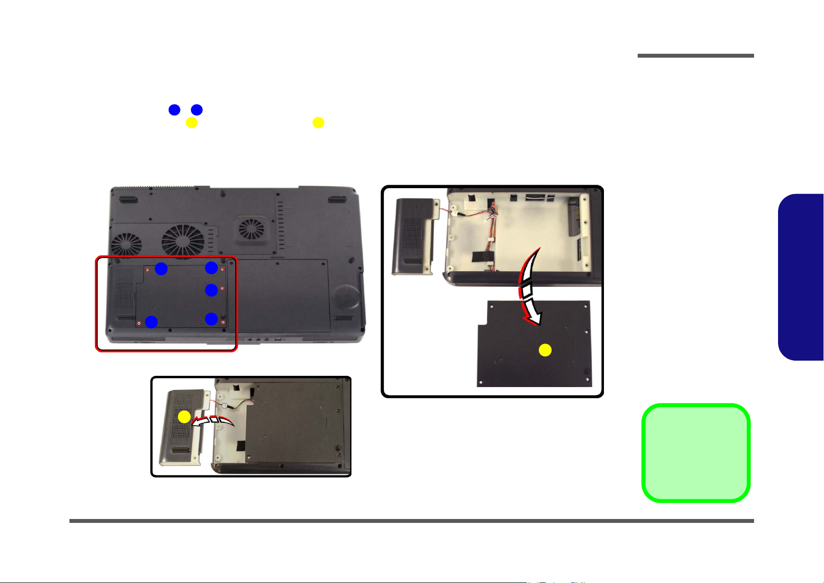
Figure 2
Memory Socket
Cover Removal
a. Remove the screws.
b. Carefully lift the cover off
the computer.
2.Disassembly
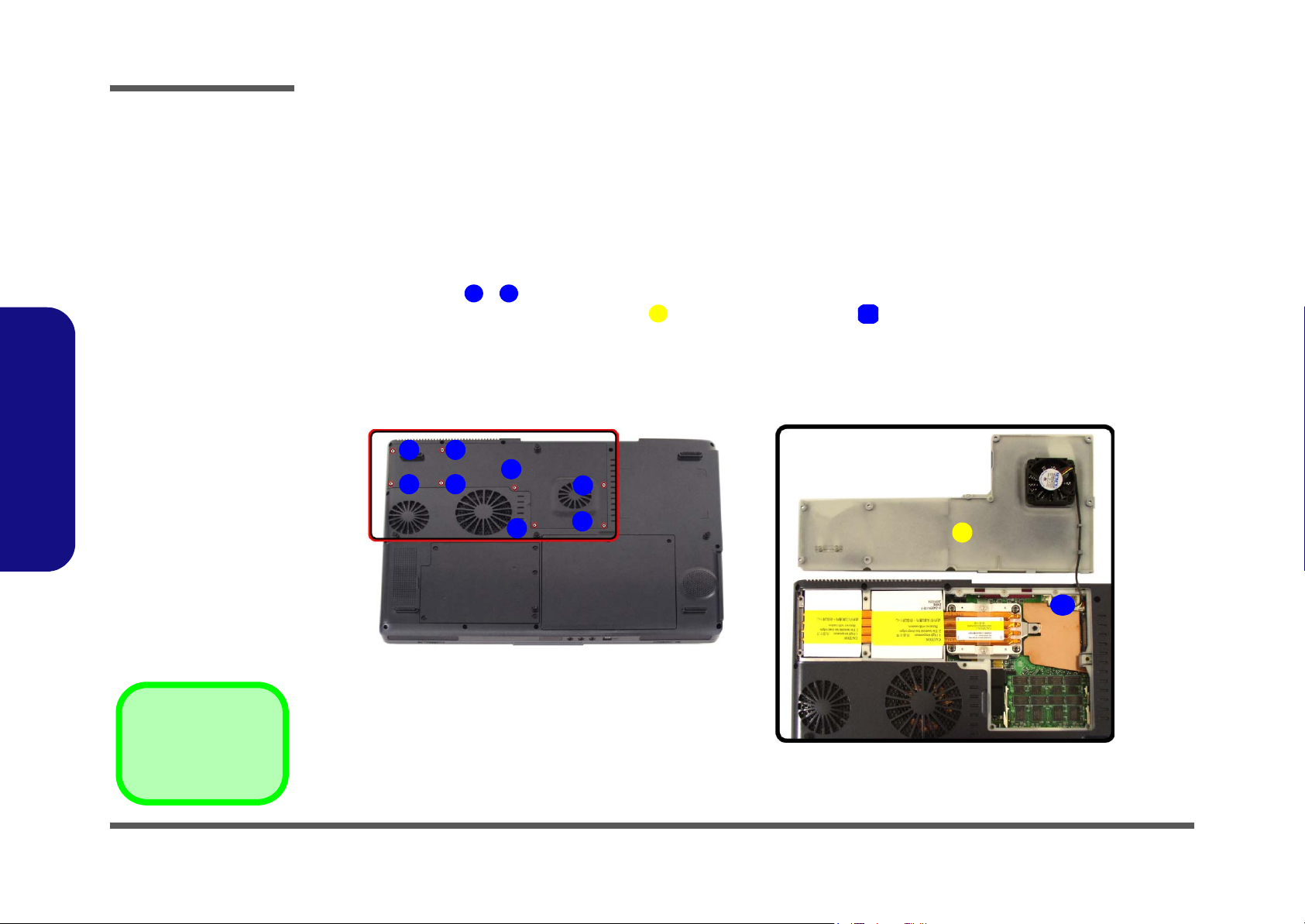
Removing the System Memory (RAM)
The computer has two memory sockets for 200 pin Small Outline Dual In-line Memory Modules (SO-DIMM) supporting
DDR 200/266 MHz. The main memory can be expanded up to 1024MB. The SO-DIMM modules supported are 128Mb,
256Mb, and 512Mb. The total memory size is automatically detected by the POST routine once you turn on your computer.
Memory Upgrade Process
1. Turn off the computer, remove the battery (page 2 - 5).
87
56
1 8
9
4
1
3
2
2. Remove screws - (Figure 2a) from the memory socket cover
3. Carefully lift up the memory socket cover (Figure 2b) (a fan cable is still attached to the mainboard and you
can disconnect it or leave it attached).
4. If there is a module currently installed which needs to be upgraded/replaced then remove it.
a. b.
.
10
10
9
9. Socket Cover
•8 Screws
2 - 6 Removing the System Memory (RAM)
10
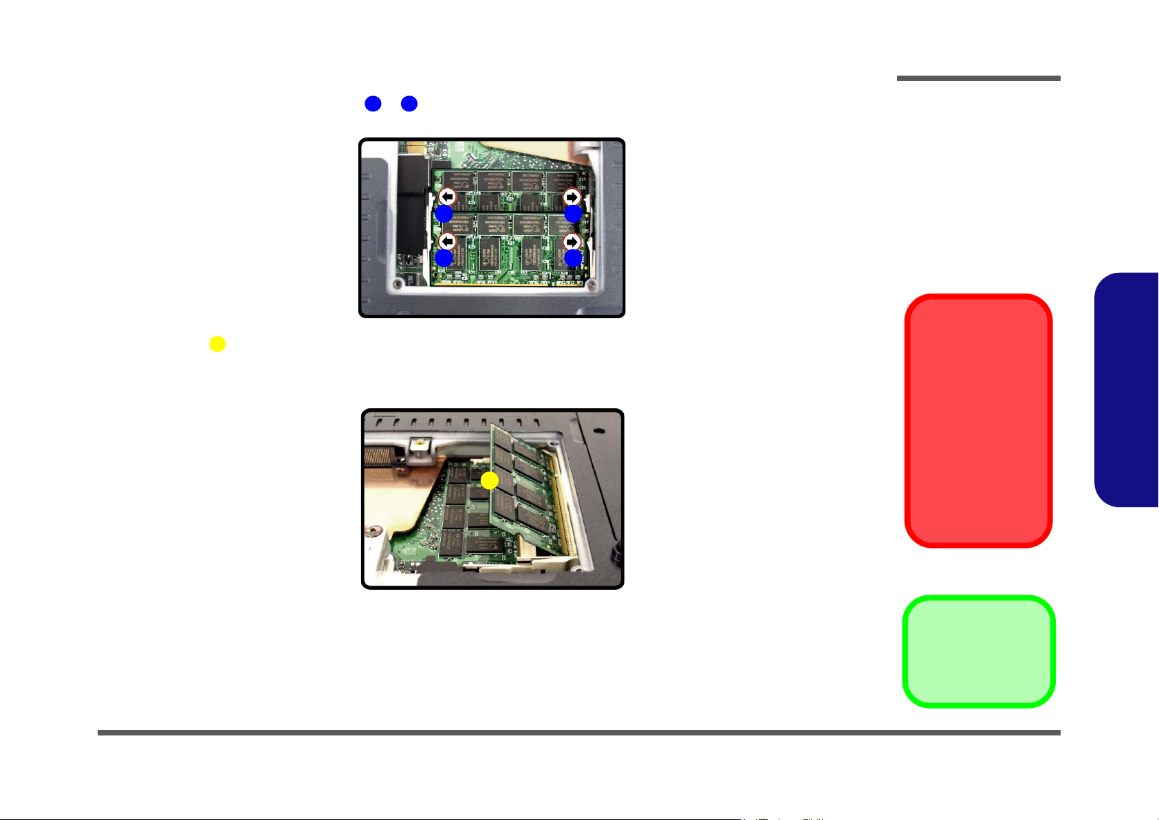
Disassembly
5. Gently pull the two release latches ( & ) on the sides of the memory socket toward the sides of the computer.
1 2
a.
1 2
1 2
6. The module (Figure 3b) will pop-up, and you can remove it.
3
7. Repeat the process for the second module if necessary.
8. Insert a new module holding it at about a 30° angle and fit the connectors firmly into the memory slot.
b.
3
Figure 3
Removing/
Installing a RAM
Module
a. Pull the release
latches.
b. Remove the mod-
ule.
2.Disassembly
Contact Warning
Be careful not to touch
the metal pins on the
module’s connecting
edge. Even the cleanest hands have oils
which can attract particles, and degrade the
module’s performance.
9. The module will only fit one way as defined by its pin alignment. Make sure the module is seated as far into the slot
as it will go. DO NOT FORCE IT; it should fit without much pressure.
10. Press the module down towards the mainboard until the slot levers click into place to secure the module.
11. Replace the memory socket cover (be careful with the fan cable) and the 8 screws (page 2 - 6).
12. Restart the computer.
13. The BIOS will register the new memory configuration as it starts up.
Removing the System Memory (RAM) 2 - 7
3. RAM Module
Disassembly
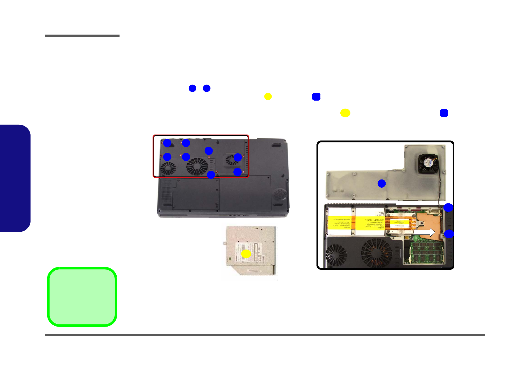
Removing the CD/DVD Device (Bay Two)
The easy changeable CD device may be upgraded or changed.
1. Turn off the computer, remove the battery (page 2 - 5).
2. Remove screws - (Figure 4a) from the memory socket cover
3. Carefully lift up the memory socket cover (a fan cable is still attached to the mainboard and you can either
disconnect it or leave it attached).
4. Use a screwdriver to carefully push the CD/DVD device assembly out of the computer at point .
1 8
9
10
10
.
11
10
12
Figure 4
CD Device Removal
a. Remove the screws.
b. Carefully lift the socket
cover and slide the CD/
DVD device out of the
computer.
2.Disassembly
11. CD/DVD Device
•8 Screws
a. b.
87
56
5. Insert the new device and carefully slide it into the computer (the device only fits one way. DO NOT FORCE IT; The
screw holes should line up.
6. Replace the memory socket cover (be careful with the fan cable) and the 8 screws (page 2 - 8).
7. Restart the computer to allow it to automatically detect the new device.
4
1
3
2
9
10
12
11
2 - 8 Removing the CD/DVD Device (Bay Two)
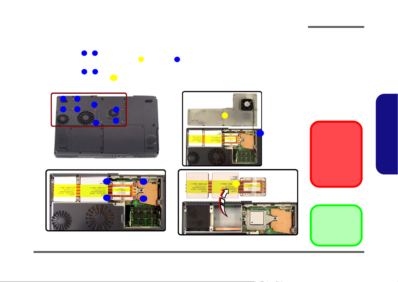
Removing the Processor
1. Turn off the computer, remove the battery (page 2 - 5).
2. Remove screws - from the memory socket cover
3. Carefully lift up the memory socket cover (a fan cable is still attached to the mainboard and you can disconnect it).
4. Remove screws
5. Carefully lift up the heat sink (Figure 5d) off the computer.
a.
c. d.
1 8
9
- (Figure 5c) from the heat sink, in the order indicated on the label.
11 14
15
87
.
10
b.
4
56
1
9
14
2
12
3
10
15
Disassembly
Figure 5
Processor Removal
a. Remove the screws.
b. Carefully lift the cover off
the computer.
c. Remove the screws in
the order indicated.
d. Remove the heat sink.
Reassembly Screw
Order
When replacing the
heat sink, make sure
you insert the screws
in the same order indicated on the label.
2.Disassembly
11
13
15. Heat Sink
•12 Screws
Removing the Processor 2 - 9
 Loading...