

Page 1

Page 2

Page 3

Notebook Computer
D800P Series
Service Manual
Preface
Preface
I
Page 4

Preface
Preface
Notice
The company reserves the right to revise this publication or to change its contents without notice. Information contained
herein is for reference only and does not constitute a commitment on the part of the manufacturer or any subsequent vendor. They assume no responsibility or liability for any errors or inaccuracies that may appear in this publication nor are
they in anyway responsible for any loss or damage resulting from the use (or misuse) of this publication.
This publication and any accompanying software may not, in whole or in part, be reproduced, translated, transmitted or
reduced to any machine readable form without prior consent from the vendor, manufacturer or creators of this publication, except for copies kept by the user for backup purposes.
Brand and product names mentioned in this publication may or may not be copyrights and/or registered trademarks of
their respective companies. They are mentioned for identification purposes only and are not intended as an endorsement
of that product or its manufacturer.
Version 1.0
December 2003
Trademarks
Intel® and Pentium® are registered trademarks of Intel Corporation.
Windows® is a registered trademark of Microsoft Corporation.
Other brand and product names are trademarks and/or registered trademarks of their respective companies.
II
Page 5

About this Manual
This manual is intended for service personnel who have completed sufficient training to undertake the maintenance and
inspection of personal computers.
It is organized to allow you to look up basic information for servicing and/or upgrading components of the notebook PC.
The following information is included:
Chapter 1, Introduction, provides general information about the location of system elements and their specifications.
Chapter 2, Disassembly, provides step-by-step instructions for disassembling parts and subsystems and how to upgrade
elements of the system.
Appendices A, Part Lists
Appendices B, Schematic Diagrams
Preface
Preface
III
Page 6

Preface
Preface
Related Documents
You may also need to consult the following manual for additional information:
User’s Manual on CD
This describes the notebook PC’s features and the procedures for operating the computer and its ROM-based setup program. It also describes the installation and operation of the utility programs provided with the notebook PC.
IV
Page 7

Contents
Preface
Introduction ..............................................1-1
Overview .........................................................................................1-1
System Specifications .....................................................................1-2
External Locator - Top Views .........................................................1-6
External Locator - Front View & Left Side View ........................... 1-7
External Locator - Right Side & Rear Views .................................. 1-8
External Locator - Bottom View .....................................................1-9
Mainboard Overview - Top ...........................................................1-10
Key Parts .......................................................................................1-10
Mainboard Overview - Bottom .....................................................1-11
Key Parts .......................................................................................1-11
Mainboard Overview - Top ...........................................................1-12
Connectors .....................................................................................1-12
Mainboard Overview - Bottom .....................................................1-13
Connectors .....................................................................................1-13
Disassembly ...............................................2-1
Overview .........................................................................................2-1
Maintenance Tools .......................................................................... 2-2
Connections .....................................................................................2-2
Maintenance Precautions .................................................................2-3
Cleaning ..........................................................................................2-3
Disassembly Steps ...........................................................................2-4
Removing the Battery ......................................................................2-6
Removing the 2nd Modular Drive Bay (Bay Two) CD Device ...... 2-7
Removing the 1st Modular Drive Bay (Bay One) Device ..............2-8
Removing the Primary Hard Disk ...................................................2-9
Removing the Hard Disk Drive in Bay One .................................2-10
Removing the Hard Disk Drive in Bay Three ...............................2-11
Removing the TV Tuner Module ..................................................2-12
Removing the Keyboard ............................................................... 2-13
Removing the System Memory .................................................... 2-14
Removing the CPU ....................................................................... 2-15
Removing the Switch Keyboard Assembly .................................. 2-17
Removing the Bottom Case Assembly ......................................... 2-18
Removing the HDD & MP3 Converter Board ............................. 2-20
Removing the Audio Board .......................................................... 2-21
Removing the Modem Module ..................................................... 2-22
Removing the Floppy Disk Drive Assembly ................................ 2-23
Removing the TouchPad Module ................................................. 2-24
Removing the Inverter Board ....................................................... 2-25
Removing the LCD ....................................................................... 2-26
Part Lists for D800P ................................A-1
Part List Illustration Location ........................................................ A-2
Top ................................................................................................. A-3
Bottom ........................................................................................... A-4
LCD 15" ......................................................................................... A-5
LCD 16" ......................................................................................... A-6
Battery ............................................................................................ A-7
Center Cover .................................................................................. A-8
Center Cover Finger ...................................................................... A-9
CD-ROM Drive ........................................................................... A-10
CD-RW Drive .............................................................................. A-11
Combo Drive ............................................................................... A-12
DVD-ROM Drive ........................................................................ A-13
Audio DJ ...................................................................................... A-14
Floppy Disk Drive ....................................................................... A-15
First Hard Disk Drive .................................................................. A-16
Second Hard Disk Drive .............................................................. A-17
Third Hard Disk Drive ................................................................. A-18
Preface
V
Page 8

Preface
Third Hard Disk - Dummy ........................................................... A-19
IP Sharing Module .......................................................................A-20
MP3 Player ...................................................................................A-21
Card Reader ..................................................................................A-22
Schematic Diagrams for D800P .............. B-1
System Block Diagram ................................................................... B-2
CPU Northwood & Prescott (1 of 2) .............................................. B-3
CPU Northwood & Prescott (2 of 2) .............................................. B-4
CPU Decoupling ............................................................................ B-5
CLK409 .......................................................................................... B-6
Springdale (HOST, AGP, Hub) ...................................................... B-7
Springdale (DDR, Interface) .......................................................... B-8
DDR Termination ........................................................................... B-9
DDR SODIMM ............................................................................ B-10
Springdale (Voltage, PLL, VSS) .................................................. B-11
Mobility M10-P ............................................................................ B-12
Preface
Mobility M10-P MEM A/B .......................................................... B-13
VGA DDR DRAM Channel A ..................................................... B-14
VGA DDR DRAM Channel B ..................................................... B-15
VGA DDR DRAM Termination .................................................. B-16
Mobility M10-P_POW ................................................................. B-17
TV Tuner, DVI & Video In .......................................................... B-18
TV Out & LVDS .......................................................................... B-19
ICH5 (1 of 2) ................................................................................ B-20
ICH5 (2 of 2) ................................................................................ B-21
USB Port & RTC .......................................................................... B-22
RAID PDC20265R ....................................................................... B-23
HDD, CD-R/W & IP Sharer ......................................................... B-24
AMP TPA0132 / ALC650 ............................................................ B-25
LCM & Audio Jack ...................................................................... B-26
Audio DJ/CDROM ....................................................................... B-27
Fan Control & Beep ......................................................................B-28
Flash ROM/LPT1 .........................................................................B-29
NS87393 LPC Bridge & Super I/O ..............................................B-30
I/O, FDD, LED & Debug .............................................................B-31
KBC H8 ........................................................................................B-32
MDC, Wireless & BT ...................................................................B-33
PCI 1520 .......................................................................................B-34
PCMCIA Connector .....................................................................B-35
IEEE 1394 TSB43AB21 ...............................................................B-36
LAN RTL8100C/RTL8110S(B)-32 .............................................B-37
Power Plane ..................................................................................B-38
Vcore .............................................................................................B-39
System Power 1 ............................................................................B-40
System Power 2 ............................................................................B-41
Charger .........................................................................................B-42
3VH8, VDD1.8 .............................................................................B-43
VI
Page 9

Chapter 1: Introduction
Overview
This manual covers the information you need to service or upgrade the D800P series notebook computer. Information about
operating the computer (e.g. getting started, and the Setup utility) is in the User’s Manual. Information about drivers (e.g. VGA
& audio) is also found in User’s Manual. That manual is shipped with the computer.
Operating systems (e.g. Windows 2000 & Windows XP) have their own manuals as do application software (e.g. word processing and database programs). If you have questions about those programs, you should consult those manuals.
Introduction
The D800P notebook is designed to be upgradeable. See “Disassembly” on page 2 - 1 for a detailed description of the upgrade
procedures for each specific component. Please note the warning and safety information indicated by the “
The balance of this chapter reviews the computer’s technical specifications and features.
” symbol.
1.Introduction
Overview 1 - 1
Page 10
1.Introduction
Introduction
Table 1 - 1
D800P
System
Specifications
System Specifications
Feature Specifications D800P
Processor Types Intel Pentium 4 Processor - (478-pin) mFC-PGA2 package supporting Hyper Threading Technology
µ0.13) 0.13 Micron Process Technology,
(
512K L2 Cache & 800MHz FSB
2.40/ 2.60/ 2.80/ 3.00/ 3.20 GHz
Core Logic Intel® 865PE + ICH5
Structure Fully PC2001 Compliant
ACPI 1.0B Compliant
PC2001 Compliant
Security Security (Kensington® Type) Lock Slot
BIOS Password
Memory 64 bit data bus system memory
Two 200-pin DDR SODIMM sockets, supporting Dual DDR SDRAM SODIMM (2.5V) - DDR400MHz or
DDR333MHz compliant
DDR 400MHz memory expandable to 1GB (compatible with 256/512 MB SODIMM Modules)
DDR 333MHz memory expandable to 2GB (compatible with 256/512/1024 MB SODIMM Modules)
BIOS One 512KB Flash ROM
LCD Options 16.0" 1280 x 1024 SXGA TFT
Display ATI Radeon 9600 PRO High Performance Chip
1 - 2 System Specifications
Phoenix BIOS with Smart Battery
Plug and Play (1.0a), ACPI 1.0B
15.0" 1600 x 1200 UXGA TFT
128MB DDR Graphic Memory On Board
UltraAGP™ 8x
128-bit 2D/3D Graphics Engine
Motion Compensation and IDCT for DVD Content Playback Accelerator
Fully DirectX 9 Compliant Graphics Engine
Page 11

Feature Specifications D800P
Audio Virtual 6-Channel Audio Output
AC'97 2.2 Compliant Interface
Compatible with Sound-Blaster PRO™/ 16
Advanced Wavetable Synthesizer
Direct Sound™ 3D Accelerator
Full Duplex
Virtual AC3
S/PDIF Digital Output (5.1 CH) for DVD content and Stereo Audio
Built-In Microphone
Audio DJ
2 Built-In Speakers
Introduction
Interface Built-in TouchPad (PS/2)
Four USB 2.0 Ports (USB 1.1 compatible)
One IEEE 1394 Port
One S-Video-Out Jack for TV output
One S-Video-In Jack (option included with TV Tuner only)
One Parallel Port (LPT1), supporting ECP / EPP 1.7 and 1.9
One COM port
Infrared Transceiver supporting FIR & IrDA 1.1 file transfer
One DVI Video Output
One External Keyboard/Mouse (through Y-Cable)
One Headphone-Out/Speaker-Out Jack
One S/PDIF Out Port/Microphone-In Jack (through Y-cable only)
One Line-In Jack (option included with TV Tuner only)
One RJ-45 Jack for 1000M/10M LAN
One RJ-11 Jack for 56K MDC Modem
DC-In Jack
Keyboard “Win Key” Keyboard (including a numeric keypad)
3 Application Hot-keys for Web Browser, E-Mail, and Application
PC Card Two Type II PCMCIA 3.3V/5V Sockets, OR one Type III PCMCIA 3.3V/5V Socket (no Zoomed Video support)
1.Introduction
System Specifications 1 - 3
Page 12
1.Introduction
Introduction
Feature Specifications D800P
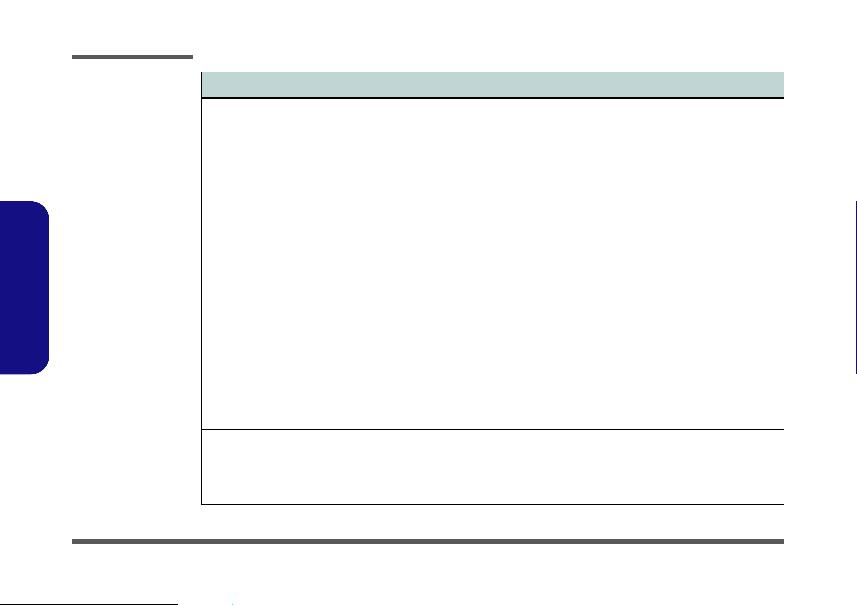
Storage One Fixed FDD
One Changeable 2.5" 9.5mm Primary HDD
1st Modular Drive Bay (Bay One) for one of the following:
DVD-ROM (12.7mmH)
CD-ROM
CD-RW
Combo Drive (DVD-ROM + CD-RW)
IP Sharing Module
2nd HDD
RAID HDD (RAID 0, RAID 1 HDD Fault-Tolerance System)
DVD-RW
2nd Modular Drive Bay (Bay Two) for one of the following:
DVD-ROM (12.7mmH)
CD-ROM
CD-RW
Combo Drive (DVD-ROM + CD-RW / DVD-RW)
DVD-RW
3rd Modular Drive Bay (Bay Three) for one of the following:
3rd HDD (optional)
TV-Tuner (optional)
Communication Wireless Infrared Transfer IrDA 1.1, 1cm~1M Operating Distance, 4Mbps FIR
1 - 4 System Specifications
4th Modular Drive Bay (Bay Four) for one of the following:
One Portable MP3 Player with Storage Disk (optional)
One Portable 6-in-1 Flash Card Reader (optional)
1000 BASE-T (Gigabit) Ethernet LAN on board (10/100 BASE-T compatible)
56K MDC Modem V.90 compliant (V.92 software driver upgradeable)
802.11b Wireless LAN, USB Interface (optional)
IP Sharing Module for ADSL or Cable Modem (optional)
Bluetooth Module with USB Interface (optional)
Page 13
Feature Specifications D800P
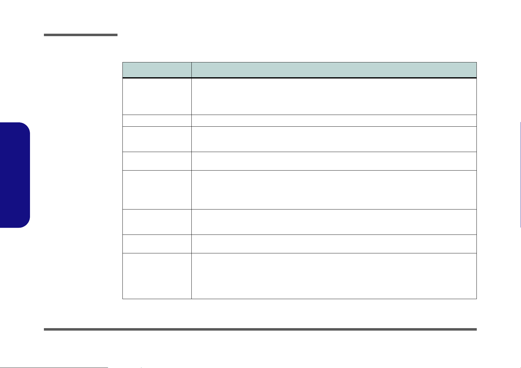
Indicators LED Indicator (HDD, Power Status, Num Lock, Caps Lock, Scroll Lock, AC-In, Battery Charging, E-Mail)
Audio DJ Control Display (Power, Play/Pause, FWD, RWD, Stop, Volume+, Volume-)
Power Management Supports ACPI v1.0B
Supports APM v1.2
Soft Off by System Power Button
Supports Suspend to Disk
Battery Low Suspend
Resume From Alarm
Close-Cover Switch
Power Full Range 120 Watt AC adapter - AC in 100~240V, 47~63Hz
Supports Smart Lithium-Ion Battery 14.8v, 6.6Ah (12 cells)
Weight 4.97 kg with 12-Cell Lithium-Ion Battery (Minimum)
Physical Dimensions 360 (w) x 299 (d) x 54.5 (h) mm
Environmental Spec Temperature
Operating: 5
Non-Operating: -20°C ~ 60°C
Relative Humidity
Operating:20% ~ 80%
Non-Operating:10% ~ 90%
°C~ 35°C
Introduction
1.Introduction
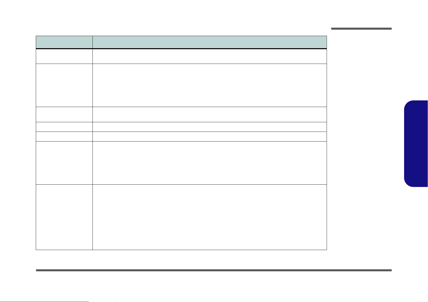
Optional DVD-ROM Drive (12.7mmH)
CD-RW Drive (12.7mmH)
Combo Drive (DVD-ROM and CD-RW, 12.7mmH)
Portable MP3 Player
USB Wireless LAN Module
Software DVD Player
IP Sharing Module
TV-Tuner Module
DVD-RW Drive (12.7mmH)
Bluetooth Module
6-in-1 Flash Card Reader
System Specifications 1 - 5
Page 14
Introduction
1.Introduction
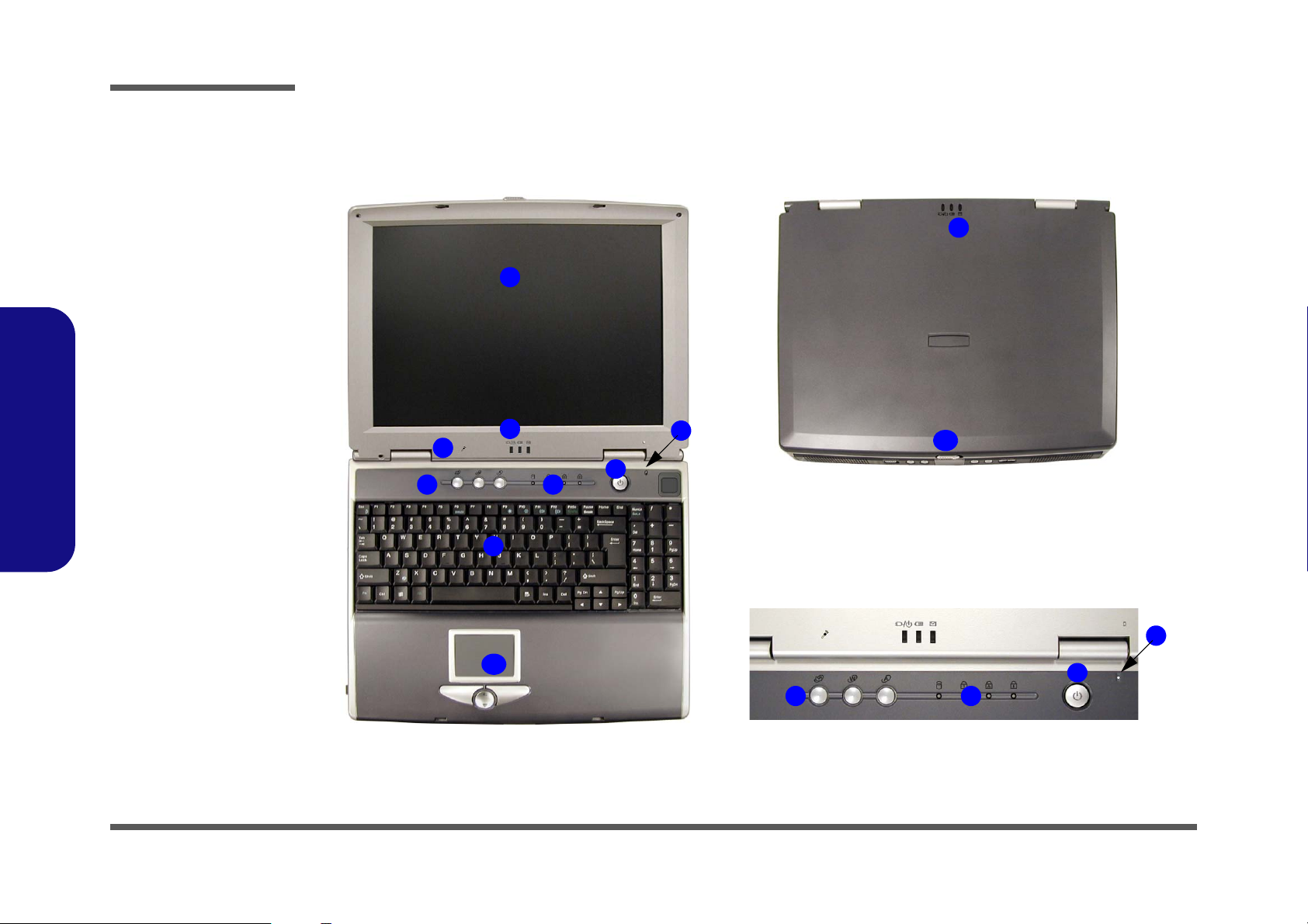
Figure 1 - 1
Top Views
1. LCD
2. LED Power,
Battery & E-Mail
Status Indicators
3. Built-In
Microphone
4. Hot-Key Buttons
5. LED Status
Indicators
6. Power Button
7. Close Cover
Switch
8. Keyboard
9. TouchPad and
Buttons
10. LCD Latch
External Locator - Top Views
1
2
3
4
8
5
6
7
2
10
1 - 6 External Locator - Top Views
7
9
4
5
6
Page 15
Introduction
External Locator - Front View & Left Side View
1
2 876
1
3
54
9
43
5
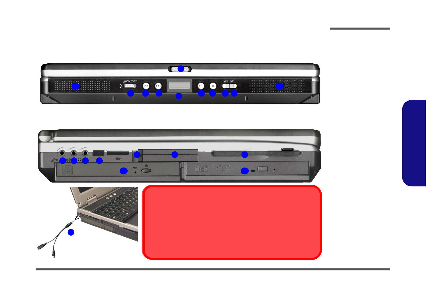
S/PDIF Out & Microphone-In Functions
You must use the Y-cable provided to enable the S/PDIF Out and MicrophoneIn functions (S/PDIF connection is to the longer end of the cable).
2
With the TV Tuner installed, the line-in jack will only be functional while the TV Studio
software is running.
Line-In Function with TV Tuner Installed
Figure 1 - 2
Front View
1. LCD Latch
2. Audio “DJ” CD
Player Control
Panel On/Off
Switch
1010
9
3. Previous Track
4. Next Track
5. LCD
6. Play/Pause
7. Stop
8. Volume Down
9. Volume Up
10. Speakers
1.Introduction
Figure 1 - 3
Left Side View
876
10
1. S/PDIF Out Port/
Microphone-In
Jack
2. Y-Cable
3. Line-In Jack
4. Headphone-Out
Jack
5. Infrared
Transceiver
6. PC Card Slot
Eject Buttons
7. PC Card Slot
8. FDD
9. Drive Bay One
10. Drive Bay Two
External Locator - Front View & Left Side View 1 - 7
Page 16
Introduction
1.Introduction
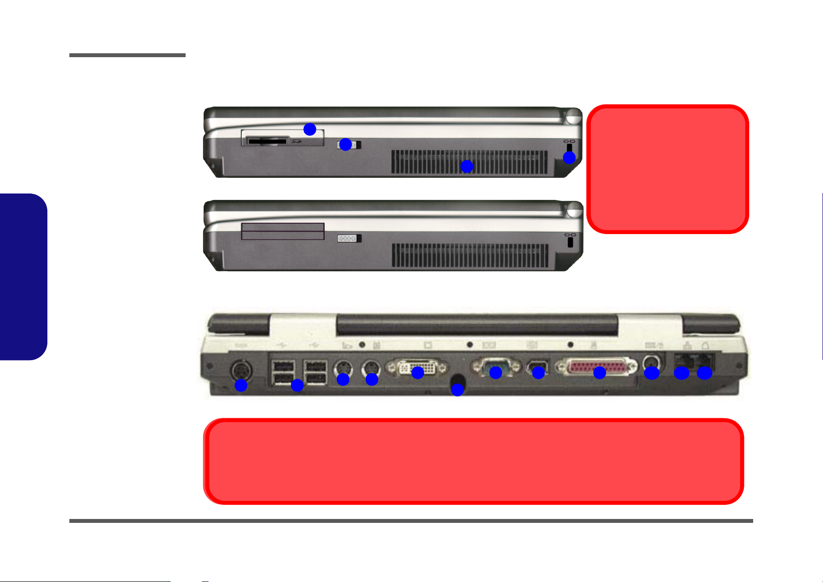
Figure 1 - 4
Right Side View
1. 4th Modular
Drive Bay (Bay
Four) for MP3
Player (Optional)
Or 6-in-1 Flash
Card Reader
(Optional)
2. Bay Four
Release Switch
3. Fan Intake/Vent
4. Kensington Lock
Figure 1 - 5
Rear View
1. DC-In Jack
2. 4 * USB Ports
3. S-Video-In Port
(Optional)
4. S-Video-Out Port
5. External Monitor
(CRT) Port
6. Coaxial TV
Antenna Input
(Optional)
7. Serial Port
8. IEEE 1394 Port
9. Parallel Port
10. PS/2 Type Port
11. Giga LAN Jack
12. RJ-11 Phone
Jack
External Locator - Right Side & Rear Views
1
2
3
3
1
2
4
5
6
7 8 9
S-Video-In Port
The S-Video-In port will only be available if you have the Optional TV Tuner installed.
Software Installation Warning
4
Make sure the MP3 player is not in
the slot when installing operating
systems, and any of the drivers
listed in User’s Manual.
10
11 12
1 - 8 External Locator - Right Side & Rear Views
Page 17
Introduction
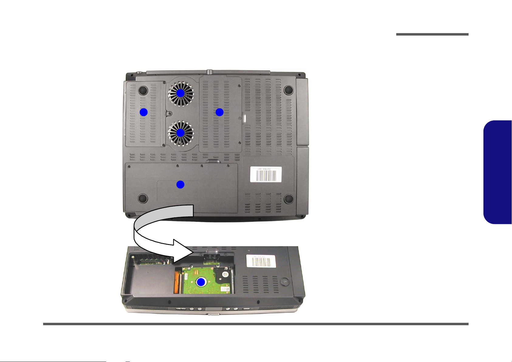
External Locator - Bottom View
1
2
1
3
Figure 1 - 6
Bottom View
1. Vent/Fan Outlets
2. CPU Cover
3. Battery (the
primary HDD is
located under
5
the battery)
4. Primary Hard
Disk
5. Changeable
Drive Bay Three
(for TV Tuner or
HDD)
1.Introduction
4
External Locator - Bottom View 1 - 9
Page 18
Introduction
1.Introduction
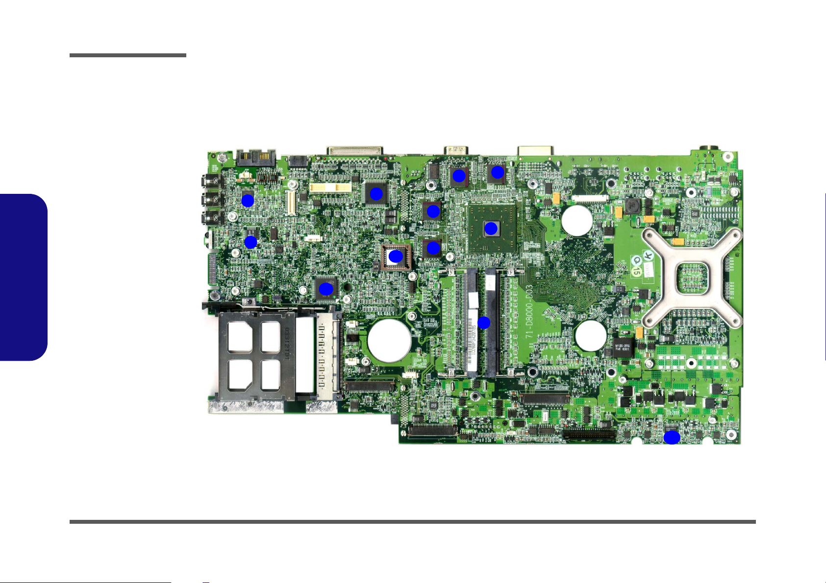
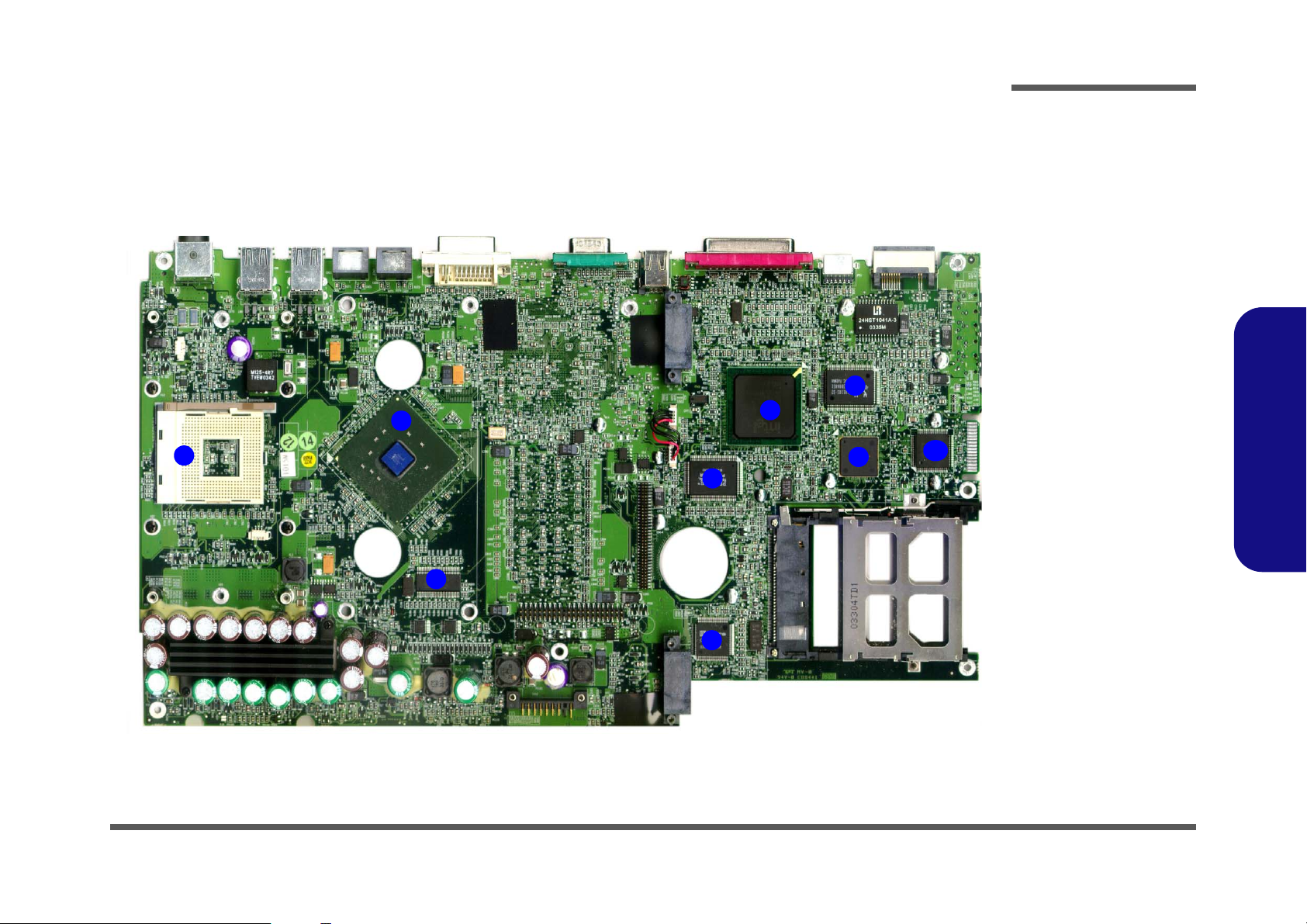
Figure 1 - 7
Mainboard Top
Key Parts
1. Memory Sockets
(no memory
installed)
2. ATI Mobility
M10-P
3. VGA DDR
DRAM
4. 1394 Controller
TSB43AB21
5. Flash ROM
BIOS
6. KBC H8 H8S2149 HM
7. Audio Codec
ALC650
8. TPA0132
9. LPC Super I/O
10. VCORE
Mainboard Overview - Top
Key Parts
8
7
6
4
5
3
3
3
3
2
1
1 - 10 Mainboard Overview - Top
10
Page 19
Introduction
Mainboard Overview - Bottom
Key Parts
2
1
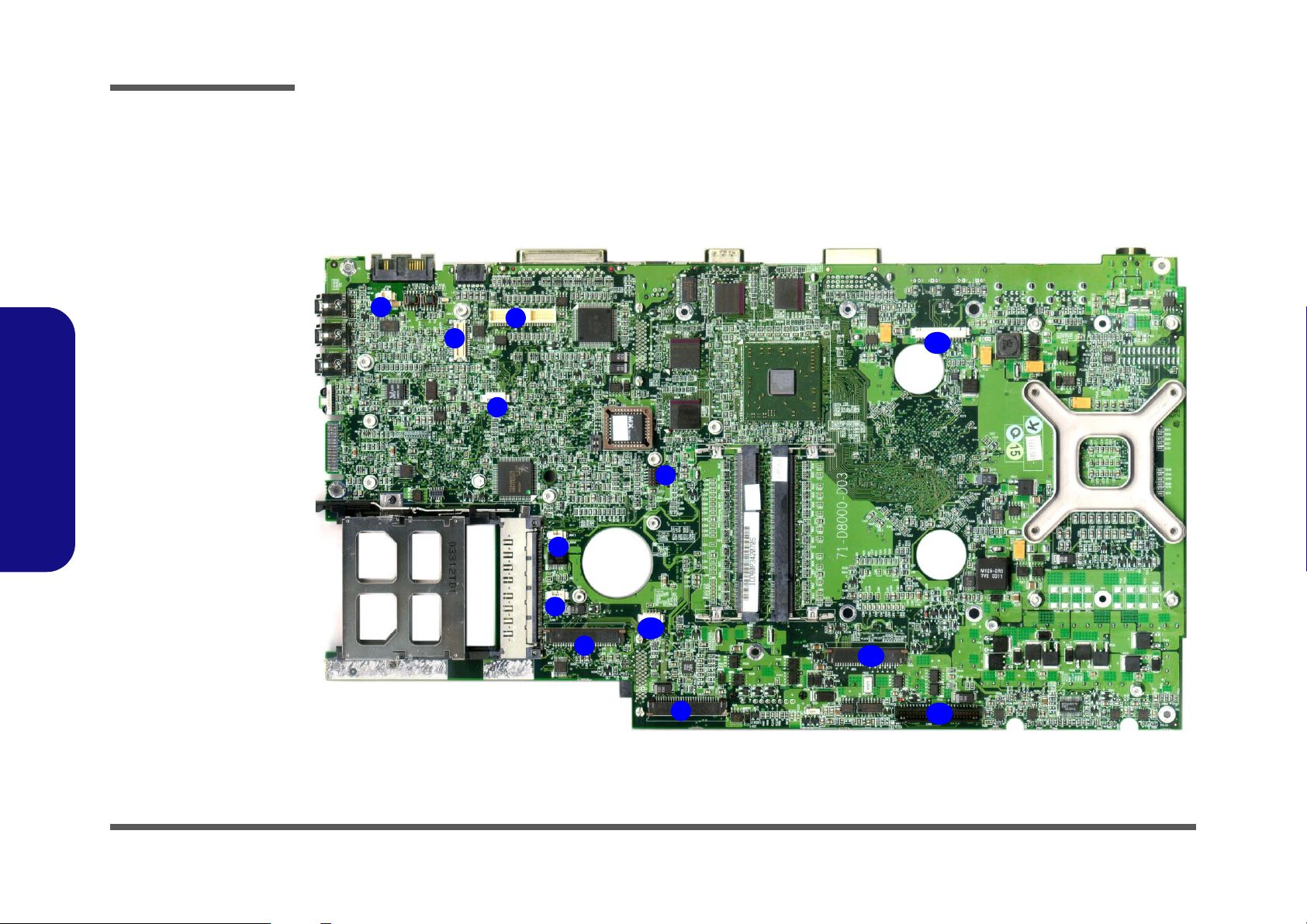
Figure 1 - 8
Mainboard Bottom
Key Parts
1. CPU Socket (no
CPU installed)
2. Intel Springdale
865PE
3. CLK 409
4. Intel ICH5
5. Realtek
RTL8100C/
RTL8110S (B)-32
5
4
8
6
9
6. RAID
PDC20265R
7. Audio DJ
Controller
8. Cardbus TI1520
9. LPC Bridge &
Super I/O
1.Introduction
3
7
Mainboard Overview - Bottom 1 - 11
Page 20
Introduction
1.Introduction
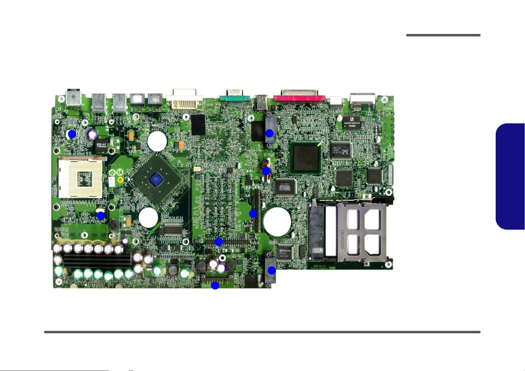
Figure 1 - 9
Mainboard Top
Connectors
1. Modem Cable
(JFAN1)
2. Modem
Connector
(JMDC1)
3. LCD/Inverter
connector (CN4)
4. WLAN Cable
(JML1)
5. CMOS Battery
(JBAT1)
6. Fan (JFAN2)
7. Bluetooth (JBT1)
8. Floppy Disk
Drive Connector
(CN5)
9. Audio Board
Connector (J4)
10. TouchPad
Connector (J2)
11. Keyboard
Connector
(JKB1)
12. Hard Disk Drive
& MP3 Board
Connector
(CON1)
13. Switch Keyboard
Connector(J1)
Mainboard Overview - Top
Connectors
1
2
3
4
5
6
10
8
13
7
11
9
12
1 - 12 Mainboard Overview - Top
Page 21
Introduction
Mainboard Overview - Bottom
Connectors
1
2
Figure 1 - 10
Mainboard Bottom
Connectors
1. Fan Connector
(JFAN3)
1
7
6
5
2. Fan Connector
(JFAN4)
3. Battery
Connector
(CN16)
4. Hard Disk
Connector
(JHDD1)
5. TV Tuner
Connector
(CN14)
6. IP Sharing
Module Jumper
(J6 & J7)
Note: J6 & J7 must
1.Introduction
have a terminator inserted in order to use
4
8
3
the IP sharing module.
7. Bay One Device
Connector
(CON2)
8. Bay Two Device
Connector
(JCD1)
Mainboard Overview - Bottom 1 - 13
Page 22

1.Introduction
Introduction
1-14
Page 23
2: Disassembly
Overview
This chapter provides step-by-step instructions for disassembling parts and subsystems. When it comes to reassembly,
reverse the procedures (unless otherwise indicated).
We suggest you completely review any procedure before you take the computer apart.
Disassembly
Procedures such as upgrading/replacing the RAM, CD device and hard disk are included in the User’s Manual but are
repeated here for your convenience.
To make the disassembly process easier each section may have a box in the page margin. Information contained under
the figure # will give a synopsis of the sequence of procedures involved in the disassembly procedure. A box with a
will provide any possible helpful information, and lists the relevant parts you will have after the disassembly process is
complete. Note: The parts listed will be for the disassembly procedure listed ONLY, and not any previous disassembly
step(s) required. Refer to the part list for the previous disassembly procedure. The amount of screws you should be left
with will be listed here also. A box with a contains warnings.
An example of these types of boxes are shown in the sidebar.
2.Disassembly
Information and
Component Parts
Warning
Overview 2 - 1
Page 24

Disassembly
2.Disassembly
NOTE: All disassembly procedures assume that the system is turned OFF, and disconnected from any power supply (the
battery is removed too).
Maintenance Tools
The following tools are recommended when working on the notebook PC:
• M3 Philips-head screwdriver
• M2.5 Philips-head screwdriver (magnetized)
• M2 Philips-head screwdriver
• Small flat-head screwdriver
• Pair of needle-nose pliers
• Anti-static wrist-strap
Connections
Connections within the computer are one of four types:
Locking collar sockets for ribbon connectors To release these connectors, use a small flat-head screwdriver to gently pry
the locking collar away from its base. When replacing the connection, make
sure the connector is oriented in the same way. The pin1 side is usually not
indicated.
2 - 2 Overview
Pressure sockets for multi-wire connectors To release this connector type, grasp it at its head and gently rock it from side
to side as you pull it out. Do not pull on the wires themselves. When replacing
the connection, do not try to force it. The socket only fits one way.
Pressure sockets for ribbon connectors To release these connectors, use a small pair of needle-nose pliers to gently
lift the connector away from its socket. When replacing the connection, make
sure the connector is oriented in the same way. The pin1 side is usually not
indicated.
Board-to-board or multi-pin sockets To separate the boards, gently rock them from side to side as you pull them
apart. If the connection is very tight, use a small flat-head screwdriver - use
just enough force to start.
Page 25

Maintenance Precautions
The following precautions are a reminder. To avoid personal injury or damage to the computer while performing a removal and/or replacement job, take the following precautions:
1. Don't drop it. Perform your repairs and/or upgrades on a stable surface. If the computer falls, the case and other
components could be damaged.
2. Don't overheat it. Note the proximity of any heating elements. Keep the computer out of direct sunlight.
3. Avoid interference. Note the proximity of any high capacity transformers, electric motors, and other strong mag-
netic fields. These can hinder proper performance and damage components and/or data. You should also monitor
the position of magnetized tools (i.e. screwdrivers).
4. Keep it dry. This is an electrical appliance. If water or any other liquid gets into it, the computer could be badly
damaged.
5. Be careful with power. Avoid accidental shocks, discharges or explosions.
•Before removing or servicing any part from the computer, turn the computer off and detach any power supplies.
•When you want to unplug the power cord or any cable/wire, be sure to disconnect it by the plug head. Do not pull on the wire.
6. Peripherals – Turn off and detach any peripherals.
7. Beware of static discharge. ICs, such as the CPU and main support chips, are vulnerable to static electricity.
Before handling any part in the computer, discharge any static electricity inside the computer. When handling a
printed circuit board, do not use gloves or other materials which allow static electricity buildup. We suggest that
you use an anti-static wrist strap instead.
8. Beware of corrosion. As you perform your job, avoid touching any connector leads. Even the cleanest hands produce oils which can attract corrosive elements.
9. Keep your work environment clean. Tobacco smoke, dust or other air-born particulate matter is often attracted
to charged surfaces, reducing performance.
10. Keep track of the components. When removing or replacing any part, be careful not to leave small parts, such as
screws, loose inside the computer.
Disassembly
Power Safety
Warning
Before you undertake
any upgrade procedures, make sure that
you have turned off the
power, and disconnected all peripherals
and cables (including
telephone lines). It is
advisable to also remove your battery in
order to prevent accidentally turning the
machine on.
2.Disassembly
Cleaning
Do not apply cleaner directly to the computer, use a soft clean cloth.
Do not use volatile (petroleum distillates) or abrasive cleaners on any part of the computer.
Overview 2 - 3
Page 26

Disassembly
Disassembly Steps
The following table lists the disassembly steps, and on which page to find the related information. PLEASE PERFORM
THE DISASSEMBLY STEPS IN THE ORDER INDICATED.
To remove the Battery:
1. Remove the battery page 2 - 6
To remove the Keyboard:
1. Remove the battery page 2 - 6
2. Remove the keyboard page 2 - 13
2.Disassembly
To remove the Bay One Device:
1. Remove the battery page 2 - 6
2. Remove the Bay One device page 2 - 6
To remove the Bay Two Device:
1. Remove the battery page 2 - 6
2. Remove the Bay Two device page 2 - 8
To remove the Primary HDD:
1. Remove the battery page 2 - 6
2. Remove the primary HDD page 2 - 9
To remove the HDD in Bay Two:
1. Remove the battery page 2 - 6
2. Remove the HDD in Bay Two page 2 - 10
To remove the HDD in Bay Three:
1. Remove the battery page 2 - 6
2. Remove the HDD in Bay Three page 2 - 11
To remove the TV Tuner Module:
1. Remove the battery page 2 - 6
2. Remove the TV Tuner module page 2 - 12
To remove the System Memory:
1. Remove the battery page 2 - 6
2. Remove the keyboard page 2 - 13
3. Remove the memory page 2 - 14
To remove the CPU:
1. Remove the battery page 2 - 6
2. Remove the CPU page 2 - 15
To remove the Switch Keyboard Assembly:
1. Remove the battery page 2 - 6
2. Remove the keyboard page 2 - 13
3. Remove the switch keyboard assembly page 2 - 17
To remove the Bottom Case Assembly:
1. Remove the battery page 2 - 6
2. Remove the Bay One device page 2 - 6
3. Remove the Bay Two device page 2 - 8
4. Remove the primary HDD page 2 - 9
5. Remove the HDD in Bay Two page 2 - 10
6. Remove the HDD in Bay Three page 2 - 11
7. Remove the TV Tuner Module page 2 - 12
8. Remove the keyboard page 2 - 13
2 - 4 Disassembly Steps
Page 27

Disassembly
9. Remove the memory page 2 - 14
10. Remove the CPU page 2 - 15
11. Remove the switch keyboard assembly page 2 - 17
12. Remove the bottom case assembly page 2 - 18
To remove the HDD & MP3 Converter Board:
1. Remove the battery page 2 - 6
2. Remove the bottom case assembly page 2 - 18
3. Remove the HDD & MP3 con board page 2 - 20
To remove the Audio Board:
1. Remove the battery page 2 - 6
2. Remove the bottom case assembly page 2 - 18
3. Remove the audio board page 2 - 21
To remove the Modem:
1. Remove the battery page 2 - 6
2. Remove the bottom case assembly page 2 - 18
3. Remove the modem page 2 - 22
To remove the Inverter Board:
1. Remove the battery page 2 - 6
2. Remove the bottom case assembly page 2 - 18
3. Remove the inverter board page 2 - 25
To remove the LCD:
1. Remove the battery page 2 - 6
2. Remove the bottom case assembly page 2 - 18
3. Remove the inverter board page 2 - 25
4. Remove the LCD page 2 - 26
2.Disassembly
To remove the Floppy Disk Drive Assembly:
1. Remove the battery page 2 - 6
2. Remove the bottom case assembly page 2 - 18
3. Remove the FDD assembly page 2 - 23
To remove the TouchPad Module:
1. Remove the battery page 2 - 6
2. Remove the bottom case assembly page 2 - 18
3. Remove the TouchPad module page 2 - 24
Disassembly Steps 2 - 5
Page 28
Disassembly
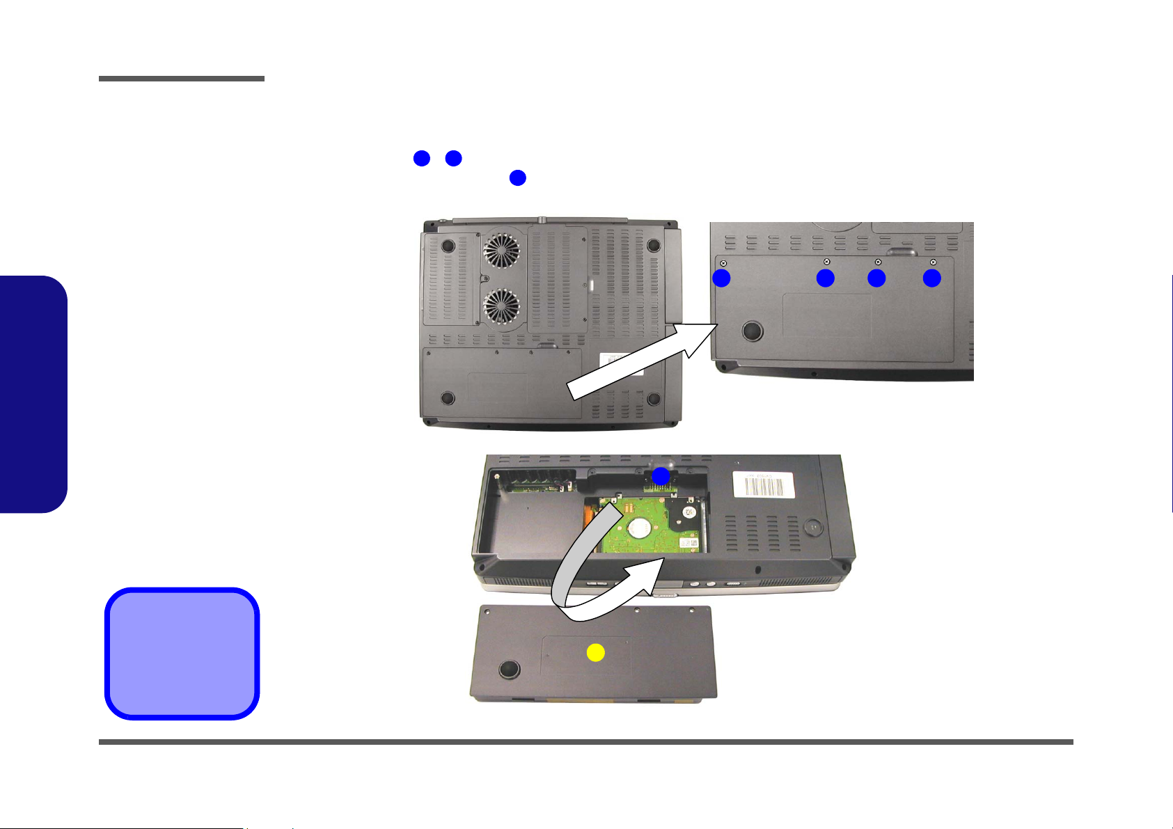
Figure 2 - 1
Battery Removal
Sequence
a. Remove the 4
screws.
b. Apply pressure at
point 5 to push the
battery out.
2.Disassembly
Removing the Battery
1. Turn the computer OFF and turn it over.
2. Remove screws - in Figure 2 - 1a.
3. Apply gentle pressure at point to push the battery up and out of the computer.
1 4
5
a.
21 3 4
b.
5
6. Battery
•4 Screws
2 - 6 Removing the Battery
6
Page 29
Disassembly
Removing the 2nd Modular Drive Bay (Bay Two) CD Device
1. Turn the computer OFF, remove the battery (page 2 - 6) and turn it over.
2. Remove screws - in (Figure 2 - 2a), then lift the 3rd Modular Drive Bay cover off and set it aside.
3. Remove screw (Figure 2 - 2b), then gently push the device out of the bay (you may need to use a screwdriver to
do this).
a.
b.
1 3 4
5
1
4
2
3
c.
Figure 2 - 2
2nd Modular Drive
Bay (Bay Two) CD
Device Removal
Sequence
a. Remove the screws
from the Bay Three
cover.
b. Remove screw 5.
c. Push the device out of
the computer.
2.Disassembly
6
4. Drive Bay Cover
5
Removing the 2nd Modular Drive Bay (Bay Two) CD Device 2 - 7
6. CD Device
•4 Screws
Page 30
Disassembly
Figure 2 - 3
1st Modular Drive
(Bay One) Device
Removal
Sequence
a. Remove the screws
from the Bay Three
cover.
b. Remove screw 5.
c. Push the device out of
the computer.
2.Disassembly
Removing the 1st Modular Drive Bay (Bay One) Device
1. Turn the computer OFF, remove the battery (page 2 - 6) and turn it over.
2. Remove screws - in (Figure 2 - 3a), then lift the 3rd Modular Drive Bay cover off and set it aside.
3. Remove screw (Figure 2 - 3b), then gently push the device out of the bay (you may need to use a screwdriver).
a.
b.
1 3 4
5
1
4
2
3
c.
5
4. Drive Bay Cover
6. CD Device
•4 Screws
2 - 8 Removing the 1st Modular Drive Bay (Bay One) Device
6
Page 31

Disassembly
Removing the Primary Hard Disk
1. Turn the computer OFF, remove the battery (page 2 - 6) and turn it over.
2. Remove screws and (Figure 2 - 4a) and release the HDD connector cable .
3. Remove the HDD assembly from the bay.
4. Remove screws and (Figure 2 - 4c) and the HDD connector cable .
a.
c.
1 2 3
5 8 3
b.
21
3
4
3
5
Figure 2 - 4
Primary Hard Disk
Removal
Sequence
a. Remove the 2 screws
and release the HDD
cable
b. Remove the HDD as-
sembly.
c. Remove the 4 screws
and HDD cable.
2.Disassembly
HDD Cables
The illustrated HDD
cable may differ from
4
the one in your model
depending on the configuration purchased.
Be careful not to bend
the pins on the hard
disk when removing
the cable.
6
9
3. HDD Cable
8
7
4. HDD
9. HDD Case
•6 Screws
Removing the Primary Hard Disk 2 - 9
Page 32

Disassembly
Figure 2 - 5
Bay One HDD
Removal
Sequence
a. Remove the screws
from the Bay Three
cover.
b. Remove screw 5 and
push the device out of
the computer.
c. Remove the 4 screws
from the HDD case.
d. Disconnect the cable
and remove the HDD
assembly.
e. Remove the screws
from the assembly
brackets.
2.Disassembly
Removing the Hard Disk Drive in Bay One
1. Turn the computer OFF, remove the battery (page 2 - 6) and turn it over.
2. Remove screws - in (Figure 2 - 3a), then lift the 3rd Modular Drive Bay cover off and set it aside.
3. Remove screw (Figure 2 - 5b), then gently push the device out of the bay (you may need to use a screwdriver to
do this).
4. Remove screws - (Figure 2 - 5c), and disconnect cable (Figure 2 - 5d), then take the HDD assembly out
of the case.
5. Remove screws - (Figure 2 - 5e) from the HDD assembly (note the disk orientation within the brackets).
a.
1 3 4
5
6 9
12 15
10
b.
5
1
2
4
3
c.
6
7
89
d.
10
4. Drive Bay Cover
11. Drive Case
16. HDD
17. Assembly Brackets
•9 Screws
2 - 10 Removing the Hard Disk Drive in Bay One
11
15
e.
12
17
13
16
17
14
Page 33

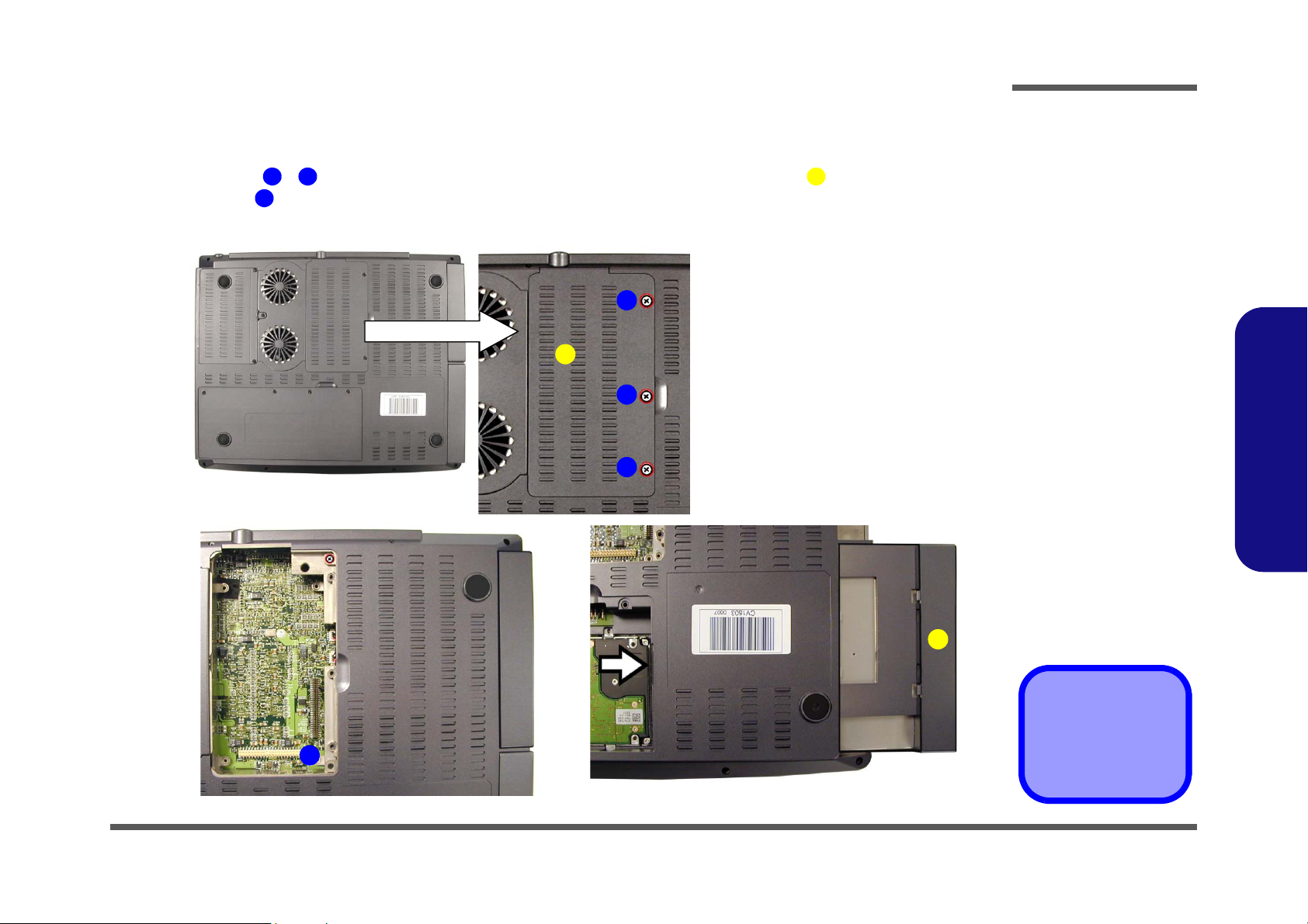
Disassembly
Removing the Hard Disk Drive in Bay Three
1. Turn the computer OFF, remove the battery (page 2 - 6) and turn it over.
2. Remove screws - in (Figure 2 - 3a), then lift the 3rd Modular Drive Bay cover off and set it aside.
3. Remove screws - (Figure 2 - 6b), then lift the HDD assembly out of the bay.
4. Remove screws - (Figure 2 - 6d) to separate the HDD from the case, and disconnect cable .
a.
c.
1 3 4
5 8
9 12
b.
5
6
1
4
2
3
8
7
d.
9
13
Figure 2 - 6
Bay Three HDD
Removal
Sequence
a. Remove the screws
from the Bay Three
cover.
b. Remove the 4
screws.
c. Lift the HDD assem-
bly out of the bay.
d. Remove the 4 screws
from the HDD case,
and disconnect the
cable.
2.Disassembly
12
15
11
10
14
13
4. Drive Bay Cover
13. HDD Cable
14. Drive Case
15. HDD
•11 Screws
Removing the Hard Disk Drive in Bay Three 2 - 11
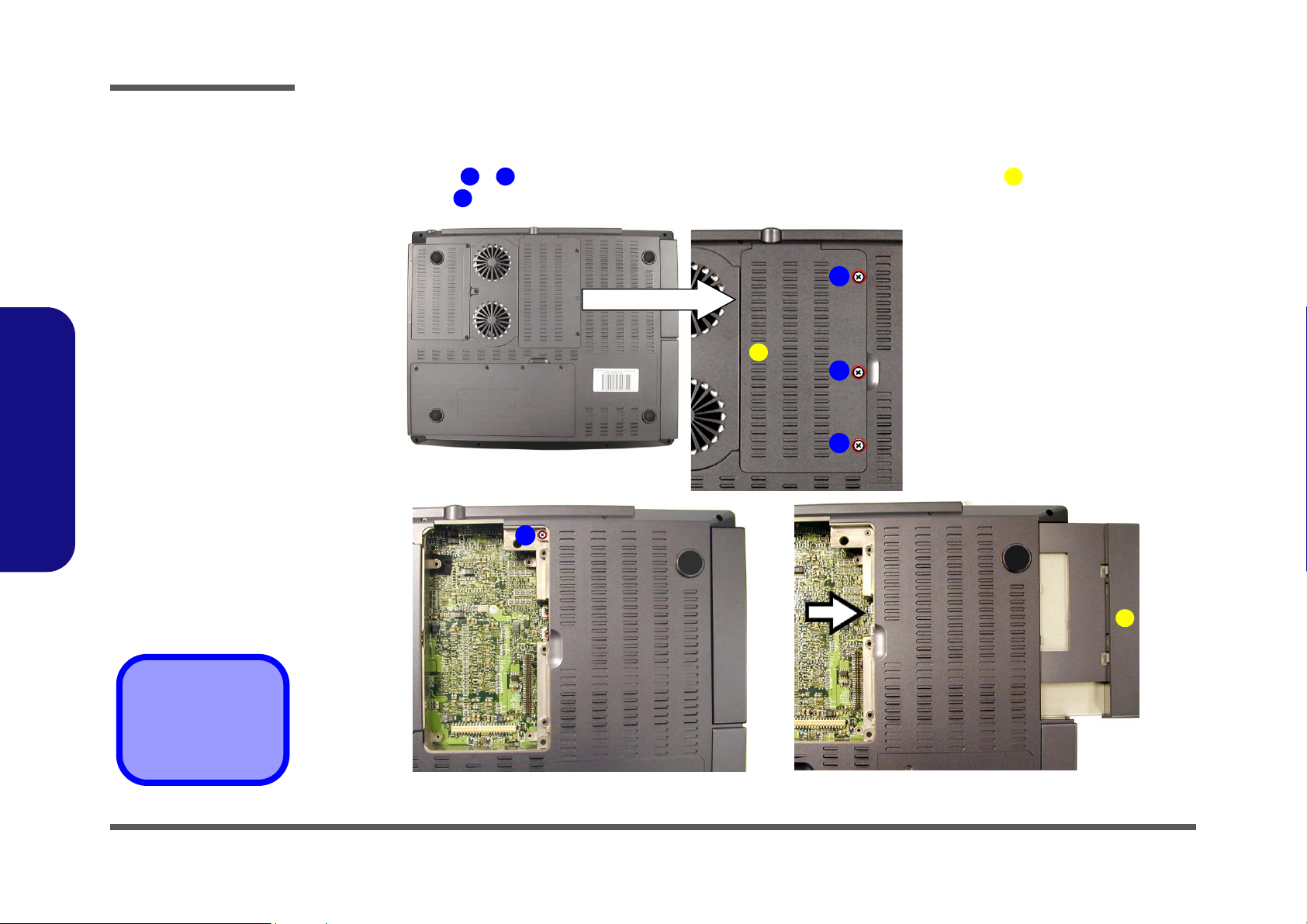
Page 34

Disassembly
Figure 2 - 7
TV Tuner Module
Removal
Sequence
a. Remove the screws
from the Bay Three
cover.
b. Remove cable con-
nector and the 4
screws.
c. Lift the TV Tuner
module out of the
computer.
2.Disassembly
Removing the TV Tuner Module
1. Turn the computer OFF, remove the battery (page 2 - 6) and turn it over.
2. Remove screws - in (Figure 2 - 3a), then lift the 3rd Modular Drive Bay cover off and set it aside.
3. Remove the cable connector (Figure 2 - 7b).
4. Remove screws - (Figure 2 - 7b), and carefully lift the TV tuner module out of the computer.
5. When re-inserting the TV tuner, the module should align with the connecting pins at point (push firmly down to
make sure the module is secure).
a.
1 3 4
5
6
9
5
b. c.
1
4
2
6 7
3
11
10
11
4. Drive Bay Cover
5. Cable Connector
10. TV Tuner Module
•7 Screws
2 - 12 Removing the TV Tuner Module
89
Page 35

Disassembly
Removing the Keyboard
1. Turn the computer OFF and remove the battery (page 2 - 6).
2. Press the two keyboard latches at the top of the keyboard to elevate the keyboard from its normal position (you may
need to use a small screwdriver to do this).
3. Carefully lift the keyboard up and out, being careful not to bend the keyboard ribbon cable (Figure 2 - 8b).
4. Disconnect the keyboard ribbon cable from the locking collar socket (Figure 2 - 8b).
a.
1
2
b.
4
3
4
5
Re-Inserting the
Keyboard
5
Figure 2 - 8
Keyboard Removal
Sequence
a. Press the two latches
to release the keyboard.
b. Lift the keyboard out
and disconnect the
cable from the locking
collar.
2.Disassembly
When re-inserting the
keyboard firstly align
the five keyboard tabs
(Figure 2 - 8b) at the
bottom of the keyboard
with the slots in the
case.
3
5. Keyboard
Keyboard Tabs
Removing the Keyboard 2 - 13
Page 36

Disassembly
Figure 2 - 9
Memory Removal
Sequence
a. Remove the screws
from the shielding
plate.
b. Remove the shielding
plate.
c. Pull the latches on the
memory sockets to
release the module(s). When the
module pops up, lift it
out.
Contact Warning
Be careful not to touch
2.Disassembly
the metal pins on the
module’s connecting
edge. Even the cleanest hands have oils
which can attract particles, and degrade the
module’s performance.
Removing the System Memory
1. Turn the computer OFF, remove the battery (page 2 - 6) and keyboard (page 2 - 13).
2. Remove screws - (Figure 2 - 9a) from the shielding plate (Figure 2 - 9b), and lift the plate up off the
computer.
3. Locate the memory sockets & (Figure 2 - 9c), and gently pull the latches & (and/or & ) on the
memory socket toward the front and rear of the computer as indicated.
4. The module (Figure 2 - 9c) will pop-up, and you can remove it.
5. Insert a new module holding it at about a 30° angle and fit the connectors firmly into the memory slot.
a.
c.
1 3 4
5 6 8
7
1
2
3
c.
10
9
7
5 6
9 10 11
b.
5 6
4
4. Shielding Plate
7. Memory Module(s)
•3 Screws
2 - 14 Removing the System Memory
11
8
Page 37

Disassembly
Removing the CPU
1. Turn the computer OFF, remove the battery (page 2 - 6) and turn it over.
2. Remove screws - (Figure 2 - 10a), and lift the cover (Figure 2 - 10c) up off the computer (it may be necessary to lift up the cover sticker (Figure 2 - 10b) in order to reveal the heat sink caution label).
a.
3. Remove the four screws from the heat sink in order indicated on the label, and lift out the heat sink Figure 2 -
11.
Caution
The heat sink, and
CPU area in general,
contains parts which
are subject to high
temperatures. Allow
the area time to cool
before removing these
parts.
1 3 5
4
1
b.
2
4
3
c.
5
6
Reassembly Screw
Order
6
When replacing the
heat sink, make sure
you insert the screws
in the same order indicated on the label.
Figure 2 - 10
Processor
Removal
Sequence
a. Remove the three
screws from the CPU
cover.
b. Remove the CPU
cover
c. Lift up the cover stick-
er if necessary.
2.Disassembly
Figure 2 - 11
Processor
Removal
Sequence (cont’d)
Remove the four
screws from the heat
sink in the order indi-
cated.
5. CPU Cover
6. Heat Sink
•7 Screws
Removing the CPU 2 - 15
Page 38

Disassembly
Figure 2 - 12
Processor
Removal
Sequence
(cont’d)
a. Remove the screws
from the bracket.
b. Lift the bracket up.
c. Raise the latch to un-
lock the CPU.
d. Lift the CPU out of the
socket.
2.Disassembly
4. Remove screws & (Figure 2 - 12a) from the CPU bracket, then lift the bracket off the CPU (Figure 2 -
1 2 3
12b).
5. Fully raise latch in the direction indicated in Figure 2 - 12c to unlock the CPU.
6. Carefully (it may be hot) lift the CPU up out of the socket. (Figure 2 - 12d).
4
5
7. When re-inserting the CPU pay careful attention to the pin alignment, it will fit only one way (don’t force it!).
a.
1
2
c.
b.
3
d.
3. CPU Bracket
5. CPU
•2 Screws
2 - 16 Removing the CPU
4
5
Page 39

Disassembly
Removing the Switch Keyboard Assembly
1. Turn the computer OFF, remove the battery (page 2 - 6), keyboard (page 2 - 13), and memory (page 2 - 14).
2. Carefully slide the center cover assembly (Figure 2 - 13a) forward.
3. Carefully disconnect the cable at point (Figure 2 - 13b) and lift the center cover assembly out of the computer.
4. Remove screws - (Figure 2 - 13c) and disconnect the cable at point , then lift up the switch keyboard
assembly .
a.
d.
9
1
3 7 8
c.
1
2
b.
2
3
4
6
7
5
8
Figure 2 - 13
Switch Keyboard
Assembly
Removal
Sequence
a. Slide the center cover
assembly forward.
b. Disconnect the cable
and lift off the cover
assembly.
c. Remove the screws
and disconnect the
cable from the switch
keyboard assembly.
d. Lift the switch key-
board assembly off
the center cover assembly.
2.Disassembly
1
1. Center Cover As-
9
9. Switch Keyboard
sembly
Assembly
•5 Screws
Removing the Switch Keyboard Assembly 2 - 17
Page 40

Disassembly
Figure 2 - 14
Bottom Case
Assembly
Removal
Sequence
a. Remove all the previ-
ously listed devices
and components prior
to this page (as applicable).
b. Remove the 14
screws from the bottom of the computer.
2.Disassembly
Removing the Bottom Case Assembly
1. Turn the computer OFF, remove the battery (page 2 - 6), and all applicable devices listed in the previous pages
(from page 2 - 6 to page 2 - 17,).
2. Remove screws - (Figure 2 - 14b) from the bottom of the computer.
a.
1
14
b.
1
14
2
3
4
5
6
7
8
•14 Screws
2 - 18 Removing the Bottom Case Assembly
13
12
11
10
9
Page 41

Disassembly
3. Turn the computer back over and disconnect cables - (Figure 2 - 15a), and remove screw .
4. Remove screws - (Figure 2 - 15b) from the rear of the computer.
5. Carefully ease the top case assembly (Figure 2 - 15c) off the bottom case assembly .
a.
5
15
16 17
1
3
c.
4
1
16
3
2
4
Figure 2 - 15
Bottom Case
Assembly
Removal
Sequence (cont’d)
a. Disconnect the ca-
bles and remove the
screw from inside the
top case assembly.
b. Remove the 11
screws from the rear
of the computer
c. Carefully lift the top
case assembly up
and off the bottom
case assembly.
2.Disassembly
b.
17
6
5
7 8
16.Top Case Assem-
9
101112131415
17.Bottom Case As-
bly
sembly
•12 Screws
Removing the Bottom Case Assembly 2 - 19
Page 42

Disassembly
Figure 2 - 16
HDD & MP3
Converter Board
Removal
Sequence
a. Remove the 2
screws.
b. Lift the HDD & MP3
converter board off
the connector.
2.Disassembly
Removing the HDD & MP3 Converter Board
1. Turn the computer OFF, remove the battery (page 2 - 6), and the bottom case assembly (page 2 - 18).
2. Remove screws & (Figure 2 - 16a) from the HDD & MP3 converter board.
3. Lift the converter board (Figure 2 - 16b) off the connector on the mainboard.
a.
1
2
3
b.
1
2
4
4
3
3. HDD & MP3 Converter Board
•2 Screws
2 - 20 Removing the HDD & MP3 Converter Board
Page 43

Disassembly
Removing the Audio Board
1. Turn the computer OFF, remove the battery (page 2 - 6), and the bottom case assembly (page 2 - 18).
2. Remove screw (Figure 2 - 17a) and disconnect cable from the mainboard.
3. Lift the Audio DJ bezel module (Figure 2 - 17b) out off the computer, and remove cable .
4. Remove screws - (Figure 2 - 17c), and disconnect cables & .
5. Lift the audio board (Figure 2 - 17d) off the Audio DJ bezel.
a.
c.
1
3 4
5
10 11 12
13
2
b.
2
1
3
4
6
11
10
Figure 2 - 17
Audio Board
Removal
Sequence
a. Remove the screw
and disconnect the
cable.
b. Lift the Audio DJ bez-
el out of the computer
and remove the connector cable.
c. Remove the screws
and cables from the
rear of the audio
board.
d. Remove the audio
board from the Audio
DJ bezel.
2.Disassembly
d.
12
5
7
8
9
3. Audio DJ Bezel
3
13
Removing the Audio Board 2 - 21
4. Audio DJ Cable
13.Audio Board
•7 Screws
Page 44

Disassembly
Figure 2 - 18
Modem Module
Removal
Sequence
a. Remove the screws
and lift the modem
module off the mainboard.
2.Disassembly
Removing the Modem Module
1. Turn the computer OFF, remove the battery (page 2 - 6), and the bottom case assembly (page 2 - 18).
2. Remove screws - (Figure 2 - 18) and lift the modem module off the mainboard modem connector .
1
2
4
1
4
2
3
3
4. Modem Module
•2 Screws
2 - 22 Removing the Modem Module
Page 45

Disassembly
Removing the Floppy Disk Drive Assembly
1. Turn the computer OFF, remove the battery (page 2 - 6) and the bottom case assembly (page 2 - 18).
2. Remove screws - (Figure 2 - 19a) on the floppy disk drive assembly (located under the top case assem-
1
4
bly).
3. Lift the floppy disk drive assembly off the top case.
a.
3 4
5
21
Figure 2 - 19
Floppy Disk Drive
Assembly
Removal
Sequence
a. Remove the 4
screws.
b. Lift the FDD assem-
bly off the top case.
2.Disassembly
b.
5
Removing the Floppy Disk Drive Assembly 2 - 23
5. FDD Assembly
4 Screws
Page 46

Disassembly
Figure 2 - 20
TouchPad Module
Removal
Sequence
Remove the 6 screws
and lift the TouchPad
module off the top
case.
2.Disassembly
Removing the TouchPad Module
1. Turn the computer OFF, remove the battery (page 2 - 6), the bottom case assembly (page 2 - 18) and the floppy
disk drive assembly (page 2 - 23).
2. Remove screws - (Figure 2 - 20) on the TouchPad module .
1
6
3. Lift the TouchPad module off the top case.
3 4
7
7
21
7. TouchPad Module
•6 Screws
2 - 24 Removing the TouchPad Module
5 6
Page 47

Disassembly
Removing the Inverter Board
1. Turn the computer OFF, remove the battery (page 2 - 6) and the bottom case assembly (page 2 - 18).
2. Remove any rubber covers and screws - (Figure 2 - 21a), then run your finger around the middle of the frame
to carefully unsnap the LCD front panel module from the back.
3. Remove screw (Figure 2 - 21b) from the inverter, and carefully lift the inverter board up slightly.
4. Disconnect cables & (Figure 2 - 21c) from the inverter, then remove the inverter (Figure 2 - 21d) from
6
7
8
the top case assembly.
a. b.
4
1
2
5
3
1
4
5
9
6
c.
7 8
Figure 2 - 21
Inverter Board
Removal
Sequence
a. Remove the 4 screws
and unsnap the LCD
front panel module
from the back.
b. Remove the screw
from the inverter
board and lift the
board up slightly.
c. Disconnect the ca-
bles from the inverter.
d. Remove the inverter.
2.Disassembly
d.
9
5. LCD Front Panel
9. Inverter Board
•5 Screws
Removing the Inverter Board 2 - 25
Page 48

Disassembly
Figure 2 - 22
LCD Removal
Sequence
a. Remove the 8 screws
from the LCD.
b. Disconnect the cable
and lift up the LCD.
c. Remove the screws
and separate the
brackets from the
LCD.
2.Disassembly
Removing the LCD
1. Turn the computer OFF, remove the battery (page 2 - 6), the bottom case assembly (page 2 - 18) and the inverter
board (page 2 - 25).
2. Remove screws - (Figure 2 - 22a) from the LCD.
3. Disconnect the cable at point (Figure 2 - 22b), then lift the LCD up off the display back panel and top
case module.
4. Remove screws - (Figure 2 - 22c) from the LCD brackets & , then separate the LCD from the brackets.
a. b.
1
1
8
13 18
9
10 11
19 20
10
9
11
12
2
10.LCD
11.Display Back Panel
12.Top Case Module
19.LCD Bracket
20.LCD Bracket
•14 Screws
2 - 26 Removing the LCD
786
16
3
4
c.
19
17
18
5
13
14
20
15
Page 49

Appendix A:Part Lists for D800P
This appendix breaks down the D800P model notebook’s construction into a series of illustrations. The component part
numbers are indicated in the tables opposite the drawings.
Note: This section indicates the manufacturer’s part numbers. Your organization may use a different system, so be sure
to cross-check any relevant documentation.
Note: Some assemblies may have parts in common (especially screws). However, the part lists DO NOT indicate the
total number of duplicated parts used.
Part Lists
Note: Be sure to check any update notices. The parts shown in these illustrations are appropriate for the system at the
time of publication. Over the product life, some parts may be improved or re-configured, resulting in new part numbers.
Part Lists
A-1
Page 50

Part Lists
Table A- 1
Part List Illustration
Location
Part List Illustration Location
The following table indicates where to find the appropriate part list illustration.
Part D800P Part D800P
Top
page A - 3
DVD-ROM Drive
page A - 13
Part Lists
Bottom
LCD 15"
LCD 16"
Battery
Center Cover
Center Cover Finger
CD-ROM Drive
CD-RW Drive
Combo Drive
page A - 4
page A - 5
page A - 6
page A - 7
page A - 8
page A - 9
page A - 10
page A - 11
page A - 12
Audio DJ
Floppy Disk Drive
First Hard Disk Drive
Second Hard Disk Drive
Third Hard Disk Drive
Third Hard Disk - Dummy
IP Sharing Module
MP3 Player
Card Reader
page A - 14
page A - 15
page A - 16
page A - 17
page A - 18
page A - 19
page A - 20
page A - 21
page A - 22
A - 2 Part List Illustration Location
Page 51
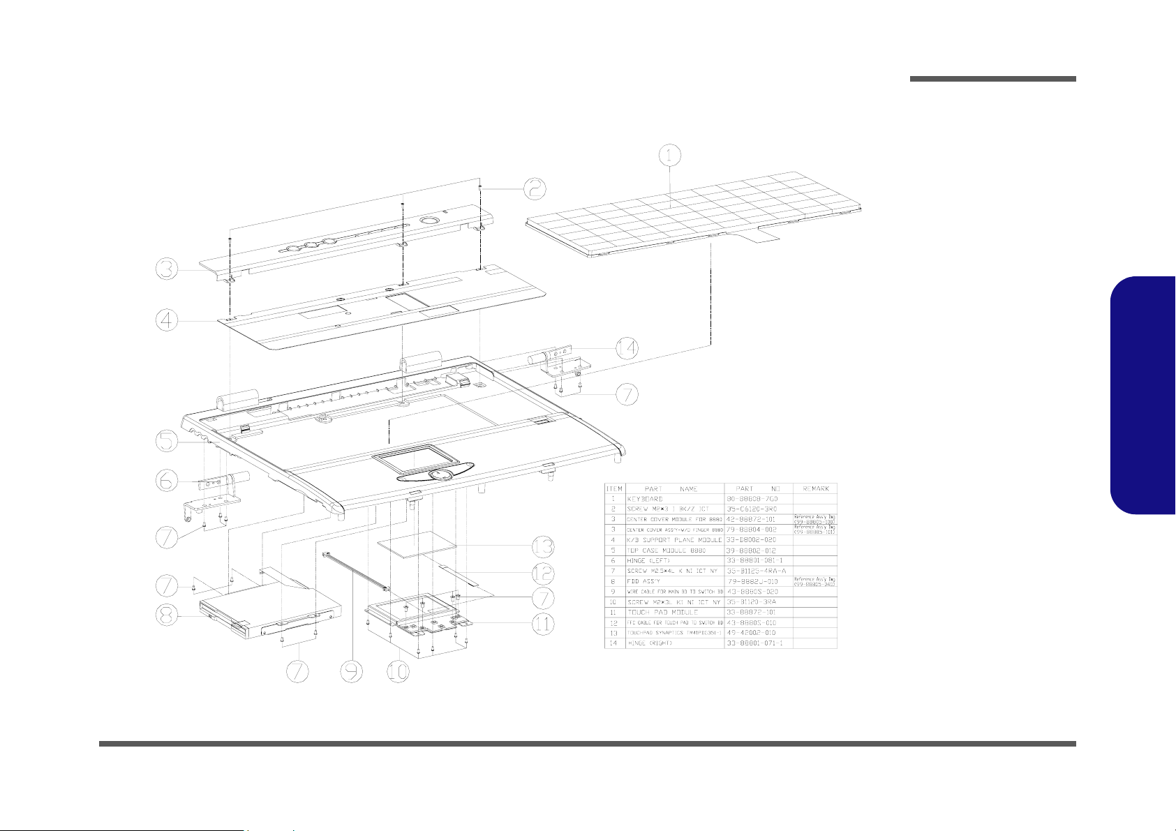
Top
Part Lists
Figure A-1
Top
Part Lists
Top A - 3
Page 52

Part Lists
Part Lists
Bottom
Figure A-2
Bottom
A - 4 Bottom
Page 53

LCD 15"
Part Lists
Figure A-3
LCD 15"
Part Lists
LCD 15" A - 5
Page 54

Part Lists
Part Lists
LCD 16"
Figure A-4
LCD 16"
A - 6 LCD 16"
Page 55

Battery
Part Lists
Figure A-5
Battery
Part Lists
Battery A - 7
Page 56

Part Lists
Part Lists
Center Cover
Figure A-6
Center Cover
A - 8 Center Cover
Page 57

Center Cover Finger
Part Lists
Figure A-7
Center Cover
Finger
Part Lists
Center Cover Finger A - 9
Page 58

Part Lists
CD-ROM Drive
Part Lists
CD-ROM Drive
Figure A-8
A - 10 CD-ROM Drive
Page 59

CD-RW Drive
Part Lists
Figure A-9
CD-RW Drive
Part Lists
CD-RW Drive A - 11
Page 60

Part Lists
Part Lists
Combo Drive
Figure A-10
Combo Drive
A - 12 Combo Drive
Page 61

DVD-ROM Drive
Part Lists
Figure A-11
DVD-ROM Drive
Part Lists
DVD-ROM Drive A - 13
Page 62

Part Lists
Part Lists
Audio DJ
Figure A-12
Audio DJ
A - 14 Audio DJ
Page 63

Floppy Disk Drive
Part Lists
Figure A-13
Floppy Disk Drive
Part Lists
Floppy Disk Drive A - 15
Page 64

Part Lists
First HDD Drive
Part Lists
First Hard Disk Drive
Figure A-14
A - 16 First Hard Disk Drive
Page 65

Second Hard Disk Drive
Part Lists
Figure A-15
Second HDD Drive
Part Lists
Second Hard Disk Drive A - 17
Page 66

Part Lists
Part Lists
Third Hard Disk Drive
Figure A-16
Third Hard Disk
Drive
A - 18 Third Hard Disk Drive
Page 67

Third Hard Disk - Dummy
Part Lists
Figure A-17
Third Hard Disk -
Dummy
Part Lists
Third Hard Disk - Dummy A - 19
Page 68

Part Lists
IP Sharing Module
Part Lists
IP Sharing Module
Figure A-18
A - 20 IP Sharing Module
Page 69

MP3 Player
Part Lists
Figure A-19
MP3 Player
Part Lists
MP3 Player A - 21
Page 70
Part Lists
Part Lists
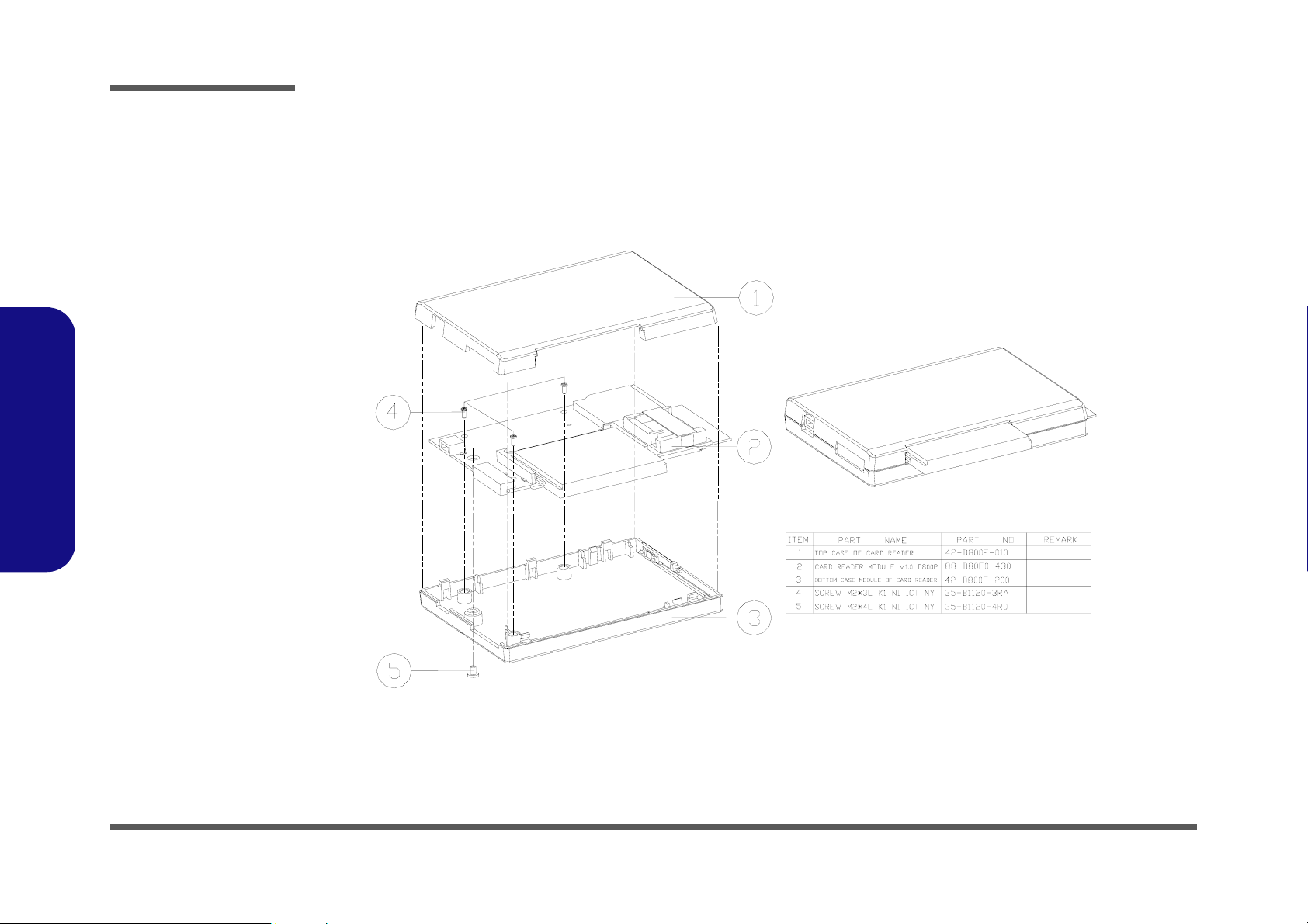
Card Reader
Figure A-20
Card Reader
A - 22 Card Reader
Page 71

Schematic Diagrams
Appendix B: Schematic Diagrams for D800P
This appendix has circuit diagrams of the D800P notebook computer’s PCBs.
Diagram - Page Diagram - Page Diagram - Page
System Block Diagram - Page B - 2 Mobility M10-P_POW - Page B - 17 KBC H8 - Page B - 32
CPU Northwood & Prescott (1 of 2) - Page B - 3 TV Tuner, DVI & Video In - Page B - 18 MDC, Wireless & BT - Page B - 33
CPU Northwood & Prescott (2 of 2) - Page B - 4 TV Out & LVDS - Page B - 19 PCI 1520 - Page B - 34
CPU Decoupling - Page B - 5 ICH5 (1 of 2) - Page B - 20 PCMCIA Connector - Page B - 35
CLK409 - Page B - 6 ICH5 (2 of 2) - Page B - 21 IEEE 1394 TSB43AB21 - Page B - 36
Springdale (HOST, AGP, Hub) - Page B - 7 USB Port & RTC - Page B - 22 LAN RTL8100C/RTL8110S(B)-32 - Page B - 37
Springdale (DDR, Interface) - Page B - 8 RAID PDC20265R - Page B - 23 Power Plane - Page B - 38
DDR Termination - Page B - 9 HDD, CD-R/W & IP Sharer - Page B - 24 Vcore - Page B - 39
Schematic Diags
DDR SODIMM - Page B - 10 AMP TPA0132 / ALC650 - Page B - 25 System Power 1 - Page B - 40
Springdale (Voltage, PLL, VSS) - Page B - 11 LCM & Audio Jack - Page B - 26 System Power 2 - Page B - 41
Mobility M10-P - Page B - 12 Audio DJ/CDROM - Page B - 27 Charger - Page B - 42
Mobility M10-P MEM A/B - Page B - 13 Fan Control & Beep - Page B - 28 3VH8, VDD1.8 - Page B - 43
VGA DDR DRAM Channel A - Page B - 14 Flash ROM/LPT1 - Page B - 29
VGA DDR DRAM Channel B - Page B - 15 NS87393 LPC Bridge & Super I/O - Page B - 30
VGA DDR DRAM Termination - Page B - 16 I/O, FDD, LED & Debug - Page B - 31
B-1
Page 72

Schematic Diagrams
System Block Diagram
D800 SCHEMATIC
Sheet 1 of 42
System Block
Diagram
CK 409
Clocking
VIDEO IN
LVDS
DVI-I
DDR-SDRAM
Mobility M10-P
ATI
708 BGA
AGP 8X
Intel
Pentium 4
Northwood & Prescott
478 FC-BGA
400/533/800MHz
Intel
SPRINGDALE
865PE
932 FC-BGA
GNT#0
GNT#1
GNT#2
LAN RTL8100C
GNT#3
LAN RTL8110S(B)
GNT#4
MOBILITY M10
PCI1520
TSB43AB21
RAID
TV TUNNER
PREQ0#
PREQ1# AD17
PREQ2#
PREQ3#
PREQ4#
DDR DRAM CHANNEL A
DDR DRAM CHANNEL B
INT#A/B
SERIRQ/INT#A/E
INT#B/F
INT#A/D
INT#C/G
INT#B/D
SODIMM0
SODIMM1
A/E
B
AD16
F
AD18
D
G
AD19
D
AD20
USB0
Hub Interface 1.8V , 66MHz
USB1
USB2
Schematic Diags
USB3
CARD
READER
MP3
PLAYER
WIRELESS
BLUETOOTH
IDE INTERFACE 1
CD-ROM/DVD-ROM
LCM
IDE INTERFACE 1
SECOND
CD-R/W(OPTION)
MDC
MODEM
USB 2.0
AC'97 2.1 I/F
AUDIO
ALC650
AUDIO DJ
OZ165
CODEC
Intel
ICH5
460 BGA
IN. K/B
EX. K/B
EX. PS/2
RAID
PDC20265R
KBC H8
H8S-2149 HM
TOUCH PAD
Realtek
RTL8100C/RTL8110S(B)-32
33MHz, 3.3V PCI 2.2 I/F
CARDBUS
(TI1520)
33MHz, 3.3V LPC I/F
NS87393
LPC SUPER I/O
ROMFlash
1394
TSB43AB21
IDE INTERFACE 0
HDD
IDE INTERFACE 0
SECOND
HDD(OPTION)
IR PORT
COM
FDC
B - 2
Page 73

CPU Northwood & Prescott (1 of 2)
Schematic Diagrams
HD[0..63][6]
LAYOUT NOTICE:
HD[0..63]
Data Line lengths:
2"-10" from pin to
pin.
HRS0#[6]
HRS1#[6]
HRS2#[6]
HD[0..63]
HD0
HD1
HD2
HD3
HD4
HD5
HD6
HD7
HD8
HD9
HD10
HD11
HD12
HD13
HD14
HD15
HD16
HD17
HD18
HD19
HD20
HD21
HD22
HD23
HD24
HD25
HD26
HD27
HD28
HD29
HD30
HD31
HD32
HD33
HD34
HD35
HD36
HD37
HD38
HD39
HD40
HD41
HD42
HD43
HD44
HD45
HD46
HD47
HD48
HD49
HD50
HD51
HD52
HD53
HD54
HD55
HD56
HD57
HD58
HD59
HD60
HD61
HD62
HD63
HRS0#
HRS1#
HRS2#
VCORE
A10
A12
A14
A16
A18
A20A8AA10
AA12
AA14
AA16
AA18
AA8
AB11
AB13
AB15
AB17
AB19
AB7
AB9
AC10
AC12
AC14
AC16
AC18
AC8
AD11
AD13
AD15
AD17
AD19
AD7
AD9
AE10
AE12
AE14
AE16
AE18
AE20
AE6
AE8
AF11
AF13
AF15
AF17
AF19
AF2
AF21
AF5
AF7
AF9
B11
B13
B15
B17
B19B7B9
C10
C12
C14
C16
C18
C20C8D11
D13
D15
D17
D19D7D9
E10
E12
E14
E16
E18
E20E8F11
F13
F15
F17
F19
U38A
VCC
VCC
VCC
VCC
VCC
VCC
VCC
VCC
VCC
VCC
VCC
VCC
VCC
VCC
VCC
VCC
VCC
VCC
VCC
VCC
VCC
VCC
VCC
VCC
VCC
VCC
VCC
VCC
VCC
VCC
VCC
VCC
VCC
VCC
VCC
VCC
VCC
VCC
VCC
VCC
VCC
VCC
VCC
VCC
VCC
VCC
VCC
VCC
VCC
VCC
VCC
VCC
VCC
VCC
VCC
VCC
VCC
VCC
VCC
VCC
VCC
VCC
VCC
VCC
VCC
VCC
VCC
VCC
VCC
VCC
VCC
VCC
VCC
VCC
B21
D0
B22
D1
A23
D2
A25
D3
C21
D4
D22
D5
B24
LAYOUT NOTICE:
D6
C23
HD[0..15]»Ýµ¥ªø, »~®t
D7
C24
D8
+/-100mils.
B25
D9
G22
¥B©MHDSTBN0#, HDSTBP0#, HDBI0#
D10
H21
D11
µ¥ªø, »~®t+/-25mils.
C26
D12
D23
D13
J21
D14
D25
D15
H22
D16
E24
D17
G23
D18
F23
D19
F24
D20
E25
D21
F26
LAYOUT NOTICE:
D22
D26
HD[16..31]»Ýµ¥ªø, »~®t
D23
L21
D24
+/-100mils.
G26
D25
H24
¥B©MHDSTBN1#, HDSTBP1#, HDBI1#
D26
M21
D27
µ¥ªø, »~®t+/-25mils.
L22
D28
J24
D29
K23
D30
H25
D31
M23
D32
N22
D33
P21
D34
M24
D35
N23
D36
M26
D37
N26
LAYOUT NOTICE:
D38
N25
HD[32..47]»Ýµ¥ªø, »~®t
D39
R21
D40
+/-100mils.
P24
D41
R25
¥B©MHDSTBN2#, HDSTBP2#, HDBI2#
D42
R24
D43
µ¥ªø, »~®t+/-25mils.
T26
D44
T25
D45
T22
D46
T23
D47
U26
D48
U24
D49
U23
D50
V25
D51
U21
D52
V22
D53
V24
LAYOUT NOTICE:
D54
W26
Y26
W25
Y23
Y24
Y21
AA25
AA22
AA24
HD[48..63]»Ýµ¥ªø, »~®t
D55
D56
+/-100mils.
D57
¥B©MHDSTBN3#, HDSTBP3#, HDBI3#
D58
D59
µ¥ªø, »~®t+/-25mils.
D60
D61
D62
D63
F1
RS0
G5
RS1
F4
RS2
VSS
VSS
VSS
VSS
H1H4H23
H26
VSS
VSS
VSS
VSS
VSS
VSS
VSS
VSS
VSS
VSS
VSS
VSS
VSS
VSS
VSS
VSS
VSS
VSS
VSS
VSS
VSS
VSS
VSS
VSS
VSS
VSS
VSS
VSS
VSS
VSS
VSS
VSS
VSS
VSS
VSS
VSS
VSS
VSS
VSS
VSS
VSS
VSS
VSS
VSS
VSS
VSS
VSS
VSS
VSS
VSS
VSS
VSS
VSS
VSS
VSS
VSS
VSS
VSS
A11
A13
A15
A17
A19
A21
A24
A26A3A9
AA1
AA11
AA13
AA15
AA17
AA19
AA23
AA26
AA4
AA7
AA9
AB10
AB12
AB14
AB16
AB18
AB20
AB21
AB24
AB3
AB6
AB8
AC11
AC13
AC15
AC17
AC19
AC2
AC22
AC25
AC5
AC7
AC9
AD10
AD12
AD14
AD16
AD18
AD21
AD23
AD4
PJ11 2mm
R752 2K(R)
12
VID0
VID1
VID2
VID3
VID4
VID5
Reserved
R619 1K(R)1 2
R618 1K(R)1 2
R617 1K(R)1 2
R615 1K(R)1 2
R614 1K(R)1 2
R616 1K1 2
VCC3S
VSS
AD8
AE11
AE13
AE15
AE17
AE19
AE22
AE24
T323
Place close to cpu
TPREQ#
TPRDY#
BPM3#
BPM2#
BPM1#
BPM0#
VCC
LAYOUT NOTICE:
HA[17..35]»Ýµ¥ªø,
»~®t+/-200mils.
¥B©MADSTB1#µ¥ªø,
»~®t+/-25mils.
LAYOUT NOTICE:
HA[3..16]»Ýµ¥ªø,
»~®t+/-200mils.
¥B©MADSTB0#, HREQ[0..4]#µ¥ªø,
»~®t+/-25mils.
VSS
VSS
VSS
VSS
VSS
VSS
VSS
VSS
VSS
AE26
AE7
AE9
AF1
AF10
AF12
AF14
AF16
AF18
AF20
R594 62
R585 62
R584 62
R271 62
R601 62
R260 62
VCC
VCC
VSS
SKTOCC#
AF26
VCORE
VCC
VCC
VSS
VSS
AF6
AF8
SKTOCC#
F9
VCC
VCC
VCC
VCC
VCC
VCC
VSS
VSS
VSS
VSS
VSS
VSS
VSS
B10
B12
B14
B16
B18
B20
B23
T324
L25
TESTHI0/BYPASSEN#
VSS
VSS
VSS
VSS
B26B4B8
C11
C13
DP3#
DP2#
DP1#
DP0#
J26
K25
K26
DEP0
DEP1
DEP2
DEP3
REQ4
REQ3
REQ2
REQ1
REQ0
BPM5
BPM4
BPM3
BPM2
BPM1
BPM0
TESTHI12/DPSLP#
TESTHI11/GHI#
TESTHI10/BR1#
TESTHI9/BR2#
TESTHI8/BR3#
TESTHI7/MCLKIO1
TESTHI6/MCLKIO0
TESTHI5/MCLK3
TESTHI4/MCLK2
TESTHI3/MCLK1
TESTHI2/MCLK0
TESTHI1/ODT
VSS
VSS
VSS
VSS
VSS
NORTHWOOD478
C15
C17
C19
C2
T302
T297
T295
T294
HA35
T318
HA34
T310
HA33
T309
HA32
HA31
HA30
HA29
HA28
HA27
HA26
HA25
HA24
HA23
HA22
HA21
HA20
HA19
HA18
HA17
HA16
HA15
HA14
HA13
HA12
HA11
HA10
HA9
HA8
HA7
HA6
HA5
HA4
HA3
VID0
VID1
VID2
VID3
VID4
VID5
PRE/NOR#
1 2
T301
LAYOUT NOTICE:
HA[3..31]
Address Line lengths:
2"-10" from pin to
pin.
VID0 [38]
VID1 [38]
VID2 [38]
VID3 [38]
VID4 [38]
VID5 [38]
HREQ4# [6]
HREQ3# [6]
HREQ2# [6]
HREQ1# [6]
HREQ0# [6]
TPREQ# [3]
TPRDY# [3]
BPM3#
BPM2#
BPM1# [3]
BPM0# [3]
G_HIGH [19]
VCORE
VCORE
VCORE
VCORE
PRE/NOR# [38,40]
VCORE
AB1
A35
Y1
A34
W2
A33
V3
A32
U4
A31
T5
A30
W1
A29
R6
A28
V2
A27
T4
A26
U3
A25
P6
A24
U1
A23
T2
A22
R3
A21
P4
A20
P3
A19
R2
A18
T1
A17
N5
A16
N4
A15
N2
A14
M1
A13
N1
A12
M4
A11
M3
A10
L2
A9
M6
A8
L3
A7
K1
A6
L6
A5
K4
A4
K2
A3
AE5
VID0
AE4
VID1
AE3
VID2
AE2
VID3
AE1
VID4
AD3
VID5
HREQ4#
H3
HREQ3#
J3
HREQ2#
J4
HREQ1#
K5
HREQ0#
J1
TPREQ#
AB4
TPRDY#
AA5
BPM3#
Y6
BPM2#
AC4
BPM1#
AB5
BPM0#
AC6
AD25
R596 621 2
R506 621 2
A6
R259 621 2
Y3
R244 621 2
W4
R243 621 2
U6
AB22
AA20
R620 621 2
AC23
AC24
AC20
AC21
AA2
R621 621 2
AD24
AD1
VSS
R270 1K
Prescott Northwood
Line to line spacing: Greater than
3:1
Trace Impedance: 50ohm +/-15%
VCORE [3,4,5,19,20,38]
HA[3..31] [6]
VCORE
Hight Low
1.45V 1.225V
Schematic Diags
Sheet 2 of 42
CPU Northwood &
Prescott
(1 of 2)
B-3
Page 74
Schematic Diagrams
CPU Northwood & Prescott (2 of 2)
GTLREF GENERATION CIRCUITS
12
12
C715
220P
12
C727
220P
D12
VSS
VSS
VSS
VSS
VSS
VSS
K24K3K6L1L23
12
C724
220P
12
C736
220P
F6
F20
AA6
D20
D21
VSS
VSS
VSS
VSS
M22
D24D3D6
VSS
VSS
M25M5N21
VSS
VSS
D8
VSS
VSS
N24N3N6P2P22
AA21
E1
C22
VSS
VSS
VSS
GTLREF2
GTLREF1
GTLREF0
RESERVED5/VCCVIDPRG
VSS
VSS
VSS
VSS
VSS
VSS
VSS
P25
P5
R1
GTLREF3
PROCHOT
PWRGOOD
THERMDA
THERMDC
THERMTRIP
RESERVED0
RESERVED1
VIDPWRGD
RESERVED4
RESERVED6
RESERVED7
VSS
VSS
VSS
R23
R26
IERR
MCERR
FERR
STPCLK
BINIT
INIT
RSP
DBSY
DRDY
TRDY
ADS
LOCK
BR0
BNR
HIT
HITM
BPRI
DEFER
TCK
TDI
TMS
TRST
TDO
IGNNE
SMI
A20M
SLP
RESET
NC
BSEL0
BSEL1
AP0
AP1
VCCVID
VSS
VSS
VSS
VSS
VSS
VSS
VSS
VSS
VSS
VSS
VSS
VSS
VSS
VSS
VSS
VSS
VSS
VSS
VSS
VSS
VSS
NORTHWOOD478
AC3
V6
B6
Y4
AA3
W5
AB2
H5
H2
J6
G1
G4
H6
G2
F3
E3
D2
E2
D4
C1
F7
E6
D5
C3
B2
B5
C6
AB26
AB23
AB25
B1
B3
C4
A2
AD6
AD5
AC1
V5
AF4
AF3
A22
A7
AD2
AE21
AF24
AF25
Y5
Y25
Y22
Y2
W6
W3
W24
W21
V4
V26
V23
V1
U5
U25
U22
U2
T6
T3
T24
T21
R4
IERR#
MCERR#
FERR#VCCCA
HSTPCLK#
BINIT#VSSA
INIT#
RSP#
DBSY#
HDRDY#
HTRDY#
ADS#
HLOCK#
BNR#
HIT#
HITM#
BPRI#
DEFER#
TCK
TDI
TMS
TRST#
TDO
PROCHOT#
IGNNE#
SMI#
A20M#
CPUSLP#
CPUPWRGD
HCPURST#
T270
THERMDA
THERMDC
THERMTRIP#
FSA
FSB
T272
T271
VID_PWRGD
T326
T327
T328
T154
T158
T170
R519 0
T171
T155
VCCVID
C326
0.1U
FERR# [19]
HSTPCLK# [19]
INIT# [19]
DBSY# [6]
HDRDY# [6]
HTRDY# [6]
ADS# [6]
HLOCK# [6]
BR0# [6]
BNR# [6]
HIT# [6]
HITM# [6]
BPRI# [6]
DEFER# [6]
PROCHOT# [6]
IGNNE# [19]
SMI# [19]
A20M# [19]
CPUSLP# [19]
CPUPWRGD [19]
HCPURST# [6]
12
THERMTRIP#_ICH
FSA [5]
FSB [5]
VCCVID
VID_PWRGD [42]
THERMTRIP#_ICH [19]
VCC3 [5,6,19,22,23,27,29,32,33,35,36,37,38,39,40,41,42]
VCORE [2,4,5,19,20,38]
THERMDA
THERMDC
C648 2200P
C638
0.1U
10 MILE
10 MILE
VDD3
D14
D16
D18
VSS
VSS
VSS
VSS
VSS
VSS
VSS
VSS
L26L4M2
R729
200
1
2
3
R824 0
R490 10K(R)
IERR#
FERR#
BR0#
PROCHOT#
CPUPWRGD
TDI
TMS
HCPURST#
TCK
TRST#
R147 20K
U35
SCLK
VDD
SDATA
D+
ALERT#
D-
GNDTHERM#
ADM1032ARM
D14
AC
F01J2E(R)
R593 6212
R507 62_1%12
R222 20012
R162 12012
R595 300_1%12
CPU SIGNAL TERMINATION
CLOSE TO CPU
A C
D18 F01J2E(R)
R201 15012
R221 39.2_1%12
R586 6212
R208 27.4_1%12
R209 68012
8
TMP_SMCLK
7
TMP_SMDATA
6
R146 0(R)
54
DD_ON [19,25,26,31,39]
VDD3
C735
CLOSE TO CPU PIN
R556 200_1%1 2
VCORE
HGTLREF[6]
12mil trace
Layout Note:
L should be close to c
VCCA route parallel and VSSA route
VCORE
L65 4.7UH(0805)1 2
1 2
L66
Sheet 3 of 42
CPU Northwood &
Prescott
(2 of 2)
R559 61.9_1%12
R557 61.9_1%12
Schematic Diags
VCC3S
R141
10K
TP_DBA_ITP
TP_DBA_ITP
DBR#
DBR#[19]
TDI
TMS
TRST#
TCK
T54
TPWR
R138 47
TDO
T53
RES Place close to ITP
R139 5112
TDO
R140 1.5K_1%
TPWR
10
12
14
16
18
20
22
24
26
2
4
6
8
CN2
*
*
*
*
*
*
*
*
*
*
*
*
*
ITP CONN
1
*
3
*
5
*
7
*
9
*
11
*
13
*
15
HCPURST#
*
17
TCK
*
19
*
21
*
23
*
25
*
VCORE
4.7UH(0805)
CP2 10U(0805)1 2
+
CP3 10U(0805)1 2
+
ITPCLK[5]
ITPCLK#[5]
HDBI3#[6]
HDBI2#[6]
HDBI1#[6]
HDBI0#[6]
HADSTB1#[6]
HADSTB0#[6]
CPUCLK#[5]
CPUCLK[5]
HDSTBP3#[6]
HDSTBP2#[6]
HDSTBP1#[6]
HDSTBP0#[6]
HDSTBN3#[6]
HDSTBN2#[6]
HDSTBN1#[6]
HDSTBN0#[6]
VCC_SENSE[38]
VSS_SENSE[38]
VCCIOPLL
HDBI3#
HDBI2# BR0#
HDBI1#
HDBI0#
DBR#
NMI
NMI[19]
INTR
INTR[19]
COMP_1
COMP_0
BPM0# [2]
BPM1# [2]
TPRDY# [2]
TPREQ# [2]
ITPCLK [5]
ITPCLK# [5]
1U_0805_X7R
HGTLREF
12
12
R555
C716
169_1%
1U_0805_X7R
C25C5C7C9D10
U38B
AE23
AD20
AD22
AC26
AD26
V21
P26
G25
E21
R5
L5
AE25
E5
D1
AF23
AF22
P1
L24
W23
P23
J23
F21
W22
R22
K22
E22
A5
A4
E11
E13
E15
E17
E19
E23
E26
E4
E7
E9
F10
F12
F14
F16
F18
F2
F22
F25
F5
F8
G21
G24
G3
VCCIOPLL
VCCA
VSSA
ITP_CLK0
ITP_CLK1
DB#3
DB#2
DB#1
DB#0
ADSTB1
ADSTB0
DBRESET
LINT1
LINT0
BCLK1
BCLK0
COMP1
COMP0
STBP3
STBP2
STBP1
STBP0
STBN3
STBN2
STBN1
STBN0
VCC_SENSE
VSS_SENSE
VSS
VSS
VSS
VSS
VSS
VSS
VSS
VSS
VSS
VSS
VSS
VSS
VSS
VSS
VSS
VSS
VSS
VSS
VSS
VSS
VSS
VSS
VSS
VSS
G6
VSS
VSS
VSS
VSS
VSS
VSS
VSS
J2
J22
J25J5K21
VCORE
PWROK [6,19,27]
VCORE
TMP_SMCLK [31]
TMP_SMDATA [31]
ATF_INT# [19,32]
B - 4
Page 75

CPU Decoupling
CLOSE TO SO DIMM
1
Put the cap on the North side of the processor
VCORE
12
VCORE
12
C238
10U(0805)
C219
0.47U
12
C239
10U(0805)
12
C218
0.47U
12
C276
10U(0805)
12
C220
0.47U
12
C271
10U(0805)
12
C217
0.47U
12
C336
10U(0805)
Schematic Diagrams
BACK SIDE CPU DECOUPING
VCORE
12
C318
10U(0805)
12
12
12
12
C274
C275
0.47U
0.47U
C273
0.47U
C272
0.47U
12
12
C256
C255
0.47U
0.47U
12
12
C258
C257
0.47U
0.47U
12
12
C260
C259
0.47U
0.47U
12
C319
10U(0805)
12
C171
10U(0805)
12
C170
10U(0805)
12
C324
10U(0805)
12
C169
10U(0805)
12
C168
10U(0805)
Put the cap on the South side of the processor
VCORE
VCORE
VCORE
12
12
C320
10U(0805)
12
C793
0.47U
12
C321
10U(0805)
12
C792
0.47U
12
C322
C323
10U(0805)
10U(0805)
12
12
C791
0.47U
C790
0.47U
12
C789
0.47U
Put the cap in the processor cavity
12
C325
10U(0805)
12
C333
10U(0805)
CLOSE TO SO DIMM 0
+2.5V
+2.5V
+2.5V
+2.5V
12
12
C332
C334
10U(0805)
10U(0805)
12
12
12
C774
C709
0.1U_X7R
0.1U_X7R
12
C817
0.1U_X7R
12
12
C731
0.1U_X7R
C833
0.1U_X7R
12
12
C818
0.1U_X7R
CLOSE TO SO DIMM 1
12
C730
0.1U_X7R
12
C847
0.1U_X7R
12
C728
0.1U_X7R
C831
0.1U_X7R
C335
10U(0805)
12
C761
0.1U_X7R
12
C834
0.1U_X7R
Schematic Diags
Sheet 4 of 42
CPU Decoupling
12
12
12
C651
C788
0.47U
0.47U
12
C331
10U(0805)
12
C729
0.1U_X7R
12
C759
0.1U_X7R
12
C776
0.1U_X7R
12
C819
0.1U_X7R
12
C726
1U_X7R
12
C718
1U_0805_X7R
12
C832
0.1U_X7R
12
12
C650
0.47U
C720
1U_0805_X7R
C820
0.1U_X7R
12
12
12
C845
0.1U_X7R
12
C649
0.47U
C725
1U_X7R
C801
1U_0805_X7R
12
C803
1U_0805_X7R
12
C838
0.1U_X7R
12
C652
0.47U
12
12
C739
10U(0805)
12
12
C837
1U_0805_X7R
12
C839
1U_0805_X7R
C740
10U(0805)
C653
0.47U
12
12
12
C802
10U(0805)
C844
10U(0805)
12
C654
0.47U
12
C741
10U(0805)
C786
10U(0805)
12
12
12
C787
0.47U
C738
10U(0805)
C710
10U(0805)
12
+
CP8
150U/6V_D
POSCAP
12
C794
0.47U
12
+
150U/6V_D
POSCAP
12
+
CP1
330U/16V_D
POSCAP
VCORE [2,3,5,19,20,38]
CP9
B-5
Page 76

Schematic Diagrams
CLK409
L67 BK2125HS601(R)
VCC3
L68 BK2125HS601
VCC3S
CLOSED CK-409
L70 BK2125HS601(R)
VCC3
VCC3S
Sheet 5 of 42
CLK409
Schematic Diags
FSB FSA FUNCTION
0
0
1
11
L69 BK2125HS601
12
C389
C390
10U(0805)
0.01U
FSB[3]
FSA[3]
BSEL0[6]
BSEL1[6]
0
100 MHz HOST CLK
1
133 MHz HOST CLK
0
200 MHz HOST CLK
166 MHz HOST CLK
VCC3 [6,19,22,23,27,29,32,33,35,36,37,38,39,40,41,42]
VCC3S [2,3,9,10,11,12,16,17,18,19,20,23,24,27,28,29,31,32,33,36,37,42]
12
C388
10U(0805)
R648
2.49K_1%
VCC3_CLK
12
C387
C383
4.7U(1206)
0.1U
R647 2K_1%
R646 2K_1%
R317
2.49K_1%
C380
0.1U
R315
1K
VCC3_CLK
C368
1U(0805)
R316
1K
VCORE
0.1U
1U(0805)
SMB_ICHCLK[9,19,36]
SMB_ICHDATA[9,19,36]
VCC3_CLK
R338 10K
0.1U
C381
0.1U
C367
C382
C379
VCC3_CLKA
12
C351
10U(0805)
C366
C365
0.1U
0.1U
C830
0.1U
C386
0.1U
R339 33
12
C377
2.2U(0805)
C835
0.1U
C385
C384
0.1U
0.01U
VR_PWRGD_CK409#
R645
475_1%
VCC3_CLK
R333
10K
C
Q15
B
E
2N3904
55
VDDA
34
VDD48
3
VDDREF
10
VDDPCI
16
VDDPCI
24
VDD3V66
36
VDDSRC
42
VDDCPU
48
VDDCPU
28
SCLK
30
SDATA
21
PD#
49
50
35
51
56
52 47
11
17
25
33
39
45
53
54
24_48MHz/SEL24_48#
PCI_STOP#
CPU_STOP#
VTT_PWRGD#
FS_A
FS_B
IREF CPUCLK_2
6
GND
GND
GND
GND
GND
GND
GND
GND
GND
CY48209/ICS952605
VR_PWRGD_CK409#
R334
0(R)
U41
PCICLK0/Reset_EN
PCICLK1
PCICLK2
PCICLK3
PCICLK4
PCICLK5
PCICLK6
PCICLK_FS2
PCICLK_FS4
PCICLK_F2
3V66_0/Reset#
3V66_1
3V66_2
3V66_3
3V66_4/VCH_CLK
48MHz_0/FS3
CPUCLK_0
CPUCLK_0#
CPUCLK_1
CPUCLK_1#
CPUCLK_2#
SRCCLKC
SRCCLKT
REF0
REF1
12
13
14
15
18
19
20
7
8
9
22
23
26
27
29
C984 10P(R)1 2
31
32
1
2
41
40
44
43
46
37
38
4
X1
5
X2
C369
56P
CPUCLK_0
CPUCLK_0#
CPUCLK_1
CPUCLK_1#
CPUCLK_2
CPUCLK_2#
R336
Y7
1 2
12
14.318MHz
1M(R)
R676 33
R677 33
R678 33
R679 33
R680 33
R681 33
R682 33
R674 33
R675 33
R343 33(R)
R683 33
R666 33
R665 33
R335 33
R662 33
R672 33
R673 33
R658 33
R659 33
R656 33
R657 33
R654 33
R655 33
R661 33(R)
R660 33(R)
12
C376
56P
CLK_ICHPCI
PCLK_LAN
PCLK_RAID
PCLK_TUNER
PCLK_1394
PCLK_CARDBUS
PCLK_H8
PCLK_LPC
PCLK_80P
CLK66_ICH_HUB
CPU66IN_MCH
G_66M_ATI_M10
CLK48_IO
CLK48_USB
14.3M_AUDIO
14.3M_ICH5
R326
49.9_1%
R324
R327
49.9_1%
49.9_1%
49.9_1%
CLK_ICHPCI
PCLK_LAN
PCLK_RAID
PCLK_TUNER
PCLK_1394
PCLK_CARDBUS
PCLK_H8
PCLK_LPC
PCLK_80P
CLK48_IO
CLK48_USB
CAP should be placed near CK-409
R325
CLK_ICHPCI [19]
PCLK_LAN [36]
PCLK_RAID [22]
PCLK_TUNER [17]
PCLK_1394 [35]
PCLK_CARDBUS [33]
PCLK_H8 [31]
PCLK_LPC [29]
PCLK_80P [30]
CLK66_ICH_HUB [20]
CPU66IN_MCH [6]
G_66M_ATI_M10 [11]
CLK48_IO [29]
CLK48_USB [20]
14.3M_AUDIO [24]
14.3M_ICH5 [19]
R322
49.9_1%
49.9_1%
C400 10P1 2
C399 10P1 2
C398 10P1 2
C397 10P1 2
C396 10P1 2
C395 10P1 2
C394 10P1 2
C402 10P1 2
C401 10P1 2
C378 10P1 2
C350 10P1 2
ITPCLK
ITPCLK#
MCHCLK
MCHCLK#
CPUCLK
CPUCLK#
SATACLK
SATACLK#
R323
R321
49.9_1%
R320
49.9_1%
ITPCLK [3]
ITPCLK# [3]
MCHCLK [6]
MCHCLK# [6]
CPUCLK [3]
CPUCLK# [3]
SATACLK [19]
SATACLK# [19]
B - 6
Page 77

Springdale (HOST, AGP, Hub)
Schematic Diagrams
PWROK_GMCH
GMCHVCCP
C167
1U(R)
C673
0.1U
HREQ0#[2]
HREQ1#[2]
HREQ2#[2]
HREQ3#[2]
HREQ4#[2]
HADSTB0#[3]
HADSTB1#[3]
MCHCLK[5]
MCHCLK#[5]
HDSTBP0#[3]
HDSTBN0#[3]
HDBI0#[3]
HDSTBP1#[3]
HDSTBN1#[3]
HDBI1#[3]
HDSTBP2#[3]
HDSTBN2#[3]
HDBI2#[3]
HDSTBP3#[3]
HDSTBN3#[3]
HDBI3#[3]
ADS#[3]
HTRDY#[3]
HDRDY#[3]
DEFER#[3]
HITM#[3]
HIT#[3]
HLOCK#[3]
BR0#[3]
BNR#[3]
BPRI#[3]
DBSY#[3]
HRS0#[2]
HRS1#[2]
HRS2#[2]
HCPURST#[3]
R530 20_1%
R522
301_1%
HDSWING
R178
102_1%
HA[3..31]
HREQ0#
HREQ1#
HREQ2#
HREQ3#
HREQ4#
HADSTB0#
HADSTB1#
MCHCLK
MCHCLK#
HDSTBP0#
HDSTBN0#
HDBI0#
HDSTBP1#
HDSTBN1#
HDBI1#
HDSTBP2#
HDSTBN2#
HDBI2#
HDSTBP3#
HDSTBN3#
HDBI3#
ADS#
HTRDY#
HDRDY#
DEFER#
HITM#
HIT#
HLOCK#
BR0#
BNR#
BPRI#
DBSY#
HRS0#
HRS1#
HRS2#
HCPURST#
PWROK_GMCH
HDRCOMP
HDSWING
HGTLREF
CLOSE TO GMCH
G_AD0
G_AD1
G_AD2
G_AD3
G_AD4
G_AD5
G_AD6
G_AD7
G_AD8
G_AD9
G_AD10
G_AD11
G_AD12
G_AD13
G_AD14
G_AD15
G_AD16
G_AD17
G_AD18
G_AD19
G_AD20
G_AD21
G_AD22
G_AD23
G_AD24
G_AD25
G_AD26
G_AD27
G_AD28
G_AD29
G_AD30
G_AD31
REFSET
SBA0
SBA1
SBA2
SBA3
SBA4
SBA5
SBA6
SBA7
AD_STB0
AD_STB0#
AD_STB1
AD_STB1#
SB_STB
SB_STB#
T313
T311
T303
T264
T265
T147
T167
T336
T337
T331
T150
T305
T304
T279
T266
T312
T285
T267
T121
T120
T135
G_AD[0..31]
SBA[0..7]
R575
0
G_PAR[11]
AD_STB0 [11]
AD_STB0# [11]
AD_STB1 [11]
AD_STB1# [11]
SB_STB [11]
SB_STB# [11]
G_AD[0..31] [11]
G_PAR
SBA[0..7] [11]
R812
10K(R)
Schematic Diags
Sheet 6 of 42
Springdale
(HOST, AGP, Hub)
G_PAR[11]
DB_HI[11]
DB_LO[11]
R623
0
R609 62_1%
HL[0..10]
R610 52.3_1%
VCC1.5S
ICHSYNC#[19]
C808
10P
R306
147_1%(R)
HUBREF
R624
113_1%(R)
For testing only
G_CBE#[0..3]
G_FRAME#
CPU66IN_MCH
G_DEVSEL#
G_IRDY#
G_TRDY#
G_STOP#
G_PAR
G_REQ#
G_GNT#
GRCOMP
GSWING
MCHAGPREF
G_RBF#
G_WBF#
DB_HI
DB_LO
ST[0..2]
HUBSWING
HUBREF
R305 51.1_1%
G_CBE#0
G_CBE#1
G_CBE#2
G_CBE#3
ST0
ST1
ST2
HL0
HL1
HL2
HL3
HL4
HL5
HL6
HL7
HL8
HL9
HL10
HLSTBF
HLSTBS
HCOMP
WISWING1
WIVREF1
T332
ICHSYNC#
T133
T315
T335
HUBSWING [20]
HUBREF [20]
AD11
AC10
AG10
AN35
AP34
Y7
W5
AA3
U2
U6
H4
AB4
V11
AB5
W11
AB2
N6
M7
AC2
AC3
AD2
R10
R9
M4
M5
N3
N5
N2
AF5
AG3
AK2
AG5
AK5
AL3
AL2
AL4
AJ2
AH2
AJ3
AH5
AH4
AD4
AE3
AE2
AK7
AH7
AF7
AD7
AF8
AG7
AE9
AH9
AG6
AJ6
AJ5
AG2
AF2
AF4
G4
AP8
AJ8
AK4
AG9
AR1
BGA12D
GCBE0
GCBE1
GCBE2
GCBE3
GFRAME
GCLKIN
GDEVSEL
GIRDY
GTRDY
GSTOP
GPAR/ADD_DETECT
GREQ
GGNT
GRCOMP
GSWING
GVREF
GRBF
GWBF
DBI_HI
DBI_LO
GST0
GST1
GST2
HI0
HI1
HI2
HI3
HI4
HUB
HI5
HI6
HI7
HI8
HI9
HI10
HISTRF
HISTRS
HI_RCOMP
HI_SWING
HI_VREF
CI0
CI1
CI2
CI3
CI4
CI5
CI6
CSA
CI7
CI8
CI9
CI10
CISTRF
CISTRS
CI_RCOMP
CI_SWING
CI_VREF
DREFCLK
EXTTS#
ICH_SYNC#
RSTIN#
RESERVED_1
RESERVED_2
RESERVED_3
RESERVED_4
RESERVED_5
SPDG MCH
AGP
GADSTBF0
GADSTBS0
GADSTBF1
GADSTBS1
DDCA_DATA
DDCA_CLK
VGA
GAD0
GAD1
GAD2
GAD3
GAD4
GAD5
GAD6
GAD7
GAD8
GAD9
GAD10
GAD11
GAD12
GAD13
GAD14
GAD15
GAD16
GAD17
GAD18
GAD19
GAD20
GAD21
GAD22
GAD23
GAD24
GAD25
GAD26
GAD27
GAD28
GAD29
GAD30
GAD31
GSBA0#
GSBA1#
GSBA2#
GSBA3#
GSBA4#
GSBA5#
GSBA6#
GSBA7#
GSBSTBF
GSBSTBS
RED#
GREEN
GREEN#
BLUE
BLUE#
HSYNC
VSYNC
REFSET
NC_1
NC_2
NC_3
NC_4
NC_5
NC_6
NC_7
NC_8
NC_9
NC_10
NC_11
NC_12
NC_13
NC_14
NC_15
NC_16
NC_17
NC_18
NC_19
NC_20
AE6
AC11
AD5
AE5
AA10
AC9
AB11
AB7
AA9
AA6
AA5
W10
AA11
W6
W9
V7
AA2
Y4
Y2
W2
Y5
V2
W3
U3
T2
T4
T5
R2
P2
P5
P4
M2
R6
P7
R3
R5
U9
U10
U5
T7
AC6
AC5
V4
V5
U11
T11
H3
F2
F4
RED
E4
H6
G5
H7
G6
G3
E2
D2
A3
A33
A35
AF13
AF23
AJ12
AN1
AP2
AR3
AR33
AR35
B2
B25
B34
C1
C23
C35
E26
M31
R25
R308
226_1%
R307
147_1%
R313
113_1%
CPU66IN_MCH[5]
G_DEVSEL#[11]
HUBSWING[20]
HUBSWING
G_CBE#[0..3][11]
G_FRAME#[11]
G_IRDY#[11]
G_TRDY#[11]
G_STOP#[11]
G_REQ#[11]
G_GNT#[11]
VCC1.5S
G_RBF#[11]
G_WBF#[11]
ST[0..2][11]
HL[0..10][20]
HLSTBF[20]
HLSTBS[20]
VCC1.5S
HUBREF[20]
R312 0
HD[0..63]
VCC1.5S
R269
60.4_1%
R283
39.2_1%
R282
30.1_1%
Please near GMCH
PROCHOT# [3]
BSEL0 [5]
BSEL1 [5]
GMCHVCCP
R179
200_1%
PWROK_GMCH
VCC1.5S
HD[0..63] [2]HA[3..31][2]
C7691UC768
C782
0.1U
R314
226_1%
R628
147_1%
R629
113_1%
HGTLREF
GSWING
0.1U
MCHAGPREF
C770
1U
C329
1U
C806
1U
HGTLREF [3]
CLOSE TO GMCH
WISWING1
CLOSE TO GMCH
C330
0.1U
WIVREF1
C805
0.1U
PCIRST#[11,19,23,29,30,31,32,33]
C783
C310
0.1U
1U
C797
C807
0.1U
1U
DIVIDER PLACE MIDDDLE
BETWEEN GMCH AND ICH
VCC1.5S
BGA12A
HA3
D26
HA3#
HA4
D30
HA4#
HA5
L23
HA5#
HA6
E29
HA6#
HA7
B32
HA7#
HA8
K23
HA8#
HA9
C30
HA9#
HA10
C31
HA10#
HA11
J25
HA11#
HA12
B31
HA12#
HA13
E30
HA13#
HA14
B33
HA14#
HA15
J24
HA15#
HA16
F25
HA16#
HA17
D34
HA17#
HA18
C32
HA18#
HA19
F28
HA19#
C34
HA20
HA20#
HA21
J27
HA21#
HA22
G27
HA22#
HA23
F29
HA23#
HA24
E28
HA24#
HA25
H27
HA25#
HA26
K24
HA26#
HA27
E32
HA27#
HA28
F31
HA28#
HA29
G30
HA29#
HA30
J26
HA30#
HA31
G26
HA31#
B29
HREQ0#
J23
HREQ1#
L22
HREQ2#
C29
HREQ3#
J21
HREQ4#
B30
HADSTB0#
D28
HADSTB1#
B7
HCLKP
C7
HCLKN
B19
HDSTBP0#
C19
HDSTBN0#
C17
DINV0#
L19
HDSTBP1#
K19
HDSTBN1#
L17
DINV1#
G9
HDSTBP2#
F9
HDSTBN2#
L14
DINV2#
D12
HDSTBP3#
E12
HDSTBN3#
C15
DINV3#
F27
ADS#
D24
HTRDY#
G24
ADRDY#
L21
DEFER#
E23
HITM#
K21
HIT#
E25
HLOCK#
B24
BREQ0#
B28
BNR#
B26
BPRI#
E27
DBSY#
G22
RS0#
C27
RS1#
B27
RS2#
E8
CPURST#
AE14
PWROK#
E24
HDRCOMP
C25
HDSWING
F23
HDVREF
SPDG MCH
C206
0.1U
SUSB#[19,31]
PWROK[3,19,27]
FSB
PROCHOT#
BSEL0
BSEL1
SUSB#
PWROK
HD10
HD11
HD12
HD13
HD14
HD15
HD16
HD17
HD18
HD19
HD20
HD21
HD22
HD23
HD24
HD25
HD26
HD27
HD28
HD29
HD30
HD31
HD32
HD33
HD34
HD35
HD36
HD37
HD38
HD39
HD40
HD41
HD42
HD43
HD44
HD45
HD46
HD47
HD48
HD49
HD50
HD51
HD52
HD53
HD54
HD55
HD56
HD57
HD58
HD59
HD60
HD61
HD62
HD63
HD0
HD1
HD2
HD3
HD4
HD5
HD6
HD7
HD8
HD9
B23
E22
B21
D20
B22
D22
B20
C21
E18
E20
B16
D16
B18
B17
E16
D18
G20
F17
E19
F19
J17
L18
G16
G18
F21
F15
E15
E21
J19
G14
E17
K17
J15
L16
J13
F13
F11
E13
K15
G12
G10
L15
E11
K13
J11
H10
G8
E9
B13
E14
B14
B12
B15
D14
C13
B11
D10
C11
E10
B10
C9
B9
D8
B8
L20
L13
L12
VCC3
C972
0.1U
5
2
1
3
HD0
HD1
HD2
HD3
HD4
HD5
HD6
HD7
HD8
HD9
HD10
HD11
HD12
HD13
HD14
HD15
HD16
HD17
HD18
HD19
HD20
HD21
HD22
HD23
HD24
HD25
HD26
HD27
HD28
HD29
HD30
HD31
HD32
HD33
HD34
HD35
HD36
HD37
HD38
HD39
HD40
HD41
HD42
HD43
HD44
HD45
HD46
HD47
HD48
HD49
HD50
HD51
HD52
HD53
HD54
HD55
HD56
HD57
HD58
HD59
HD60
HD61
HD62
HD63
PROCHOT#
BSEL0
BSEL1
U86
4
74AHC1G08(SC-88A)
B-7
Page 78

Schematic Diagrams
Springdale (DDR, Interface)
SMAA_A[0..12]
SWE_A#
SWE_A#[8,9]
SCAS_A#
SCAS_A#[8,9]
SRAS_A#
SRAS_A#[8,9]
SBA_A0
SBA_A0[8,9]
SBA_A1
SBA_A1[8,9]
SCS_A0#
SCS_A0#[8,9]
SCS_A1#
SCS_A1#[8,9]
SCKE_A0
SCKE_A0[8,9]
Sheet 7 of 42
Springdale
(DDR, Interface)
DDRCLK_A0[9]
DDRCLK_A0#[9]
DDRCLK_A1[9]
DDRCLK_A1#[9]
DDRCLK_A2[9]
DDRCLK_A2#[9]
SDM_A[0..7][8,9]
SCKE_A1
SCKE_A1[8,9]
DDRCLK_A0
DDRCLK_A0#
DDRCLK_A1
DDRCLK_A1#
DDRCLK_A2
DDRCLK_A2#
SDM_A[0..7]
Schematic Diags
SDREFA
SMXRCOMP
SMXVOH
SMXVOL
C657
10U(0805)
SDREFA
C152
0.1U
SMAA_A0
SMAA_A1
SMAA_A2
SMAA_A3
SMAA_A4
SMAA_A5
SMAA_A6
SMAA_A7
SMAA_A8
SMAA_A9
SMAA_A10
SMAA_A11
SMAA_A12
T306
T138
T314
T320
T319
T129
T292
T156
T321
T139
T140
T329
T163
T130
T124
SDM_A0
SDM_A1
SDM_A2
SDM_A3
SDM_A4
SDM_A5
SDM_A6
SDM_A7
AN31
AN25
AN23
AN21
AM34
AM26
AC33
AH34
AN19
AM20
AN17
AM16
AM24
AJ34
AL33
AK29
AL30
AL26
AL28
AP26
AP24
AJ33
AL34
AP32
AP31
AB34
Y34
AE33
AA34
Y31
Y32
W34
AL20
AP20
AK32
AK31
AP17
N33
N34
AK33
AK34
AL16
P31
P32
AP12
AP16
AP30
AF31
W33
M34
H32
E34
AK9
AN9
AL9
BGA12B
SMAA_A0
SMAA_A1
SMAA_A2
SMAA_A3
SMAA_A4
SMAA_A5
SMAA_A6
SMAA_A7
SMAA_A8
SMAA_A9
SMAA_A10
SMAA_A11
SMAA_A12
SMAB_A1
SMAB_A2
SMAB_A3
SMAB_A4
SMAB_A5
SWE_A#
SCAS_A#
SRAS_A#
SBA_A0
SBA_A1
SCS_A0#
SCS_A1#
SCS_A2#
SCS_A3#
SCKE_A0
SCKE_A1
SCKE_A2
SCKE_A3
SCMDCLK_A0
SCMDCLK_A0#
SCMDCLK_A1
SCMDCLK_A1#
SCMDCLK_A2
SCMDCLK_A2#
SCMDCLK_A3
SCMDCLK_A3#
SCMDCLK_A4
SCMDCLK_A4#
SCMDCLK_A5
SCMDCLK_A5#
SDM_A0
SDM_A1
SDM_A2
SDM_A3
SDM_A4
SDM_A5
SDM_A6
SDM_A7
SMVREF_A
SMXRCOMP
SMXRCOMPVOH
SMXRCOMPVOL
SPDG MCH
DDR Channel A Interface
SDQ_A0
SDQ_A1
SDQ_A2
SDQ_A3
SDQ_A4
SDQ_A5
SDQ_A6
SDQ_A7
SDQ_A8
SDQ_A9
SDQ_A10
SDQ_A11
SDQ_A12
SDQ_A13
SDQ_A14
SDQ_A15
SDQ_A16
SDQ_A17
SDQ_A18
SDQ_A19
SDQ_A20
SDQ_A21
SDQ_A22
SDQ_A23
SDQ_A24
SDQ_A25
SDQ_A26
SDQ_A27
SDQ_A28
SDQ_A29
SDQ_A30
SDQ_A31
SDQ_A32
SDQ_A33
SDQ_A34
SDQ_A35
SDQ_A36
SDQ_A37
SDQ_A38
SDQ_A39
SDQ_A40
SDQ_A41
SDQ_A42
SDQ_A43
SDQ_A44
SDQ_A45
SDQ_A46
SDQ_A47
SDQ_A48
SDQ_A49
SDQ_A50
SDQ_A51
SDQ_A52
SDQ_A53
SDQ_A54
SDQ_A55
SDQ_A56
SDQ_A57
SDQ_A58
SDQ_A59
SDQ_A60
SDQ_A61
SDQ_A62
SDQ_A63
SDQS_A0
SDQS_A1
SDQS_A2
SDQS_A3
SDQS_A4
SDQS_A5
SDQS_A6
SDQS_A7
close to pin E34
AP10
AP11
AM12
AN13
AM10
AL10
AL12
AP13
AP14
AM14
AL18
AP19
AL14
AN15
AP18
AM18
AP22
AM22
AL24
AN27
AP21
AL22
AP25
AP27
AP28
AP29
AP33
AM33
AM28
AN29
AM31
AN34
AH32
AG34
AF32
AD32
AH31
AG33
AE34
AD34
AC34
AB31
V32
V31
AD31
AB32
U34
U33
T34
T32
K34
K32
T31
P34
L34
L33
J33
H34
E33
F33
K31
J34
G34
F34
AN11
AP15
AP23
AM30
AF34
V34
M32
H31
SDQ_A0
SDQ_A1
SDQ_A2
SDQ_A3
SDQ_A4
SDQ_A5
SDQ_A6
SDQ_A7
SDQ_A8
SDQ_A9
SDQ_A10
SDQ_A11
SDQ_A12
SDQ_A13
SDQ_A14
SDQ_A15
SDQ_A16
SDQ_A17
SDQ_A18
SDQ_A19
SDQ_A20
SDQ_A21
SDQ_A22
SDQ_A23
SDQ_A24
SDQ_A25
SDQ_A26
SDQ_A27
SDQ_A28
SDQ_A29
SDQ_A30
SDQ_A31
SDQ_A32
SDQ_A33
SDQ_A34
SDQ_A35
SDQ_A36
SDQ_A37
SDQ_A38
SDQ_A39
SDQ_A40
SDQ_A41
SDQ_A42
SDQ_A43
SDQ_A44
SDQ_A45
SDQ_A46
SDQ_A47
SDQ_A48
SDQ_A49
SDQ_A50
SDQ_A51
SDQ_A52
SDQ_A53
SDQ_A54
SDQ_A55
SDQ_A56
SDQ_A57
SDQ_A58
SDQ_A59
SDQ_A60
SDQ_A61
SDQ_A62
SDQ_A63
SDQS_A0
SDQS_A1
SDQS_A2
SDQS_A3
SDQS_A4
SDQS_A5
SDQS_A6
SDQS_A7
SDQ_A[0..63]
SDQS_A[0..7]
SDQ_A[0..63] [8,9]
SDQS_A[0..7] [8,9]
SDREFB
C810
C799
10U(0805)
0.1U
close to pin
AP9
SMAA_B[0..12][8,9]
SDM_B[0..7][8,9]
SMAA_B[0..12]
SWE_B#
SWE_B#[8,9]
SCAS_B#
SCAS_B#[8,9]
SRAS_B#
SRAS_B#[8,9]
SBA_B0
SBA_B0[8,9]
SBA_B1
SBA_B1[8,9]
SCS_B0#
SCS_B0#[8,9]
SCS_B1#
SCS_B1#[8,9]
SCKE_B0
SCKE_B0[8,9]
SCKE_B1
SCKE_B1[8,9]
SDM_B[0..7]
DDRCLK_B0
DDRCLK_B0#
DDRCLK_B1
DDRCLK_B1#
DDRCLK_B2
DDRCLK_B2#
SDREFB
SMYRCOMP
SMYVOH
SMYVOL
DDRCLK_B0[9]
DDRCLK_B0#[9]
DDRCLK_B1[9]
DDRCLK_B1#[9]
DDRCLK_B2[9]
DDRCLK_B2#[9]
SMAA_B0
SMAA_B1
SMAA_B2
SMAA_B3
SMAA_B4
SMAA_B5
SMAA_B6
SMAA_B7
SMAA_B8
SMAA_B9
SMAA_B10
SMAA_B11
SMAA_B12
T143
T148
T146
T152
T149
T134
T144
T157
T153
T141
T142
T164
T162
T125
T131
SDM_B0
SDM_B1
SDM_B2
SDM_B3
SDM_B4
SDM_B5
SDM_B6
SDM_B7
AG31
AD27
AE24
AK27
AG25
AF21
AF29
AE27
AD26
AE23
AA25
AK19
AF19
AG19
AE18
AG29
AG30
AF17
AG17
AH29
AK15
AG11
AG15
AE21
AC31
AA33
AJ31
AL25
AL23
AJ22
AL21
AJ20
AL29
AL27
W27
W31
W26
Y25
U26
T29
V25
W25
N27
N26
AJ30
AL15
N31
N30
AJ28
U31
M29
J31
AP9
R34
R33
BGA12C
SMAA_B0
SMAA_B1
SMAA_B2
SMAA_B3
SMAA_B4
SMAA_B5
SMAA_B6
SMAA_B7
SMAA_B8
SMAA_B9
SMAA_B10
SMAA_B11
SMAA_B12
SMAB_B1
SMAB_B2
SMAB_B3
SMAB_B4
SMAB_B5
SWE_B#
SCAS_B#
SRAS_B#
SBA_B0
SBA_B1
SCS_B0#
SCS_B1#
SCS_B2#
SCS_B3#
SCKE_B0
SCKE_B1
SCKE_B2
SCKE_B3
SCMDCLK_B0
SCMDCLK_B0#
SCMDCLK_B1
SCMDCLK_B1#
SCMDCLK_B2
SCMDCLK_B2#
SCMDCLK_B3
SCMDCLK_B3#
SCMDCLK_B4
SCMDCLK_B4#
SCMDCLK_B5
SCMDCLK_B5#
SDM_B0
SDM_B1
SDM_B2
SDM_B3
SDM_B4
SDM_B5
SDM_B6
SDM_B7
SMVREF_B
SMYRCOMP
SMYRCOMPVOH
SMYRCOMPVOL
SPDG MCH
DDR Channel B Interface
SDQ_B0
SDQ_B1
SDQ_B2
SDQ_B3
SDQ_B4
SDQ_B5
SDQ_B6
SDQ_B7
SDQ_B8
SDQ_B9
SDQ_B10
SDQ_B11
SDQ_B12
SDQ_B13
SDQ_B14
SDQ_B15
SDQ_B16
SDQ_B17
SDQ_B18
SDQ_B19
SDQ_B20
SDQ_B21
SDQ_B22
SDQ_B23
SDQ_B24
SDQ_B25
SDQ_B26
SDQ_B27
SDQ_B28
SDQ_B29
SDQ_B30
SDQ_B31
SDQ_B32
SDQ_B33
SDQ_B34
SDQ_B35
SDQ_B36
SDQ_B37
SDQ_B38
SDQ_B39
SDQ_B40
SDQ_B41
SDQ_B42
SDQ_B43
SDQ_B44
SDQ_B45
SDQ_B46
SDQ_B47
SDQ_B48
SDQ_B49
SDQ_B50
SDQ_B51
SDQ_B52
SDQ_B53
SDQ_B54
SDQ_B55
SDQ_B56
SDQ_B57
SDQ_B58
SDQ_B59
SDQ_B60
SDQ_B61
SDQ_B62
SDQ_B63
SDQS_B0
SDQS_B1
SDQS_B2
SDQS_B3
SDQS_B4
SDQS_B5
SDQS_B6
SDQS_B7
AJ10
AE15
AL11
AE16
AL8
AF12
AK11
AG12
AE17
AL13
AK17
AL17
AK13
AJ14
AJ16
AJ18
AE19
AE20
AG23
AK23
AL19
AK21
AJ24
AE22
AK25
AH26
AG27
AF27
AJ26
AJ27
AD25
AF28
AE30
AC27
AC30
Y29
AE31
AB29
AA26
AA27
AA30
W30
U27
T25
AA31
V29
U25
R27
P29
R30
K28
L30
R31
R26
P25
L32
K30
H29
F32
G33
N25
M25
J29
G32
AF15
AG13
AG21
AH27
AD29
U30
L27
J30
SDQ_B0
SDQ_B1
SDQ_B2
SDQ_B3
SDQ_B4
SDQ_B5
SDQ_B6
SDQ_B7
SDQ_B8
SDQ_B9
SDQ_B10
SDQ_B11
SDQ_B12
SDQ_B13
SDQ_B14
SDQ_B15
SDQ_B16
SDQ_B17
SDQ_B18
SDQ_B19
SDQ_B20
SDQ_B21
SDQ_B22
SDQ_B23
SDQ_B24
SDQ_B25
SDQ_B26
SDQ_B27
SDQ_B28
SDQ_B29
SDQ_B30
SDQ_B31
SDQ_B32
SDQ_B33
SDQ_B34
SDQ_B35
SDQ_B36
SDQ_B37
SDQ_B38
SDQ_B39
SDQ_B40
SDQ_B41
SDQ_B42
SDQ_B43
SDQ_B44
SDQ_B45
SDQ_B46
SDQ_B47
SDQ_B48
SDQ_B49
SDQ_B50
SDQ_B51
SDQ_B52
SDQ_B53
SDQ_B54
SDQ_B55
SDQ_B56
SDQ_B57
SDQ_B58
SDQ_B59
SDQ_B60
SDQ_B61
SDQ_B62
SDQ_B63
SDQS_B0
SDQS_B1
SDQS_B2
SDQS_B3
SDQS_B4
SDQS_B5
SDQS_B6
SDQS_B7
SDQ_B[0..63]
SDQS_B[0..7]
SDQ_B[0..63] [8,9]SMAA_A[0..12][8,9]
SDQS_B[0..7] [8,9]
B - 8
VSMYRCOVSMYRCOVSMYRC+2.5V +2.5V+2.5V+2.5V
R311
42.2_1%
R630
C309
0.1U
42.2_1%
R298
30.1K_1%
SMXVOL
R611
C308
0.1U
10K_1%
R304
10K_1%
SMXVOH
R303
C798
0.1U
30.1K_1%
C307
10U(0805)
R302
150_1%
R625
150_1%
C313
1U
C197
R187
0.1U
42.2_1%
SMYRCOMP
R531
C215
0.1U
42.2_1%
R177
30.1K_1%
SMYVOL
R176
C198
0.1U
10K_1%
C166
10U(0805)
C674
0.1U
R524
10K_1%
SMYVOHSMXRCOMP SDREFB
R523
30.1K_1%
Page 79

DDR Termination
Schematic Diagrams
SDQ_A[0..63]
SDQS_A[0..7]
SDM_A[0..7]
SMAA_A[0..12]
SDQ_A2
SDQS_A0
SDQ_A1
SDQ_A0
RN64 8P4R_56
SDQ_A6
SDQ_A7
SDQ_A5
SDQ_A4
RN127 8P4R_56
SDQS_A1
SDQ_A9
SDQ_A8
SDQ_A3
RN62 8P4R_56
SDQ_A13
SDM_A1
SDQ_A12
SDM_A0
RN125 8P4R_56
SDQ_A24
SDQ_A19
SDQ_A18
SDQS_A2
RN58 8P4R_56
SDQ_A29
SDQ_A23
SDM_A2
SDQ_A22
RN121 8P4R_56
SDQ_A27
SDQ_A26
SDQS_A3
SDQ_A25
RN56 8P4R_56
SDM_A3
SDQ_A30
SDQ_A31
SDQ_A28
RN119 8P4R_56
SDQ_A34
SDQS_A4
SDQ_A33
SDQ_A32
RN46 8P4R_56
SDM_A5
SDQ_A45
SDQ_A44
SDM_A4
RN102 8P4R_56
SDQS_A5
SDQ_A41
SDQ_A40
RN45 8P4R_56
SDQ_A52
SDQ_A53
SDQ_A47
SDQ_A46
RN99 8P4R_56
SDQ_A56
SDQ_A51
SDQ_A50
SDQS_A6
RN40 8P4R_56
SDM_A7
SDQ_A55
SDM_A6
SDQ_A54
RN97 8P4R_56
SDQ_A59
SDQ_A58
SDQS_A7
SDQ_A57
RN38 8P4R_56
SDQ_A63
SDQ_A62
SDQ_A60
SDQ_A61
RN95 8P4R_56
SDQ_A[0..63] [7,9]
SDQS_A[0..7] [7,9]
SDM_A[0..7] [7,9]
SMAA_A[0..12] [7,9]
1
2
3
4 5
8
7
1
2
3
4 5
8
7
1
2
3
4 5
8
7
1
2
3
4 5
8
7
1
2
3
4 5
8
7
1
2
3
4 5
8
7
1
2
3
4 5
8
7
1
2
3
4 5
8
7
+1.25V +1.25V
8
C842 0.1U
7
6
1
C364 0.1U
2
3456
8
C356 0.1U
7
6
C345 0.1U
1
2
3456
8
C343 0.1U
7
6
1
C312 0.1U
2
3456
8
C306 0.1U
7
6
1
C293 0.1U
2
3456
8
C214 0.1U
7
6
1
C707 0.1U
2
3456
8
C717 0.1U
7
6
1
C737 0.1U
2
3456
8
C758 0.1U
7
6
1
C772 0.1U
2
3456
8
C785 0.1U
7
6
1
C800 0.1U
2
3456
SCS_A0#[7,9]
SBA_A0[7,9]
SCS_A1#[7,9]
SBA_A1[7,9]
SWE_A#[7,9]
SCAS_A#[7,9]
SRAS_A#[7,9]
SCKE_A0[7,9]
SCKE_A1[7,9]
SDQ_A17
SDQ_A16
SDQ_A11
SDQ_A10
RN60 8P4R_56
SDQ_A49
SDQ_A48
SDQ_A43
SDQ_A42
RN42 8P4R_56
SDQ_A20
SDQ_A21
SDQ_A15
SDQ_A14
RN123 8P4R_56
SDQ_A38
SDQ_A39
SDQ_A36
SDQ_A37
RN106 8P4R_56
SMAA_A2
SMAA_A4
SMAA_A6
SMAA_A8
RN116 8P4R_47
SMAA_A10
SMAA_A1
SMAA_A3
SMAA_A5
RN52 8P4R_47
SMAA_A7
SMAA_A9
SMAA_A0
SMAA_A11
RN54 8P4R_47
SMAA_A12
R310 47
SCS_A0#
SBA_A0
SCS_A1#
SBA_A1
RN48 8P4R_47
SWE_A#
SCAS_A#
SRAS_A#
SCKE_A0
SCKE_A1
+1.25V +1.25V
12
+
C700
C349
220U(D)
4.7U(0805)
Place close to SO-DIMM0 Place close to SO-DIMM1
+1.25V +1.25V
1
8
C301
4.7U(0805)
7
6
8
7
6
1
2
3456
1
2
3456
1
2
3456
8
7
6
8
7
6
8
7
6
SDQ_B[0..63]
SDQS_B[0..7]
SDM_B[0..7]
SMAA_B[0..12]
C284 0.1U
C267 0.1U
C250 0.1U
C231 0.1U
C816 0.1U
C825 0.1U
C836 0.1U
C843 0.1U
C375 0.1U
C811 0.1U
SDQ_B[0..63] [7,9]
SDQS_B[0..7] [7,9]
SDM_B[0..7] [7,9]
SMAA_B[0..12] [7,9]
2
3
4 5
1
2
3
4 5
8
7
8
7
8
7
1
2
3
4 5
1
2
3
4 5
1
2
3
4 5
R281 47
R612 47
R604 47
R631 47
R632 47
SDQ_B3
SDQ_B2
SDQ_B0
SDQ_B1
RN128 8P4R_56
SDQ_B6
SDM_B0
SDQ_B5
SDQ_B4
RN63 8P4R_56
SDQS_B0
SDQ_B8
SDQ_B9
SDQS_B1
RN126 8P4R_56
SDM_B1
SDQ_B13
SDQ_B12
SDQ_B7
RN61 8P4R_56
SDQ_B24
SDQ_B19
SDQ_B18
SDQS_B2
RN122 8P4R_56
SDQ_B28
SDQ_B23
SDQ_B22
SDM_B2
RN57 8P4R_56
SDQ_B27
SDQ_B26
SDQS_B3
SDQ_B25
RN120 8P4R_56
SDQ_B31
SDQ_B30
SDM_B3
SDQ_B29
RN55 8P4R_56
SDQ_B32
SDQ_B34
SDQS_B4
SDQ_B33
RN103 8P4R_56
SDQ_B38
SDM_B4
SDQ_B37
SDQ_B36
RN47 8P4R_56
SDQS_B5
SDQ_B41
SDQ_B40
SDQ_B35SDQ_A35
RN101 8P4R_56
SDM_B5
SDQ_B45
SDQ_B44
SDQ_B39
RN44 8P4R_56
SDQS_B7
SDQS_B6
SDQ_B50
SDQ_B51
RN98 8P4R_56
SDQ_B60
SDQ_B55
SDQ_B54
SDM_B6
RN39 8P4R_56
SDQ_B59
SDQ_B58
SDQ_B56
SDQ_B57
RN96 8P4R_56
SDQ_B63
SDQ_B62
SDM_B7
SDQ_B61
RN37 8P4R_56
1
2
3
4 5
8
7
1
2
3
4 5
8
7
1
2
3
4 5
8
7
1
2
3
4 5
8
7
8
7
8
7
1
2
3
4 5
8
7
1
2
3
4 5
8
7
1
2
3
4 5
8
7
8
C213 0.1U
7
6
1
C230 0.1U
2
3456
8
C249 0.1U
7
6
1
C342 0.1U
2
3456
8
C282 0.1U
7
6
1
C750 0.1U
2
3456
8
C291 0.1U
7
6
1
C305 0.1U
2
3456
1
C341 0.1U
2
3456
1
C348 0.1U
2
3456
8
C362 0.1U
7
6
1
C853 0.1U
2
3456
8
C840 0.1U
7
6
1
C829 0.1U
2
3456
8
C804 0.1U
7
6
1
C363 0.1U
2
3456
SCS_B1#[7,9]
SCS_B0#[7,9]
SBA_B1[7,9]
SBA_B0[7,9]
SWE_B#[7,9]
SCAS_B#[7,9]
SRAS_B#[7,9]
SCKE_B0[7,9]
SCKE_B1[7,9]
12
+
C858
220U(D)
1
SDQ_B17
2
SDQ_B16
3
SDQ_B11
4 5
SDQ_B10
RN124 8P4R_56
1
SDQ_B48
2
SDQ_B49
3
SDQ_B43
4 5
SDQ_B42
RN100 8P4R_56
8
SDQ_B21
7
SDQ_B20
SDQ_B15
SDQ_B14
RN59 8P4R_56
8
SDQ_B53
7
SDQ_B52
SDQ_B47
SDQ_B46
RN41 8P4R_56
8
SMAA_B0
7
SMAA_B2
SMAA_B10
SMAA_B1
RN51 8P4R_47
SMAA_B3
1
SMAA_B5
2
SMAA_B7
3
SMAA_B9
4 5
RN117 8P4R_47
SMAA_B4
8
SMAA_B6
7
SMAA_B8
SMAA_B11
RN53 8P4R_47
SMAA_B12
R635 47
SCS_B1#
1
SCS_B0#
2
SBA_B1
3
SBA_B0
4 5
RN107 8P4R_47
SWE_B#
R605 47
SCAS_B#
R268 47
SRAS_B#
R280 47
SCKE_B0
R301 47
SCKE_B1
R636 47
C292
C327
4.7U(0805)
4.7U(0805)
+2.5V [4,7,9,10,27,37,40,41]
8
C229 0.1U
7
6
8
C248 0.1U
7
6
1
C300 0.1U
2
3456
1
C283 0.1U
2
3456
1
C299 0.1U
2
3456
8
C311 0.1U
7
6
1
C344 0.1U
2
3456
8
C374 0.1U
7
6
C848 0.1U
C822 0.1U
Sheet 8 of 42
DDR Termination
Schematic Diags
B-9
Page 80

Schematic Diagrams
DDR SODIMM
+2.5V
91021223334364546575869708182929394113
SMAA_A0
SMAA_A1
SMAA_A2
SMAA_A3
SMAA_A4
SMAA_A5
SMAA_A6
SMAA_A7
SMAA_A8
SMAA_A9
SMAA_A10
SMAA_A11
SMAA_A12
SDM_A0
SDM_A1
SDM_A2
SDM_A3
SDM_A4
SDM_A5
SDM_A6
SDM_A7
SDQS_A0
SDQS_A1
SDQS_A2
SDQS_A3
SDQS_A4
SDQS_A5
SDQS_A6
SDQS_A7
C708
0.1U
10K
U21
VDD
VDD
112
A0
111
A1
110
A2
109
A3
108
A4
107
A5
106
A6
105
A7
102
A8
101
A9
115
A10/AP
100
A11
99
A12
117
BA0
116
BA1
12
DM0
26
DM1
48
DM2
62
DM3
134
DM4
148
DM5
170
DM6
184
DM7
78
DM8
11
DQS0
25
DQS1
47
DQS2
61
DQS3
133
DQS4
147
DQS5
169
DQS6
183
DQS7
77
DQS8
118
RAS#
119
WE#
120
CAS#
121
S0#
122
S1#
96
CKE0
95
CKE1
35
CK0
37
CK0#
160
CK1
158
CK1#
89
CK2
91
CK2#
193
SDA
195
SCL
71
CB0
73
CB1
79
CB2
83
CB3
72
CB4
74
CB5
80
CB6
84
CB7
1
VREF
2
VREF
197
VDDSPD
199
VDDID
VSS
R547
3415162728383940515263647576878890103
DDR SO-DIMM-R
VDD
VDD
VDD
VDD
VDD
VDD
VDD
VDD
VSS
VSS
VSS
VSS
VSS
VSS
VSS
VSS
SMAA_A[0..12][7,8]
Sheet 9 of 42
SMAA_A[0..12]
SDM_A[0..7]
+2.5V
R633 8.2K
SBA_A0
SBA_A1
SDQS_A[0..7]
SBA_A0[7,8]
SBA_A1[7,8]
SDM_A[0..7][7,8]
SDQS_A[0..7][7,8]
DDR SODIMM
SRAS_A#
SRAS_A#[7,8]
SWE_A#
SWE_A#[7,8]
SCAS_A#
SCAS_A#[7,8]
SCS_A0#
SCS_A0#[7,8]
SCS_A1#
SCS_A1#[7,8]
SCKE_A0
SCKE_A0[7,8]
SCKE_A1
SCKE_A1[7,8]
VCC3S
DDRCLK_A1
DDRCLK_A1#
DDRCLK_A2
DDRCLK_A2#
DDRCLK_A0
DDRCLK_A0#
R668
75_1%
R667
75_1%
DDRCLK_A1[7]
DDRCLK_A1#[7]
DDRCLK_A2[7]
DDRCLK_A2#[7]
DDRCLK_A0[7]
DDRCLK_A0#[7]
SMB_ICHCLK[5,19,36]
C856
0.1U
Schematic Diags
114
131
132
VDD
VDD
VDD
VDD
VDD
VDD
VDD
VDD
VDD
VDD
VDD
VDD
VSS
VSS
VSS
VSS
VSS
VSS
VSS
VSS
VSS
VSS
VSS
VSS
104
125
SDQ_A[0..63][7,8]
143
144
155
156
157
167
168
179
180
VDD
VDD
VDD
VDD
VDD
VDD
VDD
VDD
VDD
DU/RESET#
VSS
VSS
VSS
VSS
VSS
VSS
VSS
VSS
126
VSS
137
138
149
150
159
161
162
173
SDQ_A[0..63]
191
192
VDD
VDD
5
SDQ_A0
DQ0
7
SDQ_A1
DQ1
13
SDQ_A2
DQ2
17
SDQ_A3
DQ3
6
SDQ_A4
DQ4
8
SDQ_A5
DQ5
14
SDQ_A6
DQ6
18
SDQ_A7
DQ7
19
SDQ_A8
DQ8
23
SDQ_A9
DQ9
29
SDQ_A10
DQ10
31
SDQ_A11
DQ11
20
SDQ_A12
DQ12
24
SDQ_A13
DQ13
30
SDQ_A14
DQ14
32
SDQ_A15
DQ15
41
SDQ_A16
DQ16
43
SDQ_A17
DQ17
49
SDQ_A18
DQ18
53
SDQ_A19
DQ19
42
SDQ_A20
DQ20
44
SDQ_A21
DQ21
50
SDQ_A22
DQ22
54
SDQ_A23
DQ23
55
SDQ_A24
DQ24
59
SDQ_A25
DQ25
65
SDQ_A26
DQ26
67
SDQ_A27
DQ27
56
SDQ_A28
DQ28
60
SDQ_A29
DQ29
66
SDQ_A30
DQ30
68
SDQ_A31
DQ31
127
SDQ_A32
DQ32
129
SDQ_A33
DQ33
135
SDQ_A34
DQ34
139
SDQ_A35
DQ35
128
SDQ_A36
DQ36
130
SDQ_A37
DQ37
136
SDQ_A38
DQ38
140
SDQ_A39
DQ39
141
SDQ_A40
DQ40
145
SDQ_A41
DQ41
151
SDQ_A42
DQ42
153
SDQ_A43
DQ43
SDQ_A44
142
DQ44
SDQ_A45
146
DQ45
SDQ_A46
152
DQ46
SDQ_A47
154
DQ47
SDQ_A48
163
DQ48
SDQ_A49
165
DQ49
SDQ_A50
171
DQ50
SDQ_A51
175
DQ51
SDQ_A52
164
DQ52
SDQ_A53
166
DQ53
SDQ_A54
172
DQ54
SDQ_A55
176
DQ55
SDQ_A56
177
DQ56
SDQ_A57
181
DQ57
SDQ_A58
187
DQ58
SDQ_A59
189
DQ59
SDQ_A60
178
DQ60
SDQ_A61
182
DQ61
SDQ_A62
188
DQ62
SDQ_A63
190
DQ63
85
T176
DU
123
T161
DU
124
T325
DU
200
T128
DU
86
T175
97
DU/A13
DU/BA2
VSS
174
185
T333
98
T174
194
SA0
196
SA1
198
SA2
VSS
VSS
186
SMAA_B[0..12][7,8]
SDQS_B[0..7][7,8]
+2.5V+2.5V
NEAR DIMM PINNEAR DIMM PIN
R670
75_1%
R669
75_1%
SMAA_B[0..12]
SMAA_B0
SMAA_B1
SMAA_B2
SMAA_B3
SMAA_B4
SMAA_B5
SMAA_B6
SMAA_B7
SMAA_B8
SMAA_B9
SMAA_B10
SMAA_B11
SMAA_B12
+2.5V
R634 8.2K
SRAS_B#[7,8]
SWE_B#[7,8]
SCAS_B#[7,8]
SCS_B0#[7,8]
SCS_B1#[7,8]
SCKE_B0[7,8]
SCKE_B1[7,8]
VCC3S
SDM_B[0..7]
SDQS_B[0..7]
SBA_B0
SBA_B1
SDM_B0
SDM_B1
SDM_B2
SDM_B3
SDM_B4
SDM_B5
SDM_B6
SDM_B7
SDQS_B0
SDQS_B1
SDQS_B2
SDQS_B3
SDQS_B4
SDQS_B5
SDQS_B6
SDQS_B7
SRAS_B#
SWE_B#
SCAS_B#
SCS_B0#
SCS_B1#
SCKE_B0
SCKE_B1
DDRCLK_B1
DDRCLK_B1#
DDRCLK_B2
DDRCLK_B2#
DDRCLK_B0
DDRCLK_B0#
C711
0.1U
10K
SBA_B0[7,8]
SBA_B1[7,8]
SDM_B[0..7][7,8]
DDRCLK_B1[7]
DDRCLK_B1#[7]
DDRCLK_B2[7]
DDRCLK_B2#[7]
DDRCLK_B0[7]
DDRCLK_B0#[7]
SMB_ICHDATA[5,19,36]SMB_ICHDATA[5,19,36]
SMB_ICHCLK[5,19,36]
DIMM_VREFBDIMM_VREFA
C857
0.1U
91021223334364546575869708182929394113
U20
VDD
VDD
VDD
VDD
112
A0
111
A1
110
A2
109
A3
108
A4
107
A5
106
A6
105
A7
102
A8
101
A9
115
A10/AP
100
A11
99
A12
117
BA0
116
BA1
12
DM0
26
DM1
48
DM2
62
DM3
134
DM4
148
DM5
170
DM6
184
DM7
78
DM8
11
DQS0
25
DQS1
47
DQS2
61
DQS3
133
DQS4
147
DQS5
169
DQS6
183
DQS7
77
DQS8
118
RAS#
119
WE#
120
CAS#
121
S0#
122
S1#
96
CKE0
95
CKE1
35
CK0
37
CK0#
160
CK1
158
CK1#
89
CK2
91
CK2#
193
SDA
195
SCL
71
CB0
73
CB1
79
CB2
83
CB3
72
CB4
74
CB5
80
CB6
84
CB7
1
VREF
2
VREF
197
VDDSPD
199
VDDID
VSS
VSS
R548
DDR SO-DIMM
VSS
3415162728383940515263647576878890103
VDD
VDD
VSS
VSS
+2.5V
114
131
132
VDD
VDD
VDD
VDD
VDD
VDD
VDD
VDD
VDD
VDD
VDD
VDD
VDD
VDD
VDD
VDD
VSS
VSS
VSS
VSS
VSS
VSS
VSS
VSS
VSS
VSS
VSS
VSS
VSS
VSS
VSS
VSS
104
125
SDQ_B[0..63][7,8]
143
144
155
156
157
167
168
179
180
VDD
VDD
VDD
VDD
VDD
VDD
VDD
VDD
VSS
VSS
VSS
VSS
VSS
VSS
VSS
VSS
126
137
138
149
150
159
161
162
173
191
192
VDD
VDD
VDD
DQ10
DQ11
DQ12
DQ13
DQ14
DQ15
DQ16
DQ17
DQ18
DQ19
DQ20
DQ21
DQ22
DQ23
DQ24
DQ25
DQ26
DQ27
DQ28
DQ29
DQ30
DQ31
DQ32
DQ33
DQ34
DQ35
DQ36
DQ37
DQ38
DQ39
DQ40
DQ41
DQ42
DQ43
DQ44
DQ45
DQ46
DQ47
DQ48
DQ49
DQ50
DQ51
DQ52
DQ53
DQ54
DQ55
DQ56
DQ57
DQ58
DQ59
DQ60
DQ61
DQ62
DQ63
DU/RESET#
DU/A13
DU/BA2
VSS
VSS
VSS
174
185
186
SDQ_B[0..63]
5
SDQ_B0
DQ0
7
SDQ_B1
DQ1
13
SDQ_B2
DQ2
17
SDQ_B3
DQ3
6
SDQ_B4
DQ4
8
SDQ_B5
DQ5
14
SDQ_B6
DQ6
18
SDQ_B7
DQ7
SDQ_B8
19
DQ8
SDQ_B9
23
DQ9
SDQ_B10
29
SDQ_B11
31
SDQ_B12
20
SDQ_B13
24
SDQ_B14
30
SDQ_B15
32
SDQ_B16
41
43
SDQ_B17
SDQ_B18
49
SDQ_B19
53
42
SDQ_B20
SDQ_B21
44
SDQ_B22
50
SDQ_B23
54
55
SDQ_B24
59
SDQ_B25
65
SDQ_B26
67
SDQ_B27
56
SDQ_B28
60
SDQ_B29
66
SDQ_B30
SDQ_B31
68
127
SDQ_B32
129
SDQ_B33
135
SDQ_B34
139
SDQ_B35
128
SDQ_B36
130
SDQ_B37
136
SDQ_B38
140
SDQ_B39
141
SDQ_B40
145
SDQ_B41
151
SDQ_B42
153
SDQ_B43
142
SDQ_B44
146
SDQ_B45
152
SDQ_B46
154
SDQ_B47
163
SDQ_B48
165
SDQ_B49
171
SDQ_B50
175
SDQ_B51
164
SDQ_B52
166
SDQ_B53
172
SDQ_B54
176
SDQ_B55
177
SDQ_B56
181
SDQ_B57
187
SDQ_B58
189
SDQ_B59
178
SDQ_B60
182
SDQ_B61
188
SDQ_B62
190
SDQ_B63
85
T177
DU
123
T160
DU
124
T159
DU
200
T296
DU
86
T172
97
T173
T334
R726 0
R727 0
R728 0
VCC3S
98
194
SA0
196
SA1
198
SA2
VSS
B - 10
+2.5V [4,7,10,27,37,40,41]
VCC3 [5,6,19,22,23,27,29,32,33,35,36,37,38,39,40,41,42]
VCC3S [2,3,5,10,11,12,16,17,18,19,20,23,24,27,28,29,31,32,33,36,37,42]
SO DIMM 0
SO DIMM 1
Page 81

Springdale (Voltage, PLL, VSS)
Schematic Diagrams
BGA12E
A15
VTT
A21
VTT
A31
VTT
A4
VTT
A5
VTT
A6
VTT
B5
VTT
B6
VTT
C5
VTT
C6
VTT
D5
VTT
D6
VTT
D7
VTT
E6
VTT
E7
VTT
F7
VTT
AA35
VCC_DDR
AL35
VCC_DDR
AL6
VCC_DDR
AL7
VCC_DDR
AM1
VCC_DDR
AM2
VCC_DDR
AM3
VCC_DDR
AM5
VCC_DDR
AM6
VCC_DDR
AM7
VCC_DDR
AM8
VCC_DDR
AN2
VCC_DDR
AN4
VCC_DDR
AN5
VCC_DDR
AN6
VCC_DDR
AN7
VCC_DDR
AN8
VCC_DDR
AP3
VCC_DDR
AP4
VCC_DDR
AP5
VCC_DDR
AP6
VCC_DDR
AP7
VCC_DDR
AR15
VCC_DDR
AR21
VCC_DDR
AR31
VCC_DDR
AR4
VCC_DDR
AR5
VCC_DDR
AR7
VCC_DDR
E35
VCC_DDR
R35
VCC_DDR
G1
VCC_DAC
G2
VCC_DAC
Y11
VCCA_AGP
B4
VCCA_FSB
B3
VCCA_DPLL
C2
VCCA_DAC
AB25
VCCA_DDR1
AC25
VCCA_DDR2
AC26
VCCA_DDR3
SPDG MCH
POWER
VCC_AGP
VCC_AGP
VCC_AGP
VCC_AGP
VCC_AGP
VCC_AGP
VCC_AGP
VCC_AGP
VCC_AGP
VCC_AGP
VCC_AGP
VCC_AGP
VCC_AGP
VCC_AGP
VCC_AGP
VCC_AGP
VSSA_DAC
J6
VCC
J7
VCC
J8
VCC
J9
VCC
K6
VCC
K7
VCC
K8
VCC
K9
VCC
L6
VCC
L7
VCC
L9
VCC
L10
VCC
L11
VCC
M8
VCC
M9
VCC
M10
VCC
M11
VCC
N9
VCC
N10
VCC
N11
VCC
P10
VCC
P11
VCC
R11
VCC
T16
VCC
T17
VCC
T18
VCC
T19
VCC
T20
VCC
U16
VCC
U17
VCC
U20
VCC
V16
VCC
V18
VCC
V20
VCC
W16
VCC
W19
VCC
W20
VCC
Y16
VCC
Y17
VCC
Y18
VCC
Y19
VCC
Y20
VCC
AG1
J1
J2
J3
J4
J5
K2
K3
K4
K5
L1
L2
L3
L4
L5
Y1
D3
GMCHVCCP
VSMYRC
VSMYRCO
VCC3S
+2.5V
VCCPCAP1
VCCPCAP2
VCCPCAP3
VSMYRC
VDDCAP2
VDDCAP5
VDDCAP4
T151
VDDCAP1
VSMYRCO
VCC1.5S
VCCA_FSB
VCCA_SM
Decoupling capacitors (Place near DDR SDRAM DIMM modules)
One 0.1U cap per power pin.
+2.5V
C760 0.1U_X7R1 2
C773 0.1U_X7R1 2
C826 0.1U_X7R1 2
C827 0.1U_X7R1 2
C846 0.1U_X7R1 2
C821 0.1U_X7R1 2
C828 0.1U_X7R1 2
C814 0.1U_X7R1 2
C815 0.1U_X7R1 2
C813 0.1U_X7R1 2
+2.5V
C812 0.01U
C775 0.01U
C762 0.01U
C749 0.01U
C748 0.01U
C747 0.01U
C746 0.01U
C719 0.01U
C721 0.01U
C712 0.01U
VCC1.5S
C882
220U(D)
VCC1.5S
VC15CAP1
VC15CAP2
VCCPCAP1
VCCPCAP2
VCCPCAP3
VC15CAP1
VC15CAP2
VSMYRC
VSMYRCO
VDDCAP1
VDDCAP2
VDDCAP4
VDDCAP5
VCC1.5S
VCC1.5S
C199 0.1U
C686 0.1U
C655 0.1U
C796 0.1U
C757 0.1U
C691 0.1U
C687 0.1U
C656 0.1U
C232 0.1U
C771 0.1U
C784 0.1U
BK2125HS121
BK2125HS121
L58
VCCA_SM
12
C196
C233
10U(0805)
0.1U
L59
VCCA_FSB
12
C705
C236
10U(0805)
0.1U
+2.5VGMCHVCCP
C254 0.1U
C706 0.1U
C699 0.1U
C216 0.1U
C207 0.1U
C237 10U(0805)1 2
CLOSE TO GMCH
VCC1.5S
C315 0.1U C251 0.1U
C316 0.1U C252 0.1U
C809 0.1U
C328 0.1U
C314 10U(0805)1 2
L31
L26
L25
L24
K33
K29
K27
K25
K22
K20
K18
K16
K14
K12
K11
J35
J32
J28
J22
J20
J18
J16
J14
J12
J10
H33
H30
H26
H24
H22
H20
H18
H16
H14
H12
H9
H8
H5
H2
G35
G31
G28
F26
F24
F22
F20
F18
C235 0.1U
C269 0.1U
C253 0.1UC317 10U(0805)1 2
C268 0.1U
C270 10U(0805)1 2
C234 10U(0805)1 2
BGA12G
VSS
VSS
VSS
VSS
VSS
VSS
VSS
VSS
VSS
VSS
VSS
VSS
VSS
VSS
VSS
VSS
VSS
VSS
VSS
VSS
VSS
VSS
VSS
VSS
VSS
VSS
VSS
VSS
VSS
VSS
VSS
VSS
VSS
VSS
VSS
VSS
VSS
VSS
VSS
VSS
VSS
VSS
VSS
VSS
VSS
VSS
VSS
SPDG MCH
GND
BGA12F
AR32
F16
VSS
F14
VSS
F12
VSS
F10
VSS
F8
VSS
F5
VSS
F3
VSS
F1
VSS
E3
VSS
E1
VSS
D35
VSS
D33
VSS
D31
VSS
D29
VSS
D27
VSS
D25
VSS
D23
VSS
D21
VSS
D19
VSS
D17
VSS
D15
VSS
D13
VSS
D11
VSS
D9
VSS
D1
VSS
C28
VSS
C26
VSS
C24
VSS
C22
VSS
C20
VSS
C18
VSS
C16
VSS
C14
VSS
C12
VSS
C10
VSS
C8
VSS
C4
VSS
A32
VSS
A29
VSS
A27
VSS
A25
VSS
A23
VSS
A20
VSS
A16
VSS
A13
VSS
A11
VSS
A9
VSS
A7
VSS
AR29
AR27
AR25
AR23
AR20
AR16
AR13
AR11
AN32
AN30
AN28
AN26
AN24
AN22
AN20
AN18
AN16
AN14
AN12
AN10
AM35
AM29
AM27
AM25
AM23
AM21
AM19
AM17
AM15
AM13
AM11
AL32
AK28
AK26
AK24
AK22
AK20
AK18
AK16
AK14
AK12
AK10
AJ35
AJ32
AH33
AH30
AH24
AH22
AH20
AH18
AH16
AH14
AH12
AH10
AG35
AG32
AG28
AG26
AG24
AG22
AG20
AG18
AG16
AG14
AF33
AF30
AF25
AF24
AF22
AF20
AF18
AF16
AF14
AF11
AE35
AE32
AE26
AE25
AE13
AE12
VSS
VSS
VSS
VSS
VSS
VSS
VSS
VSS
VSS
AR9
VSS
VSS
VSS
VSS
VSS
VSS
VSS
VSS
VSS
VSS
VSS
VSS
VSS
VSS
VSS
VSS
VSS
VSS
VSS
VSS
VSS
VSS
VSS
VSS
AM9
VSS
VSS
AL1
VSS
VSS
VSS
VSS
VSS
VSS
VSS
VSS
VSS
VSS
VSS
AK8
VSS
AK3
VSS
VSS
VSS
AJ9
VSS
AJ4
VSS
AJ1
VSS
VSS
VSS
VSS
VSS
VSS
VSS
VSS
VSS
VSS
VSS
AH6
VSS
AH3
VSS
VSS
VSS
VSS
VSS
VSS
VSS
VSS
VSS
VSS
VSS
AG8
VSS
AG4
VSS
VSS
VSS
VSS
VSS
VSS
VSS
VSS
VSS
VSS
VSS
AF9
VSS
AF6
VSS
AF3
VSS
VSS
VSS
VSS
VSS
VSS
VSS
SPDG MCH
GND
AE11
VSS
AE10
VSS
AE4
VSS
AE1
VSS
AD33
VSS
AD30
VSS
AD28
VSS
AD10
VSS
AD9
VSS
AD8
VSS
AD6
VSS
AD3
VSS
AC35
VSS
AC32
VSS
AC4
VSS
AC1
VSS
AB33
VSS
AB30
VSS
AB28
VSS
AB27
VSS
AB26
VSS
AB10
VSS
AB9
VSS
AB8
VSS
AB6
VSS
AB3
VSS
AA32
VSS
AA4
VSS
AA1
VSS
Y35
VSS
Y33
VSS
Y30
VSS
Y28
VSS
Y27
VSS
Y26
VSS
Y10
VSS
Y9
VSS
Y8
VSS
Y6
VSS
Y3
VSS
W32
VSS
W18
VSS
W17
VSS
W4
VSS
V33
VSS
V30
VSS
V28
VSS
V27
VSS
V26
VSS
V19
VSS
V17
VSS
V10
VSS
V9
VSS
V8
VSS
V6
VSS
V3
VSS
U32
VSS
U19
VSS
U18
VSS
U4
VSS
T35
VSS
T33
VSS
T30
VSS
T28
VSS
T27
VSS
T26
VSS
T10
VSS
T9
VSS
T8
VSS
T6
VSS
T3
VSS
T1
VSS
R32
VSS
R4
VSS
R1
VSS
P33
VSS
P30
VSS
P28
VSS
P27
VSS
P26
VSS
P9
VSS
P8
VSS
P6
VSS
P3
VSS
N35
VSS
N32
VSS
N4
VSS
N1
VSS
M33
VSS
M30
VSS
M28
VSS
M27
VSS
M26
VSS
M6
VSS
M3
VSS
L35
VSS
Sheet 10 of 42
Springdale
(Voltage, PLL, VSS)
Schematic Diags
B-11
Page 82

Schematic Diagrams
Mobility M10-P
R401 0(0402)(R)
R400
0(0402)(R)
TXOUTL-0 [18]
TXOUTL+0 [18]
TXOUTL-1 [18]
TXOUTL+1 [18]
TXOUTL-2 [18]
TXOUTL+2 [18]
TXOUTL-3 [18]
TXOUTL+3 [18]
TXCLKL- [18]
TXCLKL+ [18]
TXOUTU-0 [18]
TXOUTU+0 [18]
TXOUTU-1 [18]
TXOUTU+1 [18]
TXOUTU-2 [18]
TXOUTU+2 [18]
TXOUTU-3 [18]
TXOUTU+3 [18]
TXCLKU- [18]
TXCLKU+ [18]
DIGON
BLON [18]
VCC3S
VCC3S
VCC3S
R7 8.2K(R) R366 8.2K(R)
MCLK_SREAD
R8 22(R)
XTALIN
R362 75
R363
150
VCC3S
LTGIO0 [18]
LTGIO1 [18]
LTGIO2 [18]
R381
1K(0402)
R380
1K(0402)
R1 8.2K(R)
VCC3S
R22 2.21K
R21 2.21K
I2CDATA
I2CCLK
CLOSE TO ASIC
R115 330(0402)
R116 330(0402)
R467 330(0402)
R462 330(0402)
I2CCLK
I2CDATA
OSC3.3
VCC3S
C420
10U(0805)
L74 0
R367 10
C419
10U(0805)
4
32
R199
210(R)
R198
120(R)
VCC3S
VCC3S
C195
0.01U
U1
8
T534
15
14
11
10
2
3
9
ICS91719
CLKOUT
VDDO1
VDDO0
SCLK
SDATA
X1
X2
SS_ENA
VDDREF
VDDA
REF_STOP
GNDA
VDD
PD#
GND
GND
16
VCC1.8S
6
5
12
13
1
7
4
C415
C9
T535
T536
0.1U
0.1U
Close to Mobility M10-P
Y4
1
MHz
27.0000MHZ-OSC
R200 0(0402)
OSC3.3
XTALIN
VCC3S
5
AGP_GPIO14
DIGON
TMDS_TX0N [17]
TMDS_TX0P [17]
TMDS_TX1N [17]
TMDS_TX1P [17]
TMDS_TX2N [17]
TMDS_TX2P [17]
TMDS_TXCN [17]
TMDS_TXCP [17]
VGADDCCLK [17]
VGADDCDATA [17]
MONDET [17]
R [17]
G [17]
B [17]
HSY [17]
VSY [17]
U85
2
1
3
74AHC1G08(SC-88A)(R)
R750 0(0402)
4
DIGON_G
DIGON_G [18]
G_66M_ATI_M10[5]
G_DEVSEL#[6]
VCC3S
G_AD[0..31]
G_CBE#[3..0]
PCIRST#[6,19,23,29,30,31,32,33]
G_REQ#[6]
G_GNT#[6]
G_PAR[6]
G_STOP#[6]
G_TRDY#[6]
G_IRDY#[6]
G_FRAME#[6]
INT#A[19,22,33]
INT#B[17,19,35]
G_WBF#[6]
G_RBF#[6]
AD_STB0[6]
AD_STB1[6]
SB_STB[6]
SBA[0..7][6]
ST[0..2][6]
SB_STB#[6]
AD_STB0#[6]
AD_STB1#[6]
AGP_VDDQ
R528 0(0402)(R)
R527 0(0402)(R)
DB_LO[6]
DB_HI[6]
C/R[18]
Y/G[18]
REMOVE PULL DOWN
R195 0(0402)(R)
R544 0(0402)
G_WBF#
R541 33(0402)
SBA[7..0]
ST[0..2]
R540 47
Rc
C/R
Y/G
XTALIN
R172 1K(0402)
G_AD0
G_AD1
G_AD2
G_AD3
G_AD4
G_AD5
G_AD6
G_AD7
G_AD8
G_AD9
G_AD10
G_AD11
G_AD12
G_AD13
G_AD14
G_AD15
G_AD16
G_AD17
G_AD18
G_AD19
G_AD20
G_AD21
G_AD22
G_AD23
G_AD24
G_AD25
G_AD26
G_AD27
G_AD28
G_AD29
G_AD30
G_AD31
G_CBE#0
G_CBE#1
G_CBE#2
G_CBE#3
G_66M_ATI_M10
PCIRST#
SBA0
SBA1
SBA2
SBA3
SBA4
SBA5
SBA6
SBA7
ST0
ST1
ST2
R813 10K(0402)(R)
R542
10K(0402)
R194 715
T68
T67
T69
T70
T90
T255
H29
H28
J29
J28
K29
K28
L29
L28
N28
P29
P28
R29
R28
T29
T28
U29
N25
R26
P25
R27
R25
T25
T26
U25
V27
W26
W25
Y26
Y25
AA26
AA25
AA27
N29
U28
P26
U26
AG30
AG28
AF28
AD26
M25
N26
V29
V28
W29
W28
AE26
AC26
AE29
M28
V25
AB29
AD28
AD29
AC28
AC29
AA28
AA29
Y28
Y29
AF29
AD27
AE28
AB28
M29
V26
M26
M27
AB26
AB25
AC25
AK21
AJ23
AJ22
AK22
AJ24
AK24
AG23
AG24
AK25
AJ25
AH28
AJ29
AH27
E8
B6
AE25
BGA3A
AD0
AD1
AD2
AD3
AD4
AD5
AD6
AD7
AD8
AD9
AD10
AD11
AD12
AD13
AD14
AD15
AD16
AD17
AD18
AD19
AD20
AD21
AD22
AD23
AD24
AD25
AD26
AD27
AD28
AD29
AD30
AD31
C/BE#0
C/BE#1
C/BE#2
C/BE#3
PCICLK
RST#
REQ#
GNT#
PAR
STOP#
DEVSEL#
TRDY#
IRDY#
FRAME#
INTA#
WBF#
RBF#
AD_STBF_0
AD_STBF_1
SB_STBF
SBA0
SBA1
SBA2
SBA3
SBA4
SBA5
SBA6
SBA7
ST0
ST1
ST2
SB_STBS
ADSTBS_0
ADSTBS_1
AGPREF
AGPTEST
DBI_LO
DBI_HI
AGP8X_DET#
R2SET
C_R
Y_G
COMP_B
H2SYNC
V2SYNC
DDC3CLK
DDC3DATA
SSIN
SSOUT
XTALIN
XTALOUT
TESTEN
TEST_YCLK(NC)
TEST_MCLK(NC)
PLLTEST(NC)
M10-P
Part 1 of 6
PCI / AGP
AGP2X4X
AGP
8X
DAC2SSCLK
DVO / EXT TMDS / GPIOLVDSTMDSDAC1
MAN
PWR
THERM
GPIO0
GPIO1
GPIO2
GPIO3
GPIO4
GPIO5
GPIO6
GPIO7
GPIO8
GPIO9
GPIO10
GPIO11
GPIO12
GPIO13
GPIO14
GPIO15
GPIO16
DVOMODE
ZV_LCDDATA0
ZV_LCDDATA1
ZV_LCDDATA2
ZV_LCDDATA3
ZV_LCDDATA4
ZV_LCDDATA5
ZV_LCDDATA6
ZV_LCDDATA7
ZV_LCDDATA8
ZV_LCDDATA9
ZV_LCDDATA10
ZV_LCDDATA11
ZV_LCDDATA12
ZV_LCDDATA13
ZV_LCDDATA14
ZV_LCDDATA15
ZV_LCDDATA16
ZV_LCDDATA17
ZV_LCDDATA18
ZV_LCDDATA19
ZV_LCDDATA20
ZV_LCDDATA21
ZV_LCDDATA22
ZV_LCDDATA23
ZV_LCDCNTL0
ZV_LCDCNTL1
ZV_LCDCNTL2
ZV_LCDCNTL3
(NC)VREFG
TXOUT_L0N
TXOUT_L0P
TXOUT_L1N
TXOUT_L1P
TXOUT_L2N
TXOUT_L2P
TXOUT_L3N
TXOUT_L3P
TXCLK_LN
TXCLK_LP
TXOUT_U0N
TXOUT_U0P
TXOUT_U1N
TXOUT_U1P
TXOUT_U2N
TXOUT_U2P
TXOUT_U3N
TXOUT_U3P
TXCLK_UN
TXCLK_UP
DIGON
BLON
TXCM
DDC2CLK
DDC2DATA
HPD1
HSYNC
VSYNC
DDC1DATA
DDC1CLK
RSET
AUXWIN
SUS_STAT#
STP_AGP#
AGP_BUSY#
RSTB_MSK(NC)
DMINUS
DPLUS
TXCP
TX0M
TX0P
TX1M
TX1P
TX2M
TX2P
R
G
B
AJ5
AH5
AJ4
AK4
AH4
AF4
AJ3
AK3
AH3
AJ2
AH2
AH1
AG3
AG1
AG2
AF3
AF2
AE10
AH6
AJ6
AK6
AH7
AK7
AJ7
AH8
AJ8
AH9
AJ9
AK9
AH10
AE6
AG6
AF6
AE7
AF7
AE8
AG8
AF8
AE9
AF9
AG10
AF10
AJ10
AK10
AJ11
AH11
AG4
AK16
AH16
AH17
AJ16
AH18
AJ17
AK19
AH19
AK18
AJ18
AG16
AF16
AG17
AF17
AF18
AE18
AH20
AG20
AF19
AG19
AE12
AG12
AJ13
AH14
AJ14
AH15
AJ15
AK15
AH13
AK13
AE13
AE14
AF12
AK27
AJ27
AJ26
AG25
AH25
AF25
AF24
AH26
AF26
AG26
AH30
AH29
AG29
AE11
AF11
R18 10K(0402)
R41 10K(0402)
T212
T211
R19 10K(0402)
R377 10K(0402)
R42 10K(0402)
R20 10K(0402)
R43 10K(0402)
T3
T4
T5
T210
T14
AGP_GPIO14
T6
MCLK_SREAD
T13
T19
T21
T20
T221
T222
T232
T230
T231
T27
T229
T220
R379 33(0402)
R378 33(0402)
R44 0(0402)
R403 0(0402)
R402 0(0402)
T240
T38
TXOUTL-0
TXOUTL+0
TXOUTL-1
TXOUTL+1
TXOUTL-2
TXOUTL+2
TXOUTL-3
TXOUTL+3
TXCLKLTXCLKL+
TXOUTU-0
TXOUTU+0
TXOUTU-1
TXOUTU+1
TXOUTU-2
TXOUTU+2
TXOUTU-3
TXOUTU+3
TXCLKUTXCLKU+
DIGON
BLON
R196 499
R543 10K(0402)
R532 10K(0402)
R173 10K(0402)
R197 10K(0402)
R186 1K(0402)
T239
G_AD[0..31][6]
G_66M_ATI_M10[5]
Sheet 11 of 42
Mobility M10-P
AGP MODE
AGP 2.0
(4X)
.75V
AGP 3.0 (8X)
.35V
Close to Mobilty
M10-P
Schematic Diags
C675
0.1U
AGP_TEST RESISTOR SELECTION
R174
0(0402)
C162
10P
PLACE C83 CLOSE TO ASIC PIN
1.02K_1%1.02K_1%
100_1%324_1%
AGP_VDDQ
Ra
R525
324_1%
1/30 ATI CHANGE
Rb
R526
100_1%
AGP MODE
Rc
AGP 2.0
40R
(4X)
40R
AGP 3.0
(8X)
RbRa
C676
0.1U
G_CBE#[0..3][6]
C677
AGP_VDDQ
10U(0805)
FOR OPTIONAL TEST MODE ENABLE
REFER TO DATA BOOK FOR JTAG AND SCAN SIGNAL SOURCES
B - 12
Page 83

Mobility M10-P MEM A/B
Schematic Diagrams
OPTIONAL SERIES
TERMINATION
DMAA0
DMAA1
DMAA2
DMAA3
DMAA4
DMAA5
DMAA6
DMAA7
DMAA8
DMAA9
DMAA10
DMAA11
R509 10(0402)
R508 10(0402)
DMAA13
DQMA#0
DQMA#1
DQMA#2
DQMA#3
DQMA#4
DQMA#5
DQMA#6
DQMA#7
QSA0
QSA1
QSA2
QSA3
QSA4
QSA5
QSA6
QSA7
RASA#
CASA#
WEA#
CSA0#
CKEA
CLKA0
CLKA0#
CLKA1
CLKA1#
DIMA_0
DIMA_1
VREF = .50*VDDQ
FOR MEMORY
ADDR & CNTRL
INSTALL
RESISTORS
CLOSER TO
M10
1
8
DMAA1
2
7
DMAA5
3
6
DMAA2
4
5
DMAA4
4
5
DMAA6
3
6
DMAA0
2
7
DMAA7
1
8
DMAA8
1
8
DMAA9
2
7
DMAA3
3
6
DMAA11
4
5
DMAA10
R483 10(0402)
R466 10(0402)
R484 10(0402)
R495 10(0402)
R134 10(0402)
R145 10(0402)
R135 10(0402)
R124 10(0402)
R123 10(0402)
R753 10(0402)(R)
R754 10(0402)(R)
2.8/2.5VS
R89
800_1%
R90
1K_1%
MEM_MAA1
MEM_MAA5
MEM_MAA2
MEM_MAA4
MEM_MAA6
MEM_MAA0
MEM_MAA7
MEM_MAA8
MEM_MAA9
MEM_MAA3
MEM_MAA11
MEM_MAA10
MEM_MAA12DMAA12
MEM_MAA13
QSA0 [13]
QSA1 [13]
QSA2 [13]
QSA3 [13]
QSA4 [13]
QSA5 [13]
QSA6 [13]
QSA7 [13]
MEM_RASA# [13]
MEM_CASA# [13]
MEM_WEA# [13]
MEM_CSA0# [13]
MEM_CKEA [13]
MEM_CLKA0 [13]
MEM_CLKA0# [13]
MEM_CLKA1 [13]
MEM_CLKA1# [13]
MEM_DIMA0 [13]
MEM_DIMA1 [13]
C41
0.01U
C75
0.01U
Close to ASIC
RN34
8P4R_10(0402)
RN83
8P4R_10(0402)
RN35
8P4R_10(0402)
C463
10U(0805)
C90
10U(0805)
2.8/2.5VS
R50
800_1%
R414
1K_1%
MEMORY CHANNEL B
MDB[63..0]
CASB#
WEB#
CSB0#
CKEB
CLKB0#
CLKB0
RASB#
CLKB1
CLKB1#
DQMB#[7..0]
MEM_MAB[13..0]
BGA3C
D7
MDB0
DQB0
F7
MDB1
DQB1
E7
MDB2
DQB2
G6
MDB3
DQB3
G5
MDB4
DQB4
F5
MDB5
DQB5
E5
MDB6
DQB6
C4
MDB7
DQB7
B5
MDB8
DQB8
C5
MDB9
DQB9
A4
MDB10
DQB10
B4
MDB11
DQB11
C2
DQB12
D3
MDB13
DQB13
D1
MDB14
DQB14
D2
MDB15
DQB15
G4
MDB16
DQB16
H6
MDB17
DQB17
H5
MDB18
DQB18
J6
MDB19
DQB19
K5
MDB20
DQB20
K4
MDB21
DQB21
L6
MDB22
DQB22
L5
MDB23
DQB23
G2
MDB24
DQB24
F3
MDB25
DQB25
H2
MDB26
DQB26
E2
MDB27
DQB27
F2
MDB28
DQB28
J3
MDB29
DQB29
F1
MDB30
DQB30
H3
MDB31
DQB31
U6
MDB32
DQB32
U5
MDB33
DQB33
U3
MDB34
DQB34
V6
MDB35
DQB35
W5
MDB36
DQB36
W4
MDB37
DQB37
Y6
MDB38
DQB38
Y5
MDB39
DQB39
U2
MDB40
DQB40
V2
MDB41
DQB41
V1
MDB42
DQB42
V3
MDB43
DQB43
W3
MDB44
DQB44
Y2
MDB45
DQB45
Y3
MDB46
DQB46
AA2
MDB47
DQB47
AA6
MDB48
DQB48
AA5
MDB49
DQB49
AB6
MDB50
DQB50
AB5
MDB51
DQB51
AD6
MDB52
DQB52
AD5
MDB53
DQB53
AE5
MDB54
DQB54
AE4
MDB55
DQB55
AB2
MDB56
DQB56
AB3
MDB57
DQB57
AC2
MDB58
DQB58
AC3
MDB59
DQB59
AD3
MDB60
DQB60
AE1
MDB61
DQB61
AE2
MDB62
DQB62
AE3
MDB63
DQB63
M10-P
1
8 C921 0.1U
2
7
3
6
4 5
1
8
2
7
3
6
4 5
R763 56(0402)
RN132
8P4R_56(0402)
RN133
8P4R_56(0402)
Part 3 of 6
MEMORY INTERFACE
(MAB13)MAB12
(MAB12)MAB13
(NC)MAB14
B
MEMVMODE_0
MEMVMODE_1
C922
0.1U
MAB0
MAB1
MAB2
MAB3
MAB4
MAB5
MAB6
MAB7
MAB8
MAB9
MAB10
MAB11
DQMB#0
DQMB#1
DQMB#2
DQMB#3
DQMB#4
DQMB#5
DQMB#6
DQMB#7
QSB0
QSB1
QSB2
QSB3
QSB4
QSB5
QSB6
QSB7
RASB#
CASB#
WEB#
CSB0#
CSB1#
CKEB
CLKB0
CLKB0#
CLKB1
CLKB1#
DIMB_0
DIMB_1
ROMCS#
MEMTEST
DQMB#[7..0][14]
MEM_MAB[13..0][14]
MDB[63..0][14,15]
DMAA[0..13] [13]
DMAB[0..13] [14]
MDA[63..0]
RASA#
CASA#
WEA#
CSA0#
CLKA0
CLKA0#
CKEA
CLKA1
CLKA1#
DQMA#[7..0]
MEM_MAA[13..0]
MDA0
MDA1
MDA2
MDA3
MDA4
MDA5
MDA6
MDA7
MDA8
MDA9
MDA10
MDA11
MDA12
MDA13
MDA14
MDA15
MDA16
MDA17
MDA18
MDA19
MDA20
MDA21
MDA22
MDA23
MDA24
MDA25
MDA26
MDA27
MDA28
MDA29
MDA30
MDA31
MDA32
MDA33
MDA34
MDA35
MDA36
MDA37
MDA38
MDA39
MDA40
MDA41
MDA42
MDA43
MDA44
MDA45
MDA46
MDA47
MDA48
MDA49
MDA50
MDA51
MDA52
MDA53
MDA54
MDA55
MDA56
MDA57
MDA58
MDA59
MDA60
MDA61
MDA62
MDA63
1
2
3
4 5
1
2
3
4 5
R762 56(0402)
L25
L26
K25
K26
J26
H25
H26
G26
G30
D29
D28
E28
E29
G29
G28
F28
G25
F26
E26
F25
E24
F23
E23
D22
B29
C29
C25
C27
B28
B25
C26
B26
F17
E17
D16
F16
E15
F14
E14
F13
C17
B18
B17
B15
C13
B14
C14
C16
A13
A12
C12
B12
C10
C9
B9
B10
E13
E12
E10
F12
F11
E9
F9
F8
DQMA#[7..0][13]
MEM_MAA[13..0][13]
MDA[63..0][13,15]
M10 M10
MEMORY CHANNEL A
BGA3B
DQA0
Part 2 of 6
DQA1
DQA2
DQA3
DQA4
DQA5
DQA6
DQA7
DQA8
DQA9
DQA10
DQA11
DQA12
DQA13
DQA14
DQA15
DQA16
DQA17
DQA18
DQA19
DQA20
DQA21
DQA22
DQA23
DQA24
DQA25
DQA26
DQA27
DQA28
DQA29
DQA30
DQA31
DQA32
DQA33
DQA34
DQA35
DQA36
DQA37
DQA38
DQA39
DQA40
DQA41
DQA42
DQA43
DQA44
DQA45
DQA46
DQA47
DQA48
DQA49
DQA50
DQA51
DQA52
DQA53
DQA54
DQA55
DQA56
DQA57
DQA58
DQA59
DQA60
DQA61
DQA62
DQA63
M10-P
8 C919 0.1U
7
6
8
7
6
RN130
8P4R_56(0402)
RN131
8P4R_56(0402)
MEMORY INTERFACE
E22
MAA0
B22
MAA1
B23
MAA2
B24
MAA3
C23
MAA4
C22
MAA5
F22
MAA6
F21
MAA7
C21
MAA8
A24
MAA9
C24
MAA10
A25
MAA11
E21
(MAA13)MAA12
B20
(MAA12)MAA13
C19
(NC)MAA14
J25
DQMA#0
F29
DQMA#1
E25
DQMA#2
A27
DQMA#3
F15
DQMA#4
C15
DQMA#5
C11
DQMA#6
E11
DQMA#7
J27
QSA0
F30
QSA1
F24
QSA2
B27
QSA3
E16
QSA4
B16
QSA5
B11
QSA6
F10
QSA7
A19
RASA#
E18
CASA#
E19
WEA#
E20
CSA0#
F20
CSA1#
B19
CKEA
A
B21
CLKA0
C20
CLKA0#
C18
CLKA1
A18
CLKA1#
D30
DIMA_0
B13
DIMA_1
B7
MVREFD
B8
MVREFS
2.8/2.5VS1.25VS 2.8/2.5VS1.25VS
C920
0.1U
OPTIONAL SERIES
TERMINATION
FOR MEMORY
ADDR & CNTRL
INSTALL
RESISTORS
CLOSER TO
M10
RN12
8P4R_10(0402)
1
DMAB12MDB12
DMAB13
QSB0
QSB1
QSB2
QSB3
QSB4
QSB5
QSB6
QSB7
RASB#
CASB#
WEB#
CSB0#
CKEB
CLKB0
CLKB0#
CLKB1
CLKB1#
R442
47(0402)
DIMB_0
DIMB_1
8
DMAB4
DMAB2
DMAB5
DMAB1
DMAB8
DMAB6
DMAB0
DMAB7
DMAB11
DMAB10
DMAB9
DMAB3
R416 10(0402)
R417 10(0402)
T7T52
R47 10(0402)
R397 10(0402)
R398 10(0402)
R394 10(0402)
T454T453
R395 10(0402)
R48 10(0402)
R49 10(0402)
R46 10(0402)
R45 10(0402)
R755 10(0402)(R)
R756 10(0402)(R)
R427
4.7K(0402)
MEM_MAB4
2
7
MEM_MAB2
3
6
MEM_MAB5
4
5
MEM_MAB1
1
8
MEM_MAB8
2
7
MEM_MAB6
3
6
MEM_MAB0
4
5
MEM_MAB7
4
5
MEM_MAB11
3
6
MEM_MAB10
2
7
MEM_MAB9
1
8
MEM_MAB3
MEM_MAB12
MEM_MAB13
R399 10K(0402)
R56 4.7K(0402)
R415 4.7K(0402)(R)
R64
4.7K(0402)(R)
MEMVMODE[1:0] MEMORY IO VOLTAGE
0
1
10
11
RN67
8P4R_10(0402)
RN13
8P4R_10(0402)
QSB0 [14]
QSB1 [14]
QSB2 [14]
QSB3 [14]
QSB4 [14]
QSB5 [14]
QSB6 [14]
QSB7 [14]
MEM_RASB# [14]
MEM_CASB# [14]
MEM_WEB# [14]
MEM_CSB0# [14]
MEM_CKEB [14]
MEM_CLKB0 [14]
MEM_CLKB0# [14]
MEM_CLKB1 [14]
MEM_CLKB1# [14]
MEM_DIMB0 [14]
MEM_DIMB1 [14]
VCC3S
VCC1.8S
2.5V (DDR)
1.8V (DDR)
2.8V (DDR)
Schematic Diags
Sheet 12 of 42
Mobility M10-P
MEM A/B
N5
DMAB0
M1
DMAB1
M3
DMAB2
L3
DMAB3
L2
DMAB4
M2
DMAB5
M5
DMAB6
P6
DMAB7
N3
DMAB8
K2
DMAB9
K3
DMAB10
J2
DMAB11
P5
P3
P2
E6
DQMB#0
B2
DQMB#1
J5
DQMB#2
G3
DQMB#3
W6
DQMB#4
W2
DQMB#5
AC6
DQMB#6
AD2
DQMB#7
F6
B3
K6
G1
V5
W1
AC5
AD1
R2
T5
T6
R5
R6
R3
N1
N2
T2
T3
E3
AA3
AF5
C6
C7
C8
B-13
Page 84

Schematic Diagrams
A
VGA DDR DRAM Channel A
2.8/2.5VS
C3E3F4G4J4K4C5
C7
C8
C10
F11
G11
J11
K11
C12
VDDQ
VDDQ
VSSQ
VSSQ
2.8/2.5VS
VDDQ
VSSQ
D6
K5
C474
10U(0805)
VDDQ
VSSQ
E6D9E9
VDDQ
VSSQ
VDDQ
VSSQ
VDDQ
VDDQ
VSSQ
VSSQ
D10
C461
10U(0805)
E12
BGA6
VDDQ
VDDQ
E4
VDD
L4
VDD
D7
VDD
L7
VDD
D8
VDD
L8
VDD
E11
VDD
L11
VDD
MEM_MDA32
B7
DQ0
MEM_MDA33
C6
DQ1
MEM_MDA34
B6
DQ2
MEM_MDA35
B5
DQ3
MEM_MDA36
C2
DQ4
MEM_MDA37
D3
DQ5
MEM_MDA38
D2
DQ6
E2
MEM_MDA39
DQ7
MEM_MDA40
K13
DQ8
MEM_MDA41
K12
DQ9
MEM_MDA42
J13
DQ10
J12
MEM_MDA43
DQ11
MEM_MDA44
G13
DQ12
MEM_MDA45
G12
DQ13
F13
MEM_MDA46
DQ14
MEM_MDA47
F12
DQ15
MEM_MDA48
F3
DQ16
MEM_MDA49
F2
DQ17
MEM_MDA50
G3
DQ18
MEM_MDA51
G2
DQ19
MEM_MDA52
J3
DQ20
MEM_MDA53
J2
DQ21
K2
MEM_MDA54
DQ22
MEM_MDA55
K3
DQ23
MEM_MDA56
E13
DQ24
MEM_MDA57
D13
DQ25
MEM_MDA58
D12
DQ26
MEM_MDA59
C13
DQ27
B10
MEM_MDA60
DQ28
MEM_MDA61
B9
DQ29
MEM_MDA62
C9
DQ30
MEM_MDA63
B8
DQ31
L10
VSS
E10
VSS
K9
VSS
J9
VSS
H9
VSS
G9
VSS
F9
VSS
K8
VSS
J8
VSS
H8
VSS
G8
VSS
F8
VSS
E8
VSS
K7
VSS
J7
VSS
H7
VSS
G7
VSS
D11
VSSQ
B11
VSSQ
K10
VSSQ
J10
VSSQ
H10
VSSQ
VSSQ
VSSQ
2/16/32 DDR
F10
G10
R494 56(0402)
R440 56(0402)
C3E3F4G4J4K4C5
C7
C8
C10
F11
G11
J11
K11
C12
E12
BGA5
VDDQ
VDDQ
VDDQ
VDDQ
VDDQ
VDDQ
E4
VDD
L4
VDD
D7
VDD
L7
VDD
D8
VDD
L8
VDD
E11
VDD
L11
VDD
MEM_MDA0
B7
DQ0
MEM_MDA1
C6
DQ1
MEM_MDA2
B6
DQ2
MEM_MDA3
B5
DQ3
MEM_MDA4
C2
DQ4
MEM_MDA5
D3
DQ5
MEM_MDA6
D2
DQ6
MEM_MDA7
E2
DQ7
MEM_MDA8
K13
DQ8
K12
MEM_MDA9
DQ9
MEM_MDA10
J13
DQ10
MEM_MDA11
J12
DQ11
MEM_MDA12
G13
DQ12
G12
MEM_MDA13
DQ13
MEM_MDA14
F13
K4D263238A-GC50
DQ14
MEM_MDA15
F12
DQ15
F3
MEM_MDA16
DQ16
MEM_MDA17
F2
DQ17
MEM_MDA18
G3
DQ18
G2
MEM_MDA19
Sheet 13 of 42
VGA DDR DRAM
Channel A
Schematic Diags
MEM_MDA20
MEM_MDA21
MEM_MDA22
MEM_MDA23
MEM_MDA24
MEM_MDA25
MEM_MDA26
MEM_MDA27
MEM_MDA28
MEM_MDA29
MEM_MDA30
MEM_MDA31
C64
0.1U
D13
D12
C13
D11
H10
2/16/32 DDR
C92
0.1U
DQ19
J3
DQ20
J2
DQ21
K2
DQ22
K3
DQ23
E13
DQ24
DQ25
DQ26
DQ27
B10
DQ28
B9
DQ29
C9
DQ30
B8
DQ31
L10
VSS
E10
VSS
K9
VSS
J9
VSS
H9
VSS
G9
VSS
F9
VSS
K8
VSS
J8
VSS
H8
VSS
G8
VSS
F8
VSS
E8
VSS
K7
VSS
J7
VSS
H7
VSS
G7
VSS
VSSQ
B11
VSSQ
K10
VSSQ
J10
VSSQ
VSSQ
G10
C101
C604
0.1U
0.1U
VSSQ
F10
C151
0.1U
VSSQ
VSSQ
D10
2.8/2.5VS
VSSQ
VSSQ
VSSQ
VSSQ
VSSQ
VSSQ
D6
K5
E6D9E9
2.8/2.5VS
C658
C91
0.1U
0.1U
NC/A9
NC/A10
NC/A11
DSF,MCL
RFU1
RFU2
RAS#
CAS#
WE#
DQM0
DQM1
DQM2
DQM3
DQS0
DQS1
DQS2
DQS3
VREF
VSSQ
VSSQ
VSSQ
VSSQ
VSSQ
VSSQ
B4D4D5F5G5H5J5
R482 1K_1%(0402)
1K_1%(0402)
C77
C639
10U(0805)
0.1U
N5
A0
N6
A1
M6
A2
N7
A3
N8
A4
M9
A5
N9
A6
N10
A7
N11
A8
M8
L6
M7
M5
BA1
N4
BA0
M13
L9
M10
N2
CS#
M2
L2
L3
B3
H12
H3
B12
M11
CK
M12
CK#
N12
CKE
B2
H13
H2
B13
N13
L13
NC
L12
NC
H11
NC
C11
NC
M4
NC
N3
NC
M3
NC
H4
NC
C4
NC
E5
VSS
L5
VSS
F6
VSS
G6
VSS
H6
VSS
J6
VSS
K6
VSS
E7
VSS
F7
VSS
R136
C640
10U(0805)
MEM_MAA0
MEM_MAA1
MEM_MAA2
MEM_MAA3
MEM_MAA4
MEM_MAA5
MEM_MAA6
MEM_MAA7
MEM_MAA8
MEM_MAA9
MEM_MAA10
MEM_MAA11
MEM_MAA13
MEM_MAA12
MEM_DIMA1[12]
MEM_CSA0#
MEM_RASA#
MEM_CASA#
MEM_WEA#
MEM_CKEA
MEM_DIMA0 [12]
10U(0805)
T24
T23
VDQMA#4
VDQMA#5
VDQMA#6
VDQMA#7
MEM_CLKA1
MEM_CLKA1#
VQSA5
VQSA6
VQSA7
T10
T9
T22
T43
T42
T41
T40
T29
C42
T94
T72
VDQMA#0
VDQMA#1
VDQMA#2
VDQMA#3
MEM_CLKA0
MEM_CLKA0#
VQSA0 VQSA4
VQSA1
VQSA2
VQSA3
T61
MEM_DIMA0 MEM_DIMA1
T60
T71
T119
T118
T117
T116
T115
C100
C605
10U(0805)
0.1U
CLOSE TO DDR MEMORY
C581
C462
C460
0.1U
0.1U
0.1U
N5
N6
M6
N7
N8
M9
N9
N10
N11
M8
L6
M7
M5
N4
M13
L9
M10
N2
M2
L2
L3
B3
H12
H3
B12
M11
M12
N12
B2
H13
H2
B13
N13
L13
L12
H11
C11
M4
N3
M3
H4
C4
E5
L5
F6
G6
H6
J6
K6
E7
F7
C63
0.1U
C494
C550
0.1U
0.1U
VDDQ
VDDQ
VDDQ
VDDQ
VDDQ
VDDQ
VDDQ
VDDQ
VDDQ
VDDQ
VDDQ
VDDQ
VDDQ
VDDQ
VDDQ
A0
A1
A2
A3
A4
A5
A6
A7
A8
NC/A9
NC/A10
NC/A11
BA1
BA0
DSF,MCL
RFU1
RFU2
CS#
RAS#
CAS#
WE#
DQM0
DQM1
K4D263238A-GC50
DQM2
DQM3
CK
CK#
CKE
DQS0
DQS1
DQS2
DQS3
VREF
NC
NC
NC
NC
NC
NC
NC
NC
NC
VSS
VSS
VSS
VSS
VSS
VSS
VSS
VSS
VSS
VSSQ
VSSQ
VSSQ
VSSQ
B4D4D5F5G5H5J5
R413 1K_1%(0402)
R426
1K_1%(0402)
2.8/2.5VS
C117
C571
C126
0.1U
0.1U
0.1U
VDDQ
VSSQ
C127
470P
R493 56(0402)
MEM_CLKA0
MEM_CLKA0#
MEM_CLKA1
MEM_CLKA1#
R441 56(0402)
C76
470P
QSA0
R765 10(0402)
QSA1
R766 10(0402)
QSA2
R767 10(0402)
QSA3
R768 10(0402)
QSA4
R769 10(0402)
QSA5
R770 10(0402)
QSA6
R771 10(0402)
QSA7
R772 10(0402)
DQMA#0
R773 10(0402)
DQMA#1
R774 10(0402)
DQMA#2
R775 10(0402)
DQMA#3
R776 10(0402)
DQMA#4
R777 10(0402)
DQMA#5 VDQMA#5
R778 10(0402)
DQMA#6
R779 10(0402)
DQMA#7
R780 10(0402)
MEM_CKEA
MEM_CLKA0
MEM_CLKA0#
MEM_CLKA1
MEM_CLKA1#
MEM_CSA0#
MEM_RASA#
MEM_CASA#
MEM_WEA#
VQSA0
VQSA1
VQSA2
VQSA3
VQSA4
VQSA5
VQSA6
VQSA7
VDQMA#0
VDQMA#1
VDQMA#2
VDQMA#3
VDQMA#4
VDQMA#6
VDQMA#7
MDA[63..0] [12,15]
DQMA#[0..7] [12]
QSA[0..7] [12]
DMAA[0..13] [12]
MEM_MDA[63..0] [15]
MEM_MAA[0..13] [12]
MEM_CKEA [12]
MEM_CLKA0 [12]
MEM_CLKA0# [12]
MEM_CLKA1 [12]
MEM_CLKA1# [12]
MEM_CSA0# [12]
MEM_RASA# [12]
MEM_CASA# [12]
MEM_WEA# [12]
DQMA#2
MDA18
MDA19
MDA17
MDA49
MDA51
DQMA#6
QSA6
QSA2
MDA16
MDA7
MDA5
MDA56
MDA57
MDA39
MDA38
DMAA4
DMAA2
DMAA5
DMAA1
DMAA8
DMAA7
DMAA0
DMAA6
DMAA10
DMAA11
DMAA3
DMAA9
DMAA12
DMAA13
MDA3
MDA2
MDA1
MDA0
MDA6
MDA4
QSA0
DQMA#0
DQMA#1
MDA15
MDA12
MDA11
MDA13
MDA8
MDA14
QSA1
MDA9
MDA10
MDA25
MDA24
MDA22
MDA23
MDA20
MDA21
MDA28
MDA27
QSA3
DQMA#3
MDA30
MDA31
MDA26
MDA29
MDA34
MDA35
MDA33
MDA32
MDA36
DQMA#4
MDA37
QSA4
MDA41
MDA40
MDA42
MDA47
QSA5
DQMA#5
MDA43
MDA46
MDA45
MDA44
MDA48
MDA50
MDA52
MDA55
MDA53
MDA54
QSA7
DQMA#7
MDA60
MDA59
MDA63
MDA62
MDA61
MDA58
R757 56(0402)
R758 56(0402)
8
7
8
7
1
2
3
4 5
1
2
3
4 5
1
2
3
4 5
8
7
1
2
3
4 5
1
2
3
4 5
8
7
1
2
3
4 5
1
2
3
4 5
1
2
3
4 5
1
2
3
4 5
1
2
3
4 5
1
2
3
4 5
1
2
3
4 5
8
7
1
2
3
4 5
8
7
1
2
3
4 5
1
2
3
4 5
1
2
3
4 5
1
2
3
4 5
RN134
1
2
3456
8P4R_56(0402)
RN135
1
2
3456
8P4R_56(0402)
RN136
8
7
6
8P4R_56(0402)
8
RN137
7
6
8P4R_56(0402)
8
RN138
7
6
8P4R_56(0402)
1
RN139
2
3456
8P4R_56(0402)
RN140
8
7
6
8P4R_56(0402)
RN141
8
7
6
8P4R_56(0402)
RN142
1
2
3456
8P4R_56(0402)
RN143
8
7
6
8P4R_56(0402)
RN144
8
7
6
8P4R_56(0402)
RN145
8
7
6
8P4R_56(0402)
RN146
8
7
6
8P4R_56(0402)
RN147
8
7
6
8P4R_56(0402)
RN148
8
7
6
8P4R_56(0402)
RN149
8
7
6
8P4R_56(0402)
RN150
1
2
3456
8P4R_56(0402)
RN151
8
7
6
8P4R_56(0402)
RN152
1
2
3456
8P4R_56(0402)
RN153
8
7
6
8P4R_56(0402)
RN154
8
7
6
8P4R_56(0402)
RN155
8
7
6
8P4R_56(0402)
RN156
8
7
6
8P4R_56(0402)
1.25VS
1.25VS
C939 0.1U
C923
0.1U
C924
0.1U
C941 0.1U
C925
0.1U
C942 0.1U
C926
0.1U
C943 0.1U
C927
0.1U
C944 0.1U
C928
0.1U
C945 0.1U
C929
0.1U
C946 0.1U
C930
0.1U
C935 0.1U
C931
0.1U
C936 0.1U
C932
0.1U
C937 0.1U
C933
0.1U
C938 0.1U
C934
0.1U
2.8/2.5VS
2.8/2.5VS
B - 14
CHANNEL
Page 85

VGA DDR DRAM Channel B
Schematic Diagrams
2.8/2.5VS
C3E3F4G4J4K4C5
C7
C8
C10
F11
G11
J11
K11
C12
E12
BGA7
VDDQ
VDDQ
VDDQ
VDDQ
VDDQ
E4
VDD
L4
VDD
D7
VDD
L7
VDD
D8
VDD
L8
VDD
E11
VDD
L11
VDD
MEM_MDB0
B7
DQ0
MEM_MDB1
C6
DQ1
MEM_MDB2
B6
DQ2
MEM_MDB3
B5
DQ3
C2
MEM_MDB4
DQ4
MEM_MDB5
D3
DQ5
D2
MEM_MDB6
DQ6
E2
MEM_MDB7
DQ7
MEM_MDB8
K13
DQ8
K12
MEM_MDB9
DQ9
J13
MEM_MDB10
DQ10
J12
MEM_MDB11
DQ11
G13
MEM_MDB12
DQ12
G12
MEM_MDB13
DQ13
F13
MEM_MDB14
MEM_MDB15
MEM_MDB17
MEM_MDB18
MEM_MDB19 MEM_MDB51
MEM_MDB20
MEM_MDB21
MEM_MDB22
MEM_MDB23
MEM_MDB24
MEM_MDB25
MEM_MDB26
MEM_MDB27
MEM_MDB28
MEM_MDB29
MEM_MDB30
MEM_MDB31
C477
0.1U
K4D263238A-GC50
DQ14
F12
DQ15
F3
DQ16
F2
DQ17
G3
DQ18
G2
DQ19
J3
DQ20
J2
DQ21
K2
DQ22
K3
DQ23
E13
DQ24
D13
DQ25
D12
DQ26
C13
DQ27
B10
DQ28
B9
DQ29
C9
DQ30
B8
DQ31
L10
VSS
E10
VSS
K9
VSS
J9
VSS
H9
VSS
G9
VSS
F9
VSS
K8
VSS
J8
VSS
H8
VSS
G8
VSS
F8
VSS
E8
VSS
K7
VSS
J7
VSS
H7
VSS
G7
VSS
D11
VSSQ
B11
VSSQ
K10
VSSQ
J10
VSSQ
H10
VSSQ
VSSQ
VSSQ
VSSQ
VSSQ
VSSQ
2/16/32 DDR
D10
F10
G10
2.8/2.5VS 2.8/2.5VS
C123
C187
C124
C555
C526
0.1U
0.1U
0.1U
0.1U
0.1U
VDDQ
VDDQ
VDDQ
VDDQ
VDDQ
VDDQ
VDDQ
VDDQ
VDDQ
VDDQ
VDDQ
A0
A1
A2
A3
A4
A5
A6
A7
A8
NC/A9
NC/A10
NC/A11
BA1
BA0
DSF,MCL
RFU1
RFU2
CS#
RAS#
CAS#
WE#
DQM0
DQM1
DQM2
DQM3
CK
CK#
CKE
DQS0
DQS1
DQS2
DQS3
VREF
NC
NC
NC
NC
NC
NC
NC
NC
NC
VSS
VSS
VSS
VSS
VSS
VSS
VSS
VSS
VSS
VSSQ
VSSQ
VSSQ
VSSQ
VSSQ
VSSQ
VSSQ
VSSQ
VSSQ
VSSQ
B4D4D5F5G5H5J5
D6
K5
E6D9E9
R39 1K_1%(0402)
2.8/2.5VS 2.8/2.5VS
R40
1K_1%(0402)
N5
N6
M6
N7
N8
M9
N9
N10
N11
M8
L6
M7
M5
N4
M13
L9
M10
N2
M2
L2
L3
B3
H12
H3
B12
M11
M12
N12
B2
H13
H2
B13
N13
L13
L12
H11
C11
M4
N3
M3
H4
C4
E5
L5
F6
G6
H6
J6
K6
E7
F7
VDQMB#0
VDQMB#1
VDQMB#2
VDQMB#3
MEM_CLKB0
MEM_CLKB0#
T11
MEM_DIMB0
T2
T16
T37
T36
T35
T34
T25
C39
0.1U
VQSB0
VQSB1
VQSB2
VQSB3
T18
T17
MEM_DIMB1[12]
C40
10U(0805)
MEM_MAB0
MEM_MAB1
MEM_MAB2
MEM_MAB3
MEM_MAB4
MEM_MAB5
MEM_MAB6
MEM_MAB7
MEM_MAB8
MEM_MAB9
MEM_MAB10
MEM_MAB11
MEM_MAB13
MEM_MAB12
MEM_CSB0#
MEM_RASB#
MEM_CASB#
MEM_WEB#
MEM_CKEB
MEM_DIMB0 [12]
C615
10U(0805)
T66
T59
VDQMB#4
VDQMB#5
VDQMB#6
VDQMB#7
MEM_CLKB1
MEM_CLKB1#
VQSB4
VQSB5
VQSB6
VQSB7
MEM_DIMB1
CLOSE TO DDR MEMORY
C696
C186
C618
C695
0.1U
10U(0805)
10U(0805)
0.1U
C188
C466
C578
0.1U
0.1U
0.1U
T57
T56
T65
T114
T113
T112
T111
T81
C586
0.1U
N5
A0
N6
A1
M6
A2
N7
A3
N8
A4
M9
A5
N9
A6
N10
A7
N11
A8
M8
NC/A9
L6
NC/A10
M7
NC/A11
M5
BA1
N4
BA0
M13
DSF,MCL
L9
RFU1
M10
RFU2
N2
CS#
M2
RAS#
L2
CAS#
L3
WE#
B3
DQM0
H12
DQM1
H3
DQM2
B12
DQM3
M11
CK
M12
CK#
N12
CKE
B2
DQS0
H13
DQS1
H2
DQS2
B13
DQS3
N13
VREF
L13
NC
L12
NC
H11
NC
C11
NC
M4
NC
N3
NC
M3
NC
H4
NC
C4
NC
E5
VSS
L5
VSS
F6
VSS
G6
VSS
H6
VSS
J6
VSS
K6
VSS
E7
VSS
F7
VSS
R122 1K_1%(0402)
C616
R121
0.1U
1K_1%(0402)
C498
C161
0.1U
0.1U
C3E3F4G4J4K4C5
VDDQ
VDDQ
VDDQ
VDDQ
VDDQ
VDDQ
K4D263238A-GC50
VSSQ
VSSQ
VSSQ
VSSQ
VSSQ
B4D4D5F5G5H5J5
C138
C499
0.1U
0.1U
C7
VDDQ
VSSQ
C8
VDDQ
VDDQ
VSSQ
VSSQ
K5
C465
10U(0805)
C10
F11
G11
J11
K11
C12
E12
BGA8
VDDQ
VDDQ
VDDQ
VDDQ
VDDQ
VDDQ
VDDQ
E4
VDD
L4
VDD
D7
VDD
L7
VDD
D8
VDD
L8
VDD
E11
VDD
L11
VDD
MEM_MDB32
B7
DQ0
C6
MEM_MDB33
DQ1
MEM_MDB34
B6
DQ2
B5
MEM_MDB35
DQ3
C2
MEM_MDB36
DQ4
D3
MEM_MDB37
DQ5
MEM_MDB38
D2
DQ6
MEM_MDB39
E2
DQ7
K13
MEM_MDB40
DQ8
K12
MEM_MDB41
DQ9
J13
MEM_MDB42
DQ10
J12
MEM_MDB43
DQ11
MEM_MDB44
G13
DQ12
G12
MEM_MDB45
DQ13
MEM_MDB46
F13
DQ14
F12
MEM_MDB47
DQ15
F3
MEM_MDB48MEM_MDB16
DQ16
F2
MEM_MDB49
DQ17
G3
MEM_MDB50
DQ18
G2
DQ19
J3
MEM_MDB52
DQ20
J2
MEM_MDB53
DQ21
K2
MEM_MDB54
DQ22
K3
MEM_MDB55
DQ23
E13
MEM_MDB56
DQ24
D13
MEM_MDB57
DQ25
D12
MEM_MDB58
DQ26
C13
MEM_MDB59
DQ27
B10
MEM_MDB60
DQ28
B9
MEM_MDB61
DQ29
C9
MEM_MDB62
DQ30
B8
MEM_MDB63
DQ31
L10
VSS
E10
VSS
K9
VSS
J9
VSS
H9
VSS
G9
VSS
F9
VSS
K8
VSS
J8
VSS
H8
VSS
G8
VSS
F8
VSS
E8
VSS
K7
VSS
J7
VSS
H7
VSS
G7
VSS
D11
VSSQ
B11
VSSQ
K10
VSSQ
J10
VSSQ
H10
VSSQ
VSSQ
VSSQ
VSSQ
VSSQ
VSSQ
VSSQ
VSSQ
2/16/32 DDR
D6
E6D9E9
D10
F10
G10
C476
10U(0805)
C525
470P
R88 56(0402)
MEM_CLKB0
MEM_CLKB0#
MEM_CLKB1
MEM_CLKB1#
R510 56(0402)
C140
470P
R781 10(0402)
QSB0
R782 10(0402)
QSB1
R783 10(0402)
QSB2
R784 10(0402)
QSB3
R785 10(0402)
QSB4 VQSB4
R786 10(0402)
R787 10(0402)
QSB6
R788 10(0402)
QSB7
R789 10(0402)
DQMB#0
R790 10(0402)
DQMB#1
R791 10(0402)
DQMB#2
R792 10(0402)
DQMB#3
R793 10(0402)
DQMB#4
R794 10(0402)
DQMB#5
R795 10(0402)
DQMB#6
R796 10(0402)
DQMB#7
MEM_CKEB
MEM_CLKB0
MEM_CLKB0#
MEM_CLKB1
MEM_CLKB1#
MEM_CSB0#
MEM_RASB#
MEM_CASB#
MEM_WEB#
R78 56(0402)
R520 56(0402)
MDB[63..0] [12,15]
DQMB#[63..0] [12]
QSB[0..7] [12]
DMAB[0..13] [12]
MEM_MDB[63..0] [15]
MEM_MAB[0..13] [12]
MEM_CKEB [12]
MEM_CLKB0 [12]
MEM_CLKB0# [12]
MEM_CLKB1 [12]
MEM_CLKB1# [12]
MEM_CSB0# [12]
MEM_RASB# [12]
MEM_CASB# [12]
MEM_WEB# [12]
VQSB0
VQSB1
VQSB2
VQSB3
VQSB5QSB5
VQSB6
VQSB7
VDQMB#0
VDQMB#1
VDQMB#2
VDQMB#3
VDQMB#4
VDQMB#5
VDQMB#6
VDQMB#7
DMAB12
DMAB13
MDB15
MDB14
MDB27
MDB25
QSB5
DQMB#5
MDB44
MDB45
MDB17
MDB16
MDB4
MDB5
QSB4
DQMB#4
MDB37
MDB36
DMAB4
DMAB2
DMAB5
DMAB1
DMAB8
DMAB6
DMAB0
DMAB7
DMAB11
DMAB10
DMAB9
DMAB3
MDB3
MDB2
MDB1
MDB0
QSB0
MDB6
DQMB#0
MDB7
MDB8
MDB9
MDB10
MDB11
QSB1
DQMB#1
MDB12
MDB13
QSB2
DQMB#2
MDB19
MDB18
MDB23
MDB22
MDB21
MDB20
MDB28
MDB30
DQMB#3
QSB3
MDB24
MDB31
MDB26
MDB29
MDB32
MDB33
MDB34
MDB35
MDB49
MDB48
MDB39
MDB38
MDB40
MDB41
MDB42
MDB43
MDB46
MDB47
MDB56
MDB57
MDB55
QSB6
MDB51
MDB50
MDB52
MDB54
DQMB#6
MDB53
MDB58
MDB59
QSB7
DQMB#7
MDB61
MDB60
MDB62
MDB63
1
8
2
7
3
6
4 5
1
8
2
7
3456
1
8
2
7
3
6
4 5
1
8
2
7
3
6
4 5
1
8
2
7
3
6
4 5
1
8
2
7
3
6
4 5
1
8
2
7
3
6
4 5
1
8
2
7
3
6
4 5
1
8
2
7
3456
1
8
2
7
3
6
4 5
1
8
2
7
3
6
4 5
1
8
2
7
3
6
4 5
1
8
2
7
3
6
4 5
1
8
2
7
3
6
4 5
1
8
2
7
3
6
4 5
1
8
2
7
3
6
4 5
1
8
2
7
3456
1
8
2
7
3456
1
8
2
7
3
6
4 5
3456
2
7
1
8
1
8
2
7
3
6
4 5
1
8
2
7
3
6
4 5
1
8
2
7
3
6
4 5
R759 56(0402)
R760 56(0402)
1.25VS 2.8/2.5VS
RN157
8P4R_56(0402)
RN158
8P4R_56(0402)
RN159
8P4R_56(0402)
RN160
8P4R_56(0402)
RN161
8P4R_56(0402)
RN162
8P4R_56(0402)
RN163
8P4R_56(0402)
RN164
8P4R_56(0402)
RN165
8P4R_56(0402)
RN166
8P4R_56(0402)
RN167
8P4R_56(0402)
RN168
8P4R_56(0402)
RN169
8P4R_56(0402)
RN170
8P4R_56(0402)
RN171
8P4R_56(0402)
RN172
8P4R_56(0402)
RN173
8P4R_56(0402)
RN174
8P4R_56(0402)
RN175
8P4R_56(0402)
RN176
8P4R_56(0402)
RN177
8P4R_56(0402)
RN178
8P4R_56(0402)
RN179
8P4R_56(0402)
C947 0.1U
C948
0.1U
C949 0.1U
C950
0.1U
C951 0.1U
C952
0.1U
C953 0.1U
C954
0.1U
C955 0.1U
C956
0.1U
C958
0.1U
C960
0.1U
C961 0.1U
C962
0.1U
C963 0.1U
C964
0.1U
C965 0.1U
C966
0.1U
C967 0.1U
C968
0.1U
C969 0.1U
C970
0.1U
Schematic Diags
QSB7 [12]
DQMB#7 [12]
DQMB#6 [12]
QSB6 [12]
2.8/2.5VS1.25VS
Sheet 14 of 42
VGA DDR DRAM
Channel B
CHANNEL B
B-15
Page 86

Schematic Diagrams
VGA DDR DRAM Termination
MDA[63..0]
MDA[63..0][12,13]
Sheet 15 of 42
VGA DDR DRAM
Termination
Schematic Diags
MDA0
MDA2
MDA1
MDA3
MDA4
MDA5
MDA6
MDA7
MDA11
MDA10
MDA9
MDA8
MDA12
MDA13
MDA14
MDA15
MDA19
MDA18
MDA17
MDA16
MDA20
MDA21
MDA23
MDA22
MDA24
MDA25
MDA26
MDA27
MDA28
MDA30
MDA29
MDA31
MDA32
MDA34
MDA33
MDA35
MDA36
MDA37
MDA38
MDA39
MDA40
MDA41
MDA42
MDA43
MDA44
MDA45
MDA46
MDA47
MDA48
MDA49
MDA50
MDA51
MDA52
MDA53
MDA55
MDA54
MDA56
MDA57
MDA58
MDA59
MDA60
MDA62
MDA61
MDA63
CHANNEL A
H25
H26
H7
H8
H9
C276D110
C276D110
C276D110
C276D110
C276D110
Close to memory device
RN73 8P4R-10(0402)1
RN79 8P4R-10(0402)1
RN71 8P4R-10(0402)
RN72 8P4R-10(0402)1
RN82 8P4R-10(0402)
RN86 8P4R-10(0402)1
RN91 8P4R-10(0402)
RN90 8P4R-10(0402)
RN33 8P4R-10(0402)
RN32 8P4R-10(0402)
RN15 8P4R-10(0402)1
RN14 8P4R-10(0402)1
RN18 8P4R-10(0402)
RN20 8P4R-10(0402)
RN31 8P4R-10(0402)
RN22 8P4R-10(0402)
H12
H11
C276D110
C276D110
7
8
7
8
8
7
7
8
8
7
7
8
1
2
3
4 5
1
2
3
4 5
1
2
3
4 5
1
2
3
4 5
7
8
7
8
1
2
3
4 5
1
2
3
4 5
1
2
3
4 5
1
2
3
4 5
H21
C276D110
3456
2
3456
2
1
2
3456
3456
2
1
2
3456
3456
2
8
7
6
8
7
6
8
7
6
8
7
6
3456
2
3456
2
8
7
6
8
7
6
8
7
6
8
7
6
H22
C276D110
H31
C276D110
MEM_MDA0
MEM_MDA2
MEM_MDA1
MEM_MDA3
MEM_MDA4
MEM_MDA5
MEM_MDA6
MEM_MDA7
MEM_MDA11
MEM_MDA10
MEM_MDA9
MEM_MDA8
MEM_MDA12
MEM_MDA13
MEM_MDA14
MEM_MDA15
MEM_MDA19
MEM_MDA18
MEM_MDA17
MEM_MDA16
MEM_MDA20
MEM_MDA21
MEM_MDA23
MEM_MDA22
MEM_MDA24
MEM_MDA25
MEM_MDA26
MEM_MDA27
MEM_MDA28
MEM_MDA30
MEM_MDA29
MEM_MDA31
MEM_MDA32
MEM_MDA34
MEM_MDA33
MEM_MDA35
MEM_MDA36
MEM_MDA37
MEM_MDA38
MEM_MDA39
MEM_MDA40
MEM_MDA41
MEM_MDA42
MEM_MDA43
MEM_MDA44
MEM_MDA45
MEM_MDA46
MEM_MDA47
MEM_MDA48
MEM_MDA49
MEM_MDA50
MEM_MDA51
MEM_MDA52
MEM_MDA53
MEM_MDA55
MEM_MDA54
MEM_MDA56
MEM_MDA57
MEM_MDA58
MEM_MDA59
MEM_MDA60
MEM_MDA62
MEM_MDA61
MEM_MDA63
H5
C276D110
H10
C276D110
H1
C276D110
MEM_MDA[63..0] [13]
H6
H19
C276D110
C236B197D110
MDB[63..0][12,14]
H15
C236B197D110
MDB[63..0]
Close to memory device
RN10 8P4R-10(0402)1
MDB0
MDB3
MDB4
MDB5
MDB6
MDB7
MDB8
MDB9
MDB10
MDB11
MDB12
MDB13
MDB14
MDB15
MDB16
MDB17
MDB18
MDB19
MDB20
MDB21
MDB24
MDB25
MDB26
MDB27
MDB28
MDB31
MDB32
MDB35
MDB36
MDB37
MDB39
MDB40
MDB41
MDB42
MDB43
MDB44
MDB45
MDB46
MDB47
MDB48
MDB49
MDB50
MDB51
MDB52
MDB53
MDB56
MDB57
MDB58
MDB59
MDB63
MDB2
MDB1
MDB23
MDB22
MDB30
MDB29
MDB34
MDB33
MDB55
MDB54
MDB62
MDB61
8
2
7
8
7
2
3
4 5
2
3
4 5
2
3
4 5
2
3
4 5
2
3
4 5
8
7
4 5
3
2
1
8
7
2
3
4 5
2
3
4 5
4 5
3
2
1
RN84 8P4R-10(0402)1
8
7
RN81 8P4R-10(0402)1
8
7
4 5
3
2
1
3456
2
3456
8
7
6
8
7
6
8
7
6
8
7
6
8
7
6
2
3456
6
7
8
2
3456
8
7
6
8
7
6
6
7
8
2
3456
2
3456
6
7
8
RN11 8P4R-10(0402)1
RN27 8P4R-10(0402)1
RN21 8P4R-10(0402)1
RN28 8P4R-10(0402)1
RN29 8P4R-10(0402)1
RN19 8P4R-10(0402)1
RN9 8P4R-10(0402)1
RN76 8P4R-10(0402)
RN75 8P4R-10(0402)1
RN92 8P4R-10(0402)1
RN93 8P4R-10(0402)1
RN94 8P4R-10(0402)
RN77 8P4R-10(0402)
CHANNL B
MEM_MDB0
MEM_MDB2
MEM_MDB1
MEM_MDB3
MEM_MDB4
MEM_MDB5
MEM_MDB6
MEM_MDB7
MEM_MDB8
MEM_MDB9
MEM_MDB10
MEM_MDB11
MEM_MDB12
MEM_MDB13
MEM_MDB14
MEM_MDB15
MEM_MDB16
MEM_MDB17
MEM_MDB18
MEM_MDB19
MEM_MDB20
MEM_MDB21
MEM_MDB23
MEM_MDB22
MEM_MDB24
MEM_MDB25
MEM_MDB26
MEM_MDB27
MEM_MDB28
MEM_MDB30
MEM_MDB29
MEM_MDB31
MEM_MDB32
MEM_MDB34
MEM_MDB33
MEM_MDB35
MEM_MDB36
MEM_MDB37
MEM_MDB38MDB38
MEM_MDB39
MEM_MDB40
MEM_MDB41
MEM_MDB42
MEM_MDB43
MEM_MDB44
MEM_MDB45
MEM_MDB46
MEM_MDB47
MEM_MDB48
MEM_MDB49
MEM_MDB50
MEM_MDB51
MEM_MDB52
MEM_MDB53
MEM_MDB55
MEM_MDB54
MEM_MDB56
MEM_MDB57
MEM_MDB58
MEM_MDB59
MEM_MDB60MDB60
MEM_MDB62
MEM_MDB61
MEM_MDB63
MEM_MDB[63..0]
MEM_MDB[63..0] [14]
B - 16
H24
C276D110
H28
C276D169
H27
C276D169
H4
C276D169
H3
C276D91
H2
C276D110
H30
C276D110
H18
C276D110
H29
C276D110
H14
C236D110
H23
C236D110
H16
C236D110
H13
C236D110
H17
C236D110
H20
C236D110
H32
C236D110
H33
C236D110
Page 87

Mobility M10-P_POW
2.8/2.5VS
VCC1.8S
2.5VS
2.8/2.5VS
2.5VS
2.8/2.5VS
VCC1.8S
L97
BK2125HS121
C475
22U/16V
C497
0.01U
C582
22U/16V
ADD DECOUPLING CAPS
BK2125HS121(R)
L122
BK2125HS121
VCC1.8S
BK2125HS121
VCC1.8S
BK2125HS121
2.8/2.5VS
BK2125HS121
BK2125HS121(R)
L123
BK2125HS121
L96
BK2125HS121
12
C642
0.1U
655mA
AS REQUIRED
L94
L90
L87
L76
L53
12
12
12
C613
0.1U
C139
10U(0805)
C659
0.01U
C553
0.01U
C495
0.01U
12
12
12
12
12
C630
0.1U
75mA
20mA
C612
0.1U
2mA
C577
0.1U
C614
0.1U
C583
0.1U
45mA
C125
10U(0805)
VCC1.8S
C552
0.1U
C607
0.1U
C573
0.1U
C116
10U(0805)
C496
1U
C572
1U
C606
1U
C99
10U(0805)
C85
10U(0805)
C73
10U(0805)
C464
10U(0805)
L86
BK2125HS121
12
C74
0.1U
BGA3D
T7
VDDR1
R4
VDDR1(CLKBFB)
R1
VDDR1
N8
VDDR1
N7
VDDR1
M4
VDDR1
L27
VDDR1
L8
VDDR1
J24
VDDR1
J23
VDDR1
J8
VDDR1
J7
VDDR1
J4
VDDR1
J1
VDDR1
H10
VDDR1
H13
VDDR1
H15
VDDR1
H17
VDDR1
T8
VDDR1
V4
VDDR1
V7
VDDR1
V8
VDDR1
AA1
VDDR1
AA4
VDDR1
AA7
VDDR1
AA8
VDDR1
A3
VDDR1
A9
VDDR1
A15
VDDR1
A21
VDDR1
A28
VDDR1
B1
VDDR1
B30
VDDR1
D26
VDDR1
D23
VDDR1
D20
VDDR1
D17
VDDR1
D14
VDDR1
D11
VDDR1
D8
VDDR1
D5
VDDR1
E27
VDDR1
F4
VDDR1
G7
VDDR1
G10
VDDR1
G13
VDDR1
G15
VDDR1
G19
VDDR1
G22
VDDR1
G27
VDDR1
H22
VDDR1
H19
VDDR1
AD4
VDDR1
T4
VDDR1
N4
VDDR1
D19
VDDR1(CLKAFB)
D13
VDDR1
AE17
LVDDR_25(LVDDR18_25)
AE20
LVDDR_25(LVDDR18_25)
AE15
LVDDR_18
AF21
LVDDR_18
AJ20
LPVDD
AK12 AJ12
TPVDD TPVSS
AF13
TXVDDR
AF14
TXVDDR
F18
VDDRH0
N6
VDDRH1
AG21
A2VDD
AH21
A2VDD
AF22
A2VDDQ
AH24
AVDD
AE24
VDD1DI
AE22
VDD2DI
AK28 AJ28
PVDD PVSS
A7 A6
5mA
MPVDD MPVSS
M10-P
C62
10U(0805)
ADD ASIC DECOUPLING FOR ALL POWER AS REQUIRED
PLACED CLOSE TO THE POWER/GND PINS
WITH AS MANY AS POSSIBLE PLACED UNDER THE ASIC
Part 4 of 6
(VDDC18)VDD15
(VDDC18)VDD15
(VDDC18)VDD15
(VDDC18)VDD15
(VDDC18)VDD15
(VDDC18)VDD15
(VDDC18)VDD15
(VDDC18)VDD15
I/O
POWER
VDDC
VDDC
VDDC
VDDC
VDDC
VDDR3
VDDR3
VDDR3
VDDR3
VDDR3
VDDR3
VDDR3
VDDR3
VDDR4
VDDR4
VDDR4
VDDR4
VDDR4
VDDP
VDDP
VDDP
VDDP
VDDP
VDDP
VDDP
VDDP
VDDP
VDDP
VDDP
VDDP
VDDP
VDDP
VDDP
VDDP
VDDP
VDDP
VDDP
VDDP
VDDP
AVSSQ
LVSSR
LVSSR
LVSSR
LVSSR
LPVSS
TXVSSR
TXVSSR
TXVSSR
VSSRH0
VSSRH1
A2VSSN
A2VSSN
A2VSSQ
AVSSN
VSS1DI
VSS2DI
AC13
AD13
AD15
AC15
AC17
P8
Y8
AC11
AC20
Y23
L23
H20
H11
AD7
AD19
AD21
AD22
AC22
AC21
AC19
AC8
AG7
AD9
AC9
AC10
AD10
J30
AF27
AE30
AC27
AC23
AB30
AA24
AA23
Y27
W30
V23
V24
M23
M24
N30
P23
P27
T23
T24
T30
U27
AD24
AF20
AE19
AE16
AF15
AJ19
AH12
AG13
AG14
F19
M6
AH22
AJ21
AF23
AH23
AE23
AE21
C608
0.1U
C150
22U/16V
150mA
VCC3S
A C
C22
22U/16V
C678
10U(0805)
C629
0.01U
R461 0(0603)
C165
22U/16V
DIODE SUPPLIES POWER
TO VDDC RAIL
WHEN VDDC IS OFF AND +3.3V IS ON
D24
F01J2E
L101
BK2125HS121
C554
0.1U
BK2125HS121(R)
C574
0.01U
C611
1U
L36
C662
0.01U
C610
0.1U
12
VCC1.5S
C679
0.01U
12
AGP_VDDQ
C628
0.1U
C436
22U/16V
C660
22U/16V
C29
C576
1U
0.01U
L98
BK2125HS121
ADD DECOUPLING CAPS
AS REQUIRED
VCC1.8S
C641
C661
0.01U
1U
+1.2VS
C575
C692
0.1U
1U
ADD DECOUPLING CAPS
AS REQUIRED
12
VCC3S
L102
12
BK2125HS121
ADD DECOUPLING CAPS
AS REQUIRED
C609
0.1U
VCC1.5S
8000mA
C23
220U(D)
C983
330uF/3V
1/30 ATI CHANGE
BGA3F
P17
VDDC
Part 6 of 6
P18
VDDC
P19
VDDC
U12
VDDC
U13
VDDC
U14
VDDC
U17
VDDC
U18
VDDC
U19
VDDC
M10-P
V19
VDDC
V18
VDDC
CENTER
V17
VDDC
V14
VDDC
ARRAY
V13
VDDC
V12
VDDC
N18
VDDC
N17
VDDC
N14
VDDC
W17
VDDC
W18
VDDC
W12
VDDC
W13
VDDC
W14
VDDC
N13
VDDC
N19
VDDC
M19
VDDC
M18
VDDC
M12
VDDC
N12
VDDC
M13
VDDC
M14
VDDC
P12
VDDC
P13
VDDC
P14
VDDC
M17
VDDC
W19
VDDC
M10-P
L103
12
BK2125HS121
BGA3E
A2
VSS
A10
A16
A22
A29
C1
C3
C28
C30
D27
D24
D21
D18
D15
D12
D9
D6
D4
F27
G9
G12
G16
G18
G21
G24
H27
H23
H21
H18
H16
H14
H12
H9
H8
H4
K30
K27
K24
K23
AG15
AD12
AE27
AG5
AG9
AG11
AG18
AG22
AG27 AJ1
E4
AB4
Part 5 of 6
VSS
VSS
VSS
VSS
VSS
VSS
VSS
VSS
VSS
VSS
VSS
VSS
VSS
VSS
CORE GND
VSS
VSS
VSS
VSS
VSS
VSS
VSS
VSS
VSS
VSS
VSS
VSS
VSS
VSS
VSS
VSS
VSS
VSS
VSS
VSS
VSS
VSS
VSS
VSS
VSS
VSS
VSS
VSS
VSS
VSS
VSS
VSS
VSS VSS
VSS
VSS
M10-P
C164
22U/16V
VDDC1
VDDC1
VDDC1
VDDC1
M16
VSS
N16
VSS
N15
VSS
P15
VSS
P16
VSS
R18
VSS
R17
VSS
R16
VSS
R15
VSS
R14
VSS
R13
VSS
R12
VSS
T13
VSS
T14
VSS
T15
VSS
W15
VSS
V16
VSS
V15
VSS
U15
VSS
U16
VSS
T19
VSS
T18
VSS
T17
VSS
T16
VSS
W16
M15
R19
T12
C585
C163
1U
0.1U
VSS
VSS
VSS
VSS
VSS
VSS
VSS
VSS
VSS
VSS
VSS
VSS
VSS
VSS
VSS
VSS
VSS
VSS
VSS
VSS
VSS
VSS
VSS
VSS
VSS
VSS
VSS
VSS
VSS
VSS
VSS
VSS
VSS
VSS
VSS
VSS
VSS
VSS
VSS
VSS
VSS
VSS
VSS
VSS
VSS
VSS
VSS
VSS
VSS
K8
K7
K1
L4
M30
M8
M7
N23
N24
N27
P4
R7
R8
R23
R24
R30
T27
T1
U4
U8
U23
V30
W7
W8
W23
W24
W27
Y4
AA30
AB27
AB24
AB23
AB8
AB7
AB1
AC4
AC12
AC14
AD16
AC16
AC18
AD30
AD25
AD18
AK2
AK29
AJ30
D10
D25
Schematic Diagrams
Sheet 16 of 42
C584
0.01U
Mobility M10-
P_POW
Schematic Diags
B-17
Page 88

Schematic Diagrams
TV Tuner, DVI & Video In
VCC5SVCC5S
1
VCC3S
G
S DR438
HSY[11]
VSY[11]
Sheet 17 of 42
TV Tuner, DVI &
Video In
VGADDCDATA[11]
VGADDCCLK[11]
Schematic Diags
PCLK_TUNER[5]
33(0402)
S D
R439
33(0402)
G
VCC3S
VCC3SVCC3S
R389
R52
4.7K(0402)
12V[18,23,24,25,33,37,39,42]
4.7K(0402)
R51
C370
C371
4.7U(1206)
0.1U
AD0[19,22,30,33,35,36]
AD2[19,22,30,33,35,36]
AD4[19,22,30,33,35,36]
AD6[19,22,30,33,35,36]
AD8[19,22,30,33,35,36]
AD10[19,22,30,33,35,36]
AD12[19,22,30,33,35,36]
AD14[19,22,30,33,35,36]
AD16[19,22,33,35,36]
AD18[19,22,33,35,36]
AD20[19,22,33,35,36]
AD22[19,22,33,35,36]
AD24[19,22,33,35,36]
AD26[19,22,33,35,36]
AD28[19,22,33,35,36]
AD30[19,22,33,35,36]
PERR#[19,33,35,36] SERR# [19,33,35,36]
C/BE#2[19,22,30,33,35,36]
GATERST#[22,31,32,33,35,36] PREQ#4 [19]
PCLK_TUNER
IRDY#[19,22,30,33,35,36]
TRDY#[19,22,30,33,35,36]
FRAME#[19,22,30,33,35,36]
CIR_RX[25,31] VIDEO-R [24]
T_C/R
T_Y/G
Q3
2N7002
Q23
2N7002
VCC5
33(0402)
33(0402)
D7
DA221(R)
3 2
VCC3S
Q19
G
2N7002
S DR390
S D
G
Q2
VCC3S
CN14
1
1
3
3
5
5
7
7
9
9
11
11
13
13
15
15
17
17
19
19
21
21
23
23
25
25
27
27
29
29
31
31
33
33
35
35
37
37
39
39
41
41
43
43
45
45
47
47
49
49
51
51
53
53
55
55
57
57
59
59
61 62
61 62
63 64
63 64
65 66
65 66
67 68
67 68
CON68
6.8K(0402)
2N7002
1
D26
DA221(R)
3 2
HSYNC
VSYNC
VCC5
R424
R425
6.8K(0402)
DDCDATA
DDCLK
MONDET[11]
DVI
R
R[11]
G
G[11]
B
B[11]
HSYNC
VSYNC
DDCDATA
DDCLK
32
1
D8
DA221(R)
MONDET
1
D23
F01J2E
A C
32
D25
DA221(R)
1
VCC3S VCC3SVCC5SVCC5S VCC3S
PORT
TMDS_TX2N[11]
TMDS_TX2P[11]
TMDS_TX1N[11]
TMDS_TX1P[11]
R376
TMDS_TX0N[11]
TMDS_TX0P[11]
100K(0402)
TMDS_TXCP[11]
TMDS_TXCN[11]
32
32
D5
D27
DA221(R)
DA221(R)
1
1
32
D6
DA221(R)
TMDS_TX2N
TMDS_TX2P
TMDS_TX1N
TMDS_TX1P
TMDS_TX0N
TMDS_TX0P
TMDS_TXCP
TMDS_TXCN
R393
75(0402)
R391
75(0402)
R392
75(0402)
C30
C32
10P
10P
C974 10P(0402)(R)
C975 10P(0402)(R)
R25 0(0402)
R24 0(0402)
C976 10P(0402)(R)
C977 10P(0402)(R)
R23 0(0402)
R28 0(0402)
R814 0(0402)
R815 0(0402)
R816 0(0402)
R817 0(0402)
L27 FCM2012V-121
L29 FCM2012V-121
L28 FCM2012V-121
L30 FCM2012V-121
L26 FCM2012V-121
L25 FCM2012V-121
L24 FCM2012V-121
C31
10P
Close to DVI PORT
R29 20K(0402)
C978 10P(0402)(R)
C980 10P(0402)(R)
R27 100(0402)
R26 100(0402)
C433
C434
33P
33P
C979 10P(0402)(R)
C981 10P(0402)(R)
C429
C432
C431
C428
10P
33P
33P
10P
C435
C430
0.1U
10P
L23 BK2125HS121
DVI
D SUB
CASE
CASE
CASE
VCC5S
GND
GND
CN7
1
TMDS DATA 2-
2
TMDS DATA 2+
3
TMDS 2/4 Shield
4
TMDS DATA 4-
5
TMDS DATA 4+
9
TMDS DATA 1-
10
TMDS DATA 1+
11
TMDS DATA 1/3 Shield
12
TMDS DATA 3-
13
TMDS DATA 3+
14
+5V POWER
15
GND (ANALOG)
16
HOT PLUG DETECT
17
TMDS DATA 0-
18
TMDS DATA 0+
19
TMDS DATA 0/5 Shield
20
TMDS DATA 5-
21
TMDS DATA5+
22
TMDS CLK Shield
23
TMDS CLK +
24
TMDS Clk -
C1
RED
C2
GREEN
C3
BLUE
C4 M4
H SYNC CASE
8
V SYNC
7
DDC Data
6
DDC Clk
CON DVI-I
M1
M3
M2
C5
C6
Close to DVI PORT
TV Tuner
2
2
4
4
6
6
8
8
10
10
12
12
14
14
16
16
18
18
20
20
22
22
24
24
26
26
28
28
30
30
32
32
34
34
36
36
38
38
40
40
42
42
44
44
46
46
48
48
50
50
52
52
54
54
56
56
58
58
60
60
AD1 [19,22,30,33,35,36]
AD3 [19,22,30,33,35,36]
AD5 [19,22,30,33,35,36]
AD7 [19,22,30,33,35,36]
AD9 [19,22,30,33,35,36]
AD11 [19,22,30,33,35,36]
AD13 [19,22,30,33,35,36]
AD15 [19,22,30,33,35,36]
AD17 [19,22,33,35,36]
AD19 [19,22,33,35,36]
AD21 [19,22,33,35,36]
AD23 [19,22,33,35,36]
AD25 [19,22,33,35,36]
AD27 [19,22,33,35,36]
AD29 [19,22,33,35,36]
AD31 [19,22,33,35,36]
C/BE#1 [19,22,30,33,35,36]C/BE#0[19,22,30,33,35,36]
C/BE#3 [19,22,30,33,35,36]
GNT#4 [19]
DEVSEL# [19,22,33,35,36]
STOP# [19,22,33,35,36]
PAR [19,22,33,35,36]
C289
C281
0.1U(R)
0.1U(R)
R297 0(R)
R296 0
R279 100
TLINE-L [25]
TLINE-R [25]
C298
0.1U(R)
PCLK_TUNER
C290
0.1U(R)
R295
10(R)
C304
10P(R)
INT#B [11,19,35]
INT#D [19,22]
AD20 [19,22,33,35,36]
VIDEO-L [24]
T_C/R
T_Y/G
C14 0.01U
C15 0.01U
VIDEO IN
L3
R372
75_1%(0402)
R371
75_1%(0402)
BK2125HS121
C13
82P
C16
82P
L4
BK2125HS121
C425
82P
CN11
4
CRMA
2
GND
1
GND
3
LUMA
SVIDEO_CON
C424
82P
5
SLD
6
SLD
B - 18
Page 89

TV Out & LVDS
Schematic Diagrams
BK2125HS121
TXOUT-LN0
TXOUT-LP0
TXOUT-LN1
TXOUT-LP1
TXOUT-LN2
TXOUT-LP2
TXOUT-LN3
TXOUT-LP3
TXCLK-LN
LTGIO0[11]
LTGIO1[11]
LTGIO2[11]
E-MAIL[30]
WL_LED[30]
VIN
L12 FBM3216HS800
H8_BEEP[27]
Close to CON50Close to CON50
L47 0
L46 0
L45 0
L44 0
L43 0
L42 0L17 0
L41 0
L40 0
L39 0
L38 0
C513
10P
L48
R10 10K
R419 10K
R430 10K
D29 1SS355A C
PANEL
C453
0.1U
A C
D28 1SS355(R)
DIGON_G[11]
C532
C534
10P(R)
10P(R)
C533
10P(R)
C535
10P(R)
C503
0.1U
10P(R)
CN1
1
1
3
3
5
5
7
7
9
9
11
11
13
13
15
15
17
17
19
19
21
21
23
23
25
25
27
27
29
29
31
31
33
33
35
35
37
37
39
39
41
41
43
43
45
45
47
47
49
49
CON50
DIGON_G
G S
C538
C540
C536
10P(R)
10P(R)
C539
C537
10P(R)
10P(R)
C480
2
0.1U
2
4
4
6
6
8
8
10
10
12
12
14
14
16
16
18
18
20
20
22
22
24
24
26
26
28
28
30
30
32
32
34
34
36
36
38
38
40
40
42
42
44
44
46
46
48
48
50
50
C515
0.1U(R)
12V
VCC5S
R447
10K
Q24
D
G S
Q4
2N7002
D
2N7002
TXOUTU-0 [11]TXOUT-UN0
TXOUTU+0 [11]
TXOUTU-1 [11]
TXOUTU+1 [11]
TXOUTU-2 [11]
TXOUTU+2 [11]
TXOUTU-3 [11]
TXOUTU+3 [11]
TXCLKU- [11]
C559
10P(R)
LCDVDD
C11
82P
C12
82P
L1
BK2125HS241
L2
BK2125HS241
C427
82P
C426
82P
R374
0(0402)
4
2
1
3
CN12
CRMA
GND
GND
LUMA
SVIDEO_CON
5
SLD
6
SLD
CHA/BATLOW[30]
C/R
C/R[11]
R375
75_1%(0402)
Y/G
Y/G[11]
R373
75_1%(0402)
TV OUT
VCC5
R421
10K
D11 F01J2E(R)
GATE_LID_SW#[19]
TXOUT-LP0
TXOUT-LN1
TXOUT-LP1
TXOUT-LN2
TXOUT-LP2
TXOUT-LN3
TXOUT-LP3
TXCLK-LN
TXCLK-LP TXCLKU+ [11]
C481
10P
C482
10P
GATE_LID_SW#
LID_SW#
LID_SW#[30,31]
BLON
BLON[11]
C483
10P
C484
10P
C489
C487
C485
10P
10P
10P
C488
C486
10P
10P
AC
D30 F01J2E
C973
0.1U
R420
470K
EVEN PIXELS ODD PIXELS
L22 0
L21 0
L20 0
L19 0
L18 0
L16 0
L15 0
L14 0
L13 0
C490
10P
5
C443
10P(R)
C444
10P(R)
C445
10P(R)
2
1
3
C446
10P(R)
U4
4
74AHC1G08(SC-88A)
C447
C449
10P(R)
10P(R)
C448
10P(R)
C450
10P(R)
C451
10P(R)
PANEL
C452
10P(R)
TXOUTL-0 [11]TXOUT-LN0
TXOUTL+0 [11]
TXOUTL-1 [11]
TXOUTL+1 [11]
TXOUTL-2 [11]
TXOUTL+2 [11]
TXOUTL-3 [11]
TXOUTL+3 [11]
TXCLKL- [11]
TXCLKL+ [11]
TXOUT-UP0
TXOUT-UN1
TXOUT-UP1
TXOUT-UN2
TXOUT-UP2
TXOUT-UN3
TXOUT-UP3
TXCLK-UN
TXCLK-UP
C504
C508
C506
C510
C512
10P
10P
10P
C507
C505
10P
10P
10P
10P
C509
C511
10P
10P
AC
R429
100K
C514
0.1U(R)
TXOUT-UN0
TXOUT-UP0
TXOUT-UN1
TXOUT-UP1
TXOUT-UN2
TXOUT-UP2
TXOUT-UN3
TXOUT-UP3
TXCLK-UN
TXCLK-UPTXCLK-LP
VCC3S
VDD5
BAT_FULL [30]
PWR/SUS_LED [30]
INTMIC [25]
BRIGADJ [31]
ACIN_LED [31]
VCC3S
C442
C441
10U/10V(0805)
LVDS
Q1
Si4800
8
7 3
6 2
5
1
4
0.1U
C479
0.1U
C37
10U/10V(0805)
LCDVDD
12
+
10U/10V(0805)
Schematic Diags
Sheet 18 of 42
TV Out & LVDS
C60
B-19
Page 90

Schematic Diagrams
ICH5 (1 of 2)
AD31
AD30
AD29
AD28
AD27
AD26
AD25
AD24
AD23
AD22
AD21
AD20
AD19
AD18
AD17
AD16
AD15
AD14
AD13
AD12
AD11
AD10
AD9
AD8
AD7
AD6
AD5
AD4
AD3
AD2
AD1
C/BE#3
C/BE#2
C/BE#1
C/BE#0
ICHSYNC#[6]
PWROK[3,6,27]
SDD[0..15]
SDIOW# [26]
SDDACK# [26]
SDDREQ [26]
SDIOR# [26]
SIORDY [26]
SDA2 [26]
SDA1 [26]
SDA0 [26]
SDCS3# [26]
SDCS1# [26]
IRQ15 [26]
AD[0..31]
C/BE#[0..3]AD0
ICHSYNC#
R582 0(R)
AA10
AB10
AD10
AA12
THERMTRIP#_ICH
IRQ15
IRQ14
PIORDY
SIORDY
PDDREQ
SDDREQ
IDE_SATADET
SUSPEND#
T22
V23
P22
U24
R21
R23
U23
R22
P23
F23
V24
T24
U1
T21
P20
R24
AA8
AB8
AD7
AC7
AD9
AC9
Y11
Y9
AC5
AD5
T5
R4
R3
U4
T4
U5
R2
Y12
C663
10P
PAR
BGA10D
A20GATE
A20M#
CPU_SLP#
FERR#
IGNNE#
INIT#
INTR
NMI
RCIN#
SERIRQ
SMI#
STPCLK#
SYS_RESET#
THRMTRIP#
DPRSLPVR
DPSLP#
SATA0TXP
SATA0TXN
SATA0RXN
SATA0RXP
SATA1TXP
SATA1TXN
SATA1RXN
SATA1RXP
SATARBIASP
SATARBIASN
CLK100P
CLK100N
LAD0
LAD1
LPC & FWH
LAD2
LAD3
LFRAME#
LDRQ0#
LRDQ1#/GPI41
INTRUDER#
INTVRMEN
RTCRST#
SPDG ICH5
R159 10M
Y3
1 2
12
32.768KHz
R161 6212
R229 10K
R185 10K
R190 4.7K
R228 4.7K
R533 5.6K(R)
R191 5.6K(R)
R475 100
R473 10K
SUSPEND# [33,36]SUSB#[6,31]
CPU I/F
ICH5-4
SATA
RTC
RTCX1
AC11
GPIO
&
MISC
S/M
SMBALERT#/GPI11
SeedStep
CPUPWRGD/GPO49
VGATE/VRMPWRGD
P/M
AGPBUSY#/GPI6
RTCX2
NC
AB12
A11
T110
12
C680
10P
VCORE
VCC3S
VCC3S
SMBDATA
LINKALERT#
PWRBTN#
BATLOW#
SUS_STAT#
RSMRST#
AD[0..31] [17,22,30,33,35,36]
1
8
GNT#1
2
7
GNT#0
3
6
PREQ#3
4
5
PREQ#4
1
8
PREQ#0
2
7
PREQ#2
3
6
INT#F
4
5
INT#E
1
8
PLOCK#
2
7
PERR#
3
6
INT#G
4
5
INT#B
1
8
PREQ#6
2
7
DEVSEL#
3
6
SERR#
4
5
IRDY#
1
8
PREQ#5
2
7
GNT#3
3
GNT#2
GNT#4
C/BE#[0..3] [17,22,30,33,35,36]
R761
10K
PWROK
6
4
5
SERIRQ
R128 8.2K
VCC3
14
U15B
4
5
7 D74 F01J2E(R)
74(A)HC08
RSMRST#[31]
RSMRST#
CLK_ICHPCI[5]
PLACE NEAR ICH5
R723
R722
10K
4.7K
Q48
G
S D
2N7002
RN25
8P4R_8.2K
RN78
8P4R_8.2K
RN68
8P4R_8.2K
RN24
8P4R_8.2K
RN23
8P4R_8.2K
6
R583 0
C971
1U
VDD3
VCC3S
PWROK_ICH
R529
100K
CLK_ICHPCI
HSTPCLK#[3]
DBR#[3]
THERMTRIP#_ICH[3]
SATACLK[5]
SATACLK#[5]
LAD[0..3][29,31]
VCC3S
VBAT
RTC_RST#[21]
IDE_PATADET
THERMTRIP#_ICH[3]
R129
10
C114
10P
VCC3
SUSB#
A20GATE[32]
A20M#[3]
CPUSLP#[3]
FERR#[3]
IGNNE#[3]
INIT#[3]
INTR[3]
NMI[3]
RCIN#[31]
SERIRQ[29,31,33]
SMI#[3]
THERMTRIP#_ICH
R151 24.9_1%
LAD[0..3]
LFRAME#[29,31]
LDRQ#[29]
VCC5S
R107
10K(R)
R474
10K
IDE_SATADET
R227 10K
D17 F01J2E
A20GATE
A20M#
CPUSLP#
FERR#
IGNNE#
INIT#
INTR
NMI
RCIN#
SERIRQ
SMI#
HSTPCLK#
R109 0
T126
T299
T268
T263
T63
T64
T77
T78
T269
T80
LAD0
LAD1
LAD2
LAD3
LFRAME#
LDRQ#
R108 100K
R171 1M
R170 300K
RTC_RST#
PIORDY[23]
SIORDY[26]
PDDREQ[23]
SDDREQ[26]
PAR[17,22,33,35,36]
AC
GPI12
GPI13
GPO18
GPO19
GPO20
GPO21
GPO22
GPIO23
GPIO24
GPIO25
GPIO27
GPIO28
GPIO32
GPIO33
GPIO34
SMLINK0
SMLINK1
SPKR
SMBCLK
CLK14
SUSCLK
SLP_S3#
SLP_S4#
SLP_S5#
THRM#
PWROK
U3
IDE_SATADET
GPI7
Y2
EXTSMI#
GPI8
W4
SCI#
W5
SWI#
U21
T127
T20
T122
U22
T298
R1
T250
R826 0
U20
GATE_LID_SW#
F22
AC1
T246
W3
V3
GATED_PCIRST#
R470 10K
W2
T1
2nd_HDDDET
R799 0(R)
G23
F21
2nd_CDDET#
R512 4.7K
AD3
R468 4.7K
AA2
E24
PCBEEP
AD2
SMCLK
AD1
SMDATA
AC3
SMBALT#
R511 10K
R132 10K
V5
R561 0
P24
R560 0
R20
F20
14.3M_ICH5
R499 8.2K
AB3
RI#
Y4
PWRBTN#
R800 10K
Y1
R720 10K
AB2
AB1
SUS_STAT#
W1
SUSB#
R130 0
U2
R131 0(R)
AA3
R721 10K
T2
R5
IDE_PATADET
AB13
RSMRST#
A C
AC12
PWROK_ICH
R160 10K
EXTSMI#[31]
SCI#[31]
SWI#[31]
PWRBTN#[31]
DD_ON[3,25,26,31,39]
GATED_PCIRST#[32]
PME#[29,30,31,33,35,36]
DBR#[3]
SUSB#[6,31]
PWROK[3,6,27]
D75
A C
CPUPWRGD
PGOOD
SUSC#
ATF_INT#
SMCLK
SMDATA
EXTSMI#
SCI#
SWI#
PWRBTN#
DD_ON
GATED_PCIRST#
PME#
DBR#
SUSB#
PWROK
IDE_SATADET
EXTSMI# [31]
SCI# [31]
SWI# [31]
F01J2E
G_HIGH [2]
GATE_LID_SW# [18]
R112 10K
GATED_PCIRST# [32]
VDD3
2nd_HDDDET [23]
IDE/RAID# [22]
2nd_CDDET# [23]
V_ADJ# [38]
VDD3
PCBEEP [27]
SMCLK
SMDATA
SMBALT#
VDD3
VDD3
CPUPWRGD [3]
PGOOD [27,38]
14.3M_ICH5 [5]
VDD3
PWRBTN# [31]
VDD3
SUS_STAT# [29]
SUSB# [6,31]
SUSC# [31]
VCC3S
RSMRST# [31]
ATF_INT# [3,32]
VDD3
R487 10K
R498 10K
R469 22K(R)
R110 22K(R)
R114 10K
R113 10K
R599 10K(R)
R472 10K
R76 10K(R)
R471 10K(R)
R573 20K(R)
IDE/RAID# [22]
VDD3
R602
150
VDD3
12
VCC3
8
7
6
5
PDD15
PDD14
PDD13
PDD12
PDD11
PDD10
PDD9
PDD8
PDD7
PDD6
PDD5
PDD4
PDD3
PDD2
PDD1
PDD0
VCC3S
R724
4.7K
AB17
AA16
Y16
AC16
AA15
AD16
Y15
AD15
AB14
AD14
AC15
AA14
AC14
Y14
Y13
AB16
AA17
AC18
AC17
AD18
AA18
AC19
AD19
AA19
Y18
AB19
Y17
Q49
G
S D
2N7002
BGA10A
D2
FRAME#
M3
IRDY#
E4
TRDY#
L3
DEVSEL#
E5
STOP#
F1
PAR
K2
PERR#
L2
PLOCK#
L4
SERR#
V2
PME#
N1
PCICLK
V4
PCIRST#
B3
PIRQA#
ICH5-1
E1
PIRQB#
A2
PIRQC#
C2
PIRQD#
D7
PIRQE#/GPI2
A6
PIRQF#/GPI3
E2
PIRQG#/GPI4
B1
PIRQH#/GPI5
D5
REQ0#
C1
REQ1#
C5
REQ2#
B6
REQ3#
C6
REQ4#/GPI40
A5
REQA#/GPI0
E7
REQB#REQ5#/GPI1
D4
GNT0#
A3
GNT1#
B7
GNT2#
C7
GNT3#
A4
GNT4#/GPO48
E8
GNTA#/GPO16
B4
GNTB#/GNT5#/GPO17
SPDG ICH5
RN70
1
INT#D
2
INT#H
3
INT#C
4
INT#A
8P4R_8.2K
BGA10C
PDD15
PDD14
PDD13
PDD12
PDD11
PDD10
PDD9
PDD8
PDD7
PDD6
PDD5
PDD4
PDD3
PDD2
PDD1
PDD0
ICH5-3
PDIOW#
SDIOW#
PDDACK#
SDDACK#
PDDREQ
SDDREQ
PDIOR#
SDIOR#
PIORDY
SIORDY
PDA2
PDA1
PDA0
PDCS3#
SDCS3#
PDCS1#
SDCS1#
IRQ14
SPDG ICH5
R725
10K
SMCLKSMB_ICHCLK[5,9,36] SMB_ICHDATA[5,9,36] SMDATA
8
7
6
5
SDD15
SDD14
SDD13
SDD12
SDD11
SDD10
IRQ15
SDD9
SDD8
SDD7
SDD6
SDD5
SDD4
SDD3
SDD2
SDD1
SDD0
SDA2
SDA1
SDA0
VCC3S
C/BE3#
C/BE2#
C/BE1#
C/BE0#
AA23
AB24
AC24
AB22
AA20
AC22
AD22
Y19
AC20
AB20
AC21
AB21
AD24
AD23
AB23
AA22
Y22
W20
Y20
Y23
Y21
W21
W23
W22
V20
V22
Y24
P2
AD31
F4
AD30
P4
AD29
F5
AD28
N2
AD27
D3
AD26
P3
AD25
E6
AD24
N4
AD23
C4
AD22
N5
AD21
H3
AD20
P5
AD19
B2
AD18
L1
AD17
G4
AD16
G5
AD15
K1
AD14
G2
AD13
L5
AD12
H4
AD11
M4
AD10
F2
AD9
K5
AD8
J2
AD7
J3
AD6
H2
AD5
H5
AD4
K4
AD3
G3
AD2
J5
AD1
J4
AD0
M2
N3
J1
E3
SDD15
SDD14
SDD13
SDD12
SDD11
SDD10
SDD9
SDD8
SDD7
SDD6
SDD5
SDD4
SDD3
SDD2
SDD1
SDD0
SDIOW#
SDDACK#
SDDREQ
SDIOR#
SIORDY
SDA2
SDA1
SDA0
SDCS3#PDCS3#
SDCS1#
IRQ15
FRAME#
FRAME#[17,22,30,33,35,36]
IRDY#
IRDY#[17,22,30,33,35,36]
TRDY#
TRDY#[17,22,30,33,35,36]
DEVSEL#
DEVSEL#[17,22,33,35,36]
STOP#
STOP#[17,22,33,35,36]
PAR
PAR[17,22,33,35,36]
PERR#
PERR#[17,33,35,36]
PLOCK#
PLOCK#
SERR#
SERR#[17,33,35,36]
PME#
PME#[29,30,31,33,35,36]
CLK_ICHPCI[5]
Sheet 19 of 42
ICH5 1/2
PDD[0..15][23] SDD[0..15] [26]
Schematic Diags
CLK_ICHPCI
PCIRST#
PCIRST#[6,11,23,29,30,31,32,33]
R111 33
INT#A
INT#A[11,22,33]
INT#B
INT#B[11,17,35]
INT#C
INT#C[36]
INT#D
INT#D[17,22]
INT#E
INT#E[33]
INT#F
INT#F[35]
INT#G
INT#G[36]
INT#H
INT#H
PREQ#0
PREQ#0[33]
PREQ#1
PREQ#1[35]
PREQ#2
PREQ#2[22]
PREQ#3
PREQ#3[36]
PREQ#4
PREQ#4[17]
PREQ#5
PREQ#6
GNT#0
GNT#0[33]
GNT#1
GNT#1[35]
GNT#2
GNT#2[22]
GNT#3
GNT#3[36]
GNT#4
GNT#4[17]
R144 8.2K(R)
R488 8.2K
VCC3S
RN69
1
TRDY#
2
STOP#
3
FRAME#
4
PREQ#1
8P4R_8.2K
PDD[0..15]
PDIOW#
PDIOW#[23]
PDDACK#
PDDACK#[23]
PDDREQ
PDDREQ[23]
PDIOR#
PDIOR#[23]
PIORDY
PIORDY[23]
PDA2
PDA2[23]
PDA1
PDA1[23]
PDA0
PDA0[23]
PDCS3#[23]
PDCS1#
PDCS1#[23]
IRQ14
IRQ14[23]
VCC3S VCC3S
B - 20
Page 91

ICH5 (2 of 2)
Schematic Diagrams
HL0
HL1
HL2
HL3
HL4
HL5
HL6
HL7
HL8
HL9
HL10
HL11
C211 0.1U
C203 0.1U
R567 62
R169 10K(R)
R158 10K(R)
C156
0.1U
H20
H21
J20
H23
M23
M21
N21
M20
L22
J22
K21
G22
K23
J24
N24
L20
L24
N22
C10
C9
C11
D9
E9
B12
D10
E10
AA1
B11
B10
A12
B9
B8
C12
A9
E12
D12
A13
D8
C137
0.1U
BGA10B
HI0
HI1
HI2
HI3
HI4
HI5
HI6
HI7
HI8
HI9
HI10
HI11
HI_STBF
HI_STBS
HIRCOMP
HI_VSWING
HIREF
CLK66
LAN_RXD0
LAN_RXD1
LAN_RXD2
LAN_TXD0
LAN_TXD1
LAN_TXD2
LAN_RSTSYNC
LAN_CLK
LAN_RST#
EE_DIN
EE_CS
EE_SHCLK
EE_DOUT
AC_SYNC
AC_RST#
AC_SDOUT
AC_SDIN0
AC_SDIN1
AC_SDIN2
AC_BIT_CLK
SPDG ICH5
C179
0.1U
HUB LINK
ICH5-2
LAN
AC'97
ICHCOMP
VDD3
C182
10U/10V(0805)
VCC3S
USBP0P
USBP0N
USBP1P
USBP1N
USBP2P
USBP2N
USBP3P
USBP3N
USBP4P
USBP4N
USBP5P
USBP5N
USBP6P
USBP6N
USBP7P
USBP7N
OC4#/GPI9
OC5#/GPI10
OC6#/GPI14
OC7#/GPI15
USBRBIAS
USBRBIAS#
USB I/F
R220
C180
10U/10V(0805)
OC0#
OC1#
OC2#
OC3#
CLK48
52.3_1%
C23
D23
A22
B22
C21
D21
A20
B20
C19
D19
A18
B18
C17
D17
A16
B16
C15
D15
D14
C14
B14
A14
D13
C13
A24
B24
F24
USBP0+
USBP0USBP1+
USBP1USBP2+
USBP2USBP3+
USBP3USBP4+
USBP4USBP5+
USBP5USBP6+
USBP6-
R188 100K
R183 100K
R182 100K
USBRBIAS
CLK48_USB
VCC1.5S
OC0#
OC1#
OC2#
OC3#
OC4#
R207 22.6_1%
USBP0+ [21]
USBP0- [21]
USBP1+ [21]
USBP1- [21]
USBP2+ [21]
USBP2- [21]
USBP3+ [21]
USBP3- [21]
USBP4+ [23]
USBP4- [23]
USBP5+ [32]
USBP5- [32]
USBP6+ [32]
USBP6- [32]
OC0# [21]
OC1# [21]
OC2# [21]
OC3# [21]
OC4# [23]
VDD3
CLK48_USB [5]
VBAT
VCORE
C160 0.1U C194 0.1U
VDD5
VCC3S
VDD3
C181
0.1U
VREF5V
BGA10E
AD13
AD20
AD11
M10
N10
R13
W15
W17
W24
G19
G21
W14
VCC3S
VCC5S
G1
H6
V19
E18
B15
E11
F10
F11
E13
E14
U6
F16
F17
F18
K15
E16
B5
F6
K6
L6
P6
V6
A8
VCC3_3
VCC3_3
VCC3_3
VCC3_3
VCC3_3
VCC3_3
VCC3_3
VCC3_3
VCC3_3
VCC3_3
VCC3_3
VCC3_3
VCC3_3
VCC3_3
VCC3_3
VCC3_3
VCC3_3
VCC3_3
VCCSUS3_3
VCCSUS3_3
VCCSUS3_3
VCCSUS3_3
VCCSUS3_3
VCCSUS3_3
VCCSUS3_3
VCCSUS3_3
VCCSUS3_3
VCCSUS3_3
VCCSUS3_3
VCCSUS3_3
VCCSUS3_3
V5REF
V5REF
V5REF_SUS
VCCRTC
SPDG ICH5
ICH5-5
D44 1SS355
A C
R184 1K
VCCSATAPLL
VCCSATAPLL
VCCUSBPLL
C133
1U
VCC1_5
VCC1_5
VCC1_5
VCC1_5
VCC1_5
VCC1_5
VCC1_5
VCC1_5
VCC1_5
VCC1_5
VCC1_5
VCC1_5
VCC1_5
VCC1_5
VCC1_5
VCC1_5
VCC1_5
VCC1_5
VCC1_5
VCC1_5
VCC1_5
VCC1_5
VCC1_5
VCC1_5
VCC1_5
VCCSUS1_5
VCCSUS1_5
VCCSUS1_5
VCCSUS1_5
VCCSUS1_5
VCCSUS1_5
V_CPU_IO
V_CPU_IO
V_CPU_IO
C159
0.1U
VREF5V
CLOSE TO ICH5
VCC1.5S
K10
K12
K13
L19
P19
R10
R6
H24
J19
K19
M15
N15
N23
E15
F15
F14
W19
R12
W9
W10
W11
W6
W7
W8
AA6
AB6
C24
E22
F19
Y5
AA4
AB4
F7
F8
R15
R19
T19
C184
0.1U
C192
C158
0.1U
0.1U
VCC1.5S
These pins need to be
separarted power
plane
C593 0.1U
R749 0
VCC1.5S
C136
0.1U
VCOREVBAT
VDD1.5
C704
0.1U
BGA10F
A1
VSS
A7
VSS
A10
VSS
A15
VSS
A17
VSS
A19
VSS
A21
VSS
A23
VSS
AA5
VSS
AA7
VSS
AA9
VSS
AA11
VSS
AA13
VSS
AA21
VSS
AA24
VSS
AB5
VSS
AB7
VSS
AB9
VSS
AB11
VSS
ICH5-6
AB15
VSS
AB18
VSS
AC2
VSS
AC4
VSS
AC6
VSS
AC8
VSS
AC10
VSS
AC13
VSS
AC23
VSS
AD4
VSS
AD6
VSS
AD8
VSS
AD17
VSS
AD21
VSS
AD12
VSS
B13
VSS
B17
VSS
B19
VSS
B21
VSS
B23
VSS
C3
VSS
C8
VSS
C16
VSS
C18
VSS
C20
VSS
C22
VSS
D1
VSS
D6
VSS
D11
VSS
D16
VSS
D18
VSS
D20
VSS
D22
VSS
D24
VSS
E17
VSS
E19
VSS
E20
VSS
E21
VSS
E23
VSS
F3
VSS
F9
VSS
SPDG ICH5
G6
VSS
G20
VSS
G24
VSS
H1
VSS
H19
VSS
H22
VSS
J6
VSS
J21
VSS
J23
VSS
K3
VSS
K11
VSS
K14
VSS
K20
VSS
K22
VSS
K24
VSS
L10
VSS
L11
VSS
L12
VSS
L13
VSS
L14
VSS
L15
VSS
L21
VSS
L23
VSS
M1
VSS
M5
VSS
M11
VSS
M12
VSS
M13
VSS
M14
VSS
M22
VSS
M24
VSS
N11
VSS
N12
VSS
N13
VSS
N14
VSS
N20
VSS
P1
VSS
P10
VSS
P11
VSS
P12
VSS
P13
VSS
P14
VSS
P15
VSS
P21
VSS
R11
VSS
R14
VSS
T23
VSS
T3
VSS
T6
VSS
U19
VSS
V1
VSS
V21
VSS
W16
VSS
W18
VSS
Y3
VSS
Y6
VSS
Y7
VSS
Y8
VSS
Y10
VSS
Sheet 20 of 42
ICH 2/2
Schematic Diags
HL[0..10]
HL[0..10][6]
HLSTBF
HLSTBF[6]
HLSTBS
HLSTBS[6]
ICHCOMP
HUBSWING[6]
CLK66_ICH_HUB[5]
AC_SYNC[24,32]
AC_SDOUT[24,32]
AC_SDIN0[24]
AC_SDIN1[24,32]
HUBSWING
HUBREF
HUBREF[6]
CLK66_ICH_HUB
T106
T74
T76
T109
T73
T75
T248
T108
T103
T107
R500 33_1%
AC_RST#
AC_RST#[24,32]
AC_SDOUT
AC_SDIN0
AC_SDIN1
T104
AC_BCLK
AC_BCLK[24,32]
HUBREF
HUBSWING
HL11
AC_SDIN0
AC_SDIN1
C144
C191
0.1U
0.1U
C134
C135
C147
C202
C185
0.1U
0.1U
0.1U
0.1U
0.01U
C227
0.01U
C205
0.01U
C212
10U/10V(0805)
C122
10U/10V(0805)
C145
C148
C204
0.1U
0.01U
0.1U
C157
0.01U
C146
0.01U
C210
0.01U
C149
10U/10V(0805)
C183
10U/10V(0805)
B-21
Page 92

Schematic Diagrams
USB Port & RTC
Close to USB-PLUG
C48
0.1U
A C
D31 F1AJ3
C471
0.1U
C43
0.1U
USBVCC3
USBVCC2
A C
C472
0.1U
USBVCC0
AC
L33 FBM3216HS800
L82
FBM3216HS800
AC
D12
F1AJ3
D32
F1AJ3
D13
F1AJ3
L32 FBM3216HS800
L85
FBM3216HS800
CN9
USB-PLUG
5
V+_OUT1
6
DATA_L1
7
DATA_H1
8
GND
1
V+_OUT2
2
DATA_L2
3
DATA_H2
4
GND
GND
GND
GND
GND
91011
12
CN10
USB-PLUG
5
V+_OUT1
6
DATA_L1
7
DATA_H1
8
GND
1
V+_OUT2
2
DATA_L2
3
DATA_H2
4
GND
GND
GND
GND
GND
91011
12
Close to USB-PLUG
VBAT
A C
VDD3
D52 F01J2E
A C
D20 F01J2E
R349
1K
JBAT1
2
2
1
1
CON2
RTC Circuitry
Sheet 21 of 42
USB Port & RTC
VCC5
U3
4
VIN
USBVCC1
C470
0.1U
C459
10U/10V(0805)
C34
4.7U(0805)
5
VOUT
RT9701CBL
Schematic Diags
VCC5
U31
4
VIN
USBVCC3
OC3#[20] OC1#[20]
C493
0.1U
OC3# OC1#
R435 470K
R434
560K
5
VOUT
C473
C492
10U/10V(0805)
RT9701CBL
4.7U(0805)
USBVCC3 USBVCC1
RTC_RST#
R350
180K
C406
C407
1U
0.1U
1
VOUT
2
GND
3
VIN
1
VOUT
2
GND
3
VIN
RTC_RST# [19]
C24
10U/10V(0805)
C66
10U/10V(0805)
R411 470K
R412
560K
L81
PLW3216S161SQ2
R69
15K
L80
PLW3216S161SQ2
R71
15K
PLW3216S161SQ2
R65
15K
PLW3216S161SQ2
R67
15K
PLACE NEAR USB
CONNECTOR
21
34
C49
C50
47P(R)
47P(R)
21
34
C52
C51
C45
47P(R)
C47
47P(R)
47P(R)
C44
47P(R)
C46
47P(R)
USBVCC1
47P(R)
L84
21
34
L83
21
34
USBP0-[20]
USBP0+[20]
USBP1-[20]
USBP1+[20]
USBVCC0
C53
C33
0.1U
4.7U(0805)
USBP2-[20]
USBP2+[20]
USBVCC2
C67
C65
4.7U(0805)
0.1U
USBP3-[20]
USBP3+[20]
R70
15K
R72
15K
R66
15K
R68
15K
B - 22
OC2#
OC2#[20]
R79 470K
560K
USBVCC2
R80
OC0#
OC0#[20]
R58 470K
560K
USBVCC0
R57
Page 93

RAID PDC20265R
Schematic Diagrams
C287
10U/10V(0805)
C247
0.1U
50
R_DRVPRST
56
R_PINTRQ
58
R_PDMARQ
57
R_PDMACK#
69
R_PIORDY
76
R_PIOR#
67
R_PIOW#
53
R_PCS0#
51
R_PCS1#
54
R_PDA0
55
R_PDA1
52
R_PDA2
113
115
R_DRVSRST
86
R_SINTRQ
88
R_SDMARQ
87
R_SDMACK#
91
R_SIORDY
93
R_SIOR#
98
R_SIOW#
83
R_SCS0#
81
84
R_SDA0
85
R_SDA1
82
R_SDA2
114
60
62
65
70
72
74
78
80
79
75
73
71
66
63
61
59
89
94
96
100
102
104
106
111
112
107
105
103
101
97
95
90
R802
100K
C228
0.1U
R_PHD0
R_PHD1
R_PHD2
R_PHD3
R_PHD4
R_PHD5
R_PHD6
R_PHD7
R_PHD8
R_PHD9
R_PHD10
R_PHD11
R_PHD12
R_PHD13
R_PHD14
R_PHD15
R_SHD0
R_SHD1
R_SHD2
R_SHD3
R_SHD4
R_SHD5
R_SHD6
R_SHD7
R_SHD8
R_SHD9
R_SHD10
R_SHD11
R_SHD12
R_SHD13
R_SHD14
R_SHD15
VCC3
C296
10U/10V(0805)
C246
10U/10V(0805)
R_PDA2
IDE/RAID# [19]
R_DRVPRST
R_PINTRQ
R_PDMARQ
R_PDMACK#
R_PIORDY
R_PIOR#
R_PIOW#
R_PCS0#
R_PCS1#
R_PDA0
R_PDA1
R_PDA2
R_DRVSRST
R_SINTRQ
R_SDMARQ
R_SDMACK#
R_SIORDY
R_SIOR#
R_SIOW#
R_SCS0#
R_SCS1#
R_SDA0
R_SDA1
R_SDA2
R_SHD[0:15]
VCC5
C295
10U/10V(0805)
R_PHD[0:15]AD[0:31][17,19,30,33,35,36]
R_SHD[0:15]
R_SDA0
R_SDA1
R_PCS1#
R_PCS0#
R_PDA0
R_PDA1
R_SDA2
R_PPDIAG
R797 0(R)
R798
R_SDMACK# R_SSDMACK#
10K
R_SDA0
R_SDA1
R_SDA2
R_SCS0#
R_SCS1# R_SSDCS1#
R_SIOR# R_SSIOR#
R_SIOW# R_SSIOW#
R810 0(R)
R811
10K
R_DRVPRST
R_DRVSRST
R577 33
R237
0
R250 33
R589 0(R)
R_PIORDY R_PPIORDY
R292 22
R276 1K
R275 1K
R242 1K
R257 1K
R258 1K
R264 1K
R277
1K
R_PPDIAG [23]
R251 22
R252 10
R290 10
R253 10
R239 10
R240 10
R274 22
R273 22
R_SPDIAG
R_SSDA0
R_SSDA1
R_SSDA2
R_SSDCS0#
R_SPDIAG [23]
C303
20P
C302
20P
C280
20P
C288
20P
R_PHDRVRST#
C266
1000P
R_SHDRVRST#
C286
1000P
R293 4.7K
22
R287
R289 22
R288 22
R588 22
R265 22
VCC3
R_SIORDY
R_SINTRQ
R_SDMARQ
R_PINTRQ
R_PDMARQ R_PPDRVREQ
VCC3
R_SSDMACK# [23]
R_SSDA0 [23]
R_SSDA1 [23]
R_SSDA2 [23]
R_SSDCS0# [23]
R_SSDCS1# [23]
R_SSIOR# [23]
R_SSIOW# [23]
R286 4.7K
R_SSIORDY
R_SSIDEINT
R637
10K
R_SSDRVREQ
R638
5.6K
R_PPIDEINT
R266
10K
R267
5.6K
R_PHDRVRST# [23]
R_SHDRVRST# [23]
R_PPIORDY [23]
VCC3
R_SSIORDY [23]
R_SSIDEINT [23]
R_SSDRVREQ [23]
R_PPIDEINT [23]
R_PPDRVREQ [23]
R_PHD[0..15]
R_SHD[0..15]
8
R_PHD13
7
R_PHD2
R_PHD12
8
R_PHD11
7
R_PHD4
R_PHD10
R_PHD5
8
R_PHD9
R_PHD6
7
R_PHD8
R_PHD7
R_PHD15
8
R_PHD0
7
R_PHD14
R_PHD1
8
R_SHD0
7
R_SHD15
R_SHD1
R_SHD14
R_SHD8
1
R_SHD7
2
R_SHD9
3
R_SHD6
4 5
8
R_SHD4
7
R_SHD10
R_SHD5
R_SHD11
R_SHD2
8
7
R_SHD3
R_SHD12
R278 22
R_PIOR# R_PPIOR#
R291 22
R_PIOW#
R294 22
R255 10
R_PCS1# R_PPDCS1#
R241 10
R_PDA0
R587 10
R_PDA1
R263 10
R_PDA2
R254 10
RN108
8P4R-10
RN110
8P4R-10
RN111
8P4R-10
RN104
8P4R-10
RN112
8P4R-10
RN115
8P4R-10
RN114
8P4R-10
RN113
8P4R-10
1
2
3456
1
2
3456
1
2
3456
1
2
3456
1
2
3456
8
7
6
1
2
3456
1
2
3456
R_PPHD[0:15]
R_PPHD13
R_PPHD0
R_PPHD2
R_PPHD1
R_PPHD12
R_PPHD2
R_PPHD3R_PHD3
R_PPHD3
R_PPHD11
R_PPHD4
R_PPHD4
R_PPHD5
R_PPHD10
R_PPHD6
R_PPHD5
R_PPHD7
R_PPHD9
R_PPHD6
R_PPHD8
R_PPHD7
R_PPHD15
R_PPHD0
R_PPHD14
R_PPHD1
R_SSHD[0:15]
R_SSHD0
R_SSHD0
R_SSHD1
R_SSHD15
R_SSHD2
R_SSHD1
R_SSHD3
R_SSHD14
R_SSHD4
R_SSHD8
R_SSHD5
R_SSHD7
R_SSHD9 R_SSHD6
R_SSHD7
R_SSHD6
R_SSHD4
R_SSHD10
R_SSHD5
R_SSHD11
R_SSHD2
R_SSHD13R_SHD13
R_SSHD3
R_SSHD12
R_PPDMACK#R_PDMACK#
R_PPIOW#
R_PPDCS0#R_PCS0#
R_PPDA0
R_PPDA1
R_PPDA2
R_PPHD[0:15] [23]
RN50
1
8
2
7
3
6
4 5
8P4R-10K
RN109
4 5
3
6
2
7
1
8
8P4R-10K
R_SSHD[0:15] [23]
RN118
1
8
2
7
3456
8P4R-10K
RN49
1
8
2
7
3456
8P4R-10K
R_PPDMACK# [23]
R_PPIOR# [23]
R_PPIOW# [23]
R_PPDCS0# [23]
R_PPDCS1# [23]
R_PPDA0 [23]
R_PPDA1 [23]
R_PPDA2 [23]
Schematic Diags
Sheet 22 of 42
RAID PDC20265R
C278
C297
1U
1030436892
VCC
VCC
VCC
VCC
PVDD
116
C279
1U
R803 1K
R804 1K
0.1U
C245
C294
0.1U
0.1U
108
U40
DRVRSTN
DINT0
VCC
VCC
DMARQ0
DMACK0N
PCHRDY
PIORDN
PIOWRN
PBCS0N
PBCS1N
PBDSA0
PBDSA1
PBDSA2
PCBLID
BFLHCSN
DINT1
DMARQ1
DMACK1N
SCHRDY
SIORDN
SIOWRN
SBCS0N
SBCS1N
SBDSA0
SBDSA1
SBDSA2
SCBLID
PBDSD0
PBDSD1
PBDSD2
PBDSD3
PBDSD4
PBDSD5
PBDSD6
PBDSD7
PBDSD8
PBDSD9
PBDSD10
PBDSD11
PBDSD12
PBDSD13
PBDSD14
PBDSD15
SBDSD0
SBDSD1
SBDSD2
SBDSD3
SBDSD4
SBDSD5
SBDSD6
SBDSD7
SBDSD8
SBDSD9
SBDSD10
SBDSD11
SBDSD12
SBDSD13
SBDSD14
SBDSD15
PGND
119
VCC3
R801
100K
L61
R238 3.6
VCC5
PCLK_RAID[5]
PCLK_RAID
R597 1K
R232 100
AD18
AD18[17,19,33,35,36]
R578 100
INT#D
INT#D[17,19]
INT#A[11,19,33]
R231 100(R)
INT#A
GATERST#[17,31,32,33,35,36]
GNT#2[19]
PREQ#2[19]
FRAME#[17,19,30,33,35,36]
IRDY#[17,19,30,33,35,36]
TRDY#[17,19,30,33,35,36]
DEVSEL#[17,19,33,35,36]
STOP#[17,19,33,35,36]
PAR[17,19,33,35,36]
C/BE#[0..3]
C/BE#[0..3][17,19,30,33,35,36]
AD[0:31]
BK2125HS121
1 2
C244
C265
0.1U
GATERST#
GNT#2
PREQ#2
FRAME#
IRDY#
TRDY#
DEVSEL#
STOP#
PAR
C264
10U/10V(0805)
0.1U
117
118
AVCC
AGND
120
CLK
109
ECLK66
7
IDSEL
121
INTAN
122
RESETN
123
PCIGNTN
124
PCIREQN
20
BFRAMEN
21
BIRDYN
22
BTRDYN
23
BDEVSELN
24
BSTOPN
25
PAR
38
C/BE#0 R_SCS1#
BCBE0N
C/BE#1
26
BCBE1N
C/BE#2
19
BCBE2N
C/BE#3
6
PCI I / F
BCBE3N
AD0
49
BAD0
48
AD1
BAD1
46
AD2
BAD2
45
AD3
BAD3
AD4
44
BAD4
42
AD5
BAD5
AD6
41
BAD6
AD7
39
BAD7
37
AD8
BAD8
36
AD9
BAD9
AD10
35
BAD10
AD11
33
BAD11
AD12
32
BAD12
AD13
31
BAD13
29
AD14
BAD14
AD15
28
BAD15
18
AD16
BAD16
AD17
17
BAD17
16
AD18
BAD18
14
AD19
BAD19
13
AD20
BAD20
12
AD21
BAD21
AD22
11
BAD22
9
AD23
BAD23
5
AD24
BAD24
AD25
4
BAD25
3
AD26
BAD26
2
AD27
BAD27
AD28
128
BAD28
127
AD29
BAD29
126
AD30
BAD30
AD31
125
BAD31
PDC20265R
L63
1 2
VCC5
BK2125HS121
S1
1 4
2 3
SW DPST
B-23
Page 94

Schematic Diagrams
HDD, CD-R/W & IP Sharer
CON1 DB50
1
2
1
2
3
4
3
4
5
6
5
6
7
8
7
8
9
10
9
10
11
12
11
12
13
14
13
14
15
16
15
16
17
18
17
18
19
20
19
20
21
22
21
22
23
24
23
24
25
26
25
26
27
28
27
28
29
30
29
30
31
32
31
32
33
34
33
34
35
36
35
36
37
38
37
38
39
40
39
40
41
42
41
42
43
44
43
44
4546
4546
4748
4748
4950
4950
C874
C876
0.1U
10U/10V(0805)
R_SHDRVRST#
R_SSHD[0..15]
R77 0
R_SSHD7
R_SSHD6
R_SSHD5
R_SSHD4
R_SSHD3
R_SSHD2
R_SSHD1
R_SSHD0
R_SSIOW#[22]
R_SSIORDY[22] R_SSDMACK# [22]
R_SSIDEINT[22]
R_SSDCS0#[22]
CD_DASP#
R154
470
IP _Share detect
R_SSIOW#
R_SSIORDY
R_SSIDEINT
R_SSDA1
R_SSDA1[22]
R_SSDA0 R_SSDA2
CD_DASP#
CSEL
12
C115
C587
+
0.1U
100U/16V(D)
IP_Share detect
R_PPHD7
R_PPHD6
R_PPHD5
R_PPHD4
R_PPHD3
R_PPHD2
R_PPHD1
R_PPHD0
R_PPDRVREQ
R_PPIOW#
R_PPIOR#
R_PPIORDY
R_PPDMACK#
R_PPIDEINT
R_PPDA1
R_PPDA0
R_PPDCS0#
R_PIDEACT#
USBVCC4
12
C871
+
100U/16V(D)
R_PHDRVRST#
R_PPHD[0..15]
R189 18.2_1%
R205 18.2_1%
OC4#[20]
CON2
1
1
3
3
5
5
7
7
9
9
11
11
13
13
15
15
17
17
19
19
21
21
23
23
25
25
27
27
29
29
31
31
33
33
35
35
37
37
39
39
41
41
43
43
45
45
47
47
49
49
CON25X2&IP Share
2
2
4
4
6
6
8
8
10
10
12
12
14
14
16
16
18
18
20
20
22
22
24
24
26
26
28
28
30
30
32
32
34
34
36
36
38
38
40
40
42
42
44
44
46
46
48
48
50
50
R_PHDRVRST# [22]
R_PPHD[0..15] [22]R_PPHD[0..15][22]
R_PPDRVREQ [22]
R_PPIOW# [22]
R_PPIOR# [22]
R_PPIORDY [22]
R_PPDMACK# [22]
R_PPIDEINT [22]
R_PPDA1 [22]
R_PPDA0 [22]
R_PPDCS0# [22]
R_PIDEACT#
OC4#
R_SSHD8
R_SSHD9
R_SSHD10
R_SSHD11
R_SSHD12
R_SSHD13
R_SSHD14
R_SSHD15
R_SSDRVREQ
R_SSIOR#
R_SSDMACK#
T33
R_SPDIAG
R_SSDCS1#R_SSDCS0#
T51
T543
C588
0.1U
C698
47P(R)
R361 470K
R360
560K
R_SSHD[0..15]
12
C97
+
100U/16V(D)
USBP4+
USBP4-
C703
47P(R)
PLACE NEAR ICH5
USBVCC4
R_SSDRVREQ [22]
R_SSIOR# [22]
R_SPDIAG [22]
R_SSDA2 [22]R_SSDA0[22]
R_SSDCS1# [22]
SVCC5VS
USBP4+ [20]
USBP4- [20]
F1
POLYFUSE
SMDC110
SCD-R [24]
R_SSHD[0..15] [22]
VCC5
Sheet 23 of 42
HDD, CD-R/W & IP
Sharer
1
3
5
7
9
11
13
15
17
19
21
23
25
27
29
31
33
35
37
39
41
43
U15C
74(A)HC08
R342 33
1
3
PDD7
5
PDD6
PDD5
7
PDD4
9
PDD3
11
PDD2
13
PDD1
15
PDD0
17
19
PDDREQ
21
PDIOW#
23
PDIOR#
25
PIORDY
27
PDDACK#
29
IRQ14
31
PDA1
33
PDA0
35
PDCS1#
37
PIDEACT#
39
41
43
8
PDD8
PDD9
PDD10
PDD11
PDD12
PDD13
PDD14
PDD15
H_CSEL
T344
PDA2
PDCS3#
R345
0
PCIRST#
2
2
4
4
6
6
8
8
10
10
12
12
14
14
16
16
18
18
20
20
22
22
24
24
26
26
28
28
30
30
T343
32
32
34
34
36
36
38
38
40
40
42
42
T346
44
44
HDD CON
VCC3
C734
0.1U
14
9
10
7
PDD[0..15]
PDD[0..15][19] PDD[0..15] [19]
R340 100K
VCC3S
2nd_HDDDET[19]
R346 10K(R)
VCC5S
PDA2[19]
PDCS3#[19]
PDD7
R341
10K(R)
PCIRST#[6,11,19,29,30,31,32,33]
JHDD1
C393
0.1U
IDE1RST#
PDD[0..15]
12
C859
+
100U/16V(D)
IDE1RST#
PDDREQ [19]
PDIOW# [19]
PDIOR# [19]
PIORDY [19]
PDDACK# [19]
IRQ14 [19]
PDA1 [19]
PDA0 [19]
PDCS1# [19]
PIDEACT#
C372
10U/10V(0805)
IDE1RST# [26]
R_PPHD[0..15]
R_PPHD8
R_PPHD9
R_PPHD10
R_PPHD11
R_PPHD12
R_PPHD13
R_PPHD14
R_PPHD15
R707 470
R_PPDIAG[22]
R_PPDA2[22]
R_PPDCS1#[22]
R347 2.2K
R437 2.2K
R423 2.2K
VCC5S
VCC5S
C877
0.1U
VCC5S
C392
0.1U
PIDEACT#
R_PIDEACT#
CD_DASP#
C875
10U/10V(0805)
R_PPDIAG
R_PPDA2
R_PPDCS1#
12
+
100U/16V(D)
R_SHDRVRST#[22]
R_SSHD[0..15][22]
HS_CSEL
C414
SCD-GND[24]
SCD-L[24]
VCC5S
VCC5S
Q21
3906
IP _Share detect
HD_LED [30]
VDD5
VCC5S
12V
R463
47K
IP_Share detect
VDD5
A C
D15 F1AJ3
8
7
6
5
R486
330K
B
Q30
DTD114EK
R152 100K
VCC3S
2nd_CDDET#[19]
VCC5S
SVCC5VS
Q9
9410
3
2
1
4
C620
10U/10V(0805)
R497
C619
100K
0.1U
C621
0.1U
C
E
SVCC5VS
At least 60 mils traces width
R153 10K(R)
R422
PIDEACT#
Schematic Diags
SDACT#[26]
R_PIDEACT#
CD_DASP#
SDACT#
D9
D10
D76
D77
AC
1SS355
AC
1SS355
AC
1SS355
AC
1SS355
10K
B - 24
Page 95

AMP TPA0132 / ALC650
Schematic Diagrams
PHONE
R93
4.7K
R489 20K
R505 20K
R95
4.7K
14.3M_AUDIO
AC_RST#[20,32]
AC_BCLK[20,32]
AC_SYNC[20,32]
AC_SDOUT[20,32]
AC_SDIN0[20]
C597 1U(0805)
C624 1U(0805)
C599 1U(0805)(R)
C625 1U(0805)(R)
C601 1U(0805)
C626 0.1U
C636 1U(0805)
LFE_A
C627
C103
0.01U
0.01U
14.3M_AUDIO[5]
AGND
LBP[27]
PHONE[32]
VIDEO-L[17]
VIDEO-R[17]
R97 100
R98 100
R96 4.7K
CD_L
CD_L[26]
R94 4.7K
CD_R
CD_R[26]
MIC1
MIC1[25]
LINE-L[25]
LINE-R[25]
C602 1U(0805)
C603 1U(0805)
AGND
SCD-GND[23]
AC_SDIN0[20]
AC_SDIN1[20,32]
AC_BCLK[20,32]
AC_SDIN0
AC_SDIN1
AC_BCLK
NEAR AD1886
C521
LINE_OUT_R
LINE_OUT_L
LINE_OUT_R
AMP_CD_R
AMP_CD_R
LINE_OUT_L
AMP_CD_L
AMP_CD_L VOLUME_1
Q54
SE
352AP
R828
10K
0.47U_X7R
C55
0.47U_X7R
C520
0.47U
C56
0.47U
C567
0.47U
C566
0.47U
C81
0.47U_X7R
C80
0.47U_X7R
R433
R827
10
R829
10(R)
AMP5V
4.7K
VDD5
L100
VCC3S
R166 0
C143
22P
AC_BCLK V_REFOUT
AC_SYNC
AC_SDOUT
AC_SDIN0
C112 1U(0805)
C598
1U(0805)
C600
1U(0805)
C105
C106
C104
0.01U
0.01U
0.01U
AGND
SCD-GND
AGND
R513 10K
R104 10K
R514 10K(R)
R53
R54
AGND
C546
C545
R82
R73
SHUTDOWN#
AGND
C518
R515 47
R504 47
CD_IN_L
CD_IN_R
LFE
C107
C109
C108
0.01U
0.33U
0.01U
C633 0.1U(R)
R516 2.7K
R518 2.7K
0
200K
0.47U
0.47U
200K
0
VOLUME_1
47nF
R451
4.7K
C110
0.33U
T
C111
0.01U
C517
0.01U
AGND
BK2125HS121(0805)
C669
10U/10V(0805)
2
XTL-IN
3
XTL-OUT
11
RESET#
6
BIT-CLK
10
SYNC
5
SDATA-OUT
8
SDATA-IN
12
PC-BEEP
13
PHONE
14
AUX-L
15
AUX-R
16
VIDEO-L
17
VIDEO-R
18
CD-L
20
CD-R
21
MIC1
22
MIC2
23
LINE-L
24
LINE-R
C113
0.047U
C634 1U(0805)
C635 1U(0805)R517 2.7K
SCD-L
SCD-L[23]
SCD-R
SCD-R[23]
U5
TPA0132
23
RLINEIN
20 16
RHPIN ROUT-
8
RIN
10
LIN
6
LHPIN
5
LLINEIN
2
PCB_ENABLE
3
VOLUME
22
SHUTDOWN
17
CLK
14
PC-BEEP
GND/HS
GND/HS
GND/HS
GND/HS
1
121324
C646
0.1U
CD-GND
VSS
VSS
4726
19
AGND
C83
1000P(R)
ROUT+
LOUT+
SE/BTL
BYPASS
1925
VDD
VDD
AVSS
NC
42
1000P(R)
VDD
VDD
PVDD
LOUT-
VDDA
38
AVDD
AVDD
AVSS
44
C918
0.1U(R)
R85 4.7K
R83 4.7K
C82
21
7
19
18
4
9
15
SE
11
C544 0.47U
AGND
R521
0(R)
43
AVDD
LINE-OUTL
LINE-OUTR
MONO-OUT
VREFOUT
AFILT1
AFILT2
SPDIFO
HP-OUT-L
HP-OUT-R
ALC650
R74
4.7K
Close to TPA0132
AMP5V
C547 0.1U
C519 0.1U
C985
SE [25]
AGND AGND
C155
0.1U
U10
VREF
VRAD
VRDA
CAP1
NC
ID1#
ID0#
AVSS
JD
R84
4.7K
AGND
+
1 2
C690
10U/10V(0805)
AGND
35
36
37
27
28
29
30
31
32
33
34
46
45
48
39
40
41
47
0.1U(R)
C564
C565
100U/16V_D
SPDIF/LFE#
SPDIFOUT
Z803
Z815AC_RST#
Z74
Z75
Z76
Z77
Z78
Z79
SPDIF/LFE#
SPDIFOUT
C917
AGND
LFE_A
R716
1U(0805)
1U(0805)
C647
R165
AC_BCLK[20,32]
Q46
D S
Z58
T
C683 1U(0805)
Z59
1000P
C672
1000P
0.47U(R)C142
0
C671 1U(0805)
C670 1U(0805)
1
2
3
CD_IN_L
CD_IN_R
SPKR1
SPKR2
AGND
SPKL1
SPKL2
VDDA
R718 10K
R719
10K
G
2N7002
1U(0805)C154
C916
C119 10U/10V(0805)
V_REFOUT [25]
AGND
4.7K(R)
U9
NC
A
GND
NC7ST04
AC_BCLK
Q47
D S
2N7002
VDDA
LINE_OUT_L
LINE_OUT_R
0.1U
1U(0805)(R)
AGND
VCC
Y
SPKR1 [25]
SPKR2 [25]
SPKL1 [25]
SPKL2 [25]
G
AGND
G
5
4
DS
C173
C689
0.1U
4.7U(1206)
AGND
AGND
C153
C141
1U(0805)
1U(0805)
AGND
AGND AGND
AMP5V
D80
AC
F01J2E
C36 0.1U(R)
L35
FBM3216HS800
C668
47P
VOLUME[31]
Q45
2N7002
SPDIF
L57
U36 78L05(SO8)(R)
1 8
OUT IN
GND
GND1
GND2
GND3
23674
AGND
C684
SHUTDOWN#
AGND
AMP5V
R100
100K(R)
R102 10K(R)
R101
168K(R)
SPDIF [25]
BK2125HS121(0805)
Z813
BK2125HS121(0805)(R)
5
C172
T
T
0.1U
T533
T
Shutdown# [31]
CD_L[26]
CD_R[26]
D04 3/30 ADD
C86
0.1U(R)
CD_ROM5VAMP5V
C580
10U/10V(0805)
AD1886
0.1UF
0.047UF
1UF
1UF
270PF
270PF
0.1UF
0
0
0Pin44
NC
C84
0.1U
DJPWR_ON [25,31,42]
AMP_CD_L
AMP_CD_R
VOLUME_1
R126
100K(R)
Schematic Diags
Sheet 24 of 42
AMP TPA0132 /
ALC650
L92 L(1206)
C543
10U/10V(0805)
ALC201
NC
1UFPin32
1UF
1000PF
1000PF
10UF
0.47U
NC
NC
NC
10K
NC 10K
VCC5S
L56
Pin27
Pin33NC1UF
12V
Pin31
Pin30
Pin29
Pin27
Pin34
Pin43
Pin40
Pin43
Pin47
C71
0.1U
AGND
R818 10K
Q26 2N7002
Q25 2N7002
ABC=H
ABC=L
U33
4
LMV331(R)
D S
D S
G
AMP_CD_L
G
AMP_CD_R
[X,Y,Z]=[X1,Y1,Z1]
[X,Y,Z]=[X0,Y0,Z0]
D40
A C
RB751V
R99
10K(R)
D41
A C
RB751V(R)
CD_L
CD_R
AMP5V
5
VC
1
V+
O
3
V-
G
2
B-25
Page 96

Schematic Diagrams
LCM & Audio Jack
D22
A C
F1AJ3
VDD5
Q18
8
9410
7
3
6
5
2
B
Q44
DTD114EK
C68
330P
R119 100KR125 100K
C102
0.1U
1
4
C
E
C25
470P
12V
R709
330K
INTMIC [18]
C78
330P
C94
680P(R)
C872
C881
10U/10V(0805)
0.1U
L31 BK1608HS121
R30
75(R)
AMP5V
CD_ROM5V
R703
C878
100K
0.1U
C35
680P
T
T
T
T
T
INTMIC
R9
R748
0
C17
0.22U(R)
L52 BK2125HS121
L54 BK2125HS121
R142
R92
1K
VCC5S
AUDIO_DJ_ON/OFF
C10
0.1U
L5 BK1608HS121
C118
680P(R)
VDD3
R706
10K
D
G S
DD_ON[3,19,26,31,39]
VDD3
D72
A C
1SS355
Q43
2N7002
DD_ON
R705 330K
D71
R704 10K
R708
100K
1
2
3
1SS355
U45
IN
IN
GND
TC7S32F
AC
G S
Sheet 25 of 42
LCM & Audio Jack
DJPWR_ON[24,31,42]
DJPWR_ON
AUDIO_ON[42]
Schematic Diags
VDD3
C873
5
VCC
OUT
CD_POWER#
D
C880
0.1U
V_REFOUT[24]
MIC1[24]
SPDIF[24]
LINE-R[24]
TLINE-R[17]
LINE-L[24]
TLINE-L[17]
SPKR1[24]
SPKL1[24]
Q42
2N7002
SE[24]
4
0.1U
AUDIO_DJ_ON/OFF
CD_POWER# [32]
V_REFOUT
MIC1
SPDIF
C26
0.01U
AGND
C70 0.22U
C79 0.22U
C54 0.22U
C69 0.22U
SPKR1
C568
C637
SPKL1
10U/10V(0805)(R)
R388 2.2K
R410 1K
+
1 2
100U/16V_D
+
1 2
100U/16V_D
AUDIO_DJ_ON/OFF
R31
2.2K(R)
C491
2.2K(R)
AGND
R81
100K
MSPKR
MSPKL
AUDIO_DJ_ON/OFF
VDDA
C469
470P
L34 BK2125HS121
L37 BK2125HS121
R59
100K
1K
J4 CON26
1
2
3
4
5
6
7
8
9
10
11
12
13
14
15
16
17
18
19
20
21
22
23
24
25
26
To LCM Module
JAUDIO1 AUDIO_JACK
5
4
3
6
2
1
JAUDIO2 AUDIO_JACK
5
4
3
6
2
1
JAUDIO3 AUDIO_JACK
5
4
3
6
2
1
SEG0
SEG1
SEG2
SEG3
SEG4
SEG5
SEG6
SEG7
COM0
COM1
VOLUME+
VOLUMEC_STOP_EJECT#
C_RD#
C_FF#
C_PLAY_PAUSE#
AUDIO_ON
L111 BK1608HS121
L110 BK1608HS121
L109 BK1608HS121
L108 BK1608HS121
VIN
C412
0.1U(0805)
C879
0.1U
SEG0 [26]
SEG1 [26]
SEG2 [26]
SEG3 [26]
SEG4 [26]
SEG5 [26]
SEG6 [26]
SEG7 [26]
COM0 [26]
COM1 [26]
VOLUME+ [32]
VOLUME- [32]
C_STOP_EJECT# [32]
C_RD# [32]
C_FF# [32]
C_PLAY_PAUSE# [32]
AUDIO_ON [42]
CIR_RX [17,31]
VDD5
SPKR1
SPKR2
SPKL1
SPKL2
VIN
CD_ROM5V
C413
4.7U(0805)
SPDIF OUT/MIC IN
LINE IN
SPEAKER OUT
SPKR1 [24]
SPKR2 [24]
SPKL1 [24]
SPKL2 [24]
B - 26
AGND
Page 97

Audio DJ/CDROM
Schematic Diagrams
CD_ROM5V
RP2
1
CDD0
10
1
CDD1
2
9
2
CDD2
3
8
3
4
7
4
5
6
5
10P8R-10K
RP3
CD_ROM5V
CD_L
CD_R
CD_GND
1
2
3
4
5
1
2
3
4
5
10P8R-10K
A5V
A3V
CD_ROM5V
10
9
8
7
6
CDD12
CDD13
CDD14
CDD15
TO CD ROM
CD_R
CDD8
CDD9
CDD10
CDD11
CDD12
CDD13
CDD14
R359
CDD15 CDD1
CDMARQ
CDIORN
5.6K
CDMACKN
Z1616
T197
T198
CDA2
CCS1
T204 PAD
Z1602
10
9
8
7
6
10
9
8
7
6
C868
4.7U(0805)
CDD11
CDD10
CDD9
CDD8
CD_L [24]
CD_R [24]
CD_GND
R358 10K
CDD6
CDD5
CDD4
CDD3
JCD1
JAE_KX15-50K5
12
100U/16V(D)
CINTRQ
VDD5
CD_ROM5V
R823
R356
10K
10K(R)
CD_ON#
CD_ON#
DD_ON[3,19,25,31,39]
SDACT#[23] CDASPN
CDD7
CDD6
CDD5
CDD4
CDD3
CDD2
CDD0
R695 0
PAD
CDASPN
L72
0_0805
R354
10K
Z1603
Z1604
C869
0.1U
CD_L
CD_GND
CRESETN
CDIOWN
CIORDY
CINTRQ
CDA1
CDA0
CCS0
T199
R357
10K
C870
0.1U
12
34
56
78
910
1112
1314
1516
1718
1920
2122
2324
2526
2728
2930
3132
3334
3536
3738
3940
4142
4344
4546
4748
4950
+
C411
G
Q17
2N7002
S D
R454 0
SDACT# CDASPN
R699 10KR353 0
CINTRQ
CD_ROM5V
CD_ROM5V CD_ROM5V CD_ROM5V
R694
4.7K
DJSMBCLK
DJSMBDATA
DJSMBALT
R697
4.7K
Y8 8MHz
R691 1M
C865
10P
CD_ON#
CD_ROM5V
IDE1RST#[23]
SDD[0..15][19]
SDDREQ[19]
SDIOW#[19]
SDIOR#[19]
SIORDY[19]
SDDACK#[19]
IRQ15[19]
SDA0[19]
SDA1[19]
SDA2[19]
SDCS1#[19]
SDCS3#[19]
SDACT#[23]
1 2
CD_ROM5V
C864
10P
STOP_EJECT#[31,32]
RD#[31,32]
FF#[31,32]
PLAY_PAUSE#[31,32]
R693 10
R690 4.7K(R)
R689 4.7K C863
SMB BUS PULL HIGH TO +3VH8
SMB BUS NEED ISLAND WITH BATTERY BUS
R696
4.7K
IDE1RST#SDD[0..15]
SDD0
SDD1
SDD2
SDD3
SDD4
SDD6
SDD7
SDD8
SDD9
SDD10
SDD11
SDD12
SDD13
SDD14
SDD15
SDDREQ
SDIOW#
SDIOR#
SIORDY
SDDACK#
IRQ15
T339
SDA0
SDA1
SDA2
SDCS1#
SDCS3#
R684 0(R)
SDACT#
T345
T341
T347
RN129 8P4R_4.7K
4
5
3
6
2
7
1
8
T342
T348
STOP_EJECT#
RD#
FF#
PLAY_PAUSE#
Z1609
DJSMBCLK
DJSMBDATA
DJSMBALT
PAVMODE
0-->34 SMB Address
1-->B4 SMB Address
LOW IS OPEN VCC
HIGH IS CLOSE VCC
U44
24
HRESETN
76
HDD[0]
78 79
HDD[1] CDD[1]
81
HDD[2]
83
HDD[3]
86
HDD[4]
90
HDD[5]
95
HDD[6]
97
HDD[7]
2
HDD[8]
4
HDD[9]
8
HDD[10]
11
HDD[11]
15
HDD[12]
18
HDD[13]
20
HDD[14]
22
HDD[15]
12
HDMARQ
6
HDIOWN
99
HDIORN
93
HIORDY
88
HDMACKN
74
HINTRQ
72
Z1617
ACTIVITY
68
HDA[0]
70
HDA[1]
66
HDA[2]
63
HCS[0]
61
HCS[1]
31
OSCI
OSCI
32
OSCO
OSCO
41
Z1618
CSN
42
Z1619
INCN
43
Z1620
UDN
Z1605
56
MODE[0]
Z1606
57
MODE[1]
Z1607
80
ISCDROM
40
Z1621
GPIO[0]
39
Z1622
GPIO[1]
37
STOP/EJECT
34
REWIND
35
FFORWARD
36
PLAY_PAUSE
28
PAV_EN
29
PCSYSTEM_OFF
27
SCLK
26
SDATA
25
DJSMBALT
INTN
38
PAVMODE
OZ165
CRESETN
CDD[0]
CDD[2]
CDD[3]
CDD[4]
CDD[5]
CDD[6]
CDD[7]
CDD[8]
CDD[9]
CDD[10]
CDD[11]
CDD[12]
CDD[13]
CDD[14]
CDD[15]
CDMARQ
CDIOWN
CDIORN
CIORDY
CDMACKN
CINTRQ
TOUCHDOWN
CDA[1]
CDA[0]
CDA[2]
CCS[0]
CCS[1]
CDASPNHDASPN
RESETN
PWR_CTL
COM0
COM1
SEG[7]
SEG[6]
SEG[5]
SEG[4]
SEG[3]
SEG[2]
SEG[1]
SEG[0]
VCC
VCC
VCC
GND
GND
GND
GND
GND
SYSTEM OFF
23
CRESETN
77
CDD0
CDD1
82
CDD2
CDD3
84
87
CDD4
91
CDD5SDD5
96
CDD6
98
CDD7
1
CDD8
3
CDD9
7
CDD10
10
CDD11
CDD12
14
17
CDD13
19
CDD14
21
CDD15
13
CDMARQ
5
CDIOWN
100
CDIORN
94
CIORDY
89
CDMACKN
75
CINTRQ
Z1623
73
71
CDA1
69
CDA0
67
CDA2
64
CCS0
62
CCS1
6059
30
51
52
53
45
46
47
48
49
50
54
55
9
58
44
16
33
65
85
92
Z1608
RESETN
COM0
COM1
SEG7
SEG6
SEG5
SEG4
SEG3
SEG2
SEG1
SEG0
CD_ROM5V
R355
100K
C408
10U/10V(0805)
R685 4.7K
C867
0.1U
0 SYSTEM ON
1 SYSTEM OFF
CRESETN
CDD0
CDD1
CDD2
CDD3
CDD4
CDD5
CDD6
CDD7
CDD8
CDD9
CDD10
CDD11
CDD12
CDD13
CDD14
CDD15
CDMARQ
CDIOWN
CDIORN
CIORDY
CDMACKN
CINTRQ
T338
CDA1
CDA0
CDA2
T340
A C
COM0 [25]
COM1 [25]
SEG7 [25]
SEG6 [25]
SEG5 [25]
SEG4 [25]
SEG3 [25]
SEG2 [25]
SEG1 [25]
SEG0 [25]
1SS355
CCS0
CCS1
D21
CD_ROM5V
CD_ROM5V
C860
0.1U
0.1U
QUICK SWITCH FOR HOST IDE WITH CDROM
TOUCHDOWN
0
1
OPEN
CLOSE
CD_ROM5V
CIORDY
C862
10U/10V(0805)
R352
1K
Schematic Diags
Sheet 26 of 42
Audio DJ/CDROM
B-27
Page 98

Schematic Diagrams
Fan Control & Beep
VCC3S
FAN1-ON
FAN1-ON
VDD3
FAN1-ON
R644
4.7K(R)
R652 510
VDD3
R481
4.7K(R)
VDD3
G
R480 510
R820
4.7K(R)
R822 510
Sheet 27 of 42
Fan Control & Beep
PGOOD[19,38]
1.5V/2.5V_PG
R330 0(R)
R642 100K
R319 0(R)
VCC3S
R318 0(R)
VCC5S
5
U23
R650
10K
C347
0.1U
C346
0.1U(R)
U22
3
MR#
4
RST-IN
5
VCC
MAX6306UKD3
2
1
3
74AHC1G08(SC-88A)
U26
3
VCC
1
GND
MAX809(R)_SOT23
RESET#
RESET#
4
GND
1.5V/2.5V_PG
1
2
2
PWROK
1.5V/2.5V_PG
R651 10K
VCC3
Z173 PWROK
R329 0
C353
0.1U(R)
PWROK [3,6,19]
FAN1-ON[31]
PWROK [3,6,19]
FAN1-ON[31]
FAN1-ON[31]
1.5VPG[42]
2.5VPG[40]
+2.5V
R643
VCC5
100K
Schematic Diags
VCC3
5
U17
VCC3
U18
53
24
74AHC1G14(SC-88A)
2
1
3
74AHC1G08(SC-88A)
4
H8_BEEP
R261 1M
C285
2200P
H8_BEEP
H8_BEEP[18]
PCBEEP[19]
SPKROUT[33]
PCBEEP
SPKROUT
C174
C176
C175 1U
1U
1U
LBP [24]
H8BEEP[31]
H8BEEP
R653
4.7K
R328
1K(1206)
D
Q35
2N7002
S
D
Q31
G
2N7002
S
D
Q53
G
2N7002
S
R479
4.7K
R478
1K(1206)
Q36
2SB1198K(R)
R819
4.7K
R821
1K(1206)
VDD5
B
Q28
2SB1198K(R)
B
Q51
2SB1198K(R)
E
C
+
C352
100U/16V(D)
VDD5
B
E
C
+
C569
100U/16V(D)
VDD5
E
C
+
C982
100U/16V(D)
Q37
2SB1198K
B
Q29
2SB1198K
VDD3
B
VDD3
Q52
2SB1198K
E
D49
C
1SS355
A C
FAN2#[31]
R622 10K
D48 1SS355
E
C
FAN3#[31]
R452 10K
D37 1SS355
B
VDD3
D38
1SS355
A C
D78
E
C
1SS355
A C
FAN1#[31]
R344 10K
D51 1SS355
0.1U(R)
40MIL
0.1U(R)
DDR FAN
40MIL
40MIL
40MIL
0.1U
C795
C548
C403
JFAN4
1
2
3
FI-S03P-HF
CPU FAN
JFAN3
1
2
3
FI-S03P-HF
CPU FAN
JFAN2
1
2
3
FI-S03P-HF
40MIL
40MIL
FAN2#
40MIL
AC
40MIL
FAN3#
40MIL
AC
R825
4(0805)
FAN1#
AC
B - 28
Page 99

Flash ROM/LPT1
FLASH#[29]
MEMW#[29]
RN7 8P4R-32164S471
1
PD1
PD1[29]
PD0
PD0[29]
PATFD#[29]
PBUSY[29]
PATFD#
PSTB#
PSTB#[29]
PD7
PD7[29]
PD6
PD6[29]
PD5
PD5[29]
PD4
PD4[29]
PSLCT[29]
PPE[29]
PACK#[29]
PD3[29]
PSLIN#[29]
PD2[29]
PINIT#[29]
8
2
7
3
6
4
5
1
8
2
7
3
6
4
5
RN4 8P4R-32164S471
RN2 8P4R-32164S471
PSLCT
1
8
PPE
2
7
3
6
4
5
PACK#
1
8
PD3
PSLIN#
2
7
3
6
PD2
4
5
PINIT#
RN6 8P4R-32164S471
PPERR#
PPERR#[29]
C_PD1
C_PD0
C_PATFD#
C_PSTB#
C_PD7
C_PD6
C_PD5
C_PD4
C_PSLCT
C_PPE
C_PBUSY
C_PACK#
C_PD3
C_PSLIN#
C_PD2
C_PINIT#
R2
VCC3S
FLASH#
MEMW#
C_PSTB#
C_PATFD#
C_PD0
C_PD1
C_PD4
C_PD5
C_PD6
C_PD7
C_PACK#PBUSY
C_PBUSY
C_PPE
C_PSLCT
C_PD2
C_PD3
C_PSLIN#
C_PINIT#
BK1608HS601
R551
10K
1
2
3
CP6
8P4C-180P
CP7
8P4C-180P
U37
IN
IN
GND
TC7S32F
4 5
182736
Schematic Diagrams
U13
SA0[29]
SA1[29]
SA2[29]
SA3[29]
SA4[29]
SA5[29]
SA6[29]
SA7[29]
SA8[29]
SA9[29]
SA10[29]
SA11[29]
SA12[29]
VCC5S
5
R553
VCC
4
OUT
1K
R546 0(R)
VCC5S
C697
0.1U
SA13[29]
SA14[29]
SA15[29]
SA16[29]
BIOSCS#[29]
MEMR#[29]
R545 0
C701
0.1U(R)
BIOSCS#
MEMR#
Z215
WBIOS#
11
SA1
10
SA2
9
SA3
SA4
8
SA5
7
6
SA6
5
SA7
27
SA8
26
SA9
23
SA10
25
SA11
4
SA12
28
SA13
29
SA14
3
SA15
2
SA16
22
24
1
31
SA18
12
SA0
A0
A1
A2
A3
A4
A5
A6
A7
A8
A9
A10
A11
A12
A13
A14
A15
A16
CE
OE
VPP
PGM
29F020
VCC
GND
O0
O1
O2
O3
O4
O5
O6
O7
A17
13
14
15
17
18
19
20
21
32
30
16
SA18 [29]
SD0
SD1
SD2
SD3
SD4
SD5
SD6
SD7
VCC5S
SA17
C702
0.1U
SD0 [29]
SD1 [29]
SD2 [29]
SD3 [29]
SD4 [29]
SD5 [29]
SD6 [29]
SD7 [29]
SA17 [29]
Schematic Diags
Sheet 28 of 42
Flash ROM/LPT1
D4
VCC5S
CP5
8P4C-180P
1 8
2 7
3 6
4 5
1 8
2 7
3 6
182736
45
45
CP4
8P4C-180P
C421
180P
CN8
1
14
2
15
3
16
4
17
5
18
6
19
7
20
8
21
9
22
10
23
11
24
12
25
13
PRT_PORT
29
28
A C
1SS355
C423
C422
10U/10V(0805)
0.1U
R3 2.7K
RN1 8P4R-2.7K
4
5
3
6
2
7
1
8
1
8
2
7
3
6
4
5
RN8 8P4R-2.7K
RN5 8P4R-2.7K
1
8
2
7
3
6
4
5
1
8
2
7
3
6
4
5
RN3 8P4R-2.7K
PPERR#
PSLCT
PPE
PBUSY
PACK#
PSTB#
PATFD#
PD0
PD1
PINIT#
PD2
PSLIN#
PD3
PD4
PD5
PD6
PD7
PPERR# [29]
PSLCT [29]
PPE [29]
PBUSY [29]
PACK# [29]
PSTB# [29]
PATFD# [29]
PD0 [29]
PD1 [29]
PINIT# [29]
PD2 [29]
PSLIN# [29]
PD3 [29]
PD4 [29]
PD5 [29]
PD6 [29]
PD7 [29]
B-29
Page 100

Schematic Diagrams
NS87393 LPC Bridge & Super I/O
VSS
VSS
VSS
VSS
T291
U39
65
NC
FDCCOM
LPTIR
MTR0#
SETP#
WDATA#
WGATE#
HDSEL#
INDEX#
TRK0#
RDATA#
DSKCHG#
DENSEL
XCNF0/SOUT1
DSR1#
TEST/RTS1#
CTS1#
BADDR/DTR1#_BOUT1
DCD1#
INDEX#/PD0
TRK0#/PD1
WP#/PD2
RDATA#/PD3
DSKCHG#/PD4
MSEN0/PD5
DRATE0/PD6
MSEN1/PD7
WGATE#/SLCT
WDATA#/PE
MTR1#/BUSY_WAIT#
DR1#/ACK#
STEP#/SLIN#_ASTRB#
DIR#/INIT#
HDSEL#/ERR#
DENSEL/AFD#_DSTRB#
STB#_WRITE#
XRDY/PNF
IRRX1
IRRX2_IRSL0
IRSL1
DRATE0/IRSL2
DR0#
DIR#
PC87393
R247 10K(R)
MEMW#
R248 10K
SOUTA
DTRA#
RTSA#
R212 1K
R213 10K(R)
R211 4.7K(R)
XBUS RESET CONFIGURATION
BASE ADDRESS CONFIGURATION
DTRA# PULL-UP :4E
DTRA# PULL-DOWN :2E (DEFAULT)
1
2
3
4
RN36 8P4R-47K
1
8
2
7
3
6
4
5
VCC3S
LAD3
LAD2
LDRQ#
C222
4.7U(1206)
VCC3S
DRV0#
30
MTR0#
31
DIR#
29
STEP#
28
WDATA#
27
WGATE#
26
HDSEL#
22
INDEX#
32
TRK0#
25
WRPRT#
24
WP#
RDATA#
23
DISKCHG#
21
3MODE#
33
SINA
57
SIN1
SOUTA
59
DSRA#
56
RTSA#
58
CTSA#SD3
60
DTRA#
61
RIA#
62
RI1#
DCDA#
55
PD0
52
PD1
50
PD2
48
PD3
46
PD4
45
PD5
44
PD6
43
PD7
42
PSLCT
36
PPE
37
PBUSY
40
PACK#
41
PSLIN#
47
PINIT#
49
PPERR#
51
PATFD#
53
PSTB#
54
PRT_NFDD#
35
IRTX
70
IRTX
IRRX
69
IRMODE
68
67
T290
34
T300
Y6
1
4
CNT
VCC
2
3
GND
OUT
48MHZ-OSC(R)
VCC3S
R21010K
C277 0.1U
R245 33
DRV0# [30]
MTR0# [30]
DIR# [30]
STEP# [30]
WDATA# [30]
WGATE# [30]
HDSEL# [30]
INDEX# [30]
TRK0# [30]
WRPRT# [30]
RDATA# [30]
DISKCHG# [30]
3MODE# [30]
SINA [30]
SOUTA [30]
DSRA# [30]
RTSA# [30]
CTSA# [30]
DTRA# [30]
RIA# [30]
DCDA# [30]
PD[0..7] [28]
PSLCT [28]
PPE [28]
PBUSY [28]
PACK# [28]
PSLIN# [28]
PINIT# [28]
PPERR# [28]
PATFD# [28]
PSTB# [28]
IRTX
IRRX
IRMODE
VCC3S
393-48M
R203
R
R215
10K
VCC3
RIA#
R214 47K
MEMR#
R234 10K
BIOSCS#
R204 10K
3MODE#
R574 10K
INDEX#
R223 1K
CTSA#
SINA
DSRA#
DCDA#
RN43 8P4R-10K
8
7
6
5
FDD
TRK0#
WRPRT#
RDATA#
DISKCHG#
COM
RP1
1
2
3
4
5
10P8Rx4.7K
Close to PC87393
C200
C261
0.1U
0.1U
10
9
8
7
6
C221
4.7U(1206)
LAD1
LAD0
VCC3S
VCC3S
LPC
C722
0.1U
CLOSE TO PC87393
C723
0.1U
393-48M
R225
R
MBID0
MBID0
MBID1
MBID1
R224
10K
VCC3S
143963
LAD[0..3]
LAD[0..3][19,31]
R714 10K
VCC3S
PME#[19,30,31,33,35,36]
MBID0
SUS_STAT#[19]
PCLK_LPC[5]
PCIRST#[6,11,19,23,30,31,32,33]
SERIRQ[19,31,33]
LDRQ#[19]
LFRAME#[19,31]
FLASH#[28]
393-48M
SD[0..7]
SD[0..7][28]
R246 0
CLK48_IO[5]
Sheet 29 of 42
LPC Bridge &
Super I/O
R592 R
C756
0.1U(R)
2 1
Close to PC87393
MEMW#[28]
MEMR#[28]
MBID1
BIOSCS#[28]
Schematic Diags
L55 BK2125HS121
VCC3S
R148
4.7K(R)
IRRX
IRRX
IRMODE
IRMODE
IRTX
IRTX
R163
4.7K
JA1
1 2
SHORT-A
FIRGND
SUS_STAT#
SA0[28]
SA1[28]
SA2[28]
SA3[28]
SA4[28]
SA5[28]
SA6[28]
SA7[28]
SA8[28]
SA9[28]
SA10[28]
SA11[28]
SA12[28]
SA13[28]
SA14[28]
SA15[28]
SA16[28]
SA17[28]
SA18[28]
T288
T289
R164
47K
PME#
MBID0
PCLK_LPC
PCIRST#
SERIRQ
LDRQ#
LFRAME#
FLASH#
393-48M
8P4R-18
IR
LAD0
LAD1
LAD2
LAD3
R202 0(R)
R715 0(R)
SD0
SD1
SD2
SD4
SD5
SD6
SD7
SA0
SA1
SA2
SA3
SA4
SA5
SA6
SA7
SA8PCLK_LPC
SA9
SA10
SA11
SA12
SA13
SA14
SA15
SA16
SA17
SA18
MEMW#
MEMR#
MBID1
BIOSCS#
45
RN85
8
RXD
3
FIR_SEL
9
TXD
11
GNDPAD
NC
T
15
LAD0
16
LAD1
17
LAD2
18
LAD3
66
PWUREQ#/IRSL3
6
CLKRUN#/GPIO36
7
LPCPD#
8
LCLK
9
LRESET#
10
SERIRQ
11
LDRQ#
12
LFRAME#
19
SMI#/GPIO35
20
CLKIN
3
XD0/GPIO00/JOYABTN1
2
XD1/GPIO01/JOYBBTN1
1
XD2/GPIO02/JOYAY
100
XD3/GPIO03/JOYBY
99
XD4/GPIO04/JOYBX
98
XD5/GPIO05/JOYAX
97
XD6/GPIO06/JOYBBTN0
96
XD7/GPIO07/JOYABTN0
95
XA0/GPIO20
94
XA1/GPIO21
93
XA2/GPIO22
92
XA3/GPIO23
91
XA4/GPIO24/XSTB0#
90
XA5/XSTB1#/XCNF2
87
XA6/GPIO26/PRIQA/XSTB2#
86
XA7/GPIO27/PIRQB
85
XA8/GPIO30/PIRQC
84
XA9/GPIO31/MTR1#/PIRQD
83
XA10/GPIO32/XIORD#/MDRX
82
XA11/GPIO33/XIOWR#/MDTX
81
XA12/GPIO10/JOYABTN1/RI2#
80
XA13/GPIO11/JOYBBTN1/DTR2#_BOUT2
79
XA14/GPIO12/JOYAY/CTS2#
78
XA15/GPIO13/JOYBY/SOUT2
77
XA16/GPIO14/JOYBX/RTS2#
76
XA17/GPIO15/JOYAX/SIN2
75
XA18/GPIO16/JOYBBTN0/DSR2#
74
XA19/DCD2#/JOYABTN0/GPIO17
4
XWR#/XCNF1
5
XRD#/GPIO34/WDO#
71
XIORD#/GPIO37/IRSL2/DR1#
73
XIOWR#/XCS1#/MTR1#/DRATE0
72
XCS0#/DR1#/XDRY/GPIO25
FIRVCC
182736
45
182736
10
LEAD
MDO
MD1
AGNDD
GND
1
276
C130 0.1U
C129 0.047U
C131 10U/10V(0805)
RN87
8P4R-18
VCC
U12
4
5
HSDL-3600
C132
4.7U(1206)
C685
1000P
R157 2.2K
R156 2.2K
FIRVCC
VDD
VDD
VDD
POWER
LPC
ISA
FIRGND
8813386489
VDD
B - 30
 Loading...