

Page 1
Page 2

Page 3

Notebook Computer
D500E/D510E/D520E/D530E
Service Manual
Preface
Preface
I
Page 4

Preface
Preface
Notice
The company reserves the right to revise this publication or to change its contents without notice. Information contained
herein is for reference only and does not constitute a commitment on the part of the manufacturer or any subsequent vendor. They assume no responsibility or liability for any errors or inaccuracies that may appear in this publication nor are
they in anyway responsible for any loss or damage resulting from the use (or misuse) of this publication.
This publication and any accompanying software may not, in whole or in part, be reproduced, translated, transmitted or
reduced to any machine readable form without prior consent from the vendor, manufacturer or creators of this publication, except for copies kept by the user for backup purposes.
Brand and product names mentioned in this publication may or may not be copyrights and/or registered trademarks of
their respective companies. They are mentioned for identification purposes only and are not intended as an endorsement
of that product or its manufacturer.
Version 1.0
March 2004
Trademarks
Intel® and Pentium® are registered trademarks of Intel Corporation.
Windows® is a registered trademark of Microsoft Corporation.
Other brand and product names are trademarks and/or registered trademarks of their respective companies.
II
Page 5

About this Manual
This manual is intended for service personnel who have completed sufficient training to undertake the maintenance and
inspection of personal computers.
It is organized to allow you to look up basic information for servicing and/or upgrading components of the computer.
The following information is included:
Chapter 1, Introduction, provides general information about the location of system elements and their specifications.
Chapter 2, Disassembly, provides step-by-step instructions for disassembling parts and subsystems and how to up-
grade elements of the system.
Appendix A, Part Lists
Appendix B, Schematic Diagrams
Appendix C, Installing Optional Module
Preface
Preface
III
Page 6

Preface
IMPORTANT SAFETY INSTRUCTIONS
When using your telephone equipment, basic safety precautions should always be followed to reduce the risk of fire, electric shock and injury to persons, including the following:
1. Do not use this product near water, for example near a bath tub, wash bowl, kitchen sink or laundry tub, in a wet
basement or near a swimming pool.
2. Avoid using a telephone (other than a cordless type) during an electrical storm. There may be a remote risk of electrical shock from lightning.
3. Do not use the telephone to report a gas leak in the vicinity of the leak.
4. Use only the power cord and batteries indicated in this manual. Do not dispose of batteries in a fire. They may
explode. Check with local codes for possible special disposal instructions.
5. This product is intended to be supplied by a Listed Power Unit (DC Output 20V, 6.0A).
CAUTION
Always disconnect all telephone lines from the wall outlet before servicing or disassembling this equipment.
Preface
IV
TO REDUCE THE RISK OF FIRE, USE ONLY NO. 26 AWG OR LARGER,
TELECOMMUNICATION LINE CORD
Page 7
Instructions for Care and Operation
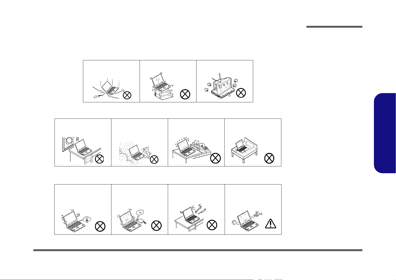
The notebook computer is quite rugged, but it can be damaged. To prevent this, follow these suggestions:
1. Don’t drop it, or expose it to shock. If the computer falls, the case and the components could be damaged.
Preface
Do not expose the computer
to any shock or vibration.
Do not place it on an unstable
surface.
Do not place anything heavy
on the computer.
2. Keep it dry, and don’t overheat it. Keep the computer and power supply away from any kind of heating element. This
is an electrical appliance. If water or any other liquid gets into it, the computer could be badly damaged.
Do not expose it to excessive
heat or direct sunlight.
Do not leave it in a place
where foreign matter or moisture may affect the system.
Don’t use or store the computer in a humid environment.
Do not place the computer on
any surface which will block
the vents.
3. Follow the proper working procedures for the computer. Shut the computer down properly and don’t forget to save
your work. Remember to periodically save your data as data may be lost if the battery is depleted.
Do not turn off the power
until you properly shut down
all programs.
Do not turn off any peripheral
devices when the computer is
on.
Do not disassemble the computer by yourself.
Perform routine maintenance
on your computer.
Preface
V
Page 8
Preface
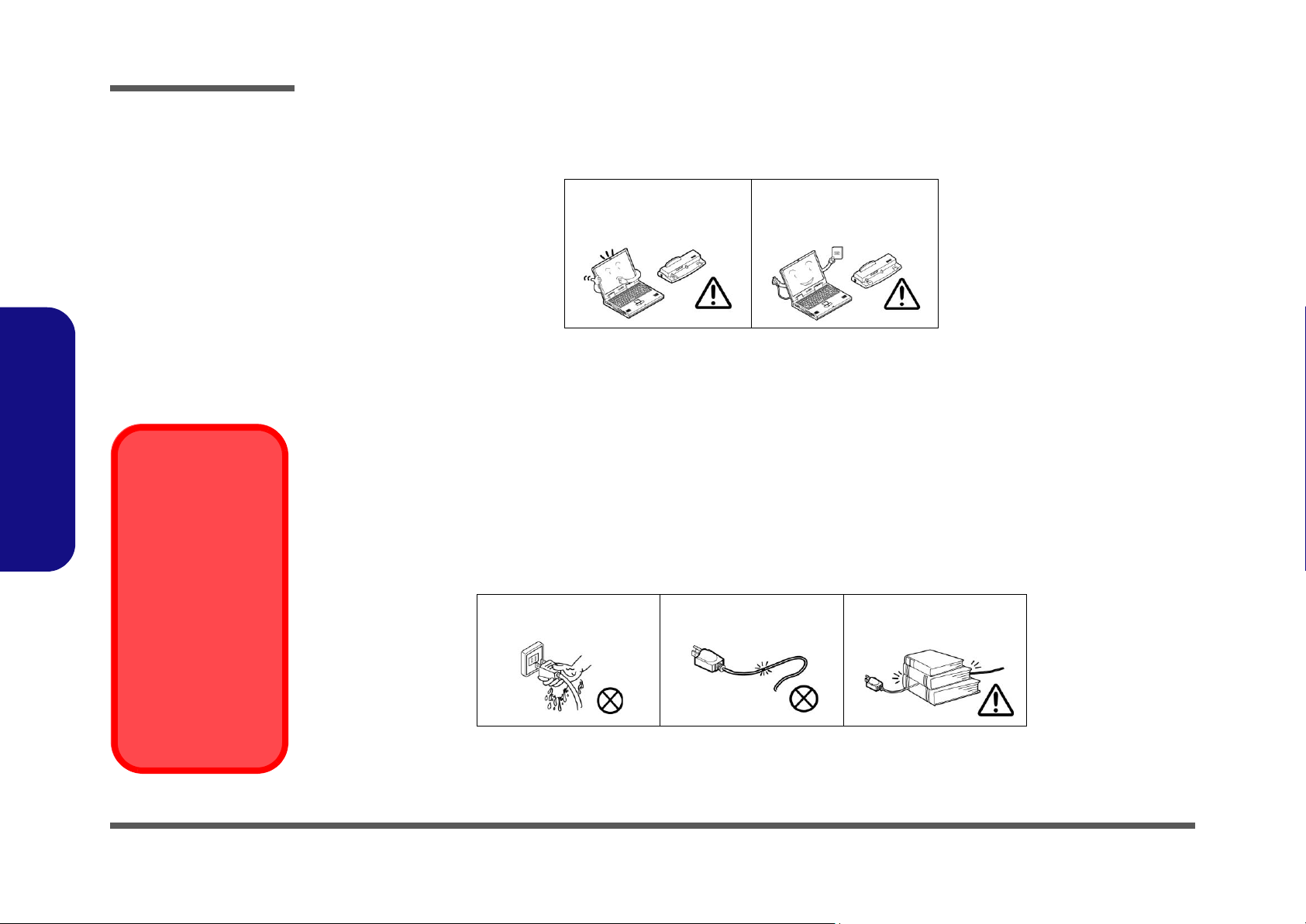
4. Avoid interference. Keep the computer away from high capacity transformers, electric motors, and other strong mag-
netic fields. These can hinder proper performance and damage your data.
5. Take care when using peripheral devices.
Preface
Power Safety
Warning
Before you undertake
any upgrade procedures, make sure that
you have turned off the
power, and disconnected all peripherals
and cables (including
telephone lines). It is
advisable to also remove your battery in
order to prevent accidentally turning the
machine on.
Use only approved brands of
peripherals.
Unplug the power cord before
attaching peripheral devices.
Power Safety
The computer has specific power requirements:
• Only use a power adapter approved for use with this computer.
• Your AC adapter may be designed for international travel but it still requires a steady, uninterrupted power supply. If you are
unsure of your local power specifications, consult your service representative or local power company.
• The power adapter may have either a 2-prong or a 3-prong grounded plug. The third prong is an important safety feature; do
not defeat its purpose. If you do not have access to a compatible outlet, have a qualified electrician install one.
• When you want to unplug the power cord, be sure to disconnect it by the plug head, not by its wire.
• Make sure the socket and any extension cord(s) you use can support the total current load of all the connected devices.
• Before cleaning the computer, make sure it is disconnected from any external power supplies.
Do not plug in the power
cord if you are wet.
Do not use the power cord if
it is broken.
Do not place heavy objects
on the power cord.
VI
Page 9

Battery Precautions
• Only use batteries designed for this computer. The wrong battery type may explode, leak or damage the computer.
• Recharge the batteries using the notebook’s system. Incorrect recharging may make the battery explode.
• Do not try to repair a battery pack. Refer any battery pack repair or replacement to your service representative or qualified service
personnel.
• Keep children away from, and promptly dispose of a damaged battery. Always dispose of batteries carefully. Batteries may explode
or leak if exposed to fire, or improperly handled or discarded.
• Keep the battery away from metal appliances.
• Affix tape to the battery contacts before disposing of the battery.
• Do not touch the battery contacts with your hands or metal objects.
Preface
Battery Disposal
The product that you have purchased contains a rechargeable battery. The battery is recyclable. At the end of
its useful life, under various state and local laws, it may be illegal to dispose of this battery into the municipal
waste stream. Check with your local solid waste officials for details in your area for recycling options or proper
disposal.
Caution
Danger of explosion if battery is incorrectly replaced. Replace only with the same or equivalent type recommended by the manufacturer. Discard used battery according to the manufacturer’s instructions.
Preface
VII
Page 10

Preface
Related Documents
You may also need to consult the following manual for additional information:
User’s Manual on CD
This describes the computer’s features and the procedures for operating the computer and its ROM-based setup program.
It also describes the installation and operation of the utility programs provided with the computer.
Preface
VIII
Page 11

Contents
Preface
Introduction ..............................................1-1
Overview .........................................................................................1-1
System Specifications ................................. 1-2
Processor Types ...............................................................................1-2
Core Logic .......................................................................................1-2
Structure ..........................................................................................1-2
Security ............................................................................................1-2
Memory ...........................................................................................1-2
BIOS ................................................................................................1-2
LCD (Options) .................................................................................1-2
Display ............................................................................................1-2
Device Bay Options ........................................................................1-3
Hard Disk ........................................................................................1-3
PC Card ...........................................................................................1-3
Keyboard .........................................................................................1-3
Pointing Device ............................................................................... 1-3
Audio ...............................................................................................1-3
Interface ...........................................................................................1-3
Communication ...............................................................................1-3
Power Management .........................................................................1-4
Power ...............................................................................................1-4
Indicator ..........................................................................................1-4
Environmental Spec ........................................................................1-4
Physical Dimensions .......................................................................1-4
Weight .............................................................................................1-4
Optional ...........................................................................................1-4
External Locator - Top Views .........................................................1-5
External Locator - Front & Left Side View ....................................1-6
External Locator - Right Side & Rear Views .................................. 1-7
External Locator - Bottom View .................................................... 1-8
Mainboard Overview - Top (Key Parts) ......................................... 1-9
Mainboard Overview - Bottom (Key Parts) ................................. 1-10
Mainboard Overview - Top (Cable Connectors) .......................... 1-11
Mainboard Overview - Bottom (Cable Connectors) ..................... 1-12
Disassembly ...............................................2-1
Overview ......................................................................................... 2-1
Maintenance Tools .......................................................................... 2-2
Connections .................................................................................... 2-2
Maintenance Precautions ................................................................ 2-3
Disassembly Steps .......................................................................... 2-4
Removing the Battery ..................................................................... 2-7
Removing the Bay One Device ...................................................... 2-8
Removing the Hard Disk Drive Assembly ..................................... 2-9
Removing the Bay Two Device .................................................... 2-10
Removing the Keyboard ............................................................... 2-11
Removing the System Memory .................................................... 2-12
Removing the CPU ....................................................................... 2-13
Removing the Modem .................................................................. 2-15
Removing the Wireless LAN ........................................................ 2-16
Removing the Palm Rest .............................................................. 2-17
Removing the Bottom Case .......................................................... 2-18
Removing the Audio "DJ" Module ............................................... 2-20
Removing the HDD Converter Board .......................................... 2-21
Removing the Mainboard ............................................................. 2-22
Removing the DC/DC Board ........................................................ 2-24
Removing the Click Board ........................................................... 2-25
Removing the TouchPad ............................................................... 2-25
Removing the LED Board ............................................................ 2-26
Preface
IX
Page 12

Preface
Removing the Speakers .................................................................2-26
Removing the Inverter ................................................................... 2-27
Removing the LCD Panel .............................................................2-28
Part Lists ..................................................A-1
Part List Illustration Location ........................................................A-2
Top (D500E) ..................................................................................A-3
Bottom (D500E) ............................................................................. A-4
LCD 15” (D500E) .......................................................................... A-5
Card Reader (D500E) .....................................................................A-6
SAMSUNG CD-ROM Drive (D500E) .......................................... A-7
KME CD-RW Drive (D500E) ........................................................ A-8
Combo Drive (D500E) ................................................................... A-9
DVD-ROM Drive (D500E) .......................................................... A-10
Audio DJ (D500E) .......................................................................A-11
HDD (D500E) .............................................................................. A-12
Preface
Floppy Disk Drive (D500E) ......................................................... A-13
Top (D510E) ................................................................................A-14
Bottom (D510E) ........................................................................... A-15
LCD 15” (D510E) ........................................................................A-16
Card Reader (D510E) ...................................................................A-17
SAMSUNG CD-ROM Drive (D510E) ........................................ A-18
KME CD-RW Drive (D510E) ...................................................... A-19
Combo Drive (D510E) ................................................................. A-20
DVD-ROM Drive (D510E) .......................................................... A-21
Audio DJ (D510E) .......................................................................A-22
HDD (D510E) .............................................................................. A-23
Floppy Disk Drive (D510E) ......................................................... A-24
Top (D520E) ................................................................................A-25
Bottom (D520E) ........................................................................... A-26
LCD 15” (D520E) ........................................................................A-27
Card Reader (D520E) ...................................................................A-28
TEAC CD-ROM Drive (D520E) ................................................. A-29
KME CD-RW Drive (D520E) ..................................................... A-30
Combo Drive (D520E) ................................................................ A-31
DVD-ROM Drive (D520E) ......................................................... A-32
Audio DJ (D520E) ....................................................................... A-33
HDD (D520E) .............................................................................. A-34
Floppy Disk Drive (D520E) ........................................................ A-35
Top (D530E) ................................................................................ A-36
Bottom (D530E) .......................................................................... A-37
LCD 15” (D530E) ........................................................................ A-38
Card Reader (D530E) .................................................................. A-39
TEAC CD-ROM Drive (D530E) ................................................. A-40
KME CD-RW Drive (D530E) ..................................................... A-41
Combo Drive (D530E) ................................................................ A-42
DVD-ROM Drive (D530E) ......................................................... A-43
Audio DJ (D530E) ....................................................................... A-44
HDD (D530E) .............................................................................. A-45
Floppy Disk Drive (D530E) ........................................................ A-46
Schematic Diagrams................................. B-1
System Block Diagram ...................................................................B-2
CPU 1 of 2 ......................................................................................B-3
CPU 2 of 2 ......................................................................................B-4
Clock Generator ..............................................................................B-5
GMCH-1 .........................................................................................B-6
GMCH-2 Power ..............................................................................B-7
GMCH-3 DDR ...............................................................................B-8
DIMMA ..........................................................................................B-9
DIMMB ........................................................................................B-10
AGP/ POWER ..............................................................................B-11
GMC-1 ..........................................................................................B-12
GMC-2 ..........................................................................................B-13
X
Page 13

VGA Connector ............................................................................ B-14
ICH5 (1 of 3) ................................................................................ B-15
ICH5 (2 of 3) ................................................................................ B-16
ICH5 (3 of 3) ................................................................................ B-17
HDD/CD-ROM/FDD ................................................................... B-18
PCI 1410 ....................................................................................... B-19
PCI1394 TSB43AB21 .................................................................. B-20
PCI RTL8100C / RTL8110S ........................................................ B-21
LPC Super I/O .............................................................................. B-22
LPC H8 ......................................................................................... B-23
AC'97 Codec ................................................................................ B-24
FAN/MBC/Mini PCI .................................................................... B-25
ACIN; PWR Button ..................................................................... B-26
D/D Conn ..................................................................................... B-27
VCORE ........................................................................................ B-28
System Power 1 ............................................................................ B-29
System Power 2 ............................................................................ B-30
Installing Optional Module .................... C-1
Preface
Preface
Overview ........................................................................................ C-1
Installing a Bluetooth Modem ........................................................ C-2
Installing the 802.11b+g Wireless LAN ........................................ C-3
Installing the 802.11a+b+g Wireless LAN .................................... C-4
XI
Page 14

Preface
Preface
XII
Page 15

1: Introduction
Overview
This manual covers the information you need to service or upgrade the D500E/D510E/D520E/D530E notebook computer. Information about operating the computer (e.g. getting started, and the Setup utility) is in the User’s Manual. Information about drivers (e.g. VGA & audio) is also found in User’s Manual. That manual is shipped with the computer.
Operating systems (e.g. DOS, Windows 9x, Windows NT 4.0, Windows 2000, Windows XP, OS/2 Warp, UNIX, etc.) have
their own manuals as do application software (e.g. word processing and database programs). If you have questions about
those programs, you should consult those manuals.
The D500E/D510E/D520E/D530E notebook is designed to be upgradeable. See “Disassembly” on page 2 - 1 for a detailed description of the upgrade procedures for each specific component. Please note the warning and safety information
indicated by the “” symbol.
The balance of this chapter reviews the computer’s technical specifications and features.
Introduction
1.Introduction
Overview 1 - 1
Page 16
Introduction
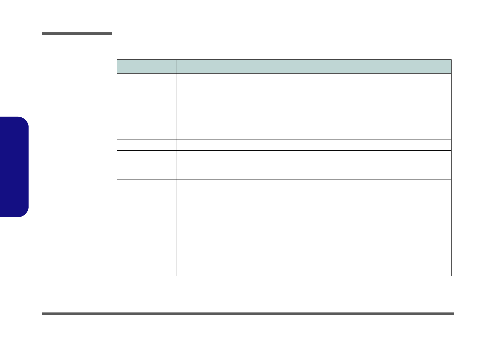
System Specifications
Feature Specification
Processor Types Intel Pentium® 4 Processor (478-pin) m-PGA package
(µ0.13) 0.13 Micron Process Technology, 512KB On-die L2 Cache & 533MHz Front Side Bus - 2.8/ 3.06 GHz
Intel Pentium® 4 Processor (478-pin) m-PGA package
(
µ0.13) 0.13 Micron Process Technology, 512KB On-die L2 Cache & 800MHz Front Side Bus - 2.4/ 2.6/ 2.8/ 3.0/
3.2 GHz
Intel Prescott® Processor (478-pin) m-PGA package
µ0.09) 0.09 Micron Process Technology, 1MB On-die L2 Cache & 800MHz Front Side Bus
(
- 3.2/ 3.4 GHz
Core Logic Intel® 865PE
1.Introduction
1 - 2 System Specifications
Structure PC 2001 Compliant
PCI 2.2 Compliant
Security Security (Kensington® Type) Lock Slot, BIOS Password
Memory Two 200 Pins SODIMM Sockets, supporting DDR 266/ 333/ 400 MHz Modules
Expandable up to 1 GB (128/ 256/ 512MB DDR Modules)
BIOS One 512KB Flash ROM, Phoenix BIOS
LCD (Options) 15.0" - XGA TFT (1024x768)
15.0" - SXGA+ TFT (1400x1050)
Display ATI Mobility Radeon 9700 (M11)
AGP™ 8X
128-bit Memory Interface
2D/3D Graphics Engine
Fully DirectX 9 Compliant Notebook GPU
External Memory up to 128MB DDR SGRAM On Board
TV Encoder
ACPI 2.0 Compliant
15.0" - UXGA TFT (1600x1200)
15.0" - QXGA TFT (2048x1536)
Page 17

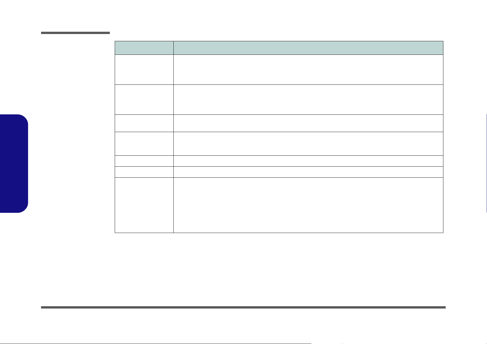
Feature Specification
Introduction
Device Bay Options Bay One
for one of the following interchangeable devices:
3.5" 3-mode FDD
Secondary Battery
Secondary CD Device
Secondary Hard Disk Drive
7-in-1 Card Reader
Hard Disk Easy changeable 2.5" 9.5/12.7 mm (h) Hard Disk Drive
Supports Master mode IDE, PIO mode 4, ATA-33/ 66/ 100/ 133, Ultra ATA Port
PC Card One Type II PCMCIA 3.3V/5V socket supporting CardBus
Keyboard “Win-Key” keyboard
Pointing Device Built-in TouchPad (scrolling key functionality integrated)
Audio AC'97 compliant interface
3D stereo enhanced sound system
Compatible Sound-Blaster PRO™
S/PDIF Digital output (5.1 CH)
Interface Four USB 2.0 ports
One Mini-IEEE 1394 port
One S-Video out port
One parallel port (LPT1)
One infrared transceiver supporting IrDA 1.1/ FIR/SIR/
ASKIR
One external monitor (VGA) port
One PS/2 port
Bay Two
for one of the following interchangeable devices:
CD-ROM
DVD-ROM
Combination DVD-ROM/CD-RW
CD-RW
DVD-RW
1.Introduction
Built-in microphone
2 Built-In Speakers
Audio DJ
One headphone-out jack
One microphone-in jack
One RJ-11 jack for modem
One RJ-45 jack for LAN
One DC-In jack
One S/PDIF out port
3 Built-in hot-key buttons: WWW, E-Mail, & application
Communication 56K Plug & Play Modem (V.90 & V.92 Compliant)
Infrared transfer: 115.2K bps SIR/ 4M bps FIR, IrDA 1.1 compliant
Built-In 10/ 100/ 1000M Fast Ethernet LAN
802.11b or 802.11g or 802.11a+b+g Wireless LAN Module with Mini-PCI Interface (optional)
Bluetooth 1.1 with MDC Interface (optional)
System Specifications 1 - 3
Page 18
Introduction
Feature Specification
1.Introduction
Power Management Supports ACPI v2.0
Supports Standby mode
Supports Hibernate mode
Supports Battery low suspend
Power Full Range AC adapter
AC Input: 100~240V, 50~60Hz
DC Output: 20V, 6.0A
Indicator LED indicators (Power On/ AC-In/ Suspend, Battery Charging/Battery Full, E-Mail, HDD, Num Lock, Caps Lock,
Scroll Lock)
Environmental Spec Temperature
Operating: 5
Non-Operating: -20°C ~ 60°C
Physical Dimensions 329 (w) x 290 (d) x 44 (h) mm
Weight Around 3.7 kg (depend on optional modules included) without battery
Optional Secondary Battery Pack
Secondary Hard Disk Drive
Secondary CD-ROM Drive Module
Secondary DVD-ROM Drive Module
Secondary DVD-ROM and CD-RW Combo Drive
Module
Secondary CD-RW Drive Module
Secondary DVD-RW Drive Module
°C ~ 35°C
Supports resume from alarm time
Supports resume from modem ring
Supports resume from LAN ring
Primary Battery Smart Li-Ion 14.8v, 4400mAh
(removable)
Second Battery Smart Li-Ion 14.8v, 3400mAh
(removable)
Relative Humidity
20% ~ 80%
10% ~ 90%
Software DVD Player
802.11b Wireless LAN Module
802.11g Wireless LAN Module
802.11a+b+g Wireless LAN Module
7-in-1 Card Reader
1 - 4 System Specifications
Page 19
Introduction
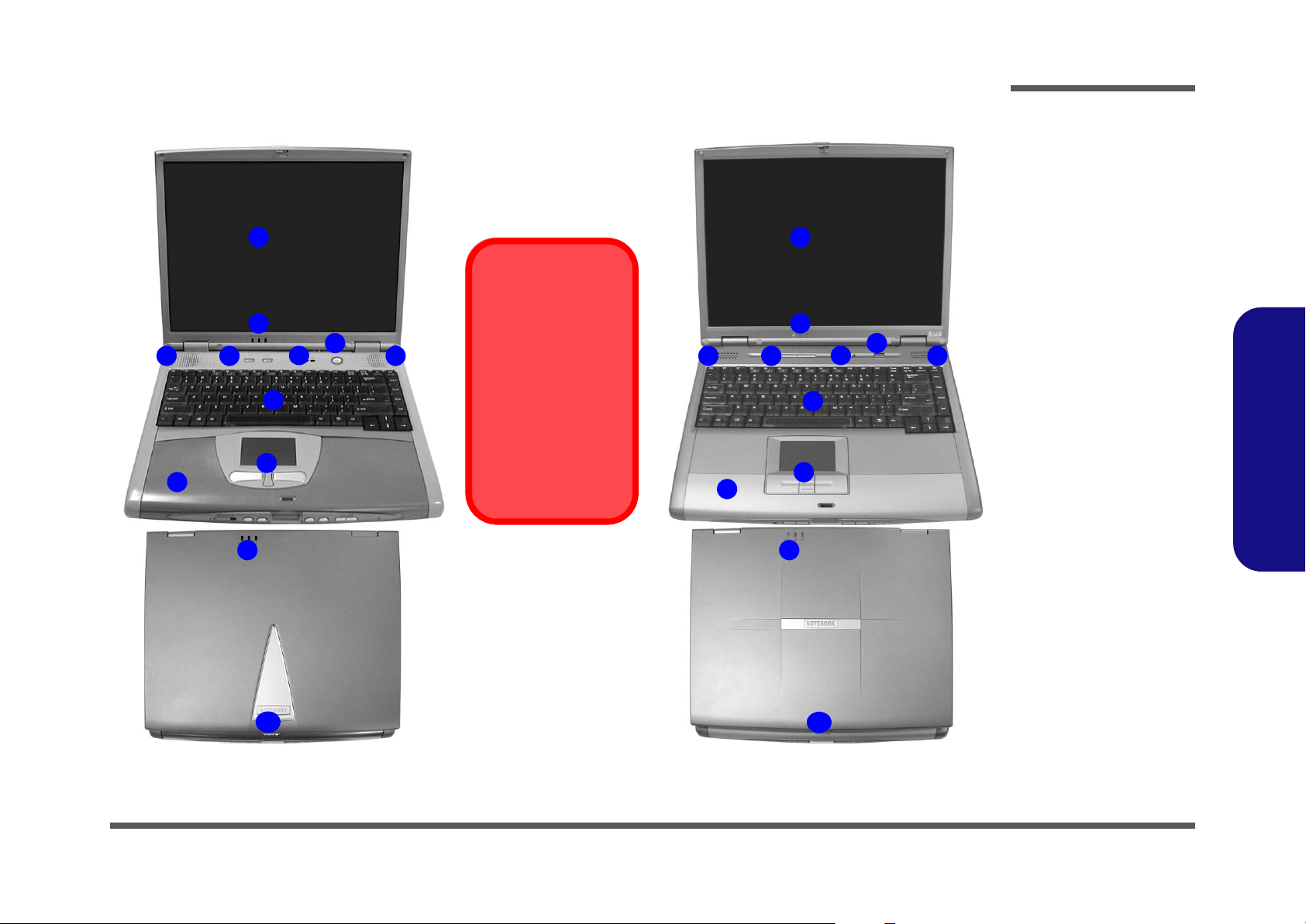
External Locator - Top Views
1
2
6
3 4
9
2
5
7
8
3
Model Differences
This manual refers to
the two notebook models pictured on this
page.
The models vary
slightly in external design. Photographs
used throughout this
manual are of Model A.
3 4
9
Figure 1 - 1
Top Views with
LCD Panel Open
1. LCD
1
2
6
5
7
8
2
3
2. LED Power &
E-Mail Indicators
3. Speakers
4. Hot-Key buttons
5. LED Status
Indicators
6. Power Button
7. Keyboard
8. TouchPad and
Buttons
9. Palm Rest
(Removable)
10. LCD Latch
1.Introduction
10
10
Model A Model B
External Locator - Top Views 1 - 5
Page 20
Introduction
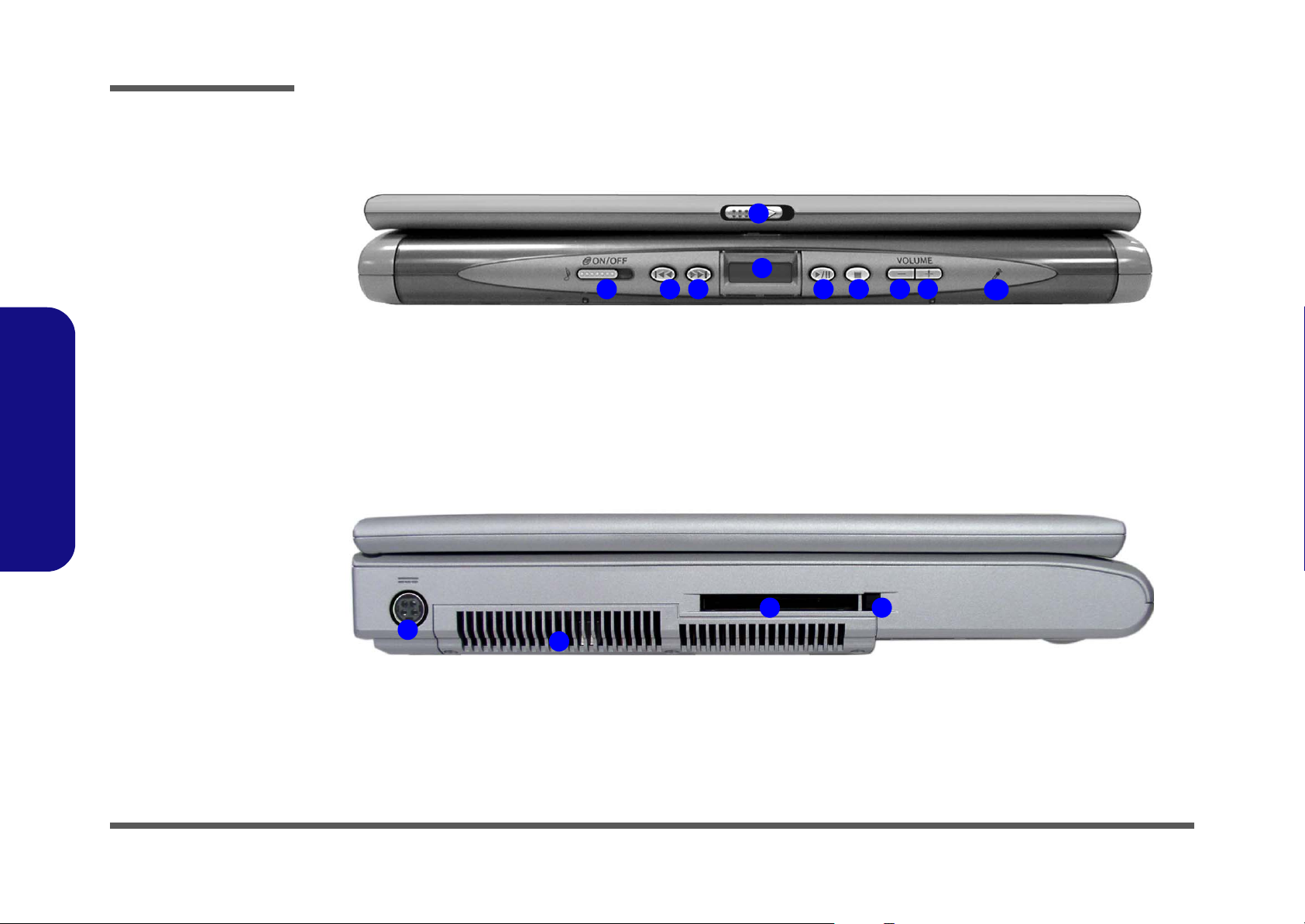
Figure 1 - 2
Front View
1. LCD Latch
2. Audio “DJ” CD
Player Control
Panel On/Off
Switch
3. Previous Track
4. Next Track
5. LCD
6. Play Pause
7. Stop/Eject
8. Volume Down
9. Volume Up
10. Built-In
Microphone
1.Introduction
Figure 1 - 3
Left Side View
External Locator - Front & Left Side View
1
5
2 876
43
9
10
1. DC-In Jack
2. Vent
3. PC Card Slot
4. PC Card Eject
Button
1
1 - 6 External Locator - Front & Left Side View
43
2
Page 21
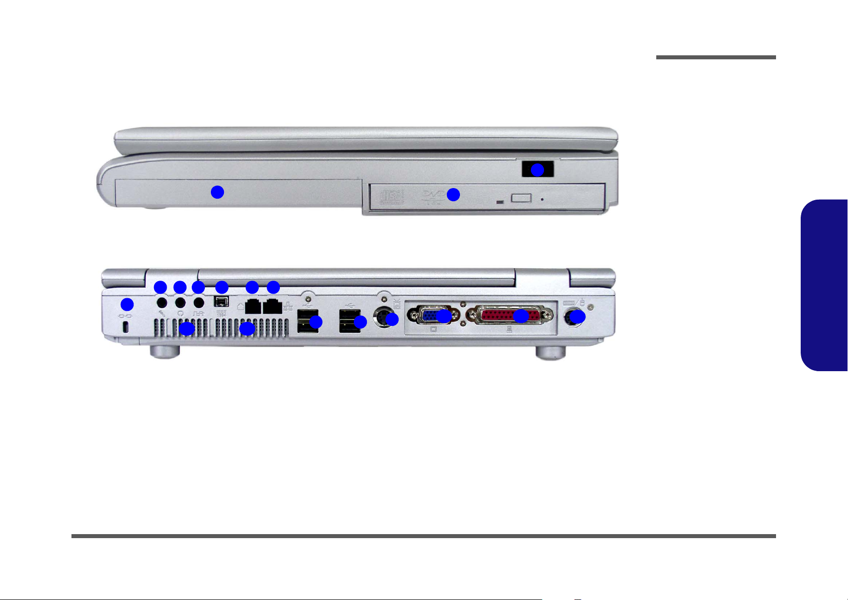
External Locator - Right Side & Rear Views
1
Introduction
Figure 1 - 4
Right Side View
1. Device Bay One
2. Device Bay Two
3
2
3. Infrared
Transceiver
1.Introduction
Figure 1 - 5
Rear View
2 4 6 7
3 5
1
11
12
13
13
8
8
9
10
1. Security Lock
2. Microphone-In
Jack
3. Headphone-Out
Jack
4. S/PDIF Out Port
5. Mini - IEEE 1394
Port
6. RJ-11 Phone
Jack
7. RJ-45 LAN Jack
8. 4 USB Ports
9. S-Video
Connector
10. External Monitor (VGA) Port
11. Parallel Port
12. PS/2 Type Port
13. Vents
External Locator - Right Side & Rear Views 1 - 7
Page 22
Introduction
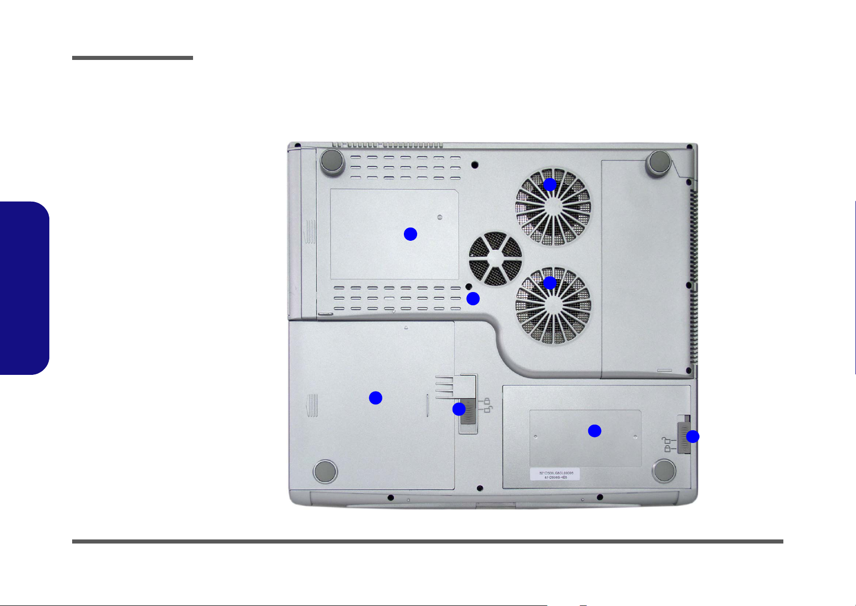
Figure 1 - 6
Bottom View
1. Vent/Fan
Intakes
2. Device Bay One
3. Device Bay One
Release Latch
4. Device Bay Two
5. Device Bay Two
Release Screw
6. Battery
7. Battery Release
Latch
1.Introduction
External Locator - Bottom View
1
4
1
5
1 - 8 External Locator - Bottom View
2
3
6
7
Page 23

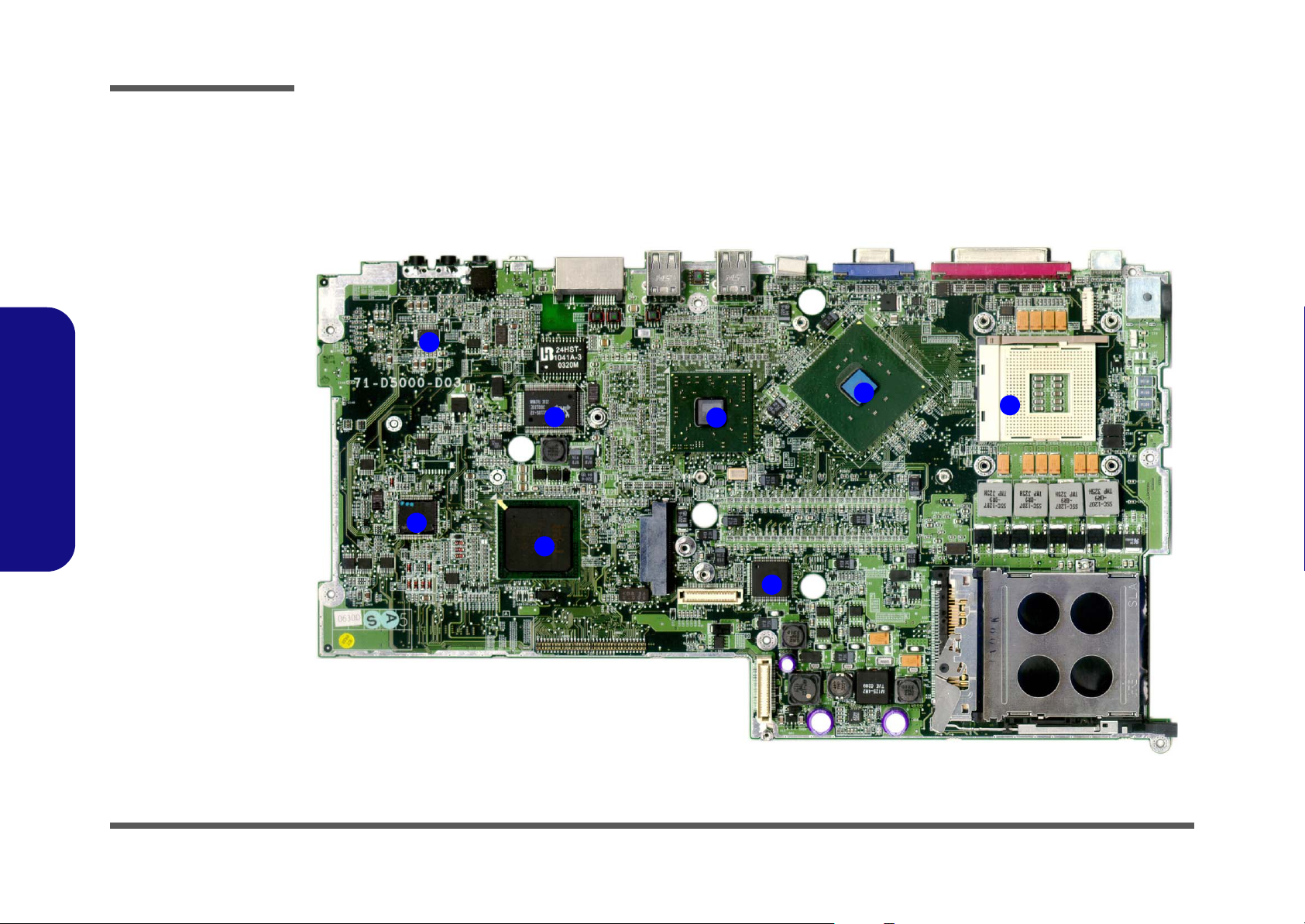
Introduction
Mainboard Overview - Top (Key Parts)
1
Figure 1 - 7
Mainboard
Overview - Top
Key Parts
1. 2 * SO-DIMM
sockets
2. AC’97 Codec
3
4
5
2
3. TI 1394 Controller
4. Flash BIOS ROM
5. Audio DJ
Controller
6. PCI Bus1410
Controller
1.Introduction
6
7
8
Mainboard Overview - Top (Key Parts) 1 - 9
Page 24
Introduction
Figure 1 - 8
Mainboard
Overview - Bottom
Key Parts
1. CPU Socket (no
CPU installed)
2. VGA Chip - ATI
M11
3. LAN Controller RTL8110S-32
4. Super IO
NS87393
5. Southbridge Intel
82801
6. Northbridge Intel
GMCH 865PE
7. H8 Keyboard
Controller
1.Introduction
8. Audio AMP TITPA0132
Mainboard Overview - Bottom (Key Parts)
9
8
7
5
10
3
11
12
2
6
1
1 - 10 Mainboard Overview - Bottom (Key Parts)
4
Page 25
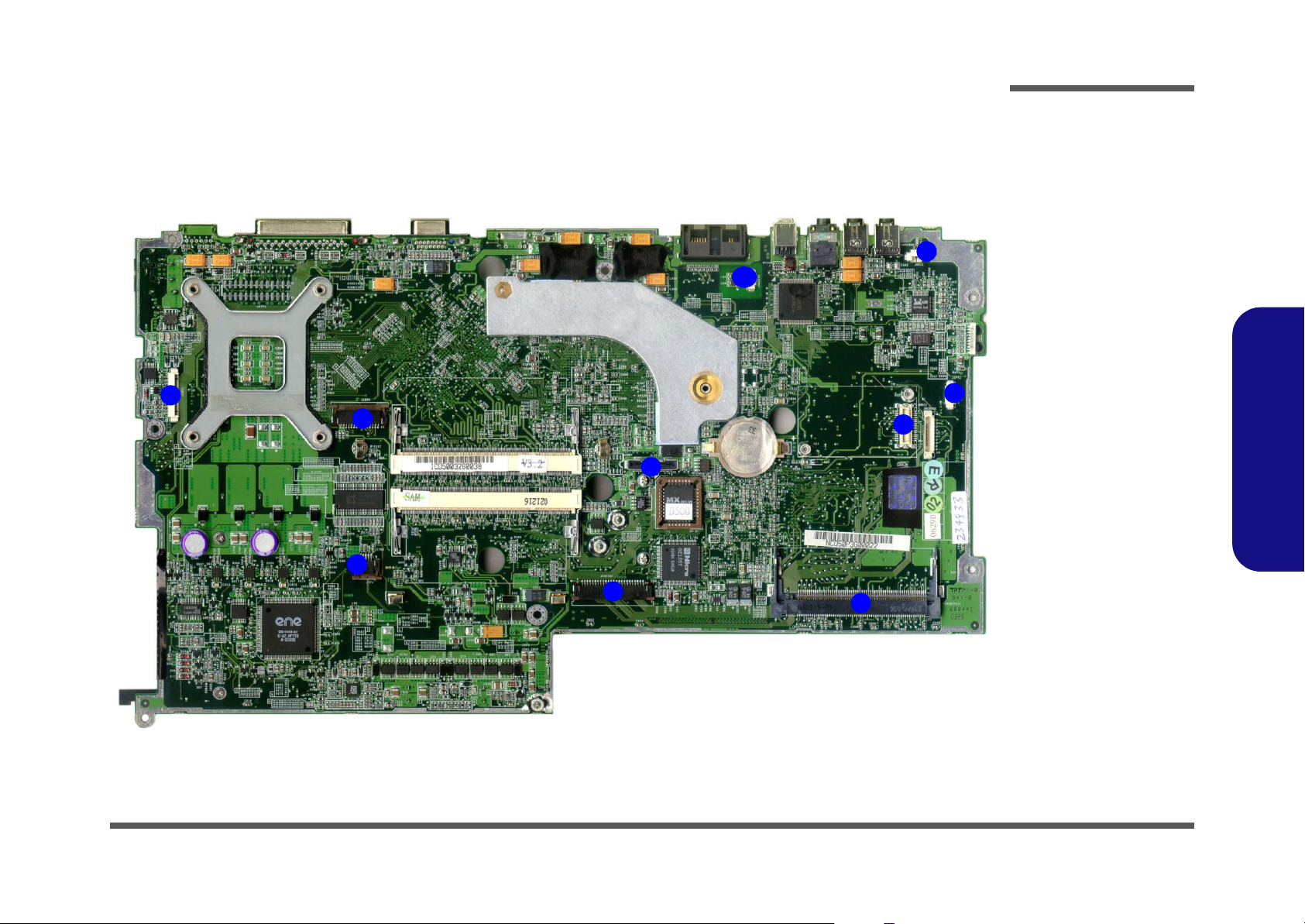
Introduction
Mainboard Overview - Top (Cable Connectors)
7
5
6
2
1
10
Figure 1 - 9
Mainboard
Overview - Top
Cable Connectors
1. JINTKB1 (Key-
8
4
3
9
board Connector)
2. JTP1 (TouchPad
Connector)
3. JMDC1 (Modem
Connector)
4. JSPK1 (Speaker
Connector)
5. JLED1 (LED
Connector)
6. JLCD1 (LCD
Connector)
7. JINV1 (Inverter
Connector)
8. JMIC1
(Microphone
Connector)
9. JMINIPCI1 (MiniPCI Connector)
10.JMODEM1 (RJ11
Connector)
1.Introduction
12
10
11
Mainboard Overview - Top (Cable Connectors) 1 - 11
Page 26
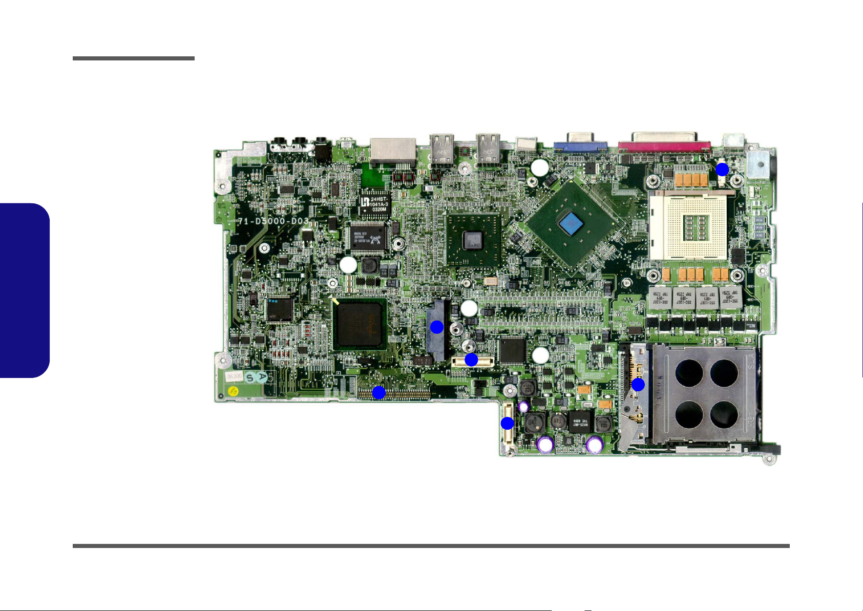
Introduction
Figure 1 - 10
Mainboard
Overview - Bottom
Cable Connectors
1. JHDD1 (Hard
Disk Connector)
2. JFAN1 (Fan
Connector)
3. PCMCIA
Connector
4. JCD1 (Bay Two
Device
Connector)
5. JDD1 (DC/DC
Board Connector)
6. JDD2 (DC/DC
Board Connector)
1.Introduction
Mainboard Overview - Bottom (Cable Connectors)
2
4
5
1
1 - 12 Mainboard Overview - Bottom (Cable Connectors)
3
6
7
Page 27

2: Disassembly
Overview
This chapter provides step-by-step instructions for disassembling parts and subsystems. When it comes to reassembly,
reverse the procedures (unless otherwise indicated).
We suggest you completely review any procedure before you take the computer apart.
Disassembly
Procedures such as upgrading/replacing the RAM, CD device and hard disk are included in the User’s Manual but are
repeated here for your convenience.
To make the disassembly process easier each section may have a box in the page margin. Information contained under
the figure # will give a synopsis of the sequence of procedures involved in the disassembly procedure. A box with a
lists the relevant parts you will have after the disassembly process is complete. Note: The parts listed will be for the disassembly procedure listed ONLY, and not any previous disassembly step(s) required. Refer to the part list for the previous disassembly procedure. The amount of screws you should be left with will be listed here also.
A box with a will provide any possible helpful information. A box with a contains warnings.
An example of these types of boxes are shown in the sidebar.
2.Disassembly
Information
Warning
Overview 2 - 1
Page 28

Disassembly
2.Disassembly
NOTE: All disassembly procedures assume that the system is turned OFF, and disconnected from any power supply (the
battery is removed too).
Maintenance Tools
The following tools are recommended when working on the notebook PC:
• M3 Philips-head screwdriver
• M2.5 Philips-head screwdriver (magnetized)
• M2 Philips-head screwdriver
• Small flat-head screwdriver
• Pair of needle-nose pliers
• Anti-static wrist-strap
Connections
Connections within the computer are one of four types:
Locking collar sockets for ribbon connectors To release these connectors, use a small flat-head screwdriver to
gently pry the locking collar away from its base. When replacing the connection, make sure the connector is oriented in the
same way. The pin1 side is usually not indicated.
2 - 2 Overview
Pressure sockets for multi-wire connectors To release this connector type, grasp it at its head and gently
rock it from side to side as you pull it out. Do not pull on the
wires themselves. When replacing the connection, do not try to
force it. The socket only fits one way.
Pressure sockets for ribbon connectors To release these connectors, use a small pair of needle-nose pli-
ers to gently lift the connector away from its socket. When replacing the connection, make sure the connector is oriented in
the same way. The pin1 side is usually not indicated.
Board-to-board or multi-pin sockets To separate the boards, gently rock them from side to side as
you pull them apart. If the connection is very tight, use a small
flat-head screwdriver - use just enough force to start.
Page 29

Maintenance Precautions
The following precautions are a reminder. To avoid personal injury or damage to the computer while performing a removal and/or replacement job, take the following precautions:
1. Don't drop it. Perform your repairs and/or upgrades on a stable surface. If the computer falls, the case and other
components could be damaged.
2. Don't overheat it. Note the proximity of any heating elements. Keep the computer out of direct sunlight.
3. Avoid interference. Note the proximity of any high capacity transformers, electric motors, and other strong magnetic fields. These can hinder proper performance and damage components and/or data. You should also monitor
the position of magnetized tools (i.e. screwdrivers).
4. Keep it dry. This is an electrical appliance. If water or any other liquid gets into it, the computer could be badly dam-
aged.
5. Be careful with power. Avoid accidental shocks, discharges or explosions.
• Before removing or servicing any part from the computer, turn the computer off and detach any power supplies.
• When you want to unplug the power cord or any cable/wire, be sure to disconnect it by the plug head. Do not pull on the
wire.
6. Peripherals – Turn off and detach any peripherals.
7. Beware of static discharge. ICs, such as the CPU and main support chips, are vulnerable to static electricity.
Before handling any part in the computer, discharge any static electricity inside the computer. When handling a
printed circuit board, do not use gloves or other materials which allow static electricity buildup. We suggest that you
use an anti-static wrist strap instead.
8. Beware of corrosion. As you perform your job, avoid touching any connector leads. Even the cleanest hands produce oils which can attract corrosive elements.
9. Keep your work environment clean. Tobacco smoke, dust or other air-born particulate matter is often attracted to
charged surfaces, reducing performance.
10.Keep track of the components. When removing or replacing any part, be careful not to leave small parts, such as
screws, loose inside the computer.
Disassembly
Power Safety
Warning
Before you undertake
any upgrade procedures, make sure that
you have turned off the
power, and disconnected all peripherals
and cables (including
telephone lines). It is
advisable to also remove your battery in
order to prevent accidentally turning the
machine on.
2.Disassembly
Cleaning
Do not apply cleaner directly to the computer, use a soft clean cloth.
Do not use volatile (petroleum distillates) or abrasive cleaners on any part of the computer.
Overview 2 - 3
Page 30

Disassembly
2.Disassembly
Disassembly Steps
The following table lists the disassembly steps, and on
which page to find the related information. PLEASE
PERFORM THE DISASSEMBLY STEPS IN THE
ORDER INDICATED.
To remove the Battery:
1. Remove the battery page 2 - 7
To remove the Bay One Device:
1. Remove the battery page 2 - 7
2. Remove the Bay One device page 2 - 8
To remove the Hard Disk Drive:
1. Remove the battery page 2 - 7
2. Remove the Bay One device page 2 - 8
3. Remove the hard disk drive assembly page 2 - 9
To remove the Bay Two Device:
1. Remove the battery page 2 - 7
2. Remove the Bay Two device page 2 - 10
To remove the Keyboard:
1. Remove the battery page 2 - 7
2. Remove the keyboard page 2 - 11
To remove the CPU:
1. Remove the battery page 2 - 7
2. Remove the CPU page 2 - 13
To remove the Modem:
1. Remove the battery page 2 - 7
2. Remove the keyboard page 2 - 11
3. Remove the modem page 2 - 15
To remove the Wireless LAN:
1. Remove the battery page 2 - 7
2. Remove the keyboard page 2 - 11
3. Remove the Wireless LAN page 2 - 16
To remove the Palm Rest:
1. Remove the Palm Rest page 2 - 17
To remove the Bottom Case:
1. Remove the battery page 2 - 7
2. Remove the Bay One device page 2 - 8
3. Remove the hard disk drive assembly page 2 - 9
4. Remove the Bay Two device page 2 - 10
5. Remove the keyboard page 2 - 11
6. Remove the CPU page 2 - 13
7. Remove the Palm Rest page 2 - 17
8. Remove the bottom case page 2 - 18
To remove the System Memory:
1. Remove the battery page 2 - 7
2. Remove the keyboard page 2 - 11
3. Remove the memory page 2 - 12
2 - 4 Disassembly Steps
Page 31

Disassembly
To remove the Audio “DJ” Module:
1. Remove the battery page 2 - 7
2. Remove the Bay One device page 2 - 8
3. Remove the hard disk drive assembly page 2 - 9
4. Remove the Bay Two device page 2 - 10
5. Remove the keyboard page 2 - 11
6. Remove the CPU page 2 - 13
7. Remove the Palm Rest page 2 - 17
8. Remove the bottom case page 2 - 18
9. Remove the Audio “DJ” module page 2 - 20
To remove the HDD Converter Board:
1. Remove the battery page 2 - 7
2. Remove the Bay One device page 2 - 8
3. Remove the hard disk drive assembly page 2 - 9
4. Remove the Bay Two device page 2 - 10
5. Remove the keyboard page 2 - 11
6. Remove the CPU page 2 - 13
7. Remove the Palm Rest page 2 - 17
8. Remove the bottom case page 2 - 18
9. Remove the Audio “DJ” module page 2 - 20
10. Remove the HDD converter board page 2 - 21
To remove the Mainboard:
1. Remove the battery page 2 - 7
2. Remove the Bay One device page 2 - 8
3. Remove the hard disk drive assembly page 2 - 9
4. Remove the Bay Two device page 2 - 10
5. Remove the keyboard page 2 - 11
6. Remove the CPU page 2 - 13
7. Remove the Palm Rest page 2 - 17
8. Remove the bottom case page 2 - 18
9. Remove the Audio “DJ” module page 2 - 20
10. Remove the HDD converter board page 2 - 21
11. Remove the mainboard page 2 - 22
To remove the DC/DC Board:
1. Remove the battery page 2 - 7
2. Remove the Bay One device page 2 - 8
3. Remove the hard disk drive assembly page 2 - 9
4. Remove the Bay Two device page 2 - 10
5. Remove the keyboard page 2 - 11
6. Remove the CPU page 2 - 13
7. Remove the Palm Rest page 2 - 17
8. Remove the bottom case page 2 - 18
9. Remove the Audio “DJ” module page 2 - 20
10. Remove the HDD converter board page 2 - 21
11. Remove the mainboard page 2 - 22
12. Remove the DC/DC board page 2 - 24
To remove the Click Board:
1. Remove the battery page 2 - 7
2. Remove the Bay One device page 2 - 8
3. Remove the hard disk drive assembly page 2 - 9
4. Remove the Bay Two device page 2 - 10
5. Remove the keyboard page 2 - 11
6. Remove the CPU page 2 - 13
7. Remove the Palm Rest page 2 - 17
8. Remove the bottom case page 2 - 18
9. Remove the Click Board page 2 - 25
2.Disassembly
Disassembly Steps 2 - 5
Page 32

Disassembly
2.Disassembly
To remove the TouchPad:
1. Remove the battery page 2 - 7
2. Remove the Bay One device page 2 - 8
3. Remove the hard disk drive assembly page 2 - 9
4. Remove the Bay Two device page 2 - 10
5. Remove the keyboard page 2 - 11
6. Remove the CPU page 2 - 13
7. Remove the Palm Rest page 2 - 17
8. Remove the bottom case page 2 - 18
9. Remove the TouchPad page 2 - 25
To remove the LED Board:
1. Remove the battery page 2 - 7
2. Remove the Bay One device page 2 - 8
3. Remove the hard disk drive assembly page 2 - 9
4. Remove the Bay Two device page 2 - 10
5. Remove the keyboard page 2 - 11
6. Remove the CPU page 2 - 13
7. Remove the Palm Rest page 2 - 17
8. Remove the bottom case page 2 - 18
9. Remove the LED board page 2 - 26
To remove the Inverter:
1. Remove the battery page 2 - 7
2. Remove the Bay One device page 2 - 8
3. Remove the hard disk drive assembly page 2 - 9
4. Remove the Bay Two device page 2 - 10
5. Remove the keyboard page 2 - 11
6. Remove the CPU page 2 - 13
7. Remove the Palm Rest page 2 - 17
8. Remove the bottom case page 2 - 18
9. Remove the inverter page 2 - 27
To remove the LCD panel:
1. Remove the battery page 2 - 7
2. Remove the Bay One device page 2 - 8
3. Remove the hard disk drive assembly page 2 - 9
4. Remove the Bay Two device page 2 - 10
5. Remove the keyboard page 2 - 11
6. Remove the CPU page 2 - 13
7. Remove the Palm Rest page 2 - 17
8. Remove the bottom case page 2 - 18
9. Remove the LCD Panel page 2 - 28
To remove the Speakers:
1. Remove the battery page 2 - 7
2. Remove the Bay One device page 2 - 8
3. Remove the hard disk drive assembly page 2 - 9
4. Remove the Bay Two device page 2 - 10
5. Remove the keyboard page 2 - 11
6. Remove the CPU page 2 - 13
7. Remove the Palm Rest page 2 - 17
8. Remove the bottom case page 2 - 18
9. Remove the speakers page 2 - 26
2 - 6 Disassembly Steps
Page 33

Disassembly
Removing the Battery
1. Turn the computer OFF and turn it over to locate the battery release latch (Figure 2 - 1a).
2. Slide the battery release latch towards the unlock symbol.
3. The battery will pop-up and can be lifted out of the computer.
a.
2
b.
1
c.
1
Figure 2 - 1
Battery Removal
Sequence
a. Slide the battery re-
lease latch to the
unlock position.
b. The battery will pop-
up.
c. Remove the battery.
2.Disassembly
2
2. Battery
Removing the Battery 2 - 7
Page 34

Disassembly
Figure 2 - 2
Bay One Device
Removal
Sequence
a. Slide the release
latch to the unlock
position and hold it
in position.
b. Partially slide the
device out partially.
c. Lift the device up
and out of the computer.
2.Disassembly
Removing the Bay One Device
1. Turn the computer OFF.
2. Place the computer on a clean, stable surface and turn it over.
3. Locate the release latch (Figure 2 - 2a) for the Bay One device.
4. Slide the release latch towards the unlock symbol and hold it in position.
5. With the release latch held in position, slide the device out slightly, then lift it up and out of the computer.
a. b.
c.
1
1
2. Bay One Device
2 - 8 Removing the Bay One Device
2
Page 35

Disassembly
Removing the Hard Disk Drive Assembly
1. Turn the computer OFF and turn it over.
2. Remove the device in Bay One (see “Removing the Bay One Device” on page 2 - 8).
3. Remove screw (Figure 2 - 3a).
4. Slide the HDD assembly forward, then lift it up out of the computer.
5. Remove screws - (Figure 2 - 3e) from the assembly, and slide the hard disk out of the case .
.
a. b.
1
d.
1
2 5 7 6
c.
e.
7
Figure 2 - 3
Hard Disk
Removal
Sequence
a. Remove the HDD
assembly screw.
b. Slide the HDD as-
sembly in the direction of the arrow.
c. Lift the HDD assem-
bly up.
d. Lift the HDD assem-
bly out of the computer.
e. Remove the screws
and separate the
HDD from the case.
2.Disassembly
2
3
6
4
5
Removing the Hard Disk Drive Assembly 2 - 9
6. HDD case
7. HDD
•5 Screws
Page 36

Disassembly
Figure 2 - 4
Bay Two Device
Removal
Sequence
a. Remove the screw
from point .
b. Apply pressure to
2
point to slide the
device out of the
bay.
2.Disassembly
Removing the Bay Two Device
1. Turn OFF the computer.
2. Turn the computer over.
3. Remove screw (Figure 2 - 4a).
4. Apply gentle but firm pressure at point (Figure 2 - 4b), and slide the device out of the computer.
1
a.
1
2
b.
1
c.
2
3. Bay Two device
•1 Screw
2 - 10 Removing the Bay Two Device
3
Page 37

Disassembly
Removing the Keyboard
1. Turn OFF the computer.
2. Press the two keyboard latches at the top of the keyboard as in Figure 2 - 5a (you may need to use a small screw-
driver to do this). The keyboard will then pop-up and can be lifted out of the computer
3. Carefully lift the keyboard up and out, being careful not to bend the keyboard ribbon cable (Figure 2 - 5b).
4. Disconnect the keyboard ribbon cable from the locking collar socket (Figure 2 - 5b).
a.
1 2
c.
b.
3
3
Figure 2 - 5
Keyboard
Removal
Sequence
a. Press the two latch-
es to release the
keyboard.
b. Lift the keyboard out
and disconnect the
cable from the locking collar.
2.Disassembly
Re-Inserting the Key-
board
When re-inserting the
keyboard firstly align
the five keyboard tabs
(Figure 2 - 5c) at the
bottom of the keyboard
with the slots in the
case.
4
Keyboard Tabs
4. Keyboard
Removing the Keyboard 2 - 11
Page 38

Disassembly
Figure 2 - 6
Memory Removal
Sequence
a. Remove the screws
from the shielding
plate.
b. Remove the shield-
ing plate.
c. Pull the latch(es) on
the memory sockets
to release the module(s).
d. When the module
pops up, lift it out.
1. Shielding plate
10. Memory module(s)
2.Disassembly
•4 Screws
Contact Warning
Removing the System Memory
1. Remove the keyboard (page 2 - 11).
2. Remove screws - (Figure 2 - 6a) from the shielding plate, and lift the plate up off the computer.
3. Locate the memory sockets and (Figure 2 - 6c), and gently pull latches and (Figure 2 - 6c) on the
memory socket toward the sides of the computer as indicated in Figure 2 - 6c.
4. The module (Figure 2 - 6d) will pop-up, and you can remove it.
5. Insert a new module holding it at about a 30° angle and fit the connectors firmly into the memory slot.
a.
c.
2 5 1
6 7 8 9
10
5
b.
4
2
3
8 9
1
Be careful not to touch
the metal pins on the
module’s connecting
edge. Even the cleanest hands have oils
which can attract particles, and degrade the
module’s performance.
2 - 12 Removing the System Memory
6
7
8 9
d.
10
Page 39

Disassembly
Removing the CPU
1. Turn OFF the computer and turn it over.
2. Remove the screws - (Figure 2 - 7a) from the CPU cover, and remove the CPU cover .
3. Remove the four screws from the heat sink in order - as indicated (Figure 2 - 8).
1 3 4
b.a.
1
4
2
3
5 8
Caution
The heat sink, and
CPU area in general,
contains parts which
are subject to high
temperatures - Please
allow the area time to
cool before removing
these parts.
8
6
75
When inserting a new
or replacement CPU,
make sure you insert
the screws in the
same order indicated
in Figure 2 - 8.
Reassembly Screw
Order
Figure 2 - 7
Processor
Removal
Sequence
a. Remove the three
screws and the CPU
cover.
b. Remove the CPU
cover.
4
2.Disassembly
Figure 2 - 8
Processor
Removal
Sequence
(cont’d)
Remove the four
screws from the
heat sink in the or-
der indicated.
4. CPU cover
•7 Screws
Removing the CPU 2 - 13
Page 40

Disassembly
Figure 2 - 9
Processor
Removal
Sequence
(cont’d)
a. Pull the heat sink
unit upwards.
b. Remove the heat
sink from the computer.
c. Unlock the cpu and
remove it.
2.Disassembly
4. Carefully pull the heat sink upward using the label at point (Figure 2 - 9a).
5. Remove the heat sink (Figure 2 - 9b) from the computer.
6. Unlock the processor by raising lever (Figure 2 - 9c) to the fully vertical position, and carefully lift the proces-
4
sor off the socket.
a.
1 2
1
3
b.
2
1
1
c.
3
4
1. Heat sink
4. CPU
2 - 14 Removing the CPU
4
Page 41

Disassembly
Removing the Modem
1. Remove the keyboard (page 2 - 11) and shielding plate (page 2 - 12).
2. Remove screws - and carefully lift the modem up off the mainboard (Figure 2 - 10).
3. Disconnect the modem cable from the modem module.
4. When replacing the standard MDC modem module with a Bluetooth modem combo module, see “Installing a
Bluetooth Modem” on page C - 2.
1 2 3
4
2
3
1
4
Figure 2 - 10
Modem Removal
Sequence
Remove the screws,
lift the modem off
the mainboard, and
disconnect the cable.
Note: Disregard the
two antenna cables
if the computer has
no wireless LAN
module. If the computer has a wireless
LAN module, the
two antenna cables
should be connected to the wireless
LAN module - see
“Wireless LAN
Module Removal
Sequence” on
page 2 - 16.
2.Disassembly
3. Modem
•2 Screws
Removing the Modem 2 - 15
Page 42

Disassembly
Figure 2 - 11
Wireless LAN
Module Removal
Sequence
Pull the latches, lift
the module off the
mainboard, and disconnect the cables.
Removing the Wireless LAN
1. Remove the keyboard (page 2 - 11) and shielding plate (page 2 - 12).
2. Gently pull latches & in the direction of the arrows (Figure 2 - 11) and the module will pop-up.
3. For computers with standard modem., disconnect the two antenna cables & (shorter cable “MAIN/ J1” socket
and longer cable “AUX/ J2” socket) and carefully remove the wireless LAN module .
4. For computers with Bluetooth modem combo, reverse the installation procedure of the wireless LAN (see “Install-
ing the 802.11b+g Wireless LAN” on page C - 3 or “Installing the 802.11a+b+g Wireless LAN” on page C - 4).
1 2
3 4
5
3
4
2.Disassembly
5. Wireless LAN
module
2 - 16 Removing the Wireless LAN
1
2
5
Page 43

Removing the Palm Rest
Disassembly
1. With the computer shut down and on a level surface, raise the LCD cover.
2. Remove the palm rest by applying gentle upward pressure with your fingers close to the area around the left Alt
key, and the right Ctrl key (Figure 2 - 12).
3. To replace the palm rest , slide it back in to place, and then apply slight downward pressure to points and
1 2 3
in order to snap it gently back down.
2
1
3
Figure 2 - 12
Palm Rest
Removal
Sequence
Apply gentle upward
pressure with your
fingers close to the
area indicated, and
lift the palm rest up.
2.Disassembly
1. Palm Rest
Removing the Palm Rest 2 - 17
Page 44

Disassembly
Figure 2 - 13
Bottom Case
Removal
Sequence
Remove the 15
screws from the bottom of the case.
2.Disassembly
Removing the Bottom Case
1. Remove the battery (page 2 - 7), bay one device (page 2 - 8), hard disk assembly (page 2 - 9), bay two device (page
2 - 10), keyboard (page 2 - 11), shielding plate (page 2 - 12), CPU (page 2 - 13) and palm rest (page 2 - 17).
2. Turn the computer over and remove screws - (Figure 2 - 13).
4
3
2
1
15
5
6
7
•15 Screws
2 - 18 Removing the Bottom Case
14 15
8
13
1
12
11
10
9
Page 45

Disassembly
3. Turn the computer around and remove screws - (Figure 2 - 14) from the rear of the computer.
1
4. Disconnect the inverter cable , touchpad cable , LED cable , LCD cable , Wireless LAN module (if
included) speaker cable (Figure 2 - 15).
1 2 3 4 5
6
5. Carefully lift the LCD and top case assembly off the bottom case assembly .
1 6
2
7 8
3
4
5
6
b.
a.
1
6
3
4
5
2
Figure 2 - 14
Bottom Case
Removal
Sequence
(cont’d)
Remove the six
screws from the rear
of the computer.
2.Disassembly
Figure 2 - 15
Bottom Case
Removal
Sequence
(cont’d)
a. Remove the cables
connected to the
mainboard.
b. Lift the LCD and top
case off the bottom
case.
7
8
7. LCD & Top Case
8. Bottom Case
•6 Screws
Removing the Bottom Case 2 - 19
Page 46

Disassembly
Figure 2 - 16
Audio "DJ"
Module Removal
Sequence
a. Disconnect the mi-
crophone and Audio
"DJ" cables.
b. Remove the mod-
ule.
c. Remove the 4
screws to separate
the board, module
and power button.
2.Disassembly
Removing the Audio "DJ" Module
1. Remove the battery (page 2 - 7), bay one device (page 2 - 8), hard disk assembly (page 2 - 9), bay two device (page
2 - 10), keyboard (page 2 - 11), shielding plate (page 2 - 12), CPU (page 2 - 13), palm rest (page 2 - 17) and bottom
case (page 2 - 18).
2. When the top and bottom case assemblies are separated, the Audio "DJ" module will be visible.
3. Disconnect the microphone cable , the Audio "DJ" cable , then carefully remove the Audio "DJ" module
(Figure 2 - 16b).
4. Remove screws - from the back of the Audio "DJ" board in order to separate the board from the module
3 9
and power button (Figure 2 - 16c).
4 7 8
a. b.
1 2 3
1
1
1. Microphone Cable
2. Audio "DJ" Cable
3. Audio "DJ" Module
8. Audio "DJ" Board
9. Power Button
c.
5
4
•4 Screws
2 - 20 Removing the Audio "DJ" Module
2
7
6
8
9
3
Page 47

Disassembly
Removing the HDD Converter Board
1. Remove the battery (page 2 - 7), bay one device (page 2 - 8), hard disk assembly (page 2 - 9), bay two device (page
2 - 10), keyboard (page 2 - 11), shielding plate (page 2 - 12), CPU (page 2 - 13), palm rest (page 2 - 17), bottom
case (page 2 - 18) and Audio “DJ” module (page 2 - 20).
2. Remove screws - from the cover and HDD converter board (Figure 2 - 17a).
3. Carefully lift the cover and HDD converter board away from the mainboard (be careful not to bend the pins
in the HDD converter board when removing and inserting it).
a. b.
1 4
5 6
4
2
3
1
Figure 2 - 17
HDD Converter
Board Removal
Sequence
a. Remove the screws.
b. Remove the cover
and HDD converter
board.
2.Disassembly
5
6
5. Cover
6. HDD converter
board
•4 Screws
Removing the HDD Converter Board 2 - 21
Page 48

Disassembly
Figure 2 - 18
Mainboard
Removal
Sequence
a. Remove the screws.
2.Disassembly
Removing the Mainboard
1. Remove the battery (page 2 - 7), bay one device (page 2 - 8), hard disk assembly (page 2 - 9), bay two device (page
2 - 10), keyboard (page 2 - 11), shielding plate (page 2 - 12), CPU (page 2 - 13), palm rest (page 2 - 17), bottom
case (page 2 - 18), Audio “DJ” module (page 2 - 20) and HDD converter board (page 2 - 21).
2. Remove screws - from the mainboard (Figure 2 - 18).
1 4
2
•4 Screws
2 - 22 Removing the Mainboard
3
1
4
Page 49

Disassembly
3. Separate the system fan cable from the mainboard .
4. Lift the mainboard and DC/DC board out of the bottom case (Figure 2 - 19a).
3 1
4 2
a.
3
1
2
4
b.
Figure 2 - 19
Mainboard
Removal
Sequence
(cont’d)
a. Separate the sys-
tem fan cable.
b. Lift the mainboard
assembly out of the
bottom case.
2.Disassembly
1
1. Mainboard
2. Bottom case
3. System fan cable
4
Removing the Mainboard 2 - 23
4. DC/DC board
Page 50

Disassembly
Removing the DC/DC Board
Figure 2 - 20
DC/DC Board
Removal
Sequence
a. Remove screws
2
- .
b. Separate the main-
board from the DC/
DC board.
2.Disassembly
1. Remove the battery (page 2 - 7), bay one device (page 2 - 8), hard disk assembly (page 2 - 9), bay two device (page
2 - 10), keyboard (page 2 - 11), shielding plate (page 2 - 12), CPU (page 2 - 13), palm rest (page 2 - 17), bottom
case (page 2 - 18), Audio “DJ” module (page 2 - 20), HDD converter board (page 2 - 21) and mainboard (page 2 -
22).
2. Turn the mainboard over and remove screws - (Figure 2 - 20a).
1
3. Carefully separate the DC/DC board from the mainboard (Figure 2 - 20b).
3 4
1 2
a. b.
4
1
2
3
3. DC/DC board
4. Mainboard
2 - 24 Removing the DC/DC Board
3
3
Page 51

Disassembly
Removing the Click Board
1. Remove the battery (page 2 - 7), bay one device (page 2 - 8), hard disk assembly (page 2 - 9), bay two device (page
2 - 10), keyboard & shielding plate (page 2 - 11), CPU (page 2 - 13), palm rest (page 2 - 17) and bottom case (page
2 - 18).
2. Turn the top case assembly over and remove screws - , and disconnect cable (Figure 2 - 21a).
3. Lift the click board off the top case assembly (Figure 2 - 21b).
6
1 4 5
a. b.
5
1 4
2
3
6
Removing the TouchPad
1. Remove the battery (page 2 - 7), bay one device (page 2 - 8), hard disk assembly (page 2 - 9), bay two device (page
2 - 10), keyboard & shielding plate (page 2 - 11), CPU (page 2 - 13), palm rest (page 2 - 17) and bottom case (page
2 - 18).
2. Turn the top case assembly over and remove screws - , and disconnect cable (Figure 2 - 22a).
3. Lift the TouchPad and bracket off the top case assembly (Figure 2 - 22b).
6 7
a.
1 4 5
b.
21
Figure 2 - 21
Click Board
Removal
Sequence
a. Remove the screws
and disconnect the
cable.
b. Lift the click board
off the top case assembly.
6. Click board
•4 Screws
Figure 2 - 22
TouchPad
Removal
Sequence
a. Remove the screws
and disconnect the
cable.
b. Lift the TouchPad
and bracket off the
top case assembly.
2.Disassembly
4 3
5
6. TouchPad
7. Bracket
6 7
•4 Screws
Removing the Click Board 2 - 25
Page 52

Disassembly
Figure 2 - 23
LED Board
Removal
Sequence
a. Remove the screws.
b. Lift the LED board
off the top case assembly.
6. LED board
•5 Screws
2.Disassembly
Figure 2 - 24
Speakers
Removal
Sequence
a. Remove the screws.
b. Lift the speakers off
the top case assembly.
Removing the LED Board
1. Remove the battery (page 2 - 7), bay one device (page 2 - 8), hard disk assembly (page 2 - 9), bay two device (page
2 - 10), keyboard (page 2 - 11), shielding plate (page 2 - 12), CPU (page 2 - 13), palm rest (page 2 - 17) and bottom
case (page 2 - 18).
2. Turn the top case assembly over and remove screws - from the LED board (Figure 2 - 23a).
3. Lift the LED board off the top case assembly (Figure 2 - 23b).
6
a.
2
1
1 5
5
43
b.
6
Removing the Speakers
1. Remove the battery (page 2 - 7), bay one device (page 2 - 8), hard disk assembly (page 2 - 9), bay two device (page
2 - 10), keyboard (page 2 - 11), shielding plate (page 2 - 12), CPU (page 2 - 13), palm rest (page 2 - 17), bottom
case (page 2 - 18) and LED board (above).
2. Remove screws - from the speakers (Figure 2 - 24a).
3. Carefully lift the speakers off the top case assembly (Figure 2 - 24b).
1 4
a.
5
2
1
3
4
5. Speakers
•4 Screws
2 - 26 Removing the LED Board
b.
5
5
Page 53

Disassembly
Removing the Inverter
1. Remove the battery (page 2 - 7), bay one device (page 2 - 8), hard disk assembly (page 2 - 9), bay two device (page
2 - 10), keyboard (page 2 - 11), shielding plate (page 2 - 12), CPU (page 2 - 13), palm rest (page 2 - 17) and bottom
case (page 2 - 18).
2. Remove the rubber covers and screws - from the LCD (Figure 2 - 25a).
3. Run your finger around the middle of the frame to carefully unsnap the LCD front panel module from the back
(Figure 2 - 25b).
4. Remove screw from the inverter, lift to disconnect cables & from the rear of the inverter (Figure 2 - 25c).
5. Remove the inverter off the LCD assembly (Figure 2 - 25d).
8 9
11
a. b.
1
1 6
7
10
2
7
Figure 2 - 25
LCD Removal
Sequence
a. Remove the screws.
b. Unsnap the LCD
front panel from the
back.
c. Remove the screw
from the inverter.
d. Disconnect the ca-
bles and remove the
inverter.
2.Disassembly
c.
6
5
4
3
d.
8
9
10
11
Removing the Inverter 2 - 27
7. LCD Front Panel
11. Inverter
•7 Screws
Page 54

Disassembly
Figure 2 - 26
LCD Removal
Sequence
a. Remove the screws.
b. Lift the panel off the
assembly and remove the screws to
release the brackets.
2.Disassembly
Removing the LCD Panel
1. Remove the battery (page 2 - 7), bay one device (page 2 - 8), hard disk assembly (page 2 - 9), bay two device (page
2 - 10), keyboard (page 2 - 11), shielding plate (page 2 - 12), CPU (page 2 - 13), palm rest (page 2 - 17), bottom
case (page 2 - 18) and inverter (page 2 - 27).
2. Remove screws - and lift the LCD panel off the top assembly (Figure 2 - 26a).
3. Remove screws - to separate the LCD panel from the brackets (Figure 2 - 25b).
1 8 9
10 17 18
a.
9
7
6
8
21
4
3
5
9. LCD Panel
18. 2 * Brackets
•16 Screws
2-28
b.
13
12
11
10
18
14
15
9
18
16
17
Page 55

Appendix A: Part Lists
This appendix breaks down the notebook PC’s construction into a series of illustrations. The component part numbers
are indicated in the tables opposite the drawings.
Note: This section indicates the manufacturer’s part numbers. Your organization may use a different system, so be sure
to cross-check any relevant documentation.
Note: Some assemblies may have parts in common (especially screws). However, the part lists DO NOT indicate the
total number of duplicated parts used.
Part Lists
Note: Be sure to check any update notices. The parts shown in these illustrations are appropriate for the system at the
time of publication. Over the product life, some parts may be improved or re-configured, resulting in new part numbers.
Part Lists
A-1
Page 56

Part Lists
Part List Illustration
Part Lists
Part List Illustration Location
The following table indicates where to find the appropriate part list illustration.
Table A - 1
Part D500E D510E D520E D530E
Location
Top page A - 3 page A - 14 page A - 25 page A - 36
Bottom page A - 4 page A - 15 page A - 26 page A - 37
LCD 15” page A - 5 page A - 16 page A - 27 page A - 38
Card Reader page A - 6 page A - 17 page A - 28 page A - 39
CD-ROM page A - 7 page A - 18 page A - 29 page A - 40
KME CD-RW page A - 8 page A - 19 page A - 30 page A - 41
Combo page A - 9 page A - 20 page A - 31 page A - 42
DVD-ROM page A - 10 page A - 21 page A - 32 page A - 43
Audio DJ page A - 11 page A - 22 page A - 33 page A - 44
HDD page A - 12 page A - 23 page A - 34 page A - 45
FDD page A - 13 page A - 24 page A - 35 page A - 46
A - 2 Part List Illustration Location
Page 57

Top (D500E)
Part Lists
Figure A - 1
Top (D500E)
Part Lists
Top (D500E) A - 3
Page 58

Part Lists
Bottom (D500E)
Part Lists
Bottom (D500E)
Figure A - 2
A - 4 Bottom (D500E)
Page 59

LCD 15” (D500E)
Part Lists
Figure A - 3
LCD 15” (D500E)
Part Lists
LCD 15” (D500E) A - 5
Page 60

Part Lists
Part Lists
Card Reader (D500E)
Figure A - 4
Card Reader
(D500E)
A - 6 Card Reader (D500E)
Page 61

SAMSUNG CD-ROM Drive (D500E)
Part Lists
Figure A - 5
CD-ROM TEAC
(D500E)
Part Lists
SAMSUNG CD-ROM Drive (D500E) A - 7
Page 62

Part Lists
Part Lists
KME CD-RW Drive (D500E)
Figure A - 6
CD-RW KME
(D500E)
A - 8 KME CD-RW Drive (D500E)
Page 63

Combo Drive (D500E)
Part Lists
Figure A - 7
Combo (D500E)
Part Lists
Combo Drive (D500E) A - 9
Page 64

Part Lists
DVD-ROM Drive
Part Lists
DVD-ROM Drive (D500E)
Figure A - 8
(D500E)
A - 10 DVD-ROM Drive (D500E)
Page 65

Audio DJ (D500E)
Part Lists
Figure A - 9
Audio DJ (D500E)
Part Lists
Audio DJ (D500E) A - 11
Page 66

Part Lists
Part Lists
HDD (D500E)
Figure A - 10
HDD (D500E)
A - 12 HDD (D500E)
Page 67

Floppy Disk Drive (D500E)
Part Lists
Figure A - 11
Floppy Disk Drive
(D500E)
Part Lists
Floppy Disk Drive (D500E) A - 13
Page 68

Part Lists
Part Lists
Top (D510E)
Figure A - 12
Top (D510E)
A - 14 Top (D510E)
Page 69

Bottom (D510E)
Part Lists
Figure A - 13
Bottom (D510E)
Part Lists
Bottom (D510E) A - 15
Page 70

Part Lists
LCD 15” (D510E)
Part Lists
LCD 15” (D510E)
Figure A - 14
A - 16 LCD 15” (D510E)
Page 71

Card Reader (D510E)
Part Lists
Figure A - 15
Card Reader
(D510E)
Part Lists
Card Reader (D510E) A - 17
Page 72

Part Lists
TEAC CD-ROM
Part Lists
SAMSUNG CD-ROM Drive (D510E)
Figure A - 16
Drive
(D510E)
A - 18 SAMSUNG CD-ROM Drive (D510E)
Page 73

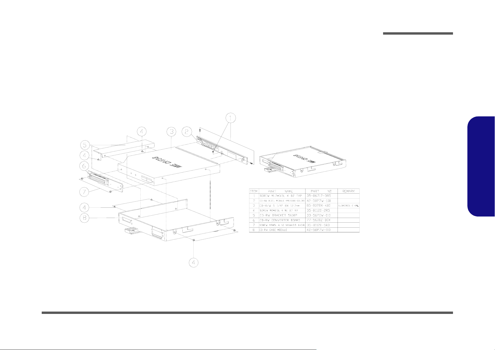
KME CD-RW Drive (D510E)
Part Lists
Figure A - 17
KME CD-RW Drive
(D510E)
Part Lists
KME CD-RW Drive (D510E) A - 19
Page 74

Part Lists
Part Lists
Combo Drive (D510E)
Figure A - 18
Combo Drive
(D510E)
A - 20 Combo Drive (D510E)
Page 75

DVD-ROM Drive (D510E)
Part Lists
Figure A - 19
DVD-ROM Drive
(D510E)
Part Lists
DVD-ROM Drive (D510E) A - 21
Page 76

Part Lists
Audio DJ (D510E)
Part Lists
Audio DJ (D510E)
Figure A - 20
A - 22 Audio DJ (D510E)
Page 77

HDD (D510E)
Part Lists
Figure A - 21
HDD (D510E)
Part Lists
HDD (D510E) A - 23
Page 78

Part Lists
Floppy Disk Drive
Part Lists
Floppy Disk Drive (D510E)
Figure A - 22
(D510E)
A - 24 Floppy Disk Drive (D510E)
Page 79

Top (D520E)
Part Lists
Figure A - 23
Top (D520E)
Part Lists
Top (D520E) A - 25
Page 80

Part Lists
Bottom (D520E)
Part Lists
Bottom (D520E)
Figure A - 24
A - 26 Bottom (D520E)
(深鐵灰色)
Page 81

LCD 15” (D520E)
Part Lists
Figure A - 25
LCD 15” (D520E)
Part Lists
LCD 15” (D520E) A - 27
Page 82

Part Lists
Part Lists
Card Reader (D520E)
Figure A - 26
Card Reader
(D520E)
A - 28 Card Reader (D520E)
Page 83

TEAC CD-ROM Drive (D520E)
Part Lists
Figure A - 27
TEAC CD_ROM
Drive
(D520E)
Part Lists
TEAC CD-ROM Drive (D520E) A - 29
Page 84

Part Lists
KME CD-RW Drive
Part Lists
KME CD-RW Drive (D520E)
Figure A - 28
(D520E)
A - 30 KME CD-RW Drive (D520E)
Page 85

Combo Drive (D520E)
Part Lists
Figure A - 29
Combo Drive
(D520E)
Part Lists
Combo Drive (D520E) A - 31
Page 86

Part Lists
DVD-ROM Drive
Part Lists
DVD-ROM Drive (D520E)
Figure A - 30
(D520E)
A - 32 DVD-ROM Drive (D520E)
Page 87

Audio DJ (D520E)
Part Lists
Figure A - 31
Audio DJ (D520E)
Part Lists
Audio DJ (D520E) A - 33
Page 88

Part Lists
Part Lists
HDD (D520E)
Figure A - 32
HDD (D520E)
A - 34 HDD (D520E)
Page 89

Floppy Disk Drive (D520E)
Part Lists
Figure A - 33
Floppy Disk Drive
(D520E)
Part Lists
Floppy Disk Drive (D520E) A - 35
Page 90

Part Lists
Part Lists
Top (D530E)
Figure A - 34
Top (D530E)
A - 36 Top (D530E)
Page 91

Bottom (D530E)
Part Lists
Figure A - 35
Bottom (D530E)
Part Lists
Bottom (D530E) A - 37
Page 92

Part Lists
LCD 15” (D530E)
Part Lists
LCD 15” (D530E)
Figure A - 36
A - 38 LCD 15” (D530E)
Page 93

Card Reader (D530E)
Part Lists
Figure A - 37
Card Reader
(D530E)
Part Lists
Card Reader (D530E) A - 39
Page 94

Part Lists
Part Lists
TEAC CD-ROM Drive (D530E)
Figure A - 38
TEAC CD_ROM
Drive
(D530E)
A - 40 TEAC CD-ROM Drive (D530E)
Page 95
KME CD-RW Drive (D530E)
Part Lists
Figure A - 39
KME CD-RW Drive
(D530E)
Part Lists
KME CD-RW Drive (D530E) A - 41
Page 96

Part Lists
Part Lists
Combo Drive (D530E)
Figure A - 40
Combo Drive
(D530E)
A - 42 Combo Drive (D530E)
Page 97

DVD-ROM Drive (D530E)
Part Lists
Figure A - 41
DVD-ROM Drive
(D530E)
Part Lists
DVD-ROM Drive (D530E) A - 43
Page 98

Part Lists
Audio DJ (D530E)
Part Lists
Audio DJ (D530E)
Figure A - 42
A - 44 Audio DJ (D530E)
Page 99

HDD (D530E)
Part Lists
Figure A - 43
HDD (D530E)
Part Lists
HDD (D530E) A - 45
Page 100

Part Lists
Floppy Disk Drive
Part Lists
Floppy Disk Drive (D530E)
Figure A - 44
(D530E)
A - 46 Floppy Disk Drive (D530E)
 Loading...