

Clevo A9105 service manual

A9105
SERVICE
MANUAL


LCD Computer
A9105
Service Manual
Preface
Preface
I

Preface
Preface
Notice
The company reserves the right to revise this publication or to change its contents without notice. Information contained herein
is for reference only and does not constitute a commitment on the part of the manufacturer or any subsequent vendor. They
assume no responsibility or liability for any errors or inaccuracies that may appear in this publication nor are they in anyway
responsible for any loss or damage resulting from the use (or misuse) of this publication.
This publication and any accompanying software may not, in whole or in part, be reproduced, translated, transmitted or reduced to any machine readable form without prior consent from the vendor, manufacturer or creators of this publication, except for copies kept by the user for backup purposes.
Brand and product names mentioned in this publication may or may not be copyrights and/or registered trademarks of their
respective companies. They are mentioned for identification purposes only and are not intended as an endorsement of that
product or its manufacturer.
Version 1.0
©April 2012
Trademarks
Intel, Intel Core, Intel Pentium and Intel Celeron are trademarks/registered trademarks of Intel Corporation.
Windows® is a registered trademark of Microsoft Corporation.
Other brand and product names are trademarks and/or registered trademarks of their respective companies.
II

About this Manual
This manual is intended for service personnel who have completed sufficient training to undertake the maintenance and
inspection of personal computers.
It is organized to allow you to look up basic information for servicing and/or upgrading components of the A9105 series
LCD PC.
The following information is included:
Chapter 1, Introduction, provides general information about the location of system elements and their specifications.
Chapter 2, Disassembly, provides step-by-step instructions for disassembling parts and subsystems and how to upgrade
elements of the system.
Preface
Appendix A, Part Lists
Appendix B, Schematic Diagrams
Appendix C, Wall Moutning Information
Appendix D, Updating the FLASH ROM BIOS
Preface
III

Preface
FCC Statement
(Federal Communications Commission)
You are cautioned that changes or modifications not expressly approved by the party responsible for compliance could void
the user's authority to operate the equipment.
This equipment has been tested and found to comply with the limits for a Class B digital device, pursuant to Part 15 of the
FCC Rules. These limits are designed to provide reasonable protection against harmful interference in a residential installation. This equipment generates, uses and can radiate radio frequency energy and, if not installed and used in accordance with
the instructions, may cause harmful interference to radio communications. However, there is no guarantee that interference
will not occur in a particular installation. If this equipment does cause harmful interference to radio or television reception,
which can be determined by turning the equipment off and on, the user is encouraged to try to correct the interference by one
or more of the following measures:
• Re orient or relocate the receiving antenna.
• Increase the separation between the equipment and receiver.
• Connect the equipment into an outlet on a circuit different from that to which the receiver is connected.
• Consult the service representative or an experienced radio/TV technician for help.
Preface
IV
Operation is subject to the following two conditions:
1. This device may not cause interference.
And
2. This device must accept any interference, including interference that may cause undesired operation of the device.

FCC RF Radiation Exposure Statement:
Warning
Use only shielded cables to connect I/O devices to this equipment. You are cautioned that changes or modifications not expressly approved by the manufacturer for compliance with the above standard s could void your authority to operate the
equipment.
1. This Transmitter must not be co-located or operating in conjunction with any other antenna or transmitter.
2. This equipment complies with FCC RF radiation exposure limits set forth for an uncontr olle d en vir onm en t. This eq u ipm e nt
should be installed and operated with a minimum distance of 20 centimeters between the radiator and your body.
IMPORTANT SAFETY INSTRUCTIONS
Follow basic safety precautions, including those listed below, to reduce the risk of fire, electric shock, and injury to persons
when using any electrical equipment:
1. Do not use this product near water, for example near a bath tub , wash b owl, kitchen sink or la undr y tub, in a wet ba sement or
near a swimming pool.
2. Avoid us ing this equ ipment with a telephone line (other than a cordless type) during an electrical storm. There may be a
remote risk of electrical shock from lightning.
3. Do not use the telephone to report a gas leak in the vicinity of the leak.
4. Use only the power cord and batteries indicated in this manual. Do not dispose of batteries in a fir e. They may explode. Check
with local codes for possible special disposal instructions.
5.
This product is intended to be supplied by a Listed Power Unit with an AC Input of 100 - 240V, 50 - 60Hz, DC Output
19V, 4.74A (90W).
Preface
Preface
CAUTION
This Computer’s Optical Device is a Laser Class 1 Product
V
Preface
Preface
Removal Warning
When removing any
cover(s) and screw(s)
for the purposes of device upgrade, remember to replace the
cover(s) and screw(s)
before restoring power
to the system.
Also note the following
when the cover is removed:
• Hazardous moving parts.
• Keep away from
moving fan blades
Power Safety
Warning
Before you undertake
any upgrade procedures, make sure that
you have turned off the
power, and disconnected all peripherals
and cables (including
telephone lines and
power cord). You must
also remove your battery in order to prevent
accidentally turning the
machine on.
Instructions for Care and Operation
The notebook computer is quite rugged, but it can be damaged. To prevent this, follow these suggestions:
1. Don’t drop it, or expose it to shock. If the computer falls, the case and the components could be damaged.
2. Keep it dry, and don’t overheat it. Keep the computer and power supply away from any kind of heating element. This
is an electrical appliance. If water or any other liquid gets into it, the computer could be badly damaged.
3. Follow the proper working procedures for the computer. Shut the computer down properly and don’t forget to save
your work. Remember to periodically save your data as data may be lost if the battery is depleted.
4. Avoid interference. Keep the computer away from high capacity transformers, electric motors, and other strong magnetic fields. These can hinder proper performance and damage your data.
5. Take care when using peripheral devices.
Power Safety
The computer has specific power requirements:
• Only use a power adapter approved for use with this computer.
• Your AC adapter may be designed for international travel but it still requires a steady, uninterrupted power supply. If you are
unsure of your local power specifications, consult your service representative or local power company.
• The power adapter may have either a 2-prong or a 3-prong grounded plug. The third prong is an important safety feature; do
not defeat its purpose. If you do not have access to a compatible outlet, have a qualified electrician install one.
• When you want to unplug the power cord, be sure to disconn ect it by the plug head, not by its wire.
• Make sure the socket and any extension cord(s) you use can support the total current load of all the connected devices.
• Before cleaning the computer, make sure it is disconnected from any external power supplies.
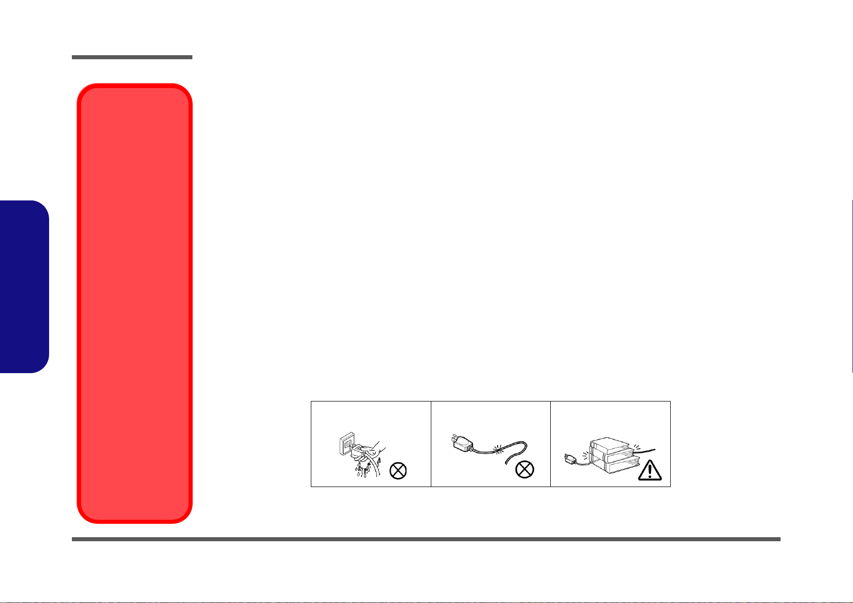
Do not plug in the power
cord if you are wet.
Do not use the power cord if
it is broken.
Do not place heavy objects
on the power cord.
VI

Cleaning
Removal Warning
When removing any cover(s) and screw(s) for the purposes of device upg rade, remember to replace the cover(s) and
screw(s) before turning the computer on.
Do not apply cleaner directly to the computer, use a soft clean cloth.
Do not use volatile (petroleum distillates) or abrasive cleaners on any part of the computer.
Servicing
Do not attempt to service the computer yourself. Doing so may violate your warranty and expose you and the computer to
electric shock. Refer all servicing to authorized service personnel. Unplug the computer from the power supply. Then refer
servicing to qualified service personnel under any of the following conditions:
• When the power cord is damaged or frayed.
• If the computer has been exposed to any liquids.
• If the computer does not work normally when you follow the operating instructions.
• If the computer has been dropped or damaged (do no t touch the poisonous liquid if the LCD panel breaks).
• If there is an unusual odor, heat or smoke coming from your computer.
Preface
Preface
VII
Preface
Power Button (located under the LCD)
Preface
Related Documents
You may also need to consult the following manual for additional information:
User’s Manual on CD
This describes the computer’s features and the procedures for operating the computer and its ROM-based setup program.
It also describes the installation and operation of the utility programs provided with the computer.
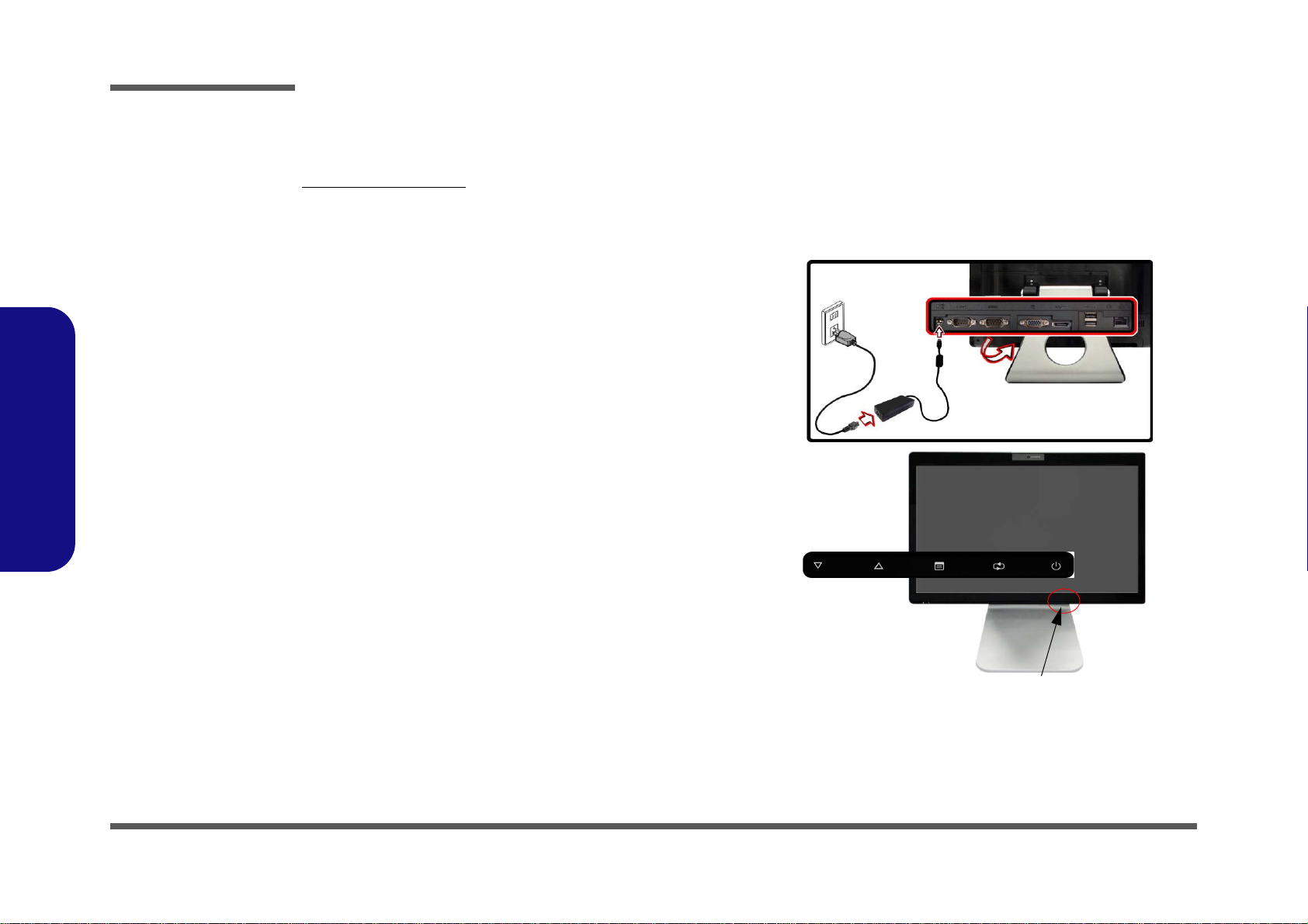
System Startup
1. Remove all packing materials.
2. Place the computer on a stable surface.
3. Securely attach any peripherals you want to use with the computer
(e.g. keyboard and mouse) to their ports.
4. Attach the AC/DC adapter to the DC-In jack located under the LCD,
then plug the AC power cord into an outlet, and connect the AC
power cord to the AC/DC adapter.
5. Push the power button at the front of the computer (under the LCD)
to turn the computer “on”.
VIII
Figure 1 -
Computer with AC/DC Adapter Plugged-In/Power Button

Contents
Preface
Notice ............................................................................................. 1-II
About this Manual .........................................................................1-III
FCC Statement ..............................................................................1-IV
FCC RF Radiation Exposure Statement: ........................................1-V
Cleaning ...................................................................................... 1-VII
Servicing ...................................................................................... 1-VII
Introduction ..............................................1-1
Overview ......................................................................................... 1-1
Specifications ..................................................................................1-2
Tilting the LCD Screen & Adjusting the Height .............................1-4
External Locator - Front View ........................................................1-5
External Locator - Left & Right Side Views ...................................1-6
External Locator - Rear View .........................................................1-7
Mainboard Overview - Top (Key Parts) .........................................1-8
Mainboard Overview - Bottom (Key Parts) ....................................1-9
Mainboard Overview - Top (Connector) ......................................1-10
Mainboard Overview - Bottom (Connectors) ...............................1-11
Disassembly ...............................................2-1
Overview ......................................................................................... 2-1
Maintenance Tools ..........................................................................2-2
Connections .....................................................................................2-2
Maintenance Precautions .................................................................2-3
Disassembly Steps ...........................................................................2-4
Removing the Rear Top Cover ........................................................2-5
Removing the Hard Disk Drive .......................................................2-6
Upgrading the System Memory (RAM) ..........................................2-7
Removing the Stand ........................................................................2-9
Removing the Rear Bottom Cover ................................................2-10
Removing the Fan Module ............................................................2-11
Removing the Optical (CD/DVD) Device .................................... 2-12
Removing the Wireless LAN Module .......................................... 2-13
Removing the CPU ....................................................................... 2-14
Part Lists ..................................................A-1
Part List Illustration Location ........................................................ A-2
LCD .............................................................................................. A-3
Stand ............................................................................................. A-4
Back .............................................................................................. A-5
DVD .............................................................................................. A-6
Combo ........................................................................................... A-7
Schematic Diagrams.................................B-1
System Block Diagram ...................................................................B-2
Clock Generator ..............................................................................B-3
CPU 1/7 (DMI, PEG, FDI) .............................................................B-4
CPU 2/7 (CLK, MISC, JTAG) .......................................................B-5
CPU 3/7 (DDR3) ............................................................................B-6
CPU 4/7 (Power) .............................................................................B-7
CPU 5/7 (Graphics Power) .............................................................B-8
CPU 6/7 (GND) ..............................................................................B-9
CPU 7/7 (RESERVED) ................................................................B-10
DDR3 SO-DIMM_0 .....................................................................B-11
DDR3 SO-DIMM_1 .....................................................................B-12
LVDS, Inverter .............................................................................B-13
LVDS & Audio Switch .................................................................B-14
HDMI, CRT ..................................................................................B-15
SCALAR .......................................................................................B-16
IBEXPEAK-M_HDA/SATA .......................................................B-17
IBEXPEAK-M_PCIE/CLK/SM ...................................................B-18
IBEXPEAK-M_DMI/FDI/GPIO ..................................................B-19
Preface
IX

Preface
IBEXPEAK-M_LVDS/DDI .........................................................B-20
IBEXPEAK-M_PCI/USB/NVRAM ............................................ B-21
IBEXPEAK-M_GPIO/MISC ....................................................... B-22
IBEXPEAK-M_Power ................................................................. B-23
IBEXPEAK-M_Power ................................................................. B-24
IBEXPEAK-M_GND ...................................................................B-25
New Card, Mini PCIE ..................................................................B-26
JMC 251 Card Reader ..................................................................B-27
LAN,SATA HDD, ODD, BT, CCD .............................................B-28
USB 3.0 ........................................................................................B-29
USB, Fan ......................................................................................B-30
Audio Codec VIA1812 (ALC272) ............................................... B-31
Audio Jack ....................................................................................B-32
KBC-ITE IT8518E ....................................................................... B-33
COM Port .....................................................................................B-34
5VS, 3VS, 1.5VS ..........................................................................B-35
Preface
Power 3.3V/5V .............................................................................B-36
Power 1.5V/0.75V, 1.8VS ............................................................ B-37
Power 1.1VS_VTT .......................................................................B-38
Power VGFX_Core ......................................................................B-39
V-Core ..........................................................................................B-40
AC In ............................................................................................B-41
Power, SW Board ......................................................................... B-42
LED Board ...................................................................................B-43
USB, Audio Board .......................................................................B-44
Sequence .......................................................................................B-45
Updating the FLASH ROM BIOS .........D-1
Download the BIOS ....................................................................... D-1
Unzip the downloaded files to a bootable CD/DVD/ or
USB Flash drive ............................................................................. D-1
Set the computer to boot from the external drive .......................... D-1
Use the flash tools to update the BIOS .......................................... D-2
Restart the computer (booting from the HDD) .............................. D-2
Wall Mounting Guide............................. C-1
Removing the Stand ....................................................................... C-2
Mounting Systems ..........................................................................C-3
General Guidelines for Wall Mounting .......................................... C-4
Mounted System Example .............................................................C-5
X

Chapter 1: Introduction
Overview
This manual covers the information you need to service or upgrade the A9105 series LCD computer. Information about
operating the computer (e.g. getting started, and the Setup utility) is in the User’s Manual. Information about drivers (e.g.
VGA & audio) is also found in User’s Manual. That manual is shipped with the computer.
Operating systems (e.g. Windows 7, etc.) have their own manuals as do application software (e.g. word processing and
database programs). If you have questions about those programs, you should consult those manuals.
Introduction
The A9105 series computer is designed to be upgradeable. See Disassembly 2 on page 2 - 1 for a detailed description of
the upgrade procedures for each specific component. Please note the warning and safety information indicated by the
“” symbol.
The balance of this chapter reviews the computer’s technical specifications and features.
1.Introduction
Overview 1 - 1

Introduction
Latest Specification Information
The specifications listed here are correct at the
time of sending them to the press. Certain items
(particularly processor types/speeds) may be
changed, delayed or updated due to the manufacturer's release schedule. Check with your
service center for more details.
CPU
The CPU is not a user serviceable part. Accessing the CPU in any way may violate your
warranty.
Specifications
1.Introduction
Processor Options
i7-640M (
32nm (32 Nanometer) Process Technology, 4MB L3
Cache &
FSB 1066MHz - TDP 35W
i7-620M (
32nm (32 Nanometer) Process Technology, 4MB L3
Cache &
FSB 1066MHz - TDP 35W
i5-540M (2.53GHz) Mobile Processor
32nm (32 Nanometer) Process Technology, 3MB L3
Cache &
FSB 1066MHz - TDP 35W
i5-450M (2.40GHz) Mobile Processor
32nm (32 Nanometer) Process Technology, 3MB L3
Cache &
FSB 1066MHz - TDP 35W
i3-370M (2.40GHz) Mobile Processor
32nm (32 Nanometer) Process Technology, 3MB L3
Cache &
FSB 1066MHz - TDP 35W
i3-350M (2.26GHz) Mobile Processor
32nm (32 Nanometer) Process Technology, 3MB L3
Cache &
FSB 1066MHz - TDP 35W
i3-330M (2.13GHz) Mobile Processor
32nm (32 Nanometer) Process Technology, 3MB L3
Cache &
FSB 1066MHz - TDP 35W
Intel® Celeron® Processor
P4500 (1.86GHz)
32nm (32 Nanometer) Process Technology, 2MB L3
Cache & FSB 1066MHz - TDP 35W
2.80GHz) Mobile Processor
2.66GHz) Mobile Processor
Intel® Pentium® Processor
P6000 (1.86GHz)
32nm (32 Nanometer) Process Technology, 3MB L3
Cache &
FSB 1066MHz - TDP 35W
Core Logic
Intel® HM55 Chipset
BIOS
One 32Mb SPI Flash ROM
Phoenix™ BIOS
Memory
Dual Channel DDRIII (DDR3)
Two 204 Pin SO-DIMM Sockets Supporting DDRIII
(DDR3) 1066MHz/1333MHz Memory Modules
Memory Expandable up to 8GB
Compatible with 1GB, 2GB or 4GB Modules
Video Adapter
Intel® GMA HD
Dynamic Frequency
Intel® Dynamic Video Memory Technology Supporting
Shared Memory of up to 1.7GB
Supports Microsoft DirectX® 10
Security
BIOS Password
Security (Kensington® Type) Lock Slot
LCD Options
19" (42.8cm) WXGA+ (1440 * 900) TFT LCD
Adjustable Height
(Factory Option) Hard Glass
(Factory Option) Multi-Touch Panel
1 - 2 Specifications

Introduction
Audio
High Definition Audio
S/PDIF Digital Output
2 Built-In Speakers
Storage
Up to Two Changeable 2.5" 9.5 mm (h) SATA (Serial)
Hard Disk Drives
One 12.7 mm Super Multi/Blu-ray Combo SATA Optical
Device Drive (Factory Option)
Keyboard
(Factory Option) RF USB Keyboard/Mouse with Trans-
ceiver
Card Reader
Embedded Multi-in-1 Card Reader
MMC (MultiMedia Card) / RS MMC
SD (Secure Digital) / Mini SD / SDHC/ SDXC
Compatible
MS (Memory Stick) / MS Pro / MS Duo
Note: Some of these cards require PC adapters that are
usually supplied with the cards.
Slots
ExpressCard/34/54 Slot
One Mini Card Slot
Half Mini-Card Module with PCIe & USB Interface
for Combo WLAN and Bluetooth v3.0
Communication
Built-In 10/100/100 Mb Base-TX Ethernet LAN
3rd Party 802.11b/g/n Wireless LAN
Module with PCIe & USB Interface (Factory Option)
(Factory Option)
Bluetooth
(Factory Option)
Bluetooth
(Factory Option)
Mini-Card PCIe WLAN Module
(Factory Option)
Mini-Card PCIe WLAN Module
(Factory Option) 2.0M Pixel PC Video Camera Module
with USB Interface
Combo WLAN
v3.0+HS Half Mini-Card Module
Combo WLAN
v4.0 LE Half Mini-Card Module
Intel® WiFi Link 1000
Intel® WiFi Link 6200
Half
Mini-Card
(802.11b/g/n)
(802.11b/g/n)
(802.1 1 b/g/n) Half
(802.1 1 a/g/n) Half
and
and
Interface
Two USB 2.0 Ports
One USB 3.0 Port
One eSATA Port
One External Monitor Port
One 1.3 HDMI-In (High-Definition Multimedia Interface)
Port
One S/PDIF Output Jack
One Line-In Jack
One RJ-45 LAN Jack
One DC-in Jack
2 RS232 Serial COM Ports
One Headphone-Out Jack
One Microphone-In Jack
Power
Full Range AC/DC Adapter
AC Input: 100 - 240V, 50 - 60Hz
DC Output: 19V, 4.74A (90W)
Energy Star 5.0 Compliant
Envionmental Spec
Temperature
Operating: 5
Non-Operating: -20°C - 60°C
Relative Humidity
Operating: 20% - 80%
Non-Operating: 10% - 90%
°C - 35°C
Dimensions & Weight
450mm (w) * 312mm (d) * 51-53.5mm (h)
Around 8kg with ODD
1.Introduction
Specifications 1 - 3
Introduction
45°
-5°
Moving the
Computer
We strongly recommend using both hands
to move the computer.
You can use one hand
to grip the computer by
the stand, and the other to hold the top of the
LCD screen.
It is recommended that
you carry the computer
with the LCD facing
your body to avoid
scratching the surface
against other objects.
However take care not
to scratch the LCD with
any personal items,
belt fittings or jewelry
etc.(one hand gripping
the stand and the other
gripping the top of the
computer to avoid accidentally dropping it).
1.Introduction
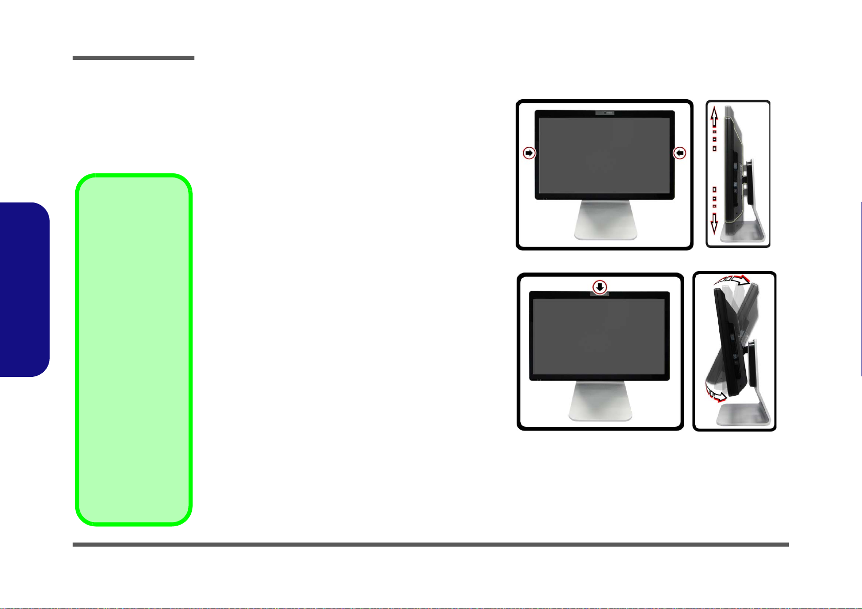
Tilting the LCD Screen & Adjusting the Height
It is possible to tilt the LCD screen in order to get the best possible viewing angle of the screen without glare etc, and to
raise/lower the screen height in order to get the best possible
vertical viewing position of the screen.
• Hold the left and right sides of the computer to raise/
lower the screen.
• Do not hold the bottom of the screen to adjust the view-
ing angle or height as the screen function buttons are
located there.
• Carefully apply pressure at the top of the screen to tilt
it.
• Note that the screen has no fixed lock position and you
are free to raise/lower and tilt the screen to any position
the stand allows (do not force it beyond the point of resistance)
Figure 1
LCD Screen Raise/Lower & Tilting
1 - 4 Tilting the LCD Screen & Adjusting the Height
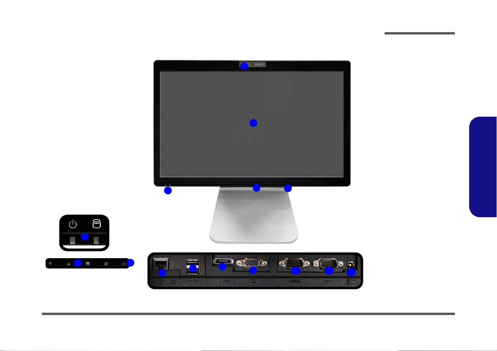
External Locator - Front View
Figure 2
Front View
1. PC Camera
(Optional)
2. LCD (With
Optional Touch
Panel)
3. Power & System
Activity LED
Indicators
4. Function Buttons*
5. Power Button*
Under the LCD
6. RJ-45 LAN Jack
7. 2 * USB Ports
8. eSATA Port
9. External Monitor
Port
10.2 * COM Ports
11. DC-In Jack
4
3
1
9
5
2
8
4
6
5
3
10
11
7
Under the LCD
10
Introduction
1.Introduction
External Locator - Front View 1 - 5
Introduction
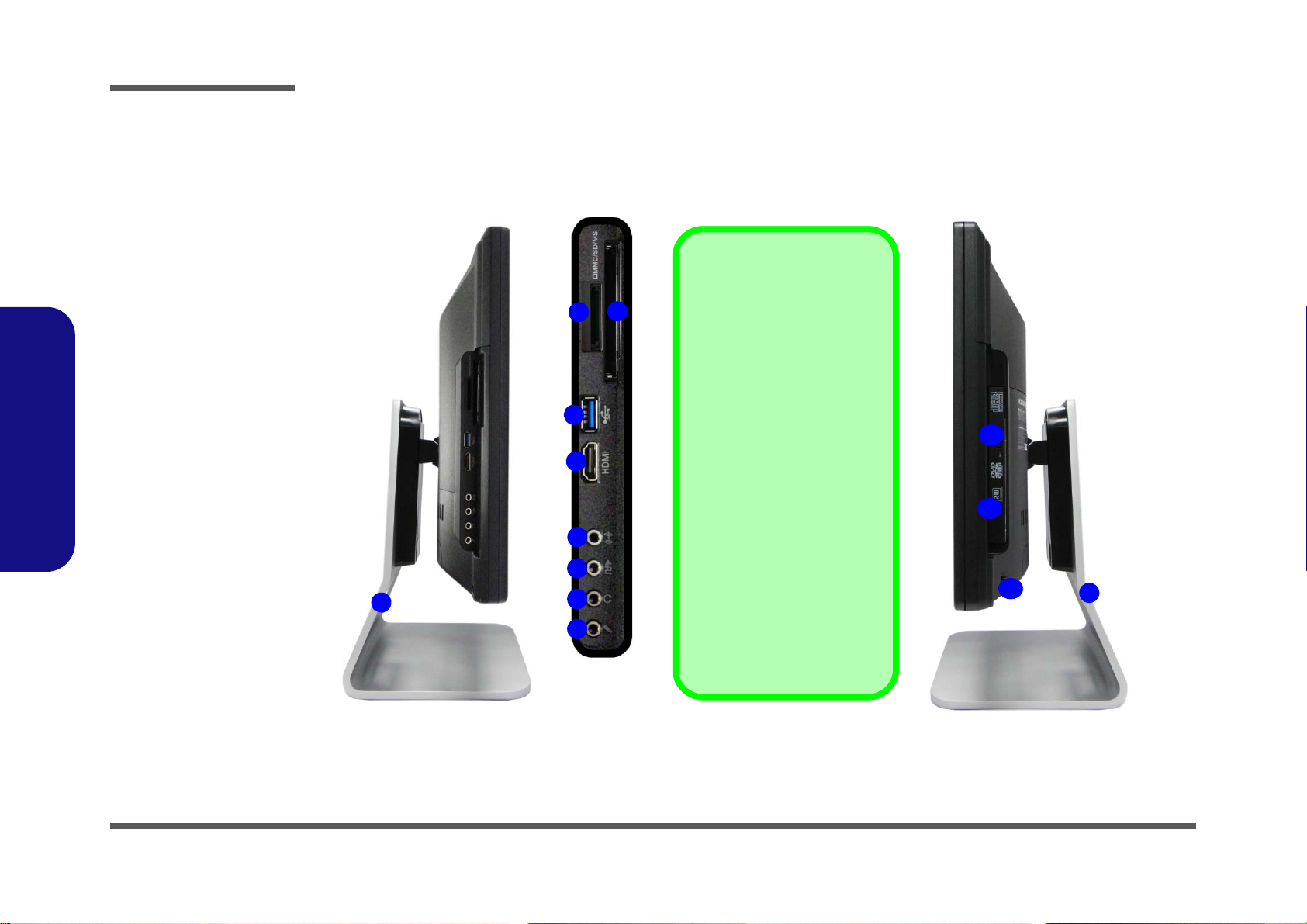
Figure 3
Left & Right Side
Views
1. Stand
2. Multi-in-1 Card
Reader
3. ExpressCard Slot
/54(34)
4. 1 * USB 3.0 Port
5. HDMI-In Port
6. Line-In Jack
7. S/PDIF-Out Jack
8. Microphone-In
Jack
9. Headphone/
Speaker-Out Jack
10.Emergency Eject
Hole
11. Optical Device
Drive Bay
12.Security Lock Slot
1
ExpressCard Slot
The ExpressCard Slot accepts
either ExpressCard/34 or Ex-
pressCard/54 formats.
7-in-1 Card Reader
The card reader allows you to
use the most popular digital
storage card formats:
MMC (MultiMedia Card) / SD (Se-
cure Digital) / MS (Memory Stick) /
MS Pro (Memory Stick Pro) / MS
Duo (requires PC adapter) /
Mini SD (requires PC adapter) / RS
MMC (requires PC adapter)
Mini-IEEE 1394 Port
The Mini-IEEE 1394 port only
supports SELF POWERED
IEEE 1394 devices.
1
10
11
3
4
5
6
7
2
8
9
12
1.Introduction
External Locator - Left & Right Side Views
1 - 6 External Locator - Left & Right Side Views
External Locator - Rear View
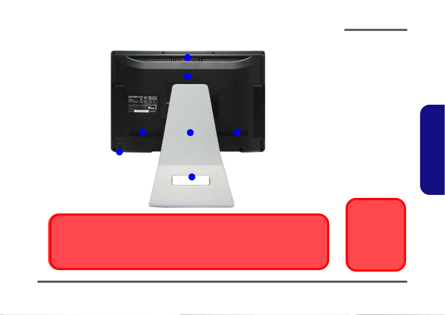
Figure 4
Rear View
1. Stand
2. Rear Component
Cover
3. Vent/Fan Intake
4. Security Lock Slot
5. Carrying Handle
Area
Overheating
To prevent your computer from overheating
make sure nothing
blocks the vent/fan intakes while the computer is in use.
1
3
2
3 3
4
5
Carrying the Computer
We strongly recommend using both hands to move the computer (one hand gripping the handle area and the other gripping the
computer) to avoid accidentally dropping it. Be care ful that objects such as belt bu ckles etc. do not scratch th e screen while it
is being carried.
Introduction
1.Introduction
External Locator - Rear View 1 - 7
Introduction
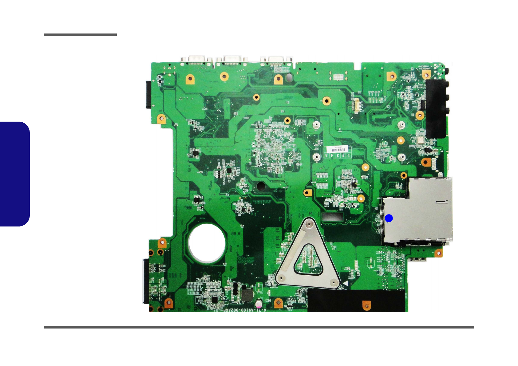
Figure 5
Mainboard Top
Key Parts
1. ExpressCard/34/
54 Slot
1
1.Introduction
Mainboard Overview - Top (Key Parts)
1 - 8 Mainboard Overview - Top (Key Parts)
Mainboard Overview - Bottom (Key Parts)
10
1
2
4
5
6
7
3
8
9
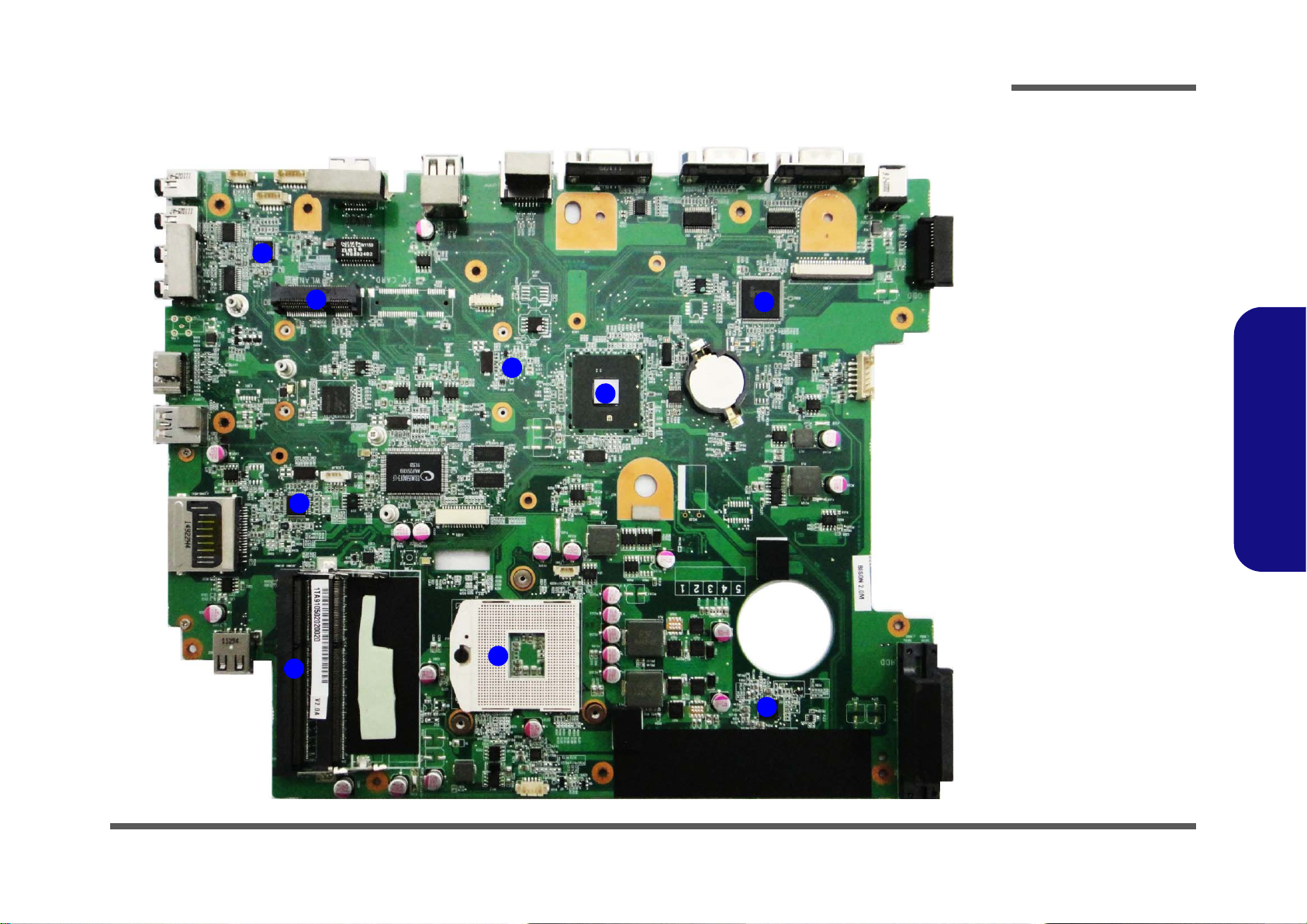
Figure 6
Mainboard Bottom
Key Parts
1. Audio Codec
2. Mini-Card
Connector (WLAN
Module)
3. Clock Generator
4. Platform Controller
Hub
5. JMC 251C
6. Memory Slots
DDR3 SO-DIMM
7. CPU Socket (CPU
uninstalled)
8. VCORE
9. KBC-ITE
IT8519HX
Introduction
1.Introduction
Mainboard Overview - Bottom (Key Parts) 1 - 9
Introduction
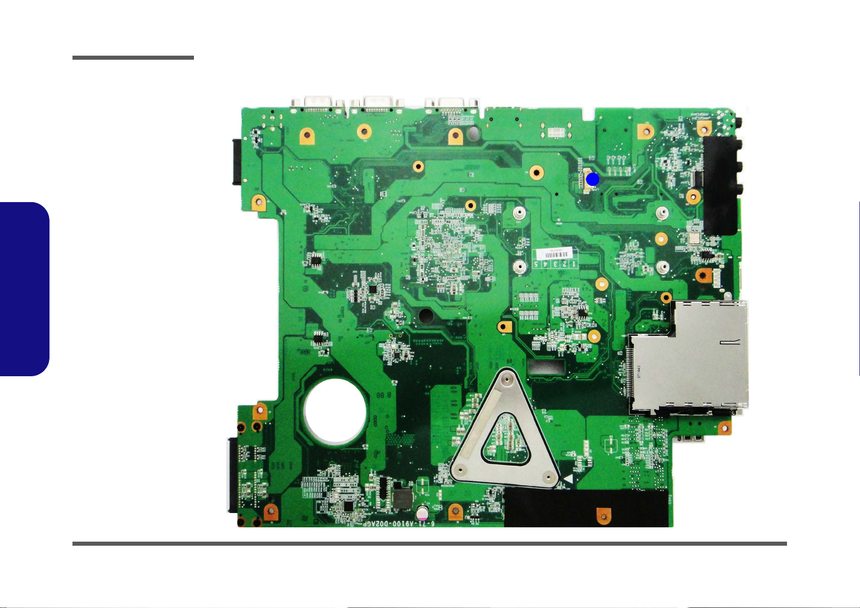
Figure 7
Mainboard Top
Connector
1. Touch Panel
Connector
1
1.Introduction
Mainboard Overview - Top (Connector)
1 - 10 Mainboard Overview - Top (Connector)
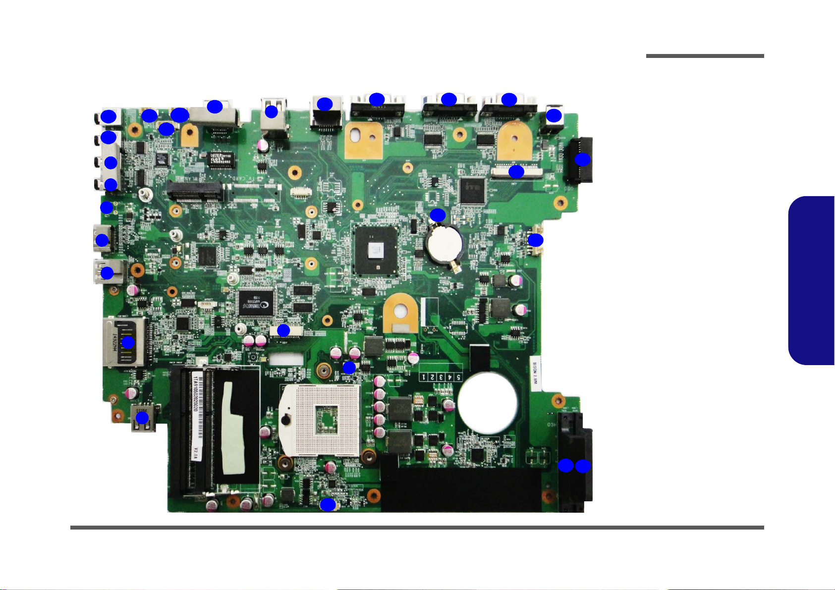
Mainboard Overview - Bottom (Connectors)
Figure 8
Mainboard Bottom
Connectors
1. S/PDIF-Out Jack
2. Line-In Jack
3. CATV
4. HDMI-In Port
5. USB 3.0 Port
6. Multi-in-1 Card
Reader
7. USB 2.0 Ports
8. LCD Cable
Connector
9. CPU Fan Cable
Connector
10. CCD Cable
Connector
11. HDD Connectors
12. Inverter Connector
13. CMOS Battery
Connector
14. Keyboard Cable
Connector
15. ODD Connector
16. DC-In Jack
17. COM Ports
18. External Monitor Port
19. eSATA Port
20. RJ-45 Lan Jack
21. Power Switch Cable
Connector
22. Speaker Cable
Connector
23. LED Cable Connector
Connector
24. Microphone-In Jack
25. Headphone/SpeakerOut Jack
9
1
5
2
3
4
6
7
11
11
12
13
14
16
17
15
8
10
1718
19
20
21
22
23
7
24
25
Introduction
Mainboard Overview - Bottom (Connectors) 1 - 11
1.Introduction

1.Introduction
Introduction
1-12

Chapter 2: Disassembly
Warning
Information
Overview
This chapter provides step-by-step instructions for disassembling the A9105 series LCD computer’s parts and subsystems. When it comes to reassembly, reverse the procedures (unless otherwise indicated).
We suggest you completely review any procedure before you take the computer apart.
Disassembly
Procedures such as upgrading/replacing the RAM, optical device and hard disk are included in the User’s Manual but are
repeated here for your convenience.
To make the disassembly process easier each section may have a box in the page margin. Information contained under
the figure # will give a synopsis of the sequence of procedures involved in the disassembly procedure. A box with a
lists the relevant parts you will have after the disassembly process is complete. Note: The parts listed will be for the disassembly procedure listed ONLY, and not any previous disassembly step(s) required. Refer to the part list for the previous disassembly procedure. The amount of screws you should be left with will be listed here also.
A box with a will also provide any possible helpful information. A box with a contains warnings.
An example of these types of boxes are shown in the sidebar.
2.Disassembly
Overview 2 - 1

Disassembly
2.Disassembly
NOTE: All disassembly procedures assume that the system is turned OFF, and disconnected from any power supply.
Maintenance Tools
The following tools are recommended when working on the notebook PC:
• M3 Philips-head screwdriver
• M2.5 Philips-head screwdriver (magnetized)
• M2 Philips-head screwdriver
• Small flat-head screwdriver
• Pair of needle-nose pliers
• Anti-static wrist-strap
Connections
Connections within the computer are one of four types:
Locking collar sockets for ribbon connectors To release these connectors, use a small flat-head screwdriver to gently pry
the locking collar away from its base. When replacing the connection, make
sure the connector is oriented in the same way. The pin1 side is usually not
indicated.
2 - 2 Overview
Pressure sockets for multi-wire connectors To release this connector type, grasp it at its head and gently rock it from side
to side as you pull it out. Do not pull on the wires themselves. When replacing
the connection, do not try to force it. The socket only fits one way.
Pressure sockets for ribbon connectors To release these connectors, use a small pair of needle-nose pliers to gently
lift the connector away from its socket. When replacing the connection, make
sure the connector is oriented in the same way. The pin1 side is usually not
indicated.
Board-to-board or multi-pin sockets To separate the boards, gently rock them from side to side as you pull them
apart. If the connection is very tight, use a small flat-head screwdriver - use
just enough force to start.

Maintenance Precautions
Power Safety
Warning
Before you undertake
any upgrade procedures, make sure that
you have turned off the
power, and disconnected all peripherals and
cables (including telephone lines).
Removal Warning
When removing any
cover(s) and screw(s)
for the purposes of device upgrade, remember
to replace the cover(s)
and screw(s) before
turning the computer on.
The following precautions are a reminder. To avoid personal injury or damage to the computer while performing a removal and/or replacement job, take the following precautions:
1. Don't drop it. Perform your repairs and/or upgrades on a stable surface. If the computer falls, the case and other
components could be damaged.
2. Don't overheat it. Note the proximity of any heating elements. Keep the computer out of direct sunlight.
3. Avoid interference. Note the proximity of any high capacity transformers, electric motors, and other strong mag-
netic fields. These can hinder proper performance and damage components and/or data. You should also monitor
the position of magnetized tools (i.e. screwdrivers).
4. Keep it dry. This is an electrical appliance. If water or any other liquid gets into it, the computer could be badly
damaged.
5. Be careful with power. Avoid accidental shocks, discharges or explosions.
•Before removing or servicing any part from the computer, turn the computer off and detach any power supplies.
•When you want to unplug the power cord or any cable/wire, be sure to disconnect it by the plug head. Do not pu ll on the wir e.
6. Peripherals – Turn off and detach any peripherals.
7. Beware of static discharge. ICs, such as the CPU and main support chips, are vulnerable to static electricity.
Before handling any part in the computer, discharge any static electricity inside the computer. When handling a
printed circuit board, do not use gloves or other materials which allow static electricity buildup. We suggest that
you use an anti-static wrist strap instead.
8. Beware of corrosion. As you perform your job, avoid touching any connector leads. Even the cleanest hands produce oils which can attract corrosive elements.
9. Keep your work environment clean. Tobacco smoke, dust or other air-born particulate matter is often attracted
to charged surfaces, reducing performance.
10. Keep track of the component s. When removing or re placing any part, be careful not to leave small p arts, such as
screws, loose inside the computer.
Cleaning
Do not apply cleaner directly to the computer, use a soft clean cloth.
Do not use volatile (petroleum distillates) or abrasive cleaners on any part of the computer.
Disassembly
2.Disassembly
Overview 2 - 3

Disassembly
Disassembly Steps
The following table lists the disassembly steps, and on which page to find the related information. PLEASE PERFORM
THE DISASSEMBLY STEPS IN THE ORDER INDICATED.
2.Disassembly
To remove the Rear Top Cover:
1. Remove the rear top cover page 2 - 4
To remove the Hard Disk Drive:
1. Remove the rear top cover page 2 - 4
2. Remove the HDD page 2 - 6
To remove and install the System Memory:
1. Remove the rear top cover page 2 - 4
2. Remove the system memory page 2 - 7
To remove the Stand:
1. Remove the rear top cover page 2 - 4
2. Remove the stand page 2 - 9
To remove the Rear Bottom Cover:
1. Remove the rear top cover page 2 - 4
2. Remove the stand page 2 - 9
3. Remove the rear bottom cover page 2 - 10
To remove the Optical Device:
1. Remove the rear top cover page 2 - 4
2. Remove the stand page 2 - 9
3. Remove the rear bottom cover page 2 - 10
4. Remove the optical device page 2 - 12
To remove the WLAN Module:
1. Remove the rear top cover page 2 - 4
2. Remove the WLAN module page 2 - 13
To remove the CPU:
1. Remove the rear top cover page 2 - 4
2. Remove the CPU page 2 - 14
3. Install the CPU page 2 - 16
To remove the Fan Module:
1. Remove the rear top cover page 2 - 4
2. Remove the stand page 2 - 9
3. Remove the rear bottom cover page 2 - 10
4. Remove the fan module page 2 - 11
2 - 4 Disassembly Steps
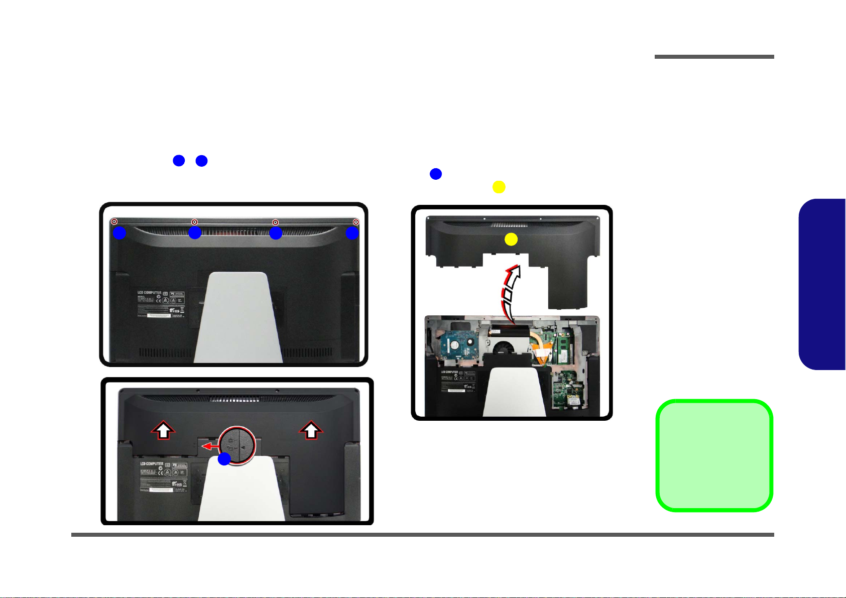
Removing the Rear Top Cover
Figure 1
Rear Top Cover
Removal
a. Remove the screws.
b. Slide the top cover to
unlock.
c. Remove the rear top
cover.
F. Rear Top Cover
•4 Screws
ADE
6
F
B
A
C D
E
a.
b.
c.
F
Before undertaking any upgrade procedure it is necessary to remove the rear top cover to access the components.
1. Turn off the computer and disconnect all cables and peripherals.
2. Carefully place the computer flat with the LCD facing down (make sure you cover the LCD to avoid scratches) so
that you may access the rear cover.
3. Remove screws -
4. Slide the rear top cover until the arrow is aligned with the unlock icon
5. When the arrow is aligned with the unlock icon you can remove the rear top cover
Disassembly
(Figure 1a).
(Figure 1b).
(Figure 1c).
2.Disassembly
Removing the Rear Top Cover 2 - 5
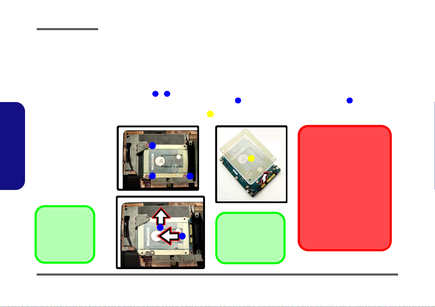
Disassembly
Figure 2
Hard Disk Drive
Removal
a. Remove the screws.
b. Slide the hard disk in
the direction of the arrows.
c. Remove the adhesive
hard disk cover top
cover.
F. Adhesive Hard Disk
Cover
•3 Screws
ACDE6
F
B
A
C
Hard Disk Slot
Make sure you install the
hard disk into the lower slot
on the mainboard.
a.
b.
c.
D
E
F
HDD System Warning
New HDD’s are blank. Before you begin
make sure:
You have backed up any data you want
to keep from your old HDD.
You have all the CD-ROMs and FDDs
required to install your operating system and programs.
If you have access to the internet,
download the latest application and
hardware driver updates for the operating system you plan to install. Copy
these to a removable medium.
Removing the Hard Disk Drive
The hard disk drive can be taken out to accommodate other 2.5" serial (SATA) hard disk drives with a height of 9.5mm
(h). Follow your operating system’s installation instructions, and install all necessary drivers and utilities (as outlined in
Chapter 4 of the User’s Manual) when setting up a new hard disk.
2.Disassembly
Hard Disk Upgrade Process
1. Remove the rear top cover (page 2 - 5).
2. Remove screws -
(Figure 2a).
3. Firstly slide the hard disk in the direction of arrow , and then slide it in the direction of arrow to remove it
(Figure 2b).
4. Remove the adhesive hard disk cover
5. Reverse the process to install a new hard disk.
(Figure 2c).
2 - 6 Removing the Hard Disk Drive
 Loading...