

Page 1

Page 2

Page 3

Introduction (English)
This Concise User’s Guide introduces the main features
of your computer. The English version of this guide begins on page 1. The expanded User’s Manual is on the
Device Drivers & Utilities + User’s Manual disc.
Einführung (Deutsch)
Dieses Ausführliche Benutzerhandbuch führt Sie in die
Hauptfunktionen des Computers ein. Die deutsche Version des Handbuchs beginnt auf Seite 29. Das erweiterte
Benutzerhandbuch finden Sie auf der Disc für die Gerätetreiber und Hilfsprogramme (Disc Device Drivers &
Utilities + User's Manual).
Présentation (Français)
Ce Guide Utilisateur Concis présente les fonctionnalités
principales de votre ordinateur. La version française de
ce guide commence à la page 57. Le Manuel de l'Utilisa-
teur étendu se trouve sur le disque de Pilotes & Utilitaires + Manuel de l'Utilisateur (disque Device Drivers
& Utilities + User's Manual).
Introducción (Español)
Esta Guía del Usuario Concisa le presenta las características principales de su ordenador. La versión española de
esta guía comienza en la página 85. El Manual del usua-
rio completo se encuentra en el disco de Controladores
del dispositivo y Utilidades + Manual del usuario (disco
Device Drivers & Utilities + User's Manual).
Introduzione (Italiano)
La presente Guida Rapida per l'Utente introduce le caratteristiche principali del computer. La versione italiana di
questa guida inizia da pagina 113. Il Manuale utente
completo si trova nel disco contenente driver e utilità +
Manuale utente (disco Device Drivers & Utilities +
User's Manual).
I
Page 4

Contents
Notice .................. ............................... ............................... ................ 1
About this Concise User Guide .........................................................2
Instructions for Care and Operation ..................................................2
Model Differences ............................................................................4
System Startup ..................................................................................5
System Map: Front View (Model A) ................... .............................6
System Map: Front View (Model B) ................................................7
System Map: Left View ..................................................................11
HDMI-In Port ..................................................................................12
System Map: Right View ................................................................13
Tilting the Screen ............................. ...............................................14
System Map: Rear View .................................................................15
Video Features ................................................................................16
Audio Features ................................................................................17
Power Management Features .......................... ................................17
Driver Installation ...........................................................................18
PC Camera (Option) .......................................................................20
Wireless LAN Module (Option) .....................................................22
Bluetooth Module (Option) .............................................................23
Touch Screen Module .....................................................................24
Troubleshooting ..............................................................................26
Specifications ................. .................................... ............................. 27
Inhalt
Hinweis ........................ .... ....... ...... ....... ....... .... ....... ....... ...... ....... .... ..29
Über das Ausführliche Benutzerhandbuch ......................................30
Hinweise zu Pflege und Betrieb ......................................................30
Modellunterschiede .................... .....................................................32
Schnellstart .................... ............................................ ......................33
Systemübersicht: Ansicht von vorne (Modell A) ............................34
Systemübersicht: Ansicht von vorne (Modell B) ............................35
Systemübersicht: Ansicht von links ................................................39
HDMI-Eingangsanschluss ................. .................. ............... .............40
Systemübersicht: Ansicht von rechts .......................................... ....41
Neigen des Bildschirms ...................................................................42
Systemübersicht: Rückansicht .........................................................43
Grafikfunktionen ...................... ....................................................... 44
Audiofunktionen ..............................................................................45
Energieverwaltungsfunktionen ... ....... ....... .... ....... ...... ....... .... ....... ....45
Installation der Treiber ....................................................................46
PC-Kamera (Option) .......................................................................48
WLAN-Modul (Option) ..................................................................50
Bluetooth-Modul (Option) ..............................................................51
Touch-Screen-Modul ......................................................................52
Fehlerbehebung ...............................................................................54
Technische Daten ............................................................................55
II
Page 5

Sommaire
Avertissement .................................................................................57
A propos de ce Guide Utilisateur Concis ........................................58
Instructions d’entretien et d’utilisation ...........................................58
Différences de modèles ...................................................................60
Guide de démarrage rapide .............................................................61
Carte du système : Vue de face (Modèle A) ...................................62
Carte du système : Vue de face (Modèle B) ..................... ..............63
Carte du système : Vue gauche .......................................................67
Port d’entrée HDMI ......... ...............................................................68
Carte du système : Vue droite ............................ .............................69
Incliner l'écran .................................................................................70
Carte du Système : Vue Arrière ......................................................71
Caractéristiques vidéo .....................................................................72
Caractéristiques audio .....................................................................73
Caractéristiques de gestion de l’alimentation .................................73
Installation du pilote .......................................................................74
Caméra PC (Option) ........... ............................................................76
Module LAN sans fil (Option) ........................................................78
Module Bluetooth (Option) .............. ...............................................79
Module d'écran tactile .................... .................................................80
Dépannage .................... ....... ...... ....... .... ....... ....... ...... ....... .... ....... .....82
Spécifications ................. .................................... ............................. 83
Sommario
Aviso ...............................................................................................85
Acerca de esta Guía del Usuario Concisa .......................................86
Instrucciones para el cuidado y funcionamiento .............................86
Diferencias de modelos ..... ..............................................................88
Guía rápida para empezar ................................................................89
Mapa del sistema: Vista frontal (Modelo A) ...................................90
Mapa del sistema: Vista frontal (Modelo B) ...................................91
Mapa del sistema: Vista izquierda ..................................................95
Puerto de entrada HDMI .................................................................96
Mapa del sistema: Vista derecha .....................................................97
Inclinar la pantalla ...........................................................................98
Mapa del sistema: Vista posterior ...................................................99
Parámetros de vídeo ......................................................................100
Características de audio .................................................................101
Funciones de administración de energía ................. ......................101
Instalación de controladores ..........................................................102
Cámara PC (Opción) .....................................................................104
Módulo WLAN (Opción) ..............................................................106
Módulo Bluetooth (Opción) ..........................................................107
Módulo de pantalla táctil ...............................................................108
Solución de problemas ............................. .....................................110
Especificaciones ................ ................................................. ...........111
III
Page 6

Contenidos
Avviso ........................ ................................................. ..................113
Informazioni sulla Guida Rapida per l'Utente .............. .. ..............114
Istruzioni per la custodia e il funzionamento ................................114
Differenze dei modelli ..................................................................116
Guida di avvio rapido ....................................................................117
Descrizione del sistema: Vista anteriore (Modello A) ..................118
Descrizione del sistema: Vista anteriore (Modello B) ..................119
Descrizione del sistema: Vista sinistra .........................................123
Porta d'ingresso HDMI .................................................................124
Descrizione del sistema: Vista destra ...........................................125
Inclinazione dello schermo ...........................................................126
Descrizione del sistema: Vista posteriore .....................................127
Funzioni video ..............................................................................128
Funzionalità audio .........................................................................129
Funzioni di risparmio energetico ..................................................129
Installazione driver ........................................................................130
Camera PC (Opzione) ........................ ...........................................132
Modulo LAN Wireless (Opzione) ................................................134
Modulo Bluetooth (Opzione) ........................................................135
Modulo Touch Screen ...................................................................136
Risoluzione dei problemi ........ ......................................................138
Specifiche tecniche .......................................................................139
IV
Page 7

Notice
FCC Statement
This device complies with Part 15 of the FCC Rules.
Operation is subject to the following two condi tions:
1.This device may not cause harmful interference.
2.This device must accept any interference received, including interference that may cause undesired operation.
The company reserves the right to revise this publication or to change its contents without notice. Information contained herein is for reference only and does not constitute a commitment on the part of the manufacturer or any subsequent vendor. They assume no responsibility or liability for any errors or inaccuracies that may appear in this
publication nor are they in anyway responsible for any loss or damage resulting from the use (or misuse) of this publication.
This publication and any accompanying software may not, in whole or in part, be reproduced, translated, transmitted
or reduced to any machine readable form without prior consent from the vendor, manufacturer or creators of this publication, except for copies kept by the user for backup purposes.
Brand and product names mentioned in this publication may or m ay not be copyrights and/or registe red trademarks
of their respective companies. They are mentioned for identification purposes only and are not intended as an endorsement of that product or its manufacturer.
© March 2012
Intel, Intel Core, Intel Pentium and Intel Celeron are trademarks/registered trademarks of Intel Corporation.
English
1
Page 8

About this Concise User
Instructions for Care and Op-
Guide
This quick guide is a brief introduction to getting your
system started. This is a supplement, and not a substitute
for the expanded English language User’s Manual in
Adobe Acrobat format on the Device Drivers & Utilities
+ User’s Manual disc supplied with your computer. This
English
disc also contains the drivers and utilities necessary for
the proper operation of the computer.
Some or all of the computer’s features may already have
been setup. If they aren’t, or you are planning to re-configure (or re-install) portions of the system, refer to the
expanded User’s Manual. The Device Drivers & Utilities
+ User’s Manual disc does not contain an operating sys-
tem.
Regulatory Information
Regulatory notices and information are contained in the
expanded User’s Manual on the Device Drivers & Utili-
ties + User’s Manual disc.
eration
The computer is quite rugged, but it can be damaged. To
prevent this, follow these suggestions:
• Don’t drop it, or expose it to shock. If the computer falls, the
case and the components could be damaged.
• Keep it dry, and don’t overheat it. Keep the computer and
power supply away from any kind of heating element. This is an
electrical appliance. If water or any other liquid gets into it, the
computer could be badly damaged.
• Avoid interference. Keep the computer away from high capac-
ity transformers, electric motors, and other strong magnetic
fields. These can hinder proper performance and damage your
data.
• Follow the proper working procedures for the computer.
Shut the computer down properly and don’t for get to save your
work. Remember to periodically save your data as data may be
lost.
2
Page 9

Servicing
Do not attempt to service the computer yourself. Doing
so may violate your warranty and expose you and the
computer to electric shock. Refer all servicing to authorized service personnel. Unplug the computer from the
power supply. Then refer servicing to qualified service
personnel under any of the following conditions:
• When the power cord is damaged or frayed.
• If the computer has been exposed to any liquids.
• If the computer does not work normally when you follow the
operating instructions.
• If the computer has been dropped or damaged (do not touch the
poisonous liquid if the LCD panel breaks).
• If there is an unusual odor, heat or smoke coming from your
computer.
Power Safety
The computer has specific power requirements:
• Only use an AC/DC adapter approved for use with this computer.
• Your AC/DC adapter may be designed for international travel
but it still requires a steady, uninterrupted power supply. If you
are unsure of your local power specifications, consult your service representative or local power company.
• The AC/DC adapter may have either a 2-prong or a 3-prong
grounded plug. The third prong is an important safety feature;
do not defeat its purpose. If you do not have access to a compatible outlet, have a qualified electrician install one.
• When you want to unplug the power cord, be sure to disconnect
it by the plug head, not by its wire.
• Make sure the socket and any extension cord(s) you use can support the total current load of all the connected devices.
• Before cleaning the computer, make sure it is disconnect ed from
any external power supplies.
English
Cleaning
• Use a soft clean cloth to clean the computer, but do not apply
cleaner directly to the computer.
• Do not use volatile (petroleum distillates) or abrasive cleaners
on any part of the computer.
3
Page 10
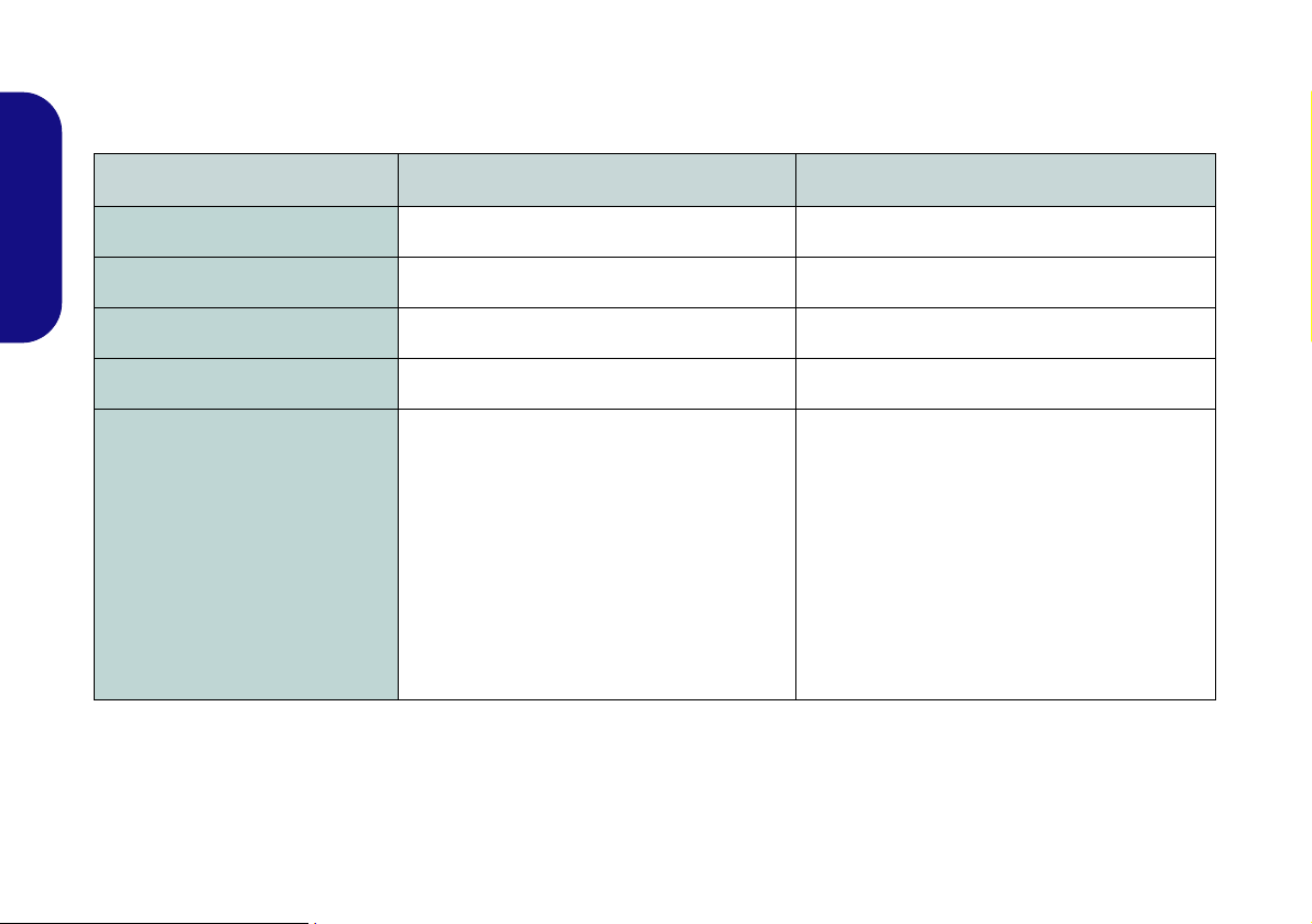
Model Differences
This computer series includes two different model types that mainly differ as indicated in the table below. Note that
your model may appear slightly different from those pictured in this manual.
Feature Model A Model B
English
Headphone/Microphone Jacks
Height Adjustable Stand
USB 2.0 Ports
Weight
Model Style
N/A Yes
4 * USB 2.0 Ports 2 * USB 2.0 Ports
On Stand On Main Unit
11kg with ODD 8kg with ODD
Table 1 - Model Differences
4
Page 11

System Startup
Shut Down
Note that you should always shut your computer down by
choosing Shut Down from the Start Menu.
This will help prevent hard disk or system problems.
Power Button (located under the LCD)
1. Remove all packing materials.
2. Place the computer on a stable surface.
3. Securely attach any peripherals you want to use with the
computer (e.g. keyboard and mouse) to their ports.
4. Attach the AC/DC adapter to the DC-In jack l ocated under the
LCD, then plug the AC power cord into an outlet, and connect
the AC power cord to the AC/DC adapter.
5. Push the power button at the front of the computer (un der the
LCD) to turn the computer “on”.
System Software
Your computer may already come with system software
pre-installed. Where this is not the case, or where you are
re-configuring your computer for a different system, you
will find this manual refers to Microsoft Windows 7.
English
Figure 1 - Computer with AC/DC Adapter Plugged-In/Pow-
er Button
5
Page 12

System Map: Front View (Model A)
Figure 2
Front View (Model A)
1. PC Camera (Optional)
2. LCD (With Optional Touch
Panel)
3. Power & System Activity LED
Indicators
4. Function Buttons*
5. Power Button*
6. 2 * USB Ports
7. Microphone-In Jack
8. Headphone/S peaker-Out Jack
Under the LCD
9. RJ-45 LAN Jack
10. 2 * USB Ports
11. eSATA Po rt
12. External Monitor Port
13. 2 * COM Ports
14. DC-In Jack
4
3
1
7
8
5
6
2
6
7
8
4
5
3
11
12
10
13
14
9
*Note the power and function buttons are located
along the bottom of the LCD
13
Under the LCD
English
6
Page 13

System Map: Front View (Model B)
Figure 3
Front View (Model B)
1. PC Camera (Optional)
2. LCD (With Optional Touch
Panel)
3. Power & System Activity LED
Indicators
4. Function Buttons*
5. Power Button*
Under the LCD
6. RJ-45 LAN Jack
7. 2 * USB Ports
8. eSATA Port
9. External Monitor Port
10. 2 * COM Ports
11. DC-In Jack
6
7
8
4
5
3
11
10
9
*Note the power and function buttons are located
along the bottom of the LCD
Under the LCD
1
2
3
4
5
10
English
7
Page 14

LED Indicators
The LED indicators on the computer display helpful information about the current status of the computer.
Icon Color Description
Function Buttons
Icon Description
English
8
Green The computer is On
Blinking Green The computer is in Sleep Mode
The AC/DC Adapter is Plugged
Orange
Green System Activity
Table 2 - LED Indicators
in & the Computer is Powered
Off
Decrease/Increase Buttons - Use the buttons to
decrease/increase the brightness/volume
Menu Toggle - Use this button to switch between
the brightness or audio menus and use the but-
tons above to adjust
Mode Toggle - Use this button to toggle between
the computer and HDMI Input modes
Table 3 - Function Buttons
Page 15
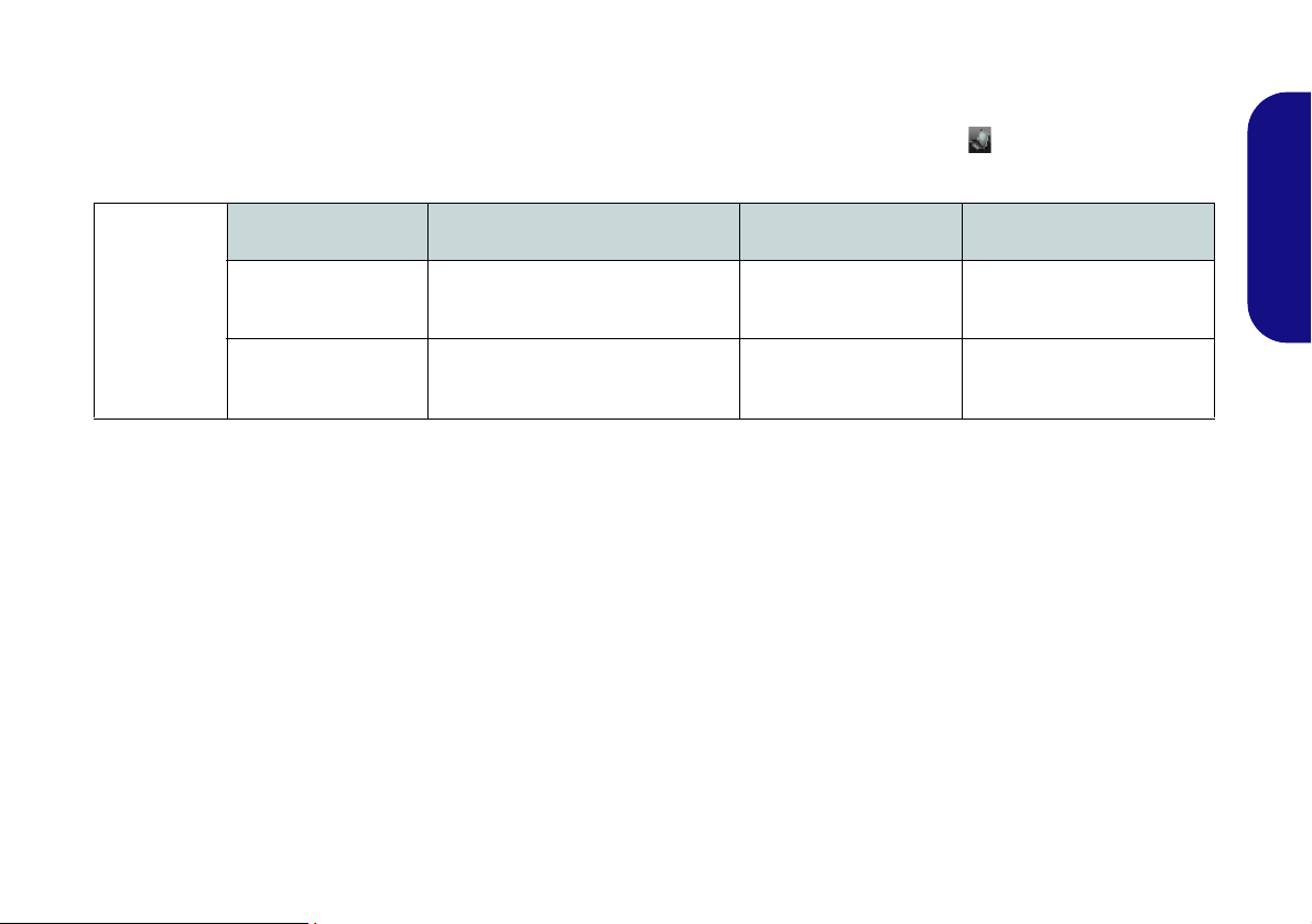
On Screen Display Indicators
Visual indicators for brightness, volume, camera power toggle and Bluetooth power toggle (note that the camera and
Bluetooth power indicators will only display if the modules are included in your purchase configuration) are available
when the OSD AP is installed (see OSD on page 19). When the driver is installed, an icon will appear in the task-
bar.
OSD Icon Description OSD Icon Description
Brightness Decrease/Increase Camera Power Toggle
Volume Decrease/Increase Bluetooth Power Toggle
Table 4 - On Screen Display Indicators
The indicators will appear when the computer boots up, or resumes from a power saving state, in order to display the
current power status of the camera and/or Bluetooth module. If you adjust the brightness or volume the OSD indicators will appear, and will also allow you to adjust the power status of the camera and/or Bluetooth module using the
mouse to click on the icon.
If your purchase configuration includes the Multi-Touch Panel you may use the stylus pen (or a finger) to slide along
the bars under the on-screen symbols to adjust the volume and brightness and controls, or to press the on/off buttons
to toggle power to the camera and/or Bluetooth module.
English
9
Page 16

Keyboard Options
Dongle & USB Ports
A single USB dongle is provided with the keyboard,
mouse and TV Tuner. This dongle acts as a transceiver
for the keyboard and mouse, and as a RF transceiver for
the TV Tuner. This dongle may be inserted into any of the
USB ports, however if you have included the TV Tuner in
your purchase option it is recommended that you do not
plug the dongle into the USB port located behind the rear
top cover in order to prevent any interference.
Figure 5
USB Port for Wire-
less Keyboard &
Mouse Kit
There are two keyboard options for this computer series.
These keyboards may include embedded numerical keypads for easy numeric data input and/or function keys/hot
keys to allow you to change operational features instantly. Some keyboards may require a driver to access all
available functions etc.
English
Figure 4 - Optional Wireless Keyboard & Mouse Kit
10
Wireless Keyboard & Mouse USB Transceiver
If your purchase includes an optional Wireless Keyboard
& Mouse Kit you can use the USB po rt located behind
the rear top cover to house the USB transceiver.
Page 17

System Map: Left View
Figure 6
Left View
1. Stand
2. Multi-in-1 Card Reader
3. ExpressCard Slot /
54(34)
4. 1 * USB 3.0 Port
5. HDMI-in Port
6. Line-In Jack
7. S/PDIF-Out Jack
8. Headphone/SpeakerOut Jack
9. Microphone-In Jack
USB 3.0 Port
The USB 3.0 port is denoted by its blue color;
USB 2.0 ports are colored
black. Note that the USB
3.0 port requires a driver installation.
2
3
4
5
6
7
1
1
2
3
4
5
6
7
8
9
Model A Model B
Multi-in-1 Card Reader
The card reader allows you to use the most popular digital storage card formats:
MMC (MultiMedia Card) / RSMMC
SD (Secure Digital) / Mini SD / SDHC / SDXC
MS (Memory Stick) / MS Pro / MS Duo
English
11
Page 18

HDMI-In Port
Input Source
HDMI
HDMI-In Port
Note that this is an HDM I Input port and cannot be used
as an HDMI Output port to
display the computer’s
screen on external displays.
HDMI-In Port
Note that the HDMI-In
Port supports video and
audio signals from attached HDMI devices.
This computer features an HDMI (High-Definition Multimedia Interface) input port that allows you to display external sources such as Blu-ray players, DVDs, set top boxes and games consoles etc. on your computer screen.
The computer itself does not need to be powered on to display video and audio from external sources. As long as the
computer is plugged-in to a power source through the AC/DC adapter (the LED indicator will be orange if the
computer is plugged-in but powered off), simply plug-in the HDMI cable from the external device to the computer’s
HDMI-In port and the computer will act as the display device.
English
Mode Toggle
Press the mode toggle button to switch between the computer and HDMI input modes. When the “Input Source
HDMI” is displayed you can use any HDMI device plugged in to the computer’s HDMI-In port.
12
Figure 7 - HDMI Input
Page 19

System Map: Right View
3
2
1
Figure 8
Right View
1. Emergency Eject
Hole
2. Optical Device
Drive Bay
3. Security Lock
Slot
4. Stand
Disc Emergency Eject
If you need to manually eject a
disc (e.g. due to an unexpected power interruption) you may
push the end of a straightened
paper clip into the emergency
eject hole. Do not use a sharpened pencil or similar object
that may break and become
lodged in the hole.
4
1
2
3
4
Model A
Model B
Moving the Computer
We strongly recommend using both hands to move
the computer. You can use one hand to grip the
computer by the stand, and the other to hold the top
of the LCD screen.
It is recommended that you carry the comput er with
the LCD facing your body to avoid scratching the
surface against other objects. However take care
not to scratch the LCD with any personal items, bel t
fittings or jewelry etc.(one hand gripping the stand
and the other gripping the top of the computer to
avoid accidentally dropping it).
English
13
Page 20

Tilting the Screen
Model A
Model B
LCD
Screen
Raise/
Lower
It is possible to tilt the LCD screen in order to get the best possible viewing angle of the screen without glare etc.
Apply pressure with one hand at the base of the computer, while carefully pushing the LCD screen to tilt it to the
appropriate viewing angle.
Adjusting the LCD Screen Height
(Only Model B Computers allow the height of the screen to be adjusted)
English
It is possible to raise/lower the screen height in order to get the best possible vertical viewing position of the screen.
• Hold the left and right sides of the computer to raise/lower the screen.
• Do not hold the bottom of the screen to adjust the viewing angle or height as the screen function buttons are located there.
•Carefully apply pressure at the top of the screen to tilt it.
• Note that the screen has no fixed lock position and you are free to raise/lower and tilt the screen to any position the stand allows (do
not force it beyond the point of resistance)
.
14
Figure 9 - Tilting the Screen
Page 21

System Map: Rear View
Figure 10
Rear View
1. Stand
2. Rear Component
Cover
3. Vent
4. Security Lock Slot
5. Carrying Handle Area
1
3
2
3
3
4
5
1
3
2
3
3
4
5
Model A
Model B
Wall Mounting Information
The computer may be mounted on
a wall for display. The system
meets VESA (FDMI) Standard
(100mm * 100mm) for wall mounting. However if you intend to wall
mount the system please contact
your service center for information
in order to avoid personal injury, or
damage to the computer.
CPU
The CPU is not a user serviceable
part. Accessing the CPU in any
way may violate your warranty.
Overheating
To prevent your computer from
overheating make sure nothing
blocks the vent while the computer
is in use.
English
15
Page 22
Video Features
1
2
2
1
Figure 11 - Display Control Panel
3
3
Figure 12 - Intel Graphics and Media Control Panel
You can switch display devices, and configure display
options, from the Display contro l panel in Windows and/
or the Intel Graphics and Media Control Panel as long
as the video dirver is installed.
To access Display control panel:
English
1. Click Start, and click Control Panel (or point to Settings and
click Control Panel).
2. Click Display (icon) - in the Appearances and
Personalization category.
3. Click Adjust Screen Resolution/Adjust resolution.
OR
4. Alternatively you can right-click the desktop and select
Screen resolution.
5. Use the dropbox to select the screen resolution .
6. Click Advanced settings .
To access the Intel® Graphics and Media Control Panel:
1. The Intel® Graphics and Media Control Panel can be
accessed by clicking the icon in the taskbar and
selecting Graphics Properties from the menu (or from the
Inte(R) Graphics and Media in the Windows Control Panel).
OR
2. Right-click the desktop and select Graphics Properties from
the menu.
16
Page 23
Audio Features
Sound Volume Adjustment
The sound volume lev el is
set using the volume control within Windows. Click
the Volume icon in the
taskbar to check the setting.
Figure 13 - Power Options
You can configure the audio options on your computer
from the Sound control panel in Windows, or from the
VIA HD Audio Deck control pan-
el.
The volume may also be adjusted by means of the function buttons
LCD.
located along the bottom of the
Power Management Features
The Power Options (Hardware and Sound menu) control panel icon in Windows allows you to configure power management features for your computer. You can
conserve power by means of power plans and configure
the options for the power button, sleep button, display
and sleep mode from the left menu. Note that the Power
saver plan may have an affect on computer performance.
Click to select one of the existing plans, or click Create
a power plan in the left menu and select the options to
create a new plan. Click Change Plan Settings and click
Change advanced power settings to access further configuration options.
English
17
Page 24

Driver Installation
Driver Page#
The Device Drivers & Utilities + User’s Manual disc
contains the drivers and utilities necessary for the proper
operation of the computer. Insert the disc and click In-
stall Drivers (button), or Option Drivers (button) to ac-
cess the Optional driver menu. Install the drivers in the
order indicated in Table 5. Click to select the drivers you
English
wish to install (you should note down the drivers as you
install them). Note: If you need to reinstall any driver,
you should uninstall the driver first.
Manual Driver Installation
Click the Browse CD/DVD button in the Drivers Installer application and browse to the executable file in the ap-
propriate driver folder. If a
appears
during the installation procedure, click Cancel,
Found New Hardware
and follow the installation procedure as directed.
Windows Update
After installing all the drivers make sure you enable
Windows Update in order to get all the latest security
updates etc. (all updates will include the latest hotfixes
from Microsoft).
wizard
Chipset page 19
Video page 19
LAN page 19
Card Reader/ExpressCard
OSD page 19
USB 3.0 page 19
Intel MEI page 19
Audio page 19
PC Camera (optional) page 20
WLAN Module (optional)
Bluetooth & WLAN Combo Module - WLAN
(optional)
Bluetooth & WLAN Combo Module Bluetooth (optional)
Touch Screen Module (optional) page 24
Enable Windows Update (see left)
Table 5 - Driver Installation
page 19
page 22
page 23
18
Page 25

Chipset
1. Click 1.Install Chipset Driver > Yes.
2. Click Next > Yes > Next > Next.
3. Click Finish to restart the computer.
Video
1. Click 2.Install VGA Driver > Yes.
2. Click Next > Yes > Next > Next.
3. Click Finish to restart the computer.
LAN
1. Click 3.Install LAN Driver > Yes.
2. Click Install > Finish.
3. The network settings can now be configured.
Card Reader/ExpressCard
1. Click 4.Install Cardreader Driver > Yes.
2. Click Install > Finish.
OSD
1. Click 5.Install OSD AP > Yes.
2. Click Next > Next.
3. Click Finish > Finish to restart your computer.
USB 3.0
1. Click 6.Install USB 3.0 Driver > Yes.
2. Click Next.
3. Click the button to accept the license and then click
Next.
4. Click Next > Install.
5. Click Finish.
Intel MEI Driver
1. Click 7.Install MEI Driver > Yes.
2. Click Next > Yes > Next > Next.
3. Click Finish.
Audio
1. Click 8.Install Audio Driver > Yes.
2. Click Next.
3. Click the button to agree to the license and click Next.
4. Click Next > Next > Next.
5. Click Finish to restart the computer.
English
19
Page 26

PC Camera (Option)
There are a number of different camera modules available with this computer model series. You will have the
appropriate application installed for your camera. Make
sure you access the application via the desktop shortcut. The PC Camera module uses the camera application
to capture video files. Install the driver as per the instruc-
English
tions below.
PC Camera Driver Installation
1. Make sure the camera module is on before beginning
the installation process (use the On Screen Display to
toggle power to the camera module - see page 9).
2. Click Option Drivers (button).
3. Click 1.Install Webcam Driver > Yes.
4. Click Next > Install > Finish to restart the computer.
5. Run the camera application program from the desktop
shortcut.
PC Camera Audio Setup
If you wish to capture video & audio with your camera,
it is necessary to setup the audio recording options in
Windows.
1. Click Start, and click Control Panel (or point to Settings and
click Control Panel).
2. Click Sound (Hardware and Sound).
3. Click Recording (tab).
4. Right-click Microphone (for the microphone-in jack on the l eft
side of the computer) or FrontMic (for t he microphone -in jack
on the base of the computer) and make sure the item is not
disabled.
5. Double-click Microphone/FrontMic (or select Properties
from the right-click menu).
6. Click Levels (tab), and adjust t he Microphone/FrontMic and
Microphone Boost sliders to the leve l required.
7. Click OK and close the control panels.
8. Run the camera application from the desktop shortcut.
9. Go to the Devices menu heading and select Microphone/
FrontMic (it should have a tick alongside it).
10. Go to the Capture menu heading and select Capture Audio
(it should have a tick alongside it).
20
Page 27

Camera Application
The camera application is video viewers use ful for general purpose video viewing and testing, and can capture
video files to .avi format.
1. Run the camera application from the desktop shortcut (it is
recommended that you Set Capture File before the capture
process - see “Set Capture File” below).
2. Go to the Capture menu heading (if you wish to capture
audio check PC Camera Audio Setup on page 20) and
select Start Capture.
3. Click OK (the file location wi ll be displayed i n the pop-up box )
to start capturing the video, and press Esc to stop the capture
(you can view the file using the Wi ndows Media Player).
Set Capture File
Prior to capturing video files you may select the Set Capture File... option in the File menu, and set the file name
and location before capture (this will help avoid accidentally overwriting files). Set the name and location then
click Open, then set the “Capture file size:” and click
OK. You can then start the capture process as above.
Reducing Video File Size
Note that capturing high resolution video files requires a
substantial amount of disk space for each file. After recording video, check the video file size (right-click the
file and select Properties) and the remaining free space
on your hard disk (go to Computer, right-click the hard
disk, and select Properties). If necessary you can remove the recorded video file to a removable medium e.g.
CD, DVD or USB Flash drive.
Note that the Windows system requires a minimum of
15GB of free space on the C: drive system partition. In
order to prevent system problems it is recommended that
you save the captured video file to a location other than
the C: drive (see Set Capture File on page 21), limit the
file size of the captured video or reduce video resolution.
To Reduce Video Resolution Output Size:
1. Run the camera application from the desktop shortcut.
2. Go to Options and scroll down to select Video Capture
Pin....
3. Click the Output Size drop box and select a lower resolution
size in order to reduce the captured file size.
English
21
Page 28

Wireless LAN Module (Option)
Third-party WLAN and Bluetooth 4.0 Combo modules
For third-party WLAN and Bluetooth 4.0 Combo modules,
both the WLAN & Bluetooth drivers are installed at the
same time, and therefore it is not necessary to install the
Bluetooth driver separately (a warning message will appear if you attempt to install the Bluetooth driver).
Follow the instructions below to install the WLAN driver.
English
WLAN (Intel)
1. Click Option Drivers (button).
2. Click 2.Install WLAN Driver > Yes.
3. Click Next > Next.
4. Click the button to accept the license and click Next.
5. Click Typical (buttom) or Custom (buttom).
6. Click Install > Finish.
WLAN/WLAN and Bluetooth 3.0 Combo (Third Party)
1. Click Option Drivers (button).
2. Click 2.Install WLAN Driver > Yes.
3. Choose the language you prefer and click Next > Next
> Install.
4. Click Finish to restart the computer.
22
WLAN and Bluetooth 4.0 Combo (Third Party)
1. Click Option Drivers (button).
2. Click 2.Install WLAN Driver > Yes.
3. Click Next.
4. Click Finish to restart the computer.
Connecting to a Wireless Network
The operating system is the default setting for Wireless
LAN control in Windows. Make sure the Wireless LAN
module is turned on.
1. Click the taskbar wireless icon , and then double-click an
access point to connect to or click to Open Network and
Sharing Center if you do not see a network you want to connect to in the taskbar menu (a list of options will appear al l owing setting changes, and creating a new network)
2. You may need to enter a security key for any access point to
which you are trying to connect.
3. Click to selct a network location (e.g. Home, Work or
Public).
4. Click “View or change settings in Network and Sharing
Center” to access further options for the connection.
5. Click the taskbar icon to see any currently connected
networks.
6. To disconnect from the wireless network you can click the
taskbar wireless icon , click the active connection and then
click Disconnect (button).
.
Page 29

Bluetooth Module (Option)
Third-party WLAN and Bluetooth 4.0 Combo modules
For third-party WLAN and Bluetooth 4.0 Combo modules,
both the WLAN & Bluetooth drivers are installed at the
same time, and therefore it is not necessary to install the
Bluetooth driver separately (a warning message will appear if you attempt to install the Bluetooth driver).
Follow the instructions below to install the Bluetooth
driver.
WLAN and Bluetooth 3.0 Combo (Third Party)
1. Click Option Drivers (button).
2. Click 3.Install Combo BT Driver > Yes.
3. Click Next.
4. Click the button to accept the license and click Next.
5. Click Next (select if you want to create an icon to
appear on the desktop) > Next > Install > Finish.
6. The Bluetooth icon will appear on the desktop and
the Bluetooth item will be installed in the Programs/
All Programs menu.
Bluetooth Configuration
Setup your Bluetooth Device so the Computer Can Find it
1. Turn your Bluetooth device (e.g. PDA, mobile phone etc.) on.
2. Make the device discoverable (to do this check your device
documentation).
To Turn the Bluetooth Module on
1. A Bluetooth icon will appear in the taskbar (you may need
to enable the option from the Bluetooth Devices control
panel)
.
2. Y ou ca n then do any of the f ollowin g to acce ss the Bluetooth
Devices control panel.
• Double-click the icon to access the Bluetooth Devices
control panel.
• Click/Right-click the icon and choose an option from
the menu.
Bluetooth Help
Click Start and select Help & Support and then type
Bluetooth in the Search Help box, and then click the
magnifying glass icon to find more information on Bluetooth transfer.
23
English
Page 30
Touch Screen Module
Touch Panel Input Device
Do not use any sharp or pointed objects as your input device e.g. the end of a pen or pencil.
Be very careful not to press too hard with the stylus pen
when using it as the input device.
If you have included a Touch Screen module in your purchase option, you should
with the computer in the same way you would use a
mouse (use a stylus pen to tap/double-tap on-screen buttons etc.). Make sure you install the driver as indicated
below.
English
Touch Screen Driver Installation
1. Click Option Drivers (button).
2. Click 4.Install Touch Screen Driver > Yes.
3. Click Next > Next.
4. Click Finish to restart the computer.
obtain a stylus pen to interact
Tablet PC Options
Tablet PC settings (for touch screen input) may be customized from the Tablet PC Settings in Windows 7.
1. T o access the control p anel click St art, and then click Control
Panel.
2. The Tablet PC Settings and Pen and Touch control panel
are in the Hardware and Sound category .
Figure 14 - Pen and Touch & Tablet PC Settings Control
Panels
24
Page 31

3. Click T a blet PC Settings and click Other.
4. Click Go to Input Panel Settings (in Tablet PC Input Panel
Options) to configure where and how the Tablet PC Input
Panel appears.
Figure 15 - Input Panel Settings
5. Click Go to Pen and Touch (in Pen and touch) to configure
the Pen Options, flicks and handwriting etc.
6. When not in use the Tablet PC Input Panel docks at the side
of the screen (and may be docked at either side of the screen
at any height) with just a small portion visible.
7. Move the pen over the TIC and then tap it to activate it. The
input panel allows you to input text without the use of a
keyboard.
8. You can use the writing pad (write continuously), character
pad (write one character at a time) or touch ke yboa rd t o inpu t
text.
9. Use Help topics from the Tools menu for further information.
English
Figure 16 - Tablet PC Input Panel
25
Page 32

Troubleshooting
Problem Possible Cause - Solution
No sound can be heard
from the internal/external
speakers/headphones.
English
The captured video files
from the PC Camera are
taking up too much disk
space.
You have plugged in headphones or speakers to the audio jacks at the front of the computer. Note that
the system has two sets of audio jacks as well as internal speakers. All the audio jacks cannot
function at the same time and are therefore assigned a priority order depending on your audio
connections.
Priority 1 = The audio jacks at the front of the computer. Thus the audio jacks at the side of the
computer and the internal speakers are di sabled (e.g if you c onnect hea d phones to t he head phon e-out
jack at the front of the computer then speakers/headphones connected to the headphone-out jack at
the side of the computer are disabled).
Priority 2 = The audio jacks at the side of the computer. Thus the internal speakers are disabled
(e.g if you connect speakers to the headphone-out jack at the side of the computer then the internal
speakers are disabled).
Priority 3 = The internal speakers. If there are no audio connections to any of the audio jacks, then
the audio output will default to the internal speakers.
Note that capturing high resolution video files requires a substantial amount of disk space for each file.
See Reducing Video File Size on page 21.
26
Page 33

Specifications
Latest Specification Informat ion
The specifications listed in this section
are correct at the time of going to press.
Certain items (particularly processor
types/speeds) may be changed, delayed or updated due to the manufacturer's release schedule. Check with
your service center for details.
Processor Options
Intel® Core™ i7 Processor
i7-640M (2.80GHz), i7-620M (2.66GHz)
4MB L3 Cache & 1066MHz FSB
Intel® Core™ i5 Processor
i5-540M (2.53GHz), i5-520M (2.40GHz),
i5-450M (2.40GHz)
3MB L3 Cache & 1066MHz FSB
Intel® Core™ i3 Processor
i3-370M (2.40GHz), i3-350M (2.26GHz),
i3-330M (2.13GHz),
3MB L3 Cache & 1066MHz FSB
Intel® Pentium® Processor
P6000 (1.86GHz)
3MB L3 Cache & 1066MHz FSB
Intel® Celeron® Processor
P4500 (1.86GHz)
2MB L3 Cache & 1066MHz FSB
Core Logic
Intel® HM55 Chipset
BIOS
One 16Mb SPI Flash ROM
Phoenix™ BIOS
Memory
Two 204 Pin SO-DIMM Sockets Supporting
DDR3 1066/1333MHz Memory
Memory Expandable up to 8GB
(The real memory operating frequency
depends on the FSB of the processor.)
Video Adapter
Intel® GMA HD
Shared Memory Architecture up to 1.7GB
Supports DirectX10.0
Security
BIOS Password
Security (Kensington® Type) Lock Slot
LCD
19" (48,26cm) WXGA+ (1440 * 900) TFT
LCD
Adjustable Height (Model B Only)
(Factory Option) Hard Glass
(Factory Option) Touch Panel
Audio
High Definition Audio Compliant Interface
2 * Built-In Speakers
Storage
(Factory Option) One Changeable
12.7mm(h) Optical Device Type Drive
(Super Multi Drive Module or
Blu-Ray Combo Drive Module)
Two Changeable 2.5" 9.5mm (h) SATA
(Serial) HDD
English
27
Page 34

Interface
Four USB 2.0 Ports (Model A)
Two USB 2.0 Ports (Model B)
One USB 3.0 Port
One eSATA Port
Two Serial (COM) Ports
One External Monitor Port
One Headphone-Out Jack
English
One Microphone-In Jack
One S/PDIF Output Jack
One Line-In Jack
One RJ-45 LAN Jack
One DC-in Jack
One HDMI-In Port
Resolutions Supported:
1440 * 900
1280 * 800
1280 * 720
1024 * 768
800 * 600
Slots
One Slot for WLAN Module or Combo
WLAN and Bluetooth Module
One ExpressCard/34(54) Slot
Card Reader
Embedded Multi-in-1 Card Reader
MMC (MultiMedia Card) / RS MMC
SD (Secure Digital) / Mini SD / SDHC/
SDXC
MS (Memory Stick) / MS Pro / MS Duo
Keyboard
Standard USB Keyboard (Option) or RF
Keyboard with Receiver (Option)
(Factory Option) RF USB Remote Controller with Transceiver
Communication
Built-In Gigabit Ethernet LAN
(Factory Option) 2.0M Pixel USB PC Cam-
era Module
WLAN/ Bluetooth Half Mini-Card
Modules:
(Factory Option) Intel® WiFi Link 1000
(802.11b/g/n) Wireless LAN
(Factory Option) Intel WiFi Link 6200
(802.11a/g/n) Wireless LAN
(Factory Option) Third-Party Wireless LAN
(802.11b/g/n)
(Factory Option) Third-Party Wireless LAN
(802.11b/g/n) + Bluetooth 3.0
(Factory Option - Model B Only) ThirdParty Wireless LAN (802.11b/g/n) + Bluetooth 4.0
Power
Full Range AC/DC Adapter
AC Input: 100 - 240V, 50 - 60Hz
DC Output: 19V, 4.74A (90W)
Envionmental Spec
Temperature
Operating: 5
Non-Operating: -20°C - 60°C
Relative Humidity
Operating: 20% - 80%
Non-Operating: 10% - 90%
°C - 35°C
Dimensions & Weight
450mm (w) * 312mm (d) * 66.5mm (h))
Around 11kg (Model A)
Around 8kg (Model B)
28
Page 35

Hinweis
Das Unternehmen behält sich das Recht vor, diese Publikation ohne Vorankündigung zu überarbeiten und den Inhal t zu
verändern. Alle enthaltenen Informationen sind nur Anhaltspunkte und stellen keine Verpflichtung seitens des Herstellers
oder Wiederverkäufers dar. Sie übernehmen weder Verantwortung oder Haftung für mögliche Fehler oder Ungenauigkeiten dieser Publikation noch sind sie in irgendei ner We ise verantwortlich für Verluste oder Schäden aus der Nutzung
(oder fehlerhaften Nutzung) dieser Publikation.
Die Publikation und alle beiliegende Software darf nicht, ganz oder in Teilen, ohne vorheriges Einverständnis des Verkäufers, Herstellers oder Autors dier Publikation reproduziert, üb ersetzt, übertragen oder in maschinenlesbare Form umgewandelt werden, abgesehen von Kopien, die für Archivzwecke erstellt werden.
In dier Publikation erwähnte Marken- und Produktnamen können Copyrights und/oder eingetragene Warenzeichen ihrer
jeweiligen Firmen in. Sie werden nur zu Ide ntifikationszwecken e rwähnt und sind nic ht als Werbung für die Produkte o der
ihre Hersteller gedacht.
© März 2012
Intel, Intel Core, Intel Pentium und Intel Celeron sind warenzeichen/eingetragenes warenzeichen der Intel Corporation.
Deutsch
29
Page 36

Über das Ausführliche Benutzerhandbuch
Diese Kurzanleitung soll einen Überblick über die Schritte
geben, die dazu notwendig sind, das System zu starten. Dieses ist nur eine Ergänzung und kein Ersatz für das erweiterte
englischsprachige Benutzerhandbuch, das auf der mitgelieferten Disc Device Drivers & Utilities + User's Manu-
al im Adobe-Acrobat-Format vorliegt. Diese Disc enthält
auch die Treiber und Utility-Programme, die für einen einwandfreien Betrieb des Computers notwendig sind.
Einige oder alle Funktionen des Computers sind bereits
Deutsch
eingerichtet worden. Falls das nicht der Fall ist oder wenn
Sie einzelne Teile des Systems neu konfigurieren (oder neu
installieren) möchten, finden Sie eine Anleitung im erweiterten Benutzerhandbuch. Die Disc Device Drivers & Utili-
ties + User's Manual enthält nicht das Betriebssystem.
Informationen zu gesetzlichen Vorschriften
Die Informationen zu gesetzlichen Vorschriften finden Sie
im erweiterten Benutzerhandbuch auf der Disc Device Dri-
vers & Utilities + User's Manual.
Hinweise zu Pflege und Betrieb
Der Computer ist zwar sehr stabil, kann aber dennoch beschädigt werden. Damit es nicht dazu kommt, sollten Sie
die folgenden Hinweise beachten:
• Das Gerät darf nicht herunterfallen und in anderer Form Stö-
ßen ausgesetzt werden. Wenn der Computer fällt, können das
Gehäuse und andere Komponenten beschädigt werden.
• Halten Sie den Computer trocken, Das Gerät darf nichtüber-
hitzt werden. Computer und Netzteil dürfen nicht in der Nähe von
Wärmequellen stehen oder gelagert werden. Dies ist ein elektrisches Gerät. W enn Wasser oder andere Flüssigkeiten eindringen,
kann der Computer stark beschädigt werden.
• Vermeiden Sie Interferenzen mit anderen Geräten. Halten Sie
den Computer fern von magnetischen Feldern, die von Stromquellen, Monitoren, Magneten etc. erzeugt werden. Die können die
Leistung beeinträchtigen und Ihre Daten beschädigen.
• Achten Sie auf die richtige Bedienung des Computers. Schalten
Sie ihn erst aus, wenn alle Programme geschlossen wurden
(speichern Sie Ihre Daten!). Speichern Sie regelmäßig Ihre Daten,
da diese verloren gehen können, wenn der Akku verbraucht ist.
• Seien Sie vorsichtig bei der Verwendung von Peripheriegerä-
ten.
30
Page 37

Reparatur
Reparieren Sie das Gerät nicht selbst. Damit verstoßen Sie
gegen die Garantiebedingungen und Sie können Schäden
am Gerät und an der eigenen Gesundheit verursachen.
Überlassen Sie alle Reparaturen autorisiertem Fachpersonal. Trennen Sie den Computer vom Stromnet z. Unter den
folgenden Umständen sollten Sie das Gerät zur Reparatur
geben:
• Wenn das Netzkabel oder der AC/DC-Adapter beschädigt oder
zerschlissen sind.
• Wenn der Computer Regen ausgesetzt war oder mit Flüssigkeiten
in Berührung gekommen ist.
• Wenn der Computer unter Beachtung der Bedienungsanweisungen
nicht korrekt arbeitet.
• Wenn der Computer heruntergef a llen ist oder beschädigt wurde
(berühren Sie nicht die giftige Flüssigkeit des LCD-Bildschirms).
• Wenn ein ungewöhnlicher Geruch, Hitze oder Rauch aus dem
Computer entweicht.
Stromsicherheit
Für dieses Computer werden bestimmte Stromanforderungen gestellt:
• V erwenden Sie nur einen AC/DC-Adapter , der für die Verwendung
mit diesem Computer zugelassen ist.
• Der AC/DC-Adapter kann zwar für internationale Benutzung vorgesehen sein, benötigt aber trotzdem eine gleichmäßige, ununterbrochene Stromversorgung. Wenn Sie sich über Ihre lokalen
Stromspezifikationen nicht im klaren sind, wenden Sie sich an
Ihren Servicevertreter oder Ihre lokale Stromgellschaft.
• Der AC/DC-Adapter kann einen zwei- oder dreipoligen geerdeten
Netzstecker haben. Der dritte Pol hat eine wichtige Sicherheits-
funktion. Setzen Sie die nicht außer Kraft. Wenn Sie keinen
Zugang zu einer passenden Steckdose haben, lassen Sie von einem
qualifizierten Elektriker eine solche einbauen.
• Fassen Sie das Netzkabel am Stecker und nicht am Kabel an, wenn
Sie es vom Stromnetz trennen möchten.
• Achten Sie darauf, daß die Steckdose und alle verwendeten Verlängerungskabel die Gesamtstromlast aller angeschlossenen
Geräte trägt.
• Trennen Sie den Computer vor dem Reinigen von allen externen
Stromquellen.
Reinigung
• Reinigen Sie den Computer mit einem weichen, sauberen Tuch.
Tragen Sie das Reinigungsmittel nicht direkt auf den Computer
auf.
• Verwenden Sie keine flüchtigen Reinigungsmittel
(Petroleumdestillate) oder Scheuermittel zum Reinigen des
Computers.
Deutsch
31
Page 38

Modellunterschiede
Diese Computerserie umfasst zwei verschiedene Modelltypen, die sich hauptsächlich in Fol gendem unterscheiden. Es ist
möglich, dass das von Ihnen erworbene Modell von dem in diesem Benutzerhandbuch abgebildeten Modell abweicht.
Funktion Modell A Modell B
Höhenverstellbarer Fuß
Lautsprecher/Kopfhörer-
Deutsch
Mikrofon-Eingangsbuchse
USB 2.0-Anschlüsse
Ausgangsbuchse
Gewicht
Modell
Nein Ja
Veir USB 2.0-Anschlüsse Zwei USB 2.0-Anschlüsse
Am Fuß
Ca. 11kg mit optische Laufwerk Ca. 8kg mit optischem Laufwerk
Tabelle 1 - Modellunterschiede
Am Gerät
32
Page 39

Schnellstart
Herunterfahren
Bitte beachten Sie, daß der Computer immer mit dem Befehl
Herunterfahren im Menü
Start heruntergefahren werden muß.
Dadurch werden Festplatten- bzw. Systemprobleme vermieden.
Netzschalter (unter dem LCD-Bildschirm)
1. Entfernen Sie das gesamte Verpackungsmaterial.
2. Legen Sie den Computer auf eine stabile Unterlage.
3. Schließen Sie alle Peripheriegeräte, die Sie mit dem computer
verwenden wollen (z. B. Tastatur und Maus), an die
entsprechenden Schnittstellen an.
4. Verbinden Sie den AC/DC-Adapter mit der DCEingangsbuchse, die sich unter dem LCD-Bildschirm befindet.
Verbinden Sie dann das Netzkabel mit eine r Netzsteckdose und
dem AC/DC-Adapter.
5. Drücken Sie auf den Netzschalter des Computers (unter dem
LCD-Bildschirm), um das Gerät einzuschalten.
Systemsoftware
Möglicherweise wurde Ihr Computer bereits mit vorinstallierter Software ausgeliefert. Ist das nicht der Fall, oder
wenn Sie Ihren Computer für ein anderes System neu
konfigurieren möchten, finden Sie dazu eine Anleitung in
diesem Handbuch zu Microsoft Windows 7.
Deutsch
Abb. 1 - Computer mit angeschlossenem AC/DC-Adapter/
Netzschalter
33
Page 40

Systemübersicht: Ansicht von vorne (Modell A)
Abb. 2
Ansicht von vorne (Modell A)
1. PC-Kamera (optional)
2. LCD-Bildschirm (mit optionalem
Touch Panel)
3. LED für Betriebs- und Systemaktivitätsanzeige
4. Funktionstasten*
5. Netzschalter*
6. 2 USB 2.0-Anschlüsse
7. Mikrofon-Eingangsbuchse
8. Kopfhörer-Ausgangsbuchse
Unter dem LCD-Bildschirm
9. RJ-45 LAN-Buchse
10. 2 USB 2.0-Anschlüsse
11. eSATA Anschluss
12. Schnittstelle für externen Monitor
13. Zwei serielle (COM) Schnittstellen
14. DC-Eingangsbuchse
6
7
8
4
5
3
11
12
10
13
14
9
13
Unter dem LCD-Bildschirm
*Der Netzschalter und die Funktionstasten befinden sich
am Rand des LCD-Bildschirms
4
3
1
7
8
5
6
2
sich
Deutsch
34
Page 41

Systemübersicht: Ansicht von vorne (Modell B)
Abb. 3
Ansicht von vorne (Modell B)
1. PC-Kamera (optional)
2. LCD-Bildschirm (mit optionalem
Touch Panel)
3. LED für Betriebs- und Systemaktivitätsanzeige
4. Funktionstasten*
5. Netzschalter*
Unter dem LCD-Bildschirm
6. RJ-45 LAN-Buchse
7. 2 USB 2.0-Anschlüsse
8. eSATA Anschluss
9. Schnittstelle für externen Monitor
10. Zwei serielle (COM) Schnittstellen
11. DC-Eingangsbuchse
6
7
8
4
5
3
11
10
9
Unter dem LCD-Bildschirm
*Der Netzschalter und die Funktionstasten befinden sich
am Rand des LCD-Bildschirms
1
2
3
4
5
10
Deutsch
35
Page 42

LED-Anzeigen
Die LED-Anzeigen auf dem Computer zeigen wichtige
Informationen über den aktuellen Status des Computers.
Symbol Farbe Beschreibung
Grün Der Computer ist angeschaltet
Deutsch
Lampe blinkt
grün
Orange
Grün
Tabelle 2 - LED-Anzeigen
Das System ist im konfigu-
rierten Energiesparmodus
Der AC/DC-Adapter ist ange-
schlossen
Es wird auf die Festplatte
zugegriffen
Funktionstasten
Symbol Beschreibung
Erhöhen/Verringern-Taste – Mit diesen Tasten
können Sie die Helligkeit/Lautstärke erhöhen/
verringern
Menü-Taste – Mit dieser Taste können Sie zwi-
schen dem Helligkeits- und Audiomenü wech-
seln; mit den oben genannten Tasten können Sie
die Einstellungen ändern
Modus-Taste – Mit dieser Taste können Sie zwi-
schen dem Computer- und HDMI-Eingangsmo-
dus wechseln
Tabelle 3 - Funktionstasten
36
Page 43

OSD-Anzeigen
Wenn OSD AP installiert ist (siehe OSD auf Seite 47), erscheinen auf dem Bildschirm Anzeigen für die Helligkeit, Laut-
stärke, Kamera- und Bluetoothaktivität (die Anzeigen für die Kamera- und Bluetoothaktivität erscheinen nur, wenn diese
bei Ihrer Modellkonfiguration enthalten sind). Ist der Treiber installiert, erscheint ein entsprechendes Symbol in der
Taskleiste.
OSD-Symbol Beschreibung OSD-Symbol Beschreibung
LCD-Helligkeit verringern/erhö-
hen
Audio-Lautstärke verringern/erhö-
hen
Tabelle 4 - OSD-Anzeigen
PC-Kamera aktivieren/deak-
tivieren
Bluetooth-Modul aktivieren/
deaktivieren
Die Anzeigen erscheinen beim Hochfahren des Computers und wenn der Computer aus einem Stromsparmodus wieder aktiviert wird, um den aktuellen Aktivitätszustand der Kamera und/oder des Bluetooth-Moduls anzuzeigen. Wenn Sie die
Helligkeit oder Lautstärke einstellen, erschei nen die Bildschirmanzeigen. Sie können auch den Aktivitätsstatus der Kamera
und/oder des Bluetooth-Moduls durch Anklicken des Moduls ändern.
Wenn das von Ihnen erworbene Modell über ein Multi-Touchpanel verfügt, können Sie mit dem Griffel (oder einem
Finger) die Lautstärke und Helligkeit über die Regler unter den Bildschirmsymbolen einstellen und die Kamera und/oder
das Bluetooth-Modul durch Drücken der jeweiligen Ein/Aus-Taste ein- oder ausschalten.
37
Deutsch
Page 44

Tastaturoptionen
Dongle & USB-Anschlüsse
Für die Tastatur, die Maus und den TV-Tuner gibt es nur
einen USB-Dongle. Dieser Dongle ist der Transceiver für die
Tastatur und die Maus und gleichzeitig RF-Transceiver für
den TV-Tuner. Der Dongle kann an einen beliebigen USBAnschluss angeschlossen werden. Wenn bei Ihrem Modell
jedoch der TV-Tuner enthalten ist, empfehlen wir, nicht den
USB-Anschluss an der Rückseite des Geräts zu verwenden,
um mögliche Interferenzen zu vermeiden.
Abb. 5
USB-Anschluss für
Funk-Tastatur/
Maus
Bei dieser Computerserie gibt es zwei Tastaturoptionen.
Diese Tastaturen können für eine einfache Zifferneingabe
über eingebettete Zahlentasten und/oder Funktionstasten/
Hotkey-Tasten verfügen, mit denen Sie direkt bestimmte
Funktionen aufrufen können. Für einige Tastaturen ist u. U.
ein Treiber erforderlich, durch den diese Funktionen erst
genutzt werden können.
Deutsch
Abb. 4 - Optionale Drahtlostastatur mit Maus
38
USB-Transceiver für Funk-Tastatur/Maus
Wenn Ihr Modell die optionale Funk-Tastatur/Maus hat,
können Sie den USB-Transceiver an den USB-Anschluss
an der Rückseite des Computers anschließen.
Page 45

Systemübersicht:
Abb. 6
Ansicht von links
1. Fuß
2. Multi-in-1 Kartenleser
3. ExpressCard/54(34)Steckplatz
4. USB 3.0-Anschluss
5. HDMI-Eingangsanschluss
6. Line-Eingangsbuchse
7. S/PDIF-Ausgangsbuchse
8. Kopfhörer-Ausgangsbuchse
9. Mikrofon-Eingangsbuchse
USB 3.0-Anschluss
Der USB 3.0-Anschluss ist
blau codiert, USB 2.0-Anschlüsse sind schwarz. Der
USB 3.0-Anschluss erfordert die Installation eines
Treibers.
2
3
4
5
6
7
1
1
2
3
4
5
6
7
8
9
Multi-in-1 Kartenleser
Mit dem Kartenleser können einige der neuesten digitalen Speicherkarten
gelesen werden.
MMC (MultiMedia Card) / RS MMC
SD (Secure Digital) / Mini SD / SDHC/ SDXC
MS (Memory Stick) / MS Pro / MS Duo
Modell A Modell B
Ansicht von links
Deutsch
39
Page 46

HDMI-Eingangsanschluss
Input Source
HDMI
HDMI-Eingangsanschluss
Dieses ist nur ein HDMIEingangsanschluss. Er kann
nicht als HDMI-Ausgangsanschluss verwendet werden, um
das Computerbild auf einem externen Bildschirm anzuzeigen.
HDMI-Eingangsanschluss
Der HDMI-Eingangsanschluss
unterstützt Video- und Audiosignale von angeschlossenen
HDMI-Geräten.
Dieser Computer verfügt über einen HD MI-Eingangsanschluss, an dem Sie externe Geräte wie Blu-ray-Player, DVD-Player, Set-top-Boxen, Spielekonsolen usw. anschließen und auf dem Computerbildschirm wiedergeben können.
Für die Wiedergabe von Video- und Audio dateien extern er Geräte muss der Computer selb st nicht ei ngeschal tet werden .
Schließen Sie zuerst den Computer über den AC/DC-Adapter an eine Netzsteckdose (die LED-Anzeige leuchtet
orangefarben, wenn der Computer angeschlossen aber ausgeschaltet ist) und dann das externe Gerät mit einem HDMIKabel an den HDMI-Eingangsanschluss des Computers an. Der Computer ist dann das Anzeigegerät.
Modus-Taste
Drücken Sie auf die Modus-Taste , um zwischen dem Computer- und HD MI-Eingangsmodus zu wechseln. Wenn “Input Source HDMI” (Signalquelle HDMI) angezeigt wird, können Sie ein beliebiges HDMI-Gerät an den HDMI-
Deutsch
Eingangsanschluss anschließen.
40
Abb. 7 - HDMI-Eingang
Page 47

Systemübersicht:
3
2
1
Abb. 8
Ansicht von recht
1. Schacht für optisches Laufwerk
2. Notauswurfloch
3. SicherheitsschloßBuchse
4. Fuß
Disc-Notauswurf
Wenn eine Disc manuell entnommen
werden muß (z.B. wegen eines
Stromausfalls) können Sie mit dem
Ende einer geradegebogenen Büroklammer in das Notauswurfloch drükken. Verwenden Sie hierzu aber
keinen spitzen Bleistift oder ähnliche
Objekte, die im Loch abbrechen und
darin stekkenbleiben könnten.
4
1
2
3
4
Modell A
Modell B
Transportieren des Computers
Es wird empfohlen, den Computer beim Transport mit
beiden Händen anzufassen. Fassen Sie den Computer
mit einer Hand am
Fuß an und mit der anderen am obe-
ren Rand des LCD-Bildschirms.
Es wird empfohlen, den Computer mit dem LCD-Bildschirm zu Ihnen zeigend zu tragen, um zu vermeiden,
dass er verkratzt wird. Achten Sie darauf, dass der
LCD-Bildschirm dann nicht von einer Gürtelschnalle,
Knöpfen, Schmuck o. ä. verkratzt wird. (Fassen Sie
das Gerät mit einer Hand am Fuß und mit der anderen
Hand oben am Bildschirm fest, damit Sie ihn sicher
halten können).
Ansicht von rechts
Deutsch
41
Page 48

Neigen des Bildschirms
Modell A
Modell B
LCDBildschirm
anhebe
n/absenken
Es ist möglich, den LCD-Monitor zu neigen, um auf diese We ise d en be stmöglichen Sichtwinkel ohne Lichtspiegelungen
einzustellen. Halten Sie den LCD-Monitor mit einer Hand am Fuß fest, während Sie mit der anderen Hand vorsichtig den
Bildschirm auf den gewünschten Winkel neigen.
Einstellen der LCD-Bildschirmhöhe
(Die Bildschirmhöhe lässt sich nur bei Modell B einstellen)
Durch die Höheneinstellung des Bildschirms erreichen Sie seine bestmögliche vertikale Sichtposition.
• Um den Bildschirm höher/niedriger einzustellen, fassen Sie den Computer rechts und links an.
• Fassen Sie dazu nicht am unteren Bildschirmrand an, da sich dort die Funktionstast en befinden.
• Drücken Sie vorsichtig auf den oberen Rand des Bildschirms, um ihn zu neigen.
• Der Bildschirm rastet in keiner festen Position ein. Das bedeutet, dass Sie ihn in jede beliebige Position bringen können,
Deutsch
soweit es der Fuß zulässt (üben Sie bei Widerstand keinen Druck aus).
42
Abb. 9 - Neigen des Bildschirms
Page 49

Systemübersicht:
Abb. 10
Rückansicht
1. Fuß
2. Rückwärtige Abdeckung
des Komponentenfachs
3. Luftungsoffnung
4. SicherheitsschloßBuchse
5. Transportöffnung
1
3
2
3
3
4
5
1
3
2
3
3
4
5
Modell A
Modell B
CPU
Die CPU darf nicht vom Anwender
repariert werden. Jeglicher Zugriff
auf die CPU führt zum Verlust der
Garantieansprüche.
Überhitzung
Zum Schutz vor Überhitzung Ihres
Computers dürfen die Luftungsoffnung(en) nicht während der Computer in Betrieb ist verdeckt
werden.
Informationen zur Wandmontage
Der Computer kann an einer Wand
befestigt werden. Das System entspricht dem VESA-Standard
(FDMI) für die Wandmontage (100
x 100 mm). Wenden Sie sich diesbezüglich an ein Service-Center,
um Verletzungen und Beschädigungen am Computer zu
vermeiden.
Rückansicht
Deutsch
43
Page 50

Grafikfunktionen
1
2
2
1
Abb. 11 - Einstellfenster Anzeige
3
3
Abb. 12 - Intel® Steuerung für Grafik und Medien
Wenn der Grafiktreiber installiert ist, können Sie bei
Windows im Einstellfenster Anzeige und/oder in der Intel®
Steuerung für Grafik und Medien die Anzeigegeräte
wechseln und Anzeigeoptionen konfigurieren .
So öffnen Sie in Windows das Einstellfenster Anzeige:
1. K licken Sie Start (Menü) und klicken Sie Systemsteuerung
(oder zeigen auf Einstellungen und klicken Systemsteue-
rung).
2. K licken Sie auf Anzeige (Symbol) - im Kategorie Darstellung
und Anpassung.
3. K licken Sie auf Bildschirmauflösung anpassen/Auflösung
Deutsch
anpassen.
Oder
4. Sie können auch mit der rechten Maustaste auf den
Arbeitsplatz klicken und dann die Option Bildschirmauflösung
wählen.
5. Wählen Sie aus dem Drop-down-Menü die Bildschirmauflösung
.
6. K licken Sie auf Erweiterte Einstellungen
.
So rufen Sie die Intel® Steuerung für Grafik und Medien
auf:
1. Die Intel® Steuerung für Grafik und Medien kann aufger ufe n
werden, indem Sie in der Taskleiste auf das Symbol
klikken und dann aus dem Menü die Option Grafikeigen-
schaften wählen (sie können dorthin auch über Intel® Grafik
und Medien (Symbol) in der Windows-Systemsteuerung
gelangen).
Oder
2. Klicken Sie mit der rechten Maustaste auf den Desktop und
dann aus dem Menü die Option Grafikeigenschaften wählen.
44
Page 51

Audiofunktionen
Lautstärkeeinstellung
Die Lautstärke wird mit den Windows-
Lautstärkereglern eingestellt. Überprüfen Sie die Einstellung, indem Sie
in der Taskleiste auf das Lautstärke-
Symbol klikken.
Abb. 13
Energieop-
tionen
Die Audioeinstellungen können Sie bei Windows durch
Anklicken des Soundsymbols oder des
-Symbols in der Systemsteue-
Deck
rung aufrufen.
Die Lautstärke kann auch mithilfe der Funktionstasten
am Rand des LCD -Bildschirms eingestellt wer-
den.
VIA HD Audio
Energieverwaltungsfunktionen
Die Energieoptionen von Windows ermöglichen Ihnen die
Konfiguration der Optionen für das Energiemanagement
des Computers. Sie können Strom sparen, indem Sie Ener-
giesparpläne erstellen, die Netzschalter-, Energiespartasten- und im linken Menü den Anzeige- und
Energiesparmodus festlegen. Beachten Sie, dass sich die
Energiesparpläne (Energiesparmodus) auf die Compu-
terleistung auswirken.
Wählen Sie einen bestehenden Plan aus, oder klicken Sie im
linken Menü auf Energiesparplan erstellen, und wählen
Sie die Optionen, um einen neuen Plan zu erstellen. Klicken
Sie auf Energieplaneinstellungen ändern, und klicken Sie
auf Erweiterte Ene rgi eeinst ell ungen än dern, um we itere
Optionen für die Konfiguration aufzurufen.
Deutsch
45
Page 52

Installation der Treiber
Die Disc Device Drivers & Utilities + User's Manual enthält die Treiber und Hilfsprogramme, die für das einwandfreie Funktionieren des Computers notwendig sind. Legen
Sie die mitgelieferte Disc und klicken Sie auf Install Dri-
vers (Schaltfläche), oder klicken Sie auf Option Drivers
(Schaltfläche), um das optionale Treibermenü aufzurufen.
Installieren Sie die Treiber in der in Tabelle 5 angegebenen
Reihenfolge. Markieren Sie die Treiber, die installiert werden sollen (notieren Sie zum späteren Nachlesen die
Treiber, die Sie installiert haben). Hinweis: Muss ein
Treiber neu installiert werden, sollten Sie den alten Treiber
zunächst deinstallieren.
Deutsch
Manuelle Treiber-Installation
Klicken Sie in der Anwendung Drivers Installer auf die
Schaltfläche Brow se CD/DVD und navigieren Sie zu der
ausführbaren Datei in dem Ordner für Ihren Treiber.
Wenn während des Installationsvorgangs das Fenster Neue
Hardware gefunden erscheint, klicken Sie auf Abbrechen, und befolgen Sie dann die Installationsanwei-
sungen.
Treiber Seite#
Chipsatz Seite 47
Video Seite 47
Network (LAN) Seite 47
ExpressCard / Kartenleser Seite 47
OSD Seite 47
USB 3.0 Seite 47
Intel MEI Seite 47
Audio Seite 47
PC-Kamera (Option) Seite 48
WLAN-Modul (Option)
Kombinierte Bluetooth- und WLAN-Modul WLAN (Option)
Kombinierte Bluetooth- und WLAN-Modul Bluetooth (Option)
Touch-Screen-Modul (Option) Seite 52
Windows Update aktivieren (siehe links)
Seite 50
Seite 51
Windows Update
Nachdem Sie alle Treiber installiert haben, sollten Sie die
Funktion Windows Update aktualisieren, um immer die
neuesten Sicherheits-Updates usw. zu erhalten (die Updates
enthalten die neuesten Fehlerbehebungen von Microsoft).
46
Tabelle 5 - Installationsvorgang
Page 53

Chipsatz
1. Klicken Sie auf 1.Install Chipset Driver > Ja.
2. Klicken Sie auf Weiter > Ja > Weiter > Weiter.
3. Klicken Sie auf Fertig stellen, um den Computer neu zu
starten.
Video
1. Klicken Sie auf 2.Install VGA Driver > Ja .
2. Klicken Sie auf Weiter > Ja > Weiter > Weiter.
3. Klicken Sie auf Fertig stellen, um den Computer neu zu
starten.
LAN
1. Klicken Sie auf 3.Install LAN Driver > Ja.
2. Klicken Sie auf Installieren > Fertig stellen.
3. Nun können die Netzwerkeinstellungen konfiguriert
werden.
ExpressCard/ Kartenleser
1. Klicken Sie auf 4.Install CardReader Driver > Ja.
2. Klicken Sie auf Installieren > Fertig stellen.
OSD
1. Klicken Sie auf 5.Install OSD AP > Yes.
2. Klicken Sie auf Next > Next.
3. Klicken Sie auf Finish > Finish um den Computer neu
zu starten.
USB 3.0
1. Klicken Sie auf 6.Install USB 3.0 Driver > Ja.
2. Klicken Sie auf Weiter.
3. Klicken Sie auf die Schaltfläche Ich bin mit den
Bedingungen der Lizenzvereinbarung einverstanden,
und dann auf Weiter.
4. Klicken Sie auf Weiter > Installieren.
5. Klicken Sie auf Fertig stellen.
Intel MEI
1. Klicken Sie auf 7.Install MEI Driver > Ja.
2. Klicken Sie auf Weiter > Ja > Weiter > Weiter.
3. Klicken Sie auf Fertig stellen.
Audio
1. Klicken Sie auf 8.Install Audio Driver > Ja.
2. Klicken Sie auf Weiter
3. Klicken Sie auf die Schaltfläche Ich bin mit den
Bedingungen der Lizenzvereinbarung einverstanden,
und dann auf Weiter.
4. Klicken Sie auf Weiter > Weiter > Weiter.
5. Klicken Sie auf Fertig stellen, um den Computer neu zu
starten.
Deutsch
47
Page 54

PC-Kamera (Option)
Bei dieser Modellserie sind verschiedene Kameramodule
verfügbar. Bei Ihrem Modell ist die für Ihre Kamera
geeignete Anwendung installiert. Öffnen Sie die An-
wendung unbedingt über die Desktop-Verknüpfung.
Das PC-Kamera-Modul benötigt die Kameraanwendung
für die Aufnahme von Videodateien. Installieren Sie den
Treiber entsprechend der Anleitung unten.
Installieren des PC-Kamera-Treibers
1. Schalten Sie das Kameramodul ein, bevor Si e mit der
Deutsch
Installation beginnen (verwenden Sie dazu die Ein/AusTaste auf dem Bildschirm (OSD) - siehe Seite 37).
2. Klicken Sie auf Option Drivers
(Schaltfläche).
3. Klicken Sie auf 1.Install Webcam Driver > Ja.
4. Klicken Sie auf Weiter >
Installieren > Fertig stellen,
um das Computer neu zu starten.
5. Starten Sie die Kameranwendung über die Verknüpfung
auf dem Desktop.
Audio-Setup für die PC-Kamera
Wenn Sie mit der Kamera Video- und Audio-Daten
aufnehmen möchten, müssen Sie bei Windows die Optionen
für die Audio-Aufnahme einstellen.
1. Klicken Sie Start (Menü) und klicken Sie Systemsteuerung
(oder zeigen auf Einstellungen und klicken Systemsteue-
rung).
2. Klicken Sie auf Sound (Hardware und Sound).
3. Klicken Sie auf Aufnahme (Registerkarte).
4. Klicken Sie mit der rechten Maustaste auf Mikrofon ( MikrofonEingangsbuchse auf der linken Seite des Computers)/FrontMic
(Mikrofon-Eingangsbuchse an der Vorderseite des Computers)
und stellen Sie sicher, dass die Funktion nicht deaktiviert ist.
5. Klicken sie doppelt auf Mikrofon/FrontMic (oder wählen Sie
aus dem Rechtsklick-Menü die Option Eigenschaften).
6. Klicken Sie auf Pegel (Registerkarte), und regeln Sie die
Einstellungen von Mikrofon/FrontMic and
Mikrofonverstärkung.
7. Klicken Sie auf OK und schließen Sie alle Fenster.
8. Starten Sie die Kameranwendung über die V erknüpfung auf
dem Desktop.
9. Rufen Sie das Menü Geräte auf, und wählen Sie Mikrofon/
FrontMic (es sollte mit einem Häkchen gekennzeichnet sein).
10. Rufen Sie das Menü Aufnahme auf, und wählen Sie Audio
aufnehmen (es sollte mit einem Häkchen gekennzeichnet
sein).
48
Page 55

Kameranwendung
Die Kameranwendung ist ein Videowiederg abegerät für die
allgemeine Videowiedergabe und -prüfung. Die Videodateien werden im Format .avi aufgenommen.
1. Starten Sie die Kameranwendung über die Verknüpfung auf
dem Desktop (es wird empfohlen, vor der Aufnahme die
Aufnahmedatei einzustellen - siehe "Einstellen der
Aufnahmedatei" weiter unten).
2. Gehen Sie zum Menü Aufnahme (wenn Sie Ton aufnehmen
möchten, siehe Audio-Setup für die PC-Kamera auf Seite 48)
und wählen Sie dann Aufnahme starten.
3. K licken Sie auf OK (der Speicherort der Datei wird im Pop-upFenster angezeigt), um die Aufzeichnung zu starten, und auf
Esc, um sie zu stoppen (Die Datei können Sie sich dann mit
Windows Media Player ansehen).
Einstellen der Aufnahmedatei
Vor dem Aufnehmen von Videodateien können Sie im Menü
Datei die Option Aufnahmedatei einst. wählen und den
Dateinamen und den Speicherort für die aufgenommene
Datei festlegen (dadurch können Sie vermeiden, dass andere
Dateien versehentlich überschrieben werden). Wählen Sie
den Namen und den Speicherort, und klicken Sie auf Öffnen.
Legen Sie dann bei "Capture file size:" die Größe der
Aufnahmedatei fest, und klicken Sie auf OK. Nun können
Sie den Aufnahmevorgang wie oben beschrieben starten.
Reduzieren der Videodateigröße
Beachten Sie, dass die Dateien beim Aufnehmen von Videodateien mit großer Auflösung sehr viel Speicherplatz in Anspruch nehmen. Prüfen Sie nach dem Aufnehmen des Videos
die Dateigröße (klicken Sie mit der rechten Maustaste auf die
Datei, und wählen Sie Eigenschaften) und den freien
Speicherplatz auf der Festplatte (klicken Sie auf Computer,
danach mit der rechten Maustaste auf die Festplatte, und
wählen Sie dann Eigenschaften). Wenn nötig, können Sie
die aufgenommene Videodatei auf einem austauschbaren
Datenträger speichern, z. B. CD, DVD oder USB-Speicher.
Beachten Sie, dass das Betriebssystem Windows mindes-
tens 15GB freien Speicher auf der Systempartition
Laufwerk C: benötigt. Um Probleme mit dem Betriebssystem zu vermeiden, sollten Sie die Videodateien nicht auf
Laufwerk C: speichern, die Dateigröße beschr änken oder
die Auflösung der Videoaufnahmen verringern.
So verringern Sie die Größe der Videoauflösung:
1. Starten Sie die Kameranwendung über die V erknüpfung auf
dem Desktop.
2. Gehen Sie zu Optionen, und wählen Sie dort Video Aufnahme
konfigurieren....
3. Klicken Sie das Feld Ausgabegröße an, und wählen Sie eine
niedrigere Auflösung, um die Größe der Aufnahmedateien zu
verringern.
Deutsch
49
Page 56

WLAN-Modul (Option)
WLAN- und Bluetooth 4.0-Kombimodulen anderer
Hersteller
Bei WLAN- und Bluetooth 4.0-Kombimodulen anderer Hersteller sind sowohl der WLAN- als auch der BluetoothTreiber installiert. Daher ist es nicht notwendig den Bluetooth-Treiber noch zusätzlich zu installieren (beim Versuch, den Bluetooth-Treiber zu installieren, erscheint eine
Warnmeldung).
Führen Sie die folgenden Schritte aus, um den WLANTreiber zu installieren.
Deutsch
WLAN (Intel)
1. Klicken Sie auf Option Drivers (Schaltfläche).
2. Klicken Sie auf 2.Install WLA N Driver > Ja.
3. Klicken Sie auf Weiter > Weiter.
4. Klicken Sie auf die Schaltfläche, um die Lizenzverein-
barung anzunehmen und klicken Sie dann auf Weiter.
5. Klicken Sie auf Standard (Schaltfläche) oder
Benutzerdefiniert (Schaltfläche).
6. Klicken Sie auf
WLAN/WLAN und Bluetooth 3.0 Combo (andere Hersteller)
1. Klicken Sie auf Option Drivers (Schaltfläche).
2. Klicken Sie auf 2.Install WLA N Driver > Ja.
3. Wählen Sie eine Sprache und klicken auf Weiter.
4. Klicken Sie auf Weiter >
5. Klicken Sie auf Fertig stellen, um den Computer neu zu
starten.
50
Installieren > Fertig stellen.
Installieren.
WLAN und Bluetooth 4.0 Combo (andere Hersteller)
1. Klicken Sie auf Option Drivers (Schaltfläche).
2. Klicken Sie auf 2.Install WLAN Driver > Ja.
3. Klicken Sie auf Weiter.
4. Klicken Sie auf Fertig stellen, um den Computer neu zu
starten.
Anschließen an ein Drahtlosnetzwerk
Das Betriebssystem ist die Standardeinstellung für die Steue-
rung des Wireless LAN
das Wireless-LAN-Modul aktiviert ist.
1. Klicken Sie auf das Wireless LAN-Symbol in der Taskleiste,
klicken Sie dann doppelt auf einen Zugriffspunkt, zu dem die
Verbindung hergestellt werden soll, oder klicken Sie auf Netz-
werk- und Freigabecenter öffnen, wenn im Taskleisten-Menü
nicht das Netzwerk angezeigt wird, zu dem die Verbindung hergestellt werden soll (es erscheint eine Liste mit Optionen zum
Ändern von Einstellungen und Erstellen eines neuen Netzwerks).
2. Möglicherweise müssen Sie für die Verbindung zu einem
Zugriffspunkt einen Sicherheitsschlüssel eingeben.
3. Klicken Sie die Position des Netzwerks an (z. B.
Heimnetzwerk, Arbeitsplatznetzwerk oder Öffentliches
Netzwerk).
4. Klicken Sie auf “Einstellungen im Netzwerk- und
Freigabecenter anzeigen oder ändern”, um weitere Optionen
für die Verbindung aufzurufen.
5. Klicken Sie auf das Taskleistensymbol , um die aktuell
angeschlossenen Netzwerke anzuzeigen.
6. Wenn Sie die Verbindung zum Drahtlosnetzwerk trennen
möchten, klicken sie auf das Wireless LAN-Symbol in der
Taskleiste, dann auf die aktive Verbind ung und dann auf
Trennen (Schaltfläche).
bei Windows. Stellen Sie sicher, dass
Page 57

Bluetooth-Modul (Option)
WLAN- und Bluetooth 4.0-Kombimodulen anderer
Hersteller
Bei WLAN- und Bluetooth 4.0-Kombimodulen anderer Hersteller sind sowohl der WLAN- als auch der BluetoothTreiber installiert. Daher ist es nicht notwendig den Bluetooth-Treiber noch zusätzlich zu installieren (beim Versuch, den Bluetooth-Treiber zu installieren, erscheint eine
Warnmeldung).
Führen Sie die folgenden Schritte aus, um den BluetoothTreiber zu installieren.
Bluetooth-Konfiguration
Richten Sie Ihr Bluetooth-Gerät so ein, dass
der Computer es erkennen kann
1. Schalten Sie Ihr Bluetooth-Gerät (z. B. PDA, Mobiltelefon) ein.
2. Schalten Sie das Gerät in den Erkennbar-Modus (eine Beschreibung dazu finden Sie in der dazugehörigen Dokumentation).
WLAN und Bluetooth 3.0 Combo (andere Hersteller)
1. Klicken Sie auf Option Drivers (Schaltfläche).
2. Klicken Sie auf 3.Install Combo BT Driver > Ja .
3. Klicken Sie auf Weiter.
4. Klicken Sie auf die Schaltfläche, um die
Lizenzvereinbarung anzunehmen und klicken Sie dann auf
Weiter.
5. Klicken Sie auf Weiter (wählen Sie diese Option, wenn
auf dem Desktop ein Symbol angezeigt werden soll) >
Weiter > Installier en.
6. Klicken Sie auf Fertig stellen.
7. Auf dem Desktop erscheint das Bluetooth-Sym bol , und
der Eintrag Bluetooth wird im Menü Programme/Alle
Programme eingefügt.
Einschalten des Bluetooth-Moduls
1. In der Taskleiste erscheint das Bluetooth-Symbol (möglicherweise müssen Sie die Option über das Fenster Bluetooth-
Geräte aktivieren).
2. Führen Sie dann einen der folgenden Schritte aus, um das
Fenster Bluetooth-Geräte aufzurufen.
• Klicken Sie doppelt auf das Symbol , um das Fenster
Bluetooth-Geräte aufzurufen.
• Klicken/klicken Sie mit der rechten Maustaste auf das
Symbol und wählen Sie eine Option aus dem Menü.
Bluetooth-Hilfe
Klicken Sie auf Start, wählen Sie Hilfe und Support, und
geben Sie in das Feld Suchen das Wort Bluetooth ein. Klikken Sie dann auf das Lupen-Symbol. Sie erhalten dann weitere Informationen zur Bluetooth-Übertragung.
51
Deutsch
Page 58

Touch-Screen-Modul
Eingabegeräte für den Touch-Panel-Bildschirm
Verwenden Sie als Eingabegerät keine scharfen oder spitzen
Gegenstände wie etwa Bleistiftspitzen.
Vorsicht, damit Sie mit dem Griffel nicht zu fest aufdrücken,
wenn Sie ihn als Eingabegerät benutzen.
Wenn das von Ihnen erworben Modell über ein Touch-Screen-Modul verfügt, erhalten Sie gleichzeitig einen Stylus,
mit dem Sie auf dem Feld so arbeiten können, als würden
Sie eine Maus benutzen (tippen/doppeltippen Sie auf
Schaltflächen am Bildschirm usw.). Installieren Sie den
Treiber wie unten beschrieben.
Installation des Touch-Screen-Treibers
1. Klicken Sie auf Option Drivers (Schaltfläche).
2. Klicken Sie auf 4.Install Touch Screen Driver > Ja.
3. Klicken Sie auf Weiter > Weiter.
Deutsch
4. Klicken Sie auf Fertig stellen, um den Computer neu zu
starten.
Tablet PC-Optionen
Die Tablet PC-Einstellungen (für die TouchscreenEingabe) können bei Windows 7 unter Tablet PC-Ein-
stellungen konfiguriert werden.
1. Um die Systemsteuerung zu öffnen, klicken Sie auf Start, und
klicken Sie auf Systemsteuerung.
2. Die Seite Tablet PC-Einstellungen und Stift- und Fingereingabe
befinden sich in der Kategorie Hardware und Sound.
Abb. 14 - Stift- und Fingereingabe & Tablet PC-Ein-
stellungen
52
Page 59

3. Klicken Sie auf Tablet PC-Einstellungen und klicken Sie auf
Andere.
4. K licken Sie auf Zu den Eingabebereichseinstellungen
wechseln (bei Tablet PC-Eingabebereichoptionen), um
festzulegen, wo und wie der T ablet PC-Eingabebereich
erscheint.
Abb. 15 - Eingabebereichseinstellungen
5. K licken Sie auf Zu "Stift- und Fingereingabe" wechseln (bei
Stift- und Fingereingab), um die Stiftoptionen,
Bewegungen, Handschrift usw. zu konfigurieren.
6. Der Tablet PC-Eingabebereich (TIC) wird an einer Seite des
Bildschirms auf einer beliebigen Höhe angedockt und steht
dann nur ein klein wenig über.
7. Fahren Sie mit dem Stift über den TIC und tippen Sie dann
darauf, u m es zu ak tiv ier en. D er Einga bebereich ges t atte t Ih nen,
Text ohne Verwendung einer Tastatur einzugeben.
8. Für die Eingabe von Text können Sie wählen zwischen dem
Schreibpad (für kontinuierliches Schreiben), dem Zeichenpad
(für einzelne Buchstaben) oder einer Bildschirmtastatur.
9. Weitere Informationen finden Sie bei den Extras unter
Hilfethemen.
Deutsch
Abb. 16 - Tablet PC-Eingabebereich
53
Page 60

Fehlerbehebung
Problem Mögliche Ursache - Lösung
Von den internen/externen
Lautsprechern/Kopfhörern ist
kein Ton zu hören.
Deutsch
Die mit der PC-Kamera
aufgenommenen Dateien
benötigen zu viel Speicherplatz.
Sie haben Kopfhörer oder Lautsprecher an die Audiobuchsen an der Vorderseite des
Computers angeschlossen. Beachten Sie, dass das System über zwei Audiobuchsen und
interne Lautsprecher verfügt. Die Audiobuchsen funktionieren nicht gleichzeitig, weshalb
den einzelnen Audiobuchsen eine Priorität zugewiesen wurde.
Priorität 1 = Audiobuchsen an de r Vorderseite des Computers. Die Audiobuchsen an der
Seite des Computers und die internen Lautsprecher sind deaktiviert (wenn Sie z. B. Kopfhörer
an den Kopfhörerausgang an der Vorderseite des Computers anschließen, sind die
Lautsprecher/Kopfhörer deaktiviert, die an den Kopfhörerausgang an der Seite des Computers
angeschlossen sind).
Priorität 2 = Audiobuchsen an der Seite des Computers. Die internen Lautsprecher sind
deaktiviert (wenn Sie z. B. Lautspr echer an den Kopf hörerausgang an der Seite des Computers
anschließen, sind die internen Lautsprecher deaktiviert).
Priorität 3 = Interne Lautsprecher. Wenn keine Geräte an die Audiobuchsen angeschlossen
wurden, wird der Ton über die internen Lautsprecher ausgegeben.
Videodateien, die mit hoher Auflösung aufgeno mmen werden, erfordern sehr viel S peicherplatz.
Siehe Reduzieren der Videodateigröße auf Seite 49.
54
Page 61

Technische Daten
Aktualität der technischen Daten
Die in diesem Anhang aufgeführten
technischen Daten sind zum Zeitpunkt
der Druckstellung richtig. Bestimmte
Elemente (insbesondere Prozessortypen/-geschwindigkeiten) können im
Rahmen des Entwicklungsplans des Herstellers zwischenzeitlich geändert oder
aktualisiert werden. Detailinformationen
erhalten Sie bei Ihrem Servicezentrum.
Prozessor-Optionen
Intel® Core™ i7 Prozessor
i7-640M (2,80GHz), i7-620M (2,66GHz)
4MB L3 Cache, 1066-MHz-FSB
Intel® Core™ i5 Prozessor
i5-540M (2,53GHz), i5-520M (2,40GHz),
i5-450M (2,40GHz)
3MB L3 Cache, 1066-MHz-FSB
Intel® Core™ i3 Prozessor
i3-370M (2,40GHz),, i3-350M (2,26GHz), i3-
330M (2,13GHz)
3MB L3 Cache, 1066-MHz-FSB
Intel® Pentium® Prozessor
P6000 (1,86GHz)
3MB L3 Cache &1066-MHz-FSB
Intel® Celeron® Prozessor
P4500 (1,86GHz)
2MB L3 Cache & 1066-MHz-FSB
Core Logic
Intel® HM55 Chipsatz
BIOS
Phoenix BIOS (16Mb SPI Flash-ROM)
Speicher
Zwei 204-Pin SODIMM-Sockel, Unterstützung von DDR3 1066/1333MHz Speicher
Speicher auf bis zu 8GB erweiterbar
(Die tatsächliche Speicherarbeitsfrequenz
hängt vom FSB des Prozessors ab.)
Videoadapter
Intel® GMA HD
Shared-Memory-Architektur bis zu 1,7GB
Unterstützt DirectX 10.0
Sicherheit
Öffnung für Sicherheitsschloß (Typ Kensington)
BIOS-Paßwort
LCD
TFT-Flachbildschirm, 19" (48,26cm)
WXGA+ (1440*900)
Einstellbare Höhe (nur Modell B)
(Werkseitige Option) Gehärtetes Glas
(Werkseitige Option) Touch-Panel
Audio
High-Definition-Audio-kompatible Schnittstelle
2 eingebaute Lautsprecher
Speicher
(Werkseitige Option) Ein austauschbares
optisches Laufwerk (12,7 mm Höhe) (Super
Multi-Laufwekrsmodul oder kombiniertes
Ray-Laufwerksmodul)
Zwei austauschbare SATA-2,5"-Festplatte
(9,5 mm Höhe)
Blu-
Deutsch
55
Page 62

Schnittstellen
Veir USB 2.0-Anschlüsse (Modell A)
Zwei USB 2.0-Anschlüsse (Modell B)
Ein USB 3.0-Anschluss
Ein eSATA-Anschluss
Zwei serielle Schnittstellen (COM)
Eine Schnittstelle für externen Monitor
Eine Lautsprecher/Kopfhörer-Ausgangs-
buchse
Eine Mikrofon-Eingangsbuchse
Eine S/PDIF-Ausgangsbuchse
Eine Line-Eingangsbuchse
Deutsch
Eine RJ-45-LAN-Buchse
Eine DC-Eingangsbuchse
Ein HDMI-Eingangsanschluss
Unterstützte Auflösungen:
1440 * 900
1280 * 800
1280 * 720
1024 * 768
800 * 600
Steckplätze
Ein Steckplatz für Wireless-LAN-Modul o
Kombinierte Bluetooth und WLAN-Modul
Ein ExpressCard/54(34)-Steckplatz
Kartenleser
Festes Multi-in-1 Kartenleser-Modul
MMC (MultiMedia Card) / RS MMC
SD (Secure Digital) / Mini SD / SDHC/
SDXC
MS (Memory Stick) / MS Pro / MS Duo
Tastatur
Standard-USB-Tastatur (Option) oder
Funktastatur mit Empfänger (Option)
(Werkseitige Option) RF USB-Fernbedie-
nung mit Transceiver
Kommunikation
1 Gbit Ethernet-LAN eingebaut
(Werkseitige Option) 2,0M Pixel USB PCKamera-Modul
WLAN/ Bluetooth Half Mini-Card Module:
(Werkseitige Option) Intel® WiFi Link 1000
Wireless LAN (802.11b/g/n)
(Werkseitige Option) Intel® WiFi Link 6200
Wireless LAN (802.11a/g/n)
(Werkseitige Option) Wireless LAN
(802.11b/g/n) (andere Hersteller)
(Werkseitige Option) Wireless LAN
(802.11b/g/n) und Bluetooth 3.0 (andere
Hersteller)
(Werkseitige Option - nur Modell B)
Wireless LAN (802.11b/g/n) und Bluetooth
4.0 (andere Hersteller)
Stromversorgung
AC/DC-Adapter für den gesamten Spannungsbereich
AC-Eingang: 100-240 V, 50-60Hz
DC-Ausgang: 19V, 4,74A (90W)
Umgebungsbedingungen
Temperatur
In Betrieb: 5ºC – 35ºC
Bei Aufbewahrung: -20ºC – 60ºC
Relative Luftfeuchtigkeit
In Betrieb: 20 – 80 %
Bei Aufbewahrung: 10 – 90 %
Abmessungen und Gewicht
450 (B) x 312 (T) x 66,5 (H) mm
Ca. 11kg (Modell A)
Ca. 8kg (Modell B)
56
Page 63

Avertissement
La compagnie se réserve le droit de revoir cette publication ou de modifier son contenu sans préavis. Les informations
qu’elle contient sont pour référence seul emen t et n’engagent pas la responsabilité du fabricant ou d’aucun distribute ur. Ils
n’assument aucune responsabilité en cas d’erreurs ou d’imprécisions qui pourraient se trouver dans cette publication et ne
sont en aucun cas responsable d’aucunes pertes ou dommages résultant de l’u tilisation (corre cte ou incorrecte) de cette publication.
Cette publication et les logiciels qui l’accompagnent ne peuvent pas, dans leur intégrité ou en partie, être reproduits, traduits, transmits ou convertis en format électronique sans l’aut orisatio n pré alable du vendeur, du fabricant ou des créateurs
de cette publication, à l’exception de copies conservées par l’utilisateur pour archive.
Les noms de marques ou de produits mentionnés dans cette publication peuvent ou pas être protégés et/ou ê tre des marques
déposées par leur compagnies respectives. Ils sont mentionnés dans u n but d’identificatio n seulement et n e signifient pas
l’approbation de ce produit ou de son fabricant.
© Mars 2012
Intel, Intel Core, Intel Pentium et Inte l Celeron sont des marques déposées ou enregistrées d’Intel Corporation.
Français
57
Page 64

A propos de ce Guide
Instructions d’entretien et
Utilisateur Concis
Ce guide rapide est une brève introduction à la mise en route
de votre système. Il s’agit d’un supplément, et non pas
d’une alternative au Manuel de l’Utilisateur en Anglais
complet au format Adobe Acrobat sur le disque Device Dri-
vers & Utilities + User's Manual fourni avec votre ordinateur. Ce disque contient aussi les pilotes et utilitaires
nécessaires au fonctionnement correct de votre ordinateur.
Certains ou tous les éléments de l’ordinateur peuven t avo ir
été déjà installés. Si ce n’est pas le cas, ou si vous avez l’intention de reconfigurer (ou réinstaller) des portions du système, reportez-vous au Manuel de l’Utilisateur complet. Le
disque Device Drivers & Utilities + User’s Manual ne
contient pas de système d’exploitation.
Français
Informations de contrôle
Des mises en garde et informations de contrôle sont
incluses dans le Manuel de l'Utilisateur complet qui se
trouve sur le disque Device Drivers & Utilities +User’s
Manual.
d’utilisation
L’ordinateur est robuste, mais il peut toutefois être
endommagé. Afin d’éviter ceci, veuillez suivre ces
recommandations :
• Ne le laissez pastomber. Ne l’exposez à aucun choc ou vibra-
tion. Si l’ordinateur tombe, le boîtier et d’autres éléments pourraient être endommagés.
• Gardez-le sec. Ne le laisser pas surchauffer. T e nez l’ordina-
teur et son alimentation externe à distance de toute source de
chaleur. Il s’agit d’un appareil électrique. Si de l’eau ou tout
autre liquide venait à pénétrer à l’intérieur de votre ordinateur , il
pourrait être sérieusement endommagé.
• Evitez les interférences. Tenez l’ordinateur à distance de transformateurs à haute capacité, moteurs électriques, et autres appareils générateurs de champs magnétiques importants. Ceux-ci
peuvent gêner ses performances normales et endommager vos
données.
• Suivez les procédures appropriées d’utilisation de votre
ordinateur. Arrêtez l’ordinateur correctement, et fermez tous
vos programmes (n’oubliez pas d’enregistrer votre travail).
N’oubliez pas d’enregistrer vos données régulièrement
puisqu’elles peuvent être perdues si la batterie est vide.
• Soyez prudent lorsque vous utilisez des périphériques.
58
Page 65

Révision
N’essayez pas de réaliser les opérations de révision de votre
ordinateur par vous-même. Le faire pourrait annulez votre
garantie et vous exposez à des chocs électriques. Pour toute
opération de révision, adressez-vous à des personnes
agrées. Débranchez votre ordinateur de toute source d’alimentation. Puis adressez-vous à des professionnels agréés
si vous rencontrez l’une des situations suivantes :
• Si le cordon d’alimentation ou l’adaptateur AC/DC est endommagé, abimé ou effiloché.
• Si votre ordinateur a été exposé à la pluie ou tout autre liquide.
• Si votre ordinateur ne fonctionne pas normalement bien que
vous ayez suivi les instructions de mise en marche à la lettre.
• Si votre ordinateur est tombé par terre ou a été endommagé de
quelque manière que ce soit (ne touchez pas le liquide qui sortirait de l’écran LCD au cas où celui-ci serait cassé : il est très
dangereux et contient des produits qui pourraient vous empoisonner).
• Si une odeur inhabituel, de la chaleur ou de la fumée apparaissait sortant de votre ordinateur.
Sécurité electrique
Votre ordinateur possède des besoins en énergie propre :
• Utilisez uniquement un adaptateur AC/DC agréé avec votre
ordinateur.
• Votre adaptateur AC/ DC peut avoir été conçu pour les voyages
internationaux mais il lui faut tout de même une source de courant régulière et ininterrompue. Si vous n’êtes pas sûr des caractèristiques du réseau électrique local, consultez notre
représentant de service ou la compagnie électrique locale.
• L ’adaptateur AC/DC que vous utilisez, peut être à 2 broches ou à
3 broches, comprenant une prise de terre. Cette prise de terre est
un des éléments de sécurité importants, ne vous en passez pas !
Si une prise murale compatible n’est pas disponible, demandez à
un électricien qualifié de vous en installez une.
• Quand vous voulez débrancher le cordon d’alimentation, ne tirez
pas sur le fil, mais attrapez la tête de la prise.
• Assurez-vous que la prise murale et la (les) rallonge(s) que vous
utilisez peuvent supporter la consommation électrique de tous
les appareils qui y sont reliées.
• A vant de nettoyez votre ordinateur, assurez-vous qu’il n’est relié
à aucune source de courant.
Nettoyage
• Utilisez un chiffon propre et doux pour nettoyer l'ordinateur,
mais n'appliquez pas d'agent de nettoyage directement sur l'ordinateur.
• N’utilisez pas de produit de nettoyage volatil (des distillés
pétrôle) ou abrasifs sur aucun des éléments de l’ordinateur.
Français
59
Page 66

Différences de modèles
Cette série d’ordinateurs inclut duex types de modèles dont les principales différences sont indiquées dans le tableau cidessous. Remarquez que l’apparence de votre modèle peut être légèrement diffé rente de celle s présentées dans ce manuel.
Caractéristique Modèle A Modèle B
Socle réglable en hauteur
Prise de sortie haut-parleurs/
Prise d'entrée de microphone
Français
Ports USB 2.0
casque &
Poids
Style de modèle
Non Oui
Quatre ports USB 2.0 Duex ports USB 2.0
Sur socle Sur l'unité principale
Environ 11kg avec lecteur optique Environ 8kg avec lecteur optique
Tableau 1 - Différences de modèles
60
Page 67

Guide de démarrage rapide
Arrêt
Veuillez noter que vous devriez toujours éteindre votre ordinateur en utilisant la commande Arrêter du menu Démarrer.
Cette précaution évite des problèmes de disque dur ou de système.
Bouton de mise en marche (situé sous le LCD)
1. Enlevez tous les emballages.
2. Posez l’ordinateur sur une surface stable.
3. Connectez fermement les périphériques que vous souhaitez
utiliser avec votre ordinateur
ports respectifs.
4. Fixez l'adaptateur AC/DC à la prise d'entrée DC située sous le
LCD, branchez ensuite le cordon secteur à une prise murale,
puis à l’adaptateur AC/DC.
5. Appuyez sur le bouton de mise en marche situé à l'avant de
l'ordinateur (sous le panneau LCD) pour allumer l'ordinateur.
Logiciel système
Votre ordinateur peut être livré avec un logiciel système
pré-installé. Si ce n’est pas le cas, ou si vous re-configurez
votre ordinateur pour un système différent, vous constaterez
que ce manuel fait référence à Microsoft Windows 7.
(par ex. clavier et souris) à leurs
Français
Figure 1 - Ordinateur avec un adaptateur AC/DC branché/
Bouton de mise en marche
61
Page 68

Carte du système : Vue de face (Modèle A)
6
7
8
4
5
3
11
12
10
13
14
9
*Notez que le bouton de mise en marche et les boutons
de fonctions sont situés le long de la base du LCD
13
Sous le LCD
Figure 2
Vue de face (Modèle A)
1. Caméra PC optionnelle
2. LCD (Avec écran tactile en
option)
3. Indicateurs LED d'alimentation
et d'activité système
4. Boutons de fonction*
5. Bouton de mise en marche
*
6. 2 Ports USB 2.0
7. Prise d'entrée de microphone
8. Prise de sortie haut-parleurs/
casque
Sous le LCD
9. Prise RJ-45 pour réseau
10. 2 Ports USB 2.0
11. Port eSATA
12. Port Moniteur Externe
13. 2 Ports Série (COM)
14. Prise d’entrée DC
4
3
1
7
8
5
6
2
Français
62
Page 69

Carte du système : Vue de face (Modèle B)
6
7
8
4
5
3
11
10
9
*Notez que le bouton de mise en marche et les boutons
de fonctions sont situés le long de la base du LCD
Sous le LCD
Figure 3
Vue de face (Modèle B)
1. Caméra PC optionnelle
2. LCD (Avec écran tactile en
option)
3. Indicateurs LED d'alimentation
et d'activité système
4. Boutons de fonction*
5. Bouton de mise en marche
*
Sous le LCD
6. Prise RJ-45 pour réseau
7. 2 Ports USB 2.0
8. Port eSATA
9. Port Moniteur Externe
10. 2 Ports Série (COM)
11. Prise d’entrée DC
1
2
3
4
5
10
Français
63
Page 70

Indicateurs LED
Les indicateurs LED affichent des informations utiles sur
l’état actuel de votre ordinateur.
Icône Couleur Description
Vert L’ordinateur est allumé
Français
Vert
clignotant
Orange
Vert
Tableau 2 - Indicateurs LED
Le système est dans le mode de
Veille configuré
L'adaptateur AC/DC est bran-
chée
Le disque dur est en cours d'utili-
sation
Boutons de fonction
Icône de Hot-Key Description
Boutons Diminuer/Augmenter – Utili-
sez ces boutons pour diminuer/aug-
menter la luminosité ou le volume
Menu Permuter – Utilisez ce bouton
pour commuter entre les menus luminosité et audio et utilisez les boutons
ci-dessus pour faire le réglage
Mode Permuter – Utilisez ce bouton
pour choisir entre les modes d’entrée
HDMI et ordinateur
Tableau 3 - Boutons de fonction
64
Page 71

Indicateurs d’affichage à l'écran (OSD)
Des indicateurs visuels de luminosité, volume, permutation d’alimentation de l'appareil photo et permutation
d’alimentation Bluetooth (notez que les indicateurs d’alimentation de l'appareil photo et Bluetooth s'afficheront
uniquement si les modules sont inclus dans la configuration de votre achat) son t disponib les lorsq ue l'AP OSD est installé
(reportez-vous à OSD à la page 75). Quand le pilote est installé une icône
Icône de OSD Description Icône de OSD Description
apparaît dans la barre des tâches.
Diminution/Augmentation de la
luminosité de l’écran LCD
Diminution/Augmentation du
volume sonore
Tableau 4 - OSD Indicators
Activer/Désactiver le module
caméra PC
Activer/Désactiver le module
Bluetooth
Les indicateurs apparaîtront quand l’ordinateur démarre, ou reprend à partir de l’état d’économie d’énergie, afin d’afficher
l’état actuel d’alimentation de l’appareil photo et/ou du modul e Bluetooth. Si vous réglez la luminosit é ou le volume, les
indicateurs OSD apparaîtront, et vous permettront également de régler l’état de l’alimentation de l'appareil photo et/ou du
module Bluetooth à l’aide de la souris en cliquant sur l'icône.
Si la configuration de votre achat comprend le Panneau Multi-Touch, vous pouvez utiliser le stylet (ou un doigt) pour
glisser le long des barres sous les symboles à l'écran pour régler le volume et la luminosité et les contrôles, ou pour appuyer
sur les boutons on/off pour permuter l’alimentation sur l’appareil photo et/ou le module Bluetooth.
65
Français
Page 72

Options du clavier
Dongle & Ports USB
Un seul dongle USB est fourni avec le clavier, la souris et le
tuner TV. Ce dongle agit comme émetteur-récepteur pour le
clavier et la souris, et comme émetteur-récepteur RF pour le
tuner TV. Ce dongle se connecte dans n’importe quel port
USB, cependant si vous avez inclus le tuner TV dans votre
option d’achat, il est recommandé de ne pas connecter le
dongle au le port USB situé derrière le couvercle du dessus
à l’arrière afin d’éviter toute interférence.
Figure 5
Port USB pour le kit
clavier et souris
sans fil
Il y a deux options de clavier pour cette série d'ordinateurs.
Ces claviers peuvent inclure des pavés numériques intégrés
pour faciliter la saisie de données numériques et/ou de
touches de fonction/touches de raccourci pour vous
permettre de modifier instantanément les fonctionnalités
d'utilisation. Certains claviers peuvent nécessiter un pilote
pour accéder à toutes les fonctions disponibles etc.
Français
Figure 4 - Clavier sans fil en option & kit de souris
66
Émetteur-récepteur USB de clavier et souris
sans fil
Si votre achat inclut un kit de clavier et souris sans fil,
utilisez le port USB situé derrière le couvercle du dessus à
l’arrière pour intégrer l'émetteur-récepteur.
Page 73

Carte du système : Vue gauche
Figure 6
Vue gauche
1. Socle
2. Lecteur de carte multi-en-1
3. Logement d'ExpressCard/
54(34)
4. Port USB 3.0
5. Prise d'entrée de HDMI
6. Prise d'entrée de Ligne
7. Prise de sortie S/PDIF
8. Prise de sortie hautparleurs/casque
9. Prise d'entrée de
microphone
Port USB 3.0
Le port USB 3.0 est noté
par sa couleur bleue; les
ports USB 2.0 sont colorés en noir. Notez que le
port USB 3.0 nécessite
l’installation d’un pilote.
2
3
4
5
6
7
1
1
2
3
4
5
6
7
8
9
Lecteur de carte multi-en-1
Le lecteur de carte vous permet d'utiliser certaines des cartes de stockage numériques les plus ressentes.
MMC (MultiMedia Card) / RS MMC
SD (Secure Digital) / Mini SD / SDHC/ SDXC
MS (Memory Stick) / MS Pro / MS Duo
Modèle A Modèle B
Français
67
Page 74

Port d’entrée HDMI
Input Source
HDMI
Port d’entrée HDMI
Notez que c’est un port d’entrée
HDMI et qu’il ne peut pas être
utilisé comme un port de sortie
HDMI pour afficher l’écran de
l’ordinateur sur un afficheur externe.
Prise d'entrée de HDMI
Notez que le port d’entrée
HDMI prend en charge les signaux audio et vidéo provenant des périphériques HDMI
connectés.
Le port d’entrée HDMI vous permet d’afficher des sources externes telles que de s lecteurs Blu-ray, DVD, boîtiers décodeur
et consoles de jeux, etc. sur votre écran d’ordinateur.
L’ordinateur n’a pas besoin d’être alimenté pour afficher la vidéo et l’audio provenant des sources externes. Tant que
l’ordinateur est branché à une source d’alimentation à travers l’adaptateur CA/CC (l’indicateur lumineux X est orange si
l’ordinateur est connecté mais éteint), connectez simplement le câble HDMI du périphérique externe au port d’entrée
HDMI et l’ordinateur agira comme un périphérique d’affichage.
Mode Permuter
Appuyez sur le bouton du mode permuter pour commuter entre les modes d’entrée HDMI et ordinateur. Si la « Source
d’entrée HDMI » est affichée, vous pouvez utiliser n’importe quel périphérique HDMI connecté au port d’entrée HDMI
de l’ordinateur.
Français
68
Figure 7 - Entrée HDMI
Page 75

Carte du système : Vue droite
3
2
1
Figure 8
Vue droite
1. Trou d’ejection
d’urgence
2. Baie de
périphérique
optique
3. Fente de
verrouillage de
sécurité
4. Socle
Ejection d’urgence du disque
Si vous devez éjecter manuellement un disque (par ex. suite à une
coupure de courant) vous pouvez
enfoncer l’extrémité d’un trombone
redressé dans le trou d’ejection
d’urgence. N’utilisez pas la pointe
d’un crayon, ou tout autre objet similaire qui pourrait se casser et rester coincé dans le trou.
4
1
2
3
4
Modèle A
Modèle B
Déplacer l'ordinateur
Nous conseillons fortement d'utiliser les deux mains
pour déplacer l'ordinateur. Vous pouvez tenir l'ordina-
teur par le socle d'une main, et de l'autre tenir le sommet de l'écran LCD.
Il est recommandé de transporter l'ordinateur avec le
LCD face à vous afin d'éviter de rayer la surface
contre d'autres objets. Cependant, faites attention à
ne pas rayer le LCD avec des objets personnels,
boucle de ceinture ou bijoux etc. (une main tenant le
socle et l'autre tenant le sommet de l'ordinateur pour
éviter de le faire tomber accidentellement).
Français
69
Page 76

Incliner l'écran
Modèle A
Modèle B
Elever/
Baisser
l’écran
LCD
Il est possible d'incliner l'écran LCD afin d'obtenir le meilleur an gle de vision possible de l' écran sans reflets etc. Appliquez
une pression d'une main à la base de l'ordinateur, en appuy ant avec précaut ion sur l'écra n LCD pour l'incli ner de l'angl e de
visualisation approprié
Réglage de la hauteur de l'écran LCD
(Seuls les ordinateurs de modèle B permettent le réglage de la hauteur de l'écran)
Il est possible d'augmenter/diminuer la hauteur de l'écra n afin d'obten ir la meilleure po sition possible de visi on verticale d e
l'écran.
• Maintenez les côtés gauche et droit de l'ordinateur pour lever/abaisser l'écran.
• Ne pas tenir le bas de l'écran pour régler l'angle ou la hauteur de vision car les boutons de fonction d'écran s’y trouvent.
• Appliquez avec précaution une pression au sommet de l'écran pour l'incliner.
• Notez que l'écran n'a pas de position de verrouillage fixe et vous êtes libre de lever/abaisser et incliner l'écran à n'importe
quelle position permise par le socle (ne pas forcer au-delà du point de résistance).
Français
.
70
Figure 9 - Incliner l'écran
Page 77

Carte du Système : Vue Arrière
Figure 10
Vue Arrière
1. Socle
2. Cache de composants
arrière
3. Ventilation
4. Fente de verrouillage de
sécurité
5. Zone de poignée de
transport
1
3
2
3
3
4
5
1
3
2
3
3
4
5
Modèle A
Modèle B
CPU
Veuillez ne pas essayer d’ouvrir ou
de forcer le processeur UC de votre
ordinateur. Le fait d'accéder au CPU
de quelque manière que ce soit
risque de violer la garantie.
Surchauffe
Afin de ne pas causer une surchauffe
de votre ordinateur, verifiez que rien
ne bouche la (les) ventilation(s)
quand le systeme est allume.
Informations sur la fixation
murale
L'ordinateur peut être fixé au mur
pour l'affichage. Le système répond
au standard VESA (FDMI)
(100mm*100mm) pour la fixation
murale. Cependant, si vous avez l'intension de fixer le système au mur,
contactez votre service clientèle
pour obtenir les informations nécessaires afin de ne pas vous blesser ou
endommager l'ordinateur.
Français
71
Page 78

Caractéristiques vidéo
1
2
2
1
Figure 11 - Panneau de contrôle Affichage
3
Figure 12 - Panneau de configuration graph iq ue s et
média Intel
3
Vous pouvez permuter les dispositifs d'affichage et configurer les options d'affichage depuis le panneau de contrôle Af-
fichage dans Windows et/ou le Panneau de configuration
graphiques et média Intel, à partir du momen t où le pilote
vidéo est installé.
Pour accéder au panneau de contrôle Affichage:
1. Cliquez sur le menu Démarrer, et cliquez sur Panneau de
configuration (ou pointez sur Paramètres et cliquez sur
Panneau de configuration).
2. Cliquez sur Affichage dan Apparence et personnalisation
(catégorie).
3. Cliquez sur Modifier la résolution de l’écran/Ajuster la
résolution.
OU
4. Autrement, vous pouvez cliquer-droit sur le bureau et
sélectionner la Résolution d’écran.
Français
5. Utilisez le menu déroulant pour sélectionner la résolution
d’écran .
6. Cliquez sur Paramètres avancés .
Pour accéder au panneau de configuration graphiques et
média Intel:
1. Vous pouvez accéder au panneau de configuration graphiques et média Intel en cliquant sur l'ic ône dans la
barre des tâches et en sélectionnant Propriétés grap hiques
dans le menu
dans le Panneau de configuration de Windows)
OU
2. Cliquez-droit sur le bureau et sélectionnez Propriétés
graphiques dans le menu.
(ou à partir du Graphiques et média Intel(R)
.
72
Page 79

Caractéristiques audio
Réglages du Volume Sonore
Le niveau du volume sonore est réglé à l'aide du
contrôle de volume dans
Windows. Cliquez sur
l'icône Volume dans la
barre des tâches pour vérifier le réglage.
Figure 13 - Options d’alimentation
Vous pouvez configurer les options audio sur votre
ordinateur à partir du panneau de configuration de Sons
dan Windows, ou à partir du panneau de configuration de
VIA HD Audio Deck .
Le volume est réglable en utilisant les boutons de
fonction situés sur la base du LCD.
Caractéristiques de gestion de l’alimentation
Le panneau de configuration Options d'alimentation de
votre système Windows vous permet de configurer la
gestion d'alimentation de votre ordinateur. Vous pouvez
économiser de l'énergie à l'aide de modes de gestion de
l'alimentation et configurer les options pour le bouton
d'alimentation, bouton de veille, mode Affichage et
Veille dans le menu de gauche. Remarquez que le mode de
gestion d'économie d'énergie peut avoir un impact sur les
performances de l'ordinateur.
Cliquez pour sélectionner l'un des modes existants, ou
cliquez sur Créer un mode de gestion d'alim entation dans
le menu gauche et sélectionnez les options pour créer un
nouveau mode. Cliquez sur Modifier les paramètres du
mode et cliquez sur Modifier les paramètres
d'alimentation avancés pour accéder à plus d'options de
configuration.
Français
73
Page 80

Installation du pilote
Le disque Device Drivers & Utilities + User’s Manual
contient les pilotes et les utilitaires nécessaires pour un bon
fonctionnement de votre ordinateur. Insérez le disque et
cliquez sur Install Drivers (bouton) ou cliquez sur Option
Drivers (bouton) pour accéder au menu de pilote optionnel.
Installez les pilotes en respectant l'ordre indiqué dans le
Tableau 5. Cliquez pour sélectionner les pilotes que vous
désirez installer (vous devez noter les pilotes lorsque vous
les installez). Remarque: Si vous devez réinstaller un pi-
lote, vous devez d’abord le désinstaller.
Installation manuelle du pilote
Cliquez le bouton Browse CD/DVD dans l'application
Drivers Installer et naviguer jusqu'au fichier exécutable
dans le dossier de pilote approprié.
Si l’assistant Nouveau matériel détecté apparaît pen dant la
Français
procédure d'installation, cliquez sur Annuler, et suivez la
procédure d'installation comme indiqué.
Windows Update
Après avoir installé tous les pilotes vérifiez que vous avez
activé Windows Update afin d'obtenir toutes les dernières
mises à jour de sécurité etc. (toutes les mises à jour
incluront les derniers correctifs de Microsoft).
Pilote Page#
Chipset page 75
Vidéo (VGA) page 75
Réseau page 75
Lecteur de carte page 75
OSD page 75
USB 3.0 page 75
Intel MEI page 75
Son page 75
Caméra PC (option) page 76
Module LAN sans fil (option)
Module Combo Bluetooth et LAN sans fil -
LAN sans fil
Module Combo Bluetooth et LAN sans fil - Blue-
tooth
Module d'écran tactile (option) page 80
Activer Windows Update (voir à gauche)
(option)
(option)
Tableau 5 - Procédure d'Installation
page 78
page 79
74
Page 81

Chipset
1. Cliquez sur 1.Install Chipset Driver > Oui.
2. Cliquez sur Suivant > Oui > Suivant > Suivant.
3. Cliquez sur Terminer pour redémarrer votre ordinateur.
Vidéo
1. Cliquez sur 2.Install VGA Driver > Oui.
2. Cliquez sur Suivant > Oui > Suivant > Suivant.
3. Cliquez sur Terminer pour redémarrer votre ordinateur.
Réseau
1. Cliquez sur 3.Install LAN Driver > Oui.
2. Cliquez sur Installer > Terminer.
3. La carte réseau est maintenant prête à etre configurée.
Lecteur de carte
1. Cliquez sur 4.Install Ca rdReader Driver > Oui.
2. Cliquez sur Installer > Terminer.
OSD
1. Cliquez sur 5.Install OSD AP > Oui.
2. Cliquez sur Next > Next.
3. Cliquez sur Finish
ordinateur.
> Finish pour redémarrer votre
USB 3.0
1. Cliquez sur 6.Install USB 3.0 Driver > Oui.
2. Cliquez sur Suivant.
3. Cliquez sur le bouton J’accepte les termes de contrat de
licence, puis cliquez sur Suivant.
4. Cliquez sur Suivant > Installer.
5. Cliquez surTerminer.
Intel MEI
1. Cliquez sur 7.Install MEI Driver > Oui.
2. Cliquez sur Suivant > Oui > Suivant > Suivant .
3. Cliquez sur Terminer.
Son
1. Cliquez sur 8.Install Audio Driver > Oui.
2. Cliquez sur Suivant.
3. Cliquez sur le bouton J’accepte les termes de contrat de
licence, puis cliquez sur Suivant.
4. Cliquez sur Suivant > Suivant > Suivant.
5. Cliquez sur Terminer pour redémarrer votre ordinateur .
Français
75
Page 82

Caméra PC (Option)
Il y a de nombreux modules de caméra différents
disponibles avec la série du modèle de cet ordinateu r. Vous
aurez l'application adéquate installée pour votre caméra.
Vérifiez que vous avez accès à l’application via le
raccourci du bureau. Le module de la caméra PC utilise
l’application de la caméra pour capturer des fichiers vidéo.
Installez le pilote en suivant les instructions ci-dessous.
Installation du pilote de la caméra PC
1. Assurez-vous que la caméra PC est sous tension avant de
lancer la procédure d'installation (utilisez l'affichage à
l'écran pour basculer l'alimentation sur le module de la
caméra PC - voir la page 65).
2. Cliquez sur Option Drivers (bouton).
3. Cliquez sur 1.Install Webcam Driver > Oui.
4. Cliquez sur Next > Next > Install.
Français
5. Cliquez sur Finish pour redémarrer votre ordinateur.
6. Exécutez l'application caméra à partir du raccourci sur le
bureau.
Paramétrage audio de caméra PC
Si vous souhaitez capturer de la vidéo et du son avec votre
caméra, il est nécessaire de ré gler les options d'enregi strement du son dans Windows.
1. Cliquez sur le menu Démarrer, et cliquez sur Panneau de
configuration (ou pointez sur Paramètres et cliquez sur
Panneau de configuration).
2. Cliquez sur Son (Matériel et audio).
3. Cliquez sur Enregistrement (onglet).
4. Cliquez avec le bouton droit de la souris sur Microphone
(prise d'entrée de microphone sur le côte gauche de
l’ordinateur)/FrontMic (prise d'entrée de microphone à l'ava nt
de l'ordinateur) et vérifiez que l'élément n'est pas dés activé.
5. Double-cliq u ez s ur Microphone/FrontMic (ou sélectionnez
Propriétés dans le menu contextuel).
6. Cliquez sur Niveaux (onglet), et réglez les curseurs
Microphone et Ampli microphone au niveau requis.
7. Cliquez sur OK et fermez les panneaux de contrôle.
8. Exécutez l'application caméra à partir du raccourci sur le
bureau.
9. Allez aux en-têtes de menu des Périphériques et
sélectionnez Microphone/FrontMic (il devrait y avoir une
marque sur le côté)
10. Allez aux en-têtes de menu des Capture et sélectionnez
Capture Audio (il devrait y avoir une marque sur le côté).
76
Page 83

Application caméra
L'application caméra est un afficheur vidéo utile pour visua -
liser et tester les vidéos en général, et permet de capturer des
fichiers vidéo au format .avi..
1. Exécutez l'application caméra à partir du raccourci sur le
bureau (il est recommandé de Définir le fichier de capture
avant la capture - voir "Définir le fichier de capture" ci-des-
sous).
2. Allez à l'en-tête du menu Capture (si vous désirez capturer de
l'audio, reportez-vous à Paramétrage audio de caméra PC à
la page 76)
3. Cliquez sur OK (l'emplacement du fichier s'affichera dans la
fenêtre contextuelle) pour démarrer la capture, et appuyez sur
Echap pour arrêter (vous pouvez visionner le fichier en
utilisant Windows Media Player).
Définir le fichier de capture
Avant de capturer des fichiers vidéo vous pouvez sélectionner
l'option Définir le fichier de capture/Set Capture File dans
le menu Fichier/File et définir le nom et l'emplacement du fichier avant de capturer (ceci permettra d'éviter d'écraser accidentellement des fichiers). Définissez le nom et l'emplacement
puis cliquez sur Ouvrir, puis définissez la "Taille du fichier de
capture :" et cliquez sur OK. Vous pouvez alors lancer le processus de capture comme ci-dessus.
et sélectionnez Démarrer la capture.
Réduire la taille des fichiers vidéo
Notez que la capture de fichiers vidéo à haute résolution nécessite un espace substantiel sur le disque pour chaque fichier. Après avoir enregistré la vidéo, vérifiez la taille du
fichier vidéo (cliquez avec le bouton droit de la souris sur le
fichier et sélectionnez Propriétés) et l'espace disponible
restant sur votre disque dur (allez à Ordinateur, cliquez
avec le bouton droit de la souris sur le disque dur, et sélectionnez Propriétés). Si nécessaire, vous pouvez retirer le fi-
chier vidéo enregistré sur un support amovible ex. CD,
DVD ou mémoire Flash USB.
Notez que le système Windows nécessite un minimum de
15Go d'espace libre sur la partition système du lecteur C:.
Pour éviter tout problème système, il est recommandé d'enregistrer le fichier vidéo capturé dans un autre emplacement
que le lecteur C:, limitez la taille du fichier de la vidéo capturée ou réduisez la résolution vidéo.
Pour réduire la taille de sortie de la résolution vidéo:
1. Exécutez l'application caméra à partir du raccourci sur le
bureau.
2. Allez à Options et faites défiler vers le bas pour sélectionner
Video Capture Pin... (Broche de capture vidéo...).
3. Cliquez sur la liste déroulante Taille de sortie et sélectionnez
une taille de résolution inférieure afin de diminuer la taille du
fichier capturé.
Français
77
Page 84

Module LAN sans fil (Option)
Modules WLAN et Bluetooth Combo 4.0 tiers
Pour les modules WLAN et Bluetooth Combo 4.0 tiers, les pilotes WLAN et Bluetooth sont tous deux installés en même
temps, et donc il n'est pas nécessaire d'installer le pilote Bluetooth séparément (un message d'avertissement apparaîtra si
vous tentez d'installer le pilote Bluetooth).
Suivez les instructions ci-dessous pour installer le pilote
WLAN.
WLAN (Intel)
1. Cliquez sur Option Drivers (bouton).
2. Cliquez sur 2.Install W L AN Driv er > Oui .
Français
3. Cliquez sur Suivant > Suivant.
4. Cliquez sur le bouton pour accepter le contrat de licence,
puis cliquez sur Suivant.
5. Cliquez sur Par défaut (bouton) ou Personnalisée
(bouton).
6. Cliquez sur Installer > Terminer.
WLAN/Combo WLAN et Bluetooth 3.0 (tiers)
1. Cliquez sur Option Drivers (bouton).
2. Cliquez sur 2.Install W L AN Driv er > Oui .
3. Choisissez la langue que vou s préférez, et cliquez sur
Suivant
4. Cliquez sur Terminer pour terminer l'installation.
78
> Suivant > Installer.
Combo WLAN et Bluetooth 4.0 (tiers)
1. Cliquez sur Option Drivers (bouton).
2. Cliquez sur 2.Install WLAN Driver > Oui.
3. Cliquez sur Suivant.
4. Cliquez sur Terminer pour terminer l'installation.
Se connecter à un réseau sans fil
Le système d'exploitation est le paramètre par défaut pour
le contrôle LAN sans fil dans Windows. Assurez-vous que
le module LAN sans fil est allumé.
1. Cliquez sur l’icône LAN sans fil de la barre des tâches,
puis double-cliquez sur un point d’accès auquel vous souhaitez vous connecter ou cliquez sur Ouvrir le Centre Réseau
et partage si vous ne voyez pas le réseau auquel vous souhaitez vous connecter dans le menu de la barre des tâches
(une liste d’options apparaîtra vou s permett ant de modifi er les
paramètres, et de créer un nouveau réseau).
2. Vous devrez saisir un code d’authentification pour chaque
point d’accès auquel vous souhaitez vous connecter.
3. Cliquez pour sélectionner le type de réseau (ex.: Réseau
domestique, Réseau de bureau ou Réseau public).
4. Cliquez sur « Afficher ou modifier les paramètres dans le
Centre Réseau et partage » pour accéder à plus d’options de
connexion.
5. Cliquez sur l’icône de la barre des tâches pour voir les
réseaux en cours de connexion.
6. Pour déconnecter le réseau sans fil, cliquez sur l’icône LAN
sans fil de la barre des tâches, cliquez sur la connexion
active puis cliquez sur Déconnecter (bouton).
Page 85

Module Bluetooth (Option)
Modules WLAN et Bluetooth Combo 4.0 tiers
Pour les modules WLAN et Bluetooth Combo 4.0 tiers, les pilotes WLAN et Bluetooth sont tous deux installés en même
temps, et donc il n'est pas nécessaire d'installer le pilote Bluetooth séparément (un message d'avertissement apparaîtra si
vous tentez d'installer le pilote Bluetooth).
Suivez les instructions ci-dessous pour installer le pilote
Bluetooth.
Combo LAN sans fil et Bluetooth 3.0 (tiers)
1. Cliquez sur Option Drivers (bouton).
2. Cliquez sur 3.Install Co mbo BT Driver > Oui.
3. Cliquez sur Suivant.
4. Cliquez sur le bouton pour accepter le contrat de licence,
puis cliquez sur Suivant.
5. Cliquez sur Suivant (sélectionnez si vous voulez créer une
icône apparaissant sur le bureau) > Suivant > Installer >
Terminer.
6. L’icône Bluetooth apparaîtra sur le bureau et l’élément
Bluetooth sera installé dans le menu Programmes/Tous les
programmes.
Configuration Bluetooth
Configurez votre périphérique Bluetooth afin
que votre ordinateur le trouve
1. Allumez votre périphérique Bluetooth (ex. PDA, téléphone
mobile etc.).
2. Rendez le périphérique détectable (pour cela consultez la
documentation de votre périphérique).
Allumer le module Bluetooth
1. Une icône Bluetooth apparaîtra sur la barre des tâches
(vous devrez peut-être activer l'option à partir du panneau de
contrôle des périphériques Bluetooth).
2. Vous pouvez alors procéder comme suit pour accéder au
panneau de contrôle des périphériques Bluetooth.
• Double-cliquez sur l'icône pour accéder au panneau de
contrôle des périphériques Bluetooth.
• Cliquez/Cliquez avec le bouton droit de la souris sur l'icône et
sélectionnez une option dans le menu.
Aide Bluetooth
Cliquez sur Démarrer et sélectionnez Aide et assistance
puis tapez Bluetooth dans la boîte d'Aide de recherche, puis
cliquez sur l'icône de la loupe pour rechercher plus d'informations à propos du transfert Bluetooth.
79
Français
Page 86

Module d'écran tactile
Périphérique d'entrée Touch Panel
N'utilisez pas d'objets tranchants ou pointus pour la saisie ex.
l'extrémité d'un stylo ou d'un crayon.
Faites particulièrement attention à ne pas appuyer trop fort
avec le stylet quand vous l'utilisez comme périphérique d'entrée.
Si votre option d'achat comprend un module d'écran tactile,
vous devez vous procurer un stylet pour interagir avec
l'ordinateur de la même manière que vous utiliseriez une
souris (utilisez un stylet pour taper/taper deux fois sur les
boutons d'écran etc.). Prenez soin d'installer le pilote
comme indiqué ci-dessous.
Installation de l'utilitaire de l'écran tactile
1. Cliquez sur Option Drivers (bouton).
2. Cliquez sur 4.Install TouchScreen Driver > Oui.
3. Cliquez sur Suivant > Suivant.
4. Cliquez sur Terminer pour redémarrer votre ordinateur.
Français
Options du Tablet PC
Les paramètres du Tablet PC (pour la saisie tactile) sont
personnalisables dans Paramètres du Tablet PC dans
Windows 7.
1. Pour accéder au panneau de configuration, cliquez sur
Démarrer, puis cliquez sur Panneau de configuration.
2. Paramètres du T ablet PC et S tyl et et fonction t actile sont dans
la catégorie Matériel et audio.
80
Figure 14 - Stylet et fonction tactile & Paramètres du Tablet
PC
Page 87

3. Cliquez sur Paramètres du Tablet PC et cliquez sur Autre.
4. Cliquez sur Accéder à Paramètres du panneau de saisie
(dans Options du Panneau de saisie Tablet PC) pour
configurer où et comment le Panneau de saisie du Tablet PC
apparaît.
Figure 15 - Paramètres du panneau de saisie
5. Cliquez sur Accéder à Stylet et fonction tactile (dans Stylet
et fonction tactile) pour configurer les options du stylet,
effleurement et écriture manuelle, et c.
6. Lorsqu'il n'est pas utilisé, le Panneau de saisie Tablet PC
ancre sur le côté de l'écran (et peut être ancré d'un côté ou
l'autre de l'écran à la hauteur voulue) avec uniquement une
petite portion visible.
7. Déplacez le stylet sur le TIC et tapez sur celui-ci pour l'activer .
Le panneau de saisi vous permet de saisir du texte sans
utiliser de clavier.
8. Le panneau de saisi vous permet de saisir du texte sans
utiliser de clavier . Vous pouvez utiliser le bloc d'écriture (é crire
en continu), bloc à caractères (écrire un caractère à la fois) ou
le clavier virtuel pour saisir du texte.
9. Utilisez la Rubriques d’aide dans le menu Outils pour plus
d’informations.
Français
Figure 16 - Panneau de saisie Tablet PC
81
Page 88

Dépannage
Problème Cause possible - résolution
Aucun son ne provient
des haut-parleurs/casque
internes/externes.
Français
Les fichiers vidéo capturés
depuis la caméra PC
prennent trop de place sur
le disque.
Vous avez branché le casque ou les haut-parleurs aux prises audio situées à l'avant de l'ordinateur.
Remarquez que le système a deux jeux de prises audio ainsi que de haut-parleurs internes. Toutes
les prises audio ne peuvent fonctionner simultanément et reçoivent donc un ordre de priorité
selon vos connexions audio.
Priorité 1 = Les prises audio à l'a vant de l'ordinateur. Ainsi, les prises audio sur le côté de
l'ordinateur et les haut-parleurs internes sont désactivés (ex. si vous connectez le casque à la prise
de sortie casque à l'avant de l'ordinateur alors les haut-parleurs/casques connectés à la prise de
sortie casque sur le côté de l'ordinateur sont désactivés).
Priorité 2 = Les prises audio sur le côté de l'ordinateur. Ainsi les haut-parleurs internes sont
désactivés (ex. si vous connectez des haut-parleurs à la prise de sortie casque sur le côté de
l'ordinateur alors les haut-parleurs internes sont désactivés).
Priorité 3 = Les haut-parleurs internes. S'il n'y a pas de connexion audio à l'une des prises audio,
alors la sortie audio se fera par défaut sur les haut-parleurs internes.
Notez que la capture de fichiers vidéo à haute résolution nécessite un espace substantiel sur le
disque pour chaque fichier. Report ez-vous à Re portez-vous à Réduire la taille des fichiers vidéo à
la page 77.
82
Page 89

Spécifications
Dernières informations de
spécification
Les spécifications énumérées dans cet
Appendice sont correctes à l'heure de
la mise sous presse. Certains éléments
(particulièrement les types de processeur/vitesse unique) peuvent être modifiés ou mis à niveau en fonction du
calendrier des parutions du fabricant.
Voyez auprès de votre service clientèle
pour les détails.
Options de processeurs
Processeur Intel® Core™i7
i7-640M (2,8GHz), i7-620M (2,66GHz)
Cache L3 4Mo & bus principal à 1066MHz
Processeur Intel® Core™i5
i5-540M (2,53GHz), i5-520M (2,40GHz),
i5-450M (2,40GHz)
Cache L3 3Mo & bus principal à 1066MHz
Processeur Intel® Core™i3
i3-370M (2,40GHz), i3-350M (2,26GHz),
i3-330M (2,13GHZ)
Cache L3 3Mo & bus principal à 1066MHz
Processeur Intel® Pentium®
P6000 (1,86GHz)
Cache L3 3Mo & bus principal à 1066MHz
Processeur Intel® Celeron®
P4500 (1,86GHz)
Cache L3 2Mo & bus principal à 1066MHz
Core logic
Chipset Intel® HM55
BIOS
Phoenix BIOS (SPI Flash ROM de 16Mb)
Mémoire
Deux emplacements SODIMM 204 broches,
supportant la mémoire DDR3 1066/1333MHz
Mémoire extensible jusqu’à 8Go
(La fréquence réelle d’opération de la
mémoire dépend du FSB du processeur.)
Adaptateur Vidéo
Intel® GMA HD
Architecture de mémoire partagée allant
jusqu'à 1,7Go
Prend totalement en charge DirectX® 10.0
Sécurité
Fente de verrouillage de sécurité (type
Kensington)
Mot de Passe du BIOS
LCD
19" (48,26cm) WXGA+ (1440*900) Ecran
Plat TFT
Hauteur réglable (Modèle B seulement)
(Option d’usine) Verre dur
(Option d’usine) Ecran tactile
Son
Interface conforme HDA
2 haut-parleurs intégrés
Stockage de données
(Option d’usine) Un lecteur de type unité
optique 12,7mm(h) remplaçable (module de
lecteur Super Multi)
Deux disque dur SATA échangeable de 2,5"
9,5 mm (H)
Français
83
Page 90

Interface
Quatre ports USB 2.0 (Modèle A)
Duex ports USB 2.0 (Modèle B)
Un port USB 3.0
Un port eSATA
Deux ports série (COM)
Un port moniteur externe
Une prise de sortie haut-parleurs/casque
Une prise d'entrée de microphone
Une prise de sortie S/PDIF
Une prise d'entrée de Ligne
Une prise RJ-45 pour réseau
Une prise d’entrée en DC
Un prise d'entrée de HDMI
Résolutions supportées:
1440 * 900
Français
1280 * 800
1280 * 720
1024 * 768
800 * 600
Logements
Un logement Mini-carte pour module
WLAN
Un logement d'ExpressCard/54(34)
Lecteur de carte
Lecteur de carte Multi-en-1
MMC (MultiMedia Card) / RS MMC
SD (Secure Digital) / Mini SD / SDHC/
SDXC
MS (Memory Stick) / MS pro / MS Duo
Clavier
Clavier standard USB (Option) ou clavier
RF avec récepteur (Option)
(Option d’usine) Télécommande USB RF
avec émetteur-récepteur
Communication
1Gbit réseau Ethernet intégré
(Option d’usine) 2,0M pixel caméra PC
USB
Modules Half Mini-carte LAN sans fil/
Bluetooth:
(Option d’usine) LAN sans fil (802.11b/g/n)
Intel® WiFi Link 1000
(Option d’usine) LAN sans fil (802.11a/g/n)
Intel® WiFi Link 6200
(Option d’usine) LAN sans fil (802.11b/g/n)
(tiers)
(Option d’usine) Bluetooth 3.0 et LAN sans
fil (802.11b/g/n) (tiers)
(Option d’usine - Modèle B seulement)
Bluetooth 4.0 et LAN sans fil (802.11b/g/n)
(tiers)
Mise en marche
Adaptateur AC/DC pleine bande
Entrée AC: 100-240V, 50-60Hz
Sortie DC: 19V, 4,74A (90W)
Conforme à la norme Energy Star 5.0
Spécifications environnementales
Température
En fonction : 5
Eteint : -20°C - 60°C
Humidité relative
En fonction : 20% - 80%
Eteint : 10% - 90%
°C- 35°C
Dimensions physiques & Poids
450 (l) x 312 (p) x 66,5 (h) mm
Environ 11kg (Modèle A)
Environ 8kg (Modèle B)
84
Page 91

Aviso
La compañía se reserva el derecho a revisar esta publicación o cambiar su contenido sin previo aviso. La información
contenida aquí sirve sólo como referencia y no constituye ninguna obligación po r parte del fabricante o cualq uier vendedor.
No se asume responsabilidad o compromiso por cualquier error o inexactitud que pueda aparecer en esta publicación ni nos
hacemos responsables de cualquier pérdida o daño como resultado del uso (o mal uso) de esta publicación.
Esta publicación y cualquier software que la acompañe no puede, en parte o en su totalidad, ser reproducida, traducida,
transmitida o reducida a cualquier forma legible sin el previo consentimiento del vendedor, fabricante o creadores de esta
publicación, excepto para copias de seguridad guardadas por el propio usuario.
Los nombres de productos y marcas mencionados en esta publicación pueden ser o no marcas con derechos de copia y/o
marcas registradas de sus respectivas compañías. Se mencionan aquí sólo para propósitos de identifi cación y no como
apoyo a ese producto o su fabricante.
© Marzo de 2012
Intel, Intel Core, Intel Pentium e Intel Celeron son marcas/marcas registradas de Intel Corporation.
Español
85
Page 92

Acerca de esta Guía del Usuario
Instrucciones para el cuidado y
Concisa
Esta guía rápida es una breve introducción para poner su
sistema en funcionamiento. Es un suplemento y no un
sustituto del Manual del usuario completo en inglés en
formato Adobe Acrobat del disco Device Drivers &
Utilities + User's Manual suministrado con el ordenador.
En este disco también se encuentran los controladores y
utilitarios necesarios para utilizar el ordenador
correctamente.
Algunas o todas las características del ordenador pueden
haberse configurado de antemano. Si no lo están, o si d esea
reconfigurar (o reinstalar) partes del sistema, consulte el
Manual del usuario completo. El disco Device Drivers &
Utilities + User’s Manual no contiene un sistema operativo.
Información de regulación
Las notas de regulación e información están contenidas en
el Manual del usuario completo en el disco Device Drivers
& Utilities + User’s Manual.
Español
funcionamiento
El ordenador es muy robusto, pero puede dañarse. Para
evitar esto, siga estas sugerencias:
• No lo deje caer ni lo exponga a golpes fuertes. Si el ordenador
se cae, la carcasa y los componentes podrían dañarse.
• Manténgalo seco y no lo sobrecaliente. Mantenga el ordenador
y fuente de alimentación alejados de cualquier tipo de fuente de
calor. Esto es un aparato eléctrico. Si se derrama agua u otro
líquido en su interior, el ordenador podría dañarse seriamente.
• Evite las interferencias. Mantenga el ordenador alejado de
transformadores de alta capacidad, motores eléctricos y otros
campos magnéticos fuertes. Éstos pueden dificultar el correcto
funcionamiento y dañar los datos.
• Siga las instrucciones apropiadas de manejo del ordenador.
Apague el ordenador correctamente y no olvide guardar su
trabajo. Recuerde guardar periódicamente sus datos, pues los
datos pueden perderse si la batería se descarga.
• Tenga cuidado cuando utilice dispositivos periféricos.
86
Page 93

Servicio
No intente arreglar el ordenador por su cuenta. Si lo hace,
puede violar la garantía y exponerse usted y el ordenador a
descarga eléctrica. Encargue las reparaciones a personal
técnico autorizado. Desenchufe el ordenador de la fuente de
alimentación. Encargue las reparaciones a personal
cualificado en los siguientes casos:
• Cuando el cable de alimentación esté dañado o pelado.
• Si el ordenador ha estado expuesto a la lluvia u otros líquidos.
• Si el ordenador no funciona con normalidad tras seguir las
instrucciones de uso.
• Si el ordenador se ha caído o dañado (no toque el líquido
venenoso si el panel LCD se rompe).
• Si hay un olor fuera de lo normal, calor o humo que sale del
ordenador.
Seguridad sobre la alimentación
El ordenador tiene unos requisitos de alimentación
específicos:
• Utilice solamente un adaptador de alimentación aprobado para su
uso con este ordenador.
• Su adaptador de AC/DC puede estar diseñado para viajes
internacionales, pero puede que necesite una fuente de
alimentación continuada. Si no está seguro de las
especificaciones de alimentación locales, consulte con el servicio
de asistencia o compañía de electricidad del lugar.
• El adaptador de alimentación puede tener un enchufe de 2 dientes
o un enchufe con tierra de 3 dientes. El tercer diente es una
característica de seguridad; no lo elimine. Si no tiene acceso a un
enchufe de pared compatible, haga que un electricista cualificado
instale uno.
• Cuando desee desenchufar el cable de alimentación, asegúrese de
desconectarlo por la cabeza del enchufe, no por su cable.
• Compruebe que la toma y cualquier alargadera que utilice puedan
soportar la carga de corriente total de todos los dispositivos
conectados.
• Antes de limpiar el ordenador, asegúrese de que esté
desconectado de cualquier fuente de alimentación externa.
Limpieza
• Utilice un trapo limpio y suave para limpiar el ordenador , pero no
aplique limpiador directamente en el ordenador.
• No utilice limpiadores volátiles (derivados del petróleo) o
limpiadores abrasivos en ningún lugar del ordenador.
Español
87
Page 94

Diferencias de modelos
Esta serie de ordernadores incluye dos tipos de modelos distintos que principalmente se diferencian según se indica en la
siguiente tabla. Tenga en cuenta que el modelo puede parecer ligeramente distinto al de las imágenes en este manual.
Característica Modelo A Modelo B
Soporte ajustable en altura
Conector de entrada para
Español
Puertos USB 2.0
Conector de salida de
altavoces/auriculares &
micrófono
Peso
Estilo de modelo
No Sí
Cuatro puertos USB 2.0 Dos puertos USB 2.0
En soporteEn unidad principal En unidad principal
Alrededor de 11kgs con unidad óptica Alrededor de 8kgs con unidad óptica
Tabla 1 - Diferencias de modelos
88
Page 95

Guía rápida para empezar
Apagar
Por favor, tenga en cuenta que debería siempre apagar el ordenador eligiendo la opción Apagar desde el menú Inicio.
Esto le ayudará a evitar problemas con el disco duro o el sistema.
Botón de encendido (bajo el LCD)
1. Quite todos los materiales del embalaje.
2. Coloque el ordenador en una superficie estable.
3. Conecte en los puertos correspondientes los periféricos que
desee utilizar con el ordenador (p. ej. teclado y ratón)
4. Coloque el adaptador AC/DC en el conector de entrada de DC
ubicado bajo la pantalla LCD y luego conecte el cable de
alimentación AC en un eschufe y al adaptador.
5. Pulse el botón de encendido en la parte frontal del ordenador
(bajo el LCD) para encender el ordenador "on".
Software de sistema
Puede ser que su ordenador tenga instalado un software de
sistema. Si no es el caso, o si desea reconfigurarlo con otro
sistema, este manual se refiere a Microsoft Windows 7.
Español
Figura 1 - Ordenador con el adaptador AC/DC enchufado/
Botón de encendido
89
Page 96

Mapa del sistema: Vista frontal (Modelo A)
6
7
8
4
5
3
11
12
10
13
14
9
*Tenga en cuenta que los botones de encendido y funciones
están situados en la parte inferior del LCD
13
Bajo el LCD
Figura 2
Vista frontal (Modelo A)
1. Cámara PC (opcional)
2. LCD (con panel táctil opcional)
3. Indicadores LED de encendido y
actividad del sistema
4. Botones de función*
5. Botón de encendido
*
6. 2 Puertos USB 2.0
7. Conector de entrada para
micrófono
8. Conector de salida de
auriculares
Bajo el LCD
9. Conector RJ-45 para LAN
10. 2 Puertos USB 2.0
11. Puerto eSATA
12. Puerto para monitor externo
13. 2 Puertos serie
14. Conector de entrada de DC
4
3
1
7
8
5
6
2
Español
90
Page 97

Mapa del sistema: Vista frontal (Modelo B)
6
7
8
4
5
3
11
10
9
*Tenga en cuenta que los botones de encendido y funciones
están situados en la parte inferior del LCD
Bajo el LCD
Figura 3
Vista frontal (Modelo B)
1. Cámara PC (opcional)
2. LCD (con panel táctil opcional)
3. Indicadores LED de encendido y
actividad del sistema
4. Botones de función*
5. Botón de encendido
*
Bajo el LCD
6. Conector RJ-45 para LAN
7. 2 Puertos USB 2.0
8. Puerto eSATA
9. Puerto para monitor externo
10. 2 Puertos serie
11. Conector de entrada de DC
1
2
3
4
5
10
Español
91
Page 98

Indicadores de LED
Los indicadores LED en su ordenador muestran una valiosa
información sobre el estado actual del ordenador.
Icono Color Descripción
Verde El ordenador está encendido
Verde
parpadeante
Naranja
El ordenador está en modo Sus-
pensión
El adaptador de AC/DC está
conectado
Botones de función
Icono Descripción
Botones Disminuir/Aumentar - Utilice l os botones
para disminuir o aumentar el brillo/volumen
Cambiar Menú - Utilice este botón para cambiar
entre los menús de brillo o audio y utilice los
botones anteriores para el ajuste
Cambiar Modo - Utilice este botón para cambiar
entre los modos de entrada ordenador y HDMI
Español
92
Verde El disco duro está en uso
Tabla 2 - Indicadores LED
Tabla 3 - Botones de función
Page 99

Indicadores del menú en pantalla (OSD)
Los indicadores visuales de brillo, volumen, encendido de la cámara y el Bluetooth (tenga en cuenta que los indicadores
de encendido de la cámara y el Bluetooth sólo se encenderán si los módulos están inc luidos en su compra) están disponibles
cuando OSD AP está instalado (consulte OSD en la página 103). Cuando el controlador está instalado, aparecerá un icono
en la barra de tareas.
Icono de OSD Descripción Icono de OSD Descripción
Reducción/Aumento brillo LCD
Reducción/Aumento volumen
de sonido
Tabla 4 - Indicadores de OSD
Activar/desactivar el módulo
cámara PC
Activar/desactivar el módulo
Bluetooth
Los indicadores aparecerán cuando arranque el equipo o si reanuda de un estado de ahorro de energía para mostrar el estado
de encendido actual de la cámara y/o del Blue toot h. Si aj usta el b rill o o el vo lumen , los i ndica dore s del OSD apa recerán y
también le permitirán ajustar el estado d e encendido del módulo de la cámara y/o del Bluetooth con un clic del ratón en el
icono.
Si su compra incluye el Multi-Touch Panel puede utilizar el lápiz (o un dedo) para deslizar las barras bajo los símbolos
en pantalla para ajustar el volumen, el brillo y los controles o presionar en los botones on/off para encender o apagar el
módulo de la cámara y/o del Bluetooth.
93
Español
Page 100

Opciones del teclado
Dispositivo & Puertos USB
Se incluye un único dispositivo USB con el teclado, ratón y
sintonizador de TV. Este dispositivo actúa como transceptor
para el teclado y el ratón, y como transceptor RF para el sintonizador de TV. Este dispositivo puede insertarse en cualquier puerto USB, sin embargo, si ha incluido el sintonizador
de TV en su opción de compra, se recomienda que no lo enchufe en el puerto USB situado detrás de la tapa superior trasera para evitar interferencias.
Figura 5
Puerto USB para kit
de teclado y ratón
inalámbricos
Hay dos opciones de teclado para esta serie de ordenadores.
Estos teclados pueden llevar teclados numéricos
incorporados para facilitar la introducción de números o
teclas de función/teclas directas para poder cambiar entre
funciones al instante. Algunos teclados pueden necesitar un
controlador para acceder a todas las funciones disponibles,
etc.
Transceptor USB del teclado y ratón inalámbricos
Si su compra incluye un kit de teclado y ratón inalámbricos
puede utilizar el puerto USB situado detrás de la tapa
superior trasera para colocar el transceptor USB
Español
Figura 4 - Kit de teclado y ratón inalámbricos
opcional
94
 Loading...