

Page 1

MULTIMEDIA
NOTEBOOK COMPUTER
1
2
3
4
5
6
USERS MANUAL
7
8
i
Page 2

Preface
1
2
3
4
5
6
7
8
NOTICE
The company reserves the right to revise this publication or to change its
contents without notice. Information contained herein is for reference
only and does not constitute a commitment on the part of the manufacturer or any subsequent vendor. They assume no responsibility or liability for any errors or inaccuracies that may appear in this publication nor
are they in anyway responsible for any loss or damage resulting from the
use (or misuse) of this publication.
This publication and any accompanying software may not, in whole or in
part, be reproduced, translated, transmitted or reduced to any machine
readable form without prior consent from the vendor, manufacturer or creators of this publication, except for copies kept by the user for backup
purposes.
Brand and product names mentioned in this publication may or may not
be copyrights and/or registered trademarks of their respective companies. They are mentioned for identification purposes only and are not
intended as an endorsement of that product or its manufacturer.
2nd Edition ©July, 1998
Trademarks
This product may incorporate copyright protection technology that is protected by
method claims of certain U.S. patents and other intellectual property rights owned
by Macrovision Corporation and other rights owners. Use of this copyright protection technology must be authorized by Macrovision Corporation, and is intended
for home or other limited viewing uses only unless otherwise authorized by
Macrovision Corporation. Reverse engineering or disassembly is prohibited.
Intel and Pentium are registered trademarks of Intel Corporation.
IBM and OS/2 are registered trademarks of IBM Corporation.
MS-DOS, Windows, Windows 95, Windows 98 and Windows NT are regis-
tered trademarks of Microsoft Corporation.
SystemSoft and CardWizard are registered trademarks of SystemSoft Corporation.
Other brand and product names are trademarks and/or registered trade-
marks of their respective companies.
ii
notice
Page 3

FEDERAL COMMUNICATIONS COMMISSION (FCC) STATEMENT
This equipment has been tested and found to comply with the limits for
a Class B digital device, pursuant to Part 15 of the FCC Rules. These limits
are designed to provide reasonable protection against harmful interference in a residential installation. This equipment generates, uses and can
radiate radio frequency energy and, if not installed and used in accordance with the instructions, may cause harmful interference to radio communications. However, there is no guarantee that interference will not
occur in a particular installation. If this equipment does cause harmful
interference to radio or television reception, which can be determined by
turning the equipment off and on, the user is encouraged to try to correct
the interference by one or more of the following measures:
Reorient or relocate the receiving antenna.
Increase the separation between the equipment and receiver.
Connect the equipment into an outlet on a circuit different from
that to which the receiver is connected.
Consult the dealer or an experienced radio/TV technician for
help.
WARNING
Use only shielded cables to connect I/O devices to this equipment.
1
2
3
4
5
6
7
8
You are cautioned that changes or modifications not expressly approved
by the manufacturer for compliance with the above standards could void
your authority to operate the equipment.
FCC
iii
Page 4

Preface
1
2
3
4
5
6
7
8
IMPORTANT SAFETY INSTRUCTIONS
The notebook computer is quite rugged, but it can be damaged.
To ensure that does not happen, follow these suggestions:
1. Don't drop it. Make sure its on a stable surface. If the computer
falls, the case and other components could be damaged.
2. Don't overheat it. Keep the computer and power supply away
from any kind of heating element. Keep the computer out of
direct sunlight.
3. Avoid interference. Keep the computer away from high capac-
ity transformers, electric motors, and other strong magnetic fields.
These can hinder proper performance and damage your data.
4. Keep it dry. This is an electrical appliance. If water or any other
liquid gets into it, the computer could be badly damaged.
5. Be careful with power. The computer has specific power re-
quirements.
Only use a power adapter approved for use with this computer.
Your AC adapter may be designed for international travel but it
still requires a steady, uninterrupted power supply. If you are
unsure of your local power specifications, consult your dealer or
local power company.
The power adapter may have a 3-prong grounded plug. This
is an important safety feature; do not defeat its purpose. If you do
not have access to a compatible outlet, have a qualified electrician install one.
When you want to unplug the power cord, be sure to disconnect it by the plug head, not by its wire.
iv
safety
Page 5

Make sure the socket and any extension cord(s) you use can
support the total current load of all the connected devices.
Before cleaning the computer, make sure it is disconnected
from any external power supplies (i.e. AC adapter or car adapter).
BATTERY PRECAUTIONS
Only use batteries designed for this computer. The wrong battery type may explode, leak or damage the computer.
Recharge the batteries using the notebook's system. Incorrect
recharging may make the battery explode.
Do not try to repair a battery pack. Refer any battery pack repair
or replacement to your dealer or qualified service personnel.
Keep children away from, and promptly dispose of a damaged
battery.
Always dispose of batteries carefully. Batteries may explode
or leak if exposed to fire, or improperly handled or discarded.
®
UL
Mainboard Battery Note
CAUTION: Danger of explosion if battery is incorrectly re-
placed. Replace only with the same or equivalent type
recommended by the manufacturer. Discard used battery according to the manufacturers instructions.
M
Warning
The product that you
have purchased contains a rechargeable
battery. The battery is
recyclable. At the end of
its useful life, under
various state and local
laws, it may be illegal to
dispose of this battery
into the municipal waste
stream. Check with your
local solid waste officials
for details in your area
for recycling options or
proper disposal.
Your battery pack is labeled with the type and
manufacturer.
1
2
3
4
5
6
7
8
safety
v
Page 6

1
2
Preface
CLEANING
Do not apply cleaner directly to the computer, use a soft clean
cloth.
Do not use volatile (petroleum distillates) or abrasive cleaners on
any part of the computer.
3
4
5
6
7
8
vi
SERVICING
Do not attempt to service the computer yourself. Doing so
may violate your warranty and expose you and the computer to
electric shock. Refer all servicing to authorized service personnel.
Unplug the computer from the power supply. Then refer servicing to qualified service personnel under any of the following
conditions:
When the power cord or AC/DC adapter is damaged or frayed.
If the computer has been exposed to rain or other liquids.
If the computer does not work normally when you follow the
operating instructions.
If the computer has been dropped or damaged.
maintenance
Page 7

CONVENTIONS
This manual uses the following typesetting conventions:
1
Example
commonly used terms (capitals): FDD, HDD, AC, DC
features on the notebook (icons):
keyboard keys (bold, as printed): Y, N, Enter
programs, operating systems (italics): Setup, Windows 95
files (all capitals): AUTOEXEC.BAT
program groups (bold): Control Panel
sequences (arrows): My Computer >
Control Panel
icons/user interface switches (bold): Continue, Yes
menu items (initial capitals): Boot High Speed
variables (quotes): Enabled
text the user must enter (bold): a:>\setup
keys to press while in DOS (brackets, bold): [Enter]
command switches (bold): format /s
space:
~
2
3
4
5
6
7
8
conventions
vii
Page 8

1
2
3
4
5
6
7
8
Preface
Table of Contents
Preface
Notice....................................................................................... ii
Federal Communications Commission (FCC) Statement ......... iii
Important Safety Instructions.....................................................iv
Battery Precautions ...................................................................... v
Cleaning .....................................................................................vi
Servicing .....................................................................................vi
Conventions ............................................................................vii
Chapter 1: Introduction
Using this Manual.................................................................. 1-2
Pages ....................................................................................... 1-2
Chapters................................................................................... 1-3
Not Here.................................................................................. 1-4
System Map ........................................................................... 1-5
Front View: LCD, Work Panel & TouchPad ............................. 1-5
Left View: CD-ROM Bay, and Power Bay ............................... 1-6
Right View: Drives, Audio & PC Card ..................................... 1-7
Rear View: Ports ...................................................................... 1-8
Bottom View: Compartments................................................. 1-11
Hot Key Controls ................................................................... 1-12
Status Screen Indicators ......................................................... 1-13
Packing Contents ................................................................... 1-14
Quick Start........................................................................... 1-15
viii
TOC
Page 9

Chapter 2: System
Setup Procedures ................................................................... 2-2
Keyboards .............................................................................. 2-3
External Keyboards .................................................................. 2-4
TouchPad .............................................................................. 2-5
TouchPad & Serial Device ....................................................... 2-6
TouchPad & PS/2 Device ......................................................... 2-6
Video ..................................................................................... 2-7
Setup........................................................................................ 2-8
LCD ......................................................................................... 2-8
External Monitor ...................................................................... 2-9
TV (Factory Installed Option) ............................................... 2-10
Switching ............................................................................... 2-11
Audio................................................................................... 2-12
Additional Audio ................................................................... 2-13
PC Cards .............................................................................. 2-14
Operating Systems ................................................................. 2-15
Windows 95 ...................................................................... 2-15
Windows NT 4.0 ............................................................... 2-16
Inserting a PC Card ................................................................ 2-16
Removing a PC Card.............................................................. 2-16
Fax/Modem (optional module)............................................. 2-17
Usage..................................................................................... 2-18
1
2
3
4
5
6
7
8
TOC
ix
Page 10

1
2
3
4
Preface
Chapter 3: Media
Indicators ............................................................................... 3-2
HDD ...................................................................................... 3-3
Removing the HDD Module .................................................... 3-3
Installing the HDD Cartridge............................................... 3-3
Replacing/Upgrading the Cartridge ......................................... 3-4
Setting Up a New HDD for the First Time ............................... 3-5
The CD-ROM Drive ............................................................... 3-6
Audio CD................................................................................. 3-6
The FDD ................................................................................ 3-9
Inserting/Removing Floppy Disks............................................. 3-9
FDD Care ................................................................................ 3-9
5
6
7
8
Chapter 4: Firmware
The Power-On Self Test (POST) ............................................. 4-2
Failing the POST ...................................................................... 4-3
The Setup Program ................................................................ 4-4
Entering Setup .......................................................................... 4-4
Setup Screens........................................................................... 4-4
More on Setup ..................................................................... 4-6
IDE Adapter 0 Master (Main Menu) .................................................... 4-6
IDE Adapter 1 Master (Main Menu) ................................................... 4-8
Advanced Menu ................................................................ 4-12
Plug & Play O/S (Advanced Menu) .................................................... 4-12
Security Menu ................................................................... 4-13
Fixed disk boot sector (Security Menu) ............................................ 4-16
Power Menu ...................................................................... 4-16
x
TOC
Page 11

Chapter 5: Power
The Interface .......................................................................... 5-2
Power Hardware .................................................................... 5-3
AC Power................................................................................. 5-3
Battery Power .......................................................................... 5-4
First-Time Use & Storage ..................................................... 5-4
Installing & Removing a Battery Pack ................................. 5-6
Using & Charging the Battery Pack ..................................... 5-7
Power Management ............................................................... 5-8
Hardware (Battery Status & Warnings) .................................... 5-8
Low Battery & Save ............................................................. 5-9
Firmware (Setup Controls) ..................................................... 5-10
Save to Disk ...................................................................... 5-10
Suspend ............................................................................. 5-11
Software (Utilities) ................................................................. 5-12
APM .................................................................................. 5-12
Chapter 6: Extras
Other Extras ........................................................................... 6-2
Memory ................................................................................. 6-3
TouchPad .............................................................................. 6-5
Gestures ................................................................................... 6-5
Customizing Gestures.......................................................... 6-6
FIR for the IrDA...................................................................... 6-7
CardWizard ........................................................................... 6-8
CardWizard & Operating Systems ........................................... 6-8
CardWizard & Windows NT 4.0 ......................................... 6-9
1
2
3
4
5
6
7
8
TOC
xi
Page 12

1
2
3
4
5
6
7
8
Preface
Using Card Wizard .................................................................. 6-9
Power Management........................................................... 6-10
Using Removable Storage Cards ............................................ 6-10
CardWizard Utilities ......................................................... 6-10
Supported PC Cards & ZV Socket ...................................... 6-12
Port Replicator ..................................................................... 6-13
Docking Procedures............................................................... 6-14
Undocking Procedure........................................................ 6-14
Troubleshooting ..................................................................... 6-15
Regulatory Information .......................................................... 6-15
Appendix A: Specifications
CPU & Chipset ...................................................................... A-2
Memory .................................................................................A-3
Video ..................................................................................... A-4
Audio..................................................................................... A-4
Drives ....................................................................................A-5
I/O .........................................................................................A-5
Power (minimum Requirements) ............................................ A-6
Other Features ....................................................................... A-7
Environment .......................................................................... A-7
Dimensions............................................................................ A-7
Accessories/Options .............................................................. A-8
xii
Appendix B: Troubleshooting
Glossary
Index
TOC
Page 13

ADVANCED USER GUIDES
Advanced Advice ......................................................................................................... 1-2
PS/2 Note ...................................................................................................................... 1-9
Printer Note ................................................................................................................ 1-10
1
Special Characters ........................................................................................................ 2-3
Configuring the TouchPad ............................................................................................. 2-5
Using TouchPad & Serial Device .................................................................................. 2-5
Windows 95 ............................................................................................................ 2-5
Using TouchPad & Serial Device .................................................................................. 2-6
Windows NT 4.0 ..................................................................................................... 2-6
More on Video Displays................................................................................................ 2-7
Video Setup .................................................................................................................. 2-7
Windows 95 ............................................................................................................ 2-7
Windows NT 4.0 ..................................................................................................... 2-9
Audio Setup ................................................................................................................ 2-12
Windows 95 .......................................................................................................... 2-12
Windows NT 4.0 ................................................................................................... 2-13
PC Card Setup for Windows 95 ................................................................................... 2-15
Setting up the Fax/Modem .......................................................................................... 2-17
Windows 95 .......................................................................................................... 2-17
Windows NT 4.0 ................................................................................................... 2-18
Replacing a HDD ......................................................................................................... 3-4
Formatting the HDD ..................................................................................................... 3-5
528MB or Larger HDDs & LBA Mode...................................................................... 3-5
CD-ROM Drivers ......................................................................................................... 3-6
Windows 95 ............................................................................................................ 3-6
Windows NT 4.0 ..................................................................................................... 3-6
Windows NT 3.51 ................................................................................................... 3-6
OS/2 Warp .............................................................................................................. 3-6
Other Operating Systems ......................................................................................... 3-6
CD-ROM Drivers (cont.) .............................................................................................. 3-7
Serial Resources .......................................................................................................... 4-10
Parallel Modes ............................................................................................................ 4-11
2
3
4
5
6
7
8
TOC - advanced
xiii
Page 14

Preface
Plug & Play OSs .......................................................................................................... 4-12
1
2
3
4
5
6
7
8
Partial Charges .............................................................................................................. 5-7
Save to Disk Setup ........................................................................................................ 5-8
Space ...................................................................................................................... 5-8
Save to Disk Setup (cont.) ............................................................................................. 5-9
The Partition Method ............................................................................................... 5-9
Save to Disk Setup (cont.) ........................................................................................... 5-10
Other Controls Reformatting ............................................................................... 5-10
Other Controls Resizing ...................................................................................... 5-10
Save to Disk Setup (cont.) ........................................................................................... 5-11
The File Method .................................................................................................... 5-11
Save to Disk Setup (cont.) ........................................................................................... 5-12
APM for Windows NT 4.0 Setup.................................................................................. 5-12
Installing DIMMs ........................................................................................................... 6-4
TouchPad Driver Installation ......................................................................................... 6-5
MouseWare Driver for Windows 95 & NT 4.0 ......................................................... 6-5
Installing CardWizard ................................................................................................... 6-8
Windows 95 ............................................................................................................ 6-8
Windows NT 4.0 ..................................................................................................... 6-9
Installing CardWizard (cont.) ....................................................................................... 6-10
Formatting in Windows NT 4.0 ................................................................................... 6-10
More on CPUs .............................................................................................................. A-2
Voltage, Speed & Power Savings ............................................................................. A-2
Packaging................................................................................................................ A-2
MMX .................................................................................................................... A-2
More on Video Standards .............................................................................................. A-4
Recharge timing ............................................................................................................ A-6
More on Charging ......................................................................................................... A-6
Type ........................................................................................................................ A-6
Environment ............................................................................................................ A-6
Temperature ............................................................................................................ A-6
Condition ................................................................................................................ A-6
More on Battery Life ..................................................................................................... A-7
xiv
TOC - advanced
Page 15

TIPS
For Beginners ................................................................................................................ 1-2
Key Combinations ....................................................................................................... 1-12
Battery Charges........................................................................................................... 1-15
Suspend To Disk ......................................................................................................... 1-15
Other Systems ............................................................................................................... 2-2
Function Keys ............................................................................................................... 2-3
1
2
Switching Hard Disks ................................................................................................... 4-7
Auto Limitations ............................................................................................................ 4-7
When to Use LBA ......................................................................................................... 4-8
LIST OF FIGURES
Fig. 1 1 Work Panel View ............................................................ 1-5
Fig. 1 2 Left Panel ........................................................................ 1-6
Fig. 1 3 Right Panel ...................................................................... 1-7
Fig. 1 4 Rear Panel (cover closed) ................................................ 1-8
Fig. 1 5 Rear Panel (cover open) .................................................. 1-9
Fig. 1 6 Bottom Panel ................................................................ 1-11
Fig. 2 1 Type Keys........................................................................ 2-3
Fig. 2 2 Function Keys ................................................................. 2-3
Fig. 2 3 PS/2 Keyboard Port ......................................................... 2-4
Fig. 2 4 The TouchPad ................................................................. 2-5
Fig. 2 5 The LCD Controls ........................................................... 2-7
Fig. 2 6 Display Properties Control Panel .................................... 2-8
Fig. 2 7 VGA Port......................................................................... 2-9
Fig. 2 8 TV Port (Factory Installed Option) ................................. 2-10
Fig. 2 9 Display Panel TV Settings ............................................. 2-10
Fig. 2 10 Audio Subsystem Ports .................................................. 2-12
TOC - tips & figures
3
4
5
6
7
8
xv
Page 16

1
2
3
Preface
Fig. 2 11 PC Card Sockets ............................................................ 2-14
Fig. 2 12 Fax/Modem Port ............................................................ 2-17
Fig. 3 1 Drives ............................................................................. 3-2
Fig. 3 2 Status Screen Drive Indicators ........................................ 3-2
Fig. 3 3 Removing the HDD ........................................................ 3-3
Fig. 3 4 Assembling the HDD Cartridge ...................................... 3-4
Fig. 3 5 Using a CD-ROM ........................................................... 3-6
Fig. 3 6 FDD ................................................................................ 3-9
4
5
6
7
8
xvi
Fig. 4 1 Startup Screen: The POST ............................................... 4-2
Fig. 4 2 Setup Main Menu............................................................ 4-5
Fig. 4 3 Setup Main Menu, Integrated Peripherals Sub-menu ...... 4-9
Fig. 4 4 Advanced Menu ............................................................ 4-12
Fig. 4 5 Security Menu ............................................................... 4-13
Fig. 5 1 Connecting AC Adapter .................................................. 5-3
Fig. 5 2 Removing the Battery ...................................................... 5-6
Fig. 6 1 Inserting the DIMM ......................................................... 6-4
Fig. 6 2 Mouse Properties............................................................. 6-6
Fig. 6 3 Port Replicator Docking ................................................ 6-14
TOC - figures
Page 17

LIST OF TABLES
Table 1 1 Hot Key Controls ......................................................... 1-12
Table 1 2 Status Screen Indicators ............................................... 1-13
Table 1 2 (cont.)Status Screen Indicators ..................................... 1-14
Table 2 1 TV-out Display Options ............................................... 2-11
1
2
Table 5 1 Status Screen Indicators ................................................. 5-2
Table 6 1Default TouchPad Gestures ............................................ 6-5
TOC - tables
3
4
5
6
7
8
xvii
Page 18

1
2
3
4
5
6
7
Preface
NOTES:
8
xviii
Notes
Page 19

1 Introduction
1
2
3
4
5
This manual is an introduction to your notebook computer system, its main features, and how
to get it working.
In this chapter we cover:
How to use this manual.
A system map
A Quick Start Guide for advanced users.
1 1
6
7
8
Page 20

Introduction
1
2
3
4
5
6
7
8
þ
For Beginners
If you are new to the
wonders of notebook
computers, or just feel
like a beginner, you
should still look over all
of the documentation.
Dont worry if you don't
understand everything
the first time around. Just
keep this manual near
your computer, and
learn as you go.
USING THIS MANUAL
Depending on how your system is configured, some or all of its features may
already be set up. If they arent, or if
you need to re-configure (or re-install)
portions of the system, refer to this
manual.
PAGES
Each page of the book has three parts:
Outer Margin This area is reserved for
warnings (be on the look-
out for a M), special
notices or tips (þ)
Main Section for introductory text and
descriptions
Inner Margin for advanced explanations
& procedures (watch for a
¯) and software setup in-
structions (watch for a <)
¯
Advanced Advice
Advanced users should check the sidebars which
look like this.
Youll find setup information about drivers, tips and
more detailed information about the notebooks
various features.
Beginners are welcome too. As you get used to
your computer, you may be surprised at how much
of this stuff you can understand.
1 2
pages
Page 21

CHAPTERS
Each chapter highlights one of the computers main sub-systems,
what it does, and how to get it working.
1
Preface This has the usual legalities, table of contents, and
most importantly, safety instructions.
Chapter 2: System Has information about the keyboard, TouchPad,
video & audio systems, and PC Card (PCMCIA).
Chapter 3: Media Looks at media storage devices: HDD, CD-ROM
and Floppy.
Chapter 4: Firmware Is about the notebooks built-in software: the POST
and Setup utilities.
Chapter 5: Power Examines the power system, both hardware and
software, including power management options.
Chapter 6: Extras Is about improving the system with additional
RAM, utilities, some non-essential or enhancement software, and the optional port replicator.
Appendicies A & B These have information and explanations of the
systems specifications and troubleshooting tips.
Glossary & Index Have definitions for terminology that may be new
to you and a quick way to locate specific topics.
M
Warning
Pay careful attention to
warning and safety information indicated by
the M symbol and in
the Preface.
Improper usage or
maintenance of the the
computer and/or its
power system could
damage the system and/
or data as well as void
your warrantee.
2
3
4
5
6
7
8
chapters
1 3
Page 22

1
2
3
4
5
6
7
Introduction
NOT HERE
Operating systems (i.e. Windows 95, Windows NT 4.0 , OS/2 Warp,
UNIX, etc.) have their own manuals as do application software (e.g.
word processing and database programs). If you have questions
about those programs, you should consult those manuals.
8
1 4
non-manual
Page 23
SYSTEM MAP
The following graphics are a general map of the notebook computer. Explanations of the various subsystems are covered in the
chapters indicated.
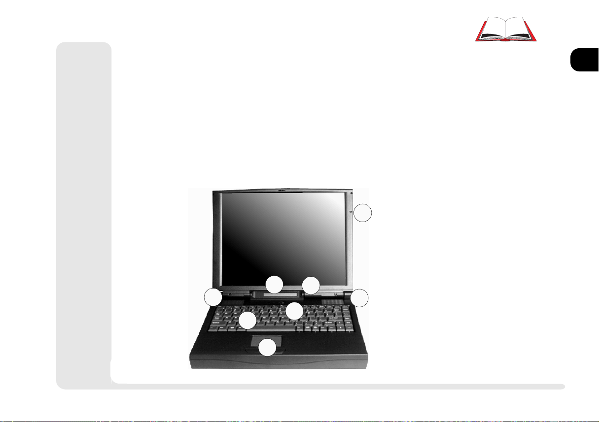
FRONT VIEW: LCD, WORK PANEL & TOUCHPAD
Latch To open the notebook cover, slide this latch to the right.
TouchPad Chapter 2: System covers basic functions.
Chapter 6: Enhancements, has a supplemental driver.
LCD Video functions are covered in Chapter 2: System.
1
2
3
4
1
5
2
6
7
3
2
4
WORK PANEL VIEW
FIG. 1 1
1. microphone
2. speakers
3. close-cover switch
4. power button
5. status screen
6. keyboard
7. TouchPad & buttons
front view
1 5
5
6
7
8
Page 24
Introduction
1
2
3
4
5
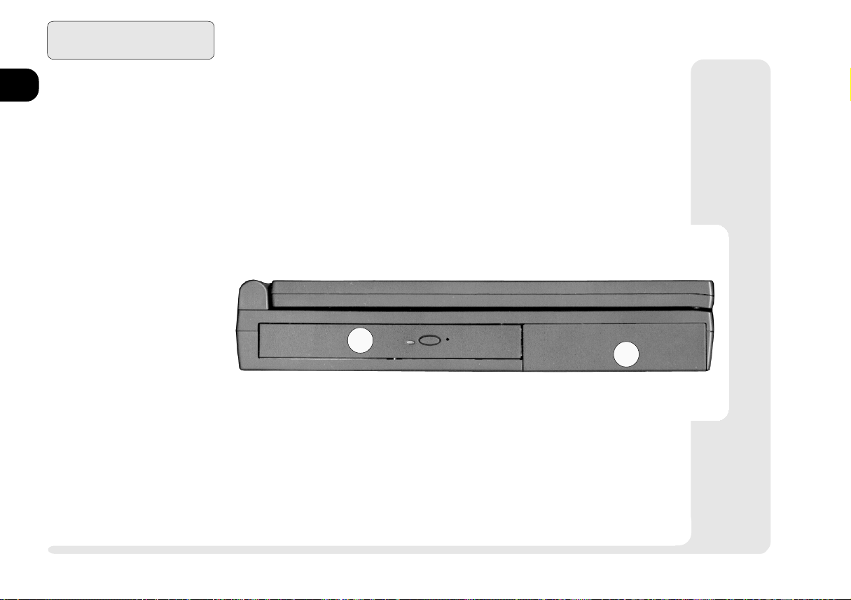
1. CD-ROM Bay
2. Power Bay
6
7
LEFT VIEW: CD-ROM BAY, AND POWER BAY
CD-ROM Chapter 2: System covers basic functions,
Chaprer 6: Enhancements, has additional audio utilities.
Power Bay Refer to Chapter 5: Power and Appendix A: Specifi-
cations for all aspects of the power system.
LEFT PANEL
FIG. 1 2
1
2
8
1 6
left view
Page 25
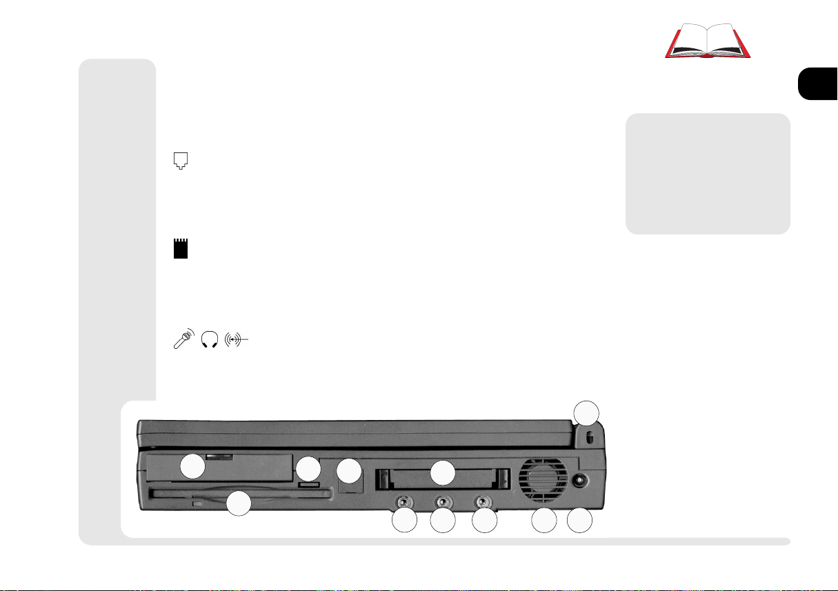
RIGHT VIEW: DRIVES, AUDIO & PC CARD
HDD Bay Refer to Chapter 3: Modules for more on how to setup
or replace a HDD.
FDD Chapter 3: Modules, covers the options available for
this bay.
(Fax-Modem) For more on this option, refer to Chap-
ter 2: System. If your system doesnt have a fax-modem installed, this slot will have a cover. Do not remove it. Ask your dealer about installing a fax-modem module.
(PC Card) Your computer uses newer technologies than
the drivers included in Windows 95. Use the setup
procedure detailed in Chapter 2: System. Supplemen-
tal PC Card drivers are detailed in Chapter 6: Extras,
Card Wizard.
(Audio) Setup for these ports is covered in Chapter 2:
System.
Kensington Lock This is a standard security port.
11
1
2
3
4
5
6
7
8
9
10
M
Warning
Dont block the fan.
Overheating may cause
system instablility.
RIGHT PANEL
FIG. 1 3
1. HDD Bay
2. Floppy
3. Floppy eject button
4. fax-modem (option)
5. PC Card slots
6. mic-in
7. phones - using this port
disables the speakers.
8. audio line-in
9. system cooling fan
10. adapter port
11. Kensington lock port
1
2
3
4
5
6
7
8
right view
1 7
Page 26
1
2
3
Introduction
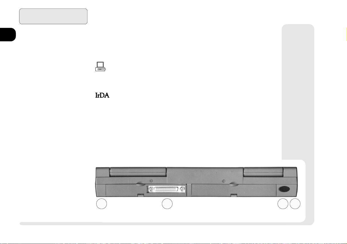
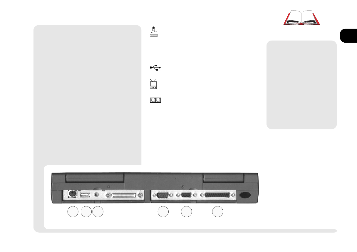
REAR VIEW:PORTS
The principal peripherals plug in on this panel. To be safe, turn off
both the system and peripherals before connecting them. Turn the
peripherals on first, before you turn on the system.
[Expansion Port] With the main hinged door closed, connect to
this port through the sliding door. The optional port replicator is
covered in Chapter 6: Extras.
4
5
6
7
8
REAR PANEL (COVER CLOSED)
FIG. 1 4
1. expansion door (open)
2. serial 2 IrDA port
3. port-replicator guides
1 8
rear view
This port uses (serial) COM2 resources. The infrared connection
supports the SIR, FIR and ASK standards. Its most common use is
for a printer, modem or LAN.
Note: Newer versions of Windows 95 have an IrDA driver built
-in For older versions, support is available from Microsoft Corp.
For other operating systems and IrDA standards, consult your
system vendor. Also consult the users guides for the device this
port is going to work with.
3 3
1 2
Page 27
¯
PS/2 Note
You can only use one type of PS/2 device per system session. If you want to
use a different device (mouse or keyboard), you must shut down and restart
the system. However, you can detach
and reconnect the same device during
a system session.
[PS/2 Port] Use this with any standard PS/2 external keyboard or
mouse. For details, refer to Chap-
ter 2: System, TouchPad.
(USB) Refer to Chapter 2: System
on how to activate this port.
[TV-out] Jack This is explained in
Chapter 2: System.
[COM1 (serial)] Use this with any
9-pin serial device (e.g. a mouse,
serial printer or modem). Consult
the users guides for the device this
port is going to work with. For
pointing devices, refer to Chapter
2: System, TouchPad.
M
Warning
The default settings in
Setup makes all ports
hot. Depending on the
peripheral, this could
cause a problem when
you attach it. Check your
peripherals manual before you make a connection.
REAR PANEL (COVER OPEN)
FIG. 1 5
4. PS/2 port
5. USB port
6. TV-out
7. COM1 serial port
8. external monitor port
9. LPT1 parallel port
1
2
3
4
5
6
7
8
4 5 6 7 8 9
1 9rear view
Page 28

1
2
3
4
5
6
7
Introduction
[External Monitor] Use this port
with any standard color VGA
monitor. For details, refer to Chap-
ter 2: System.
[Parallel Port] This port supports
several standards:
Output only (Standard AT)
Bidirectional
Enhanced (EPP) -versions 1.7 & 1.9
Extended Capabilities ECP
Most printers use the Standard
mode. The Setups Help bar (refer to Chapter 4: Firmware) explains how to adjust this setting.
Your peripherals manual explains
how to configure the device.
This port also serves as the external FDD connection. Refer to
Chapter 3: Modules for more on
this feature.
¯
Printer Note
Your operating system may include drivers for many printer models. Consult your
printer dealer for the most recent driver
for your model, as this can greatly affect
the performance of the printer.
8
1 10
rear view
Page 29
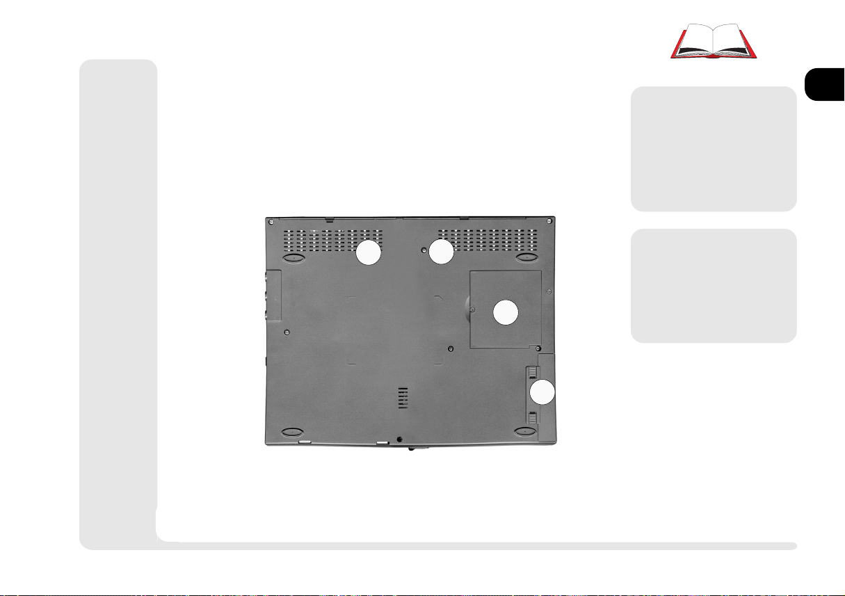
BOTTOM VIEW: COMPARTMENTS
The Drive bay is covered in Chapter 3: Modules.
M
Warning
Dont block the cooling
vents. Overheating may
cause system instablility.
1
2
3
1
1
Follow the safety in-
2
3
structions for using batteries.
1. system cooling vents
2. RAM compartment
3. Battery compartment
M
Warning
BOTTOM PANEL
FIG. 1 6
4
5
6
7
8
bottom view
1 11
Page 30
1
2
Introduction
HOT KEY CONTROLS
Some of the features are managed by Fn+key combinations:
3
4
5
6
7
8
þ
Key Combinations
Whenever you use a key
combination, start pressing them in the order
they are listed. Dont release any of the keys in
a sequence until youve
pressed the last one.
Table 1 1
HOT KEY CONTROLS
1 12
hot keys
Keys Control Comment
Fn + freeze activates Save to Disk if the Save to Disk partition/file is
available otherwise activates Suspend (to RAM)
F2 enter Setup If pressed immediately after boot-up,
this starts the Setup utility
Fn + Standby/Suspend activates Suspend (to RAM)
Fn + LCD/monitor toggles between display devices: monitor, LCD and combi-
nations. (refer to video setup information)
Fn + Speakers On/Off toggles the on-board speakers on/off (does not affect phones)
Fn + volume up increases audio volume
Fn + volume down reduces audio volume
Fn + brightness up increases LCD brightness
Fn + brightness down reduces LCD brightness
Fn + contrast up increases LCD image contrast (DSTN display only)
Fn + contrast down reduces LCD image contrast (DSTN display only)
(any key) resume ends power-saving modes,
including Suspend (to RAM), but not Save to Disk
Page 31

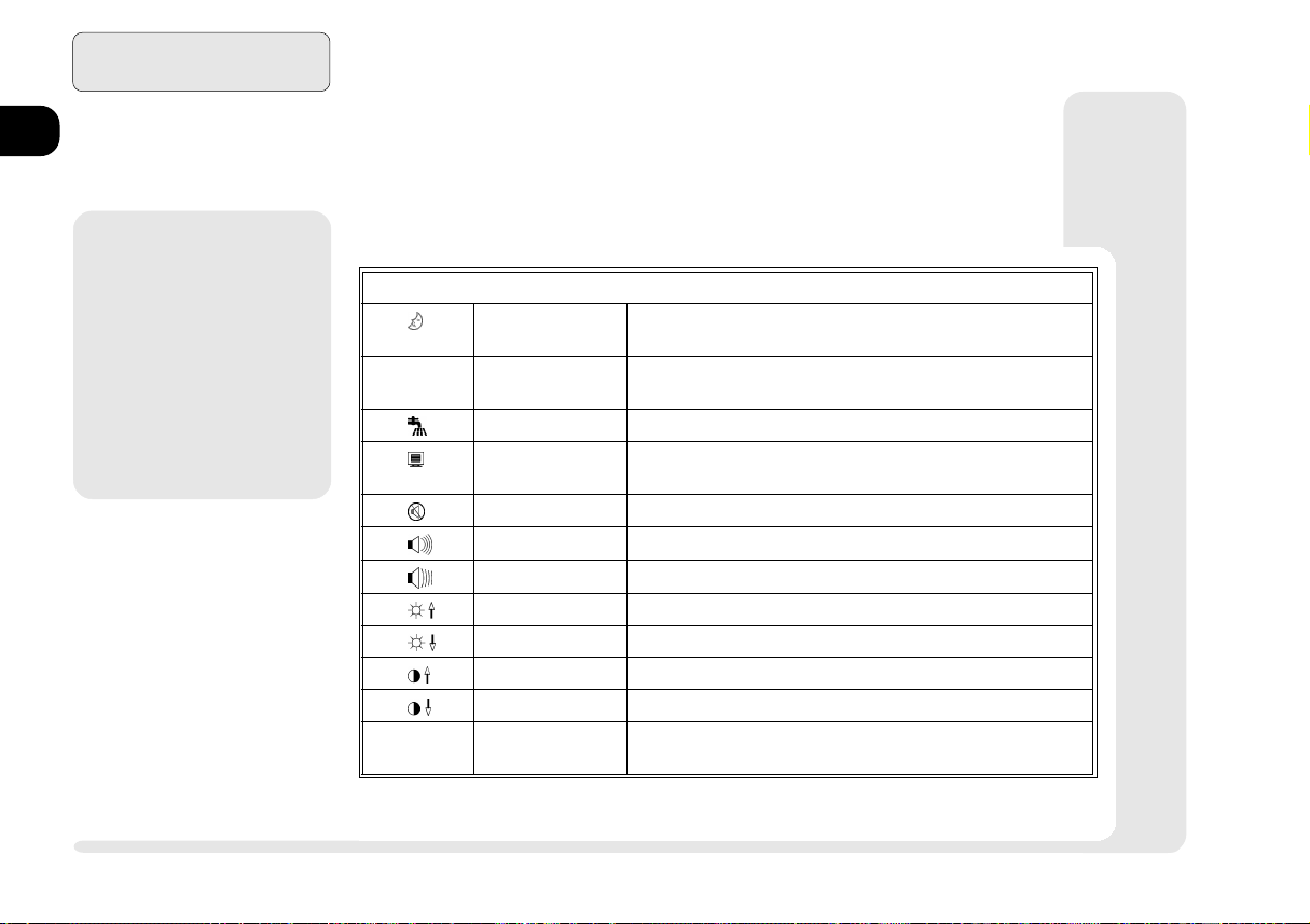
STATUS SCREEN INDICATORS
Your notebook lets you know what its doing with the following
status screen indicators:
Indicator Meaning Effect
NumLock Embedded numeric keyboard is on pressing the affected keys
produces numeric characters.
CapsLock CapsLock is on. Pressing alphabetic keys produces capitalized
characters other keys are unaffected.
Scroll Lock Scroll Lock is on.
HDD bay HDD is being accessed.
Table 1 2
STATUS SCREEN INDICATORS
1
2
3
4
5
6
Floppy Floppy is being accessed.
PC Card PC Card socket(s) are in use
Drive bay CD-ROM is being accessed.
icons
7
8
1 13
Page 32

Introduction
1
2
3
4
5
6
7
8
Table 1 2 (cont.)
STATUS SCREEN INDICATORS
Indicator Meaning Effect
Full Power All subsystems are fully powered
Doze mode The CPU doesnt initiate activity, all storage devices
are in idle mode, all peripheral devices & ports are
fully powered.
Sleep mode The CPU clock is on hold, all subsystems are in a
reduced-power mode, and the LCD is OFF.
Suspend to RAM The CPU and other chips are turned OFF, RAM is
refreshed slowly, system fan is OFF, peripheral devices and ports are in power-saving mode.
Battery > 80% Battery has more than 80%, considered Full
~ Battery < 80 to 20%
Battery < 20% Low battery range, recharge with the adapter
Battery empty
~ Charging steady lines correspond to charge level,
lines & frame blink cycling lines indicate dumb battery charging
system problem re-insert or replace the battery, if the problem
all lines & frame blink continues, consult your service representative.
Do Not Attempt to Repair the battery
AC-in System is receiving AC power.
PACKING CONTENTS
Keep the packing materials in a safe place in case you need them
for shipping or long-term storage.
1 14
icons
Page 33

QUICK START
If you're already familiar with notebook computers, the steps listed
below tell you how to start up the notebook for the first time. They
assume that you know where all of the parts of the computer are.
You should review these steps, before you take any action. If you
arent sure about one of the procedures, check the relevant chapter
before continuing.
1. Follow the safety instructions on page iv, especially the instructions on
placement.
2. Remove all packing materials, floppy disks and any PC Cards.
3. Secure the battery pack in its compartment. (Ch. 5)
4. Securely attach any peripherals you want to use with the notebook (i.e.
mouse or keyboard) to their ports. (Ch. 1)
5. Attach the AC adapter to the port on the side of the computer. (Ch.5)
6. Plug the AC power cord into an outlet.
7. Connect the AC power cord to the AC adapter.
8. Raise the lid/LCD to a 90o angle.
9. Push in the button (power switch) to turn on.
þ
Battery Charges
When you get your system, the
battery(ies) may not be fully
charged. Follow the procedure
in Chapter 5: Power, First Time
Use and Storage (page 5-4), to
charge it.
þ
Suspend To Disk
If you plan to use the Suspend
to Disk partition option in the
future, setup the partition before you install the operating
system. This involves creating
partitions and formating your
hard disk. Refer to Chapter 5:
Power and your operating system documentation for details.
1
2
3
4
5
6
7
8
1 15quick start
Page 34

1
2
3
4
5
6
7
Introduction
NOTES:
8
1 16
notes
Page 35

2 System
1
2
3
4
5
This chapter is about how to use and setup the most visible parts of the system:
input: the keyboard
the TouchPad
Output: Video subsystem
Audio subsystem
Communications PC Card
Fax/modem
6
7
8
2 1
Page 36

System
1
2
3
4
5
6
7
8
þ
Other Systems
Some operating systems
lack supporting software
for some components.
If the software you need
is not included on our
CD-ROM, contact your
dealer or service representative.
SETUP PROCEDURES
This chapter describes the basic setup for the Windows 95 and
Windows NT 4.0 operating systems. These procedures are described
in the inner margins and indicated by a < .
If youre using another system (i.e. OS/2 Warp, Windows 3.1, Windows NT 3.51 or DOS), check the appropriate README files on
the accompanying CD-ROM.
For additional, nonessential, utilities check out Chapter 6: Extras.
2 2
procedures
Page 37

¯
Special Characters
Some software applications allow the number-keys
to be used in conjunction with Alt to produce special characters. These special characters can only
be produced by using number keys on the embedded numeric keypad. Regular number keys
wont work.
KEYBOARDS
The notebook keyboard is like a fullsized version with typewriter-like keys
and function keys. But, since its a notebook, it also has special function keys
(listed on page 1-14) .
þ
Function Keys
Many software packages
make use of Function
keys (F1 ~ F12), so you
should consult those
manuals.
1
2
3
4
TYPE KEYS
FIG. 2 1
The embedded numeric keypad (outlined) is activated by
pressing NumLock its LCD
will appear)
FUNCTION KEYS
FIG. 2 2
keyboards
2 3
5
6
7
8
Page 38

1
2
3
4
5
6
7
8
System
EXTERNAL KEYBOARDS
You can attach an external keyboard to the (PS/2) port. If you
dont have a 6-pin keyboard connector, use a 5-to-6 pin adapter
cable. The system automatically detects and enables the external
keyboard as well as the notebooks. However, for those functions
requiring the Fn key, use the Ctrl + Alt key combination.
If you have a Y-connector, you can attach both a keyboard and PS/
2 mouse. However whatever the arrangement, the port can only
accept one type of device configuration per system session. For
example, if you connect a PS/2 mouse to this port, you cannot
connect a keyboard to the port during the same system session.
Doing so will cause a system conflict. If you already have a mouse
attached, and want to use a keyboard, you must shut down and
restart the system. However, you can detach and reconnect the same
device during a system session.
PS/2 KEYBOARD PORT
FIG. 2 3
ñ
2 4
keyboards
Page 39

¯
Configuring the TouchPad
The TouchPad uses the PS/2 port which is factory
enabled. It can use the Microsoft, or IBM PS/2
mouse driver available with most operating systems. Optimized TouchPad software for various
operating systems is on the Software & Utilites CDROM which came with the system and is covered
in Chapter 6: Extras.
TOUCHPAD
The system automatically enables the builtin TouchPad. If youre using any version
of Windows or OS/2, you dont have to
install a driver for it. However, you must
install a driver (if your dealer hasnt already done this for you) for the DOS environment.
1
2
3
¯
Using TouchPad & Serial Device
WINDOWS 95
1. Attach the serial device when the system is off.
2. Turn on the system and allow Windows 95
to detect and configure the device on the serial port (COM1). Insert the manufacturers
driver disk(s) if required.
3. Both devices are enabled.
To switch back to the TouchPad exclusively:
1. Exit Windows 95.
2. Detach the serial device.
3. Start Windows 95. It will automatically enable the available pointing device, in this case
the TouchPad.
For information on how to change mouse settings
for other operating systems, consult the manuals
for those operating systems.
If you want to use the TouchPads advanced features, refer to the driver information in Chapter 6: Extras.
1
2
3
THE TOUCHPAD
FIG. 2 4
1. sensor pad
2. left mouse button
3. right mouse button
Note for left-handers: most
operating systems allow you
to reverse the mouse-button
settings.
TouchPad
2 5
4
5
6
7
8
Page 40

System
1
2
3
4
5
6
7
8
TOUCHPAD & SERIAL DEVICE
If you want to use a serial device as well
as the TouchPad, you must make sure
the devices driver can see it on COM1.
In some operating systems, you can only
use one pointing device driver at a time,
either serial or PS/2. To use a serial device, attach it to the port (while the
system is OFF) and then start up and
configure it with a suitable driver.
TOUCHPAD & PS/2 DEVICE
If you havent installed any specialized
pointer drivers, you can also use a mouse
connected to the PS/2 port. Just make
the connection, and the system automatically detects an attached mouse, enabling it as well as the TouchPad using
the same drivers.
Note: the PS/2 port only accepts one type
of device per system session. If you
want to switch to another device,
you must shut down and restart the
system. However, you can detach
and reconnect the same device during a system session.
¯
Using TouchPad & Serial Device
(cont.)
WINDOWS NT 4.0
To use a serial device and the TouchPad at the
same time in the Windows NT 4.0 environment,
you must configure the operating system as you
install it the first time.
1. Attach the serial device when the system is
off.
2. As Windows NT 4.0 runs its installation program, it will ask you to confirm its hardware
and software components. At this point,
modify the list so that the pointing device is:
Logitech Serial Mouse.
The on-board PS/2 mouse will still be automatically enabled and if you install one, the
resources will be available for a serial mouse.
3. If you want to use serial mouse on COM1,
make sure it is present when you boot-up,
and both devices will be active.
2 6
TouchPad
Page 41

¯
More on Video Displays
Appendix A: Specifications has a chart of the
systems display capabilities.
<
Video Setup
WINDOWS 95
To setup the Windows 95 video driver and utilities:
1. Open Control Panel > Display.
2. Click on Settings > Change Display Type... (or
Settings > Advanced Properties >Adapter).
3. Click on the Change... button next to the
Adapter Type field.
4. Insert the Software & Utilities CD-ROM
(drive D:).
5. Select Have Disk.... Then Browse... to the
DRIVERS\WIN95\VIDEO directory. Click
on OK and then on OK again.
6. Select S3 ViRAGE MX and click on OK.
7. After the installation finishes, Windows 95
will return to the Display page where you can
change the settings. When you click on Close,
Windows 95 prompts you to select a monitor. Click Yes and choose a Laptop Display
Panel (any size). Next, Windows prompts
you to restart the system. Close any other applications and click Yes.
VIDEO
There are three display options: the
notebooks LCD, an external monitor
(CRT) and TV. You can select between
them with the Fn+
trols embedded in the video driver interface. The interface also lets you
change the screen resolution and color
output to whatever is most comfortable/
efficient for you.
As you examine the video driver (see the
side-bars for setup information), youll notice that some displays have more flexibility than others. This is a matter of hardware, video memory and the driver for your
operating system. The driver interface
shows the available options.
3
toggle or the con-
2
1
THE LCD CONTROLS
FIG. 2 5
1. Contrast controls
(not active with TFT)
2. Brightness controls
3. Display toggle
(LCD/CRT/TV)
1
2
3
4
5
6
7
8
video
2 7
Page 42

System
1
2
3
4
5
6
7
8
M
Warning
Do not allow any foreign objects (i.e. paper
or plastic) to get between the lid/LC D and
the work panel. They
could damage or
scratch the LCD and/or
accidentally activate
the close-cover switch.
DISPLAY PROPERTIES
CONTROL PANEL
FIG. 2 6
SETUP
The video drivers on the accompanying
Software & Utilities CD-ROM are optimized for specific operating systems. If
the driver for your operating system isnt
included, or you suspect its outdated,
consult your dealer. These drivers are required if you want to use a TV display or
want enhanced performance on an external monitor as well as the LCD.
The instructions in the side-bars tell you
how to install the drivers. However, your
operating systems documentation may
have additional tips.
Note: For most operating systems, video
driver installation is different from
any other drivers (i.e. sound).
LCD
AS you open the lid, adjust it so you can
look at the screen straight-on, without
any glare. If necessary, adjust the brightness and contrast controls.
<
Video Setup (cont.)
The S3 driver adds an additional page to Display
Properties. This has current display status informa-
tion. It allows you to select the control system,
output devices and image processing:
Single control devotes all video memory to a single
display system (the LCD/CRT choice will display exactly the same thing)
Dual control divides the video memory to support
2 devices. It also lets you select the type of
external monitor you are using.
Use the on-line help (?) to get more information
about the various features.
2 8
Note: If your model has a TFT screen, the
contrast controls arent necessary.
video
Page 43

<
Video Setup (cont.)
WINDOWS NT 4.0
To setup the Windows NT video driver and utilities:
1. Open Control Panel > Display.
2. Click on Settings > Display Type .
3. Click on the Change... button in the vga com-
patible display adapter field.
4. Insert the Software & Utilities CD-ROM
(drive D:).
5. Select Have Disk.... Then use Browse... to
the NT40\VIDEO directory. Click on OK
and then on OK again.
6. Select S3 Incorporated Display Driver...
and click on OK or Yes to start the installation.
7. After the installation finishes, Windows NT
4.0 will tell you to close the various screens
and reboot. When you restart and return to
the Display page, you can change the settings.
This driver doesnt support different image output.
EXTERNAL MONITOR
If you prefer to use an external monitor, connect it to the VGA port on the
rear panel.
Note: To reduce flickering on an exter-
nal monitor, use faster refresh
rates. But first check your
monitors documentation to make
sure it can support the rates listed
by the video driver.
ñ
VGA PORT
FIG. 2 7
Make sure both the external
monitor & notebook are OFF
before you connect them.
1
2
3
4
5
6
7
8
video
2 9
Page 44

System
1
2
3
The NTSC and PAL settings can only be used
with the appropriate
televisions.
M
Warning
4
TV PORT
5
6
(FACTORY INSTALLED OPTION)
FIG. 2 8
Both the TV & notebook
should be OFF before you
connect them.
7
8
DISPLAY PANEL TV SETTINGS
FIG. 2 9
Be sure the NTSC/PAL setting
on the Device page is correct.
TV (FACTORY INSTALLED OPTION)
The mini-DIN plug connects to a video adapter cable. However, before you use this connector, make sure the driver is
configured for your TVs standard: NTSC or PAL (use the video
driver control panel).
ñ
2 10
video
Page 45

SWITCHING
You can switch between the notebooks LCD and monitor (CRT)
by toggling Fn+
driver control panel:
. TV output is available only by using the video
1
2
VT
dradnatS
CSTN
LAP
CSTN
LAP
DCL
noituloseR
004x046
006x008
084x046
006x008
004x046
006x008
084x046
006x008
VT+DCL,VT
snoitpOyalpsiDtnemmoC
)syalpsidllanoegamiemas(lortnoCelgniS
004x046sinoituloserCSTN
)084x046(AGV
VT
,rotinom,rotinom+DCL,DCL
VTnotceffe
)syalpsidllanoegamitnereffidroemas(lortnoClauD
)084x046(AGV
,rotinom,rotinom+DCL,DCL
VTnotceffe
satistaertDCLehtrevewoh
CSTNnahtregralsnoituloserllA
gninnapehthtiwdeweivera
AGVhtobstroppusLAP
snoituloserAGVSdna
004x046sinoituloserCSTN
satistaertDCLehtrevewoh
CSTNnahtregralsnoituloserllA
gninnapehthtiwdeweivera
AGVhtobstroppusLAP
snoituloserAGVSdna
TABLE 2 1
TV-OUT DISPLAY OPTIONS
2 11video
3
4
5
6
7
8
Page 46

System
1
2
Warning
3
4
To protect your hearing,
turn down the volume
before you plug-in either headphones or
speakers.
5
AUDIO SUBSYSTEM PORTS
FIG. 2 10
1. microphone
6
7
8
(disables internal microphone)
2. headphones
/external speakers
(disables on-board speakers)
3. line-in
4. volume up control
5. volume down control
M
AUDIO
The audio subsystem, in combination
with the CD-ROM module, gives the
notebook multimedia capabilities. To
use it, You first have to install the correct drivers. These are included in the
software package which comes with the
system. The procedure is explained in
the side-bar.
The controls and ports are on the function keys and on the left panel:
21 3
4
5
<
Audio Setup
WINDOWS 95
The Yamaha Sound System takes advantage of
technical improvements since Windows 95s release. To make the sound system work,
1. Open Control Panel > System > Device Man-
ager (tab). Click on Other Devices and select
OPL3-SAx Sound.. Double-click on this
item.
2. When the properties window opens, click on
Device ( tab) > Update Driver..
3. When the Update Device Driver Wizard appears, click on Yes > Next> Browse...
4. Navigate to Drivers\Win95\Audio\driver
on the Software & Utilities CD-ROM
Click on OK > OK > Finish
Note: During this procedure, you may have
to repeat this step.
5. When the system asks for the Win 95 CDROM, insert it and click OK > Close > OK.
6. When the additional files are installed, return
to the Device Manager page and click on
Refresh. Windows will configure itself to use
the new drivers.
7. Click on Close. A speaker icon will appear in
the system tray.
When complete, the Yamaha drivers appear
under Sound, video and game controllers.
If you want enhanced performance, click on the
OPL3-SAx Configuration button in Control Panel.
2 12
audio
Page 47

<
Audio Setup (cont.)
WINDOWS NT 4.0
To install the audio driver after youre into the system, load the Software & Utilities CD-ROM. Then,
1. Open Control Panel then Multimedia and
click on the Devices tab then on the Add
button.
2. Choose Unlisted or Updated Driver from
the list. Then use the Browse button to choose
drive D:\NT40\AUDIO as the location of the
driver.
4. Click on OK when OPL...Sound System appears. If prompted, select the your language
version and click on OK. In addition to the
default settings which appear, click on Use
Dual DMA and Enable MPU401. Again,
you should use the default settings. When
youre finished,choose Continue or OK to
confirm the resource settings. Then restart the
system to activate the driver.
5. Once the system has restarted, double-click
on the speaker icon of the tray on the lower
right to open the sound control panel.
If you want enhanced performance, click on
the OPL3-SAx Configuration button in Con-
trol Panel.
ADDITIONAL AUDIO
The utility disks which accompany your
system also include supplemental audio software for Windows 95 and Win-
dows 3.1/DOS. Refer to Chapter 6: Extras for more details.
1
2
3
4
5
6
7
8
2 13audio
Page 48

System
1
2
3
4
5
6
7
1. Socket 0 (lower)
8
eject button
2. Socket 1 (upper)
eject button
PC CARDS
The notebook has two PC Card expansion sockets:
socket 0 (lower), is Type III
socket 1 (upper), is Type II
Both sockets are backward -compatible. For example, a Type
III socket can handle a Type I, II, or III card.
Both support PCMCIA (rev. 2) and CardBus (PCI bus to PCMCIA
socket).
Both sockets are Zoomed Video (ZV). The ZV Port is a direct connection between the PC Card and the notebooks video and audio
subsystems. As such, it works directly with the CD-ROM module to
support multimedia features.
Refer to the documentation which comes with your ZV card for
more information about its capabilities and how to use its features.
PC CARD SOCKETS
FIG. 2 11
1
2
2 14
PC Card
Page 49

<
PC Card Setup for Windows 95
The PC Card components are newer than the drivers supplied by Windows 95, so before you can
use this device, you must make some changes to
your system:
1. Open Control Panel > System > Device Man-
ager (tab) > Other devices. Remove the
CardBus Bridge listings (there are 2).
2. Under PCMCIA socket remove PCIC or com-
patible PCMCIA controller.
3. Using Windows Explorer to navigate to
D:\drivers\win95\utilities\TI-1250
on your Software & Utilities CD-ROM.
4. Install Ti1250.inf (the Install command is in
the File menu)
5. Return to Control Panel> System Properties
and click on Refresh.
When asked for the Windows 95 CD-ROM,
reinstall it. Click on OK.
6. Return to System Properties. The PCMCIA
listing will have two entries for Texas Instruments devices. Double-click on the first one.
7. When its Properties, General (tab) appears,
uncheck Disable in this hardware profile.
Click OK > OK and Yes to Restart when it
asks.
8. When you restart the computer, the sockets
will be ready for use.
OPERATING SYSTEMS
WINDOWS 95
The PC Card components are newer
than the drivers supplied by Windows
95, so before you can use this device,
you must make some changes (described in the side-bar) to your system.
However after you activate them, they
are always hot.
The updated drivers are also PCMCIA
(rev. 2) , and CardBus compliant and
they recognize Plug n Play PC Cards.
However some older, legacy, cards
may require their own drivers. You can
hot swap any PC Card. If you want to
use a ZV card, install the optional
SystemSoft CardWorks driver (see
Chapter 6: Extras).
The optional SystemSoft drivers which
come with your computer take advantage of technical improvements since the
release of Windows 95 and support
legacy and ZV cards.
1
2
3
4
5
6
7
8
2 15PC Card
Page 50

1
2
3
4
5
6
7
8
System
M
Warning
Do not add, remove or
change cards while the
system is in a power saving mode. This may cause
a conflict with the stored
system configuration information.
M
Warning
Some operating systems
may experience difficulties if an I/O card (e.g.
a fax/modem) is present
in the socket when you
warm boot the notebook. Depending on
your operating system,
the COM ports (I/O) for
PC Card devices are reassigned.
Note: Windows 95 does
not have this limitation.
WINDOWS NT 4.0
The operating system automatically installs the PC Card socket drivers. This driver is only PCMCIA (rev. 2) compliant. You can install or
remove cards only when the system is turned off. In particular, any I/
O PC Card (e.g. LAN or SCSI) must be present when you boot-up the
system. CardBus and ZV support are not available.
The optional SystemSoft Driver allows hot insertion and hot removal, and provides CardBus support (see Chapter 6: Extras).
INSERTING A PC CARD
PC Cards require drivers specific to your operating system: one for
the computers sockets (see above), and a driver for the card youre
installing. The first time you install a PC Card, Windows 95 and NT
4.0 prompt you for that cards driver. If your operating system
supports Plug n Play (e.g. Windows 95), PC Cards can be inserted
and removed while the system is on.
When the card is in correctly, the system beeps once. If the PC
Card is not detected, check if the correct drivers are loaded.
REMOVING A PC CARD
Push the appropriate eject button to remove the card. The system
will beep twice when the card is ejected.
2 16
PC Card
Page 51

<
Setting up the Fax/Modem
WINDOWS 95
When Windows 95 starts up, it detects the Fax/
Modem and launches the Update Device Driver
Wizard.
1. Click on Next. If youre installing from the Soft-
ware & Utilities CD-ROM, direct the wizard to the
driver in D:\Drivers\Win95\Modem.
2. Click Finish. During the installation, the utility
may not recognize that all of its elements are in
the same folder, so just redirect it as necessary.
3. When the installation is complete, Windows 95
returns to its standard view.
4. Shut down the system and restart. When Win-
dows 95 resumes, run Modem Driver Setup Program: Open the Start (menu) > Run > Browse...
5. Navigate to
D:\Drivers\Win95\Modem\setup.exe*
* this assumes youre installing from the
Software & Utilities CD-ROM
6. Click OK then Next.
Follow the directions (we recommend the default
destination directory and settings).
When finished, the system will restart itelf and reallocate system resources as it reboots. Click the
Modem icon in the Control Panel to continue the
setup (the modem should be assigned to COM3).
Note: For Dial-up Internet access, you must be sure
to have all the proper protocols installed (i.g.
TCP/IP). Refer to your operating system manual for
this and/or your Internet Service Providers documentation.
FAX/MODEM (OPTIONAL MODULE)
If your system includes the fax/modem
module, both Windows 95 and Windows
NT 4.0 will detect it during setup. However, our module takes advantage of
newer technologies so you will have to
install our updated drives to take advantage of its full speed.
ñ
1
2
3
4
5
FAX/MODEM PORT
FIG. 2 12
6
7
8
PC Card
2 17
Page 52

System
1
2
3
4
5
6
7
8
USAGE
Once your fax/modem is setup, you still
have to configure the software that will
use it. For the most part, this means
working with your operating systems
Network settings.
Be sure to keep the original installation
software handy as you do this.
Additional information about how to use
the fax/modem (e.g. AT commands) is
included with the driver on the Internal
Fax/Modem Drivers floppy.
<
Setting up the Fax/Modem (cont.)
WINDOWS NT 4.0
To install the Fax Modem,
run Modem Driver Setup Program:
1. Open the Start (menu) > Run > Browse...
2. Navigate to
D:\Drivers\NT40\Modem\setup.exe*
* this assumes youre installing from the
Software & Utilities CD-ROM
3. Click OK > Next.
Choose, Install new modem driver and components > OK
Follow the directions (we recommend the default
destination directory and settings).
When finished, the system will restart itelf and reallocate system resources as it reboots. Click the
Modem icon in the Control Panel to continue the
setup (the modem should be assigned to COM3).
Note: For Dial-up Internet access, you must be sure
to have all the proper protocols installed (e.g.
TCP/IP). Refer to your operating system manual for
this and/or your Internet Service Providers documentation.
2 18
PC Card
Page 53

3 Media
1
2
3
4
5
This chapter is about the systems data storage devices (or drives):
HDD: How to configure the system to use it
how to replace it
CD-ROM: How to access it
FDD (Floppy) How to use it and care for the media
6
7
8
3 1
Page 54

Media
1
2
3
4
5
6
7
8
DRIVES
FIG. 3 1
1. CD-ROM
2. HDD
3. FDD
STATUS SCREEN
DRIVE INDICATORS
FIG. 3 2
4. CD-ROM
5. FDD
6. HDD
INDICATORS
Whenever a drive is in use, the corresponding indicator appears:
accessing the main HDD.
accessing the FDD.
accessing a CD-ROM.
The icon does not appear if you are playing an audio CD.
1
3
2
3 2
icons
6
5
4
Page 55

HDD
The HDD is in a removable metal frame.
REMOVING THE HDD MODULE
If for some reason you must remove the HDD cartridge:
1. Make sure the computer is turned off and flip down the HDD bay door.
2. Grasp the HDD bay door handle and pull the cartridge out.
Ê
1
M
Warning
Dont try to remove the
hard disk (HDD) while
the system is on, or a
floppy disk while the
system is accessing it.
These actions may cause
the system to crash,
result in data loss or
damage.
1
2
3
4
5
6
2
ñ
INSTALLING THE HDD CARTRIDGE
To install the (new or upgraded) HDD cartridge, carefully slide it
back into the HDD bay. Be sure that the bay door handle is securely locked in position.
REMOVING THE HDD
FIG. 3 3
1. grasp the HDD bay door
2. pull the cartridge out
HDD
3 3
7
8
Page 56

Media
1
2
3
4
5
Warning
Some (usually older)
HDDs have a small
jumper switch. It must
be set to master or the
system may not correctly recognize the
drive. Check your
drives documentation.
6
ASSEMBLING THE HDD
CARTRIDGE
7
1. cartridge frame
2. HDD
8
3. master/slave jumper
4. mylar shield
5. connector
6. screws
FIG. 3 4
(electronics face-down)
M
REPLACING/UPGRADING
THE
CARTRIDGE
If youre too harried or a bit of a technophobe, contact your dealer to purchase or
replace your current HDD with an upgrade.
1
2
ï
5
6
3
4
6
¯
Replacing a HDD
You can replace your HDD with another 2.5,
12mm high IDE hard disk drive.
To assemble the cartridge,
1. Make sure the HDDs jumper pins are set to
master (3). - Most HDDs dont require any
settings, but check your HDDs documentation to be sure.
2. Holding the HDD (1) at an angle, plug its pins
into the connector (5). Make sure all the pins
are inserted fully.
3. Cover the HDDs electronic component side
with the shield (4).
4. Insert the HDD and shield combination into
the frame (1). As you do so, carefully fit the
edges of the shield around the screw holes of
the frame.
5. Secure the HDD, shield and frame with the
four mounting screws (6).
3 4
HDD
Page 57

¯
Formatting the HDD
A hard disk must be partitioned, and formatted before use. To partition the HDD, use the utility from
your operating system (e.g. MS-DOSs fdisk command) to do this. To format, use the utility from
your operating system (e.g. MS-DOSs format or
format/s command). Consult your operating
systems manual for more information on its partitioning and formatting utilities.
Note: If you want to use the Save to Disk fea-
ture, refer to Chapter 5: Power before you par-
tition the HDD.
After you replace or upgrade the HDD, turn the
system on and configure it for the newly-installed
HDD using Setup. Refer to Chapter 4: Firmware.
528MB OR LARGER HDDS & LBA MODE
The notebook automatically reads any HDD
528MB or larger as using LBA Mode. If you are
using a 528MB or larger HDD which was formatted on an older system which did not use LBA
mode, this system will not see it correctly. In that
case, you must re-format the HDD on this system.
SETTING UP A NEW HDD
FOR THE FIRST TIME
Before you can use a new HDD for the
first time, you have to do two things:
tell the computer about the HDD.
(refer to Chapter 4: Firmware)
prepare the HDD to accept data.
(refer to your operating system manual)
M
Warning
Whenever you install a
different hard disk that
has a Save-to-Disk partition on it, make sure
you follow the procedures detailed in Chap-
ter 4: Firmware and
Chapter 5: Power.
1
2
3
4
5
6
7
8
HDD
3 5
Page 58

Media
1
2
3
4
5
6
7
USING A CD-ROM
FIG. 3 5
1. Insert the disk face down.
2. Push the tray in until it
clicks in place.
8
THE CD-ROM DRIVE
The CD-ROM drive appears in your file
management utility as another drive.
AUDIO CD
If you want to use the CD-ROM to play
an audio CD, make sure your operating
system has the necessary drivers installed.
Chapter 6: Enhancements has more information on the audio drivers which
come with your system.
Ê
¯
CD-ROM Drivers
WINDOWS 95
WINDOWS NT 4.0
WINDOWS NT 3.51
OS/2 WARP
These operating systems automatically detect and
configure the CD-ROM drive. The start-up floppies which come with them should also be able to
configure the CD-ROM.
If they cant, install a version of DOS and the CDROM driver as described below. Then follow the
installation utilities for the operating system you
plan to use. As the installation progresses, the operating system will replace, or modify our CD-ROM
driver.
OTHER OPERATING SYSTEMS
These instructions assume youve already installed
some version of DOS.
1. If you do not have a floppy disk with the CDROM driver on it, your only other source is
the CD-ROM which accompanies ythe system. Using a CD-ROM drive on another computer, navigate to the d:\drivers\other directory and copy the cd-rom folder onto a
1.44MB floppy.
2. Insert the floppy containing CD-ROM driver
into the notebook and open the CD-ROM
driver directory on the floppy disk (drive A:),
and type:
INSTALL.EXE
3 6
CD-ROM
Page 59

¯
CD-ROM Drivers (cont.)
3. As each page appears, press Y or Enter to confirm the settings.
If you dont want to install the driver in the
default directory (C:\CDROM), when the
Specify the directory... dialog box appears,
use Backspace to delete the current name,
then type in your preference. Remember to
start the directory name with C:\.
When you get to the Specify the parameter...
page, make sure the ( )/D [CDROM001] switch
has an asterisk (*). Then press Enter.
4. When the installation is complete, remove the
floppy disk and reboot your computer.
INSERTING & REMOVING A CD-ROM
To insert a CD-ROM, follow these steps:
1. With the notebook turned on, press the
button on the front of the module to release the spring-loaded tray.
2. Gently pull the tray out to its fullest extension.
3. Insert your CD-ROM shiny-side down
(like an audio CD).
4. Gently push the tray in until it clicks in
place. The CD-ROM is ready to play.
To remove the CD-ROM, press the same
button to release the tray.
If the notebook is turned off, you can
open the tray by inserting a probe (e.g.
a straightened paperclip) into the small
hole next to the button.
1
2
3
4
5
6
7
8
3 7CD-ROM
Page 60

1
2
3
4
5
6
Media
MULTIMEDIA APPLICATIONS
MPEG
If you want to use the CD-ROM to watch movies or other MPEG
features, there are two options:
1. Software - There are various software products which make use
of the raw power of your systems CPU to decode MPEG1 material.
2. ZV-Port - Both PC Card sockets support a ZV card. This card
type works with the CD-ROM and video subsystems to produce
better quality images. However, to use it, you must install these
drivers:
The CD-ROM driver (covered in this chapter)
The audio and video drivers (covered in Chapter 2: System).
VPM driver - built into the video driver for Windows 3.1x
Windows 95 and Windows NT 4.0*.
ZV Card driver (supplied by the ZV Cards manufacturer).
7
8
3 8
*As of this publication, this feature is pending, check with your system vendor for the latest informatiion.
AUDIO CDS
Audio CDs are played using a CD-player application included in
your operating system.
CD
Page 61

THE FDD
INSERTING/REMOVING FLOPPY DISKS
Gently insert a 3.5-inch disk (with its label side up) into the Floppy
drive until the disk is properly seated. Press the button on the right
of the disk drive to eject the disk.
FDD Care
Following are a few tips on the proper handling of floppies:
Store disks away from magnetic fields and extreme temperatures. These
conditions can damage your data. Its also a good idea to make backup
copies of software and data.
If a disk label is already on the disk, use a soft-tipped pen to write on
the label. This prevents damage to the disk. Dont use a pencil - its
carbon particles can rub off inside the drive.
Do not remove any disk from the drive when the LCD is flashing (in-
use).
Do not try to clean, bend, or throw disks.
Do not touch or scratch any exposed portion of the disk medium. Dont
pull open the protective door either - this lets dust get inside.
M
Warning
Do not remove a floppy
disk while the drive is
active. Doing so may
damage the medium or
cause a generaol protection fault, result in data
loss and/or corruption.
FDD
FIG. 3 6
1
2
3
4
5
6
7
8
3 9FDD
Page 62

1
2
3
4
5
6
7
Media
NOTES:
8
3 10
notes
Page 63

4 Firmware
1
2
3
4
5
This chapter is about the notebooks built-in software:
the POST (Power-On Self Test) and
the Setup utility.
If your computer has never been set up, or you are making important changes to the system (i.e.
power management features), then you should review this chapter first and note the original
settings found in Setup. Even if you are a beginner, keep a record of the settings you find and
any changes you make. This information could be useful if your system ever needs servicing.
There is one general rule: Dont make any changes unless you are sure of what you are doing.
Many of the settings are required by the system, and changing them could cause it to become
unstable or worse. If you have any doubts, consult your system dealer.
4 1
6
7
8
Page 64

Firmware
1
2
3
4
5
6
7
8
STARTUP SCREEN: THE POST
FIG. 4 1
1. BIOS information.
2. CPU type
3. memory status
4. HDD identification notice
5. error notice (example)
6. Enter Setup cue
- appears if there is an error
7. Enter Setup cue
- appears only during POST
(#6 is not present)
THE POWER-ON SELF TEST (POST)
Each time you turn on the computer, several things happen:
BIOS information flashes on the screen.
the system takes a few seconds to conduct a POST,
including a quick test of the on-board RAM.
As the POST proceeds, the computer will tell you if there is anything wrong. If there is a problem which prevents the system from
booting, it will tell you to run Setup. If there are no problems, the
system will present a summary, and announce that it is starting the
operating system. Once that message appears, you can no longer get
into Setup.
Phoenix BIOS 4.Ø Release 6.Ø
Copyright 1985-1997 Phoenix Technologies Ltd.
All Rights Reserved.
PP 1.01.24b 03-23-98-98L.01.07
CPU = Pentium with MMX 233 MHz
64ØK System RAM Passed
Ø31M Extended RAM Passed
Ø512K Cache SRAM Passed
System BIOS shadowed
Video BIOS shadowed
UMB upper limit segment address: FØ73
Mouse initialized
Fixed Disk Ø: IBM-DCTA-2324Ø
ATAPI CD-ROM: Toshiba CD-ROM XM-17Ø2B
ERROR
Com A configuration changed
Press <F1> to resume, <F2> to Setup
Press <F2> to enter SETUP
}
6
1
}
2
3
4
5
7
4 2
POST
Page 65

FAILING THE POST
Errors can be detected during the POST. There are two categories,
fatal and non-fatal.
1
Fatal Errors These stop the boot process and usually indicate there
is something seriously wrong with your system. Take
the computer to your dealer or authorized service center as soon as possible.
Non-Fatal Errors This kind of error still allows you to boot. You will get a
message identifying the problem (make a note of this
message!) followed by the cue:
Press <F1> to resume, <F2> to enter SetupPress <F1> to resume, <F2> to enter Setup
Press <F1> to resume, <F2> to enter Setup
Press <F1> to resume, <F2> to enter SetupPress <F1> to resume, <F2> to enter Setup
Press F1 to see if the boot process can continue. It may
work, without the correct configuration.
Press F2 to run the Setup program and try to correct
the problem. If you still get an error message after you
change the setting, or if the cure seems even worse,
call for help.
2
3
4
5
6
7
8
POST
4 3
Page 66

Firmware
1
2
3
4
5
6
7
8
THE SETUP PROGRAM
The Phoenix Setup program tells the system how to configure itself
and manage basic features and subsystems (e.g. display and power
management).
ENTERING SETUP
To enter Setup, turn on the computer and press F2 during the POST.
The prompt seen in Fig. 4 1 is usually present for a few seconds
after you turn on the system. If you get a Keyboard Error (usually
because you pressed F2 too quickly) just press F2 again.
If the computer is already on, reboot using the Ctrl + Alt + Delete
combination and then hold down F2. Setups main menu will appear.
SETUP SCREENS
The Setup interface looks like a windows screen:
Along the top of the screen is a menu bar with five (5) menu headings.
When you select a heading, a new screen appears. Scroll through the
features listed on each screen to make changes to Setup.
Instructions on how to navigate each screen are in the box along
the bottom of the screen. If these tools are confusing, press F1 to
call up a General Help screen. Then use the arrow keys to scroll up
or down this page.
4 4
setup
Page 67

ainain
M
ain
ainain
System Time: [13:43:12]
System Date: [1Ø/31/1996]
Diskette A: [1.44”]
u IDE Adapter 0 Master [3253MB]
u IDE Adapter 0 Slave [None]
u IDE Adapter 1 Master [CD-ROM]
u IDE Adapter 1 Slave [none]
u Integrated Peripherals
u Memory Cache
u Boot option
Language: [English (US) ]
System Memory: 640 KB
Extended Memory 31744 KB
F1 Help ñò Select Item -/+ Change Values F9 Setup Defaults
ESC Exit ïð Select Menu Enter Select u Sub-Menu F1Ø Previous Defaults
AdvancedAdvanced
Advanced
AdvancedAdvanced
SecuritySecurity
Security
SecuritySecurity
PhoenixBIOS Setup Utility
PowerPower
Power
PowerPower
ExitExit
Exit
ExitExit
Item Specific Help
<Tab>, <Shift-Tab>, or
<Enter> selects field.
SETUP MAIN MENU
FIG. 4 2
The Setup menus shown in
this section are for reference
only. Your computers menus
will indicate the configuration
appropriate for your model
and options.
1
2
3
4
5
6
7
The Item Specific Help on the right side of each screen explains the
highlighted item and has useful messages about its options.
If you see an arrow (}) next to an item, press Enter to go to a
sub-menu on that subject. The sub-menu screen which appears has
a similar layout but the Enter key may execute a command.
8
4 5main menu
Page 68

1
Firmware
MORE ON SETUP
Following is additional advice on portions of the Setup, not covered in the Item Specific Help.
2
3
4
5
6
7
8
TIME AND DATE (MAIN MENU)
The hour setting uses the 24-hour system (i.e., ØØ = midnight; 13 =
1 pm). If you can change the date and time settings in your operating system, you will also change these settings. Some applications
may also alter data files to reflect these changes.
DISKETTE A (MAIN MENU)
Operating systems which use 3-mode formatting (used mainly in
Japan), instruct the BIOS to change Floppy modes as necessary.
IDE ADAPTER 0 MASTER (MAIN MENU)
Pressing Enter opens the sub-menu to configure the main IDE
HDD which fits into the notebooks HDD bay. Refer to Chapter 3:
Modules for more on these modules.
The following fields for this sub-menu are the same for Primary
Master.
4 6
main menu
Page 69

TYPE
(MAIN MENU >PRIMARY MASTER, PRIMARY SLAVE, SECONDARY MASTER & SECONDARY SLAVE)
This setting has several options for choosing which method Setup
will use to detect the hard disk:
Auto (Default setting) This is the easiest solution. It allows Setup to
determine the hard disks type and other information when
you press Enter. It automatically loads the information into
the BIOS.
None or Rsrv No hard disk is installed. With this option, the system will
require a floppy disk to supply the bootup information.
1-14, 16-39 This is a list of older drives. Scroll to the drives number.
Then carefully check the information for compatibility. Most
newer drives dont use these settings.
User This allows you to fill in the Cylinders, Heads and Sectors/
Track fields. The size (MB) field is automatically calculated
based on this information. The information for all these fields
should be printed on the hard disk itself, or in its accompanying documentation.
CD-ROM The system expects a CD-ROM or DVD CD-ROM
ATAPI The system expects a removable disk drive (this feature is
not available with this notebook computer model).
þ
Switching Hard Disks
Every time you install a different hard disk in the notebook,
it should be (re)configured, unless Auto is selected.
þ
Auto Limitations
The Auto feature may provide a
different set of parameters for the
same hard disk at different times.
However, it should be
reconfigured with the same parameters you got the first time. If
you use a different set of parameters, it may be impossible for
you to read any data on the hard
disk.
Make a record the original
configuration parameters for
your hard disk for future use.
1
2
3
4
5
6
7
8
4 7main menu
Page 70

1
2
3
4
5
6
7
8
Firmware
M
Warning
If you enable LBA mode
while setting the HDD
parameters manually,
be sure to enable it each
time you use the same
hard disk. If you dont
you may encounter
read/write errors.
þ
When to Use LBA
The standard or ATA mode
of seeing HDDs is inadequate for drives larger than
528MB. LBA mode corrects
this and allows for hard disks
up to 128GB.
ATA and LBA modes overlap.
So if LBA mode is not activated
when an HDD is first formatted, sections may not be readable under the LBA system.
(This does not matter with 528
MB or smaller HDDs).
If youre using a HDD not formatted using LBA mode, do not
use the Auto setting.
MULTI-SECTOR TRANSFERS
(MAIN MENU >HARD DISK Ø & HARD DISK 1)
This feature determines the number of sectors in each block that
can be transferred together. The Auto Type setting selects the
optimum number.
LBA MODE CONTROL
(MAIN MENU >HARD DISK Ø & HARD DISK 1)
If your hard disk is larger than 528MB (unformatted capacity), enable this feature. The Auto Type setting enables this setting if the
disk is large enough.
IDE ADAPTER 1 MASTER (MAIN MENU)
Pressing Enter opens the sub-menu to configure the drive on the
secondary bus. For this system, this setting should be CD-ROM
Refer to Chapter 3: Modules for more on these modules.
The fields on this screen are the same as those for Primary Master.
4 8
main menu
Page 71

INTEGRATED PERIPHERALS (MAIN MENU)
Press Enter to open the sub-menu to configure port connections.
PhoenixBIOS Setup UtilityPhoenixBIOS Setup Utility
PhoenixBIOS Setup Utility
PhoenixBIOS Setup UtilityPhoenixBIOS Setup Utility
MainMain
Main
MainMain
AdvancedAdvanced
Advanced
AdvancedAdvanced
SecuritySecurity
Security
SecuritySecurity
PowerPower
Power
PowerPower
ExitExit
Exit
ExitExit
1
2
3
Integrated Peripherals Item Specific Help
COM1 Port: [Enabled]
Base I/O address: [3F8]
Interrupt: [IRQ 4]
COM2 Port: [Enabled]
Mode: [SIR]
Base I/O address: [2F8]
Interrupt: [IRQ 3]
LPT port: [Enabled]
Mode: [ Bi-directional]
Base I/O address: [378]
Interrupt: [IRQ 7]
Diskette controller: [Enabled]
Base I/O address: [Primary]
Local Bus IDE adapter: [Both]
u Audio options menu
F1 Help ñò Select Item -/+ Change Values F9 Setup Defaults
ESC Exit ïð Select Menu Enter Select u Sub-Menu F1Ø Previous Defaults
Set the mode for the
parallel port using
options:
Output only
Bi-directional
ECP
EPP (version 1.9)
SETUP MAIN MENU,
INTEGRATED PERIPHERALS
SUB-MENU
FIG. 4 3
4 9peripherals
4
5
6
7
8
Page 72

1
2
3
4
5
Firmware
COM1 PORT
(MAIN MENU >INTEGRATED PERIPHERALS)
If you dont plan to use this port, you
can set this line to Disabled to conserve power.
COM2 PORT
(MAIN MENU >INTEGRATED PERIPHERALS)
This assigns resources to the built in infrared port or (if attached) to the 2nd serial
port on the optional port replicator.
If you dont plan to use this port, you
can set this line to Disabled to conserve power.
¯
Serial Resources
If you are not planning to use these serial ports,
you can disable them (by choosing Disabled).
This way you can assign resources to another device, e.g. a PC Card device.
6
7
8
4 10
MODE (IR)
(MAIN MENU >INTEGRATED PERIPHERALS > SERIAL PORT B)
Make sure the mode you choose is supported by the device with which you
want to communicate. Fast IR, as the
name implies, is the most powerful option followed by SIR and then ASK-IR.
peripherals
Page 73

¯
Parallel Modes
Most devices on the market use Standard mode.
MODE (LPT)
(MAIN MENU > INTEGRATED PERIPHERALS > PARALLEL PORT)
There are several modes available:
Output only (Standard)
Bi-directional
EPP (version 1.9)
ECP (Extended)
You should check your parallel
devices documentation to see which
one it can use.
1
2
3
4
If you dont plan to use this port, you
can set it to Disabled to conserve
power.
peripherals
5
6
7
8
4 11
Page 74

1
2
3
4
Firmware
ADVANCED MENU
PLUG & PLAY O/S
(ADVANCED MENU)
As this manual went to press, only MS
Windows 95 supported Plug & Play.
¯
Plug & Play OSs
Most operating systems do not support Plug & Play.
This includes Microsofts DOS, Windows 3.1x,
Windows NT 4.0 and IBMs OS/2 Warp. However, future versions of these systems may include
Plug & Play. So you should check your O/S documentation to be sure.
If the operating system doesnt support Plug &
Play, this switch must be set to No or your
audio system and other features may not work.
5
6
7
8
ADVANCED MENU
FIG. 4 4
4 12
advanced menu
PhoenixBIOS Setup Utility
MainMain
Main
MainMain
Setting items on this menu to incorrect values
may cause your system to malfunction
Plug & Play O/S:Plug & Play O/S:
Plug & Play O/S: [Yes]
Plug & Play O/S:Plug & Play O/S:
Reset Configuration Data: [No]
Large Disk Access Mode: [MS-type]
F1 Help ñò Select Item -/+ Change Values F9 Setup Defaults
ESC Exit ïð Select Menu Enter Select u Sub-Menu F1Ø Previous Defaults
Advanced Advanced
Advanced
Advanced Advanced
Setup WarningSetup Warning
Setup Warning Item Specific Help
Setup WarningSetup Warning
SecuritySecurity
Security
SecuritySecurity
PowerPower
Power
PowerPower
ExitExit
Exit
ExitExit
Select ‘Yes’ if you
are using a Plug &
Play capable
operating system.
Select ‘No’ if you
need the BIOS to
configure non-boot
devices.
Page 75

SECURITY MENU
SET USER PASSWORD & SET SUPERVISOR PASSWORD (SECURITY MENU)
These lines change to Enabled as their passwords are set. The
Supervisors password must be set before you can set the Users.
PhoenixBIOS Setup Utility
Main Advanced Security Power Exit
Item Specific Help
Set User Password [Enter]
Set Supervisor Password [Enter]
Password on boot [Disabled]
Fixed disk boot sector [Normal]
User Password controls
access to the system at
boot.
SECURITY MENU
FIG. 4 5
1
2
3
4
5
6
7
8
F1 Help ñò Select Item -/+ Change Values F9 Setup Defaults
ESC Exit ïð Select Menu Enter Select u Sub-Menu F1Ø Previous Defaults
security menu
4 13
Page 76

1
Firmware
Passwords can be up to seven (7) characters and/or numbers (but
not symbols). When creating a password it must be entered twice,
the second time for confirmation.
2
3
4
5
6
7
8
If you forget or lose a password, consult your dealer or service
center.
SET SUPERVISOR PASSWORD (SECURITY MENU)
Supervisors have unrestricted access to the system and can assign
a User password.
Only a Supervisor can change a Supervisor password. Opening
the Supervisor Password field erases any older password. If you
leave the field empty, both the Supervisor and User passwords are
disabled and erased.
SET USER PASSWORD (SECURITY MENU)
To use this feature, a Supervisor password must already be enabled. Changing the User password field or leaving it blank only
affects this field.
Users are cannot change:
specific disk & drive information
peripheral & port configuration (except for audio)
the Advanced menu
Fixed disk boot sector (virus protection)
The Supervisor password
4 14
security menu
Page 77

Users can still change settings on all menus except Security,
where only the User password can be changed.
PASSWORD ON BOOT (SECURITY MENU)
1
When this is Enabled, the system will ask for a password each
time you turn on the system or reboot. Type either password and
then press Enter.
The system allows three attempts. If the wrong password is entered
again, the system locks and must be restarted.
2
3
4
5
6
7
8
security menu
4 15
Page 78

1
2
3
Firmware
FIXED DISK BOOT SECTOR (SECURITY MENU)
If this feature is active, you will get a warning message
Hard drive not installed
If operating system not found,
re-install hard drive.
Hit any key to exit.
whenever Boot Sector 0 is different from the one recorded. This
includes re-partitioning or reformatting the hard disk. You must
turn off the Write Protect feature to preform those functions or
install a different hard disk.
4
5
6
7
8
4 16
power menu
If boot sector protection is not enabled, make sure that the new
hard disk is not infected with viruses.
POWER MENU
Before you adjust the settings in this menu, we suggest a review of
the power management system in Chapter 5: Power.
Note: The Fn+
partition has been prepared).
The Fn+
combination activates Save to Disk (if a file or
key combination activates Suspend (to RAM).
Page 79

5 Power
1
2
3
4
5
This chapter is about the power system, both hardware and software:
Hardware AC adapter (also see page 1-7)
battery pack (also see page 1-11)
Software Setup utility parameters (also see page 4-16)
power & battery management controls (also see pages 1-12 & 1-14)
6
7
8
5 1
Page 80

Power
1
2
3
4
5
6
7
8
TABLE 5 1
STATUS SCREEN INDICATORS
THE INTERFACE
The status screen has three icon groups about the Power system,
Indicator Meaning Effect
Full Power All subsystems are fully powered
Doze mode The CPU doesnt initiate activity, all storage devices
are in idle mode, all peripheral devices & ports are
fully powered.
Sleep mode The CPU clock is on hold, all subsystems are in a
reduced-power mode, and the LCD is OFF.
Suspend to RAM The CPU and other chips are turned OFF, RAM is
refreshed slowly, system fan is OFF, peripheral devices and ports are in power-saving mode.
Battery > 80% Battery has more than 80%, considered Full
~ Battery < 80 to 20%
Battery < 20% Low battery range, recharge with the adapter
Battery empty
~ Charging steady lines correspond to charge level,
lines & frame blink cycling lines indicate dumb battery charging
system problem re-insert or replace the battery, if the problem
all lines & frame blink continues, consult your service representative.
Do Not Attempt Repair the battery
AC-in System is receiving AC power.
5 2
and two hot-key controls:
suspend/standby activates Suspend (to RAM).
interface
Page 81

freeze activates Save to Disk if the Save to Disk
partition/file is available, otherwise activates Suspend (to RAM).
1
POWER HARDWARE
You can operate the notebook on either AC or battery power. The
next two sections are about how to use these power sources and
other AC/battery power related information.
AC POWER
The notebook comes with an AC power cord and a universal, autoswitching power adapter. You can use the adapter anywhere the
voltage is steady, between 100 and 240 volts.
When the adapter is connected to a power source and then to the
computer, the
system is receiving AC power. To use the AC adapter:
1. Plug the power cord
to the power adapter.
2. Plug the power
adapter to the
(adapter port) on the computers
right panel.
3. Plug the power cord into a wall outlet.
4. Press the switch for one second to turn
the system on.
icon on the status screen appears to indicate the
M
Warning
Only use an approved
adapter. The wrong
adapter could damage
the computer.
CONNECTING AC ADAPTER
FIG. 5 1
2
3
4
5
6
7
8
adapter
5 3
Page 82

1
Power
BATTERY POWER
The notebook comes with a rechargeable battery pack. You can
get a replacement pack from your dealer.
2
3
4
5
6
7
8
FIRST-TIME USE & STORAGE
If you dont use a battery pack for a long time (about three weeks),
it should be discharged completely and then recharged. The battery pack that came with your new computer may have been in
storage or shipment for some time. So, we strongly recommend
that you follow these steps when you receive this computer or if
you have not used the battery pack for a long time.
1. Install the battery pack in its comaprtment (if its not already there).
2. Make sure the AC adapter isnt plugged in when you boot up your
system.
3. When Windows 95 is up and running, insert the Software & Utilities
CD-ROM and go to the Start menu, choose Programs > MS-DOS
Prompt.
For Windows NT 4.0, go to the Start Menu and choose Command
Prompt.
4. When the DOS window appears, type
d:\drivers\utilities\chgstus.exe [Enter]
(this assumes the CD-ROM is drive D:)
The utility will exhaust your battery over several hours and cause the
system to shut down automatically. In the process, it bypasses your
5 4
battery
Page 83

computers power saving systems and does not require you to make
any adjustments to your prefered power-saving scheme.
If you cannot use the chgstus utility, skip to step A through E.
1
5. Once the system has turned itself off, plug in the AC power source to
recharge the battery. For a faster charge, leave the system off while
charging. The icon flashes while the system is charging. When the
battery is full, the icon is steady, with all bars present. To figure out
how long it takes to recharge the battery, refer to Appendix A: Specifi-
cations.
6. Turn on the computer and press F2 to enter Setup. Open the Power
menu and reset your preference. Save the setting and reboot.
If you cannot use the chgstus utility,
A. Make sure that the AC power source is plugged in. Refer to the AC
Power section for details. Turn on the system and press F2 to enter
Setup. (If you are not sure how to do this, refer to Chapter 4: Firmware.)
B. Open the Power menu and set Power Savings to Disabled. This pre-
vents automatic Suspend when the battery is low.
C. Exit using the Save Value & Exit option.
D. Make sure that your operating system does not activate Advanced Power
Management (APM). If you are using Windows 95, reboot using
Command prompt only.
Note: if your hard disk is not bootable, insert a bootable floppy disk in
drive A: before rebooting.
E. After the system finishes booting, detach the AC power source. Discharge
the battery completely by leaving the system on for about two (2) hours,
until the system shuts itself down. Ignore any low power warnings.
M
Warning
Always save your work
before changing the battery.
Do not attempt this
function without entering Save to Disk or turning off the system. Otherwise you will loose all
unsaved data.
2
3
4
5
6
7
8
5 5battery
Page 84

1
2
3
4
5
6
7
8
Power
REMOVING THE BATTERY
FIG. 5 2
1. slide the power bay
latches in
2. grasp the battery tab
3. pull the battery out
INSTALLING & REMOVING A BATTERY PACK
Before installing or removing a battery pack, avoid the chance
of data-loss by saving your work first and then using one of
these methods:
Shut down the system.
Use Save to Disk mode.
Put the system in Suspend (to RAM) mode and make sure power is
available from the AC adapter.
To install a battery pack:
1. Turn the computer upside down and open the battery compartment by
releasing the latch and sliding the cover to the right.
2. Remove the used battery (if present) by pulling on its tab.
3. Remove the battery from its packaging.
4. Slide the battery into the compartment. You should feel a slight click as
the connectors in the notebook slide into the battery packs slots.
5. Replace the compartment cover and secure its latch.
ñ
1
ñ
3
5 6
2
battery
Page 85

¯
Partial Charges
If you dont have time to charge the battery fully,
try to make sure the battery has enough power to
complete the Save to Disk process (if youve con-
figured your system to use it). You must charge the
battery to at least the level.
USING & CHARGING THE BATTERY PACK
When the system is using battery power
only, the status screen indicates the
batterys charge. If the icon has only 1
bar left (less than 20%), the battery is
low. If this happens, save your work im-
mediately and either plug in the AC
adapter and/or replace the battery pack.
When the system receives AC power,
both
to indicate AC-in and battery charging.
When the battery is fully charged, the
Specifications for a guide to battery life
and figuring recharge times.
SMART& DUMB BATTERIES
The status screen icons appear the same
for both battery types. However the values for dumb batteries are much less
accurate.
and a flashing icon appear
icon is steady. Refer to Appendix A:
M
Warning
If your system does
not have a smart
battery (i.e. a Sony
LIP9020), Windows
APM will register
power levels as either
20% for Low or 80%
for all other states.
1
2
3
4
5
6
7
8
Though not shown, the system detects
Low battery status (about 10%) for both.
5 7battery
Page 86

Power
1
2
3
4
5
6
7
8
POWER MANAGEMENT
HARDWARE (BATTERY STATUS & WARNINGS)
When the POST is finished, the status
screen icon indicates the approximate
battery charge. When the system detects
a level of about 10% (sometime after
the icon appears) the system starts
making a warning beep. When this
happens, save your work immediately and
plug in the power adapter.
If you dont have access to an AC power
source, shut down the system and replace the battery pack or recharge until
the power level is at least 40% (
Note: The battery charge level is visible
after the system completes the POST.
The battery recharges when the system
is OFF.
).
<
Save to Disk Setup
When the BIOS instructs the system to Save to
Disk, it makes use of a special file or partition on
the HDD. This is created and managed by the
PHDisk utility found on the same floppy as the
CD-ROM driver. Another copy is on the Software
& Utilities CD-ROM.
DOS, Windows 3.1x and Windows 95 can use
both file and partition methods.
Windows NT and OS/2 only use the partition
method.
The Save to Disk partition must be setup before
you install the operating system.
Setup the Save to Disk file after you install the operating system.
SPACE
Both partition and file methods occupy the same
amount of space on your HDD. A typical setups
space requirements might be:
memory type size in KB size in MB
(as seen by PHDisk)
system memory 16,384.0KB (16 MB)
video memory 4096.0KB (4 MB)
standard overhead 0.3KB
total 20480.3KB (approx 20MB)
recommended space 21,504.0KB 21MB*
*The recommended space should always be about
1MB more than the total calculated.
1MB = 1024KB
Check the specifications for your system
before you run the PHDisk utility.
5 8
power management
Page 87

<
Save to Disk Setup (cont.)
THE PARTITION METHOD
The Save to Disk partition must be setup on an
unpartitioned, unformatted hard disk. If your hard
disk already has information you want to keep,
make sure it is backed-up because this operation
will reconfigure your HDD. If you are setting up a
new (unformatted) hard disk, follow these steps:
1. Boot up the computer from a bootable disk.
2. Insert the PhDisk Utility floppy.
3. Run PHDISK.EXE
to find out how much space you need, type
a:>PHDISK [Enter]
for a list of command switches, press
Enter again.
to have PHDisk automatically create a
partition to meet your current needs, type
a:>PHDISK~/CREATE~/
PARTITION [Enter]
or a:>PHDISK~/C~/P [Enter]
to make a partition the size you prefer,type
a:>PHDISK~/CREATE~[size]~/
PARTITION [Enter]
or a:>PHDISK~/C~[size]~/P [Enter]
e.g. for a 19MB partition, type
a:>PHDISK~/C~19456~/P [Enter]
Note: Since this method requires you to configure
your HDD, you should make your Save to Disk par
LOW BATTERY & SAVE
When the Low battery warning starts, you
have about 10% of battery power left.
Then, the computer goes into Save to Disk
or Suspend mode (if you havent given
the system more power).
The Battery Low line in Power Savings (see
Chapter 4: Firmware) has two options:
Save to Disk System status information
is recorded to a special file
or partition on the HDD and
then the system turns OFF.
This requires the PHDisk
utility (see the sidebar).
Suspend Information is saved to the
RAM and the system goes
into low power mode.
If either of these options starts, the battery is fully depleted, though it maintains a small, safety, reserve.
If the battery depletes its safety reserve,
the system cant be turned on and anything not saved to disk is lost. In this case,
replace or enhance the power supply.
M
Warning
If you havent set up
the system for Save to
Disk, or if the space reserved for the Save to
Disk partition isnt
large enough, the system will default to the
Save to Disk file (if
present and large
enough) or to Suspend
mode. If the system
uses Suspend mode,
your unsaved data will
be lost when power is
turned off.
1
2
3
4
5
6
7
8
5 9save to disk
Page 88

Power
1
2
3
4
5
6
7
8
FIRMWARE (SETUP CONTROLS)
Setups Item Specific Help (see Chapter 4:
Firmware), describes the power manage-
ment controls on the Power Savings page.
You can see the default time-out values
as you try the different settings on the
Power Savings line.
SAVE TO DISK
Pressing Fn + or a system timeout activates this.
When Save to Dis
puter makes a starting beep to let you
know when current work is being stored
into the specially-reserved hard disk area
(partition or file). When its finished, the
system shuts down.
To resume work, you must restart the
computer.
Ring in Note: If you want a ring-in
K is enabled, the com-
from a fax-modem to
wake the system, do not
use this setting.
<
Save to Disk Setup (cont.)
tition large enough to accommodate the largest
amount of memory you expect to have.
4. When the utility has finished creating the partition, run your operating systems partition
utility (e.g. MS-DOSs fdisk). It will tell you
that it has found a non-DOS or unknown
partition. Do not do anything to this partition,
just partition and setup the rest of the hard
disk with your operating system. Be careful
not to format the non-DOS or unknown
partition.
Other Controls Reformatting
If your Save to Disk partition becomes corrupted
or develops too many bad sectors, you should
reformat the partition by typing,
a:>PHDISK~/REFORMAT~/
PARTITION [ENTER]
or a:>PHDISK~/R~/P [ENTER]
Other Controls Deleting
If you want to remove the partition, type
a:>PHDISK~/DELETE~/PARTITION [ENTER]
or d:>drivers\PHDISK~/D~/P [ENTER]
This deletes the contents of the partition. To make
the partition DOS-usable, next use DOSs FORMAT utility.
Other Controls Resizing
To resize the partition (i.e. make it larger), run the
same commands you used when you first set up
the partition.
5 10
save to disk
Page 89

<
Save to Disk Setup (cont.)
a:>PHDISK~/CREATE~[size]~/
PARTITION [ENTER]
or a:>PHDISK~/C~[size]~/P [ENTER]
If you dont want to change the size of the partition,
but still want to have a larger Save to Disk area,
create a Save to Disk file. Then delete the partition
as described above. This will prevent the system
from getting confused and make sure the information is now written in the file.
THE FILE METHOD
This is a more flexible means of preparing your hard
disk for the Save to Disk power saving system. How-
ever, it is not compatible with all operating systems.
To setup this file you should
1. Make sure your hard disk is defragmented (there
are numerous utilities available for this).
2. Re-boot the computer in the DOS mode.
3. Insert the PhDisk Utility floppy.
4. Run PHDISK.EXE
to find out how much space you need, type,
a:>PHDISK [Enter]
for a list of command switches,
press Enter again.
to have PHDisk automatically create a
file to meet your current needs, type
a::>PHDISK~/CREATE~/FILE [Enter]
or a:>PHDISK~/C~/F [Enter]
SUSPEND
Activated by pressing Fn + or a
system time-out.
In this mode, the computer is powered
down, but still maintains power to the
DRAM to preserve the system state information stored there.
Pressing any key reactivates the computer. However, each time this happens,
you risk depleting the battery beyond
its safety reserve and losing any data
not saved to a disk.
Security Note: Passwords are not
needed to resume from
Suspend. If you want
password protection,
use the Save to Disk
alternative.
Ring in Note: The system will wake if
a ring-in is detected from
a fax-modem or an activated serial (or other
COM) port.
M
Warning
Do not remove or
change the PC Cards
while the system is in
Suspend Mode.
The slots are turned off
and any change in the
system configuration
may cause problems
when the computer
comes back on.
1
2
3
4
5
6
7
8
5 11suspend
Page 90

Power
1
2
3
4
5
6
7
8
SOFTWARE (UTILITIES)
Your system is designed to work with
three power management utilities: APM,
and two optional utilities form Phoenix.
APM
Developed by Microsoft and Intel this
utility is embedded in the Windows 3.1x,
Windows 95 and IBMs OS/2 Warp operating systems. However, neither APM
nor SystemSofts Power Profiler utilize
the full range of options available in
Phoenixs Setup-based power manage-
ment system. Use the battery icon on
the (Windows)control panel to access
APM (in Windows 95) or PowerProfiler
(in Windows NT 4.0). For best results,
use Advanced settings.
For more information about APM, refer
to your operating system documentation.
Note: If you are using a dumb bat-
tery, neither utility offers accurate information about the charge levels.
<
Save to Disk Setup (cont.)
to make a file the size you prefer, type
a:>PHDISK~/CREATE~[size]~/
FILE [Enter]
or a:>PHDISK~/C~[size]~/F [Enter]
e.g. for a 19MB file, type
a:>PHDISK~/C~19456~/F [Enter]
4. When the utility announces that it has finished creating the file, it will want to restart
to inform the CMOS of the change to the system configuration.
<
Installing SystemSoft PowerProfiler
To install PowerProfiler for Windows NT 4.0:
1. Insert the Software & Utilities CD-ROM.
2. From the Start menu, select Run.... Then
Browse... Navigate to:
D:\drivers\nt40\powerprofile\SETUP.
3. Click Next to proceed.
4. Click Next to accept the default installation di-
rectory. Or click Browse... to select an alternative directory.
5. After the files finish installing, select Yes to read
the README file. Or select No to proceed.
6. Click on Finish to restart.
5 12
APM
Page 91

6 Extras
1
2
3
4
5
This chapter is about add-ons and extra features available with your system:
Hardware memory (also refer to page A-3)
Software improved TouchPad drivers (also see page 2-5 & 2-6)
FIR driver for IrDA
PC Card
If you plan on increasing your system memory, be sure to read the Memory section before
you make any purchases.
If you use the TouchPad frequently, the enhanced driver allows you to make it even more
user friendly. However, it doesnt have any effect if youre using an external pointing device.
6 1
6
7
8
Page 92

Extras
1
2
3
4
5
6
7
8
OTHER EXTRAS
The Software & Utilities CD-ROM which comes with the system
has a number of features for other operating systems which are
not covered in this manual. If you have need of them, make sure
to review any accompanying README files.
Windows 3.1x PC Card driver
Audio driver
Video driver (including VPM for multimedia)
CD-ROM driver (duplicated on Floppy)
Windows NT 3.5x PC Card driver
Audio driver
TouchPad driver by Logitech
OS/2 Warp 3.0 Audio driver
Video driver
OS/2 Warp 4.0 Audio driver
If you need aditional utilities or drivers, consult your system dealer
and/or ask your operating system vendor about availability.
6 2
other extras
Page 93

MEMORY
You can upgrade your notebooks memory to as much as 128MB.
This involves opening the memory compartment and installing
one or two DIMMs.
You can install these modules in either one socket or both sockets (in any order and any size combination).
Socket requirements:
up to 128MB maximum using one or both sockets
Socket 1 & Socket 2 requirements:
8MB, 16MB, 32MB or 64MB modules
144-pin SO-DIMMs
3.3-volt
TSOP package
SDRAM DIMMs
rated at 10ns or faster
Make sure you put the correct type in each socket.
M
Warning
Check with your dealer
to make sure installing
RAM yourself doesnt
violate your warranty.
M
Warning
Make sure each module
meets all of the criteria
for the socket it will be
used in.
1
2
3
4
5
6
7
8
memory
6 3
Page 94

Extras
1
2
3
4
Do not touch the
modules edge connectors. Even the cleanest
hands can leave oils
which may attract corrosive particles.
M
Warning
5
6
7
INSERTING THE DIMM
FIG. 6 1
Follow the instructions on
the opposite side-panel.
Modules can be inserted in
any order.
8
4
1
3
ñ
ñ
ñ
5
2
¯
Installing DIMMs
If you install additional memory by yourself,
1. Make sure the system is turned off, you are
wearing an antistatic wrist strap (available
from most computer supply dealers) and
you are in a dust/smoke-free environment.
2. Place the computer on a clean, dry, level
surface.
3. Using a small Philips-head screwdriver, remove the anchor screw (1) from the memory
bay cover and set the cover aside (2).
4. Insert a DIMM in either slot at about a 20
angle (3). Grooves on the sides of the module allow you to insert it only one way.
Make sure it is seated as far into the slot as it
will go.
5. Gently push down on the module (4) until its
lock-catches snap into place. DO NOT
FORCE IT. The module should fit in without
much pressure. If there is a lot of resistance,
check to make sure the DIMM is properly
seated.
6. Install the second module in the same way.
7. Replace the memory bay cover (5).
8. After changing the RAM configuration, run
Setup so the new total can be registered in
the CMOS (refer to Chapter 4: Firmware).
o
6 4
memory
Page 95

¯
TouchPad Driver Installation
MOUSEWARE DRIVER FOR WINDOWS 95 & NT 4.0
1. Insert the Software Utilities CD-ROM.
2. Use the Add/Remove Programs utility in
the Control Panel.
3. Click on Install then Next >.
Click on Browse... and navigate to:
D:\drivers\win95\touchpad\setup.exe*
or D:\drivers\NT40\touchpad\setup.exe*
Click Open, then Finish to start the installation.
* This assumes your CD-ROM is drive D:.
4. Choose the Express installation. The program will use C:\MOUSE" as its directory.
If you prefer a different location, run the
Custom Installation.
When its finished installing, allow the
system to reboot.
5. When the system restarts, the Device
Setup Wizard will
guide you through
some customized
settings.
For normal operations, click on the
Mouse button in the
Control Panel if you
want to change the
default settings.
edilSedilS dapehtssorcarosrucehtevoM
L
OGITECHGESTURE
dn
2paT
regniF
ts
1gnidlohelihw(
dn
regniF
2paTelbuoD
ts
1gnidlohelihw(
sregniF2garD
sregniF3paT
dn
3&
2paT
)sregnif3htiwecnopat(ro
dr
sregniF
ts
1gnidlohelihw(
sregniF3garD
1garD&3paT
TOUCHPAD
If you want to take full advantage of
the TouchPads capabilities, you need
to install the specialized drivers which
come with your system. These are on
the Software Utilities CD-ROM which
came with your system.
GESTURES
The software has a default set of TouchPad gestures:
S
TANDARDGESTURE
)nwodregnif
roemitemasehttaecnosregniF2paT
)nwodregnif
)emitemasehttasregnifhtobedils(
)nwodregnif
)emitemasehttasregnif3edils(ro
)enohtiwgardnehtsregnif3pat(
regniF1paT esuomtfelehtkcilcelgniS
regniF1paT-elbuoD esuomtfelehtkcilc-elbuoD
garD&paT
)tievom
D
ESCRIPTIONE/QUIVALENCE
nottub
nottub
dloh&patneht,ecnopat(
uoysadapehtotregnifruoy
nottubesuom
nottub
nottubesuom
DEFAULT TOUCHPAD GESTURES
The MouseWare driver supports both Logitech and Stan-
tfelehthtiwgard&kcilC
esuomthgirehtkcilcelgniS
thgirehthtiwgard&kcilC
dard gestures.
TABLE 6 1
1
2
3
4
5
6
7
8
6 5TouchPad
Page 96

1
2
3
4
5
6
7
Extras
CUSTOMIZING GESTURES
WINDOWS 95 & WINDOWS NT 4.0
To customize TouchPad gestures in Window 95, use the Buttons
tab in Mouse Properties of Control Panel:
1. From the Start menu, select Settings > Control Panel.
2. Double-click on the Mouse icon.
When the Mouse Properties page appears, use the on-line help to
get information about each feature. To configure other common
features, click on other tabs.
8
MOUSE PROPERTIES
FIG. 6 2
6 6
TouchPad
Page 97

FIR FOR THE IRDA
The Software & Utilities CD-ROM also includes a FIR driver for
the IrDA port. This driver only works with Windows 95, so its
included in that operating systems driver folder.
Before installing it, please be sure to read the RELNOTES.DOC
file included in the FIR folder. This file has important instructions
about the installation procedure and system settings. You can
open the file with the Wordpad utility included with Windows
95.
1
2
3
4
5
6
7
8
6 7FIR
Page 98

Extras
1
2
3
4
5
6
7
8
CARDWIZARD
The CardWizard utility is required for Win-
dows 3.1x but is only supplemental for
Windows 95 and Windows NT 4.0 (though
highly recommended for the later).
CARDWIZARD & OPERATING SYSTEMS
CardWizard can give you information about the status of the cards and sockets, troubleshoot card configuration problems, and resolve resource conflicts.
In Windows 3.1x, start CardWizard by
clicking on its icon in the CardWorks
folder of the Program Manager.
In Windows 95 and Windows NT 4.0, start
CardWizard from the taskbar (Start >
Programs > CardWizard).
For more information on CardWizard
features, you can click on CardWizards
Help icon or go to the Help menu if
you have already activated CardWizard.
¯
Installing CardWizard
WINDOWS 95
The CardWizard utility replaces Windows 95s PC
Card utility with enhanced support. However, you
should install this after you have activated the PC
Card utility in Windows 95. To install,
1. Open Control Panel > Add/Remove Pro-
grams and choose Install...
2. Insert the Software & Utilities CD-ROM and
click Next.
3. Browse to
DRIVERS\WIN95\PC_CARD\SETUP.EXE,
click on the Finish button.
4. Follow the programs dialog boxes. The utility will create a CARDWORK directory
for itself on your C: drive unless you choose
otherwise.
5. Choose Typical to enable the slots for all
types of cards (this will use more system
resources).
Choose Custom Installation if you know
that you wont need some features.
6. Allow the modifications to the various files.
7. When complete, reboot the system.
Note: If you allow SRAM/ATA drive support, it
will add removable drive resources before your
CD-ROM. This will affect programs which depend on CD-ROM based files. If you dont want
to use SRAM/ATA cards, use the Custom Installation.
6 8
pc card
Page 99

¯
Installing CardWizard (cont.)
and de-select that option during installation.
Near the end of the installation, the utility asks if
you want to view the readme file. We suggest
you take a moment to scan it. The latest information about ATA PC Card configuration is included.
WINDOWS NT 4.0
The CardWizard utility is the same as that for
the Windows 95. You should install it after you
have activated the PC Card utility in Windows
NT. To install,
1. Open Control Panel > Add/Remove Pro-
grams and choose Install...
2. Insert the Software & Utilities CD-ROM and
click Next.
3. Browse to
DRIVERS\NT40\PC_CARD\SETUP.EXE,
click on the Finish button. (You can also
use the WIN95 directory.)
4. Follow the programs dialog boxes. The utility creates a set of sub-directories for itself
in the Program Files directory on your C:
drive unless you choose otherwise.
5. When the installation is complete, allow
the system to reboot to complete the setup.
CARDWIZARD & WINDOWS NT 4.0
On its own, Windows NT 4.0 wont allow hot insertion or removal of PC
Cards. CardWizard overcomes this de-
ficiency. However, before removing a
card, you should click on Stop in the
CardWizard control panel. This makes
sure no applications are using the card,
which might cause a problem if the
card is removed. For more details, refer to CardWizards Help menu.
USING CARD WIZARD
Card Wizard can detect a cards installation and correct the system resources allocation. Press the Wizard
button for more information. When you
first install an unrecognized card, youll
hear a warning beep. Run CardWizard
and allow it to configure the system
resources. The next time you install
that card, CardWizard will recognize
it and adjust the system automatically.
1
2
3
4
5
6
7
8
pc card
6 9
Page 100

Extras
1
2
3
4
5
6
7
8
POWER MANAGEMENT
CardWizard for Windows 3.1x includes
a utility to allow it to work with power
management systems. To use it, copy the
CS_APM.EXE file from the Drivers/Utilities CD-ROM to the CardWizard directory on your HDD. Then using an editor
program, modify the CONFIG.SYS file:
install= [drive]:\[path]\cs_apm.exe
e.g. Install=c:\cardwiz\cs_apm.exe
USING REMOVABLE STORAGE CARDS
If you are using removable storage cards
(i.e., ATA Hard Disk/ATA Flash Disk
cards and SRAM cards), be sure to read
the readme files which come with
CardWizard.
CARDWIZARD UTILITIES
CardWizards directory in Windows 3.1x
or Windows 95 includes utilities to format removable storage cards. You can
launch them by clicking their icons in
the File Manager.
¯
Installing CardWizard (cont.)
Note: Card Wizard can detect a cards installation and correct the system resources allocation. Press the Wizard button for more information. When you first install an unrecognized card,
youll hear a warning beep. Run CardWizard
and allow it to configure the system resources.
The next time you install that card, CardWizard
will recognize it.
¯
Formatting in Windows NT 4.0
Windows NT 4.0 has the necessary formatting
utilities built in.
6 10
pc card
 Loading...