

Page 1

Model 5100S/5500S
Service Manual
Mainboard
D/D board
Inverter board
Hard transfer board
Specifications are subject to change without notice. October, 2000
Page 2

Contents
System specifications........................................................................................... 1
Chipsets ................................................................................................................ 3
SiS630S .................................................................................................................3
PC Card Chipset.....................................................................................................8
CPU and Memory .................................................................................................. 9
CPU ........................................................................................................................ 9
Adding or replacing the processor. ........................................................................10
A: Remove the heat sink ................................................................................................10
B: Remove the processor ..............................................................................................11
C: Insert a new processor..............................................................................................12
D: Reinstall the heat sink................................................................................................13
E: Changing the SW1 DIP Switch settings ....................................................................13
Memory .................................................................................................................15
Expansion Memory Socket .................................................................................... 16
Installing a Memory Module ............................................................................................17
Changing the S3 DIP Switch settings ............................................................................18
Removing a Memory Module..........................................................................................19
Drive information and Pin assignments ............................................................. 20
Storage Devices....................................................................................................20
HDD (BUIL T-IN).................................................................................................................20
HDD PIN ASSIGNMENT.................................................................................................20
Removing the HDD from the notebook ..........................................................................21
Removing the HDD from its tray ....................................................................................21
Inserting the HDD...........................................................................................................21
FDD ..................................................................................................................................22
FDD PIN ASSIGNMENT .................................................................................................22
Removing the Floppy Disk Drive ....................................................................................22
Inserting the Floppy Disk Drive.......................................................................................23
DVD-ROM.........................................................................................................................24
DVD-ROM PIN ASSIGNMENT .......................................................................................24
Removing the DVD-ROM Module...................................................................................25
Inserting the DVD-ROM module.....................................................................................25
CD-ROM (OPTIONAL)......................................................................................................26
CD-ROM PIN ASSIGNMENT..........................................................................................26
Interface Pin Assignments .....................................................................................27
RS-232 Serial Interface ..................................................................................................27
Parallel Interface.............................................................................................................27
USB Interface .................................................................................................................27
Internal trackpad Interface ..............................................................................................28
External Monitor Interface...............................................................................................28
External Keyboard/PS2 Mouse Interface........................................................................28
PCMCIA CardBus Interface............................................................................................29
Internal PCI Interface ......................................................................................................30
LCD Interface .................................................................................................................31
Power.................................................................................................................. 32
Application: ...........................................................................................................32
Charge board ........................................................................................................35
Inverter board ........................................................................................................38
Adaptor .................................................................................................................39
Page 3

Battery Pack..........................................................................................................41
Battery diagram.....................................................................................................44
Component diagrams and part numbers ........................................................... 45
Schematic Drawings ........................................................................................... 51
Page 4

System specifications
The 5100S/5500S uses the SiS630S core logic and InSyde BIOS code. This product also
features three bays for user-installed modules (a HDD, a CD-ROM or DVD-ROM or a FDD),
and has an optional Fax/Modem MDC module.
The main unit of the Model 5100S/5500S Notebook PC has the following components:
– Intel Mobile Pentium III with AGP technology-based mainboard, using the SiS630S
chipset solution supporting SDRAM with 0 MB on-board DRAM, expandable to
32MB, 64MB, 96MB, 128MB, 192MB, 256MB, or 512MB using one or two expansion
S.O. DIMMs
– user-installed modules: CD-ROM, DVD-ROM and an FDD
– main storage (HDD) bay: principal HDD, 2.5” up to 12GB(Ultra DMA33/66)
– User interfaces:
· one internal keyboard, 84 keys (depending on the language)
· one built-in trackpad
· one 800x600 SVGA TFT 12.1” LCD display panel with CCFT backlight
– Power Solutions
· power bay: battery pack
· AC/DC adapter
CPU ( µPGA2)
Intel Celeron-450 (1.6V)
Intel Celeron-500 (1.6V)
Intel Celeron-550 (1.6V)
Intel Celeron-700 (1.6V)
Intel Pentium III-600 * (1.6V)
Intel Pentium III-650 * (1.6V)
Intel Pentium III-700 * (1.6V)
Intel Pentium III-750 * (1.6V)
Intel Pentium III-850 * (1.6V)
* with Intel SpeedStep Technology
CD-ROM (MKE CR175) 24X removable module
CD type 12.8cm
Height 12.7mm
Data transfer rate 3600KB/s (max)
Random access time <100ms
Compliance Multimedia PC-2 Spec.
Transport drawer type load/eject
Interface PCI local bus master IDE
FDD
removable 3.5" 1.44MB
Memory
L2 Cache (on die)
Celeron(.18) series 128KB
Pentium III series 256KB
On board RAM 0MB
Upgradable to 512MB (MAX.)
BIOS
InSyde 256KB
HDD
Removable module up to 12GB
Drive size 2.5"
Height maximum 12.7mm
Average access time <13ms
Interface: PCI local bus master
IDE with Ultra DMA33/66 I/F
1
Page 5

Keyboard
Keys 84
Fn key support YES
Integrated numeric keypad YES
Inverted "T" layout cursor keys YES
TouchPad
built-in x 1
Interface PS/2
Power Supply
AC adapter
AC-in 100-240V 47-63Hz
Capacity 65W
Battery pack Li-Ion
Physical
Dimension 316mm(W)
256mm(D)
38.5mm(H)
Weight 3KG (with Lithium-lon
battery)
Packaging
(standard)
AC/DC adaptor & power cord x 1
User™s manual (printed format) x 1
Power Saving Management
Doze mode YES
Sleep mode YES
Suspend/Resume mode YES
Suspend to HDD mode YES
Hot key control suspend YES
APM ver 1.2 support YES
ACPI Ver 1.0 support YES
LCD TFT/DSTN
Backlite CCFT
Size 12.1"
Resolution 800x600
Color (CRT) 16,77M
Monitor 1280x1024
Support non-interlaced
Display
LCD/CRT (simultaneous) YES
VGA/EGA/CGA/Hercules compatible
YES
AGP 3D graphics accelerator YES
Adjustable brightness (TFT) YES
(Optional)
Car adapter x 1
Smart Li-Ion battery pack x 1
S.O. DIMM 32MB/64MB/128MB/256MB
Fax/modem module(56K, MDC) x 1
DVD-ROM (X8) x 1
CD-RW x1
Audio
3D, Sound Blaster compatible YES
Built-in speakers 2
Built-in microphone 1
External Audio Jacks
Speaker-out Jack YES
Microphone-in Jack YES
Ports
Serial port x 1
IrDA/SIR/ASK/FIR x 1
Parallel port x 1
15 pin external video port x 1
External 101/102 keyboard port/ PS/2 mouse
x 1
PC Card Standard Type I x 1
Modem (RJ-11) port for MDC x 1
USB connector x 1
speaker-out jack x 1
microphone-in jack x 1
LAN (RJ-45) port x 1
2
Page 6

Chipsets
SiS630S
– provides a high performance/low cost Desktop solution for the Intel mobile CPU
based system
– integrates a high performance North Bridge
– has an advanced hardware 2D/3D GUI engine, Super-South bridge or an external
AGP4X Slot
The SiS630S is a system-on-chip solution that complies with
– Easy PC Initiative which supports Instantly Available/OnNow PC technology
– USB
– Legacy Removal
– Slotless Design and FlexATX form factor
The SiS630S:
– integrates UltraAGPTM technology and advanced 128-bit graphic display interface.
– delivers AGP 4x performance and memory bandwidth up to 1 GB/s.
– supports an extra AGP Slot that supports 4X and Fast Write transactions.
– provides powerful hardware decoding DVD accelerator to improve the DVD
playback performance.
– Provides the standard interface for CRT monitors
– provides the Digital Flat Panel Port (DFP) for a standard interface between a
personal computer and a digital flat panel monitor.
– adopts Share System Memory Architecture which can flexibly utilize the frame
buffer size up to 64MB.
Key Features:
“Super-South Bridge” in SiS630S
- integrates all peripheral controllers/accelerators /interfaces.
- provides a total communication solution including 10/100Mb Fast Ethernet for
Office requirement and 1Mb HomePNA for Home Networking.
- offers AC’97 compliant interface that comprises digital audio engine with 3D-
hardware accelerator, on-chip sample rate converter, and professional wavetable
along with separate modem DMA controller.
- provides interface to Low Pin Count (LPC) operating at 33 MHz clock which is the
same as PCI clock on the host, and dual USB host controllers with six USB ports
that deliver better connectivity and 2 x 12Mb bandwidth.
- The built-in fast PCI IDE controller supports the ATA PIO/DMA, and the Ultra
DMA33/66 function that supports the data transfer rate up to 100 MB/s. It provides
the separate data path for two IDE channels that can eminently improve the
performance under the multi-tasking environment.
3
Page 7

Host Interface Controller
- Supports Intel mobile Pentium II/!!! CPUs
- Synchronous Host/DRAM Clock Scheme
- Asynchronous Host/DRAM Clock Scheme
Integrated DRAM Controller
- 3-DIMM/6-Bank of 3.3V SDRAM
- Supports Memory Bus up to 133 MHz
- System Memory Size up to 3 GB
- Up to 512MB per Row
- Supports 16Mb, 64Mb, 128Mb, 256Mb, 512Mb SDRAM Technology
- Suspend-to-RAM (STR)
- Relocatable System Management Memory Region
- Programmable Buffer Strength for CS#, DQM[7:0], WE#, RAS#, CAS#, CKE,
MA[14:0] and MD[63:0]
- Shadow RAM Size from 640KB to 1MB in 16KB increments
- Two Programmable PCI Hole Areas
Integrated A.G.P . Compliant T arget/66Mhz Host-to-PCI Bridge
- AGP v2.0 Compliant
- Supports Graphic Window Size from 4MBytes to 256MBytes
- Supports Pipelined Process in CPU-to-Integrated 3D A.G.P. VGA Access
- Supports 8 Way, 16 Entries Page Table Cache for GART to Enhance Integrated
A.G.P. VGA Controller
- Read/Write Performance
- Supports PCI-to-PCI Bridge Function for Memory Write from 33Mhz PCI Bus to
Integrated A.G.P. VGA
- Supports Additional AGP slot with 4X and Fast Write Transaction
Meet PC99 Requirements
PCI 2.2 Specification Compliant
High Performance PCI Arbiter
- Supports up to 4 PCI Masters
- Rotating Priority Arbitration Scheme
- Advanced Arbitration Scheme Minimizing Arbitration Overhead.
- Guaranteed Minimum Access Time for CPU And PCI Masters
Integrated Host-T o-PCI Bridge
- Zero Wait State Burst Cycles
- CPU-to-PCI Pipeline Access
- 256B to 4KB PCI Burst Length for PCI Masters
- PCI Master Initiated Graphical Texture Write Cycles Re-mapping
- Reassembles PCI Burst Data Size into Optimized Block Size
4
Page 8

Fast PCI IDE Master/Slave Controller
- Supports PCI Bus Mastering
- Native Mode and Compatibility Mode
- PIO Mode 0, 1, 2 , 3, 4
- Multiword DMA Mode 0, 1, 2
- Ultra DMA 33/66/100
- Two Independent IDE Channels Each with 16 DW FIFO
Virtual PCI-to-PCI Bridge
Integrated Ultra AGP VGA for Hardware 2D/3D Video/Graphics Accelerators
- Supports Tightly Coupled 64 Bits Host Interface to VGA to Speed Up GUI
Performance and Video Playback Frame Rate
- AGP v. 2.0 Compliant
- Zero-Wait-State 128x4 Post-Write Buffer with Write Combine Capability
- Zero-Wait-State 128x4 2-Way Read Ahead Cache Capability
- Re-locatable Memory-Mapped and I/O Address Decoding
- Flexible Design Shared Frame Buffer Architecture for Display Memory
- Shared System Memory Area up to 64MB
- Built-in 8K Bytes Texture Cache
- Supports High Quality Dithering
- Supports Bump Mapping
- Supports 8/16/24/32 BPP RGB/ARGB Texture Format
- Supports Video YUV Texture in All Supported Texture Formats
- 128-Bit 2D Engine with a Full Instruction Set
- Maximum 64 MB Frame Buffer with Linear Addressing
- Supports Hardware DVD Accelerator
- Supports Single Frame Buffer Architecture
- Supports Two Independent Video Windows with Overlay Function and Scaling
Factors
- Supports YUV-To-RGB Color Space Conversion
- Supports Graphic and Video Overlay Function
- Supports CD/DVD to TV Playback Mode
- Simultaneous Graphic and TV Video Playback Overlay
- Supports RGB555, RGB565, YUV422 and YUV420 Video Playback Format
- Supports Filtered Horizontal Up and Down Scaling Playback
- Supports DVD Sub-Picture Playback Overlay
- Supports DVD Playback Auto-Flipping
- Built-in Two Video Playback Line Buffers
- Built-in Programmable 24-bit True-Color RAMDAC up to 270 MHz Pixel Clock
RAMDAC Snoop Function
- Built-in Dual-Clock Generator
- Supports Multiple Adapters and Multiple Monitors
- Built-in PCI Multimedia Interface
- Supports Digital Flat Panel Port for Digital Monitor (LCD Panel)
5
Page 9

- Built-in VESA Plug and Display for CH7003, PanelLinkTM and LVDS Digital
Interface
- Built-in Secondary CRT Controller for Independent Secondary CRT, LCD or TV
digital output
- Supports VESA Standard Super High Resolution Graphic Modes
640x480 16/256/32K/64K/16M colors 120 Hz NI
800x600 16/256/32K/64K/16M colors 120 Hz NI
1024x768 256/32K/64K/16M colors 120 Hz NI
1280x1024 256/32K/64K/16M colors 85 Hz NI
1600x1200 256/32K/64K/16M colors 85 Hz NI
1920x1440 8bbp/16bbp 60NI
- Low Resolution Modes
- Supports Virtual Screen up to 4096x4096
- Fully Directx 7.0 Compliant
- Efficient and Flexible Power Management with ACPI Compliance
Low Pin Count Interface
- Forwards PCI I/O and Memory Cycles into LPC Bus
- Translates 8-/16-bit DMA Cycles into PCI Bus Cycles
Advanced PCI H/W Audio & Modem
Advanced Power Management
- Meets ACPI 1.0b Requirements
- Meets APM 1.2 Requirements
- ACPI Sleep States Include S1, S4, S5
- CPU Power States Include C0, C1, C2 C3
- Power Button with Override
- RTC Day-of-Month, Month-of-Year Alarm
- 24-bit Power Management Timer
- LED Blinking in S1 State
- System Power-Up Events Include: Power Button, Hot-Key, Keyboard Password/
Hot-
- Key, RTC Alarm, Modem Ring-In, LAN, PME#, AC’97 Wake-Up and USB
- Wake-Up
- Software Watchdog Timer
- Power Supply’98 Support
- PCI Bus Power Management Interface Spec. 1.0
Integrated DMA Controller
- Two 8237A Compatible DMA Controllers
- 8/16- bit DMA Data Transfer
- Distributed DMA Support
Integrated Interrupt Controller
- Two 8237A Compatible DMA Controllers
- Two 8259A Compatible Interrupt Controllers
- Level- or Edge-Triggered Programmable
6
Page 10

- Serial IRQ
- Interrupt Sources Re-routable to Any IRQ Channel
Three 8254 Compatible Programmable 16-bit Counters
- System Timer Interrupt
- Generate Refresh Request
- Speaker Tone Output
Integrated Keyboard Controller
- Hardwired Logic Provides Instant Response
- Supports PS/2 Mouse Interface
- Password Security and Password Power-Up
- System Sleep and Power-Up by Hot-Key
- KBC and PS2 Mouse Can Be Individually Disabled
Integrated Real Time Clock (RTC) with 256B CMOS SRAM
- Supports ACPI Day-of-Month and Month-of-Year Alarm
- 256 Bytes of CMOS SRAM
- Provides RTC H/W Year 2000 Solution
Universal Serial Bus Host Controller
- OpenHCI Host Controller with Root Hub
- Two USB Host Controllers
- Six USB Ports
- Supports Legacy Devices
- Over Current Detection
I2C Bus/SMBUS Series Interface
Integrated Fast Ethernet Controller and MAC Interface
- Plug and Play Compatible
- High-Performance 32-Bit PCI Bus Master Architecture with Integrated Direct
Memory
- Supports Big Endian and Little Endian Byte Alignments
- Implements Optional PCI 3.3v Auxiliary Power Source 3.3Vaux Pin And Optional
PCI
- Supports Software, Enhanced Software, and Automatic Polling Schemes to Internal
- PHY Status Monitor and Interrupt
- Supports 10base-T, 100base-Tx
NAND Tree for Ball Connectivity T esting
672-Balls BGA Package
1.8V Core with Mixed 3.3V and 5V I/O CMOS T echnology
7
Page 11

PC Card Chipset
The PCI1410 supports the following features:
- Ability to wake from D3 hot and D3 cold
- Fully compatible with the IntelE 430TX (Mobile Triton II) chipset
- A 144-Pin Low-Profile QFP (PGE), 144-ball MicroStar Ball Grid Array (GGU)
package, or 209-ball MicroStar Ball Grid Array (GHK) package
- 3.3-V core logic with universal PCI interfaces compatible with 3.3-V and 5-V PCI
signaling environments
- Mix-and-match 5-V/3.3-V 16-bit PC Cards and 3.3-V CardBus Cards
- Single PC Card or CardBus slot with hot insertion and removal
- Burst transfers to maximize data throughput on the PCI bus and the CardBus bus
- Parallel PCI interrupts, parallel ISA IRQ and parallel PCI interrupts, serial ISA
IRQ with parallel PCI interrupts, and serial ISA IRQ and PCI interrupts
- Serial EEPROM interface for loading subsystem ID and subsystem vendor ID
- Pipelined architecture allows greater than 130M bps sustained throughput from
CardBus-to-PCI and from PCI-to-CardBus
- Interface to parallel single-slot PC Card power interface switches like the TI
TPS2211
- Up to five general-purpose I/Os
- Programmable output select for CLKRUN
- Five PCI memory windows and two I/O windows available to the 16-bit PC Card
socket
- Two I/O windows and two memory windows available to the CardBus socket
- Exchangeable Card Architecture (ExCA) compatible registers are mapped in
memory and I/O space
- Intel 82365SL-DF and 82365SL register compatible
- Distributed DMA (DDMA) and PC/PCI DMA
- 16-Bit DMA on the PC Card socket
- Ring indicate, SUSPEND, PCI CLKRUN, and CardBus CCLKRUN
- Socket activity LED pins
- PCI Bus Lock (LOCK)
- Advanced Submicron, Low-Power CMOS Technology
- Internal Ring Oscillator
8
Page 12

CPU and Memory
CPU
The 5100S/5500S Notebook PC uses the Intel Mobile Pentium III/Celeron (.18) processor in a
µPGA2 package.
The Intel Mobile Pentium III/Celeron (.18) processor features an integrated L2 cache(256KB
for Pentium III and 128KB for Celeron (.18)) and a 64-bit high performance system bus.
The Mobile Pentium III/Celeron (.18) processor’s 64-bit wide Low Power Gunning Transceiver Logic system bus is compatible with the SIS630S AGPSet and provides a glue-less,
point-to-point interface for an I/O bridge/memory controller.
The Intel Mobile Pentium III and Celerons (.18) processors are fully compatible with all
software written for the Pentium processor with MMX technology, Pentium processor,
Intel486 microprocessor, and Intel386 microprocessor. In addition, they provide improved
multimedia & communications performance.
They feature:
Performance improved over existing mobile processors
- Supports the Intel Architecture with Dynamic Execution
- Supports the Intel Architecture MMX technology
Integrated primary (L1) instructions and data caches
- 4-way set associative, 32-byte line size, 1 line per sector
- 16-Kbyte instruction cache and 16-Kbyte writeback data cache
- Cacheable range programmable by processor programmable registers
Integrated second level (L2) cache
- 4-way set associative, 32-byte line size, 1 line per sector
- Operated at full core speed
- 128/256-Kbyte, ECC protected cache data array
Low Power GTL+ system bus interface
- 64-bit data bus, 100-MHz operation
- Uniprocessor, two loads only (processor and I/O bridge/memory controller)
- Short trace length and low capacitance allows for single ended termination
Voltage reduction technology
Pentium III processor clock control
- Quick Start for low power, low exit latency clock ‘throttling’
- Deep Sleep mode for extremely low power dissipation
Thermal diode for measuring processor temperature
9
Page 13
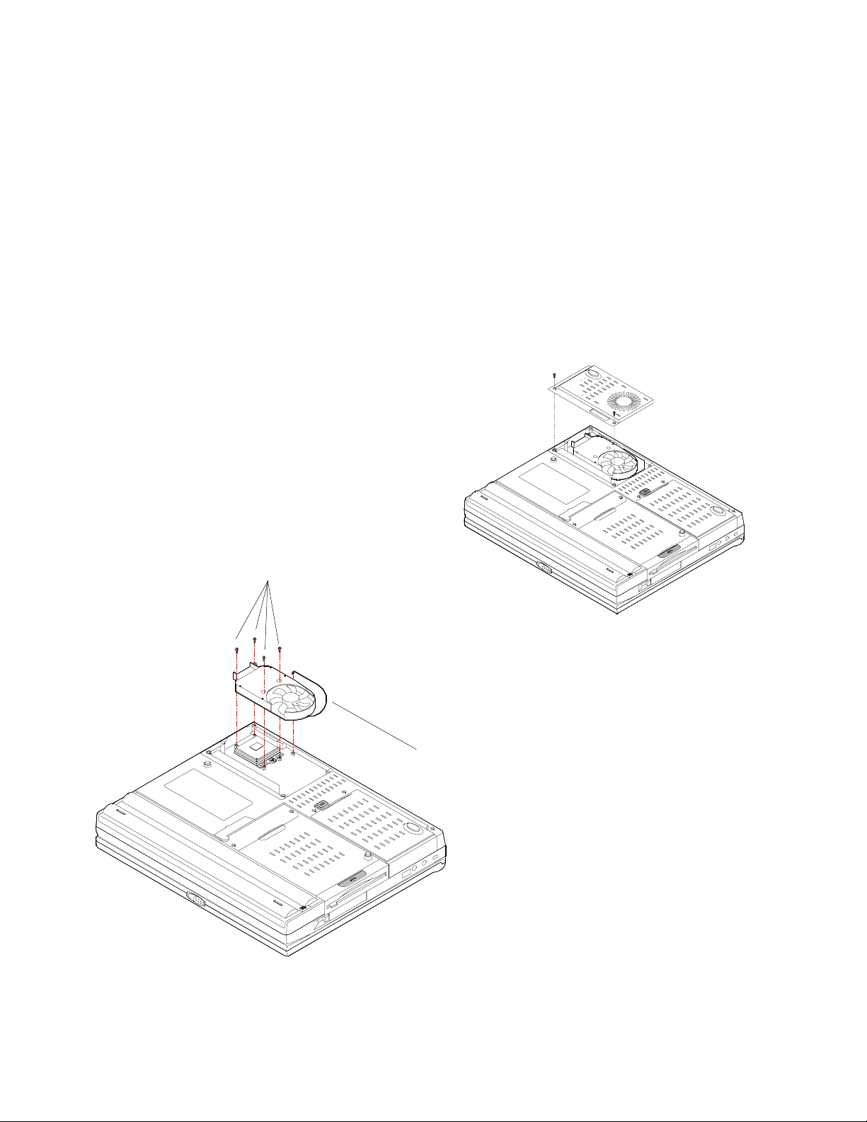
Adding or replacing the processor .
Note: If you plan on removing the heat sink, which is necessary to add or replace the
processor, you will need to have a replacement heat sink pad available. Before proceeding, please contact your dealer to get a replacement pad which you will need when you
reinstall the heat sink.
In order to add or replace the processor you must:
A: Remove the heat sink
B: Remove the processor
C: Insert a new processor
D: Reinstall the heat sink
E: Changing the SW DIP Switch settings
A: Remove the heat sink
1) Turn off the computer
2) Turn over the computer
3) Remove the Heat Sink and CPU Cover
Heat sink
heat sink screws
O
L
Figure 4-3
heat sink cable
4) Remove the 4 screws which hold the
heat sink in place.
5) Gently remove the heat sink cable.
6) Lift the heat sink out of the computer
10
Page 14
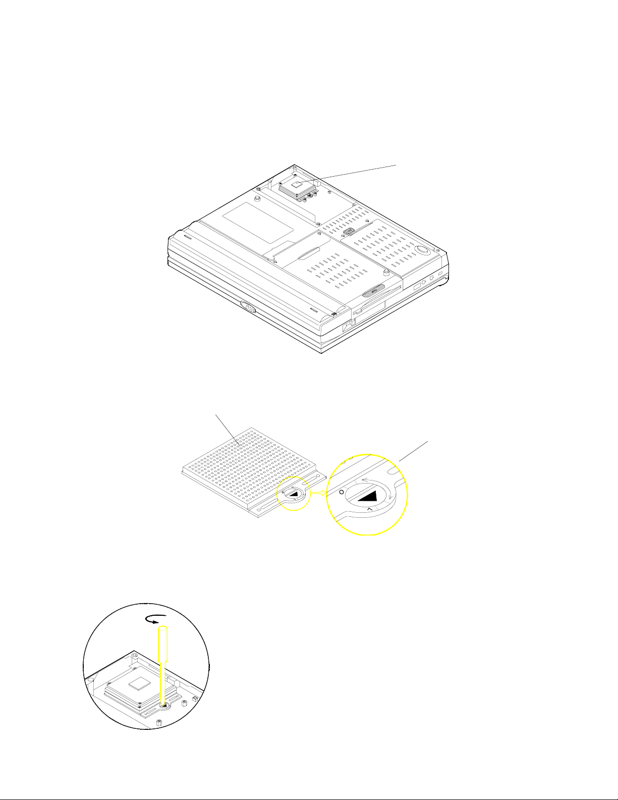
B: Remove the processor
The processor is secured on the mainboard with a lock which is easily opened using a small
regular screwdriver.
With the heat sink already removed you will need to set the lock to the open position before
removing the processor:
processor mounted on the socket
O
L
OPEN
Processor socket
Lock
1) Turn the screw on the
processor lock to the
open position. (O)
O
L
11
Page 15
2) Lift the processor
O
L
from the socket.
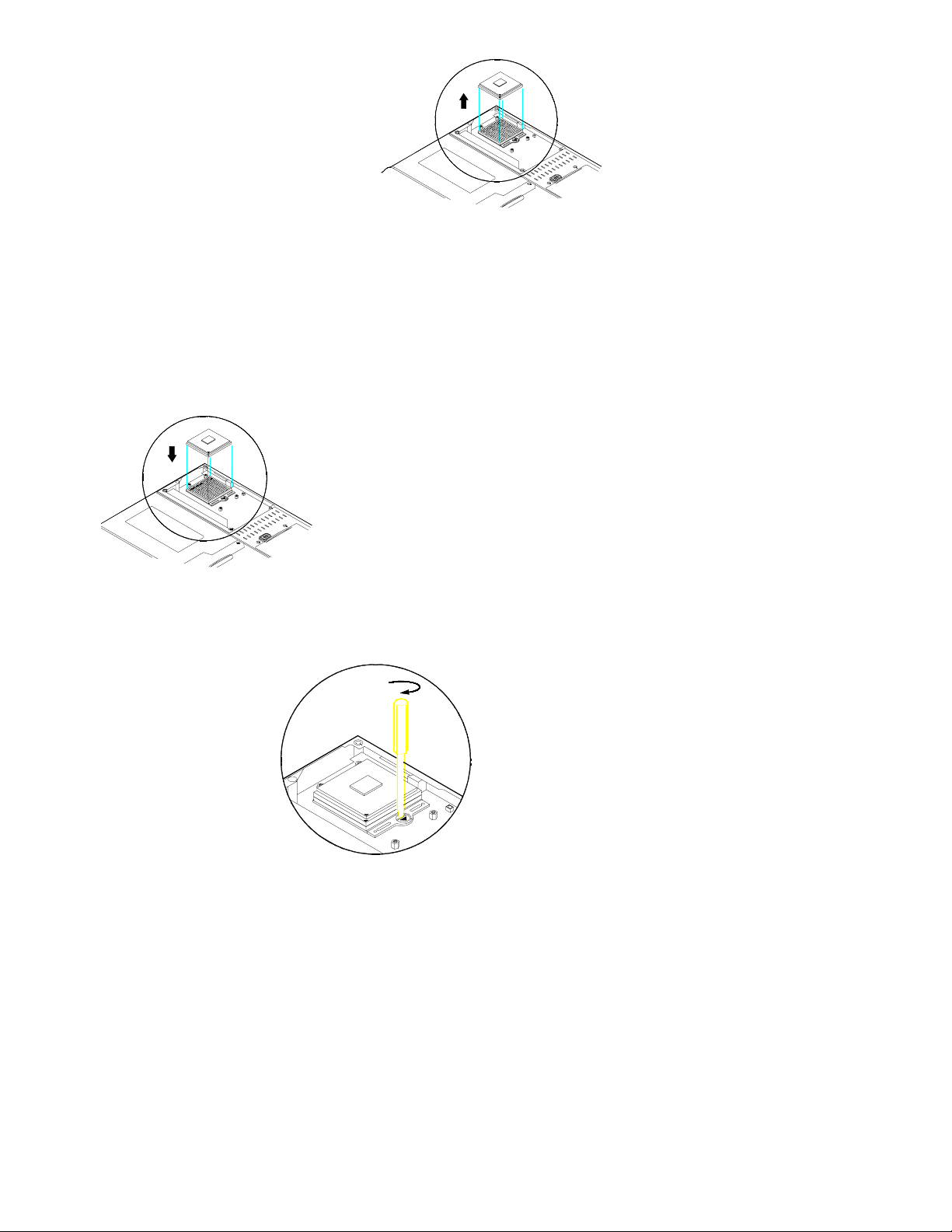
C: Insert a new processor
1) With the processor lock in the open position, align the pins of the processor with the
holes in the socket.
2) Press the processor into
O
L
the socket.
LOCK
3) Turn the screw to the locked
position (L)
O
L
12
Page 16
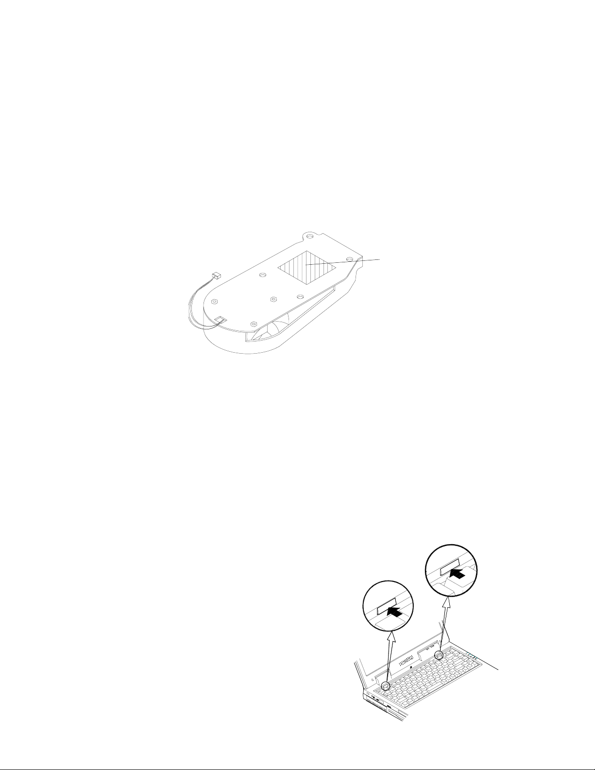
D: Reinstall the heat sink
Note: When reinstalling the heat sink, you will also have to replace the heat sink pad. A
heat sink pad can be obtained from your dealer.
1) Peel off the old heat sink pad and stick on a new one.
2) Insert the heat sink cable in the slot. (Figure 4-3)
3) Align the 4 screw holes on the heat sink with those on the mainboard and screw them
in about half way. Once all the screws are in about half way and the heat sink is
seated probably tighten the screws.
Heat sink pad
E: Changing the SW1 DIP Switch settings
If you have installed the processor with Intel Speedstep you will have to change the
SW1 DIP Switch settings. Follow these steps to get to change the SW1 DIP Switch
setings:
1) Turn off the computer.
2) Press the two keyboard latches to elevate the keyboard from its normal position.
3) Carefully lift the keyboard assembly out to expose the
mainboard.
13
Page 17
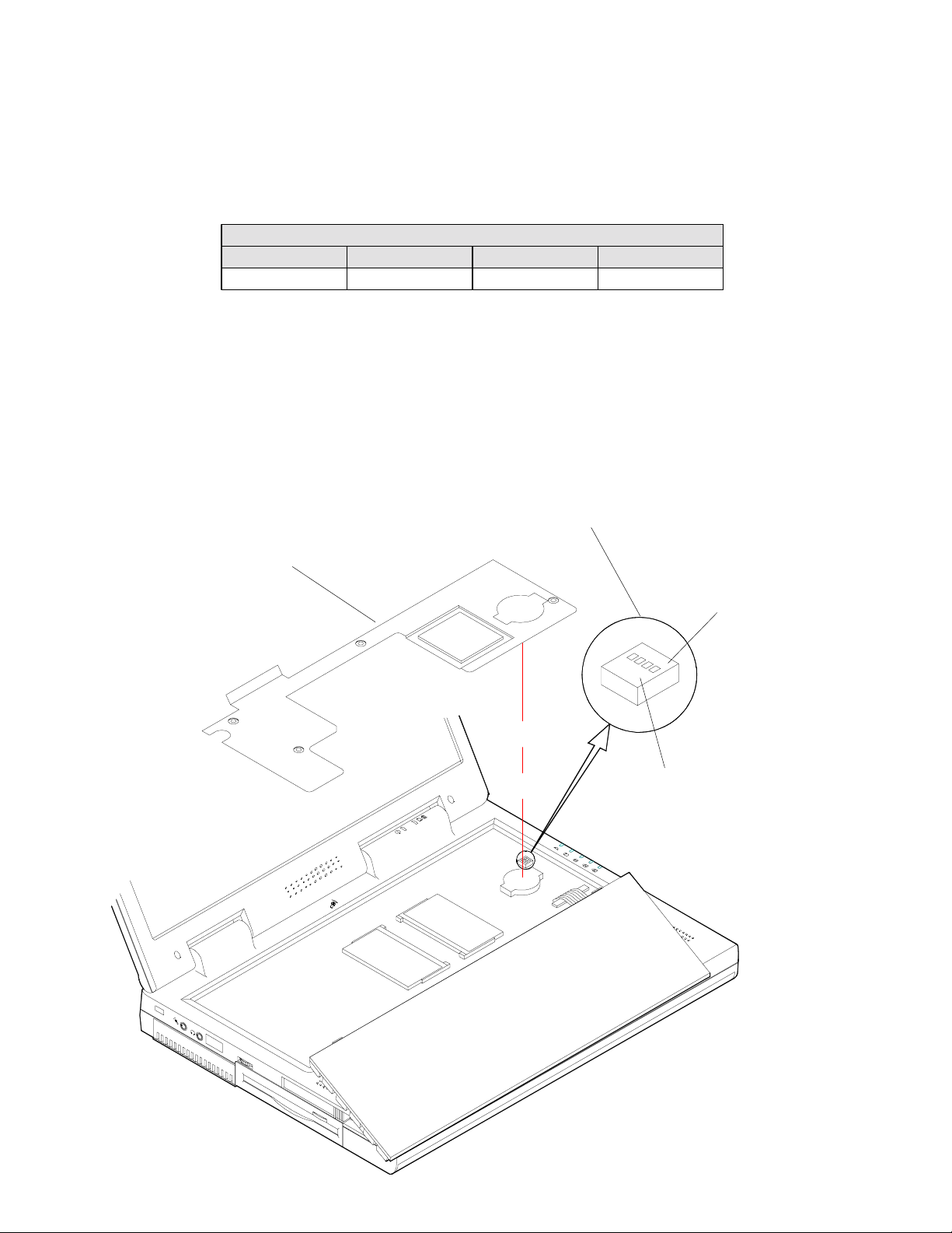
4) Remove the metal protective shield
5) Locate the SW DIP Switch on the right side.
6) Change the settings to the following:
SW settings for Intel Speedstep processor
SW1-1 SW1-2 SW1-3 SW1-4
ON ON ON OFF
7) Put the metal shield back into place
8) Put the keyboard back into place.
Metal shield
SW1 DIP Switch
OFF position
ON position
14
Page 18
Memory
The computer has two memory sockets for PC-100/PC-133 compliant, 144 pin SODIMM
(Small Outline Dual In-line Memory Module) modules. The memory can be expanded to 512
MB with the following combinations:
Bank 0
(64-bit)
32 MB Emp t y 32 MB
32 MB 32 MB 64 MB
64 MB Emp t y 64 MB
64 MB 32 MB 96 MB
64 MB 64 MB 128 MB
128 MB Empty 128 MB
128 MB 32 MB 160 MB
128 MB 64 MB 192 MB
128 MB 128 MB 256 MB
256 MB Empty 256 MB
256 MB 32 MB 288 MB
256 MB 64 MB 320 MB
256 MB 128 MB 384 MB
256 MB 256 MB
Bank 1
(64-bit)
Power Total
Size
3.3V
512 MB
Once a new module is installed the memory size is automatically
detected by the POST routines when you turn on your computer.
15
Page 19

Expansion Memory Socket
The Model 5100S/5500S Notebook PC has two 144-pin SODIMM type memory sockets with the
following configuration:
Pin SDRAM Pin SDRAM Pin SDRAM Pin SDRAM
1 Vss 2 Vss 73 Reserved 74 CLK1
3 DQ0 4 DQ32 75 Vss 76 Vss
5 DQ1 6 DQ33 77 Reserved 78 Reserved
7 DQ2 8 DQ34 79 Reserved 80 Reserved
9 DQ3 10 DQ35 81 Vdd 82 Vdd
11 Vdd 12 Vdd 83 DQ16 84 DQ48
13 DQ4 14 DQ36 85 DQ17 86 DQ49
15 DQ5 16 DQ37 87 DQ18 88 DQ50
17 DQ6 18 DQ38 89 DQ19 90 DQ51
19 DQ7 20 DQ39 91 Vss 92 Vss
21 Vss 22 Vss 93 DQ20 94 DQ52
23 DQMB0 24 DQMB4 95 DQ21 96 DQ53
25 DQMB1 26 DQMB5 97 DQ22 98 DQ54
27 Vdd 28 Vdd 99 DQ23 100 DQ55
29 A0 30 A3 101 Vdd 102 Vdd
31 A1 32 A4 103 A6 104 A7
33 A2 34 A5 105 A8 106 BA0
35 Vss 36 Vss 107 Vss 108 Vss
37 DQ8 38 DQ40 109 A9 110 BA1
39 DQ9 40 DQ41 111 A10 112 A11
41 DQ10 42 DQ42 113 Vdd 114 Vdd
43 DQ11 44 DQ43 115 DQMB2 116 CAS6#
45 Vdd 46 Vdd 117 DQMB3 118 DQMB7
47 DQ12 48 DQ44 119 Vss 120 Vss
49 DQ13 50 DQ45 121 DQ24 122 DQ56
51 DQ14 52 DQ46 123 DQ25 124 DQ57
53 DQ15 54 DQ47 125 DQ26 126 DQ58
55 Vss 56 Vss 127 DQ27 128 DQ59
57 Reserved 58 Reserved 129 Vdd 130 Vdd
59 Reserved 60 Reserved 131 DQ28 132 DQ60
61 CLK0 62 CKE0 133 DQ29 134 DQ61
63 Vdd 64 Vdd 135 DQ30 136 DQ62
65 RAS# 66 CAS# 137 DQ31 138 DQ63
67 WE# 68 CKE1# 139 Vss 140 Vss
69 S0# 70 A12 141 SDA 142 SCL
71 S1# 72 A13 143 Vdd 144 Vdd
16
Page 20
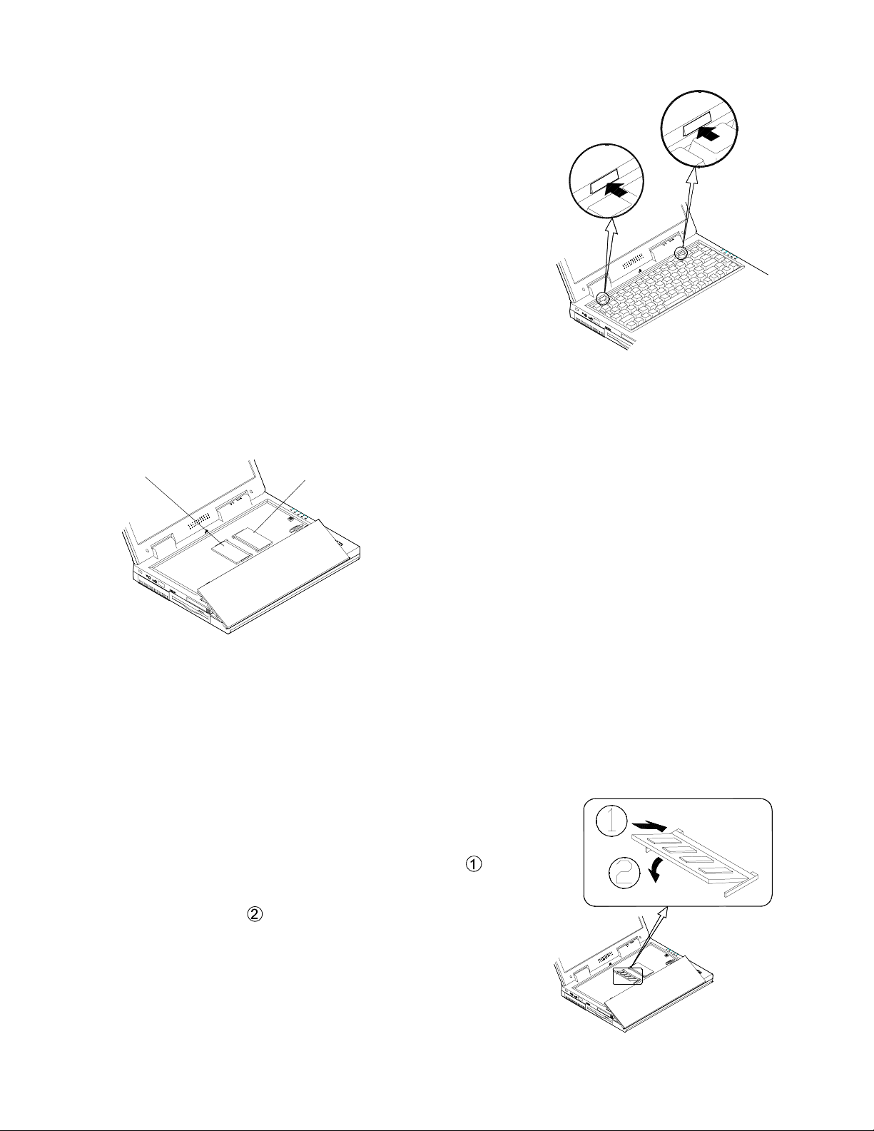
Installing a Memory Module
1) Turn off the computer.
2) Press the two keyboard latches at the top of the
keyboard to elevate the keyboard from its normal
position.
3) Carefully lift the keyboard assembly out to expose
the mainboard.
Figure 4-1
Bank 1 Bank 0
4) Locate the memory banks, Bank 0 is on the
right and Bank 1 is on the left.
Figure 4-2
Note: Only use Bank 0 if you have one memory module. If you are using two memory modules always use the larger module in Bank 0.
5) Insert the memory module at an angle (about 45°)
and fit its connectors firmly into the bank
.
6) Press down the edge of the memory module and lock
it into place
.
7) Put the keyboard back into place.
17
Page 21
Note: Make sure the connectors go into the bank. You must use a RAM module that complies with Intel unbuffered SODIMM (67.6 mm x 29.0 mm). Please consult your dealer for
the details.
67.6 mm
29.0 mm
connectors
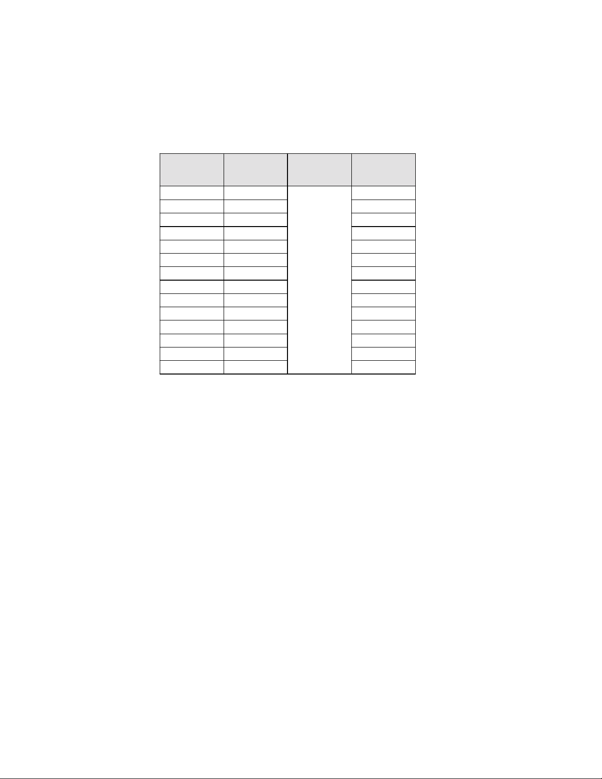
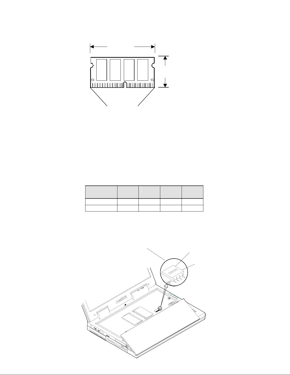
Changing the S3 DIP Switch settings
Once you have installed the new memory you will have to change the DIP Switch settings depending on the type of memory you have installed. Please refer to the chart
below for the correct settings for the S3 DIP Switches
SDRAM
TYPE
PC100 ON OFF OFF OFF
PC133 ON OFF ON OFF
S3-1 S3-2 S3-3 S3-4
S3 DIP Switch
ON position
OFF position
18
Page 22
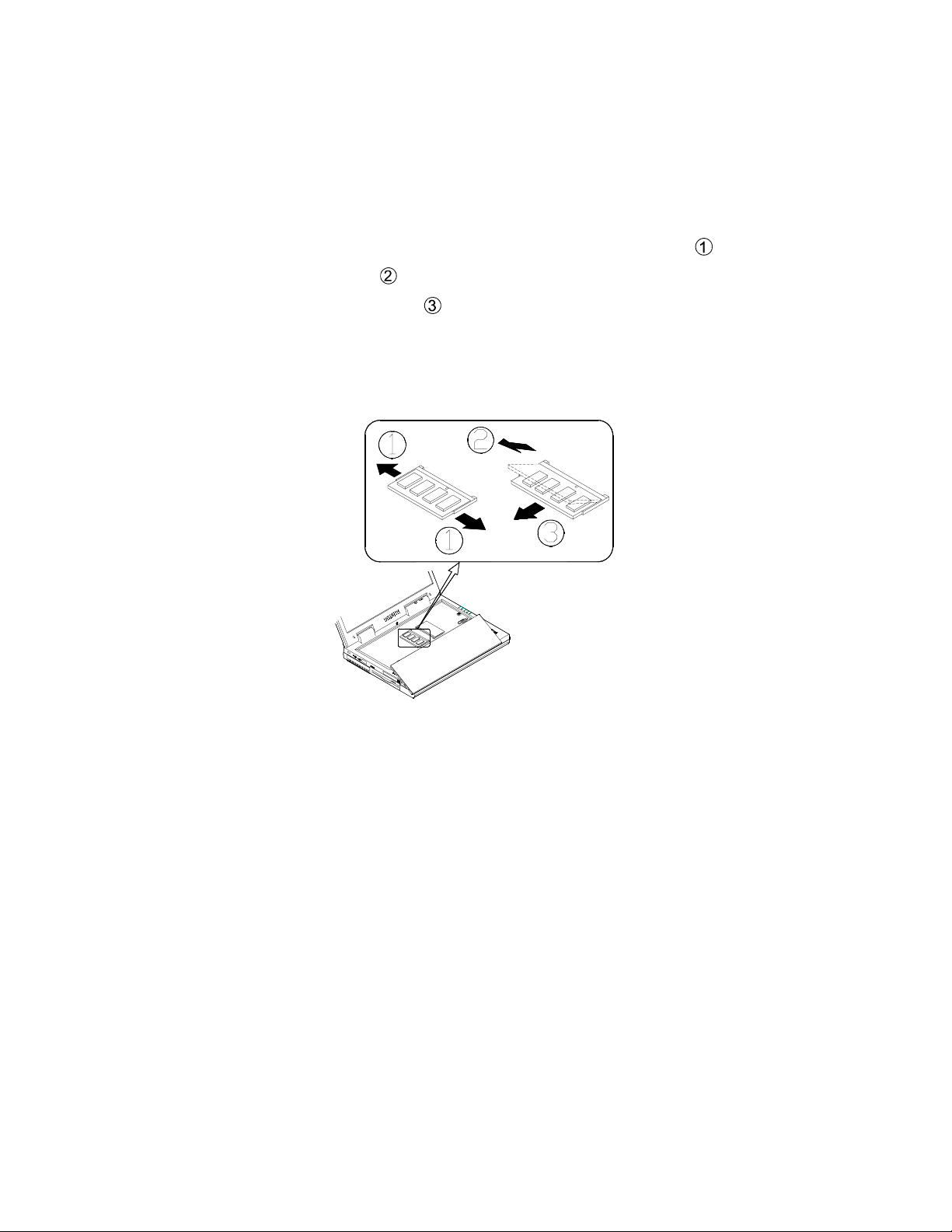
Removing a Memory Module
1) Turn off the computer.
2) Press the two keyboard latches to elevate the keyboard from its normal position
(refer to Figure 4-1)
3) Carefully lift the keyboard assembly out to expose the mainboard.
4) Locate the memory sockets. Bank 0 is on the left and Bank 1 is on the right. (refer
to Figure 4-2)
5) Gently pull the two latches outward on both ends of the module
6) The module will pop up
7) Remove the memory module
8) Install a new memory module if desired (refer to Installing a Memory Module).
9) Put the keyboard back into place.
.
.
.
19
Page 23

Drive information and Pin assignments
Storage Devices
HDD (BUIL T-IN)
- 2.5", 12.7mm max. height and removable HDD
- Average access time: below 13ms
- PCI local bus IDE interface
- Supports: 12GB or higher HDD (Ultra DMA 33/66/100)
- MTBF 300,000 hours
- ULTRA DMA/SMART
HDD PIN ASSIGNMENT
Pin Description Pin Description
A-D DRIVE ID SELECT E, F KEY
1 RESET- 2 GROUND
3+DD74+DD8
5+DD66+DD9
7+DD58+DD10
9 +DD4 10 +DD11
11 +DD3 12 +DD12
13 +DD2 14 +DD13
15 +DD1 16 +DD14
17 +DD0 18 +DD15
19 GROUND 20 KEY
21 DMARQ 22 GROUND
23 DIOW- 24 GROUND
25 DIOR- 26 GROUND
27 IORDY 28 CSEL
29 DMACK- 30 GROUND
31 INTRQ 32 IOCS1633 DA1 34 PDIAG35 DA0 36 DA2
37 CS0- 38 CS139 DASP- 40 GROUND
41 +5 VOLTS SUPPLY 42 +5 VOLTS SUPPLY
43 GROUND 44 RESERVED
20
Page 24
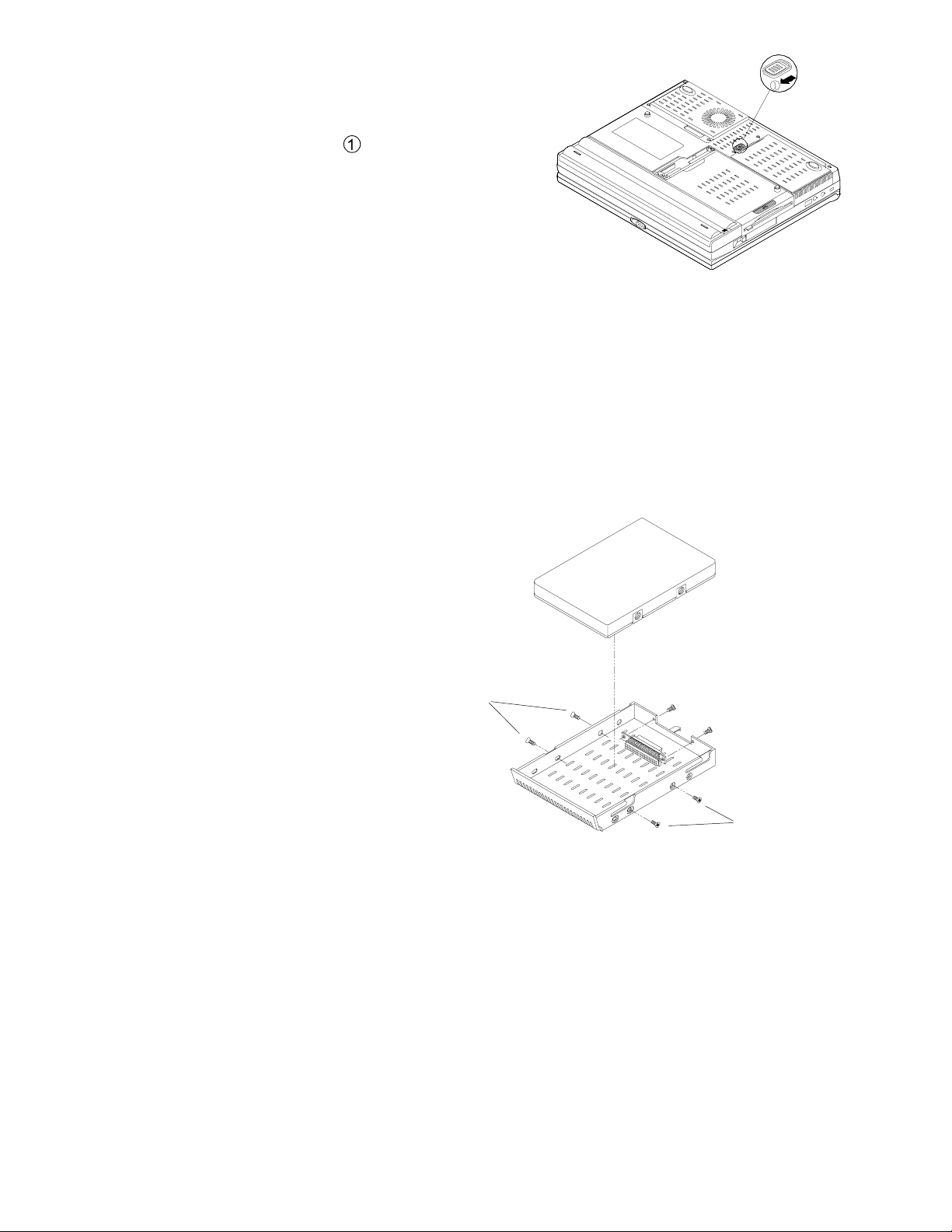
Removing the HDD from the notebook
1) Turn the computer off.
2) Turn the computer over.
3) Locate the HDD latch
4) Slide and hold the latch forward then slide
the HDD out of the computer.
5) Lift the hard disk drive out of the
computer.
.
Removing the HDD from its tray
1) Remove the HDD case from the computer (refer to Removing the HDD in Chapter
2 for details).
2) Remove the two sets of screws on the side of the case.
3) Slowly remove the HDD from the case until you see the connecting cable.
4) Gently disconnect the cable from the HDD being careful not to bend any pins or
crimp the cable.
5) Connect a new HDD
to the cable being
careful not to bend
any pins or crimp the
cable.
6) Slowly place the HDD
back into the case.
7) Hold the HDD firmly
in place with two
screws on each side.
8) Insert the HDD into
the computer (refer to
Inserting the HDD
in Chapter 2 for
details)
fastening screws
fastening screws
Inserting the HDD
1) Turn off the computer.
2) Turn the computer over.
3) Place the HDD case into the computer.
4) Slide the HDD in until you hear a click.
21
Page 25
FDD
- 3.5", 1.44MB floppy disk drive
- 3-Mode support for Japanese market
FDD PIN ASSIGNMENT
Pin Description Pin Description
1+5 V2INDEX
3 +5 V 4 DRIVE SELECT0
5+5 V6DISK CHANGE
7N.C.8Ready
9 HD(High : HD) 10 MOTOR ON
11 N.C. 12 DIRECTION
13 Mode Select 14 STEP
15 GND 16 WRITE DATA
17 GND 18 WRITE GATE
19 GND 20 TRACK 00
21 GND 22 WRITE PROTECT
23 GND 24 READ DATA
25 GND 26 Side One Select
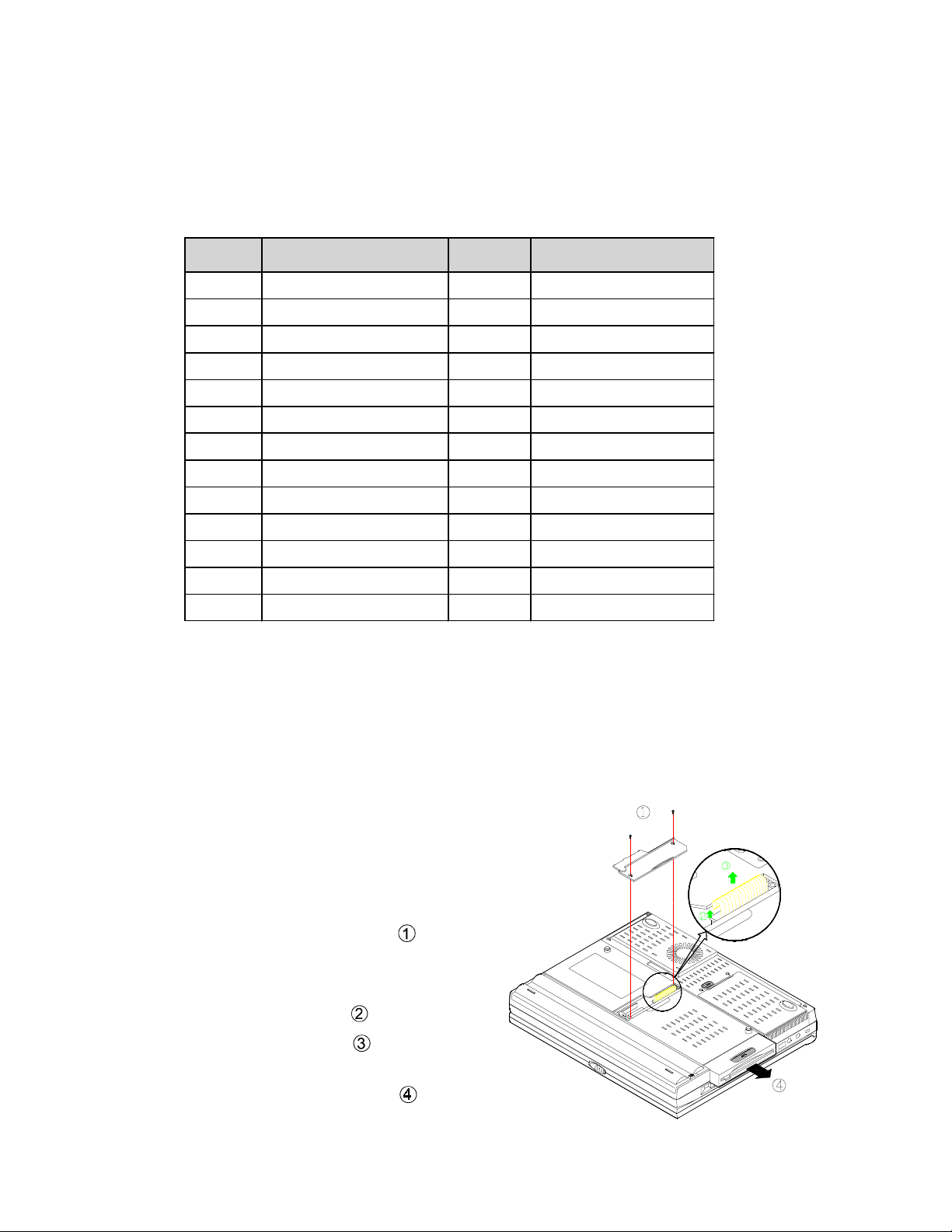
Removing the FDD
Removing the Floppy Disk Drive
1) Turn off the computer.
2) Turn the computer over.
3) Locate the DVD / FDD cover
4) Unscrew and remove the cover .
5) Lift the white plastic piece which holds
.
the FDD cable in place
6) Pull out the FDD cable
7) Grasp the FDD tab and gently PULL
the FDD out of the computer
.
.
.
22
Page 26

8) Remove the two screws on each side of the FDD tray.
9) Remove the FDD from its tray. (see picture)
fastening screws
fastening screws
The FDD floppy disk drive out of its bay
Inserting the Floppy Disk Drive
Follow the instructions for removing the FDD in reverse order.
23
Page 27

DVD-ROM
- Model Matsushita SR8173
- Dimensions 128mm(W)x12.7mm(H)x127mm(D)
- Random access time 130ms-CD / 170ms-DVD
- Data transfer rate 4X speed (5400KB/s)-DVD
- Mechanism tray-loading
- Interface ATAPI
- MTBF 60,000POH
DVD-ROM PIN ASSIGNMENT
Signal Name I/O
AUDIO L-CH O 1 2 O AUDIO R-CH
AUDIO GROUND
/RESET I 5 6 I/O DD8
DD7 I/O 7 8 I/O DD9
DD6 I/O 9 10 I/O DD10
DD5 I/O 11 12 I/O DD11
DD4 I/O 13 14 I/O DD12
DD3 I/O 15 16 I/O DD13
DD2 I/O 17 18 I/O DD14
DD1 I/O 19 20 I/O DD15
DD0 I/O 21 22 O DMARQ
GROUND 23 24 I /DIOR
/DIOW I 25 26 GROUND
IORDY O 27 28 I /DMACK
INTRQ O 29 30 O /IOCS16
DA1 I 31 32 I/O /PDIAG
DA0 I 33 34 I DA2
/CS1FX I 35 36 I /CS3FX
/DASP I/O 37 38 I +5 V
+5 V I 39 40 I +5 V
+5 V I 41 42 I +5 V
GROUND 43 44 GROUND
GROUND 45 46 GROUND
CSEL I 47 48 GROUND
RESERVED 49 50 RESERVED
Connector
Contact
3 4 N.C.
I/O Signal Name
24
Page 28

Removing the DVD-ROM Module
Removing the DVD-ROM Module
1) Turn off the computer.
2) Turn the computer over.
3) Locate the DVD/FDD cover
4) Unscrew and remove the cover.
5) Remove the single screw which holds the DVD-ROM in the computer
6) Locate the cable tab and gently pull the cable tab upward to disconnect the DVD-ROM
from the computer mainboard
7) Grasp the DVD-ROM tab and gently PULL the DVD-ROM out of the computer
.
.
.
.
Inserting the DVD-ROM module
Refer to removing the DVD-ROM and follow the instructions in reverse order.
25
Page 29

CD-ROM (OPTIONAL)
- Model Matsushita CR175
- Dimensions 128mm(W)x12.7mm(H)x127mm(D)
- Random access time 120ms
- Data transfer rate 24X speed (3600KB/s)
- Mechanism tray-loading
- Interface ATAPI
- MTBF 60,000POH
CD-ROM PIN ASSIGNMENT
Signal Name I/O
AUDIO L-CH O 1 2 O AUDIO R-CH
AUDIO
GROUND
/RESET I 5 6 I/O DD8
DD7 I/O 7 8 I/O DD9
DD6 I/O 9 10 I/O DD10
DD5 I/O 11 12 I/O DD11
DD4 I/O 13 14 I/O DD12
DD3 I/O 15 16 I/O DD13
DD2 I/O 17 18 I/O DD14
DD1 I/O 19 20 I/O DD15
DD0 I/O 21 22 O DMARQ
GROUND 23 24 I /DIOR
/DIOW I 25 26 GROUND
IORDY O 27 28 I /DMACK
INTRQ O 29 30 O /IOCS16
DA1 I 31 32 I/O /PDIAG
DA0 I 33 34 I DA2
/CS1FX I 35 36 I /CS3FX
/DASP I/O 37 38 I +5 V
+5 V I 39 40 I +5 V
+5 V I 41 42 I +5 V
GROUND 43 44 GROUND
GROUND 45 46 GROUND
CONFIG(*1) I 47 48 GROUND
RESERVED 49 50 RESERVED
Connector
Contact
3 4 GROUND
I/O Signal Name
26
Page 30

Interface Pin Assignments
RS-232 Serial Interface
The RS-232C Serial Interface uses a 9 pin D-sub male connector with the following configuration:
Parallel Interface
The Parallel interface uses a 25-pin D-sub female connector with the following configuration:
Pin Description
1 DCD (DATA Carrier Detect)
2 RXD (Received Data)
3 TXD (Transmitted Data)
4 DTR (Data Terminal Ready)
5 GND (Signal Ground)
6 DSR (Data Set Ready)
7 RTS (Request To Send)
8 CTS (Clear To Send)
9 RI (Ring Indicator)
Pin Description Pin Description
1 Strobe# 2 Data 0
3 Data 1 4 Data 2
5 Data 3 6 Data 4
7 Data 5 8 Data 6
9 Data 7 10 ACK#
11 Busy 12 Paper Empty
13 Select 14 Auto Feed#
15 Error# 16 Initialize#
17 Select In 18 Ground
19 Ground 20 Ground
21 Ground 22 Ground
23 Ground 24 Ground
25 Ground
USB Interface
The external USB (Universal Serial Bus) has the following configuration:
Pin Description
1 USB_VCCA
2 USBP03 USBP0+
4 GND
27
Page 31

Internal trackpad Interface
The internal trackpad interface connector has the following configuration:
Pin Description
1 EKDA
2 EMDA
3 GND
4 VCC
5 EKCLK
6 EMCLK
7 GND
8 GND
9 GND
External Monitor Interface
The external monitor interface uses a 15-pin D-sub female connector with the following
configuration:
Pin Description Pin Description Pin Description
1 RED 6 GND 11 NC
2 GREEN 7 GND 12 DDCDA
3 BLUE 8 GND 13 HSYNC
4 NC 9 NC 14 VSYNC
5 GND 10 GND 15 DDCLK
RGB Out:
- Output Impedance : 75 Ohms
- RGB peak voltage: 0.7Vpp
External Keyboard/PS2 Mouse Interface
The external keyboard/PS2 mouse interface connector has the following configuration:
Pin Description
1 EKDA
2 EMDK
3 GND
4 VCC
5 EKCLK
6 EMCLK
7 GND
8 GND
9 GND
28
Page 32

PCMCIA CardBus Interface
Description DescriptionPin
CardBus 16Bit Card
A1 GND GND A40 A_VPP2 A_VPP2
A2 GND GND A41 A_CCLK A_A16
A3 A_CAD0 A_D3 A42 GND GND
A4 A_CCD1# A_CD1# A43 A_CTRDY# A_A22
A5 A_CAD14 A_D4 A44 A_CIRDY# A_A15
A6 A_CAD2 A_D11 A45 A_CFRAME# A_A23
A7 A_CAD3 A_D5 A46 A_CC/BE2# A_A12
A8 A_CAD4 A_D12 A47 A_CAD17 A_A24
A9 GND GND A48 A_CAD18 A_A7
A10 A_CAD5 A_D6 A49 GND GND
A11 A_CAD6 A_D13 A50 A_CAD19 A_A25
A12 A_CAD7 A_D7 A51 A_CAD20 A_A6
A13 RFU A_D14 A52 A_CVS2 A_VS2#
A14 A_CC/BE0# A_CE1# A53 A_CAD21 A_A5
A15 A_CAD9 A_D15 A54 A_CRST A_RESET
A16 A_CAD10 GND A55 A_CAD22 A_A4
A17 A_CAD9 A_A10 A56 A_CSERR# A_WAIT#
A18 A_CAD10 A_CE2# A57 GND GND
A19 A_CAD11 A_OE# A58 A_CAD23 A_A3
A20 A_CVS1 A_VS1# A59 A_CREQ# A_INPACK
A21 A_CAD12 A_A11 A60 A_CAD24 A_A2
A22 GND GND A61 A_CC/BE3# A_REG#
A23 A_CAD13 A_IORD# A62 A_CAD25 A_A1
A24 A_CAD14 A_A9 A63 A_CAUDIO# A_BVD2
A25 A_CAD15 A_IOWR# A64 A_CAD26 A_A0
A26 A_CC/BE1# A_A8 A65 GND GND
A27 A_CAD16 A_CAD16 A66 A_CSTSCHG A_BVD1
A28 GND GND A67 A_CAD27 A_D0
A29 A_CPAR A_A13 A68 A_CAD28 A_D8
A30 RFU A_A18 A69 A_CAD29 A_D1
A31 A_CPERR# A_A14 A70 A_CAD30 A_D9
A32 A_CBLOCK# A_A19 A71 RFU A_D2
A33 A_CGNT# A_WE# A72 A_CAD31 A_D10
A35 A_CINT# A_CINT# A73 GND GND
A36 A_CDEVSEK# A_CDEVSEL# A74 A_CCLKRUN# A_WP
A37 A_VCC A_VCC A75 A_CCD2# A_CD2#
A38 A_VCC A_VCC A76 GND GND
A39 A_VPP1 A_VPP1 A77 GND GND
Pin
CardBus 16Bit Card
29
Page 33

Internal PCI Interface
(For optional modem or LAN card)
Pin Description Pin Description
1 GND 2 GND
3 GND 4 GND
5 GND 6 GND
7 AUXBR 8 MIC_MODM
9 AD8 10 AD6
11 AD9 12 AD5
13 AD10 14 AD7
15 AD11 16 CBE#0
17 AD12 18 AD0
19 AD13 20 AD1
21 AD14 22 AD2
23 AD15 24 AD3
25 CBE#1 26 AD4
27 PAR 28 MODEMRI
29 VCC 30 VCC
31 SERR# 32 IDSEL
33 PERR# 34 CBE#3
35 STOP# 36 PME#
37 DEVSEL# 38 INTA#
39 TRDY# 40 RESET#
41 IRDY# 42 PCLKMODM
43 FRAME# 44 GNT#4
45 CBE#2 46 REQ#4
47 GND 48 GND
49 VCC3 50 VCC3
51 VCC3 52 VCC3
53 VCC3 54 VCC3
55 GND 56 GND
57 GND 58 GND
59 VCC 60 VCC
61 VCC 62 VCC
63 VCC 64 VCC
65 AD16 66 AD31
67 AD17 68 AD30
69 AD18 70 AD29
71 AD19 72 AD28
73 AD20 74 AD27
75 AD21 76 AD26
77 AD22 78 AD25
79 AD23 80 AD24
30
Page 34

LCD Interface
( For XGA TFT)
Pin Description Pin Description
1 INVVCC 2 INVVCC
3 ENABL 4 BRIGADJ
5 GND 6 LP
7 FLM 8 DISPOFF#
9 GND 10 CL2
11 CONTADJ 12 LDE
13 PANELID0 14 PANELID1
15 GND 16 LCDVDD
17 LCDVDD 18 GND
19 TXOUTV0- 20 TXOUTV0+
21 GND 22 TXOUTV123 TXOUTV1+ 24 GND
25 TXOUTV2- 26 TXOUTV2+
27 GND 28 TXCLKV29 TXCLKV+ 30 GND
31
Page 35

Power
Application:
This specification shall apply to the power module to be operated in the Notebook 5100S/
5500S system. The power board provides the following voltages for Intel P!!! CPUs:
1.35V &1.6V for CPU VCC_CORE
Input Power:
a. Adapter: +20.0V Constant Voltage Mode (65W ).
b. Battery: LI-ION Smart Battery ( 47.36W ).
c. Input Rating
ITEM MIN TYP MAX UNIT REMARK
Input Voltage 12 20 21 V --
Output Power:
DC OUTPUT
VOLTAGE REGULATION
Vcc / 5V ±5% 150mV 4.0A 6.0A
Vcc3 / 3.3V ±5% 150mV 4.0A 6.0A
12V / 12V ±5% 200mV 0.22A 0.35A
Vcc_Core / 1.6V ±5% 150mV 15A 17A
VccT / 1.5V ±5% 150mV 1.5A 2.0A
Vcc1.8 / 1.8V ±5% 100mV 2.0A 3.0A
Vdd1.8 / 1.8V ±5% 100mV 70mA 80mA
VC / 5V ±5% 100mV 70mA 80mA
Note:
The surge currents of all outputs can keep 10 seconds maximum .
The output ripple/noise requirements should be met throughout the load range and under
the input voltage from 12Vdc to 20Vdc. Measurements should be made with an
oscilloscope with the 20Mhz bandwidth output bypassed with a connector with a
0.1uF ceramic capacitor and a 10 uF electrolytic capacitor to simulate loading.
The system is full run under auto test.
RIPPLE &
NOISE
CURRENT
Max Surge
32
Page 36

Output Protection Requirements:
a. Over current protection:
Vcc OCP —7A max
Vcc3 OCP — 7A max
Vcc_Core OCP — 20A max
VccT OCP — 3.5A max
Vcc1.8 OCP — 3.5A max
b. Output Short Protection : Vcc,Vcc3,12V,Vcc_Core,VccT,Vcc1.8
The power supply shall not be damaged by short form the output to return .
Battery Protection:
The discharge circuits should be SHUTDOWN when the voltage for the Li-ion battery
voltage is down to 12V(+/-0.2V)
Vcc_Core VID setting :
No VID4 VID3 VID2 VID1 VID0 COREVCC
1 0 0 0 0 0 2.0V
2 0 0 0 0 1 1.95V
3 0 0 0 1 0 1.90V
4 0 0 0 1 1 1.85V
5 0 0 1 0 0 1.80V
6 0 0 1 0 1 1.75V
7 0 0 1 1 0 1.70V
8 0 0 1 1 1 1.65V
9 0 1 0 0 0 1.60V
10 0 1 0 0 1 1.55V
11 0 1 0 1 0 1.50V
12 0 1 0 1 1 1.45V
13 0 1 1 0 0 1.40V
14 0 1 1 0 1 1.35V
15 0 1 1 1 0 1.30V
16 0 1 1 1 1 1.25V
33
Page 37

Interface Specifications
JP1. Battery Connector (Off The Mother Board)
PIN SIGNAL
1~8 B+
9 BAT-DATA
10 TEMP
11 BAT-CLK
12 CELL
13~20 GND
CNA1. DC/DC Connector (Off The Power Board)
PIN SIGNAL
1~6 B+
7 VR_ON
8~13 GND
14 ~ 21 VCC3
22~27 GND
28~33 VCC
34~39 GND
40~42 12V
CN4. Battery Connector(Off The Mother Board)
PIN SIGNAL
1,2 GND
3 CELL
4 TEMP
5 BAT_CLK
6 BAT_DATA
7,8 BAT+
34
Page 38

Charge board
Battery parameters
The BIOS will download all battery parameters to the smart charger before POST. The
battery parameters are as follows:
LI-ION CHG V (0x39) : Li-ion CV = (0x39) /3 *4
LI-ION DESINH V (0x3A) : ERROR = (0X3A) * 1.27 +2.3V
LI-ION EDVI (0x3B) : EDVI = (0x3B) /3 *4
LI-ION EDVF (0x3C) : EDVI = (0x3C) /3 *4
Default EDVI and EDVF and Constant Voltage:
Battery Item Voltage
LI-ION Constant Voltage 16.8V ± 0.2V
EDVI 11.4V ± 0.2V
LI-ION
EDVF 10.8V ± 0.2V
Charge current and Charge Time:
ITEM MIN TYPE MAX UNIT REMARK
Input Voltage 19 20 21 V From AC Adapter
0.6 0. 8 1.0 A When System is on
Charge Current
1.3 1. 5 1.7 A When System is off
LI-Ion
Charge Time
Total Power Current ( IRQ ) :
Total Power Current
3A ±0.2A
- - 450 min When System is on
- - 230 min When System is off
*Total Power = System Power + Charge Power
35
Page 39

Hardware ShutDown:
Battery Type Max Voltage
LI-ION 12V ± 0.2V
Max Voltage Protection :
Battery Type Max Voltage
LI-ION 17.1V ± 0.2V
O.P.T ( Protect for environment temperature ) :
For a LI-ION battery charger start, if the temperature exceeds
50°C or falls below 5°C, the charger shall not charge and the charge indicator will
show no charger current.
If the environment temperature is below 50°C the charger shall auto re Charge. The thermistor of the battery pack will detect the environment temperature.
O.P.T
5 ~ 50°C
The trickle charge:
If the LI-ION battery voltage is below 3V/cell,the charge controller will enter the trickle
charge mode. The trickle charge current is about 200~300 mA (trickle charge time is 60
minutes max).
Charger full :
When the battery is fully charged, the charge controller will send a full signal and the gas
guage indicator will display capacity greater than 90%.
For the smart battery, the charge controller full signal and the gas gauge are different.
It’s normal for the gas gauge indicator to show a 90% charge even if the battery has just
been fully charged and is actually above a 90% capacity.
Battery empty shutdown :
When the battery is empty, the charge controller will send a shut down signal within 3
seconds. The shut down signal is 3.3V.
36
Page 40

Alert :
The charge controller will send an alert signal, when the adapter is plugged in or out, when
the battery is inserted or removed, or when the battery is low.
During the alert signal, the charge controller will send the low signal pulse three times
within a 10 second period.
Battery low alarm :
When the battery is low, the charge controller will send out the battery low alert. If KBC or
the OS doesn’t respond, the battery will go to the low signal in 2 seconds.
The battery low alarm is decided by the “alarm time”, the battery voltage is for reference
only. Therefore the battery low alarm defines the alarm time not the voltage.
Alarm time :
- Alarm time is defined from the time the battery low beep starts until the computer
shuts down.
- The alarm time of a dumb battery must be less than 15 minutes and greater than 3
minutes for ZD Mark3.0.
- The alarm time of a smart battery is defined by either the remaining capacitor
alarm or the remaining time alarm.
The battery is not normal if the green LED blinks while the battery is charging.
You must shutdown the computer, unplug the adapter and remove the battery. After the
battery cools down, reinstall the battery and plug in the adapter to recharge the battery.
Smart battery :
The charge current of the smart battery depends on BQ2040 data.
The full charge of a smart battery depends on the remaining capacitor alarm or remaining
time alarm .
The smart charger always reads the temperature of the smart battery to detect Max. T and
OPT.
BIOS issue
After re-flashing the Bios, don’t use the Ctrl+Alt+Del key to restart your computer. Instead you should press the power button to shutdown the computer and then turn on the
computer, this will reload the default BIOS.
While using Ctrl+Alt+Del keys (warm start), KBC doesn’t send out battery setup parameters to charge controller IC.
37
Page 41

Inverter board
APPLICA TION :
This specification refers to an inverter which operates a cold cathode fluorescent lamp for a
liquid-crystal display module.
This inverter is designed for the 12.1” TFT LCD-modules.
ELECTRICAL CHARACTERISTICS:
ITEM MIN TYPE MAX UNIT REMARKS
Input Voltage 4.5 5 5.5 V/DC
Input Current - 900 - mA/DC at Vin=5V
Inrush Current - - 4 A/AC Less than 1ms
Lamp Current
Output Voltage - 560 - V/AC
Frequencey - 60 - KHz
Starting Voltage 1000 - - V/AC
BKLO 0 - 3.3 V/DC ON = 3.3V
BRIGADJ 0 - 2.5 V/DC
5.5 6.0 6.5 mA/AC BRIG:2.5V
2.5 3.0 3.5 mA/AC BRIG:0V
Interface Specification:
J1 ( Connector 6 Pin ) Inverter To M/B Connector
PIN SIGNAL
1 B+
2 B+
3 GND
4 GND
5 BRIGADJ
6 BKLO
38
Page 42

Adapter
Configuration :
3-wire input AC line (line, neutral, FG)
Input characteristics:
Input Voltage: 100 ~ 240
Input Frequency: 47 ~ 63 Hz
Input Current : 1.6A max @115VAC,at full load.
0.8A max @230VAC,at full load.
Efficiency: 80 % (min) .at full load .
Output characteristics:
Output power: 65W (max)
Output Current:
ITEM TOLERANCE OUTPUT CURRENT
+10%vac,Full range
Output voltage (Accuracy) Min Max
+20Vdc (main) +/- 5% 0 3.25A
Regulation:
VOLTAGE TOLERANCE REGULATION
+20Vdc (main) +/- 5 % 19 ~ 21 V
Ripple & Noise :
The power supply shall not exceed 250mVrms on the indicated voltage for 60Hz or 50Hz
ripple, switching frequency ripple and noise dynamic load variations measured with a
20MHz bandwidth. Ripple & noise are measured at the end of output cables to which are
added a 0.1uf ceramic capacitor and a 10uF electrolytic capacitor.
Leakage Current:
0.75mA
Over Voltage Protection :
27V max.(do not test with external DC source).
Shutdown voltage protection:
10V max.
39
Page 43

Over Current Protection :
The power supply will not be damaged by an over current from the output (measure at 110
Vac input).
OUTPUT VOLTAGE LOWER UPPER
+20 to 10.0 Vdc 3.3A 3.8A
Short circuit protection:
A short circuit place at any output will cause no damage.
ESD requirements :
The adapter shall withstand IEC PUB. 801-5 (surge ) level 4 requirements.
EMI / EMC :
The radiated and conducted emissions of this AC adapter complies with the requirements
of the FCC PART 15, CLASS B & EN55022.
SAFETY :
This AC adapter is designed to meet the following standards:
# UL 1950 LISTED
# CUL LEVEL 3
# TUV EN60950
40
Page 44

Battery Pack
Recharging by AC Power
The battery pack automatically recharges when it is installed into a computer that is connected to an AC power supply. You can still use the computer when it is recharging. To
fully recharge the battery will take several hours and may be slightly longer if the computer is being used while the battery is recharging.
Proper Handling of the Battery Pack
DO NOT disassemble the battery pack under any circumstances.
DO NOT expose the battery to fire or high temperatures, it may explode.
DO NOT connect the metal terminals (+, -) together.
Battery Information
Proper care will improve the performance and extend the life and cycle life of the battery.
Follow these guidelines to get the best use out of the battery.
Power loss
When not in use, a battery will gradually lose its power, this is normal. The rate of power
loss depends on the battery type and is approximately:
0.2% / Day for a Li-Ion Battery
Battery storage
Outside the computer
If you are going to store a battery outside the computer for an extended period you must:
· Charge the battery to at least 40% capacity prior to storage.
· Follow steps 1 through 3 approximately every 30 days:
1. Completely recharge the battery.
2. Use the battery until it is fully discharged
3. Recharge the battery to at least 40% capacity.
Inside the computer
If a fully charged battery is stored inside the computer and the battery is not used for more
than 30 days, you must follow these steps:
41
Page 45

1. Completely recharge the battery.
2. Use the battery until it is fully discharged
3. Recharge the battery to 100% capacity.
(In this case it doesn’t matter whether or not the computer is being used)
Note: An empty battery will become damaged if stored too long and by following
these steps the battery cycle life and the battery life will increase.
Battery T esting
Testing a battery while its temperature remains high could possibly cause inaccurate measurements, therefore we strongly recommend:
· Waiting 30 minutes before testing a battery that has just been fully charged.
· Waiting at least 30 minutes before recharging a fully discharged battery.
Note: All battery testing should be done on a fully charged or fully discharged battery.
Battery alarm
The battery alarm is activated by a program and will sound when the battery power is low.
Note: If a fully discharged battery has been charged for less than 3 minutes, this program
will not be activated.
This happens when these 3 steps occur:
1. The computer is being used and the low battery alarm sounds.
2. The AC adapter is connected to charge the battery while the computer continues to be
used.
3. The adapter is unplugged within the first 3 minutes of charging.
After this sequence of steps, the computer will eventually shutdown without the low
battery alarm sounding and you will lose any work you have entered and not saved.
Therefore you should make sure that the AC adapter is firmly plugged into the computer
when charging the battery.
42
Page 46

Removing the battery pack
1) Turn the computer over.
2) Slide the latch in the direction indicated .
3) Gently grasp the battery pack on the edge
below the latches and lift it out of the bay
.
Inserting the battery pack
1) Turn the computer over.
2) Place the battery in its bay inserting the side without the latch in first.
3) Push down on the side with the latch until it clicks into place.
43
Page 47

Battery diagram
44
Page 48

Component diagrams and part numbers
10
18
15
14
4
16
6
8
1
2
13
4
11
4
5
3
7
9
21
22
19
20
31
12
22
23
17
22
22
25
26
33
7
22
24
35
36
22
7
32
22
14
28
34
29
30
31
45
Page 49

46
Page 50

4
6
3
5
13
11
7
ITEM
1
DISPLAY FRON T PA N EL
LCD 12.1" TFT SANYO T M 121SV- 02L07
2
DISPLAY BAC K PAN EL
3
HOOK KNOW
4
5
HOOK
SPRING FO R HOOK EXTEN
6
7
INV ERTER
LCD BRACKET (L)
8
LCD BRACKET (R)
9
10
CABLE 1H /2H 28AW G 35P 203m m
11
DISPLAY RU BBER PAD
12
DISPLAY RU BBER PAD
13
SCREW
SCREW
14
15
SCREW
16
SCREW
PART NAM E
14
16
9
15
2
8
15
10
PART NO.
39- 51011- 01E
50- F1255- S01
39- 51S01- 02A
1
FO R 12.1"
12.1" SV
FOR 12.1 SANYO
15
12
REM ARK
••••
42- 51081- 010
42- 510A 1- 010
38- 10R35- 021
0.35
43- 5 1S0R- 010
33- 51001- 050
33- 51001- 040
43- 51 S01-010
47- 51021- 010
47- 51021- 020
35- 01120- 4RO
35- 41120- 3RA
35- 84130- 6RA
35- B6130- 4R A
FOR LG (S2 ) 12. 1
FOR LG (S2 ) 12. 1
SANYO
UP
BOTTO M
M2*4L,P,NI,ICT
M2*0,4P*3L , B,NI,ICT,NY
M3*6L,K,BK/0,ICT,NY
M3*4,K1,BZ,ICT.NY
47
Page 51

48
Page 52

4
7
2
3
12
10
2
13
9
14
15
16
1
5
22
6
2
7
3
21
9
8
10
2
11
8
5
15
16
17
19
17
18
20
2
49
Page 53

50
Page 54

51
VCC_CORE
R191 0
VCC_SENSE
HA#3
HA#4
HA#5
HA#6
HA#7
HA#8
HA#9
HA#10
HA#11
HA#12
HA#13
HA#14
HA#15
HA#16
HA#17
HA#18
HA#19
HA#20
HA#21
HA#22
HA#23
HA#24
HA#25
HA#26
HA#27
HA#28
HA#29
HA#30
HA#31
Z2
Z3
Z4
Z5
Z6
Z7
Z8
Z9
Z10
Z11
Z12
Z13
BR EQ0#
HREQ#0
HREQ#1
HREQ#2
HREQ#3
HREQ#4
AD S#
Z14
Z15
Z16
Z17
Z18
Z19
Z20
BN R #
Z21
Z22
DBSY#
DRDY#
HIT#
HITM #
Z23
HLOCK#
TPRDY#
IER R #
CPU_FERR#
UPICD0
UPICD1
TC K
TDI
TDO
TM S
TRST#
TH ER M D P
THER MD N
VC C 3
C677
.1 U ( R )
PW R O KK
VCC_SENSE24
HA#[3..31]
T
T
T
T
T
T
T
T
T
T
T
T
BR EQ0# 3
HREQ#03
HREQ#13
HREQ#23
HREQ#33
HREQ#43
AD S# 3
T
T
T
T
T
T
T
BN R # 3
T
T
DBSY# 3
DRDY#3
HIT# 3
HITM #3
T
HLOCK#3
TPRDY#
IER R #
CPU_FERR#
UPICD0
UPICD1
TC K
TDI
TDO
TM S
TRST#
TH ER M D P2
THER MD N2
R720 10K(R)
U51
5
VC C
4
OUT
TC7S08F(R)
R728 0
HA#[3..31]3
IN 1
IN 2
GND
VC C T
1
2
3
R 193 1K
R 194 1.5K
DBRESET#
PW RO K
PW RG OO D12
TPRDY#
TPREQ#
CPURST#3
PW RO K12
Z629
TDI
TDO
TC K
TM S
TRST#
HD#[0..63]
HD#[0..63]3
CPURST#3
R244 110_1%
CPUPWR GD
CPU_STP#
PICCLK
R257 0
STP C L K#12,20
G C L _ L O /H I#12
HCLKCPU11
R205 0
CPU_STP#11 ,1 2,20
PIC C L K11
BPR I#3
RS#03
RS#13
RS#23
HTRDY#3
DEFER#3
A20M #12
IG N N E#12
IN IT#12
IN T R12
NMI12
TPREQ#
BSEL0
BSEL111
SM I#12
FLUSH#
BPR I#
CPURST#
RS#0
RS#1
RS#2
Z1
T
HTRDY#
DEFER#
ED G E C T R L P
A20M #
IG N N E#
IN IT#
IN T R
NMI
TPREQ#
CPUPWR GD
BSEL0
BSEL1
SLP#
SM I#
FLUSH#
STP C L K#
G C L _ L O /H I#
HCLKCPU
UPICCLK
R242
1K(R )
HD#0
HD#1
HD#2
HD#3
HD#4
HD#5
HD#6
HD#7
HD#8
HD#9
HD#10
HD#11
HD#12
HD#13
HD#14
HD#15
HD#16
HD#17
HD#18
HD#19
HD#20
HD#21
HD#22
HD#23
HD#24
HD#25
HD#26
HD#27
HD#28
HD#29
HD#30
HD#31
HD#32
HD#33
HD#34
HD#35
HD#36
HD#37
HD#38
HD#39
HD#40
HD#41
HD#42
HD#43
HD#44
HD#45
HD#46
HD#47
HD#48
HD#49
HD#50
HD#51
HD#52
HD#53
HD#54
HD#55
HD#56
HD#57
HD#58
HD#59
HD#60
HD#61
HD#62
HD#63
D10
D11
C10
B11
C12
B13
A14
B12
E12
B16
A13
D13
D15
D12
B14
E14
C13
A19
B17
A18
C17
D17
C18
B19
D18
B20
A20
B21
D19
C21
E18
C20
D20
D21
H18
E20
H19
E21
H21
G20
P18
G21
K18
K21
M18
R19
K19
T20
M19
U18
R18
AA2
AA16
AD 10
AC 13
AA10
AB18
AC 19
AB20
AA12
AB15
AB12
AB10
AC 9
AC 11
AA18
F19
F18
J18
F21
J20
L18
L21
J21
L20
W1
M3
C7
C8
B9
A9
U4
A6
U1
Y1
U2
U3
V5
R2
H8
H10
D0#
D1#
D2#
D3#
CPUVCC
D4#
D5#
D6#
D7#
D8#
D9#
D10#
D11#
D12#
D13#
D14#
D15#
D16#
D17#
D18#
D19#
D20#
D21#
D22#
D23#
D24#
D25#
D26#
D27#
D28#
D29#
D30#
D31#
D32#
D33#
D34#
D35#
D36#
D37#
D38#
D39#
D40#
D41#
D42#
D43#
D44#
D45#
D46#
D47#
D48#
D49#
D50#
D51#
D52#
D53#
D54#
D55#
D56#
D57#
D58#
D59#
D60#
D61#
D62#
D63#
BPR I#
RESET#
RS0#
RS1#
RS2#
RSP#
TRD Y#
DEFER#
ED G E C T R L P
A20M #
IG N N E#
IN IT#
LINT0/INTR
LINT1/NM I
PR EQ#
PW RG OO D
BSEL0
BSEL1
SLP#
SM I#
FLUSH#
STP C L K#
GHI#
BC LK
PIC C L K
A2A7A8
H12
H14
H16J7J9
CPUVCC
CPUVCC
CPUVCC
CPUVCC
CPUVCC
CPUVCC
LOW POWER GTL+ DATA BUS
GTL+ I nput
1.5V CM OS I nput
<-- 2 .5 CM OS Input
GND
GND
GND
GND
GND
GND
A12
A21B1B5B6B7B8B10
J11
J13
J15K8K10
K12
K14
K16L7L9
L11
L13
L15M8M10
M12
M14
M16N7N9
N11
N13
N15P8P10
P12
P14
P16R7R9
R11
R13
R15T8T10
T12
T14
T16U7U9
U11
U13
U15
U40A
L3
CPUVCC
CPUVCC
CPUVCC
CPUVCC
CPUVCC
CPUVCC
CPUVCC
CPUVCC
CPUVCC
CPUVCC
CPUVCC
CPUVCC
CPUVCC
CPUVCC
CPUVCC
CPUVCC
CPUVCC
CPUVCC
CPUVCC
CPUVCC
CPUVCC
CPUVCC
CPUVCC
CPUVCC
CPUVCC
CPUVCC
CPUVCC
CPUVCC
CPUVCC
CPUVCC
CPUVCC
CPUVCC
CPUVCC
CPUVCC
CPUVCC
CPUVCC
GTL+ Ou tput
1.5V O pen Drai n Outp ut
1.5V Op en D rain I/O
JTAG I NTER FACE
THERMAL INT ERFA CE
GND
GND
GND
GND
GND
GND
GND
GND
GND
GND
GND
GND
GND
GND
GND
GND
GND
GND
GND
GND
GND
GND
GND
GND
GND
GND
GND
GND
GND
GND
GND
GND
GND
GND
GND
B15
B18C9C11
C15
C16
C19D2D6D7D9E3E7E8E9
E10
E11
E13
E19F3F6F7F8F9F10
GND
F11
F12
F13
F14
F15
F16
F20G3G19H2H7H9H11
A3#
CPUVCC
CPUVCC
CPUVCC
CPUVCC
CPUVCC
CPUVCC
CPUVCC
K3
A4#
J2
A5#
L4
A6#
L1
A7#
K5
A8#
K1
A9#
J1
A10#
J3
A11#
K4
A12#
G1
A13#
H1
A14#
E4
A15#
F1
A16#
F4
A17#
F2
A18#
E1
A19#
C4
A20#
D3
A21#
D1
A22#
E2
A23#
D5
A24#
D4
A25#
C3
A26#
C1
A27#
B3
A28#
A3
A29#
B2
A30#
C2
A31#
A4
A32#
A5
A33#
B4
A34#
C5
A35#
V20
DEP0#
T21
DEP1#
U21
DEP2#
R21
DEP3#
V18
DEP4#
P21
DEP5#
P20
DEP6#
U19
DEP7#
C6
BR EQ0#
T2
REQ0#
V4
REQ1#
V2
REQ2#
W3
REQ3#
W5
REQ4#
TH ER M D A
THER MD C
GND
GND
GND
AD S#
AP0#
AP1#
BP2#
BP3#
BPM 0#
BPM 1#
BIN IT#
BN R #
BERR#
AERR#
DBSY#
DRDY#
HIT#
HITM #
RP#
LOCK#
PR DY#
IER R #
FERR#
PIC D 0
PIC D 1
TC K
TDI
TDO
TM S
TRST#
GND
GND
H13
Copperm ine
PW R O KK12
AB2
AB1
Y2
AA21
Y21
W21
W19
V21
T4
E6
AA1
AA3
T1
V1
Y4
W2
R1
W20
AD 9
AC 12
AB21
Y20
AA11
AD 13
AC 15
AD 14
AA14
AA15
AB16
LOW POWER GTL+ INTERFACE
GND
GND
GND
STP C L K#
STP C L K#12,20
SM I#
SM I#12
SLP#
SLP#
IN IT#
IN IT#12
IN T R
IN T R12
NMI
NMI12
IG N N E#
IG N N E#12
A20M #
A20M #12
IER R #
IER R #
CPURST#
CPURST#3
FLUSH#
TPREQ#
TTC K
TTM S
TDI
TDO
BSEL0
BSEL111
TRST#
TC K
UPICD0
UPICD1
GCL_LO/HI#12
B
Q45
E C
2N3904
R183 0(R)
PWRGOOD
PW R O KK
TDI
TDO
TC K
TM S
TRST#
TPRDY#
TPREQ#
CPURST#
Title
Size Docum ent Num ber Rev
Custom
Date: Sheet
Mo nday, S eptem ber 18, 2 000
C?
.1 U
FLUSH#
TPREQ#
TTC K
TTM S
TDI
TDO
BSEL0
BSEL1
TRST#
TC K
UPICD0
UPICD1
G C L _ L O /H I#
VC C 3
R182
4.7K
FERR#
CPU_FERR#
R134 0(R)
D48
AC
F01 J 2 E
C676 .1U(R)
R 721 47
R 722 47
´ ¯ ⁄ „q ‚ £ C L E V O CO .
CLEVO CO.
uPG A 2 P III-1
71-51S00-D02
R163 680
R158 270
R 258 1.5K
R 160 1K
R 226 1.5K
R 225 1.5K
R 166 1.5K
R 157 1.5K
R 156 1.5K
R 292 56 .2 _1%
R 159 1.5K
R 227 1.5K
R 224 1K
R 180 1K
R179 150
R181 150
R164 10K
R189 R
R188 0
R 238 1K
R 236 1K(R )
R 241 1K
R 243 1K
R 327 1.5K
R682 R
FERR#12
CPU_FERR#
CPUPWR GD
R 326 1.5K
VC C T
1
2
3
4
TTC K
5
TTM S
6
7
8
9
10
11
12
VC C T
VC C T
CPUPWR GDPW R O KK12
V2 .5
CN29
VC C T
TDI
TDO
TC K
TM S
TRST#
PR DY#
PR EQ#
CPURST#
GND
DBRESET#
GND
Conn. 12P(R)
of
1
A
29
Schematic Drawings
Page 55

52
5
#
VCCT
R736
R
Z73 0
R737
0
VCC_CORE
G1 0
G1 1
G1 2
G1 3
G1 4
G1 5
G1 6
G1 7
H1 7
K17
L17
M1 7
N1 7
P17
R1 7
T17
U1 7
V10
V11
V12
V13
V14
V15
V16
V17
W10
W11
W12
W13
W14
W15
W16
W17
AA6
AA7
AA8
AB6
AB7
AB8
AC6
AC7
AC8
AD6
AD7
AD8
R1 0
R1 2
R1 4
R1 6
R2 0
T11
T13
T15
T18
T19
U1 0
U1 2
U1 4
U1 6
G6
G7
G8
G9
H6
J17
K6
L6
M6
N6
P1
P6
R6
T6
U6
V6
V7
V8
V9
W6
W7
W8
W9
Y6
Y7
Y8
R8
T3
T5
T7
T9
U8
J6
A15
A16
A17
C1 4D8D1 4
D1 6
E15G2G5
VCCT
NCNCNCNCNCNCNCNCNCNCNCNCNCNCNCNCNCNCNCNCNCNCNC
VCCT
VCCT
VCCT
VCCT
VCCT
VCCT
VCCT
VCCT
VCCT
VCCT
VCCT
VCCT
VCCT
VCCT
VCCT
VCCT
VCCT
VCCT
VCCT
VCCT
VCCT
VCCT
VCCT
VCCT/CPUVCC
VCCT
VCCT
VCCT
VCCT
VCCT
VCCT
VCCT
VCCT
VCCT
VCCT
VCCT
VCCT
VCCT
VCCT
VCCT
VCCT
VCCT
VCCT
VCCT
VCCT
VCCT
VCCT
VCCT
VCCT
VCCT
VCCT
VCCT
VCCT
VCCT
VCCT
VCCT
VCCT
VCCT
VCCT
VCCT
VCCT
VCCT
VCCT
VCCT
VCCT
VCCT
VCCT
VCCT
VCCT
VCCT
VCCT
VCCT
GND
GND
GND
GND
GND
GND
GND
GND
GND
GND
GND
GND
GND
GND
GND
GND
GND
GND
GND
GND
GND
GND
GND
H1 5
H2 0J4J8
G1 8H3H5J5M4M5P3P4AA5
GND
GND
GND
GND
GND
GND
GND
GND
GND
J10
GND
J12
J14
J16
J19K2K7K9K11
K13
FREQUENCY SELECT TABLE
AA19
AC3
AC17
AC20
AD15
NC
GND
GND
GND
GND
GND
GND
GND
GND
GND
GND
GND
GND
GND
GND
GND
GND
GND
GND
GND
GND
GND
GND
GND
GND
GND
GND
K15
K20L5L8
L10
L12
L14
L16
L19M7M9
M1 1
M1 3
M1 5
M2 0N2N3N4N8
GND
N1 0
N1 2
N1 4
N1 6
N1 8
N1 9
N2 0P5P7P9P11
U40B
E5
VRE F
E16
VRE F
E17
VRE F
F5
VRE F
F1 7
VRE F
U5
VRE F
Y17
VRE F
Y18
VRE F
L2
PLL1
M2
PLL2
AD17
TESTHI
Y5
TESTLO1
N5
TESTLO2
AD20
TES TP
H4
TES TP
AA17
TES TP
G4
TES TP
AD2
VID0
AD3
VID1
AD4
VID2
AC4
VID3
AB4
VID4
AD19
RTTIMPEDP
AA9
CMOS R E F
AD18
CMOS R E F
P2
CL K R E F
AB19
RSVD
U2 0
GND
V3
GND
V19
GND
W4
GND
W18
GND
Y3
GND
Y9
GND
Y10
GND
Y11
GND
Y12
GND
Y13
GND
Y14
GND
Y15
GND
Y16
GND
Y19
GND
AA4
GND
AA13
GND
AA20
GND
AB3
GND
AB5
GND
AB9
GND
AB11
GND
AB13
GND
AB14
GND
AB17
GND
AC1
GND
AC2
GND
AC5
GND
AC10
GND
AC14
GND
AC16
GND
AC18
GND
AC21
GND
AD1
GND
AD5
GND
AD16
GND
AD21
GND
GND
GND
GND
GND
GND
GND
GND
GND
GND
GND
P13
P15
P19R3R4
R5
Copp erm in e
C178
C180
C232
C240
.1U
.1U
R146 1
Z29 0
R19 0 10K
R148 1K
R328 1K
R240 R
R135 R
R204 R
R329 R
VID0 15,24
VID1 15,24
VID2 15,24
VID3 15,24
VID4 15,24
R23 9 56.2_1%
R20 3 1K_1%(08 05)
R18 7 2K_1%(08 05)
R14 4 2K_1%(08 05)
R14 5 2K_1%(08 05)
C168
.1U
VS S_S E N SE
C246
.1U
PLL1
PLL2
Z3 1
.1U
C179
22U/10V_1210
TESTHI
TESTLO1
TESTLO2
TESTP1
TESTP2
TESTP3
TESTP4
VID0
VID1
VID2
VID3
VID4
RTTIMPEDP
CMOS R E F
CL K R E F
C261
T
.1U
R192 0
.1U
L51
4.7UH(08 05)
CP U VRM S ELE C T TABL E FO R u PGA 2 P 3
VCC_ Core
VID[4:0]
NO CPU
11111
0.925 V
11110
0.950 V
11101
0.975 V
11100
1.000 V
11011
1.025 V
11010
1.050 V
11001
1.075 V
11000
1.100 V
10111
1.125 V
10110
1.150 V
10101
1.175 V
10100
1.200 V
10011
1.225 V
10011
1.250 V
10001
1.275 V
10000
C239
C167
.1U
4.7U
VCCT
VCCT
VS S_S E N SE 2 4
VID[4:0]
01111
01110
01101
01100
01011
01010
01001
01000
00111
00110
00101
00100
00011
00010
00001
00000
GT LRE F
2K _1%(08 05)
VCCT
V2.5
VCC_ Core
NO CPU
1.30V
1.35V
1.40V
1.45V
1.50V
1.55V
1.60V
1.65V
1.70V
1.75V
1.80V
1.85V
1.90V
1.95V
2.00V
R142
R143
1K _1%(08 05)
VCC_CORE
C262
10U
VCC_CORE
C200
.1U
12
220 U/6.3V
VCCT
C187
.1U
C257
.1U
THERMDP1
THERMDN1
TALERT#12
VCCT
C272
C252
C247
C160
10U
C198
.1U
C186
.1U
C256
220 0P
12
+
C283
470 U/4V
mils
10U
C214
.1U
C185
.1U
Z69 3
20
C188
10U
C226
.1U
12
220 U/6.3V
C244
.1U
2
3
4
11
7
8
10U
10U
C199
C197
.1U
.1U
VCC_CORE
12
+
+
C662
C248
470 U/4V
C175
C184
.1U
.1U
VCC 3
R705 0_0805
R706 R_0805
TALERT# Z26
BSEL1 BSEL0 FREQUENCY
0
0
1
11
C201
C202
C264
C277
10U
10U
C225
C212
.1U
.1U
12
+
+
C218
C265
470 U/4V
C243
C242
.1U
.1U
U3 5
STBY#
VCC
SMBDA T A
SMBCLK
DXP
DXN
ALER T #
NC/CRIT1
NC/CRIT0
GND
NC/OS#
GND
MA X 1 6 1 7
Title
Size Docum ent Num ber
Cu s tom
Date: Sheet
C216
.1U
.1U
.1U
C222
C288
C233
.1U
.1U
.1U
VCCT
C224
C245
.1U
4.7U
C241
C169
C196
.1U
.1U
.1U
15
Z29 3
12
14
6
Z2 5
ADD 1
10
ADD 0
1
Z2 7
5
Z2 8
9
13
Z2 9
NC
16
Z3 0
NC
R230
4.7K (R)
´¯ ⁄ „q ‚£ C L EV O C O .
uPGA2 PIII-2
0
1
0
C229
C230
.1U
.1U
C273
C263
.1U
.1U
C217
C203
.1U
.1U
C231
C176
.1U
.1U
R217
4.7K
20 m ils
T
T
CLEVO CO.
71-51S00-D02
66MHz
100MHz
RES E RVE D
133MHz
C228
C227
.1U
.1U
C253
C213
.1U
.1U
12
+
C177
C181
470P
100 U/ 10V
C223
C289
.1U
.1U
VCC 3
R229
R228
4.7K
4.7K
SDA_ATF 23
S CL_A T F 2 3
R207 10K_0805(R)
R20 8 10K(R)
OS#
R214
4.7K (R)
C215
470P
C276
.1U
C284
.1U
VCC 3
2Monday, Sept em ber 18, 2000
C32
470
12
+
C
100
V2.
C
4.
OS
of
Page 56

53
E
C
9
0
VCCT
R10 9
C13 4
R13 2
HLOCK #1
HTRDY#1
BREQ0#1
630CL K11
DE FER #1
C38 7
4.7U
C15 5
75_1%
.001U
GTLREFA
GTLREFB
R13 1
C15 4
150_1%
.001U
BPRI#1
RS #21
RS #11
RS #01
HITM #1
HIT #1
DRDY #1
DB SY #1
BNR#1
HA#31
HA#30
HA#29
HA#28
HA#27
HA#26
HA#25
HA#24
HA#23
HA#22
HA#21
HA#20
HA#19
HA#18
HA#17
HA#16
HA#15
HA#14
HA#13
HA#12
HA#11
HA#10
HA#9
HA#8
HA#7
HA#6
HA#5
HA#4
HA#3
CPUAV DD
C13 2
.1 U
630CLK
HLO CK#
DEF ER#
HT RDY #
CPURST#
BPRI#
BREQ0#
RS#2
RS#1
RS#0
HITM#
HIT #
DRDY #
DBSY#
BNR#
HREQ #4
HREQ #3
HREQ #2
HREQ #1
HREQ #0
C13 3
.01 U
C37 9
470P
B24
P26
V29
T29
R26
P25
G27
R29
G28
V26
R25
U29
U26
R24
U28
T27
U27
P28
R27
T26
T28
R28
P27
M24
H26
G29
H29
H27
K27
H28
K26
K28
L26
L27
L28
K29
M25
M26
M27
L29
N25
N28
M28
M29
N29
N26
P24
N27
V27
V28
HD#[0..63]1
J26
J29
J27
J28
H D # [ 0. . 6 3]
VSSQ A
VSSQ B
CPUCLK
HLOCK #
DE FER #
HTRDY#
CP UR S T #
BPRI#
BREQ0#
RS#[2]
RS#[1]
RS#[0]
ADS#
HITM #
HIT #
DRDY #
DB SY #
BNR#
HREQ#[4]
HREQ#[3]
HREQ#[2]
HREQ#[1]
HREQ#[0]
HA#[31]
HA#[30]
HA#[29]
HA#[28]
HA#[27]
HA#[26]
HA#[25]
HA#[24]
HA#[23]
HA#[22]
HA#[21]
HA#[20]
HA#[19]
HA#[18]
HA#[17]
HA#[16]
HA#[15]
HA#[14]
HA#[13]
HA#[12]
HA#[11]
HA#[10]
HA#[9]
HA#[8]
HA#[7]
HA#[6]
HA#[5]
HA#[4]
HA#[3]
CP UA VD D
CP UA VS S
A24
GT L V R E F B
MDD63
MDD62
MDD61
MDD60
MDD59
MDD58
MDD57
MDD56
MDD55
MDD54
MDD53
MDD52
MDD51
MDD50
MDD49
MDD48
MDD47
MDD46
MDD45
MDD44
MDD43
MDD42
MDD41
MDD40
MDD39
MDD38
MDD37
MDD36
MDD35
MDD34
MDD33
MDD32
MDD31
MDD30
MDD29
MDD28
MDD27
MDD26
MDD25
MDD24
MDD23
MDD22
MDD21
MDD15
MDD13
MDD17
MDD19
MDD18
MDD20
T25
W28
W27
Y29
Y27
Y26
AA28
AA26
AB28
AB26
AC29
AC27
AC25
AD28
AD27
Y25
AG22
AJ22
AF21
AH21
AF20
AH20
AJ20
AG19
AJ19
AF18
AH18
AF17
AG17
AJ17
AF16
AH16
T24
W29
U25
W26
Y28
V25
AA29
AA27
AB29
AB27
V24
AC28
AC26
P29
MD 63
MD 62
MD 61
MD 60
MD 59
MD 58
MD 57
MD 56
MD 55
MD 54
MD 53
MD 52
MD 51
MD 50
MD 49
MD 48
MD 47
MD 46
MD 45
MD 44
MD 43
MD 42
MD 41
MD 40
MD 39
MD 38
MD 37
MD 36
MD 35
MD 34
MD 33
MD 32
MD 31
MD 30
MD 29
MD 28
MD 27
AD29
MD 26
MD 25
MD 24
MD 23
MD 22
MD 21
MD 20
MD 19
MD 18
MDD10
MDD8
MDD7
MDD11
MDD12
MDD16
MDD9
MDD14
W25
AD26
AF22
AH22
AE23
AG21
AJ21
AG20
AE22
AF19
AH19
MD 9
MD 17
MD 16
MD 8
MD 15
MD 14
MD 13
MD 12
MD 11
MD 10
GT L V R E F A
Memory Interface
SiS630S-1
HO S T Inte r fa ce
HD#63
HD#62
HD#61
HD#60
HD#59
HD#58
HD#57
HD#56
HD#55
HD#54
HD#53
HD#52
HD#51
HD#50
HD#49
HD#48
HD#47
HD#46
HD#45
HD#44
HD#43
HD#42
HD#41
HD#40
HD#39
HD#38
HD#37
HD#36
HD#35
HD#34
HD#33
HD#32
HD#31
HD#30
HD#29
HD#28
HD#27
HD#26
HD#25
HD#24
HD#23
HD#22
HD#21
HD#20
HD#19
HD#18
HD#17
HD#16
HD#15
HD#14
HD#13
HD#12
HD#11
HD#10
HD# 9
HD# 8
HD# 7
HD# 6
HD# 5
E21
A19
C19
B20
B21
B19
A21
A20
D19
E20
D20
B22
C22
C20
A22
D21
A23
C21
B23
C23
A25
E22
D22
D24
D23
C25
B25
C24
E25
F22
D25
E23
B26
E24
C26
A26
A27
D26
B27
C27
B28
F24
C28
D28
H24
C29
E26
D27
J25
E28
D29
E27
H25
HD#63
HD#62
HD#61
HD#60
HD#59
HD#58
HD#57
HD#56
HD#55
HD#54
HD#53
HD#52
HD#51
HD#50
HD#49
HD#48
HD#47
HD#46
HD#45
HD#44
HD#43
HD#42
HD#41
HD#40
HD#39
HD#38
HD#37
HD#36
HD#35
HD#34
HD#33
HD#32
HD#31
HD#30
HD#29
HD#28
HD#27
HD#26
HD#25
HD#24
HD#23
HD#22
HD#21
HD#20
HD#19
HD#18
HD#17
HD#16
HD#15
HD#14
HD#13
HD#12
HD# 4
K24
F25
F27
E29
F26
L25
K25
F29
HD#11
HD#10
HD#9
HD#8
HD#7
HD#6
HD#5
HD#4
HD#3
VCC1.8 630S VT T
C15 6
4.7U
C39 0
.1 U
C38 9
.01 U
C38 8
.1 U
C37 7
.01 U
C37 1
.1 U
C36 3
.01 U
C40 7
.1 U
C39 1
.01 U
C16 5
4.7U
C37 2
.1 U
C39 2
.01 U
C37 8
.1 U
C16 6
.01 U
C37 3
4.7U
C36 4
.1 U
C36 5
.01 U
75_1%
.001U
R10 8
C13 8
150_1%
.001U
VCCT
CP UR S T #1
C38 1
R39 7
56.2_1%
.1 U
ADS#
ADS#1
HRE Q#[0..4]1
HRE Q#[0..4]
HA#[3..31]
HA#[3..31]1
R92 0(0805)
VCC3
C11 7
10U
VCC3
C33 4
C43 4
10U
10U
M DD [ 0. . 63]
MDD0
AG16
U25 A
MD 0
MA[14]
MA[13]
MA[12]
MA[11]
MA[10]
MA [9 ]
MA [8 ]
MA [7 ]
MA [6 ]
MA [5 ]
MA [4 ]
MA [3 ]
MA [2 ]
MA [1 ]
MA [0 ]
DQM[7]
DQM[6]
DQM[5]
DQM[4]
DQM[3]
DQM[2]
DQM[1]
DQM[0]
SRAS #
SCAS #
SDCLK
WE#
CK E
MDD[0..63] 4,7,11
AE24
Z32
AG24
Z33
AF24
RA SA #3
AJ25
RA SA #2
AH25
RA SA #1
AG25
RA SA #0
AF28
Z34
AF29
Z35
AA25
Z36
AE25
Z37
AE26
Z38
AE27
Z39
AB25
MAA14
AF27
MAA13
AF26
MAA12
AG29
MAA11
AG28
MAA10
AG27
MAA9
AH28
MAA8
AB24
MAA7
AH27
MAA6
AD24
MAA5
AJ27
MAA4
AG26
MAA3
AH26
MAA2
AJ26
MAA1
AF25
MAA0
Y24
DQMA 7
AE28
DQMA 6
AF23
DQMA 5
AG23
DQMA 4
AD25
DQMA 3
AE29
DQMA 2
AJ24
DQMA 1
AD22
DQMA 0
AH23
WEA#
AH24
SRASA#
AJ23
SCASA#
AJ16
630SD CL K
E9
CK E
AE19
SDAVDD
AE20
CK E
T
T
RAS A#[0..3]
T
T
T
T
T
T
MA A [0 ..14 ]
DQMA[0..7]
WEA# 4
SRASA# 4
SCASA# 4
630SD CL K 11
CK E
R33 1 8.2K
R429 0(0805)
C40 8
C39 3
.1 U
.01 U
U20
1
1G
VCC
19
CK E
2G
1Y1
1Y2
2
1A1
1Y3
4
1A2
1Y4
6
1A3
8
1A4
2Y1
2Y2
11
2A1
2Y3
13
2A2
2Y4
15
2A3
17
2A4
GN D
74LVC2 44
Title
Si630S HOST/MEMORY INTERFAC
Size Document Number
Custo m
Date: Sheet
Monday, Sept ember 18, 2000
RAS A#[0..3] 4
MA A [0 ..14 ] 4
DQMA[0..7] 4
VCC3
C38 0
10U
VCC3
C44 7
R49 3
R49 5
R48 6
.1 U
20
270
270
CKE0
CKE1
CKE2
CKE3
Z40
Z41
Z42
Z43
CLEVO CO.
270
T
T
T
T
18
16
14
12
9
7
5
3
10
´¯ ⁄ „q ‚ £ C L E VO
71-51S00-D02
R4
27
3
MDD6
MDD2
MDD5
MDD3
MDD4
MDD1
AE18
AG18
AJ18
AD20
AH17
AE21
MD 7
MD 6
MD 5
MD 4
MD 3
MD 2
MD 1
CS A# [5]
CS A# [4]
CS A# [3]
CS A# [2]
CS A# [1]
CS A# [0]
CS B# [5]
CS B# [4]
CS B# [3]
CS B# [2]
CS B# [1]
CS B# [0]
SDAVDD
SDAVSS
HD# 3
HD# 2
HD# 1
HD# 0
SiS630S
F28
G26
G25
HD#2
HD#1
HD#0
Page 57

54
E
RN46 8P4R -10
MAA1
MAA13
MAA2
MAA23
MAA0
MAA03
MAA4
MAA43
Z44
T T
MAA5
MAA53
MAA7
MAA73
MAA14
MAA143
MAA13
MAA133
MAA11
MAA113
MAA10
MAA103
MAA9
MAA93
MAA3
MAA33
MAA6
MAA63
MAA8
MAA83
MAA12
MAA123
RA SA# 0 IRASA #0
RA SA# 03
RA SA# 1 IRASA #1
RA SA# 13
RA SA# 2 IRASA #2
RA SA# 23
RA SA# 3 IRASA #3
RA SA# 33
CKE0 ICKE0
CKE03
CKE1 ICKE1
CKE13
CKE2 ICKE2
CKE23
CKE3 ICKE3
CKE33
DQMA2
DQMA23
DQMA6
DQMA63
DQMA3
DQMA33
DQMA7
DQMA73
DQMA0
DQMA03
DQMA1
DQMA13
DQMA4
DQMA43
DQMA5
DQMA53
Z46
T T
SRASA#
SRASA#3
SCASA#
SCASA#3
WEA#
WEA#3
1 8
2 7
3 6
4 5
1 8
2 7
3 6
4 5
RN45 8P4R -10
RN36 8P4R -10
1 8
2 7
3 6
4 5
1 8
2 7
3 6
4 5
RN35 8P4R -10
RN34 8P4R -10
1 8
2 7
3 6
4 5
1 8
2 7
3 6
4 5
RN39 8P4R -22
RN47 8P4R -10
1 8
2 7
3 6
4 5
1 8
2 7
3 6
4 5
RN44 8P4R -10
RN33 8P4R -10
1 8
2 7
3 6
4 5
IMA B1
IMA B2
IMA B0
IMA B4
Z45
IMA B5
IMA B7
IMA B1 4
IMA B1 3
IMA B1 1
IMA B1 0
IMA B9
IMA B3
IMA B6
IMA B8
IMA B1 2
IDQ MA2
IDQ MA6
IDQ MA3
IDQ MA7
IDQ MA0
IDQ MA1
IDQ MA4
IDQ MA5
Z47
ISRA SA#
ISCA SA#
IWE A#
SDRAM BUS INTERFACE NEAR SiS630S
Thes e H /W traps hav e internal pull-dow n resis tors.
MDD[55..53] : Clock sk ew control of A GP
MD32: PAL/NT SC Select
MD33 : Enable Video Bridge
MD36 : E n a b l e E xt- P L i n k
M D 38 : Enable VGA Interr upt Func t ion
MD 31 : Quick Start Function
1:PAL
0:NTSC
(For 3D Str ereo)
1 : Enable
0 : Disable
1 : Enable
0 : Disable
input/output loop
( Default: 001)
IMA B1 5
IMA B2 5
IMA B0 5
IMA B4 5
IMA B5 5
IMA B7 5
IMA B1 4 5
IMA B1 3 5
IMA B1 1 5
IMA B1 0 5
IMA B9 5
IMA B3 5
IMA B6 5
IMA B8 5
IMA B1 2 5
IRA S A#0 5
IRA S A#1 5
IRA S A#2 5
IRA S A#3 5
ICKE 0 5
ICKE 1 5
ICKE 2 5
ICKE 3 5
IDQ MA2 5
IDQ MA6 5
IDQ MA3 5
IDQ MA7 5
IDQ MA0 5
IDQ MA1 5
IDQ MA4 5
IDQ MA5 5
ISRA SA# 5
ISCA SA# 5
IWE A# 5
VCC3
R451 4.7K(R)
R452 4.7K(R)
R428 4.7K(R)
R681 4.7K(R)
R410 4.7K
MDD53
MDD54
MDD55
MDD38
MDD31
MDD[0..63]
MDD36
MDD37
MDD38
MDD39
MDD3
MDD2 MD2
MDD1
MDD0
MDD47
MDD46
MDD45
MDD44 MD44
MDD15
MDD14
MDD13
MDD12
MDD23
MDD22
MDD21
MDD20
MDD52
MDD53
MDD54
MDD55
MDD24
MDD26
MDD27
MDD31
MDD30
MDD29
MDD28
MDD7
MDD6
MDD5
MDD4
MDD32
MDD33
MDD34
MDD35 MD35
MDD8
MDD9
MDD10
MDD11
MDD43 MD43
MDD42
MDD41
MDD40
MDD48
MDD49
MDD50
MDD51
MDD19
MDD18
MDD17
MDD16
MDD56
MDD57
MDD58
MDD59
MDD60
MDD61
MDD62
MDD63
MDD[0..63] 3,7,11
RN29 8P4R -10
1 8
2 7
3 6
4 5
1 8
2 7
3 6
4 5
RN30 8P4R -10
RN31 8P4R -10
1 8
2 7
3 6
4 5
1 8
2 7
3 6
4 5
RN32 8P4R -10
RN38 8P4R -10
1 8
2 7
3 6
4 5
1 8
2 7
3 6
4 5
RN37 8P4R -10
RN28 8P4R -10
RN27 8P4R -10
RN41 8P4R -10
1 8
2 7
3 6
4 5
1 8
2 7
3 6
4 5
RN40 8P4R -10
RN43 8P4R -10
1 8
2 7
3 6
4 5
1 8
2 7
3 6
4 5
RN42 8P4R -10
RN48 8P4R -10
1 8
2 7
3 6
4 5
1 8
2 7
3 6
4 5
RN49 8P4R -10
RN15 8P4R -10
RN16 8P4R -10
MD[ 0.. 63]5
MD36
MD37
MD38
MD39
MD3
MD1
MD0
MD47
MD46
MD45
MD15
MD14
MD13
MD12
MD23
MD22
MD21
MD20
MD52
MD53
MD54
MD55
18
MD24
27
MD25MDD25
36
MD26
45
MD27
18
MD31
27
MD30
36
MD29
45
MD28
MD7
MD6
MD5
MD4
MD32
MD33
MD34
MD8
MD9
MD10
MD11
MD42
MD41
MD40
MD48
MD49
MD50
MD51
MD19
MD18
MD17
MD16
18
MD56
27
MD57
36
MD58
45
MD59
18
MD60
27
MD61
36
MD62
45
MD63
MD[0..63]
VCC1.8
C362
.1U
VDD3
VDD1.8
C349
4.7U
VCC3
VCC3
AA8
AA9
AB8
U25C
AA11
OV DD
AA12
OV DD
AA13
OV DD
AA18
OV DD
AA19
OV DD
AA20
OV DD
AA22
OV DD
AB12
OV DD
AB19
OV DD
AB21
OV DD
AB22
OV DD
H10
OV DD
H17
OV DD
J11
OV DD
J12
OV DD
J9
OV DD
K8
OV DD
K9
OV DD
M9
OV DD
U21
OV DD
U22
OV DD
V21
OV DD
V22
OV DD
W21
OV DD
W22
OV DD
Y21
OV DD
AB10
PVDD
AB11
PVDD
AB13
PVDD
AB18
PVDD
AB20
PVDD
H11
PVDD
H12
PVDD
H18
PVDD
J18
PVDD
L8
PVDD
M8
PVDD
N22
PVDD
T22
PVDD
Y22
PVDD
AA10
IV DD
AA14
IV DD
AA17
IV DD
AA21
IV DD
AB14
IV DD
AB17
IV DD
H13
IV DD
H16
IV DD
J10
IV DD
J13
IV DD
J16
IV DD
J17
IV DD
J19
IV DD
J20
IV DD
K21
IV DD
L21
IV DD
L9
IV DD
M21
IV DD
N21
IV DD
N9
IV DD
T21
IV DD
U9
IV DD
H9
AUX3.3V
J8
AUX1.8V
VDD3VDD1.8
C348
C340
4.7U
.1U
AB9N8P8P9U8V8V9W8W9Y8Y9
VDDQ
VDDQ
VDDQ
VDDQ
VDDQ
VDDQ
VDDQ
SiS630S-3
H19
VDDQ
VDDQ
VDDQ
VDDQ
VDDQ
VDDQ
VDDQ
GTLVTT
Title
DAM P ING FOR DRA M INTERFA C
Size Docu m ent Num be r
B
Dat e: Sheet
Monday, Septem ber 18, 2000
630SV T T
R138 0(1206)(R)
J21
J22
K22
GTLVTT
GTLVTT
R137 0(1206)
L22
M22
VSS
VSS
GTLVTT
GTLVTT
GTLVTT
VSS
VSS
VSS
VSS
VSS
VSS
VSS
VSS
VSS
VSS
VSS
VSS
VSS
VSS
VSS
VSS
VSS
VSS
VSS
VSS
VSS
VSS
VSS
VSS
VSS
VSS
VSS
VSS
VSS
VSS
VSS
VSS
VSS
VSS
VSS
VSS
VSSD
VSSD
VSSD
VSSD
VSSD
VSSD
VSSD
VSSD
VSSD
VSSD
VSSD
VSSD
VSSD
VSSD
VSSD
VSSD
VSSD
VSSD
VSSD
VSSD
VSSQ
VSSQ
VSSQ
VSSQ
VSSQ
VSSQ
VSSQ
VSSQ
VSSQ
VSSQ
VSSQ
SiS630S
CLEVO CO.
L13
L14
L15
L16
L17
M12
M13
M14
M15
M16
M17
M18
N11
N12
N13
N14
N15
N16
N17
N18
N19
P14
P15
P18
P19
R14
R15
T14
T15
U14
U15
V14
V15
W13
W14
W15
P16
P17
R16
R17
R18
R19
T16
T17
T18
T19
U16
U17
U18
U19
V16
V17
V18
W16
W17
P11
P12
P13
R11
R12
R13
T11
T12
T13
U11
U12
U13
V12
V13
H20
H21
H22
GTLVTT
GTLVTT
GTLVTT
´¯ ⁄ „q ‚ £ C L E V O C O .
71-51S00-D02
of
4
Page 58

55
VCC3
L2 1
J3216HS480
C9 0
10U
MEMCLK 111
MEMCLK 211 MEMCLK 311
C54 2
10U
MEM_VCC MEM_VCC
C48 8
4.7U
C8 8
10U
MD [0 ..6 3]4
MEMCLK 1
MEMCLK 2
NEAR SODIMM
MEM_VCC
C54 9
.1U
C47 1
4.7U
MEM_VCC
C8 7
C47 0
.1U
.1U
MD [0 ..6 3]
C47 6
R
MEMCLK 111
ISRA SA #4
IRAS A# 04
IRAS A# 14
C47 8
.1U
MEM_VCC
GND GND MEMCLK4 GND GND
C48 4
R
ID Q MA 04
ID Q MA 14
IMAB04
IMAB14
IMAB24
IW EA #4
R53 3
1K
IMAB64
IMAB84
IMAB94
IMA B1 04
ID Q MA 24
ID Q MA 34
SDA _RA23 SCL_RA 23 SCL_RB 23SDA _RB23
C47 3
.1U
MD 0
MD 1
MD 2
MD 3
MD 4
MD 5
MD 6
MD 7
GND GND GND GND
ID Q MA 0 ID Q MA 4 ID Q MA 0 ID Q MA 4
ID Q MA 1 ID Q MA 5 ID Q MA 1 ID Q MA 5
IMAB0 IMAB3 IMAB0 IMAB 3
IMAB1 IMAB4 IMAB1 IMAB 4
IMAB2 IMAB5 IMAB2 IMAB 5
GND GND GND GND
MD 8
MD 9
MD10
MD11
MD12
MD13
MD14
MD15
GND GND GND GND
Z4 8
T
Z4 9
T
MEMCLK 1 ICKE 0 MEMCLK 3 ICKE 2
ISRA SA # ISC A SA # ISRA SA # ISCASA #
IW EA # ICKE 1 IW EA # ICKE 3
IRAS A# 0 IMA B14 IRAS A# 2 IMAB14
IRAS A# 1 IRAS A# 3
Z5 6 MEMCLK 2 Z6 0 MEMCLK 4
GND GND GND GND
Z5 0
T
Z5 1
T
MD16
MD17
GND GND GND
MD21
MD22
MD23
IMAB6 IMAB7 IMAB6 IMAB 7
IMAB8 IMA B1 1 IMAB8 IMAB1 1
GND GND GND GND
IMAB9 IMA B1 2 IMAB9 IMAB1 2
IMA B1 0 IMAB1 3 IMAB10 IMAB13
ID Q MA 2 ID Q MA 6 ID Q MA 2 ID Q MA 6
ID Q MA 3 ID Q MA 7 ID Q MA 3 ID Q MA 7
GND GND GND GND
MD24
MD25
MD26
MD27
MD28
MD29
MD31
GND GND GND GND
SDA _RA SCL_RA SDA _RB SCL_RB
C47 2
C47 7
.01U
C47 4
.01U
.01U
BANK0
BANK0BANK0BANK0
BANK0
CN11 PIN145 -> 148:NC CN10 PIN145 -> 148:NC
CN11
1
3
5
7
9
11
13
15
17
19
21
23
25
27
29
31
33
35
37
39
41
43
45
47
49
51
53
55
57
59
61
63
65
67
69
71
73
75
77
79
81
83
85
87
89
91
93
95
97
99
10 1
10 3
10 5
10 7
10 9
11 1
11 3
11 5
11 7
11 9
12 1
12 3
12 5
12 7
12 9
13 1
13 3
13 5
13 7
13 9
14 1
14 3
C47 9
.01U
VSS
DQ0
DQ1
DQ2
DQ3
VCC
DQ4
DQ5
DQ6
DQ7
VSS
CE 0 # /D QM0
CE 1 # /D QM1
VCC
A0
A1
A2
VSS
DQ8
DQ9
DQ10
DQ11
VCC
DQ12
DQ13
DQ14
DQ15
VSS
RESVD/DQ64
RESVD/DQ65
CLK0
VCC
RAS#
WE#
CS0#
CS1#
QE #
VSS
RESVD/DQ66
RESVD/DQ67
VCC
DQ16
DQ17
DQ18
DQ19
VSS
DQ20
DQ21
DQ22
DQ23
VCC
A6
A8
VSS
A9
A10
VCC
CE 2 # /D QM2
CE 3 # /D QM3
VSS
DQ24
DQ25
DQ26
DQ27
VCC
DQ28
DQ29
DQ30
DQ31
VSS
SDA
VCC
S O-DIMM144_4
MEM_VCC
C48 0
.1U
CE 4 # /D QM4
CE 5 # /D QM5
RESVD/DQ68
RESVD/DQ69
RESVD/DQ70
RESVD/DQ71
CE 6 # /D QM6
CE 7 # /D QM7
C47 5
.1U
DQ32
DQ33
DQ34
DQ35
DQ36
DQ37
DQ38
DQ39
DQ40
DQ41
DQ42
DQ43
DQ44
DQ45
DQ46
DQ47
CKE0
CAS#
CKE1
CLK1
DQ48
DQ49
DQ50
DQ51
DQ52
DQ53
DQ54
DQ55
BA 0/A1 1
BA 1/A1 2
A 11/A1 3
DQ56
DQ57
DQ58
DQ59
DQ60
DQ61
DQ62
DQ63
C53 3
.1U
VSS
VCC
VSS
VCC
VSS
VCC
VSS
VCC
A12
A13
VSS
VCC
VSS
VCC
VSS
VCC
VSS
VCC
VSS
SCL
VCC
A3
A4
A5
A7
C53 1
.1U
MEM_VCC
2
4
MD32
6
MD33
8
MD34
10
MD35
12
14
MD36
16
MD37
18
MD38
20
MD39
22
24
26
28
30
32
34
36
38
MD40 MD 8
40
MD41
42
MD42
44
MD43
46
48
MD44
50
MD45
52
MD46
54
MD47
56
58
Z5 2
60
62
64
66
68
70
72
74
76
78
80
82
84
86
88
90
92
94
96
98
10 0
10 2
10 4
10 6
10 8
11 0
11 2
11 4
11 6
11 8
12 0
12 2
12 4
12 6
12 8
13 0
13 2
13 4
13 6
13 8
14 0
14 2
14 4
T
Z5 3
T
Z5 7 Z6 5
Z5 4
T
Z5 5
T
MD48
MD49
MD50
MD51
MD52 MD20MD20
MD53
MD54
MD55
MD56
MD57
MD58
MD59
MD60
MD61
MD62
MD63
C52 9
C48 7
.1U
.1U
MEMCLK 411
ID Q MA 4 4
ID Q MA 5 4
IMAB3 4
IMAB4 4
IMAB5 4
ICKE 0 4 ICKE 2 4
ISCA SA # 4 ISCA SA # 4
ICKE 1 4
IMA B1 4 4
MEMCLK 2 1 1
IMAB7 4
IMA B1 1 4
IMA B1 2 4
IMA B1 3 4
ID Q MA 6 4
ID Q MA 7 4
C52 4
C50 5
.1U
.1U
MEMCLK 3
NEAR SODIMM
R52 61KR55 4
C52 3
C50 6
4.7U
4.7U
BANK1BANK1BANK1BANK1
BANK1
BANK1BANK0
MD [0 ..6 3]MD [0 ..6 3]
CN10
1
VSS
Z5 8
Z5 9
Z6 1
Z6 2
C53 0
.01U
10 1
10 3
10 5
10 7
10 9
11 1
11 3
11 5
11 7
11 9
12 1
12 3
12 5
12 7
12 9
13 1
13 3
13 5
13 7
13 9
14 1
14 3
C53 2
.01U
3
5
7
9
11
13
15
17
19
21
23
25
27
29
31
33
35
37
39
41
43
45
47
49
51
53
55
57
59
61
63
65
67
69
71
73
75
77
79
81
83
85
87
89
91
93
95
97
99
DQ0
DQ1
DQ2
DQ3
VCC
DQ4
DQ5
DQ6
DQ7
VSS
CE 0 # /D QM0
CE 1 # /D QM1
VCC
A0
A1
A2
VSS
DQ8
DQ9
DQ10
DQ11
VCC
DQ12
DQ13
DQ14
DQ15
VSS
RESVD/DQ64
RESVD/DQ65
CLK0
VCC
RAS#
WE#
CS0#
CS1#
QE #
VSS
RESVD/DQ66
RESVD/DQ67
VCC
DQ16
DQ17
DQ18
DQ19
VSS
DQ20
DQ21
DQ22
DQ23
VCC
A6
A8
VSS
A9
A10
VCC
CE 2 # /D QM2
CE 3 # /D QM3
VSS
DQ24
DQ25
DQ26
DQ27
VCC
DQ28
DQ29
DQ30
DQ31
VSS
SDA
VCC
SO-DIMM144_4R
C50 4
.01U
MD 0
C48 1
.1U
C52 7
.01U
T
T
T
T
MD 1
MD 2
MD 3
MD 4
MD 5
MD 6
MD 7
MD 9
MD10
MD11
MD12
MD13
MD14
MD15
MD16
MD17
MD18MD18
MD19MD19
MD21
MD22
MD23
MD24
MD25
MD26
MD27
MD28
MD29
MD30MD30
MD31
C52 8
C50 3
R
R
ID Q MA 04
ID Q MA 14
IMAB04
IMAB14
IMAB24
MEMCLK 311
ISRA SA #4
IW EA #4
IRAS A# 24
IRAS A# 34
1K
IMAB64
IMAB84
IMAB94
IMA B1 04
ID Q MA 24
ID Q MA 34
C48 6
C48 5
.1U
.1U
VSS
DQ32
DQ33
DQ34
DQ35
VCC
DQ36
DQ37
DQ38
DQ39
VSS
CE 4 # /D QM4
CE 5 # /D QM5
VCC
A3
A4
A5
VSS
DQ40
DQ41
DQ42
DQ43
VCC
DQ44
DQ45
DQ46
DQ47
VSS
RESVD/DQ68
RESVD/DQ69
CKE0
VCC
CAS#
CKE1
A12
A13
CLK1
VSS
RESVD/DQ70
RESVD/DQ71
VCC
DQ48
DQ49
DQ50
DQ51
VSS
DQ52
DQ53
DQ54
DQ55
VCC
A7
BA 0/A1 1
VSS
BA 1/A1 2
A 11/A1 3
VCC
CE 6 # /D QM6
CE 7 # /D QM7
VSS
DQ56
DQ57
DQ58
DQ59
VCC
DQ60
DQ61
DQ62
DQ63
VSS
SCL
VCC
Title
Size Docum ent Number
B
Date: Sheet
MEM_VCCMEM_VCC
2
4
MD32
6
MD33
8
MD34
10
MD35
12
14
MD36
16
MD37
18
MD38
20
MD39
22
24
26
28
30
32
34
36
38
MD40
40
MD41
42
MD42
44
MD43
46
48
MD44
50
MD45
52
MD46
54
MD47
56
58
Z6 3
60
Z6 4
62
64
66
68
70
72
74
76
78
Z6 6
80
Z6 7
82
84
MD48
86
MD49
88
MD50
90
MD51
92
94
MD52
96
MD53
98
MD54
10 0
MD55
10 2
10 4
10 6
10 8
11 0
11 2
11 4
11 6
11 8
12 0
12 2
MD56
12 4
MD57
12 6
MD58
12 8
MD59
13 0
13 2
MD60
13 4
MD61
13 6
MD62
13 8
MD63
14 0
14 2
14 4
CLEVO CO.
´¯ ⁄ „q ‚ £ C L EV O C O .
ID Q MA 4 4
ID Q MA 5 4
IMAB3 4
IMAB4 4
IMAB5 4
T
T
ICKE 3 4
IMA B1 4 4
MEMCLK 4 1 1
T
T
IMAB7 4
IMA B1 1 4
IMA B1 2 4
IMA B1 3 4
ID Q MA 6 4
ID Q MA 7 4
SODIMM
71-51S00-D02
of
5Monday, S eptem ber 18, 2000
Page 59

56
C
GREEN9
VCC3
VCC3
VCC3
VCC3
VCC3
RED
R342 0
RED9
BLUE9
GREEN
BLUE
BK21 25HS3 30
C329
4.7U
BK21 25HS3 30
C164
4.7U
BK21 25HS3 30
C153
4.7U
BK21 25HS3 30
C320
4.7U
C146 C
R333 0
C148 C
R332 0
C149 C
L58
L43
L44
L57
Z6 31
Z6 32
Z6 33
HSYNC9
VSYNC9
DDCDA9
DDCLK9
VOSCI11
R369 14 0 _1%
C150 .1U
C327 1U
C328
4.7U
C151
4.7U
C152
4.7U
C326
4.7U
T
C355
.01U
C353
.01U
C354
.01U
C352
.01U
Z6 31
Z6 32
Z6 33
HSYNC
VSYNC
DDCDA
DDCLK
SSYNC
VOSCI
RSET
630VREF
COMP
DACA VD DC
ECLKAV DD
DCLKAVDD
DACA VD DB
B14
A14
A15
D15
A16
C15
B16
C16
A11
E19
C14
B15
E15
E16
E14
D14
F18
F20
F15
F16
TTT
AAD1
AAD0
AD6
AG1
AAD0
ROUT
GOUT
BOUT
HSYNC
VSYNC
DDC 1DA TA
DDC1 CLK
SSYNC
VOSCI
RSE T
VREF
COMP
DACA VD DC
DACA VS SC
ECLKAV DD
ECLKAV SS
DCLK A V DD
DCLK A V SS
DACA VD DB
DACA VS SB
T
TTTTTTTTTTT
AAD3
AAD2
AAD5
AAD4
AAD7
AAD6
AAD8
AF3
AF2
AF1
AE4
AE3
AE2
AE1
AAD1
AAD2
AAD3
AAD4
AAD5
AAD6
AAD7
VG A
Int e rfa ce
C616
C615
C595
SHFCLK
.01U
P0_0
P1_0
P2_0
P3_0
P13_0
P12_0
P6_0
P7_0
P8_0
P9_0
P10_0
P11_0
P5_0
P4_0
P14_0
P16_0
P17_0
C596
4.7U
TXOUT0-
TXOUT0+
TXOUT1-
TXOUT1+
TXOUT2-
TXOUT2+
TXCLKO-
TXCLKO+
LVDSVCC
LVDSGND
LVDSGND
LVDSGND
P LLV CC
P LLGND
P LLGND
R748 0
C701
10 P(R)
R448 0
R91 0
N/C
GND
GND
GND
GND
a“æU 25
RN25
8P4 R-0
RN17
8P4 R-0
RN18
8P4 R-0
RN26
8P4 R-0
Z8 03
41
40
39
38
35
34
33
32
37
36
42
31
29
30
28
43
17
11
5
46
Y0M
Y0P
Y1M
Y1P
Y2M
Y2P
CLKO UT M
CLKO UT P
LVDSVCC
PLLVCC
Z90
R617 0
81
72
63
54
81
72
63
54
81
72
63
54
81
72
63
54
C603
.01U
C594
.01U
T
P0
P1
P2
P3
P13
P12
P6
P7
P8
P9
P10
P11
P5
P4
P15P15_0
P14
P16
P17
C604
.1U
C602
.1U
C585
10 P(R)
Y0M 7
Y0P 7
Y1M 7
Y1P 7
Y2M 7
Y2P 7
CLKOUTM 7
CLKOUTP 7
BK21 25HS3 30
C614
4.7U
BK21 25HS3 30
C593
4.7U
DO T CLK
P[0..17]
L74
L73
V
P[0..17]
R625
.01U
T
AAD9
AAD11
AAD10
AAD13
AAD12
AAD15
AAD14
AD5
AD4
AD1
AC4
AC3
AC2
AC5
AAD8
AAD9
AAD10
AAD11
AAD12
AAD13
AAD14
AAD15
P17_0
P16_0
AB2
Y6
AIRDY#/B6
AFRAME#/B7
P14_0
P15_0
P13_0
P12_0
AA4Y5Y4Y3Y2
AA3
AAD16/B5
AAD17/B2
AAD18/B3
ACBE2# /B4
T
T
PB1
PB0
AAD19/B0
AAD20/B1
T
T
P6_0
P7_0
P8_0
P9_0
P11_0
P10_0
PG1
PG0
T1
SBA6/G4
SBA5/G5
SBA4/G6
SBA3/G7
AAD28/G2
AAD29/G0
AAD30/G1
AAD31/G3
AGP In t e r f a c e
SiS630S-4
P4_0
P5_0
P3_0
AAD25/R5
AAD26/R6
AAD27/R7
T
T
P2_0
P0_0
P1_0
PR0
PR1
Y1W4W3V5V4V3V2V1U5U4W5U2U1T5T4
U3
AAD21/R1
AAD22/R2
AAD23/R3
AAD24/R4
ACBE3# /R0
ACBE1#
ACBE0#
ATRDY#
ADEVSEL
ASERR#
ASTOP#
VBCAD/AREQ#
VBHCLK /RB F#
VBCTL0/WBF#
VBCTL1/PIPE#
VBHSYNC/ST 0
VBVSYNC/ST1
SBA0/VBB LANK #
VGCLK/AGNT#
VBCLK/ST 2
SBA2/DDC2CLK
SBA 1/DD C2DAT
SB_STB
SB_ST B #
AD_STB 0
A D _ST B 0#
AD_STB 1
A D _ST B 1#
AGPCLK
AGPVREF
AGPRCOMP
AGPAVDD1
AGPAVSS1
AGPAVDD2
AGPAVSS2
AGPVSSREF
SiS630S
U25D
SBA7
APAR
AC1
AG2
AB3
AB4
AB6
AA5
AB5
R6
P2
P1
U6
V6
R5
R3
T6
R4
R1
R2
T2
T3
AD2
AD3
W1
W2
AJ3
AA1
AB1
AE10
AD10
AE9
AD8
AA2
P[0..17]8
Z68
T
Z69
T
Z70
T
Z71
T
Z72
T
Z73
T
Z74
T
Z75
T
Z76
T
Z77
T
Z78
T
Z79
T
VBVSY NC VBVSY NC
M
SHFCLK
LCD_PD# LCD_PD#
ENAVDD#
ENABKKL#
Z82
Z83
Z84
Z85
Z86
Z87
AGP_CLK
Z88
Z89
AGPAVDD0
AGPAVDD1
SHFCLK
ENAVDD# 7,8
ENABKKL# 7
T
T
T
T
T
T
AGP_CLK 11
R472 8 .2K
R471 59
C406
.01U
R447
1K(R)
R624 R
P[0..17]
VBHSYNC 8
VBVSYNC 8
M8
VCC3
L26
BK21 25HS3 30
C116
4.7U
L59
J3216HS480NT
C405
.01U
10K
Z6 24
P0
P1
P2
P3
P4
P5
P6
P7
P8
P9
P10
P11
P12
P13
P14
P15
P16
P17
VBHSY NCVBHSY NC
M
DO T CLK
DOTCLK8
R409
4.7K
VCC3
C423
4.7U
VCC3
C435
.01U
.01U
U12
21
VCC
14
VCC
8
VCC
2
VCC
44
TXIN0
45
TXIN1
47
TXIN2
48
TXIN3
1
TXIN4
3
TXIN5
4
TXIN6
6
TXIN7
7
TXIN8
9
TXIN9
10
TXIN10
12
TXIN11
13
TXIN12
15
TXIN13
16
TXIN14
18
TXIN15
19
TXIN16
20
TXIN17
22
TXIN18
23 24
TXIN19 GND
25
TXIN20
26
TXCLKIN
27
/P W R DW N
S N 75LV DS 84A
SHFCLK DOTCLK 8
CLEVO CO.
Title
Size Docum ent Number
Custom
Date: Sheet
´¯ ⁄ „q ‚ £ C L E VO C O.
SiS63 0S VGA INTERFACE
71-51S00-D02
6Monday, Septem ber 18, 2000
of
Page 60

57
ENAVDD#6,8
FP _V DD EN8
CLKOUTM6
CLKOUTP6
Near SiS630S and place top side
VCC3
S5
1
2
HC H_ DIP S W _ 2
Panel ID
12.1"1
2
3
4
R63 9 0
ENAVDD#
FP _V DD EN
G S
FOR DSTN
LP8
FLM8
Y0M
Y0P
Y1M
Y1P
Y2M
Y2P
CLKOUTM
CLKO UT P
R516 4.7K
R517 4.7K
R515 4.7K
TM121SV-02L04
LT121SU-121
AA121SJ 03
R4 4 1 8
R4 3 1 8
R4 0 1 8
R3 9 1 8
R3 8 1 8
R3 4 1 8
R3 3 1 8
R3 2 1 8
Y0M6
Y0P6
Y1M6
Y1P6
Y2M6
Y2P6
4
Z74 0
3
Z74 1
SAN YO
Sam su ng
ADI
IBM ITSV53C1
LP
FLM
VCC3
D
Q7 9
MD D3 3
MD D3 9
MD D3 2
MD D3 6
+12V
R63 8
1M
R63 7
10K
Z61 2
2N70 02(R)
R74 9 0
R75 0 0
G S
+12V
C63 2
10P
MD D3 3 3 , 4
MD D3 9 3 , 4
MD D3 2 3 , 4
MD D3 6 3 , 4
VCC
D
Q2
2N700 2
C70 2
C
C63 3
10P
MD32,MD33: PANEL ID
VMD39 VMD36 VMD33 VMD32
11
1
0
00
VCC3
C6 9
C63 5
4.7U
.1U
Z29 4
C63 4
.1U
D6 6
A C
F1J 4
D6 5
A C
F1 J4( R)
ENABL
BRIGADJ19
DISPOFF#8
C70 3
C
C64 3
10P
C64 4
10P
CONTADJ
PANELID08
PANELID18
C64 5
10P
CL 28
LDE8
C64 8
10P
MD39 1: LVDS
0: CMOS
MD36 1: 1024*768
0: 800*600
0
1
0
0
0
00
0
0
0
LC DV DD
C64 9
10P
U9
1
D
2
D
3
G
SI3456DV
INVV CC
ENABL
BRIGADJ
Z80 4
Z80 2
DISPOFF#
CL2
CO NT ADJ
LDE
PANELID0
PANELID1
TXOUTU0TXOUT U0+
TXOUTU1TXOUT U1+
TXOUTU2TXOUT U2+
TXCLKU-
TXCLKU+
C65 5
10P
PCS116
IOW R #16 ,17,19
6
D
5
D
4
S
PCS1
IOW R #
LC DV DD
C62 6
.1U
CN 6
1
2
3
4
5
6
7
8
9
10
11
12
13
14
15
16
17
18
19
20
21
22
23
24
25
26
27
28
29
30
HRS_R_HEAD30
VCC
R64 8
10K
U5 0
1
IN1
2
IN2
3
GND
SN74AHCT1G02
C7 4
4.7U
CN 9
1
2
3
4
5
6
7
8
9
10
11
12
13
14
15
16
17
18
19
20
HRS_R_HEAD20
VCC
OUT
C62 5
.1U
SD016,17 ,19,20
SD116,17 ,19,20
SD216,17 ,19,20
SD316,17 ,19,20
SD416,17 ,19,20
SD516,17 ,19,20
SD616,17 ,19,20
SD716,17 ,19,20
5
4
LC DV DD
Z56 9
Z57 0
Z57 1
Z57 2
Z57 3
Z57 4
Z57 5
Z57 6
Z57 7
Z57 8
Z57 9
Z58 0
Z58 1
Z58 2
Z58 3
Z58 4
Z58 5
Z58 6
VCC
C62 4
4.7U
C66 9
.1U
SD0
SD1
SD2
SD3
SD4
SD5
SD6
SD7
C51 3
PCSS1
BRIGADJ
C60 1
C60 0
.1U
4.7U
C51 4
C52 0
R
R
U8
3
4 5
7 6
8 9
13 12
14 15
17 16
18 19
11
1 10
C52 1
R
D0
D1 Q1
D2 Q2
D3 Q3
D4 Q4
D5 Q5
D6 Q6
D7 Q7
VCC
LE
GND
OE
74HC T 37 3
ENABKKL#6
DISPOFF#8
BRIGADJ 19
C52 2
R
2
Q0
20
VCC3
ENABKKL#
G S
R61 6
10K
D
Q7 8
2N700 2
R62 0 0
ENABKKL
ENABL
ENABKKL
ENABL
FOR DS TN
DISPOFF#
CONTADJ
C61 3
C61 2
4.7U
.1U
FOR DS TN
C54 7
C54 8
C54 6
C54 0
C54 1
R
R
Z61 3
Z61 4
Z61 5
Z61 6
Z61 7
Z61 8
Z61 9
Z62 0
R
R
R659 680K
R658 330K
R657 160K
R650 82K
R649 39K
R654 20K
R655 10KR514 4.7K
R656 4.7K
VCC
C65 6
.1U
R
R
VCC
R62 3 R
CONTADJ
R54 4 0
R54 5 0
R54 8 0
R54 9 0
R55 0 0
R56 0 0
R56 1 0
R58 2 0
R58 3 0
R58 4 0
R59 6 0
R59 3 0
R59 7 0
R59 4 0
R59 8 0
R59 5 0
R60 4 0
R60 3 0
C55 9
R
R66 2
5.6K
Z62 5 C ON T AD J
C55 6RC56 0
C5 9
1U
C55 7
R
R
R3 0
2.2K
C56 1
R
S D
G
2N700 2
C55 8
Q1
NDS352
Z62 6
Q8 0
C57 1
R
R
R661 10K
D
GS
C57 0
R
FP_VCONEN
TFT_B0
TFT_B1
DS T N_ UD 0
DS T N_ UD 1
DS T N_ UD 2
DS T N_ UD 3
DS T N_ UD 4
DS T N_ UD 5
DS T N_ UD 6
DS T N_ UD 7
DSTN_LD0
DSTN_LD1
DSTN_LD2
DSTN_LD3
DSTN_LD4
DSTN_LD5
DSTN_LD6
DSTN_LD7
CONTADJ
VCC
FP_VCONEN 8
TFT_B0 8
TFT_B1 8
DS T N_ UD 0
DS T N_ UD 1
DS T N_ UD 2
DS T N_ UD 3
DS T N_ UD 4
DS T N_ UD 5
DS T N_ UD 6
DS T N_ UD 7
DSTN_LD0
DSTN_LD1
DSTN_LD2
DSTN_LD3
DSTN_LD4
DSTN_LD5
DSTN_LD6
DSTN_LD7
FOR DSTN
CLEVO CO.
Title
Size Docum ent Number
B
Date: Sheet
´¯ ⁄ „q ‚ £ C L EV O C O .
LCD INTERFAC E
71-51S00-D02
7Monday, S eptem ber 18, 2000
of
Page 61

58
R586 1K
L_RXER12
L_T X D 212
L_T X D 112
L_T X D 012
VCC
M6
9211S DO
9211S CS
9211 SD IN
9211 S CLK
ENAVDD #6, 7
Z6 5 7
L_RXER
L_T X D 2
L_T X D 1
L_T X D 0
C550 .1U
M
C704 5P
1 8
2 7
3 6
4 5
RN72 8P 4R-10K
VCC3
PANELID07
PANELID17
ENAVDD #
U43
8
GND
15
E#
12
YD
9
YC
7
YB
4
YA
16
VCC
QS32 57
P [0..17]6
R567 20K
R569 20K
PANELID0
PANELID1
B
VCC3
VCC3
I1D
I0D
I1C
I0C
I1B
I0B
I1A
I0A
VCC3
S
P [0..17]
R571
10K
C
E
1
13
14
10
11
6
5
3
2
ENALCDIN
ENAVDD
DOT CLK6
VBHSYNC6
VBVSYNC6
PCIRST#9,10,13,14,1 6,21 ,23
9211 _OS C16
ENAVDD
Q77
DTC114EUA
USERSW#
L_RX E E R
9211S DO
L_T X DD 2
9211S CS
L_T X DD 1
9211 SD IN
L_T X DD 0
9211 S CLK
R570 3 30
R568 3 30
R51 100K
R50 100K
R49 100K
R48 100K
R47 100K
R46 100K
ENAVDD
USERSW# 19
L_RX E E R 13
L_T X DD 2 13
L_T X DD 1 13
L_T X DD 0 13
ENALCDIN
ENAVDD
DOTCLK
VBHSYNC
VBVSYNC
P0
P1
P2
P3
P4
P5
P6
P7
P8
P9
P10
P11
P12
P13
P14
P15
P16
P17
PCIRST#
R565 10K
R552 10K
R566 10K
9211 _OS C
T
367314411737557291
VDD
VDD
VDD
VDDIO
VDDIO
VDDIO
VDDIO
VSS
VSS
VSSIO
VSSIO
VSSIO
128218387190109
VDDIO
FP_VCONEN
VSSIO
40 30
SCLK SHFCLK
41
SDIN
43
SCS
42
SDO
101
ENA_LCDIN
77
ENA_VDDIN
95
ENA_DISP
75
DOT CLK
97
FP_HSYNC
99
FP_VSYNC
76
RED0
79
RED1
78
RED2
85
RED3
86
RED4
96
RED5
93
GREEN0
92
GREEN1
87
GREEN2
94
GREEN3
98
GREEN4
100
GREEN5
80
BLUE0
82
BLUE1
83
BLUE2
81
BLUE3
84
BLUE4
88
BLUE5
44
RST#
45
Z5 9 8
TESTA
47
Z5 9 9
TEST_SE
46
Z6 0 0
SCAN_EN
48
XTALIN
49
Z5 9 7
XT ALOUT
70
Z5 8 9
GP IO0
69
Z5 9 0
GP IO1
68
Z5 9 1
GP IO2
67
Z5 9 2
GP IO3
66
Z5 9 3
GP IO4
65
Z5 9 4
GP IO5
64
Z5 9 5
GP IO6
63
Z5 9 6
GP IO7
50
NC
51
NC
52
NC
53
NC
56
NC
57
NC
58
NC
59
NC
60
NC
61
NC
62
NC
74
NC
VSS
VSS
195489
108
125
VDDIO
VDDIO
VDDIO
LD10
LD11
UD10
UD11
DISP OFF#
FP_VDDEN
MA 10
MD 10
MD 11
MD 12
MD 13
MD 14
MD 15
RAS#
CASL#
CA SH #
OE#/BA
CKE#
DQML
DQMH
VSSIO
VSSIO
VSSIO
CS 92 11
126
U44
FLM
LD2
LD3
LD4
LD5
LD6
LD7
UD0
UD1
UD2
UD3
UD6
UD7
UD8
UD9
LD0
LD1
LD8
LD9
UD4
UD5
LDE
MA 0
MA 1
MA 2
MA 3
MA 4
MA 5
MA 6
MA 7
MA 8
MA 9
MD 0
MD 1
MD 2
MD 3
MD 4
MD 5
MD 6
MD 7
MD 8
MD 9
CS #
WE#
CLK
VCC3
C79
C584
.1U
.1U
31
LP
LP
PAN _CLK
33
FLM
27
TFT_B0
26
TFT_B1
25
DSTN_UD0
24
DSTN_UD1
23
DSTN_UD2
22
DSTN_UD3
16
DSTN_UD4
15
DSTN_UD5
14
DSTN_UD6
13
DSTN_UD7
12
DS TN _ LD 0
11
DS TN _ LD 1
8
DS TN _ LD 2
7
DS TN _ LD 3
6
DS TN _ LD 4
5
DS TN _ LD 5
4
DS TN _ LD 6
3
DS TN _ LD 7
29
Z6 0 6
Z6 0 7
Z6 0 8
Z6 0 9
Z6 1 0
Z6 1 1
DISP OFF#
FP_VDDEN
FP_VCONEN
LDE
SDRAMCS#
SDRAMWE#
SDRAMRAS#
SDRAMCAS#
Z5 8 8
SDRAMBA
SDRAMCKE
SDRAMDQML
SDRAMDQMH
SDRAMCLK
T
T
T
T
T
T
RN64 8P4R -10
T
RN65 8P4R -10
28
21
20
10
9
39
34
35
32
136
138
143
142
141
140
139
137
134
132
135
103
105
107
111
113
115
117
119
118
116
114
112
110
106
104
102
131
122
130
127
124
133
129
120
121
123
C543
C562
.1U
.1U
LP 7
PAN _CLK
FLM 7
TFT_B0 7
TFT_B1 7
DSTN_UD0 7
DSTN_UD1 7
DSTN_UD2 7
DSTN_UD3 7
DSTN_UD4 7
DSTN_UD5 7
DSTN_UD6 7
DSTN_UD7 7
DS TN _ LD 0 7
DS TN _ LD 1 7
DS TN _ LD 2 7
DS TN _ LD 3 7
DS TN _ LD 4 7
DS TN _ LD 5 7
DS TN _ LD 6 7
DS TN _ LD 7 7
DISP OFF# 7
FP_VDDEN 7
FP_VCONEN 7
LDE 7
SDMA0
SDMA1
SDMA2
SDMA3
SDMA4
SDMA5
SDMA6
SDMA7
SDMA8
SDMA9
SDMA10
SDMD0
SDMD1
SDMD2
SDMD3
SDMD4
SDMD5
SDMD6
SDMD7
SDMD8
SDMD9
SDMD10
SDMD11
SDMD12
SDMD13
SDMD14
SDMD15
1 8
2 7
3 6
4 5
1 8
2 7
3 6
4 5
R640 10
C544
.1U
C545
.1U
SDCS#
SDWE#
SDRAS#
SDCAS#
SDBA
SDCKE
SDDQML
SDDQMH
SDCLK
C617
10U
R599 1 0K(R)
VCC3
PA N_CLK
VDDQ
VDDQ
VDDQ
VDDQ
VSSQ
VSSQ
VSSQ
VSSQ
VDD
VDD
VSS
VSS
NC
1
25
7
13
38
44
33
37
47
41
10
4
50
26
R600 0
C628
.1U
Z6 0 5
T
PAN _CLK CL2 7
U11
21
A0
22
A1
23
A2
24
A3
27
A4
28
A5
29
A6
30
A7
31
A8
32
A9
20
A10AP
2
DQ0
3
DQ1
5
DQ2
6
DQ3
8
DQ4
9
DQ5
11
DQ6
12
DQ7
39
DQ8
40
DQ9
42
DQ10
43
DQ11
45
DQ12
46
DQ13
48
DQ14
49
DQ15
18
CS #
15
WE#
17
RAS#
16
CAS#
19
BA
34
CKE
14
LDQM
36
UDQM
35
CLK
NCRFU
K M416S 1120 DT -G/F10
C627
.1U
C619
.1U
C572
10P(R)
C621
.1U
CL2
VCC3
C620
C618
C76
.1U
.1U
10U
VCC3
R641 20K
R642 R
ENALCDIN
ENALCDIN
CLEVO CO.
Title
Size Document Number
Custom
Date: Sheet
´¯ ⁄ „q ‚ £ C LEV O CO.
TFT TO DSTN - CS9 211
71-51S00-D02
of
8Monday, Septem ber 18, 2000
Page 62

59
AD[0..31]
AD[0..31]14,23
PREQ#[0..2]14
PGNT#[0..2]14
C/BE#[0..3]14,23
PREQ#[0..2]
PGNT#[0..2]
C/BE#[0..3]
INT# A14
INT# B
INT# C
INT# D
FRA ME #14,23
IRDY #14,23
T RDY #14,23
STOP#14
SERR#14
PAR14
DEVSEL#14
PLOCK#
630PCLK
630PCL K11
PCIRST# Z100
PCIRST#8,10,13,14,16,21,23
PREQ#2
PREQ#1
PREQ#0
PGNT #2
PGNT #1
PGNT #0
C/BE #3
C/BE #2
C/BE #1
C/BE #0
INT #A
INT #B
INT #C
INT #D
FRAME#
IRDY #
TRDY#
ST OP#
SERR#
PAR
DEVSEL#
PLOCK#
R136 33
B11
AJ15
C11
C1
C2
C3
D2
D3
D4
F3
H4
J1
L1
N1
P4
P5
P3
H3
H2
H1
J2
M6
J3
L4
AD31
AD30
AD29
AD28
AD27
AD26
AD25
AD24
AD23
AD22
AD21
AD20
AD19
AD18
AD17
AD16
AD15
AD14
AD13
AD12
AD11
AD10
AD9
AD8
D1E4J4E3K6E2E1F4F2K5F1G4G3G2G1L5K4K3M5K2K1L3N6L2M4N5M3M2M1N4P6N3AH15
AD9
PREQ#[2]
PREQ#[1]
PREQ#[0]
PGNT#[2]
PGNT#[1]
PGNT#[0]
C/BE#[3]
C/BE#[2]
C/BE#[1]
C/BE#[0]
INTA #
INTB #
INTC#
INTD#
FRA ME #
IRDY #
T RDY #
STOP#
SERR#
PAR
DEVSEL#
PLOCK#
PCICLK
PCIRST#
AD31
AD30
AD29
AD28
AD27
AD26
IDB0
IDB1
IDB2
IDB3
IDB4
IDB5
IDB6
AE17
AG12
AF12
AH11
AE16
AJ10
AD15
DDS 0
DDS 1
DDS 2
DDS 3
DDS 4
DDS 5
DDS 6
AD25
AD24
AD23
AD22
AD21
AD20
AD19
AD18
AD17
AD16
PCI Interface
SiS630S-2
IDB7
IDB8
IDB9
IDB10
IDB11
IDB12
IDB13
IDB14
AE15
AG10
DDS 7
DDS 8
IDB15
AH10
AF11
AG11
AJ11
AD16
AH12
AJ12
DDS 9
DDS10
DDS11
DDS12
DDS13
DDS14
DDS15
AD8
AD15
AD14
AD13
AD12
AD11
AD10
IDE Int er f ace
IDA0
IDA1
IDA2
IDA3
IDA4
AE8
AE12
AG7
AJ6
AD12
DDP 0
DDP 1
DDP 2
DDP 3
DDP 4
AD7
AD6
AD5
AD4
AD3
AD2
AD1
AD7
AD6
AD5
AD4
AD3
AD2
IDA5
IDA6
IDA7
IDA8
IDA9
IDA10
AF6
AE11
AH5
AJ5
AE6
AG6
AH6
DDP 5
DDP 6
DDP 7
DDP 8
DDP 9
DDP10
DDP11
IDEAVDD
AD0
AD1
AD0
IDA11
IDA12
IDA13
IDA14
AF7
AH7
AJ7
AD13
DDP12
DDP13
DDP14
DDP15
IDA15
DDP[0..15]
DDS[0..15]
.00 1 U
U25 B
ICHRDY A
IDEAVDD
IDREQ[A]
CBL IDA
IIOR#[A]
IIO W #[ A]
IDACK#[A]
IDSAA[2]
IDSAA[1]
IDSAA[0]
IDECSA#[1]
IDECSA#[0]
ICHRDY B
IDREQ[B]
CBL IDB
IIOR#[B]
IIO W #[ B]
IDACK#[B]
IDSAB[2]
IDSAB[1]
IDSAB[0]
IDECSB#[1]
IDECSB#[0]
SiS630S
IIR QA
IIR QB
.1 U
AE13
AG8
AF9
AH9
AH8
AF8
AJ8
AD14
AE14
AG9
AF10
AJ9
AH13
AD17
AF15
AG15
AG13
AF13
AJ13
AG14
AF14
AD18
AJ14
AH14
DDP[0..15] 10
DDS[0..15] 10
R496 0
C449
C448
PIORDY
PDREQ
IDE-IRQ14
CBL IDA
PDIOR#
PDIOW#
PDACK#
PDA2
PDA1
PDA0
CS3P#
CS1P#
SIORDY
SDREQ
IDE-IRQ15
CBL IDB
SDIOR#
SDIOW#
SDACK#
SDA2
SDA1
SDA0
CS3S#
CS1S#
VCC1.8
C453
4.7 U
PIORDY 10
PDREQ 10
IDE-IRQ14 10
CBL IDA 10
PDIOR# 10
PDIOW# 10
PDACK# 10
PDA2 10
PDA1 10
PDA0 10
CS3P# 10
CS1P# 10
SIORDY 10
SDREQ 10
IDE-IRQ15 10
CBL IDB 10
SDIOR# 10
SDIOW# 10
SDACK# 10
SDA2 10
SDA1 10
SDA0 10
CS3S# 10
CS1S# 10
VCC3
RN63 8P4R-10K
1 8
2 7
3 6
4 5
RN24 8P 4R-8.2K
RN8 8 P 4 R-4.7K
1 8
2 7
3 6
4 5
RN7 8 P 4 R-2.7K
1 8
2 7
3 6
4 5
RN19 8P 4R-2.7K
R367 4.7K
R366 4.7K
R450 R
R396 10 K
R612 10 K
a“æ 630S CHIP PCI BUS
INTERF A CE
C/BE #3
C/BE #2
C/BE #1
C/BE #0
18
INT #A
27
INT #D
36
INT #C
45
INT #B
ST OP#
PERR#
SERR#
PLOCK#
FRAME#
IRDY #
TRDY#
DEVSEL#
45
PREQ#0
36
PREQ#2
27
PGNT #0
18
PGNT #2
PREQ#1
PGNT #1
CBL IDB
PAR
CLKRUN#
C/BE#3 14,23
C/BE#2 14,23
C/BE#1 14,23
C/BE#0 14,23
INT# A 14
INT# D
INT# C
INT# B
STOP# 14
PERR# 14
SERR# 14
PLOCK#
FRA ME # 14, 23
IRDY # 14, 23
T RDY # 14,2 3
DEVSEL# 14
PREQ#0 14
PREQ#2
PGNT #0 14
PGNT#2
PREQ#1
PGNT#1
CBL IDB 10
PAR 14
CLK RUN # 14,17
VGA_VCC
1
D58
DA 221
3 2
L31 B K160 8HS330
L24 B K160 8HS330
L32 B K160 8HS121
L33 B K160 8HS121
L28 B K160 8HS121
L34 B K160 8HS121
L25 B K160 8HS121
32
D7
DA 221
1
VGA_VCC
C124
.01 U
C386
.01 U
C385
33P
C384
33P
C403
33P
C420
220P
C375
220P
R407
75_1%
VGA_VCC
3 2
R426
75_1%
1
DA 221
D9
C422
.01 U
C123
33P
VCC VC C
R90
R82
2.2 K
2.2 K
DDCD A
DDCD A6
DDCL K
DDCL K6
RE D Z91
RE D6
GR E E N Z93
GR E E N6
BLUE
BLUE6
HS YN C Z97
HS YN C6
VSYN C Z98
VSYN C6
C114
33P
R443
75_1%
C131
33P
C421
220P
C402
220P
VCC3
L35
BK212 5HS 330
R86
R(0805)
T
T
VGA_VCC
CN1 7
1
9
Z92
2
10
3
Z94
11
Z95
4
Z96
12
Z297
5
13
6
14
7
15
Z99
8
PA N_ C RT _DB 15
CN17 PIN 18-35 -> GND
19
18
VGA_VCC
C404
.1 U
Title
Size Docum ent Number
Cus tom
Date: Sheet
CLEVO CO.
´¯ ⁄ „q ‚ £ C LE V O C O.
SiS63 0S IDE INTERFACE
71-51S00-D02
9Monday, S eptem ber 18, 2000
of
Page 63

60
X
C
T
T
PCIRS T #
PCIRS T #8,9,13,14,16,21,23
RN9 8P4R-10
18
DDP 6
DDP 69
DDP 7
DDP 79 PDDP7
DDP 8
DDP 89
DDP 9
DDP 4
DDP 49
DDP 59
DDP10
DDP109
DDP11
DDP119
PDDP2
PDDP3
PDD P1 2
PDD P1 3
PDDP0
PDDP1
PDD P1 4 DDP14 9
PDD P1 5
ID E -IRQ1 49 PHDIRQ
PIORDY9
RN1 0 8P 4R-10
RN1 1 8P 4R-10
1 8
PDDP2
2 7
PDDP3
3 6
PDD P1 2
4 5
PDD P1 3
1 8
PDDP0
2 7
PDDP1
3 6
PDD P1 4
4 5
PDD P1 5
RN1 2 8P 4R-10
R531 82
IDE-IRQ1 4 P HDIRQ
R530 10
PIORDY
R527 82
PDDP6
PDDP7
PDDP8
PDDP9
PDDP4
PDDP5DDP 5
PDD P1 0
PDD P1 1
DDP 2
DDP 3
DDP12
DDP13
DDP 0
DDP 1
DDP14
DDP15
PPIORDY
PPDREQPD RE Q
PDDP6
PDDP8
PDDP9DDP 99
PDDP4
PDDP5
PDD P1 0
PDD P1 1
DDP 2 9
DDP 3 9
DDP12 9
DDP13 9
DDP 0 9
DDP 1 9
DDP15 9
PPIORDY
PPDREQPDR EQ9
PDDP7
PDDP6
PDDP5
PDDP4
PDDP3
PDDP2
PDDP1
PDDP0
PPDREQ
PPDIOW #
PPD IOR#
PPIORDY
PPDACK#
PHDIRQ
PPDA1
PPDA0
PCS 1P #
PHD _LE D #
T T
27
36
45
18
27
36
45
NEAR TO CONNECTOR
PHD _LE D #
PDIOW #
PDIOR#
PDACK#
CS1P#
PDA 0
CS3P#
PDA 1
R476 22
R488 10
R449 33
R487 33
1 8
2 7
3 6
4 5
RN5 0 8P 4R-33
PDIOW #9
PDIOR#9
PDA 29 ID E -IRQ1 59
PDACK#9
CS1P#9 PCS 1P #
PDA 09
CS3P#9
PDA 19
PPDIOW #
PPD IOR#
PPDA2PDA 2
PPDACK#
PCS 1P #
PPDA0
PCS 3P #
PPDA1
PPDIOW #
PPD IOR#
PPDA2
PPDACK#
PPDA0
PCS 3P #
PPDA1
PHD _LE D #
PPIORDY
ID E -IRQ1 49
DDP 79
PPDREQ
PD_CSEL
PPIORDY
ID E -IRQ1 4
DDP 7
PPDREQ
PD_CSEL
C8 9
R
CN22
1 2
PDDP7 PDDP8
PDDP6 PDDP9
PDDP5 PDDP10
PDDP4 PDDP11
PDDP3 PDDP12
PDDP2 PDDP13
PDDP1 PDDP14
PDDP0 PDDP15
PPDREQ
PPDIOW #
PPD IOR#
PPIORDY
PPDACK#
PHDIRQ
PPDA1
PPDA0
PCS 1P #
PHD _LE D #
Z10 1 Z1 0 4
R53 2 10K
R52 9 4.7K
R52 5 10K
R52 4 10K
R52 8 5.6K
R551 470
3 4
5 6
7 8
9 10
11 12
13 14
15 16
17 18
19 20
21 22
23 24
25 26
27 28
29 30
31 32
33 34
35 36
37 38
39 40
41 42
43 44
45 46
47 48
SPEED_S_B/B_HDD48
HDD _V CC
NEAR TO SiS630S
RN5 2 8P 4R-10
DDS 8
DDS 89
DDS 9
DDS 99
DDS10
DDS109
DDS11
DDS119
DDS12
DDS129
DDS13
DDS139
DDS14
DDS149
DDS15
DDS159
DDS 7 S DD S 7
DDS 79
DDS 6 S DD S 6
DDS 69
DDS 5 S DD S 5
DDS 59
DDS 4 S DD S 4
DDS 49
DDS 3 S DD S 3
DDS 39
DDS 2 S DD S 2
DDS 29
DDS 1 S DD S 1
DDS 19
DDS 0 S DD S 0
DDS 09
ID E -IRQ1 5 CD IR Q
ID E -IRQ1 59
SIORDY SSIORDY
SIORDY9 SSIORDY
SDR EQ S SDR EQ
SDR EQ9 SSDREQ
4 5
3 6
2 7
1 8
4 5
3 6
2 7
1 8
RN5 1 8P 4R-10
RN5 5 8P 4R-10
RN5 4 8P 4R-10
R5 9 82
R6 0 10
R523 82
SDDS8
SDDS8
SDDS9
SDDS9
SDD S1 0
SDD S1 0
SDD S1 1
SDD S1 1
SDD S1 2
SDD S1 2
SDD S1 3
SDD S1 3
SDD S1 4
SDD S1 4
SDD S1 5
SDD S1 5
45
36
27
18
45
36
27
18
SDDS7
SDDS6
SDDS5
SDDS4
SDDS3
SDDS2
SDDS1
SDDS0
CDI RQ
NEAR TO CONNECTOR
SDA 2 SSD A 2
SDA 29
SDIOW # S SDIOW #
SDIOW #9
SDIOR# SSDIOR#
SDIOR#9
SD AC K # SSDA CK #
SDACK#9
SDA 1 SSD A 1
SDA 19
SDA 0 SSD A 0
SDA 09
CS1S# SCS1S#
CS1S#9
CS3S# SCS3S#
CS3S#9
R7 4 22
R7 0 10
R6 9 33
R7 1 33
18
27
36
45
RN1 3 8P 4R-33
SSDA2
SSDIOW #
SSD IOR#
SSDACK#
SSDA1
SSDA0
SCS 1S #
SCS 3S #
NEAR TO SiS630S
HDD _V CC
C482
C483
.01U
.1U
PCIRS T #
PCIRS T #8,9,13,14,16,21,23
CD_L CD_ R
CDG N D
CDG N D21
SDDS7 SDDS9
SDDS7
SDDS6 SDD S1 0
SDDS6
SDDS5 SDD S1 1
SDDS5
SDDS4 SDD S1 2
SDDS4
SDDS3 SDD S1 3
SDDS3
SDDS2 SDD S1 4
SDDS2
SDDS1 SDD S1 5
SDDS1
SDDS0 SSDREQ
SDDS0
SSDIOW #
SSDIOW #
SSIORDY SS DACK#
SSIORDY
CDI RQ
CDI RQ
SSDA1 CBLIDB
SSDA1
SSDA0 SSDA2
SSDA0
SCS 1S # SCS 3S #
SCS 1S #
SHD _LE D #
SHD _LE D #
SD_CSEL
SD_CSEL
Z10 5 Z10 8
T T
C525
4.7U
C495
R
J3216HS480
12
+
C526
100U /10V
L70
C501
.1U
R6 5 0
CN19
1
AUXAL
3
AGND
5
RESET#
7
DD7
9
DD6
11
DD5
13
DD4
15
DD3
17
DD2
19
DD1
21
DD0
23
GND
25
IOW#
27 28
IOCHRDY DACK#
29
IRQ
31
DA1
33
DA0
35
CS1FX #
37
DASP#
39
+5V
41
+5V
43
GND
45
GND
47
CS E L
SPEED_S_B/B_CDROM50
VCC
C502
4.7U
RESERVEDN.C
AUX AR
AGND
DD10
DD11
DD12
DD13
DD14
DD15
IOR #
IOCS16#
PDIAG
CS3FX #
DRQ
GND
GND
GND
GND
DD8
DD9
DA2
+5V
+5V
+5V
Z10 2
PD_CSEL
PPDA2
PCS 3P #
Z10 3
SHD _LE D #
SSIORDY
SSDREQ
SD_CSEL
C462
.01U
Z10 7
2
4
6
8
10
12
14
16
18
20
22
24
26
30
32
34
36
38
40
42
44
46
48
5049
DDS 79
CD_VCC
PDDP8
PDDP9
PDD P1 0
PDD P1 1
PDD P1 2
PDD P1 3
PDD P1 4
PDD P1 5
T
PD_CSEL
R745 R
Z73 8
PPDA2
PCS 3P #
R746
HDD _V CC
0
T
SHD _LE D #
R57 10K
SSIORDY
R6 1 4.7 K
ID E -IRQ1 5
R58 10K
DDS 7
R62 10K
SSDREQ
R52 2 5.6K
SD_CSEL
R5 6 47 0
J3216HS480
12
C100
C463
.1U
L64 B K 2125 HS 33 0
SDDS8
SSD IOR#
Z10 6
4.7U
+
C467
100U /10V
CD_ R 2 1CD_L21
SDDS8
SDDS9
SDD S1 0
SDD S1 1
SDD S1 2
SDD S1 3
SDD S1 4
SDD S1 5
SSDREQ
SSD IOR#
SSDACK#
T
CBLIDB 9
SSDA2
SCS 3S #
FD D _V CC
CN18
1
2
2
4
4
6
6
8
8
10
10
12
12
14
14
16
16
18
18
20
20
22
22
24
24
26
26
R534
10K
3 6
4 5
C490
.1U
D2
CA
1SS355
D6 4
CA
1SS355
CLEVO CO.
71-51S00-D02
INDEX #
DRV0#
DS K CH G#
Z666
MT R0#
DIR #
STEP#
WDATA#
WGATE#
TRK0#
WP#
RDATA#
HDS E L #
VCC
VCC
1
3
3
5
5
7
Z665
T T
R536
R
HDD _V CC
CD_VCC
T
R535 0
T
RDATA#17
TRK0#17
DS K CH G#17
INDEX #17
3MODE #17
WP#17
FD D _V CC
C489
.01U
R5 5 4.7K
R54 2 4.7K
Title
Size Docum ent Num ber
Cu s t om
Date: Sheet
3MODE #
3MODE #17
CBLIDA
CBLIDA 9
CD_VCC
C461
.1U
VCCCD_VCC
C9 9
4.7U
PHD _LE D #
PHD _LE D #
SHD _LE D # Z11 4
SHD _LE D #
L22
7
9
Z10 9
9
11
Z664
11
13
Z11 0
13
15
15
17
17
19
19
21
Z663
21
23
23
25
25
A CES _S _FDD_ FCC2 6
RN53
8P4R-1K
1 8
Z11 2
J3216HS480
C9 7
10U
Q3
2N390 6
B
Q7 4
2N390 6
B
2 7
L71
CE
Z11 1
CE
Z11 3
RDATA#
TRK0#
DS K CH G#
INDEX #
3MODE #
WP#
C9 6
.1U
´¯ ⁄ „q ‚ £ C L E V O C O .
HDD/CDROM/FDD CONNECTOR
R622
1K
C9 8
4.7U
HD_ L ED
HD_ L ED
10Monday, Septem ber 18, 2000
INDE
DRV0
DS K
MT R0
DIR #
STEP
WDA
WGA
TRK0
WP#
RDAT
HDS E
of
Page 64

' ƒ‡„s ¥ a“æCLOCK GENERATOR IC
61
CLKVCC
VCC3
VCC3
L23
BK 2125HS330
C443
C103
.1U
R414 2.7K
R403 2.7K
R402 2.7K
R401 2.7K
(FS 3) (FS 0)
0
00
0
C442
.001U
10U
V2.5
Z115
Z116
Z117
Z118
FS0
FS0
BS EL1
BS EL11
FS1
FS1
FS2
FS2
FS3
FS3
(FS 2)
SW2-3
SiS630S CLOCK
(FS 1)
SW2-2
SW2-1SW2-4
0100
1
0
1
133.33133
1
1 14.318133
1 33.33
C110
C109
.001U
.1U
C441
C438
.1U
.001U
S3
128
3
4 5
HCH_ DIP S W _ 4
R400 10K (R)
(MH z)
100
133
C126
C127
.1U
.001U
L27
BK 2125HS330
FS0
7
6
SDRAM
(MH z)
100
C125
.1U
CLK V CC2 .5
C106
10U
FS0
CLKVCC
C119
.001U
CLKVCC2.5
C107
.1U
C104 22P
14.318M_E
C136 22P
R411 2.7K(R)
R413 10K
R412 10K
R399 10K
R398 10K
PCI
(MH z)
33.33
NOTE:
C118
C135
.1U
.001U
C436
C437
.001U
.1U
14XIN-1
Y2
14XIN-2
REFCP U
(MH z)
14.318
14.318
PCICLK<37.5MHz
C108
470P
C439
.001U
VCC3
C440
470P
R94
1M
0 = OFF
1 = ON
U22
1
VDDREF
15
VDD
19
VDD
27
VDD
30
VDD
36
VDD
42
VDD
6
VD DPCI
3
GNDREF
16
GN D
22
GN D
33
GN D
39
GN D
10
GNDP CI
47
VD DLCP U
44
GN DL
4
X1
5
X2
45
CPUCLK1
43
CPUCLK2
46
CPUCLK_F
7
FS1/P C ICLK _F
8
FS2 /PCIC LK 1
9
PCICLK2
11
PCICLK3
12
PCICLK4
13
PCICLK5
14
PCICLK6
2
FS 3 /RE F0
48
REF1
CPU2.5_3.3#/24_48MHz
MD D443,4
MD D433,4
MD D423,4
MD D413,4
CPU Frequency Ratio Select
1/2
1/3
1/4
1/5
2/5
2/7
2/9
2/11
1/6
1/7
1/8
Res erved
2/13
2/15
2/3
1/2
25
26
FS0/48MHz
40
SDRAM_F0
41
SDRAM_F1
28
SDRAM0
29
SDRAM1
31
SDRAM2
32
SDRAM3
34
SDRAM4
35
SDRAM5
37
SDRAM6
38
SDRAM7
20
CPU _ST OP #
18
PD#
17
SDRAM_ST O P#
21
PCI_STOP#
23
SDAT A
24
SCLK
ICS9248-135
MDD44
R520 4.7K(R)
MDD43
R521 4.7K(R)
MDD42
R519 4.7K(R)
MDD41
R518 4.7K(R)
MD D44 MD D 43 MD D4 2 MD D 41
(NMI) (INTR) (A20M#) (IGNNE#)
0000
0
0
0
0
0
0
1
0
1
0
1
0
1
0
0
1
0
1
0
1
0
1
1
1
1
1
1
1
1
1
0 = Non-STUF F
1 = ST UFF
66MHz-1
66MHz-2
Z119
T
PCI-2
PCI-3
PCI-4
PCI-5
PCI-6
14-1
MOD E
C414
C426
10P
10P
R685
10K
CLKVCC
C413
C412
10P
10P
C394
10P
R686
10K
VCC3 VC C3
C683
1000P
C397
C398
C427
10P
C395
10P
VCC3
C425
10P
10P
10P
C396
C409
C410
10P
10P
10P
R508 100K
U18
8
EN
GN D
7
IN
GN D
6
OU T
GN D
ADJGN D
MIC5209BM
V2.5
C684
C685
1000P
1000P
Title
Size Document Number Rev
Custom
Date: Sheet
Monday, Septem ber 18, 2000
C411
T
T
T
T
T
VCC3
1
0
1
0
1
0
1
0
1
0
1
0
1
0
1
C424
10P
10P
T
T
SDA_ATFF 15,23
SCL_ATFF 15,23
R735
10K
C679 1000P
C680 1000P
C681 1000P
C682 1000P
FOR EM I FOR EMI FOR EMI FOR EMI
Z120
Z121
Z122
Z123
MEM CLK-1
MEM CLK-2
MEM CLK-3
MEM CLK-4
Z124
630SDCLK-1 630SDC LK
Z127
Z126
Z128
Z687
SDA_ATFF
SCL_ATFF
0
1
1
0
0
1
1
0
0
1
1
0
0
1
1
HCLKCPU
R477 22
630CLK
R455 22
FS1
FS2
PICCLK
R88 3 3
PCLKTI
R479 33
83626CLK
R458 33
80PORT_CLK
R457 33
869_PCLK
R456 33
AGP_CLK
R433 33
630PCLK
R434 33
FS3
VOSCI
R480 22
83626CLK- 14
R478 22
R99 1 0K
USBCLK
R98 2 2
FS0
C382
10P
MEMCLK1
R430 22
MEMCLK2
R431 22
MEMCLK3
R432 22
MEMCLK4
R453 22
R454 22
CP U_ST P#
R93 0
R415 0
C454
.1U
1
2
VCC3
3
45
C451
.1U
VRIOSET
C686
1000P
CLEVO CO.
´¯ ⁄ „q ‚ £ CL EV O C O.
CLO CK G E NE R A TOR
71-51S00-D02
VR_O N 2 4, 27
C450
.1U
R507
10K_1%(0805)
R497
10.2K_1%
HC L K CP U 1
630CLK 3
FS1
FS2
PICCLK 1
PCLKT I 14
83626CLK 16
80PORT_CLK 23
869_PCLK 17
AGP_CLK 6
630PCLK 9
FS3
VOSCI 6
83626CLK-14 16
VCC3
USBC LK 12
FS0
MEMCLK1 5
MEMCLK2 5
MEMCLK3 5
MEMCLK4 5
630SDCLK 3
CP U_ST P# 1,12, 2 0
V2.5
C101
4.7U
of
29
11
A
Page 65

62
E
o
C
C
R
P
R
PW R _ O N #19
SUS_LED#
EXTSM I#19
630PWR SW#22
W AKE#19
TALERT #2
VR_HI/LO#15
GCL_ LO/H I#1
GV_GATE
L_TXD313
AU XO K
BATO K23
PW R O KK1
SD ATI-M13
SD ATAI13,21
SD ATAO13,21
AC _BC L K13,21
SC I19
AC IN#20,2 2
L_TXD08
L_TXD18
L_TXD28
L_ R XER8
L_TXCLK13
L_CO L13
L_CRS13
L_ M D C13
L_RXCLK13
PC SPK20
SPD IF21
AC _SYN C13,21
AC _R ST#13,21
VDD3
PWR_ON#
SUS_LED#
EXTSMI#
630PW R S W #
SCI
WAKE#
TALERT #
VR_HI/LO#
GCL_ LO/H I#
GV_GATE
R354 0
AC IN#
L_TXD3
T
T
R105 4.7K
L_TXD0
L_TXD1
L_TXD2
L_ R XER
L_TXCLK
L_CO L
L_CRS
L_ M D C
L_RXCLK
PCSPK
SPDIF
AC_SYNC
AC_RS T#
AUXOK
BATOK
PWROKK
C678
.1 U
RTCVDD
SDATI-M
BK160 8HS330
C307
C
SD ATAI
BK160 8HS330
C163
C
SDATAO
BK160 8HS330
C322CC321
AC_BCLK
BK160 8HS330
C299
C
R353
10K
RTCVDD
L55
L48
L56
L54
R368
10K
Z130
Z131
Z132
EN TEST
Z650
Z651
Z652
Z653
R385
10K
E11
B12
E10
D13
AE7
AH 2
C12
D12
E17
F12
C10
F14
D10
E18
E12
B10
A10
A13
B13
D11
C13
Z650
C319
C
Z651
C170
C
Z652
C
Z653
C351
10P(R)
C7
B6
A6
B7
A7
D8
C8
B8
N2
C6
D9
A5
C5
C4
A4
A3
U25E
PSO N #
AC PILED
EXTSM I#
PW R BT N #
RING
PME#
THER M#
KBD AT/GP10
KBC LK/GP1 1
PM D A T /G P 1 2
PM C L K /G P 1 3
KLO C K#/G P14 /TXD
RESERVE2
RESERVE1
EN TEST
GP0/PREQ#3/TXD [
GP1/PGN T#3/TXD [
GP2/LDRQ1#/TXD[
GP3/RXER
GP4/TXCLK
GP5/COL
GP6/CRS
GP8/M DC
GP9/RXCLK
SPK
GP7/SPDIF
AC_SDIN[1]
AC_SDIN[0]
AC _ SD OU T
AC _SYN C
AC _R ESET #
AC _BIT_C L K
AU XO K
BATO K
PW R O K
RTCVDD
RTCVSS
B4
R308
100K
Z133
R445
100K
ACPI
In t e rf a c e
KBC
In t e rf a c e
MAC
In t e rf a c e
AC97
In t e rf a c e
RTC
In t e rf a c e
OSC32KHI
R340 10M
Y4
1 2
32.768K_C
C333
10P
SiS630S-5
OSC32KHO
B5
Z134
C332
10P
VSSA
VSSB
F13
F17
N24
SUS_LED#
LPC
In t e rf a c e
CPU
In t e rf a c e
SM B
In t e rf a c e
VSSC
VSSD
U24
VDD3
C PU ST OP# /C PU SLP
TXEN /GP15 /SMBAL
USB
In t e rf a c e
MII
In t e rf a c e
PW R _ O N #19
R83 1K
VCC3
SUS_LED#
G S
LAD0
LAD1
LAD2
LAD3
LD R Q #
LFRAME#
SIRQ
NMI
SMI#
IN T R
A20 M#
IN IT#
IGNNE#
FERR#
STPC L K#
SMC L K
SMBD AT
RXDV/OC0#
MDIO/OC1#
UV0-
UV0+
UV1-
UV1+
UV2-
UV2+
UV3-
UV3+
UV4-
UV4+
UV5-
UV5+
USBCLK48M
USBVDD0
USBVDD1
RXD[0]
RXD[1]
RXD[2]
RXD[3]
LANCLK25M
SiS6 30 S
DTB114EK(SOT-323 )
VDD3
PWR_ON#
C115
R473
100K
22U/10V_ 1210
R446 10K
R87 0
Q8
D
NDS0610
Q91A
D
AG4
AF4
AJ 4
AE5
AF5
AH 4
AG5
C18
D16
D18
B17
A17
B18
A18
C17
D17
AH 3
AG3
A8
F10
D6
H5
J5
G5
H6
E5
F5
E6
F6
F8
E7
E8
D7
A12
B2
B3
C9
B9
E13
A9
D5
Z135
Q66
2N7002
VCC3
LAD0
LAD1
LAD2
LAD3
LDR E Q #
LFR A ME#
SIRQ
NMI
SMI#
INTR
A20M#
INIT#
IGNNE#
FE RR#
STPCLK #
CPU_STP #
SMBCLK
SMBDATA
L_ TXEN
D51 1SS355(R )
CA
OC0#
L_RXDV
L_MDIO
UV0UV0+
UV1-
R106 15K
UV1+
R114 15K
UV2-
R394 15K
UV2+
R107 15K
UV3-
R393 15K
UV3+
R115 15K
UV4-
R116 15K
UV4+
R382 15K
UV5-
R381 15K
UV5+
R383 15K
USBCLK
VDD3
L_RXD0
L_RXD1
L_RXD2
L_RXD3
R684 10
C663
10P
PW R _ON
Q91
D TB1 14EK( SOT- 23)
GS
Z143
R474 1K
C696
.47U
SU SPEN D #
SU SPEN D
C
B
Q65
E
DTD114EK
SUS_LED
1 8
2 7
3 6
4 5
NMI 1
SMI# 1
IN T R 1
A20 M# 1
IN IT# 1
IGNNE#1
FERR#1
STPC L K# 1 ,2 0
CPU_STP#1,11,20
SMBC LK23
SMBD AT A 23
L_TXEN 13
OC0#
L_RXDV13
L_MDIO13
C350
C
L_RXD013
L_RXD113
L_RXD213
L_RXD313
3
25MHz
Z728
T
PWR _ON19,22,23,25 ,28,29
AUXOK
SHUTDOWN
SU SPEN D #14
SU SPEN D 22
SUS_LED20
RN14
8P4R-4.7K
LAD0 16
LAD1 16
LAD2 16
LAD3 16
R384 22
R395 22
C361
C370
47P
47P
NEAR TO SiS630S
USBCLK11
Y3
4
OSC
VC C
21
GNDNC
25M OSC
AU XO K
SH UTDOW N22,28
R475
4.7K
R485
4.7K
VCC3
C692
.1U
R484
4.7K
VCC3
LDREQ#16
LFRAME#16
SIR Q 14,16,17
PW R G O O D1
VCC3
VC C 1 .8
PW R G O O D1
PW R G O O D
R123 150K
R341
VC C
PW R G O O D
GCL_GATE24
GV_GATE
USBP0+
R352 15K
R122 15K
Z140
VC C
R363
100K
61.9K _1%
GCL_GATE
GV_GATE
C325
.1 U
R562 4.7K
L_TXD0
L_TXD1
R563 4.7K
L_TXD2
SPD IF
R585 4.7K(R)
L_ R XER
R683 4.7K
L_TXCLK
R634 4.7K
L_CO L
L_CRS
R575 4.7K
L_ M D C
L_RXCLK
R556 4.7K
L_ TXEN
L39
J3216HS480
OC0#
Z136
C347
.1 U
R351 470K
R339 560K
VC C
OC0#
USBVCC
L41 J3216HS480
L38 N 1608Z301
L40 N 1608Z301
NEAR TO CONNECTOR
R(0)
R364
U28
3
MR#
4
RST-IN
5
VC C
C141
.1 U
R330 100K_1%
3
Z587
4
5
C145
.1 U
VCC3
R408
4.7K
Title
Size Document Number
Custom
Date: Sheet
MAX6306
U31
VCCA
VC C
VCC3
LTC1728ES5-5
VC C VCC3
R113 10K
R380 10K
R392
10K
D
Q12
G S
2N7002
D85 F01J2E
´¯ ⁄ „q ‚ £ C L E V O C O .
S iS630 S CP U,LP C,LA N,USB INT
POL YFU SE
C339
4.7U
Z137
Z138
Z139USBP0-
C338
C346
22P
22P
1
RESET#
2
GND
1
RESET#
2
GND
G S
Z141
AC
CLEVO CO.
71-51S00-D02
R564 4.7K
R444 4.7K
R555 4.7K
R633 4.7K
R579 4.7K
F3
C143
.01U
CN12
1
V+
3
USB+
2
USB-
4
GND
5
GND
6
GND
USB_R_T4
R365 10K
PWROK
C360
C_0805
PWROK
PW R G O O D
D
Q61
2N7002
V
USBVC
USBVC
V
PW
PW
12Monday, Septem ber 18, 2000
Page 66

63
N
L
M
R
R
K
g
l
LRX+
TP_CP
LRX -
LTX+
LT X -
LRX+
R601 56.2_1%
LRX-
PLACE NEAR THE TRANSFORMER
LT X+
LT X-
R635
61.9_1%
Z659
TP_CP
L_COL12
L_CRS12
L_MDC12
L_MD IO12
L_RXCLK12
L_RXDV12
L_RXEER8
L_RXD012
L_RXD112
L_RXD212
L_RXD312
L_TXDD08
L_TXDD18
L_TXDD28
L_TXD312
L_TXCLK12
L_TXEN12
C623 C
C622
C
C564
C
Z660
R605 56.2_1%C573 .1U
R636
61.9_1%
C631
.1U
VCC3
R591
1.5K
R628 22
L_COL
L_CRS
R627 22
L_MDC
R592 22
R590 22
L_MD IO
L_RXCLK
R606 22
L_RXDV RX DV
R602 22
L_RXEER
R576 22
RN60 8P4R-22
4 5
L_RXD0
3 6
L_RXD1
2 7
L_RXD2 RXD2
1 8
L_RXD3
RN62 8P4R-22
1 8
L_TXDD0
2 7
L_TXDD1
3 6
L_TXDD2
4 5
L_TXD3
L_TXCLK TXCLK
R577 22
L_TXEN TXEN
R578 22
R608 1K
R607 1K
(RXTRI=0 Tri-State Off)
Z144
COL
CRS
MDC
MDI O
RXCLK
RXER
RXD0
RXD1
RXD3
TXD0
TXD1
TXD2
TXD3
TXER
RXTR I
C78 1 0P
C77 1 0P
Tran s f or mer
L80
1
RX+
2
RX -
3
RXC
4
NC
7
TX+
8
TX-
6
TXC
5
NC
LF-H49P
L12
J3216HS480
U45
49
COL
50
CRS
31
MDC
30
MDI O
38
RXCLK
36
RXDV
39
RXER
35
RXD0
34
RXD1
33
RXD2
32
RXD3
45
TXD0
46
TXD1
47
TXD2
48
TXD3
43
TXCLK
44
TXEN
42
TXER
41
RXTR I
4
VSS_T
61
VSS_T
11
VSS_R
12
VSS_R
17
VSS_R
58
VSS_R
28
VSS_D
29
VSS_IO
40
VSS_IO
56
VSS_IO
57
VSS_D
REF_OUT
Y1
25MH z_ E
REF_IN
16
RD+
15
RD-
14
Z147
RDC
13
Z148Z145
NC
10
TD+
9
TD-
11
Z149
TDC
12
Z150Z146
NC
C
Media
Independent
Interface
(MII)
REF_OUT
52
R734
1M
RD+
RD-
TT
TD+
TD-
TT
Tranform er
Interface
PHY
Address
Configuration
Pins
REF_IN
53
R660
75_1%(0805)
C630
.01U/2KV(1210)
C
NOD/REP
10/100SEL
DPXSEL
100TCSR
RESETN
ICS 18 93
VDD_D
VDD_IO
VDD_IO
VDD_IO
VDD_T
VDD_T
VDD_R
VDD_R
VDD_R
TP_RX+
TP_RX-
TP_TX+
TP_TX-
TP_CP
P0AC
P1CL
P2LI
P3TD
P4RD
MII/S I
ANSEL
LOCK
LSTAVSS_R
HW /SW
10TCSR
R644
75_1%(0805)
25
37
54
51
7
63
8
15
16
13
14
5
6
3
20
NC
55
59
60
62
64
1
19
2
24
26
27
2122
23
9
10
18
R25 0
R26 0(R)
R678 R
VDD3
VCC3
VCC3
CN25
2
1
HC_R_RJ 11
T
T
T
T
AC_RESET#
Z157
L84 BK1608HS121
Z158
L83 BK1608HS121
CN26
1
MONO_OUT
3
GND
5
Z160
Z161
Z162
Z163
Z684
AUXR
7
AUXL
9
CDGND
11
CD_R
13
CD_L
15
GND
17
3.3V
19
GND
21
3.3V
23
SDATA_O
25
RESET#
27
GND
29 30
MCLK BCLK
HRTXRXN
HRTXRXP
2
AUDIO_PD
MONO_PHONE
Title
Size Document Num ber
B
Date: Sheet
4
6
R_D
8
GND
10
VCC
12
R_D
14
R_D
16
P_DN
18
VCC
20
GND
22
SYNC
24
SDATA_INB
26
SDATA_INA
28
GND
MODE M
In SW mode
Pin2 (10/100SEL) is output, show now i s 10MHz or 100MHz
Low(0) is 10 Base-T, High(1) is 100Base-T
Pin24 (DPXSEL) is output, show no w is Half or F ull
Low(0) is Half-Duplex, High(1) is Full-Dup lex
Pi n2 6 (A N S E L) i s outpu t, s h ow A u to-N e
Low(0) is Disable, High(1) is Enable
´¯ ⁄ „q ‚£ CLEVO CO.
ICS1893 LAN PHY & MDC
CN24
1
2
3
Z154
4
5
6
Z156
7
8
HRS _R_RJ4 5
R37
75_1%(0805)
Z292
Z291
LRX+
LRX -
LTX+
LT X -
TP_CP
Z168
P0AC
P1CL
P2LI
P3TD
P4RD
NOD/REP
MII/S I
Z169
Z170
Z171
Z172
Z173
HW /SW
100TCSR
10TCSR
RESET-
R31
75_1%(0805)
SDATAO12,21
AC_RST#12,21
PCIRST#8,9,10,14,16,21,23
C606
C553
C565
.1U
.1U
.1U
C586
C551
C605
.1U
.1U
.1U
LRX+
LRX -
LTX+
LT X -
TP_CP
T
R679 R
R632 1K
R631 1K
R630 1K
R629 1K
R626 1K
R680 R
R618 1K
R588 1K
T
T
T
T
T
R589 1K
R5 74 12.1K _1% (080 5)
R572 2K_1%(0805)
R573 1.54K_1%(0603)
R587 10K
C552
.1U
MCL K21
C607
.1U
C574
.1U
VCC3
SDATAO
AC_RST#
PCIRST#
MCL K
VCC3
L72
BK2125HS330
C563
.1U
---> Trace Width : 24 mils
(ADD0)
(ADD1)
(ADD2)
Set PHY address=00001
(ADD3)
(ADD4)
1.HW/SW=1
Set as SW mode
2.MII/SI=0
Set as MII mode
3.NOD/REP=0
NODE Operation
VCC3
VCC3
Set t ransmitting driving current
VCC3
CN27
HRS_R_HEAD2
Z164Z159
PHONE
Z685
Z165
Z166
Z167
AC_SYNC
SDATI-M
R677 R
Z686
AC_BCLK
CLEVO CO.
71 -51S0 0-D02
1
2
TT
PHONE 21
T
VCC
T
T
AC_SY
SDATI-
SDATAI
SDATA
AC_BC
otitation is Enable or Disab
of
13Monday, September 18, 2000
10
Page 67

64
VCC3
R558 10K(R)
PME #19
PME #19
VCC3_AU X
SUSP END#12
T
PME #
AD219
INT# A9
C535
.1 U
Z175
PME #
VCC3_AU X
R64
47K
R63
47K
VDD3
C516
.1 U
SUSP END#
AD21
INT #A
R540
47K
R5 57 0 (1206)
U13
2
3
4
1
T PS 2032(R)
IN
IN
EN
GN D
8
OU T
7
OU T
6
OU T
5
OC #
EN = "H" , Vin = Vout
AD[0..31]9,23
OU T
VCC3_AUX
4
U15
5
IN 1
3
IN 2
1 2
EN# GND
T PS 2100(R)
EN# = "L" , Vin1 = Vout
C/BE#[0..3]9,23
VCC3_AU X
PCIRST#8,9,10,1 3,16,2 1,23
R537 10K
R543 100
R541 0(R)
ZV S E L0#
ZV S E L1#
LED_SKT
ZV S E L0#
ZV S E L1#
LED_SKT
VCC3_AUX
C534
.1 U
Z174
T
AD[0..31]
C515
.1 U
C/BE#[0..3]
R539 0(R)
PCIRST#
FRA ME #9,23
IRDY #9,23
T RDY #9,23
DEVSEL#9
STOP#9
PERR#9
SERR#9
PAR9
PREQ#09
PGNT#09
PCLKTI11
PME #19
ZV S E L0#
PC_RING#20
ZV S E L1#
LED_SKT
CL K RUN #9,17
SPKR OUT20
B_VCC_C
C492
.1 U
B_CA [0..25]
R614 47
B_CD15
B_CD14
B_CD13
B_CD12
B_CD11
B_CD10
B_CD9
B_CD8
B_CD7
B_CD6B_CD6
B_CD5
B_CD4
B_CD3
B_CD2
B_CD1
B_CD0
VCC3_AU X
C517
4.7 U
Z176
C498
4.7 U
56
55
54
53
50
49
48
47
46
19
20
14
13
21
10
11
12
22
23
24
25
26
27
28
29
41
40
39
38
37
66
65
64
32
31
30
60
44
45
15
33
59
61
16
58
63
62
36
67
42
43
57
CN8
8
6
5
4
3
2
9
7
A25
A24
A23
A22
A21
A20
A19
A18
A17
A16
A15
A14
A13
A12
A11
A10
A9
A8
A7
A6
A5
A4
A3
A2
A1
A0
D15
D14
D13
D12
D11
D10
D9
D8
D7
D6
D5
D4
D3
D2
D1
D0
INPAC K
RFU(IORD)
RFU(IOW R)
OE
WE/PGM
WP(IOIS16)
WAIT
RE G
RDY/BSY/(IREQ)
RE SE T
BVD1(STSC HG)
BVD2(SPKR)
CD1
CD2
CE 1
CE 2
RFSH(VS1)
RFU(VS 2)
VCC3_AU X
HRS _5 1L_P CM_R
B_VCC _C
C539
C508
C494
C493
C509
C536
C507
C537
.1 U
.1 U
AD31
AD30
AD29
AD28
AD27
AD26
AD25
AD24
AD23
AD22
AD21
AD20
AD19
AD18
AD17
AD16
AD15
AD14
AD13
AD12
AD11
AD10
AD9
AD8
AD7
AD6
AD5
AD4
AD3
AD2
AD1
AD0
C/BE # 3
C/BE # 2
C/BE # 1
C/BE # 0
R538 0
Z177
TI_INTA#
ZV S E L0#
PC_RING#
SIRQ
ZV S E L1#
LED_SKT
CL K RUN #
SPKR OUT
VPPD 0
VPPD 1
VCCD0#
VCCD1#
U16
3
AD31
4
AD30
5
AD29
7
AD28
8
AD27
9
AD26
10
AD25
11
AD24
15
AD23
16
AD22
17
AD21
19
AD20
23
AD19
24
AD18
25
AD17
26
AD16
38
AD15
39
AD14
40
AD13
41
AD12
43
AD11
45
AD10
46
AD9
47
AD8
49
AD7
51
AD6
52
AD5
53
AD4
54
AD3
55
AD2
56
AD1
57
AD0
12
C/BE 3 #
27
C/BE 2 #
37
C/BE 1 #
48
C/BE 0 #
66
GRST#
20
PRST#
28
FRA ME #
29
IRDY #
31
T RDY #
32
DEVSEL#
33
STOP#
34
PERR#
35
SERR#
36
PAR
1
REQ#
2
GNT #
21
PCLK
59
RI_OUT #/ PME #
70
SUSP END#
13
IDSEL
60
MF0/INTA #
61
MF1/ZV SE L0 #
64
MF2/P C _RING #
65
MF3/SERIRQ
67
MF4/ZV SE L1 #
68
MF5/LED_ SK T
69
MF6/CLK RUN #
SPKR OUT
717273
74
126
VPPD 0
VPPD 1
VCCCB
VCCD0#
VCCD1#
PCI1410
VPPD 015
VPPD 115
VCCD0#15
VCCD1#15
GRST#
FRA ME #
IRDY #
T RDY #
DEVSEL#
STOP#
PERR#
SERR#
PAR
PREQ#0
PGNT#0
PCLKTI
PME #
SIRQ12,16,17
.01 U
186244
86
10290122
138
VCC
VCC
VCC
VCC
VCCP
VCCP
VCCCB
INPACK#/CREQ#
WP (IOIS16#)/CCLKRUN#
READY(IREQ#)/CINT #
B VD1 (ST S CHG #/ RI#)/CST S CH G
BVD2 (S PKR#)/CAU DIO
GN D
GN D
GN D
GN D
GN D
GN D
GN D
6
GN D
22
42
58
7894114
130
.01 U
.01 U
14
30
50
63
VCC
VCC
VCC
V CCI
A25/CAD19
A24/CAD17
A23/CFRAME#
A22/CTRDY #
A21/CDEVSE L#
A20/CSTOP #
A19/CBLOCK#
A18/CRSVD
A17/CAD16
A 16/CCL K
A 15/CI RDY #
A14/CPERR#
A13/CPAR
A12/CC/BE2#
A11/CAD12
A10/CAD9
A9/CAD14
A8/CC/BE1#
A7/CAD18
A6/CAD20
A5/CAD21
A4/CAD22
A3/CAD23
A2/CAD24
A1/CAD25
A0/CAD26
D15/CAD8
D14/CRSVD
D13/CAD6
D12/CAD4
D11/CAD2
D10/CAD31
D9/CAD30
D8/CAD28
D7/CAD7
D6/CAD5
D5/CAD3
D4/CAD1
D3/CAD0
D2/CR SV D
D1/CAD29
D0/CAD27
IORD#/CAD13
IOWR #/CAD15
OE #/C AD 11
WE#/CGNT#
WAIT#/CSERR#
REG#/CC/BE3#
RESET/CRST#
CD1#/CCD1#
CD2#/CCD2#
CE1 #/CC/ BE 0#
CE2 #/CA D 10
VS1#/CVS1
VS2#/CVS2
PCI1410
.01 U
.1 U
116
B_CA25
113
B_CA24
111
B_CA23
109
B_CA22
107
B_CA21
105
B_CA20
103
B_CA19
100
B_CA18
98
B_CA17
108
B_CA16
110
B_CA15
104
B_CA14
101
B_CA13
112
B_CA12
95
B_CA11
89
B_CA10
97
B_CA9
99
B_CA8
115
B_CA7
118
B_CA6
120
B_CA5
121
B_CA4
124
B_CA3
127
B_CA2
128
B_CA1
129
B_CA0
87
B_CD15
84
B_CD14
82
B_CD13
80
B_CD12
77
B_CD11
144
B_CD10
142
B_CD9
140
B_CD8
85
B_CD7
83
81
B_CD5
79
B_CD4
76
B_CD3
143
B_CD2
141
B_CD1
139
B_CD0
123
93
96
92
106
136
133
125
132
119
135
134
75
137
88
91
131
117
.1 U
B_CA [0..25]
B_CA25
B_CA24
B_CA23
B_CA22
B_CA21
B_CA20
B_CA19
B_CA18
B_CA17
B_CA16
B_CA15
B_CA14
B_CA13
B_CA12
B_CA11
B_CA10
B_CA9
B_CA8
B_CA7
B_CA6
B_CA5
B_CA4
B_CA3
B_CA2
B_CA1
B_CA0
B_CD[0..15]
B_INPACK
B_IORD#
B_IOW R#
B_OE#
B_WE #
B_WP #
B_WA IT#
B_REG#
B_RDYBY #
B_RESET
B_BVD 1#
B_BVD 2#
B_CD1#
B_CD2#
B_CE1#
B_CE2#
B_VS1
B_VS2
C497
.1 U
R559 43K
RN59 8P4R-43K
1 8
2 7
3 6
4 5
RN58 8P4R-43K
1 8
2 7
3 6
4 5
RN56 8P4R-43K
1 8
2 7
3 6
4 5
RN57 8P4R-43K
4 5
3 6
2 7
1 8
17
VCC
51
VCC
VPP1
VPP2
GN D
GN D
GN D
GN D
Title
Size Docum ent Num ber
B
Date: Sheet
C577
.1 U
18
52
C578
.1 U
1
34
35
68
B_BVD 1#
B_BVD 2#
B_RDYBY #
B_WA IT#
B_WP #
B_RESET
B_INPACK
B_CA15
B_CA22
B_CA19
B_CA14
B_CA20
B_CA21
B_CD2#
B_VS1
B_VS2
B_CD1#
C491
.01 U
C566
C576
.1 U
.1 U
B_VPP
C569
4.7 U
´¯ ⁄ „q ‚ £ CL E V O C O.
CLEVO CO.
B _V CC_ C
C567
.1 U
C538
.01 U
B_BVD 1#
B_BVD 2#
B_RDYBY #
B_WA IT#
B_WP #
B_RESET
B_INPACK
B_CA15
B_CA22
B_CA19
B_CA14
B_CA20
B_CA21
B_CD2#
B_VS1
B_VS2
B_CD1#
C568
4.7 U
PCMCIA -TI1410
71-51S00-D02
14Mond ay, S eptem ber 18, 2000
of
Page 68

65
6
7
8
9
6
7
8
9
6
7
8
9
6
7
8
9
6
7
8
9
CVID 0
CVID 0
CVID 1
CVID 1
CVID 2
CVID 2
CVID 3
CVID 3
CVID 4
CVID 4
SCL_AT FF
SDA_AT FF
VR_HI/LO#
R265 1K (R)
RN23
8P4R-10K
1 8
2 7
CVID 0
CVID 1
CVID 2
CVID 3
CVID 4 VID4
SW1
8
ON
7
6
R195 0
R206 0
VR_HI/LO#12
VCC3
LOW VOLTAGE
CVID 0
CVID 1
CVID 2
CVID 3
CVID 4
HIGH VOLTAGE
SCL_AT FF11,23
SDA_AT FF11,23
VR_HI/LO#12
1
2
3
4 5
HCH _ DI P SW _4
CPU VRM SELECT TABLE(Batt ery Life Mode)
VCC_Core
NO C PU
0.925V
0.950V
0.975V
1.000V
1.025V
1.050V
1.075V
1.100V
1.125V
1.150V
1.175V
1.200V
1.225V
1.250V
1.275V
VID[4:0]
01111
01110
01101
01100
01011
01010
01001
01000
00111
00110
00101
00100
00011
00010
00001
00000
VID[4:0]
11111
11110
11101
11100
11011
11010
11001
11000
10111
10110
10101
10100
10011
10011
10001
10000
Z178
VCC3
3 6
4 5
R259 10K
VCC_Core
NO C PU
1.30V
1.35V
1.40V
1.45V
1.50V
1.55V
1.60V
1.65V
1.70V
1.75V
1.80V
1.85V
1.90V
1.95V
2.00V
VCC3
Y0
Y1
Y2
Y3
Y4
R197
RN21
C278 . 1U
20
15
14
13
12
11
3
Z179
9
Z180
17
Z181
19
R260 1K (R)
Z182
0(R)
1
8
2
7
3
6
4
5
8P4R-0(R)
2
C0
6
C1
10
C2
16
C3
20
C4
5
Z189
D0
9
Z190
D1
15
Z191
D2
19
Z192
D3
23
Z193
D4
24
Z295
VCC
12
C249 .01 U
A25
U39
4
I0
5
I1
6
I2
7
I3
8
I4
1
SCL
2
SDA
16
MUX _ S E L
18
WP
10
GND
RN22
8P4R-10K
45
Z183
Z184
Z185
Z186
Z187
Z188
VR_HI/LO#
CVID 0
CVID 2
CVID 1
CVID 3
182736
CVID 4
R198
10K
High
Low
VCC
OVE R RID E#
LEVE L
NON_MUX_OUT
ASE L
FM3560(R)
CVID 0
CVID 2
CVID 1
CVID 3
CVID 4
U38
3
A0
7
A1
11
A2
17
A3
21
A4
4
B0
8
B1
14
B2
18
B3
22
B4
1
BE#
13
BX
SN74CBV T L3383
: B0 .. . B4-->C0 ... C4
: A0 .. . A4-->C0 ... C4
CPU VRM SELECT TABLE(Performance Optimized)
SW1- 4 SW1- 3 SW1-2 SW1-1
ON
ON
ON
ON
ON
ON
ON
ON
ON
OFF
OFF
OFF
OFF
OFF
OFF
OFF
OFF
ON
ON
ON
OFF
ON
OFF
ON
OFF
ON
OFF
ON
OFF
OFF
OFF
OFF
ON
ON
ON
ON
OFF
ON
OFF
ON
OFF
ON
OFF
ON
OFF
OFF
OFF
OFF
V_CORE
2.00V
ON
1.95V
OFF
1.90V
ON
1.85V
OFF
1.80V
ON
1.75V
OFF
1.70V
ON
1.65V
OFF
1.60V
ON
1.55V
OFF
1.50V
ON
1.45V
OFF
1.40V
ON
1.35V
OFF
1.30V
ON
NO C PU
OFF
VID0
VID1
VID2
VID3
VID4
T
T
T
VID0 2,24
VID1 2,24
VID2 2,24
VID3 2,24
VID4 2,24
VID0
VID1
VID2
VID3
T
T
T
T
T
R196
R245 0(0805)
VID0 2,24
VID1 2,24
VID2 2,24
VID3 2,24
VID4 2,24
R(0805)
FD22
C-MARK 1
1
FD25
C-MARK 1
1
FD18
C-MARK 1
1
FD5
C-MARK 1
1
VCC
VCC3
FD4
C-MARK 1
1
FD19
C-MARK 1
1
FD9
C-MARK 1
1
FD23
C-MARK 1
1
FD3
C-MARK 1
1
FD24
C-MARK 1
1
FD10
C-MARK 1
1
FD11
C-MARK 1
1
FD13
C-MARK 1
1
FD15
C-MARK 1
1
VCC 3_AU X
2
3
4
5 6
2
3
4
5 6
HoleC315D105N-A
FD14
C-MARK 1
1
FD26
C-MARK 1
1
FD8
C-MARK 1
1
C82
4.7U
H30
Hol e F
H27
VCC
1
1
FD12
C-MARK 1
1
FD1
C-MARK 1
1
FD6
C-MARK 1
1
+12V
VCC3_AU X
C555
.1U
C81
4.7U
R54 10K
H2
2
9
3
8
4
7
1
5 6
Hol e A
H13
2
9
3
8
4
7
1
5 6
HoleC315D105N-A
FD21
C-MARK 1
1
FD16
C-MARK 1
1
FD17
C-MARK 1
1
C86
.1U
C554
.1U
Z194
9
2
8
3
7
4
5 6
2
9
3
8
4
7
5 6
FD2
C-MARK 1
1
FD7
C-MARK 1
1
FD20
C-MARK 1
1
H15
Hol e C
H28
Hol e A
H14
Hol e G
U14
9
12V
5
5V
6
5V
3
3.3V
4
3.3V
16
SHDN#
H6
Hol e E
GND- 1 GND- 1
9
8
7
1
9
8
7
1
11
BVCC
12
BVCC
13
BVCC
10
BVP P
1
VCCD0#
VCCD1#
VPP D0
VPP D1
OC#
GND
TPS2211
H1
Hol e E
H29
2
3
4
1
5 6
Hol e F
H21
2
3
4
1
5 6
HoleC315D105N-A
H17
2
3
4
1
5 6
Hol e F
H20
2
3
4
1
5 6
Hol e H
Title
Size Document Number
B
Dat e: Sheet
VCCD0#
2
VCCD1#
15
VPP D0
14
VPP D1
8
Z628
7
H8
H4
Hol e D
Hol e D
H11
2
9
3
8
4
7
1
5 6
Hol e F
H22
9
2
8
3
7
4
1
5 6
HoleC315D105N-A
H12
2
9
3
8
4
7
1
5 6
Hol e H
H7
2
9
3
8
4
7
1
5 6
Hol e H
H9
2
3
4
1
5 6
Hol e H
´¯ ⁄ „q ‚£ CLEVO CO.
PCMCIA POW ER SW ITCH
C84
C83
.1U
4.7U
C85
.1U
VCCD0# 14
VCCD1# 14
VPP D0 14
VPP D1 14
T
H19
9
2
8
3
7
4
1
5 6
Hol e F
H18
9
2
8
3
7
4
1
5 6
Hol e G
H5
2
9
3
8
4
7
1
5 6
Hol e H
H16
9
2
8
3
7
4
1
5 6
Hol e H
H25
9
2
8
3
7
4
1
5 6
Hol e H
CLEVO CO.
71-51S 00 -D 02
B_VCC_C
B_VP P
9
2
8
3
7
4
5
9
2
8
3
7
4
5
HoleC315D105N-A
2
9
3
8
4
7
5
2
9
3
8
4
7
5
2
9
3
8
4
7
5
H3
Hol e F
H26
H10
Hol e H
H23
Hol e H
H24
Hol e H
15Monday , September 18, 2000
1
1
1
1
1
of
Page 69

66
#
#
7
7
S
R
1
2
2
2
83 626 CLK
83 626 CLK11
LFRA ME #12
PCIRST#8,9,10,13,14 ,21,2 3
83 626 CLK11
LDREQ#12
SIRQ12 ,14,17
LAD012
LAD112
LAD212
VCC
C2 4
10U
C6 5
.1U
VCC3
C2 5
4.7U
R664 4.7K
VCC3
R674 4.7K
VCC3
83 626C LK -1411
83626CLK-14
869_OSC
86 9_OSC17
921 1_OS C
921 1_OS C8
AUDCLK
AUDCLK21
R667 4.7K
VCC
BIOSCS#20
C4 6
C4 5
.1U
.1U
R668 0(0805)
C65 8
.1U
R669 22
R665 22
R2 3 2 2
SELECTA23
SELECTB23
FAN _S T P22
REFRE SH#
MAS T ER #
IOCHCK#
SMEMW#
SME MR#
LAD312
FLASH#20
PCS17
MCCS #19
KB DCS #19
BALE
SBHE#
MEMR#20
ME M W #20
LA1 7
LA1 8
LA1 9
LA2 0
LA2 1
LA2 2
LA2 3
DACK#017
DACK#5
DACK#6
DACK#7
OWS #
80PCS#
DREQ7
C2 7
.1U
IRQ119
LFRAME#
PCIRST #
83 626 CLK
LDREQ #
SIRQ
LAD0
LAD1
LAD2
LAD3
R66 6
14MOUT 1
14MOUT 2
24 MHZ
FLASH#
PCS1
SELECT A
SELECT B
FAN_STP
MCCS#
KBDCS#
IRQ1
BIOS CS#
RE FRE SH#
BALE
SBHE#
MEMR#
MEMW#
MAST ER#
LA17
LA18
LA19
LA20
LA21
LA22
LA23
DACK#0
DACK#5
DACK#6
DACK#7
IO CHCK #
OWS#
SMEMW#
SMEM R#
80PCS#
DREQ 7
Z19 5
0(0805)
C2 6
R
Z19 6
Z68 0
13
LFRAM#
14
PCIRST#
21
PCICLK
22
LDRQ#
23
SERIRQ
19
LAD0
18
LAD1
17
LAD2
16
LAD3
5
VCC
45
VCC
55
VCC
70
VCC
85
VCC
10 5
VCC
12 0
VCC
20
VCC3
25
AVCC3
15
GND
50
GND
60
GND
80
GND
95
GND
11 0
GND
12 5
GND
30
AGND
24
PWRDN#
26
14 .318
27
14MOUT 1
28
14MOUT 2
29
24 M&25M
65
RT CC S # /GP IO6
66
IOHCS# /GPIO7
64
G P IO 5/IR Q8 #
63
GP IO 4 /I RQ IN
62
PLED /GP IO3
40
MCCS# /GPIO2
39
KBCS#/GPIO1
38
IR Q1 /GP IO 0
37
ROM CS #
91
REFRE SH#
10 1
BALE
10 2
SBHE#
11 2
MEMR#
11 3
ME M W #
12 3
MA S T E R #/ R T C EN
11 1
LA1 7
10 9
LA1 8
10 8
LA1 9
10 7
LA2 0
10 6
LA2 1
10 4
LA2 2
10 3
LA2 3
4
DACK#0
2
DACK#5
12 8
DACK#6/HEFRAS
12 6
DACK7#
76
IOCHCK#
81
OWS #
82
SMEMW#
83
SME MR#
36
80PCS#/KBEN
12 4
DRQ7
U6
SA10
SA11
SA12
SA13
SA14
SA15
SA16
SA17
SA18
SA19
SD10
SD11
SD12
SD13
SD14
SD15
IOW #
RSTDRV
DACK#2
DRQ2
IOCHRDY
IR Q1 0
DACK#1
DRQ3
DACK#3
IR Q1 1
DRQ1
IR Q1 2
IR Q1 4
IR Q1 5
IOC S1 6 #
DRQ0
DRQ5
DRQ6
SYSCLK
MEMCS16 #
IOR#
IRQ3
IRQ4
IRQ6
IRQ7
IRQ5
IRQ9
SA 0
SA 1
SA 2
SA 3
SA 4
SA 5
SA 6
SA 7
SA 8
SA 9
SD0
SD1
SD2
SD3
SD4
SD5
SD6
SD7
SD8
SD9
AEN
31
32
33
34
35
41
42
43
44
46
47
48
49
51
52
53
54
56
57
58
67
68
69
71
72
73
74
75
11 4
11 5
11 6
11 7
11 8
11 9
12 1
12 2
86
84
59
77
99
10 0
TC
79
98
97
94
93
61
10
89
88
87
9
96
90
8
78
6
7
11
3
1
12 7
92
12
SA0
SA1
SA2
SA3
SA4
SA5
SA6
SA7
SA8
SA9
SA10
SA11
SA12
SA13
SA14
SA15
SA16
SA17
SA18
SA19
SD0
SD1
SD2
SD3
SD4
SD5
SD6
SD7
SD8
SD9
SD10
SD11
SD12
SD13
SD14
SD15
IORD#
IOW R #
AEN
RSTDRV
DACK#2
TC
DREQ2
IRQ3
IRQ4
IRQ6
IRQ7
IOCHRDY
IRQ10
DACK#1
DREQ3
DACK#3
IRQ11
IRQ5
DREQ1
IRQ12
IRQ9
IRQ14
IRQ15
IOCS16#
DREQ0
DREQ5
DREQ6
Z19 7
MEMCS16 #
S A [0 ..1 9]
S D [0..15]
IORD# 1 7,19
IOW R # 7 ,1 7 ,1 9
AEN 17
RSTDRV 17
DACK#2 17
TC 17
DREQ 2 17
IRQ3
IRQ4
IRQ6
IRQ7
IOCHRDY 17
IR Q1 0
DACK#1 17
DREQ3 17
DACK#3 17
IR Q1 1
IRQ5
DREQ1 17
IR Q1 2 19
IRQ9
IR Q1 4
IR Q1 5
IOC S1 6 #
DREQ0 17
DREQ5
DREQ6
T
MEMCS16 #
S A [0..19] 17 ,19,20
S D[0 ..15] 7,17 ,1 9,20
W 8362 6
VCC
RP 5
1
10
1
10
2
9
SD6
2
3
3
4
4
5
5
10P 8R -8.2K
9
8
8
7
7
6
6
SD6 7,17,19,20
SD7
SD7 7,17,19,20
SD4
SD4 7,17,19,20
SD5
SD5 7,17,19,20
SD0
SD0 7,17,19,20
SD1
SD1 7,17,19,20
SD2
SD2 7,17,19,20
SD3
SD3 7,17,19,20
VCC VCC
RP 9
1
10
1
10
2
9
2
3
3
4
4
5
5
1 0 P 8R-1 0 K(R)
SA 2
9
8
8
7
7
6
6
SA 2 17 ,19,20
SA 3
SA 3 1 7,20
SA 0
SA 0 1 7,20
SA 1
SA 1 1 7,20
SA 5
SA 5 1 7,20
SA 4 SA13
SA 4 1 7,20
SA 7
SA 7 1 7,20
SA 6
SA 6 1 7,20
VCC
RP 4
1
10
1
10
2
9
2
3
3
4
4
5
5
10 P8 R-10K
IRQ6
9
8
8
7
7
6
6
IRQ5
IRQ4
IRQ3
IR Q1 0
IRQ1
IRQ9
IRQ7
IRQ6
IRQ5
IRQ4
IRQ3
IR Q1 0
IRQ1 1 9
IRQ9
IRQ7
VCC
RP 6
1
1
2
2
3
3
4
4
5
5
10 P8 R-10K
VCC
RP 8
1
1
2
2
3
3
4
4
5
5
1 0 P 8R-1 0 K(R)
RP11
1
1
2
2
3
3
4
4
5
5
10P 8R -8.2K
10
10
9
LA2 0
9
8
8
7
7
6
6
10
10
9
9
8
8
7
7
6
6
10
10
9
9
8
8
7
7
6
6
LA1 9
LA1 8
LA1 7
Z19 8
LA2 1
LA2 2
LA2 3
DACK#2
DACK#7
DACK#6
DACK#5
Z19 9
DACK#0
DACK#3
DACK#1
DREQ6
DREQ7
DREQ0
DREQ5
Z20 0
DREQ2
DREQ3
DREQ1
LA2 0
LA1 9
LA1 8
LA1 7
T
LA2 1
LA2 2
LA2 3
DACK#2 17
DACK#7
DACK#6
DACK#5
T
DACK#0 17
DACK#3 17
DACK#1 17
DREQ6
DREQ7
DREQ0 17
DREQ5
T
DREQ2 17
DREQ3 17
DREQ1 17
VCC
1 8
2 7
3 6
4 5
1 8
2 7
3 6
4 5
4 5
3 6
2 7
1 8
Title
Size Docum ent Num ber
Custom
Date: Sheet
VCC
RP 7
1
10
1
10
2
9
2
3
3
4
4
5
5
10P 8R -8.2K
RP10
1
1
2
2
3
3
4
4
5
5
10P8R-10K(R)
SD8
9
8
SD9
8
7
SD10
7
6
SD11
6
SD12
SD13
SD14
SD15
10
10
9
SA10
9
8
SA11
8
7
SA 8
7
6
SA 9
6
SA12
SA14
SA15
VCC
RP12
1
10
1
10
2
9
3
4
5
RN69
8P 4R -1K
RN68
8P 4R -1K
RN66
2
3
4
5
10 P8 R-10K
IR Q1 4
9
8
IR Q1 5
8
7
IR Q1 2
7
6
IR Q1 1
6
SA16
SA17
SA18
SA19
REFRE SH#
IOCHRDY
MEMCS16 #
MAS T ER #
OWS #
SMEMW#
SME MR#
IOC S1 6 #
80PCS#
45
36
BALE
27
SBHE#
18
IOCHCK#
8P 4R -4.7K
RN67
ME M W #
MEMR#
IORD#
IOW R #
8P 4R -8.2K
´¯ ⁄ „q ‚£ C L E V O C O .
CLEVO CO.
LPC TO ISA - W38626
71-51S00-D02
16Monday, Septem ber 18, 2000
SD8
SD9
SD10
SD11
SD12
SD13
SD14
SD15
SA10 1
SA11 1
SA 8 1
SA 9 1
SA12 1
SA13 1
SA14 1
SA15 1
IR Q1 4
IR Q1 5
IR Q1 2
IR Q1 1
SA16
SA17
SA18
SA19
REFRE
IOCHRD
MEMCS
MAS T E
OWS #
SMEMW
SME MR
IOC S1 6
80PCS#
BALE
SBHE#
IOCHCK
ME M W #
MEMR#
IORD#
IOW R #
of
Page 70

67
#
#
U1
RXD
FIR_SEL
TXD
GNDPAD
NC
Z667
T
45
GND
276
C659 .047U
C660 10U
PD0 18
PD1 18
PD2 18
PD3 18
PD4 18
PD5 18
PD6 18
PD7 18
PSTB#
PATFD#
PINIT#
PSLIN#
FIRVC C
182736
45
182736
AGNDD
C5 .1U
RN70
8P4R-18
Z203
10
4
R3 2.2K
LEAD
VCC3
Z201
MDO
5
R4 2.2K
Z202
MD 1
VCC
HSDL-3600
1
FIRVC C
PSTB# 18
PATFD# 18
PINIT# 18
PSLIN# 18
CTS 2#
CTS 2#
DSR2#
DSR2#
SIN2
SIN2
DCD2#
DCD2#
RI2#
R619 1K
R621 1K
Title
Size Docum ent Num ber
B
Da te : Sheet
´¯ ⁄ „q ‚£ C LEVO C O.
SUPER I/O - 37N869
FIR
FIRGND
RN61
8P4R-10K
R609 10 K
WDATA#
WGATE#
C597CC587
C
CLEVO CO.
71-51S00-D0 2
VCC3
45
36
27
18
WDATA
WGATE
of
17Monday, September 18, 2000
BK2125HS330
IRRX2
IRR3
IRTX2
1 2
SHOR T-A
PPERR# 18
PACK# 18
PBUSY 18
PPE 18
PSLCT 18
CTS 1# 18
DSR1# 18
DCD1# 18
RI 1# 18
SIN1 18
SOUT 1 18
RTS 1# 18
DTR1# 18
CTS 2#
DSR2#
DCD2#
RI2#
SIN2
T
T
RDATA# 10
WDATA# 10
DSKCHG# 10
WGATE# 10
DIR# 10
STEP# 10
HDSEL# 10
TRK0# 10
WP# 10
INDEX# 10
MT R0# 10
DRV0# 10
3MODE# 10
T
L85
JA1
RN3 8P 4R -33
1 8
2 7
3 6
4 5
RN2 8P 4R -33
STROBE#
AUTOFD#
PPINIT#
SLCTIN#
VCC3
R610
R
R611
820
FIRGND
R2
4.7K
R6
4.7K
45
36
27
18
RN5 8P 4R -33
R5
47K
RN71
8P4R-18
11
45
36
27
18
8
3
9
VCC3
IRRX2
IRR3
IRTX2
VCC3
C80
C608
PD0
PD1
PD2
PD3
PD4
PD5
PD6
PD7
DIR#
C609
.1U
.01U
69
PPD0 PD0
68
67
66
64
63
62
61
75
71
72
74
73
60
59
58
PE
57
80
78
83
82
RI1
76
77
SOUT 1
79
RTS 1#
81
DTR1#
90
88
85
84
RI2
RI2#
86
SIN2
87
89
RTS 2#
91
14
7
15
8
5
DIR#
6
9
11
TRK0#
12
10
INDEX#
100
2
DRV0#
99
3MODE#
16
Z207
C575
.1U
4.7U
13
4
GND
459893
70
VCC
VCC
STROBE#
SLCTIN#
INIT #
AUTOFD#
ERROR#
ACK#
BUS Y
SLCT
CTS 1#
DSR1#
DCD1#
RXD1
TXD1
RTS 1#
DTR1#
CTS 2#
DSR2#
DCD2#
RXD2/IRRX
TXD2 /IRT X
RTS 2#
DTR2#
RDATA#
WDATA#
DSKCHG#
WGATE#
STEP#
HDSEL#
TRK0#
WRTPRT#
INDEX#
MT R0#
DS0#
DRVDEN0
DRVDEN1
GND
GND
GND
65
37N869
SD[0..7]
SD[0..7]7,16,19,20
SA[0..15]
SA[0..15]16,1 9,20
IORD#16,19
IOWR#7,16,19
C694
33P
869_OSC16
C695
C
R613
1K
C610
R
AEN16
RSTDRV16
IOCHRDY16
DACK#016 RI2#
DACK#116
DACK#216
DACK#316
DREQ016
DREQ116
DREQ216
DREQ316
CLKRUN#9, 14
SIRQ12 ,14, 16
869_PCLK11
R53 10K
VCC3
IRR3
IRRX2
IRTX2
SD0 PPD1 PD1
SD1 PPD2 PD2
SD2 PPD3 PD3
SD3 PPD4 PD4
SD4 PPD5 PD5
SD5 PPD6 PD6
SD6 PPD7 PD7
SD7
SA0 STROBE#
SA1 SLCTIN#
SA2 PPINIT#
SA3 AUTOFD#
SA4
SA5 PPERR#
SA6 PACK#
SA7 PBUSY
SA8 PPE
SA9 PSLCT
SA10
SA11 CTS 1#
SA12 DSR1#
SA13 DCD1#
SA14 RI1#
SA15 SIN1
IORD#
IOWR#
AEN
RSTDRV CTS2#
TC DSR2#
TC16
IOCHRDY DCD2#
IRQIN
DACK#0 Z205
DACK#1
DACK#2 Z206
DACK#3
DREQ0 RDATA#
DREQ1 WDATA#
DREQ2 DSKCHG#
DREQ3 WGATE#
CLKRUN# STEP#
SIRQ HDSEL#
869_OSC
869_PCLK WP#
IRR3
IRRX2
IRTX2
U46
46
D0
47
D1
48
D2
49
D3
51
D4
52
D5
53
D6
54
D7
26
A0
27
A1
28
A2
29
A3
30
A4
31
A5
32
A6
39
A7
40
A8
41
A9
95
A10
35
A11
36
A12
1
A13
3
A14
25
A15
42
IOR#
43
IOW#
44
AEN
55
RESET
33
TC
IOCHRDY
96
IRQIN
20
DACK_A#
34
DACK_B#
94
DACK_C#
22
DACK_D#
19
DRQ_A
50
DRQ_B
97
DRQ_C
17
DRQ_D
92
ADRX#/CLKRUN#
37
SIRQ
18
CLK14
38
CLK33
56
Z204 MT R0#
PWRGD/GAMECS#
21
IRMODE/IRR3
23
IRRX2
24
IRTX2
Page 71

68
COM1RI20
VCC
VCC
C581
.1U
26
U47
28
Z212 Z217
C591
.1 U_ K %
C592
.1 U_ K %
SOUT1 Z20 9 R IA
SOUT117
RT S1 # Z21 0 DT RA
RT S1 #17
DT R1 # Z211 CTS A
DT R1 #17
COM1RI
DSR1 #
DSR1 #17
RI1 #
RI1 #17
CT S1 #
CT S1 #17
SIN1
SIN117
DCD1 #
DCD1 #17
R615 10 0K
T
C1+
24
Z213 Z216
C1-
1
Z214
C2+
Z215
2
C2-
14
T1IN
13
T2IN
12
T3IN
20
R2OUT B
19
R1OUT
18
R2OUT
17
R3OUT
16
R4OUT
15
R5OUT
23
FORCEON
Z224
22
/F ORC E OF F
Z223
21
/INV A LID
27
V+
VCC
3
V-
C583
.1 U_ K %
9
T1OUT
10
T2OUT
11
T3OUT
Z218
4
R1IN
5
Z219
R2IN
Z220
6
R3IN
Z221
7
R4IN
8
Z222
R5IN
25
GND
MAX 324 3
L6 2 0(N1608Z3 01)
PD0
PD017
PD117
PD217
PD317
PD417
PD517
PD617
PD717
PACK#17
PBUSY17
PPE17
PSLCT17
PSTB#17
PATFD#17
PPE RR#17
PINIT#17
PSLIN#17
PD1
PD2
PD3
PD4
PD5
PD6
PD7
PACK#
PBUSY
PPE
PSLCT
PSTB#
PATFD#
PPE RR#
PINIT#
PSLIN#
L6 5 0(N1608Z3 01)
L6 7 0(N1608Z3 01)
L6 9 0(N1608Z3 01)
L2 0 0(N1608Z3 01)
L1 9 0(N1608Z3 01)
L1 8 0(N1608Z3 01)
L1 7 0(N1608Z3 01)
L1 6 0(N1608Z3 01)
L1 5 0(N1608Z3 01)
L1 4 0(N1608Z3 01)
L1 3 0(N1608Z3 01)
L6 0 0(N1608Z3 01)
L6 1 0(N1608Z3 01)
L6 3 0(N1608Z3 01)
L6 6 0(N1608Z3 01)
L6 8 0(N1608Z3 01)
C496
220P
C455
220P
C499
220P
C458
220P
C500
220P
C460
220P
C582
.1 U_ K %
RN4
4 5
3 6
2 7
1 8
8P 4R -33
RN1
4 5
3 6
2 7
1 8
8P 4R -33
C510
220P
C465
220P
C459
220P
C511
220P
C464
220P
C512
220P
SOUTA
RT SA
SINA
DSRA
DCDA
C466
220P
C518
220P
C469
220P
C519
220P
C611
220P
C599
220P
C598
220P
C468
180P
C590
220P
C589
220P
C588
C580
220P
220P
Z226
Z227
Z228
Z229
Z230
Z231
Z232
Z233
Z234
Z235
Z236
Z237
Z238
Z239
Z240
Z241
Z242
CN 21 PIN 28-45 ->GND
C579
CN 23:14-29 P IN ->GND
220P
CN21
1
14
2
15
3
16
4
17
5
18
6
19
7
20
8
21
9
22
10
23
11
24
12
25
13
PAN_LP T_DB25
CN23
5
9
4
8
3
7
2
6
1
PA N_ CO M_DB 9
29
28
12
13
VCC
D1
1S S35 5
C A
Z225
RP2
1
PD3
PD317
PSLIN#
PSLIN#17
PSTB#
PSTB#17
PATFD#
PATFD#17
PBUSY
PBUSY17
PACK#
PACK#17
PPE
PPE17
PSLCT
PSLCT17
1
10
2
2
3
3
4
4
5
5
10P 8R -2K
R66 2K
RP1
1
1
10
2
2
3
3
4
4
5
5
10P 8R -2K
10
9
PD2
PD4
PD5
PD6
PD7
PINIT#
PD0
PD1
PPE RR#
PD2 1 7
PINIT# 1 7
PD0 1 7
PD1 1 7
PPE RR# 1 7
PD4 1 7
PD5 1 7
PD6 1 7
PD7 1 7
9
8
8
7
7
6
6
10
9
9
8
8
7
7
6
6
´¯ ⁄ „q ‚£ C L E VO C O .
Title
Size Docum ent N umber
B
Date: S heet
CLEVO CO.
COM & PRINT PORT
71-51S00-D02
of
18Monday, Sept em ber 18, 2000
Page 72

69
2
T
K
K
CN14
1
1
2
2
3
3
4
4
5
5
6
6
7
7
8
8
9
9
10
10
11
11
12
12
13
13
14
14
15
15
16
16
17
17
18
18
19
19
20
20
21
21
22
22
23
23
24
24
25
25
26
26
ACES_U_K/B_FCC26
COL5
COL6
COL7
COL8
VOLT AG E :2.5V
CN13
1
2
3
4
5
6
7
8
ACES _U_T P_FFC8
COL8
COL8
COL7
COL7
COL6 EMCLK
COL6
COL5 EMDA
COL5
COL4
COL4
COL3 EK DA
COL3
COL2 EKCLK
COL2
COL1
COL1
ROW 1
ROW 1
ROW 2
ROW 2
ROW4-1
ROW4-2
ROW 6
ROW 6
ROW4-3
ROW 7
ROW 7
ROW 5
ROW 5
ROW 9
ROW 9
ROW10
ROW10
ROW11
ROW11
ROW 8
ROW 8
ROW12
ROW12
ROW 3
ROW 3
ROW16
ROW16
ROW13
ROW13
ROW14
ROW14
ROW15
ROW15
KBV3
RP 3
1
COL5 ROW 8 SD 5
COL6 COL4 ROW 7 SD 4
COL7 COL3 ROW 6 SD 3
COL8 COL2 ROW 5 SD 2
C31 3
.1U
1
2
3
4
5
6
7
8
VCC
A C
Z256
Z257
R31 6
1K (0805)
D4 5
AS 243 1
A1
VCC
R
T
T
1
2
2
3
3
4
4
5
5
10 P8 R-10K
C35 6
.1U
10
SW R
SW L
9
8
7
6
C35 7
4.7U
D4 4
CA
ROW 4
KBV3
COL4
COL3
COL2
COL1
SMALERT
Z397
R315 10K
AMP _DOW N21
USER SW #8
R270 100K
R268 100K
R172 100K
R26 9 0(R)
D1 9 F0 1J 2E
D3 3 F0 1J 2 E(R)
IMDATA
IMCLK
ROW 4
VDD3
C17 1
4.7U
PME#14
DISBL20
RING#20
A C
KBV3
PWR_ON12,22,23,25,28,29
MBID0
MBID1
R31 1
0(1206)(R)
G
Q5 7
2N700 2
SD
AC
Q22
VDD3
D
C31 1
.1U
R293 100K
R262 100K
Q
PWR_ON
R170 10K
R184 10K
Q2 3
C31 2
.01U
KBV3
MBID0
MBID1
R31 2 0
GS
NDS352
D3 1
C A
1S S3 55(R)
D3 2
C A
1S S3 55(R)
ROW16
ROW15
ROW14
ROW13
ROW12
ROW11
ROW10
ROW 9
ROW 8
ROW 7
ROW 6
ROW 5
ROW 4
ROW 3
ROW 2
ROW 1
COL8
COL7
COL6
COL5
COL4
COL3
COL2
COL1
KBV3
R314 100K
R147 100K
R305 100K
BRIGAD J7
FA N_ PW M22
SCI12
MBID0
MBID1
BEEP_EN#20
KB_SUS#22
PW R_ ON#
PW R_ ON# 1 2
KB_ON#
KB_ON# 22
U4 1
C29 7
71
VCC
39
P17
40
P16
41
P15
42
P14
43
P13
44
P12
45
P11
46
P10
47
PO7
48
PO6
49
PO5
50
PO4
51
PO3
52
PO2
53
PO1
54
PO0
55
P37
56
P36
57
P35
58
P34
59
P33
60
P32
61
P31
62
P30
74
P67
75
P66
76
P65
77
P64
78
P63
79
P62
80
P61
1
P60
72
VREF
10
P57
11
P56
19
P46
21
P44
20
P45
35
P23
36
P22
37
P21
38
P20
12
P55
13
P54
25
RESET#
24
CNVSS
30
VSS
73
.1U
AV SS
M3886 7M8
VCC3
P 53/W R #
P52/RD #
P51/CS #
P 50/A 0
P 42/IRQ1
P43/IRQ12
P 47/C S(A CP I)
P76/SDA
P77/SC L
P74/EMCLK
P71/EMDA
P75/EKCLK
P72/EK DA
P73/IMCLK
P70/IMDA
KBV3
ROW16 SCROLL#
ROW15 NUM#
ROW14 CAPS#
ROW13
ROW12
ROW11
ROW10
ROW 9 SD 7
ROW 3 SD 0
ROW 2
ROW 1
COL8 IORD#
COL7
COL6 SA 2
COL5
COL4
COL3
COL2 IRQ1
COL1 IR Q1 2
R313 100K
ALERT#
PME#
DISBL
WEBSW# MCCS #
RING#
EMAILSW #
AMP _DOW N
USER SW #
Z255
BRIGAD J
FA N_ PW M
SCI EK DA
MBID0
MBID1 IMCLK
Z254
Z62 7
Z253
BEEP_EN#
KB_SUS#
KBRESET#
C28 0
10U
R26 1 10 K (R)
R25 4 10 K (R)
1S S35 5
D4 3
CA
1S S35 5
D4 1
CA
1S S35 5
10
9
8
7
6
COL1 ROW 4 SD 1
SMALERT28
D4 6
A C
KBV3
F01J 2E
KBV3
PWRSW#
PWRSW#22
BA T FUL L
BA T FUL L20,28
PWR_ON
PWR_ON12,22,23,25,28,29
IMDATA
IMCLK
C34 1
C34 2
33P
33P
S2
1 3
2 4
HCH _51 _T P _B U T T ON
S1
1 3
2 4
HCH _51 _T P _B U T T ON
XOUT
31
P27
32
P26
33
P25
34
P24
63
DQ7
64
DQ6
65
DQ5
66
DQ4
67
DQ3
68
DQ2
69
DQ1
70
DQ0
14
15
16
17
23
22
18
3
2
5
8
4
7
6
9
27
P40
26
P41
Z251
28
XIN
29
Z252
SPDIFON
SD6
IOW R #
Z299
Z250
SMBDA
SMBCL
EMCLK
EMDA
EKCLK
IMDATA
ES MI
WAKE#
R171 100K
C23 4
22P
C23 5
22P
EMCLK
EMDA
EK DA
EKCLK
SCROLL# 20
NUM# 20
CAPS# 20
SPDIFON 21
SD7 7,16 ,17,20
SD6 7,16 ,17,20
SD5 7,16 ,17,20
SD4 7,16 ,17,20
SD3 7,16 ,17,20
SD2 7,16 ,17,20
SD1 7,16 ,17,20
SD0 7,16 ,17,20
IOW R # 7 ,1 6,1 7
IORD# 1 6,17
SA2 16,17,20
IRQ1 16
IR Q1 2 1 6
SMBDA
SMBCL
EMCLK
EMDA
EKCLK
EK DA
IMCLK
IMDATA
WAKE# 12
KBV3
Y5
8MHZ_C
1 2
Y5 :3-4 PIN->GND
L4 5 BK 160 8H S24 1
L4 7 BK 160 8H S24 1
L4 9 BK 160 8H S24 1
L5 0 BK 160 8H S24 1
VCC
C32 3
4.7U
VDD3
R283 10K
Q5 0
SD
G
2N700 2
R161 10K
Q2 6
SD
G
2N700 2
D
Q2 7
G S
2N700 2
R26 7
10K
VCC
KB DCS #
EXTSMI#
SMBDA
VCC
R149 10K
R150 10K
R266 8.2K
KBV3
VCC
KBV3
VCC
L4 6
BK2 125HS330 _0805
C31 8
C31 6
68P
68P
RN20
1 8
2 7
3 6
4 5
8P4R-10K
KB DCS # 16
MCCS # 1 6
EXTSMI# 12
SMBDA
SMBCL
Title
Size Docum ent Number
B
Date: Sheet
Monday, S eptem ber 18, 2000
C31 7 .1U
Z549
Z243
Z244
Z245
Z246
C30 6
C30 5
68P
68P
CN15 PIN 10-18 ->GND
C19 2CC19 3CC19 1CC19 0
R29 4 0
R30 4 0
´¯ ⁄ „q ‚ £ C L EV O C O .
K/B C ONTROLLER-M38867
71-51S00-D02
CN15
4
6
2
7
1
5
398
PAN_K/B_T6
EKCLK
EK DA
EMCLK
EMDA
C
IMCLK
IMDATA
EXTSMI#
C27 9
C
BAT_DATA
BAT_CLK
C18 2
C18 9
22P
22P
CLEVO CO.
EKCL
EK DA
EMCL
EMDA
IMCLK
IMDA
EXTS
BAT_
BAT_SMBCL
of
19
Page 73

70
VCC
OU T
VCC
G
Q52
S D
2N70 02
Q56
14
1 2
R2 01 10 K
D
2N70 02
U36 A
74 HC 14
5
4
VCC3
VCC3
RING#
VCC
R6 47 10 K
Z258
C73
.1 U
R7 14
STPCLK#1, 12
R7 16
CP U_S T P #1,11,12
C A
Z261
D68
C A
1S S3 55
220(0805)
220(0805)
RING# 19
3 4
Z262
D29
1S S3 55
B
U36 B
74 HC 14
Z7 12 Z7 37
STPCLK#
Z7 13 Z7 39
CP U_S T P #
R2 49 3 M
R2 48
Z289
220 K
Z260
C
Q32
E
2N39 04
U48
PC_RING#
COM1RI
VCC
BEEP _EN#19
1
IN
2
IN
3
GN D
TC 7S H 32F U
VCC3
R2 82
10 K
R3 02 100 K
G S
R3 03 100 K
C2 68
.1 U
BEEP _EN#
FLA S H #
FLA S H #16
MEMW #
MEMW #16 ME MR #16
PC_RING#14
KBV3
COM1RI18
VCC
AC
D67
F01J 2 E
C6 29
.1 U
BIOS CS#16
D79
A C
SML_010MT_G
D80
A C
SML_010MT_G
G S
G S
Z266
U36 C
5 6
74 HC 14
C2 69
4.7U
SA0
SA1
SA2
SA3
SA4
SA5
SA6
SA7
SA8
SA9
SA10
SA11
SA12
SA13
SA14
SA15
SA16
BIOS CS#
ME MR #
Z259
WBIOS#
R6 43
R
SA18
SA 18 16
D
Q84
2N70 02
D
Q85
2N70 02
R2 09 1 K
Z263 Z265
DISB L
DISB L19
PCSP K12
SPKR OUT14
12
11
10
9
8
7
6
5
27
26
23
25
4
28
29
3
2
22
24
1
31
VCC
U10
A0
A1
A2
A3
A4
A5
A6
A7
A8
A9
A10
A11
A12
A13
A14
A15
A16
CE
OE
VPP
PGM
C2 55
.1 U
9 8
BAT_BEEP
PCSP K
SPKR OUT
O0
O1
O2
O3
O4
O5
O6
O7
VCC
A17
GN D
29F02 0
U36 D
74 HC 14
Q38
S D
G
2N70 02
13
14
15
17
18
19
20
21
32
30
16
BAT_BEEP
D21
1S S3 55
C2 58 .1U
C2 54
.047U
SA[0..16]
SD0
SD1
SD2
SD3
SD4
SD5
SD6
SD7
VCC
SA17
C6 42
.1 U
R2 22 1 0K(R)
R2 32
1M(R)
Z272
R2 10 4.7 K
CA
Z268
R2 31 2.2 K
S A[0..16] 16,17,19
SD0 7,16,17,19
SD1 7,16,17,19
SD2 7,16,17,19
SD3 7,16,17,19
SD4 7,16,17,19
SD5 7,16,17,19
SD6 7,16,17,19
SD7 7,16,17,19
B
Z288
C2 59
.47U(0805)(R)
Z264
Z271
C
Q37
E
DTD114EK(R)
Z267
R2 46
1K
BAT FULL19,28
BAT_BEEP
B
Q33
2N39 06
B
C2 66
.1 U
BATCHA28SA 17 16
BAT ON22
ACIN#12,22
E
C
SUS_LED12
SCROLL#19
Q36
B
2N 3904(R)
Z269
R2 15 0
C
E
LB P
C
Q30
E
2N39 04
HD_L E D10
NUM#19
CA PS #19
BAT FULL
BATCHA
BAT ON
ACIN#
R1 65 4.7 K
BAT_BEEP
E
C
C
E
Z270
VCC3
VCC3
COM
Q41
2N39 04
Q31
2N39 06
R1 99
2.2K(R)
HD_L E D
SUS_LED
NUM#
CA PS #
SCROLL#
B
B
Z273
CE
Q49
2N39 06
B
Z279
EC
Q48
2N39 04
B
U36 E
1110
74 HC 14
13 12
Z658
R2 20 10 K
R2 00 2.2 K
R2 52 10 K
R2 18 330(0805)
R2 16 220(0805)
R2 19 220(0805)
R2 21 220(0805)
R2 23 220(0805)
R1 51 330(0805)
R1 52 330(0805)
R2 90 330(0805)
D37
Z277
1S S3 55
D34
Z278
1S S3 55
Z275
U3 6F
74 HC 14
Z274
DISB L
FA ULT #
R2 53
10 K
VDDA
LB P
LB P 21
Title
Size Document Number
B
Dat e: Sheet
Z280
Z281
Z282
Z283
Z284
Z285
Z286
Z287
CA
CA
Z276
R2 47
100 K
DISB L 19
FA ULT # 22
VCC
´¯ ⁄ „q ‚ £ CLE V O C O.
BIOS & LED INDICATOR
D25
A C
SML_010MT_G
D24
A C
SML_010MT_G
D26
SML_010MT_G
D27
SML_010MT_G
D28
SML_010MT_G
D14
G
R
LE D(CS L-F300)
D13
G
Z2 96
R
LE D(CS L-F300)
R2 91
220(0805)
C2 67
.047U
CLEVO CO.
71-51S00-D02
AC
VCC3
AC
VCC3
AC
VCC3
C
C
of
20M onday, Septem ber 18, 2000
Page 74

71
V
N
6
R
CID0 CID1
NC
TP174
TP176TTP4TTP8
C54 .01 U(R)
VCC3
AUDCLK16
MCLK13
AC_SYNC12,13
CODE CR ST #
L75
B K2 1 25H S3 3 0
VDDA
AUDCLK
MCLK
AC_SYNC
CODE CR ST #
C64 7
4.7U
C65 2
4.7U
AGND
R45 R
C38 10U
C49 .1U
C39 10U(R)
C50 .1U(R)
C51 .001U
C52 .001U
C40 10U
C53 .1U
C42 .001U
C41 10U(R)
C65 4
.1U
Z307
C70
.1U
C65 3
.01U
C71
C
C72
.01U
Z6 54
Z6 55
Z6 56
Z310
Z311
Z312
Z313
Z314
Z315
Z6 81
C43
.047U(R)
AGND
1
9
25
38
2
3
5
6
8
10
11
27
28
29
30
31
32
U7
DV DD1
DV DD2
AVDD1
AVDD2
XTL_IN
XT L_OUT
SDAT A_OUT
BIT_CLK
SDAT A _IN
SYNC
RESET#
VREF
VREFOUT
AFILT 1
AFILT 2
CAP1
CAP2
AGND
SDAT AO
SDAT AO12,13
AC_BCLK Z655
AC_BCLK12,13
AOUT L
VCC
C15 .22U
C23 .22U
OPVCC
BK 212 5H S 33 0(R)
AOUTL AOUTR
L77
Z6 54
B K1 6 08H S3 3 0
C64 0
C
L76
B K1 6 08H S3 3 0
C63 8
C
Z339
Z340
R22 10K
CN5
HRS_R_HEAD2
SPEAK_L SPEAK_R
L8
L_OUT +
1
2
L_OUT-
C34
4.7U
C64 1
C
C63 9
C
MUT EOUT
C30
.1U
SDAT AI12,13
R20
C16
10K
5P
C32
C33
1U
.1U
AGND
T
TP175
TP177
T
T
Z300
Z302
Z301
Z303
Z318
Z305
Z304
3334394041434445464748
NCNCNCNCNCNCNCNCNCNCNC
AVSS 1
AVSS 2
VSS2
VSS1
26
42
7
4
AGND
L11
B K1 6 08H S3 3 0
C63 6
C
U4
4
Z337
L_L INE IN
5
Z338 Z343
L_H P IN
R19
15K
3
L_OUT +
10
L_OUT-
Z565
6 19
L_BY PASS R_BYPA SS
8
SHUTDOWN
9
MU TE OUT
7
VDD
18
VDD
1
GN D/ HS
12
GN D/ HS
13
GN D/ HS
24
GN D/ HS
AG ND:25, 26,27 ,28,29,30,31,32,33
T
CID0
CID1
Z317
Z306
PC_BEEP
VIDEO_L
VIDEO_R
LINE _IN _L
LINE _IN_R
LINE _OU T _L
LINE_OUT_R
MONO_OUT
AK M4543
Z6 56SDAT AI
C63 7
C
PHONE
AUX_L
AUX_R
MIC2
MIC1
CD_L
CD_GND
CD_R
R_L INE IN
GND
NC
GND
R35 20K(R)
R36 20K(R)
R42 R
R_HP IN
R_OUT+
R_OUT-
SE/BT L#
HP/LINE#
MUT E IN
TPA0202
status
NC
MAST ER
NC
SLAVE
GND
SLAVE
GND
SLAVE
12
Z319
13
Z320
14
Z321
15
Z322
16
Z323
17
Z325
23
Z326
24
Z327
22
Z328
21
MIC _ IN Z7 15Z7 16
35
C44 1U
36
Z662 LOUT R
C55 1U
37
Z331
18
Z332
19
Z333
20
Z334
C68 .1U
C64 .1U
C650 .047U
C63 .047U
C651 .047U
C62 .047U
C57 .047U
C48 .047U
C58 .047U
TP3
T
C66 1U
C61 1U
C60 1U
Z324
R41 1K
C64 6
R64 6
.01U
20K
AGND
LOUT LZ661
LOUT L
LOUT R
Z335
R645 4.7K
Z336
R29 4.7K
R65 2
R65 11KR65 3
R
1K
AGND
R27 100
AC_RST #
AC_RST #12,13
PCIRST#8,9,10,13,14,16,23 CODECR ST #
21
Z342
20
R16
15K
22
15
Z341
14
16
11
2
Z550
NC
NC
NC
TP2
T
17
Z551
TP180
T
23
Z552
TP1
T
10K
R28 R
PCIRST# CODECRST#
Z344
Z345
R21 10K C22 .22U
R15
C13
10K
5P
R_O UT +
R_O UT -
R24
C29
C31
1U
.1U
LBP
PHONE
C67 4
1U
AGND
C47
.01U
C14 .22UR17 10KR18 10K
CN7
1
2
HRS_R_HEAD2
HP_SENSE
AMP_DOWN
VDDA
LBP 20
PHONE 13
R71 8 1K
C67 5
.01U
CD_L
CDGND
CD_R
C67
.01U
C56
.01U
AOUT R
HP_SENSE
AMP_DOWN 19
C36
.1U
SPDIF12
SPDIFON19
CD_L 10
CDGND 10
CD_R 10
AOUTR
LOUT R
LOUT L
AOUTL
R_OUT+
L_OUT +
AGND
L10
Z329
BK 212 5H S 33 0(R)
L9
B K2 1 25H S3 3 0
C35
.1U
U5
7 8L05(S O8)
1 8
OUT IN
C37
GND
4.7U
236
GND1
GND2
GND3
7
AGND
AGND
U3
1
C17
680P
R66 3
2.7K
VR1
2
3
6
5
HCH_ VR _10K
PINN C3.4=AG ND
8
7
6
COM
NO
NIC
IN
PI5A319
1
GND
2
NC
3
45
VCCNIC
AGND
SPDIF SPDIFOUT
SPDIFON
AOUT R
LO UT R
LOUT L
AOUT L
C18
680P
AGND
HP_SENSE
1 2
R_O UT +
L_OUT +
+
C21
+
1 2
C10
47U/16V
47U/16V
C11
680P
MSP KR
MS PK L
C20
680P
AGND
L6
BE AD (12 06)
AGND
VCC
+12V
VDDA
R8
C65 7
.1U
2.7K
Z330
R14
2.7K
L2
B K1 6 08H S2 4 1
VDDA
C9
10U
R7 R
AGND
R12
10K _1% (0805)
Z350
C8
4.7U
R13
3.6K _1% (0805 )
AGND
HP_SENSE
R11KR9
Title
Size Docum ent Num ber
Date: S heet
R10 100K R11 100K
L5 B K2 1 25H S1 21
L4 B K2 1 25H S1 21
1K
´¯ ⁄ „q ‚ £ CL E V O C O.
A3
INTM IC
AGND
L3
B K1 6 08H S3 3 0
Z351
Z352
C7
C1
.22U
680P
C4
680P
U2
8
OUT
7
GND4
6
GND3
C12
680P
GND1
GND2
OFF #SET
AME8807
Z346
TP191
C3
.1U
1
IN
2
3
45
Z347
Z348
T
Z349
CLEVO CO.
AUDIO CODEC & AMP
71-51S00-D02
CN3
1
2
HRS_R_HE
CN1
5
4
3
2
1
HCH_P HO NE _T
MIC IN
VCCOPVCC
CN2
5
4
3
2
1
HCH_P HO
SPEAKE
21Monday, Sept em ber 18, 2000
C
4.
OP
of
Page 75

72
P
R738 0
63 0P W R S W #12
PWRSW#19
PWR_ON12 ,19,23 ,25,28,29
PWRSW#19
S4
Z7 29
HCH_51_PW R_BUTTON
63 0P W R S W #
R740
1M
G
PWRSW#
PWR_ON
FA N _ P W M19
FA N _ P W M
FAN_STP
FAN_STP16
SUSPEND
SUSPEND12
VDD3
R202
10 K (R)
PWRSW#
C251
.1 U (R)
R213 R
R739
100K
Z7 36
Q87
2N 7002
S D
VCC3
G
S D
2N7002(R)
G
Q40
S D
2N7002(R)
SHUTDOWN12,28
B++ VDD1.8_B+
D83
CA
G
Z7 34
1SS355
D84
1SS355
R672
10K
R376 1K
R741
100K
CA
B++
Q89
DTB114EK(SOT-23)
Q89A
DTB114EK(SOT-323)
Q14
Z 366
B
2N 3906
Z 367
D
Q15
2N 7002
G S
Q42
D22
Z353
C A
1SS355(R)
SHUTDOWN
VCC3
R211 10K(R)
R212 10K(R)
OS#
OS#2
VA
Q86
DTB114EK(SOT-23)
Z7 31
D82 1 SS355
B++
Z7 32
Q88
2N 7002
S D
R7 43 47 0K
E
C
KB_SUS#
D81
CA
1SS355
CA
Q86A
Z7 31
DTB114EK(SOT-323)
Z7 32
R391
0
R378
R
VDD3
KB_SUS# 19
Z356
G S
U17
1 3
VI VO
2
R744
200K
R389
34.8K_1%
Z 368
R379
15 K _1 %
Q
R235 10K(R)
R251
10 K (R)
Z354
C260
.1 U (R)
D30
A C
F01J2E(R)
D
Q39
2N7002(R)
VDD3
GND
LT 11 21
VDD3
G
Z7 35Z7 33
S D
C693
1U
R390
C359
100K
.0 1U
5
3
7
C457
4.7U
R742
10K
63 0P W R S W #
Q90
2N 7002
C376
.0 1U
VDD3
Z 355
R234
R
U26
VIN
VMIN
CF
C271
.1 U (R)
VCC
KB_ON#
VDD3
R67
470(0805)
SENSE
GND VDD
4 8
1M(R)
FAULT
TC646
U37A
14
VDD
D
1
CLK
Q
2
GND
Q
RS
744013(R)
4 6
R511
100K(R)
63 0P W R S W # 12
1
12mil
3
Z 566
2
R377
C137
.22U_K%(0805)
Q19
D20
F01J2E(R)
KB_ON# 19
C270
1U_K%(R)
R250 560K(R)
R68
470(0805)
470(0805)
C369
.1U
6
7
VO
5
Z369
AC
R512
R388
820
C A
Z 370
D54
1SS355
VDD3
C274
R513
470(0805)
C456
.1U(0805)
C358
.0 1U _ K %
R185
10 K (R)
PWR_ON
R
B+
B++
C A
PW R_ON 12,19,23,25,28,29
Q13
2S C 46 72
Z 372
B
D11
1SS355
Z 371
R387
C368
6.8K
1U
40 MIL
40 MIL
C
E
VDD3
VCC
C250
.1U
L37
BK2125HS330
Z 375
1
40 MIL
Z 374
2
Z 373
3
HRS_S_HEAD3
FA U L T #
R375 10K
R233
Z386
10 K (R)
VCC3
R177
10K(0805)
1
Z381
2
3
CN 28 #4~# 6 , #11~ #18 ->GND
#7 ~# 1 0 -> Z38 1
R237
VCC
10K
R178
VA
10K(0805)
Title
Size Docum ent Num ber
B
Dat e: S heet
CN16
1
2
3
VDD3
VA
CN28
HCH_R_DCIN3
FA U L T # 20
VCC
TP96
T
Z 387
U37B
9
11
CLKDQ
R168 1 00K
Z383
R169 1K
L7
J3216HS480L1J3216HS480
C19
.1 U _K % (1 20 6)
Z399
Z 400
R186
10K
´¯ ⁄ „q ‚ £ CL EV O CO.
Z384
13
TP92
T
Z385
12
TP95
ACIN#
C
E
Z382
C2
.1U _K% (1206)
VCC3
C
E
Z398
E
C
BATON
Q47
2N 3904
Q43
2N 3904
Q44
2N 3906
T
ACIN# 12,20
BATON 20
Q
RS
744013(R)
10 8
B
B
B
CLEVO CO.
POWER ON & FAN CONTROL
71-51S00-D02
22Mond ay , Sep t em ber 1 8, 200 0
ADA
of
Page 76

G
SD
8P 4R -4.7K
10A
11A
12A
13A
10B
11B
12B
13B
Q75
2N70 02
VCC3
RN6
1 8
6
5
4
Z670
3
10
11
12
Z669
13
G
SD
VCC3
AD[0..31]
AD[0..31]9,14
C/BE#0
C/BE#09,14
C/BE#1
C/BE#19,14
C/BE#2
C/BE#29,14
C/BE#3
C/BE#39,14
VCC
K1
1
3
5
7
9
11
13
15
17
19
21
23
25
27
29
31
L
U
L
U
L
U
L
U
L
U
L
U
L
U
L
U
L
U
L
U
L
U
L
U
L
U
L
U
L
U
L
U
GOL D -FIGE N
2
4
6
8
10
12
14
16
18
20
22
24
26
28
30
32
AD0
AD2 AD3
AD4
AD6 AD7
AD8
AD10 AD11
AD12 AD13
AD14 AD15
AD1
AD5
AD9
80P ORT _ CLK
PCIRST#
FRAME#
IRDY #
TRDY#
80PORT _CLK 11
PCIRS T # 8,9,10,13,14, 16,21
FRAME# 9,14
IRDY# 9,14
TRDY# 9,14
VCC
R670
R671
10K
10K
SELECTA SDA_AT F
SELECTA16
SELECTB
SELECTB16
SMBDATA SCL_RA
SMBDATA12
SMBCLK
SMBCLK12
SCL_ATF2
SDA_AT F2
VCC
R581
R580
10K
SCL_ATF SCL_ATFF
SDA_AT F SD A_AT FF
C689
10K
.1U
U42
16
VCC
1
EA#
15
EB#
14
S0
2
S1
7
YA
9
YB
8
GND
QS3253
VCC
Q76
2N70 02
VCC3
R5471KR546
1K
2 7
3 6
4 5
T
SDA_RA
SDA_RB
T
SCL_RB
SCL_ATF
SCL_AT FF 1 1,15
SDA_ATFF 11,15
SDA_RA 5
SDA_RB 5
SDA_AT F 2
SCL_RA 5
SCL_RB 5
SCL_ATF 2
73
VCC
VCC3
VDD1.8
B+
PWR_ON12,19,22 ,25,28,29
C92
C93
.1U
10U
C94
C95
.1U
10U
VCC3
VCC
+12V
1
3
5
7
9
11
13
15
17
19
21
23
25
27
29
31
33
35
37
39
41
CN20
1
3
5
7
9
10
11
12
13
14
15
16
17
18
19
20
21
22
23
24
25
26
27
28
29
30
31
32
33
34
35
36
37
38
39
40
41
42
DC/D C Co nn
2
2
4
4
6
6
8
8
10
12
14
16
18
20
22
24
26
28
30
32
34
36
38
40
42
VCC3
VCC
+12V
C91
.1U
Z6 83
VDD3
R280 4 70
C691
.1U
D35
CA
1S S3 5 5
Z389
Z393
R281
100K
D36
1S S3 5 5
G S
BT1
B AT _CR 20 23
D42
A C
F0 1J2 E
C690
.1U
D39
CA
A C
Z390
CA
D38
1S S3 5 5
Z392
D
Q51
NDS3 5 2
Z394
R300
1K
Z395
F0 1J4 C
CA
1S S3 5 5(R)
D40
Z391
R704 0
1.8V
R310 51 K
RT CV DD
C3001UC308
.01U
Title
Size Docum ent Number
B
Date: Sheet
BAT O K
D70
C A
1S S3 5 5
C310
22 U/10V _12 10
´¯ ⁄ „q ‚ £ C L E VO C O.
CLEVO CO.
SMBUS & RTC POWER
71-51S00-D02
BATOK 12
of
23Mo nday, S eptem ber 18, 2000
Page 77

74
D
D74
CA
F5
5A
R25 5
R
R69 9
R
2N3906
Z402
R69 5
R
R70 0
R
Q46
Z401
INTV CC
R69 6
R
R70 1
R
Z404
R27 8
10K
R69 7
R
R70 2
R
C22 1
1000P
Z6 77
C29 5
220PF
INTV CC
VCC
R28 5
2
R26 3
Z4 03
R16 7
R
R27 7
R
2
C28 5 0.1U F(0805)
P2
C281 0.1UF
C21 1 C
C21 0 68P F
R26 4 0
0
C27 5
5
4
1.5uH(MODING)
F1A J3
D23
A C
0
J2
1 2
SHORT-A
2
J1
1 2
SHORT-A
P2
6
1
L53
7
2
0.1U F(0805)
Q29
8
S I48 84 (SO8)
3
R17 3
14m (1206)
Z6 90
R17 4
14m (1206)
R17 5
14m (1206)
R69 2
20m (1206)
COR E 1. 35V/1 .6V 1 5A PK 17 A
Siz e Doc u m ent Num ber Rev
B
Date: She et
VCC_CORE VCC2_CORE+
N8
N9
N10
N11
N12
C29 1
2.2UF/25V(1206)
C29 0
0.1UF
C20 5
220uF /4V
C20 6
47UF/6.3V(D)
C20 7
47UF/6.3V(D)
D
ZD 3
C20 8
220uF /4V
³Í³Õ¹q¸£ªÑ¥÷¦³--¤½
C20 4
47UF/6.3V(D)
C20 9
47UF/6.3V(D)
C23 6
220uF /4V
CLEVO CO.
71-51S00-D01
71-51S 00-D 02
of
24 29Monday, Septem ber 18, 2000
1.0
C23 8
10K
R27 3
LT C17 36 CG
<P CB Footpr int>
VSS_S ENSE
R27 6
R
2.2UF/25V (1206 )
PGOOD
INT V cc
VIDVcc
BOOST
SENSE+
SENS E-
VOSENSE
PGND
TG
SW
BG
VFB
GCL_GAT E12
C29 2
0.1U F(0805)
P2
INTV CC
C29 3
6
20
16
23
24
22
19
8
7
10
9
18
C29 4
C
2
Z409
Z410
Z411
Z412
Z413
Z5 67
Z407
C28 7
560P
P2
VCC3
R
Z405
U34
21
VIN
2
RUN/S S
3
ITH
1
Z5 48
Cos c
17
Z406
EXTVcc
4
FCB
15
B4
14
B3
13
B2
12
B1
11
B0
5
SGND
2
22UF/25V( DI P 10X5)
Q28
8
6
7
5
S I48 84 (SO8)
4
3
2
Z4 16
8
3
Q35
C23 7
C
2
1
C286 0.1UF
8
6
7
5
4
3
2
1
S I48 74 (SO8)
R17 6 0
R27 5
0
Q34
R27 4
D16 F1J4
A C
R29 5 1
6
7
5
4
2
1
S I48 74 (SO8)
Z5 68
R27 1 1
C28 2
C
C22 0
0.01U F
C21 9
C
2
P2
R27 2
392K
2
VCC_SENSE1VSS_SENSE 2
VCC_SENSE
B+
VR_ON11, 27
R25 6
10K
200K (0603)
R69 3RR69 4
VID42,15
VID32,15
VID22,15
VID12,15
VID02,15
R69 8
R
Page 78

75
P3
C417
0.1UF
Z688
U23
13 12
R482
R
Z418
C432
C419
33PF
0.1UF
C431
C668
1000P(0603)
Z460
PWR_ON12,19,22,23,28,29
R435 10K
R460
R
Q67
2N3906
C429
220PF
Z421
470PF
R481
33K
S3
VIN INTVCC
9
EXTVCC
2
RUN/SS
1
Z419
COS C
3
Z420
ITH
4
PGOOD
8 6
SGND SENSE+
7
Z429
VOSE NSE
LTC1735-1
BOOST
PGND
SENSE-
TG
SW
BG
R461
4. 7
Z425
C428
+
Z671
16
Z422
15
Z423
14
Z424
11
Z426
4. 7UF(1206)
P3
D5
F1J4
C A
C430
0.2 2UF
10
C418
1000 PF
C415
47PF
P3
Z427
5
Z428
Q16
8
6
7
5
SI4416(SO-8)
C687
1
6
3
2
8
7
22UF / 25V (C)
Q17
SI4416(SO-8)
4
5
4
3
2
1
C416
47PF
S3
CA
F2 5A
+
C142
100 UF /25 V (6. 3X7)-L
L36
SDS 1005-4R7M
D57
F1AJ3
R89
14m (1206)
B+
R437
32.4K 1%
R436
25.5K 1%
R691
0
N1
N2
ZD2
2.4V
+
Z696
C111
330UF /4V
S3
JUMP ER SHORT
JP3
S3 P3
JUMP ER SHORT
JP2
VCC1.8 2A PK 3A
Title
71-51S 00-D01
Size Document Number
71-51S 00-D02
B
Dat e : Sheet
Monday, September 18, 2000
CLEVO CO.
Page 79

76
+
CA8
47U F /6.3 V (D)
FA1
7A
100U F / 25 V( DI P6 . 3 x 7)
RA 14
VCC3-1
B-1
CA 20
2.2UF/25V(1206)
14m(1206)
RA 13
RA 24
R(1206)
RA6
63.4K
CA 37
ZDA1
3.9V(LL-34)
RA 36 0
33m(1206)
INT V C C -1
100P
RA5
20K
CA9
47U F /6.3 V (D)
S1
C A
+
CA 22
47U F /6.3 V (D)
+
VIN1
B-1
VR_ON-1
VCC3-1
VCC-1
12V-1 12V-1
CNA1
1
1
3
3
5
5
7
7
9
9
11
11
13
13
15
15
17
17
19
19
21
21
23
23
25
25
27
27
29
29
31
31
33
33
35
35
37
37
39
39
41
41
DC/DC ConnA
2
2
4
4
6
6
8
8
10
10
12
12
14
14
16
16
18
18
20
20
22
22
24
24
26
26
28
28
30
30
32
32
34
34
36
36
38
38
40
40
42
42
CA 12
0.1UF/50V(1206)
CA 11
+
LA2
SDS 1208-6R5M
RA1 0
RA2 R
RA9 0
DA 73
D
RA 33
1M
Z433
CA 10
22UF/25V(DIP10X5)
CA 13
0.1UF(0805)
CA
DA2
F1AJ3
RA 31
RA3
R
R
S1
CA 25
1000P
VCC3-1
VCC-1
+
8
3
8
3
6
7
5
QA3
SI4416(SO-8)
4
CA7 0 .1UF
2
1
6
7
5
QA4
SI4812(S0-8)
4
2
1
CA 34
0.1UF
Z678
RA 28
RA 17
10K
1000P
INTVCC-1
CA6
0.1UF
CA 23
2.2UF/25V(1206)
DA7
F1J4
C A
P1
Z434
Z435
Z436
Z437
Z438
CA 32
1000P
Z439
Z440
Z441 Z456
Z442
RA 26
R
S1
CA 26
220P
Z443
CA 27
10K
1000P
S1
QA6
2N3904
Z444
B
RA 18
200KCA 14
16
18
17
9
14
13
12
5
6
11
S1
21
TG2
BOOS T 2
SW2
SGND
SENSE2+
SENSE2VOSENSE2
FREQSET
STB YMD
IT H 2
15
RA 22
R(0603)
Z445
C
E
VIN1
IN T V C C
UA1
LTC1628
RUN/SS2
INTVCC-1
CA 18
1000P
RA 27
5R1(0805)
CA5
2.2UF/25V(1206)
24
VIN
TG1
BOOS T 1
SW1
BG1BG2
PGND
SENSE1+
SENSE1-
VOSENSE1
FCB
3.3Vout
EXT VCCFL T C P L
IT H 1
RUN/SS1
1
RA 23
R(0603)
Z446
C
CA 16
E
1000P
P1
27
25
26
2319
20
2
3
4
7
10
2228
8
QA7
2N3904
S1
C A
Z454
Z455
Z457
CA 35
1000P
B
RA 21
200K
0.1UF(0805)
DA6
F1J4
Z449
Z450
Z451
Z452
Z453
P1
Z448
S1
CA 15
CA 24
0.1UF
RA4
RA 10
CA 30
1000P
220P
RA 32
10K
RA 20
CA 17
1000P
Z679
CA1
10K
R
0
1 2
SHO RT-A
S1
6
7
5
4
2
1
6
7
5
4
2
1
SI4812(SO-8)
VCC3-1
VCC-1
CA 36
1000P
S1
INTVCC-1
DD_O N+Z447
QA5
2N3904
JA3
QA2
8
SI4416(SO-8)
3
8
CA
DA1
D(F1AJ3)
3
QA1
287K
RA7
CA 291000P
RA8
20K
RA 19
10K
C
Z555 VR_ON-1
B
E
RA 16
200K
S1
JA2
1 2
SHO RT-A
Z554
10UH (1.42)
7 2
3
4
5
RA 15
10K
P1
DA4
F1J4
LA1
CA 33
CA
CA2
100UF/25V(6.3 x 7)
4.7U F/35V(1206)(R)
CA 19
4.7U F/35V(1206)(R)
+
DA5
RA 25
5.6V(LL-34)
R(1206)
RA 12
8
9
10
10m(1206)
RA 11
40m(1206)
2.2UF/25V(1206)
0
RA 37
D
DA 72
RA 30
CA
20K
S1
CA 21
VCC3-1
Z694Z695
RA 29 10 5 K
CA 31
100P
CA
DA3
F1AJ3
VR_ON-1
VCC3 4A PK 6A
VCC 4A P K 6A
12V 0.22A PK 0.35A
CLEVO CO.
³Í³Õ¹q¸ £ ªÑ¥÷¦³--
S iz e Do cu m ent N u m ber Rev
Custom
71-51S00-D02
Dat e: Sh eet
71- 51S00 -D 01
12V-1
RA 35
150(1206)
CA 28
47UF /6 .3V (D)
RA 34
R(1206)
+
47UF /6 .3V (D)
26 29Monday, September 18, 2000
CA3
+
of
VCC-1
CA4
+
47UF/6.3V(D)
1.0
Page 80

V
VD D 1 .8_B +
C66 5
2.2UF/25V(1206)
C66 4
Z72 3
C
U4 9
MACA-2951(SO-8)
8
VI
3 7
SD# FB
C66 7
C
Z69 2
ERROR#
5
C A
GNDVO5V
426
D7 1
D
1
VO
2.2UF/25V(1206)
C66 6
Z459
R34 3
43 .2K/F
Z69 8
R68 9
1K
R34 5
10 0K/F
VD D 1.8 +
D7 5
2.4V
VD D 1 .8
N1 3
C68 8
.1 U
VCC3
N1 4 N1 5
77
4.7UF/6.3V(D)
U3 3
1
Z461
VR _O N11,2 4
R15 4 10 K
Z70 7
Q53
2N 3906
1000P(0603)
C19 4
1000P(0603)
R15 3
R
C31 4
C19 5
C
JUMP ER SHO RT
JP 1
Z467
C30 3
220 P
P4
R32 0
10 K
C30 2
220 P
Z557
SE NSE-
2
Z462
IT H
3
Z463
VFB
4 5
Z556
RU N/SS S YN C
L TC 1622
C30 1
R31 7
0.01U F
237 K
Z69 7
V DD 1.8= 1 .8V / 100m A
V CCT =1 .5V / 1 .5A
PDRV
R69 0
0
R31 9
75 K
VIN
GND
R31 8
93.1K
8
7
Z464
6
Z80 1
R13 9
+ C17 2
14 m(1206 )
4
1
256
Q20
S I34 43(TSO P-6)
L5 2
SDS 100 5-4 R7M
Z466
3
Z465
P4
CA
R30 6
R
Tit le
Size D ocum ent N um b er
B
Dat e: Sheet
D4 7
F1AJ3
71 -51 S00 -D01
71 -51 S00 -D02
C18 3
330UF/4V(D)
CLEVO CO.
VCCT +
ZD 4
2.4V
N7
N3
of
27M o nda y, Sep tem b er 18, 200 0
Page 81

78
¤
AC_IN29
Hi => Reset Charg er
VA
BAT29
Q71A
DT B114EK(SOT-32 3)
PWR_ON12 ,19 ,22 ,2 3 ,25 ,29
Q70A
DT D114EK(SOT-323)
R361
0
CHG_CTL29
SMALERT19
IR Q
D4
EC11FS2
R703 R
Q71D T B 1 1 4 E K (S O T -2 3)
VC
CA
Z475
R372
R
C366
0.1UF
R358
10 K
D3
EC11FS2
Z474
Q70
DT D114EK (S OT-23)
R362
10K
Z473
CA
R80
470(0805)
R84
470(0805)
R81
470(0805)
C344
1U F/16 V (08 0 5)
VC
Z472
C
B
E
R77
470(0805)
R129
10K
R130
R
R334
330(0805)
Q58
2N3904
BATCHA 20
VIN 29
C113
Z476
2 .2U F/ 25 V (12 0 6)
R125
R126
C158
10K
10UF(1206)
R
C445
C
Z479
Z7 22
U21
MIC2 9 51 (S O 8)
8
VI
3 7
SD# FB
5
C452
C
Z468
Z469
Z470
Z471
C A
GNDVO5V
ERROR#
426
D61
1S S 3 5 5
VO
C343
1UF/16V (0805)
1
Z8 00
C444
2 .2U F/ 25 V (12 0 6)
D6
5.6V
R127
100K
U29
21
ESV
8
PB1/T CAP
15
Vdd
7
IR Q / V p p
28
RES ET
9
PB2/CS0(OSC1)
10
PB3/CS1(OSC2)
U30
21
ESV
8
PB1/T CAP
15
Vdd
7
IR Q / V p p
28
RES ET
9
PB2/CS0(OSC1)
10
PB3/CS1(OSC2)
0.1UF
WIN723( SOIC-28)
WIN723( SSO P-28)
VC
R492
18K/B
R506
18K/B
PA0/PWM0
PA1/PWM1
PA2/PWM2
PA3/PWM3
PA4/SCL0
PA5/SDA0
PA6/SCL1
PA7/SDA1
PB7/AN0
PB6/AN1
PB5/AN2
PB4/AN3
CAP (A DC)VSS
PA0/PWM0
PA1/PWM1
PA2/PWM2
PA3/PWM3
PA4/SCL0
PA5/SDA0
PA6/SCL1
PA7/SDA1
PB7/AN0
PB6/AN1
PB5/AN2
PB4/AN3
CAP (A DC)VSS
VIN29
2_5V
BAT _MODE
6
PC4
5
PC5
4
PC6
3
PC7
22
23
24
25
26
27
2
1
14
13
12
11
18
TM
19
CSA
20
VM
1716
6
PC4
5
PC5
4
PC6
3
PC7
22
23
24
25
26
27
2
1
14
13
12
11
18
TM
19
CSA
20
VM
1716
C159
1U F/16 V (08 0 5)
D60
1S S 3 5 5
R121
VC
0
VCC
Z560
1U F/16 V (08 0 5)
CA
Z486
R498
10K
C147
R489
158k
R78
100K
Z489
R120
R
Z559
Z7 24
R350
Z480
Z481
Z482
C337
1U F/16 V (08 0 5)
R731
0
R75
10 0 K /F
Z488
Q69
2N7002
VC
R
Z483
Z484
C336
1U F/16 V (08 0 5)
Z7 25Z7 26
R732
0
R348
10K
Z6 22
R499
10 0 K /F
Q5
2N7002
R349
0
R338
R
Z485
2_5V
R124
R
R356
0
C330
1UF /16V( A)
R128
14K/B
V_BAT 29
TEMP 29
C102
0.1UF(080 5)
CA
R133
510K
R357
47K
R370
R
VC
R337
43.2K /F
R374
R
R119
R
R373
FULL_LED
0
R117
R359
4.7K
R371
4.7K
1S S 3 5 5
CA
0
1S S 3 5 5
R360
10 K
Z493
3_5V
R347
10 0 K /F
Z7 27
R729
R
SHDN_CT L
U19A
LM3 39
6
-
1
7
Z492
+
3 12
R509
CA
0C446
D63
1S S 3 5 5
Z491
R5001M
Size Document Number Rev
B
71 -51 S 00 -D 02
Date: S heet
VCC3
R73
47 K
R72
10 K
Z6 23
Z490
Q72
2N3904
CLEVO CO.
³Í³Õ¹q¸ £ ªÑ¥÷¦³--
71- 51 S00- D 01
D53
D55
CA
1S S 3 5 5
CA
1S S 3 5 5
1S S 3 5 5
C698
C(0805)
D52
SHDN _C T L
FU LL_LED
PW M_CTL 29
CHG_CTL 29
BUS_CT L
BAT_CLK 19,29
BAT _DAT A 19, 29
D49
CHG_I 29
VC
VC
R335
330(0805)
Z494
Q59
2N3906
BATFULL 19,20
D62
CA
SHUT DOW N 12,22
Hi => Shutdowm system
of
28 29Mon d ay, S e pte m b e r 18 , 20 00
1.0
Page 82

79
ADAPT ER
VA
C374
10UF/25V(1812)
CHG_CTL28
Q18
Q
E C
PWM_CTL28
F1 5A
C367
0.1UF/50V(1206)
AC_IN28
B
Z506
C140
R112
1000P
10K
R85
3.3K
10UF/16V(B)
Z630 Z495
L29 600(1206)
C122
1000P
Z495
R406
36.5 K/F
L30 600(1206)
R440
10K/ F
Z496
R463
100K/ F
R418
4.7K
2N3904
R405
D76
10K/ F
D
Z505
2N3906
VA
Q60
E
Q
R110
0
B
C
Z507
Z508
Z509
Z510
Z511
R111
100K
R422
5.1K
R483
R470
5.1K
5.1K
Z517
C105
C121
1UF 16V( 0805)
B
B
VA
R103
Q62
Q63
Z518
8
11
12
13
5
6
4
3
VA
100m (251 2)
R439
10K/ F
10
+
Z497
9
-
1
2
3
4 5
Z503
C
E
R118
4.7
Z504
E
C
U27
Q1-C
Q2-C
VCC
MO DE
CT
RT
DE AD
COMP
TL494(S O-16)
Z512
R421
510K
C697 C(0603)
411
3
+
2
-
U24A
LM324
C130
10P(1206)
Z649
D12
KS 823C04(TO-252)
A1A2C
R438
100K/ F
C399
C
Z498
8
U24C
LM324
Q19
SOURCES
DRAIN
SOURCES
DRAIN
SOURCES
DRAIN
GA T E D RAIN
SI4431(SO8)
1
1IN+
9
Q1-E
10
Q2-E
16
2IN+
15
2IN-
14
VREF
2
Z672
1IN-
7
GND
C383
0.1U F
R424
10K/ F
R423
5.1 K/F
1
R687
0
Z516
C129
0.1U /50V(1206)
B+
C345
0.1UF/50V(1206)
CA
D59
1S S 35 5
R462
100K
8
7
6
R100
Z513
Z514
Z515
1UF/16V(0805)
R416
6.8K
R102
R404
R
Z519
Z689
G
S D
Q64
Q(7002)
R96
10K/ F
Z499
R95
11.3 K/F
Z521
R469
200K/FD81S S 35 5
R
R417
C139
Z564
510K
Z520
G
Q92
S D
Q(7002)
VC
U24D
LM324
12
+
13
Z621
-
AC_IN28
C120
1UF/16V(0805)
LA3 SDS1208_LA
L42
CA
C173
100UH
D50
RB05L
100U F/ 25V( 6.3x 7)-L
C671
C(SMT )
C A
Z523
CHG_I28
0
R419RR420
100K
VC
R386
R
R747
R
Z742
VC
R464
R
14
R468
Z502
510K
C112
1UF/16V(0805)
Z522
C670
100U F/ 25V( 6.3x 7)-L
C673
C672
C(SMT )
C(SMT )
Z524
C128
C315
22UF/25V(2220)
R425
10K/ F
C174
100U F/ 25V( 6.3x 7)-L
1UF/16V(0805)
P_CV
PW R_ON 12,19,22,23,25,28
BAT_MODE
R465
20K
Q7
2N3906
C304
0.1UF(0805)
22UF/25V(2220)
R442
10K
R101
40.2 K/F
Z501Z500
C433
1UF/16V(0805)
R141
R140
C331
R466
2K/F
Z527
R467
499K/ F
7
U24B
LM324
R97 499K/F
Z525
C401 0.1UF
R288
0
Q68
2N3904
IRQ
CELLS
BAT28
C298
0.1UF/50V(1206)
40m (120 6)
40m (120 6)
R441
2K/F
C400
C
5
+
6
-
Z526
R325
100K
2N3904
Z528
Q55
C
E
Q24
1
SOURCES
2
SOURCES
3
SOURCES
4 5
Z532
GA T E D RA IN
SI4431(SO8)
R322
20K
Z533
Z534
B
V_BAT28
R307
10K
53.6 K/B
R505
10.7 K/B
R76
0
R79
DRAIN
DRAIN
DRAIN
BAT 28
Z676
Z541
S D
S D
Z546
8
7
6
2N7002
CHG_CTL 28
R286
44.2 K/B
P_CV
Q4
2N7002
G
Q6
2N7002
Z545
G
S D
Q25
R284
18K/ B
Z542
G
Q73
2N7002
Z714
S D
Z537
Z540
R155
R
R296
220
R504
100K
Z544
Z535
G
R510
100K
Z538
S D
D15
F1AJ3
Z536
R162
100K/ B
G
Q54
2N7002
CA
Z539
BAT _MODE
Vc
R503
100K
R297
100K
Ni = Hi
R287
100K
R298
0
R502
47K
VA
4.53 K /B
VIN 28
R299
18K/ B
R289
D18
KS 823C04(TO-252)
A1A2C
V_BAT 28
Z674
R279
0
BAT_MODE
VC
312
+
2
-
CN4
CON20
U19B
LM339
5
4
V_BAT 28
1
2
3
4
5
6
7
8
9
10
11
12
13
14
15
16
17
18
19
20
Z543
Z547
B+
C699
0.1UF/50V(1206)
F4
7A
C700
0.1UF/50V(1206)
BAT_DATA 19,28
TEMP 28
BAT _CLK 19,28
CELLS
R501
383K/ F
R490
53.6 K/F
BAT 28
TEMP 28
Z699
R491
0
CLEVO CO.
³Í³Õ¹q¸ £ ªÑ¥÷¦³--
Size Document Number Rev
Custom
Date: Sheet
71- 5 1S 0 0- D01
71-51S00-D02
of
29 29Monday, September 18, 2000
1.0
 Loading...