

Page 1

Table of Contents
Chapter 1: Introduction .............................................................. 1 - 1
Safety Tips ............................................................................... 1 - 1
Operating Environment ............................................................. 1 - 6
Ergonomics.......................................................................... 1 - 6
Lighting................................................................................ 1 - 7
Checking your items:................................................................. 1 - 8
Chapter 2: A quick tour of your new computer ......................... 2 - 1
Right Side view......................................................................... 2 - 1
Rear V iew ................................................................................ 2 - 3
Left Side V iew .......................................................................... 2 - 5
Underside................................................................................. 2 - 6
Opening the LCD display.......................................................... 2 - 8
T op view with display open ....................................................... 2 - 9
Chapter 3: Using your new computer ........................................ 3 - 1
The power sources ................................................................... 3 - 1
Battery pack............................................................................. 3 - 2
Removing the battery pack ................................................... 3 - 2
Inserting the battery pack ..................................................... 3 - 3
Recharging by AC Power .................................................... 3 - 3
Proper Handling of the Battery Pack .................................... 3 - 3
Turning on your notebook computer.......................................... 3 - 4
LED indicators ......................................................................... 3 - 4
LED Power indicators.......................................................... 3 - 5
LED Status indicators .......................................................... 3 - 6
The Hard Disk Drive (HDD)..................................................... 3 - 7
About the HDD ................................................................... 3 - 7
Removing the HDD.............................................................. 3 - 7
Inserting the HDD ................................................................ 3 - 7
The Floppy Disk Drive (FDD) .................................................. 3 - 8
About the FDD.................................................................... 3 - 8
Using the FDD..................................................................... 3 - 8
Page 2

Inserting/Removing Diskettes................................................ 3 - 8
The CD-ROM ......................................................................... 3 - 9
About the CD-ROM ........................................................... 3 - 9
Loading Compact Discs ....................................................... 3 - 9
Handling Compact Discs .................................................... 3 - 10
The PC Card Sockets ............................................................ 3 - 11
Inserting PC Cards ............................................................ 3 - 11
Removing PC Cards .......................................................... 3 - 11
The Hot Keys......................................................................... 3 - 12
The Numeric Keypad ............................................................. 3 - 13
Chapter 4: Adding peripherals ................................................... 4 - 1
PS/2 Keyboard or Mouse ........................................................ 4 - 1
USB compatible Device............................................................ 4 - 2
Serial Mouse ............................................................................ 4 - 3
External Monitor (CR T) ............................................................ 4 - 4
TV Set ..................................................................................... 4 - 5
Parallel Printer .......................................................................... 4 - 6
Attaching a Phone Line (optional).............................................. 4 - 7
Security Lock ........................................................................... 4 - 8
Attaching a Proprietary Port Replicator ..................................... 4 - 9
Chapter 5: Upgrading your notebook computer........................ 5 - 1
Replacing the HDD................................................................... 5 - 1
Removing the Floppy Disk Drive (FDD) ................................... 5 - 2
Inserting the Floppy Disk Drive (FDD)...................................... 5 - 2
Removing the CD-ROM module............................................... 5 - 3
Inserting the CD-ROM module ................................................. 5 - 3
Installing a Modem or LAN Card ............................................. 5 - 4
Upgrading the Memory ............................................................. 5 - 4
Installing a Memory Module ................................................. 5 - 5
Removing a Memory Module ............................................... 5 - 7
Adding or replacing the Processor............................................. 5 - 8
Flash ROM BIOS update ......................................................... 5 - 8
Chapter 6: BIOS Utilities ........................................................... 6 - 1
Power on Self T est (POST) ...................................................... 6 - 1
Page 3

System Configuration Utility ................................................. 6 - 3
Information in the System Configuration Utility ................. 6 - 3
W orking with the Menu Bar ............................................ 6 - 4
Initiating the System Configuration Utility ......................... 6 - 4
W orking with the Pull-down Menu .................................. 6 - 5
Features of the System Configuration Utility.......................... 6 - 6
Startup Menu.................................................................. 6 - 6
Memory Menu................................................................ 6 - 9
Disks Menu .................................................................. 6 - 11
Components Menu ....................................................... 6 - 12
Power Menu................................................................. 6 - 15
Exit Menu ..................................................................... 6 - 18
Power Management........................................................... 6 - 19
Advanced Power Management (APM 1.2) ................... 6 - 19
Global Standby ............................................................. 6 - 19
Hard Disk Standby ....................................................... 6 - 19
Suspend and Resume .................................................... 6 - 19
Powered On Suspend (POS) ........................................ 6 - 20
Resume from POS Mode.............................................. 6 - 20
Suspend T o RAM (STR) .............................................. 6 - 20
Resume from STR Mode .............................................. 6 - 20
Suspend to Disk ........................................................... 6 - 21
Resume from Suspend to Disk Mode ............................ 6 - 21
Chapter 7: Installing drivers ................................................. 7 - 1
Getting you new notebook computer ready:.......................... 7 - 1
Installing Windows 98 SE (For Reference) ........................... 7 - 1
Installing Drivers in Windows 98 SE..................................... 7 - 2
Installing Drivers in Windows NT 4.0 ................................... 7 - 3
Chapter 8: T roubleshooting................................................... 8 - 1
Audio .................................................................................. 8 - 1
Battery ................................................................................ 8 - 1
Boot Password.................................................................... 8 - 3
CD...................................................................................... 8 - 4
Page 4

A TI DVD Play Station (optional)......................................... 8 - 5
Floppy Disk drive (FDD)..................................................... 8 - 5
Hard Disk Drive (HDD) ...................................................... 8 - 6
Hardware Installation ........................................................... 8 - 6
LCD Panel .......................................................................... 8 - 7
Memory Module ................................................................. 8 - 7
PC Card ............................................................................. 8 - 8
Power ................................................................................. 8 - 9
Printer ................................................................................. 8 - 9
Appendix A: Specifications ...................................................A - 1
Appendix B: I/O Port Pin Assignments ................................B - 1
Appendix C: Battery Information .........................................C - 1
Appendix D: Technical Changes .......................................... D - 1
Page 5
Chapter 1: Introduction
Chapter 1: Introduction
Thank you for purchasing a new notebook computer from us. W e
hope you will enjoy using our product and before doing so will take the
time to carefully read this manual. Reading this manual will make using
your notebook computer easier and more enjoyable.
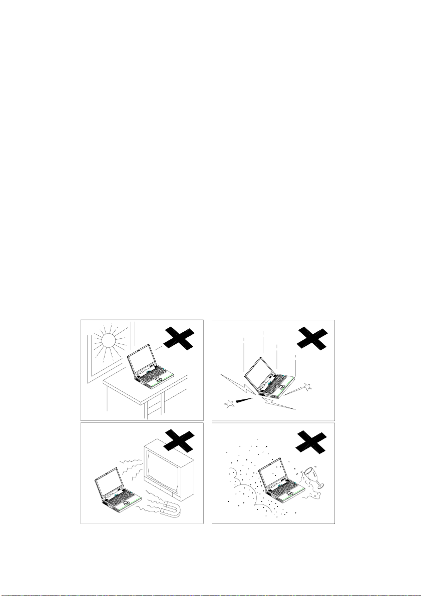
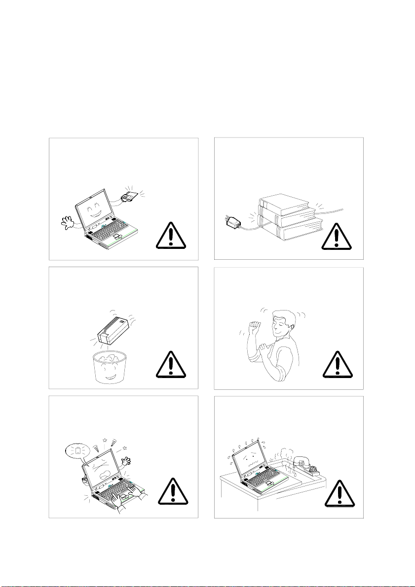
Safety Tips
As with any other piece of precision electronic equipment, proper
care and operation of your notebook computer will prolong its use. Help
your notebook computer last longer by following this advice:
DO NOT expose it to excessive heat or direct sunlight.
DO NOT expose your notebook computer to any shock or vibration.
DO NOT expose it to strong magnetic fields.
DO NOT leave it in a place where foreign matter or moisture may effect
the system.
1 - 1
Page 6
User’ s Guide
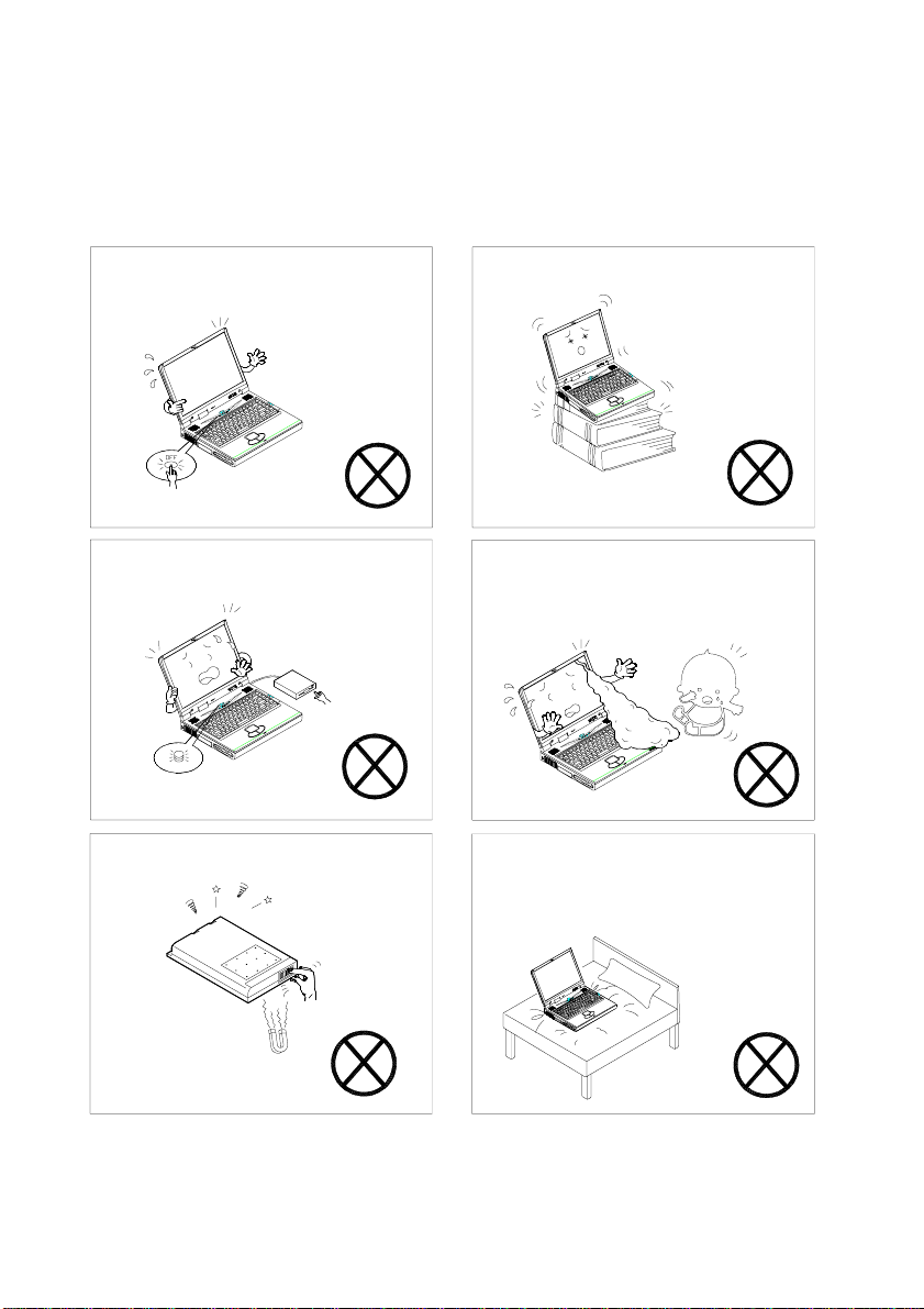
In addition:
Do not turn off the power until you
properly shutdown all programs.
Do not turn off any peripheral devices
when the computer power is on
Do not touch the battery contacts
with your hands or any metal objects.
Do not place the computer on an
unstable surface.
Do not touch the poisonous liquid if
the LCD panel breaks.
Do not place the computer on any
surface which will block the vents.
1 - 2
Page 7
Chapter 1: Introduction
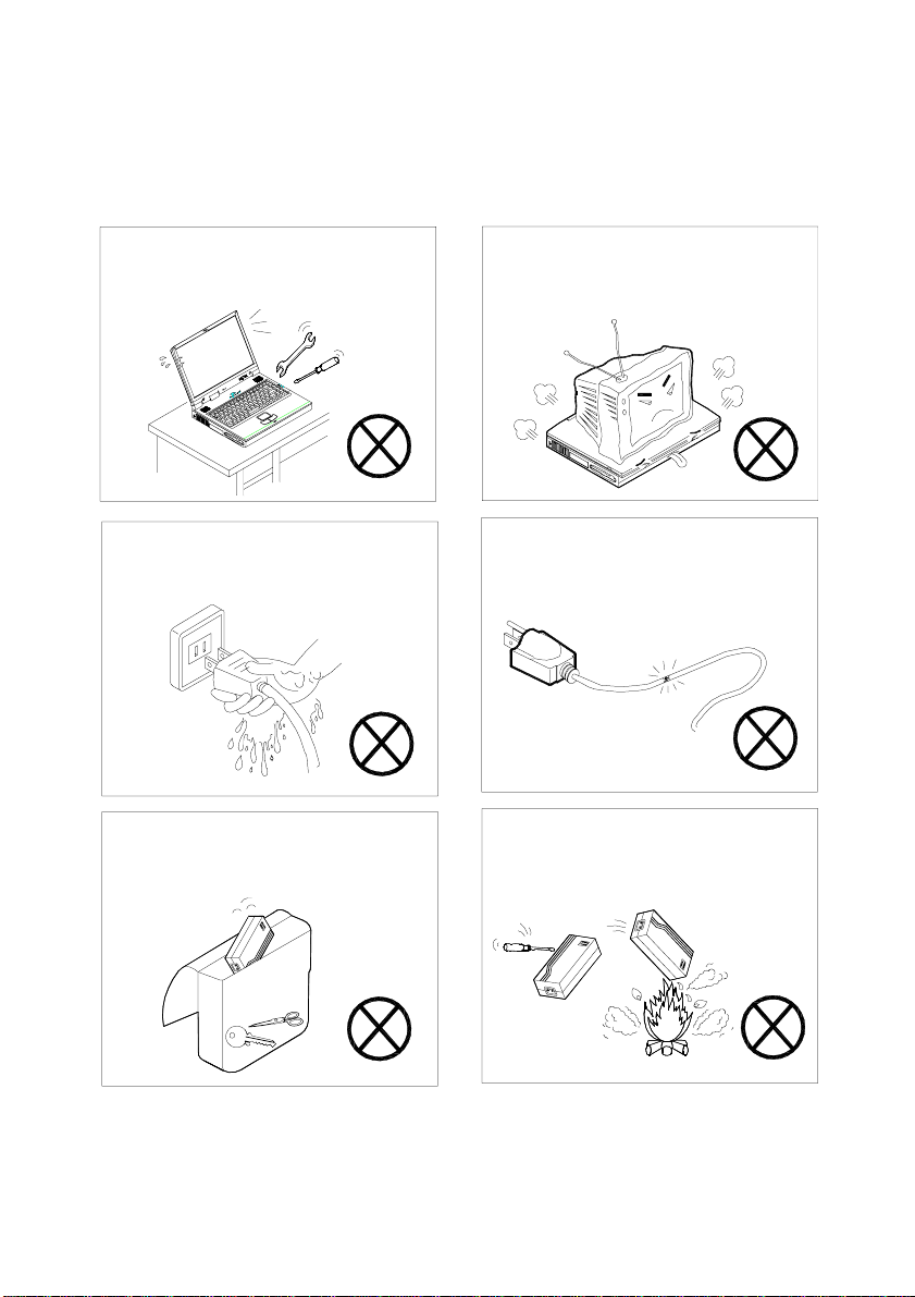
Do not disassemble the computer by
yourself.
Do not plug in the power cord if you
are wet.
Keep the battery away from any
metal appliances.
Do not place anything heavy on the
computer.
Do not use the power cord if it is
broken.
Do not throw the computer or
accessories into a fire.
1 - 3
Page 8
User’ s Guide
I
p
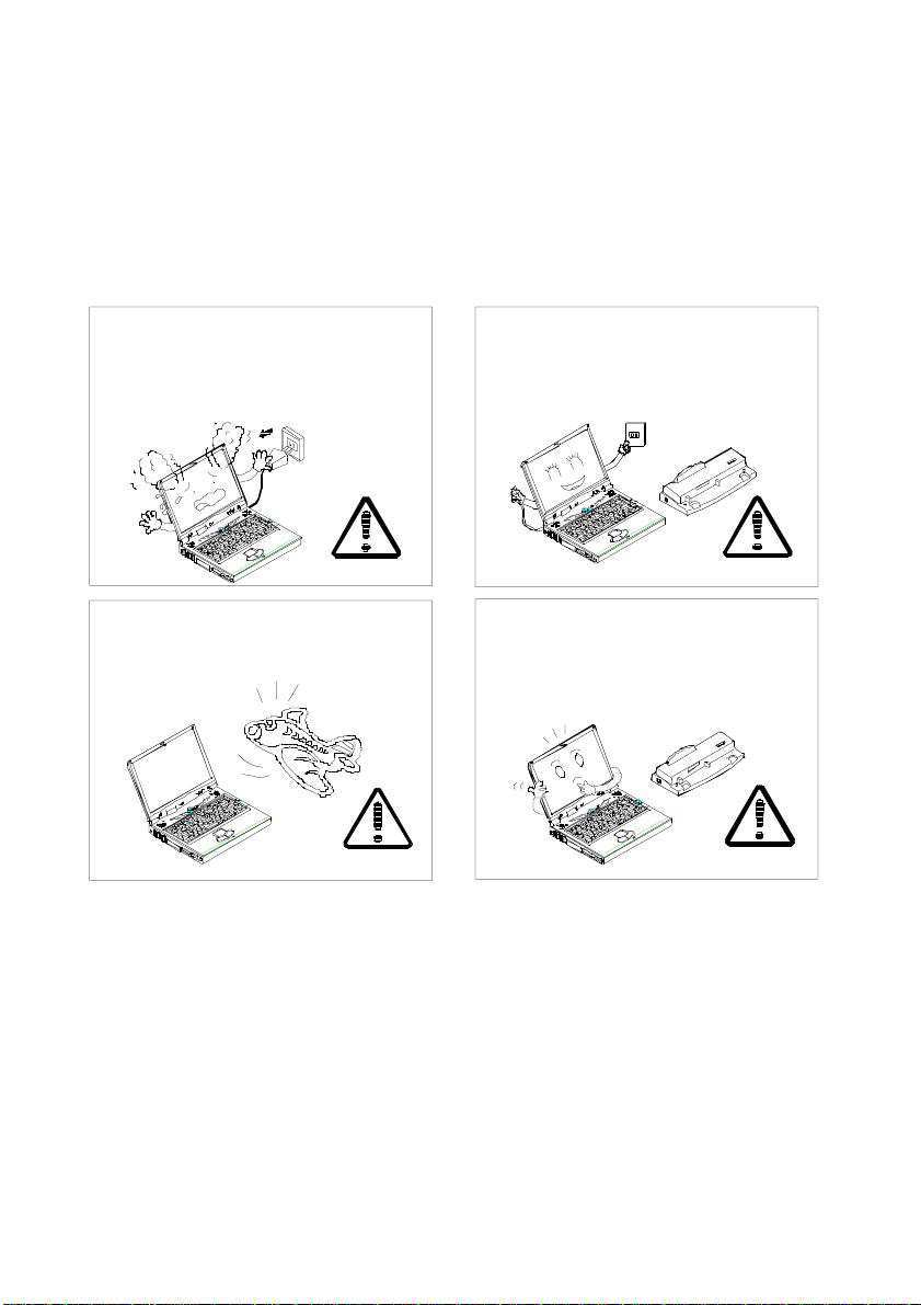
Here is still more important information:
f there is an unusual odor, he at or
smoke coming from your computer,
unplug the cord.
When traveling by air, follow the
airline's instr uctions for in-flight use.
Unplug the power cord before
attaching any peripheral devices.
Use only approved brands of
eripheral devices.
1 - 4
Page 9
Chapter 1: Introduction
Perform routine maintenance on
your computer.
Affix tape to the battery contacts
before disposing of the battery.
Remember to periodically save your
data. Data may be lost if the
battery is depleted.
Do not place heavy objects on the
power cord.
Take periodic breaks if you are
using the computer for long
periods of time.
Don’t use or store the computer in
a humid environment.
1 - 5
Page 10

User’ s Guide
Operating Environment
Ergonomics
Developing good work habits are important if you need to work in
front of the computer for long periods of time. Improper work habits can
result in discomfort or serious injury from repetitive strain to your hands,
wrists or other joints. The following are some tips to reduce the strain:
• Adjust the height of the chair and/or desk so that the keyboard is at or
slightly below the level of your elbow.
• Keep your forearms, wrists, and hands in a relaxed position.
• Y our knees should be slightly higher than your hips.
• Place your feet flat on the floor or on a footrest if necessary.
• Use a chair with a back and adjust it to support your lower back
comfortably.
• Sit straight so that your knees, hips and elbows form approximately
90° angles when you are working.
1 - 6
Page 11

Chapter 1: Introduction
Lighting
- Proper lighting and a comfortable display viewing angle can reduce
eyestrain and muscle fatigue in your neck and shoulders.
- Position the display to avoid glare or reflections from overhead lighting
or outside sources of light.
- Keep the display screen clean and set the brightness and contrast to
levels that allow you to see the screen clearly.
- Position the display directly in front of you at a comfortable viewing
distance.
- Adjust the display viewing angle to find the best position
In addition, continuous concentration on computing work can result in
discomfort and injury.
Remember to:
• Alter your posture frequently.
• Stretch and exercise your body several times a day.
• T ake periodic breaks when you work at the computer for long
periods of time. Frequent and short breaks are better than fewer and
longer breaks.
1 - 7
Page 12
User’ s Guide
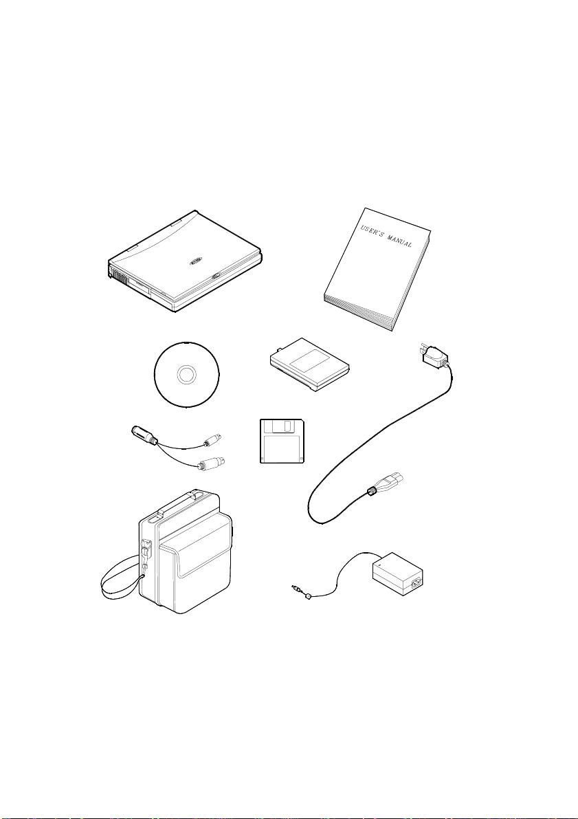
Checking your items:
Carefully remove everything from the shipping box and check the
items one by one. If any item is missing or damaged, contact your dealer
immediately.
√ Notebook Computer.
√ Carrying Bag.
√ Power Adapter.
√ Power Cord.
1 - 8
√ User Manual.
√ PS/2 Transfer Cable.
√ Battery Pack.
√ Utilities Diskette(s) and
CD-ROM.
Page 13

Chapter 2: A quick tour of your new computer
Chapter 2: A quick tour of your new computer
Now lets take a quick look at you notebook and its features.
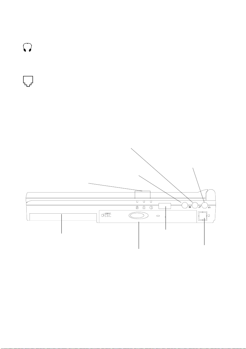
Right Side view
Battery Pack
The notebook comes with a rechargeable battery pack that lets you
operate the computer without an external power source.
Removable 5.25" CD-ROM Drive
The notebook comes standard with a 24-speed 5.25" CD-ROM
drive. The removable CD-ROM drive module can be replaced with
the optional drive units, such as a 12.7 mm high DVD-ROM drive.
(Please refer to the chapter 5 for more information on using the CDROM.)
LED power indicators
These indicators display the current power source of the computer.
For more information please refer to Chapter 3.
Infrared port
This port allows communication with an infrared-compatible device.
The Infrared port supports IrDA (HPSIR) 1.1 mode, Amplitude
Shifted Keyed IR (ASKIR) mode, and Fast IR (FIR) mode. For
further information, please refer to the manual of the wireless device
you wish to connect.
Line-in jack
An external audio source can be fed into the notebook through this
jack.
Microphone-in jack
A microphone can be connected to your notebook with this jack.
2 - 1
Page 14
User’ s Guide
Speaker-out jack
Headphone and speakers can be attached to the system through
this jack.
Phone jack (optional)
The phone jack is used to support an optional built-in modem or
LAN card. If you do not intend to install this optional card, please
do not punch out the phone jack. For more information on the
phone jack please refer to chapter 4.
Microphone-in jack
LED power indicators
Battery pack
Line-in jack
Infrared port
Removable 5.25" CD-ROM drive
Audio-out jack
Phone ja ck
2 - 2
Page 15

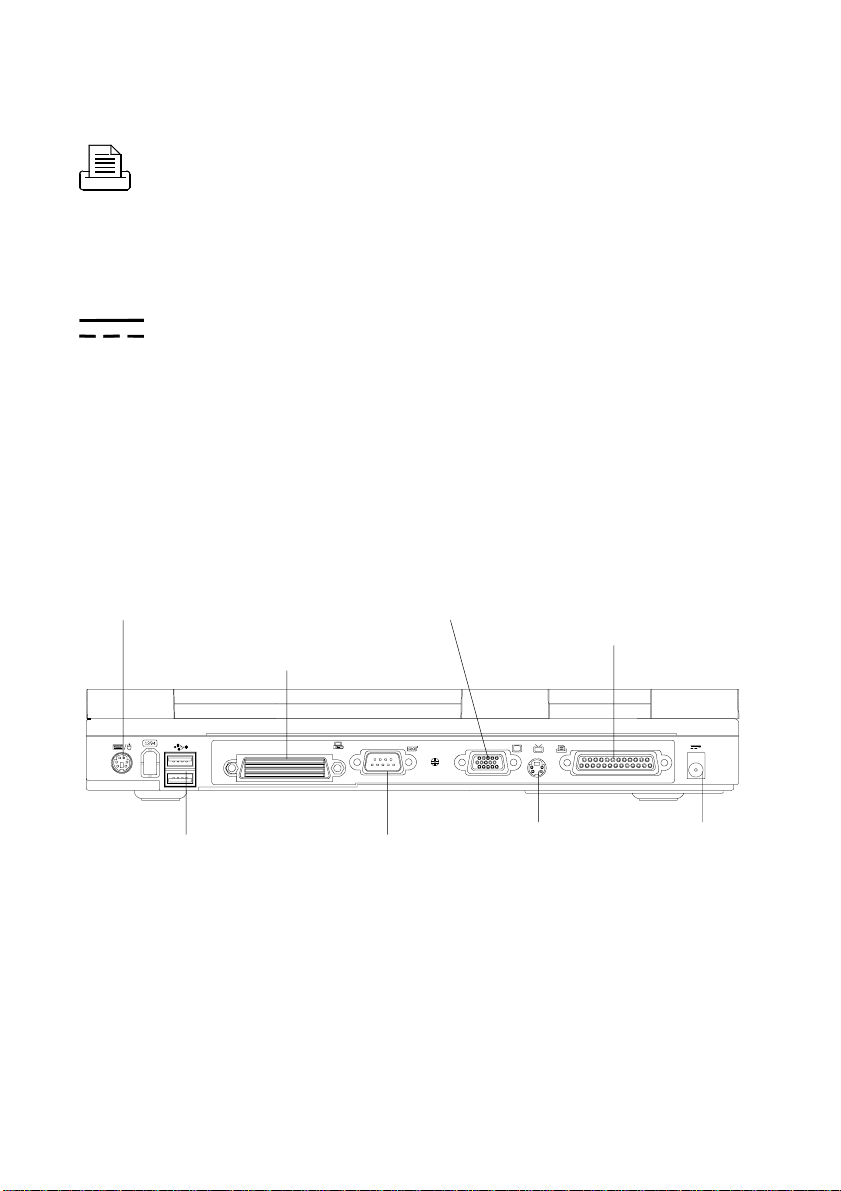
Rear View
PS/2 T ype port
The PS/2 T ype Port uses a 6 pin connector for connecting an
external PS/2 type mouse or keyboard.
Dual USB ports
The dual Universal Serial Bus (USB) ports make adding
peripheral devices easy.
Expansion port
The Expansion port uses a 120 pin Docking connector for
connecting a Port Replicator.
Serial port
The RS-232C serial port uses a 9 pin male connector for
connecting an external serial mouse, serial printer or fax/modem.
Chapter 2: A quick tour of your new computer
External Monitor (CRT) port
The External Monitor uses a 15 pin connector for connecting
an external CR T monitor. Simultaneous display on the LCD
screen and external CR T monitor is possible.
S-video jack
Use this jack to transmit a video signal to a TV set.
2 - 3
Page 16
User’ s Guide
Parallel port
The Parallel Port uses a 25 pin female connector for connecting a parallel printer or other parallel devices. This parallel port
supports EPP (Enhanced Parallel Port) V1.7/V1.9 and ECP
(Extended Capabilities Port) modes.
AC-in socket
The AC adapter is plugged into this socket to power to your
notebook.
PS/2 Type port
2 - 4
Expansion port
Dual USB ports
External Monitor (CRT) por t
Serial port
S-video jack
Parallel port
AC-in socket
Page 17

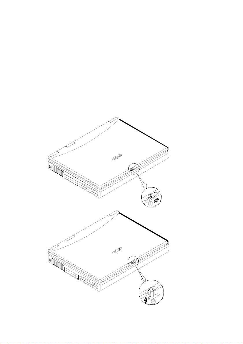
Left Side View
Security slot
A lock for your computer can be attached to this slot to
prevent possible theft.
V ent
Prevents the notebook from overheating.
PC Card Sockets
The notebook provides two T ype II or one Type III PC card
sockets. These sockets support a Zoom V ideo Port (socket A)
or CardBus.
The top socket is Socket A, the bottom socket is Socket B
3.5" Floppy Disk Drive (FDD)
The drive is a 3.5", 3 mode, 1.44 MB removable floppy disk
drive. The floppy disk module can be replaced with a 12.7 mm
high 2.5" hard disk drive or a 12.7 mm high LS-120 120 MB
floppy drive. (Please refer to Chapter 3 for more information on
using the floppy disk drive.)
Chapter 2: A quick tour of your new computer
Ventilation
Security slot
PC Card Sockets
Removable 3.5" FDD
2 - 5
Page 18

User’ s Guide
Underside
CD-ROM Cover
Secures the removable CD-ROM drive in its bay. For more infor-
mation on removing the CD-ROM please refer to Chapter 5.
CD-ROM tab
Use this tab to pull the CD-ROM module from its bay after you have
unscrewed the CD-ROM cover. (Please refer to chapter 5 for more
information on inserting or removing the CD-ROM.)
Battery pack latches
These latches secure the battery pack in its bay. (Please refer to
chapter 3 for more information on inserting or removing the Battery pack.)
FDD latch
This latch secures the Floppy Disk Drive module in its bay. (Please
refer to the chapter 5 for more information on inserting or removing the
Floppy Disk Drive.)
FDD tab
Use this tab to release the Floppy Disk Drive module from its bay
after releasing the FDD latch. (Please refer to the chapter 5 for more
information on inserting or removing the Floppy Disk Drive.)
HDD latch
This latch secures the Hard Disk Drive (HDD) module in its bay.
(Please refer to chapter 3 for more information on inserting or removing
the Hard Disk Drive.)
2 - 6
Page 19
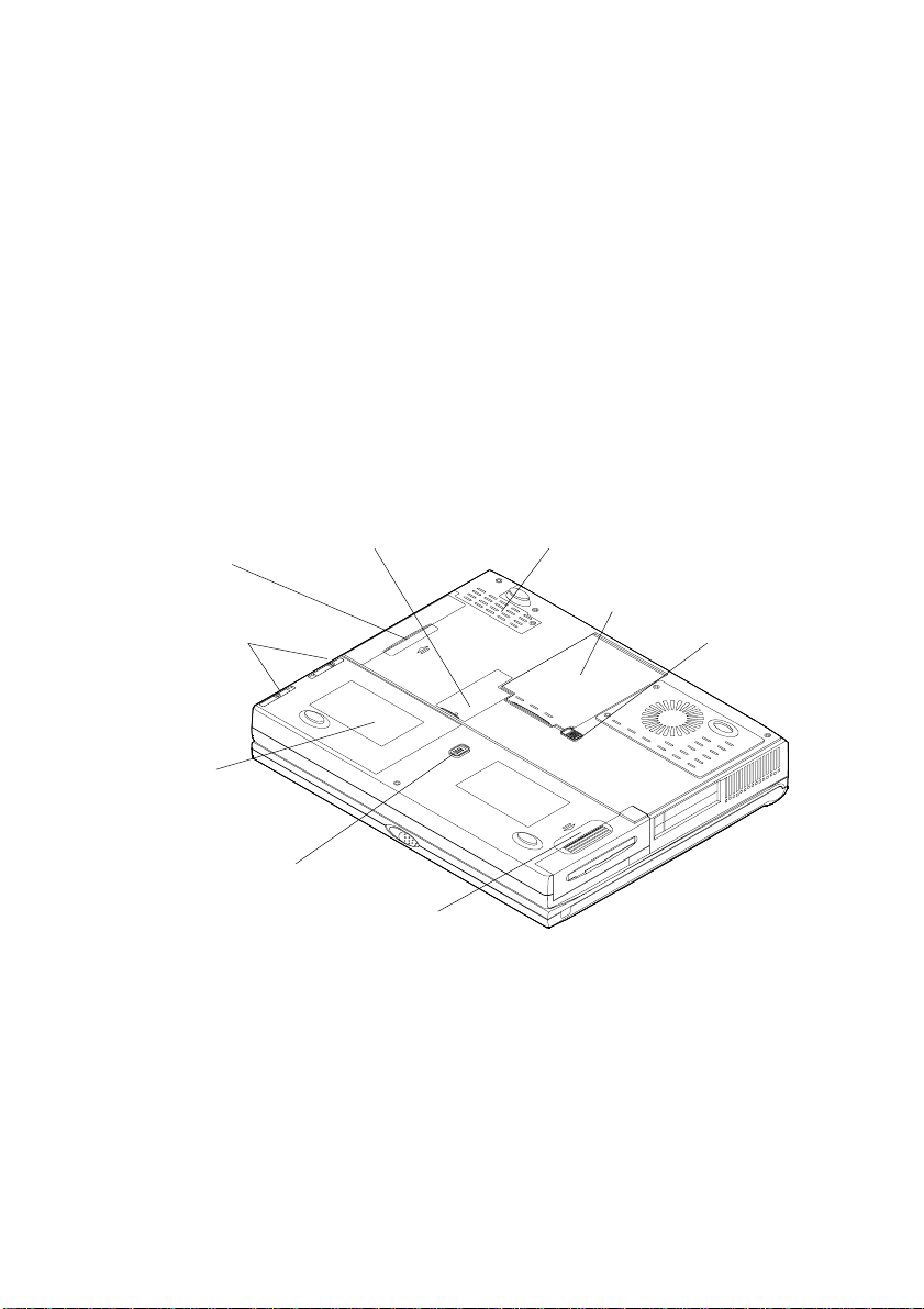
Chapter 2: A quick tour of your new computer
Modem cover
The optional modem or LAN card is installed beneath this cover.
CD-ROM tab
Battery latches
Battery pack
CD-ROM cover
FDD latch
Modem cover
HDD
HDD latch
FDD tab
2 - 7
Page 20
User’ s Guide
Opening the LCD display
1) Move the cover latch to the right to release the top cover.
2) Lift the top cover to reveal the LCD panel and keyboard.
3) Adjust the LCD panel to a comfortable viewing angle.
4) Press the power button to power up the system.
2 - 8
Page 21

Chapter 2: A quick tour of your new computer
Top view with display open
LCD Display
The Notebook has a LCD (Liquid Crystal Display) panel.
Depending upon the model you have purchased, the display
screen can be a 13.3" or 14.1" XGA TFT color panel. The
notebook's LCD panel supports up to 1024 × 768 × 16M
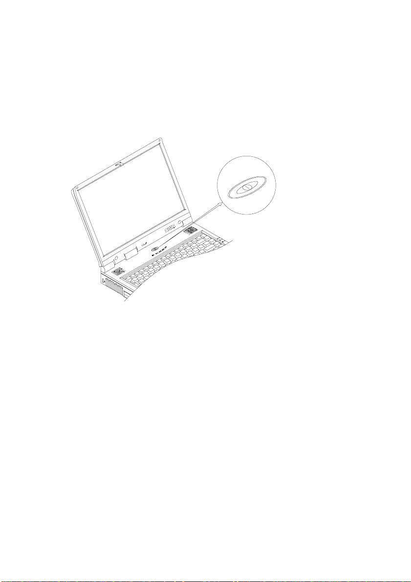
resolution. The LCD panel is driven by a AGP bus video controller with 8 MB video memory.
Power Button
Pressing this button turns your notebook computer on or off.
After proper configuration with the System Configuration
Utility (SCU), the Power Button can also be used as a Suspend/
Resume hot button (refer to Chapter 6: BIOS Utilities, Power
Menu for more information.
Note: After turning your notebook computer off, wait a few
seconds before turning it on again.
LED power indicators
These indicators display the current power source of the
computer. For more information please refer to Chapter 3 LED
power indicators.
Stereo Speakers
T wo built-in speakers provide rich, stereo sound.
T rackpad and Buttons
The pointing device features a sensitive glide pad for precise
movements. It functions the same as a two-button mouse. The
right trackpad button is the same as a right mouse button; the left
trackpad button is the same as a left mouse button.
2 - 9
Page 22
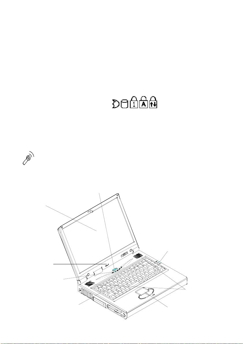
User’ s Guide
y
Keyboard
This 88 key keyboard has an embedded numeric keypad and
can be used with Windows 95 or W indows 98. It also has many
of the same features as a full-size desktop keyboard and can
easily be replaced with non-English keyboards.
LED status indicators
These LED indicators display the system's operational status.
Refer to Chapter 3 LED status indicators for more information.
Microphone
With the built-in microphone you can record on your
notebook computer.
Microphone
LED status indicators
2 - 10
LCD Displa
Keyboard
Power button
LED power indicators
Stereo speakers
Trackpad and buttons
Page 23
Chapter 3: Using your new computer
Chapter 3: Using your new computer
Y our notebook computer can be used almost anywhere, in the home,
office, or on the road. T o learn more about how to operate your
computer, the features available and how to power your computer please
read this chapter.
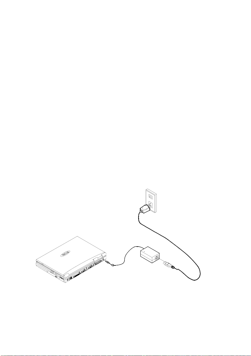
The power sources
It can be powered by either an AC adapter or battery pack depending on where you want to use it.
AC Power Adapter
1) Plug the power adapter cord into the AC-in socket on the rear
panel of the computer.
2) Connect the power adapter with the power cord.
3) Plug the power cord into a properly grounded outlet.
Note: Use only the power adapter that comes with your computer.
An incorrect type of power adapter will damage the computer and its
components.
3 - 1
Page 24
User’ s Guide
Battery pack
The battery pack allows you to use your notebook computer when an
electrical outlet is unavailable or inconvenient. Battery life depends on the
application and the configuration you're using.
Note: To increase battery life, let the battery discharge completely
before r echar ging.
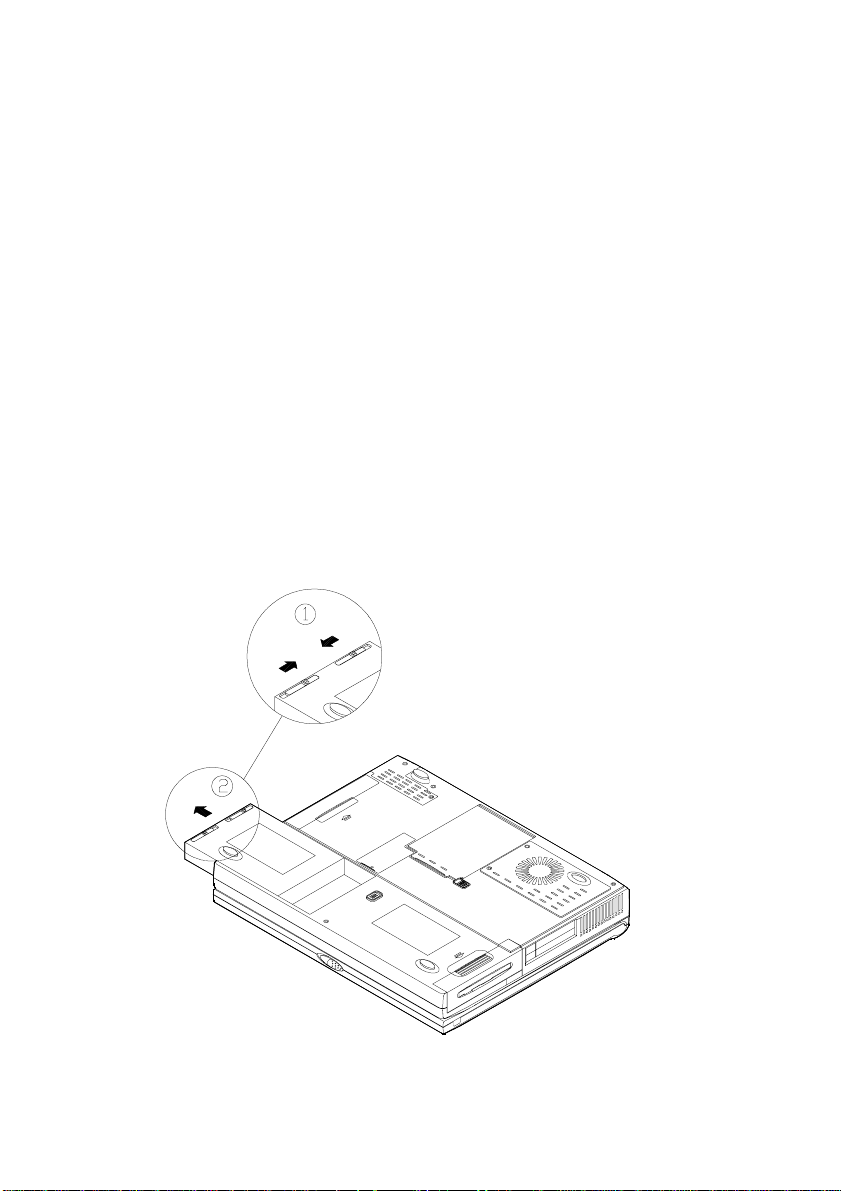
Removing the battery pack
1) Turn the computer over .
2) Squeeze the latches together with your left hand ¬.
3) With your right hand gently grasp the battery pack on the ridge
below the latches and lift it out of the bay Á.
3 - 2
Page 25

Chapter 3: Using your new computer
Inserting the battery pack
1) Turn the computer over .
2) Place the battery in its bay.
3) Push down on the side with the latches until it clicks into place.
Recharging by AC Power
The battery pack will automatically recharge when it is in its bay in
the computer and the computer is plugged into an AC power supply.
While the battery is recharging, you can still use the computer.
It will take several hours to fully recharge the battery and slightly
longer if you are using the computer while the battery is recharging.
Please refer to LED power indicators in Chapter 3 for more infor-
mation on the battery charge status.
Note:
– The second battery indicator light will blink when the
battery overheats or there is a problem with the battery. Should this
happen, remove the battery and allow it to cool down. If the indicator light still blinks contact your vendor about a possible battery
problem.
– The battery has protection design to detect the temperature
while recharging or discharging. T o ensure the battery can be
recharged, while discharging wait until the battery returns to normal
temperature, then recharge the battery
– For better battery life:
1) Fully discharge the battery before r echarging.
2) Recharge the battery to full capacity each time you recharge
it.
Proper Handling of the Battery Pack
Do not disassemble the battery pack under any circumstances.
Do not expose the battery to fire or high temperatures, it may
explode.
Do not connect the metal terminals (+, -) together.
3 - 3
Page 26
User’ s Guide
Turning on your notebook computer
Now you are ready to begin using your new notebook computer . T o
turn it on simply press the power button in the middle top of the front
panel.
Power button
Pressing the power button turns your notebook computer on or off.
After proper configuration with the System Configuration Utility
(SCU), the Power Button can also be used as a Suspend/Resume hot
button (refer to Chapter 6, BIOS Utilities, Power Menu for more
information.
LED indicators
There are two sets of LED indicators on your computer to display
information which is helpful to you.
3 - 4
Page 27
Chapter 3: Using your new computer
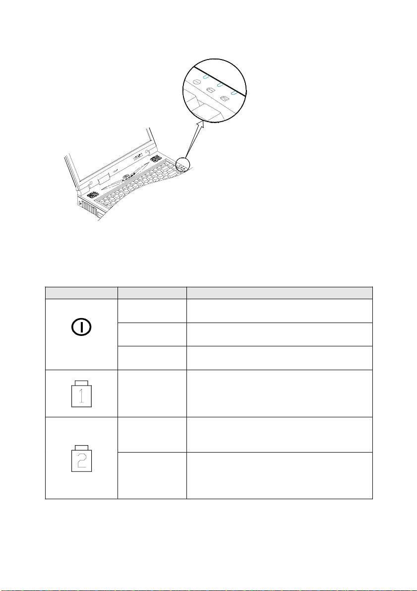
LED Power indicators
LED Power indicators
The LED power indicators located on the right side display the
power status.
Icons Color Descrip tion
Green Battery power is being used.
Red AC power is being used.
Blinking
Red
Red The battery is being charged.
G ree n Th e ba tte ry is fu lly ch a rg ed .
Blinking
Green **
Ba tter y po we r is c ritic ally lo w .
The ba ttery is overheated
Th e ba tte ry is ma lfu n c tion in g .
** Should this happen, remove the battery and allow it to cool down.
If the indicator light still blinks contact your vendor about a possible
battery problem.
3 - 5
Page 28
User’ s Guide
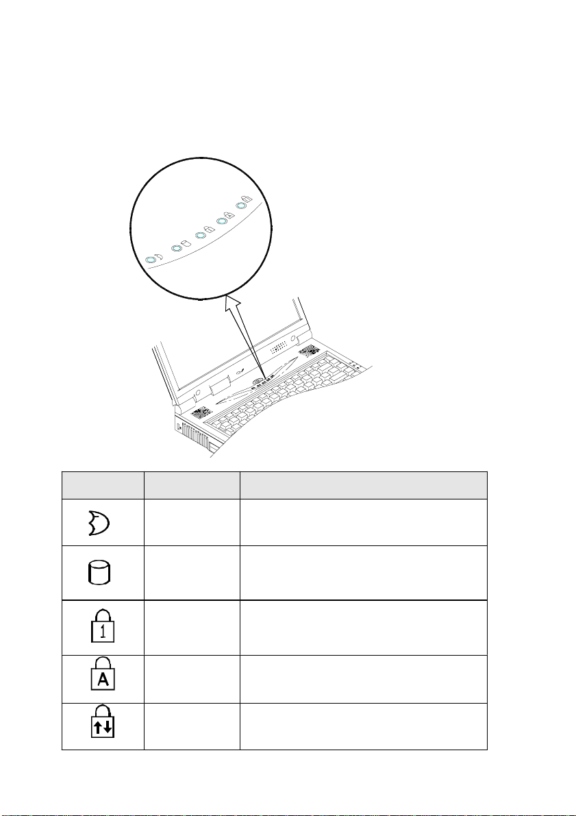
LED Status indicators
Once your computer is on and in use the LED status indicators will
display the system's operating status.
LED Status indicators
3 - 6
Icon Color Description
Green The system has entered the
configured suspend mode.
Green The hard disk is being accessed
Green Num lock is activated
Green Cap Lock is activated.
Green Scroll Lock is activated.
Page 29
Chapter 3: Using your new computer
The Hard Disk Drive (HDD)
About the HDD
The hard disk drive is used to store your data internally in the notebook computer. It is mounted in a removable case and can be taken out
to accommodate other 2.5" IDE hard disk drives with a height of 12.7
mm or 9.5 mm. The system supports PIO mode 4, Master mode IDE,
LBA mode and provides a high performance data transfer rate at speeds
up to 33 MBytes/second (AT A-33). For data security you can easily
remove the HDD.
Removing the HDD
1) Turn the computer off.
2) Turn the computer over .
3) Locate the HDD latch ¬.
4) Slide and hold the latch
forward then slide the HDD
out of the computer Á.
5) Lift the hard
disk drive out of
the computer  .
Inserting the HDD
1) Turn off the computer .
2) Turn the computer over .
3) Place the HDD case into the computer.
4) Slide the HDD in until you hear a click.
3 - 7
Page 30
User’ s Guide
The Floppy Disk Drive (FDD)
About the FDD
The computer is equipped with a removable 1.44 MB, 3.5" floppy
disk drive module. It is usually designated drive A by default and can be
used as a boot device if properly set in the SCU (please refer to Chapter
6, BIOS Utilities). Y ou may replace the floppy disk drive module with a
120 MB LS-120 drive (12.7 mm height) or a 12.7 mm high 2.5" hard
disk drive. Contact your dealer for details.
Using the FDD
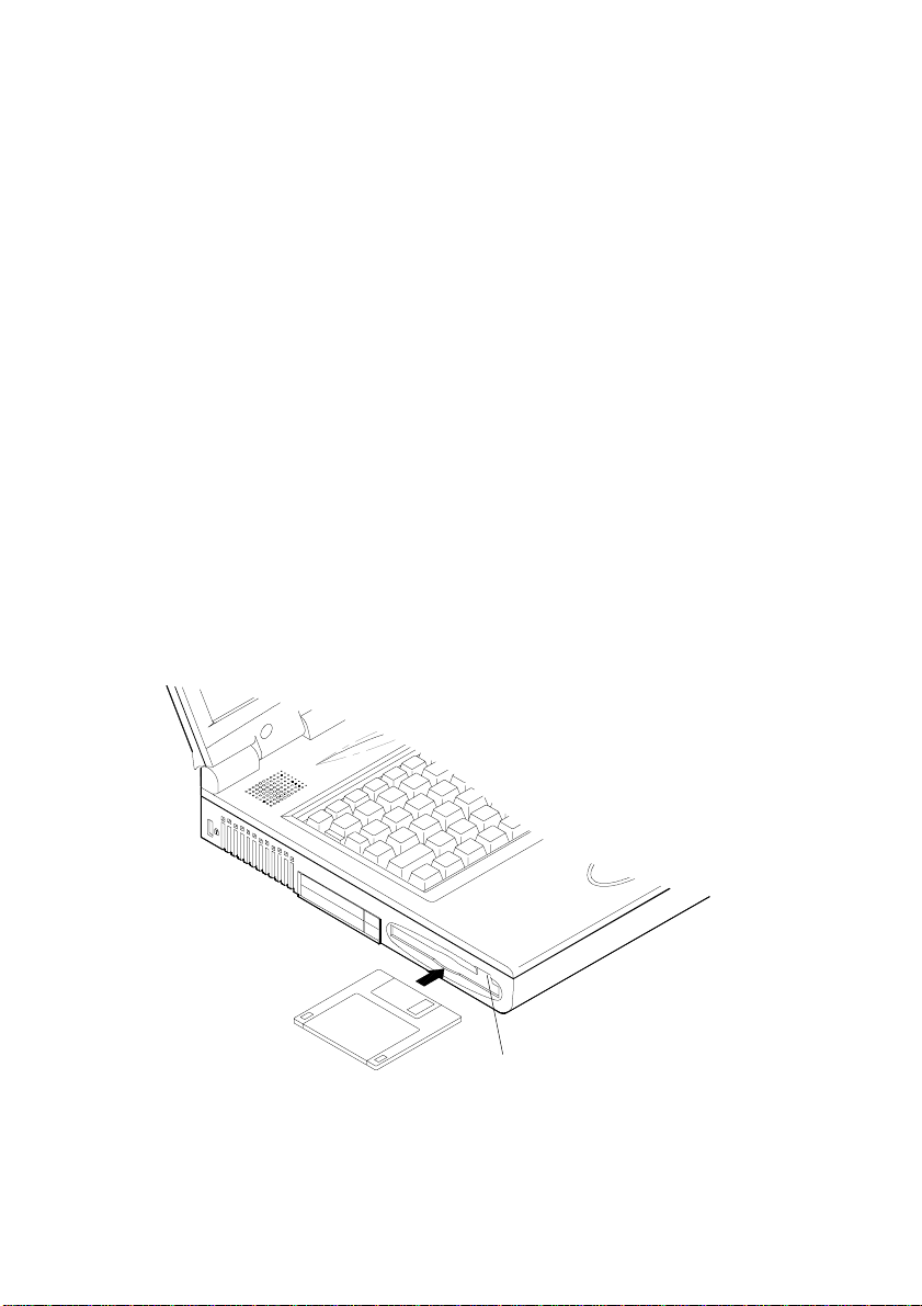
Inserting/Removing Diskettes
When using the floppy drive, always insert your floppy diskette labelside up. T o remove your diskette, press the eject button on the top-right
corner of the floppy drive.
3 - 8
FDD eject button
Page 31

Chapter 3: Using your new computer
y
The CD-ROM
About the CD-ROM
The notebook computer comes standard with a 24 speed removable
5.25" CD-ROM drive. It is labeled drive D and may be used as a boot
device if properly set in the System Configuration Utility. The removable
CD-ROM drive can be replaced with optional drive units, such as a 12.7
mm high DVD-ROM drive.
Loading Compact Discs
T o insert a CD, press the Open Button and carefully place a CD into
the Disc tray with label-side facing up (see below). Push the CD tray in
and you are ready to start. The Busy Indicator will light up while data is
being accessed or while an audio CD is playing. When power is unexpectedly interrupted, insert an object such as a straightened paper clip into
the Emergency Eject hole to open the tray.
Note: When manually ejecting a CD, DO NOT use a sharpened
pencil or similar object that may break and become lodged in the
hole.
Disc tra
Emergency eject hole
Busy indicator
Open button
3 - 9
Page 32

User’ s Guide
Handling Compact Discs
Proper handling of your CDs will prevent them from being damaged.
Please follow the advice listed below to make sure that the data stored on
your CD-ROMs can be accessed.
Remember to:
- Hold the CD by the edges; do not touch the surface of the disc.
- Use a clean, soft, dry cloth to remove dust or fingerprints.
- Do not write on the surface with a pen.
- Do not attach paper or other materials to the surface of the disk.
- Do not store or place the CD in high-temperature areas.
- Do not use benzene, thinners, or other cleaners to clean the CD.
- Do not bend the compact disc.
- Do not drop or subject the CD to shock.
3 - 10
Page 33

Chapter 3: Using your new computer
The PC Card Sockets
The computer is equipped with two PC card sockets (previously
referred to as PCMCIA). Both sockets support two 3.3V/5V type II or
one type III PC card or two 3.3V CardBus cards. PC card Socket A is
on the top and Socket B is on the bottom. Socket A can also support a
Zoomed Video Port.
Inserting PC Cards
Align the PC card with the slot and push the card in until it locks into
place.
Removing PC Cards
T o remove a PC card, simply press the eject button next to the slot.
Socket A
Socket B
Eject button for Socket A
Eject button for Socket B
3 - 11
Page 34

User’ s Guide
Fn + F3 Expand LCD display
Fn + F6 Toggle between CRT / LCD / LCD+CRT
Fn + F9 Decrease LCD brightness
Fn + F10 Increase LCD brightness
Fn + F11 Decrease audio volume
Fn + F12 Increase audio volume
Fn + Z T oggle audio on/off
Fn + Esc Suspend/resume
The Hot Keys
Located on the bottom-left of the keyboard is the Fn key or Function
key. The Fn key allows you to change operational features instantly (Hot
Keys).
When you use the following functions, press and hold the Fn key;
then press the appropriate function key (F1, F2, F3, etc....) located at the
top of your keyboard.
3 - 12
Page 35

Chapter 3: Using your new computer
The Numeric Keypad
A numeric keypad is integrated into the keyboard for easy numeric
data input. The keypad stands out by its blue typeface.
T o use the keypad simply:
• Activate the Num Lock feature (press the Num Lock key).
• Press and hold down the Fn key.
• Press the desired number keys.
3 - 13
Page 36

Chapter 4: Adding peripherals
Chapter 4: Adding peripherals
T o enhance your computer's capabilities, you can attach peripheral
devices to the computer using the ports or jacks located on the rear panel
of the computer. The computer can support the following peripheral
devices:
PS/2 Keyboard or Mouse
The computer can use a PS/2 keyboard or mouse attached by a PS/2
transfer cable that comes with your notebook computer. Attach the
external keyboard or mouse to the PS/2 port as shown below.
PS/2 Transfer cable
4 - 1
Page 37

User’ s Guide
USB compatible Device
The computer has a dual USB port for connecting one or two USB
compatible devices such as a keyboard, mouse, or other USB device.
Simply plug the device into the USB port as shown below.
4 - 2
Page 38

Chapter 4: Adding peripherals
Serial Mouse
The serial port features a 9 pin connector. You can connect any serial
device such as a mouse to this port.
To connect a serial device you must:
1) Turn off the computer .
2) Connect the cable to the serial port on the rear of the computer.
3) Tighten the screws that fasten the cable to the serial port.
4) Turn on the computer .
Note: In addition, you may need to install the manufacturer-supplied
driver for the serial mouse. Refer to the device's user guide for more
information.
4 - 3
Page 39

User’ s Guide
External Monitor (CRT)
The computer can support an XGA compatible external monitor. The
external monitor can be used simultaneously with the LCD display turned
on or off. You can setup your computer to use an external monitor by
entering the System Configuration Utility (SCU) and selecting the appropriate parameters or using the Fn + F6 keys (refer to The Hot Keys in
Chapter 3).
T o install an external monitor you simply:
1) Turn off the computer .
2) Connect the cable to the CRT port on the rear of the computer.
3) Tighten the screws that fasten the cable to the CR T .
4) Insert the other end of the cable to the external monitor.
5) Turn on the computer .
4 - 4
Page 40

Chapter 4: Adding peripherals
Using Windows 98 for simultaneous display to a TV
Click on the ST AR T button
Click Settings
Click Control Panel
Double click on the Display icon
In the Display Properties window select Settings
Click Advanced
In the Rage L T PRO AGP 2x Properties window select Displays
Click TV
Click OK
TV Set
The S-V ideo jack on the rear panel of the computer is used for
transmitting video signals to a TV set. T o add a TV set simply plug the
TV set cable into the S-V ideo jack as shown below .
Also with Windows 98 you can use your computer display and TV
simultaneously.
Note: You may need to select the video standard for video display. To
do so, enter the System Configuration Utility (SCU) Components
Menu and select the appropriate TV standard.
4 - 5
Page 41

User’ s Guide
Parallel Printer
You can connect any standard Centronics parallel printer to your
computer using the parallel port.
T o connect a printer simply:
1) Turn off the computer .
2) Connect the cable to the parallel port on the rear of the computer.
3) Tighten the screws that fasten the cable to the parallel port.
4) Insert the other end of the cable to the printer's connector.
5) Fasten the cable's connector.
6) Turn on the printer and computer .
Note: You may also need to install the manufacturer-supplied driver
for the printer. Refer to the device’s user guide for more information.
If the connected printer supports Enhanced Parallel Port (EPP) or
Extended Capabilities Port (ECP) mode, please enter the System
Configuration Utility (SCU) to configure the required setting.
4 - 6
Page 42

Chapter 4: Adding peripherals
Attaching a Phone Line (optional)
The notebook has a phone jack for connecting to a phone line or a
local area network (LAN). The notebook doesn’t come with a modem
or LAN card, so if you want to use this jack you must first install a
modem or LAN card on the mainboard. Once the modem or LAN card
is installed you simply attach a phone cord to the jack. For more information on this please contact your dealer for the appropriate modem or
LAN card and instructions.
Once you have installed the modem or LAN card you can then
punch out the plastic covering your computer’s phone jack.
4 - 7
Page 43

User’ s Guide
Security Lock
A security lock can be installed on your notebook computer to help
prevent theft. T o install the security lock, wrap the cable around a desk or
other immovable object, then insert the locking device in the slot located
on the left side of your notebook computer.
4 - 8
Page 44

Chapter 4: Adding peripherals
Attaching a Proprietary Port Replicator
The Proprietary Port Replicator gives you access to numerous
peripherals without having to connect cables to the back of your
notebook. The peripherals are attached to the proprietary port replicator
and all you have to do is dock your notebook into the replicator.
Please contact your dealer for more information.
4 - 9
Page 45

Chapter 5: Upgrading your notebook computer
Chapter 5: Upgrading your notebook computer
Before you begin you will need:
- A small crosshead or Phillips screwdriver.
- A small regular screw driver.
- An antistatic wrist strap
Note: Make sure you wear an antistatic wrist strap to ground yourself before working with or repairing the internal components. Static
electricity may damage the components.
Replacing the HDD
1) Remove the HDD case from the
computer (refer to Removing the
HDD in Chapter 3 for details).
2) Remove the two screws on
each side of the case (The location
of the screws depends on the hard
disk model).
3) Slowly remove the HDD from
the case until you see the connecting cable.
4) Gently disconnect the cable
from the HDD being careful not to
bend any pins or crimp the cable.
5) Connect a new HDD to the
cable being careful not to bend any
pins or crimp the cable.
6) Slowly place the HDD back into the case.
7) Hold the HDD firmly in place with two screws on each side.
8) Insert the HDD into the computer (refer to Inserting the HDD in
Chapter 3 for details.)
5 - 1
Page 46

User’ s Guide
Removing the Floppy Disk Drive (FDD)
1) Turn off the computer .
2) Turn the computer over .
3) Slide the and hold the FDD latch to unlock the FDD module.
4) Grasp the FDD tab and pull the FDD out of the computer.
FDD latch
FDD tab
Inserting the Floppy Disk Drive (FDD)
Follow the instructions for removing the FDD in reverse order.
5 - 2
Page 47

Chapter 5: Upgrading your notebook computer
Removing the CD-ROM module
1) Turn off the computer .
2) Turn the computer over .
3) Locate the CD-ROM cover.
4) Unscrew and remove the cover À.
5) Locate the cable tab.
6) Gently pull the cable tab upward to disconnect the CD-ROM from
the computer mainboard Á.
7) Grasp the CD-ROM tab and gently PULL the CD-ROM out of
the computer Â.
CD-ROM cover
cable tab
CD-ROM tab
Inserting the CD-ROM module
Refer to removing the CD-ROM and follow the instructions in reverse
order.
5 - 3
Page 48

User’ s Guide
Installing a Modem or LAN Card
If you choose to install the optional modem or LAN card please
contact a registered dealer for the card and installation instructions.
Upgrading the Memory
Memory can be expanded up to 256 MB. T o upgrade the memory
you will need 3.3v, PC-100 compliant 144 pin SODIMM (Small Outline
Dual In-line Memory Module) modules.
Memory can be expanded with the following combinations:
Bank 0
(64-bit)
32 MB Empty 32 MB
32 MB 32 MB 64 MB
64 MB Empty 64 MB
64 MB 32 MB 96 MB
64 MB 64 MB 128 MB
128 MB Empty 128 MB
128 MB 32 MB 160 MB
128 MB 64 MB 192 MB
128 MB 128 MB
Bank 1
(64-bit)
Power Total Size
3.3V
256 MB
Once a new module is installed the memory size is automatically
detected by the POST routines when you turn on your computer.
5 - 4
Page 49

Chapter 5: Upgrading your notebook computer
Installing a Memory Module
1) Turn off the computer .
2) Press the two keyboard
latches at the top of the keyboard to
elevate the keyboard from its normal
position.
3) Carefully lift the keyboard
assembly out to expose the
mainboard.
4) Locate the memory banks,
Bank 0 is on the left and Bank 1 is on
the right.
Drawing 5-1
Bank 1
Bank 0
Drawing 5-2
Note: Only use Bank 0 if you have one memory module. If you are
using two memory modules always use the larger module in Bank 0.
5 - 5
Page 50

User’ s Guide
5) Insert the memory module at a
slight angle about 45° and fit its
connectors firmly into the bank À .
6) Press down the two edges of
the memory module and lock it into
place Á.
7) Put the keyboard back into
place.
Note:
Make sure the connectors go into the bank.
You must use a RAM module that complies with Intel unbuffered
SODIMM (67.6 mm x 31.75 mm). Please consult your dealer for the
details.
5 - 6
67.6 mm
31.75 mm
connectors
Page 51

Chapter 5: Upgrading your notebook computer
Removing a Memory Module
1) Turn off the computer .
2) Press the two keyboard latches to elevate the keyboard from its
normal position (refer to Drawing 5-1)
3) Carefully lift the keyboard assembly out to expose the mainboard.
4) Locate the memory sockets. Bank 0 is on the left and Bank 1 is
on the right. (refer to Drawing 5-2)
5) Gently pull the two latches outward on both ends of the module À.
6) The module will pop up Á.
7) Remove the memory module Â.
8) Install a new memory module if desired (refer to Installing a
Memory Module).
9) Put the keyboard back into place.
5 - 7
Page 52

User’ s Guide
Adding or replacing the Processor
The mainboard can support a Intel®Pentium !!! FC-PGA370 processor or a Intel®Celeron PPGA 370 type processor. Unlike the earlier
Pentium processors, these processors lock into the mainboard. T o open
and close the CPU lock you will need a special tool which is not supplied
with your notebook computer.
If you would like to upgrade your existing processor, please contact
your vendor for the complete upgrade instructions and the necessary tool.
When you contact the vendor please specify whether you will use a
FC-PGA370 or PPGA370 type processor.
Flash ROM BIOS update
In order to keep up with the latest system BIOS, your notebook
may be upgraded. Consult your dealer for further information.
5 - 8
Page 53

Chapter 6: BIOS Utilities
SystemSoft BIOS MobilePRO BIOS Version 1.01 (2482-
00)-(R1.XX)
Copyright 1983-1996 SystemSoft Corp. All Rights Reserved
300 MHz Celeron with MMX CPU
L2 Cache: 128 KB Installed
8 MB V ideo RAM
SystemSoft Plug-n-Play BIOS ver1.17.01
Base Memory 000640 Kb
Extended Memory 130048 Kb
T otal Memory 131072 Kb
Auto Detecting IDE Devices[Done]
Press <CTRL-AL T-S> to enter System Configuration Utility
Chapter 6: BIOS Utilities
In this chapter you will learn about the Power On Self T est (POST)
and how to configure the system parameters using the System Configuration Utility (SCU).
Power on Self Test (POST)
The system BIOS (Basic Input/Output System) performs a series of
tests on the system memory and key computer components every time the
computer is powered on. These tests are called the Power On Self T est
(POST). Should an error exist, the POST routine may halt execution
(depending on the problem). If no error exists, the POST will initialize the
BIOS configuration, and boot (start) the operating system.
POST Message: Normal Operation
Y ou will see the following message if no error exists after the POST is
performed
6 - 1
Page 54

User’ s Guide
SystemSoft BIOS MobilePRO BIOS Version 1.01 (2482-00)(R1.XX)
Copyright 1983-1996 SystemSoft Corp. All Rights Reserved
300 MHz Celeron with MMX CPU
L2 Cache: 128 KB Installed
8 MB V ideo RAM
SystemSoft Plug-n-Play BIOS ver1.17.01
Base Memory 000640 Kb
Extended Memory 130048 Kb
T otal Memory 131072 Kb
WARNING - HARD DISK CONTROLLER 1 F AILURE
Auto Detecting IDE Devices[Done]
Press <CTRL-AL T-S> to enter System Configuration Utility
Press F1 to Continue
Note: You may press the Spacebar key to skip the memory test.
POST Message: Error Detected
If an error is detected, you will see the following W ARNING message.
You may press the F1 key to continue, or press the Ctrl-Alt-S keys
simultaneously to enter the System Configuration Utility.
6 - 2
Page 55

Chapter 6: BIOS Utilities
System Configuration Utility
The System Configuration Utility (SCU) can be used to set your
notebook's system parameters. Things like the date and time or what
your computer will do if it is turned on but not used are what you set in
the SCU.
The settings are stored in a nonvolatile battery-backed CMOS RAM.
This simply means that your settings are saved even when the notebook is
turned off.
Information in the System Configuration Utility
Here is a list of the system settings which may be changed within the
System Configuration Utility.
This menu bar choice: Allows you to set or change:
Startup Date and Time, Fast Boot, Boot Device,
Display, Enable Battery Low Beep,
Enable LCD expand Mode, Enable
Power On Beep, Enable PNP OS
Support, Boot Password, SCU Password.
Memory Cache Systems.
Disks Enable LS120/ZIP 100 Drive, Diskette
Drives, IDE Settings.
Components COM Ports, LPT Port, PS/2 Mouse Port,
Keyboard Numlock, Keyboard Repeat,
TV Mode
Power Enable Power Saving, Low Power
Saving, Medium Power Saving, High
Power Saving, Customize, Suspend
Controls, Resume Timer, Enable
MODEM Ring Resume, Enable Battery
Low Suspend.
Exit Save and Exit, Exit (No Save), Default
Settings, Restore Settings, Version Info.
6 - 3
Page 56

User’ s Guide
Initiating the System Configuration Utility
The System Configuration Utility (SCU) can be accessed by pressing
the Ctrl, Alt, and S keys simultaneously when you turn on your computer
and see this message:
<CTRL-AL T-S> to enter System Configuration Utility
This message lasts only a few seconds and if you don’t respond in
time, the computer will initiate the boot process. If you were unable to
enter the SCU you must reboot the system and try again.
Working with the Menu Bar
Use these keys to begin working in the SCU.
Keys Action
Alt Highlights the menu bar
Left arrow (¬)
Selects a menu bar option.
Right arrow (®)
Highlighted letters
Left mouse button
Opens the menu bar option.
Down arrow (¯)
Spacebar
Enter
Right mouse button
Esc
6 - 4
Cancels current action
Page 57

Chapter 6: BIOS Utilities
Working with the Pull-down Menu
Once your desired menu bar item is highlighted, press Enter or the
down arrow to see the pull-down menu items. Y ou move about the pulldown menu with these keys:
Keys Action
Down/Up arrows (¯) ( - )
Select a pull-down menu item.
Highlighted letters
Enter Enable/disable the specified
function.
A (Ö) indicates, the function is on.
Esc Close the pull-down menu and Save
the changes.
Some Pull-Down menu options have an arrow to the left of the entry.
Choose these options by pressing Enter and another screen will be
displayed. Navigate the new screen with the following keys:
Keys Action
Tab Move from one record to another.
Down/Up arrows
Change the value of a field.
(¯)( - )
Spacebar Select a field
Enter Choose <OK> to save any changes.
<Cancel> to ignore any changes.
Esc Quit
6 - 5
Page 58

User’ s Guide
Features of the System Configuration Utility
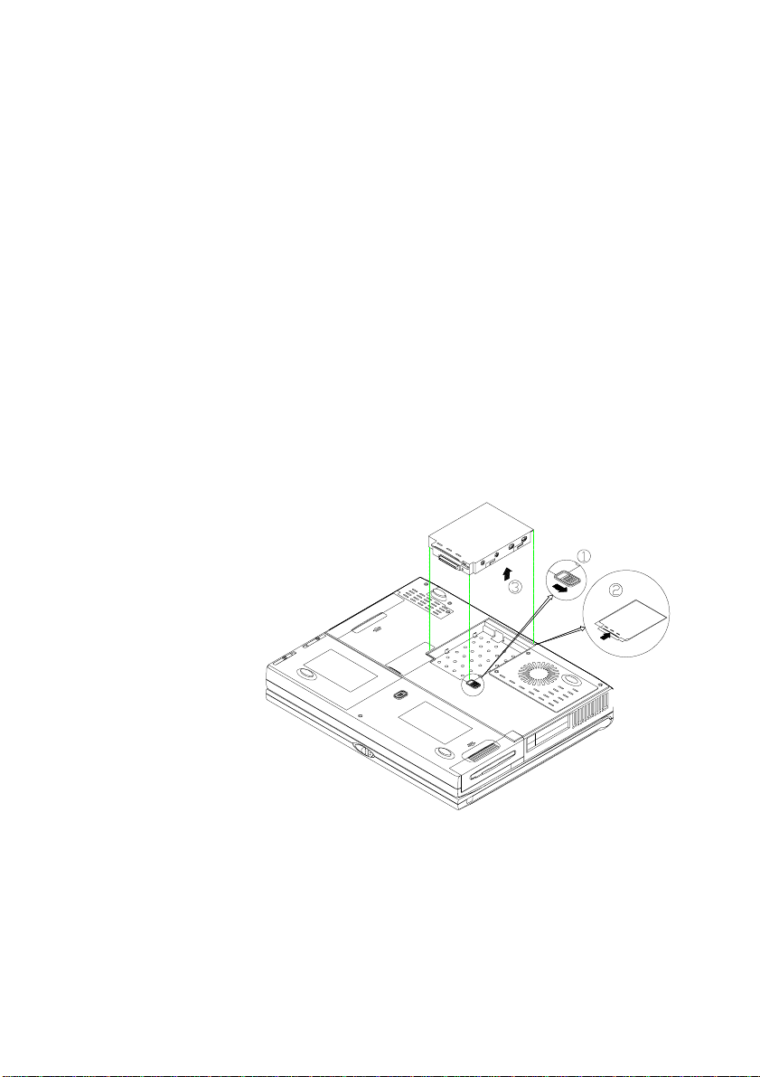
Startup Menu
Item Setting/Option Function
Date and Time Day/Month/Year
Hour/Minute/Second
Fast Boot
Enable Initialize and
Disable Disable the Fast
Boot Device
1st Boot
Device
Hard Disk C
CD-ROM
Drive
Diskette A
nd
2
Boot
Device
Hard Disk C
CD-ROM
Drive
Diskette A
Set the date and
time.
quickly boot the
system by
skipping certain
diagnostic tests.
Boot.
Specify the
system’s 1
st
choice for the
boot drive.
Specify the
system’s 2
nd
choice for the
boot drive.
6 - 6
3rd Boot
Device
Hard Disk C
CD-ROM
Drive
Diskette A
Specify the
system’s 3
rd
choice for the
boot drive.
Page 59

Chapter 6: BIOS Utilities
Item Setting/Option Function
Display
LCD Activate the system’s
LCD panel.
CRT Activate an external
monitor.
LCD + CRT Activate both the LCD
and the CRT.
TV Activate an external TV.
CRT + TV Activate both the CRT
and the TV.
Enable Battery
Low Beep
Enable A series of warning
beeps will sound when
the battery power is low.
Disable Disable the above.
Enable LCD
Expand Mode
On Beep
OS Support
Enable Stretch the display to fill
the entire area of the
LCD panel.
Disable Disable the above.
EnableEnable Power
Disable
EnableEnable PNP
Disable
Enable or Disable Power
On Beep.
Enable or disable PNP
OS Support
6 - 7
Page 60

User’ s Guide
Caution: If you choose to set a boot password, NEVER forget
your password, the consequences could be serious. If you cannot
remember your boot password you must contact your vendor and
you may lose all of the information on your HDD.
Item Setting/Option Function
Boot Password
SCU Password
Enter old Power-On
Password
Enter new Power-On
Password
Verify new PowerOn Password
Enable Password to
Power-On
Enter old Setup
Password
Enter new Setup
Password
Verify new Setup
Password
Enable Setup
Password
Set a password for
booting the
computer.
Only users who
enter a correct
password can boot
the system.
Set a password for
modifying the
SCU. Only users
who enter the
correct password
can change the
SCU.
Startup Screen
6 - 8
Page 61

Memory Menu
Item Setting/Option Function
Cache
Systems
L1
Cache
Disabled Disable the processor’s
internal cache.
Write
Back
Enable the Processor’s
internal write-back cach e.
Write back cache
improves performance,
because a write to the
high-speed cache is faster
than to normal RAM.
L2
Cache
Disabled Disable the L2 cache
controller.
Write
Back
Enable the L2 write-back
cache.
Write back cache
improves performance,
because a write to the
high-speed cache is faster
than to normal RAM.
BIOS
Shadow
Cached Shadowing copies
instructions from system
BIOS into RAM to
improve system
performance.
Not
Disable the above.
Cached
Video
Shadow
Cached Shadowing copies
instructions from the
video BIOS into the RAM
to improve system
performance.
Not
Disable the above.
Cached
Chapter 6: BIOS Utilities
6 - 9
Page 62

User’ s Guide
Memory Screen
6 - 10
Page 63

Chapter 6: BIOS Utilities
g
(
)
Disks Menu
Item Setting/Option Function
Enable
LS120/
ZIP100
Drive
Diskette
Drives
Ena b le Ena b le th e LS1 2 0
or ZIP100 drive.
Disa b le Disa b le th e LS1 2 0
or ZIP100 drive.
Drive A
None
1.44 MB
2.88 MB
Specify the drive
type fo r th e
diske tte d riv e A.
IDE
Settin
Primary HDD
s
DVD-ROM
nd
HDD
2
IDE UD M A -33 Function:
Ena b le (d e fau lt)
IDE 3 2 B it I/O: E n ab le
Disks Menu Screen
Drive Enab led
M ultiple
Sector Mode
PIO Mode
Drive Enab ledCD-ROM /
PIO Mode
Drive Enab ledLS120 / ZIP /
PIO Mode
default
Enable enh anced
IDE s ettin g s.
6 - 11
Page 64

User’ s Guide
Components Menu
Item Setting/Option Function
COM
Ports
COM A
I/O
Settings
None
COM1, 3F8,
IRQ4
COM2, 2F8,
IRQ3
COM3, 3E8,
IRQ10
COM4, 2E8,
IRQ11
COM B
I/O
Settings
None
COM1, 3F8,
IRQ4
COM2, 2F8,
IRQ3
COM3, 3E8,
IRQ10
COM4, 2E8,
IRQ11
IrDA (HPSIR)Mode
Setting for
ASK IR
COM B
DMA
Setting for
Fast IR
DMA 0
DMA 1
DMA 3
Specify the COM A
configuration.
(COM3 & COM4
Only for DOS mode
and Non-PnP OS.)
Specify the COM B
configuration.
(COM3 & COM4
Only for DOS mode
and Non-PnP OS.)
Define the COM B
hardware.
Specify the Fast IR
DMA configuration.
6 - 12
Page 65

Chapter 6: BIOS Utilities
Components Menu (continued)
Item Setti ng/Opt ion Function
LPT Port
Port
Address
Port
Definition
Setting
For ECP
Mode
EPP Type
None
LPT1, Addr 378,
IRQ7
LPT2, Addr 278,
IRQ5
LPT3, Addr
3BC, IRQ7
Standard AT
(Centronics)
Standard AT (Centronics)
Bi-direction al (P S -2 )
Enhanced P a rallel (E P P )
Extended Capabilities (E C P)
DMA 1DMA
DMA 3
EPP 1.7
EPP 1.9
Specify the E C P DMA
configuration.
Specify the E P P typ e.
Specify the L P T
port and IRQ
configuration.
PS/2
Mouse
Port
Enable Enable the system’s
trackpad or an ext ernal
PS/2 mouse.
Disable Disable the trackpad or
PS/2 m o use if an external
mouse is con n ected to
COM A port.
6 - 13
Page 66

User’ s Guide
Components Menu (continued)
Item Setting/Option Function
EnableKeyboard
Numlock
Disable
Keyboard
Repeat
Key Repeat
Rate
2 cps
6 cps
10 cps
15 cps
20 cps
30 cps
Key Delay
1/4 sec
1/2 sec
3/4 sec
1 sec
NTSCTV Mode
PAL
Specify whether
Num Lock is on
or off at system
boot time.
The rate
(characters per
second) at which
a key repeats
while pressed.
The amount of
time (seconds)
that will pass
after a pressed
key starts to
repeat.
Specify the TV
mode
Components Menu Screen
6 - 14
Page 67

Chapter 6: BIOS Utilities
Power Menu
Item Setting/Option Function
Saving
EnableEnable Power
Disable
Enable/Disable all
power saving
features.
EnableLow Power
Saving
Disable
This setting gives
maximum
performance but the
shortest battery life.
EnableMedium
Power Saving
Disable
This setting results
in moderate
performance and
battery life.
EnableHigh Power
Saving
Disable
This setting results
in minimum
performance and the
longest battery life.
Customize
Disk Standby
5 sec
10 sec
15 sec
20 sec
30 sec
Always
on
The hard disk will
enter standby mode
if it is not accessed
within the specified
period. Hard disk
power will be
restored when the
disk drive is
accessed.
Global
Timeout
1 min
2 min
4 min
6 min
8 min
12 min
16 min
Always
on
System power will
be reduced if the
system has been idle
over the specified
period. System
power will be
restored when any
system activity is
detected.
6 - 15
Page 68

User’ s Guide
Item Setting/Option Function
Suspend
Controls
Power
Button
Function
Power
On/Off
Suspend/
Resume
Suspend
Type
Suspend
to Disk
Suspend
to RAM
Powered
on
Suspend
Suspend
Timeout
1 min
5 min
10 min
20 min
30 min
Never
Resume
Timer
Alarm
Resume
Enable System resumes from the
Disable Disable the above
Resume
Month/Day/Hour/
Minute
6 - 16
The power button is used to
turn the system on or off.
The power button acts as a
suspend/resume button for
switching the system
between a working state and
the suspend mode.
Pressing the power button for
more than four seconds will
generate a power button
over-ride event to switch the
system from a working state
to the Soft-Off state.
Specify the suspend mode for
power management.
If the system has been idle
for the specified period, the
system will enter userdefined suspend.
configured suspend mode
when the resume alarm timer
expires.
The system will resume at
the specified time (month,
day, hour and minute).
Page 69

Chapter 6: BIOS Utilities
Power Menu (continued)
Item Setting/Option Function
Enable
MODEM
Ring
Resume
Enable Resume the system from
STR or POS mode when a
modem ring (an incoming
call to the modem) is
detected.
Disable Disable the above.
Enable
Battery
Low
Suspend
Advance
CPU
controls
Enable Automatically suspend the
system to disk when the
battery is low.
Disable Disable the above.
Clock
Control
Mechanism
Full
Mode
Doze
Specify the processor clock
control
Mode
Note: For more detailed information on the different types of power
management, please refer to the Power Management section at the
end of this chapter.
Note: Advance CPU controls are only available with 366MHz or
slower processors or mobile pr ocessors.
Power Menu Screen
6 - 17
Page 70

User’ s Guide
Exit Menu
Item Function
Save and Exit Save the current settings and reboot
the system.
Exit (No Save) Exit without saving any changes.
Defau lt S ettin g s Restore the de fa ult se ttin gs (the
original ones found in ROM).
Restore Settings Restore the current setup to the
previous ones.
Vers ion Info Show the cu rren t BIOS v e rsio n
inform atio n .
Exit Menu Screen
6 - 18
Page 71

Chapter 6: BIOS Utilities
Power Management
Y ou can manage power consumption while maintaining system
performance by setting your computer to one of the available power
management modes. Information on the various types of power
management are listed below. If you want information on how to set the
power management options please refer to the Power Menu in this
chapter.
Advanced Power Management (APM 1.2)
T o reduce power consumption, the system provides built-in
Advanced Power Management (APM 1.2). The APM function varies
depending on your operating system (OS). Some operating systems, such
as Windows NT do not support APM.
Global Standby
In Global Standby mode, the CPU clock will stop and most
controllable peripheral devices will be powered off. If the idle timer
expires before any system activity is detected, the system will change from
Standby mode into Suspend mode.
Hard Disk Standby
The computer's hard disk drive motor will be turned off if the hard
drive has not been accessed for a specified period of time. If the system
reads or writes data the hard disk motor will be turned back on.
Suspend and Resume
With this function you can stop an operation and restart where you left
off. The hard disk is turned off, and the CPU is made to idle at its slowest
6 - 19
Page 72

User’ s Guide
speed. All open applications are retained in memory. This system
features two suspend mode levels: Powered On Suspend (POS) and
Suspend to Disk (SD).
Caution: Do not enter suspend mode when you are:
1. Accessing any of the disk drives, such as the HDD, FDD or CDROM drives.
2. Using any audio or video applications.
3. Playing a DOS game.
Powered On Suspend (POS)
Powered On Suspend saves the least amount of power, but takes the
shortest time to return to full operation. When you are not using your
computer for a certain length of time, which you specify in the SCU
Power Menu, it will enter POS mode to save power.
Resume from POS Mode
The system can resume from POS mode by:
· Pressing any keyboard key.
· Pressing the power button (if configured as a Suspend/Resume
function under SCU)
· An incoming call to your modem.
· Alarm resume is enabled and expires.
Suspend To RAM (STR)
Suspend-T o-RAM is the middle level of system power management
and it suspends your system to the DRAM. It is similar to the POS, but
uses less power and is not as fast in resuming.
Resume from STR Mode
The system will resume from Suspend-T o RAM mode by:
· Pressing the power button (if configured as a Suspend/Resume
6 - 20
Page 73

Chapter 6: BIOS Utilities
function under SCU)
· Opening the display lid (only if the suspend mode is initiated by
closing the display lid)
· An incoming ring from a modem
· Alarm resume is enabled and expires.
Suspend to Disk
Suspend to Disk uses no power and saves all of your information on a
part of the HDD. It saves the maximum power but takes the longest time
to return to full operation. Y ou can set your notebook to automatically
enter Suspend to Disk mode when the battery power is almost depleted.
This prevents losing any data due to loss of power. To set this feature go
to the SCU Power Menu and choose Enable Battery Low Suspend.
In order to use Suspend to Disk, you must partition your Hard Disk
Drive, the instructions are as follows:
1) Use your operating system's FDISK program to delete all hard
disk partitions if any already exist on the target drive.
2) Boot the system and run the 0VMAKFIL.EXE Utility to create the
Suspend to Disk partition on the hard disk. The size of the Suspend to
Disk partition will be the installed DRAM (n) plus 8 MB integrated video
RAM.
:\>0VMAKFIL -Pn
For example, if the system DRAM is 32 MB, 0VMAKFIL will create a
partition size of approximately 40 MB.
:\>0VMAKFIL -P32
Resume from Suspend to Disk Mode
The system will resume from Suspend-to-Disk mode by:
· Pressing the power button.
· Alarm resume (month/day/hour/minute)
6 - 21
Page 74

Chapter 7: Installing drivers
Chapter 7: Installing drivers
This chapter provides step-by-step instruction for installing device
drivers and utilities, for more detailed information please refer to your
operating system's manual or the product manual supplied with the device
you wish to install. The information here has been designed for users with
basic computer knowledge though inexperienced users may also find this
section helpful.
This chapter includes:
Installing Windows 98 SE
Installing Drivers in Windows 98 SE
Installing Drivers in Windows NT 4.0
Getting you new notebook computer ready:
1. Use a bootable floppy disk to start the system.
2. Run the FDISK utility from DOS to create a bootable partition (See
the DOS manual for operational details.)
3. Format the hard disk. Use the command "Format C:/S" to create a
bootable hard disk and create a system boot file. (C:/S copies system
files to the formatted disk)
4. Run the program CDINST.COM from the "CD-ROM Drive Installation Diskette" This will install a CD-ROM driver device automatically.
5. Restart the system.
Installing Windows 98 SE (For Reference)
1. Start DOS.
2. Insert the Windows 98 CD-ROM.
3. T ype "setup", then press [Enter].
4. Follow the instructions on the screen and choose the recommended
option.
7 - 1
Page 75

User’ s Guide
5. The Windows 98 setup program will check the hard disk drive
automatically.
6. When the setup initializes, click "Continue".
7. Choose "License Agreement" to agree to the contract.
8. Click "Next" to type the product ID number.
9. Click "Next" . The program will automatically check the system.
10. Choose the directory for your computer. Select the path of "C:
\Windows", or type another path if you pefer .
11. For reinstallation, choose "Yes" (recommended) to keep the files.
12. Select your location.
13. T o create a W in98 Startup disk, insert a floppy disk into drive A. T o
create the startup disk later, choose "cancel".
14. Press "Next". The program will copy files to your computer's hard
disk.
15. At the same time, the screen will show relevent Win98 information
and the items being installed.
16. After the setup stops, restart the computer.
Installing Drivers in Windows 98 SE
Step 1: Installing VGA Driver
· Click "Start".
· Click "Run".
· Select the file "Setup.exe" from the CD-ROM (The path is :
\VGA\Win98.)
· Click "OK".
Step 2: Installing an Audio Driver
· Click "Start".
· Select "Settings".
· Click "Control Panel"/"System"/Device Manager".
· Select "Other Devices".
· Remove "PCI Multimedia Audio Device".
· Click "OK", then restart the system.
7 - 2
Page 76

Chapter 7: Installing drivers
· After entering into Win98 system. The program will automatically go
to the "Add New Hardware Wizard" (PCI Multimedia Audio Device).
· Click "Next", and then select "search for the best driver for your
device".
· Click "Next".
· Select "specify a location".
· Click "Browse" to locate the audio driver from the CD-ROM. (The
path is :\Audio\Win98)
· Click "Next"/"Finish" to set up the audio driver.
· Click "Next", and then click "Finish" to set up the first audio driver.
Installing Drivers in Windows NT 4.0
Note: After installing Windows NT 4.0, please install Service Pack
to enhance Windows NT functions. Download the latest Service
Pack version from the Microsoft web site.
Step 1: Installing a VGA Driver
· Click "Start".
· Select " "Settings".
· Click "Control Panel".
· Select "Display".
· Click "Settings".
· Select " Display T ype", and then select "Change".
· Click "Have Disk".
· Select "Browse" to specify the location.
· Open the path "D:\VGA\NT4.0".
· Click "OK". (All appropriate files are then copied to the hard disk.)
· Restart WinNT 4.0.
7 - 3
Page 77

User’ s Guide
Step 2: Installing an Audio Driver
· Click "Start".
· Select "Settings".
· Click "Control Panel"/"Multimedia".
· Select "Devices".
· Click "Add".
· Select "Unlisted or Updated Driver".
· Click "OK".
· Click "Browse" to locate the audio driver from the CD-ROM.
(The path is :\Audio\NT4.0)
· Click "OK".
· Restart the system.
7 - 4
Page 78

Chapter 8: Troubleshooting
Chapter 8: Troubleshooting
Should you have any problems with your computer, before consulting
the computer vendor, you may want to try to solve the problem yourself.
This chapter lists some common problems and their possible solutions.
Audio
Problem: The speaker cannot be heard.
Solution: The volume might be set too low, please check the volume
control.
Problem: The volume is too high (or too low).
Solution: The volume is not correctly set, please check the volume
control.
Problem: The headphone doesn't work.
Solution 1: The volume level is not correctly set, please check the
volume control.
Solution 2: The headphone is plugged into the wrong jack.
Solution 3: There is no audio source.
Battery
Problem: The battery pack will not charge.
Solution 1: The battery pack is exposed to an excessively hot or cold
environment. Place the battery in a suitable environment and after it
returns to normal temperature try again.
Solution 2: The battery may be bad and may need to be replaced, call
your vendor for more details.
8 - 1
Page 79

User’ s Guide
Problem: The battery pack will not charge and the charge indicator light is off.
Solution 1: The battery is already fully charged and the indicator light is
broken.
Solution 2: The battery pack is exposed to an excessively hot or cold
environment. Place the battery in a suitable environment and after it
returns to a suitable temperature try again.
Solution 3: The battery may be defective and may need to be replaced,
call your vendor for more details.
Problem: A beeping sound is hear d and the low-battery indicator
is on.
Solution: The battery power is nearly used up. Connect the AC
adapter to your computer or press the Fn + Esc keys to enter suspend
mode.
Problem: A beep isn't heard when the low-battery indicator turns
on and the gauge indicates power is less than 10%.
Solution: The battery power is nearly used up and the volume control
may be turned down. Please adjust the volume control and connect the
computer with the AC adapter.
Problem: Actual battery operating time is shorter than expected.
Solution 1: The battery is exposed to excessively high or low
temperatures. Suitable operating conditions are between 32°F and 113°F
(0°C and 45°C) while the ideal temperature for battery operation is
between 50°F and 95°F (10°C and 35°C).
8 - 2
Page 80

Chapter 8: Troubleshooting
Solution 2: Make sure the battery is fully discharged and recharge it
completely before reusing.
Solution 3: Power management has been turned off, turn the power
management back on.
Solution 4: A peripheral device or PC card is consuming a lot of power.
Turn of f the unused device to save power.
Solution 5: Previously the battery was given only a partial charge.
Always fully charge the battery after it has been totally used up.
Note: Make sure the battery is totally discharged before recharging
and make sure you recharge the battery to full capacity each time
you recharge it.
Problem: When the battery is being charged and the temperature is
over 60 ºC, the LED indicators blink green.
Solution 1: The battery may be too hot, so remove the battery and let it
cool down, afterwards recharge it.
Solution 2: The computer may be too hot. Turn off the computer and let it
cool down. Afterwards turn on the notebook computer and recharge the
battery.
Boot Password
Problem: You forget the boot password.
Solution: If you forget the password, you may have to delete the
memory and you could lose all of the data on your computer. Call your
vendor for help.
8 - 3
Page 81

User’ s Guide
CD
Problem: The compact disk tray will not open when there is a disk
in the tray.
Solution: The compact disk is not correctly placed in the tray, gently
try to remove the disk using the eject hole.
Problem: The compact disk cannot be read.
Solution 1: The compact disk is not correctly placed in the tray.
Solution 2: The compact disk is dirty. Please clean it with a CD-ROM
cleaner kit.
Problem: An audio compact disk can be read while a data disk can
not.
Solution: There may be a problem with the disk hardware or software.
Refer to your operating system manual for more information on the
software and make sure you have the correct software installed for
running video compact disks. If the proper software is properly installed
and a problem still exists, contact your vendor about a possible hardware
problem.
Problem: All compact disks cannot be read.
Solution 1: The Windows system does not recognize the CD-ROM
drive or the CD-ROM drive is not compatible with other devices. Make
sure you have the CD-ROM drive properly installed and configured.
Solution 2: The CD-ROM drive is dirty, please clean it with a CDROM cleaner kit.
Solution 3: There may be a problem with the disk hardware or software.
8 - 4
Page 82

Chapter 8: Troubleshooting
Refer to your operating system manual for more information on the
software and make sure you have the proper software installed for using
compact disks. If the correct software is properly installed, contact your
vendor about a possible hardware problem.
A TI DVD Play Station (optional)
Problem: When the DVD station is playing, after pressing any Hot
keys (Fn keys), the DVD station stops running.
Solution: A void pressing the Hot keys too rapidly . For example, when
using the Fn key for volume control press the Fn key, stopping for a
second before pressing it again.
Y ou may also adjust the volume and other functions without using the
Hot keys should the problem persist.
Floppy Disk drive (FDD)
Problem: The floppy disk drive will not write data to disk.
Solution 1: The floppy disk is not formatted, format the disk.
Solution 2: The floppy disk is write-protected. Undo the protection.
Solution 3: You specified an incorrect disk drive.
Solution 4: There is not enough unused space available on the disk.
Please use a new disk or delete any unneeded data.
Problem: The disk drive will not read the disk.
Solution 1: The disk is not formatted.
Solution 2: The disk is damaged.
Solution 3: An incorrect type of disk is being used.
8 - 5
Page 83

User’ s Guide
Hard Disk Drive (HDD)
Problem: The message "Non-system disk" appears.
Solution: The computer is trying to boot from an incorrect floppy disk.
Please remove the floppy and insert a correct one before restarting the
computer.
Problem: The computer takes longer during START UP.
Solution 1: Data saved on the hard disk drive may be lost or damaged.
Please operate the disk scan or disk defragmenter to check for any lost or
damaged data.
Solution 2: As in low battery status, the computer is waking up from the
suspend mode.
Hardware Installation
Problem: The computer will not recognize the device as part of the
system.
Solution 1: The new device is not powered on, please power on the
device, then restart the computer.
Solution 2: You did not properly configure the system for the new device
or you didn’t properly install the device. Try reconfiguring the device or
reinstalling the device using the device manual and drivers.
Solution 3: The computer is not properly connected to the device.
Please make sure the device is properly connected with the computer.
Solution 4: You did not properly configure the system for the new
device. Please reconfigure the system according to the instructions which
came with the new device.
8 - 6
Page 84

Chapter 8: Troubleshooting
LCD Panel
Problem: The fonts are too dark.
Solution: The brightness or contrast is not correctly set. Use Fn + F9
or Fn + F10 keys to adjust the brightness.
Problem: The screen is blank.
Solution 1: The screen saver is activated, please press any key or touch
the trackpad to return to your display.
Solution 2: The system is in suspend mode. Please press any key or
touch the trackpad to wake up the computer.
Solution 3: The brightness or contrast needs to be adjusted. Please
press the Fn + F7 or Fn + F8 key combination (only with a DSTN panel)
to adjust the contrast. Use Fn + F9 or Fn + F10 to adjust the brightness
control.
Solution 4: The panel may be set for an external monitor, please reset
your computer to LCD panel display using the hot keys.
Problem: The LCD panel displays incorrect fonts or blinks when
the computer is connected with an external monitor.
Solution: The external monitor resolution exceeds what the LCD panel
can support. Please disconnect the external monitor and restart the
computer.
Memory Module
Problem: The computer will not boot.
Solution: An incorrect type of memory module is installed, make sure
8 - 7
Page 85

User’ s Guide
a correct module is installed.
Problem: The memory capacity is insufficient.
Solution: The memory is not correctly configured for the application,
make sure the memory is correctly configured for the application.
Problem: The detected memory capacity is not correct.
Solution: A memory module is not correctly installed or not compatible
with your computer.
Problem: The message "out of memory" is displayed.
Solution: The memory configuration is not correctly set or the memory
is not enough to run the application.
Problem: The message "insufficient memory" is displayed.
Solution: The application cannot be operated since all the memory is
used up.
PC Card
Problem: The PC card cannot be configured.
Solution: The PC card is not supported.
Problem: The system cannot recognize the PC card.
Solution 1: The PC card is not inserted into the socket or inserted
incorrectly.
Solution 2: The PC card driver is not installed.
8 - 8
Page 86

Chapter 8: Troubleshooting
Solution 3: The PC card or card driver is not compatible with the
computer.
Problem: A beep sound is not heard while the PC card is inserted.
Solution: The beep sound control is closed.
Power
Problem: The computer will not boot when the battery pack is not
inserted.
Solution 1: The power cord is not correctly connected with the AC
adapter. Make sure the power cord is firmly plugged into a grounded
outlet and the computer.
Solution 2: The outlet does not work, use another outlet.
Problem: The system has automatically entered suspend mode.
Solution 1: The system's temperature is too high, let it cool before using.
Solution 2: The system has entered suspend mode after a specified
period of time. Press any key or touch the trackpad to wake up the
computer.
Printer
Problem: The printer cannot be added to the system.
Solution: The printer power is off or the printer is not correctly connected to the computer.
Problem: The printer will not work.
Solution 1: The printer is not turned on, please turn on the printer.
8 - 9
Page 87

User’ s Guide
Solution 2: The printer is not properly connected. Please make sure the
printer is properly connected.
Solution 3: There is no paper in the printer. Please put more paper in
the printer.
Solution 4: The printer driver is not installed or is configured incorrectly.
Please check to see that the printer is properly installed and configured.
Solution 5: The printer is a network printer and it is not properly connected to the network.
Problem: The printer prints incorrect data.
Solution 1: The printer driver is not installed or configured correctly.
Solution 2: The printer connector is not correctly connected.
8 - 10
Page 88

Appendix A: Specifications
Appendix A: Specifications
The following are the features and specifications of the notebook
computer:
Processor
• Intel® Pentium !!! (FC-PGA 370) 500, 550, 600, 650, 700,
750 MHz processor with 256KB integrated full speed L2 cache
packaged in a 370 pin PGA socket
• Intel® Celeron (PPGA 370) 300A, 333, 360, 400 and 433 MHz
with 128 KB integrated full speed L2 cache packaged in a 370 pin
PGA socket
Memory
• Provides 64-bit data bus system memory
• Two 144 pin SODIMM sockets, supports 3.3V, PC-100
compliant, Sync DRAM SODIMM
• Expandable memory up to 256 MB, depends on 32 / 64/ 128
MB SODIMM Module
System BIOS
• One 256KB Flash ROM
• SystemSoft BIOS with Smart Battery
• Plug and Play (1.0a)
Display
• XGA TFT flat panel 13.3" / 14.1" LCD screen
• AGP 2X
• Complete 64 bit hardware 2D / 3D Accelerator Graphics Engine
Motion Compensation
• High quality TV-out (6 Line buffer quality) with MacroV ision®
A - 1
Page 89

User’ s Guide
• V7.01 anti-copy technology
• 8MB display memory SGRAM type (100MHz)
• V ertically Interpolate 720V x 480H pixel wide video source
• Supports TFT panel resolution up to 1024x768x16M
• CRT resolution up to 1280x1024x16M (non-interlaced)
• TV resolution 1024x768
• Tri-view™ for triple display devices, TV, CR T and LCD
• DuoView™ display capability under W indows 98
• Supports Zoomed V ideo Port
• Supports Software MPEG II
Storage
• One removable intelligent bay for 3.5" 3-mode FDD /
12.7mm(h) LS-120/2.5" 12.7mm(h) 2nd HDD
• One easy change bay for DVD-ROM(12.7mm) / CD-ROM
(24X speed or higher)
• Removable 2.5" 12.7mm (h) or 9.5mm (h) HDD, supports LBA
mode
• Supports DMA mode 2/ PIO mode 4/ AT A-33 (Ultra DMA)
IDE
Audio
• 3D stereo enhancement sound system
• Full duplex support
• Compatible with Sound-Blaster PRO™ version 3.01
• Built in microphone
• 2 built in speakers
• Hardware W avetable
PC Card Sockets
• T wo (PCI) PCMCIA 3.3V/5V sockets , 2 type II or 1 type III
• Supports Zoom Video Port (Socket A)
• Supports CardBus (PC Card95)
A - 2
Page 90

Appendix A: Specifications
Input / Output
• Built in Trackpad (PS/2)
• Dual USB ports
• One serial port
• One parallel port (LPT1)
• One Infrared (FIR) file transfer
• One external CR T monitor
• One S-V ideo jack for TV output
• One External keyboard / Mouse (PS/2 type) port
• One line-in jack
• One headphone jack
• One microphone jack
• One RJ-11 jack for 56K S/W Modem (optional) or one
RJ-45 jack for 10M/ 100M LAN Module (optional)
• One (120 pins) connector for Port Replicator DC-in jack
Communication
• Wireless Infrared: 4M bps data rate/ 1cm ~1M operating
distance, and compliant with IrDA 1.1 or ASKIR (SHARP standard)
Power Management
• Supports APM v1.2
• CPU Over T emperature Protection
• Device Power Management for all devices
• Supports suspend to disk (APCI mode excluded)
• Battery low suspend
• Resume from alarm time/modem ring (Com Port only)
Power
• Full Range AC adapter - AC in 100~240V,47~63Hz.
• Supports one pack removable Smart Lithium-Ion Battery or
Dumb Ni-MH Battery
A - 3
Page 91

User’ s Guide
Size & Weight
• 316 mm (w) x 256 mm (d) x 38.5 mm (h)
3.5 kg
Keyboard
• A4 size Win 95 keyboard
Optional
• 3001S Lithium-Ion smart battery pack
• 3002D Ni-MH battery pack
• 2005 Car Adapter
• 3006 Port Replicator
• 3007 LS-120 120 MB Floppy Drive Kit
• 1008A S/W MPEG II
• 300D DVD-ROM Drive Kit
• 300F 10M/ 100M LAN Module
A - 4
Page 92

Appendix B: I/O Port Pin Assignments
Appendix B: I/O Port Pin Assignments
Parallel Port
Pin D escription Pin D escription
1 S trobe# 2 Data 0
3 Data 1 4 D ata 2
5 Data 3 6 D ata 4
7 Data 5 8 D ata 6
9 Data 7 10 AC K #
11 Busy 12 Paper Empty
13 Select 14 Auto Feed#
15 Error# 16 Initialize#
17 Select In 18 G round
19 Ground 20 Ground
21 Ground 22 Ground
23 Ground 24 Ground
25 Ground
RS-232C Serial Port
Pin Description
1 D C D (D AT A C a rrier De tec t)
2 RXD (Received Data)
3 TXD (Tra n smitte d D a ta)
4 D T R (D ata T erm inal Ready )
5 GND (Signal Ground)
6 D S R (D ata Set R eady)
7 R TS (Request To Send)
8 CTS (Clear To Send)
9 R I (R in g In dic ato r)
External Monitor Port
Pin Description Pin Description Pin Description
1 RED 6 GND 11 NC
2 GREEN 7 GND 12 DDCDA
3 BLUE 8 GND 13 HSYNC
4 NC 9 NC 14 VSYNC
5 GND 10 GND 15 DDCLK
B - 1
Page 93

User’ s Guide
PS/2 T ype Port
Pin Description
1 EKDA
2EMDK
3 GND
4 VCC
5 EKCLK
6EMCLK
7 GND
8 GND
9 GND
S-Video jack
Pin Description
1GND
2COMP
3XLUMA
4XCRMA
USB Ports:
Port A
B - 2
Port B
Pin Description
1 USB_VCCA
2USBP03USBP0+
4 GND
Pin Description
1 USB_VCCB
2 USBP13 USBP1+
4 GND
Page 94

PC Card Sockets
Socket A
Appendix B: I/O Port Pin Assignments
Description DescriptionPin
CardBus 16Bit Card
A1 GND GND A40 AÅVPP2 AÅVPP2
A2 GND GND A41 AÅCCLK AÅA16
A3 AÅCAD0 AÅD3 A42 GND GND
A4 AÅCCD1# AÅCD1# A43 AÅCTRDY# AÅA22
A5 AÅCAD14 AÅD4 A44 AÅCIRDY# AÅA15
A6 AÅCAD2 AÅD11 A45 AÅCFRAME# AÅA23
A7 AÅCAD3 AÅD5 A46 AÅCC/BE2# AÅA12
A8 AÅCAD4 AÅD12 A47 AÅCAD17 AÅA24
A9 GND GND A48 AÅCAD18 AÅA7
A10 AÅCAD5 AÅD6 A49 GND GND
A11 AÅCAD6 AÅD13 A50 AÅCAD19 AÅA25
A12 AÅCAD7 AÅD7 A51 AÅCAD20 AÅA6
A13 RFU AÅD14 A52 AÅCVS2 AÅVS2#
A14 AÅCC/BE0# AÅCE1# A53 AÅCAD21 AÅA5
A15 AÅCAD9 AÅD15 A54 AÅCRST AÅRESET
A16 AÅCAD10 GND A55 AÅCAD22 AÅA4
A17 AÅCAD9 AÅA10 A56 AÅCSERR# AÅWAIT#
A18 AÅCAD10 AÅCE2# A57 GND GND
A19 AÅCAD11 AÅOE# A58 AÅCAD23 AÅA3
A20 AÅCVS1 AÅVS1# A59 AÅCREQ# AÅINPACK
A21 AÅCAD12 AÅA11 A60 AÅCAD24 AÅA2
A22 GND GND A61 AÅCC/BE3# AÅREG#
A23 AÅCAD13 AÅIORD# A62 AÅCAD25 AÅA1
A24 AÅCAD14 AÅA9 A63 AÅCAUDIO# AÅBVD2
A25 AÅCAD15 AÅIOWR# A64 AÅCAD26 AÅA0
A26 AÅCC/BE1# AÅA8 A65 GND GND
Pin
CardBus 16Bit Card
continued on next page
B - 3
Page 95

User’ s Guide
Socket A continued
Description DescriptionPin
CardBus 16Bit Card
A27 AÅCAD16 AÅCAD16 A66 AÅCSTSCHG AÅBVD1
A28 GND GND A67 AÅCAD27 AÅD0
A29 AÅCPAR AÅA13 A68 AÅCAD28 AÅD8
A30 RFU AÅA18 A69 AÅCAD29 AÅD1
A31 AÅCPERR# AÅA14 A70 AÅCAD30 AÅD9
A32 AÅCBLOCK# AÅA19 A71 RFU AÅD2
A33 AÅCGNT# AÅWE# A72 AÅCAD31 AÅD10
A35 AÅCINT# AÅCINT# A73 GND GND
A36 AÅCDEVSEK# AÅCDEVSEL# A74 AÅCCLKRUN# AÅWP
A37 AÅVCC AÅVCC A75 AÅCCD2# AÅCD2#
A38 AÅVCC AÅVCC A76 GND GND
A39 AÅVPP1 AÅVPP1 A77 GND GND
Pin
CardBus 16Bit Card
Socket B:
Description DescriptionPin
CardBus 16Bit Card
B1 GND GND B40 BÅVPP2 BÅVPP2
B2 GND GND B41 BÅCCLK BÅA16
B3 BÅCAD0 BÅD3 B42 GND GND
B4 BÅCCD1# BÅCD1# B43 BÅCTRDY# BÅA22
B5 BÅCAD14 BÅD4 B44 BÅCIRDY# BÅA15
B6 BÅCAD2 BÅD11 B45 BÅCFRAME# BÅA23
B7 BÅCAD3 BÅD5 B46 BÅCC/BE2# BÅA12
B8 BÅCAD4 BÅD12 B47 BÅCAD17 BÅA24
B9 GND GND B48 BÅCAD18 BÅA7
B10 BÅCAD5 BÅD6 B49 GND GND
B11 BÅCAD6 BÅD13 B50 BÅCAD19 BÅA25
B12 BÅCAD7 BÅD7 B51 BÅCAD20 BÅA6
B13 RFU BÅD14 B52 BÅCVS2 BÅVS2#
B14 BÅCC/BE0# BÅCE1# B53 BÅCAD21 BÅA5
B15 BÅCAD9 BÅD15 B54 BÅCRST BÅRESET
B16 BÅCAD10 GND B55 BÅCAD22 BÅA4
Pin
CardBus 16Bit Card
continued on next page
B - 4
Page 96

Socket B continued
Appendix B: I/O Port Pin Assignments
Description DescriptionPin
CardBus 16Bit Card
B17 BÅCAD9 BÅA10 B56 BÅCSERR# BÅWAIT#
B18 BÅCAD10 BÅCE2# B57 GND GND
B19 BÅCAD11 BÅOE# B58 BÅCAD23 BÅA3
B20 BÅCVS1 BÅVS1# B59 BÅCREQ# BÅINPACK
B21 BÅCAD12 BÅA11 B60 BÅCAD24 BÅA2
B22 GND GND B61 BÅCC/BE3# BÅREG#
B23 BÅCAD13 BÅIORD# B62 BÅCAD25 BÅA1
B24 BÅCAD14 BÅA9 B63 BÅCAUDIO# BÅBVD2
B25 BÅCAD15 BÅIOWR# B64 BÅCAD26 BÅA0
B26 BÅCC/BE1# BÅA8 B65 GND GND
B27 BÅCAD16 BÅCAD16 B66 BÅCSTSCHG BÅBVD1
B28 GND GND B67 BÅCAD27 BÅD0
B29 BÅCPAR BÅA13 B68 BÅCAD28 BÅD8
B30 RFU BÅA18 B69 BÅCAD29 BÅD1
B31 BÅCPERR# BÅA14 B70 BÅCAD30 BÅD9
B32 BÅCBLOCK# BÅA19 B71 RFU BÅD2
B33 BÅCGNT# BÅWE# B72 BÅCAD31 BÅD10
B35 BÅCINT# BÅCINT# B73 GND GND
B36 BÅCDEVSEK#BÅCDEVSEL# B74 BÅCCLKRUN# BÅWP
B37 BÅVCC BÅVCC B75 BÅCCD2# BÅCD2#
B38 BÅVCC BÅVCC B76 GND GND
B39 BÅVPP1 BÅVPP1 B77 GND GND
Pin
CardBus 16Bit Card
B - 5
Page 97

Appendix C: Battery Information
Appendix C: Battery Information
Please follow these simple guidelines to get the best use out of your
battery.
New battery:
Always use a new battery before recharging it.
Battery life:
Battery life may be shortened through improper maintenance. T o
optimize the life and improve the performance of your battery, fully
discharge and recharge the battery at least once every 30 days.
Battery gauge:
The battery has an internal gauge which measures the battery life.
The gauge relies on a battery’ s “memory” to determine the level it must
stop charging or discharging the battery. This “memory” will become
distorted if you partially charge or partially discharge the battery too
often.
T o increase the accuracy of the gauge, you must fully discharge and
then fully recharge the battery at least once every 30 days or after about
20 partial discharges.
How do I completely discharge the battery ?
Use the computer with battery power until it shuts down due to a
low battery. Don’t turn off the computer by yourself even when you
see a message or hear beeps that indicate the battery is critically low,
just let the computer use up all of the battery power and shut down on
its own.
How do I fully charge the battery ?
When charging the battery, don’t stop until the battery LED
indicator light is green.
C - 1
Page 98

User’ s Guide
How do I maintain the battery ?
Completely discharge and charge the battery at least once every 30
days or after about 20 partial discharges.
Conserving battery power:
Advanced Power Management:
Y our notebook computer has Advanced Power Management
(APM) features which slow down the speed of the processor and
components. Using these features will help conserve battery power.
Display brightness:
The LCD display consumes a lot of power, so setting the brightness
level to low will save power.
Applications and external devices:
Different applications and external devices consume battery power
even when they are not being used.
T o conserve battery power we recommend:
being used.
Suspend mode.
C - 2
· Closing modem or communication applications when they are not
· Removing any unused PC Cards from the computer.
PC Cards quickly use up battery power even if the system enters
· Removing any unnecessary external devices from the computer.
Page 99

Appendix D: Technical Changes
(
)
Appendix D: Technical Changes
The model has been upgraded to support Pentium !!!
UPGRADED computers, some technical changes are made and listed as below:
1. New Heat Sink
This heat sink will be labeled as “
thermal pad (0.5mm thick) to black one (0.1mm thick).
Part No. PPGA FC-PGA
Old Heat Sink 31-31B0N-052 31-31B0N- 052
New Heat Sink 31-31B0N-053 31-31B0N-053
CAUTION
For keep good
touch with CPU
the screw tight
order is 1,2,3,4
Torque=2kgf-cm
31C-1
” and its thermal pad will be changed from the blue
2. New Screws for Heat Sink
The four screws to install the heat sink are also changed. The screws, with a height of 12mm,
will be circled with a roll of spring.
650 MHz
up to
750MHz
. For the NEWLY
Thermal Pad
Part No. PPGA FC-PGA
Old 35-B4125-4RA 35-B4125-4RA
New 35-41125-120 35-41125-120
Old type
New type
3. New Hex Studs
The four hex studs on the motherboard are changed as below:
Part No. PP GA FC-PGA
Old
New
34-31C0N-04A
(
black, 7.7mm height
34-31C0N-01A
(
silver, 5.5mm height
34-31C0N-05A
)
(
silver, 6.5mm height
34-8500S-03A
)
light blue, 4.2mm height
)
4. New V ersion of BIOS
The BIOS version must be updated to R 1.25 or later.
D - 1
Page 100

Notice
The company reserves the right to make any updates, revisions, or
changes to the information contained herein as and when deemed
necessary. The company is under no obligation to notify any purchaser or
end-user of such actions in advance or afterwards.
2000
T rademarks
IBM PC, OS/2, PS/2, EGA, and VGA are registered trademarks of
International Business Machines Corporation.
Intel, Pentium are trademarks of Intel Corporation.
MS-DOS, Microsoft Windows, W indows NT and Microsoft Mouse
are registered trademarks of Microsoft Corporation.
Sound Blaster Pro is a trademark of Creative Labs, Inc.
SystemSoft is a registered trademark of SystemSoft Corp.
Other brand and product names are trademarks of their respective
companies.
Copyright
This product incorporates copyright protection technology that is
protected by method claims of certain U.S. patents and other intellectual
property rights owned by Macrovision Corporation and other rights
owners. Use of this copyright protection technology must be authorized
by Macrovision Corporation, and is intended for home and other limited
viewing uses only unless otherwise authorized by Macrovision
Corporation. Reverse engineering or disassembly is prohibited.
 Loading...