

Page 1

Page 2

Notice
The company reserves the right to revise this publication or to change its contents without notice.
Information contained herein is for reference only and does not constitute a commitment on the part
of the manufacturer or any subsequent vendor. They assume no responsibility or liability for any
errors or inaccuracies that may appear in this publication nor are they in anyway responsible for
any loss or damage resulting from the use (or misuse) of this publication.
This publication and any accompanying software may not, in whole or in part, be reproduced, translated, transmitted or reduced to any machine readable form without prior consent from the vendor,
manufacturer or creators of this publication, except for copies kept by the user for backup purposes.
Brand and product names mentioned in this publication may or may not be copyrights and/or registered trademarks of their respective companies. They are mentioned for identification purposes only
and are not intended as an endorsement of that product or its manufacturer.
©October, 2001
Preface
Version 1.0
i
Page 3

Service Manual
Contents
Chapter 1: Introduction
System specifications (general) ............................ 1-2
External components .............................................. 1-6
2200T................................................................................................1-6
2700T................................................................................................1-8
Mainboard overview .............................................. 1-10
Key parts ..................................................................................... 1-10
Cable connectors & switches ................................................. 1-11
Chapter 2: Disassembly
Size chart for screws and hex nuts: ........................................2-1
Disassembly steps ..................................................... 2- 2
Steps to remove the CD device assembly: .............................2-2
Steps to remove the CPU: ...........................................................2-2
Steps to remove the FDD: ..........................................................2-2
Steps to remove the HDD:..........................................................2-3
Steps to remove the inverter board: .......................................2-3
Steps to remove the LCD panel:...............................................2-3
Steps to remove the mainboard: ..............................................2-4
Steps to remove the modem module: ......................................2 -4
Removal Procedures ................................................ 2-5
Remove the battery .....................................................................2-5
Remove the keyboard .................................................................2-6
Remove the HDD assembly........................................................2-7
ii
Page 4

Remove the CD device assembly..............................................2-8
Remove the heat sink ..................................................................2-9
Applying a heat sink pad...........................................................2-9
Remove the CPU ........................................................................ 2-10
Reinstall the CPU ...................................................................... 2-11
Separate the notebook base in two..................................... 2-12
Remove the FDD assembly ..................................................... 2-15
Remove the CD device tray .................................................... 2-15
Remove the Fan......................................................................... 2-15
Remove the mainboard and tray
from the bottom case................................................................ 2-16
Remove the mainboard
from the mainboard tray......................................................... 2-17
The LCD Panel ........................................................ 2-18
Remove the LCD panel frame ................................................ 2-18
Remove the LCD panel and bracket
from the LCD panel case * ..................................................... 2-19
Remove the LCD panel from the bracket ........................... 2-21
Remove only the LCD panel
(for 14.1” LCD screens)............. ..... ...... ..... ................................ 2-22
Remove the modem module ................................................... 2-24
Preface
iii
Page 5

Service Manual
Appendix A:
Mechanical Drawings and Parts Lists
2200T ........................................................................... A-1
Bottom half assembly and parts list ...................................... A-1
LCD panel (13.3”) assembly and parts list ............................ A-2
LCD panel (14.1”) assembly and parts list ............................ A-3
Keyboard and TouchPad assembly and parts list .............A-4
FDD assembly and parts list.................................................... A-5
HDD assembly and parts list ................................................... A-6
CD-ROM assembly and parts list ............................................ A-7
DVD-ROM assembly and parts list ......................................... A-8
CD-RW assembly and parts list ............................................... A-9
DVD-ROM+CD-RW combo assembly and parts list ..........A-10
2700T ......................................................................... A-11
Bottom half assembly and parts list .................................... A-11
LCD panel (13.3”) assembly and parts list..........................A-12
LCD panel (14.1”) assembly and parts list..........................A-13
Keyboard and TouchPad assembly and parts list ........... A-14
FDD assembly and parts list..................................................A-15
HDD assembly and parts list ................................................. A-16
CD-ROM assembly and parts list .......................................... A-17
DVD-ROM assembly and parts list ....................................... A-18
CD-RW assembly and parts list .............................................A-19
DVD-ROM+CD-RW combo assembly and parts list ..........A-20
iv
Page 6

Appendix B: Schematic Diagrams
Mainboard (71-22T00-D03)..................................... B-1
Appendix C: Switch Settings
Clock Settings (SW6) .................................................................. C-1
Panel ID Settings (SW7) ............................................................C-2
Appendix D: Updating the Flash ROM BIOS
A: Download the BIOS update from the web site ..............D-1
B: Unzip the file onto a bootable floppy disk ....................D-1
C: Reboot your computer from the FDD ..............................D-1
D: Use the flash tools to update the flash BIOS ................D-2
E: Restart the computer booting from the HDD .................D-2
Preface
v
Page 7

Service Manual
Notes:
vi
Page 8

Chapter 1: Introduction
This manual covers information you will need to service or upgrade your Notebook Computer. Information about operating the computer (e.g. getting started, etc...) is in the User’s Manual. Driver Information is also found in the User’s Manual. The User’s Manual is shipped with the computer. Operating Systems (Windows ME, Windows 2000, etc.) have their own manuals as do application software. If you have
any questions regarding those, please consult their user’s manual.
This manual is intended for service personnel who have completed sufficient training to undertake maintenance and inspection of personal computers. It is organized to allow you to look up basic
information for servicing and/or upgrading components of the notebook computer. The following information is covered.
– System overview
– Disassembly
Introduction
– Mechanical drawings and Parts Lists
– Schematic Diagrams
– Switch Settings
– Updating the Flash ROM BIOS
1 - 1
Page 9

Service Manual
System specifications (general)
The main unit of the 2200T/2700T Notebook PC has the following components:
– Intel Pentium III-S/Pentium III/Celeron with AGP technology-based mainboard, using the
SiS630ST chipset solution supporting SDRAM with 0MB on-board DRAM, expandable to 32MB,
64MB, 128MB, 256MB, 512MB or 1GB using one or two expansion SODIMMs
– user-installed modules: CD-ROM or DVD-ROM or CD-RW or DVD+CD-RW
– main storage (HDD) bay: principal 12.7/9.5mm IDE HDD
supporting DMA mode 2, PIO mode 4, ATA-33/66/100
– User interfaces
- one internal, A4-size, AT-compatible keyboard
- one built-in touchpad
- one 1024x768 XGA Color TFT LCD with CCFT backlight, size 13.3” or 14.1”
supporting IDCT
– Power Solutions
1 - 2
- power bay: battery pack
- AC adapter
Page 10

CPU
Introduction
Intel Pentium III-S
0.13 Micron Process Technology
Package Socket 370 (FC-PGA2)
L2 Cache 512K B
Speed 1.13/1.26/1.4 GHz
Intel Pentium III
0.13 Micron Process Technology
Package Socket 370 (FC-PGA2)
L2 Cache 256K B
Speed 1.13/1.2 GHz
0.18 Micron Process Technology
Package Socket 370 (FC-PGA)
L2 Cache 256K B
Speed 1.0 GHz
Intel Celeron
0.13 Micron Process Technology
Package Socket 370 (FC-PGA2)
L2 Cache 128KB
Speed 1.2/1.3/1.4 GHz
0.18 Micron Process Technology
Package Socket 370 (FC-PGA)
L2 Cache 128KB
Speed 800/850/900/950 MHz/1.0 GHz
Core Logic
SiS 630ST
System Memory
Socket: 2 SODIMM sockets
Type: SDRAM, 100/133MHz (PC100/
PC133)
Supported Modules: 32/64/128/256/512MB
SODIMM
Base 0 MB
Expansion 1 GB
1 - 3
Page 11

Service Manual
BIOS
InSyde 256KB
Video
Controller built-in SiS630ST
Memory* SSMA
Built-in Display 13.3”/14.1”, XGA, TFT
Ports external CRT monitor port (x1)
S-Video connector (x1)
* The system allocates or “shares” a portion of
system memory for video use. “Shared” memory
size is user-configurable via the SCU. The video
memory can be set to 8MB/16MB/32MB/64MB.
Audio
Controller built-in SiS630ST
Compatibility Sound Blaster, MS Windows
Sound System
Storage Devices
HDD (fixed) 2.5”, 9.5mm/12.7mm (h),
IDE interface
supporting DMA mode 2, PIO
mode 4, ATA-33/66/100
FDD (fixed) 3.5”, 1.44MB, 3-mode
12.7mm CD Device
24X CD-ROM
8X DVD-ROM
4X CD-RW
DVD-ROM+CD-RW combo
Input
Keyboard A4-size, AT-compatible, with
special function keys and
built-in numeric keypad
TouchPad PS/2 interface
1 - 4
Compliance AC’97 specs
Built-in speaker x2
Built-in mic x1
Ports mic-in or S/PDIF out jack (x1)
speaker-out jack (x1)
I/O Ports
IEEE 1394 port x 1 (unpowered)
Parallel port x 1 (supporting ECP/EPP
1.7 & 1.9 modes)
PS/2 port x 1
Page 12

Introduction
External CRT monitor port x 1
Infrared port x 1 (supporting IrDA 1.1,
ASKIR and FIR modes)
Micropone-in or S/PDIF out jack x 1
Speaker-out jack x 1
S-Video connector x 1
USB port x 2
RJ-45 jack for 100M/10M LAN x 1
RJ-11 jack for 56K MDC modem x 1
DC-in jack x 1
PCMCIA
1 Socket for Type II cards with CardBus support
Communication
100M/10M LAN on-board Modem module MDC, 56K,
Power Saving Management
APM ver 1.2 support YES
ACPI Ver 1.0b support YES
Soft Off by power button YES
Suspend to disk support YES
Battery low suspend YES
Resume from alarm time YES
Resume from modem ring YES
Environment
Temperature
Operating 5oC ~ 35oC
Non-Operating -20oC ~ 60oC
Relative Humidity
Operating 20% ~ 80%
Non-Operating 10% ~ 90%
V.90 compliant (optional)
Power
Full Range AC adapter
Input 100 - 240VAC, 50/60Hz, 1.5A (max)
Output 20VDC, 3.25A, 65W (max)
Battery pack smart, Lithium-Ion
Physical
Dimension
308 mm(W) x 254mm(D) x 37.5mm(H)
Weight
3.25KG (with Lithium-lon battery)
1 - 5
Page 13

Service Manual
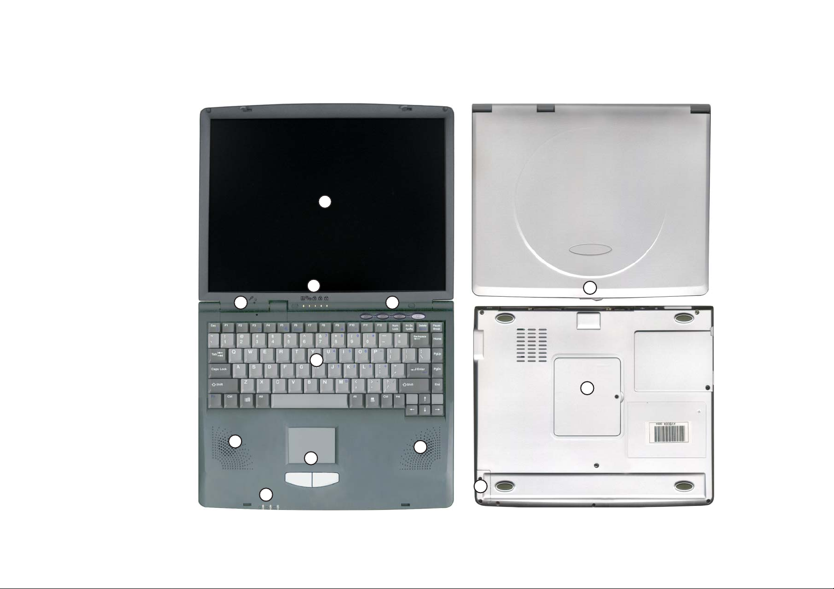
1) LCD panel
2) microphone
3) LED status
indicators
External components
2200T
4) Hot keys and
power button
5) Keyboard
6) Stereo
speakers
7) TouchPad
and buttons
8) LED power
indicators
9) Open latch
10) RAM cover
11) Battery cover
1
9
3
2
5
6
7
8
4
10
6
11
1 - 6
Page 14
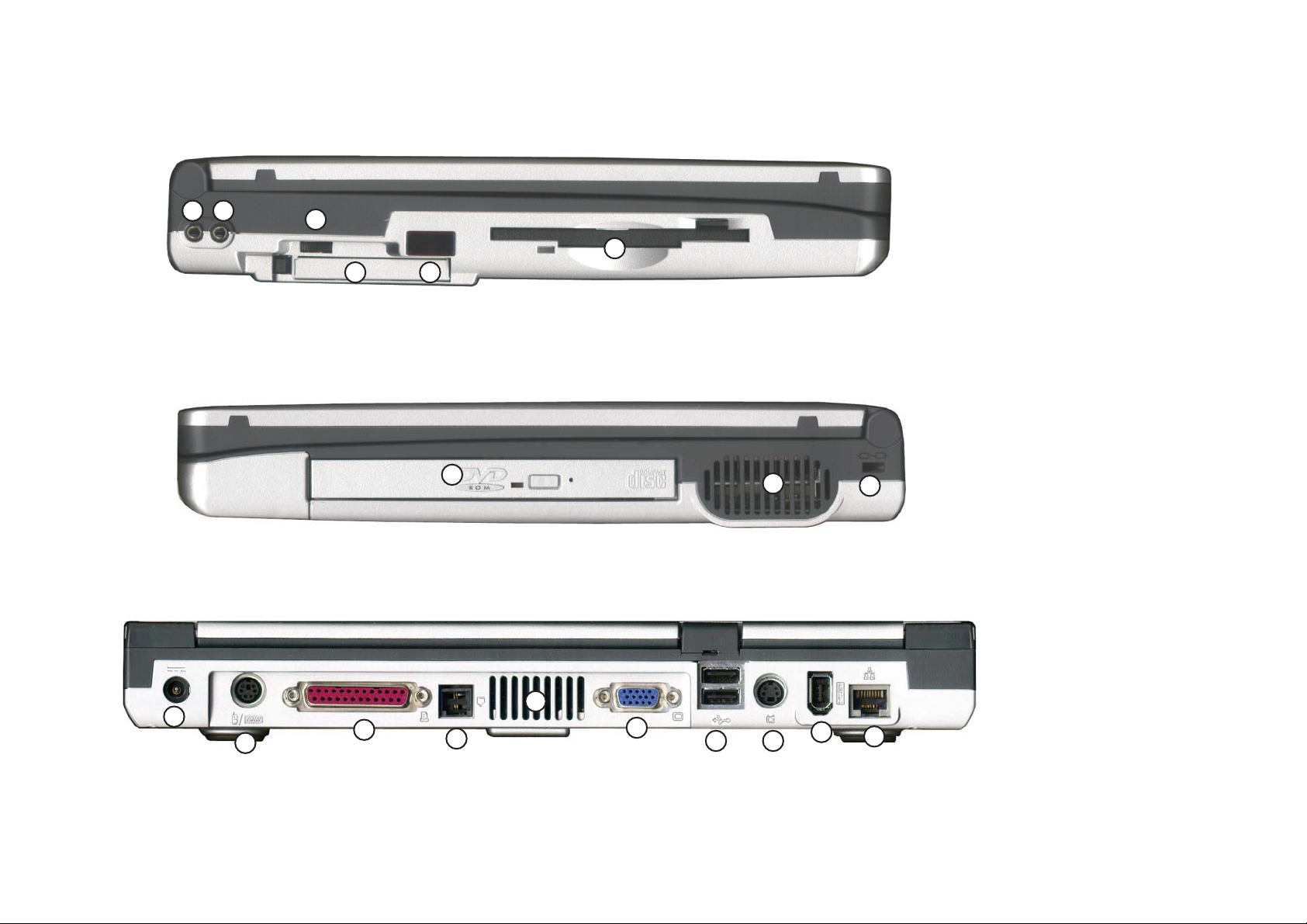
Introduction
12 ) Mic-in jack
13) Speaker-out jack
12 13
14
15
16
18
17
19
20
14) Volume knob
15) PC Card slot
16) Infrared port
17) FDD
18) CD device
(CD-ROM/DVDROM/CD-RW/
DVD+CD-RW)
19) Vent
20) Security slot
21 ) DC-in jack
22) PS/2 type port
23) Parallel port
24 ) Phone jack
25) Vent
26) External CRT
monitor port
21
22
23
24
25
26
27 ) Dual USB ports
28) S-Video
2827
29
30
connector
29 ) IEEE1394 port
30) LAN jack
1 - 7
Page 15
Service Manual
1) LCD panel
2) microphone
2700T
3) LED status
indicators
4) Hot keys and
power button
5) Keyboard
6) Stereo
speakers
7) TouchPad
and buttons
8) LED power
indicators
9) Open latch
10) RAM cover
11) Battery cover
1
3
2
4
9
5
10
6
6
7
11
8
1 - 8
Page 16
Introduction
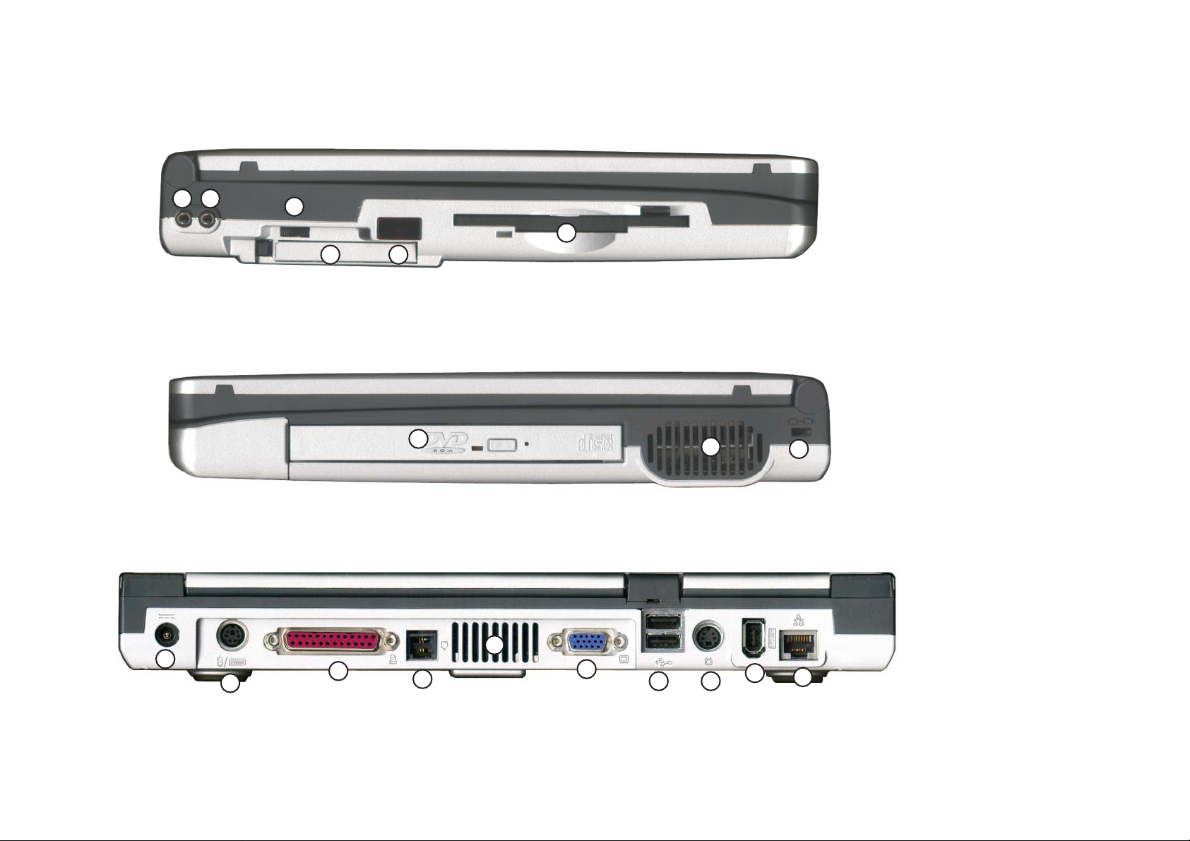
12 ) Mic-in jack
13) Speaker-out jack
12 13
14
15
16
18
17
19
20
14) Volume knob
15) PC Card slot
16) Infrared port
17) FDD
18) CD device
(CD-ROM/DVDROM/CD-RW/
DVD+CD-RW)
19) Vent
20) Security slot
21 ) DC-in jack
22) PS/2 type port
23) Parallel port
24 ) Phone jack
25) Vent
26) External CRT
monitor port
21
22
23
24
25
26
27 ) Dual USB ports
28) S-Video
2827
29
30
connector
29 ) IEEE1394 port
30) LAN jack
1 - 9
Page 17
Service Manual
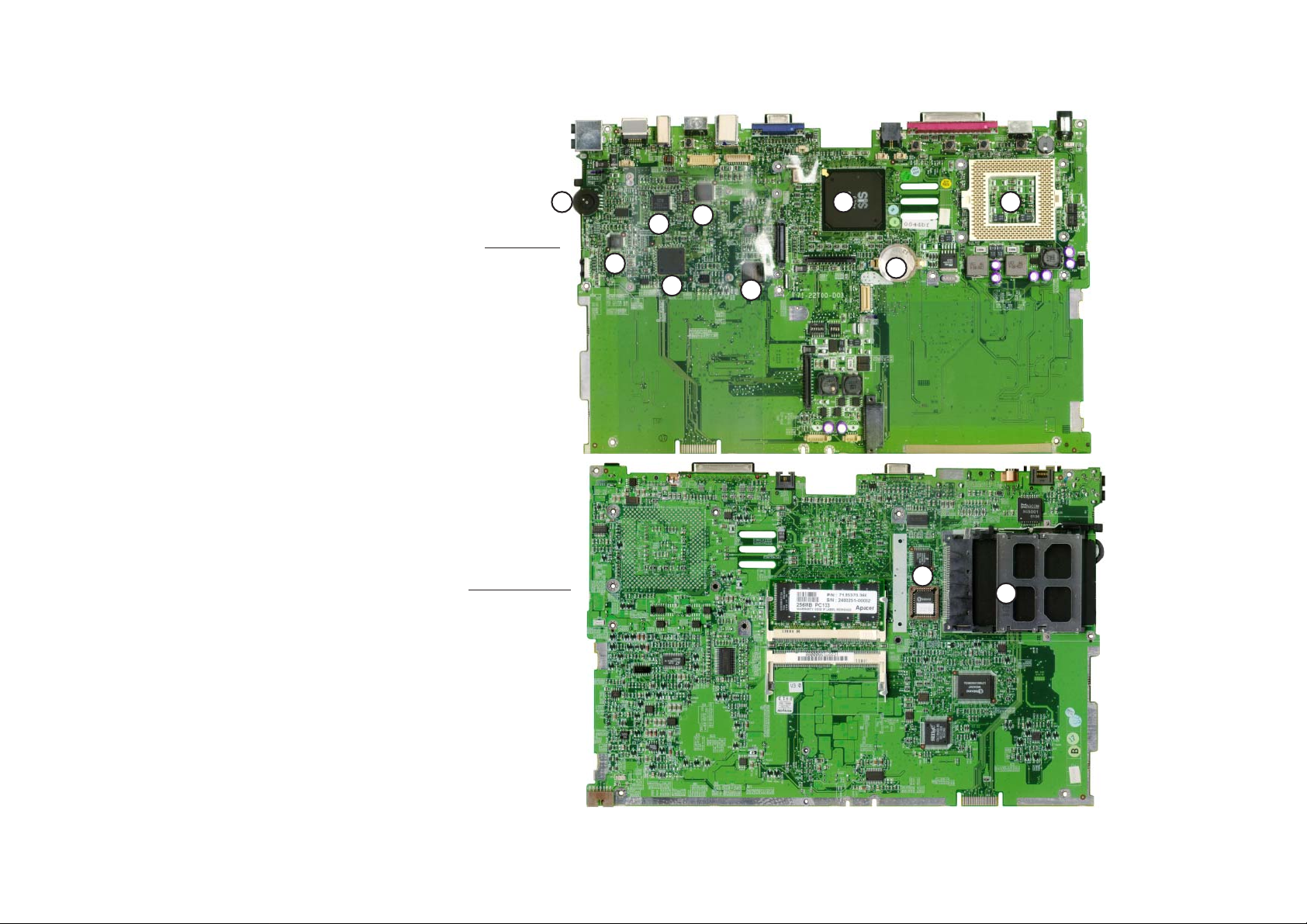
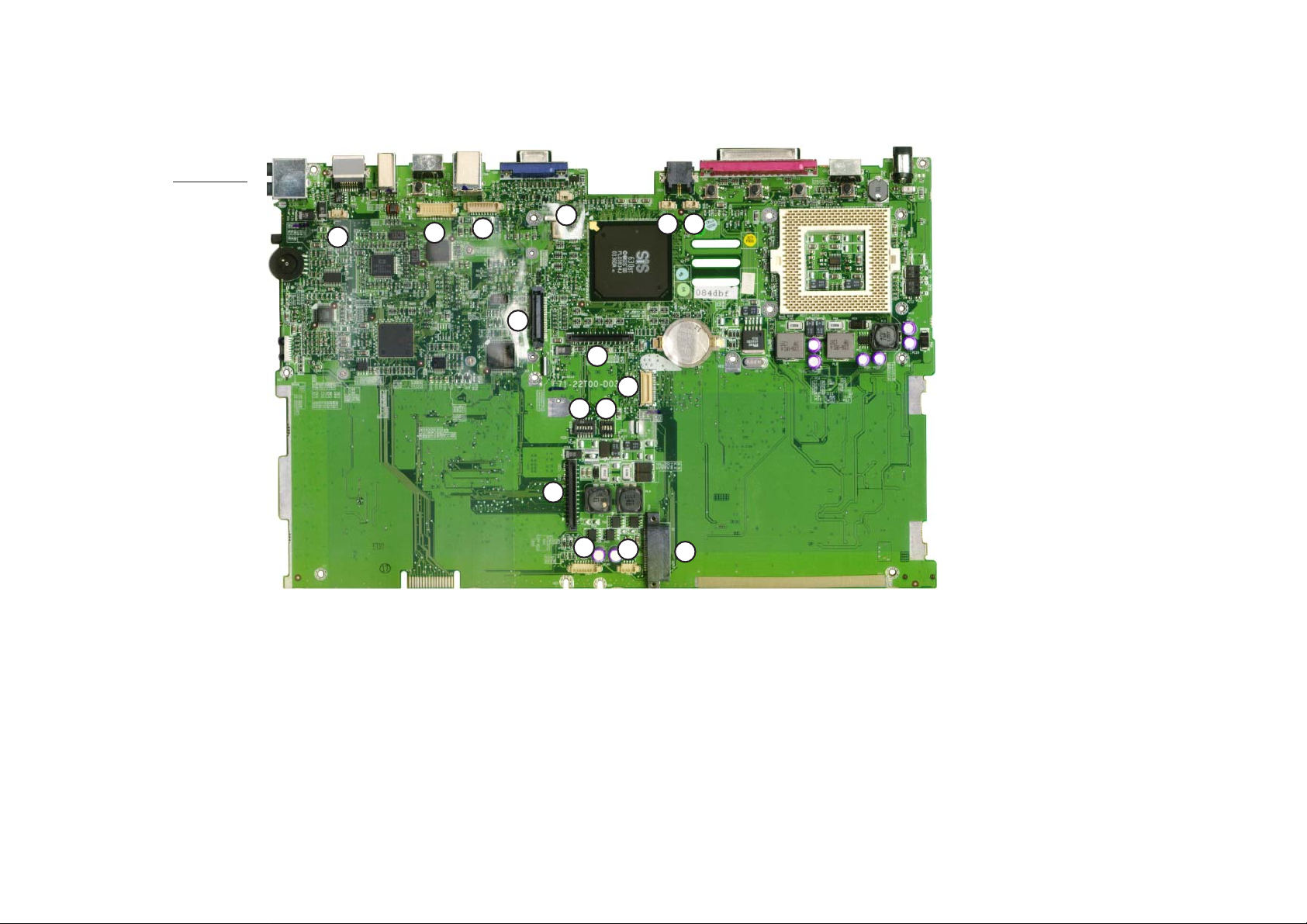
Mainboard overview
Key parts
1) CPU socket (no
CPU installed)
2) Core logic
SiS630st
3) VR
4) ICS1893 Lan
PHY
5) 1394 PHY
6) Audio Codec
7) TI4410
(PCMCIA +
1394
Controller)
8) K/B Controller
M33867
9) CMOS battery
Top view
Bottom view
5
4
6
7
8
9
10
11
123
10 ) Flash BIOS
ROM
11) PCMCIA socket
1 - 10
Page 18
Cable connectors & switches
Top view
Introduction
1
1) Microphone connector (CN13)
2) Panel connector (CN15)
2
3
7
8
4
15
14
11
12
8) K/B connector (CN17)
9) MDC connector (CN18)
13
6
5
9
10
14 ) CPU and Memory frequency
switch (SW6)
3) Inverter connector (CN12)
4) Heat sink connector (CN10)
5) Fan connector (CN11)
6) MDC cable connector (CN14)
7) HDD connector (CN16)
10) CD device connector (CN20)
11) FDD connector (CN19)
12) Indicative LED and
touchpad connector (CN21)
13) Internal Speaker connector
(CN22)
15 ) Panel ID switch (SW7)
1 - 11
Page 19

Service Manual
Notes:
1 - 12
Page 20
Chapter 2: Disassembly
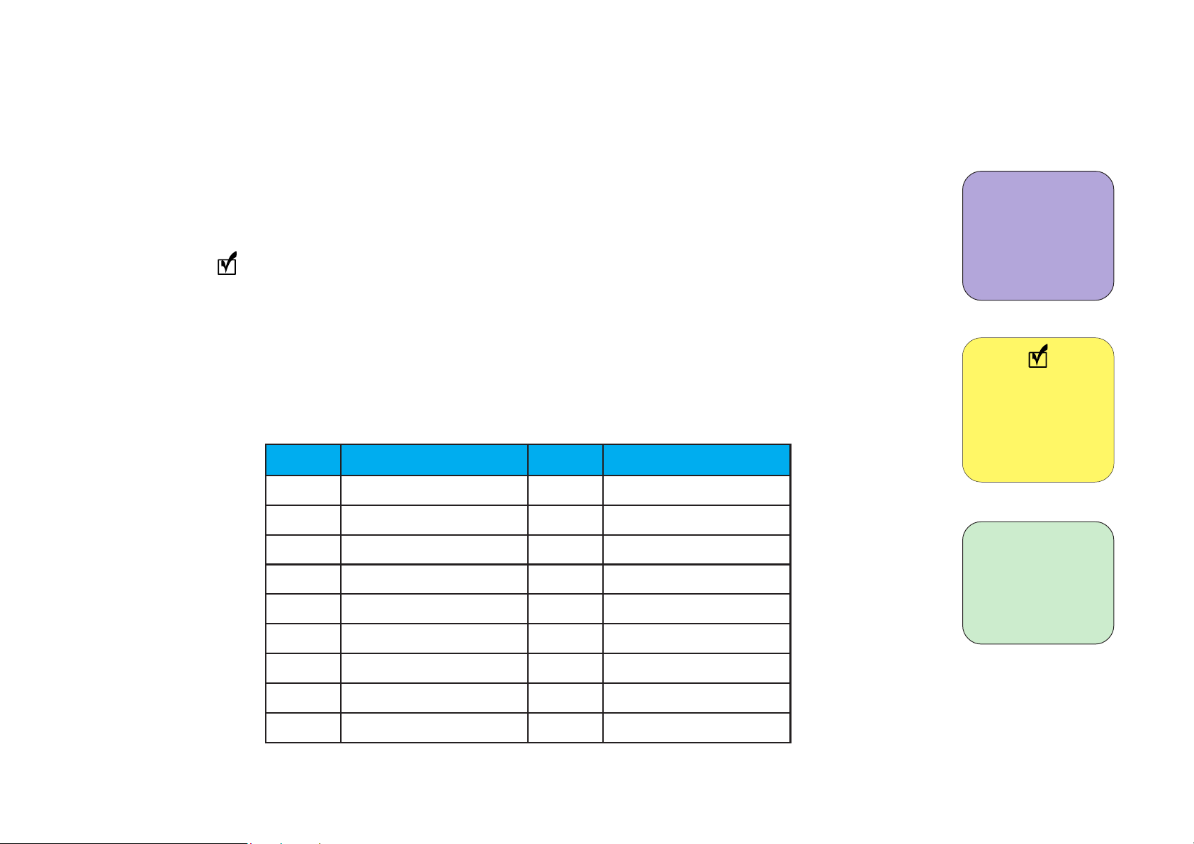
To make the disassembly process easier each section may have a box in the page margin. Informa-
Disassembly
tion contained in the boxes informs you what tools will be needed for a given procedure and the
amount of screws involved. A box lists the components that are important for that particular
procedure. A contains information that may be helpful to you. Examples are shown on the left.
All screw and nuts used in the assembly of the Notebook Computer are assigned a letter. If
you encounter any problems reassembling the machine, refer to this table to make sure you are
using the proper screw or nut.
Size chart for screws and hex nuts:
retteL eziS retteL eziS
A
B
C
D
.mm5x7.1
.mm2x2
.mm3x2
.mm4x2
E
F
.mm5x2
.mm01x2
J
K
L
M
N
O
.mm6x5.2
.mm8x5.2
.mm41x5.2
.mm32x5.2
.mm5.3x6.2
.mm4x3
This box lists the
tools needed and
the amount of
screws used.
Note
Information in
thie box will give
possible useful
information.
This box lists the
names of the
relevant parts.
G
H
Q
R
P
wercsknistaeH
tunxehffodnatS
).mm11(dutsxeH
2 - 1
.mm3x5.2
.mm4x5.2
I
.mm5x5.2
Page 21

Service Manual
Disassembly steps
From the list below choose the component that you want to disassemble, then follow the steps listed
Note
Remember to
wear an antistatic wrist strap
and remove all
power sources
when working on
the computer.
and go to the appropriate page for detailed instruction.
Steps to remove the CD device assembly:
Remove the battery p 2-5
Remove the keyboard p 2-6
Remove the heat sink p 2-9
Remove the CD device assembly p 2-8
Steps to remove the CPU:
Remove the battery p 2-5
Remove the keyboard p 2-6
Remove the heat sink p 2-9
Remove the CPU p 2-10
Steps to remove the FDD assembly:
Remove the battery p 2-5
2 - 2
Remove the keyboard p 2-6
Remove the HDD assembly p 2-7
Separate the notebook base in two p 2-12
Remove the FDD assembly from the mainboard p 2-15
Page 22

Steps to remove the HDD assembly:
Remove the battery p 2-5
Remove the keyboard p 2-6
Remove the HDD assembly p 2-7
Steps to remove the inverter board:
Remove the battery p 2-5
Remove the LCD panel frame p 2-18
Remove the LCD panel from the LCD panel case p 2-19 (up to step 4)
Steps to remove the LCD panel:
Remove the battery p 2-5
Remove the LCD panel frame p 2-18
Remove the LCD panel and bracket from the LCD panel case p 2-19
Disassembly
Remove the LCD panel from the bracket p 2-21
Remove only the LCD panel (for 14.1” LCD screens) p 2-22
2 - 3
Page 23

Service Manual
Steps to remove the mainboard:
Remove the battery p 2-5
Remove the keyboard p 2-6
Remove the HDD assembly p 2-7
Remove the CD device assembly p 2-8
Remove the heat sink p 2-9
Remove the CPU p 2-10
Separate the notebook base in two p 2-12
Remove the FDD assembly p 2-15
Remove the CD device tray p 2-15
Remove the fan p 2-15
Remove the mainboard from the bottom case p 2-16
Remove the mainboard from the mainboard tray p 2-17
2 - 4
Steps to remove the modem module:
Remove the battery p 2-5
Remove the keyboard p 2-6
Remove the heat sink p 2-9
Remove the modem module p 2-24
Page 24
Removal Procedures
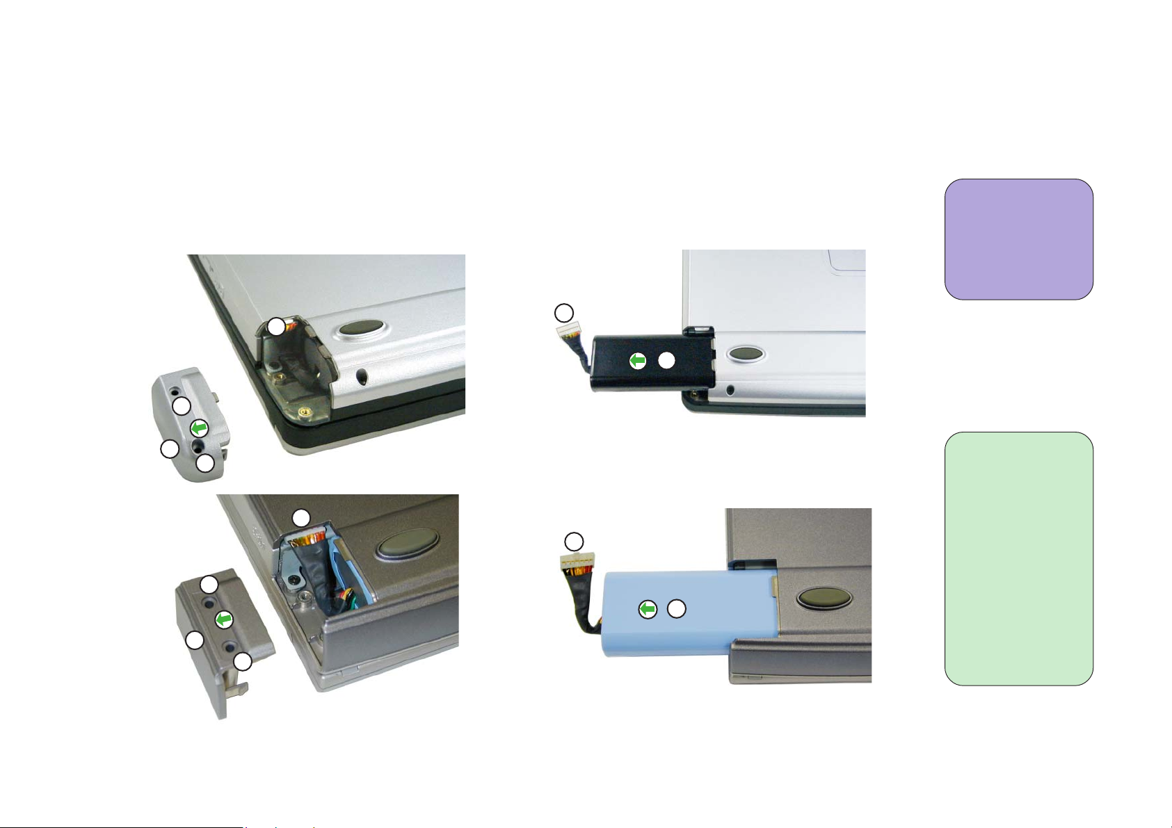
Remove the battery
1. Remove the 2 screws on the battery cover (figures 2-1).
Disassembly
2. Disconnect the battery connector from the computer.
3. Slide the battery out of the computer (figures 2-2).
2
L
1
L
2
M
figure 2-1a
1 Philips screw-
driver
2 screws
3
4
figure 2-2a
1) Battery
Cover
3
4
2) Battery
Connector
plug
3) Battery
1
M
figure 2-1b
figure 2-2b
Connector
4) Battery
2 - 5
Page 25
Service Manual
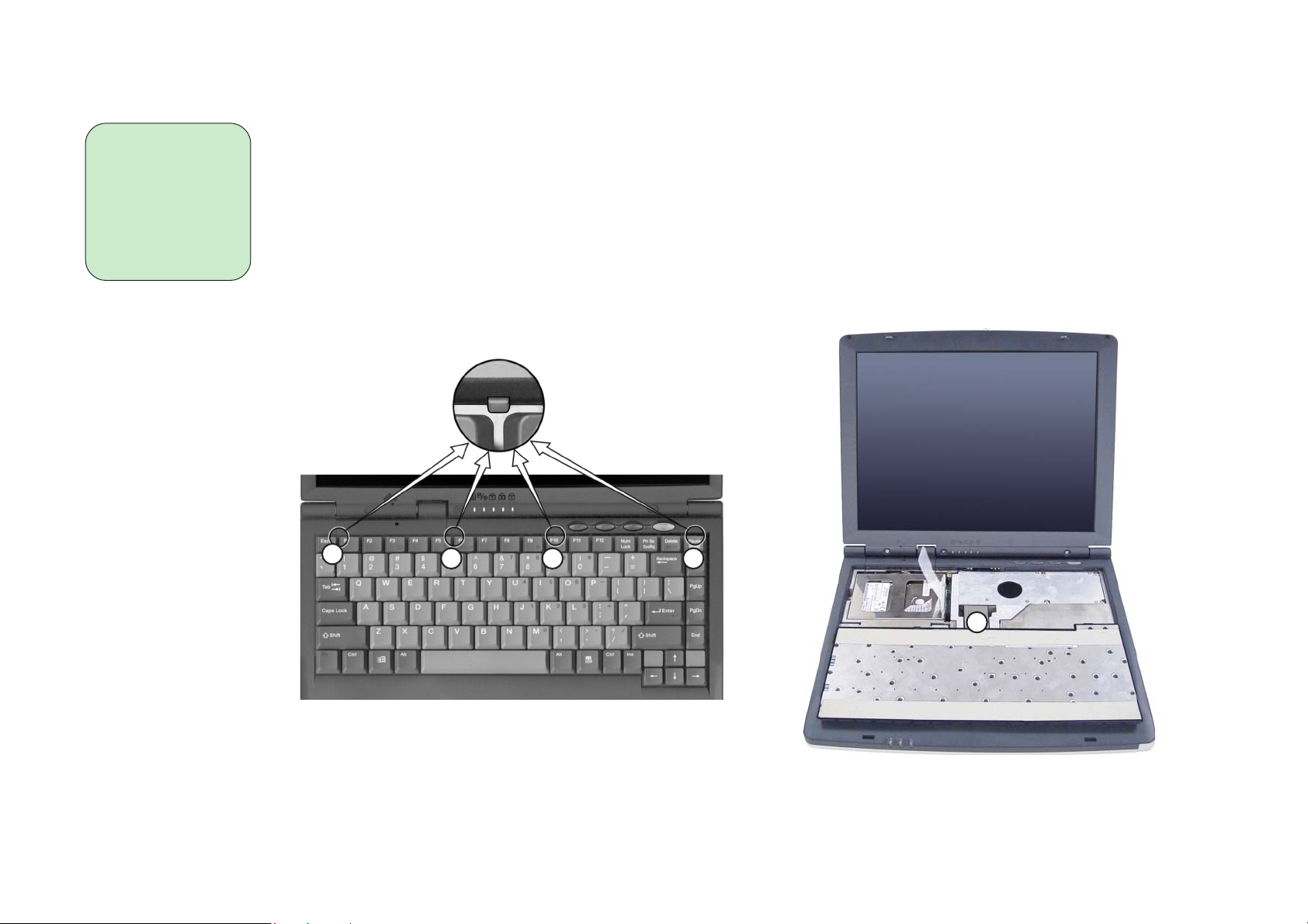
Remove the keyboard
1) keyboard
latch
2) ribbon cable
1. Press the 4 keyboard latches at the top of the keyboard (figure 2-3).
2. Lift the top of the keyboard up and out of the computer (figure 2-4).
3. Remove the keyboard ribbon cable.
1
1 1
1
2 - 6
2
figure 2-3
figure 2-4
Page 26
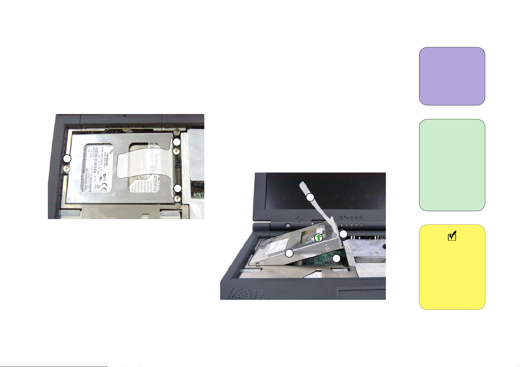
Remove the HDD assembly
1. Remove 3 screws (D) holding the HDD assembly in place (figure 2-5).
Disassembly
2. Lift the HDD assembly out of the case using the HDD tab (figure 2-6).
D
D
D
figure 2-5
1
1 Philips screw-
driver
3 screws
1) HDD assembly
2) HDD tab
3) HDD connector
2
3
4
figure 2-6
4) HDD socket
Note
For information
on removing the
HDD from the
HDD assembly
go to Appendix
A.
2 - 7
Page 27
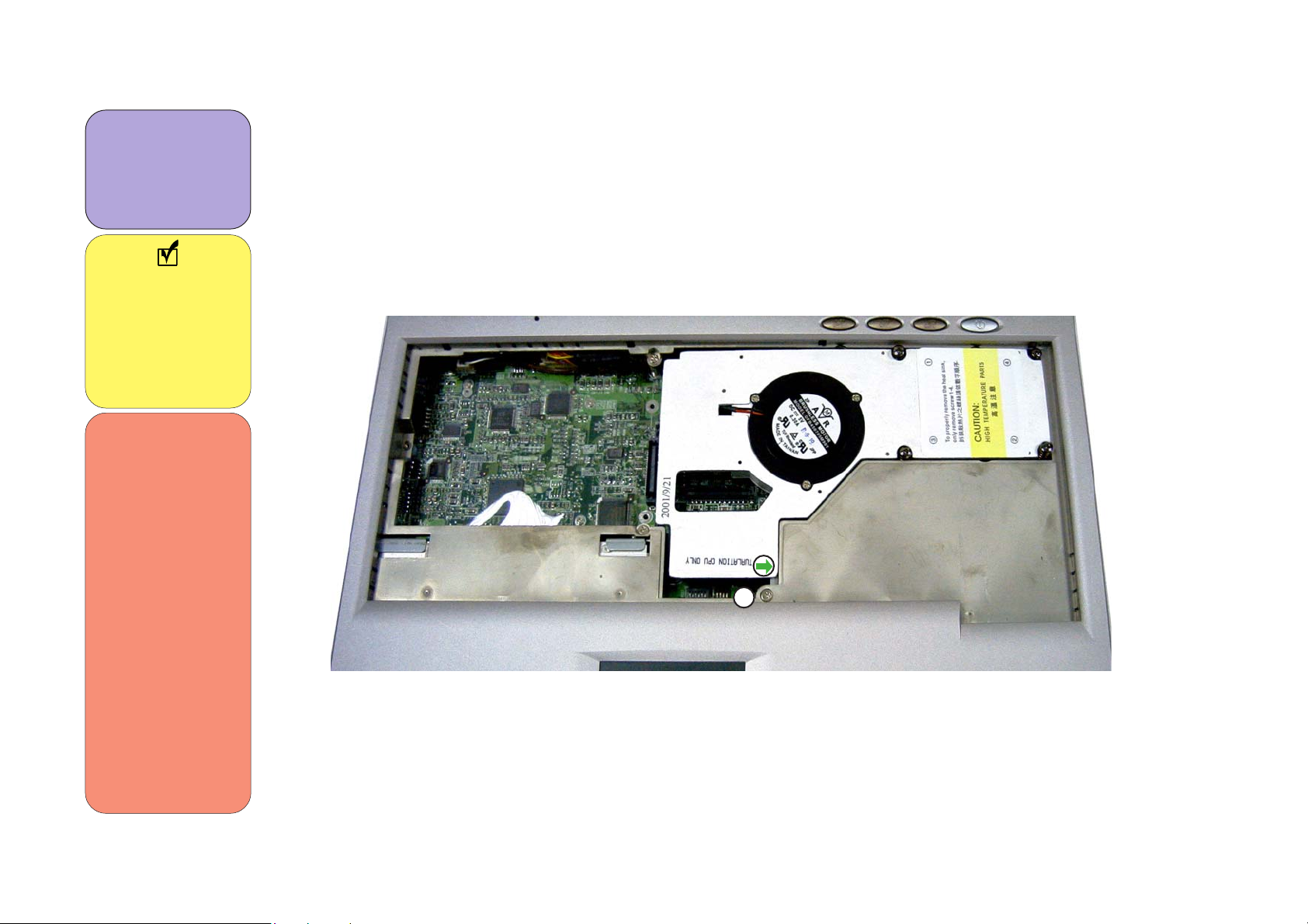
Service Manual
1 Philips
screwdriver
1 screw
Note
For information
on removing the
CD device from
the assembly go
to Appendix A.
**
When reinstalling the CD device assembly
you should do so
with the heat
sink removed.
Reinstall the
assembly, fasten
the screw and
then reinstall
the heat sink.
This will ensure
that there are no
interference
problems later
once you restart
your computer.
Remove the CD device assembly
1. Remove screw (I) in figure 2-7.
2. Use a small screwdriver to gently push the CD device assembly out of the case (figure 2-7).
3. Remove the heat sink. ** (refer to page 2-9 for heat sink removal steps)
I
figure 2-7
2 - 8
Page 28
Disassembly
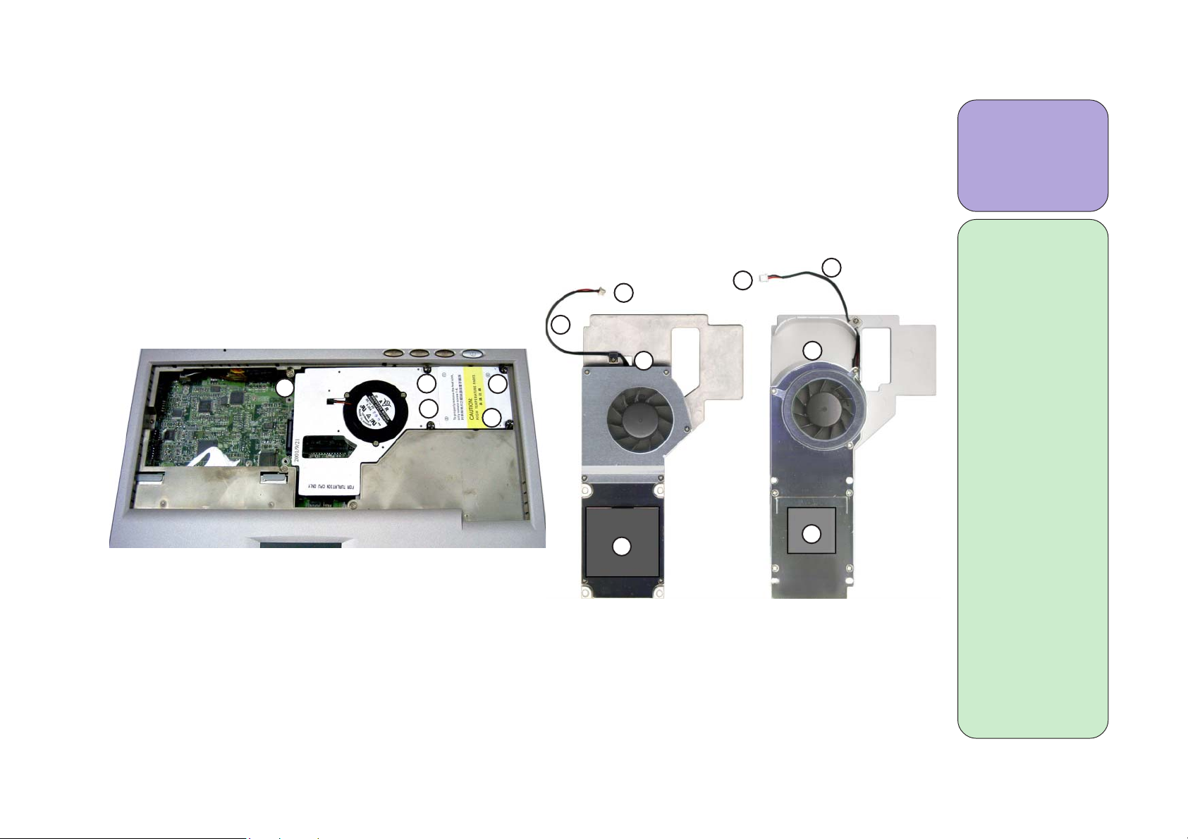
Remove the heat sink
1. Unscrew the 4 screws (P) securing the heat sink to the mainboard (figure 2-8).
2. Lift up the heat sink part way until you see the heat sink cable. Disconnect the cable from the
mainboard (figure 2-9).
3. Place the heat sink aside.
2
3
1b
2
P
P
P
P
4
2
3
1a
4
1 Philips screw-
driver
4 screws
1a)Heat sink
(for FC-PGA
Pentium III
and Celeron
CPUs)
Part no.: 31-
22C0N-10X
1b)Heat sink
(for FC-PGA2
Pentium III-S,
Pentium III
and Celeron
figure 2-8
figure 2-9
Applying a heat sink pad
1. When the heat sink has been removed you will need to apply a new heat sink pad before reinstalling it. To do so simply peel off the old pad and adhere a new one to the same area.
CPUs)
Part no.: 31-
22T0N-10X
2) Cable connector
3) Cable
4) Heat sink pad
2 - 9
Page 29
Service Manual
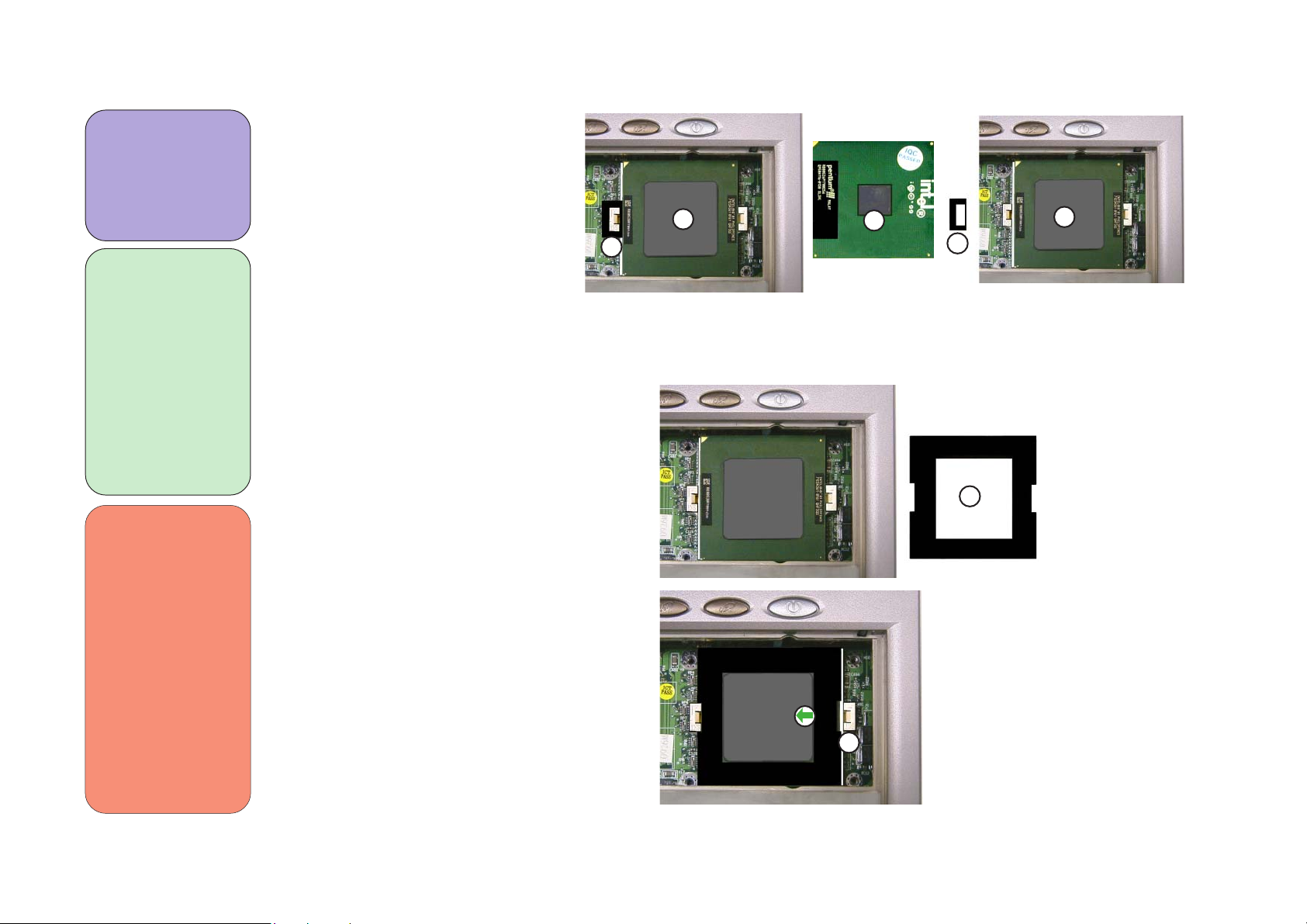
1 Regular
screwdriver
1 CPU tool
1a) FC-PGA2
CPU
1b) FC-PGA
CPU
2) CPU lock
3) CPU Tool
4) Open Slot
**
The removal and
reinstallation/
replacement
procedures for
both FC-PGA
and FC-PGA2
CPUs are the
same. However,
both types of
CPUs go with
different heat
sinks (page 2-9).
Remove the CPU
1. Remove the CPU lock from
the CLOSE slot of the CPU
socket (figure 2-10a).
2. Place the CPU tool over
the CPU (figure 2-10b).
3. Place a screwdriver in
the OPEN slot of the
CPU socket and move it
to the left (figure 2-10b).
4. The CPU is now unlocked from the socket
so remove the CPU tool
and lift the CPU out of
the socket.
1a
2
figure 2-10a
1b
2
3
4
1a
figure 2-10b
2 - 10
Page 30

Reinstall the CPU
Disassembly
1. Place the CPU firmly in the
socket.
2. Place the CPU tool over the
CPU (figure 2-11a).
3. Place a screwdriver in the
CLOSE slot of the CPU socket
(figure 2-11a) and move it to the
right.
4. The CPU is now secure in the
socket.
5. Remove the CPU tool, place
the CPU lock on the CLOSE
slot of the socket (figure 211b).
1 Regular
screwdriver
1 CPU tool
1
2
3
figure 2-11a
1) CPU
2) CPU tool
3) CLOSE slot
4) CPU lock
6. Now that the CPU is properly
installed, reinstall the heat
sink.
4
figure 2-11b
2 - 11
Page 31

Service Manual
1 Philips screwdriver
1 Hex socket
wrench
Top: 1 Screw
1 Hex nut
Right Side:
1 Screw
Bottom:
7 Screws (2700T)
5 Screws (2200T)
Bottom Rear:
3 Screws
4 Hex nuts
1) microphone
connector
2) LCD panel
cable connector
3) Inverter cable
connector
4) LCD panel
cable
5) Inverter cable
Separate the notebook base in two
With the CPU and heat sink, keyboard, HDD and CD device removed:
1. Remove screw (I), the LCD panel cable and
the inverter cable. When reinstalling make
sure to place the LCD panel cable on top of
the case and the inverter cable on the inside
of the case just above the hex nut (figure 2-
12).
4
1
2
3
I
5
figure 2-12
2 - 12
Page 32

2. Remove screw (I) (figure 2-13).
Disassembly
I
figure 2-13
3. Close the LCD panel and go to the right side of the computer and remove screw (I) (figure 2-14).
I
figure 2-14
2 - 13
Page 33

Service Manual
4. Remove the hex nuts (R) on the parallel port (figure 2-15).
5. Remove the hex nuts (R) on the monitor out port (figure 2-15).
1 Hex socket
wrench
4 Hex nuts
3 Screws
1) parallel port
2) monitor port
6. Remove screws (D) just above the ports (figure 2-15).
D D
R
7. Remove all screws as shown in (figures 2-16).
K
1
R
D
R
2
K
J
R
K
figure 2-15
K
J
2 - 14
J
DD
D
J
J
figure 2-16afigure 2-16a
Page 34

Disassembly
Remove the FDD assembly
1. Remove screw (I).
2. Remove the hex nut (Q).
3. Unplug the FDD cable and lift the FDD assembly off of the mainboard.
1
Q
Remove the CD device tray
1. Remove screws (I).
2. Remove screw (F)
3. Unplug the CD device cable and slide the tray
slightly to the right and lift it off of the mainboard.
2
3
I
I
Remove the Fan
1. Unplug the fan cable
from the mainboard.
2. Lift out the fan.
1 Philips screwdriver
1 Hex socket
wrench
FDD:
1 Stand-off Hex
nut
1 Screw
CD device tray:
3 Screws
1) Fan
2) Fan cable
3) Fan cable
4) FDD assembly
connector
5) CD device tray
4
I
F
Note
5
figure 2-17
For information
on removing the
FDD from the
FDD assembly
go to Appendix
A.
2 - 15
Page 35

Service Manual
1 Philips screw-
driver
1 Hex socket
wrench
2 Screws
1 Hex nut
Remove the mainboard and tray from the bottom case
1. Remove screws (F, H) and hex nut (Q).
2. Lift the mainboard up from the battery side and pull it out of the case.
Q
2 - 16
H
F
figure 2-18
Page 36

Remove the mainboard from the mainboard tray
1. Lift the mainboard out of the tray.
Disassembly
mainboard bottom view
figure 2-19
mainboard top view
2 - 17
Page 37

Service Manual
1 Philips
screwdriver
5 Screws
1) Top half of
notebook
computer
2) LCD panel in
back
3) LCD panel
frame
The LCD Panel
Remove the LCD panel frame
1. Remove the rubber stoppers in positions D and J (figure 2-20).
2. Remove the screws (D, J) (figure2-20).
3. Run your finger around the middle of the frame and separate
the frame from the back (figure 2-21).
2
D
1
J J
J
D
figure 2-20
2 - 18
3
figure 2-21
Page 38

Disassembly
Remove the LCD panel and bracket from the LCD panel case *
1. Remove the bracket screws (D) on the side of the LCD panel (figure 2-22).
2. Remove the 4 screws (I) at the bottom of the LCD screen (figure 2-22).
3. Remove screws (D) securing the inverter board (figure 2-22).
D
D
1 Philips
screwdriver
10 Screws
1) Ground wire
(for reassembly, please
note where
the ground
wire is attached )
2) Inverter
Board
D
*
1
I
I
D
2
D
I
I
D
figure 2-22
The following
models need to
have the LCD
bracket removed.
2700T - 13.3”
2200T - 13.3”
2 - 19
Page 39

Service Manual
1) Inverter
cable
2) LCD to inverter cable
3) LCD cable
4) LCD cable
connector
5) LCD bracket
1
4. Lift the inverter board and disconnect the inverter cable and the LCD to inverter cable (figure
2-23).
5. Lift the LCD screen and bracket out of the case
and place it atop the keyboard (figure 2-24).
6. Disconnect the LCD cable.
2
figure 2-23
5
3
5
2 - 20
4
figure 2-24
Page 40

Remove the LCD panel from the bracket
Disassembly
1. Gently lift out the panel.
2. Remove the screws (C) holding the LCD in the bracket (figure 2-25).
C
C
1 Philips screw-
driver (small)
4 Screws
C
C
figure 2-25
2 - 21
Page 41

Service Manual
1 Philips
screwdriver
4 Screws
Remove only the LCD panel (for 14.1” LCD screens)
Once the frame is removed from a 14.1” model, you will not need to remove the bracket. Instead:
1) Remove the four screws (figure 2-26)
E
E
2 - 22
E
E
figure 2-26
Page 42

2) Gently remove the LCD panel from the case and place it on top of the keyboard (figure 2-27).
Disassembly
3) Remove the tape and connectors and lift the LCD panel out.
1
2
1) LCD cable
2) LCD cable
connector
figure 2-27
2 - 23
Page 43

Service Manual
Remove the modem module
1 Philips
screwdriver
2 Screws
1) modem
module
2) modem cable
With the keyboard and heat sink removed:
1) Remove screws (H) (figure 2-28)
2) Disconnect the modem cable from the mainboard.(the modem module with the cable is still connected
to the mainboard via a board-to-board connector.)
3) Remove the modem module with the cable.
1
2
2
2 - 24
H
1
H
1
Page 44

Mechanical Drawings and Parts Lists
Appendix A: Mechanical Drawings and Parts Lists
2200T
Bottom half assembly and parts list
2200T
A - 1
Page 45

Service manual
LCD panel (13.3”) assembly and parts list
2200T
A - 2
Page 46

LCD panel (14.1”) assembly and parts list
Mechanical Drawings and Parts Lists
2200T
A - 3
Page 47

Service manual
Keyboard and Touchpad assembly and parts list
2200T
A - 4
Page 48

FDD assembly and parts list
Mechanical Drawings and Parts Lists
2200T
A - 5
Page 49

Service manual
HDD assembly and parts list
2200T
A - 6
Page 50

CD-ROM assembly and parts list
Mechanical Drawings and Parts Lists
2200T
A - 7
Page 51

Service manual
DVD-ROM assembly and parts list
2200T
A - 8
Page 52

CD-RW assembly and parts list
Mechanical Drawings and Parts Lists
2200T
A - 9
Page 53

Service manual
DVD-ROM+CD-RW combo assembly and parts list
2200T
A - 10
Page 54

2700T
Bottom half assembly and parts list
Mechanical Drawings and Parts Lists
2700T
A - 11
Page 55

Service manual
LCD panel (13.3”) assembly and parts list
2700T
A - 12
Page 56

LCD panel (14.1”) assembly and parts list
Mechanical Drawings and Parts Lists
2700T
A - 13
Page 57

Service manual
Keyboard and Touchpad assembly and parts list
2700T
A - 14
Page 58

FDD assembly and parts list
Mechanical Drawings and Parts Lists
2700T
A - 15
Page 59

Service manual
HDD assembly and parts list
2700T
A - 16
Page 60

CD-ROM assembly and parts list
Mechanical Drawings and Parts Lists
2700T
A - 17
Page 61

Service manual
DVD-ROM assembly and parts list
2700T
A - 18
Page 62

CD-RW assembly and parts list
Mechanical Drawings and Parts Lists
2700T
A - 19
Page 63

Service manual
DVD-ROM+CD-RW combo assembly and parts list
2700T
A - 20
Page 64

Appendix B:Schematic Diagrams
Mainboard (71-22T00-D03)
Schematic Diagrams
Sheet 1 of 31
HA#[3..31]
PREQ#(2)
PRDY#
HREQ#[0..4]
DEFER#(4)
A20M#(2,10)
IGNNE#(2,10)
INTR(2,10)
NMI(2,10)
SLP#(2,10)
PinAF36(2)
IERR#(2)
BPRI#(4)
RS#0(4)
RS#1(4)
RS#2(4)
SMI#(2,10)
TCK
TDO
TDI
TMS
TRST#
PREQ#
PRDY#
ADS#
IERR#
BREQ0#
BPRI#
BNR#
HLOCK#
HIT#
HITM#
DEFER#
HTRDY#
RS#0
RS#1
RS#2
A20M#
CPU_FERR#
IGNNE#
PWRGOOD
SMI#
R168 47
R167 47
INTR
NMI
STPCLK#
SLP#
VCCT
R571
1K
B
ADS#(4)
BREQ0#(4)
BNR#(4)
HLOCK#(4)
HIT#(4)
HITM#(4)
HTRDY#(4)
CPU_FERR#(2)
PWRGOOD(2)
TCK(2)
TDO(2)
TDI(2)
TMS(2)
TRST#(2)
STPCLK#(2,10)
HREQ#[ 0..4](4)
HA#3
HA#4
HA#5
HA#6
HA#7
HA#8
HA#9
HA#10
HA#11
HA#12
HA#13
HA#14
HA#15
HA#16
HA#17
HA#18
HA#19
HA#20
HA#21
HA#22
HA#23
HA#24
HA#25
HA#26
HA#27
HA#28
HA#29
HA#30
HA#31
HREQ#0
HREQ#1
HREQ#2
HREQ#3
HREQ#4
Z744
Z743
R569
10K
C
E
Q46
2N3904
U9A
AK8
A#3
AH12
A#4
AH8
A#5
AN9
A#6
AL15
A#7
AH10
A#8
AL9
A#9
AH6
A#10
AK10
A#11
AN5
A#12
AL7
A#13
AK14
A#14
AL5
A#15
AN7
A#16
AE1
A#17
Z6
A#18
AG3
A#19
AC3
A#20
AJ1
A#21
AE3
A#22
AB6
A#23
AB4
A#24
AF6
A#25
Y3
A#26
AA1
A#27
AK6
A#28
Z4
A#29
AA3
A#30
AD4
A#31
X6
A#32
AC1
A#33
W3
A#34
AF4
A#35
AK18
REQ#0
AH16
REQ#1
AH18
REQ#2
AL19
REQ#3
AL17
REQ#4
AN31
ADS#
AE35
IERR#
AN29
BR0#
AN17
BPRI#
AH14
BNR#
AK20
LOCK#
AL25
HIT#
AL23
HITM#
AN19
DEFER#
G33
BP#2
E37
BP#3
C35
BPM#0
E35
BPM#1
AN25
TRDY #
AH26
RS#0
AH22
RS#1
AK28
RS#2
AE33
A20M#
AC35
FERR#
AG37
IGNNE#
AK26
PWGOOD
AJ35
SMI#
AL33
TCK
AN37
TDO
AN35
TDI
AK32
TMS
AN33
TRST#
J37
PREQ#
A35
PRDY#
M36
LINT0#/INTR
L37
LINT1#/NMI
AG35
STPCLK#
AH30
SLP#
TUALU TIN
VCCVCC
VCCT
R570
DS
10K
Q45
SI2302DS
G
G
Q47
2N7002
Cu+/Tu- (29)
DS
PinAG1 (2)
Cu-/Tu+ (2,3)
R572
1K
DBSY#
DRDY#
PICCLK
PICD1
PICD0
FLUSH#
RESET#
RESET#
BSEL0
BSEL1
CLKREF
W1
D#0
T4
D#1
N1
D#2
M6
D#3
U1
D#4
S3
D#5
T6
D#6
J1
D#7
S1
D#8
P6
D#9
Q3
D#10
M4
D#11
Q1
D#12
L1
D#13
N3
D#14
U3
D#15
H4
D#16
R4
D#17
P4
D#18
H6
D#19
L3
D#20
G1
D#21
F8
D#22
G3
D#23
K6
D#24
E3
D#25
E1
D#26
F12
D#27
A5
D#28
A3
D#29
J3
D#30
C5
D#31
F6
D#32
C1
D#33
C7
D#34
B2
D#35
C9
D#36
A9
D#37
D8
D#38
D10
D#39
C15
D#40
D14
D#41
D12
D#42
A7
D#43
A11
D#44
C11
D#45
A21
D#46
A15
D#47
A17
D#48
C13
D#49
C25
D#50
A13
D#51
D16
D#52
A23
D#53
C21
D#54
C19
D#55
C27
D#56
A19
D#57
C23
D#58
C17
D#59
A25
D#60
A27
D#61
E25
D#62
F16
D#63
AL27
AN27
J33
L35
J35
AG33
INIT#
AE37
Z907
X4
AH4
W37
BCLK
AJ33
AJ31
Y33
HD#0
HD#1
HD#2
HD#3
HD#4
HD#5
HD#6
HD#7
HD#8
HD#9
HD#10
HD#11
HD#12
HD#13
HD#14
HD#15
HD#16
HD#17
HD#18
HD#19
HD#20
HD#21
HD#22
HD#23
HD#24
HD#25
HD#26
HD#27
HD#28
HD#29
HD#30
HD#31
HD#32
HD#33
HD#34
HD#35
HD#36
HD#37
HD#38
HD#39
HD#40
HD#41
HD#42
HD#43
HD#44
HD#45
HD#46
HD#47
HD#48
HD#49
HD#50
HD#51
HD#52
HD#53
HD#54
HD#55
HD#56
HD#57
HD#58
HD#59
HD#60
HD#61
HD#62
HD#63
DBSY#
DRDY#
CPU_PICCLK
PICD1
PICD0
INIT#
FLUSH#
R553 1K
CPURST #
HCLKCPU
BSEL0
BSEL1
CLKREF
HD#[0..63]
DBSY# (4)
DRDY# (4)
CPU_PICCLK (3)
PICD1 (2)
PICD0 (2)
INIT# (2,10)
FLUSH# (2)
CPURST# (4)
HCLKCPU ( 3)
BSEL0 (2,3)
BSEL1 (2,3)
R300 150(1%)(0805)
R299 150(1%)(0805)
C322
.1U
CPURST#(4)
ITP_RST#(26)
TRST#(2)
PRDY#
PREQ#(2)
HD#[0..6 3]
VCCT
10
9
8
7
6
VCCT
10
9
8
7
6
VCCT
10
9
8
7
6
VCCT
10
9
8
7
6
VCCT
10
9
8
7
6
VCCT
10
9
8
7
6
VCCT
56
56
HD#1
HD#5
HD#8
HD#17
HD#0
HD#6
C369
HD#15
.1U
HD#4
HD#2
HD#14
HD#11
HD#13
HD#10
HD#12
C126
HD#18
.1U
HD#9
HD#35
HD#32
HD#29
HD#31
HD#26
C357
HD#19
.1U
HD#33
HD#24
HD#21
HD#23
HD#16
HD#20
C368
HD#7
.1U
HD#30
HD#22
HD#34
HD#43
HD#38
HD#36
C365
HD#37
.1U
HD#39
HD#45
HD#44
HD#42
HD#27
HD#51
HD#49
HD#41
HD#47
C367
.1U
HD#40
HD#52
HD#48
HD#59
HD#63
HD#57
HD#55
HD#46
C356
.1U
HD#50
HD#58
HD#53
HD#54
HD#56
HD#61
HD#62
HD#60
Titl e
Size Document Number Rev
Custom
Date: Sheet
Tuesday, September 11, 2001
HA#[3..31]
HA#28
HA#15
HA#12
HA#13
HA#16
HA#3
HA#9
HA#6
HA#25
HA#22
HA#17
HA#31
HA#5
HA#10
HA#21
HA#19
HA#30
HA#29 HD#25
HA#26
HA#18
HA#20
HA#24
HA#23
HA#27
HA#14
HA#7 HD#3
HA#4
HA#8
HA#11
PRDY# HD#28
PRDY#
HREQ#4
HREQ#4(4)
HREQ#0
HREQ#0(4)
BREQ0#(4)
BREQ0#
RS#2
RS#2(4)
DBSY#
DBSY#(4)
RS#0
RS#0(4)
DRDY#
DRDY#(4)
HIT#
HIT#(4)
HTRDY #
HTRDY#(4)
HITM #
HITM#(4)
RS#1
RS#1(4)
DEFER#
DEFER#(4)
HLOCK #
HLOCK#(4)
HREQ#3
HREQ#3(4)
HREQ#2
HREQ#2(4)
BPRI#
BPRI#(4)
HREQ#1
HREQ#1(4)
BNR#
BNR#(4)
V_IO2.5
TDI(2)
TDO(2)
TCK(2)
TMS(2)
CPURST#(4)
TDI
TDO
TCK
TMS
TRST#
PRDY#
PREQ#
CPURST#
ITP_RS T #
ADS#(4)
.1U(R)
CPURST#
ADS#
C482
C481
C480
.1U(R)
.1U
HA#[3..31] (4)
RP17
1
1
2
2
3
3
4
4
5
5
TSMC8R -56
RP9
1
1
2
2
3
3
4
4
5
5
TSMC8R -56
RP8
1
1
2
2
3
3
4
4
5
5
TSMC8R -56
RP16
1
1
2
2
3
3
4
4
5
5
TSMC8R -56
RP14
1
1
2
2
3
3
4
4
5
5
TSMC8R -56
RP15
1
1
2
2
3
3
4
4
5
5
TSMC8R -56
R308
R314
TP187
TP188
TP189
TP190
TP191
TP192
TP193
TP194
TP195
HD#[0..63](4)HD#[0..63] (4)HA#[3. .31](4)
10
9
8
7
6
10
9
8
7
6
10
9
8
7
6
10
9
8
7
6
10
9
8
7
6
10
9
8
7
6
RP7
1
10
1
10
2
9
2
9
3
8
3
8
4
7
4
7
5
6
5
6
TSMC8 R-56
RP6
1
10
1
10
2
9
2
9
3
8
3
8
4
7
4
7
5
6
5
6
TSMC8 R-56
RP4
1
10
1
10
2
9
2
9
3
8
3
8
4
7
4
7
5
6
5
6
TSMC8 R-56
RP5
1
10
1
10
2
9
2
9
3
8
3
8
4
7
4
7
5
6
5
6
TSMC8 R-56
RP1
1
10
1
10
2
9
2
9
3
8
3
8
4
7
4
7
5
6
5
6
TSMC8 R-56
RP2
1
10
1
10
2
9
2
9
3
8
3
8
4
7
4
7
5
6
5
6
TSMC8 R-56
RP3
1
10
1
10
2
9
2
9
3
8
3
8
4
7
4
7
5
6
5
6
TSMC8 R-56
RP11
1
10
1
10
2
9
2
9
3
8
3
8
4
7
4
7
5
6
5
6
TSMC8 R-56
ÂÅ ¤Ñ ¹q ¸£ CLEVO CO.
CPU & AGTL TERMINATION
71-22T00-D03
VCCT
C337
.1U
VCCT
C325
.1U
VCCT
C287
.1U
VCCT
C307
.1U
VCCT
C40
.1U
VCCT
C41
.1U
VCCT
C42
.1U
VCCT
C234
.1U
A
31
of
1
B - 1
Page 65

Service Manual
Sheet 2 of 31
CPU VRM S ELECT T ABLE FOR T UALAT I N
Cu-/Tu+(1,3)
GTLREF(4)
VID[4:0]
10000
10001
10010
10011
10100
10101
10110
10111
11000
11001
11010
11011
11100
11101
11110
11111
SI2305DS
G S
Q49
L70
0(0805)
V_IO2.5
V_IO1.5
VID0(27)
VID1(27)
VID2(27)
VID3(27)
VID25mV(27)
VCC_Core
1.00V
1.05V
1.10V
1.15V
1.20V
1.25V
1.30V
1.35V
1.40V
1.45V
1.50V
1.55V
1.60V
1.65V
1.70V
1.75V
D
20 MIL
VCCT
C547
.1U(0805)
VID0
VID1
VID2
VID3
VID25mV
V_IO1.5
G
D S
C88
4.7U
R559 75(1%)
Q48
SI2302DS
20 MIL
C354
.1U
C97
.1U
V_IO_CPU
V_IO2.5
Z893
R560
150(1%)
VCC_CORE
C494
10U
C129
.1U
C543
.1U
VCCT
R574 R
C279
.1U
VCCT
C283
.1U
AM36
AD32
AH24
AH32
AH36
AM12
AM16
AM20
AM24
AM28
AM32
AD36
AL35
AL37
AJ37
AK36
AA37
AB34
AF34
AJ13
AJ17
AJ21
AJ25
AJ29
AK34
AB36
AK12
AK22
VCCT
AN1AK24
AH20
AK16
AL13
AL21
AN11
AN15
G35
AA33
AA35
AN21
E23
S33
S37
U35
U37
C33
C31
A33
VID0
VTT
VTT
VTT
VTT
VTT
VTT
VTT
VTT
VTT
VTT
PR#
AC37
BR1
RSP#
F10
Z892
NCNCNCNCNCNCNCNCNC
L33
G37
N33
N35
Z891
VTT
N37
Q33
VID1
VCC3AERR#
VID2
VID3
VID4
VCC-CORE
AA5
VCC-CORE
AB2
VCC-CORE
VCC-CORE
VCC-CORE
AE5
VCC-CORE
AF2
VCC-CORE
VCC-CORE
VCC-CORE
VCC-CORE
VCC-CORE
VCC-CORE
VCC-CORE
VCC-CORE
VCC-CORE
VCC-CORE
AJ5
VCC-CORE
AJ9
VCC-CORE
AK2
VCC-CORE
VCC-CORE
VCC-CORE
VCC-CORE
VCC-CORE
VCC-CORE
VCC-CORE
VCC-CORE
AM4
VCC-CORE
AM8
VCC-CORE
B10
VCC-CORE
B14
VCC-CORE
B18
VCC-CORE
B22
VCC-CORE
B26
VCC-CORE
B30
VCC-CORE
B34
VCC-CORE
B6
VCC-CORE
C3
VCC-CORE
D20
VCC-CORE
D24
VCC-CORE
D28
VCC-CORE
D32
VCC-CORE
D36
VCC-CORE
D6
VCC-CORE
E13
VCC-CORE
E17
VCC-CORE
E5
VCC-CORE
E9
VCC-CORE
F14
VCC-CORE
F2
VCC-CORE
F22
VCC-CORE
F26
VCC-CORE
F30
VCC-CORE
F34
VCC-CORE
F4
VCC-CORE
H32
VCC-CORE
H36
VCC-CORE
J5
VCC-CORE
K2
VCC-CORE
K32
VCC-CORE
K34
VCC-CORE
M32
VCC-CORE
N5
VCC-CORE
P2
VCC-CORE
P34
VCC-CORE
R32
VCC-CORE
R36
VCC-CORE
S5
VCC-CORE
T2
VCC-CORE
T34
VCC-CORE
V32
VCC-CORE
V36
VCC-CORE
W5
VCC-CORE
X34
VCC-CORE
Y35
VCC-CORE
Z32
VCC-CORE
VCC_1.5V
Z36
VCC_2.5V
VCC_CMOS
E33
VREF0
F18
VREF1
K4
VREF2
R6
VREF3
V6
VREF4
AD6
VREF5
VREF6
VREF7
BERR#
BINIT #
AP#0
AP#1
V4
B36
AL11
AN13
AN23
R561 0
VCCT
R562 14
VCCT
VTT
VTT
Q35
Q37X2Y1
VTT
R2
VTT
NC
NC
W35
DEP#0
DEP#1
DEP#2
NC
NC
VCORE_DE
AK30
E21
A31
DEP#3
EDGCTRL/VR SEL
SLEWCTR L
E27
E31
C29
E29
DEP#4
DEP#5
DEP#6
CPUPRES#
THERMTRIP#
THER MDP
THER MDN
RTTCTRL
S35
RTTCTRL
SLE WCT RL
A29
GND
GND
DEP#7
GND
GND
GND
GND
GND
GND
GND
GND
GND
GND
GND
GND
GND
GND
GND
GND
GND
GND
GND
GND
GND
GND
NC
GND
GND
GND
GND
GND
GND
GND
GND
GND
GND
GND
GND
GND
GND
GND
GND
GND
GND
GND
GND
GND
GND
GND
GND
GND
GND
GND
GND
GND
GND
GND
GND
GND
GND
GND
GND
GND
GND
GND
GND
GND
GND
GND
GND
GND
GND
GND
GND
GND
GND
GND
GND
PLL1
PLL2
TUAL UTIN
A37
AB32
AC33
AC5
AD2
AD34
AF32
AF36
AG5
AH2
AH34
AJ11
AJ15
AJ19
AJ23
AJ27
AJ3
AJ7
AK4
AL1
AL3
AM10
AM14
AM18
AM2
AM22
AM26
AM30
AM34
AM6
AN3
B12
B16
B20
B24
B28
B32
B4
B8
D18
D2
D22
D26
D30
D34
D4
E11
E15
E19
E7
F20
F24
F28
F32
F36
G5
H2
H34
K36
L5
M2
M34
P32
P36
Q5
R34
T32
T36
U5
V2
V34
X32
X36
Y37
Y5
Z2
Z34
AG1
C37
AH28
AL31
AL29
W33
U33
R292
R282
U9B
PinAF36
Z897
Z899
Z898
PinAG1
VCC_COR E VCC_CORE
A C
R556
VCCT
THERMDP
THERMDN
PLL1
PLL2
110(1%)
110(1%)
PinAF36 (1)
VTT_PW RGD (3)
D47
F01J2E
R555
1K
R557
1K
THER MDP
THER MDN
R541 0
VCC3
VCC
PinAG1 (1)
VCCT
1K
STPCLK#(1,10)
IGNNE#(1,10)
FLUSH#(1)
PREQ#(1)
THER MDP
THER MDN
C77
10U
C51
.1U
SMI#(1, 10)
INIT#(1,10)
INTR(1,10)
NMI(1,10)
A20M#(1,10)
SLP#(1,10)
PICD0(1)
PICD1(1)
TCK(1)
TMS(1)
TDI(1)
TDO(1)
IERR#(1)
TRST#(1)
BSEL0(1,3)
BSEL1(1,3)
LO/HI#(10)
L19
4.7UH(0805)
C89
22U(1206)
C114
C113
10U
10U
C353
C286
.1U
.1U
C378
C377
.1U
.1U
STPCLK#
SMI#
INIT#
INTR
NMI
IGNNE#
A20M#
SLP#
PICD0
PICD1
FLUSH#
PREQ#
TCK
TMS
TDI
TDO
IERR#
TRST#
BSEL0
BSEL1
ATF_INT#(10)
R304 200(0805)
R79 R(0805)
C323 .1U (R)
Z806
C61
10U
VCC_COR E
C336
.1U
C376
.1U
C520
.1U(0805)
R80 1
C87
C355
4.7U
4.7U
C302
.1U
C375
C374
.1U
.1U
R312
R313
R134 470
R70 470
R69
R133
R311 470
R315
R280 150
R288 150
R111
R281
R321 150(R)
R322 200
R169 330
R316 150
R110
R320
R147
R148
R529 1.5K
Z717
C324
C305
C100
4.7U
4.7U
VCCT
C370
4.7U
C282
C127
.1U
.1U
.1U
12
+
C150
220U/6.3V
V_IO_CPU
C488
C489
.1U
.1U
V_IO_CPU
470
V_IO_CPU
470
470
470
330
150
330
R
680
1K
1K
C335
22P
3
4
11
2
7
8
Hardware Protect = 95«×
85
95
100
115
VCC_CORE
U8
DXP
DXN
ALERT#
GND(VCC)
GND
GND
TC1066
R297
R298
VDD3
STBY#
SMBDATA
SMBCLK
ADD1
ADD0
CRIT1/VCC
CRIT0
OS#
CRIT0
CRIT1
0
0
X
1
Titl e
Size Document N um ber Rev
Custom
Date: Sheet
C281
.1U
C483
10U
1K
PWROK
NC
NC
0
1
0
0
Tuesday, Sept em ber 11, 2001
C304
C306
C128
C284
.1U
.1U
.1U
.1U
C484
C486
10U
10U
C492
C491
.1U
.1U
VCC3
Z330
Q11
B
E C
150
2N3904
CPU_FERR#
D18
AC
F01J2E
TCK(1)
VCC3
R294
R301
1K
1K
15
12
14
6
Z210
10
Z211
1
Z241
5
Z240
9
13
16
Z936
TP227
R305
4.7K
R89 R
R302 10K
OS#
R303
4.7K(R)
ÂÅ ¤Ñ ¹q ¸£ CLEVO CO.
CPU
71-22T00-D03
C98
C366
.1U
.1U
V_IO2.5
R291
4.7K
FERR#
CPU_FERR# (1)
PWRGOOD
R307 330
R573 510
Z717
R295
0
SDA_ATF (25)
SCL_ATF (25)
C303
.1U
C99
4.7U
TCK
OS# (26)
C285
.1U
C334
.1U
FERR# (10)
PWRGOOD (1)PWROK(10,26)
V_IO2.5
R590 1.3K
VCC3
of
2
C280
.1U
A
31
B - 2
Page 66

Sheet 3 of 31
Schematic Diagrams
VCC3
VCCT
L56
BEAD
R552 10K
FS3
0
0
0
0
0
0
0
0
1
1
1
1
1
1
1
1
1
FS2
C384
.1U
C542
1U(0805)
0
0
0
1
1
1
1
1
0
0
0
0
1
1
1
1
1
C389
C441
.1U
.1U
L57
V_IO2.5
BEAD
B
Q41
2N3904
C552
0.1U(C)
CLOCK SELECT
FS0
FS1
0
0
1
0
0
1
1
1
0
0
1
0
1
0
1
1
0
0
1
0
1
1
1
0
0
1
0
01
1
1
1
VDDREF
C446
.1U
R549
100K
C
E
C444
.1U
C443
4.7U
CLOSE TO CLOCK GEN ER ATOR
C387
4.7U
VCC3VCC3
Z905
G
Q42
2N7002
1
2
3
C399
.1U
C386
0.01U
C395
C396
0.01U
.1U
CLOSE TO CLOCK GENERATOR
R550
2.2K
Z906
R551 0
DS
U34
N.C
IN
GND
TC7S 14F
5
VCC
4
OUT
SCL_ATFF(25)
SDA_ATFF(25)
C429
0.01U
C394
.1U
C541
R
C438
.1U
C397
0.01U
VTTPG_CLK
VCC3
VTT_PWRGD (2)
CLK2.5V
SCL_ATFF
SDA_ATFF
C427
0.01U
15
19
27
30
36
42
16
22
33
39
10
47
44
24
23
1
6
3
VDDREF
VDD
VDD
VDD
VDD
VDD
VDD
VDDPCI
GNDREF
GND
GND
GND
GND
GNDPCI
VDDLCPU
GNDL
SCLK
SDATA
X1
4
R332 1M
Z29
1 2
14.318MHz_DIP
C382
22P
Y6
CPU RATIO SELECT
MD43
MD42
MD41
(A20M#)
(IGNNE#)
0
0
0
0
0
1
1
1
1
0
0
0
0
1
1
1
1
1
0
1
0
01
1
1
0
0
1
0
0
1
11
1
00
0
1
1
0
101
0
01
1
1
0
11
1
SDRAM
100
100
100
100
133.6
133100
150
133
66.8
97
105
95
126.7
112
129.3
96.2
PCI
33.3
33.3
37.5
33.3
33.3
37.5
33.3
33.4
32.3
35
31.7
31.7
37.3
32.2
32.1
CPU
66
100
1500
133
66.8
100
133
66.8
970
95
95
112
97
96.2
1/2
1/3
1/4
1/5
2/533.4
2/7
2/9
2/11
1/6
1/7
1/870
Reserved
2/13
2/15
2/3
1/2
MD44
(NMI)
(INTR)
0
0
0
0
0
0
0
0
1
1
1
1
1
1
1
1
CPUCLKF
CPUCLK1
CPUCLK2
FS1/PCICLKF
FS2/PCIC LK1
PCICLK2
PCICLK3
PCICLK4
PCICLK5
PCICLK6
FS3/REF0
24_48/CPU 2.5_3.3V#
FS0/48MHZ
SDRAM0
SDRAM1
SDRAM2
SDRAM3
SDRAM4
SDRAM5
SDRAM6
SDRAM7
SDRAM_F0
SDRAM_F1
PCI_STOP#
CPU_STOP#
SDRAM_STOP#
X2
ICS9248-135
5
Z33
C383
22P
VCC3
VCC3
U26
46
45
43
7
8
9
11
12
13
14
2
48
REF1
25
26
28
29
31
32
34
35
37
38
40
41
18
PD#
21
20
17
RN64 8P4R_2. 7K
5 4
6 3
7 2
8 1
Z309
Z311
Z312
Z310
Z313
Z315
PCLKPIC
Cu-/Tu+(1,2)
R523 1K
BSEL0(1,2)
BSEL1(1,2)
MD44(4,5)
MD43(4,5)
MD42(4,5)
MD41(4,5)
MD40(4,5)
Z308
CPUCLK 0
CPUCLK 1
FS1
FS2
PCICLK2
PCICLK3
PCICLK4
PCICLK5
PCICLK6
FS3
REF1
Z397
FS0
TP173
TP172
TP171
SDRAM3
SDRAM4
SDRAM6
SDRAM7
TP168
TP165
R382 10K
CPU_STP#
SDRAM_STOP
G
Z594
Z596
Z597
Z595
BSEL0
BSEL1
MD44
MD43
MD42
MD41
MD40
R479 22(R)
R341 10
R342 10
R348 33
R346 33
R347 33
R350 33
R367 33
R368 33
R381 33
R339 22
R340 22
R391 10K
R392 22
R394 22
R393 22
R369 22
R352 22
R351 22
D43
F01J2E
CA
VTTPG_CLK
VDDREF
R591 0
R388 0
CLOSE TO CLOCK GENERATOR
R575 0
R576 130
DS
Q50
2N7002
SW6
1
12
2
11
3
10
4
9
Z761
8
5
7
6
SW DIP-6
R399 10K(R)
R398 10K(R)
R223 10K(R)
R205 10K(R)
R213 10K(R)
R222 10K(R)
R544 4.7K
Z650Z855
HCLKCPU
HCLK630S
PCLKPIC
PCLK80P
PCLK630S
PCLKTI
PCLKLPC
PCLKSIO
AGPCLK0
LPC14M
VOSCI
USBCLK
DCLKREF
MEMCLK4
MEMCLK3SDRAM5
MEMCLK2
MEMCLK1
PCISTP#
CPU_PICCLK (1)
FS0
FS1
FS2
FS3
HCLKCPU (1)
HCLK630S (4)
PCLKPIC
PCLK80P (25)
PCLK630S (11)
PCLKTI (16)
PCLKLPC (20)
PCLKSIO (21)
AGPCLK0 (7)
LPC14M (20)
VOSCI (7)
VDDREF
USBCLK (10)
DCLKREF (4)
MEMCLK 4 (5)
MEMCLK 3 (5)
MEMCLK 2 (5)
MEMCLK 1 (5)
PCISTP#
CPUSTP# (10)
VCC_CORE
Z761 (16)
Z650 (20)
R524
100K
VCC
8 1
7 2
6 3
5 4
VCC3
CPUCLK0
CPUCLK1
FS2
PCICLK2
PCICLK3
PCICLK4
PCICLK5
FS3
REF1
FS0
SDRAM7
SDRAM6
SDRAM5
SDRAM4
SDRAM3
PCICLK6
FS1
PCISTP#
CPU_S T P#
SDRAM_STOP
C536
C535
1000P
100P
RN60
8P4R_10K
Title
Size Document Number Rev
Custom
Date: Sheet
C390 R
C398 R
C393 10P
C420 10P
C421 10P
C425 10P
C426 10P
C385 10P
C388 10P
C445 10P
C422 R
C428 R
C439 R
C440 R
C447 R
C437 10P
C442 10P
R390 10K
R389 10K
R480 10K(R)
VCC
C538
C537
1000P
100P
ÂÅ ¤Ñ ¹q ¸£ CLEVO CO.
CLOCK GENERATOR
0200-03.SCH
Tuesday, Sept ember 11, 2001
71-22T00-D03
VCC_CORE
C539
VCC3VCC3
100P
VDDREF
C540
100P
2.0
of
331
B - 3
Page 67

Service Manual
Sheet 4 of 31
MD[0..6 3 ]
MD[0..63] (3,5,6,9)
MD51
MD61
MD59
MD63
MD60
MD56
MD57
MD55
MD54
MD58
MD62
MD46
MD48
MD53
MD47
MD52
MD45
MD50
MD49
MD44
MD36
MD41
MD37
MD39
MD38
MD40
MD42
MD43
MD28
MD31
MD30
MD34
MD35
MD33
MD32
MD29
MD27
MD19
MD21
MD25
MD26
MD17
MD23
MD22
MD24
MD18
MD14
MD16
MD20
MD15
MD6
MD0
MD2
MD8
MD3
MD13
MD5
MD11
MD12
MD9
MD10
MD1
MD4
MD7
VCCT
R78 56(R)
C86
.1U
T25
W28
W27
Y29
Y27
Y26
AA28
AA26
AB28
AB26
AC29
AC27
AC25
AD28
AD27
Y25
AG22
AJ22
AF21
AH21
AF20
AH20
AJ20
AG19
AJ19
AF18
AH18
AF17
AG17
AJ17
AF16
AH16
T24
W29
U25
W26
Y28
V25
AA29
AA27
AB29
AB27
V24
AC28
AC26
AD29
W25
AD26
AF22
AH22
AE23
AG21
AJ21
AG20
AE22
AF19
AH19
AE18
AG18
AJ18
AD20
HA#[3.. 31](1)
ADS#
HCLK630S(3)
CPURST#(1)
ADS#(1)
BNR#(1)
BPRI#(1)
DBSY#(1)
DEFER#(1)
DRDY#(1)
HIT#(1)
HITM#(1)
HLOCK#(1)
HTRDY#(1)
BREQ0#(1)
RS#2(1)
RS#1(1)
RS#0(1)
HREQ#4(1)
HREQ#3(1)
HREQ#2(1)
HREQ#1(1)
HREQ#0(1)
VCC3
R77 0
C359
+
10U
HCLK630S
CPURST#
ADS#
BNR#
BPRI#
DBSY#
DEFER#
DRDY#
HIT#
HITM#
HLOCK#
HTRDY#
BREQ0#
RS#2
RS#1
RS#0
HREQ#4
HREQ#3
HREQ#2
HREQ#1
HREQ#0
C338
1U
HA#31
HA#30
HA#29
HA#28
HA#27
HA#26
HA#25
HA#24
HA#23
HA#22
HA#21
HA#20
HA#19
HA#18
HA#17
HA#16
HA#15
HA#14
HA#13
HA#12
HA#11
HA#10
HA#9
HA#8
HA#7
HA#6
HA#5
HA#4
HA#3
C360
0.01U
M24
HA#[31]
H26
HA#[30]
G29
HA#[29]
J26
HA#[28]
H29
HA#[27]
H27
HA#[26]
K27
HA#[25]
H28
HA#[24]
J29
HA#[23]
J27
HA#[22]
K26
HA#[21]
J28
HA#[20]
K28
HA#[19]
L26
HA#[18]
L27
HA#[17]
L28
HA#[16]
K29
HA#[15]
M25
HA#[14]
M26
HA#[13]
M27
HA#[12]
L29
HA#[11]
N25
HA#[10]
N28
HA#[9]
M28
HA#[8]
M29
HA#[7]
N29
HA#[6]
N26
HA#[5]
P24
HA#[4]
N27
HA#[3]
V29
CPUCLK
G27
CPURST#
U26
ADS#
P28
BNR#
R29
BPRI#
U27
DBSY#
R26
DEFER#
T27
DRDY#
U28
HIT#
R24
HITM#
T29
HLOCK#
P25
HTRDY#
G28
BREQ0#
V26
RS#[2]
R25
RS#[1]
U29
RS#[0]
R27
HREQ#[4]
T26
HREQ#[3]
T28
HREQ#[2]
R28
HREQ#[1]
P27
HREQ#[0]
V27
Z34
CPUAVDD
AE19
SDAVDD
V28
CPUAVSS
AE20
SDAVSS
MD63
MD62
MD61
MD60
MD59
MD58
MD57
MD56
MD55
MD54
MD53
MD52
MD51
MD50
MD49
MD48
MD47
MD46
MD45
MD44
MD43
MD42
MD41
MD40
MD39
MD38
MD37
MD36
MD35
MD34
MD33
MD32
MD31
MD30
MD29
MD28
MD27
MD26
MD25
MD24
MD23
MD22
MD21
MD20
MD19
MD18
MD17
MD16
MD15
MD14
MD13
MD12
MD11
DRAM INTERFACE
HOST INTERFACE
HOST DATA BUS
HD#63
HD#62
HD#61
HD#60
HD#59
HD#58
HD#57
HD#56
HD#55
HD#54
HD#53
HD#52
HD#51
HD#50
HD#49
HD#48
HD#47
HD#46
HD#45
HD#44
HD#43
HD#42
HD#41
HD#40
HD#39
HD#38
HD#37
HD#36
HD#35
HD#34
HD#33
HD#32
HD#31
HD#30
HD#29
HD#28
HD#27
HD#26
HD#25
HD#24
HD#23
HD#22
HD#21
HD#20
HD#19
HD#18
HD#17
HD#16
HD#15
HD#14
HD#13
HD#12
HD#11
HD#10
HD#9
E21
A19
C19
B20
B21
B19
A21
A20
D19
E20
D20
B22
C22
C20
A22
D21
A23
C21
B23
C23
A25
E22
D22
D24
D23
C25
B25
C24
E25
F22
D25
E23
B26
E24
C26
A26
A27
D26
B27
C27
B28
F24
C28
D28
H24
C29
E26
D27
HD#63
HD#61
HD#60
HD#54
HD#58
HD#57
HD#62
HD#53
HD#56
HD#55
HD#59
HD#45
HD#43
HD#42
HD#48
HD#52
HD#49
HD#46
HD#47
HD#51
HD#44
HD#50
HD#36
HD#37
HD#41
HD#38
HD#40
HD#35
HD#39
HD#27
HD#31
HD#30
HD#32
HD#28
HD#26
HD#34
HD#33
HD#25
HD#29
HD#17
HD#21
HD#23
HD#24
HD#22
HD#19
HD#20
HD#18
HD#16
HD#8
J25
E28
D29
E27
H25
K24
F25
F27
E29
HD#10
HD#9
HD#14
HD#15
HD#7
HD#13
HD#12
HD#11
HD#8
AH17
MD9
MD8
MD7
MD6
MD5
MD4
MD3
MD10
MD2
DRAM INTERFACE
HD#7
HD#6
HD#5
HD#4
HD#3
HD#2
HD#1
HD#0
F26
L25
K25
F29
F28
G26
G25
HD#2
HD#4
HD#6
HD#3
HD#0
HD#5
HD#1
AE21
AG16
MD1
MD0
GTLVREFA
GTLVREFB
SiS630ST
CSA#[5]
CSA#[4]
CSA#[3]
CSA#[2]
CSA#[1]
CSA#[0]
CSB#[5]
CSB#[4]
CSB#[3]
CSB#[2]
CSB#[1]
CSB#[0]
MA[14]
MA[13]
MA[12]
MA[11]
MA[10]
MA[9]
MA[8]
MA[7]
MA[6]
MA[5]
MA[4]
MA[3]
MA[2]
MA[1]
MA[0]
DQM[7]
DQM[6]
DQM[5]
DQM[4]
DQM[3]
DQM[2]
DQM[1]
DQM[0]
SRAS#
SCAS#
SDCLK
VSSQA
VSSQB
WE#
CKE
AE24
AG24
AF24
AJ25
AH25
AG25
AF28
AF29
AA25
AE25
AE26
AE27
AB25
AF27
AF26
AG29
AG28
AG27
AH28
AB24
AH27
AD24
AJ27
AG26
AH26
AJ26
AF25
Y24
AE28
AF23
AG23
AD25
AE29
AJ24
AD22
AH23
AH24
AJ23
AJ16
E9
B24
P26
P29
A24
U6A
Z577
TP82
Z578
Z551
Z552
Z547
Z550
Z548
Z549
Z30
Z31
Z32
630SCKE
C549
4.7U(0805)
ICSA#3
ICSA#2
ICSA#1
ICSA#0
IMA14
IMA13
IMA12
IMA11
IMA10
IMA9
IMA8
IMA7
IMA6
IMA5
IMA4
IMA3
IMA2
IMA1
IMA0
IDQM7
IDQM6
IDQM5
IDQM4
IDQM3
IDQM2
IDQM1
IDQM0
R177 10
R178 10
R176 10
DCLKREF
TP100
TP99
TP72
TP83
TP101
TP98
C76
C75
TP102
VCCT
1000P
1000P
630SCKE (6)
R275
65 (1%)
GTLREF
R284
150 (1%)
RAMW#
SRAS#
SCAS#
ICSA#[0..3] (6)
IMA[0..14] (6)
IDQM[0..7] (6)
RAMW# (5)
SRAS# (5)
SCAS# (5)
DCLKREF (3)
GTLREF (2)
B - 4
HD#[0. .63](1)
HD#[0. .63]
Titl e
Size Document Number Rev
Custom
Date: Sheet
ÂÅ ¤Ñ ¹q ¸£ CLEVO CO.
630(NORTHBRIDGE)
0200-04.SCH
Tuesday , Sept em ber 11 , 2001
71-22T00-D03
431
of
A
Page 68

Sheet 5 of 31
MD[0..63](3,4,6,9)
MEMCL K1(3)
BANK0 BANK1
MD[0..63] MD[0..63] MD[0..63]
MEM_VCC
C195
+
C203
10U
.1U
DQM0(6)
DQM1(6)
MA0(6)
MA1(6)
MA2(6)
FB1
BEAD
SRAS#(4) SCAS# (4) SCAS# (4)
RAMW#(4)
CSA#0(6)
CSA#1(6)
R193
1K(R)
MA6(6)
MA8(6) MA8(6)
MA9(6)
MA10(6)
DQM2(6)
DQM3(6)
SDA_RA(25) SCL_RA (25) SDA_RB(25)
GND
MD0
MD1
MD2
MD3
MD4
MD5
MD6
MD7
GND
DQM0 DQM4 DQM0 DQM4
DQM1 DQM5 DQM1 DQM5
MA0
MA1
MA2
GND
MD8
MD9
MD10
MD11
MD12
MD13
MD14
MD15
GND
C204
C
Z651
T
T
SRAS# SCAS# SRAS# SCAS#
RAMW# CKE1 RAMW# CKE3
CSA#0 MA14 C SA#2 MA14
CSA#1
Z207
GND
MD16
MD17
MD18
MD19
GND
MD20
MD21
MD22
MD23
MA6
MA8
GND
MA9 MA12 MA9 MA 12
MA10 MA13 MA10 MA13
DQM2 DQM6 DQM2 DQM6
DQM3
GND
MD24
MD25
MD26
MD27
MD28
MD29
MD30
MD31
GND
SDA_RA SCL_RA SDA_RB
CN24
1
VSS
3
DQ0
5
DQ1
7
DQ2
9
DQ3
11
VCC
13
DQ4
15
DQ5
17
DQ6
19
DQ7
21
VSS
23
CE0#/DQM0
25
CE1#/DQM1
27
VCC
29
A0
31
A1
33
A2
35
VSS
37
DQ8
39
DQ9
41
DQ10
43
DQ11
45
VCC
47
DQ12
49
DQ13
51
DQ14
53
DQ15
55
VSS
57
RESVD/DQ64
59
RESVD/DQ65
61
CLK0
63
VCC
65
RAS#
67
WE#
69
CS0#
71
CS1#
73
QE#
75
VSS
77
RESVD/DQ66
79
T
RESVD/DQ67
81
VCC
83
DQ16
85
DQ17
87
DQ18
89
DQ19
91
VSS
93
DQ20
95
DQ21
97
DQ22
99
DQ23
101
VCC
103
A6
105
A8
107
VSS
109
A9
111
A10
113
VCC
115
CE2#/DQM2
117
CE3#/DQM3
119
VSS
121
DQ24
123
DQ25
125
DQ26
127
DQ27
129
VCC
131
DQ28
133
DQ29
135
DQ30
137
DQ31
139
VSS
141
SDA
143
VCC
SOCKET-DIMM144-R
DQ32
DQ33
DQ34
DQ35
DQ36
DQ37
DQ38
DQ39
CE4#/DQM4
CE5#/DQM5
DQ40
DQ41
DQ42
DQ43
DQ44
DQ45
DQ46
DQ47
RESVD/DQ68
RESVD/DQ69
CKE0
CAS#
CKE1
CLK1
RESVD/DQ70
RESVD/DQ71
DQ48
DQ49
DQ50
DQ51
DQ52
DQ53
DQ54
DQ55
BA0/A11
BA1/A12
CE6#/DQM6
CE7#/DQM7
DQ56
DQ57
DQ58
DQ59
DQ60
DQ61
DQ62
DQ63
VSS
VCC
VSS
VCC
A3
A4
A5
VSS
VCC
VSS
VCC
A12
A13
VSS
VCC
VSS
VCC
A7
VSS
A13
VCC
VSS
VCC
VSS
SCL
VCC
MEM_VCC
Z653
GND
MD0
MD1
MD2
MD3
MD4
MD5
MD6
MD7
GND
GND
MD8
MD9
MD10MD42
MD11
MD12MD44
MD13
MD14
MD15
GND
CSA#3
GND
MD17
MD18
MD19
GND
MD20
MD21
MD22
MD23
MA6
GND
MD24
MD26
MD27MD59
MD28
MD29
MD30
MD31
Z208
T
T
T
T
GND
2
MD32
4
MD33
6
MD34
8
MD35
10
12
MD36
14
MD37
16
18
MD38
MD39
20
GND
22
24
26
28
MA3 MA0
30
MA4 MA1 MA4
32
MA5 MA2 MA5
34
GND
36
MD40
38
MD41
40
42
MD43
44
46
48
MD45
50
52
MD46
MD47
54
GND
56
58
T
60
T
CKE0 CKE2
62
64
66
68
70
72
Z205
Z652
74
GND
76
78
TT
80
T
82
84
MD48 MD16
86
MD49
MD50
88
90
MD51
GND
92
MD52
94
96
MD53
98
MD54
MD55
100
102
104
MA7 MA7
106
MA11 MA8 MA 11
GND
108
110
112
114
116
118
DQM7 DQM3 DQM7
GND
120
122
MD56
124
MD57 MD25
MD58
126
128
130
132
MD60
MD61
134
136
MD62
138
MD63
GND
140
142
144
DQM4 (6)
DQM5 (6)
MA3 ( 6) MA0(6)
MA4 ( 6)
MA5 ( 6)
CKE0 (6) CKE2 (6)
CKE1 (6)
MA14 (6)
C216
C
MA7 ( 6)
MA11 (6)
MA12 (6)
MA13 (6)
DQM6 (6)
DQM7 (6)
MEMCL K3(3)
R192 1K R195 1K
FB2
MEMCLK 2 (3)
BEAD
DQM0(6)
DQM1(6)
MA1(6)
MA2(6)
C217
C
FB3
BEAD
SRAS#(4)
RAMW#(4)
CSA#2(6)
CSA#3(6)
R194
1K(R)
MA6(6)
MA9(6)
MA10(6)
DQM2(6)
DQM3(6)
CN25
1
VSS
3
DQ0
5
DQ1
7
DQ2
9
DQ3
11
VCC
13
DQ4
15
DQ5
17
DQ6
19
DQ7
21
VSS
23
CE0#/DQM0
25
CE1#/DQM1
27
VCC
29
A0
31
A1
33
A2
35
VSS
37
DQ8
39
DQ9
41
DQ10
43
DQ11
45
VCC
47
DQ12
49
DQ13
51
DQ14
53
DQ15
55
VSS
57
RESVD/DQ64
59
RESVD/DQ65
61
CLK0
63
VCC
65
RAS#
67
WE#
69
CS0#
71
CS1#
73
QE#
75
VSS
77
RESVD/DQ66
79
RESVD/DQ67
81
VCC
83
DQ16
85
DQ17
87
DQ18
89
DQ19
91
VSS
93
DQ20
95
DQ21
97
DQ22
99
DQ23
101
VCC
103
A6
105
A8
107
VSS
109
A9
111
A10
113
VCC
115
CE2#/DQM2
117
CE3#/DQM3
119
VSS
121
DQ24
123
DQ25
125
DQ26
127
DQ27
129
VCC
131
DQ28
133
DQ29
135
DQ30
137
DQ31
139
VSS
141
SDA
143
VCC
SOCKET-DIMM144
Schematic Diagrams
VCC3
BANK1BANK0
GND
2
VSS
MD32
4
DQ32
MD33
6
DQ33
MD34
8
DQ34
MD35
10
DQ35
12
VCC
MD36
14
DQ36
MD37
16
DQ37
MD38
18
DQ38
MD39
20
DQ39
GND
22
VSS
24
CE4#/DQM4
26
CE5#/DQM5
28
VCC
MA3
30
A3
32
A4
34
A5
GND
36
VSS
38
MD40
DQ40
40
MD41
DQ41
MD42
42
DQ42
44
MD43
DQ43
46
VCC
48
MD44
DQ44
50
MD45
DQ45
MD46
52
DQ46
54
MD47
DQ47
GND
56
VSS
58
RESVD/D Q68
RESVD/D Q69
CKE0
CAS#
CKE1
CLK1
RESVD/D Q70
RESVD/D Q71
DQ48
DQ49
DQ50
DQ51
DQ52
DQ53
DQ54
DQ55
BA0/A11
BA1/A12
CE6#/DQM6
CE7#/DQM7
DQ56
DQ57
DQ58
DQ59
DQ60
DQ61
DQ62
DQ63
VCC
A12
A13
VSS
VCC
VSS
VCC
A7
VSS
A13
VCC
VSS
VCC
VSS
SCL
VCC
T
60
T
62
64
66
68
70
72
Z206
Z654
74
GND
76
78
T
80
T
82
84
MD48
86
MD49
MD50
88
MD51
90
92
MD52
94
96
MD53
MD54
98
MD55
100
102
104
106
GND
108
110
112
114
116
118
GNDGND
120
MD56
122
124
MD57
126
MD58
128
MD59
130
132
MD60
134
MD61
136
MD62
138
MD63
GNDGND
140
SCL_RB
142
144
L24 BEAD(1206)
MEM_VC CMEM_VCCMEM_VC C
C515
.1U
DQM4 (6)
DQM5 (6)
MA3 (6)
MA4 (6)
MA5 (6)
CKE3 (6)
MA14 ( 6)
FB4
BEAD
C218
C
MA7 (6)
MA11 ( 6)
MA12 ( 6)
MA13 ( 6)
DQM6 (6)
DQM7 (6)
SCL_RB (25)
C516
.1U
MEM_VC C
C209
C205
C
.1U
MEMCLK4 (3)
MEM_VC C MEM_VCCMEM_VC C
C414
C416
10U
C409
10U
C415
.1U
C413
.1U
C411
.1U
0.01U
C412
0.01U
C410
0.01U
C196
0.01U
C402
C406
.1U
C404
.1U
C407
0.01U
C405
0.01U
C403
0.01U
C401
0.01U
Title
Size Document Number Rev
Custom
Date: Sheet
ÂÅ ¤Ñ ¹q ¸£ CLEVO CO.
SODIMM
0200-05.SCH
Tuesday, Septem ber 11, 2001
71-22T00-D03
A
of
531
C197
.1U
.1U
C193
.1U
C194
.1U
C400
.1U
10U
10U
C408
C198
B - 5
Page 69
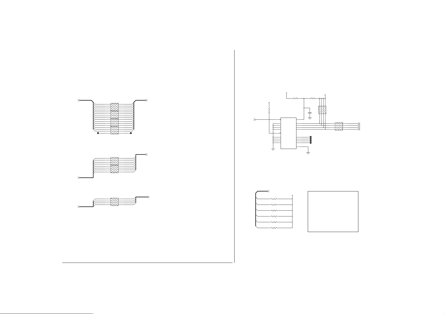
Service Manual
Sheet 6 of 31
IMA[ 0 ..1 4]
IMA[0..14](4) MA[0..14] (5)
IDQM[0..7](4)
ICSA#[0.. 3](4)
RN17
8P4R_10
RN32
8P4R_10
RN31
8P4R_10
RN30
8P4R_10
RN29
8P4R_10
RN42
8P4R_10
IDQM[0..7]
ICSA#[0.. 3]
IMA14
IMA13
IMA11
IMA12
IMA7
IMA9
IMA8
IMA5
IMA3
IMA6
IMA4
IMA1
IMA2
IMA0
IDQM6
IDQM5
IDQM7
IDQM4
IDQM2
IDQM3
IDQM0
IDQM1
ICSA#3
ICSA#2
ICSA#1
ICSA#0
5 4
6 3
7 2
8 1
5 4
6 3
7 2
8 1
5 4
6 3
7 2
8 1
8 1
7 2
6 3
5 4
5 4
6 3
7 2
8 1
5 4
6 3
7 2
8 1
RN41
8 1
7 2
6 3
5 4
8P4R_10
MA14
MA13
MA11
MA12
MA7
MA10IMA10
MA9
MA8
MA5
MA3
MA6
MA4
MA1
MA2
MA0
DQM6
DQM5
DQM7
DQM4
DQM2
DQM3
DQM0
DQM1
CSA#3
CSA#2
CSA#1
CSA#0
TT
MA[0..14]
DQM[0..7]
CSA#[0..3]
DQM[0..7] (5)
CSA#[0..3] (5)
DRAM BUS DAMPIN G R ESISTOR NEAR SIS630S
VDD3
VDD3
R401
8.2K
630SCKE
630SCKE(4)
MD[0..63]
MD[0..63] (3,4,5,9)
R225 4.7K(R)
MD55
R226 4.7K(R)
MD54
R224 4.7K(R)
MD53
R383 4.7K(R)
MD38
R384 4.7K(R)
MD39
R400 4.7K
MD31
R219
0
Z657
U27
1
OE1#
2
1A1
4
1A2
6
1A3
8
1A4
19
OE2#
11
2A1
13
2A2
15
2A3
17
2A4
74LVC244
VCC3
20
VCC
18
Z406
1Y1
16
Z404
1Y2
14
Z405
1Y3
12
Z407
1Y4
9
Z614
2Y1
Z764
7
2Y2
5
Z615
2Y3
Z765
3
2Y4
10
GND
VCC3
R221
0(R)
817263
54
RN59
C448
.1U
T
T
T
T
MD[55..53]: CLOCK SKEW CONTROL OF AGP
MD38: VGA INTERRUPT FUNCTION
MD39: VGA ECLK AND MCLK MODE
MD31: QUICK START FUNCTION
8P4R_270
RN58
8P4R_22
DEFAULT 001
1: ENABLE
0: DISABLE
1: SYNCHRONOUS MODE
0: ASYNCHRONOUS MODE
1: ENABLE
0: DISABLE
81
CKE0
CKE1
CKE2
CKE3
CKE0 (5)
CKE1 (5)
CKE2 (5)
CKE3 (5)
72
63
54
B - 6
Title
Size Document Number Rev
Custom
Date: Sheet
ÂÅ ¤Ñ ¹q ¸£ CLEVO CO.
RESI STOR
0200-06.SC H
Tuesday , September 11, 20 01
71-22T00-D03
of
631
A
Page 70

Sheet 7 of 31
Schematic Diagrams
TP76 TP92 TP59 TP6 4
R[2..7]B[2..7]
TP77
R7
Z356
Z559
AAD17/B2
AAD20/B1
AAD19/B0
TP87
DACAVDDB
R6
AAD27/R7
AAD0
AAD1
AAD2
AD6
AG1
AF3
AF2
Z561
Z563
Z562
Z564
TP111 TP1 04
TP108 TP94
TP110 TP113 TP89
C243
0.01U
B4
B6
B7
B3
B2
B5
AB2Y6AA4
AA3Y4Y5Y2Y3V2V3V4V5W3W4Y1U3T1T4T5U1W5V1U4U5
AAD16/B5
AAD18/B3
B6/AIRDY#
B4/ACBE2#
B7/AFR AME#
BRG
RED
RED(9)
GREEN
GREEN(9)
BLUE
BLUE(9)
HSYNC
HSYNC(9)
VSYNC(9)
DDC1DATA(8,9)
DDC1CLK(8,9)
VOSCI(3)
R248 33
R247 33
VSYNC
R35 33
DDC1DATA
R36 33
DDC1CLK
TP30
VOSCI
ECLKAVDD
DCLKAVDD
DACAVDDC
DACAVDDB
C238
0.01U
C239
1U
VCOMP
DACAVDDC DCLKAVDD
VRSET
VVREF
VCOMP
B14
ROUT
A14
GOUT
A15
BOUT
D15
Z383
HSYNC
A16
Z384
VSYNC
C15
Z385
DDC1DATA
B16
Z386
DDC1CLK
C16
Z387
SSYNC
A11
VOSCI
E19
RSET
C14
VREF
B15
COMP
F15
ECLKAVDD
E15
ECLKAVSS
F16
DCLKAVDD
E16
DCLKAVSS
F18
DACAVDDC
F20
DACAVSSC
E14
DACAVDDB
D14
DACAVSSB
VCC3 VCC3 VCC3 VCC3
L38 0
C237
1U
C37
10U
TP63
R4
R3
R5
R2
Z558
Z357
SBA3/G7
AAD26/R6
AAD25/R5
AAD24/R4
AAD23/R3
AAD22/R2
AAD21/R1
R0/ACBE3#
AAD3
AAD4
AAD5
AAD6
AAD7
AAD8
AAD9
AAD10
AF1
AE4
AE3
AE2
AE1
AD5
AD4
Z569
Z571
Z567
Z566
Z568
Z570
Z565
TP91TP107 TP114
TP105 TP2
C242
1U
G[2..7]
AAD11
AD1
Z572
TP84
AAD12
AAD13
AC4
AC3
Z573
Z574
TP95
G7G3G2
G5
G4
G6
SBA4/G6
SBA5/G5
SBA6/G4
AAD14
AAD15
AC2
AC5
Z575
Z576
TP103
C34
10U
TP58
Z553
Z355
Z557
U2
AAD31/G3
AAD28/G2
AAD30/G1
AAD29/G0
SBA7
SBA0/VBBLANK#
ECLKAVDD
C291
0.01U
U6B
SBA2/DDC2C LK
SBA1/DDC2D AT
ACBE1#
ACBE0#
VBCAD/AREQ#
VGCLK/AGNT#
ATRDY#
ADEVSEL#
ASERR#
APAR
ASTOP#
VBHCLK/RBF#
VBCTL0/WBF#
VBCTL1/PIPE#
VBCLK/ST2
VBVSYNC/ ST1
VBHSYNC/ST0
SB_STB
SB_STB#
AD_STB0
AD_STB0#
AD_STB1
AD_STB1#
AGPCLK
AGPVREF
AGPRCOMP
AGPAVDD1
AGPAVSS1
AGPAVDD2
AGPAVSS2
AGPVSSREF
SiS630ST
L40 0L41 0
C241
1U
R1
R2
R3
AC1
AG2
R6
T6
AB3
AB4
AB6
AA5
AB5
P2
P1
U6
R4
R5
V6
T2
T3
AD2
AD3
W1
W2
AJ3
AA1
AB1
AE10
AD10
AE9
AD8
AA2
Z367
Z382
Z368
Z369
Z370
Z371
Z372
Z373
ENVDD#
ENABKKL
VBBLANK#
Z379
Z380
Z381
VGCLK
Z374
Z377
Z378
Z388
Z389
Z366
VBCLK
VBVSYNC
VBHSY NC
AGPCLK0
Z742
R306 8.2K
R88 60
C110
.1U
C35
10U
ENVDD# (9)
ENABKKL (13)
VBBLANK#
TP90
TP112
TP57
VGCLK (8)
R[2..7]
TP115
ADEVSEL# (8)
ASERR# (8)
TP74
TP88
TP62
G[2..7]
TP65
TP56
VBCLK
VBVSYNC (8)
VBHSYNC (8)
B[2..7]
TP61
TP60
TP106
TP93
TP75
TP73
AGPCLK0 (3)
L20 0(0805)
VCC3
VCC3
PLACE THESE CIRCUITS CLOSE TO SiS 630
VRSET
C272
0.01U
R[2..7]
R2
R3
R4
R5
R6
R7
G[2..7]
G2
G3
G4
G5
G6
G7
B[2..7]
B2
B3
B4
B5
B6
B7
VVREF
R276
140(1%)
L39 0
C240
1U
R50 0(R)
RN6
RN54
RN55
RN8
VBHSYNC(8)
VBVSYNC(8)
VBBLANK#
VGCLK(8)
VBCLK
R310 0
R108 0
C273
.1U
C36
10U
8P4R_0
8P4R_0
8P4R_0
8P4R_0
VBHSY NC
VBVSYNC
VBBLANK#
VGCLK
VBCLK
Z392
R56
0
2
8
14
Z395
21
44
81
P0
P1
45
72
P2
47
63
P3
48
54
P4
81
1
P5
72
3
63
P6
54
P7
4
6
P8
81
7
P9
72
9
P10
63
10
P11
54
12
P12
13
81
P13
15
72
P14
16
63
P15
18
54
19
P16
20
P17
22
23
25
26
27 46
R260
4.7K
P3(8)
P2(8)
P1(8)
P0
P4(8)
P5(8)
P7(8)
P8(8)
P9(8)
P10(8)
P11(8)
P13(8)
P14(8)
P15(8)
P16(8)
P17(8)
C59
C58
C50
1000P
1000P
1000P
VCC
VCC
VCC
VCC
TXIN0
TXIN1
TXIN2
TXIN3
TXIN4
TXIN5
TXIN6
TXIN7
TXIN8
TXIN9
TXIN1 0
TXIN1 1
TXIN1 2
TXIN1 3
TXIN1 4
TXIN1 5
TXIN1 6
TXIN1 7
TXIN1 8
TXIN1 9
TXIN2 0
TXCLKIN
PWRDWN# GND
TXOUT0+
TXOUT0-
TXOUT1+
TXOUT1-
TXOUT2+
TXOUT2-
TXCLKO+
TXCLKO-
PLLVCC
PLLGND
PLLGND
LVDSVCC
LVDSGND
LVDSGND
LVDSGND
CS5820
P3
P2
P1
P0
P4
P5
P6
P7
P8
P9
P10
P11
P12
P13
P14
P15
P16
P17
C321CC299
C
4 5
8P4C_C
L15 0(0805)
C60
C298
4.7U
1000P
U21
40
R0+
41
R0-
38
R1+
39
R1-
34
R2+
35
R2-
32
RCLKIN+
33
RCLKIN-
29
Z394
C264
28
.1U
30
37
Z393
C262
31
.1U
36
42
43
N/C
GND
GND
GND
GND
3 6
CP10
T
5
11
17
24
1 8
2 7
3 6
4 5
1 8
2 7
CP9
8P4C_C
3 6
4 5
8P4C_C
CP8
R0+ (9)
R0- (9)
R1+ (9)
R1- (9)
R2+ (9)
R2- (9)
RCLKIN+ (9)
RCLKIN- (9)
C263
1000P
C261
1000P
1 8
2 7
CP7
8P4C_C
L10 0(0805)
C247
4.7U
L11 0(0805)
C32
4.7U
1 8
2 7
3 6
4 5
VCC3
VCC3
Titl e
Size Document Number Rev
Custom
Date: Sheet
ÂÅ ¤Ñ ¹q ¸£ CLEVO CO.
630(VGA) & LVDS
0200-07.SCH
Tuesday , Sept em be r 11, 2001
71-22T00-D03
of
731
A
B - 7
Page 71

Service Manual
Sheet 8 of 31
VCC
L61
BEAD(0805)
C495
4.7U
P[1..5](7)
P5
P4 Z767
P3
P2 Z768
P1
P11
P10
P9
P[7..11](7)
P8
P7
P17
P16
P15
P14
P13
P[13..17](7)
TP183
Place close to SIS630S
R509 0
VGCLK
VGCLK(7)
Up to 47MHz
VBHSYNC
VBVSYNC
DDC1DATA
DDC1CLK
R511 0
R512 0
R518 0
R519 0
R587 R
R588 R
VCC3
R516
4.7K
VBHSY NC(7)
VBVSYN C(7)
DDC1DATA(7,9)
DDC1CLK(7,9)
ASERR#(7)
ADEVSEL#(7)
Z787
Z788
Z789
TP186
VCC3
R515
10K
R517
4.7K
Z791
Z792
U32
15
D15
14
D14
13
D13
12
D12
11
D11
10
D10
9
D9
7
D8
6
D7
4
D6
3
D5
2
D4
1
D3
44
D2
43
D1
42
D0
39
XCL K
40
H
41
V
35
DS/BCO
29
Z790
RESETB
26
SD
27
SC
32 33
XI XO/FIN
CH7005/6
Y7
Z793 Z794
14.31818MHz+-20PPM
C511
10P
The two external
loadcapacitors value
iseaqual to 2 x
crystalinternal cap -
12.5pF
AVDD
DVDD
DVDD
DVDD
DVDD
CSYNC
CVBS
RSET
POUT
AGND
DGND
DGND
DGND
DGND
VDD
GND
GND
25
Z766
31
5
16
30
38
17
21
C
22
Y
20
24
Z798
37
34
8
18
28
36
19
23
C499
C498
.1U
.1U
TP184
TP196
Place close
R510
to7005/6
360 1%
TP185
Connect to pin 19 ground
with short/wide
trace.
Analog and
digitalground should
connect to a common
ground plane
C512
10P
L62
BEAD(0805)
C496
4.7U
C501
C500
.1U
.1U
Place close to
7005
Z795
Z796
VCC3
C
VCC3
L63
BEAD(0805)
C497
10U
C503
C502
.1U
.1U
D35
DA204U
A
D36
AC
DA204U
C
A
AC
R508
75 1%
Place close to
7005/6
R513
75 1%
Place close to
7005/6
C504
C
Z805
L64
1 2
1.2uH(0805)
C514
150p
C505
C
Z804
L66
1 2
1.2uH(0805)
C506
150p
L65 0
1 2
C513
270p
L67 0
1 2
C507
270p
Z801
Z799
CN27
4
CRMA
2
GND
1
GND
3
LUMA
SVIDEO_C ON
5
SLD
6
SLD
7
SLD
8
SLD
ALL COMPONENTS MUST CLOSE TO SVIDEO_CON
B - 8
Page 72

Sheet 9 of 31
Panel ID
13.3"
14.1"
VSYNC(7)
HSYNC(7)
GREEN(7)
R0+(7)
R0-(7)
R1+(7)
R1-(7)
R2+(7)
R2-(7)
RCLKIN+(7)
RCLKIN-(7)
LG
ADT
UNIPAC
HYUNDAI
LG
ADT L141 X1
CP T CL AA14 1XB 01
CPT
UNIPAC UP141X01
HYUNDAI
BLUE(7)
RED(7)
VCC
VSYNC
HSYNC
BLUE
GREEN
RED
R0R1+
R1R2+
R2RCLKIN+
RCLKIN-
C
R272 18
R269 18
R270 18
R267 18
R268 18
R265 18
R266 18
LP133X7-C2CC
L133X2-1
UP133X01
HT13X14
LP141X5
CL AA14 1XC 01
HT14X13
R26 47
R253 47
D2
AC
DA204U
A
R271 18
R0+
Close to LCD connector.
C249
10P
10P
10P
SW7-1
SW7-2 SW7-3 SW7-4
VMD39 VMD3 6 VMD 33 VMD 32
1
1
1
1
1
1
1
1
1
1
1
1
1
1
11
1100
1110
10P
10P
00
1
0
0
00
C253
C250
C251
C269
ON=H=1 OFF=L=0
VCC
Q1
G
2N7002
S D
2N7002
Q9
C33
R254
33P
75
Z477 Z473
VCC
G
S D
Z474 Z475
D1
D16
AC
AC
C
DA204U
A
DA204U
C
A
C252
10P
00
00
0
0
0
00
R237
75
C254
C255
10P
10P
MD39 1 : LVDS
MD36 1 : 1024*768
MD32,MD 33 : PANEL ID
R236
C25
75
33P
0 : CM OS
0 : 800*600
C26
33P
RIN0+
RIN0RIN1+
RIN1RIN2+
RIN2RCLK+
RCLK-
DDC1DATA(7,8)
DDC1CLK(7,8)
DDC1CLK
DDC1DATA
VCC
L27 BEAD
L43 BEAD
L28 BEAD
L30 BEAD
L31 BEAD
R0+
R0- RIN0 -
R1+
ENVDD#(7)
R4
2.2K
C10
33P
RN63
8P4R_10K
L26 BEAD
L29 BEAD
C12
33P
MD39
MD39(4,5,6)
MD36
MD36(4,5)
MD33
MD33(4,5)
MD32
MD32(4,5)
R235
2.2K
C9
33P
LAYOUT NOTE:
Make sure VIDEOGND is as c lean as poss ible
Also, the RED , GREEN , and BLU E signal t races
should be shielded with VIDEOGND traces.
L53 L
4 3
..
1 2
L52 L
4 3
..
1 2
ENVDD#
54
63
72
81
C11
220P
C13
220P
Schematic Diagrams
L51 L
RCLKIN+
RCLKIN-
12V
G S
SW7
1
2
3
4
Z469
C15
220P
R2+
R2-
R256
47K
D
2N7002
SW DIP-4
Z471
Z470
Z467
Z472
Z465
Z466
4 3
1 2
4 3
1 2
Z390
Q10
8
7
6
5
..
L50 L
..
VCC3
VCC3
CN5
8
15
7
14
6
13
5
12
4
11
3
10
2
9
1
CRT CONN. 15P
PIN18~29=GND
RIN2+
RIN2-
RCLK+
RCLK-
16
17
Q8
C256
.1U
1
2
3
D
D
G
SI3456DV
VCC
L2
BEAD(0805)
6
D
5
D
4
S
RCLKRCLK+
C231
.1U
LCDVCC
LCDVC C
C230
4.7U
CN15
12
34
56
78
910
11 12
13 14
15 16
17 18
19 20
LCD CONN . 20P
Z464
C16
.1U
Title
Size Document Num ber R ev
Custom
Date: Sheet
ÂÅ ¤Ñ ¹ q ¸£ CLEVO CO.
LCD & CRT CON
0200-08.SCH
Tuesday, Sept em ber 11, 2001
71-22T00-D03
RIN0RIN0+
RIN1RIN1+
RIN2RIN2+
931
of
A
RIN0+
RIN1+
RIN1-R1-
VCC
R255
2.2K
Z447
Z446
Z444
Z445
C14
220P
B - 9
Page 73

Service Manual
Sheet 10 of 31
VCC3
R528
4.7K
D38
F01J2E
D39
F01J2E
RTCVDD
AC
AC
SYSPWGD
BATOK(26)
C518
C553
.1U
100P
EXTSM I
EXTSMI(23)
VCC3
VCC3
WAKE#(23)
TI_PME#(16,17)
SPKR(24)
PWR_ON#(23,24,31)
SUSPEND #(16,25)
EXTSMI#
PWRSW#(31)
SCI(23)
ATF_INT#(2)
VCC3
LO/HI#(2)
VCC3
ACIN#(23,24,26)
TXD3(14)
TXD0(14)
TXD1(14)
TXD2(14)
RXER(14)
TXCLK(14)
COL(14)
CRS(14)
SPDIF(19)
MDC(14)
RXCLK(14)
SDATI1(15,18 )
SDATI0(15,18 )
SDATO(15, 18)
SYNC(15,18)
AC_RESET#(15,18)
BIT_CLK(15,18)
AUXOK(26)
C519
100P
EXTSMI #
R343
10K
R327 300(R)
R333 300(R)
C294
.1U
EXTSMI#
SPKR
PWR_ON#
SUSPEND#
EXTSMI#
PWRSW#
SCI
Z856
ATF_INT#
LO/HI#
ACIN#
TXD3
TXD0
TXD1
TXD2
RXER
TXCLK
COL
CRS
SPDIF
MDC
RXCLK
SDATI1
SDATI0
SDATO
SYNC
AC_RESET#
BIT_CLK
AUXOK
SYSPWGD
C259
.1U
G S
Z718
Z719
R250 0
R32 0
R33 0
R249 10K
R589 10K
R34 0
R46 10M
Y1
1 2
32.768KHz_DI P
C43
10P
R336 10K
D
Q17
2N7002
D21
LED(R)
D22
LED(R)
C274
C
BATOK
C260
10P
Q13
2N3906(R)
Z720
Q14
2N3906(R)
Z721
Z560
Z483
Z484
VR_HI/LO#
GV_GATE
Z592
Z402
Z398
B
B
E18
E11
C7
B12
E10
B6
A6
D13
B7
A7
D8
C8
B8
C12
D12
E17
F12
C10
F14
C6
E12
D9
D10
B10
A10
A13
B13
D11
C13
A5
C4
C5
A4
B4
B5
SiS630ST
STPCLK#
CE
CPUST P #
CE
SPK
PSON#
ACPILED
EXTSMI#
PWRBTN#
RING
PME#
THER M#
KBDAT/VR-H I_LO#
KBCLK/LO_H I#
PMDAT/GV_GATE
PMCLK/GP13
KLOCK#/GP14/TXD
GP0/PREQ#3/TXD[
GP1/PGNT#3/TXD[
GP2/LDRQ1#/TXD[
GP3/RXER
GPIO4/VR-HI_LO#
GPIO5/LO_HI #
GPIO6/GV_GATE
GP7/SPDIF
GP8/MDC
GP9/RXCLK
AC_SDIN [1]
AC_SDIN [0]
AC_SDOUT
AC_SYNC
AC_RESET#
AC_BIT_CLK
AUXOK
PWROK
BATOK
RTCVDD
OSC32KHI
OSC32KHO
VDD3
STPCLK# (1,2)
CPUSTP# (3)
ACPI
KBC
GPIO
AC '97
RTC
RTCVSS
A3
LPC
HOST
SMBUS
USB
MII
F13
LFRAME#
CPUSTOP#/CPUSLP
TXEN/GP15/SMBAL#
RXDV/OC0#
MDIO/OC1 #
USBCLK48M
USBVDD0
USBVDD1
LANCLK25M
RESERVE2
RESERVE1
VSSA
VSSB
VSSC
VSSD
F17
N24
U24
SUSPEND#(16,25)
U6C
LDRQ#
A20M#
IGNNE#
FERR#
STPCLK#
SMBDAT
SMCLK
RXD[0]
RXD[1]
RXD[2]
RXD[3]
ENTEST
LAD0
LAD1
LAD2
LAD3
SIRQ
SMI#
INTR
INIT#
UV0UV0+
UV1UV1+
UV2UV2+
UV3UV3+
UV4UV4+
UV5UV5+
LPC PULL-HI GH
PLACE NEAR TO W 83626F
RN62
1
LAD0
2
LAD1
3
LAD2
4
LAD3
RN61
1
LDRQ#
2
SERIRQ
3
LFRAME#
Z935
TP228
Titl e
Size Docum ent N um ber R ev
Custom
Tuesday, Sept em ber 11, 2001
Date: Sheet
4
R47 10K
ATF_INT#
R251 10K
SUSPEND#
R252 10K
WAKE#
R455 10K
PWR_ON#
NEAR TO SiS 630
RN53
1
USBP2-
2
USBP2+
USBP1-
3
4
USBP1+
RN4
1
USBP4-
2
USBP4+
3
USBP5-
4
USBP5+
TXD0
TXD1
TXD2
SPDIF
TXCLK
COL
CRS
MDC
RXCLK
TXEN
RXER
ÂÅ ¤Ñ ¹q ¸£ CLEVO C O.
630S(SOUTHBRIDGE)
0200-09.SCH
VCC3
8
7
6
5
8P4R_4.7K
8
7
6
5
8P4R_4.7K
VDD3
8
7
6
5
8P4R_15K
8
7
6
5
8P4R_15K
R28 4.7K
R259 4. 7K
R258 4. 7K
R27 4.7K
R277 4. 7K
R13 4.7K
R231 4. 7K
R229 4. 7K
R278 4. 7K
R230 4. 7K
R12 4.7K
71-22T00-D03
VCC3
VDD3
of
10 31
A
R287 10
C297
10P
D17
F01J2 E
D
Q29
2N7002
LAD[0.. 3] (20)
LDRQ# (20)
LFRAME# (20)
SERIRQ (16,20,21)
NMI (1,2)
SMI# (1,2)
INTR (1,2)
A20M# (1,2)
INIT# (1,2)
IGNNE# (1,2)
FERR# (2)
STPCLK# (1,2)
TXEN (14)
SMBDATA (25)
SMBCLK (25)
RXDV (14)
MDIO (14)
USBP0- (15)
USBP0+ (15)
USBP3- (15)
USBP3+ (15)
USBCLK (3)
D40
AC
F01J2E
RXD0 (14)
RXD1 (14)
RXD2 (14)
RXD3 (14)
Z716
AC
R286 1.5K
SUSPEND
R426 10K
SLP#
CPUSTP#
3
SYSPWGD
SLP# (1,2)
CPUSTP# (3)
C275
.1U
Y2
OSC
25M OSC
SYSPWGDPWROK(2,26)
SUSPEND (24)
VCC
GNDNC
VCC3
VCC1.8
C276
.1U
VDD3
C277
10U
VDD3
4
21
C278
.1U
AG4
LAD0
LAD1
AF4
AJ4
LAD2
LAD3
AE5
AF5
LDRQ#
LFRAME#
AH4
Z758
R481 0
AG5
C18
NMI
D16
D18
B17
A17
B18
A18
C17
D17
A8
AG3
AH3
F10
D6
H5
J5
G5
H6
E5
F5
E6
F6
F8
E7
E8
D7
A12
B2
B3
C9
B9
E13
A9
D5
AE7
AH2
N2
PWR_ON(23, 30,31)
SUSPEND#
Z555
Z400
Z401
Z486
R296
4.7K
PWROK
D48
F01J2E
SERIRQ
NMI
SMI#
INTR
A20M#
INIT#
IGNNE#
FERR#
STPCLK#
R257 0
R48 R
TXEN
SMBDATA
SMBCLK
RXDV
MDIO
USBP0 USBP0 +
USBP1 USBP1 +
USBP2USBP2+
USBP3USBP3+
USBP4USBP4+
USBP5USBP5+
USBCLK
Z882
RXD0
RXD1
RXD2
RXD3
MIICLK
TP85
TP109
AC
G S
B - 10
Page 74

Sheet 11 of 31
C/BE#[0..3](16,25)
PCLK630S(3)
PCIRST#(13,16,18,20, 25)
VCC1.8
C344
0.01U
REQ2#
REQ1#
REQ0#(16)
GNT2#
GNT1#
GNT0#(16)
INTA#(16)
INTB#(16)
INTC#
INTD#
FRAME#(16,25)
IRDY#(16, 25)
TRDY#(16,25)
STOP#(16)
SERR#(16)
DEVSEL#(16)
PCLK630S
PCIRST#
PAR(16)
C348
0.01U
REQ2#
REQ1#
REQ0#
GNT2#
GNT1#
GNT0#
C/BE#3
C/BE#2
C/BE#1
C/BE#0
INTA#
INTB#
INTC#
INTD#
FRAME#
IRDY#
TRDY#
STOP#
SERR#
PAR
DEVSEL#
PLOCK#
R31 33
C315
0.01U
Z505
C317
.1U
AJ15
Schematic Diagrams
VCC1.8
C112
1000P
IDB0
IDB1
IDB2
IDB3
IDB4
IDB5
IDB6
IDB7
IDB8
IDB9
IDB10
IDB11
IDB12
IDB13
IDB14
IDB15
IDSAB0
IDSAB1
IDSAB2
CBLIDB
ICHRDYB
IIRQB
IDREQB
IDACKB#
IIORB#
IIOWB#
IDECSB0#
IDECSB1#
SIORDY
SDREQ
IIRQB
R109 0
C111
.1U
RN23
8P4R_10
RN36
8P4R_10
RN34
8P4R_10
RN35
8P4R_10
R465 10
R175 82
R470 82
R461 33
R466 10
R467 22
R464 33
R460 33
RN24
8P4R_33
R459 4.7K
R458 5.6K
R174 10K
IDB0
IDB2
IDB1
IDB3
IDB5
IDB6
IDB7
IDB4
IDB8
IDB9
IDB11
IDB10
IDB12
IDB15
IDB14
IDB13
IDSAB0
IDSAB2
CBLIDB
IDSAB1
5
6
7
8
8
7
6
5
5
6
7
8
8
7
6
5
8
7
6
5
3
2
1
1
2
3
4
4
3
2
1
1
2
3
4
SIORDY
SIRQ
SDREQ
SDDACK#
SDIOR#
SDIOW#
SDCS0#
SDCS1#
1
2
3
4
SDD2
SDD1
SDD3
SDD5
SDD6
SDD7
SDD4
SDD8
SDD9
SDD11
SDD10
SDD12
SDD15
SDD14
SDD13
SDA0
SDA2
S66CBLID
SDA1
SIORDY (13)
SIRQ (13)
SDREQ (13)
SDDACK# (13)
SDIOR# (13)
SDIOW# (13)
SDCS0# (13)
SDCS1# (13)
SDD[0..15] (13)
SDA0 (13)
SDA2 (13)
S66CBLID (13)
SDA1 (13)
SDD0
4
Z506
U6D
C327
10U
AD31
D1
AD30
E4
AD29
J4
AD28
E3
AD27
K6
AD26
E2
AD25
E1
AD24
F4
AD23
F2
AD22
K5
AD21
F1
AD20
G4
AD19
G3
AD18
G2
AD17
G1
AD16
L5
AD15
K4
AD14
K3
AD13
M5
AD12
K2
AD11
K1
AD10
L3
AD9
N6
AD8
L2
AD7
M4
AD6
N5
AD5
M3
AD4
M2
AD3
M1
AD2
N4
AD1
P6
AD0
N3
C1
PREQ#[2]
C2
PREQ#[1]
C3
PREQ#[0]
D2
PGNT#[2]
D3
PGNT#[1]
D4
PGNT#[0]
F3
C/BE#[3]
H4
C/BE#[2]
J1
C/BE#[1]
L1
C/BE#[0]
N1
INTA#
P4
INTB#
P5
INTC#
P3
INTD#
H3
FRAME#
H2
IRDY#
H1
TRDY#
J2
STOP#
B11
SERR#
M6
PAR
J3
DEVSEL#
L4
PLOCK#
PCICLK
C11
PCIRST#
C314
.1U
C333
.1U
PCI
AD31
AD30
AD29
AD28
AD27
AD26
AD25
AD24
AD23
AD22
AD21
AD20
AD19
AD18
AD17
AD16
AD15
AD14
AD13
AD12
AD11
AD10
AD9
AD8
AD7
AD6
AD5
AD4
AD3
AD2
AD1
AD0
SiS630ST
C328
10U
AD[0..31] (16,25)
PDD[0..15](13)
PDDACK#(13)
PDA1(13)
PDA2(13)
P66CBLID(13)
PDA0(13)
C329
10U
PIORDY(13)
PDIOR#(13)
PDIOW#(13)
PDCS0#(13)
PDCS1#(13)
PDREQ(13)
PIRQ(13)
PDA1
PDA2
P66CBLID
PDA0
PDD0
PDD1
PDD2
PDD3
PDD4
PDD5
PDD6
PDD7
PDD8
PDD9
PDD10
PDD11
PDD12
PDD13
PDD14
PDD15
PIORDY
PIRQ
PDREQ
PDDACK#
PDIOR#
PDIOW#
PDCS0#
PDCS1#
PIORDY
PDREQ
IIRQA
8
7
6
5
8
7
6
5
4
3
2
1
4
3
2
1
R154 10
R131 82
R146 82
R162 33
R156 10
R153 22
R166 33
R164 33
1
2
3
4
RN22 8P4R_33
R157 4.7K
R155 5.6K
R132 10K
8
7
6
5
U6E
1
RN16
2
8P4R_10
3
4
1
RN15
2
8P4R_10
3
4
5
RN14
6
8P4R_10
7
8
5
RN21
6
7
8P4R_10
8
IDSAA1
IDSAA2
CBLIDA
IDSAA0
VCC3 VCC3
IDA0
IDA1
IDA2
IDA3
IDA4
IDA5
IDA6
IDA7
IDA8
IDA9
IDA10
IDA11
IDA12
IDA13
IDA14
IDA15
ICHRDYA
IIRQA
IDREQA
IDACKA#
IIORA#
IIOWA#
IDECSA0#
IDECSA1#
IDSAA0
IDSAA1
IDSAA2
CBLIDA
AE12
AD12
AE11
AD13
AE13
AF10
AE14
AD14
AE8
IDA0
IDA1
AG7
IDA2
AJ6
IDA3
IDA4
AF6
IDA5
IDA6
AH5
IDA7
AJ5
IDA8
AE6
IDA9
AG6
IDA10
AH6
IDA11
AF7
IDA12
AH7
IDA13
AJ7
IDA14
IDA15
ICHRDYA
AF9
IIRQA
AG8
IDREQ[A]
AJ8
IDACK#[A]
AH8
IIOR#[A]
AF8
IIOW#[A]
AJ9
IDEC SA#[0]
IDEC SA#[1]
AG9
IDSAA[0]
IDSAA[1]
IDSAA[2]
AH9
CBLIDA
SiS630ST
AH15
IDE
IDEAVDD
IDB10
IDB11
IDB12
IDB13
IDB14
IDB15
ICHRDYB
IIRQB
IDREQ[B]
IDACK#[B]
IIOR#[B]
IIOW#[B]
IDECSB#[0]
IDECSB#[1]
IDSAB[0]
IDSAB[1]
IDSAB[2]
CBLIDB
IDB0
IDB1
IDB2
IDB3
IDB4
IDB5
IDB6
IDB7
IDB8
IDB9
AE17
AG12
AF12
AH11
AE16
AJ10
AD15
AE15
AG10
AH10
AF11
AG11
AJ11
AD16
AH12
AJ12
AH13
AF15
AD17
AJ13
AG13
AF13
AH14
AJ14
AD18
AF14
AG14
AG15
C332
0.01U
NEAR TO 630S
C362
C345
0.01U
0.01U
C352
10U
C361
10U
C358
10U
C293
10U
VCC3
VCC3
R289 330
PLOCK#
R68 10K
PERR#
C/BE#0
C/BE#1
C/BE#2
C/BE#3
INTB#
INTA#
INTC#
INTD#
PAR
R290 10K
RN68 8P4R_10K
1
8
2
7
3
6
4
5
RN7 8P4R_10K
1
8
2
7
3
6
4
5
R201 10K
PERR#(16)
FRAME#
RN2 8P4R_10K
REQ2#
1
REQ1#
2
REQ0#
3
4
RN52 8P4R_10K
1
GNT0#
IRDY#
2
GNT2#
3
GNT1#
4
RN3 8P4R_10K
STOP#
1
DEVSEL#
2
SERR#
3
TRDY#
4
Titl e
Size Docum ent N umber Rev
Custom
Date: Sheet
VCC3
8
7
6
5
8
7
6
5
8
7
6
5
ÂÅ ¤Ñ ¹ q ¸£ C LEVO CO.
630S(PCI/IDE)
0200-10.SCH
Tuesday, Septem ber 11, 2001
71-22T00-D03
of
11 31
A
B - 11
Page 75

Service Manual
Sheet 12 of 31
VCC1.8
GTLVTT
C347 .1U
C312 .1U
C313 .1U
C330
C521 330U
.1U
C310 1U
C309 1U
C288 .1U
C289 .1U
C346 .1U
C311 .1U
C316 .1U
C349 .1U
VCC3
VCC3
C339 .1U
C343 .1U
C340 .1U
C290 .1U
C319 . 1U
C350 . 1U
C364 . 1U
C342 .1U
C341 .1U
C326 .1U
C292 .1U
C318 . 1U
C331 . 1U
C351 . 1U
C363 . 1U
VDD3
VDD1.8
C246
10U
C2441UC245
0.01U
VCC1.8
VDD3
VDD1.8
VCC3
AA11
AA12
AA13
AA18
AA19
AA20
AA22
AB12
AB19
AB21
AB22
AB10
AB11
AB13
AB18
AB20
AA10
AA14
AA17
AA21
AB14
AB17
VCC3
GTLVTT
AA8
AA9
AB8
AB9N8P8P9U8V8V9W8W9Y8Y9
OVDD
OVDD
VDDQ
VDDQ
VDDQ
VDDQ
VDDQ
VDDQ
OVDD
OVDD
OVDD
OVDD
OVDD
OVDD
OVDD
OVDD
OVDD
H10
OVDD
H17
OVDD
J11
OVDD
J12
OVDD
J9
OVDD
K8
OVDD
K9
OVDD
M9
OVDD
U21
OVDD
U22
OVDD
V21
OVDD
V22
OVDD
W21
OVDD
W22
OVDD
Y21
OVDD
PVDD
PVDD
PVDD
PVDD
PVDD
H11
PVDD
H12
PVDD
H18
PVDD
J18
PVDD
L8
PVDD
M8
PVDD
N22
PVDD
T22
PVDD
Y22
PVDD
IVDD
IVDD
IVDD
IVDD
IVDD
IVDD
H13
IVDD
H16
IVDD
J10
IVDD
J13
IVDD
J16
IVDD
J17
IVDD
J19
IVDD
J20
IVDD
K21
IVDD
L21
IVDD
L9
IVDD
M21
IVDD
N21
IVDD
N9
IVDD
T21
IVDD
U9
IVDD
H9
AUX3.3V
J8
AUX1.8V
U6F
SiS630S_3
VDDQ
VDDQ
VDDQ
VDDQ
VDDQ
POWER
H19
H20
H21
H22
J21
J22
K22
L22
M22
VSS
VDDQ
VDDQ
VDDQ
GTLVTT
GTLVTT
GTLVTT
VSS
VSS
GTLVTT
GTLVTT
GTLVTT
GTLVTT
GTLVTT
GTLVTT
VSS
VSS
VSS
VSS
VSS
VSS
VSS
VSS
VSS
VSS
VSS
VSS
VSS
VSS
VSS
VSS
VSS
VSS
VSS
VSS
VSS
VSS
VSS
VSS
VSS
VSS
VSS
VSS
VSS
VSS
VSS
VSS
VSS
VSSD
VSSD
VSSD
VSSD
VSSD
VSSD
VSSD
VSSD
VSSD
VSSD
VSSD
VSSD
VSSD
VSSD
VSSD
VSSD
VSSD
VSSD
VSSD
VSSQ
VSSQ
VSSQ
VSSQ
VSSQ
VSSQ
VSSQ
VSSQ
VSSQ
VSSQ
VSSQ
VSSQ
VSSQ
VSSQ
L13
L14
L15
L16
L17
M12
M13
M14
M15
M16
M17
M18
N11
N12
N13
N14
N15
N16
N17
N18
N19
P14
P15
P18
P19
R14
R15
T14
T15
U14
U15
V14
V15
W13
W14
W15
P16
P17
R16
R17
R18
R19
T16
T17
T18
T19
U16
U17
U18
U19
V16
V17
V18
W16
W17
P11
P12
P13
R11
R12
R13
T11
T12
T13
U11
U12
U13
V12
V13
R285 R(1206)
R274 0(1206)
Default : 1-2
VCCTVCC1.8
B - 12
C296
10U
C2951UC320
0.01U
Page 76

Sheet 13 of 31
PCIRST#(11,16, 18,20,25)
PIRQ(11)
SW1
COVER CL OSE SW . 4P
R165
10K
PCIRST#(11,16,18,20, 25)
13
24
VCC
R129 0
R163 33
R130 0
R25
10K
C31
.1U
COVER_SW#
PDD[0..7]
PDDACK#(11)
R363 10K
VCC
R362 10K
HDDDASP#
CDDASP#
VCC VCC
R365
2.2K
ENABKKL
ENABKKL(7)
HDDRST#
PDD7
PDD6
PDD5
PDD4 PDD11
PDD3
PDD1
PDD0
PDREQ
PDREQ(11)
PDIOW#
PDIOW#(11)
PDIOR#
PDIOR#(11)
PIORDY
PIORDY(11)
PDDACK#
PDIRQ
PDA1
PDA1(11)
PDA0
PDA0(11)
PDCS0#
PDCS0#(11)
HDDD ASP#
HDD_VCC
CDRST#
G
S D
CN16
12
34
56
78
910
11 12
13 14
15 16
17 18
19 20
21 22
23 24
25 26
27 28
29 30
31 32
33 34
35 36
37 38
39 40
41 42
43 44
45 46
47 48
49 50
HDD conn. 50P
R364
47K
Q18
2N7002
COVER_SW#
Z539
Z307
Schematic Diagrams
VCC
U23A
147
VCC
147
74HCT08
3
6
U23B
74HCT08
PDD[8..15]
TP7
P66CBLID (11)
PDA2 (11)
PDCS1# (11)
HDD_VCC
PDD[0. .15]
SDD[0. .15]
IDELED#
PANEL
R152
470
PDD[0..15] (11)
SDD[0..15] (11)
HDD_VCC
CD_VCC
1
2
4
5
PDD8
PDD9
PDD10
PDD12
PDD13PDD2
PDD14
PDD15
T
PCSEL
P66CBLID
PDA2
PDCS1#
The components should be close to the connector.
C173
.1U
C174
.1U
C191
10U
The components should be close to the connector.
C470
.1U
C471
.1U
IMDATA(23)
IMCLK(23)
BATLED#(24)
PWRLED#(24)
CHRLED#(24)
IMDATA
IMCLK
BATLED#
PWRLED#
CHRLED#
C472
10U
VDD
C476
33P
C477
33P
+
C192
100U/10V
+
C222
10U
VCC
L22
BEAD(1206)
L60
BEAD(1206)
CN21
1
2
3
4
5
6
7
8
T/P X CHR LE D 8 P
VCC
VCC
BRIGADJ
PANEL
VCC
L48 BEAD(1206)
L45 BEAD
L46 BEAD
C248
.1U
CN12
Z316
L44
BEAD(0805)
1
2
3
4
5
6
7
8
9
10
INVERTER 10P
13 31
of
Z319
Z318
Z317
SCROLED#(23)
CAPLED#(23)
NUMLED#(23)
C265
.1U
Title
Size Document Number Rev
Custom
0200-12.SCH
Tuesday, Septem ber 11, 2001
Date: Sheet
FDDLED#(21)
C266
.1U
ÂÅ ¤Ñ ¹ q ¸£ C LEVO CO.
IDE
SCROLED#
CAPLED#
NUMLED#
FDDLED#
IDELED#
71-22T00-D03
A
CD_L(18) CD_R (18)
R472
10K
SDD[0..7]
SIRQ(11)
R463 33
R462
10K
CD_L
SDD7
SDD6
SDD5
SDD4
SDD3
SDD2
SDD1
SDD0
SDIOW#
SDIOW#(11)
SIORDY
SIORDY(11)
SDIRQ
SDA1
SDA1(11)
SDA0
SDA0(11)
SDCS0#
SDCS0#(11)
CDDASP#
SCSEL
TP20
Z306
R450
470
CN20
12
34
56
78
910
11 12
13 14
15 16
17 18
19 20
21 22
23 24
25 26
27 28
29 30
31 32
33 34
35 36
37 38
39 40
41
42
43
44
45
46
47
48
49
50
CD-ROM conn. 50P
PINGND1..2=GND
CD_R
SDD8
SDD9
SDD10
SDD11
SDD12
SDD13
SDD14
SDD15
SDREQ
SDIOR#
SDDACK#
Z304
S66CBLID
SDA2
SDCS1#
Z305
TP21
TP180
SDD[8..15]
SDREQ (11)
SDIOR# (11)
SDDACK# (11)
S66CBLID (11)
SDA2 (11)
SDCS1# (11)
BRIGADJ(23)
R471
10K
CD_VCCCD_VCC
PANEL
B - 13
Page 77

Service Manual
Sheet 14 of 31
CRS(10)
COL(10)
TXD3(10)
TXD2(10)
TXD1(10)
TXD0(10)
TXEN(10)
TXCLK(10)
RXER(10)
RXCLK(10)
RXDV(10)
RXD0(10)
RXD1(10)
RXD2(10)
RXD3(10)
MDC(10)
MDI O(10)
1.HW/SW=1
SW MODE
2.MII/SI=0
MII MODE
3.NOD/REP=0
NODE OPERATION
10/100SEL: 10/100MHZ INDECATED
LOW=10 BASE-T, HIGH=100BASE-T
DPXSEL: HAL F OR FULL INDECATED
LOW=HALF-DUPLEX,
HIGH=FULL-DUPLEX
ANSEL: AU TO-NEGOTI TATI ON INDECATED
LOW=DISABLE,
HIGH=ENABLE
Y3
25M
Z15TXD2
Z16TXD1
Z17TXD0
54
Z23
63
Z24
72
Z25
81
Z26
R96 1K
R95 1K
R62 1K
REF_IN
REF_OUT
Z12
Z13
Z18
Z19
TXER
Z20
Z21
Z22
Z27
Z28
VDD3
VDD3
VDD3
48
TXD3
47
TXD2
46
TXD1
45
TXD0
44
TXEN
43
TXCLK
42
TXER
41
RXTRI
40
VSS_IO
39
RXER
38
RXCLK
37
VDD_IO
36
RXDV
35
RXD0
34
RXD1
33
RXD2
P1CL
P2LI
P0AC
495051525354555657585960616263
COL
LRX+
LTX+
CRS
VDD_I O
MDIO
MDC
RXD3
32
LRX-
LTX-
REF_IN
VDD_I O
REF_OUT
LOCK
VSS_D
VSS_IO
TP233
VDD3
LRX+
NEAR TO 1893
LRXLTX+
LTX-
TP_C P
P1CL
P0AC
VSS_D
VSS_R
VSS_IO
VSS_R
HW/SW
DPXSEL
VDD_D
ANSEL
TP232
HW/SW
Z663
C54
.1U
P3TD
P4RD
PVCC3
U7
64
P2LI
P3TD
P4RD
VSS_T
VDD_T
NOD/REP
10/100SEL
TP_CP
VSS_T
TP_TX+
TP_TXVDD_T
VDD_R
10TCSR
100TCSR
VSS_R
VSS_R
TP_RX+
TP_RXVDD_R
VDD_R
VSS_R
RESETN
MII/SINCLSTA
171819202122232425262728293031
MII/SI
RESET-
R592
R
R52
61.9(1%)
R53
1
2
3
4
5
6
7
8
9
10
11
12
13
14
15
16
ICS1893
R94 10K
C104
.1U
C55
C
C53 C
PVCC3
LTX+
LTX-
10TCSR
100TCSR
LRX+
LRX-
VDD3
61.9(1%)
R60
61.9(1%)
Z664
R61
61.9(1%)
C66
.1U
C69 5P
C70 5P
CRS
R65 22
COL
R66 22
RN5
8 1
TXD3 Z14
7 2
6 3
5 4
TXEN NOD/REP
TXCLK TP_C P
RXER
RXCLK
RXDV
RXD0
RXD1
RXD2
RXD3
MDC
MDI O
8P4R_22
R74 22
R86 22
R84
1K
R85 22
R101 22
R100 22
RN9
8P4R_22
VDD3
R98
1.5K
R99 22
R97 22
HW/SW
MII /SI
NOD/REP
VDD3
PVCC3
PVCC3
TP229
10TCSR
R82 12.1K
VDD3
100TCSR
U20
1
RD+
RX+
2
RDC
RX-
3
Z263
4
Z264
TP43
7
6
8
5
Z517
TP44
C52
C
RXC
NC
TX+
TXC
TX-
NC
H0009
RD-
NC
TD+
TDC
TDNC
R118 2K(1%)
C122 C
R83 1.54K(1%)
C94 C
RD+
16
14
Z78
RD-
15
13
Z518
TD+
10
11
Z79
9
TD-
12
Z579
C103
.1U
C68
.1U
TP22
TP23
R875R9
C21
1000P(1210)2KV
.1U
C106
.1U
C102
75
C83
C82
.1U
.1U
VDD3
C105
C71
.1U
.1U
Z80
Titl e
Size Document Number Rev
Custom
Date: Sheet
L17
1 2
BEAD(1206)
C67
.1U
SET PHY
ADDRESS=00001SET TRANSMITTING DRIVING CURRE NT
P0AC
R67 1K
(ADD0)
P1CL
R64 1K
(ADD1)
P2LI
R55 1K
(ADD2)
P3TD
R63 1K
(ADD3)
P4RD
R54 1K
(ADD4)
Z904
Z262
R41
R40
75
75
ÂÅ ¤Ñ ¹q ¸£ CLEVO C O.
LAN PHY
0200-13.SCH
Tuesday , September 11, 2001
VDD3
CN2
1
2
3
4
5
6
789
10
LAN RJ-45 8P
71-22T00-D03
of
14 31
A
B - 14
Page 78

Sheet 15 of 31
Schematic Diagrams
L13 BEAD(1206)
VCC
USBP0-
USBP0-(10)
USBP0+
USBP0+(10)
USBP3-
USBP3-(10)
USBP3+
USBP3+(10)
VDD3
R543
VCC3
TP12
TP11
TP10
TP15
TP16
SDATO
SDATO(10,18)
AC_RESET#(10,18)
AC_RESET#
R370 0
TP17
MDC_RESET#
0(0805)
1
Z533
3
5
Z534
7
Z535
9
11
Z536
13
Z537
15
17
19
21
23
25
27
29 30
Z529
MONO_OU T
GND
AUXR
AUXL
CDGND
CD_R
CD_L
GND
3.3V
GND
3.3V
SDATA_O
RESET#
GND
MCLK BCLK
MONO_PHONE
SDATA_INB
SDATA_INA
MDC CON 30P
AUDIO_PD
P_DN
SYNC
GND
GND
GND
R_D
VCC
R_D
R_D
VCC
CN18
VCC
2
Z528
Z527
Z526
Z525
Z530
Z524
R353 0(R)
TP14
TP13
TP166
TP167
4
6
8
10
12
14
16
18
20
22
24
26
28
Z521 Z522
C49
0.01U
C8
47P(R)
C227
47P(R)
MODEMSPK
SYNC
SDATI1
SDATI0
BIT_CLK
MODEMSPK (18)
SYNC (10,18)
SDATI1 (10,18)
SDATI0 (10,18)
BIT_CLK (10,18)
C224
47P(R)
C24
47P(R)
C48
10U
F2
POLYFUSE
SMDC110
R3 22
R238 22
R11 22
USBVCC0 USBVCC1
R2
15K
R239
15K
L1 0
L25 0R232 22
L32 0
L6 0
VCC
Z324
Z323
Z325
Z326
R354
10K(R)
R355
0
R233
15K
R10
15K
L12 BEAD(1206)
VCC
BEAD(1206)
C225
47PC747P
C23
47P
47P
C228
C46
0.01U
CN14
MDC 2 P
F1
POLYFUSE
C47
SMDC110
10U
USBVCC0USBVCC1
L49
L47
BEAD(1206)
Z1
Z3
Z85
Z523
Z86
Z2
1
2
1
2
3
4
5
6
7
8
CN4
VCC
1DATA1DATA+
GND
VCC
2DATA2DATA+
GND
USB CON 8P
RING
TIP
CN29
123
4
RJ-11
B - 15
Page 79

Service Manual
Sheet 16 of 31
B - 16
Page 80

Sheet 17 of 31
TI_PME#(10,16)
B_VCC
10
VCC
C215
4.7U
VCC3_AUX
12V
C213
.1U
Z217
C190
.1U
R151 0(1206)
U12
2
IN
3
IN
4
EN
1
GND
TPS2032(R)
B_WP# (16)
B_RDY BY# (16)
B_WAIT# (16)
B_BVD2# (16)
B_BVD1# (16)
B_INPACK (16)
B_RESET (16)
B_CA22 (16)
B_CA15 (16)
B_CA21 (16)
B_CA20 (16)
B_CA14 (16)
B_CA19 (16)
U16
9
12V
5
5V
6
5V
3
3.3V
4
3.3V
16
SHDN#
TPS2211
R200
2.7K
OUT
OUT
OUT
OC#
VCC3_AUX
Z756
R199
2.7K
8
7
6
5
BVCC
BVCC
BVCC
BVPP
VCCD0#
VCCD1#
VPPD0
VPPD1
TP235
Z928
R209
47K
11
12
13
10
1
2
15
14
8
OC#
7
GND
R483 0(R)R482 0
C210
.1U
U18
8
VCC
7
WE#
6
SCL
S-24C02
VCC3 VCC3_AUX
R173 10K(R)
TI_PME#
C172
.1U
B_WP#
RN19
81
B_RDYBY#
72
B_WAIT#
63
B_BVD2#
54
8P4R_43K
RP10
5
10P8R_43K
C214
.1U
B_BVD1#
1
B_INPACK
2
B_RESET
3
B_CA22
4
B_CA15
6
B_CA21
7
B_CA20
8
B_CA14
9
B_CA19
VCC3
C212
4.7U
R191
10K
VCC3_AUX VCC
PHYSCLK
PHYSC LK(16)
PHYSDATA
PHYSD ATA(16)
C146
.1U
RN20
8P4R_43K
VCC3_AUX
R210
47K
Z929
C211
1U
AD0
AD1
AD2
GNDSDA
R206
47K
VCCD0#
VCCD1#
VPPD0
VPPD1
TP236
1
2
3
45
81
72
63
54R172 43K
ZVSEL0 #
ZVSEL1 #
LED_SKT
ZVSEL0# (16)
ZVSEL1# (16)
LED_SKT (16)
C188
.1U
C189
.1U
VCCD0# (16)
VCCD1# (16)
VPPD0 (16)
VPPD1 (16)
C187
4.7U
C171
.1U(R)
B_VS2
B_CD2#
B_CD1#
B_VS1
C145
.1U(R)
B_VCC
B_VPP
TPB1-(16)
TPB1+(16)
TPA1-(16)
TPA1+(16)
TPBIAS1(16)
B_VS2 (16)
B_CD2# (16)
B_CD1# (16)
B_VS1 (16)
TPB1TPB1+
TPA1TPA1+
TPBIAS1
R42
56.2_1%
C270
1U(0805)(K%)
H26
HoleC158D158
H11
HoleC120D87A
R43
56.2_1%
H25
HoleC158D158
H14
HoleC120D87A
FD16
C-MARK1
1
FD12
C-MARK1
1
D3
F1J4(2A)
A C C30 0.1u
B+
R45
R44
56.2_1%
56.2_1%
Z730
R273
4.7K
C271
220P
H1
HoleC158D158
SS1
Hole197D91
FD19
C-MARK1
1
FD13
C-MARK1
1
H13
2
3
4
1
5 6
HoleC237D107B
H22
2
3
4
1
5 6
HoleC237D110
Z735
R24 30
R23 30
R22 30
R21 30
L71
3
4
CML16D
FD20
C-MARK1
FD9
C-MARK1
9
8
7
9
8
7
.. ..
1
1
81
72
6
5
H2
HoleC158D158
FD22
C-MARK1
FD7
C-MARK1
H12
2
3
4
1
5 6
HoleC237D107A
H17
2
3
4
1
5 6
HoleC237D110
Z732
Z731
Z733
Z734
H3
O90X130D40X87
FD21
C-MARK1
1
1
FD10
C-MARK1
1
H9
9
2
8
3
7
4
1
5 6
HoleC237D107A
H16
9
2
8
3
7
4
1
5 6
HoleC237D110
CN8
1
VPP
2
VGND
3
TPB#
4
TPB
5
TPA#
6
TPA
1394_CON
CN16 PIN 10 ~ 17 : TPGND
H6
H7
Holeoblong
Holeoblong
FD18
FD17
C-MARK1
C-MARK1
1
1
FD1
FD14
C-MARK1
C-MARK1
1
1
1
H10
9
2
8
7
9
8
7
GND
GND
GND
9
3
8
4
7
1
5 6
HoleC237D107B
H8
2
9
3
8
4
7
1
5 6
HoleC237D110
H15
2
9
3
8
4
7
1
5 6
HoleC217D110
7
8
9
Title
Size Document N umber Rev
Custom
Date: Sheet
ÂÅ ¤Ñ ¹ q ¸£ CLEVO CO.
0200-16.SCH
Tuesday, Sept em ber 11, 2001
H18
HoleC55D55
FD8
FD2
C-MARK1
C-MARK1
1
1
FD24
FD15
C-MARK1
C-MARK1
1
H24
2
3
4
5 6
HoleC237D110
2
3
4
5 6
HoleC237D110
2
3
4
5 6
HoleC237D110
2
9
3
8
4
7
1
5 6
HoleC217D110
H5
9
2
8
3
7
4
1
5 6
HoleC237D110
H23
2
9
3
8
4
7
1
5 6
HoleC237D110
PCMCIA PO W ER
71-22T00-D03
FD11
C-MARK1
1
H20
1
H4
1
H21
1
Schematic Diagrams
H19
HoleC55D55
1
FD23
C-MARK1
1
9
8
7
9
8
7
9
8
7
A
of
17 31
B - 17
Page 81

Service Manual
Sheet 18 of 31
CID0 CID1
NC
NC
GND NC
NC
GND
GND
GND
DACGND
status
MASTER
SLAVE
SLAVE
SLAVE
DACVCC
DACGND
AC_RESET#(10,15)
PCIRST#(11,13,16,20,25)
AUDCLK(20)
SDATO(10,15)
BIT_CLK(10,15)
SDATI0(10,15)
SYNC(10,15)
DACVCC3
C169
10U
C138
.1U
R113 1(0805)
AUDCLK
SDATO
BIT_CLK
SDATI0
SYNC
AC_RESET#
R521 R
DACGND
DACGND
C119
0.047U(R)
R135 0(0805)
C130
.1U
R112 R(0805)
C167
C116
.1U
.1U
R149 22(R)
R150 47
R160 47
R520 0
C517 0.01U
C168
C156
.1U
10U(R)
C117 0. 01U(R)
R116 20K(R )
R115 20K(R )
R114 20K(R )
C115
4.7U
C184
10U
DACGND
C155
TP4
TP118
TP127
TP119
TP120
TP3
TP5
Z87
Z88
.1U(R)
Z832
Z327
Z328
Z89
Z92
Z320
Z507
Z419
Z418
Z508
Z509
Z510
Z511
Z512
CID0
CID1
Z513
Z420
1
9
25
38
2
3
5
6
8
10
11
27
28
37
33
34
39
40
41
43
44
45
46
47
48
DVDD1
DVDD2
AVDD1
AVDD2
XTL_IN
XTL_OUT
SDATA_OUT
BIT_CLK
SDATA_IN
SYNC
RESET#
VREF
VREFOU T
MONO_OUT
NC
NC
NC
NC
NC
NC
NC
NC
NC
NC
NC
L21 BEAD(0805)
VCC3
U11
C479 0.01U
12
PC_BEEP
13
PHONE
21
MIC 1
35
LINE_OUT_L
36
LINE_OUT_R
18
CD_L
19
CD_GND
20
CD_R
23
LINE_IN _L
24
LINE_IN _R
14
AUX_L
15
AUX_R
16
VIDEO_L
17
VIDEO_R
22
MIC 2
29
AFILT1
30
AFILT2
31
CAP1
32
CAP2
AVSS1
AVSS2
VSS2
VSS1
7
4
26
42
DACGND
ALC201A
DACGND
DACGND
Z105 Z107
C162 . 1U
Z110
C179 1U
Z108
Z116
C166 1U
Z109 Z117
C183 0.01U
Z90
C181 0.01U
Z91
C163 0.01U
Z113
C177 0.01U
Z115
C178 0.01U
Z112
C164 0.01U
Z111
C182 0.01U
Z114
Z422
Z423
Z424
Z421
C132
10U(R)
Z118
C165 1U
Z106
DACGND
C131
.1U
Z757
DACGND
R477 20K
R184 20KC176 0.01U
DACGND DACGND
R182 20KC161 . 1U R 183 1K
R478 20K
MIC 1
SOUND_L
SOUND_R
R186 1K
R187 1K
R185 4.7K
R188 4.7K
C139
.1U
C141
10U
C199
0.01U
DACGND
C140
1000P
C180
0.01U
DACGND
CD_L
CD_R
DACGND
LBP (24)
MODE MSPK (15)
MIC1 (19)
SOUND_L (19)
SOUND_R (19)
C154
1000P
CD_L (13)
CD_R (13)
C151
.1U
C137
.1U
C136
10U
DACVCC3
B - 18
L14 BK2125HS330(0805)
IN
OFF#
GND
GND
U5
OUT
SET
GND
GND
MAX603(R)
8
5
7
6
VCC
C45
R73 10K(R)
10U(R)
1
4
Z321 Z10
2
3
R51
294K,1%(R)
R59
100K(R)
C65
.1U
L16 BEAD(1206)
C44 .1U
C64
10U
DACVCC
DACGND
R30 100K
R161 100K
AC'97 PULL-D OWN
PLACE NEAR TO AC'97 COD EC
Titl e
Size Doc um ent Number Rev
Custom
Date: Sheet
SDATI1
SDATI1 (10, 15)
SDATI0
SDATI0 (10, 15)
ÂÅ ¤Ñ ¹q ¸£ CLEVO CO.
AUDIO CODEC
0200-17.SCH
71-22T00-D03
A
of
18 31Tuesday, Sept em ber 11, 2001
Page 82

Sheet 19 of 31
VSOUND_L
C91 0.22U
C90 0.22U
DACVCC
R81 10K(1%)
Z95 Z84 Z96
R90 10K
Z97 Z83 Z9 8
L_OUT+ R_OUT+
L_OUT- R_OUT-
MUTEOUT
C92
.1U
DACGND DACGND DACGND
Z81
Z82
C101
R92
10K
10P
Z99 Z100
C93
4.7U
C118
1U
U10
4
L_LINE I N
5
R91
18K(1%)
L_HP IN
3
L_OUT+
10
L_OUT-
6 19
L_BYPASS R_BYPASS
8
SHUTDOWN
7
VDD
18
VDD
1
GND/H S
12
GND/H S
13
GND/H S
24
GND/H S
APA2020A
DACGND:25,26,27,28,29,30,31,32,33
R_LINE I N
R_HP IN
R_OUT+
R_OUT-
SE/BTL#
HP/LINE#
MUTE I N
MUTE O U T
21
Z923
Z924
AMP_DOWN
MUTEO UT
R71
18K(1%)
TP238
TP239
20
22
15
14
16
11
9
2
NC
17
NC
23
NC
R57 10K(1%)
R58 10K
C80
R72
10P
10K
R117
10K
DACGND DACGND
PHONE_IN
C81
1U
C78 0.22U
C79 0.22U
AMP_DOWN (23)
SOUND_R(18)
SOUND_L(18)
VSOUND_R
NEAR TO AKM4543
INT_MIC
C120 1U
C121 1U
L54 BEAD
L55 BEAD
Z665
C63
680P
DACGNDDACGND
C62
680P
R_OUT+
R_OUTL_OUTL_OUT+
VSOUND_R
Z666
VSOUND_L
TP237
PIN NC3.4=DACGND
CN22
1
1
2
2
3
3
4
4
SPEAKERS CONN . 4P
Z93
Z930
Z94
INT MIC CONN. 3P
VR1
2
3
1
6
5
VR-AUDIO
CN13
1
2
3
DACGND
Schematic Diagrams
R_OUT+
L_OUT+
+
C28 47U/16V_D
+
C27 47U/16V_D
C20
680P
DACGND
R6
1K
C232
680P
L3 BEAD
L36 BEAD
R243
1K
DACGND
Z4
Z122 Z102
DACGNDDACGND
C19
680P
DACVCC
C233
680P
R17
100K
R16 100K
Z5
Z101
CN9
4
3
5
2
1
EXT_SPEAKER
PHONE_IN
NEAR AKM4543 PIN
SPDIF(10)
SPDIFON(23)
MIC 1(18)
SPDIF
SPDIFON
MIC 1
DACGND
TP240
TP241
R242 7.5K
DACVCC
Z921
Z922
Z104
DACGND
8
7
6
C258
0.01U(R)
U1
NO
NIC
IN
PI5A319
R522 7.5K
COM
NC
GND
VCCNI C
C257 .1U R240 1K
C478
0.01U
Z103
C226
10U
DACGND
R241 0(R)
Z556
1
2
3
45
VCC
C29
.1U
INT_MIC
R1
7.5K(R)
L37
BEAD(0805)
SPDIFOU T
Z121
R586
C2
C1
R
680P
.22U(0603)
Titl e
Size Document Number Rev
Custom
Date: Sheet
ÂÅ ¤Ñ ¹ q ¸£ CLEVO CO.
AUDIO AMP
0200-18.SCH
CN1
4
3
5
2
1
MIC I N
71-22T00-D03
19 31Tuesday, September 11, 2001
A
of
B - 19
Page 83

Service Manual
Sheet 20 of 31
VCC3 VCC
VCC
SMEMW#
R415 1K
SMEMR#
R413 1K
IOWR#
R416 8. 2K
IORD#
R417 8. 2K
MEMW #
R403 8. 2K
MEMR#
R402 8. 2K
IOCHK#
R411 4. 7K
SBHE#
R418 4. 7K(R)
IOCHRDY
R410 1K
OWS#
R412 1K
REFRESH#
R414 1K
M16#
R376 1K
IO16#
R359 1K
MASTE R#
R395
IRQ12
R377
IRQ14
R361
IRQ15
R360
10
9
IRQ11
8
IRQ10
7
IRQ9
6
IRQ7
10
SA16
9
SA17
8
SA18
7
SA19
6
10
LA23
9
LA22
8
LA21
7
6
10
9
DREQ7
8
DREQ6
7
DREQ5
6
Titl e
Size Docum ent N um ber Rev
Custom
0200-19.SCH
Tuesday , Sept em ber 11, 2001
Date: Sheet
1K
10K
10K
10K
VCC
RP26
1
2
3
4
5
VCC
6
7
8
9
10
VCC
1
2
3
4
5
VCC
1
2
3
4
5
1
10
2
9
3
8
4
7
5
6
10P8R_4.7K
RP23
6
5
7
4
8
3
9
2
10
1
10P8R_4.7K
RP20
1
10
2
9
3
8
4
7
5
6
10P8R_R
RP22
1
10
2
9
3
8
4
7
5
6
10P8R_R
10
9
SD7
8
SD6IRQ6
7
SD5
6
SD4
5
SD12
4
SD13
3
SD14
2
SD15
1
10
SA1
9
SA2
8
SA3
7
SA4
6
10
SA12
9
SA13
8
SA14
7
SA15
6
SD3
SD2
SD1
SD0
SD11
SD10
SD9
SD8
SA11
SA10
SA9
SA8
SA0
SA7
SA6
SA5
ÂÅ ¤Ñ ¹q ¸£ CLEVO CO.
LPC-ISA BRI DGE
71-22T00-D03
20 31
A
of
IOW#
BALE
IOR#
OWS
AEN
C455
.1U
TC
W83626F
C456
C454
.1U
Z650 (3)
C450
.1U
TC (21)
AEN (21)
IORD# (21,23)
IOWR# (21,23)
IOCHRDY (21)
RSTDRV (21)
IO16#
M16#
IOCHK#
OWS#
LA[17..23]
SMEMW#
SMEMR#
REFRESH#
SBHE#
MEMR# (24)
MEMW # (24)
MASTE R#
DREQ[0..7]
DAK#[0..7]
R371 10K
IRQ1
KBDCS#
MCCS#
CPU_FAN
SELECTB
SELECTA
FLASH#
LPC14M
869_OSC
AUDCLK
.1U
U28
100
TC
AEN
59
86
IORD#
84
IOWR#
61
IOCHRDY
92
T
77
RSTDRV
11
IO16#
M16#
12
76
IOCHK#
81
OWS#
111
LA17
109
LA18
108
LA19
LA20
107
LA21
106
104
LA22
103
LA23
82
SMEMW#
SMEMR#
83
91
REFRESH#
101
T
SBHE#
102
MEMR#
112
113
MEMW #
123
MASTER#
3
DREQ0
90
DREQ1
79
DREQ2
88
DREQ3
1
DREQ5
DREQ6
127
124
4
DAK#0
89
DAK#1
DAK#2
99
DAK#3
87
2
DAK#5
DAK#6
128
DAK#7
126
38
39
40
62
63
64
65
66
Z650
26
27
Z6
R375 22
28
T
29
Z8
R374 22
R357
4.7K
VCC3
C431
.1U
20
545557085
105
SA[0..19]
SA[0..19](21,23,24)
SD[0..15]
SD[0..15](21,23,24)
IRQ[3..15]
IRQ[3..15](23)
LAD[0..3]
LAD[0..3](10)
LFRAME#(10)
PCLKLPC(3)
PCIRST#(11, 13,16,18,25)
SERIRQ(10,16, 21)
LDRQ#(10)
VCC
VCC3
BIOSCS#(24)
R372 10K
SA0
SA1
SA2
SA3
SA4
SA5
SA6
SA7
SA8
SA9
SA10
SA11
SA12
SA13
SA14
SA15
SA16
SA17
SA18
SA19
SD0
SD1
SD2
SD3
SD4
SD5
SD6
SD7
SD8
SD9
SD10
SD11
SD12
SD13
SD14
SD15
IRQ3 DREQ7
IRQ4
IRQ5
IRQ6
IRQ7
IRQ9
IRQ10
IRQ11
IRQ12
IRQ14
IRQ15
LAD0
LAD1
LAD2
LAD3
LFRAME#
PCLKLPC
PCIRST#
SERIRQ
LDRQ#
R358 4.7K
BIOSCS#
VCC3
Z7
Z514
R373
4.7K
L58
1 2
31
32
33
34
35
41
42
43
44
46
47
48
49
51
52
53
54
56
57
58
67
68
69
71
72
73
74
75
114
115
116
117
118
119
121
122
98
97
96
94
93
78
10
9
8
6
7
19
18
17
16
13
21
14
23
22
24
36
37
SA[0]
SA[1]
SA[2]
SA[3]
SA[4]
SA[5]
SA[6]
SA[7]
SA[8]
SA[9]
SA[10]
SA[11]
SA[12]
SA[13]
SA[14]
SA[15]
SA[16]
SA[17]
SA[18]
SA[19]
SD[0]
SD[1]
SD[2]
SD[3]
SD[4]
SD[5]
SD[6]
SD[7]
SD[8]
SD[9]
SD[10]
SD[11]
SD[12]
SD[13]
SD[14]
SD[15]
IRQ3
IRQ4
IRQ5
IRQ6
IRQ7
IRQ9
IRQ10
IRQ11
IRQ12
IRQ14
IRQ15
LAD[0]
LAD[1]
LAD[2]
LAD[3]
LFRAME#
PCICL K
PCIRST#
SERIRQ
LDRQ#
PWRDN#
80PCS#/KBEN
ROMCS#
BEAD
C430
.1U
Z9
VCC3
LPC-ISA
AVCC3
25
C424
10U
120
VCC5
VCC5
VCC5
VCC5
VCC5
VCC5
VCC5
IOCHRDY
SYSCLK
RSTDRV
IOCS16#
MEMCS16#
IOCHK#
LA[17]
LA[18]
LA[19]
LA[20]
LA[21]
LA[22]
LA[23]
SMEMW#
SMEMR#
REFRESH#
SBHE#
MEMR#
MEMW#
RTCEN/MASTER#
DRQ0
DRQ1
DRQ2
DRQ3
DRQ5
DRQ6
DRQ7
DACK0#
DACK1#
DACK2#
DACK3#
DACK5#
HEFRAS/DACK6#
DACK7#
IRQ1/GPIO[0]
KBCS#/GPI O[1]
MCCS#/GPIO[2]
PLED/GPIO[3]
IRQIN/ GPIO[4]
IRQ8/GPIO[5]
RTCCS#/GPIO[6]
IOHCS#/GPIO[7]
14.318M
14MOUT1
14MOUT2
24.576M/25M
AGND
GND
GND
GND
GND
GND
GND
GND
1550608095
110
30
125
C432
.1U
LA[17..23]
DREQ[0. .7] (21)
DAK#[0..7] (21)
IRQ1 (23)
KBDCS# (23)
MCCS# (23)
CPU_FAN (25)
SELECTB (23,25)
SELECTA (25)
FLASH# (24)
LPC14M (3)
869_OSC (21)
AUDCLK (18)
VCC3
C449
.1U
C452
.1U
IRQ3
IRQ4
IRQ5
LA17
LA18
LA19
LA20
DREQ0
DREQ1
DREQ2
DREQ3
VCC
1
2
3
4
5
VCC
1
2
3
4
5
VCC
1
2
3
4
5
1
2
3
4
5
RP27
1
10
2
9
3
8
4
7
5
6
10P8R_10K
RP24
1
10
2
9
3
8
4
7
5
6
10P8R_R
RP25
1
10
2
9
3
8
4
7
5
6
10P8R_10K
RP21
1
10
2
9
3
8
4
7
5
6
10P8R_10K
B - 20
Page 84

Sheet 21 of 31
869_OSC(20)
VCC3
RP28
1
CTS2 #
CTS2#
DSR2#
DSR2#
SIN2
SIN2
DCD2#
DCD2#
RN66
8P4R_1K
INDEX#
INDEX#
TRK0 #
TRK0 #
RDATA#
RDATA#
DSKCHG#
DSKCHG#
3MODE#
3MODE#
WP#
WP#
SD[0.. 7]
SD[0..7](20,23, 24)
SA[0..15]
SA[0..15](20,23,24)
IORD#(20, 23)
IOWR#(20,23)
AEN(20)
RSTDRV(20)
TC(20)
IOCHRDY(20)
DAK#0(20)
DAK#1(20)
C459
C
VCC3
R451 10K
SERIRQ(10,16,20)
PCLKSIO(3)
VCC3
DAK#2(20)
DAK#3(20)
DREQ0(20)
DREQ1(20)
DREQ2(20)
DREQ3(20)
R420 10K
IRR3
IRRX2
IRTX2
R445
1K
869_OSC TRK0 #
10
10
2
3
4
5
678
4 5
1
2
3
4
5
10P8R_10K
CTS1#
9
9
8
8
7
7
6
6
R453
123
10K
SD0 PPD1 PD1
SD1 PPD2 PD2
SD2 PPD3 PD3
SD3 PPD4 PD4
SD4 PPD5 PD5
SD5 PPD6 PD6
SD6 PPD7 PD7
SD7
SA0 STROBE#
SA1 SLCTIN#
SA2 PPINIT#
SA3 AUTOFD#
SA4
SA5 PPERR#
SA6 PACK#
SA7 PBUSY
SA8 PPE
SA9 PSLCT
SA10
SA11 CTS1#
SA12 DSR1#
SA13 DCD1#
SA14 RI1#
SA15 SIN1
IORD#
IOWR# DTR1#
AEN
RSTDRV CTS2#
TC DSR2#
IOCHRDY DCD2#
Z198
DAK#0
DAK#1 RTS2#
DAK#2
DAK#3
DREQ0 RDATA#
DREQ1 WDATA#
DREQ2 DSKCHG#
DREQ3 WGATE#
Z201
SERIRQ HDSEL#
PCLKSIO WP#
Z202
IRR3
IRRX2 3MODE#
IRTX2
VCC
R429
10K
RI1#
DCD1#
RI2#
46
47
48
49
51
52
53
54
26
27
28
29
30
31
32
39
40
41
95
35
36
1
3
25
42
43
44
55
33
96
20
34
94
22
19
50
97
17
92
37
18
38
56
21
23
24
U30
CTS1#
RI1#
DCD1#
RI2#
D0
D1
D2
D3
D4
D5
D6
D7
A0
A1
A2
A3
A4
A5
A6
A7
A8
A9
A10
A11
A12
A13
A14
A15
IOR#
IOW#
AEN
RESET
TC
IOCHRDY
IRQIN
DACK_A#
DACK_B#
DACK_C#
DACK_D#
DRQ_A
DRQ_B
DRQ_C
DRQ_D
ADRX#/CLKRUN#
SIRQ
CLK14
CLK33
PWRGD/GAMECS#
IRMODE/IRR3
IRRX2
IRTX2
VCC3
INIT#
ACK#
BUSY
SLCT
CTS1#
DSR1#
DCD1#
RXD1
TXD1
RTS1#
DTR1#
CTS2#
DSR2#
DCD2#
RTS2#
DTR2#
DIR#
STEP#
TRK0 #
INDEX#
MTR0#
DS0#
DSR1#
SIN1
C463
C458
.1U
.1U
69
PD0
PD1
PD2
PD3
PD4
PD5
PD6
PD7
RI1
RI2
PPD0 PD0
68
67
66
64
63
62
61
75
71
72
74
73
60
59
58
PE
57
80
78
83
82
76
SOUT1
77
79
81
90
88
85
RI2#
84
SIN2
86
87
Z199
89
91
Z200
14
7
15
8
DIR#
5
STEP#
6
9
11
12
INDEX#
10
MTR0#
100
DRV0#
2
99
16
Z213
37N3869
R488 10K
R489 10K
VCC3
C468
4.7U
VCC3
13
70
VCC
VCC
STROBE#
SLCTIN#
AUTOFD#
ERROR#
RXD2/IRRX
TXD2/IRTX
RDATA#
WDATA#
DSKCHG#
WGATE#
HDSEL#
WRTPRT#
DRVDEN 0
GND
459893
DRVDEN 1
GND
GND
65
GND
4
C464
0.01U
TP19
TP18
TP179
DSR1#
SIN1
RN51
8P4R_33
RN50
8P4R_33
TP181
TP182
PPERR# (22)
PACK# (22)
PBUSY (22)
PPE (22)
PSLCT (22)
CTS1#
DSR1#
DCD1#
RI1#
SIN1
RTS1 #
CTS2#
DSR2#
DCD2#
RI2#
SIN2
RDATA#
DSKCHG#
DIR#
STEP#
HDSEL#
TRK0 #
WP#
INDEX#
MTR0#
DRV0#
3MODE#
VCC3
IRRX2
IRR3
IRTX2
54
63
72
81
54
63
72
81
SLCTIN#
PPINIT #
AUTOFD#
VCC3 VCC3
R490
820
R427
1K
FDDVCC
L23
BEAD(0805)
C523
4.7U(0805)
IRRX2
IRR3
IRTX2
R546 1
FIRGND
PD0 (22)
PD1 (22)
PD2 (22)
PD3 (22)
PD4 (22)
PD5 (22)
PD6 (22)
PD7 (22)
RN67
1
8
7
6
R428
1K
WDATA#
WGATE#
2
3
45
8P4R_33
PSLIN#
PINIT#
PATFD#
PSTB#STROBE#
R444
820
NEAR TO THE CONNECTOR
C221
C220
.1U
.1U
R170
4.7K
R198
4.7K
FIRVCC
R181
47K
PSLIN# (22)
PINIT# (22)
PATFD# (22)
PSTB# (22)
3MODE#
C453
10U
817263
54
817263
RN43
8P4R_18
U14
8
RXD
3
FIR_SEL
9
TXD
11
GND
NC
DRV0# FDDLED# (13)
R452 0(R)
R443 0
L59
BEAD(1206)
+
C219
100U/10V
54
RN44
8P4R_18
C524 2200P
Z195
10
4
Z196
MDO
5
Z197
MD1
VCC
HSDL-3600
1
FIRVCC
VCC
Q25
G
S D
2N7002
FDDVCC
INDEX#
DRV0#
DSKCHG#
TP221
TP222
Z411
MTR0#
TP223
DIR#
Z412
STEP#
WDATA#
WGATE#
TRK0 #
WP#
RDATA#
HDSEL#
Titl e
Size Document Number Rev
Custom
Date: Sheet
ÂÅ ¤Ñ ¹q ¸£ CLEVO CO.
S I / O
0200-20.SCH
Tuesday , Sept em ber 11, 2001
AGNDD
GND
276
C153 .47U(0805)
C152 10U
VCC
LEAD
R430
10K
FIRGND
R179 2.2K
R180 2.2K
FDDLED#DRV0#
FDD CON 26P
71-22T00-D03
CN19
1
2
3
4
5
6
7
8
9
10
11
12
13
14
15
16
17
18
19
20
21
22
23
24
25
26
Schematic Diagrams
FIRGND
A
of
21 31
B - 21
Page 85

Service Manual
Sheet 22 of 31
VCC3
RP28
1
CTS2 #
CTS2#
DSR2#
DSR2#
SIN2
SIN2
DCD2#
DCD2#
RN66
8P4R_1K
INDEX#
INDEX#
TRK0#
TRK0#
RDATA#
RDATA#
DSKCHG#
DSKCHG#
3MODE#
3MODE#
WP#
WP#
SD[0..7]
SD[0..7](20, 23,24)
SA[0..15]
SA[0..15](20,23,24)
IORD#(20,23)
IOWR#(20,23)
AEN(20)
RSTDRV(20)
TC(20)
IOCHRDY(20)
DAK#0(20)
DAK#1(20)
C459
C
VCC3
R451 10K
SERIRQ(10,16,20)
PCLKSIO(3)
VCC3
DAK#2(20)
DAK#3(20)
DREQ0(20)
DREQ1(20)
DREQ2(20)
DREQ3(20)
R420 10K
IRR3
IRRX2
IRTX2
R445
1K
869_OSC TR K0#
869_OSC(20)
10
1
10
2
2
3
3
4
4
5
5
10P8R_10K
678
4 5
IORD#
IOWR# DTR1#
AEN
RSTDRV CTS2#
TC DSR2#
IOCHRDY DCD2#
DAK#0
DAK#1 RTS2#
DAK#2
DAK#3
DREQ0 RDATA#
DREQ1 WDATA#
DREQ2 DSKCHG#
DREQ3 WGATE#
SERIRQ HDSEL#
PCLKSIO WP#
IRR3
IRRX2 3MODE#
IRTX2
CTS1#
9
9
8
8
7
7
6
6
R453
123
10K
SD0 PPD1 PD1
SD1 PPD2 PD2
SD2 PPD3 PD3
SD3 PPD4 PD4
SD4 PPD5 PD5
SD5 PPD6 PD6
SD6 PPD7 PD7
SD7
SA0 STROBE#
SA1 SLCTIN#
SA2 PPINIT#
SA3 AUTOFD#
SA4
SA5 PPERR#
SA6 PACK#
SA7 PBUSY
SA8 PPE
SA9 PSLCT
SA10
SA11 CTS1#
SA12 DSR1#
SA13 DCD1#
SA14 RI1#
SA15 SIN1
Z198
Z201
Z202
VCC
R429
10K
RI1#
DCD1#
RI2#
U30
46
D0
47
D1
48
D2
49
D3
51
D4
52
D5
53
D6
54
D7
26
A0
27
A1
28
A2
29
A3
30
A4
31
A5
32
A6
39
A7
40
A8
41
A9
95
A10
35
A11
36
A12
1
A13
3
A14
25
A15
42
IOR#
43
IOW#
44
AEN
55
RESET
33
TC
IOCHRDY
96
IRQIN
20
DACK_A#
34
DACK_B#
94
DACK_C#
22
DACK_D#
19
DRQ_A
50
DRQ_B
97
DRQ_C
17
DRQ_D
92
ADRX#/CLKRUN#
37
SIRQ
18
CLK14
38
CLK33
56
PWRGD/GAMECS#
21
IRMODE/IRR3
23
IRRX2
24
IRTX2
CTS1#
RI1#
DCD1#
RI2#
VCC3
VCC3
VCC3
13
70
VCC
VCC
GND
GND
GND
GND
4
65
459893
R488 10K
R489 10K
C468
4.7U
PD0
PD1
PD2
PD3
PD4
PD5
PD6
PD7
STROBE#
SLCTIN#
INIT#
AUTOFD#
ERROR#
ACK#
BUSY
SLCT
CTS1#
DSR1#
DCD1#
RI1
RXD1
TXD1
RTS1#
DTR1#
CTS2#
DSR2#
DCD2#
RI2
RXD2/IRRX
TXD2/IRTX
RTS2#
DTR2#
RDATA#
WDATA#
DSKCHG#
WGATE#
DIR#
STEP#
HDSEL#
TRK0#
WRTPRT#
INDEX#
MTR0#
DS0#
DRVDEN0
DRVDEN1
DSR1#
DSR1#
SIN1
SIN1
C463
PE
C464
C458
.1U
0.01U
.1U
PPD0 PD0
69
68
67
66
64
63
62
61
75
71
72
74
73
60
59
58
57
80
78
83
82
76
77
79
81
90
88
85
84
86
87
89
91
14
7
15
8
5
6
9
11
12
10
100
2
99
16
37N3869
Z199
Z200
Z213
SOUT1
RI2#
SIN2
DIR#
STEP#
INDEX#
MTR0#
DRV0#
TP19
TP18
TP179
RN51
8P4R_33
RN50
8P4R_33
TP181
TP182
PPERR# (22)
PACK# (22)
PBUSY (22)
PPE (22)
PSLCT (22)
CTS1#
DSR1#
DCD1#
RI1#
SIN1
RTS1 #
CTS2#
DSR2#
DCD2#
RI2#
SIN2
RDATA#
DSKCHG#
DIR#
STEP#
HDSEL#
TRK0#
WP#
INDEX#
MTR0#
DRV0#
3MODE#
VCC3
IRRX2
IRR3
IRTX2
54
63
72
81
54
63
72
81
SLCTIN#
PPINIT#
AUTOFD#
VCC3 VCC3
R490
820
R427
1K
FDDVCC
L23
BEAD(0805)
C523
4.7U(0805)
IRRX2
IRR3
IRTX2
R546 1
FIRGND
PD0 (22)
PD1 (22)
PD2 (22)
PD3 (22)
PD4 (22)
PD5 (22)
PD6 (22)
PD7 (22)
RN67
1
8
7
6
R428
1K
WDATA#
WGATE#
2
3
45
8P4R_33
PSLIN#
PINIT#
PATFD#
PSTB#STROBE#
R444
820
NEAR TO THE CO NNECTOR
C221
C220
.1U
.1U
R170
4.7K
R198
4.7K
FIRVCC
R181
47K
PSLIN# (22)
PINIT# (22)
PATFD# (22)
PSTB# (22)
3MODE#
C453
10U
817263
54
817263
RN43
8P4R_18
U14
8
RXD
3
FIR_SEL
9
TXD
11
GND
NC
DRV0# FDDLED# (13)
R452 0(R)
R443 0
L59
BEAD(1206)
+
C219
100U/10V
54
RN44
8P4R_18
C524 2200P
Z195
10
4
Z196
MDO
5
Z197
MD1
VCC
HSDL-3600
1
FIRVCC
VCC
Q25
G
S D
2N7002
FDDVCC
INDEX#
DRV0#
DSKCHG#
TP221
TP222
Z411
MTR0#
TP223
DIR#
Z412
STEP#
WDATA#
WGATE#
TRK0#
WP#
RDATA#
HDSEL#
Titl e
Size Document Number Rev
Custom
Date: Sheet
ÂÅ ¤Ñ ¹q ¸£ CLEVO CO.
S I / O
0200-20.SCH
Tuesday, Sept em ber 11, 2001
AGNDD
GND
276
C153 . 47U(0805)
C152 10U
VCC
LEAD
R430
10K
FIRGND
R179 2. 2K
R180 2. 2K
FDDLED#DRV0#
FDD CON 26P
71-22T00-D03
CN19
1
2
3
4
5
6
7
8
9
10
11
12
13
14
15
16
17
18
19
20
21
22
23
24
25
26
FIRGND
21 31
of
A
B - 22
Page 86

Sheet 23 of 31
C373
.1U
VOLTAGE:2.5V
ACIN#(10,24,26)
TEMP(30)
A C
D44 F 01J2E
SELECTB (20,25)
CN17
ROW16
1
ROW15
2
ROW11
3
ROW10
4
ROW9
5
ROW8
6
COL2
7
COL1
8
COL8
9
COL7
10
ROW14
11
ROW13
12
ROW12
13
COL6
14
COL5
15
COL4
16
COL3
17
ROW7
18
ROW6
19
ROW5
20
ROW4
21
ROW3
22
ROW2
23
ROW1
24
HEAD24
VCC
R318
1K(0805)
D20
R530
AS2431
R
0
A C
A1
R531
R
147
U33A
1
2
7432
BATCHA
BATCHA(24,30)
EMDA
EMDA
EKDA IMDATA
EKDA
IMCLK
IMCLK(13)
EMCLK
EMCLK
1
2
3
4
5
U13
71
VCC
39
P17
40
P16
41
P15
42
P14
43
P13
44
P12
45
P11
46
P10
47
PO7
48
PO6
49
PO5
50
PO4
51
PO3
52
PO2
53
PO1
54
PO0
55
P37
56
P36
57
P35
58
P34
59
P33
60
P32
61
P31
62
P30
74
P67
75
P66
76
P65
77
P64
78
P63
79
P62
80
P61
1
P60
72
VREF
10
P57
11
P56
19
P46
21
P44
20
P45
35
P23
36
P22
37
P21
38
P20
12
P55
13
P54
25
RESET#
24
CNVSS
30
VSS
73
AVSS
M38867M8(LQFP)
R212 10K
R324 R
KBV3
RP18
10
1
9
2
8
3
7
4
6
5
10P8R_10K
10
9
8
7
6
COL4
COL3
COL2
COL1
DQ7
DQ6
DQ5
DQ4
DQ3
DQ2
DQ1
DQ0
P53/WR#
P52/RD#
P51/CS#
P50/A0
P42/IRQ1
P43/IRQ12
P47/CS(ACPI)
P76/SDA
P77/SCL
P74/EMCLK
P71/EMDA
P75/EKCLK
P72/EKDA
P73/IMCLK
P70/IMDA
XOU T
BEEP_EN#
AMP_DOWN
ROW16
ROW15
ROW11
ROW10
ROW9
ROW8
COL2
COL1
COL8 COL4
COL7
ROW14
ROW13
ROW12
COL6
COL5
COL4
COL3
ROW7
ROW6
ROW5
ROW4
ROW3
ROW2
ROW1
PWR_ON(10,30,31)
3
Z914
VCC
RP19
1
1
2
2
3
3
4
4
5
5
10P8R_10K
KBV3
U33B
4
5
7432
10
9
8
7
6
PWR_ON
10
9
8
7
6
147
Z938
Z939
EKCLK
PWR_ON(10,30,31)
KBV3
R335 100K(R)
A C
D24
F01J2E(R)
KBV3
Z915
6
TP242
TP243
R145
0(0805)
C133
C134
0.01U
.1U
KBV3
R29 10K
D12 1SS355
PWR_ON
IMDATA (13)
EKCLK
AC
VDD3
D
C135
10U
GS
NDS352P(R)
Q2
R204 100K
KBV3
R329
10K
D23
AC
1SS355(R)
C381
10U
KBV3
AMP_DOWN(19)
FAN_PWM(25)
KBV3
PWR_ON #
ROW16
ROW15
ROW14
ROW13
ROW12
ROW11
ROW10
ROW9
ROW8
ROW7
ROW6
ROW5
ROW4
ROW3
ROW2
ROW1
COL8
COL7
COL6
COL5
COL4
COL3
COL2
COL1
ACIN#(10,24,26)
DUMPLO#(31)
DISBL(24)
WEBSW#
RING#(22)
EMAILSW#
USERSW#
BRIGADJ(13)
MBID 0
MBID 1
BEEP_EN#(24)
TEMP(30)
VCC3
SCI(10)
R328 100K
R334
10K(R)
COL6
COL6
COL7
COL7
COL5
COL5
COL8
COL8
PWR_ON# (10,24,31)
ROW16 SCROLED#
ROW15 NUMLED#
ROW14 CAPLED#
ROW13
ROW12
ROW11
ROW10
ROW9 SD7
ROW8 SD5
ROW7 SD4
ROW6 SD3
ROW5 SD2
ROW4 SD1
ROW3 SD0
ROW2
ROW1
COL8 IORD#
COL7
COL6 SA2
COL5
COL4
COL3
COL2 IRQ1
COL1 IRQ12
R144
10K
ACIN#
DUMPLO#
DISBL
WEBSW#
RING#
EMAILSW#
AMP_DOWN
USERSW#
Z159
BRIGADJ
FAN_PWM EKCLK
SCI EKDA
MBID 0
MBID 1 IMCLK
Z515
BATFULL#
Z160
BEEP_EN#
Z162
Z658
C379
.1U
R220
0
VCC3
KBV3
Schematic Diagrams
VCC
EMCLK
EMCLK
EMDA
Z157
Z155
C201
22P
Z164
EMDA
EKDA
EKCLK
SCROLED# (13)
NUMLED# (13)
CAPLED# (13)
SD7 (20,21,24)
SD6 (20,21,24)
SD5 (20,21,24)
SD4 (20,21,24)
SD3 (20,21,24)
SD2 (20,21,24)
SD1 (20,21,24)
SD0 (20,21,24)
IOWR# (20,21)
IORD# (20,21)
SA2 (20,21,24)
IRQ1 (20)
IRQ12 (20)
SMBDA (25)
SMBCL (25)
EMCLK
EMDA
EKCLK
EKDA
IMCLK (13)
IMDATA (13)
EXTSMI (10)
WAKE# (10)
1 2
C202
22P
EKDA
EKCLK
R330 4.7K
R475 0(R)
Q16 2N7002
R331
R476 0(R)
Q15
Y5
8MHZ
Y6:3-4 PIN->GND
KBV3
R345
R
R217
10K
COL3
COL2
COL1
31
P27
32
P26
33
P25
34
P24
63
64
SD6
65
66
67
68
69
70
IOWR#
14
15
16
Z156
17
23
22
18
3
SMBDA
2
SMBCL
5
EMCLK
8
EMDA
4
7
6
9
IMDATA
27
EXTSMI
P40
26
WAKE#
P41
28
Z163
XIN
29
L5
L34
L4
L35
R211 0
SD
G
4.7K
SD
G
2N7002
R344
10K
R218
R
BEAD(0803)
BEAD(0803)
BEAD(0803)
BEAD(0803)
KBDCS#
MCCS#
MBID 0
MBID 1
F3
POLYFUSE
SMDC110
C5
120PC6120P
SPDIFON
SPDIFON (19)
KBV3
KBDCS# (20)
VCC
KBV3
MCCS# (20)
USERSW#
VCC
EMAILSW#
WEBSW#
MBID 0
MBID 1
Titl e
Size Doc um ent N um ber Rev
0200-22.SCH
Custom
Tuesday, S ept em ber 11, 200 1
Date: Sheet
C545 0.1U
C22 .1U
Z149
80MIL80MIL
C546 10U(1206)(R)
CN3
4
6
Z150
2
C4
120P
KBV3
KBV3
KBV3
Z151
Z152
Z153
C3
120P
R126 10K
USERSW#
R127 10K
EMAILSW#
R128 10K
WEBSW#
1
5
398
MS_K/ B
WEB0 FUNCTION SW4P
C123
.1U
WEB1 FUNCTION SW4P
C124
.1U
WEB2 FUNCTION SW4P
C125
.1U
7
1 3
2 4
1 3
2 4
1 3
2 4
SW4
SW2
SW3
ÂÅ ¤Ñ ¹q ¸£ CLEVO CO .
KB CONTROLLER
71-22T00-D03
of
23 31
A
B - 23
Page 87

Service Manual
Sheet 24 of 31
12
11
10
27
26
23
25
28
29
22
24
31
DISBL
SPKR
SPKROUT
9
8
7
6
5
4
3
2
1
U22
A0
A1
A2
A3
A4
A5
A6
A7
A8
A9
A10
A11
A12
A13
A14
A15
A16
CE
OE
VPP
PGM
29F020
S D
G
SA[0..16]
13
O0
14
O1
15
O2
17
O3
18
O4
19
O5
20
O6
21
O7
32
VCC
30
A17
16
GND
Z142 Z143
Q36
2N7002
D33
A C
Z146
1SS355
C522
.1U
C465
0.047U
5 6
74HC14(TSSOP)
VCC
VCC
C418
C417
.1U
.1U
VCC3
R356
U24
10K
U31A
74HC14(TSSOP)
BEEP_EN#(23)
1
IN
2
IN
3
GND
TC7S32F
C A
Z145
9 8
Z141
1SS355
FLASH#
FLASH#(20)
MEMW #
MEMW#(20)
C467
.1U
14
1 2
VDD
VCC
OUT
U31D
74HC14(TSSOP)
R424
D30
Z242
VDD
VCC
5
4
R425
220K
Z626
LOOP
3M
R422 100K
C A
C423
.1U
SA18(20)
C460
1U(0805)
D29
C A
LOOP Z139
1SS355
D28
1SS355
B
Z148BEEP_EN#
VCCVC C
R566
R75
0
1K
C85
.1U
BIOSCS# SA17
BIOSCS#(20)
MEMR#
MEMR#(20)
R76 0(R)
SA18
VDD
R448
100K
U31E
11 10
74HC14(TSSOP)
C
Q24
2N3904
E
Z889
SA0
SA1
SA2
SA3
SA4
SA5
SA6
SA7
SA8
SA9
SA10
SA11
SA12
SA13
SA14
SA15
SA16
BAT_BEEP#
DISBL(23)
SPKR(10)
SPKROUT(16)
U31C
R439
4.7K
SD0
SD1
SD2
SD3
SD4
SD5
SD6
SD7
R454
2.2K
VCC
SA[0..16] (20,21, 23)
SD0 (20,21,23)
SD1 (20,21,23)
SD2 (20,21,23)
SD3 (20,21,23)
SD4 (20,21,23)
SD5 (20,21,23)
SD6 (20,21,23)
SD7 (20,21,23)
SA17 (20)
BATCHA(23, 30)
U31F
13 12
74HC14(TSSOP)
R423
Z136
100K
Z137
2N3906
2N3904
Z147
R446
C466
1K
.1U
Q32
PWR_ON# PWRLED#
LOOP
SUSPEND
SUSPEND(10)
ACIN#
ACIN#(10,23,26)
LOOP
VC
147
U33C
9
BATCHA
10
COM
C461
.01U(K%)
Z140
Q27
C
B
E
LBP
Q31
C
B
E
R438
1K(R)
E
C
7432
DACVCC
Q37
2N3904
8
COM
B
Z138
R93
10K
2N7002
S D
G
Z586
Q33
2N7002
S D
G
Z587
R447
0
DISBL
R440
10K
R457
10K
S D
Q28
G
2N7002
S D
Q35
G
2N7002
Z913
BAT_BEEP# BATLED#
R449 10K
CHRLED#
DISBL (23)
LBP (18)
PWRLED# (13)PWR_ON#(10,23,31)
VCC3
CHRLED# (13)
VDD3
BATLED# (13)
B - 24
Titl e
Size Document Number Rev
B
Date: Sheet
ÂÅ ¤Ñ ¹q ¸£ CLEVO C O.
BI OS & PCBEEP
0200-23.SCH
Tuesday , Se pt em ber 11, 2001
71-22T00-D03
of
24 31
A
Page 88

Sheet 25 of 31
KBV3
C208
.1U
BAT_DA(30)
SMBDA(23)
SMBCL(23)
BAT_CLK(30)
U17
1
VCC
2
GND
TP244
Z937
3 4
NC SMCLK
LTC1694(R)
BAT_DA
SMBDA
R202 0
SMBCL SMBDATA SCL_RA
R203 0
BAT_CLK
CPU_FAN(20)
SUSPEND #(10,16)
SUSPEND#
SMDA
FAN_PWM(23)
KBV3
D49 F01J2E
D50 F01J2E
5
R404
R408
R406
R409
10K
10K
10K
10K
KBV3
R338
10K
R337
32
D14
DA221(R)
1
VCC3
R585
10K
AC
AC
Z126
Z133
FAN_PWM
34
U31B
74HC14(TSSOP)
Z910
Z940CPU_FAN
32
D25
DA221(R)
1
40MIL
D15
F01J2E
40MIL
A C
9
10
12
13
10K
CN11
1
1
2
2
FAN_CON
VCC
147
FAN_HI
8
U23C
74HCT08
VCC
147
FAN_LOW
11
U23D
74HCT08
C
Q43
B
E
2SC4672
Z912
R564
2.4(1206)
40MIL
SELECTA SDA_ATF
SELECTA(20)
SELECTB
SELECTB(20,23)
SMBDATA(10)
SMBCLK
SMBCLK(10)
VCC
40MIL
L42
C525
C235
.1U
4.7U
BEAD(1206)
Z909
R563
0(0805)
Z126
40MIL
Z133
40MIL
C
Q44
B
E
2SC4672
Z911
R565
10(1206)
40MIL
SDA_ATF(2)
1
2
VCC
U29
16
VCC
1
EA#
15
EB#
14
S0
2
S1
7
YA
9
YB
8
GND
QS3253(R)
R583 0
R584 0
SCL_ATF SCL_ATFF
SCL_ATF(2)
SDA_ATF SDA_ATFF
AD[0..31](11,16)
CN10
1
2
FAN_CON
C/BE#[0. .3](11,16)
VCC3VCC3 VCC3
RN65
8P4R_4.7K
6
10A
5
11A
4
12A
3
13A
10
10B
11
11B
12
12B
13
13B
VCC
G
SD
TP245
TP246
123
Q22
2N7002
AD0
AD2
AD4
AD6
AD8
AD10
AD12
AD14
C/BE#0
C/BE#2
C/BE#3
Z926
Z927
678
45
R4051KR407
Q21
G
2N7002
SD
A1
A2
A3
A4
A5
A6
A7
A8
A9
A10
A11
A12
A13
A14
A15
A16
1K
Debug Port
P1
L
L
L
L
L
L
L
L
L
L
L
L
L
L
L
L
DEBUG-P80
SDA_RA
SDA_RB
SCL_RB
SCL_ATF
U
U
U
U
U
U
U
U
U
U
U
U
U
U
U
U
SCL_ATFF (3)
SDA_ATFF (3)
B1
B2
B3
B4
B5
B6
B7
B8
B9
B10
B11
B12
B13
B14
Z925
B15
B16
SDA_RA (5)
SDA_RB (5)
SDA_ATF (2)
SCL_RA (5)
SCL_RB (5)
SCL_ATF (2)
AD1
AD3
AD5
AD7
AD9
AD11
AD13
AD15
PCLK80P
PCIRST#C/BE#1
FRAME#
IRDY#
TRDY#
Schematic Diagrams
PCLK80P (3)
PCIRST# (11, 13,16,18,20)
FRAME# (11,16)
IRDY # (11,16)
TRDY# (11,16)
TP247
VCCVCC
Titl e
Size Docum ent Number Rev
B
Date: Sheet
ÂÅ ¤Ñ ¹q ¸£ CLEVO CO.
FAN CONTROLLER
0200-24.SCH
Tuesday, Sept em ber 11, 2001
71-22T00-D03
of
25 31
A
B - 25
Page 89

Service Manual
Sheet 26 of 31
VCC1.8
R228 150K(1%)
VCC3
120K(1%)
R49 61.9K_1%(R)
R227
ITP_RST#(1)
PWRGD
R39
100K(R)
PWRGD
C551
.1U
ITP _ RST#
VR_PWRGD
VCC
VCC
Z123
C223
.1U
R246 0(R)
U19
3
MR#
4
RST-I N
5
VCC
MAX6306UKD3
Z888
RESET#
GND
1
2
R38 10K
R567 0
VCC3
PWROK
C236
C(0805)
PWROK (2,10)
VCC3
R435
R434
OS#
OS#(2)
SHUTDOWN(31)
SHUTDOWN
10K
10K
Z239
G S
D
Q30
2N7002
D32
F01J2E
D31
F01J2E
CA
CA
Z238
C462
.1U
VDD3
G S
R419
10K
D
Q23
2N7002
AUXOK
C457
22U(1206)
AUXOK (10)
R542
100K(R)
VDD1.8
D6
1SS355
R158 10K
C148
0.01U
Z124
R442
1K(0805)
BATOK
AC
R317
100K(R)
ACIN#
C
Q34
B
E
2N3904
BATOK (10)
C160
22U(1206)
ACIN # (10,23,24)VR_PWRGD(27)
Z296
1.8V
R159 0
C544
220U(R)
PLEASE NEAR TO SIS630ST
RTCVDD
12
+
VDD3
C147
.1U
C149
1U
R456 100K
R441
VA
10K(0805)
C175
.1U
Z628
U3
3
VCCA
4
VCC
5
VCC3
LTC1728-5(R)
C39
C38
.1U
.1U
RESET#
GND
1
PWROK
PWROK (2,10)
2
Z409
D41
1SS355
Z895
C380
.1U
A C
Z896
A C
A C
CA
D42
1SS355
D45
1SS355
D46
F01J4L
R568
0
R15 10K
U2
1
IN1
2
IN2
3
GND
TC7S08F(R)
R37 0
VCC
OUT
VCC3
C17
5
4
.1U
PWRGD
C A
CA
Z715
A C
A C
Z410
A C
Z908
12
D7
F01J2 E (R)
D8
F01J4 L
D9
1SS355
D10
1SS355
D11
1SS355
R196
1K
BT1
BATTER Y
B - 26
VDD3
Page 90

Sheet 27 of 31
PC78
PD14
RB751V(D)
PR72
100K(R)
PR65
1M(R)
PR51 3.9K
PC72
A C
PC71
PC70
PC66
PR48 10K(R)
PR53
600K 1%(R)
VC
PQ24
2N7002(D)
G
1000P
0.1U
0.01U
0.01U
330P
PR47 22K
DS
PG
RUN/SS
PR49
0(R)
PC69
1000P
VID25mV(2)
PR50
INTVCC
1M
PR52
10K
PC68
47P
PR66
0
PR54 10
PR55 10
PR56 10
PR57 10
PR78 0
1
RUN/SS
PC73
2
SENSE1+
3
1000P
SENSE1-
4
EAIN
5
PLLFLTR
6
PLLIN
7
FCB
8
9
10
11
12
13
14 36
15
16
17
18
PR73
0(R)
PU3
Ith
LTC1709-85
SGND
VDIFFOUT
VOSVOS+
SENSE2SENSE2+ NC
ATTEN OUT
ATTEN IN
B0
B1
PC82 1U
PGOOD
TG1
SW1
BOOST1
BG1
EXTVCC
INTVCC
PGND
BG2
BOOST2
SW2
TG2
VBIAS
Schematic Diagrams
PD20
A C
VIN2
1SS355
PR81 10
PC83
PD21
RB751V
A C
AC
PD19
RB751V
PC92
VID3 (2)
VID2 (2)
VID1 (2)
VID0 (2)
0.1U
INTVCC
PQ16
SI4884
INTVCC
0.1U
PC80
0.1U
PQ14
SI4404
PC81
10U
4
4
PQ15
SI4884
4
PQ11
SI4404
4
23
35
PR70 0
34
PR91
33
2.7
32
Vin
31
30
T
29
28
27
PR80
26
2.7
25
PR79 0
24
22
21
B4
20
B3
19
B2
B+
PC23
PC3
0.1U(0805)
+
62738
5
10U/25V
1
62738
5
PQ13
SI4404(Q)
4
1
62738
5
1
62738
5
PQ12
SI4404(Q)
4
1
PL4 1.1UH
62738
5
PD12
20QS04
1
A C
B+
PC20
+
10U/25V
PL5 1.1UH
62738
5
PD11
20QS04
1
A C
PR5
3m(2512)
PC65
0.1U(0805)
PR6
3m(2512)
PC9
220U(C)
12
+
PC17
220U
12
+
PR27 0
PC4
220U(C)
12
PC18
220U
12
VCC_CORE
PC6
220U(C)
PC5
220U(C)
12
12
+
+
+
VCC_CORE
PZD1
PC11
PC10
2.7V(PTZ)
220U
220U
12
12
+
+
+
A C
PR360PR35
0
VCC3+
Z691
PR108
10K
PR109
100K
VC
PR77
100K
Z291 1
DS
PQ29
2N7002
PR762MPC91
G
RUN/SS
DS
PQ27
2N7002
G
30P
PWR_ON+(28,29,31)
PR103
10K
B+
PQ33
DTC114EUA
B
PQ32
DTA114EUA
B
VIN2
CE
C
E
Titl e
Size Document Number Rev
A3
Date: Sheet
ÂÅ ¤Ñ ¹q ¸£ CLEVO CO.
CPU POWER
0200-27.SCH
Tuesday, September 11, 2001
71-22T00-D03
of
27 31
A
VCC3+
PR100
PR89
10K
PQ31
2N3906(Q)
VR_PWRGD(26)
C
E
2N3904(Q)
B
PQ30
PR88
0
PG
PR101
10K(R)
10K(R)
E
B
C
PR110
10K(R)
INTVCC
PC96
0.1U(C)
PR90 10K(R)
PG
B - 27
Page 91

Service Manual
Sheet 28 of 31
VDD3
PJ1
1 2
6mm
+
PC28
47U(C)
VDD3+
PC29
+
47U(C)
PC25
+
220U
6A
PC30
+
47U
PC34
+
47U
PR17
3.65K 1%
PR16
10K 1%
PC39
100P
B+
0.1U(0805)
PC35
PR11
15m(2512)
VL
PC42
+
10U/25V
PL9
CDRH-1205-100
PR14 0
PC43
+
10U/25V(C)
PC37
47P
PR13
1M
PR15
0(R)
PD33
1SS355
A C
VIN1(31)
2A 2A
PC127
62573
PQ2
Si4416
4A
8
8
A C
PD7
10QS06
2.5V
VL
0.1U
4
PR140 0
1
62573
4
PQ3
Si4812
1
PC139
1U
PR157
0
PR156
0(R)
PR149
Z2036
AC
PD9
RB751V
Z200 4
Z200 5Z2006
Z200 7
Z200 8
Z200 9
Z201 0
PR158
Z201 1
0
Z201 2
Z2013 Z2031
V+
10
PC124
4.7U/25V
22
25
27
26
24
15
10
11
V+
BST3
DH3
BST5
LX3
DH5
DL3
1
CSH3
2
CSL3
FB3
REF
SEQ
SKIP
RESET
SYNC
GND
CSH5
CSL5
VDD
12VOUT
3VON
5VON
SHDN
PGND
MAX1632
3
9
6
8
PC126
0.1U
VL
LX5
DL5
FB5
PU11
VL
PC125
PC38
10U
0.1U
PD8
RB751V
A C
21
18
Z2021
PR142 0
16
Z2022
17
Z2024
19
Z2025
14
Z2026
13
12
Z2027
12VR
5
4
3VON
28
5VON
7
PR12 10K
23
20
PC36
0.1U
PC129
0.1U
0.1A
Z2023
4
4
PC138
4.7U/25V
V+
62573
1
62573
1
PC40
+
10U/25V(C )
8
PQ5
Si4416
PD6
4A
10QS06
8
PQ4
Si4812
A C
PR153 0
PC41
+
10U/25V
4 2
PC141
47P
PR161
2M
12V12V+
PC132
0.1U(0805)
Z699
PL8
CDRH125-100
1:2.2
0.1A
12VR
PC31
PC32
PD5
11FS2
A C
PR10
15m(2512)
31
4.7U/25V
PC140
100P
PR160
10K 1%
4.7U/25V
PR159
10.7K 1%
6A
+
PC26
47U
VCC+
+
+
PC27
150U
1 2
PC33
47U(C)
PJ2
6mm
VCC
+
PC24
47U(C)
B - 28
12V+
PR151
PR143
100K
47K
Z677
Z676
DS
DS
PR150 0
PWR_ON+(27,29,31)
Z695
G
G
PQ46
2N7002
PQ47
2N7002
VDD3+
PC131
1000P
PQ43
Si4800
8
7 3
6 2
5
1
4
PC123
0.1U
1 2
PC130
10U
PJ8
5mm
PC116
0.1U
VCC3VCC3+
PC117
10U
PWR_ON+(27,29,31)
VDD_ON(29, 31)
PR154 10K
PR141 10K
PR135
33K(R)
PC128
1U
PC137
0.01U(C)
5VON
3VON
PR155
33K(R)
Page 92

Sheet 29 of 31
Schematic Diagrams
VDD3+
PU7
1
IN
VC
T
Z881
PC57
0.1U(C)
PC113
1000P
PR19 0
B+
PR22
0(R)
Z3308
2
3
PC53
0.1U
Z3307
PC60
N.C
IN
3025LS
PC55
10U
Z3304
Z3305
Z3306
1U
PC115
10U
PR23
100K
PR25
100K
PR21
0(R)
PR128
47K
PR33
47K
PR32
75K
PWR_ON+(27,28,31)
PR28 10K
VDD_ON(28,31)
PR24 0
PR26 0(R)
VD
VOUT
VOUT
GND
GNDVC
14
PU2
17
V+
VDD
3
/SHDN
6
ILIM
18
/SKIP
7
REF
16
TON
AGND
NC
2
8
91011
Z932
TP249
NC
TP250
15
VCC
PGOOD
NC
Z933
8
7
6
54
PR18
10
Z688
BST
DH
DL
PGND
OUT
FB
MAX1714
PC51
10U
LX
V_IO+
PC99
10U
VD
19
PR20 5.1
1
Z3303
20
Z3312
13
12
Z3311
5
4
Z3310
Z934
PR29
2.49K 1%
PC104
0.1U
TP248
0.3A
PC52
0.1U
Z3313
PC59
0.1U
PC100
10U
AC
Z3301
PD10
RB751V
2
4
B+
8
1
5
6
3
PJ7
1 2
PC101
1mm
10U
PQ6A
SI4818
7
PQ6B
SI4818
PR31 0
PR30 2K 1%
PC58
V_IO2.5
PC47
PC49
10U
10U
PL1 SD104-100
PL2 BC 3316F-120M
30P
PC48
10U
+
PC50
47U
PC44
0.1U(0805)
PC46
10U
12V+
PR3
PR4
100K
100K
PQ9
Z679
2N7002
G
PWR_ON+(27,28,31)
VDD1.8+
4A
PC45
10U
1 2
PC148
0.1U
VDD1.8
PJ3
1mm
DS
DS
PQ8
G
2N7002
VDD1.8+
Z680
PQ7
Si4800
8
7 3
6 2
5
PC54
0.1U
VCC1.8+ VCC1.8
2A
1
4
PC147
0.1U
1 2
PC56
10U
PJ4
3mm
VDD3+
VDD1.8+
PWR_ON +(27,28,31)
PR39 0(0805)
PR38 0(0805)(R)
PC61
10U
PR8 47K
PR7
1M
Z903
2
1 5
Z760
PC16
0.1U
PU1
MIC29302BU(TO263)
VI
VO
ON/OF F ADJ
GND
3
VCCT+ VCCT
PR162
200
2A
PC63
10U
PC62
0.1U
4
PR34
1K 1%
PC64
10U
1 2
PC14
10U
Z487
PR37
62K
DS
PR40
4.99K 1%
G
PQ10
2N7002
Cu+/Tu- (1)
VDD3+
PU6
Z902
PC103
0.1U
Si3012LS
2
IN
VOUT
1 4
VC FB
GND
GND
GND
GND
785
6
3
150 1%
Z901
PR107
1.1K 1%
0.3A
PC107
PC111
10U
0.1U
Title
Size Doc um ent N um ber Rev
Custom
Date: Sheet
Tuesday, September 11, 2001
PJ5
3mm
PR123 47K PR114
PWR_ON +(27,28,31)
PR119
1M
V_IO1.5+
PC110
PC109
10U
10U
ÂÅ ¤Ñ ¹q ¸£ CLEVO CO.
VDD1.8,VCC1.8
0200-29.SCH
V_IO1.5
PJ6
1 2PC108 10U
1mm
71-22T00-D03
of
29 31
A
B - 29
Page 93
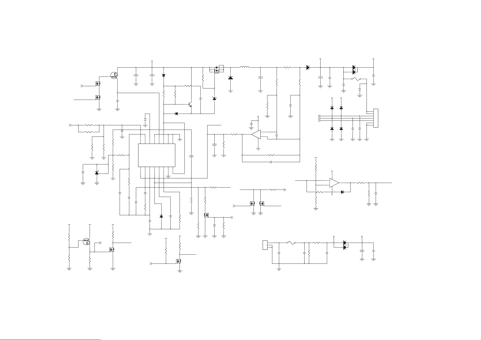
Service Manual
Sheet 30 of 31
BAT+(31)
PR62
100K
Z57
PR61
10K(R)
AC_IN(31)
BAT_IN
PC74
0.1U
PQ21
2N7002
G
PQ19
2N7002
G
PR63 102K 1%
PR64 0(R)
PR59
18K 1%
PD16
TL431
VCVA
PQ25
DTC114EUA
C
B
E
PR86
10K
PR60
2M
C
A
DS
DS
V2.5
AC_IN (31)
PQ22
DTA114EUA
B
PR68
2K 1%
R
G
VC
PC86
0.1U
DS
E
C
PC77
0.1U(0805)
PR69
100K
PR74
2K 1%(R)
Z281 7
PR67
100K
AC_IN #
PQ26
2N7002
PC85
0.1U
PC75
0.1U
PC21
10U/25V
PC88
0.1U
PR75
10K
VA
PC22
10U/25V
PC76
0.1U
12
13
14
15
16
2IN-
REF
VCC
OUT
2IN+
PU4
TL594
1IN+
1IN-
FBK
DTCCTRT
1234567
PC89
0.1U
PR87
10K
PC87
0.1U(C)
TEMP
TEMP(23)
PD18
1SS355
A C
AC
11
C2
VC
PD13
1N4148
PR44
2K(0805)
10
E2
GND
PR42
100K
PD15
1N4148
8 9
PC79
1000P
G
C1 E1
PR45
2K(0805)
2SD1782K
DS
PQ23
AC
PR71
7.5K
PR43
100K
PQ18
2N7002
PR46
5.1
B
PR99
2.2K
BAT_IN
C
E
PR95
120K 1%
PC90
1U
PR41
100K
PC67
0.01U
DS
4
CURSEN
PC94
0.1U(0805)
PR96
30K 1%
PR97
8.06K 1%
PQ28
2N7002
G
PC95
1U
PQ1
Si4435
PZD2
9.1V(LL34)
A C
8
62
5731
CA
PR93 40 . 2K 1%
PR92
10K 1%
V2.5
TEMP(23)
PR98
100K
PL3
CDRH-1205-470
PD3
03A04
PC93
0.1U(0805)
PU5A
LM358
BATCHA1
PQ17
2N7002
G
PWR_ON (10,23,31)
PC19
10U/25V(O)
1
DS
2A2A
PR112
200K 1%
VA
84
3
+
2
-
PR102 200K 1%
PC97
PR58 0
DS
CON1
1
2
3
POWER JACK
PQ20
2N7002
G
PR9 25m(2010)
PR113
1K 1%
PC98
30P(C)
0.1U(C)
AC_IN#TEMP
Z618
PC1
0.1U(0805)
PR111
1K 1%
PC102
0.1U(C)
CURSEN
BATCHA (23,24)
PF1 5A
0.1U(0805)
PC143
BAT
PD4
CA
03A04
PC15
10U/25V
BAT_DA(25)
BAT_CLK(25)
TEMP(23)
VC
PR85
200K
PR94 2M
PR84
10K
PR2
0(1206)
PR1
100K
PU5B
LM358
PD27
1SS355
TEMP
PD31
1SS355
VC VC
5
+
6
-
PC2
1000P
PC13
0.1U(0805)
A C
PD32
1SS355
A C
84
A C
PD17 RB751V
VA
A1A2C
60QC04(TO-252)
A1A2C
PF2 7A
PC149
0.1U(0805)
PD28
1SS355
A C
PC118
30P
A C
7
PD1
PD2 60QC04(TO-252)
PC150
0.1U(0805)
PC133
30P
PR83 30K
PR82
10K
B+VC
PC7
22U/25V
B+
CON2
1
2
3
4
5
6
7
BAT CON
PC12
0.1U(0805)
BATCHA1
PC84
0.1U
PC8
0.1U(0805)
B - 30
Title
Size Document Number Rev
Custom
Date: Sheet
ÂÅ ¤Ñ ¹q ¸£ CLEVO C O.
CHARGER-PWM
0200-30.SCH
Tuesday, September 11, 2001
71-22T00-D03
30 31
of
A
Page 94

Sheet 31 of 31
Schematic Diagrams
VCC3+VC
PR117 10M(R)
CE
B
C
E
PR116 2M(R)
PC106
4.7U/25V
B+
PD35
1SS355
PR115
95.3K 1%
PR104
25.5K 1%
CA
Z685
PR130
100K
PR146
100K
BAT+(30)
BAT
PQ36
DTA114EUA
VC
PQ37
DTC114EUA
PR124
B
10K
SW5
1 3
B+
2 4
POWER SW . 4P
Z689
C A
Z763
PR105
PC105
2M(R)
1U
VA
PQ40 2SB1198
Z687
Z684
PR138
100K
PD23
1SS355
PR129
10K
Z456
Z700
G
PC122
0.1U
DS
VREF
PC112
1U
PD24
1N4148
PD25
1N4148
PQ42
2N7002
5
6
CA
CA
1SS355
+
-
PD34
84
PU8B
LM393
PQ39
2N7002
DS
PC114
4.7U/25V
CA
7
Z460
G
VIN1 (28)
VDD3+
PR145 330K
Z762
PR120
47K
PD22
1SS355
AC_IN (30)
C A
PU10
MIC2951(SO8)
8
VI
3 5
ON/OFF ADJ
6
6
7
Z745
C A
PR144
PR152
100K
Hi => Shutdowm system
CA
SHUTDOWN (26)
Z920
PD38
PC145
TL431
0.1U
PD26
1SS355
VO
VO
GND
7
Z455
4
PC121 0.1U
PD29
1SS355
10K
G
Z683
PC134
1U
1
2
DS
VC
C
A
PQ44
2N7002
PR121
2K
PC119
10U
T
BAT+(30)
R
PC120
0.1U
PWRSW# (10)
PR134 95.3K 1%
PR122 47K
PC146
0.1U
VC
PZD3
5.6V(D)
PSM
A C
1U
PR132
22K 1%
VREF
PR137 0
PR136
3
VCC
RESET
GND
1
VREF
10K
2
PU9
TCM8 09(U )
2
3
PR131 330K
PR133
2M(R)
VDD
VDD_ON (28,29)
PWR_ON#(10,23,24)
-
+
8 4
VC
PWR_ON(10,23,30)
12V+
VCC3+
PU8A
LM393
1
A CPC144
PD36 RB751V
PC142
0.1U
C A
PR147 100K(R)
VDD3+
PWR_ON
DS
G
PR127
10K
PR126 0
VCC+
PD30
1SS355(D)
PR106
10K
PQ34
2N7002
Low => Battery Low to system
PR148 0
Z707
PC135
PC136
0.1U(C)
0.1U(C)
PQ38
DTA114EUA
G
DUMPLO# (23)
DTC114EUA(Q)
CE
B
Z708
DS
PQ35
2N7002
PD37 1N4148
PQ45
SI2305
PQ48
B
PR118
10K
PWR_ON (10,23,30)
CA
SD
G
PR139
10K(R)
Z706
C
E
PWR_ON+ (27,28,29)
VC
B - 31
Page 95

Service Manual
Notes:
B - 32
Page 96

Appendix C: Switch Settings
Clock Settings (SW6)
)BSF(UPC MARDS 1-6WS 2-6WS 3-6WS 4-6WS 6-6WS
66331-CPFFOFFOFFOFFONO
66001-CPFFOFFOFFOFFOFFO
001001-CPNOFFOFFOFFOFFO
001331-CPNOFFONOFFOFFO
Switch Settings
331331-CPNONONOFFOFFO
C - 1
Page 97

Service Manual
EZIS DNARB .oNledoM 1-7WS 2-7WS 3-7WS 4-7WS
"3.31
GLCC2C-7X331PLNONOFFOFFO
TDA1-2X331LNONOFFOFFO
CAPINU10X331PUNONOFFOFFO
IADNUYH41X31THNONONOFFO
"1.41
GL5X141PLNONOFFOFFO
TDA1X141LNONOFFOFFO
TPC10BX141AALCNONOFFOFFO
TPC10CX141AALCNONOFFOFFO
CAPINU10X141PUNONOFFOFFO
IADNUYH31X41THNONONOFFO
Panel ID Settings (SW7)
C - 2
Page 98

Updating the Flash ROM BIOS
Appendix D: Updating the Flash ROM BIOS
To update the FLASH ROM BIOS you must:
A:Download the BIOS update from the web site.
B:Unzip the files onto a bootable Floppy Disk.
C: Reboot your computer from the FDD.
D:Use the flash tools to update the flash BIOS.
E: Restart the computer booting from the HDD.
A: Download the BIOS update from the web site
1) Using your web browser go to www.clevo.com.tw
2) Choose Download from the menu bar at the top of the page.
3) In the Driver section select the model of your computer (2200T/2700T series) and the driver type (BIOS).
4) Select GO.
5) Click on 2xTRxxx.ZIP to download the BIOS files (including BIOS refresh tools).
B: Unzip the file onto a bootable floppy disk
Unzip the file you have just downloaded on to a bootable floppy disk.
(Some of the files you should see on this disk are: FP.EXE, FLASH.EXE and 2xTRxxx.BIN)
C: Reboot your computer from the FDD
With the bootable floopy disk containing the BIOS files in your Floppy Drive, restart the computer.
D - 1
Page 99

Service Manual
D: Use the flash tools to update the flash BIOS
After the computer has been booted from the floppy disk:
1) Go to the DOS prompt.
2) Type in the command:
A: FP 2xTRxxx.BIN
(This file was one of the zipped files and is now on your bootable floppy disk. For example, if you have downloaded file
2xTR103.ZIP then you should type in the command “FP 2xTR103.BIN)
3) Remove the floppy disk from the drive.
E: Restart the computer booting from the HDD
Your notebook is now running normally with the updated BIOS.
D - 2
 Loading...