

Page 1
User Instructions
ZSU-5A
Zone Selector Unit
Page 2
The ZSU-5A is a zone selector unit
which, when used with a public address
amplifier, allows up to 5 speaker
zones to be controlled individually or
simultaneously from an external console
microphone or similar unit.
The Unit has an integral signal muting
facility.
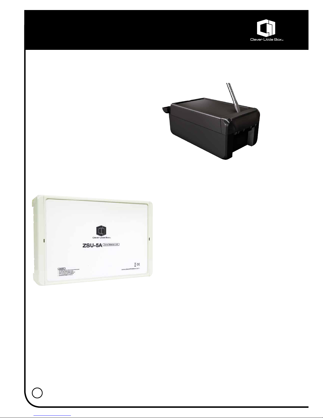
The Unit is supplied in a plastic case
which can be wall or table mounted and
is powered either by 240v (120v option)
50/60Hz mains and/or 24v DC.
Introduction:
2
By using the hinged quick-release
catch, the enclosures can easily be
closed by hand – use a standard
screwdriver to open.
Page 3

Description:
• Zone Control:
The zone control section consists of
five DPCO relays which can be selected
individually as required or all together
by activation of the corresponding zone
select terminal(s).
The 100v speaker line signal is
connected to the AMP IN terminals
which are connected to the Normally
Open contacts of each relay. When the
required relay is activated, the amplifier
signal is routed to the corresponding
zone’s output terminals (e.g. +Z1 OUT
and –Z1 OUT in the case4 of Zone 1).
Each Zone also has a set of terminals
marked +Z1 IN (in the case of Zone 1)
which are wired to the Normally Closed
contacts of the corresponding selection
relay. When the relay is relaxed (not
selected) these are connected straight
through to the +Z1 OUT and –Z1 OUT
terminals allowing another amplifier
to feed that zone. This could be used
for background music etc., allowing a
paging amplifier connected to AMP IN
terminals to be routed to selected zones
without disturbing the background music
in the others.
The Zone IN terminals can be paralleled
together as required. If no amplifier
is connected to them they should be
shorted together with a wire link to
prevent crosstalk (i.e. +Z1 IN to –Z1 IN,
+Z2 IN to –Z2 IN, etc.)
Activation of a selected zone is achieved
by connecting the appropriate selection
terminal to 0v (e.g. to activate Zone 1,
the Z1 terminal should be connected to
the 0v terminal, typically via a zone select
switch in a microphone console).
An LED adjacent to the zone relay
illuminates when the zone is selected,
giving a visual indication of its operation
and helping to confirm correct selection
wiring etc.
The terminal marked AC is the All Call
which activates all zones when selected
by connecting it to the 0v terminals.
3
Page 4

• Signal Muting:
A signal muting facility is supplied,
consisting of a DCPO signal relay
which has all contacts brought out to
the ‘SIGNAL MUTE’ terminal group.
The actual muting can be achieved in
several ways depending on the system
requirements, although typically the
signal (from tuner, tape deck, etc.) would
be connected to the common terminal
(C-1) and the normally open terminal
(N\0-1). When the mute relay is activated
the contacts close and the signal is shortcircuited. It is important to check that
the signal source from the tuner, tape
deck, etc., is suitably buffered so that
shorting-out the signal will not damage
the source. If in doubt, the relay contacts
should be configured to open circuit the
signal to the amplifier.
As there are two sets of contacts
available, several muting arrangements
are possible. These include muting
balanced signals, muting two separate
signals or using one set of terminals to
trigger a chime.
Activation is achieved by connecting
the MUTE terminal to the 0v terminal on
the zone select terminal group, visual
indication of operation being given by
LED6 ‘MUTE’.
• Signal Wiring point:
When wiring a multizone microphone
these terminals can be used as a neat
and convenient wiring point for the
microphone signal. These can then be
wired to the amplifier mic input.
• DC OUT:
A 24 volt DC fused supply is available
from the Unit, and is suitable for
powering ancillary equipment such as
multizone consoles, line amplifiers, tone
generators, etc. The current available is
limited to 100mA by a fuse (F2).
• DC IN:
The ZSU can be powered from an
external 24 volt power supply via these
terminals. The Unit has reverse current
protection, so that both the mains supply
and the external 24v can be connected
at the same time (e.g. when used in
systems requiring battery backup).
• MAINS INPUT:
Connect the mains input to the ‘L’, ‘N’
and ‘E’ terminals and ensure that the
supply cord is held firmly in place by the
cable clamp adjacent to the terminals.
The Unit is supplied with a standard input
voltage of 240v 50/60 Hz, although it can
be supplied with a 120v 50/60 Hz input
as an option.
• WARNING:
Under no circumstances should any
wiring be carried out to the unit while the
mains power is connected.
4
Description:
Page 5

5
Layout Diagram:
Specifications:
Zone switching: 5 individually selectable zones, plus All-Call
Muting operated: 2 sets of change-over contacts-over (2 pole 2 way)
from a single input
Zone relay ratings: DPCO 5 Amp 250v AC contact rating with 24v DC coil
Muting relay rating: DPCO 1 Amp 30v AC contact rating with 24v DC coil
Visual status indication: By LED indicators mounted on PCB
Power handling: 750W with 100v line signal
Connections: Screw terminations on PCB
Power requirements: 240v AC 50/60 Hz (120v option) and/or 24v DC
Power consumption: 11W using 240v AC supply, 185mA using 24v DC supply
DC supply
Case materials: Light grey painted metal
Case dimensions: 220(L) x 165(W) x 50(H) mm
Weight: 1.7kg
ZONE ACTIVE INDICATORS
1 2 3 4 5
ZONE
INPUT
LINKS
MAINS
INPUT
ZONE CONNECTIONS
AMPLIFIER INPUT (1) AMPLIFIER INPUT (2)
SIGNAL
WIRING
POINT
ZONE
SELECT
INPUTS
SIGNAL
MUTING
MUTING
INDICATOR
DC OUT
FUSE
POWER
INDICATOR
MAINS
FUSE
+AMP IN
–AMP IN
+Z1 IN
–Z1 IN
+Z1 OUT
–Z1 OUT
+Z2 IN
–Z2 IN
+Z1 OUT
–Z2 OUT
+Z3 IN
–Z3 IN
+Z3 OUT
–Z3 OUT
+Z4 IN
–Z4 IN
+Z4 OUT
–Z4 OUT
+Z5 IN
–Z5 IN
+Z5 OUT
–Z5 OUT
–AMP IN
+AMP IN
Link 1
Link 2
Link 3
Link 4
Link 5
Link 6
Link 7
Link 8
Link 9
Link 10
Lnk
Lnk
TB13 TB7 TB7A TB8 TB8A TB9 TB9A TB10 TB10A TB11 TB11A TB12
TB4 TB5 TB6C TB6B TB6A TB6 TB3B TB3A TB3
NC-1
NO-1
C-1
NC-2
NO-2
C-2
MUTE
+24v
0v
AC
Z5
Z4
Z3
Z2
Z1
+SIG OUT
–SIG OUT
SCREEN
SCREEN
+SIG IN
–SIG IN
DC POWER
TERMINALS
L
N
E
LD7
POWER
MUTE
LD6
DC OUT
+24v 0v
DC IN
+24v 0v
Page 6

Circuit Diagram:
6
Page 7

7
Page 8

8
Connection details:
All connections to the ZSU are made
via screw terminals mounted on the
edge of the printed circuit board.
• Amp in:
There are two pairs of ‘AMP IN’ terminals,
one on the right side of the ZONE
CONNECTIONS and the other on the
left. The output of the amplifier can be
connected to either as by default they
are connected together internally.
It is however possible to isolate the two
pairs of terminals so that two separate
amplifiers can be used, e.g. one amplifier
supplying Zones 1 and 2, and the other
supplying zones 3,4 and 5. Please
contact our Technical Department for
further information. (See our website for
contact details).
In the case of an unbalanced or polarised
system, the ‘earthy’ or ground line should
be connected to the –AMP IN terminal.
• Zone in:
Abbreviated to +Zn IN and –Zn IN
(where ‘n’ represents the zone number).
An output from an auxiliary amplifier
supplying BGM etc., can be connected
to these terminals as they are routed
directly to the corresponding Zone Out
terminals when the zone is not selected.
The Zone IN terminals can be paralleled
together as required (observe polarity!).
If they are not used, a shorting link should
be fitted in between them (i.e. +Z1 IN to
–Z1 IN, in the case of Zone 1 to prevent
crosstalk).
• Zone Out:
Abbreviated to +Zn OUT and –Zn OUT
(where ‘n’ represents the zone number).
The wiring from the speakers within a
particular zone should be connected to
these terminals e.g. the wiring from the
speakers in Zone 1 should be connected
to +Zn OUT and –Zn OUT. Similarly, the
wiring from Zone 2 should be connected
to +Z2 OUT and –Z2 OUT etc.
• Zone Select:
These terminals are identified by the
zones they control (i.e. Z1 activates Zone
1, Z2 activates Zone 2, etc). The terminal
marked AC is the ‘all call’ input which
activates all the zones simultaneously.
The ‘MUTE’ terminal controls the
operation of the SIGNAL MUTE RELAY.
Selection is carried out by connecting
any of these terminals to the 0v terminal,
usually by closing switch contacts in a
microphone console.
Page 9

9
Connection details:
• Signal Mute:
These are simply the two sets of muting
relay contacts brought out to terminals.
N/C refers to Normally Closed contacts,
N/C to Normally Open contacts and C to
the Common contact. For wiring options
see the section ‘Signal Muting’. DC OUT
24 volts DC at a maximum of 100mA
is available from these terminals. The
output is protected by a 100mA plain
fuse (F2).
• DC IN:
An external 24v supply which is to
be used to power the unit should be
connected to these terminals.
• Mains Input:
The mains power input should be
connected to these terminals. The
supply input should be 230 volts (=/-10%)
50/60 Hz. A 120 volt 50/60 Hz option is
available. The Live conductor should be
connected to the terminal marked ‘L’ the
Neutral to the terminal marked ‘N’ and
the Earth to the terminal marked ‘E’.
• Mains supply colour coding:
The UK convention for mains supply
colour coding is:
LIVE: BROWN
NEUTRAL: BLUE
EARTH: GREEN/YELLOW
• Accessories supplied:
4 x 1.25” x 6 mounting screws
4 x 30mm plastic rawlplugs
Page 10

10
Notes:
Page 11

11
Notes:
Page 12

T: +44 (0)115 9770075 F: +44 (0)115 9770081 E: info@cie-group.com W: www.cie-group.com
CIE-Group Widdowson Close Blenheim Industrial Estate Bulwell Nottingham NG6 8WB UK
 Loading...