

Page 1
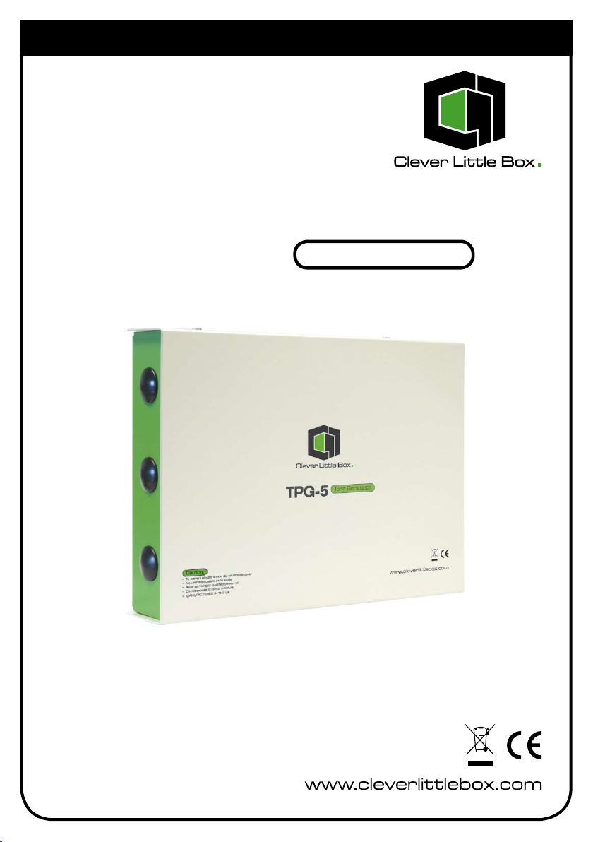
TPG-5
User Instructions
Tone Pulse Generator
Tone Generator
Page 2

Introduction:
The TPG-5 Tone Generator incorporates the latest microcontroller technology and
offers a choice of four audio tones suitable for line level inputs of P.A. amplifiers:
Tone 1 - “Whooping” tone signal.
Tone 2 - Two tone signal.
Tone 3 - Greenwich Mean Time pips (GMT).
Tone 4 - Single tone signal.
No tone priority hierarchy exists with the TPG-5.
Tone signal output is activated by external contact closure to one of the four tone
inputs. If the external contact closure to any of the Tones 1 to 4 is momentary,
the activated tone will be present for approximately 6 seconds and then stop. If
the external contact closure to any of the tones 1 to 4 is latched (held closed), the
activated tone will be present until such time that the contact is opened plus an
additional period of up to 6 seconds.
A set of voltage-free S.P.C.O. contacts are provided to allow other external equipment
to be controlled during operation of the tone generator.
The TPG-5 is supplied in a metal case that can be wall, table or rack mounted. It is
powered by 240v AC mains and/or 24v DC supply.
2
Page 3
Technical Specifications:
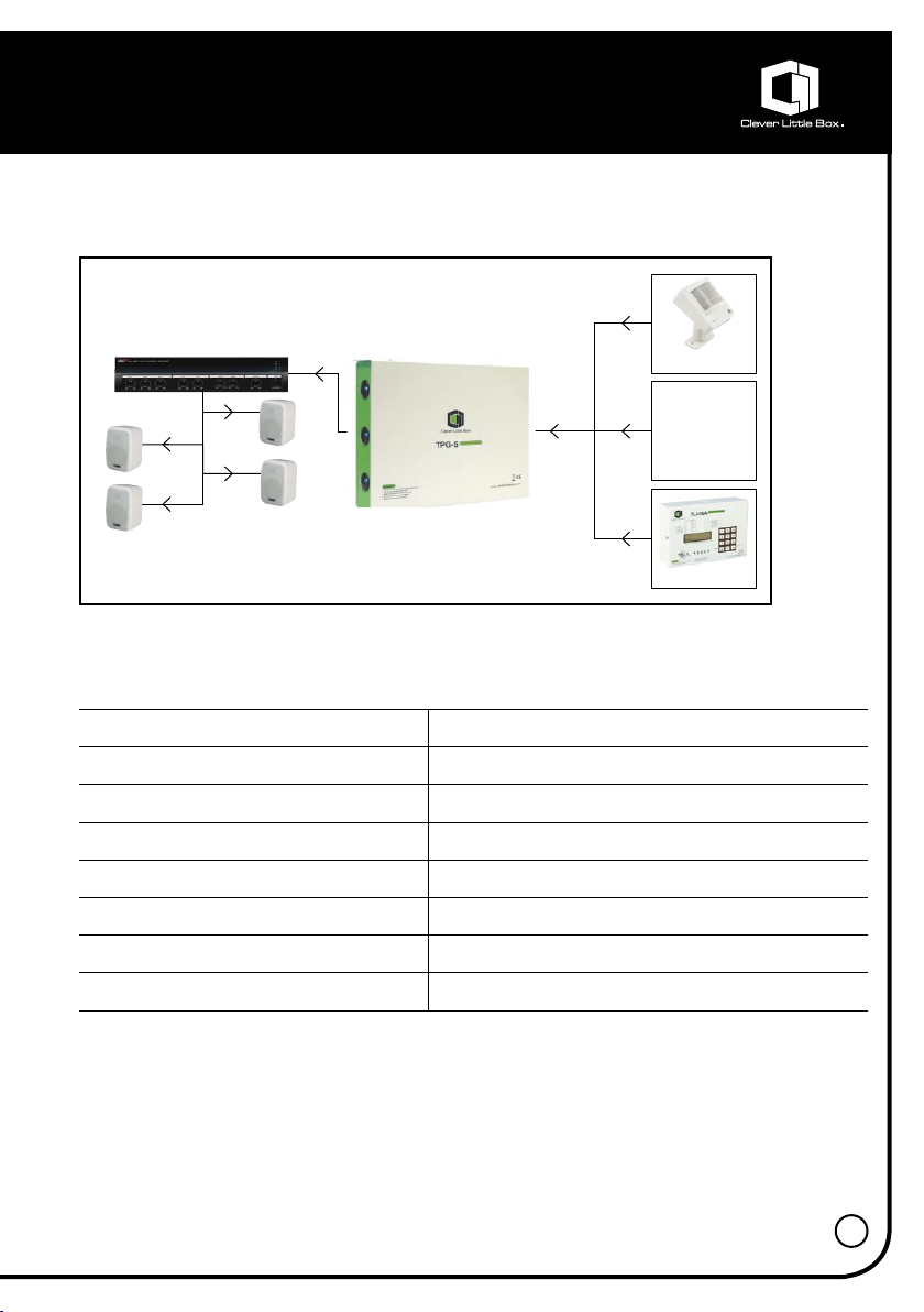
Suggested System Diagram:
ACTIVATION OF
MESSAGE VIA:
AMPLIFIER
Specifications:
Audio output: 0.7v RMS over the frequency range
AUX IN
PIR
SWITCH
BUTTON
RELAY
TPG-5
TU16A
Output configuration: Unbalanced
Activation: Voltage-free contact closure
S.P.C.O. rating: 1A @ 24v DC, 0.5A @ 125v AC
Connections: Screw terminals on PCB
Power consumption: 3VA @ 240v AC, 50mA @ 24v DC
Dimensions (mm): 162(H) x 220(W) x 44(D) mm
Weight: 1.8kg
• CIE-Group reserves the right to alter the above specifications without prior notice
3
Page 4

Description:
• Tone 1:
• Tone 1 produces a “whooping” signal.
• Activation is by remote switch operation to
TONE 1 input.
• Fit a momentary type push button switch if
automatic reset of the tone is required after
6 seconds.
• Fit a latching type switch if the tone is
required to be continuous, i.e. active for the
period that the switch is latched ON.
• Tone 2:
• Tone 2 produces a two tone signal.
• Activation is by remote switch operation to
TONE 2 input.
• Fit a momentary type push button switch if
automatic reset of the tone is required after
6 seconds.
• Fit a latching type switch if the tone is
required to be continuous, i.e. active for the
period that the switch is latched ON.
• Tone 3:
• Tone 3 produces Greenwich Mean Time
pips (5 short, 1 long).
• Fit a momentary type push button switch for
this tone.
• Automatic reset of the signal takes place at
the end of the pips.
• Tone 4:
• Tone 4 produces a single tone signal.
• Activation is by remote switch operation to
TONE 4 input.
• Fit a momentary type push button switch if
automatic reset of the tone is required after
6 seconds.
• Fit a latching type switch if the tone is
required to be continuous, i.e. active for the
period that the switch is latched ON.
4
Page 5

Installation:
Terminal Block Designation Description
TB7 Tone 3 Switch closure across these two
terminals will activate the GMT pips.
TB7 Tone 4 Switch closure across these two
terminals will activate the single
tone signal.
TB6 Tone 5 (FUNCTION NOT AVAILABLE)
TB5 SIG OUT These two terminals provide the
audio tone signal output which is
suitable for line level inputs of P.A.
amplifiers.
Cable Requirements
Connection to the tone activation terminals must
be by means of 2-core screened cable. The
screen must be connected at the TPG-5 end
only to terminal block TB8 that is marked ‘TONE
I/P SCREENS’, the other end of the screen must
be left open i.e., not connected.
TPG-5A
5
Page 6

Configuration &
Connection Details:
All connections are via knock-out holes on the sides of the box and onto screw
terminals located on the printed circuit board. All external wiring to the tone activation
terminals (see below) must be run in screened cable and the screens connected to
the terminals marked “tone i/p screens”. The screen at the other end of the cable
must not be connected to anything, i.e., isolated.
WARNING: Under no circumstances must any wiring or maintenance be
carried out to the unit whilst the mains power is connected.
Terminal Block Designation Description
TB7 L (Live) 240v AC supply terminals (please ensure
N (Neutral) that the supply cord is held firmly in place
E (Earth) by the cable clamp next to the terminals).
TB2 +24v 24v DC input supply terminals
0v
TB4 Set of potential free relay contacts for
control of external equipment. Relay is
energised during tone activation.
NO Normally Open contact
NC Normally Closed contact
COM Common contact
External wiring for tones 1 to 5 activation must be run in screened cable and
terminated as follows:
TB8 Tone i/p The screens of the external cables for tone
Screens activation to be connected to these
terminals. The screen at the other end of the
cables must not be connected to anything.
TB3 Tone 1 Switch closure across these two terminals
will activate the “whooping” tone signal.
TB3 Tone 2 Switch closure across these two terminals
will activate the two tone signal.
6
Page 7

Notes:
7
Page 8

www.cie-group.com
bigger - better - faster - wider
The new CIE-Group website is bigger and better than ever before; faster
and easier to search through 1000’s of products for the PA, AV, CCTV,
electronics and test professional.
T: +44 (0)115 9770075 F: +44 (0)115 9770081 E: [email protected] W: www.cie-group.com
CIE-Group Widdowson Close Blenheim Industrial Estate Bulwell Nottingham NG6 8WB UK
 Loading...