

Page 1
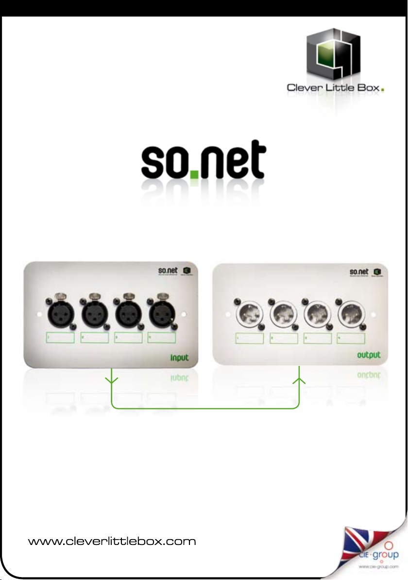
Sound-over-Ethernet
User Guide
Linked via Cat5 cable
Up to 1000m!
11/09
Page 2

Overview
SONET4: Cat5 Audio Distribution
System - 4 in / 4 out
The new ‘so.net’ Sound-over-Ethernet System
has been designed to simplify and speed up
installations where multiple microphone inputs
or line level inputs need to be situated a distance
from the amplifier equipment.
Types of installation include churches, schools,
theatres and corporate boardrooms.
It is an extremely versatile and cost effective
installation device that removes the need for
multiple cable runs from remote audio inputs to
the amplifier equipment. The SONET4 System can
transmit up to four microphone or line level signals
down one screened Cat5e cable for up to 1000m.
Each input and output can be independently
configured for balanced or unbalanced signals
as well as line level or microphone level. There is
also an option to provide phantom power to the
microphone inputs independently.
Each unit fits neatly into a standard UK doublegang back box (minimum depth 47mm) and only
requires a power supply at the output or amplifier
end (PSU supplied as part of system).
Linked via
Cat5 cable
Up to 1000m
Features:
• Reduces installation time
• Up to 1000m between Input and Output plates
• Very high interference immunity
• Balanced or unbalanced inputs & outputs
• Line or Microphone level inputs & outputs
• Phantom powering
• Four XLR sockets on standard 2 gang plates
• No power required at input module
• Power supply included as part of system
Sound-over-Ethernet
Suggested System Diagram:
4 x MIC/ LINE Signa ls
so.net I NPUT plate
Standard single
Cat5 cab le
(up to 1 000m)
MIXER/AM PLIFIER
so.net O UTPUT plate
LINE Out
PSU
Page 3

Installation
Installation
The system consists of two Modules interconnected with screened Cat5 cable and a 24v DC power supply
(supplied). Unscreened Cat5 cable can be used but only three audio channels will be available.
The input module has four XLR female sockets to plug microphones or line level inputs into.
The output module has four XLR male sockets to connect to the amplifier or mixer.
There are screw terminals on the rear of the plates for ease of connection of the Cat5 cable.
Power is connected to the Output Module only and is transferred down the Cat5 cable so no power supply
is needed at the Input Module end.
1 Decide on the best position for the Input Module avoiding close proximity to mains sockets
and wiring.
The Input Module fits a standard UK 2 gang back box or surface mount box (minimum depth 47mm),
which ever is preferred.
2 Run the Cat5 cable from the input position back to the amplifier or mixer location avoiding running
the cable alongside mains cables.
Keep at least 100mm clearance when ever possible to prevent any possibility of interference.
The cable should be clipped in place to prevent damage to the cable.
If using unscreened cable (UTP), one of the four pairs will need to be used as the ground return link.
This means that only three channels can be used.
To use all four channels, you must use screened Cat5 cable.
3 Ensure that the relevant links are fitted for ‘Mic’ or ‘Line’ level for each channel and the ‘phantom’
power links are fitted if required. See diagram on page 4.
4 Connect the Cat5 cable to the Input Module as shown in the diagrams over the page taking care
to ensure that the pair colours are connected to the same channel number at each end of the
Cat5 cable. It is very important that both conductors of a twisted pair are connected to a channel
and not split across channels.
Ensure that the screen wire is connected to the ’GND’ terminal if using screened cable or the blue
pair (both wires) if using unscreened cable.
5 Double check the wiring is sound and secure and there are no stray bits of wire before
fitting the input module into the back box.
6 Select a convenient location for the Output Module which could be within the back of a
rack containing the amplifier or alternatively, the Module can be fixed to the wall nearby.
A mains socket needs to be available for the SONET4 power supply unit.
7 Decide whether the Output Module is supplying ‘mic’ or ‘line’ level output signals to the amplifier
or mixer and fit links accordingly. See diagram on next page. CAUTION: Ensure that the phantom
power of the mixer or amplifier is OFF. The SONET4 will create the phantom power needed at the
microphone module if the appropriate links are fitted.
8 Connect the CAT5 cable to the Output Module as shown in diagram on page 4 observing correct
colours of wires.
9 Connect the 24v power supply to the terminals marked ‘GND & 24v’. The red wire or the wire with
a white trace is the ‘24v’ or positive wire.
10 There are holes in the Output Module circuit board to allow the cables to be ‘tie-wrapped’ in
place if desired.
Before applying power, ensure that there are no stray bits of wire in the modules and that all of
the terminals are securely holding the wires in place.
03
Page 4

Wiring: MIC/AMP screened cable
Wiring for MIC end using screened cable
INPUT MODULE
Using SCREENED
cable
Screen wire
Pair 4
Pair 3
Pair 2
Pair 1
Fit links for MIC level
Remove links for LINE level
Fit link for PHANTOM power
Screened CAT5e
Cable
Wiring for AMPLIFIER end using screened cable
OUTPUT MODULE
Using SCREENED
cable
24VDC
Input
Sound-over-Ethernet
Screen wire
Pair 4
Pair 3
Pair 2
Pair 1
Fit links for MIC level
Remove links for LINE level
SCREENED
CAT5 Cable
Page 5

Wiring: MIC/AMP un-screened cable
Wiring for MIC end using un-screened cable
INPUT MODULE
Using UNSCREENED
cable
Fit links for MIC level
Remove links for LINE level
Fit link for PHANTOM power
Pair 4
Pair 3
Pair 2
Pair 1
Unscreened
UTP CAT5e
Cable
Wiring for AMPLIFIER end using un-screened cable
OUTPUT MODULE
Using UNSCREENED
cable
24VDC
Input
Fit links for MIC level
Remove links for LINE level
Pair 4
Pair 3
Pair 2
Pair 1
Unscreened
UTP CAT5e
Cable
05
Page 6

Connection Details
12
3
Input module.
Female socket
1 2
3
Output module.
Male socket
XLR pinout
Pin 2 Positive (hot)
Pin 3 Negative (cold)
Balanced v Unbalanced
It is always best to use balanced signals where possible as this type of
connection is much less susceptible to interference from items such as mobile
phones and noisy electrical switches. Most PA amplifiers have balanced inputs
as do most professional microphones.
However, some devices such as CD players or less expensive microphones
have unbalanced outputs.
These can be connected to a balanced input by wiring up as follows:
Unbalanced input
Connect the screen of the device to pin 1
Connect the signal wire to pin 2
Connect a shorting link between pin 1 and pin 3
If the Output Module is to be connected to an unbalanced input, it is simply
a case of wiring up as follows:
Unbalanced output
Connect the screen of the amplifier to pin 1
Connect the signal to pin 2
Sound-over-Ethernet
Page 7

Specifications
Specifications:
INPUT Module:
Power Over Cat5 cable
Ground Over Cat5 cable screen (or spare pair)
Inputs x 4 Balanced XLR female
MIC/LINE in Selectable by jumper
Phantom power 15v jumper selectable
MIC impedance 600R
MIC level input 10mV RMS
LINE impedance 50K
LINE input level 700mV RMS (1.5v RMS max)
Cat5 termination Screw terminals
Dimensions 145(W) x 85(H) x 35(D)mm
OUTPUT Module:
Power requirements 24v DC @ 100mA
Outputs x 4 Balanced XLR male
MIC/LINE out Selectable by jumper
MIC out impedance 600R
MIC level output 20mV RMS (into 600R)
LINE out impedance 20K
LINE level output 700mV RMS (into 20K)
Dimensions 145(W) x 85(H) x 35(D)mm
General:
Channels Four, individually configurable
Bandwidth 100Hz to 20KHz (-3dB)
Crosstalk >60dB
Signal to Noise Ratio >60dB
Cable Spec Screened Cat5e cable (can use UTP but one pair required for ground
meaning only three channels would be available)
Cable length 1000m maximum
Cat5 terminators Screw terminals
Protected against short circuit on Cat5 cable to ground
07
Page 8

Sound-over-Ethernet
User Guide
Take a look at our new website for details on our
full range of Clever Little Box products
CIE-Group Widdowson Close Blenheim Industrial Estate Bulwell Nottingham NG6 8WB
T: 0115 9770075 F: 0115 9770081 E: info@cie-group.com W: www.cie-group.com
 Loading...