

Clever Electronics NPM2000, NPM5000, NPM4000, NPM3000 User Manual

NPM Manual
Network Power Manager
(v1.10.1)
Shenzhen Clever Electronics Co.,Ltd.
Page 1 of 28

NPM Manual
1. PRODUCT INTRODUCTION.........................................................................................................3
2. PRODUCT DESCRIPTION ............................................................................................................3
2.1 NPM 2000 ...................................................................................................................................3
2.2 NPM 3000 ...................................................................................................................................4
2.3 NPM 4000/5000..........................................................................................................................6
3. HARDWARE INSTALLATION ........................................................................................................7
3.1. OPTION SWITCH .......................................................................................................................... 7
3.2 NETWORK CONNECTION AND DAISY CHAIN OF NPM...................................................................8
4. USE OF CONTROL SOFTWARE .................................................................................................9
4.1 NPM WHICH CONNECT TO NETWORK .......................................................................................... 9
4.2. EXPLANATION FOR USING CONTROL SOFTWARE........................................................................9
4.2.1 Login system.....................................................................................................................10
4.2.2 Main screen.......................................................................................................................10
4.2.3 Initialization network configure....................................................................................... 13
4.2.5 The alarm setting about the overload and exceed limit.............................................. 18
4.2.6 the automatic manage setting........................................................................................ 19
4.2.7 User management............................................................................................................21
4.2.8 Assign properties of NPM for user.................................................................................22
4.2.10 change the user..............................................................................................................24
4.2.11.modem initialization........................................................................................................ 24
4.2.12 NPM groups’ configuration............................................................................................24
5: TECHNOLOGY PARAMETERS ..................................................................................................25
6: THE INCASEMENT LISTING ......................................................................................................25
7: INSTALLATION ..............................................................................................................................26
APPENDIX1 LIST FOR DEFAULT OCCUPIED PORTS IN TCP AND UDP............................28
Page 2 of 28

NPM Manual
1. Product Introduction
NPM network power manager is an intelligent power managing system. The user can
control and manage outlets of each NPM through software. The administrators can control the
NPM from anywhere via Internet, or just dial-in from a modem for off-internet power control,
and also can perform the 0-800m short distance off-internet power control via RS-232, or
RS-485 in the LAN.
Through the NPM management software, the user can expediently configure the name of
each outlet, switch on/off, timing switch on/off, and look over current of individual outlet,
environment temperature, humidity, smoke, water, door open status, etc. For CLVER NPM
product, there is Four series, contain:NPM2000、NPM3000, NPM4000, NPM5000.
Security feature
NPM have two security levels, administrator level and user level. The administrator is allowed
to access all configuration and command functions. The user is allowed to access functions
which had been given property. User level security features are ideal for co-location
applications. It allows multiple users access to a certain outlet of NPM unit. Each NPM have
a system password and you can modify it. This password will reject the access of any PC
which is not allowed.
Convince installation
The on/off of the plugs are controlled by the simply ASCII commands which are sent via
network, modem, short distance PC (LAN). Its configuration is also simple and easy to install
following the menu of the installation program.
2. Product Description
2.1 NPM 2000
Main character:
Horizontal installation, 8way outlets, 19” length, 2U;
Switch on/off individual outlet and display on/off status of individual outlet;
Timing switch on/off individual outlet and display on/off status of individual outlet;
Original state and keep original state of individual outlet;
Sequential power up/down individual outlet,
Page 3 of 28
NPM Manual
1 4
3
2
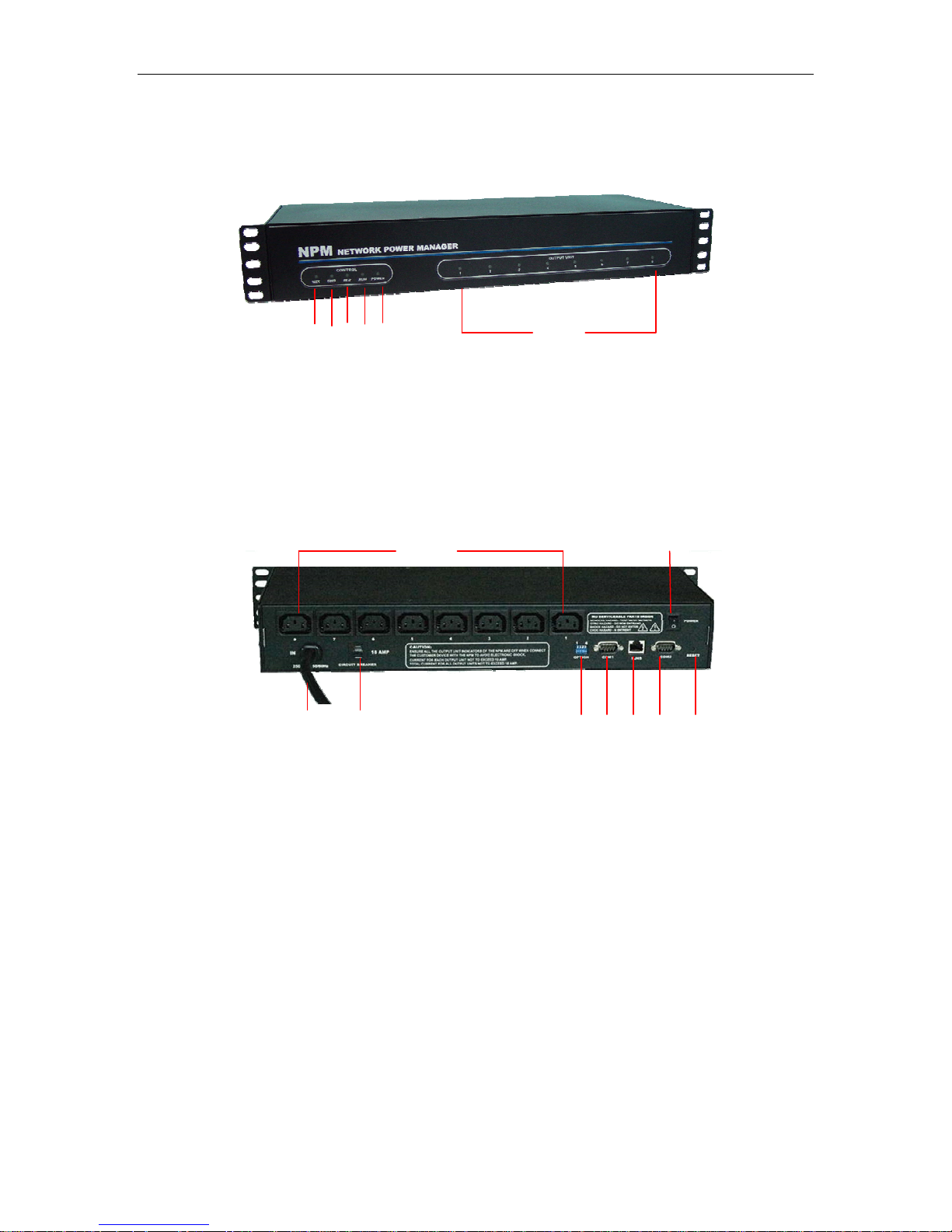
1: Network connect indicator: light when connect;
2: RND next unit communicated indicator: flashes when next NPM unit is
communicating.
3: RLD this unit communicated indicator: flashes when this NPM unit is communicating;
4: RUN run status indicator: flashes when this unit works normal;
5: POWER power indicator: Light when power supply of this unit is normal;
6: Bus A Indicators(1-8):Lights when the relative outlet is switched on.
5
Picture 2.1-1. NPM 2000 frontal panel
1
3
1: AC Power outlets: 8way, 10A/way;
2: Master power switch: ON/OFF power supply of this unit;
3: Power input: power input cable plug (IEC320 C20/IEC60309 plug);
4: Circuit breaker: overload protector;
5: Option switch: DIP switch, for configure master/slave unit and other status;
6: COM1: RS-232/482 port, DB9 connector, for connecting PC or next unit.
7: Network port: RJ45 ethernet network port, for connecting TCP/IP network;
8: COM2: MODEM port, RS-232/DB9 connector, for connecting external MODEM, when
control NPM via MODEM;
9: RESET button: Restart or reset NPM CPU. Under not effect outlets on/off status,
allows to reset NPM CPU.
4 5 6 7 8 9
Picture 2.1-2. NPM 2000 back panel
6
2
2.2 NPM 3000
Main characaters:
Horizontal installation, 8way outlets, 19” length, 1U;
Page 4 of 28
NPM Manual
Switch on/off individual outlet and display on/off status of individual outlet;
Timing switch on/off individual outlet and display on/off status of individual outlet;
Original state and keep original state of individual outlet;
Sequential power up/down individual outlet
Display current of individual outlet;
Display total current of unit;
Display humidity and temperature;
User-define alarm;
8
1 4 5
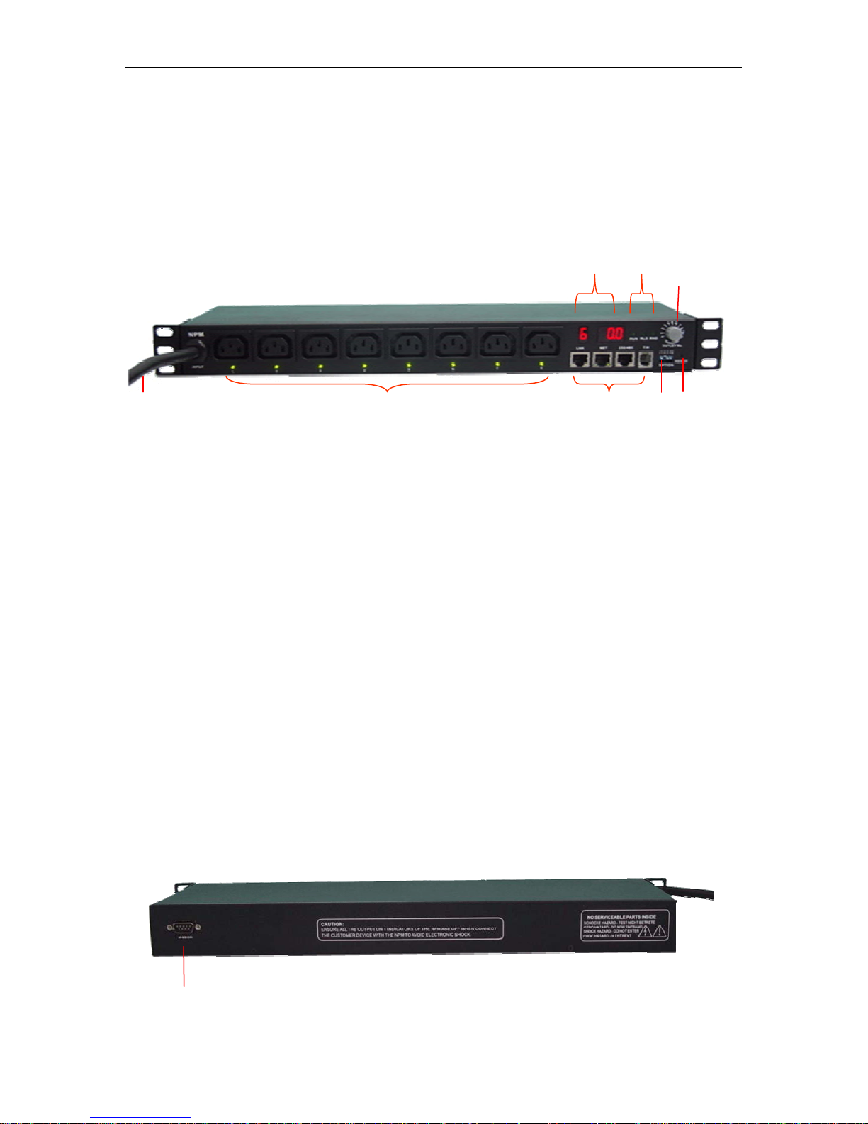
Picture 2.2-1. NPM 3000 frontal panel
1: Power input: power input cable;
2: AC power outlets: IEC320 C13 socket, 8way;
Power indicator of relative outlet: Lights when relative outlet is switched on;
3: Four ports;
LINK: When daisy chain multi NPM, this port for connecting RS232/485 port of next
NPM;
NET: For connecting master NPM to WAN, LAN or PC.
232/485: For connecting serial interface of PC;
T/H: For connecting temperature/humidity sensor.
4: OPTION: option switch for set up master and slave property, baud rate, etc.
5: RESET: Reset button, for restart this unit;
6: Three system signal indicator
RUN: Flashes when NPM work normally;
RLD: Lights when NPM unit receive command;
RND: Lights when command received not from this unit;
7: OUTLET NO. Knob for choosing display information, you can choose display current of
certain outlet, or total current of unit, or temperature, or humidity.
8: Digit display, left part and right part
Left part means chosen item, as picture,“6”——mean at present choose to display
No.6 outlet;
Right part means current and temperature or humidity value, such as“0.0”—— mean
temperature /humidity/current is zero.
2 3
6
7
9
Page 5 of 28
NPM Manual
Picture 2.2-2. NPM 3000 back panel
9: MODEM PORT: For connecting MODEM when control via external MODEM.
2.3 NPM 4000/5000
Main character:
Vertical installation, super high power, 380V AC input (NPM 5000);
Switch on/off individual outlet and display on/off status of individual outlet;
Timing switch on/off in of individual outlet;
Original state and keep original state of individual outlet;
Sequential power up/down individual outlet
Display current of individual outlet;
Display total curren
Display current of group outlets;
Display humidity a
User-define alarm;
dividual outlet and display on/off status
t of this unit;
nd temperature, smoke, water, door open status, etc;
15
14
13
12
3
11
10
9
4
5
8
6
7
2
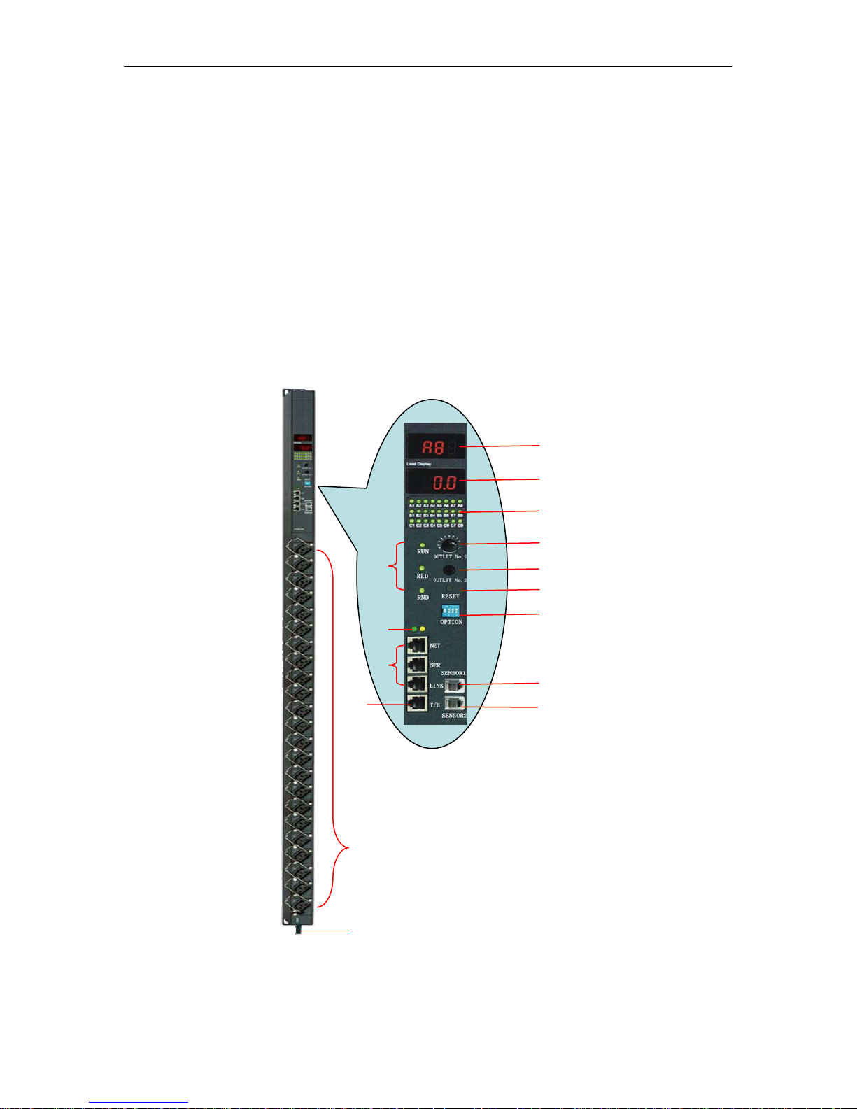
Picture 2.3-1. NPM 4000/5000 control panel
1: Power input cable;
Page 6 of 28
1

NPM Manual
2: Max. 24way outlets;
3: Three system signal indicator
RUN: Flashes when NPM work normally;
RLD: Lights when NPM unit receive command;
RND: Lights when command received not from this unit;
4: Indicator of network connection
5: Three connect ports
NET: For connecting master NPM to WAN, LAN or PC, when control via network;
SER: for connecting COM port of PC when control NPM via local RS-232;
LINK: When daisy chain multi NPM, this port for connecting serial port of next NPM;
6、T/H: For connecting 1 or 2pcs of temperature/humidity sensor;
7、SENSOR2: for connecting water, door open status sensor;
8、SENSOR1: for connecting smoke sensor;
9、OPTION: option switch for set up master and slave property, baud rate, etc.
10、RESET: reset button for restart NPM.
11: Choose group A or group B or group C outlets;
12: Choose certain outlet in a group(A/B/C);
13: On/off status of individual outlet, green color means switch on.
14: Display current and environment parameter, such as temperature, humidity,etc.
15: Display outlet No. chosen at present.
3. Hardware installation
3.1. Option Switch
1: Choose master/slave property:
Option NO.1and option NO.2, for selecting master or slave features of NPM unit.
1OFF/2ON: NPM is master NPM, 1ON/2OFF NPM is slave NPM.
One master NPM max. can daisy chain 31pcs slave NPM.
2: Choose baud rat
Option NO.3 fo F
Default baud rate of NPM
3: Reset default value.
A: Option No.1, No.2, No.3 for reset default a
Reset NPM default address and pass
address=65535;
Operate procedure:
1): Switch off power supply of total unit;
2): Set up option No.1, option No.2, option No.3 be on;
3): Switch on power supply of total unit, wait for 3 second, then switch off power
ply again, for 3 second;
p
su
4: Resume on/off status of option switch.
B: Option No.4 for reset network default parameters of NPM
Reset NPM default network
mask=255.255.255.0,port=4001, baud rate=19200, data bit=8, stop bit=
setting password=88888;
Operate procedure:
e:
r setting baud rate: 3OF =19200BIT,3ON=9600BIT.
is 9600BIT。
ddress, password of NPM;
word init
ial value: password=12345678,
.
parameters: IP=192.168.0.178, Subnet
1, network
Page 7 of 28
1): Switch off power supply of total unit;
r
p
y
y
2): Disconnect all devices connecting to the NPM;
3): Make option No.4 to be ON.;
4): Switch on power supply of total unit
again, for 3 second;
5): Make option No.5 to
NPM Manual
, wait for 3 second, then switch off power supply
be OFF.
3.2 Network connection and daisy
Conn
ection picture of NPM2000:
Master NPM
Input cable
Slave NPM
Picture 3.2-1. NPM2000 series connection
Ex
planation of NPM 2000 series connection:
1: If or HUB, Router, Switch,
control NPM via network, please connect to RJ45 port of PC
etc.
control NPM via local RS-232, connect to COM port of PC.
2: If
onnect to COM1 port of nex
3: C t NPM.
chain of NPM
3 connect to
next NPM
1
connect RJ45
2 connect PC COM port
Master
NPM
Slave NPM
Page 8 of 28
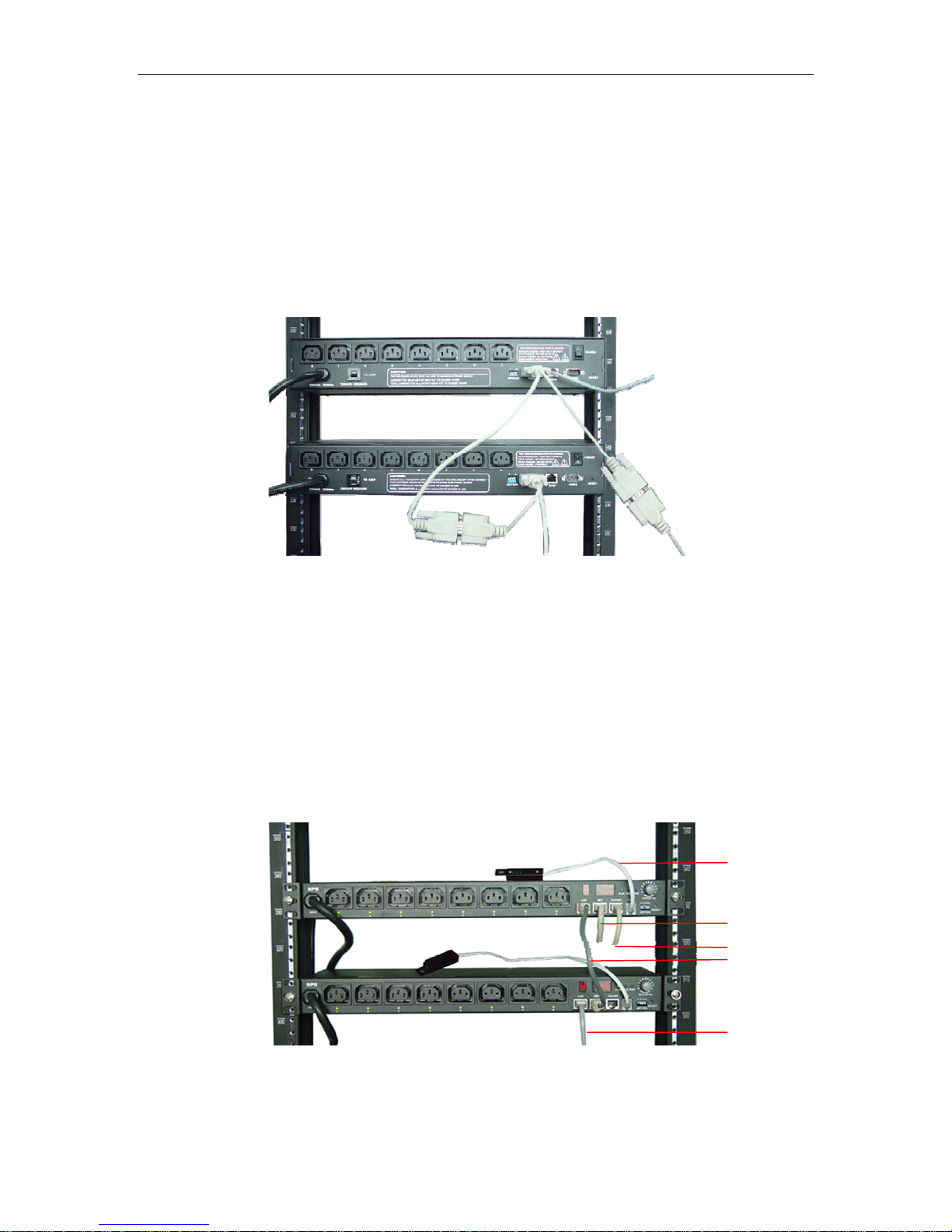
Picture 3.2-2. NPM 3000 series connection
1 T emperatur e/hum idity
senso
2 Connect RJ45
3 connect to PC COM
4 NPM dais
4 NPM dais
chain
chain
ort
NPM Manual
Explanation of NPM 3000 series connection (NPM 4000/5000 series similar)
emperature/humidity sensor;
1: T
: If control NPM via network, please connect to RJ45 port of PC or HUB, Router, Switch,
2
etc.
: If control NPM via local RS-232, connect to COM port of PC.
3
: NPM daisy chain cable, begin at master NPM unit, from LINK port to RS-232 port of next
4
NPM unit, the rest may be deduced by analogy.
4. Use of control software
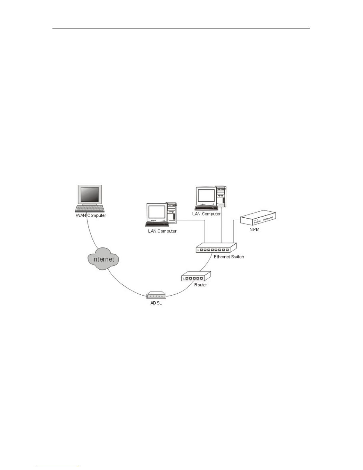
4.1 NPM which connect to network
Dummy connect method when NPM connect to Ethernet:
4.2. Explanation for using control softw re
After finished install hardware, install control software: Network Power Manage System
o
n PC. The following is explanation of control software: Network Power Manage System.
Page 9 of 28
Picture 4.1-1 NPM connect to network
a
 Loading...