

Page 1

NPM Manual
Network Power Manager
(v1.10.1)
Shenzhen Clever Electronics Co.,Ltd.
Page 1 of 28
Page 2

NPM Manual
1. PRODUCT INTRODUCTION.........................................................................................................3
2. PRODUCT DESCRIPTION ............................................................................................................3
2.1 NPM 2000 ...................................................................................................................................3
2.2 NPM 3000 ...................................................................................................................................4
2.3 NPM 4000/5000..........................................................................................................................6
3. HARDWARE INSTALLATION ........................................................................................................7
3.1. OPTION SWITCH .......................................................................................................................... 7
3.2 NETWORK CONNECTION AND DAISY CHAIN OF NPM...................................................................8
4. USE OF CONTROL SOFTWARE .................................................................................................9
4.1 NPM WHICH CONNECT TO NETWORK .......................................................................................... 9
4.2. EXPLANATION FOR USING CONTROL SOFTWARE........................................................................9
4.2.1 Login system.....................................................................................................................10
4.2.2 Main screen.......................................................................................................................10
4.2.3 Initialization network configure....................................................................................... 13
4.2.5 The alarm setting about the overload and exceed limit.............................................. 18
4.2.6 the automatic manage setting........................................................................................ 19
4.2.7 User management............................................................................................................21
4.2.8 Assign properties of NPM for user.................................................................................22
4.2.10 change the user..............................................................................................................24
4.2.11.modem initialization........................................................................................................ 24
4.2.12 NPM groups’ configuration............................................................................................24
5: TECHNOLOGY PARAMETERS ..................................................................................................25
6: THE INCASEMENT LISTING ......................................................................................................25
7: INSTALLATION ..............................................................................................................................26
APPENDIX1 LIST FOR DEFAULT OCCUPIED PORTS IN TCP AND UDP............................28
Page 2 of 28
Page 3

NPM Manual
1. Product Introduction
NPM network power manager is an intelligent power managing system. The user can
control and manage outlets of each NPM through software. The administrators can control the
NPM from anywhere via Internet, or just dial-in from a modem for off-internet power control,
and also can perform the 0-800m short distance off-internet power control via RS-232, or
RS-485 in the LAN.
Through the NPM management software, the user can expediently configure the name of
each outlet, switch on/off, timing switch on/off, and look over current of individual outlet,
environment temperature, humidity, smoke, water, door open status, etc. For CLVER NPM
product, there is Four series, contain:NPM2000、NPM3000, NPM4000, NPM5000.
Security feature
NPM have two security levels, administrator level and user level. The administrator is allowed
to access all configuration and command functions. The user is allowed to access functions
which had been given property. User level security features are ideal for co-location
applications. It allows multiple users access to a certain outlet of NPM unit. Each NPM have
a system password and you can modify it. This password will reject the access of any PC
which is not allowed.
Convince installation
The on/off of the plugs are controlled by the simply ASCII commands which are sent via
network, modem, short distance PC (LAN). Its configuration is also simple and easy to install
following the menu of the installation program.
2. Product Description
2.1 NPM 2000
Main character:
Horizontal installation, 8way outlets, 19” length, 2U;
Switch on/off individual outlet and display on/off status of individual outlet;
Timing switch on/off individual outlet and display on/off status of individual outlet;
Original state and keep original state of individual outlet;
Sequential power up/down individual outlet,
Page 3 of 28
Page 4
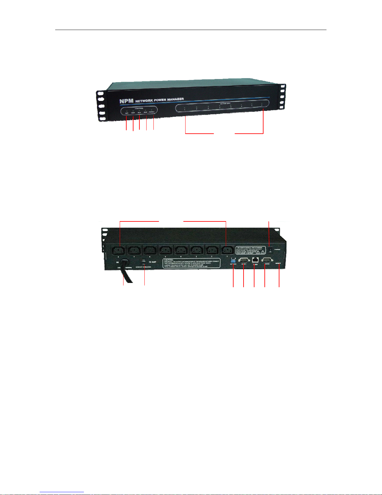
NPM Manual
1 4
3
2
1: Network connect indicator: light when connect;
2: RND next unit communicated indicator: flashes when next NPM unit is
communicating.
3: RLD this unit communicated indicator: flashes when this NPM unit is communicating;
4: RUN run status indicator: flashes when this unit works normal;
5: POWER power indicator: Light when power supply of this unit is normal;
6: Bus A Indicators(1-8):Lights when the relative outlet is switched on.
5
Picture 2.1-1. NPM 2000 frontal panel
1
3
1: AC Power outlets: 8way, 10A/way;
2: Master power switch: ON/OFF power supply of this unit;
3: Power input: power input cable plug (IEC320 C20/IEC60309 plug);
4: Circuit breaker: overload protector;
5: Option switch: DIP switch, for configure master/slave unit and other status;
6: COM1: RS-232/482 port, DB9 connector, for connecting PC or next unit.
7: Network port: RJ45 ethernet network port, for connecting TCP/IP network;
8: COM2: MODEM port, RS-232/DB9 connector, for connecting external MODEM, when
control NPM via MODEM;
9: RESET button: Restart or reset NPM CPU. Under not effect outlets on/off status,
allows to reset NPM CPU.
4 5 6 7 8 9
Picture 2.1-2. NPM 2000 back panel
6
2
2.2 NPM 3000
Main characaters:
Horizontal installation, 8way outlets, 19” length, 1U;
Page 4 of 28
Page 5
NPM Manual
Switch on/off individual outlet and display on/off status of individual outlet;
Timing switch on/off individual outlet and display on/off status of individual outlet;
Original state and keep original state of individual outlet;
Sequential power up/down individual outlet
Display current of individual outlet;
Display total current of unit;
Display humidity and temperature;
User-define alarm;
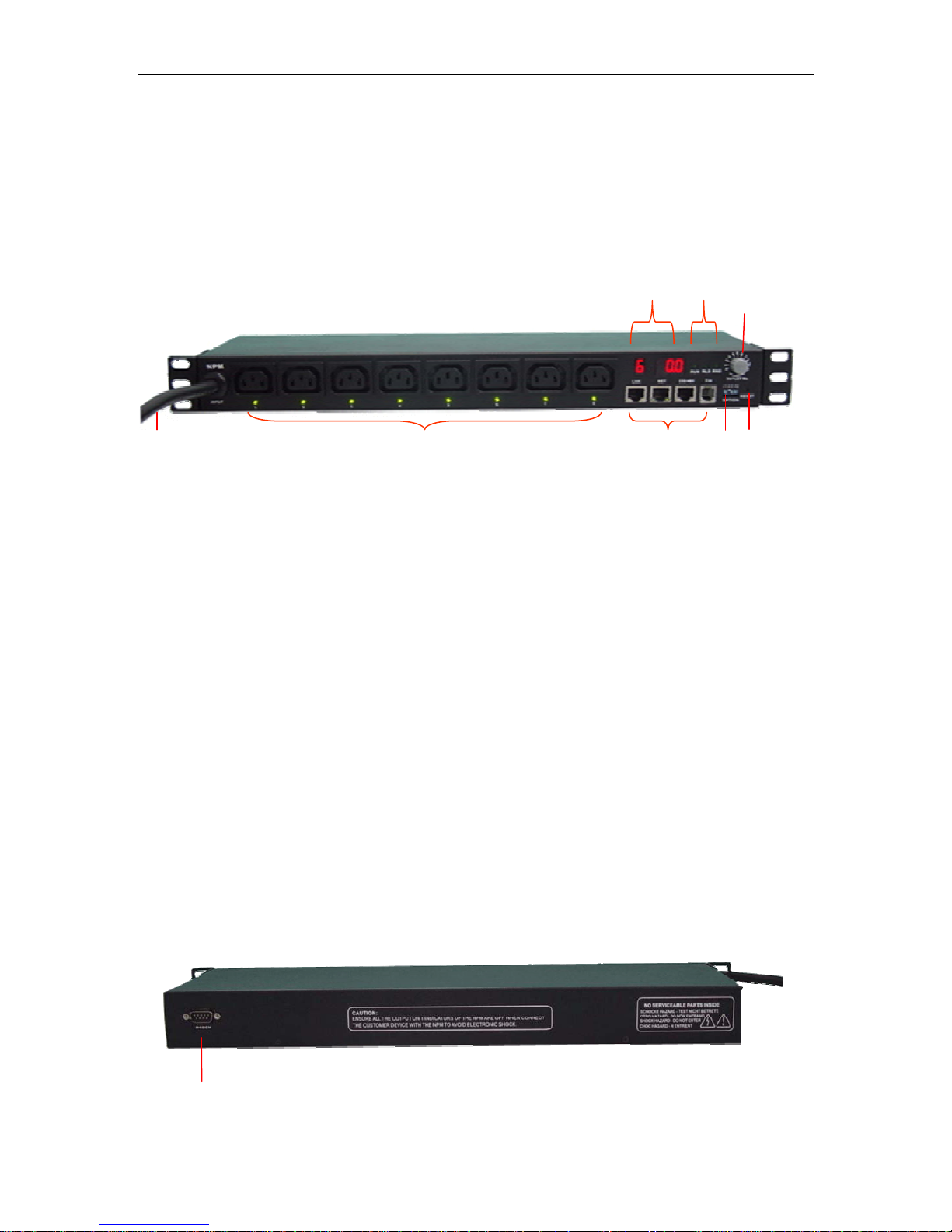
8
1 4 5
Picture 2.2-1. NPM 3000 frontal panel
1: Power input: power input cable;
2: AC power outlets: IEC320 C13 socket, 8way;
Power indicator of relative outlet: Lights when relative outlet is switched on;
3: Four ports;
LINK: When daisy chain multi NPM, this port for connecting RS232/485 port of next
NPM;
NET: For connecting master NPM to WAN, LAN or PC.
232/485: For connecting serial interface of PC;
T/H: For connecting temperature/humidity sensor.
4: OPTION: option switch for set up master and slave property, baud rate, etc.
5: RESET: Reset button, for restart this unit;
6: Three system signal indicator
RUN: Flashes when NPM work normally;
RLD: Lights when NPM unit receive command;
RND: Lights when command received not from this unit;
7: OUTLET NO. Knob for choosing display information, you can choose display current of
certain outlet, or total current of unit, or temperature, or humidity.
8: Digit display, left part and right part
Left part means chosen item, as picture,“6”——mean at present choose to display
No.6 outlet;
Right part means current and temperature or humidity value, such as“0.0”—— mean
temperature /humidity/current is zero.
2 3
6
7
9
Page 5 of 28
Page 6
NPM Manual
Picture 2.2-2. NPM 3000 back panel
9: MODEM PORT: For connecting MODEM when control via external MODEM.
2.3 NPM 4000/5000
Main character:
Vertical installation, super high power, 380V AC input (NPM 5000);
Switch on/off individual outlet and display on/off status of individual outlet;
Timing switch on/off in of individual outlet;
Original state and keep original state of individual outlet;
Sequential power up/down individual outlet
Display current of individual outlet;
Display total curren
Display current of group outlets;
Display humidity a
User-define alarm;
dividual outlet and display on/off status
t of this unit;
nd temperature, smoke, water, door open status, etc;
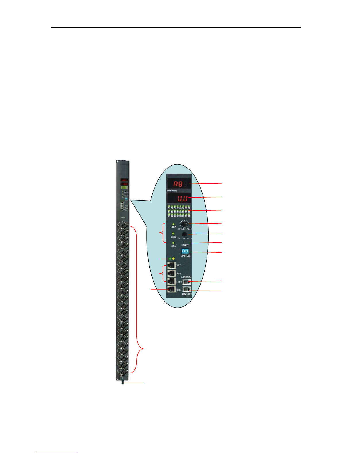
15
14
13
12
3
11
10
9
4
5
8
6
7
2
Picture 2.3-1. NPM 4000/5000 control panel
1: Power input cable;
Page 6 of 28
1
Page 7

NPM Manual
2: Max. 24way outlets;
3: Three system signal indicator
RUN: Flashes when NPM work normally;
RLD: Lights when NPM unit receive command;
RND: Lights when command received not from this unit;
4: Indicator of network connection
5: Three connect ports
NET: For connecting master NPM to WAN, LAN or PC, when control via network;
SER: for connecting COM port of PC when control NPM via local RS-232;
LINK: When daisy chain multi NPM, this port for connecting serial port of next NPM;
6、T/H: For connecting 1 or 2pcs of temperature/humidity sensor;
7、SENSOR2: for connecting water, door open status sensor;
8、SENSOR1: for connecting smoke sensor;
9、OPTION: option switch for set up master and slave property, baud rate, etc.
10、RESET: reset button for restart NPM.
11: Choose group A or group B or group C outlets;
12: Choose certain outlet in a group(A/B/C);
13: On/off status of individual outlet, green color means switch on.
14: Display current and environment parameter, such as temperature, humidity,etc.
15: Display outlet No. chosen at present.
3. Hardware installation
3.1. Option Switch
1: Choose master/slave property:
Option NO.1and option NO.2, for selecting master or slave features of NPM unit.
1OFF/2ON: NPM is master NPM, 1ON/2OFF NPM is slave NPM.
One master NPM max. can daisy chain 31pcs slave NPM.
2: Choose baud rat
Option NO.3 fo F
Default baud rate of NPM
3: Reset default value.
A: Option No.1, No.2, No.3 for reset default a
Reset NPM default address and pass
address=65535;
Operate procedure:
1): Switch off power supply of total unit;
2): Set up option No.1, option No.2, option No.3 be on;
3): Switch on power supply of total unit, wait for 3 second, then switch off power
ply again, for 3 second;
p
su
4: Resume on/off status of option switch.
B: Option No.4 for reset network default parameters of NPM
Reset NPM default network
mask=255.255.255.0,port=4001, baud rate=19200, data bit=8, stop bit=
setting password=88888;
Operate procedure:
e:
r setting baud rate: 3OF =19200BIT,3ON=9600BIT.
is 9600BIT。
ddress, password of NPM;
word init
ial value: password=12345678,
.
parameters: IP=192.168.0.178, Subnet
1, network
Page 7 of 28
Page 8
1): Switch off power supply of total unit;
r
p
y
y
2): Disconnect all devices connecting to the NPM;
3): Make option No.4 to be ON.;
4): Switch on power supply of total unit
again, for 3 second;
5): Make option No.5 to
NPM Manual
, wait for 3 second, then switch off power supply
be OFF.
3.2 Network connection and daisy
Conn
ection picture of NPM2000:
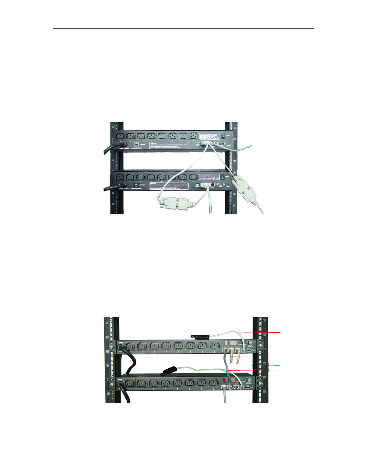
Master NPM
Input cable
Slave NPM
Picture 3.2-1. NPM2000 series connection
Ex
planation of NPM 2000 series connection:
1: If or HUB, Router, Switch,
control NPM via network, please connect to RJ45 port of PC
etc.
control NPM via local RS-232, connect to COM port of PC.
2: If
onnect to COM1 port of nex
3: C t NPM.
chain of NPM
3 connect to
next NPM
1
connect RJ45
2 connect PC COM port
Master
NPM
Slave NPM
Page 8 of 28
Picture 3.2-2. NPM 3000 series connection
1 T emperatur e/hum idity
senso
2 Connect RJ45
3 connect to PC COM
4 NPM dais
4 NPM dais
chain
chain
ort
Page 9
NPM Manual
Explanation of NPM 3000 series connection (NPM 4000/5000 series similar)
emperature/humidity sensor;
1: T
: If control NPM via network, please connect to RJ45 port of PC or HUB, Router, Switch,
2
etc.
: If control NPM via local RS-232, connect to COM port of PC.
3
: NPM daisy chain cable, begin at master NPM unit, from LINK port to RS-232 port of next
4
NPM unit, the rest may be deduced by analogy.
4. Use of control software
4.1 NPM which connect to network
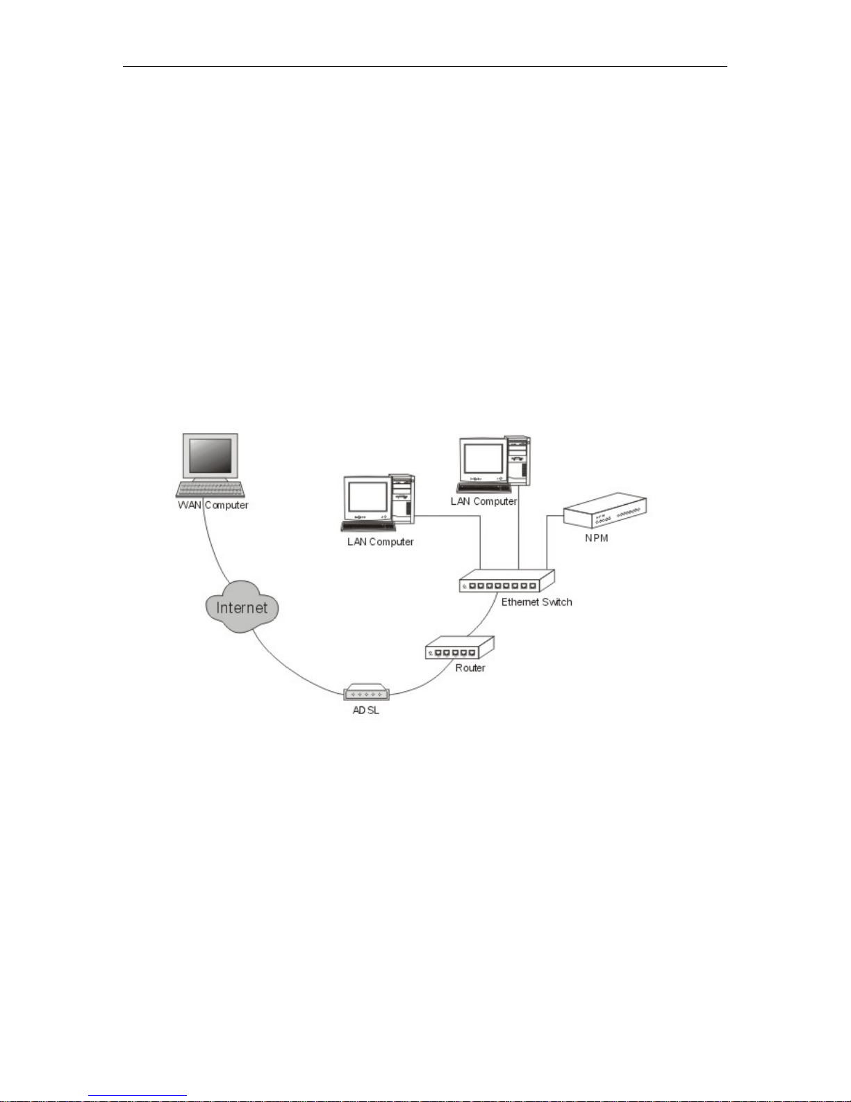
Dummy connect method when NPM connect to Ethernet:
4.2. Explanation for using control softw re
After finished install hardware, install control software: Network Power Manage System
o
n PC. The following is explanation of control software: Network Power Manage System.
Page 9 of 28
Picture 4.1-1 NPM connect to network
a
Page 10
4.2.1 Login system
NPM Manual
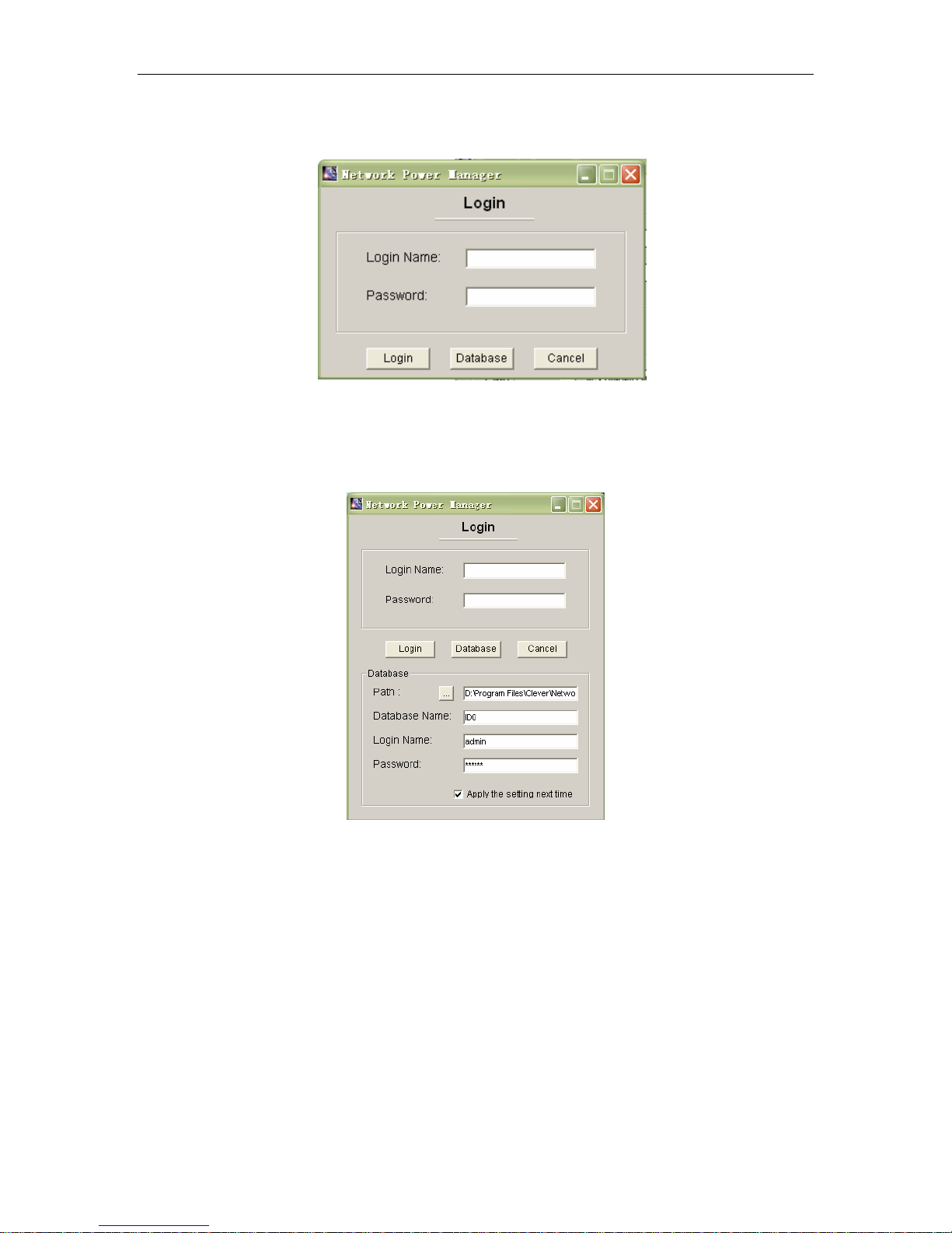
Picture 4.2.1-1 Login system
Explanation:
1: After finished installation of software, there are two default login name: “lxb” and “aa”,
“lxb” is administrator, “aa” is normal user, both passwords are 123.
2: Press “Database”, can configure database information. As following:
Picture 4.2.1-2、Database configure
The database had kept necessary information for running the software. After installed
the system, there is a file”ID0” (Access format) in the install path, Login Name: admin;
Password:(123456). You must defined this path when access the first time. Choose path (is
install path of software, such as “D:\Program Files\Clever\Network Power Manage
System”) . Then press “login”, login the system.
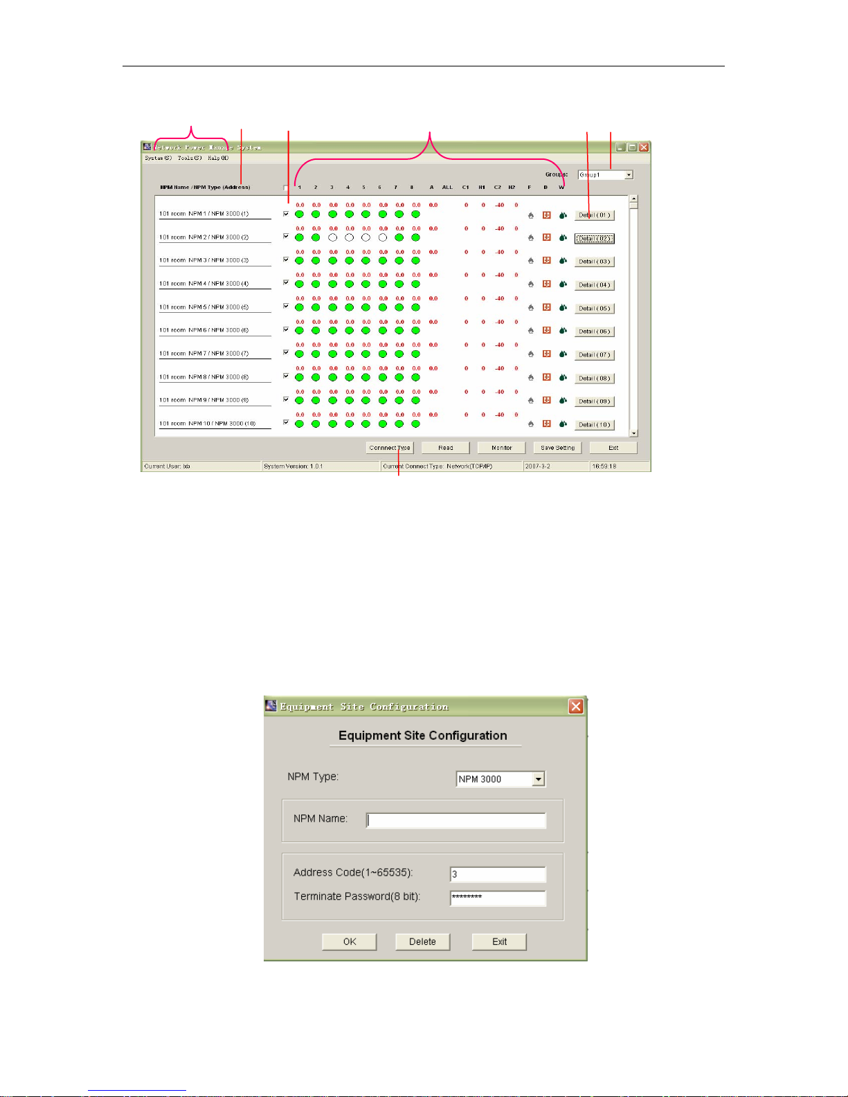
4.2.2 Main screen
After login, access main screen, as following picture. User can get information of
many pieces of daisy chain NPM unit, contain on/off status, current and other parameters.
Also can run the automatic ti rogram
Page 10 of 28
ming get information monitor p
Page 11
NPM Manual
1
.
1、System menu;
2、NPM group choose. Can group NPM units
example, China, USA, Germany or Guangzhou, Shanghai, Shenzhen, etc.
Explanation:
A: NPM of differen
B: NPM unit of different groups have relative configuration.( such as network IP);
C: You can switch to other NPM group, press ”Save setting” to save configuration of
cu
rrent group.
3: etc. Press to modify;
NPM naming: display NPM naming, NPM type and physics address,
3
4
Picture 4.2.2-1 Main screen
t groups, NPM name can different. (contain outlet name.);
5
7
according area or other requirement: For
6
2
Page 11 of 28
Picture 4.2.2-2、NPM name and address
Page 12
NPM Manual
4:
Choose NPM, when choose you can read this NPM;
5:
Status parameters of NPM:
1~8: on/off status of NPM outlet, and current of outlets.
Green color means switch on, white color means switch off, grey color m
invalid or have no right to access relative outlet.
A:total current of this 8way outlets;
ALL:Total current of group A, B, C;
C1: Temperature of place No.1.
T1:Humidity of place No.1;
C2:Temperature of place No.2;
T2:Humidity of place No.2;
F: Smoke sensor: red mark flashes when it detect smoke;
D: Door open sensor: red door mark means door open, gray mark means door closed.
W: Water sensor: water mark flashes when there is water.
6: Manage NPM:
Press to access relative NPM unit control screen, reference “4.2.4 Manage
Screen” section.
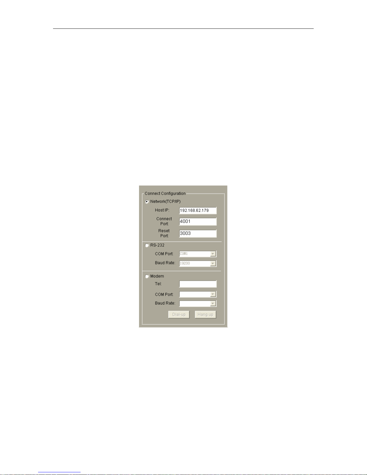
7: Connection configure
eans
Press “Connect Type” button at main screen, it will display configure window, as picture
above:
When “Connect Type” is Network (TCP/ IP ), Configuration parameters as following:
When PC is at the same LAN of PC:
Host IP: Default IP of NPM is 192.168.0.178
Connect Port: Default Port of NPM is 4001
Reset Port: Default reset port of NPM is 3003
When PC control NPM via Internet:
Host IP is WAN port IP of NPM’S LAN. NPM’s IP, Connect Port, Reset Port
must be mapped at NPM’s LAN. More information please refer “Network
configurat
When “Connect Type
Page 12 of 28
Picture 4.2.2-3 connection configuration
ion”Section.
” is RS-232, configuration parameter .
Page 13
NPM Manual
Configure port and baud rate.
When “Connect Type” is Modem, configure parame
The “Tel” is p
hone number of the phone wire which connecting to the
external MODEM;
“Port” number is PC’s MODEM port number ;
“Baud Rate”: Choose one of them.
ters:
4.2.3 Initialization network config
Initializing NPM network config
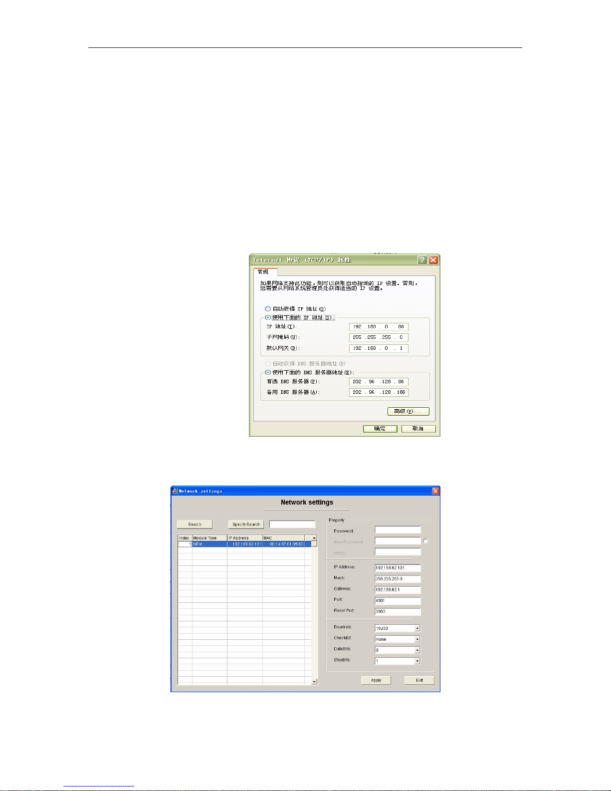
1: If change IP of NPM, nee
For example, configure local IP as follow(DNS can be ig
initialized NPM in the same Net. (NPM’s default IP is 192.168.0.178).
Picture 4.2.3-1、 Make PC and NPM’s IP at the same network section
2: After login the manage software, you will access main screen, then through the
menu access network settings screen:
ure
d make the connected PC at the
ure
before control NPM via network
same network section.
nored),Setting PC and not
Picture 4.2.3-2、 Initialization network configuration
Page 13 of 28
Page 14
NPM Manual
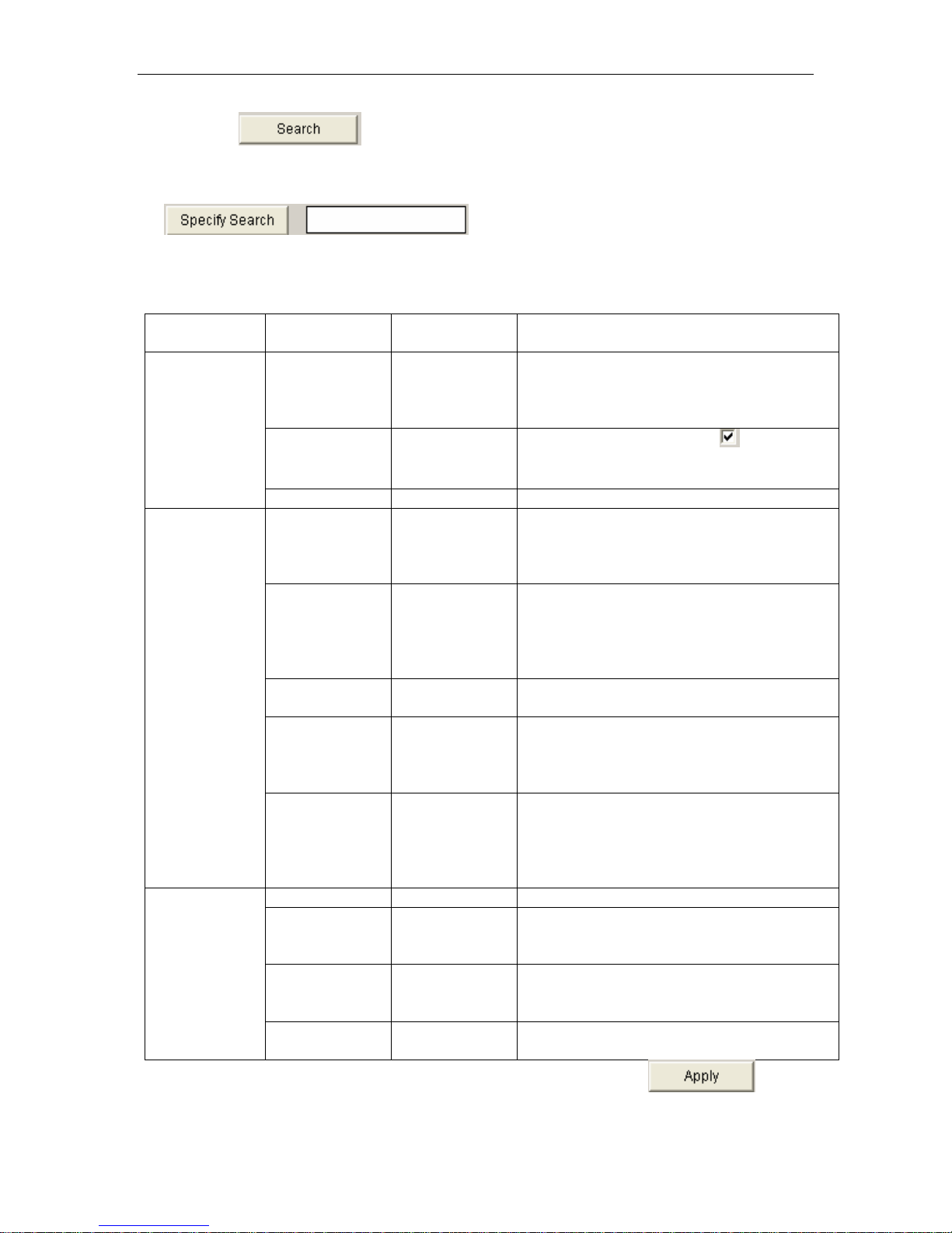
Press search all NPM units of the same network. And list these
nits.The list contains module type, IP address, physics
u address, etc. Double click a
ain NPM, it will show the main parameters of this NPM at “Property” section at
cert right.
tain IP address
Con , subnet mask, gateway, work port, reset port, etc.
Is search via specified IP, the right blank fill the
specified IP.
Explanation of items as following:
Item
Name Default Value Explanation
You must enter correct password before
modifying other items. The password can
reach 9 bits. And you can
use a~ z, A~Z,
0~9 etc.
You must choose “Yes”
firs on the
right side. Then you can fill ”New
password” and “Confirm new password”.
Password
Operation
Password 88888
New Password
No
Verify No Confirm new password
You cannot fill X.X.X.0 or X.X.X.255. IP
IP Address 192.168.0.178
address is address in the network for
network devices such as PC and NPM,
etc. It is exclusive in the same network.
Subnet mask is very important for the
network. The value of subnet mask is the
Mask 255.255.255.0
same with IP address
in the same network. So you must set the
IP address and subnet mask correctly.
IP Configure
Gatewa
y 192.168.0.1
Fill the gateway’s IP address or router
address of home network.
You can fill 1~65535, some are occupied
Port 4001
by other network agreements. Thes
occupied ports can’t be used. More
relative details please refer appendix.
Reset port. Can fill 1~65535. Some ports
are occupied by other
Reset Port 3003
network agreements. These occupied
ports can’t be used. More details please
refer appendix.
Config of
Serial Port
for
communicatin
g
network and
NPM
Baud rate 19200 Can choose 9600 19200
There are 5 items. You can choose “No”,
Check Bit NONE
“even”, “odd”, “force configure to 1”, “force
configure to 2”
Mean the availability data bits which
Data Bits 8
through the serial port. You can choose
5,6,7,8.
Stop Bits 1
There are 2 choices; 1 bit and 2 bits.
(Mean the length of stop bit)
e
If you modified parameters in the “Properties” menu, you must click in the
Page 14 of 28
Page 15
NPM Manual
“Properties” menu. Then the modifying can be sent to NPM. If you fill a wrong value and
haven’t applied it, you can click “search” and modify again. If the NPM can’t work because of
the
modifying (For example modify to a wrong IP address, wrong subnet mask, or forget
pas
sword), you can resume defaulting configuration when factory installed. About the detailed
procedu 3.1.
kwown the properties and the modificatio
n n method of the network parameters for the NPM. So
e b nfigure the NPM to be part of LAN:
res, please refer to
After finished the network c
onfigurations of PC, you can set the module. Now we had
egin to co
). Do sword;
1 uble-click the searched NPM and enter pas
2). Modify the IP in “IP config”, the new IP is
3). Mo
4). Mo
5). Click
6). Resume the network parameters of PC.
dify the subnet mask in “IP config” to be the same as
the gateway in ateway’s IP address or route
dify ” IP config” to be g r
in the “Properties” bla
Then the whole configuration is finished.
Now age N N
we can man PM through LA
an unused IP in the IP pool of the LAN.
subnet mask of LAN.
nk to submit the modifying.
.
Remote manage NPM via PC
If remote manage and control NPM via PC, do as foll
A) Configure the NPM to be part of as
the LAN, same
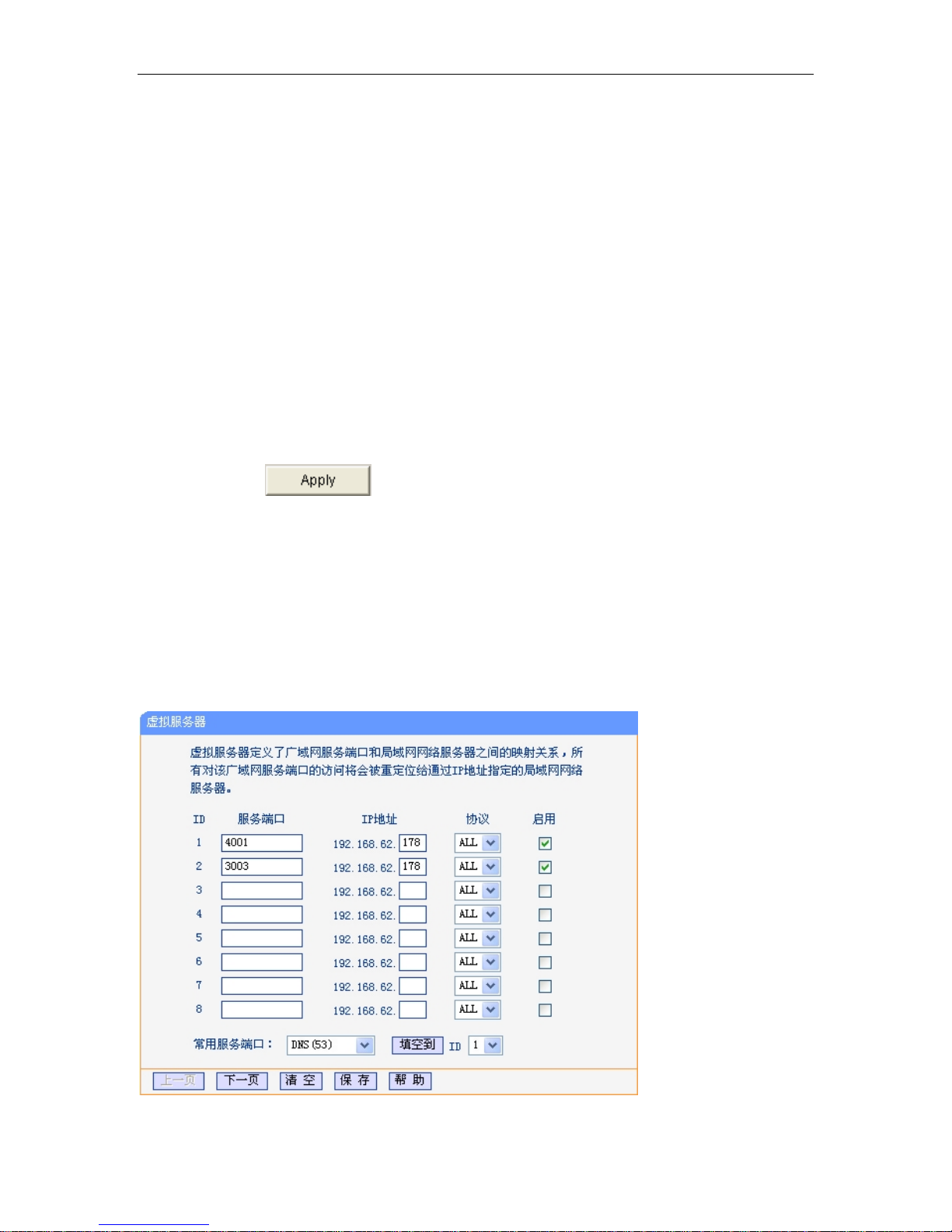
B) Let the PC access the Router in the LAN, Map NP
owing:
above.
M’s IP and Port (4001 and 3003) in the
uter’s Virtual S rver. As fo picture.
Ro e llowing
Page 15 of 28
Page 16
NPM Manual
C) Run the NPM management software in the remote PC, login as administrator, in the m
window, enter the “HOST IP” and the two ports. The “HOST IP” is the same with the “WAN”
port’s IP address of LAN’s Router. This LAN means the LAN which the NPM belong.
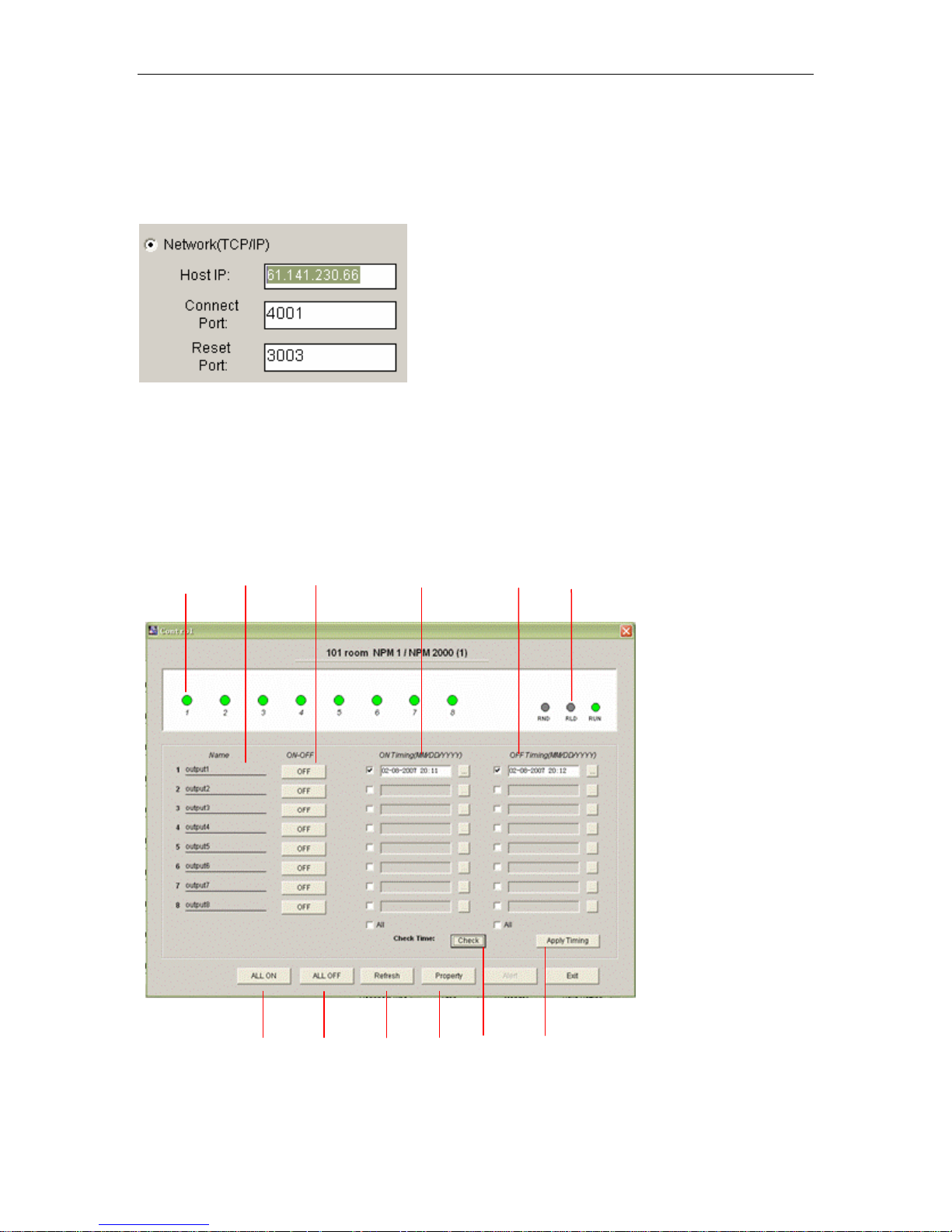
4.2.4
In main resses “Deta l screen of
NPM. In this screen user can pow ate
addres
Control Screen Details
window, p il (01)”or: “Detail (02)”…access the relative contro
s and terminate password of NPM, and check the time of NPM.
1
er on/off, timing on/off each outlets, modify the termin
4
5
62 3
ain
7
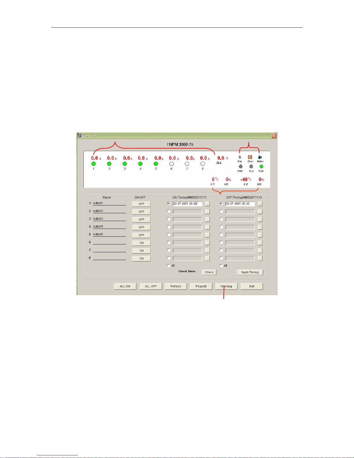
1: Power on, power off state of each outlet;
Page 16 of 28
8 9
Picture 4.2.4-1、、NPM 2000 control managing window
10
11 12
Page 17
NPM Manual
2: Name of each outlet unit;
3: Configure on/off of each outlet;
4: Timing on;
5: Timing off;
6: System the 3indactors on the front panel, more information please to
the produ description part;
7: Power on all the outlets;
8: Power off all the outlets;
9: Refresh outlets state, Read all information of outlet state again
10: Property setting of NPM, Including the amending address code and terminal password of
NPM
11: Verify NPM inner clock, Making the same with the clock in the PC system.
12: Apply for timing setting, Making the timing setting effectively.
indicator applies to
cts
1
2
3
Picture 4.2.4-2 NPM 3000 control managing window
NPM3000 control interface setting, except saving all setting of NPM2000, the main difference
is:
Add current display, sensor data display, setting of alarm as follow:
1. Current display of each outlet, Total current display (ALL)
2. Smoke state display,
Door state display,
Water state display;
3. Temperature/ humidity display;
4. Overload, Exceed limit setting ( Detail please see latter introduction).
4
Page 17 of 28
Page 18
NPM Manual
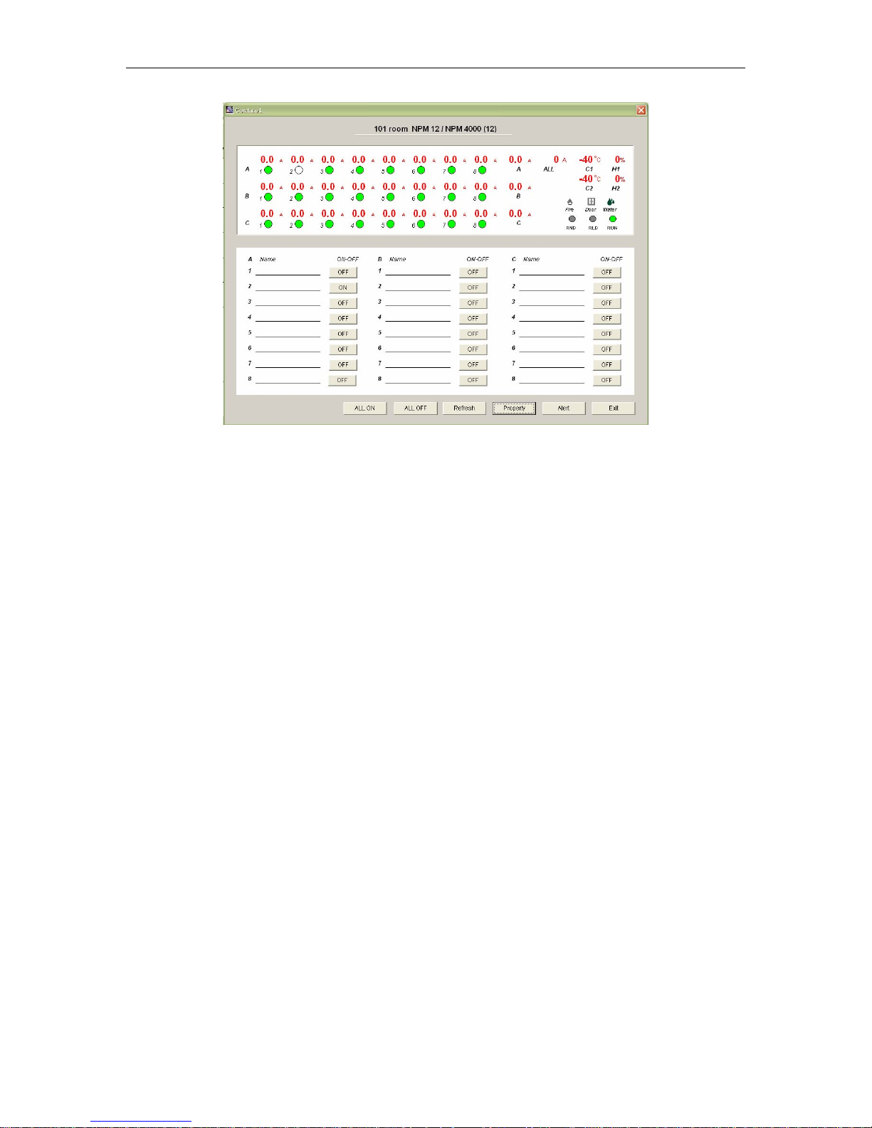
Picture 4.2.4-3. NPM 4000/5000 control managing window
NPM 4000
NPM4000 due to the character of super great current, This control interface setting,
except saving all setting of NPM3000, the main difference is: Add the group setting of
outlets, and grouping current display as follow:
NPM4000
1: A group total current, A group 1-8 way current display of outlet units;
2: B group total current, B group 1-8 way current display of outlet units
3: C group total current, C group 1-8 way current display of outlet units;
4: ALL: Total current display of A+B+C three groups;
NPM 5000
NPM5000 due to 380VAC input, owning the display character of L1, L2, L3 every phase
current, This control interface setting, except saving all setting of NPM4000, the main
difference is: NPM5000 group L1, L2, L3 according to 380VAC power supply as follow:
1. A group means L1: A group total current, A group 1-8 way current display of outlet
units;
2. B group means L2: B group 1-8 way current display of outlet units;
3. C group means L3: C group 1-8 way current display of outlet units;
4. ALL: The t
otal current display without L1, L2, L3 three group;
4.2.5 The alarm setting about the overload and exceed limit.
The administrator can set the current, temperature and humidity lim
are and the NPM system also have the alarm function. When
softw the outlet data overtop the
ng data and the controlling
setti software will flash give an alarm, and you can choose the
sound a arm.
Page 18 of 28
larm or send email al
it value on the controlling
Page 19
NPM Manual
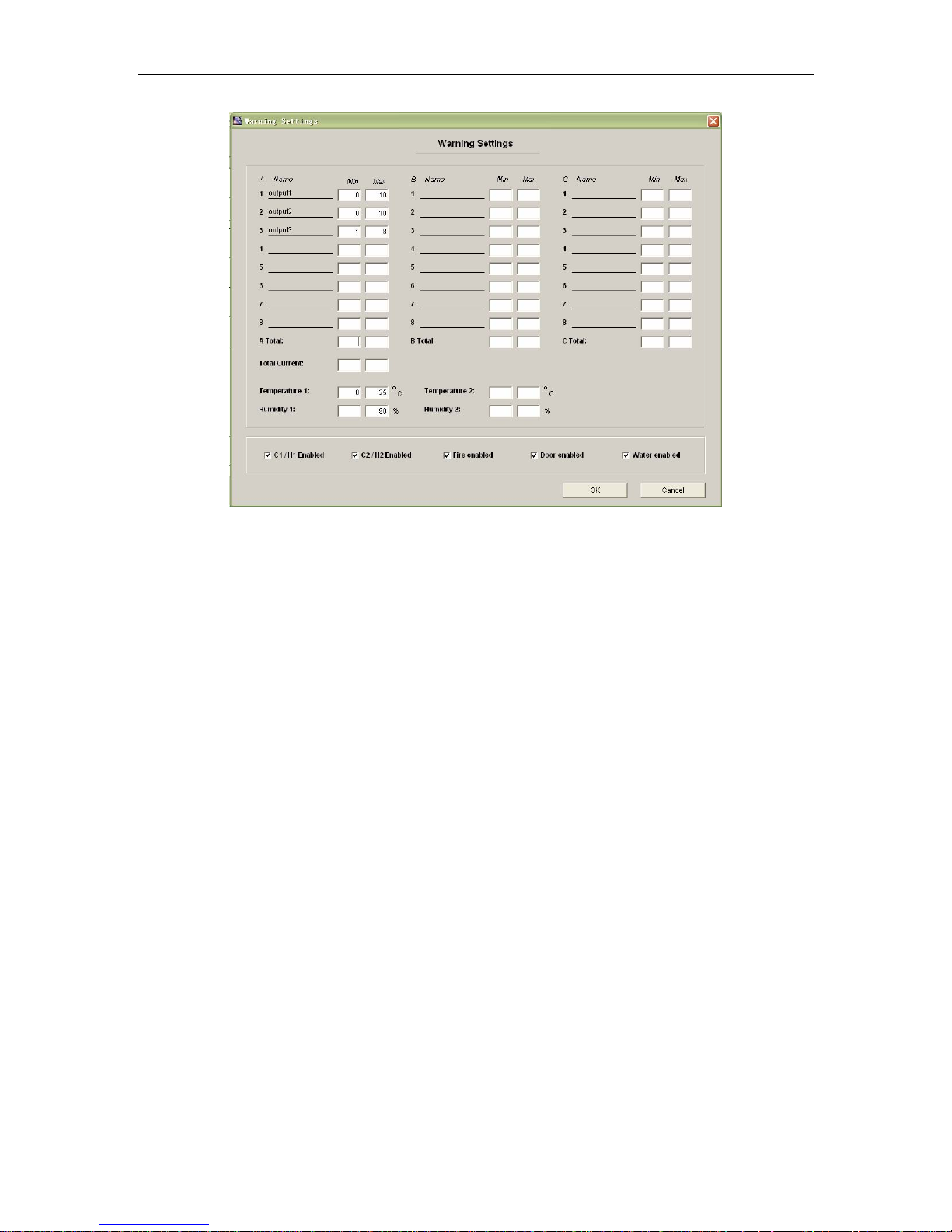
Picture 4.2.5-1、setting the safety limit bound
1, Pre
ss “Warning” can enter the overload and exceed limit setting.
2, Th ture and humidity limit bound
e
administrator can set the outlet current, tempera
3, data
If the system
top the setting data.
over
in: the min limit;Max:the max limit.
4,M
5,Th if is connecting
e warn setting interface contains five options, the us
with the co
rresponding sensor, when the user mark it an
operating automonitor, the system will send the alarm when the outlet
er has been confirm
d it will display the corresponding
data, or it will not.
6,The original default is NPM system default.
4.2
.6 the automatic manage setting.
When the administrator have not the time to manage the NPM, the
will operate and monitor the NPM automatically, then it will display the N
state and others environment state.
1: Operating entrance: (main menu: Tools >> Monitor Set
Page 19 of 28
manage software
PM operating
tings)
Page 20
NPM Manual
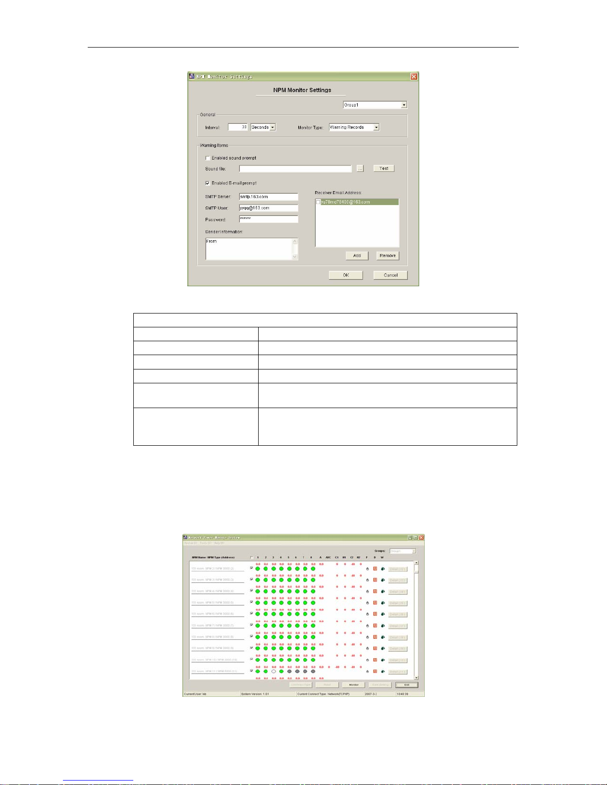
Picture 4.2.6-1、The automatic manage setting.
explain:
Setting the automatic manage parameter
Interval data Interval about the automatic reply
Monitor Type Monitor Type
Warning Records Inquire about alarm records
All Records
Keep all the monitor data。
Enable sound prompt If choose the sound alarm and can user-defined the
soun
d
Enable sound prompt
If open the email alarm,when the user open it , the
user need to collocate SMTP ,including the mail list
that receive the alarm.
2: The operating automatism manage function
The operating entrance:(main interface butt
on —— “ Monitor ”), when operating and the
main interface will automatic hide.
According to the appoi
default 10 seconds )can obtain the NPM state data automatically. When the outlet data
will
top the setting data and the NPM will automatic give an alarm.
over
nted the interval(If you do not set the automatic interval and the system
Picture 4.2.6-2、The operating automatism manage state
Page 20 of 28
Page 21
NPM Manual
When you set the interval, this window will display the NPM outlet state in time, when the
outlet data overtop the setting data and the NPM will automatic give an alarm.
Picture 4.2.6 -3
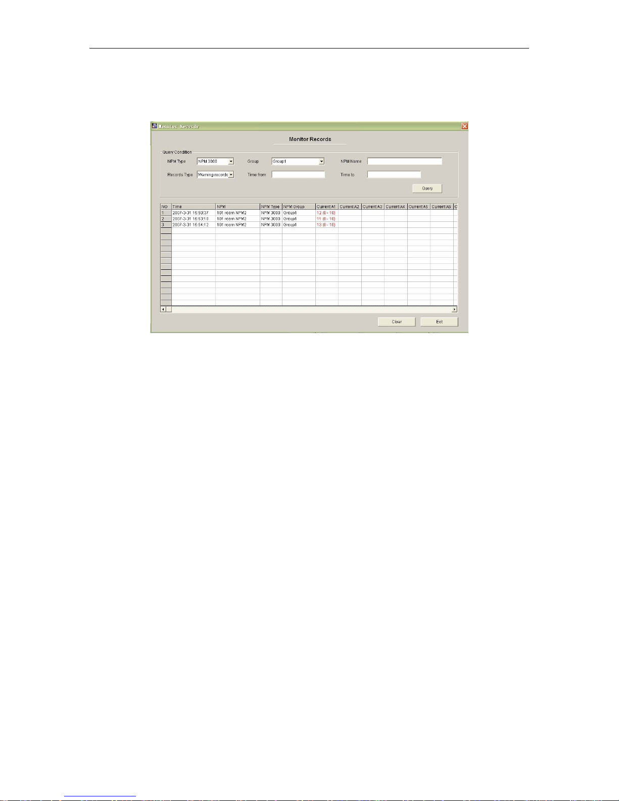
、the automatic manage record
The system will aut
you choose
when ll record the system will record all
ata about th
the d and
m. Press “Monitor Rec
syste ords
omatic data and the sensor data,
the “A
e current
record these overtop current
s” in the manage setting and
the sensor. You can monito
r the records in the alarm
” enters the alarm system menu. As shows the picture.
4.2.7 User managem
Entrance:(main menu: system>>user manage
ent
ment)
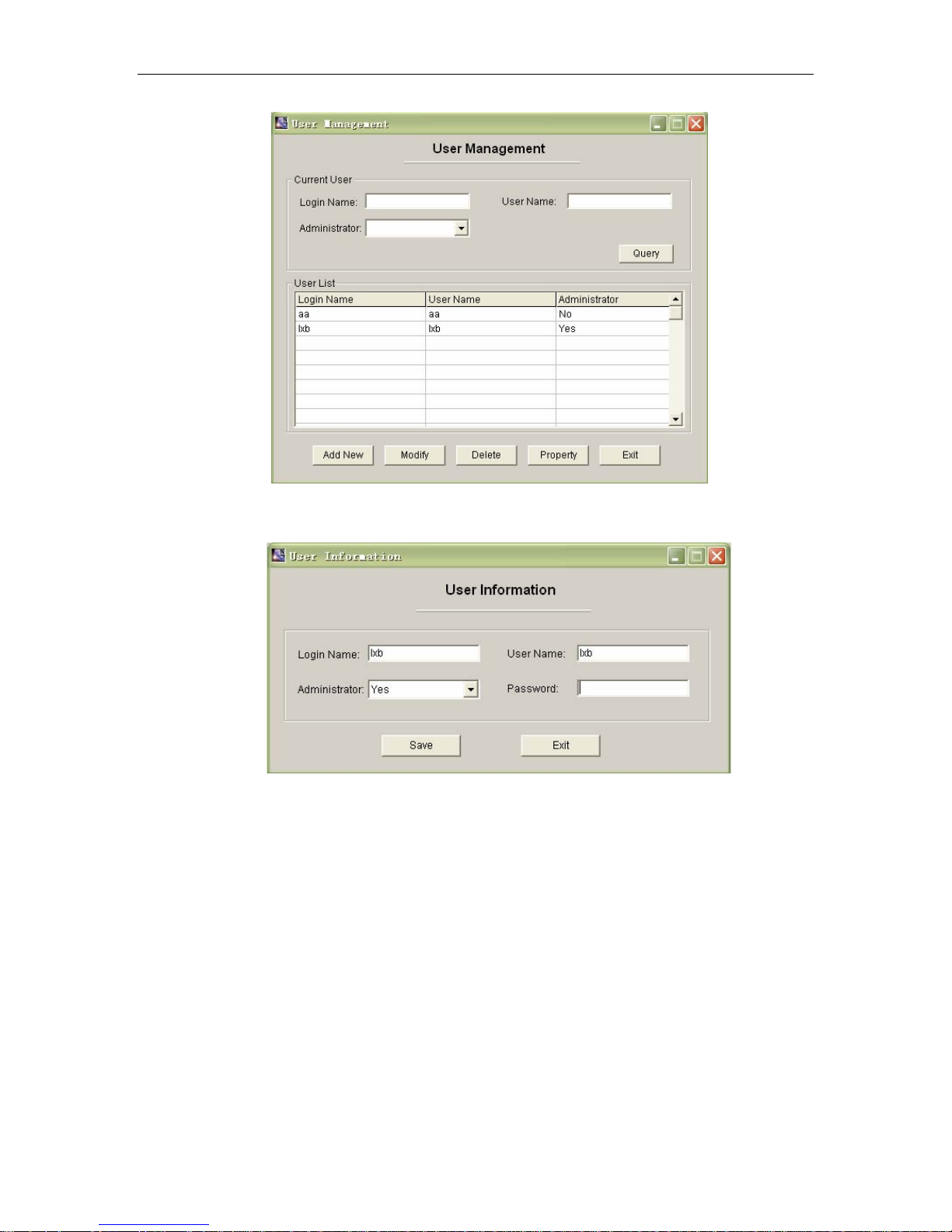
The administrator can manage the users: to add, cancel, modify, the user information.
The selects user’s information will display as shown in picture NO.16. And can modify
only one user’s information each time.
(1) “login name” for login the system is unique. ”User nam
e “is true name of user. It
is not required.
(2) “Administrator”:” yes ” indicates it is administrator currently, “no” indicates it is
not administrator currently.
Page 21 of 28
Page 22
NPM Manual
Picture 4.2.7-1、the user manage
(3 Press “”A picture.
)
dd new” can add new user. As show in following
(4) In the list choose one user and pr
(5)Press “property can assign the properties for the current user. As shown in picture
NO.17..
4.2.8 Assign properties of NPM for user
Entrance: user management >>button “property”.
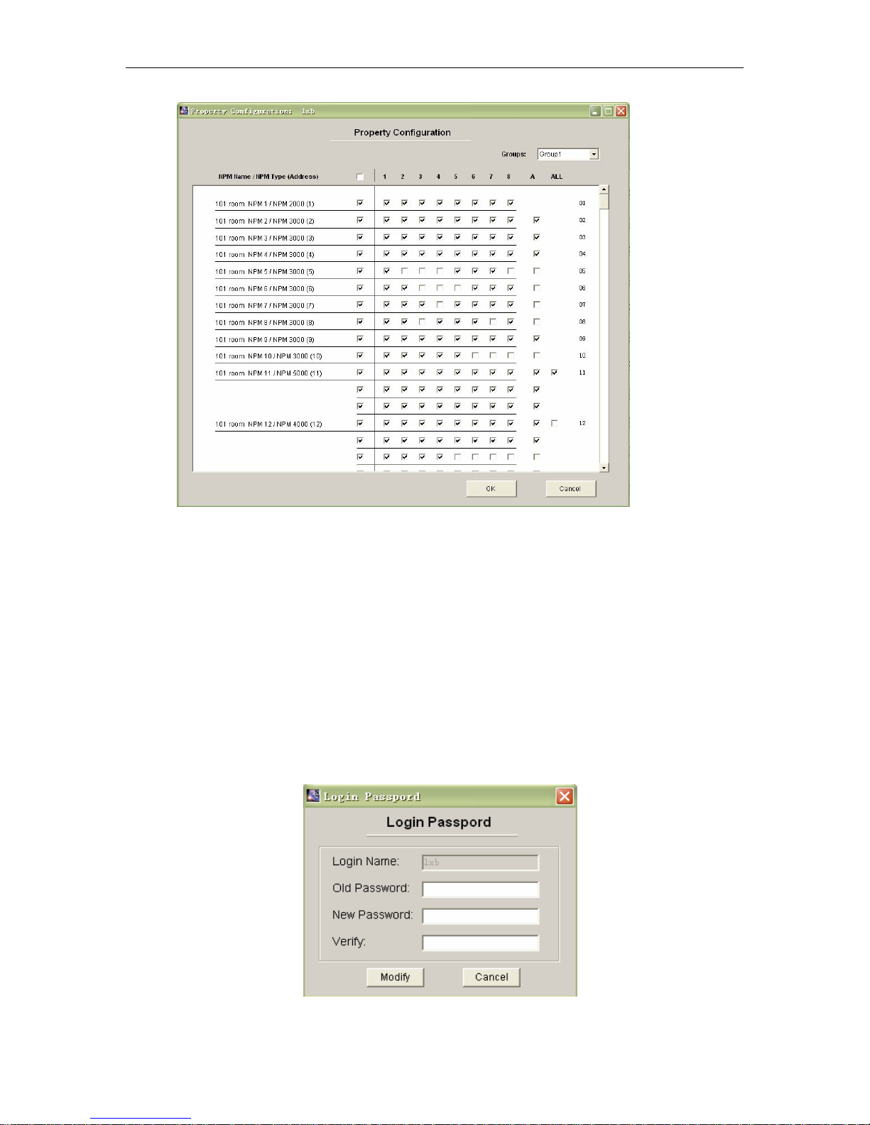
Administrator can perform all functions of all NPM. User can only perform the property
assigned by administrator. The user can control the selected out assign properties of NPM
for user.
Page 22 of 28
Picture 4.2.7-2、the user manage
ess ”Modify”, then you can edit the user information.
Page 23
NPM Manual
865161620
Picture 4.2.8-1、NPM property configuration
1、It is the first step choosing NPM group;
2、Administrator have the right control all the NPM;
3、The administrator assign the user’s right,the frame display each PNM’s outlet state
in the window,if you choose ones and you have the right to control, then you can
see the outlet state and current.
4、A has the corresponding NPM, A/B/C group can display each group total current,
ALL can display A/B/C three groups total current。
5、Press“OK”and save
4.2.9 Modify use’s passwor
the setting.
d
Entrance (main menu: system>>change password)
Yo
u can modify your login password after enter the system, as shown in the following:
Page 23 of 28
Picture 4.2.9-1、Modify the password
Page 24
NPM Manual
4.2.10 Change the user
Entrance:(main menu: system>>change user)
Change the current login user and login again.
4.2.11. Modem initialization
Entrance:(main menu: Tools>>modem initialization)
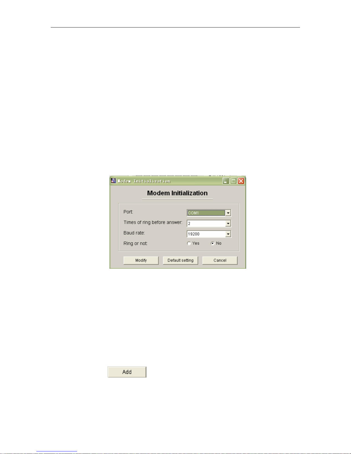
This function is conveniences connect with the NPM external modem. When the user
use it, the external modem connect with the pc port directly, then select the parameter (the
main setting: how many times the system will automatism answer, baud rate, diabolo or no,)
press ”modify is OK”. ”Default setting ” is rebooting the modem to the manufacture’s setting.
Because the different manufacturers produced the modem’s AT are different. The user
can achieve the initialization works by the window systemic super-terminate if it could not
achieve the initialization works by the window.
Picture 4.2.11-1、Modem initialization
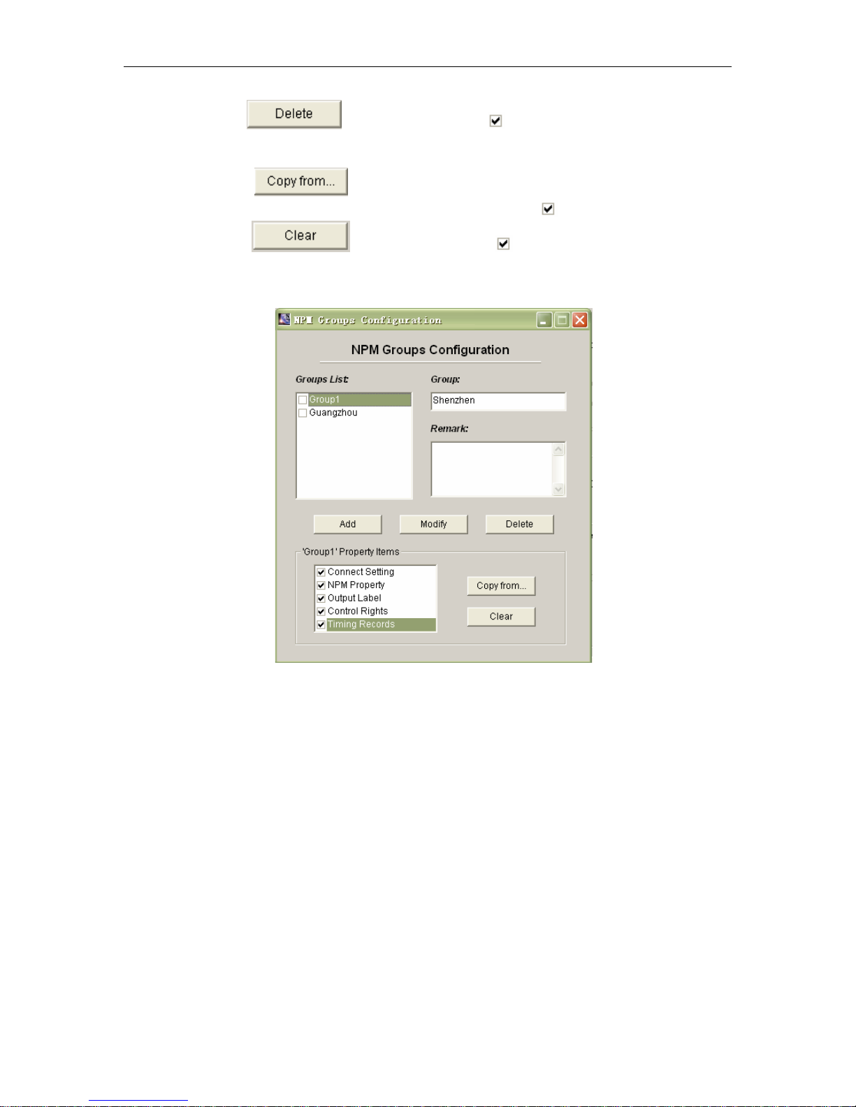
4.2.12 NPM groups’ configuration
Entrance:(main menu: Tools >> Groups Configuration )
In order to control the different area NPM, the manufacturers add the function. The user
can add, delete, modify and setting in the window.
The groups contain connect scheme, NPM (contain the NPM name, address code
terminal password), NPM outlet mark, control purview, timing note and so on five items,
when add a new group, the content is blank and the user can copy it. The following is
operation information.
1、 Press
remark, then keep it.
2、 Choose one group in the groups list, in the right form will display group name
and remark information, and then the user can fill the information in the window.
Page 24 of 28
add the new grouping, in the form fill the name and
Page 25
NPM Manual
3、 Press will delete all marking groups。
4、 Below the window attribute is the current
into two items: copy it from another group, clear these attribute.
attribute, the user can divide attribute
5、 Press
content to the currentl
7、About the detail information, such as conn
and so on will display in others window, the user could not control it in this
window.
will show the Groups List,choose one group and copy the
y group. (only parenthesis
6、Press will clear all marking content。
ect annex, NPM’ s name, outlet mark
like this mark)。
Picture 4.2.12-1、group configuration
5: Technology parameters
The c
haracteristic of the NPM input and outlet, the NPM dimension and the others technology
p
arameters, please reverence the manual.
6
: The incasement listing
N
PM 2000:
1、 ;
one piece of NPM
2、 one piece of serial port line;(3 pin)
3、
one piece of ”Y” type serial port line.
4、 one
5、 one piece of CD (contain a manage software and the user manual
Page 25 of 28
piece of network cable(beeline);
Page 26
NPM 300 000、NPM 5
0、NPM 4 000:
1、o
ne piece of NPM;
2、one
3、o
4、o e
piece of (3 pin);
ne piece of network cable(beeline);
n piece of CD (contain a manage software and the user manual
NPM Manual
7: Ins
(2): Connect single NPM with PC as the foregoing drawing to initialize every NPM.
tallation
1: The ha
2. The software operation
(1) NPM Initializing NPM
rdware Configuring
(1): y NPM as the master NPM model in OPTION. Configuring
Configuring ever
method as 3.1 explanation
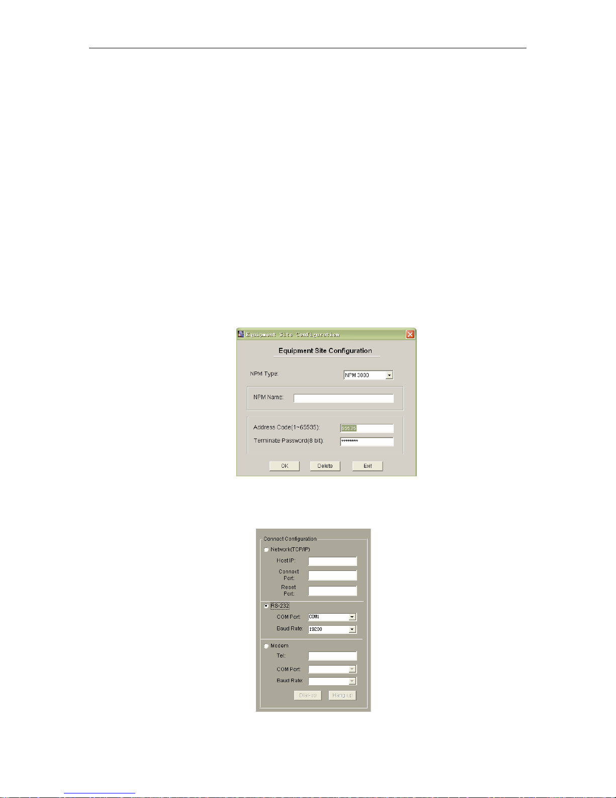
1、Refer to 4.2.1 explanation to log on the controlling software
2、Choose the first NPM name, property label in the main interface, then pop-up the
following configuring window, fill in the address code 65535 and terminal
password 12345678, and choose corresponding NPM type. Press “OK” to save.
Pictu on
re 7 -1、NPM name、address orientati
3、The faster way to initialize the NPM is through connecting the RS-232 port. After log
on the system, press “connect Type” to pop-up the connecting configuration frame.
Page 26 of 28
Page 27
NPM Manual
Picture7 -2、connecting configure
Choose RS-232 a
nd port number, baud rate, then press “Connect Type” again to
the choosing frame.
exit
4、Choose the first NPM(put√in the c
hoosing frame),press inferior button “Read”to
NPM state data.
read
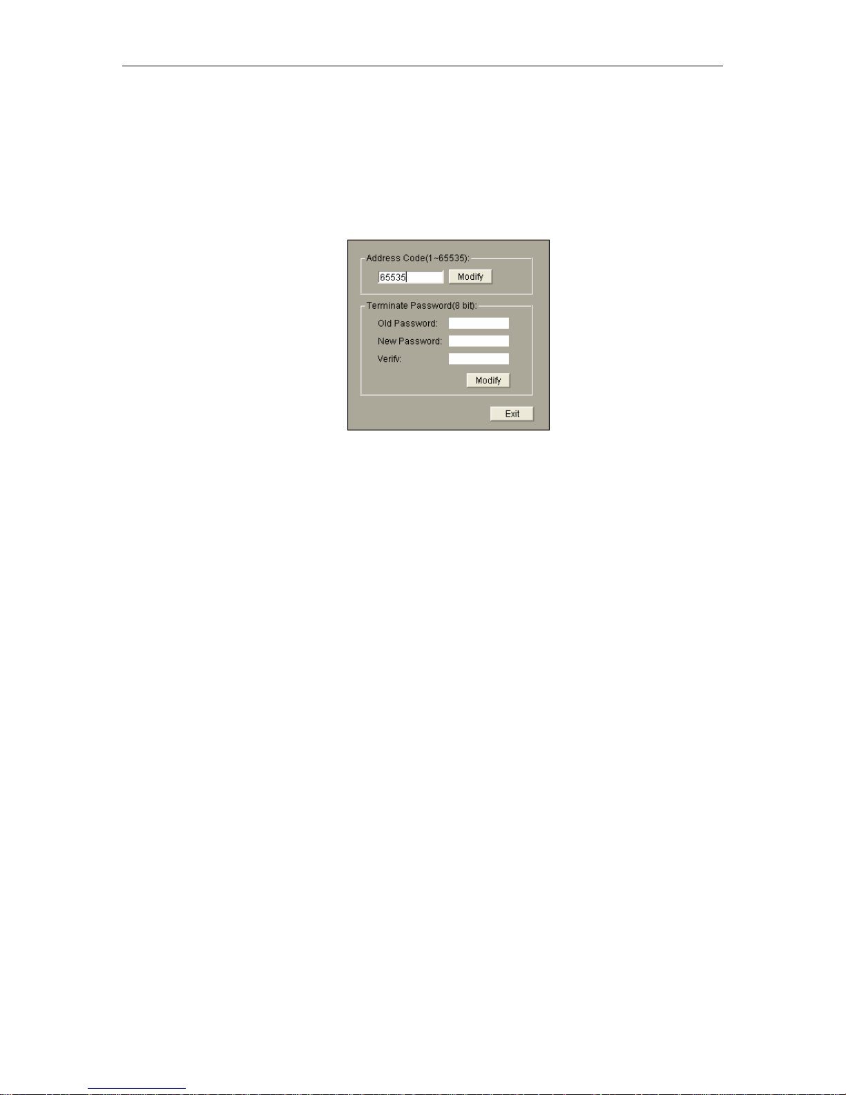
5、Press “Detail(01)” to enter the controlling window, press inferior button “Prope
to pop-up th
e following window:
Picture7 -3、Modify NPM address code, terminal password
The user can modify NPM address code and terminal password in the above
window. The address code among daisy-chain NPM are different, and need to
be configured again. In order to remember, it can be configured the integer
number such as 1,2,3,4,5 etc between 1~65535. Exit the controlling window
after modify successfully.。
6、Carrying out the above operation can achieve to initialize one NPM. If one NPM
is as the master NPM among the daisy-chian NPM and used through network, it
should be network initialization. Follow “4.2.3 Initializing network configuration”
explanation to operate, configure a LAN IP for NPM, can control NPM in the
LAN after configuring successfully.
7、If want to control NPM remotely through internet, shou image from the router
port in the LA external network
N where NPM is located to transfer the data from
ld
to the master NPM. Configuring method see the rearward part of “4.2.3
Initializing network configuration”.。
) Daisy-chain NPM
(2
1、If want to daisy-chain NPM, configure one NPM as master NPM, the rest NPM
are slave NPM, operation please see 3.1
2、Can control NPM through network when network is configured successfully.
Choose “Network(TCP/IP) in the above connecting configuration frame, fill in
the NPM IP address(fill in the IP address of NPM’s router when remotely
control), working port and reset port. Conceal the configuring frame, press
“Read” to read NPM state data.
3、If want to read many daisy-chian NPM, fill in the NPM’s type, address code and
terminal password in the main interface, picth on and choose the corresponding
connecting type.
rty”
Page 27 of 28
Page 28

NPM 用户使用手册
Appendix1 List for default occupied ports in TCP and UDP
Agreement
Port
Reservation 0
TCP port multi channel server 1
2reservation 2
ECHO 7
Reservation 9
Reservation 11
Reservation 13
Network status 15
FTP 20
FTP 21
TELNET 23
SMTP 25
Printer 35
Time server 37
Name server 2 4
Reservation 43
Login host computer agreement 49
DNS 53
DHCP 67
DHCP 68
TETP 69
Gopler 70
Finger 79
HTTP 80
Remote TELNET 107
SUN 111
NNTP 119
NTP 123
SNMP 161
SNMP 162
IPX 213
Reservation 160-223
第 28 页 共 28 页
 Loading...