

Page 1
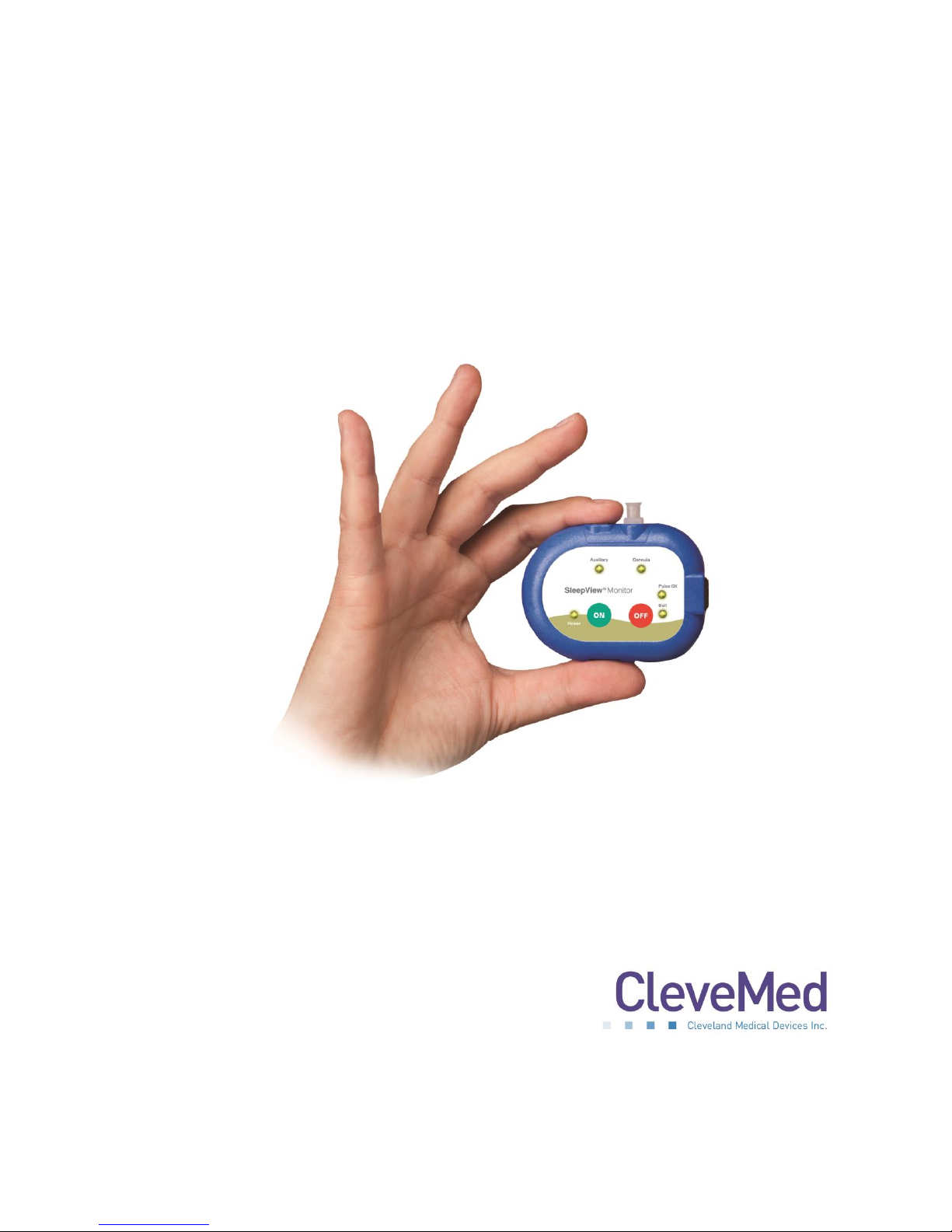
SleepView
User Manual
®
Page 2
SLEEPVIEW USER MANUAL
Cleveland Medical Devices Inc.
4415 Euclid Avenue, 4th Floor, Cleveland, Ohio 44103
EMERGO EUROPE
Molenstraat 15, 2513 BH, The Hague, The Netherlands
© Cleveland Medical Devices Inc. 2015
This manual is copyrighted with all rights reserved. No part of this manual may be reproduced,
transmitted, stored in a retrieval system, or translated into any language in any form by any means
without the written permission of CleveMed. Information in this manual is subject to change without
notice. CleveMed assumes no responsibility for any errors, omissions, or inaccuracies. No part of the
software described in this manual can be reproduced, transmitted, stored in a retrieval system, or
translated into any language in any form by any means without the written permission of CleveMed.
Sani-Cloth is a registered trademark of Professional Disposables International, Inc.
Cavicide and Caviwipes are registered trademarks of Metrex Research LLC.
Windows and Internet Explorer are registered trademarks of Microsoft Corporation in the United
States and other countries.
SleepView is a registered trademark of Cleveland Medical Devices Inc.
392-0027 Rev. G, DCO 1078
2
Page 3

SLEEPVIEW USER MANUAL
Table of Contents
Chapter 1: Introduction ................................................................................................................................ 4
Contraindications ...................................................................................................................................... 4
Warnings ................................................................................................................................................... 4
Minimum System Requirements .............................................................................................................. 5
Intended Use ............................................................................................................................................. 5
Package Contents and Warranty Information .......................................................................................... 5
Chapter 2: About SleepView ......................................................................................................................... 7
Chapter 3: Accessories, Sensors and Maintenance ...................................................................................... 8
Chapter 4: SleepView Manager Software ................................................................................................... 11
Chapter 5: Data Upload Management ........................................................................................................ 13
Chapter 6: Using SleepView with clevemedsleepview.com ....................................................................... 15
Creating a New Study .............................................................................................................................. 15
Check-In Study Data from SleepView Monitor ....................................................................................... 21
Chapter 7: Manage Recordings ................................................................................................................... 23
Chapter 8: Reviewing Studies ..................................................................................................................... 25
Chapter 9: Using SleepView Manager (Offline) .......................................................................................... 27
Preparing SleepView for a Study (Offline Usage) ................................................................................... 27
Downloading Study Data from SleepView Monitor (Offline Usage) ....................................................... 29
Chapter 10: Collecting Data ........................................................................................................................ 30
Chapter 11: Tips for Dispensing SleepView ................................................................................................ 32
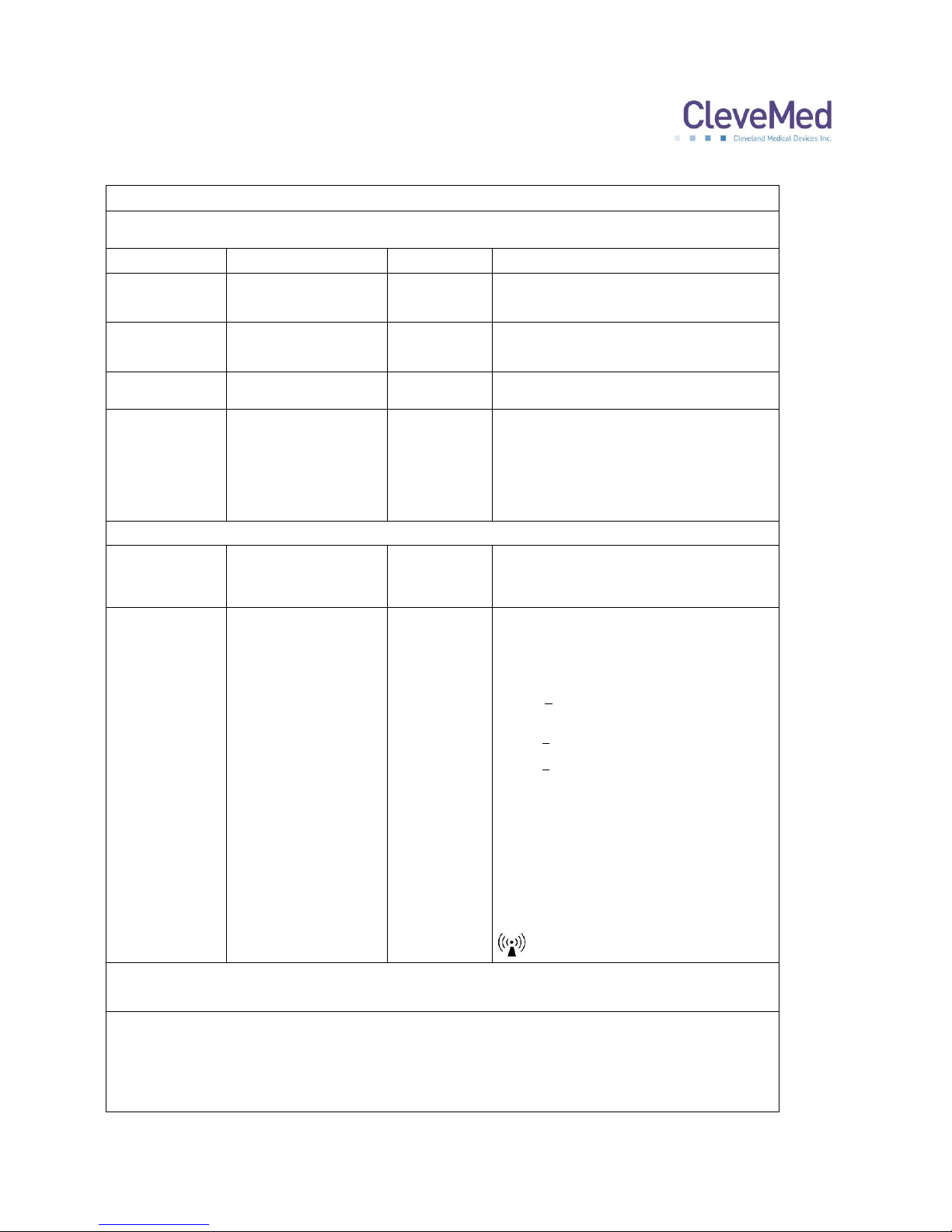
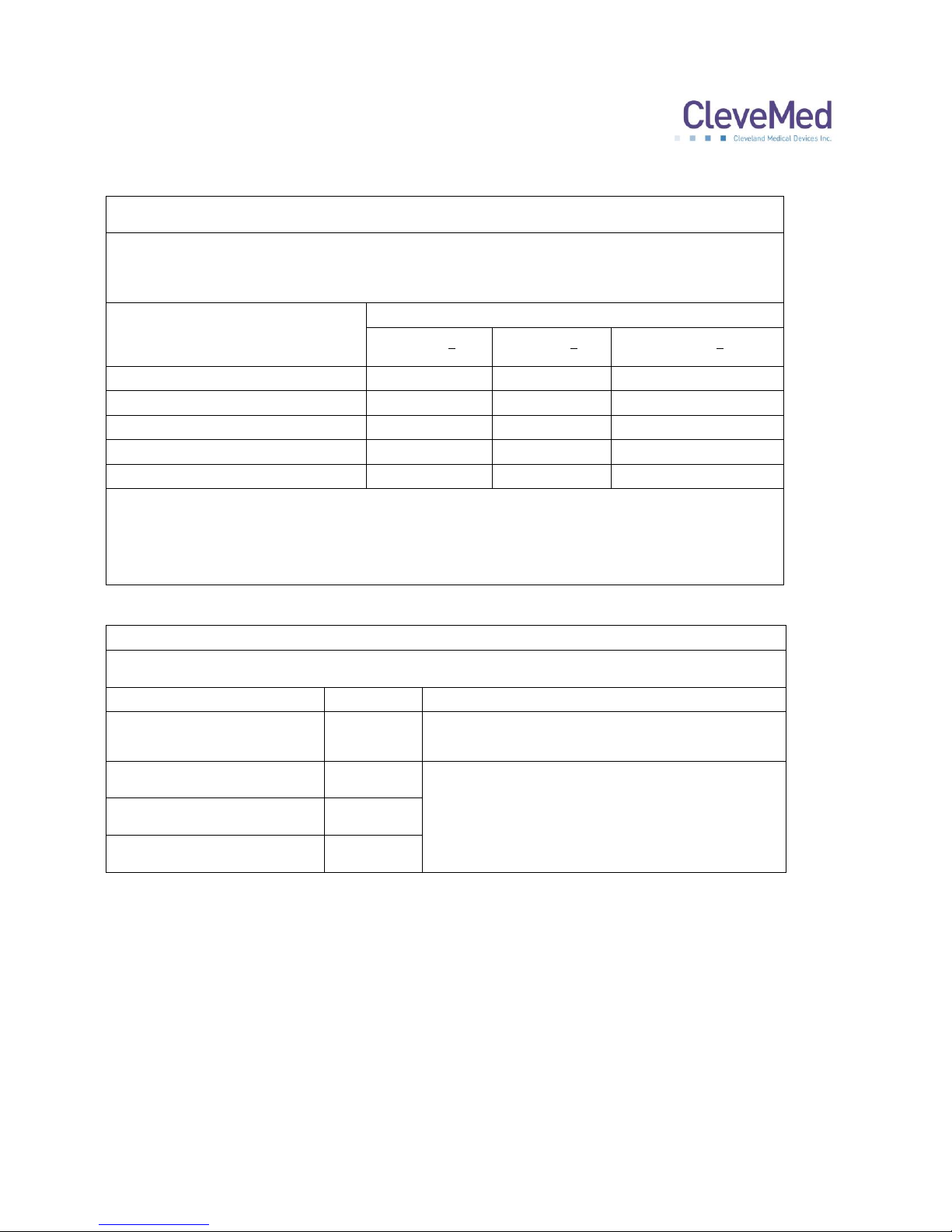
Appendix A: Electromagnetic Immunity and Emissions ............................................................................. 33
Appendix B: Technical Specifications .......................................................................................................... 35
3
Page 4
SLEEPVIEW USER MANUAL
Chapter 1: Introduction
The SleepView Monitor complies with Part 15 of the FCC rules. Operation is subject to
the following two conditions: (1) this device may not cause harmful interference, and (2)
this device must accept any interference received, including interference that may
cause undesired operation.
IMPORTANT NOTE: The manufacturer is not responsible for any radio or TV
interference caused by unauthorized modifications to this equipment. Such
modifications could void the user’s authority to operate the equipment.
Contraindications
Normal operation may be affected when used in the vicinity of equipment marked with
the following symbol:
This device complies with CFR 47 – Part 15, 15.109(b), 15.249 and 15.247.
See Appendix A : Electromagnetic Immunity and Emissions for more details.
Warnings
Improper routing of leads may result in a choking hazard.
Do not use in conjunction with an external defibrillator.
Only use the recommended ‘AAA’ size batteries.
Follow all local regulations when disposing of used batteries or devices.
Never dispose of batteries or devices in a fire.
Never place batteries or devices on or in heating devices, such as
microwave ovens, stoves, or radiators.
Never crush or puncture the battery.
Use of cables or accessories not provided with or sold by CleveMed for use
with the SleepView system may result in increased emissions or decreased
immunity of the SleepView System.
4
Page 5

SLEEPVIEW USER MANUAL
Minimum System Requirements
Personal computer with 2.4 GHz or higher processor;
Microsoft® Windows XP Service Pack 3 or higher, or
Microsoft® Windows Vista, or
Microsoft® Windows 7;
1 GB of installed memory;
Minimum 2GB free hard disk space
CD-ROM Drive;
Mouse or other pointing device;
One USB port;
Internet Explorer (see Web Portal for supported browsers)
Adobe Acrobat Reader X or higher
Intended Use
The SleepView is intended for recording of physiological signals to aid in research
and/or diagnostic purposes.
This device is not intended for use as life support equipment such as vital signs
monitoring in intensive care units.
Package Contents and Warranty Information
Thank you for your recent purchase. For your benefit, we recommend that you record
the pertinent details below. If necessary, this information will allow us to better serve
your needs.
Date of Purchase: _____________________________
SleepView Monitor Serial Number: ________________
WARRANTY: CleveMed warrants the products delivered hereunder: 1) to be free from
defects in material and workmanship under normal use and service; and 2) to meet
applicable specifications and description at time of delivery to Purchaser. The obligation
of CleveMed under this warranty is limited to the repair, re-work or replacement, at
CleveMed’s option of any non-conforming product, part or component thereof, which
within one (1) year from date of delivery is examined by CleveMed and discloses to
5
Page 6

SLEEPVIEW USER MANUAL
CleveMed’s satisfaction to have been non-conforming or defective. CleveMed shall in
no event be liable to Purchaser or to Purchaser's customers for any incidental or
consequential damages, or other commercial loss, however occasioned. Warranty does
not apply if the device is damaged by accident, abuse, misuse, misapplication, or is
modified without the written permission from CleveMed. Breaking the tamper-proof seal
(label) will void warranty. This warranty includes servicing and/or replacing any
instrument or part thereof, except batteries and expendable supplies, returned to the
factory for that purpose with transportation charges prepaid by CleveMed. Items not
manufactured by CleveMed carry the original manufacturer’s warranty. CleveMed
makes no warranties, expressed or implied, including without limitation, warranties of
merchantability, fitness for particular purpose or performance characteristics, except to
the extent set forth herein. Technical support is included free of charge within the
warranty period. Technical support for SleepView is offered from 8:00 am to 8:00 pm
eastern standard time. CleveMed offers 24/7 technical support for some of its medical
products to accommodate urgent customer calls. Non-urgent customer calls made after
hours will be subject to additional charges based on CleveMed’s hourly rate of $175 /
hour (1hour min).
6
Page 7
SLEEPVIEW USER MANUAL
Chapter 2: About SleepView
General Device Description
SleepView is a type III sleep system capable of recording, displaying, scoring and
analyzing physiological signals for sleep studies. The system is also capable of
generating flexible, customizable reports for efficient interpretation and diagnosis. The
SleepView system consists of one hardware component, SleepView® Monitor, and a
software component. The software is SleepViewSM Manager with either the web portal
www.clevemedsleepview.com or Crystal PSG™ desktop software. The SleepView
Monitor is worn by the patient and is responsible for acquiring the physiological signals
from sensors on the body. The SleepView Monitor amplifies, samples, and digitizes the
physiological signals and stores the data in internal memory.
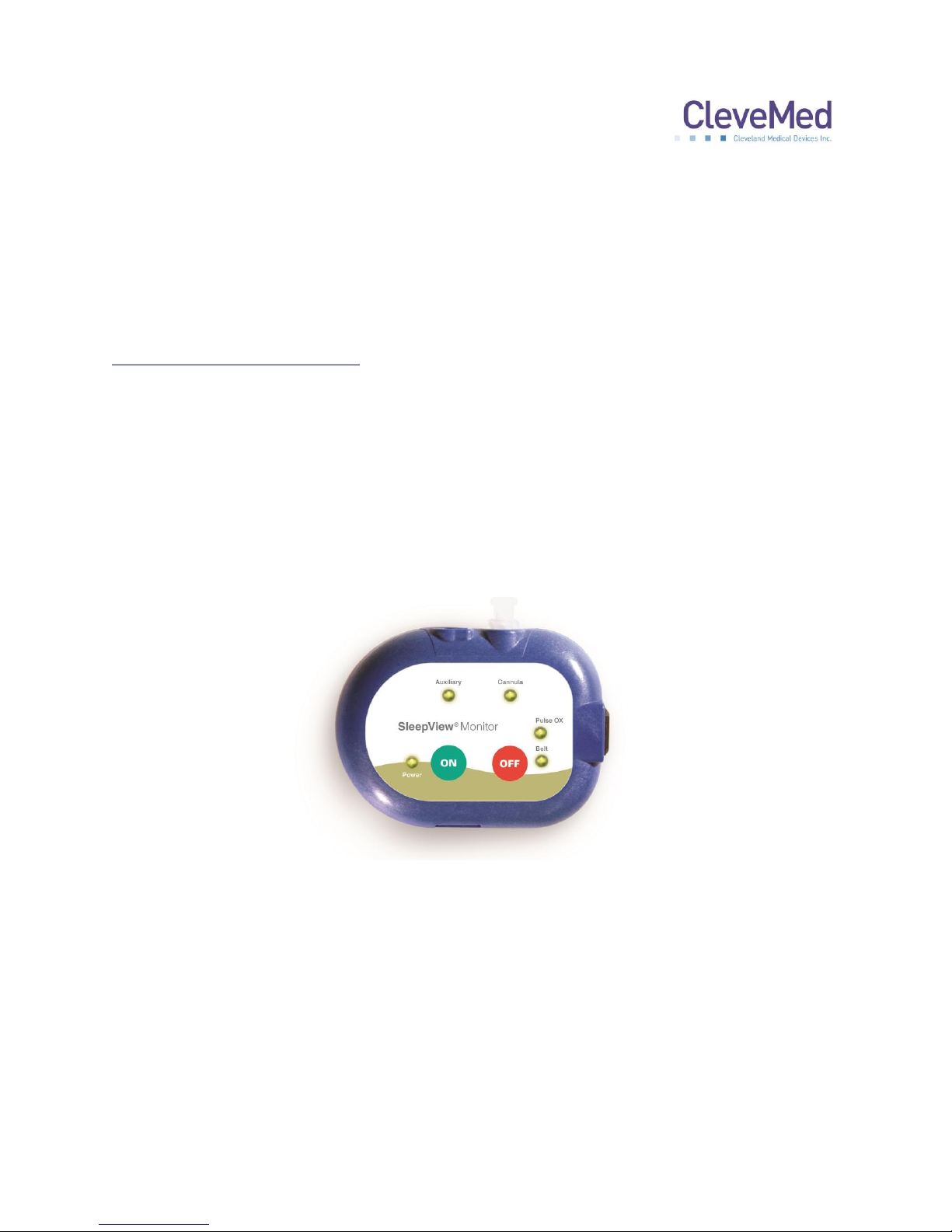
SleepView Monitor
The SleepView monitor can record up to 8 signals (summarized below). The SleepView
monitor is powered by one AAA battery, typically lasting for more than 10 hours of data
acquisition time.
Signals Measured:
• Airflow (pressure-based, compatible with CPAP)
• Auxiliary (thermistor, IDcheck™ or Respiratory Effort)
• Snore
• Pulse Oximetry
• Respiratory Effort (chest)
• Body Position (supine, prone, left, right, and upright)
• Heart Rate
• Sleep/wake (actigraphy) – web portal only
7
Page 8

SLEEPVIEW USER MANUAL
Chapter 3: Accessories, Sensors and
Maintenance
Several types of sensors are available for use with SleepView. CleveMed offers
prepackaged study kits with all of the disposable supplies need for a study.
Airflow
A nasal oral cannula is most commonly used with SleepView to detect nasal and oral
airflow as well as snore. A nasal cannula can also be used with the system and is
commonly combined with a thermistor. Cannula are available in adult and pediatric
sizes.
Pulse Oximetry
A soft pulse oximetry finger sensor is packaged in the SleepView starter kit. Wrap style
and disposable sensors are also available.
Respiratory Effort
The SleepView interfaces directly with a RIP (respiratory inductive plethysmography)
belt. Reusable and single use ReadyRIP™ belts are available.
8
Page 9
SLEEPVIEW USER MANUAL
Auxiliary
The auxiliary port accepts three types of sensors.
Thermistor – A thermistor can be used as a measure of airflow. An oral
thermistor is commonly combined with a nasal cannula.
Respiratory Effort – A second respiratory effort belt (RIP belt) can be used on the
auxiliary port. An interface cable is required for an effort belt to be used with the
auxiliary port. If a second belt is used the primary belt should be worn on the
chest and the secondary belt on the abdomen.
IDcheck™ – This sensor is used to verify the identity of the patient recording the
sleep test. CleveMed customer service can provide more information about using
an IDcheck sensor.
Cleaning SleepView and Accessories
In order to prevent the spread of bacteria and other germs from one patient to another,
supplies and accessories including the respiratory belt, pulse oximeter, and thermistor
must be disinfected between uses and/or between patients. The cannula is intended for
a single use only, please discard it after completion of study.
9
Page 10

SLEEPVIEW USER MANUAL
Cleaning Supplies:
The following supplies are commonly used. They are recommended; however, similar
products of equal strength may be chosen.
Sani-Cloth®
CaviWipes®
Cavicide®
Procedure:
1. Gather belts, pulse oximeter, re-usable nasal sensor/thermistor
2. Remove adhesive left over from any tape if tape was used
3. Wipe down thoroughly using disinfecting cloths or spray
4. Wipe dry with clean cloth,
5. Store item for next usage.
6. The exterior of the SleepView must also be wiped clean with a disinfecting cloth
or spray or a standard household surface cleanser.
Maintenance
SleepView does not require calibration. The SleepView software can be updated by end
customers. The SleepView Manager software will alert users that an update is available
as long as the computer is connected to the internet. Follow the software prompts to
download and install any updates. Please contact customer service with any questions.
10
Page 11
SLEEPVIEW USER MANUAL
Chapter 4: SleepView Manager Software
The SleepView Manager software is used to prepare the SleepView Monitor for
collecting patient data, and to download the data collected as part of a study. The
SleepView interfaces with the PC through a micro USB port located inside the battery
door. The battery must be removed to connect the USB cable. The SleepView Monitor
must be manually turned on by pushing the ON button after connecting to the PC.
Installing the SleepView Manager Program
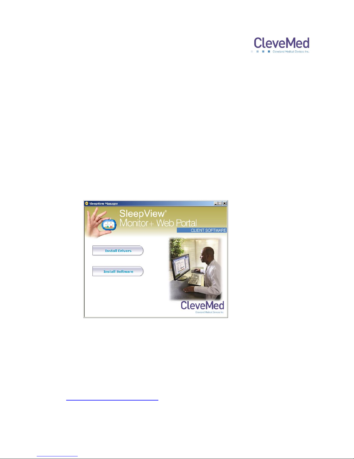
1. Insert the SleepView Manager Installation CD-ROM into your computer’s CD-ROM
drive. It should automatically open the SleepView Manager splash screen as shown
below. If this does not occur, please navigate to the CD-ROM folder and double-click
“SOFTWARE_MENU.EXE”
2. Click “Install Drivers” and follow the on-screen prompts to complete driver
installation.
3. Click “Install Software” and follow on-screen prompts to install the SleepView
Manager Software.
4. Once the software has been installed, you may be prompted to register the system
with www.clevemedsleepview.com.
11
Page 12
SLEEPVIEW USER MANUAL
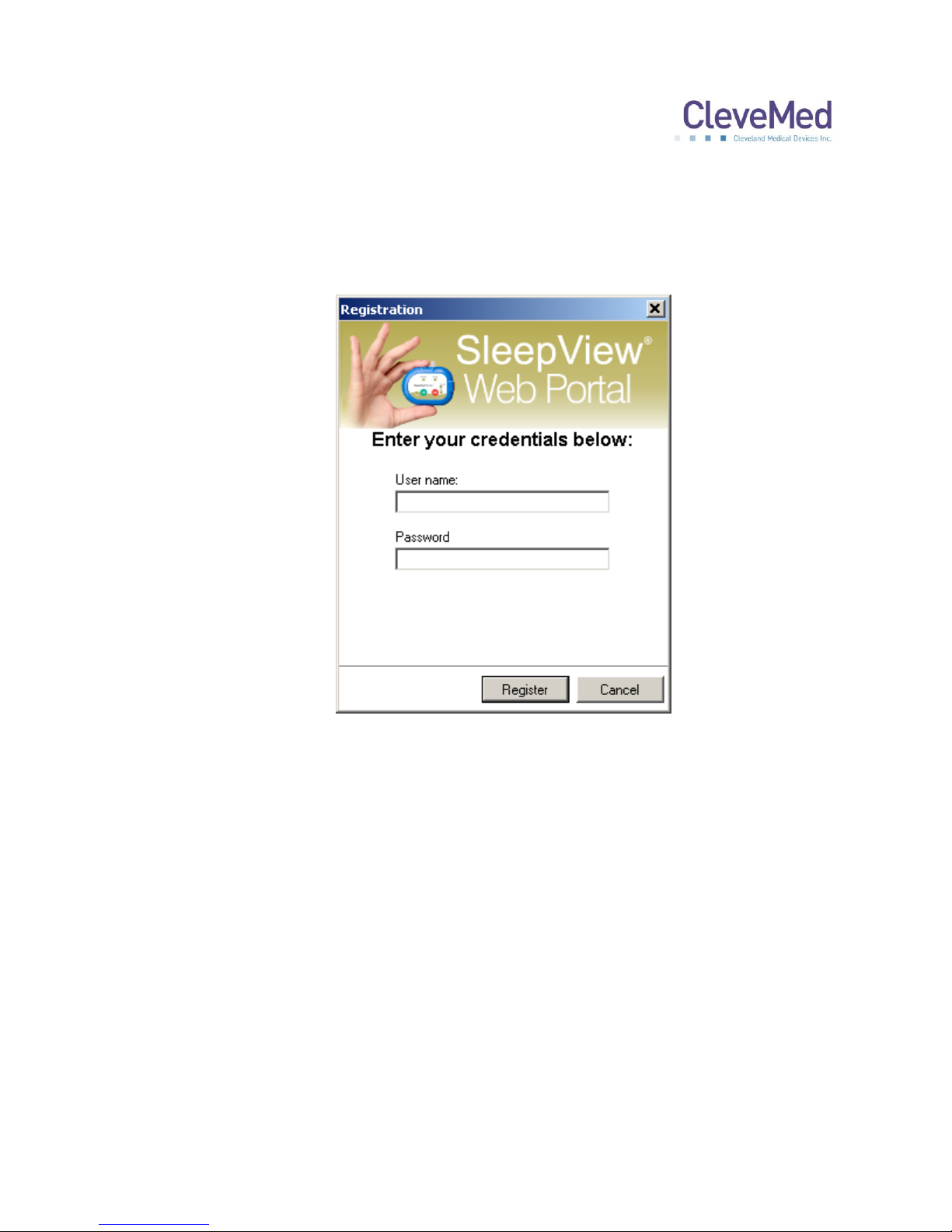
5. If this is the first time you are installing the system, you will be prompted with a
dialog entitled “Registration”. In order to continue, enter valid
clevemedsleepview.com credentials (username and password) using the fields
provided and click <Register>. If you do not have a username or password, then
click <Cancel> and contact technical support for assistance.
PLEASE NOTE: If you are unable to register the system with
www.clevemedsleepview.com at the time of installation, you can re-initiate
registration by selecting “Upload Client” from the SleepView Manager Program
menu. Additionally, this dialog will appear after every reboot until you have
registered the system with www.clevemedsleepview.com.
12
Page 13

SLEEPVIEW USER MANUAL
Chapter 5: Data Upload Management
An important component of the SleepView Manager called the “PSG Upload Client”
runs continuously in the background to ensure any data taken from a SleepView device
will be transferred to the website. Once registered, this component automatically starts
and as a rule will always be running even after a reboot without user intervention. The
component runs quietly as an icon in the system tray only notifying the user using
balloon tips when major system state changes occur such as:
Initial connection to server is established
Connection to server is lost
An upload begins after being idle
Additional information about the upload process can be viewed from the Uploader
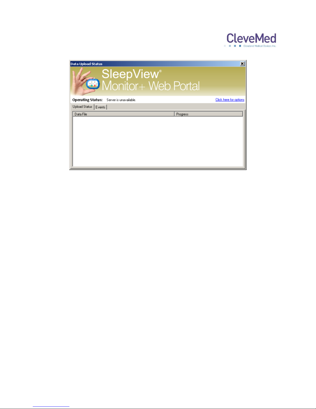
window, which can be accessed by double clicking on the Uploader icon. The top
portion of the main screen provides the general operating status of the system, which
can include:
Indication of idleness “No files to upload”
Indication of disconnection from the server “Server unavailable”
Indication of what files are being uploaded active or queued
The bottom portion of the window offers two information tabs:
Upload Status – showing the progress of files being uploaded
Events – showing time-stamped events of all major events including when files
were uploaded, completed, and what errors occurred.
PLEASE NOTE: The information in the “Events” tab is duplicated in the log files
that reside in the Program folder of this application.
13
Page 14
SLEEPVIEW USER MANUAL
Upload Status
The software is configured to monitor a specific directory for files. When files become
available it immediately queues them for upload to the server. The software employs
multiple threads to do its work, which can be configured using the options screen. As
shown in the picture at the left, the “Upload Status” tab will show the upload progress of
one or more files with additional information provided in the “Operating Status” field in
the top portion of the window. This field will display the number of files being actively
uploaded “Uploading” and the number of files pending upload “queued”.
Events
All operations including upload begin, end and completion along with any errors during
processing are logged to a date-stamped log file in the application directory. These
events can be viewed live in the “Events” tab.
14
Page 15

SLEEPVIEW USER MANUAL
Chapter 6: Using SleepView with
clevemedsleepview.com
SleepView is designed for use with the clevemedsleepview.com website, which
provides a guided workflow for patient and study management. The SleepView
Manager software is integrated with the website at specific points in the process.
Creating a New Study
1. To begin using the web portal, enter the following address into your web browser:
http://www.clevemedsleepview.com.
2. The login page will appear prompting entry of a “User Name” and “Password” in the
upper right corner. To enter the site, enter your user name and password and click
“Log In”.
15
Page 16
SLEEPVIEW USER MANUAL
Section
Purpose
Home
Provides access to workflow tasks
Patients
Provides patient management functions
Studies
Provides study management functions
Section
Purpose
Step 1 Schedule
Study
Create a new study record for an
existing or new patient.
Step 2 Check-In
Device, Manage
Recordings
Check in recorded data files from a
SleepView and assign those data
files to scheduled studies
Step 3 Review
Studies
Retrieve study reports or check the
status of a study.
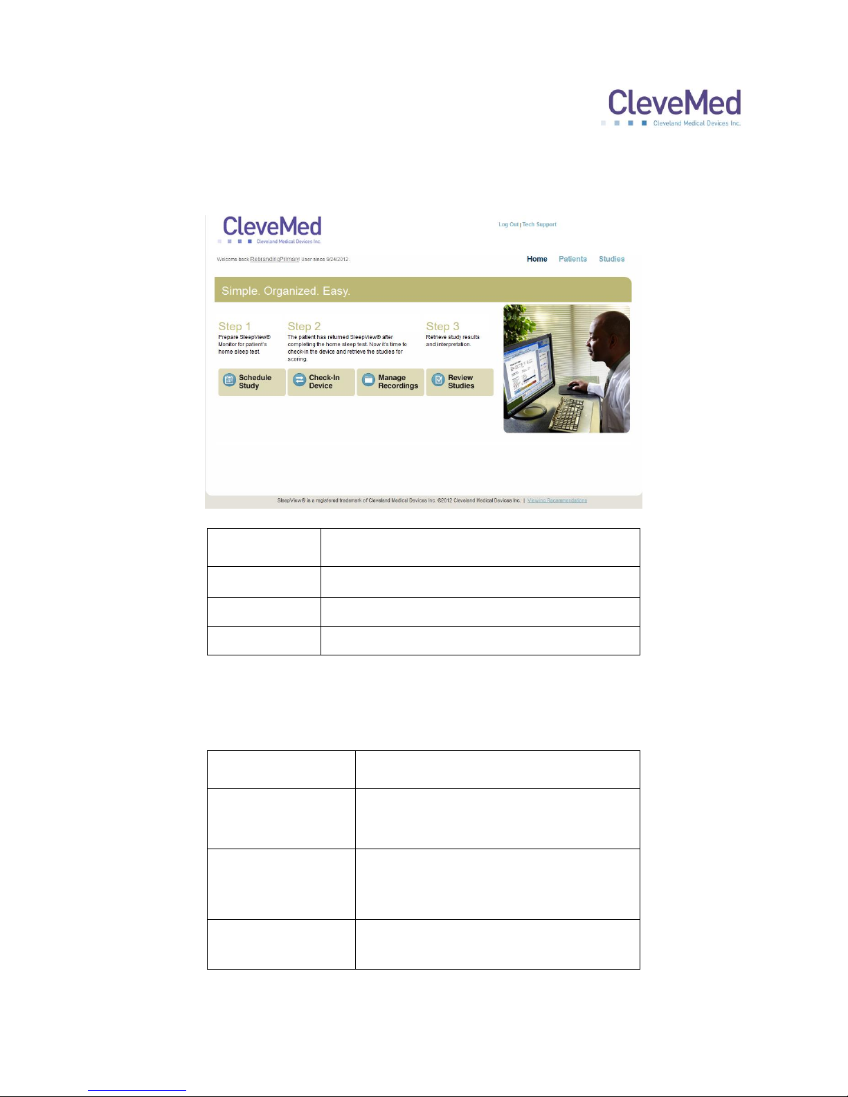
3. The main page of the site will appear and is separated into three sections indicated
by the text at the top right of the page:
The “Home” page provides three main tasks that are part of the portal workflow
indicated as buttons within the section:
16
Page 17
SLEEPVIEW USER MANUAL
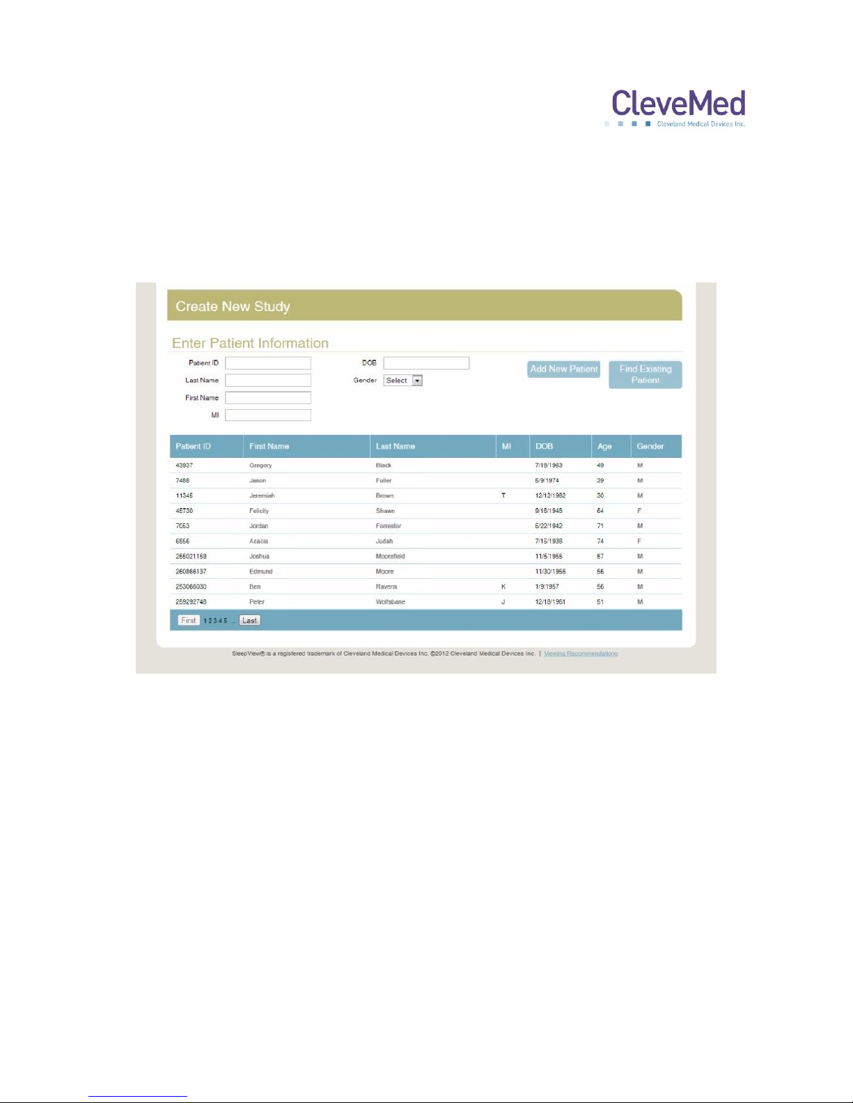
4. To create a new study, click the “Schedule Study” button from the “Home” page and
the following page will appear
PLEASE NOTE: The Patient List will be empty if this is the first time you are
scheduling a study with the company.
5. Select an existing patient by clicking on a name in list provided.
PLEASE NOTE: If this is a new patient, enter the new patient information in the
fields provided and click “Add New Patient”.
Once you have selected, or added the patient to study, the next step will become
available.
6. The next step “Enter/Edit Study Information” asks that you enter the desired date for
the study to take place, as well as the name of the ordering physician. Enter the date
of the study in the “Date” field and select the name of the ordering physician from the
drop-down menu labeled “Physician.” Click on the “Save Study Info” button to
proceed to the next step.
17
Page 18
SLEEPVIEW USER MANUAL
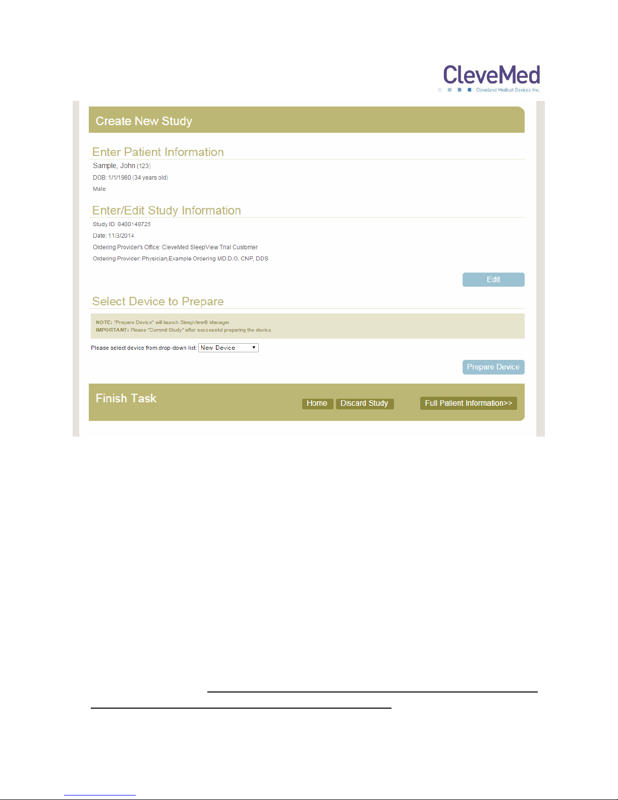
7. The final step of study creation is “Enter/Edit ID into Device”. Each SleepView device
that is registered with the portal is provided in the drop-down menu labeled “Select
Device”. Select the device that is used for the study. If the desired SleepView
Monitor has never been registered with the system, select “New Device” from the
dropdown box.
8. Click “Prepare Device” and the website will start the SleepView Manager software.
PLEASE NOTE: If this is the first time you are using the system with your web
browser, you may receive a security warning since the website is executing a
program on your machine. The warning will vary depending on the browser
you are using, and will offer you the option to allow the website to access the
secured resource. If you experience any problems with this, please contact
technical support.
IMPORTANT NOTE: Preparing a SleepView Monitor for a new study will cause
all previously recorded studies to be deleted from it.
18
Page 19
SLEEPVIEW USER MANUAL
The “Connect Device” page will appear with instructions on how to connect the system
to the PC.
1. Connect your SleepView to the computer using the USB cable provided. There is a
connection inside the battery compartment for one end of the USB cable.
2. Once the SleepView is connected to the computer, press and hold the ON button
until the power LED illuminates.
PLEASE NOTE: A green or flashing amber LED is not a concern, however if at
any point the power LED flashes red, this indicated a serious system failure
and technical support should be contacted immediately.
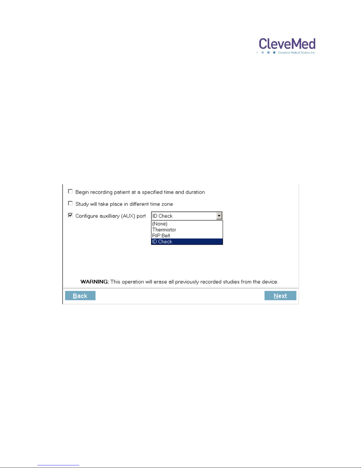
3. Click <Next> and the “Prepare device” screen will appear with the recording options.
4. If you would like the SleepView unit to automatically turn on and remain on for a
specified duration, click the check box labeled “Begin recording at a specified time
and duration” and select the desired start time and duration (specified in hours and
minutes). It is recommended that the recording duration only last as long as the
patient is likely to sleep so that the Smart Check can be used in the morning.
AUTOMATIC ON: If a recording time is programmed, the OFF button on
SleepView Monitor will be disabled during the set recording duration. The
patient may turn SleepView ON early (for example, if they chose to go to bed
earlier than scheduled) by pressing the ON button. SleepView will continue to
record until the programmed OFF time. The programmed auto recording time
19
Page 20

SLEEPVIEW USER MANUAL
can be cancelled by pressing down the OFF button, then pressing the ON
button, and then releasing the OFF button after the LEDs rapidly flash amber.
5. If the study you are scheduling will be done at a location in a time zone different from
the one your computer is set to, check the checkbox labeled “Study will take place in
a different time zone” and select the time zone using the drop-down list provided.
This will adjust the internal clock within the SleepView to the time zone where the
study will be performed.
6. Configure the auxiliary port for the appropriate sensor that will be used for the study.
If no sensor will be used, select ”(None)” to disable the LED for this channel only. It
will remain off during use.
IMPORTANT NOTE: The next step will cause all previously recorded studies to
be deleted from the device.
7. Click <Next> and the “Downloading Parameters” page will appear and begin to send
all of the options you selected to the device.
8. Once programming is complete, all of the operations will report “DONE” next to its
label and the <NEXT> button will become active. Click <Next> and the “Insert
Battery and Check Device” page will appear.
PLEASE NOTE: If you did not program the SleepView Monitor to automatically
turn ON then “N/A” will appear next to “Setting auto-start time”
9. The SleepView will turn OFF after programming is complete.
IMPORTANT NOTE: The next steps must be performed in order to commit the
settings to the device. You must comply within 2 minutes to ensure proper
configuration.
10. Click <NEXT> and the “Insert Battery and Check Device” page will appear.
Disconnect the SleepView from the USB cable and within 2 MINUTES insert a new
AAA battery.
11. Press and hold the ON button until the power LED lights green.
IMPORTANT NOTE: If the power LED does not illuminate green and flashes
amber, then the settings did not properly transfer into the device.
20
Page 21

SLEEPVIEW USER MANUAL
12. A green power LED indicates that the unit is ready for the study. Turn OFF the unit
prior to sending home with a patient.
13. Upon clicking <Finish> the SleepView Manager window will close.
14. Click <Commit Study> in the webpage and you are returned to the home screen.
Check-In Study Data from SleepView Monitor
When a patient returns a SleepView, the study data must be uploaded to the portal
before it can be submitted for review and interpretation. The following instructions will
provide a walkthrough of the process of transferring data from a SleepView Monitor to
Portal.
From the home page select Step 2 Check-In Device.
1. The “Connect Device” page will appear with instructions on how to connect the
system to the PC.
2. Connect your SleepView to the computer using the USB cable provided. There is a
connection inside the battery compartment for one end of the USB cable.
3. Once the SleepView is connected to the computer, press and hold the ON button for
at least 3 seconds.
4. The power LED will illuminate. Typically, it will immediately illuminate green, but it
may also flash amber first and then green.
PLEASE NOTE: If at any point the power LED flashes red, this indicates a
serious system failure and technical support should be contacted
immediately.
5. Click <Next> and the “Download Files” screen will appear and begin to show
progress of files being transferred from the device to the computer. Two progress
bars will be shown. The top progress bar shows the progress of the current file being
downloaded. The second one shows the overall progress of the entire transaction.
6. Wait until the transaction is complete and the <Finish> button becomes available.
Press the OFF button on the SleepView until the power LED turns off and
disconnect it from the PC.
7. Click <Finish> and you will be returned to the home screen.
21
Page 22

SLEEPVIEW USER MANUAL
8. At this point SleepView data will be transferred to the portal and processed to
become available within the “Manage Recordings” section.
22
Page 23
SLEEPVIEW USER MANUAL
Chapter 7: Manage Recordings
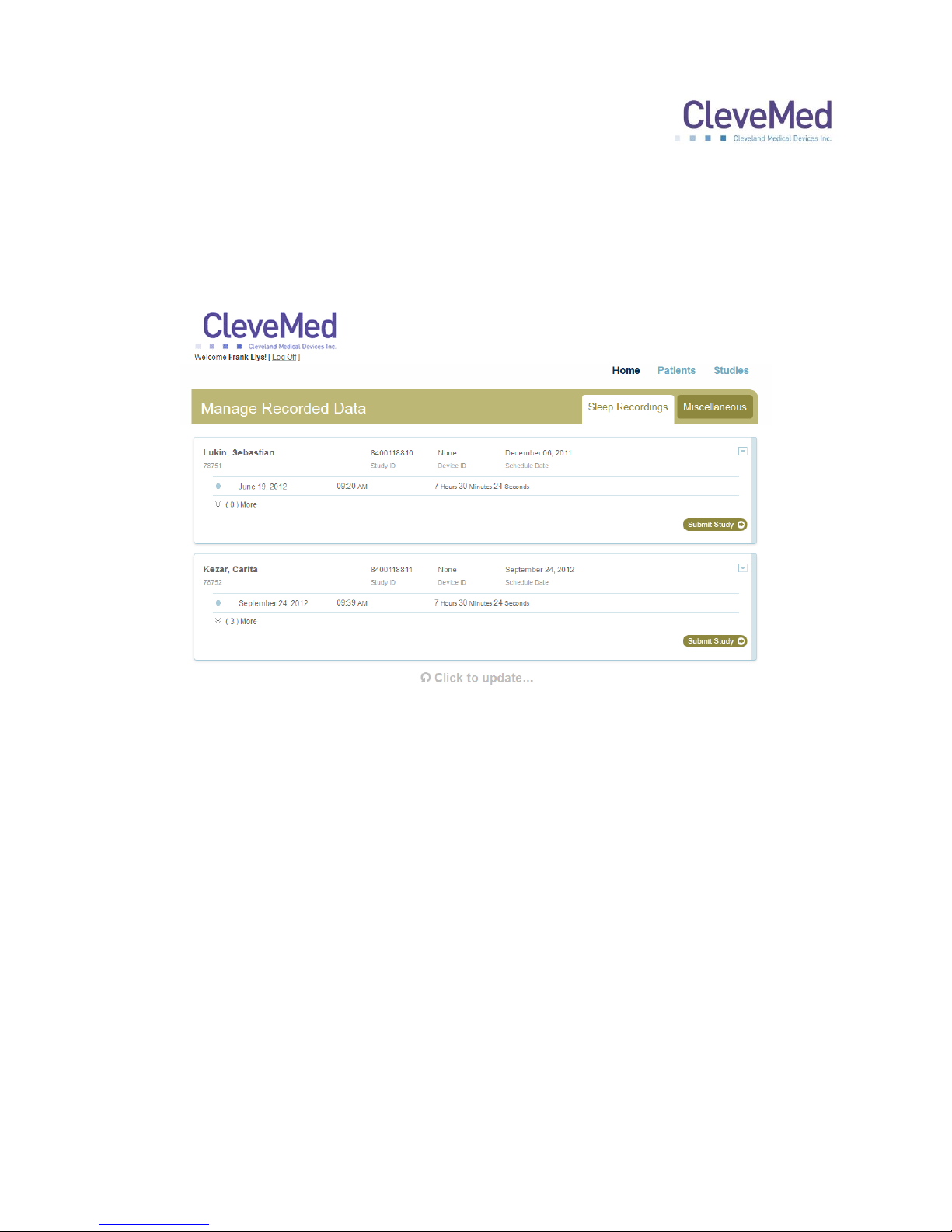
1. On the home page, select “Step 2 Manage Recordings” to assign the data files to
scheduled patient studies. You will be presented with a list of scheduled studies
with recordings uploaded to them.
2. Successful recordings will be listed under each scheduled study. If there is one study
click “Submit Study.” If there are more than one study listed, select one study and
click “Submit Study.”
3. A questionnaire will appear and will need to be filled out before the selected recording
can be submitted to review.
4. Repeat the above steps for any remaining studies.
23
Page 24
SLEEPVIEW USER MANUAL
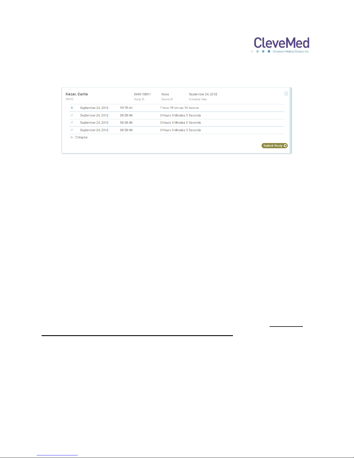
Clicking the double arrow at the bottom left of the study list will expand to show
suboptimal recordings.
These studies may be the result of training the patient or testing the system before
dispensing it or the patient may have not recorded good data over night. Please contact
technical support if you have any questions about these studies.
The blue arrow at the top right of the study list is an option menu. Please follow the
onscreen prompts or contact technical support for assistance.
About the Miscellaneous Tab
If a study is uploaded that does not match a scheduled study or was part of a scheduled
study and was not submitted for review, it will be listed on the “Miscellaneous” tab.
In the event that a study was not properly acquired and submitted without a proper
“Study ID”, you may need to look for it in this list and try to match the time, date, and
unit ID, to the actual study date and time and SleepView Monitor that went home with
the patient.
PLEASE NOTE: The “Miscellaneous” Tab is not designed to be a part of regular
system usage. It is offered only to manage situations that may occur if the user
fails to follow the recommended steps to using SleepView. Please contact
technical support if you are having difficulty with the system usage.
24
Page 25
SLEEPVIEW USER MANUAL
Chapter 8: Reviewing Studies
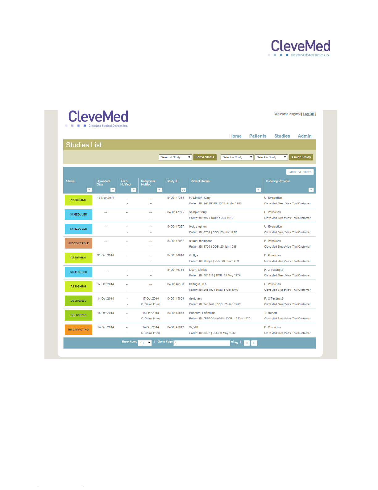
To review a study, click “Review Studies” from the “Home” page and a list of available
studies for your practice will be presented:
The list can be searched, filtered and sorted by selecting menu button at the top of each
column. Click on the study you would like to view and a study detail page will appear.
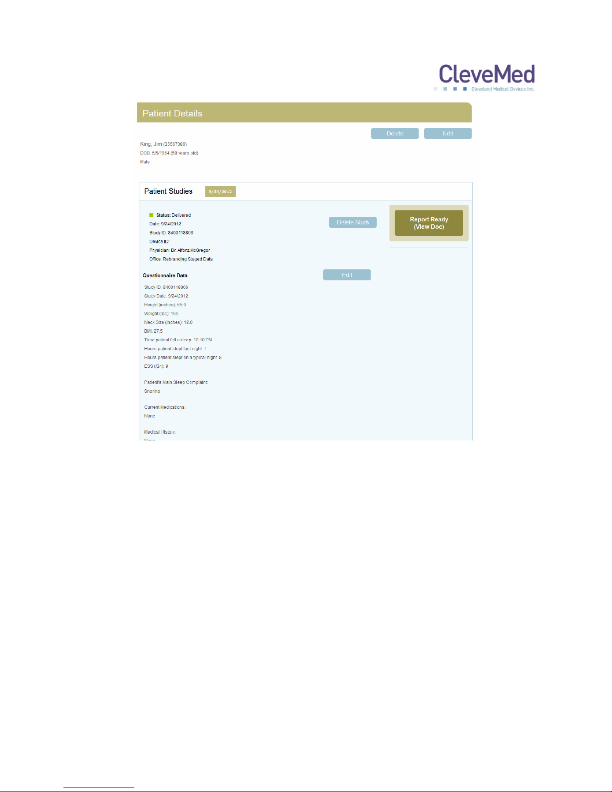
The study detail page has two sections: “Patient Details” displays the patient information
at the top of the page. “Patient Studies” provides one or more tabs representing each
study the system has for that patient. The tab for the study you selected will be
highlighted. Within the selected tab are presented summary information about the type
of study and equipment used, as well as access to the questionnaire and reports.
25
Page 26
SLEEPVIEW USER MANUAL
Click the “Report Ready” button to view, save or print the study report in PDF. Each
report is electronically signed by the interpreter. An e-mail will be sent to the primary
contact for your practice when a report is completed by the interpreter.
NOTE: In order to verify electronically signed documents you must use Adobe
Acrobat Reader X or higher to view the signed PDF report.
26
Page 27

SLEEPVIEW USER MANUAL
Chapter 9: Using SleepView Manager (Offline)
Offline usage of the SleepView Manager can be used when an internet connection to
clevemedsleepview.com is not available.
Preparing SleepView for a Study (Offline Usage)
Before a device can be sent home with a patient, it must be prepared by entering in
information about the study and how it will be collected. The following instruction
provides a walkthrough of the configuration process and explains each of the
configuration options.
The SleepView manager must be manually opened by locating SleepView from the
Windows program list. Select SleepView manager.
IMPORTANT NOTE: preparing a device for a new study will cause all previously
recorded studies to be deleted from the device.
1. Click <Prepare device> and the “Connect Device” page will appear with instructions
on how to connect the system to the PC.
2. Connect your SleepView to the computer using the USB cable provided. There is a
connection inside the battery compartment for one end of the USB cable.
3. Once the SleepView is connected to the computer, press and hold the ON button
until the power LED illuminates.
PLEASE NOTE: a green or flashing amber led is not a concern, however if at
any point the power led flashes red, this indicates a serious system failure and
technical support should be contacted immediately.
4. Click <Next> and the “Prepare device” screen will appear with the recording options
5. Enter a Study ID in the field provided. If you do not have a Study ID, click the
checkbox labeled “I don’t have a Study ID” and a default “(UNKNOWN)” ID will be
used for your study.
PLEASE NOTE: it is recommended that a study id is assigned to each study to
allow for better data management.
27
Page 28

SLEEPVIEW USER MANUAL
6. If you would like the SleepView unit to automatically turn on and remain on for a
specified duration, click the check box labeled “Begin recording at a specified time
and duration” and select the desired start time and duration (specified in hours and
minutes).
PLEASE NOTE: see note on “automatic on” below.
If the study you are scheduling is being done at a location in a time zone different from
the one your computer is set to, check the checkbox labeled “Study will take place in a
different time zone” and select the time zone using the drop-down list provided. This will
adjust the internal clock within the SleepView to the time zone where the study will be
performed.
Configure the auxiliary port for the appropriate sensor that will be used for the study. If
no sensor will be used select none. This option will disable the LED for this channel only
and it will remain off.
IMPORTANT NOTE: the next step will cause all previously recorded studies to be
deleted from the device.
7. Click <Next> and the “Downloading Parameters” page will appear and begin to send
all of the options you selected down to the device.
8. Once programming is complete, all of the operations will report “DONE” next to its
label and the <NEXT> button will become active. Click <Next> and the “Insert
Battery and Check Device” page will appear.
PLEASE NOTE: if you did not program the SleepView unit to automatically
turn on,“n/a” will appear next to “setting auto-start time”.
9. The SleepView will turn off after programming is complete.
IMPORTANT NOTE: the next steps must be performed in order to commit the
settings to the device. You must comply within 2 minutes to ensure proper
configuration.
10. Click <NEXT> and the “Insert Battery and Check Device” page will appear.
Disconnect the SleepView from the USB cable and within 2 minutes insert a new
AAA battery.
11. Press and hold the ON button until the power LED lights green.
IMPORTANT NOTE: if the power led does not illuminate green and flashes
amber, then the settings did not properly transfer into the device.
28
Page 29

SLEEPVIEW USER MANUAL
13. A green power LED indicates that the unit is ready for the study. Turn off the unit
prior to sending home with a patient.
14. Click <Finish> and the SleepView Manager window will return to the main screen.
AUTOMATIC ON: if a recording time is programmed, the off button on the
SleepView will be disabled during the set recording duration. The patient may
turn the system on early, for example if they chose to go to bed early, by pressing
to on button. The system will continue to record until the programmed off time.
The programmed auto recording time can be cancelled by holding the off button,
pressing the on button, and then releasing the off button after the LEDs rapidly
flash amber.
Downloading Study Data from SleepView Monitor (Offline Usage)
When a patient returns a SleepView, the study data must be downloaded to a computer
before it can be sent for review and interpretation. The following instructions will provide
a walkthrough of the process of downloading data from a SleepView.
1. Click <Download data> and the “Connect Device” page will appear with instructions
on how to connect the system to the PC.
2. Connect your SleepView to the computer using the USB cable provided. There is a
connection inside the battery compartment for one end of the USB cable.
3. Once the SleepView is connected to the computer, press and hold the ON button
until the power LED illuminates.
PLEASE NOTE: a green or flashing amber led is not a concern, however if at any
point the power led flashes red, this indicates a serious system failure and
technical support should be contacted immediately.
4. Click <Next> and the “Download Files” screen will appear and begin to show
progress of files being transferred from the device to the computer. Two progress
bars will be shown. The top progress bar shows the progress of the current file being
downloaded. The second one shows the overall progress of the entire transaction.
5. Wait until the transaction is complete and the <Finish> button becomes available
6. Click <Finish> and you will be returned to the main screen.
7. Press the OFF button for at least 3 seconds until the LEDs turn off and disconnect
from the PC.
29
Page 30
SLEEPVIEW USER MANUAL
LED Action
Indication
Action Required
All LEDs flash greenOFF 5 times
This indicates that the
device has its Auto Start
Time enabled.
None, unless it wasn’t supposed
to be set.
All LEDs quickly flash
amber-OFF 10 times
This indicates that the
device has just had its
Auto Start Time disabled
by holding the off button
on start up.
None, unless it wasn’t meant to
be overridden.
All LEDs are
momentarily green
This is the normal boot
indication.
None, this state should be very
short before the unit starts. If all
LEDs remain, turn the device
OFF and back ON.
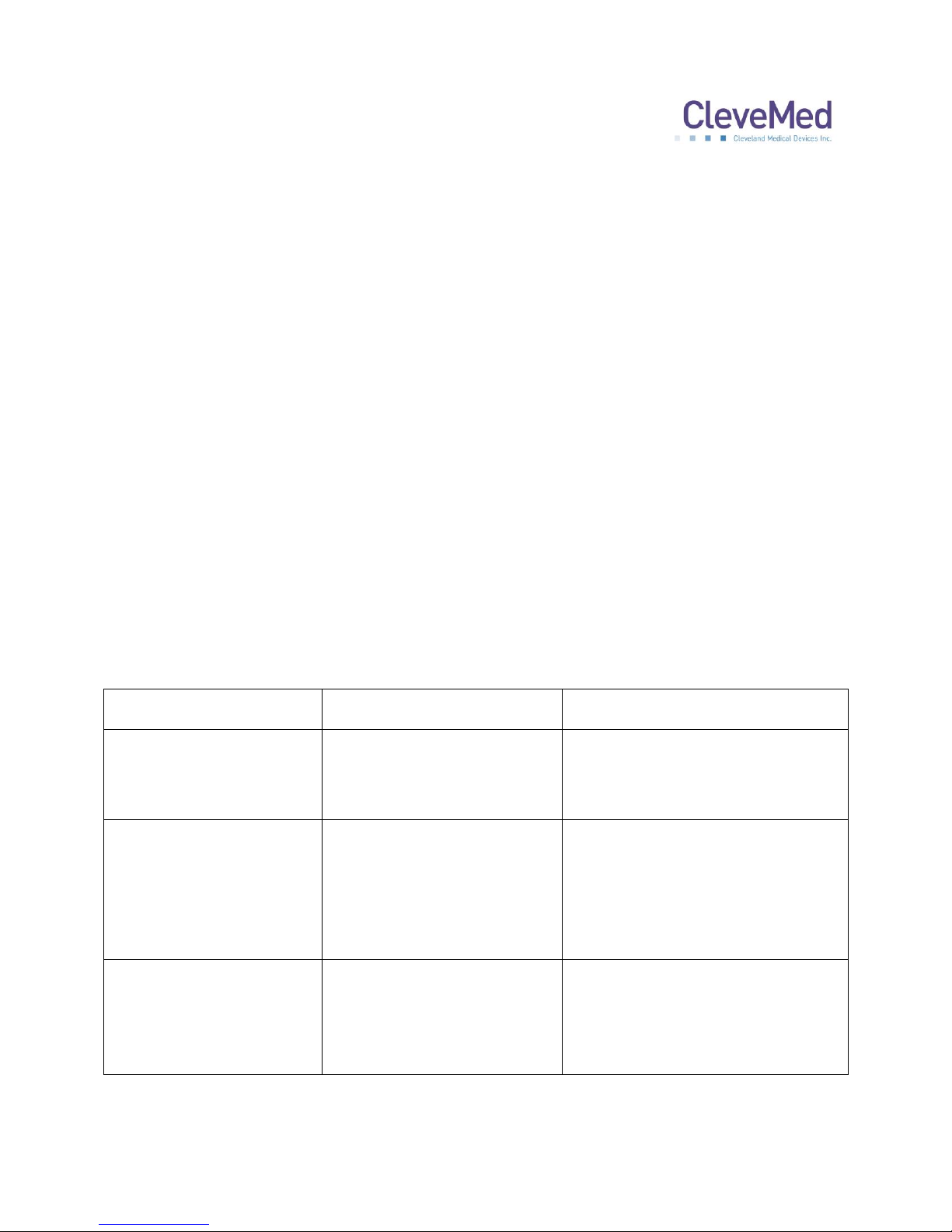
Chapter 10: Collecting Data
A new AAA battery should be used for each overnight study. A new battery will typically
last for more than 10 hours of continuous recording. The SleepView mounts directly on
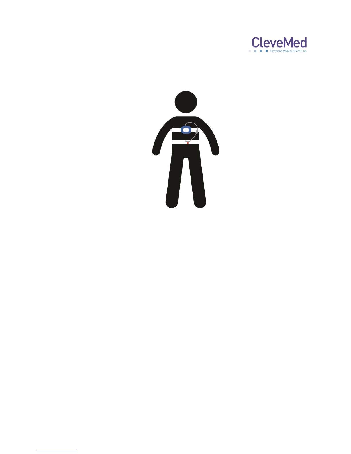
the respiratory effort belt. It is recommended that the SleepView only be detached from
the belt when a new belt is needed. The SleepView and the belt may be cleaned with
the same cleaner while they are connected to each other as described in chapter 3.
The belt with the SleepView should be placed on the patient first. Next the cannula,
thermistor and pulse oximetry sensor may be placed. After the sensors are positioned
on the patient the SleepView Monitor can be turned ON. Patient instructional materials
are available from CleveMed, please contact your sales representative for information.
SleepView can be used in conjunction with CPAP at set pressure of 20 CM water or
less. A standard pressure line adaptor is placed in line with the CPAP hose. Tubing is
then run from the pressure line adaptor to the cannula input on the SleepView in place
of a cannula. The recorded airflow signal will appear the same as a signal without
treatment. The SleepView does not record the set CPAP pressure.
LED Signal Status Indicators
After the sensors are placed the SleepView should be turned on. The SleepView
Monitor will go through a brief boot up process. The LED indicators will flash during the
boot up process as described in the table.
30
Page 31
SLEEPVIEW USER MANUAL
Red
Amber
Green
Power
Not Recording
Low Battery
New Battery
Cannula
Not Connected or
Poor Signal
N/A
Good Signal
Auxiliary
(LED remains off if
sensor set to none)
Not Connected
Poor Signal
Good Signal
Pulse Oximeter
Not Connected
Poor Signal
Good Signal
Belt
Not Connected
Poor Signal
Good Signal
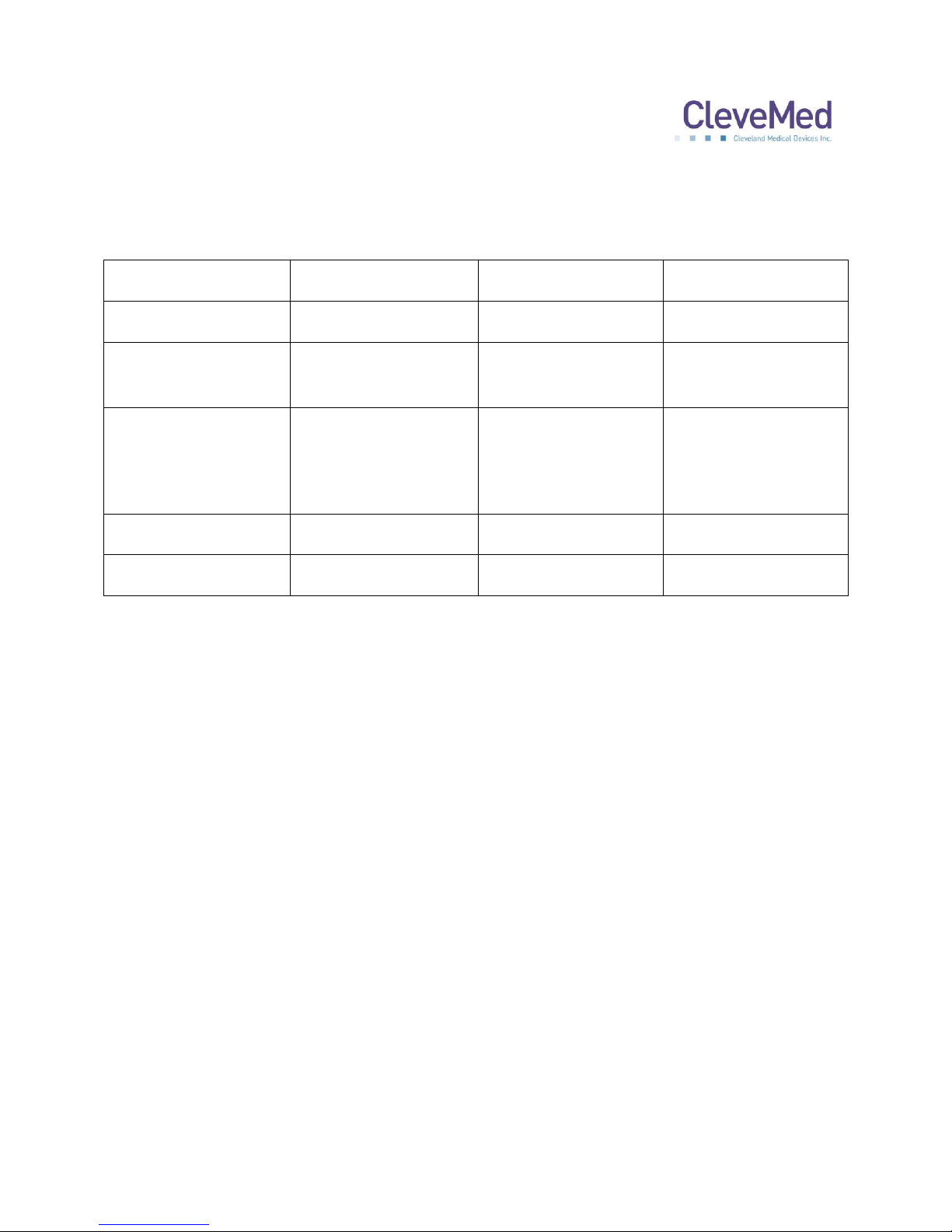
After the boot process the LED indicators will display the status of each sensor. The
LED should be green for all sensors that are supposed to be collecting data for the
study.
The sensor indicators will remain lit for 90 seconds. Then all but the power LED will turn
OFF. At any time the power button may be depressed to turn ON the indicators for an
additional 60 seconds. During normal recording the power indicator will pulse green.
At the end of the study the patient must press and hold the OFF button to turn the
device OFF manually. Alternatively the device can be programmed to turn OFF
automatically using the SleepView Manager software.
Smart-Check Feature
The SleepView offers a feature for the patient to see if the system collected enough
data that is of good quality (at least 2 hours). Each time the unit is turned OFF, the
status LEDs will show a light moving in a circular pattern to indicate the following:
1. LEDs show green circle pattern to indicate a good quality study was recorded.
2. LEDs show red circle pattern to indicate a good quality study has NOT been
recorded.
Note: for patients that are color blind, please note that the green LEDs indicating a
good quality study rotate in a clockwise direction, while the red LEDs will rotate in a
counter-clockwise direction.
If the patient did not notice or remember the Smart-Check result (e.g. the device was
set to automatically turn OFF), the patient can simply turn the SleepView back ON and
then turn it OFF again to see the Smart-Check result.
31
Page 32

SLEEPVIEW USER MANUAL
Chapter 11: Tips for Dispensing SleepView
Steps for Dispensing SleepView to patients:
Verify that the SleepView has been cleaned (See Chapter 3)
Use SleepView Manager software to program the study ID and recording time
Place a new battery in the SleepView
Turn the SleepView ON
PLEASE NOTE: Verify that the LED indicators flash green five times and that the
power LED turns green. This confirms the recording time has been programmed
and the battery is fully charged.
Verify that the correct size belt is connected to the SleepView
Train the patient on hooking up the sensors and give them hookup instructions
Instruct the patient to turn OFF the SleepView by pressing the OFF button until
the LED change.
Instruct the patient to use Smart-Check to verify diagnostic data was recorded.
32
Page 33
SLEEPVIEW USER MANUAL
Guidance and manufacturer’s declaration – electromagnetic immunity
The SleepView System is intended for use in the electromagnetic environment specified below. The customer or the user of the
SleepView System should assure that it is used in such an environment.
IMMUNITY test
IEC 60601 test level
Compliance level
Electromagnetic environment – guidance
Electrostatic
discharge (ESD)
IEC 61000-4-2
±6kV contact
±8kV air
±6kV contact
±8kV air
Floors should be wood, concrete, or ceramic tile. If floors
are covered with synthetic material, the relative humidity
should be at least 30 %.
Electrical fast
transient/burst
IEC 61000-4-4
±2kV for power supply lines
±1kV for input/output lines
N/A
Mains power quality should be that of a typical
commercial or hospital environment.
Surge
IEC 61000-4-5
±1kV line(s) to line(s)
±2kV line(s) to earth
N/A
Mains power quality should be that of a typical
commercial or hospital environment.
Voltage dips, short
interruptions and
voltage variations on
power supply input
lines
IEC 61000-4-11
<5%UT (>95 % dip in UT)
for 0,5 cycle
40%UT (60 % dip in UT)
for 5 cycles
70%UT (30 % dip in UT)
for 25 cycles
<5%UT (>95 % dip in UT)
for 5 s
N/A
Mains power quality should be that of a typical
commercial or hospital environment.
If the user of the SleepView System requires continued
operation during power mains interruptions, it is
recommended that the SleepView System be powered
from an uninterruptible power supply or a battery.
NOTE UT is the a.c. mains voltage prior to application of the test level.
Power frequency
(50/60 Hz) magnetic
field
IEC 61000-4-8
3 A/m
3 A/m
Power frequency magnetic fields should be at levels
characteristic of a typical location in a typical commercial
or hospital environment.
Conducted RF
IEC 61000-4-6
Radiated RF
IEC 61000-4-3
3 Vrms
150 kHz to 80 MHz
3 V/m
80 MHz to 2.5 GHz
3 Vrms
3 V/m
Portable and mobile RF communications equipment
should be used no closer to any part of the SleepView
system, including cables, than the recommended
separation distance calculated from the equation
applicable to the frequency of the transmitter.
Recommended separation distance
𝑑 = 1.2 √𝑃
𝑑 = 1.2 √𝑃 80 MHz to 800 MHz
𝑑 = 2.3 √𝑃 800 MHz to 2.3 GHz
where P is the maximum output power rating of the
transmitter in watts (W) according to the transmitter
manufacturer and d is the recommended separation
distance in meters (m).
Field strengths from fixed RF transmitters, as determined
by an electromagnetic site survey,a should be less than
the compliance level in each frequency range.b
Interference may occur in the vicinity of equipment
marked with the following symbol:
NOTE 1 At 80 MHz and 800 MHz, the higher frequency range applies.
NOTE 2 These guidelines may not apply in all situations. Electromagnetic propagation is affected by absorption and reflection from
structures, objects, and people.
a
Field strengths from fixed transmitters, such as base stations for radio (cellular/cordless) telephones and land mobile radios, amateur
radio, AM and FM radio broadcast and TV broadcast cannot be predicted theoretically with accuracy. To assess the electromagnetic
environment due to fixed RF transmitters, an electromagnetic site survey should be considered. If the measured field strength in the
location in which the SleepView system is used exceeds the applicable RF compliance level above, the SleepView system should be
observed to verify normal operation. If abnormal performance is observed, additional measures may be necessary, such as re-orienting
or relocating the SleepView system.
b
Over the frequency range 150 kHz to 80 MHz, field strengths should be less than 3 V/m.
Appendix A: Electromagnetic Immunity and Emissions
33
Page 34
SLEEPVIEW USER MANUAL
Recommended separation distances between portable and mobile RF communications equipment
and the SleepView system
The SleepView system is intended for use in an electromagnetic environment in which radiated RF disturbances are controlled. The
customer or the user of the SleepView system can help prevent electromagnetic interference by maintaining a minimum distance between
portable and mobile RF communications equipment (transmitters) and the SleepView system as recommended below, according to the
maximum output power of the communications equipment.
Rated maximum output power of transmitter
W
Separation distance according to frequency of transmitter (m)
150 kHz to 80 MHz
𝑑 = 1.2 √𝑃
80 MHz to 800 MHz
𝑑 = 1.2 √𝑃
800 MHz to 2.5 GHz
𝑑 = 2.3 √𝑃
0.01
0.12
0.12
0.23
0.1
0.38
0.38
0.73 1 1.2
1.2
2.3
10
3.8
3.8
7.3
100
12
12
23
For transmitters rated at a maximum output power not listed above, the recommended separation distance d in meters (m) can be
estimated using the equation applicable to the frequency of the transmitter, where P is the maximum output power rating of the transmitter
in watts (W) according to the transmitter manufacturer.
NOTE 1 At 80 MHz and 800 MHz, the separation distance for the higher frequency range applies.
NOTE 2 These guidelines may not apply in all situations. Electromagnetic propagation is affected by absorption and reflection from
structures, objects, and people.
Guidance and manufacturer’s declaration – electromagnetic emissions
The SleepView System is intended for use in the electromagnetic environment specified below. The customer or the user of the
SleepView System should assure that it is used in such an environment.
Emissions test
Compliance
Electromagnetic environment - guidance
RF emissions
CISPR 11
Group 1
The SleepView uses RF energy only for its internal function. Therefore,
its RF emissions are very low and are not likely to cause any interference
in nearby electronic equipment.
RF emissions
CISPR 11
Class B
The SleepView System is suitable for use in all establishments, including
domestic establishments and those directly connected to the public lowvoltage power supply network that supplies buildings used for domestic
purposes.
Harmonic emissions
IEC 61000-3-2
Not applicable
Voltage fluctuations/ flicker emissions
IEC 61000-3-3
Not applicable
34
Page 35
SLEEPVIEW USER MANUAL
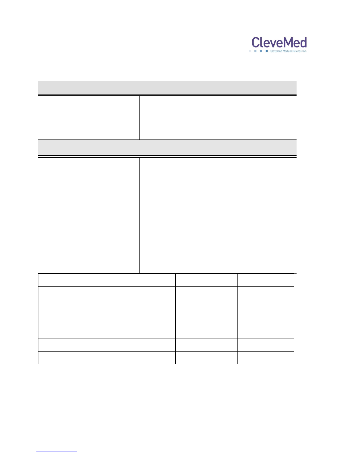
Channel Name
Sampling Rate
Sensor
Respiratory Effort
25
RIP Belt
Body Position
1
Internal 3-axis
accelerometer
Auxiliary
25
Thermistor, IDcheck
or RIP Belt
Airflow, Snore (derived from airflow)
25
Nasal Cannula
Pulse Oximetry, Heart Rate
10
Pulse Oximetry
System Specifications
Storage Humidity:
25% to 95% (non-condensing)
Operating Temperature:
10-40 C
Case Weight (all parts & accessories):
4 lbs
Patient Unit
Dimensions:
3” x 2.6” x 0.7” (7.6 cm x 6.6 cm x 1.8 cm)
Weight:
2 oz (57 g) (approx.) with battery
Number of Channels:
8 channel
Resolution:
12 bits
Power Source:
1 AAA alkaline battery
Battery Life
10 hours continuous use
User Control:
ON/OFF membrane switch
Case Material:
Polycarbonate (20% glass fiber)
Indicators
Power On, Low battery, good signals for auxiliary, nasal cannula,
RIP belt and Pulse oximetry sensors.
Appendix B: Technical Specifications
35
 Loading...