

Page 1
SE95050 Rev. 6
Operators Manual
Installation, Operation & Service
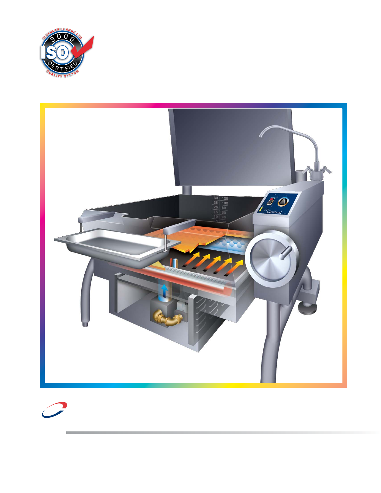
Gas T1 Skillets
1333 East 179th St., Cleveland, Ohio, U.S.A. 44110
Phone: (216) 481-4900 Fax: (216) 481-3782
Visit our web site at www.clevelandrange.com
d
FOR MODELS
BUILT AFTER
MAY 2006:
SGL-30-T1
SGL-40-T1
Enodis
For a complete Service Manual
refer to www.clevelandrange.com
™
Clev elan
Page 2

FOR THE USER
IMPORTANT
Post in a prominent location, instructions to be followed in the event the user smells gas.
This information shall be obtained by consulting your local gas supplier.
Keep appliance area free and clear from combustibles.
Do not obstruct the flow of combustion and ventilation air.
All service must be performed by a qualified cleveland range technician.
For unit equipped with casters, the installation shall be made with a connector that complies
with the Standard for Connectors for Movable Gas Appliances, ANSI Z21.69 or Connectors
for Moveable Gas Appliances, CAMCGA-6.16, and a quick-disconnect device that complies
with the Standard for Quick Disconnect Devices for Use With Gas Fuel, ANSI Z21.41, or
Quick Disconnect Devices for Use with Gas Fue4 CANT-6.9. Adequate means must be
provided to limit the movement of the appliance without depending on the connector and the
quick-disconnect device or its associated piping to limit the appliance movement. A restraint
can be attached to the rear leg next to the gas connection.
RETAIN THIS MANUAL FOR YOUR REFERENCE.
WARNING: Improper installation,
adjustment, alteration, service or
maintenance can cause property
damage, injury or death. Read the
Installation and Operating
instructions thoroughly before
installing or servicing this
equipment.
FOR YOUR SAFETY
DO NOT STORE OR USE
GASOLINE OR ANY OTHER
FLAMMABLE LIQUIDS AND
VAPOURS IN THE VICINITY
OF THIS OR ANY OTHER
APPLIANCE.
Page 3

GENERAL
Installation of the unit must be accomplished by
qualified installation personnel working to all applicable
local and national codes. Improper installation of
product could cause injury or damage.
This equipment is built to comply with applicable
standards for manufacturers. Included among those
approval agencies are: UL, A.G.A., NSF, ASME/N.Bd.,
CSA, CGA, ETL, and others. Many local codes exist,
and it is the responsibility of the owner/installer to
comply with these codes.
Observe all clearance requirements to provide proper
make-up air flow. Do not obstruct the flow of combustion
and ventilation air. Check rating plate to ensure that unit
has been equipped to operate with the type of gas
available at the installation.
Dimensions and clearance requirements are shown on
the Specification Sheet.
INSPECTION / UNPACKING
1. Before unpacking visually inspect the unit for
evidence of damage during shipping.
2. If damage is noticed, do not unpack the unit, follow
"SHIPPING DAMAGE INSTRUCTIONS" shown below.
3. Carefully remove unit from shipping carton. Remove
any packing material from unit. After carefully
unpacking check for "concealed" damage. If
damage is noticed, follow "SHIPPING DAMAGE
INSTRUCTIONS" shown below.
4. A protective material has been applied to the
stainless steel panels. This material must be
removed immediately after installation, as heat will
melt the material and make it more difficult to
remove.
SHIPPING DAMAGE
INSTRUCTIONS
If shipping damage to the unit is discovered or
suspected, observe the following guidelines in
preparing a shipping damage claim.
1. Write down a description of the damage or the
reason for suspecting damage as soon as it is
discovered. This will help in filling out the claim
forms later.
2. As soon as damage is discovered or suspected,
notify the carrier that delivered the shipment.
3. Arrange for the carrier's representative to examine
the damage.
4. Fill out all carrier claims forms and have the
examining carrier sign and date each form.
CLEARANCE REQUIREMENTS
This unit must be installed in accordance with the
clearances shown on the rating label which is adhered
to the unit.
FOR YOUR SAFETY. Keep the appliance area free and
clear of combustible materials.
INSTALLATION
1. Position the unit in it's permanent location, and level
the unit by turning the adjustable feet.
2. Once positioned
and leveled,
permanently
secure the unit's
rear flanged feet to
the floor using
5/16" lag bolts and
floor anchors
(supplied by the
installer). Three
bolts are required to secure each of the flanged
feet.
3. Seal joints of flanged feet with a silicone sealant.
GAS
ENSURE THE GAS SUPPLY MATCHES THE UNIT'S
REQUIREMENTS AS STATED ON THE RATING
PLATE.
It is recommended that a sediment trap (drip leg) be
installed in the gas supply line. If the gas pressure
exceeds 14” water column, a pressure regulator must
be installed, to provide a maximum of 14” water column
gas pressure to the gas control valve.
Connect the gas line to the manual valve located at the
rear of the control box.
Installation must be in accordance with local codes
and/or the National Fuel Gas Code ANSI Z223.1 Latest
Edition (USA) or the latest Installation Codes for Gas
Burning Appliances and Equipment CAN/ CGA B149.1
(natural gas) and CAN/ CGA B149.2 (propane gas).
Use a gas pipe joint compound which is resistant to L.P.
gas. Test all pipe joints for leaks with soap and water
solution. Ensure that the gas pressure regulator is set
for the manifold pressure indicated on the gas rating
plate.
The appliance and its individual shut-off valve must be
disconnected from the gas supply piping system during
any pressure testing of that system at test pressures in
excess of 1/2 psi (3.45 kPa). The appliance must be
isolated from the gas supply piping system by closing
its individual manual shut-off valve during any pressure
testing of the gas supply piping system at test
pressures equal to or less than 1/2 psi (3.45 kPa).
INSTALLATION
7/16"Ø, 3 HOLES
ON 3 1/8" (80mm) B.C.D.
FLANGED FOOT DETAIL
(REAR LEGS ONLY)
120 120
4 7/8" (124mm)
Page 4

ELECTRICAL
NOTE: Wiring diagram is located on the underside of the
unit's control panel.
ENSURE THE ELECTRICAL SUPPLY MATCHES THE
UNIT'S REQUIREMENTS AS STATED ON THE RATING
LABEL.
A cord and plug are supplied with the 115 volt unit.
Simply plug the unit into any grounded outlet rated for a
minimum of 10 amps. The wiring diagram is located on
the back of the console access panel.
When a unit is ordered and built for 208/240 volt, the
supply line must be connected to the wiring terminations
located inside the console. A wiring diagram is attached
to the underside of the control panel.
WARNING: Electrical Grounding Instructions.
This unit is equipped with a three-prong (grounding) plug
for your protection against shock hazard and should be
plugged directly into a properly grounded three-prong
receptacle. Do not cut or remove the grounding prong
from this plug. Standard supply voltage is 115 volts A.C.,
however, optional A.C. voltages can be supplied on
special order. A separate fused disconnect switch must
be supplied and installed in the high voltage electrical
supply line. The unit when installed, must be electrically
installed and grounded in accordance with local codes,
or in the absence of local codes, with National Electrical
Code, ANSI/NFPA 70-1990 (USA) or the Canadian
Electrical Code, CSA C22.2, Part 1 (Canada).
VENTILATION
Gas fired units are only to be installed under a ventilation
hood in a room which has provisions for adequate make
up air. Further information can be obtained by referring to
the U.S.A. National Fire Protection Associations NFPA96
regulations. These standards have also been adopted by
the National Building Code in Canada.
WATER CONNECTION
(OPTIONAL)
A 1/2" NPT cold water line and/or a 1/2" NPT hot water
line are required if unit is equipped with a single or
double pantry faucet.
INSTALLATION CHECKS
Although the unit has been thoroughly tested before
leaving the factory, the installer is responsible for ensuring
the proper operation of unit once installed.
DO NOT ATTEMPT TO OPERATE THIS UNIT DURING A
POWER FAILURE.
KEEP APPLIANCE AND AREA FREE AND CLEAR OF
COMBUSTIBLES.
1. Supply power to the unit by placing the fused
disconnect switch to the "ON" position.
2. Turn on main gas supply to unit. Open the skillet's
shut-off valve (located at lower rear left).
3. Toggle HI / OFF / LO Switch to the "HI" or "LO"
position.
4. For your safety the skillet is equipped with a power
interrupter which automatically shuts off the gas
supply to the burners whenever the skillet is raised
more than 8°.
IMPORTANT: Before commencing to cook, ensure the
skillet pan is in the lowered position. Also ensure the
cover is raised.
5. Turn temperature control to maximum. Tilt skillet pan
until heat indicator light turns off and heating system
shuts down. The pan should be on a 5-10° angle.
6. Lower pan. Heat indicator light will re-light and
heating system will re-energize.
7. Unit will continue to heat, heat indicator light will
remain on until temperature is reached. Then the heat
indicator light will cycle OFF indicating the heating
system has shut off. The heat indicator light will
continue to cycle ON and OFF as the heating system
cycles ON and OFF maintaining the desired
temperature.
3. Toggle HI / OFF / LO Switch to the "OFF" position.
CLEANING
After installation the unit must be thoroughly cleaned and
sanitized prior to cooking.
Page 5

HI
LO
OPERATING INSTRUCTIONS
General Parts Drawing
ITEM # DESCRIPTION FUNCTION
1. HI / OFF / LO Switch Center position - power to the unit is OFF.
HI position - unit is in high fire mode (unit heats faster).
LO position - unit is in low fire mode (unit heats slower).
2. Power Indicator Light (red) Indicates power is ON.
3. Temperature Dial Regulates the surface temperature of the pan.
4. Heat Indicator Light (yellow) Turns ON when system is calling for heat and
OFF when system is satisfied.
5. Hand Tilt Wheel Used for tilting the pan up or down.
6. Power Tilt Switch Option - Used for tilting the pan up or down.
7. Reset Button Fuse protection for optional power tilt.
8. Manual Tilt Override Used on units with optional power tilt for tilting the pan up or down
in case of power or mechanical failure.
9. Gas Shut Off Valve Allows you to shut the gas off to the appliance if required.
10. Faucet Option - hot and/or cold faucet mounts to skillet for
convenient filling of the pan.
11. Tangent Draw-Off Valve Option - allows you to discharge product from the pan through
(not shown) the valve.
5
8
9
10
4 1 2 3
CONTROL PANEL
7
6
Page 6
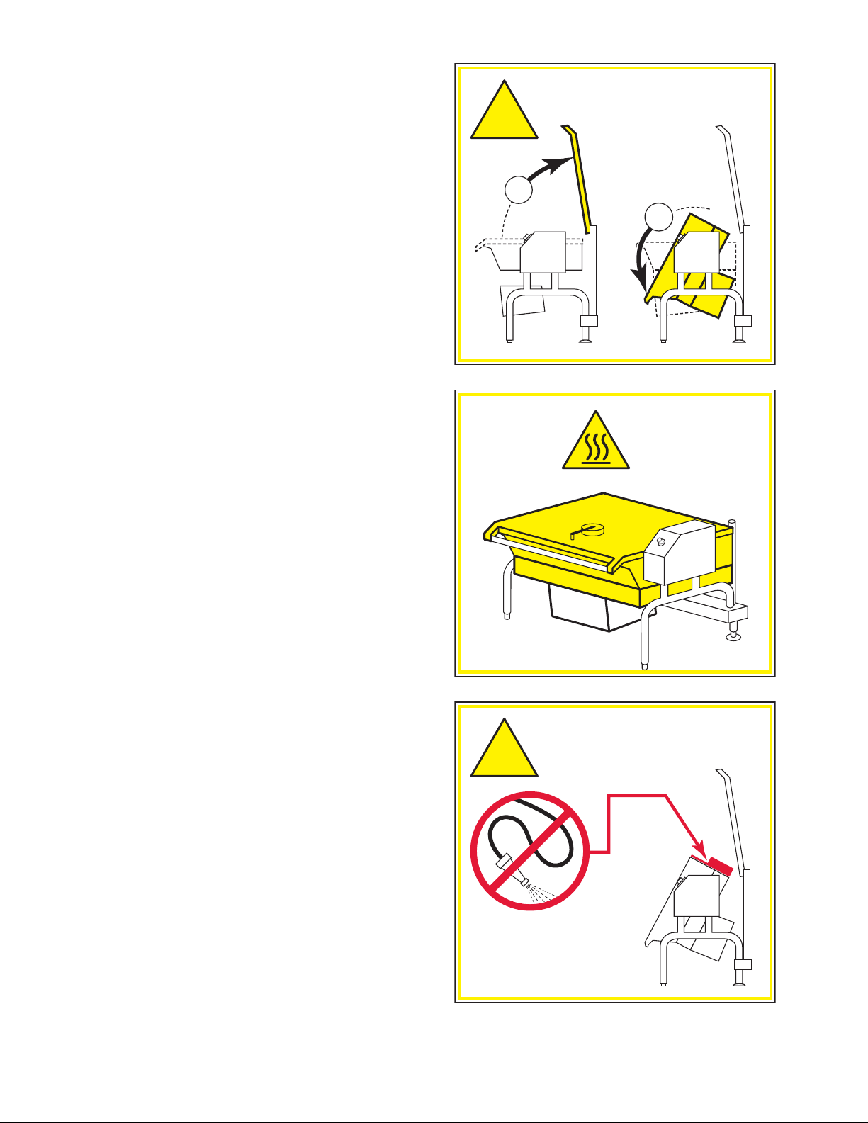
OPERATING THE UNIT
1. Ensure the gas and electrical supply to the unit are
in the ON position.
FOR YOUR SAFETY:
This skillet will automatically shut off the gas supply
when pan is raised more than 8°.
Before commencing to cook, ensure pan is in the
lowered position.
2. MANUAL TILT: Cleveland skillets are equipped
with a manual tilt mechanism for raising and
lowering the pan. To raise pan, raise the cover and
turn the crank clockwise. To lower pan, turn
counterclockwise.
POWER TILT: Cleveland skillets can also be
equipped with an optional electric power tilt
mechanism for raising and lowering the pan. To
raise pan, raise the cover and press up on the tilt
switch. To lower pan, press down on the tilt switch.
3. Toggle HI / OFF / LO Switch to the "HI" or "LO"
position. The red Power Indicator Light indicates
power is on. The yellow Heat Indicator Light
indicates burners are on.
4. To preheat, set Temperature Dial to desired
cooking temperature. Unit is preheated when the
yellow light goes out.
5. Insert product in pan.
6. If desired, once product has cooked, it can be held
prior to serving at a lower temperature setting.
7. When cooking is completed, set Temperature Dial
and HI / OFF / LO Switch to the OFF position.
8. The best time to clean the skillet is immediately
after use, once skillet has cooled down. Refer to
section titled "CLEANING INSTRUCTIONS" for
details.
OPERATING SUGGESTIONS
1. Turn power switch to the "OFF" position when skillet
is not in use.
2. Allow skillet to preheat before adding product.
3. Always lift the spring assist cover before activating
the tilt mechanism.
4. During an electrical power interruption, turn Power
Switch to the OFF position. This unit cannot be
made to operate without electrical power.
OPEN LID BEFORE
TILTING PAN
!
1
2
HOT
DO NOT
HOSE DOWN
!
THIS AREA
Page 7
CARE AND CLEANING
Cooking equipment must be cleaned regularly to
maintain its fast, efficient cooking performance and
to ensure its continued safe, reliable operation. The
best time to clean is shortly after each use (allow
unit to cool to a safe temperature).
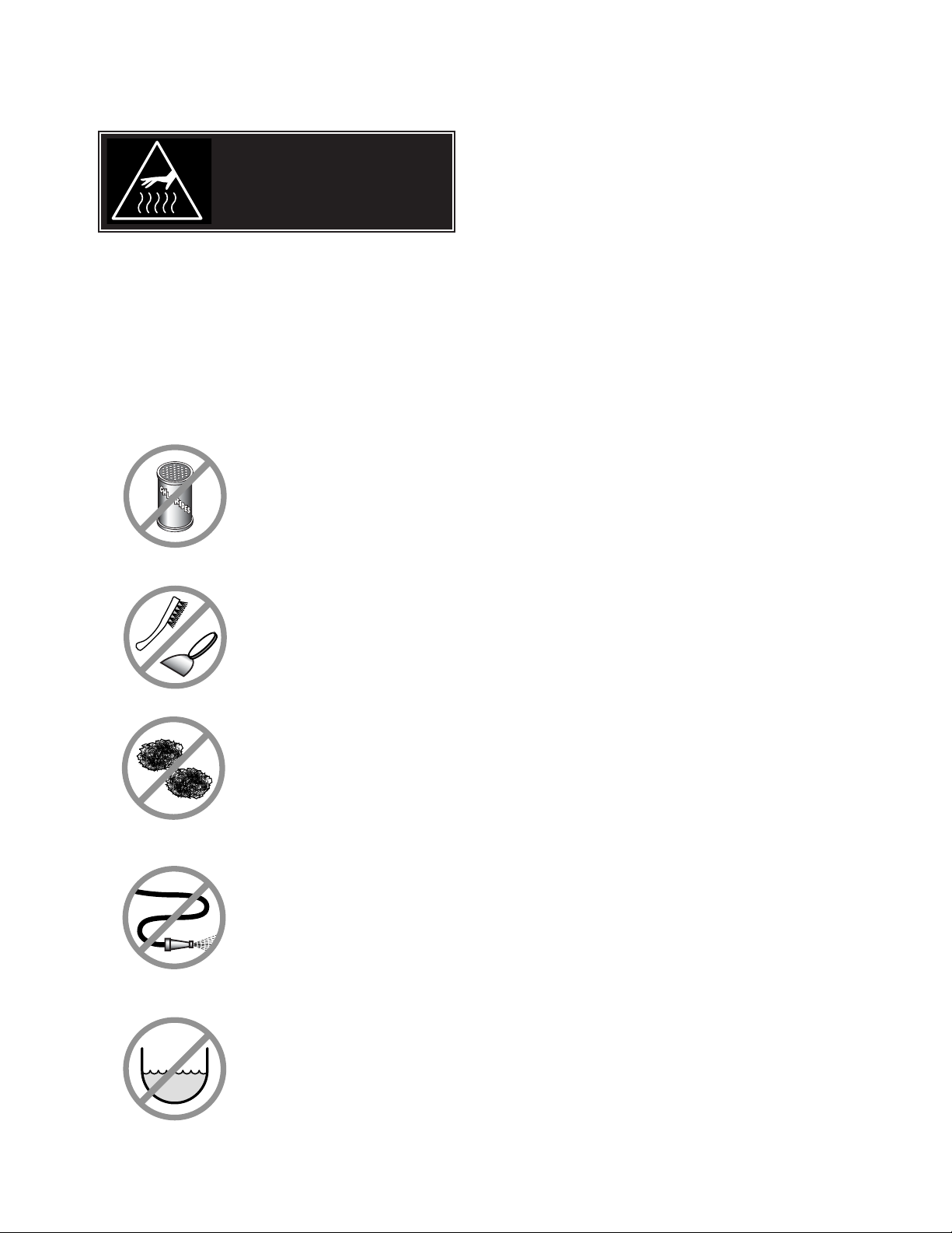
WARNINGS
➩ Do not use detergents or
cleansers that are chloride
based or contain quaternary
salt.
➩ Do not use a metal bristle
brush or scraper.
➩ Steel wool should never be
used for cleaning the stainless
steel.
➩ Unit should never be cleaned
with a high pressure spray
hose.
➩
Do not leave water sitting in unit
when not in use.
Stagnant
Water
High Pressure
Spray Hose
Chloride Cleaners
Steel Pads
Wire Brush &
CLEANING INSTRUCTIONS
CAUTION
SURFACES MAY
BE EXTREMELY HOT!
CLEANING INSTRUCTIONS
1. Turn unit off.
2. Remove drain screen (if applicable). Thoroughly
wash and rinse the screen either in a sink or a
dishwasher.
3. Prepare a warm water and mild detergent solution in
the unit.
4. Remove food soil using a nylon brush.
5. Loosen food which is stuck by allowing it to soak at
a low temperature setting.
6. Drain unit.
7. Rinse interior thoroughly.
8. If the unit is equipped with a Tangent Draw-Off
Valve, clean as follows:
a) Disassemble the draw-off valve first by turning
the valve knob counter-clockwise, then turning
the large hex nut counter-clockwise until the
valve stem is free of the valve body.
b) In a sink, wash and rinse the inside of the valve
body using a nylon brush.
c)
Use a nylon brush to clean tangent draw-off tube.
d) Rinse with fresh water.
e) Reassemble the draw-off valve by reversing the
procedure for disassembly. The valve's hex nut
should be hand tight only.
9. If the unit is equipped with a Butterfly Valve, clean
as follows:
a) Place valve in open position.
b) Wash using a warm water and mild detergent
solution.
c) Remove food deposits using a nylon brush.
d) Rinse with fresh water.
e) Leave valve open when unit is not in use.
10 . Using mild soapy water and a damp sponge, wash
the exterior, rinse, and dry.
NOTES
➩ For more difficult cleaning applications one of the
following can be used: alcohol, baking soda, vinegar,
or a solution of ammonia in water.
➩ Leave the cover off when the kettle is not in use.
➩ For more detailed instructions refer to the Nafem
Stainless Steel Equipment Care and Cleaning manual
(supplied with unit).
Page 8

STAINLESS STEEL EQUIPMENT CARE AND CLEANING
(Suppied courtesy of Nafem. For more information visit their web site at www.nafem.org)
Contrary to popular belief, stainless steels ARE susceptible to rusting.
Corrosion on metals is everywhere. It is recognized quickly on iron and
steel as unsightly yellow/orange rust. Such metals are called “active”
because they actively corrode in a natural environment when their atoms
combine with oxygen to form rust.
Stainless steels are passive metals because they contain other metals, like
chromium, nickel and manganese that stabilize the atoms. 400 series
stainless steels are called ferritic, contain chromium, and are magnetic;
300 series stainless steels are called austenitic, contain chromium and
nickel; and 200 series stainless, also austenitic, contains manganese,
nitrogen and carbon. Austenitic types of stainless are not magnetic, and
generally provide greater resistance to corrosion than ferritic types.
With 12-30 percent chromium, an invisible passive film covers the steel’s
surface acting as a shield against corrosion. As long as the film is intact
and not broken or contaminated, the metal is passive and stain-less. If the
passive film of stainless steel has been broken, equipment starts to
corrode. At its end, it rusts.
Enemies of Stainless Steel
There are three basic things which can break down stainless steel’s
passivity layer and allow corrosion to occur.
1. Mechanical abrasion
2. Deposits and water
3. Chlorides
Mechanical abrasion means those things that will scratch a steel surface.
Steel pads, wire brushes and scrapers are prime examples.
Water comes out of the faucet in varying degrees of hardness. Depending
on what part of the country you live in, you may have hard or soft water.
Hard water may leave spots, and when heated leave deposits behind that
if left to sit, will break down the passive layer and rust stainless steel. Other
deposits from food preparation and service must be properly removed.
Chlorides are found nearly everywhere. They are in water, food and table
salt. One of the worst chloride perpetrators can come from household and
industrial cleaners.
So what does all this mean? Don’t Despair!
Here are a few steps that can help prevent stainless steel rust.
1.
Use the proper tools.
When cleaning stainless steel products, use non-abrasive tools. Soft
cloths and plastic scouring pads will not harm steel’s passive layer.
Stainless steel pads also can be used but the scrubbing motion must
be in the direction of the manufacturers’ polishing marks.
2.
Clean with the polish lines.
Some stainless steel comes with visible polishing lines or “grain.”
When visible lines are present, always scrub in a motion parallel to the
lines. When the grain cannot be seen, play it safe and use a soft cloth
or plastic scouring pad.
3.
Use alkaline, alkaline chlorinated or non-chloride containing cleaners.
While many traditional cleaners are loaded with chlorides, the industry
is providing an ever-increasing choice of non-chloride cleaners. If you
are not sure of chloride content in the cleaner used, contact your cleaner
supplier. If your present cleaner contains chlorides, ask your supplier if
they have an alternative. Avoid cleaners containing quaternary salts; it
also can attack stainless steel and cause pitting and rusting.
4.
Treat your water.
Though this is not always practical, softening hard water can do much
to reduce deposits. There are certain filters that can be installed to
remove distasteful and corrosive elements. To insure proper water
treatment, call a treatment specialist.
5.
Keep your food equipment clean.
Use alkaline, alkaline chlorinated or non-chloride cleaners at
recommended strength. Clean frequently to avoid build-up of hard,
stubborn stains. If you boil water in stainless steel equipment,
remember the single most likely cause of damage is chlorides in the
water. Heating cleaners that contain chlorides have a similar effect.
6.
Rinse, rinse, rinse.
If chlorinated cleaners are used, rinse and wipe equipment and
supplies dry immediately. The sooner you wipe off standing water,
especially when it contains cleaning agents, the better. After wiping
equipment down, allow it to air dry; oxygen helps maintain the
stainless steel’s passivity film.
7.
Never use hydrochloric acid (muriatic acid) on stainless steel.
8.
Regularly restore/passivate stainless steel.
Recommended cleaners for specific situations
Job Cleaning Agent Comments
Routine cleaning Soap, ammonia, Apply with cloth or sponge
detergent, Medallion
Fingerprints & smears Arcal 20, Lac-O-Nu Provides barrier film
Ecoshine
Stubborn stains & Cameo, Talc, Zud, Rub in direction of polish lines
discoloration First Impression
Grease & fatty acids, Easy-off, De-Grease Excellent removal on all finishes
blood, burnt-on-foods It Oven Aid
Grease & oil Any good Apply with sponge or cloth
commercial detergent
Restoration/Passivation Benefit, Super Sheen
Review
1. Stainless steels rust when passivity (film-shield) breaks down as a
result of scrapes, scratches, deposits and chlorides.
2. Stainless steel rust starts with pits and cracks.
3. Use the proper tools. Do not use steel pads, wire brushes or scrapers
to clean stainless steel.
4. Use non-chlorinated cleaners at recommended concentrations. Use
only chloride- free cleaners.
5. Soften your water. Use filters and softeners whenever possible.
6. Wipe off cleaning agent(s) and standing water as soon as possible.
Prolonged contact causes eventual problems.
To learn more about chloride-stress corrosion and how to prevent it,
contact the equipment manufacturer or cleaning materials supplier.
Developed by Packer Engineering, Naperville, Ill., an independent testing
laboratory.
Page 9
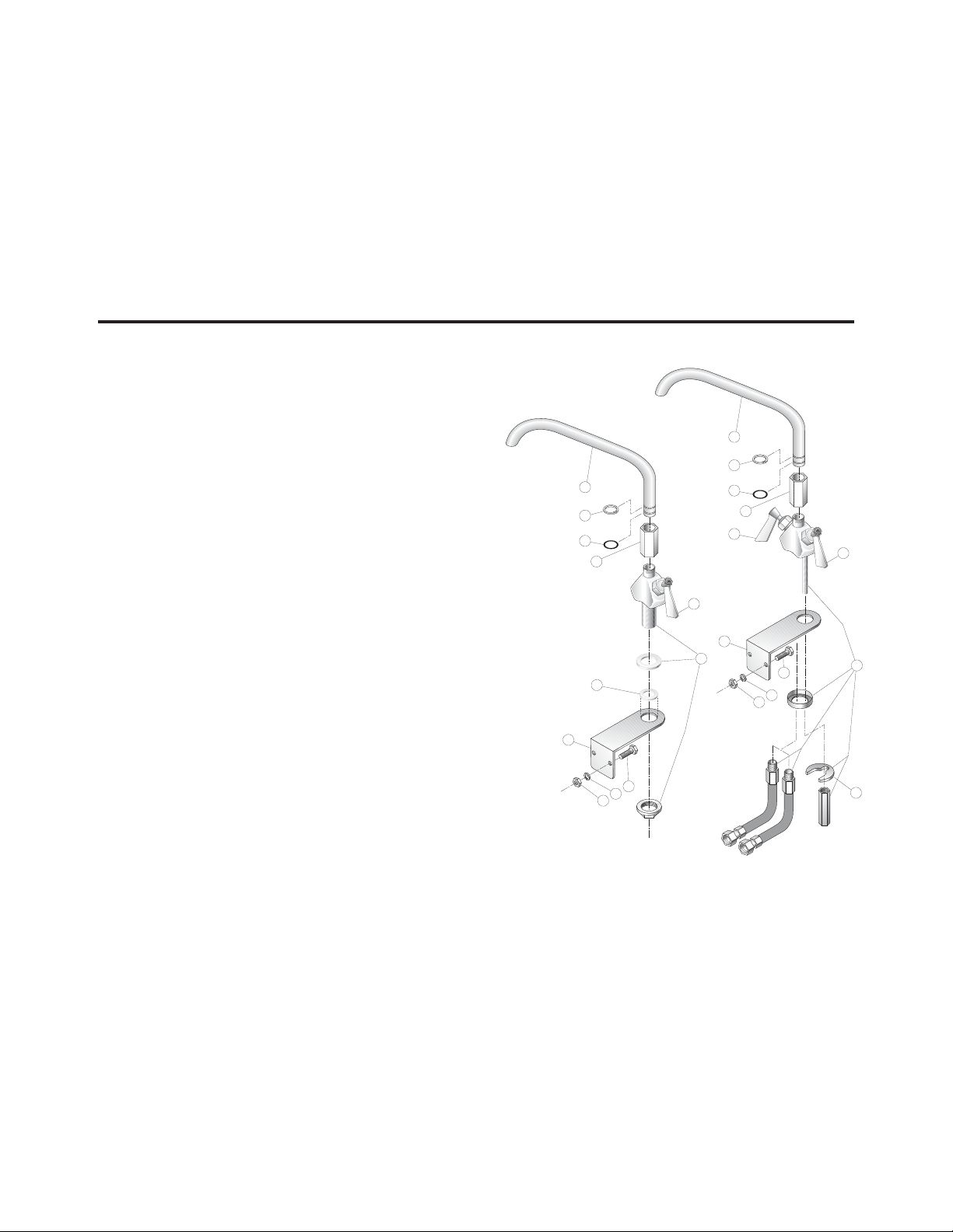
FAUCET ASSEMBLY
ITEM PART DESCRIPTION QTY.
NO. NO.
1. KE50825-7 3/4" SPOUT . . . . . . . . . . . . . . . . . . . . . . . .1
2. FA95022 RETAINING RING . . . . . . . . . . . . . . . . . . . .1
3. FA05002-19 "O" RING . . . . . . . . . . . . . . . . . . . . . . . . . . .1
4. KE51736 LONG FAUCET NUT . . . . . . . . . . . . . . . . .1
5. SE50020 HOT WATER STEM ASSEMBLY . . . . . . . . .1
(DOUBLE PANTRY ONLY)
6. SE50021 COLD WATER STEM ASSEMBLY . . . . . . . .1
7. KE51401 SINGLE PANTRY BODY . . . . . . . . . . . . . . .1
(C/W ITEM NO. 6)
8. KE50335 ADAPTER WASHER . . . . . . . . . . . . . . . . . .1
(SINGLE PANTRY ONLY)
9. KE51403 DOUBLE PANTRY BODY . . . . . . . . . . . . . .1
(C/W ITEM NO. 5&6)
10. SK00395-1 FAUCET MOUNTING BRACKET . . . . . . . .1
11. FA11258 HEX CAP SCREW . . . . . . . . . . . . . . . . . . .2
12. FA30505-1 WASHER . . . . . . . . . . . . . . . . . . . . . . . . . .2
13. FA21008 HEX NUT . . . . . . . . . . . . . . . . . . . . . . . . . .2
14. SE50447 WASHER HORSESHOE . . . . . . . . . . . . . . .1
1
1
2
2
3
3
4
4
5
9
10
10
13
8
12
11
13
14
12
11
7
6
6
SERVICE PARTS
WARRANTY
Our Company supports a worldwide network of Maintenance and Repair Centers. Contact your nearest
Maintenance and Repair Centre for replacement parts, service, or information regarding the proper
maintenance and repair of your cooking equipment
In order to preserve the various agency safety certification (UL, NSF, ASME/Ntl. Bd., etc.), only factorysupplied replacement parts should be used. The use of other than factory supplied replacement parts will
void warranty.
Page 10

FRAME / LID ASSEMBLY
ITEM NO. PART NO. DESCRIPTION QTY.
1. SK00392-1 FRAME WELDMENT (30 GALLON) . . . . . . . . . . . . . . . . . . . . . . . . . . . . . . . . . .1
SK00392-2 FRAME WELDMENT (40 GALLON) . . . . . . . . . . . . . . . . . . . . . . . . . . . . . . . . . .1
2. SK2457192 LID ASSEMBLY (30 GALLON) . . . . . . . . . . . . . . . . . . . . . . . . . . . . . . . . . . . . . .1
SK2457193 LID ASSEMBLY (40 GALLON) . . . . . . . . . . . . . . . . . . . . . . . . . . . . . . . . . . . . . .1
4. KE50187-1 CAP . . . . . . . . . . . . . . . . . . . . . . . . . . . . . . . . . . . . . . . . . . . . . . . . . . . . . . . . . . .2
5. SK00394-1 HOOK WELDMENT . . . . . . . . . . . . . . . . . . . . . . . . . . . . . . . . . . . . . . . . . . . . . . .2
6. SK2452300 SPRING . . . . . . . . . . . . . . . . . . . . . . . . . . . . . . . . . . . . . . . . . . . . . . . . . . . . . . . .2
7. FA95087-1 EYE BOLT . . . . . . . . . . . . . . . . . . . . . . . . . . . . . . . . . . . . . . . . . . . . . . . . . . . . . .2
8. FA20008 HEX NUT . . . . . . . . . . . . . . . . . . . . . . . . . . . . . . . . . . . . . . . . . . . . . . . . . . . . . . .2
9. KE53573-1 BEARING . . . . . . . . . . . . . . . . . . . . . . . . . . . . . . . . . . . . . . . . . . . . . . . . . . . . . . .2
10. FA15019-4 SHOULDER BOLT . . . . . . . . . . . . . . . . . . . . . . . . . . . . . . . . . . . . . . . . . . . . . . . .2
11. FA21501-2 ACORN NUT . . . . . . . . . . . . . . . . . . . . . . . . . . . . . . . . . . . . . . . . . . . . . . . . . . . .2
12. KE00099 ADJUSTABLE FOOT (FLANGED) . . . . . . . . . . . . . . . . . . . . . . . . . . . . . . . . . . . .2
13. KE50249-1 FOOT ADJUSTOR (W/O FLANGE) . . . . . . . . . . . . . . . . . . . . . . . . . . . . . . . . . . .2
17. FA31029 LOCKWASHER . . . . . . . . . . . . . . . . . . . . . . . . . . . . . . . . . . . . . . . . . . . . . . . . . .2
18. FA11054 SCREW . . . . . . . . . . . . . . . . . . . . . . . . . . . . . . . . . . . . . . . . . . . . . . . . . . . . . . . .4
19. SK2459299 COUPLING ASSEMBLY . . . . . . . . . . . . . . . . . . . . . . . . . . . . . . . . . . . . . . . . . . . .1
20. FA21024 HEX NUT (5/16-18) . . . . . . . . . . . . . . . . . . . . . . . . . . . . . . . . . . . . . . . . . . . . . . .2
21. FA31030 LOCKWASHER . . . . . . . . . . . . . . . . . . . . . . . . . . . . . . . . . . . . . . . . . . . . . . . . . .2
22. FA30055 FLAT WASHER . . . . . . . . . . . . . . . . . . . . . . . . . . . . . . . . . . . . . . . . . . . . . . . . . .2
23. SK00054 VENT COVER ASSEMBLY . . . . . . . . . . . . . . . . . . . . . . . . . . . . . . . . . . . . . . . . . .1
24. SK2211200 SPACER . . . . . . . . . . . . . . . . . . . . . . . . . . . . . . . . . . . . . . . . . . . . . . . . . . . . . . . .1
25. FA95081-1 BOLT, MODIFIED . . . . . . . . . . . . . . . . . . . . . . . . . . . . . . . . . . . . . . . . . . . . . . . . .1
26. SK50179 WASHER . . . . . . . . . . . . . . . . . . . . . . . . . . . . . . . . . . . . . . . . . . . . . . . . . . . . . . .1
27. FA30504 WASHER . . . . . . . . . . . . . . . . . . . . . . . . . . . . . . . . . . . . . . . . . . . . . . . . . . . . . . .2
P
KE53068-3 Caster
KE53068-4 Locking caster
19 120 21 22
9
10
11
17
13 12
23
24 25 26
2
4 18
5
OPEN END OF
SPRING TO BE
6
LOCATED ON TO
7
APPLY
REMOVABLE
8
LOCKTITE
27
Page 11

1
2
3
4
5
6
7
2" TANGENT DRAW-OFF VALVE
ITEM NO. PART NO. DESCRIPTION QTY.
1. - 7. KE50972-B DRAW-OFF ASSEMBLY . . . . . . . . . . . . . . . . . . . . . . . . . . . . . . . . . . . . . . . . . . . .1
1. FA95049 WING NUT . . . . . . . . . . . . . . . . . . . . . . . . . . . . . . . . . . . . . . . . . . . . . . . . . . . . . .1
2. KE527551 KNOB . . . . . . . . . . . . . . . . . . . . . . . . . . . . . . . . . . . . . . . . . . . . . . . . . . . . . . . . .1
3. KE52754 HEX NUT . . . . . . . . . . . . . . . . . . . . . . . . . . . . . . . . . . . . . . . . . . . . . . . . . . . . . . .1
4. KE52753 RETAINER . . . . . . . . . . . . . . . . . . . . . . . . . . . . . . . . . . . . . . . . . . . . . . . . . . . . . .1
5. KE52752 PISTON . . . . . . . . . . . . . . . . . . . . . . . . . . . . . . . . . . . . . . . . . . . . . . . . . . . . . . . .1
6. FA00111 "O" RING . . . . . . . . . . . . . . . . . . . . . . . . . . . . . . . . . . . . . . . . . . . . . . . . . . . . . . .1
7. KE52751 VALVE BODY . . . . . . . . . . . . . . . . . . . . . . . . . . . . . . . . . . . . . . . . . . . . . . . . . . .2
Page 12

TILT COMPONENTS
Handwheel KE00508-2
9
47
172118 19
10 0
23 75 45 29 51
23 22
3
9
20
116
66
6
5
13
9 47
14
15
16
11 171819 16 12 2548
4415
23 1022
47
POWER
TILT
43 42 41
20 49 50 24
22 23
26
20
*116
4
39
40
22 23
3
9 5
20
116
353634
13
14
15
16
11 171819 20 37
7
8
6
47
MANUAL
32
33 29 51
38
12
15 16
TILT
26
20
*116
4
24 25
Page 13

ITEM NO. PART NO. DESCRIPTION QTY.
3. REF.SK00387 GEARBOX COVER ASSEMBLY . . . . . . . . . . . . . . . . . . . . . . . . . . . . . . . . . . . . . 1
4. KE002590 WRAP WELDMENT FOR GEAR . . . . . . . . . . . . . . . . . . . . . . . . . . . . . . . . . . . . . 1
5. KE55513 GEAR BOX . . . . . . . . . . . . . . . . . . . . . . . . . . . . . . . . . . . . . . . . . . . . . . . . . . . . 1
6. KE602239 STOP ARM . . . . . . . . . . . . . . . . . . . . . . . . . . . . . . . . . . . . . . . . . . . . . . . . . . . . . 1
7. KE602587 SAFETY MOUNTING BRACKET . . . . . . . . . . . . . . . . . . . . . . . . . . . . . . . . . . . . 1
8. KE602598 MOUNTING BRACKET . . . . . . . . . . . . . . . . . . . . . . . . . . . . . . . . . . . . . . . . . . . . 1
9. SK2474500 SWITCH, TILT LIMIT . . . . . . . . . . . . . . . . . . . . . . . . . . . . . . . . . . . . . . . . . . . . . 1
10. REF.SK00410 COMPONENT PLATE ASSEMBLY . . . . . . . . . . . . . . . . . . . . . . . . . . . . . . . . . . . 1
11. FA95055-13 KEY, 3/8 X 3/8 X 5 . . . . . . . . . . . . . . . . . . . . . . . . . . . . . . . . . . . . . . . . . . . . . . . 1
12. FA15019-6 SHOULDER BOLT . . . . . . . . . . . . . . . . . . . . . . . . . . . . . . . . . . . . . . . . . . . . . . . 1
13 FA21024 5-16 HEX NUT, 18-8 S.S. . . . . . . . . . . . . . . . . . . . . . . . . . . . . . . . . . . . . . . . . . . 1
14. KE002527 STOP ASSEMBLY . . . . . . . . . . . . . . . . . . . . . . . . . . . . . . . . . . . . . . . . . . . . . . . 1
15. FA15021 BOLT, HEX CAP M10 X 30 . . . . . . . . . . . . . . . . . . . . . . . . . . . . . . . . . . . . . . . . 2
16. FA31500 LOCKWASHER, M10 . . . . . . . . . . . . . . . . . . . . . . . . . . . . . . . . . . . . . . . . . . . . . 2
17. FA11526 HEX. CAP SCREW, 7/16-14 X 1-1/4" S.S. 18-8 . . . . . . . . . . . . . . . . . . . . . . . . . 6
18. FA31011 7/16 SPLIT LOCKWASHER, S.S. 18-8 . . . . . . . . . . . . . . . . . . . . . . . . . . . . . . . . 6
19. FA21506 NUT, 7/16-14 S.S. 18-8 . . . . . . . . . . . . . . . . . . . . . . . . . . . . . . . . . . . . . . . . . . . . 6
20. FA11135 SCREW, 10-24 X 1/2 . . . . . . . . . . . . . . . . . . . . . . . . . . . . . . . . . . . . . . . . . . . . . . 7
21. KE602573 MOUNTING BRACKET . . . . . . . . . . . . . . . . . . . . . . . . . . . . . . . . . . . . . . . . . . . . 1
22. FA21008 HEX. NUT, 1/4-20 . . . . . . . . . . . . . . . . . . . . . . . . . . . . . . . . . . . . . . . . . . . . . . . . 6
23. FA31029 SPLIT LOCKWASHER, 1/4 . . . . . . . . . . . . . . . . . . . . . . . . . . . . . . . . . . . . . . . . . 6
24. FA21024 5/16 - 18, HEX NUT, 18-8 S.S. . . . . . . . . . . . . . . . . . . . . . . . . . . . . . . . . . . . . . . 4
25. FA31030 SPLIT LOCKWASHER, 5/16 . . . . . . . . . . . . . . . . . . . . . . . . . . . . . . . . . . . . . . . . 4
26. KE600284-4 GASKET, SILICONE GRAY . . . . . . . . . . . . . . . . . . . . . . . . . . . . . . . . . . . . . . . . . 1
29. FA31031 SPLIT LOCKWASHER . . . . . . . . . . . . . . . . . . . . . . . . . . . . . . . . . . . . . . . . . . . . . 2
32. KE002215 STOP ARM . . . . . . . . . . . . . . . . . . . . . . . . . . . . . . . . . . . . . . . . . . . . . . . . . . . . . 1
33. FA19196 SET SCREW, 3/8-16 X 2 1/2" . . . . . . . . . . . . . . . . . . . . . . . . . . . . . . . . . . . . . . . 1
34. KE002509 HAND CRANK ASSEMBLY . . . . . . . . . . . . . . . . . . . . . . . . . . . . . . . . . . . . . . . . 1
35. KE54738-5 WASHER, FLAT . . . . . . . . . . . . . . . . . . . . . . . . . . . . . . . . . . . . . . . . . . . . . . . . . . 1
36. FA19505 SET SCREW, 3/8-24 X 3/8” . . . . . . . . . . . . . . . . . . . . . . . . . . . . . . . . . . . . . . . . . 1
37. KE602511 BOTTOM COVER . . . . . . . . . . . . . . . . . . . . . . . . . . . . . . . . . . . . . . . . . . . . . . . . 1
38. KE602032 SPACER . . . . . . . . . . . . . . . . . . . . . . . . . . . . . . . . . . . . . . . . . . . . . . . . . . . . . . . 1
39. KE601725 SUPPORT . . . . . . . . . . . . . . . . . . . . . . . . . . . . . . . . . . . . . . . . . . . . . . . . . . . . . . 1
40. KE52832-5 MOTOR, POWER TILT . . . . . . . . . . . . . . . . . . . . . . . . . . . . . . . . . . . . . . . . . . . . 1
41. KE50582-5 COUPLING HUB, 1/2 BORE . . . . . . . . . . . . . . . . . . . . . . . . . . . . . . . . . . . . . . . . 1
42. KE50583-1 COUPLING SPIDER . . . . . . . . . . . . . . . . . . . . . . . . . . . . . . . . . . . . . . . . . . . . . . 1
43. KE50582-4 COUPLING HUB, 3/4 BORE . . . . . . . . . . . . . . . . . . . . . . . . . . . . . . . . . . . . . . . . 1
44. KE601886 STOP . . . . . . . . . . . . . . . . . . . . . . . . . . . . . . . . . . . . . . . . . . . . . . . . . . . . . . . . . . 1
45. FA11384 HEX. CAP SCREW, 3/8-16 X 1” . . . . . . . . . . . . . . . . . . . . . . . . . . . . . . . . . . . . . 2
47. FA10140 SCREW, 6-32 X 1 1/4 . . . . . . . . . . . . . . . . . . . . . . . . . . . . . . . . . . . . . . . . . . . . . 2
48. KE602542 EXTENSION FOR SHAFT . . . . . . . . . . . . . . . . . . . . . . . . . . . . . . . . . . . . . . . . . 1
49. KE602543 SOCKET SET SCREW, CONE POINT . . . . . . . . . . . . . . . . . . . . . . . . . . . . . . . . . 1
50. KE602507 BOTTOM COVER . . . . . . . . . . . . . . . . . . . . . . . . . . . . . . . . . . . . . . . . . . . . . . . . 1
51. FA21026 3/8 HEXAGON NUT . . . . . . . . . . . . . . . . . . . . . . . . . . . . . . . . . . . . . . . . . . . . . . 2
66. KE602571 MOUNTING BRACKET . . . . . . . . . . . . . . . . . . . . . . . . . . . . . . . . . . . . . . . . . . . . 1
75. FA11258 1/4-20 X 3/4 BOLT, 18-8 S.S. . . . . . . . . . . . . . . . . . . . . . . . . . . . . . . . . . . . . . . . 4
100. FA30505-1 FLAT WASHER, 1/4 . . . . . . . . . . . . . . . . . . . . . . . . . . . . . . . . . . . . . . . . . . . . . . 4
116. FA11511-2 10-32 X 3/8 PAN HEAD TORX SCREW . . . . . . . . . . . . . . . . . . . . . . . . . . . . . . . 1
TILT COMPONENTS
KE55513-1
Page 14

CONTROL BOX ASSEMBLY
ITEM NO. PART NO. DESCRIPTION QTY.
1. SK2138700 KNOB ASSEMBLY . . . . . . . . . . . . . . . . . . . . . . . . . . . . . . . . . . . . . . . . . . . . . . . .1
2. SK2360700 DIAL INSERT °F . . . . . . . . . . . . . . . . . . . . . . . . . . . . . . . . . . . . . . . . . . . . . . . . .1
SK2360701 DIAL INSERT °C . . . . . . . . . . . . . . . . . . . . . . . . . . . . . . . . . . . . . . . . . . . . . . . . .1
3. KE51005 RUBBER BOOT. #N9030 X 1/4 . . . . . . . . . . . . . . . . . . . . . . . . . . . . . . . . . . . . . .1
4. SK2498399 POTENTIOMETER SHAFT ASSEMBLY . . . . . . . . . . . . . . . . . . . . . . . . . . . . . . . .1
SK2166800 POTENTIOMETER SHAFT . . . . . . . . . . . . . . . . . . . . . . . . . . . . . . . . . . . . . . . . . . . . . . . . . . . . . . . . . . . .1
SK2167000 TENSION PIN . . . . . . . . . . . . . . . . . . . . . . . . . . . . . . . . . . . . . . . . . . . . . . . . . . . . . . . . . . . . . . . . . . . . .1
SK2167100 WASHER, BOWED/SPRING . . . . . . . . . . . . . . . . . . . . . . . . . . . . . . . . . . . . . . . . . . . . . . . . . . . . . . . . . .1
SK2167200 RETAINING RING, SP-NR #R1000-25 . . . . . . . . . . . . . . . . . . . . . . . . . . . . . . . . . . . . . . . . . . . . . . . . . . .1
SK2167300 PANEL BEARING . . . . . . . . . . . . . . . . . . . . . . . . . . . . . . . . . . . . . . . . . . . . . . . . . . . . . . . . . . . . . . . . . . .1
SK2382800 RETAINING RING CLIP . . . . . . . . . . . . . . . . . . . . . . . . . . . . . . . . . . . . . . . . . . . . . . . . . . . . . . . . . . . . . .1
5. FA21006 NUT, S.S. F#10-24 . . . . . . . . . . . . . . . . . . . . . . . . . . . . . . . . . . . . . . . . . . . . . . . .2
6. FA32022 TOOTH LOCK WASHER #10 S.S. . . . . . . . . . . . . . . . . . . . . . . . . . . . . . . . . . . .2
7. FA40000-6 #10-24 X 3/8 S.S. WELD STUD . . . . . . . . . . . . . . . . . . . . . . . . . . . . . . . . . . . . . .2
8. SK50903-1 BRACKET, INDICATOR LIGHT . . . . . . . . . . . . . . . . . . . . . . . . . . . . . . . . . . . . . .1
9. SK50905-1 HEAT INDICATOR, 28V . . . . . . . . . . . . . . . . . . . . . . . . . . . . . . . . . . . . . . . . . . . .1
10. SK2142002 THERMOSTAT . . . . . . . . . . . . . . . . . . . . . . . . . . . . . . . . . . . . . . . . . . . . . . . . . . .1
11. SK2159300 THERMOSTAT INSULATOR . . . . . . . . . . . . . . . . . . . . . . . . . . . . . . . . . . . . . . . . .1
12. SK2491500 STOP PLATE ASSEMBLY . . . . . . . . . . . . . . . . . . . . . . . . . . . . . . . . . . . . . . . . . .1
13. SK95063 CAUTION LABEL . . . . . . . . . . . . . . . . . . . . . . . . . . . . . . . . . . . . . . . . . . . . . . . .1
14. SK90125-3 WIRING DIAGRAM . . . . . . . . . . . . . . . . . . . . . . . . . . . . . . . . . . . . . . . . . . . . . . .1
15. KE95604-5 CONTROLS LABEL, MANUAL TILT . . . . . . . . . . . . . . . . . . . . . . . . . . . . . . . . . .1
KE95604-6 CONTROLS LABEL, POWER TILT . . . . . . . . . . . . . . . . . . . . . . . . . . . . . . . . . . .1
16. SK2474102 SWITCH, ON/OFF/ON, DUAL FIRING . . . . . . . . . . . . . . . . . . . . . . . . . . . . . . . . .1
17. KE53137-3 TILT SWITCH, ON/OFF/ON . . . . . . . . . . . . . . . . . . . . . . . . . . . . . . . . . . . . . . . . .1
KE53184 CONTACT SECTION HOLDER (LATCH) . . . . . . . . . . . . . . . . . . . . . . . . . . . . . . .1
KE53138-1 CONTACT BLOCK . . . . . . . . . . . . . . . . . . . . . . . . . . . . . . . . . . . . . . . . . . . . . . .4
18. KE50579-2 CIRCUIT BREAKER . . . . . . . . . . . . . . . . . . . . . . . . . . . . . . . . . . . . . . . . . . . . . . .1
FA05002-34 "O" RING, CIRCUIT BREAKER . . . . . . . . . . . . . . . . . . . . . . . . . . . . . . . . . . . . . .1
KE50580 WATER RESISTANT BOOT . . . . . . . . . . . . . . . . . . . . . . . . . . . . . . . . . . . . . . . . .1
{
INCLUDES
KE003209-11 Tilt Switch, on/off/on 1
SE00119
1 2
3 4
9
5 6
7
WARNING:
Improper installation,
adjustment, alteration, service or
maintenance can cause property
damage, injury or death. Read the
installation, operating and maintenance
instructions thoroughly before installing
8
SECTION
A - A
or servicing this equipment.
AVERTISSEMENT: Une mauvaise
installation, un réglage inadapté ou
un manque d'entretien peuvent
occasionner des dommages
matériels ou corporels. Il est donc
indispensable de lire attentivement
les notices avant l'installation ou
l'entretien.
WARNUNG: Unsachgemäßer Einbau,
Einstellung, Veränderung, Bedienung oder
Wartung können Sachschaden,
Verletzungen oder Tod verursachen. Lesen
Sie bitte die Einbau-, Bedienungs- und
Wartungsanleitungen genau durch, ehe Sie
dieses Gerät einbauen oder bedienen.
ADVERTENCIA: La instalación, ajuste,
alteración, servicio o mantenimiento
incorrectos pueden causar daños a la
propiedad, lesiones o muerte. Lea
detenidamente las instrucciones de
instalación, operación y mantenimiento antes
de instalar o dar servicio a este equipo.
SECTION
B - B
13
BA
16
8
9
18
17
15
11
9
10
12
14
SECTION
ABCC
C - C
HOT
CHAUD
ATTENZIONE:
Installazione, regolazione,
modifiche, riparazioni o manutenzione
erronee possono causare danni, infortuni o
morte. Leggere attentamente le istruzioni per
l'installazione, il funzionamento e la
manutenzione prima di installare o riparare
questo macchinario
.
!
1
2
SK95063
Page 15

CORRECTIONAL
PACKAGE OPTIONS
GENERAL ASSEMBLY
COMPONENTS
Page 16

GENERAL ASSEMBLY COMPONENTS
ITEM NO. PART NO. DESCRIPTION QTY.
4400 GGaall..
3300 GGaall..
22 FA21008 HEX. NUT 1/4-20 4 4
23 FA31029 SPLIT LOCKWASHER 1/4 44
46 KE51084-2 WASHER 11
65 KE002486-1 FLUE DEFLECTOR ASSEMBLY 1-
KE002486-2 FLUE DEFLECTOR ASSEMBLY - 1
67 FA21501-2 ACORN NUT 1/4-20, S.S. 5 5
68 SK50942-1 FRONT COVER 1 -
SK50942-2 FRONT COVER -1
69 SK50943-1 SIDE COVER, R.H. 11
70 SK50943-2 SIDE COVER, L. H. 11
71 SK50946-1 FRONT BOX COVER ASSEMBLY 1 1
75 FA11511-20 SECURITY HEX SOCKET SCREW 3/8-16 X1 (CP OPTION) 4 4
KE55443 CAP SCREW, 3/8-16 X1 HIGH STRENGTH (NO CP OPTION) 4 4
80 KE53068-3 SWIVEL CASTER W/O BRAKE 2 2
81 KE53068-4 SWIVEL CASTER WITH BRAKE 2 2
82 KE53046-1 CASTER SLEEVE 4 4
83 KE95447 LABEL TO COVER FAUCET MTG. HOLES 1 1
85 KE003160 HANDLE WELDMENT 11
88 SK2473800 SPRING CUP 22
89 F10 SCREW: PAN QUAD 8-32 X 3/8 22
90 FA11511-101 SHORT ARM SECURITY HEX KEY 1 1
91 SK2495600 STRIP FILL 1-
SK2474400 STRIP FILL - 1
92 KE55445 WASHER, HIGH STRENGTH ULTRA-COATED 4 4
93 FA31031 SPLIT LOCK WASHER, S.S., 3/8 DIA. 4 4
94 FA95007-12 RETAINING RING, 1 DIA. 3/16 1 1
95 KE55440 WIPER SEAL 1 1
96 FA05002-47 0-RING, 2 DIA. X 2 DIA. 3/16 1 1
97 KE55446 PLATE, BEARING RETAINING 1 1
98 FA11511-2 10-32 X 3/8 PAN HEAD TORX SCREW (CP OPTION) 4 4
F182 10-32 X 1/2 SLOTTED HEAD S.S. SCREW (NO CP OPTION) 4 4
99 KE02383 HOUSING ASSEMBLY, TRUNNION 1 1
100 FA30505-1 FLAT WASHER 1/4 44
101 FA11258 1/4-20 X 3/4 BOLT, 18-8 S.S. 44
102 F01518-1 SHUT SET VALVE 1 1
103 N0640C1.5 NIPPLE 1 1
104 SK2472702 SWIVEL CONNECTOR 1 1
105 KE95497 RISK OF ELECTRIC SYMBOL 1 1
106 KE95552-2 LABEL, GAS RATING 1 1
107 KE95533-9 TAG 1 1
108 KE51258-1 CONDUIT CONNECTOR 1 1
110 KE54907-16 PLUG BUTTON 1 1
111 KE55356 EXTRUDEC WASHER 4 4
113 KE55407 EQUIPMENT INSTALLATION LABEL 1 1
114 FAL1511-2 10-32 X 3/8 PAN HEAD TORX SCREW (CP OPTION) 8 8
114 FL 82 10-32 X 1/2 S.S. SLOTTED HEAD SCREW (NO CP OPTION) 8 8
120 FAL1511-11 1/4-20 X 3/4 PAN HEAD TORX SCREW (CP OPTION) 2 2
FA11258 1/4-20 X 3/4 PAN HEAD CAP SCREW (NO CP OPTION) 2 2
Page 17

COMPONENT PLATE
ASSEMBLY
ITEM NO. PART NO. DESCRIPTION QTY.
1. KE602092 COMPONENT PLATE . . . . . . . . . . . . . . . . . . . . . . . . . . . . . . . . . . . . . . . . . . . . . . . . . 1
2. KE53838-10 TRANSFORMER . . . . . . . . . . . . . . . . . . . . . . . . . . . . . . . . . . . . . . . . . . . . . . . . . . . . .1
3. KE51139 FUSE HOLDER . . . . . . . . . . . . . . . . . . . . . . . . . . . . . . . . . . . . . . . . . . . . . . . . . . 2
4. KE50753-10 RELAY, DTDP / 10A / 120VAC . . . . . . . . . . . . . . . . . . . . . . . . . . . . . . . . . . . . . . . . . . 2
5. KE50581 BRIDGE RECTIFIER . . . . . . . . . . . . . . . . . . . . . . . . . . . . . . . . . . . . . . . . . . . . . . . . . .1
6. SK2475500 RELAY (ELECTRIC MODELS ONLY) . . . . . . . . . . . . . . . . . . . . . . . . . . . . . . . . . . . . . 1
7. KE53838-25 TRANSFORMER . . . . . . . . . . . . . . . . . . . . . . . . . . . . . . . . . . . . . . . . . . . . . . . . . . . . .1
8. KE53444 BRACKET, TRANSFORMER MOUNTING . . . . . . . . . . . . . . . . . . . . . . . . . . . . . . 1
9. F10 8-32 X 3/8 . . . . . . . . . . . . . . . . . . . . . . . . . . . . . . . . . . . . . . . . . . . . . . . . . . . . . . 3
10. KE50473 GROUND LUG . . . . . . . . . . . . . . . . . . . . . . . . . . . . . . . . . . . . . . . . . . . . . . . . . .1
11. FA904 6-32 x 5/8 . . . . . . . . . . . . . . . . . . . . . . . . . . . . . . . . . . . . . . . . . . . . . . . . . . . . . . . . . . 2
12. KE52936-8 FUSE, 1.25 AMP. . . . . . . . . . . . . . . . . . . . . . . . . . . . . . . . . . . . . . . . . . . . . . . . . . 1
14. FA15018-8 8-32 X 1 . . . . . . . . . . . . . . . . . . . . . . . . . . . . . . . . . . . . . . . . . . . . . . . . . . . . . . . . . . . .1
15. SK2475600 HOLDER (ELECTRIC MODELS ONLY) . . . . . . . . . . . . . . . . . . . . . . . . . . . . . . . . . . . . 1
16. SK2475700 SPRING (ELECTRIC MODELS ONLY) . . . . . . . . . . . . . . . . . . . . . . . . . . . . . . . . . . . . 1
17. F904 6-32 X 5/8 (ELECTRIC MODELS ONLY) . . . . . . . . . . . . . . . . . . . . . . . . . . . . . . . . . . . 2
18. KE50577 TERMINAL BLOCK (ELECTRIC MODELS ONLY) . . . . . . . . . . . . . . . . . . . . . . . . . . . 3
19. KE50576 END (ELECTRIC MODELS ONLY) . . . . . . . . . . . . . . . . . . . . . . . . . . . . . . . . . . . . . . . 1
20. KE50750-7 CONTACTOR (ELECTRIC MODELS ONLY) . . . . . . . . . . . . . . . . . . . . . . . . . . . . . . . . 2
21. KE52936-6 FUSE, 3 AMP . . . . . . . . . . . . . . . . . . . . . . . . . . . . . . . . . . . . . . . . . . . . . . . . . . . . . . . 1
10
12
21
11
5
9
14
3
11
3
2
9
9
8
1
20 9
7
9 18 19
4 13
6 15 16
Page 18

BURNER ASSEMBLY
6
3
ENLARGED
VIEW
37
35
39
8
45
36
34
49
50
38 1
2 7
9
12 45
48
11
30
ENLARGED
VIEW
29
53
424110
28
46
47
42
43
19
17
43
15
4241
14
27
16 40
18
11
26
25
24
41
32
13
42
24
23
21525112
22
ENLARGED SIDE VIEW ENLARGED VIEW
22
21 20 42
52
12
41
Page 19

ITEM NO. PART NO. DESCRIPTION QTY.
1. SK00399-1 BURNER PAN ASSEMBLY (30 GALLON) . . . . . . . . . . . . . . . . . . . . . . . . . . . . . .1
SK00389-1 BURNER PAN ASSEMBLY (40 GALLON) . . . . . . . . . . . . . . . . . . . . . . . . . . . . . .1
2. SK2495500 BURNER ASSEMBLY (30 GALLON) . . . . . . . . . . . . . . . . . . . . . . . . . . . . . . . . . .1
SK2478800 BURNER ASSEMBLY (40 GALLON) . . . . . . . . . . . . . . . . . . . . . . . . . . . . . . . . . .1
3. SK2460300 INSULATION, SIDE . . . . . . . . . . . . . . . . . . . . . . . . . . . . . . . . . . . . . . . . . . . . . . .2
4. SK2460700 INSULATION, BURNER/IGNITOR . . . . . . . . . . . . . . . . . . . . . . . . . . . . . . . . . . . .1
5. SK2460500 INSULATION FRONT (30 GALLON) . . . . . . . . . . . . . . . . . . . . . . . . . . . . . . . . . .1
SK2460400 INSULATION FRONT (40 GALLON) . . . . . . . . . . . . . . . . . . . . . . . . . . . . . . . . . .1
6. SK50939-1 INSULATION BOTTOM (30 GALLON) . . . . . . . . . . . . . . . . . . . . . . . . . . . . . . . .1
SK50919-1 INSULATION BOTTOM (40 GALLON) . . . . . . . . . . . . . . . . . . . . . . . . . . . . . . . .1
7. SK2494999 BAFFLE ASSEMBLY (30 GALLON) . . . . . . . . . . . . . . . . . . . . . . . . . . . . . . . . . . .1
SK2471099 BAFFLE ASSEMBLY (40 GALLON) . . . . . . . . . . . . . . . . . . . . . . . . . . . . . . . . . . .1
8. SK00396-1 BOX ASSEMBLY . . . . . . . . . . . . . . . . . . . . . . . . . . . . . . . . . . . . . . . . . . . . . . . . .1
9. SK2471200 HEAT SHIELD (30 GALLON) . . . . . . . . . . . . . . . . . . . . . . . . . . . . . . . . . . . . . . . .1
SK50927-1 HEAT SHIELD (40 GALLON) . . . . . . . . . . . . . . . . . . . . . . . . . . . . . . . . . . . . . . . .1
10.* SK00397-1 GAS IGNITION CONTROL ASSEMBLY. . . . . . . . . . . . . . . . . . . . . . . . . . . . . . . .1
*
SEE "GAS IGNITION CONTROL SYSTEM" DRAWING FOR MORE DETAIL
11. SK2463299 AIR MIX CHAMBER ASSEMBLY . . . . . . . . . . . . . . . . . . . . . . . . . . . . . . . . . . . . .1
12. SK2460000 GASKET, BURNER MOUNTING . . . . . . . . . . . . . . . . . . . . . . . . . . . . . . . . . . . . .2
13. SK2460200 GASKET, FAN MOUNTING . . . . . . . . . . . . . . . . . . . . . . . . . . . . . . . . . . . . . . . . .1
14. SK2476000 BLOWER FAN . . . . . . . . . . . . . . . . . . . . . . . . . . . . . . . . . . . . . . . . . . . . . . . . . . .1
15. SK2480101 AIR ORIFICE: BLOWER (30 GALLON) . . . . . . . . . . . . . . . . . . . . . . . . . . . . . . . .1
SK2480100 AIR ORIFICE: BLOWER (40 GALLON) . . . . . . . . . . . . . . . . . . . . . . . . . . . . . . . .1
16. SK2488100 AIR SWITCH . . . . . . . . . . . . . . . . . . . . . . . . . . . . . . . . . . . . . . . . . . . . . . . . . . . .1
17. SK2491100 1/4 TUBE AIR PROVE . . . . . . . . . . . . . . . . . . . . . . . . . . . . . . . . . . . . . . . . . . . . .1
18. SK2473000 COMPRESSION TEE . . . . . . . . . . . . . . . . . . . . . . . . . . . . . . . . . . . . . . . . . . . . . .1
19. SK2491200 1/4 TUBE AIR MIX - IGNITOR . . . . . . . . . . . . . . . . . . . . . . . . . . . . . . . . . . . . . . .1
20. SK2491300 1/4 TUBE GAS VALVE ELBOW COMPT. . . . . . . . . . . . . . . . . . . . . . . . . . . . . . . .1
21. FI05226-1 NIPPLE . . . . . . . . . . . . . . . . . . . . . . . . . . . . . . . . . . . . . . . . . . . . . . . . . . . . . . . .1
22. FI00073-1 UNION . . . . . . . . . . . . . . . . . . . . . . . . . . . . . . . . . . . . . . . . . . . . . . . . . . . . . . . . .1
23. FI05226-7 NIPPLE . . . . . . . . . . . . . . . . . . . . . . . . . . . . . . . . . . . . . . . . . . . . . . . . . . . . . . . .1
24. FI00040-1 ELBOW . . . . . . . . . . . . . . . . . . . . . . . . . . . . . . . . . . . . . . . . . . . . . . . . . . . . . . . .2
25. SK01477-11 NIPPLE (30 GALLON) . . . . . . . . . . . . . . . . . . . . . . . . . . . . . . . . . . . . . . . . . . . . .1
SK01477-12 NIPPLE (40 GALLON) . . . . . . . . . . . . . . . . . . . . . . . . . . . . . . . . . . . . . . . . . . . . .1
26. FI05231 REDUCER . . . . . . . . . . . . . . . . . . . . . . . . . . . . . . . . . . . . . . . . . . . . . . . . . . . . . .1
27. SK2459299 COUPLING ASSEMBLY . . . . . . . . . . . . . . . . . . . . . . . . . . . . . . . . . . . . . . . . . . . .1
28. SK076015-2 ELBOW, 3/4 UNION . . . . . . . . . . . . . . . . . . . . . . . . . . . . . . . . . . . . . . . . . . . . . .1
29. SK076029-70 UNION . . . . . . . . . . . . . . . . . . . . . . . . . . . . . . . . . . . . . . . . . . . . . . . . . . . . . . . . .1
30. SK2489700 STREET ELBOW . . . . . . . . . . . . . . . . . . . . . . . . . . . . . . . . . . . . . . . . . . . . . . . . .1
32. FI05226-8 NIPPLE . . . . . . . . . . . . . . . . . . . . . . . . . . . . . . . . . . . . . . . . . . . . . . . . . . . . . . . .1
34. SK2462899 COVER ASSEMBLY, GAS COMPT. BOX . . . . . . . . . . . . . . . . . . . . . . . . . . . . . . .1
35. SK50933-1 SENSOR . . . . . . . . . . . . . . . . . . . . . . . . . . . . . . . . . . . . . . . . . . . . . . . . . . . . . . .1
36. SK2490600 FULL COUPLING, S.S. . . . . . . . . . . . . . . . . . . . . . . . . . . . . . . . . . . . . . . . . . . . .1
37. SK2487800 BAYONET, ADAPTER . . . . . . . . . . . . . . . . . . . . . . . . . . . . . . . . . . . . . . . . . . . . .1
38. F95 PAL NUT . . . . . . . . . . . . . . . . . . . . . . . . . . . . . . . . . . . . . . . . . . . . . . . . . . . . .15-19
BURNER ASSEMBLY
if plastic air switch KE55453-1
SK000086-3
SK000086-4
If metal air switch:
KE02423 conversion kit
Page 20

39. F10 SCREW, PAN QUARD, 8-32X3/8 . . . . . . . . . . . . . . . . . . . . . . . . . . . . . . . . . . . . .6
40. F900 K-LOCK NUT, 10-24 . . . . . . . . . . . . . . . . . . . . . . . . . . . . . . . . . . . . . . . . . . . . . .3
41. FA21008 HEX NUT, 1/4 -20 S.S. . . . . . . . . . . . . . . . . . . . . . . . . . . . . . . . . . . . . . . . . . . .23-25
42. FA31029 SPLIT LOCKWASHER, 1/4-S.S. . . . . . . . . . . . . . . . . . . . . . . . . . . . . . . . . . . . .23-25
43. FA11258 HEX SCREW, 1/4-20 X 3/4 . . . . . . . . . . . . . . . . . . . . . . . . . . . . . . . . . . . . . . . .8-10
44. FA30505-1 WASHER, 1/4 . . . . . . . . . . . . . . . . . . . . . . . . . . . . . . . . . . . . . . . . . . . . . . . . . .13-15
45. SK50399 CONNECTOR, 1/2 LIQUIDTIGHT . . . . . . . . . . . . . . . . . . . . . . . . . . . . . . . . . . . .1
46. KE54617-1 CONNECTOR, 45 DEG. 1/2 TIGHT . . . . . . . . . . . . . . . . . . . . . . . . . . . . . . . . . .1
47. KE51916-2 1/2 LIQUIDTIGHT . . . . . . . . . . . . . . . . . . . . . . . . . . . . . . . . . . . . . . . . . . . . . . . .1
48. SK50941-1 PROBE INSULATION (30 GALLON) . . . . . . . . . . . . . . . . . . . . . . . . . . . . . . . . . .1
SK50941-2 PROBE INSULATION (40 GALLON) . . . . . . . . . . . . . . . . . . . . . . . . . . . . . . . . . .1
49. FA30505-3 WASHER . . . . . . . . . . . . . . . . . . . . . . . . . . . . . . . . . . . . . . . . . . . . . . . . . . . . . . .1
50. SK2460900 GASKET . . . . . . . . . . . . . . . . . . . . . . . . . . . . . . . . . . . . . . . . . . . . . . . . . . . . . . .1
51.* SK00398-1 PILOT ASSEMBLY, NATURAL GAS . . . . . . . . . . . . . . . . . . . . . . . . . . . . . . . . . . .1
SK00398-2 PILOT ASSEMBLY, LP . . . . . . . . . . . . . . . . . . . . . . . . . . . . . . . . . . . . . . . . . . . . .1
*
SEE "PILOT ASSEMBLY" DRAWING FOR MORE DETAIL
52. SK2488200 GAS VALVE, NATURAL GAS . . . . . . . . . . . . . . . . . . . . . . . . . . . . . . . . . . . . . . . .1
SK2488201 GAS VALVE, LP . . . . . . . . . . . . . . . . . . . . . . . . . . . . . . . . . . . . . . . . . . . . . . . . . .1
53. SK2499600 ORIFICE, NATURAL GAS (30 GALLON) . . . . . . . . . . . . . . . . . . . . . . . . . . . . . . .1
SK2473100 ORIFICE, NATURAL GAS (40 GALLON) . . . . . . . . . . . . . . . . . . . . . . . . . . . . . . .1
SK2499700 ORIFICE, LP. (30 GALLON) . . . . . . . . . . . . . . . . . . . . . . . . . . . . . . . . . . . . . . . .1
SK2473200 ORIFICE, LP. (40 GALLON) . . . . . . . . . . . . . . . . . . . . . . . . . . . . . . . . . . . . . . . .1
BURNER ASSEMBLY (continued)
KE003671-1
1057821
KE55278-1
KE55278-22
KE55278-10
KE55278-30
Page 21

GAS TRAIN,
TRUNNION ASSEMBLIES
ITEM PART DESCRIPTION QTY.
NO. NO.
GAS TRAIN
1. FI00134 ELBOW . . . . . . . . . . . . . . . . . . . . . . .2
2. F01518-1 SHUT OFF VALVE . . . . . . . . . . . . . . .1
3. FI00607 NIPPLE . . . . . . . . . . . . . . . . . . . . . . . .1
4. SK2472702 SWIVEL CONNECTOR . . . . . . . . . . .1
5. SK2472701 GAS CONNECTOR HOSE . . . . . . . . .1
6. SK2459299 BRACKET ASSEMBLY, GAS LINE . . .1
TRUNNION
6. FA95027 BOLT MODIFIED . . . . . . . . . . . . . . . 3
7. KE00351 TRUNNION HOUSING ASSEMBLY . .1
8. KE50666 SPHERICAL WASHER . . . . . . . . . . . .1
9. FA95007-1 RETAINING RING . . . . . . . . . . . . . . .1
4
5
16 3 2 1
8 7 9
6
Page 22

PILOT ASSEMBLY
ITEM PART DESCRIPTION QTY.
NO. NO.
1. SK00398-1 PILOT ASSEMBLY, NATURAL GAS . . . . . .1
SK00398-2 PILOT ASSEMBLY, LP . . . . . . . . . . . . . . . .1
2. SK2460100 GASKET . . . . . . . . . . . . . . . . . . . . . . . . . . .1
3. SK2477000 IGNITOR/PILOT ASSEMBLY . . . . . . . . . . .1
4. SK2488300 GAS REGULATOR . . . . . . . . . . . . . . . . . . .1
5. SK2489800 TEE, 1/8 . . . . . . . . . . . . . . . . . . . . . . . . . . .1
6. FI05198-1 ELBOW, 1/8 . . . . . . . . . . . . . . . . . . . . . . . . 2
7. SK2488400 VARIABLE ORIFICE NATURAL GAS . . . . .1
SK2488401 VARIABLE ORIFICE PROPANE . . . . . . . . .1
GAS IGNITION CONTROL
SYSTEM
ITEM PART DESCRIPTION QTY.
NO. NO.
1.
SK00397-1
GAS IGNITION CONTROL ASSEMBLY
. .1
2. SK2475300 GAS CONTROL MODULE . . . . . . . . . . . . 1
3. SK50931 BRACKET FOR HIGH LIMIT . . . . . . . . . . 1
4. KE55069-7 HIGH LIMIT . . . . . . . . . . . . . . . . . . . . . . . . 1
5. FA12 SCREW, 10-24 X 3/8 . . . . . . . . . . . . . . . . . 8
6. SK2475600 HOLDER . . . . . . . . . . . . . . . . . . . . . . . . . . 1
7. SK2475500 RELAY . . . . . . . . . . . . . . . . . . . . . . . . . . . . 1
SK2475700 SPRING . . . . . . . . . . . . . . . . . . . . . . . . . . . 1
SE00117 Ignition
Cable
105693
1
3
6
4
7
6
5
2
1
2
4
3
5
6
71
Page 23

FLUE DIVERTER ASSEMBLY
ITEM NO. PART NO. DESCRIPTION QTY
1. KE002440-1 CHANNEL WLD'T ASS'Y; 30 . . . . . . . . . . . . . . . . . . . . . . . . . . . . . . . . . . . . . . .1
KE002440-2 CHANNEL WLD'T ASS'Y; 40 . . . . . . . . . . . . . . . . . . . . . . . . . . . . . . . . . . . . . . .1
2. KE602434-1 FLUE FRONT; 30 . . . . . . . . . . . . . . . . . . . . . . . . . . . . . . . . . . . . . . . . . . . . . . .1
KE602434-2 FLUE FRONT; 40 . . . . . . . . . . . . . . . . . . . . . . . . . . . . . . . . . . . . . . . . . . . . . . .1
9. KE602438-1 ANGLE; 30 . . . . . . . . . . . . . . . . . . . . . . . . . . . . . . . . . . . . . . . . . . . . . . . . . . . .1
KE602438-1 ANGLE; 30 . . . . . . . . . . . . . . . . . . . . . . . . . . . . . . . . . . . . . . . . . . . . . . . . . . . .1
10. KE602444 BRACKET; FRAME CLAMP . . . . . . . . . . . . . . . . . . . . . . . . . . . . . . . . . . . . . . .2
11. FA95092-3 U; 3" FRAME CLAMP . . . . . . . . . . . . . . . . . . . . . . . . . . . . . . . . . . . . . . . . . . . .2
12. FA21008 HEX NUT; S.S.; 1/4-20 . . . . . . . . . . . . . . . . . . . . . . . . . . . . . . . . . . . . . . . . . . .6/8
13. FA21501-2 HEX HEAD DOMED NUT; S.S.; 1/4-20 . . . . . . . . . . . . . . . . . . . . . . . . . . . . . . .4
14. FA31029 SPRING LOCK WASHER; 1/4 I.D. . . . . . . . . . . . . . . . . . . . . . . . . . . . . . . . . .10/12
15. FA30505-1 FLAT WASHER; S.S.; 1/4 I.D. . . . . . . . . . . . . . . . . . . . . . . . . . . . . . . . . . . . .14/16
16. FA11258 HEX HEAD SCREW; S.S.; 1/4-20 X3/4 . . . . . . . . . . . . . . . . . . . . . . . . . . . . . .8/10
17. KE602373-1 FILLER PIECE; R.H. . . . . . . . . . . . . . . . . . . . . . . . . . . . . . . . . . . . . . . . . . . . . .1
18. KE602373-2 FILLER PIECE; L.H. . . . . . . . . . . . . . . . . . . . . . . . . . . . . . . . . . . . . . . . . . . . . .1
19. SK2330100 SILICONE (NOT SHOWN) . . . . . . . . . . . . . . . . . . . . . . . . . . . . . . . . . . . . . . . .1
22. SK2472405 GASKET, PAN TO FLUE (NOT SHOWN); 30 . . . . . . . . . . . . . . . . . . . . . . . . . .1
SK2472406 GASKET, PAN TO FLUE (NOT SHOWN); 40 . . . . . . . . . . . . . . . . . . . . . . . . . .1
23. KE602382 INSULATION (NOT SHOWN) . . . . . . . . . . . . . . . . . . . . . . . . . . . . . . . . . . . . . .1
24. FA31030 SPRING LOCK WASHER, 5/16”I.D. . . . . . . . . . . . . . . . . . . . . . . . . . . . . . . . . .4
25. FA21024 HEX NUT, S.S. 5/16”-18 . . . . . . . . . . . . . . . . . . . . . . . . . . . . . . . . . . . . . . . . . .4
26. KE602568-1 FLUE BACK; 30 . . . . . . . . . . . . . . . . . . . . . . . . . . . . . . . . . . . . . . . . . . . . . . . .1
KE602568-2 FLUE BACK; 40 . . . . . . . . . . . . . . . . . . . . . . . . . . . . . . . . . . . . . . . . . . . . . . . .1
27. KE802607 INSTALLATION INSTRUCTIONS FOR SERVICE (NOT SHOWN) . . . . . . . . . . .1
KE002486-4 COMPLETE KIT 40 GALLON
KE002486-3 COMPLETE KIT FOR 30 GALLON
2
13
25
24 15 18
10
16
11
1
12
14
9
17
15
14
12
26
Page 24

MAINTENANCE
WARNING:
Any maintenance or service involving disassembly of components
should be made by a qualified service technician. Ensure gas,
electrical and water supply (if applicable) to the unit are shut off.
!
HINGE ADJUSTMENT INSTRUCTIONS
LUBRICATION PROCEDURE
Lubricate the following parts every three months to
insure smooth operation and reduce wear.
TRUNNIONS
On the left hand side of
the skillet there are two
grease nipples on the
top back portion of the
trunnion housing.
1.
FULLY LIFT COVER
TO RELEASE SPRING
TENSION
SPRING
3.
WHEN PROPERLY
ADJUSTED, COVER
SHOULD REST AT 70˚
2.
USING A
7/16" DEEP
SOCKET
ADJUST LEFT
AND RIGHT
BOLTS
EVENLY
Trunnion Housing
Grease Nipple
Page 25

BURNER ASSEMBLY GASKET
EXAMINATION PROCEDURE
NOTE: It is imperative that this procedure be completed
at least twice yearly.
1. Turn skillet to ON. The burner must be firing during
this procedure.
2. Using a stainless steel extension mirror, inspect
gasket between burner pan assembly and skillet pan
(sides and front only).
3. Replace gasket if:
- gasket shows signs of deterioration
- a flame can be seen coming through the gasket
- condensation forms on the extension mirror
(indicating escaping heat)
GASKET PART #s
30 GALLON 40 GALLON
SIDES SK2472402 SK2472402
FRONT SK2472400 SK2472401
VIEW FROM
UNDERSIDE OF
SKILLET PAN
2
1
1
BURNER PAN ASSEMBLY
GASKET
SKILLET PAN
1
2
Page 26

SEQUENCE OF OPERATIONS
When using these instructions refer to the SGL-TI wiring
schematic.
1. 115 VAC is sent through the 3 amp fuse to
■ The primary of the 24 VAC transformer
❏ 24 VAC is sent from the secondary of the
24VACtransformer to the Hi/Off/Low Switch.
■ Contacts of the RI Blower Relay
■ The optional Power Tilt Circuit
2. With the Hi/Off/Low switch in the Low position.
■ 24 VAC is sent through the normally closed high
limit switch to the mercury switch.
■ If the skillet is in the down position then 24 VAC
is sent through mercury switch to pin 9 on the
thermostat.
3. With the Hi/Off/Low Switch in the Hi position 24
VAC is also sent to the Hi terminal on the gas
valve.
■ Gas will not leave the valve until the main gas
valve opens (see step 7).
4. If the steamer is calling for heat the 24 VAC is sent
from pin number 10 to R1 Blower Relay.
■ The normally open contacts of the blower relay
close sending 115 VAC to the blower.
■ The blower turns closing the air switch.
■ 24 VAC is sent through the now closed air switch
to the ignition module.
5. Ignition module sends spark from terminal SP to
the igniter.
6. Ignition module also sends 24 VAC from pins PV
and MV/PV to the pilot coil of the gas valve pins P
and C.
■ Pilot valve opens sending gas to the Pilot
assembly.
■ Spark and gas meet and pilot is ignited.
■ AC current is passed through the flame and
rectified then sent back to the ignition module.
7. If the ignition module reads a minimum of 1.0
micro-amps through the burner ground then 24
VAC is sent from pins MV and MV/PV of the ignition
module to pins M and C on the Gas valve.
■ The main (low) gas valve opens and gas (3.0"
W.C. natural gas or 8.0" W.C. LP) is sent to the
burner.
■ If the skillet is in the Hi position (see step 3)
24VAC will be at the HI terminal and the gas
pressure will be 3.5" W.C. natural or 10.0" W.C. LP.
■ Burner ignites until thermostat is satisfied.
8. When thermostat is satisfied, 24 VAC is removed
from pin 10 on the thermostat and the heat circuit
is de-energized
9. If the skillet has the optional Power Tilt option and
is in the down position, 115 VAC is sent from the
customer connect through the circuit breaker and
the up limit switch to the tilt switch.
10. With the tilt switch in switch in the Up position
■115 VAC is sent to the Bridge Rectifier
❏ 115 VDC is sent from the rectifier through
the 30-ohm resistor to the normally open
RY10 and RY11 relay contacts.
■ 115 VAC is sent to the RY 10 relay coil.
■ The normally open RY10 contact close and 90
VDC is sent to the DC motor
■ The DC motor is energized and the skillet tilts
until the switch is released or the up limit switch
opens.
11. With the Tilt switch in the Down position
■ 115 VAC is sent to the Bridge Rectifier
❏ 115 DC is sent from the rectifier through the
30-ohm resistor to the normally open RY10
and RY11 relay contacts.
■ 115 VAC is sent to the RY 11 relay coil.
■ The normally open RY 11 contact close and the
polarity of the 90 VDC is reversed.
■ The DC motor is energized and the skillet lowers
until the switch is released or the Down limit switch
opens.
POWER TILT MANUAL
OVERRIDE
In case of power failure or malfunction the skillet pan
can be tilted manually following these instructions.
1. Fit a 1/2” SIX POINT SOCKET over the MANUAL
TILT SHAFT as shown above.
2. Turn socket wrench clockwise to empty contents.
MANUAL
TILT
SHAFT
1/2”
SIX POINT
SOCKET
Page 27

PART NO. DESCRIPTION QTY.
SK2474500 SWTCH, TILT LIMIT . . . . . . . . . . . . . . . . . . . . . . . . . . . . . . . . . . . . . . . . . . . . . . . . . . . . . . . . . . . . . .1
KE53838-25 TRANSFORMER . . . . . . . . . . . . . . . . . . . . . . . . . . . . . . . . . . . . . . . . . . . . . . . . . . . . . . . . . . . . . . . .1
KE52936-8 FUSE, 1.25 AMP . . . . . . . . . . . . . . . . . . . . . . . . . . . . . . . . . . . . . . . . . . . . . . . . . . . . . . . . . . . . . . . .1
KE52936-6 FUSE, 3 AMP . . . . . . . . . . . . . . . . . . . . . . . . . . . . . . . . . . . . . . . . . . . . . . . . . . . . . . . . . . . . . . . . . .1
SK00397-1 GAS IGNITION CONTROL ASSEMBLY. . . . . . . . . . . . . . . . . . . . . . . . . . . . . . . . . . . . . . . . . . . . . . .1
SK50933-1 TEMPERATURE SENSOR (RTD) . . . . . . . . . . . . . . . . . . . . . . . . . . . . . . . . . . . . . . . . . . . . . . . . . . . .1
SK2488200 GAS VALVE, NATURAL GAS . . . . . . . . . . . . . . . . . . . . . . . . . . . . . . . . . . . . . . . . . . . . . . . . . . . . . . .1
SK2488201 GAS VALVE, LP . . . . . . . . . . . . . . . . . . . . . . . . . . . . . . . . . . . . . . . . . . . . . . . . . . . . . . . . . . . . . . . . .1
FA15019-6 SHOULDER BOLT . . . . . . . . . . . . . . . . . . . . . . . . . . . . . . . . . . . . . . . . . . . . . . . . . . . . . . . . . . . . . . 1
FA21024 5-16 HEX NUT, 18-8 S.S. . . . . . . . . . . . . . . . . . . . . . . . . . . . . . . . . . . . . . . . . . . . . . . . . . . . . . . . . . 1
SK2498399 POTENTIOMETER SHAFT ASSEMBLY . . . . . . . . . . . . . . . . . . . . . . . . . . . . . . . . . . . . . . . . . . . . . . . 1
INCLUDES:
SK2166800 POTENTIOMETER SHAFT . . . . . . . . . . . . . . . . . . . . . . . . . . . . . . . . . . . . . . . . . . . . . . . . . . . . . . . . . . . . . . . . . . . . . . . .1
SK2167000 TENSION PIN . . . . . . . . . . . . . . . . . . . . . . . . . . . . . . . . . . . . . . . . . . . . . . . . . . . . . . . . . . . . . . . . . . . . . . . . . . . . . . . . . .1
SK2167100 WASHER, BOWED/SPRING . . . . . . . . . . . . . . . . . . . . . . . . . . . . . . . . . . . . . . . . . . . . . . . . . . . . . . . . . . . . . . . . . . . . . . .1
SK2167200 RETAINING RING, SP-NR #R1000-25 . . . . . . . . . . . . . . . . . . . . . . . . . . . . . . . . . . . . . . . . . . . . . . . . . . . . . . . . . . . . . . .1
SK2167300 PANEL BEARING . . . . . . . . . . . . . . . . . . . . . . . . . . . . . . . . . . . . . . . . . . . . . . . . . . . . . . . . . . . . . . . . . . . . . . . . . . . . . . .1
SK2382800 RETAINING RING CLIP . . . . . . . . . . . . . . . . . . . . . . . . . . . . . . . . . . . . . . . . . . . . . . . . . . . . . . . . . . . . . . . . . . . . . . . . . .1
SK50905-1 INDICATOR LIGHT CLEAR, 28V . . . . . . . . . . . . . . . . . . . . . . . . . . . . . . . . . . . . . . . . . . . . . . . . . . . .1
SK2142002 THERMOSTAT . . . . . . . . . . . . . . . . . . . . . . . . . . . . . . . . . . . . . . . . . . . . . . . . . . . . . . . . . . . . . . . . . .1
SK2477000 IGNITOR/PILOT ASSEMBLY . . . . . . . . . . . . . . . . . . . . . . . . . . . . . . . . . . . . . . . . . . . . . . . . . . . . . . .1
SK2488300 GAS REGULATOR . . . . . . . . . . . . . . . . . . . . . . . . . . . . . . . . . . . . . . . . . . . . . . . . . . . . . . . . . . . . . .1
SK2475300 GAS CONTROL MODULE . . . . . . . . . . . . . . . . . . . . . . . . . . . . . . . . . . . . . . . . . . . . . . . . . . . . . . . . 1
KE55069-7 SAFETY THERMOSTAT . . . . . . . . . . . . . . . . . . . . . . . . . . . . . . . . . . . . . . . . . . . . . . . . . . . . . . . . . . 1
SK2475500 RELAY . . . . . . . . . . . . . . . . . . . . . . . . . . . . . . . . . . . . . . . . . . . . . . . . . . . . . . . . . . . . . . . . . . . . . . . . 1
SK2474102 SWITCH, ON/OFF/ON, DUAL FIRING . . . . . . . . . . . . . . . . . . . . . . . . . . . . . . . . . . . . . . . . . . . . . . . 1
POWER TILT ONLY
KE53137-3 TILT SWITCH, ON/OFF/ON . . . . . . . . . . . . . . . . . . . . . . . . . . . . . . . . . . . . . . . . . . . . . . . . . . . . . . . .1
KE53184 CONTACT SECTION HOLDER (LATCH) . . . . . . . . . . . . . . . . . . . . . . . . . . . . . . . . . . . . . . . . . . . . .1
KE53138-1 CONTACT BLOCK . . . . . . . . . . . . . . . . . . . . . . . . . . . . . . . . . . . . . . . . . . . . . . . . . . . . . . . . . . . . . .4
KE50579-2 CIRCUIT BREAKER . . . . . . . . . . . . . . . . . . . . . . . . . . . . . . . . . . . . . . . . . . . . . . . . . . . . . . . . . . . . .1
FA05002-34 "O" RING, CIRCUIT BREAKER . . . . . . . . . . . . . . . . . . . . . . . . . . . . . . . . . . . . . . . . . . . . . . . . . . . . .1
KE50580 WATER RESISTANT BOOT . . . . . . . . . . . . . . . . . . . . . . . . . . . . . . . . . . . . . . . . . . . . . . . . . . . . . . . .1
SPARE PARTS LIST
Page 28

WIRING DIAGRAM
ELECTRICAL
COMPONENT
PART #s
FUSE 3A KE52936-6
FUSE 1.25A KE52936-8
RELAY 1 SK2475500
BLOWER SK2476000
PILOT IGNITOR SK2477000
GAS CONTROL MODULE SK2475300
GAS VALVE (NATURAL) SK2488200
GAS VALVE (LP) SK2488201
TRANSFORMER, 24V KE53838-25
AIR SWITCH SK2488100
HIGH/OFF/LO SWITCH SK2474102
HIGH LIMIT KE55069-7
TILT LIMIT SWITCH SK2474500
THERMOSTAT SK2142002
SENSOR SK50933-1
HEAT INDICATOR SK50905-1
CIRCUIT BREAKER KE50579-2
RY10 (RELAY) KE50753-10
RY11 (RELAY) KE50753-10
DC MOTOR KE52832-5
BRIDGE RECTIFIER KE50581
TILT SWITCH KE53137-3
- SECTION KE53184
- CONTACT BLOCK KE53138-1
TILT SWITCH
TILT LIMIT SWITCH
HIGH/OFF/LO
SWITCH
TRANSFORMER
ELECTRONIC
SENSOR
105693
KE003671-1
1057821
KE55453-1
SE00119
KE003209-11
 Loading...